[go: up one dir, main page]

JP7666528B2 - Control device, control method, and program - Google Patents

Control device, control method, and program Download PDF

Info

Publication number
JP7666528B2
JP7666528B2 JP2022577875A JP2022577875A JP7666528B2 JP 7666528 B2 JP7666528 B2 JP 7666528B2 JP 2022577875 A JP2022577875 A JP 2022577875A JP 2022577875 A JP2022577875 A JP 2022577875A JP 7666528 B2 JP7666528 B2 JP 7666528B2
Authority
JP
Japan
Prior art keywords
sorting
robot
sorting container
container
control device
Prior art date
Legal status (The legal status is an assumption and is not a legal conclusion. Google has not performed a legal analysis and makes no representation as to the accuracy of the status listed.)
Active
Application number
JP2022577875A
Other languages
Japanese (ja)
Other versions
JPWO2022162783A1 (en
JPWO2022162783A5 (en
Inventor
雅嗣 小川
真澄 一圓
永哉 若山
Current Assignee (The listed assignees may be inaccurate. Google has not performed a legal analysis and makes no representation or warranty as to the accuracy of the list.)
NEC Corp
Original Assignee
NEC Corp
Priority date (The priority date is an assumption and is not a legal conclusion. Google has not performed a legal analysis and makes no representation as to the accuracy of the date listed.)
Filing date
Publication date
Application filed by NEC Corp filed Critical NEC Corp
Publication of JPWO2022162783A1 publication Critical patent/JPWO2022162783A1/ja
Publication of JPWO2022162783A5 publication Critical patent/JPWO2022162783A5/en
Application granted granted Critical
Publication of JP7666528B2 publication Critical patent/JP7666528B2/en
Active legal-status Critical Current
Anticipated expiration legal-status Critical

Links

Images

Classifications

    • BPERFORMING OPERATIONS; TRANSPORTING
    • B25HAND TOOLS; PORTABLE POWER-DRIVEN TOOLS; MANIPULATORS
    • B25JMANIPULATORS; CHAMBERS PROVIDED WITH MANIPULATION DEVICES
    • B25J19/00Accessories fitted to manipulators, e.g. for monitoring, for viewing; Safety devices combined with or specially adapted for use in connection with manipulators
    • B25J19/02Sensing devices
    • B25J19/021Optical sensing devices
    • B25J19/023Optical sensing devices including video camera means
    • BPERFORMING OPERATIONS; TRANSPORTING
    • B25HAND TOOLS; PORTABLE POWER-DRIVEN TOOLS; MANIPULATORS
    • B25JMANIPULATORS; CHAMBERS PROVIDED WITH MANIPULATION DEVICES
    • B25J9/00Programme-controlled manipulators
    • B25J9/16Programme controls
    • BPERFORMING OPERATIONS; TRANSPORTING
    • B25HAND TOOLS; PORTABLE POWER-DRIVEN TOOLS; MANIPULATORS
    • B25JMANIPULATORS; CHAMBERS PROVIDED WITH MANIPULATION DEVICES
    • B25J9/00Programme-controlled manipulators
    • B25J9/16Programme controls
    • B25J9/1656Programme controls characterised by programming, planning systems for manipulators
    • B25J9/1661Programme controls characterised by programming, planning systems for manipulators characterised by task planning, object-oriented languages
    • BPERFORMING OPERATIONS; TRANSPORTING
    • B25HAND TOOLS; PORTABLE POWER-DRIVEN TOOLS; MANIPULATORS
    • B25JMANIPULATORS; CHAMBERS PROVIDED WITH MANIPULATION DEVICES
    • B25J9/00Programme-controlled manipulators
    • B25J9/16Programme controls
    • B25J9/1656Programme controls characterised by programming, planning systems for manipulators
    • B25J9/1664Programme controls characterised by programming, planning systems for manipulators characterised by motion, path, trajectory planning

Landscapes

  • Engineering & Computer Science (AREA)
  • Robotics (AREA)
  • Mechanical Engineering (AREA)
  • Multimedia (AREA)
  • Manipulator (AREA)

Description

本発明は、ロボットに作業させるタスクに関する処理を行う制御装置、制御方法及び記憶媒体の技術分野に関する。 The present invention relates to the technical field of control devices, control methods, and storage media that perform processing related to tasks to be performed by a robot.

ロボットに作業させるタスクが与えられた場合に、当該タスクを実行するために必要なロボットの制御を行う制御手法が提案されている。例えば、特許文献1には、ハンドを有するロボットにより複数の物品を把持して容器に収容する場合に、ハンドが物品を把持する順序の組み合わせを決定し、組み合わせ毎に算出した指標に基づき、収容する物品の順序を決定するロボット制御装置が開示されている。また、特許文献2には、バラ品の詰め合わせ計画に従って、バラ品の仕分パレットへの詰め合わせをロボットに実行させるシステムが開示されている。A control method has been proposed for controlling a robot to perform a task given to the robot in order to execute the task. For example, Patent Document 1 discloses a robot control device that, when a robot with hands grasps multiple objects and stores them in a container, determines a combination of the order in which the hands grasp the objects, and determines the order in which the objects will be stored based on an index calculated for each combination. Patent Document 2 discloses a system that causes a robot to pack loose items onto a sorting pallet according to a packing plan for the loose items.

特開2018-051684号公報JP 2018-051684 A 特開2010-202291号公報JP 2010-202291 A

段ボールなどの箱に収容された複数種類の物品を種類又はロット別に仕分ける作業は、箱から物品の取り出し、物品の種類等に応じた仕分容器(トレイ)への移動、トレイの搬送などの複数の作業が絡んでおり、ロボットによる作業自動化のための動作計画の策定が困難であった。The task of sorting multiple types of items contained in boxes such as cardboard by type or lot involves multiple tasks such as removing the items from the boxes, moving them to sorting containers (trays) according to the type of item, etc., and transporting the trays, making it difficult to formulate an operating plan for automating the task using robots.

本発明の目的の1つは、上述した課題を鑑み、物品の仕分けに関するタスクをロボットに好適に実行させることが可能な制御装置、制御方法及び記憶媒体を提供することである。 In view of the above-mentioned problems, one of the objects of the present invention is to provide a control device, a control method, and a storage medium that can enable a robot to suitably perform tasks related to sorting items.

制御装置の一の態様は、
複数の物品を当該物品の分類に基づき複数の第1仕分容器に移動させるピックアンドプレイスの作業に関するロボットの動作計画を決定する動作計画手段と、
前記第1仕分容器の配置のずれを伴う第2仕分容器が補充されたか否か判定する判定手段と、を有し、
前記動作計画手段は、前記第2仕分容器が補充された場合、補充後の前記第1仕分容器及び前記第2仕分容器の配置に基づき、前記動作計画を更新する、制御装置である。
One aspect of the control device is
a motion planning means for determining a motion plan for a robot for a pick-and-place operation of moving a plurality of articles to a plurality of first sorting containers based on a classification of the articles;
and a determination means for determining whether or not a second sorting container associated with a misalignment of the first sorting container has been replenished,
The operation planning means is a control device that, when the second sorting container is replenished, updates the operation plan based on an arrangement of the first sorting container and the second sorting container after the replenishment.

制御方法の一の態様は、
コンピュータが、
複数の物品を当該物品の分類に基づき複数の第1仕分容器に移動させるピックアンドプレイスの作業に関するロボットの動作計画を決定し、
前記第1仕分容器の配置のずれを伴う第2仕分容器が補充されたか否か判定し、
前記第2仕分容器が補充された場合、補充後の前記第1仕分容器及び前記第2仕分容器の配置に基づき、前記動作計画を更新する、制御方法である。
One aspect of the control method includes:
The computer
determining a robot motion plan for a pick-and-place operation to move a plurality of articles to a plurality of first sorting bins based on a classification of the articles;
determining whether a second sorting container associated with the misalignment of the first sorting container has been replenished;
In the control method, when the second sorting container is replenished, the operation plan is updated based on an arrangement of the first sorting container and the second sorting container after the replenishment.

プログラムの一の態様は、
複数の物品を当該物品の分類に基づき複数の第1仕分容器に移動させるピックアンドプレイスの作業に関するロボットの動作計画を決定し、
前記第1仕分容器の配置のずれを伴う第2仕分容器が補充されたか否か判定し、
前記第2仕分容器が補充された場合、補充後の前記第1仕分容器及び前記第2仕分容器の配置に基づき、前記動作計画を更新する処理をコンピュータに実行させるプログラムである。
One aspect of the program is
determining a robot motion plan for a pick-and-place operation to move a plurality of articles to a plurality of first sorting bins based on a classification of the articles;
determining whether a second sorting container associated with the misalignment of the first sorting container has been replenished;
The program causes a computer to execute a process of updating the operation plan based on an arrangement of the first sorting container and the second sorting container after the second sorting container is replenished.

物品の仕分けに関するタスクをロボットに好適に実行させることができる。 Robots can be efficiently used to perform tasks related to sorting items.

第1実施形態における仕分制御システムの構成の一例を示す。1 shows an example of the configuration of a sorting control system in a first embodiment. 制御装置のハードウェア構成の一例を示す。2 illustrates an example of a hardware configuration of a control device. バラ仕分けの作業空間の俯瞰図の一例である。This is an example of an overhead view of a work space for loose sorting. 制御装置の機能ブロックの一例である。3 is an example of a functional block of a control device. アプリケーション情報のデータ構造の一例を示す。13 shows an example of a data structure of application information. 動作計画部の機能ブロックの一例である。3 is an example of a functional block of a motion planning unit. 図3に示すバラ仕分けの作業を簡略化したピックアンドプレイスの作業空間の俯瞰図の一例を示す。FIG. 4 shows an example of an overhead view of a pick-and-place workspace in which the bulk sorting work shown in FIG. 3 is simplified. 第1実施形態において制御装置が実行するロボット制御処理の概要を示すフローチャートの一例である。4 is an example of a flowchart illustrating an overview of a robot control process executed by the control device in the first embodiment. 変形例における仕分制御システムの構成の一例を示す。13 shows an example of the configuration of a sorting control system in a modified example. 第2実施形態における制御装置のブロック構成の一例である。13 is an example of a block configuration of a control device in a second embodiment. 第2実施形態において制御装置が実行するフローチャートの一例である。13 is an example of a flowchart executed by a control device in a second embodiment.

以下、図面を参照しながら、制御装置、制御方法及び記憶媒体の実施形態について説明する。 Below, embodiments of the control device, control method, and storage medium are described with reference to the drawings.

<第1実施形態>
(1)システム構成
図1は、第1実施形態に係る仕分制御システム100の構成を示す。仕分制御システム100は、倉庫に運ばれた薬品などの物品(製品)を種類別又はロット別に仕分ける作業(「バラ仕分け」とも呼ぶ。)を自動又は半自動により実行するシステムであって、主に、制御装置1と、計測装置4と、被制御機器5と、を備える。制御装置1と計測装置4と被制御機器5とは、通信網3を介してデータ通信を行う。
First Embodiment
(1) System configuration
1 shows the configuration of a sorting control system 100 according to the first embodiment. The sorting control system 100 is a system that automatically or semi-automatically executes the task of sorting items (products) such as medicines delivered to a warehouse by type or by lot (also called "bulk sorting"), and mainly includes a control device 1, a measuring device 4, and a controlled device 5. The control device 1, the measuring device 4, and the controlled device 5 communicate data via a communication network 3.

制御装置1は、計測装置4から供給される計測信号「S1」に基づき、バラ仕分けを実行するために必要な制御信号「S2」を、ロボット51等の被制御機器5に対して供給する。この場合、制御装置1は、ロボット51に実行させるタスク(「目的タスク」とも呼ぶ。)を設定し、設定した目的タスクを実行するためのロボット51の動作計画を時相論理に基づき策定する。この場合、制御装置1は、ロボット51が受付可能なタスクのタイムステップ(時間刻み)毎のシーケンスに目的タスクを変換する。そして、制御装置1は、生成した動作シーケンスを表す制御信号S2をロボット51に供給することで、ロボット51を制御する。以後では、ロボット51が受付可能な単位により目的タスクを分解したタスク(コマンド)を、「サブタスク」とも呼び、目的タスクを達成するためにロボット51が実行すべきサブタスクのシーケンスを「動作シーケンス」と呼ぶ。なお、本実施形態では、一例として、時相論理に基づき動作計画を策定する処理について説明するが、時相論理に基づく動作計画の策定に限らず、制御装置1は、他の任意の方法により動作計画を策定してもよい。Based on the measurement signal "S1" supplied from the measuring device 4, the control device 1 supplies the control signal "S2" required to execute the bulk sorting to the controlled device 5 such as the robot 51. In this case, the control device 1 sets a task (also called a "target task") to be executed by the robot 51, and formulates an operation plan for the robot 51 to execute the set target task based on temporal logic. In this case, the control device 1 converts the target task into a sequence for each time step (time interval) of the task that the robot 51 can accept. The control device 1 then controls the robot 51 by supplying the control signal S2 representing the generated operation sequence to the robot 51. Hereinafter, the tasks (commands) obtained by breaking down the target task into units that the robot 51 can accept are also called "subtasks", and the sequence of subtasks that the robot 51 should execute to achieve the target task is called an "operation sequence". In this embodiment, a process of formulating an operation plan based on temporal logic will be described as an example, but the operation plan is not limited to the formulation of an operation plan based on temporal logic, and the control device 1 may formulate an operation plan by any other method.

計測装置4は、バラ仕分けの作業空間内の状態を検出するセンサである。計測装置4は、例えば、カメラ41と、BCR(Bar-Code Reader)42とを含んでいる。計測装置4は、生成した計測信号S1を、通信網3を介して制御装置1に供給する。なお、計測装置4は、作業空間内で移動する自走式又は飛行式のセンサ(ドローンを含む)を含んでもよい。また、計測装置4は、ロボット51などの被制御機器5に設けられたセンサ、及び作業空間内の他の物体に設けられたセンサなどを含んでもよい。また、計測装置4は、作業空間内の音を検出するセンサを含んでもよい。このように、計測装置4は、作業空間内の状態を検出する種々のセンサであって、任意の場所に設けられたセンサを含んでもよい。The measuring device 4 is a sensor that detects the state in the work space for bulk sorting. The measuring device 4 includes, for example, a camera 41 and a BCR (Bar-Code Reader) 42. The measuring device 4 supplies the generated measurement signal S1 to the control device 1 via the communication network 3. The measuring device 4 may include a self-propelled or flying sensor (including a drone) that moves within the work space. The measuring device 4 may also include a sensor provided on a controlled device 5 such as a robot 51, and a sensor provided on another object in the work space. The measuring device 4 may also include a sensor that detects sound in the work space. In this way, the measuring device 4 may include various sensors that detect the state in the work space and sensors provided at any location.

被制御機器5は、バラ仕分けの作業空間において設けられ、制御装置1から供給される制御信号S2等に基づき制御される機器である。本実施形態では、一例として、被制御機器5は、ロボット51と、倉庫内において物品を搬送する搬送機械(コンベア)52と、ロボット51が仕分けた物品を収容するトレイなどの仕分容器の補充を行う仕分容器補充機構53とを有している。ロボット51は、作業空間において複数台存在し、バラ仕分けに関するタスクを必要に応じて協働して実行する。ロボット51は、垂直多関節型ロボット、水平多関節型ロボット、又はその他の任意の種類のロボットであってもよい。ロボット51は、ロボット51の状態を示す状態信号を制御装置1に供給してもよい。この状態信号は、ロボット51全体又は関節などの特定部位の状態(位置、角度等)を検出するセンサの出力信号であってもよく、ロボット51の制御部が生成したロボット51のサブタスクの進捗状態を示す信号であってもよい。The controlled device 5 is provided in the work space for bulk sorting and is controlled based on a control signal S2 or the like supplied from the control device 1. In this embodiment, as an example, the controlled device 5 has a robot 51, a conveying machine (conveyor) 52 that conveys items in the warehouse, and a sorting container refilling mechanism 53 that refills sorting containers such as trays that contain items sorted by the robot 51. A plurality of robots 51 are present in the work space, and they cooperate with each other to execute tasks related to bulk sorting as necessary. The robot 51 may be a vertical articulated robot, a horizontal articulated robot, or any other type of robot. The robot 51 may supply a status signal indicating the status of the robot 51 to the control device 1. This status signal may be an output signal of a sensor that detects the status (position, angle, etc.) of the entire robot 51 or a specific part such as a joint, or may be a signal indicating the progress status of the subtask of the robot 51 generated by the control unit of the robot 51.

なお、図1に示す仕分制御システム100の構成は一例であり、当該構成に種々の変更が行われてもよい。例えば、制御装置1は、計測装置4及び被制御機器5と、通信網3を介すことなく、無線若しくは有線による直接通信により、データ通信を行ってもよい。また、制御装置1とロボット51とは、一体に構成されてもよい。また、制御装置1は、複数の装置から構成されてもよい。この場合、制御装置1を構成する複数の装置は、予め割り当てられた処理を実行するために必要な情報の授受を、これらの複数の装置間において行う。また、ロボット51には、制御装置1の少なくとも一部又は全ての機能が組み込まれていてもよい。 Note that the configuration of the sorting control system 100 shown in FIG. 1 is one example, and various modifications may be made to the configuration. For example, the control device 1 may communicate data with the measuring device 4 and the controlled device 5 by direct wireless or wired communication without going through the communication network 3. The control device 1 and the robot 51 may be configured as one unit. The control device 1 may also be configured from multiple devices. In this case, the multiple devices that make up the control device 1 exchange information necessary to execute pre-assigned processing between these multiple devices. The robot 51 may also incorporate at least some or all of the functions of the control device 1.

(2)ハードウェア構成
図2は、制御装置1のハードウェア構成を示す。制御装置1は、ハードウェアとして、プロセッサ11と、メモリ12と、インターフェース13とを含む。プロセッサ11、メモリ12及びインターフェース13は、データバス10を介して接続されている。
(2) Hardware configuration
2 shows a hardware configuration of the control device 1. The control device 1 includes, as hardware, a processor 11, a memory 12, and an interface 13. The processor 11, the memory 12, and the interface 13 are connected via a data bus 10.

プロセッサ11は、メモリ12に記憶されているプログラムを実行することにより、制御装置1の全体の制御を行うコントローラ(演算装置)として機能する。プロセッサ11は、例えば、CPU(Central Processing Unit)、GPU(Graphics Processing Unit)、TPU(Tensor Processing Unit)などのプロセッサである。プロセッサ11は、複数のプロセッサから構成されてもよい。プロセッサ11は、コンピュータの一例である。The processor 11 functions as a controller (computing device) that performs overall control of the control device 1 by executing a program stored in the memory 12. The processor 11 is, for example, a processor such as a CPU (Central Processing Unit), a GPU (Graphics Processing Unit), or a TPU (Tensor Processing Unit). The processor 11 may be composed of multiple processors. The processor 11 is an example of a computer.

メモリ12は、RAM(Random Access Memory)、ROM(Read Only Memory)、フラッシュメモリなどの各種の揮発性メモリ及び不揮発性メモリにより構成される。また、メモリ12には、制御装置1が実行する処理を実行するためのプログラムが記憶される。また、メモリ12は、アプリケーション情報IAと、仕分情報IBとを有する。The memory 12 is composed of various types of volatile and non-volatile memory, such as a RAM (Random Access Memory), a ROM (Read Only Memory), and a flash memory. The memory 12 also stores a program for executing the processes executed by the control device 1. The memory 12 also has application information IA and sorting information IB.

アプリケーション情報IAは、ロボット51が実行すべきシーケンスである動作シーケンスを目的タスクから生成するために必要な種々の情報である。仕分情報IBは、物品の仕分けに関する情報であり、例えば、各物品に付されるバーコードから読み取られる物品の識別情報(ID)と商品の仕分上の分類とが紐付けられた情報である。上述の分類は、同一の仕分容器に区分け可能か否かに基づく分類であり、例えば、物品の種類又はロットに基づく分類である。なお、仕分容器にID(識別情報)が付されている場合には、仕分情報IBは、バーコードから読み取られる物品のIDと当該物品の仕分先となる仕分容器のIDとを紐付けた情報であってもよい。 Application information IA is various information necessary to generate an operation sequence, which is a sequence to be executed by robot 51, from a target task. Sorting information IB is information regarding the sorting of items, for example, information linking the item's identification information (ID) read from the barcode attached to each item with the sorting classification of the product. The above-mentioned classification is based on whether the items can be sorted into the same sorting container, for example, classification based on the type or lot of the item. Note that if the sorting container is assigned an ID (identification information), sorting information IB may be information linking the item's ID read from the barcode with the ID of the sorting container into which the item will be sorted.

なお、メモリ12が記憶する情報の一部は、制御装置1と通信可能な1又は複数の外部記憶装置により記憶されてもよく、制御装置1に対して着脱自在なフラッシュメモリなどの記憶媒体により記憶されてもよい。In addition, part of the information stored in memory 12 may be stored in one or more external storage devices capable of communicating with the control device 1, or may be stored in a storage medium such as a flash memory that is removable from the control device 1.

インターフェース13は、制御装置1と他の装置とを電気的に接続するためのインターフェースである。これらのインターフェースは、他の装置とデータの送受信を無線により行うためのネットワークアダプタなどのワイアレスインタフェースであってもよく、他の装置とケーブル等により接続するためのハードウェアインターフェースであってもよい。The interface 13 is an interface for electrically connecting the control device 1 to other devices. These interfaces may be wireless interfaces such as network adapters for wirelessly transmitting and receiving data to and from other devices, or may be hardware interfaces for connecting to other devices via cables or the like.

なお、制御装置1のハードウェア構成は、図2に示す構成に限定されない。例えば、制御装置1は、表示装置、入力装置又は音出力装置の少なくともいずれかと接続又は内蔵してもよい。The hardware configuration of the control device 1 is not limited to the configuration shown in Fig. 2. For example, the control device 1 may be connected to or built-in at least one of a display device, an input device, or a sound output device.

(3)バラ仕分けの概要
図3は、仕分制御システム100によるバラ仕分けの一例を概略的に表した作業空間の俯瞰図である。図3では、仕分けの対象となる複数種類の物品を梱包した梱包箱6がメーカ等から配送された倉庫内において、梱包箱6から取り出した物品7(7A~7G,…)を複数の仕分容器8(8A~8D,…)により仕分けする作業が概略的に示されている。カメラ41は、この作業空間が撮影範囲に含まれるように設置されている。なお、カメラ41は、撮影範囲が異なる複数台のカメラであって、作業空間の状態認識に必要な個所を分担して夫々撮影するものであってもよい。
(3) Overview of bulk sorting
3 is a bird's-eye view of a work space, which is a schematic representation of an example of bulk sorting by the sorting control system 100. In FIG. 3, in a warehouse where a packing box 6 in which multiple types of items to be sorted are packed is delivered from a manufacturer or the like, work is shown in which items 7 (7A-7G, ...) taken out of the packing box 6 are sorted into multiple sorting containers 8 (8A-8D, ...). The camera 41 is installed so that the work space is included in its shooting range. The camera 41 may be a plurality of cameras with different shooting ranges, each of which may take a share of the location required for recognizing the state of the work space and shoot the location.

図3に示す作業空間には、搬送機械52の一態様である、第1搬送機械52Aと、第2搬送機械52Bと、第3搬送機械52Cとが存在している。図3では、第1搬送機械52A、第2搬送機械52B、及び第3搬送機械52Cに対し、搬送方向を補助的に表した矢印を付加している。In the work space shown in Figure 3, there are a first conveying machine 52A, a second conveying machine 52B, and a third conveying machine 52C, which are one embodiment of the conveying machine 52. In Figure 3, arrows are added to the first conveying machine 52A, the second conveying machine 52B, and the third conveying machine 52C to additionally indicate the conveying direction.

第1搬送機械52Aは、例えばベルトコンベアなどであり、梱包箱6から作業者又はロボットにより取り出された物品7(7A~7G,…)をロボットアーム51Aの可動範囲「RA」又はロボットアーム51Bの可動範囲「RB」が存在する方向に搬送する。第1搬送機械52Aには、ロボットアーム51A、51Bの可動範囲に到達する前に各物品のバーコードを読み取るBCR42が設けられており、梱包箱6から取り出された各物品7は、バーコードが付された面が上向きとなるように第1搬送機械52Aに載置される。第1搬送機械52Aによる搬送速度は、一定速度であってもよく、制御装置1等の制御に基づき調整が行われてもよい。例えば、ロボットアーム51Aとロボットアーム51Bとが物品7の受渡しを行う場合、制御装置1の制御に基づき、受渡し作業中において、第1搬送機械52Aは、一時停止又は減速するように調整されてもよい。なお、上述の受渡しの期間に限らず、ロボットアームの全般的な動作期間等において、第1搬送機械52Aは、一時停止又は減速するように調整されてもよい。The first conveying machine 52A is, for example, a belt conveyor, and conveys the items 7 (7A to 7G, ...) taken out of the packing box 6 by the worker or robot in the direction of the movable range "RA" of the robot arm 51A or the movable range "RB" of the robot arm 51B. The first conveying machine 52A is provided with a BCR 42 that reads the barcode of each item before it reaches the movable range of the robot arms 51A and 51B, and each item 7 taken out of the packing box 6 is placed on the first conveying machine 52A so that the side with the barcode is facing upward. The conveying speed of the first conveying machine 52A may be a constant speed or may be adjusted based on the control of the control device 1 or the like. For example, when the robot arm 51A and the robot arm 51B transfer the item 7, the first conveying machine 52A may be adjusted to pause or slow down during the transfer operation based on the control of the control device 1. In addition, the first conveying machine 52A may be adjusted to temporarily stop or decelerate not only during the above-mentioned transfer period, but also during the entire operation period of the robot arm, etc.

第2搬送機械52Bは、仕分けされた物品7を収容した仕分容器8を、仕分容器8を収容する棚が存在するエリアに搬送するマテリアルハンドリング(マテハン)である。 The second conveying machine 52B is a material handling machine that transports sorting containers 8 containing sorted items 7 to an area where shelves for storing sorting containers 8 are located.

第3搬送機械52Cは、例外的な処理が必要となる物品7をロボットアーム51Cの可動範囲が存在する方向に搬送する。第3搬送機械52Cには、例えば、バーコードが付されていない物品7(例えば物品7D)又はサイズなどの属性情報の登録がされておらず検品処理が必要な物品7が第1搬送機械52Aから運ばれる。なお、このような物品7を第3搬送機械52Cに運ぶ作業は、ロボットアーム51Bにより実行されてもよく、ロボットアーム51B以外の機械により実行されてもよく、手作業により実行されてもよい。同様に、第3搬送機械52Cに運ばれた物品7に対するバーコードの貼り付け処理又は検品処理は、ロボットアーム51Cにより実行されてもよく、ロボットアーム51C以外の機械により実行されてもよく、手作業により実行されてもよい。The third conveying machine 52C conveys the item 7 that requires exceptional processing in the direction in which the movable range of the robot arm 51C exists. For example, an item 7 without a barcode (e.g., item 7D) or an item 7 that does not have registered attribute information such as size and requires inspection processing is conveyed from the first conveying machine 52A to the third conveying machine 52C. Note that the work of conveying such an item 7 to the third conveying machine 52C may be performed by the robot arm 51B, may be performed by a machine other than the robot arm 51B, or may be performed manually. Similarly, the barcode attachment process or inspection process for the item 7 conveyed to the third conveying machine 52C may be performed by the robot arm 51C, may be performed by a machine other than the robot arm 51C, or may be performed manually.

また、第1搬送機械52Aと第2搬送機械52Bとの間には、仕分容器8が載置される仕分容器台54が設けられている。仕分容器台54は最大4個の仕分容器8を載せることが可能であり、仕分容器台54には、ロボットアーム51A、51Bが仕分けに使用する仕分容器8(8A~8D)が載置されている。同様に、第3搬送機械52Cと第2搬送機械52Bとの間には、仕分容器台55が設けられている。 In addition, a sorting container table 54 on which the sorting containers 8 are placed is provided between the first conveying machine 52A and the second conveying machine 52B. The sorting container table 54 can hold up to four sorting containers 8, and the sorting containers 8 (8A-8D) used for sorting by the robot arms 51A and 51B are placed on the sorting container table 54. Similarly, a sorting container table 55 is provided between the third conveying machine 52C and the second conveying machine 52B.

仕分容器台54に載置される仕分容器8には、同一の仕分容器8について同一種類又は同一のロットとなる物品7が収容される。仕分容器8は、所定の条件が満たされた場合に、第2搬送機械52Bに搬出される。具体的には、所定の基準状態(例えばさらなる物品7の収容ができない状態)となった仕分容器8が存在する場合、又は、追加の仕分容器8を仕分容器台54に載置する必要が生じた場合に、仕分容器8が仕分容器台54から第2搬送機械52Bに搬出される。この搬出作業は、仕分容器台54により行われてもよく、ロボットアーム51A又はロボットアーム51Bにより行われてもよい。前者の場合、仕分容器台54は、例えば、仕分容器8の各々に対して個別にスライド自在な機構を有し、制御装置1から供給される制御信号S2に基づき、指定された仕分容器8を第2搬送機械52Bの方向にスライドさせることで当該仕分容器8を第2搬送機械52Bに移動させる。後者の場合、ロボットアーム51A又はロボットアーム51Bは、制御装置1から供給される制御信号S2に基づき、対象の仕分容器8を押し出す動作又はピックアッププレイスにより第2搬送機械52Bに移動させる。The sorting containers 8 placed on the sorting container table 54 contain items 7 of the same type or the same lot for the same sorting container 8. The sorting containers 8 are transported to the second conveying machine 52B when a predetermined condition is met. Specifically, when a sorting container 8 that has reached a predetermined reference state (for example, a state in which further items 7 cannot be accommodated) exists, or when it becomes necessary to place an additional sorting container 8 on the sorting container table 54, the sorting container 8 is transported from the sorting container table 54 to the second conveying machine 52B. This transport operation may be performed by the sorting container table 54, or by the robot arm 51A or the robot arm 51B. In the former case, the sorting container table 54 has, for example, a mechanism that can slide independently for each sorting container 8, and moves the specified sorting container 8 to the second conveying machine 52B by sliding the specified sorting container 8 in the direction of the second conveying machine 52B based on a control signal S2 supplied from the control device 1. In the latter case, the robot arm 51A or the robot arm 51B moves the target sorting container 8 to the second conveying machine 52B by a pushing action or a pick-up place based on a control signal S2 supplied from the control device 1.

仕分容器台55においても、ロボットアーム51Cが仕分けに使用する仕分容器8が載置されている。そして、仕分容器台55上の仕分容器8には、バーコードの貼り付け又は/及び検品処理等の例外処理が行われた物品7がロボットアーム51Cにより載置される。なお、例外処理が行われる物品7については、数が少ないため、例えば、1個の仕分容器8につき1個の物品7が使用される。従って、物品7が収容された仕分容器8は、ロボットアーム51C又は仕分容器台55により、第2搬送機械52Bに搬出される。Sorting containers 8 used by the robot arm 51C for sorting are also placed on the sorting container table 55. Then, items 7 that have been subjected to exceptional processing such as attaching a barcode and/or inspection processing are placed on the sorting containers 8 on the sorting container table 55 by the robot arm 51C. Note that since there are only a small number of items 7 that are subjected to exceptional processing, for example, one item 7 is used per sorting container 8. Therefore, the sorting container 8 containing the items 7 is transported to the second conveying machine 52B by the robot arm 51C or the sorting container table 55.

仕分容器補充機構53は、仕分容器台54及び仕分容器台55に載置する仕分容器8を補充する機構である。仕分容器補充機構53は、例えば、仕分容器台54又は仕分容器台55のいずれかの仕分容器8が第2搬送機械52Bに搬出された場合に、仕分容器8が搬出された仕分容器台54又は仕分容器台55に対し、補充用の仕分容器8を供給する。この場合、仕分容器補充機構53は、例えば、補充用の仕分容器8を保持する機構と、補充用の仕分容器8を供給先の仕分容器台54又は仕分容器台55に押し出す(スライドさせる)ことで仕分容器8を供給する機構とを有する。この場合、例えば、図3の仕分容器8B~仕分容器8Dのいずれかが搬出された場合には、仕分容器補充機構53は、補充用の仕分容器8を仕分容器台54に供給することで仕分容器8Aを図3の仕分容器8Bの位置に押し出し、補充用の仕分容器8を仕分容器8Aが存在していた位置に配置する。なお、仕分容器補充機構53は、補充用の仕分容器8を搬送するコンベアから補充用の仕分容器8の供給を受ける構成であってもよい。The sorting container refill mechanism 53 is a mechanism that refills sorting containers 8 placed on the sorting container table 54 and the sorting container table 55. For example, when a sorting container 8 on either the sorting container table 54 or the sorting container table 55 is transported to the second conveying machine 52B, the sorting container refill mechanism 53 supplies a refill sorting container 8 to the sorting container table 54 or the sorting container table 55 from which the sorting container 8 was transported. In this case, the sorting container refill mechanism 53 has, for example, a mechanism for holding the refill sorting container 8 and a mechanism for supplying the sorting container 8 by pushing (sliding) the refill sorting container 8 to the sorting container table 54 or the sorting container table 55 of the supply destination. In this case, for example, when any of the sorting containers 8B to 8D in Fig. 3 is carried out, the sorting-container refilling mechanism 53 supplies a refill sorting container 8 to the sorting-container table 54, thereby pushing out the sorting container 8A to the position of the sorting container 8B in Fig. 3, and disposing the refill sorting container 8 in the position where the sorting container 8A was located. The sorting-container refilling mechanism 53 may be configured to receive the refill sorting containers 8 from a conveyor that transports the refill sorting containers 8.

ロボットアーム51Aとロボットアーム51Bは、第1搬送機械52Aを挟んで向かい合う位置に設けられている。図3では、ロボットアーム51Aの可動範囲RAとロボットアーム51Bの可動範囲RBとが破線円により示されている。ロボットアーム51Aとロボットアーム51Bは、夫々、「第1ロボット」及び「第2ロボット」の一例である。 Robot arm 51A and robot arm 51B are positioned facing each other across first conveying machine 52A. In Figure 3, the movable range RA of robot arm 51A and the movable range RB of robot arm 51B are indicated by dashed circles. Robot arm 51A and robot arm 51B are examples of a "first robot" and a "second robot", respectively.

図3に示すように、ロボットアーム51Aの可動範囲RAとロボットアーム51Bの可動範囲RBとは、第1搬送機械52A上において一部重複しており、かつ、互いの可動範囲外となる第1搬送機械52A上の範囲をカバーする位置に設けられている。これにより、ロボットアーム51A又はロボットアーム51Bの少なくともいずれかが第1搬送機械52A上の物品7を把持可能となっている。具体的には、第1搬送機械52Aにより搬送される物品7A、物品7C、物品7F等は、これらがロボットアーム51Aの正面(ここでは、ロボットアーム51Aの位置から第1搬送機械52Aへ引いた仮想的な垂線の方向とする)付近まで運ばれた場合であっても可動範囲RAの範囲外となる。一方、これらの物品は、ロボットアーム51Bの正面付近まで運ばれた場合に可動範囲RBの範囲内となる。また、第1搬送機械52Aにより搬送される物品7B及び物品7G等は、ロボットアーム51Bの正面(ここでは、ロボットアーム51Bの位置から第1搬送機械52Aへ引いた仮想的な垂線の方向とする)付近に運ばれた場合であっても、可動範囲RBの範囲外となる。一方、これらの物品は、ロボットアーム51Aの正面付近まで運ばれた場合に可動範囲RAの範囲内となる。3, the movable range RA of the robot arm 51A and the movable range RB of the robot arm 51B overlap partially on the first conveying machine 52A, and are provided at positions that cover the ranges on the first conveying machine 52A that are outside each other's movable range. This allows at least one of the robot arms 51A and 51B to grasp the item 7 on the first conveying machine 52A. Specifically, the items 7A, 7C, 7F, etc. conveyed by the first conveying machine 52A are outside the movable range RA even when they are conveyed near the front of the robot arm 51A (here, the direction of the virtual perpendicular line drawn from the position of the robot arm 51A to the first conveying machine 52A). On the other hand, these items are within the movable range RB when they are conveyed near the front of the robot arm 51B. Furthermore, even if the items 7B and 7G transported by the first transport machine 52A are transported near the front of the robot arm 51B (here, this is taken to be the direction of an imaginary perpendicular line drawn from the position of the robot arm 51B to the first transport machine 52A), they are outside the movable range RB. On the other hand, when these items are transported near the front of the robot arm 51A, they are within the movable range RA.

また、ロボットアーム51A又はロボットアーム51Bの少なくともいずれかは、仕分容器台54上に載置される仕分容器8A~8Dに物品7を置くことが可能となっている。図3の例では、仕分容器8Cと仕分容器8Dは、ロボットアーム51Aの可動範囲RAの範囲内かつロボットアーム51Bの可動範囲RBの範囲外となり、仕分容器8Aと仕分容器8Bは、ロボットアーム51Aの可動範囲RAの範囲外かつロボットアーム51Bの可動範囲RBの範囲内となる。 At least one of robot arm 51A and robot arm 51B is capable of placing an item 7 on sorting containers 8A to 8D placed on the sorting container platform 54. In the example of Figure 3, sorting containers 8C and 8D are within the movable range RA of robot arm 51A but outside the movable range RB of robot arm 51B, and sorting containers 8A and 8B are outside the movable range RA of robot arm 51A but within the movable range RB of robot arm 51B.

このように、可動範囲RAと可動範囲RBが重複することで、ロボットアーム51Aとロボットアーム51Bは、互いに物品7の受渡しを行うことが可能となる。詳しくは、一方のロボットアームは、自身が届かない仕分容器8に収容すべき物品7が存在し、かつ、当該物品7が他方のロボットアームの可動範囲外である場合、当該物品7を他方のロボットアームの可動範囲内に移動させる。この場合、他方のロボットアームは、一方のロボットアームが移動させた物品7をピックアンドプレイスにより適切な仕分け先の仕分容器8に移動させる。制御装置1は、このような動作をロボットアーム51A、51Bの動作計画に組み込むことで、ロボットアーム51A、51Bは、第1搬送機械52A上の任意の位置に載置された物品7を、適切な仕分容器8に載置するように仕分け作業を行うことができる。In this way, the overlap of the movable range RA and the movable range RB allows the robot arms 51A and 51B to hand over the items 7 to each other. In more detail, when an item 7 to be stored in a sorting container 8 that one robot arm cannot reach and the item 7 is outside the movable range of the other robot arm, the robot arm moves the item 7 into the movable range of the other robot arm. In this case, the other robot arm moves the item 7 moved by the one robot arm to the appropriate sorting container 8 by pick-and-place. The control device 1 incorporates such operations into the operation plan of the robot arms 51A and 51B, so that the robot arms 51A and 51B can perform sorting work so that the item 7 placed at any position on the first conveying machine 52A is placed in the appropriate sorting container 8.

上述の受渡しの具体例について図3を参照して説明する。例えば、物品7Aは、仕分け先が仕分容器8Cであり、可動範囲RAの範囲外かつ可動範囲RBの範囲内に存在している。この場合、制御装置1は、物品7Aをロボットアーム51Bによるピックアンドプレイスにより可動範囲RA内に移動させ、移動後の物品7Aをロボットアーム51Aによるピックアンドプレイスにより仕分容器8Cに移動させるように、ロボットアーム51A、51Bの動作計画を策定する。同様に、物品7Bは、仕分け先が仕分容器8Aであり、可動範囲RBの範囲外かつ可動範囲RAの範囲内に存在している。この場合、制御装置1は、物品7Bをロボットアーム51Aによるピックアンドプレイスにより可動範囲RBに移動させ、移動後の物品7Bをロボットアーム51Bによるピックアンドプレイスにより仕分容器8Aに移動させる。A specific example of the above-mentioned transfer will be described with reference to FIG. 3. For example, the sorting destination of the item 7A is a sorting container 8C, and the item 7A is outside the movable range RA but within the movable range RB. In this case, the control device 1 formulates an operation plan for the robot arms 51A and 51B so that the item 7A is moved into the movable range RA by pick-and-place by the robot arm 51B, and the moved item 7A is moved to the sorting container 8C by pick-and-place by the robot arm 51A. Similarly, the sorting destination of the item 7B is a sorting container 8A, and the item 7B is outside the movable range RB but within the movable range RA. In this case, the control device 1 moves the item 7B to the movable range RB by pick-and-place by the robot arm 51A, and moves the moved item 7B to the sorting container 8A by pick-and-place by the robot arm 51B.

なお、受渡しの要否判定等において、制御装置1は、物品7が最もロボットアームに近づく位置(図3では正面位置)まで第1搬送機械52Aにより運ばれた時点での当該位置に基づき、当該物品7がロボットアームの可動範囲内か否か判定するとよい。例えば、物品7Dは、図3に示す時点では可動範囲RA、RBの範囲外であるが、ロボットアーム51A、51Bの正面位置まで運ばれた時点では可動範囲RA、RBの範囲内となるため、制御装置1は、受渡しの要否判定等においては、物品7Dを可動範囲RA、RBの範囲内とみなす。In addition, when determining whether a transfer is necessary, the control device 1 may determine whether the item 7 is within the movable range of the robot arm based on the position of the item 7 at the time when the first conveying machine 52A carries the item 7 to the position closest to the robot arm (the front position in Figure 3). For example, the item 7D is outside the movable ranges RA and RB at the time shown in Figure 3, but is within the movable ranges RA and RB when it is carried to the front position of the robot arms 51A and 51B, so the control device 1 considers the item 7D to be within the movable ranges RA and RB when determining whether a transfer is necessary.

ロボットアーム51Cは、バーコードの貼り付け又は/及び検品処理等の例外処理がなされた第3搬送機械52C上の物品7を、ピックアンドプレイスにより仕分容器台55上に載置された仕分容器8に移動させる。The robot arm 51C picks and places the item 7 on the third conveying machine 52C, which has been subjected to exceptional processing such as the affixing of a barcode and/or inspection processing, to a sorting container 8 placed on the sorting container table 55.

(4)機能ブロック
図4は、制御装置1の処理の概要を示す機能ブロックの一例である。概略的には、制御装置1は、物品7を適切な仕分容器8に仕分けるためのロボット51の動作計画を行い、かつ、仕分容器8の補充が行われた場合には当該動作計画の更新(再決定)を行う。これにより、制御装置1は、仕分容器8の配置変更等が生じた場合であっても、物品7を適切な仕分け先となる仕分容器8に仕分けるようにロボット51を動作させる。制御装置1のプロセッサ11は、機能的には、ロボット制御部14と、動作計画部15と、判定部16と、仕分容器制御部17とを有している。なお、図4では、データの授受が行われるブロック同士を実線により結んでいるが、データの授受が行われるブロックの組合せは図4に限定されない。後述する他の機能ブロックの図においても同様である。
(4) Functional blocks
FIG. 4 is an example of a functional block showing an overview of the processing of the control device 1. In summary, the control device 1 performs an operation plan for the robot 51 to sort the items 7 into appropriate sorting containers 8, and updates (re-determines) the operation plan when the sorting containers 8 are replenished. As a result, even if the arrangement of the sorting containers 8 is changed, the control device 1 operates the robot 51 to sort the items 7 into the appropriate sorting containers 8. The processor 11 of the control device 1 functionally has a robot control unit 14, an operation planning unit 15, a determination unit 16, and a sorting container control unit 17. Note that in FIG. 4, the blocks between which data is exchanged are connected by solid lines, but the combination of blocks between which data is exchanged is not limited to FIG. 4. The same applies to other functional block diagrams described later.

ロボット制御部14は、制御信号S2をロボット51に送信することで、動作計画部15が決定した動作計画に従いロボット51を動作させるようにロボット51を制御する。具体的には、ロボット制御部14は、動作計画部15が動作計画により生成した動作シーケンスを構成する各サブタスクを、夫々定められた実行タイミング(タイムステップ)でロボット51が実行するための制御(例えばロボット51の関節の位置制御又はトルク制御など)を実行する。また、ロボット制御部14は、動作シーケンスに基づくロボット51の制御中に、更新された動作シーケンスが動作計画部15から供給された場合、更新された動作シーケンスに基づき、ロボット51の動作制御を行う。The robot control unit 14 controls the robot 51 to operate according to the operation plan determined by the operation planning unit 15 by transmitting a control signal S2 to the robot 51. Specifically, the robot control unit 14 executes control (e.g., position control or torque control of the joints of the robot 51) for the robot 51 to execute each subtask constituting the operation sequence generated by the operation planning unit 15 according to the operation plan at a respective determined execution timing (time step). In addition, when an updated operation sequence is supplied from the operation planning unit 15 during control of the robot 51 based on the operation sequence, the robot control unit 14 controls the operation of the robot 51 based on the updated operation sequence.

なお、ロボット制御部14に相当する機能を、制御装置1に代えてロボット51が有してもよい。この場合、ロボット51は、動作計画部15が生成した動作シーケンスを表す制御信号S2を受信することで、当該動作シーケンスを実現するための関節の位置制御又はトルク制御などを実行する。The robot 51 may have a function equivalent to the robot control unit 14 instead of the control device 1. In this case, the robot 51 receives a control signal S2 representing a movement sequence generated by the movement planning unit 15, and performs joint position control or torque control, etc., to realize the movement sequence.

動作計画部15は、アプリケーション情報IAと、仕分情報IBと、計測信号S1とに基づき、仕分け対象の物品7の分類に応じて仕分容器8に移動させるピックアンドプレイスに関するロボット51の動作シーケンスを生成する。そして、動作計画部15は、生成した動作シーケンスを、ロボット制御部14に供給する。ここで、動作シーケンスには、各サブタスクの実行順序及び実行タイミングを示す情報が含まれている。Based on the application information IA, sorting information IB, and measurement signal S1, the motion planning unit 15 generates a motion sequence for the robot 51 related to pick-and-place, which moves the items 7 to be sorted to the sorting containers 8 according to the classification of the items 7. The motion planning unit 15 then supplies the generated motion sequence to the robot control unit 14. Here, the motion sequence includes information indicating the execution order and execution timing of each subtask.

また、動作計画部15は、仕分容器8が補充されたことを示す判定結果を判定部16から受信した場合には、未だ仕分容器8に仕分けられていない仕分け対象の物品7のピックアンドプレイスに関する動作計画の更新(再決定)を行い、ロボット51の動作シーケンスを生成する。 In addition, when the operation planning unit 15 receives a judgment result from the judgment unit 16 indicating that the sorting container 8 has been refilled, it updates (re-determines) the operation plan for picking and placing the items 7 to be sorted that have not yet been sorted into the sorting container 8, and generates an operation sequence for the robot 51.

ここで、上述の動作計画の更新の必要性について補足説明する。仕分容器8が補充された場合、補充された空の仕分容器8を物品7の仕分け先として設定するというロボット51の動作計画上の選択肢が増え、かつ、仕分容器8の補充に伴い既存の仕分容器8についても配置がずれる(スライドする)場合がある。以上を勘案し、動作計画部15は、仕分容器8が補充された場合に、未だ仕分容器8に仕分けられていない仕分け対象の物品7のピックアンドプレイスに関する動作計画の更新(再決定)を行う。これにより、動作計画部15は、物品7を適切な仕分け先となる仕分容器8に移動させるようにロボット51の動作計画を好適に策定することができる。Here, we will provide additional explanation on the need to update the operation plan mentioned above. When sorting containers 8 are replenished, the options in the operation plan of the robot 51 increase, in that the replenished empty sorting containers 8 are set as the sorting destination of the items 7, and the placement of existing sorting containers 8 may also shift (slide) as the sorting containers 8 are replenished. Taking the above into consideration, when sorting containers 8 are replenished, the operation plan unit 15 updates (re-determines) the operation plan for picking and placing the items 7 to be sorted that have not yet been sorted into the sorting containers 8. This allows the operation plan unit 15 to suitably formulate an operation plan for the robot 51 so as to move the items 7 to the sorting containers 8 that are the appropriate sorting destinations.

判定部16は、仕分容器8が補充されたか否か判定し、その判定結果を動作計画部15に供給する。この場合、判定部16は、計測装置4から供給される計測信号S1に基づき、仕分容器8が補充されたか否か判定してもよく、仕分容器制御部17から供給される信号に基づき、仕分容器8が補充されたか否か判定してもよい。前者の場合、判定部16は、例えば、カメラ41が撮影した画像に基づき、新たな仕分容器8が所定の場所(図3では仕分容器台54)に配置されたことを検知した場合に、仕分容器8が補充されたと判定する。また、後者の場合、判定部16は、仕分容器8を補充する処理の実行完了を通知する信号を仕分容器制御部17から受信した場合に、仕分容器8の補充が行われたと判定する。The judgment unit 16 judges whether the sorting containers 8 have been replenished and supplies the judgment result to the operation planning unit 15. In this case, the judgment unit 16 may judge whether the sorting containers 8 have been replenished based on the measurement signal S1 supplied from the measuring device 4, or may judge whether the sorting containers 8 have been replenished based on a signal supplied from the sorting container control unit 17. In the former case, the judgment unit 16 judges that the sorting containers 8 have been replenished when it detects that a new sorting container 8 has been placed in a predetermined location (the sorting container table 54 in FIG. 3) based on an image taken by the camera 41. In the latter case, the judgment unit 16 judges that the sorting containers 8 have been replenished when it receives a signal from the sorting container control unit 17 notifying the completion of the execution of the process of replenishing the sorting containers 8.

なお、図3の例において、判定部16は、仕分容器台54での仕分容器8の補充の有無に関する判定のみを行い、例外処理が行われた物品7を収容する仕分容器8の補充の有無に関する判定を行わなくともよい。この場合、動作計画部15は、仕分容器台55において仕分容器8の補充がされた場合であっても、ロボットアーム51A及びロボットアーム51Bに対する動作計画を更新しなくともよい。この場合、動作計画部15は、例えば、ロボットアーム51A及びロボットアーム51Bの動作計画と、ロボットアーム51Cの動作計画とを、夫々独立して実行する。以後で述べる動作計画の決定及び更新については、特に言及しない限り、ロボットアーム51A及びロボットアーム51Bに関する動作計画を対象とするものとし、例外処理のライン(ロボット51C、第3搬送機械52C、仕分容器台55)の状態については考慮しないものとする。In the example of FIG. 3, the judgment unit 16 may only judge whether the sorting container 8 is replenished on the sorting container table 54, and may not judge whether the sorting container 8 containing the item 7 that has been subjected to the exception processing is replenished. In this case, the operation planning unit 15 may not update the operation plans for the robot arm 51A and the robot arm 51B even if the sorting container 8 is replenished on the sorting container table 55. In this case, the operation planning unit 15 executes, for example, the operation plans for the robot arm 51A and the robot arm 51B and the operation plan for the robot arm 51C independently. Unless otherwise specified, the determination and update of the operation plans described below are intended to be for the operation plans for the robot arm 51A and the robot arm 51B, and the state of the exception processing line (robot 51C, third conveying machine 52C, sorting container table 55) is not taken into consideration.

仕分容器制御部17は、仕分容器8の搬出及び補充に関する制御を行う。図3の例では、仕分容器制御部17は、所定の条件が満たされた場合に、制御信号S2に基づき、仕分容器補充機構53及び仕分容器台54を制御することで、仕分容器台54上の仕分容器8を第2搬送機械52Bに搬出し、新たな仕分容器8を仕分容器台54上に補充する。The sorting container control unit 17 controls the removal and refilling of the sorting containers 8. In the example of Figure 3, when a predetermined condition is satisfied, the sorting container control unit 17 controls the sorting container refilling mechanism 53 and the sorting container table 54 based on the control signal S2 to remove the sorting container 8 on the sorting container table 54 to the second conveying machine 52B and refill the sorting container table 54 with a new sorting container 8.

仕分容器8の搬出・補充の第1の例では、仕分容器制御部17は、更なる物品7の収容ができない状態(「基準状態」とも呼ぶ。)になった仕分容器8が存在する場合、当該仕分容器8を搬出対象として認識し、当該仕分容器8を第2搬送機械52Bに搬出し、かつ、新たな仕分容器8を補充する制御を行う。この場合、仕分容器制御部17は、仕分容器8が基準状態になったか否かを、計測装置4の計測信号S1に基づき判定してもよく、ロボット制御部14が策定した動作計画の進捗度合いに基づき判定してもよい。前者の判定方法では、仕分容器制御部17は、例えば、計測信号S1に基づき対象の仕分容器8に収容された物品7の種類及び個数を認識し、認識した種類に応じた収容上限個数に達しているか否かを判定する。この場合、例えば、メモリ12等には、上述の物品7の種類毎の仕分容器8の収容上限個数に関する情報が予め記憶されている。後者の判定方法では、仕分容器制御部17は、動作計画部15が策定した動作計画の進捗状況に基づき、現在の時刻において仕分容器8に載置されている物品7の種類及び個数を推定し、当該推定結果と上述の収容上限個数の情報とを照合することで、基準状態か否か判定する。In a first example of the removal and refilling of the sorting container 8, when there is a sorting container 8 that is in a state where it cannot accommodate any more items 7 (also referred to as the "reference state"), the sorting container control unit 17 recognizes the sorting container 8 as a target for removal, and controls the sorting container 8 to be removed to the second conveying machine 52B and to be refilled with a new sorting container 8. In this case, the sorting container control unit 17 may determine whether the sorting container 8 has reached the reference state based on the measurement signal S1 of the measuring device 4, or may determine based on the progress of the operation plan formulated by the robot control unit 14. In the former determination method, the sorting container control unit 17 recognizes, for example, the type and number of items 7 accommodated in the target sorting container 8 based on the measurement signal S1, and determines whether the upper limit number of items 7 corresponding to the recognized type has been reached. In this case, for example, information regarding the upper limit number of items 7 that can be accommodated in the sorting container 8 for each type of item 7 described above is pre-stored in the memory 12 or the like. In the latter judgment method, the sorting container control unit 17 estimates the type and number of items 7 placed in the sorting container 8 at the current time based on the progress of the operation plan formulated by the operation planning unit 15, and determines whether or not the state is in the reference state by comparing the estimated result with the information on the maximum storage capacity mentioned above.

仕分容器8の搬出・補充の第2の例では、仕分容器制御部17は、仕分け対象となる物品7が、仕分容器台54上に載置された仕分容器8A~8Dのいずれにも仕分けできない新たな分類に属する場合、当該物品7の仕分け先の候補が存在しないと判定する。この場合、例えば、仕分容器制御部17は、BCR42から供給される仕分け対象の物品7の識別情報と、仕分情報IBとに基づき、当該物品7が仕分容器8A~8Dに収容されている物品7と異なる分類である(かつ仕分容器8A~8Dがいずれも空ではない)場合に、仕分け先の候補が存在しないと判定する。そして、仕分容器制御部17は、仕分容器8A~8Dのいずれかを第2搬送機械52Bに搬出し、新たな仕分容器8を仕分容器補充機構53に補充する制御を行う。この場合、仕分容器制御部17は、例えば、仕分容器8A~8Dのうち最も物品7の収容率(収容上限個数に対する実際の収容数の比率)が高い、又は物品7の収容数が最も多い仕分容器8を、第2搬送機械52Bに搬出する対象として選択する。これにより、仕分容器制御部17は、使用する仕分容器8の個数をなるべく少なくするようにしつつ、物品7の仕分けが適切に実行されるように仕分容器8の搬出及び補充を好適に制御することができる。In a second example of the removal and refilling of sorting containers 8, the sorting container control unit 17 determines that there are no candidates for the sorting destination of the item 7 if the item 7 to be sorted belongs to a new classification that cannot be sorted into any of the sorting containers 8A-8D placed on the sorting container table 54. In this case, for example, based on the identification information of the item 7 to be sorted supplied from the BCR 42 and the sorting information IB, the sorting container control unit 17 determines that there are no candidates for the sorting destination if the item 7 belongs to a different classification from the items 7 contained in the sorting containers 8A-8D (and none of the sorting containers 8A-8D are empty). The sorting container control unit 17 then controls the removal of one of the sorting containers 8A-8D to the second conveying machine 52B and the refilling of the sorting container refilling mechanism 53 with a new sorting container 8. In this case, the sorting container control unit 17 selects, for example, the sorting container 8 that has the highest storage rate of the items 7 (the ratio of the actual storage number to the maximum storage number) or that stores the largest number of items 7 among the sorting containers 8A to 8D as the target for transport to the second conveying machine 52B. This allows the sorting container control unit 17 to suitably control the transport and replenishment of the sorting containers 8 so that the sorting of the items 7 is appropriately performed while minimizing the number of sorting containers 8 used.

なお、上述した仕分容器8の搬出・補充の判定処理は、動作計画部15が目的タスクを設定する際に実行されてもよい。この場合、仕分容器制御部17は、動作計画部15からの仕分容器8の搬出・補充の要求に応じて、仕分容器8の搬出・補充を実行する。目的タスクの設定時における搬出・補充の要否判定については図6を参照して後述する。The above-mentioned process of determining whether to remove or replenish the sorting containers 8 may be executed when the operation planning unit 15 sets the target task. In this case, the sorting container control unit 17 executes the removal or replenishment of the sorting containers 8 in response to a request for removal or replenishment of the sorting containers 8 from the operation planning unit 15. The determination of whether removal or replenishment is required when setting the target task will be described later with reference to FIG. 6.

ここで、ロボット制御部14、動作計画部15、判定部16及び仕分容器制御部17の各構成要素は、例えば、プロセッサ11がプログラムを実行することによって実現できる。また、必要なプログラムを任意の不揮発性記憶媒体に記憶しておき、必要に応じてインストールすることで、各構成要素を実現するようにしてもよい。なお、これらの各構成要素の少なくとも一部は、プログラムによるソフトウェアで実現することに限ることなく、ハードウェア、ファームウェア、及びソフトウェアのうちのいずれかの組合せ等により実現してもよい。また、これらの各構成要素の少なくとも一部は、例えばFPGA(Field-Programmable Gate Array)又はマイクロコントローラ等の、ユーザがプログラミング可能な集積回路を用いて実現してもよい。この場合、この集積回路を用いて、上記の各構成要素から構成されるプログラムを実現してもよい。また、各構成要素の少なくとも一部は、ASSP(Application Specific Standard Produce)、ASIC(Application Specific Integrated Circuit)又は量子コンピュータ制御チップにより構成されてもよい。このように、各構成要素は、種々のハードウェアにより実現されてもよい。以上のことは、後述する他の実施の形態においても同様である。さらに、これらの各構成要素は,例えば,クラウドコンピューティング技術などを用いて、複数のコンピュータの協働によって実現されてもよい。Here, each component of the robot control unit 14, the operation planning unit 15, the determination unit 16, and the sorting container control unit 17 can be realized, for example, by the processor 11 executing a program. In addition, the necessary programs may be stored in any non-volatile storage medium and installed as necessary to realize each component. At least a part of these components may be realized by any combination of hardware, firmware, and software, without being limited to being realized by software by a program. In addition, at least a part of these components may be realized using a user-programmable integrated circuit, such as an FPGA (Field-Programmable Gate Array) or a microcontroller. In this case, the integrated circuit may be used to realize a program composed of each of the above components. In addition, at least a part of each component may be composed of an ASSP (Application Specific Standard Produce), an ASIC (Application Specific Integrated Circuit), or a quantum computer control chip. In this way, each component may be realized by various hardware. The above is the same in other embodiments described later. Furthermore, each of these components may be realized by the cooperation of multiple computers, for example, using cloud computing technology.

(5)動作計画の詳細
次に、動作計画部15が実行するロボット51の動作計画の詳細について説明する。以下では、一例として、時相論理により表した目標状態に基づきロボット51のタイムステップごとのサブタスクのシーケンスである動作シーケンスを生成する方法について説明する。
(5) Details of the motion plan
Next, a detailed description will be given of the motion plan of the robot 51 executed by the motion planning unit 15. As an example, a method for generating a motion sequence, which is a sequence of subtasks for each time step of the robot 51, based on a target state expressed by temporal logic will be described below.

(5-1)アプリケーション情報
まず、動作計画部15による動作計画において使用するアプリケーション情報IAのデータ構造について説明する。
(5-1) Application information
First, the data structure of the application information IA used in the action plan by the action planner 15 will be described.

図5は、アプリケーション情報IAのデータ構造の一例を示す。図5に示すように、アプリケーション情報IAは、抽象状態指定情報I1と、制約条件情報I2と、動作限界情報I3と、サブタスク情報I4と、抽象モデル情報I5と、物体モデル情報I6とを含む。 Figure 5 shows an example of the data structure of application information IA. As shown in Figure 5, application information IA includes abstract state designation information I1, constraint condition information I2, operational limit information I3, subtask information I4, abstract model information I5, and object model information I6.

抽象状態指定情報I1は、動作シーケンスの生成にあたり定義する必要がある抽象状態を指定する情報である。この抽象状態は、作業空間内における物体の抽象的な状態であって、後述する目標論理式において使用する命題として定められる。The abstract state specification information I1 is information that specifies the abstract state that needs to be defined when generating an action sequence. This abstract state is the abstract state of an object in the working space, and is defined as a proposition to be used in the goal formula described later.

制約条件情報I2は、目的タスクを実行する際の制約条件を示す情報である。制約条件情報I2は、例えば、目的タスクがピックアンドプレイスの場合、障害物にロボット51(ロボットアーム)が接触してはいけないという制約条件、ロボット51(ロボットアーム)同士が接触してはいけないという制約条件などを示す。Constraint information I2 is information indicating the constraint conditions when executing the target task. For example, when the target task is pick-and-place, constraint information I2 indicates the constraint condition that the robot 51 (robot arm) must not come into contact with an obstacle, the constraint condition that the robots 51 (robot arms) must not come into contact with each other, and the like.

動作限界情報I3は、制御装置1により制御が行われるロボット51の動作限界に関する情報を示す。動作限界情報I3は、例えば、ロボット51の速度、加速度、又は角速度の上限を規定する情報である。なお、動作限界情報I3は、ロボット51の可動部位又は関節ごとに動作限界を規定する情報であってもよい。The motion limit information I3 indicates information regarding the motion limits of the robot 51 controlled by the control device 1. The motion limit information I3 is, for example, information that specifies the upper limit of the speed, acceleration, or angular velocity of the robot 51. Note that the motion limit information I3 may be information that specifies the motion limits for each movable part or joint of the robot 51.

サブタスク情報I4は、ロボット51が受付可能なサブタスクの情報を示す。例えば、目的タスクがピックアンドプレイスの場合には、サブタスク情報I4は、ロボット51のロボットアームの移動であるリーチングと、ロボットアームによる把持であるグラスピングとをサブタスクとして規定する。Subtask information I4 indicates information on subtasks that can be accepted by robot 51. For example, if the target task is pick-and-place, subtask information I4 defines reaching, which is the movement of the robot arm of robot 51, and grasping, which is the gripping by the robot arm, as subtasks.

抽象モデル情報I5は、作業空間におけるダイナミクスを抽象化した抽象モデルに関する情報である。例えば、抽象モデルは、後述するように、現実のダイナミクスをハイブリッドシステムにより抽象化したモデルにより表されている。抽象モデル情報I5は、上述のハイブリッドシステムにおけるダイナミクスの切り替わりの条件を示す情報を含む。切り替わりの条件は、例えば、対象物をロボット51が掴んで所定位置に移動させるピックアンドプレイスの場合、対象物はロボット51により把持されなければ移動できないという条件などが該当する。 Abstract model information I5 is information about an abstract model that abstracts the dynamics in the workspace. For example, the abstract model is represented by a model that abstracts real-world dynamics using a hybrid system, as described below. Abstract model information I5 includes information indicating the conditions for switching dynamics in the above-mentioned hybrid system. For example, in the case of pick-and-place, in which robot 51 grasps an object and moves it to a specified position, the switching condition is that the object cannot be moved unless it is grasped by robot 51.

物体モデル情報I6は、計測装置4が生成した計測信号S1から認識すべき作業空間内の各物体の物体モデルに関する情報である。上述の各物体は、例えば、ロボット51、障害物、ロボット51が扱う工具その他の対象物、ロボット51以外の作業体などが該当する。物体モデル情報I6は、例えば、上述した各物体の種類、位置、姿勢、現在実行中の動作などを制御装置1が認識するために必要な情報と、各物体の3次元形状を認識するためのCAD(Computer Aided Design)データなどの3次元形状情報とを含んでいる。前者の情報は、ニューラルネットワークなどの機械学習における学習モデルを学習することで得られた推論器のパラメータを含む。この推論器は、例えば、画像が入力された場合に、当該画像において被写体となる物体の種類、位置、姿勢等を出力するように予め学習される。The object model information I6 is information on the object model of each object in the working space to be recognized from the measurement signal S1 generated by the measuring device 4. The above-mentioned objects include, for example, the robot 51, obstacles, tools handled by the robot 51 and other objects, and work bodies other than the robot 51. The object model information I6 includes, for example, information necessary for the control device 1 to recognize the type, position, posture, and currently executed operation of each of the above-mentioned objects, and three-dimensional shape information such as CAD (Computer Aided Design) data for recognizing the three-dimensional shape of each object. The former information includes parameters of an inference device obtained by learning a learning model in machine learning such as a neural network. For example, when an image is input, this inference device is trained in advance to output the type, position, posture, etc. of the object that is the subject of the image.

なお、アプリケーション情報IAは、上述した情報の他、動作シーケンスの生成処理に関する種々の情報を記憶してもよい。In addition to the information described above, the application information IA may also store various information related to the operation sequence generation process.

(5-2)動作計画部の機能ブロック
図6は、動作計画部15の処理の概要を示す機能ブロックの一例である。動作計画部15は、機能的には、目的タスク設定部70と、抽象状態設定部71と、目標論理式生成部72と、タイムステップ論理式生成部73と、抽象モデル生成部74と、制御入力生成部75と、動作シーケンス生成部76と、を有する。
(5-2) Functional block of the motion planning unit
6 is an example of a functional block diagram showing an overview of the processing of the motion planning unit 15. The motion planning unit 15 functionally includes a target task setting unit 70, an abstract state setting unit 71, a target logical formula generating unit 72, a time step logical formula generating unit 73, an abstract model generating unit 74, a control input generating unit 75, and a motion sequence generating unit 76.

目的タスク設定部70は、物品7から供給される計測信号S1と、仕分情報IBとに基づき、目的タスクを設定する。この場合、目的タスク設定部70は、仕分け対象となる物品7の決定、及び、物品7の仕分け先となる仕分容器8の決定を行う。The target task setting unit 70 sets a target task based on the measurement signal S1 supplied from the item 7 and the sorting information IB. In this case, the target task setting unit 70 determines the item 7 to be sorted and the sorting container 8 into which the item 7 will be sorted.

抽象状態設定部71は、計測装置4から供給される計測信号S1と、抽象状態指定情報I1と、物体モデル情報I6と、に基づき、作業空間内の抽象状態を設定する。この場合、抽象状態設定部71は、ロボット51の作業において考慮する必要がある作業空間内の物体(物品7、仕分容器8等)を認識し、当該物体に関する認識結果「Im」を生成する。そして、抽象状態設定部71は、認識結果Imに基づいて、ロボット51の作業において考慮する必要がある各抽象状態に対し、論理式で表すための命題を定義する。抽象状態設定部71は、設定した抽象状態を表す情報(「抽象状態設定情報IS」とも呼ぶ。)を、目標論理式生成部72に供給する。The abstract state setting unit 71 sets an abstract state in the workspace based on the measurement signal S1, abstract state designation information I1, and object model information I6 supplied from the measurement device 4. In this case, the abstract state setting unit 71 recognizes objects (items 7, sorting containers 8, etc.) in the workspace that need to be considered in the work of the robot 51, and generates a recognition result "Im" for the object. Then, based on the recognition result Im, the abstract state setting unit 71 defines a proposition for expressing each abstract state that needs to be considered in the work of the robot 51 as a logical formula. The abstract state setting unit 71 supplies information representing the set abstract state (also called "abstract state setting information IS") to the target logical formula generation unit 72.

目標論理式生成部72は、抽象状態設定情報ISに基づき、目的タスクを、最終的な達成状態を表す時相論理の論理式(「目標論理式Ltag」とも呼ぶ。)に変換する。この場合、目標論理式生成部72は、アプリケーション情報IAの制約条件情報I2を参照することで、目的タスクの実行において満たすべき制約条件を、目標論理式Ltagに付加する。そして、目標論理式生成部72は、生成した目標論理式Ltagを、タイムステップ論理式生成部73に供給する。Based on the abstract state setting information IS, the target logical formula generation unit 72 converts the target task into a logical formula of temporal logic (also called a "target logical formula Ltag") that represents the final achieved state. In this case, the target logical formula generation unit 72 adds constraint conditions to be satisfied in the execution of the target task to the target logical formula Ltag by referring to the constraint condition information I2 of the application information IA. The target logical formula generation unit 72 then supplies the generated target logical formula Ltag to the time step logical formula generation unit 73.

タイムステップ論理式生成部73は、目標論理式生成部72から供給された目標論理式Ltagを、各タイムステップでの状態を表した論理式(「タイムステップ論理式Lts」とも呼ぶ。)に変換する。そして、タイムステップ論理式生成部73は、生成したタイムステップ論理式Ltsを、制御入力生成部75に供給する。The time-step logical formula generation unit 73 converts the target logical formula Ltag supplied from the target logical formula generation unit 72 into a logical formula (also called the "time-step logical formula Lts") that represents the state at each time step. The time-step logical formula generation unit 73 then supplies the generated time-step logical formula Lts to the control input generation unit 75.

抽象モデル生成部74は、アプリケーション情報IAの抽象モデル情報I5と、抽象状態設定部71から供給される認識結果Imとに基づき、作業空間における現実のダイナミクスを抽象化した抽象モデル「Σ」を生成する。この場合、抽象モデル生成部74は、対象のダイナミクスを連続ダイナミクスと離散ダイナミクスとが混在したハイブリッドシステムとみなし、ハイブリッドシステムに基づく抽象モデルΣを生成する。抽象モデルΣの生成方法については後述する。抽象モデル生成部74は、生成した抽象モデルΣを、制御入力生成部75へ供給する。The abstract model generation unit 74 generates an abstract model "Σ" that abstracts the real dynamics in the working space based on the abstract model information I5 of the application information IA and the recognition result Im supplied from the abstract state setting unit 71. In this case, the abstract model generation unit 74 regards the target dynamics as a hybrid system in which continuous dynamics and discrete dynamics are mixed, and generates an abstract model Σ based on the hybrid system. The method of generating the abstract model Σ will be described later. The abstract model generation unit 74 supplies the generated abstract model Σ to the control input generation unit 75.

制御入力生成部75は、タイムステップ論理式生成部73から供給されるタイムステップ論理式Ltsと、抽象モデル生成部74から供給される抽象モデルΣとを満たし、評価関数(例えば、ロボットによって消費されるエネルギー量を表す関数)を最適化するタイムステップ毎のロボット51への制御入力を決定する。そして、制御入力生成部75は、ロボット51へのタイムステップ毎の制御入力を示す情報(「制御入力情報Icn」とも呼ぶ。)を、動作シーケンス生成部76へ供給する。The control input generation unit 75 determines a control input to the robot 51 for each time step that satisfies the time step logical formula Lts supplied from the time step logical formula generation unit 73 and the abstract model Σ supplied from the abstract model generation unit 74 and optimizes an evaluation function (e.g., a function representing the amount of energy consumed by the robot). The control input generation unit 75 then supplies information indicating the control input to the robot 51 for each time step (also referred to as "control input information Icn") to the operation sequence generation unit 76.

動作シーケンス生成部76は、制御入力生成部75から供給される制御入力情報Icnと、アプリケーション情報IAのサブタスク情報I4とに基づき、サブタスクのシーケンスである動作シーケンスを生成し、動作シーケンスをロボット51へ供給する。The operation sequence generation unit 76 generates an operation sequence, which is a sequence of subtasks, based on the control input information Icn supplied from the control input generation unit 75 and the subtask information I4 of the application information IA, and supplies the operation sequence to the robot 51.

(5-3)目的タスク設定部
目的タスク設定部70は、仕分け対象となる物品7及び当該物品7の仕分け先となる仕分容器8を決定し、仕分け対象の物品7をピックアンドプレイスにより仕分け先の仕分容器8へ移動させるという目的タスクを設定する。
(5-3) Target task setting section
The target task setting unit 70 determines the items 7 to be sorted and the sorting containers 8 into which the items 7 will be sorted, and sets a target task of moving the items 7 to the destination sorting containers 8 by pick-and-place.

ここで、仕分け対象となる物品7及び仕分け先となる仕分容器8の決定方法について説明する。まず、目的タスク設定部70は、例えば、BCR42を通過した物品7を仕分け対象となる物品7として特定し、特定した物品7に対するBCR42の読み取り結果と仕分情報IBとに基づき、当該物品7の仕分上の分類(例えば種類又はロットによる分類)を行う。例えば、仕分情報IBが物品7のIDと仕分上の分類との対応関係を示す場合、目的タスク設定部70は、BCR42により読み取った物品7のIDと、上述の対応関係とに基づき、物品7の仕分け上の分類を認識する。なお、BCR42により読み取られる情報が物品7の仕分上の分類を示す場合には、目的タスク設定部70は、仕分情報IBを用いることなく、BCR42の読み取り結果に基づき、仕分け対象となる物品7の仕分け上の分類を認識する。Here, a method for determining the item 7 to be sorted and the sorting container 8 to be sorted will be described. First, the destination task setting unit 70, for example, identifies the item 7 that has passed through the BCR 42 as the item 7 to be sorted, and performs sorting classification (for example, classification by type or lot) of the item 7 based on the reading result of the BCR 42 for the identified item 7 and the sorting information IB. For example, when the sorting information IB indicates a correspondence between the ID of the item 7 and the sorting classification, the destination task setting unit 70 recognizes the sorting classification of the item 7 based on the ID of the item 7 read by the BCR 42 and the above-mentioned correspondence. Note that, when the information read by the BCR 42 indicates the sorting classification of the item 7, the destination task setting unit 70 recognizes the sorting classification of the item 7 to be sorted based on the reading result of the BCR 42 without using the sorting information IB.

次に、仕分け対象の物品7の分類に基づく仕分け先の仕分容器8の決定方法の具体例について場合分けして説明する。目的タスク設定部70は、例えば、仕分け対象の物品7と同一仕分け先(即ち同一分類)となる物品7が既にいずれかの仕分容器8に収容されている場合、仕分け対象の物品7の仕分け先を当該仕分容器8に設定する。ここで、目的タスク設定部70は、仕分容器8に既に収容されている物品7の分類を、例えば、過去の動作計画の策定時での当該物品7の分類の認識結果に基づき特定する。なお、仕分け先として特定した仕分容器8が基準状態である場合の対応については後述する。Next, specific examples of a method for determining a destination sorting container 8 based on the classification of the item 7 to be sorted will be explained for different cases. For example, if an item 7 that has the same sorting destination (i.e., the same classification) as the item 7 to be sorted is already contained in one of the sorting containers 8, the destination task setting unit 70 sets the sorting destination of the item 7 to be sorted to that sorting container 8. Here, the destination task setting unit 70 identifies the classification of the item 7 already contained in the sorting container 8 based on, for example, the recognition result of the classification of the item 7 when a past operation plan was formulated. Note that the response when the sorting container 8 identified as the sorting destination is in the reference state will be described later.

また、目的タスク設定部70は、仕分け対象の物品7と同一仕分け先となる物品7がいずれの仕分容器8にも収容されておらず、かつ、空の仕分容器8が存在する場合には、当該空の仕分容器8を仕分け対象の物品7の仕分け先として決定する。 In addition, if there is no item 7 that has the same sorting destination as the item 7 to be sorted contained in any sorting container 8 and an empty sorting container 8 exists, the target task setting unit 70 determines that empty sorting container 8 as the sorting destination for the item 7 to be sorted.

また、目的タスク設定部70は、仕分け対象の物品7と同一仕分け先となる物品7がいずれの仕分容器8にも収容されておらず、かつ、空の仕分容器8が存在しないと判定した場合、いずれかの仕分容器8の搬出及び新たな仕分容器8の補充が必要であると判定する。よって、この場合、目的タスク設定部70は、仕分容器8に関する搬出及び補充の要求信号を、仕分容器制御部17に供給する。そして、目的タスク設定部70は、空の仕分容器8が補充されたことを計測信号S1又は仕分容器補充機構53からの補充完了通知等に基づき検知した場合に、補充された空の仕分容器8を、仕分け対象の物品7の仕分け先として決定する。Furthermore, when the destination task setting unit 70 determines that none of the sorting containers 8 contains an item 7 that has the same sorting destination as the item 7 to be sorted, and that there are no empty sorting containers 8, it determines that one of the sorting containers 8 needs to be removed and a new sorting container 8 needs to be refilled. Therefore, in this case, the destination task setting unit 70 supplies a request signal for removal and refilling of the sorting container 8 to the sorting container control unit 17. Then, when the destination task setting unit 70 detects that an empty sorting container 8 has been refilled based on the measurement signal S1 or a refill completion notification from the sorting container refill mechanism 53, it determines that the refilled empty sorting container 8 is the sorting destination for the item 7 to be sorted.

また、目的タスク設定部70は、仕分け対象の物品7と同一仕分け先となる物品7が既にいずれかの仕分容器8に収容され、かつ、当該仕分容器8が基準状態の場合、仕分容器8の搬出及び補充が必要であると判定する。よって、この場合、目的タスク設定部70は、基準状態の仕分容器8の搬出及び新たな仕分容器8の補充の要求信号を、仕分容器制御部17に供給する。そして、目的タスク設定部70は、空の仕分容器8が補充されたことを計測信号S1又は仕分容器補充機構53からの補充完了通知等に基づき検知した場合に、補充された空の仕分容器8を仕分け対象の物品7の仕分け先として決定する。なお、目的タスク設定部70は、空の仕分容器8が存在する場合には、上述の搬出及び補充を待つことなく、当該空の仕分容器8を仕分け先として目的タスクを設定し、動作計画の策定を進めてもよい。In addition, when an item 7 that is to be sorted to the same destination as the item 7 to be sorted is already contained in one of the sorting containers 8 and the sorting container 8 is in the reference state, the destination task setting unit 70 determines that the sorting container 8 needs to be removed and refilled. Therefore, in this case, the destination task setting unit 70 supplies a request signal for removing the sorting container 8 in the reference state and refilling a new sorting container 8 to the sorting container control unit 17. Then, when the destination task setting unit 70 detects that an empty sorting container 8 has been refilled based on the measurement signal S1 or a refill completion notification from the sorting container refill mechanism 53, the destination task setting unit 70 determines the refilled empty sorting container 8 as the sorting destination of the item 7 to be sorted. Note that, when an empty sorting container 8 exists, the destination task setting unit 70 may set the destination task with the empty sorting container 8 as the sorting destination without waiting for the above-mentioned removal and refilling, and proceed with the formulation of the operation plan.

なお、仕分容器8に識別情報(ID)が割り当てられており、各仕分容器8に収容すべき物品7の分類(種類又はロット)が仕分情報IBにおいて指定されていた場合には、目的タスク設定部70は、仕分対象の物品7から読み取ったバーコードの読み取り情報と、仕分情報IBとに基づき、仕分け先の仕分容器8を認識する。この場合、各仕分容器8は、ARマーカなどが付されることにより、カメラ41等による計測に基づいて、固有の識別情報(ID)が識別可能となっている。In addition, when identification information (ID) is assigned to the sorting containers 8 and the classification (type or lot) of the items 7 to be stored in each sorting container 8 is specified in the sorting information IB, the target task setting unit 70 recognizes the sorting container 8 to which the items 7 are to be sorted based on the barcode read information read from the items 7 to be sorted and the sorting information IB. In this case, each sorting container 8 is provided with an AR marker or the like, so that its unique identification information (ID) can be identified based on measurements by the camera 41 or the like.

そして、目的タスク設定部70は、仕分け対象となる物品7及び当該物品7の仕分け先となる仕分容器8の決定結果を、目的タスクに関する情報として目標論理式生成部72等に供給する。これにより、設定した目的タスク毎に動作計画が策定され、仕分け対象となった物品7に対するロボット51の動作シーケンスが逐次的に生成される。なお、目的タスク設定部70は、BCR42を通過した物品7毎に目的タスクを設定する代わりに、BCR42を所定期間(例えば所定秒数ごとに定まる期間)において通過した物品7毎に、目的タスクを設定してもよい。この場合、制御装置1は、動作計画時及びロボット51の動作時では、第1搬送機械52Aによる搬送を停止させてもよい。この場合、制御装置1は、例えば、動作計画の策定、動作計画に基づくロボット51の動作、及び第1搬送機械52Aによる所定期間の搬送等を含むサイクルを繰り返し実行する。Then, the target task setting unit 70 supplies the result of determining the items 7 to be sorted and the sorting containers 8 into which the items 7 are to be sorted to the target logical formula generating unit 72, etc. as information about the target task. As a result, an operation plan is formulated for each set target task, and an operation sequence of the robot 51 for the items 7 to be sorted is generated sequentially. Note that instead of setting a target task for each item 7 that has passed through the BCR 42, the target task setting unit 70 may set a target task for each item 7 that has passed through the BCR 42 in a predetermined period (for example, a period determined every predetermined number of seconds). In this case, the control device 1 may stop the transportation by the first conveying machine 52A during the operation plan and the operation of the robot 51. In this case, the control device 1 repeatedly executes a cycle including, for example, the formulation of an operation plan, the operation of the robot 51 based on the operation plan, and transportation for a predetermined period by the first conveying machine 52A.

(5-4)抽象状態設定部
まず、抽象状態設定部71は、物体モデル情報I6を参照し、作業空間の環境を認識する技術によりカメラ41等の外界センサの出力信号である計測信号S1を解析することで、認識結果Imを生成する。上述の作業空間の環境を認識する技術は、画像処理技術、画像認識技術、音声認識技術、RFID(Radio Frequency Identifier)を用いる技術等のいずれであってもよい。認識結果Imには、作業空間内の物体(仕分け対象の物品7を含む)の種類、位置、及び姿勢などの情報が含まれている。作業空間内の物体は、例えば、ロボット51、物品7、障害物及び他作業体(ロボット51以外に作業を行う人又はその他の物体)などである。なお、抽象状態設定部71は、例えば、BCR42が物品7のバーコードの読み取りを行った時点でBCR42がバーコードを読み取り可能な位置に存在する物品7を、仕分け対象の物品7として認識する。
(5-4) Abstract State Setting Section
First, the abstract state setting unit 71 refers to the object model information I6, and generates a recognition result Im by analyzing the measurement signal S1, which is an output signal of an external sensor such as the camera 41, using a technology for recognizing the environment of the work space. The technology for recognizing the environment of the work space described above may be any of image processing technology, image recognition technology, voice recognition technology, and technology using RFID (Radio Frequency Identifier). The recognition result Im includes information such as the type, position, and posture of objects (including the items 7 to be sorted) in the work space. The objects in the work space are, for example, the robot 51, the items 7, obstacles, and other work bodies (people or other objects performing work other than the robot 51). Note that the abstract state setting unit 71 recognizes, for example, the items 7 that are present in a position where the BCR 42 can read the barcode at the time when the BCR 42 reads the barcode of the item 7, as the items 7 to be sorted.

次に、抽象状態設定部71は、認識結果Imと、アプリケーション情報IAの抽象状態指定情報I1とに基づき、作業空間内の抽象状態を設定する。この場合、まず、抽象状態設定部71は、抽象状態指定情報I1を参照し、作業空間内において設定すべき抽象状態を認識する。Next, the abstract state setting unit 71 sets the abstract state in the work space based on the recognition result Im and the abstract state designation information I1 of the application information IA. In this case, the abstract state setting unit 71 first refers to the abstract state designation information I1 and recognizes the abstract state to be set in the work space.

図7は、図3に示すバラ仕分けの作業を簡略化したピックアンドプレイスの作業空間の俯瞰図を示す。図7に示す作業空間には、2つのロボットアーム51a、51bと、搬送機械52aに載置された4つの物品7(7a~7d)と、障害物9と、物品7の目的地である仕分容器8aとが存在している。このように、図7では、仕分容器8を説明の簡略化のため1個としている。以後では、物品7を置くべき仕分容器8aの内部領域を「領域G」とも呼ぶ。ロボットアーム51a、51bは、夫々、「第1ロボット」及び「第2ロボット」の一例である。 Figure 7 shows an overhead view of a pick-and-place workspace that simplifies the bulk sorting work shown in Figure 3. The workspace shown in Figure 7 includes two robot arms 51a, 51b, four items 7 (7a-7d) placed on a conveying machine 52a, an obstacle 9, and a sorting container 8a that is the destination of the items 7. Thus, in Figure 7, there is only one sorting container 8 for the sake of simplicity. Hereinafter, the internal area of the sorting container 8a where the items 7 should be placed is also referred to as "area G". The robot arms 51a, 51b are examples of a "first robot" and a "second robot", respectively.

この場合、まず、抽象状態設定部71は、物品7の状態、障害物9の存在範囲、ロボット51の状態、領域Gの存在範囲等を認識する。In this case, first, the abstract state setting unit 71 recognizes the state of the item 7, the range of the obstacle 9, the state of the robot 51, the range of the area G, etc.

ここでは、抽象状態設定部71は、物品7a~7dの各々の中心の位置ベクトル「x」~「x」を、物品7a~7dの位置として認識する。また、抽象状態設定部71は、ロボットアーム51aのロボットハンドの位置ベクトル「xr1」と、ロボットアーム51bのロボットハンドの位置ベクトル「xr2」とを、ロボットアーム51aとロボットアーム51bの位置として認識する。なお、物品7a~7dが搬送機械52aにより所定の搬送速度により搬送されている場合には、抽象状態設定部71は、位置ベクトルx~xを、認識結果Imが示す初期位置と、搬送機械52aの搬送速度と、初期位置からの経過時間長とをパラメータとする所定のモデル(関数)により表してもよい。上述のモデル(関数)の情報は、例えばアプリケーション情報IAに予め含まれている。また、動作計画時及びロボット51の作動時に搬送機械52aによる搬送を制御装置1が停止させている場合には、抽象状態設定部71は、位置ベクトルx~xを、認識結果Imに基づく固定値に定める。 Here, the abstract state setting unit 71 recognizes the position vectors "x 1 " to "x 4 " of the centers of the items 7a to 7d as the positions of the items 7a to 7d. The abstract state setting unit 71 also recognizes the position vector "x r1 " of the robot hand of the robot arm 51a and the position vector "x r2 " of the robot hand of the robot arm 51b as the positions of the robot arms 51a and 51b. When the items 7a to 7d are transported by the transport machine 52a at a predetermined transport speed, the abstract state setting unit 71 may represent the position vectors x 1 to x 4 by a predetermined model (function) having parameters of the initial position indicated by the recognition result Im, the transport speed of the transport machine 52a, and the elapsed time length from the initial position. Information on the above-mentioned model (function) is included in advance in, for example, the application information IA. Furthermore, when the control device 1 stops the conveying machine 52a from conveying during the operation planning and during the operation of the robot 51, the abstract state setting unit 71 sets the position vectors x 1 to x 4 to fixed values based on the recognition result Im.

同様に、抽象状態設定部71は、物品7a~7dの姿勢、障害物9の存在範囲、領域Gの存在範囲等を認識する。なお、抽象状態設定部71は、例えば、障害物9を直方体とみなし、領域Gを矩形とみなす場合には、障害物9及び領域Gの各頂点の位置ベクトルを認識する。Similarly, the abstract state setting unit 71 recognizes the postures of the items 7a to 7d, the range of the obstacle 9, the range of the area G, etc. Note that, for example, when the abstract state setting unit 71 regards the obstacle 9 as a rectangular parallelepiped and the area G as a rectangle, it recognizes the position vectors of each vertex of the obstacle 9 and the area G.

また、抽象状態設定部71は、抽象状態指定情報I1を参照することで、目的タスクにおいて定義すべき抽象状態を決定する。この場合、抽象状態設定部71は、作業空間内に存在する物体に関する認識結果Im(例えば物体の種類毎の個数)と、抽象状態指定情報I1とに基づき、抽象状態を示す命題を定める。In addition, the abstract state setting unit 71 determines the abstract state to be defined in the target task by referring to the abstract state designation information I1. In this case, the abstract state setting unit 71 determines a proposition indicating the abstract state based on the recognition results Im (e.g., the number of each type of object) regarding the objects present in the workspace and the abstract state designation information I1.

図7の例では、抽象状態設定部71は、認識結果Imにより特定される物品7a~7dに対し、夫々識別ラベル「1」~「4」を付す。また、抽象状態設定部71は、物品「i」(i=1~4)が最終的に載置されるべき目標地点である領域G内に存在するという命題「g」を定義する。また、抽象状態設定部71は、障害物9に対して識別ラベル「O」を付し、物品iが障害物Oに干渉しているという命題「o」を定義する。さらに、抽象状態設定部71は、ロボットアーム51a、51bが互いに干渉するという命題「h」を定義する。 7, the abstract state setting unit 71 assigns identification labels "1" to "4" to the items 7a to 7d identified by the recognition result Im, respectively. The abstract state setting unit 71 also defines a proposition "g i " that the item "i" (i=1 to 4) is present in an area G that is a target point where the item is to be placed. The abstract state setting unit 71 also assigns an identification label " O " to the obstacle 9, and defines a proposition "o i " that the item i is interfering with the obstacle O. The abstract state setting unit 71 also defines a proposition "h" that the robot arms 51a and 51b interfere with each other.

このように、抽象状態設定部71は、抽象状態指定情報I1を参照することで、定義すべき抽象状態を認識し、当該抽象状態を表す命題(上述の例ではg、o、h等)を、物品7の数、ロボット51の数、障害物9の数等に応じてそれぞれ定義する。そして、抽象状態設定部71は、抽象状態を表す命題を示す情報を、抽象状態設定情報ISとして目標論理式生成部72に供給する。 In this way, the abstract state setting unit 71 recognizes the abstract state to be defined by referring to the abstract state designation information I1, and defines the propositions (g i , o i , h, etc. in the above example) representing the abstract state according to the number of articles 7, the number of robots 51, the number of obstacles 9, etc. Then, the abstract state setting unit 71 supplies information indicating the propositions representing the abstract state to the target logical formula generation unit 72 as abstract state setting information IS.

(5-5)目標論理式生成部
まず、目標論理式生成部72は、目的タスク設定部70により設定された目的タスクを、時相論理を用いた論理式に変換する。
(5-5) Target formula generation part
First, the target logical expression generating unit 72 converts the target task set by the target task setting unit 70 into a logical expression using temporal logic.

例えば、図7の例において、「最終的に物品(i=2)が領域Gに存在する」という目的タスクが与えられたとする。この場合、目標論理式生成部72は、目的タスクを線形論理式(LTL:Linear Temporal Logic)の「eventually」に相当する演算子「◇」と、抽象状態設定部71により定義された命題「g」と用いて、論理式「◇g」を生成する。また、目標論理式生成部72は、演算子「◇」以外の任意の時相論理の演算子(論理積「∧」、論理和「∨」、否定「¬」、論理包含「⇒」、always「□」、next「○」、until「U」等)を用いて論理式を表現してもよい。また、線形時相論理に限らず、MTL(Metric Temporal Logic)やSTL(Signal Temporal Logic)などの任意の時相論理を用いて論理式を表現してもよい。 For example, in the example of Fig. 7, suppose that a goal task "Eventually, an item (i = 2) is present in area G" is given. In this case, the goal logical formula generating unit 72 generates a logical formula "◇ g2 " by using the goal task with an operator "◇" corresponding to "eventually" in linear temporal logic (LTL) and a proposition "g i " defined by the abstract state setting unit 71. In addition, the goal logical formula generating unit 72 may express a logical formula using any temporal logic operator other than the operator "◇" (logical product "∧", logical sum "∨", negation "¬", logical inclusion "⇒", always "□", next "○", until "U", etc.). Furthermore, the logical formula may be expressed using any temporal logic, such as Metric Temporal Logic (MTL) or Signal Temporal Logic (STL), rather than linear temporal logic.

次に、目標論理式生成部72は、制約条件情報I2が示す制約条件を、目的タスクを示す論理式に付加することで、目標論理式Ltagを生成する。Next, the target logical formula generation unit 72 generates a target logical formula Ltag by adding the constraint conditions indicated by the constraint condition information I2 to the logical formula indicating the target task.

例えば、図7に示すピックアンドプレイスに対応する制約条件として、「ロボットアーム同士が常に干渉しない」、「物品iは障害物Oに常に干渉しない」の2つが制約条件情報I2に含まれていた場合、目標論理式生成部72は、これらの制約条件を論理式に変換する。具体的には、目標論理式生成部72は、図7の説明において抽象状態設定部71により定義された命題「o」及び命題「h」を用いて、上述の2つの制約条件を、夫々以下の論理式に変換する。
□¬h
□¬o
For example, if the constraint condition information I2 includes two constraint conditions corresponding to the pick-and-place shown in Fig. 7, namely, "the robot arms do not interfere with each other" and "the object i does not interfere with the obstacle O", the target logical formula generating unit 72 converts these constraint conditions into logical formulas. Specifically, the target logical formula generating unit 72 converts the above-mentioned two constraint conditions into the following logical formulas, respectively, using the proposition "o i " and the proposition "h" defined by the abstract state setting unit 71 in the explanation of Fig. 7.
□¬h
¬oi

よって、この場合、目標論理式生成部72は、「最終的に物品(i=2)が領域Gに存在する」という目的タスクに対応する論理式「◇g」に、これらの制約条件の論理式を付加することで、以下の目標論理式Ltagを生成する。
(◇g)∧(□¬h)∧(∧□¬o
Therefore, in this case, the target logical formula generation unit 72 generates the following target logical formula Ltag by adding the logical formulas of these constraint conditions to the logical formula "◇ g2 " corresponding to the objective task "finally, the item (i = 2) is present in area G."
(◇g 2 )∧(□¬h)∧(∧ i □¬o i )

なお、実際には、ピックアンドプレイスに対応する制約条件は、上述した2つに限られず、「ロボットアームが障害物Oに干渉しない」、「複数のロボットアームが同じ物品を掴まない」、「物品同士が接触しない」などの制約条件が存在する。このような制約条件についても同様に、制約条件情報I2に記憶され、目標論理式Ltagに反映される。In reality, the constraint conditions corresponding to pick-and-place are not limited to the two mentioned above, and there are other constraint conditions such as "the robot arm does not interfere with obstacle O," "multiple robot arms do not grab the same item," and "items do not come into contact with each other." These constraint conditions are also stored in the constraint condition information I2 and reflected in the target logical formula Ltag.

(5-6)タイムステップ論理式生成部
タイムステップ論理式生成部73は、目的タスクを完了するタイムステップ数(「目標タイムステップ数」とも呼ぶ。)を定め、目標タイムステップ数で目標論理式Ltagを満たすような各タイムステップでの状態を表す命題の組み合わせを定める。この組み合わせは、通常複数存在するため、タイムステップ論理式生成部73は、これらの組み合わせを論理和により結合した論理式を、タイムステップ論理式Ltsとして生成する。上述の組み合わせは、ロボット51に命令する動作のシーケンスを表す論理式の候補となり、以後では「候補φ」とも呼ぶ。
(5-6) Time step logical formula generation part
The time-step logical formula generation unit 73 determines the number of time steps (also called the "target number of time steps") for completing the target task, and determines a combination of propositions that express the state at each time step that satisfies the target logical formula Ltag in the target number of time steps. Since there are usually multiple combinations, the time-step logical formula generation unit 73 generates a logical formula that combines these combinations by logical sum as the time-step logical formula Lts. The above combinations become candidates for a logical formula that expresses a sequence of operations to be commanded to the robot 51, and are hereinafter also called "candidates φ".

ここで、図7の説明において例示した「最終的に物品(i=2)が領域Gに存在する」という目的タスクが設定された場合のタイムステップ論理式生成部73の処理の具体例について説明する。Here, we will explain a specific example of the processing of the time step logical expression generation unit 73 when the objective task is set as "finally, item (i = 2) is present in area G," as exemplified in the explanation of Figure 7.

この場合、以下の目標論理式Ltagが目標論理式生成部72からタイムステップ論理式生成部73へ供給される。
(◇g)∧(□¬h)∧(∧□¬o
この場合、タイムステップ論理式生成部73は、命題「g」をタイムステップの概念を含むように拡張した命題「gi,k」を用いる。ここで、命題「gi,k」は、「タイムステップkで物品iが領域Gに存在する」という命題である。ここで、目標タイムステップ数を「3」とした場合、目標論理式Ltagは、以下のように書き換えられる。
(◇g2,3)∧(∧k=1,2,3□¬h)∧(∧i,k=1,2,3□¬oi,k
In this case, the following target logical formula Ltag is supplied from the target logical formula generator 72 to the time step logical formula generator 73.
(◇g 2 )∧(□¬h)∧(∧ i □¬o i )
In this case, the time step logical formula generating unit 73 uses a proposition "g i ,k " which is an extension of the proposition "g i " to include the concept of time steps. Here, the proposition "g i,k " is a proposition that "item i exists in area G at time step k." Here, when the target number of time steps is set to "3", the target logical formula Ltag is rewritten as follows.
(◇g 2,3 )∧(∧ k=1,2,3 □¬h k )∧(∧ i,k=1,2,3 □¬o i,k )

また、◇g2,3は、以下の式に示すように書き換えることが可能である。 Moreover, g2,3 can be rewritten as shown in the following equation.

Figure 0007666528000001

このとき、上述した目標論理式Ltagは、以下に示す4つの候補「φ」~「φ」の論理和(φ∨φ∨φ∨φ)により表される。 At this time, the above-mentioned target logical formula Ltag is expressed by the logical sum (φ 1 ∨φ 2 ∨φ 3 ∨φ 4 ) of the four candidates “φ 1 ” to “φ 4 ” shown below.

Figure 0007666528000002

よって、タイムステップ論理式生成部73は、4つの候補φ~φの論理和をタイムステップ論理式Ltsとして定める。この場合、タイムステップ論理式Ltsは、4つの候補φ~φの少なくともいずれかが真となる場合に真となる。 Therefore, the time-step logical expression generating unit 73 determines the logical sum of the four candidates φ 1 to φ 4 as the time-step logical expression Lts. In this case, the time-step logical expression Lts is true when at least one of the four candidates φ 1 to φ 4 is true.

次に、目標タイムステップ数の設定方法について補足説明する。 Next, we will provide additional explanation on how to set the target number of time steps.

タイムステップ論理式生成部73は、例えば、メモリ12等に予め記憶された作業の見込み時間に基づき、目標タイムステップ数を決定する。この場合、タイムステップ論理式生成部73は、メモリ12等に予め記憶された、1タイムステップ当たりの時間幅の情報に基づき、上述の見込み時間から目標タイムステップ数を算出する。他の例では、タイムステップ論理式生成部73は、設定すべき目標タイムステップ数を表す情報がメモリ12等に予め記憶されている場合には、当該情報を参照することで、目標タイムステップ数を決定する。The time step logical formula generating unit 73 determines the target number of time steps based on, for example, the expected time of the work stored in advance in the memory 12, etc. In this case, the time step logical formula generating unit 73 calculates the target number of time steps from the expected time based on information on the time width per time step stored in advance in the memory 12, etc. In another example, when information indicating the target number of time steps to be set is stored in advance in the memory 12, etc., the time step logical formula generating unit 73 determines the target number of time steps by referring to the information.

好適には、タイムステップ論理式生成部73は、目標タイムステップ数を所定の初期値に設定する。そして、タイムステップ論理式生成部73は、制御入力生成部75が制御入力を決定できるタイムステップ論理式Ltsが生成されるまで、目標タイムステップ数を徐々に増加させる。この場合、タイムステップ論理式生成部73は、設定した目標タイムステップ数により制御入力生成部75が最適化処理を行った結果、最適解を導くことができなかった場合、目標タイムステップ数を所定数(1以上の整数)だけ加算する。Preferably, the time step logical formula generating unit 73 sets the target number of time steps to a predetermined initial value. Then, the time step logical formula generating unit 73 gradually increases the target number of time steps until a time step logical formula Lts that allows the control input generating unit 75 to determine the control input is generated. In this case, if the control input generating unit 75 performs optimization processing using the set target number of time steps and is unable to derive an optimal solution, the time step logical formula generating unit 73 adds a predetermined number (an integer equal to or greater than 1) to the target number of time steps.

(5-7)抽象モデル生成部
抽象モデル生成部74は、抽象モデル情報I5と、認識結果Imとに基づき、抽象モデルΣを生成する。ここで、抽象モデル情報I5には、抽象モデルΣの生成に必要な情報が記録されている。例えば、物品の位置や数、物品を置く領域の位置、ロボット51の台数等を特定しない汎用的な形式の抽象モデルが抽象モデル情報I5に記録されている。そして、抽象モデル生成部74は、抽象モデル情報I5に記録された、ロボット51のダイナミクスを含む汎用的な形式の抽象モデルに対し、認識結果Imを反映することで、抽象モデルΣを生成する。これにより、抽象モデルΣは、作業空間内の物体の状態と、ロボット51のダイナミクスとが抽象的に表されたモデルとなる。作業空間内の物体の状態は、物品の位置及び数、物品を置く領域(仕分容器8)の位置及び数、ロボット51の台数等を示す。
(5-7) Abstract model generation unit
The abstract model generating unit 74 generates an abstract model Σ based on the abstract model information I5 and the recognition result Im. Here, the abstract model information I5 records information necessary for generating the abstract model Σ. For example, a general-purpose abstract model that does not specify the position and number of items, the position of the area where the items are placed, the number of robots 51, etc. is recorded in the abstract model information I5. Then, the abstract model generating unit 74 generates the abstract model Σ by reflecting the recognition result Im to the general-purpose abstract model recorded in the abstract model information I5, which includes the dynamics of the robot 51. As a result, the abstract model Σ becomes a model that abstractly represents the state of the object in the working space and the dynamics of the robot 51. The state of the object in the working space indicates the position and number of items, the position and number of the area (sorting container 8) where the items are placed, the number of robots 51, etc.

なお、制御対象となるロボット51以外の他作業体が存在する場合、他作業体の抽象化されたダイナミクスに関する情報が抽象モデル情報I5に含まれてもよい。この場合、抽象モデルΣは、作業空間内の物体の状態と、ロボット51のダイナミクスと、他作業体のダイナミクスとが抽象的に表されたモデルとなる。In addition, when there are other work objects other than the robot 51 to be controlled, information regarding the abstracted dynamics of the other work objects may be included in the abstract model information I5. In this case, the abstract model Σ is a model that abstractly represents the state of the objects in the workspace, the dynamics of the robot 51, and the dynamics of the other work objects.

ここで、ロボット51による目的タスクの作業時においては、作業空間内のダイナミクスが頻繁に切り替わる。例えば、ロボットアームが物品iを掴んでいる場合には、当該物品iを動かすことができるが、ロボットアームが物品iを掴んでない場合には、当該物品iを動かすことができない。Here, when the robot 51 is working on a target task, the dynamics in the workspace frequently change. For example, if the robot arm is holding an item i, it can move the item i, but if the robot arm is not holding the item i, it cannot move the item i.

以上を勘案し、本実施形態においては、物品iを掴むという動作を論理変数「δ」により抽象表現する。この場合、例えば、抽象モデル生成部74は、図7に示す作業空間に対して設定すべき抽象モデルΣを、以下の式(1)により定めることができる。 Considering the above, in this embodiment, the action of grabbing an item i is abstractly represented by a logical variable "δ i ". In this case, for example, the abstract
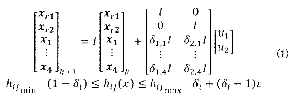
 model generation unit 74 can determine the abstract model Σ to be set for the working space shown in FIG. 7 by the following formula (1).

Figure 0007666528000003

ここで、「u」は、ロボットハンドj(「j=1」はロボットアーム51aのロボットハンド、「j=2」はロボットアーム51bのロボットハンド)を制御するための制御入力を示し、「I」は単位行列を示し、「0」は零行例を示す。なお、制御入力は、ここでは、一例として速度を想定しているが、加速度であってもよい。また、「δj,i」は、ロボットハンドjが物品iを掴んでいる場合に「1」であり、その他の場合に「0」である論理変数である。また、「xr1」、「xr2」は、ロボットハンドj(j=1、2)の位置ベクトル、「x」~「x」は、物品i(i=1~4)の位置ベクトルを示す。また、「h(x)」は、物品を掴める程度に物品の近傍にロボットハンドが存在する場合に「h(x)≧0」となる変数であり、論理変数δとの間で以下の関係を満たす。
δ=1 ⇔ h(x)≧0
この式では、物品を掴める程度に物品の近傍にロボットハンドが存在する場合には、ロボットハンドが物品を掴んでいるとみなし、論理変数δを1に設定している。
Here, "u j " denotes a control input for controlling the robot hand j ("j=1" is the robot hand of the robot arm 51a, and "j=2" is the robot hand of the robot arm 51b), "I" denotes a unit matrix, and "0" denotes a zero-row matrix. Note that the control input is assumed to be a velocity as an example here, but it may be an acceleration. Furthermore, "δ j,i " is a logical variable that is "1" when the robot hand j is gripping an item i, and is "0" otherwise. Furthermore, "x r1 " and "x r2 " denote the position vector of the robot hand j (j=1, 2), and "x 1 " to "x 4 " denote the position vectors of the item i (i=1 to 4). Furthermore, "h(x)" is a variable that is "h(x)≧0" when a robot hand is present close enough to grip the item, and satisfies the following relationship with the logical variable δ.
δ=1 ⇔ h(x)≧0
In this equation, if the robot hand is close enough to an object to grasp the object, it is assumed that the robot hand is grasping the object, and the logical variable δ is set to 1.

ここで、式(1)は、タイムステップkでの物体の状態とタイムステップk+1での物体の状態との関係を示した差分方程式である。そして、上記の式(1)では、把持の状態が離散値である論理変数により表わされ、物体の移動は連続値により表わされているため、式(1)はハイブリッドシステムを示している。 Here, equation (1) is a differential equation that shows the relationship between the state of the object at time step k and the state of the object at time step k+1. In the above equation (1), the grip state is represented by a logical variable that is a discrete value, and the movement of the object is represented by a continuous value, so equation (1) shows a hybrid system.

式(1)では、ロボット51全体の詳細なダイナミクスではなく、物品を実際に把持するロボット51の手先であるロボットハンドのダイナミクスのみを考慮している。これにより、制御入力生成部75による最適化処理の計算量を好適に削減することができる。 Equation (1) considers only the dynamics of the robot hand, which is the end effector of the robot 51 that actually grasps an object, rather than the detailed dynamics of the entire robot 51. This makes it possible to effectively reduce the amount of calculation required for the optimization process performed by the control input generation unit 75.

また、抽象モデル情報I5には、ダイナミクスが切り替わる動作(ピックアンドプレイスの場合には物品iを掴むという動作)に対応する論理変数、及び、認識結果Imから式(1)の差分方程式を導出するための情報が記録されている。よって、抽象モデル生成部74は、物品の位置や数、物品を置く領域(仕分容器8)の位置や数、ロボット51の台数等が変動する場合であっても、抽象モデル情報I5と認識結果Imとに基づき、対象の作業空間の環境に即した抽象モデルΣを決定することができる。 The abstract model information I5 also records logical variables corresponding to the action of switching dynamics (the action of grasping item i in the case of pick-and-place), and information for deriving the difference equation of formula (1) from the recognition result Im. Therefore, the abstract model generation unit 74 can determine an abstract model Σ that is suited to the environment of the target workspace based on the abstract model information I5 and the recognition result Im, even if the positions and number of items, the positions and number of areas where the items are placed (sorting containers 8), the number of robots 51, etc. vary.

なお、抽象モデル生成部74は、式(1)に示されるモデルに代えて、混合論理動的(MLD:Mixed Logical Dynamical)システムまたはペトリネットやオートマトンなどを組み合わせたハイブリッドシステムのモデルを生成してもよい。In addition, the abstract model generation unit 74 may generate a model of a mixed logical dynamic (MLD) system or a hybrid system that combines Petri nets, automata, etc., instead of the model shown in equation (1).

(5-8)制御入力生成部
制御入力生成部75は、タイムステップ論理式生成部73から供給されるタイムステップ論理式Ltsと、抽象モデル生成部74から供給される抽象モデルΣとに基づき、最適となるタイムステップ毎のロボット51に対する制御入力を決定する。この場合、制御入力生成部75は、目的タスクに対する評価関数を定義し、抽象モデルΣ及びタイムステップ論理式Ltsを制約条件として評価関数を最小化する最適化問題を解く。評価関数は、例えば、予めメモリ12に記憶されている。
(5-8) Control input generation unit
The control input generation unit 75 determines an optimal control input for the robot 51 for each time step based on the time step logical formula Lts supplied from the time step logical formula generation unit 73 and the abstract model Σ supplied from the abstract model generation unit 74. In this case, the control input generation unit 75 defines an evaluation function for the target task, and solves an optimization problem of minimizing the evaluation function with the abstract model Σ and the time step logical formula Lts as constraints. The evaluation function is stored in advance in the memory 12, for example.

例えば、ピックアンドプレイスを目的タスクとした場合、制御入力生成部75は、運ぶ対象となる物品と当該物品を運ぶ目標地点との距離「d」と制御入力「u」とが最小となる(即ちロボット51が費やすエネルギーを最小化する)ように評価関数を定める。上述の距離dは、「最終的に物品(i=2)が領域Gに存在する」という目的タスクの場合には、物品(i=2)と領域Gとのタイムステップkでの距離に相当する。 For example, when pick-and-place is the goal task, the control input generating unit 75 determines the evaluation function so that the distance "d k " between the item to be transported and the target point to which the item is to be transported and the control input "u k " are minimized (i.e., the energy consumed by the robot 51 is minimized). In the case of a goal task in which "an item (i=2) is finally present in area G", the above-mentioned distance d k corresponds to the distance between the item (i=2) and area G at time step k.

この場合、制御入力生成部75は、全タイムステップにおける距離dのノルムの2乗と制御入力uのノルムの2乗との和を評価関数として定める。そして、制御入力生成部75は、抽象モデルΣ及びタイムステップ論理式Lts(即ち候補φの論理和)を制約条件とする以下の式(2)に示す制約付き混合整数最適化問題を解く。 In this case, the control input generation unit 75 determines the sum of the square of the norm of the distance d k in all time steps and the square of the norm of the control input u k as the evaluation function. Then, the control input generation unit 75 solves the constrained mixed integer optimization problem shown in the following formula (2) in which the abstract model Σ and the time step logical formula Lts (i.e., the logical sum of the candidates φ i ) are constraints.

Figure 0007666528000004

ここで、「T」は、最適化の対象となるタイムステップ数であり、目標タイムステップ数であってもよく、後述するように、目標タイムステップ数よりも小さい所定数であってもよい。この場合、好適には、制御入力生成部75は、論理変数を連続値に近似する(連続緩和問題とする)。これにより、制御入力生成部75は、計算量を好適に低減することができる。なお、線形論理式(LTL)に代えてSTLを採用した場合には、非線形最適化問題として記述することが可能である。このような最適化により、ロボット51同士の物品7の受渡しを必要に応じて含んだロボット51の動作を規定する制御入力が決定される。Here, "T" is the number of time steps to be optimized, and may be the target number of time steps, or may be a predetermined number smaller than the target number of time steps, as described below. In this case, preferably, the control input generation unit 75 approximates the logical variables to continuous values (continuous relaxation problem). This allows the control input generation unit 75 to preferably reduce the amount of calculation. Note that when STL is adopted instead of linear logic (LTL), it is possible to describe it as a nonlinear optimization problem. Through such optimization, a control input that specifies the operation of the robot 51, including the transfer of the item 7 between the robots 51 as necessary, is determined.

また、制御入力生成部75は、目標タイムステップ数が長い場合(例えば所定の閾値より大きい場合)、最適化に用いるタイムステップ数を、目標タイムステップ数より小さい値(例えば上述の閾値)に設定してもよい。この場合、制御入力生成部75は、例えば、所定のタイムステップ数が経過する毎に、上述の最適化問題を解くことで、逐次的に制御入力uを決定する。 Furthermore, when the target number of time steps is long (e.g., larger than a predetermined threshold), the control input generating unit 75 may set the number of time steps used for optimization to a value smaller than the target number of time steps (e.g., the above-mentioned threshold). In this case, the control input generating unit 75 sequentially determines the control input u k by solving the above-mentioned optimization problem, for example, every time a predetermined number of time steps elapses.

好適には、制御入力生成部75は、目的タスクの達成状態に対する中間状態に相当する所定のイベント毎に、上述の最適化問題を解き、使用すべき制御入力uを決定してもよい。この場合、制御入力生成部75は、次のイベント発生までのタイムステップ数を、最適化に用いるタイムステップ数に設定する。上述のイベントは、例えば、作業空間におけるダイナミクスが切り替わる事象である。例えば、ピックアンドプレイスを目的タスクとした場合には、ロボット51が物品を掴む、ロボット51が運ぶべき複数の物品のうちの1つの物品を目的地点へ運び終える、などがイベントとして定められる。イベントは、例えば、予め定められており、イベントを特定する情報がメモリ12等に予め記憶されている。 Preferably, the control input generating unit 75 may solve the above optimization problem for each predetermined event corresponding to an intermediate state with respect to the achievement state of the target task, and determine the control input u k to be used. In this case, the control input generating unit 75 sets the number of time steps until the next event occurs to the number of time steps used for optimization. The above-mentioned event is, for example, an event in which the dynamics in the working space is switched. For example, when pick-and-place is set as the target task, the robot 51 grasps an item, the robot 51 finishes carrying one of the multiple items to be carried to the destination point, and the like are defined as events. For example, the event is defined in advance, and information specifying the event is stored in advance in the memory 12 or the like.

(5-9)動作シーケンス生成部
動作シーケンス生成部76は、制御入力生成部75から供給される制御入力情報Icnと、アプリケーション情報IAのサブタスク情報I4とに基づき、動作シーケンスを生成する。この場合、動作シーケンス生成部76は、サブタスク情報I4を参照することで、ロボット51が受け付け可能なサブタスクを認識し、制御入力情報Icnが示すタイムステップ毎の制御入力をサブタスクに変換する。
(5-9) Operation sequence generation unit
The movement sequence generating unit 76 generates a movement sequence based on the control input information Icn supplied from the control input generating unit 75 and the subtask information I4 of the application information IA. In this case, the movement sequence generating unit 76 recognizes subtasks that the robot 51 can accept by referring to the subtask information I4, and converts the control input for each time step indicated by the control input information Icn into a subtask.

例えば、サブタスク情報I4には、ピックアンドプレイスを目的タスクとする場合にロボット51が受け付け可能なサブタスクとして、ロボットハンドの移動(リーチング)とロボットハンドの把持(グラスピング)の2つのサブタスクを示す関数が定義されている。この場合、リーチングを表す関数「Move」は、例えば、当該関数実行前のロボット51の初期状態、当該関数実行後のロボット51の最終状態、及び当該関数の実行に要する所要時間をそれぞれ引数とする関数である。また、グラスピングを表す関数「Grasp」は、例えば、当該関数実行前のロボット51の状態、及び当該関数実行前の把持対象の物品の状態、論理変数δをそれぞれ引数とする関数である。ここで、関数「Grasp」は、論理変数δが「1」のときに掴む動作を行うこと表し、論理変数δが「0」のときに放す動作を行うこと表す。この場合、動作シーケンス生成部76は、関数「Move」を、制御入力情報Icnが示すタイムステップ毎の制御入力により定まるロボットハンドの軌道に基づき決定し、関数「Grasp」を、制御入力情報Icnが示すタイムステップ毎の論理変数δの遷移に基づき決定する。For example, in the subtask information I4, functions are defined that indicate two subtasks, namely, moving the robot hand (reaching) and grasping (grasping) of the robot hand, as subtasks that the robot 51 can accept when the target task is pick-and-place. In this case, the function "Move" that indicates reaching is a function that takes as arguments, for example, the initial state of the robot 51 before the execution of the function, the final state of the robot 51 after the execution of the function, and the time required to execute the function. Also, the function "Grasping" is a function that takes as arguments, for example, the state of the robot 51 before the execution of the function, the state of the item to be grasped before the execution of the function, and the logical variable δ. Here, the function "Grasping" indicates that a grasping action is performed when the logical variable δ is "1", and indicates that a releasing action is performed when the logical variable δ is "0". In this case, the operation sequence generation unit 76 determines the function "Move" based on the trajectory of the robot hand determined by the control input for each time step indicated by the control input information Icn, and determines the function "Grasp" based on the transition of the logical variable δ for each time step indicated by the control input information Icn.

そして、動作シーケンス生成部76は、関数「Move」と関数「Grasp」とにより構成される動作シーケンスを生成し、当該動作シーケンスをロボット51に供給する。例えば、目的タスクが「最終的に物品(i=2)が領域Gに存在する」の場合、動作シーケンス生成部76は、物品(i=2)に最も近いロボットハンドに対し、関数「Move」、関数「Grasp」、関数「Move」、関数「Grasp」の動作シーケンスを生成する。この場合、物品(i=2)に最も近いロボットハンドは、1回目の関数「Move」により物品(i=2)の位置まで移動し、1回目の関数「Grasp」により物品(i=2)を把持し、2回目の関数「Move」により領域Gまで移動し、2回目の関数「Grasp」により物品(i=2)を領域Gに載置する。Then, the motion sequence generating unit 76 generates a motion sequence consisting of the function "Move" and the function "Grasp" and supplies the motion sequence to the robot 51. For example, if the target task is "finally, the item (i=2) is present in the area G", the motion sequence generating unit 76 generates a motion sequence of the function "Move", the function "Grasp", the function "Move", and the function "Grasp" for the robot hand closest to the item (i=2). In this case, the robot hand closest to the item (i=2) moves to the position of the item (i=2) by the first function "Move", grasps the item (i=2) by the first function "Grasp", moves to the area G by the second function "Move", and places the item (i=2) in the area G by the second function "Grasp".

(6)処理フロー
図8は、第1実施形態において制御装置1が実行する処理の概要を示すフローチャートの一例である。
(6) Processing flow
FIG. 8 is an example of a flowchart showing an outline of the process executed by the control device 1 in the first embodiment.

まず、制御装置1は、仕分け対象となる物品7を検出する(ステップS11)。この場合、制御装置1は、例えば、計測装置4が生成する計測信号S1に基づき、所定範囲に存在する物品7を仕分け対象の物品7として検出する。First, the control device 1 detects the items 7 to be sorted (step S11). In this case, the control device 1 detects the items 7 present within a predetermined range as the items 7 to be sorted, for example, based on the measurement signal S1 generated by the measurement device 4.

次に、制御装置1は、ステップS11で検出した物品7の仕分け先となる仕分容器8を決定する(ステップS12)。この場合、制御装置1は、例えば、計測信号S1と仕分情報IBとに基づき、ステップS11で検出した物品7の各々の仕分先となる仕分容器8を決定する。なお、ステップS11及びステップS12の処理は、例えば、上述した動作計画部15の目的タスク設定部70の処理に相当する。Next, the control device 1 determines the sorting container 8 into which the items 7 detected in step S11 are to be sorted (step S12). In this case, the control device 1 determines the sorting container 8 into which each of the items 7 detected in step S11 is to be sorted, for example, based on the measurement signal S1 and the sorting information IB. Note that the processing of steps S11 and S12 corresponds to, for example, the processing of the target task setting unit 70 of the operation planning unit 15 described above.

次に、制御装置1は、仕分容器8の搬出及び補充が必要か否か判定する(ステップS13)。そして、制御装置1は、仕分容器8の搬出及び補充が必要と判定した場合(ステップS13;Yes)、仕分容器8の搬出及び補充を実現するための制御を行う(ステップS14)。ステップS13及びステップS14の処理は、例えば、仕分容器制御部17の処理に相当する。Next, the control device 1 determines whether or not the sorting containers 8 need to be removed and refilled (step S13). If the control device 1 determines that the sorting containers 8 need to be removed and refilled (step S13; Yes), it performs control to realize the removal and refilling of the sorting containers 8 (step S14). The processing of steps S13 and S14 corresponds to, for example, the processing of the sorting container control unit 17.

そして、制御装置1は、仕分容器8が補充されたか否か判定する(ステップS15)。ステップS15の処理は、例えば、判定部16の処理に相当する。そして、制御装置1は、仕分容器8が補充されたと判定した場合(ステップS15;Yes)、補充後の仕分容器8の配置に基づき、動作計画の更新を行う(ステップS16)。このように、制御装置1は、仕分容器8の補充が行われた場合、最新の仕分容器8の配置に基づき、物品7を仕分けるための動作計画の更新(再決定)を行う。これにより、制御装置1は、最新の仕分容器8の配置に基づき、物品7の仕分けを的確に行うことができる。なお、この場合、例えば、制御装置1は、ステップS11で検出した物品7に対するピックアンドプレイスの動作計画を新たに策定すると共に、動作計画済みであって仕分容器8に移動前の物品7に対するピックアンドプレイスの動作計画を更新用の動作計画として策定する。ステップS16の処理は、例えば、目的タスク設定部70以外の動作計画部15の処理に相当する。一方、制御装置1は、仕分容器8が補充されていない場合(ステップS15;No)、引き続きステップS14の処理を継続する。Then, the control device 1 determines whether the sorting container 8 has been replenished (step S15). The processing of step S15 corresponds to, for example, the processing of the judgment unit 16. Then, when the control device 1 determines that the sorting container 8 has been replenished (step S15; Yes), it updates the operation plan based on the arrangement of the sorting container 8 after replenishment (step S16). In this way, when the sorting container 8 has been replenished, the control device 1 updates (re-determines) the operation plan for sorting the item 7 based on the latest arrangement of the sorting container 8. This allows the control device 1 to accurately sort the item 7 based on the latest arrangement of the sorting container 8. In this case, for example, the control device 1 formulates a new pick-and-place operation plan for the item 7 detected in step S11, and formulates a pick-and-place operation plan for the item 7 for which an operation plan has been made and which has not yet been moved to the sorting container 8 as an updated operation plan. The processing of step S16 corresponds, for example, to the processing of the operation plan unit 15 other than the target task setting unit 70. On the other hand, if the sorting container 8 has not been replenished (step S15; No), the control device 1 continues the process of step S14.

一方、ステップS13において、仕分容器8の搬出及び補充が必要でない場合(ステップS13;No)、制御装置1は、動作計画の決定を行う(ステップS17)。ステップS17の処理は、例えば、目的タスク設定部70以外の動作計画部15の処理に相当する。On the other hand, in step S13, if removal and refilling of the sorting container 8 is not required (step S13; No), the control device 1 determines an operation plan (step S17). The processing of step S17 corresponds to, for example, the processing of the operation plan unit 15 other than the target task setting unit 70.

そして、制御装置1は、ステップS16又はステップS17で決定した動作計画に基づくロボット51の制御を行う(ステップS18)。なお、制御装置1は、ステップS18でのロボット制御を、決定した動作計画が完了するまで継続して実行したまま、次のステップに移行してもよい。ステップS18の処理は、例えば、ロボット制御部14の処理に相当する。The control device 1 then controls the robot 51 based on the operation plan determined in step S16 or step S17 (step S18). The control device 1 may continue to execute the robot control in step S18 until the determined operation plan is completed, and then proceed to the next step. The processing in step S18 corresponds to, for example, the processing of the robot control unit 14.

そして、制御装置1は、ロボット51等の制御処理を終了すべきか否か判定する(ステップS19)。例えば、制御装置1は、ロボット51等の制御処理を停止すべき旨の外部入力等を検知した場合、ロボット51等の制御処理を終了すべきと判定する。そして、制御装置1は、ロボット51等の制御処理を終了すべきと判定した場合(ステップS19;Yes)、フローチャートの処理を終了する。一方、制御装置1は、ロボット51等の制御処理を終了すべきでない場合(ステップS19;No)、ステップS11に処理を戻す。Then, the control device 1 determines whether or not the control process of the robot 51, etc. should be terminated (step S19). For example, when the control device 1 detects an external input indicating that the control process of the robot 51, etc. should be stopped, it determines that the control process of the robot 51, etc. should be terminated. When the control device 1 determines that the control process of the robot 51, etc. should be terminated (step S19; Yes), it terminates the processing of the flowchart. On the other hand, when the control device 1 determines that the control process of the robot 51, etc. should not be terminated (step S19; No), it returns the processing to step S11.

(7)変形例
次に、第1実施形態の変形例について説明する。以下の変形例は任意に組み合わせて適用してもよい。
(7) Modifications
Next, a description will be given of modifications of the first embodiment. The following modifications may be applied in any combination.

(変形例1)
図6に示す動作計画部15のブロック構成は一例であり、種々の変更がなされてもよい。
(Variation 1)
The block configuration of the operation planning unit 15 shown in FIG. 6 is an example, and various modifications may be made.

例えば、ロボット51に命令する動作のシーケンスの候補φの情報がメモリ12に予め記憶され、動作計画部15は、当該情報に基づき、制御入力生成部75の最適化処理を実行する。これにより、動作計画部15は、最適な候補φの選定とロボット51の制御入力の決定を行う。この場合、動作計画部15は、抽象状態設定部71、目標論理式生成部72及びタイムステップ論理式生成部73に相当する機能を有しなくともよい。このように、図6に示す動作計画部15の一部の機能ブロックの実行結果に関する情報がアプリケーション情報IAの一部として予め記憶されていてもよい。For example, information on candidates φ for a sequence of operations to be commanded to the robot 51 is pre-stored in the memory 12, and the motion planning unit 15 executes an optimization process for the control input generation unit 75 based on the information. As a result, the motion planning unit 15 selects the optimal candidate φ and determines the control input for the robot 51. In this case, the motion planning unit 15 does not need to have functions equivalent to the abstract state setting unit 71, the target logical formula generation unit 72, and the time step logical formula generation unit 73. In this way, information on the execution results of some of the functional blocks of the motion planning unit 15 shown in FIG. 6 may be pre-stored as part of the application information IA.

他の例では、アプリケーション情報には、目的タスクに対応する動作シーケンスを設計するためのフローチャートなどの設計情報が予め含まれており、動作計画部15は、当該設計情報を参照することで、動作シーケンスを生成してもよい。なお、予め設計されたタスクシーケンスに基づきタスクを実行する具体例については、特開2017-39170号に開示されている。In another example, the application information may include design information such as a flowchart for designing an operation sequence corresponding to a target task, and the operation planning unit 15 may generate the operation sequence by referring to the design information. A specific example of executing a task based on a pre-designed task sequence is disclosed in JP 2017-39170 A.

(変形例2)
図3に示す作業空間は一例であり、図3に示す作業空間に対して種々の変更がなされてもよい。
(Variation 2)
The workspace shown in FIG. 3 is an example, and various modifications may be made to the workspace shown in FIG.

例えば、作業空間には、BCR42が設けられていなくともよい。この場合、例えば、目的タスク設定部70は、カメラ41により得られた画像に対して画像認識技術を適用することで、第1搬送機械52A上の物品7の種類及び位置を認識し、所定の位置に存在する物品7を仕分け対象となる物品7として特定する。また、目的タスク設定部70は、認識した物品7の種類に基づき、仕分け対象となる物品7の仕分け先となる仕分容器8を特定する。この場合、カメラ41による画像認識結果である物品7の種類に応じて物品7の仕分けを行うため、仕分情報IBを利用する必要がない。For example, the work space does not need to be provided with a BCR 42. In this case, for example, the target task setting unit 70 recognizes the type and position of the item 7 on the first conveying machine 52A by applying image recognition technology to the image obtained by the camera 41, and identifies the item 7 present at a predetermined position as the item 7 to be sorted. The target task setting unit 70 also identifies the sorting container 8 into which the item 7 to be sorted is to be sorted based on the recognized type of item 7. In this case, there is no need to use the sorting information IB, because the item 7 is sorted according to the type of item 7, which is the result of image recognition by the camera 41.

他の例では、梱包箱6から取り出された物品7は、ロボット51の可動範囲内に直接置かれてもよい。この場合、図3における第1搬送機械52Aは存在しなくともよい。さらに別の例では、仕分容器補充機構53は、仕分容器台54又は仕分容器台55から仕分容器8が搬出されたことを自センサの出力等に基づき検出し、制御装置1からの制御信号S2に依らずに自律的に仕分容器8の補充作業を行ってもよい。In another example, the items 7 removed from the packing box 6 may be placed directly within the movable range of the robot 51. In this case, the first conveying machine 52A in FIG. 3 does not need to be present. In yet another example, the sorting container refill mechanism 53 may detect that a sorting container 8 has been removed from the sorting container table 54 or the sorting container table 55 based on the output of its own sensor, etc., and autonomously perform the refilling work of the sorting container 8 without relying on the control signal S2 from the control device 1.

さらに別の例では、仕分容器補充機構53は、仕分容器台54と仕分容器台55とに対して夫々設けられてもよい。この場合、仕分容器補充機構53は、仕分容器台54又は仕分容器台55に対して図3に示す位置と反対側に夫々設けられてもよい。また、仕分容器台54及び仕分容器台55は、仕分容器補充機構53に相当する機能を有してもよい。この場合、仕分容器台54及び仕分容器台55は、例えば、いずれかの仕分容器8が第2搬送機械52Bに搬出された場合に、当該仕分容器8が存在した位置に補充用の仕分容器8を内部から送り出す機構を有してもよい。また、仕分容器補充機構53に代えて、ロボットアーム51A~51Cが仕分容器8を補充する作業を行ってもよい。In yet another example, the sorting container refill mechanism 53 may be provided for each of the sorting container tables 54 and 55. In this case, the sorting container refill mechanism 53 may be provided on the opposite side of the sorting container table 54 or the sorting container table 55 from the position shown in FIG. 3. The sorting container table 54 and the sorting container table 55 may also have a function equivalent to the sorting container refill mechanism 53. In this case, the sorting container table 54 and the sorting container table 55 may have a mechanism for sending a refilling sorting container 8 from inside to the position where the sorting container 8 was located when any of the sorting containers 8 is transported to the second conveying machine 52B, for example. Also, instead of the sorting container refill mechanism 53, the robot arms 51A to 51C may perform the task of refilling the sorting containers 8.

また、倉庫内における入荷商品の仕分け作業に限らず、組み立て製造業、食品製造業、又は物流業での入荷作業等においても、図4及び図8等に示されるロボット51等の制御処理は好適に適用される。 In addition, the control processing of the robot 51, etc. shown in Figures 4 and 8, etc., can be suitably applied not only to sorting incoming goods in a warehouse, but also to receiving operations in the assembly manufacturing industry, food manufacturing industry, or logistics industry.

(変形例3)
仕分制御システム100には、倉庫管理システム(WMS:Warehouse Management System)が含まれ、制御装置1は倉庫管理システムと連携してバラ仕分けに関する処理を実行してもよい。
(Variation 3)
The sorting control system 100 includes a warehouse management system (WMS), and the control device 1 may cooperate with the warehouse management system to execute processes related to bulk sorting.

図9は、変形例3における仕分制御システム100Aの概略構成図である。図9に示されるように、仕分制御システム100Aは、倉庫管理システムにおける情報を管理する倉庫管理装置2を含んでいる。そして、制御装置1と倉庫管理装置2は、図1に示す制御装置1が実行する処理を協働して実行する。例えば、倉庫管理装置2は、BCR42によるバーコードの読み取り結果及び仕分情報IBを管理し、制御装置1は、カメラ41等によりBCR42を通過した物品7を検出し、当該物品7の仕分け先となる仕分容器8に関する情報を倉庫管理装置2から受信する。このように、本変形例によれば、制御装置1は、倉庫管理装置2とデータ通信を行うことで、物品7の仕分け先となる仕分容器8を好適に決定し、上述した実施形態に基づくロボット51の動作計画を策定することができる。9 is a schematic diagram of a sorting control system 100A in the third modified example. As shown in FIG. 9, the sorting control system 100A includes a warehouse management device 2 that manages information in the warehouse management system. The control device 1 and the warehouse management device 2 cooperate to execute the process executed by the control device 1 shown in FIG. 1. For example, the warehouse management device 2 manages the barcode reading result by the BCR 42 and the sorting information IB, and the control device 1 detects an item 7 that has passed through the BCR 42 using a camera 41 or the like, and receives information about the sorting container 8 to which the item 7 is to be sorted from the warehouse management device 2. Thus, according to this modified example, the control device 1 can appropriately determine the sorting container 8 to which the item 7 is to be sorted by performing data communication with the warehouse management device 2, and can formulate an operation plan for the robot 51 based on the above-mentioned embodiment.

<第2実施形態>
図10は、第2実施形態における制御装置1Xの概略構成図である。図10に示すように、制御装置1Xは、主に、動作計画手段15Xと、判定手段16Xと、を有する。なお、制御装置1Xは、複数の装置から構成されてもよい。
Second Embodiment
Fig. 10 is a schematic configuration diagram of a control device 1X in the second embodiment. As shown in Fig. 10, the control device 1X mainly includes an operation planning unit 15X and a determination unit 16X. The control device 1X may be composed of a plurality of devices.

動作計画手段15Xは、複数の物品を複数の仕分容器に仕分ける作業に関するロボットの動作計画を決定する。ここで、「複数の物品を複数の仕分容器に仕分ける」とは、複数の物品を各物品の分類に従って区分けした状態となるように仕分容器内に移動させることを指す。動作計画手段15Xは、例えば、第1実施形態における動作計画部15とすることができる。The motion planning means 15X determines a motion plan for the robot regarding the task of sorting multiple items into multiple sorting containers. Here, "sorting multiple items into multiple sorting containers" refers to moving multiple items into the sorting containers so that the items are separated according to the classification of each item. The motion planning means 15X can be, for example, the motion planning unit 15 in the first embodiment.

判定手段16Xは、仕分容器が補充されたか否か判定する。ここで、「仕分容器の補充」は、物品の仕分け先の候補となる空の仕分容器を新たに設置することを指す。判定手段16Xは、例えば、第1実施形態における判定部16とすることができる。The determination means 16X determines whether the sorting containers have been replenished. Here, "replenishment of sorting containers" refers to the installation of new empty sorting containers that are candidates for sorting items. The determination means 16X can be, for example, the determination unit 16 in the first embodiment.

そして、動作計画手段15Xは、仕分容器が補充された場合、補充後の仕分容器の配置に基づき、動作計画を更新する。ここで、「動作計画を更新する」とは、仕分容器の補充前の仕分容器の状態に基づいて策定された動作計画の代わりとして、補充後の仕分容器の配置に基づいて新たな動作計画を策定することを指す。この場合には、仕分け作業が行われていない物品を対象として動作計画が策定される。 When the sorting containers are refilled, the operation planning means 15X updates the operation plan based on the arrangement of the sorting containers after refilling. Here, "updating the operation plan" refers to formulating a new operation plan based on the arrangement of the sorting containers after refilling, instead of the operation plan formulated based on the state of the sorting containers before refilling. In this case, the operation plan is formulated for items for which sorting work has not been performed.

図11は、第2実施形態において制御装置1Xが実行するフローチャートの一例である。まず、動作計画手段15Xは、複数の物品を複数の仕分容器に仕分ける作業に関するロボットの動作計画を決定する(ステップS21)。そして、判定手段16Xは、仕分容器が補充されたか否か判定する(ステップS22)。そして、仕分容器が補充された場合(ステップS22;Yes)、補充後の仕分容器の配置に基づき、動作計画を更新する(ステップS23)。なお、仕分容器が補充されない場合(ステップS22;No)、引き続きステップS22において、判定手段16Xは、仕分容器が補充されたか否か判定する。なお、動作計画が正常に実行された場合等には、制御装置1Xは、ステップS23を実行することなく本フローチャートの処理を終了してもよい。 Figure 11 is an example of a flowchart executed by the control device 1X in the second embodiment. First, the motion planning means 15X determines a motion plan for the robot regarding the task of sorting multiple items into multiple sorting containers (step S21). Then, the judgment means 16X judges whether the sorting containers have been replenished (step S22). Then, if the sorting containers have been replenished (step S22; Yes), the motion plan is updated based on the arrangement of the sorting containers after replenishment (step S23). Note that if the sorting containers have not been replenished (step S22; No), the judgment means 16X continues to judge in step S22 whether the sorting containers have been replenished. Note that if the motion plan is executed normally, etc., the control device 1X may end the processing of this flowchart without executing step S23.

第2実施形態の構成によれば、制御装置1Xは、仕分容器の補充があった場合においても的確な動作計画を策定し、物品の仕分け作業をロボットに好適に実行させることができる。 According to the configuration of the second embodiment, the control device 1X can formulate an accurate operation plan even when the sorting container is replenished, and can cause the robot to optimally perform the item sorting task.

なお、上述した各実施形態において、プログラムは、様々なタイプの非一時的なコンピュータ可読媒体(non-transitory computer readable medium)を用いて格納され、コンピュータであるプロセッサ等に供給することができる。非一時的なコンピュータ可読媒体は、様々なタイプの実体のある記憶媒体(tangible storage medium)を含む。非一時的なコンピュータ可読媒体の例は、磁気記憶媒体(例えばフレキシブルディスク、磁気テープ、ハードディスクドライブ)、光磁気記憶媒体(例えば光磁気ディスク)、CD-ROM(Read Only Memory)、CD-R、CD-R/W、半導体メモリ(例えば、マスクROM、PROM(Programmable ROM)、EPROM(Erasable PROM)、フラッシュROM、RAM(Random Access Memory))を含む。また、プログラムは、様々なタイプの一時的なコンピュータ可読媒体(transitory computer readable medium)によってコンピュータに供給されてもよい。一時的なコンピュータ可読媒体の例は、電気信号、光信号、及び電磁波を含む。一時的なコンピュータ可読媒体は、電線及び光ファイバ等の有線通信路、又は無線通信路を介して、プログラムをコンピュータに供給できる。In each of the above-mentioned embodiments, the program can be stored using various types of non-transitory computer readable media and supplied to a computer, such as a processor. The non-transitory computer readable medium includes various types of tangible storage media. Examples of the non-transitory computer readable medium include magnetic storage media (e.g., flexible disks, magnetic tapes, hard disk drives), magneto-optical storage media (e.g., magneto-optical disks), CD-ROMs (Read Only Memory), CD-Rs, CD-R/Ws, and semiconductor memories (e.g., mask ROMs, PROMs (Programmable ROMs), EPROMs (Erasable PROMs), flash ROMs, and RAMs (Random Access Memory)). The program may also be supplied to the computer by various types of transitory computer readable media. Examples of the transitory computer readable medium include electrical signals, optical signals, and electromagnetic waves. The transitory computer readable medium can supply the program to the computer via wired communication paths such as electric wires and optical fibers, or wireless communication paths.

その他、上記の各実施形態の一部又は全部は、以下の付記のようにも記載され得るが以下には限られない。In addition, some or all of the above embodiments may be described as, but are not limited to, the following notes:

[付記1]
複数の物品を複数の仕分容器に仕分ける作業に関するロボットの動作計画を決定する動作計画手段と、
前記仕分容器が補充されたか否か判定する判定手段と、を有し、
前記動作計画手段は、前記仕分容器が補充された場合、補充後の前記仕分容器の配置に基づき、前記動作計画を更新する、制御装置。
[付記2]
前記ロボットは、第1ロボットと第2ロボットとを含み、かつ、前記第1ロボットの可動範囲と前記第2ロボットの可動範囲とが重複しており、
前記動作計画手段は、前記第1ロボットと前記第2ロボットとの間での前記物品の受渡しに関する動作を含む前記動作計画を決定する、付記1に記載の制御装置。
[付記3]
前記第1ロボットの可動範囲内に存在しない前記仕分容器が前記第2ロボットの可動範囲内に存在し、
前記動作計画手段は、前記第1ロボットの可動範囲内に存在し、かつ、前記第2ロボットの可動範囲外に存在する物品を、前記第1ロボットにより前記第2ロボットの可動範囲に移動させる動作を含む前記動作計画を決定する、付記2に記載の制御装置。
[付記4]
前記仕分容器の搬出及び補充を制御する仕分容器制御手段をさらに有する、付記1~3のいずれか一項に記載の制御装置。
[付記5]
前記仕分容器制御手段は、前記複数の物品のいずれかの物品の仕分け先となる前記仕分容器が所定の基準状態である場合、当該仕分容器の搬出及び新規の仕分容器の補充を行う、付記4に記載の制御装置。
[付記6]
前記仕分容器制御手段は、前記複数の物品のいずれかの物品の仕分け先の候補が前記複数の仕分容器に存在しない場合、前記複数の仕分容器のいずれかの仕分容器の搬出及び新規の仕分容器の補充を行う、付記4に記載の制御装置。
[付記7]
前記仕分容器制御手段は、前記いずれかの仕分容器を、前記複数の仕分容器の各々の物品の収容数又は収容率に基づき、前記複数の仕分容器から選択する、付記6に記載の制御装置。
[付記8]
前記動作計画手段は、前記動作計画として、前記ロボットが実行すべき目的となる目的タスクを時相論理により表した論理式に基づき、前記ロボットのタイムステップ毎の動作を表す動作シーケンスを生成する、付記1~7のいずれか一項に記載の制御装置。
[付記9]
前記目的タスクは、前記複数の物品を、当該物品の分類に基づき前記複数の仕分容器に移動させるピックアンドプレイスのタスクである、付記8に記載の制御装置。
[付記10]
コンピュータが、
複数の物品を複数の仕分容器に仕分ける作業に関するロボットの動作計画を決定し、
前記仕分容器が補充されたか否か判定し、
前記仕分容器が補充された場合、補充後の前記仕分容器の配置に基づき、前記動作計画を更新する、制御方法。
[付記11]
複数の物品を複数の仕分容器に仕分ける作業に関するロボットの動作計画を決定し、
前記仕分容器が補充されたか否か判定し、
前記仕分容器が補充された場合、補充後の前記仕分容器の配置に基づき、前記動作計画を更新する処理をコンピュータに実行させるプログラムが格納された記憶媒体。
[Appendix 1]
a motion planning means for determining a motion plan for the robot with respect to a task of sorting a plurality of articles into a plurality of sorting containers;
A determination means for determining whether the sorting container has been replenished,
The operation planning means, when the sorting containers are replenished, updates the operation plan based on the arrangement of the sorting containers after replenishment.
[Appendix 2]
the robots include a first robot and a second robot, and a movable range of the first robot and a movable range of the second robot overlap with each other;
The control device described in Appendix 1, wherein the motion planning means determines the motion plan including an operation related to the transfer of the item between the first robot and the second robot.
[Appendix 3]
the sorting container that is not within the movable range of the first robot is within the movable range of the second robot,
The control device described in Appendix 2, wherein the motion planning means determines the motion plan including an operation of moving an item that is within the movable range of the first robot and outside the movable range of the second robot by the first robot, into the movable range of the second robot.
[Appendix 4]
A control device according to any one of claims 1 to 3, further comprising a sorting container control means for controlling the removal and replenishment of the sorting containers.
[Appendix 5]
The control device described in Appendix 4, wherein the sorting container control means removes the sorting container to which any of the multiple items is to be sorted and replenishes it with a new sorting container when the sorting container is in a predetermined reference state.
[Appendix 6]
The control device described in Appendix 4, wherein the sorting container control means, when there is no candidate sorting destination for any of the plurality of items in the plurality of sorting containers, removes any of the plurality of sorting containers and refills a new sorting container.
[Appendix 7]
The control device according to claim 6, wherein the sorting container control means selects one of the sorting containers from the plurality of sorting containers based on the number or capacity of items contained in each of the plurality of sorting containers.
[Appendix 8]
The control device according to any one of appendices 1 to 7, wherein the motion planning means generates, as the motion plan, a motion sequence representing the motion of the robot for each time step based on a logical formula that expresses a target task, which is a target to be executed by the robot, using temporal logic.
[Appendix 9]
The control device of claim 8, wherein the target task is a pick-and-place task of moving the plurality of items to the plurality of sorting containers based on the classification of the items.
[Appendix 10]
The computer
determining a motion plan for the robot with respect to a task of sorting a plurality of articles into a plurality of sorting containers;
determining whether the sorting container has been replenished;
When the sorting container is replenished, the operation plan is updated based on the arrangement of the sorting container after replenishment.
[Appendix 11]
determining a motion plan for the robot with respect to a task of sorting a plurality of articles into a plurality of sorting containers;
determining whether the sorting container has been replenished;
a storage medium storing a program for causing a computer to execute a process of updating the operation plan based on the arrangement of the sorting containers after the sorting containers have been replenished;

以上、実施形態を参照して本願発明を説明したが、本願発明は上記実施形態に限定されるものではない。本願発明の構成や詳細には、本願発明のスコープ内で当業者が理解し得る様々な変更をすることができる。すなわち、本願発明は、請求の範囲を含む全開示、技術的思想にしたがって当業者であればなし得るであろう各種変形、修正を含むことは勿論である。また、引用した上記の特許文献等の各開示は、本書に引用をもって繰り込むものとする。 Although the present invention has been described above with reference to the embodiments, the present invention is not limited to the above-mentioned embodiments. Various modifications that a person skilled in the art can understand can be made to the configuration and details of the present invention within the scope of the present invention. In other words, the present invention naturally includes various modifications and amendments that a person skilled in the art could make in accordance with the entire disclosure, including the scope of the claims, and the technical ideas. Furthermore, the disclosures of the above cited patent documents, etc. are incorporated by reference into this document.

1、1X 制御装置
2 倉庫管理装置
3 通信網
4 計測装置
5 被制御機器
41 カメラ
42 BCR
51 ロボット
52 搬送機械
53 仕分容器補充機構
100、100A 仕分制御システム
1, 1X Control device 2 Warehouse management device 3 Communication network 4 Measuring device 5 Controlled device 41 Camera 42 BCR
51 Robot 52 Conveying machine 53 Sorting container refilling mechanism 100, 100A Sorting control system

Claims (10)

複数の物品を当該物品の分類に基づき複数の第1仕分容器に移動させるピックアンドプレイスの作業に関するロボットの動作計画を決定する動作計画手段と、
前記第1仕分容器の配置のずれを伴う第2仕分容器が補充されたか否か判定する判定手段と、を有し、
前記動作計画手段は、前記第2仕分容器が補充された場合、補充後の前記第1仕分容器及び前記第2仕分容器の配置に基づき、前記動作計画を更新する、制御装置。
a motion planning means for determining a motion plan for a robot for a pick-and-place operation of moving a plurality of articles to a plurality of first sorting containers based on the classification of the articles;
and a determination means for determining whether or not a second sorting container associated with a displacement of the first sorting container has been replenished,
The operation planning means updates the operation plan based on an arrangement of the first sorting container and the second sorting container after the second sorting container is replenished, the control device.
前記ロボットは、第1ロボットと第2ロボットとを含み、かつ、前記第1ロボットの可動範囲と前記第2ロボットの可動範囲とが重複しており、
前記動作計画手段は、前記第1ロボットと前記第2ロボットとの間での前記物品の受渡しに関する動作を含む前記動作計画を決定する、請求項1に記載の制御装置。
the robots include a first robot and a second robot, and a movable range of the first robot and a movable range of the second robot overlap with each other;
The control device according to claim 1 , wherein the motion planning means determines the motion plan including a motion related to a transfer of the article between the first robot and the second robot.
前記第1ロボットの可動範囲内に存在しない前記第1仕分容器が前記第2ロボットの可動範囲内に存在し、
前記動作計画手段は、前記第1ロボットの可動範囲内に存在し、かつ、前記第2ロボットの可動範囲外に存在する物品を、前記第1ロボットにより前記第2ロボットの可動範囲に移動させる動作を含む前記動作計画を決定する、請求項2に記載の制御装置。
the first sorting container that is not within the movable range of the first robot is within the movable range of the second robot,
The control device according to claim 2, wherein the motion planning means determines the motion plan including an operation of the first robot moving an item that is within the movable range of the first robot and outside the movable range of the second robot into the movable range of the second robot.
前記第1仕分容器の搬出及び前記第2仕分容器の補充を制御する仕分容器制御手段をさらに有する、請求項1~3のいずれか一項に記載の制御装置。 4. The control device according to claim 1, further comprising a sorting container control means for controlling the ejection of the first sorting container and the replenishment of the second sorting container . 前記仕分容器制御手段は、前記複数の物品のいずれかの物品の移動先となる前記第1仕分容器が所定の基準状態である場合、当該第1仕分容器の搬出及び前記第2仕分容器の補充を行う、請求項4に記載の制御装置。 The control device described in claim 4, wherein the sorting container control means removes the first sorting container and replenishes the second sorting container when the first sorting container to which any one of the plurality of items is to be moved is in a predetermined reference state. 前記仕分容器制御手段は、前記複数の物品のいずれかの物品の移動先の候補が前記複数の第1仕分容器に存在しない場合、前記複数の第1仕分容器のいずれかの仕分容器の搬出及び前記第2仕分容器の補充を行う、請求項4に記載の制御装置。 The control device described in claim 4, wherein the sorting container control means, when there is no candidate destination for any of the plurality of items in the plurality of first sorting containers, removes any of the plurality of first sorting containers and refills the second sorting container. 前記仕分容器制御手段は、前記いずれかの仕分容器を、前記複数の第1仕分容器の各々の物品の収容数又は収容率に基づき、前記複数の第1仕分容器から選択する、請求項6に記載の制御装置。 The control device according to claim 6 , wherein the sorting container control means selects one of the sorting containers from the plurality of first sorting containers based on the number or capacity of articles contained in each of the plurality of first sorting containers. 前記動作計画手段は、前記動作計画として、前記ロボットが実行すべき目的となる目的タスクを時相論理により表した論理式に基づき、前記ロボットのタイムステップ毎の動作を表す動作シーケンスを生成する、請求項1~7のいずれか一項に記載の制御装置。 The control device according to any one of claims 1 to 7, wherein the motion planning means generates, as the motion plan, a motion sequence representing the motion of the robot for each time step based on a logical expression that expresses a target task that is the target to be executed by the robot using temporal logic. コンピュータが、
複数の物品を当該物品の分類に基づき複数の第1仕分容器に移動させるピックアンドプレイスの作業に関するロボットの動作計画を決定し、
前記第1仕分容器の配置のずれを伴う第2仕分容器が補充されたか否か判定し、
前記第2仕分容器が補充された場合、補充後の前記第1仕分容器及び前記第2仕分容器の配置に基づき、前記動作計画を更新する、制御方法。
The computer
determining a robot motion plan for a pick-and-place operation to move a plurality of articles to a plurality of first sorting bins based on a classification of the articles;
determining whether a second sorting container associated with the misalignment of the first sorting container has been replenished;
A control method, in which, when the second sorting container is replenished, the operation plan is updated based on an arrangement of the first sorting container and the second sorting container after replenishment.
複数の物品を当該物品の分類に基づき複数の第1仕分容器に移動させるピックアンドプレイスの作業に関するロボットの動作計画を決定し、
前記第1仕分容器の配置のずれを伴う第2仕分容器が補充されたか否か判定し、
前記第2仕分容器が補充された場合、補充後の前記第1仕分容器及び前記第2仕分容器の配置に基づき、前記動作計画を更新する処理をコンピュータに実行させるプログラム。
determining a robot motion plan for a pick-and-place operation to move a plurality of articles to a plurality of first sorting bins based on a classification of the articles;
determining whether a second sorting container associated with the misalignment of the first sorting container has been replenished;
a program that causes a computer to execute a process of updating the operation plan based on an arrangement of the first sorting container and the second sorting container after the second sorting container is replenished, when the second sorting container is replenished;
JP2022577875A 2021-01-27 2021-01-27 Control device, control method, and program Active JP7666528B2 (en)

Applications Claiming Priority (1)

Application Number Priority Date Filing Date Title
PCT/JP2021/002820 WO2022162783A1 (en) 2021-01-27 2021-01-27 Control device, control method, and storage medium

Publications (3)

Publication Number Publication Date
JPWO2022162783A1 JPWO2022162783A1 (en) 2022-08-04
JPWO2022162783A5 JPWO2022162783A5 (en) 2023-10-13
JP7666528B2 true JP7666528B2 (en) 2025-04-22

Family

ID=82652790

Family Applications (1)

Application Number Title Priority Date Filing Date
JP2022577875A Active JP7666528B2 (en) 2021-01-27 2021-01-27 Control device, control method, and program

Country Status (3)

Country Link
US (1) US20240416516A1 (en)
JP (1) JP7666528B2 (en)
WO (1) WO2022162783A1 (en)

Families Citing this family (1)

* Cited by examiner, † Cited by third party
Publication number Priority date Publication date Assignee Title
CN120015672A (en) * 2023-11-15 2025-05-16 天津市环智新能源技术有限公司 Silicon chip cache system and method

Citations (11)

* Cited by examiner, † Cited by third party
Publication number Priority date Publication date Assignee Title
JP2003211096A (en) 2002-01-18 2003-07-29 Fuji Photo Film Co Ltd Sorting/array apparatus of article
KR200455226Y1 (en) 2010-04-30 2011-08-25 혼. 테크놀로지스, 인코포레이티드 Electronic Device Test Sorter
JP2014231420A (en) 2013-05-29 2014-12-11 株式会社ダイフク Article transport carriage
US20160039550A1 (en) 2014-08-05 2016-02-11 Premier Tech Technologies Ltee Apparatus and method for grouping and positioning items
US20170225330A1 (en) 2016-02-08 2017-08-10 Berkshire Grey Inc. Systems and methods for providing processing of a variety of objects employing motion planning
WO2018034252A1 (en) 2016-08-14 2018-02-22 ライフロボティクス株式会社 Dishwashing system
US20180273296A1 (en) 2017-03-23 2018-09-27 Berkshire Grey, Inc. Systems and methods for processing objects, including automated linear processing stations
JP2019025566A (en) 2017-07-27 2019-02-21 株式会社日立物流 Picking robot and picking system
WO2019121338A1 (en) 2017-12-22 2019-06-27 Robert Bosch Gmbh Method for operating a robot in a multi-agent system, robot and multi-agent system
US20200023514A1 (en) 2018-04-19 2020-01-23 Brown University Sequence-to-Sequence Language Grounding of Non-Markovian Task Specifications
JP2020203361A (en) 2019-06-19 2020-12-24 株式会社Ihi Robot control device and method for controlling the same

Patent Citations (11)

* Cited by examiner, † Cited by third party
Publication number Priority date Publication date Assignee Title
JP2003211096A (en) 2002-01-18 2003-07-29 Fuji Photo Film Co Ltd Sorting/array apparatus of article
KR200455226Y1 (en) 2010-04-30 2011-08-25 혼. 테크놀로지스, 인코포레이티드 Electronic Device Test Sorter
JP2014231420A (en) 2013-05-29 2014-12-11 株式会社ダイフク Article transport carriage
US20160039550A1 (en) 2014-08-05 2016-02-11 Premier Tech Technologies Ltee Apparatus and method for grouping and positioning items
US20170225330A1 (en) 2016-02-08 2017-08-10 Berkshire Grey Inc. Systems and methods for providing processing of a variety of objects employing motion planning
WO2018034252A1 (en) 2016-08-14 2018-02-22 ライフロボティクス株式会社 Dishwashing system
US20180273296A1 (en) 2017-03-23 2018-09-27 Berkshire Grey, Inc. Systems and methods for processing objects, including automated linear processing stations
JP2019025566A (en) 2017-07-27 2019-02-21 株式会社日立物流 Picking robot and picking system
WO2019121338A1 (en) 2017-12-22 2019-06-27 Robert Bosch Gmbh Method for operating a robot in a multi-agent system, robot and multi-agent system
US20200023514A1 (en) 2018-04-19 2020-01-23 Brown University Sequence-to-Sequence Language Grounding of Non-Markovian Task Specifications
JP2020203361A (en) 2019-06-19 2020-12-24 株式会社Ihi Robot control device and method for controlling the same

Also Published As

Publication number Publication date
JPWO2022162783A1 (en) 2022-08-04
WO2022162783A1 (en) 2022-08-04
US20240416516A1 (en) 2024-12-19

Similar Documents

Publication Publication Date Title
US12311551B2 (en) Controller and control method for robotic system
CN111823226B (en) Robotic system with coordination mechanism and method of operation thereof
US11905116B2 (en) Controller and control method for robot system
JP7364534B2 (en) Handling system and control method
US20220072587A1 (en) System and method for robotic horizontal sortation
US9519882B2 (en) Autonomous mobile bin storage and retrieval system
KR102674374B1 (en) Minimize robot dwell time in warehouse order fulfillment operations
CN117098634A (en) Systems and methods for dynamic robotic packaging and preparation lines
KR20180126620A (en) Optimize warehouse layouts based on customizable goals
JP7603799B2 (en) Coordinating the order in which functions are performed on items in an order
JP7494943B2 (en) Control device, control method and program
WO2023031772A2 (en) Systems, apparatuses, and methods for warehouse operation and automatic order fulfillment
JP7666528B2 (en) Control device, control method, and program
WO2020231319A1 (en) Robot cell setup system and process
EP3549072B1 (en) Identifying and managing equipment within an operational environment
US20240002153A1 (en) Robotic system to fulfill orders using cooperating robots
Rhiat et al. Combining mobile robotics and packing for optimal deliveries
KR102387778B1 (en) Robot system and method for providing store pickup service
Rizqi et al. Towards energy-efficient Robotic Mobile Fulfillment System: Hybrid agent-based simulation with DEA-based surrogate machine learning
KR102321318B1 (en) Modularized robot platform
KR102321329B1 (en) Method of establishing modularized robot platform
Halt et al. AMADEUS-A robotic multipurpose solution for intralogistics
EP4552060A1 (en) Item processing systems and methods employing parameter exploration
CN121194934A (en) Box distribution method and box distribution device
Mauro Towards the design of an effective and robust multi-robot parcel sorting system

Legal Events

Date Code Title Description
A521 Request for written amendment filed

Free format text: JAPANESE INTERMEDIATE CODE: A523

Effective date: 20230720

A621 Written request for application examination

Free format text: JAPANESE INTERMEDIATE CODE: A621

Effective date: 20230720

A131 Notification of reasons for refusal

Free format text: JAPANESE INTERMEDIATE CODE: A131

Effective date: 20240827

A521 Request for written amendment filed

Free format text: JAPANESE INTERMEDIATE CODE: A523

Effective date: 20241021

A131 Notification of reasons for refusal

Free format text: JAPANESE INTERMEDIATE CODE: A131

Effective date: 20241210

A521 Request for written amendment filed

Free format text: JAPANESE INTERMEDIATE CODE: A523

Effective date: 20250203

TRDD Decision of grant or rejection written
A01 Written decision to grant a patent or to grant a registration (utility model)

Free format text: JAPANESE INTERMEDIATE CODE: A01

Effective date: 20250311

A61 First payment of annual fees (during grant procedure)

Free format text: JAPANESE INTERMEDIATE CODE: A61

Effective date: 20250324

R150 Certificate of patent or registration of utility model

Ref document number: 7666528

Country of ref document: JP

Free format text: JAPANESE INTERMEDIATE CODE: R150