JP7648839B1 - Display control device, transport system, and control method and program for transport system - Google Patents
Display control device, transport system, and control method and program for transport system Download PDFInfo
- Publication number
- JP7648839B1 JP7648839B1 JP2024105160A JP2024105160A JP7648839B1 JP 7648839 B1 JP7648839 B1 JP 7648839B1 JP 2024105160 A JP2024105160 A JP 2024105160A JP 2024105160 A JP2024105160 A JP 2024105160A JP 7648839 B1 JP7648839 B1 JP 7648839B1
- Authority
- JP
- Japan
- Prior art keywords
- pallet
- shelf
- support
- robot
- hand
- Prior art date
- Legal status (The legal status is an assumption and is not a legal conclusion. Google has not performed a legal analysis and makes no representation as to the accuracy of the status listed.)
- Active
Links
Images


Classifications
-
- B—PERFORMING OPERATIONS; TRANSPORTING
- B23—MACHINE TOOLS; METAL-WORKING NOT OTHERWISE PROVIDED FOR
- B23Q—DETAILS, COMPONENTS, OR ACCESSORIES FOR MACHINE TOOLS, e.g. ARRANGEMENTS FOR COPYING OR CONTROLLING; MACHINE TOOLS IN GENERAL CHARACTERISED BY THE CONSTRUCTION OF PARTICULAR DETAILS OR COMPONENTS; COMBINATIONS OR ASSOCIATIONS OF METAL-WORKING MACHINES, NOT DIRECTED TO A PARTICULAR RESULT
- B23Q7/00—Arrangements for handling work specially combined with or arranged in, or specially adapted for use in connection with, machine tools, e.g. for conveying, loading, positioning, discharging, sorting
- B23Q7/04—Arrangements for handling work specially combined with or arranged in, or specially adapted for use in connection with, machine tools, e.g. for conveying, loading, positioning, discharging, sorting by means of grippers
-
- B—PERFORMING OPERATIONS; TRANSPORTING
- B23—MACHINE TOOLS; METAL-WORKING NOT OTHERWISE PROVIDED FOR
- B23Q—DETAILS, COMPONENTS, OR ACCESSORIES FOR MACHINE TOOLS, e.g. ARRANGEMENTS FOR COPYING OR CONTROLLING; MACHINE TOOLS IN GENERAL CHARACTERISED BY THE CONSTRUCTION OF PARTICULAR DETAILS OR COMPONENTS; COMBINATIONS OR ASSOCIATIONS OF METAL-WORKING MACHINES, NOT DIRECTED TO A PARTICULAR RESULT
- B23Q7/00—Arrangements for handling work specially combined with or arranged in, or specially adapted for use in connection with, machine tools, e.g. for conveying, loading, positioning, discharging, sorting
- B23Q7/10—Arrangements for handling work specially combined with or arranged in, or specially adapted for use in connection with, machine tools, e.g. for conveying, loading, positioning, discharging, sorting by means of magazines
-
- B—PERFORMING OPERATIONS; TRANSPORTING
- B25—HAND TOOLS; PORTABLE POWER-DRIVEN TOOLS; MANIPULATORS
- B25J—MANIPULATORS; CHAMBERS PROVIDED WITH MANIPULATION DEVICES
- B25J11/00—Manipulators not otherwise provided for
-
- B—PERFORMING OPERATIONS; TRANSPORTING
- B25—HAND TOOLS; PORTABLE POWER-DRIVEN TOOLS; MANIPULATORS
- B25J—MANIPULATORS; CHAMBERS PROVIDED WITH MANIPULATION DEVICES
- B25J13/00—Controls for manipulators
-
- B—PERFORMING OPERATIONS; TRANSPORTING
- B25—HAND TOOLS; PORTABLE POWER-DRIVEN TOOLS; MANIPULATORS
- B25J—MANIPULATORS; CHAMBERS PROVIDED WITH MANIPULATION DEVICES
- B25J13/00—Controls for manipulators
- B25J13/08—Controls for manipulators by means of sensing devices, e.g. viewing or touching devices
-
- B—PERFORMING OPERATIONS; TRANSPORTING
- B25—HAND TOOLS; PORTABLE POWER-DRIVEN TOOLS; MANIPULATORS
- B25J—MANIPULATORS; CHAMBERS PROVIDED WITH MANIPULATION DEVICES
- B25J9/00—Programme-controlled manipulators
- B25J9/16—Programme controls
-
- G—PHYSICS
- G05—CONTROLLING; REGULATING
- G05B—CONTROL OR REGULATING SYSTEMS IN GENERAL; FUNCTIONAL ELEMENTS OF SUCH SYSTEMS; MONITORING OR TESTING ARRANGEMENTS FOR SUCH SYSTEMS OR ELEMENTS
- G05B19/00—Programme-control systems
- G05B19/02—Programme-control systems electric
- G05B19/18—Numerical control [NC], i.e. automatically operating machines, in particular machine tools, e.g. in a manufacturing environment, so as to execute positioning, movement or co-ordinated operations by means of programme data in numerical form
- G05B19/406—Numerical control [NC], i.e. automatically operating machines, in particular machine tools, e.g. in a manufacturing environment, so as to execute positioning, movement or co-ordinated operations by means of programme data in numerical form characterised by monitoring or safety
- G05B19/4063—Monitoring general control system
-
- G—PHYSICS
- G06—COMPUTING OR CALCULATING; COUNTING
- G06T—IMAGE DATA PROCESSING OR GENERATION, IN GENERAL
- G06T7/00—Image analysis
Landscapes
- Engineering & Computer Science (AREA)
- Mechanical Engineering (AREA)
- Robotics (AREA)
- General Physics & Mathematics (AREA)
- Human Computer Interaction (AREA)
- Physics & Mathematics (AREA)
- Theoretical Computer Science (AREA)
- Manufacturing & Machinery (AREA)
- Automation & Control Theory (AREA)
- Computer Vision & Pattern Recognition (AREA)
- Manipulator (AREA)
- Feeding Of Workpieces (AREA)
- Warehouses Or Storage Devices (AREA)
Abstract
【課題】自動化の範囲を広げることが可能な搬送システム、搬送システムの制御方法およびプログラム、を提供する。
【解決手段】搬送システムは、ハンド(210)を有するロボット(21)と、ワークを保持するためのパレット(410)を載置可能な棚板(510)と、各々が棚板(510)を支持可能であり、上下方向に間隔を開けて並ぶ複数の支持部(560)とを有し、パレット(410)を格納するためのパレットストッカ(31)と、複数の支持部(560)のうちの第1支持部(560A)から第2支持部(560B)への棚板(510)の位置替えの指令を受け付けた場合に、棚板(510)をハンド(210)により把持しつつ、第1支持部(560A)から第2支持部(560B)に移動させるように、ロボット(21)を制御するロボット制御部(620)とを備える。
【選択図】図24
A transport system capable of expanding the scope of automation, and a control method and program for the transport system are provided.
[Solution] The transport system includes a robot (21) having a hand (210), a shelf (510) on which a pallet (410) for holding workpieces can be placed, and a plurality of support parts (560) each capable of supporting the shelf (510) and arranged at intervals in the vertical direction, a pallet stocker (31) for storing the pallets (410), and a robot control part (620) which controls the robot (21) to move the shelf (510) from the first support part (560A) to the second support part (560B) while grasping it with the hand (210) when a command is received to reposition the shelf (510) from a first support part (560A) to a second support part (560B) among the plurality of support parts (560).
[Selection] Figure 24
Description
この発明は、搬送システム、搬送システムの制御方法およびプログラムに関する。 This invention relates to a transport system, a control method for the transport system, and a program.
たとえば、特開2017-102825号公報(特許文献1)には、テーブルと一体的に移動可能なワーク固定治具を有する工作機械と、ワークを格納するワークストッカと、ワーク固定治具およびワークストッカの間でワークの供給および取り出しを行なうロボットを有するロボットシステムとを備える複合システムが開示されている。 For example, Japanese Patent Application Laid-Open No. 2017-102825 (Patent Document 1) discloses a composite system that includes a machine tool having a workpiece fixing jig that can move integrally with the table, a workpiece stocker that stores the workpieces, and a robot system that has a robot that supplies and removes the workpieces between the workpiece fixing jig and the workpiece stocker.
上述の特許文献1に開示されるように、ロボットを用いてワークを搬送する搬送システムが知られている。このような搬送システムにおいては、ロボットの用途を増やすことで自動化の範囲を広げることが求められている。 As disclosed in the above-mentioned Patent Document 1, a transport system that uses a robot to transport workpieces is known. In such transport systems, there is a demand to expand the scope of automation by increasing the number of applications for the robot.
この発明の目的は、自動化の範囲を広げることが可能な搬送システム、搬送システムの制御方法およびプログラムを提供することである。 The object of this invention is to provide a conveying system, a control method for a conveying system, and a program that can expand the scope of automation.
この発明に従った搬送システムは、ハンドを有するロボットと、ワークを保持するためのパレットを載置可能な棚板と、各々が棚板を支持可能であり、上下方向に間隔を開けて並ぶ複数の支持部とを有し、パレットを格納するためのパレットストッカと、複数の支持部のうちの第1支持部から第2支持部への棚板の位置替えの指令を受け付けた場合に、棚板をハンドにより把持しつつ、第1支持部から第2支持部に移動させるように、ロボットを制御するロボット制御部とを備える。 The transport system according to the present invention includes a robot having a hand, a shelf on which a pallet for holding workpieces can be placed, a plurality of support parts each capable of supporting a shelf and arranged at intervals in the vertical direction, a pallet stocker for storing the pallets, and a robot control unit that controls the robot to move the shelf from the first support part to the second support part while grasping it with the hand when a command is received to change the position of the shelf from a first support part to a second support part among the plurality of support parts.
この発明に従った搬送システムの制御方法において、搬送システムは、ハンドを有するロボットと、ワークを保持するためのパレットを載置可能な棚板と、各々が棚板を支持可能であり、上下方向に間隔を開けて並ぶ複数の支持部とを有し、パレットを格納するためのパレットストッカとを備える。搬送システムの制御方法は、複数の支持部のうちの第1支持部から第2支持部への棚板の位置替えの指令を受け付けるステップと、その指令に応じて、棚板をハンドにより把持しつつ、第1支持部から第2支持部に移動させるように、ロボットを制御するステップとを備える。 In a control method for a conveying system according to the present invention, the conveying system includes a robot having a hand, a shelf on which a pallet for holding workpieces can be placed, and a pallet stocker for storing the pallets, the pallet stocker having a plurality of support parts spaced apart in the vertical direction, each capable of supporting a shelf. The control method for the conveying system includes a step of receiving a command to change the position of the shelf from a first support part to a second support part among the plurality of support parts, and a step of controlling the robot in response to the command to move the shelf part from the first support part to the second support part while grasping it with the hand.
この発明に従ったプログラムは、搬送システムを制御するためのコンピュータにより実行されるプログラムである。搬送システムは、ハンドを有するロボットと、ワークを保持するためのパレットを載置可能な棚板と、各々が棚板を支持可能であり、上下方向に間隔を開けて並ぶ複数の支持部とを有し、パレットを格納するためのパレットストッカとを備える。プログラムは、コンピュータに、複数の支持部のうちの第1支持部から第2支持部への棚板の位置替えの指令を受け付けるステップと、その指令に応じて、棚板をハンドにより把持しつつ、第1支持部から第2支持部に移動させるように、ロボットを制御するステップとを実行させる。 The program according to the present invention is a program executed by a computer for controlling a transport system. The transport system includes a robot having a hand, a shelf on which a pallet for holding workpieces can be placed, and a pallet stocker for storing the pallets, the pallet stocker having a plurality of support parts spaced apart in the vertical direction, each capable of supporting a shelf. The program causes the computer to execute the steps of receiving a command to change the position of the shelf from a first support part to a second support part among the plurality of support parts, and controlling the robot in response to the command to move the shelf part from the first support part to the second support part while grasping it with the hand.
この発明に従えば、自動化の範囲を広げることが可能な搬送システム、搬送システムの制御方法およびプログラムを提供することができる。 This invention provides a transport system that can expand the scope of automation, and a control method and program for the transport system.
この発明の実施の形態について、図面を参照して説明する。なお、以下で参照する図面では、同一またはそれに相当する部材には、同じ番号が付されている。 The embodiment of the present invention will be described with reference to the drawings. Note that in the drawings referred to below, the same or equivalent components are given the same numbers.
図1は、この発明の実施の形態における搬送システムを示す上面図である。図2は、図1中の搬送システムを簡略化して示す上面図である。 Figure 1 is a top view showing a conveying system according to an embodiment of the present invention. Figure 2 is a top view showing a simplified version of the conveying system shown in Figure 1.
図1および図2を参照して、本実施の形態における搬送システム100は、ロボット21と、ロボットベース22とを有する。
Referring to Figures 1 and 2, the
典型的な例として、ロボット21は、6軸の多関節型ロボットである。ロボット21は、基台部26と、第1アーム27と、第2アーム28と、ハンド取り付け部29と、マスターハンド210とを有する。
As a typical example, the
ロボットベース22は、ロボット21を支持する支持台であり、工場等の床面に固定されている。ロボットベース22は、金属からなる。基台部26は、旋回中心軸101を中心に回転可能なようにロボットベース22に接続されている。旋回中心軸101は、ロボット21の旋回中心に対応する仮想上の直線であり、上下方向に延びている。
The
第1アーム27は、基台部26に取り付けられている。第1アーム27は、基台部26に対する第1アーム27の取り付け部(関節部)に配置される回動中心軸102を中心にして回動可能である。第2アーム28は、第1アーム27に取り付けられている。第2アーム28は、第1アーム27に対する第2アーム28の取り付け部(関節部)に配置される回動中心軸103を中心して回動可能であり、かつ、ハンド取り付け部29を、第2アーム28に沿った回転中心軸104を中心にして回転させることが可能である。ハンド取り付け部29は、第2アーム28に取り付けられている。ハンド取り付け部29は、第2アーム28に対するハンド取り付け部29の取り付け部(関節部)に配置される回動中心軸105を中心にして回動可能であり、かつ、マスターハンド210を、ハンド取り付け部29に沿った回転中心軸106を中心にして回転させることが可能である。
The
マスターハンド210は、エンドエフェクタとして、ハンド取り付け部29に取り付けられている。マスターハンド210は、第2アーム28に対して、回動中心軸105を中心に回動可能なように取り付けられている。マスターハンド210は、ハンド取り付け部29を介して第2アーム28に取り付けられている。第2アーム28は、第1アーム27に対して、回動中心軸103を中心に回動可能なように取り付けられている。
The
ロボット21は、基台部26、第1アーム27、第2アーム28、ハンド取り付け部29およびマスターハンド210を、上記の複数の軸(旋回中心軸101、回動中心軸102、回動中心軸103、回転中心軸104、回動中心軸105および回転中心軸106)を中心にそれぞれ動作させるための複数の駆動用サーボモータ23をさらに有する(後出の図9および図25を参照)。
The
図1中には、2点鎖線111によって、搬送システム100においてマスターハンド210が移動する領域(マスターハンド210の稼働領域)が示されている。また、旋回中心軸101を中心に円弧状に延びる2点鎖線112によって、マスターハンド210が移動可能な最大領域が示されている。
In FIG. 1, the area in which the
搬送システム100は、工作機械10(10S,10T)と、パレットストッカ31(31S,31T)と、ワークストッカ71と、ハンドストッカ81と、段取りステーション61(61S、61T)とをさらに有する。
The
工作機械10(10S,10T)、パレットストッカ31(31S,31T)、ワークストッカ71、ハンドストッカ81および段取りステーション61(61S、61T)は、ロボットベース22の周囲に設けられている。工作機械10(10S,10T)、パレットストッカ31(31S,31T)、ワークストッカ71、ハンドストッカ81および段取りステーション61(61S、61T)は、旋回中心軸101の周方向に沿って並んでいる。図1に示す上面視において、工作機械10(10S,10T)、パレットストッカ31(31S,31T)、ワークストッカ71、ハンドストッカ81および段取りステーション61(61S、61T)の各装置の少なくとも一部は、2点鎖線111により示されるマスターハンド210の稼働領域と重なっている。
The machine tool 10 (10S, 10T), pallet stocker 31 (31S, 31T),
なお、本発明におけるロボットは、上記の6軸の多関節型ロボットに限られず、たとえば、搬送対象物を、互いに直交する3軸方向に移動させることが可能なロボット(ガントリーローダ)であってもよい。また、工作機械、パレットストッカ、ワークストッカ、ハンドストッカおよび段取りステーションは、直線方向に並んで配置されてもよい。 The robot in the present invention is not limited to the six-axis articulated robot described above, but may be, for example, a robot (gantry loader) capable of moving an object to be transported in three mutually perpendicular axial directions. In addition, the machine tool, pallet stocker, work stocker, hand stocker, and setup station may be arranged in a straight line.
工作機械10は、ワークに回転する工具を接触させることによって、ワーク加工を行なうマシニングセンタである。工作機械10は、コンピュータによる数値制御によって、ワーク加工のための各種動作が自動化されたNC(Numerically Controlled)工作機械である。
The
工作機械10は、固定工具を用いた旋削機能と、回転工具を用いたミーリング機能とを有する複合加工機であってもよいし、ワークの付加加工(Additive Manufacturing)と、ワークの除去加工(Subtractive Manufacturing)とが可能なAM/SMハイブリッド加工機であってもよい。工作機械10Sおよび工作機械10Tは、互いに同一の種類の工作機械であってもよいし、互いに異なる種類の工作機械であってもよい。
The
工作機械10は、カバー体14を有する。カバー体14は、工作機械10の外観をなすとともに、加工エリア12を区画形成している。加工エリア12は、ワークの加工が行なわれる空間であり、ワーク加工に伴う切屑または切削油等の異物が加工エリアの外側に漏出しないようにカバー体14により密閉されている。
The
カバー体14には、開口部16が設けられている。ロボット21は、開口部16を通じて、加工エリア12に対してワークWまたはパレット410等の搬送対象物を搬送する。開口部16には、開閉動作が可能な扉またはシャッターが設けられている。
The
加工エリア12には、工具を回転させるための工具主軸、および、パレット410を保持するためのテーブル等が設けられている。
The
工作機械10は、操作盤18をさらに有する。操作盤18は、工作機械10の動作を制御する制御装置と、加工に関する各種情報を表示するための表示部(ディスプレイ)と、工作機械10に対する各種操作を受け付ける操作部とを含む。
The
工作機械10Sおよび工作機械10Tは、ロボットベース22を挟んで互いに対向する位置に設けられている。工作機械10Sおよび工作機械10Tは、旋回中心軸101を中心とする周方向において、180°ずれた角度位置に設けられている。
The
パレットストッカ31は、パレット410を格納するための装置である。パレットストッカ31は、旋回中心軸101を中心とする周方向において、工作機械10Sおよび工作機械10Tの間に設けられている。パレットストッカ31Sおよびパレットストッカ31Tは、旋回中心軸101を中心とする周方向に隣り合って設けられている。
ワークストッカ71は、ワークWを格納するための装置である。ワークストッカ71は、ワークWを載置可能な棚構造を有する。ハンドストッカ81は、後述するワーク用ハンド310およびティーチング用ハンド710等の各種ハンドを格納するための装置である。ハンドストッカ81は、各種ハンドを載置可能な棚構造を有する。
The
ワークストッカ71およびハンドストッカ81は、旋回中心軸101を中心とする周方向において、工作機械10Sおよび工作機械10Tの間に設けられている。ワークストッカ71およびハンドストッカ81は、ロボットベース22を挟んで、パレットストッカ31(31S,31T)と対向する位置に設けられている。ワークストッカ71およびハンドストッカ81は、上下に並んで設けられている。
The
段取りステーション61は、主には、パレット410に対するワークWの着脱作業を行なうための装置である。段取りステーション61には、パレット410を載置可能なパレット載置台(不図示)が設置されている。段取りステーション61は、旋回中心軸101を中心とする周方向において、ワークストッカ71およびハンドストッカ81と、工作機械10との間に設けられている。段取りステーション61は、旋回中心軸101を中心とする周方向において、ワークストッカ71およびハンドストッカ81と隣り合って設けられている。
The
段取りステーション61Sおよび段取りステーション61Tは、旋回中心軸101を中心とする周方向において、ワークストッカ71およびハンドストッカ81の両側に設けられている。
The
なお、搬送システム100に備わる工作機械10、パレットストッカ31、ワークストッカ71、ハンドストッカ81および段取りステーション61の各装置の数は、特に限定されない。
The number of each device, i.e.,
搬送システム100は、複数の柵56(56h,56i,56j,56k)をさらに有する。柵56は、工場等の床面から立ち上がっている。図1に示す上面視において、柵56hは、工作機械10Sおよびパレットストッカ31Sの間で延びている。図1に示す上面視において、柵56iは、パレットストッカ31Tおよび工作機械10Tの間で延びている。図1に示す上面視において、柵56jは、工作機械10Tおよび段取りステーション61Tの間で延びている。図1に示す上面視において、柵56kは、段取りステーション61Sおよび工作機械10Sの間で延びている。
The
ロボット21は、複数の柵56(56h,56i,56j,56k)、工作機械10(10S,10T)、パレットストッカ31(31S,31T)、ワークストッカ71、ハンドストッカ81および段取りステーション61(61S,61T)により取り囲まれた空間113に配置されている。2点鎖線111により示されるマスターハンド210の稼働領域は、空間113に含まれる。
The
作業者は、空間113の外側からパレットストッカ31にアクセス不可である。作業者は、段取りステーション61を通じて、パレットストッカ31にパレット410を投入したり、パレットストッカ31からパレット410を回収したりすることができる。作業者は、空間113の外側からワークストッカ71およびハンドストッカ81にアクセス可能である。作業者は、ワークストッカ71を通じて、未加工のワークWを搬送システム100に投入したり、加工済みのワークW’を搬送システム100から回収したりすることができる。作業者は、ハンドストッカ81を通じて、各種のハンドを、搬送システム100に投入したり、搬送システム100から回収したりすることができる。
The worker cannot access the
搬送システム100は、搬送用操作盤51をさらに有する。搬送用操作盤51は、ロボット21の動作を制御する制御装置610と、ロボット21による搬送に関する各種情報を表示するための表示部670と、ロボット21に対する各種操作を受け付ける操作部とを含む(後出の図9および図25を参照)。本実施の形態では、表示部670が、オペレータが操作可能なタッチパネルディスプレイにより構成されており、操作部の機能の一部を担っている。操作部は、押下可能な各種ボタン、数字を入力可能な数字キー、または、ダイヤル等から構成されてもよい。
The
搬送用操作盤51は、ワークストッカ71およびハンドストッカ81に取り付けられている。搬送用操作盤51が設けられる位置は、特に限定されない。
The
図3は、マスターハンドに対するパレット、ワークハンド、棚板およびティーチング用ハンドの関係を示す斜視図である。図4および図5は、マスターハンドを示す斜視図である。図6は、マスターハンドの構造を説明するための図である。 Figure 3 is a perspective view showing the relationship of the pallet, work hand, shelf, and teaching hand to the master hand. Figures 4 and 5 are perspective views showing the master hand. Figure 6 is a diagram for explaining the structure of the master hand.
図3から図6を参照して、マスターハンド210は、クランプ機構220を有する。クランプ機構220は、把持部120を保持するクランプ状態と、把持部120を解放するアンクランプ状態との間で動作可能に構成されている。
Referring to Figures 3 to 6, the
図4から図6に示されるように、把持部120は、中心軸126を中心とするグリップ形状を有する。把持部120には、溝部121が設けられている。溝部121は、把持部120の外周面から凹み、中心軸126を中心に周回する溝形状を有する。
As shown in Figs. 4 to 6, the
クランプ機構220は、ブロック体の外観を有する。クランプ機構220には、グリップ挿入孔221が設けられている。グリップ挿入孔221は、一方向を向いて開口している。
The
クランプ機構220は、シリンダピストンからなる。クランプ機構220は、一対のピストン226を有する。一対のピストン226は、中心軸126と直交し、グリップ挿入孔221と交差する中心軸231に沿って、シャフト状に延びている。一対のピストン226は、中心軸231の軸方向において、互いに間隔を開けて対向している。一対のピストン226は、中心軸126の軸方向にスライド可能に支持されている。各ピストン226の先端部には、溝部121に係合可能な突起部227が設けられている。
The
マスターハンド210により把持部120を把持する場合、クランプ機構220が把持部120と対向するように、マスターハンド210を位置決めする。マスターハンド210を把持部120に近づく方向に直線的に移動させることによって、グリップ挿入孔221に把持部120を挿入する。エア圧等の供給により、一対のピストン226を互いに近づく方向にスライド移動させることによって、クランプ機構220をアンクランプ状態からクランプ状態に動作させる。これにより、一対のピストン226の突起部227が、グリップ挿入孔221に進出し、溝部121に係合する。
When the
マスターハンド210が把持部120を開放する場合、一対のピストン226を互いに遠ざかる方向にスライド移動させることによって、クランプ機構220をクランプ状態からアンクランプ状態に動作させる。これにより、一対のピストン226の突起部227が、グリップ挿入孔221から退出し、溝部121から抜ける。マスターハンド210を把持部120から遠ざかる方向に直線的に移動させることによって、グリップ挿入孔221から把持部120を抜く。
When the
図5に示されるように、搬送システム100は、センサ230をさらに有する。センサ230は、物体の有無を検知可能なセンサであり、一例として、非接触式の光電センサである。センサ230は、近接センサであってもよいし、リミットスイッチ等の接触式センサであってもよい。
As shown in FIG. 5, the conveying
センサ230は、ロボット21に搭載されている。センサ230は、マスターハンド210に搭載されている。センサ230が光電センサである場合に、センサ230からの光の出射方向は、マスターハンド210に対する把持部120の出退方向と平行であってもよい。
The
図3を参照して、搬送システム100は、ワークを保持するためのパレット410をさらに有する。搬送システム100は、複数のパレット410を有する。
Referring to FIG. 3, the conveying
パレット410は、金属製の板材からなり、上面視した場合に略矩形形状を有する。工作機械10に備わるテーブルには、パレット410を把持するためのクランプ機構が内蔵されている。パレット410上には、イケールまたはクランプ装置等の治具が取り付けられ、その治具を介してパレット410にワークが保持される。
The
パレット410は、第1把持部120Aを有する。第1把持部120Aは、上記の把持部120に対応しており、マスターハンド210が把持可能なように構成されている。第1把持部120Aは、パレット410の側面に設けられている。第1把持部120Aは、パレット410に対して着脱可能に設けられている。
The
マスターハンド210が第1把持部120Aを把持することによって、ロボット21は、パレット410を搬送可能である。
By the
図7は、図1中のパレットストッカを示す斜視図である。図8は、図7中の2点鎖線VIIIで囲まれた範囲のパレットストッカを示す斜視図である。 Figure 7 is a perspective view showing the pallet stocker in Figure 1. Figure 8 is a perspective view showing the pallet stocker in the area surrounded by the two-dot chain line VIII in Figure 7.
図7および図8、ならびに、パレットストッカ31を示す他の図中には、パレットストッカ31における座標軸であるX軸、Y軸およびZ軸が示されている。X軸は、パレットストッカ31の幅方向(左右方向)に対応する水平方向に延び、Y軸は、上下方向に延び、Z軸は、パレットストッカ31の奥行き方向(前後方向)に対応する水平方向に延びている。X軸、Y軸およびZ軸は、互いに直交する3軸である。
In Figures 7 and 8, as well as in other figures showing the
図3、図7および図8を参照して、パレットストッカ31は、フレーム体550と、複数の支持部560と、複数の棚板510とを有する。
Referring to Figures 3, 7 and 8, the
フレーム体550は、直方体形状の枠体をなしている。フレーム体550は、X軸方向およびY軸方向の各方向が長手方向となり、Z軸方向が短手方向となる直方体形状の枠体をなしている。フレーム体550は、4本の柱551を有する。4本の柱551は、上面視におけるフレーム体550の四隅に配置されている。各柱551は、Y軸方向(上下方向)に延びている。
The
支持部560は、棚板510を支持可能なように構成されている。複数の支持部560は、上下方向において、互いに間隔を開けて並んでいる。
The
支持部560は、左右に一対のプレート561を有する。一対のプレート561は、X軸方向において、互いに間隔を開けて設けられている。プレート561は、X軸-Y軸平面により切断された場合にL字状の断面形状をなしながら、Z軸方向に延びている。Z軸方向におけるプレート561の両端部は、Z軸方向に並ぶ2本の柱551にそれぞれ接続されている。
The
棚板510は、パレット410を載置可能なように構成されている。棚板510は、上面視において、X軸方向が長手方向となり、Z軸方向が短手方向となる矩形状をなし、かつ、Y軸方向が厚み方向となる板形状をなしている。
The
棚板510は、左右に一対の縦フレーム532と、前後に一対の横フレーム531とを有する。一対の縦フレーム532は、X軸方向において、互いに間隔を開けて設けられている。一対の縦フレーム532は、X軸方向における棚板510の両端部にそれぞれ設けられている。縦フレーム532は、Y軸方向が厚み方向となる板材からなり、Z軸方向に延びている。一対の横フレーム531は、Z軸方向において、互いに間隔を開けて設けられている。横フレーム531は、X軸方向に延びるとともに、その両端で一対の縦フレーム532にそれぞれ接続されている。
The
図7および図8に示されるように、棚板510は、支持部560により支持されている。一対の縦フレーム532は、一対のプレート561に載置されている。一対の縦フレーム532は、棚板510の重量を受けている。
As shown in Figures 7 and 8, the
図8に示されるように、支持部560は、ピン562をさらに有する。ピン562は、プレート561に設けられている。ピン562は、プレート561の頂面から上方に向けて突出している。縦フレーム532には、ピン孔533が設けられている。ピン孔533は、Y軸方向において縦フレーム532を貫通する貫通孔からなる。ピン562は、ピン孔533に配置されている。このような構成により、支持部560に対する棚板510の位置ずれを防いでいる。
As shown in FIG. 8, the
図3に示されるように、棚板510は、複数のパレット支持部520(520p,520q,520r)をさらに有する。
As shown in FIG. 3, the
各パレット支持部520は、パレット410を支持可能に構成されている。各パレット支持部520は、X軸方向およびZ軸方向において互いに間隔を開けて並ぶ4つのテーパコーン受け部525から構成されている。テーパコーン受け部525は、横フレーム531に設けられている。テーパコーン受け部525は、横フレーム531の頂面から上方に向けて突出している。テーパコーン受け部525は、パレット410の底面に設けられたテーパコーンを受け入れ可能な凹形状をなしている。
Each
パレット支持部520p、パレット支持部520qおよびパレット支持部520rは、挙げた順に、X軸方向に並んでいる。
棚板510は、サイズの異なるパレット410の載置に対応している。たとえば、棚板510は、400mm×400mmサイズのパレット410の載置と、500mm×500mmサイズのパレット410の載置とに対応している。パレット410が400mm×400mmサイズである場合、パレット支持部520p、パレット支持部520qおよびパレット支持部520rを用いて、3つのパレット410を棚板510に載置可能である。パレット410が500mm×500mmサイズの場合、パレット支持部520pおよびパレット支持部520rを用いて、2つのパレット410を棚板510に載置可能である。
The
図3および図7に示されるように、棚板510は、第2把持部120Bを有する。第2把持部120Bは、上記の把持部120に対応しており、マスターハンド210が把持可能なように構成されている。第2把持部120Bは、X軸方向における棚板510の中心位置に設けられている。第2把持部120Bは、棚板510(横フレーム531)の前面からZ軸方向に突出している。第2把持部120Bは、パレット支持部520(テーパコーン受け部525)よりも下方に設けられている。第2把持部120Bは、棚板510に対して着脱可能に設けられている。
As shown in Figures 3 and 7, the
マスターハンド210が第2把持部120Bを把持することによって、ロボット21は、棚板510を搬送可能である。ロボット21は、パレットストッカ31における複数の支持部560の間で棚板510の位置替えを実行する。このロボット21を用いた棚板510の位置替えについては、後で詳細に説明する。
By the
図7に示されるように、パレットストッカ31は、固定式棚板515をさらに有する。固定式棚板515は、基本的に棚板510と同様の構造を有するが、第2把持部120Bが設けられていない点で棚板510と異なる。固定式棚板515は、複数の支持部560の間で位置替えが不可であり、パレットストッカ31における位置が固定されている。
As shown in FIG. 7, the
パレットストッカ31は、2つの固定式棚板515を有する。2つの固定式棚板515は、パレットストッカ31における最上段および最下段にそれぞれ配置されている。棚板510は、その最上段に配置される固定式棚板515と、最下段に配置される固定式棚板515の間における上下方向の範囲で、位置替えが可能である。
The
図3を参照して、ワーク用ハンド310は、ワークWを把持可能なように構成されている。ワーク用ハンド310は、一対の把持爪320を有する。一対の把持爪320は、互いに間隔を開けて対向している。
Referring to FIG. 3, the
ワーク用ハンド310は、一対の把持爪320によりワークWを把持するクランプ状態と、一対の把持爪320がワークWを解放するアンクランプ状態との間で動作可能に構成されている。一対の把持爪320を互いに近づく方向にスライド移動させることによって、ワーク用ハンド310が、アンクランプ状態からクランプ状態に動作する。一対の把持爪320を互いに遠ざかる方向にスライド移動させることによって、ワーク用ハンド310が、クランプ状態からアンクランプ状態に動作する。
The
ワーク用ハンド310は、一対の把持爪320をスライド移動させるための動力源として、ピストンシリンダ330およびサーボモータ340を有する(後出の図9を参照)。
The
ワーク用ハンド310は、第3把持部120Cをさらに有する。第3把持部120Cは、上記の把持部120に対応しており、マスターハンド210が把持可能なように構成されている。第3把持部120Cは、一対の把持爪320のスライド方向に対して直交する方向に延びるグリップ形状を有する。第3把持部120Cは、ワーク用ハンド310に対して着脱可能に設けられている。
The
マスターハンド210が第3把持部120Cを把持することによって、ロボット21にワーク用ハンド310を装着可能である。ロボット21は、ワーク用ハンド310を用いて、ワークWを搬送可能である。
The
ティーチング用ハンド710は、タッチプローブ720を有する。ティーチング用ハンド710は、タッチプローブ720を用いたロボット21のティーチング作業に使用される。
The
ティーチング用ハンド710は、第4把持部120Dをさらに有する。第4把持部120Dは、上記の把持部120に対応しており、マスターハンド210が把持可能なように構成されている。タッチプローブ720は、計測対象と接触するピン状の接触子720gを有する。第4把持部120Dは、接触子720gがピン状に延びる方向に対して直交する方向に延びるグリップ形状を有する。第4把持部120Dは、ティーチング用ハンド710に対して着脱可能に設けられている。
The
マスターハンド210が第4把持部120Dを把持することによって、ロボット21にティーチング用ハンド710を装着可能である。
The
第1把持部120A、第2把持部120B、第3把持部120Cおよび第4把持部120Dは、互いに同一のグリップ形状を有する。マスターハンド210は、第1把持部120A、第2把持部120B、第3把持部120Cおよび第4把持部120Dのいずれか1つの把持部120を選択的に把持可能なように構成されている。
The first
図9は、図1中の搬送システムの制御系を示すブロック図である。図9を参照して、搬送システム100は、制御装置610をさらに有する。
Figure 9 is a block diagram showing a control system of the transport system in Figure 1. Referring to Figure 9, the
制御装置610の各構成要素は、CPU(Central Processing Unit)および各種コンピュータプロセッサなどの演算器、メモリまたはストレージといった記憶装置、ならびに、それらを連結する有線または無線の通信線を含むハードウェアと、記憶装置に格納され、演算器に処理命令を供給するソフトウェアとによって実現されている。ソフトウェアを構成するコンピュータプログラムは、デバイスドライバ、オペレーティングシステム、それらの上位層に位置する各種アプリケーションプログラム、または、これらのプログラムに共通機能を提供するライブラリによって構成されてもよい。コンピュータプログラムは、コンピュータ可読記憶媒体(Computer-readable storage medium)に記録されてもよいし、一時的でないコンピュータ可読記憶媒体(Non-transitory computer-readable storage medium)に記録されてもよい。コンピュータプログラムは、コンピュータプログラム製品に含まれてもよい。以下に説明する各ブロックは、機能単位のブロックを示している。
Each component of the
制御装置610は、操作受け付け部660と、ロボット制御部620とを有する。操作受け付け部660は、たとえば、タッチパネルディスプレイからなる表示部670(操作部)を通じた作業者の操作を受け付ける。操作受け付け部660は、作業者の操作に応じた信号をロボット制御部620に出力する。
The
ロボット制御部620は、ロボット21の動作(マスターハンド210に装着されるワーク用ハンド310の動作を含む)を制御する。
The
ロボット制御部620は、プログラム記憶部621と、プログラム解析部622と、軸制御部623と、ハンド制御部624と、パラメータ記憶部625とを有する。
The
プログラム記憶部621は、ロボット21の動作を指令する各種の動作プログラム641を記憶している。プログラム記憶部621に記憶される動作プログラム641は、たとえば、ロボット21の移動および停止などを定義する動作指令、マスターハンド210の位置および向き(姿勢)を定義する位置指令、直線移動および円弧移動などの移動経路を定義する経路指令、ならびに、移動速度を定義する速度指令を含む。動作プログラム641は、ロボット制御部620に接続される入出力装置630を介して入力され、プログラム記憶部621に格納される。
The
動作プログラム641は、たとえば、SLIM(Standard Language for Industrial Manipulators)と呼ばれる言語で記述されている。動作プログラム641に含まれる各位置指令における具体的な位置および向き(姿勢)は、ロボット21をティーチング操作と呼ばれる手動操作により動作させることによって得られる。ティーチング操作によるロボット21の動作に伴って、ロボット21に内蔵される各駆動用サーボモータ23の回転角度位置がパラメータとして取得され、取得されたパラメータが入出力装置630を介してパラメータ記憶部625に格納される。
The
プログラム解析部622は、操作受け付け部660からの信号に応じて、プログラム記憶部621に格納された動作プログラム641であって、実行する動作プログラム641を読み出す。プログラム解析部622は、動作プログラム641を解析して、移動に関する指令を抽出し、その指令を軸制御部623に送信する。プログラム解析部622は、動作プログラム641を解析して、ハンド動作に関する指令を抽出し、その指令をハンド制御部624に送信する。
In response to a signal from the
軸制御部623は、プログラム解析部622からの指令に応じて、複数の駆動用サーボモータ23を制御する。ハンド制御部624は、プログラム解析部622からの指令に応じて、マスターハンド210および/またはワーク用ハンド310を制御する。
The
具体的には、軸制御部623は、各位置指令に応じたパラメータをパラメータ記憶部625から読み出し、各駆動用サーボモータ23の回転角度位置が読み出した回転角度位置となり、マスターハンド210の移動経路が指令された移動経路(直線移動または円弧移動)となり、さらに、指令された速度で移動するように、各駆動用サーボモータ23に対する回転指令(制御信号)を生成し、各駆動用サーボモータ23に送信する。複数の駆動用サーボモータ23は、軸制御部623からの回転指令に応じた駆動電流が供給されることによって、マスターハンド210を指令された位置に移動させる。
Specifically, the
ハンド制御部624は、プログラム解析部622からの指令に応じて、一対のピストン226がスライド動作するように、エアバルブの開閉指令を生成し、その開閉指令をクランプ機構220に送信する。ハンド制御部624は、プログラム解析部622からの指令に応じて、一対の把持爪320がスライド移動するように、エアバルブの開閉指令を生成し、その開閉指令をピストンシリンダ330に送信したり、サーボモータ340に対する回転指令(制御信号)を生成し、その回転指令をサーボモータ340に送信したりする。
In response to a command from the
続いて、搬送システム100におけるロボット21の使用形態の具体例について説明する。図10から図15は、ワークストッカを用いたワーク加工のステップを示す上面図である。図10から図15は、図2に対応している。
Next, a specific example of how the
図2を参照して、初期状態として、パレットストッカ31に複数のパレット410が格納されている。パレット410には、イケールまたはクランプ装置等の治具(不図示)が搭載されている。ワークストッカ71には、未加工のワークWが格納されている。ハンドストッカ81には、複数のワーク用ハンド310と、ティーチング用ハンド710とが格納されている。ワーク用ハンド310は、複数のワーク用ハンド310の間で形状または大きさが互いに異なる一対の把持爪320を有してもよい。
Referring to FIG. 2, in the initial state,
図9および図10を参照して、制御装置610(ロボット制御部620)は、マスターハンド210が、パレットストッカ31に格納されたパレット410の第1把持部120Aを把持するように、ロボット21を制御する。
Referring to Figures 9 and 10, the control device 610 (robot control unit 620) controls the
本ステップでは、マスターハンド210が、パレットストッカ31に向けて移動し、Z軸方向において、パレット410の第1把持部120Aと対向するように位置決めされる。マスターハンド210がZ軸方向に移動することによって、第1把持部120Aがグリップ挿入孔221に挿入される。マスターハンド210が第1把持部120Aを把持する。マスターハンド210が上方に移動することによって、パレット410が棚板510から持ち上げられる。
In this step, the
図9および図11を参照して、次に、制御装置610(ロボット制御部620)は、マスターハンド210により把持したパレット410が工作機械10の加工エリア12に移動するように、ロボット21を制御する。
Referring to Figures 9 and 11, the control device 610 (robot control unit 620) then controls the
本ステップでは、マスターハンド210が加工エリア12に進入し、パレット410をテーブル(不図示)に載置する。パレット410は、テーブルに内蔵されたクランプ機構によって、テーブルに保持される。マスターハンド210は、第1把持部120Aを開放し、加工エリア12から退出する。
In this step, the
図9および図12を参照して、次に、制御装置610(ロボット制御部620)は、マスターハンド210が、ハンドストッカ81に格納されたワーク用ハンド310の第3把持部120Cを把持するように、ロボット21を制御する。
Referring to Figures 9 and 12, next, the control device 610 (robot control unit 620) controls the
本ステップでは、マスターハンド210が、ハンドストッカ81に向けて移動する。マスターハンド210が第3把持部120Cを把持することによって、ロボット21にワーク用ハンド310を装着する。
In this step, the
図9および図13を参照して、次に、制御装置610(ロボット制御部620)は、ワーク用ハンド310がワークWを把持するように、ロボット21およびワーク用ハンド310を制御する。
Referring to Figures 9 and 13, next, the control device 610 (robot control unit 620) controls the
本ステップでは、ワーク用ハンド310が、ワークストッカ71に向けて移動する。ワーク用ハンド310により、未加工のワークWを把持する。
In this step, the
図9および図14を参照して、次に、制御装置610(ロボット制御部620)は、ワーク用ハンド310により把持したワークWが、工作機械10の加工エリア12に配置されたパレット410により保持されるように、ロボット21およびワーク用ハンド310を制御する。
Referring to Figures 9 and 14, the control device 610 (robot control unit 620) then controls the
本ステップでは、ワーク用ハンド310が、加工エリア12に進入し、ワークWをパレット410上の治具に対して配置する。治具がワークWを保持するとともに、ワーク用ハンド310がワークWを開放する。ワーク用ハンド310は、加工エリア12から退出する。本ステップに続いて、工作機械10が、加工エリア12においてワークWの加工を実行する。
In this step, the
図9および図15を参照して、次に、制御装置610(ロボット制御部620)は、加工済みのワークW’をワークストッカ71に格納するように、ロボット21およびワーク用ハンド310を制御する。
Referring to Figures 9 and 15, the control device 610 (robot control unit 620) then controls the
本ステップでは、ワーク用ハンド310が、加工エリア12に進入する。ワーク用ハンド310が加工済みのワークW’を把持するとともに、パレット410上の治具がワークW’を開放する。ワークW’を把持したワーク用ハンド310が、加工エリア12から退出し、ワークストッカ71に向けて移動する。ワーク用ハンド310は、ワークW’をワークストッカ71に配置するとともに、ワークW’を解放する。以上のステップにより、ワークストッカ71を用いたワーク加工が完了する。
In this step, the
図16から図20は、段取りステーションを用いたワーク加工のステップを示す上面図である。図16から図20は、図2に対応している。 Figures 16 to 20 are top views showing the steps of workpiece machining using the setup station. Figures 16 to 20 correspond to Figure 2.
図2を参照して、初期状態は、上記のワークストッカ71を用いたワーク加工と同様である。
Referring to Figure 2, the initial state is the same as that of workpiece machining using the
図9および図16を参照して、制御装置610(ロボット制御部620)は、マスターハンド210が、パレットストッカ31に格納されたパレット410の第1把持部120Aを把持するように、ロボット21を制御する。制御装置610(ロボット制御部620)は、マスターハンド210により把持したパレット410が段取りステーション61に移動するように、ロボット21を制御する。
Referring to Figures 9 and 16, the control device 610 (robot control unit 620) controls the
本ステップでは、マスターハンド210が段取りステーション61に向けて移動し、パレット410を段取りステーション61に設置されたパレット載置台(不図示)に載置する。マスターハンド210は、第1把持部120Aを開放する。マスターハンド210は、段取りステーション61から退出する。
In this step, the
図9および図17を参照して、次に、作業者が、パレット410に対してワークWをセッティングする。本ステップでは、パレット410上の治具を用いて、未加工のワークWをパレット410に対して保持する。
Referring to Figures 9 and 17, next, the worker sets the workpiece W on the
図9および図18を参照して、次に、制御装置610(ロボット制御部620)は、マスターハンド210が、段取りステーション61に配置されたパレット410の第1把持部120Aを把持するように、ロボット21を制御する。
Referring to Figures 9 and 18, next, the control device 610 (robot control unit 620) controls the
図9および図19を参照して、次に、制御装置610(ロボット制御部620)は、マスターハンド210により把持したパレット410が加工エリア12に移動するように、ロボット21を制御する。本ステップに続いて、工作機械10が、加工エリア12においてワークWの加工を実行する。
Referring to Figures 9 and 19, next, the control device 610 (robot control unit 620) controls the
図9および図20を参照して、次に、制御装置610(ロボット制御部620)は、マスターハンド210が、加工エリア12に配置されたパレット410の第1把持部120Aを把持するように、ロボット21を制御する。制御装置610(ロボット制御部620)は、マスターハンド210により把持したパレット410が段取りステーション61に移動するように、ロボット21を制御する。本ステップに続いて、作業者は、パレット410上の治具から加工済みのワークW’を取り外す。以上のステップにより、段取りステーション61を用いたワーク加工が完了する。
Referring to FIG. 9 and FIG. 20, next, the control device 610 (robot control unit 620) controls the
図21から図23は、パレットストッカに対するパレット投入のステップを示す上面図である。図21から図23は、図2に対応している。 Figures 21 to 23 are top views showing the steps of inserting pallets into the pallet stocker. Figures 21 to 23 correspond to Figure 2.
図9および図21を参照して、初期状態として、パレットストッカ31にパレット410が格納されていない。作業者は、段取りステーション61におけるパレット載置台(不図示)にパレット410を載置する。
Referring to Figures 9 and 21, in the initial state, no
図9および図22を参照して、制御装置610(ロボット制御部620)は、マスターハンド210が、段取りステーション61に配置されたパレット410の第1把持部120Aを把持するように、ロボット21を制御する。制御装置610(ロボット制御部620)は、マスターハンド210により把持したパレット410がパレットストッカ31に移動するように、ロボット21を制御する。
Referring to Figures 9 and 22, the control device 610 (robot control unit 620) controls the
図9および図22を参照して、次に、制御装置610(ロボット制御部620)は、マスターハンド210により把持したパレット410を棚板510に載置するように、ロボット21を制御する。
Referring to Figures 9 and 22, next, the control device 610 (robot control unit 620) controls the
以上のステップを繰り返すことによって、パレットストッカ31に複数のパレット410を投入することができる。
By repeating the above steps,
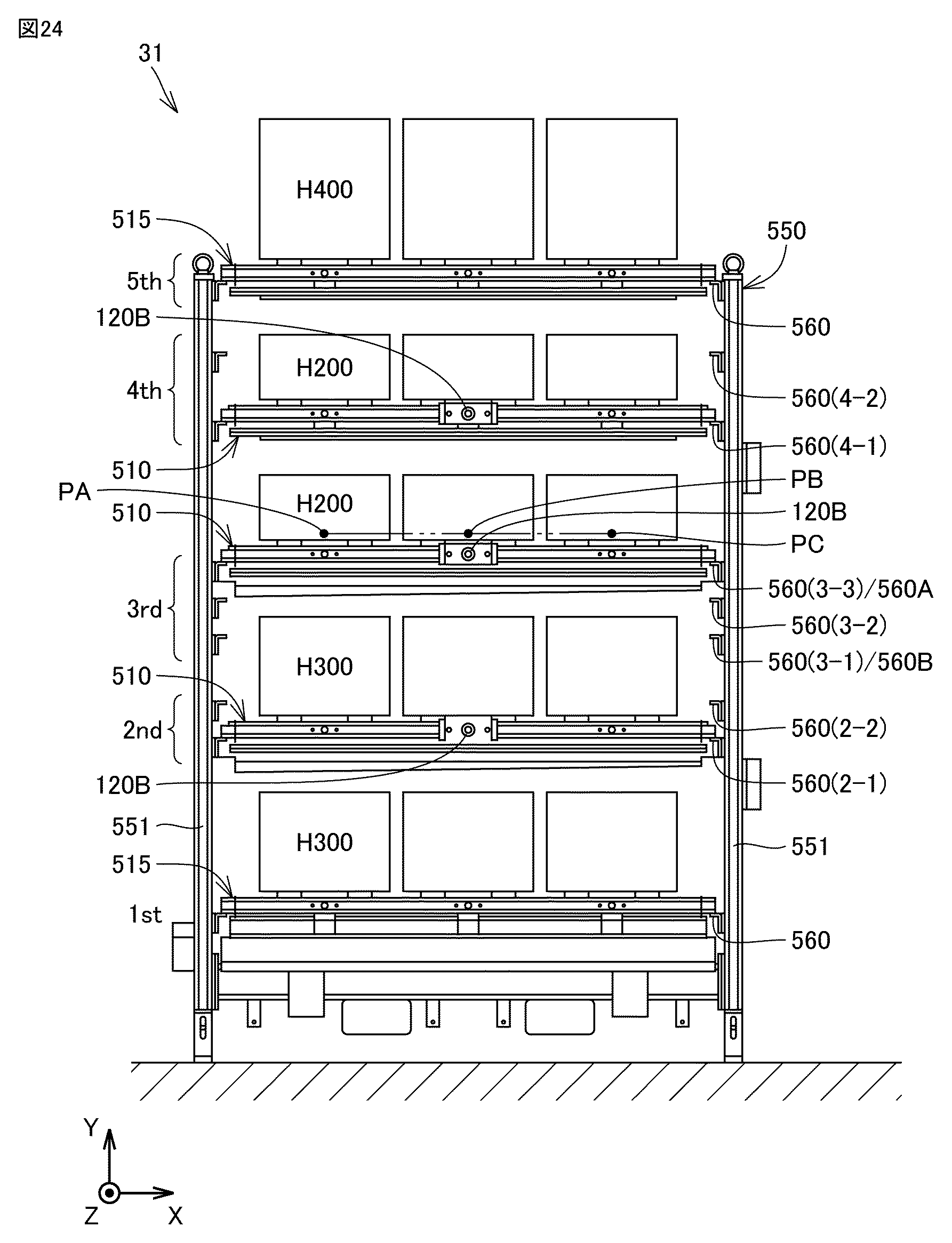
搬送システム100におけるロボット21のさらなる使用形態として、パレットストッカ31における棚板510の位置替えがある。以下では、ロボット21を用いた棚板510の位置替えについて、詳細に説明する。図24は、図7中のパレットストッカを示す正面図である。
Another use of the
図24を参照して、パレットストッカ31は、「1st」、「2nd」、「3rd」、「4th」および「5th」の複数フロアからなる多段式の棚構造を有する。
Referring to FIG. 24, the
「1st」と示される最下段のフロアと、「5th」と示される最上段のフロアとの各フロアには、固定式棚板515が配置されている。
「2nd」と示される下から2番目のフロアには、上下に間隔を開けて支持部560(2-1)および支持部560(2-2)が設けられている。ロボット21は、棚板510を、支持部560(2-1)および支持部560(2-2)の間で移動させることが可能である。
On the second floor from the bottom, indicated as "2nd", support parts 560(2-1) and 560(2-2) are provided at a distance from each other. The
「3rd」と示される真ん中のフロアには、上下に間隔を開けて支持部560(3-1)、支持部560(3-2)および支持部560(3-3)が設けられている。ロボット21は、棚板510を、支持部560(3-1)、支持部560(3-2)および支持部560(3-3)の間で移動させることが可能である。
On the middle floor, marked "3rd", support parts 560(3-1), 560(3-2), and 560(3-3) are provided at intervals above and below. The
「4th」と示される上から2番目のフロアには、上下に間隔を開けて支持部560(4-1)および支持部560(4-2)が設けられている。ロボット21は、棚板510を、支持部560(4-1)および支持部560(4-2)の間で移動させることが可能である。
On the second floor from the top, indicated as "4th," support parts 560 (4-1) and 560 (4-2) are provided at a distance from each other. The
一例として、上下方向における支持部560(2-1)および支持部560(2-2)の間隔は、100mmであり、上下方向における支持部560(3-1)、支持部560(3-2)および支持部560(3-3)の間隔は、100mmであり、上下方向における支持部560(4-1)および支持部560(4-2)の間隔は、200mmである。 As an example, the spacing between support parts 560(2-1) and 560(2-2) in the vertical direction is 100 mm, the spacing between support parts 560(3-1), 560(3-2), and 560(3-3) in the vertical direction is 100 mm, and the spacing between support parts 560(4-1) and 560(4-2) in the vertical direction is 200 mm.
各フロアにおける支持部560の間隔は、等間隔であってもよいし、不等間隔であってもよい。第1フロアにおける支持部560の間隔は、第2フロアにおける支持部560の間隔と同じであってもよいし、異なってもよい。上下に隣り合うフロア間における支持部560の間隔は、各フロアにおける支持部560の間隔よりも大きくてもよい。
The spacing between the
現在の棚板510の配置として、「2nd」のフロアでは、支持部560(2-1)により棚板510が支持されてる。「3rd」のフロアでは、支持部560(3-3)により棚板510が支持されている。「4th」のフロアでは、支持部560(4-1)により棚板510が支持されている。固定式棚板515および棚板510には、400mm×400mmサイズのパレット410が載置されている。
The current arrangement of the
このような棚板510の配置において、各フロアに載置可能なワークの最大高さは、「1st」のフロアで300mmであり、「2nd」のフロアで300mmであり、「3rd」のフロアで200mmであり、「4th」のフロアで200mmであり、「5th」のフロアで400mmである。
When
たとえば、「2nd」のフロアにおいて、棚板510が支持部560(2-1)から支持部560(2-2)に移された場合を想定すると、載置可能なワークの最大高さは、「1st」のフロアで400mmとなり、「2nd」のフロアで200mmとなる。
For example, if we assume that on the "2nd" floor,
また別の例として、「4th」のフロアにおいて、棚板510が支持部560(4-1)から支持部560(4-2)に移され、「3rd」のフロアにおいて、棚板510が支持部560(3-3)から支持部560(3-2)に移され、「2nd」のフロアにおいて、棚板510が取り除かれた場合を想定すると、載置可能なワークの最大高さは、「1st」のフロアで600mmとなり、「3rd」のフロアで600mmとなる。
As another example, if
このように棚板510の位置替えを実行することによって、パレットストッカ31に格納されるパレット410に載置可能なワークの最大高さを自在に調整することができる。
By changing the position of the
図25は、パレットストッカにおける棚板の位置替えのための制御系を示すブロック図である。図26は、パレットストッカにおける棚板の位置替えの流れを示すフローチャートである。図27および図28は、表示部における位置替え用画面を示す図である。 Figure 25 is a block diagram showing a control system for changing the position of shelves in a pallet stocker. Figure 26 is a flowchart showing the flow of changing the position of shelves in a pallet stocker. Figures 27 and 28 show the position changing screen on the display unit.
図24から図28を参照して、制御装置610は、表示制御部650をさらに有する。表示制御部650は、表示部670における画面表示を制御する。
Referring to FIG. 24 to FIG. 28, the
作業者は、タッチパネルディスプレイからなる表示部670を通じて、棚板510の位置替えモードの起動のための操作を行なう。操作受け付け部660は、作業者の操作を受け付けるとともに、その操作に応じた信号を表示制御部650に出力する。これにより、表示制御部650は、図27に示される棚板510の位置替え用画面671を表示部670に表示させる。
The worker performs an operation to activate the
図27に示されるように、位置替え用画面671は、パレットストッカ画像部680を有する。パレットストッカ画像部680は、Z軸方向に見た場合のパレットストッカ31の画像に対応している。パレットストッカ画像部680は、パレットストッカ31を模式的に示した画像であってもよい。位置替え用画面671の初期画面では、現状の棚板510の配置(一例として、支持部560(2-1)、支持部560(3-3)および支持部560(4-1)の各支持部560により支持される棚板510の配置)がパレットストッカ画像部680に示されている。後述の第1位置表示部691および第2位置表示部692は、空欄である。
As shown in FIG. 27, the
位置替え用画面671は、第1操作部681をさらに有する。第1操作部681は、作業者による操作によって、棚板510の位置替えの対象となるフロアが選択されるように構成されている。第1操作部681は、「2nd」、「3rd」および「4th」とそれぞれ示された複数のタブを含む。「2nd」のタブは、パレットストッカ画像部680において「2nd」のフロアに対応する位置に示され、「3rd」のタブは、パレットストッカ画像部680において「3rd」のフロアに対応する位置に示され、「4th」のタブは、パレットストッカ画像部680において「4th」のフロアに対応する位置に示されている。
The
位置替え用画面671は、第2操作部682をさらに有する。第2操作部682は、作業者による操作によって、位置替えの対象となる棚板510の移動後の支持部560が選択されるように構成されている。
The
第2操作部682は、「2-1」、「2-2」、「3-1」、「3-2」、「3-3」、「4-1」および「4-2」とそれぞれ示された複数のタブを含む。「2-1」、「2-2」、「3-1」、「3-2」、「3-3」、「4-1」および「4-2」とそれぞれ示された複数のタブは、それぞれ、パレットストッカ画像部680において、支持部560(2-1)、支持部560(2-2)、支持部560(3-1)、支持部560(3-2)、支持部560(3-3)、支持部560(4-1)および支持部560(4-2)に対応する位置に示されている。
The
位置替え用画面671は、第1位置表示部691と、第2位置表示部692とをさらに有する。
The
第1位置表示部691は、位置替えの対象となる棚板510の移動前の位置を表示する。第2位置表示部692は、位置替えの対象となる棚板510の移動後の位置を表示する。
The first
作業者による第1操作部681の操作に伴って、表示制御部650は、位置替えの対象となるフロアを特定する。表示制御部650は、特定したフロアにおける現在の棚板510の位置を、第1位置表示部691に表示させる。図27では、一例として、作業者が、第1操作部681において「3rd」のタブを操作した場合が想定されている。表示制御部650は、第1位置表示部691に、「3rd」のフロアにおける現在の棚板510の位置として「3-3」を表示させる。
As the worker operates the
作業者による第2操作部682の操作に伴って、表示制御部650は、棚板510の移動後の位置を特定する。表示制御部650は、特定した棚板510の移動後の位置を第2位置表示部692を表示させる。図27では、一例として、作業者が、第2操作部682において「3-1」のタブを操作した場合が想定されている。表示制御部650は、第2位置表示部692に、棚板510の移動後の位置として「3-1」を表示させる。
As the worker operates the
位置替え用画面671は、第3操作部693をさらに有する。第3操作部693は、棚板510の位置替えの処理を開始するために、作業者により操作される。
The
図28に示されるように、表示制御部650は、棚板510の位置替えが完了すると、パレットストッカ画像部680における棚板510の位置を更新する。図27では、表示制御部650が、支持部560(3-1)により支持される棚板510をパレットストッカ画像部680に表示させている。
As shown in FIG. 28, when the repositioning of the
図24および図25に示されるように、ロボット制御部620は、複数の支持部560のうちの第1支持部560Aから第2支持部560Bへの棚板510の位置替えの指令を受け付けた場合に、棚板510をマスターハンド210により把持しつつ、第1支持部560Aから第2支持部560Bに移動させるように、ロボット21を制御する。図24中では、一例として、支持部560(3-3)が、第1支持部560Aに対応し、支持部560(3-1)が、第2支持部560Bに対応している。
As shown in Figures 24 and 25, when the
より具体的には、作業者が第3操作部693を操作すると、操作受け付け部660は、作業者の操作を受け付けるとともに、その操作に応じた信号をプログラム解析部622に出力する。プログラム解析部622に対して出力される信号は、位置替えの対象となる棚板510の移動前後の位置を特定するための信号を含む。
More specifically, when the worker operates the
プログラム記憶部621は、ロボット21の動作を指令する各種の動作プログラム641を記憶している。動作プログラム641は、棚板位置替え用の動作プログラム641Pを含む。棚板位置替え用の動作プログラム641Pは、棚板510の位置替え時のロボット21の動作を指令するものであり、棚板510の移動前の位置と、棚板510の移動後の位置との組み合わせ毎に作成されている。
The
プログラム解析部622は、操作受け付け部660からの信号により棚板510の位置替えの指令を受け付け、プログラム記憶部621から、対応する棚板位置替え用の動作プログラム641Pを読み出す。プログラム解析部622は、動作プログラム641Pを解析して、移動に関する指令を抽出し、その指令を軸制御部623に送信する。プログラム解析部622は、動作プログラム641Pを解析して、マスターハンド210の動作に関する指令を抽出し、その指令をハンド制御部624に送信する。
The
軸制御部623は、プログラム解析部622からの指令に応じて、複数の駆動用サーボモータ23を制御する。ハンド制御部624は、プログラム解析部622からの指令に応じて、マスターハンド210を制御する。
The
図3から図5、ならびに、図24および図25を参照して、ロボット制御部620は、センサ230により棚板510上にパレット410が存在しないことが検知された場合に、その棚板510の位置替えを実行する。
Referring to Figures 3 to 5, and Figures 24 and 25, when the
より具体的には、棚板位置替え用の動作プログラム641Pは、位置替えの対象となる棚板510上のパレット410の有無を検知するためのロボット21の動作を指令するプログラムを含む。プログラム解析部622は、その動作プログラムに基づいた指令を軸制御部623およびハンド制御部624に送信する。
More specifically, the
図24中では、位置替えの対象となる、支持部560(3-3)に支持された棚板510上の空間に、第1位置PA、第2位置PBおよび第3位置PCが示されている。図3および図24に示されるように、第1位置PAは、棚板510の左端のパレット支持部520pにパレット410が載置されている場合に、そのパレット410が配置される位置に対応する。第2位置PBは、棚板510の中央のパレット支持部520qにパレット410が載置されている場合に、そのパレット410が配置される位置に対応する。第3位置PCは、棚板510の右端のパレット支持部520rにパレット410が載置されている場合に、そのパレット410が配置される位置に対応する。
In FIG. 24, the first position PA, second position PB, and third position PC are shown in the space above the
軸制御部623は、センサ230がZ軸方向において第1位置PAと対向して位置決めされるように、複数の駆動用サーボモータ23を制御する。ハンド制御部624は、センサ230によるセンシングを実行させる。センサ230が光電センサからなる場合、センサ230の出光部から第1位置PAに向けて光を出射し、その光の反射光をセンサ230の受光部で受光する。センサ230は、受光量に対応する信号をプログラム解析部622に出力する。プログラム解析部622は、センサ230からの信号に基づいて、受光量が予め定められた閾値を超えるか否かを判断する。プログラム解析部622は、受光量が閾値を超える場合には、棚板510上にパレット410が存在すると判定し、受光量が閾値以下である場合には、棚板510上にパレット410が存在しないと判定する。
The
軸制御部623は、センサ230がZ軸方向において第2位置PBと対向して位置決めされるように、複数の駆動用サーボモータ23を制御する。ハンド制御部624は、センサ230による上記センシングを実行させる。軸制御部623は、センサ230がZ軸方向において第3位置PCと対向して位置決めされるように、複数の駆動用サーボモータ23を制御する。ハンド制御部624は、センサ230による上記センシングを実行させる。
The
プログラム解析部622は、上記センシングにより、第1位置PA、第2位置PBおよび第3位置PCのいずれの位置にもパレット410が存在しないと判定した場合に、棚板510の位置替えの処理を続行する。プログラム解析部622は、上記センシングにより、第1位置PA、第2位置PBおよび第3位置PCの少なくとも1つの位置にパレット410が存在すると判定した場合に、棚板510の位置替えの処理を停止する。この場合に、制御装置610は、パレット410の存在を作業者に報知するためのアラートを発信してもよい。
When the
パレットストッカ31における棚板510の位置替えの流れを説明する。図25から図28を参照して、作業者により棚板510の位置替えモードの起動が操作された場合に、制御装置610(表示制御部650)は、位置替え用画面671を表示部670に表示させる(S100)。
The flow of changing the position of the
次に、制御装置610(ロボット制御部620)は、棚板510の位置替えの指令を受け付ける(S101)。 Next, the control device 610 (robot control unit 620) receives a command to reposition the shelf 510 (S101).
本ステップにおいて、作業者は、位置替え用画面671における第1操作部681を操作することによって、位置替えの対象となるフロア(棚板510)を指定し、位置替え用画面671における第2操作部682を操作することによって、位置替えの対象となる棚板510の移動後の位置(支持部560)を指定する。プログラム解析部622は、操作受け付け部660からの信号が入力されることにより、棚板510の位置替えの指令を受け付ける。
In this step, the worker operates the
次に、制御装置610(表示制御部650)は、棚板510の移動前後の位置を表示部670に表示させる(S102)。
Next, the control device 610 (display control unit 650) causes the
本ステップにおいて、表示制御部650は、棚板510の位置替えの対象となるフロアにおける棚板510の移動前の位置を、第1位置表示部691に表示させ、棚板510の移動後の位置を、第2位置表示部692に表示させる。
In this step, the
次に、制御装置610(ロボット制御部620)は、棚板510の位置替えの処理を開始する(S103)。 Next, the control device 610 (robot control unit 620) starts the process of changing the position of the shelf 510 (S103).
本ステップにおいて、作業者は、位置替え用画面671における第3操作部693を操作する。ロボット制御部620は、作業者による第3操作部693の操作を受けて、棚板510の位置替えの処理を開始する。
In this step, the worker operates the
次に、制御装置610(ロボット制御部620)は、センサ230によるセンシングを実行するように、ロボット21およびセンサ230を制御する(S104)。
Next, the control device 610 (robot control unit 620) controls the
本ステップにおいて、プログラム解析部622は、センサ230が、Z軸方向において、第1位置PA、第2位置PBおよび第3位置PCと順に対向して位決めされ、第1位置PA、第2位置PBおよび第3位置PCの各位置において、センサ230によるセンシングを実行するように、ロボット21およびセンサ230を制御する。
In this step, the
次に、制御装置610(ロボット制御部620)は、位置替えの対象となる棚板510上にパレット410が存在するか否かを判定する(S105)。
Next, the control device 610 (robot control unit 620) determines whether or not a
制御装置610は、S105のステップにおいて、棚板510上の第1位置PA、第2位置PBおよび第3位置PCの少なくとも1つの位置にパレット410が存在すると判定した場合、パレット410の存在を作業者に報知するためのアラートを発信する(S106)。
If the
本ステップでは、表示制御部650が、表示部670に、位置替えの対象となる棚板510上にパレット410が存在する旨のコメントを表示させてもよい。作業者は、パレット410を棚板510上から退避させる作業をロボット21に行なわせた後、再び、SS101のステップを開始させる。
In this step, the
制御装置610(ロボット制御部620)は、S105のステップにおいて、棚板510上の第1位置PA、第2位置PBおよび第3位置PCのいずれの位置にもパレット410が存在しないと判定した場合、棚板510の位置替えを実行する(S107)。
If the control device 610 (robot control unit 620) determines in step S105 that the
本ステップでは、マスターハンド210が、パレットストッカ31に向けて移動し、Z軸方向において、位置替えの対象となる棚板510の第2把持部120Bと対向するように位置決めされる。マスターハンド210がZ軸方向に移動することによって、第2把持部120Bがグリップ挿入孔221に挿入される。マスターハンド210が第2把持部120Bを把持する。マスターハンド210が上方に移動することによって、棚板510が第1支持部560Aから持ち上げられる。マスターハンド210は、棚板510が第1支持部560A上の空間から退避するように、Z軸方向に移動する。
In this step, the
マスターハンド210は、Y軸方向に移動する。マスターハンド210は、棚板510が第2支持部560B上の空間に進出するように、Z軸方向に移動する。マスターハンド210が下方に移動することによって、棚板510が第2支持部560Bに載置される。マスターハンド210が第2把持部120Bを開放する。マスターハンド210がZ軸方向に移動することによって、第2把持部120Bがグリップ挿入孔221から退出する。
The
次に、制御装置610(表示制御部650)は、パレットストッカ画像部680における棚板510の位置を更新する(S108)。以上のステップにより、棚板510の位置替えが完了する。
Next, the control device 610 (display control unit 650) updates the position of the
以上に説明した、この発明の実施の形態における搬送システム100の構成をまとめると、本実施の形態における搬送システム100は、ハンドとしてのマスターハンド210を有するロボット21と、ワークWを保持するためのパレット410を載置可能な棚板510と、各々が棚板510を支持可能であり、上下方向に間隔を開けて並ぶ複数の支持部560とを有し、パレット410を格納するためのパレットストッカ31と、複数の支持部560のうちの第1支持部560Aから第2支持部560Bへの棚板510の位置替えの指令を受け付けた場合に、棚板510をマスターハンド210により把持しつつ、第1支持部560Aから第2支持部560Bに移動させるように、ロボット21を制御するロボット制御部620とを備える。
To summarize the configuration of the
このような構成によれば、ロボット21を用いることによって、パレットストッカ31における棚板510の位置替えを自動化することができる。これにより、ロボット21の用途を増やして、搬送システム100における自動化の範囲を広げることができる。
With this configuration, the
特に本実施の形態では、作業者が空間113の外側からパレットストッカ31にアクセス不可であるため、ロボット21を用いた自動化によって、棚板510の位置替えを簡易かつ安全に行なうことができる。
In particular, in this embodiment, since workers cannot access the
また、搬送システム100は、表示部670と、パレットストッカ31の画像を表示部670に表示させるとともに、棚板510の位置替えの実行の前後で、パレットストッカ31の画像における棚板510の位置を第1支持部560Aから第2支持部560Bに更新する表示制御部650とをさらに備える。
The conveying
このような構成によれば、作業者は、表示部670を通じて、位置替えの実行の前後における棚板510の位置を確認することができる。
With this configuration, the worker can check the position of the
また、搬送システム100は、ロボット21に搭載され、物体の有無を検知可能なセンサ230をさらに備える。ロボット制御部620は、センサ230により棚板510上にパレット410が存在しないことが検知された場合に、棚板510の位置替えを実行する。
The
このような構成によれば、パレット410が載置されたままの棚板510に対して、ロボット21による位置替えが実行されることを防止できる。
This configuration prevents the
また、パレットストッカ31は、位置替えが不可である固定式棚板515をさらに有する。このような構成によれば、固定式棚板515の上方に隣り合って配置された棚板510の位置替えを実行することによって、固定式棚板515に載置可能なワークの最大高さも調整することができる。
The
本実施の形態における搬送システム100の制御方法は、複数の支持部560のうちの第1支持部560Aから第2支持部560Bへの棚板510の位置替えの指令を受け付けるステップ(S101)と、その指令に応じて、棚板510をマスターハンド210により把持しつつ、第1支持部560Aから第2支持部560Bに移動させるように、ロボット21を制御するステップ(S107)とを備える。
The control method of the
本実施の形態におけるプログラムは、搬送システム100を制御するためのコンピュータにより実行されるプログラムである。プログラムは、コンピュータに、複数の支持部560のうちの第1支持部560Aから第2支持部560Bへの棚板510の位置替えの指令を受け付けるステップ(S101)と、その指令に応じて、棚板510をマスターハンド210により把持しつつ、第1支持部560Aから第2支持部560Bに移動させるように、ロボット21を制御するステップ(S107)とを実行させる。
The program in this embodiment is a program executed by a computer for controlling the
このような構成によれば、ロボット21を用いることによって、パレットストッカ31における棚板510の位置替えを自動化することができる。これにより、ロボット21の用途を増やして、搬送システム100における自動化の範囲を広げることができる。
With this configuration, the
今回開示された実施の形態はすべての点で例示であって制限的なものではないと考えられるべきである。本発明の範囲は上記した説明ではなくて特許請求の範囲によって示され、特許請求の範囲と均等の意味および範囲内でのすべての変更が含まれることが意図される。 The embodiments disclosed herein should be considered to be illustrative and not restrictive in all respects. The scope of the present invention is indicated by the claims rather than the above description, and it is intended to include all modifications within the meaning and scope of the claims.
10,10S,10T 工作機械、12 加工エリア、14 カバー体、16 開口部、18 操作盤、21 ロボット、22 ロボットベース、23 駆動用サーボモータ、26 基台部、27 第1アーム、28 第2アーム、29 ハンド取り付け部、31,31S,31T パレットストッカ、51 搬送用操作盤、56,56h,56i,56j,56k 柵、61,61S,61T 段取りステーション、71 ワークストッカ、81 ハンドストッカ、100 搬送システム、101 旋回中心軸、102,103,105 回動中心軸、104,106 回転中心軸、113 空間、120 把持部、120A 第1把持部、120B 第2把持部、120C 第3把持部、120D 第4把持部、121 溝部、126,231 中心軸、210 マスターハンド、220 クランプ機構、221 グリップ挿入孔、226 ピストン、227 突起部、230 センサ、310 ワーク用ハンド、320 把持爪、330 ピストンシリンダ、340 サーボモータ、410 パレット、510 棚板、515 固定式棚板、520,520p,520q,520r パレット支持部、525 テーパコーン受け部、531 横フレーム、532 縦フレーム、533 ピン孔、550 フレーム体、551 柱、560 支持部、560A 第1支持部、560B 第2支持部、561 プレート、610 制御装置、620 ロボット制御部、621 プログラム記憶部、622 プログラム解析部、623 軸制御部、624 ハンド制御部、625 パラメータ記憶部、630 入出力装置、641,641P 動作プログラム、650 表示制御部、660 操作受け付け部、670 表示部、671 位置替え用画面、680 パレットストッカ画像部、681 第1操作部、682 第2操作部、691 第1位置表示部、692 第2位置表示部、693 第3操作部、710 ティーチング用ハンド、720 タッチプローブ、720g 接触子、PA 第1位置、PB 第2位置、PC 第3位置、W ワーク。 10, 10S, 10T Machine tool, 12 Processing area, 14 Cover body, 16 Opening, 18 Operation panel, 21 Robot, 22 Robot base, 23 Drive servo motor, 26 Base unit, 27 First arm, 28 Second arm, 29 Hand attachment unit, 31, 31S, 31T Pallet stocker, 51 Transport operation panel, 56, 56h, 56i, 56j, 56k Fence, 61, 61S, 61T Setup station, 71 Work stocker, 81 Hand stocker, 100 Transport system, 101 Swivel center axis, 102, 103, 105 Rotation center axis, 104, 106 Rotation center axis, 113 Space, 120 Grip unit, 120A First grip unit, 120B Second grip unit, 120C Third gripping portion, 120D Fourth gripping portion, 121 Groove portion, 126, 231 Central axis, 210 Master hand, 220 Clamping mechanism, 221 Grip insertion hole, 226 Piston, 227 Protrusion portion, 230 Sensor, 310 Work hand, 320 Grip claws, 330 Piston cylinder, 340 Servo motor, 410 Pallet, 510 Shelf, 515 Fixed shelf, 520, 520p, 520q, 520r Pallet support portion, 525 Taper cone receiving portion, 531 Horizontal frame, 532 Vertical frame, 533 Pin hole, 550 Frame body, 551 Pillar, 560 Support portion, 560A First support portion, 560B Second support portion, 561 Plate, 610 Control device, 620 Robot control portion, 621 Program memory unit, 622 program analysis unit, 623 axis control unit, 624 hand control unit, 625 parameter memory unit, 630 input/output device, 641, 641P operation program, 650 display control unit, 660 operation acceptance unit, 670 display unit, 671 position change screen, 680 pallet stocker image unit, 681 first operation unit, 682 second operation unit, 691 first position display unit, 692 second position display unit, 693 third operation unit, 710 teaching hand, 720 touch probe, 720g contactor, PA first position, PB second position, PC third position, W work.
Claims (6)
前記表示部に、前記パレットストッカの画像を表示する画像表示部と、
前記ロボットにより、前記棚板が複数の前記支持部のうちの第1支持部から第2支持部に位置替えされた場合に、その位置替えの実行の前後で、前記パレットストッカの画像における前記棚板の位置を前記第1支持部から前記第2支持部に更新する画像更新部とを備える、表示制御装置。 1. A display control device for controlling a screen display of a display unit in a pallet stocker having a shelf on which a pallet can be placed and a plurality of support parts arranged at intervals in a vertical direction, each of which can support the shelf, when changing the position of the shelf using a robot, comprising:
an image display unit that displays an image of the pallet stocker on the display unit;
a display control device comprising: an image update unit that, when the robot repositions the shelf from a first support part to a second support part among the plurality of support parts, updates the position of the shelf in the image of the pallet stocker from the first support part to the second support part before and after the repositioning is performed.
ワークを保持するためのパレットを載置可能な棚板と、各々が前記棚板を支持可能であり、上下方向に間隔を開けて並ぶ複数の支持部とを有し、前記パレットを格納するためのパレットストッカと、
複数の前記支持部のうちの第1支持部から第2支持部への前記棚板の位置替えの指令を受け付け、その指令に応じて、前記棚板を前記ハンドにより把持しつつ、前記第1支持部から前記第2支持部に移動させるように、前記ロボットを制御するロボット制御部と、
表示部と、
前記パレットストッカの画像を前記表示部に表示させるとともに、前記棚板の位置替えの実行の前後で、前記パレットストッカの画像における前記棚板の位置を前記第1支持部から前記第2支持部に更新する表示制御部とを備える、搬送システム。 A robot having a hand;
a pallet stocker for storing the pallets, the pallet stocker having a shelf plate on which a pallet for holding workpieces can be placed and a plurality of support parts arranged at intervals in the vertical direction, each of which can support the shelf plate;
a robot control unit that receives a command to change the position of the shelf board from a first support unit to a second support unit among the plurality of support units, and controls the robot in response to the command to move the shelf board from the first support unit to the second support unit while holding the shelf board with the hand;
A display unit;
a display control unit that displays an image of the pallet stocker on the display unit and updates the position of the shelf in the image of the pallet stocker from the first support unit to the second support unit before and after the shelf position change is performed .
前記ロボット制御部は、前記センサにより前記棚板上に前記パレットが存在しないことが検知された場合に、前記棚板の位置替えを実行する、請求項2に記載の搬送システム。 The robot further includes a sensor capable of detecting the presence or absence of an object,
The conveying system according to claim 2 , wherein the robot control unit changes the position of the shelf board when the sensor detects that the pallet is not present on the shelf board.
前記搬送システムは、
ハンドを有するロボットと、
ワークを保持するためのパレットを載置可能な棚板と、各々が前記棚板を支持可能であり、上下方向に間隔を開けて並ぶ複数の支持部とを有し、前記パレットを格納するためのパレットストッカと、
表示部とを備え、
前記搬送システムの制御方法は、
複数の前記支持部のうちの第1支持部から第2支持部への前記棚板の位置替えの指令を受け付けるステップと、
前記指令に応じて、前記棚板を前記ハンドにより把持しつつ、前記第1支持部から前記第2支持部に移動させるように、前記ロボットを制御するステップと、
前記パレットストッカの画像を前記表示部に表示させるとともに、前記棚板の位置替えの実行の前後で、前記パレットストッカの画像における前記棚板の位置を前記第1支持部から前記第2支持部に更新するステップとを備える、搬送システムの制御方法。 A method for controlling a conveyance system, comprising the steps of:
The transport system includes:
A robot having a hand;
a pallet stocker for storing the pallets, the pallet stocker having a shelf plate on which a pallet for holding workpieces can be placed and a plurality of support parts arranged at intervals in the vertical direction, each of which can support the shelf plate ;
A display unit ,
The control method for the transport system includes:
receiving a command to change the position of the shelf board from a first support portion to a second support portion among the plurality of support portions;
controlling the robot in response to the command to move the shelf board from the first support portion to the second support portion while gripping the shelf board with the hand ;
A method for controlling a conveying system comprising the steps of displaying an image of the pallet stocker on the display unit, and updating the position of the shelf board in the image of the pallet stocker from the first support part to the second support part before and after performing a repositioning of the shelf board.
前記搬送システムは、
ハンドを有するロボットと、
ワークを保持するためのパレットを載置可能な棚板と、各々が前記棚板を支持可能であり、上下方向に間隔を開けて並ぶ複数の支持部とを有し、前記パレットを格納するためのパレットストッカと、
表示部とを備え、
前記プログラムは、前記コンピュータに、
複数の前記支持部のうちの第1支持部から第2支持部への前記棚板の位置替えの指令を受け付けるステップと、
前記指令に応じて、前記棚板を前記ハンドにより把持しつつ、前記第1支持部から前記第2支持部に移動させるように、前記ロボットを制御するステップと、
前記パレットストッカの画像を前記表示部に表示させるとともに、前記棚板の位置替えの実行の前後で、前記パレットストッカの画像における前記棚板の位置を前記第1支持部から前記第2支持部に更新するステップとを実行させる、プログラム。 A program executed by a computer for controlling a conveyance system,
The transport system includes:
A robot having a hand;
a pallet stocker for storing the pallets, the pallet stocker having a shelf plate on which a pallet for holding workpieces can be placed and a plurality of support parts arranged at intervals in the vertical direction, each of which can support the shelf plate ;
A display unit ,
The program causes the computer to
receiving a command to change the position of the shelf board from a first support portion to a second support portion among the plurality of support portions;
controlling the robot in response to the command to move the shelf board from the first support portion to the second support portion while gripping the shelf board with the hand ;
A program that causes an image of the pallet stocker to be displayed on the display unit, and executes a step of updating the position of the shelf board in the image of the pallet stocker from the first support part to the second support part before and after the repositioning of the shelf board is performed.
Priority Applications (3)
| Application Number | Priority Date | Filing Date | Title |
|---|---|---|---|
| JP2024105160A JP7648839B1 (en) | 2024-06-28 | 2024-06-28 | Display control device, transport system, and control method and program for transport system |
| JP2025034695A JP2026008686A (en) | 2024-06-28 | 2025-03-05 | Transport system, transport system control method and program |
| PCT/JP2025/021261 WO2026004624A1 (en) | 2024-06-28 | 2025-06-12 | Display control device |
Applications Claiming Priority (1)
| Application Number | Priority Date | Filing Date | Title |
|---|---|---|---|
| JP2024105160A JP7648839B1 (en) | 2024-06-28 | 2024-06-28 | Display control device, transport system, and control method and program for transport system |
Related Child Applications (1)
| Application Number | Title | Priority Date | Filing Date |
|---|---|---|---|
| JP2025034695A Division JP2026008686A (en) | 2024-06-28 | 2025-03-05 | Transport system, transport system control method and program |
Publications (2)
| Publication Number | Publication Date |
|---|---|
| JP7648839B1 true JP7648839B1 (en) | 2025-03-18 |
| JP2026006286A JP2026006286A (en) | 2026-01-16 |
Family
ID=95019405
Family Applications (2)
| Application Number | Title | Priority Date | Filing Date |
|---|---|---|---|
| JP2024105160A Active JP7648839B1 (en) | 2024-06-28 | 2024-06-28 | Display control device, transport system, and control method and program for transport system |
| JP2025034695A Pending JP2026008686A (en) | 2024-06-28 | 2025-03-05 | Transport system, transport system control method and program |
Family Applications After (1)
| Application Number | Title | Priority Date | Filing Date |
|---|---|---|---|
| JP2025034695A Pending JP2026008686A (en) | 2024-06-28 | 2025-03-05 | Transport system, transport system control method and program |
Country Status (2)
| Country | Link |
|---|---|
| JP (2) | JP7648839B1 (en) |
| WO (1) | WO2026004624A1 (en) |
Families Citing this family (1)
| Publication number | Priority date | Publication date | Assignee | Title |
|---|---|---|---|---|
| US12528131B2 (en) * | 2020-06-26 | 2026-01-20 | Niterra Co., Ltd. | Joined body and electrostatic chuck |
Citations (11)
| Publication number | Priority date | Publication date | Assignee | Title |
|---|---|---|---|---|
| JPH01234189A (en) * | 1988-03-11 | 1989-09-19 | Mitsubishi Electric Corp | Robot hand coupling mechanism |
| JPH04141350A (en) * | 1990-09-28 | 1992-05-14 | Makino Milling Mach Co Ltd | Processing system transport vehicle control method and device |
| JPH04152050A (en) * | 1990-10-15 | 1992-05-26 | Yamazaki Mazak Corp | Automatic working device |
| JP2006035397A (en) * | 2004-07-29 | 2006-02-09 | Fanuc Ltd | Conveyance robot system |
| JP2009291869A (en) * | 2008-06-04 | 2009-12-17 | Kawasaki Heavy Ind Ltd | Robot, robot hand, and attachment |
| CN106064734A (en) * | 2009-04-10 | 2016-11-02 | 西姆伯蒂克有限责任公司 | Storage and extraction system |
| JP2020535090A (en) * | 2017-09-29 | 2020-12-03 | オムニセル, インコーポレイテッド | Equipment, systems, and methods for automatic distribution of goods |
| JP2021094634A (en) * | 2019-12-16 | 2021-06-24 | 野村ユニソン株式会社 | Work feeding/removing material system, portable robot device, and portable work stocker |
| JP2022124094A (en) * | 2021-02-15 | 2022-08-25 | 凸版印刷株式会社 | Robot hand jig and robot hand |
| CN219057817U (en) * | 2023-01-09 | 2023-05-23 | 宁波贝克韦尔智能科技有限公司 | Robot tray handling device and feed workstation |
| JP2023181389A (en) * | 2020-09-08 | 2023-12-21 | パナソニックIpマネジメント株式会社 | system, refrigerator |
Family Cites Families (5)
| Publication number | Priority date | Publication date | Assignee | Title |
|---|---|---|---|---|
| JP5346694B2 (en) * | 2009-06-05 | 2013-11-20 | 株式会社森精機製作所 | Machine Tools |
| JP2013086891A (en) * | 2011-10-14 | 2013-05-13 | Jx Nippon Mining & Metals Corp | Automated storage and retrieval warehouse |
| JP6285405B2 (en) | 2015-12-04 | 2018-02-28 | ファナック株式会社 | Complex system with machine tool and robot |
| JP7659401B2 (en) * | 2021-02-18 | 2025-04-09 | 株式会社アマダ | Material Management System |
| JP2024105160A (en) | 2023-01-25 | 2024-08-06 | ヤンマーホールディングス株式会社 | Construction Machinery |
-
2024
- 2024-06-28 JP JP2024105160A patent/JP7648839B1/en active Active
-
2025
- 2025-03-05 JP JP2025034695A patent/JP2026008686A/en active Pending
- 2025-06-12 WO PCT/JP2025/021261 patent/WO2026004624A1/en active Pending
Patent Citations (11)
| Publication number | Priority date | Publication date | Assignee | Title |
|---|---|---|---|---|
| JPH01234189A (en) * | 1988-03-11 | 1989-09-19 | Mitsubishi Electric Corp | Robot hand coupling mechanism |
| JPH04141350A (en) * | 1990-09-28 | 1992-05-14 | Makino Milling Mach Co Ltd | Processing system transport vehicle control method and device |
| JPH04152050A (en) * | 1990-10-15 | 1992-05-26 | Yamazaki Mazak Corp | Automatic working device |
| JP2006035397A (en) * | 2004-07-29 | 2006-02-09 | Fanuc Ltd | Conveyance robot system |
| JP2009291869A (en) * | 2008-06-04 | 2009-12-17 | Kawasaki Heavy Ind Ltd | Robot, robot hand, and attachment |
| CN106064734A (en) * | 2009-04-10 | 2016-11-02 | 西姆伯蒂克有限责任公司 | Storage and extraction system |
| JP2020535090A (en) * | 2017-09-29 | 2020-12-03 | オムニセル, インコーポレイテッド | Equipment, systems, and methods for automatic distribution of goods |
| JP2021094634A (en) * | 2019-12-16 | 2021-06-24 | 野村ユニソン株式会社 | Work feeding/removing material system, portable robot device, and portable work stocker |
| JP2023181389A (en) * | 2020-09-08 | 2023-12-21 | パナソニックIpマネジメント株式会社 | system, refrigerator |
| JP2022124094A (en) * | 2021-02-15 | 2022-08-25 | 凸版印刷株式会社 | Robot hand jig and robot hand |
| CN219057817U (en) * | 2023-01-09 | 2023-05-23 | 宁波贝克韦尔智能科技有限公司 | Robot tray handling device and feed workstation |
Also Published As
| Publication number | Publication date |
|---|---|
| JP2026006286A (en) | 2026-01-16 |
| WO2026004624A1 (en) | 2026-01-02 |
| JP2026008686A (en) | 2026-01-19 |
Similar Documents
| Publication | Publication Date | Title |
|---|---|---|
| JP5423441B2 (en) | Work system, robot apparatus, and manufacturing method of machine product | |
| US8322591B2 (en) | Automated assembly and welding of structures | |
| JP5160700B1 (en) | NC machine tool system | |
| EP1533087A2 (en) | Operation program preparation device | |
| JP7648839B1 (en) | Display control device, transport system, and control method and program for transport system | |
| CN113182935A (en) | Flexible production line for framework machining | |
| WO2015075777A1 (en) | Robot system and production method for processed items | |
| CN113084407A (en) | Intelligent welding production line for trolley frame and partition plate | |
| KR102324545B1 (en) | Automatic attachment changer and boring machine including the same | |
| JP7648838B1 (en) | Transport Systems and Robots | |
| CA3179264A1 (en) | System and method for an adjustable machine apparatus | |
| JP7675905B1 (en) | Robot control device and robot control method | |
| JP7692094B1 (en) | Hand Device | |
| JP3002250B2 (en) | Automatic processing equipment | |
| JP7628212B1 (en) | Oil pan structure | |
| JP2026008750A (en) | Frame and Transport System | |
| JPH11226801A (en) | Work transfer control method for moving spindle machine tool and numerical control device for moving spindle machine tool | |
| WO2026004769A1 (en) | Frame and transport system | |
| CN218785278U (en) | Butt-welding equipment and butt-welding workstation | |
| JP3393110B2 (en) | Automatic processing equipment | |
| JP4839850B2 (en) | Work positioning apparatus and work positioning method | |
| JP2668988B2 (en) | Processing machine | |
| CN119238128A (en) | A multi-station continuous sanitary ware processing machine tool | |
| KR20220109148A (en) | Machine tool material supply and discharge device and its control method | |
| Appleton et al. | Robot Handling |
Legal Events
| Date | Code | Title | Description |
|---|---|---|---|
| A621 | Written request for application examination |
Free format text: JAPANESE INTERMEDIATE CODE: A621 Effective date: 20240722 |
|
| A871 | Explanation of circumstances concerning accelerated examination |
Free format text: JAPANESE INTERMEDIATE CODE: A871 Effective date: 20240722 |
|
| A131 | Notification of reasons for refusal |
Free format text: JAPANESE INTERMEDIATE CODE: A131 Effective date: 20240910 |
|
| A601 | Written request for extension of time |
Free format text: JAPANESE INTERMEDIATE CODE: A601 Effective date: 20241105 |
|
| A521 | Request for written amendment filed |
Free format text: JAPANESE INTERMEDIATE CODE: A523 Effective date: 20241223 |
|
| TRDD | Decision of grant or rejection written | ||
| A01 | Written decision to grant a patent or to grant a registration (utility model) |
Free format text: JAPANESE INTERMEDIATE CODE: A01 Effective date: 20250204 |
|
| A61 | First payment of annual fees (during grant procedure) |
Free format text: JAPANESE INTERMEDIATE CODE: A61 Effective date: 20250306 |
|
| R150 | Certificate of patent or registration of utility model |
Ref document number: 7648839 Country of ref document: JP Free format text: JAPANESE INTERMEDIATE CODE: R150 |