JP7644145B2 - Techniques for distributing forces in high field magnets and related systems and methods - Patents.com - Google Patents
Techniques for distributing forces in high field magnets and related systems and methods - Patents.com Download PDFInfo
- Publication number
- JP7644145B2 JP7644145B2 JP2022570130A JP2022570130A JP7644145B2 JP 7644145 B2 JP7644145 B2 JP 7644145B2 JP 2022570130 A JP2022570130 A JP 2022570130A JP 2022570130 A JP2022570130 A JP 2022570130A JP 7644145 B2 JP7644145 B2 JP 7644145B2
- Authority
- JP
- Japan
- Prior art keywords
- pancakes
- tape
- hts
- magnet
- bulkhead
- Prior art date
- Legal status (The legal status is an assumption and is not a legal conclusion. Google has not performed a legal analysis and makes no representation as to the accuracy of the status listed.)
- Active
Links
Images


Classifications
-
- H—ELECTRICITY
- H01—ELECTRIC ELEMENTS
- H01F—MAGNETS; INDUCTANCES; TRANSFORMERS; SELECTION OF MATERIALS FOR THEIR MAGNETIC PROPERTIES
- H01F6/00—Superconducting magnets; Superconducting coils
- H01F6/06—Coils, e.g. winding, insulating, terminating or casing arrangements therefor
-
- H—ELECTRICITY
- H01—ELECTRIC ELEMENTS
- H01F—MAGNETS; INDUCTANCES; TRANSFORMERS; SELECTION OF MATERIALS FOR THEIR MAGNETIC PROPERTIES
- H01F41/00—Apparatus or processes specially adapted for manufacturing or assembling magnets, inductances or transformers; Apparatus or processes specially adapted for manufacturing materials characterised by their magnetic properties
- H01F41/02—Apparatus or processes specially adapted for manufacturing or assembling magnets, inductances or transformers; Apparatus or processes specially adapted for manufacturing materials characterised by their magnetic properties for manufacturing cores, coils, or magnets
- H01F41/04—Apparatus or processes specially adapted for manufacturing or assembling magnets, inductances or transformers; Apparatus or processes specially adapted for manufacturing materials characterised by their magnetic properties for manufacturing cores, coils, or magnets for manufacturing coils
- H01F41/048—Superconductive coils
-
- H—ELECTRICITY
- H01—ELECTRIC ELEMENTS
- H01F—MAGNETS; INDUCTANCES; TRANSFORMERS; SELECTION OF MATERIALS FOR THEIR MAGNETIC PROPERTIES
- H01F41/00—Apparatus or processes specially adapted for manufacturing or assembling magnets, inductances or transformers; Apparatus or processes specially adapted for manufacturing materials characterised by their magnetic properties
- H01F41/02—Apparatus or processes specially adapted for manufacturing or assembling magnets, inductances or transformers; Apparatus or processes specially adapted for manufacturing materials characterised by their magnetic properties for manufacturing cores, coils, or magnets
- H01F41/04—Apparatus or processes specially adapted for manufacturing or assembling magnets, inductances or transformers; Apparatus or processes specially adapted for manufacturing materials characterised by their magnetic properties for manufacturing cores, coils, or magnets for manufacturing coils
- H01F41/06—Coil winding
- H01F41/071—Winding coils of special form
- H01F41/074—Winding flat coils
-
- H—ELECTRICITY
- H01—ELECTRIC ELEMENTS
- H01F—MAGNETS; INDUCTANCES; TRANSFORMERS; SELECTION OF MATERIALS FOR THEIR MAGNETIC PROPERTIES
- H01F6/00—Superconducting magnets; Superconducting coils
- H01F6/02—Quenching; Protection arrangements during quenching
-
- H—ELECTRICITY
- H01—ELECTRIC ELEMENTS
- H01F—MAGNETS; INDUCTANCES; TRANSFORMERS; SELECTION OF MATERIALS FOR THEIR MAGNETIC PROPERTIES
- H01F6/00—Superconducting magnets; Superconducting coils
- H01F6/04—Cooling
Landscapes
- Engineering & Computer Science (AREA)
- Power Engineering (AREA)
- Manufacturing & Machinery (AREA)
- Superconductors And Manufacturing Methods Therefor (AREA)
- Containers, Films, And Cooling For Superconductive Devices (AREA)
Description
[0001]本開示は、一般に超伝導マグネットコイルに関し、より詳しくは高温超伝導体(HTS)マグネットアセンブリの作製および冷却に関する。 [0001] This disclosure relates generally to superconducting magnet coils, and more particularly to the fabrication and cooling of high temperature superconductor (HTS) magnet assemblies.
[0002]超伝導体は、何らかの臨界温度未満において電流に対して電気抵抗がない(「超伝導」)材料である。多くの超伝導体に関して、超伝導状態のそれらの材料の動作が液体または冷気体ヘリウムまたは他のクライオジェンなどによる大幅な冷却を必要とするように、臨界温度は30K未満である。 [0002] A superconductor is a material that has no electrical resistance to electric current ("superconducting") below some critical temperature. For many superconductors, the critical temperature is below 30 K, so that operation of those materials in the superconducting state requires significant cooling, such as with liquid or cold gaseous helium or other cryogens.
[0003]抵抗なく大電流を運ぶ超伝導体の機能のため、高磁界マグネットは、超伝導体で作製されることが多い。そのようなマグネットは、例えば、5kAを上回る電流を運び得る。 [0003] High field magnets are often made from superconductors because of the ability of superconductors to carry large currents without resistance. Such magnets can carry currents in excess of 5 kA, for example.
[0004]いくつかの態様によれば、高温超伝導体(HTS)材料を含むコイルと、少なくとも第1の隔壁を備えるハウジングとを備えるHTSマグネットが提供され、コイルは、ハウジング内に配置され、コイルの第1の部分の巻回が第1の隔壁内に全体的に配置され、コイルの第2の部分の巻回が第1の隔壁の外側に全体的に配置されるように、ハウジングの第1の隔壁が、コイルの第1の部分を、コイルの第2の部分から分離するように配置され、第1の隔壁は、コイルが貫通するスリットを備える。 [0004] According to some aspects, a high temperature superconductor (HTS) magnet is provided that includes a coil including a HTS material and a housing including at least a first bulkhead, the coil is disposed within the housing, the first bulkhead of the housing is disposed to separate a first portion of the coil from a second portion of the coil such that the turns of the first portion of the coil are disposed generally within the first bulkhead and the turns of the second portion of the coil are disposed generally outside the first bulkhead, the first bulkhead including a slit through which the coil extends.
[0005]いくつかの態様によれば、複数のパンケーキであり、パンケーキのそれぞれが電流が印加されると磁界を発生させる高温超伝導体(HTS)テープの1つまたは複数の巻回を有し、パンケーキのそれぞれは、さらに、電気回路の一部としてそのHTSテープの1つまたは複数の巻回を電気的に結合するための1つまたは複数の接合体を有する、複数のパンケーキと、複数の冷却板であり、冷却板のそれぞれは冷却板を冷却装置に熱的に結合するための端子を有する、複数の冷却板とを備えるマグネットアセンブリが提供され、複数のパンケーキおよび複数の冷却板が交互に積み重ねられ、パンケーキのそれぞれは、1つまたは2つのいずれかの近くのパンケーキの接合体に対してその1つまたは複数の接合体によって電気的に結合され、それにより、パンケーキのそれぞれにおいてHTSテープを含む動作電流路を形成し、パンケーキのそれぞれは、冷却装置への熱伝導によってパンケーキから熱を除去するための冷却板のうちの1つまたは2つのいずれかと隣り合っている。 [0005] According to some aspects, a magnet assembly is provided that includes a plurality of pancakes, each of which has one or more turns of high temperature superconductor (HTS) tape that generates a magnetic field when a current is applied to the pancake, and each of which further has one or more joints for electrically coupling the one or more turns of the HTS tape as part of an electrical circuit, and a plurality of cold plates, each of which has a terminal for thermally coupling the cold plate to a cooling device, the plurality of pancakes and the plurality of cold plates being stacked in an alternating manner, each of the pancakes being electrically coupled by its one or more joints to the joints of one or two of the neighboring pancakes, thereby forming an operating current path that includes the HTS tape in each of the pancakes, and each of the pancakes being adjacent to either one or two of the cold plates for removing heat from the pancake by thermal conduction to the cooling device.
[0006]いくつかの態様によれば、複数のパンケーキを備えるマグネットアセンブリが提供され、パンケーキのそれぞれは、ハウジングと、ハウジング内に配置された高温超伝導体(HTS)テープの複数の巻回と、HTSテープに結合され、ハウジングの外部に配置された1つまたは複数の伝導性接合体と、複数の冷却であって、冷却板のそれぞれは冷却板を冷却装置に熱的に結合するための端子を有する複数の冷却板とを備えており、複数のパンケーキおよび複数の冷却板が交互にスタックに配置され、スタックにおけるパンケーキのそれぞれは、スタックにおける1つまたは2つのいずれかの近くのパンケーキの接合体に対してその1つまたは複数の伝導性接合体によって電気的に結合され、それにより、パンケーキのそれぞれにおいてHTSテープを含むスタックを通る動作電流路を形成し、パンケーキのそれぞれは、冷却板のうちの1つまたは2つのいずれかと隣り合って熱的に結合される。 [0006] According to some aspects, a magnet assembly is provided that includes a plurality of pancakes, each of the pancakes including a housing, a plurality of turns of high temperature superconductor (HTS) tape disposed within the housing, one or more conductive joints coupled to the HTS tape and disposed external to the housing, and a plurality of cooling plates, each of the cooling plates having a terminal for thermally coupling the cooling plate to a cooling device, the plurality of pancakes and the plurality of cooling plates being arranged in an alternating stack, each of the pancakes in the stack being electrically coupled by its one or more conductive joints to the joints of one or two nearby pancakes in the stack, thereby forming an operating current path through the stack including the HTS tape in each of the pancakes, and each of the pancakes being adjacent and thermally coupled to one or two of the cooling plates.
[0007]いくつかの態様によれば、磁界を発生させるために巻かれたテープを保持するハウジングが提供され、ハウジングは、1つまたは複数の第1の円形スロットを有する第1の構造板と、1つまたは複数の隔壁であり、それぞれの隔壁が隔壁の内径から隔壁の外径へテープを巻くための貫通接続を有し、各隔壁が第1の円形スロットのうちの対応スロットに挿抜可能かつ回転可能に挿入される、1つまたは複数の隔壁と、1つまたは複数の第2のスロットを有する第2の構造板であり、各隔壁が第2のスロットのうちの対応スロットに挿抜可能に挿入される、第2の構造板とを備える。 [0007] According to some aspects, a housing is provided for holding a wound tape to generate a magnetic field, the housing comprising a first structural plate having one or more first circular slots, one or more bulkheads, each bulkhead having a through connection for winding the tape from an inner diameter of the bulkhead to an outer diameter of the bulkhead, each bulkhead being removably and rotatably inserted into a corresponding one of the first circular slots, and a second structural plate having one or more second slots, each bulkhead being removably inserted into a corresponding one of the second slots.
[0008]いくつかの態様によれば、マグネットを形成するために伝導性テープを巻く方法が提供され、この方法は、(a)1つまたは複数の円形スロットを有する表面を有し、その内径に第1の電気的接合体を有する第1の構造板を設けるステップと、(b)第1の電気的接合体に伝導性テープを物理的および電気的に結合するステップと、(c)伝導性テープが円形スロットのうちの1つに到達するまで、第1の構造板の表面上に伝導性テープを円状に巻くステップと、(d)円形スロットの1つに、貫通接続を有する隔壁を挿抜可能に挿入するステップであり、隔壁は、円形スロットの1つの内部で回転され、それによってその貫通接続が巻かれた伝導性テープの方位角位置と整列する、ステップと、(e)第1の構造板の表面上に、貫通接続を通って隔壁の外径の周りに伝導性テープを巻くことにより、伝導性テープと隔壁との間の間隙を最小限にするステップとを含む。 [0008] According to some aspects, a method of winding conductive tape to form a magnet is provided, the method including the steps of: (a) providing a first structural plate having a surface with one or more circular slots and a first electrical joint at an inner diameter thereof; (b) physically and electrically coupling the conductive tape to the first electrical joint; (c) circularly winding the conductive tape on the surface of the first structural plate until the conductive tape reaches one of the circular slots; (d) removably inserting a septum having a feedthrough into one of the circular slots, the septum being rotated within one of the circular slots such that the feedthrough aligns with an azimuthal position of the wrapped conductive tape; and (e) winding the conductive tape on the surface of the first structural plate through the feedthrough and around an outer diameter of the septum, thereby minimizing a gap between the conductive tape and the septum.
[0009]上記の装置および方法の実施形態は、上述および下記で詳述される態様、特徴、および動作の任意の適切な組み合わせにより、実施され得る。本教示の上記および他の態様、実施形態、および特徴は、添付図面と併せて以下の説明により、より十分に理解され得る。 [0009] The above-described apparatus and method embodiments may be implemented in any suitable combination of the aspects, features, and operations described above and in detail below. These and other aspects, embodiments, and features of the present teachings may be more fully understood from the following description taken in conjunction with the accompanying drawings.
[0010]様々な態様および実施形態が以下の図面を参照して説明される。なお、図面は必ずしも同一の縮尺通りに描かれていないことを理解されたい。図面において、様々な図に示されたそれぞれの同一またはほぼ同一の構成要素は、同様の番号で表される。明確性を目的として、全ての構成要素が各図に示されていない場合がある。 [0010] Various aspects and embodiments are described with reference to the following drawings. It should be understood that the drawings are not necessarily drawn to scale. In the drawings, respective identical or nearly identical components shown in various figures are represented by like numerals. For purposes of clarity, not all components may be shown in every figure.
[0028]上述したように、抵抗なく大電流を運ぶ超伝導体の機能のため、高磁界マグネットは、超伝導材料で作製されることが多い。超伝導材料がその臨界温度未満になる程度に十分に低温(それ未満では材料の電気抵抗率が零にまで降下する温度)の場合、マグネットは、電流が損失なく超伝導路を通過できるようにする。 [0028] As mentioned above, high field magnets are often made of superconducting materials because of the ability of superconductors to carry large electrical currents without resistance. When the temperature is low enough that the superconducting material is below its critical temperature (the temperature below which the material's electrical resistivity drops to zero), the magnet allows electrical current to pass through the superconducting path without loss.
[0029]高温超伝導体(HTS)は、高磁界超伝導マグネットを作製するための特に望ましい自由度を提供する。低温度超伝導体(LTS)と比較した場合のHTSおよびHTS希土類バリウム銅酸化物(REBCO)超伝導体の重要な特徴は、以下を含む。第1に、HTSは、動作温度に対してより小さい臨界電流感度を呈し、より大きな動作温度マージンを可能にする。第2に、HTSは、LTSよりも高い動作温度を有し、HTS動作温度において、超伝導マグネット内の材料の熱容量は、LTS動作温度よりも大幅に高くなり得る。その結果、HTSマグネットは、局所加熱に対するより小さい感度を有し得る。第3に、HTSは、詳細に後述されるように、HTSの束ねられた部分間での良好な電流共有に起因し、電気的に非絶縁設計の原理と親和性を有する。第4に、非絶縁超伝導マグネットにおいて、小電圧(例えば、約1V未満)がマグネットにおいて発生する場合があるが、LTSマグネットとは異なり、HTS超伝導マグネットにおいて、それらの電圧が高電圧電気絶縁を必要としない場合がある。そして最後に、HTSマグネットは、さらにより高い磁界で動作可能であり、LTSマグネットよりも磁界の強度に対して低感度を示し得る。 [0029] High temperature superconductors (HTS) offer a particularly desirable degree of freedom for making high field superconducting magnets. Important features of HTS and HTS rare earth barium copper oxide (REBCO) superconductors as compared to low temperature superconductors (LTS) include the following. First, HTS exhibits a smaller critical current sensitivity to operating temperature, allowing for a larger operating temperature margin. Second, HTS has a higher operating temperature than LTS, and at HTS operating temperatures, the heat capacity of the materials in the superconducting magnet can be significantly higher than at LTS operating temperatures. As a result, HTS magnets can have a smaller sensitivity to localized heating. Third, HTS has compatibility with electrically non-insulated design principles due to good current sharing between bundled parts of HTS, as described in detail below. Fourth, in non-insulated superconducting magnets, small voltages (e.g., less than about 1 V) may be generated in the magnet, but unlike LTS magnets, in HTS superconducting magnets, those voltages may not require high voltage electrical insulation. And finally, HTS magnets can operate at much higher magnetic fields and may exhibit less sensitivity to magnetic field strength than LTS magnets.
[0030]超伝導マグネットがLTS材料またはHTS材料を含むかにかかわらず、一般に、超伝導マグネットは、高磁界も発生させながら、比較的高い電流密度(例えば、超伝導材料の単位容積当たりまたは単位断面積当たりの大電流量)を有することができる。ただし、大電流密度および高磁界は、結果として、顕著なローレンツ負荷(磁界を流れる電流の結果として生じるローレンツ力)が超伝導体の様々な領域に印加される。そのようなローレンツ負荷の増加は、マグネットの構造的整合性の低減につながり得る。例えば、高磁界マグネットにおいて、ローレンツ負荷によって超伝導材料に印加にされた歪みは、材料を破損させるのに十分な場合があり、電流を運ぶ機能を低減または妨げ得る。 [0030] Whether a superconducting magnet comprises LTS or HTS materials, generally, a superconducting magnet can have a relatively high current density (e.g., a large amount of current per unit volume or cross-sectional area of superconducting material) while also generating a high magnetic field. However, high current densities and high magnetic fields result in significant Lorentz loads (Lorentz forces resulting from current flowing through a magnetic field) being applied to various regions of the superconductor. Such increased Lorentz loads can lead to a reduction in the structural integrity of the magnet. For example, in high field magnets, the strain applied to the superconducting material by the Lorentz loads can be sufficient to cause the material to fracture, reducing or preventing its ability to carry electrical current.
[0031]発明者は、歪みを遮断してマグネットのハウジングなどの機械的により強い構造に伝達する超伝導材料の巻回間に構造隔壁を配置することによって、超伝導マグネットにおける超伝導材料へ印加される歪みを低減するための技法を認識および理解している。構造隔壁は、貫通接続スリットを有して形成されてもよく、それによって超伝導材料が隔壁を容易に貫通できる。多数の構造隔壁がマグネットにおける超伝導材料の巻回のグループ間に挿入されてもよく、それによってマグネット全体を通して隔壁によって力が十分に分散可能となる。同時に、構造隔壁の数は、隔壁によって占有される、または導電性の超伝導材料によって他のやり方で占有され得るマグネット内の空間量を最小限に抑えるために選択され得る。 [0031] The inventors have recognized and understood techniques for reducing strain applied to the superconducting material in a superconducting magnet by placing structural septa between turns of superconducting material that isolate and transfer the strain to a mechanically stronger structure, such as the magnet's housing. The structural septa may be formed with through-connecting slits, which allows the superconducting material to easily penetrate the septa. Multiple structural septa may be inserted between groups of turns of superconducting material in a magnet, which allows the septa to adequately distribute forces throughout the magnet. At the same time, the number of structural septa may be selected to minimize the amount of space within the magnet that is occupied by the septa or that may otherwise be occupied by the conductive superconducting material.
[0032]いくつかの実施形態によれば、構造隔壁は、マグネットのハウジングまたは他の支持構造から取り外し可能でもよい。取り外し可能な隔壁は、隔壁がない場合にマグネットの巻回が巻かれることを可能とし、その後、マグネットが隔壁の貫通接続スリットを貫通する程度に十分に巻かれると、隔壁がマグネットに追加され得る。このプロセスは、マグネットが単一面において巻かれることを可能とし、それにより、組立プロセスを単純化し、同一面において構造(隔壁またはハウジングの中心構造)の周りで巻き線が行われ得るため、巻き線のサイズが大きくなると、必要に応じて隔壁が追加される。 [0032] According to some embodiments, the structural bulkhead may be removable from the housing or other support structure of the magnet. A removable bulkhead allows the magnet windings to be wound in the absence of the bulkhead, and then the bulkhead can be added to the magnet once the magnet is wound enough to pass through the bulkhead feed-through slits. This process allows the magnet to be wound in a single plane, thereby simplifying the assembly process, and bulkheads can be added as needed as the size of the windings increases, since the windings can be made around a structure (the bulkhead or central structure of the housing) in the same plane.
[0033]いくつかの実施形態によれば、貫通接続スリットの位置が巻き線中に調節可能なように、構造隔壁は、マグネットのハウジングまたは他の支持構造内で移動可能でもよい。いくつかの場合において、構造隔壁は、マグネット内の溝、スロットおよび/または他の保持機構内に配置されてもよく、それによって、構造隔壁が回転されることが可能であり、または、その位置が保持機構によってある程度限定されるが、他のやり方で位置が調節され得る。例えば、構造隔壁は円形でもよく、円形の溝内で回転可能でもよい。いくつかの場合において、構造隔壁は円形以外でもよく(例えば、長方形)、マグネット内で回転可能でなくてもよい。ただし、そのような場合、小さい保持機構は、巻き線および隔壁の設置中の隔壁の動きを減らすために、マグネットのハウジングまたは他の支持構造に含まれ得る。あるいは、構造隔壁は、マグネット構造内で自由に動き得るが、隔壁の内部をほぼ埋めるマグネットの巻回の周りに隔壁を配置することによって、巻いている間にある程度適切な位置に保持され得る。いくつかの場合、構造隔壁は、他の部品への結合によって制約を受けながらも独立して移動できる複数の接合部品を含み得る。例えば、構造隔壁は、回転可能に互いに結合された隣り合った部分とのループに配置された複数の部分を含み得る(例えば、自転車のチェーンに相当する)。 [0033] According to some embodiments, the structural diaphragm may be movable within the magnet housing or other support structure such that the position of the feedthrough slits can be adjusted during winding. In some cases, the structural diaphragm may be disposed within a groove, slot, and/or other retention mechanism within the magnet, thereby allowing the structural diaphragm to be rotated or otherwise adjusted in position, although its position is somewhat limited by the retention mechanism. For example, the structural diaphragm may be circular and rotatable within a circular groove. In some cases, the structural diaphragm may be other than circular (e.g., rectangular) and not rotatable within the magnet. However, in such cases, a small retention mechanism may be included in the magnet housing or other support structure to reduce movement of the diaphragm during installation of the winding and diaphragm. Alternatively, the structural diaphragm may be free to move within the magnet structure, but may be held in place to some degree during winding by placing the diaphragm around a turn of the magnet that substantially fills the interior of the diaphragm. In some cases, the structural diaphragm may include multiple joint parts that can move independently while being constrained by connections to other parts. For example, the structural bulkhead may include multiple sections arranged in a loop with adjacent sections rotatably coupled to each other (e.g., comparable to a bicycle chain).
[0034]いくつかの実施形態によれば、超伝導マグネットは、上述したように巻かれていて1つまたは複数の構造隔壁を貫通するHTS材料を含み得る。いくつかの場合、HTS材料は、他の層に加えて、多結晶HTSの層を含む、長く平坦な要素であるHTSテープを含み得る。本明細書で使用される場合、HTS「テープ」は、図12に示すようなテープ1200など、希土類銅塩HTS(例えば、REBCO)などのHTSの層を含む任意の構造を指す場合があり、1つまたは複数のバッファ層、安定化層、基板、オーバーレイ層および/またはクラッド層などの1つまたは複数の他の層も含み得る。 [0034] According to some embodiments, a superconducting magnet may include HTS material wound as described above and penetrating one or more structural septa. In some cases, the HTS material may include HTS tape, which is a long, flat element that includes, in addition to other layers, a layer of polycrystalline HTS. As used herein, HTS "tape" may refer to any structure that includes a layer of HTS, such as a rare earth copper salt HTS (e.g., REBCO), such as tape 1200 as shown in FIG. 12, and may also include one or more other layers, such as one or more buffer layers, stabilization layers, substrates, overlay layers, and/or cladding layers.
[0035]いくつかの実施形態では、本明細書に記載されるような1つまたは複数の構造隔壁を備える超伝導マグネットは、HTS材料の少なくともいくつかの隣り合った巻回間に絶縁材料なしで巻かれるHTS材料を含み得る。本明細書で非絶縁(NI)マグネット(または絶縁無しマグネット)と呼ばれるそのようなマグネットでは、マグネットの隣り合った超伝導巻回は、互いに絶縁されず、代わりに従来の導体によって分離される(すなわち超伝導体ではない)。マグネットが超伝導体の臨界温度未満で動作している時、巻回間に存在する導体の有限抵抗と比較すると超伝導体が零の抵抗を有するため、電流は超伝導体を通って流れ、巻回を横切らない。 [0035] In some embodiments, a superconducting magnet with one or more structural septa as described herein may include HTS material wound without insulating material between at least some adjacent turns of the HTS material. In such magnets, referred to herein as non-insulated (NI) magnets (or no insulation magnets), adjacent superconducting turns of the magnet are not insulated from one another, but instead are separated by conventional conductors (i.e., are not superconductors). When the magnet is operating below the critical temperature of the superconductor, current flows through the superconductor and does not cross the turns, since the superconductor has zero resistance compared to the finite resistance of the conductors present between the turns.
[0036]いくつかの実施形態では、超伝導マグネットは、図12に示すようなテープのx軸が巻軸と並列に整列されるように、巻軸の周りに巻かれるHTSテープを備え得る。したがって、非絶縁マグネット設計の場合、例えば、各HTSテープは、隣り合ったテープの面(図12のxy面)と接触し得る。いくつかの実施形態では、超伝導マグネットは、鋼などの非超伝導材料とともにHTSテープのスタックの巻き線を含み得る。例えば、HTSテープと同一の幅(図12のx方向の大きさ)を有する単一の鋼テープの最上部に向き合って積み重ねられる10~20個のHTSテープのスタックは、マグネットを作製するために、中心構造の周りにともに巻かれてもよく、そのスタックは、巻き線に沿って1つまたは複数の構造隔壁を貫通する。 [0036] In some embodiments, a superconducting magnet may include HTS tapes wound around a winding axis such that the x-axis of the tape is aligned parallel to the winding axis as shown in FIG. 12. Thus, in the case of a non-insulated magnet design, for example, each HTS tape may contact the face of the adjacent tape (xy plane in FIG. 12). In some embodiments, a superconducting magnet may include windings of a stack of HTS tapes along with a non-superconducting material such as steel. For example, a stack of 10-20 HTS tapes stacked against each other on top of a single steel tape having the same width as the HTS tape (dimension in the x-direction in FIG. 12) may be wound together around a central structure to create a magnet, with the stack penetrating one or more structural bulkheads along the windings.
[0037]いくつかの実施形態では、超伝導マグネットは、レーストラック形状のらせんに配置されたHTSテープ(またはHTSテープのスタック)を備えてもよく、そのらせんは、巻き線に沿って1つまたは複数の構造隔壁を貫通する。 [0037] In some embodiments, a superconducting magnet may comprise an HTS tape (or a stack of HTS tapes) arranged in a racetrack-shaped spiral, the spiral penetrating one or more structural bulkheads along its windings.
[0038]いくつかの実施形態では、超伝導マグネットのハウジングは、ハウジング内の超伝導材料をハウジングの外面に結合するように構成された導電性の接合体構造を含み得る。巻き線中に、超伝導材料は、そのような接合体構造に電気的に結合(例えば、はんだ付け)され得る。いくつかの場合では、ハウジングは、超伝導材料の巻き線の内部と、超伝導材料の巻き線の外部とにおける接合体など、複数の接合体を含み得る。 [0038] In some embodiments, the housing of a superconducting magnet may include electrically conductive joint structures configured to couple the superconducting material within the housing to an exterior surface of the housing. During winding, the superconducting material may be electrically coupled (e.g., soldered) to such joint structures. In some cases, the housing may include multiple joints, such as joints inside the winding of superconducting material and outside the winding of superconducting material.
[0039]いくつかの実施形態では、超伝導マグネットは、ともに結合された超伝導材料の複数の個別の巻き線を含み得る。いくつかの場合、各巻き線のハウジングは、各ハウジング上に巻き線間に電気的結合を実現する導電性の接合体とともに積み重ねられ、または他のやり方で組み立てられ得る。その結果、伝導性経路が、巻き線を通って、例えば、第1のハウジングの巻き線の内側から外側へ、接合体を介して第2のハウジングにおける巻き線の外側へ、第2のハウジングの巻き線の外側から内側へなどのように形成され得る。少なくともいくつかのユースケースに対して、そのようなアセンブリにおけるハウジングは、それらの全体的に円形で平坦な形状を参考にして、本明細書において「パンケーキ」と呼ばれる場合がある。 [0039] In some embodiments, a superconducting magnet may include multiple individual windings of superconducting material bonded together. In some cases, the housings for each winding may be stacked or otherwise assembled with conductive joints on each housing that provide electrical coupling between the windings. As a result, a conductive path may be formed through the windings, e.g., from the inside to the outside of the windings in a first housing, through the joints to the outside of the windings in a second housing, from the outside to the inside of the windings in the second housing, etc. For at least some use cases, the housings in such assemblies may be referred to herein as "pancakes" in reference to their generally circular, flat shape.
[0040]いくつかの実施形態では、上述したように個別に収納された巻き線のスタックは、1つまたは複数の冷却板に結合され得る。冷却板は、伝導冷却を実現可能であり、銅などの熱伝導性の材料を含み得る。いくつかの実施形態では、冷却板は、隣り合ったハウジングの間に挿入されてもよく、この冷却板は、隣り合ったハウジングの間で接合体から電気絶縁される。 [0040] In some embodiments, the stack of individually housed windings as described above may be coupled to one or more cold plates. The cold plates may provide for conduction cooling and may include a thermally conductive material such as copper. In some embodiments, the cold plates may be inserted between adjacent housings, with the cold plates being electrically insulated from the joints between the adjacent housings.
[0041]以下は、超伝導マグネットにおいて超伝導材料に印加される歪みを低減するための技法に関連する様々な概念またはその実施形態の詳細な説明である。なお、本明細書に記載される様々な態様は、多くのやり方のうちのいずれかで実施され得ることを理解されたい。特定の実施の例は、例示目的でのみ本明細書において提供される。さらに、以下の実施形態に記載される様々な態様は、単独または任意の組み合わせで使用されてもよく、本明細書で明示的に記載された組み合わせに限定されない。 [0041] The following is a detailed description of various concepts related to techniques for reducing strain applied to superconducting materials in superconducting magnets or embodiments thereof. It should be understood that the various aspects described herein may be implemented in any of many ways. Examples of specific implementations are provided herein for illustrative purposes only. Furthermore, the various aspects described in the following embodiments may be used alone or in any combination, and are not limited to the combinations expressly described herein.
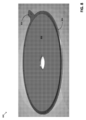
[0042]図1は、いくつかの実施形態による、構造隔壁を備えた超伝導マグネットの断面図である。マグネット100は、上板111と、下板112と、内径の電気的接合体を含み得る中心構造113とを備えるハウジング110を含む。HTSテープ115の単一の連続した部品は、中心構造113の周りに巻かれる。あるいは、HTSテープのいくつかの結合された切片は、単一の巻き線としてともに巻かれ得る。図1に示す断面図のため、同一のHTSテープが、中心構造とは異なる半径位置の連続した巻き線で示される。マグネット100は、さらに、中心構造の周りに巻かれるときにHTSテープ115が貫通する構造隔壁(以下「隔壁」)121および122を含む。HTSテープ115が隔壁を貫通する位置は、明確性のために図1では示されないが、隔壁121および122は、上述したようにHTSテープ115が貫通する貫通接続スリットを含み得る。
[0042] FIG. 1 is a cross-sectional view of a superconducting magnet with a structural septum, according to some embodiments. The
[0043]いくつかの実施形態では、隔壁121および122は、ハウジング110内で移動可能でもよく、それによって隔壁内の貫通接続スリットが、HTSテープが隔壁内を埋める点においてHTSテープと整列し得る。例示的な貫通接続スリットが図3A~図3Cに示され、以下で詳細に説明される。テープが隔壁を貫通する必要がある方位角位置が不明な場合があるため、巻いている間に移動可能な隔壁は有益な場合があり、それによって、テープが隔壁内部の空間を全て埋めた時に必要な方位角位置に、隔壁の貫通接続スリットが配置される。いくつかの場合、隔壁を所望の方位角位置に依然として正しく動かすことができるが、隔壁は、スロット内に配置されているため、または他のやり方で動きがある程度制限されているため、限定されて移動可能でもよい。
[0043] In some embodiments,
[0044]いくつかの実施形態によれば、隔壁121および122は円形の場合があり、したがって図1の同断面図が、マグネット100の中心を通る、任意の選択断面に適用可能である(スリットを含み図1とは異なって見える隔壁を貫通するスリットを含む断面を除く)。いくつかの実施形態では、隔壁121および122は、円形以外でもよく、その代わりに、長方形、または角が丸い長方形(例えば、レーストラック形状)、楕円、または任意の他の適切な形状などの形状を有してもよい。
[0044] According to some embodiments,
[0045]いくつかの実施形態によれば、上板111および下板112は、鋼、インコネル(登録商標)、ナイトロニック(登録商標)40、ナイトロニック(登録商標)50、インコロイ(登録商標)、またはそれらの組み合わせなどであるがそれに限定されない高機械的強度材料を含み得る、またはそれから成ることが可能である。いくつかの実施形態では、隔壁121および122は、鋼、インコネル(登録商標)、ナイトロニック(登録商標)40、ナイトロニック(登録商標)50、インコロイ(登録商標)、高エントロピー合金、高強度複合材料、セラミックス、またはそれらの組み合わせなどであるが、それに限定されない高機械的強度材料を含み得る、またはそれから成ることが可能である。
[0045] According to some embodiments, the
[0046]いくつかの実施形態によれば、HTSテープ115は、イットリウム系バリウム銅酸化物(YBCO)などの希土類バリウム銅酸化物超伝導体(REBCO)を含み得る。いくつかの実施形態では、HTSテープは、約0.001mmから約0.1mmの範囲の厚さ(または高さ)と約1mmから約12mmの範囲の幅の断面寸法を有する、HTS材料から成る長尺で薄いストランドを備え得る。いくつかの実施形態によれば、HTSテープの各ストランドは、導電性材料に加えてREBCOなどのHTS材料を含み得る。いくつかの実施形態では、導電性の材料は、REBCO上に配置され得る。いくつかの実施形態では、導電性材料は、銅などのクラッド材料でもよい。いくつかの実施形態では、HTSテープは、多結晶HTSを含んでもよく、および/または高い粒度のアライメントを有してもよい。
[0046] According to some embodiments, the
[0047]いくつかの実施形態では、HTSテープ115は、鋼または銅などの非超伝導性材料とともに共巻きされ得る。HTSテープのスタックは、共巻き材料の1つまたは複数の層とともに共巻きされ得る。いくつかの実施形態では、構成要素間の潜在的な間隙を埋めるために、追加の伝導性材料がマグネット100に含まれ得る。例えば、インジウムなどの軟金属は、上板111または下板112のいずれかとHTSテープとの間に配置され得る。
[0047] In some embodiments, the
[0048]中心構造113は、全体として一体化しているとして図1で示されるが、図に示されるような構造は、マグネット100の必須構成要素ではなく、一般に、マグネットがハウジング中に任意の中心構造を含み得ることが理解されるであろう。例えば、中心構造113は、代わりに、壁の内側が空いた円筒形でもよく、その壁の周りにHTSテープが巻かれることが可能である。
[0048] Although the
[0049]図2Aは、いくつかの実施形態による、溝に配置された構造隔壁を備えた超伝導マグネットの断面図である。マグネット250は、上板261と、下板262と、内径の電気的接合体278を含み得る中心構造263とを備えるハウジング260を含む。HTSテープ265の単一の連続した部品は、内径の電気的接合体278から巻かれる。あるいは、HTSテープのいくつかの結合された切片は、単一の巻き線としてともに巻かれ得る。図2Aに示す断面図のため、同一のHTSテープは、中心構造から異なる半径位置の連続した巻き線で示される。マグネット250は、中心構造の周りに巻かれるときにHTSテープ265が貫通する隔壁271および272をさらに含む。HTSテープ265が隔壁を貫通する位置は、明確性のために図2Aでは示されないが、隔壁271および272は、上述したようにHTSテープ265が貫通する貫通接続スリットを含み得る。
[0049] Figure 2A is a cross-sectional view of a superconducting magnet with a structural septum disposed in a groove, according to some embodiments.
[0050]図2Aの例では、隔壁271および272は、上板261および下板262に形成された溝に配置される。この溝は、組み立て中に隔壁を適切な位置に保持する保持機構の役割を果たすことが可能であり、および/またはマグネットに追加の構造的強度を提供して、隔壁に印加された力が板261および262により容易に伝達されることを可能としてもよい。いくつかの実施形態では、上板261および下板262の面に形成されたこの溝は、円形状を有してもよい。他の場合では、板の面に形成された溝は、長方形、または角が丸い長方形など、異なる形状を有してもよい。
2A, the
[0051]図2Aの例では、マグネット260は、上述したようにマグネット内のHTSテープを外面に結合するように構成された構造である、導電性の接合体構造(以下「接合体」)278および279を含む。巻いている間に、HTSテープ265は、内側接合体278と外側接合体279とに対して電気的に結合(例えば、はんだ付け)され得る。図2Aの例で、内側接合体278は、HTSテープ265の導電性経路をマグネット250の上面に結合する一方、外側接合体279は、HTSテープ265の導電性経路をマグネットの下面に結合する。
2A, the
[0052]いくつかの実施形態では、内側接合体278は、各断面において、図2Aに示すようにハウジングの最上部まで延在しなくてもよい。いくつかの場合、内側接合体278は、ハウジングの一側部の周囲など、ハウジングの最上部の一部までしか延在しなくてもよい。同様に、いくつかの実施形態では、外側接合体279は、各断面において、図2Aに示すようにハウジングの最下部まで延在しなくてもよい。いくつかの場合、外側接合体279は、ハウジングの一側部の周囲など、ハウジングの最下部の一部までしか延在しなくてもよい。これらの構成は、依然として導電性経路が接合体を通ってマグネットを出ることができながら、追加要素がハウジングの次に挿入可能となる利点を有し得る。 [0052] In some embodiments, the inner joint 278 may not extend to the top of the housing as shown in FIG. 2A in each cross section. In some cases, the inner joint 278 may only extend to a portion of the top of the housing, such as around one side of the housing. Similarly, in some embodiments, the outer joint 279 may not extend to the bottom of the housing as shown in FIG. 2A in each cross section. In some cases, the outer joint 279 may only extend to a portion of the bottom of the housing, such as around one side of the housing. These configurations may have the advantage that additional elements can be inserted next to the housing while still allowing a conductive path to exit the magnet through the joint.
[0053]中心構造263が図2Aに示されるが、図に示されるような構造は、マグネット250の必須構成要素ではなく、一般に、マグネットがハウジング中に任意の中心構造を含み得ることが理解されるであろう。例えば、中心構造263は、代わりに、内径電気的接合体278のみから成って、壁の内側が空いた円筒形でもよく、その壁の周りにHTSテープが巻かれることが可能である。
[0053] Although a
[0054]図2Bおよび図2Cは、図2Aのように構成された例示的なハウジング(または「パンケーキ」)の断面斜視図であり、ハウジングは円形で、円形の溝と、その溝内に配置された円形の隔壁とを含む。同一の構造が図2Bおよび図2Cの両方に図示されているが、図2Bは、ハウジングの一側部の詳細を示す。図2B~図2Cの例では、マグネット200は、上板203、下板204、および隔壁210、212および214を含むハウジング202を備える。マグネットは、さらに、内側接合体206および外側接合体208を含む。
[0054] Figures 2B and 2C are cross-sectional perspective views of an exemplary housing (or "pancake") configured as in Figure 2A, where the housing is circular and includes a circular groove and a circular bulkhead disposed within the groove. The same structure is illustrated in both Figures 2B and 2C, but Figure 2B shows details of one side of the housing. In the example of Figures 2B-2C,
[0055]図2Bおよび図2Cの例では、マグネット200は、3つの構造隔壁210、212、および214を備える。いくつかの実施形態によれば、それらの隔壁は、高ローレンツ力にさらされた時に複数の巻回上のHTSテープに蓄積される周歪みを減少させ得る。図2B~図2Cに示すように、構造隔壁210、212、および214は、上部構造板203および下部構造板204に形成されたスロットまたは溝に収められる。スロットおよびそれらの関連する構造隔壁210、212、および214の半径方向の位置は、コンピュータ分析によって求められてもよく、それによって蓄積された動作上のテープ歪みが許容範囲を超えない。逆に、隔壁の数は最小限に抑えられることが可能であり、それによってハウジング内の空間が不要な数の隔壁に取られず、そうでない場合は、HTSテープによって占有され得る。HTSテープが配置され得る隔壁間の空間、すなわち、図2Bおよび図2Cの例では空間220、222、224、および226は、以下で「チャネル」と呼ばれる場合がある。
[0055] In the example of Figures 2B and 2C,
[0056]図2Bおよび図2Cの例で、各構造隔壁210、212、および214は、隔壁の一方の側から他方の側へ半径方向にテープスタックを遷移させるための貫通接続スリットを有する。適切な貫通接続スリット構造の説明上の例を以下に説明する。したがって、図2Bおよび図2Cに示すように、マグネットアセンブリにおけるパンケーキのうちの少なくとも1つは、半径方向荷重に耐えるための1つまたは複数の隔壁によって分離された複数のチャネルを備えてもよく、各チャネルは、HTSテープの1つまたは複数の巻回を有し、各隔壁は、近くのチャネルにおいてHTSテープの巻回を接続する貫通接続を有する。この貫通接続スリットを使用して、連続した1本のHTSテープまたはテープスタックは、隔壁を貫通するものの、隔壁によって構造上支持されながら内径から外径へ巻かれることができる。 2B and 2C, each structural bulkhead 210, 212, and 214 has a through-connection slit for transitioning the tape stack radially from one side of the bulkhead to the other. Illustrative examples of suitable through-connection slit structures are described below. Thus, as shown in FIGS. 2B and 2C, at least one of the pancakes in the magnet assembly may include multiple channels separated by one or more bulkheads for bearing radial loads, each channel having one or more turns of HTS tape, and each bulkhead having a through-connection connecting turns of HTS tape in nearby channels. Using this through-connection slit, a continuous length of HTS tape or tape stack can be wound from the inner diameter to the outer diameter while passing through the bulkhead but being structurally supported by the bulkhead.
[0057]なお、1つのパンケーキにおける隔壁の数、したがって、そのパンケーキにおけるチャネル数は、調節され得ることが理解され得る。そのような調節の理由は、とりわけ、パンケーキの直径、隔壁自体を含むパンケーキの作製で使用される材料、HTSテープ(またはHTSテープのスタック)で使用される材料、設計材料応力の大きさ、設計動作温度、磁界、および技術的な電流密度(または輸送電流)、および/または他の適切な要素におけるばらつきを吸収することを含む。 [0057] It will be appreciated that the number of septa in a pancake, and therefore the number of channels in that pancake, may be adjusted. Reasons for such adjustments include, among others, to accommodate variations in the diameter of the pancake, the materials used in the fabrication of the pancake, including the septa themselves, the materials used in the HTS tape (or stack of HTS tapes), the magnitude of the design material stresses, the design operating temperature, magnetic field, and technical current density (or transport current), and/or other suitable factors.
[0058]図2Dは、いくつかの実施形態による、隔壁およびHTSテープを備えるマグネットの写真である。マグネット280は、HTSテープを備えるマグネット200の一例であり、上部構造板が取り除かれており、それによってマグネットの内部が見られる。図2Dに示すように、マグネット280は、3つの隔壁286、287、および288を含む。3つの隔壁のそれぞれは、貫通接続スリット(図2Dでは明確に示されていない)を含み、HTSテープは、マグネットの内部から中心構造285の周りに巻かれ(テープ領域281を形成)、隔壁286を通って、隔壁286の周りに巻かれ(テープ領域282を形成)、隔壁287を通って、隔壁287の周りに巻かれ(テープ領域283を形成)、隔壁288を通って隔壁288の周りに巻かれる(テープ領域284を形成)。図2Dの例で、中心構造285は、上述したように、内径電気的接合体のみから成る。
[0058] FIG. 2D is a photograph of a magnet with septa and HTS tape, according to some embodiments.
[0059]図3A~図3Cは、いくつかの実施形態による、構造隔壁の貫通接続スリットの様々な構成を図示する。図3A~図3Cのそれぞれは、構造板の円形スロット内に配置された円形隔壁を図示する。なお、例示的な貫通接続スリットが円形隔壁および円形スロットのために図示されるが、同種のスリット設計が他の形状(長方形など)の隔壁においても実現可能であり、および/または構造板内のスロットに配置されない隔壁において実現可能であることが理解され得る。 [0059] Figures 3A-3C illustrate various configurations of through-connection slits in structural bulkheads, according to some embodiments. Each of Figures 3A-3C illustrates a circular bulkhead disposed within a circular slot in a structural plate. It should be understood that while exemplary through-connection slits are illustrated for a circular bulkhead and a circular slot, similar slit designs are also feasible in bulkheads of other shapes (e.g., rectangular) and/or bulkheads that are not disposed in a slot in a structural plate.
[0060]図3Aの例で、隔壁は、スリットが隔壁の高さ全体にわたって延在しない部分スリット構成310を含む。図3Bの例で、隔壁は、スリットが隔壁の高さ全体にわたって延在する全スリット構成320を含む。図3Cの例で、隔壁は、その外径において加工されたらせんを有する隔壁のための部分スリット構成330を含み、それによって隔壁が純粋な円形ではなく、むしろほぼ1巻き全部のらせんの形状を有する。図3Cの構成は、全方位角方向において等しく半径方向荷重に耐えることができる半径方向で均一の厚さを有する隔壁を含み得る。図3Cは、隔壁がその外径において加工されたらせんを有するが内径では円形であることを図示するが、隔壁のために他の適切な構成は、内径および外径の両方でらせんの形状を有する場合がある。なお、他のスリット構成も、本明細書で開示された概念、技法、および構造の実施形態に従って、特に半径方向応力を軽減するために使用され得ることを理解されたい。 3A, the septum includes a partial slit configuration 310 where the slit does not extend the entire height of the septum. In the example of FIG. 3B, the septum includes a full slit configuration 320 where the slit extends the entire height of the septum. In the example of FIG. 3C, the septum includes a partial slit configuration 330 for a septum having a machined helix at its outer diameter, whereby the septum is not purely circular, but rather has the shape of approximately one full turn of a helix. The configuration of FIG. 3C may include a septum having a radially uniform thickness that can withstand radial loads equally in all azimuthal directions. Although FIG. 3C illustrates a septum having a machined helix at its outer diameter but is circular at the inner diameter, other suitable configurations for a septum may have a helical shape at both the inner and outer diameters. It should be understood that other slit configurations may also be used in accordance with embodiments of the concepts, techniques, and structures disclosed herein, particularly to reduce radial stresses.
[0061]上述したように、本明細書の実施形態は円形スロット内に配置された円形隔壁に限定されず、マグネットを巻いている時に隔壁がスロット内で回転可能な構成に対しても利点があり得る。テープが隔壁を貫通する必要がある方位角位置が不明な場合があるため、円形隔壁および円形スロット構成は、巻き線中に隔壁が回転可能とし、それによって、テープが隔壁内部の空間を全て埋めた時に必要な方位角位置に、隔壁の貫通接続スリットが配置される。 [0061] As noted above, embodiments herein are not limited to circular septa disposed within a circular slot, but may also have advantages over configurations in which the septa can rotate within the slot as the magnet is wound. Because the azimuthal position at which the tape needs to pass through the septa may be unknown, a circular septum and circular slot configuration allows the septa to rotate during winding, thereby positioning the septa feedthrough slits at the azimuthal position required when the tape has filled all of the space inside the septa.
[0062]上述したように、いくつかの実施形態では、高磁界超伝導マグネットは、平坦な層に配置されたHTS、HTSテープ、またはHTSテープスタックの巻回によって形成されてもよく(例えば、層の接触面が、それを中心として層が配置されるマグネットの中心長手方向軸に直交するように形成されてもよい)、そのような構成は、「パンケーキ状巻」またはより単純に「パンケーキ」と呼ばれ得る。それによって、パンケーキは、HTS部品と、HTSを収容するための構造的部品との両方を含む。マグネットが巻回を有する層によって形成される(例えば層の接触面がそれを中心として層が配置されるマグネットの中心長手方向軸に平行になるように形成する)場合、そのような構成は、「層状巻手法」または単に「層状構成」、さらに単純に「層状」と呼ばれ得る。 [0062] As noted above, in some embodiments, a high-field superconducting magnet may be formed by winding HTS, HTS tape, or HTS tape stacks arranged in flat layers (e.g., formed so that the interface of the layers is perpendicular to the central longitudinal axis of the magnet about which the layers are arranged), and such a configuration may be referred to as a "pancake winding" or more simply, a "pancake." The pancake thereby includes both the HTS components and the structural components for housing the HTS. When a magnet is formed by layers with windings (e.g., formed so that the interface of the layers is parallel to the central longitudinal axis of the magnet about which the layers are arranged), such a configuration may be referred to as a "layered winding approach" or simply a "layered configuration," or even more simply, "layered."
[0063]図4Aは、いくつかの実施形態による、マグネットアセンブリ400の断面図であり、図4Bは、その断面図の拡大部分を示す図である。いくつかの実施形態によれば、マグネットアセンブリ400は、高磁界(例えば、10テスラ以上)での使用のために設計され得る。いくつかの実施形態によれば、マグネットアセンブリ400は、外径(OD)電気的接合体402および内径(ID)電気的接合体404を有する複数のパンケーキの伝導冷却された「コールドマス」から構成され得る。本明細書で詳細に説明される実施形態において、HTSを保持する各パンケーキの機械的構造(以下「ハウジング」)は、米国ニューヨーク州ニューハートフォードのSpecial Metals Corporationによるインコネル(登録商標)合金などのオーステナイト系ニッケルクロム合金、または米国オハイオ州ウエストチェスターのAK Steelによるナイトロニック(登録商標)合金などの窒素強化オーステナイト系ステンレス鋼など、鋼、または他の適切な構造的導電体で形成されてもよく、またはそれを含んでもよい。ただし、他の実施形態において、ハウジングは、導電体の場合がある、または導電体でない場合がある他の構造的材料で形成され得ることを理解されたい。図4の例で、マグネットアセンブリ400は、電気絶縁体406(高圧ファイバーグラス積層体など)によってマグネットアセンブリから電気的に絶縁された端子408で冷却装置を使用して熱伝導によって熱を伝達または他のやり方で除去するように結合される。
[0063] FIG. 4A is a cross-sectional view of a
[0064]図4A~図4Bの例が特定の非絶縁パンケーキ設計を図示したが、本明細書に開示される特徴および製造技法のうちの多くは、全体的または部分的に絶縁されたHTSテープまたはテープスタックによって形成されたマグネットに適用可能であり、当業者は、全体的または部分的に絶縁された設計に対して本明細書で教示された概念、技法、および構造を適応する方法を理解するであろうことを理解されたい。例えば、マグネットアセンブリは、各パンケーキにおいて同数の隔壁を含む必要はなく、図4A~図4Bの例で示すように、各パンケーキにおける同一の半径位置にパンケーキを含む必要はない。 [0064] Although the example of Figures 4A-4B illustrates a particular non-insulated pancake design, it should be understood that many of the features and fabrication techniques disclosed herein are applicable to magnets formed with fully or partially insulated HTS tapes or tape stacks, and one of ordinary skill in the art would understand how to adapt the concepts, techniques, and structures taught herein to fully or partially insulated designs. For example, the magnet assembly need not include the same number of bulkheads in each pancake, nor need it include pancakes at the same radial locations in each pancake, as shown in the example of Figures 4A-4B.
[0065]図4Bは、図4Aの断面図の拡大部分を示す図である。図4Bの例で、マグネットアセンブリ400は、本明細書で「定型」パンケーキおよび「末端」パンケーキと呼ばれる2種類のパンケーキを含む。定型パンケーキ410、412、414、416、418、420、422、および424はそれぞれ、間に構造隔壁を有する1対の構造板で形成され得る。それらの隔壁は、上述したように、HTSテープまたはテープスタックの1つまたは複数の巻回を保持するための複数のチャネルを画定し、電流が印加されると磁界を発生させる。(HTSテープスタックは、パンケーキ自体の構造をより視覚的に明瞭にするために図4A~図4Bでは不図示である。すなわち、ハウジングのみが図示される)。
[0065] FIG. 4B illustrates an enlarged portion of the cross-sectional view of FIG. 4A. In the example of FIG. 4B,
[0066]図4Bの例で、パンケーキ410は、内径から外向きに3つの隔壁425、426、427を備えており、この隔壁設計は、積み重ねられたマグネットアセンブリ400の他の定型パンケーキにおいて複製される。HTSスタックの巻回は、各パンケーキのチャネルにおいて連続したらせんを形成し、その内径をその外径に電気的に接続する。いくつかの実施形態によれば、パンケーキの少なくとも1つのHTSテープは、REBCOなどの希土類酸化銅を含み得る。なお、本明細書で開示された概念、技法、および構造の実施形態に従って磁界を生成するために、他の超伝導材料がマグネットアセンブリ400内で使用され得ることを理解されたい。
[0066] In the example of FIG. 4B, pancake 410 includes three bulkheads 425, 426, 427 outward from the inner diameter, and this bulkhead design is replicated in the other standard pancakes of stacked
[0067]いくつかの実施形態によれば、マグネットアセンブリ400内のHTSテープと、共巻きされる材料とは、パンケーキの構造において自立して密に搭載されることが可能であり、それによって、チャネルのそれぞれにおけるHTSテープスタックの1つまたは複数の巻回がチャネルの容積をほぼ埋める。あるいは、パンケーキのうちの少なくとも1つのHTSテープは、複数のチャネルのうちの少なくとも1つにはんだ付けされ、1つまたは複数の接合体にはんだ付けされる。なお、本明細書で開示された概念、技法、および構造の実施形態により、マグネットアセンブリ400内で超伝導テープまたはテープスタックを固定するために、他の方法が使用され得ることを理解されたい。
[0067] According to some embodiments, the HTS tape and co-wound material in the
[0068]いくつかの実施形態によれば、接合体における小さい抵抗加熱、接合体におけるテープの潜在的な過度の歪みおよび/または過度の応力、および各パンケーキ内の構造隔壁を通るチャネル間遷移に起因するクエンチの安定性を高めるために、それらの臨界領域において、銅の共巻きが追加され得る。接合体、電流リードおよびチャネル間遷移における銅成分の誘導ピックアップ渦電流加熱によるクエンチに関係した温度上昇を減少させるため、HTSテープスタックは、より大きな通電容量を実現する直列のHTSテープを追加することによって補強され得る。さらに、接合体、電流リードおよびチャネル間遷移におけるHTSテープスタックの潜在的なよじれを減少させるため、HTSテープスタックは鋼テープの共巻きによって補強され得る。さらなる共巻きが追加されてもよい。例えば、クエンチ中に隔壁を通る常電導伝搬を向上させるため、または他の目的のために、銅の共巻きが追加可能である。 [0068] According to some embodiments, copper co-wraps may be added in those critical regions to enhance quench stability due to small resistive heating in the joints, potential over-distortion and/or over-stress of the tapes in the joints, and the inter-channel transitions through the structural diaphragm in each pancake. To reduce quench-related temperature rise due to inductive pickup eddy current heating of the copper components in the joints, current leads, and inter-channel transitions, the HTS tape stack may be reinforced by adding HTS tapes in series to achieve a larger current carrying capacity. Additionally, to reduce potential kinking of the HTS tape stack in the joints, current leads, and inter-channel transitions, the HTS tape stack may be reinforced with steel tape co-wraps. Additional co-wraps may be added. For example, copper co-wraps can be added to improve normal conduction propagation through the diaphragm during a quench, or for other purposes.
[0069]いくつかの実施形態によれば、マグネットアセンブリ400のパンケーキのそれぞれは、電気回路の一部としてHTSテープの1つまたは複数の巻回を電気的に結合するための1つまたは複数の接合体を含み得る。より具体的には、構造板に埋め込まれたリング形状の接合体が各定型パンケーキの内径および外径に位置してもよく、超伝導電気路を終端する。これらの接合体は、銅および/または他の導電性の材料を含んでもよく、またはそれで構成されてもよく、および/または超伝導材料を含んでもよく、またはそれで構成されてもよい。例として、定型パンケーキ422は、内径接合体440と、外径接合体442とを有する。HTSテープスタックのらせんは、それらの接合体の溝へと続く。例示的な実施形態において、らせんは、複数の完全な360度の回転後に終端してもよく、他の実施形態では、溝が1回の完全な回転の前または後に終端してもよい。
[0069] According to some embodiments, each of the pancakes of the
[0070]いくつかの実施形態によれば、内径接合体440および外径接合体442は、それぞれ、各パンケーキの構造板に埋め込まれてもよく、それによってその対向する側において構造板の平面と同一平面となる、またはわずかにその上に延在する。特に、接合体は、以下に説明するように、冷却板のために隣の空間を提供するため、構造板の上に延在してもよい。本明細書で開示されたモジュラー設計によれば、定型パンケーキの数は、所望の磁界を発生させるために、1以上の任意の数のパンケーキであることが可能である。 [0070] According to some embodiments, the inner diameter joint 440 and the outer diameter joint 442 may each be recessed into the structural plate of each pancake, so that they are flush with or extend slightly above the plane of the structural plate on opposite sides thereof. In particular, the joints may extend above the structural plate to provide adjacent space for a cooling plate, as described below. According to the modular design disclosed herein, the number of stylized pancakes can be any number of pancakes greater than or equal to one to generate the desired magnetic field.
[0071]図4Aおよび図4Bの例では、複数の同一の定型パンケーキが、HTSテープで埋められたチャネルの交互の軸配向でともに積み重ねられ得る。この配置は、最も外側の2つのパンケーキの露出接合体間で、HTSテープのらせんと、マグネットアセンブリ400の全パンケーキの嵌合されたID間およびOD間接合体とを介した連続電気路を提供し得る。詳細には、パンケーキのうちの1つが、パンケーキのうちの第2のパンケーキの外径上の接合体に対して、その外径上の接合体によって電気的に結合され、パンケーキのうちの第1のパンケーキは、パンケーキのうちの第3のパンケーキの内径上の接合体に対して、その内径上の接合体によって電気的に結合される、交互ハウジングのパターンが繰り返され得る。例として、図4Bでは、第1のパンケーキ412の外径接合体と、第2のパンケーキ414の外径接合体は、電気的結合領域446を介して嵌合され、第1のパンケーキ412の内径接合体と、第3のパンケーキ410の内径接合体は、電気的結合444を介して嵌合される。パンケーキ間の接合体のより良好な電気接触を促進するために、製造時に、2つの隣り合って積み重ねられたパンケーキの接合体のそれぞれの嵌合面間に導電性の(例えば、インジウムの)ガスケットが挿入されてもよい。
[0071] In the example of Figures 4A and 4B, multiple identical stylized pancakes may be stacked together with alternating axial orientations of the HTS tape filled channels. This arrangement may provide a continuous electrical path between the exposed joints of the two outermost pancakes through the spiral of HTS tape and the mated ID-to-ID and OD-to-OD joints of all pancakes of the
[0072]なお、図4Bにおいて、結合領域446は、パンケーキ412および414における接合体間に挿入された冷却板452の一部を含むことに留意されたい。図4Aおよび図4Bの例示的なマグネットアセンブリにおいて、板間の外側接合体は、パンケーキの半分でのみ接触し、残りの半分は、パンケーキ間に挿入された冷却板を有する。この違いは、接合体が互いに接触していることを示す図4Aの左側の接合体領域402と、その間に冷却板を有する接合体を示す図4Aの右側の接合体領域402を比較すると明らかである。 [0072] Note that in FIG. 4B, bond region 446 includes a portion of a cold plate 452 inserted between the joints in pancakes 412 and 414. In the exemplary magnet assembly of FIGS. 4A and 4B, the outer joints between the plates only contact half of the pancakes, while the other half has a cold plate inserted between them. This difference is evident when comparing the joint region 402 on the left side of FIG. 4A, which shows the joints in contact with each other, to the joint region 402 on the right side of FIG. 4A, which shows the joints with a cold plate therebetween.
[0073]図4Aおよび図4Bの例で、HTSテープの巻き線の電気経路は、最外部の2つの末端パンケーキ430および432によって完成する。末端パンケーキ430、432は、電気接触する定型パンケーキと同一の半径方向位置のIDまたはODのいずれかに位置する唯一のリング形状接合体を有する一体化した構造板を呈する。すなわち、積み重ねられた板の最上部および積み重ねられた板の最下部の各パンケーキは、他の(定型)パンケーキの接合体に電気的に結合されるその外径またはその内径のいずれかに接合体を有する内面と、接合体を有さない平行な外面とを有する。 [0073] In the example of Figures 4A and 4B, the electrical path of the HTS tape windings is completed by the two outermost end pancakes 430 and 432. The end pancakes 430, 432 present an integral structural plate with a single ring-shaped joint located at either the ID or OD at the same radial position as the regular pancake with which it electrically contacts. That is, each pancake at the top of the stack and at the bottom of the stack has an inner surface with a joint at either its outer diameter or its inner diameter that is electrically coupled to the joint of the other (regular) pancake, and a parallel outer surface that has no joint.
[0074]図4Aおよび図4Bの例で、両方の末端パンケーキ430、432は、ODに、ただしそれらの内面のみに、それぞれの接合体434、436を有する。末端パンケーキ430、432のリング形状の接合体434、436は、同一の導体の導電性の板と連続的に接続され、半径方向で外向きに、通常はHTS電流リード(例えば、図4Aおよび図4Bに示すような導電体406)の方向に延在している。HTSテープスタックは、接合体のリングの内部から始まり、接合体の溝において360度のループを形成し、その後、拡張板の溝に入って収まる。それによって、パンケーキのそれぞれ(定型と末端の両方)は、その1つまたは複数の接合体によって、1つまたは2つの近くのパンケーキのいずれかの接合体に電気的に結合され、それにより、パンケーキのそれぞれにHTSテープを含む動作電流路を形成する。
4A and 4B, both end pancakes 430, 432 have respective joints 434, 436 at the OD, but only on their inner surfaces. The ring-shaped joints 434, 436 of the end pancakes 430, 432 are connected continuously with a conductive plate of the same conductor and extend radially outward, usually in the direction of the HTS current lead (e.g.,
[0075]いくつかの実施形態によれば、IDおよびODの接合体は、連続した円形リングの形状で実行されると上述したが、接合体は、代替として、不連続の板として構成され、それぞれのパンケーキからの拡張部として形成され、パンケーキを中心として位置決めされてもよく、それによってアセンブリにおいて嵌合し、上述したように、コールドマスアセンブリにおいて個々に、または一度に1つの接合体ずつ、または全てを一緒に加圧され、固定され得る。 [0075] Although according to some embodiments, the ID and OD joints are described above as being implemented in the shape of a continuous circular ring, the joints may alternatively be configured as discontinuous plates formed as extensions from their respective pancakes and positioned about the pancakes, thereby fitting together in an assembly that can be pressed and secured individually, one joint at a time, or all together in the cold mass assembly as described above.
[0076]いくつかの実施形態によれば、パンケーキは、互いに独立しており、接合体でのみ電気動作のために接続されるため、個々のパンケーキの形状は、隣り合ったパンケーキの接合体が嵌合面を有する限り、異なることが可能である。一般に、コールドマスおよびHTS巻き線は、ソレノイドまたはレーストラックとして成形可能であり、またはそれらのいずれかとトポロジ的に合致する異なる形状を有することが可能である。したがって、パンケーキのうちの少なくとも2つは、異なるサイズまたは異なる形状を有してもよい。なお、当業者は、本明細書で開示された概念および技法から逸脱せずに、他のサイズまたは形状を考え出し得ることが予想される。 [0076] According to some embodiments, because the pancakes are independent of one another and connected for electrical operation only at the junctions, the shapes of the individual pancakes can be different, so long as the junctions of adjacent pancakes have mating surfaces. In general, the cold mass and HTS windings can be shaped as solenoids or racetracks, or can have different shapes that topologically match either of them. Thus, at least two of the pancakes may have different sizes or shapes. It is anticipated that one of ordinary skill in the art may conceive of other sizes or shapes without departing from the concepts and techniques disclosed herein.
[0077]いくつかの実施形態によれば、コールドマスは、接合体によってまだ埋められていない空間におけるパンケーキ間に挿入された熱伝導性(例えば、銅、アルミニウム、銀、金、グラファイトなど)の冷却板によって伝導冷却されてもよい。図4Aおよび図4Bの例で、銅冷却板450は、隣り合った定型パンケーキ422と424との間に配置され、交互のパンケーキと冷却板のこの設計は、図示するように、マグネットアセンブリ400全体において繰り返される。いくつかの実施形態では、銅冷却板は、パンケーキ間の電気的短絡を防止するように電気絶縁されてもよい。この絶縁は、ポリテトラフルオロエチレン(PTFE)または類似のものなどの電気絶縁体の層で各面を被覆し、その絶縁体を固化することによって実現され得る。なお、他のコーティングも使用され得ることを理解されたい。
[0077] According to some embodiments, the cold mass may be conductively cooled by a thermally conductive (e.g., copper, aluminum, silver, gold, graphite, etc.) cold plate inserted between the pancakes in the spaces not yet filled by the bond. In the example of Figs. 4A and 4B, a
[0078]銅冷却板450のそれぞれは、熱伝導性でもよく、冷却板を冷却装置に熱的に結合するために、パンケーキ間から電気絶縁体の層を介して端子へ渡るように配置され得る。図4Aおよび図4Bの例で、銅冷却板450は、冷却装置の端子470と熱接触する端子452を有する。このように、パンケーキのそれぞれは、冷却板のうちの1つまたは2つのいずれかと隣り合っており、パンケーキが動作温度まで冷却可能とし、パンケーキがパンケーキで発生した熱を熱伝導によって冷却装置へ伝達可能とする。具体的には、各末端パンケーキは、冷却板のうちの1つと隣り合っており、各定型パンケーキは冷却板のうちの2つと隣り合っている。
[0078] Each of the
[0079]いくつかの実施形態によれば、HTSが構造隔壁の貫通接続スリットを貫通している場合、貫通接続におけるあらゆる間隙を埋めるために、HTSテープ以外の追加材料が供給されてもよい。この追加材料は、マグネットの動作中に圧力および/または他の力によって引き起こされた変形に起因するテープの劣化を軽減し得る。スリット中のHTSテープは比較的薄い場合があるため、変形の影響を特に受けやすい場合があり、貫通接続に配置された「シミング」材料を追加することによって、そのような変形を回避し得る。 [0079] According to some embodiments, where the HTS penetrates feedthrough slits in the structural bulkhead, additional material other than the HTS tape may be provided to fill any gaps in the feedthrough. This additional material may mitigate degradation of the tape due to deformations caused by pressure and/or other forces during operation of the magnet. Because the HTS tape in the slits may be relatively thin, it may be particularly susceptible to deformations, which may be avoided by adding "shimming" material placed in the feedthrough.
[0080]図5は、いくつかの実施形態による、HTSテープに加えて、シムを備える貫通接続スリットの写真である。図5の例で、上板が取り除かれ、上記の様々な実施形態で説明するようにHTSテープが隔壁内部および隔壁間に巻かれた状態のマグネットが示される。図5の例で、隔壁520は、HTSテープ巻き線の領域512からHTSテープ巻き線の領域511を分離し、このHTSテープは隔壁520のスリットを貫通する。図5の例で、隔壁520は図3Cに示すような種類のものであり、この隔壁は、ほぼ1回の全巻回を有するらせんの形状を有する。追加のシミング材料522および523は、HTSテープ518の巻回が隔壁520を通過する時に他のやり方で出現し得る間隙を埋めるために、隔壁のいずれかの側で挿入される。
[0080] Figure 5 is a photograph of a feedthrough slit with shims in addition to HTS tape, according to some embodiments. In the example of Figure 5, the magnet is shown with the top plate removed and the HTS tape wrapped inside and between the septa as described in various embodiments above. In the example of Figure 5, a septum 520 separates an area 511 of HTS tape windings from an area 512 of HTS tape windings, which passes through a slit in the septum 520. In the example of Figure 5, the septum 520 is of the type shown in Figure 3C, which has the shape of a spiral with approximately one full turn. Additional shimming material 522 and 523 is inserted on either side of the septum to fill gaps that may otherwise appear as the turns of
[0081]シミング材料522および523は、HTSテープの追加の小片、および/または導電性の材料の追加のストリップ(例えば、銅のストリップおよび/または鋼のストリップ)を含み得る。各種の材料の複数のストリップが必要に応じて挿入されてもよい(例えば、HTSテープの複数のストリップ、銅テープの複数のストリップ、および鋼テープの複数のストリップが、単一のシムまたは「共巻き」として全てがともに挿入されてもよい)。 [0081] Shimming material 522 and 523 may include additional pieces of HTS tape and/or additional strips of conductive material (e.g., copper strips and/or steel strips). Multiple strips of various materials may be inserted as desired (e.g., multiple strips of HTS tape, multiple strips of copper tape, and multiple strips of steel tape may all be inserted together as a single shim or "co-wrap").
[0082]図6は、いくつかの実施形態によるマグネットを組み立てる方法のフローチャートである。例示を目的として、図7に示すようなマグネットの分解組立図に関連して方法600が説明されるが、方法600は、図7の特定の部品を用いたマグネットの組立に限定されないことを理解されたい。特に図7は、円形隔壁と、円形スロットを有する円形構造板とを図示するが、方法600は、任意の適切な形状の隔壁および板(スロットのない板、または円形以外のスロットを含む)を用いて実践され得る。 [0082] FIG. 6 is a flow chart of a method of assembling a magnet according to some embodiments. For illustrative purposes, method 600 is described with reference to an exploded view of a magnet as shown in FIG. 7, but it should be understood that method 600 is not limited to assembling a magnet with the particular components of FIG. 7. In particular, FIG. 7 illustrates a circular bulkhead and a circular structural plate with a circular slot, but method 600 may be practiced with bulkheads and plates of any suitable shape, including plates without slots or with slots other than circular.
[0083]図7の要素に関して、図は、図4Aおよび図4Bに示されるマグネットアセンブリ400、または図2Bおよび図2Cのマグネット200に含まれるパンケーキなど、完全な定型パンケーキ500における構造的および電気的な構成要素の分解組立図を示す。図7に示される設計は、パンケーキを作製してHTSテープスタックをパンケーキの構造板に巻く便利なプロセスを促進する。HTSテープスタックは、図4Aおよび図4Bと関連して上述されたようなテープスタックでもよい。末端パンケーキの製造も同様であり、異なる点は以下で指摘される。
[0083] With respect to the elements of FIG. 7, the figure shows an exploded view of the structural and electrical components of a complete stylized pancake 500, such as the pancake included in the
[0084]パンケーキは、構造板710の下方において、内径接合体720を最初に設置してボルト留めすることによって組み立てられ得る。HTSスタックは、ID接合体720における溝に前もってはんだ付けされていてもよく、または、任意で、動作602での接合体の設置後に適切な位置にはんだ付けされてもよい。組立プロセスにおけるこの段階で、ID接合体720の外側の半径方向の空間は開放されており、特に、下部構造板710のスロットに設置されている隔壁はない。 [0084] The pancake may be assembled by first installing and bolting the ID joints 720 under the structural plate 710. The HTS stack may be pre-soldered into grooves in the ID joints 720 or, optionally, soldered in place after installation of the joints in operation 602. At this stage in the assembly process, the radial space outside the ID joints 720 is open, and in particular, there are no bulkheads installed in the slots in the lower structural plate 710.
[0085]動作604で、積み重ねられたHTSテープは、その後、単一の面においてID接合体720から外向きに、すなわちカセットリールにテープが巻かれるのと同様にして巻かれ得る。この「リール間」の手法によって作製されるHTSテープのリールからパンケーキへの巻き線は、巻き線プロセスを大幅に単純化する。巻き線は、堆積された半径方向の構造が第1の隔壁730のスロット712に到達するまで継続する。
[0085] In operation 604, the stacked HTS tape can then be wound in a single plane outward from the ID joint 720, similar to how tape is wound onto a cassette reel. This "reel-to-reel" approach to reel-to-pancake winding of HTS tape greatly simplifies the winding process. Winding continues until the deposited radial structure reaches the slot 712 of the
[0086]任意で、第1の隔壁730は、下部構造板710に固定されるのではなく、巻き線プロセス中に挿入可能でもよい。そのような場合、隔壁は、動作606でID接合体720の周りへのHTSテープの巻き線中の適切なタイミングで第1の隔壁スロット712に挿入されてもよい。そのような場合、隔壁730は、下部構造板710のスロット712に挿入されてもよく、それによってテープと隔壁730との間の間隙は可能な限り小さくなる。円形(管状)の巻き線の場合、これは、上記の間隙を最小限にする最良の方位角位置に、すなわち、動作608でHTSテープの円周方向の巻き線がスロット712にまさに達した位置にその貫通接続を配置するために隔壁730を回転させることによって実現される。
Optionally, the
[0087]動作610で、上述した任意の局所共巻き材料(例えば、銅、鋼および/またはHTSテープ)が遷移領域におけるキンクの形成を軽減するHTSテープスタックは、隔壁730における間隙を通って隔壁730の外径へ駆動されてもよく、その後、隔壁730は、スロット712内で回転され、隔壁730内部の容積がテープで全体的に埋められるまで、貫通接続を通ってテープを送る。この時、隔壁730は適切な位置に保持され、隔壁730の外側の周りで「リール間」巻き線が継続する。
[0087] In operation 610, the HTS tape stack, with any of the local co-wound materials described above (e.g., copper, steel and/or HTS tape) to mitigate the formation of kinks in the transition region, may be driven through the gap in the
[0088]いくつかの実施形態によれば、第1の隔壁730ならびに他の隔壁740および750は、図3A、図3B、または図3Cのいずれかに示すように、または貫通接続を有する他の構成を使用して、HTSテープスタックが貫通する貫通接続スリットを備える。
[0088] According to some embodiments, the
[0089]動作604と任意で動作606、ならびに動作608および610の処理は、巻き線が外径接合体760の位置に到達するまで各隔壁730、740および750に対して繰り返されてもよい。その設置後、HTSテープスタック(共巻きを有する)は、OD接合体760における間隙に挿入され、はんだ付けされる。巻き線と隔壁730、740、750または接合体720、760との間の潜在的な間隙は、銅または鋼の個体によるシムが入れられてもよく、または1つまたは複数の薄テープシムで構成されてもよい。このように、各定型パンケーキの内部はモノリシックとなってもよく、HTSテープスタックは、半径方向力に対して適切な位置に固定される。
[0089] The process of operation 604 and optionally operation 606, as well as operations 608 and 610, may be repeated for each
[0090]いくつかの実施形態によれば、隔壁730、740、750のそれぞれは、HTSテープ巻き線の最上部の上に延在してもよく、すなわち、隔壁730、740、750は、巻かれたHTSテープをわずかに上回る高さを有し得る。そのような場合、上部構造板で最終的に覆われる前に、巻かれたHTSテープの上方の空間にインジウムの層が追加され得る。最終的に、HTSテープ、隔壁、および接合体の最上部と同一平面で上部構造板770が設置される。設置中に、隔壁730、740、750は、下部構造板710のスロット712、714、716と同一の半径方向位置に存在する、上部構造板770の下側のスロットに挿入され、それにより、動作中に蓄積された半径方向力に対して隔壁への支持を提供する。
[0090] According to some embodiments, each of the
[0091]末端パンケーキの作製は、OD接合体760および銅拡張板の挿入と、接合体の溝へのHTSテープスタックのはんだ付けとを含み得る。 [0091] Preparation of the end pancake may include inserting the OD joint 760 and copper extension plate, and soldering the HTS tape stack into the joint grooves.
[0092]したがって、磁界を生成するために巻かれたテープを保持するためのハウジングが開示される。このハウジングは、1つまたは複数の第1の円形スロット712、714、716を有する第1の構造板710を備える。ハウジングは、さらに、1つまたは複数の隔壁730、740、750を備えており、そのような隔壁のそれぞれは、隔壁の内径から隔壁の外径へテープを巻くための貫通接続を有する。各隔壁730、740、750は、第1の円形スロットのうちの対応スロットに挿抜可能および回転可能に挿入される。すなわち、スロットが円形であり、隔壁がスロット内に収納されるように設計されているため、隔壁は、有益なことに、各スロット内で回転可能であり、それによってそれらの貫通接続は、所望の方位角位置を有し、巻き線を容易にする、すなわち、スロットにおいて貫通接続を回転させて、隔壁内部の容積全体がテープで確実に埋められるようにする。ハウジングは、さらに、1つまたは複数の第2のスロットを有する第2の構造板770を備えており、各隔壁が第2のスロットのうちの対応スロットに挿抜可能に挿入される。隔壁730、740、750のうちの1つは、図3A~図3Cに示される構成310、320、または330のいずれか、または隔壁の一方の側から他方の側へ巻かれたテープを渡すことを容易にする任意の他の構成に従って貫通接続スリットを有し得る。
[0092] Thus, a housing for holding wound tape to generate a magnetic field is disclosed. The housing comprises a first structural plate 710 having one or more first circular slots 712, 714, 716. The housing further comprises one or
[0093]すなわち、マグネットを形成するために伝導性テープを巻く方法が開示される。方法600は、1つまたは複数の円形スロット712、714、716を有する表面を有し、その内径に第1の電気的接合体720を有する第1の構造板710を設けるステップを含む。この方法は、次に、任意で、第1の電気的接合体720に伝導性テープが物理的および電気的に結合される動作602を含む。方法は、動作604に進み、伝導性テープが円形スロット(例として円形スロット712)のうちの1つに到達するまで、第1の構造板710の表面上に伝導性テープを円状に巻く。次に、方法は、任意で、円形スロット712の1つに、貫通接続スリットを有する隔壁(例として隔壁730)を挿抜可能に挿入される動作606を含み、ここで隔壁730は、円形スロット712の1つの内部で任意で回転されてもよく、それによってその貫通接続が、巻かれた伝導性テープの方位角位置と整列する。方法は動作608に進み、HTSテープは貫通接続スリットと整列され(隔壁を回転させる、または他のやり方による)、その後、動作610で、第1の構造板710の表面上に、貫通接続を通って隔壁730の外径の周りに伝導性テープが巻かれ、それにより伝導性テープと隔壁730との間の間隙を最小限にする。
[0093] That is, a method of winding conductive tape to form a magnet is disclosed. Method 600 includes providing a first structural plate 710 having a surface with one or more circular slots 712, 714, 716 and having a first
[0094]上記方法は、続けて、1つまたは複数の円形スロットの各追加スロットに対して(例として、隔壁740および750を使用して、それぞれ追加円形スロット714および716に対して)、動作604~610を繰り返してもよい。第1の構造板710がその外径に第2の電気的接合体(例として接合体760)を有する場合、上記方法は、伝導性テープを第2の電気的接合体760に物理的および電気的に結合するステップを含み得る。上記方法は、巻かれた伝導性テープに隣り合ってインジウムの層を追加するステップをさらに含み得る。
[0094] The method may continue by repeating operations 604-610 for each additional slot of the one or more circular slots (e.g., for additional circular slots 714 and 716, using
[0095]方法600は、いくつかの実施形態では、第2の円形スロットを有する表面を有する第2の構造板(例として、板770)をさらに設けて、巻かれた伝導性テープと同一平面に第2の構造板770を配置することによって、隔壁(この場合、隔壁730)が第2の円形スロットに挿抜可能に挿入されることによって、完全な構造的ハウジングと巻かれたテープとを有するパンケーキを作製し得る。なお、第2の構造板が追加隔壁(例として、隔壁740および750)を収容するスロットを有してもよく、第2の構造板770を配置することは、さらに、それらの追加隔壁を第2の構造板の対応スロットに挿抜可能に挿入し得ることを理解されたい。上述したように、伝導性テープは、銅、鋼、または銅および鋼の両方と共巻きされる。
[0095] In some embodiments, the method 600 may further include providing a second structural plate (e.g., plate 770) having a surface with a second circular slot, and placing the second structural plate 770 flush with the wrapped conductive tape, thereby creating a pancake with a complete structural housing and wrapped tape, by removably inserting a bulkhead (in this case bulkhead 730) into the second circular slot. It should be understood that the second structural plate may have slots to accommodate additional bulkheads (e.g.,
[0096]図8は、図4A~図4Bに示されるマグネットアセンブリ400などのマグネットアセンブリで使用され得る末端パンケーキ800の斜視図である。末端パンケーキ800は、構造板802と、導電体806を介してマグネットアセンブリとの間で電流を運ぶために使用される単一の電気的接合体804とを含む。末端パンケーキ800は、その外径に沿った電気的接合体804とともに示される。上述したように、さらに、その内径に沿って、例えば、奇数の定型パンケーキを有するマグネットアセンブリで使用される単一の接合体を有する末端パンケーキを設けることが企図される。そのような代替の末端パンケーキは、外部回路への結合のために、内径から半径方向で外向きに導電体を必要とする場合があり、当業者は、そのような導体を作製する手法を理解すると思われる。
[0096] FIG. 8 is a perspective view of an
[0097]連続したパンケーキ間電気路は、その全長にわたって、スタックの内径と外径との間で交互になるため、それに応じて成形された2種類の銅冷却板が存在する。したがって、図9は、例えば、図4Bに示されるような電気結合444におけるパンケーキ410と412との間の接続、ならびにパンケーキ414と416との間、パンケーキ418と420との間、およびパンケーキ422と424との間の同様の接続間など、電気結合界面910によって図示されるようにその内径に沿って嵌合されるパンケーキ間で使用される銅冷却板900を示す。特に、銅冷却板450は、図9の銅冷却板900として実施され得る。なお、末端パンケーキがその内径に沿ってリング形状の電気的接合体を有し定型パンケーキと嵌合する設計において、銅冷却板900または同様の設計の板は、界面において使用されるべきであることを理解されたい。
[0097] Because the continuous inter-pancake electrical path alternates between the inner and outer diameters of the stack over its entire length, there are two types of copper cold plates shaped accordingly. Thus, FIG. 9 shows a
[0098]同様に、図10は、例えば、図4Bに示されるような電気結合446におけるパンケーキ412と414との間の接続、ならびにパンケーキ416と418との間、およびパンケーキ420と422との間の同様の接続など、電気結合界面1010によって図示されるようにその外径に沿って嵌合されるパンケーキ間で使用される銅冷却板1000を示す。特に、銅冷却板454は、図10の銅冷却板1000として実施され得る。末端パンケーキ430および432のそれぞれが単一のリング形状の接合体を有する図4Aおよび図4Bの例示的な設計において、銅冷却板1000は、パンケーキ430と410との間、およびパンケーキ424と432との間の結合のために使用され得る。
[0098] Similarly, FIG. 10 shows a
[0099]なお、奇数の定型パンケーキを有する設計において、一方の末端パンケーキは、その内径に沿って電気的接合体を有し、他方の末端パンケーキは、その外径に沿って電気的接合体を有することを理解されたい。そのような場合、第1の末端パンケーキは、銅冷却板900と隣り合っており、第2の末端パンケーキは、銅冷却板1000と隣り合っている。
[0099] It should be understood that in designs with an odd number of regular pancakes, one end pancake will have an electrical connection along its inner diameter and the other end pancake will have an electrical connection along its outer diameter. In such a case, the first end pancake will be adjacent to
[00100]いくつかの実施形態によれば、マグネットアセンブリが真空状態の時に熱伝導性を高め、HTSテープが取り入れられたパンケーキの冷却を促進するために、パンケーキのうちの1つと、隣り合って積み重ねられた冷却板との間に、熱伝導性の部材が挿入され得る。例として、その熱伝導性部材は、インジウムフォイルでもよく、または英国マンチェスター州のM&I Materials Limitedによるアピエゾン(登録商標)Nグリースなどの極低温高真空グリース、または導電線のメッシュでもよい。 [00100] According to some embodiments, a thermally conductive member may be inserted between one of the pancakes and the adjacent stacked cold plate to enhance thermal conductivity and facilitate cooling of the pancake incorporating the HTS tape when the magnet assembly is under vacuum. By way of example, the thermally conductive member may be indium foil, or a cryogenic high vacuum grease such as Apiezon® N grease by M&I Materials Limited, Manchester, UK, or a mesh of conductive wire.
[00101]図4A~図4Bに示されるマグネットアセンブリ400の作製を完了するために、動作要件に適切な数を有する定型および末端パンケーキが、上述したように絶縁銅冷却板とともに積み重ねられ、中間冷却板を用いたパンケーキのスタックは、その内径およびその外径の両方においてボルトによってともに連結され得る。任意で、マグネットアセンブリ400は、スタックの最上部および最下部に追加構造板480、482を含み、それらは互いにボルト留めされ、積み重ねられた板は、代わりに(または追加して)それらのさらなる構造板480、482によってともに加圧される。その後の時点で、マグネットアセンブリ400は、締め付けボルトを取り外して個々のパンケーキを分離することによって、分解され得る。その後、必要に応じて、異なる動作磁界を実現するために、コールドマスが、より多いまたはより少ない定型パンケーキを用いて再度組み立てられ得る。したがって、マグネットアセンブリ400の設計は、有益なことに、モジュラーと伝導冷却との両方が可能で、組立および分解が容易になることと、図4Aおよび図4Bに示される実施形態において10個のパンケーキと9個の冷却板の使用が例に過ぎないこととを理解されたい。
[00101] To complete the construction of the
[00102]したがって、複数の冷却板(そのうちの冷却板450および454は例)を含み、冷却板のそれぞれが冷却板を冷却装置470に熱的に結合するための端子(例えば、端子452)を有するマグネットアセンブリ400が開示される。図4Aおよび図4Bに示されるように、複数のパンケーキおよび複数の冷却板が交互にスタックに配置され、スタックにおけるパンケーキのそれぞれは、スタックにおける1つまたは2つのいずれかの近くのパンケーキの接合体に対してその1つまたは複数の接合体によって電気的に結合され、それにより、パンケーキのそれぞれにおいてHTSテープを含むスタックを通る動作電流路を形成し、パンケーキのそれぞれは、冷却板のうちの1つまたは2つのいずれかと隣り合って熱的に結合される。
[00102] Thus, a
[00103]マグネットアセンブリ400の動作に関して、動作電流は、導体における所与の動作温度および最大磁界に特化したHTSテープスタックの通電容量によって定義され得る。ピーク磁界は巻回間で異なるため、任意で、スタックにおけるテープの数を変化させることによって、HTSテープスタックの傾斜をもたらしてもよい。これは、マグネットアセンブリ400におけるテープの総量を減少させる上で役立つ。説明のため、磁界がIDにおいて高くODにおいて低いため、HTSテープの臨界電流は、外径(OD)よりも内径(ID)の法が小さい。その差を補償するために、IDではより多くのテープが必要であり、すなわちHTSテープスタックは「傾斜」がつけられる。これは、最大の必要数のテープを用いてIDにおいて巻き線を開始し、その後、所与の半径方向位置においてテープのいくつかを終端させることによって実現され、これは上述したように巻き線のプロセスにおいて行われ得る。なお、この簡略化した説明はテープ面に対する磁界の方向への臨界電流の依存性の原因を明らかにしていないが、本開示に関しては十分であることに留意されたい。
[00103] For operation of the
[00104]マグネットアセンブリ400を動作させるために、非制御クエンチとともに、充電、定常状態、低速および高速放電という、いくつかの公称モードが存在する。それらのモードのそれぞれを以下に説明する。 [00104] There are several nominal modes for operating the magnet assembly 400: charge, steady state, slow rate and fast discharge, along with uncontrolled quench. Each of these modes is described below.
[00105]充電および低速放電モードは、外部電源(不図示)によって制御された輸送電流を変化させることによって行われる。絶縁ケーブルが巻かれた従来のマグネットとは異なり、非絶縁マグネットの充電は非常に長くかかり、誘導電圧駆動の巻回間電流共有および結果的な加熱によって駆動される。充電速度dl/dtが速いほど、それらの放射状の電流が強くなり、コールドマス構造およびHTSテープの温度上昇を避けるために、構造内部に蓄積されたより大きな抵抗加熱パワーが伝導冷却によって除去される必要がある。充電を速めるために、このマグネットアセンブリ400では、最も高い許容値で最も温かい位置(すなわち冷却源から最も離れた位置)で測定された温度を維持するために、充電速度が制御されて動的に調整され得る。最も高い許容温度は、ピーク磁界と温度との電流組み合わせに関して、臨界電流に対する輸送電流の近似によって定義される。
[00105] The charging and slow discharge modes are performed by varying the transport current controlled by an external power source (not shown). Unlike conventional magnets wrapped with insulated cables, charging of non-insulated magnets takes much longer and is driven by inductive voltage driven inter-turn current sharing and resulting heating. The faster the charging rate dl/dt, the stronger those radial currents are, and the more resistive heating power stored inside the structure needs to be removed by conductive cooling to avoid temperature rise of the cold mass structure and HTS tape. To speed up charging, the
[00106]所与の定電流での定常状態モード動作における熱損失は、非常に小さく、図11Aおよび図11Bと関連して説明した冷却源の利用可能な冷却パワーによって容易に管理される。 [00106] Heat losses in steady state mode operation at a given constant current are very small and easily managed by the available cooling power of the cooling source described in connection with Figures 11A and 11B.
[00107]高速な放電は、緊急の状況においてマグネットアセンブリ400の電流と磁界を零に駆動するために使用される。これは、電流供給回路を開放することによって実現される。この動作は、軸方向で最も外側のパンケーキの半径方向で最も外側の巻回において強力な誘導渦電流をトリガし、マグネットアセンブリ400における磁束を保護する傾向にある。外径接合体402は、それらの電流の便利な周回経路を形成し、巻き線の縁に沿って実質的に均一な加熱を促進する。この熱線は、マグネットアセンブリ400内に半径方向でより深く伝搬し、パンケーキ全体がクエンチされるまでHTSテープの巻回を1つずつクエンチする。この時、輸送電流の大部分が、その経路を、らせんHTSテープの巻き線に方位的に沿う経路から構造板とHTSテープ自体(例えば、米国インディアナ州ココモのHaynes International,Inc.のハステロイ(登録商標)ニッケル系合金などの耐食合金でもよい)の基板とを含むより高抵抗の経路を半径方向で介する経路へ変化させる。クエンチされたパンケーキの損失磁束は、次のパンケーキによって得られ、それにおいて同様のプロセスをトリガする。このプロセスは、全パンケーキがクエンチされるまで続き、全ての保存された電磁エネルギーが熱の形態でコールドマスに蓄積される。
[00107] A fast discharge is used to drive the current and magnetic field in
[00108]マグネットをクエンチするこの方法の利点は、クエンチが開始され、予測可能な、非常に均一に伝搬し、局所的な過熱箇所を形成しないことである。これは、基本的に、誘導電流のための経路を形成する接合体に起因して実現される。クエンチ時間は、マグネットアセンブリ400のサイズに応じて決定され、非常に高速で、1秒未満となることが予想される。これは、外部抵抗器を介して電流をダンプすることによってクエンチされる、本発明が属する分野で知られている絶縁マグネットとは異なる。この場合、クエンチ時間は、端子電圧によって定義され、通常非常に長い。非絶縁マグネットにおけるクエンチの顕著な特徴は、マグネットを備える構成要素間で生成される1V以下のオーダの低電圧である。この特徴は、要件を絶縁まで顕著に減少させ、上述した絶縁手法の使用を可能とする。
[00108] The advantage of this method of quenching the magnet is that the quench is initiated, predictable, propagates very uniformly, and does not form localized overheat spots. This is achieved primarily due to the joints forming a path for the induced current. The quench time is expected to be very fast, less than one second, depending on the size of the
[00109]制御されていないクエンチは、何らかの理由で輸送電流が臨界電流を超える、クエンチ開始帯の局所的な形成によって通常発生する。非絶縁マグネットにおいて、本設計を含めて、この状況は、直列巻き線電流の一部を局所的に放射状に再分散させ、それによって磁束分布を変化させ、制御されたクエンチによる緊急遮断のための上述した条件と同様の条件を創出する。銅接合体の形態における銅クラッディングは、同様の目的を満たし、本設計において、より制御されたクエンチ伝搬に繋がり、結果としてより均一なジュール加熱となる。あるいは、十分な冷却パワーがあれば、常伝導帯は、超伝導状態に戻ることができる。 [00109] Uncontrolled quenching usually occurs due to the local formation of a quench initiation zone, where the transport current exceeds the critical current for some reason. In non-insulated magnets, including the present design, this situation locally radially redistributes a portion of the series winding current, thereby changing the magnetic flux distribution and creating a condition similar to that described above for emergency shutdown with controlled quench. Copper cladding in the form of a copper joint serves a similar purpose and in the present design leads to a more controlled quench propagation, resulting in more uniform Joule heating. Alternatively, with sufficient cooling power, the normal conduction band can return to a superconducting state.
[00110]いくつかの実施形態によれば、マグネットアセンブリのコールドマスは、断熱真空によって囲まれ、クライオスタットに封入されてもよく、熱輻射シールドがクライオスタット壁とコールドマスとの間に挿入される。伝導冷却は、極低温液体の連続流を利用するクライオクーラ、クライオ冷蔵庫、熱交換器によって、または他の従来使用されてきた手法で実現され得る。ただし、一般に、冷却装置は、コールドマスで生成された熱エネルギーのためのヒートシンクとして動作する。さらに、冷却装置は、その断熱とともに、マグネットのコールドマスの動作温度への冷却をもたらし、マグネットアセンブリの充電/放電を促進し、動作中、さらに必要に応じて輸送中にマグネットアセンブリを物理的に支持する。 [00110] According to some embodiments, the cold mass of the magnet assembly may be surrounded by an insulating vacuum and enclosed in a cryostat, with a thermal radiation shield inserted between the cryostat walls and the cold mass. Conduction cooling may be achieved by cryocoolers, cryo-refrigerators, heat exchangers utilizing a continuous flow of cryogenic liquid, or other conventionally used approaches. In general, however, the cooling device acts as a heat sink for the thermal energy generated in the cold mass. Additionally, the cooling device, along with its insulation, provides cooling of the cold mass of the magnet to an operating temperature, facilitates charging/discharging of the magnet assembly, and physically supports the magnet assembly during operation and, if necessary, during transportation.
[00111]これに関連して、図11Aは、冷却装置1110の一部に結合されるマグネットアセンブリ1100の破断図であり、図11Bは、マグネットアセンブリ1100を囲む異なる熱保護層を強調した部分1110を示す図である。マグネットアセンブリ1100は、例えば、図4Aおよび図4Bのマグネットアセンブリ400でもよい。
[00111] In this regard, FIG. 11A is a cutaway view of
[00112]断熱は、いくつかの形態で実現される。第1の形態は、例えば10-4トル未満の圧力でもあり得る、クライオスタットを断熱真空へポンプ出力することを含む。第2の形態は、クライオスタット壁温度とコールドマス温度との間の何らかの中間温度まで冷却された熱輻射シールド1120をコールドマスの周りに設置することを含む。第3の形態は、図11Bでより詳細に示す多層断熱材(MLI)1130で、コールドマスおよび輻射シールド1120を包むことを含む。
[00112] Insulation is achieved in several forms. The first involves pumping the cryostat to an adiabatic vacuum, which can be, for example, a pressure less than 10-4 Torr. The second involves placing a
[00113]マグネットアセンブリ1100および全コールドマスを囲む輻射シールド1120は、冷却の中間温度源と良好な熱接触を有する熱伝導性の金属、通常、銅を含む。この冷却源は、個別のクライオクーラ、またはマグネットを冷却するクライオクーラの第1の段、またはクライオ冷蔵庫からの液体窒素または極低温ガスなどの必要な温度および冷却パワーの任意の他の発生源、またはそれらの任意の組み合わせでもよい。
[00113] The
[00114]輻射シールド1120の位置におけるフリンジ磁界と、マグネットクエンチ中の磁界の変化速度とに応じて、輻射シールド1120は、シールド1120の材料における渦電流を制限するため、さらにクエンチしているマグネットとシールド1120との間で相互作用するローレンツ力を制限するために一部1122が電気絶縁のために切断され得る。そのような力は、輻射シールド1120を変形、または破壊までする場合がある。シールド1120の熱伝導性材料は、同様の理由により、強い金属または非金属構造によって補強され得る。
[00114] Depending on the fringe magnetic field at the location of the
[00115]非常に高速で1秒未満のクエンチ発生時間は、本明細書で開示された非絶縁コイルに特化したものである。この時間において、コイル電流と、この電流によって生成される高磁界は、その動作値から零へ変化する。これらの変化は、結果として、輻射シールド1120において強いローレンツ力を発生させる可能性があり、非常に強力なので、上述したものと同様な一般的な手段は、クエンチ中にシールド1120の保全性を保護するのに十分ではない。
[00115] Very fast, sub-second quench onset times are specific to the non-insulated coils disclosed herein. During this time, the coil current and the high magnetic field generated by this current change from their operating values to zero. These changes can result in strong Lorentz forces in the
[00116]ここで図11Bを参照すると、開示される冷却装置において輻射シールド1120に作用する渦電流と力とを減少および制限するために、輻射シールド1120の伝導性材料(例えば、銅)は、少なくとも一部1122において狭いストリップに切断される。これらのストリップのサイズは、シールド1120の構造に対する許容できる力によって決定される。部分1122におけるストリップは、互いに電気絶縁される。例として、ストリップは、間に0.5~1.0mmの絶縁間隙を有する10mm幅の銅ストリップとして実施され得る。ストリップは、ファイバーグラスG11-CRなどの非導電性材料で形成され得る下に置かれたシールド構造1124に結合される。あるいは、クエンチ中に生成された力が許容する場合、下に置かれたシールド構造1124は、ステンレス鋼などの低導電性であるが強力な金属で形成され得る。
[00116] Referring now to FIG. 11B, to reduce and limit eddy currents and forces acting on the
[00117]部分1122における銅ストリップの、シールド1120の構造体1124への結合は、接着、リベット締め、またはねじ留めによって実現され得る。電気絶縁膜は、存在する場合にステンレス鋼体から銅ストリップを絶縁するために使用され得る。マグネットアセンブリ1100の最上面および最下面の面に平行に輻射シールド1120へ取り付けられた任意のストリップは、シールド構造の外面に結合される必要がある。クエンチ中に、この位置では、ストリップがシールド構造へ、マグネットアセンブリ1100に向かって押される。
[00117] Bonding of the copper strips in
[00118]輻射シールド1120の少なくとも一部は、マグネットアセンブリ1100から離れて位置し、磁界のレベルは、シールドの通常の設計を可能とする(すなわち、ストリップによって切断されない)。熱伝導性の銅ストリップは、囲んでいる真空における接合体の熱抵抗を低減するために、インジウムのシムまたアピエゾン(登録商標)Nグリースの適用により、シールドの熱伝導性の部分に結合される。
[00118] At least a portion of the
[00119]変形例として、輻射シールド1120は、必要な形状の刷り込み銅ストリップを有するファイバーグラスのダッシュボードとして形成され得る。計装用線を配線するために、同様の回路基板が使用され得る。
[00119] Alternatively, the
[00120]いくつかの実施形態では、温度降下と、温かいクライオスタット壁からの伝熱に起因するシールドに対する熱負荷を減少させるために、輻射シールド1120が多層断熱材(MLI)1130で包まれる。MLI1130は、クライオスタットの良好な熱的性能のために10-5から10-7トルの減圧の真空環境での断熱のために使用される。MLI1130は、低放射率の輻射シールドと低熱伝導率のスペーサ材料との交互の層から成る。最も一般的に使用されている低放射率の輻射シールドは、シートの片側または両側に真空蒸着したアルミニウムコーティングを有するマイラー(登録商標)基板である。スペーサ材料は様々に異なることが可能で、最も一般的には、ポリエステルである。MLI1130のブランケットは、例えば32層など、多くの層から成ってもよく、多くの場合、2つのブランケットがシールドのより良好な断熱のために使用される。
[00120] In some embodiments, the
[00121]蒸着されたアルミニウムの厚さは、例えば350オングストローム、すなわち3.5*10-5mmなど、非常に小さい。この例では、二重のアルミニウム処理された32層を有するブランケットの中のアルミニウムの全体の厚さは、0.00224mmである。同時に、蒸着材料は、およそ1000以上の残留抵抗比(RRR)を有する非常に高純度のアルミニウム(出版物で使用される表現に準じる)でもよい。RRRは、室温と約20Kの極低温度とでの材料の抵抗の比率である。これらの特性は、輻射シールド1120の動作温度60~80Kにおいて、非電気絶縁マグネットのクエンチ中のMLIブランケットにおける渦電流の複合効果が、輻射シールド1120に印加される有意の力を発生させることが可能であり、それをMLI1130のブランケットが包むことを意味する。この力は、輻射シールドを破損させる場合があり、さらにMLI1130も破損させる場合がある。
[00121] The thickness of the deposited aluminum is very small, for example 350 Angstroms, i.e. 3.5* 10-5 mm. In this example, the total thickness of aluminum in the blanket with 32 double aluminized layers is 0.00224 mm. At the same time, the deposited material can be very high purity aluminum (according to the expression used in the publication) with a residual resistance ratio (RRR) of approximately 1000 or more. RRR is the ratio of the resistance of the material at room temperature and at a cryogenic temperature of about 20 K. These properties mean that at the operating temperature of the
[00122]高磁界、非電気絶縁マグネット冷却装置のために、MLI1130のマイラー膜(または他の材料の膜)へのアルミニウムの堆積は、アルミニウム処理された膜の両側の異なる場所に位置する遮断物を有して行われる。それらの狭い遮断物は、アルミニウム処理された層をストリップに分割する際に必要な電気絶縁をもたらす。マグネットのクエンチ中に、それらの遮断物は、アルミニウム処理された膜における渦電流を制限し、シールド1120に印加されるローレンツ力を許容可能なレベルまで低減する。同時に、MLI1130の熱的性能は、大幅に劣化していない。これは、アルミニウム膜における遮断物の微小な表面面積に起因し、二重のアルミニウム処理された膜において透明な場所がないためである。
[00122] For high field, non-electrically insulating magnet cooling devices, the deposition of aluminum on the Mylar film (or film of other material) of the
[00123]上記の説明は、コールドマスがドライの伝導冷却方式を使用して冷却されることを前提とする。あるいは、コールドマスは、クライオジェン貯留方式によって冷却されてもよく、その場合、例えば、ヘリウム、ネオン、アルゴン、水素などの極低温液体を含む密閉構造ケースによって囲まれる。後者の場合、当業者は、冷却装置設計におけるこの変更を実施するために、上述した特徴のいくつかを修正するやり方を理解するであろう。 [00123] The above description assumes that the cold mass is cooled using a dry, conduction cooling scheme. Alternatively, the cold mass may be cooled by a cryogenic reservoir scheme, in which case it is surrounded by a sealed case containing a cryogenic liquid, e.g., helium, neon, argon, hydrogen, etc. In the latter case, one skilled in the art will understand how to modify some of the features described above to implement this change in cooling device design.
[00124]例示を目的として、図12は、いくつかの実施形態による、例示的な被覆導体HTSテープの層の断面図である。以下の説明は、いくつかの実施形態では、マグネットまたはマグネットアセンブリ内に配置された上述のHTSテープに適用可能である。希土類バリウム銅酸化物(「REBCO」)は、セラミック系HTSである。セラミック系HTSは1987年に最初に発見されたが、REBCOのHTS伝導体の大規模製造は、依然として高性能を維持するREBCOの長尺ストランドを製造する際の困難性に起因し比較的最近まで可能でなかった。 [00124] For illustrative purposes, FIG. 12 is a cross-sectional view of layers of an exemplary coated conductor HTS tape, according to some embodiments. The following description is applicable, in some embodiments, to the HTS tape described above disposed within a magnet or magnet assembly. Rare earth barium copper oxide ("REBCO") is a ceramic-based HTS. Although ceramic-based HTS was first discovered in 1987, large-scale manufacturing of REBCO HTS conductors was not possible until relatively recently due to the difficulty in producing long strands of REBCO that still maintained high performance.
[00125]図12は、被覆導体として作製されるHTSテープ1200の一例であり、HTS層1210はREBCOの層である。上述したように、「REBCO」は、「rare-earth barium copper oxide」の頭字語である。本明細書で使用される場合、少なくともいくつかの場合、「REBCO」は、任意の希土類銅塩HTSをより一般的に指すために使用され得る。したがって、明示されない限り、バリウムはREBCOに存在してもよいが、その存在は必須ではない。ただし、図12の例で、REBCO層はHTS層の一例として提供され、例示されている構造を特定のHTSの使用に限定する意図はない。 [00125] FIG. 12 is an example of an HTS tape 1200 made as a coated conductor, where the HTS layer 1210 is a layer of REBCO. As noted above, "REBCO" is an acronym for "rare-earth barium copper oxide." As used herein, at least in some instances, "REBCO" may be used to refer more generally to any rare-earth copper salt HTS. Thus, unless expressly noted, barium may be present in REBCO, but its presence is not required. However, in the example of FIG. 12, the REBCO layer is provided as an example of an HTS layer and is not intended to limit the illustrated structure to a particular HTS use.
[00126]図12の例で、例示的なテープ1200は、さらに、バッファ層1212と、ハステロイ(登録商標)層1214と、それぞれがREBCO層の上下両方に配置される銅層1216および銀層1218とを含む。この銅層は、「安定剤」層と呼ばれる場合がある。テープの例示的な寸法が図12において示されており、テープは、およそ2~12mmの幅(X方向の大きさ)と、およそ0.1mmの厚さ(Y方向の大きさ)とを有する。 [00126] In the example of FIG. 12, the exemplary tape 1200 further includes a buffer layer 1212, a Hastelloy® layer 1214, and a copper layer 1216 and a silver layer 1218 disposed both above and below the REBCO layer. The copper layer may be referred to as a "stabilizer" layer. Exemplary dimensions of the tape are shown in FIG. 12, with the tape having a width (dimension in the X-direction) of approximately 2-12 mm and a thickness (dimension in the Y-direction) of approximately 0.1 mm.
[00127]いくつかの実施形態では、HTSテープは、10、20、40、60、80、100、120または150以上であるアスペクト比(厚さに対するテープの幅の比率である)を有し得る。いくつかの実施形態では、HTSテープは、150、120、100、80、60、40、20または10以下であるアスペクト比を有し得る。上記で言及した範囲の任意の適切な組み合わせ(例えば、60以上および100以下のアスペクト比)も可能である。 [00127] In some embodiments, the HTS tape may have an aspect ratio (which is the ratio of the width of the tape to its thickness) that is 10, 20, 40, 60, 80, 100, 120, or 150 or more. In some embodiments, the HTS tape may have an aspect ratio that is 150, 120, 100, 80, 60, 40, 20, or 10 or less. Any suitable combination of the above-mentioned ranges (e.g., aspect ratios of 60 or more and 100 or less) are also possible.
[00128]いくつかの実施形態では、HTSテープは、0.005mm、0.01mm、0.05mm、0.1mm、0.15mm、または0.2mm以上の厚さを有し得る。いくつかの実施形態では、HTSテープは、0.5mm、0.2mm、0.15mm、0.1mm、0.05mm、または0.01mm以下の厚さを有し得る。上記で言及した範囲の任意の適切な組み合わせ(例えば、0.01mm以上および0.1mm以下の厚さ)も可能である。 [00128] In some embodiments, the HTS tape may have a thickness of 0.005 mm, 0.01 mm, 0.05 mm, 0.1 mm, 0.15 mm, or 0.2 mm or more. In some embodiments, the HTS tape may have a thickness of 0.5 mm, 0.2 mm, 0.15 mm, 0.1 mm, 0.05 mm, or 0.01 mm or less. Any suitable combination of the ranges mentioned above (e.g., thicknesses of 0.01 mm or more and 0.1 mm or less) is also possible.
[00129]図13は、いくつかの実施形態による、核融合動力プラントの様々な構成要素を示す破断部分を有する動力プラントの三次元グラフィックである。核融合動力プラントは、上述したように作製されたマグネットまたはマグネットアセンブリを備え得る。図13は、動力プラントの断面を示し、マグネットコイル1314と、中性子シールド1312と、中核領域1311とを含む。いくつかの実施形態によれば、マグネットコイル1314は、トロイダル磁場コイルでもよく、またはその一部を形成してもよい。いくつかの実施形態では、マグネットコイル1313は、上記で論じられ、説明されたように作製された超伝導マグネットから作製されてもよく、または他のやり方で含んでもよい。いくつかの実施形態によれば、マグネットコイル1313は、中心ソレノイドおよび/または他のポロイダル磁界ソレノイド巻きコイルでもよく、またはその一部を形成してもよい。
[00129] FIG. 13 is a three-dimensional graphic of a power plant with cutaway portions showing various components of the fusion power plant, according to some embodiments. The fusion power plant may include a magnet or magnet assembly fabricated as described above. FIG. 13 shows a cross section of the power plant, including
[00130]当業者は、本明細書で開示された概念、結果、および技法の他の実施形態を認識し得る。本明細書で記載される概念および技法もよって構成された超伝導マグネットが幅広い用途のために有益であり得ることが認識される。例えば、そのような一用途は、例えば、個体物理学、生理学、またはたんぱく質に対して核磁気共鳴(NMR)研究を実行することである。他の用途は、小型の高磁界マグネットが必要とされる有機体またはその一部のメディカルスキャニングのために臨床的な磁気共鳴映像法(MRI)を実行することである。さらの他の用途は、大口径ソレノイドが必要とされる高磁界MRIである。さらに他の用途は、物理学、化学、および材料科学において磁気的研究を実行するためである。さらなる用途は、材料加工または調査のための粒子加速器、発電機、一般的に陽子線治療、放射線治療、および放射線発生のための医用加速器、超伝導エネルギー蓄積、磁気流体(MHD)発電機、および採鉱、半導体作製、およびリサイクルなどの材料分離のためのマグネットにある。なお、上記の用途の列挙は徹底的なものではなく、本明細書で開示された概念、プロセス、技法がそれらの範囲から逸脱することなく適用されるさらなる用途が存在することを理解されたい。 [00130] Those skilled in the art may recognize other embodiments of the concepts, results, and techniques disclosed herein. It is recognized that superconducting magnets constructed according to the concepts and techniques described herein may be useful for a wide range of applications. For example, one such application is performing nuclear magnetic resonance (NMR) studies, for example, on solid physics, physiology, or proteins. Another application is performing clinical magnetic resonance imaging (MRI) for medical scanning of organisms or parts thereof, where a small high-field magnet is required. Yet another application is high-field MRI, where a large-bore solenoid is required. Still other applications are for performing magnetic studies in physics, chemistry, and materials science. Further applications are in particle accelerators for materials processing or research, generators, medical accelerators generally for proton therapy, radiation therapy, and radiation generation, superconducting energy storage, magnetohydrodynamic (MHD) generators, and magnets for material separation, such as mining, semiconductor fabrication, and recycling. It should be understood that the above list of applications is not exhaustive and that there are additional applications to which the concepts, processes, and techniques disclosed herein may be applied without departing from their scope.
[00131]本明細書で使用される場合、「HTS材料」または「HTS超伝導体」という表現は、零の自己場において30°Kを上回る臨界温度を有する超伝導材料を指す。 [00131] As used herein, the terms "HTS material" or "HTS superconductor" refer to a superconducting material that has a critical temperature above 30° K at zero self-field.
[00132]このように、本発明の少なくとも1つの実施形態のいくつかの態様を説明したが、様々な改変、修正、および改善は、当業者が容易に思いつくことを理解されたい。 [00132] Having thus described several aspects of at least one embodiment of the present invention, it should be appreciated that various alterations, modifications, and improvements will readily occur to those skilled in the art.
[00133]そのような改変、修正、および改善は、本開示の一部であることが意図され、本発明の趣旨および範囲内にあることが意図される。さらに、本発明の利点が示されるが、本明細書で説明される技術のそれぞれの実施形態が説明されたそれぞれの利点を含むわけではないことを理解されたい。いくつかの実施形態は、本明細書で有益であるとして説明されたいずれかの特徴を実施しない場合があり、いくつかの例で、説明された特徴のうちの1つまたは複数は、さらなる実施形態を実現するために実施され得る。したがって、上述の説明および図面は一例に過ぎない。 [00133] Such alterations, modifications, and improvements are intended to be part of this disclosure and are intended to be within the spirit and scope of the present invention. Moreover, while advantages of the present invention are set forth, it should be understood that not every embodiment of the technology described herein includes every described advantage. Some embodiments may not implement any of the features described herein as being beneficial, and in some instances, one or more of the described features may be implemented to achieve further embodiments. Thus, the foregoing description and drawings are by way of example only.
[00134]上記の詳細な説明において、実施形態の様々な特徴は、本開示を合理化する目的で1つまたは複数の個々の実施形態においてともにグループ化される。本開示の方法は、請求項が本明細書で明示した特徴よりも多くの特徴を必要とするという意図を反映しているとして解釈されるべきではない。むしろ、新規の態様が、それぞれの開示される実施形態における全特徴よりも少ない特徴に存在する場合がある。 [00134] In the foregoing Detailed Description, various features of the embodiments are grouped together in one or more individual embodiments for the purpose of streamlining the disclosure. This method of disclosure is not to be interpreted as reflecting an intention that the claims require more features than are expressly recited herein. Rather, novel aspects may reside in less than all features of each disclosed embodiment.
[00135]本明細書で説明した技術の上述の実施形態は、多くの手法のうちのいずれかで実施され得る。本発明の様々な態様は、単独、組み合わせ、または上記で説明された実施形態で具体的に説明されていない様々な構成において使用されてもよく、したがって、その用途において上記の説明で記載され、または図面に示された詳細および構成要素の構成に限定されない。例えば、一実施形態で説明された態様は、他の実施形態で説明された態様と、任意のやり方で組み合わされ得る。 [00135] The above-described embodiments of the technology described herein may be implemented in any of numerous ways. Various aspects of the invention may be used alone, in combination, or in various configurations not specifically described in the embodiments described above, and are therefore not limited in their application to the details and configurations of components set forth in the above description or illustrated in the drawings. For example, aspects described in one embodiment may be combined in any manner with aspects described in other embodiments.
[00136]また、本発明は、一例が提供された方法として具現化され得る。方法の一部として実行される動作は、任意の適切なやり方で順序が決定されてもよい。それに応じて、動作が図示される順序と異なる順序で実行され、例示的な実施形態における順次の動作として示される場合でも、いくつかの動作を同時に実行することを含み得る実施形態が構築され得る。 [00136] The invention may also be embodied as a method, of which an example has been provided. Operations performed as part of the method may be ordered in any suitable manner. Accordingly, embodiments may be constructed in which operations are performed in different orders than those shown, and may include performing some operations simultaneously, even when shown as sequential operations in the example embodiments.
[00137]さらに、いくつかの行動は、「ユーザ」によって実行されるとして説明される。なお、「ユーザ」は、単一個体である必要はなく、いくつかの実施形態では、「ユーザ」に起因する行動は、個人から成るチームおよび/またはコンピュータ支援ツールまたは他の機構と組み合わせた個人によって実行され得ることを理解されたい。 [00137] Additionally, some actions are described as being performed by a "user." It should be understood that a "user" need not be a single individual, and that in some embodiments, actions attributed to a "user" may be performed by a team of individuals and/or an individual in combination with computer-assisted tools or other mechanisms.
[00138]請求項の要素を修飾するための請求項における「第1」、「第2」、「第3」などの順序を表す用語の使用は、方法の動作が実行される他の順序または時間的な順序に対する、1つの請求項の要素の何らかの優先度、優先順位または順序を単独で暗示するものではなく、請求項の要素を区別するために、特定の名称を有する1つの請求項要素を、(順序を表す用語の使用のために)同一の名称を有する他の要素から区別する表示としてのみ使用される。 [00138] The use of ordinal terms such as "first," "second," "third," etc. in the claims to modify claim elements does not in itself imply any priority, precedence, or order of a claim element relative to other orders or temporal orders in which method operations are performed, but is used solely as an indication to distinguish a claim element having a particular name from other elements having the same name (due to the use of ordinal terms) to distinguish claim elements.
[00139]「およそ」および「約」という用語は、いくつかの実施形態では目標値の±20%以内、いくつかの実施形態では目標値の±10%以内、いくつかの実施形態では目標値の±5%以内、さらにいくつかの実施形態では目標値の±2%以内を意味するために使用され得る。「およそ」および「約」という用語は、目標値を含み得る。「ほぼ等しい」という用語は、いくつかの実施形態では互いに±20%以内、いくつかの実施形態では互いに±10%以内、いくつかの実施形態では互いに±5%以内、さらにいくつかの実施形態では互いに±2%以内である値を指すために使用され得る。 [00139] The terms "approximately" and "about" may be used in some embodiments to mean within ±20% of a target value, in some embodiments within ±10% of a target value, in some embodiments within ±5% of a target value, and even in some embodiments within ±2% of a target value. The terms "approximately" and "about" may include a target value. The term "approximately equal" may be used to refer to values that are within ±20% of each other in some embodiments, within ±10% of each other in some embodiments, within ±5% of each other, and even in some embodiments within ±2% of each other.
[00140]「ほぼ」という用語は、いくつかの実施形態の比較測定の±20%以内、いくつかの実施形態では±10%以内、いくつかの実施形態では±5%以内、さらにいくつかの実施形態では±2%以内である値を指すために使用され得る。例えば、第2の方向に「ほぼ」垂直な第1の方向は、いくつかの実施形態では第2の方向とともに90°の角度を形成する±20%以内、いくつかの実施形態では第2の方向とともに90°の角度を形成する±10%以内、いくつかの実施形態では第2の方向とともに90°の角度を形成する±5%以内、さらにいくつかの実施形態では第2の方向とともに90°の角度を形成する±2%以内である第1の方向を指し得る。 [00140] The term "approximately" may be used to refer to values that are within ±20%, in some embodiments, within ±10%, in some embodiments, within ±5%, and even in some embodiments, within ±2% of a comparative measurement in some embodiments. For example, a first direction that is "approximately" perpendicular to a second direction may refer to a first direction that is within ±20% of forming a 90° angle with the second direction in some embodiments, within ±10% of forming a 90° angle with the second direction in some embodiments, within ±5% of forming a 90° angle with the second direction, and even in some embodiments, within ±2% of forming a 90° angle with the second direction.
[00141]また、本明細書で使用される語法および用語は説明を目的としたものであり、限定するとしてみなされるべきではない。「含む」、「備える」、または「有する」、「含有する」、「伴う」、および本明細書におけるそれらの変形の使用は、その前に列挙される項目と、その等価物とともに、追加項目を包含することが意図される。 [00141] Also, the phraseology and terminology used herein is for the purpose of description and should not be regarded as limiting. The use of "including," "comprising," "having," "containing," "involving," and variations thereof herein are intended to encompass the items listed before it, as well as equivalents thereof, and additional items.
Claims (49)
HTS材料を含むコイルと、
少なくとも第1の隔壁を備えるハウジングと
を備え、
前記コイルは、前記ハウジング内に配置され、
前記コイルの第1の部分の巻回が前記第1の隔壁内に全体的に配置され、前記コイルの第2の部分の巻回が前記第1の隔壁の外側に全体的に配置されるように、前記ハウジングの前記第1の隔壁が、前記コイルの前記第1の部分を、前記コイルの前記第2の部分から分離するように配置され、
前記第1の隔壁は、前記コイルが貫通するスリットを備え、
前記コイルが巻かれる前には、前記第1の隔壁は前記ハウジング内で自由に移動できる、
高温超伝導体(HTS)マグネット。 1. A high temperature superconductor (HTS) magnet, comprising:
a coil including an HTS material;
a housing having at least a first partition;
The coil is disposed within the housing,
a first bulkhead of the housing is positioned to separate the first portion of the coil from the second portion of the coil such that the turns of the first portion of the coil are disposed generally within the first bulkhead and the turns of the second portion of the coil are disposed generally outside the first bulkhead;
the first partition wall has a slit through which the coil passes,
Before the coil is wound, the first bulkhead is free to move within the housing.
High temperature superconductor (HTS) magnets.
複数の冷却板であり、前記冷却板のそれぞれは前記冷却板を冷却装置に熱的に結合するための端子を有する、複数の冷却板と
を備えるマグネットアセンブリであって、
前記複数のパンケーキおよび前記複数の冷却板が交互に積み重ねられ、前記パンケーキのそれぞれは、1つまたは2つのいずれかの近くのパンケーキの前記接合体に対してその1つまたは複数の接合体によって電気的に結合され、それにより、前記パンケーキのそれぞれにおいて前記HTSテープを含む動作電流路を形成し、前記パンケーキのそれぞれは、前記冷却装置への熱伝導によって前記パンケーキから熱を除去するための前記冷却板のうちの1つまたは2つのいずれかと隣り合っていて、
前記パンケーキのうちの少なくとも1つは、第1の隔壁を備えるハウジングを備え、
前記HTSテープを含むコイルが巻かれる前には、前記第1の隔壁は前記ハウジング内で自由に移動できる、
マグネットアセンブリ。 a plurality of pancakes, each of the pancakes having one or more turns of high temperature superconductor (HTS) tape that generates a magnetic field when an electric current is applied to the pancake, each of the pancakes further having one or more joints for electrically coupling the one or more turns of the HTS tape as part of an electric circuit;
a plurality of cooling plates, each of the cooling plates having a terminal for thermally coupling the cooling plate to a cooling device;
the plurality of pancakes and the plurality of cold plates are stacked in an alternating fashion, each of the pancakes being electrically coupled by its one or more joints to the joints of either one or two nearby pancakes, thereby forming an operating current path including the HTS tape in each of the pancakes, each of the pancakes being adjacent to either one or two of the cold plates for removing heat from the pancake by thermal conduction to the cooling device;
At least one of the pancakes comprises a housing having a first partition;
Before the coil containing the HTS tape is wound, the first bulkhead is free to move within the housing.
Magnet assembly.
第1の隔壁を備えるハウジングと、
前記ハウジング内に配置された高温超伝導体(HTS)テープの複数の巻回と、
前記HTSテープに結合され、前記ハウジングの外部に配置された1つまたは複数の伝導性接合体と、
複数の冷却板であり、前記冷却板のそれぞれは前記冷却板を冷却装置に熱的に結合するための端子を有する、複数の冷却板とを備えており、
前記複数のパンケーキおよび前記複数の冷却板が交互にスタックに配置され、前記スタックにおける前記パンケーキのそれぞれは、前記スタックにおける1つまたは2つのいずれかの近くのパンケーキの前記接合体に対してその1つまたは複数の伝導性接合体によって電気的に結合され、それにより、前記パンケーキのそれぞれにおいて前記HTSテープを含む前記スタックを通る動作電流路を形成し、前記パンケーキのそれぞれは、前記冷却板のうちの1つまたは2つのいずれかと隣り合って熱的に結合され、
前記HTSテープを含むコイルが巻かれる前には、前記第1の隔壁は前記ハウジング内で自由に移動できる、
マグネットアセンブリ。 1. A magnet assembly comprising a plurality of pancakes, each of said pancakes comprising:
a housing having a first partition ;
a plurality of turns of high temperature superconductor (HTS) tape disposed within the housing;
one or more conductive joints coupled to the HTS tape and disposed on the exterior of the housing;
a plurality of cooling plates, each of the cooling plates having a terminal for thermally coupling the cooling plate to a cooling device;
the plurality of pancakes and the plurality of cold plates are arranged in an alternating stack, each of the pancakes in the stack being electrically coupled by its one or more conductive joints to the joints of either one or two nearby pancakes in the stack, thereby forming an operating current path through the stack including the HTS tape in each of the pancakes, each of the pancakes being adjacent and thermally coupled to either one or two of the cold plates ;
Before the coil containing the HTS tape is wound, the first bulkhead is free to move within the housing.
Magnet assembly.
1つまたは複数の第1の円形スロットを有する第1の構造板と、
1つまたは複数の隔壁であり、それぞれの隔壁が前記隔壁の内径から前記隔壁の外径へ前記テープを巻くための貫通接続を有し、各隔壁が前記第1の円形スロットのうちの対応スロットに挿抜可能かつ回転可能に挿入される、1つまたは複数の隔壁と、
1つまたは複数の第2のスロットを有する第2の構造板であり、各隔壁が前記第2のスロットのうちの対応スロットに挿抜可能に挿入される、第2の構造板と
を備えるハウジング。 A housing for holding a wound tape for generating a magnetic field, said housing comprising:
a first structural plate having one or more first circular slots;
one or more bulkheads, each bulkhead having a through connection for winding the tape from an inner diameter of the bulkhead to an outer diameter of the bulkhead, each bulkhead removably and rotatably inserted into a corresponding one of the first circular slots;
a second structural plate having one or more second slots, each bulkhead being removably inserted into a corresponding one of the second slots;
(a)第1の電気的接合体を有する第1の構造板を設けるステップと、
(b)前記第1の電気的接合体に前記HTS伝導性テープを物理的および電気的に結合するステップと、
(c)前記第1の構造板の前記表面上に前記伝導性テープを円状に巻くステップと、
(d)前記第1の構造板に、貫通接続を有する隔壁を挿抜可能に挿入するステップであり、前記隔壁は、前記第1の構造板の内部で移動し、それによってその貫通接続が巻かれた前記伝導性テープの方位角位置と整列する、ステップと、
(e)前記第1の構造板の前記表面上に、前記貫通接続を通って前記隔壁の外径の周りに前記伝導性テープを巻くことにより、前記HTS伝導性テープと前記隔壁との間の間隙を最小限にするステップと
を含む方法。 1. A method of winding a high temperature superconductor (HTS) conductive tape to form an HTS magnet, the method comprising:
(a ) providing a first structural board having a first electrical connection;
(b) physically and electrically coupling the HTS conductive tape to the first electrical joint;
(c ) wrapping the conductive tape in a circular shape on the surface of the first structural plate;
(d) removably inserting a bulkhead having a feedthrough into the first structural plate , the bulkhead moving within the first structural plate such that the feedthrough aligns with an azimuthal position of the wrapped conductive tape;
(e) wrapping the conductive tape on the surface of the first structural plate, through the feedthrough, and around an outer diameter of the septum, thereby minimizing a gap between the HTS conductive tape and the septum.
巻かれた前記伝導性テープと同一平面に前記第2の構造板を配置することによって、前記隔壁が前記第2の円形スロットに挿抜可能に挿入されるステップと
をさらに含む、請求項44に記載の方法。 providing a second structural plate having a surface with a second circular slot;
45. The method of claim 44, further comprising: placing the second structural plate flush with the wrapped conductive tape such that the bulkhead is removably inserted into the second circular slot.
Applications Claiming Priority (3)
| Application Number | Priority Date | Filing Date | Title |
|---|---|---|---|
| US202063027552P | 2020-05-20 | 2020-05-20 | |
| US63/027,552 | 2020-05-20 | ||
| PCT/US2021/033349 WO2021236901A2 (en) | 2020-05-20 | 2021-05-20 | Techniques for distributing forces in high field magnets and related systems and methods |
Publications (2)
| Publication Number | Publication Date |
|---|---|
| JP2023526615A JP2023526615A (en) | 2023-06-22 |
| JP7644145B2 true JP7644145B2 (en) | 2025-03-11 |
Family
ID=76444641
Family Applications (1)
| Application Number | Title | Priority Date | Filing Date |
|---|---|---|---|
| JP2022570130A Active JP7644145B2 (en) | 2020-05-20 | 2021-05-20 | Techniques for distributing forces in high field magnets and related systems and methods - Patents.com |
Country Status (6)
| Country | Link |
|---|---|
| US (1) | US20230162900A1 (en) |
| EP (1) | EP4154285A2 (en) |
| JP (1) | JP7644145B2 (en) |
| KR (1) | KR20230011341A (en) |
| CA (1) | CA3174309A1 (en) |
| WO (1) | WO2021236901A2 (en) |
Families Citing this family (1)
| Publication number | Priority date | Publication date | Assignee | Title |
|---|---|---|---|---|
| GB2631528A (en) * | 2023-07-06 | 2025-01-08 | Tokamak Energy Ltd | Superconducting magnet arrangement |
Citations (4)
| Publication number | Priority date | Publication date | Assignee | Title |
|---|---|---|---|---|
| JP2006196720A (en) | 2005-01-14 | 2006-07-27 | Masataka Iwakuma | Superconducting conductor and superconducting coil using the same |
| JP2011228065A (en) | 2010-04-16 | 2011-11-10 | Fujikura Ltd | Electrode bonding structure of superconducting wire, superconducting wire, and superconducting coil |
| US20140312999A1 (en) | 2013-04-22 | 2014-10-23 | Siemens Aktiengesellschaft | Winding support, electrical coil and method to produce an electrical coil |
| JP2017175031A (en) | 2016-03-25 | 2017-09-28 | 古河電気工業株式会社 | Superconducting coil and manufacturing method of superconducting coil |
Family Cites Families (7)
| Publication number | Priority date | Publication date | Assignee | Title |
|---|---|---|---|---|
| US4135294A (en) * | 1978-03-24 | 1979-01-23 | The United States Of America As Represented By The United States Department Of Energy | Winding a multi-pancake magnet from a continuous conductor |
| JPS57108314U (en) * | 1980-12-24 | 1982-07-03 | ||
| US5426408A (en) * | 1993-05-07 | 1995-06-20 | The United States Of America As Represented By The Secretary Of The Navy | Ceramic superconducting magnet using stacked modules |
| EP1194935A2 (en) * | 1999-07-14 | 2002-04-10 | E.I. Du Pont De Nemours & Company Incorporated | Superconducting coil assembly |
| JP2003007526A (en) * | 2001-06-20 | 2003-01-10 | Sumitomo Heavy Ind Ltd | Refrigerator cooling type superconducting magnet device |
| CN106298149B (en) * | 2016-09-13 | 2018-01-23 | 华北电力大学 | A kind of conduction cooling superconducting magnet and preparation based on ReBCO spiral coating conductor pieces |
| CN109102987A (en) * | 2018-07-16 | 2018-12-28 | 中国科学院合肥物质科学研究院 | Layer-across connecting structure between a kind of adjacent cake of high-temperature superconductive magnet double-cake coils |
-
2021
- 2021-05-20 JP JP2022570130A patent/JP7644145B2/en active Active
- 2021-05-20 CA CA3174309A patent/CA3174309A1/en active Pending
- 2021-05-20 US US17/919,606 patent/US20230162900A1/en active Pending
- 2021-05-20 EP EP21732726.1A patent/EP4154285A2/en active Pending
- 2021-05-20 WO PCT/US2021/033349 patent/WO2021236901A2/en unknown
- 2021-05-20 KR KR1020227043520A patent/KR20230011341A/en active Pending
Patent Citations (4)
| Publication number | Priority date | Publication date | Assignee | Title |
|---|---|---|---|---|
| JP2006196720A (en) | 2005-01-14 | 2006-07-27 | Masataka Iwakuma | Superconducting conductor and superconducting coil using the same |
| JP2011228065A (en) | 2010-04-16 | 2011-11-10 | Fujikura Ltd | Electrode bonding structure of superconducting wire, superconducting wire, and superconducting coil |
| US20140312999A1 (en) | 2013-04-22 | 2014-10-23 | Siemens Aktiengesellschaft | Winding support, electrical coil and method to produce an electrical coil |
| JP2017175031A (en) | 2016-03-25 | 2017-09-28 | 古河電気工業株式会社 | Superconducting coil and manufacturing method of superconducting coil |
Also Published As
| Publication number | Publication date |
|---|---|
| WO2021236901A2 (en) | 2021-11-25 |
| US20230162900A1 (en) | 2023-05-25 |
| JP2023526615A (en) | 2023-06-22 |
| WO2021236901A3 (en) | 2022-01-13 |
| EP4154285A2 (en) | 2023-03-29 |
| CA3174309A1 (en) | 2021-11-25 |
| KR20230011341A (en) | 2023-01-20 |
Similar Documents
| Publication | Publication Date | Title |
|---|---|---|
| Bruzzone et al. | High temperature superconductors for fusion magnets | |
| US11417464B2 (en) | Grooved, stacked-plate superconducting magnets and electrically conductive terminal blocks and related construction techniques | |
| US20230073419A1 (en) | Conductor and Coolant Schemes for Spiral-Grooved, Stacked Plate, Non-Insulated Superconducting Magnets | |
| US20020125787A1 (en) | Stator coil assembly for superconducting rotating machines | |
| EP3622544B1 (en) | Superconducting magnet | |
| EP4115432B1 (en) | Partitioned superconducting cable | |
| US11978587B2 (en) | Wound HTS magnet coils | |
| US20200211744A1 (en) | Spiral-Grooved, Stacked-Plate Superconducting Magnets And Related Construction Techniques | |
| JP7644145B2 (en) | Techniques for distributing forces in high field magnets and related systems and methods - Patents.com | |
| GB2578307A (en) | Wound HTS magnet coils | |
| US20240371533A1 (en) | Central column for a toroidal field coil of a tokamak plasma chamber | |
| US20240412908A1 (en) | Wound hts magnet coils | |
| WO2024129846A1 (en) | Techniques for mitigating overcurrents in high temperature superconductor magnets and related systems and methods | |
| WO2024118671A1 (en) | High-temperature superconductor magnets with quench damage resiliency |
Legal Events
| Date | Code | Title | Description |
|---|---|---|---|
| A621 | Written request for application examination |
Free format text: JAPANESE INTERMEDIATE CODE: A621 Effective date: 20240423 |
|
| A131 | Notification of reasons for refusal |
Free format text: JAPANESE INTERMEDIATE CODE: A131 Effective date: 20241023 |
|
| A521 | Request for written amendment filed |
Free format text: JAPANESE INTERMEDIATE CODE: A523 Effective date: 20250122 |
|
| TRDD | Decision of grant or rejection written | ||
| A01 | Written decision to grant a patent or to grant a registration (utility model) |
Free format text: JAPANESE INTERMEDIATE CODE: A01 Effective date: 20250130 |
|
| A61 | First payment of annual fees (during grant procedure) |
Free format text: JAPANESE INTERMEDIATE CODE: A61 Effective date: 20250227 |
|
| R150 | Certificate of patent or registration of utility model |
Ref document number: 7644145 Country of ref document: JP Free format text: JAPANESE INTERMEDIATE CODE: R150 |