JP7625405B2 - washing machine - Google Patents
washing machine Download PDFInfo
- Publication number
- JP7625405B2 JP7625405B2 JP2020191695A JP2020191695A JP7625405B2 JP 7625405 B2 JP7625405 B2 JP 7625405B2 JP 2020191695 A JP2020191695 A JP 2020191695A JP 2020191695 A JP2020191695 A JP 2020191695A JP 7625405 B2 JP7625405 B2 JP 7625405B2
- Authority
- JP
- Japan
- Prior art keywords
- tank
- washing machine
- detergent
- water supply
- storage area
- Prior art date
- Legal status (The legal status is an assumption and is not a legal conclusion. Google has not performed a legal analysis and makes no representation as to the accuracy of the status listed.)
- Active
Links
- 238000005406 washing Methods 0.000 title claims description 93
- XLYOFNOQVPJJNP-UHFFFAOYSA-N water Substances O XLYOFNOQVPJJNP-UHFFFAOYSA-N 0.000 claims description 95
- 239000007788 liquid Substances 0.000 claims description 82
- 239000003795 chemical substances by application Substances 0.000 claims description 38
- 239000002184 metal Substances 0.000 claims description 14
- 239000003599 detergent Substances 0.000 description 101
- 239000002979 fabric softener Substances 0.000 description 55
- 238000003780 insertion Methods 0.000 description 15
- 230000037431 insertion Effects 0.000 description 15
- 239000000843 powder Substances 0.000 description 12
- 239000008399 tap water Substances 0.000 description 11
- 235000020679 tap water Nutrition 0.000 description 11
- 238000010586 diagram Methods 0.000 description 3
- 230000000694 effects Effects 0.000 description 3
- 238000000034 method Methods 0.000 description 3
- 238000001035 drying Methods 0.000 description 2
- 238000013461 design Methods 0.000 description 1
- 238000004519 manufacturing process Methods 0.000 description 1
- 238000005259 measurement Methods 0.000 description 1
- 239000000203 mixture Substances 0.000 description 1
- 238000012986 modification Methods 0.000 description 1
- 230000004048 modification Effects 0.000 description 1
- 239000011347 resin Substances 0.000 description 1
- 229920005989 resin Polymers 0.000 description 1
- 239000008400 supply water Substances 0.000 description 1
Images


Classifications
-
- D—TEXTILES; PAPER
- D06—TREATMENT OF TEXTILES OR THE LIKE; LAUNDERING; FLEXIBLE MATERIALS NOT OTHERWISE PROVIDED FOR
- D06F—LAUNDERING, DRYING, IRONING, PRESSING OR FOLDING TEXTILE ARTICLES
- D06F39/00—Details of washing machines not specific to a single type of machines covered by groups D06F9/00 - D06F27/00
- D06F39/02—Devices for adding soap or other washing agents
- D06F39/022—Devices for adding soap or other washing agents in a liquid state
Landscapes
- Engineering & Computer Science (AREA)
- Textile Engineering (AREA)
- Detail Structures Of Washing Machines And Dryers (AREA)
Description
本発明は、洗濯槽への液剤(液体洗剤や柔軟剤など)の自動投入機能を有し、自動投入される液剤を収容する液剤タンクを備えた洗濯機に関する。 The present invention relates to a washing machine that has a function for automatically dispensing liquid agents (such as liquid detergent and fabric softener) into a washing tub and is equipped with a liquid agent tank that contains the liquid agents that are automatically dispensed.
液体洗剤や柔軟剤などの液剤を洗濯槽へ自動投入する機能を備えた洗濯機が知られている。このような洗濯機は、液剤タンク(洗剤タンクや柔軟剤タンク)を着脱可能に備えており、洗濯槽へ自動投入される液剤は液剤タンクに収容されている。 Washing machines are known that have a function for automatically dispensing liquid agents such as liquid detergent and fabric softener into the washing tub. Such washing machines are equipped with a removable liquid agent tank (detergent tank and fabric softener tank), and the liquid agent that is automatically dispensed into the washing tub is stored in the liquid agent tank.
特許文献1には、液剤タンクを洗濯槽の後方側(背面側)に配置した洗濯機が開示されている。縦型洗濯機の場合、洗濯槽を洗濯機の前方寄りに配置するには、液剤タンクの配置箇所は洗濯機の後方側とすることが好ましい。
しかしながら、液剤タンクを洗濯槽の後方側に配置する場合、洗濯機の後方には、給水ホースや風呂水ホースなどを接続するための接続部もあり、液剤タンクの配置スペースや容量の確保が難しいといった問題がある。また、洗濯槽の後方側に配置される液剤タンクに対しては、洗濯機に対する液剤タンクの着脱操作性に関しても改善の余地がある。 However, when the liquid tank is placed behind the washing tub, there are also connection parts at the rear of the washing machine for connecting a water supply hose, bath water hose, etc., making it difficult to secure the space and capacity for the liquid tank. In addition, there is room for improvement in terms of the ease of attaching and detaching the liquid tank from the washing machine when the liquid tank is placed behind the washing tub.
本発明は、上記課題に鑑みてなされたものであり、液剤タンクの配置スペースや容量が確保でき、かつ、液剤タンクの着脱がしやすい洗濯機を提供することを目的とする。 The present invention was made in consideration of the above problems, and aims to provide a washing machine that can secure the space and capacity for the liquid agent tank and that allows the liquid agent tank to be easily attached and detached.
上記の課題を解決するために、本発明の洗濯機は、洗濯槽への液剤の自動投入機能を有し、自動投入される液剤を収容する液剤タンクを備えた洗濯機であって、前記液剤タンクは、当該洗濯機の幅方向を長手方向とする横長の形状を有しており、当該洗濯機の幅方向の全幅に亘って形成されたタンク収納領域に配置され、前記タンク収納領域の後方に、給水ホース接続部が設けられていることを特徴としている。 In order to solve the above problems, the washing machine of the present invention is a washing machine that has a function of automatically dispensing a liquid agent into a washing tub and is equipped with a liquid agent tank that contains the liquid agent to be automatically dispensed, and the liquid agent tank has a horizontally elongated shape with the width direction of the washing machine as its longitudinal direction, and is disposed in a tank storage area that is formed across the entire width of the washing machine in the width direction, and a water supply hose connection part is provided behind the tank storage area.
上記の構成によれば、液剤タンクは幅方向を長手方向とする横長の形状であり、タンク収納領域は洗濯機の幅方向の全幅に亘っており形成されているため、タンク収納領域も洗濯機の前後方向における寸法を小さくすることができる。このため、タンク収納領域の後方にさらに給水ホース接続部を設けても、洗濯機全体としての前後方向の寸法増大を抑制しながら液剤タンクの配置スペースを確保できる。また、液剤タンクは、幅方向の寸法を大きくすることで十分な液剤容量が確保されており、奥行き寸法だけでなく、高さ方向の寸法が大きくなることも抑制できる。これにより、液剤タンクを洗濯機から着脱する際に、ユーザによる抜き差しが行いやすくなる。 According to the above configuration, the liquid agent tank has a horizontally elongated shape with the width direction as the longitudinal direction, and the tank storage area is formed to span the entire width of the washing machine, so the tank storage area can also have a small dimension in the front-to-rear direction of the washing machine. Therefore, even if a water supply hose connection section is provided behind the tank storage area, it is possible to ensure space for the liquid agent tank while suppressing an increase in the front-to-rear dimension of the washing machine as a whole. Furthermore, by increasing the width dimension of the liquid agent tank, sufficient liquid agent capacity is ensured, and it is possible to suppress an increase in not only the depth dimension but also the height dimension. This makes it easier for the user to insert and remove the liquid agent tank when attaching or detaching it from the washing machine.
また、上記洗濯機では、前記タンク収納領域は、当該洗濯機の洗濯物投入口を覆う上蓋の後方に設けられている構成とすることができる。 In addition, in the washing machine, the tank storage area can be configured to be located behind a top lid that covers the laundry inlet of the washing machine.
上記の構成によれば、タンク収納領域の寸法分、上蓋のサイズおよび重量を削減でき、ユーザによる上蓋の開閉が行いやすくなる。 With the above configuration, the size and weight of the top lid can be reduced by the dimensions of the tank storage area, making it easier for users to open and close the top lid.
また、上記洗濯機は、前記液剤タンクを複数備えており、前記複数の液剤タンクが、前記タンク収納領域において横並びに配置される構成とすることができる。 The washing machine may be configured to include a plurality of the liquid agent tanks, and the plurality of liquid agent tanks may be arranged side-by-side in the tank storage area.
また、上記洗濯機は、前記タンク収納領域の前方に板金部材を有しており、前記板金部材に対して前記上蓋のヒンジ軸が取り付けられている構成とすることができる。 The washing machine may also have a sheet metal member in front of the tank storage area, and the hinge shaft of the top lid may be attached to the sheet metal member.
上記の構成によれば、上蓋の開閉時において、ヒンジ軸に掛かる荷重は板金部材によって吸収され、ヒンジ軸の荷重による洗濯機筐体における液剤タンクの収納箇所の変形を抑制できる。 With the above configuration, when the top lid is opened or closed, the load on the hinge shaft is absorbed by the sheet metal member, and deformation of the storage location of the liquid agent tank in the washing machine housing due to the load of the hinge shaft can be suppressed.
本発明の洗濯機は、液剤タンクを横長の形状とし、タンク収納領域を洗濯機の幅方向の全幅に亘っており形成することで、洗濯機全体としての前後方向の寸法増大を抑制しながら液剤タンクの配置スペースを確保することができるといった効果を奏する。さらに、液剤タンクは、幅方向の寸法を大きくすることで十分な液剤容量が確保されており、高さ方向の寸法が大きくなることを抑制できるため、ユーザによる液剤タンクの抜き差しが行いやすくなるといった効果を併せて奏する。 The washing machine of the present invention has an elongated liquid tank and a tank storage area that spans the entire width of the washing machine, thereby achieving the effect of ensuring space for the liquid tank while suppressing an increase in the overall front-to-rear dimension of the washing machine. Furthermore, the liquid tank has an increased width dimension to ensure sufficient liquid capacity, and the height dimension is suppressed from increasing, which also achieves the effect of making it easier for users to insert and remove the liquid tank.
〔実施の形態1〕
以下、本発明の実施の形態について、図面を参照して詳細に説明する。図1は、本実施の形態1に係る洗濯機1における上部付近の構成を示す斜視図である。図2は、洗濯機1の上面図である。洗濯機1の外部筐体は、図1に示される上面板10と下部筐体とに分割されて構成されている。下部筐体には内部に洗濯槽などが配置されるが、この部分は公知の構成であるため、ここでは詳細な説明を省略する。
[First embodiment]
Hereinafter, an embodiment of the present invention will be described in detail with reference to the drawings. Fig. 1 is a perspective view showing a configuration near the upper part of a
上面板10には、洗濯機1の上面を覆う(すなわち、洗濯物投入口を覆う)上蓋11が設けられている。上蓋11は、後端側(洗濯機1背面側)でヒンジを介して上面板10と接続されており、上蓋11の前端側を上下方向に回動させるようにして開閉可能となっている。また、図2に示すように、洗濯機1では、上蓋11の後方にタンク収納領域Rtが設けられ、タンク収納領域Rtのさらに後方であって洗濯機1上面の最後方に給水ホース領域Rhが設けられている。
The
タンク収納領域Rtには、液剤タンクとして、洗剤タンク20および柔軟剤タンク21が収納できるようになっている。タンク収納領域Rtは、蓋12(図1参照)で覆われており、蓋12を開くことで洗剤タンク20および柔軟剤タンク21の上面が露出する。蓋12は、上蓋11と同様に、後端側でヒンジを介して上面板10と接続されており、蓋12の前端側を上下方向に回動させるようにして開閉可能となっている。尚、図2では、洗剤タンク20および柔軟剤タンク21の収納状態が視認できるように蓋12の図示を省略している。
The tank storage area Rt is configured to store a
上蓋11と蓋12とを別体化することで、タンク収納領域Rtの寸法分、上蓋11のサイズおよび重量を削減でき、ユーザによる上蓋11の開閉が行いやすくなる。また、蓋12を上蓋11の後端よりも上方まで突出させることができるため、上蓋11の構造の複雑化や意匠性の低下を伴わずに、液剤タンクを容易に大容量とすることができる。尚、液剤タンクの容量を大容量としなくてもよい場合には、蓋12を上蓋11と一体化し、上蓋11によってタンク収納領域Rtをも覆うようにしてもよい。
By separating the
給水ホース領域Rhには、給水ホース接続口(給水ホース接続部)13が設けられており、水道蛇口からホースを繋げるようになっている。また、給水ホース領域Rhには、風呂水ホース差込口14や、(本発明を適用する洗濯機1が洗濯乾燥機である場合)乾燥ユニット用の排気口15などが設けられていてもよい。尚、風呂水ホース差込口14は、使用しない場合には蓋16(図1参照、図2では図示省略)で覆われていてもよい。
The water supply hose area Rh is provided with a water supply hose connection port (water supply hose connection section) 13 so that a hose can be connected to a water faucet. The water supply hose area Rh may also be provided with a bath water
図3は、液剤タンクの一例である洗剤タンク20の斜視図である。洗剤タンク20は、幅方向の寸法が奥行き方向の寸法に比べて十分に長くされており(幅方向が長手方向とされており)、前後方向に短い横長の略直方体形状とされている。尚、ここでの説明では、洗剤タンク20の寸法方向は、洗濯機1に収納された状態における洗濯機1の各方向と一致させている。また、柔軟剤タンク21の形状は、洗剤タンク20の形状に対し略左右対称である。
Figure 3 is a perspective view of a
タンク収納領域Rtは、洗濯機1の幅方向の全幅に亘っており形成されており、洗剤タンク20および柔軟剤タンク21はタンク収納領域Rtにおいて横並びに配置される。そして、洗剤タンク20および柔軟剤タンク21は前後方向に短い横長の形状であるため、タンク収納領域Rtも洗濯機1の前後方向における寸法を小さくすることができる。このため、タンク収納領域Rtの後方にさらに給水ホース領域Rhを設けても、洗濯機1全体としての前後方向の寸法増大を抑制できる。
The tank storage area Rt is formed across the entire width of the
また、洗剤タンク20および柔軟剤タンク21は、幅方向の寸法を大きくすることで十分な液剤容量が確保されており、奥行き寸法を短くするだけでなく、高さ方向の寸法が大きくなることも抑制されている。これにより、洗剤タンク20および柔軟剤タンク21を洗濯機1から着脱する際に、ユーザによる抜き差しが行いやすくなっている。
In addition, the
尚、本実施の形態1に係る洗濯機1は、液体洗剤や柔軟剤などの液剤の自動投入以外に、液剤や粉末洗剤の手動投入も可能となっており、そのため、図4に示すような洗剤投入ケース30を有している。洗剤投入ケース30は、洗濯機1の幅方向の略中央部に配置される。また、洗剤投入ケース30は洗剤タンク20および柔軟剤タンク21の下部に配置される。
The
洗剤投入ケース30は、外部ケース31と、引出し型の手動投入ケース32とを備えており、図4は手動投入ケース32を外部ケース31に対して引き出した状態を示している。また、手動投入ケース32の前面は、上蓋11の開放時に外部に露出し、ユーザが手動投入ケース32を前方に引き出して、洗剤(液体洗剤または粉末洗剤)や柔軟剤を手動投入ケース32に補充できるようになっている。
The
手動投入ケース32は、液体洗剤投入部32a、粉末洗剤投入部32bおよび柔軟剤投入部32cを備えている。外部ケース31には、上述した給水ホース接続口13が設けられており、洗剤投入ケース30を洗濯機1に装着したときに、給水ホース接続口13が洗濯機1の上面に露出するようになっている。また、洗剤投入ケース30には、後述する弁機構33(図6参照)が備えられており、給水ホース接続口13から給水される水道水の給水経路を弁機構33によって切り替え、所望の給水経路で手動投入ケース32に給水できるようになっている。手動投入ケース32に給水された水は、洗剤または柔軟剤を溶かしながら外部ケース31の下部に設けられた給水口34から洗剤投入ケース30の外部に排出され、洗濯機1の洗濯槽に給水される。
The
図5は、手動投入ケース32を抜き取った状態の外部ケース31における内部を示す図であり、外部ケース31を前方斜め下から見た斜視図である。図5に示すように、外部ケース31において、手動投入ケース32が収納される空間の天面には、洗剤用のシャワー穴出口31aと、柔軟剤用のシャワー穴出口31bとが設けられている。シャワー穴出口31aは、手動投入ケース32の装着時、液体洗剤投入部32aおよび粉末洗剤投入部32bの上部に位置しており、洗濯槽への洗剤投入時に使用される。また、シャワー穴出口31bは、手動投入ケース32の装着時、柔軟剤投入部32cの上部に位置しており、洗濯槽への柔軟剤投入時に使用される。このように、手動投入ケース32へは、シャワー穴出口31aまたは31bよりシャワー状に給水を行うことで、洗剤や柔軟剤の溶け残りを防止するようになっている。
Figure 5 is a diagram showing the inside of the
また、洗濯機1が風呂水ホース差込口14を有している場合は、外部ケース31には、風呂水ホース差込口14と連通するホース差込口35(図4参照)が設けられていてもよい。これにより、風呂水を洗濯に利用する場合、風呂水ホースをホース差込口35に差し込み、風呂水の供給を受けることができる。ホース差込口35から供給される風呂水は、給水口34から洗濯槽に給水することができる。但し、この場合の風呂水は、手動投入ケース32を通過しなくてもよい。
In addition, if the
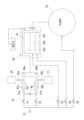
図6は、洗濯機1における液剤の自動投入、および液剤または粉末洗剤の手動投入方法を説明するためのブロック図である。図6に示すように、給水ホース接続口13から給水される水道水は、給水弁V1~V5を有する5連の弁機構33によって給水経路の切り替えが受けられるようになっている。
Figure 6 is a block diagram for explaining the automatic addition of liquid agents to the
給水弁V1,V2は、液剤タンク(洗剤タンク20および柔軟剤タンク21)から液剤の自動投入を行う場合に使用される(液剤の自動投入時には、給水弁V3~V5は閉状態とされる)。給水弁V1は、負圧管41aを介して洗剤交換室42aに接続されている。給水弁V2は、負圧管41bを介して柔軟剤交換室42bに接続されている。負圧管41aと負圧管41bとは接続給水経路43で接続されており、負圧管41a,41bは、ベンチュリ効果によって接続給水経路43に負圧を発生させることができる。さらに、接続給水経路43には流量計44が配置されている。
The water supply valves V1 and V2 are used when liquid is automatically dispensed from the liquid tanks (
洗剤交換室42aには逆止弁45aを介して洗剤タンク20が接続されており、柔軟剤交換室42bには逆止弁45bを介して柔軟剤タンク21が接続されている。さらに、洗剤交換室42aの下流側にはフロート弁46aが設けられており、柔軟剤交換室42bの下流側にはフロート弁46bが設けられている。フロート弁46aおよび46b以降の給水経路は合流し、洗剤投入ケース30を介して洗濯槽50に接続されている。
The
まずは、洗剤タンク20から規定量の液体洗剤を自動投入する場合の自動投入動作を説明する。液体洗剤の自動投入動作における第1段階では、給水弁V1およびV2の両方を開きながら、給水ホース接続口13からの給水を行う。この給水により、給水弁V1、負圧管41a、洗剤交換室42a、およびフロート弁46aを介する給水経路と、給水弁V2、負圧管41b、柔軟剤交換室42b、およびフロート弁46bを介する給水経路とに水が流れる。すなわち、このときは、水道水がフロート弁46a,46bをそれぞれ押し上げて開状態とする。
First, the automatic dispensing operation when a specified amount of liquid detergent is automatically dispensed from the
この第1段階の動作では、洗剤交換室42aおよび柔軟剤交換室42bが水道水で満たされる。但し、逆止弁45aおよび45bは共に閉状態となっており、洗剤タンク20および柔軟剤タンク21から洗剤交換室42aおよび柔軟剤交換室42bへの液剤流入は生じない。また、接続給水経路43における流れも殆ど発生しない。
In this first stage of operation, the
第1段階の動作によって洗剤交換室42aおよび柔軟剤交換室42bが水道水で満たされると、給水弁V1およびV2が一旦閉じられ、フロート弁46a,46bが下がって閉状態となる。
When the
続く第2段階として、給水弁V2のみを開いて給水ホース接続口13からの給水を行う。これにより、給水弁V2、負圧管41b、柔軟剤交換室42b、およびフロート弁46bを介する給水経路に水の流れが生じ、負圧管41bにおいて負圧が発生する。この負圧により、接続給水経路43では、負圧管41aから負圧管41bに向かっての水道水の流れが生じる。一方で、給水弁V1およびフロート弁46aは共に閉状態であるため、洗剤交換室42a内も負圧となり、この負圧によって逆止弁45aが開き、洗剤タンク20から洗剤交換室42aへ液体洗剤が引き込まれる。
In the second stage, only the water supply valve V2 is opened to supply water from the water supply
第2段階の動作では、接続給水経路43を流れた水道水と同量の液体洗剤が、洗剤タンク20から洗剤交換室42aへ引き込まれる。このため、第2段階では、接続給水経路43を流れる水道水の流量が流量計44によって計測され、流量計44の計測値が規定値に到達すると、給水弁V2を閉じて第2段階の動作を終了する。尚、第2段階の終了時点で、洗剤タンク20から引き込まれた液体洗剤は洗剤交換室42a内のみに留まっており、接続給水経路43へは流入していない。
In the second stage of operation, the same amount of liquid detergent as the tap water flowing through the connecting
続く第3段階では、再び給水弁V1およびV2の両方を開きながら、給水ホース接続口13からの給水を行う。これにより、洗剤交換室42aからは水道水と液体洗剤との混合液が洗濯槽50へ送られ、柔軟剤交換室42bからは水道水が洗濯槽50へ送られる。すなわち、上述の第2段階で洗剤交換室42aに引き込まれた液体洗剤が、第3段階において洗濯槽50へ投入される。全ての給水経路内の全てが水道水に置き換わるのに十分な量の給水が行われると、給水弁V1およびV2が閉じられ、液体洗剤の自動投入動作が終了する。
In the following third stage, water is supplied from the water supply
柔軟剤タンク21から規定量の柔軟剤を自動投入する場合の自動投入動作は、液体洗剤の自動投入動作と同様に行うことができる。但し、柔軟剤の自動投入動作では、第2段階において給水弁V1[のみが開かれる。これにより、柔軟剤の自動投入動作では、柔軟剤交換室42b側に負圧が発生し、逆止弁45bが開いて、柔軟剤タンク21から柔軟剤交換室42bへ柔軟剤が引き込まれる。
The automatic dispensing operation when automatically dispensing a specified amount of fabric softener from the
尚、上記説明では、洗剤または柔軟剤の自動投入動作における給水経路は、途中で洗剤投入ケース30を経由するものとされているが、手動投入ケース32(すなわち、液体洗剤投入部32a、粉末洗剤投入部32bおよび柔軟剤投入部32c)は経由しない。これにより、シャワー穴出口31aまたは31bの淵に液体洗剤や柔軟剤が残り、乾燥し堆積していくことを防止できる。また、洗剤または柔軟剤の自動投入動作における給水経路が、途中で洗剤投入ケース30を経由することも必須ではない。
In the above description, the water supply path in the automatic detergent or fabric softener dispensing operation passes through the
次に、洗剤または柔軟剤の手動投入動作について説明する。洗剤の手動投入時には、ユーザにより所定量の洗剤が手動投入ケース32に投入される。具体的には、液体洗剤は液体洗剤投入部32aに投入され、粉末洗剤は粉末洗剤投入部32bに投入される。このときの給水は、給水弁V3を開いて行われる。給水弁V3はシャワー穴出口31aに接続されており、液体洗剤投入部32aまたは粉末洗剤投入部32bに投入された洗剤を溶かしながら洗濯槽50に投入することができる。
Next, the operation of manually adding detergent or fabric softener will be described. When manually adding detergent, a predetermined amount of detergent is added to the
柔軟剤の手動投入時には、ユーザにより所定量の柔軟剤が手動投入ケース32の柔軟剤投入部32cに投入される。このときの給水は、給水弁V4を開いて行われる。給水弁V4はシャワー穴出口31bに接続されており、柔軟剤投入部32cに投入された柔軟剤を溶かしながら洗濯槽50に投入することができる。
When manually adding fabric softener, the user adds a predetermined amount of fabric softener to the fabric
給水弁V5は、洗濯槽50へシャワー給水を行うための給水弁である。洗濯槽50へシャワー給水は、洗濯槽50への注水時や、洗濯物の濯ぎ工程において利用できるものであるが、本発明において必須の構成ではない。
The water supply valve V5 is a water supply valve for supplying shower water to the
本実施の形態1に係る洗濯機1は、図4に示すような洗剤投入ケース30を有しており、洗剤投入ケース30の外部ケース31に、液剤の自動投入および液剤や粉末洗剤の手動投入を含めた給水経路が構成されている。これにより、液剤の自動投入機能を別のユニットの追加で実現する場合の、ユニット間の配管を省略することができ、製造コストの低減や耐久性の向上が期待できる。
The
また、本実施の形態1に係る洗剤投入ケース30では、洗剤タンク20および柔軟剤タンク21との接続口36aおよび36bが幅方向の中央側に寄せて配置されており、連結部37によって互いに幅方向に連結されている。また、連結部37は、シャワー穴出口31aおよび31bが形成された給水経路の天面38の上方に位置しており、連結部37と天面38とが接続部39を介して接続されている。このような構成とすることで、給水経路の天面38、接続部39および連結部37によって、洗剤タンク20および柔軟剤タンク21との接続口36aおよび36bを共に補強することができる。図6にも示すように、接続口36aおよび36bには逆止弁45aおよび45bがそれぞれ配されており、洗剤交換室42aおよび柔軟剤交換室42b内の圧力に応じて弁が開閉する。したがって、連結部37の形状が歪むと逆止弁45aおよび45bが正常に機能しなくなる恐れがある。一方で、接続口36aおよび36bには、洗剤タンク20や柔軟剤タンク21との水密性を維持するためにパッキンなどが配されているため、液剤タンクの着脱時に応力がかかりやすい。洗剤投入ケース30では、給水経路の天面38が連結部37を下から支持する構造となっているので、液剤タンクの着脱時にかかる上下方向の応力に対して、連結部37の変形を防止することができる。
In addition, in the
〔実施の形態2〕
上述した洗濯機1は、タンク収納領域Rtの前方に、図7に示すような板金部材60を有している。板金部材60は、洗濯機1の幅方向を長手方向としており、長手方向の両側にヒンジ取付部61を有している。また、ヒンジ取付部61から下方に延設した板金部材60の下端部には、上面板10との取付部62が設けられている。すなわち、洗濯機1において、洗濯物投入口を覆う上蓋11は、板金部材60のヒンジ取付部61に対して上蓋11のヒンジ軸が取り付けられ、板金部材60の取付部62が洗濯機1の上面板10に固定される。
[Embodiment 2]
The above-mentioned
これにより、上蓋11の開閉時において、ヒンジ軸に掛かる荷重は洗濯機1の幅方向に亘って配された板金部材60によって左右方向やねじれ方向の応力が吸収される。したがって、板金部材60の取付部62には左右で異なる応力がかかりにくくなるため、樹脂部材である上面板10に左右不均等の荷重がかかることを抑制できる。その結果、ヒンジ軸の荷重による上面板10の変形を抑制でき、洗剤タンク20および柔軟剤タンク21のタンク収納領域Rtが洗濯機1の幅方向の全幅に亘って配されていた場合であっても、上面板10における洗剤タンク20および柔軟剤タンク21の収納箇所の変形を抑制できる。
As a result, when the
今回開示した実施形態は全ての点で例示であって、限定的な解釈の根拠となるものではない。したがって、本発明の技術的範囲は、上記した実施形態のみによって解釈されるものではなく、特許請求の範囲の記載に基づいて画定される。また、特許請求の範囲と均等の意味および範囲内での全ての変更が含まれる。 The embodiments disclosed herein are illustrative in all respects and are not intended to be a basis for a restrictive interpretation. Therefore, the technical scope of the present invention is not to be interpreted solely by the above-described embodiments, but is defined based on the claims. Furthermore, all modifications within the scope and meaning equivalent to the claims are included.
1 洗濯機
10 上面板
11 上蓋
12 蓋
13 給水ホース接続口(給水ホース接続部)
20 洗剤タンク(液剤タンク)
21 柔軟剤タンク(液剤タンク)
30 洗剤投入ケース
31 外部ケース
31a,31b シャワー穴出口
32 手動投入ケース
32a 液体洗剤投入部
32b 粉末洗剤投入部
32c 柔軟剤投入部
33 弁機構
34 給水口
41a,41b 負圧管
42a 洗剤交換室
42b 柔軟剤交換室
43 接続給水経路
44 流量計
45a,45b 逆止弁
46a,46b フロート弁
50 洗濯槽
60 板金部材
61 ヒンジ取付部
Rt タンク収納領域
Rh 給水ホース領域
V1~V5 給水弁
1
20 Detergent tank (liquid agent tank)
21 Softener tank (liquid agent tank)
30
Claims (2)
前記液剤タンクは、当該洗濯機の幅方向を長手方向とする横長の形状を有しており、当該洗濯機の幅方向の全幅に亘って形成されたタンク収納領域に配置され、
前記タンク収納領域は、当該洗濯機の洗濯物投入口を覆う上蓋の後方に設けられ、
前記タンク収納領域の後方に、給水ホース接続部が設けられており、
前記タンク収納領域の前方に、当該洗濯機の幅方向を長手方向としており、長手方向の両側にヒンジ取付部を有する板金部材を有しており、前記ヒンジ取付部に対して前記上蓋のヒンジ軸が取り付けられており、
前記タンク収納領域の底部に設けられた前記液剤タンクとの接続口が、下方から支持される構造であることを特徴とする洗濯機。 A washing machine having a function of automatically dispensing a liquid agent into a washing tub and including a liquid agent tank for accommodating the liquid agent to be automatically dispensed,
The liquid agent tank has a horizontally elongated shape with the width direction of the washing machine as a longitudinal direction, and is disposed in a tank storage area formed across the entire width of the washing machine in the width direction;
The tank storage area is provided behind a top cover covering a laundry inlet of the washing machine,
A water supply hose connection portion is provided at the rear of the tank storage area,
A sheet metal member is provided in front of the tank storage area, the sheet metal member having a width direction of the washing machine as a longitudinal direction and a hinge mounting portion on both sides in the longitudinal direction, and a hinge shaft of the top cover is attached to the hinge mounting portion,
The washing machine is characterized in that a connection port to the liquid agent tank provided at the bottom of the tank storage area is supported from below.
前記液剤タンクを複数備えており、
前記複数の液剤タンクが、前記タンク収納領域において横並びに配置されており、
前記タンク収納領域の底部に設けられた複数の前記接続口が、互いに幅方向に連結された状態で下方から支持されていることを特徴とする洗濯機。 2. The washing machine according to claim 1 ,
The liquid agent tank is provided in a plurality of tanks,
The plurality of liquid agent tanks are arranged side by side in the tank storage area,
The washing machine is characterized in that the multiple connection ports provided at the bottom of the tank storage area are supported from below while being connected to each other in the width direction.
Priority Applications (2)
| Application Number | Priority Date | Filing Date | Title |
|---|---|---|---|
| JP2020191695A JP7625405B2 (en) | 2020-11-18 | 2020-11-18 | washing machine |
| CN202111356479.9A CN114517390A (en) | 2020-11-18 | 2021-11-16 | Washing machine |
Applications Claiming Priority (1)
| Application Number | Priority Date | Filing Date | Title |
|---|---|---|---|
| JP2020191695A JP7625405B2 (en) | 2020-11-18 | 2020-11-18 | washing machine |
Publications (2)
| Publication Number | Publication Date |
|---|---|
| JP2022080559A JP2022080559A (en) | 2022-05-30 |
| JP7625405B2 true JP7625405B2 (en) | 2025-02-03 |
Family
ID=81594873
Family Applications (1)
| Application Number | Title | Priority Date | Filing Date |
|---|---|---|---|
| JP2020191695A Active JP7625405B2 (en) | 2020-11-18 | 2020-11-18 | washing machine |
Country Status (2)
| Country | Link |
|---|---|
| JP (1) | JP7625405B2 (en) |
| CN (1) | CN114517390A (en) |
Families Citing this family (3)
| Publication number | Priority date | Publication date | Assignee | Title |
|---|---|---|---|---|
| KR20240077942A (en) * | 2022-11-25 | 2024-06-03 | 엘지전자 주식회사 | Laundry Treatment Apparatus |
| KR20240086410A (en) * | 2022-12-09 | 2024-06-18 | 엘지전자 주식회사 | Laundry treating apparatus |
| JP2024169080A (en) * | 2023-05-25 | 2024-12-05 | 青島海爾洗衣机有限公司 | Treatment liquid dispenser and washing machine |
Citations (4)
| Publication number | Priority date | Publication date | Assignee | Title |
|---|---|---|---|---|
| JP2000157782A (en) | 1998-11-30 | 2000-06-13 | Toshiba Corp | Washing machine |
| JP2017221326A (en) | 2016-06-14 | 2017-12-21 | 東芝ライフスタイル株式会社 | Washing machine |
| US20200248374A1 (en) | 2015-08-04 | 2020-08-06 | Whirlpool Corporation | Laundry treating appliance with internal housing |
| JP2020156794A (en) | 2019-03-27 | 2020-10-01 | 日立グローバルライフソリューションズ株式会社 | Washing machine |
-
2020
- 2020-11-18 JP JP2020191695A patent/JP7625405B2/en active Active
-
2021
- 2021-11-16 CN CN202111356479.9A patent/CN114517390A/en active Pending
Patent Citations (4)
| Publication number | Priority date | Publication date | Assignee | Title |
|---|---|---|---|---|
| JP2000157782A (en) | 1998-11-30 | 2000-06-13 | Toshiba Corp | Washing machine |
| US20200248374A1 (en) | 2015-08-04 | 2020-08-06 | Whirlpool Corporation | Laundry treating appliance with internal housing |
| JP2017221326A (en) | 2016-06-14 | 2017-12-21 | 東芝ライフスタイル株式会社 | Washing machine |
| JP2020156794A (en) | 2019-03-27 | 2020-10-01 | 日立グローバルライフソリューションズ株式会社 | Washing machine |
Also Published As
| Publication number | Publication date |
|---|---|
| CN114517390A (en) | 2022-05-20 |
| JP2022080559A (en) | 2022-05-30 |
Similar Documents
| Publication | Publication Date | Title |
|---|---|---|
| JP7625405B2 (en) | washing machine | |
| AU2012292157B2 (en) | Laundry washing machine with a water softening device | |
| JP3982821B2 (en) | Detergent supply device for washing machine | |
| AU2012292187B2 (en) | Laundry washing machine with a water softening device | |
| JP2016522729A (en) | Washing machine | |
| WO2005116322A1 (en) | Detergent container of washing machine | |
| KR101384759B1 (en) | Washing machine | |
| JP2020080918A (en) | Washing machine | |
| CN101063267B (en) | Drum washing machine with detergent input device | |
| TWI660092B (en) | Washing machine | |
| JP7469984B2 (en) | Fluid dosing units and washing machines | |
| JP5597007B2 (en) | Toilet device | |
| CN114369931B (en) | Clothes treating apparatus | |
| JP2022029495A (en) | Liquid agent charging unit and washing machine | |
| US11203832B2 (en) | Washing machine appliance and additive dispensing assembly | |
| CN110300824A (en) | Washing machine | |
| JP6041245B2 (en) | Washing machine | |
| JP7627633B2 (en) | Drum-type washing machine equipped with a water softener | |
| JP4382686B2 (en) | Finishing agent charging device for washing machine | |
| JP7628909B2 (en) | Clothes Processing Equipment | |
| JP7433399B2 (en) | washing machine | |
| TW202442970A (en) | Washing Machine | |
| JP2022029494A (en) | Detergent charging unit and washing machine | |
| TW202442971A (en) | Washing Machine | |
| JP2024016636A (en) | Washing machine and liquid agent supply unit |
Legal Events
| Date | Code | Title | Description |
|---|---|---|---|
| A621 | Written request for application examination |
Free format text: JAPANESE INTERMEDIATE CODE: A621 Effective date: 20230920 |
|
| A977 | Report on retrieval |
Free format text: JAPANESE INTERMEDIATE CODE: A971007 Effective date: 20240131 |
|
| A131 | Notification of reasons for refusal |
Free format text: JAPANESE INTERMEDIATE CODE: A131 Effective date: 20240206 |
|
| A521 | Request for written amendment filed |
Free format text: JAPANESE INTERMEDIATE CODE: A523 Effective date: 20240404 |
|
| A131 | Notification of reasons for refusal |
Free format text: JAPANESE INTERMEDIATE CODE: A131 Effective date: 20240723 |
|
| A521 | Request for written amendment filed |
Free format text: JAPANESE INTERMEDIATE CODE: A523 Effective date: 20240918 |
|
| A131 | Notification of reasons for refusal |
Free format text: JAPANESE INTERMEDIATE CODE: A131 Effective date: 20241105 |
|
| A521 | Request for written amendment filed |
Free format text: JAPANESE INTERMEDIATE CODE: A523 Effective date: 20241128 |
|
| TRDD | Decision of grant or rejection written | ||
| A01 | Written decision to grant a patent or to grant a registration (utility model) |
Free format text: JAPANESE INTERMEDIATE CODE: A01 Effective date: 20241224 |
|
| A61 | First payment of annual fees (during grant procedure) |
Free format text: JAPANESE INTERMEDIATE CODE: A61 Effective date: 20250122 |
|
| R150 | Certificate of patent or registration of utility model |
Ref document number: 7625405 Country of ref document: JP Free format text: JAPANESE INTERMEDIATE CODE: R150 |