JP7625139B2 - Color control using high frequency wavelength swept sources and phosphors - Google Patents
Color control using high frequency wavelength swept sources and phosphors Download PDFInfo
- Publication number
- JP7625139B2 JP7625139B2 JP2024516692A JP2024516692A JP7625139B2 JP 7625139 B2 JP7625139 B2 JP 7625139B2 JP 2024516692 A JP2024516692 A JP 2024516692A JP 2024516692 A JP2024516692 A JP 2024516692A JP 7625139 B2 JP7625139 B2 JP 7625139B2
- Authority
- JP
- Japan
- Prior art keywords
- light
- generating
- generating device
- luminescent material
- laser
- Prior art date
- Legal status (The legal status is an assumption and is not a legal conclusion. Google has not performed a legal analysis and makes no representation as to the accuracy of the status listed.)
- Active
Links
Images


Classifications
-
- F—MECHANICAL ENGINEERING; LIGHTING; HEATING; WEAPONS; BLASTING
- F21—LIGHTING
- F21V—FUNCTIONAL FEATURES OR DETAILS OF LIGHTING DEVICES OR SYSTEMS THEREOF; STRUCTURAL COMBINATIONS OF LIGHTING DEVICES WITH OTHER ARTICLES, NOT OTHERWISE PROVIDED FOR
- F21V9/00—Elements for modifying spectral properties, polarisation or intensity of the light emitted, e.g. filters
- F21V9/40—Elements for modifying spectral properties, polarisation or intensity of the light emitted, e.g. filters with provision for controlling spectral properties, e.g. colour, or intensity
-
- F—MECHANICAL ENGINEERING; LIGHTING; HEATING; WEAPONS; BLASTING
- F21—LIGHTING
- F21S—NON-PORTABLE LIGHTING DEVICES; SYSTEMS THEREOF; VEHICLE LIGHTING DEVICES SPECIALLY ADAPTED FOR VEHICLE EXTERIORS
- F21S10/00—Lighting devices or systems producing a varying lighting effect
- F21S10/02—Lighting devices or systems producing a varying lighting effect changing colors
- F21S10/023—Lighting devices or systems producing a varying lighting effect changing colors by selectively switching fixed light sources
-
- F—MECHANICAL ENGINEERING; LIGHTING; HEATING; WEAPONS; BLASTING
- F21—LIGHTING
- F21V—FUNCTIONAL FEATURES OR DETAILS OF LIGHTING DEVICES OR SYSTEMS THEREOF; STRUCTURAL COMBINATIONS OF LIGHTING DEVICES WITH OTHER ARTICLES, NOT OTHERWISE PROVIDED FOR
- F21V13/00—Producing particular characteristics or distribution of the light emitted by means of a combination of elements specified in two or more of main groups F21V1/00 - F21V11/00
- F21V13/02—Combinations of only two kinds of elements
-
- F—MECHANICAL ENGINEERING; LIGHTING; HEATING; WEAPONS; BLASTING
- F21—LIGHTING
- F21V—FUNCTIONAL FEATURES OR DETAILS OF LIGHTING DEVICES OR SYSTEMS THEREOF; STRUCTURAL COMBINATIONS OF LIGHTING DEVICES WITH OTHER ARTICLES, NOT OTHERWISE PROVIDED FOR
- F21V9/00—Elements for modifying spectral properties, polarisation or intensity of the light emitted, e.g. filters
- F21V9/30—Elements containing photoluminescent material distinct from or spaced from the light source
-
- H—ELECTRICITY
- H01—ELECTRIC ELEMENTS
- H01S—DEVICES USING THE PROCESS OF LIGHT AMPLIFICATION BY STIMULATED EMISSION OF RADIATION [LASER] TO AMPLIFY OR GENERATE LIGHT; DEVICES USING STIMULATED EMISSION OF ELECTROMAGNETIC RADIATION IN WAVE RANGES OTHER THAN OPTICAL
- H01S5/00—Semiconductor lasers
- H01S5/005—Optical components external to the laser cavity, specially adapted therefor, e.g. for homogenisation or merging of the beams or for manipulating laser pulses, e.g. pulse shaping
- H01S5/0087—Optical components external to the laser cavity, specially adapted therefor, e.g. for homogenisation or merging of the beams or for manipulating laser pulses, e.g. pulse shaping for illuminating phosphorescent or fluorescent materials, e.g. using optical arrangements specifically adapted for guiding or shaping laser beams illuminating these materials
-
- H—ELECTRICITY
- H05—ELECTRIC TECHNIQUES NOT OTHERWISE PROVIDED FOR
- H05B—ELECTRIC HEATING; ELECTRIC LIGHT SOURCES NOT OTHERWISE PROVIDED FOR; CIRCUIT ARRANGEMENTS FOR ELECTRIC LIGHT SOURCES, IN GENERAL
- H05B45/00—Circuit arrangements for operating light-emitting diodes [LED]
- H05B45/20—Controlling the colour of the light
-
- H—ELECTRICITY
- H05—ELECTRIC TECHNIQUES NOT OTHERWISE PROVIDED FOR
- H05B—ELECTRIC HEATING; ELECTRIC LIGHT SOURCES NOT OTHERWISE PROVIDED FOR; CIRCUIT ARRANGEMENTS FOR ELECTRIC LIGHT SOURCES, IN GENERAL
- H05B45/00—Circuit arrangements for operating light-emitting diodes [LED]
- H05B45/30—Driver circuits
- H05B45/32—Pulse-control circuits
- H05B45/325—Pulse-width modulation [PWM]
-
- F—MECHANICAL ENGINEERING; LIGHTING; HEATING; WEAPONS; BLASTING
- F21—LIGHTING
- F21V—FUNCTIONAL FEATURES OR DETAILS OF LIGHTING DEVICES OR SYSTEMS THEREOF; STRUCTURAL COMBINATIONS OF LIGHTING DEVICES WITH OTHER ARTICLES, NOT OTHERWISE PROVIDED FOR
- F21V5/00—Refractors for light sources
-
- F—MECHANICAL ENGINEERING; LIGHTING; HEATING; WEAPONS; BLASTING
- F21—LIGHTING
- F21Y—INDEXING SCHEME ASSOCIATED WITH SUBCLASSES F21K, F21L, F21S and F21V, RELATING TO THE FORM OR THE KIND OF THE LIGHT SOURCES OR OF THE COLOUR OF THE LIGHT EMITTED
- F21Y2115/00—Light-generating elements of semiconductor light sources
- F21Y2115/10—Light-emitting diodes [LED]
-
- F—MECHANICAL ENGINEERING; LIGHTING; HEATING; WEAPONS; BLASTING
- F21—LIGHTING
- F21Y—INDEXING SCHEME ASSOCIATED WITH SUBCLASSES F21K, F21L, F21S and F21V, RELATING TO THE FORM OR THE KIND OF THE LIGHT SOURCES OR OF THE COLOUR OF THE LIGHT EMITTED
- F21Y2115/00—Light-generating elements of semiconductor light sources
- F21Y2115/30—Semiconductor lasers
-
- H—ELECTRICITY
- H01—ELECTRIC ELEMENTS
- H01S—DEVICES USING THE PROCESS OF LIGHT AMPLIFICATION BY STIMULATED EMISSION OF RADIATION [LASER] TO AMPLIFY OR GENERATE LIGHT; DEVICES USING STIMULATED EMISSION OF ELECTROMAGNETIC RADIATION IN WAVE RANGES OTHER THAN OPTICAL
- H01S5/00—Semiconductor lasers
- H01S5/30—Structure or shape of the active region; Materials used for the active region
- H01S5/32—Structure or shape of the active region; Materials used for the active region comprising PN junctions, e.g. hetero- or double- heterostructures
- H01S5/323—Structure or shape of the active region; Materials used for the active region comprising PN junctions, e.g. hetero- or double- heterostructures in AIIIBV compounds, e.g. AlGaAs-laser, InP-based laser
- H01S5/32308—Structure or shape of the active region; Materials used for the active region comprising PN junctions, e.g. hetero- or double- heterostructures in AIIIBV compounds, e.g. AlGaAs-laser, InP-based laser emitting light at a wavelength less than 900 nm
- H01S5/32341—Structure or shape of the active region; Materials used for the active region comprising PN junctions, e.g. hetero- or double- heterostructures in AIIIBV compounds, e.g. AlGaAs-laser, InP-based laser emitting light at a wavelength less than 900 nm blue laser based on GaN or GaP
-
- H—ELECTRICITY
- H01—ELECTRIC ELEMENTS
- H01S—DEVICES USING THE PROCESS OF LIGHT AMPLIFICATION BY STIMULATED EMISSION OF RADIATION [LASER] TO AMPLIFY OR GENERATE LIGHT; DEVICES USING STIMULATED EMISSION OF ELECTROMAGNETIC RADIATION IN WAVE RANGES OTHER THAN OPTICAL
- H01S5/00—Semiconductor lasers
- H01S5/40—Arrangement of two or more semiconductor lasers, not provided for in groups H01S5/02 - H01S5/30
- H01S5/4025—Array arrangements, e.g. constituted by discrete laser diodes or laser bar
- H01S5/4087—Array arrangements, e.g. constituted by discrete laser diodes or laser bar emitting more than one wavelength
-
- H—ELECTRICITY
- H01—ELECTRIC ELEMENTS
- H01S—DEVICES USING THE PROCESS OF LIGHT AMPLIFICATION BY STIMULATED EMISSION OF RADIATION [LASER] TO AMPLIFY OR GENERATE LIGHT; DEVICES USING STIMULATED EMISSION OF ELECTROMAGNETIC RADIATION IN WAVE RANGES OTHER THAN OPTICAL
- H01S5/00—Semiconductor lasers
- H01S5/40—Arrangement of two or more semiconductor lasers, not provided for in groups H01S5/02 - H01S5/30
- H01S5/42—Arrays of surface emitting lasers
- H01S5/423—Arrays of surface emitting lasers having a vertical cavity
-
- H—ELECTRICITY
- H10—SEMICONDUCTOR DEVICES; ELECTRIC SOLID-STATE DEVICES NOT OTHERWISE PROVIDED FOR
- H10H—INORGANIC LIGHT-EMITTING SEMICONDUCTOR DEVICES HAVING POTENTIAL BARRIERS
- H10H20/00—Individual inorganic light-emitting semiconductor devices having potential barriers, e.g. light-emitting diodes [LED]
- H10H20/042—Superluminescent diodes
-
- H—ELECTRICITY
- H10—SEMICONDUCTOR DEVICES; ELECTRIC SOLID-STATE DEVICES NOT OTHERWISE PROVIDED FOR
- H10H—INORGANIC LIGHT-EMITTING SEMICONDUCTOR DEVICES HAVING POTENTIAL BARRIERS
- H10H20/00—Individual inorganic light-emitting semiconductor devices having potential barriers, e.g. light-emitting diodes [LED]
- H10H20/80—Constructional details
- H10H20/85—Packages
- H10H20/851—Wavelength conversion means
- H10H20/8511—Wavelength conversion means characterised by their material, e.g. binder
- H10H20/8512—Wavelength conversion materials
-
- H10W90/00—
Landscapes
- Physics & Mathematics (AREA)
- Spectroscopy & Molecular Physics (AREA)
- Engineering & Computer Science (AREA)
- General Engineering & Computer Science (AREA)
- Condensed Matter Physics & Semiconductors (AREA)
- General Physics & Mathematics (AREA)
- Electromagnetism (AREA)
- Optics & Photonics (AREA)
- Luminescent Compositions (AREA)
- Circuit Arrangement For Electric Light Sources In General (AREA)
Description
本発明は、光生成システムに関する。本発明は、更に、このような光生成システムを有する光生成デバイスに関する。 The present invention relates to a light generating system. The present invention further relates to a light generating device comprising such a light generating system.
垂直キャビティレーザを含むデバイスは、当技術分野においては知られている。例えば、WO2004/107512は、a)基板と、b)基板に垂直なレーザ光の白色ビームを発するために基板に形成される1つ以上の個別にアドレス指定可能なレーザ光ピクセルとを有する白色光レーザ集積構造であって、1つ以上の個別にアドレス指定可能なレーザ光ピクセルの各々が、1つ以上の有機発光ダイオード(OLED)と、1つ以上のOLEDによって光学的にポンピングされるよう配設される複数の有機垂直キャビティレーザとを含み、複数の有機垂直キャビティレーザが、 異なる色の光を発し、1つ以上の個別にアドレス指定可能なレーザ発光ピクセルが、異なる色の光が組み合わされるときに実質的に白色の光を発する白色光レーザ集積構造について記載している。複数の有機垂直キャビティレーザは、2つの異なる色の光を発する。 Devices including vertical cavity lasers are known in the art. For example, WO2004/107512 describes a white light laser integrated structure having a) a substrate and b) one or more individually addressable laser light pixels formed in the substrate for emitting a white beam of laser light perpendicular to the substrate, each of the one or more individually addressable laser light pixels including one or more organic light emitting diodes (OLEDs) and a plurality of organic vertical cavity lasers arranged to be optically pumped by the one or more OLEDs, the plurality of organic vertical cavity lasers emitting different colors of light, and the one or more individually addressable laser emitting pixels emitting substantially white light when the different colors of light are combined. The plurality of organic vertical cavity lasers emit light of two different colors.
白色LED光源は、例えば約300lm/mm2までの強度を与えることができるが、静的蛍光体変換レーザ白色光源は、約20.000lm/mm2までの強度さえ与えることができる。Ceドープガーネット(例えば、YAG、LuAG)は、ガーネット母材が非常に高い化学的安定性を有するので、青色レーザ光でポンピングするために使用されることができる最も適切なルミネッセンス変換器であり得る。更に、(例えば、0.5%未満の)低いCe濃度では、温度消光は、約200℃超でしか生じない可能性がある。更に、Ceからの発光は、非常に速い減衰時間を持ち、故に、光飽和の発生が本質的に防止されることができる。例えば反射モード動作と仮定すると、青色レーザ光が、蛍光体に入射する可能性がある。これは、実施形態においては、変換光の発光をもたらす、青色光のほぼ完全な変換を実現する可能性がある。相対的に高い安定性及び熱伝導率を備えるガーネット蛍光体の使用が提案されるのは、この理由のためである。しかしながら、他の蛍光体も適用され得る。極めて高い出力密度が使用される場合、熱管理は依然として課題であり得る。 A white LED light source can provide an intensity of, for example, up to about 300 lm/mm2, whereas a static phosphor-converted laser white light source can provide an intensity of even up to about 20.000 lm/ mm2 . Ce-doped garnets (e.g. YAG, LuAG) may be the most suitable luminescence converters that can be used to pump with blue laser light, since the garnet host material has a very high chemical stability. Furthermore, at low Ce concentrations (e.g. below 0.5%), temperature quenching may only occur above about 200°C. Furthermore, the emission from Ce has a very fast decay time, so that the occurrence of light saturation can be essentially prevented. Assuming, for example, a reflection mode operation, blue laser light may be incident on the phosphor. This may, in an embodiment, achieve an almost complete conversion of the blue light, resulting in the emission of the converted light. It is for this reason that the use of garnet phosphors with relatively high stability and thermal conductivity is proposed. However, other phosphors may also be applied. When extremely high power densities are used, thermal management can still be a challenge.
高輝度光源は、投影、ステージ照明、スポット照明、自動車用照明などの用途において使用されることができる。この目的のために、レーザがレーザ光を供給し、例えば(遠隔)蛍光体がレーザ光を変換光に変換するレーザ・蛍光体技術が使用され得る。前記蛍光体は、実施形態においては、熱管理の改善のために、従って、より高い輝度のために、ヒートシンク上に配設されてもよく、又はヒートシンクに挿入されてもよい。 High brightness light sources can be used in applications such as projection, stage lighting, spot lighting, automotive lighting, etc. For this purpose, laser-phosphor technology can be used, where a laser provides the laser light and e.g. a (remote) phosphor converts the laser light into converted light. The phosphor may in embodiments be disposed on or inserted into a heat sink for improved thermal management and thus higher brightness.
このような(レーザ)光源に関連し得る問題のうちの1つは、(セラミック)蛍光体の熱管理である。このようなレーザ光源に関連する他の問題は、コンパクトな高出力デバイスを作成したいという要望であり得る。更に、波長調整可能である光源を提供することは望ましいと思われる。しかしながら、一般に、レーザベースの光源は波長調整可能ではない。 One of the problems that may be associated with such (laser) light sources is the thermal management of the (ceramic) phosphor. Another problem associated with such laser light sources may be the desire to create compact high power devices. Furthermore, it would be desirable to provide a light source that is wavelength tunable. However, laser-based light sources are generally not wavelength tunable.
従って、代替光生成システムを提供することが、本発明の或る態様であり、前記代替光生成システムは、好ましくは、更に、上記の不利な点のうちの1つ以上を少なくとも部分的に取り除く。本発明は、従来技術の不利な点のうちの少なくとも1つを解消若しくは改善すること、又は有用な代替手段を提供することを目的とし得る。 It is therefore an aspect of the present invention to provide an alternative light generating system, which preferably also at least partially obviates one or more of the above disadvantages. The present invention may aim to eliminate or ameliorate at least one of the disadvantages of the prior art, or to provide a useful alternative.
或る態様においては、本発明は、第1光生成デバイスと、第2光生成デバイスと、ルミネッセンス材料とを有する光生成システム(「システム」)を提供する。特には、前記第1光生成デバイスは、第1デバイス光を生成するよう構成され得る。更に、特には、前記第2光生成デバイスは、第2デバイス光を生成するよう構成され得る。更に、特には、(前記システムの動作モードにおいて)、前記第1デバイス光と、前記第2デバイス光とが、異なるスペクトルパワー分布を持つ。更に、特には、前記ルミネッセンス材料は、(a)前記第1デバイス光及び(b)前記第2デバイス光のうちの1つ以上の少なくとも一部をルミネッセンス材料光に変換するよう構成され得る。特には、前記第1光生成デバイスは、波長可変光生成デバイスを含み得る。前記波長可変光生成デバイスは、前記光生成システムの動作モードにおいて、(前記第1光の)少なくとも2つの重心波長(λ1c,1、λ1c,2)の間で変化する第1デバイス光を生成するよう構成され得る。特には、前記2つの重心波長は、少なくとも20nmなどの、少なくとも10nmの波長差を持ち得る。更に、前記波長可変光生成デバイスは、前記光生成システムの動作モードにおいて、少なくとも40Hzの、特に少なくとも50Hzの変化周波数で、少なくとも2つの重心波長(λ1c,1、λ1c,2)の間で変化する第1デバイス光を生成するよう構成され得る。更に、前記光生成システムは、前記光生成システムの前記動作モードにおいて、前記ルミネッセンス材料光、並びに前記第1デバイス光及び前記第2デバイス光のうちの少なくとも1つを含む白色システム光を生成するよう構成され得る。特には、実施形態において、本発明は、第1光生成デバイスと、第2光生成デバイスと、ルミネッセンス材料とを有する光生成システムであって、(A)前記第1光生成デバイスが、第1デバイス光を生成するよう構成され、前記第2光生成デバイスが、第2デバイス光を生成するよう構成され、前記第1デバイス光と、前記第2デバイス光とが、異なるスペクトルパワー分布を持ち、(B)前記ルミネッセンス材料が、前記第1デバイス光及び前記第2デバイス光のうちの1つ以上の少なくとも一部をルミネッセンス材料光に変換するよう構成され、(C)前記第1光生成デバイスが、前記光生成システムの動作モードにおいて、少なくとも40Hzの変化周波数で、少なくとも10nmの波長差を持つ少なくとも2つの重心波長(λ1c,1、λ1c,2)の間で変化する第1デバイス光を生成するよう構成される波長可変光生成デバイスを有し、(D)前記光生成システムが、前記光生成システムの前記動作モードにおいて、前記ルミネッセンス材料光、並びに前記第1デバイス光及び前記第2デバイス光(のうちの少なくとも1つ)を含む白色システム光を生成するよう構成される光生成システムを提供する。 In one aspect, the present invention provides a light generation system ("system") comprising a first light generation device, a second light generation device, and a luminescent material. In particular, the first light generation device may be configured to generate a first device light. Further, in particular, the second light generation device may be configured to generate a second device light. Further, in particular, the first device light and the second device light (in an operation mode of the system) have different spectral power distributions. Further, in particular, the luminescent material may be configured to convert at least a portion of one or more of (a) the first device light and (b) the second device light into luminescent material light. In particular, the first light generation device may include a tunable light generation device. The tunable light generation device may be configured to generate a first device light that varies between at least two centroid wavelengths (λ 1c,1 , λ 1c,2 ) (of the first light) in an operation mode of the light generation system. In particular, the two centroid wavelengths may have a wavelength difference of at least 10 nm, such as at least 20 nm. Furthermore, the tunable light generating device may be configured to generate a first device light that varies between at least two centroid wavelengths (λ 1c,1 , λ 1c,2 ) with a variation frequency of at least 40 Hz, in particular at least 50 Hz, in an operation mode of the light generating system. Furthermore, the light generating system may be configured to generate a white system light comprising the luminescent material light and at least one of the first device light and the second device light in the operation mode of the light generating system. In particular, in an embodiment, the present invention provides a light generation system having a first light-generating device, a second light-generating device, and a luminescent material, wherein (A) the first light-generating device is configured to generate a first device light and the second light-generating device is configured to generate a second device light, the first device light and the second device light having different spectral power distributions, (B) the luminescent material is configured to convert at least a portion of one or more of the first device light and the second device light into luminescent material light, and (C) the first light-generating device is configured to convert at least two centroid wavelengths (λ 1c,1 , λ 1c,2 ) having a wavelength difference of at least 10 nm with a variation frequency of at least 40 Hz in an operation mode of the light generation system. ), and (D) the light-generation system is configured to generate white system light comprising the luminescent material light, and (at least one of) the first device light and the second device light in the operational mode of the light-generation system.
このようなシステムでは、限られた数の光源で相対的に大きな色域及び/又は相対的に大きなCCT調整可能性を提供することが可能である。更に、このようなシステムでは、(実質的に黒体軌跡に沿って)制御可能なCCTを持つ白色光を供給することが可能であり得る。更に、限られた数の光源で、相対的に高いCRIが提供され得る。更に、相対的に強い光が前記システムで供給され得る。 In such a system, it is possible to provide a relatively large color gamut and/or a relatively large CCT tunability with a limited number of light sources. Furthermore, it may be possible with such a system to provide white light with a controllable CCT (substantially along the blackbody locus). Furthermore, a relatively high CRI may be provided with a limited number of light sources. Furthermore, a relatively intense light may be provided with the system.
上記のように、前記光生成システムは、特には、第1光生成デバイスと、第2光生成デバイスと、ルミネッセンス材料とを含み得る。 As mentioned above, the light generating system may include, inter alia, a first light generating device, a second light generating device, and a luminescent material.
特には、前記第1光生成デバイスは、第1デバイス光を生成するよう構成される。更に、特には、前記第2光生成デバイスは、第2デバイス光を生成するよう構成される。特には、前記システムの動作モードにおいて、前記第1デバイス光と、前記第2デバイス光とが、異なるスペクトルパワー分布を持つ。 In particular, the first light-generating device is configured to generate a first device light. Further in particular, the second light-generating device is configured to generate a second device light. In particular, in an operating mode of the system, the first device light and the second device light have different spectral power distributions.
前記第1光生成デバイスは、1つ以上の(第1)光源、より特には1つ以上の(第1)固体光源を含み得る。更に、前記第1光生成デバイスは、光学系を有してもよい。前記1つ以上の光源から脱出する、光、即ち、(前記1つ以上の第1光源からの)第1光源光は、実施形態においては、前記光学系を介してビーム成形されてもよい。第1デバイス光は、特には、前記第1光源光を含み得る。より特には、前記第1デバイス光は、前記1つ以上の第1光源の前記(第1光源)光から成り得る。 The first light-generating device may include one or more (first) light sources, more particularly one or more (first) solid-state light sources. Furthermore, the first light-generating device may have an optical system. Light escaping from the one or more light sources, i.e., first light source light (from the one or more first light sources), may be beam-shaped through the optical system in an embodiment. The first device light may include, in particular, the first light source light. More particularly, the first device light may consist of the (first light source) light of the one or more first light sources.
前記第2光生成デバイスは、1つ以上の(第2)光源、より特には1つ以上の(第2)固体光源を含み得る。更に、前記第2光生成デバイスは、光学系を有してもよい。前記1つ以上の光源から脱出する、光、即ち、(前記1つ以上の第2光源からの)第2光源光は、実施形態においては、前記光学系を介してビーム成形されてもよい。第2デバイス光は、特には、前記第2光源光を含み得る。より特には、前記第2デバイス光は、前記1つ以上の第2光源の前記(第2光源)光から成り得る。 The second light-generating device may include one or more (second) light sources, more particularly one or more (second) solid-state light sources. Furthermore, the second light-generating device may have an optical system. The light escaping from the one or more light sources, i.e. the second light source light (from the one or more second light sources), may be beam-shaped through the optical system in an embodiment. The second device light may include, in particular, the second light source light. More particularly, the second device light may consist of the (second light source) light of the one or more second light sources.
以下では、前記第1光生成デバイス(の前記光源)及び前記第2光生成デバイス(の前記光源)に適用され得る、光源に関する幾つかの一般的な態様について説明する。 The following describes some general aspects of light sources that may be applied to the first light-generating device (the light source of the first light-generating device) and the second light-generating device (the light source of the second light-generating device).
「光源」という用語は、原則として、当技術分野において知られている任意の光源に関し得る。それは、従来の(タングステン)電球、低圧水銀ランプ、高圧水銀ランプ、蛍光灯、LED(発光ダイオード)であってもよい。 The term "light source" may in principle relate to any light source known in the art. It may be a conventional (tungsten) bulb, a low-pressure mercury lamp, a high-pressure mercury lamp, a fluorescent lamp, an LED (light-emitting diode).
特定の実施形態においては、前記光源は、(LED又はレーザダイオード(若しくは「ダイオードレーザ」)などの)固体LED光源を有する。 In certain embodiments, the light source comprises a solid-state LED light source (such as an LED or a laser diode (or "diode laser")).
「光源」という用語は、2乃至200個の(固体)LED光源などの複数の光源に関することもある。従って、LEDという用語は、複数のLEDを指すこともある。更に、「光源」という用語は、実施形態においては、所謂チップオンボード(COB)光源を指すこともある。「COB」という用語は、特に、包まれてもおらず、接続されてもおらず、PCBのような基板上に直接取り付けられている半導体チップの形態のLEDチップを指す。従って、複数の発光半導体光源が同じ基板に構成されてもよい。実施形態においては、COBは、単一の照明モジュールとして一緒に構成されるマルチLEDチップである。 The term "light source" may also relate to a plurality of light sources, such as 2 to 200 (solid-state) LED light sources. Thus, the term LED may also refer to a plurality of LEDs. Furthermore, the term "light source" may also refer in embodiments to so-called chip-on-board (COB) light sources. The term "COB" in particular refers to an LED chip in the form of a semiconductor chip that is not encapsulated or connected but is directly mounted on a substrate such as a PCB. Thus, several light-emitting semiconductor light sources may be arranged on the same substrate. In an embodiment, the COB is a multi-LED chip arranged together as a single lighting module.
前記光源は、光脱出面(light escape surface)を有する。電球又は蛍光灯のような従来の光源に関しては、前記光脱出面は、ガラス又は石英のエンベロープの外面であり得る。LEDの場合は、前記光脱出面は、例えば前記LEDダイであり得る、又は前記LEDダイに樹脂が塗布される場合、前記樹脂の外面であり得る。原理上、前記光脱出面は、ファイバの終端である可能性もある。脱出面という用語は、特に、前記光源の、光が実際に前記光源から出る又は脱出する部分に関する。前記光源は、光ビームを供給するよう構成される。(従って)前記光源の光出射面からこの光ビームが脱出する。 The light source has a light escape surface. For conventional light sources like light bulbs or fluorescent lamps, the light escape surface can be the outer surface of a glass or quartz envelope. In the case of LEDs, the light escape surface can be for example the LED die or the outer surface of a resin if the resin is applied to the LED die. In principle, the light escape surface can also be the end of a fiber. The term escape surface particularly relates to the part of the light source where the light actually leaves or escapes from the light source. The light source is configured to provide a light beam. This light beam escapes from the light exit surface of the light source.
同様に、光生成デバイスは、端部窓(end window)などの光脱出面を含み得る。更に、同様に、光生成システムは、端部窓などの光脱出面を含み得る。 Similarly, the light generating device may include a light escape surface, such as an end window. Similarly, the light generating system may include a light escape surface, such as an end window.
「光源」という用語は、発光ダイオード(LED)、共振空洞発光ダイオード(RCLED)、垂直キャビティレーザダイオード(VCSEL)、端面発光レーザなどのような半導体発光デバイスを指し得る。「光源」という用語は、パッシブマトリクス(PMOLED)又はアクティブマトリクス(AMOLED)などの有機発光ダイオード(OLED)を指すこともある。特定の実施形態においては、前記光源は、(LED又はレーザダイオードなどの)固体光源を有する。実施形態においては、前記光源は、LED(発光ダイオード)を有する。「光源」又は「固体光源」という用語は、スーパールミネッセントダイオード(superluminescent diode)(SLED)を指すこともある。 The term "light source" may refer to a semiconductor light emitting device such as a light emitting diode (LED), a resonant cavity light emitting diode (RCLED), a vertical cavity laser diode (VCSEL), an edge emitting laser, etc. The term "light source" may also refer to an organic light emitting diode (OLED), such as a passive matrix (PMOLED) or active matrix (AMOLED). In certain embodiments, the light source comprises a solid state light source (such as an LED or a laser diode). In embodiments, the light source comprises an LED (light emitting diode). The term "light source" or "solid state light source" may also refer to a superluminescent diode (SLED).
LEDという用語は、複数のLEDを指すこともある。更に、「光源」という用語は、実施形態においては、所謂チップオンボード(COB)光源を指すこともある。「COB」という用語は、特に、包まれてもおらず、接続されてもおらず、PCBのような基板上に直接取り付けられている半導体チップの形態のLEDチップを指す。従って、複数の半導体光源が同じ基板に構成されてもよい。実施形態においては、COBは、単一の照明モジュールとして一緒に構成されるマルチLEDチップである。 The term LED may also refer to multiple LEDs. Furthermore, the term "light source" may also refer in embodiments to so-called chip-on-board (COB) light sources. The term "COB" refers in particular to LED chips in the form of semiconductor chips that are not encapsulated or connected but are directly mounted on a substrate such as a PCB. Thus, multiple semiconductor light sources may be configured on the same substrate. In embodiments, a COB is a multi-LED chip that is configured together as a single lighting module.
「光源」という用語は、2乃至2000個の固体光源などの複数の(本質的に同一の(又は異なる))光源に関することもある。実施形態においては、前記光源は、LEDなどの単一の固体光源の下流に、又は複数の固体光源の下流に(即ち、例えば複数のLEDによって共有される)、1つ以上のマイクロ光学要素(マイクロレンズのアレイ)を有してもよい。実施形態においては、前記光源は、オンチップ光学系を備えるLEDを有してもよい。実施形態においては、前記光源は、(実施形態においては、オンチップビームステアリングを提供する)(光学系を備える又は備えない)ピクセル化された単一のLEDを有する。 The term "light source" may also refer to multiple (essentially identical (or different)) light sources, such as 2-2000 solid-state light sources. In embodiments, the light source may comprise one or more micro-optical elements (array of microlenses) downstream of a single solid-state light source, such as an LED, or downstream of multiple solid-state light sources (i.e., shared by multiple LEDs, for example). In embodiments, the light source may comprise an LED with on-chip optics. In embodiments, the light source comprises a single pixelated LED (with or without optics) (in embodiments providing on-chip beam steering).
実施形態においては、例えば、青色LEDのような青色光源、又は緑色LEDのような緑色光源、及び赤色LEDのような赤色光源などの、前記光源は、その自体として使用される一次放射線を供給するよう構成されてもよい。ルミネッセンス材料(「蛍光体」)を含まないことがある、このようなLEDは、ダイレクトカラーLED(direct color LED)と示されることがある。 In an embodiment, the light source may be configured to provide a primary radiation that is used as such, e.g., a blue light source such as a blue LED, or a green light source such as a green LED, and a red light source such as a red LED. Such LEDs, which may not include a luminescent material ("phosphor"), may be denoted direct color LEDs.
しかしながら、他の実施形態においては、前記光源は、一次放射線を供給するよう構成されてもよく、前記一次放射線の一部は、二次放射線に変換される。二次放射線は、ルミネッセンス材料による変換に基づき得る。それ故、前記二次放射線は、ルミネッセンス材料放射線と示されることもある。前記ルミネッセンス材料は、実施形態においては、ルミネッセンス材料を含むルミネッセンス材料層又はドームを備えるLEDなどの、前記光源によって含まれてもよい。このようなLEDは、蛍光体変換LED又はPC LED(phosphor converted LED)と示されることがある。他の実施形態においては、前記ルミネッセンス材料は、前記LEDのダイと物理的に接触していないルミネッセンス材料層を備えるLEDのように、前記光源から幾らかの距離を置いて(「遠隔」に)構成されてもよい。従って、特定の実施形態においては、前記光源は、動作中、少なくとも、380乃至470nmの範囲から選択される波長において光を発する光源であり得る。しかしながら、他の波長も可能であり得る。この光は、部分的に、前記ルミネッセンス材料によって使用され得る。 However, in other embodiments, the light source may be configured to provide a primary radiation, a portion of which is converted into a secondary radiation. The secondary radiation may be based on conversion by a luminescent material. The secondary radiation may therefore also be referred to as luminescent material radiation. The luminescent material may be included by the light source, in embodiments, such as an LED with a luminescent material layer or dome that includes the luminescent material. Such an LED may be referred to as a phosphor converted LED or PC LED. In other embodiments, the luminescent material may be configured at some distance from the light source ("remote"), such as an LED with a luminescent material layer that is not in physical contact with the LED die. Thus, in certain embodiments, the light source may be a light source that, in operation, emits light at a wavelength selected from the range of at least 380 to 470 nm. However, other wavelengths may also be possible. This light may be used, in part, by the luminescent material.
実施形態においては、前記光生成デバイスは、ルミネッセンス材料を有してもよい。実施形態においては、前記光生成デバイスは、PC LEDを有してもよい。他の実施形態においては、前記光生成デバイスは、直射LED(direct LED)(即ち、蛍光体なし)を有してもよい。実施形態においては、前記光生成デバイスは、レーザダイオードのような、レーザデバイスを有してもよい。実施形態においては、前記光生成デバイスは、スーパールミネッセントダイオードを有してもよい。従って、特定の実施形態においては、前記光源は、レーザダイオード及びスーパールミネッセントダイオードのグループから選択されてもよい。他の実施形態においては、前記光源は、LEDを有してもよい。 In embodiments, the light generating device may comprise a luminescent material. In embodiments, the light generating device may comprise a PC LED. In other embodiments, the light generating device may comprise a direct LED (i.e., no phosphor). In embodiments, the light generating device may comprise a laser device, such as a laser diode. In embodiments, the light generating device may comprise a superluminescent diode. Thus, in certain embodiments, the light source may be selected from the group of laser diodes and superluminescent diodes. In other embodiments, the light source may comprise an LED.
前記光源は、特に、光軸(O)、(ビーム形状、)及びスペクトルパワー分布を有する光源光を生成するよう構成され得る。前記光源光は、実施形態においては、レーザについて知られているような帯域幅を有する、1つ以上の帯域を有し得る。 The light source may be configured to generate a source light having, among other things, an optical axis (O), a (beam shape), and a spectral power distribution. The source light may, in embodiments, have one or more bands having a bandwidth as known for lasers.
「光源」という用語は、(従って、)例えば固体光源のような光生成要素それ自体を指すことがあり、又は例えば、固体光源などの前記光生成要素、並びにルミネッセンス材料を含む要素、及びレンズ、コリメータのような(他の)光学系のうちの1つ以上のパッケージを指すことがある。光変換要素(「変換要素」又は「変換器」)は、ルミネッセンス材料を含む要素を有してもよい。例えば、青色LEDのような固体光源それ自体は、光源である。青色LEDと光変換要素との組み合わせなどの、(光生成要素のような)固体光源と、前記固体光源に光学的に結合される光変換要素との組み合わせは、光源であることもある(が、光生成デバイスと示されることもある)。従って、白色LEDは、光源である(が、例えば(白色)光生成デバイスと示されることもある)。 The term "light source" may therefore refer to the light generating element itself, e.g. a solid-state light source, or may refer to a package of one or more of said light generating element, e.g. a solid-state light source, and an element comprising a luminescent material, and (other) optics, e.g. lenses, collimators. A light conversion element ("conversion element" or "converter") may have an element comprising a luminescent material. A solid-state light source, e.g. a blue LED, is itself a light source. A combination of a solid-state light source (e.g. a light generating element) and a light conversion element optically coupled to said solid-state light source, e.g. a blue LED and a light conversion element, may also be a light source (but may also be denoted as a light generating device). A white LED is therefore a light source (but may also be denoted as a (white) light generating device).
「光源」という用語は、本明細書においては、LED又はレーザダイオード又はスーパールミネッセントダイオードなどの固体光源を含む光源を指すこともある。 The term "light source" as used herein may refer to light sources including solid-state light sources such as LEDs or laser diodes or superluminescent diodes.
「光源」という用語は、(従って、)実施形態においては、ルミネッセンス変換材料と組み合わせた光源などの、光の変換に(も)基づいている光源を指すこともある。従って、「光源」という用語は、LEDと、前記LEDの放射線の少なくとも一部を変換するよう構成されるルミネッセンス材料の組み合わせ、又は(ダイオード)レーザと、前記(ダイオード)レーザの放射線の少なくとも一部を変換するよう構成されるルミネッセンス材料の組み合わせを指すこともある。 The term "light source" may therefore also refer, in embodiments, to a light source that is (also) based on the conversion of light, such as a light source in combination with a luminescence conversion material. The term "light source" may therefore also refer to a combination of an LED and a luminescent material configured to convert at least a portion of the radiation of the LED, or a combination of a (diode) laser and a luminescent material configured to convert at least a portion of the radiation of the (diode) laser.
実施形態においては、「光源」という用語は、LEDのような光源と、前記光源によって生成される光のスペクトルパワー分布を変化させ得る光学フィルタとの組み合わせを指すこともある。特に、「光生成デバイス」は、光源、並びに光学フィルタ及び/又はビーム成形要素などのような更なる光学的構成要素を扱うために使用されることがある。 In embodiments, the term "light source" may refer to a combination of a light source, such as an LED, and an optical filter that may change the spectral power distribution of the light generated by the light source. In particular, the term "light generating device" may be used to refer to a light source and further optical components, such as optical filters and/or beam shaping elements.
「異なる光源」又は「複数の異なる光源」という語句、及び同様の語句は、実施形態においては、少なくとも2つの異なるビン(bin)から選択される複数の固体光源を指し得る。同様に、「同一の光源」又は「複数の同じ光源」という語句、及び同様の語句は、実施形態においては、同じビンから選択される複数の固体光源を指し得る。 The phrases "different light sources" or "multiple different light sources" and similar phrases may refer, in embodiments, to multiple solid-state light sources selected from at least two different bins. Similarly, the phrases "same light source" or "multiple identical light sources" and similar phrases may refer, in embodiments, to multiple solid-state light sources selected from the same bin.
「固体光源」又は「固体材料光源」という用語、及び同様の用語は、特に、発光ダイオード(LED)、ダイオードレーザ、又はスーパールミネッセントダイオードなどの半導体光源を指し得る。 The terms "solid-state light source" or "solid-state material light source" and similar terms may refer, among other things, to semiconductor light sources such as light-emitting diodes (LEDs), diode lasers, or superluminescent diodes.
「レーザ光源」という用語は、特にレーザを指す。このようなレーザは、特に、UV、可視、又は赤外において1つ以上の波長を有する、特に、300乃至1500nmなどの、200乃至2000nmのスペクトル波長範囲から選択される波長を有するレーザ光源光を生成するよう構成され得る。「レーザ」という用語は、特に、電磁放射線の誘導放出に基づく光増幅のプロセスを通して光を発するデバイスを指す。 The term "laser source" refers in particular to a laser. Such a laser may be configured to generate laser source light having one or more wavelengths in the UV, visible, or infrared, in particular having a wavelength selected from the spectral wavelength range of 200 to 2000 nm, such as 300 to 1500 nm. The term "laser" refers in particular to a device that emits light through a process of light amplification based on stimulated emission of electromagnetic radiation.
特に、実施形態においては、「レーザ」という用語は、固体レーザを指し得る。特定の実施形態においては、「レーザ」若しくは「レーザ光源」という用語、又は同様の用語は、レーザダイオード(又はダイオードレーザ)を指す。 In particular, in embodiments, the term "laser" may refer to a solid-state laser. In certain embodiments, the term "laser" or "laser source" or similar terms refer to a laser diode (or diode laser).
従って、実施形態においては、前記光源は、レーザ光源を有する。実施形態においては、「レーザ」又は「固体レーザ」又は「固体材料レーザ」という用語は、セリウムドープリチウムストロンチウム(又はカルシウム)フッ化アルミニウム(Ce:LiSAF、Ce:LiCAF)、クロムドープクリソベリル(アレキサンドライト)レーザ、クロムZnSe(Cr:ZnSe)レーザ、二価サマリウムドープフッ化カルシウム(Sm:CaF2)レーザ、Er:YAGレーザ、エルビウムドープ及びエルビウムイッテルビウムコドープガラスレーザ、F-センターレーザ、ホルミウム(Ho:YAG)レーザ、Nd:YAGレーザ、NdCrYAGレーザ、ネオジウムドープイットリウムカルシウムオキソボレートNd:YCa4O(BO3)3又はNd:YCOB、ネオジウムドープオルトバナジウム酸イットリウム(Nd:YVO4)レーザ、ネオジウムガラス(Nd:ガラス)レーザ、ネオジウムYLF(Nd:YLF)固体レーザ、プロメチウム147ドープリン酸ガラス(147Pm3+:ガラス)固体レーザ、ルビーレーザ(Al2O3:Cr3+)、ツリウムYAG(Tm:YAG)レーザ、チタンサファイア(Ti:サファイア;Al2O3:Ti3+)レーザ、三価ウランドープフッ化カルシウム(U:CaF2)固体レーザ、イッテルビウムドープガラスレーザ(ロッド、プレート/チップ及びファイバ)、イッテルビウムYAG(Yb:YAG)レーザ、Yb2O3(ガラス又はセラミックス)レーザなどのうちの1つ以上を指し得る。 Thus, in an embodiment, the light source comprises a laser light source. In embodiments, the term "laser" or "solid-state laser" or "solid-state material laser" refers to a laser such as a cerium-doped lithium strontium (or calcium) aluminum fluoride (Ce:LiSAF, Ce:LiCAF), a chromium-doped chrysoberyl (alexandrite) laser, a chromium ZnSe (Cr:ZnSe) laser, a divalent samarium-doped calcium fluoride (Sm:CaF 2 ) laser, an Er:YAG laser, an erbium-doped and an erbium-ytterbium co-doped glass laser, an F-center laser, a holmium (Ho:YAG) laser, an Nd:YAG laser, an NdCrYAG laser, a neodymium-doped yttrium calcium oxoborate Nd:YCa 4 O(BO 3 ) 3 or Nd:YCOB, a neodymium-doped yttrium orthovanadate (Nd:YVO 4 ) , or a combination thereof. ) laser, neodymium glass (Nd:glass) laser, neodymium YLF (Nd:YLF) solid state laser, promethium 147 doped phosphate glass (147Pm 3+ :glass) solid state laser, ruby laser (Al 2 O 3 :Cr 3+ ), thulium YAG (Tm:YAG) laser, titanium sapphire (Ti:sapphire; Al 2 O 3 :Ti 3+ ) laser, trivalent uranium doped calcium fluoride (U:CaF 2 ) solid state laser, ytterbium doped glass laser (rod, plate/chip and fiber), ytterbium YAG (Yb:YAG) laser, Yb 2 O 3 (glass or ceramics) laser, etc.
例えば、第2及び第3高調波生成の実施形態を含めると、前記光源は、F中心レーザ(F center laser)、オルトバナジウム酸イットリウム(Nd:YVO4)レーザ、プロメチウム147ドープリン酸ガラス(147Pm3+:ガラス)、及びチタンサファイア(Ti:サファイア;Al2O3:Ti3+)レーザのうちの1つ以上を含み得る。例えば、第2及び第3高調波生成を考慮すると、このような光源は、青色光を生成するために使用され得る。 For example, including second and third harmonic generation embodiments, the light source may include one or more of an F center laser, an yttrium orthovanadate (Nd: YVO4 ) laser, a promethium-147 doped phosphate glass (147Pm3 + :glass), and a titanium sapphire (Ti:sapphire; Al2O3 :Ti3 + ) laser. For example, considering second and third harmonic generation, such a light source may be used to generate blue light.
実施形態においては、「レーザ」又は「固体レーザ」又は「固体材料レーザ」という用語は、GaN、InGaN、AlGaInP、AlGaAs、InGaAsP、鉛塩、垂直共振器面発光レーザ(vertical cavity surface emitting laser)(VCSEL)、量子カスケードレーザ、ハイブリッドシリコンレーザなどの半導体レーザダイオードのうちの1つ以上を指し得る。 In embodiments, the term "laser" or "solid-state laser" or "solid-state material laser" may refer to one or more of semiconductor laser diodes, such as GaN, InGaN, AlGaInP, AlGaAs, InGaAsP, lead salt, vertical cavity surface emitting laser (VCSEL), quantum cascade laser, hybrid silicon laser, etc.
レーザは、より短い(レーザ)波長に達するために、アップコンバータ(upconverter)と組み合わされてもよい。例えば、何らかの(三価)希土類イオンで、アップコンバージョン(upconversion)が達成され得る、又は非線形結晶で、アップコンバージョンが達成され得る。他の例においては、色素レーザなどのレーザは、より長い(レーザ)波長に達するために、ダウンコンバータ(downconverter)と組み合わされ得る。 A laser may be combined with an upconverter to reach shorter (laser) wavelengths. For example, upconversion can be achieved with some (trivalent) rare earth ions or with nonlinear crystals. In another example, a laser such as a dye laser can be combined with a downconverter to reach longer (laser) wavelengths.
以下から導き出され得るように、「レーザ光源」という用語は、複数の(異なる又は同一の)レーザ光源を指すこともある。特定の実施形態においては、「レーザ光源」という用語は、複数のN個の(同一の)レーザ光源を指し得る。実施形態においては、N=2以上である。特定の実施形態においては、Nは、特に少なくとも8などの、少なくとも5であり得る。このやり方においては、より高い輝度が得られ得る。実施形態においては、レーザ光源は、レーザバンク(laser bank)内に配設されてもよい(上記も参照)。前記レーザバンクは、実施形態においては、ヒートシンク、及び/又は光学系、例えば、レーザ光をコリメートするためのレンズを含んでもよい。 As can be derived from the following, the term "laser source" may also refer to a plurality of (different or identical) laser sources. In certain embodiments, the term "laser source" may refer to a plurality of N (identical) laser sources. In embodiments, N=2 or more. In certain embodiments, N may be at least 5, such as in particular at least 8. In this way, higher brightness may be obtained. In embodiments, the laser sources may be arranged in a laser bank (see also above). The laser bank may in embodiments include a heat sink and/or an optical system, e.g. a lens for collimating the laser light.
前記レーザ光源は、レーザ光源光(又は「レーザ光」)を生成するよう構成される。前記光源光は、本質的に、前記レーザ光源光から成っていてもよい。前記光源光は、2つ以上の(異なる又は同一の)レーザ光源のレーザ光源光を有することもある。例えば、2つ以上の(異なる又は同一の)レーザ光源の前記レーザ光源光を有する単一の光ビームを供給するために、前記2つ以上の(異なる又は同一の)レーザ光源の前記レーザ光源光が、光ガイドに結合されてもよい。従って、特定の実施形態においては、前記光源光は、特に、コリメート光源光である。更に他の実施形態においては、前記光源光は、特に、(コリメート)レーザ光源光である。 The laser source is configured to generate laser source light (or "laser light"). The source light may consist essentially of the laser source light. The source light may also comprise laser source light of two or more (different or the same) laser sources. For example, the laser source light of the two or more (different or the same) laser sources may be coupled into a light guide to provide a single light beam comprising the laser source light of the two or more (different or the same) laser sources. Thus, in certain embodiments, the source light is in particular a collimated source light. In yet other embodiments, the source light is in particular a (collimated) laser source light.
前記レーザ光源光は、実施形態においては、レーザについて知られているような帯域幅を有する、1つ以上の帯域を有し得る。特定の実施形態においては、前記帯域は、10nm以下などの、室温(RT)において20nm未満の範囲内の半値全幅(full width half maximum)(FWHM)を有するものなどの、相対的にシャープな(sharp)線であってもよい。従って、前記光源光は、1つ以上の(狭)帯域を含み得るスペクトルパワー分布(波長の関数としての、エネルギ尺度における強度)を有する。 The laser source light, in embodiments, may have one or more bands, with a bandwidth as known for lasers. In certain embodiments, the bands may be relatively sharp lines, such as having a full width half maximum (FWHM) in the range of less than 20 nm at room temperature (RT), such as 10 nm or less. Thus, the source light has a spectral power distribution (intensity in energy scale as a function of wavelength) that may include one or more (narrow) bands.
(光源光の)ビームは、(レーザ)光源光の、集束又はコリメートビームであってもよい。「集束」という用語は、特に、小さいスポットに収束していることを指し得る。この小さいスポットは、個別の変換器領域(discrete converter region)にあってもよく、又は前記個別の変換器領域の(わずかに)上流若しくは前記個別の変換器領域の(わずかに)下流にあってもよい。特に、集束及び/又はコリメーションは、(側面における)前記個別の変換器領域における前記ビームの(前記光軸に対して垂直な)断面形状が、(前記光源光が前記個別の変換器領域を照射する場所での)前記個別の変換器領域の(前記光軸に対して垂直な)断面形状よりも、本質的に大きくはないようなものであり得る。集束は、(集束)レンズのような1つ以上の光学系で実行され得る。特に、前記レーザ光源光を集束させるために、2つのレンズが適用されてもよい。コリメーションは、レンズ及び/又は放物面鏡などの、コリメーション要素のような1つ以上の(他の)光学系で実行され得る。実施形態においては、(レーザ)光源光のビームは、実施形態において、≦2°(FWHM)、より特に≦1°(FWHM)、最も特に≦0.5°(FWHM)のような、相対的に高度なコリメートをされてもよい。従って、≦2°(FWHM)は、(高度に)コリメートされた光源光とみなされ得る。(高度な)コリメーションを提供するために、光学系が使用されてもよい(上記も参照)。 The (source light) beam may be a focused or collimated beam of (laser) source light. The term "focused" may in particular refer to converging to a small spot. This small spot may be at a discrete converter region or may be (slightly) upstream or (slightly) downstream of the discrete converter region. In particular, the focusing and/or collimation may be such that the cross-sectional shape (perpendicular to the optical axis) of the beam at the discrete converter region (at the side) is essentially not larger than the cross-sectional shape (perpendicular to the optical axis) of the discrete converter region (where the source light illuminates the discrete converter region). Focusing may be performed with one or more optical systems, such as (focusing) lenses. In particular, two lenses may be applied to focus the laser source light. Collimation may be performed with one or more (other) optical systems, such as collimation elements, such as lenses and/or parabolic mirrors. In embodiments, the beam of (laser) source light may be relatively highly collimated, such as ≦2° (FWHM), more particularly ≦1° (FWHM), and most particularly ≦0.5° (FWHM). Thus, ≦2° (FWHM) may be considered as (highly) collimated source light. Optical systems may be used to provide the (highly) collimated light (see also above).
「固体材料レーザ」という用語、及び同様の用語は、遷移金属イオン及び/又はランタニドイオンのようなイオンをドープした結晶体又はガラス体をベースとしたもののような固体レーザ、ファイバレーザ、フォトニック結晶レーザ、例えば垂直共振器面発光レーザ(VCSEL)のような半導体レーザなどを指すことがある。 The term "solid-state material laser" and similar terms may refer to solid-state lasers, such as those based on crystals or glasses doped with ions such as transition metal ions and/or lanthanide ions, fiber lasers, photonic crystal lasers, semiconductor lasers such as vertical cavity surface emitting lasers (VCSELs), and the like.
「固体光源」という用語、及び同様の用語は、特に、発光ダイオード(LED)、ダイオードレーザ、又はスーパールミネッセントダイオードなどの半導体光源を指し得る。 The term "solid-state light source" and similar terms may refer, among other things, to semiconductor light sources such as light emitting diodes (LEDs), diode lasers, or superluminescent diodes.
スーパールミネッセントダイオードは、当技術分野においては知られている。スーパールミネッセントダイオードは、レーザダイオード並みの明るさを持ちながら、LEDのように広域スペクトルの低コヒーレンス光を発することができる可能性がある半導体デバイスと示され得る。 Superluminescent diodes are known in the art. They can be described as semiconductor devices that potentially can emit broad-spectrum, low-coherence light like an LED, while having the brightness of a laser diode.
US2020192017は、例えば、「現在の技術では、単一のSLEDは、十分なスペクトル平坦性及び十分な出力で、800乃至900nmの波長範囲において、例えば最大で50乃至70nmの帯域幅にわたって発光することが可能である」ことを示している。ディスプレイ用途のために使用される可視範囲、即ち、450乃至650nmの波長範囲においては、単一のSLEDは、現在の技術では、最大で10乃至30nmの帯域幅にわたって発光することが可能である。これらの発光帯域幅は、赤色(640nm)、緑色(520nm)及び青色(450nm)、即ち、RGBの発光を必要とするディスプレイ又はプロジェクタ用途のためには小さすぎる。更に、スーパールミネッセントダイオードは、とりわけ、著者が、Szymon Stanczyk、Anna Kafar、Dario Schiavon、Stephen Najda、Thomas Slight、Piotr Perlinであり、書籍編集者が、Fabrizio Roccaforte、Mike Leszczynskiである、2020年8月3日に初めて出版された「Edge Emitting Laser Diodes and Superluminescent Diodes」 https://doi.org/10.1002/9783527825264.ch9の第9.3章 superluminescent diodesに記載されている。この書籍、特に第9.3章は、参照により本明細書に盛り込まれる。前記書籍においては、とりわけ、スーパールミネッセントダイオード(SLD)は、レーザダイオードの特徴と発光ダイオードの特徴とを兼ね備える放射体(emitter)であることが示されている。SLD放射体は誘導放出を利用する。このことは、これらのデバイスがレーザダイオードの電流密度と同様の電流密度で動作することを意味する。LDとSLDとの主な違いは、後者の場合には、デバイス導波路が、定在波の形成及びレーザ発振を防止する特別なやり方で設計されることがあることである。それでも、導波路の存在は、光の高い空間コヒーレンスを持つ高品質の光ビームの放射を保証するが、前記光は、同時に、低い時間コヒーレンスを特徴とする。現在、窒化物SLDの最も成功した設計は、曲がった、湾曲した、又は傾斜した導波路形状(waveguide geometry)、及び傾斜したファセット形状(facet geometry)である一方で、全ての場合において、図9.10において示されているように、前記導波路の前端部が、デバイスファセットと傾斜して接する。傾斜した前記導波路は、前記ファセットから前記導波路への光を、デバイスチップの損失の多い非ポンピング領域(unpumped area)へと外部に向けることによって、前記光の反射を抑制する。従って、SLDは、特に、自然放出光がデバイスの活性領域における誘導放出によって増幅される半導体光源であり得る。このような発光は、「スーパールミネッセンス」と呼ばれる。スーパールミネッセントダイオードは、レーザダイオードの高い出力及び輝度と、従来の発光ダイオードの低いコヒーレンスを兼ね備える。光源の低い(時間的)コヒーレンスには、スペックルが、大幅に低減される又は見えないという利点があり、発光のスペクトル分布は、レーザダイオードに比べてはるかに広く、このことは、照明用途により適している可能性がある。特には、電流を変化させることによって、前記スーパールミネッセントダイオードのスペクトルパワー分布は変化し得る。このやり方においては、前記スペクトルパワー分布が制御されることができる(例えば、Abdullah A. Alatawiらによる、Optics Express Vol. 26, Issue 20, pp. 26355-26364, https://doi.org/10.1364/OE.26.026355も参照されたい)。
US2020192017, for example, indicates that "with current technology, a single SLED can emit light over a bandwidth of, for example, up to 50-70 nm in the 800-900 nm wavelength range with sufficient spectral flatness and sufficient power." In the visible range used for display applications, i.e., the 450-650 nm wavelength range, a single SLED can emit light over a bandwidth of, for example, up to 10-30 nm with current technology. These emission bandwidths are too small for display or projector applications requiring red (640 nm), green (520 nm) and blue (450 nm) emission, i.e., RGB. Furthermore, superluminescent diodes are described, inter alia, in chapter 9.3 superluminescent diodes in the book "Edge Emitting Laser Diodes and Superluminescent Diodes" https://doi.org/10.1002/9783527825264.ch9, first published on August 3, 2020, by authors Szymon Stanczyk, Anna Kafar, Dario Schiavon, Stephen Najda, Thomas Slight, Piotr Perlin, and book editors Fabrizio Roccaforte, Mike Leszczynski. This book, in particular chapter 9.3, is incorporated herein by reference. In said book, inter alia, it is shown that superluminescent diodes (SLDs) are emitters that combine the characteristics of laser diodes and light-emitting diodes. SLD emitters use stimulated emission. This means that these devices operate at current densities similar to those of laser diodes. The main difference between LDs and SLDs is that in the latter case the device waveguide may be designed in a special way to prevent the formation of standing waves and lasing. Nevertheless, the presence of a waveguide ensures the emission of a high quality light beam with high spatial coherence of light, which at the same time is characterized by low temporal coherence. Currently, the most successful designs of nitride SLDs are bent, curved or tilted waveguide geometries and tilted facet geometries, while in all cases the front end of the waveguide meets the device facet at an angle, as shown in Fig. 9.10. The tilted waveguide suppresses reflection of the light from the facet to the waveguide by directing it outwards into the lossy unpumped area of the device chip. Thus, SLDs can be semiconductor light sources in particular where spontaneous emission is amplified by stimulated emission in the active region of the device. Such light emission is called "superluminescence". Superluminescent diodes combine the high power and brightness of laser diodes with the low coherence of conventional light emitting diodes. The low (temporal) coherence of the light source has the advantage that speckle is significantly reduced or invisible, and the spectral distribution of the emitted light is much broader than that of laser diodes, which may be more suitable for illumination applications. In particular, by varying the current, the spectral power distribution of the superluminescent diode can be changed. In this way, the spectral power distribution can be controlled (see also, for example, Abdullah A. Alatawi et al., Optics Express Vol. 26,
垂直共振器面発光レーザ、即ち、VCSELは、当技術分野においては知られており、特に、ウェハから個々のチップを切り出すことによって形成される表面から放射する端面発光半導体レーザ(面内レーザ)とは対照的に、上面から垂直なレーザビーム放射を備える半導体レーザダイオードの一種であり得る。当技術分野においては知られているように、VCSELは、放射波長が調整可能であり得る。例えば、Dupontらによる、Applied Physics Letters 98(16):161105 - 161105-3, DOI:10.1063/1.3569591、又はWendi Changらによる、 Applied Physics Letters 105(7):073303, DOI:10.1063/1.4893758、又はThor Ansbaekによる、IEEE Journal of Selected Topics in Quantum Electronics 19(4):1702306-1702306, DOI:10.1109/JSTQE.2013.2257164、又はC.J. Chang-Hasnainによる、IEEE Journal of Selected Topics in Quantum Electronics ( Volume: 6, Issue: 6, Nov.-Dec. 2000), DOI:10.1109/2944.902146、参照により本明細書に盛り込まれる全ての文献が、放射波長調整可能VCSELについて記載している。特に、電圧を変化させることによって、前記VCSELのスペクトルパワー分布は変化し得る。 Vertical-cavity surface-emitting lasers, or VCSELs, are known in the art and may be a type of semiconductor laser diode with a laser beam emitting vertically from the top surface, as opposed to edge-emitting semiconductor lasers (in-plane lasers), which emit from a surface formed by cutting individual chips from a wafer. As is known in the art, VCSELs may be tunable in emission wavelength. See, for example, Dupont et al., Applied Physics Letters 98(16):161105 - 161105-3, DOI:10.1063/1.3569591, Wendi Chang et al., Applied Physics Letters 105(7):073303, DOI:10.1063/1.4893758, Thor Ansbaek, IEEE Journal of Selected Topics in Quantum Electronics 19(4):1702306-1702306, DOI:10.1109/JSTQE.2013.2257164, or C.J. Chang-Hasnain, IEEE Journal of Selected Topics in Quantum Electronics ( Volume: 6, Issue: 6, Nov.-Dec. 2000), DOI:10.1109/2944.902146, all of which are incorporated herein by reference, describe tunable emission VCSELs. In particular, by varying the voltage, the spectral power distribution of the VCSELs can be varied.
前記光生成デバイスは、各サブセットは、本質的に同じスペクトルパワー分布を有する光源光を生成するよう構成される1つ以上の光源を含むが、異なるサブセットの光源は、異なるスペクトル分布を有する光源光を生成するよう構成される、光源の2つ以上のサブセットなどの、複数の異なる光源を有してもよい。このような実施形態においては、前記制御システムは、前記複数の光源を制御するよう構成され得る。特定の実施形態においては、前記制御システムは、光源のサブセットを個別に制御し得る(更に下記も参照)。 The light-generating device may include a plurality of different light sources, such as two or more subsets of light sources, each subset including one or more light sources configured to generate source light having essentially the same spectral power distribution, but with light sources of different subsets configured to generate source light having different spectral distributions. In such embodiments, the control system may be configured to control the plurality of light sources. In certain embodiments, the control system may control subsets of light sources individually (see further below).
以下では、前記ルミネッセンス材料に関する幾つかの実施形態について説明して、その後、(それぞれ)前記第1光生成デバイス及び前記第2光生成デバイスに関する幾つかの実施形態に戻る。 Below, we describe some embodiments relating to the luminescent material and then return to some embodiments relating to the first light-generating device and the second light-generating device (respectively).
上記のように、前記システムは、ルミネッセンス材料も含み得る。 As noted above, the system may also include a luminescent material.
「ルミネッセンス材料」という用語は、特に、第1放射線、特にUV放射線及び青色放射線のうちの1つ以上を、第2放射線に変換することができる材料を指す。一般に、前記第1放射線と前記第2放射線とは、異なるスペクトルパワー分布を有する。従って、「ルミネッセンス材料」という用語の代わりに、「ルミネッセンス変換器」又は「変換器」という用語が適用されることもある。一般に、前記第2放射線は、前記第1放射線よりも大きい波長の所にスペクトルパワー分布を有し、これは、所謂ダウンコンバージョンの場合である。しかしながら、特定の実施形態においては、前記第2放射線は、前記第1放射線よりも小さい波長の所に強度を持つスペクトルパワー分布を有し、これは、所謂アップコンバージョンの場合である。 The term "luminescent material" refers in particular to a material capable of converting one or more of a first radiation, in particular UV radiation and blue radiation, into a second radiation. Generally, the first radiation and the second radiation have different spectral power distributions. Therefore, instead of the term "luminescent material", the term "luminescence converter" or "converter" may also be applied. Generally, the second radiation has a spectral power distribution at a larger wavelength than the first radiation, which is the case of so-called down-conversion. However, in certain embodiments, the second radiation has a spectral power distribution with an intensity at a smaller wavelength than the first radiation, which is the case of so-called up-conversion.
実施形態においては、前記「ルミネッセンス材料」は、特に、放射線を、例えば可視光及び/又は赤外光に変換することができる材料を指す場合がある。例えば、実施形態においては、前記ルミネッセンス材料は、UV放射線及び青色放射線のうちの1つ以上を、可視光に変換することができる場合がある。前記ルミネッセンス材料は、特定の実施形態においては、放射線を赤外放射線(IR)に変換する場合もある。従って、前記ルミネッセンス材料は、放射線で励起されると、放射線を放出する。一般に、前記ルミネッセンス材料は、ダウンコンバータであり、即ち、より小さい波長の放射線が、より大きい波長(λex<λem)を持つ放射線に変換されるが、特定の実施形態においては、前記ルミネッセンス材料は、アップコンバータ・ルミネッセンス材料を有する場合があり、即ち、より大きい波長の放射線が、より小さい波長(λex>λem)を持つ放射線に変換される。 In embodiments, the "luminescent material" may refer in particular to a material capable of converting radiation, for example into visible light and/or infrared light. For example, in embodiments, the luminescent material may be capable of converting one or more of UV radiation and blue radiation into visible light. The luminescent material may also convert radiation into infrared radiation (IR) in certain embodiments. Thus, when excited with radiation, the luminescent material emits radiation. Generally, the luminescent material is a downconverter, i.e., radiation with a smaller wavelength is converted into radiation with a larger wavelength (λ ex < λ em ), but in certain embodiments the luminescent material may comprise an upconverter luminescent material, i.e., radiation with a larger wavelength is converted into radiation with a smaller wavelength (λ ex > λ em ).
実施形態においては、「ルミネッセンス」という用語は、リン光を指すことがある。実施形態においては、「ルミネッセンス」という用語は、蛍光を指すこともある。「ルミネッセンス」という用語の代わりに、「発光」という用語が適用されることもある。従って、「第1放射線」及び「第2放射線」という用語は、それぞれ、励起放射線及び発光(放射線)を指すことがある。同様に、「ルミネッセンス材料」という用語は、実施形態においては、リン光及び/又は蛍光を指すことがある。 In embodiments, the term "luminescence" may refer to phosphorescence. In embodiments, the term "luminescence" may refer to fluorescence. Instead of the term "luminescence", the term "emission" may be applied. Thus, the terms "first radiation" and "second radiation" may refer to excitation radiation and emission (radiation), respectively. Similarly, the term "luminescent material" may refer to phosphorescence and/or fluorescence, in embodiments.
「ルミネッセンス材料」という用語は、複数の異なるルミネッセンス材料を指すこともある。可能なルミネッセンス材料の例を以下に示す。従って、「ルミネッセンス材料」という用語は、特定の実施形態においては、ルミネッセンス材料組成物を指すこともある。 The term "luminescent material" may refer to multiple different luminescent materials. Examples of possible luminescent materials are provided below. Thus, the term "luminescent material" may refer to a luminescent material composition in certain embodiments.
実施形態においては、ルミネッセンス材料は、それぞれ、特に三価セリウム又は二価ユーロピウムをドープした、ガーネット及び窒化物から選択される。「窒化物」という用語は、酸窒化物又はニトリドシリケートなどを指すこともある。 In an embodiment, the luminescent material is selected from garnets and nitrides, in particular doped with trivalent cerium or divalent europium, respectively. The term "nitride" may also refer to oxynitrides or nitridosilicates, etc.
特定の実施形態においては、前記ルミネッセンス材料は、A3B5O12:Ceタイプのルミネッセンス材料を含み、Aは、実施形態においては、Y、La、Gd、Tb及びLuのうちの1つ以上、特に、Y、Gd、Tb及びLuのうちの(少なくとも)1つ以上を含み、Bは、実施形態においては、Al、Ga、In及びScのうちの1つ以上を含む。特に、Aは、特にY及びLuのうちの1つ以上のような、Y、Gd及びLuのうちの1つ以上を含み得る。特に、Bは、Al及びGaのうちの1つ以上、より特に、本質的にAlだけのような、少なくともAlを含み得る。従って、特に適切なルミネッセンス材料は、セリウムを含むガーネット材料である。ガーネットの実施形態は、特に、A3B5O12ガーネットを含み、Aは、少なくともイットリウム又はルテチウムを含み、Bは、少なくともアルミニウムを含む。このようなガーネットは、セリウム(Ce)、プラセオジム(Pr)、又はセリウムとプラセオジムとの組み合わせをドープしている可能性があるが、特にCeをドープしている可能性がある。特に、Bは、アルミニウム(Al)を含むが、Bは、ガリウム(Ga)及び/又はスカンジウム(Sc)及び/又はインジウム(In)も、部分的に、特に最大でAlの約20%、より特に最大でAlの約10%含んでもよい(即ち、Bイオンは、本質的に、90モル%以上のAlと、10モル%以下のGa、Sc及びInのうちの1つ以上とから成る)。Bは、特に、最大で約10%のガリウムを含んでもよい。別の変形例においては、B及びOは、少なくとも部分的にSi及びNに置き換えられてもよい。元素Aは、特に、イットリウム(Y)、ガドリニウム(Gd)、テルビウム(Tb)、及びルテチウム(Lu)から成るグループから選択され得る。更に、Gd及び/又はTbは、特に、Aの約20%の量までしか存在しない。特定の実施形態においては、ガーネットルミネッセンス材料は、(Y1-xLux)3B5O12:Ceを含み、xは、0以上且つ1以下である。「:Ce」という用語は、ルミネッセンス材料中の金属イオンの一部(即ち、ガーネットにおいては、「A」イオンの一部)が、Ceに置き換えられることを示している。例えば、(Y1-xLux)3Al5O12:Ceの場合には、Y及び/又はLuの一部が、Ceに置き換えられる。このことは、当業者には知られている。Ceは、Aを、一般に10%以下置き換え、一般に、Ce濃度は、(Aに対して)0.1乃至4%、特に0.1乃至2%の範囲内である。1%のCe及び10%のYと仮定すると、完全に正しい式は、(Y0.1Lu0.89Ce0.01)3Al5O12となり得る。ガーネットにおけるCeは、当業者には知られているように、実質的に三価状態にある、又は三価状態にしかない。 In a particular embodiment, the luminescent material comprises a luminescent material of the A3B5O12 : Ce type, where A comprises, in an embodiment, one or more of Y, La, Gd, Tb and Lu, in particular (at least) one or more of Y, Gd, Tb and Lu, and B comprises, in an embodiment, one or more of Al, Ga, In and Sc. In particular, A may comprise one or more of Y, Gd and Lu, in particular one or more of Y and Lu. In particular, B may comprise at least Al, such as one or more of Al and Ga, more particularly essentially only Al. Thus, a particularly suitable luminescent material is a garnet material containing cerium. An embodiment of the garnet particularly comprises A3B5O12 garnet , where A comprises at least yttrium or lutetium, and B comprises at least aluminum. Such garnets may be doped with cerium (Ce), praseodymium (Pr) or a combination of cerium and praseodymium, but in particular with Ce. In particular, B comprises aluminum (Al), but B may also comprise, in part, gallium (Ga) and/or scandium (Sc) and/or indium (In), in particular up to about 20% of Al, more in particular up to about 10% of Al (i.e., B ions consist essentially of 90 mol % or more of Al and 10 mol % or less of one or more of Ga, Sc and In). B may in particular comprise up to about 10% of gallium. In another variant, B and O may be at least partially replaced by Si and N. The element A may in particular be selected from the group consisting of yttrium (Y), gadolinium (Gd), terbium (Tb) and lutetium (Lu). Furthermore, Gd and/or Tb are particularly present in amounts up to about 20% of A. In a particular embodiment, the garnet luminescent material comprises ( Y1-xLux ) 3B5O12 : Ce, where x is 0 or more and 1 or less. The term ":Ce" indicates that some of the metal ions in the luminescent material (i.e., in the garnet, some of the "A" ions) are replaced by Ce. For example, in the case of (Y1-xLux)3Al5O12 : Ce , some of the Y and/or Lu are replaced by Ce. This is known to those skilled in the art. Ce replaces A, typically up to 10%, and typically the Ce concentration is in the range of 0.1 to 4%, particularly 0.1 to 2% (relative to A). Assuming 1 % Ce and 10 % Y, a perfectly correct formula would be (Y0.1Lu0.89Ce0.01)3Al5O12 . The Ce in garnets is substantially or exclusively in the trivalent state, as known to those skilled in the art.
実施形態においては、ルミネッセンス材料は、(従って)A3B5O12を含み、特定の実施形態においては、B-Oの最大10%が、Si-Nによって置き換えられ得る。 In embodiments, the luminescent material thus comprises A 3 B 5 O 12 , where in certain embodiments up to 10% of the B—O may be replaced by Si—N.
特定の実施形態においては、ルミネッセンス材料は、(Yx1-x2-x3A'x2Cex3)3(Aly1-y2B'y2)5O12を含み、x1+x2+x3=1であり、x3>0であり、0<x2+x3≦0.2であり、y1+y2=1であり、0≦y2≦0.2であり、A'は、ランタニドから成るグループから選択される1つ以上の元素を含み、B'は、Ga、In及びScから成るグループから選択される1つ以上の元素を含む。実施形態においては、x3は、0.001乃至0.1の範囲から選択される。本発明においては、特に、x1>0.2などの、少なくとも0.8のような、x1>0である。Yを備えるガーネットは、適切なスペクトルパワー分布を提供し得る。 In a particular embodiment, the luminescent material comprises (Y x1-x2-x3 A' x2 Ce x3 ) 3 (Al y1-y2 B' y2 ) 5 O 12 , where x1 + x2 + x3 = 1, x3 > 0, 0 < x2 + x3 ≦ 0.2, y1 + y2 = 1, 0 ≦ y2 ≦ 0.2, A' comprises one or more elements selected from the group consisting of lanthanides, and B' comprises one or more elements selected from the group consisting of Ga, In, and Sc. In an embodiment, x3 is selected from the range of 0.001 to 0.1. In particular, in the present invention, x1 > 0, such as at least 0.8, such as x1 > 0.2. Garnets with Y may provide suitable spectral power distribution.
特定の実施形態においては、B-Oの最大10%が、Si-Nに置き換えられ得る。ここでは、B-OにおけるBは、Al、Ga、In及びScのうちの1つ以上を指し(且つOは、酸素を指し)、特定の実施形態においては、B-Oは、Al-Oを指す場合がある。上記のように、特定の実施形態においては、x3は、0.001乃至0.04の範囲から選択され得る。特に、このようなルミネッセンス材料は、適切なスペクトル分布を有し(但し、下記参照)、相対的に高い効率を有し、相対的に高い熱安定性を有し、(第1光源光及び第2光源光(並びに光学フィルタ)と組み合わせて)高いCRIを可能にし得る。従って、特定の実施形態においては、Aは、Lu及びGdから成るグループから選択され得る。その代わりに、又は加えて、Bは、Gaを含み得る。従って、実施形態においては、ルミネッセンス材料は、(Yx1-x2-x3(Lu,Gd)x2Cex3)3(Aly1-y2Gay2)5O12を含み、Lu及び/又はGdが利用可能であってもよい。更により特には、x3は、0.001乃至0.1の範囲から選択され、0<x2+x3≦0.1であり、0≦y2≦0.1である。更に、特定の実施形態においては、B-Oの最大1%が、Si-Nに置き換えられ得る。ここで、百分率は、(当技術分野において知られているように)モルを指し、例えば、EP3149108も参照されたい。更に他の特定の実施形態においては、ルミネッセンス材料は、(Yx1-x3Cex3)3Al5O12を含み、x1+x3=1であり、0<x3≦0.2であり、0.001乃至0.1などである。 In certain embodiments, up to 10% of B-O may be replaced by Si-N, where B in B-O refers to one or more of Al, Ga, In, and Sc (and O refers to oxygen), and in certain embodiments B-O may refer to Al-O. As noted above, in certain embodiments, x3 may be selected from the range of 0.001 to 0.04. In particular, such luminescent materials may have suitable spectral distributions (but see below), relatively high efficiency, relatively high thermal stability, and enable high CRI (in combination with the first and second source lights (and optical filters)). Thus, in certain embodiments, A may be selected from the group consisting of Lu and Gd. Alternatively or in addition, B may include Ga. Thus, in an embodiment, the luminescent material comprises (Y x1-x2-x3 (Lu,Gd) x2 Ce x3 ) 3 (Al y1-y2 Ga y2 ) 5 O 12 , where Lu and/or Gd may be utilized. Even more particularly, x3 is selected from the range of 0.001 to 0.1, 0<x2+x3≦0.1 and 0≦y2≦0.1. Furthermore, in certain embodiments, up to 1% of B—O may be replaced by Si—N, where percentages refer to molar (as known in the art), see also, for example, EP 3149108. In yet another specific embodiment, the luminescent material comprises (Y x1-x3 Ce x3 ) 3 Al 5 O 12 , where x1+x3=1, and 0<x3≦0.2, such as from 0.001 to 0.1.
特定の実施形態においては、光生成デバイスは、セリウムを含むガーネットのタイプから選択されるルミネッセンス材料しか含まないことがある。もっと他の特定の実施形態においては、光生成デバイスは、(Yx1-x2-x3A'x2Cex3)3(Aly1-y2B'y2)5O12などの、単一のタイプのルミネッセンス材料を含む。従って、特定の実施形態においては、前記光生成デバイスは、ルミネッセンス材料を有し、前記ルミネッセンス材料の少なくとも85重量%、更により特に少なくとも約90重量%、例えば更にもっとより特に少なくとも約95重量%が、(Yx1-x2-x3A'x2Cex3)3(Aly1-y2B'y2)5O12を含む。ここで、A'は、ランタニドから成るグループから選択される1つ以上の元素を含み、B'は、Ga In及びScから成るグループから選択される1つ以上の元素を含み、x1+x2+x3=1であり、x3>0であり、0<x2+x3≦0.2であり、y1+y2=1であり、0≦y2≦0.2である。特に、x3は、0.001乃至0.1の範囲から選択される。実施形態においては、x2=0であることに留意されたい。その代わりに、又は加えて、実施形態においては、y2=0である。 In certain embodiments, the light-generating device may only comprise luminescent material selected from the cerium-containing garnet type. In yet other particular embodiments, the light-generating device comprises a single type of luminescent material, such as (Y x1-x2-x3 A' x2 Ce x3 ) 3 (Al y1-y2 B' y2 ) 5 O 12. Thus, in certain embodiments, the light-generating device comprises a luminescent material, wherein at least 85% by weight, even more particularly at least about 90% by weight, such as even more particularly at least about 95% by weight of the luminescent material comprises (Y x1-x2-x3 A' x2 Ce x3 ) 3 (Al y1-y2 B' y2 ) 5 O 12 . where A' comprises one or more elements selected from the group consisting of lanthanides, B' comprises one or more elements selected from the group consisting of Ga, In, and Sc, and x1+x2+x3=1, x3>0, 0<x2+x3≦0.2, y1+y2=1, and 0≦y2≦0.2. In particular, x3 is selected from the range of 0.001 to 0.1. Note that in an embodiment, x2=0. Alternatively, or in addition, in an embodiment, y2=0.
特定の実施形態においては、Aは、特に、少なくともYを含んでもよく、Bは、特に、少なくともAlを含んでもよい。 In certain embodiments, A may, in particular, include at least Y, and B may, in particular, include at least Al.
その代わりに、又は加えて、前記ルミネッセンス材料は、A3Si6N11:Ce3+タイプのルミネッセンス材料を含んでもよく、Aは、実施形態においてはLa及びYのうちの1つ以上などの、Y、La、Gd、Tb及びLuのうちの1つ以上を含む。 Alternatively, or in addition, the luminescent material may comprise a luminescent material of the A3Si6N11 :Ce3 + type, where A comprises one or more of Y, La, Gd, Tb and Lu, such as one or more of La and Y in embodiments.
実施形態においては、ルミネッセンス材料は、その代わりに、又は加えて、M2Si5N8:Eu2+及び/又はMAlSiN3:Eu2+及び/又はCa2AlSi3O2N5:Eu2+などのうちの1つ以上を含んでもよく、Mは、Ba、Sr及びCaのうちの1つ以上、特に実施形態においては、少なくともSrを含む。従って、実施形態においては、ルミネッセンス材料は、(Ba,Sr,Ca)S:Eu、(Ba,Sr,Ca)AlSiN3:Eu及び(Ba,Sr,Ca)2Si5N8:Euから成るグループから選択される1つ以上の材料を含んでもよい。これらの化合物において、ユーロピウム(Eu)は、実質的に二価のものである、又は二価のものしかなく、示されている二価カチオンのうちの1つ以上を置き換える。一般に、Euは、カチオンの10%よりも多い量では存在せず、Euの存在は、特に、Euが置き換えるカチオンに対して、約0.5乃至10%の範囲内、より特に約0.5乃至5%の範囲内である。「:Eu」という用語は、金属イオンの一部が、Eu(これらの例においてはEu2+)に置き換えられることを示している。例えば、CaAlSiN3:Euにおいて2%のEuと仮定すると、正しい式は、(Ca0.98Eu0.02)AlSiN3となり得る。二価ユーロピウムは、一般に、上記の二価アルカリ土類カチオンなどの、二価カチオン、特にCa、Sr又はBaを置き換える。材料(Ba,Sr,Ca)S:Euは、MS:Euと示されることもあり、Mは、バリウム(Ba)、ストロンチウム(Sr)及びカルシウム(Ca)から成るグループから選択される1つ以上の元素であり、特に、Mは、この化合物においては、カルシウム若しくはストロンチウム、又はカルシウム及びストロンチウム、より特にカルシウムを含む。ここで、Euが、導入され、M(即ち、Ba、Sr及びCaのうちの1つ以上)の少なくとも一部を置き換える。更に、材料(Ba,Sr,Ca)2Si5N8:Euは、M2Si5N8:Euと示されることもあり、Mは、バリウム(Ba)、ストロンチウム(Sr)及びカルシウム(Ca)から成るグループから選択される1つ以上の元素であり、特に、Mは、この化合物においては、Sr及び/又はBaを含む。更なる特定の実施形態においては、Mは、Sr及び/又はBa(Euの存在は考慮に入れていない)から成り、Ba1.5Sr0.5Si5N8:Eu(即ち、75%のBa;25%のSr)のような、特に50乃至100%、より特に50乃至90%のBa、及び50乃至0%、特に50乃至10%のSrから成る。ここで、Euが、導入され、M(即ち、Ba、Sr及びCaのうちの1つ以上)の少なくとも一部を置き換える。同様に、材料(Ba,Sr,Ca)AlSiN3:Euは、MAlSiN3:Euと示されることもあり、Mは、バリウム(Ba)、ストロンチウム(Sr)及びカルシウム(Ca)から成るグループから選択される1つ以上の元素であり、特に、Mは、この化合物においては、カルシウム若しくはストロンチウム、又はカルシウム及びストロンチウム、より特にカルシウムを含む。ここで、Euが、導入され、M(即ち、Ba、Sr及びCaのうちの1つ以上)の少なくとも一部を置き換える。上記のルミネッセンス材料におけるEuは、当業者には知られているように、実質的に二価状態にある、又は二価状態にしかない。 In embodiments, the luminescent material may alternatively or additionally comprise one or more of M2Si5N8 :Eu2 + and/or MAlSiN3 :Eu2 + and/or Ca2AlSi3O2N5 :Eu2 + , etc. , where M comprises one or more of Ba, Sr and Ca, in particular embodiments at least Sr. Thus, in embodiments , the luminescent material may comprise one or more materials selected from the group consisting of (Ba,Sr,Ca) S :Eu, (Ba,Sr, Ca ) AlSiN3 :Eu and (Ba,Sr,Ca) 2Si5N8 :Eu. In these compounds, europium (Eu) is substantially or exclusively divalent, replacing one or more of the divalent cations shown. Generally, Eu is not present in an amount greater than 10% of the cations, and the presence of Eu is in the range of about 0.5-10%, more particularly in the range of about 0.5-5%, particularly with respect to the cations it replaces. The term ":Eu" indicates that a portion of the metal ion is replaced by Eu (Eu 2+ in these examples). For example, assuming 2% Eu in CaAlSiN 3 :Eu, the correct formula would be (Ca 0.98 Eu 0.02 )AlSiN 3. Divalent europium generally replaces divalent cations, such as the divalent alkaline earth cations listed above, particularly Ca, Sr or Ba. The material (Ba,Sr,Ca)S:Eu may also be denoted as MS:Eu, where M is one or more elements selected from the group consisting of barium (Ba), strontium (Sr) and calcium (Ca), in particular M comprises calcium or strontium, or calcium and strontium, more particularly calcium, in this compound, where Eu is introduced to replace at least a portion of M (i.e. one or more of Ba, Sr and Ca). Furthermore, the material (Ba, Sr , Ca ) 2Si5N8 :Eu may also be denoted as M2Si5N8 : Eu, where M is one or more elements selected from the group consisting of barium (Ba), strontium (Sr) and calcium (Ca), in particular M comprises Sr and/or Ba, in this compound. In further particular embodiments, M consists of Sr and/or Ba (not taking into account the presence of Eu), in particular 50-100%, more particularly 50-90% Ba and 50-0%, in particular 50-10% Sr, such as Ba1.5Sr0.5Si5N8 : Eu (i.e. 75% Ba; 25% Sr), where Eu is introduced to replace at least a portion of M (i.e. one or more of Ba, Sr and Ca). Similarly, the material (Ba,Sr,Ca) AlSiN3 :Eu may be denoted MAlSiN3 :Eu, where M is one or more elements selected from the group consisting of barium (Ba), strontium (Sr) and calcium (Ca), in particular M comprises calcium or strontium, or calcium and strontium, more particularly calcium, in this compound. Here, Eu is introduced to replace at least a portion of M (i.e., one or more of Ba, Sr, and Ca). The Eu in the above luminescent materials is substantially or exclusively in a divalent state, as known to those skilled in the art.
実施形態においては、赤色ルミネッセンス材料は、(Ba,Sr,Ca)S:Eu、(Ba,Sr,Ca)AlSiN3:Eu及び(Ba,Sr,Ca)2Si5N8:Euから成るグループから選択される1つ以上の材料を含んでもよい。これらの化合物において、ユーロピウム(Eu)は、実質的に二価のものである、又は二価のものしかなく、示されている二価カチオンのうちの1つ以上を置き換える。一般に、Euは、カチオンの10%よりも多い量では存在せず、Euの存在は、特に、Euが置き換えるカチオンに対して、約0.5乃至10%の範囲内、より特に約0.5乃至5%の範囲内である。「:Eu」という用語は、金属イオンの一部が、Eu(これらの例においてはEu2+)に置き換えられることを示している。例えば、CaAlSiN3:Euにおいて2%のEuと仮定すると、正しい式は、(Ca0.98Eu0.02)AlSiN3となり得る。二価ユーロピウムは、一般に、上記の二価アルカリ土類カチオンなどの、二価カチオン、特にCa、Sr又はBaを置き換える。 In embodiments, the red luminescent material may include one or more materials selected from the group consisting of (Ba,Sr,Ca)S:Eu, (Ba,Sr,Ca) AlSiN3 :Eu, and (Ba,Sr,Ca) 2Si5N8 :Eu. In these compounds, europium (Eu) is substantially or exclusively divalent and replaces one or more of the divalent cations shown. In general, Eu is not present in an amount greater than 10% of the cations, and the presence of Eu is in the range of about 0.5 to 10%, more particularly in the range of about 0.5 to 5%, particularly relative to the cations it replaces. The term ":Eu" indicates that a portion of the metal ions are replaced by Eu (Eu2 + in these examples). For example, assuming 2% Eu in CaAlSiN 3 :Eu, the correct formula would be (Ca 0.98 Eu 0.02 )AlSiN 3. Divalent europium typically replaces a divalent cation, such as the divalent alkaline earth cations listed above, particularly Ca, Sr or Ba.
材料(Ba,Sr,Ca)S:Euは、MS:Euと示されることもあり、Mは、バリウム(Ba)、ストロンチウム(Sr)及びカルシウム(Ca)から成るグループから選択される1つ以上の元素であり、特に、Mは、この化合物においては、カルシウム若しくはストロンチウム、又はカルシウム及びストロンチウム、より特にカルシウムを含む。ここで、Euが、導入され、M(即ち、Ba、Sr及びCaのうちの1つ以上)の少なくとも一部を置き換える。 The material (Ba,Sr,Ca)S:Eu is sometimes denoted as MS:Eu, where M is one or more elements selected from the group consisting of barium (Ba), strontium (Sr) and calcium (Ca), and in particular M in this compound includes calcium or strontium, or calcium and strontium, more particularly calcium, where Eu is introduced to replace at least a portion of M (i.e., one or more of Ba, Sr and Ca).
更に、材料(Ba,Sr,Ca)2Si5N8:Euは、M2Si5N8:Euと示されることもあり、Mは、バリウム(Ba)、ストロンチウム(Sr)及びカルシウム(Ca)から成るグループから選択される1つ以上の元素であり、特に、Mは、この化合物においては、Sr及び/又はBaを含む。更なる特定の実施形態においては、Mは、Sr及び/又はBa(Euの存在は考慮に入れていない)から成り、Ba1.5Sr0.5Si5N8:Eu(即ち、75%のBa;25%のSr)のような、特に50乃至100%、より特に50乃至90%のBa、及び50乃至0%、特に50乃至10%のSrから成る。ここで、Euが、導入され、M(即ち、Ba、Sr及びCaのうちの1つ以上)の少なくとも一部を置き換える。 Furthermore, the material ( Ba ,Sr,Ca) 2Si5N8 :Eu may also be denoted as M2Si5N8 : Eu , where M is one or more elements selected from the group consisting of barium (Ba), strontium (Sr) and calcium (Ca), in particular M comprises Sr and/or Ba in this compound. In a further particular embodiment, M consists of Sr and/or Ba (not taking into account the presence of Eu), in particular 50-100%, more particularly 50-90 % Ba, and 50-0%, in particular 50-10% Sr, such as Ba1.5Sr0.5Si5N8 : Eu (i.e. 75% Ba; 25% Sr), where Eu is introduced to replace at least a portion of M (i.e. one or more of Ba, Sr and Ca).
同様に、材料(Ba,Sr,Ca)AlSiN3:Euは、MAlSiN3:Euと示されることもあり、Mは、バリウム(Ba)、ストロンチウム(Sr)及びカルシウム(Ca)から成るグループから選択される1つ以上の元素であり、特に、Mは、この化合物においては、カルシウム若しくはストロンチウム、又はカルシウム及びストロンチウム、より特にカルシウムを含む。ここで、Euが、導入され、M(即ち、Ba、Sr及びCaのうちの1つ以上)の少なくとも一部を置き換える。 Similarly, the material (Ba,Sr,Ca) AlSiN3 :Eu may be denoted as MAlSiN3 :Eu, where M is one or more elements selected from the group consisting of barium (Ba), strontium (Sr) and calcium (Ca), and in particular M comprises calcium or strontium, or calcium and strontium, more particularly calcium, in this compound, where Eu is introduced to replace at least a portion of M (i.e. one or more of Ba, Sr and Ca).
上記のルミネッセンス材料におけるEuは、当業者には知られているように、実質的に二価状態にある、又は二価状態にしかない。 The Eu in the above luminescent materials is substantially or exclusively in a divalent state, as known to those skilled in the art.
青色ルミネッセンス材料は、YSO(Y2SiO5:Ce3+)、若しくは同様の化合物、又はBAM(BaMgAl10O17:Eu2+)、若しくは同様の化合物を含んでもよい。 Blue luminescent materials may include YSO (Y 2 SiO 5 :Ce 3+ ), or a similar compound, or BAM (BaMgAl 10 O 17 :Eu 2+ ), or a similar compound.
「ルミネッセンス材料」という用語は、本明細書においては、特に、無機ルミネッセンス材料に関する。 The term "luminescent material" as used herein relates specifically to inorganic luminescent materials.
「ルミネッセンス材料」という用語の代わりに、「蛍光体」という用語が適用されることもある。これらの用語は、当業者には知られている。 Instead of the term "luminescent material", the term "phosphor" is sometimes applied. These terms are known to those skilled in the art.
その代わりに、又は加えて、他のルミネッセンス材料が適用されることもある。例えば、量子ドット及び/又は有機色素が、適用されてもよく、随意に、例えばPMMA又はポリシロキサンなどのようなポリマのような、透過性マトリックスに埋め込まれてもよい。 Alternatively or additionally, other luminescent materials may be applied. For example, quantum dots and/or organic dyes may be applied, optionally embedded in a transparent matrix, for example a polymer such as PMMA or polysiloxane.
量子ドットは、一般にわずか数ナノメートルの幅又は直径を有する半導体材料の小さい結晶である。量子ドットは、入射光によって励起されるときに、前記結晶のサイズ及び材料によって決定されている色の光を発する。従って、ドットのサイズを適合させることによって、特定の色の光が生成されることができる。可視域で発光する、最も知られている量子ドットは、硫化カドミウム(CdS)及び硫化亜鉛(ZnS)などのシェルを備えるセレン化カドミウム(CdSe)をベースにしている。リン化インジウム(InP)、並びに硫化銅インジウム(CuInS2)及び/又は硫化銀インジウム(AgInS2)などの、カドミウムを含まない量子ドットも、使用されることができる。量子ドットは非常に狭い発光帯域を示し、従って、量子ドットは飽和色を示す。更には、発光色は、量子ドットのサイズを適合させることによって、容易に調整されることができる。本発明においては、当技術分野において知られている任意のタイプの量子ドットが使用され得る。しかしながら、環境に関する安全性及び懸念の理由で、カドミウムを含まない量子ドット、又は少なくともカドミウム含有量が非常に少ない量子ドットを使用することが好ましい場合がある。 Quantum dots are small crystals of semiconductor materials, generally with a width or diameter of only a few nanometers. When excited by incident light, quantum dots emit light with a color determined by the size and material of the crystal. Thus, by adapting the size of the dot, light of a specific color can be generated. Most known quantum dots that emit in the visible range are based on cadmium selenide (CdSe) with shells such as cadmium sulfide (CdS) and zinc sulfide (ZnS). Cadmium-free quantum dots such as indium phosphide (InP) and copper indium sulfide (CuInS 2 ) and/or silver indium sulfide (AgInS 2 ) can also be used. Quantum dots exhibit very narrow emission bands, therefore they exhibit saturated colors. Moreover, the emission color can be easily tuned by adapting the size of the quantum dot. In the present invention, any type of quantum dot known in the art can be used. However, for reasons of environmental safety and concerns, it may be preferable to use cadmium-free quantum dots, or at least quantum dots that have a very low cadmium content.
量子ドットの代わりに、又は量子ドットに加えて、他の量子閉じ込め構造が使用されることもある。「量子閉じ込め構造」は、本願との関連においては、例えば、量子井戸、量子ドット、量子ロッド、トライポッド、テトラポッド、又はナノワイヤなどとして理解されたい。 Other quantum confinement structures may be used instead of or in addition to quantum dots. In the context of this application, "quantum confinement structure" is understood to mean, for example, quantum wells, quantum dots, quantum rods, tripods, tetrapods, or nanowires.
有機蛍光体も使用されることができる。適切な有機蛍光体材料の例は、ペリレン誘導体をベースとした有機ルミネッセンス材料、例えば、BASFによってLumogen(登録商標)という名称で販売されている化合物である。適切な化合物の例は、Lumogen(登録商標)Red F305、Lumogen(登録商標)Orange F240、Lumogen(登録商標)Yellow F083、及びLumogen(登録商標)F170を含むが、これらに限定されない。 Organic phosphors can also be used. Examples of suitable organic phosphor materials are organic luminescent materials based on perylene derivatives, such as the compounds sold under the name Lumogen® by BASF. Examples of suitable compounds include, but are not limited to, Lumogen® Red F305, Lumogen® Orange F240, Lumogen® Yellow F083, and Lumogen® F170.
異なるルミネッセンス材料は、異なるスペクトルパワー分布のそれぞれのルミネッセンス材料光を有し得る。その代わりに、又は加えて、このような異なるルミネッセンス材料は、特に、異なるカラーポイント(又は主波長)を有し得る。 Different luminescent materials may have different spectral power distributions of their respective luminescent material light. Alternatively, or in addition, such different luminescent materials may have, among other things, different color points (or dominant wavelengths).
上記のように、他のルミネッセンス材料も可能であり得る。従って、特定の実施形態においては、前記ルミネッセンス材料は、二価ユーロピウム含有窒化物、二価ユーロピウム含有酸窒化物、二価ユーロピウム含有ケイ酸塩、セリウムを含むガーネット、及び量子構造のグループから選択される。量子構造は、例えば、量子ドット又は量子ロッド(又は他の量子型粒子)(上記参照)を含み得る。量子構造は、量子井戸も含み得る。量子構造は、フォトニック結晶も含み得る。 As noted above, other luminescent materials may be possible. Thus, in certain embodiments, the luminescent material is selected from the group of divalent europium-containing nitrides, divalent europium-containing oxynitrides, divalent europium-containing silicates, cerium-containing garnets, and quantum structures. The quantum structures may include, for example, quantum dots or quantum rods (or other quantum-type particles) (see above). The quantum structures may also include quantum wells. The quantum structures may also include photonic crystals.
上でも示したように、固体材料レーザは、レーザ光を生成するために使用される、ルミネッセンス材料を含む単結晶又はガラスなどの、ルミネッセンス材料を含み得る。上記では、固体光源、より特にレーザ光源について述べる際に、このようなレーザの幾つかの例を示している。ルミネッセンス材料に関する上記の実施形態のうちの1つ以上は、このような固体材料レーザにも適用され得る。しかしながら、前記システムの少なくとも3つの要素のうちの1つとして本明細書において記載されている前記ルミネッセンス材料は、特に、前記第1デバイス光及び前記第2デバイス光のうちの1つ以上の少なくとも一部をルミネッセンス材料光に変換するよう構成され得る。従って、このようなルミネッセンス材料は、レーザ光を変換することができ、必ずしもレーザ光も生成するように構成されなくてもよい。従って、前記ルミネッセンス材料光は、必ずしもレーザ光でなくてもよいが、本明細書においてはレーザ光も除外されない。しかしながら、特には、前記ルミネッセンス材料によって生成される前記ルミネッセンス材料光は、レーザ光ではない。より特には、前記ルミネッセンス材料は、少なくとも50nmのような、少なくとも40nmの(前記ルミネッセンス材料光の)半値全幅の発光帯域が得られるように選ばれ得る。例えば、前記ルミネッセンス材料は、少なくとも60nmの半値全幅の発光帯域が得られるように選ばれ得る。これは、例えば、(本明細書において記載されているような)ガーネットルミネッセンス材料を含む3価セリウムの場合であり得る。従って、特には、前記ルミネッセンス材料は、広帯域放射体を含み得る。前記ルミネッセンス材料は、複数の広帯域放射体を有することもある。特に、前記第1デバイス光の少なくとも一部及び/又は前記第2デバイス光の少なくとも一部を変換するために、2つ以上のルミネッセンス材料が適用される場合、前記2つ以上のルミネッセンス材料のうちの少なくとも2つは、各々が、少なくとも50nmのような、少なくとも40nmの(前記ルミネッセンス材料光の)半値全幅を持つ発光帯域を有するそれぞれのルミネッセンス材料光を供給するよう構成され得る。 As also indicated above, a solid-state material laser may include a luminescent material, such as a single crystal or glass containing the luminescent material, used to generate laser light. Some examples of such lasers are given above when discussing solid-state light sources, more particularly laser light sources. One or more of the above embodiments relating to luminescent materials may also be applied to such solid-state material lasers. However, the luminescent material described herein as one of at least three elements of the system may be configured to convert at least a portion of one or more of the first device light and the second device light into luminescent material light. Thus, such a luminescent material may convert laser light and may not necessarily be configured to also generate laser light. Thus, the luminescent material light may not necessarily be laser light, but laser light is not excluded herein. However, in particular, the luminescent material light generated by the luminescent material is not laser light. More particularly, the luminescent material may be selected to provide an emission band with a full width at half maximum (of the luminescent material light) of at least 40 nm, such as at least 50 nm. For example, the luminescent material may be selected to provide an emission band with a full width at half maximum of at least 60 nm. This may be the case, for example, for trivalent cerium containing garnet luminescent materials (as described herein). Thus, in particular, the luminescent material may include a broadband emitter. The luminescent material may also have multiple broadband emitters. In particular, when two or more luminescent materials are applied to convert at least a portion of the first device light and/or at least a portion of the second device light, at least two of the two or more luminescent materials may each be configured to provide a respective luminescent material light having an emission band with a full width at half maximum (of the luminescent material light) of at least 40 nm, such as at least 50 nm.
特には、前記ルミネッセンス材料光は、可視光を含み得る。「可視」、「可視光」又は「可視発光」という用語、及び同様の用語は、約380乃至780nmの範囲内に1つ以上の波長を有する光を指す。本明細書においては、「光」という用語が可視光のみを指すことが文脈から明らかな場合を除き、「光」及び「放射線」という用語は交換可能に使用される。従って、「光」及び「放射線」という用語は、UV放射線、可視光、及びIR放射線を指すことがある。特に照明アプリケーションのための、特定の実施形態においては、「光」及び「放射線」という用語は、(少なくとも)可視光を指す。 In particular, the luminescent material light may include visible light. The terms "visible," "visible light," or "visible emission," and similar terms refer to light having one or more wavelengths in the range of about 380-780 nm. In this specification, the terms "light" and "radiation" are used interchangeably unless the context makes clear that the term "light" refers only to visible light. Thus, the terms "light" and "radiation" may refer to UV radiation, visible light, and IR radiation. In certain embodiments, particularly for lighting applications, the terms "light" and "radiation" refer to (at least) visible light.
特には、前記第1光生成デバイスは、波長可変光生成デバイスを含み得る。特定の実施形態においては、前記第1光生成デバイスは、(発光)色可変光生成デバイスを含み得る。 In particular, the first light-generating device may include a wavelength-tunable light-generating device. In certain embodiments, the first light-generating device may include a (luminescent) color-tunable light-generating device.
例えば、実施形態においては、前記第1光生成デバイスは、垂直共振器面発光レーザ(VCSEL)及びスーパールミネッセントダイオードのうちの1つ以上を有する。 For example, in an embodiment, the first light generating device comprises one or more of a vertical cavity surface emitting laser (VCSEL) and a superluminescent diode.
従って、特には、前記第1光生成デバイスは、それぞれ異なる時点に少なくとも2つの異なるスペクトルパワー分布を有する第1デバイス光を供給し得る。従って、特には、前記第1光生成デバイスは、パルスモードで動作される。 Thus, in particular, the first light-generating device may provide first device light having at least two different spectral power distributions at different times. Thus, in particular, the first light-generating device is operated in a pulsed mode.
前記システムの動作モードの実施形態においては、前記少なくとも2つの異なるスペクトルパワー分布間の変化は、人間の目が知覚することができるよりも速い場合がある。従って、前記少なくとも2つの異なるスペクトルパワー分布間の変化は、0.02秒以内などの、更には約0.0167秒以内のような、0.025秒以内である場合がある。 In an embodiment of an operating mode of the system, the change between the at least two different spectral power distributions may be faster than the human eye can perceive. Thus, the change between the at least two different spectral power distributions may be within 0.025 seconds, such as within 0.02 seconds, or even within about 0.0167 seconds.
前記第1光生成デバイスは、実施形態においては、(少なくとも)2つのスペクトルパワー分布、第1重心波長λ1c,1を有するものと、第2重心波長λ1c,2を有するものとの間で掃引する(sweep)場合がある。 The first light-generating device, in an embodiment, may sweep between (at least) two spectral power distributions, one having a first centroid wavelength λ 1c,1 and one having a second centroid wavelength λ 1c,2 .
スペクトルパワー分布は、重心波長によって特徴付けられ得る。λcとも示される「重心波長」という用語は、当技術分野において知られており、光エネルギの半分がより短い波長にあり、光エネルギの半分がより長い波長にある波長値を指し、値はナノメートル(nm)単位で示される。それは、式λc=Σλ*I(λ)/(ΣI(λ)によって表されるような、スペクトルパワー分布の積分を2等分に分ける波長であり、総和は、関心のある波長範囲にわたるものであり、I(λ)は、スペクトルエネルギ密度である(即ち、積分強度に正規化された発光帯域にわたる波長及び強度の積の積分である)。前記重心波長は、例えば、動作状態において決定されてもよい。 The spectral power distribution may be characterized by a centroid wavelength. The term "centroid wavelength", also denoted λc, is known in the art and refers to the wavelength value at which half the light energy is at shorter wavelengths and half the light energy is at longer wavelengths, the value being given in nanometers (nm). It is the wavelength that halves the integral of the spectral power distribution as expressed by the formula λc = Σλ * I(λ)/(ΣI(λ), where the sum is over the wavelength range of interest, and I(λ) is the spectral energy density (i.e., the integral of the product of wavelength and intensity over the emission band normalized to the integrated intensity). The centroid wavelength may be determined, for example, at operating conditions.
従って、特には、前記第1光生成デバイスは、前記光生成システムの動作モードにおいて、少なくとも2つの重心波長(λ1c,1、λ1c,2)の間で変化する第1デバイス光を生成するよう構成される波長可変光生成デバイスを有する。従って、実質的に、動作モードにおいては、前記第1光生成デバイス(又はより正確にはそのデバイス光)は、2つの重心波長の間で掃引し得る。第1重心波長及び第2重心波長から変化させるとき、中間の重心波長が存在する場合がある。それ故、「少なくとも2つの重心波長(λ1c,1、λ1c,2)」という用語が使用される。前記少なくとも2つの重心波長(λ1c,1、λ1c,2)は、実施形態においては、外側重心波長と示されることもある。前記第1重心波長及び前記第2重心波長(λ1c,1、λ1c,2)は、少なくとも20nmなどの、少なくとも30nm又は更に実施形態においては(更に少なくとも60nm、若しくは更に少なくとも80nmのような、特定の実施形態においては少なくとも100nmなどの)少なくとも40nmのような、少なくとも10nmの差を有することがある。特定の実施形態においては、前記少なくとも2つの重心波長(λ1c,1、λ1c,2)の間の差は、少なくとも50nmであってもよい。更に、前記第1重心波長から前記第2重心波長への変化は、少なくとも50Hz、又はより特には少なくとも60Hzのような、少なくとも80Hz(及び特定の実施形態においては(更に)少なくとも100Hz)のような、少なくとも40Hzの周波数での変化であり得る。従って、実施形態においては、前記第1光生成デバイスは、前記光生成システムの動作モードにおいて、少なくとも40Hzの変化周波数で、少なくとも10nmの波長差を持つ少なくとも2つの重心波長(λ1c,1、λ1c,2)の間で変化する第1デバイス光を生成するよう構成される波長可変光生成デバイスを有する。特には、前記変化周波数は、少なくとも60Hzであり得る。 Thus, in particular, the first light-generating device comprises a tunable light-generating device configured to generate a first device light varying between at least two centroid wavelengths (λ 1c,1 , λ 1c,2 ) in an operation mode of the light-generating system. Thus, essentially, in an operation mode, the first light-generating device (or more precisely its device light) can be swept between two centroid wavelengths. When varying from the first and second centroid wavelengths, there may be intermediate centroid wavelengths. Hence the term "at least two centroid wavelengths (λ 1c,1 , λ 1c,2 )" is used. The at least two centroid wavelengths (λ 1c,1 , λ 1c,2 ) may in some embodiments be referred to as outer centroid wavelengths. The first and second centroid wavelengths (λ 1c,1 , λ 1c,2 ) may have a difference of at least 10 nm, such as at least 20 nm, at least 30 nm or even in embodiments at least 40 nm (such as even at least 60 nm, or even at least 80 nm, such as at least 100 nm in certain embodiments). In certain embodiments, the difference between the at least two centroid wavelengths (λ 1c,1 , λ 1c,2 ) may be at least 50 nm. Furthermore, the change from the first to the second centroid wavelength may be at a frequency of at least 40 Hz, such as at least 50 Hz, or more particularly at least 60 Hz, such as at least 80 Hz (and in certain embodiments (even) at least 100 Hz). Thus, in an embodiment, the first light-generating device comprises a tunable light-generating device configured to generate a first device light that varies between at least two centroid wavelengths (λ 1c,1 , λ 1c,2 ) with a wavelength difference of at least 10 nm with a variation frequency of at least 40 Hz in an operation mode of the light-generating system. In particular, the variation frequency may be at least 60 Hz.
前記ルミネッセンス材料は、前記第1デバイス光の少なくとも一部及び/又は前記第2デバイス光の少なくとも一部を変換するよう構成され得る。従って、前記ルミネッセンス材料は、前記第1光生成デバイス及び/又は前記第2光生成デバイスの下流に構成され得る。「上流」及び「下流」という用語は、光生成手段(ここでは、特に、前記光源)からの光の伝搬に対するアイテム又は特徴の配置に関し、前記光生成手段からの光ビーム内の第1位置に対して、前記光生成手段により近い前記光ビーム内の第2位置は「上流」であり、前記光生成手段からより遠く離れた前記光ビーム内の第3位置は「下流」である。特には、前記ルミネッセンス材料は、前記第1デバイス光の少なくとも一部又は前記第2デバイス光の少なくとも一部を変換するよう構成され得る。 The luminescent material may be configured to convert at least a portion of the first device light and/or at least a portion of the second device light. Thus, the luminescent material may be configured downstream of the first light-generating device and/or the second light-generating device. The terms "upstream" and "downstream" refer to the location of an item or feature relative to the propagation of light from a light generating means (here, in particular the light source), such that with respect to a first position in the light beam from the light generating means, a second position in the light beam closer to the light generating means is "upstream" and a third position in the light beam further away from the light generating means is "downstream". In particular, the luminescent material may be configured to convert at least a portion of the first device light or at least a portion of the second device light.
従って、前記ルミネッセンス材料は、前記第1デバイス光の少なくとも一部を変換するよう構成され得る。それ故、特には、前記ルミネッセンス材料、及び前記第1光生成デバイスの動作状態は、前記動作モードにおいて、前記ルミネッセンス材料が、前記第1重心波長を持つ前記第1デバイス光及び前記第2重心波長を持つ前記第1デバイス光を変換するように選択される。しかしながら、上記のように、前記ルミネッセンス材料は、前記第2デバイス光の少なくとも一部を変換するよう構成されてもよい。前記第2光生成デバイスが、前記光生成システムの動作モードにおいて、少なくとも40Hzの変化周波数で、少なくとも10nmの波長差を持つ少なくとも2つの重心波長(λ2c,1、λ2c,2)の間で変化する第2デバイス光を生成するよう構成され(下記も参照)、前記ルミネッセンス材料が、前記第2デバイス光の少なくとも一部を変換するよう構成される場合には、前記ルミネッセンス材料及び前記第2光生成デバイスは、前記動作モードにおいて、前記ルミネッセンス材料が、(前記第2デバイス光の)前記第1重心波長を持つ前記第2デバイス光及び(前記第2デバイス光の)前記第2重心波長を持つ前記第2デバイス光を変換するように選択され得る。 The luminescent material may therefore be configured to convert at least a portion of the first device light. Hence, in particular the operating conditions of the luminescent material and the first light-generating device are selected such that in the operating mode the luminescent material converts the first device light having the first centroid wavelength and the first device light having the second centroid wavelength. However, as mentioned above, the luminescent material may also be configured to convert at least a portion of the second device light. When the second light-generating device is configured to generate, in an operating mode of the light-generating system, a second device light that varies between at least two centroid wavelengths (λ 2c,1 , λ 2c,2 ) having a wavelength difference of at least 10 nm at a variation frequency of at least 40 Hz (see also below) and the luminescent material is configured to convert at least a portion of the second device light, the luminescent material and the second light-generating device may be selected such that, in the operating mode, the luminescent material converts the second device light having the first centroid wavelength (of the second device light) and the second device light having the second centroid wavelength (of the second device light).
前記システムは、動作モードにおいて、白色光を生成するよう構成されてもよい。前記白色光は、特には、前記ルミネッセンス材料光と、(a)前記第1デバイス光及び(b)前記第2デバイス光のうちの1つ以上とを含み得る。更により特には、前記白色光は、特に、前記ルミネッセンス材料光と、前記第1デバイス光と、前記第2デバイス光とを含み得る。更に、特定の実施形態においては、前記白色光は、本質的に、前記ルミネッセンス材料光、前記第1デバイス光及び前記第2デバイス光から成り得る。従って、実施形態においては、前記光生成システムは、前記光生成システムの前記動作モードにおいて、前記ルミネッセンス材料光、並びに前記第1デバイス光及び前記第2デバイス光のうちの少なくとも1つを含む白色システム光を生成するよう構成され得る。 The system may be configured to generate white light in an operational mode. The white light may in particular include the luminescent material light and one or more of (a) the first device light and (b) the second device light. Even more particularly, the white light may in particular include the luminescent material light, the first device light and the second device light. Furthermore, in certain embodiments, the white light may essentially consist of the luminescent material light, the first device light and the second device light. Thus, in an embodiment, the light generating system may be configured to generate white system light including the luminescent material light and at least one of the first device light and the second device light in the operational mode of the light generating system.
本明細書における「白色光」という用語は、当業者には知られている。前記白色光は、特に、約2000Kと20000Kとの間、特に2700K乃至20000K、全般照明の場合は特に約2700K乃至6500Kの範囲内のような、約1800Kと20000Kとの間の相関色温度(CCT)を有する光に関する。実施形態においては、バックライト用途の場合は、相関色温度(CCT)は、特に約7000乃至20000Kの範囲内であり得る。更に他に、実施形態においては、相関色温度(CCT)は、特にBBL(黒体軌跡)から約15SDCM(カラーマッチングの標準偏差)内、特にBBLから約10SDCM内、更により特にBBLから約5SDCM内である。 The term "white light" in this specification is known to those skilled in the art. Said white light particularly relates to light having a correlated color temperature (CCT) between about 2000K and 20000K, particularly between 2700K and 20000K, particularly between about 2700K and 6500K for general illumination, between about 1800K and 20000K. In embodiments, for backlighting applications, the correlated color temperature (CCT) may particularly be in the range of about 7000 to 20000K. In yet other embodiments, the correlated color temperature (CCT) is particularly within about 15 SDCM (standard deviation of color matching) from the BBL (black body locus), particularly within about 10 SDCM from the BBL, and even more particularly within about 5 SDCM from the BBL.
本発明では、BBLの15SDCM内、より特には10SDCM内、更により特には約5SDCM内などの、実質的に黒体軌跡に沿った制御可能なCCTを持つ白色光を供給することが可能であり得る。更に、特には、CCT調整可能性は、少なくとも1500Kのような、更により特には少なくとも2000Kのような、少なくとも500K、より特には少なくとも1000Kにわたり得る。例えば、前記システム光は、約4500乃至6500Kの間で調整可能(2000Kの調整可能性)、又は約2200乃至4200Kの間で調整可能(同様に2000Kの調整可能性)、又は実施形態においては、例えば、2200乃至6500Kにわたって調整可能(4300Kの調整可能性)であり得るが、他の範囲も可能であり得る。 In the present invention, it may be possible to provide white light with a controllable CCT substantially along the blackbody locus, such as within 15 SDCM of the BBL, more particularly within 10 SDCM, and even more particularly within about 5 SDCM. More particularly, the CCT tunability may range from at least 500 K, more particularly at least 1000 K, such as at least 1500 K, even more particularly at least 2000 K. For example, the system light may be tunable between about 4500 and 6500 K (2000 K tunability), or between about 2200 and 4200 K (also 2000 K tunability), or in embodiments, for example, tunable over 2200 and 6500 K (4300 K tunability), although other ranges may be possible.
更なる実施形態においては、前記システムは、更なる動作モードを有してもよく、前記システム光は、前記ルミネッセンス材料光、前記第1デバイス光及び前記第2デバイス光のうちの1つ以上を有してもよいことに留意されたい。更に、特定の実施形態においては、前記第1デバイス光及び前記第2デバイス光とは異なるスペクトルパワー分布を持つデバイス光を生成するよう構成される更なる光生成デバイスが、利用可能であり、(動作モードにおいて)それらの光で前記システム光に寄与することもある。 It should be noted that in further embodiments, the system may have further modes of operation and the system light may comprise one or more of the luminescent material light, the first device light and the second device light. Furthermore, in certain embodiments, further light generating devices configured to generate device light having a different spectral power distribution than the first device light and the second device light may be available and contribute their light to the system light (in the modes of operation).
特には、前記第1デバイス光と、前記第2デバイス光とが、異なるスペクトルパワー分布を持ち得る。前記第1デバイス光がどのような重心波長を有していても、前記第1デバイス光は、前記第2デバイス光と(実質的に)異なり得る。例えば、前記第1デバイス光の前記重心波長と前記第2デバイス光の前記重心波長とは、少なくとも50nmなどの、少なくとも80nmのような、少なくとも30nm異なり得る。更に、更なる特定の実施形態においては、前記第1デバイス光の前記重心波長と前記第2デバイス光の前記重心波長とは、少なくとも90nmなどの、少なくとも105nm、又は更に少なくとも約115nmのような、少なくとも60nm異なり得る。更に、実施形態においては、より大きな発光帯域によるより小さな発光帯域のスペクトル重複は、前記より小さな発光帯域の10%未満などの、20%未満であり得る。 In particular, the first device light and the second device light may have different spectral power distributions. Whatever the centroid wavelength of the first device light, the first device light may be (substantially) different from the second device light. For example, the centroid wavelength of the first device light and the centroid wavelength of the second device light may differ by at least 30 nm, such as at least 80 nm, such as at least 50 nm. Furthermore, in further specific embodiments, the centroid wavelength of the first device light and the centroid wavelength of the second device light may differ by at least 60 nm, such as at least 105 nm, or even at least about 115 nm, such as at least 90 nm. Furthermore, in embodiments, the spectral overlap of a smaller emission band by a larger emission band may be less than 20%, such as less than 10% of the smaller emission band.
特定の実施形態においては、前記第1光生成デバイス及び前記第2光生成デバイスは、本質的に、前記第1デバイス光及び前記第2デバイス光の重複するスペクトルパワー分布が得られるほどまでは制御可能ではないことがある。特には、より大きな発光帯域によるより小さな発光帯域のスペクトル重複は、0.5%未満などの、1%未満であり得る。 In certain embodiments, the first light-generating device and the second light-generating device may not be essentially controllable to such an extent that overlapping spectral power distributions of the first device light and the second device light are obtained. In particular, the spectral overlap of a smaller emission band with a larger emission band may be less than 1%, such as less than 0.5%.
上記のように、前記第1光生成デバイスは、1つ以上の光源、特に固体光源を有してもよい。更に、前記第1デバイス光は、制御可能であってもよい。このことは、前記1つ以上の光源の光源光が制御可能であることを意味し得る。例えば、前記第1デバイスの前記1つ以上の光源は、上記の、垂直共振器面発光レーザ(VCSEL)及びスーパールミネッセントダイオードのうちの1つ以上を有してもよい。 As mentioned above, the first light generating device may comprise one or more light sources, in particular solid-state light sources. Furthermore, the first device light may be controllable. This may mean that the source light of the one or more light sources is controllable. For example, the one or more light sources of the first device may comprise one or more of the vertical cavity surface emitting lasers (VCSELs) and superluminescent diodes mentioned above.
上記のように、実施形態においては、前記第1デバイス光は、前記1つ以上の光源の前記光源光から成り得る。しかしながら、他の実施形態も可能であり得る。例えば、前記第1デバイス光は可視範囲内にあり得るにもかかわらず、前記光源光は可視範囲内にないことが可能であり得る。あるいは、実施形態においては、前記光源光は、赤色内にあることがあり、前記第1デバイス光は、青色内にあることがある。特には、これは、アップコンバータ材料を使用する場合に達成され得る。従って、特定の実施形態においては、前記第1光生成デバイスは、(a)前記光生成システムの動作モードにおいて、特には少なくとも50Hzなどの、少なくとも40Hzの変化周波数で、少なくとも20nmの波長差を持つ少なくとも2つの重心波長(λpc,1、λpc,2)(一次重心波長)の間で変化する第1光源光を生成するよう構成される波長可変第1光源と、(b)前記波長可変第1光源の下流に構成され、前記少なくとも2つの重心波長(λpc,1、λpc,2)の間で変化する前記第1光源光の少なくとも一部を、前記少なくとも2つの重心波長(λ1c,1、λ1c,2)の間で変化する前記第1デバイス光に変換するよう構成されるアップコンバータ材料とを有する。特には、前記アップコンバータ材料は、アップコンバータ・ルミネッセンス材料及び周波数2倍化材料(frequency doubling material)のうちの1つ以上を有する。 As mentioned above, in embodiments, the first device light may consist of the source light of the one or more light sources. However, other embodiments may be possible. For example, the first device light may be in the visible range, yet the source light may not be in the visible range. Alternatively, in embodiments, the source light may be in the red and the first device light may be in the blue. In particular, this may be achieved when using an upconverter material. Thus, in a particular embodiment, the first light-generating device comprises (a) a tunable first light source configured to generate, in an operating mode of the light-generating system, a first light source light varying between at least two centroid wavelengths (λ pc,1 , λ pc,2 ) (primary centroid wavelengths) with a wavelength difference of at least 20 nm with a variation frequency of at least 40 Hz, in particular at least 50 Hz, and (b) an upconverter material configured downstream of the tunable first light source and configured to convert at least a portion of the first light source light varying between the at least two centroid wavelengths (λ pc,1 , λ pc,2 ) into the first device light varying between the at least two centroid wavelengths (λ 1c ,1 , λ 1c,2 ). In particular, the upconverter material comprises one or more of an upconverter luminescence material and a frequency doubling material.
アップコンバージョンは、例えば、アップコンバータ・ルミネッセンス材料及び周波数2倍化変換材料に基づいていてもよい。本明細書においては、両方とも「変換材料」という総称で示される。アップコンバージョンは、例えば、BiBO(BiB3O6)、ヨウ素酸リチウムLiO3、BBO(β-BaB2O4)、KH2PO4などのような、第2高調波発生結晶のような周波数2倍化材料で行われてもよく、又は例えばYb3+-Er3+結合(couple)をベースとしたもの(例えば、現在、一般に、エネルギ移動アップコンバージョン(ETU)として知られている、「エネルギ移動による光子添加(ddition de photons par transfer d′energie)」(APTE)に基づくシステム)のような、ルミネッセンス材料に基づいて行われてもよく、又は例えばEr3+ベースのシステムで可能であり得るような、2段階吸収プロセスを介して行われてもよく、又はYb3+-Tb3+結合で可能であり得るような、協同増感(cooperative sensitization)プロセスを介して行われてもよく、又は協同発光(cooperative luminescence)プロセスによって行われてもよく、又は例えば幾つかのEu2+ベースのシステムで可能なような、2光子励起プロセスを介して行われてもよい周波数2倍化(又は波長半減(wavelength halving))であり得る。他の結合、例えばYb3+-Tm3+も可能であり得る。 Up-conversion may be based, for example, on up-converter luminescent materials and frequency-doubling conversion materials, both of which are referred to herein under the collective term "conversion material." The upconversion may be carried out with frequency doubling materials such as second harmonic generation crystals, for example BiBO (BiB 3 O 6 ), lithium iodate LiO 3 , BBO (β-BaB 2 O 4 ), KH 2 PO 4 , etc., or it may be based on luminescent materials, for example those based on a Yb 3+ -Er 3+ couple (for example systems based on "addition of photons by energy transfer" (APTE), now commonly known as energy transfer upconversion (ETU)), or it may be carried out via a two-step absorption process, as may be possible for Er 3+ based systems, or it may be carried out via a cooperative sensitization process, as may be possible for a Yb 3+ -Tb 3+ couple, or it may be carried out by a cooperative luminescence process, or it may be carried out by using, for example, some Eu Frequency doubling (or wavelength halving) may be achieved via a two-photon excitation process, as is possible with .sup.2+ -based systems. Other couplings may also be possible, for example Yb.sup.3 + -Tm.sup.3 + .
別のシステムは、参照により本明細書に盛り込まれるUS2010/0297206に記載されているような、Pr3+、及び/又はHo3+、Tb3+、Tm3+、Er3+のうちの1つ以上をベースとしたものであってもよい。 Alternative systems may be based on Pr 3+ and/or one or more of Ho 3+ , Tb 3+ , Tm 3+ , Er 3+ , as described in US 2010/0297206, which is incorporated herein by reference.
例えば、実施形態においては、(「ホスト材料」と示されることもある)材料は、NaLnF4、LiLnF4、KLnF4、LnF3、BaLn2F8、SrLn2F8、CaLn2F8、MgLn2F8から成るグループから選択されてもよく、Lnは、(a)Pr3+、Yb3+、Ho3+、Tm3+及びEr3+のうちの1つ以上であり、より特には、Ln3+は、Gd3+、並びに(b)Pr3+、Yb3+、Ho3+、Tm3+及びEr3+のうちの1つ以上であり、前記材料は、特に、少なくとも、第1ランタニドイオン、及び前記第1ランタニドイオンとは異なる第2ランタニドイオンを有する。例えば、実施形態においては、前記材料は、NaLnF4、LiLnF4、KLnF4、LnF3、LiYF4、KYF4、BaLn2F8、SrLn2F8、CaLn2F8又はMgLn2F8から成るグループから選択されてもよく、Lnは、(a)Gd3+、Pr3+、Tm3+又はEr3+のグループから選択される第1ランタニドイオンうちの1つ以上と、(b)Pr3+、Yb3+、Ho3+、Tm3+及びEr3+のグループから選択される1つ以上の第2ランタニドイオンとを有し、前記材料は、少なくとも、第1ランタニドイオン、及び前記第1ランタニドイオンとは異なる第2ランタニドイオンを有する。特には、実施形態において、Lnは、Lu及びLaのうちの1つ以上、並びに少なくとも1つ以上の第1ランタニドイオン及び1つ以上の第2ランタニドイオンを含み得る。更に、特に実施形態においては、Lnは、少なくともGdと、随意にLu及びLaのうちの1つ以上と、少なくとも1つ以上の第2ランタニドイオンとを含み得る。 For example, in embodiments, the material (sometimes referred to as the "host material") may be selected from the group consisting of NaLnF4 , LiLnF4 , KLnF4, LnF3 , BaLn2F8 , SrLn2F8 , CaLn2F8 , MgLn2F8 , where Ln is one or more of (a) Pr3 + , Yb3 + , Ho3 + , Tm3 + , and Er3 + , and more particularly, Ln3 + is one or more of Gd3 + , and (b) Pr3 + , Yb3 + , Ho3 + , Tm3 + , and Er3 + , and the material particularly has at least a first lanthanide ion and a second lanthanide ion different from the first lanthanide ion. For example, in embodiments, the material may be selected from the group consisting of NaLnF4 , LiLnF4 , KLnF4 , LnF3 , LiYF4 , KYF4 , BaLn2F8 , SrLn2F8 , CaLn2F8 , or MgLn2F8 , where Ln comprises (a) one or more first lanthanide ions selected from the group of Gd3 + , Pr3 + , Tm3 + , or Er3 + , and (b) one or more second lanthanide ions selected from the group of Pr3 + , Yb3 + , Ho3 + , Tm3 +, and Er3 + , and the material comprises at least the first lanthanide ion and the second lanthanide ion different from the first lanthanide ion. In particular embodiments, Ln may include one or more of Lu and La, and at least one or more first lanthanide ions and one or more second lanthanide ions. Further, in particular embodiments, Ln may include at least Gd, and optionally one or more of Lu and La, and at least one or more second lanthanide ions.
更に、半導体ナノ粒子を使用することが可能である可能性もある。例えば、分子合成装置(molecular synthesizer)を用いたペロブスカイトCsPbBr3のナノ結晶は、440nmの励起により340乃至400nmの範囲内で発光する10%を超える変換効率が得られ得ることを示した。それは、例えば、Wieghold S及びNienhaus Lによる、Correction: Engineering 3D perovskites for photon interconversion applications. PLOS ONE 15(4): e0232196.https://doi.org/10.1371/journal.pone.0232196を参照されたい。 Furthermore, it may be possible to use semiconductor nanoparticles. For example, nanocrystals of the perovskite CsPbBr3 using a molecular synthesizer have been shown to be capable of achieving conversion efficiencies of over 10% with emission in the range of 340-400 nm upon excitation at 440 nm. See, for example, Wieghold S and Nienhaus L, Correction: Engineering 3D perovskites for photon interconversion applications. PLOS ONE 15(4): e0232196. https://doi.org/10.1371/journal.pone.0232196.
他のアップコンバージョンの例は、例えば、Lu7O6F9:Pr3+若しくはY2SiO5:Pr3+のようなUV Pr3+ドープ結晶、又はNaYF4:Yb3+、Tm3+であり得る。その他の例は、参照により本明細書に盛り込まれる、CaF2シェルを備える15nm以下(sub-15 nm)のアルカリ土類希土類フッ化物UCNPs (M1-xLnxF2+x,MLnF)のNIRからUV/可視までの発光について記載している、Bright Infrared‐to‐Ultraviolet/Visible Upconversion in Small Alkaline Earth‐Based Nanoparticles with Biocompatible CaF2 Shells - Fischer - 2020 - Angewandte Chemie International Edition - Wiley Online Libraryにおいて見つけられることができる。アルカリ土類(M)は、Ca、Sr及びBa、MgSr、CaSr、CaBa、SrBa、並びにCaSrBaに及ぶ、様々なアルカリ土類ホスト材料は、Yb3+及びTm3+をドープしている。
Other upconversion examples can be UV Pr 3+ doped crystals such as Lu 7 O 6 F 9 :Pr 3+ or Y 2 SiO 5 :Pr 3+ , or NaYF 4 :Yb 3+ , Tm 3+ . Other examples can be found in Bright Infrared-to-Ultraviolet/Visible Upconversion in Small Alkaline Earth-Based Nanoparticles with Biocompatible CaF2 Shells - Fischer - 2020 - Angewandte Chemie International Edition - Wiley Online Library, which describes the NIR to UV/visible emission of sub-15 nm alkaline earth rare earth fluoride UCNPs (M 1-x Ln x F 2+ x , MLnF) with
更に、参照により本明細書に盛り込まれる、US2010/0297206を参照されたい。アップコンバージョンについての更なる情報は、例えば、G. Blasseらによる、Luminescent Materials, Springer Verlag 1994, chapter 10.1においても見つけられることができる。従って、実施形態においては、前記第1変換材料は、アップコンバータ・ルミネッセンス材料を含み得る。その代わりに又は加えて、前記第1変換材料は、周波数2倍化(結晶)材料を含み得る。 See further US2010/0297206, which is incorporated herein by reference. Further information on upconversion can also be found, for example, in G. Blasse et al., Luminescent Materials, Springer Verlag 1994, chapter 10.1. Thus, in an embodiment, the first conversion material may comprise an upconverter luminescent material. Alternatively or additionally, the first conversion material may comprise a frequency doubling (crystal) material.
上記のように、実施形態においては、前記ルミネッセンス材料は、A3B5O12:Ceタイプのルミネッセンス材料を有してもよく、Aは、Y、La、Gd、Tb及びLuのうちの1つ以上を含み、Bは、Al、Ga、In及びScのうちの1つ以上を含む。。 As mentioned above, in embodiments, the luminescent material may comprise an A3B5O12 : Ce type luminescent material, where A comprises one or more of Y, La, Gd, Tb and Lu, and B comprises one or more of Al, Ga, In and Sc.
実施形態においては、前記ルミネッセンス材料は、単結晶、ガラス又はセラミック体に含まれてもよい。(従って、)特定の実施形態においては、前記システムは、セラミック体を有してもよく、前記セラミック体は、前記ルミネッセンス材料を有する。 In embodiments, the luminescent material may be included in a single crystal, glass, or ceramic body. (Thus) in certain embodiments, the system may include a ceramic body, the ceramic body including the luminescent material.
上記では、前記第1光生成デバイスについてより詳細に説明した。前記第2光生成デバイスは、特には、固体材料光源などの、固体光源を有することもある。特には、前記第2光生成デバイスは、ダイオードレーザ及びスーパールミネッセントダイオードのうちの1つ以上を含み得る。更に、実施形態においては、前記第2光生成デバイスは、垂直共振器面発光レーザ(VCSEL)を有する。 Above, the first light-generating device has been described in more detail. The second light-generating device may in particular comprise a solid-state light source, such as a solid-state material light source. In particular, the second light-generating device may comprise one or more of a diode laser and a superluminescent diode. Furthermore, in an embodiment, the second light-generating device comprises a vertical cavity surface-emitting laser (VCSEL).
従って、特定の実施形態においては、前記第2光生成デバイスは、波長可変光生成デバイスを有することもある。それ故、実施形態においては、前記第2光生成デバイスは、(発光)色可変光生成デバイスを含み得る。 Thus, in certain embodiments, the second light-generating device may comprise a wavelength-tunable light-generating device. Thus, in embodiments, the second light-generating device may comprise a (luminescent) color-tunable light-generating device.
従って、特定の実施形態においては、前記第2光生成デバイスは、前記光生成システムの動作モードにおいて、特には少なくとも50Hzの、更により特には少なくとも60Hzのような、少なくとも80Hzのような、(特定の実施形態においては(更には)少なくとも100Hzの、)少なくとも40Hzの変化周波数で、少なくとも30nmなどの、更には少なくとも40nmのような、少なくとも10nmの波長差を持つ少なくとも2つの重心波長(λ2c,1、λ2c,2)の間で変化する第2デバイス光を生成するよう構成される波長可変光生成デバイスを含み得る。従って、特定の実施形態においては、前記第2光生成デバイスは、パルスモードで動作され得る。
Thus, in certain embodiments, the second light-generating device may comprise a tunable light-generating device configured to generate second device light that varies between at least two centroid wavelengths (
従って、特定の実施形態においては、前記第2光生成デバイスは、それぞれ異なる時点に少なくとも2つの異なるスペクトルパワー分布を有する第2デバイス光を供給し得る。 Thus, in certain embodiments, the second light generating device may provide second device light having at least two different spectral power distributions at different times.
上記のように、前記システムの動作モードの実施形態においては、前記少なくとも2つの異なるスペクトルパワー分布間の変化は、人間の目が知覚することができるよりも速い場合がある。従って、前記少なくとも2つの異なるスペクトルパワー分布間の変化は、0.02秒以内などの、更には約0.0167秒以内のような、0.025秒以内である場合がある。 As described above, in embodiments of the operating mode of the system, the change between the at least two different spectral power distributions may be faster than the human eye can perceive. Thus, the change between the at least two different spectral power distributions may be within 0.025 seconds, such as within 0.02 seconds, or even within about 0.0167 seconds.
従って、前記第2光生成デバイスは、実施形態においては、(少なくとも)2つのスペクトルパワー分布、第1重心波長λ2c,1を有するものと、第2重心波長λ2c,2を有するものとの間で掃引する場合がある。 Thus, in an embodiment, the second light-generating device may sweep between (at least) two spectral power distributions, one having a first centroid wavelength λ 2c,1 and one having a second centroid wavelength λ 2c,2 .
更に、前記第2光生成デバイスは、アップコンバージョン材料を有することもある。従って、前記第1光生成デバイスに関して記載されている実施形態は、前記第2光生成デバイスに関しても適用され得る。しかしながら、これらのデバイスは、特には、前記第1デバイス光と、前記第2デバイス光とが、異なるスペクトルパワー分布を持つように選択される(上記も参照)。 Furthermore, the second light-generating device may comprise an upconversion material. Thus, the embodiments described with respect to the first light-generating device may also be applied with respect to the second light-generating device. However, these devices are particularly selected such that the first device light and the second device light have different spectral power distributions (see also above).
前記第1光生成デバイスの場合にアップコンバージョンを仮定すると、前記第1光生成デバイスは、実施形態においては、IR VCSEL又はIRスーパールミネッセントダイオードを含み得る。前記第2光生成デバイスの場合にアップコンバージョンを仮定すると、前記第2光生成デバイスは、実施形態においては、IR VCSEL又はIRスーパールミネッセントダイオードを含み得る。 Assuming upconversion in the case of the first light-generating device, the first light-generating device may include, in an embodiment, an IR VCSEL or an IR superluminescent diode. Assuming upconversion in the case of the second light-generating device, the second light-generating device may include, in an embodiment, an IR VCSEL or an IR superluminescent diode.
実施形態においては、前記ルミネッセンス材料は、緑色、黄色又はオレンジ色の、特には緑色又は黄色のカラーポイントを有するルミネッセンス材料光を生成するよう構成され得る。更に、実施形態においては、前記第1光生成デバイスは、青色光又は赤色光を生成するよう構成され得る。更に、実施形態においては、前記第2光生成デバイスは、赤色光又は青色光を生成するよう構成され得る。従って、特定の実施形態においては、(a)前記第1光生成デバイスは、青色波長範囲内に重心波長を持つ第1デバイス光を生成するよう構成され、前記第2光生成デバイスは、赤色波長範囲内に重心波長を持つ第2デバイス光を生成するよう構成されてもよく、又は(b)前記第1光生成デバイスは、赤色波長範囲内に重心波長を持つ第1デバイス光を生成するよう構成され、前記第2光生成デバイスは、青色波長範囲内に重心波長を持つ第2デバイス光を生成するよう構成されてもよい。 In embodiments, the luminescent material may be configured to generate luminescent material light having a green, yellow or orange color point, in particular a green or yellow color point. Further, in embodiments, the first light generating device may be configured to generate blue light or red light. Further, in embodiments, the second light generating device may be configured to generate red light or blue light. Thus, in certain embodiments, (a) the first light generating device may be configured to generate a first device light having a centroid wavelength in a blue wavelength range, and the second light generating device may be configured to generate a second device light having a centroid wavelength in a red wavelength range, or (b) the first light generating device may be configured to generate a first device light having a centroid wavelength in a red wavelength range, and the second light generating device may be configured to generate a second device light having a centroid wavelength in a blue wavelength range.
「紫色光」又は「紫色発光」という用語は、特に、約380乃至440nmの範囲内に波長を有する光に関する。「青色光」又は「青色発光」という用語は、特に、(幾らか紫色及びシアンの色相を含む)約440乃至495nmの範囲内に波長を有する光に関する。「緑色光」又は「緑色発光」という用語は、特に、約495乃至570nmの範囲内に波長を有する光に関する。「黄色光」又は「黄色発光」という用語は、特に、約570至590nmの範囲内に波長を有する光に関する。「オレンジ色光」又は「オレンジ色発光」という用語は、特に、約590乃至620nmの範囲内に波長を有する光に関する。「赤色光」又は「赤色発光」という用語は、特に、約620乃至780nmの範囲内に波長を有する光に関する。「ピンク色光」又は「ピンク色発光」という用語は、青色成分と赤色成分とを有する光を指す。「シアン」という用語は、約490乃至520nmの範囲から選択される1つ以上の波長を指すことがある。「琥珀色」という用語は、約590乃至600nmなどの、約585乃至605nmの範囲から選択される1つ以上の波長を指すことがある。「波長範囲内に1つ以上の波長を持つ光」という語句、及び同様の語句は、特に、示されている前記光(又は放射線)が、示されている前記波長範囲内のこれらの1つ以上の波長において少なくとも1つ以上の強度を持つスペクトルパワー分布を有することを示し得る。例えば、青色発光固体光源は、440乃至495nmの波長範囲内の1つ以上の波長において強度を持つスペクトルパワー分布を有する。 The term "purple light" or "purple emission" particularly relates to light having a wavelength in the range of about 380 to 440 nm. The term "blue light" or "blue emission" particularly relates to light having a wavelength in the range of about 440 to 495 nm (including some purple and cyan hues). The term "green light" or "green emission" particularly relates to light having a wavelength in the range of about 495 to 570 nm. The term "yellow light" or "yellow emission" particularly relates to light having a wavelength in the range of about 570 to 590 nm. The term "orange light" or "orange emission" particularly relates to light having a wavelength in the range of about 590 to 620 nm. The term "red light" or "red emission" particularly relates to light having a wavelength in the range of about 620 to 780 nm. The term "pink light" or "pink emission" refers to light having a blue component and a red component. The term "cyan" may refer to one or more wavelengths selected from the range of about 490 to 520 nm. The term "amber" may refer to one or more wavelengths selected from a range of about 585-605 nm, such as about 590-600 nm. The phrase "light having one or more wavelengths within a wavelength range" and similar phrases may specifically indicate that the light (or radiation) shown has a spectral power distribution with at least one or more intensities at those one or more wavelengths within the wavelength range shown. For example, a blue-emitting solid-state light source has a spectral power distribution with intensities at one or more wavelengths within a wavelength range of 440-495 nm.
特定の実施形態においては、前記システムは、特には、ユーザインターフェースの入力信号、センサのセンサ信号、及びタイマのうちの1つ以上に依存して、特には、前記第1光生成デバイス及び前記第2光生成デバイスを(個別に)制御することによって、前記システム光を制御するよう構成される制御システムを更に含み得る。 In certain embodiments, the system may further include a control system configured to control the system light, in particular by (individually) controlling the first light-generating device and the second light-generating device, in dependence on one or more of a user interface input signal, a sensor signal of a sensor, and a timer.
「制御する」という用語及び同様の用語は、特に、少なくとも、要素の挙動を決定すること、又は要素の動作を管理する(supervise)ことを指す。従って、本明細書においては、「制御する」という用語及び同様の用語は、例えば、測定する、表示する、作動する、開く、シフトする、温度を変更するなどのような、挙動を前記要素に課すこと(要素の挙動を決定すること又は要素の動作を管理すること)などを指すことがある。「制御する」という用語及び同様の用語は、その上、モニタすることを更に含むことがある。従って、「制御する」という用語及び同様の用語は、要素に挙動を課すことを含むことがあり、要素に挙動を課し、前記要素をモニタすることを含むこともある。前記要素の制御は、「コントローラ」と示されることもある制御システムで行われ得る。従って、前記制御システム及び前記要素は、少なくとも一時的に、又は恒久的に、機能的に結合されてもよい。前記要素が、前記制御システムを有してもよい。実施形態においては、前記制御システム及び前記要素は、物理的に結合されていなくてもよい。制御は、有線及び/又は無線制御を介して行われることができる。「制御システム」という用語は、特に機能的に結合されている、複数の異なる制御システムを指すこともあり、例えば、前記複数の異なる制御システムのうちの1つの制御システムは、マスタ制御システムであってもよく、1つ以上の他の制御システムは、スレーブ制御システムであってもよい。制御システムは、ユーザインターフェースを有してもよく、又はユーザインターフェースに機能的に結合されてもよい。 The term "control" and similar terms refer in particular to at least determining the behavior of an element or supervising the operation of an element. Thus, in this specification, the term "control" and similar terms may refer to imposing a behavior on the element (determining the behavior of an element or supervising the operation of an element), such as, for example, measuring, displaying, activating, opening, shifting, changing the temperature, etc. The term "control" and similar terms may further include monitoring as well. Thus, the term "control" and similar terms may include imposing a behavior on an element and may include imposing a behavior on an element and monitoring the element. The control of the element may be performed by a control system, which may be denoted as a "controller". Thus, the control system and the element may be functionally coupled, at least temporarily or permanently. The element may comprise the control system. In an embodiment, the control system and the element may not be physically coupled. Control may be performed via wired and/or wireless control. The term "control system" may also refer to multiple different control systems, particularly those that are functionally coupled, where, for example, one control system of the multiple different control systems may be a master control system and one or more other control systems may be slave control systems. A control system may have a user interface or may be functionally coupled to a user interface.
前記制御システムはまた、遠隔制御装置からの命令を受信し、実行するよう構成されてもよい。実施形態においては、前記制御システムは、スマートフォン又はiPhone、タブレットなどのようなポータブルデバイスなどのデバイスにおけるアプリを介して制御されてもよい。従って、前記デバイスは、必ずしも前記照明システムに結合されないが、前記照明システムに(一時的に)機能的に結合されてもよい。 The control system may also be configured to receive and execute commands from a remote control device. In an embodiment, the control system may be controlled via an app on a device, such as a smartphone or portable device such as an iPhone, tablet, etc. Thus, the device is not necessarily coupled to the lighting system, but may be (temporarily) functionally coupled to the lighting system.
従って、実施形態においては、前記制御システムは(また)、遠隔デバイスにおけるアプリによって制御されるよう構成されてもよい。このような実施形態においては、前記照明システムの前記制御システムは、スレーブ制御システムであってもよく、又はスレーブモードで制御してもよい。例えば、前記照明システムは、コード、特にそれぞれの照明システムのための固有のコードで識別可能であってもよい。前記照明システムの前記制御システムは、(固有の)コードの光学センサ(例えばQRコードリーダ)を備えるユーザインターフェースによって入力される知識に基づいて前記照明システムにアクセスする外部の制御システムによって制御されるよう構成されてもよい。前記照明システムはまた、Bluetooth、WIFI、LiFi、ZigBee、BLE若しくはWiMAX、又は別の無線技術などに基づいて、他のシステム又はデバイスと通信するための手段を有してもよい。 Thus, in an embodiment, the control system may (also) be configured to be controlled by an app on a remote device. In such an embodiment, the control system of the lighting system may be a slave control system or may be controlled in slave mode. For example, the lighting systems may be identifiable by a code, in particular a unique code for each lighting system. The control system of the lighting system may be configured to be controlled by an external control system that accesses the lighting system based on knowledge entered by a user interface comprising an optical sensor (e.g. a QR code reader) of the (unique) code. The lighting system may also have means for communicating with other systems or devices, such as based on Bluetooth, WIFI, LiFi, ZigBee, BLE or WiMAX, or another wireless technology.
前記システム、又は装置、又はデバイスは、或る「モード」又は「動作モード」又は「動作のモード」又は「動作可能モード」で動作を実行し得る。「動作モード」という用語は、「制御モード」と示されることもある。同様に、方法においては、動作、又は段階、又はステップが、或る「モード」又は「動作モード」又は「動作のモード」又は「動作可能モード」で実行され得る。これは、前記システム、又は装置、又はデバイスが、別の制御モード、又は複数の他の制御モードを提供するよう適合されることもあることを除外しない。同様に、これは、前記モードを実行する前に及び/又は前記モードを実行した後に、1つ以上の他のモードが実行され得ることを除外しない場合がある。 The system, or apparatus, or device may perform an operation in a "mode" or "operation mode" or "mode of operation" or "operable mode". The term "operation mode" may also be denoted as "control mode". Similarly, in a method, an operation, or a stage, or a step may be performed in a "mode" or "operation mode" or "mode of operation" or "operable mode". This does not exclude that the system, or apparatus, or device may also be adapted to provide another control mode or multiple other control modes. Similarly, this may not exclude that one or more other modes may be performed before and/or after performing the mode.
しかしながら、実施形態においては、少なくとも前記制御モードを提供するよう適合される制御システムが利用可能である場合がある。他のモードが利用可能である場合には、このようなモードの選択は、特には、ユーザインターフェースを介して実行されてもよいが、センサ信号又は(時間)スキームに依存してモードを実行するような他の選択肢も可能であってもよい。前記動作モードは、実施形態においては、単一の動作モード(即ち、更なる調整可能性のない、「オン」)でしか動作することができないシステム、又は装置、又はデバイスを指すこともある。 However, in embodiments, a control system may be available that is adapted to provide at least said control mode. If other modes are available, the selection of such modes may in particular be performed via a user interface, although other options may also be possible, such as performing the mode depending on a sensor signal or a (time) scheme. The operating mode may also refer in embodiments to a system, or an apparatus, or a device that can only operate in a single operating mode (i.e. "on", without further adjustability).
従って、実施形態においては、前記制御システムは、ユーザインターフェースの入力信号、(センサの)センサ信号、及びタイマのうちの1つ以上に依存して制御してもよい。「タイマ」という用語は、クロック及び/又は所定の時間スキームを指すことがある。 Thus, in an embodiment, the control system may be controlled in dependence on one or more of a user interface input signal, a sensor signal (of a sensor), and a timer. The term "timer" may refer to a clock and/or a predefined time scheme.
前記システム光のスペクトルパワー組成を調整することが望ましい場合もある。これは、特には、前記第1光生成デバイス及び前記第2光生成デバイスを制御することによって行われ得る。特には、これは、前記第1デバイス光(及び/又は随意に、前記第2デバイス光)のデューティサイクルを制御することによって行われ得る。このやり方においては、前記第1デバイス光の(変化)周波数を本質的に同じに保つことが可能である場合があるが、前記スペクトルパワー分布は、前記第1重心波長又は前記第2重心波長のためのそれぞれのパルスのパルス時間を増加させる又は短縮することによって制御されることができる。従って、実施形態においては、前記制御システムは、パルス幅変調によって前記第1光生成デバイスを制御するよう構成されてもよく、前記制御システムは、前記動作モードにおいて、前記第1デバイス光のデューティサイクルを制御することによって、前記システム光のスペクトルパワー分布を制御するよう構成される。特には、実施形態において、前記波長可変光生成デバイスは、前記動作モードにおいて、各々が少なくとも40Hz(より特には少なくとも50Hz、更により特には少なくとも60Hz)のパルス周波数を持つ、前記重心波長(λ1c,1)を持つ第1デバイス光の第1パルスと、前記重心波長(λ1c,2)を持つ第1デバイス光の第2パルスとを生成するよう構成され、前記動作モードにおいて、前記システム光の前記スペクトルパワー分布を制御することは、前記第1パルスのデューティサイクル及び前記第2パルスのデューティサイクルを個別に制御することを含む。 It may also be desirable to adjust the spectral power composition of the system light. This can be done in particular by controlling the first light-generating device and the second light-generating device. In particular, this can be done by controlling the duty cycle of the first device light (and/or optionally the second device light). In this way, it may be possible to keep the (variation) frequency of the first device light essentially the same, but the spectral power distribution can be controlled by increasing or shortening the pulse time of each pulse for the first or second centroid wavelength. Thus, in an embodiment, the control system may be configured to control the first light-generating device by pulse width modulation, the control system being configured to control the spectral power distribution of the system light in the operating mode by controlling the duty cycle of the first device light. In particular, in an embodiment, the wavelength-tunable light generating device is configured to generate, in the operating mode, a first pulse of a first device light having the centroid wavelength (λ 1c,1 ) and a second pulse of a first device light having the centroid wavelength (λ 1c,2 ), each having a pulse frequency of at least 40 Hz (more particularly at least 50 Hz, even more particularly at least 60 Hz), and in the operating mode, controlling the spectral power distribution of the system light includes individually controlling the duty cycle of the first pulse and the duty cycle of the second pulse.
従って、実施形態においては、前記第1デバイス光の前記スペクトルパワー分布を制御し、それによって、前記システム光の前記スペクトルパワー分布を制御するよう、パルス幅変調が適用され得る。パルスの高さを制御することによるものなどの、前記第1デバイス光の前記スペクトルパワー分布を制御するための代替ソリューションも、可能であり得る。前記第2デバイス光を制御することによって前記システム光の前記スペクトルパワー分布を制御することも可能であり得ることに留意されたい。これも、特定の実施形態においては、パルス幅変調を介して行われ得るが、前記第2光生成デバイスに供給される電力を変えるなどの他のソリューションも、適用され得る。 Thus, in an embodiment, pulse width modulation may be applied to control the spectral power distribution of the first device light, and thereby the spectral power distribution of the system light. Alternative solutions for controlling the spectral power distribution of the first device light, such as by controlling the pulse height, may also be possible. Note that it may also be possible to control the spectral power distribution of the system light by controlling the second device light. Again, this may be done in certain embodiments via pulse width modulation, but other solutions such as varying the power supplied to the second light generating device may also be applied.
更に、特定の実施形態においては、前記ルミネッセンス材料は、A3B5O12:Ceタイプのルミネッセンス材料を有することがあり、Aは、Y、La、Gd、Tb及びLuのうちの1つ以上を有することがあり、Bは、Al、Ga、In及びScのうちの1つ以上を有することがあり、前記光生成システムは、セラミック体を有することがあり、前記セラミック体は、前記ルミネッセンス材料を有することがあり、前記第2光生成デバイスは、ダイオードレーザ及びスーパールミネッセントダイオードのうちの1つ以上を有することがあり、前記第1光生成デバイスは、青色波長範囲内に重心波長を持つ第1デバイス光を生成するよう構成されることがあり、前記第2光生成デバイスが、赤色波長範囲内に重心波長を持つ第2デバイス光を生成するよう構成されることがある。 Further, in certain embodiments, the luminescent material may comprise an A3B5O12 : Ce type luminescent material, where A may comprise one or more of Y, La, Gd, Tb and Lu, and B may comprise one or more of Al, Ga, In and Sc, the light-generating system may comprise a ceramic body, which may comprise the luminescent material, the second light-generating device may comprise one or more of a diode laser and a superluminescent diode, the first light-generating device may be configured to generate first device light having a centroid wavelength in a blue wavelength range, and the second light-generating device may be configured to generate second device light having a centroid wavelength in a red wavelength range.
更に、特定の実施形態においては、前記制御システムは、前記光生成システムの動作モードにおいて、2200乃至6500Kなどの、更により特には2700乃至6500Kの、2000乃至6500Kの相関色温度範囲内で前記システム光を制御するよう構成され得る。その代わりに又は加えて、前記制御システムは、前記光生成システムの動作モードにおいて、少なくとも80の演色評価数を持つ前記システム光を制御するよう構成され得る。従って、特には、前記制御システムは、前記光生成システムの動作モードにおいて、2700乃至6500Kの相関色温度範囲内で、少なくとも80の演色評価数を持つ前記システム光を制御するよう構成され得る。 Furthermore, in certain embodiments, the control system may be configured to control the system light in an operation mode of the light generating system within a correlated color temperature range of 2000 to 6500 K, such as 2200 to 6500 K, even more particularly 2700 to 6500 K. Alternatively or additionally, the control system may be configured to control the system light in an operation mode of the light generating system with a color rendering index of at least 80. Thus, in particular, the control system may be configured to control the system light in an operation mode of the light generating system within a correlated color temperature range of 2700 to 6500 K, with a color rendering index of at least 80.
前記光生成システムは、例えば、オフィス照明システム、家庭用アプリケーションシステム、店舗照明システム、家庭用照明システム、アクセント照明システム、スポット照明システム、劇場照明システム、光ファイバアプリケーションシステム、投影システム、自己照明ディスプレイシステム(self-lit display system)、画素化ディスプレイシステム、セグメント化ディスプレイシステム、警告標識システム、医療用照明アプリケーションシステム、インジケータサインシステム、装飾照明システム、携帯用システム、自動車アプリケーション、(屋外)道路照明システム、都市照明システム、温室照明システム、園芸照明、デジタル投影、又はLCDバックライトの一部であってもよく、又はそれらにおいて利用されてもよい。前記光生成システム(又は前記照明器具)は、例えば光通信システム又は消毒システムの一部であってもよく、又はそれらにおいて利用されてもよい。 The light generating system may be part of or be used in, for example, an office lighting system, a home application system, a store lighting system, a domestic lighting system, an accent lighting system, a spot lighting system, a theater lighting system, a fiber optic application system, a projection system, a self-lit display system, a pixelated display system, a segmented display system, a warning sign system, a medical lighting application system, an indicator sign system, a decorative lighting system, a portable system, an automotive application, an (outdoor) road lighting system, an urban lighting system, a greenhouse lighting system, a horticultural lighting, digital projection, or an LCD backlight. The light generating system (or the luminaire) may be part of or be used in, for example, an optical communication system or a disinfection system.
更に他の態様においては、本発明は、本明細書において規定されているような光生成システムを有するランプ又は照明器具も提供する。前記照明器具は、ハウジング、光学要素、ルーバーなどなどを更に含み得る。前記ランプ又は前記照明器具は、前記光生成システムを囲むハウジングを更に含み得る。前記ランプ又は前記照明器具は、前記ハウジングにおける光窓(light window)、又はハウジング開口部を有してもよく、前記システム光は、前記光窓又は前記ハウジング開口部を通して、前記ハウジングから脱出し得る。更に他の態様においては、本発明は、本明細書において規定されているような光生成システムを有する投影デバイスも提供する。特に、投影デバイス又は「プロジェクタ」又は「画像プロジェクタ」は、例えば投影スクリーンなどの表面に画像(又は動画)を投影する光学デバイスであり得る。前記投影デバイスは、本明細書において記載されているような光生成システムを1つ以上含み得る。従って、本発明は、或る態様においては、ランプ、照明器具、プロジェクタデバイス、消毒デバイス、及び光無線通信デバイスのグループから選択される光生成デバイスであって、本明細書において規定されているような光生成システムを有する光生成デバイスも提供する。前記光生成デバイスは、前記光生成システムの1つ以上の要素を、収容するよう構成されるハウジング、又は支持するよう構成される担体を有してもよい。例えば、実施形態においては、前記光生成デバイスは、前記第1光生成デバイス、前記第2光生成デバイス及び前記ルミネッセンス材料のうちの1つ以上を、収容するよう構成されるハウジング、又は支持するよう構成される担体を有してもよい。 In yet another aspect, the present invention also provides a lamp or luminaire having a light generating system as defined herein. The luminaire may further include a housing, optical elements, louvers, etc. The lamp or luminaire may further include a housing enclosing the light generating system. The lamp or luminaire may have a light window or housing opening in the housing, and the system light may escape from the housing through the light window or housing opening. In yet another aspect, the present invention also provides a projection device having a light generating system as defined herein. In particular, a projection device or "projector" or "image projector" may be an optical device that projects an image (or a moving image) onto a surface, such as a projection screen. The projection device may include one or more light generating systems as described herein. Thus, the present invention also provides, in one aspect, a light generating device selected from the group of a lamp, a luminaire, a projector device, a disinfection device, and an optical wireless communication device, the light generating device having a light generating system as defined herein. The light generating device may have a housing configured to accommodate or a carrier configured to support one or more elements of the light generating system. For example, in an embodiment, the light generating device may have a housing configured to accommodate or a carrier configured to support one or more of the first light generating device, the second light generating device, and the luminescent material.
ここで、ほんの一例として、対応する参照符号が対応する部分を示す添付の概略的な図面を参照して、本発明の実施形態について説明する。
概略的な図面は、必ずしも縮尺通りではない。 Schematic drawings are not necessarily to scale.
波長可変VCSELは、例えば、MEMを使用して赤色乃至IRの領域内で利用可能である。このような光源は、例えば周波数2倍化によって、青色領域内の波長可変レーザを生成するために、使用されることができる。これに加えて、青色領域内で発光するVCSELが登場しており、その効率及び出力は、既に数ワット超に達している。 Tunable VCSELs are available in the red to IR range, for example using MEMs. Such sources can be used to generate tunable lasers in the blue range, for example by frequency doubling. In addition, VCSELs emitting in the blue range are emerging, with efficiencies and powers already exceeding several watts.
以下では、このような波長可変レーザを使用してBBL調整可能白色光源がどのように製造されることができるかについて説明する。波長調整は、実施形態においては、波長可変青色レーザ、(波長可変であることもある)赤色レーザ、及び青色光を部分的に変換するためのセラミック蛍光体を使用して行われることができる。 Below we describe how such tunable lasers can be used to produce a BBL tunable white light source. In an embodiment, the wavelength tuning can be done using a tunable blue laser, a (possibly tunable) red laser, and a ceramic phosphor to partially convert the blue light.
465nmにおいて、ピーク吸光度に近い0.42という吸光度を持つCeドープYAGセラミックについて考えてみる。Ce:YAGの吸光度曲線を波長の関数として使用すると、セラミックを通過する青色光の量と、青色光が吸収された結果としてCe:YAGによって発せられる黄色光の量とを計算することができる。図1は、離散青色波長におけるカラーポイントを示している。 Consider a Ce-doped YAG ceramic with an absorbance of 0.42 at 465 nm, close to the peak absorbance. Using the absorbance curve of Ce:YAG as a function of wavelength, we can calculate the amount of blue light that passes through the ceramic and the amount of yellow light that is emitted by the Ce:YAG as a result of the blue light being absorbed. Figure 1 shows the color points at discrete blue wavelengths.
例えば、440nmと465nmとの間で掃引し、625nmにおいて発光するレーザと組み合わせることができる光源が使用される場合には、図2において示されている三角形内の任意のカラーポイントを生成することができる光源を作成することが可能である。その場合、BBLに沿ってCCTを変化させることが、約3000乃至7000Kの範囲内で可能であり得る。 For example, if a light source is used that can be swept between 440 nm and 465 nm and combined with a laser emitting at 625 nm, it is possible to create a light source that can produce any color point within the triangle shown in Figure 2. Varying the CCT along the BBL may then be possible in the range of about 3000 to 7000 K.
440nmと460nmとの間で連続的に青色レーザ光を掃引し、青色光源及び赤色光源の相対強度を調節することによって、7000Kと2700Kとの間でBBLに沿って連続的にカラーポイントを移動させることも可能であり得る。 By continuously sweeping the blue laser light between 440 nm and 460 nm and adjusting the relative intensities of the blue and red light sources, it may also be possible to move the color point continuously along the BBL between 7000 K and 2700 K.
図3においては、465nmにおいて0.56という吸光度を持つYAGセラミックの使用が示されており、440nmと465nmとの間で掃引し、625nmにおいて発光するレーザを組み合わされる光源を使用している。図3において示されている三角形内の任意のカラーポイントを生成することができる光源を作成することが可能になる。このことは、約4800Kと2200Kとの間で(システム光を)掃引することを可能にする。 In Figure 3, the use of a YAG ceramic with an absorbance of 0.56 at 465 nm is shown, using a light source that sweeps between 440 nm and 465 nm, combined with a laser emitting at 625 nm. It is possible to create a light source that can produce any color point within the triangle shown in Figure 3. This allows for a sweep between approximately 4800K and 2200K.
表1は、走査中に得られる波長におけるBBL上の白色光の特性を示している。
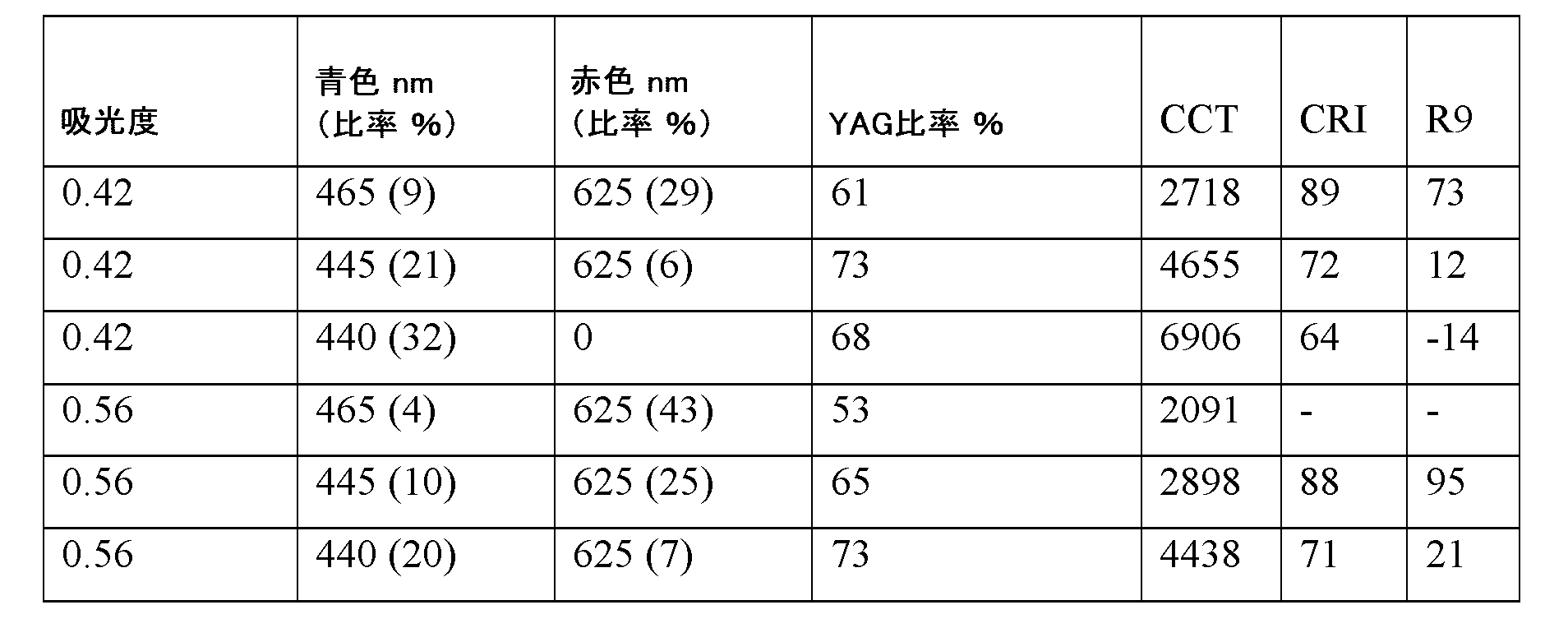
レーザ・蛍光体ベースの光源は、非常に高い強度をもたらす可能性があるため、多くの関心を集めている。レーザが蛍光体をポンピングするために使用される、自動車のヘッドライト及びプロジェクタなどの製品が、既に市場に出回っている。レーザ・蛍光体は、他の照明アプリケーションのためにも使用されることができる。しかしながら、BBL調光のためには、少なくとも赤色、緑色、青色の個別に制御可能なレーザベースの光源が必要とされる。 Laser-phosphor based light sources have attracted a lot of interest because of their potential for very high intensity. There are already products on the market, such as car headlights and projectors, where a laser is used to pump a phosphor. Laser-phosphor can also be used for other lighting applications. However, for BBL dimming, at least red, green, and blue individually controllable laser-based light sources are needed.
本明細書においては、とりわけ、(少なくとも)高周波波長掃引レーザ及びセラミック蛍光体を使用するBBL調光が提案されている。高周波波長掃引レーザは、オレンジ色光と赤色光との間で切り替えられることができるVCSELであり得る。青色レーザ及びYAG/LuAGセラミック蛍光体タイルと組み合わせてこのような光源を使用することによって、例えばBBL調光のために、BBLをたどることができる。その代わりに、又は加えて、青色(又は緑色)波長を調節するために、青色(又は緑色)高周波波長掃引レーザが使用されてもよい。レーザの強度を制御するためにPWM(パルス幅変調)が使用され得る。 Herein, BBL dimming is proposed using, among other things, (at least) a high-frequency wavelength-swept laser and a ceramic phosphor. The high-frequency wavelength-swept laser can be a VCSEL that can be switched between orange and red light. By using such a light source in combination with a blue laser and a YAG/LuAG ceramic phosphor tile, the BBL can be followed, for example, for BBL dimming. Alternatively or in addition, a blue (or green) high-frequency wavelength-swept laser may be used to tune the blue (or green) wavelength. PWM (Pulse Width Modulation) may be used to control the intensity of the laser.
図4は、約450nmの青色レーザ、560nmにおいてカラーポイントを持つ緑色/黄色発光材料、及び様々な波長でほぼオレンジ色/赤色で発光するVCSELで利用可能である幾つかのカラーポイントを概略的に図示している。白色光が、(実質的に黒体軌跡に沿った)制御可能なCCTを持ち得ることに留意されたい。様々な円は、(例として示されている)VCSELなどの、波長可変デバイス光の重心波長に依存して選ばれることができるカラーポイントを示している。 Figure 4 shows a schematic of some color points available for a blue laser at about 450 nm, a green/yellow emitting material with a color point at 560 nm, and a VCSEL emitting near orange/red at various wavelengths. Note that the white light can have a controllable CCT (substantially along the blackbody locus). The various circles show color points that can be chosen depending on the centroid wavelength of a tunable device light, such as a VCSEL (shown as an example).
本明細書においては、とりわけ、(i)色温度、(ii)CRI及び/又は(iii)R9値などの調節可能な特性を持つ光源の製造における調整可能なレーザの使用も提案されている。それは、補償される必要がある他の効果のためにも使用されることができる。とりわけ、第2高調波発生のための適切な非線形光学(NLO)結晶と組み合わせて波長可変IR垂直共振器面発光レーザ(VCSEL)を使用することが提案されており、従って、調整可能な可視レーザを得ることが提案されている。 The use of tunable lasers in the manufacture of light sources with adjustable properties, such as, inter alia, (i) color temperature, (ii) CRI and/or (iii) R9 value, is also proposed herein. It can also be used for other effects that need to be compensated for. In particular, it is proposed to use tunable IR vertical cavity surface emitting lasers (VCSELs) in combination with suitable nonlinear optical (NLO) crystals for second harmonic generation, thus obtaining tunable visible lasers.
図5は、可能な波長可変VCSELのスペクトルを概略的に図示している。 Figure 5 shows a schematic diagram of the spectrum of a possible tunable VCSEL.
調整可能な可視レーザ光は、例えば、カラーポイント/色温度を調節するために使用されることができる。これは、調整可能な可視レーザ光によって直接達成されることができる、又は変換率はポンプ波長に依存する蛍光体をポンピングすることによって間接的に達成されることができる。後者の構成においては、効果を高めるために色分離要素(例えば、レーザビームを分離するためのダイクロイック)が使用され得る。多くのピークが示されている。中間ピークもあり得る。 Tunable visible laser light can be used to adjust the color point/color temperature, for example. This can be achieved directly by the tunable visible laser light, or indirectly by pumping a phosphor, where the conversion rate depends on the pump wavelength. In the latter configuration, color separation elements (e.g. dichroics to separate the laser beams) can be used to enhance the effect. Many peaks are shown. Intermediate peaks are also possible.
あるいは、例えば、所与の波長におけるガーネット蛍光体からの吸光度のレベルは、温度の上昇とともに減少することが知られている。この結果、光源のカラーポイントは、光の強度の関数として変化する。温度吸光度を補償するために、従って、温度が変化する状態で蛍光体のカラーポイントを保つために、調整可能な青色レーザが使用されることができる。 Alternatively, for example, it is known that the level of absorbance from a garnet phosphor at a given wavelength decreases with increasing temperature. As a result, the color point of the light source changes as a function of the light intensity. A tunable blue laser can be used to compensate for the temperature absorbance and thus preserve the color point of the phosphor under changing temperatures.
実施形態においては、1240nmから1350nmまでの波長範囲を放射する調整可能なIRレーザの周波数2倍化後には、620nmから675nmまでの範囲の波長範囲内の光を発する調整可能な赤色発光レーザが得られることができる。従って、IR範囲内で調整可能である波長可変光源で、可視範囲内で調整可能である波長可変光源も得られ得る(更に下記も参照)。 In an embodiment, after frequency doubling of a tunable IR laser emitting in the wavelength range from 1240 nm to 1350 nm, a tunable red-emitting laser emitting light in the wavelength range from 620 nm to 675 nm can be obtained. Thus, a tunable light source that is tunable in the IR range, and also in the visible range, can be obtained (see also further below).
同じやり方で、900nmから990nmまでの波長範囲内の調整可能なIR放射レーザ及び990nmから1140nmまでの波長範囲内の調整可能なIR放射レーザが、それぞれ、青色450乃至495nmにおいて発光する調整可能なレーザ及び緑色495乃至570nmにおいて発光する調整可能なレーザを製造するために使用されることができる。 In the same way, tunable IR emitting lasers in the wavelength range of 900 nm to 990 nm and tunable IR emitting lasers in the wavelength range of 990 nm to 1140 nm can be used to manufacture tunable lasers emitting in the blue 450-495 nm and green 495-570 nm, respectively.
図6は、610nmにおける赤色レーザ光と組み合わせて、YAG:Ce 2%蛍光体をポンピングする440nmの青色レーザを有する光源のスペクトルを示している。例えば、CCT=3000Kにおいて、CRI=66、R9=-64、及び373lm/Wの変換効率を持つ光が得られ得る。連続増加曲線は、約3000Kにおける黒体放射体のスペクトルパワー分布を概略的に図示している(図7も参照)。
Figure 6 shows the spectrum of a light source with a 440 nm blue laser pumping a YAG:
図7は、青色レーザ470nm及び赤色レーザ630nmで得られる、より高い光品質、即ち、同じCCT=3000Kにおいて、CRI=90及びR9=92を持つが、330lm/Wのより低い効率を持つスペクトルを示している。 Figure 7 shows the spectrum obtained with a blue laser at 470 nm and a red laser at 630 nm, with higher light quality, i.e., CRI=90 and R9=92, but lower efficiency of 330 lm/W, at the same CCT=3000K.
図8aを参照すると、実施形態においては、光生成システム1000は、第1光生成デバイス110と、第2光生成デバイス120と、ルミネッセンス材料200とを含み得る。
Referring to FIG. 8a, in an embodiment, the
第1光生成デバイス110は、第1デバイス光111を生成するよう構成され得る。第2光生成デバイス120は、第2デバイス光121を生成するよう構成され得る。第1デバイス光111及び第2デバイス光121は、異なるスペクトルパワー分布を持つ。
The first light-generating
ルミネッセンス材料200は、第1デバイス光111及び第2デバイス光121のうちの1つ以上の少なくとも一部をルミネッセンス材料光201に変換するよう構成され得る。ルミネッセンス材料200は、A3B5O12:Ce3+タイプのルミネッセンス材料を有することがある。Aは、Y、La、Gd、Tb及びLuのうちの1つ以上を有することがあり、Bは、Al、Ga、In及びScのうちの1つ以上を有することがある。光生成システム1000は、セラミック体210を有することがあり、セラミック体210は、ルミネッセンス材料200を有することがある。参照符号550は、例えば、コリメータ又はレンズのようなビーム成形要素を含み得る、光学系を指している。他の光学系(図示せず)も可能であり得る。特には、光学系550は、第1光生成デバイス、第2光生成デバイス及びルミネッセンス材料の下流に構成される光学系を指している。
The luminescent material 200 may be configured to convert at least a portion of one or more of the
実施形態においては、光生成システム1000は、ユーザインターフェースの入力信号、(センサの)センサ信号、及びタイマのうちの1つ以上に依存して、第1光生成デバイス110及び第2光生成デバイス120を制御することによって、システム光1001を制御するよう構成される制御システム300を更に有してもよい。
In an embodiment, the
図8a乃至8bを参照すると、第1光生成デバイス110(図8a参照)は、光生成システム1000の動作モードにおいて、少なくとも40Hzの変化周波数で、少なくとも10nmの(図面においてはλ1cと示されている)波長差を持つ少なくとも2つの重心波長(λ1c,1、λ1c,2)の間で変化する第1デバイス光111を生成するよう構成される波長可変光生成デバイスを含み得る。変化周波数は、特には少なくとも50Hzであることがあり、更により特には少なくとも60Hzなどであることがある。(左側の)最小波長帯域が、重心波長λ1c,1を持つことがあり、(右側の)最大波長帯域が、重心波長λ1c,2を持つことがある。従って、これらの少なくとも2つの重心波長λ1c,1、λ1c,2は、外側重心波長と示されることがある。
8a-8b, the first light-generating device 110 (see FIG. 8a) may comprise a tunable light-generating device configured to generate a
光生成システム1000は、光生成システム1000の動作モードにおいて、ルミネッセンス材料光201と、第1デバイス光111及び第2デバイス光121(のうちの少なくとも1つ)とを含む白色システム光1001を生成するよう構成され得る。
In an operating mode of the
光生成システム1000の特定の実施形態においては、第1光生成デバイス110は、垂直共振器面発光レーザ(VCSEL)及びスーパールミネッセントダイオードのうちの1つ以上を含み得る。
In certain embodiments of the
図8cは、ルミネッセンス材料の吸収(透過)(左側y軸)及び発光(右側y軸)の実施形態を概略的に図示しており、ルミネッセンス材料は、制御可能な重心波長を持つ第1デバイス光(図8b参照)の一部を変換するよう構成されている。 Figure 8c shows a schematic representation of an embodiment of the absorption (transmission) (left y-axis) and emission (right y-axis) of a luminescent material configured to convert a portion of the first device light (see Figure 8b) with a controllable centroid wavelength.
図8dは、ルミネッセンス材料が第2デバイス光121の一部を変換するよう構成される実施形態を概略的に図示している。更に、概略的に図示されている実施形態は、図8aにおいて概略的に図示されている実施形態と本質的に同じである。
Figure 8d illustrates a schematic representation of an embodiment in which the luminescent material is configured to convert a portion of the
図8eは、第2光生成デバイス120が、光生成システム1000の動作モードにおいて、特には少なくとも50Hzの、少なくとも60Hzなどの、少なくとも40Hzの変化周波数で、少なくとも10nmの波長差を持つ少なくとも2つの重心波長(λ2c,1、λ2c,2)の間で変化する第2デバイス光121を生成するよう構成される波長可変光生成デバイスを含み得る実施形態を概略的に図示している。
Figure 8e illustrates generally an embodiment in which the second light-generating
図8fは、あり得る重複(発光)帯域の態様を概略的に図示している。重複領域は、ハッチングが施されている。より小さな帯域の重複のパーセンテージは、より大きな(ここでは、より広い)帯域の重複のパーセンテージよりも大きい。本明細書においては、重複は、特には、より小さな発光帯域に対して規定され得る。より大きな発光帯域によるより小さな発光帯域のスペクトル重複は、20%未満であり得る。特に、発光帯域のスペクトルパワー(積分パワー)が、別の発光帯域のものよりも小さい場合、発光帯域は、別の発光帯域よりも小さい可能性がある。図8fにおいては、重複は、(狭帯域発光の)約50%であり得る(広帯域発光の約10%だけが狭帯域発光と重なり得る)。 Figure 8f illustrates a schematic representation of possible overlapping (emission) bands. The overlapping area is hatched. The percentage of overlap of the smaller band is greater than the percentage of overlap of the larger (here wider) band. Herein, the overlap may be defined specifically for the smaller emission band. The spectral overlap of the smaller emission band with the larger emission band may be less than 20%. In particular, an emission band may be smaller than another emission band if the spectral power (integrated power) of the emission band is less than that of the other emission band. In Figure 8f, the overlap may be about 50% (of the narrowband emission) (only about 10% of the broadband emission may overlap with the narrowband emission).
図9a乃至9bを参照すると、実施形態Iにおいては、第1光生成デバイス110が、(a)光生成システム1000の動作モードにおいて、少なくとも50Hzの変化周波数で、少なくとも20nmの波長差を持つ少なくとも2つの重心波長(λpc,1、λpc,2)の間で変化する第1光源光11を生成するよう構成される波長可変第1光源10を含み得る。更に、(第1)アップコンバータ材料410が、波長可変第1光源10の下流に構成され、少なくとも2つの重心波長(λpc,1、λpc,2)の間で変化する第1光源光11の少なくとも一部を、少なくとも2つの重心波長(λ1c,1、λ1c,2)の間で変化する第1デバイス光111に変換するよう構成される。
9a-9b, in embodiment I, the first light-generating
アップコンバータ材料410は、アップコンバータ・ルミネッセンス材料及び周波数2倍化材料のうちの1つ以上を含み得る。
The
実施形態においては、第2光生成デバイス120は、ダイオードレーザ及びスーパールミネッセントダイオードのうちの1つ以上を含み得る。実施形態においては、第2光生成デバイス120は、垂直共振器面発光レーザ(VCSEL)を含み得る。
In an embodiment, the second light-generating
従って、図9aの実施形態IIにおいては、第2光生成デバイス120が、光生成システム1000の動作モードにおいて、少なくとも50Hzの変化周波数で、少なくとも20nmの波長差を持つ少なくとも2つの重心波長の間で変化する第2光源光21を生成するよう構成される第2光源20を有するこのような実施形態が概略的に図示されている。更に、(第2)アップコンバータ材料420が、波長可変第2光源20の下流に構成され、少なくとも2つの重心波長の間で変化する第2光源光21の少なくとも一部を、少なくとも2つの重心波長の間で変化する第2デバイス光121に変換するよう構成される。
9a, such an embodiment is illustrated in schematic form, in which the second light-generating
第1光生成デバイス110は、青色波長範囲内に重心波長を持つ第1デバイス光111を生成するよう構成されることがあり、且つ第2光生成デバイス120は、赤色波長範囲内に重心波長を持つ第2デバイス光121を生成するよう構成されることがある。その代わりに、第1光生成デバイス110は、赤色波長範囲内に重心波長を持つ第1デバイス光111を生成するよう構成されることがあり、且つ第2光生成デバイス120は、青色波長範囲内に重心波長を持つ第2デバイス光121を生成するよう構成されることがある。
The first light-generating
実施形態においては、第1光源10は、IRスーパールミネッセントダイオード又はIR VCSELを含み得る。
In an embodiment, the
制御システム(図示されていないが、図8a又は8d参照)は、パルス幅変調によって第1光生成デバイス110を制御するよう構成され得る。特には、制御システムは、動作モードにおいて、第1デバイス光111のデューティサイクルを制御することによって、システム光1001のスペクトルパワー分布を制御するよう構成され得る。
A control system (not shown, but see FIG. 8a or 8d) may be configured to control the first light-generating
波長可変光生成デバイスは、動作モードにおいて、各々が少なくとも40Hzのパルス周波数を持つ、重心波長(λ1c,1)を持つ第1デバイス光111の第1パルスと、重心波長(λ1c,2)を持つ第1デバイス光111の第2パルスとを生成するよう構成されてもよく、動作モードにおいて、システム光1001のスペクトルパワー分布を制御することは、第1パルスのデューティサイクル及び第2パルスのデューティサイクルを個別に制御することを含み得る。
In an operating mode, the tunable light generating device may be configured to generate a first pulse of the
制御システムは(また)、実施形態においては、パルス幅変調によって第2光生成デバイスを制御するよう構成され得ることに留意されたい。 It should be noted that in an embodiment, the control system may (also) be configured to control the second light-generating device by pulse width modulation.
図9cを参照すると、パルス幅変調の例が概略的に図示されている。第2実施形態においてパルス幅を短くすることによって、第1タイプのパルスにおいて供給される光のシステム光への寄与が減らされている。このやり方においては、色が、例えばBBLに沿って、調整され得る。ハッチングが施されていない矩形及びハッチングが施されている矩形で示されている2つの異なるパルスは、例えばそれぞれ重心波長λ1c,1、λ1c,2を持つ第1デバイス光のパルスを指し得る。このやり方においては、光生成デバイスは、2つ(以上)の異なるスペクトルパワー分布の間で掃引することができ、それによって、特にPWMで、システム光のスペクトルパワー分布が制御され得る。 With reference to Fig. 9c, an example of pulse width modulation is illustrated in a schematic manner. By shortening the pulse width in the second embodiment, the contribution of the light provided in the first type of pulse to the system light is reduced. In this way, the color can be adjusted, for example along the BBL. The two different pulses shown by the open and hatched rectangles can refer to pulses of the first device light, for example with centroid wavelengths λ 1c,1 and λ 1c,2, respectively. In this way, the light-generating device can be swept between two (or more) different spectral power distributions, whereby the spectral power distribution of the system light can be controlled, especially with PWM.
制御システムは、光生成システム1000の動作モードにおいて、2700乃至6500Kの相関色温度範囲内で、少なくとも80の演色評価数を持つシステム光1001を制御するよう構成され得る。
The control system may be configured to control the system light 1001 in an operating mode of the
図10は、上記のような光生成システム1000を含む照明器具2の実施形態を概略的に図示している。参照符号301は、光生成システム1000によって含まれる又は光生成システム1000に機能的に結合される制御システム300と機能的に結合され得るユーザインターフェースを示している。図10は、光生成システム1000を有するランプ1の実施形態も概略的に図示している。従って、図10は、ランプ1、照明器具2、プロジェクタデバイス、消毒デバイス、及び光無線通信デバイスのグループから選択される照明デバイス1200であって、本明細書において記載されているような光生成システム1000を有する照明デバイス1200の実施形態を概略的に図示している。実施形態においては、このような照明デバイスは、ランプ1、照明器具2、プロジェクタデバイス、消毒デバイス、又は光無線通信デバイスであり得る。照明デバイス1200から脱出する照明デバイス光が、参照符号1201で示されている。照明デバイス光1201は、本質的に、システム光1001から成ってもよく、従って、特定の実施形態においては、システム光1001であってもよい。
Figure 10 illustrates a schematic embodiment of a
「複数」という用語は、2つ以上を指す。 The term "plurality" refers to two or more.
本明細書における「実質的に」又は「本質的に」という用語、及び同様の用語は、当業者には理解されるだろう。「実質的に」又は「本質的に」という用語は、「全体的に」、「完全に」、「全て」などを備える実施形態も含み得る。従って、実施形態においては、実質的に又は本質的にという形容詞が取り除かれることもある。適用可能な場合には、「実質的に」という用語又は「本質的に」という用語は、100%を含む、95%以上、特に99%以上、更により特に99.5%以上などの、90%以上に関することもある。 The terms "substantially" or "essentially" and similar terms herein will be understood by those of skill in the art. The terms "substantially" or "essentially" may also include embodiments with "entirely," "completely," "all," and the like. Thus, in embodiments, the adjectives substantially or essentially may be omitted. Where applicable, the terms "substantially" or "essentially" may also refer to 90% or more, including 100%, such as 95% or more, particularly 99% or more, and even more particularly 99.5% or more.
「有する」という用語は、「有する」という用語が「から成る」を意味する実施形態も含む。 The term "comprises" also includes embodiments in which the term "comprises" means "consists of."
「及び/又は」という用語は、特に、「及び/又は」の前及び後で言及されている項目のうちの1つ以上に関する。例えば、「項目1及び/又は項目2」という語句、及び同様の語句は、項目1及び項目2のうちの1つ以上に関し得る。「有する」という用語は、或る実施形態においては、「から成る」ことを指す場合があるが、別の実施形態においては、「少なくとも規定されている種を含み、随意に、1つ以上の他の種を含む」ことを指す場合もある。
The term "and/or" specifically refers to one or more of the items mentioned before and after "and/or." For example, the phrase "
更に、明細書及び特許請求の範囲における、第1、第2、第3などの用語は、同様の要素を区別するために使用されるものであり、必ずしも、逐次的又は時間的な順序を説明するために使用されるものではない。そのように使用される用語は、適切な状況下で交換可能であり、本明細書において記載されている本発明の実施形態は、本明細書において記載又は図示されている順序以外の順序で動作が可能であることは理解されるべきである。 Furthermore, in the specification and claims, terms such as first, second, third, etc. are used to distinguish between similar elements and are not necessarily used to describe a sequential or chronological order. The terms so used are interchangeable under appropriate circumstances, and it should be understood that the embodiments of the invention described herein are capable of operation in orders other than those described or illustrated herein.
本明細書においては、とりわけ、動作中の、デバイス、装置、又はシステムが記載されているかもしれない。当業者には明らかであるだろうように、本発明は、動作の方法、又は動作中の、デバイス、装置、若しくはシステムに限定されるものではない。 The present specification may describe, among other things, devices, apparatus, or systems in operation. As will be apparent to one of ordinary skill in the art, the present invention is not limited to methods of operation or devices, apparatus, or systems in operation.
上述の実施形態は、本発明を限定するものではなく、本発明を説明するものであり、当業者は、添付の特許請求の範囲の範囲から逸脱することなく、多くの他の実施形態を設計することができるだろうことに留意されたい。 It should be noted that the above-described embodiments are illustrative of the invention rather than limiting, and that a person skilled in the art could design many other embodiments without departing from the scope of the appended claims.
特許請求の範囲において、括弧内に配置される如何なる参照符号も、請求項を限定するものとして解釈されるべきではない。 In the claims, any reference signs placed between parentheses shall not be construed as limiting the claim.
「有する」という動詞及びその語形変化の使用は、請求項において示されている要素又はステップ以外の要素又はステップの存在を除外するものではない。文脈から明らかに別の意味が必要とされない限り、明細書及び特許請求の範囲全体を通して、「有する」などの単語は、排他的又は網羅的な意味とは対照的な、包括的な意味で、即ち、「含むが、これに限定されない」という意味で解釈されるべきである。 The use of the verb "to have" and its conjugations does not exclude the presence of elements or steps other than those stated in a claim. Unless the context clearly requires otherwise, throughout the specification and claims, words like "to have" and the like should be construed in their inclusive sense, i.e., "including, but not limited to," as opposed to their exclusive or exhaustive sense.
要素の単数形表記は、このような要素の複数の存在を除外するものではない。 The singular reference of an element does not exclude the presence of a plurality of such elements.
本発明は、幾つかの別個の要素を有するハードウェアによって実施されてもよく、又は適切にプログラムされたコンピュータによって実施されてもよい。幾つかの手段を列挙している、デバイスの請求項、又は装置の請求項、又はシステムの請求項においては、これらの手段のうちの幾つかは、ハードウェアの全く同一のアイテムによって実施されてもよい。単に、或る特定の手段が、相互に異なる従属請求項において挙げられているという事実は、これらの手段の組み合わせは有利になるようには使用されることができないことを示すものではない。(従って、)更に他の態様においては、本発明は、コンピュータにおいて実行するときに、本明細書において記載されているような方法(の1つ以上の実施形態)を実現することが可能であるソフトウェアを提供する。 The invention may be implemented by means of hardware comprising several distinct elements, or by means of a suitably programmed computer. In a device claim, or an apparatus claim, or a system claim enumerating several means, several of these means may be embodied by one and the same item of hardware. The mere fact that certain means are recited in mutually different dependent claims does not indicate that a combination of these means cannot be used to advantage. (Thus) in yet another aspect, the invention provides software which, when executed on a computer, is capable of implementing (one or more embodiments of) the method as described herein.
本発明は、デバイス、装置、若しくはシステムを制御し得る、又は本明細書において記載されている方法若しくはプロセスを実行し得る制御システムも提供する。更に他に、本発明は、デバイス、装置、又はシステムに機能的に結合される又は含まれるコンピュータにおいて実行するときに、このようなデバイス、装置、又はシステムの1つ以上の制御可能な要素を制御するコンピュータプログラム製品も提供する。 The invention also provides a control system that may control a device, apparatus, or system, or that may perform the methods or processes described herein. Additionally, the invention also provides a computer program product that, when executed on a computer operatively coupled to or included in a device, apparatus, or system, controls one or more controllable elements of such a device, apparatus, or system.
本発明は、更に、明細書において記載されている、及び/又は添付の図面において示されている、特徴付けている特徴のうちの1つ以上を有するデバイス、装置、又はシステムに当てはまる。本発明は、更に、明細書において記載されている、及び/又は添付の図面において示されている、特徴付けている特徴のうちの1つ以上を有する方法又はプロセスに関する。 The invention further applies to a device, an apparatus or a system having one or more of the characterizing features described in the specification and/or shown in the accompanying drawings. The invention further relates to a method or process having one or more of the characterizing features described in the specification and/or shown in the accompanying drawings.
この特許において説明されている様々な態様は、更なる利点を提供するために組み合わされることができる。更に、当業者は、実施形態は組み合わされることができること、及び3つ以上の実施形態も組み合わされることができることを理解するだろう。更に、特徴のうちの幾つかは、1つ以上の分割出願のための基礎を形成することができる。 The various aspects described in this patent can be combined to provide additional advantages. Moreover, one skilled in the art will appreciate that the embodiments can be combined, and that more than two embodiments can be combined. Furthermore, some of the features can form the basis for one or more divisional applications.
特には、本発明は、波長掃引レーザと蛍光体との組み合わせ、及び第2レーザを提供し得る。実施形態においては、波長掃引レーザは、赤色レーザであり、第2レーザは、青色レーザであってもよく、別の実施形態においては、その逆であってもよい。 In particular, the present invention may provide a combination of a wavelength-swept laser and a phosphor, and a second laser. In an embodiment, the wavelength-swept laser may be a red laser and the second laser may be a blue laser, or vice versa in another embodiment.
Claims (15)
前記第1光生成デバイスが、第1デバイス光を生成するよう構成され、前記第2光生成デバイスが、第2デバイス光を生成するよう構成され、前記第1デバイス光と、前記第2デバイス光とが、異なるスペクトルパワー分布を持ち、
前記ルミネッセンス材料が、前記第1デバイス光及び前記第2デバイス光のうちの1つ以上の少なくとも一部をルミネッセンス材料光に変換するよう構成され、
前記第1光生成デバイスが、前記光生成システムの動作モードにおいて、少なくとも50Hzの変化周波数で、少なくとも10nmの波長差を持つ少なくとも2つの重心波長の間で変化する第1デバイス光を生成するよう構成される波長可変光生成デバイスを有し、
前記光生成システムが、前記光生成システムの前記動作モードにおいて、前記ルミネッセンス材料光、前記第1デバイス光及び前記第2デバイス光を含む白色システム光を生成するよう構成される光生成システム。 1. A light generating system having a first light generating device, a second light generating device, and a luminescent material,
the first light-generating device is configured to generate a first device light and the second light-generating device is configured to generate a second device light, the first device light and the second device light having different spectral power distributions;
the luminescent material is configured to convert at least a portion of one or more of the first device light and the second device light to luminescent material light;
the first light-generating device comprises a tunable light-generating device configured to generate a first device light that varies between at least two centroid wavelengths having a wavelength difference of at least 10 nm with a variation frequency of at least 50 Hz in an operation mode of the light-generating system;
The light-generation system is configured to generate white system light comprising the luminescent material light, the first device light, and the second device light, in the operational mode of the light-generation system.
前記第1光生成デバイスが、赤色波長範囲内に重心波長を持つ第1デバイス光を生成するよう構成され、前記第2光生成デバイスが、青色波長範囲内に重心波長を持つ第2デバイス光を生成するよう構成される請求項1乃至4のいずれか一項に記載の光生成システム。 5. The light-generating system of claim 1, wherein the first light-generating device is configured to generate a first device light having a centroid wavelength in a blue wavelength range and the second light-generating device is configured to generate a second device light having a centroid wavelength in a red wavelength range; or the first light-generating device is configured to generate a first device light having a centroid wavelength in a red wavelength range and the second light-generating device is configured to generate a second device light having a centroid wavelength in a blue wavelength range.
Applications Claiming Priority (3)
| Application Number | Priority Date | Filing Date | Title |
|---|---|---|---|
| EP21196577 | 2021-09-14 | ||
| EP21196577.7 | 2021-09-14 | ||
| PCT/EP2022/075291 WO2023041486A1 (en) | 2021-09-14 | 2022-09-12 | Color control using a high frequency wavelength sweeping light source and a phosphor |
Publications (2)
| Publication Number | Publication Date |
|---|---|
| JP2024535839A JP2024535839A (en) | 2024-10-02 |
| JP7625139B2 true JP7625139B2 (en) | 2025-01-31 |
Family
ID=77750150
Family Applications (1)
| Application Number | Title | Priority Date | Filing Date |
|---|---|---|---|
| JP2024516692A Active JP7625139B2 (en) | 2021-09-14 | 2022-09-12 | Color control using high frequency wavelength swept sources and phosphors |
Country Status (5)
| Country | Link |
|---|---|
| US (1) | US12287088B2 (en) |
| EP (1) | EP4402404B1 (en) |
| JP (1) | JP7625139B2 (en) |
| CN (1) | CN117940701B (en) |
| WO (1) | WO2023041486A1 (en) |
Families Citing this family (1)
| Publication number | Priority date | Publication date | Assignee | Title |
|---|---|---|---|---|
| US12322306B2 (en) * | 2023-11-15 | 2025-06-03 | ROE Visual US, Inc. | RGBCA LED display modules and LED display tiles and LED video displays having the same |
Citations (4)
| Publication number | Priority date | Publication date | Assignee | Title |
|---|---|---|---|---|
| JP2015528187A (en) | 2012-07-18 | 2015-09-24 | コーニンクレッカ フィリップス エヌ ヴェ | Adjustable correlated color temperature LED-based white light source with mixing chamber and remote phosphor exit window |
| JP2015233127A (en) | 2014-05-12 | 2015-12-24 | キヤノン株式会社 | Surface emitting laser, laser array, light source device, information acquisition device, and optical coherence tomography |
| JP2017536694A (en) | 2014-10-31 | 2017-12-07 | コーニンクレッカ フィリップス エヌ ヴェKoninklijke Philips N.V. | Fluorescent LED using temperature stable flux and saturated red point |
| JP2018511386A (en) | 2015-03-19 | 2018-04-26 | フィリップス ライティング ホールディング ビー ヴィ | Bio hue lamp |
Family Cites Families (26)
| Publication number | Priority date | Publication date | Assignee | Title |
|---|---|---|---|---|
| JPS48102585A (en) * | 1972-04-04 | 1973-12-22 | ||
| WO1994018809A1 (en) * | 1993-02-11 | 1994-08-18 | Phares Louis A | Controlled lighting system |
| JP2596709B2 (en) * | 1994-04-06 | 1997-04-02 | 都築 省吾 | Illumination light source device using semiconductor laser element |
| US6350041B1 (en) * | 1999-12-03 | 2002-02-26 | Cree Lighting Company | High output radial dispersing lamp using a solid state light source |
| KR100628264B1 (en) * | 2002-09-26 | 2006-09-27 | 엘지.필립스 엘시디 주식회사 | Backlight Unit of LCD |
| US7005679B2 (en) * | 2003-05-01 | 2006-02-28 | Cree, Inc. | Multiple component solid state white light |
| US6807211B1 (en) | 2003-05-27 | 2004-10-19 | Eastman Kodak Company | White-light laser |
| US7982229B2 (en) * | 2004-11-18 | 2011-07-19 | Koninklijke Philips Electronics N.V. | Light emitting device with conversion structure |
| US7316497B2 (en) * | 2005-03-29 | 2008-01-08 | 3M Innovative Properties Company | Fluorescent volume light source |
| US20110170290A1 (en) * | 2008-09-17 | 2011-07-14 | Koninklijke Philips Electronics N.V. | Lighting device and method of lighting |
| KR20100126208A (en) | 2009-05-21 | 2010-12-01 | 조지아 테크 리서치 코포레이션 | Antimicrobial UV Reverse Conversion Composition |
| US8884508B2 (en) * | 2011-11-09 | 2014-11-11 | Cree, Inc. | Solid state lighting device including multiple wavelength conversion materials |
| US9810826B2 (en) * | 2014-01-28 | 2017-11-07 | Philips Lighting Holding B.V. | Light emitting device |
| JP6306264B2 (en) | 2014-09-11 | 2018-04-04 | フィリップス ライティング ホールディング ビー ヴィ | PC-LED module with improved white rendering and conversion efficiency |
| TWI571694B (en) * | 2014-11-26 | 2017-02-21 | 中強光電股份有限公司 | Illumination system and projection apparatus |
| US20180375003A1 (en) * | 2015-07-02 | 2018-12-27 | Philips Lighting Holding B.V. | Led lamp with slow decay red phosphor resulting in cct variation with light output |
| US10879673B2 (en) | 2015-08-19 | 2020-12-29 | Soraa Laser Diode, Inc. | Integrated white light source using a laser diode and a phosphor in a surface mount device package |
| WO2017036789A1 (en) * | 2015-09-01 | 2017-03-09 | Philips Lighting Holding B.V. | Meat lighting system with improved efficiency and red oversaturation |
| WO2019020395A1 (en) | 2017-07-24 | 2019-01-31 | Lumileds Holding B.V. | Vcsel assembly |
| US10222474B1 (en) * | 2017-12-13 | 2019-03-05 | Soraa Laser Diode, Inc. | Lidar systems including a gallium and nitrogen containing laser light source |
| EP3791450A1 (en) | 2018-05-11 | 2021-03-17 | Excelitas Technologies Corp. | Optically pumped tunable vcsel employing geometric isolation |
| JP7238294B2 (en) * | 2018-08-24 | 2023-03-14 | セイコーエプソン株式会社 | Light source device and projector |
| GB2579801B (en) | 2018-12-13 | 2021-04-14 | Exalos Ag | Superluminescent diode module |
| US20200232610A1 (en) | 2019-01-18 | 2020-07-23 | Soraa Laser Diode, Inc. | Laser-based waveguide-coupled white light system for a lighting application |
| US12000552B2 (en) | 2019-01-18 | 2024-06-04 | Kyocera Sld Laser, Inc. | Laser-based fiber-coupled white light system for a vehicle |
| US10912171B1 (en) | 2019-07-31 | 2021-02-02 | Lumileds Llc | Control design for perceptually uniform color tuning |
-
2022
- 2022-09-12 JP JP2024516692A patent/JP7625139B2/en active Active
- 2022-09-12 CN CN202280061748.5A patent/CN117940701B/en active Active
- 2022-09-12 US US18/691,148 patent/US12287088B2/en active Active
- 2022-09-12 EP EP22783467.8A patent/EP4402404B1/en active Active
- 2022-09-12 WO PCT/EP2022/075291 patent/WO2023041486A1/en not_active Ceased
Patent Citations (4)
| Publication number | Priority date | Publication date | Assignee | Title |
|---|---|---|---|---|
| JP2015528187A (en) | 2012-07-18 | 2015-09-24 | コーニンクレッカ フィリップス エヌ ヴェ | Adjustable correlated color temperature LED-based white light source with mixing chamber and remote phosphor exit window |
| JP2015233127A (en) | 2014-05-12 | 2015-12-24 | キヤノン株式会社 | Surface emitting laser, laser array, light source device, information acquisition device, and optical coherence tomography |
| JP2017536694A (en) | 2014-10-31 | 2017-12-07 | コーニンクレッカ フィリップス エヌ ヴェKoninklijke Philips N.V. | Fluorescent LED using temperature stable flux and saturated red point |
| JP2018511386A (en) | 2015-03-19 | 2018-04-26 | フィリップス ライティング ホールディング ビー ヴィ | Bio hue lamp |
Also Published As
| Publication number | Publication date |
|---|---|
| JP2024535839A (en) | 2024-10-02 |
| US12287088B2 (en) | 2025-04-29 |
| CN117940701B (en) | 2025-12-19 |
| US20240392948A1 (en) | 2024-11-28 |
| WO2023041486A1 (en) | 2023-03-23 |
| CN117940701A (en) | 2024-04-26 |
| EP4402404A1 (en) | 2024-07-24 |
| EP4402404B1 (en) | 2025-03-26 |
Similar Documents
| Publication | Publication Date | Title |
|---|---|---|
| US20240027887A1 (en) | Increased red content in high cri high brightness light source | |
| US20240421554A1 (en) | White light source | |
| US12287087B2 (en) | High brightness light source comprising a blue laser pumping a green yellow phosphor and a yellow orange superluminescent diode pumping a red phosphor | |
| JP7625139B2 (en) | Color control using high frequency wavelength swept sources and phosphors | |
| US12398860B2 (en) | High intensity white light source with good uniformity based on a plurality of light sources | |
| US12416386B2 (en) | High brightness light source | |
| US12264790B2 (en) | Integrated solid state light source and phosphor module | |
| US12359794B2 (en) | Heatsink comprising a closed-logo slit for pumping a cylindrical phosphor body | |
| US12302463B2 (en) | Color tunable laser based source | |
| CN117242158B (en) | High brightness light source comprising a blue laser pumping a green/yellow phosphor and a yellow/orange superluminescent diode pumping a red phosphor | |
| WO2024149717A1 (en) | Laser-phosphor based stage lighting engine with a highly efficient polarization maintaining diffuser configuration | |
| WO2024083743A1 (en) | Laser-phosphor based stage-lighting fixture providing ctt control |
Legal Events
| Date | Code | Title | Description |
|---|---|---|---|
| A521 | Request for written amendment filed |
Free format text: JAPANESE INTERMEDIATE CODE: A523 Effective date: 20240314 |
|
| A621 | Written request for application examination |
Free format text: JAPANESE INTERMEDIATE CODE: A621 Effective date: 20240314 |
|
| A871 | Explanation of circumstances concerning accelerated examination |
Free format text: JAPANESE INTERMEDIATE CODE: A871 Effective date: 20240314 |
|
| A131 | Notification of reasons for refusal |
Free format text: JAPANESE INTERMEDIATE CODE: A131 Effective date: 20240827 |
|
| A521 | Request for written amendment filed |
Free format text: JAPANESE INTERMEDIATE CODE: A523 Effective date: 20241120 |
|
| TRDD | Decision of grant or rejection written | ||
| A01 | Written decision to grant a patent or to grant a registration (utility model) |
Free format text: JAPANESE INTERMEDIATE CODE: A01 Effective date: 20241224 |
|
| A61 | First payment of annual fees (during grant procedure) |
Free format text: JAPANESE INTERMEDIATE CODE: A61 Effective date: 20250121 |
|
| R150 | Certificate of patent or registration of utility model |
Ref document number: 7625139 Country of ref document: JP Free format text: JAPANESE INTERMEDIATE CODE: R150 |