[go: up one dir, main page]

JP7620102B2 - Glenoid Implant - Google Patents

Glenoid Implant Download PDF

Info

Publication number
JP7620102B2
JP7620102B2 JP2023532755A JP2023532755A JP7620102B2 JP 7620102 B2 JP7620102 B2 JP 7620102B2 JP 2023532755 A JP2023532755 A JP 2023532755A JP 2023532755 A JP2023532755 A JP 2023532755A JP 7620102 B2 JP7620102 B2 JP 7620102B2
Authority
JP
Japan
Prior art keywords
glenoid
implant
glenoid implant
recess
cavity
Prior art date
Legal status (The legal status is an assumption and is not a legal conclusion. Google has not performed a legal analysis and makes no representation as to the accuracy of the status listed.)
Active
Application number
JP2023532755A
Other languages
Japanese (ja)
Other versions
JPWO2022147376A5 (en
JP2023551317A (en
Inventor
ガーガック,ショーン・マーティン
ウルフ,アレクサンダー・ポール
マッチラー,オースティン・ワイアット
コートニー,ロバート
イム,アラン
ダソンビル,ベンジャミン
アンリ,ジル
スタンプ,デイビッド・アール
クランジュ,バンサン
ガボリ,バンサン
Current Assignee (The listed assignees may be inaccurate. Google has not performed a legal analysis and makes no representation or warranty as to the accuracy of the list.)
Howmedica Osteonics Corp
Original Assignee
Howmedica Osteonics Corp
Priority date (The priority date is an assumption and is not a legal conclusion. Google has not performed a legal analysis and makes no representation as to the accuracy of the date listed.)
Filing date
Publication date
Application filed by Howmedica Osteonics Corp filed Critical Howmedica Osteonics Corp
Publication of JP2023551317A publication Critical patent/JP2023551317A/en
Publication of JPWO2022147376A5 publication Critical patent/JPWO2022147376A5/ja
Priority to JP2025002678A priority Critical patent/JP2025072370A/en
Application granted granted Critical
Publication of JP7620102B2 publication Critical patent/JP7620102B2/en
Active legal-status Critical Current
Anticipated expiration legal-status Critical

Links

Images

Classifications

    • AHUMAN NECESSITIES
    • A61MEDICAL OR VETERINARY SCIENCE; HYGIENE
    • A61FFILTERS IMPLANTABLE INTO BLOOD VESSELS; PROSTHESES; DEVICES PROVIDING PATENCY TO, OR PREVENTING COLLAPSING OF, TUBULAR STRUCTURES OF THE BODY, e.g. STENTS; ORTHOPAEDIC, NURSING OR CONTRACEPTIVE DEVICES; FOMENTATION; TREATMENT OR PROTECTION OF EYES OR EARS; BANDAGES, DRESSINGS OR ABSORBENT PADS; FIRST-AID KITS
    • A61F2/00Filters implantable into blood vessels; Prostheses, i.e. artificial substitutes or replacements for parts of the body; Appliances for connecting them with the body; Devices providing patency to, or preventing collapsing of, tubular structures of the body, e.g. stents
    • A61F2/02Prostheses implantable into the body
    • A61F2/30Joints
    • A61F2/40Joints for shoulders
    • A61F2/4081Glenoid components, e.g. cups
    • AHUMAN NECESSITIES
    • A61MEDICAL OR VETERINARY SCIENCE; HYGIENE
    • A61BDIAGNOSIS; SURGERY; IDENTIFICATION
    • A61B17/00Surgical instruments, devices or methods
    • A61B17/16Instruments for performing osteoclasis; Drills or chisels for bones; Trepans
    • A61B17/1659Surgical rasps, files, planes, or scrapers
    • AHUMAN NECESSITIES
    • A61MEDICAL OR VETERINARY SCIENCE; HYGIENE
    • A61BDIAGNOSIS; SURGERY; IDENTIFICATION
    • A61B17/00Surgical instruments, devices or methods
    • A61B17/16Instruments for performing osteoclasis; Drills or chisels for bones; Trepans
    • A61B17/1662Instruments for performing osteoclasis; Drills or chisels for bones; Trepans for particular parts of the body
    • A61B17/1684Instruments for performing osteoclasis; Drills or chisels for bones; Trepans for particular parts of the body for the shoulder
    • AHUMAN NECESSITIES
    • A61MEDICAL OR VETERINARY SCIENCE; HYGIENE
    • A61BDIAGNOSIS; SURGERY; IDENTIFICATION
    • A61B17/00Surgical instruments, devices or methods
    • A61B17/16Instruments for performing osteoclasis; Drills or chisels for bones; Trepans
    • A61B17/17Guides or aligning means for drills, mills, pins or wires
    • A61B17/1739Guides or aligning means for drills, mills, pins or wires specially adapted for particular parts of the body
    • A61B17/1778Guides or aligning means for drills, mills, pins or wires specially adapted for particular parts of the body for the shoulder
    • AHUMAN NECESSITIES
    • A61MEDICAL OR VETERINARY SCIENCE; HYGIENE
    • A61FFILTERS IMPLANTABLE INTO BLOOD VESSELS; PROSTHESES; DEVICES PROVIDING PATENCY TO, OR PREVENTING COLLAPSING OF, TUBULAR STRUCTURES OF THE BODY, e.g. STENTS; ORTHOPAEDIC, NURSING OR CONTRACEPTIVE DEVICES; FOMENTATION; TREATMENT OR PROTECTION OF EYES OR EARS; BANDAGES, DRESSINGS OR ABSORBENT PADS; FIRST-AID KITS
    • A61F2/00Filters implantable into blood vessels; Prostheses, i.e. artificial substitutes or replacements for parts of the body; Appliances for connecting them with the body; Devices providing patency to, or preventing collapsing of, tubular structures of the body, e.g. stents
    • A61F2/02Prostheses implantable into the body
    • A61F2/30Joints
    • A61F2/30721Accessories
    • A61F2/30749Fixation appliances for connecting prostheses to the body
    • AHUMAN NECESSITIES
    • A61MEDICAL OR VETERINARY SCIENCE; HYGIENE
    • A61BDIAGNOSIS; SURGERY; IDENTIFICATION
    • A61B17/00Surgical instruments, devices or methods
    • A61B17/16Instruments for performing osteoclasis; Drills or chisels for bones; Trepans
    • A61B17/1637Hollow drills or saws producing a curved cut, e.g. cylindrical
    • AHUMAN NECESSITIES
    • A61MEDICAL OR VETERINARY SCIENCE; HYGIENE
    • A61BDIAGNOSIS; SURGERY; IDENTIFICATION
    • A61B17/00Surgical instruments, devices or methods
    • A61B17/56Surgical instruments or methods for treatment of bones or joints; Devices specially adapted therefor
    • A61B17/58Surgical instruments or methods for treatment of bones or joints; Devices specially adapted therefor for osteosynthesis, e.g. bone plates, screws or setting implements
    • A61B17/88Osteosynthesis instruments; Methods or means for implanting or extracting internal or external fixation devices
    • A61B17/8897Guide wires or guide pins
    • AHUMAN NECESSITIES
    • A61MEDICAL OR VETERINARY SCIENCE; HYGIENE
    • A61BDIAGNOSIS; SURGERY; IDENTIFICATION
    • A61B17/00Surgical instruments, devices or methods
    • A61B17/56Surgical instruments or methods for treatment of bones or joints; Devices specially adapted therefor
    • A61B2017/568Surgical instruments or methods for treatment of bones or joints; Devices specially adapted therefor produced with shape and dimensions specific for an individual patient
    • AHUMAN NECESSITIES
    • A61MEDICAL OR VETERINARY SCIENCE; HYGIENE
    • A61FFILTERS IMPLANTABLE INTO BLOOD VESSELS; PROSTHESES; DEVICES PROVIDING PATENCY TO, OR PREVENTING COLLAPSING OF, TUBULAR STRUCTURES OF THE BODY, e.g. STENTS; ORTHOPAEDIC, NURSING OR CONTRACEPTIVE DEVICES; FOMENTATION; TREATMENT OR PROTECTION OF EYES OR EARS; BANDAGES, DRESSINGS OR ABSORBENT PADS; FIRST-AID KITS
    • A61F2/00Filters implantable into blood vessels; Prostheses, i.e. artificial substitutes or replacements for parts of the body; Appliances for connecting them with the body; Devices providing patency to, or preventing collapsing of, tubular structures of the body, e.g. stents
    • A61F2/02Prostheses implantable into the body
    • A61F2/30Joints
    • A61F2002/30001Additional features of subject-matter classified in A61F2/28, A61F2/30 and subgroups thereof
    • A61F2002/30316The prosthesis having different structural features at different locations within the same prosthesis; Connections between prosthetic parts; Special structural features of bone or joint prostheses not otherwise provided for
    • A61F2002/30329Connections or couplings between prosthetic parts, e.g. between modular parts; Connecting elements
    • A61F2002/30476Connections or couplings between prosthetic parts, e.g. between modular parts; Connecting elements locked by an additional locking mechanism
    • A61F2002/305Snap connection
    • AHUMAN NECESSITIES
    • A61MEDICAL OR VETERINARY SCIENCE; HYGIENE
    • A61FFILTERS IMPLANTABLE INTO BLOOD VESSELS; PROSTHESES; DEVICES PROVIDING PATENCY TO, OR PREVENTING COLLAPSING OF, TUBULAR STRUCTURES OF THE BODY, e.g. STENTS; ORTHOPAEDIC, NURSING OR CONTRACEPTIVE DEVICES; FOMENTATION; TREATMENT OR PROTECTION OF EYES OR EARS; BANDAGES, DRESSINGS OR ABSORBENT PADS; FIRST-AID KITS
    • A61F2/00Filters implantable into blood vessels; Prostheses, i.e. artificial substitutes or replacements for parts of the body; Appliances for connecting them with the body; Devices providing patency to, or preventing collapsing of, tubular structures of the body, e.g. stents
    • A61F2/02Prostheses implantable into the body
    • A61F2/30Joints
    • A61F2002/30001Additional features of subject-matter classified in A61F2/28, A61F2/30 and subgroups thereof
    • A61F2002/30316The prosthesis having different structural features at different locations within the same prosthesis; Connections between prosthetic parts; Special structural features of bone or joint prostheses not otherwise provided for
    • A61F2002/30535Special structural features of bone or joint prostheses not otherwise provided for
    • A61F2002/30604Special structural features of bone or joint prostheses not otherwise provided for modular
    • A61F2002/30606Sets comprising both cemented and non-cemented endoprostheses
    • AHUMAN NECESSITIES
    • A61MEDICAL OR VETERINARY SCIENCE; HYGIENE
    • A61FFILTERS IMPLANTABLE INTO BLOOD VESSELS; PROSTHESES; DEVICES PROVIDING PATENCY TO, OR PREVENTING COLLAPSING OF, TUBULAR STRUCTURES OF THE BODY, e.g. STENTS; ORTHOPAEDIC, NURSING OR CONTRACEPTIVE DEVICES; FOMENTATION; TREATMENT OR PROTECTION OF EYES OR EARS; BANDAGES, DRESSINGS OR ABSORBENT PADS; FIRST-AID KITS
    • A61F2/00Filters implantable into blood vessels; Prostheses, i.e. artificial substitutes or replacements for parts of the body; Appliances for connecting them with the body; Devices providing patency to, or preventing collapsing of, tubular structures of the body, e.g. stents
    • A61F2/02Prostheses implantable into the body
    • A61F2/30Joints
    • A61F2002/30001Additional features of subject-matter classified in A61F2/28, A61F2/30 and subgroups thereof
    • A61F2002/30316The prosthesis having different structural features at different locations within the same prosthesis; Connections between prosthetic parts; Special structural features of bone or joint prostheses not otherwise provided for
    • A61F2002/30535Special structural features of bone or joint prostheses not otherwise provided for
    • A61F2002/30604Special structural features of bone or joint prostheses not otherwise provided for modular
    • A61F2002/30607Kits of prosthetic parts to be assembled in various combinations for forming different prostheses
    • AHUMAN NECESSITIES
    • A61MEDICAL OR VETERINARY SCIENCE; HYGIENE
    • A61FFILTERS IMPLANTABLE INTO BLOOD VESSELS; PROSTHESES; DEVICES PROVIDING PATENCY TO, OR PREVENTING COLLAPSING OF, TUBULAR STRUCTURES OF THE BODY, e.g. STENTS; ORTHOPAEDIC, NURSING OR CONTRACEPTIVE DEVICES; FOMENTATION; TREATMENT OR PROTECTION OF EYES OR EARS; BANDAGES, DRESSINGS OR ABSORBENT PADS; FIRST-AID KITS
    • A61F2/00Filters implantable into blood vessels; Prostheses, i.e. artificial substitutes or replacements for parts of the body; Appliances for connecting them with the body; Devices providing patency to, or preventing collapsing of, tubular structures of the body, e.g. stents
    • A61F2/02Prostheses implantable into the body
    • A61F2/30Joints
    • A61F2/30767Special external or bone-contacting surface, e.g. coating for improving bone ingrowth
    • A61F2/30771Special external or bone-contacting surface, e.g. coating for improving bone ingrowth applied in original prostheses, e.g. holes or grooves
    • A61F2002/3082Grooves
    • AHUMAN NECESSITIES
    • A61MEDICAL OR VETERINARY SCIENCE; HYGIENE
    • A61FFILTERS IMPLANTABLE INTO BLOOD VESSELS; PROSTHESES; DEVICES PROVIDING PATENCY TO, OR PREVENTING COLLAPSING OF, TUBULAR STRUCTURES OF THE BODY, e.g. STENTS; ORTHOPAEDIC, NURSING OR CONTRACEPTIVE DEVICES; FOMENTATION; TREATMENT OR PROTECTION OF EYES OR EARS; BANDAGES, DRESSINGS OR ABSORBENT PADS; FIRST-AID KITS
    • A61F2/00Filters implantable into blood vessels; Prostheses, i.e. artificial substitutes or replacements for parts of the body; Appliances for connecting them with the body; Devices providing patency to, or preventing collapsing of, tubular structures of the body, e.g. stents
    • A61F2/02Prostheses implantable into the body
    • A61F2/30Joints
    • A61F2/30767Special external or bone-contacting surface, e.g. coating for improving bone ingrowth
    • A61F2/30771Special external or bone-contacting surface, e.g. coating for improving bone ingrowth applied in original prostheses, e.g. holes or grooves
    • A61F2002/30841Sharp anchoring protrusions for impaction into the bone, e.g. sharp pins, spikes
    • A61F2002/30845Sharp anchoring protrusions for impaction into the bone, e.g. sharp pins, spikes with cutting edges
    • AHUMAN NECESSITIES
    • A61MEDICAL OR VETERINARY SCIENCE; HYGIENE
    • A61FFILTERS IMPLANTABLE INTO BLOOD VESSELS; PROSTHESES; DEVICES PROVIDING PATENCY TO, OR PREVENTING COLLAPSING OF, TUBULAR STRUCTURES OF THE BODY, e.g. STENTS; ORTHOPAEDIC, NURSING OR CONTRACEPTIVE DEVICES; FOMENTATION; TREATMENT OR PROTECTION OF EYES OR EARS; BANDAGES, DRESSINGS OR ABSORBENT PADS; FIRST-AID KITS
    • A61F2/00Filters implantable into blood vessels; Prostheses, i.e. artificial substitutes or replacements for parts of the body; Appliances for connecting them with the body; Devices providing patency to, or preventing collapsing of, tubular structures of the body, e.g. stents
    • A61F2/02Prostheses implantable into the body
    • A61F2/30Joints
    • A61F2/30767Special external or bone-contacting surface, e.g. coating for improving bone ingrowth
    • A61F2/30771Special external or bone-contacting surface, e.g. coating for improving bone ingrowth applied in original prostheses, e.g. holes or grooves
    • A61F2002/30878Special external or bone-contacting surface, e.g. coating for improving bone ingrowth applied in original prostheses, e.g. holes or grooves with non-sharp protrusions, for instance contacting the bone for anchoring, e.g. keels, pegs, pins, posts, shanks, stems, struts
    • A61F2002/30879Ribs
    • A61F2002/30881Circumferential ribs, flanges or fins
    • AHUMAN NECESSITIES
    • A61MEDICAL OR VETERINARY SCIENCE; HYGIENE
    • A61FFILTERS IMPLANTABLE INTO BLOOD VESSELS; PROSTHESES; DEVICES PROVIDING PATENCY TO, OR PREVENTING COLLAPSING OF, TUBULAR STRUCTURES OF THE BODY, e.g. STENTS; ORTHOPAEDIC, NURSING OR CONTRACEPTIVE DEVICES; FOMENTATION; TREATMENT OR PROTECTION OF EYES OR EARS; BANDAGES, DRESSINGS OR ABSORBENT PADS; FIRST-AID KITS
    • A61F2/00Filters implantable into blood vessels; Prostheses, i.e. artificial substitutes or replacements for parts of the body; Appliances for connecting them with the body; Devices providing patency to, or preventing collapsing of, tubular structures of the body, e.g. stents
    • A61F2/02Prostheses implantable into the body
    • A61F2/30Joints
    • A61F2/30767Special external or bone-contacting surface, e.g. coating for improving bone ingrowth
    • A61F2/30771Special external or bone-contacting surface, e.g. coating for improving bone ingrowth applied in original prostheses, e.g. holes or grooves
    • A61F2002/30878Special external or bone-contacting surface, e.g. coating for improving bone ingrowth applied in original prostheses, e.g. holes or grooves with non-sharp protrusions, for instance contacting the bone for anchoring, e.g. keels, pegs, pins, posts, shanks, stems, struts
    • A61F2002/30886Special external or bone-contacting surface, e.g. coating for improving bone ingrowth applied in original prostheses, e.g. holes or grooves with non-sharp protrusions, for instance contacting the bone for anchoring, e.g. keels, pegs, pins, posts, shanks, stems, struts externally-threaded
    • AHUMAN NECESSITIES
    • A61MEDICAL OR VETERINARY SCIENCE; HYGIENE
    • A61FFILTERS IMPLANTABLE INTO BLOOD VESSELS; PROSTHESES; DEVICES PROVIDING PATENCY TO, OR PREVENTING COLLAPSING OF, TUBULAR STRUCTURES OF THE BODY, e.g. STENTS; ORTHOPAEDIC, NURSING OR CONTRACEPTIVE DEVICES; FOMENTATION; TREATMENT OR PROTECTION OF EYES OR EARS; BANDAGES, DRESSINGS OR ABSORBENT PADS; FIRST-AID KITS
    • A61F2/00Filters implantable into blood vessels; Prostheses, i.e. artificial substitutes or replacements for parts of the body; Appliances for connecting them with the body; Devices providing patency to, or preventing collapsing of, tubular structures of the body, e.g. stents
    • A61F2/02Prostheses implantable into the body
    • A61F2/30Joints
    • A61F2/30767Special external or bone-contacting surface, e.g. coating for improving bone ingrowth
    • A61F2/30771Special external or bone-contacting surface, e.g. coating for improving bone ingrowth applied in original prostheses, e.g. holes or grooves
    • A61F2002/30878Special external or bone-contacting surface, e.g. coating for improving bone ingrowth applied in original prostheses, e.g. holes or grooves with non-sharp protrusions, for instance contacting the bone for anchoring, e.g. keels, pegs, pins, posts, shanks, stems, struts
    • A61F2002/30891Plurality of protrusions
    • A61F2002/30892Plurality of protrusions parallel
    • AHUMAN NECESSITIES
    • A61MEDICAL OR VETERINARY SCIENCE; HYGIENE
    • A61FFILTERS IMPLANTABLE INTO BLOOD VESSELS; PROSTHESES; DEVICES PROVIDING PATENCY TO, OR PREVENTING COLLAPSING OF, TUBULAR STRUCTURES OF THE BODY, e.g. STENTS; ORTHOPAEDIC, NURSING OR CONTRACEPTIVE DEVICES; FOMENTATION; TREATMENT OR PROTECTION OF EYES OR EARS; BANDAGES, DRESSINGS OR ABSORBENT PADS; FIRST-AID KITS
    • A61F2/00Filters implantable into blood vessels; Prostheses, i.e. artificial substitutes or replacements for parts of the body; Appliances for connecting them with the body; Devices providing patency to, or preventing collapsing of, tubular structures of the body, e.g. stents
    • A61F2/02Prostheses implantable into the body
    • A61F2/30Joints
    • A61F2/30767Special external or bone-contacting surface, e.g. coating for improving bone ingrowth
    • A61F2002/3092Special external or bone-contacting surface, e.g. coating for improving bone ingrowth having an open-celled or open-pored structure
    • AHUMAN NECESSITIES
    • A61MEDICAL OR VETERINARY SCIENCE; HYGIENE
    • A61FFILTERS IMPLANTABLE INTO BLOOD VESSELS; PROSTHESES; DEVICES PROVIDING PATENCY TO, OR PREVENTING COLLAPSING OF, TUBULAR STRUCTURES OF THE BODY, e.g. STENTS; ORTHOPAEDIC, NURSING OR CONTRACEPTIVE DEVICES; FOMENTATION; TREATMENT OR PROTECTION OF EYES OR EARS; BANDAGES, DRESSINGS OR ABSORBENT PADS; FIRST-AID KITS
    • A61F2/00Filters implantable into blood vessels; Prostheses, i.e. artificial substitutes or replacements for parts of the body; Appliances for connecting them with the body; Devices providing patency to, or preventing collapsing of, tubular structures of the body, e.g. stents
    • A61F2/02Prostheses implantable into the body
    • A61F2/30Joints
    • A61F2/40Joints for shoulders
    • A61F2/4081Glenoid components, e.g. cups
    • A61F2002/4085Glenoid components, e.g. cups having a convex shape, e.g. hemispherical heads

Landscapes

  • Health & Medical Sciences (AREA)
  • Life Sciences & Earth Sciences (AREA)
  • Animal Behavior & Ethology (AREA)
  • Veterinary Medicine (AREA)
  • Oral & Maxillofacial Surgery (AREA)
  • Orthopedic Medicine & Surgery (AREA)
  • Public Health (AREA)
  • Engineering & Computer Science (AREA)
  • Biomedical Technology (AREA)
  • Heart & Thoracic Surgery (AREA)
  • General Health & Medical Sciences (AREA)
  • Surgery (AREA)
  • Cardiology (AREA)
  • Transplantation (AREA)
  • Vascular Medicine (AREA)
  • Molecular Biology (AREA)
  • Medical Informatics (AREA)
  • Nuclear Medicine, Radiotherapy & Molecular Imaging (AREA)
  • Dentistry (AREA)
  • Prostheses (AREA)

Description

本開示は全般的に、人工肩関節用の関節窩インプラントに関する。 The present disclosure relates generally to glenoid implants for shoulder prostheses.

人工肩関節には、肩甲骨の関節窩と置き換わることを意図した関節窩インプラント及び/または上腕骨頭と置き換わることを意図した上腕骨インプラントが含まれる。関節窩インプラントには全般的に、上腕骨頭と関節運動することが意図された関節体と、肩甲骨に対して関節体を安定させる固定手段とが含まれる。 A shoulder prosthesis includes a glenoid implant intended to replace the glenoid cavity of the scapula and/or a humeral implant intended to replace the humeral head. The glenoid implant generally includes a glenoid body intended to articulate with the humeral head and fixation means for stabilizing the glenoid body relative to the scapula.

最適な関節窩の拘束は、単純な球面では実現できない場合がある。この原理は、天然の関節窩/関節唇の組み合わせによって強調されるが、これは球面ではなく、すべての並進方向において同じ最大の拘束をもたらすわけではない。図1を参照して、現在入手できる人工肩関節関節窩コンポーネント10が有する関節面12は、球面または二重半径の完全に凹状の幾何学的形状によって本質的に画定される。このように、従来技術の関節窩コンポーネントは、異なる活動に必要な異なるレベルの拘束も、天然の関節窩の変化する曲率も考慮していない。 Optimal glenoid constraint may not be achieved with a simple spherical surface. This principle is highlighted by the natural glenoid/labrum combination, which is not spherical and does not provide the same maximum constraint in all translational directions. With reference to FIG. 1, currently available prosthetic shoulder glenoid components 10 have an articular surface 12 that is essentially defined by a spherical or double radius fully concave geometry. Thus, prior art glenoid components do not account for the different levels of constraint required for different activities, nor the changing curvature of the natural glenoid.

また、現在入手できる関節窩コンポーネントは完全に凹状の関節面を有しているため、上腕骨頭が平行移動すると、頭部と関節窩との間の接点が関節窩の端部に近づく。ある時点で、図2に例示するように、上腕骨頭22によって関節窩コンポーネント10に加えられる荷重ベクトル20は、もはや関節窩24を通らないが、関節窩コンポーネント10に覆いかぶさるように荷重をかけて、関節窩コンポーネント10の緩み傾向を著しく増加させる。 Additionally, currently available glenoid components have a completely concave articular surface, so that as the humeral head translates, the point of contact between the head and the glenoid cavity approaches the edge of the glenoid cavity. At some point, as illustrated in FIG. 2, the load vector 20 applied to the glenoid component 10 by the humeral head 22 no longer passes through the glenoid cavity 24, but instead loads the glenoid component 10 over itself, significantly increasing the tendency of the glenoid component 10 to loosen.

典型的に、関節窩人工装具コンポーネントには、関節面12とは反対側に1つ以上のペグまたは1つ以上のキールが設けられる。ペグまたはキールは、肩甲骨頸部の関節窩内に用意された嵌合穴内に挿入される。ペグまたはキールは、骨セメントを用いて肩甲骨頸部に取り付けられる。 Typically, the glenoid prosthetic component is provided with one or more pegs or one or more keels on the side opposite the articular surface 12. The pegs or keels are inserted into mating holes provided in the glenoid cavity of the scapular neck. The pegs or keels are attached to the scapular neck using bone cement.

多くの従来技術の関節窩コンポーネントはオンレーデザインである。近年、研究によって、インレーのデザインが、関節窩コンポーネントの安定性を改善し、全人工肩関節置換術において一般的な関節窩コンポーネントの緩みを減らし得ることが分かっている。関節窩コンポーネントに対するインレーデザインへの関心が高まる中、新しい改善されたインレー及び/またはオンレー関節窩コンポーネントが求められている。 Many prior art glenoid components are of onlay design. Recently, studies have shown that inlay designs can improve glenoid component stability and reduce glenoid component loosening that is common in total shoulder arthroplasty. With increasing interest in inlay designs for glenoid components, new and improved inlay and/or onlay glenoid components are needed.

本明細書では、肩における関節窩の置換関節面を提供する関節窩インプラントの種々の実施形態が提供される。開示した関節窩インプラントの実施形態の多くは、種々の固定機能部を伴うインレースタイルのインプラントである。埋め込まれたインレーインプラントは、関節面に対向する面が関節窩面の下方に配置されるように、関節窩におけるリーマー加工/ドリル加工された空洞の内部に配置される。示した関節窩デザインのいくつかは、インレーまたはオンレーインプラントとして用いてもよい。 Provided herein are various embodiments of glenoid implants that provide a replacement articular surface for the glenoid in the shoulder. Many of the disclosed glenoid implant embodiments are inlay style implants with various fixation features. The recessed inlay implant is placed within a reamed/drilled cavity in the glenoid such that the surface facing the articular surface is positioned below the glenoid surface. Some of the glenoid designs shown may be used as inlay or onlay implants.

本開示の本発明のヒドロゲルインプラントの種々の実施形態について、以下の図面の図とともにより詳細に説明する。図面の図中の構造は、概略的に例示しており、実際の寸法を示すことは意図していない。 Various embodiments of the inventive hydrogel implants of the present disclosure are described in more detail in conjunction with the following drawing figures. The structures in the drawing figures are illustrated diagrammatically and are not intended to be drawn to actual scale.

球面の関節面及び標準的なペグを伴う従来技術の関節窩コンポーネントの斜視図である。FIG. 1 is a perspective view of a prior art glenoid component with a spherical articular surface and standard pegs. 従来技術の関節窩コンポーネントに対する張出し荷重を説明する側断面図である。FIG. 1 is a side cross-sectional view illustrating overhang loads on a prior art glenoid component. 本開示によるリング状の関節窩インプラントが受け取られるリング状トラフを備えて用意された関節窩を示す図である。FIG. 1 illustrates a glenoid cavity prepared with a ring-shaped trough into which a ring-shaped glenoid implant according to the present disclosure is received. 本開示の完全に着座したリング状の関節窩インプラントを示す図である。FIG. 1 illustrates a fully seated ring shaped glenoid implant of the present disclosure. 完全に着座したリング状の関節窩インプラントの断面図である。FIG. 1 is a cross-sectional view of a fully seated ring-shaped glenoid implant. 人工上腕骨頭と嵌合しているリング状の関節窩インプラントの断面図である。FIG. 1 is a cross-sectional view of a ring-shaped glenoid implant mated with a prosthetic humeral head. インプラントの底面に沿ってペグを含むリング状の関節窩インプラントの実施形態を示す図である。13A-13D show an embodiment of a ring-shaped glenoid implant that includes pegs along the bottom surface of the implant. 関節窩内へのセメントレス固定に対して構成されたリング状の関節窩インプラントの別の実施形態を示す図である。13A-13C show another embodiment of a ring-shaped glenoid implant configured for cementless fixation within the glenoid cavity. 関節窩の中心を特定するためのドリルガイドである。This is a drill guide for identifying the center of the glenoid cavity. 関節窩上に配置された図9のドリルガイドの斜視図である。FIG. 10 is a perspective view of the drill guide of FIG. 9 positioned over the glenoid cavity. リーマーを用いて関節窩内にトラフを切り込むための手順を示す図である。13A-13D illustrate a procedure for cutting a trough in the glenoid cavity with a reamer. リーマーを用いて関節窩内にトラフを切り込むための手順を示す図である。13A-13D illustrate a procedure for cutting a trough in the glenoid cavity with a reamer. リーマーを用いて関節窩内にトラフを切り込むための手順を示す図である。13A-13D illustrate a procedure for cutting a trough in the glenoid cavity with a reamer. 関節窩内にトラフを切り込むためのリーマーの例の図である。FIG. 13 is a diagram of an example of a reamer for cutting a trough in the glenoid cavity. 本開示の実施形態によるドリルガイドの図である。1 is a diagram of a drill guide according to an embodiment of the present disclosure; 図7のリング状の関節窩インプラントを受け取るためのトラフ及び止まり穴を備えて用意された関節窩の図である。FIG. 8 is a view of a glenoid cavity prepared with a trough and blind hole for receiving the ring-shaped glenoid implant of FIG. 埋め込まれた状態にある別の実施形態による関節窩インプラントの図である。FIG. 13 illustrates a glenoid implant according to another embodiment in an implanted state. 図17の関節窩インプラントの側面図である。FIG. 18 is a side view of the glenoid implant of FIG. 17 . 図17~18の関節窩インプラントのアンカー表面を示す等角投影図である。FIG. 19 is an isometric view of the anchor surface of the glenoid implant of FIGS. 17-18. 図17~19の関節窩インプラント用の関節窩を用意する手順を示す図である。20-22 illustrate a procedure for preparing a glenoid cavity for the glenoid implant of FIGS. 17-19. 図17~19の関節窩インプラント用の関節窩を用意する手順を示す図である。20-22 illustrate a procedure for preparing a glenoid cavity for the glenoid implant of FIGS. 17-19. 図17~19の関節窩インプラント用の関節窩を用意する手順を示す図である。20-22 illustrate a procedure for preparing a glenoid cavity for the glenoid implant of FIGS. 17-19. 図17~19の関節窩インプラント用の関節窩を用意する手順を示す図である。20-22 illustrate a procedure for preparing a glenoid cavity for the glenoid implant of FIGS. 17-19. 図17~19の関節窩インプラント用の関節窩を用意する手順を示す図である。20-22 illustrate a procedure for preparing a glenoid cavity for the glenoid implant of FIGS. 17-19. 図17~19の関節窩インプラント用の関節窩を用意する手順を示す図である。20-22 illustrate a procedure for preparing a glenoid cavity for the glenoid implant of FIGS. 17-19. 図17~19の関節窩インプラント用の関節窩を用意する手順を示す図である。20-22 illustrate a procedure for preparing a glenoid cavity for the glenoid implant of FIGS. 17-19. 図17~19の関節窩インプラント用の関節窩を用意する手順を示す図である。20-22 illustrate a procedure for preparing a glenoid cavity for the glenoid implant of FIGS. 17-19. 図17~19の関節窩インプラント用の関節窩を用意する手順を示す図である。20-22 illustrate a procedure for preparing a glenoid cavity for the glenoid implant of FIGS. 17-19. 図17~19の関節窩インプラント用の関節窩を用意する手順を示す図である。20-22 illustrate a procedure for preparing a glenoid cavity for the glenoid implant of FIGS. 17-19. 図17~19の関節窩インプラント用の関節窩を用意する手順を示す図である。20-22 illustrate a procedure for preparing a glenoid cavity for the glenoid implant of FIGS. 17-19. 図17~19の関節窩インプラント用の関節窩を用意する手順を示す図である。20-22 illustrate a procedure for preparing a glenoid cavity for the glenoid implant of FIGS. 17-19. 図17~19の関節窩インプラント用の関節窩を用意する手順を示す図である。20-22 illustrate a procedure for preparing a glenoid cavity for the glenoid implant of FIGS. 17-19. 図17~19の関節窩インプラント用の関節窩を用意する手順を示す図である。20-22 illustrate a procedure for preparing a glenoid cavity for the glenoid implant of FIGS. 17-19. インプラントの関節面を示す、別の実施形態による関節窩インプラントの等角図である。FIG. 13 is an isometric view of a glenoid implant according to another embodiment showing the articular surface of the implant. インプラントのアンカー表面を示す、図34Aの関節窩インプラントの等角図である。FIG. 34B is an isometric view of the glenoid implant of FIG. 34A showing the anchor surfaces of the implant. 図34A~34Bの関節窩インプラント用の関節窩を用意する手順を示す一連の図である。34A-34B , depicting a sequence of steps for preparing a glenoid cavity for the glenoid implant of FIGS. 34A-34B . 図34A~34Bの関節窩インプラント用の関節窩を用意する手順を示す一連の図である。34A-34B , depicting a sequence of steps for preparing a glenoid cavity for the glenoid implant of FIGS. 34A-34B . 図34A~34Bの関節窩インプラント用の関節窩を用意する手順を示す一連の図である。34A-34B , depicting a sequence of steps for preparing a glenoid cavity for the glenoid implant of FIGS. 34A-34B . 図34A~34Bの関節窩インプラント用の関節窩を用意する手順を示す一連の図である。34A-34B , depicting a sequence of steps for preparing a glenoid cavity for the glenoid implant of FIGS. 34A-34B . 別の実施形態による関節窩インプラントを示す図である。FIG. 1 illustrates a glenoid implant according to another embodiment. 別の実施形態による関節窩インプラントを示す図である。FIG. 1 illustrates a glenoid implant according to another embodiment. 図37A~37Bの関節窩インプラントの断面図である。FIG. 37C is a cross-sectional view of the glenoid implant of FIGS. 37A-37B. 図37A~37Bの関節窩インプラントを受け取る関節窩を用意する手順の例を示す図である。37A-37B depict an example of a procedure for preparing a glenoid cavity to receive the glenoid implant of FIGS. 図37A~37Bの関節窩インプラントを受け取る関節窩を用意する手順の例を示す図である。37A-37B depict an example of a procedure for preparing a glenoid cavity to receive the glenoid implant of FIGS. 図37A~37Bの関節窩インプラントを受け取る関節窩を用意する手順の例を示す図である。37A-37B depict an example of a procedure for preparing a glenoid cavity to receive the glenoid implant of FIGS. 図37A~37Bのインプラントを埋め込むための手順を示す図である。37A-37B depict a procedure for implanting the implant of FIG. 図37A~37Bのインプラントを埋め込むための手順を示す図である。37A-37B depict a procedure for implanting the implant of FIG. 図37A~37Bのインプラントを埋め込むための手順を示す図である。37A-37B depict a procedure for implanting the implant of FIG. 別の実施形態による関節窩インプラントを示す図である。FIG. 1 illustrates a glenoid implant according to another embodiment. 別の実施形態による関節窩インプラントを示す図である。FIG. 1 illustrates a glenoid implant according to another embodiment. 図38A~38Bのインプラントを、用意された関節窩内に埋め込むための手順を示す図である。38A-38B into a prepared glenoid cavity. 図38A~38Bのインプラントを、用意された関節窩内に埋め込むための手順を示す図である。38A-38B into a prepared glenoid cavity. 図38A~38Bのインプラントを、用意された関節窩内に埋め込むための手順を示す図である。38A-38B into a prepared glenoid cavity. 別の実施形態による関節窩インプラントをその埋め込み前構成で示す図である。FIG. 1 illustrates a glenoid implant according to another embodiment in its pre-implantation configuration. 別の実施形態による関節窩インプラントをその埋め込み前構成で示す図である。FIG. 1 illustrates a glenoid implant according to another embodiment in its pre-implantation configuration. 図39A~39Bの関節窩インプラントの断面図である。FIG. 39C is a cross-sectional view of the glenoid implant of FIGS. 39A-39B. 図39A~39Bの関節窩インプラントをその埋め込み構成で示す図である。FIG. 39C illustrates the glenoid implant of FIGS. 39A-39B in its implanted configuration. 図39A~39Bの関節窩インプラントをその埋め込み構成で示す図である。FIG. 39C illustrates the glenoid implant of FIGS. 39A-39B in its implanted configuration. 図39D~39Eの関節窩インプラントの断面図である。39D-39E are cross-sectional views of the glenoid implant of FIGS. 図39D~39Eの関節窩インプラントを受け取る関節窩を用意する手順を示す図である。39A-39E illustrate a procedure for preparing a glenoid cavity to receive the glenoid implant of FIGS. 39D-39E. 図39D~39Eの関節窩インプラントを受け取る関節窩を用意する手順を示す図である。39A-39E illustrate a procedure for preparing a glenoid cavity to receive the glenoid implant of FIGS. 39D-39E. 図39G~39Hに示す手順において用いる2イン1リーマーの断面図である。FIG. 39C is a cross-sectional view of a 2-in-1 reamer used in the procedure shown in FIGS. 39G-39H. 図39G~39Iに示す手順によって形成された関節窩内の凹部の図である。39G-39I depict a recess in the glenoid cavity formed by the procedure shown in FIGS. 図39A~39Bの関節窩インプラントを埋め込むための手順を示す図である。39A-39B depict a procedure for implanting the glenoid implant of FIGS. 図39A~39Bの関節窩インプラントを埋め込むための手順を示す図である。39A-39B depict a procedure for implanting the glenoid implant of FIGS. 図39A~39Bの関節窩インプラントを埋め込むための手順を示す図である。39A-39B depict a procedure for implanting the glenoid implant of FIGS. 図39A~39Bの関節窩インプラントを埋め込むための手順を示す図である。39A-39B depict a procedure for implanting the glenoid implant of FIGS. 図39A~39Bの関節窩インプラントを埋め込むための手順を示す図である。39A-39B depict a procedure for implanting the glenoid implant of FIGS. 図39A~39Bの関節窩インプラントを埋め込むための手順を示す図である。39A-39B depict a procedure for implanting the glenoid implant of FIGS. 別の実施形態による関節窩インプラントを示す図である。FIG. 1 illustrates a glenoid implant according to another embodiment. 別の実施形態による関節窩インプラントを示す図である。FIG. 1 illustrates a glenoid implant according to another embodiment. 別の実施形態による関節窩インプラントを示す図である。FIG. 1 illustrates a glenoid implant according to another embodiment. 図40Aの関節窩インプラントを受け取るための凹部を備えて用意された関節窩の図である。FIG. 40B is a view of a glenoid cavity prepared with a recess for receiving the glenoid implant of FIG. 40A. 関節窩内に着座した図40Aの関節窩インプラントの図である。FIG. 40B is a diagram of the glenoid implant of FIG. 40A seated within the glenoid cavity. 別の実施形態による全ポリマー関節窩インプラントの図である。FIG. 13 is an illustration of an all-polymer glenoid implant according to another embodiment. 別の実施形態による全ポリマー関節窩インプラントの図である。FIG. 13 is an illustration of an all-polymer glenoid implant according to another embodiment. 全ポリマー関節窩インプラントのさらなる実施形態である。1 is a further embodiment of an all-polymer glenoid implant. 全ポリマー関節窩インプラントのさらなる実施形態である。1 is a further embodiment of an all-polymer glenoid implant. 全ポリマー関節窩インプラントのさらなる実施形態である。1 is a further embodiment of an all-polymer glenoid implant. 全ポリマー関節窩インプラントのさらなる実施形態である。1 is a further embodiment of an all-polymer glenoid implant. 全ポリマー関節窩インプラントのさらなる実施形態である。1 is a further embodiment of an all-polymer glenoid implant. 全ポリマー関節窩インプラントのさらなる実施形態である。1 is a further embodiment of an all-polymer glenoid implant. 全ポリマー関節窩インプラントのさらなる実施形態である。1 is a further embodiment of an all-polymer glenoid implant. 全ポリマー関節窩インプラントのさらなる実施形態である。1 is a further embodiment of an all-polymer glenoid implant. 全ポリマー関節窩インプラントのさらなる実施形態である。1 is a further embodiment of an all-polymer glenoid implant. 図40Jの関節窩インプラントを受け取るための凹部を用いて用意される関節窩の図である。FIG. 40J illustrates a glenoid cavity prepared with a recess for receiving the glenoid implant of FIG. 40J. 関節窩内に着座した図40Jの関節窩インプラントの図である。FIG. 40J is a view of the glenoid implant of FIG. 40J seated within the glenoid cavity. 関節窩内に着座した図40Iの関節窩インプラントの図である。FIG. 40I shows the glenoid implant of FIG. 40I seated within the glenoid cavity. 全ポリマー関節窩インプラントの1つを受け取るために関節窩内に用意された凹部の部分の図であり、この部分は、全ポリマー関節窩インプラントとの締まり嵌めを形成するように構成されている図である。FIG. 2 is a diagram of a portion of a recess prepared in the glenoid for receiving one of the all-polymer glenoid implants, the portion being configured to form an interference fit with the all-polymer glenoid implant; 本開示による別の関節窩インプラントの種々の実施形態の図である。11A-11D are various embodiments of another glenoid implant according to the present disclosure; 本開示による別の関節窩インプラントの種々の実施形態の図である。11A-11D are various embodiments of another glenoid implant according to the present disclosure; 本開示による別の関節窩インプラントの種々の実施形態の図である。11A-11D are various embodiments of another glenoid implant according to the present disclosure; 本開示による別の関節窩インプラントの種々の実施形態の図である。11A-11D are various embodiments of another glenoid implant according to the present disclosure; 本開示による別の関節窩インプラントの種々の実施形態の図である。11A-11D are various embodiments of another glenoid implant according to the present disclosure; 本開示による別の関節窩インプラントの種々の実施形態の図である。11A-11D are various embodiments of another glenoid implant according to the present disclosure; 図41A~41Fに示す関節窩と関節窩インプラントとの間の締まり嵌めを示す詳細図である。FIG. 41C is a detailed view showing the interference fit between the glenoid and the glenoid implant shown in FIGS. 41A-41F. 金属で裏打ちされた関節窩インプラントの実施形態の図である。FIG. 1 illustrates an embodiment of a metal-lined glenoid implant. 金属で裏打ちされた関節窩インプラントの実施形態の図である。FIG. 1 illustrates an embodiment of a metal-lined glenoid implant. 金属で裏打ちされた関節窩インプラントの実施形態の図である。FIG. 1 illustrates an embodiment of a metal-lined glenoid implant. 金属で裏打ちされた関節窩インプラントの実施形態の図である。FIG. 1 illustrates an embodiment of a metal-lined glenoid implant. 図42A~42Dの金属で裏打ちされた関節窩インプラントの金属アンカーコンポーネントの図である。FIG. 42D is a view of a metal anchor component of the metal-backed glenoid implant of FIGS. 42A-42D. 図42A~42Dの金属で裏打ちされた関節窩インプラントの金属アンカーコンポーネントの図である。FIG. 42D is a view of a metal anchor component of the metal-backed glenoid implant of FIGS. 42A-42D. 図42A~42Cの金属で裏打ちされた関節窩インプラントを受け取るための凹部を備えて用意された関節窩の図である。42A-42C 的磁体内嵌入环口 ...地。 42A-42C of the metal lined glenoid implant prepared with a recess for receiving the glenoid implant. 図42A~42Cの金属で裏打ちされた関節窩インプラントを受け取るための凹部を備えて用意された関節窩の図である。42A-42C 的磁体内嵌入环口 ...地。 42A-42C of the metal lined glenoid implant prepared with a recess for receiving the glenoid implant. 多孔性金属で裏打ちされた関節窩インプラント実施形態の図である。FIG. 13 illustrates a porous metal lined glenoid implant embodiment. 多孔性金属で裏打ちされた関節窩インプラント実施形態の図である。FIG. 13 illustrates a porous metal lined glenoid implant embodiment. 図43A~43Bの多孔性金属で裏打ちされた関節窩インプラントの分解組立図である。FIG. 43C is an exploded view of the porous metal-lined glenoid implant of FIGS. 43A-43B. 図43A~43Bの多孔性金属で裏打ちされた関節窩インプラントの断面図である。FIG. 43C is a cross-sectional view of the porous metal-lined glenoid implant of FIGS. 43A-43B. 図43Dにおいて示した領域Aの詳細図である。FIG. 43E is a detailed view of area A shown in FIG. 43D. インプラントの関節面1130をまっすぐ見ている、図43A~3Bの多孔性金属で裏打ちされた関節窩インプラントの図である。43A-3B, looking straight on at the articular surface 1130 of the implant. FIG. 種々のモジュール方式の非周囲固定機能部を、図43A~43Bの金属で裏打ちされた関節窩インプラントと組み合わせてどのように使用できるかを示す図である。FIG. 43C illustrates how various modular non-circumferential fixation features can be used in combination with the metal-backed glenoid implant of FIGS. 43A-43B. 逆構成に変換されたインプラントの断面図である。テーパーの付いた円筒状の機能部をグレノスフィアと組み立てる。さらに、この円筒状のアタッチメントを通るネジ穴が存在することができる。FIG. 2 is a cross-sectional view of an implant converted to an inverted configuration, where a tapered cylindrical feature is assembled with a glenosphere. Additionally, there can be screw holes through this cylindrical attachment. 別の実施形態による、円形の骨嵌合リムを用いる関節窩インプラントの等角投影図である。FIG. 13 is an isometric view of a glenoid implant using a circular bone-engaging rim in accordance with another embodiment. 図44Aの関節窩インプラントの側面図である。FIG. 44B is a side view of the glenoid implant of FIG. 44A. 図44Aの関節窩インプラントの断面図である。FIG. 44B is a cross-sectional view of the glenoid implant of FIG. 別の実施形態による、円形の骨嵌合リムを用いる関節窩インプラントの等角投影図である。FIG. 13 is an isometric view of a glenoid implant using a circular bone-engaging rim in accordance with another embodiment. 図44Aの関節窩インプラントの変形の断面図である。FIG. 44B is a cross-sectional view of a variation of the glenoid implant of FIG. 44A. 図44Aの関節窩インプラントの変形の断面図である。FIG. 44B is a cross-sectional view of a variation of the glenoid implant of FIG. 44A. 別の実施形態による円形の骨嵌合リムを用いる関節窩インプラントの等角投影図である。FIG. 13 is an isometric view of a glenoid implant using a circular bone-engaging rim in accordance with another embodiment. 図45Aの関節窩インプラントの側面図である。FIG. 45B is a side view of the glenoid implant of FIG. 45A. 別の実施形態による円形の骨嵌合リムを用いる関節窩インプラントの等角投影図である。FIG. 13 is an isometric view of a glenoid implant using a circular bone-engaging rim in accordance with another embodiment. 図45Cの関節窩インプラントの側面図である。FIG. 45D is a side view of the glenoid implant of FIG. 45C. 図44A及び45Aに示す関節窩インプラントを受け取るための凹部を伴う関節窩がどのように用意され得るかを示す図である。FIG. 45B illustrates how the glenoid cavity may be prepared with a recess for receiving the glenoid implant shown in FIGS. 44A and 45A. 関節窩内に埋め込まれた図44Aまたは45Aの関節窩インプラントを示す図である。FIG. 44A shows the glenoid implant of FIG. 45A implanted within the glenoid cavity. 図44A及び45Aに示す関節窩インプラントを受け取るための関節窩を用意するための切断器具の例を示す図である。FIG. 45B illustrates an example of a cutting tool for preparing a glenoid cavity to receive the glenoid implant shown in FIGS. 44A and 45A. 図44A及び45Aに示す関節窩インプラントを受け取るための関節窩を用意するための切断器具の例を示す図である。FIG. 45B illustrates an example of a cutting tool for preparing a glenoid cavity to receive the glenoid implant shown in FIGS. 44A and 45A. 別の実施形態による円形の骨嵌合リムを用いる関節窩インプラントの等角投影図である。FIG. 13 is an isometric view of a glenoid implant using a circular bone-engaging rim in accordance with another embodiment. 図46Aの関節窩インプラントの断面図である。FIG. 46B is a cross-sectional view of the glenoid implant of FIG. 46A.

この典型的な実施形態の説明は、書面の説明全体の一部であると考えられる添付図面とともに読まれることが意図されている。図面の図は必ずしも一定の比率ではなく、特定の機能部が、明瞭さ及び簡潔さのために、一定の割合でまたはいくらか概略的な形で誇張されている場合がある。説明において、「水平方向」、「垂直方向」、「上」、「下」、「最上部」、及び「最下部」などの相対語ならびにそれらの派生語(たとえば、「水平方向に」、「下向きに」、「上向きに」など)は、その時に説明されている方向また説明中の図面の図に示されている方向を指すと解釈すべきである。これらの相対語は、説明の便宜上のものであり、通常は、特定の方向を要求することは意図していない。「内向き」対「外向き」、「長手方向」対「横方向」などを含む用語は、必要に応じて、互いに対して、または伸長の軸もしくは回転中心もしくは回転軸に対して解釈すべきである。取り付け、結合などに関する用語、たとえば「接続される」及び「相互接続される」は、特に明記のない限り、構造が直接または介在構造を通して間接的に互いに固定されるかまたは取り付けられる関係、ならびに可動または固定の両方の取り付けまたは関係を指す。単一の装置のみを例示しているが、用語「装置」はまた、本明細書で説明する方法のいずれか1つ以上を実行するために命令の組(または複数の組)を個別にまたは合同で実行する装置の任意の集まりを含むと解釈すべきである。用語「動作可能に接続される」は、関連する構造がその関係によって意図した通りに動作できるようにする取り付け、結合、または接続である。特許請求の範囲では、ミーンズプラスファンクション条項が用いられている場合、説明した機能を行うための書面の説明または図面によって説明、示唆、または明らかにされた構造をカバーすることが意図されており、構造的均等物だけでなく同等の構造も含む。 This description of exemplary embodiments is intended to be read in conjunction with the accompanying drawings, which are considered part of the entire written description. The drawing figures are not necessarily to scale, and certain features may be exaggerated to a certain extent or in some schematic manner for clarity and conciseness. In the description, relative terms such as "horizontal," "vertical," "up," "down," "top," and "bottom," as well as their derivatives (e.g., "horizontally," "downward," "upward," etc.) should be interpreted as referring to the directions being described at the time and as shown in the drawing figures in the description. These relative terms are for convenience of description and are not usually intended to require a particular direction. Terms including "inward" vs. "outward," "longitudinal" vs. "lateral," etc., should be interpreted relative to each other or relative to an axis of extension or center of rotation or axis of rotation, as appropriate. Terms relating to attachment, coupling, and the like, such as "connected" and "interconnected," refer to relationships in which structures are fixed or attached to each other directly or indirectly through intervening structures, as well as both movable and fixed attachments or relationships, unless otherwise specified. Although only a single device is illustrated, the term "device" should also be construed to include any collection of devices that individually or jointly execute a set (or sets) of instructions to perform any one or more of the methods described herein. The term "operably connected" refers to an attachment, coupling, or connection that enables the associated structures to operate in the manner intended by that relationship. In the claims, when a means-plus-function clause is used, it is intended to cover the structures described, suggested, or revealed by the written description or drawings to perform the described function, including equivalent structures as well as structural equivalents.

本明細書では、肩関節置換インプラントシステムの解剖学的な上腕骨頭または上腕骨コンポーネントと嵌合するように構成された関節面を有する種々の改善された関節窩インプラントが提供される。したがって、本明細書で用いる「上腕骨頭」への言及は、解剖学的上腕骨頭ならびにインプラント上腕骨頭の両方を含むと解釈すべきである。 Provided herein are various improved glenoid implants having an articular surface configured to mate with an anatomical humeral head or humeral component of a shoulder replacement implant system. Thus, references to "humeral head" as used herein should be construed to include both the anatomical humeral head as well as the implant humeral head.

図3~7に例示する実施形態によれば、リング様の構造を有するインレー関節窩インプラント100が提供される。リング状の関節窩インプラント100は、穴102を含むリング状本体101を有する。リング状本体101は、一方の側に設けられた関節面110と、反対側に設けられたベース面101aと、を含む。穴102は、関節面110からベース面101aまで、インプラント100を通って完全に延びている。関節窩24内に埋め込まれると、関節面110は、関節窩24から外側に面して、関節窩の自然な関節面と置き換わる。関節面110は、上腕骨頭と嵌合するように構成されている。 According to the embodiment illustrated in Figures 3-7, an inlay glenoid implant 100 is provided having a ring-like structure. The ring-shaped glenoid implant 100 has a ring-shaped body 101 including a hole 102. The ring-shaped body 101 includes an articular surface 110 on one side and a base surface 101a on the opposite side. The hole 102 extends completely through the implant 100 from the articular surface 110 to the base surface 101a. When implanted in the glenoid cavity 24, the articular surface 110 faces outward from the glenoid cavity 24 and replaces the natural articular surface of the glenoid cavity. The articular surface 110 is configured to mate with the humeral head.

この関節窩インプラントのリング形状によって、骨のリーマー加工/除去を最小限にしながら肩の安定化が可能にする。骨のリーマー加工/除去を最小限にすることは、手術部位の治療にとって有用である可能性がある。中心に穴を有するリング形状によって、関節窩は、接触の連続リングを維持しながら、種々の嵌合部品の曲率をサポートすることができる。これは、理論上の一点接触(材料の変形を考慮していない)を有する従来の関節面とは異なっている。さらに、リング接触のこの性質によって、嵌合する上腕骨の球面ヘッドに自動調心力がもたらされる。自動調心は、上腕骨頭が関節窩から離れないようにするのに役立つのに好適である。 The ring shape of this glenoid implant allows for shoulder stabilization while minimizing bone reaming/removal, which may be beneficial for surgical site healing. The ring shape with a hole in the center allows the glenoid to support the curvature of various mating components while maintaining a continuous ring of contact. This differs from traditional articular surfaces that have a theoretical single point contact (which does not account for material deformation). Additionally, this nature of the ring contact provides a self-centering force on the mating spherical head of the humerus. Self-centering is desirable to help prevent the humeral head from moving away from the glenoid.

穴102は、任意の所望の形状及び任意のサイズとすることができる。たとえば、いくつかの実施形態では、穴102は、図示したように円形の輪郭を有することができる。いくつかの他の実施形態では、穴は、多角形の輪郭を有するように構成することができる。多角形は、正多角形または不規則な多角形とすることができる。いくつかの実施形態では、穴102は、保存されている領域をリング状インプラント100が囲むように無傷のままでいることが望ましい患者の関節窩の領域の形状に一致するようにカスタマイズされた患者固有の不規則な形状の穴として構成することができる。 The hole 102 can be of any desired shape and any size. For example, in some embodiments, the hole 102 can have a circular outline as shown. In some other embodiments, the hole can be configured to have a polygonal outline. The polygon can be a regular polygon or an irregular polygon. In some embodiments, the hole 102 can be configured as a patient-specific irregular shaped hole customized to match the shape of the area of the patient's glenoid that is desired to remain intact so that the ring-shaped implant 100 surrounds the preserved area.

関節面110の曲率は、任意の所望の輪郭を有するように構成することができる。いくつかの実施形態では、関節面110の曲率は球面とすることができる。 The curvature of the articular surface 110 can be configured to have any desired contour. In some embodiments, the curvature of the articular surface 110 can be spherical.

図3を参照して、関節窩24は、リング状の関節窩インプラント100が配置されるリング状凹部24aを備えて用意される。図4に、リング状凹部24a内に着座するリング状の関節窩インプラント100を示す。図5に、着座したリング状の関節窩インプラント100の断面図を示す。リング状本体101の底面101aは、リング状凹部24aの底面と接触している。図6の断面図は、リング状の関節窩インプラント100の関節面110と嵌合する上腕骨頭22を示す。 Referring to FIG. 3, the glenoid cavity 24 is prepared with a ring-shaped recess 24a in which the ring-shaped glenoid implant 100 is placed. FIG. 4 shows the ring-shaped glenoid implant 100 seated in the ring-shaped recess 24a. FIG. 5 shows a cross-sectional view of the seated ring-shaped glenoid implant 100. The bottom surface 101a of the ring-shaped body 101 is in contact with the bottom surface of the ring-shaped recess 24a. The cross-sectional view of FIG. 6 shows the humeral head 22 mating with the articular surface 110 of the ring-shaped glenoid implant 100.

リング状本体101及びリング状凹部24aの対応する表面は、密着をもたらし、関節窩インプラント100が凹部24a内にしっかりと着座できるように構成されている。リング状本体101のベース面101a及びリング状トラフ24aの底面は、関節窩インプラント100がリング状凹部24a内に挿入されたときに2つの表面が密接に接触することを確実にするために、互いの輪郭に一致するように輪郭形成されている。例示した例では、ベース面101a及びリング状凹部24aの底部は平坦である。しかし、いくつかの実施形態では、ベース面101aは、凹面、凸面、または平坦とすることができ、リング状トラフ24aの底面は相補的な輪郭を有する。同様に、リング状の関節窩インプラント100の内面105及び外面103は、ベース面101aに実質的に直交する。リング状凹部24aは、凹部24aの底面に実質的に直交する内面24a2及び外面24a1を含む。(図5を参照)。関節窩インプラント100が、埋め込みのためにリング状凹部24a内に挿入されると、関節窩インプラント100及びリング状凹部24aの対応する表面が互いに接触して、関節窩インプラント100を所定の位置に確実に保持する。 The corresponding surfaces of the ring-shaped body 101 and the ring-shaped recess 24a are configured to provide a tight fit so that the glenoid implant 100 can be securely seated in the recess 24a. The base surface 101a of the ring-shaped body 101 and the bottom surface of the ring-shaped trough 24a are contoured to match each other's contours to ensure that the two surfaces are in intimate contact when the glenoid implant 100 is inserted into the ring-shaped recess 24a. In the illustrated example, the base surface 101a and the bottom of the ring-shaped recess 24a are flat. However, in some embodiments, the base surface 101a can be concave, convex, or flat, and the bottom surface of the ring-shaped trough 24a has a complementary contour. Similarly, the inner surface 105 and the outer surface 103 of the ring-shaped glenoid implant 100 are substantially orthogonal to the base surface 101a. The ring-shaped recess 24a includes an inner surface 24a2 and an outer surface 24a1 that are substantially orthogonal to the bottom surface of the recess 24a. (See FIG. 5). When the glenoid implant 100 is inserted into the ring recess 24a for implantation, the corresponding surfaces of the glenoid implant 100 and the ring recess 24a contact each other to securely hold the glenoid implant 100 in place.

いくつかの実施形態では、リング状の関節窩インプラント100を、全体的または部分的に、特に関節面110を形成する部分を、たとえば、ポリエチレン(たとえば超高分子量ポリエチレン(UHMWPE))、ポリエーテルエーテルケトン(PEEK)などの合成材料で形成することができる。本明細書におけるUHMWPEへのすべての言及には、ビタミンE拡散UHMWPEなどの整形外科用途におけるUHMWPEのすべての変種が含まれる。好ましい実施形態では、リング状の関節窩インプラント100は、全体的または部分的に、特に関節面110を形成する部分を、ヒドロゲル材料で形成することができる。 In some embodiments, the ring-shaped glenoid implant 100 can be made entirely or partially, particularly the portion that forms the articular surface 110, of a synthetic material, such as, for example, polyethylene (e.g., ultra-high molecular weight polyethylene (UHMWPE)), polyetheretherketone (PEEK), or the like. All references to UHMWPE herein include all variants of UHMWPE in orthopedic applications, such as vitamin E-diffused UHMWPE. In a preferred embodiment, the ring-shaped glenoid implant 100 can be made entirely or partially, particularly the portion that forms the articular surface 110, of a hydrogel material.

本明細書で言及するヒドロゲル材料は、ポリビニルアルコール(PVA)で形成される架橋された親水性ポリマー鎖から生じる3次元固体を指す。ヒドロゲル材料は、PVAに加えて、たとえば、他のヒドロゲル、他のポリマー材料、添加物などの1つ以上の他の材料を含むことができる。いくつかの実施形態では、本明細書で開示したインプラント中のヒドロゲルのPVA含有量は、約40重量%とすることができる。ヒドロゲルのPVA含有量は、特定の応用例に応じて、約10重量%~約80重量%の範囲とすることができる。 Hydrogel materials as referred to herein refer to three-dimensional solids resulting from cross-linked hydrophilic polymer chains formed with polyvinyl alcohol (PVA). In addition to PVA, hydrogel materials can include one or more other materials, such as, for example, other hydrogels, other polymeric materials, additives, etc. In some embodiments, the PVA content of the hydrogel in the implants disclosed herein can be about 40% by weight. The PVA content of the hydrogel can range from about 10% to about 80% by weight, depending on the particular application.

ヒドロゲルは、水、生理食塩水、他の液体、それらの組み合わせなどを含むことができる。いくつかの実施形態では、特定の状況下では、生理食塩水は、埋め込み後に周囲の解剖学的組織との浸透性バランスを維持するのに役立つ可能性があるため、生理食塩水は水よりも好ましい場合がある。インプラント中のヒドロゲル成分の正確な組成は、特定の応用例における最適な性能が得られるように選択して、所望のまたは必要な強度、耐荷重能力、圧縮性、柔軟性、寿命、耐久性、弾力性、摩擦係数、ならびに/または他の特性及び特徴を実現することができる。 Hydrogels can include water, saline, other liquids, combinations thereof, and the like. In some embodiments, under certain circumstances, saline may be preferred over water, as saline may help maintain osmotic balance with the surrounding anatomical tissues after implantation. The exact composition of the hydrogel components in the implant can be selected for optimal performance in a particular application to achieve the desired or required strength, load-bearing capacity, compressibility, flexibility, longevity, durability, resiliency, coefficient of friction, and/or other properties and characteristics.

いくつかの実施形態では、リング状の関節窩インプラント100及び本明細書で開示した関節窩インプラントの他のすべての実施形態のこのようなヒドロゲル部分(複数可)は、薬物送達のために処方することができ、及び/または成長因子及び/または細胞を播種することができる。このような実施形態では、ヒドロゲル成分は以下のうちの1つ以上を含むことができる。軟骨細胞、成長因子、骨形成タンパク質、コラーゲン、ヒアルロン酸、核酸、及び幹細胞。インプラント中に含まれるこのような因子及び/または任意の他の材料は、関節部位におけるインプラントの長期固定を助長及び/または促進するのに役立つことができる。 In some embodiments, such hydrogel portion(s) of the ring-shaped glenoid implant 100 and all other embodiments of the glenoid implants disclosed herein can be formulated for drug delivery and/or seeded with growth factors and/or cells. In such embodiments, the hydrogel components can include one or more of the following: chondrocytes, growth factors, bone morphogenetic proteins, collagen, hyaluronic acid, nucleic acids, and stem cells. Such factors and/or any other materials included in the implant can help to promote and/or facilitate long-term fixation of the implant at the joint site.

リング状の関節窩インプラントを、用意された関節窩24内に、種々の方法を用いて取り付けることができる。図7に、関節窩24内にインプラントを固定するために、ベース面101aに沿って1つ以上のペグ120を含むことができるリング状の関節窩インプラント100の実施形態を示す。ペグ120のそれぞれは、骨24内にインプラント100を固定するために骨セメントを収容するための1つ以上のスロット122を含むことができる。リング状の関節窩インプラントのこの実施形態を用いるためには、関節窩24を、ペグ120に対する対応する穴を備えて用意する必要がある。骨を用意する手順について以下に説明する。 The ring-shaped glenoid implant can be installed in the prepared glenoid cavity 24 using a variety of methods. FIG. 7 shows an embodiment of a ring-shaped glenoid implant 100 that can include one or more pegs 120 along a base surface 101a to secure the implant in the glenoid cavity 24. Each of the pegs 120 can include one or more slots 122 for receiving bone cement to secure the implant 100 in the bone 24. To use this embodiment of the ring-shaped glenoid implant, the glenoid cavity 24 must be prepared with corresponding holes for the pegs 120. The bone preparation procedure is described below.

図8において、関節窩24内へのセメントレス固定に対して構成されたリング状の関節窩インプラント100の別の実施形態を示す。この実施形態では、関節窩インプラント100は、関節窩インプラント内への骨の内部成長のために、Wright Medial Technology,Inc.のADVANCE(登録商標)BIOFOAM(商標)などの多孔性の小柱金属材料104によってコーティングされた外面103の少なくとも一部を含む。コーティングされた小柱金属材料の構造は、小柱骨のそれと似ている。いくつかの実施形態では、リング状の関節窩インプラント100の内面105の少なくとも一部(複数可)も、小柱金属材料によってコーティングすることができる。 8 shows another embodiment of a ring-shaped glenoid implant 100 configured for cementless fixation into the glenoid cavity 24. In this embodiment, the glenoid implant 100 includes at least a portion of an outer surface 103 coated with a porous trabecular metal material 104, such as ADVANCE® BIOFOAM™ from Wright Medial Technology, Inc., for bone ingrowth into the glenoid implant. The structure of the coated trabecular metal material resembles that of trabecular bone. In some embodiments, at least a portion(s) of the inner surface 105 of the ring-shaped glenoid implant 100 may also be coated with trabecular metal material.

セメントレス固定用に構成されたリング状の関節窩インプラント100のいくつかの実施形態では、骨嵌合ベース面101aを含むリング状の関節窩インプラント100の大部分は、多孔性の小柱金属材料で形成することができ、関節面部分は、多孔性の小柱状材料に結合したヒドロゲルで形成することができる。 In some embodiments of the ring-shaped glenoid implant 100 configured for cementless fixation, the majority of the ring-shaped glenoid implant 100, including the bone-engaging base surface 101a, can be formed of a porous trabecular metal material, and the articular surface portion can be formed of a hydrogel bonded to the porous trabecular material.

図9~17を参照して、リング状の関節窩インプラント100を受け取るための関節窩24を用意するための対応する手順を開示する。図9に示すのは、関節窩24上に配置された、関節窩24の中心を特定するためのドリルガイド200である。ドリルガイド200は、ガイド穴201と、ガイド穴201の中心軸に直交してガイド穴201から半径方向に延びる複数のアーム202a、202b、202c、及び202dと、を含む。アーム202a~202dのそれぞれには、アームの終端にエッジガイド205が設けられている。図10の斜視図から分かるように、エッジガイド205のそれぞれは、それぞれのアームに直交して延び、図示したように関節窩24の周縁にまたがって用いるように構成されている。図9に示すように、ドリルガイド200の好ましい実施形態では、アーム202a及び202cの2つは、互いに180°離れてガイド穴201から延びている。残りの2つのアーム202b及び202dは、アーム202cにまたがって配置されている。すべてのアームがガイド穴201の中心軸に直交するようにガイド穴201から延びているので、アームは同じ平面内にある。 9-17, a corresponding procedure for preparing the glenoid 24 for receiving the ring-shaped glenoid implant 100 is disclosed. Shown in FIG. 9 is a drill guide 200 positioned over the glenoid 24 for identifying the center of the glenoid 24. The drill guide 200 includes a guide hole 201 and a plurality of arms 202a, 202b, 202c, and 202d extending radially from the guide hole 201 perpendicular to the central axis of the guide hole 201. Each of the arms 202a-202d is provided with an edge guide 205 at the end of the arm. As can be seen from the perspective view of FIG. 10, each of the edge guides 205 extends perpendicular to the respective arm and is configured for use across the periphery of the glenoid 24 as shown. As shown in FIG. 9, in a preferred embodiment of the drill guide 200, two of the arms 202a and 202c extend from the guide hole 201 180° apart from each other. The remaining two arms, 202b and 202d, are positioned across arm 202c. All of the arms extend from guide hole 201 perpendicular to the central axis of guide hole 201, so that the arms are in the same plane.

アーム及びそれらのエッジガイド205の配置により、エッジガイド205は、図示したように関節窩24の周囲に沿って適合することができるため、ガイド穴201は幾何学的中心を自動的に位置決める。患者の間で異なるサイズの関節窩に対応するために、ドリルガイド200は種々の段階的なサイズで設けることができる。 The arrangement of the arms and their edge guides 205 allows the edge guides 205 to fit around the periphery of the glenoid 24 as shown, so that the guide holes 201 automatically locate the geometric center. To accommodate different sized glenoids among patients, the drill guides 200 can be provided in a variety of graduated sizes.

適切なサイズのドリルガイド200を、図9に示したように関節窩24上に配置した後に、ガイド穴201を介して関節窩24内に穴をドリル加工する。次に、図10に示すように、ピンPをドリル加工した穴内に挿入する。図11及び13を参照して、ピンPを所定の位置に配置したら、ドリルガイド200を取り外し、リーマー220を用いて、関節窩24内にリング状トラフ24aを刻む。 After an appropriately sized drill guide 200 is placed over the glenoid fossa 24 as shown in FIG. 9, a hole is drilled into the glenoid fossa 24 via the guide hole 201. A pin P is then inserted into the drilled hole as shown in FIG. 10. With reference to FIGS. 11 and 13, once the pin P is in place, the drill guide 200 is removed and a reamer 220 is used to carve a ring-shaped trough 24a into the glenoid fossa 24.

関節窩24上のドリルガイド200の配置は、視覚的に、またはWright Medical TechnologyのBlueprint(商標)の3D手術計画システムを用いて、達成することができる。さらに、ドリルガイド200は、Blueprint(商標)システムを用いて製造された患者固有の器具とすることができる。 Placement of the drill guide 200 on the glenoid fossa 24 can be accomplished visually or using Wright Medical Technology's Blueprint™ 3D surgical planning system. Additionally, the drill guide 200 can be a patient-specific instrument manufactured using the Blueprint™ system.

図13及び14に示すように、リーマー220は概ね、ベルソーのような形をしており、マンドレル部分223及び円筒状ブレード部分222を含む。円筒状ブレード部分222は、トラフ24aを形成する幅222wを有する切断端222cを有する。円筒状ブレード部分222は、外壁222a及び内壁222bを有する。切断端222cと外壁及び内壁222a、222bとによって画定される2つの円周縁が、刃先を形成する。外壁及び内壁222a、222bはさらに、切断動作、ならびにリーマー加工手順中の骨切断破片の放出を助ける溝222gを含むことができる。溝222gの形状及び寸法は、リーマー220のリーマー加工効率を最適化するように変更することができる。マンドレル部分223の中心には、穴221が設けられているため、リーマー220をピンP上に配置することができる。マンドレル部分223は、駆動工具嵌合部分225を含む。駆動工具嵌合部分225は、リーマー加工動作のためにリーマー220を回転させることができる外科用ハンドドリルなどの駆動工具と嵌合するように構成されている。 13 and 14, the reamer 220 is generally shaped like a bell saw and includes a mandrel portion 223 and a cylindrical blade portion 222. The cylindrical blade portion 222 has a cutting end 222c with a width 222w that forms a trough 24a. The cylindrical blade portion 222 has an outer wall 222a and an inner wall 222b. Two circumferential edges defined by the cutting end 222c and the outer and inner walls 222a, 222b form a cutting edge. The outer and inner walls 222a, 222b may further include a groove 222g that aids in the cutting action and the release of bone chips during the reaming procedure. The shape and dimensions of the groove 222g may be altered to optimize the reaming efficiency of the reamer 220. The mandrel portion 223 has a hole 221 in the center so that the reamer 220 can be positioned on the pin P. The mandrel portion 223 includes a drive tool mating portion 225. The drive tool mating portion 225 is configured to mate with a drive tool, such as a surgical hand drill, that can rotate the reamer 220 for the reaming operation.

関節窩インプラント100が、関節窩24内にインプラントを固定するための複数のペグ120を有する図7に示す実施形態である場合、図15に示すドリルガイド240を用いて、トラフ24aの底部においてペグ120を受け取るための止まり穴を用意することができる。ドリルガイド240は、ドリルガイド240がトラフ24aと位置合わせするように、ピンP上を滑るように構成されている。図16は、図7に示す関節窩インプラント100実施形態を受け取るためのトラフ24a及び止まり穴24hを備えて用意された関節窩24の図である。 If the glenoid implant 100 is the embodiment shown in FIG. 7 having multiple pegs 120 for securing the implant in the glenoid 24, a drill guide 240 shown in FIG. 15 can be used to prepare blind holes in the bottom of the trough 24a to receive the pegs 120. The drill guide 240 is configured to slide over the pin P so that the drill guide 240 aligns with the trough 24a. FIG. 16 is an illustration of the glenoid 24 prepared with the trough 24a and blind holes 24h to receive the glenoid implant 100 embodiment shown in FIG. 7.

図17~21を参照して、インレー構成で関節窩内に埋め込まれるように構成された関節窩インプラント300の実施形態を開示する。図17に、関節窩24内に埋め込まれた状態の関節窩インプラント300を示す。図18は、関節窩インプラント300の実施形態の側面図である。図19は、関節窩インプラント300の等角投影図である。関節窩インプラント300は、関節面330及び反対側のアンカー表面322を含む本体310を含む。関節窩インプラント300は、関節窩インプラント300によって置き換えられる関節窩24の関節面を最大にする形状を有するように構成することができる。関節面330は、関節窩24の解剖学的関節面を再現するように輪郭形成されている。いくつかの実施形態では、アンカー表面322は、そこから延びる支柱、フィン付きアンカー、またはキールなどの1つ以上の固定機能部を含む。図示した例示例では、3つのアンカー325がアンカー表面322から延びている。 17-21, an embodiment of a glenoid implant 300 configured to be implanted in a glenoid cavity in an inlay configuration is disclosed. FIG. 17 shows the glenoid implant 300 implanted in the glenoid cavity 24. FIG. 18 is a side view of an embodiment of the glenoid implant 300. FIG. 19 is an isometric view of the glenoid implant 300. The glenoid implant 300 includes a body 310 including an articular surface 330 and an opposing anchor surface 322. The glenoid implant 300 can be configured to have a shape that maximizes the articular surface of the glenoid cavity 24 replaced by the glenoid implant 300. The articular surface 330 is contoured to replicate the anatomical articular surface of the glenoid cavity 24. In some embodiments, the anchor surface 322 includes one or more fixation features, such as a post, a finned anchor, or a keel extending therefrom. In the illustrated example, three anchors 325 extend from the anchor surface 322.

図17に示すように、関節窩インプラント300のサイズ及び形状は、関節窩インプラント300を受け取るための凹部を備えて用意された関節窩24内に埋め込まれるように設定される。関節窩インプラント300及びリング状の関節窩インプラント100などのインレー関節窩インプラントは、関節窩24の全表面よりも小さい。したがって、インレー構成により、関節窩の関節面の欠陥または損傷部分だけを置き換えることができ、本来の関節窩の骨材料を乱すことを最小限にする。 As shown in FIG. 17, the size and shape of the glenoid implant 300 is set to be implanted into a prepared glenoid 24 with a recess to receive the glenoid implant 300. Inlay glenoid implants, such as the glenoid implant 300 and the ring glenoid implant 100, are smaller than the entire surface of the glenoid 24. Thus, the inlay configuration can replace only the defective or damaged portion of the glenoid articular surface, minimizing disturbance of the natural glenoid bone material.

いくつかの実施形態では、1つ以上のアンカー325のそれぞれは、1つ以上の骨セメントポケット327を含むことができる。関節窩インプラント300を、関節窩24内に用意された対応する凹部内に固定しているとき、骨セメントを用いてインプラントの固定を強化することができる。アンカー325内のポケット327のそれぞれは、ある量の骨セメントを保持して、関節窩インプラント300の固定を助ける。 In some embodiments, each of the one or more anchors 325 may include one or more bone cement pockets 327. Bone cement may be used to enhance fixation of the glenoid implant 300 when the implant is secured within a corresponding recess provided within the glenoid cavity 24. Each of the pockets 327 in the anchors 325 may hold a quantity of bone cement to aid in fixation of the glenoid implant 300.

いくつかの実施形態では、関節窩インプラント300を、全体的または部分的に、特に関節面110を形成する部分を、たとえば、ポリエチレン(たとえば超高分子量ポリエチレン(UHMWPE))、ポリエーテルエーテルケトン(PEEK)など合成材料で形成することができる。好ましい実施形態では、関節面330を、前述したヒドロゲル材料で形成することができる。 In some embodiments, the glenoid implant 300 may be formed in whole or in part, particularly the portion that forms the articular surface 110, from a synthetic material, such as, for example, polyethylene (e.g., ultra-high molecular weight polyethylene (UHMWPE)), polyetheretherketone (PEEK), or the like. In a preferred embodiment, the articular surface 330 may be formed from a hydrogel material as previously described.

いくつかの実施形態では、関節窩インプラント300を、好適な外科グレードの金属または金属合金で形成することができる。いくつかの例は、コバルトクロム合金及びチタン合金である。関節窩インプラント300が金属または金属合金で形成される場合、インプラントの本体310は、金属によって与えられる付加的な剛性及び強度のために、より薄くすることができる。関節窩インプラント300の金属実施形態では、アンカー表面322を、インプラント300が埋め込まれた後の骨組織の内部成長を促進するために、前述した多孔性の小柱状金属コーティングによってコーティングすることができる。いくつかの実施形態では、インプラント300の側壁310s(図18を参照)の一部も、多孔性の小柱状金属コーティングによってコーティングすることができる。 In some embodiments, the glenoid implant 300 can be formed of a suitable surgical grade metal or metal alloy. Some examples are cobalt chromium alloys and titanium alloys. If the glenoid implant 300 is formed of a metal or metal alloy, the body 310 of the implant can be thinner due to the additional stiffness and strength provided by the metal. In metal embodiments of the glenoid implant 300, the anchor surface 322 can be coated with a porous trabecular metal coating as described above to promote bone tissue ingrowth after the implant 300 is implanted. In some embodiments, a portion of the sidewall 310s (see FIG. 18) of the implant 300 can also be coated with a porous trabecular metal coating.

図20~31を参照して、関節窩インプラント300を受け取るための関節窩24を用意するための対応する手順を開示する。最初に、ドリルガイド30を関節窩24上に配置して、ガイドピン用の2つの止まり穴をドリル加工するための場所を特定する。関節窩24上のドリルガイド30の配置は、視覚的に、またはWright Medical TechnologyのBlueprint(商標)3D手術計画システムを用いて、達成することができる。いくつかの実施形態では、ドリルガイド30は、Blueprint(商標)3D手術計画システムを用いて製造された患者固有の器具とすることができる。 20-31, a corresponding procedure for preparing the glenoid 24 to receive the glenoid implant 300 is disclosed. First, the drill guide 30 is placed on the glenoid 24 to identify locations for drilling two blind holes for the guide pins. Placement of the drill guide 30 on the glenoid 24 can be accomplished visually or with Wright Medical Technology's Blueprint™ 3D surgical planning system. In some embodiments, the drill guide 30 can be a patient-specific instrument manufactured with the Blueprint™ 3D surgical planning system.

ドリルガイド30は、2つのドリルガイド穴37a、37bが設けられた主本体31を含む。主本体31は、主本体31から外側に延びる複数のアーム32を含む。アーム32は、アーム32の端部に設けられたエッジガイド35で終わる。エッジガイド35のそれぞれは、それぞれのアームに直交して延び、図20及び21に例示するように、関節窩24の周縁にまたがって用いられるように構成されている。ドリルガイド30は、異なる患者における異なるサイズの関節窩に対応するように種々のサイズで設けることができる。関節窩24上に適切なサイズのドリルガイド30を配置すると、2つのドリルガイド穴37が所望の位置に配置される。ドリルガイド30が所望の位置に配置されたら、ガイド穴37を用いて、2つの止まり穴を関節窩24内にドリル加工する。次に、2つのガイドピンP1、P2を、関節窩24内のドリル加工された止まり穴内に配置して、ドリルガイド30を取り外す。図22~23を参照。 The drill guide 30 includes a main body 31 with two drill guide holes 37a, 37b. The main body 31 includes a number of arms 32 extending outwardly from the main body 31. The arms 32 terminate in edge guides 35 at the ends of the arms 32. Each of the edge guides 35 extends perpendicular to the respective arm and is configured to be used to span the periphery of the glenoid 24, as illustrated in FIGS. 20 and 21. The drill guide 30 can be provided in a variety of sizes to accommodate different sizes of glenoids in different patients. When an appropriately sized drill guide 30 is placed on the glenoid 24, the two drill guide holes 37 are located at the desired position. Once the drill guide 30 is located at the desired position, two blind holes are drilled into the glenoid 24 using the guide holes 37. Two guide pins P1, P2 are then placed into the drilled blind holes in the glenoid 24 and the drill guide 30 is removed. See FIGS. 22-23.

次に、一連の骨リーマー加工手順を行って、関節窩インプラント300を受け取るために関節窩24内に適切な形状の凹部を形成する。図24を参照して、ピンP1、P2によってガイドされるスペードドリルSを用いて、2つの広くて浅い止まり穴(たとえば凹部)を形成する。図25に、こうして形成された第1の浅い止まり穴24bを示す。例示した例では、ガイドピンP1を最初に用いて第1の止まり穴24bを形成したが、他のガイドピンP2を最初に用いることもできた。この手順をガイドピンP2上で繰り返して、図26に示すように第2の浅い止まり穴24cを形成する。2つの浅い止まり穴24b及び24cは、示したように重なって、単一の浅い凹部24dを形成する。浅い止まり穴の深さは、関節窩インプラント300の厚さに対応するように決定する。 Next, a series of bone reaming procedures are performed to form an appropriately shaped recess in the glenoid 24 to receive the glenoid implant 300. Referring to FIG. 24, a spade drill S guided by pins P1, P2 is used to form two wide, shallow blind holes (e.g., recesses). FIG. 25 shows the first shallow blind hole 24b thus formed. In the illustrated example, guide pin P1 was used first to form the first blind hole 24b, but the other guide pin P2 could have been used first. This procedure is repeated on guide pin P2 to form a second shallow blind hole 24c as shown in FIG. 26. The two shallow blind holes 24b and 24c overlap as shown to form a single shallow recess 24d. The depth of the shallow blind hole is determined to correspond to the thickness of the glenoid implant 300.

図27~29を参照して、クッキーカッタータイプの骨切断デバイス39を適用して、関節窩インプラント300を受け取るための浅い凹部24dに対する最終的な輪郭を作成する。骨切断デバイス39の刃先39cは、図28に示す点線Cに沿って2つの浅い止まり穴24b、24cの間で骨を切断するように成形されている。この結果、2つの浅い止まり穴24b、24c間の余分な骨材料が取り除かれて、図30に示すように、関節窩インプラント300の輪郭を有する凹部24dが関節窩24内に形成される。クッキーカッタータイプの骨切断デバイス39のガイド及び位置合わせを助けるために、骨切断デバイスに、ピンP1、P2上をスライドするように骨切断デバイス39上に適切なサイズで配置された2つのガイド穴39a及び39bを設けることができる。骨切断デバイス39が所定の位置にあり、刃先39cが意図する切断線Cと接触すると、骨切断デバイス39を叩いて骨内に切り込むことができる。 27-29, a cookie cutter type bone cutting device 39 is applied to create the final contour for the shallow recess 24d to receive the glenoid implant 300. The cutting edge 39c of the bone cutting device 39 is shaped to cut the bone between the two shallow blind holes 24b, 24c along the dotted line C shown in FIG. 28. As a result, excess bone material between the two shallow blind holes 24b, 24c is removed to form a recess 24d in the glenoid cavity 24 with the contour of the glenoid implant 300 as shown in FIG. 30. To help guide and align the cookie cutter type bone cutting device 39, the bone cutting device can be provided with two guide holes 39a and 39b appropriately sized and positioned on the bone cutting device 39 to slide over the pins P1, P2. Once the bone cutting device 39 is in place and the cutting edge 39c is in contact with the intended cut line C, the bone cutting device 39 can be tapped to cut into the bone.

図30を参照して、骨切断デバイス39は、さらなるドリルガイド穴39eをさらに含むことができる。ドリルガイド穴39eは、関節窩インプラント300上に設けることができるアンカー325を受け取るための止まり穴をドリル加工するために用いることができる。図32は、埋め込まれた関節窩インプラント300の断面図である。図33に、関節窩インプラント300の関節面と相互に作用する上腕骨頭インプラントH1の例を示す。 Referring to FIG. 30, the bone cutting device 39 may further include an additional drill guide hole 39e that may be used to drill a blind hole for receiving an anchor 325 that may be provided on the glenoid implant 300. FIG. 32 is a cross-sectional view of an implanted glenoid implant 300. FIG. 33 shows an example of a humeral head implant H1 interacting with the articular surface of the glenoid implant 300.

図34A~34Bを参照して、別のインレー構成で関節窩内に埋め込まれるように構成された関節窩インプラント400の実施形態を開示する。関節窩インプラント300と同様に、インプラント400は、インプラント400によって置き換えられる関節窩24の関節表面積を最大にする形状で構成することができる。図34Aに、関節窩インプラント400の上面(すなわち、関節面430側)の等角投影図を示す。図34Bは、底面からの関節窩インプラント400の等角投影図である。関節窩インプラント400は、関節面430及び反対側のアンカー表面422を有する本体410を含む。関節面430は、関節窩24の自然の関節面を模倣するように輪郭形成されている。関節面430は、上腕骨頭と、それが自然のものであろうと人工のものであろうと、解剖学的に協同するように意図された凹面プロファイルを含む。アンカリング表面422は、用意された関節窩にインプラントが埋め込まれた後に関節窩への関節窩インプラント400の結合を高めるために骨組織の内部成長を促進することができるWright Medical TechnologyのADAPTIS(商標)などの多孔性の小柱金属材料をコーティングすることができる。 34A-34B, an embodiment of a glenoid implant 400 configured to be implanted in the glenoid cavity in another inlay configuration is disclosed. Similar to the glenoid implant 300, the implant 400 can be configured with a shape that maximizes the articular surface area of the glenoid cavity 24 replaced by the implant 400. FIG. 34A shows an isometric view of the top (i.e., articular surface 430 side) of the glenoid implant 400. FIG. 34B shows an isometric view of the glenoid implant 400 from the bottom. The glenoid implant 400 includes a body 410 having an articular surface 430 and an opposing anchor surface 422. The articular surface 430 is contoured to mimic the natural articular surface of the glenoid cavity 24. The articular surface 430 includes a concave profile that is intended to anatomically cooperate with the humeral head, whether natural or artificial. The anchoring surface 422 may be coated with a porous trabecular metal material, such as ADAPTIS™ from Wright Medical Technology, which may promote bone tissue ingrowth to enhance attachment of the glenoid implant 400 to the glenoid cavity after the implant is implanted into the prepared glenoid cavity.

アンカーリングキール425がアンカー表面422から延びている。アンカーリングキール425は、インプラント400を関節窩24内にインレー構成で確実に固定して、インプラント400が埋め込まれた後のその揺動を最小限にするかまたは防止するように構成されている。キール425は長手軸X-Xに沿って延びる。キール425は好ましくは、その横断寸法または幅よりも大きい長手方向の寸法または長さを含む。キール425は、関節窩インプラント400の長手軸に沿って配向された長さで、関節窩インプラントの本体410に取り付けられた細長い尾根または直立した構造の構造を有することができる。キール425の長手軸X-Xに沿った長さは、関節窩インプラント400の本体410より大きく、より小さく、または同じとすることができる。キール425は、種々の突起物、凹部、アンカー部材、及び穴を含むことができる概ね平面の側面を有することができる。 An anchoring keel 425 extends from the anchor surface 422. The anchoring keel 425 is configured to securely fix the implant 400 in an inlay configuration within the glenoid 24 to minimize or prevent rocking of the implant 400 after it is implanted. The keel 425 extends along a longitudinal axis X-X. The keel 425 preferably includes a longitudinal dimension or length that is greater than its transverse dimension or width. The keel 425 may have the structure of an elongated ridge or upstanding structure attached to the glenoid implant body 410 with a length oriented along the longitudinal axis of the glenoid implant 400. The length of the keel 425 along the longitudinal axis X-X may be greater than, less than, or the same as the body 410 of the glenoid implant 400. The keel 425 may have a generally planar side that may include various projections, recesses, anchoring members, and holes.

図34Bに示す例示した例では、キール425は、横断穴427を含み、インプラント400がセメントで固定される場合、それを固定するためのセメントブリッジの形成を可能にする。関節窩インプラント400がセメントで固定されない場合、穴427は、骨ブリッジの形成を可能にする可能性がある。いくつかの実施形態では、穴427を用いて、骨ネジなどの1つ以上の留め具を受け取ってもよい。 In the illustrated example shown in FIG. 34B, the keel 425 includes a transverse hole 427 to allow for the formation of a cement bridge to secure the implant 400 if it is cemented. If the glenoid implant 400 is not cemented, the hole 427 may allow for the formation of a bone bridge. In some embodiments, the hole 427 may be used to receive one or more fasteners, such as bone screws.

次に、関節窩インプラント400を受け取るための関節窩24を用意するプロセスについて、図35A~36Bと関連して説明する。プロセスは、ミリングガイド40を用いて、関節窩24の関節面から関節窩24の一部を取り除き、インプラント400を受け取ることができる浅い凹部を形成すること、を含む。ミリングガイド40は、中心に開口部42があるリング様構造を有する。図36Aを参照して、ミリングガイド40を関節窩24上の所望の場所に配置した後、開口部42によって、リーマービット55を用いて取り除くための関節窩24の領域へのアクセスが可能になる。図36Aに対する説明文に示すように、リーマービットを用いたミリング作業のための任意の経路例は、開口部42の内部に示した矢印が示すとおりとすることができる。リーマービットに対する移動方向は、リーマーが開口部42内に維持される限り、任意の方向とすることができる。リーマービットを用いた後に、何らかの骨材料が部位に、特に開口部42の中心に残っている場合、骨材料を骨鉗子ドリルビットを用いて取り除いて、骨の用意を完了することができる。 The process of preparing the glenoid 24 to receive the glenoid implant 400 will now be described in connection with Figures 35A-36B. The process involves removing a portion of the glenoid 24 from the articular surface of the glenoid 24 using a milling guide 40 to form a shallow recess that can receive the implant 400. The milling guide 40 has a ring-like structure with an opening 42 in the center. With reference to Figure 36A, after the milling guide 40 is placed in a desired location on the glenoid 24, the opening 42 allows access to an area of the glenoid 24 for removal using a reamer bit 55. As shown in the legend to Figure 36A, an optional example path for the milling operation using the reamer bit can be as indicated by the arrows shown within the opening 42. The direction of movement for the reamer bit can be in any direction as long as the reamer is maintained within the opening 42. If any bone material remains at the site after the reamer bit is used, particularly in the center of the opening 42, the bone material can be removed using a rongeur drill bit to complete the bone preparation.

図36Bを参照して、ミリング動作の結果、関節窩インプラント400を受け取るように成形された関節窩24内に形成された浅い凹部24fが得られる。キール用のスロット24gを、パンチツールを用いて形成することができる。 Referring to FIG. 36B, the milling operation results in a shallow recess 24f formed in the glenoid 24 that is shaped to receive the glenoid implant 400. A slot 24g for the keel can be formed using a punch tool.

開口部42の形状は、任意の所望の形状とすることができる。それは円形、楕円形、梨状などにすることができる。関節窩と接触するミリングガイド40の裏側は、すべての患者に対して広く使用できる平坦とすることもできるし、表面を、患者固有の輪郭を有するカスタマイズされた表面によって予め形成することもできる。またミリングガイド40は、後続のリーマー加工手順中にミリングガイド40を所定の位置に一時的に取り付けるための固定ピン/タック50を収容するためのリング様構造上に設けられた複数の穴43を含む。例示した例では、ミリングガイド40は3つのこのような穴43を有する。ピン50は、その長さの中央に穴43よりも大きい直径を有する肩52を含んでいるため、ピン50を図35Bに示すように所定の位置に配置した後に、ミリングガイド40はピン50を滑り上がることができない。 The shape of the opening 42 can be any desired shape. It can be circular, oval, pear-shaped, etc. The back side of the milling guide 40 that contacts the glenoid can be flat for universal use for all patients, or the surface can be preformed with a customized surface with a patient-specific contour. The milling guide 40 also includes a number of holes 43 on the ring-like structure for receiving fixation pins/tacks 50 for temporarily attaching the milling guide 40 in place during the subsequent reaming procedure. In the illustrated example, the milling guide 40 has three such holes 43. The pin 50 includes a shoulder 52 in the center of its length with a diameter larger than the hole 43, so that the milling guide 40 cannot slide up the pin 50 after the pin 50 is in place as shown in FIG. 35B.

図37A~37Cを参照して、別の実施形態による関節窩インプラント500を開示する。関節窩インプラント500は、関節窩内に用意された凹部にしっかりと圧入されて、損傷した自然の関節面と置き換わるように構成されている。関節窩インプラント500は、一方の側に関節面530、反対側にアンカリング表面520を有する円形の本体510と、円形の本体510の周囲に沿って延びる環状の側壁511と、を含む。関節面530は、関節窩の自然の関節面を模倣する略凹面によって輪郭形成されている。関節面530は、上腕骨頭と解剖学的に協同するように構成されている。 37A-37C, another embodiment of a glenoid implant 500 is disclosed. The glenoid implant 500 is configured to be securely press-fit into a recess provided in the glenoid cavity to replace a damaged natural articular surface. The glenoid implant 500 includes a circular body 510 having an articular surface 530 on one side and an anchoring surface 520 on the opposite side, and an annular sidewall 511 extending along the circumference of the circular body 510. The articular surface 530 is contoured with a generally concave surface that mimics the natural articular surface of the glenoid cavity. The articular surface 530 is configured to cooperate anatomically with the humeral head.

関節面530は、上腕骨頭と嵌合することが意図された関節面に適した表面仕上げを有する。アンカリング表面520は略平坦で、用意された関節窩の皮質骨と接触することが意図されている。アンカリング表面520は、関節窩内に用意された凹部にインプラントが圧入された後に関節窩への関節窩インプラント500の結合を高めるために骨組織の内部成長を促進することができるWright Medical TechnologyのADAPTIS(商標)などの多孔性の小柱金属材料によって、コーティングすることができる。 The articular surface 530 has a surface finish suitable for an articular surface intended to mate with the humeral head. The anchoring surface 520 is generally flat and intended to contact the cortical bone of a prepared glenoid cavity. The anchoring surface 520 may be coated with a porous trabecular metal material, such as ADAPTIS™ from Wright Medical Technology, which may promote bone tissue ingrowth to enhance attachment of the glenoid implant 500 to the glenoid cavity after the implant is press-fit into a prepared recess in the glenoid cavity.

関節窩インプラント500の圧入機能を可能にするために、環状の側壁511は、環状の側壁511に沿って設けられた複数の保持脚512を含む。関節窩インプラント500。いくつかの実施形態では、保持脚512は、保持脚512のそれぞれが、図37Cの断面図に示すようにU字形の板バネとして形成されるように、関節面530に向かって折り返される環状の側壁511の延長部分である。保持脚512のU字形の板バネ形状のそれぞれは、開いた構成であり、半径方向内側方向に弾性的に圧縮可能である。U形状は、インプラント500の関節面530側に向かって開いている。関節窩内に形成された浅い凹部24h(図37Gを参照)にインプラント500を圧入するために、凹部は、保持脚512の外面によって画定される関節窩インプラント500の外径よりもわずかに小さい直径を有しなければならない。したがって、関節窩内に形成された浅い環状の凹部内に関節窩インプラント500を挿入すると、保持脚512は、インプラント500が押し込まれたときに円形の凹部の側壁によって弾性的に圧縮される。保持脚512によって環状の凹部24hの側壁に対して及ぼされる外向きのバネ力によって、インプラント500が凹部内に確実に保持される。保持脚512が骨内に圧縮されて、アンカリングの品質を改善する。関節窩24の表面に向かって開いている保持脚512のU字形の構成のために、インプラント500が凹部から外側に引っ張られるほど、保持脚512は周囲の骨内へと半径方向外側に広がって、インプラント500を埋め込まれた位置にしっかりと保持する。 To allow for the press-fit function of the glenoid implant 500, the annular sidewall 511 includes a plurality of retention legs 512 disposed along the annular sidewall 511. The glenoid implant 500. In some embodiments, the retention legs 512 are extensions of the annular sidewall 511 that are folded back toward the articular surface 530 such that each of the retention legs 512 is formed as a U-shaped leaf spring as shown in the cross-sectional view of FIG. 37C. Each of the U-shaped leaf spring shapes of the retention legs 512 is in an open configuration and is elastically compressible in a radially inward direction. The U-shape is open toward the articular surface 530 side of the implant 500. In order to press-fit the implant 500 into the shallow recess 24h (see FIG. 37G) formed in the glenoid, the recess must have a diameter slightly smaller than the outer diameter of the glenoid implant 500 defined by the outer surface of the retention legs 512. Thus, when the glenoid implant 500 is inserted into the shallow annular recess formed in the glenoid cavity, the retention legs 512 are elastically compressed by the sidewalls of the circular recess as the implant 500 is pressed in. The outward spring force exerted by the retention legs 512 against the sidewalls of the annular recess 24h securely holds the implant 500 in the recess. The retention legs 512 are compressed into the bone to improve anchoring quality. Due to the U-shaped configuration of the retention legs 512 that open toward the surface of the glenoid cavity 24, the more the implant 500 is pulled outward from the recess, the more the retention legs 512 spread radially outward into the surrounding bone to securely hold the implant 500 in its implanted position.

関節窩インプラント500は、チタン、CoCr合金などの金属、またはUHMWポリエチレンなどの高弾性率ポリマーで形成することができる。好ましくは、関節窩インプラント500は、単一部片構成として一体に形成する。必須ではないが、好ましくは、保持脚512及び円形の本体510は、単一材料から形成される。関節窩インプラント500の厚さ及び直径は、手術部位の状態に対して任意の所望する値になるように選択することができる。 The glenoid implant 500 may be formed of a metal, such as titanium, a CoCr alloy, or a high modulus polymer, such as UHMW polyethylene. Preferably, the glenoid implant 500 is integrally formed as a single piece construction. Preferably, but not required, the retention legs 512 and the circular body 510 are formed from a single material. The thickness and diameter of the glenoid implant 500 may be selected to be any desired value for the conditions at the surgical site.

図37A~37Cに示す例では、関節窩インプラント500は略円形またはディスク状の輪郭形状を有する。しかし、関節窩インプラント500は、このような円形状に限定されず、任意の所望の非円形の輪郭形状を有するように設けることができる。たとえば、関節窩インプラント500は、図18に示すインプラント300及び図34Aに示すインプラント400と同様の関節窩様の輪郭形状を有することができる。 In the examples shown in FIGS. 37A-37C, the glenoid implant 500 has a generally circular or disc-like profile. However, the glenoid implant 500 is not limited to such a circular shape and can be provided with any desired non-circular profile. For example, the glenoid implant 500 can have a glenoid-like profile similar to the implant 300 shown in FIG. 18 and the implant 400 shown in FIG. 34A.

図37D~37Fは、図37A~37Bの関節窩インプラントを受け取る関節窩を用意する手順の例を示す図である。図37Dを参照して、ピンP4を関節窩24内の所望の場所に配置する。適切なピンガイド器具またはWright Medical TechnologyのBlueprint(商標)3D手術計画システムを用いて、ピンP4を所望の場所に配置することができる。次に、図37Eを参照して、カニューレを挿入した2イン1リーマー60をピンP4上でスライドさせて、図37Fに詳細に示すように、周囲に沿った環状の凹部24hに囲まれた円形の実質的に平坦な表面24kを含む円形の凹部を関節窩24内に形成する。円形の平坦面24kは、インプラントが凹部内に圧入されたときに、インプラント500のアンカリング表面520を収容するように形成する。環状の凹部24hは、インプラント500の保持脚512を受け取る。リーマー60は、骨対向側に円形の平坦面を有するディスク形状の本体63を備える環状の切断リング64を含む。また切断リング64の骨対向側の円形の平坦面は、関節窩を切断する研磨面である。図37Gを参照して、円形の凹部が形成された後、ピンP4を取り除いて、関節窩インプラント500を凹部内に圧入する。図37Hに、完全に着座したインプラント500を示す。図37Iは、完全に着座した関節窩インプラント500の断面図である。 37D-37F illustrate an example of a procedure for preparing the glenoid cavity to receive the glenoid implant of FIGS. 37A-37B. Referring to FIG. 37D, pin P4 is placed in the desired location within glenoid cavity 24. A suitable pin guide instrument or Wright Medical Technology's Blueprint™ 3D surgical planning system can be used to place pin P4 in the desired location. Referring to FIG. 37E, a cannulated 2-in-1 reamer 60 is then slid over pin P4 to form a circular recess in glenoid cavity 24 including a circular substantially flat surface 24k surrounded by a circumferential annular recess 24h, as shown in detail in FIG. 37F. Circular flat surface 24k is formed to accommodate anchoring surface 520 of implant 500 when the implant is press-fitted into the recess. Annular recess 24h receives retention leg 512 of implant 500. The reamer 60 includes an annular cutting ring 64 with a disk-shaped body 63 having a circular flat surface on the bone-facing side. The circular flat surface on the bone-facing side of the cutting ring 64 is an abrasive surface for cutting the glenoid cavity. Referring to FIG. 37G, after the circular recess is formed, the pin P4 is removed and the glenoid implant 500 is press-fit into the recess. FIG. 37H shows the implant 500 fully seated. FIG. 37I is a cross-sectional view of the fully seated glenoid implant 500.

図38A~38Bを参照して、別の実施形態による圧入関節窩インプラント600を提供する。関節窩インプラント600は、関節窩内に用意された凹部内にしっかりと圧入されて、損傷した自然の関節面と置き換わるように構成されている。関節窩インプラント600は、一方の側に関節面630、反対側にベース面620を含む円形の本体610と、円形の本体610の周囲に沿って延びる環状の側壁611と、を含む。環状の側壁611は、2つの隣接する溝の間に形成されたブレード612を伴う複数の溝を含む溝付き表面である。関節窩インプラント600は、関節窩24内に用意された円形の凹部内に圧入されることが意図されている。関節窩インプラント500に対する図37F~37Gに示した円形の凹部と同様に、関節窩インプラント600のために用意した円形の凹部も、圧入関節窩インプラント600のベース面620の輪郭を収容する環状の凹部24hに囲まれた円形の平坦面24kを含む。これは、円形の凹部内に完全に着座した圧入関節窩インプラント600の図38Eの断面図に見ることができる。複数のブレード612は周囲の骨と干渉して、確実な圧入を達成する。 38A-38B, a press-fit glenoid implant 600 according to another embodiment is provided. The glenoid implant 600 is configured to be firmly press-fitted into a recess prepared in the glenoid cavity to replace a damaged natural articular surface. The glenoid implant 600 includes a circular body 610 including an articular surface 630 on one side and a base surface 620 on the other side, and an annular sidewall 611 extending along the circumference of the circular body 610. The annular sidewall 611 is a grooved surface including a plurality of grooves with a blade 612 formed between two adjacent grooves. The glenoid implant 600 is intended to be press-fitted into a circular recess prepared in the glenoid cavity 24. Similar to the circular recess shown in Figs. 37F-37G for the glenoid implant 500, the circular recess prepared for the glenoid implant 600 also includes a circular flat surface 24k surrounded by an annular recess 24h that accommodates the contour of the base surface 620 of the press-fit glenoid implant 600. This can be seen in the cross-sectional view of FIG. 38E, which shows the press-fit glenoid implant 600 fully seated within the circular recess. The blades 612 interfere with the surrounding bone to achieve a secure press-fit.

関節面630は、関節窩の自然の関節面を模倣する略凹面によって輪郭形成されている。関節面630は、上腕骨頭と、それが自然のものであろうと人工のものであろうと、解剖学的に協同するように構成されている。 The articular surface 630 is contoured with a generally concave surface that mimics the natural articular surface of the glenoid cavity. The articular surface 630 is configured to cooperate anatomically with the humeral head, whether natural or artificial.

関節面630は、自然上腕骨頭または人工上腕骨頭と嵌合することが意図された関節面に適した表面仕上げを有する。アンカリング表面620は略平坦で、用意された関節窩の皮質骨と接触することが意図されている。アンカリング表面620は、関節窩内に用意された凹部内にインプラントが圧入された後に関節窩への関節窩インプラント600の結合を高めるために骨組織の内部成長を促進することができるWright Medical TechnologyのADAPTIS(商標)などの多孔性の小柱金属材料によって、コーティングすることができる。 The articular surface 630 has a surface finish suitable for an articular surface intended to mate with a natural or artificial humeral head. The anchoring surface 620 is generally flat and intended to contact the cortical bone of a prepared glenoid. The anchoring surface 620 can be coated with a porous trabecular metal material, such as ADAPTIS™ from Wright Medical Technology, which can promote bone tissue ingrowth to enhance attachment of the glenoid implant 600 to the glenoid after the implant is press-fit into a prepared recess in the glenoid.

関節窩24内に圧入インプラント600を埋め込むための関節窩24を用意する手順は、前述した37D~F図に例示した手順と同様である。この手順を用いて、環状の凹部24hに囲まれた円形の平坦面24kを含む円形の凹部を形成する。次に、インプラント600を円形の凹部内に圧入する。図38D及び図38Eの断面に、完全に着座した関節窩インプラント600の図を示す。 The procedure for preparing the glenoid cavity 24 for implantation of the press-fit implant 600 therein is similar to the procedure illustrated in Figures 37D-F above. This procedure is used to form a circular recess including a circular flat surface 24k surrounded by an annular recess 24h. The implant 600 is then press-fit into the circular recess. A view of the fully seated glenoid implant 600 is shown in cross section in Figures 38D and 38E.

関節窩インプラント600は、チタン、CoCr合金などの金属、またはPEEKで形成することができる。好ましくは、関節窩インプラント600は、単一部片構成として一体に形成する。関節窩インプラント600の厚さ及び直径は、手術部位の状態に対して任意の所望する値に選択することができる。 The glenoid implant 600 may be formed of a metal such as titanium, a CoCr alloy, or PEEK. Preferably, the glenoid implant 600 is integrally formed as a single piece construction. The thickness and diameter of the glenoid implant 600 may be selected to any desired value for the conditions at the surgical site.

図39A~39Fは、本開示の別の実施形態による関節窩インプラント700を示す図である。関節窩インプラント700は、一方の側に関節面730、反対側にアンカリング表面720を含む円形の本体710と、関節面730から離れる方向に向かって円形の本体710の周囲から延びる複数の柔軟な脚部712と、を含む。したがって、関節窩インプラント700の全体的な形状は、全般的にボトルキャップに似ている。 39A-39F illustrate a glenoid implant 700 according to another embodiment of the present disclosure. The glenoid implant 700 includes a circular body 710 including an articular surface 730 on one side and an anchoring surface 720 on the opposite side, and a number of flexible legs 712 extending from the periphery of the circular body 710 in a direction away from the articular surface 730. Thus, the overall shape of the glenoid implant 700 generally resembles a bottle cap.

関節窩インプラント700は、その埋め込み前構成からその埋め込み構成に、塑性変形によって変換することができる。図39A~39Cは、関節窩インプラント700をその埋め込み前構成で示す図であり、図39D~39Fは、関節窩インプラント700をその埋め込み構成で示す図である。 The glenoid implant 700 can be transformed from its pre-implanted configuration to its implanted configuration by plastic deformation. Figures 39A-39C show the glenoid implant 700 in its pre-implanted configuration, and Figures 39D-39F show the glenoid implant 700 in its implanted configuration.

埋め込み前構成では、円形の本体710は浅いドーム状の構成であるため、図39A~39Cに示すように、関節面730は凸面であり、反対側のアンカリング表面720は凹面である。好ましくは、柔軟な脚部712は、インプラント700の長手軸Lに実質的に平行にまたはそれに向かって、円形の本体710の周囲から延びる。長手軸Lは、円形の本体710の中心を通って画定される。ここで実質的に平行であるとは、平行またはほぼ平行であることを意味する。この構成は、図39Cの断面図に見ることができる。柔軟な脚部712を長手軸Lに実質的に平行に維持することで、凹部が用意された関節窩24内にインプラント700を挿入することができる。 In the pre-implantation configuration, the circular body 710 has a shallow dome-like configuration such that the articular surface 730 is convex and the opposing anchoring surface 720 is concave, as shown in FIGS. 39A-39C. Preferably, the flexible legs 712 extend from the periphery of the circular body 710 substantially parallel to or toward the longitudinal axis L of the implant 700. The longitudinal axis L is defined through the center of the circular body 710. Substantially parallel here means parallel or nearly parallel. This configuration can be seen in the cross-sectional view of FIG. 39C. By maintaining the flexible legs 712 substantially parallel to the longitudinal axis L, the implant 700 can be inserted into the recessed glenoid cavity 24.

埋め込み構成では、インプラントの円形の本体710は可塑的に変形されているため、ここでは、その埋め込み前構成とは反対方向に湾曲している。ここでは、図39D~39Fに示すように、関節面730は凹面であり、反対側のアンカリング表面720は凸面である。この埋め込み構成では、円形の本体710の湾曲方向のために、周囲に沿った柔軟な脚部712はここでは、半径方向外側に(すなわち、長手軸Lから離れるように)延びている。この構成は、後にさらに説明するように、関節窩24内に用意された凹部の内部に関節窩インプラント700を固定するのに役立つ。 In the implanted configuration, the circular body 710 of the implant has been plastically deformed so that it is now curved in the opposite direction to its pre-implanted configuration. Here, the articular surface 730 is concave and the opposing anchoring surface 720 is convex, as shown in FIGS. 39D-39F. In this implanted configuration, the flexible legs 712 along the periphery now extend radially outward (i.e., away from the longitudinal axis L) due to the direction of curvature of the circular body 710. This configuration helps to secure the glenoid implant 700 within a recess provided in the glenoid cavity 24, as will be further described below.

図39G~39Lの図を参照して、次に、関節窩24を用意して関節窩インプラント700を埋め込む手順について説明する。最初に、図39G、図37D~37Fに例示した手順を用いて、関節窩インプラント700を受け取るために関節窩24内に凹部を形成する。図39Gを参照して、ピンP4を、関節窩24内の所望の場所に配置する。適切なピンガイド器具またはWright Medical TechnologyのBlueprint(商標)3D手術計画システムを用いて、ピンP4を、関節窩インプラント700を中心に置く必要がある場所に基づいて、所望の場所に配置することができる。次に、図39Hを参照して、カニューレを挿入した2イン1リーマー70をピンP4上でスライドさせて、関節窩インプラント700を受け取るための円形の凹部を作成する。リーマー70は、骨対向側に円形の研磨面73を有するディスク形状の本体を備えた環状の切断リング74を含む。円形の研磨面73は平坦ではなく、図39Iの詳細な断面図に示すように曲率を有する。この湾曲面73は、研磨している骨表面に向かって凸である。したがって、2イン1リーマー70は、図39Jに詳細に示すように、周囲に沿った環状の凹部24hに囲まれた円形の凹面24kを含む凹部を関節窩24内に形成する。円形の凹面24kは、インプラント700が、埋め込み構成にあるときに、そのアンカリング表面720を収容するように形成する。 39G-39L, the procedure for preparing the glenoid cavity 24 and implanting the glenoid implant 700 will now be described. First, a recess is formed in the glenoid cavity 24 to receive the glenoid implant 700 using the procedure illustrated in FIG. 39G, 37D-37F. Referring to FIG. 39G, the pin P4 is placed in the desired location in the glenoid cavity 24. Using an appropriate pin guide instrument or Wright Medical Technology's Blueprint™ 3D surgical planning system, the pin P4 can be placed in the desired location based on where the glenoid implant 700 needs to be centered. Next, referring to FIG. 39H, a cannulated 2-in-1 reamer 70 is slid over the pin P4 to create a circular recess to receive the glenoid implant 700. The reamer 70 includes an annular cutting ring 74 with a disk-shaped body having a circular abrasive surface 73 on the bone-facing side. The circular polishing surface 73 is not flat, but has a curvature, as shown in the detailed cross-sectional view of FIG. 39I. This curved surface 73 is convex toward the bone surface being polished. Thus, the 2-in-1 reamer 70 forms a recess in the glenoid cavity 24 that includes a circular concave surface 24k surrounded by a circumferential annular recess 24h, as shown in detail in FIG. 39J. The circular concave surface 24k is formed to accommodate the anchoring surface 720 of the implant 700 when it is in the implanted configuration.

図39K及び39Lを参照して、関節窩24内に適切なサイズの凹部を形成した後に、埋め込み前構成にある関節窩インプラント700を凹部24h内に挿入する。インプラント700の柔軟な脚部712は、環状の凹部24h内に受けられる。図示したように、関節面730は凸面である。柔軟な脚部712は、インプラント700の長手軸Lに実質的に平行にまたはそれに向かって延びるため、凹部24h内に挿入されたときに干渉しない。図39Mに、凹部内に挿入された後の関節窩インプラント700の断面図を示す。 39K and 39L, after forming an appropriately sized recess in the glenoid cavity 24, the glenoid implant 700 in a pre-implantation configuration is inserted into the recess 24h. The flexible legs 712 of the implant 700 are received in the annular recess 24h. As shown, the articular surface 730 is convex. The flexible legs 712 extend substantially parallel to or toward the longitudinal axis L of the implant 700, so as not to interfere when inserted into the recess 24h. FIG. 39M shows a cross-sectional view of the glenoid implant 700 after it has been inserted into the recess.

次に、図39Nを参照して、インパクタ80を用いて関節面730を押し下げて、インプラント700をその埋め込み構成に塑性変形する。インパクタ80は、インプラント700がその埋め込み構成に変形された後に、関節面730の凸曲率と実質的に一致する曲率を有する凸状の先端82を含む。図39O及び39Pに、その埋め込み構成に変形された後のインプラント700を示す。ここで、インプラント本体710は、埋め込み構成に変形されるため、関節面730は凹面となる。ここで、インプラント700の反対側のアンカリング表面720は凸面であり、関節窩24内の凹部の円形の凹面24kの凹面と接触している。 39N, an impactor 80 is then used to press down on the articular surface 730 to plastically deform the implant 700 into its embedded configuration. The impactor 80 includes a convex tip 82 having a curvature that substantially matches the convex curvature of the articular surface 730 after the implant 700 has been deformed into its embedded configuration. FIGS. 39O and 39P show the implant 700 after it has been deformed into its embedded configuration. The implant body 710 is now deformed into the embedded configuration such that the articular surface 730 is concave. The opposing anchoring surface 720 of the implant 700 is now convex and in contact with the concave circular concave surface 24k of the recess in the glenoid cavity 24.

関節窩インプラント700の埋め込み構成では、関節面730は、関節窩の自然の関節面を模倣する略凹面によって輪郭形成されている。関節面730は、上腕骨頭と、それが自然のものであろうと人工のものであろうと、解剖学的に協同するように構成されている。 In the implanted configuration of the glenoid implant 700, the articular surface 730 is contoured with a generally concave surface that mimics the natural articular surface of the glenoid. The articular surface 730 is configured to anatomically cooperate with the humeral head, whether natural or artificial.

関節面730は、自然上腕骨頭または人工上腕骨頭と嵌合することが意図された関節面に適した表面仕上げを有する。アンカリング表面720は略平坦で、用意された関節窩の皮質骨と接触することが意図されている。アンカリング表面720及び/または柔軟な脚部712は、インプラントが圧入されて埋め込まれた後に関節窩への関節窩インプラント700の結合を高めるために骨組織の内部成長を促進することができるWright Medical TechnologyのADAPTIS(商標)などの多孔性の小柱金属材料によってコーティングすることができる。 The articular surface 730 has a surface finish suitable for an articular surface intended to mate with a natural or artificial humeral head. The anchoring surface 720 is generally flat and intended to contact the cortical bone of a prepared glenoid. The anchoring surface 720 and/or the flexible legs 712 can be coated with a porous trabecular metal material, such as ADAPTIS™ from Wright Medical Technology, which can promote bone tissue ingrowth to enhance attachment of the glenoid implant 700 to the glenoid after the implant is press-fit and implanted.

インプラント700は、CoCr、ニチノール、またはチタンなどの金属で形成することができる。好ましくは、関節窩インプラント700は、単一部片構成として一体に形成する。必須ではないが、好ましくは、保持脚712及び円形の本体710は、単一材料から形成される。関節窩インプラント700の厚さ及び直径は、手術部位の状態に対して任意の所望する値に選択することができる。インプラント700を形成する材料の弾性率が高いため、インプラントが埋め込み前構成から埋め込み構成に変形されているとき、移行は、インパクタ80によって凸状のアンカリング表面に及ぼされる力730が閾値レベルに達して、インプラントの本体710が埋め込み前構成から埋め込み構成にポップすると、直ちに起こる。 The implant 700 may be formed of a metal such as CoCr, Nitinol, or Titanium. Preferably, the glenoid implant 700 is integrally formed as a single piece construction. Preferably, but not required, the retention legs 712 and the circular body 710 are formed from a single material. The thickness and diameter of the glenoid implant 700 may be selected to any desired value for the conditions at the surgical site. Due to the high modulus of elasticity of the material forming the implant 700, when the implant is being transformed from the pre-implantation configuration to the implantation configuration, the transition occurs immediately when the force 730 exerted by the impactor 80 on the convex anchoring surface reaches a threshold level and the implant body 710 pops from the pre-implantation configuration to the implantation configuration.

前述したように、インプラント700が図39D~39Fに示すその埋め込み構成にあるとき、柔軟な脚部712は半径方向外側に広がっている。したがって、図39Pの断面図に示すように、インプラント700が、関節窩24内の凹部内に着座している間にその埋め込み構成に変換されると、脚部712は、外側に広がりながら環状の凹部24hの外壁に付き合わされる。これにより、インプラントが凹部内に固定される。脚部712及び/またはアンカリング表面720上にコーティングすることができるWright Medical TechnologyのADAPTIS(商標)などの多孔性の小柱金属材料によって、関節窩24内でのインプラント700の長期間固定がさらに強化される。 As previously mentioned, when the implant 700 is in its embedded configuration shown in FIGS. 39D-39F, the flexible legs 712 are flared radially outward. Thus, as shown in the cross-sectional view of FIG. 39P, when the implant 700 is converted to its embedded configuration while seated in a recess in the glenoid fossa 24, the legs 712 flare outwardly to butt against the outer wall of the annular recess 24h, thereby securing the implant within the recess. Long-term fixation of the implant 700 within the glenoid fossa 24 is further enhanced by a porous trabecular metal material, such as ADAPTIS™ from Wright Medical Technology, which may be coated on the legs 712 and/or the anchoring surface 720.

図40A~41Fを参照して、UHMWPEまたはPEEKなどの高弾性率ポリマー材料で一体に形成された関節窩への固定を改善するように構成されたインレー関節窩インプラントの実施形態を、開示する。これらのインプラントは、本明細書では「全ポリマー」インプラントと言う。全ポリマー関節窩インプラントは、インプラント本体の周囲(または円周)に沿って設けられたかまたはインプラント本体の外周を越えて延びさえもする1つ以上の周囲固定機能部を含むことができる。固定機能部のこのような配置によって、インプラントの安定性、特に横方向の安定性、及び固定の質が改善される。 With reference to Figures 40A-41F, embodiments of inlay glenoid implants configured for improved fixation in the glenoid are disclosed that are integrally formed of a high modulus polymeric material such as UHMWPE or PEEK. These implants are referred to herein as "all-polymer" implants. All-polymer glenoid implants can include one or more peripheral fixation features located around the periphery (or circumference) of the implant body or even extending beyond the periphery of the implant body. Such placement of fixation features improves the stability of the implant, particularly the lateral stability, and the quality of fixation.

いくつかの実施形態では、1つ以上の周囲固定機能部は、インプラント本体の周囲に沿った締まりばめを可能にするテーパーの付いた外側壁プロファイルとすることができる。他の実施形態では、1つ以上の周囲固定機能部は、インプラント本体の外周を越えた場所に配置される、支柱、ペグ、フィン付きアンカーなどのインプラント本体の底面またはベース面から延びる1つ以上のアンカリング要素とすることができる。これらの固定機能部は、機械的な締まりばめ、部分的締まりばめ、締まりばめなし、またはそれらの任意の組み合わせによって、関節窩と嵌合することができる。これらの固定機能部は、骨セメントによって補強することもできる。骨セメントによって補強された固定機能部を、セメントポケットの有無にかかわらず設けることができる。 In some embodiments, the one or more peripheral fixation features can be a tapered outer wall profile that allows for an interference fit along the perimeter of the implant body. In other embodiments, the one or more peripheral fixation features can be one or more anchoring elements extending from the bottom or base surface of the implant body, such as posts, pegs, finned anchors, etc., that are positioned beyond the perimeter of the implant body. These fixation features can mate with the glenoid cavity by a mechanical interference fit, a partial interference fit, no interference fit, or any combination thereof. These fixation features can also be reinforced with bone cement. Bone cement reinforced fixation features can be provided with or without a cement pocket.

さらに、全ポリマー関節窩インプラントは、周囲固定機能部に加えて、たとえば、支柱、ペグ、フィン付きアンカー、キールなどの、インプラント本体のベース面から延びる従来のアンカリング要素をさらに含むことができる。 Additionally, all-polymer glenoid implants may include, in addition to the peripheral fixation features, further conventional anchoring elements extending from the base surface of the implant body, such as, for example, posts, pegs, finned anchors, keels, etc.

全ポリマー関節窩インプラントの外輪郭は、テーパーの付いた(すなわち、円錐台形)、テーパーが付いていない直線(すなわち、ベース面(関節面と反対側の面)に垂直、ベース面は平坦である)とすることができ、または骨との干渉を起こすへりを有することができる。関節窩インプラントを受け取るために用意された骨空洞は、干渉へりと嵌合する器具によって作成されたアンダーカットを有することができる。 The outer contour of the all-polymer glenoid implant can be tapered (i.e., frustoconical), straight (i.e., perpendicular to the base surface (the surface opposite the articular surface) and the base surface is flat), or can have an edge that interferes with the bone. The bone cavity prepared to receive the glenoid implant can have an undercut created by the instrument that mates with the interference edge.

いくつかの実施形態によれば、全ポリマー関節窩インプラントは、適切な場合にはさらなる固定のために骨ネジ(複数可)を使用できるように、1つ以上の貫通孔を含むこともできる。 According to some embodiments, the all-polymer glenoid implant may also include one or more through holes to allow for the use of a bone screw(s) for further fixation, if appropriate.

いくつかの実施形態によれば、全ポリマー関節窩インプラントのベース面は、平坦、凹面、または凸面とすることができる。
図40A~40Cに、インレー構成で関節窩内に埋め込まれるように構成された全ポリマー関節窩インプラント800の実施形態を示す。関節窩インプラント800は、関節面830、反対側のアンカーリングベース面820、及び2つの間を延びる側壁810を有する実質的に円形ディスク状の本体805を含む。関節窩インプラント800は、関節窩インプラント800によって置き換えられる関節窩24の関節面を最大にする形状を有するように構成することができる。関節面830は、関節窩24の自然の関節面を再現するように輪郭形成されている。
According to some embodiments, the base surface of the all-polymer glenoid implant can be flat, concave, or convex.
40A-40C show an embodiment of an all-polymer glenoid implant 800 configured to be implanted within the glenoid cavity in an inlay configuration. The glenoid implant 800 includes a substantially circular, disc-shaped body 805 having an articular surface 830, an opposing anchoring base surface 820, and a sidewall 810 extending between the two. The glenoid implant 800 can be configured to have a shape that maximizes the articular surface of the glenoid cavity 24 that is replaced by the glenoid implant 800. The articular surface 830 is contoured to replicate the natural articular surface of the glenoid cavity 24.

その周囲固定機能部のために、側壁810は好ましくは、関節窩24内に用意された凹部内にインプラント800が埋め込まれたときに、インプラント本体の周囲に沿った締まりばめを可能にするテーパープロファイルを有する。側壁810のテーパーは、関節面830がアンカーリングベース面820よりも直径が大きくなるようなものである。こうして、本体805は浅い円錐台形状を有する。テーパーの付いた側壁810によって設けられた締まりばめは、実質的に円形状の本体805の周囲を越えて半径方向外側に延びる固定機能部である。 Because of its peripheral fixation feature, the sidewall 810 preferably has a tapered profile that allows for an interference fit along the periphery of the implant body when the implant 800 is embedded in a recess provided in the glenoid cavity 24. The taper of the sidewall 810 is such that the articular surface 830 is larger in diameter than the anchoring base surface 820. Thus, the body 805 has a shallow frusto-conical shape. The interference fit provided by the tapered sidewall 810 is a fixation feature that extends radially outward beyond the periphery of the substantially circular body 805.

関節窩インプラント800は、関節窩24内にインプラント800を固定するのに役立つさらなる機能部を含む。たとえば、アンカー表面820から、少なくとも1つのフィン付きアンカー825及び複数の安定化支柱825’が延びている。関節面830は略凹面であり、上腕骨頭と嵌合するように構成されている。 The glenoid implant 800 includes additional features that aid in anchoring the implant 800 within the glenoid cavity 24. For example, at least one finned anchor 825 and a number of stabilizing posts 825' extend from the anchor surface 820. The articular surface 830 is generally concave and configured to mate with the humeral head.

関節窩インプラント800のフィン付きアンカー825及び安定化支柱825’は、ベース面820から延びて、関節窩コンポーネント800を関節窩24に固定する。安定化支柱825’が関節窩インプラント800の周辺領域に沿って配置されて、埋め込み後に関節窩インプラント800に安定性をもたらすように、安定化支柱825’はフィン付きアンカー825から半径方向外側に配置される。例示した実施形態例では、フィン付きアンカー825及び安定化支柱825’は、ベース面820から実質的に垂直に延びる。いくつかの実施形態では、フィン付きアンカー825は、ベース面820に対して他の種々の角度で延びることができる。フィン付きアンカー825は好ましくは、ベース面820の実質的に中心に配置され、近位端825p及び遠位端825dを有する円筒状シャフトの形状である。(図40Cを参照)。フィン付きアンカー825は、近位端825pにおいてベース面820に取り付けられて、遠位端825dにおいてテーパーが付いており、関節窩24内に用意されたアンカー受け取り穴内へのフィン付きアンカー825の挿入を容易にする。一実施形態では、フィン付きアンカー825の遠位端825dは、予め穿孔された穴の有無にかかわらず、円錐状の先端、または関節窩24内への挿入を容易にする他の形状を含む。図40A~40Cに示す例では、遠位端825dは円錐状の先端を有する。 The finned anchors 825 and stabilizing posts 825' of the glenoid implant 800 extend from the base surface 820 to secure the glenoid component 800 to the glenoid 24. The stabilizing posts 825' are disposed radially outward from the finned anchors 825 such that the stabilizing posts 825' are disposed along the peripheral region of the glenoid implant 800 to provide stability to the glenoid implant 800 after implantation. In the illustrated embodiment, the finned anchors 825 and stabilizing posts 825' extend substantially perpendicularly from the base surface 820. In some embodiments, the finned anchors 825 can extend at various other angles relative to the base surface 820. The finned anchors 825 are preferably substantially centrally disposed on the base surface 820 and are in the form of a cylindrical shaft having a proximal end 825p and a distal end 825d. (See FIG. 40C). The finned anchor 825 is attached to the base surface 820 at a proximal end 825p and is tapered at a distal end 825d to facilitate insertion of the finned anchor 825 into an anchor receiving hole prepared in the glenoid 24. In one embodiment, the distal end 825d of the finned anchor 825 includes a conical tip or other shape to facilitate insertion into the glenoid 24, with or without a pre-drilled hole. In the example shown in FIGS. 40A-40C, the distal end 825d has a conical tip.

例示した例では、フィン付きアンカー825は、実質的に一定の直径を含み、半径方向外側に延びる複数のフィン827をさらに含む。フィン827のそれぞれは、フィン付きアンカー825の長さに沿って互いに離間に配置されている。フィン827を等間隔に配置することができるか、または間隔を必要に応じて変えることができる。 In the illustrated example, the finned anchor 825 further includes a plurality of fins 827 that include a substantially constant diameter and extend radially outward. Each of the fins 827 are spaced apart from one another along the length of the finned anchor 825. The fins 827 can be equally spaced apart or the spacing can vary as desired.

フィン827は柔軟であり、力が及ぼされると湾曲または変形するように構成されている。フィン827の変形は可塑性または弾性とすることができる。いくつかの実施形態では、フィン827は、関節窩24内への挿入時に可塑的に変形し、埋め込まれたら略湾曲した構成を取るように処方される。いくつかの実施形態では、フィン827は、関節窩24内への挿入時に弾性的に変形し、埋め込まれたら、フィンがその未変形構成に戻ろうとするときに周囲の骨に対してある量の力を絶えず及ぼすように処方される。 The fins 827 are flexible and configured to bend or deform when a force is applied. The deformation of the fins 827 can be plastic or elastic. In some embodiments, the fins 827 are formulated to deform plastically upon insertion into the glenoid 24 and assume a generally curved configuration once implanted. In some embodiments, the fins 827 are formulated to deform elastically upon insertion into the glenoid 24 and once implanted, constantly exerting an amount of force against the surrounding bone as the fins attempt to return to their undeformed configuration.

いくつかの実施形態では、フィン付きアンカー825及びそのフィン827は、本体805と一体に形成することができる。たとえば、関節窩インプラント800は、単一の単体構造としてモールドするか、またはポリマー材料のモノリシック片から機械加工することができる。他の実施形態では、フィン付きアンカー825及び本体805は別個のコンポーネントである。代替的な実施形態では、本体805を第1の材料からモールドすることができ、一方で、フィン付きアンカー825及びそのフィン827を第2の材料からモールドする。この実施形態では、第2の材料は好ましくは、第1の材料よりも剛性が高い。 In some embodiments, the finned anchor 825 and its fins 827 can be integrally formed with the body 805. For example, the glenoid implant 800 can be molded as a single unitary structure or machined from a monolithic piece of polymeric material. In other embodiments, the finned anchor 825 and the body 805 are separate components. In an alternative embodiment, the body 805 can be molded from a first material, while the finned anchor 825 and its fins 827 are molded from a second material. In this embodiment, the second material is preferably stiffer than the first material.

安定化支柱825’は、関節窩24内にインプラント800が埋め込まれたら、関節窩インプラント800が関節窩24に対して移動するのを防ぐ。安定化支柱825’は好ましくは、インプラント800のベース面820に実質的に垂直に延びる。安定化支柱825’のそれぞれは、近位端825p’及び遠位端825d’を有する本体を含む。安定化支柱825’の本体のそれぞれを、その近位端825p’において、インプラント本体805のベース面820に取り付ける。また安定化支柱825’は、骨セメントを受け入れて固定して安定化支柱825’を所定の位置に維持する窪みまたは一連の窪みを含むことができる。 The stabilization posts 825' prevent the glenoid implant 800 from moving relative to the glenoid fossa 24 once the implant 800 is implanted in the glenoid fossa 24. The stabilization posts 825' preferably extend substantially perpendicular to the base surface 820 of the implant 800. Each of the stabilization posts 825' includes a body having a proximal end 825p' and a distal end 825d'. Each of the stabilization posts 825' is attached at its proximal end 825p' to the base surface 820 of the implant body 805. The stabilization posts 825' may also include a recess or a series of recesses that receive and secure bone cement to maintain the stabilization posts 825' in place.

安定化支柱825’は好ましくは、フィン付きアンカー825よりも短い。フィン付きアンカー825の遠位端825dと同様に、安定化支柱825’の遠位端825’dにもテーパーを付けて、関節窩24内に用意した穴内への安定化支柱825’の挿入を容易にすることができる。いくつかの実施形態では、安定化支柱825’の遠位端825’dは、予め穿孔された穴の有無にかかわらず、円錐状の先端、または関節窩24内への挿入を容易にする他の形状を有する。 The stabilization post 825' is preferably shorter than the finned anchor 825. Similar to the distal end 825d of the finned anchor 825, the distal end 825'd of the stabilization post 825' may also be tapered to facilitate insertion of the stabilization post 825' into a prepared hole in the glenoid fossa 24. In some embodiments, the distal end 825'd of the stabilization post 825' has a conical tip or other shape that facilitates insertion into the glenoid fossa 24, with or without a pre-drilled hole.

安定化支柱825’は、ベース面820上に任意の構成で配置することができる。一実施形態では、安定化支柱825’を、安定化支柱825’のうちの1つが他の安定化支柱825’よりもフィン付きアンカー825から遠くに配置されるように、配置される。別の実施形態では、安定化支柱825’は、フィン付きアンカー825及び各隣接した安定化支柱825’から実質的に等距離の周囲に沿って、フィン付きアンカー825の周りに配置される。 The stabilization struts 825' may be arranged in any configuration on the base surface 820. In one embodiment, the stabilization struts 825' are arranged such that one of the stabilization struts 825' is located farther from the finned anchor 825 than the other stabilization struts 825'. In another embodiment, the stabilization struts 825' are arranged around the finned anchor 825 along a periphery substantially equidistant from the finned anchor 825 and each adjacent stabilization strut 825'.

フィン付きアンカー825の構造及び機能は、米国特許第10,524,922号に記載の同様のアンカーのものと同様である。なお、この文献の開示は参照により本明細書に組み込まれている。 The structure and function of the finned anchor 825 is similar to that of a similar anchor described in U.S. Pat. No. 10,524,922, the disclosure of which is incorporated herein by reference.

図40D~40Eを参照して、関節窩インプラント800を受け取るために、関節窩インプラント800に適したサイズ及び形状の凹部24Aを、関節窩24内にリーマー加工する。凹部は底面24Bを含み、そこに、アンカー825を受け取るために穴24Cがドリル加工され、安定化支柱825’を受け取るためにさらなる穴24Dがドリル加工される。穴24C及び24Dは、対応するフィン付きアンカー825または安定化支柱825’を受け取るのに適した直径及び深さを有する。凹部24Aは、関節窩インプラント800 の側壁810のテーパーと一致するようにテーパーが付けられた側壁24Eを有する。図40Eは、凹部24A内に着座した関節窩インプラント800を示す。 Referring to Figs. 40D-40E, a recess 24A of a size and shape suitable for the glenoid implant 800 is reamed into the glenoid cavity 24 to receive the glenoid implant 800. The recess includes a bottom surface 24B in which a hole 24C is drilled to receive an anchor 825 and a further hole 24D is drilled to receive a stabilizing post 825'. The holes 24C and 24D have a diameter and depth suitable for receiving a corresponding finned anchor 825 or stabilizing post 825'. The recess 24A has a sidewall 24E that is tapered to match the taper of the sidewall 810 of the glenoid implant 800. Fig. 40E shows the glenoid implant 800 seated in the recess 24A.

いくつかの実施形態では、安定化支柱825’のそれぞれは、1つ以上の骨セメントポケット828を含むことができる。関節窩インプラント800を、関節窩24内に用意された対応する凹部24A内に固定しているとき、骨セメントを用いてインプラントの固定を強化することができる。ポケット828のそれぞれは、ある量の骨セメントを保持することができる。 In some embodiments, each of the stabilization posts 825' may include one or more bone cement pockets 828. Bone cement may be used to enhance fixation of the glenoid implant 800 when the implant is secured within a corresponding recess 24A provided in the glenoid fossa 24. Each of the pockets 828 may hold a quantity of bone cement.

図40F~40Gに、別の実施形態による関節窩内へのインレー埋め込みに対して構成された全ポリマー関節窩インプラント900を示す。関節窩インプラント900は、関節面930、反対側にベース面920、2つの間を延びる側壁910を含む本体905を含む。関節窩インプラント900は、関節窩インプラント900によって置き換えられる関節窩24の関節面を最大にする形状を有するように構成することができる。関節面930は、関節窩24の自然の関節面を再現するように輪郭形成されている。 40F-40G show an all-polymer glenoid implant 900 configured for inlay implantation within the glenoid cavity according to another embodiment. The glenoid implant 900 includes a body 905 including an articular surface 930, an opposing base surface 920, and a sidewall 910 extending between the two. The glenoid implant 900 can be configured to have a shape that maximizes the articular surface of the glenoid cavity 24 that is replaced by the glenoid implant 900. The articular surface 930 is contoured to replicate the natural articular surface of the glenoid cavity 24.

側壁910は、関節窩24内に用意された凹部内にインプラント900が埋め込まれたときに、インプラント本体の周囲に沿った締まりばめを可能にするテーパープロファイルを有することができる。側壁910のテーパーは、関節面930がベース面920よりも直径が大きくなるようなものである。 The sidewall 910 can have a tapered profile that allows for an interference fit along the periphery of the implant body when the implant 900 is implanted into a recess provided in the glenoid fossa 24. The taper of the sidewall 910 is such that the articular surface 930 is larger in diameter than the base surface 920.

この実施形態では、本体905は、本体905の実質的に円形状の外周(または円周)を越えて半径方向外側に延びる複数の突出部905’を有し、安定化支柱925’などの固定機能部が、ベース面から延びる突出部905’のそれぞれ上に設けられている。突出部905’によって、本体905の周囲の外側に固定機能部を配置できるため、この構成は、骨内の関節窩インプラント900の横方向の安定性を高め、インプラントの揺動を緩和するのに役立つ。 In this embodiment, the body 905 has a plurality of projections 905' that extend radially outward beyond the substantially circular periphery (or circumference) of the body 905, and a fixation feature, such as a stabilization post 925', is provided on each of the projections 905' that extend from the base surface. This configuration helps to increase the lateral stability of the glenoid implant 900 in the bone and reduce implant rocking, as the projections 905' allow fixation features to be positioned outwardly around the body 905.

関節窩インプラント900は、関節窩24内にインプラント900を固定するのに役立つ1つ以上のさらなる非周囲固定機能部をさらに含むことができる。非周囲固定機能部は、支柱、フィン付きアンカー、またはキールなどのうちのいずれか1つを含むことができる。たとえば、例示した関節窩インプラント例900では、アンカー表面920からフィン付きアンカー925が延びる。関節面930は略凹面であり、上腕骨頭と嵌合するように構成されている。 The glenoid implant 900 may further include one or more additional non-peripheral fixation features that aid in securing the implant 900 within the glenoid 24. The non-peripheral fixation features may include any one of a post, a finned anchor, or a keel. For example, in the illustrated glenoid implant 900, a finned anchor 925 extends from an anchor surface 920. An articular surface 930 is generally concave and configured to mate with the humeral head.

関節窩インプラント900のフィン付きアンカー925及び安定化支柱925’は、ベース面920から延びて、関節窩コンポーネント900を関節窩24に固定する。安定化支柱925’が関節窩インプラント900の周辺領域に沿って配置されて、埋め込み後に関節窩インプラント900に安定性をもたらすように、安定化支柱925’はフィン付きアンカー925から半径方向外側に配置される。 The finned anchors 925 and stabilizing posts 925' of the glenoid implant 900 extend from the base surface 920 to secure the glenoid component 900 to the glenoid 24. The stabilizing posts 925' are positioned radially outward from the finned anchors 925 such that the stabilizing posts 925' are positioned along the peripheral region of the glenoid implant 900 to provide stability to the glenoid implant 900 after implantation.

例示した実施形態例では、フィン付きアンカー925及び安定化支柱925’はベース面920から実質的に垂直に延びる。いくつかの実施形態では、フィン付きアンカー925は、ベース面920に対して他の種々の角度で延びることができる。フィン付きアンカー925は好ましくは、ベース面920の実質的に中心に配置され、近位端925p及び遠位端925dを有する円筒状シャフトの形状である。(図40Gを参照)。フィン付きアンカー925は、近位端925pにおいてベース面920に取り付けられて、遠位端925dにおいてテーパーが付いており、関節窩24内に用意されたアンカー受け取り穴内へのフィン付きアンカー925の挿入を容易にする。一実施形態では、フィン付きアンカー925の遠位端925dは、予め穿孔された穴の有無にかかわらず、関節窩24内への挿入を容易にする円錐状の先端、または他の形状を含む。図40F~40Gに示す例では、遠位端925dは円錐状の先端を有する。 In the illustrated embodiment, the finned anchor 925 and the stabilizing post 925' extend substantially perpendicularly from the base surface 920. In some embodiments, the finned anchor 925 can extend at various other angles relative to the base surface 920. The finned anchor 925 is preferably substantially centered on the base surface 920 and is in the shape of a cylindrical shaft having a proximal end 925p and a distal end 925d. (See FIG. 40G). The finned anchor 925 is attached to the base surface 920 at the proximal end 925p and is tapered at the distal end 925d to facilitate insertion of the finned anchor 925 into an anchor receiving hole prepared in the glenoid 24. In one embodiment, the distal end 925d of the finned anchor 925 includes a conical tip or other shape that facilitates insertion into the glenoid 24, with or without a pre-drilled hole. In the example shown in FIGS. 40F-40G, the distal end 925d has a conical tip.

例示した例では、フィン付きアンカー925は、実質的に一定の直径を含み、半径方向外側に延びる複数のフィン927をさらに含む。フィン927のそれぞれは、フィン付きアンカー925の長さに沿って互いに離間に配置されている。フィン927を等間隔に配置することができるか、または間隔を必要に応じて変えることができる。 In the illustrated example, the finned anchor 925 further includes a plurality of fins 927 that include a substantially constant diameter and extend radially outward. Each of the fins 927 are spaced apart from one another along the length of the finned anchor 925. The fins 927 can be equally spaced apart or the spacing can vary as desired.

フィン927は柔軟であり、力が及ぼされると湾曲または変形するように構成されている。フィン927の変形は可塑性または弾性とすることができる。いくつかの実施形態では、フィン927は、関節窩24内への挿入時に可塑的に変形し、埋め込まれたら略湾曲した構成を取るように処方される。いくつかの実施形態では、フィン927は、関節窩24内への挿入時に弾性的に変形し、埋め込まれたら、フィンがその未変形構成に戻ろうとするときに周囲の骨に対してある量の力を絶えず及ぼすように処方される。 The fins 927 are flexible and configured to curve or deform when a force is applied. The deformation of the fins 927 can be plastic or elastic. In some embodiments, the fins 927 are formulated to deform plastically upon insertion into the glenoid 24 and assume a generally curved configuration once implanted. In some embodiments, the fins 927 are formulated to deform elastically upon insertion into the glenoid 24 and, once implanted, constantly exert an amount of force against the surrounding bone as the fins attempt to return to their undeformed configuration.

いくつかの実施形態では、フィン付きアンカー925及びそのフィン927は、本体905と一体に形成することができる。たとえば、関節窩インプラント900は、単一の単体構造としてモールドするか、またはポリマー材料のモノリシック片から機械加工することができる。他の実施形態では、フィン付きアンカー925及び本体905は別個のコンポーネントである。代替的な実施形態では、本体905を第1の材料からモールドすることができ、一方で、フィン付きアンカー925及びそのフィン927を第2の材料からモールドする。この実施形態では、第2の材料は好ましくは、第1の材料よりも剛性が高い。 In some embodiments, the finned anchor 925 and its fins 927 can be integrally formed with the body 905. For example, the glenoid implant 900 can be molded as a single unitary structure or machined from a monolithic piece of polymeric material. In other embodiments, the finned anchor 925 and the body 905 are separate components. In an alternative embodiment, the body 905 can be molded from a first material, while the finned anchor 925 and its fins 927 are molded from a second material. In this embodiment, the second material is preferably stiffer than the first material.

フィン付きアンカー925及び安定化支柱925’の機能は、関節窩インプラント800のフィン付きアンカー825及び安定化支柱825’のそれと同様である。ただし、安定化支柱925’は、関節窩24内に埋め込まれたときにインプラント900の横方向の安定性をさらに高めるために、実質的に円形の本体905の周囲を越えて位置するように、配置されている。 The function of the finned anchors 925 and stabilizing posts 925' is similar to that of the finned anchors 825 and stabilizing posts 825' of the glenoid implant 800, except that the stabilizing posts 925' are positioned beyond the periphery of the substantially circular body 905 to further enhance the lateral stability of the implant 900 when implanted in the glenoid fossa 24.

いくつかの実施形態では、安定化支柱925’のそれぞれは、1つ以上の骨セメントポケット928を含むことができる。関節窩インプラント900を、関節窩24内に用意された対応する凹部内に固定しているとき、骨セメントを用いてインプラントの固定を強化することができる。ポケット928のそれぞれは、ある量の骨セメントを保持することができる。 In some embodiments, each of the stabilization posts 925' may include one or more bone cement pockets 928. Bone cement may be used to enhance fixation of the glenoid implant 900 when the implant is secured within a corresponding recess provided within the glenoid 24. Each of the pockets 928 may hold a quantity of bone cement.

いくつかの実施形態では、関節窩インプラント900を、異なるタイプ及び数の固定要素を有するように、種々の構成で設けることができる。たとえば、インプラント900は、設けた1つ以上の固定要素として、アンカリング表面920から延びるただ1つのタイプの固定要素(すなわち、フィン付きアンカー925、安定化支柱925’、キール929など)を有することができる。他の実施形態では、インプラント900は、異なる骨セメントポケット、またはキールなどの異なるタイプのアンカリング要素さえも有することができる。たとえば、図40Hに、安定化支柱925’が、安定化支柱925’内に切り込まれたスロットである1つ以上の骨セメントポケット928’を有する全ポリマー関節窩インプラント実施形態900aを示す。図40Iに、互いに180°離れて配置された2つの安定化支柱925’を含む全ポリマー関節窩インプラント実施形態900bを示す。また、安定化支柱925’上のセメントポケット928は溝である。図40Jに、図40Hの実施形態におけるものと同じ3つの安定化支柱925’を有するが、何らフィン付きアンカー925は有していない全ポリマー関節窩インプラント実施形態900cを示す。全ポリマー関節窩インプラント実施形態900cでは、ベース面920は実質的に平坦にすることができるか、またはわずかに凸状または凹状の輪郭を有することができる。凸状の輪郭のベース面920の利点は、このような表面が自然な関節窩の関節運動により適合するため、軟骨下の(良好な)骨リーマー加工が少なくて済むことである可能性がある。凸面はまた、平坦なベース面よりも大きい接触面積をもたらす。凹状の輪郭のベース面920の利点は、周囲の負荷条件下でインプラントの横方向の滑りを引き起こす可能性がある「ソープディッシュ」効果を逆転させることにより、インプラントの安定性を改善し得ることである。さらに、凹状の背面により、インプラントの周囲を骨内により深く配置できる一方で、力が最大で、主要な非周囲固定機能部が配置される中心における皮質骨の厚さを保持できる。 In some embodiments, the glenoid implant 900 can be provided in various configurations with different types and numbers of fixation elements. For example, the implant 900 can have only one type of fixation element extending from the anchoring surface 920 (i.e., finned anchors 925, stabilization posts 925', keels 929, etc.) as one or more fixation elements provided. In other embodiments, the implant 900 can have different bone cement pockets or even different types of anchoring elements such as keels. For example, FIG. 40H illustrates an all-polymer glenoid implant embodiment 900a in which the stabilization posts 925' have one or more bone cement pockets 928' that are slots cut into the stabilization posts 925'. FIG. 40I illustrates an all-polymer glenoid implant embodiment 900b that includes two stabilization posts 925' that are positioned 180° apart from each other. Also, the cement pockets 928 on the stabilization posts 925' are grooves. FIG. 40J shows an all-polymer glenoid implant embodiment 900c with the same three stabilizing posts 925' as in the embodiment of FIG. 40H, but without any finned anchors 925. In the all-polymer glenoid implant embodiment 900c, the base surface 920 can be substantially flat, or can have a slight convex or concave contour. The advantage of a convex contoured base surface 920 may be that less subchondral (good) bone reaming is required, as such a surface is more compatible with the articulation of the natural glenoid. The convex surface also provides a larger contact area than a flat base surface. The advantage of a concave contoured base surface 920 is that it may improve the stability of the implant by reversing the "soap dish" effect that can cause lateral slippage of the implant under circumferential loading conditions. Additionally, the concave back surface allows the periphery of the implant to be placed deeper into the bone, while retaining the cortical bone thickness in the center, where the forces are greatest and where the primary non-peripheral fixation features are located.

図40Kに、フィン付きアンカー925または安定化支柱925’で.はなく、キール929を有する全ポリマー関節窩インプラント実施形態900dを示す。キール929及びその変形は、米国特許第8,080,063号に記載の関節窩コンポーネント用のキールと同様である。なお、この文献の内容は参照により本明細書に組み込まれている。いくつかの実施形態では、関節窩インプラント900は、必要に応じて本明細書に記載の固定機能部の任意の組み合わせによって構成することができる。 40K illustrates an all-polymer glenoid implant embodiment 900d having a keel 929 rather than finned anchors 925 or stabilizing struts 925'. The keel 929 and variations thereof are similar to the keel for the glenoid component described in U.S. Patent No. 8,080,063, the contents of which are incorporated herein by reference. In some embodiments, the glenoid implant 900 can be configured with any combination of fixation features described herein as desired.

図40Lに、関節窩24の状態に適応するために、インプラントのベース面920を任意の種々の方法で輪郭形成することができる全ポリマー関節窩インプラント実施形態900eを示す。例示した例では、ベース面920は、インプラント900の本体905に対するくさび形プロファイルを形成するために、インプラントの一方の側で傾斜している。 40L illustrates an all-polymer glenoid implant embodiment 900e in which the base surface 920 of the implant can be contoured in any of a variety of ways to accommodate the conditions of the glenoid 24. In the illustrated example, the base surface 920 is sloped on one side of the implant to form a wedge-shaped profile for the body 905 of the implant 900.

図40M及び40Nに、1つ以上の周囲固定機能部としてベース面920から延びるミニフィン付きアンカー925”を備えた複数の突出部905’を含む全ポリマー関節窩インプラント実施形態900fを示す。関節窩インプラント900fはさらに、さらなる周囲固定機能部として、本体905のベース面920側の周囲に沿って突出したへり960を含む。突出したへり960は、関節窩24内に用意された凹部の側壁24K(図40Mにおける凹部24Gを参照)と嵌合し、関節窩24内にインプラント900fを固定するのに役立つ締まり嵌めを作成する。 40M and 40N show an all-polymer glenoid implant embodiment 900f including multiple protrusions 905' with mini-fin anchors 925" extending from the base surface 920 as one or more peripheral fixation features. The glenoid implant 900f further includes a protruding lip 960 along the periphery of the base surface 920 side of the body 905 as an additional peripheral fixation feature. The protruding lip 960 mates with the side wall 24K of a recess provided in the glenoid cavity 24 (see recess 24G in FIG. 40M) to create an interference fit that helps secure the implant 900f within the glenoid cavity 24.

この形状は、嵌合する上腕骨頭の並進運動を制御することが意図されており、1つの線形ベクトルにおいて表面を横切って並進することのみを可能にする。たとえば、「スイープ」ジオメトリの向きによっては、関節窩は上下の軌跡に沿って関節窩表面を容易に横断することができるが、前後方向の動きで関節窩を横断することには抵抗を受ける。 This shape is intended to control the translational motion of the mating humeral head, only allowing it to translate across the surface in one linear vector. For example, a "sweep" geometry orientation allows the glenoid to easily traverse the glenoid surface along an up-down trajectory, but resists traversing the glenoid in an anterior-posterior motion.

図40Pは、テーパーの付いた側壁910と、1つ以上の周囲固定機能部としてベース面920から延びるミニフィン付きアンカー925”を備えた複数の突出部905’と、を含む全ポリマー関節窩インプラント実施形態900gの側面図である。この関節窩インプラント900gは、任意の非周囲固定機能部は何ら有していない。 FIG. 40P is a side view of an all-polymer glenoid implant embodiment 900g including a tapered sidewall 910 and multiple protrusions 905' with mini-fin anchors 925" extending from a base surface 920 as one or more peripheral fixation features. This glenoid implant 900g does not have any non-peripheral fixation features.

図40Qに、複数のネジ穴970が周囲固定機能部であり、支柱、フィン付きアンカー、またはキールなどの任意のさらなる非周囲固定機能部を有さない全ポリマー関節窩インプラント実施形態900hを示す。関節窩インプラント900hは、骨ネジを用いる関節窩に固定される。いくつかの他の実施形態では、関節窩インプラントは、ネジ穴に加えて他の固定機能部を有することができる。 FIG. 40Q shows an all-polymer glenoid implant embodiment 900h in which multiple screw holes 970 are peripheral fixation features and do not have any additional non-peripheral fixation features such as posts, finned anchors, or keels. The glenoid implant 900h is fixed to the glenoid using bone screws. In some other embodiments, the glenoid implant can have other fixation features in addition to the screw holes.

図40Rは、図40Jに示した関節窩インプラント900例を受け取るのに適切なサイズ及び形状の凹部24Gを形成するためにリーマー加工された関節窩24の図である。凹部24Gは、底面24H、側壁24K、及び穴24Jを含み、穴24Jは、安定化支柱925’を受け取り、インプラント本体905の実質的に円形状の外周を越えて半径方向外側に延びる突出部905’を収容及び嵌合するために、凹部24Gの周囲に沿ってドリル加工されている。 Figure 40R is an illustration of a glenoid 24 that has been reamed to form a recess 24G of appropriate size and shape to receive the example glenoid implant 900 shown in Figure 40J. The recess 24G includes a bottom surface 24H, a sidewall 24K, and a hole 24J that is drilled along the periphery of the recess 24G to receive a stabilizing post 925' and to accommodate and mate with a protrusion 905' that extends radially outward beyond the substantially circular periphery of the implant body 905.

図40Sは、凹部24G内に埋め込まれた図40Jのインプラント900の図である。図40Tは、凹部24Gと同様に、図40Iのインプラント900に対する形状及びサイズである凹部内に埋め込まれた図40Iのインプラント900の図である。 Figure 40S is a view of the implant 900 of Figure 40J embedded within recess 24G. Figure 40T is a view of the implant 900 of Figure 40I embedded within a recess that is similar in shape and size to the implant 900 of Figure 40I, as recess 24G.

図40F~40Kから分かるように、関節窩インプラント900のいくつかの実施形態では、突出部905’と側壁910部分の残りの部分との間の移行領域911は、湾曲面である。関節窩24内に形成された凹部24G及び穴24Jの輪郭は、関節窩インプラント900の湾曲した移行領域911との締まりばめ嵌合を形成するように形作られている。これを図40Uに例示する。図40Uは、関節窩24内に用意された穴24Jのうちの1つの周りの関節窩24の部分を示す。凹部24Gの側壁24Kが穴24Jと交わる場所が尖頭24Xである。この尖頭24Xと、関節窩インプラント900の湾曲した移行領域911とが互いに重なる結果、締まり嵌めが形成される。図40Uでは、関節窩インプラント900の移行領域911の輪郭が尖頭24Xと図示では重なっており、締まり嵌めを可能にしている。 40F-40K, in some embodiments of the glenoid implant 900, the transition area 911 between the protrusion 905' and the remainder of the sidewall 910 portion is a curved surface. The contours of the recess 24G and hole 24J formed in the glenoid 24 are shaped to form an interference fit with the curved transition area 911 of the glenoid implant 900. This is illustrated in FIG. 40U. FIG. 40U shows a portion of the glenoid 24 around one of the holes 24J provided in the glenoid 24. Where the sidewall 24K of the recess 24G meets the hole 24J is the cusp 24X. This cusp 24X overlaps with the curved transition area 911 of the glenoid implant 900, forming an interference fit. In FIG. 40U, the contour of the transition area 911 of the glenoid implant 900 is shown overlapping the cusp 24X, allowing for an interference fit.

図41A~41Cに、全ポリマー関節窩インプラント900jの別の実施形態を示す。関節窩インプラント900jは、凹部内にインプラントの本体905を押し込むことによって、関節窩内に用意された凹部24内にインプラント900jを固定するロッキングリム構造940を、その周囲固定機能部として含む。関節窩インプラント900jはさらに、1つ以上のさらなる固定機能部として、フィン付きアンカー925を含む。図41Cの側面図でより良好に分かるように、ロッキングリム940は、実質的に円形の本体905の外側壁910内に形成された環状の溝942と、本体905のベース面920内に形成されたアンダーカット溝944とによって画定される。ロッキングリム940は、実質的に円形の本体905よりも直径が大きく、本体905から半径方向外側に突出するエッジ941を含む。ロッキングリム940と関節窩内に用意された凹部24との間の嵌合は、図41Gに詳細に見ることができる。図41Gは、関節窩内に用意された凹部24内に埋め込まれた全ポリマー関節窩インプラント900jの部分断面図である。断面は、ロッキングリム940の構造を示す。環状の溝942及びアンダーカット溝944によって、ロッキングリム940が画定される。ロッキングリム940のエッジ941は、側壁910を越えて半径方向外側に突出している。関節窩内にリーマー加工された凹部は、図40Dに示した凹部24Aと同様であり、側壁24E及び底面24Bを有する。関節窩インプラント900jを受け取るために、凹部の側壁24Eの底部を、アンダーカットでさらに半径方向外側にリーマー加工し、こうして張り出し24E’を形成する。ロッキングリム940のエッジ941は半径方向外側に突出しているので、リム940の直径は、側壁24Eによって形成される凹部の直径よりも大きい。したがって、関節窩インプラント900jが矢印Aで示す方向に関節窩24内の凹部内に押し込まれていると、ロッキングリム940は、エッジ941が張り出し24E’を通過するまで、半径方向内側に弾性的に湾曲する。エッジ941が張り出し24E’を通過したら、ロッキングリム940は外側に跳ね返って図41Gに示す構成になる。ここでは、エッジ941及び張り出し24E’が、関節窩インプラント900jを所定の位置に固定する機械的ロックを作成する。関節窩インプラント900jは全ポリマーインプラントであるため、ポリマー材料によって、ロッキングリム940は、説明したように弾性的に湾曲することができる。ロッキングリム940の弾性率は、適切なポリマー配合を選択することによって調整することができる。 41A-41C show another embodiment of an all-polymer glenoid implant 900j. The glenoid implant 900j includes as its peripheral fixation feature a locking rim structure 940 that secures the implant 900j in a prepared recess 24 in the glenoid by forcing the implant body 905 into the recess. The glenoid implant 900j further includes a finned anchor 925 as one or more additional fixation features. As better seen in the side view of FIG. 41C, the locking rim 940 is defined by an annular groove 942 formed in the outer wall 910 of the substantially circular body 905 and an undercut groove 944 formed in the base surface 920 of the body 905. The locking rim 940 is of a larger diameter than the substantially circular body 905 and includes an edge 941 that projects radially outward from the body 905. The fit between the locking rim 940 and the prepared recess 24 in the glenoid can be seen in detail in FIG. 41G. FIG. 41G is a partial cross-sectional view of an all-polymer glenoid implant 900j embedded in a prepared recess 24 in the glenoid cavity. The cross-section shows the structure of a locking rim 940. An annular groove 942 and an undercut groove 944 define the locking rim 940. An edge 941 of the locking rim 940 projects radially outward beyond the sidewall 910. The reamed recess in the glenoid cavity is similar to the recess 24A shown in FIG. 40D and has a sidewall 24E and a bottom surface 24B. To receive the glenoid implant 900j, the bottom of the recess's sidewall 24E is further reamed radially outward with an undercut, thus forming an overhang 24E'. Because the edge 941 of the locking rim 940 projects radially outward, the diameter of the rim 940 is larger than the diameter of the recess defined by the sidewall 24E. Thus, as the glenoid implant 900j is pressed into the recess in the glenoid cavity 24 in the direction indicated by arrow A, the locking rim 940 elastically flexes radially inward until the edge 941 clears the overhang 24E'. Once the edge 941 clears the overhang 24E', the locking rim 940 springs outward to the configuration shown in FIG. 41G, where the edge 941 and overhang 24E' create a mechanical lock that secures the glenoid implant 900j in place. Because the glenoid implant 900j is an all-polymer implant, the polymer material allows the locking rim 940 to elastically flex as described. The elastic modulus of the locking rim 940 can be tailored by selecting an appropriate polymer formulation.

代替的に、いくつかの実施形態では、関節窩24内の凹部の側壁24Eは、何らアンダーカットのない単純な直線とすることができ、ロッキングリム940のエッジ941は、リーマー加工された凹部との締まり嵌めを単に作成する。 Alternatively, in some embodiments, the sidewall 24E of the recess in the glenoid fossa 24 can be simply straight without any undercuts, and the edge 941 of the locking rim 940 simply creates an interference fit with the reamed recess.

いくつかの実施形態によれば、ロッキングリム940をさらに、図示したように複数の圧縮逃がし切り欠き943によって構成することができる。圧縮逃がし切り欠き943は、図示したようにロッキングリム940を複数のセグメントに分割する。好ましくは、圧縮逃がし切り欠き943は、ロッキングリム940が等しいサイズのセグメントに分割され、それによって、関節窩インプラント900fが関節窩24内の凹部内に押し込まれたときに半径方向に対称な圧縮逃がしが得られるように、半径方向に対称な位置に配置される。 According to some embodiments, the locking rim 940 may further be configured with a plurality of compression relief notches 943 as shown. The compression relief notches 943 divide the locking rim 940 into a plurality of segments as shown. Preferably, the compression relief notches 943 are located at radially symmetric locations such that the locking rim 940 is divided into equal sized segments, thereby providing radially symmetric compression relief when the glenoid implant 900f is pressed into the recess in the glenoid cavity 24.

図41D~41Fに、周囲固定機能部としてロッキングリム940機能部を含むが、ベース面920から延びる種々の他の可能な固定機能部のうちの1つによって構成される全ポリマー関節窩インプラントのさらなる実施形態の例を示す。図41Dは、関節窩インプラント900jと同様のロッキングリム940を含むが、1つ以上のさらなる固定機能部として、ベース面920から延びる3つの安定化支柱925’を有する全ポリマー関節窩インプラント実施形態900kを示す。図41Eは、関節窩インプラント900jと同様のロッキングリム940をやはり含むが、1つ以上のさらなる固定機能部として、ベース面920から延びるキール929を有する全ポリマー関節窩インプラント実施形態900mを示す。図41Fは、関節窩インプラント900jと同様のロッキングリム940をやはり含むが、ロッキングリム940は圧縮逃がし切り欠きを有さない全ポリマー関節窩インプラント実施形態900nを示す。 41D-41F show examples of further embodiments of all-polymer glenoid implants that include a locking rim 940 feature as a peripheral fixation feature, but are configured with one of various other possible fixation features extending from the base surface 920. FIG. 41D shows an all-polymer glenoid implant embodiment 900k that includes a locking rim 940 similar to glenoid implant 900j, but has three stabilizing posts 925' extending from the base surface 920 as one or more additional fixation features. FIG. 41E shows an all-polymer glenoid implant embodiment 900m that also includes a locking rim 940 similar to glenoid implant 900j, but has a keel 929 extending from the base surface 920 as one or more additional fixation features. FIG. 41F shows an all-polymer glenoid implant embodiment 900n that also includes a locking rim 940 similar to glenoid implant 900j, but the locking rim 940 does not have a compression relief notch.

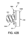
図42A~42Dに、金属で裏打ちされた関節窩インプラントの実施形態1000を示す。金属で裏打ちされた関節窩インプラントは、ツーピース構造、すなわち、金属アンカー1000A、及びポリマーインサート1000Bを含む。これらは、埋め込みプロセス中に互いにロックするように構成されている。ポリマーインサート1000Bは、UHMWPEまたはPEEKなどの高弾性率ポリマー材料で形成することができる。金属アンカー1000Aは、2つの面を含む円板部分1011と、骨対向ベース面1020である2つの面のうちの1つの中心から延びるネジ付きネジ部分1012と、を含む。ベース面1020の反対側の面は、ポリマーインサート1000Bを受け取る面である。板部分1011は、板部分1011の周囲に沿った複数の切り欠きまたはノッチ1013によって構成される。ポリマーインサート1000Bは、関節面1030を含み、関節面1030とは反対側でポリマーインサート1000Bから延びる複数のタブ1002をさらに含む。タブ1002は、対応する切り欠き1013内に嵌まり込むように構成されている。タブ1002の数及び場所は、板部分1011上の複数の切り欠き1013の数及び場所と一致する。ポリマーインサート1000B及び金属アンカー1000Aは、タブ1002を位置合わせし、切り欠き1013を通して挿入することによって、互いにロックする。図42E~42Fは、ポリマーインサート1000Bのない金属アンカー1000Aの図である。 42A-42D show an embodiment 1000 of a metal-backed glenoid implant. The metal-backed glenoid implant includes a two-piece structure, namely, a metal anchor 1000A, and a polymer insert 1000B, which are configured to lock together during the implantation process. The polymer insert 1000B can be formed of a high modulus polymer material such as UHMWPE or PEEK. The metal anchor 1000A includes a disk portion 1011 that includes two faces, and a threaded screw portion 1012 that extends from the center of one of the two faces, which is a bone-facing base surface 1020. The surface opposite the base surface 1020 is the surface that receives the polymer insert 1000B. The plate portion 1011 is configured with a number of notches or notches 1013 along the periphery of the plate portion 1011. The polymer insert 1000B includes an articular surface 1030 and further includes a number of tabs 1002 extending from the polymer insert 1000B opposite the articular surface 1030. The tabs 1002 are configured to fit into corresponding notches 1013. The number and location of the tabs 1002 correspond to the number and location of the number of notches 1013 on the plate portion 1011. The polymer insert 1000B and the metal anchor 1000A lock together by aligning and inserting the tabs 1002 through the notches 1013. FIGS. 42E-42F are views of the metal anchor 1000A without the polymer insert 1000B.

埋め込みプロセス中、金属アンカー1000Aを最初に、タップ付きネジ穴24nを有する凹部24m(図42Hを参照)が用意された骨24内にねじ込む。金属アンカー1000Aが凹部24m内の所定の位置にねじ込まれると、最初に複数のタブを切り欠き1013と位置合わせし、タブ1002が切り欠き1013を通して完全に挿入されてロックされるまでポリマーインサート1000Bを板部分1011に向けて押し込むことによって、ポリマーインサート1000Bが金属アンカー1000Aの板部分1011上に嵌まる。タブ1002のそれぞれは、1つ以上の圧縮逃がしスロット1002a、1002bを含み、タブ1002の先端1002cは切り欠き1013よりも大きい。これにより、タブ1002は、切り欠き1013内に押し込まれると圧縮し、そして、ポリマーインサート1000Bが金属アンカー1000Aと完全に嵌合したらその静止構成に跳ね戻ることができる。図42Dは、ポリマーインサート1000Bの側面図である。タブ1002のそれぞれは、切り欠き1013によって設けられた開口部よりもある程度大きい先端1002cと、切り欠き1013によって設けられた開口部のサイズと一致するサイズの首部分1002dとを有する。したがって、タブ1002が切り欠き1013内に挿入されると、圧縮逃がしスロット1002a、1002bによって、タブ1002それぞれ上の先端1002cが圧縮され、タブ1002が切り欠き1013を通って嵌合することが可能になる。切り欠き1013が先端1002cを通過して首部分1002dと嵌合すると、先端1002cは除圧されてその静止状態に戻り、先端1002cと板部分1011との間の締まり嵌めが形成されて、ポリマーインサート1000B及び金属アンカー1000Aが一緒に保持される。図42A~42Cから分かるように、金属アンカー1000A及びポリマーインサート1000Bを一緒に組み立てると、タブ1002の先端1002cが金属アンカー1000Aのベース面1020から突出する。 During the embedding process, the metal anchor 1000A is first screwed into the bone 24, which is prepared with a recess 24m (see FIG. 42H) having a tapped screw hole 24n. Once the metal anchor 1000A is screwed into place in the recess 24m, the polymer insert 1000B is fitted onto the plate portion 1011 of the metal anchor 1000A by first aligning the tabs with the notches 1013 and forcing the polymer insert 1000B towards the plate portion 1011 until the tabs 1002 are fully inserted through the notches 1013 and locked. Each of the tabs 1002 includes one or more compression relief slots 1002a, 1002b, with the tips 1002c of the tabs 1002 being larger than the notches 1013. This allows the tabs 1002 to compress when pressed into the notches 1013 and then spring back to their resting configuration once the polymer insert 1000B is fully mated with the metal anchor 1000A. FIG. 42D is a side view of the polymer insert 1000B. Each of the tabs 1002 has a tip 1002c that is somewhat larger than the opening provided by the notch 1013 and a neck portion 1002d that is sized to match the size of the opening provided by the notch 1013. Thus, when the tabs 1002 are inserted into the notches 1013, the compression relief slots 1002a, 1002b compress the tip 1002c on each of the tabs 1002, allowing the tabs 1002 to fit through the notches 1013. As the notch 1013 passes the tip 1002c and engages with the neck portion 1002d, the tip 1002c is decompressed and returns to its resting state, forming an interference fit between the tip 1002c and the plate portion 1011, holding the polymer insert 1000B and the metal anchor 1000A together. As can be seen in Figures 42A-42C, when the metal anchor 1000A and the polymer insert 1000B are assembled together, the tip 1002c of the tab 1002 protrudes from the base surface 1020 of the metal anchor 1000A.

図42G~42Hは、金属で裏打ちされた関節窩インプラント1000を受け取るために関節窩骨内に用意されるであろう円形の凹部24mの例を示す図である。図42G~42Hは、凹部24mが形成されてバルク骨材料が取り除かれた後の骨の表面だけの3次元形状のグラフィックレンダリングを示す。図42Gを再び参照して、円形の凹部24mは底面24nを有する。円形の凹部24mを骨内にリーマー加工した後、金属アンカー1000Aのネジ付きネジ部分1012を受け取るために、ネジ穴24oを底面24n内にねじを切る。図42Hを参照して、次に、複数のより深い凹部24pを、タブ1002の配置と一致する配置でリーマー加工またはドリル加工する。これらのより深い凹部24pによって、金属で裏打ちされた関節窩インプラント1000が骨内に埋め込まれたときに、金属アンカー1000Aのベース面1020から突出するタブ1002に対するクリアランススペースが得られる。凹部24mが図42Hに示すように完全に用意されたら、関節窩インプラント1000を埋め込むために必要なねじ込み動作のために、埋め込み手順は2つのステップを含む。最初に、金属アンカー1000Aを凹部24m内に、金属アンカー1000Aが完全に着座して、金属アンカー1000Aのベース面1020が凹部24mの底面24nと接触するまで、螺入する。この時点で、金属アンカー1000Aは凹部24mの底部に着座する。次に、ポリマーインサート1000Bのタブ1002を、金属アンカー1000A内の切り欠き1013と位置合わせして、ポリマーインサート1000Bを凹部24m内に、タブ1002の先端1002cが切り欠き1013を通して押し込まれて所定の位置に嵌まるまで押し込む。より深い凹部24pによって、タブ1002の先端1002cに対するクリアランスが得られる。さらに、タブ1002の先端1002cは、より深い凹部24p内に位置するため、インプラント1000が回転することが防止されるので、インプラント1000はネジを緩めることによって後退することはできない。 42G-42H show an example of a circular recess 24m that may be prepared in the glenoid bone to receive the metal-backed glenoid implant 1000. FIGS. 42G-42H show a graphic rendering of the three-dimensional shape of only the bone surface after the recess 24m is formed and the bulk bone material is removed. Referring again to FIG. 42G, the circular recess 24m has a bottom surface 24n. After the circular recess 24m is reamed into the bone, a screw hole 24o is tapped into the bottom surface 24n to receive the threaded portion 1012 of the metal anchor 1000A. Referring to FIG. 42H, a number of deeper recesses 24p are then reamed or drilled in an arrangement that matches the arrangement of the tabs 1002. These deeper recesses 24p provide clearance space for the tabs 1002 that protrude from the base surface 1020 of the metal anchor 1000A when the metal-backed glenoid implant 1000 is implanted into the bone. Once the recess 24m is fully prepared as shown in FIG. 42H, for the screwing action required to embed the glenoid implant 1000, the embedding procedure involves two steps. First, the metal anchor 1000A is screwed into the recess 24m until the metal anchor 1000A is fully seated and the base surface 1020 of the metal anchor 1000A contacts the bottom surface 24n of the recess 24m. At this point, the metal anchor 1000A is seated at the bottom of the recess 24m. Next, the tab 1002 of the polymer insert 1000B is aligned with the notch 1013 in the metal anchor 1000A and the polymer insert 1000B is pushed into the recess 24m until the tip 1002c of the tab 1002 is pushed through the notch 1013 and snaps into place. The deeper recess 24p provides clearance for the tip 1002c of the tab 1002. Furthermore, the tip 1002c of the tab 1002 is located within the deeper recess 24p, preventing the implant 1000 from rotating, so that the implant 1000 cannot be retracted by unscrewing.

図43A~43Bに、多孔性金属で裏打ちされた関節窩インプラントの実施形態1100を示す。関節窩インプラントの実施形態1100は、金属ベースプレート1100A上に直接オーバーモールドされた、関節面1130を与えるポリマーインサート1100Bを含む。ポリマーインサート1100Bは、UHMWPEまたはPEEKなどの高弾性率ポリマー材料で形成することができる。関節面1130は、上腕骨頭(解剖学的なものまたは人工装具のもの)と嵌合するためである。図43A~43Bに示すインプラント1100に対するオーバーモールド構造では、金属ベースプレート1100Aは骨接触ベース面1120をもたらす。いくつかの実施形態では、骨接触ベース面1120を、埋め込み後に関節窩への関節窩インプラント1100の結合を高めるために骨組織の内部成長を促進することができるWright Medical TechnologyのADAPTIS(商標)などの多孔性の小柱金属材料によってコーティングする。図43Cは、骨接触ベース面1120を特定している。図43Dにおけるインプラント1100の断面図は、ベース面1120上の多孔性の小柱状金属コーティングPを示す。 43A-43B show a porous metal backed glenoid implant embodiment 1100. The glenoid implant embodiment 1100 includes a polymer insert 1100B that provides an articular surface 1130, overmolded directly onto a metal base plate 1100A. The polymer insert 1100B can be formed of a high modulus polymer material such as UHMWPE or PEEK. The articular surface 1130 is for mating with the humeral head (anatomical or prosthetic). In the overmolded configuration for the implant 1100 shown in FIGS. 43A-43B, the metal base plate 1100A provides the bone contacting base surface 1120. In some embodiments, the bone-contacting base surface 1120 is coated with a porous trabecular metal material, such as ADAPTIS™ from Wright Medical Technology, which can promote bone tissue ingrowth to enhance bonding of the glenoid implant 1100 to the glenoid cavity after implantation. FIG. 43C identifies the bone-contacting base surface 1120. The cross-sectional view of the implant 1100 in FIG. 43D shows the porous trabecular metal coating P on the base surface 1120.

いくつかの実施形態では、ポリマーインサート1100Bの側壁1110は、周囲の固定を強化するためにテーパーを付けることができる。 In some embodiments, the sidewalls 1110 of the polymer insert 1100B can be tapered to enhance circumferential fixation.

ポリマーインサート1100Bは金属ベースプレート1100A上にオーバーモールドされるが、インプラント1100は、必要に応じて金属ベースプレート1100Aからポリマーインサート1100Bを取り外せるように構成されたアセンブリである。図43Cにおけるインプラント1100の分解組立図は、インプラント1100が3つのコンポーネント、すなわち、ベースプレート1100A、取り外しウェッジネジ1140、及びオーバーモールドされたポリマーインサート1100Bを含むことを示している。取り外しウェッジネジ1140は、ポリマーインサート1100Bを金属ベースプレート1100A上にオーバーモールドする前に、金属ベースプレート1100A内に組み付ける。取り外しウェッジネジ1140を、金属ベースプレート1100Aの長手軸LLに沿って金属ベースプレート1100Aを通って延びるネジ穴1155内にねじ込む。取り外しウェッジネジ1140は、ヘッド部分1141及びネジ付きステム部分1142を含む。次に、ポリマーインサート1100Bを、ベースプレート1100A及び取り外しウェッジネジ1140のヘッド部分1141上にオーバーモールドする。ヘッド部分1141は、金属ベースプレート1100Aの実質的な部分を覆う直径を有しており、オーバーモールドされたポリマーインサート1100Bによって覆われる金属ベースプレートの表面積の実質的な部分がヘッド部分1141である。後述するように、この構成によって、オーバーモールドされたポリマーインサート1100Bを取り外すことが、取り外しウェッジネジ1140を用いて可能である。図43Dにおける断面図に示すように、取り外しウェッジネジ1140は、そのヘッド部分1141の中心に工具嵌合ソケット1145を含む。これは、取り外しウェッジネジ1140をネジ穴1155にねじ込むかまたは緩めるために用いることができる。工具嵌合ソケット1145は、種々の既知の種類のネジ回しのうちの1つと嵌合するように構成することができる。オーバーモールドされたポリマーインサート1100Bは、インサート1100Bの中心に、工具嵌合ソケット1145へのアクセスをもたらすアクセス穴1135が設けられている。図43Fは、ポリマーインサート1100Bの関節面1130をまっすぐ見た図である。この図において、工具嵌合ソケット1145をアクセス穴1135を通して見ることができる。この例では、工具嵌合ソケット1145は、六角形のネジ回しの先端を受け入れる種類である。取り外しウェッジネジ1140を、金属ベースプレート1100Aのネジ穴1155から緩めることによって、取り外しウェッジネジ1140のヘッド部分1141が、オーバーモールドされたポリマーインサート1100Bをベースプレート1100Aから持ち上げて取り外す。この取り外し手順をさらに可能にするために、ベースプレート1100A及びポリマーインサート1100Bの両方が、互いに位置合わせされた一対のスロット1132A及び1132Bをそれぞれ備えて構成されている。これらのスロット1132A、1132Bは、取り外しウェッジネジ1140を取り外すときに逆トルクを与えるために用いる。取り外しウェッジネジ1140を緩めるとき、適切な工具をスロット1132A、1132Bの対内に挿入して、ベースプレート1100A及びポリマーインサート1100Bを所定の位置に保持し、取り外しウェッジネジ1140とともに回転することがないようにする。 Although the polymer insert 1100B is overmolded onto the metal base plate 1100A, the implant 1100 is an assembly configured to allow the polymer insert 1100B to be removed from the metal base plate 1100A as needed. The exploded view of the implant 1100 in FIG. 43C shows that the implant 1100 includes three components: the base plate 1100A, the removal wedge screw 1140, and the overmolded polymer insert 1100B. The removal wedge screw 1140 is assembled into the metal base plate 1100A prior to overmolding the polymer insert 1100B onto the metal base plate 1100A. The removal wedge screw 1140 is threaded into a threaded hole 1155 extending through the metal base plate 1100A along the longitudinal axis LL of the metal base plate 1100A. The removal wedge screw 1140 includes a head portion 1141 and a threaded stem portion 1142. Next, the polymer insert 1100B is overmolded onto the base plate 1100A and the head portion 1141 of the removal wedge screw 1140. The head portion 1141 has a diameter that covers a substantial portion of the metal base plate 1100A, and the substantial portion of the surface area of the metal base plate that is covered by the overmolded polymer insert 1100B is the head portion 1141. As will be described below, this configuration allows the overmolded polymer insert 1100B to be removed using the removal wedge screw 1140. As shown in cross section in FIG. 43D, the removal wedge screw 1140 includes a tool engagement socket 1145 in the center of its head portion 1141, which can be used to thread or unthread the removal wedge screw 1140 into the threaded hole 1155. The tool engagement socket 1145 can be configured to mate with one of various known types of screwdrivers. The overmolded polymer insert 1100B is provided with an access hole 1135 at the center of the insert 1100B that provides access to the tool engagement socket 1145. FIG. 43F is a straight-on view of the articular surface 1130 of the polymer insert 1100B. In this view, the tool engagement socket 1145 can be seen through the access hole 1135. In this example, the tool engagement socket 1145 is of the type that accepts the tip of a hexagonal screwdriver. By loosening the removal wedge screw 1140 from the threaded hole 1155 in the metal base plate 1100A, the head portion 1141 of the removal wedge screw 1140 lifts and removes the overmolded polymer insert 1100B from the base plate 1100A. To further enable this removal procedure, both the base plate 1100A and the polymer insert 1100B are configured with a pair of slots 1132A and 1132B, respectively, that are aligned with one another. These slots 1132A, 1132B are used to provide counter torque when removing the removal wedge screw 1140. When loosening the removal wedge screw 1140, an appropriate tool is inserted into the pair of slots 1132A, 1132B to hold the base plate 1100A and polymer insert 1100B in place and prevent them from rotating with the removal wedge screw 1140.

図43Eに、図43Dにおける領域Bの詳細図を示す。図43Eは、オーバーモールドされたポリマーインサート1100Bが金属ベースプレート1100Aに結合する様子を示す。いくつかの実施形態では、2つのコンポーネント間の結合の機械的完全性を高めるために、ベースプレート1100Aは、ベースプレート1100Aの周囲に沿って延びる溝1150を含むことができ、その結果、2つのコンポーネント間のより入り組んだ嵌合界面がもたらされ、たとえば、直線的な界面よりも機械的に強い接合界面が得られる。 Figure 43E shows a detailed view of region B in Figure 43D. Figure 43E shows an overmolded polymer insert 1100B bonding to a metal base plate 1100A. In some embodiments, to increase the mechanical integrity of the bond between the two components, the base plate 1100A can include a groove 1150 that runs along the periphery of the base plate 1100A, resulting in a more intricate mating interface between the two components, e.g., resulting in a mechanically stronger bond interface than a straight interface.

いくつかの実施形態では、モジュラー支柱、モジュラーネジ、キールなどの異なる固定オプションを、この多孔性金属で裏打ちされた関節窩インプラント1100とともに用いることができる。たとえば、モジュラー支柱1162、またはモジュラーネジ1164、1166を、図43Gに例示するように、ネジ穴1155内に螺入することができる。 In some embodiments, different fixation options, such as modular posts, modular screws, keels, etc., can be used with the porous metal-lined glenoid implant 1100. For example, a modular post 1162 or modular screws 1164, 1166 can be threaded into the screw holes 1155, as illustrated in FIG. 43G.

図43Hに、インプラント1100を逆構成肩インプラントに変換することができる実施形態を示す。この変換のために、ポリマーインサート1100Bの代わりに、グレノスフィア1100Gと嵌合するように構成されたテーパーボス1100Cを、金属ベースプレート1100Aに取り付ける。図43Hでは、金属ベースプレート1100A及びテーパーボス1100Cを断面で示している。いくつかの実施形態では、テーパーボス1100Cを、ネジ1140aによって金属ベースプレート1100Aに取り付けるように構成することができる。ネジ1140aは、図示したように、金属ベースプレート1100Aのネジ穴1155内にネジ込まれる。テーパーボス1100Cは、ネジ1140aを受け取るための穴を中心に含み、テーパーボス1100C内の穴は、内側に延びてネジ1140aの頭部を捕らえる縁1100C’を含む。したがって、ネジ1140aの頭部は、ネジの頭部と金属ベースプレート1100Aとの間でテーパーボス1100Cを捕捉して、テーパーボス1100Cを固定する。ネジの頭部には、種々の既知の種類のネジ回しのうちの1つと嵌合するように構成された工具嵌合ソケット1140a’が設けられている。テーパーボス1100Cは、モールステーパータイプのロッキング接続を介してグレノスフィア1100Gと嵌合するようにテーパーが付けられた側壁1110を有する。グレノスフィア1100Gは、雄型テーパー面1110と嵌合する対応する雌型テーパー面1100G’を含む。またテーパーボス1100Cは、金属ベースプレート1100A内のスロット1132Aと位置が合い、固定を強化するためのネジを受け入れることができるネジ穴(図示せず)によって構成することができる。 FIG. 43H illustrates an embodiment in which the implant 1100 can be converted to a reverse configuration shoulder implant. For this conversion, instead of the polymer insert 1100B, a tapered boss 1100C configured to mate with the glenosphere 1100G is attached to the metal base plate 1100A. In FIG. 43H, the metal base plate 1100A and the tapered boss 1100C are shown in cross section. In some embodiments, the tapered boss 1100C can be configured to attach to the metal base plate 1100A by a screw 1140a. The screw 1140a is threaded into a threaded hole 1155 of the metal base plate 1100A as shown. The tapered boss 1100C includes a hole in the center for receiving the screw 1140a, and the hole in the tapered boss 1100C includes a lip 1100C' that extends inward to capture the head of the screw 1140a. Thus, the head of the screw 1140a captures the tapered boss 1100C between the head of the screw and the metal base plate 1100A to secure the tapered boss 1100C. The head of the screw is provided with a tool engagement socket 1140a' configured to mate with one of various known types of screwdrivers. The tapered boss 1100C has a tapered sidewall 1110 to mate with the glenosphere 1100G via a Morse taper type locking connection. The glenosphere 1100G includes a corresponding female tapered surface 1100G' that mates with the male tapered surface 1110. The tapered boss 1100C can also be configured with a threaded hole (not shown) that aligns with the slot 1132A in the metal base plate 1100A and can receive a screw for enhanced fixation.

図44A~45Dに、周囲リング固定機能部を用いた関節窩インプラントの実施形態を示す。図44Aを参照して、関節窩インプラント1200は、一方の側に関節面1230、反対側に骨対向ベース面1220を含む実質的に円形の本体1205を含む。円形の本体1205の周囲に沿って、2つの表面1220及び1230間を延びる側壁1210がある。骨対向ベース面1220から、関節窩と嵌合するためのリング1212を含む周囲固定機能部が延びている。図44Cにおける断面図に示すように、いくつかの実施形態では、関節面1230は、関節窩の解剖学的関節面を再現するように輪郭形成されている。いくつかの実施形態では、関節面1230は、必要に応じて球形の輪郭を有することができる。骨対向ベース面1220は、インプラント1200を受け取るための相補的な表面を備えて用意された、関節窩と嵌合する球形の輪郭を有する。 44A-45D show embodiments of glenoid implants using a peripheral ring fixation feature. With reference to FIG. 44A, the glenoid implant 1200 includes a substantially circular body 1205 including an articular surface 1230 on one side and a bone-facing base surface 1220 on the opposite side. Along the periphery of the circular body 1205 is a sidewall 1210 extending between the two surfaces 1220 and 1230. Extending from the bone-facing base surface 1220 is a peripheral fixation feature including a ring 1212 for mating with the glenoid cavity. As shown in cross section in FIG. 44C, in some embodiments, the articular surface 1230 is contoured to replicate the anatomical articular surface of the glenoid cavity. In some embodiments, the articular surface 1230 can have a spherical contour, if desired. The bone-facing base surface 1220 has a spherical contour to mate with the glenoid cavity, which is provided with a complementary surface to receive the implant 1200.

関節窩インプラント1200はさらに、骨対向面1220の周囲から延びる周囲リング1212であって、周囲リング1212を受け取るための環状の凹部24q(図45Eを参照)を備えて用意された関節窩とも嵌合する周囲リング1212を含む。インプラント本体1205が実質的に円形状を有する関節窩インプラントのこの実施形態1200では、周囲リング1212は側壁1210の延長部分である。周囲リング1212は、関節窩への固定の質を高めるように構成されている。周囲リング1212は、リング1212の外面上に設けられた溝1213を含み、リング1212の周囲に沿って延びている。溝1213は、関節窩と結合するためにリング1212の周囲に沿ってある量の骨セメントを保持する目的を果たす。また周囲リング1212は、溝1213に隣接してリング1212の外面に沿って設けられた任意的なさらなる複数のセメント溝1214も含むことができる。複数のセメント溝1214は軸方向に配向される。好ましい実施形態では、複数のセメント溝1214は、リング1212に沿って半径方向に対称な場所に配置される。複数のセメント溝1214を介してさらなる骨セメントを適用することは、埋め込み後の関節窩インプラント1200の回転を防ぐことが意図されている。 The glenoid implant 1200 further includes a peripheral ring 1212 extending from the periphery of the bone-facing surface 1220 and mating with a prepared glenoid cavity with an annular recess 24q (see FIG. 45E) for receiving the peripheral ring 1212. In this embodiment 1200 of the glenoid implant, in which the implant body 1205 has a substantially circular shape, the peripheral ring 1212 is an extension of the side wall 1210. The peripheral ring 1212 is configured to enhance the quality of fixation to the glenoid cavity. The peripheral ring 1212 includes a groove 1213 on the outer surface of the ring 1212 and extending along the circumference of the ring 1212. The groove 1213 serves the purpose of retaining a quantity of bone cement along the circumference of the ring 1212 for coupling with the glenoid cavity. The peripheral ring 1212 may also include an optional further plurality of cement grooves 1214 adjacent to the groove 1213 and along the outer surface of the ring 1212. The cement grooves 1214 are axially oriented. In a preferred embodiment, the cement grooves 1214 are disposed at radially symmetric locations along the ring 1212. The application of additional bone cement through the cement grooves 1214 is intended to prevent rotation of the glenoid implant 1200 after implantation.

いくつかの実施形態では、関節窩インプラント1200は、ベース面1220から延びる1つ以上のさらなる固定機能部をさらに含むことができる。これらのさらなる固定機能部は、支柱、フィン付きアンカー、キールなどの固定機能部のうちのいずれか1つとすることができる。図44Dに、ベース面1220の中心から延びるフィン付きアンカー925を含む関節窩インプラント1200の例を示す。 In some embodiments, the glenoid implant 1200 may further include one or more additional fixation features extending from the base surface 1220. These additional fixation features may be any one of the following fixation features: a post, a finned anchor, a keel, etc. FIG. 44D shows an example of a glenoid implant 1200 including a finned anchor 925 extending from the center of the base surface 1220.

いくつかの他の実施形態では、関節窩インプラント1200のベース面1220は、図44Eに示す断面例に示すように、平坦面とすることができる。いくつかの他の実施形態では、周囲リング1212の外面には、図44Fに示す断面図例に示すように、セメントレス用途のための柔軟なフィン1217が設けられる。フィン1217は、フィン付きアンカー925上のフィン927と同じ機能を果たす。 In some other embodiments, the base surface 1220 of the glenoid implant 1200 can be a flat surface, as shown in the example cross-section shown in FIG. 44E. In some other embodiments, the outer surface of the peripheral ring 1212 is provided with flexible fins 1217 for cementless applications, as shown in the example cross-section shown in FIG. 44F. The fins 1217 perform the same function as the fins 927 on the finned anchor 925.

図45A~45Bに、インプラント本体1205Aと、図44Aに示す関節窩インプラント1200と同様に周囲固定要素として骨対向ベース面1220上に設けられた周囲リング1212と、を含む、別の関節窩インプラント1200Aの実施形態を示す。関節窩インプラント1200Aに対する周囲リング1212は、関節窩インプラント1200に対する周囲リング1212と同じ構造的特徴であり、任意的な機能部をすべて含む。しかし、実施形態1200Aでは、インプラント本体1205Aは円形ではなく、解剖学的関節窩の輪郭を反映する形状を有する。関節窩インプラント1200と同様に、関節窩インプラント1200Aもまた、ベース面1220から延びる1つ以上のさらなる固定機能部によって構成することができる。これらのさらなる固定機能部は、支柱、フィン付きアンカー、キールなどの固定機能部のうちのいずれか1つとすることができる。図45C~45Dに、このようなさらなる固定機能部を含む関節窩インプラントの実施形態1200Bを示す。関節窩インプラント1200Bはまた、関節窩インプラント1200及び1200Aと同様に、周囲固定要素として周囲リング1212構造を有する。関節窩インプラント1200Bに対する周囲リング1212は、関節窩インプラント1200及び1200Aに対する周囲リング1212と同じ構造的特徴であり、任意的な機能部をすべて含む。インプラント本体1205Bも、解剖学的関節窩の輪郭を反映するように形作られている。しかし、実施形態1200Bでは、インプラント本体1205Bは、前述した1つ以上のさらなる固定機能部として周囲リング1212の一部から延びる2つ以上の安定化支柱925’を含む。関節窩インプラントの実施形態1200、1200A、及び1200Bは、UHMWPEまたはPEEKなどの高弾性率ポリマー材料で形成することができる。 45A-45B show another embodiment of a glenoid implant 1200A including an implant body 1205A and a peripheral ring 1212 provided on the bone-facing base surface 1220 as a peripheral fixation element similar to the glenoid implant 1200 shown in FIG. 44A. The peripheral ring 1212 for the glenoid implant 1200A has the same structural features and includes all the optional features as the peripheral ring 1212 for the glenoid implant 1200. However, in the embodiment 1200A, the implant body 1205A is not circular, but has a shape that reflects the contour of the anatomical glenoid. Similar to the glenoid implant 1200, the glenoid implant 1200A can also be configured with one or more additional fixation features extending from the base surface 1220. These additional fixation features can be any one of the fixation features such as struts, finned anchors, keels, etc. FIGS. 45C-45D show an embodiment 1200B of a glenoid implant including such additional fixation features. The glenoid implant 1200B also has a peripheral ring 1212 structure as a peripheral fixation element, similar to glenoid implants 1200 and 1200A. The peripheral ring 1212 for the glenoid implant 1200B has all the same structural features and optional features as the peripheral ring 1212 for the glenoid implants 1200 and 1200A. The implant body 1205B is also shaped to reflect the contours of the anatomical glenoid. However, in embodiment 1200B, the implant body 1205B includes two or more stabilizing posts 925' extending from a portion of the peripheral ring 1212 as one or more additional fixation features as previously described. The glenoid implant embodiments 1200, 1200A, and 1200B can be formed of a high modulus polymeric material, such as UHMWPE or PEEK.

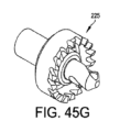
図45Eは、関節窩24を、図44A及び45Aに示す関節窩インプラントを受け取るための環状の凹部24qを備えて、どのように用意し得るかを示す図である。環状の凹部24qは、関節窩インプラント1200、1200Aの周囲リング1212を受け取るような寸法である。湾曲したベース面1220を有するインプラント1200または1200Aを受け取るために、関節窩24を最初に、湾曲したリーマーによってリーマー加工して、湾曲したベース面1220の曲率に一致する湾曲面24sに関節窩24表面を用意する。次に、ベルソー型リーマー225を用いて、環状の凹部24qをリーマー加工する。 Figure 45E illustrates how the glenoid 24 may be prepared with an annular recess 24q to receive the glenoid implant shown in Figures 44A and 45A. The annular recess 24q is dimensioned to receive the peripheral ring 1212 of the glenoid implant 1200, 1200A. To receive the implant 1200 or 1200A having a curved base surface 1220, the glenoid 24 is first reamed with a curved reamer to prepare the glenoid 24 surface with a curved surface 24s that matches the curvature of the curved base surface 1220. The annular recess 24q is then reamed using a Bell-Saw type reamer 225.

図45Fは、環状の凹部24qが形成された後に関節窩24内に埋め込まれた図44Aまたは45Aの関節窩インプラントを示す図である。 Figure 45F shows the glenoid implant of Figure 44A or 45A implanted into the glenoid fossa 24 after the annular recess 24q has been formed.

図45G~45Hは、関節窩24内に環状の凹部24qを形成するために使用できるベルソー型リーマー225及び226の例を示す図である。 Figures 45G-45H show examples of Bell-Saw type reamers 225 and 226 that can be used to form an annular recess 24q in the glenoid fossa 24.

周囲リング固定機能部に加えて、関節窩インプラントは、支柱、フィン付きアンカー、またはキールなどの1つ以上のさらなる非周囲固定機能部を有することができる。 In addition to the peripheral ring fixation feature, the glenoid implant may have one or more additional non-peripheral fixation features, such as posts, finned anchors, or keels.

図46A~46Bは、別の実施形態による関節窩インプラント例1300を示す図である。関節窩インプラント1300は、一方の側に関節面1330、反対側に骨対向ベース面1320面を有するインプラント本体1305を含む。関節窩インプラント1300はさらに、関節窩インプラント1200及び1200Aと同様に、周囲固定要素として骨対向ベース面1320上に設けられた周囲リング1312を含む。関節窩インプラント1300はまた、ベース面1320から延び、周囲リング1312に沿ったどこかに位置する1つ以上の支柱925’’を含み、骨とのインプラントの固定をさらに強化することができる。 46A-46B illustrate an example glenoid implant 1300 according to another embodiment. The glenoid implant 1300 includes an implant body 1305 having an articular surface 1330 on one side and a bone-facing base surface 1320 on the opposite side. The glenoid implant 1300 further includes a peripheral ring 1312 disposed on the bone-facing base surface 1320 as a peripheral fixation element, similar to glenoid implants 1200 and 1200A. The glenoid implant 1300 also includes one or more struts 925'' extending from the base surface 1320 and positioned anywhere along the peripheral ring 1312 to further enhance fixation of the implant with the bone.

いくつかの好ましい実施形態では、1つ以上の支柱925’’は、周囲リング1312に沿って半径方向に対称な位置に配置される。周囲リング1312と共に半径方向に離間に配置された支柱925’’は、患者内での関節窩インプラント1300の微動を最小限にするかまたは実質的になくすと考えられる。 In some preferred embodiments, one or more struts 925'' are positioned at radially symmetric locations along the peripheral ring 1312. It is believed that the struts 925'' spaced radially apart along with the peripheral ring 1312 minimize or substantially eliminate micromotion of the glenoid implant 1300 within the patient.

周囲リング1312及び支柱925’’は、セメントレス用途における関節窩への関節窩インプラント1300の固定を強化するために骨組織の内部成長を促進する多孔性の小柱状金属構造である。 The peripheral ring 1312 and posts 925'' are porous trabecular metal structures that promote bone tissue ingrowth to enhance fixation of the glenoid implant 1300 to the glenoid cavity in cementless applications.

図46Bの断面図を参照して、いくつかの実施形態では、支柱925’’は、支柱925’’に適切な構造安定性(すなわち、剛性)を与える固体金属コアを有する複合構造である。固体金属コアを、多孔性の小柱状金属コーティングが固体金属コアに結合して患者内の一生涯の構造信頼性を実現することができる適切な合金で形成することができる。周囲リング固定機能部1312と、固体金属コアを有する1つ以上のさらなる固定機能部925’’との組み合わせは、本明細書では、患者内に埋め込まれたときに骨の内部成長を促すための多孔性の小柱金属材料で実質的に形成されていると言う。 Referring to the cross-sectional view of FIG. 46B, in some embodiments, the struts 925'' are composite structures having a solid metal core that provides suitable structural stability (i.e., rigidity) to the struts 925''. The solid metal core can be formed of a suitable alloy to which a porous trabecular metal coating can bond to provide lifetime structural reliability within a patient. The combination of the peripheral ring fixation feature 1312 and one or more additional fixation features 925'' having a solid metal core is referred to herein as being substantially formed of a porous trabecular metal material for promoting bone ingrowth when implanted within a patient.

関節窩インプラント1300は、UHMWPEまたはPEEKなどの高弾性率ポリマー材料で形成することができる。いくつかの実施形態では、インプラント本体1305は、解剖学的関節窩の輪郭を反映する形状を有する。高弾性率ポリマー材料のインプラント本体1305は、金属周囲リング1312及び支柱925’’構造の一部上にオーバーモールドすることができる。小柱状金属の周囲リング1312と1つ以上の支柱925’’との組み合わせは、関節窩骨への関節窩インプラント1300の一次固定を強化するはずである。 The glenoid implant 1300 may be formed of a high modulus polymeric material such as UHMWPE or PEEK. In some embodiments, the implant body 1305 has a shape that reflects the contours of the anatomical glenoid. The high modulus polymeric material implant body 1305 may be overmolded onto the metal circumferential ring 1312 and a portion of the strut 925'' structure. The combination of the trabecular metal circumferential ring 1312 and one or more struts 925'' should enhance the primary fixation of the glenoid implant 1300 to the glenoid bone.

デバイス、キット、システム、及び方法を、典型的な実施形態に関して説明してきたが、これらはそれに限定されない。むしろ、添付の特許請求の範囲は、デバイス、キット、システム、及び方法の他の変形及び実施形態を含むように広く解釈すべきであり、これらは、デバイス、キット、システム、及び方法の均等物の領域及び範囲から逸脱することなく、当業者によって作られ得る。
Although the devices, kits, systems, and methods have been described with respect to exemplary embodiments, they are not limited thereto. Rather, the appended claims should be construed broadly to include other variations and embodiments of the devices, kits, systems, and methods, which may be made by those skilled in the art without departing from the realm and scope of equivalents of the devices, kits, systems, and methods.

Claims (11)

関節窩インプラントであって、
関節面及び反対側のアンカリング表面を含む円形の本体であって、前記アンカリング表面は、用意された関節窩における対応する平坦な表面に接触して前記平坦な表面を収容するために平坦である、円形の本体と、
前記円形の本体の周囲に沿って延びる環状の側壁であって、前記環状の側壁から延在し前記関節面に向かって折り返されることでU字形の板バネを形成する複数の保持脚を有する、環状の側壁と、を含み、
前記環状の側壁は、関節窩内に用意された凹部に圧入されるように構成されている、前記関節窩インプラント。
1. A glenoid implant comprising:
a circular body including an articular surface and an opposing anchoring surface, the anchoring surface being flat to contact and accommodate a corresponding flat surface in a prepared glenoid cavity;
an annular sidewall extending around a circumference of the circular body , the annular sidewall having a plurality of retaining legs extending from the annular sidewall and folding back towards the articular surface to form a U-shaped leaf spring;
The glenoid implant, wherein the annular side wall is configured to be press-fit into a recess provided in the glenoid cavity.
前記インプラントは金属で形成される、請求項1に記載の関節窩インプラント。 The glenoid implant of claim 1, wherein the implant is formed of metal. 前記金属はCoCrまたはチタンである、請求項に記載の関節窩インプラント。 The glenoid implant of claim 2 , wherein the metal is CoCr or titanium. 前記インプラントは高弾性率ポリマーで形成される、請求項1に記載の関節窩インプラント。 The glenoid implant of claim 1, wherein the implant is formed of a high modulus polymer. 前記ポリマーはUHMWポリエチレンである、請求項に記載の関節窩インプラント。 The glenoid implant of claim 4 wherein the polymer is UHMW polyethylene. 前記円形の本体及び前記保持脚は同じ材料から一体に形成される、請求項1に記載の関節窩インプラント。 The glenoid implant of claim 1, wherein the circular body and the retention legs are integrally formed from the same material. 前記アンカリング表面は多孔性金属材料によってコーティングされる、請求項1に記載の関節窩インプラント。 The glenoid implant of claim 1, wherein the anchoring surface is coated with a porous metal material. 前記関節窩インプラントが前記関節窩内に用意された前記凹部に圧入されることを可能にするように、前記環状の側壁は、2つの隣接する溝の間に形成されたブレードを伴う複数の溝を含む溝付き表面である、請求項1に記載の関節窩インプラント。 The glenoid implant of claim 1, wherein the annular sidewall is a grooved surface including a plurality of grooves with a blade formed between two adjacent grooves to allow the glenoid implant to be press-fit into the recess provided in the glenoid. 前記インプラントは金属で形成される、請求項に記載の関節窩インプラント。 The glenoid implant of claim 8 , wherein the implant is formed of metal. 前記金属はCoCrまたはチタンである、請求項に記載の関節窩インプラント。 The glenoid implant of claim 9 , wherein the metal is CoCr or titanium. 前記アンカリング表面は多孔性金属材料によってコーティングされる、請求項に記載の関節窩インプラント。 The glenoid implant of claim 8 , wherein the anchoring surface is coated with a porous metallic material.
JP2023532755A 2020-12-31 2021-09-30 Glenoid Implant Active JP7620102B2 (en)

Priority Applications (1)

Application Number Priority Date Filing Date Title
JP2025002678A JP2025072370A (en) 2020-12-31 2025-01-08 Glenoid Implant

Applications Claiming Priority (3)

Application Number Priority Date Filing Date Title
US202063132600P 2020-12-31 2020-12-31
US63/132,600 2020-12-31
PCT/US2021/071653 WO2022147376A1 (en) 2020-12-31 2021-09-30 Glenoid implants

Related Child Applications (1)

Application Number Title Priority Date Filing Date
JP2025002678A Division JP2025072370A (en) 2020-12-31 2025-01-08 Glenoid Implant

Publications (3)

Publication Number Publication Date
JP2023551317A JP2023551317A (en) 2023-12-07
JPWO2022147376A5 JPWO2022147376A5 (en) 2024-06-18
JP7620102B2 true JP7620102B2 (en) 2025-01-22

Family

ID=82259688

Family Applications (2)

Application Number Title Priority Date Filing Date
JP2023532755A Active JP7620102B2 (en) 2020-12-31 2021-09-30 Glenoid Implant
JP2025002678A Pending JP2025072370A (en) 2020-12-31 2025-01-08 Glenoid Implant

Family Applications After (1)

Application Number Title Priority Date Filing Date
JP2025002678A Pending JP2025072370A (en) 2020-12-31 2025-01-08 Glenoid Implant

Country Status (6)

Country Link
US (1) US20240008995A1 (en)
EP (1) EP4231968A4 (en)
JP (2) JP7620102B2 (en)
CN (1) CN116615158A (en)
AU (1) AU2021413348B2 (en)
WO (1) WO2022147376A1 (en)

Families Citing this family (8)

* Cited by examiner, † Cited by third party
Publication number Priority date Publication date Assignee Title
FR2971144A1 (en) 2011-02-08 2012-08-10 Tornier Sa GLENOIDAL IMPLANT FOR SHOULDER PROSTHESIS AND SURGICAL KIT
US10722374B2 (en) 2015-05-05 2020-07-28 Tornier, Inc. Convertible glenoid implant
AU2020208306B2 (en) * 2019-01-15 2025-06-05 Biopoly, Llc Implant systems for repair of a glenoid cavity
CA3134015C (en) 2019-05-13 2024-01-02 Howmedica Osteonics Corp. Glenoid baseplate and implant assemblies
EP3982848A1 (en) 2019-08-09 2022-04-20 Howmedica Osteonics Corp. Apparatuses and methods for implanting glenoid prostheses
WO2022182426A1 (en) 2021-02-26 2022-09-01 Howmedica Osteonics Corp. Glenoid implant components and instruments therefor
DE102022132352B4 (en) * 2022-12-06 2025-01-23 mechamed GmbH socket for a joint prosthesis
WO2025090285A1 (en) * 2023-10-24 2025-05-01 Howmedica Osteonics Corp. Improved glenoid implants

Citations (4)

* Cited by examiner, † Cited by third party
Publication number Priority date Publication date Assignee Title
US20070260321A1 (en) 2006-05-02 2007-11-08 Stchur Robert P Conically-shaped glenoid implant with a prosthetic glenoid insert used in total shoulder arthroplasty and method
US20100228352A1 (en) 2009-03-05 2010-09-09 Tomier, Inc. Glenoid implant anchor post
US20140018927A1 (en) 2011-03-18 2014-01-16 DePuy Synthes Products, LLC Revision Glenoid Device and Method
WO2015051476A1 (en) 2013-10-13 2015-04-16 Startech Engineering Ag Shoulder prosthesis assembly

Family Cites Families (10)

* Cited by examiner, † Cited by third party
Publication number Priority date Publication date Assignee Title
DE4438620A1 (en) * 1994-05-02 1995-11-09 Laghaollah Dr Elhami Joint prosthesis and device for making a bore in at least one joint head
US6629997B2 (en) * 2000-03-27 2003-10-07 Kevin A. Mansmann Meniscus-type implant with hydrogel surface reinforced by three-dimensional mesh
EP1455692B1 (en) * 2001-12-04 2010-02-17 Active Implants Corporation Cushion bearing implants for load bearing applications
US8778028B2 (en) 2005-02-25 2014-07-15 Shoulder Innovations, Inc. Methods and devices for less invasive glenoid replacement
EP1940322A2 (en) 2005-10-26 2008-07-09 Exactech, Inc. Apparatus and method to obtain bone fixation
CA2868764C (en) * 2006-01-20 2016-10-11 Roy C. Wiley Shoulder arthroplasty system
FR2940607B1 (en) * 2008-12-29 2012-04-06 Didier Capon GLENOIDAL IMPLANT COMPRISING A CUP FOR COOPERATING WITH A PROTHETIC HUMERAL HEAD
JP2013521889A (en) * 2010-03-11 2013-06-13 ザ キュレイターズ オブ ザ ユニヴァーシティー オブ ミズーリ Joint implant, artificial joint and method
US9597191B2 (en) * 2015-04-03 2017-03-21 Biomet Manufacturing, Llc Humeral trial and implant assembly and method of use
EP3829486A4 (en) 2018-07-27 2022-05-04 Ignite Orthopedics Llc IMPLANTS, THEIR SYSTEMS AND METHODS OF USE

Patent Citations (4)

* Cited by examiner, † Cited by third party
Publication number Priority date Publication date Assignee Title
US20070260321A1 (en) 2006-05-02 2007-11-08 Stchur Robert P Conically-shaped glenoid implant with a prosthetic glenoid insert used in total shoulder arthroplasty and method
US20100228352A1 (en) 2009-03-05 2010-09-09 Tomier, Inc. Glenoid implant anchor post
US20140018927A1 (en) 2011-03-18 2014-01-16 DePuy Synthes Products, LLC Revision Glenoid Device and Method
WO2015051476A1 (en) 2013-10-13 2015-04-16 Startech Engineering Ag Shoulder prosthesis assembly

Also Published As

Publication number Publication date
CN116615158A (en) 2023-08-18
EP4231968A1 (en) 2023-08-30
US20240008995A1 (en) 2024-01-11
EP4231968A4 (en) 2024-08-07
JP2023551317A (en) 2023-12-07
AU2021413348A1 (en) 2023-06-22
AU2021413348B2 (en) 2024-09-12
WO2022147376A1 (en) 2022-07-07
JP2025072370A (en) 2025-05-09

Similar Documents

Publication Publication Date Title
JP7620102B2 (en) Glenoid Implant
US12508132B2 (en) Convertible stem/fracture stem
EP2685920B1 (en) Device for retroversion correction for shoulder arthroplasty
US4955919A (en) Multi-component joint prosthesis with increased wall flexibility facilitating component assembly
US20130018476A1 (en) Shoulder prosthesis
AU2020370078A1 (en) Orthopedic implant system with augmentation device and methods of use
US20030163203A1 (en) Acetabular component with removable screw hole plugs
WO2013086440A1 (en) Shoulder arthroplasty
US20240000577A1 (en) Convertible shoulder arthroplasty systems and related methods
US20250000663A1 (en) Glenoid implants
WO2025010184A1 (en) Stemless implant assemblies with screw fixation

Legal Events

Date Code Title Description
A521 Request for written amendment filed

Free format text: JAPANESE INTERMEDIATE CODE: A523

Effective date: 20230530

A621 Written request for application examination

Free format text: JAPANESE INTERMEDIATE CODE: A621

Effective date: 20230530

A521 Request for written amendment filed

Free format text: JAPANESE INTERMEDIATE CODE: A523

Effective date: 20240610

A131 Notification of reasons for refusal

Free format text: JAPANESE INTERMEDIATE CODE: A131

Effective date: 20240611

AA91 Notification that invitation to amend document was cancelled

Free format text: JAPANESE INTERMEDIATE CODE: A971091

Effective date: 20240625

A131 Notification of reasons for refusal

Free format text: JAPANESE INTERMEDIATE CODE: A131

Effective date: 20240709

A521 Request for written amendment filed

Free format text: JAPANESE INTERMEDIATE CODE: A523

Effective date: 20240927

TRDD Decision of grant or rejection written
A01 Written decision to grant a patent or to grant a registration (utility model)

Free format text: JAPANESE INTERMEDIATE CODE: A01

Effective date: 20241210

A61 First payment of annual fees (during grant procedure)

Free format text: JAPANESE INTERMEDIATE CODE: A61

Effective date: 20250109

R150 Certificate of patent or registration of utility model

Ref document number: 7620102

Country of ref document: JP

Free format text: JAPANESE INTERMEDIATE CODE: R150