JP7613199B2 - Intraocular lens insertion device - Google Patents
Intraocular lens insertion device Download PDFInfo
- Publication number
- JP7613199B2 JP7613199B2 JP2021052962A JP2021052962A JP7613199B2 JP 7613199 B2 JP7613199 B2 JP 7613199B2 JP 2021052962 A JP2021052962 A JP 2021052962A JP 2021052962 A JP2021052962 A JP 2021052962A JP 7613199 B2 JP7613199 B2 JP 7613199B2
- Authority
- JP
- Japan
- Prior art keywords
- optical
- intraocular lens
- rear support
- section
- restricting
- Prior art date
- Legal status (The legal status is an assumption and is not a legal conclusion. Google has not performed a legal analysis and makes no representation as to the accuracy of the status listed.)
- Active
Links
- 238000003780 insertion Methods 0.000 title claims description 63
- 230000037431 insertion Effects 0.000 title claims description 63
- 230000003287 optical effect Effects 0.000 claims description 215
- 238000001125 extrusion Methods 0.000 claims description 47
- 230000002093 peripheral effect Effects 0.000 claims description 19
- 238000000034 method Methods 0.000 claims description 7
- 230000001105 regulatory effect Effects 0.000 claims 1
- 210000000695 crystalline len Anatomy 0.000 description 124
- 239000000463 material Substances 0.000 description 4
- 239000003190 viscoelastic substance Substances 0.000 description 4
- 239000011347 resin Substances 0.000 description 3
- 229920005989 resin Polymers 0.000 description 3
- CQEYYJKEWSMYFG-UHFFFAOYSA-N butyl acrylate Chemical compound CCCCOC(=O)C=C CQEYYJKEWSMYFG-UHFFFAOYSA-N 0.000 description 2
- 230000007423 decrease Effects 0.000 description 2
- 230000002452 interceptive effect Effects 0.000 description 2
- 229920002818 (Hydroxyethyl)methacrylate Polymers 0.000 description 1
- 208000002177 Cataract Diseases 0.000 description 1
- 102100026735 Coagulation factor VIII Human genes 0.000 description 1
- 101000911390 Homo sapiens Coagulation factor VIII Proteins 0.000 description 1
- WOBHKFSMXKNTIM-UHFFFAOYSA-N Hydroxyethyl methacrylate Chemical compound CC(=C)C(=O)OCCO WOBHKFSMXKNTIM-UHFFFAOYSA-N 0.000 description 1
- 239000004743 Polypropylene Substances 0.000 description 1
- 125000005396 acrylic acid ester group Chemical group 0.000 description 1
- 239000002131 composite material Substances 0.000 description 1
- 238000005516 engineering process Methods 0.000 description 1
- 238000001746 injection moulding Methods 0.000 description 1
- 125000005397 methacrylic acid ester group Chemical group 0.000 description 1
- -1 polypropylene Polymers 0.000 description 1
- 229920001155 polypropylene Polymers 0.000 description 1
- 230000036316 preload Effects 0.000 description 1
- 239000000126 substance Substances 0.000 description 1
- 229940006076 viscoelastic substance Drugs 0.000 description 1
Images


Landscapes
- Prostheses (AREA)
Description
本開示は、眼内レンズを眼内に挿入する眼内レンズ挿入器具に関する。 This disclosure relates to an intraocular lens insertion device for inserting an intraocular lens into the eye.
従来、白内障の手術方法の一つとして、水晶体の代わりに折り曲げ可能な軟性の眼内レンズを眼内に挿入する手法が一般的に用いられている。また、眼の屈折力を矯正するために、水晶体よりも前側に眼内レンズが挿入される場合もある。眼内レンズの眼内への挿入には、インジェクターと呼ばれる眼内レンズ挿入器具が用いられる場合がある。 Traditionally, one of the most common surgical methods for cataracts is to insert a soft, foldable intraocular lens into the eye instead of the crystalline lens. In some cases, the intraocular lens is inserted in front of the crystalline lens to correct the refractive power of the eye. An intraocular lens insertion tool called an injector is sometimes used to insert the intraocular lens into the eye.
このようなインジェクターとして、先端に切欠きが形成される挿入部において、先端に向かい内径が徐々に小さくなる中空部分にて眼内レンズを押し出すことで、眼内レンズを小さく折り畳んで先端から外部に射出する眼内レンズ挿入器具が知られている(例えば特許文献1)。この特許文献1の眼内レンズ挿入器具は、後方支持部を光学部上にタッキングさせつつ眼内レンズを射出する。また光学部の縁をレンズ支持部材で支持しつつ眼内レンズを保管し、眼内レンズを保管している状態からそのまま押出し軸によってスムーズに眼内に押し出すことが可能な眼内レンズ挿入器具が知られている。
One such injector is an intraocular lens insertion device that pushes out an intraocular lens through a hollow portion of an insertion section with a notch formed at the tip, the inner diameter of which gradually decreases toward the tip, folding the intraocular lens small and ejecting it from the tip (see, for example, Patent Document 1). The intraocular lens insertion device of
しかし、上述する特許文献1の眼内レンズ挿入器具は、眼内レンズが予め充填される眼内レンズ挿入器具で後方支持部を光学部上にタッキングさせて射出する場合、タッキングさせようとする後方支持部と保管時用の移動規制機構とが干渉することがあった。この干渉により、後方支持部に意図しない変形が生じる可能性がある。
However, in the intraocular lens insertion device of
そこで、本開示は上記した問題点を解決するためになされたものであり、眼内レンズ挿入器具において、保管時の眼内レンズの移動規制と射出時の後方支持部の好適なタッキングとを両立できることを技術課題とする。 The present disclosure has been made to solve the above-mentioned problems, and the technical objective is to achieve both the restriction of intraocular lens movement during storage and the appropriate tacking of the rear support part during ejection in an intraocular lens insertion device.
本開示の典型的な実施形態が提供する眼内レンズ挿入器具は、円盤形状の光学部と前記光学部の外周部分から径方向外方に延びる一対の支持部を備える眼内レンズを筒状の本体の内部における押出軸上に予め保管し、前記保管された前記眼内レンズを基端側から先端側へと棒状のプランジャーで前記押出軸に沿って押し出して患者眼の眼内に前記眼内レンズを挿入する眼内レンズ挿入器具であって、前記筒状の本体は、前記光学部に対して、前記先端側に一方の支持部である前方支持部を、前記基端側に他方の支持部である後方支持部をそれぞれ配置するように前記眼内レンズが保管される保管部と、前記保管部に設けられ、前記保管部に保管される前記眼内レンズにおける前記光学部のうち前記押出軸から最も遠い辺縁が光軸と平行な方向へ移動するのを規制する第1規制部と、を備え、前記第1規制部は、前記光学部の光学面の面内方向であって前記押出軸に交差する方向に向き合う前記保管部の内壁のうち前記後方支持部の根元が配設されない側である側方内壁側から前記光学部における前面光学面の一部と向き合う位置まで延在する鍔形状で構成されており、前記第1規制部と、前記保管部の内壁のうち前記前面光学面と向き合う天井内壁との間には、前記前面光学面と向き合う位置まで変形される前記後方支持部の先端が通過できる第1隙間が設けられており、
前記保管部に保管される前記眼内レンズにおける前記光学部のうち前記押出軸の基端側にある辺縁が前記光軸と平行な方向へ移動するのを規制する第2規制部を備え、
前記第2規制部は、前記光学部の光学面の面内方向であって前記押出軸の基端側から前記前面光学面の一部と向き合う位置まで延在する鍔形状で構成されており、
前記第2規制部と、前記天井内壁との間には、前記前面光学面と向き合う位置まで変形される前記後方支持部の先端が通過できる第2隙間が設けられている。
An intraocular lens insertion device provided by a typical embodiment of the present disclosure is an intraocular lens insertion device that stores an intraocular lens having a disk-shaped optical portion and a pair of support portions extending radially outward from an outer periphery of the optical portion on a push-out shaft inside a cylindrical main body in advance, and pushes the stored intraocular lens from a base end side to a tip end side along the push-out shaft with a rod-shaped plunger to insert the intraocular lens into a patient's eye, the cylindrical main body having a storage section in which the intraocular lens is stored such that a front support portion, which is one support portion, is disposed on the tip end side and a rear support portion, which is the other support portion, is disposed on the base end side with respect to the optical portion, and a storage section provided in the storage section, and a first restricting portion that restricts a peripheral edge of the optical portion of the intraocular lens stored in the storage unit from moving in a direction parallel to the optical axis, the peripheral edge being the farthest from the extrusion axis, the first restricting portion being configured in a brim shape extending from a side inner wall side, which is a side on which a root of the rear support portion is not disposed, of an inner wall of the storage unit facing a direction intersecting the extrusion axis in an in-plane direction of the optical surface of the optical portion, to a position facing a part of a front optical surface of the optical portion, and a first gap is provided between the first restricting portion and a ceiling inner wall of the inner wall of the storage unit facing the front optical surface, through which a tip of the rear support portion that is deformed to a position facing the front optical surface can pass ,
a second restriction portion that restricts a peripheral edge of the optical portion of the intraocular lens stored in the storage portion on a base end side of the push-out shaft from moving in a direction parallel to the optical axis,
the second restricting portion is configured in a flange shape extending in an in-plane direction of an optical surface of the optical portion from a base end side of the extrusion shaft to a position facing a part of the front optical surface,
A second gap is provided between the second restricting portion and the ceiling inner wall, through which the tip of the rear support portion, which is deformed to a position facing the front optical surface, can pass.
本開示の眼内レンズ挿入器具によれば、保管時の眼内レンズの移動規制と射出時の後方支持部の好適なタッキングとを両立できる。 The intraocular lens insertion device disclosed herein can both restrict the movement of the intraocular lens during storage and provide optimal tacking of the rear support part during ejection.
<概要>
本開示で例示する眼内レンズ挿入器具は、円盤形状の光学部と光学部の外周部分から径方向外方に延びる一対の支持部を備える眼内レンズを筒状の本体の内部における押出軸上に予め保管し、保管された眼内レンズを基端側から先端側へと棒状のプランジャーで押出軸に沿って押し出して患者眼の眼内に眼内レンズを挿入する眼内レンズ挿入器具である。筒状の本体は、光学部に対して、先端側に一方の支持部である前方支持部を、基端側に他方の支持部である後方支持部をそれぞれ配置するように眼内レンズが保管される保管部と、保管部に設けられ、保管部に保管される眼内レンズにおける光学部のうち押出軸から最も遠い辺縁が光軸と平行な方向へ移動するのを規制する第1規制部と、を備える。第1規制部は、光学部の光学面の面内方向であって押出軸に交差する方向に向き合う保管部の内壁のうち後方支持部の根元が配設されない側である側方内壁側から光学部における前面光学面の一部と向き合う位置まで延在する鍔形状で構成されている。第1規制部と、保管部の内壁のうち前面光学面と向き合う天井内壁との間には、前面光学面と向き合う位置まで変形される後方支持部の先端が通過できる第1隙間が設けられている。
<Overview>
The intraocular lens insertion device exemplified in the present disclosure is an intraocular lens insertion device that stores an intraocular lens having a disk-shaped optical section and a pair of support sections extending radially outward from an outer periphery of the optical section on a push-out shaft inside a cylindrical main body in advance, and pushes the stored intraocular lens from the base end side to the tip end side along the push-out shaft with a rod-shaped plunger to insert the intraocular lens into a patient's eye. The cylindrical main body includes a storage section in which the intraocular lens is stored such that one support section, the front support section, is disposed on the tip end side relative to the optical section, and the other support section, the rear support section, is disposed on the base end side, and a first restricting section that is provided in the storage section and restricts the edge of the optical section of the intraocular lens stored in the storage section that is farthest from the push-out shaft from moving in a direction parallel to the optical axis. The first restricting section is configured in a brim shape that extends from a side inner wall side, which is a side on which the root of the rear support section is not disposed, of the inner wall of the storage section that faces the optical surface of the optical section in the in-plane direction and in the direction intersecting the push-out shaft, to a position facing a part of the front optical surface of the optical section. A first gap is provided between the first restricting portion and the ceiling inner wall of the storage portion that faces the front optical surface, through which the tip of the rear support portion, which is deformed to a position facing the front optical surface, can pass.
本開示の眼内レンズ挿入器具によれば、第1規制部を有するため、保管部に保管される眼内レンズにおける光学部のうち押出軸から最も遠い辺縁が光軸と平行な方向へ移動するのを規制することができる。また、第1規制部は、保管部の内壁のうち後方支持部の根元が配設されない側である側方内壁側から光学部における前面光学面の一部と向き合う位置まで延在する鍔形状で構成されており、第1規制部と天井内壁との間に第1隙間が設けられている。そのため、後方支持部がタッキングする際に先端が第1隙間を通過することで好適なタッキングができる。よって、保管時の眼内レンズの移動規制と射出時の後方支持部の好適なタッキングとを両立できる。 The intraocular lens insertion device disclosed herein has a first restricting portion, and therefore can restrict the edge of the optical portion of the intraocular lens stored in the storage portion that is farthest from the extrusion axis from moving in a direction parallel to the optical axis. The first restricting portion is configured in a brim shape that extends from the side inner wall side of the inner wall of the storage portion, which is the side on which the root of the rear support portion is not disposed, to a position facing a part of the front optical surface of the optical portion, and a first gap is provided between the first restricting portion and the ceiling inner wall. Therefore, when the rear support portion tacks, the tip passes through the first gap, allowing for suitable tacking. This makes it possible to achieve both restriction of movement of the intraocular lens during storage and suitable tacking of the rear support portion during ejection.
また、上記眼内レンズ挿入器具において、保管部に保管される眼内レンズにおける光学部のうち押出軸の基端側にある辺縁が光軸と平行な方向へ移動するのを規制する第2規制部を備えていてもよい。第2規制部は、光学部の光学面の面内方向であって押出軸の基端側から前面光学面の一部と向き合う位置まで延在する鍔形状で構成されている。第2規制部と、天井内壁との間には、前面光学面と向き合う位置まで変形される後方支持部の先端が通過できる第2隙間が設けられている。係る第2規制部の構成により、後方支持部のタッキングが開始する際に、後方支持部を押出軸の基端側から前面光学面へ導くことができるため好適なタッキングがより一層図られる。 The intraocular lens insertion device may further include a second restricting portion that restricts the edge of the optical portion of the intraocular lens stored in the storage portion on the base end side of the push shaft from moving in a direction parallel to the optical axis. The second restricting portion is configured in a flange shape that extends in the in-plane direction of the optical surface of the optical portion from the base end side of the push shaft to a position facing a part of the front optical surface. A second gap is provided between the second restricting portion and the ceiling inner wall, through which the tip of the rear support portion that is deformed to a position facing the front optical surface can pass. With this configuration of the second restricting portion, when tacking of the rear support portion starts, the rear support portion can be guided from the base end side of the push shaft to the front optical surface, thereby achieving even more suitable tacking.
また、上記眼内レンズ挿入器具の第1規制部と第2規制部の各々は鍔形状を維持しつつ光学部の周方向に延在して連結されているものでもよい。これにより、第1規制部と第2規制部が連結されていることから、後方支持部全体を前面光学面までタッキングさせやすくすることができる。 The first and second restricting parts of the intraocular lens insertion device may each extend circumferentially around the optical part while maintaining a flange shape and be connected together. This makes it easier to tuck the entire rear support part up to the front optical surface, since the first and second restricting parts are connected together.
また、上記眼内レンズ挿入器具において、第1規制部は、押出軸に直交し且つ光軸を含む仮想平面よりも押出軸の基端側に配置されていてもよい。これにより、後方支持部をタッキングさせた後、眼内レンズ全体を前進させる際、第1規制部の干渉を抑制できるため、眼内レンズの意図しない変形が生じ難い。 In the intraocular lens insertion device, the first restricting portion may be disposed on the proximal side of the push-out axis relative to a virtual plane that is perpendicular to the push-out axis and includes the optical axis. This makes it possible to suppress interference with the first restricting portion when advancing the entire intraocular lens after tacking the rear support portion, making it difficult for unintended deformation of the intraocular lens to occur.
また、上記眼内レンズ挿入器具において、連結された第1規制部と第2規制部には、後方支持部の先端が前面光学面と向き合う位置まで変形される過程で後方支持部を滑動させるためのスロープが形成されていてもよい。係るスロープにより後方支持部を徐々に変形させることができるため滑らかにタッキングさせることができる。 In the intraocular lens insertion device, the connected first and second restricting parts may be formed with a slope for sliding the rear support part in the process of deformation to a position where the tip of the rear support part faces the front optical surface. Such a slope allows the rear support part to be gradually deformed, so that it can be tucked smoothly.
<第1実施形態>
以下、本開示における典型的な実施形態の1つである第1実施形態について図を参照して説明する。
First Embodiment
Hereinafter, a first embodiment, which is one of typical embodiments of the present disclosure, will be described with reference to the drawings.
<インジェクター1(眼内レンズ挿入器具)>
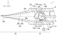
眼内レンズ挿入器具であるインジェクター1の構造について説明する。図1と図2に示すように、本実施形態のインジェクター1(眼内レンズ挿入器具)は、挿入器具本体10(筒状の本体)と、プランジャー12などから構成されている。挿入器具本体10は、挿入部20と保管部22などを備えている。このようなインジェクター1は、例えば、樹脂材料(例えば、ポリプロピレン)等を用いた射出成形などによって形成される。また、インジェクター1は、樹脂の削り出しによって形成されたものであってもよい。なお、インジェクター1は、挿入部20が交換可能なカートリッジタイプのものであってもよい。なお、本実施形態のインジェクター1は、いわゆるプリロードタイプ型であり眼内レンズ100が予め充填された状態で出荷される。
<Injector 1 (intraocular lens insertion device)>
The structure of the
<眼内レンズ100>
インジェクター1(眼内レンズ挿入器具)によって眼内に挿入される眼内レンズ100の一例について説明する。図3と図4に示すように、本実施形態で使用される眼内レンズ100は、光学部110と、一対の支持部である前方支持部112Aおよび後方支持部112Bと、が柔軟な素材で一体成形されたワンピースタイプの眼内レンズである。眼内レンズ100は、柔軟な素材の材料として、例えば、BA(ブチルアクリレート)、HEMA(ヒドロキシエチルメタクリレート)等の単体、アクリル酸エステルとメタクリル酸エステルの複合材料等の種々の軟性の樹脂材料を採用できる。なお、第1実施形態では所謂ワンピースタイプの眼内レンズ100を例示したが、本開示で例示する技術の少なくとも一部は、光学部110と一対の支持部(前方支持部112Aおよび後方支持部112B)が別部材で形成された、所謂3ピース型の眼内レンズにも適用できる。
<
An example of an
光学部110は、患者眼に所定の屈折力を与える。光学部110は、円盤形状に形成されている。光学部110の光軸Lは、光学部110の中心を通り、且つ上下方向(光学部110の厚み方向)に延びる。また、前方支持部112Aと後方支持部112Bは、光学部110の外周部分110a(辺縁)から径方向外方(外側)に湾曲して延び、光学部110の中心である光軸Lを基準として点対称の位置に形成されている。そして、前方支持部112Aは、根元部分116Aが接続部分114Aを介して光学部110の外周部分110aに接続されており、周方向に湾曲したループ形状であり、先端部分118Aが開放されている。(つまり、先端部分118Aは自由端となっている)。また、後方支持部112Bは、根元部分116Bが接続部分114Bを介して光学部110の外周部分110aに接続されており、周方向に湾曲したループ形状であり、先端部分118Bが開放されている(つまり、先端部分118Bは自由端とされている)。光学部110は、光軸L方向の端面として、後述するように保管部22の天井面22bと対面する前面光学面110cと、前面光学面110cの反対側であり、保管部22における底面22cと対面する後面光学面110bとを備えている。
The
本実施形態の眼内レンズ100は、レンズの度数に応じて光学部110の厚さのみ異なるが、光軸L方向から見た光学部110の輪郭形状、前方支持部112Aおよび後方支持部112Bの形状は変わらない。すなわち、前面光学面110c、後面光学面110bの曲率半径、及び外周部分110a(コバとも言う)の厚さが度数に応じて変化し、光学部110の厚さが変わる。
In the
<挿入器具本体10(筒状の本体)>
図5を参照して、挿入器具本体10の詳細について説明する。挿入器具本体10は、挿入部20と保管部22などを備えている。挿入部20、保管部22は、中空の筒形状に形成されている。
<Insertion instrument body 10 (cylindrical body)>
The
<挿入部20>
挿入部20は、図5、6に示すように、通路20b(前方通路)を備えている。通路20bは、眼内レンズ100を折り畳むために挿入部20の先端20aに向かうに従って、眼内レンズ100が通過する空間が狭くなっている。すなわち、先端20aに向かうにつれて通路面積が徐々に小さくなっている。なお、通路面積とは、眼内レンズ100の押し出し方向(図5の左方向)に直交する断面における通路20bの断面積である。
<
As shown in Figures 5 and 6, the
また、挿入部20の先端20aには、眼内レンズ100を外部に送出するための切欠き(ベベル)が形成されている。そして、通路20b内を通過した眼内レンズ100は、内壁面20c(前方内壁面)に沿って小さく折り畳まれて、先端20aの切欠きから外部に送出され、眼内に挿入される。なお、内壁面20c(第1内壁面24aと第2内壁面24b)は、通路20bの中心軸Lt方向に直交する方向であって、通路20b内に眼内レンズ100が配置されたときの光学部110の径方向に平行な方向について両側に形成されている。第1内壁面24aと第2内壁面24bは、通路20bの中心軸Ltに対して対称な形状(傾き)に形成されている。
The
天井面(図5の紙面手前側の内壁)と底面20e(図5参照)は、通路20bの中心軸Lt方向に直交する方向であって、通路20b内に眼内レンズ100が配置されたときの光学部110の中心軸(光軸)L方向に平行な方向について、両側に形成されている。そして、底面20eは、通路20bの外側(図5の紙面奥側)に凹状に湾曲している。
The ceiling surface (the inner wall on the front side of the paper in FIG. 5) and the
ここで、図5、6などに示すように、互いに直交するX軸とY軸とZ軸を想定し、眼内レンズ100の押し出し方向に平行な方向(通路20bと通路22aの中心軸Lt方向、押出軸Lp方向)をX軸方向と定義する。すると、通路20bは、Y軸方向の両側に形成される2つの内壁面20c(第1内壁面24aと第2内壁面24b)と、Z軸方向の両側に形成される天井面(図5の紙面手前側の内壁)と底面20e(図5参照)などに囲まれて形成されている。通路20bの中心軸Ltは、押出軸Lpと一致している。
As shown in Figures 5 and 6, the X-axis, Y-axis, and Z-axis are assumed to be mutually orthogonal, and the direction parallel to the extrusion direction of the intraocular lens 100 (the direction of the central axis Lt of the
<保管部22>
保管部22は、図5に示すように、挿入部20よりもプランジャー12の押し出し方向の後方(図5の右方向)の位置に形成されている。そして、保管部22の内部に形成される通路22a(後方通路)内に、プランジャー12により押し出される前の眼内レンズ100が予め充填(配置)されている。
<
5, the
また、保管部22は、光学部110の光学面(前面光学面110c、後面光学面110b)の面内方向(光軸Lの直交方向)であって押出軸Lpに交差する方向(Y軸方向)に向き合う側方内壁を有する。側方内壁は、右側方内壁22d(図5の紙面において押出軸Lpより上方の壁面)と、左側方内壁22e(図5の紙面において押出軸Lpより下方の壁面)で構成される。これにより、保管部22における通路22aは、天井面22b(図6参照)と、底面22c、右側方内壁22dと、左側方内壁22eに囲まれた内部空間が形成される。
The
ここで、保管部22内に保管された状態の眼内レンズ100について説明する。眼内レンズ100は、図5に示すように、光学部110の前面光学面110cが保管部22の天井面22bと対面し、前面光学面110cの反対側の後面光学面110bが保管部22における底面22cと対面する。また、光学部110は、保管部22内において押出軸Lp方向(X軸方向)の略中央であって、押出軸Lpに交差する左右方向(Y軸方向)の略中央に配設される。これにより、光学部110の光軸Lが押出軸Lp上に配設された状態となる。また、眼内レンズ100は、その光学部110に対して、前方側(挿入部20の先端20a)側(図5の左方向)に一方の支持部である前方支持部112Aが配設される。前方支持部112Aの根元部分116Aは、右側方内壁22d側に配設される。また、眼内レンズ100は、その光学部110に対して、後方側(押出軸Lpの基端側、挿入部20の先端20aの反対)側(図5の右方向)に他方の支持部である後方支持部112Bが配設される。後方支持部112Bの根元部分116Bは、左側方内壁22e側に配設される。
Here, the
さらに、保管部22は、図5に示すように、第1ピン31、第2ピン32、第3ピン33、第1規制部41、第2規制部42、第3規制部43が設けられている。保管時の眼内レンズ100は、第1ピン31、第2ピン32、第3ピン33、第1規制部41、第2規制部42、第3規制部43によって光学部110の保管部22内での移動が規制される。第1規制部41、第2規制部42及び第3規制部43は、光学部の外周部分110a(辺縁)が光軸Lと平行な方向(図5においてZ軸方向)へ移動するのを規制する。また、第1規制部41、第3規制部43は、光学部110の押出軸Lpに交差する左右方向(Y軸方向)の移動を規制する。第1ピン31、第3ピン33と第2規制部42は、光学部110の押出軸Lp方向(X軸方向、前後方向)の移動を規制する。第2ピン32は眼内レンズ100の周方向の回転を規制する。
5, the
第1ピン31、第2ピン32は、第3ピン33は、保管部22の外方から通路22a内に抜き差し可能な軸状の部材であり、インジェクター1の使用時(詳細には使用者がプランジャー12を押す直前)に使用者が挿入器具本体10から取り外す。第1ピン31~第3ピン33が取り外されると、眼内レンズ100は押出軸Lpの先端方向への移動が可能になる。第1ピン31は、光学部110の外周部分110a(辺縁)に隣接する外周のうち、光軸Lよりも前方側であって、且つ押出軸Lp上に配設されている。これにより、第1ピン31は、光学部110の押出軸Lp方向(X軸方向、前後方向)のうち前方側(挿入部20の先端20a)側(図5の左方向)の移動を規制する。第2ピン32は、光学部110の外周部分110a(辺縁)に隣接する外周のうち、後方支持部112Bの根元部分116Bに隣接する位置であって、且つ外周部分110a(辺縁)と後方支持部112Bに挟まれた位置に配設されている。これにより、第2ピン32は、眼内レンズ100の周方向の回転(図5の紙面において左回転方向)を規制する。
The
第1規制部41は、保管部22に設けられている。第1規制部41は、保管部22に保管される眼内レンズ100における光学部110の外周部分110a(辺縁)のうち押出軸Lpから最も遠い外周部分110aの部位が光軸Lと平行な方向(図5においてZ軸方向)へ移動するのを規制する。第1規制部41は、右側方内壁22d側から光学部110における前面光学面110cの一部と向き合う位置まで延在する鍔形状で構成されている。右側方内壁22dは、光学部110の光学面(前面光学面110c、後面光学面110b)の面内方向(光軸Lの直交方向)であって押出軸Lpに交差する方向に向き合う保管部22の内壁のうち後方支持部112Bの根元部分116Bが配設されない側の壁面(図5の紙面において押出軸Lpより上方の壁面)である。第1規制部41は、押出軸Lpに直交し且つ光軸Lを含む仮想平面Vsよりも押出軸Lpの基端側(図5の右方向)に配置されている。ここで、第1規制部41と、保管部22の内壁のうち前面光学面110cと向き合う天井面22b(天井内壁)との間には、第1隙間S1(図6参照)が設けられている。第1隙間S1は後方支持部112Bの厚さT1(図4参照)よりも大きい。この第1隙間S1により、後方支持部112Bが前面光学面110cと向き合う位置までタッキング(変形)される際、後方支持部112B及びその先端部分118Bが保管部22内の部位と干渉することなく通過できる。例えば、後方支持部112Bの長さにおける末端側半分の領域内での最大の厚さを、前述した厚さT1としてもよい。
The first restricting
ここで、例えば第1規制部41が天井面22bから底面22cに向かった下方に突出する形状(換言するなら第1隙間がない構造)であったと仮定した場合における後方支持部112Bのタッキングを考える。この場合、図7に示すように後方支持部112Bのタッキング途中に後方支持部112Bと第1規制部41が接触すると、後方支持部112Bの先端部分118Bが押出軸Lpの基端側に曲がってしまうおそれがある。後方支持部112Bと第1規制部41が接触する理由として、例えば室温が高温になるほど眼内レンズ100全体が柔らかくなり、大きく変形し易くなることが考えられる。これに対し、図8に示すように、保管部22には、第1規制部41と天井面22bの間に第1隙間S1が設けられている。そのため、後方支持部112Bの先端部分118Bは、第1隙間S1を通過できるため意図しない変形が生じ難い。
Here, consider tacking of the
第2規制部42は、保管部22に保管される眼内レンズ100における光学部110のうち押出軸Lpの基端側にある外周部分110a(辺縁)が光軸Lと平行な方向(図5においてZ軸方向)へ移動するのを規制する。第2規制部42は、光学部110の光学面(前面光学面110c、後面光学面110b)の面内方向(光軸Lの直交方向)であって押出軸Lpの基端側(図5の右側)から前面光学面110cの一部と向き合う位置まで延在する鍔形状で構成されている。第1規制部41と、天井面22b(天井内壁)との間には、第2隙間S2(図6参照)が設けられている。第2隙間S2は、第1隙間S1と同じ隙間間隔である。この第2隙間S2により、後方支持部112Bが前面光学面110cと向き合う位置までタッキング(変形)される際、後方支持部112B及びその先端部分118Bが保管部22内の部位と干渉することなく通過できる。
The second restricting
第3規制部43は、保管部22に設けられている。第3規制部43は、保管部22に保管される眼内レンズ100における光学部110の外周部分110a(辺縁)のうち押出軸Lpから最も遠い外周部分110aの部位が光軸Lと平行な方向(図5においてZ軸方向)へ移動するのを規制する。第3規制部43は、左側方内壁22e側から光学部110における前面光学面110cの一部と向き合う位置まで延在する鍔形状で構成されている。左側方内壁22eは、光学部110の光学面(前面光学面110c、後面光学面110b)の面内方向(光軸Lの直交方向)であって押出軸Lpに交差する方向に向き合う保管部22の内壁のうち後方支持部112Bの根元部分116Bが配設される側の壁面(図5の紙面において押出軸Lpより下方の壁面)である。第3規制部43は、押出軸Lpに直交し且つ光軸Lを含む仮想平面Vsよりも押出軸Lpの基端側に配置されている。
The third restricting
図5に示すように、保管部22の内部に形成される通路22aにおける底面22cには、眼内レンズ100がプランジャー12により挿入部20の先端20a側に向かって押し出されて移動する際の、光学部110の傾きを抑制する凸部22fが設けられている。凸部22fは、眼内レンズ100の光学部110の縁である外周部分110aに対向する位置であって次のような部位に配設される。凸部22fは、眼内レンズ100の光学部110の光軸Lよりも前方(挿入部20の先端20a)側(図5の左方向)であって、中心軸Lt(プランジャー12の押し出し方向の押出軸Lpでもある)から見て眼内レンズ100の前方支持部112Aの根元部分116Aが配設されない側(左側方内壁22e:図5において中心軸Ltよりも下方側)に配設される。凸部22fは、底面22cから天井面22bに向かって山なり状に突出して光学部110における後面光学面110b側の外周部分110aに近接している。凸部22fは、突出する方向に向かって先細った形状であり先端部が丸みを帯びたフィレット加工が施されている。この凸部22fにより、眼内レンズ100がプランジャー12によって押し出される際に光学部110の傾きを抑制することができ、眼内レンズ100における前方支持部112Aが意図しないで後面光学面110b側にタッキングされるいわゆる「裏タッキング状態」の発生を抑制することができる。ここで、後方支持部112Bがタッキングされた眼内レンズ100は、そのタッキング状態を解除しようとする復元力が眼内レンズ100に蓄積される。後方支持部112Bはプランジャー12によって押されているため、前述した復元力は光学部110の左下方向(図5の紙面左下方向)への応力として働きやすい。このとき、光学部110と保管部22の底面22cの隙間が大きいと光学部110がその隙間に向けて大きく変形し易い。そのため、かかる隙間を埋める凸部22fを設けることで、光学部110の意図せぬ変形(めくれ等)が抑制されている。
As shown in FIG. 5, the
実施形態1のインジェクター1(眼内レンズ挿入器具)の使用方法を説明する。インジェクター1には、保管部22に眼内レンズ100が予め充填されている。使用者がプランジャー12の基端に形成されている押出部を押してプランジャー12全体を前進させると、後方支持部112Bがタッキングされた眼内レンズ100が中心軸Lt(プランジャー12の押し出し方向の押出軸Lpでもある)に沿って押し出されてゆく。このとき、後方支持部112Bは、第2規制部42上の第2隙間S2を滑動すると共に、先端部分118Bが第1規制部41上の第1隙間S1を通過する。そのため、後方支持部112Bは、タッキング途中に保管部22の内壁などに接触して、先端部分118Bが押出軸Lpの基端側に曲がってしまい難い。これは、例えば室温が高温時のようなときに眼内レンズ100全体が柔らかくなり、大きく変形し易い状態でも後方支持部112Bを好適にタッキングすることができる。眼内レンズ100は、プランジャー12を更に押し出してゆくと前方支持部112Aも光学部110の前面光学面110c上にタッキングした後、光学部110全体がロール状に変形されて挿入口から眼内レンズ100が射出される。
A method of using the injector 1 (intraocular lens insertion device) of the first embodiment will be described. In the
<第2実施形態>
次に、本開示における典型的な実施形態の1つである第2実施形態について図を参照して説明する。なお、実施形態2のインジェクター201を説明するにあたり、実施形態1と実質的に同様な構成については実施形態1と同様の符号を付し、詳細な説明は省略することがある。
Second Embodiment
Next, a second embodiment, which is one of typical embodiments of the present disclosure, will be described with reference to the drawings. In describing an
第2実施形態においては、図9~11に示すように、庇50を有している。庇50は、第1規制部41と第2規制部42の各々は鍔形状が維持されつつ光学部110の周方向に延在して連結される形態である。庇50は、押出軸Lpに直交し且つ光軸Lを含む仮想平面Vsよりも押出軸Lpの基端側に配置されている。庇50は、後方支持部112Bの先端が前面光学面110cと向き合う位置まで変形される過程で後方支持部112Bを滑動させるためのスロープ52(図11参照)が形成されている。庇50と、天井面22b(天井内壁)との間には、前面光学面110cと向き合う位置まで変形される後方支持部112Bの先端部分118Bが通過できる第3隙間S3が設けられている。第3隙間S3は、第1隙間S1と第2隙間S2と同じ隙間間隔である。また庇50は、前面光学面110cと対向する面に底面22cに向かって突出する突起部54(図10参照)を有する。係る突起部54は、光学部110が庇50に張り付くのを抑制する。なお、実施形態2のインジェクター201においても、凸部22fの構成を有している。
In the second embodiment, as shown in Figs. 9 to 11, the
ここで、例えば、第1実施形態における第2規制部42のみの構成である場合を考える。図12に示すように、後方支持部112Bは、そのタッキング時に光学部110が所定位置から前方にズレていると、第2規制部42は、後方支持部112Bの先端部分118Bを支持することができず、後方支持部112Bの先端部分118Bが光学部110の外周部分110aに垂れ下がってしまい、先端部分118Bが外周部分110a(光学部110の側面)に接触し易い。なお、前述したように、室温が高温時のときは後方支持部112Bが柔らかくなるため、後方支持部112Bがより垂れ下がり易くなり、かかる接触がより発生し易くなる。一方、図13に示すように、第2実施形態における庇50は、後方支持部112Bの全体を支持する構成であることから、先端部分118Bが庇50上を確実に通過する構成となる。これにより、例えば、光学部110が所定位置からズレていても後方支持部112Bの先端部分118Bが光学部110の側面に接触し難い。
Here, for example, consider the case where only the second restricting
実施形態2のインジェクター201(眼内レンズ挿入器具)の使用方法を説明する。インジェクター201には、保管部22に眼内レンズ100が予め充填されている。使用者がプランジャー12の基端に形成されている押出部を押してプランジャー12全体を前進させると、後方支持部112Bがタッキングされた眼内レンズ100が中心軸Lt(プランジャー12の押し出し方向の押出軸Lpでもある)に沿って押し出されてゆく。このとき、後方支持部112Bは、庇50のスロープ52(図11参照)を滑動して第3隙間S3を通過する。ここで、庇50は、後方支持部112Bの全体を支持する構成であることから、後方支持部112Bがタッキング途中に保管部22の内壁などに接触して、先端部分118Bが押出軸Lpの基端側に曲がってしまい難い。これは、例えば室温が高温時のようなときに眼内レンズ100全体が柔らかくなり、大きく変形し易い状態でも後方支持部112Bを好適にタッキングすることができる。また、後方支持部112Bがタッキングされるときに、粘弾性物質が存在するとその抵抗により先端部分118Bが底面22c方向に折れ曲がるおそれがある。しかしながら、庇50は、後方支持部112Bの全体を支持する構成であることから、粘弾性物質の抵抗によって先端部分118Bだけが底面22c方向に折れ曲がってしまう事象が生じ難い。庇50は、前面光学面110cと向き合う位置まで変形される後方支持部112Bのタッキング不良を抑制することができる。眼内レンズ100は、プランジャー12を更に押し出してゆくと前方支持部112Aも光学部110の前面光学面110c上にタッキングした後、光学部110全体がロール状に変形されて挿入口から眼内レンズ100が射出される。
A method of using the injector 201 (intraocular lens insertion device) of the second embodiment will be described. In the
なお、実施形態1、2において、「底面20e」、「天井面22b」、「底面22c」等の名称は便宜的なものであり、インジェクター1の上下方向を厳密に規定するものではない。例えば、底面20eは眼内レンズ100の下方に常に位置するわけではない。つまり、運搬時、インジェクター1への粘弾性物質の充填時、眼内への眼内レンズ100の挿入時等の各々において、インジェクター1の上下方向は変化し得る。また実施形態1、2における前面光学面110c(第1光学面)と後面光学面110b(第2光学面)が逆の態様であってもよい。つまり実施形態1、2において前面光学面110cとした光学面が後面光学面110bであってもよい。
In addition, in the first and second embodiments, the names "
このように、本開示の第1、2実施形態に係るインジェクター1、201(眼内レンズ挿入器具)によれば、第1規制部41または庇50を有するため、保管部22に保管される眼内レンズ100における光学部110のうち押出軸Lpから最も遠い外周部分110a(辺縁)が光軸Lと平行な方向(図5においてZ軸方向)へ移動するのを規制することができる。また、第1規制部41または庇50は、保管部22の内壁のうち後方支持部112Bの根元部分116Bが配設されない側である右側方内壁22d側から光学部110における前面光学面110cの一部と向き合う位置まで延在する鍔形状で構成されており、第1規制部41と天井面22b(天井内壁)との間に第1隙間S1、第3隙間S3が設けられている。そのため、後方支持部112Bがタッキングする際に先端部分118Bが第1隙間S1、第3隙間S3を通過することで好適なタッキングができる。よって、保管時の眼内レンズ100の移動規制と射出時の後方支持部112Bの好適なタッキングとを両立できる。
Thus, according to the
また、第2規制部42は、保管部22に保管される眼内レンズ100における光学部110のうち押出軸Lpの基端側にある外周部分110a(辺縁)が光軸L方向へ移動するのを規制する。第2規制部42は、光学部110の光学面(前面光学面110c、後面光学面110b)の面内方向(光軸Lの直交方向)であって押出軸Lpの基端側から前面光学面110cの一部と向き合う位置まで延在する鍔形状で構成されている。第2規制部42と、天井面22b(天井内壁)との間には、前面光学面110cと向き合う位置まで変形される後方支持部112Bの先端部分118Bが通過できる第2隙間S2が設けられている。係る第2規制部42の構成により、後方支持部112Bの好適なタッキングがより一層図られる。
The second restricting
また、庇50は、第1規制部41と第2規制部42の各々は鍔形状を維持しつつ光学部110の周方向に延在して連結される構成である。これにより、庇50は、第1規制部41と第2規制部42の機能が連結されているで、後方支持部112B全体を前面光学面110cまでタッキングさせやすくすることができる。
The
また、第1規制部41、庇50は、押出軸Lpに直交し且つ光軸Lを含む仮想平面Vsよりも押出軸Lpの基端側に配置されている。これにより、後方支持部112Bをタッキングさせた後、眼内レンズ100全体を前進させる際、第1規制部41の干渉を抑制できるため、眼内レンズ100の意図しない変形が生じ難い。
The first restricting
また、庇50は、後方支持部112Bの先端部分118Bが前面光学面110cと向き合う位置まで変形される過程で後方支持部112Bを滑動させるためのスロープ52が形成されている。係るスロープ52により、後方支持部112Bを滑らかにタッキングさせることができる。
The
また、眼内レンズ100は、光学部110の外周部分から径方向外方に延びる一対の前方支持部112Aと後方支持部112Bを備え、挿入器具本体10(筒状の本体)には、予め充填された眼内レンズ100がプランジャー12によって押し出される際に光学部110の傾きを抑制する凸部22fが設けられており、凸部22fは、光学部110の外周部分に対向する位置のうち、光学部110の光軸Lよりも前方側であって、押出軸Lpから見て前方支持部112Aが配設されない側に配設されており、凸部22fは、挿入器具本体10における底面22cから天井面22bに向かって山なり状に突出して光学部110における後面光学面110b側の外周部分に近接するとともに先端部が丸みを帯びたフィレット加工が施されている。係る凸部22fにより、眼内レンズ100がプランジャー12によって押し出される際に光学部110の傾きを抑制することができ、眼内レンズ100における前方支持部112Aが意図せぬタッキングとなるいわゆる「裏タッキング状態」の発生を抑制することができる。また、光学部110の意図せぬめくれなどの変形を抑制できる。
The
以上、本開示の実施形態について説明したが、本開示の眼内レンズ挿入器具は、上記実施形態に限定されず、その他各種の形態で実施することができるものである。 Although the embodiments of the present disclosure have been described above, the intraocular lens insertion device of the present disclosure is not limited to the above embodiments and can be implemented in various other forms.
1 インジェクター(眼内レンズ挿入器具)
10 挿入器具本体
12 プランジャー
20 挿入部
20a 先端
20b 通路
20c 内壁面
20e 底面
24a 第1内壁面
24b 第2内壁面
22 保管部
22b 天井面
22c 底面
22d 右側方内壁
22e 左側方内壁
22f 凸部
31 第1ピン
32 第2ピン
33 第3ピン
41 第1規制部
42 第2規制部
43 第3規制部
50 庇
52 スロープ
100 眼内レンズ
110 光学部
110a 外周部分(辺縁)
110b 後面光学面
110c 前面光学面
112A 前方支持部
114A 接続部分
116A 根元部分
118A 先端部分
112B 後方支持部
114B 接続部分
116B 根元部分
118B 先端部分
L 光軸
Lp 押出軸
Lt 中心軸
S1 第1隙間
S2 第2隙間
S3 第3隙間
Vs 仮想平面
1. Injector (intraocular lens insertion device)
10
110b Rear
Claims (4)
前記筒状の本体は、
前記光学部に対して、前記先端側に一方の支持部である前方支持部を、前記基端側に他方の支持部である後方支持部をそれぞれ配置するように前記眼内レンズが保管される保管部と、
前記保管部に設けられ、前記保管部に保管される前記眼内レンズにおける前記光学部のうち前記押出軸から最も遠い辺縁が光軸と平行な方向へ移動するのを規制する第1規制部と、を備え、
前記第1規制部は、前記光学部の光学面の面内方向であって前記押出軸に交差する方向に向き合う前記保管部の内壁のうち前記後方支持部の根元が配設されない側である側方内壁側から前記光学部における前面光学面の一部と向き合う位置まで延在する鍔形状で構成されており、
前記第1規制部と、前記保管部の内壁のうち前記前面光学面と向き合う天井内壁との間には、前記前面光学面と向き合う位置まで変形される前記後方支持部の先端が通過できる第1隙間が設けられており、
前記保管部に保管される前記眼内レンズにおける前記光学部のうち前記押出軸の基端側にある辺縁が前記光軸と平行な方向へ移動するのを規制する第2規制部を備え、
前記第2規制部は、前記光学部の光学面の面内方向であって前記押出軸の基端側から前記前面光学面の一部と向き合う位置まで延在する鍔形状で構成されており、
前記第2規制部と、前記天井内壁との間には、前記前面光学面と向き合う位置まで変形される前記後方支持部の先端が通過できる第2隙間が設けられている眼内レンズ挿入器具。 An intraocular lens insertion device that stores an intraocular lens having a disk-shaped optical part and a pair of support parts extending radially outward from an outer periphery of the optical part on a push-out shaft inside a cylindrical body in advance, and pushes the stored intraocular lens from a base end side to a tip end side along the push-out shaft with a rod-shaped plunger to insert the intraocular lens into a patient's eye,
The cylindrical body includes:
a storage section in which the intraocular lens is stored such that a front support section, which is one of the support sections, is disposed on the distal end side of the optical section, and a rear support section, which is the other support section, is disposed on the proximal end side of the optical section;
a first restriction portion provided in the storage portion and restricting a peripheral edge of the optical portion of the intraocular lens stored in the storage portion that is farthest from the extrusion axis from moving in a direction parallel to the optical axis;
the first restricting portion is configured in a brim shape extending from a side inner wall side, which is a side on which a base of the rear support portion is not disposed, of an inner wall of the storage portion facing a direction intersecting the extrusion axis in an in-plane direction of the optical surface of the optical portion, to a position facing a part of a front optical surface of the optical portion,
a first gap is provided between the first restricting portion and a ceiling inner wall of the inner wall of the storage portion facing the front optical surface, through which a tip end of the rear support portion deformed to a position facing the front optical surface can pass;
a second restriction portion that restricts a peripheral edge of the optical portion of the intraocular lens stored in the storage portion on a base end side of the push-out shaft from moving in a direction parallel to the optical axis,
the second restricting portion is configured in a flange shape extending in an in-plane direction of an optical surface of the optical portion from a base end side of the extrusion shaft to a position facing a part of the front optical surface,
An intraocular lens insertion device, wherein a second gap is provided between the second restricting portion and the ceiling inner wall, through which the tip of the rear support portion, which is deformed to a position facing the front optical surface, can pass.
前記第1規制部と前記第2規制部の各々は鍔形状を維持しつつ前記光学部の周方向に延在して連結されている眼内レンズ挿入器具。 2. The intraocular lens insertion device according to claim 1,
An intraocular lens insertion device in which the first and second restricting portions are connected to each other while maintaining a flange shape and extending in a circumferential direction of the optical portion.
前記第1規制部は、前記押出軸に直交し且つ前記光軸を含む仮想平面よりも前記押出軸の基端側に配置されている眼内レンズ挿入器具。 The intraocular lens insertion device according to claim 1 or 2,
The first regulating portion is disposed on the proximal end side of the push-out shaft relative to an imaginary plane that is perpendicular to the push-out shaft and includes the optical axis.
前記連結された前記第1規制部と前記第2規制部には、前記後方支持部の先端が前記前面光学面と向き合う位置まで変形される過程で前記後方支持部を滑動させるためのスロープが形成されている眼内レンズ挿入器具。
3. The intraocular lens insertion device according to claim 2 ,
An intraocular lens insertion device, in which the connected first and second control portions have a slope formed thereon for sliding the rear support portion during the process of the tip of the rear support portion being deformed to a position facing the front optical surface.
Priority Applications (1)
| Application Number | Priority Date | Filing Date | Title |
|---|---|---|---|
| JP2021052962A JP7613199B2 (en) | 2021-03-26 | 2021-03-26 | Intraocular lens insertion device |
Applications Claiming Priority (1)
| Application Number | Priority Date | Filing Date | Title |
|---|---|---|---|
| JP2021052962A JP7613199B2 (en) | 2021-03-26 | 2021-03-26 | Intraocular lens insertion device |
Publications (2)
| Publication Number | Publication Date |
|---|---|
| JP2022150383A JP2022150383A (en) | 2022-10-07 |
| JP7613199B2 true JP7613199B2 (en) | 2025-01-15 |
Family
ID=83465232
Family Applications (1)
| Application Number | Title | Priority Date | Filing Date |
|---|---|---|---|
| JP2021052962A Active JP7613199B2 (en) | 2021-03-26 | 2021-03-26 | Intraocular lens insertion device |
Country Status (1)
| Country | Link |
|---|---|
| JP (1) | JP7613199B2 (en) |
Citations (2)
| Publication number | Priority date | Publication date | Assignee | Title |
|---|---|---|---|---|
| JP2004351196A (en) | 2003-05-28 | 2004-12-16 | Alcon Inc | Lens delivery system |
| US20170128196A1 (en) | 2005-02-11 | 2017-05-11 | Abbott Medical Optics Inc. | Intraocular Lens Insertion Apparatus and Lens Case |
-
2021
- 2021-03-26 JP JP2021052962A patent/JP7613199B2/en active Active
Patent Citations (2)
| Publication number | Priority date | Publication date | Assignee | Title |
|---|---|---|---|---|
| JP2004351196A (en) | 2003-05-28 | 2004-12-16 | Alcon Inc | Lens delivery system |
| US20170128196A1 (en) | 2005-02-11 | 2017-05-11 | Abbott Medical Optics Inc. | Intraocular Lens Insertion Apparatus and Lens Case |
Also Published As
| Publication number | Publication date |
|---|---|
| JP2022150383A (en) | 2022-10-07 |
Similar Documents
| Publication | Publication Date | Title |
|---|---|---|
| JP3944555B2 (en) | Intraocular lens insertion system | |
| US8475528B2 (en) | Intraocular lens insertion device | |
| JP6027535B2 (en) | Intraocular lens insertion device | |
| JP3876284B2 (en) | Lens insertion device for intraocular insertion | |
| JP6015226B2 (en) | Intraocular lens insertion device | |
| US20030212408A1 (en) | Insertion system for intraocular lens | |
| JP2007152010A (en) | Intraocular lens insertion device | |
| JP6454999B2 (en) | Intraocular lens insertion device | |
| JP6958668B2 (en) | Intraocular lens insertion device | |
| JP5874351B2 (en) | Intraocular lens insertion system | |
| JP7613199B2 (en) | Intraocular lens insertion device | |
| JP6027536B2 (en) | Intraocular lens insertion device | |
| JP2016019605A (en) | Intraocular lens insertion device and intraocular lens insertion system | |
| JP6476621B2 (en) | Intraocular lens insertion device | |
| JP6439303B2 (en) | Intraocular lens insertion device | |
| JP7631971B2 (en) | Intraocular lens insertion device | |
| JP2016019608A (en) | Intraocular lens insertion instrument and intraocular lens insertion system | |
| JP6627267B2 (en) | Intraocular lens insertion device | |
| EP3682850A1 (en) | Intraocular lens insertion instrument | |
| JP7035384B2 (en) | Intraocular lens insertion device | |
| JP7547719B2 (en) | Intraocular lens insertion device | |
| JP7427898B2 (en) | Intraocular lens insertion device | |
| JP6841474B2 (en) | Intraocular lens and intraocular lens insertion device | |
| JP7272014B2 (en) | Intraocular lens insertion device | |
| JP7753927B2 (en) | Intraocular lens insertion device |
Legal Events
| Date | Code | Title | Description |
|---|---|---|---|
| A621 | Written request for application examination |
Free format text: JAPANESE INTERMEDIATE CODE: A621 Effective date: 20231221 |
|
| A977 | Report on retrieval |
Free format text: JAPANESE INTERMEDIATE CODE: A971007 Effective date: 20240703 |
|
| A131 | Notification of reasons for refusal |
Free format text: JAPANESE INTERMEDIATE CODE: A131 Effective date: 20240730 |
|
| A521 | Request for written amendment filed |
Free format text: JAPANESE INTERMEDIATE CODE: A523 Effective date: 20240926 |
|
| A131 | Notification of reasons for refusal |
Free format text: JAPANESE INTERMEDIATE CODE: A131 Effective date: 20241029 |
|
| A521 | Request for written amendment filed |
Free format text: JAPANESE INTERMEDIATE CODE: A523 Effective date: 20241113 |
|
| TRDD | Decision of grant or rejection written | ||
| A01 | Written decision to grant a patent or to grant a registration (utility model) |
Free format text: JAPANESE INTERMEDIATE CODE: A01 Effective date: 20241126 |
|
| A61 | First payment of annual fees (during grant procedure) |
Free format text: JAPANESE INTERMEDIATE CODE: A61 Effective date: 20241209 |
|
| R150 | Certificate of patent or registration of utility model |
Ref document number: 7613199 Country of ref document: JP Free format text: JAPANESE INTERMEDIATE CODE: R150 |