JP7606076B2 - Shape data output program, shape data output method, and information processing device - Google Patents
Shape data output program, shape data output method, and information processing device Download PDFInfo
- Publication number
- JP7606076B2 JP7606076B2 JP2020185727A JP2020185727A JP7606076B2 JP 7606076 B2 JP7606076 B2 JP 7606076B2 JP 2020185727 A JP2020185727 A JP 2020185727A JP 2020185727 A JP2020185727 A JP 2020185727A JP 7606076 B2 JP7606076 B2 JP 7606076B2
- Authority
- JP
- Japan
- Prior art keywords
- shape data
- unit
- shape
- coordinate axis
- coordinates
- Prior art date
- Legal status (The legal status is an assumption and is not a legal conclusion. Google has not performed a legal analysis and makes no representation as to the accuracy of the status listed.)
- Active
Links
Images


Classifications
-
- G—PHYSICS
- G06—COMPUTING OR CALCULATING; COUNTING
- G06V—IMAGE OR VIDEO RECOGNITION OR UNDERSTANDING
- G06V10/00—Arrangements for image or video recognition or understanding
- G06V10/40—Extraction of image or video features
- G06V10/44—Local feature extraction by analysis of parts of the pattern, e.g. by detecting edges, contours, loops, corners, strokes or intersections; Connectivity analysis, e.g. of connected components
-
- G—PHYSICS
- G06—COMPUTING OR CALCULATING; COUNTING
- G06T—IMAGE DATA PROCESSING OR GENERATION, IN GENERAL
- G06T19/00—Manipulating 3D models or images for computer graphics
-
- G—PHYSICS
- G06—COMPUTING OR CALCULATING; COUNTING
- G06T—IMAGE DATA PROCESSING OR GENERATION, IN GENERAL
- G06T19/00—Manipulating 3D models or images for computer graphics
- G06T19/20—Editing of 3D images, e.g. changing shapes or colours, aligning objects or positioning parts
-
- G—PHYSICS
- G06—COMPUTING OR CALCULATING; COUNTING
- G06T—IMAGE DATA PROCESSING OR GENERATION, IN GENERAL
- G06T2219/00—Indexing scheme for manipulating 3D models or images for computer graphics
- G06T2219/20—Indexing scheme for editing of 3D models
- G06T2219/2021—Shape modification
-
- G—PHYSICS
- G06—COMPUTING OR CALCULATING; COUNTING
- G06V—IMAGE OR VIDEO RECOGNITION OR UNDERSTANDING
- G06V10/00—Arrangements for image or video recognition or understanding
- G06V10/70—Arrangements for image or video recognition or understanding using pattern recognition or machine learning
- G06V10/74—Image or video pattern matching; Proximity measures in feature spaces
- G06V10/761—Proximity, similarity or dissimilarity measures
-
- G—PHYSICS
- G06—COMPUTING OR CALCULATING; COUNTING
- G06V—IMAGE OR VIDEO RECOGNITION OR UNDERSTANDING
- G06V10/00—Arrangements for image or video recognition or understanding
- G06V10/70—Arrangements for image or video recognition or understanding using pattern recognition or machine learning
- G06V10/764—Arrangements for image or video recognition or understanding using pattern recognition or machine learning using classification, e.g. of video objects
Landscapes
- Engineering & Computer Science (AREA)
- Theoretical Computer Science (AREA)
- Physics & Mathematics (AREA)
- General Physics & Mathematics (AREA)
- Computer Vision & Pattern Recognition (AREA)
- Software Systems (AREA)
- Multimedia (AREA)
- General Engineering & Computer Science (AREA)
- Computer Graphics (AREA)
- Computer Hardware Design (AREA)
- Evolutionary Computation (AREA)
- Artificial Intelligence (AREA)
- Computing Systems (AREA)
- Databases & Information Systems (AREA)
- Health & Medical Sciences (AREA)
- General Health & Medical Sciences (AREA)
- Medical Informatics (AREA)
- Architecture (AREA)
- Image Generation (AREA)
- Processing Or Creating Images (AREA)
- Life Sciences & Earth Sciences (AREA)
- Bioinformatics & Cheminformatics (AREA)
- Bioinformatics & Computational Biology (AREA)
- Data Mining & Analysis (AREA)
- Evolutionary Biology (AREA)
Description
本発明は、形状データ出力プログラム、形状データ出力方法および情報処理装置に関する。 The present invention relates to a shape data output program, a shape data output method, and an information processing device.
従来、3D(Dimensions)形状の設計や製図には多くの工数がかかるため、過去の3D形状データを利用した流用設計が行われる場合がある。一方で、過去の3D形状データは、分類が不十分であることが多く、似たような形状も大量に存在するため、新規に既存品の類似形状の設計を行う際には、過去の3D形状データを適切に分類して、設計物の標準化を行うことが望ましい。 Traditionally, designing and drawing 3D (Dimensions) shapes requires a lot of man-hours, so designs are sometimes reused using past 3D shape data. However, past 3D shape data is often insufficiently classified, and there are a large number of similar shapes, so when designing a new product with a similar shape to an existing product, it is desirable to properly classify the past 3D shape data and standardize the design.
先行技術としては、例えば、設計対象部品の属性値と形状特徴データとに整合する属性値の範囲と形状特徴データの標準部品を検索し、設計対象部品の属性値に類似する属性値の範囲を有し設計対象部品の形状特徴データに類似した形状特徴データの標準部品を検索し、設計対象部品の属性値に類似する属性値と、設計対象部品の形状特徴データに類似した形状特徴データの事例部品を検索するものがある。 Prior art techniques include, for example, searching for standard parts with a range of attribute values and shape feature data that match the attribute values and shape feature data of the part to be designed, searching for standard parts with a range of attribute values similar to the attribute values of the part to be designed and shape feature data similar to the shape feature data of the part to be designed, and searching for example parts with attribute values similar to the attribute values of the part to be designed and shape feature data similar to the shape feature data of the part to be designed.
また、類似部品データを参照して、抽出型番に対応付けられた類似部品型番を検索し、抽出型番の部品データ、および、検索された全ての類似部品型番の部品データをユーザ端末に送信し、各部品の型番が表示された単品検索結果詳細画面を表示する技術がある。また、抽出された関連性情報に直接対応する設計プロセスと、関連性情報に含まれる設計パラメータがさらに関係する他の関連性情報に対応する設計プロセスとを検出し、関連性情報および他の関連性情報に対応する複数個の設計プロセスに基づいて、部品形状を特定する設計パラメータを変更して、その部品の形状を生成する技術がある。 There is also a technique for referencing similar part data to search for similar part model numbers associated with the extracted model number, sending part data for the extracted model number and part data for all searched similar part model numbers to a user terminal, and displaying a single-item search result details screen showing the model numbers of each part. There is also a technique for detecting a design process that directly corresponds to the extracted relevance information and a design process that corresponds to other relevance information to which the design parameters included in the relevance information are further related, and changing the design parameters that identify the part shape based on the relevance information and multiple design processes that correspond to the other relevance information to generate the shape of the part.
また、認識モデルの面、稜線に対して付されるラベルを使用して、稜線の凹凸や面内での頂点の凹凸などの認識モデルの位相を判断して、目的関数および制約条件を生成し、認識モデルの形状認識を規制することにより、形状認識を実行させる技術がある。また、2次元ないし3次元の形状を計算機等に入力して形状および寸法を作成し、その後に、形状あるいは寸法の変更(削除、付加、修正等)をオペレータが実行することができる技術がある。 There is also a technology that uses labels attached to the faces and edges of a recognition model to determine the topology of the recognition model, such as the unevenness of edges and the unevenness of vertices within a surface, to generate an objective function and constraint conditions, and regulate the shape recognition of the recognition model, thereby executing shape recognition. There is also a technology that allows two- or three-dimensional shapes to be input into a computer or the like to create the shape and dimensions, and then allows an operator to change (delete, add, modify, etc.) the shape or dimensions.
しかしながら、従来技術では、設計物の標準化を行うにあたり、過去に設計された設計データを適切に分類して、辺や穴などの部位間の寸法の関係性を導出することが難しい。 However, with conventional technology, when standardizing designs, it is difficult to properly classify design data from previous designs and derive the dimensional relationships between parts such as edges and holes.
一つの側面では、本発明は、複数の形状データを適切に分類して部位間の寸法の関係性を導出することを目的とする。 In one aspect, the present invention aims to appropriately classify multiple shape data and derive the dimensional relationships between parts.
1つの実施態様では、複数の形状データそれぞれの形状データを、各座標軸方向の成分ごとに正規化して単位形状データを作成し、作成した前記それぞれの形状データの単位形状データに基づいて、前記複数の形状データを分類し、分類したグループ内の各形状データの部位の寸法に基づいて、前記グループ内の形状データの異なる部位間の寸法の関係性を特定し、前記グループ内の形状データの単位形状データと対応付けて、特定した前記寸法の関係性を示す情報を出力する、形状データ出力プログラムが提供される。 In one embodiment, a shape data output program is provided that normalizes each of a plurality of shape data for each component in each coordinate axis direction to create unit shape data, classifies the plurality of shape data based on the unit shape data of each of the created shape data, identifies dimensional relationships between different parts of the shape data in the group based on dimensions of parts of each shape data in the classified group, and outputs information indicating the identified dimensional relationships in correspondence with the unit shape data of the shape data in the group.
本発明の一側面によれば、複数の形状データを適切に分類して部位間の寸法の関係性を導出することができるという効果を奏する。 According to one aspect of the present invention, it is possible to appropriately classify multiple shape data and derive the relationship between dimensions between parts.
以下に図面を参照して、本発明にかかる形状データ出力プログラム、形状データ出力方法および情報処理装置の実施の形態を詳細に説明する。 The following describes in detail the embodiments of the shape data output program, shape data output method, and information processing device according to the present invention with reference to the drawings.
(実施の形態)
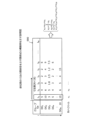
図1は、実施の形態にかかる形状データ出力方法の一実施例を示す説明図である。図1において、情報処理装置101は、対象物の設計を支援するコンピュータである。対象物は、設計対象となる物であり、例えば、部品、製品、建設部材、建築物などの立体物である。
(Embodiment)
Fig. 1 is an explanatory diagram showing an example of a shape data output method according to an embodiment. In Fig. 1, an
ここで、3D形状の設計には多くの工数がかかるため、過去の3D形状データを利用した流用設計ができれば、大変有用である。一方で、過去の3D形状データは、分類が不十分であることが多く、似たような形状も大量に存在するため、設計意図に応じた3D形状データを人手で検索するには時間や手間がかかる。 Because designing 3D shapes requires a lot of man-hours, it would be extremely useful to be able to reuse previous 3D shape data in a design. However, previous 3D shape data is often insufficiently classified, and there are a large number of similar shapes, so manually searching for 3D shape data that matches the design intent takes time and effort.
このため、新規に既存品の類似形状の設計を行うにあたり、過去の3D形状データを適切に分類して、設計物の標準化を行うことが望ましい。例えば、過去の3D形状データを適切に分類して、3D形状の部位間の寸法の関係性(パラメトリックモデル)を導出することができれば、モデルに対して各種寸法を設定することで、3D形状を規定する設計(いわゆる、パラメトリック設計)を行うことができる。 For this reason, when designing a new product with a similar shape to an existing product, it is desirable to properly classify past 3D shape data and standardize the design. For example, if past 3D shape data can be properly classified and the dimensional relationships between parts of the 3D shape (parametric model) can be derived, then a design that specifies the 3D shape (so-called parametric design) can be performed by setting various dimensions for the model.
過去の3D形状データを分類する手法としては、3D形状データ同士を比較して類似度を求め、その類似度をもとに3D形状データを分類するものがある。具体的には、例えば、ターゲットの3D形状データを指定し、その3D形状データとの類似度をもとに、同一グループに分類する3D形状データを検索することが考えられる。 One method for classifying past 3D shape data is to compare 3D shape data to find similarities and classify the 3D shape data based on the similarities. Specifically, for example, it is possible to specify target 3D shape data and search for 3D shape data to be classified into the same group based on the similarities with the 3D shape data.
ターゲットとなる3D形状データは、例えば、対象物についての設計意図を指定するための3D形状データである。設計意図は、例えば、対象物の大まかな形状(詳細な寸法を指定していない形状)、一部の部位間の寸法の比率、一部の部位の相対的な位置関係などである。 The target 3D shape data is, for example, 3D shape data for specifying the design intent for an object. The design intent is, for example, the rough shape of the object (a shape without detailed dimensions), the dimensional ratios between some parts, the relative positional relationships of some parts, etc.
ターゲットとなる3D形状データの指定は、例えば、過去に設計された3D形状データの中からいずれかの3D形状データを選択することにより行われる。ターゲットとしては、例えば、過去の3D形状データのうち、対象物とは詳細な寸法が異なるものの、対象物と同様の設計意図で作成された3D形状データが指定される。 The target 3D shape data is specified, for example, by selecting any 3D shape data from 3D shape data designed in the past. As the target, for example, from among the past 3D shape data, 3D shape data that has different detailed dimensions from the target object but was created with the same design intent as the target object is specified.
この分類手法では、ターゲットと同じ形状や、幾何学的に相似な形状の3D形状データが検索される。ところが、3D形状データでは似た形状においても、設計意図によって部位間の寸法に関係性があるものとないものがあり、同じ形状や相似な形状の3D形状データだけが、同一グループに分類したい3D形状データとは限らない。 This classification method searches for 3D shape data that is the same as the target or has a geometrically similar shape. However, even in 3D shape data with similar shapes, there may or may not be a relationship between the dimensions of parts depending on the design intent, and 3D shape data with the same or similar shapes are not necessarily the 3D shape data that you want to classify into the same group.
また、過去の3D形状データを一つ一つ人手により確認しながら、設計の意図を考慮した分類を行うことも考えられる。しかしながら、膨大な数の3D形状データを人手により分類するには時間や手間がかかり、ひいては、対象物の設計にかかる工数の増大を招くという問題がある。さらに、設計者以外の者が、3D形状データから設計の意図を判断することは難しい。 Another option is to manually review past 3D shape data one by one and classify it while taking into account the design intent. However, manually classifying a huge amount of 3D shape data takes time and effort, which in turn increases the number of steps required to design the target object. Furthermore, it is difficult for anyone other than the designer to determine the design intent from the 3D shape data.
そこで、本実施の形態では、各形状データを正規化した単位形状データをもとに、複数の形状データを分類し、単位形状データで分類される形状データ内の部位間の寸法の関係性を特定することで、パラメトリックモデルを構築する形状データ出力方法について説明する。パラメトリックモデルは、単位形状データに対応して、その単位形状データで分類される形状内の部位間の寸法の関係性を示す情報である。ここで、情報処理装置101の処理例について説明する。
In this embodiment, therefore, a shape data output method is described in which a parametric model is constructed by classifying multiple shape data based on unit shape data obtained by normalizing each shape data and identifying the dimensional relationship between parts within the shape data classified by the unit shape data. The parametric model is information that corresponds to the unit shape data and indicates the dimensional relationship between parts within the shape classified by the unit shape data. Here, an example of processing by the
(1)情報処理装置101は、複数の形状データそれぞれの形状データを、各座標軸方向の成分ごとに正規化して単位形状データを作成する。ここで、形状データは、設計物の形状をあらわす情報であり、例えば、設計物の各特徴点の位置情報、面情報、穴情報などを含む。特徴点は、例えば、設計物の頂点、穴の中心点などである。
(1) The
特徴点の位置情報は、例えば、直交座標系における特徴点の座標を示す。特徴点の面情報は、例えば、特徴点が属する面を特定する情報である。特徴点の穴情報は、例えば、特徴点が属する穴の形状、大きさなどを特定する情報である。形状データには、例えば、各面の色情報、材質情報などが含まれていてもよい。 The position information of a feature point indicates, for example, the coordinates of the feature point in a Cartesian coordinate system. The surface information of a feature point is, for example, information that specifies the surface to which the feature point belongs. The hole information of a feature point is, for example, information that specifies the shape, size, etc. of the hole to which the feature point belongs. The shape data may include, for example, color information and material information of each surface.
形状データは、例えば、3次元形状データである。より詳細に説明すると、例えば、形状データは、3次元CAD(Computer Aided Design)を利用して過去に設計された設計データである。ただし、形状データは、2次元形状データであってもよい。 The shape data is, for example, three-dimensional shape data. To explain in more detail, for example, the shape data is design data that was previously designed using three-dimensional CAD (Computer Aided Design). However, the shape data may also be two-dimensional shape data.
形状データを各座標軸方向の成分ごとに正規化するとは、各座標軸方向(例えば、x軸、y軸、z軸方向)での部位間の寸法の関係性を維持したまま、形状データを変換することである。x軸方向を例に挙げると、例えば、形状データを原点に移動させた上で、形状データの各頂点のx座標の値を、形状データのx軸方向の座標の最大値で除算することで、x軸方向での部位間の寸法の関係性を維持したまま形状データを変換する。 Normalizing shape data for each component in each coordinate axis direction means transforming the shape data while maintaining the dimensional relationships between parts in each coordinate axis direction (e.g., x-axis, y-axis, z-axis). Taking the x-axis direction as an example, for example, the shape data is transformed while maintaining the dimensional relationships between parts in the x-axis direction by moving the shape data to the origin and then dividing the x-coordinate value of each vertex of the shape data by the maximum coordinate of the shape data in the x-axis direction.
図1の例では、複数の形状データとして、過去に設計された3D形状データ11~18が表示されている。各3D形状データ11~18は、3次元空間上の各設計物の形状をあらわす。この場合、情報処理装置101は、例えば、各3D形状データ11~18を、各座標軸方向の成分ごとに正規化して単位形状データを作成する。
In the example of FIG. 1, previously designed 3D shape data 11-18 are displayed as multiple shape data. Each of the 3D shape data 11-18 represents the shape of each design object in three-dimensional space. In this case, the
(2)情報処理装置101は、作成したそれぞれの形状データの単位形状データに基づいて、複数の形状データを分類する。具体的には、例えば、情報処理装置101は、それぞれの形状データの単位形状データ間の類似度を算出する。単位形状データ間の類似度の算出には、既存のいかなる技術を用いることにしてもよい。
(2) The
例えば、単位形状データ間の類似度は、単位形状データを複数の方向から撮像した画像を単位形状データ間で比較した結果から算出することにしてもよい。そして、情報処理装置101は、算出した類似度が閾値以上となる単位形状データの組み合わせに対応する形状データ同士が同一グループとなるように、複数の形状データを分類する。
For example, the similarity between unit shape data may be calculated from the results of comparing images of unit shape data captured from multiple directions. The
すなわち、情報処理装置101は、各形状データの単位形状データを比較して、単位形状データが類似する形状データ同士を、同一グループに分類する。正規化された単位形状データをもとに分類することで、同じ形状や相似な形状だけでなく、寸法が一部異なる形状(例えば、垂直と水平方向の寸法は同じで、奥行の寸法が異なる)についても、同一グループに分類する。
That is, the
図1の例では、ターゲットの3D形状データ20が指定され、3D形状データ11~18の中から、ターゲットの3D形状データ20の類似図形として、3D形状データ16~18が、同一グループ30に分類された場合を想定する。3D形状データ16~18は、ターゲットの3D形状データ20との間で、単位3D形状データ同士の類似度が閾値以上となる3D形状データの集合である。
In the example of FIG. 1, it is assumed that target
なお、ここでは、ターゲットの3D形状データ20を指定する場合を例に挙げて説明したが、これに限らない。例えば、情報処理装置101は、各単位3D形状データ間の類似度が閾値以上となる単位3D形状データ群を特定し、単位3D形状データ群のそれぞれの単位3D形状データに対応する3D形状データを、同一グループに分類することにしてもよい。
Note that, although the case where the target
(3)情報処理装置101は、分類したグループ内の各形状データの部位の寸法に基づいて、グループ内の形状データの異なる部位間の寸法の関係性を特定する。ここで、形状データの部位とは、形状データがあらわす一部分の形状である。部位は、例えば、辺である。部位の寸法は、例えば、辺の長さである。
(3) The
同一グループに分類された各形状データは、単位形状データ同士が類似しており(正規化した形状が略一致)、互いに対応する部位をそれぞれ有している。例えば、グループ30内の3D形状データ16の各頂点、各辺は、グループ30内の他の3D形状データ17,18の各頂点、各辺に対応している。
The shape data classified into the same group are similar in terms of unit shape data (the normalized shapes are roughly the same) and have corresponding parts. For example, each vertex and each edge of
情報処理装置101は、グループ内の各形状データの部位の寸法をもとに、回帰分析等の手法により、ある部位と他の部位との関係を導出する。具体的には、例えば、情報処理装置101は、各形状データ内の複数の部位のうちのいずれかの部位を目的変数とし、他の部位を説明変数として、異なる部位間の寸法の関係性を示す関係式を作成する。
The
図1の例では、同一グループに分類された3D形状データ16~18の各辺の寸法をもとに作成された関係式の一つとして、3D形状データ18内の辺l1と辺l2との間の寸法の関係性を示す関係式「l1=a・l2+b」が示されている(a、bは係数)。この関係式「l1=a・l2+b」は、3D形状データ18の単位3D形状データで分類される3D形状のパラメトリックモデルの一つである。
1, a relational equation "l1 = a·l2 + b" (a and b are coefficients) showing the relationship in dimensions between sides l1 and l2 in the
なお、3D形状データの各辺は、その3D形状データの単位3D形状データの各辺に対応している。例えば、3D形状データ18内の辺l1と辺l2は、3D形状データ18の単位3D形状データ内のいずれかの辺に対応している。関係式に含まれる各変数(パラメータ)が、単位形状データ内のどの辺に対応しているかは特定可能である。
Each side of the 3D shape data corresponds to each side of the unit 3D shape data of the 3D shape data. For example, sides l1 and l2 in the
(4)情報処理装置101は、グループ内の形状データの単位形状データと対応付けて、特定した形状データの異なる部位間の寸法の関係性を示す情報を出力する。具体的には、例えば、情報処理装置101は、対象物に関する新規設計に利用する形状データとして、部位間の寸法の関係式が付与された単位形状データを出力することにしてもよい。
(4) The
図1の例では、3D形状データ18を例に挙げると、3D形状データ18内の異なる部位間の寸法の関係式(例えば、関係式「l1=a・l2+b」)が付与された、単位3D形状データ18’’が出力される。単位3D形状データ18’’は、3D形状データ18の単位3D形状データである。
In the example of FIG. 1 , taking the
このように、情報処理装置101によれば、単位形状データで分類される形状のパラメトリックモデル(部位間の寸法の関係性)を構築することができる。これにより、パラメトリック設計を可能にして、設計にかかる工数を削減することができる。例えば、新規設計時に、単位形状データをもとに、パラメトリックモデルに従って、各部位の寸法を設定することで、設計データを容易に生成することができる(パラメトリック設計)。
In this way, the
図1の例では、部位間の寸法の関係式(例えば、関係式「l1=a・l2+b」)が付与された単位3D形状データ18’’をもとに、対象物に関する設計を行うことができる。例えば、新規設計を行う際に設計者が設計要件(例えば、詳細な寸法)を指定することで、単位3D形状データ18’’をもとに、関係式を満たすように各部位の寸法を変換することで、設計意図に応じた設計データを生成することができる。 In the example of FIG. 1, an object can be designed based on unit 3D shape data 18'' to which a relational equation (e.g., the relational equation " l1 = a· l2 + b") between dimensions between parts is assigned. For example, when creating a new design, a designer can specify design requirements (e.g., detailed dimensions) and convert the dimensions of each part based on unit 3D shape data 18'' so as to satisfy the relational equation, thereby generating design data according to the design intent.
(情報処理システム200のシステム構成例)
つぎに、情報処理装置101を含む情報処理システム200のシステム構成例について説明する。以下の説明では、形状データとして「3D(3次元)形状データ」を例に挙げて説明する。情報処理システム200は、例えば、製品や建築物に関する3D形状の設計を支援するコンピュータシステムに適用される。
(System Configuration Example of Information Processing System 200)
Next, a system configuration example of an
図2は、情報処理システム200のシステム構成例を示す説明図である。図2において、情報処理システム200は、情報処理装置101と、クライアント装置201とを含む。情報処理システム200において、情報処理装置101およびクライアント装置201は、有線または無線のネットワーク210を介して接続される。ネットワーク210は、例えば、インターネット、LAN、WAN(Wide Area Network)などである。
FIG. 2 is an explanatory diagram showing an example of the system configuration of an
ここで、情報処理装置101は、3D形状DB(Database)220および標準形状DB230を有する。情報処理装置101は、例えば、サーバである。3D形状DB220は、過去に設計された3D形状データを記憶するデータベースである。標準形状DB230は、標準形状データを記憶するデータベースである。3D形状DB220および標準形状DB230の記憶内容については、図4および図5を用いて後述する。
Here, the
クライアント装置201は、ユーザが使用するコンピュータである。クライアント装置201は、例えば、PC(Personal Computer)、タブレットPCなどである。ユーザは、例えば、対象物の設計を行う設計者である。
The
なお、図2の例では、クライアント装置201を1台のみ表記したが、これに限らない。例えば、情報処理システム200には、複数のクライアント装置201が含まれていてもよい。また、情報処理装置101は、クライアント装置201と別体に設けることにしたが、これに限らない。例えば、情報処理装置101は、クライアント装置201により実現されることにしてもよい。
In the example of FIG. 2, only one
(情報処理装置101のハードウェア構成例)
図3は、情報処理装置101のハードウェア構成例を示すブロック図である。図3において、情報処理装置101は、CPU(Central Processing Unit)301と、メモリ302と、ディスクドライブ303と、ディスク304と、通信I/F(Interface)305と、可搬型記録媒体I/F306と、可搬型記録媒体307と、を有する。また、各構成部は、バス300によってそれぞれ接続される。
(Example of hardware configuration of information processing device 101)
Fig. 3 is a block diagram showing an example of the hardware configuration of the
ここで、CPU301は、情報処理装置101の全体の制御を司る。CPU301は、複数のコアを有していてもよい。メモリ302は、例えば、ROM(Read Only Memory)、RAM(Random Access Memory)およびフラッシュROMなどを有する。具体的には、例えば、フラッシュROMがOS(Operating System)のプログラムを記憶し、ROMがアプリケーションプログラムを記憶し、RAMがCPU301のワークエリアとして使用される。メモリ302に記憶されるプログラムは、CPU301にロードされることで、コーディングされている処理をCPU301に実行させる。
Here, the
ディスクドライブ303は、CPU301の制御に従ってディスク304に対するデータのリード/ライトを制御する。ディスク304は、ディスクドライブ303の制御で書き込まれたデータを記憶する。ディスク304としては、例えば、磁気ディスク、光ディスクなどが挙げられる。
通信I/F305は、通信回線を通じてネットワーク210に接続され、ネットワーク210を介して外部のコンピュータ(例えば、図2に示したクライアント装置201)に接続される。そして、通信I/F305は、ネットワーク210と装置内部とのインターフェースを司り、外部のコンピュータからのデータの入出力を制御する。通信I/F305には、例えば、モデムやLANアダプタなどを採用することができる。
The communication I/
可搬型記録媒体I/F306は、CPU301の制御に従って可搬型記録媒体307に対するデータのリード/ライトを制御する。可搬型記録媒体307は、可搬型記録媒体I/F306の制御で書き込まれたデータを記憶する。可搬型記録媒体307としては、例えば、CD(Compact Disc)-ROM、DVD(Digital Versatile Disk)、USB(Universal Serial Bus)メモリなどが挙げられる。
The portable recording medium I/
なお、情報処理装置101は、上述した構成部のうち、例えば、ディスクドライブ303、ディスク304、可搬型記録媒体I/F306、可搬型記録媒体307を有していなくてもよい。また、情報処理装置101は、上述した構成部のほかに、例えば、ディスプレイ、入力装置などを有することにしてもよい。また、図2に示したクライアント装置201についても、情報処理装置101と同様のハードウェア構成により実現することができる。
The
(各種DB220,230の記憶内容)
つぎに、図4および図5を用いて、情報処理装置101が有する各種DB220,230の記憶内容について説明する。各種DB220,230は、例えば、図3に示したメモリ302、ディスク304などの記憶装置により実現される。
(Storage contents of
4 and 5, the contents stored in the
図4は、3D形状DB220の記憶内容の一例を示す説明図である。図4において、3D形状DB220は、idおよび3D形状データのフィールドを有し、各フィールドに情報を設定することで、3D形状管理情報(例えば、3D形状管理情報400-1~400-3)をレコードとして記憶する。
Figure 4 is an explanatory diagram showing an example of the contents stored in
ここで、idは、3D形状データを一意に識別する識別子である。3D形状データは、過去に設計された3D形状データである。ここでは説明の便宜上、各3D形状データを「D1,D2,D3,…」と表記している。例えば、3D形状管理情報400-1は、id「1」の3D形状データD1を示す。 Here, id is an identifier that uniquely identifies the 3D shape data. The 3D shape data is 3D shape data that was designed in the past. For ease of explanation, each 3D shape data is represented as "D1, D2, D3, ...". For example, 3D shape management information 400-1 indicates 3D shape data D1 with id "1".
図5は、標準形状DB230の記憶内容の一例を示す説明図(その1)である。図5において、標準形状DB230は、id、標準形状データ、関係式および類似形状リストのフィールドを有し、各フィールドに情報を設定することで、標準形状管理情報(例えば、標準形状管理情報500-1,500-2)をレコードとして記憶する。
Figure 5 is an explanatory diagram (part 1) showing an example of the contents stored in
ここで、idは、標準形状データの作成元である3D形状データのidである。標準形状データは、標準形状データとして登録された単位3D形状データである。関係式は、標準形状データの作成元である3D形状データ内の異なる部位(例えば、辺)間の寸法の関係性を示す数式である。 Here, id is the id of the 3D shape data from which the standard shape data was created. The standard shape data is unit 3D shape data registered as standard shape data. The relational expression is a mathematical expression that indicates the dimensional relationship between different parts (e.g., sides) in the 3D shape data from which the standard shape data was created.
ここでは、Re##は、それぞれ異なる数式を示している(##は数字)。各数式は、例えば、3D形状データ内の異なる辺間の寸法の関係性を示している。類似形状リストは、標準形状データ(単位3D形状データ)をもとに同一グループに分類された3D形状データのidをリスト化したものである。 Here, Re## indicates a different mathematical formula (## is a number). Each mathematical formula indicates, for example, the relationship between dimensions of different sides in the 3D shape data. The similar shape list is a list of IDs of 3D shape data classified into the same group based on standard shape data (unit 3D shape data).
例えば、標準形状管理情報500-1は、id「1」の3D形状データD1に対応する標準形状データD1’’、関係式{Re11,Re12,…}および類似形状リスト{1,7,18,21,33}を示す。なお、標準形状データ(単位形状データ)における各部位をあらわす変数は、関係式における変数と対応している。すなわち、標準形状データ(単位形状データ)内のどの部位が、関係式におけるどの変数に対応しているか特定可能である。 For example, standard shape management information 500-1 indicates standard shape data D1'' corresponding to 3D shape data D1 with id "1", relational expressions {Re11, Re12, ...}, and similar shape list {1, 7, 18, 21, 33}. Note that the variables representing each part in the standard shape data (unit shape data) correspond to the variables in the relational expressions. In other words, it is possible to identify which part in the standard shape data (unit shape data) corresponds to which variable in the relational expressions.
(情報処理装置101の機能的構成例)
図6は、情報処理装置101の機能的構成例を示すブロック図である。図6において、情報処理装置101は、受付部601と、作成部602と、分類部603と、特定部604と、検索部605と、生成部606と、出力部607と、記憶部610と、を含む。受付部601~出力部607は制御部となる機能であり、具体的には、例えば、図3に示したメモリ302、ディスク304、可搬型記録媒体307などの記憶装置に記憶されたプログラムをCPU301に実行させることにより、または、通信I/F305により、その機能を実現する。各機能部の処理結果は、例えば、メモリ302、ディスク304などの記憶装置に記憶される。また、記憶部610は、例えば、メモリ302、ディスク304などの記憶装置により実現される。具体的には、例えば、記憶部610は、図4に示した3D形状DB220や、図5に示した標準形状DB230を記憶する。
(Example of functional configuration of information processing device 101)
6 is a block diagram showing an example of a functional configuration of the
受付部601は、ターゲットの3D形状データの指定を受け付ける。ターゲットの3D形状データは、例えば、対象物についての設計意図を指定するための3D形状データであり、3D形状DB220に記憶された3D形状データの中から指定される。また、ターゲットの3D形状データは、対象物についての基本設計(大まかな寸法で設計したもの)を終えた状態の3D形状データであってもよい。
The
具体的には、例えば、受付部601は、クライアント装置201から、3D形状DB220に記憶されたいずれかの3D形状データのidの指定を受け付けることにより、ターゲットの3D形状データの指定を受け付ける。また、受付部601は、クライアント装置201から、ターゲットの3D形状データそのものを受信することにしてもよい。
Specifically, for example, the
作成部602は、複数の3D形状データそれぞれの3D形状データを、各座標軸方向の成分ごとに正規化して単位3D形状データを作成する。具体的には、例えば、作成部602は、それぞれの3D形状データの各特徴点の座標から各座標軸方向の最小値を抽出する。特徴点は、例えば、設計物の頂点、穴の中心点などである。
The
そして、作成部602は、各特徴点の座標の各値から、抽出した各座標軸方向の最小値を減算する。つぎに、作成部602は、減算後の各特徴点の座標から各座標軸方向の最大値を抽出する。そして、作成部602は、減算後の各特徴点の座標の各値を、抽出した各座標軸方向の最大値で除算することにより、それぞれの3D形状データの単位3D形状データを作成する。
Then, the
ここで、図7を用いて、単位3D形状データの作成例について説明する。以下の説明では、複数の3D形状データのうち任意の3D形状データを「3D形状データDi」と表記する場合がある(ただし、iは、1以上の自然数)。 Here, an example of creating unit 3D shape data will be described with reference to FIG. 7. In the following description, any one of the multiple 3D shape data may be referred to as "3D shape data Di" (where i is a natural number equal to or greater than 1).
図7は、単位3D形状データの作成例を示す説明図である。図7において、3D形状データDi(図7中、実線)の各頂点jの座標をPij(xij,yij,zij)とする(j=1,2,…,J)。ここでは、3D形状データDiが「直方体」である場合を例に挙げて説明する。また、3D形状データDiの特徴点を「頂点」とする。 Fig. 7 is an explanatory diagram showing an example of creating unit 3D shape data. In Fig. 7, the coordinates of each vertex j of the 3D shape data Di (solid line in Fig. 7) are Pij ( xij , yij , zij ) (j = 1, 2, ..., J). Here, the case where the 3D shape data Di is a "rectangular parallelepiped" is taken as an example for explanation. Also, the feature points of the 3D shape data Di are the "vertices".
まず、作成部602は、3D形状データDiの各頂点jの座標から各座標軸方向の最小値を抽出する。そして、作成部602は、各頂点jの座標Pijの各値から、抽出した各座標軸方向の最小値を減算することにより、3D形状データDiを平行移動する。ここで得られる新たな3D形状データ(図7中、一点鎖線)を「Di’」とし、各頂点の座標をPij’(xij’,yij’,zij’)とする。
First, the
xij’,yij’,zij’は、下記式(1)~(3)によってあらわされる。ただし、「i,j,J∈自然数」とし、「xij,yij,zij>0」とする。 x ij ', y ij ', and z ij ' are expressed by the following formulas (1) to (3), where "i, j, J ∈ natural numbers" and "x ij , y ij , z ij >0".
xij’=xij-Min([xi1,xi2,…,xiJ]) ・・・(1)
yij’=yij-Min([yi1,yi2,…,yiJ]) ・・・(2)
zij’=zij-Min([zi1,zi2,…,ziJ]) ・・・(3)
x ij '=x ij - Min ([x i1 , x i2 ,..., x iJ ]) ... (1)
y ij '=y ij - Min ([y i1 , y i2 ,..., y iJ ]) ... (2)
z ij '=z ij - Min ([z i1 , z i2 , ..., z iJ ]) ... (3)
つぎに、作成部602は、各頂点の座標Pij’から各座標軸方向の最大値を抽出する。そして、作成部602は、各頂点の座標Pij’の各値を、抽出した各座標軸方向の最大値で除算して、正規化した単位3D形状データを作成する。ここで得られる単位D形状データ(図7中、点線)を「Di’’」とし、各頂点の座標をPij’’(xij’’,yij’’,zij’’)とする。
Next, the
xij’’,yij’’,zij’’は、下記式(4)~(6)によってあらわされる。 x ij '', y ij '', and z ij '' are expressed by the following formulas (4) to (6).
xij’’=xij’/Max([xi1’,xi2’,…,xiJ’]) ・・・(4)
yij’’=yij’/Max([yi1’,yi2’,…,yiJ’]) ・・・(5)
zij’’=zij’/Max([zi1’,zi2’,…,ziJ’]) ・・・(6)
x ij ''=x ij '/Max ([x i1 ', x i2 ',..., x iJ ']) ... (4)
y ij ''=y ij '/Max ([y i1 ', y i2 ',..., y iJ ']) ... (5)
z ij ''=z ij '/Max ([z i1 ', z i2 ', ..., z iJ ']) ... (6)
図6の説明に戻り、分類部603は、作成されたそれぞれの3D形状データの単位3D形状データに基づいて、複数の3D形状データを分類する。具体的には、例えば、分類部603は、それぞれの3D形状データの単位3D形状データ間の類似度を算出する。つぎに、分類部603は、算出した類似度が閾値以上となる単位3D形状データの組み合わせを特定する。
Returning to the explanation of FIG. 6, the
そして、分類部603は、特定した単位3D形状データの組み合わせに含まれる単位3D形状データそれぞれに対応する3D形状データ同士が同一グループとなるように、複数の3D形状データを分類する。閾値は、任意に設定可能である。例えば、閾値は、類似度が閾値以上であれば、単位3D形状データ同士が一致すると判断できる程度の値に設定される。
The
より詳細に説明すると、例えば、分類部603は、指定されたターゲットの3D形状データの単位3D形状データと、3D形状DB220内の各3D形状データの単位3D形状データとを比較して、単位3D形状データ間の類似度を算出する。例えば、分類部603は、複数の方向から各単位3D形状データを撮像した画像を、単位3D形状データ間で比較して、画像間の類似度を算出する。そして、分類部603は、算出した画像間の類似度を累積することにより、単位3D形状データ間の類似度を算出する。
To explain in more detail, for example, the
そして、分類部603は、算出した類似度が閾値以上となる単位3D形状データの組み合わせに対応する3D形状データを同一グループに分類する。これにより、ターゲットの3D形状データと単位3D形状データが類似する3D形状データを3D形状DB220から抽出することができる。
The
ここで、図8を用いて、3D形状データの分類例について説明する。 Here, we will use Figure 8 to explain an example of classifying 3D shape data.
図8は、3D形状データの分類例を示す説明図である。図8において、3D形状データD11~D15が表示されている。3D形状データD11は、ターゲットの3D形状データである。3D形状データD12は、ターゲットの3D形状データD11と向きが異なる3D形状データである。 Figure 8 is an explanatory diagram showing an example of classification of 3D shape data. In Figure 8, 3D shape data D11 to D15 are displayed. 3D shape data D11 is 3D shape data of a target. 3D shape data D12 is 3D shape data with a different orientation from the 3D shape data D11 of the target.
3D形状データD13は、ターゲットの3D形状データD11と相似関係にある3D形状データである。3D形状データD14,D15は、ターゲットの3D形状データD11と一部長さが異なる3D形状データである。図8中、3D形状データD11内のl1~l18は、3D形状データD11内の辺を示している。また、各3D形状データD11~D15内の数値は、各辺の寸法を示している。 The 3D shape data D13 is 3D shape data that is in a similar relationship to the 3D shape data D11 of the target. The 3D shape data D14 and D15 are 3D shape data that are partially different in length from the 3D shape data D11 of the target. In Fig. 8, l1 to l18 in the 3D shape data D11 indicate sides in the 3D shape data D11. The numerical values in each of the 3D shape data D11 to D15 indicate the dimensions of each side.
ここで、各3D形状データD11~D15を、図7で説明したように、各座標軸方向の成分ごとに正規化すると、同じ形状の単位3D形状データ800(3D形状データD11’’~D15’’に相当)がそれぞれ作成される。この場合、3D形状データD11~D15は、同一グループに分類される。 When each of the 3D shape data D11 to D15 is normalized for each component in the coordinate axis direction as described in FIG. 7, unit 3D shape data 800 (corresponding to 3D shape data D11" to D15") of the same shape is created. In this case, the 3D shape data D11 to D15 are classified into the same group.
このように、単位3D形状データをもとに類似性を判断することで、各座標軸方向での辺の比率が同じもの同士で分類することが可能となり、ターゲットと同一な形状や相似な形状だけでなく、一部長さが異なる形状も同一グループに分類することができる。 In this way, by determining similarity based on unit 3D shape data, it is possible to classify objects with the same ratio of sides in each coordinate axis direction, and not only objects with the same shape or similar shapes as the target, but also objects with some differences in length can be classified into the same group.
図6の説明に戻り、特定部604は、分類されたグループ内の各3D形状データの部位の寸法に基づいて、グループ内の3D形状データの異なる部位間の寸法の関係性を特定する。ここで、3D形状データの部位とは、3D形状データがあらわす設計物の部位であり、例えば、辺や穴などの設計物の特徴をあらわす部位である。また、部位の寸法は、例えば、辺の長さや穴の直径などである。
Returning to the explanation of FIG. 6, the
具体的には、例えば、特定部604は、グループ内の各3D形状データ内の部位ごとに、当該部位の各3D形状データにおける寸法を要素とするベクトルを作成する。そして、特定部604は、各3D形状データ内の複数の部位のうちのいずれかの部位を目的変数とし、他の部位を説明変数として、作成した部位ごとのベクトルに基づいて、異なる部位間の寸法の関係性を示す関係式を作成する。異なる部位間の寸法の関係性は、例えば、線形回帰分析、非線形回帰分析、ニューラルネットワークを用いた機械学習等の手法により構築することができる。
Specifically, for example, the
また、特定部604は、各3D形状データ内の複数の部位のうち、作成したベクトルの要素の分散が相対的に高い部位を目的変数とすることにしてもよい。これにより、グループ内の3D形状データ間で寸法が変わらないような部位を目的変数から除外して、関係式を構築することができる。なお、変数間の相関係数を求め、相関が相対的に低い変数を除外することにしてもよい。
The
また、特定部604は、各3D形状データ内の複数の部位のうち、目的変数に対して寄与率が相対的に高い部位を説明変数とすることにしてもよい。寄与率(決定係数)は、説明変数が目的変数のどれくらいを説明できるかをあらわす値である。より詳細に説明すると、例えば、特定部604は、関係式を構築する際に、ステップワイズ法により、目的変数に対して寄与率が高い変数を説明変数として選択する。
The
ここで、図9Aおよび図9Bを用いて、3D形状データ内の異なる部位間の寸法の関係性を示す関係式の構築例について説明する。 Here, using Figures 9A and 9B, we will explain an example of constructing a relational equation that shows the dimensional relationship between different parts in the 3D shape data.
図9Aは、3D形状データの一例を示す説明図である。図9Bは、部位間の寸法の関係性を示す関係式の構築例を示す説明図である。ここでは、単位3D形状データをもとに同一グループGaに分類された3D形状データを「3D形状データDG1~DGM」とする。Mは、グループGa内の3D形状データの総数である。 Fig. 9A is an explanatory diagram showing an example of 3D shape data. Fig. 9B is an explanatory diagram showing an example of constructing a relational equation showing the dimensional relationship between parts. Here, the 3D shape data classified into the same group Ga based on the unit 3D shape data is referred to as "3D shape data DG 1 to DG M ". M is the total number of 3D shape data in the group Ga.
図9Aにおいて、3D形状データDGiは、3D形状データDG1~DGMのうちのいずれかの3D形状データである(i=1,2,…,M)。3D形状データDGi内のli1~li18は、3D形状データDGi内の辺(部位)を示している。 9A, the 3D shape data DG i is any one of the 3D shape data DG 1 to DG M (i=1, 2, ..., M). l i1 to l i18 in the 3D shape data DG i indicate edges (parts) in the 3D shape data DG i .
まず、特定部604は、グループGaに分類された各3D形状データDG1~DGMの単位3D形状データについて、x軸、y軸、z軸の方向を一致させて向きを揃える。つぎに、特定部604は、向きを揃えた単位3D形状データに基づき、グループGa内の各3D形状データDG1~DGMの向きを揃えて、同一の部位となる頂点や寸法の整合性をとることにより、図9Bに示すような各部位(ここでは、辺)の寸法表900を作成する。
First, the
図9Bにおいて、寸法表900は、各3D形状データDG1~DGMにおける各辺li1~liNの寸法を示す。ただし、lijは、3D形状データDGiのj番目の辺を示す。Nは、3D形状データDGiの辺の数を示す。図9Aに示した3D形状データDGiの例では、「N=18」である。 9B, a dimension table 900 shows the dimensions of each side l i1 to l iN in each of the 3D shape data DG 1 to DG M , where l ij indicates the j-th side of the 3D shape data DG i , and N indicates the number of sides of the 3D shape data DG i . In the example of the 3D shape data DG i shown in FIG. 9A, "N=18".
つぎに、特定部604は、作成した寸法表900を参照して、各辺間の寸法の関係性を回帰分析等により関係式を導出する。例えば、特定部604は、3D形状データDGi内の各辺について、当該各辺の各3D形状データDG1~DGMにおける寸法を要素とする列ベクトルv(例えば、v1,v2,…)を作成する。
Next, the identifying
そして、特定部604は、変数v[v1,v2,…,vN]を用いて、各辺間の寸法の関係性を示す関係式を求める。例えば、特定部604は、変数vを目的変数yと説明変数xに分けて、回帰モデルを構築する。例えば、vNを目的変数yとし、残りの変数を説明変数xkとして回帰モデルを構築すると、下記式(7)のようにあらわされる。ただし、β0,β1,β2,…は、回帰母数である。
Then, the identifying

図9Aに示した3D形状データDGiの場合、下記式(8)~(12)の関係式(回帰モデル)が得られる。なお、ここでは、上面と下面が同形状のため、v7~v12の関係は省略している。 In the case of the 3D shape data DG i shown in Fig. 9A, the following relational expressions (regression models) (8) to (12) are obtained. Note that, since the upper and lower surfaces have the same shape, the relations between v7 to v12 are omitted here.

これにより、3D形状データDGiの単位3D形状データDGi’’で分類される形状(3D形状データDG1~DGM)のパラメトリックモデル(上記式(8)~(12))を生成することができる。 This makes it possible to generate a parametric model (the above formulas (8) to (12)) of the shapes (3D shape data DG 1 to DG M ) classified by the unit 3D shape data DG i ' ' of the 3D shape data DG i .
図6の説明に戻り、出力部607は、分類されたグループ内の形状データの単位形状データと対応付けて、特定された部位間の寸法の関係性を示す情報を出力する。出力部607の出力形式としては、例えば、メモリ302、ディスク304などの記憶装置への記憶、通信I/F305による他のコンピュータ(例えば、図2に示したクライアント装置201)への送信、不図示のディスプレイへの表示などがある。
Returning to the explanation of FIG. 6, the
具体的には、例えば、出力部607は、グループ内の3D形状データの単位3D形状データと対応付けて、特定された部位間の寸法の関係性を示す情報を記憶部610に記憶することにしてもよい。部位間の寸法の関係性を示す情報は、例えば、上記式(8)~(12)のような関係式である。
Specifically, for example, the
より詳細に説明すると、例えば、出力部607は、グループ内の3D形状データの単位3D形状データを標準形状データとして、特定されたグループ内の3D形状データの武威間の寸法の関係性を示す関係式と対応付けて、図5に示した標準形状DB230に記憶することにしてもよい。この際、出力部607は、標準形状データ(単位3D形状データ)をもとに同一グループに分類された3D形状データを特定可能な情報、例えば、類似形状リストを、標準形状DB230にあわせて記憶することにしてもよい。
To explain in more detail, for example, the
これにより、単位3D形状データとともに、単位3D形状データで分類される3D形状のパラメトリックモデル(関係式)を知識として蓄積することができる。 This allows the accumulation of knowledge, including the unit 3D shape data as well as parametric models (relational equations) of 3D shapes classified by the unit 3D shape data.
また、作成部602は、指定されたターゲットの3D形状データを、各座標軸方向の成分ごとに正規化して、ターゲットの単位3D形状データを作成する。
The
検索部605は、記憶部610を参照して、作成されたターゲットの単位3D形状データと類似する第1の単位3D形状データを検索する。具体的には、例えば、検索部605は、標準形状DB230を参照して、ターゲットの単位3D形状データと標準形状データとの類似度を算出する。そして、検索部605は、算出した類似度が閾値以上となる標準形状データを検索する。
The
出力部607は、検索された第1の単位3D形状データと、第1の単位3D形状データと対応付けて記憶部610に記憶された異なる部位間の寸法の関係性を示す情報を出力する。具体的には、例えば、出力部607は、検索された標準形状データと、当該標準形状データと対応付けて標準形状DB230に記憶されている関係式とを出力する。
The
標準形状データと関係式の出力先は、例えば、クライアント装置201である。これにより、設計者は、新規設計を行う際に、標準形状データをもとに、関係式(パラメトリックな関係)に従って対象物の設計を行うことができる。
The standard shape data and the relational equations are output to, for example, the
また、受付部601は、対象物に関する設計要件の指定を受け付ける。ここで、対象物に関する設計要件は、対象物を設計する際に満たすべき条件を示すものであり、例えば、特定の部位の寸法を示す。
The
生成部606は、検索された第1の単位3D形状データと、指定された設計要件とに基づいて、第1の単位3D形状データと対応付けて記憶部610に記憶された異なる部位間の寸法の関係性を示す情報に従って、対象物に関する設計データを生成する。この場合、出力部607は、生成された対象物に関する設計データを出力する。
The generating
具体的には、例えば、生成部606は、検索された標準形状データと、指定された設計要件とに基づいて、当該標準形状データと対応付けて標準形状DB230に記憶されている関係式に従って、対象物に関する設計データを生成する。
Specifically, for example, the
これにより、例えば、設計者が標準形状データの特定の辺の寸法を指定すると、関係式に従って、その辺と寸法の関係性を有する他の辺の寸法が自動で変更され、対象物に関する設計データを自動生成することができる。なお、関係式に反した設計要件が指定された場合は、例えば、要件違反としてエラーとなる。 This makes it possible, for example, when a designer specifies the dimensions of a particular side of standard shape data, the dimensions of other sides that have a dimensional relationship with that side are automatically changed according to the relational equation, and design data for the target object is automatically generated. Note that if a design requirement is specified that contradicts the relational equation, for example, an error will occur as a violation of the requirements.
また、記憶部610には、グループ内の3D形状データの単位3D形状データと対応付けて、当該グループ内の3D形状データが記憶されることにしてもよい。この場合、出力部607は、検索された第1の単位形状データと対応付けて記憶部610に記憶された、グループ内の3D形状データを出力することにしてもよい。
The
具体的には、例えば、まず、出力部607は、検索された標準形状データと対応付けて標準形状DB230に記憶されている類似形状リストを特定する。つぎに、出力部607は、3D形状DB220から、特定した類似形状リストに含まれるidの3D形状データを抽出する。そして、出力部607は、抽出した3D形状データを出力する。
Specifically, for example, first, the
これにより、設計者は、新規設計を行う際に、例えば、単位3D形状データをもとにターゲットと同一グループに分類された、過去に設計された3D形状データを流用して、対象物の設計を行うことができる。 This allows designers, when creating a new design, to design the target object by reusing previously designed 3D shape data that was classified into the same group as the target based on the unit 3D shape data, for example.
また、出力部607は、検索された第1の単位形状データと対応付けて記憶部610に記憶された、グループ内の3D形状データと、異なる部位間の寸法の関係性を示す情報とを出力することにしてもよい。具体的には、例えば、まず、出力部607は、検索された標準形状データと対応付けて標準形状DB230に記憶されている類似形状リストを特定する。
The
つぎに、出力部607は、3D形状DB220から、特定した類似形状リストに含まれるidの3D形状データを抽出する。そして、出力部607は、抽出した3D形状データと、検索された標準形状データと対応付けて標準形状DB230に記憶されている関係式とを出力する。
Next, the
これにより、設計者は、新規設計を行う際に、過去に設計された3D形状データをもとに、関係式(パラメトリックな関係)に従って対象物の設計を行うことができる。また、例えば、設計者が、過去に設計された3D形状データのある辺の寸法を指定すると、関係式に従って、その辺と寸法の関係性を有する他の辺の寸法が自動で変更され、対象物に関する設計データを自動生成することができる。 This allows designers, when creating a new design, to design the object according to relational equations (parametric relationships) based on previously designed 3D shape data. Also, for example, when a designer specifies the dimensions of a side of previously designed 3D shape data, the dimensions of other sides that have a dimensional relationship with that side are automatically changed according to the relational equation, and design data for the object can be automatically generated.
なお、上述した説明では、標準形状DB230には、同一グループに分類された3D形状データごとの単位3D形状データが記憶されることにしたが、これに限らない。例えば、標準形状DB230には、同一グループに分類されたいずれかの3D形状データの単位3D形状データのみが標準形状データとして登録されることにしてもよい。
In the above description, the
ここで、図10を用いて、同一グループに分類されたいずれかの3D形状データの単位3D形状データのみを標準形状データとして登録する場合の標準形状DB230の記憶内容について説明する。
Here, using FIG. 10, we will explain the contents stored in the
図10は、標準形状DB230の記憶内容の一例を示す説明図(その2)である。図10において、標準形状DB230は、sid、標準形状データ、関係式および類似形状リストのフィールドを有し、各フィールドに情報を設定することで、標準形状管理情報(例えば、標準形状管理情報1000-1,1000-2)をレコードとして記憶する。
Figure 10 is an explanatory diagram (part 2) showing an example of the contents stored in
ここで、sidは、標準形状データを一意に識別する識別子である。標準形状データは、標準形状データとして登録された単位3D形状データである。標準形状データは、単位3D形状データをもとに同一グループに分類されたいずれかの3D形状データの単位3D形状データである。 Here, sid is an identifier that uniquely identifies the standard shape data. The standard shape data is unit 3D shape data registered as standard shape data. The standard shape data is unit 3D shape data of any of the 3D shape data classified into the same group based on the unit 3D shape data.
関係式は、標準形状データ(単位3D形状データ)の作成元である3D形状データ内の異なる部位間の寸法の関係性を示す数式である。類似形状リストは、標準形状データ(単位3D形状データ)をもとに同一グループに分類された3D形状データのidをリスト化したものである。 The relational expression is a mathematical formula that indicates the dimensional relationship between different parts in the 3D shape data from which the standard shape data (unit 3D shape data) was created. The similar shape list is a list of the IDs of 3D shape data that are classified into the same group based on the standard shape data (unit 3D shape data).
例えば、標準形状管理情報1000-1は、sid「1」の標準形状データSD1、関係式{Re11,Re12,…}および類似形状リスト{1,7,18,21,33}を示す。このように、標準形状データとして、同一グループに分類されたいずれかの3D形状データの単位3D形状データのみを登録することで、図5に示した場合に比べて、標準形状DB230の記憶量を抑えることができる。
For example, standard shape management information 1000-1 indicates standard shape data SD1 of sid "1", relational expressions {Re11, Re12, ...}, and similar shape list {1, 7, 18, 21, 33}. In this way, by registering only unit 3D shape data of any of the 3D shape data classified into the same group as standard shape data, the amount of storage in
(情報処理装置101の各種処理手順)
つぎに、図11~図17を用いて、情報処理装置101の各種処理手順について説明する。まず、図11を用いて、情報処理装置101の事前準備処理手順について説明する。
(Various processing procedures of the information processing device 101)
11 to 17, various processing procedures of the
図11は、情報処理装置101の事前準備処理手順の一例を示すフローチャートである。図11のフローチャートにおいて、まず、情報処理装置101は、3D形状DB220を参照して、選択されていない未選択の3D形状データを選択する(ステップS1101)。
Figure 11 is a flowchart showing an example of a preparatory process procedure of the
つぎに、情報処理装置101は、選択した3D形状データについての単位形状作成処理を実行する(ステップS1102)。単位形状作成処理の具体的な処理手順については、図12を用いて後述する。そして、情報処理装置101は、3D形状DB220を参照して、選択されていない未選択の3D形状データがあるか否かを判断する(ステップS1103)。
Next, the
ここで、未選択の3D形状データがある場合(ステップS1103:Yes)、情報処理装置101は、ステップS1101に戻る。一方、未選択の3D形状データがない場合(ステップS1103:No)、情報処理装置101は、本フローチャートによる一連の処理を終了する。
If there is unselected 3D shape data (step S1103: Yes), the
これにより、事前準備として、3D形状DB220に登録されている各3D形状データの単位3D形状データを作成することができる。なお、作成された単位3D形状データは、例えば、作成元の3D形状データと対応付けて、3D形状DB220に保持されることにしてもよい。
As a result, as a preliminary step, unit 3D shape data can be created for each piece of 3D shape data registered in the
つぎに、図12を用いて、図11に示したステップS1102の単位形状作成処理の具体的な処理手順について説明する。 Next, the specific processing steps of the unit shape creation process in step S1102 shown in FIG. 11 will be described with reference to FIG. 12.
図12は、単位形状作成処理の具体的処理手順の一例を示すフローチャートである。図12のフローチャートにおいて、まず、情報処理装置101は、3D形状データの各頂点の座標から各座標軸方向の最小値を抽出する(ステップS1201)。そして、情報処理装置101は、各頂点の座標の各値から、抽出した各座標軸方向の最小値を減算して、3D形状データを平行移動する(ステップS1202)。
Figure 12 is a flowchart showing an example of a specific processing procedure for the unit shape creation process. In the flowchart of Figure 12, first, the
つぎに、情報処理装置101は、平行移動後の3D形状データの各頂点の座標から各座標軸方向の最大値を抽出する(ステップS1203)。そして、情報処理装置101は、平行移動後の3D形状データの各頂点の座標の各値を、抽出した各座標軸方向の最大値で除算して、単位3D形状データを作成し(ステップS1204)、単位形状作成処理を呼び出したステップに戻る。
Next, the
これにより、各座標軸方向での部位間の寸法の関係性を維持したまま、3D形状データを正規化することができる。 This allows the 3D shape data to be normalized while maintaining the dimensional relationships between parts in each coordinate axis direction.
つぎに、図13を用いて、情報処理装置101の標準形状登録処理手順について説明する。標準形状登録処理は、対象物の設計を行う前に、標準形状DB230に標準形状データを事前登録するための処理である。
Next, the standard shape registration process procedure of the
図13は、情報処理装置101の標準形状登録処理手順の一例を示すフローチャートである。図13のフローチャートにおいて、まず、情報処理装置101は、ターゲット形状の指定を受け付けたか否かを判断する(ステップS1301)。ここで指定されるターゲット形状は、3D形状DB220に登録されている3D形状データを分類するために指定される3D形状データであり、例えば、3D形状DB220から指定される。
Figure 13 is a flowchart showing an example of a standard shape registration processing procedure of the
ここで、情報処理装置101は、ターゲット形状の指定を受け付けるのを待つ(ステップS1301:No)。そして、情報処理装置101は、ターゲット形状の指定を受け付けた場合(ステップS1301:Yes)、ターゲット形状についての単位形状作成処理を実行する(ステップS1302)。
Here, the
なお、ターゲット形状についての単位形状作成処理の具体的な処理手順については、図12に示した処理手順と同様のため、図示および説明を省略する。ターゲット形状の単位3D形状データが既に作成済みの場合は、情報処理装置101は、ステップS1302をスキップすることにしてもよい。
Note that the specific processing steps of the unit shape creation process for the target shape are similar to the processing steps shown in FIG. 12, and therefore will not be illustrated or described. If unit 3D shape data for the target shape has already been created, the
つぎに、情報処理装置101は、作成した単位3D形状データに基づいて、複数の3D形状データを分類する形状分類処理を実行する(ステップS1303)。形状分類処理の具体的な処理手順については、図14を用いて後述する。
Next, the
つぎに、情報処理装置101は、分類したグループ内の3D形状データの異なる部位間の寸法の関係式を構築する関係式構築処理を実行する(ステップS1304)。関係式構築処理の具体的な処理手順については、図15を用いて後述する。
Next, the
そして、情報処理装置101は、グループ内の各3D形状データの単位3D形状データをそれぞれ標準形状データとして、標準形状データと、構築した関係式と、類似形状リストとを対応付けて、標準形状DB230に登録して(ステップS1305)、本フローチャートによる一連の処理を終了する。
Then, the
これにより、標準形状データ(単位3D形状データ)とともに、標準形状データで分類される3D形状のパラメトリックモデル(関係式)をDB化することができる。 This allows standard shape data (unit 3D shape data) as well as parametric models (relational equations) of 3D shapes classified by the standard shape data to be stored in a database.
つぎに、図14を用いて、図13に示したステップS1303の形状分類処理の具体的な処理手順について説明する。ここでは、図13に示したステップS1302において作成されたターゲット形状の単位3D形状データを「単位ターゲット形状」と表記する。 Next, the specific processing steps of the shape classification process in step S1303 shown in FIG. 13 will be described with reference to FIG. 14. Here, the unit 3D shape data of the target shape created in step S1302 shown in FIG. 13 will be referred to as a "unit target shape."
図14は、形状分類処理の具体的処理手順の一例を示すフローチャートである。図14のフローチャートにおいて、まず、情報処理装置101は、3D形状DB220内の各3D形状データの単位3D形状データのうち選択されていない未選択の単位3D形状データを選択する(ステップS1401)。
Figure 14 is a flowchart showing an example of a specific processing procedure for shape classification processing. In the flowchart of Figure 14, first, the
そして、情報処理装置101は、選択した単位3D形状データと、作成した単位ターゲット形状との類似度を算出する(ステップS1402)。つぎに、情報処理装置101は、3D形状DB220内の各3D形状データの単位3D形状データのうち選択されていない未選択の単位3D形状データがあるか否かを判断する(ステップS1403)。
Then, the
ここで、未選択の単位3D形状データがある場合(ステップS1403:Yes)、情報処理装置101は、ステップS1401に戻る。一方、未選択の単位3D形状データがない場合(ステップS1403:No)、算出した類似度が閾値以上の単位3D形状データを特定する(ステップS1404)。
If there is unselected unit 3D shape data (step S1403: Yes), the
つぎに、情報処理装置101は、3D形状DB220から、特定した単位3D形状データに対応する3D形状データを抽出する(ステップS1405)。そして、情報処理装置101は、抽出した3D形状データを同一グループに分類して(ステップS1406)、形状分類処理を呼び出したステップに戻る。
Next, the
これにより、ターゲットの3D形状データと単位3D形状データが類似する3D形状データを同一グループに分類することができる。 This allows 3D shape data whose target 3D shape data and unit 3D shape data are similar to each other to be classified into the same group.
つぎに、図15を用いて、図13に示したステップS1304の関係式構築処理の具体的な処理手順について説明する。 Next, the specific processing steps of the relational equation construction process in step S1304 shown in FIG. 13 will be described with reference to FIG. 15.
図15は、関係式構築処理の具体的処理手順の一例を示すフローチャートである。図15のフローチャートにおいて、まず、情報処理装置101は、ステップS1303において分類されたグループ内の3D形状データについて、x軸、y軸、z軸の方向を一致させて向きを揃える(ステップS1501)。
Fig. 15 is a flowchart showing an example of a specific processing procedure for the relational equation construction process. In the flowchart in Fig. 15, first, the
つぎに、情報処理装置101は、グループ内の3D形状データの各部位の寸法表を作成する(ステップS1502)。そして、情報処理装置101は、作成した各部位の寸法表を参照して、各部位について、各3D形状データにおける寸法を要素とする列ベクトルを作成する(ステップS1503)。
Next, the
つぎに、情報処理装置101は、作成した各部位の列ベクトルを変数として、最も分散の高い変数を選択する(ステップS1504)。そして、情報処理装置101は、選択した変数の分散が所定の閾値以下か否かを判断する(ステップS1505)。所定の閾値は、任意に設定可能である。
Next, the
ここで、分散が所定の閾値以下の場合(ステップS1505:Yes)、情報処理装置101は、関係式構築処理を呼び出したステップに戻る。
Here, if the variance is equal to or less than the predetermined threshold (step S1505: Yes), the
一方、分散が所定の閾値より大きい場合(ステップS1505:No)、情報処理装置101は、選択した変数を目的変数に設定する(ステップS1506)。つぎに、情報処理装置101は、ステップワイズ法により目的変数に対して寄与率の高い変数を説明変数に設定する(ステップS1507)。
On the other hand, if the variance is greater than the predetermined threshold (step S1505: No), the
そして、情報処理装置101は、作成した列ベクトルに基づく回帰分析により、3D形状データの異なる部位間の寸法の関係式を作成する(ステップS1508)。つぎに、情報処理装置101は、選択されていない未選択の変数があるか否かを判断する(ステップS1509)。
Then, the
ここで、未選択の変数がある場合(ステップS1509:Yes)、情報処理装置101は、ステップS1503に戻る。一方、未選択の変数がない場合(ステップS1509:No)、情報処理装置101は、関係式構築処理を呼び出したステップに戻る。
If there are unselected variables (step S1509: Yes), the
これにより、同一グループに分類された3D形状データの異なる部位間の寸法の関係性を示す関係式を構築することができる。 This makes it possible to construct a relational equation that shows the dimensional relationship between different parts of 3D shape data classified into the same group.
つぎに、図16を用いて、情報処理装置101の第1の設計処理手順について説明する。第1の設計処理は、対象物と似た形状を持つターゲットの3D形状データを指定して、対象物の設計データを生成する処理である。
Next, the first design processing procedure of the
図16は、情報処理装置101の第1の設計処理手順の一例を示すフローチャートである。図16のフローチャートにおいて、まず、情報処理装置101は、ターゲット形状の指定を受け付けたか否かを判断する(ステップS1601)。ここで指定されるターゲット形状は、対象物と似た形状を持つ3D形状データであり、例えば、3D形状DB220から指定される。
Figure 16 is a flowchart showing an example of a first design processing procedure of the
ここで、情報処理装置101は、ターゲット形状の指定を受け付けるのを待つ(ステップS1601:No)。そして、情報処理装置101は、ターゲット形状の指定を受け付けた場合(ステップS1601:Yes)、ターゲット形状についての単位形状作成処理を実行する(ステップS1602)。
Here, the
なお、ターゲット形状についての単位形状作成処理の具体的な処理手順については、図12に示した処理手順と同様のため、図示および説明を省略する。ターゲット形状の単位3D形状データが既に作成済みの場合は、情報処理装置101は、ステップS1602をスキップすることにしてもよい。
Note that the specific processing steps of the unit shape creation process for the target shape are similar to the processing steps shown in FIG. 12, and therefore will not be illustrated or described. If unit 3D shape data for the target shape has already been created, the
つぎに、情報処理装置101は、標準形状DB230から、ターゲット形状の単位3D形状データと類似する標準形状データを検索する(ステップS1603)。そして、情報処理装置101は、類似する標準形状データが検索されたか否かを判断する(ステップS1604)。
Next, the
ここで、標準形状データが検索されなかった場合(ステップS1604:No)、情報処理装置101は、複数の3D形状データを分類する形状分類処理を実行する(ステップS1605)。つぎに、情報処理装置101は、分類したグループ内の3D形状データの異なる部位間の寸法の関係式を構築する関係式構築処理を実行して(ステップS1606)、ステップS1607に移行する。
If no standard shape data is found (step S1604: No), the
なお、ステップS1605の形状分類処理の具体的な処理手順については、図14に示した処理手順と同様のため、図示および説明を省略する。また、ステップS1606の関係式構築処理の具体的な処理手順については、図15に示した処理手順と同様のため、図示および説明を省略する。 The specific processing steps of the shape classification process in step S1605 are similar to the processing steps shown in FIG. 14, so illustrations and explanations are omitted. Also, the specific processing steps of the relational equation construction process in step S1606 are similar to the processing steps shown in FIG. 15, so illustrations and explanations are omitted.
また、ステップS1604において、標準形状データが検索された場合(ステップS1604:Yes)、情報処理装置101は、検索された標準形状データと、当該標準形状データに対応する関係式を出力する(ステップS1607)。なお、ステップS1606で関係式が構築された場合、情報処理装置101は、グループ内のいずれかの3D形状データの単位3D形状データを標準形状データとして出力する。
If standard shape data is found in step S1604 (step S1604: Yes), the
つぎに、情報処理装置101は、出力した標準形状データ内の特定の部位の寸法の入力を受け付けたか否かを判断する(ステップS1608)。標準形状データ内の特定の部位は、標準形状データの作成元の3D形状データの特定の部位に対応している。特定の部位の寸法は、対象物に関する設計要件に相当する。
Next, the
ここで、情報処理装置101は、特定の部位の寸法の入力を受け付けるのを待つ(ステップS1608:No)。情報処理装置101は、特定の部位の寸法の入力を受け付けた場合(ステップS1608:Yes)、入力された特定の部位の寸法に基づいて、関係式に従って、標準形状データを変換して、対象物に関する設計データを生成する(ステップS1609)。
Here, the
そして、情報処理装置101は、生成した設計データを出力して(ステップS1610)、本フローチャートによる一連の処理を終了する。なお、ステップS1607において、情報処理装置101は、標準形状データで分類された3D形状データを出力することにしてもよい。
Then, the
これにより、設計者は、新規設計を行う際に、ターゲット形状と特定の部位の寸法を指定することで、標準形状データをもとに、関係式(パラメトリックな関係)に従って対象物に関する設計データを自動生成することができる。 This allows designers to specify the target shape and dimensions of specific parts when creating a new design, and automatically generate design data for the target object according to relational equations (parametric relationships) based on standard shape data.
つぎに、図17を用いて、情報処理装置101の第2の設計処理手順について説明する。第2の設計処理は、標準部品(標準形状データ)により構成されるアセンブリを用いて、対象物の設計データを生成する処理である。
Next, the second design processing procedure of the
図17は、情報処理装置101の第2の設計処理手順の一例を示すフローチャートである。図17のフローチャートにおいて、まず、情報処理装置101は、構造物の設計要件の入力を受け付けたか否かを判断する(ステップS1701)。構造物の設計要件は、例えば、設計対象である構造物の寸法(例えば、構造物を構成する標準部品の特定の部位の寸法)や、部品間の拘束条件を特定する情報を含む。部品間の拘束条件は、例えば、部品間で連動して寸法が変化する部位などを示す。
Fig. 17 is a flowchart showing an example of the second design processing procedure of the
ここで、情報処理装置101は、構造物の設計要件の入力を受け付けるのを待つ(ステップS1701:No)。情報処理装置101は、構造物の設計要件の入力を受け付けた場合(ステップS1701:Yes)、標準形状DB230から、構造物を構成する標準部品に対応する標準形状データを抽出する(ステップS1702)。
Here, the
つぎに、情報処理装置101は、構造物の設計要件に基づいて、抽出した各標準形状データに対応する関係式に従って、各標準形状データを変換して、構造物に関する設計データを生成する(ステップS1703)。そして、情報処理装置101は、生成した設計データを出力して(ステップS1704)、本フローチャートによる一連の処理を終了する。
Next, the
これにより、標準部品(標準形状データ)により構成されたアセンブリを用いて、対象物の設計データを自動生成することができる。 This makes it possible to automatically generate design data for an object using an assembly made up of standard parts (standard shape data).
ここで、図18を用いて、標準部品により構成されたアセンブリを用いた対象物の設計データの生成例について説明する。 Here, we will use Figure 18 to explain an example of generating design data for an object using an assembly made up of standard parts.
図18は、設計データの生成例を示す説明図である。図18において、構造物Aは、標準部品a-stdと、標準部品b-stdと、標準部品c-stdと、標準部品d-stdとから構成されるアセンブリである。この場合、情報処理装置101は、構造物Aの設計要件が入力されると、標準形状DB230から、構造物Aを構成する標準部品a-std,b-std,c-std,d-stdに対応する標準形状データを抽出する。
Figure 18 is an explanatory diagram showing an example of design data generation. In Figure 18, structure A is an assembly made up of standard parts a-std, b-std, c-std, and d-std. In this case, when the design requirements for structure A are input, the
つぎに、情報処理装置101は、構造物Aの設計要件に基づいて、抽出した各標準形状データに対応する関係式(パラメトリックモデル)に従って、各標準形状データを変換して、各部品a,b,c,dの3D形状データを生成する。そして、情報処理装置101は、生成した各部品a,b,c,dの3D形状データに基づいて、構造物Aに関する設計データを生成する。
Then, the
以上説明したように、実施の形態にかかる情報処理装置101によれば、複数の3D形状データそれぞれの3D形状データを、各座標軸方向の成分ごとに正規化して単位3D形状データを作成し、作成したそれぞれの3D形状データの単位3D形状データに基づいて、複数の3D形状データを分類することができる。また、情報処理装置101によれば、分類したグループ内の各3D形状データの部位の寸法に基づいて、グループ内の3D形状データの異なる部位間の寸法の関係性を特定し、グループ内の形状データの単位形状データと対応付けて、特定した部位間の寸法の関係性を示す情報を出力することができる。
As described above, according to the
これにより、単位3D形状データで分類される3D形状のパラメトリックモデル(部位間の寸法の関係性)を構築することができる。このため、例えば、単位3D形状データをもとに、パラメトリックモデルに従って、設計意図に応じた設計データを容易に生成することができる。 This makes it possible to construct a parametric model (relationship of dimensions between parts) of 3D shapes classified by unit 3D shape data. Therefore, for example, design data that corresponds to the design intent can be easily generated based on the unit 3D shape data and in accordance with the parametric model.
また、情報処理装置101によれば、それぞれの3D形状データの各特徴点の座標から各座標軸方向の最小値を抽出し、各特徴点の座標の各値から、抽出した各座標軸方向の最小値を減算することができる。そして、情報処理装置101によれば、減算後の各特徴点の座標から各座標軸方向の最大値を抽出し、減算後の各特徴点の座標の各値を、抽出した各座標軸方向の最大値で除算することにより、それぞれの3D形状データの単位3D形状データを作成することができる。
In addition, the
これにより、3D形状データを平行移動させ、各座標軸方向での部位間の寸法の関係性を維持したまま正規化することができる。このため、各座標軸方向の比率が同じもので3D形状データを分類して、パラメトリックモデルを構築することができる。例えば、同じ形状や相似な形状だけでなく、寸法が一部異なる形状についても、同一グループに分類することができ、人間の感性に近いグループ分けを行って、新規設計時の汎用性を向上させることができる。 This allows the 3D shape data to be translated and normalized while maintaining the dimensional relationships between parts in each coordinate axis direction. This makes it possible to classify 3D shape data based on the same ratio in each coordinate axis direction and build a parametric model. For example, not only shapes that are the same or similar, but also shapes that have some differences in dimensions can be classified into the same group, allowing for grouping that is closer to human sensibilities and improving versatility when designing new models.
また、情報処理装置101によれば、それぞれの3D形状データの単位3D形状データ間の類似度を算出し、算出した類似度が閾値以上となる単位3D形状データの組み合わせに対応する3D形状データ同士が同一グループとなるように、複数の3D形状データを分類することができる。
In addition, according to the
これにより、過去に設計された3D形状データのうち、正規化した単位形状データが似ているもの同士を同一グループに分類することができる。 This allows previously designed 3D shape data with similar normalized unit shape data to be classified into the same group.
また、情報処理装置101によれば、各3D形状データ内の部位ごとに、当該部位の各3D形状データにおける寸法を要素とするベクトルを作成し、各3D形状データ内の複数の部位のうちのいずれかの部位を目的変数とし、他の部位を説明変数として、作成した部位ごとのベクトルに基づいて、部位間の寸法の関係性を示す関係式を作成することができる。
In addition, according to the
これにより、回帰分析等の統計的手法により、3D形状データのある部位の寸法を、他の部位の寸法をあらわすパラメータを用いて表現する関係式を導出することができる。 This makes it possible to use statistical techniques such as regression analysis to derive a relational equation that expresses the dimensions of a certain part of the 3D shape data using parameters that represent the dimensions of other parts.
また、情報処理装置101によれば、各3D形状データ内の複数の部位のうち、作成したベクトルの要素の分散が相対的に高い部位を目的変数とすることができる。
In addition, according to the
これにより、グループ内の3D形状データ間で寸法が変わらないような部位を目的変数から除外して、関係式を構築することができる。 This allows us to construct a relational equation by excluding from the objective variable any parts whose dimensions do not change between 3D shape data within a group.
また、情報処理装置101によれば、グループ内の3D形状データの単位3D形状データと対応付けて、特定した部位間の寸法の関係性を示す情報を記憶部610(例えば、標準形状DB230)に記憶することができる。
In addition, according to the
これにより、単位3D形状データとともに、単位3D形状データで分類される3D形状のパラメトリックモデル(関係式)をDB化することができる。 This allows parametric models (relational equations) of 3D shapes classified by unit 3D shape data to be stored in a database along with the unit 3D shape data.
また、情報処理装置101によれば、ターゲットの3D形状データの指定を受け付け、指定されたターゲットの3D形状データを、各座標軸方向の成分ごとに正規化してターゲットの単位3D形状データを作成し、記憶部610を参照して、作成したターゲットの単位3D形状データと類似する第1の単位3D形状データを検索し、検索した第1の単位3D形状データと、当該第1の単位3D形状データと対応付けて記憶部610に記憶された部位間の寸法の関係性を示す情報を出力することができる。
In addition, the
これにより、ターゲットの3D形状データと単位3D形状データが類似する3D形状データの各部位の寸法をもとに構築されたパラメトリックモデルが付与された単位形状データを、標準形状データとして提供することができる。例えば、設計者は、新規設計を行う際に、設計要件(例えば、特定の部位の寸法)を指定することで、標準形状データをもとに、パラメトリックモデルに従って、対象物に関する設計データを自動生成(パラメトリック設計)することが可能となる。 This makes it possible to provide unit shape data with a parametric model constructed based on the dimensions of each part of 3D shape data in which the target 3D shape data and the unit 3D shape data are similar, as standard shape data. For example, when creating a new design, a designer can specify design requirements (e.g., dimensions of a specific part), and automatically generate design data for the target object (parametric design) based on the standard shape data and in accordance with the parametric model.
また、情報処理装置101によれば、グループ内の3D形状データの単位3D形状データと対応付けて、当該3D形状データをさらに記憶部610に記憶し、検索した第1の単位3D形状データと対応付けて記憶部610に記憶された形状データを出力することができる。
In addition, according to the
これにより、ターゲットの3D形状データと単位3D形状データが類似する過去の3D形状データを提供することができる。例えば、設計者は、新規設計を行う際に、ターゲットの3D形状データと単位3D形状データが類似する過去の3D形状データを利用して、対象物の設計を行うことができる。 This makes it possible to provide past 3D shape data in which the target 3D shape data and unit 3D shape data are similar. For example, when creating a new design, a designer can use past 3D shape data in which the target 3D shape data and unit 3D shape data are similar to design the object.
また、情報処理装置101によれば、検索した第1の単位3D形状データと対応付けて記憶部610(3D形状DB220、標準形状DB230)に記憶された形状データと部位間の寸法の関係性を示す情報を出力することができる。
In addition, the
これにより、ターゲットの3D形状データと単位3D形状データが類似する過去の3D形状データを、パラメトリックモデルとともに提供することができる。例えば、設計者は、新規設計を行う際に、設計要件(例えば、特定の部位の寸法)を指定することで、過去の3D形状データをもとに、パラメトリックモデルに従って、対象物に関する設計データを自動生成することが可能となる。 This makes it possible to provide previous 3D shape data in which the target 3D shape data and unit 3D shape data are similar, along with the parametric model. For example, when creating a new design, a designer can specify design requirements (e.g., dimensions of a specific part), and automatically generate design data for the target object based on the previous 3D shape data and in accordance with the parametric model.
これらのことから、情報処理装置101によれば、パラメトリックモデル(部位間の寸法の関係式)が付与された標準形状データを利用して、対象物に関する新規設計を行うことができる。これにより、3D形状の設計にかかる工数を削減することができる。また、新規設計時に、パラメトリックモデルに従って、各部位の寸法を変更することで、設計ミスを減らすことができる。また、新規設計時に利用する標準形状データを、単位3D形状データをもとに検索することで、設計意図に応じた標準形状データを容易に検索することができる。
For these reasons, the
なお、本実施の形態で説明した形状データ出力方法は、予め用意されたプログラムをパーソナル・コンピュータやワークステーション等のコンピュータで実行することにより実現することができる。本形状データ出力プログラムは、ハードディスク、フレキシブルディスク、CD-ROM、DVD、USBメモリ等のコンピュータで読み取り可能な記録媒体に記録され、コンピュータによって記録媒体から読み出されることによって実行される。また、本形状データ出力プログラムは、インターネット等のネットワークを介して配布してもよい。 The shape data output method described in this embodiment can be realized by executing a prepared program on a computer such as a personal computer or a workstation. This shape data output program is recorded on a computer-readable recording medium such as a hard disk, flexible disk, CD-ROM, DVD, or USB memory, and is executed by being read from the recording medium by the computer. This shape data output program may also be distributed via a network such as the Internet.
また、本実施の形態で説明した情報処理装置101は、スタンダードセルやストラクチャードASIC(Application Specific Integrated Circuit)などの特定用途向けICやFPGAなどのPLD(Programmable Logic Device)によっても実現することができる。
The
上述した実施の形態に関し、さらに以下の付記を開示する。 The following additional notes are provided with respect to the above-described embodiment.
(付記1)複数の形状データそれぞれの形状データを、各座標軸方向の成分ごとに正規化して単位形状データを作成し、
作成した前記それぞれの形状データの単位形状データに基づいて、前記複数の形状データを分類し、
分類したグループ内の各形状データの部位の寸法に基づいて、前記グループ内の形状データの異なる部位間の寸法の関係性を特定し、
前記グループ内の形状データの単位形状データと対応付けて、特定した前記寸法の関係性を示す情報を出力する、
処理をコンピュータに実行させることを特徴とする形状データ出力プログラム。
(Note 1) Each of the plurality of shape data is normalized for each component in each coordinate axis direction to generate unit shape data;
classifying the plurality of shape data based on the unit shape data of each of the created shape data;
Identifying a relationship between dimensions of different portions of the shape data in the group based on dimensions of portions of each of the classified shape data;
outputting information indicating the relationship between the specified dimensions and the unit shape data of the shape data in the group;
A shape data output program that causes a computer to execute a process.
(付記2)前記作成する処理は、
前記それぞれの形状データの各特徴点の座標から各座標軸方向の最小値を抽出し、
前記各特徴点の座標の各値から、抽出した前記各座標軸方向の最小値を減算し、
減算後の前記各特徴点の座標から各座標軸方向の最大値を抽出し、
減算後の前記各特徴点の座標の各値を、抽出した前記各座標軸方向の最大値で除算することにより、前記それぞれの形状データの単位形状データを作成する、
ことを特徴とする付記1に記載の形状データ出力プログラム。
(Additional Note 2) The process of creating the file includes:
extracting a minimum value in each coordinate axis direction from the coordinates of each feature point of each of the shape data;
subtracting the extracted minimum value in each of the coordinate axis directions from each value of the coordinates of each of the feature points;
extracting a maximum value in each coordinate axis direction from the coordinates of each of the feature points after subtraction;
and dividing each value of the coordinates of each of the feature points after the subtraction by the extracted maximum value in each of the coordinate axis directions, thereby generating unit shape data of each of the shape data.
2. A shape data output program according to
(付記3)前記分類する処理は、
前記それぞれの形状データの単位形状データ間の類似度を算出し、
算出した前記類似度が閾値以上となる単位形状データの組み合わせに対応する形状データ同士が同一グループとなるように、前記複数の形状データを分類する、
ことを特徴とする付記1または2に記載の形状データ出力プログラム。
(Additional Note 3) The classification process includes:
Calculating a similarity between unit shape data of each of the shape data;
classifying the plurality of shape data such that shape data corresponding to a combination of unit shape data whose calculated similarity is equal to or greater than a threshold value are grouped together;
3. The shape data output program according to
(付記4)前記特定する処理は、
前記各形状データ内の部位ごとに、当該部位の前記各形状データにおける寸法を要素とするベクトルを作成し、
前記各形状データ内の複数の部位のうちのいずれかの部位を目的変数とし、他の部位を説明変数として、作成した前記部位ごとのベクトルに基づいて、前記寸法の関係性を示す関係式を作成する、
ことを特徴とする付記1~3のいずれか一つに記載の形状データ出力プログラム。
(Additional Note 4) The process of specifying
For each part in each of the shape data, a vector is created whose elements are the dimensions of the part in each of the shape data;
a relational expression showing the relationship between the dimensions is created based on the created vector for each of the plurality of parts in each of the shape data, with one of the parts being a response variable and the other parts being explanatory variables;
4. A shape data output program according to
(付記5)前記各形状データ内の複数の部位のうち、作成した前記ベクトルの要素の分散が相対的に高い部位を目的変数とする、ことを特徴とする付記4に記載の形状データ出力プログラム。
(Appendix 5) The shape data output program described in
(付記6)前記各形状データ内の複数の部位のうち、前記目的変数に対して寄与率が相対的に高い部位を説明変数とする、ことを特徴とする付記4または5に記載の形状データ出力プログラム。
(Appendix 6) The shape data output program described in
(付記7)前記出力する処理は、
前記グループ内の形状データの単位形状データと対応付けて、特定した前記寸法の関係性を示す情報を記憶部に記憶する、ことを特徴とする付記1~6のいずれか一つに記載の形状データ出力プログラム。
(Additional Note 7) The output process is
A shape data output program according to any one of
(付記8)ターゲットの形状データの指定を受け付け、
指定された前記ターゲットの形状データを、各座標軸方向の成分ごとに正規化して前記ターゲットの単位形状データを作成し、
前記記憶部を参照して、作成した前記ターゲットの単位形状データと類似する第1の単位形状データを検索し、
検索した前記第1の単位形状データと、当該第1の単位形状データと対応付けて前記記憶部に記憶された寸法の関係性を示す情報を出力する、
処理を前記コンピュータに実行させることを特徴とする付記7に記載の形状データ出力プログラム。
(Appendix 8) Accept the designation of target shape data,
The specified shape data of the target is normalized for each component in each coordinate axis direction to generate unit shape data of the target;
referring to the storage unit to search for first unit shape data similar to the created unit shape data of the target;
outputting information indicating a relationship between the searched first unit shape data and dimensions stored in the storage unit in association with the first unit shape data;
8. A shape data output program according to claim 7, which causes the computer to execute a process.
(付記9)前記記憶部は、前記グループ内の形状データの単位形状データと対応付けて、当該形状データをさらに記憶しており、
前記出力する処理は、
検索した前記第1の単位形状データと対応付けて前記記憶部に記憶された形状データを出力する、ことを特徴とする付記8に記載の形状データ出力プログラム。
(Additional Note 9) The storage unit further stores the shape data in association with unit shape data of the shape data in the group,
The output process includes:
9. The shape data output program according to claim 8, further comprising: outputting shape data stored in the storage unit in association with the searched first unit shape data.
(付記10)前記出力する処理は、
検索した前記第1の単位形状データと対応付けて前記記憶部に記憶された形状データと寸法の関係性を示す情報とを出力する、ことを特徴とする付記9に記載の形状データ出力プログラム。
(Additional Note 10) The output process is
10. The shape data output program according to
(付記11)複数の形状データそれぞれの形状データを、各座標軸方向の成分ごとに正規化して単位形状データを作成し、
作成した前記それぞれの形状データの単位形状データに基づいて、前記複数の形状データを分類し、
分類したグループ内の各形状データの部位の寸法に基づいて、前記グループ内の形状データの異なる部位間の寸法の関係性を特定し、
前記グループ内の形状データの単位形状データと対応付けて、特定した前記寸法の関係性を示す情報を出力する、
処理をコンピュータが実行することを特徴とする形状データ出力方法。
(Appendix 11) Each of the plurality of shape data is normalized for each component in each coordinate axis direction to generate unit shape data;
classifying the plurality of shape data based on the unit shape data of each of the created shape data;
Identifying a relationship between dimensions of different portions of the shape data in the group based on dimensions of portions of each of the classified shape data;
outputting information indicating the relationship between the specified dimensions and the unit shape data of the shape data in the group;
A shape data output method, comprising the steps of: executing processing by a computer.
(付記12)複数の形状データそれぞれの形状データを、各座標軸方向の成分ごとに正規化して単位形状データを作成し、
作成した前記それぞれの形状データの単位形状データに基づいて、前記複数の形状データを分類し、
分類したグループ内の各形状データの部位の寸法に基づいて、前記グループ内の形状データの異なる部位間の寸法の関係性を特定し、
前記グループ内の形状データの単位形状データと対応付けて、特定した前記寸法の関係性を示す情報を出力する、
処理を実行する制御部を含むことを特徴とする情報処理装置。
(Appendix 12) Each of the plurality of shape data is normalized for each component in each coordinate axis direction to generate unit shape data;
classifying the plurality of shape data based on the unit shape data of each of the created shape data;
Identifying a relationship between dimensions of different portions of the shape data in the group based on dimensions of portions of each of the classified shape data;
outputting information indicating the relationship between the specified dimensions and the unit shape data of the shape data in the group;
1. An information processing device comprising: a control unit that executes processing.
101 情報処理装置
200 情報処理システム
201 クライアント装置
210 ネットワーク
220 3D形状DB
230 標準形状DB
300 バス
301 CPU
302 メモリ
303 ディスクドライブ
304 ディスク
305 通信I/F
306 可搬型記録媒体I/F
307 可搬型記録媒体
601 受付部
602 作成部
603 分類部
604 特定部
605 検索部
606 生成部
607 出力部
610 記憶部
900 寸法表
101
230 Standard Shape DB
300
302
306 Portable recording medium I/F
307
Claims (9)
作成した前記それぞれの形状データの単位形状データに基づいて、前記複数の形状データを分類し、
分類したグループ内の各形状データがあらわす部品の辺の長さに基づいて、前記グループ内のいずれかの形状データがあらわす部品内の異なる辺間の長さの関係性を示す関係式を特定し、
前記グループ内の前記いずれかの形状データの単位形状データと対応付けて、特定した前記関係式を出力する、
処理をコンピュータに実行させ、
前記作成する処理は、
前記それぞれの形状データの各特徴点の座標から各座標軸方向の最小値を抽出し、
前記各特徴点の座標の各値から、抽出した前記各座標軸方向の最小値を減算し、
減算後の前記各特徴点の座標から各座標軸方向の最大値を抽出し、
減算後の前記各特徴点の座標の各値を、抽出した前記各座標軸方向の最大値で除算することにより、前記それぞれの形状データの単位形状データを作成する、
ことを特徴とする形状データ出力プログラム。 Each of the multiple pieces of shape data representing each part is normalized for each component in the direction of each coordinate axis to create unit shape data;
classifying the plurality of shape data based on the unit shape data of each of the created shape data;
Identifying a relational expression that indicates a relationship between the lengths of different sides of a part represented by any of the shape data in the group, based on the length of the side of the part represented by each of the shape data in the classified group;
outputting the specified relational expression in association with unit shape data of any one of the shape data in the group;
The process is executed by a computer ,
The creating process includes:
extracting a minimum value in each coordinate axis direction from the coordinates of each feature point of each of the shape data;
subtracting the extracted minimum value in each of the coordinate axis directions from each value of the coordinates of each of the feature points;
extracting a maximum value in each coordinate axis direction from the coordinates of each of the feature points after subtraction;
and dividing each value of the coordinates of each of the feature points after the subtraction by the extracted maximum value in each of the coordinate axis directions, thereby generating unit shape data of each of the shape data.
A shape data output program comprising:
前記それぞれの形状データの単位形状データ間の類似度を算出し、Calculating a similarity between unit shape data of each of the shape data;
算出した前記類似度が閾値以上となる単位形状データの組み合わせに対応する形状データ同士が同一グループとなるように、前記複数の形状データを分類する、classifying the plurality of shape data such that shape data corresponding to a combination of unit shape data whose calculated similarity is equal to or greater than a threshold value are grouped together;
ことを特徴とする請求項1に記載の形状データ出力プログラム。2. The shape data output program according to claim 1,
前記各形状データがあらわす部品内の辺ごとに、当該辺の前記各形状データにおける長さを要素とするベクトルを作成し、creating a vector whose elements are the lengths of the edges in each of the shape data for each of the components represented by the shape data;
前記各形状データがあらわす部品内の複数の辺のうちのいずれかの辺を目的変数とし、他の辺を説明変数として、作成した前記辺ごとのベクトルに基づいて、前記グループ内のいずれかの形状データがあらわす部品内の異なる辺間の長さの関係性を示す関係式を作成する、creating a relational expression showing a relationship between the lengths of different sides in a part represented by any of the shape data in the group based on the created vectors for each of the sides, using one of the sides in the part represented by each of the shape data as a target variable and the other sides as explanatory variables;
ことを特徴とする請求項1または2に記載の形状データ出力プログラム。3. The shape data output program according to claim 1, wherein the shape data output program is a program for outputting a shape data.
前記グループ内の前記いずれかの形状データの単位形状データと対応付けて、特定した前記関係式を記憶部に記憶する、ことを特徴とする請求項1~4のいずれか一つに記載の形状データ出力プログラム。5. The shape data output program according to claim 1, further comprising: storing the specified relational expression in a storage unit in association with unit shape data of any one of the shape data in the group.
指定された前記ターゲットの形状データを、各座標軸方向の成分ごとに正規化して前記ターゲットの単位形状データを作成し、The specified shape data of the target is normalized for each component in each coordinate axis direction to generate unit shape data of the target;
前記記憶部を参照して、作成した前記ターゲットの単位形状データと類似する第1の単位形状データを検索し、referring to the storage unit to search for first unit shape data similar to the created unit shape data of the target;
検索した前記第1の単位形状データと、当該第1の単位形状データと対応付けて前記記憶部に記憶された、前記第1の単位形状データの作成元である形状データがあらわす部品内の異なる辺間の長さの関係性を示す関係式を出力する、outputting a relational expression indicating a relationship between the retrieved first unit shape data and lengths of different sides in a part represented by shape data from which the first unit shape data was created, the relational expression being stored in the storage unit in association with the first unit shape data;
処理を前記コンピュータに実行させ、causing the computer to execute a process;
前記ターゲットの単位形状データを作成する処理は、The process of creating unit shape data of the target includes:
前記ターゲットの形状データの各特徴点の座標から各座標軸方向の最小値を抽出し、extracting a minimum value in each coordinate axis direction from the coordinates of each feature point of the shape data of the target;
前記各特徴点の座標の各値から、抽出した前記各座標軸方向の最小値を減算し、subtracting the extracted minimum value in each of the coordinate axis directions from each value of the coordinates of each of the feature points;
減算後の前記各特徴点の座標から各座標軸方向の最大値を抽出し、extracting a maximum value in each coordinate axis direction from the coordinates of each of the feature points after subtraction;
減算後の前記各特徴点の座標の各値を、抽出した前記各座標軸方向の最大値で除算することにより、前記ターゲットの単位形状データを作成する、creating unit shape data of the target by dividing each value of the coordinates of each of the feature points after the subtraction by the extracted maximum value in each of the coordinate axis directions;
ことを特徴とする請求項5に記載の形状データ出力プログラム。6. The shape data output program according to claim 5,
作成した前記それぞれの形状データの単位形状データに基づいて、前記複数の形状データを分類し、
分類したグループ内の各形状データがあらわす部品の辺の長さに基づいて、前記グループ内のいずれかの形状データがあらわす部品内の異なる辺間の長さの関係性を示す関係式を特定し、
前記グループ内の前記いずれかの形状データの単位形状データと対応付けて、特定した前記関係式を出力する、
処理をコンピュータが実行し、
前記作成する処理は、
前記それぞれの形状データの各特徴点の座標から各座標軸方向の最小値を抽出し、
前記各特徴点の座標の各値から、抽出した前記各座標軸方向の最小値を減算し、
減算後の前記各特徴点の座標から各座標軸方向の最大値を抽出し、
減算後の前記各特徴点の座標の各値を、抽出した前記各座標軸方向の最大値で除算することにより、前記それぞれの形状データの単位形状データを作成する、
ことを特徴とする形状データ出力方法。 Each of the multiple pieces of shape data representing each part is normalized for each component in the direction of each coordinate axis to create unit shape data;
classifying the plurality of shape data based on the unit shape data of each of the created shape data;
Identifying a relational expression that indicates a relationship between the lengths of different sides of a part represented by any of the shape data in the classified group, based on the length of the side of the part represented by each of the shape data in the classified group;
outputting the specified relational expression in association with unit shape data of any one of the shape data in the group;
The computer executes the process ,
The creating process includes:
extracting a minimum value in each coordinate axis direction from the coordinates of each feature point of each of the shape data;
subtracting the extracted minimum value in each of the coordinate axis directions from each value of the coordinates of each of the feature points;
extracting a maximum value in each coordinate axis direction from the coordinates of each of the feature points after subtraction;
and dividing each value of the coordinates of each of the feature points after the subtraction by the extracted maximum value in each of the coordinate axis directions, thereby generating unit shape data of each of the shape data.
A shape data output method comprising:
作成した前記それぞれの形状データの単位形状データに基づいて、前記複数の形状データを分類し、
分類したグループ内の各形状データがあらわす部品の辺の長さに基づいて、前記グループ内のいずれかの形状データがあらわす部品内の異なる辺間の長さの関係性を示す関係式を特定し、
前記グループ内の前記いずれかの形状データの単位形状データと対応付けて、特定した前記関係式を出力する、
処理を実行する制御部を含み、
前記制御部は、
前記それぞれの形状データの各特徴点の座標から各座標軸方向の最小値を抽出し、
前記各特徴点の座標の各値から、抽出した前記各座標軸方向の最小値を減算し、
減算後の前記各特徴点の座標から各座標軸方向の最大値を抽出し、
減算後の前記各特徴点の座標の各値を、抽出した前記各座標軸方向の最大値で除算することにより、前記それぞれの形状データの単位形状データを作成する、
ことを特徴とする情報処理装置。 Each of the multiple pieces of shape data representing each part is normalized for each component in the direction of each coordinate axis to create unit shape data;
classifying the plurality of shape data based on the unit shape data of each of the created shape data;
Identifying a relational expression that indicates a relationship between the lengths of different sides of a part represented by any of the shape data in the classified group, based on the length of the side of the part represented by each of the shape data in the classified group;
outputting the specified relational expression in association with unit shape data of any one of the shape data in the group;
A control unit for executing a process ,
The control unit is
extracting a minimum value in each coordinate axis direction from the coordinates of each feature point of each of the shape data;
subtracting the extracted minimum value in each of the coordinate axis directions from each value of the coordinates of each of the feature points;
extracting a maximum value in each coordinate axis direction from the coordinates of each of the feature points after subtraction;
and dividing each value of the coordinates of each of the feature points after the subtraction by the extracted maximum value in each of the coordinate axis directions, thereby generating unit shape data of each of the shape data.
23. An information processing apparatus comprising:
Priority Applications (2)
| Application Number | Priority Date | Filing Date | Title |
|---|---|---|---|
| JP2020185727A JP7606076B2 (en) | 2020-11-06 | 2020-11-06 | Shape data output program, shape data output method, and information processing device |
| US17/405,137 US11710295B2 (en) | 2020-11-06 | 2021-08-18 | Storage medium, shape data output method, and information processing device |
Applications Claiming Priority (1)
| Application Number | Priority Date | Filing Date | Title |
|---|---|---|---|
| JP2020185727A JP7606076B2 (en) | 2020-11-06 | 2020-11-06 | Shape data output program, shape data output method, and information processing device |
Publications (2)
| Publication Number | Publication Date |
|---|---|
| JP2022075139A JP2022075139A (en) | 2022-05-18 |
| JP7606076B2 true JP7606076B2 (en) | 2024-12-25 |
Family
ID=81454843
Family Applications (1)
| Application Number | Title | Priority Date | Filing Date |
|---|---|---|---|
| JP2020185727A Active JP7606076B2 (en) | 2020-11-06 | 2020-11-06 | Shape data output program, shape data output method, and information processing device |
Country Status (2)
| Country | Link |
|---|---|
| US (1) | US11710295B2 (en) |
| JP (1) | JP7606076B2 (en) |
Families Citing this family (3)
| Publication number | Priority date | Publication date | Assignee | Title |
|---|---|---|---|---|
| JP7477485B2 (en) * | 2021-07-08 | 2024-05-01 | 株式会社ミスミ | Estimation system, estimation program, and control method |
| KR102702240B1 (en) * | 2023-02-13 | 2024-09-04 | 주식회사 메이코더스 | Providing method, apparatus and computer-readable medium of 3d modeling for manufacturing container using 2d images in a web-based environment |
| JP2024176143A (en) * | 2023-06-07 | 2024-12-19 | 富士通株式会社 | Specific program, specific method, and information processing device |
Citations (7)
| Publication number | Priority date | Publication date | Assignee | Title |
|---|---|---|---|---|
| JP2004054363A (en) | 2002-07-16 | 2004-02-19 | Hitachi Zosen Information Systems Co Ltd | Electronic catalog device for mold part |
| JP2004171227A (en) | 2002-11-19 | 2004-06-17 | Fujitsu Ltd | Design support apparatus, design support method, and program |
| JP2006520948A (en) | 2003-01-25 | 2006-09-14 | パーデュー リサーチ ファンデーション | Method, system and data structure for searching for 3D objects |
| JP2014006812A (en) | 2012-06-26 | 2014-01-16 | Honda Motor Co Ltd | Model application device, model application method, and program |
| JP2015171736A (en) | 2014-03-11 | 2015-10-01 | 株式会社日立製作所 | Assembly sequence generation device and assembly sequence generation method |
| JP2016537716A (en) | 2013-08-22 | 2016-12-01 | ビスポーク, インコーポレイテッド | Method and system for creating custom products |
| JP2019018446A (en) | 2017-07-14 | 2019-02-07 | 大日本印刷株式会社 | Data output restriction device for 3D object modeling |
Family Cites Families (14)
| Publication number | Priority date | Publication date | Assignee | Title |
|---|---|---|---|---|
| US5265197A (en) | 1988-12-23 | 1993-11-23 | Kabushiki Kaisha Toshiba | Geometric modeling apparatus |
| JPH09179892A (en) | 1995-12-21 | 1997-07-11 | Hitachi Ltd | Design method and design support device |
| US6882746B1 (en) * | 1999-02-01 | 2005-04-19 | Thomson Licensing S.A. | Normalized bitmap representation of visual object's shape for search/query/filtering applications |
| JP3954909B2 (en) | 2002-06-19 | 2007-08-08 | インターナショナル・ビジネス・マシーンズ・コーポレーション | Recognition model generation system, recognition model generation method, program for causing computer to execute recognition model generation method, computer-readable recording medium on which program is recorded, and structural mesh generation system |
| JP2006139486A (en) | 2004-11-11 | 2006-06-01 | Sharp Corp | Component design equipment |
| WO2011086889A1 (en) * | 2010-01-12 | 2011-07-21 | 日本電気株式会社 | Feature point selection system, feature point selection method and feature point selection program |
| US11195057B2 (en) * | 2014-03-18 | 2021-12-07 | Z Advanced Computing, Inc. | System and method for extremely efficient image and pattern recognition and artificial intelligence platform |
| US11074495B2 (en) * | 2013-02-28 | 2021-07-27 | Z Advanced Computing, Inc. (Zac) | System and method for extremely efficient image and pattern recognition and artificial intelligence platform |
| US20170143494A1 (en) * | 2014-07-10 | 2017-05-25 | Mohamed R. Mahfouz | Bone Reconstruction and Orthopedic Implants |
| KR101912034B1 (en) * | 2016-02-12 | 2018-10-26 | 경일대학교산학협력단 | Apparatus for modeling traditional wooden building based on Building Information Model, method thereof and computer recordable medium storing program to perform the method |
| CA3027819A1 (en) | 2016-06-17 | 2017-12-21 | Misumi Corporation | Design assistance system |
| US10613515B2 (en) * | 2017-03-31 | 2020-04-07 | Align Technology, Inc. | Orthodontic appliances including at least partially un-erupted teeth and method of forming them |
| EP3462373A1 (en) * | 2017-10-02 | 2019-04-03 | Promaton Holding B.V. | Automated classification and taxonomy of 3d teeth data using deep learning methods |
| US11544900B2 (en) * | 2019-07-25 | 2023-01-03 | General Electric Company | Primitive-based 3D building modeling, sensor simulation, and estimation |
-
2020
- 2020-11-06 JP JP2020185727A patent/JP7606076B2/en active Active
-
2021
- 2021-08-18 US US17/405,137 patent/US11710295B2/en active Active
Patent Citations (7)
| Publication number | Priority date | Publication date | Assignee | Title |
|---|---|---|---|---|
| JP2004054363A (en) | 2002-07-16 | 2004-02-19 | Hitachi Zosen Information Systems Co Ltd | Electronic catalog device for mold part |
| JP2004171227A (en) | 2002-11-19 | 2004-06-17 | Fujitsu Ltd | Design support apparatus, design support method, and program |
| JP2006520948A (en) | 2003-01-25 | 2006-09-14 | パーデュー リサーチ ファンデーション | Method, system and data structure for searching for 3D objects |
| JP2014006812A (en) | 2012-06-26 | 2014-01-16 | Honda Motor Co Ltd | Model application device, model application method, and program |
| JP2016537716A (en) | 2013-08-22 | 2016-12-01 | ビスポーク, インコーポレイテッド | Method and system for creating custom products |
| JP2015171736A (en) | 2014-03-11 | 2015-10-01 | 株式会社日立製作所 | Assembly sequence generation device and assembly sequence generation method |
| JP2019018446A (en) | 2017-07-14 | 2019-02-07 | 大日本印刷株式会社 | Data output restriction device for 3D object modeling |
Non-Patent Citations (1)
| Title |
|---|
| 岩淵 渉ほか,"BREPの面隣接情報に基づいた部分形状抽出による三次元モデルの部分形状類似検索",第12回データ工学と情報マネジメントに関するフォーラム(第18回日本データベース学会年次大会)= DEIM2020[online],DEIM2020実行委員会,2020年03月04日,[2024年04月22日検索],<https://db-event.jpn.org/deim2020/post/proceedings/papers/C2-2.pdf> |
Also Published As
| Publication number | Publication date |
|---|---|
| US20220148277A1 (en) | 2022-05-12 |
| JP2022075139A (en) | 2022-05-18 |
| US11710295B2 (en) | 2023-07-25 |
Similar Documents
| Publication | Publication Date | Title |
|---|---|---|
| CN106062827B (en) | 3D model comparison method and system | |
| US8429174B2 (en) | Methods, systems, and data structures for performing searches on three dimensional objects | |
| Iyer et al. | Shape-based searching for product lifecycle applications | |
| JP7606076B2 (en) | Shape data output program, shape data output method, and information processing device | |
| Lacko et al. | Product sizing with 3D anthropometry and k-medoids clustering | |
| US20050002571A1 (en) | Object shape exploration using topology matching | |
| US20190065913A1 (en) | Search method and information processing apparatus | |
| WO2023124160A1 (en) | Method, system and apparatus for automatically generating three-dimensional house layout, and medium | |
| Manafi et al. | Extracting the manufacturing information of machining features for computer-aided process planning systems | |
| JPH09179892A (en) | Design method and design support device | |
| JP7065718B2 (en) | Judgment support device and judgment support method | |
| US12530861B2 (en) | Computer-readable recording medium storing shape identification program, shape identification method, and information processing apparatus | |
| CN117786044B (en) | A building information model search method and device | |
| JP2019209446A (en) | Work instruction generation device and work instruction generation method | |
| Iyer et al. | A multi-scale hierarchical 3D shape representation for similar shape retrieval | |
| CN116028571A (en) | A method and system for building knowledge graphs based on thin-walled parts | |
| Gaha et al. | Ecodesigning with CAD features: analysis and proposals | |
| Chambers et al. | Exploring 2d shape complexity | |
| US20250078431A1 (en) | Systems and methods for manipulating images by comparing mapped styles and dimensions using machine learning models | |
| Kwon et al. | Determination of appropriate level of detail of a three-dimensional computer-aided design model from a permissible dissimilarity for fully automated simplification | |
| Khan et al. | Computer-aided process planning in prismatic shape die components based on Standard for the Exchange of Product model data | |
| US20240412396A1 (en) | Computer-readable recording medium storing specifying program, specifying method, and information processing apparatus | |
| Li et al. | Hierarchical representation and similarity assessment for reuse of sheet metal parts | |
| Msaaf et al. | Part data mining for information re-use in a PLM context | |
| CN106845543A (en) | A kind of threedimensional model sorting technique of feature based matching |
Legal Events
| Date | Code | Title | Description |
|---|---|---|---|
| A621 | Written request for application examination |
Free format text: JAPANESE INTERMEDIATE CODE: A621 Effective date: 20230707 |
|
| A977 | Report on retrieval |
Free format text: JAPANESE INTERMEDIATE CODE: A971007 Effective date: 20240418 |
|
| A131 | Notification of reasons for refusal |
Free format text: JAPANESE INTERMEDIATE CODE: A131 Effective date: 20240507 |
|
| A521 | Request for written amendment filed |
Free format text: JAPANESE INTERMEDIATE CODE: A523 Effective date: 20240704 |
|
| A131 | Notification of reasons for refusal |
Free format text: JAPANESE INTERMEDIATE CODE: A131 Effective date: 20240827 |
|
| A521 | Request for written amendment filed |
Free format text: JAPANESE INTERMEDIATE CODE: A523 Effective date: 20241025 |
|
| TRDD | Decision of grant or rejection written | ||
| A01 | Written decision to grant a patent or to grant a registration (utility model) |
Free format text: JAPANESE INTERMEDIATE CODE: A01 Effective date: 20241112 |
|
| A61 | First payment of annual fees (during grant procedure) |
Free format text: JAPANESE INTERMEDIATE CODE: A61 Effective date: 20241125 |
|
| R150 | Certificate of patent or registration of utility model |
Ref document number: 7606076 Country of ref document: JP Free format text: JAPANESE INTERMEDIATE CODE: R150 |