JP7605503B2 - 複合材のための可変ズームx線コンピュータ断層撮影方法 - Google Patents
複合材のための可変ズームx線コンピュータ断層撮影方法 Download PDFInfo
- Publication number
- JP7605503B2 JP7605503B2 JP2022521454A JP2022521454A JP7605503B2 JP 7605503 B2 JP7605503 B2 JP 7605503B2 JP 2022521454 A JP2022521454 A JP 2022521454A JP 2022521454 A JP2022521454 A JP 2022521454A JP 7605503 B2 JP7605503 B2 JP 7605503B2
- Authority
- JP
- Japan
- Prior art keywords
- sod
- specimen
- roi
- variable zoom
- ray
- Prior art date
- Legal status (The legal status is an assumption and is not a legal conclusion. Google has not performed a legal analysis and makes no representation as to the accuracy of the status listed.)
- Active
Links
Images


Classifications
-
- G—PHYSICS
- G01—MEASURING; TESTING
- G01N—INVESTIGATING OR ANALYSING MATERIALS BY DETERMINING THEIR CHEMICAL OR PHYSICAL PROPERTIES
- G01N23/00—Investigating or analysing materials by the use of wave or particle radiation, e.g. X-rays or neutrons, not covered by groups G01N3/00 – G01N17/00, G01N21/00 or G01N22/00
- G01N23/02—Investigating or analysing materials by the use of wave or particle radiation, e.g. X-rays or neutrons, not covered by groups G01N3/00 – G01N17/00, G01N21/00 or G01N22/00 by transmitting the radiation through the material
- G01N23/04—Investigating or analysing materials by the use of wave or particle radiation, e.g. X-rays or neutrons, not covered by groups G01N3/00 – G01N17/00, G01N21/00 or G01N22/00 by transmitting the radiation through the material and forming images of the material
- G01N23/046—Investigating or analysing materials by the use of wave or particle radiation, e.g. X-rays or neutrons, not covered by groups G01N3/00 – G01N17/00, G01N21/00 or G01N22/00 by transmitting the radiation through the material and forming images of the material using tomography, e.g. computed tomography [CT]
-
- A—HUMAN NECESSITIES
- A61—MEDICAL OR VETERINARY SCIENCE; HYGIENE
- A61B—DIAGNOSIS; SURGERY; IDENTIFICATION
- A61B6/00—Apparatus or devices for radiation diagnosis; Apparatus or devices for radiation diagnosis combined with radiation therapy equipment
- A61B6/02—Arrangements for diagnosis sequentially in different planes; Stereoscopic radiation diagnosis
- A61B6/03—Computed tomography [CT]
- A61B6/032—Transmission computed tomography [CT]
-
- G—PHYSICS
- G01—MEASURING; TESTING
- G01N—INVESTIGATING OR ANALYSING MATERIALS BY DETERMINING THEIR CHEMICAL OR PHYSICAL PROPERTIES
- G01N2223/00—Investigating materials by wave or particle radiation
- G01N2223/40—Imaging
- G01N2223/401—Imaging image processing
-
- G—PHYSICS
- G01—MEASURING; TESTING
- G01N—INVESTIGATING OR ANALYSING MATERIALS BY DETERMINING THEIR CHEMICAL OR PHYSICAL PROPERTIES
- G01N2223/00—Investigating materials by wave or particle radiation
- G01N2223/60—Specific applications or type of materials
- G01N2223/615—Specific applications or type of materials composite materials, multilayer laminates
-
- G—PHYSICS
- G06—COMPUTING OR CALCULATING; COUNTING
- G06T—IMAGE DATA PROCESSING OR GENERATION, IN GENERAL
- G06T2207/00—Indexing scheme for image analysis or image enhancement
- G06T2207/20—Special algorithmic details
- G06T2207/20048—Transform domain processing
Landscapes
- Health & Medical Sciences (AREA)
- Engineering & Computer Science (AREA)
- Nuclear Medicine, Radiotherapy & Molecular Imaging (AREA)
- Pulmonology (AREA)
- Radiology & Medical Imaging (AREA)
- Theoretical Computer Science (AREA)
- Physics & Mathematics (AREA)
- Life Sciences & Earth Sciences (AREA)
- Chemical & Material Sciences (AREA)
- Analytical Chemistry (AREA)
- Biochemistry (AREA)
- General Health & Medical Sciences (AREA)
- General Physics & Mathematics (AREA)
- Immunology (AREA)
- Pathology (AREA)
- Analysing Materials By The Use Of Radiation (AREA)
Description
本発明は、陸軍研究所によって授与された助成番号W911NF-17-2-0195に基づく政府支援によってなされた。政府は、本発明に一定の権利を有する。


3次元座標変換(x,y,z)T=R(θ)RV・(t,s,r)Tを計算することを含み、式中、(t,s,r)は、再構成された体積座標であり、(x,y,z)は、投影座標であり、RVは、体積変換行列であり、Rθは、標本回転の行列である。
Sθ(x,yk)=[P’θ(x,yk)*h(x)]=pxIFFT{FFTP’θ(x,yk)ZP・FFTh[npx]shift}、および


X線コーンビーム投影放射線写真からの3次元(3D)体積の再構成は、1970年代から広く研究されてきた光子透過断層撮影問題を表す。本分野での探求の歴史的なレビューを、[12]に見出すことができる。本明細書に開示される可変ズーム走査軌跡のために開発された分析的再構成方法は、産業標準のFeldkamp-Davis-Kress(FDK)アルゴリズム[30]に関連しており、その開示は、参照によりその全体が本明細書に組み込まれる。分析的再構成方法は、性能の観点で優れており、商用医用または産業用X線CTシステムの大部分で使用される。


[P’θ(x,yk)*h(x)]=pxIFFT{FFTP’θ(x,yk)ZP・FFTh[npx]shift} 式(3)
式中、FFT/IFFTは、実数入力に対する1D直接および逆離散フーリエ変換を表し、フィルタh[npx]の半空間は、fftshift方法[32]を使用してスワップされ、放射線写真は、周期間アーチファクトを回避するために下付き文字zpによって示される


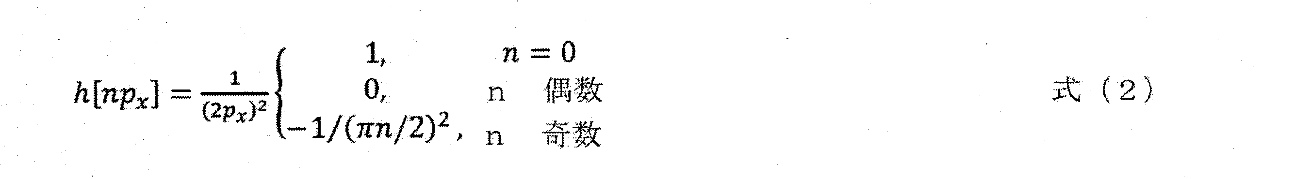
1.式(3)に従って、周波数領域FFTh[npx]shiftでのランプフィルタを計算し、
2.各投影角度/SODに対する投影/体積変換R(θ)RVを計算し、
3.式(2、4)を使用して、重み付けされ、かつフィルタリングされた放射線写真Sθ(x,yk)を計算し、周期的平滑分解を適用する[33](グラフィックカード上で)。
4.R(θ)RV変換を使用して体積座標を変換し(グラフィックカード上で)、
5.式(5)に示されるように、補間方法[34~35]を使用して、逆投影された画素値をすべてのボクセルに追加する(グラフィックカード上で)。
6.すべての投影角度/SODに対して、ステップ2から開始することを繰り返す。
第1の実施例は、炭素/エポキシパネルにおける衝撃損傷を受けたエリアの検査のための可変ズーム技法を例証する。パネルの幅および厚さは、それぞれ、401mmおよび3.5mmであり、114.57の幅対厚さアスペクト比をもたらす。衝撃損傷は、図4に例示されるように、4×4.5mm2の面積のROI210に局在している。
別の実施例では、可変ズーム技法を使用して、ハイブリッド複合材積層パネルを特性評価する。ハイブリッド複合材積層パネル材料系は、炭素繊維とガラス繊維との間の大きなコントラスト変動に起因して追加の難題を課す。図9は、可変ズームCTシステム900のシステム図である。CTシステム900は、実質的に、上述したCTシステム200、400に対するものであり、同様の数字は同様の部分を表す。例えば、標本202、線源204、検出器206、およびROI210は、上述したものと実質的に同じである。上述したように、線源204は、FOV208に沿って検出器206にX線ビームを放出するように構成されている。CTシステム900はまた、CTシステム200を参照して上述した標本ステージと実質的に同じである標本ステージ402を含む。具体的には、標本ステージ402は、標本202を回転軸Aの周りに回転させるとともに、FOV208内の標本202を線源204と検出器206との間で、取得軌跡408に沿って並進させる。示される実施例では、標本ステージ202は、45°に回転する。標本ステージ402は、標本202を標本ステージ402に解放可能に留めるためのクランプ404を備え得る。クランプは、クランプ404の中心軸Bが標本ステージ402の回転軸Aに対して平行であり、かつこれと一致するように、標本ステージ上に位置決めされている。CTシステム900は、CTシステム900の他の構成要素を包含するハウジング406を含む。様々な実装態様では、ハウジング406は、線源204からの放射線が周囲環境に入ることを防止するための放射線遮蔽を提供してもよい。
本明細書では、大きな面内寸法を有する複合材積層の検査の空間分解能を向上させることが可能である新規なX線コンピュータ断層撮影が開示される。新規な走査技法は、非因襲的な走査軌跡を利用し、標本は、回転するのみではなく、空間の寸法が許すに従ってX線源の方へ並進することも行い、それゆえ、より大きな分解能につながる。可変ズーム方法は、従来の走査方法と制限された角度の走査方法との両方を凌駕することが例証された。従来のおよび制限された角度の技法とは異なり、可変ズームCTは、3つの次元すべてで傑出した分解能を生成した。
ファントムの定義
このセクションでは、人為的な3Dファントムを使用して、可変ズーム技法の性能を見極める。ファントム体積は、ファントムの中心に位置する円筒状欠陥(直径および高さが0.5mm)を有する矩形の400mm幅かつ3.5mm厚ブロックを表す。複合材パネルを模擬したファントムのディメンションを、以下に提示する。ファントムのコーンビーム投影は、プロジェクタ関数を使用して、かつ幾何学パラメータと図3に示される炭素/エポキシパネルの取得軌跡とを使用して生成される。「逆犯罪(inverse crime)」を回避するために、ファントム体積の投影は、投影された体積中のボクセルサイズよりも小さいボクセルサイズを使用して生成される。メモリ制限に起因して、全体積は、2つの部分に分割される。欠陥を有する小さい方の内側部分は、2μmのボクセルサイズで投影され、大きい方の外側部分は、10μmのボクセルサイズで投影される。結果として得られる投影は、組み合わせられ、再構成方法セクションで上述したアルゴリズムに基づいて、再構成の入力として使用される。
目視検査は、可変ズームCT再構成スライスと従来のCT再構成スライスとの鮮鋭性の実質的な差異を明らかにする。この差異を定量的に見極めるために、Kraemer A,Kovacheva E,Lanza G,“Projection based evaluation of CT image quality in dimensional metrology,”Digit.Ind.Radiol.Comput.Tomogr.,2015,p.1-10で提案された分散推定方法を採用した。欠陥境界上の各ポイントについて、サポート窓内部の強度値の分散は、材料欠陥境界の局所的な鮮鋭性を示す。欠陥境界に沿ったすべての測定値間の最大の分散を選定して、鮮鋭性を表す。


複合材パネルのディメンション測定
Hexcelのプリプレグを使用してBoeingによって製造された、図4に示される大きなアスペクト比の炭素/エポキシ複合材パネルに対して、測定ベースの検証を実施した。パネルの中央に0.5mmの孔を穿孔し、Keyence Digital Microscope VHX-950Fによって、孔の直径を確認した。欠陥の深さは2.5mmであり、それを0.001インチ(25.4μm)精度のダイアル試験インジケータによって推定した。前のセクションで概説した手順を使用して、ディメンション測定ならびに不鮮鋭性測定を実行した。
被験標本
可変ズーム技法を、低速度衝撃損傷を受けた予備含侵された連続繊維強化ポリマー複合材パネルのX線CT走査に対して例証する。これらの標本は、大きな幅対厚さアスペクト比に起因した従来のX線CTについての難題を表す。大きなサイズのパネルは、従来のCT走査技法が、典型的にはパネル厚さに匹敵するサイズを有する損傷を受けやすいエリアで所望の空間分解能を得ることを妨げる。層間欠陥の信頼できる減退には、再構成ボクセルがパネル厚さよりも桁が小さい大きさであることが必要である。

第1の実施例は、炭素/エポキシパネルにおける衝撃を受けたエリアの検査のための可変ズーム技法を例証する。パネルの幅および厚さは、それぞれ、401mmおよび3.5mmであり、114.57の幅対厚さアスペクト比をもたらす。パネルは、パネルの中央に位置するおよそ4×4.5mm2の面積で低速度衝撃損傷を受けている。
第2の実施例として、可変ズーム技法を適用して、ハイブリッド複合材積層の衝撃損傷を特性評価した。この材料系は、炭素繊維とガラス繊維との間の大きなコントラスト変動に起因して追加の難題を課す。積層は、152mmの幅および5.2mmの厚さを有し、アスペクト比は、29.2であり、3×3mm2の衝撃損傷が、プレートの中心にある。
[1]A.Makeev,G.Seon,Y.Nikishkov,D.Nguyen,P.Mathews,M.Robeson,Analysis Methods Improving Confidence in Material Qualification for Laminated Composites,J.Am.Helicopter Soc.64(2019)1-13.
[2]G.Seon,A.Makeev,Y.Nikishkov,E.Lee,Effects of defects on interlaminar tensile fatigue behavior of carbon/epoxy composites,Compos.Sci.Technol.89(2013)194-201.
[3]Y.Nikishkov,G.Seon,A.Makeev,Structural analysis of composites with porosity defects based on X-ray computed tomography,J.Compos.Mater.48(2014)2131-2144.
[4]J.Varna,R.Joffe,L.A.Berglund,Effect of voids on failure mechanisms in RTM laminates,Compos.Sci.Technol.53(1995)241-249.
[5]G.Seon,A.Makeev,Structures Perspective for Strength and Fatigue Prognosis in Composites with Manufacturing Irregularities,J.Am.Helicopter Soc.60(2015)1-10.
[6]M.Wisnom,T.Reynolds,N.Gwilliam,Reduction in interlaminar shear strength by discrete and distributed voids,Compos.Sci.Technol.56(1996)93-101.
[7]P.J.Withers,M.Preuss,Fatigue and damage in structural materials studied by X-ray tomography,Annu.Rev.Mater.Res.42(2012)81-103.
[8]S.M.Spearing,I.Sinclair,The micro-mechanics of strength,durability and damage tolerance in composites:new insights from high resolution computed tomography,IOP conference Series:Mater.Sci.Eng.139(1)(2016).
[9]J.Lambert,A.R.Chambers,I.Sinclair,S.M.Spearing,3D damage characterisation and the role of voids in the fatigue of wind turbine blade materials,Compos.Sci.Technol.72(2012)337-343.
[10]Y.Nikishkov,L.Airoldi,A.Makeev,Measurement of voids in composites by X-ray Computed Tomography,Compos.Sci.Technol.89(2013)89-97.
[11]Y.Wang,C.S.Garcea,P.J.Withers,Computed Tomography of Composites,in:C.H.Zweben,P.Beaumont(Eds.),Compr.Compos.Mater.II,2nd ed.,Elsevier,2018:pp.101-118.
[12]W.A.Kalender,Computed Tomography,Publicis Publishing,Erlangen,2011.
[13]J.Stein,C.Soutis,P.J.Withers,The quantification of impact damage distribution in composite laminates by analysis of X-ray computed tomograms,Compos.Sci.Technol.152(2018)139-148.
[14]J.Rouse,R.Bradley,P.J.Withers,Imaging impact damage in high aspect ratio composite plates,in:18th Int.Conf.Compos.Mater.,2011.
[15]D.J.Bull,L.Helfen,I.Sinclair,S.M.Spearing,T.Baumbach,A comparison of multi-scale 3D X-ray tomographic inspection techniques for assessing carbon fibre composite impact damage,Compos.Sci.Technol.75(2013)55-61.
[16]Quinto,E.T.“Singularities of the X-ray transform and limited data tomography in R2 and R3,”SIAM J.Math.Analysis 24(1993)1215-1225.
[17]J.Zhou,M.Maisl,H.Reiter,W.Arnold,Computed laminography for materials testing,Appl.Phys.Lett.68(1996)3500-3502.
[18]F.Xu,L.Helfen,T.Baumbach,H.Suhonen,Comparison of image quality in computed laminography and tomography,Opt.Soc.Am.20(2012)361-366.
[19]L.Helfen,F.Xu,H.Suhonen,P.Cloetens,and T.Baumbach.Laminographic imaging using synchrotron radiation-challenges and opportunities.J.of Phys.:Conf.Ser.425 192025(2013).
[20]S.L.Fisher,D.J.Holmes,J.S.Jorgensen,P.Gajjar,J.Behnsen,W.R.B.Lionheart,P.J.Withers,Laminography in the lab:imaging planar objects using a conventional x-ray CT scanner,Meas.Sci.Technol.30(2019)1-13.
[21]L.Helfen,A.Myagotin,A.Rack,P.Pernot,P.Mikulik,M.Di Michiel,T.Baumbach,Synchrotron-radiation computed laminography for high-resolution three-dimensional imaging of flat devices,Phys.Status Solidi A Appl.Mater.Sci.204(2007)2760-2765.
[22]N.S.O.Brien,R.P.Boardman,I.Sinclair,T.Blumensath,Recent Advances in X-ray Cone-beam Computed Laminography,J.Xray.Sci.Technol.24(2016)691-707.
[23]C.E.Wood,N.S.O’Brien,A.Denysov,T.Blumensath,Computed Laminography of CFRP using an X-ray Cone Beam and Robotic Sample Manipulator Systems,IEEE Trans.Nucl.Sci.67(2018)1384-1393.
[24]H.Yu,Q.Xu,X.Mou,G.Wang,Recent Progress in Local Reconstruction,in:Proc.SPIE,San Diego,CA,USA,2010:pp.1-14.
[25]X.Xiao,F.De Carlo,S.Stock,Practical error estimation in zoom-in and truncated tomography reconstructions,Rev.Sci.Instrum.78(2007)063705.
[26]A.Dabravolski,K.J.Batenburg,J.Sijbers,Adaptive zooming in X-ray computed tomography,J.Xray.Sci.Technol.22(2014)77-89.
[27]Hexcel Corporation,HexPly(登録商標)8552 product data sheet.hexcel.com/user_area/content_media/raw/HexPly_8552_us_DataSheet.pdf,2016(accessed August 6,2019).
[28]Hexcel Corporation,HexPly(登録商標)913 257°F(125℃)product data sheet.hexcel.com/user_area/content_media/raw/HexPly_913_us_DataSheet.pdf,2016(accessed August 6,2019).
[29]Shimadzu Corporation,inspeXio SMX-225CT FPT HD Instruction Manual,2017.
[30]L.A.Feldkamp,L.C.Davis,J.W.Kress,Practical cone-beam algorithm,Opt.Soc.Am.1(1984)612-619.
[31]A.C.Kak,M.Slaney,Principles of Computerized Tomographic Imaging,IEEE Press,New York,NY,1988.
[32]SciPy.org,Discrete Fourier Transform(numpy.fft),docs.scipy.org/doc/numpy/reference/routines.fft.html,2019(accessed August 6,2019).
[33]L.Moisan,Periodic Plus Smooth Image Decomposition,J.Math.Imaging Vis.39(2011)161-179.
[34]B.De Man,S.Basu,Distance-driven projection and backprojection in three dimensions,Phys.Med.Biol.49(2004)2463-2475.
[35]Y.Long,J.A.Fessler,J.M.Balter,3D forward and back-projection for X-ray CT using separable footprints,IEEE Trans.Med.Imaging.29(2010)1839-1850.
[36]A.Kraemer,E.Kovacheva,G.Lanza,Projection based evaluation of CT image quality in dimensional metrology,in:Digit.Ind.Radiol.Comput.Tomogr.,2015:pp.1-10.
Claims (19)
- X線コンピュータ断層撮影(CT)スキャナの可変ズーム方法であって、
X線源からX線ビームを放出して、視野(FOV)内の標本の関心の領域(ROI)を検出器上に投影することと、
前記標本を標本ステージの回転軸の周りに回転させ、かつ前記標本ステージを前記X線源と前記検出器との間の取得軌跡に沿って並進させながら、前記検出器で前記標本の前記ROIの投影を得ることと、
再構成コンピュータによって、前記検出器によって走査された前記投影から前記標本の3次元体積を再構成することと、を含み、
前記取得軌跡が、前記標本ステージの各回転角度での前記X線源と前記標本ステージの前記回転軸との間の線源被写体間距離(SOD)を特定し、
前記3次元体積を再構成することが、
前記標本ステージの各回転角度での前記SODに基づいて放射線写真のセットを重み付けすることを含む、方法。 - 前記標本を回転させ、かつ並進させている間、前記X線源および前記検出器が、静止している、請求項1に記載の方法。
- 前記ROIが、前記検出器の中心エリア上に投影される、請求項1に記載の方法。
- 前記取得軌跡が、前記標本ステージの前記回転軸を前記FOVの中心に沿って並進させる、請求項1に記載の方法。
- 前記取得軌跡に沿った初期SODが、SODROIであり、前記SODROIが、前記ROIが完全に前記FOV内にある最近接SODである、請求項1に記載の方法。
- 前記標本ステージの回転角度が閾値角度未満である間、前記SODROIが、前記ROIが前記FOV内に留まる最近接SODである、請求項5に記載の方法。
- 前記標本ステージの各回転角度での前記SODが、以下であり:
- 前記標本ステージの前記回転角度が前記閾値角度未満である間、SOD(θ)=SODROIである、請求項7に記載の方法。
- 前記3次元体積を再構成することが、
前記標本ステージの各回転角度での前記SODに基づく重み付け係数で、フィルタリングされた放射線写真のセットの逆投影を重み付けすることを含む、請求項1に記載の方法。 - 前記重み付け係数が、以下を含み:
- 前記3次元体積を再構成することが、
各投影角度および前記SODに対する体積変換への投影を計算して、前記フィルタリングされた放射線写真のセットの前記逆投影を生成することと、
補間方法に基づいて、前記3次元体積のボクセルに、重み付けされた逆投影された画素値を追加して、前記3次元体積の前記再構成を生成することと、をさらに含む、請求項9に記載の方法。 - 前記3次元体積を再構成することが、
周波数領域のランプフィルタを計算することと、
前記ランプフィルタに基づいて、重み付けされ、かつフィルタリングされた放射線写真を計算すること、および周期的平滑分解を適用して、前記フィルタリングされた放射線写真のセットを生成することと、をさらに含む、請求項11に記載の方法。 - 前記周波数領域の前記ランプフィルタを計算することが、以下に対する1次元直接フーリエ変換を計算することを含み:
- 前記体積変換への投影を計算するときに、SOD(θ)を変動させるのに従い、各投影角度に対して投影座標が異なる、請求項11に記載の方法。
- 前記体積変換への投影を計算することが、
3次元座標変換(x,y,z)T=R(θ)RV・(t,s,r)Tを計算することを含み、式中、(t,s,r)が、再構成された体積座標であり、(x,y,z)が、投影座標であり、RVが、体積変換行列であり、Rθが、標本回転の行列である、請求項14に記載の方法。 - 前記補間方法が、距離駆動型方式またはセパラブルフットプリント方式である、請求項11に記載の方法。
- 前記重み付けされ、かつフィルタリングされた放射線写真が、円錐X線ビームの異なる光線長を考慮するように重み付けされている、請求項11に記載の方法。
- 前記重み付けされ、かつフィルタリングされた放射線写真を計算すること、および周期的平滑分解を適用することが、以下を計算することを含み:
Sθ(x,yk)=[P’θ(x,yk)*h(x)]=pxIFFT{FFTP’θ(x,yk)ZP・FFTh[npx]shift}、および
- 補間方法に基づいて、前記3次元体積のボクセルに、前記重み付けされた逆投影された画素値を追加することが、以下を計算することを含み:
Applications Claiming Priority (3)
| Application Number | Priority Date | Filing Date | Title |
|---|---|---|---|
| US201962913775P | 2019-10-11 | 2019-10-11 | |
| US62/913,775 | 2019-10-11 | ||
| PCT/US2020/055030 WO2021072229A1 (en) | 2019-10-11 | 2020-10-09 | Variable zoom x-ray computed tomography method for composites |
Publications (2)
| Publication Number | Publication Date |
|---|---|
| JP2022551500A JP2022551500A (ja) | 2022-12-09 |
| JP7605503B2 true JP7605503B2 (ja) | 2024-12-24 |
Family
ID=75438117
Family Applications (1)
| Application Number | Title | Priority Date | Filing Date |
|---|---|---|---|
| JP2022521454A Active JP7605503B2 (ja) | 2019-10-11 | 2020-10-09 | 複合材のための可変ズームx線コンピュータ断層撮影方法 |
Country Status (4)
| Country | Link |
|---|---|
| US (1) | US12130245B2 (ja) |
| JP (1) | JP7605503B2 (ja) |
| CN (1) | CN114727791A (ja) |
| WO (1) | WO2021072229A1 (ja) |
Families Citing this family (12)
| Publication number | Priority date | Publication date | Assignee | Title |
|---|---|---|---|---|
| US12174129B2 (en) * | 2021-04-28 | 2024-12-24 | The Boeing Company | X-ray tomography systems and methods for imaging an aircraft part |
| DE102021204628B3 (de) * | 2021-05-06 | 2022-04-07 | Carl Zeiss Industrielle Messtechnik Gmbh | Verfahren zum Betreiben eines Computertomographen beim Vermessen einer Interessensregion eines Objekts und Computertomograph |
| KR20240110614A (ko) * | 2021-11-16 | 2024-07-15 | 루마필드, 인크. | 슈라우드가 구비된 엑스레이 장치 |
| US12385857B2 (en) * | 2022-08-03 | 2025-08-12 | Baker Hughes Holdings Llc | Rapid high-resolution computerized tomography |
| DE102022129970A1 (de) * | 2022-11-14 | 2024-05-16 | Comet Yxlon Gmbh | Verfahren zur Erzeugung von Durchleuchtungsbildern für die Rekonstruktion eines Volumens in einem flachen Objekt mittels einer Röntgenanlage |
| US20240310306A1 (en) * | 2023-03-13 | 2024-09-19 | The Boeing Company | X-ray line scan for foreign object debris detection |
| CN116172601A (zh) * | 2023-05-04 | 2023-05-30 | 合肥锐视医疗科技有限公司 | 一种可变空间分辨率ct扫描方法、扫描装置及成像系统 |
| CN116380946B (zh) * | 2023-06-02 | 2023-08-15 | 清华大学 | 一种水泥水化全周期成像方法 |
| GB202309735D0 (en) * | 2023-06-28 | 2023-08-09 | Rolls Royce Plc | A method for scanning of a part in a scanning apparatus |
| CN118447113B (zh) * | 2024-04-24 | 2025-02-25 | 清华大学 | 扩大成像视野的x射线ct局部成像方法、装置及电子设备 |
| CN119438258B (zh) * | 2024-09-30 | 2025-10-28 | 清华大学 | 基于分布式小微焦点x射线源的ct成像系统及方法 |
| KR102872671B1 (ko) * | 2024-10-25 | 2025-10-17 | 테크밸리 주식회사 | 자동 배율 조정기능을 가지는 3d ct 장치 |
Citations (4)
| Publication number | Priority date | Publication date | Assignee | Title |
|---|---|---|---|---|
| JP2011510313A (ja) | 2008-04-30 | 2011-03-31 | フラウンホッファー−ゲゼルシャフト ツァ フェルダールング デァ アンゲヴァンテン フォアシュンク エー.ファオ | 高解像度の重要な対象領域を含む対象のct再現を作製するための装置および方法 |
| US20140233692A1 (en) | 2013-02-15 | 2014-08-21 | Xradia, Inc. | Multi Energy X-Ray Microscope Data Acquisition and Image Reconstruction System and Method |
| JP2014194414A (ja) | 2013-03-14 | 2014-10-09 | General Electric Co <Ge> | 対象オブジェクトの高解像度モデル |
| JP2020173175A (ja) | 2019-04-11 | 2020-10-22 | 株式会社リガク | 投影像の撮影方法、制御装置、制御プログラム、処理装置および処理プログラム |
Family Cites Families (26)
| Publication number | Priority date | Publication date | Assignee | Title |
|---|---|---|---|---|
| DE3021757A1 (de) * | 1980-06-10 | 1981-12-24 | Siemens AG, 1000 Berlin und 8000 München | Strahlendiagnostikgeraet |
| JPH0694651A (ja) * | 1992-09-14 | 1994-04-08 | Fujitsu Ltd | 基板検査装置 |
| JP3866431B2 (ja) * | 1999-02-17 | 2007-01-10 | 株式会社東芝 | X線ct装置 |
| US6542570B1 (en) * | 2000-04-14 | 2003-04-01 | Kabushiki Kaisha Toshiba | Method and system for reconstructing computed tomography images using redundant data |
| JP3926574B2 (ja) * | 2001-03-13 | 2007-06-06 | 株式会社島津製作所 | 断層撮影装置 |
| US6904117B2 (en) * | 2002-10-30 | 2005-06-07 | Toshiba Corporation | Tilted gantry helical cone-beam Feldkamp reconstruction for multislice CT |
| CN1930588A (zh) * | 2004-03-12 | 2007-03-14 | 皇家飞利浦电子股份有限公司 | 用于表面渲染的沿边缘的自适应采样 |
| US7778392B1 (en) * | 2004-11-02 | 2010-08-17 | Pme Ip Australia Pty Ltd | Method of reconstructing computed tomography (CT) volumes suitable for execution on commodity central processing units (CPUs) and graphics processors, and apparatus operating in accord with those methods (rotational X-ray on GPUs) |
| DE102006041033B4 (de) * | 2006-09-01 | 2017-01-19 | Siemens Healthcare Gmbh | Verfahren zur Rekonstruktion eines dreidimensionalen Bildvolumens |
| WO2008156764A1 (en) * | 2007-06-15 | 2008-12-24 | The Johns Hopkins University | Methods for motion compensated image reconstruction and systems related thereto |
| WO2010070527A2 (en) * | 2008-12-15 | 2010-06-24 | Koninklijke Philips Electronics N. V. | Semicircular inversed offset scanning for enlarged field of view 3d |
| EP2411965B1 (en) * | 2009-03-26 | 2016-01-13 | Koninklijke Philips N.V. | Method and apparatus for computed tomography image reconstruction |
| CN101750021B (zh) * | 2009-12-04 | 2011-05-11 | 深圳先进技术研究院 | Ct系统中几何参数的标定方法、装置 |
| AU2011206927B2 (en) * | 2010-01-13 | 2015-12-03 | Fei Company | A computed tomography imaging process and system |
| EP2764380B1 (en) * | 2011-10-03 | 2022-02-23 | Fei Company | A computed tomography imaging process and system |
| US9439605B2 (en) * | 2011-11-11 | 2016-09-13 | Koninklijke Philips N.V. | C-arm system with extended field of view |
| JP6181045B2 (ja) * | 2012-04-24 | 2017-08-16 | 株式会社日立製作所 | X線ct装置及び画像再構成方法 |
| US10251613B2 (en) * | 2013-03-01 | 2019-04-09 | Siemens Healthcare Gmbh | X-ray CT scanning and dual-source CT system |
| US9600138B2 (en) * | 2013-03-15 | 2017-03-21 | Synaptive Medical (Barbados) Inc. | Planning, navigation and simulation systems and methods for minimally invasive therapy |
| CN104569002B (zh) * | 2013-10-23 | 2018-04-27 | 北京纳米维景科技有限公司 | 基于光子计数的x射线相衬成像系统、方法及其设备 |
| CN104597061B (zh) * | 2015-01-28 | 2017-10-31 | 中国工程物理研究院应用电子学研究所 | 基于虚拟探测器的大视场锥束ct成像方法 |
| AU2017203626A1 (en) * | 2016-05-30 | 2017-12-14 | Katholieke Universiteit Leuven Ku Leuven R&D | A method and apparatus for motion correction in CT imaging |
| JP7198457B2 (ja) * | 2017-09-29 | 2023-01-04 | 国立大学法人東北大学 | インテリアct位相イメージングx線顕微鏡装置 |
| US11009449B2 (en) * | 2018-04-20 | 2021-05-18 | Fei Company | Scanning trajectories for region-of-interest tomograph |
| EP3660790A1 (en) * | 2018-11-28 | 2020-06-03 | Koninklijke Philips N.V. | System for reconstructing an image of an object |
| JP7512270B2 (ja) * | 2018-11-30 | 2024-07-08 | アキュレイ インコーポレイテッド | フラクション間情報を使用して画像を再構成および補正する方法および装置 |
-
2020
- 2020-10-09 JP JP2022521454A patent/JP7605503B2/ja active Active
- 2020-10-09 WO PCT/US2020/055030 patent/WO2021072229A1/en not_active Ceased
- 2020-10-09 US US17/766,637 patent/US12130245B2/en active Active
- 2020-10-09 CN CN202080077837.XA patent/CN114727791A/zh active Pending
Patent Citations (4)
| Publication number | Priority date | Publication date | Assignee | Title |
|---|---|---|---|---|
| JP2011510313A (ja) | 2008-04-30 | 2011-03-31 | フラウンホッファー−ゲゼルシャフト ツァ フェルダールング デァ アンゲヴァンテン フォアシュンク エー.ファオ | 高解像度の重要な対象領域を含む対象のct再現を作製するための装置および方法 |
| US20140233692A1 (en) | 2013-02-15 | 2014-08-21 | Xradia, Inc. | Multi Energy X-Ray Microscope Data Acquisition and Image Reconstruction System and Method |
| JP2014194414A (ja) | 2013-03-14 | 2014-10-09 | General Electric Co <Ge> | 対象オブジェクトの高解像度モデル |
| JP2020173175A (ja) | 2019-04-11 | 2020-10-22 | 株式会社リガク | 投影像の撮影方法、制御装置、制御プログラム、処理装置および処理プログラム |
Also Published As
| Publication number | Publication date |
|---|---|
| US20220381705A1 (en) | 2022-12-01 |
| WO2021072229A1 (en) | 2021-04-15 |
| US12130245B2 (en) | 2024-10-29 |
| CN114727791A (zh) | 2022-07-08 |
| JP2022551500A (ja) | 2022-12-09 |
Similar Documents
| Publication | Publication Date | Title |
|---|---|---|
| JP7605503B2 (ja) | 複合材のための可変ズームx線コンピュータ断層撮影方法 | |
| JP7438150B2 (ja) | 反復投影マッチング法を用いた放射線イメージングによる物品検査 | |
| Nikishkov et al. | Variable zoom technique for X-ray computed tomography | |
| Deyhle et al. | Spatial resolution of a laboratory based X-ray cone-beam laminography scanning system for various trajectories | |
| EP2711695B1 (en) | Method of getting a tomogram used by X-ray computed tomography and X-ray computed tomography system based on its method | |
| Banjak | X-ray computed tomography reconstruction on non-standard trajectories for robotized inspection | |
| Sun et al. | The realisation of fast X-ray computed tomography using a limited number of projection images for dimensional metrology | |
| Maisl et al. | Computed laminography for x-ray inspection of lightweight constructions | |
| CN118032822A (zh) | 产生透视图像来重构平面对象中的体积的方法 | |
| Van de Casteele et al. | The effect of beam hardening on resolution in X-ray microtomography | |
| Yusuke et al. | Investigation of industrial die-cast Al-alloys using X-ray micro-computed tomography and machine learning approach for CT segmentation | |
| Fu et al. | Large field of view computed laminography with the asymmetric rotational scanning geometry | |
| Zou et al. | A square cross-section FOV rotational CL (SC-CL) and its analytical reconstruction method | |
| Nikishkov et al. | Prior function designs for X-ray reconstructions from limited angular views | |
| Rouse | Characterisation of impact damage in carbon fibre reinforced plastics by 3D X-ray tomography | |
| Ghafarzadeh et al. | Computed Tomography Artifact Reduction Employing a Convolutional Neural Network Within the Context of Dimensional Metrology | |
| Nikishkov et al. | Prior function designs for x-ray computed tomography reconstructions from limited angular views | |
| Champley et al. | Methods for Few-View CT Image Reconstruction | |
| Makeev et al. | Integrated Structural Methods Addressing Army Aviation Life Prediction Challenges in Composites | |
| Tigkos et al. | Simulation study for optimization of X-ray inspection setup applied to CFRP aerostructures | |
| Franco et al. | Visualization software for CT: fan/cone beam and metrology applications | |
| da SILVA et al. | Image Quality Analysis of a Laminographic Multiplicative Algebraic Reconstruction Algorithm compared to Filtered Shift Averaging | |
| Liaptsis et al. | High resolution X-ray volumetric inspection of large planar samples using SART based computed laminography | |
| Bostaph | Advanced Methods of Nondestructive Inspection of Composite Structures Based on Limited Angle X-Ray Computed Tomography | |
| Scanavini et al. | Computed tomography |
Legal Events
| Date | Code | Title | Description |
|---|---|---|---|
| A621 | Written request for application examination |
Free format text: JAPANESE INTERMEDIATE CODE: A621 Effective date: 20231004 |
|
| A977 | Report on retrieval |
Free format text: JAPANESE INTERMEDIATE CODE: A971007 Effective date: 20240523 |
|
| A131 | Notification of reasons for refusal |
Free format text: JAPANESE INTERMEDIATE CODE: A131 Effective date: 20240527 |
|
| A521 | Request for written amendment filed |
Free format text: JAPANESE INTERMEDIATE CODE: A523 Effective date: 20240726 |
|
| TRDD | Decision of grant or rejection written | ||
| A01 | Written decision to grant a patent or to grant a registration (utility model) |
Free format text: JAPANESE INTERMEDIATE CODE: A01 Effective date: 20241105 |
|
| A61 | First payment of annual fees (during grant procedure) |
Free format text: JAPANESE INTERMEDIATE CODE: A61 Effective date: 20241205 |
|
| R150 | Certificate of patent or registration of utility model |
Ref document number: 7605503 Country of ref document: JP Free format text: JAPANESE INTERMEDIATE CODE: R150 |