JP7602978B2 - Gas turbine facility and method for suppressing ammonia emissions from gas turbine facility - Google Patents
Gas turbine facility and method for suppressing ammonia emissions from gas turbine facility Download PDFInfo
- Publication number
- JP7602978B2 JP7602978B2 JP2021115757A JP2021115757A JP7602978B2 JP 7602978 B2 JP7602978 B2 JP 7602978B2 JP 2021115757 A JP2021115757 A JP 2021115757A JP 2021115757 A JP2021115757 A JP 2021115757A JP 7602978 B2 JP7602978 B2 JP 7602978B2
- Authority
- JP
- Japan
- Prior art keywords
- ammonia
- water
- gas turbine
- sprinkler
- exhaust gas
- Prior art date
- Legal status (The legal status is an assumption and is not a legal conclusion. Google has not performed a legal analysis and makes no representation as to the accuracy of the status listed.)
- Active
Links
Images


Classifications
-
- F—MECHANICAL ENGINEERING; LIGHTING; HEATING; WEAPONS; BLASTING
- F01—MACHINES OR ENGINES IN GENERAL; ENGINE PLANTS IN GENERAL; STEAM ENGINES
- F01N—GAS-FLOW SILENCERS OR EXHAUST APPARATUS FOR MACHINES OR ENGINES IN GENERAL; GAS-FLOW SILENCERS OR EXHAUST APPARATUS FOR INTERNAL-COMBUSTION ENGINES
- F01N3/00—Exhaust or silencing apparatus having means for purifying, rendering innocuous, or otherwise treating exhaust
- F01N3/08—Exhaust or silencing apparatus having means for purifying, rendering innocuous, or otherwise treating exhaust for rendering innocuous
-
- F—MECHANICAL ENGINEERING; LIGHTING; HEATING; WEAPONS; BLASTING
- F02—COMBUSTION ENGINES; HOT-GAS OR COMBUSTION-PRODUCT ENGINE PLANTS
- F02C—GAS-TURBINE PLANTS; AIR INTAKES FOR JET-PROPULSION PLANTS; CONTROLLING FUEL SUPPLY IN AIR-BREATHING JET-PROPULSION PLANTS
- F02C7/00—Features, components parts, details or accessories, not provided for in, or of interest apart form groups F02C1/00 - F02C6/00; Air intakes for jet-propulsion plants
-
- B—PERFORMING OPERATIONS; TRANSPORTING
- B01—PHYSICAL OR CHEMICAL PROCESSES OR APPARATUS IN GENERAL
- B01D—SEPARATION
- B01D53/00—Separation of gases or vapours; Recovering vapours of volatile solvents from gases; Chemical or biological purification of waste gases, e.g. engine exhaust gases, smoke, fumes, flue gases, aerosols
- B01D53/14—Separation of gases or vapours; Recovering vapours of volatile solvents from gases; Chemical or biological purification of waste gases, e.g. engine exhaust gases, smoke, fumes, flue gases, aerosols by absorption
- B01D53/1456—Removing acid components
-
- B—PERFORMING OPERATIONS; TRANSPORTING
- B01—PHYSICAL OR CHEMICAL PROCESSES OR APPARATUS IN GENERAL
- B01D—SEPARATION
- B01D53/00—Separation of gases or vapours; Recovering vapours of volatile solvents from gases; Chemical or biological purification of waste gases, e.g. engine exhaust gases, smoke, fumes, flue gases, aerosols
- B01D53/14—Separation of gases or vapours; Recovering vapours of volatile solvents from gases; Chemical or biological purification of waste gases, e.g. engine exhaust gases, smoke, fumes, flue gases, aerosols by absorption
- B01D53/1493—Selection of liquid materials for use as absorbents
-
- B—PERFORMING OPERATIONS; TRANSPORTING
- B01—PHYSICAL OR CHEMICAL PROCESSES OR APPARATUS IN GENERAL
- B01D—SEPARATION
- B01D53/00—Separation of gases or vapours; Recovering vapours of volatile solvents from gases; Chemical or biological purification of waste gases, e.g. engine exhaust gases, smoke, fumes, flue gases, aerosols
- B01D53/14—Separation of gases or vapours; Recovering vapours of volatile solvents from gases; Chemical or biological purification of waste gases, e.g. engine exhaust gases, smoke, fumes, flue gases, aerosols by absorption
- B01D53/18—Absorbing units; Liquid distributors therefor
-
- B—PERFORMING OPERATIONS; TRANSPORTING
- B01—PHYSICAL OR CHEMICAL PROCESSES OR APPARATUS IN GENERAL
- B01D—SEPARATION
- B01D53/00—Separation of gases or vapours; Recovering vapours of volatile solvents from gases; Chemical or biological purification of waste gases, e.g. engine exhaust gases, smoke, fumes, flue gases, aerosols
- B01D53/34—Chemical or biological purification of waste gases
- B01D53/46—Removing components of defined structure
- B01D53/54—Nitrogen compounds
- B01D53/56—Nitrogen oxides
-
- B—PERFORMING OPERATIONS; TRANSPORTING
- B01—PHYSICAL OR CHEMICAL PROCESSES OR APPARATUS IN GENERAL
- B01D—SEPARATION
- B01D53/00—Separation of gases or vapours; Recovering vapours of volatile solvents from gases; Chemical or biological purification of waste gases, e.g. engine exhaust gases, smoke, fumes, flue gases, aerosols
- B01D53/34—Chemical or biological purification of waste gases
- B01D53/46—Removing components of defined structure
- B01D53/54—Nitrogen compounds
- B01D53/58—Ammonia
-
- B—PERFORMING OPERATIONS; TRANSPORTING
- B01—PHYSICAL OR CHEMICAL PROCESSES OR APPARATUS IN GENERAL
- B01D—SEPARATION
- B01D53/00—Separation of gases or vapours; Recovering vapours of volatile solvents from gases; Chemical or biological purification of waste gases, e.g. engine exhaust gases, smoke, fumes, flue gases, aerosols
- B01D53/34—Chemical or biological purification of waste gases
- B01D53/74—General processes for purification of waste gases; Apparatus or devices specially adapted therefor
- B01D53/75—Multi-step processes
-
- B—PERFORMING OPERATIONS; TRANSPORTING
- B01—PHYSICAL OR CHEMICAL PROCESSES OR APPARATUS IN GENERAL
- B01D—SEPARATION
- B01D53/00—Separation of gases or vapours; Recovering vapours of volatile solvents from gases; Chemical or biological purification of waste gases, e.g. engine exhaust gases, smoke, fumes, flue gases, aerosols
- B01D53/34—Chemical or biological purification of waste gases
- B01D53/74—General processes for purification of waste gases; Apparatus or devices specially adapted therefor
- B01D53/77—Liquid phase processes
- B01D53/78—Liquid phase processes with gas-liquid contact
-
- B—PERFORMING OPERATIONS; TRANSPORTING
- B01—PHYSICAL OR CHEMICAL PROCESSES OR APPARATUS IN GENERAL
- B01D—SEPARATION
- B01D53/00—Separation of gases or vapours; Recovering vapours of volatile solvents from gases; Chemical or biological purification of waste gases, e.g. engine exhaust gases, smoke, fumes, flue gases, aerosols
- B01D53/34—Chemical or biological purification of waste gases
- B01D53/74—General processes for purification of waste gases; Apparatus or devices specially adapted therefor
- B01D53/77—Liquid phase processes
- B01D53/79—Injecting reactants
-
- B—PERFORMING OPERATIONS; TRANSPORTING
- B01—PHYSICAL OR CHEMICAL PROCESSES OR APPARATUS IN GENERAL
- B01D—SEPARATION
- B01D53/00—Separation of gases or vapours; Recovering vapours of volatile solvents from gases; Chemical or biological purification of waste gases, e.g. engine exhaust gases, smoke, fumes, flue gases, aerosols
- B01D53/34—Chemical or biological purification of waste gases
- B01D53/74—General processes for purification of waste gases; Apparatus or devices specially adapted therefor
- B01D53/86—Catalytic processes
- B01D53/8621—Removing nitrogen compounds
- B01D53/8625—Nitrogen oxides
- B01D53/8631—Processes characterised by a specific device
-
- B—PERFORMING OPERATIONS; TRANSPORTING
- B01—PHYSICAL OR CHEMICAL PROCESSES OR APPARATUS IN GENERAL
- B01D—SEPARATION
- B01D53/00—Separation of gases or vapours; Recovering vapours of volatile solvents from gases; Chemical or biological purification of waste gases, e.g. engine exhaust gases, smoke, fumes, flue gases, aerosols
- B01D53/34—Chemical or biological purification of waste gases
- B01D53/74—General processes for purification of waste gases; Apparatus or devices specially adapted therefor
- B01D53/86—Catalytic processes
- B01D53/90—Injecting reactants
-
- C—CHEMISTRY; METALLURGY
- C02—TREATMENT OF WATER, WASTE WATER, SEWAGE, OR SLUDGE
- C02F—TREATMENT OF WATER, WASTE WATER, SEWAGE, OR SLUDGE
- C02F1/00—Treatment of water, waste water, or sewage
- C02F1/008—Control or steering systems not provided for elsewhere in subclass C02F
-
- C—CHEMISTRY; METALLURGY
- C02—TREATMENT OF WATER, WASTE WATER, SEWAGE, OR SLUDGE
- C02F—TREATMENT OF WATER, WASTE WATER, SEWAGE, OR SLUDGE
- C02F1/00—Treatment of water, waste water, or sewage
- C02F1/66—Treatment of water, waste water, or sewage by neutralisation; pH adjustment
-
- F—MECHANICAL ENGINEERING; LIGHTING; HEATING; WEAPONS; BLASTING
- F01—MACHINES OR ENGINES IN GENERAL; ENGINE PLANTS IN GENERAL; STEAM ENGINES
- F01D—NON-POSITIVE DISPLACEMENT MACHINES OR ENGINES, e.g. STEAM TURBINES
- F01D25/00—Component parts, details, or accessories, not provided for in, or of interest apart from, other groups
- F01D25/002—Cleaning of turbomachines
-
- F—MECHANICAL ENGINEERING; LIGHTING; HEATING; WEAPONS; BLASTING
- F02—COMBUSTION ENGINES; HOT-GAS OR COMBUSTION-PRODUCT ENGINE PLANTS
- F02C—GAS-TURBINE PLANTS; AIR INTAKES FOR JET-PROPULSION PLANTS; CONTROLLING FUEL SUPPLY IN AIR-BREATHING JET-PROPULSION PLANTS
- F02C3/00—Gas-turbine plants characterised by the use of combustion products as the working fluid
- F02C3/20—Gas-turbine plants characterised by the use of combustion products as the working fluid using a special fuel, oxidant, or dilution fluid to generate the combustion products
- F02C3/22—Gas-turbine plants characterised by the use of combustion products as the working fluid using a special fuel, oxidant, or dilution fluid to generate the combustion products the fuel or oxidant being gaseous at standard temperature and pressure
-
- F—MECHANICAL ENGINEERING; LIGHTING; HEATING; WEAPONS; BLASTING
- F02—COMBUSTION ENGINES; HOT-GAS OR COMBUSTION-PRODUCT ENGINE PLANTS
- F02C—GAS-TURBINE PLANTS; AIR INTAKES FOR JET-PROPULSION PLANTS; CONTROLLING FUEL SUPPLY IN AIR-BREATHING JET-PROPULSION PLANTS
- F02C3/00—Gas-turbine plants characterised by the use of combustion products as the working fluid
- F02C3/20—Gas-turbine plants characterised by the use of combustion products as the working fluid using a special fuel, oxidant, or dilution fluid to generate the combustion products
- F02C3/30—Adding water, steam or other fluids for influencing combustion, e.g. to obtain cleaner exhaust gases
-
- F—MECHANICAL ENGINEERING; LIGHTING; HEATING; WEAPONS; BLASTING
- F02—COMBUSTION ENGINES; HOT-GAS OR COMBUSTION-PRODUCT ENGINE PLANTS
- F02C—GAS-TURBINE PLANTS; AIR INTAKES FOR JET-PROPULSION PLANTS; CONTROLLING FUEL SUPPLY IN AIR-BREATHING JET-PROPULSION PLANTS
- F02C7/00—Features, components parts, details or accessories, not provided for in, or of interest apart form groups F02C1/00 - F02C6/00; Air intakes for jet-propulsion plants
- F02C7/22—Fuel supply systems
-
- B—PERFORMING OPERATIONS; TRANSPORTING
- B01—PHYSICAL OR CHEMICAL PROCESSES OR APPARATUS IN GENERAL
- B01D—SEPARATION
- B01D2252/00—Absorbents, i.e. solvents and liquid materials for gas absorption
- B01D2252/10—Inorganic absorbents
- B01D2252/102—Ammonia
-
- B—PERFORMING OPERATIONS; TRANSPORTING
- B01—PHYSICAL OR CHEMICAL PROCESSES OR APPARATUS IN GENERAL
- B01D—SEPARATION
- B01D2252/00—Absorbents, i.e. solvents and liquid materials for gas absorption
- B01D2252/10—Inorganic absorbents
- B01D2252/103—Water
-
- B—PERFORMING OPERATIONS; TRANSPORTING
- B01—PHYSICAL OR CHEMICAL PROCESSES OR APPARATUS IN GENERAL
- B01D—SEPARATION
- B01D2257/00—Components to be removed
- B01D2257/40—Nitrogen compounds
- B01D2257/404—Nitrogen oxides other than dinitrogen oxide
-
- B—PERFORMING OPERATIONS; TRANSPORTING
- B01—PHYSICAL OR CHEMICAL PROCESSES OR APPARATUS IN GENERAL
- B01D—SEPARATION
- B01D2257/00—Components to be removed
- B01D2257/40—Nitrogen compounds
- B01D2257/406—Ammonia
-
- C—CHEMISTRY; METALLURGY
- C02—TREATMENT OF WATER, WASTE WATER, SEWAGE, OR SLUDGE
- C02F—TREATMENT OF WATER, WASTE WATER, SEWAGE, OR SLUDGE
- C02F2101/00—Nature of the contaminant
- C02F2101/10—Inorganic compounds
- C02F2101/16—Nitrogen compounds, e.g. ammonia
-
- C—CHEMISTRY; METALLURGY
- C02—TREATMENT OF WATER, WASTE WATER, SEWAGE, OR SLUDGE
- C02F—TREATMENT OF WATER, WASTE WATER, SEWAGE, OR SLUDGE
- C02F2103/00—Nature of the water, waste water, sewage or sludge to be treated
- C02F2103/18—Nature of the water, waste water, sewage or sludge to be treated from the purification of gaseous effluents
-
- C—CHEMISTRY; METALLURGY
- C02—TREATMENT OF WATER, WASTE WATER, SEWAGE, OR SLUDGE
- C02F—TREATMENT OF WATER, WASTE WATER, SEWAGE, OR SLUDGE
- C02F2209/00—Controlling or monitoring parameters in water treatment
- C02F2209/14—NH3-N
-
- F—MECHANICAL ENGINEERING; LIGHTING; HEATING; WEAPONS; BLASTING
- F05—INDEXING SCHEMES RELATING TO ENGINES OR PUMPS IN VARIOUS SUBCLASSES OF CLASSES F01-F04
- F05D—INDEXING SCHEME FOR ASPECTS RELATING TO NON-POSITIVE-DISPLACEMENT MACHINES OR ENGINES, GAS-TURBINES OR JET-PROPULSION PLANTS
- F05D2270/00—Control
- F05D2270/01—Purpose of the control system
- F05D2270/08—Purpose of the control system to produce clean exhaust gases
- F05D2270/082—Purpose of the control system to produce clean exhaust gases with as little NOx as possible
-
- Y—GENERAL TAGGING OF NEW TECHNOLOGICAL DEVELOPMENTS; GENERAL TAGGING OF CROSS-SECTIONAL TECHNOLOGIES SPANNING OVER SEVERAL SECTIONS OF THE IPC; TECHNICAL SUBJECTS COVERED BY FORMER USPC CROSS-REFERENCE ART COLLECTIONS [XRACs] AND DIGESTS
- Y02—TECHNOLOGIES OR APPLICATIONS FOR MITIGATION OR ADAPTATION AGAINST CLIMATE CHANGE
- Y02T—CLIMATE CHANGE MITIGATION TECHNOLOGIES RELATED TO TRANSPORTATION
- Y02T10/00—Road transport of goods or passengers
- Y02T10/10—Internal combustion engine [ICE] based vehicles
- Y02T10/12—Improving ICE efficiencies
Landscapes
- Engineering & Computer Science (AREA)
- Chemical & Material Sciences (AREA)
- Environmental & Geological Engineering (AREA)
- Chemical Kinetics & Catalysis (AREA)
- Oil, Petroleum & Natural Gas (AREA)
- General Chemical & Material Sciences (AREA)
- Analytical Chemistry (AREA)
- Combustion & Propulsion (AREA)
- Health & Medical Sciences (AREA)
- Biomedical Technology (AREA)
- General Engineering & Computer Science (AREA)
- Mechanical Engineering (AREA)
- Organic Chemistry (AREA)
- Water Supply & Treatment (AREA)
- Hydrology & Water Resources (AREA)
- Life Sciences & Earth Sciences (AREA)
- Treating Waste Gases (AREA)
- Exhaust Gas Treatment By Means Of Catalyst (AREA)
- Engine Equipment That Uses Special Cycles (AREA)
Description
本開示は、アンモニアを燃料とするガスタービン設備、及びガスタービン設備のアンモニア排出抑制方法に関する。 This disclosure relates to a gas turbine facility that uses ammonia as fuel, and a method for suppressing ammonia emissions from the gas turbine facility.
ガスタービンは、空気を圧縮する圧縮機と、圧縮機で圧縮された空気中で燃料を燃焼させて燃焼ガスを生成する燃焼器と、燃焼ガスにより駆動するタービンと、を備えている。以下の特許文献1には、燃焼器に供給する燃料として、アンモニアを用いるガスタービン設備が開示されている。アンモニアをガスタービンの燃料として用いる場合、アンモニアが燃焼すると、このアンモニアを形成する窒素の一部がNOxになる。このため、このガスタービン設備は、ガスタービンからの排気ガスが流れる流路中に脱硝装置を設けている。 A gas turbine is equipped with a compressor that compresses air, a combustor that burns fuel in the air compressed by the compressor to generate combustion gas, and a turbine that is driven by the combustion gas. The following Patent Document 1 discloses a gas turbine facility that uses ammonia as fuel supplied to the combustor. When ammonia is used as fuel for a gas turbine, when the ammonia is burned, some of the nitrogen that forms this ammonia becomes NOx. For this reason, this gas turbine facility is provided with a denitrification device in the flow path through which exhaust gas from the gas turbine flows.
アンモニアをガスタービンの燃料として用いる場合、NOxのみならず、このアンモニア自体も未燃焼のまま外部に排出されることを抑制することが望ましい。 When ammonia is used as fuel for a gas turbine, it is desirable to prevent not only NOx but also the ammonia itself from being discharged unburned to the outside.
そこで、本開示は、アンモニアをガスタービンの燃料として用いる場合、外部へのアンモニアの排出を抑制することができる技術を提供することを目的とする。 Therefore, the present disclosure aims to provide a technology that can suppress the emission of ammonia to the outside when ammonia is used as fuel for a gas turbine.
前記目的を達成するための一態様としてのガスタービン設備は、
燃焼器を有するガスタービンと、前記燃焼器にアンモニアを供給するアンモニア供給装置と、前記ガスタービンからの排気ガスが流れる排気ガス流路を形成する流路形成枠と、前記排気ガス流路内に配置され、前記排気ガス流路内に散水できる散水器を有する散水装置と、前記散水装置の動作を制御する散水制御器と、を備える。前記散水制御器は、前記アンモニア供給装置から前記燃焼器へのアンモニア供給開始指示又はアンモニア供給停止指示を受け付けることを条件として、前記散水装置に対して散水開始を指示する。
A gas turbine facility as one aspect for achieving the above object includes:
The present invention includes a gas turbine having a combustor, an ammonia supplying device that supplies ammonia to the combustor, a flow path forming frame that forms an exhaust gas flow path through which exhaust gas from the gas turbine flows, a sprinkling device that is arranged in the exhaust gas flow path and has a sprinkler that can sprinkle water into the exhaust gas flow path, and a sprinkling controller that controls an operation of the sprinkling device. The sprinkling controller instructs the sprinkling device to start sprinkling water on condition that an ammonia supply start instruction or an ammonia supply stop instruction to the combustor is received from the ammonia supplying device.
アンモニア供給装置は、一般的に、燃料としてのアンモニアが流れるアンモニアラインと、このアンモニアライン中に設けられている燃料調節弁と、を有する。アンモニア供給装置から燃焼器へのアンモニアの供給開始過程では、アンモニアライン中で燃料調節弁よりも燃焼器側の部分、及び燃焼器の燃料ノズル内がアンモニアで満たされ、燃焼器の燃焼筒内にアンモニアが噴射され始める。その後、燃焼筒内のアンモニアに点火される。燃料調節弁がアンモニアの供給開始指示を受け付けて、この燃料調節弁が開いてから、燃焼筒内のアンモニアが点火されるまでの間に、燃料調節弁から流出したアンモニアは、燃焼せずに、ガスタービンから排気される。このアンモニアは、排気ガス流路内を流れる。また、燃焼器へのアンモニアの供給停止過程では、燃料調節弁がアンモニアの供給停止指示を受け付けて、この燃料調節弁が閉じた後、アンモニアライン中で燃料調節弁よりも燃焼器側の部分、及び燃焼器の燃料ノズル内のアンモニアが燃焼筒内に流出する。このアンモニアも、燃焼せずに、ガスタービンから排気される。 The ammonia supply device generally has an ammonia line through which ammonia flows as fuel, and a fuel control valve provided in the ammonia line. During the process of starting the supply of ammonia from the ammonia supply device to the combustor, the portion of the ammonia line closer to the combustor than the fuel control valve and the inside of the fuel nozzle of the combustor are filled with ammonia, and ammonia begins to be injected into the combustion tube of the combustor. The ammonia in the combustion tube is then ignited. The ammonia that flows out from the fuel control valve during the period from when the fuel control valve receives an instruction to start supplying ammonia and opens until the ammonia in the combustion tube is ignited is exhausted from the gas turbine without being burned. This ammonia flows in the exhaust gas flow path. Also, during the process of stopping the supply of ammonia to the combustor, after the fuel control valve receives an instruction to stop the supply of ammonia and closes the fuel control valve, the ammonia in the portion of the ammonia line closer to the combustor than the fuel control valve and in the fuel nozzle of the combustor flows into the combustion tube. This ammonia is also exhausted from the gas turbine without being burned.
本態様の散水制御器は、アンモニアの供給開始指示又はアンモニアの供給停止を受け付けると、散水装置に対して散水開始を指示する。この結果は、散水器から排気ガス流路内に散水が開始され、この水に排気ガス流路内を流れるアンモニアが吸収される。 When the sprinkler controller of this embodiment receives an instruction to start or stop the supply of ammonia, it instructs the sprinkler device to start sprinkling water. As a result, the sprinkler device starts sprinkling water into the exhaust gas flow path, and the ammonia flowing in the exhaust gas flow path is absorbed by this water.
よって、本態様では、アンモニア供給装置から燃焼器へのアンモニアの供給開始過程、又はアンモニアの供給停止過程におけるアンモニアの外部への排出を抑えることができる。 Therefore, in this embodiment, it is possible to suppress the emission of ammonia to the outside during the process of starting the supply of ammonia from the ammonia supply device to the combustor or during the process of stopping the supply of ammonia.
前記目的を達成するための一態様としてのガスタービン設備のアンモニア排出抑制方法は、以下のガスタービン設備に適用される。
ガスタービン設備は、燃焼器を有するガスタービンと、前記燃焼器にアンモニアを供給するアンモニア供給装置と、前記ガスタービンからの排気ガスが流れる排気ガス流路を形成する流路形成枠と、を備える。
本態様におけるアンモニア排出抑制方法では、前記排気ガス流路内に散水する散水工程を実行する。前記散水工程では、前記アンモニア供給装置から前記燃焼器へのアンモニアの供給開始指示、又はアンモニアの供給停止指示を受け付けることを条件として、前記排気ガス流路内への散水を開始する。
A method for suppressing ammonia emissions from a gas turbine facility, as one embodiment for achieving the above object, is applied to the following gas turbine facility.
The gas turbine facility includes a gas turbine having a combustor, an ammonia supplying device that supplies ammonia to the combustor, and a flow passage forming frame that forms an exhaust gas flow passage through which exhaust gas from the gas turbine flows.
In the method for suppressing ammonia emission according to this aspect, a water sprinkling step is performed in which water is sprinkled into the exhaust gas flow passage on condition that an instruction to start supplying ammonia or an instruction to stop supplying ammonia to the combustor is received from the ammonia supply device.
本態様では、前記一態様におけるガスタービン設備と同様、アンモニアの供給開始指示、又はアンモニアの供給停止を受け付けると、排気ガス流路内に散水が開始される。この水に排気ガス流路内を流れるアンモニアが吸収される。よって、本態様でも、前記一態様におけるガスタービン設備と同様、アンモニア供給装置から燃焼器へのアンモニアの供給開始過程、又はアンモニアの供給停止過程におけるアンモニアの外部への排出を抑えることができる。 In this embodiment, similar to the gas turbine equipment in the above embodiment, when an instruction to start the supply of ammonia or to stop the supply of ammonia is received, water spraying begins in the exhaust gas flow path. The ammonia flowing in the exhaust gas flow path is absorbed by this water. Therefore, similar to the gas turbine equipment in the above embodiment, this embodiment can also suppress the emission of ammonia to the outside during the process of starting the supply of ammonia from the ammonia supply device to the combustor or during the process of stopping the supply of ammonia.
本開示の一態様では、アンモニアをガスタービンの燃料として用いる場合、外部へのアンモニアの排出を抑制することができる。 In one aspect of the present disclosure, when ammonia is used as fuel for a gas turbine, it is possible to suppress the emission of ammonia to the outside.
以下、本開示に係るガスタービン設備の各種実施形態及び各種変形例について、図面を用いて説明する。 Various embodiments and variations of the gas turbine equipment according to the present disclosure are described below with reference to the drawings.
「第一実施形態」
以下、本開示に係るガスタービン設備の第一実施形態について、図1~図3を用いて説明する。
"First embodiment"
Hereinafter, a first embodiment of a gas turbine facility according to the present disclosure will be described with reference to FIGS. 1 to 3.
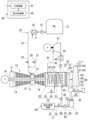
本実施形態のガスタービン設備は、図1に示すように、ガスタービン10と、ガスタービン10に燃料としてのアンモニアを供給するアンモニア供給装置20と、ガスタービン10から排気された排気ガスの熱を利用して蒸気を発生させる排熱回収ボイラ30と、排熱回収ボイラ30からの蒸気で駆動する蒸気タービン41と、蒸気タービン41からの蒸気を水に戻す復水器43と、復水器43内の水を排熱回収ボイラ30に送るポンプ45と、排熱回収ボイラ30からの排気ガスを外部に排気する煙突33と、ガスタービン10からの排気ガス中に含まれるNOx分を分解する脱硝装置50と、排熱回収ボイラ30内に散水する散水装置60と、ミストエリミネータ70と、水回収ライン71と、アンモニア水供給装置74と、制御装置90と、を備える。
As shown in FIG. 1, the gas turbine equipment of this embodiment includes a
ガスタービン10は、空気Aを圧縮する圧縮機14と、圧縮機14で圧縮された空気中で燃料を燃焼させて燃焼ガスを生成する燃焼器15と、高温高圧の燃焼ガスにより駆動するタービン16と、を備える。
The
圧縮機14は、ロータ軸線Arを中心として回転する圧縮機ロータ14rと、この圧縮機ロータ14rを覆う圧縮機ケーシング14cと、と、を有する。タービン16は、燃焼器15からの燃焼ガスにより、ロータ軸線Arを中心として回転するタービンロータ16rと、このタービンロータ16rを覆うタービンケーシング16cと、を有する。タービンロータ16rと圧縮機ロータ14rとは、同一のロータ軸線Arを中心として回転可能に相互に連結されて、ガスタービンロータ11を成す。このガスタービンロータ11には、例えば、発電機Gのロータが接続されている。なお、このガスタービン10は、一のガスタービンロータを有する一軸ガスタービンであるが、ガスタービンは、二軸ガスタービンや三軸ガスタービンであってもよい。
The
ガスタービン10は、さらに、中間ケーシング12を備える。中間ケーシング12は、ロータ軸線Arが延びている方向で、圧縮機ケーシング14cとタービンケーシング16cとの間に配置され、圧縮機ケーシング14cとタービンケーシング16cとを連結する。この中間ケーシング12内には、圧縮機14から吐出された圧縮空気が流入する。燃焼器15は、中間ケーシング12に固定されている。この燃焼器15は、燃焼筒(又は尾筒)15cと、燃焼筒15c内に燃料を噴射する燃料ノズル15nと、燃焼筒15c内に噴射された燃料を点火する点火栓15iと、有する。
The
アンモニア供給装置20は、アンモニアタンク21と、アンモニアライン22と、アンモニアポンプ23と、気化器24と、燃料調節弁25と、パージガスライン26と、パージガス調節弁27と、を有する。
The
アンモニアタンク21には、液体アンモニアが貯留される。アンモニアライン22の一端は、このアンモニアタンク21に接続され、このアンモニアライン22の他端は、燃焼器15の燃料ノズル15nに接続されている。アンモニアポンプ23は、このアンモニアライン22中に設けられている。このアンモニアポンプ23は、アンモニアタンク21内のアンモニアを昇圧して、このアンモニアを燃焼器15に送る。気化器24は、アンモニアライン22中で、アンモニアポンプ23よりも燃焼器15側の位置に設けられている。この気化器24は、加熱媒体と液体アンモニアとを熱交換させて、液体アンモニアを加熱し気化させる熱交器である。なお、アンモニア供給装置は、この気化器24の替りに、液体アンモニアを空間中に噴霧して、液体アンモニアをミストアンモニアに替える噴霧器を備えてもよい。燃料調節弁25は、アンモニアライン22中で、気化器24よりも燃焼器15側の位置に設けられている。この燃料調節弁25は、燃焼器15に供給する燃料としてのアンモニアの流量を調節する。アンモニアライン22中で、燃料調節弁25よりも燃焼器15側の位置には、パージガスライン26の一端が接続されている。このパージガスライン26の他端には、パージ用ガス供給源(不図示)が接続されている。このパージガス調節弁27は、このパージガスライン26中に設けられている。パージガス調節弁27は、パージ用ガス供給源からアンモニアライン22に送るパージ用ガスの流量を調節する。パージ用ガスは、例えば、窒素ガスである。
Liquid ammonia is stored in the
排熱回収ボイラ30は、ガスタービン10から排気された排気ガスと水とを熱交換させて、この水を加熱して蒸気にする。この排熱回収ボイラ30は、ガスタービン10に接続されているダクト31、ダクト31内に配置されている伝熱管32と、を有する。ダクト31は、ガスタービン10からの排気ガスが流れるダクトガス流路36を形成する。伝熱管32には、液体又は気体の水が流れる。なお、伝熱管32内には、水以外の熱媒体が流れてもよい。
The
排熱回収ボイラ30における伝熱管32の一端と蒸気タービン41の蒸気入口とは、主蒸気ライン42で接続されている。伝熱管32からの蒸気は、この主蒸気ライン42を介して蒸気タービン41に送られる。蒸気タービン41のロータには、例えば、発電機のロータが接続されている。蒸気タービン41から排気された蒸気は、復水器43で水に戻される。排熱回収ボイラ30における伝熱管32の他端と復水器43とは、給水ライン44で接続されている。この給水ライン44には、復水器43内の水を排熱回収ボイラ30に送るポンプ45が設けられている。
One end of the
煙突33は、排熱回収ボイラ30のダクト31に接続されている。煙突33には、ダクト31からの排気ガスを外部に排気する煙突ガス流路37が形成されている。この煙突ガス流路37は、鉛直方向に延びる。本実施形態において、ガスタービン10からの排気ガスが流れる排気ガス流路35は、ダクトガス流路36と煙突ガス流路37とを有する。よって、本実施形態において、排気ガス流路35を形成する流路形成枠34は、排熱回収ボイラ30のダクト31と煙突33とを有する。
The
脱硝装置50は、排熱回収ボイラ30のダクト31内に配置されている触媒層51と、この触媒層51のガス流れ方向における上流側にアンモニア水を散布するアンモニア散布器52と、このアンモニア散布器52にアンモニア水を供給するアンモニア水供給ライン53と、アンモニア水調節弁54と、を有する。アンモニア水調節弁54は、アンモニア水供給ライン53を流れるアンモニア水の流量を調節する。脱硝装置50は、アンモニア水を利用して、触媒の働きにより、ガスタービン10からの排気ガス中に含まれるNOxを窒素と水蒸気とに分解する。
The
散水装置60は、ダクトガス流路36内に水を散水することが可能な散水器61と、この散水器61が散水する水を溜めておくことができる水タンク62と、水タンク62内の水を散水器61に供給できる水供給装置66と、を有する。散水器61は、ダクト31内で、脱硝装置50及び伝熱管32よりも、ガス流れの下流側に配置されている。ダクト31内で、散水器61よりガス流れ方向における下流側には、ダクトガス流路36中のミストを捕捉できるミストエリミネータ70が配置されている。ミストエリミネータ70は、例えば、網又は複数の繊維で形成されたパッド等で構成されている。水供給装置66は、水タンク62と散水器61とを接続する水ライン67と、この水ライン67に設けられている水供給ポンプ68と、水ライン67中で、水供給ポンプ68よりも散水器61側に設けられている水調節弁69と、を有する。
The
水回収ライン71の一端は、ダクト31中で、ミストエリミネータ70よりもガス流れ方向における下流側の位置、又はガス流れ方向でミストエリミネータ70が配置されている領域、に接続されている。この水回収ライン71の他端は、水タンク62に接続されている。すなわち、この水回収ライン71は、散水器61からダクト31内に散水された水を水タンク62に戻すラインである。水タンク62には、この水タンク62内に水を供給することができる補給水ライン63が設けられている。水タンク62には、さらに、水タンク62内のアンモニア濃度を検知できるアンモニア濃度計64が設けられている。
One end of the
アンモニア水供給装置74は、アンモニア水サブライン75と、アンモニア水サブ調節弁76と、前述の水供給ポンプ68と、を有する。アンモニア水サブライン75は、散水装置60における水ライン67中で、水供給ポンプ68よりも散水器61側で且つ水調節弁69よりも水タンク62側の位置と、アンモニア水供給ライン53中で、アンモニア水調節弁54よりもアンモニア散布器52側の位置とを接続する。アンモニア水サブ調節弁76は、このアンモニア水サブライン75中に設けられている。なお、水供給ポンプ68は、このアンモニア水供給装置74の構成要素の一つであると共に、散水装置60の構成要素の一つでもある。
The ammonia
制御装置90は、ガスタービン制御器91と、散水制御器92と、を有する。ガスタービン制御器91は、ガスタービン10に設けられている各種計器や外部からの指示等に応じて、燃料調節弁25やパージガス調節弁27の動作等を制御する。散水制御器92は、散水装置60の動作を制御する。散水制御器92は、具体的に、水供給ポンプ68及び水調節弁69の動作を制御する。ガスタービン制御器91及び散水制御器92は、いずれも、各種演算を実行するCPU(Central Processing Unit)と、このCPUのワークエリアであるメモリ等を有する。なお、ガスタービン制御器91及び散水制御器92は、互に共有するCPUと、互に共有するメモリ等で構成されてもよい。
The
次に、以上で説明したガスタービン設備の動作について説明する。 Next, we will explain the operation of the gas turbine equipment described above.
ガスタービン10を起動させる際、起動モータを駆動させて、ガスタービンロータ11を回転させる。なお、起動モータは、ガスタービンロータ11に別途接続されている場合もあるが、ガスタービンロータ11に接続されている発電機が、起動モータとしての役割を担う場合もある。また、ガスタービン10を起動させる際、ディーゼルエンジンを起動させて、ガスタービンロータ11を回転させてもよいし、蒸気タービンでガスタービンロータ11を回転させてもよい。
When starting the
起動モータの駆動で、ガスタービンロータ11の回転数が次第に高まる。この過程で、燃焼器15に、燃料としてのアンモニアが供給される。ここで、燃焼器15へのアンモニアの供給開始過程における制御装置90の動作について、図2に示すフローチャートに従って説明する。
The rotation speed of the
ガスタービン制御器91は、ガスタービン10の起動過程で、燃料としてのアンモニアの供給開始条件を満たした否かを判断する(S10:供給開始条件の判断工程)。ガスタービン制御器91は、起動モータの駆動で、ガスタービンロータ11の回転数が予め定められた回転数になると、燃料としてのアンモニアの供給開始条件を満たしたと判断して、燃料調節弁25及び散水制御器92に対してアンモニアの供給開始を指示する(S11:供給開始の指示工程)。具体的に、ガスタービン制御器91は、燃料調節弁25に開状態になるよう指示する。燃料調節弁25は、この指示を受けると、開状態になる。この結果、燃焼器15へのアンモニアの供給が開始される。具体的には、アンモニアライン22中で燃料調節弁25よりも燃焼器15側の部分、及び燃焼器15の燃料ノズル15n内がアンモニアで満たされ、燃焼器15の燃焼筒15c内にアンモニアが噴射され始める。
During the start-up process of the
燃焼器15へのアンモニアの供給が開始されてから、予め定められた時間(例えば、数分間)が経過すると、ガスタービン制御器91は、点火栓15iにより、燃焼筒15c内のアンモニアを点火させる(S12:点火の指示工程)。この結果、燃焼筒15c内のアンモニアの燃焼が開始される。
When a predetermined time (e.g., several minutes) has elapsed since the supply of ammonia to the
前述したように、ガスタービン制御器91は、燃料調節弁25のみならず、散水制御器92にも、アンモニアの供給開始を指示する。散水制御器92は、この指示を受け付けると(S15:供給開始指示の受付工程)、散水装置60に対して散水開始を指示する(S17:散水開始の指示工程)。散水制御器92は、具体的に、散水装置60の水供給ポンプ68に対して駆動を指示すると共に、水調節弁69に対して開状態になるよう指示する。この結果、水タンク62内の水が水ライン67を介して、排熱回収ボイラ30のダクト31内に配置されている散水器61に供給され始め、ダクトガス流路36内に散水が開始される(S16:散水工程)。
As described above, the
散水制御器92は、アンモニア供給開始の指示を受け付けてから、予め定められた時間(例えば、数分間)経過したか否かを判断する(S18:散水停止条件の判断工程)。この予め定められた時間の終了時点は、アンモニアの点火が完了する時点よりも後である。言い換えると、この予め定められた時間の終了時点は、ガスタービン10から未燃焼のアンモニアが排気されなくなると想定される時点よりも後の時点である。散水制御器92は、アンモニア供給開始の指示を受け付けてから、予め定められた時間経過したと判断すると、散水装置60に対して散水停止を指示する(S19:散水停止の指示工程)。散水制御器92は、具体的に、散水装置60の水供給ポンプ68に対して駆動停止を指示すると共に、水調節弁69に対して閉状態になるよう指示する。この結果、散水器61からダクトガス流路36内へ散水が停止し、散水工程(S16)が終了する。
The
燃料調節弁25が開いてから、燃焼筒15c内のアンモニアが点火されるまでの間に、燃料調節弁25から流出したアンモニアは、燃焼せずに、ガスタービン10から排気される。このアンモニアは、排熱回収ボイラ30のダクト31内であるダクトガス流路36内を流れる。本実施形態では、ガスタービン制御器91が燃料調節弁25に対してアンモニア供給開始を指示する(S11)と共に、散水が開始される(S16)。このため、燃焼器15へのアンモニアの供給開始過程で、ガスタービン10から排気されたアンモニアは、散水器61からの水滴に吸収される。アンモニアを吸収した水滴は、ミストエリミネータ70に捕集された後、ダクト31の下部に溜まり、水回収ライン71を介して、水タンク62に戻る。すなわち、排気ガス流路35の一部であるダクトガス流路36内に散水された水を含む液体が流路形成枠34の一部であるダクト31外に導かれる。この流路形成枠34外に水を導く水回収工程は、散水工程と並行して実行させる。
Between the time when the
燃焼筒15c内でアンモニアが点火されると、失火しない限り、燃焼器15に供給されているアンモニアは、燃焼筒15c内に燃焼し続ける。このため、燃焼筒15c内でアンモニアが点火されると、失火しない限り、ガスタービン10からアンモニアは排気されなくなる。このため、本実施形態では、アンモニア供給開始の指示を受け付けてから、予め定められた時間が経過して、アンモニアの点火が完了した後に、散水器61からダクトガス流路36内へ散水が停止する。
When ammonia is ignited in the
前述したように、燃焼筒15c内でアンモニアが点火されると、アンモニアの燃焼が開始される。この燃焼で生成された燃焼ガスは、タービン16に送られ、タービンロータを回転させる。タービンロータを回転させた燃焼ガスは、排気ガスとして、ガスタービン10から排気され、排熱回収ボイラ30のダクト31内を流れる。アンモニアを燃焼させた場合、排気ガス中には、NOxが含まれている。このため、本実施形態では、アンモニアの燃焼が開始された後、アンモニア水供給源からアンモニア水供給ライン53を介して脱硝装置50へのアンモニア水の供給が開始され、排気ガス中に含まれるNOxが窒素と水蒸気とに分解される。
As described above, when ammonia is ignited in the
散水工程(S16)が繰り返し実行され、そのたびに、アンモニアを吸収した水が水タンク62に戻ってくると、水タンク62内の水中におけるアンモニア濃度は次第に高まる。水タンク62内のアンモニア濃度は、アンモニア濃度計64により検知される。このアンモニア濃度計64で検知されたアンモニア濃度が予め定められた濃度以上で、且つ脱硝装置50による脱硝処理が必要な条件下では、アンモニア水サブ調節弁76が開き、水タンク62内のアンモニアを吸収した水は、アンモニア水サブライン75を介して、脱硝装置50に供給される。脱硝装置50は、このアンモニア水を用いて、排気ガス中に含まれるNOxを窒素と水蒸気とに分解する。よって、本実施形態では、脱硝処理に用いるアンモニア水供給源からのアンモニア水の使用量を抑えることができる。
When the water spraying process (S16) is repeatedly performed and the water that has absorbed the ammonia returns to the
次に、燃焼器15へのアンモニアの供給停止過程における制御装置90の動作について、図3に示すフローチャートに従って説明する。
Next, the operation of the
ガスタービン制御器91は、燃焼器15にアンモニアを供給している間、燃料としてのアンモニアの供給停止条件を満たした否かを判断している(S20:供給停止条件の判断工程)。
While ammonia is being supplied to the
ここで、アンモニアの供給停止条件を満たす場合とは、
a.ガスタービン10の通常停止を外部から受け付けた場合
b.何らかのトラブルで、外部からの指示若しくはガスタービン10に設けられている各種センサからの信号により、ガスタービン10を緊急停止する必要が生じた場合
である。
ガスタービン10を緊急停止する必要が生じた場合とは、具体的に、燃焼筒15c内でのアンモニアの失火した場合、ガスタービン10に接続されている発電機と外部電力系統との緊急遮断を外部から受けた場合等がある。
Here, the case where the condition for stopping the supply of ammonia is satisfied is as follows:
a) When a normal shutdown of the
Specific examples of situations in which the
ガスタービン制御器91は、アンモニアの供給停止条件を満たしたと判断すると、燃料調節弁25及び散水制御器92に対してアンモニアの供給停止を指示する(S21:供給停止の指示工程)。具体的に、ガスタービン制御器91は、燃料調節弁25に閉状態になるよう指示する。燃料調節弁25は、この指示を受けると、閉状態になる。この結果、燃焼器15へのアンモニアの供給が停止される。さらに、ガスタービン制御器91は、パージガス調節弁27に開状態になるよう指示する(S22:パージ開始指示工程)。パージガス調節弁27は、この指示を受けると、開状態になる。この結果、パージ用ガス供給源から窒素等のパージ用ガスがアンモニアライン22に送られる。このパージ用ガスにより、アンモニアライン22中で燃料調節弁25よりも燃焼器15側の部分、及び燃焼器15の燃料ノズル15n内のアンモニアが燃焼筒15c内に押し出される。
When the
燃焼器15へのアンモニアの供給が停止されてから、予め定められた時間(例えば、数分間)が経過すると、ガスタービン制御器91は、パージガス調節弁27に閉状態になるよう指示する(S23:パージ終了指示工程)。この予め定められた時間の終了時点は、燃焼器15へのアンモニア供給が停止し、ガスタービンロータ11の回転数が次第に低下して、タービンケーシング内のガスの空筒速度が予め定められた速度以下になった時点である。言い換えると、この予め定められた時間の終了時点は、ガスタービン10から未燃焼のアンモニアが実質的に排気されなくなると想定される時点よりも後の時点である。パージガス調節弁27は、この指示を受けると、閉状態になり、パージ用ガス供給源からパージ用ガスがアンモニアライン22に送られなくなる。
When a predetermined time (e.g., several minutes) has elapsed since the supply of ammonia to the
前述したように、ガスタービン制御器91は、燃料調節弁25のみならず、散水制御器92にも、アンモニアの供給停止を指示する。散水制御器92は、この指示を受け付けると(S25:供給停止指示の受付工程)、散水装置60に対して散水開始を指示する(S27:散水開始の指示工程)。散水制御器92は、具体的に、散水装置60の水供給ポンプ68に対して駆動を指示すると共に、水調節弁69に対して開状態になるよう指示する。この結果、水タンク62内の水が水ライン67を介して、排熱回収ボイラ30のダクト31内に配置されている散水器61に供給され始め、ダクトガス流路36内に散水が開始される(S26:散水工程)。
As described above, the
散水制御器92は、アンモニア供給開始の指示を受け付けてから、予め定められた時間(例えば、数分間)経過したか否かを判断する(S28:散水停止条件の判断工程)。この予め定められた時間の終了時点は、パージガス調節弁27が閉状態になった時点よりも後である。散水制御器92は、アンモニア供給停止の指示を受け付けてから、予め定められた時間経過したと判断すると、散水装置60に対して散水停止を指示する(S29:散水停止の指示工程)。散水制御器92は、具体的に、散水装置60の水供給ポンプ68に対して駆動停止を指示すると共に、水調節弁69に対して閉状態になるよう指示する。この結果、散水器61からダクトガス流路36内へ散水が停止し、散水工程(S26)が終了する。
The
前述したように、燃料調節弁25が閉状態になった後、パージ用ガスにより、アンモニアライン22中で燃料調節弁25よりも燃焼器15側の部分、及び燃焼器15の燃料ノズル15n内のアンモニアが燃焼筒15c内に押し出される。このアンモニアは、燃焼せずに、ガスタービン10から排気される。このアンモニアは、排熱回収ボイラ30のダクト31内であるダクトガス流路36内を流れる。本実施形態では、前述したように、ガスタービン制御器91が燃料調節弁25に対してアンモニア供給停止を指示する(S21)と共に、散水が開始される(S26)。このため、燃焼器15へのアンモニアの供給停止過程で、ガスタービン10から排気されたアンモニアは、散水器61からの水滴に吸収される。アンモニアを吸収した水滴は、ミストエリミネータ70に捕集された後、ダクト31の下部に溜まり、水回収ライン71を介して、水タンク62に戻る。
As described above, after the
パージガス調節弁27を閉状態にした時点では、前述したように、タービンケーシングからガスがほとんど排気されなくたった時点である。このため、本実施形態では、アンモニア供給停止の指示を受け付けてから、予め定められた時間が経過して、パージ調節弁が閉状態になった後に、散水器61からダクトガス流路36内へ散水が停止する。
As described above, the point in time when the purge
以上で説明したように、燃焼器15へのアンモニアの供給開始過程、及び燃焼器15へのアンモニアの供給停止過程では、未燃焼のアンモニアがガスタービン10から排気される。本実施形態では、これらの過程で、未燃焼のアンモニアがガスタービン10から排気されるときに、散水装置60により、ダクトガス流路36内に水が散水され、この水にアンモニアが吸収される。よって、本実施形態では、外部へのアンモニアの排出を抑制することができる。
As described above, during the process of starting the supply of ammonia to the
「第二実施形態」
以下、本開示に係るガスタービン設備の第二実施形態について、図4及び図5を用いて説明する。
Second Embodiment
Hereinafter, a second embodiment of the gas turbine facility according to the present disclosure will be described with reference to FIGS. 4 and 5 .
本実施形態のガスタービン設備は、第一実施形態のガスタービン設備と同様、図4に示すように、ガスタービン10と、アンモニア供給装置20と、排熱回収ボイラ30と、蒸気タービン41と、復水器43と、ポンプ45と、煙突33と、脱硝装置50と、散水装置60aと、水回収ライン71aと、アンモニア水供給装置74と、制御装置90と、を備える。但し、本実施形態の散水装置60aは、第一実施形態の散水装置60と異なる。この関係で、本実施形態の水回収ライン71aも、第一実施形態の水回収ライン71と異なる。また、本実施形態のガスタービン設備は、第一実施形態のガスタービン設備におけるミストエリミネータ70を備えていない。
As shown in FIG. 4, the gas turbine equipment of this embodiment includes a
本実施形態の散水装置60aは、第一実施形態の散水装置60と同様、散水器61aと、水タンク62と、水供給装置66と、を有する。但し、本実施形態の散水器61aは、第一実施形態の散水器61と、配置及び構成が異なる。本実施形態の散水器61aは、排熱回収ボイラ30のダクト31内でなく、煙突33内、言い換えると煙突ガス流路37内に配置されている。この散水器61aは、図5に示すように、煙突33の内周面に沿って環状のリングヘッダ61hと、このリングヘッダ61hの内周側に設けられている複数のノズル61nと、を有する。リングヘッダ61hは、水タンク62(図4参照)から延びる水ライン67に接続されている。複数のノズル61nは、リングヘッダ61hに供給された水を、水平方向成分を有する方向であって、環状のリングヘッダ61hの内周側に向かって散水できるように設けられている。
The
図4に示すように、水回収ライン71aの一端は、煙突33中で、散水器61aが配置されている位置よりも下側の位置に接続されている。また、この水回収ライン71aの他端は、第一実施形態の水回収ライン71の他端と同様、水タンク62に接続されている。
As shown in FIG. 4, one end of the
本実施形態の制御装置90は、第一実施形態の制御装置90と同様に構成で、ガスタービン制御器91及び散水制御器92を有する。また、本実施形態の制御装置90は、第一実施形態の制御装置90と同様に動作する。このため、燃焼器15へのアンモニアの供給開始過程では、ガスタービン制御器91及び散水制御器92が、図2のフローチャートで示す動作をする。また、燃焼器15へのアンモニアの供給停止過程では、ガスタービン制御器91及び散水制御器92が、図3のフローチャートで示す動作をする。
The
本実施形態においても、第一実施形態と同様、燃焼器15へのアンモニアの供給開始過程、及び燃焼器15へのアンモニアの供給停止過程で、未燃焼のアンモニアがガスタービン10から排気されるときに、散水装置60aにより、煙突ガス流路37内に水が散布され、このアンモニアを吸収する。よって、本実施形態でも、外部へのアンモニアの排気を抑制することができる。
In this embodiment, as in the first embodiment, when unburned ammonia is exhausted from the
ところで、本実施形態では、散水器61aから散水された水滴が煙突33外に放出されないよう、散水器61aからの散水される水滴の粒径が、煙突33内を流れる排気ガスの上昇速度以上の沈降速度を持つ粒径にしている。このため、本実施形態では、散水器61aよりも、ガス流れ方向における下流側(上側)に水滴が実質的に流れず、第一実施形態のように、散水器61よりガス流れ方向における下流側にミストエリミネータ70を配置する必要性がない。よって、本実施形態では、第一実施形態よりも、排気ガス流路35中における圧力損失を抑えることができる。但し、本実施形態の水滴の粒径を第一実施形態の水滴の粒径よりも大きくする必要性があるため、アンモニアの吸収効率が第一実施形態よりも低い。
In this embodiment, the particle size of the water droplets sprayed from the
すなわち、本実施形態は、第一実施形態よりも排気ガス流路35中における圧力損失を抑えることができるというメリットを有するものの、第一実施形態よりもアンモニアの吸収効率が低いというディメリットを有する。言い換えると、第一実施形態は、本実施形態よりもアンモニアの吸収効率が高いというメリットを有するものの、本実施形態よりも排気ガス流路35中における圧力損失が高まるというディメリットを有する。このため、第一実施形態の散水器61と本実施形態の散水器61aとのうち、いずれを採用するかについては、両者のメリット及びディメリットを比較して決めることが好ましい。
That is, this embodiment has the advantage of being able to suppress pressure loss in the exhaust
本実施形態は、煙突33内に散水器61aを設け、この散水器61aよりも下流側(上側)にミストエリミネータを設けない例である。しかしながら、煙突33内に散水器61aを設けると共に、この散水器61aよりも下流側(上側)にミストエリミネータを設けてもよい。
This embodiment is an example in which a
「第三実施形態」
以下、本開示に係るガスタービン設備の第三実施形態について、図6を用いて説明する。
"Third embodiment"
Hereinafter, a third embodiment of a gas turbine facility according to the present disclosure will be described with reference to FIG. 6 .
本実施形態のガスタービン設備は、第一実施形態のガスタービン設備と同様、図6に示すように、ガスタービン10と、アンモニア供給装置20と、排熱回収ボイラ30と、蒸気タービン41と、復水器43と、ポンプ45と、煙突33と、脱硝装置50と、散水装置60と、水回収ライン71と、制御装置90と、を備える。但し、本実施形態のガスタービン設備は、第一実施形態のガスタービン設備におけるアンモニア水供給装置74を備えていない。本実施形態のガスタービン設備は、このアンモニア水供給装置74の替りに、処理水供給装置77を備える。さらに、本実施形態のガスタービン設備は、酸供給装置80を備える。
As shown in FIG. 6, the gas turbine equipment of this embodiment includes a
酸供給装置80は、アンモニアとの反応で塩が生成される酸の水溶液を溜めることができる酸タンク81と、酸タンク81と水タンク62とを接続する酸ライン82と、酸ライン82中に設けられている酸供給ポンプ83及び酸調節弁84と、を有する。アンモニアとの反応で塩が生成される酸の水溶液としては、例えば、塩酸水溶液、硫酸水溶液等である。また、アンモニアと塩酸水溶液との反応で生成される塩は、塩化アンモニウムであり、アンモニアと硫酸水溶液との反応で生成される塩は、硫酸アンモニウムである。水タンク62には、第一実施形態と同様、水回収ライン71及び補給水ライン63も接続されている。この水タンク62には、第一実施形態におけるアンモニア濃度計64の替りに、水タンク62内の塩の量を検知できる塩量検知器65が設けられている。この塩量検知器65は、例えば、水タンク62内の塩の濃度を検知するものでもよいが、水タンク62内の水のpHを検知することで、間接的に水タンク62内の塩の量を検知するものでもよい。
The
処理水供給装置77は、水タンク62内の水を排水処理装置89に導くことができる。この処理水供給装置77は、処理水ライン78と、処理水調節弁79と、散水装置60の水供給ポンプ68と、を有する。処理水ライン78は、散水装置60における水ライン67中で、水供給ポンプ68よりも散水器61側で水調節弁69よりも水タンク62側の位置と、排水処理装置89とを接続する。処理水調節弁79は、この処理水ライン78中に設けられている。なお、水供給ポンプ68は、この処理水供給装置77の構成要素の一つであると共に、散水装置60の構成要素の一つでもある。
The treated
本実施形態の制御装置90は、第一実施形態の制御装置90と同様に構成で、ガスタービン制御器91及び散水制御器92を有する。また、本実施形態の制御装置90は、第一実施形態の制御装置90と同様に動作する。このため、燃焼器15へのアンモニアの供給開始過程では、ガスタービン制御器91及び散水制御器92が、図2のフローチャートで示す動作をする。また、燃焼器15へのアンモニアの供給停止過程では、ガスタービン制御器91及び散水制御器92が、図3のフローチャートで示す動作をする。
The
本実施形態では、散水器61に供給する水中に、酸を投入する。よって、散水器61から散水される水は、弱酸性になる。このため、本実施形態では、排気ガス流路35中のアンモニアの吸収効率を高めることができる。アンモニアを吸収した水中には、アンモニアと酸との反応で生成された塩が含まれる。このアンモニア及び塩を含む水は、ダクト31の下部に溜まり、水回収ライン71を介して、水タンク62に戻る。塩量検知器65は、水タンク62内の水中の塩の量を検知する。この塩量検知器65により検知された塩の量が予め定められた値以上になると、水供給ポンプ68が駆動し、処理水調節弁79が開いて、塩を含む水が、処理水ライン78を介して、排水処理装置89に送られる。その後、補給水ライン63から水タンク62内に水が補給されると共に、酸供給装置80から水タンク62内に酸水溶液が供給される。
In this embodiment, acid is added to the water supplied to the
なお、本実施形態は、第一実施形態の変形例であるが、第二実施形態に関しても、本実施形態のように変形してもよい。すなわち、第二実施形態においても、第二実施形態のガスタービン設備におけるアンモニア水供給装置74の替りに処理水供給装置77を備え、さらに、酸供給装置80を備えてもよい。
This embodiment is a modification of the first embodiment, but the second embodiment may also be modified in the same way. That is, the second embodiment may also be provided with a treated
「付記」
以上の実施形態におけるガスタービン設備は、例えば、以下のように把握される。
"Additional Notes"
The gas turbine facility in the above embodiment can be understood, for example, as follows.
(1)第一態様におけるガスタービン設備は、
燃焼器15を有するガスタービン10と、前記燃焼器15にアンモニアを供給するアンモニア供給装置20と、前記ガスタービン10からの排気ガスが流れる排気ガス流路35を形成する流路形成枠34と、前記排気ガス流路35内に配置され、前記排気ガス流路35内に散水できる散水器61,61aを有する散水装置60,60aと、前記散水装置60,60aの動作を制御する散水制御器92と、を備える。前記散水制御器92は、前記アンモニア供給装置20から前記燃焼器15へのアンモニアの供給開始指示、又はアンモニアの供給停止指示を受け付けることを条件として、前記散水装置60,60aに対して散水開始を指示する。
(1) A gas turbine facility according to a first aspect,
The system includes a
アンモニア供給装置20は、一般的に、燃料としてのアンモニアが流れるアンモニアライン22と、このアンモニアライン22中に設けられている燃料調節弁25と、を有する。アンモニア供給装置20から燃焼器15へのアンモニアの供給開始過程では、アンモニアライン22中で燃料調節弁25よりも燃焼器15側の部分、及び燃焼器15の燃料ノズル15n内がアンモニアで満たされ、燃焼器15の燃焼筒15c内にアンモニアが噴射され始める。その後、燃焼筒15c内のアンモニアに点火される。燃料調節弁25がアンモニアの供給開始指示を受け付けて、この燃料調節弁25が開いてから、燃焼筒15c内のアンモニアが点火されるまでの間に、燃料調節弁25から流出したアンモニアは、燃焼せずに、ガスタービン10から排気される。このアンモニアは、排気ガス流路35内を流れる。また、燃焼器15へのアンモニアの供給停止過程では、燃料調節弁25がアンモニアの供給停止指示を受け付けて、この燃料調節弁25が閉じた後、アンモニアライン22中で燃料調節弁25よりも燃焼器15側の部分、及び燃焼器15の燃料ノズル15n内のアンモニアが燃焼筒15c内に流出する。このアンモニアも、燃焼せずに、ガスタービン10から排気される。
The
本態様の散水制御器92は、アンモニアの供給開始指示、又はアンモニアの供給停止を受け付けると、散水装置60,60aに対して散水開始を指示する。この結果は、散水器61,61aから排気ガス流路35内に散水が開始され、この水に排気ガス流路35内を流れるアンモニアが吸収される。
When the
よって、本態様では、アンモニア供給装置20から燃焼器15へのアンモニアの供給開始過程、又はアンモニアの供給停止過程におけるアンモニアの外部への排出を抑えることができる。
Therefore, in this embodiment, it is possible to suppress the emission of ammonia to the outside during the process of starting the supply of ammonia from the
(2)第二態様におけるガスタービン設備は、
前記第一態様におけるガスタービン設備において、前記散水制御器92は、前記アンモニアの供給開始指示、又は前記アンモニアの供給停止指示を受け付けてから、予め定められた時間の経過後に、前記散水装置60,60aに対して散水停止を指示する。前記予め定められた時間の終了時点は、ガスタービン10から未燃焼のアンモニアが排気されなくなると想定される時点よりも後の時点である。
(2) The gas turbine facility according to the second aspect includes:
In the gas turbine facility according to the first aspect, the
本態様では、未燃焼のアンモニアがガスタービン10から排気され始めてから、未燃焼のアンモニアがガスタービン10から排気されなくなると想定される時点の間、散水装置60,60aにより、排気ガス流路35内に水が散水され、この水に排気ガス流路35内のアンモニアが吸収される。そして、未燃焼のアンモニアがガスタービン10から排気されなくなると想定される時点よりも後に、散水装置60,60aから排気ガス流路35内への散水が停止される。よって、本態様では、散水装置60,60aの駆動時間を制限することができ、散水装置60,60aの駆動電力及び散水する水の消費量を抑えることができる。
In this embodiment, water is sprinkled into the exhaust
(3)第三態様におけるガスタービン設備は、
前記第一態様又は前記第二態様におけるガスタービン設備において、前記排気ガス流路35内に散水された水を含む液体を流路形成枠34の外に導く水回収ライン71,71aをさらに備える。
(3) A gas turbine facility according to a third aspect,
The gas turbine facility in the first or second aspect further includes a
散水器61,61aから排気ガス流路35内に散水されて、アンモニアを吸収した水は、排気ガス流路35内に溜まる。本態様では、この水が水回収ライン71,71aにより、流路形成枠34の外に導かれる。
Water is sprayed from the
(4)第四態様におけるガスタービン設備は、
前記第三態様におけるガスタービン設備において、ミストを捕集できるミストエリミネータ70をさらに備える。前記流路形成枠34は、前記ガスタービン10に接続されているダクト31を有する。前記ダクト31には、前記排気ガス流路35の少なくとも一部を形成するダクトガス流路36が形成されている。前記散水器61は、前記ダクトガス流路36中に配置され、前記ダクトガス流路36中の前記排気ガスの流れの下流側に向かって、散水可能に構成されている。前記ミストエリミネータ70は、前記ダクトガス流路36中であって、前記散水器61よりも前記下流側に配置されている。前記水回収ライン71は、前記ダクト31中で、前記ミストエリミネータ70よりも前記排気ガスの流れ方向における下流側の位置、又は前記排気ガスの流れ方向で前記ミストエリミネータ70が配置されている領域、に接続されている。
(4) A gas turbine facility according to a fourth aspect includes:
The gas turbine facility according to the third aspect further includes a
本態様では、ダクトガス流路36内を流れるアンモニアが、ダクトガス流路36内に配置される散水器61から散水された水滴により吸収される。アンモニアを吸収してダクトガス流路36内を下流側に流れた水滴は、ミストエリミネータ70により捕集される。ミストエリミネータ70に捕集された水滴は、ダクト31内に溜まる。ダクト31内に溜まった水は、水回収ライン71により、ダクト31の外に導かれる。
In this embodiment, the ammonia flowing in the duct
(5)第五態様におけるガスタービン設備は、
前記第三態様におけるガスタービン設備において、前記流路形成枠34は、前記ガスタービン10に接続されているダクト31と、前記ダクト31に接続されている煙突33と、を有する。前記煙突33には、前記排気ガス流路35の少なくとも一部を形成し、鉛直方向に延びる煙突ガス流路37が形成されている。前記散水器61aは、前記煙突ガス流路37中に配置され、水平方向成分を有する方向に向かって、散水可能に構成されている。前記水回収ライン71aは、前記煙突33中で、前記散水器61aが配置されている位置よりも下側の位置に接続されている。
(5) A gas turbine facility according to a fifth aspect includes:
In the gas turbine facility according to the third aspect, the flow
本態様では、煙突ガス流路37内を流れるアンモニアが、煙突ガス流路37内に配置される散水器61,61aから散水された水滴により吸収される。アンモニアを吸収した水滴は、煙突33内に溜まる。この水は、水回収ライン71aにより、煙突33の外に導かれる。
In this embodiment, the ammonia flowing through the chimney
(6)第六態様におけるガスタービン設備は、
前記第三態様から前記第五態様のいずれか一態様におけるガスタービン設備において、前記散水装置60,60aは、前記排気ガス流路35内に散水する水を溜めておくことができる水タンク62と、前記水タンク62内の水を前記散水器61,61aに供給できる水供給装置66と、を有する。前記散水制御器92は、前記水供給装置66を制御する。
(6) A gas turbine facility according to a sixth aspect includes:
In the gas turbine facility according to any one of the third to fifth aspects, the
(7)第七態様におけるガスタービン設備は、
前記第六態様におけるガスタービン設備において、前記排気ガス流路35中であって、前記散水器61,61aよりも、前記排気ガスの流れ方向における上流側に配置され、前記排気ガス中の窒素酸化物を除去する脱硝装置50と、前記水タンク62内の水を前記脱硝装置50に供給できるアンモニア水供給装置74と、をさらに備える。前記水回収ライン71,71aは、前記水タンク62に接続されている。前記水タンク62には、前記水タンク62内のアンモニア濃度を検知できるアンモニア濃度計64が設けられている。前記アンモニア水供給装置74は、前記アンモニア濃度計64で検知されたアンモニア濃度が予め定められた濃度以上になると、前記水タンク62内の水を前記脱硝装置50に供給する。
(7) A gas turbine facility according to a seventh aspect includes:
The gas turbine facility in the sixth aspect further includes a
排気ガス流路35内への散水が繰り返し実行され、そのたびに、アンモニアを吸収した水が水タンク62に戻ってくると、水タンク62内の水中におけるアンモニア濃度は次第に高まる。水タンク62内のアンモニア濃度は、アンモニア濃度計64により検知される。このアンモニア濃度計64で検知されたアンモニア濃度が予め定められた濃度以上で、且つ脱硝装置50の脱硝処理が必要な条件下では、アンモニア水供給装置74により、アンモニアを含む水タンク62内の水が脱硝装置50に供給される。脱硝装置50は、このアンモニア水を用いて、排気ガス中に含まれるNOxを窒素と水蒸気とに分解する。よって、本実施形態では、脱硝処理に用いるアンモニア水供給源からのアンモニア水の使用量を抑えることができる。
When water is repeatedly sprayed into the exhaust
(8)第八態様におけるガスタービン設備は、
前記第六態様におけるガスタービン設備において、前記アンモニアとの反応で塩が生成される酸を前記水タンク62内に供給できる酸供給装置80と、前記水タンク62内の水を排水処理装置89に導くことができる処理水供給装置77と、をさらに備える。前記水回収ライン71,71aは、前記水タンク62に接続されている。前記水タンク62には、前記水タンク62内の前記塩の量を検知できる塩量検知器65が設けられている。前記処理水供給装置77は、前記塩量検知器65で検知された前記塩の量が予め定められた量以上になると、前記水タンク62内の水を排水処理装置89に導く。
(8) A gas turbine facility according to an eighth aspect includes:
The gas turbine facility in the sixth aspect further includes an
散水器61,61aに供給する水中に、酸供給装置80からの酸を供給すると、散水器61,61aから散水される水は、弱酸性になる。このため、本態様では、排気ガス流路35中のアンモニアの吸収効率を高めることができる。アンモニアを吸収した水中には、アンモニアと酸との反応で生成された塩が含まれる。このアンモニア及び塩を含む水は、水回収ライン71,71aを介して、水タンク62に戻る。塩量検知器65は、水タンク62内の水中の塩の量を検知する。この塩量検知器65により検知された塩の量が予め定められた値以上になると、塩を含む水が、処理水供給装置77により、排水処理装置89に送られる。
When acid is supplied from the
以上の各実施形態におけるガスタービン設備のアンモニア排出抑制方法は、例えば、以下のように把握される。
(9)第九態様におけるガスタービン設備のアンモニア排出抑制方法は、以下のガスタービン設備に適用される。
ガスタービン設備は、燃焼器15を有するガスタービン10と、前記燃焼器15にアンモニアを供給するアンモニア供給装置20と、前記ガスタービン10からの排気ガスが流れる排気ガス流路35を形成する流路形成枠34と、を備える。
本態様におけるアンモニア排出抑制方法では、前記排気ガス流路35内に散水する散水工程S16を実行する。前記散水工程S16では、前記アンモニア供給装置20から前記燃焼器15へのアンモニアの供給開始指示、又はアンモニアの供給停止指示を受け付けることを条件として、前記排気ガス流路35内への散水を開始する。
The method for suppressing ammonia emission from a gas turbine facility in each of the above embodiments can be understood, for example, as follows.
(9) The method for suppressing ammonia emissions from a gas turbine facility according to a ninth aspect is applied to the following gas turbine facility.
The gas turbine facility includes a
In the ammonia emission suppression method according to this aspect, a water sprinkling step S16 is executed to sprinkle water into the exhaust
本態様では、第一態様におけるガスタービン設備と同様、アンモニアの供給開始指示、又はアンモニアの供給停止を受け付けると、排気ガス流路35内に散水が開始される。この水に排気ガス流路35内を流れるアンモニアが吸収される。よって、本態様でも、第一態様におけるガスタービン設備と同様、アンモニア供給装置20から燃焼器15へのアンモニアの供給開始過程、又はアンモニアの供給停止過程におけるアンモニアの外部への排出を抑えることができる。
In this embodiment, similar to the gas turbine equipment in the first embodiment, when an instruction to start the supply of ammonia or to stop the supply of ammonia is received, water spraying begins in the exhaust
(10)第十態様におけるガスタービン設備のアンモニア排出抑制方法は、
前記第九態様におけるガスタービン設備のアンモニア排出抑制方法において、前記散水工程S16では、前記アンモニアの供給開始指示、又は前記アンモニアの供給停止指示を受け付けてから、予め定められた時間の経過後に、前記排気ガス流路35内への散水を停止する。前記予め定められた時間の終了時点は、ガスタービン10から未燃焼のアンモニアが排気されなくなると想定される時点よりも後の時点である。
(10) A method for suppressing ammonia emission from a gas turbine facility according to a tenth aspect,
In the method for suppressing ammonia emission from a gas turbine facility according to the ninth aspect, in the water sprinkling step S16, after a predetermined time has elapsed since the instruction to start supplying ammonia or the instruction to stop supplying ammonia was received, the water sprinkling into the exhaust
本態様では、第二態様におけるガスタービン設備と同様、散水工程S16の実行時間を制限することができ、散水工程S16を実行するために必要な電力及び散水する水の消費量を抑えることができる。 In this embodiment, as in the gas turbine equipment in the second embodiment, the execution time of the water sprinkling process S16 can be limited, and the consumption of the electricity required to execute the water sprinkling process S16 and the amount of water to be sprinkled can be reduced.
10:ガスタービン
11:ガスタービンロータ
12:中間ケーシング
14:圧縮機
14r:圧縮機ロータ
14c:圧縮機ケーシング
15:燃焼器
15c:燃焼筒(又は尾筒)
15n:燃料ノズル
15i:点火栓
16:タービン
16r:タービンロータ
16c:タービンケーシング
20:アンモニア供給装置
21:アンモニアタンク
22:アンモニアライン
23:アンモニアポンプ
24:気化器
25:燃料調節弁
26:パージガスライン
27:パージガス調節弁
30:排熱回収ボイラ
31:ダクト
32:伝熱管
33:煙突
34:流路形成枠
35:排気ガス流路
36:ダクトガス流路
37:煙突ガス流路
41:蒸気タービン
42:主蒸気ライン
43:復水器
44:給水ライン
45:ポンプ
50:脱硝装置
51:触媒層
52:アンモニア散布器
53:アンモニア水供給ライン
54:アンモニア水調節弁
60,60a:散水装置
61,61a:散水器
61h:リングヘッダ
61n:ノズル
62:水タンク
63:補給水ライン
64:アンモニア濃度計
65:塩量検知器
66:水供給装置
67:水ライン
68:水供給ポンプ
69:水調節弁
70:ミストエリミネータ
71,71a:水回収ライン
74:アンモニア水供給装置
75:アンモニア水サブライン
76:アンモニア水サブ調節弁
77:処理水供給装置
78:処理水ライン
79:処理水調節弁
80:酸供給装置
81:酸タンク
82:酸ライン
83:酸供給ポンプ
84:酸調節弁
89:排水処理装置
90:制御装置
91:ガスタービン制御器
92:散水制御器
10: Gas turbine 11: Gas turbine rotor 12: Intermediate casing 14:
15n: fuel nozzle 15i: spark plug 16: turbine 16r: turbine rotor 16c: turbine casing 20: ammonia supply device 21: ammonia tank 22: ammonia line 23: ammonia pump 24: vaporizer 25: fuel control valve 26: purge gas line 27: purge gas control valve 30: exhaust heat recovery boiler 31: duct 32: heat transfer tube 33: chimney 34: flow path forming frame 35: exhaust gas flow path 36: duct gas flow path 37: chimney gas flow path 41: steam turbine 42: main steam line 43: condenser 44: water supply line 45: pump 50: denitration device 51: catalyst layer 52: ammonia diffuser 53: ammonia water supply line 54: ammonia Water control valve 60, 60a: Sprinkler 61, 61a: Sprinkler 61h: Ring header 61n: Nozzle 62: Water tank 63: Make-up water line 64: Ammonia concentration meter 65: Salt detector 66: Water supply device 67: Water line 68: Water supply pump 69: Water control valve 70: Mist eliminator 71, 71a: Water recovery line 74: Ammonia water supply device 75: Ammonia water sub-line 76: Ammonia water sub-control valve 77: Treated water supply device 78: Treated water line 79: Treated water control valve 80: Acid supply device 81: Acid tank 82: Acid line 83: Acid supply pump 84: Acid control valve 89: Wastewater treatment device 90: Control device 91: Gas turbine controller 92: Sprinkler controller
Claims (10)
前記燃焼器にアンモニアを供給するアンモニア供給装置と、
前記ガスタービンからの排気ガスが流れる排気ガス流路を形成する流路形成枠と、
前記排気ガス流路内に配置され、前記排気ガス流路内に散水できる散水器を有する散水装置と、
前記散水装置の動作を制御する散水制御器と、
を備え、
前記散水制御器は、前記アンモニア供給装置から前記燃焼器へのアンモニアの供給開始指示、又はアンモニアの供給停止指示を受け付けることを条件として、前記散水装置に対して散水開始を指示する、
ガスタービン設備。 a gas turbine having a combustor;
an ammonia supply device for supplying ammonia to the combustor;
a flow passage forming frame that forms an exhaust gas flow passage through which exhaust gas from the gas turbine flows;
a sprinkler device disposed in the exhaust gas flow path and having a sprinkler capable of sprinkling water into the exhaust gas flow path;
A water sprinkler controller for controlling the operation of the water sprinkler device;
Equipped with
The sprinkling controller instructs the sprinkling device to start sprinkling on condition that an instruction to start supplying ammonia or an instruction to stop supplying ammonia from the ammonia supply device to the combustor is received.
Gas turbine equipment.
前記散水制御器は、前記アンモニアの供給開始指示、又は前記アンモニアの供給停止指示を受け付けてから、予め定められた時間の経過後に、前記散水装置に対して散水停止を指示し、
前記予め定められた時間の終了時点は、ガスタービンから未燃焼のアンモニアが排気されなくなると想定される時点よりも後の時点である、
ガスタービン設備。 The gas turbine equipment according to claim 1,
The sprinkling controller instructs the sprinkling device to stop sprinkling after a predetermined time has elapsed since receiving the ammonia supply start instruction or the ammonia supply stop instruction,
The end point of the predetermined time is a point after a point at which unburned ammonia is expected to cease being exhausted from the gas turbine.
Gas turbine equipment.
前記排気ガス流路内に散水された水を含む液体を流路形成枠の外に導く水回収ラインをさらに備える、
ガスタービン設備。 The gas turbine facility according to claim 1 or 2,
A water recovery line is further provided to guide the liquid including the water sprayed into the exhaust gas flow passage to the outside of the flow passage forming frame.
Gas turbine equipment.
ミストを捕集できるミストエリミネータをさらに備え、
前記流路形成枠は、前記ガスタービンに接続されているダクトを有し、
前記ダクトには、前記排気ガス流路の少なくとも一部を形成するダクトガス流路が形成されており、
前記散水器は、前記ダクトガス流路中に配置され、前記ダクトガス流路中の前記排気ガスの流れの下流側に向かって、散水可能に構成され、
前記ミストエリミネータは、前記ダクトガス流路中であって、前記散水器よりも前記下流側に配置され、
前記水回収ラインは、前記ダクト中で、前記ミストエリミネータよりも前記排気ガスの流れ方向における下流側の位置、又は前記排気ガスの流れ方向で前記ミストエリミネータが配置されている領域、に接続されている、
ガスタービン設備。 The gas turbine equipment according to claim 3,
It is also equipped with a mist eliminator that can capture mist.
the flow passage forming frame has a duct connected to the gas turbine,
The duct has a duct gas passage that forms at least a part of the exhaust gas passage,
The sprinkler is arranged in the duct gas flow path and configured to be capable of sprinkling water toward a downstream side of the flow of the exhaust gas in the duct gas flow path,
The mist eliminator is disposed in the duct gas flow path and downstream of the sprinkler,
The water recovery line is connected to a position in the duct downstream of the mist eliminator in the flow direction of the exhaust gas, or to a region in which the mist eliminator is disposed in the flow direction of the exhaust gas.
Gas turbine equipment.
前記流路形成枠は、前記ガスタービンに接続されているダクトと、前記ダクトに接続されている煙突と、を有し、
前記煙突には、前記排気ガス流路の少なくとも一部を形成し、鉛直方向に延びる煙突ガス流路が形成されており、
前記散水器は、前記煙突ガス流路中に配置され、水平方向成分を有する方向に向かって、散水可能に構成され、
前記水回収ラインは、前記煙突中で、前記散水器が配置されている位置よりも下側の位置に接続されている、
ガスタービン設備。 The gas turbine equipment according to claim 3,
the flow passage forming frame has a duct connected to the gas turbine and a chimney connected to the duct,
The chimney has a chimney gas flow passage that forms at least a part of the exhaust gas flow passage and extends in a vertical direction.
The sprinkler is disposed in the chimney gas flow path and configured to be capable of sprinkling water in a direction having a horizontal component;
The water recovery line is connected to a position in the chimney lower than a position where the water sprinkler is disposed.
Gas turbine equipment.
前記散水装置は、前記排気ガス流路内に散水する水を溜めておくことができる水タンクと、前記水タンク内の水を前記散水器に供給できる水供給装置と、を有し、
前記散水制御器は、前記水供給装置を制御する、
ガスタービン設備。 In the gas turbine installation according to any one of claims 3 to 5,
The sprinkler device includes a water tank capable of storing water to be sprinkled in the exhaust gas flow path, and a water supply device capable of supplying the water in the water tank to the sprinkler,
The water sprinkler controller controls the water supply device.
Gas turbine equipment.
前記排気ガス流路中であって、前記散水器よりも、前記排気ガスの流れ方向における上流側に配置され、前記排気ガス中の窒素酸化物を除去する脱硝装置と、
前記水タンク内の水を前記脱硝装置に供給できるアンモニア水供給装置と、
をさらに備え、
前記水回収ラインは、前記水タンクに接続され、
前記水タンクには、前記水タンク内のアンモニア濃度を検知できるアンモニア濃度計が設けられ、
前記アンモニア水供給装置は、前記アンモニア濃度計で検知されたアンモニア濃度が予め定められた濃度以上になると、前記水タンク内の水を前記脱硝装置に供給する、
ガスタービン設備。 The gas turbine equipment according to claim 6,
a denitration device that is disposed in the exhaust gas flow path upstream of the sprinkler in a flow direction of the exhaust gas and removes nitrogen oxides from the exhaust gas;
an ammonia water supply device capable of supplying the water in the water tank to the denitrification device;
Further equipped with
the water recovery line is connected to the water tank;
The water tank is provided with an ammonia concentration meter capable of detecting an ammonia concentration in the water tank,
The ammonia water supply device supplies water in the water tank to the denitrification device when the ammonia concentration detected by the ammonia concentration meter becomes equal to or higher than a predetermined concentration.
Gas turbine equipment.
前記アンモニアとの反応で塩が生成される酸を前記水タンク内に供給できる酸供給装置と、
前記水タンク内の水を排水処理装置に導くことができる処理水供給装置と、
をさらに備え、
前記水回収ラインは、前記水タンクに接続され、
前記水タンクには、前記水タンク内の前記塩の量を検知できる塩量検知器が設けられ、
前記処理水供給装置は、前記塩量検知器で検知された前記塩の量が予め定められた量以上になると、前記水タンク内の水を排水処理装置に導く、
ガスタービン設備。 The gas turbine equipment according to claim 6,
an acid supply device capable of supplying an acid that reacts with the ammonia to produce a salt into the water tank;
a treated water supply device capable of directing the water in the water tank to a wastewater treatment device;
Further equipped with
the water recovery line is connected to the water tank;
The water tank is provided with a salt amount detector capable of detecting the amount of salt in the water tank,
the treated water supply device directs the water in the water tank to the wastewater treatment device when the amount of salt detected by the salt amount detector becomes equal to or greater than a predetermined amount.
Gas turbine equipment.
前記排気ガス流路内に散水する散水工程を実行し、
前記散水工程では、前記アンモニア供給装置から前記燃焼器へのアンモニアの供給開始指示、又はアンモニアの供給停止指示を受け付けることを条件として、前記排気ガス流路内への散水を開始する、
ガスタービン設備のアンモニア排出抑制方法。 1. A method for suppressing ammonia emissions from a gas turbine facility including a gas turbine having a combustor, an ammonia supplying device that supplies ammonia to the combustor, and a flow path forming frame that forms an exhaust gas flow path through which exhaust gas from the gas turbine flows, comprising:
A water spraying step is carried out to spray water into the exhaust gas flow path,
In the water sprinkling step, water sprinkling into the exhaust gas flow path is started on the condition that an instruction to start supplying ammonia or an instruction to stop supplying ammonia to the combustor is received from the ammonia supply device.
A method for reducing ammonia emissions from gas turbine equipment.
前記散水工程では、前記アンモニアの供給開始指示、又は前記アンモニアの供給停止指示を受け付けてから、予め定められた時間の経過後に、前記排気ガス流路内への散水を停止し、
前記予め定められた時間の終了時点は、ガスタービンから未燃焼のアンモニアが排気されなくなると想定される時点よりも後の時点である、
ガスタービン設備のアンモニア排出抑制方法。 The method for suppressing ammonia emission from a gas turbine facility according to claim 9,
In the water sprinkling step, after a predetermined time has elapsed since the ammonia supply start instruction or the ammonia supply stop instruction was received, the water sprinkling into the exhaust gas flow path is stopped,
The end point of the predetermined time is a point after a point at which unburned ammonia is expected to cease being exhausted from the gas turbine.
A method for reducing ammonia emissions from gas turbine equipment.
Priority Applications (10)
| Application Number | Priority Date | Filing Date | Title |
|---|---|---|---|
| JP2021115757A JP7602978B2 (en) | 2021-07-13 | 2021-07-13 | Gas turbine facility and method for suppressing ammonia emissions from gas turbine facility |
| KR1020237043073A KR20240008899A (en) | 2021-07-13 | 2022-06-16 | Gas turbine equipment, and method for suppressing ammonia emissions from gas turbine equipment |
| US18/575,948 US12228059B2 (en) | 2021-07-13 | 2022-06-16 | Gas turbine facility and method for suppressing discharge of ammonia from gas turbine facility |
| DE112022003519.6T DE112022003519T5 (en) | 2021-07-13 | 2022-06-16 | GAS TURBINE PLANT AND METHOD FOR SUPPRESSING RELEASE OF AMMONIA FROM GAS TURBINE PLANT |
| CN202280042364.9A CN117480316A (en) | 2021-07-13 | 2022-06-16 | Gas turbine equipment and ammonia emission suppression method of gas turbine equipment |
| PCT/JP2022/024074 WO2023286516A1 (en) | 2021-07-13 | 2022-06-16 | Gas turbine facility and method for suppressing discharge of ammonia from gas turbine facility |
| TW111125354A TWI840871B (en) | 2021-07-13 | 2022-07-06 | Gas turbine equipment, and method for suppressing ammonia emission from gas turbine equipment |
| JP2024213431A JP7634765B1 (en) | 2021-07-13 | 2024-12-06 | Gas turbine equipment and combustion systems |
| US19/028,840 US12492655B2 (en) | 2021-07-13 | 2025-01-17 | Gas turbine facility and method for suppressing discharge of ammonia from gas turbine facility |
| JP2025017553A JP7657395B1 (en) | 2021-07-13 | 2025-02-05 | Ammonia-fueled combustion systems and gas turbine equipment |
Applications Claiming Priority (1)
| Application Number | Priority Date | Filing Date | Title |
|---|---|---|---|
| JP2021115757A JP7602978B2 (en) | 2021-07-13 | 2021-07-13 | Gas turbine facility and method for suppressing ammonia emissions from gas turbine facility |
Related Child Applications (1)
| Application Number | Title | Priority Date | Filing Date |
|---|---|---|---|
| JP2024213431A Division JP7634765B1 (en) | 2021-07-13 | 2024-12-06 | Gas turbine equipment and combustion systems |
Publications (2)
| Publication Number | Publication Date |
|---|---|
| JP2023012236A JP2023012236A (en) | 2023-01-25 |
| JP7602978B2 true JP7602978B2 (en) | 2024-12-19 |
Family
ID=84919266
Family Applications (3)
| Application Number | Title | Priority Date | Filing Date |
|---|---|---|---|
| JP2021115757A Active JP7602978B2 (en) | 2021-07-13 | 2021-07-13 | Gas turbine facility and method for suppressing ammonia emissions from gas turbine facility |
| JP2024213431A Active JP7634765B1 (en) | 2021-07-13 | 2024-12-06 | Gas turbine equipment and combustion systems |
| JP2025017553A Active JP7657395B1 (en) | 2021-07-13 | 2025-02-05 | Ammonia-fueled combustion systems and gas turbine equipment |
Family Applications After (2)
| Application Number | Title | Priority Date | Filing Date |
|---|---|---|---|
| JP2024213431A Active JP7634765B1 (en) | 2021-07-13 | 2024-12-06 | Gas turbine equipment and combustion systems |
| JP2025017553A Active JP7657395B1 (en) | 2021-07-13 | 2025-02-05 | Ammonia-fueled combustion systems and gas turbine equipment |
Country Status (7)
| Country | Link |
|---|---|
| US (2) | US12228059B2 (en) |
| JP (3) | JP7602978B2 (en) |
| KR (1) | KR20240008899A (en) |
| CN (1) | CN117480316A (en) |
| DE (1) | DE112022003519T5 (en) |
| TW (1) | TWI840871B (en) |
| WO (1) | WO2023286516A1 (en) |
Families Citing this family (3)
| Publication number | Priority date | Publication date | Assignee | Title |
|---|---|---|---|---|
| EP4637973A1 (en) | 2022-12-23 | 2025-10-29 | thyssenkrupp AG | Reduction of nox and n2o in the exhaust gas of firing systems operated using nh3, in particular gas turbines |
| WO2024225134A1 (en) * | 2023-04-28 | 2024-10-31 | 三菱パワー株式会社 | Gas turbine plant and operation method for same |
| DE102023210753A1 (en) * | 2023-10-30 | 2025-04-30 | Siemens Energy Global GmbH & Co. KG | Low-emission gas turbine plant for peak load and process |
Citations (2)
| Publication number | Priority date | Publication date | Assignee | Title |
|---|---|---|---|---|
| JP2016183571A (en) | 2015-03-25 | 2016-10-20 | 三菱日立パワーシステムズ株式会社 | Humid air utilization gas turbine system and exhaust gas processing system of the same |
| JP2020147481A (en) | 2019-03-15 | 2020-09-17 | 三菱日立パワーシステムズ株式会社 | Ammonia decomposition equipment, gas turbine plant with the same, ammonia decomposition method |
Family Cites Families (39)
| Publication number | Priority date | Publication date | Assignee | Title |
|---|---|---|---|---|
| US5826518A (en) * | 1996-02-13 | 1998-10-27 | The Babcock & Wilcox Company | High velocity integrated flue gas treatment scrubbing system |
| JP2002253927A (en) | 2001-02-28 | 2002-09-10 | Nomura Micro Sci Co Ltd | Method, apparatus and system for treating ammonia- containing gas, and scrubbing apparatus |
| JP3683521B2 (en) | 2001-10-09 | 2005-08-17 | 川崎重工業株式会社 | Cogeneration system operation method |
| JP2004036983A (en) | 2002-07-02 | 2004-02-05 | Mitsubishi Heavy Ind Ltd | Method and device for treating ammonia containing gas |
| EP2158388B1 (en) * | 2007-06-19 | 2019-09-11 | Ansaldo Energia IP UK Limited | Gas turbine system having exhaust gas recirculation |
| JP5935124B2 (en) | 2012-11-12 | 2016-06-15 | 一般財団法人電力中央研究所 | Turbine equipment and power generation equipment |
| JP6119449B2 (en) | 2013-06-19 | 2017-04-26 | 株式会社豊田中央研究所 | Exhaust gas purification device |
| US20150020530A1 (en) * | 2013-07-18 | 2015-01-22 | General Electric Company | Gas turbine emissions control system and method |
| US20150020529A1 (en) * | 2013-07-18 | 2015-01-22 | General Electric Company | Gas turbine emissions control system and method |
| JP2015190466A (en) | 2014-03-31 | 2015-11-02 | 株式会社Ihi | Combustion device, gas turbine and power generation device |
| US9840953B2 (en) * | 2015-06-29 | 2017-12-12 | General Electric Company | Power generation system exhaust cooling |
| US9856768B2 (en) * | 2015-06-29 | 2018-01-02 | General Electric Company | Power generation system exhaust cooling |
| JP6058107B1 (en) | 2015-12-01 | 2017-01-11 | 日立造船株式会社 | Gas water washing device |
| JP2017124385A (en) | 2016-01-15 | 2017-07-20 | 株式会社東芝 | Exhaust gas treatment apparatus and exhaust gas treatment method |
| US20170204786A1 (en) * | 2016-01-15 | 2017-07-20 | General Electric Company | System and method for injecting tempering air for hot scr catalyst |
| JP6571549B2 (en) | 2016-01-29 | 2019-09-04 | 三菱日立パワーシステムズ株式会社 | Ammonia treatment apparatus and ammonia treatment method |
| US20170218790A1 (en) * | 2016-02-01 | 2017-08-03 | General Electric Company | Systems and Methods of Predicting Physical Parameters for a Combustion Fuel System |
| JP6707013B2 (en) * | 2016-11-08 | 2020-06-10 | 三菱日立パワーシステムズ株式会社 | Gas turbine plant and operating method thereof |
| JP6772925B2 (en) | 2017-03-27 | 2020-10-21 | 株式会社Ihi | Combustion equipment and gas turbine engine system |
| DE102017108843A1 (en) | 2017-04-25 | 2018-10-25 | Thyssenkrupp Ag | Apparatus and method for waste gas scrubbing |
| JP6906381B2 (en) * | 2017-07-03 | 2021-07-21 | 株式会社東芝 | Combustion equipment and gas turbine |
| JP7060996B2 (en) | 2018-03-30 | 2022-04-27 | 株式会社Ihi原動機 | Combustion equipment, gas turbines and power generation equipment |
| JP2020159264A (en) * | 2019-03-26 | 2020-10-01 | 国立大学法人東北大学 | gas turbine |
| JP7227827B2 (en) * | 2019-03-29 | 2023-02-22 | 株式会社Ihi原動機 | Combustion device |
| JP2021032230A (en) * | 2019-08-29 | 2021-03-01 | 株式会社豊田自動織機 | Internal combustion engine system |
| JP6806350B1 (en) | 2020-01-24 | 2021-01-06 | タマダ株式会社 | Biaxial stretch blow molding machine heating device and biaxial stretch blow molding machine |
| GB202017854D0 (en) * | 2020-11-12 | 2020-12-30 | Univ College Cardiff Consultants Ltd | Combustor systems and methods |
| JP7619824B2 (en) * | 2021-02-15 | 2025-01-22 | 三菱重工業株式会社 | Gas turbine plant and fuel supply method therefor |
| US20220348459A1 (en) * | 2021-04-23 | 2022-11-03 | Regents Of The University Of Minnesota | Reactor systems and methods for thermally decomposing ammonia |
| WO2023286381A1 (en) * | 2021-07-14 | 2023-01-19 | 株式会社Ihi | Gas turbine system |
| TWI846023B (en) * | 2021-09-30 | 2024-06-21 | 日商三菱重工業股份有限公司 | Gas turbine equipment |
| AU2022445346B2 (en) * | 2022-03-07 | 2025-12-18 | Ihi Corporation | Gas turbine system |
| AU2022446945B2 (en) * | 2022-03-16 | 2025-12-18 | Ihi Corporation | Gas turbine system |
| AU2022448510B2 (en) * | 2022-03-25 | 2025-10-02 | Ihi Corporation | Combustion system |
| JP7725513B2 (en) * | 2023-01-18 | 2025-08-19 | 三菱重工業株式会社 | Fuel supply system and fuel supply method for gas turbine cogeneration system |
| US11808209B1 (en) * | 2023-04-25 | 2023-11-07 | Rtx Corporation | Aftercooler exhaust duct protection |
| US12286952B1 (en) * | 2023-12-18 | 2025-04-29 | Ming Zheng | High-energy remote chamber ignition system |
| US12287095B1 (en) * | 2024-06-05 | 2025-04-29 | Ge Infrastructure Technology Llc | System and method for blending multiple fuels |
| CN119122640A (en) * | 2024-09-11 | 2024-12-13 | 陈华松 | New medium for electric energy storage and transportation, method for manufacturing the same, and dedicated non-combustible and non-emission engine |
-
2021
- 2021-07-13 JP JP2021115757A patent/JP7602978B2/en active Active
-
2022
- 2022-06-16 US US18/575,948 patent/US12228059B2/en active Active
- 2022-06-16 KR KR1020237043073A patent/KR20240008899A/en active Pending
- 2022-06-16 DE DE112022003519.6T patent/DE112022003519T5/en active Pending
- 2022-06-16 WO PCT/JP2022/024074 patent/WO2023286516A1/en not_active Ceased
- 2022-06-16 CN CN202280042364.9A patent/CN117480316A/en active Pending
- 2022-07-06 TW TW111125354A patent/TWI840871B/en active
-
2024
- 2024-12-06 JP JP2024213431A patent/JP7634765B1/en active Active
-
2025
- 2025-01-17 US US19/028,840 patent/US12492655B2/en active Active
- 2025-02-05 JP JP2025017553A patent/JP7657395B1/en active Active
Patent Citations (2)
| Publication number | Priority date | Publication date | Assignee | Title |
|---|---|---|---|---|
| JP2016183571A (en) | 2015-03-25 | 2016-10-20 | 三菱日立パワーシステムズ株式会社 | Humid air utilization gas turbine system and exhaust gas processing system of the same |
| JP2020147481A (en) | 2019-03-15 | 2020-09-17 | 三菱日立パワーシステムズ株式会社 | Ammonia decomposition equipment, gas turbine plant with the same, ammonia decomposition method |
Also Published As
| Publication number | Publication date |
|---|---|
| JP2025028805A (en) | 2025-03-04 |
| KR20240008899A (en) | 2024-01-19 |
| WO2023286516A1 (en) | 2023-01-19 |
| JP2023012236A (en) | 2023-01-25 |
| US12492655B2 (en) | 2025-12-09 |
| TWI840871B (en) | 2024-05-01 |
| US12228059B2 (en) | 2025-02-18 |
| JP2025067930A (en) | 2025-04-24 |
| CN117480316A (en) | 2024-01-30 |
| US20250172082A1 (en) | 2025-05-29 |
| TW202309446A (en) | 2023-03-01 |
| JP7657395B1 (en) | 2025-04-04 |
| US20240337207A1 (en) | 2024-10-10 |
| JP7634765B1 (en) | 2025-02-21 |
| DE112022003519T5 (en) | 2024-05-23 |
Similar Documents
| Publication | Publication Date | Title |
|---|---|---|
| JP7634765B1 (en) | Gas turbine equipment and combustion systems | |
| JP3100191B2 (en) | Flue gas denitration equipment | |
| JPS6157927B2 (en) | ||
| JP7227827B2 (en) | Combustion device | |
| CN105521706B (en) | The low ash-laden gas SCR denitration device of thermal power plant, method of denitration | |
| RU2289704C2 (en) | Method of cleaning exhaust gases of internal combustion engine and device for delivering humid air into engine | |
| JP2017048787A (en) | Methods and systems related to selective catalytic reduction | |
| WO1995007751A1 (en) | Exhaust gas boiler | |
| KR102366079B1 (en) | Denitration device, heat recovery boiler having same, gas turbine combined cycle power plant, and denitration method | |
| JP5915927B2 (en) | Exhaust gas purification device for internal combustion engine | |
| JP2013124642A (en) | Exhaust emission control device of internal combustion engine | |
| KR20180075039A (en) | Selective catalytic reduction system | |
| KR102055312B1 (en) | System for treating exhaust gas of large ship | |
| CN205517257U (en) | Ash -laden gas SCR denitrification facility hangs down in thermal power plant | |
| CN204017668U (en) | The fuel gas generation equipment equipment for denitrifying flue gas that a kind of reducing agent directly sprays | |
| JP4381881B2 (en) | Flue gas denitration device and starting method thereof | |
| US20160361686A1 (en) | Selective catalytic reduction (scr) de-nox equipment for removing visible emission | |
| JP4095525B2 (en) | Auxiliary equipment for exhaust aftertreatment equipment | |
| KR102367278B1 (en) | Selective catalytic reduction system | |
| JP2006250494A (en) | Exhaust heat recovery boiler and its operation method | |
| KR102585185B1 (en) | Thermal power plant denitrification facility urea vaporizer clogging early detection system | |
| KR20250045570A (en) | The preheating system for vaporization facility | |
| JP2002021579A (en) | Method of controlling combined cycle plant provided with gas turbine and must-heat recovery boiler, and controller therefor | |
| KR100413056B1 (en) | Noise reduction method and device in flare by water injection | |
| CN120990775A (en) | Ammonia injection device and control method for reducing NOx emissions from natural gas engines |
Legal Events
| Date | Code | Title | Description |
|---|---|---|---|
| A711 | Notification of change in applicant |
Free format text: JAPANESE INTERMEDIATE CODE: A712 Effective date: 20220124 |
|
| A621 | Written request for application examination |
Free format text: JAPANESE INTERMEDIATE CODE: A621 Effective date: 20240419 |
|
| TRDD | Decision of grant or rejection written | ||
| A01 | Written decision to grant a patent or to grant a registration (utility model) |
Free format text: JAPANESE INTERMEDIATE CODE: A01 Effective date: 20241112 |
|
| A61 | First payment of annual fees (during grant procedure) |
Free format text: JAPANESE INTERMEDIATE CODE: A61 Effective date: 20241209 |
|
| R150 | Certificate of patent or registration of utility model |
Ref document number: 7602978 Country of ref document: JP Free format text: JAPANESE INTERMEDIATE CODE: R150 |