JP7602642B2 - Aerosol generator power supply unit - Google Patents
Aerosol generator power supply unit Download PDFInfo
- Publication number
- JP7602642B2 JP7602642B2 JP2023533032A JP2023533032A JP7602642B2 JP 7602642 B2 JP7602642 B2 JP 7602642B2 JP 2023533032 A JP2023533032 A JP 2023533032A JP 2023533032 A JP2023533032 A JP 2023533032A JP 7602642 B2 JP7602642 B2 JP 7602642B2
- Authority
- JP
- Japan
- Prior art keywords
- aerosol
- coil
- power
- opening
- generating article
- Prior art date
- Legal status (The legal status is an assumption and is not a legal conclusion. Google has not performed a legal analysis and makes no representation as to the accuracy of the status listed.)
- Active
Links
Images


Classifications
-
- A—HUMAN NECESSITIES
- A24—TOBACCO; CIGARS; CIGARETTES; SIMULATED SMOKING DEVICES; SMOKERS' REQUISITES
- A24F—SMOKERS' REQUISITES; MATCH BOXES; SIMULATED SMOKING DEVICES
- A24F40/00—Electrically operated smoking devices; Component parts thereof; Manufacture thereof; Maintenance or testing thereof; Charging means specially adapted therefor
- A24F40/20—Devices using solid inhalable precursors
-
- A—HUMAN NECESSITIES
- A24—TOBACCO; CIGARS; CIGARETTES; SIMULATED SMOKING DEVICES; SMOKERS' REQUISITES
- A24F—SMOKERS' REQUISITES; MATCH BOXES; SIMULATED SMOKING DEVICES
- A24F40/00—Electrically operated smoking devices; Component parts thereof; Manufacture thereof; Maintenance or testing thereof; Charging means specially adapted therefor
- A24F40/40—Constructional details, e.g. connection of cartridges and battery parts
- A24F40/46—Shape or structure of electric heating means
- A24F40/465—Shape or structure of electric heating means specially adapted for induction heating
-
- A—HUMAN NECESSITIES
- A24—TOBACCO; CIGARS; CIGARETTES; SIMULATED SMOKING DEVICES; SMOKERS' REQUISITES
- A24F—SMOKERS' REQUISITES; MATCH BOXES; SIMULATED SMOKING DEVICES
- A24F40/00—Electrically operated smoking devices; Component parts thereof; Manufacture thereof; Maintenance or testing thereof; Charging means specially adapted therefor
- A24F40/50—Control or monitoring
- A24F40/51—Arrangement of sensors
-
- A—HUMAN NECESSITIES
- A24—TOBACCO; CIGARS; CIGARETTES; SIMULATED SMOKING DEVICES; SMOKERS' REQUISITES
- A24F—SMOKERS' REQUISITES; MATCH BOXES; SIMULATED SMOKING DEVICES
- A24F40/00—Electrically operated smoking devices; Component parts thereof; Manufacture thereof; Maintenance or testing thereof; Charging means specially adapted therefor
- A24F40/50—Control or monitoring
- A24F40/53—Monitoring, e.g. fault detection
-
- A—HUMAN NECESSITIES
- A24—TOBACCO; CIGARS; CIGARETTES; SIMULATED SMOKING DEVICES; SMOKERS' REQUISITES
- A24F—SMOKERS' REQUISITES; MATCH BOXES; SIMULATED SMOKING DEVICES
- A24F40/00—Electrically operated smoking devices; Component parts thereof; Manufacture thereof; Maintenance or testing thereof; Charging means specially adapted therefor
- A24F40/50—Control or monitoring
- A24F40/57—Temperature control
-
- A—HUMAN NECESSITIES
- A24—TOBACCO; CIGARS; CIGARETTES; SIMULATED SMOKING DEVICES; SMOKERS' REQUISITES
- A24F—SMOKERS' REQUISITES; MATCH BOXES; SIMULATED SMOKING DEVICES
- A24F47/00—Smokers' requisites not otherwise provided for
-
- H—ELECTRICITY
- H05—ELECTRIC TECHNIQUES NOT OTHERWISE PROVIDED FOR
- H05B—ELECTRIC HEATING; ELECTRIC LIGHT SOURCES NOT OTHERWISE PROVIDED FOR; CIRCUIT ARRANGEMENTS FOR ELECTRIC LIGHT SOURCES, IN GENERAL
- H05B6/00—Heating by electric, magnetic or electromagnetic fields
- H05B6/02—Induction heating
- H05B6/06—Control, e.g. of temperature, of power
-
- H—ELECTRICITY
- H05—ELECTRIC TECHNIQUES NOT OTHERWISE PROVIDED FOR
- H05B—ELECTRIC HEATING; ELECTRIC LIGHT SOURCES NOT OTHERWISE PROVIDED FOR; CIRCUIT ARRANGEMENTS FOR ELECTRIC LIGHT SOURCES, IN GENERAL
- H05B6/00—Heating by electric, magnetic or electromagnetic fields
- H05B6/02—Induction heating
- H05B6/10—Induction heating apparatus, other than furnaces, for specific applications
- H05B6/105—Induction heating apparatus, other than furnaces, for specific applications using a susceptor
- H05B6/108—Induction heating apparatus, other than furnaces, for specific applications using a susceptor for heating a fluid
-
- H—ELECTRICITY
- H05—ELECTRIC TECHNIQUES NOT OTHERWISE PROVIDED FOR
- H05B—ELECTRIC HEATING; ELECTRIC LIGHT SOURCES NOT OTHERWISE PROVIDED FOR; CIRCUIT ARRANGEMENTS FOR ELECTRIC LIGHT SOURCES, IN GENERAL
- H05B6/00—Heating by electric, magnetic or electromagnetic fields
- H05B6/02—Induction heating
- H05B6/36—Coil arrangements
Landscapes
- Physics & Mathematics (AREA)
- Electromagnetism (AREA)
- Charge And Discharge Circuits For Batteries Or The Like (AREA)
Description
本発明は、エアロゾル生成装置の電源ユニットに関する。 The present invention relates to a power supply unit for an aerosol generating device.
従来、サセプタを有するエアロゾル形成基体と近接して配置されたインダクタを用いて、誘導加熱により当該サセプタを加熱することによって、エアロゾル形成基体からエアロゾルを生成する装置が知られている(特許文献1~3)。Conventionally, there is known an apparatus that generates an aerosol from an aerosol-forming substrate by using an inductor arranged in close proximity to the aerosol-forming substrate having a susceptor to heat the susceptor by induction heating (
本発明の目的は、高機能化されたエアロゾル生成装置を提供することにある。 The object of the present invention is to provide an aerosol generating device with enhanced functionality.
本発明の一態様は、
電源と、
前記電源から供給される電力を用いて、エアロゾル源を加熱するサセプタへ渦電流を生じさせるコイルと、
前記コイルで生じた誘導電流に応じた情報を検出可能な検出回路と、
前記電源から前記コイルへの電力の供給を制御可能に構成されるコントローラと、
前記サセプタ及び前記エアロゾル源を含むエアロゾル発生物品を挿入可能であり、且つ、少なくとも部分的に前記コイルに包囲される開口と、
通知部と、を備え、
前記コントローラは、前記検出回路の出力に基づいて、前記開口に対する前記エアロゾル発生物品の挿入方向と、前記開口に対する前記エアロゾル発生物品の挿抜と、のうち少なくとも一方を識別可能に構成され、
前記コントローラは、
前記開口に対する前記エアロゾル発生物品の挿入方向を識別可能であり、
前記開口に対する前記エアロゾル発生物品の第1の向きの挿入を検知すると、前記電源から前記コイルへの電力の供給を開始し、
前記開口に対する前記エアロゾル発生物品の前記第1の向きとは逆の向きの挿入を検知すると、前記通知部に通知を実行させる、又は、前記電源から前記コイルへの電力の供給を開始しない、
エアロゾル生成装置の電源ユニットである。
本発明の他の一態様は、
電源と、
前記電源から供給される電力を用いて、エアロゾル源を加熱するサセプタへ渦電流を生じさせるコイルと、
前記コイルで生じた誘導電流に応じた情報を検出可能な検出回路と、
前記電源から前記コイルへの電力の供給を制御可能に構成されるコントローラと、
前記サセプタ及び前記エアロゾル源を含むエアロゾル発生物品を挿入可能であり、且つ、少なくとも部分的に前記コイルに包囲される開口と、
を備えるエアロゾル生成装置の電源ユニットであって、
前記コントローラは、前記検出回路の出力に基づいて、前記開口に対する前記エアロゾル発生物品の挿入方向と、前記開口に対する前記エアロゾル発生物品の挿抜と、のうち少なくとも一方を識別可能に構成され、
前記コントローラは、
前記開口に対する前記エアロゾル発生物品の挿入方向を識別可能であり、
前記開口に対する前記エアロゾル発生物品の挿入方向を識別するアクティブモードと、前記アクティブモードへ遷移可能であり且つ前記アクティブモードよりも前記電源ユニットの消費電力が少ないスリープモードとで、前記電源ユニットを動作させることが可能であり、
前記開口に対する前記エアロゾル発生物品の第1の向きの挿入を検知すると、前記電源から前記コイルへの電力の供給を開始し、
前記開口に対する前記エアロゾル発生物品の前記第1の向きとは逆の向きの挿入を検知すると、前記アクティブモードから前記スリープモードへの遷移を遅延させる、
エアロゾル生成装置の電源ユニットである。
本発明の他の一態様は、
電源と、
前記電源から供給される電力を用いて、エアロゾル源を加熱するサセプタへ渦電流を生じさせるコイルと、
前記コイルで生じた誘導電流に応じた情報を検出可能な検出回路と、
前記電源から前記コイルへの電力の供給を制御可能に構成されるコントローラと、
前記サセプタ及び前記エアロゾル源を含むエアロゾル発生物品を挿入可能であり、且つ、少なくとも部分的に前記コイルに包囲される開口と、
を備え、
前記コントローラは、前記検出回路の出力に基づいて、前記開口に対する前記エアロゾル発生物品の挿入方向と、前記開口に対する前記エアロゾル発生物品の挿抜と、のうち少なくとも一方を識別可能に構成され、
前記コントローラは、
前記開口に対する前記エアロゾル発生物品の挿抜を識別可能であり、
前記電源から前記コイルへの電力の供給を完了した後、前記開口に対する前記エアロゾル発生物品の抜取を検知しない限り、前記電源から前記コイルへの電力の供給を再び実行しない、
エアロゾル生成装置の電源ユニットである。
本発明の他の一態様は、
電源と、
前記電源から供給される電力を用いて、エアロゾル源を加熱するサセプタへ渦電流を生じさせるコイルと、
前記コイルで生じた誘導電流に応じた情報を検出可能な検出回路と、
前記電源から前記コイルへの電力の供給を制御可能に構成されるコントローラと、
前記サセプタ及び前記エアロゾル源を含むエアロゾル発生物品を挿入可能であり、且つ、少なくとも部分的に前記コイルに包囲される開口と、
前記コイルの一端が接続される+側コネクタと、
前記コイルの他端が接続される-側コネクタと、
を備え、
前記コントローラは、前記検出回路の出力に基づいて、前記開口に対する前記エアロゾル発生物品の挿入方向と、前記開口に対する前記エアロゾル発生物品の挿抜と、のうち少なくとも一方を識別可能に構成され、
前記検出回路は、
前記+側コネクタへ一端が接続される第1抵抗器と、
前記-側コネクタへ一端が接続され、且つ、グランドへ他端が接続される第2抵抗器と、
前記第1抵抗器の他端へ一端が接続され、且つ、前記第2抵抗器の他端へ他端が接続される開閉器と、
前記第1抵抗器の両端へ印加される電圧を検出する第1検出器と、
前記第2抵抗器の両端へ印加される電圧を検出する第2検出器と、を含む、
エアロゾル生成装置の電源ユニットである。
本発明の他の一態様は、
電源と、
前記電源から供給される電力を用いて、エアロゾル源を加熱するサセプタへ渦電流を生じさせるコイルと、
前記コイルで生じた誘導電流に応じた情報を検出可能な検出回路と、
前記電源から前記コイルへの電力の供給を制御可能に構成されるコントローラと、
前記サセプタ及び前記エアロゾル源を含むエアロゾル発生物品を挿入可能であり、且つ、少なくとも部分的に前記コイルに包囲される開口と、
前記コイルの一端が接続される+側コネクタと、
前記コイルの他端が接続される-側コネクタと、
を備え、
前記コントローラは、前記検出回路の出力に基づいて、前記開口に対する前記エアロゾル発生物品の挿入方向と、前記開口に対する前記エアロゾル発生物品の挿抜と、のうち少なくとも一方を識別可能に構成され、
前記検出回路は、
前記+側コネクタへ一端が接続される開閉器と、
前記-側コネクタへ一端が接続され、前記開閉器の他端へ他端が接続される抵抗器と、
前記抵抗器の両端へ接続され、且つ、前記抵抗器を流れる電流とその向きを検出可能な双方向電流センスアンプと、を含む、
エアロゾル生成装置の電源ユニットである。
本発明の他の一態様は、
電源と、
前記電源から供給される電力を用いて、エアロゾル源を加熱するサセプタへ渦電流を生じさせるコイルと、
前記コイルで生じた誘導電流に応じた情報を検出可能な検出回路と、
前記電源から前記コイルへの電力の供給を制御可能に構成されるコントローラと、
前記サセプタ及び前記エアロゾル源を含むエアロゾル発生物品を挿入可能であり、且つ、少なくとも部分的に前記コイルに包囲される開口と、
前記電源から供給される電力に基づいて負電圧を生成する負電源生成回路と、
前記コイルの一端が接続される+側コネクタと、
前記コイルの他端が接続される-側コネクタと、
を備え、
前記コントローラは、前記検出回路の出力に基づいて、前記開口に対する前記エアロゾル発生物品の挿入方向と、前記開口に対する前記エアロゾル発生物品の挿抜と、のうち少なくとも一方を識別可能に構成され、
前記検出回路は、
前記+側コネクタへ一端が接続される開閉器と、
前記-側コネクタへ一端が接続され、前記開閉器の他端へ他端が接続される抵抗器と、
反転入力端子と非反転入力端子のうち一方が前記抵抗器の一端へ接続され、反転入力端子と非反転入力端子のうち他方が前記抵抗器の他端へ接続され、負電源端子に前記負電圧が供給されるオペアンプと、を含む、
エアロゾル生成装置の電源ユニットである。
本発明の他の一態様は、
電源と、
前記電源から供給される電力を用いて、エアロゾル源を加熱するサセプタへ渦電流を生じさせるコイルと、
前記コイルで生じた誘導電流に応じた情報を検出可能な検出回路と、
前記電源から前記コイルへの電力の供給を制御可能に構成されるコントローラと、
前記サセプタ及び前記エアロゾル源を含むエアロゾル発生物品を挿入可能であり、且つ、少なくとも部分的に前記コイルに包囲される開口と、
前記コイルの一端が接続される+側コネクタと、
前記コイルの他端が接続される-側コネクタと、
前記電源から供給される直流を交流へ変換し、且つ、+側出力端子及び-側出力端子を含むインバータと、
を備え、
前記コントローラは、前記検出回路の出力に基づいて、前記開口に対する前記エアロゾル発生物品の挿入方向と、前記開口に対する前記エアロゾル発生物品の挿抜と、のうち少なくとも一方を識別可能に構成され、
前記検出回路は、
前記+側コネクタと前記+側出力端子を接続する第1抵抗器と、
前記-側コネクタと前記-側出力端子を接続する第2抵抗器と、
前記第1抵抗器の両端へ印加される電圧を検出する第1検出器と、
前記第2抵抗器の両端へ印加される電圧を検出する第2検出器と、を含む、
エアロゾル生成装置の電源ユニットである。
One aspect of the present invention is
Power supply,
a coil for generating eddy currents in a susceptor that heats an aerosol source using power supplied from the power source;
A detection circuit capable of detecting information corresponding to an induced current generated in the coil;
A controller configured to be able to control the supply of power from the power source to the coil;
an opening into which an aerosol-generating article including the susceptor and the aerosol source can be inserted and which is at least partially surrounded by the coil;
A notification unit,
the controller is configured to be able to identify at least one of an insertion direction of the aerosol-generating article into the opening and insertion/removal of the aerosol-generating article into/from the opening based on an output of the detection circuit;
The controller:
The insertion direction of the aerosol-generating article relative to the opening can be identified,
upon detecting insertion of the aerosol-generating article in a first orientation into the opening, starting a supply of power from the power source to the coil;
when it is detected that the aerosol-generating article has been inserted into the opening in an orientation opposite to the first orientation, the notification unit is caused to execute a notification, or the supply of power from the power source to the coil is not started.
This is the power supply unit for the aerosol generating device.
Another aspect of the present invention is
Power supply,
a coil for generating eddy currents in a susceptor that heats an aerosol source using power supplied from the power source;
A detection circuit capable of detecting information corresponding to an induced current generated in the coil;
A controller configured to be able to control the supply of power from the power source to the coil;
an opening into which an aerosol-generating article including the susceptor and the aerosol source can be inserted and which is at least partially surrounded by the coil;
A power supply unit for an aerosol generating device comprising:
the controller is configured to be able to identify at least one of an insertion direction of the aerosol-generating article into the opening and insertion/removal of the aerosol-generating article into/from the opening based on an output of the detection circuit;
The controller:
The insertion direction of the aerosol-generating article relative to the opening can be identified,
The power supply unit can be operated in an active mode that identifies an insertion direction of the aerosol-generating article relative to the opening, and a sleep mode that can be transitioned to the active mode and consumes less power than the active mode,
upon detecting insertion of the aerosol-generating article in a first orientation into the opening, starting a supply of power from the power source to the coil;
delaying the transition from the active mode to the sleep mode upon detecting insertion of the aerosol-generating article into the opening in an orientation opposite to the first orientation.
This is the power supply unit for the aerosol generating device.
Another aspect of the present invention is
Power supply,
a coil for generating eddy currents in a susceptor that heats an aerosol source using power supplied from the power source;
A detection circuit capable of detecting information corresponding to an induced current generated in the coil;
A controller configured to be able to control the supply of power from the power source to the coil;
an opening into which an aerosol-generating article including the susceptor and the aerosol source can be inserted and which is at least partially surrounded by the coil;
Equipped with
the controller is configured to be able to identify at least one of an insertion direction of the aerosol-generating article into the opening and insertion/removal of the aerosol-generating article into/from the opening based on an output of the detection circuit;
The controller:
The insertion and removal of the aerosol-generating article into and from the opening can be identified,
after completing the supply of power from the power source to the coil, the power source does not supply power to the coil again unless removal of the aerosol-generating article from the opening is detected;
This is the power supply unit for the aerosol generating device.
Another aspect of the present invention is
Power supply,
a coil for generating eddy currents in a susceptor that heats an aerosol source using power supplied from the power source;
A detection circuit capable of detecting information corresponding to an induced current generated in the coil;
A controller configured to be able to control the supply of power from the power source to the coil;
an opening into which an aerosol-generating article including the susceptor and the aerosol source can be inserted and which is at least partially surrounded by the coil;
a positive connector to which one end of the coil is connected;
a negative connector to which the other end of the coil is connected;
Equipped with
the controller is configured to be able to identify at least one of an insertion direction of the aerosol-generating article into the opening and insertion/removal of the aerosol-generating article into/from the opening based on an output of the detection circuit;
The detection circuit includes:
a first resistor having one end connected to the positive connector;
a second resistor having one end connected to the negative connector and the other end connected to ground;
a switch having one end connected to the other end of the first resistor and the other end connected to the other end of the second resistor;
a first detector that detects a voltage applied across the first resistor;
a second detector that detects a voltage applied across the second resistor;
This is the power supply unit for the aerosol generating device.
Another aspect of the present invention is
Power supply,
a coil for generating eddy currents in a susceptor that heats an aerosol source using power supplied from the power source;
A detection circuit capable of detecting information corresponding to an induced current generated in the coil;
A controller configured to be able to control the supply of power from the power source to the coil;
an opening into which an aerosol-generating article including the susceptor and the aerosol source can be inserted and which is at least partially surrounded by the coil;
a positive connector to which one end of the coil is connected;
a negative connector to which the other end of the coil is connected;
Equipped with
the controller is configured to be able to identify at least one of an insertion direction of the aerosol-generating article into the opening and insertion/removal of the aerosol-generating article into/from the opening based on an output of the detection circuit;
The detection circuit includes:
A switch having one end connected to the positive connector;
a resistor having one end connected to the negative connector and the other end connected to the other end of the switch;
a bidirectional current sense amplifier connected to both ends of the resistor and capable of detecting a current flowing through the resistor and a direction of the current;
This is the power supply unit for the aerosol generating device.
Another aspect of the present invention is
Power supply,
a coil for generating eddy currents in a susceptor that heats an aerosol source using power supplied from the power source;
A detection circuit capable of detecting information corresponding to an induced current generated in the coil;
A controller configured to be able to control the supply of power from the power source to the coil;
an opening into which an aerosol-generating article including the susceptor and the aerosol source can be inserted and which is at least partially surrounded by the coil;
a negative power supply generating circuit that generates a negative voltage based on the power supplied from the power supply;
a positive connector to which one end of the coil is connected;
a negative connector to which the other end of the coil is connected;
Equipped with
the controller is configured to be able to identify at least one of an insertion direction of the aerosol-generating article into the opening and insertion/removal of the aerosol-generating article into/from the opening based on an output of the detection circuit;
The detection circuit includes:
A switch having one end connected to the positive connector;
a resistor having one end connected to the negative connector and the other end connected to the other end of the switch;
an operational amplifier having one of an inverting input terminal and a non-inverting input terminal connected to one end of the resistor, the other of the inverting input terminal and the non-inverting input terminal connected to the other end of the resistor, and a negative power supply terminal supplied with the negative voltage;
This is the power supply unit for the aerosol generating device.
Another aspect of the present invention is
Power supply,
a coil for generating eddy currents in a susceptor that heats an aerosol source using power supplied from the power source;
A detection circuit capable of detecting information corresponding to an induced current generated in the coil;
A controller configured to be able to control the supply of power from the power source to the coil;
an opening into which an aerosol-generating article including the susceptor and the aerosol source can be inserted and which is at least partially surrounded by the coil;
a positive connector to which one end of the coil is connected;
a negative connector to which the other end of the coil is connected;
an inverter that converts a direct current supplied from the power source into an alternating current and that includes a positive output terminal and a negative output terminal;
Equipped with
the controller is configured to be able to identify at least one of an insertion direction of the aerosol-generating article into the opening and insertion/removal of the aerosol-generating article into/from the opening based on an output of the detection circuit;
The detection circuit includes:
a first resistor connecting the positive connector and the positive output terminal;
a second resistor connecting the negative connector and the negative output terminal;
a first detector that detects a voltage applied across the first resistor;
a second detector that detects a voltage applied across the second resistor;
This is the power supply unit for the aerosol generating device.
本発明によれば、高機能化されたエアロゾル生成装置を提供することができる。 According to the present invention, it is possible to provide an aerosol generating device with high functionality.
<エアロゾル生成装置の全体構成>
図1は、本発明の一実施形態である電源ユニット100Uを含むエアロゾル生成装置100の概略構成を示す模式図である。図1は、構成要素の厳密な配置、形状、寸法、位置関係等を示すものではないことに留意されたい。
<Overall configuration of the aerosol generating device>
Fig. 1 is a schematic diagram showing a schematic configuration of an
エアロゾル生成装置100は、電源ユニット100Uと、少なくとも一部が電源ユニット100Uに収容可能に構成されたエアロゾル形成基体108と、を備える。The
電源ユニット100Uは、ハウジング101、電源102、回路104、コイル106、及び充電電源接続部116を備える。電源102は、充電可能な二次電池、電気二重層キャパシタ等であり、好ましくは、リチウムイオン二次電池である。回路104は電源102に電気的に接続される。回路104は、電源102を用いて、電源ユニット100Uの構成要素に電力を供給するように構成される。回路104の具体的な構成については後述する。充電電源接続部116は、電源102の充電のために電源ユニット100Uを充電電源(図示せず)に接続するためのインタフェースである。充電電源接続部116は、有線充電のためのレセプタクルであってもよいし、無線充電のための受電コイルであってもよいし、これらの組合せであってもよい。充電電源接続部116に接続される充電電源は、電源ユニット100Uを収容する図示省略の収容体に内蔵される二次電池や、充電ケーブルを介して接続されるコンセントやモバイルバッテリー等である。ハウジング101は、例えば外形が柱状又は扁平状等となっており、その一部に、開口101Aが形成されている。コイル106は、例えばらせん状に巻かれた形状となっており、開口101Aの一部又は全部を包囲する状態で、ハウジング101内に埋め込まれている。コイル106は、回路104と電気的に接続されており、後述するように、誘導加熱によりサセプタ110を加熱するために用いられる。The
エアロゾル形成基体108は、磁性材料により構成されたサセプタ110と、エアロゾル源112と、フィルター114と、を含む。エアロゾル形成基体108は、一例として細長い柱状の物品である。図1の例では、サセプタ110は、エアロゾル形成基体108における長手方向の一端から長手方向の中央にかけて、エアロゾル形成基体108の内部に配置されている。また、フィルター114は、エアロゾル形成基体108の長手方向の他端に配置されている。つまり、エアロゾル形成基体108において、サセプタ110は、長手方向の一端側に偏心して設けられている。本実施形態においては、サセプタ110のN極は、フィルター114側と反対側を向くように配置されている。換言すると、エアロゾル形成基体108において、サセプタ110のN極、サセプタ110のS極、及びフィルター114は、この順番で長手方向に配列されている。The aerosol-forming
エアロゾル源112は、加熱されることによりエアロゾルを生成できる揮発性化合物を含む。エアロゾル源112は固体であってもよいし、液体であってもよいし、固体及び液体の両方を含んでもよい。エアロゾル源112は、例えば、グリセリンやプロピレングリコールなどの多価アルコール、水などの液体、又はこれらの混合液体を含んでもよい。エアロゾル源112は、ニコチンを含んでもよい。エアロゾル源112はまた、粒子状のたばこを凝集することによって形成されたたばこ材料を含んでもよい。あるいは、エアロゾル源112は、非たばこ含有材料を含んでもよい。エアロゾル源112は、サセプタ110に近接配置されており、例えば、サセプタ110を取り囲んで設けられる。The
エアロゾル生成装置100は、エアロゾル形成基体108におけるサセプタ110側の端部をハウジング101の開口101Aに対面させた状態から、エアロゾル形成基体108を開口101Aに挿入した図1に示す状態が、正規の使用状態とされる。この正規の使用状態を得るための開口101Aに対するエアロゾル形成基体108の挿入方向のことを正方向と記載する。また、エアロゾル生成装置100は、正規の使用状態とは逆向きにエアロゾル形成基体108を開口101Aに挿入することも物理的には可能になっている。つまり、エアロゾル形成基体108におけるフィルター114側の端部をハウジング101の開口101Aに対面させた状態から、エアロゾル形成基体108を開口101Aに挿入可能であり、このときの開口101Aに対するエアロゾル形成基体108の挿入方向のことを逆方向と記載する。正規の使用状態以外でのエアロゾル形成基体108の開口101Aへの挿入が不可となるように、電源ユニット100Uやエアロゾル形成基体108を構成することも可能であるが、この場合にはコストが増加する。以下では、ハウジング101の開口101Aにエアロゾル形成基体108が挿入されている状態を挿入状態とも記載する。また、ハウジング101の開口101Aにエアロゾル形成基体108が挿入されていない状態を抜取状態とも記載する。
The
エアロゾル形成基体108が開口101Aに正方向で挿入された図1に示す状態では、エアロゾル形成基体108に含まれるサセプタ110の大部分(好ましくは全部)が、コイル106によって包囲される。図1に示す状態にて、コイル106に電力が供給されることにより、サセプタ110に渦電流が生じ、サセプタ110に近接するエアロゾル源112が加熱されてエアロゾルが生成される。なお、エアロゾル形成基体108が開口101Aに逆方向で挿入された状態では、エアロゾル形成基体108が開口101Aに正方向で挿入された状態と比べると、コイル106によって包囲されるサセプタ110の体積(換言すると、エアロゾル形成基体108の長手方向の長さ)は小さくなる点に留意されたい。In the state shown in FIG. 1 in which the aerosol-forming
<電源ユニットの回路構成>
図2は、図1に示す回路104の詳細構成例を示す図である。以下に記載する“スイッチ”とは、バイポーラトランジスタ及びMOSFET(Metal-Oxide-Semiconductor Field Effect Transistor)等の半導体スイッチング素子のことを言う。このスイッチの一端と他端は、それぞれ、電流の流れる端子を意味する。バイポーラトランジスタであればコレクタ端子とエミッタ端子が一端と他端を構成し、MOSFETであればドレイン端子とソース端子が一端と他端を構成する。なお、コンタクタやリレーをスイッチに用いてもよい。
<Power supply unit circuit configuration>
2 is a diagram showing a detailed configuration example of the
回路104は、電源ユニット100U内の構成要素を制御するように構成された制御部118を備える。制御部118は、例えば、CPU(Central Processing Unit)等のプロセッサを主体に構成されたMCU(Micro Controller Unit)等によって構成される。回路104は、電源102と電気的に接続される電源接続部(正極側電源コネクタBC+及び負極側電源コネクタBC-)と、コイル106と電気的に接続されるコイル接続部(正極側コイルコネクタCC+及び負極側コイルコネクタCC-)と、を備える。The
電源102の正極端子と接続される正極側電源コネクタBC+には、固定の電気抵抗値を持つ抵抗器Rsense1の一端が接続されている。抵抗器Rsense1の他端には、固定の電気抵抗値を持つ抵抗器Rsense2の一端が接続されている。抵抗器Rsense2の他端には、並列回路130の一端が接続されている。並列回路130の他端には、コンデンサC2の一端が接続されている。なお、抵抗器Rsense1の一端は、負極側電源コネクタBC-へ接続されてもよい。この場合、抵抗器Rsense2の一端は、抵抗器Rsense1の他端又は正極側電源コネクタBC+へ接続される。また、抵抗器Rsense2の一端は、負極側電源コネクタBC-へ接続されてもよい。この場合、抵抗器Rsense1の他端は、並列回路130の一端へ接続される。
One end of a resistor R sense1 having a fixed electrical resistance value is connected to the positive power connector BC+ connected to the positive terminal of the
並列回路130は、Pチャネル型MOSFETで構成されたスイッチQ1を含む経路(以下、「第1回路」とも呼ぶ)と、npn型バイポーラトランジスタで構成されたスイッチQ2を含む経路(以下、「第2回路とも呼ぶ」)と、を備える。第2回路は、スイッチQ2、固定の電気抵抗値を持つ抵抗器Rshunt1、及び固定の電気抵抗値を持つ抵抗器Rshunt2が直列接続された直列回路である。スイッチQ2のエミッタ端子には抵抗器Rshunt1の一端が接続されている。抵抗器Rshunt1の他端には、抵抗器Rshunt2の一端が接続されている。スイッチQ1のソース端子には、スイッチQ2のコレクタ端子が接続され、スイッチQ1のドレイン端子には、抵抗器Rshunt2の他端が接続されている。スイッチQ1とスイッチQ2は、制御部118によってオン/オフ制御される。抵抗器Rshunt1と抵抗器Rshunt2の一方は、省略されてもよい。
The
コンデンサC2の他端には、ダイオードD1のアノードが接続されている。ダイオードD1のカソードには、コイル106の一端と接続された正極側コイルコネクタCC+が接続されている。コイル106の他端と接続された負極側コイルコネクタCC-には、固定の電気抵抗値を持つ抵抗器R2の一端が接続されている。抵抗器R2の他端には、Nチャネル型MOSFETで構成されたスイッチQ4のドレイン端子が接続されている。スイッチQ4のソース端子と、電源102の負極端子と接続された負極側電源コネクタBC-は、それぞれグランドに接続されている。スイッチQ4は、制御部118によってオン/オフ制御される。制御部118は、スイッチQ4のゲート端子に接地スイッチ信号(ハイ又はロー)を印加することにより、スイッチQ4のオン/オフを制御する。具体的には、接地検知スイッチ信号がハイであるとき、スイッチQ4はオン状態となり、接地スイッチ信号がローであるとき、スイッチQ4はオフ状態となる。スイッチQ4は、後述するERRORモードとSLEEPモードとCHARGEモード以外の動作モードでは少なくともオン状態に制御される。
The other end of the capacitor C2 is connected to the anode of the diode D1. The cathode of the diode D1 is connected to the positive coil connector CC+ connected to one end of the
抵抗器Rsense1と抵抗器Rsense2とを接続するノードAには、それぞれが固定の電気抵抗値を持つ抵抗器Rdiv1及び抵抗器Rdiv2の直列回路の一端が接続されている。直列回路の他端はグランドに接続されている。抵抗器Rdiv1と抵抗器Rdiv2とを接続するノードは、制御部118に接続されている。この直列回路によって、電源102の電圧(電源電圧とも記載)を検出する電圧検出回路134が構成されている。具体的には、電圧検出回路134により、電源102の出力電圧を抵抗器Rdiv1及び抵抗器Rdiv2で分圧したアナログ信号が、制御部118へ供給される。
One end of a series circuit of resistors R div1 and R div2 , each of which has a fixed electrical resistance value, is connected to node A, which connects resistors R sense1 and R sense2 . The other end of the series circuit is connected to ground. A node connecting resistors R div1 and R div2 is connected to the
抵抗器Rsense2の一端にはオペアンプOPの非反転入力端子が接続され、抵抗器Rsense2の他端にはオペアンプOPの反転入力端子が接続されている。オペアンプOPの出力端子は制御部118に接続されている。抵抗器Rsense2とオペアンプOPによって、電源102からコイル106に向けて流れる電流(電源電流とも記載)を検出する電流検出回路136が構成されている。なお、オペアンプOPは制御部118内に設けられていてもよい。
A non-inverting input terminal of an operational amplifier OP is connected to one end of the resistor R sense2 , and an inverting input terminal of the operational amplifier OP is connected to the other end of the resistor R sense2 . The output terminal of the operational amplifier OP is connected to the
並列回路130の他端とコンデンサC2の一端とを接続するラインには、並列回路130側から順に、Pチャネル型MOSFETで構成されたスイッチQ3のソース端子と、コンデンサC1の一端とが接続されている。スイッチQ3のドレイン端子とコンデンサC1の他端は、それぞれ、スイッチQ4のドレイン端子と抵抗器R2の他端とを接続するラインに接続されている。スイッチQ3のドレイン端子とコンデンサC1の他端は、それぞれ、グランドへ接続されてもよい。スイッチQ3は、制御部118によってオン/オフ制御される。スイッチQ3とコンデンサC1によって、電源102から供給される直流(直流電流IDC)を脈流(脈流電流IPC)に変換する変換回路132が構成されている。
A line connecting the other end of the
ダイオードD1のカソードと正極側コイルコネクタCC+とを接続するノードには、固定の電気抵抗値を持つ抵抗器R1の一端が接続されている。抵抗器R1の他端には、Nチャネル型MOSFETで構成されたスイッチQ5のドレイン端子が接続されている。スイッチQ5のソース端子は、抵抗器R2の他端に接続されている。スイッチQ5は、制御部118によってオン/オフ制御される。制御部118は、スイッチQ5のゲート端子に挿抜検知スイッチ信号(ハイ又はロー)を印加することにより、スイッチQ5のオン/オフを制御する。具体的には、挿抜検知スイッチ信号がハイであるとき、スイッチQ5はオン状態となり、挿抜検知スイッチ信号がローであるとき、スイッチQ5はオフ状態となる。
One end of resistor R1, which has a fixed electrical resistance, is connected to the node connecting the cathode of diode D1 and the positive coil connector CC+. The other end of resistor R1 is connected to the drain terminal of switch Q5, which is composed of an N-channel MOSFET. The source terminal of switch Q5 is connected to the other end of resistor R2. Switch Q5 is controlled to be turned on/off by
回路104は、抵抗器R1を流れる後述の誘導電流を検出する電流検出IC152と、抵抗器R2を流れる後述の誘導電流を検出する電流検出IC151と、を更に備える。電流検出IC151、152の詳細については後述する。The
回路104は、残量測定集積回路(以下、集積回路をICと記載)124を更に備える。残量測定IC124は、電源102の充放電時に抵抗器Rsense1に流れる電流を検出し、検出した電流値に基づいて、電源102の残容量、充電状態を示すSOC(State Of Charge)、及び健全状態を示すSOH(State Of Health)等のバッテリ情報を導出する。残量測定IC124の電源電圧検出端子BATは、正極側電源コネクタBC+と抵抗器Rsense1とを接続するノードに接続されている。残量測定IC124は、電源電圧検出端子BATを用いて、電源102の電圧を検出可能である。残量測定IC124は、制御部118とシリアル通信によって通信可能に構成されている。制御部118は、通信端子SDAから残量測定IC124の通信端子SDAへとI2Cデータ信号を送信することにより、制御部118の通信端子SCLから残量測定IC124の通信端子SCLへI2Cクロック信号を送信するタイミングに合わせて、残量測定IC124内に格納されているバッテリ情報等を取得することができる。なお、制御部118と残量測定IC124のシリアル通信に用いられるプロトコルはI2Cに限られず、SPIやUARTを用いてもよい。
The
回路104は、充電回路122を更に備える。充電回路122の充電端子BATは、抵抗器Rsense2と並列回路130とを接続するノードBに接続されている。充電回路122は、充電イネーブル端子CEにおいて受信された制御部118からの充電イネーブル信号に応答して、充電電源接続部116を介して接続された充電電源(図示せず)から供給される電圧(入力端子VBUSとグランド端子GNDとの間の電位差)を、電源102の充電に適した電圧へと調整するように構成されたICである。充電回路122によって調整された電圧は、充電回路122の充電端子BATから供給される。充電回路122の充電端子BATからは、調整された電流が供給されてもよい。充電電源接続部116に接続される充電電源が、電源ユニット100Uを収容する図示省略の収容体に内蔵される二次電池である場合には、充電回路122は、電源ユニット100Uではなく、この収容体に内蔵される構成であってもよい。
The
回路104は、充電回路122の入力端子VBUSと充電電源接続部116の正極側とを接続するノードに接続された2つの抵抗器からなる分圧回路140を更に備える。分圧回路140の端部のうち上述したノードに接続されない方は、グランドへ接続されることが好ましい。分圧回路140の出力は、制御部118に接続されている。充電電源接続部116に充電電源が接続されると、VBUS検知信号が、分圧回路140を介して制御部118へ入力される。充電電源が接続されると、VBUS検知信号は、充電電源から供給される電圧を分圧回路140で分圧した値となるため、VBUS検知信号はハイレベルになる。充電電源が接続されていないと、分圧回路140には電圧が供給されないため、VBUS検知信号はローレベルになる。制御部118は、VBUS検知信号がハイレベルになると、ハイレベルの充電イネーブル信号を充電回路122の充電イネーブル端子CEに入力して、充電回路122に電源102の充電制御を開始させる。充電イネーブル端子CEは正論理としているが、負論理としてもよい。充電回路122は、残量測定IC124と同様に、制御部118とシリアル通信によって通信可能に構成されている。なお、電源ユニット100Uを収容する収容体に充電回路122が内蔵される場合であっても、制御部118及び残量測定IC124は、充電回路122とシリアル通信によって通信可能に構成されることが好ましい。The
回路104は、電圧調整回路120を更に備える。電圧調整回路120の入力端子INは、ノードAに接続されている。電圧調整回路120は、入力端子INに入力される電源102の電圧VBAT(例えば、3.2~4.2ボルト)を調整して、回路104内又は電源ユニット100U内の構成要素に供給されるシステム電圧Vsys(例えば、3ボルト)を生成するように構成される。一例として、電圧調整回路120は、LDO(low dropout regulator)等のリニアレギュレータである。電圧調整回路120により生成されたシステム電圧Vsysは、制御部118、残量測定IC124、オペアンプOP、電流検出IC151、電流検出IC152、後述の発光素子駆動回路126、及び後述のボタン128を含む回路等の動作電圧として、これらに供給される。
The
回路104は、LED(light emitting diode)等の発光素子138と、発光素子138を駆動するための発光素子駆動回路126と、を更に備える。発光素子138は、電源102の残量及びエラーの発生等の電源ユニット100Uの状態等の様々な情報をユーザに提供(通知)するために用いられ得る。発光素子駆動回路126は、発光素子138の様々な発光モードに関する情報を格納していてもよい。発光素子駆動回路126は、残量測定IC124と同様に、制御部118とシリアル通信によって通信可能に構成されている。制御部118は、通信端子SDAからI2Cデータ信号を発光素子駆動回路126の通信端子SDAに送信して所望の発光モードを指定することによって、発光素子138を所望の態様で発光させるように発光素子駆動回路126を制御することができる。制御部118と発光素子駆動回路126のシリアル通信に用いられるプロトコルはI2Cに限られず、SPIやUARTを用いてもよい。回路104は、発光素子138の代わりに又は発光素子138に加えて、制御部118によって制御されるスピーカ及びバイブレータの少なくとも一方を搭載していてもよい。発光素子138、スピーカ、及びバイブレータは、エアロゾル生成装置100のユーザに各種の通知を行うための通知部として用いられる。
The
回路104は、抵抗器及びコンデンサの直列回路と、ボタン128とを含む回路を更に備える。この直列回路の一端にはシステム電圧Vsysが供給され、この直列回路の他端はグランドに接続されている。ボタン128は、この直列回路における抵抗器とコンデンサとを接続するノードとグランドの間に接続されている。このノードには、制御部118のボタン操作検知用端子が接続されている。ユーザがボタン128を押すと、制御部118のボタン操作検知用端子がボタン128を介してグランドと接続されることで、ローレベルのボタン検知信号がボタン操作検知用端子に送信される。これにより、制御部118は、ボタン128が押されたと判断することができ、操作に応じた各種の処理(例えば、電源102の残量通知や、エアロゾル生成を開始する処理)を行うことができる。
The
<制御部による加熱制御とモニタ制御>
並列回路130におけるスイッチQ1を含む第1回路は、サセプタ110の加熱に用いられる。制御部118は、スイッチQ1のゲート端子に加熱スイッチ信号(ハイ又はロー)を印加することにより、スイッチQ1のオン/オフを制御する。具体的には、加熱スイッチ信号がローであるとき、スイッチQ1はオン状態となり、加熱スイッチ信号がハイであるとき、スイッチQ1はオフ状態となる。
<Heating control and monitor control by the control unit>
The first circuit including the switch Q1 in the
並列回路130におけるスイッチQ2を含む第2回路は、サセプタ110の電気抵抗値又は温度に関連する値の取得に用いられる。電気抵抗値又は温度に関連する値は、例えば、インピーダンス又は温度等である。制御部118は、スイッチQ2のベース端子にモニタスイッチ信号(ハイ又はロー)を印加することにより、スイッチQ2のオン/オフを制御する。具体的にはモニタスイッチ信号がローであるとき、スイッチQ2はオン状態となり、モニタスイッチ信号がハイであるとき、スイッチQ2はオフ状態となる。The second circuit including the switch Q2 in the
制御部118は、スイッチQ4をオン状態且つスイッチQ5をオフ状態にした状態で、スイッチQ1のオン状態とスイッチQ2のオン状態とを切り替えることにより、サセプタ110を誘導加熱してエアロゾルを生成する加熱制御と、サセプタ110の電気抵抗値又は温度に関連する値を取得するモニタ制御とを切り替えて行う。With switch Q4 in the on state and switch Q5 in the off state, the
制御部118は、加熱制御時には、スイッチQ1をオン状態且つスイッチQ2をオフ状態にしてスイッチQ3をオン/オフ制御する。これにより、エアロゾル源112からエアロゾルを発生させるために必要な大きな電力を有する高周波(加熱用電力とも記載)を、電源102からコイル106に供給可能となる。制御部118は、モニタ制御時には、スイッチQ1をオフ状態且つスイッチQ2をオン状態にしてスイッチQ3をオン/オフ制御する。この場合、第1回路よりも十分に電気抵抗値の大きい第2回路に、電源102から電流が流れることになる。このため、モニタ制御時には、サセプタ110の電気抵抗値又は温度に関連する値の取得に必要な程度の小さな電力を有する高周波(非加熱用電力とも記載)を、電源102からコイル106に供給可能となる。モニタ制御によって取得できるサセプタ110の電気抵抗値又は温度に関連する値は、加熱制御時においてコイル106に供給する電力の制御に用いられる。During heating control, the
スイッチQ1のオン状態とスイッチQ2のオン状態との間の切り替えは、任意のタイミングで行うことができる。例えば、ユーザによる吸引が行われている間、制御部118は、スイッチQ1のオン状態とスイッチQ2のオン状態とを任意のタイミングで切り替えてもよい。The on state of switch Q1 and the on state of switch Q2 can be switched at any timing. For example, while the user is inhaling, the
制御部118は、変換回路132に含まれるスイッチQ3のゲート端子に脈流(PC)スイッチ信号(ハイ又はロー)を印加することにより、スイッチQ3のオン/オフを制御する。具体的には、PCスイッチ信号がローであるとき、スイッチQ3はオン状態となり、PCスイッチ信号がハイであるとき、スイッチQ3はオフ状態となる。図2において、変換回路132は、並列回路130とコイル106との間に配置されている。別の例として、変換回路132は、並列回路130と電源102との間に配置されてもよい。変換回路132により生成された脈流は、コンデンサC2、コイル接続部、及びコイル106を含む誘導加熱回路へ供給される。この誘導加熱回路には、挿入状態であればサセプタ110が含まれ、抜取状態であればサセプタ110が含まれない。
The
図3は、コイル106に供給される脈流電流が変換回路132により生成されるときの電圧及び電流の波形の一例を示す図である。図3に示す電圧V1は、スイッチQ1のゲート端子又はスイッチQ2のベース端子に印加される電圧波形を示す。図3に示す電圧V2は、スイッチQ3のゲート端子に印加される電圧波形を示す。図3に示す直流電流IDCは、スイッチQ3のスイッチングにより生成される直流電流IDCを示す。図3に示す脈流電流IPCは、コイル106へ流れる脈流電流IPCを示す。図3において、横軸は時間tを示す。説明を簡単にするために、スイッチQ1のゲート端子に印加される電圧及びスイッチQ2のベース端子に印加される電圧が電圧V1として1つのグラフに表されていることに留意されたい。
FIG. 3 is a diagram showing an example of voltage and current waveforms when the pulsating current supplied to the
時刻t1において電圧V1がローになると、スイッチQ1又はスイッチQ2はオン状態になる。電圧V2がハイである場合、スイッチQ3はオフ状態となり、並列回路130から出力される直流電流IDCはコンデンサC1へ流れ、コンデンサC1に電荷が蓄積される。コンデンサC1の蓄電量の増加に伴い、脈流電流IPCは、上昇を開始する。時刻t2において電圧V2がローに切り替えられると、スイッチQ3はオン状態となる。このとき、直流電流IDCの流れが停止する一方、コンデンサC1に蓄積された電荷の放電が開始される。コンデンサC1の蓄電量の減少に伴い、脈流電流IPCは、下降を開始する。時刻t3以降、同様の動作が繰り返される。上記の動作の結果として、図3に示すように、脈流電流IPCが生成され、コイル106へと流れる。なお、脈流電流(Pulsating Current)とは、0アンペア以上の範囲において、所定周期で電流値が振動する電流である。
When the voltage V1 becomes low at time t1 , the switch Q1 or the switch Q2 is turned on. When the voltage V2 is high, the switch Q3 is turned off, and the DC current IDC output from the
図3から理解されるように、脈流電流IPCの周波数fは、スイッチQ3のスイッチング周期(すなわち、PCスイッチ信号の周期)Tにより制御される。スイッチQ1がオン状態である場合、この周波数fが、サセプタ110と、コイル106と、コンデンサC2とを含む加熱時RLC直列回路の共振周波数f0に近づくほど、サセプタ110へのエネルギー供給の効率が高くなる。
3, the frequency f of the pulsating current IPC is controlled by the switching period of the switch Q3 (i.e., the period of the PC switch signal) T. When the switch Q1 is in the on state, the closer this frequency f is to the resonant frequency f0 of the heating RLC series circuit including the
上述のようにして生成された脈流電流がコイル106を流れることにより、コイル106の周囲に交番磁界が発生する。発生した交番磁界はサセプタ110内に渦電流を誘起する。この渦電流とサセプタ110の電気抵抗値とによりジュール熱(ヒステリシス損失)が発生し、サセプタ110が加熱される。結果として、サセプタ110の周囲のエアロゾル源112が加熱されてエアロゾルが生成される。The pulsating current generated as described above flows through the
回路104における電圧検出回路134及び電流検出回路136は、ノードBよりもコイル106側の回路(以下に説明するモニタ時RLC直列回路)のインピーダンスZを測定するために用いられる。制御部118は、電圧検出回路134から電圧値を取得し、電流検出回路136から電流値を取得し、これらの電圧値及び電流値に基づいて、インピーダンスZを算出する。より具体的には、制御部118は、取得した電圧値の平均値又は実効値を、取得した電流値の平均値又は実効値で除算することで、インピーダンスZを算出する。The
挿入状態において、スイッチQ1がオフ状態且つスイッチQ2がオン状態になると、抵抗器Rshunt1及び抵抗器Rshunt2を含む回路並びにサセプタ110と、コイル106と、コンデンサC2とによってモニタ時RLC直列回路が形成される。抜取状態において、スイッチQ1がオフ状態且つスイッチQ2がオン状態になると、抵抗器Rshunt1及び抵抗器Rshunt2を含む回路と、コイル106と、コンデンサC2とによってモニタ時RLC直列回路が形成される。これらのモニタ時RLC直列回路には、前述した誘導加熱回路が含まれる。
In the insertion state, when the switch Q1 is in the OFF state and the switch Q2 is in the ON state, a monitor RLC series circuit is formed by the circuit including the resistors R shunt1 and R shunt2 , the
モニタ時RLC直列回路のインピーダンスZは上述のようにして得ることができる。得られたインピーダンスZから抵抗器Rshunt1及び抵抗器Rshunt2の抵抗値を含む回路の抵抗値を差し引くことにより、挿入状態においては、コンデンサC2、コイル接続部、コイル106、及びサセプタ110を含む誘導加熱回路のインピーダンスZx(サセプタ110の電気抵抗値とほぼ同義)を算出することができる。また、抜取状態においては、コンデンサC2、コイル接続部、及びコイル106を含み且つサセプタ110を含まない誘導加熱回路のインピーダンスZxを算出することができる。インピーダンスZxの大きさを見ることで、挿入状態と抜取状態の識別、換言するとサセプタ110の検出が可能となる。また、サセプタ110の電気抵抗値が温度依存性を有する場合、算出されたインピーダンスZxに基づいて、サセプタ110の温度を推定することができる。
The impedance Z of the RLC series circuit during monitoring can be obtained as described above. By subtracting the resistance value of the circuit including the resistance values of the resistors R shunt1 and R shunt2 from the obtained impedance Z, the impedance Z x (almost synonymous with the electrical resistance value of the susceptor 110) of the induction heating circuit including the capacitor C 2 , the coil connection portion, the
<サセプタ検出とサセプタ温度取得の具体例>
図4は、インピーダンスに基づきサセプタ110を検出する原理、及び、インピーダンスに基づきサセプタ110の温度を取得する原理について説明するための模式図である。
<Example of susceptor detection and susceptor temperature acquisition>
FIG. 4 is a schematic diagram for explaining the principle of detecting the
図4に示す等価回路EC1は、抜取状態におけるモニタ時RLC直列回路の等価回路を示している。図4に示す“L”はモニタ時RLC直列回路のインダクタンスの値を示している。“L”は厳密にはモニタ時RLC直列回路に含まれる複数の素子のインダクタンス成分を合成した値であるが、コイル106のインダクタンスの値に等しいものとしてもよい。
The equivalent circuit EC1 shown in Figure 4 shows the equivalent circuit of the RLC series circuit during monitoring in the extraction state. "L" shown in Figure 4 shows the inductance value of the RLC series circuit during monitoring. Strictly speaking, "L" is the combined value of the inductance components of the multiple elements included in the RLC series circuit during monitoring, but it may also be equal to the inductance value of
図4に示す“C2”はモニタ時RLC直列回路のキャパシタンスの値を示している。“C2”は厳密にはモニタ時RLC直列回路に含まれる複数の素子のキャパシタンス成分を合成した値であるが、コンデンサC2のキャパシタンスの値に等しいものとしてもよい。 4 indicates the capacitance value of the RLC series circuit during monitoring. Strictly speaking, " C2 " is a value obtained by combining the capacitance components of multiple elements included in the RLC series circuit during monitoring, but it may be equal to the capacitance value of the capacitor C2 .
図4に示す“Rcircuit”は、モニタ時RLC直列回路におけるサセプタ110を除く素子の抵抗値を示している。“Rcircuit”は、モニタ時RLC直列回路に含まれる複数の素子の抵抗成分を合成した値である。 4 indicates the resistance value of elements in the RLC series circuit during monitoring, excluding the susceptor 110. "R circuit " is a value obtained by combining the resistance components of a plurality of elements included in the RLC series circuit during monitoring.
“L”、“C2”、及び“Rcircuit”の値は、電子素子のスペックシートから事前に取得するか又は実験的に事前に測定し、制御部118のメモリ(図示せず)又は制御部118の外部に設けられたメモリIC(図示せず)に予め記憶しておくことができる。等価回路EC1におけるモニタ時RLC直列回路のインピーダンスZ0は、以下の式により計算することができる。
The values of "L", " C2 ", and " Rcircuit " can be obtained in advance from the specification sheet of the electronic element or experimentally measured in advance and stored in advance in a memory (not shown) of the
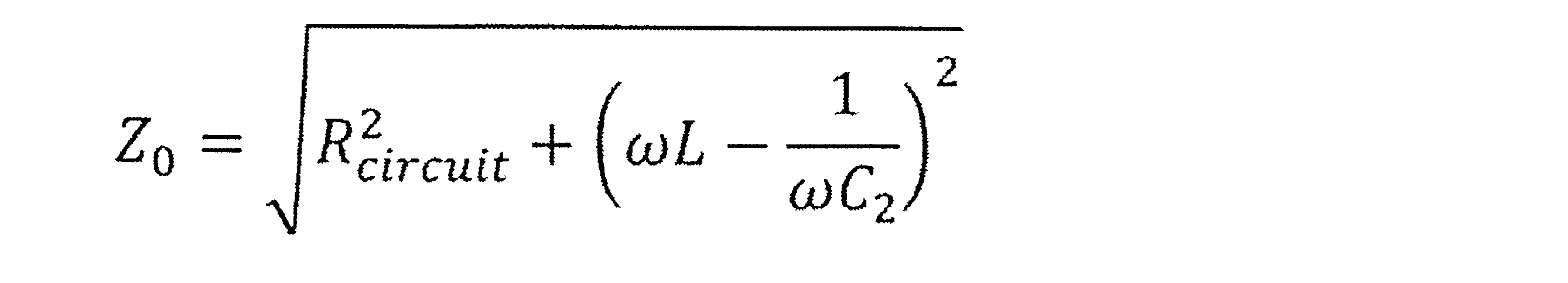
ここで、ωはモニタ時RLC直列回路に供給される脈流電力の角周波数を示している。この角周波数は、図3に示した周波数fを用いて、ω=2πfの演算で求められる。Here, ω represents the angular frequency of the pulsating power supplied to the RLC series circuit during monitoring. This angular frequency can be calculated by ω = 2πf using the frequency f shown in Figure 3.
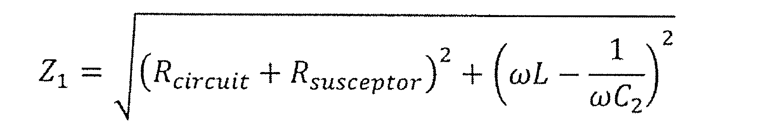
図4に示す等価回路EC2は、挿入状態におけるモニタ時RLC直列回路の等価回路を示している。等価回路EC2における等価回路EC1との相違は、エアロゾル形成基体108に含まれるサセプタ110による抵抗成分(Rsusceptor)が存在する点である。等価回路EC2におけるモニタ時RLC直列回路のインピーダンスZ1は、以下の式により計算することができる。
The equivalent circuit EC2 shown in Fig. 4 shows an equivalent circuit of the RLC series circuit at the time of monitoring in the inserted state. The difference between the equivalent circuit EC2 and the equivalent circuit EC1 is that there is a resistance component (R susceptor ) due to the
このように、挿入状態でのモニタ時RLC直列回路のインピーダンスは、抜取状態でのモニタ時RLC直列回路のインピーダンスよりも大きくなる。抜取状態でのインピーダンスZ0と、挿入状態でのインピーダンスZ1とを実験的に事前に求めて、その間に設定された閾値を制御部118のメモリ(図示せず)又は制御部118の外部に設けられたメモリIC(図示せず)に予め記憶しておく。これにより、制御部118は、測定したインピーダンスZが当該閾値より大きいか否かに基づき、挿入状態であるか否か、即ち、サセプタ110の検出が可能である。サセプタ110の検出は、エアロゾル形成基体108の検出とみなすことができる。
In this way, the impedance of the RLC series circuit when monitored in the inserted state is greater than the impedance of the RLC series circuit when monitored in the removed state. The impedance Z0 in the removed state and the impedance Z1 in the inserted state are experimentally obtained in advance, and a threshold value set therebetween is stored in advance in a memory (not shown) of the
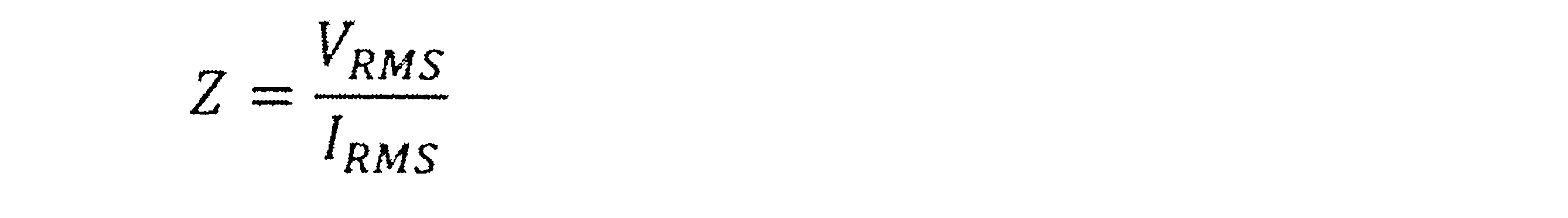
前述したように、制御部118は、電圧検出回路134及び電流検出回路136によりそれぞれ測定した電圧の実効値VRMS及び電流の実効値IRMSに基づき、モニタ時RLC直列回路のインピーダンスZを以下のように計算することができる。
As described above, the
また、インピーダンスZ1の上記式をRsusceptorについて解くと、以下の式が導かれる。
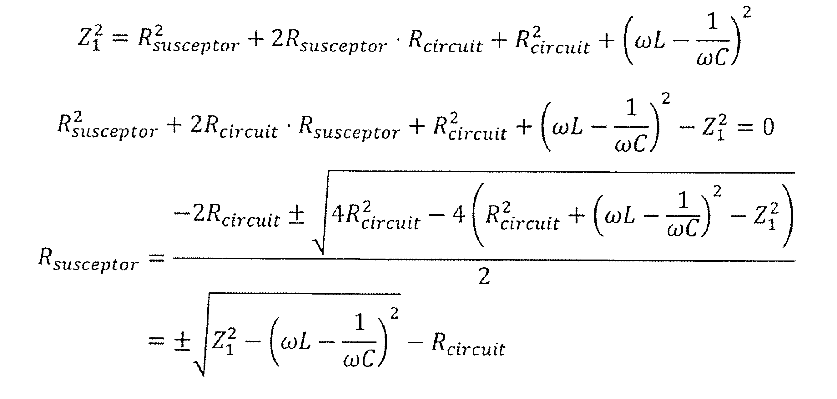
ここで、負の抵抗値を除外し、インピーダンスZ1をインピーダンスZに置き換えると、以下の式が得られる。

したがって、Rsusceptorと、サセプタ110の温度との関係を実験的に事前に求め、制御部118のメモリ(図示せず)に予め記憶しておくことにより、挿入状態においては、モニタ時RLC直列回路のインピーダンスZから数5の式で計算されたRsusceptorに基づき、サセプタ110の温度を取得することが可能である。
Therefore, by experimentally determining the relationship between R susceptor and the temperature of the
図4に示す等価回路EC3、EC4は、モニタ時RLC直列回路の共振周波数f0にて脈流電力をモニタ時RLC直列回路に供給した場合(スイッチQ3のスイッチング周波数が共振周波数f0の場合)の、モニタ時RLC直列回路の等価回路を表している。等価回路EC3は、抜取状態での等価回路を示す。等価回路EC4は、挿入状態での等価回路を示す。モニタ時RLC直列回路の共振周波数f0は以下のように導出できる。 Equivalent circuits EC3 and EC4 shown in Fig. 4 represent the equivalent circuits of the RLC series circuit during monitoring when pulsating power is supplied to the RLC series circuit during monitoring at the resonant frequency f0 of the RLC series circuit during monitoring (when the switching frequency of switch Q3 is the resonant frequency f0 ). The equivalent circuit EC3 represents the equivalent circuit in the removed state. The equivalent circuit EC4 represents the equivalent circuit in the inserted state. The resonant frequency f0 of the RLC series circuit during monitoring can be derived as follows.
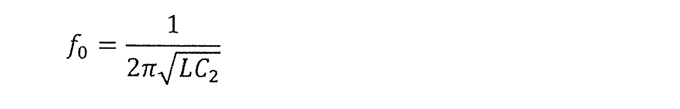
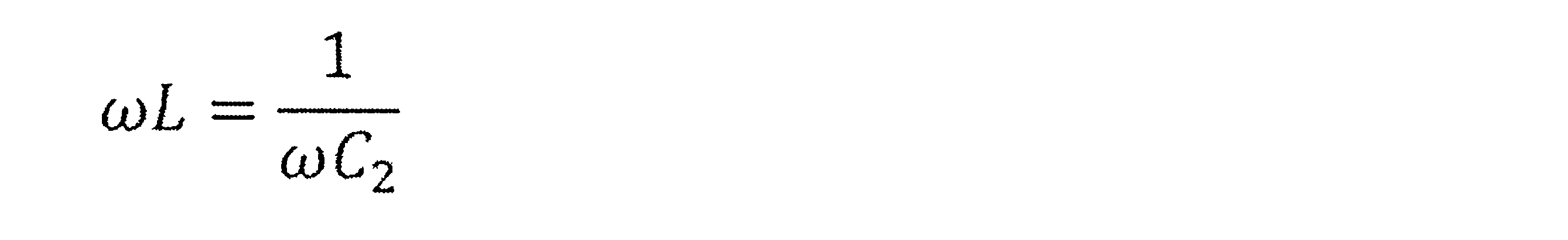
また、共振周波数f0にて脈流電力をモニタ時RLC直列回路に供給した場合には、以下の関係が満たされる。このため、数1や数2に示されるモニタ時RLC直列回路のインピーダンスについて、モニタ時RLC直列回路のインダクタンス成分及びキャパシタンス成分は無視できるようになる。
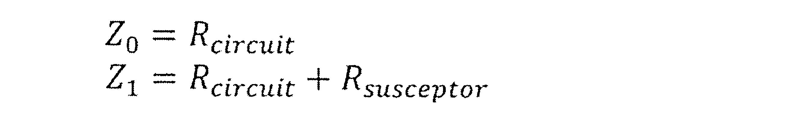
従って、スイッチQ3のスイッチング周波数が共振周波数f0の場合におけるインピーダンスZ0及びインピーダンスZ1は以下の通りである。
スイッチQ3のスイッチング周波数が共振周波数f0の場合における、挿入状態でのサセプタ110による抵抗成分の値Rsusceptorは、以下の式により計算することができる

このように、サセプタ110を検出する際、及び、インピーダンスに基づきサセプタ110の温度を取得する際の一方又は双方において、モニタ時RLC直列回路の共振周波数f0を用いることは、計算の容易さという点で有利である。もちろん、モニタ時RLC直列回路の共振周波数f0を用いることは、電源102が蓄えた電力を高効率且つ高速でサセプタ110へ供給する点でも有利である。
In this way, using the resonant frequency f0 of the RLC series circuit during monitoring when detecting the
回路104では、電流検出回路136が、電源102とコイル106との間の経路において、当該経路から電圧調整回路120への分岐点(ノードA)よりもコイル106に近い位置に配置されている。この構成によれば、電流検出回路136は、電圧調整回路120に供給される電流を含まない、コイル106へ供給される電流の値を正確に測定することができる。したがって、サセプタ110の電気抵抗値や温度を正確に測定又は推定することができる。In the
なお、電流検出回路136は、電源102とコイル106との間の経路において、当該経路から充電回路122への分岐点(ノードB)よりもコイル106に近い位置に配置されてもよい。この構成により、電源102の充電中(スイッチQ1、Q2はオフ状態)に、充電回路122から供給される電流が電流検出回路136内の抵抗器Rsense2を流れるのを防ぐことができる。したがって、抵抗器Rsense2が故障する可能性を低減することができる。また、電源102の充電中に電流検出回路136のオペアンプOPに電流が流れることを防止できるので、消費電力を抑えることができる。
The
残量測定IC124は、電源102の電圧と電源102からコイル106へ向かう電流とを測定可能である。このため、残量測定IC124により測定される電圧と電流に基づいても、モニタ時RLC直列回路のインピーダンスZは導出可能である。一般的に、残量測定IC124は、1秒周期でデータを更新するように構成される。したがって、残量測定IC124によって測定される電圧値及び電流値を用いてインピーダンスZを計算しようとすると、インピーダンスZが最速でも1秒周期で算出される。したがって、サセプタ110の温度が最速でも1秒周期で推定されることになる。そのような周期は、サセプタ110の加熱を適切に制御するのに十分に短いとは言えない。したがって、残量測定IC124により測定される電圧値及び電流値をインピーダンスZの測定に用いないことが望ましい。すなわち、好ましくは、残量測定IC124は、上述のような電圧検出回路134及び電流検出回路136として用いられない。よって、回路104において残量測定IC124は必須ではない。ただし、残量測定IC124を用いることで、電源102の状態を正確に把握することができる。The remaining
<誘導電流の検出>
コイル106の内側には、サセプタ110を含むエアロゾル形成基体108が挿入される。加熱制御及びモニタ制御のいずれも行われておらず、コイル106に電源102からの電力の供給が行われていない電力非供給状態(例えば、スイッチQ1、Q2がそれぞれオフ状態)であっても、コイル106にサセプタ110が近づいていく過程(抜取状態から挿入状態に遷移する過程)と、コイル106からサセプタ110が離れていく過程(挿入状態から抜取状態に遷移する過程)においては、コイル106に誘導電流が生じる。この誘導電流について図5を参照して説明する。
<Detection of induced current>
An aerosol-forming
図5は、図1に示すコイル106に生じる誘導電流を説明するための模式図である。状態ST1は、開口101Aに対しエアロゾル形成基体108が正方向に挿入されるとき(正方向挿入時)の状態を示す。状態ST2は、正方向で開口101Aに挿入されたエアロゾル形成基体108が開口101Aから抜き取られるとき(正方向抜取時)の状態を示す。状態ST3は、開口101Aに対しエアロゾル形成基体108が逆方向に挿入されるとき(逆方向挿入時)の状態を示す。状態ST4は、逆方向で開口101Aに挿入されたエアロゾル形成基体108が開口101Aから抜き取られるとき(逆方向抜取時)の状態を示す。
Figure 5 is a schematic diagram for explaining the induced current generated in the
状態ST1に示すように、正方向挿入時には、コイルコネクタCC-側からコイルコネクタCC+側に向かってコイル106を流れる誘導電流IDC1が発生する。状態ST2に示すように、正方向抜取時には、誘導電流IDC1とは逆向きにコイル106を流れる誘導電流IDC2が発生する。As shown in state ST1, when the coil is inserted in the forward direction, an induced current IDC1 is generated that flows through the
状態ST3に示すように、逆方向挿入時には、コイルコネクタCC+側からコイルコネクタCC-側に向かってコイル106を流れる誘導電流IDC3が発生する。状態ST4に示すように、逆方向抜取時には、誘導電流IDC3とは逆向きにコイル106を流れる誘導電流IDC4が発生する。サセプタ110はエアロゾル形成基体108において長手方向の一端側に偏心して設けられているため、状態ST3では、コイル106の内側を通過するサセプタ110の体積が、状態ST1と比べて小さくなる。そのため、状態ST3で発生する誘導電流IDC3の電流値(絶対値)は、状態ST1で発生する誘導電流IDC1の電流値(絶対値)よりも小さくなる。同様に、状態ST4では、コイル106の内側を通過するサセプタ110の体積が、状態ST2と比べて小さくなる。そのため、状態ST4で発生する誘導電流IDC4の電流値(絶対値)は、状態ST2で発生する誘導電流IDC2の電流値(絶対値)よりも小さくなる。As shown in state ST3, during reverse insertion, an induced current IDC3 is generated that flows through the
したがって、所定のタイミングで、誘導電流IDC1、IDC2、IDC3、IDC4を検出することで、開口101Aへエアロゾル形成基体108が挿入されたか否かを判断(挿入を検知)したり、開口101Aへ挿入されたエアロゾル形成基体108の挿入方向が正方向と逆方向のどちらであるのかを判断(挿入方向を検知)したり、開口101Aからエアロゾル形成基体108が抜き取られたか否かを判断(抜取を検知)したりすることが可能になる。以下では、同じ方向に流れる誘導電流IDC2と誘導電流IDC3を総称して誘導電流IDCaと記載し、同じ方向に流れる誘導電流IDC1と誘導電流IDC4を総称して誘導電流IDCbと記載する。Therefore, by detecting the induced currents IDC1, IDC2, IDC3, and IDC4 at a predetermined timing, it is possible to determine whether the aerosol-forming
回路104では、電流検出IC151によって、誘導電流IDCa(誘導電流IDC2又は誘導電流IDC3)を検出可能となっている。また、電流検出IC152によって、誘導電流IDCb(誘導電流IDC1又は誘導電流IDC4)を検出可能となっている。コイル106で生じ得る誘導電流は、電源102からコイル106へ電力が供給されていない状態(スイッチQ1、Q2がオフ状態)において、スイッチQ4、Q5がそれぞれオン状態のときに、電流検出IC151、152によって検出可能になる。In the
電流検出IC151は、例えば単方向電流センスアンプにより構成される。電流検出IC151は、抵抗器R2の両端へ印加される電圧を検出する検出器として、抵抗器R2の両端間の電圧を増幅するオペアンプを含み、このオペアンプの出力に基づいて、抵抗器R2に流れる電流の電流値を測定値として出力する。電流検出IC151に含まれるオペアンプの非反転入力端子IN+は、抵抗器R2のコイルコネクタCC-側の端子(一端)に接続されている。電流検出IC151に含まれるオペアンプの反転入力端子IN-は、抵抗器R2の他端に接続されている。したがって、電流検出IC151からは、上記電力非供給状態においてコイル106に誘導電流IDCaが生じた場合に、誘導電流IDCaに基づく所定の大きさの電流値が出力端子OUTから出力される。電流検出IC151を単方向電流センスアンプにより構成した場合、電流検出IC151は誘導電流IDCaと逆向きに流れる電流を検出できない点に留意されたい。The
電流検出IC152は、例えば単方向電流センスアンプにより構成される。電流検出IC152は、抵抗器R1の両端へ印加される電圧を検出する検出器として、抵抗器R1の両端間の電圧を増幅するオペアンプを含み、このオペアンプの出力に基づいて、抵抗器R1に流れる電流の電流値を測定値として出力する。電流検出IC152に含まれるオペアンプの非反転入力端子IN+は、抵抗器R1のコイルコネクタCC+側の端子(一端)に接続されている。電流検出IC152に含まれるオペアンプの反転入力端子IN-は、抵抗器R1の他端に接続されている。したがって、電流検出IC152からは、上記電力非供給状態においてコイル106に誘導電流IDCbが生じた場合に、誘導電流IDCbに基づく所定の大きさの電流値が出力端子OUTから出力される。電流検出IC152を単方向電流センスアンプにより構成した場合、電流検出IC152は誘導電流IDCbと逆向きに流れる電流を検出できない点に留意されたい。The
<電源ユニット100Uの動作モード>
図6は、電源ユニット100Uの動作モードを説明するための模式図である。図6に示すように、電源ユニット100Uの動作モードには、SLEEPモード、CHARGEモード、ACTIVEモード、PRE-HEATモード、INTERVALモード、HEATモード、及びERRORモードの7つのモードが含まれる。
<Operation Mode of
Fig. 6 is a schematic diagram for explaining the operation modes of the
SLEEPモードは、ボタン128の操作の検知や電源102の管理等、電力消費の少ない処理だけを制御部118が実行可能として、省電力化を図るモードである。
The SLEEP mode is a power saving mode in which the
ACTIVEモードは、電源102からコイル106への電力供給を除くほとんどの機能が有効になるモードであり、SLEEPモードよりも電力消費の多いモードである。制御部118は、電源ユニット100UをSLEEPモードにて動作させている状態にて、ボタン128の所定の操作を検知すると、動作モードをACTIVEモードに切り替える。制御部118は、電源ユニット100UをACTIVEモードにて動作させている状態にて、ボタン128の所定の操作を検知したり、ボタン128の無操作時間が所定時間に達したりすると、動作モードをSLEEPモードに切り替える。
In the ACTIVE mode, most functions are enabled except for the power supply from the
ACTIVEモードにおいて、制御部118は、コイル106に発生し得る誘導電流の検出が可能な回路状態(以下、誘導電流検出状態と記載)となるよう、回路104のスイッチを制御する。具体的には、制御部118は、スイッチQ1、Q2をオフ状態且つスイッチQ4、Q5をオン状態に制御する。この誘導電流検出状態で、制御部118は、電流検出IC151、152の出力に基づき、コイル106に誘導電流IDC1が生じたと判断した場合には、正方向でエアロゾル形成基体108が開口101Aに挿入されたと判断して、動作モードをPRE-HEATモードに切り替える。制御部118は、電流検出IC151、152の出力に基づき、コイル106に誘導電流IDC3が生じたと判断した場合には、逆方向でエアロゾル形成基体108が開口101Aに挿入されたと判断して、発光素子138等で構成される通知部を作動させて、エアロゾル形成基体108の挿入方向が逆であることをユーザに通知する。In the ACTIVE mode, the
PRE-HEATモードは、加熱制御とモニタ制御及びサセプタ110の温度取得処理等を制御部118が実行して、開口101Aに挿入されたエアロゾル形成基体108に含まれるサセプタ110を第一目標温度まで加熱又は所定時間だけ加熱するモードである。PRE-HEATモードにおいて、制御部118は、スイッチQ4をオン状態且つスイッチQ5をオフ状態にし、スイッチQ1、Q2、Q3をオンオフ制御して、加熱制御とモニタ制御及びサセプタ110の温度取得処理とを実行する。制御部118は、電源ユニット100UをPRE-HEATモードにて動作させている状態にて、サセプタ110の温度が第一目標温度に到達すると、又は、所定時間が経過すると、動作モードをINTERVALモードに切り替える。In the PRE-HEAT mode, the
INTERVALモードは、サセプタ110の温度がある程度まで低下するのを待つモードである。INTERVALモードでは、例えば制御部118は、加熱制御を一時的に停止し、モニタ制御及びサセプタ110の温度取得処理を行って、サセプタ110の温度が第一目標温度よりも低い第二目標温度まで低下するまで待機する。制御部118は、サセプタ110の温度が第二目標温度まで低下すると、動作モードをHEATモードに切り替える。
INTERVAL mode is a mode in which the temperature of the
HEATモードは、加熱制御とモニタ制御及びサセプタ110の温度取得処理を制御部118が実行して、開口101Aに挿入されたエアロゾル形成基体108に含まれるサセプタ110の温度が所定の目標温度となるよう制御するモードである。制御部118は、既定の加熱終了条件が満たされると、HEATモードを終了して、動作モードをACTIVEモードに切り替える。加熱終了条件は、HEATモードが開始されてから所定時間が経過した、又は、ユーザの吸引回数が既定値に達した等の条件である。PRE-HEATモード及びHEATモードは、エアロゾル形成基体108から所望のエアロゾルを発生させるために、電源102からコイル106へ電力の供給がなされる動作モードとなる。
In the HEAT mode, the
HEATモードからACTIVEモードに切り替わった直後において、制御部118は、図6に示した連続使用判定処理を行う。連続使用判定処理とは、ユーザが続けて新品のエアロゾル形成基体108の使用(以下、連続使用と記載)を行う意思があるのかを判定する処理である。制御部118は、連続使用の意思があり且つ新品のエアロゾル形成基体108のエアロゾル源112の消費に必要な電力を電源102から供給可能(電源残量が十分にある)である判定した場合には、動作モードをACTIVEモードからPRE-HEATモードに切り替え、それ以外の場合には、動作モードをACTIVEモードからSLEEPモードに切り替える。連続使用判定処理は必須ではなく省略可能である。Immediately after switching from HEAT mode to ACTIVE mode, the
CHARGEモードは、充電電源接続部116に接続された充電電源から供給される電力により、電源102の充電制御を行うモードである。制御部118は、電源ユニット100Uを、7つのモードのうちのCHARGEモード及びERRORモード以外のモードにて動作させている状態にて、充電電源接続部116に充電電源が接続されると、動作モードをCHARGEモードに切り替える。制御部118は、電源ユニット100UをCHARGEモードにて動作させている状態にて、電源102の充電が完了したり、充電電源接続部116と充電電源とが非接続になったりすると、動作モードをACTIVEモードに切り替える。The CHARGE mode is a mode in which charging of the
ERRORモードは、他の6つの動作モードのそれぞれにおいて、電源102の過放電や過充電、サセプタ110の過加熱等の異常(エラー)が発生した場合に、回路104の安全性を確保(例えば、全てのスイッチをオフ状態に制御)して、通知部によってユーザに通知を行うモードである。ERRORモードに遷移した場合には、電源ユニット100Uのリセットや、電源ユニット100Uの修理又は廃棄が必要になる。The ERROR mode is a mode in which, if an abnormality (error) such as over-discharging or over-charging of the
<エアロゾル形成基体108の状態の判別処理>
制御部118は、誘導電流検出状態において、電流検出IC151と電流検出IC152の出力に基づき、図5に示した状態ST1~状態ST4のいずれであるかを判別することができる。
<Discrimination process of the state of the aerosol-forming
In the induced current detection state, the
(状態ST1の判別)
誘導電流検出状態において、制御部118は、電流検出IC151と電流検出IC152のうち電流検出IC152から所定値以上の電流値が出力され、且つ、この電流値が電流閾値以上であった場合には、正方向でエアロゾル形成基体108(サセプタ110)が開口101A(コイル106)に近づくことで、コイル106で誘導電流IDC1が生じた、つまり状態ST1であると判断する。
(Determination of state ST1)
In the induced current detection state, when
(状態ST2の判別)
誘導電流検出状態において、制御部118は、電流検出IC151と電流検出IC152のうち電流検出IC151から所定値以上の電流値が出力され、且つ、この電流値が電流閾値以上であった場合には、正方向で挿入されたエアロゾル形成基体108(サセプタ110)が開口101A(コイル106)から遠ざかることで、コイル106で誘導電流IDC2が生じた、つまり状態ST2であると判断する。
(Determination of state ST2)
In the induced current detection state, when
(状態ST3の判別)
誘導電流検出状態において、制御部118は、電流検出IC151と電流検出IC152のうち電流検出IC151から所定値以上の電流値が出力され、且つ、この電流値が電流閾値未満であった場合には、逆方向でエアロゾル形成基体108(サセプタ110)が開口101A(コイル106)に近づくことで、コイル106で誘導電流IDC3が生じた、つまり状態ST3であると判断する。
(Determination of state ST3)
In the induced current detection state, when
(状態ST4の判別)
誘導電流検出状態において、制御部118は、電流検出IC151と電流検出IC152のうち電流検出IC152から所定値以上の電流値が出力され、且つ、この電流値が電流閾値未満であった場合には、逆方向で挿入されたエアロゾル形成基体108(サセプタ110)が開口101A(コイル106)から遠ざかることで、コイル106で誘導電流IDC4が生じた、つまり状態ST4であると判断する。
(Determination of state ST4)
In the induced current detection state, when
なお、誘導電流検出状態において、コイル106で誘導電流が生じた場合でも、ダイオードD1の存在により、この誘導電流がコンデンサC2及び変換回路132に流れることは防がれる。このため、誘導電流が変換回路132に影響を及ぼさなくなり、電源ユニット100Uの耐久性を向上させることができる。一方、加熱制御時には、変換回路132からの脈流がダイオードD1を通過するが、この脈流はダイオードD1によって不必要に整流されることがない。このため、加熱制御時には、電源102からコイル106へ適切な電力を供給して、エアロゾル源112を適切に加熱できる。
In addition, even if an induced current occurs in the
また、図2に示す回路104の構成では、加熱制御が行われるときに、抵抗器R2に、誘導電流とは異なる、誘導電流よりも大きな電流が流れる。このため、この大きな電流が電流検出IC151にて検出されないようにすることが好ましい。図7は、図2に示す回路104に追加される電子部品の好ましい例を示す図である。図7に示すように、回路104には、ロードスイッチ170とバリスタ171が追加されることが好ましい。
In addition, in the configuration of
ロードスイッチ170は、制御端子ONに制御部118からハイ又はローのオン信号が入力されることで、入力端子INに入力されたシステム電圧Vsysを出力端子OUTから出力する。ロードスイッチ170は、制御端子ONに制御部118からオフ信号が入力されている場合は、入力端子INに入力されたシステム電圧Vsysを出力端子OUTから出力しない。ロードスイッチ170の出力端子OUTは、電流検出IC151の電源端子VDDに接続されている。バリスタ171は、電流検出IC151の出力端子OUTと制御部118とを接続するラインと、グランドとに接続されている。
The
制御部118は、誘導電流検出状態においては、ロードスイッチ170にオン信号を入力して、電流検出IC151への電源供給を行う。制御部118は、加熱制御とモニタ制御の少なくとも一方が行われるモード(PRE-HEATモード、INTERVALモード、及びHEATモード)では、ロードスイッチ170にオフ信号を入力することで、電流検出IC151への電源供給を停止して、電流検出IC151の出力を停止させる。これにより、抵抗器R2に、誘導電流とは異なる、誘導電流よりも大きな電流が流れた場合でも、制御部118に大きな信号が入力されるのを防ぐことができる。In the induced current detection state, the
また、加熱制御とモニタ制御の少なくとも一方が行われるモード(PRE-HEATモード、INTERVALモード、及びHEATモード)において、何らかの原因でロードスイッチ170がオン状態に固定されてしまった場合でも、電流検出IC151の出力は、保護素子としてのバリスタ171によって低い値に制限される。このため、抵抗器R2に、誘導電流とは異なる、誘導電流よりも大きな電流が流れた場合でも、制御部118に大きな信号が入力されるのを防ぐことができる。
Furthermore, in modes in which at least one of heating control and monitor control is performed (PRE-HEAT mode, INTERVAL mode, and HEAT mode), even if the
なお、図2に示す回路104において、ロードスイッチ170とバリスタ171のいずれか一方を設ければ、電流検出IC151から制御部118へ大きな信号が入力されるのを防ぐ効果を得ることができる。また、バリスタ171に代えてツェナーダイオードを用いてもよい。2, if either the
<回路104の第一変形例>
図8は、図2に示す回路104の第一変形例を示す図である。図8に示す回路104は、抵抗器R1、電流検出IC152、及び電流検出IC151が削除された点と、抵抗器R2の位置が変更された点と、電流検出IC153が追加された点とを除いては、図2と同じである。
<First Modification of
Fig. 8 is a diagram showing a first modified example of the
図8に示す回路104においては、スイッチQ5のドレイン端子がコイルコネクタCC+に接続され、スイッチQ5のソース端子が抵抗器R2の一端に接続されている。抵抗器R2の他端は、コイルコネクタCC-に接続されている。8, the drain terminal of switch Q5 is connected to coil connector CC+, and the source terminal of switch Q5 is connected to one end of resistor R2. The other end of resistor R2 is connected to coil connector CC-.
電流検出IC153は、例えば双方向電流センスアンプにより構成される。電流検出IC153は、抵抗器R2の両端へ印加される電圧を検出する検出器として、抵抗器R2の両端間の電圧を増幅するオペアンプを含み、このオペアンプの出力に基づいて、抵抗器R2に流れる電流の電流値を測定値として出力する。The
図8に示す回路104では、スイッチQ1、Q2、Q4がオフ状態且つスイッチQ5がオン状態になることで、誘導電流検出状態が形成される。本実施形態における電流検出IC153は、反転入力端子IN-が非反転入力端子IN+よりも高電位である場合にプラスの電流値を出力し、反転入力端子IN-が非反転入力端子IN+よりも低電位である場合にマイナスの電流値を出力するものとする。この誘導電流検出状態において、コイル106に誘導電流IDCaが生じた場合には、誘導電流IDCaに基づく所定の大きさのマイナスの電流値が電流検出IC153から出力され、コイル106に誘導電流IDCbが生じた場合には、誘導電流IDCbに基づく所定の大きさのプラスの電流値が電流検出IC153から出力される。In the
したがって、制御部118は、誘導電流検出状態において、電流検出IC153の出力に基づき、以下に説明するように、図5に示した状態ST1~状態ST4のいずれであるかを判別することができる。Therefore, in the induced current detection state, the
(状態ST1の判別)
誘導電流検出状態において、制御部118は、電流検出IC153から絶対値が所定値以上のプラスの電流値が出力され、且つ、この絶対値が電流閾値以上であった場合には、正方向でエアロゾル形成基体108(サセプタ110)が開口101A(コイル106)に近づくことで、コイル106で誘導電流IDC1が生じた、つまり状態ST1であると判断する。
(Determination of state ST1)
In the induced current detection state, when a positive current value whose absolute value is greater than or equal to a predetermined value is output from the
(状態ST2の判別)
誘導電流検出状態において、制御部118は、電流検出IC153から絶対値が所定値以上のマイナスの電流値が出力され、且つ、この絶対値が電流閾値以上であった場合には、正方向で挿入されたエアロゾル形成基体108(サセプタ110)が開口101A(コイル106)から遠ざかることで、コイル106で誘導電流IDC2が生じた、つまり状態ST2であると判断する。
(Determination of state ST2)
In the induced current detection state, when a negative current value whose absolute value is greater than or equal to a predetermined value is output from the
(状態ST3の判別)
誘導電流検出状態において、制御部118は、電流検出IC153から絶対値が所定値以上のマイナスの電流値が出力され、且つ、この絶対値が電流閾値未満であった場合には、逆方向でエアロゾル形成基体108(サセプタ110)が開口101A(コイル106)に近づくことで、コイル106で誘導電流IDC3が生じた、つまり状態ST3であると判断する。
(Determination of state ST3)
In the induced current detection state, when a negative current value whose absolute value is greater than or equal to a predetermined value is output from the
(状態ST4の判別)
誘導電流検出状態において、制御部118は、電流検出IC153から絶対値が所定値以上のプラスの電流値が出力され、且つ、この電流値が電流閾値未満であった場合には、逆方向で挿入されたエアロゾル形成基体108(サセプタ110)が開口101A(コイル106)から遠ざかることで、コイル106で誘導電流IDC4が生じた、つまり状態ST4であると判断する。
(Determination of state ST4)
In the induced current detection state, when a positive current value whose absolute value is greater than or equal to a predetermined value is output from the
<回路104の第二変形例>
図9は、図2に示す回路104の第二変形例を示す図である。図9に示す回路104は、電流検出IC153がオペアンプ161に変更された点と、抵抗器591、抵抗器592、コンデンサ593、及びコンデンサ594からなるレールスプリッタ回路160が追加された点とを除いては、図8と同じである。
<Second Modification of
Fig. 9 is a diagram showing a second modified example of the
レールスプリッタ回路160は、電圧調整回路120によって生成されたシステム電圧Vsysが入力される入力端子T1と、2つの出力端子T2、T3を有する。レールスプリッタ回路160は、入力されたシステム電圧Vsysから、絶対値が同じで正負の異なる2つの電位((Vsys/2)のプラス電位と(-Vsys/2)のマイナス電位)を生成する。そして、レールスプリッタ回路160の出力端子T3から出力されるプラス電位(Vsys/2)は、オペアンプ161の正電源端子に入力され、レールスプリッタ回路160の出力端子T2から出力されるマイナス電位(-Vsys/2)は、オペアンプ161の負電源端子に入力されている。
The
オペアンプ161の非反転入力端子は、抵抗器R2のスイッチQ5側の端子(一端)に接続されている。オペアンプ161の反転入力端子は、抵抗器R2の他端に接続されている。オペアンプ161は、抵抗器R2の両端間の電圧を増幅して出力する。上述した通り、オペアンプ161の負電源端子にはマイナス電位が入力されるため、オペアンプ161はプラスの電圧値だけでなくマイナスの電圧値を出力できる。
The non-inverting input terminal of the
図9に示す回路104では、スイッチQ1、Q2、Q4がオフ状態且つスイッチQ5がオン状態になることで、誘導電流検出状態が形成される。この誘導電流検出状態において、コイル106に誘導電流IDCaが生じた場合には、誘導電流IDCaに基づく所定の大きさのマイナスの電圧値がオペアンプ161から出力され、コイル106に誘導電流IDCbが生じた場合には、誘導電流IDCbに基づく所定の大きさのプラスの電圧値がオペアンプ161から出力される。9, the switches Q1, Q2, and Q4 are turned off and the switch Q5 is turned on, thereby forming an induced current detection state. In this induced current detection state, if an induced current IDCa occurs in the
したがって、制御部118は、誘導電流検出状態において、オペアンプ161の出力に基づき、以下に説明するように、図5に示した状態ST1~状態ST4のいずれであるかを判別することができる。Therefore, in the induced current detection state, the
(状態ST1の判別)
誘導電流検出状態において、制御部118は、オペアンプ161から絶対値が所定値以上のプラスの電圧値が出力され、且つ、この絶対値が電圧閾値以上であった場合には、正方向でエアロゾル形成基体108(サセプタ110)が開口101A(コイル106)に近づくことで、コイル106で誘導電流IDC1が生じた、つまり状態ST1であると判断する。
(Determination of state ST1)
In the induced current detection state, when a positive voltage value whose absolute value is greater than or equal to a predetermined value is output from the
(状態ST2の判別)
誘導電流検出状態において、制御部118は、オペアンプ161から絶対値が所定値以上のマイナスの電圧値が出力され、且つ、この絶対値が電圧閾値以上であった場合には、正方向で挿入されたエアロゾル形成基体108(サセプタ110)が開口101A(コイル106)から遠ざかることで、コイル106で誘導電流IDC2が生じた、つまり状態ST2であると判断する。
(Determination of state ST2)
In the induced current detection state, when a negative voltage value whose absolute value is greater than or equal to a predetermined value is output from the
(状態ST3の判別)
誘導電流検出状態において、制御部118は、オペアンプ161から絶対値が所定値以上のマイナスの電圧値が出力され、且つ、この絶対値が電圧閾値未満であった場合には、逆方向でエアロゾル形成基体108(サセプタ110)が開口101A(コイル106)に近づくことで、コイル106で誘導電流IDC3が生じた、つまり状態ST3であると判断する。
(Determination of state ST3)
In the induced current detection state, when a negative voltage value whose absolute value is greater than or equal to a predetermined value is output from the
(状態ST4の判別)
誘導電流検出状態において、制御部118は、オペアンプ161から絶対値が所定値以上のプラスの電圧値が出力され、且つ、この絶対値が電圧閾値未満であった場合には、逆方向で挿入されたエアロゾル形成基体108(サセプタ110)が開口101A(コイル106)から遠ざかることで、コイル106で誘導電流IDC4が生じた、つまり状態ST4であると判断する。
(Determination of state ST4)
In the induced current detection state, when a positive voltage value whose absolute value is greater than or equal to a predetermined value is output from the
<回路104の第三変形例>
図10は、図2に示す回路104の第三変形例を示す図である。図10に示す回路104は、変換回路132が、直流を交流に変換するインバータ162に変更された点と、抵抗器R1、電流検出IC152、及び電流検出IC151が削除された点と、抵抗器R3、抵抗器R4、電流検出IC154、及び電流検出IC155が追加された点とを除いては、図2と同じである。
<Third Modification of
Fig. 10 is a diagram showing a third modified example of the
インバータ162は、Pチャネル型MOSFETで構成されたスイッチQ5、Q7と、Nチャネル型MOSFETで構成されたスイッチQ6、Q8と、スイッチQ5~Q8のゲート電圧を制御するゲートドライバ162bと、ゲートドライバ162bを制御するプロセッサ(Logic)162cと、ゲートドライバ162bとプロセッサ162cへ電力を供給するLDO162aと、を備える。インバータ162の正極側入力端子IN+は、並列回路130の他端に接続されている。インバータ162の負極側入力端子IN-は、スイッチQ4のドレイン端子に接続されている。LDO162aは、正極側入力端子IN+に入力された電圧を調整して得た電圧を、ゲートドライバ162bとプロセッサ162cへ供給する。プロセッサ162cは、制御部118とシリアル通信によって通信可能に構成されており、制御部118によって制御される。The
スイッチQ5のソース端子は正極側入力端子IN+に接続され、スイッチQ5のドレイン端子は、スイッチQ6のドレイン端子に接続されている。スイッチQ6のソース端子は負極側入力端子IN-に接続されている。スイッチQ5とスイッチQ6とを接続するノードは、出力端子OUT+に接続されている。 The source terminal of switch Q5 is connected to the positive input terminal IN+, and the drain terminal of switch Q5 is connected to the drain terminal of switch Q6. The source terminal of switch Q6 is connected to the negative input terminal IN-. The node connecting switch Q5 and switch Q6 is connected to the output terminal OUT+.
スイッチQ7のソース端子は正極側入力端子IN+に接続され、スイッチQ7のドレイン端子は、スイッチQ8のドレイン端子に接続されている。スイッチQ8のソース端子は負極側入力端子IN-に接続されている。スイッチQ7とスイッチQ8とを接続するノードは、出力端子OUT-に接続されている。 The source terminal of switch Q7 is connected to the positive input terminal IN+, and the drain terminal of switch Q7 is connected to the drain terminal of switch Q8. The source terminal of switch Q8 is connected to the negative input terminal IN-. The node connecting switches Q7 and Q8 is connected to the output terminal OUT-.
抵抗器R3は、一端がコンデンサC2の一端に接続され、他端が出力端子OUT+に接続されている。抵抗器R4は、一端がコイルコネクタCC-に接続され、他端が出力端子OUT-に接続されている。 One end of the resistor R3 is connected to one end of the capacitor C2 , and the other end is connected to the output terminal OUT+. One end of the resistor R4 is connected to the coil connector CC-, and the other end is connected to the output terminal OUT-.
電流検出IC155は、例えば単方向電流センスアンプにより構成される。電流検出IC155は、抵抗器R3の両端へ印加される電圧を検出する検出器として、抵抗器R3の両端間の電圧を増幅するオペアンプを含み、このオペアンプの出力に基づいて、抵抗器R3に流れる電流の電流値を測定値として出力する。電流検出IC155に含まれるオペアンプの非反転入力端子IN+は、抵抗器R3のコンデンサC2側の端子に接続されている。電流検出IC155に含まれるオペアンプの反転入力端子IN-は、抵抗器R3の出力端子OUT+側の端子に接続されている。
The
電流検出IC154は、例えば単方向電流センスアンプにより構成される。電流検出IC154は、抵抗器R4の両端へ印加される電圧を検出する検出器として、抵抗器R4の両端間の電圧を増幅するオペアンプを含み、このオペアンプの出力に基づいて、抵抗器R4に流れる電流の電流値を測定値として出力する。電流検出IC154に含まれるオペアンプの非反転入力端子IN+は、抵抗器R4のコイルコネクタCC-側の端子に接続されている。電流検出IC154に含まれるオペアンプの反転入力端子IN-は、抵抗器R4の出力端子OUT-側の端子に接続されている。 Current detection IC154 is composed of, for example, a unidirectional current sense amplifier. As a detector that detects the voltage applied to both ends of resistor R4, current detection IC154 includes an operational amplifier that amplifies the voltage across resistor R4, and outputs the current value of the current flowing through resistor R4 as a measured value based on the output of this operational amplifier. The non-inverting input terminal IN+ of the operational amplifier included in current detection IC154 is connected to the terminal on the coil connector CC- side of resistor R4. The inverting input terminal IN- of the operational amplifier included in current detection IC154 is connected to the terminal on the output terminal OUT- side of resistor R4.
制御部118は、加熱制御時には、スイッチQ1、Q4をオン状態且つスイッチQ2をオフ状態にし、スイッチQ5、Q8のオン状態をPWM(パルス幅変調、Pulse Width Modulation)制御によって制御し且つスイッチQ6、Q7をオフ状態にする第一スイッチ制御と、スイッチQ5、Q8をオフ状態且つスイッチQ6、Q7のオン状態をPWM制御によって制御する第二スイッチ制御と、を交互に行う。これにより、電源102から供給される直流が交流に変換されて、コイル106に供給される。During heating control, the
制御部118は、モニタ制御時には、スイッチQ2、Q4をオン状態且つスイッチQ1をオフ状態にし、上記の第一スイッチ制御と第二スイッチ制御を交互に行う。これにより、電源102から供給される直流が交流に変換されて、コイル106に供給される。During monitor control, the
図10に示す回路104では、制御部118は、スイッチQ1、Q2をオフ状態にし、スイッチQ4をオン状態にし、スイッチQ6、Q8をオン状態にすることで、誘導電流検出状態を形成する。この誘導電流検出状態において、コイル106に誘導電流IDCaが生じた場合には、誘導電流IDCaに基づく所定の大きさの電流値が電流検出IC154から出力され、コイル106に誘導電流IDCbが生じた場合には、誘導電流IDCbに基づく所定の大きさの電流値が電流検出IC155から出力される。10, the
したがって、制御部118は、誘導電流検出状態において、電流検出IC154、155の出力に基づき、以下に説明するように、図5に示した状態ST1~状態ST4のいずれであるかを判別することができる。Therefore, in the induced current detection state, the
(状態ST1の判別)
誘導電流検出状態において、制御部118は、電流検出IC155から絶対値が所定値以上の電流値が出力され、且つ、この絶対値が電流閾値以上であった場合には、正方向でエアロゾル形成基体108(サセプタ110)が開口101A(コイル106)に近づくことで、コイル106で誘導電流IDC1が生じた、つまり状態ST1であると判断する。
(Determination of state ST1)
In the induced current detection state, when the
(状態ST2の判別)
誘導電流検出状態において、制御部118は、電流検出IC154から絶対値が所定値以上の電流値が出力され、且つ、この絶対値が電流閾値以上であった場合には、正方向で挿入されたエアロゾル形成基体108(サセプタ110)が開口101A(コイル106)から遠ざかることで、コイル106で誘導電流IDC2が生じた、つまり状態ST2であると判断する。
(Determination of state ST2)
In the induced current detection state, when the
(状態ST3の判別)
誘導電流検出状態において、制御部118は、電流検出IC154から絶対値が所定値以上の電流値が出力され、且つ、この絶対値が電流閾値未満であった場合には、逆方向でエアロゾル形成基体108(サセプタ110)が開口101A(コイル106)に近づくことで、コイル106で誘導電流IDC3が生じた、つまり状態ST3であると判断する。
(Determination of state ST3)
In the induced current detection state, when the
(状態ST4の判別)
誘導電流検出状態において、制御部118は、電流検出IC155から絶対値が所定値以上の電流値が出力され、且つ、この電流値が電流閾値未満であった場合には、逆方向で挿入されたエアロゾル形成基体108(サセプタ110)が開口101A(コイル106)から遠ざかることで、コイル106で誘導電流IDC4が生じた、つまり状態ST4であると判断する。
(Determination of state ST4)
In the induced current detection state, when the
なお、図10に示す回路104では、加熱制御が行われるときに、抵抗器R3、R4に、誘導電流とは異なる、誘導電流よりも大きな電流が流れる。このため、この大きな電流が電流検出IC154、155にて検出されないようにすることが好ましい。具体的には、図7に示した例と同様に、電流検出IC154、155それぞれへの電源供給を制御するロードスイッチと、電流検出IC154、155それぞれの出力端子OUTに接続されるバリスタ(又はツェナーダイオード)と、の少なくとも一方を追加することが好ましい。In the
また、図10に示す回路104では、誘導電流検出状態において、コイル106で発生した誘導電流がインバータ162に入力されないようにすることが好ましい。例えば、インバータ162の出力端子OUT+と抵抗器R3とを接続するノードとグランドとを第一スイッチで接続し、インバータ162の出力端子OUT-と抵抗器R4とを接続するノードとグランドとを第二スイッチで接続する。そして、制御部118は、誘導電流検出状態においては、第一スイッチと第二スイッチをそれぞれオン状態にし、加熱制御時とモニタ制御時においては、第一スイッチと第二スイッチをそれぞれオフ状態に制御する。これにより、第一スイッチと第二スイッチを含む制限回路によって、誘導電流がインバータ162に入力されるのを防ぐことができる。
In the
ここまで説明してきた図2、図8、図9、及び図10に示す回路104では、電流検出IC151、電流検出IC152、電流検出IC153、電流検出IC154、電流検出IC155、及びオペアンプ161等により、コイル106に流れる誘導電流の向き、すなわち、誘導電流IDCaと誘導電流IDCbを区別して検出可能になっている。しかし、誘導電流IDCaと誘導電流IDCbを区別して検出できなくとも、エアロゾル形成基体108の状態を判断することは可能である。以下、回路104の第四変形例と第五変形例によって説明する。2, 8, 9, and 10, the
<回路104の第四変形例>
図11は、図2に示す回路104の第四変形例を示す図である。図11に示す回路104は、抵抗器R1、電流検出IC152、及び電流検出IC151が削除された点と、抵抗器R2の位置が変更された点と、電流検出IC156が追加された点とを除いては、図2と同じである。
<Fourth Modification of
Fig. 11 is a diagram showing a fourth modified example of the
図11に示す回路104においては、スイッチQ5のドレイン端子がコイルコネクタCC+に接続され、スイッチQ5のソース端子がコイルコネクタCC-に接続されている。また、抵抗器R2は、その一端がスイッチQ5のソース端子に接続され、その他端がスイッチQ4のドレイン端子に接続されている。図11に示す回路104では、制御部118は、スイッチQ1、Q2をオフ状態にし、スイッチQ4、Q5をオン状態にすることで、誘導電流検出状態を形成する。
In the
電流検出IC156は、例えば単方向電流センスアンプにより構成される。電流検出IC156は、抵抗器R2の両端へ印加される電圧を検出する検出器として、抵抗器R2の両端間の電圧を増幅するオペアンプを含み、このオペアンプの出力に基づいて、抵抗器R2に流れる電流の電流値を測定値として出力する。電流検出IC156に含まれるオペアンプの非反転入力端子IN+は、抵抗器R2のスイッチQ5側の端子に接続されている。電流検出IC156に含まれるオペアンプの反転入力端子IN-は、抵抗器R2のスイッチQ4側の端子に接続されている。 Current detection IC156 is composed of, for example, a unidirectional current sense amplifier. As a detector for detecting the voltage applied to both ends of resistor R2, current detection IC156 includes an operational amplifier that amplifies the voltage across resistor R2, and outputs the current value of the current flowing through resistor R2 as a measured value based on the output of this operational amplifier. The non-inverting input terminal IN+ of the operational amplifier included in current detection IC156 is connected to the terminal of resistor R2 on the switch Q5 side. The inverting input terminal IN- of the operational amplifier included in current detection IC156 is connected to the terminal of resistor R2 on the switch Q4 side.
したがって、電流検出IC156からは、誘導電流検出状態においてコイル106に誘導電流IDCa又は誘導電流IDCbが生じた場合に、所定の大きさの電流値が出力端子OUTから出力される。図11に示す回路104では、単方向センスアンプにより構成された単一の電流検出IC156のみによって誘導電流が検出される。電流検出IC156の出力は、誘導電流IDCaと誘導電流IDCbのいずれであっても、その大きさを除けば同じ符号の電流値となる。このように、電流検出IC156は、コイル106に発生した誘導電流の向きを区別した情報の出力は不可となっている。Therefore, when induced current IDCa or induced current IDCb occurs in
なお、図11に示す回路104では、加熱制御が行われるときに、抵抗器R2に、誘導電流とは異なる、誘導電流よりも大きな電流が流れる。このため、この大きな電流が電流検出IC156にて検出されないようにすることが好ましい。具体的には、図7に示した例と同様に、電流検出IC156への電源供給を制御するロードスイッチと、電流検出IC156の出力端子OUTに接続されるバリスタ(又はツェナーダイオード)と、の少なくとも一方を追加することが好ましい。In the
制御部118は、電流検出IC156の出力に基づき、以下に示すように、状態ST1~状態ST4のいずれであるかを判別する。Based on the output of the
(状態ST1の判別)
ACTIVEモード且つ誘導電流検出状態において、制御部118は、電流検出IC156から所定値以上の電流値が出力され、且つ、この電流値が電流閾値以上であった場合には、正方向でエアロゾル形成基体108(サセプタ110)が開口101A(コイル106)に近づくことで、コイル106で誘導電流IDC1が生じた、つまり状態ST1であると判断する。
(Determination of state ST1)
In ACTIVE mode and induced current detection state, when a current value greater than a predetermined value is output from the
(状態ST2の判別)
HEATモード終了直後且つ誘導電流検出状態において、制御部118は、電流検出IC156から所定値以上の電流値が出力され、且つ、この電流値が電流閾値以上であった場合には、正方向で挿入されたエアロゾル形成基体108(サセプタ110)が開口101A(コイル106)から遠ざかることで、コイル106で誘導電流IDC2が生じた、つまり状態ST2であると判断する。
(Determination of state ST2)
Immediately after the end of the HEAT mode and in the induced current detection state, when a current value greater than a predetermined value is output from the
(状態ST3の判別)
ACTIVEモード且つ誘導電流検出状態において、制御部118は、電流検出IC156から所定値以上の電流値が出力され、且つ、この電流値が電流閾値未満であった場合には、逆方向でエアロゾル形成基体108(サセプタ110)が開口101A(コイル106)に近づくことで、コイル106で誘導電流IDC3が生じた、つまり状態ST3であると判断する。
(Determination of state ST3)
In ACTIVE mode and induced current detection state, when a current value greater than a predetermined value is output from the
(状態ST4の判別)
HEATモード終了直後且つ誘導電流検出状態において、制御部118は、電流検出IC156から所定値以上の電流値が出力され、且つ、この電流値が電流閾値未満であった場合には、逆方向で挿入されたエアロゾル形成基体108(サセプタ110)が開口101A(コイル106)から遠ざかることで、コイル106で誘導電流IDC4が生じた、つまり状態ST4であると判断する。
(Determination of state ST4)
Immediately after the end of the HEAT mode and in the induced current detection state, if a current value greater than or equal to a predetermined value is output from the
本実施形態では、制御部118は、状態ST1から状態ST4までを判別する。これに代えて、制御部118は、状態ST1と状態ST3を区別しなくてもよい。つまり、ACTIVEモード且つ誘導電流検出状態において、制御部118は、電流検出IC156から所定値以上の電流値が出力されたら、状態ST1又は状態ST3であると判断してもよい。制御部118は、状態ST1又は状態ST3であると判断した場合、動作モードをPRE-HEATモードに切り替えてもよい。同様に、HEATモード終了直後且つ誘導電流検出状態において、制御部118は、電流検出IC156から所定値以上の電流値が出力されたら、状態ST2又は状態ST4であると判断してもよい。In this embodiment, the
<回路104の第五変形例>
図12は、図2に示す回路104の第五変形例を示す図である。図12に示す回路104は、レールスプリッタ回路160が削除された点と、オペアンプ161がオペアンプ162に変更された点とを除いては、図9と同じである。
Fifth Modification of
Figure 12 is a diagram showing a fifth modification of the
図12に示す回路104におけるオペアンプ162は、図9に示したオペアンプ161において、正電源端子にシステム電圧Vsysを供給し、負電源端子をグランドに接続した構成である。
An
図12に示す回路104では、制御部118は、スイッチQ1、Q2、Q4をオフ状態且つスイッチQ5をオン状態に制御して、誘導電流検出状態を形成する。誘導電流検出状態において誘導電流IDCbが発生した場合には、オペアンプ161から、その誘導電流IDCbに応じた所定値以上の電圧値が出力される。一方、誘導電流検出状態において誘導電流IDCaが発生した場合には、オペアンプ161から所定値以上の電圧値が出力されることはない。このように、オペアンプ162の出力は、誘導電流IDCbが生じたときにのみ、所定値以上の電圧値となる。つまり、オペアンプ162は、コイル106に発生した誘導電流の向きを区別した情報の出力は不可となっている。In the
図12に示す回路104において、制御部118は、ACTIVEモードにおいて誘導電流検出状態を形成し、この誘導電流検出状態において、オペアンプ161から所定値以上且つ電圧閾値以上の電圧が出力された場合に、正方向でエアロゾル形成基体108(サセプタ110)が開口101A(コイル106)に近づくことで、コイル106で誘導電流IDC1が生じた、つまり状態ST1であると判断して、動作モードをPRE-HEATモードに切り替える。In the
図12に示す回路104では、逆方向でエアロゾル形成基体108が開口101Aに挿入されたことや、正方向で開口101Aに挿入されたエアロゾル形成基体108が抜き取られたことを誘導電流に基づいて制御部118が判断することできない。しかし、制御部118は、正方向でエアロゾル形成基体108が開口101Aに挿入されたことは判断可能である。12, the
以上のように、図2及び図8~図11に示す回路104の構成であれば、制御部118が、エアロゾル形成基体108の挿入検知、エアロゾル形成基体108の抜取検知、及びエアロゾル形成基体108の挿入方向の識別を行うことが可能である。なお、例えば、エアロゾル生成装置100を、正方向でエアロゾル形成基体108を挿入したときと、逆方向でエアロゾル形成基体108を挿入したときとのいずれにおいても、エアロゾル形成基体108を加熱してエアロゾルを吸引可能に構成するのであれば、挿入方向の識別は不要となる。このため、このような構成においては、制御部118が、エアロゾル形成基体108の挿入検知と抜取検知だけを行うようにすれば十分である。つまり、制御部118、電源ユニット100U、回路104の構成を簡易なものにできる。
As described above, with the configuration of the
<制御部118の動作>
以下では、図2、図8~図12の各々に示す回路104における制御部118の動作を説明する。誘導電流又は誘導電流に応じた電圧値を検出することのできる、電流検出IC151、152、153、154、155、156とオペアンプ161、162のことを総称して、以下では誘導電流検出ICとも記載する。
<Operation of
The operation of the
図13は、SLEEPモード時に制御部118が実行する例示処理10を説明するためのフローチャートである。まず、制御部118は、充電電源が充電電源接続部116へ接続されたか否かを判定する(ステップS11)。当該判定は、例えば上述したVBUS検知信号によって実行される。制御部118は、充電電源が充電電源接続部116へ接続された場合(ステップS11:YES)には、動作モードをCHARGEモードに切り替える。制御部118は、充電電源が充電電源接続部116へ接続されていない場合(ステップS11:NO)には、ボタン128に対する所定の操作がなされたか否かを判定する(ステップS12)。この所定の操作の一例は、ボタン128の長押し又は短押し又は連打である。制御部118は、ボタン128に対する所定の操作がなされた場合(ステップS12:YES)には、動作モードをACTIVEモードに切り替える。制御部118は、ボタン128に対する所定の操作がなされていない場合(ステップS12:NO)には、ステップS11に処理を戻す。
Figure 13 is a flowchart for explaining an example process 10 executed by the
図14は、CHARGEモード時に制御部118が実行する例示処理20を説明するためのフローチャートである。まず、制御部118は、充電回路122に電源102の充電を開始させる(ステップS21)。当該処理は、例えば、制御部118が所定レベルを持つ充電イネーブル信号を充電回路122の充電イネーブル端子CEに入力することで実行される。次に、制御部118は、充電電源が充電電源接続部116から取り外されたか否かを判定する(ステップS22)。当該判定は、例えば上述したVBUS検知信号によって実行される。制御部118は、充電電源が充電電源接続部116から取り外されていない場合(ステップS22:NO)には、ステップS22に処理を戻す。制御部118は、充電電源が充電電源接続部116から取り外された場合(ステップS22:YES)には、充電回路122に電源102の充電を終了させる(ステップS23)。なお、充電回路122は、制御部118からの指令を待たずに、残量測定IC124とのシリアル通信や充電端子BATへの入力から取得される電源102の充電電流や充電電圧に基づき、電源102の充電を終了させてもよい。ステップS23の後、制御部118は、電源102の充電レベル(電源102に残っている電力量)に基づき、エアロゾル形成基体108の使用可能本数を設定する(ステップS24)。ここでは、エアロゾル形成基体108としてスティック状のものを想定しているが、エアロゾル形成基体108の形状はこれに限定されるわけではない。従って、『使用可能本数』は、『使用可能個数』へと一般化できることに留意されたい。以下、図15を参照して、使用可能本数について説明する。14 is a flowchart for explaining an example process 20 executed by the
図15は、使用可能本数について説明するための模式図である。容量610は、未だ使用されていないとき(以下、「未使用時」という。)の電源102に対応し、その面積が未使用時の満充電容量を示している。なお、電源102が未だ使用されていないとは、電源102が製造されてからの放電回数がゼロである又は所定の放電回数以下であることを意味する。未使用時の電源102の満充電容量の例は、約220mAhである。容量620は、放電と充電が繰り返されて、ある程度劣化が進んだとき(以下、「劣化時」という。)の電源102に対応し、その面積が劣化時の満充電容量を示している。図15から明らかなように、未使用時の電源102の満充電容量は、劣化時の電源102の満充電容量よりも大きい。
Figure 15 is a schematic diagram for explaining the number of usable units.
電力量630は、1つのエアロゾル形成基体108を消費するために必要な電力量(エネルギー)に対応し、その面積が対応する電力量を示している。図15における4つの電力量630は全て同じ面積であり、対応する電力量も略同じである。なお、1つのエアロゾル形成基体108を消費するために必要な電力630の例は、約70mAhである。一例として、HEATモードに移行した後に加熱終了条件が満たされたときに、1つのエアロゾル形成基体108が消費されたとみなすことができる。The amount of
電力量640及び電力量650は、それぞれ、2つのエアロゾル形成基体108を消費した後の電源102の充電レベル(以下、「余剰電力量」という。)に対応し、その面積が対応する電力量を示している。図15から明らかなように、未使用時の余剰電力量は、劣化時の余剰電力量より大きい。The amounts of
電圧660は、電源102の満充電時の出力電圧を示しており、その例は約3.64Vである。電圧670は、電源102の放電終止電圧を示しており、その例は約2.40Vである。電源102の満充電時の出力電圧と放電終止電圧は、それぞれ、基本的には、電源102の劣化によらず、即ちSOH(State Of Health)によらず一定である。
電源102は、電圧が放電終止電圧に達するまで、換言すれば電源102の充電レベルがゼロとなるまで使用されないことが好ましい。これは、電源102の電圧が放電終止電圧以下となった場合又は電源102の充電レベルがゼロとなった場合、電源102の劣化が急激に進むためである。また、電源102の電圧が放電終止電圧に近づくほど、電源102の劣化は進む。It is preferable that the
また、上述したように、電源102は、放電と充電が繰り返されると、その満充電容量が減少し、所定の数(図15においては“2”)のエアロゾル形成基体108を消費した後の余剰電力量は、未使用時よりも劣化時の方が小さくなる。
Furthermore, as described above, when the
従って、制御部118は、電源102の劣化を見込んだうえで、電圧が放電終止電圧又はその近傍に達するまで、換言すれば電源102の充電レベルがゼロ又はその近傍となるまで使用されないよう、使用可能本数を設定することが好ましい。即ち、使用可能本数は、例えば以下のように設定することができる。
n=int((e-S)/C)
Therefore, it is preferable that the
n=int((e-S)/C)
ここで、“n”は使用可能本数であり、“e”は電源102の充電レベル(単位は例えばmAh)であり、“S”は電源102の劣化時の余剰電力量に余裕を持たせるためのパラメータ(単位は例えばmAh)であり、“C”は1つのエアロゾル形成基体108を消費するのに必要な電力量(単位は例えばmAh)であり、“int()”は()内の小数点以下を切り捨てる関数である。なお、“e”は変数であり、制御部118が残量測定IC124と通信することにより取得することができる。また、“S”及び“C”は定数であり、実験的に事前に求め、制御部118のメモリ(図示せず)に予め記憶しておくことができる。Here, "n" is the number of units that can be used, "e" is the charge level of the power source 102 (e.g., in mAh), "S" is a parameter (e.g., in mAh) for allowing a margin of surplus power when the
図14に戻り、制御部118は、ステップS24の後、動作モードをACTIVEモードに切り替える。なお、図14のステップS22は、充電回路122による電源102の充電が完了したか否かを制御部118が判定する処理に置き換えることもできる。Returning to Fig. 14, after step S24, the
図16は、ACTIVEモード時に制御部118が主として実行する例示処理(メイン処理30)を説明するためのフローチャートである。まず、制御部118は、回路104のスイッチを制御して誘導電流検出状態を形成する(ステップS30)。図2とその変形例の各回路104における誘導電流検出状態の形成については上述した通りである。図2、図10、及び図11に示す各回路104において、図7に例示されるロードスイッチ170が追加される場合には、制御部118は、このステップS30において、このロードスイッチ170をオン状態にして、誘導電流検出ICを構成する電流検出ICへの電力供給を行う。
Figure 16 is a flow chart for explaining an example process (main process 30) that is mainly executed by the
また、制御部118は、第1タイマを起動する(ステップS31)。第1タイマが起動することにより、第1タイマの値は初期値から時間の経過により増加又は減少するようになる。以下では、第1タイマの値は時間の経過により増加するものとして説明する。第1タイマは、他の動作モードに切り替わる際に停止し且つ初期化される。これらについては、後述する第2タイマ及び第3タイマについても同様である。
The
次に、制御部118は、電源102の充電レベルをユーザに通知する(ステップS32)。充電レベルの通知は、残量測定IC124との通信により取得した電源102の情報に基づき、制御部118が発光素子駆動回路126と通信し、発光素子138を所定の態様で発光させることにより実現することができる。これについては、後述する他の通知についても同様である。充電レベルの通知は、一時的に行われることが好ましい。なお、通知部としてスピーカやバイブレータを含む場合には、制御部118がこれらを制御して、音又は振動によって充電レベルの通知を行う。Next, the
次に、制御部118は、メイン処理30と並列に実行されるように、別の処理(以下、『サブ処理』という。)の実行を開始する(ステップS33)。ステップS33において開始されるサブ処理については後述する。なお、サブ処理の実行は、他の動作モードに切り替わる際に停止される。これについては、後述する他のサブ処理についても同様である。Next, the
次に、制御部118は、第1タイマの値に基づき、所定時間が経過したかを判定する(ステップS34)。制御部118は、所定時間が経過したと判定した場合(ステップS34:YES)には、後述のステップS40の処理を行う。制御部118は、所定時間が経過していないと判定した場合(ステップS34:NO)には、誘導電流検出ICの出力値に基づいて、開口101Aにエアロゾル形成基体108が挿入されたか否かを判定する(ステップS35)。Next, the
制御部118は、開口101Aにエアロゾル形成基体108が挿入されていないと判定した場合(ステップS35:NO)には、ステップS34に処理を戻す。制御部118は、開口101Aにエアロゾル形成基体108が挿入されたと判定した場合(ステップS35:YES)には、ステップS36に処理を移行する。If the
ステップS36において、制御部118は、誘導電流検出ICの出力値に基づいて、開口101Aに挿入されたエアロゾル形成基体108の挿入方向が正方向であるか否かを判定する。なお、図12に示す回路104では、逆方向でエアロゾル形成基体108が挿入された場合の誘導電流は検出されないため、ステップS35の判定がYESになることは、エアロゾル形成基体108が正方向で挿入されたことに等しい。このため、図12に示す回路104では、ステップS36の処理は省略されて、ステップS38の処理が行われる。In step S36, the
制御部118は、挿入方向が逆方向であると判定した場合(ステップS36:NO)には、挿入方向が逆であることを示すエラー通知を通知部に実行させ、更に、第1タイマの値を初期値にリセットする(ステップS37)。ステップS37の後、制御部118は、ステップS34に処理を戻す。ステップS37は、ACTIVEモードからSLEEPモードへの遷移を遅延させる処理ということができる。この処理があることにより、逆方向で挿入されたエアロゾル形成基体108をユーザが抜き取ってから、ユーザが正方向でエアロゾル形成基体108を開口101Aに挿入しなおすまでの間に、動作モードがSLEEPモードに遷移してしまうのを防ぐことができ、利便性を向上させることができる。なおステップS37において、第1タイマの値は、初期値にリセットされず、減算などによって初期値に近づけられてもよい。When the
制御部118は、挿入方向が正方向であると判定した場合(ステップS36:YES)には、設定している使用可能本数が1以上か否かを判定する(ステップS38)。制御部118は、使用可能本数が1以上であった場合(ステップS38:YES)には、動作モードをPRE-HEATモードに切り替える。制御部118は、使用可能本数が1未満であった場合(ステップS38:NO)には、電源102の残量が足りないことを示す低残量通知を通知部に実行させる(ステップS39)。ステップS39の後のステップS40において、制御部118は、回路104のスイッチ等を制御して誘導電流検出状態を解除し、その後、動作モードをSLEEPモードに切り替える。If the
図2の回路104であれば、スイッチQ5がオフ状態にされ、好ましくは更に電流検出IC151への電源供給が停止されることで、誘導電流検出状態が解除される。図8、図9、及び図12の各回路104であれば、スイッチQ5がオフ状態にされることで、誘導電流検出状態が解除される。図10の回路104であれば、スイッチQ6、Q8がオフ状態にされ、好ましくは更に電流検出IC154、155への電源供給が停止されることで、誘導電流検出状態が解除される。図11の回路104であれば、スイッチQ5がオフ状態にされ、好ましくは更に電流検出IC156への電源供給が停止されることで、誘導電流検出状態が解除される。In the case of
ステップS34において、所定時間が経過したと判定された場合(ステップS34:YES)には、ステップS40の処理が行われて、その後、動作モードがSLEEPモードに切り替わる。If it is determined in step S34 that the predetermined time has elapsed (step S34: YES), processing in step S40 is performed, and then the operating mode is switched to SLEEP mode.
図17は、ACTIVEモードのメイン処理30におけるステップS33において開始される、サブ処理40及びサブ処理50を説明するためのフローチャートである。 Figure 17 is a flowchart to explain sub-processing 40 and sub-processing 50, which are started in step S33 in main processing 30 in ACTIVE mode.
(サブ処理40)
まず、制御部118は、ボタン128に対する所定の操作がなされたか否かを判定する(ステップS44)。この所定の操作の一例は、ボタン128の短押しである。制御部118は、ボタン128に対する所定の操作がなされた場合(ステップS44:YES)には、第1タイマの値を初期値にリセットする(ステップS45)。制御部118は、ボタン128に対する所定の操作がなされていない場合(ステップS44:NO)には、ステップS44に処理を戻すステップS45の後、制御部118は、図16のステップS32と同様に、電源102の充電レベルをユーザに通知し(ステップS46)、その後、ステップS44に処理を戻す。なおステップS45において、第1タイマの値は、初期値にリセットされず、減算などによって初期値に近づけられてもよい。
(Sub-process 40)
First, the
(サブ処理50)
まず、制御部118は、充電電源が充電電源接続部116へ接続されたか否かを判定する(ステップS51)。制御部118は、充電電源が充電電源接続部116へ接続されていない場合(ステップS51:NO)には、ステップS51に処理を戻す。当該判定は、例えば、上述したVBUS検知信号によって実行される。制御部118は、充電電源が充電電源接続部116へ接続された場合(ステップS51:YES)には、誘導電流検出状態を解除し(ステップS52)、動作モードをCHARGEモードに切り替える。ステップS52は、図16のステップS40と同じ処理である。制御部118は、動作モードをCHARGEモードに切り替える場合には、スイッチQ1、Q2、Q3、Q4を全てオフ状態にすることが好ましい。
(Sub-process 50)
First, the
図18は、PRE-HEATモード時に制御部118が主として実行する例示処理(メイン処理60)を説明するためのフローチャートである。まず、制御部118は、誘導電流検出状態を解除する(ステップS60)。ステップS60は、図16のステップS40と同じ処理である。
Figure 18 is a flow chart for explaining an example process (main process 60) that is mainly executed by the
次に、制御部118は、加熱制御を開始し、加熱用電力をコイル106に供給する(ステップS61)。加熱用電力は、図2、図8、図9、図11及び図12の各回路104であれば、スイッチQ1をオン状態にし、スイッチQ2をオフ状態にしたうえで、スイッチQ3をスイッチングすることにより生成されるものである。図10の回路104であれば、加熱用電力は、スイッチQ1をオン状態にし、スイッチQ2をオフ状態にしたうえで、インバータ162で上述した第一スイッチ制御と第二スイッチ制御が交互に実行されることで生成されるものである。次に、制御部118は、メイン処理60と並列に実行されるように、サブ処理の実行を開始する(ステップS62)。このサブ処理については後述する。Next, the
次に、制御部118は、加熱制御を一時的に停止した状態でモニタ制御を行って、非加熱用電力をコイル106に供給し、モニタ時RLC直列回路のインピーダンスZを測定する(ステップS63)。次に、制御部118は、測定したインピーダンスZに基づいて、開口101Aにサセプタ110(エアロゾル形成基体108)が挿入されているか否かを判定する(ステップS64)。制御部118は、開口101Aにサセプタ110が挿入されていないと判定した場合(ステップS64:NO)には、加熱制御を終了し(ステップS66)、更に、使用可能本数を1つ減らして(ステップS67)、動作モードをACTIVEモードに切り替える。ステップS64の判定がNOとなるのは、ユーザが、新品のエアロゾル形成基体108を挿入してから、すぐに抜き取った場合に相当する。Next, the
制御部118は、開口101Aにサセプタ110が挿入されていると判定した場合(ステップS64:YES)には、ステップS63にて測定したインピーダンスZに基づいて、サセプタ110の温度を取得する(ステップS65)。次に、制御部118は、ステップS65にて取得したサセプタ110の温度が第一目標温度に達しているかを判定する(ステップS66)。If the
制御部118は、サセプタ110の温度が第一目標温度に達していない場合(ステップS68:NO)には、ステップS63に処理を戻す。処理をステップS63に戻す時には、制御部118は、加熱制御を再開し、加熱用電力をコイル106に供給する。制御部118は、サセプタ110の温度が第一目標温度に達した場合(ステップS68:YES)には、通知部を制御して、予熱が完了したことをユーザに通知する(ステップS69)。ステップS69の後、制御部118は、動作モードをINTERVALモードに切り替える。なお、制御部118は、PRE-HEATモードが開始されてから所定時間経過した場合にも、予熱が完了したと判断して、動作モードをINTERVALモードに切り替えてもよい。If the temperature of the
図19は、INTERVALモード時に制御部118が実行する例示処理70を説明するためのフローチャートである。まず、制御部118は、加熱制御を終了して、加熱用電力のコイル106への供給を停止する(ステップS71)。次に、制御部118は、メイン処理70と並列に実行されるように、サブ処理の実行を開始する(ステップS72)。このサブ処理については後述する。19 is a flow chart for explaining an example process 70 executed by the
次に、制御部118は、モニタ制御を行って、非加熱用電力をコイル106に供給し、モニタ時RLC直列回路のインピーダンスZを測定する(ステップS73)。次に、制御部118は、測定したインピーダンスZに基づいて、サセプタ110の温度を取得する(ステップS74)。次に、制御部118は、ステップS74にて取得したサセプタ110の温度が第二目標温度に達しているかを判定する(ステップS75)。Next, the
制御部118は、サセプタ110の温度が第二目標温度に達していない場合(ステップS75:NO)には、ステップS73に処理を戻す。制御部118は、サセプタ110の温度が第二目標温度に達した場合(ステップS75:YES)には、動作モードをHEATモードに切り替える。なお、制御部118は、INTERVALモードが開始されてから所定時間経過した場合にも、冷却が完了したと判断して、動作モードをHEATモードに切り替えてもよい。If the temperature of the
PRE-HEATモードでは、エアロゾルを迅速に供給できるようにサセプタ110は急速に加熱される。一方で、このような急速な加熱では、生成されるエアロゾルの量が過剰になってしまう虞がある。そこで、HEATモードの前にINTERVALモードに移行することで、PRE-HEATモードの完了時点からHEATモードの完了時点までに亘り、生成されるエアロゾルの量を安定にできる。図19のメイン処理70によれば、エアロゾル生成の安定化のために、予熱されたエアロゾル形成基体108をHEATモードの前に冷却することができる。In the PRE-HEAT mode, the
図20は、HEATモード時に制御部118が実行するメイン処理80を説明するためのフローチャートである。まず、制御部118は、第2タイマを起動する(ステップS81)。次に、制御部118は、メイン処理80と並列に実行されるように、別の処理(サブ処理)の実行を開始する(ステップS82)。このサブ処理については後述する。次に、制御部118は、加熱制御を開始する(ステップS83)。
Figure 20 is a flow chart for explaining the main process 80 executed by the
加熱制御の開始後、制御部118は、加熱制御を一時的に停止した状態でモニタ制御を行って、非加熱用電力をコイル106に供給し、モニタ時RLC直列回路のインピーダンスZを測定する(ステップS84)。次に、制御部118は、測定したインピーダンスZに基づいて、開口101Aにサセプタ110(エアロゾル形成基体108)が挿入されているか否かを判定する(ステップS85)。制御部118は、開口101Aにサセプタ110が挿入されていないと判定した場合(ステップS85:NO)には、加熱制御を終了し(ステップS86)、更に、使用可能本数を1つ減らして(ステップS87)、動作モードをACTIVEモードに切り替える。ステップS85の判定がNOとなるのは、ユーザが、エアロゾル生成途中でエアロゾル形成基体108を抜き取った場合に相当する。After the heating control is started, the
制御部118は、開口101Aにサセプタ110が挿入されていると判定した場合(ステップS85:YES)には、ステップS84にて測定したインピーダンスZに基づいて、サセプタ110の温度を取得する(ステップS88)。次に、制御部118は、ステップS88にて取得したサセプタ110の温度が所定の加熱目標温度に達しているかを判定する(ステップS89)。加熱目標温度は一定値としてもよいし、エアロゾルに付加される香味成分量が一定となるよう、吸引回数や第2タイマの値が増えるにしたがって増加させてもよい。If the
制御部118は、サセプタ110の温度が加熱目標温度に達している場合(ステップS89:YES)には、加熱制御を停止して所定の時間待機し(ステップS90)、その後、ステップS83に処理を戻す。制御部118は、サセプタ110の温度が加熱目標温度に達していない場合(ステップS89:NO)には、第2タイマの値、又は、HEATモードが開始されてからのユーザの吸引回数に基づいて、加熱終了条件が満たされたか否かを判定する(ステップS91)。If the temperature of the
制御部118は、加熱終了条件が満たされていない場合(ステップS91:NO)には、ステップS84に処理を戻す。制御部118は、加熱終了条件が満たされた場合(ステップS91:YES)には、加熱制御を終了し(ステップS92)、使用可能本数を1つ減らして(ステップS87)、動作モードをACTIVEモードに切り替える。動作モードがHEATモードからACTIVEモードに切り替わると、制御部118により連続使用判定処理が実行される。連続使用判定処理の詳細は後述する。本実施形態では、ステップS89でNOと判断されるとステップS91が実行されたが、ステップS91は、ステップS84、S85、S88、S89と並列して実行されてもよいし、ステップS84、S85、S88、S89のいずれかの間で実行されてもよい。If the heating end condition is not satisfied (step S91: NO), the
図21は、PRE-HEATモードのメイン処理60、INTERVALモードの例示処理70、及びHEATモードのメイン処理80にて実行されるサブ処理(サブ処理90とサブ処理100S)を説明するためのフローチャートである。 Figure 21 is a flowchart for explaining the sub-processing (sub-processing 90 and sub-processing 100S) executed in the main processing 60 in PRE-HEAT mode, the example processing 70 in INTERVAL mode, and the main processing 80 in HEAT mode.
(サブ処理90)
まず、制御部118は、ボタン128に対する所定の操作がなされたか否かを判定する(ステップS95)。この所定の操作の一例は、ボタン128の長押し又は連打である。制御部118は、ボタン128に対する所定の操作がなされた場合(ステップS95:YES)には、加熱制御又はモニタ制御を終了し(ステップS96)、使用可能本数を1つ減らして(ステップS97)、動作モードをACTIVEモードに切り替える。制御部118は、ボタン128に対する所定の操作がなされていない場合(ステップS95:NO)には、ステップS95に処理を戻す。
(Sub-process 90)
First, the
(サブ処理100S)
まず、制御部118は、放電電流を測定する(ステップS101)。放電電流は、電流検出回路136により測定することができる。次に、制御部118は、測定した放電電流が過大であるか否かを判定する(ステップS102)。制御部118は、放電電流が過大でない場合(ステップS102:NO)にはステップS101に処理を戻し、放電電流が過大である場合(ステップS102:YES)には、所定のフェールセーフアクションを実行する(ステップS103)。所定のフェールセーフアクションは、例えば、スイッチQ1、Q2、Q3、Q4を全てオフ状態にすることである。ステップS103の後、制御部118は、通知部を制御してユーザにエラー通知を行い(ステップS104)、動作モードをERRORモードに切り替える。
(Sub-processing 100S)
First, the
図22は、ACTIVEモードにおける連続使用判定処理のうちのメイン処理200を説明するためのフローチャートである。なお、図22で例示する連続使用判定処理は、図2、図8~図11の各回路104において実行可能である。
Figure 22 is a flowchart for explaining the main processing 200 of the continuous use determination processing in the ACTIVE mode. Note that the continuous use determination processing illustrated in Figure 22 can be executed in each
まず、制御部118は、第3タイマを起動し、連続加熱FlagをFALSEに設定する(ステップS201)。次に、制御部118は、電源102の充電レベルをユーザに通知する(ステップS202)。ステップS202はステップS32の処理と同じである。First, the
次に、制御部118は、回路104のスイッチ等を制御して誘導電流検出状態を形成する(ステップS203)。次に、制御部118は、メイン処理200と並列に実行されるように、別の処理(後述の図23に示すサブ処理300)の実行を開始する(ステップS204)。Next, the
次に、制御部118は、第3タイマの値に基づき、所定時間が経過したかを判定する(ステップS205)。制御部118は、所定時間が経過したと判定した場合(ステップS205:YES)には、後述のステップS210の処理を行う。制御部118は、所定時間が経過していないと判定した場合(ステップS205:NO)には、誘導電流検出ICの出力値に基づいて、開口101Aからエアロゾル形成基体108が抜き取られたか否かを判定する(ステップS206)。Next, the
制御部118は、開口101Aからエアロゾル形成基体108が抜き取られていないと判定した場合(ステップS206:NO)には、ステップS205に処理を戻す。制御部118は、開口101Aからエアロゾル形成基体108が抜き取られたと判定した場合(ステップS206:YES)には、第3タイマをリセットする(ステップS207)。なおステップS207において、第3タイマの値は、初期値にリセットされず、減算などによって初期値に近づけられてもよい。If the
なお、制御部118は、このステップS207の後に、ステップS202と同じ処理を行ってもよい。或いは、ステップS202の処理を、ステップS201とステップS203の間ではなく、ステップS207とステップS208の間で行うようにしてもよい。ステップS206の判定がYESになったタイミングでは、ユーザの注意が電源ユニット100Uに向いている。このようなタイミングで、電源102の残量をユーザに通知することで、ユーザが電源102の残量を把握しやすくなる。
Note that the
ステップS207の後、制御部118は、連続加熱FlagをTRUEに設定する(ステップS208)。次に、制御部118は、第3タイマの値に基づき、所定時間が経過したかを判定する(ステップS209)。制御部118は、所定時間が経過していないと判定した場合(ステップS209:NO)には、ステップS209に処理を戻す。制御部118は、所定時間が経過したと判定した場合(ステップS209:YES)には、回路104のスイッチ等を制御して誘導電流検出状態を解除し(ステップS210)、動作モードをACTIVEモードからSLEEPモードに切り替える。After step S207, the
第3タイマは、ACTIVEモードからSLEEPモードに遷移させるまでの時間をカウントするために用いられる。図22に示すように、HEATモードの終了後、ユーザが連続使用を行うためにエアロゾル形成基体108の抜取を直ぐに行った場合には、ステップS206の判定がYESとなって第3タイマがリセットされる。このため、HEATモードの終了後、ユーザがエアロゾル形成基体108の抜取を行わない場合(つまり連続使用の意思がない場合)と比べると、ACTIVEモードからSLEEPモードに遷移するまでの時間は長くなる。つまり、ステップS207は、ACTIVEモードからSLEEPモードへの遷移を遅延させる処理ということができる。この処理があることにより、ユーザがエアロゾル形成基体108を抜き取ってから、新品のエアロゾル形成基体108を開口101Aに挿入するまでの間に、動作モードがSLEEPモードに遷移してしまうのを防ぐことができ、利便性を向上させることができる。The third timer is used to count the time until the ACTIVE mode is changed to the SLEEP mode. As shown in FIG. 22, if the user immediately removes the aerosol-forming
図23は、図22に示す連続使用判定処理のメイン処理200にて実行されるサブ処理300を説明するためのフローチャートである。 Figure 23 is a flowchart to explain the sub-processing 300 executed in the main processing 200 of the continuous use determination processing shown in Figure 22.
まず、制御部118は、連続加熱FlagがTRUEに設定されているかを判定する(ステップS301)。制御部118は、連続加熱FlagがFALSEに設定されている場合(ステップS301:NO)には、ステップS301に処理を戻す。制御部118は、連続加熱FlagがTRUEに設定されている場合(ステップS301:YES)には、誘導電流検出ICの出力値に基づいて、開口101Aにエアロゾル形成基体108が挿入されたか否かを判定する(ステップS302)。First, the
制御部118は、開口101Aにエアロゾル形成基体108が挿入されていないと判定した場合(ステップS302:NO)には、ステップS302に処理を戻す。制御部118は、開口101Aにエアロゾル形成基体108が挿入されたと判定した場合(ステップS302:YES)には、ステップS303に処理を移行する。If the
ステップS303において、制御部118は、誘導電流検出ICの出力値に基づいて、開口101Aに挿入されたエアロゾル形成基体108の挿入方向が正方向であるか否かを判定する。制御部118は、挿入方向が逆方向であると判定した場合(ステップS303:NO)には、挿入方向が逆であることを示すエラー通知を通知部に実行させ(ステップS304)、更に、第3タイマの値を初期値にリセットする(ステップS305)。なおステップS305において、第3タイマの値は、初期値にリセットされず、減算などによって初期値に近づけられてもよい。ステップS305の後、制御部118は、ステップS302に処理を戻す。In step S303, the
ステップS305は、ACTIVEモードからSLEEPモードへの遷移を遅延させる処理ということができる。この処理があることにより、誤って逆方向で挿入されたエアロゾル形成基体108をユーザが抜き取り、ユーザが正方向でエアロゾル形成基体108を挿入し直すまでの間に、動作モードがSLEEPモードに遷移してしまうのを防ぐことができ、利便性を向上させることができる。Step S305 can be said to be a process for delaying the transition from the ACTIVE mode to the SLEEP mode. This process can prevent the operation mode from transitioning to the SLEEP mode between the time when the user removes the aerosol-forming
制御部118は、挿入方向が正方向であると判定した場合(ステップS303:YES)には、設定している使用可能本数が1以上か否かを判定する(ステップS306)。制御部118は、使用可能本数が1以上であった場合(ステップS306:YES)には、動作モードをPRE-HEATモードに切り替える。制御部118は、使用可能本数が1未満であった場合(ステップS306:NO)には、電源102の残量が足りないことを示す低残量通知を通知部に実行させる(ステップS307)。ステップS307の後、制御部118は、回路104のスイッチ等を制御して誘導電流検出状態を解除し(ステップS308)、その後、動作モードをSLEEPモードに切り替える。If the
<エアロゾル生成装置100の主な効果>
以上のように、エアロゾル生成装置100によれば、コイル106に生じた誘導電流に基づいて、エアロゾル形成基体108の挿入を検知して、エアロゾル形成基体108の加熱を自動的に開始することができる。このため、ユーザは、ボタン128を操作して電源ユニット100UをACTIVEモードにした後、エアロゾル形成基体108を正方向で開口101Aに挿入し、フィルター114を咥えて吸引するという簡易な作業を行うだけで、香味の付加されたエアロゾルの吸引を開始することができる。
<Main Effects of the
As described above, according to the
また、エアロゾル生成装置100によれば、誘導電流に基づいて、エアロゾル形成基体108の挿入方向を識別することができる。このため、逆方向で挿入されたエアロゾル形成基体108の加熱が行われるのを防いで、意図しない香喫味を持つエアロゾルが生成されるのを防ぐことができる。
In addition, the
また、エアロゾル生成装置100によれば、誘導電流に基づいて、エアロゾル形成基体108の抜取を検知することができる。これにより、例えば、図22及び図23の連続使用判定処理にて説明したように、HEATモードの終了後、エアロゾル形成基体108の抜取が検知されない限りは、PRE-HEATモードに移行できないようにすることができる。つまり、消費済みのエアロゾル形成基体108が再び加熱されてしまうのを防ぐことができ、ユーザの吸引体験が損なわれることが回避される。
Furthermore, according to the
<連続使用判定処理の変形例>
ここまでの説明では、制御部118が、コイル106に生じる誘導電流に基づいて、エアロゾル形成基体108の挿入を検知したり、エアロゾル形成基体108の抜取を検知したり、エアロゾル形成基体108の挿入方向を判断したりするものとした。しかし、原理的には、挿入状態と抜取状態とで値が変化する上述したインピーダンスZを用いることでも、エアロゾル形成基体108の挿入を検知したり、エアロゾル形成基体108の抜取を検知したりすることは可能である。
<Modification of Continuous Use Determination Process>
In the explanation so far, the
ただし、ACTIVEモードにおいてエアロゾル形成基体108の挿入を検知してPRE-HEATモードに移行するためには、ACTIVEモードにおいて、電源102からモニタ時RLC直列回路への電力供給を高頻度で行うことが求められる。また、誘導電流の高精度な検出のためには、サセプタ110の磁性が強いことが求められるが、サセプタ110の加熱が行われる期間では、この磁性が弱まる場合がある。つまり、ACTIVEモードであれば、低消費電力で、誘導電流を高精度に検出できる。そこで、ACTIVEモードにおけるエアロゾル形成基体108の挿入の検知は誘導電流に基づいて行い、PRE-HEATモード、INTERVALモード、及びHEATモードや、HEATモードの終了直後における、エアロゾル形成基体108の抜取の検知は、モニタ時RLC直列回路のインピーダンスZに基づいて行うことが好ましい。このようにすることで、エアロゾル形成基体108の挿入を低消費電力で見逃さずに検知でき、且つ、エアロゾル形成基体108の抜取も見逃さずに検知できる。以下、フローチャートを用いて動作を説明する。However, in order to detect the insertion of the aerosol-forming
図24は、ACTIVEモードにおける連続使用判定処理のうちのメイン処理400を説明するためのフローチャートである。なお、図24で例示する連続使用判定処理は、図2、図8~図12の各回路104において実行可能である。
Figure 24 is a flowchart for explaining the main processing 400 of the continuous use determination processing in the ACTIVE mode. Note that the continuous use determination processing illustrated in Figure 24 can be executed in each
まず、制御部118は、第3タイマを起動し、連続加熱FlagをFALSEに設定する(ステップS401)。次に、制御部118は、電源102の充電レベルをユーザに通知する(ステップS402)。ステップS402はステップS202の処理と同じである。First, the
次に、制御部118は、メイン処理400と並列に実行されるように、図23に例示したサブ処理300の実行を開始する(ステップS403)。次に、制御部118は、モニタ制御を行って、非加熱用電力をコイル106に供給し、モニタ時RLC直列回路のインピーダンスZを測定する(ステップS404)。Next, the
次に、制御部118は、第3タイマの値に基づき、所定時間が経過したかを判定する(ステップS405)。制御部118は、所定時間が経過したと判定した場合(ステップS405:YES)には、動作モードをSLEEPモードに切り替える。制御部118は、所定時間が経過していないと判定した場合(ステップS405:NO)には、測定したインピーダンスZに基づいて、開口101Aにサセプタ110(エアロゾル形成基体108)が挿入されているか否かを判定する(ステップS406)。制御部118は、開口101Aにサセプタ110が挿入されていると判定した場合(ステップS406:YES)には、ステップS404に処理を戻す。Next, the
制御部118は、開口101Aにサセプタ110が挿入されていない、つまりエアロゾル形成基体108の抜取が行われたと判定した場合(ステップS406:NO)には、第3タイマをリセットする(ステップS407)。なおステップS407において、第3タイマの値は、初期値にリセットされず、減算などによって初期値に近づけられてもよい。If the
ステップS407の後、制御部118は、連続加熱FlagをTRUEに設定する(ステップS408)。次に、制御部118は、回路104のスイッチ等を制御して誘導電流検出状態を解除する(ステップS409)。ステップS409の後、制御部118は、第3タイマの値に基づき、所定時間が経過したかを判定する(ステップS410)。制御部118は、所定時間が経過したと判定した場合(ステップS410:YES)には、動作モードをSLEEPモードに切り替える。制御部118は、所定時間が経過していないと判定した場合(ステップS410:NO)には、ステップS410に処理を戻す。After step S407, the
以上のように、エアロゾル形成基体108の挿入検知には誘導電流を利用し、エアロゾル形成基体108の抜取検知にはインピーダンスZを利用することで、消費電力を多くすることなく、挿入検知と抜取検知を高精度に行うことができる。As described above, by using induced current to detect the insertion of the aerosol-forming
なお、エアロゾル形成基体108におけるサセプタ110の磁極の向きは図1に示したものに限定されるものではない。例えば、図1においてS極とN極を逆にした構成としてもよい。つまり、エアロゾル形成基体108において、サセプタ110のS極、サセプタ110のN極、及びフィルター114が、この順番で長手方向に配列される構成であってもよい。The orientation of the magnetic poles of the
このようにした場合には、正方向でエアロゾル形成基体108を開口101Aに挿入した場合に、図5に示した誘導電流IDC3が発生し、正方向で挿入されたエアロゾル形成基体108を開口101Aから抜き取る場合に、図5に示した誘導電流IDC4が発生し、逆方向でエアロゾル形成基体108を開口101Aに挿入した場合に、図5に示した誘導電流IDC1が発生し、逆方向で挿入されたエアロゾル形成基体108を開口101Aから抜き取る場合に、図5に示した誘導電流IDC2が発生する点と、誘導電流IDC3が誘導電流IDC1よりも大きくなり、誘導電流IDC4が誘導電流IDC2よりも大きくなる点に留意して、エアロゾル形成基体108の挿抜の検知と挿入方向の判定を行えばよい。In this case, when the aerosol-forming
また、この構成にしたときには、図12に示す回路104において、抵抗器R2のコイルコネクタCC-側の端子をオペアンプ162の非反転入力端子に接続し、抵抗器R2のスイッチQ5側の端子をオペアンプ162の反転入力端子に接続する構成とすることで、エアロゾル形成基体108の開口101Aへの挿入時に生じる誘導電流IDC3に応じた電圧をオペアンプ162によって検出することができる。
In addition, when this configuration is used, in the
本明細書には少なくとも以下の事項が記載されている。なお、括弧内には、上記した実施形態において対応する構成要素等を示しているが、これに限定されるものではない。This specification describes at least the following items. Note that the items in parentheses indicate corresponding components in the above-mentioned embodiment, but are not limited to these.
(1) 電源(電源102)と、
前記電源から供給される電力を用いて、エアロゾル源(エアロゾル源112)を加熱するサセプタ(サセプタ110)へ渦電流を生じさせるコイル(コイル106)と、
前記コイルで生じた誘導電流に応じた情報を検出可能な検出回路と、
前記電源から前記コイルへの電力の供給を制御可能に構成されるコントローラ(制御部118)と、
前記サセプタ及び前記エアロゾル源を含むエアロゾル発生物品(エアロゾル形成基体108)を挿入可能であり、且つ、少なくとも部分的に前記コイルに包囲される開口(開口101A)と、を備え、
前記コントローラは、前記検出回路の出力に基づいて、前記開口に対する前記エアロゾル発生物品の挿入方向と、前記開口に対する前記エアロゾル発生物品の挿抜と、のうち少なくとも一方を識別可能に構成される、
エアロゾル生成装置(エアロゾル生成装置100)の電源ユニット(電源ユニット100U)。
(1) a power source (power source 102); and
A coil (coil 106) that generates an eddy current in a susceptor (susceptor 110) that heats an aerosol source (aerosol source 112) using power supplied from the power source;
A detection circuit capable of detecting information corresponding to an induced current generated in the coil;
A controller (control unit 118) configured to be able to control the supply of power from the power source to the coil;
an opening (
the controller is configured to be able to identify at least one of an insertion direction of the aerosol-generating article into the opening and insertion/removal of the aerosol-generating article into/from the opening based on an output of the detection circuit.
A power supply unit (
サセプタを含むエアロゾル発生物品が開口に挿入される過程で、コイルには誘導電流が生じうる。この誘導電流の向きは、開口に挿入されるサセプタの向き(エアロゾル発生物品の挿入方向)によって変化し得る。(1)では、検出回路の出力に基づいて、エアロゾル発生物品の挿入方向と、エアロゾル発生物品の挿抜と、のうち少なくとも一方を識別可能となる。このため、エアロゾル発生物品の挿入方向や挿抜に応じた制御が可能になり、エアロゾル生成装置を高機能化できる。During the process of inserting an aerosol-generating article including a susceptor into the opening, an induced current may be generated in the coil. The direction of this induced current may change depending on the direction of the susceptor inserted into the opening (the insertion direction of the aerosol-generating article). In (1), at least one of the insertion direction of the aerosol-generating article and the insertion/removal of the aerosol-generating article can be identified based on the output of the detection circuit. This makes it possible to control according to the insertion direction or insertion/removal of the aerosol-generating article, thereby improving the functionality of the aerosol generating device.
(2) (1)に記載のエアロゾル生成装置の電源ユニットであって、
通知部(発光素子138)を備え、
前記コントローラは、
前記開口に対する前記エアロゾル発生物品の挿入方向を識別可能であり、
前記開口に対する前記エアロゾル発生物品の第1の向き(正方向)の挿入を検知すると、前記電源から前記コイルへの電力の供給を開始し、
前記開口に対する前記エアロゾル発生物品の前記第1の向きとは逆の向き(逆方向)の挿入を検知すると、前記通知部に通知を実行させる、又は、前記電源から前記コイルへの電力の供給を開始しない、
エアロゾル生成装置の電源ユニット。
(2) A power supply unit for the aerosol generating device according to (1),
A notification unit (light emitting element 138) is provided,
The controller:
The insertion direction of the aerosol-generating article relative to the opening can be identified,
upon detecting insertion of the aerosol-generating article into the opening in a first orientation (forward direction), starting to supply power from the power source to the coil;
when detecting insertion of the aerosol-generating article into the opening in a direction opposite to the first direction (reverse direction), causing the notification unit to issue a notification, or not starting the supply of power from the power source to the coil.
Power supply unit for the aerosol generator.
(2)によれば、第1の向きとは逆の向きにエアロゾル発生物品が挿入された場合には、エアロゾル源の加熱が行われるのを防ぐ効果と、挿入方向が逆であることをユーザに認識させて正確な方向での挿入を促す効果との少なくとも一方を得ることができる。このため、エアロゾル生成装置をより高機能化できる。According to (2), when the aerosol-generating article is inserted in a direction opposite to the first direction, at least one of the following effects can be obtained: preventing the aerosol source from being heated; and making the user aware that the insertion direction is reversed, encouraging the user to insert the article in the correct direction. This allows the aerosol generating device to have higher functionality.
(3) (1)又は(2)に記載のエアロゾル生成装置の電源ユニットであって、
前記コントローラは、
前記開口に対する前記エアロゾル発生物品の挿入方向を識別可能であり、
前記開口に対する前記エアロゾル発生物品の挿入方向を識別するアクティブモード(ACTIVEモード)と、前記アクティブモードへ遷移可能であり且つ前記アクティブモードよりも前記電源ユニットの消費電力が少ないスリープモード(SLEEPモード)とで、前記電源ユニットを動作させることが可能であり、
前記開口に対する前記エアロゾル発生物品の第1の向き(正方向)の挿入を検知すると、前記電源から前記コイルへの電力の供給を開始し、
前記開口に対する前記エアロゾル発生物品の前記第1の向きとは逆の向き(逆方向)の挿入を検知すると、前記アクティブモードから前記スリープモードへの遷移を遅延させる、
エアロゾル生成装置の電源ユニット。
(3) A power supply unit for the aerosol generating device according to (1) or (2),
The controller:
The insertion direction of the aerosol-generating article relative to the opening can be identified,
The power supply unit can be operated in an active mode (ACTIVE mode) in which the insertion direction of the aerosol-generating article relative to the opening is identified, and a sleep mode (SLEEP mode) in which the power supply unit can be switched to the active mode and consumes less power than the active mode,
upon detecting insertion of the aerosol-generating article into the opening in a first orientation (forward direction), starting to supply power from the power source to the coil;
delaying the transition from the active mode to the sleep mode when detecting insertion of the aerosol-generating article into the opening in an orientation (reverse direction) opposite to the first orientation;
Power supply unit for the aerosol generator.
第1の向きとは逆の向きにエアロゾル発生物品が挿入された状況では、ユーザがエアロゾルの生成を希望している可能性が高い。(3)では、このような状況においては、アクティブモードからスリープモードへ遷移するまでの時間がより長くなる。つまり、エアロゾル発生物品を第1の向きで再び挿入する作業を行う間に、アクティブモードからスリープモードに遷移してしまうのを防げる。これにより、ユーザがエアロゾル発生物品を正しい方向で再び挿入したタイミングで、モードの切り替えを意識することなく、エアロゾルの生成を自動的に開始できる。 In a situation where the aerosol-generating article is inserted in a direction opposite to the first direction, it is highly likely that the user wishes to generate aerosol. In (3), in such a situation, the time it takes to transition from active mode to sleep mode is longer. In other words, it is possible to prevent the transition from active mode to sleep mode while performing the task of reinserting the aerosol-generating article in the first direction. This allows aerosol generation to automatically begin when the user reinserts the aerosol-generating article in the correct direction, without the user being aware of switching modes.
(4) (1)から(3)のいずれかに記載のエアロゾル生成装置の電源ユニットであって、
前記コントローラは、
前記開口に対する前記エアロゾル発生物品の挿抜を識別可能であり、
前記電源から前記コイルへの電力の供給を完了(HEATモードを終了)した後、前記開口に対する前記エアロゾル発生物品の抜取を検知しない限り(図22、図23における連続加熱Flag=TRUEにならない限り)、前記電源から前記コイルへの電力の供給を再び実行しない、
エアロゾル生成装置の電源ユニット。
(4) A power supply unit for the aerosol generating device according to any one of (1) to (3),
The controller:
The insertion and removal of the aerosol-generating article into and from the opening can be identified,
After the supply of power from the power source to the coil is completed (the HEAT mode is ended), the supply of power from the power source to the coil is not executed again unless removal of the aerosol-generating article from the opening is detected (unless the continuous heating flag in FIG. 22 and FIG. 23 becomes TRUE).
Power supply unit for the aerosol generator.
(4)によれば、エアロゾル発生物品の抜取を検知しない限り、エアロゾル発生物品の加熱が行われないため、使用済みのエアロゾル発生物品の加熱が抑制される。これにより、ユーザの吸引体験が損なわれることが回避される。According to (4), the aerosol-generating article is not heated unless removal of the aerosol-generating article is detected, so that heating of a used aerosol-generating article is suppressed. This prevents the user's inhalation experience from being impaired.
(5) (1)から(4)のいずれかに記載のエアロゾル生成装置の電源ユニットであって、
前記コントローラは、
前記開口に対する前記エアロゾル発生物品の挿抜を識別可能であり、
前記開口に対する前記エアロゾル発生物品の挿抜を識別するアクティブモード(ACTIVEモード)と、前記アクティブモードへ遷移可能であり且つ前記アクティブモードよりも前記電源ユニットの消費電力が少ないスリープモード(SLEEPモード)とで、前記電源ユニットを動作させることが可能であり、
前記開口に対する前記エアロゾル発生物品の抜取を検知すると、前記アクティブモードから前記スリープモードへの遷移を遅延させる、
エアロゾル生成装置の電源ユニット。
(5) A power supply unit for the aerosol generating device according to any one of (1) to (4),
The controller:
The insertion and removal of the aerosol-generating article into and from the opening can be identified,
The power supply unit can be operated in an active mode (ACTIVE mode) that identifies the insertion and removal of the aerosol-generating article into and from the opening, and a sleep mode (SLEEP mode) that can be transitioned to the active mode and consumes less power than the active mode,
delaying a transition from the active mode to the sleep mode when removal of the aerosol-generating article from the opening is detected.
Power supply unit for the aerosol generator.
エアロゾル発生物品が抜き取られた状況では、ユーザが連続したエアロゾルの生成を希望している可能性がある。(5)では、このような状況においては、アクティブモードからスリープモードへ遷移するまでの時間がより長くなる。つまり、新しいエアロゾル発生物品を再び挿入する作業を行う間に、アクティブモードからスリープモードに遷移してしまうのを防げる。これにより、ユーザが新しいエアロゾル発生物品を挿入したタイミングで、エアロゾルの生成を自動的に開始できる。In a situation where the aerosol-generating item has been removed, the user may wish to continue generating aerosol. In (5), in such a situation, the time it takes to transition from active mode to sleep mode is longer. In other words, it is possible to prevent the transition from active mode to sleep mode while the user is performing the task of reinserting a new aerosol-generating item. This allows aerosol generation to automatically begin when the user inserts a new aerosol-generating item.
(6) (1)から(5)のいずれかに記載のエアロゾル生成装置の電源ユニットであって、
通知部(発光素子138)を備え、
前記コントローラは、
前記開口に対する前記エアロゾル発生物品の挿抜を識別可能であり、
前記開口に対する前記エアロゾル発生物品の抜取を検知すると、前記通知部に前記電源の残量を通知させる、
エアロゾル生成装置の電源ユニット。
(6) A power supply unit for the aerosol generating device according to any one of (1) to (5),
A notification unit (light emitting element 138) is provided,
The controller:
The insertion and removal of the aerosol-generating article into and from the opening can be identified,
When removal of the aerosol-generating article from the opening is detected, the notification unit is caused to notify the remaining power level of the power source.
Power supply unit for the aerosol generator.
エアロゾル発生物品が抜き取られたタイミングでは、ユーザの注意がエアロゾル生成装置に向いている。(6)によれば、このようなタイミングで、電源の残量をユーザに通知するので、ユーザが電源の残量を把握しやすくなる。When the aerosol-generating item is removed, the user's attention is directed to the aerosol generating device. According to (6), the remaining power level is notified to the user at this timing, making it easier for the user to grasp the remaining power level.
(7) (1)から(6)のいずれかに記載のエアロゾル生成装置の電源ユニットであって、
前記コイルの一端が接続される+側コネクタ(コイルコネクタCC+)と、
前記コイルの他端が接続される-側コネクタ(コイルコネクタCC-)と、を備え、
前記検出回路は、
前記+側コネクタへ一端が接続される第1抵抗器(図2の抵抗器R1)と、
前記-側コネクタへ一端が接続され、且つ、グランドへ他端が接続される第2抵抗器(図2の抵抗器R2)と、
前記第1抵抗器の他端へ一端が接続され、且つ、前記第2抵抗器の他端へ他端が接続される開閉器(図2のスイッチQ5)と、
前記第1抵抗器の両端へ印加される電圧を検出する第1検出器(図2の電流検出IC152)と、
前記第2抵抗器の両端へ印加される電圧を検出する第2検出器(図2の電流検出IC151)と、を含む、
エアロゾル生成装置の電源ユニット。
(7) A power supply unit for the aerosol generating device according to any one of (1) to (6),
a positive side connector (coil connector CC+) to which one end of the coil is connected;
a negative side connector (coil connector CC-) to which the other end of the coil is connected;
The detection circuit includes:
A first resistor (resistor R1 in FIG. 2 ) having one end connected to the positive connector;
a second resistor (resistor R2 in FIG. 2) having one end connected to the negative connector and the other end connected to ground;
a switch (switch Q5 in FIG. 2 ) having one end connected to the other end of the first resistor and the other end connected to the other end of the second resistor;
A first detector (current detection IC152 in FIG. 2) that detects a voltage applied to both ends of the first resistor;
A second detector (current detection IC151 in FIG. 2) that detects a voltage applied to both ends of the second resistor.
Power supply unit for the aerosol generator.
(7)によれば、検出回路によって誘導電流の向きが区別可能なため、エアロゾル発生物品の挿入方向と挿抜との少なくとも一方を識別できる。したがって、エアロゾル生成装置をより高機能化できる。According to (7), since the direction of the induced current can be distinguished by the detection circuit, at least one of the insertion direction and the insertion/removal of the aerosol-generating article can be identified. Therefore, the aerosol generating device can be made more highly functional.
(8) (1)から(6)のいずれかに記載のエアロゾル生成装置の電源ユニットであって、
前記コイルの一端が接続される+側コネクタ(コイルコネクタCC+)と、
前記コイルの他端が接続される-側コネクタ(コイルコネクタCC-)と、を備え、
前記検出回路は、
前記+側コネクタへ一端が接続される開閉器(図8のスイッチQ5)と、
前記-側コネクタへ一端が接続され、前記開閉器の他端へ他端が接続される抵抗器(図7の抵抗器R2)と、
前記抵抗器の両端へ接続され、且つ、前記抵抗器を流れる電流とその向きを検出可能な双方向電流センスアンプ(図8の電流検出IC153)と、を含む、
エアロゾル生成装置の電源ユニット。
(8) A power supply unit for the aerosol generating device according to any one of (1) to (6),
a positive side connector (coil connector CC+) to which one end of the coil is connected;
a negative side connector (coil connector CC-) to which the other end of the coil is connected;
The detection circuit includes:
A switch (switch Q5 in FIG. 8) having one end connected to the positive connector;
A resistor (resistor R2 in FIG. 7) having one end connected to the negative connector and the other end connected to the other end of the switch;
A bidirectional current sense amplifier (current detection IC153 in FIG. 8) connected to both ends of the resistor and capable of detecting a current flowing through the resistor and its direction.
Power supply unit for the aerosol generator.
(8)によれば、検出回路によって誘導電流の向きが区別可能なため、エアロゾル発生物品の挿入方向と挿抜との少なくとも一方を識別できる。したがって、エアロゾル生成装置をより高機能化できる。According to (8), since the direction of the induced current can be distinguished by the detection circuit, at least one of the insertion direction and the insertion/removal of the aerosol-generating article can be identified. Therefore, the aerosol generating device can be made more highly functional.
(9) (1)から(6)のいずれかに記載のエアロゾル生成装置の電源ユニットであって、
前記電源から供給される電力に基づいて負電圧(図9の-0.5Vsys)を生成する負電源生成回路(図9のレールスプリッタ回路160)と、
前記コイルの一端が接続される+側コネクタ(コイルコネクタCC+)と、
前記コイルの他端が接続される-側コネクタ(コイルコネクタCC-)と、を備え、
前記検出回路は、
前記+側コネクタへ一端が接続される開閉器(図9のスイッチQ5)と、
前記-側コネクタへ一端が接続され、前記開閉器の他端へ他端が接続される抵抗器(図9の抵抗器R2)と、
反転入力端子と非反転入力端子のうち一方が前記抵抗器の一端へ接続され、反転入力端子と非反転入力端子のうち他方が前記抵抗器の他端へ接続され、負電源端子に前記負電圧が供給されるオペアンプ(図9のオペアンプ161)と、を含む、
エアロゾル生成装置の電源ユニット。
(9) A power supply unit for the aerosol generating device according to any one of (1) to (6),
a negative power supply generating circuit (
a positive side connector (coil connector CC+) to which one end of the coil is connected;
a negative side connector (coil connector CC-) to which the other end of the coil is connected;
The detection circuit includes:
A switch (switch Q5 in FIG. 9 ) having one end connected to the positive connector;
A resistor (resistor R2 in FIG. 9 ) having one end connected to the negative connector and the other end connected to the other end of the switch;
an operational amplifier (
Power supply unit for the aerosol generator.
(9)によれば、検出回路によって誘導電流の向きが区別可能なため、エアロゾル発生物品の挿入方向と挿抜との少なくとも一方を識別できる。したがって、エアロゾル生成装置をより高機能化できる。According to (9), since the direction of the induced current can be distinguished by the detection circuit, at least one of the insertion direction and the insertion/removal of the aerosol-generating article can be identified. Therefore, the aerosol generating device can be made more highly functional.
(10) (1)から(6)のいずれかに記載のエアロゾル生成装置の電源ユニットであって、
前記コイルの一端が接続される+側コネクタ(コイルコネクタCC+)と、
前記コイルの他端が接続される-側コネクタ(コイルコネクタCC-)と、
前記電源から供給される直流を交流へ変換し、且つ、+側出力端子(出力端子OUT+)及び-側出力端子(出力端子OUT-)を含むインバータ(図10のインバータ162)と、を備え、
前記検出回路は、
前記+側コネクタと前記+側出力端子を接続する第1抵抗器(図10の抵抗器R3)と、
前記-側コネクタと前記-側出力端子を接続する第2抵抗器(図10の抵抗器R4)と、
前記第1抵抗器の両端へ印加される電圧を検出する第1検出器(図10の電流検出IC155)と、
前記第2抵抗器の両端へ印加される電圧を検出する第2検出器(図10の電流検出IC154)と、を含む、
エアロゾル生成装置の電源ユニット。
(10) A power supply unit for the aerosol generating device according to any one of (1) to (6),
a positive side connector (coil connector CC+) to which one end of the coil is connected;
a negative side connector (coil connector CC-) to which the other end of the coil is connected;
an inverter (
The detection circuit includes:
A first resistor (resistor R3 in FIG. 10) that connects the positive connector and the positive output terminal;
A second resistor (resistor R4 in FIG. 10) connecting the negative connector and the negative output terminal;
A first detector (current detection IC155 in FIG. 10) that detects a voltage applied to both ends of the first resistor;
a second detector (current detection IC154 in FIG. 10) that detects a voltage applied to both ends of the second resistor;
Power supply unit for the aerosol generator.
(10)によれば、検出回路によって誘導電流の向きが区別可能なため、エアロゾル発生物品の挿入方向と挿抜との少なくとも一方を識別できる。したがって、エアロゾル生成装置をより高機能化できる。According to (10), since the direction of the induced current can be distinguished by the detection circuit, at least one of the insertion direction and the insertion/removal of the aerosol-generating article can be identified. Therefore, the aerosol generating device can be made more highly functional.
100 エアロゾル生成装置
100U 電源ユニット
101 ハウジング
101A 開口
102 電源
104 回路
106 コイル
108 エアロゾル形成基体
110 サセプタ
112 エアロゾル源
114 フィルター
116 充電電源接続部
118 制御部
100
Claims (9)
前記電源から供給される電力を用いて、エアロゾル源を加熱するサセプタへ渦電流を生じさせるコイルと、
前記コイルで生じた誘導電流に応じた情報を検出可能な検出回路と、
前記電源から前記コイルへの電力の供給を制御可能に構成されるコントローラと、
前記サセプタ及び前記エアロゾル源を含むエアロゾル発生物品を挿入可能であり、且つ、少なくとも部分的に前記コイルに包囲される開口と、
通知部と、を備え、
前記コントローラは、前記検出回路の出力に基づいて、前記開口に対する前記エアロゾル発生物品の挿入方向と、前記開口に対する前記エアロゾル発生物品の挿抜と、のうち少なくとも一方を識別可能に構成され、
前記コントローラは、
前記開口に対する前記エアロゾル発生物品の挿入方向を識別可能であり、
前記開口に対する前記エアロゾル発生物品の第1の向きの挿入を検知すると、前記電源から前記コイルへの電力の供給を開始し、
前記開口に対する前記エアロゾル発生物品の前記第1の向きとは逆の向きの挿入を検知すると、前記通知部に通知を実行させる、又は、前記電源から前記コイルへの電力の供給を開始しない、
エアロゾル生成装置の電源ユニット。 Power supply,
a coil for generating eddy currents in a susceptor that heats an aerosol source using power supplied from the power source;
A detection circuit capable of detecting information corresponding to an induced current generated in the coil;
A controller configured to be able to control the supply of power from the power source to the coil;
an opening into which an aerosol-generating article including the susceptor and the aerosol source can be inserted and which is at least partially surrounded by the coil;
A notification unit ,
the controller is configured to be able to identify at least one of an insertion direction of the aerosol-generating article into the opening and insertion/removal of the aerosol-generating article into/from the opening based on an output of the detection circuit;
The controller:
The insertion direction of the aerosol-generating article relative to the opening can be identified,
upon detecting insertion of the aerosol-generating article in a first orientation into the opening, starting a supply of power from the power source to the coil;
when it is detected that the aerosol-generating article has been inserted into the opening in an orientation opposite to the first orientation, the notification unit is caused to execute a notification, or the supply of power from the power source to the coil is not started.
Power supply unit for the aerosol generator.
前記電源から供給される電力を用いて、エアロゾル源を加熱するサセプタへ渦電流を生じさせるコイルと、
前記コイルで生じた誘導電流に応じた情報を検出可能な検出回路と、
前記電源から前記コイルへの電力の供給を制御可能に構成されるコントローラと、
前記サセプタ及び前記エアロゾル源を含むエアロゾル発生物品を挿入可能であり、且つ、少なくとも部分的に前記コイルに包囲される開口と、
を備えるエアロゾル生成装置の電源ユニットであって、
前記コントローラは、前記検出回路の出力に基づいて、前記開口に対する前記エアロゾル発生物品の挿入方向と、前記開口に対する前記エアロゾル発生物品の挿抜と、のうち少なくとも一方を識別可能に構成され、
前記コントローラは、
前記開口に対する前記エアロゾル発生物品の挿入方向を識別可能であり、
前記開口に対する前記エアロゾル発生物品の挿入方向を識別するアクティブモードと、前記アクティブモードへ遷移可能であり且つ前記アクティブモードよりも前記電源ユニットの消費電力が少ないスリープモードとで、前記電源ユニットを動作させることが可能であり、
前記開口に対する前記エアロゾル発生物品の第1の向きの挿入を検知すると、前記電源から前記コイルへの電力の供給を開始し、
前記開口に対する前記エアロゾル発生物品の前記第1の向きとは逆の向きの挿入を検知すると、前記アクティブモードから前記スリープモードへの遷移を遅延させる、
エアロゾル生成装置の電源ユニット。 Power supply,
a coil for generating eddy currents in a susceptor that heats an aerosol source using power supplied from the power source;
A detection circuit capable of detecting information corresponding to an induced current generated in the coil;
A controller configured to be able to control the supply of power from the power source to the coil;
an opening into which an aerosol-generating article including the susceptor and the aerosol source can be inserted and which is at least partially surrounded by the coil;
A power supply unit for an aerosol generating device comprising:
the controller is configured to be able to identify at least one of an insertion direction of the aerosol-generating article into the opening and insertion/removal of the aerosol-generating article into/from the opening based on an output of the detection circuit;
The controller:
The insertion direction of the aerosol-generating article relative to the opening can be identified,
The power supply unit can be operated in an active mode that identifies an insertion direction of the aerosol-generating article relative to the opening, and a sleep mode that can be transitioned to the active mode and consumes less power than the active mode,
upon detecting insertion of the aerosol-generating article in a first orientation into the opening, starting a supply of power from the power source to the coil;
delaying the transition from the active mode to the sleep mode upon detecting insertion of the aerosol-generating article into the opening in an orientation opposite to the first orientation.
Power supply unit for the aerosol generator.
前記電源から供給される電力を用いて、エアロゾル源を加熱するサセプタへ渦電流を生じさせるコイルと、
前記コイルで生じた誘導電流に応じた情報を検出可能な検出回路と、
前記電源から前記コイルへの電力の供給を制御可能に構成されるコントローラと、
前記サセプタ及び前記エアロゾル源を含むエアロゾル発生物品を挿入可能であり、且つ、少なくとも部分的に前記コイルに包囲される開口と、
を備え、
前記コントローラは、前記検出回路の出力に基づいて、前記開口に対する前記エアロゾル発生物品の挿入方向と、前記開口に対する前記エアロゾル発生物品の挿抜と、のうち少なくとも一方を識別可能に構成され、
前記コントローラは、
前記開口に対する前記エアロゾル発生物品の挿抜を識別可能であり、
前記電源から前記コイルへの電力の供給を完了した後、前記開口に対する前記エアロゾル発生物品の抜取を検知しない限り、前記電源から前記コイルへの電力の供給を再び実行しない、
エアロゾル生成装置の電源ユニット。 Power supply,
a coil for generating eddy currents in a susceptor that heats an aerosol source using power supplied from the power source;
A detection circuit capable of detecting information corresponding to an induced current generated in the coil;
A controller configured to be able to control the supply of power from the power source to the coil;
an opening into which an aerosol-generating article including the susceptor and the aerosol source can be inserted and which is at least partially surrounded by the coil;
Equipped with
the controller is configured to be able to identify at least one of an insertion direction of the aerosol-generating article into the opening and insertion/removal of the aerosol-generating article into/from the opening based on an output of the detection circuit;
The controller:
The insertion and removal of the aerosol-generating article into and from the opening can be identified,
after completing the supply of power from the power source to the coil, the power source does not supply power to the coil again unless removal of the aerosol-generating article from the opening is detected;
Power supply unit for the aerosol generator.
前記コントローラは、
前記開口に対する前記エアロゾル発生物品の挿抜を識別可能であり、
前記開口に対する前記エアロゾル発生物品の挿抜を識別するアクティブモードと、前記アクティブモードへ遷移可能であり且つ前記アクティブモードよりも前記電源ユニットの消費電力が少ないスリープモードとで、前記電源ユニットを動作させることが可能であり、
前記開口に対する前記エアロゾル発生物品の抜取を検知すると、前記アクティブモードから前記スリープモードへの遷移を遅延させる、
エアロゾル生成装置の電源ユニット。 A power supply unit for the aerosol generating device according to any one of claims 1 to 3 ,
The controller:
The insertion and removal of the aerosol-generating article into and from the opening can be identified,
The power supply unit can be operated in an active mode that identifies insertion and removal of the aerosol-generating article into and from the opening, and a sleep mode that can be transitioned to the active mode and consumes less power than the active mode,
delaying a transition from the active mode to the sleep mode when removal of the aerosol-generating article from the opening is detected.
Power supply unit for the aerosol generator.
通知部を備え、
前記コントローラは、
前記開口に対する前記エアロゾル発生物品の挿抜を識別可能であり、
前記開口に対する前記エアロゾル発生物品の抜取を検知すると、前記通知部に前記電源の残量を通知させる、
エアロゾル生成装置の電源ユニット。 A power supply unit for the aerosol generating device according to any one of claims 1 to 4 ,
A notification section is provided,
The controller:
The insertion and removal of the aerosol-generating article into and from the opening can be identified,
When removal of the aerosol-generating article from the opening is detected, the notification unit is caused to notify the remaining power level of the power source.
Power supply unit for the aerosol generator.
前記電源から供給される電力を用いて、エアロゾル源を加熱するサセプタへ渦電流を生じさせるコイルと、
前記コイルで生じた誘導電流に応じた情報を検出可能な検出回路と、
前記電源から前記コイルへの電力の供給を制御可能に構成されるコントローラと、
前記サセプタ及び前記エアロゾル源を含むエアロゾル発生物品を挿入可能であり、且つ、少なくとも部分的に前記コイルに包囲される開口と、
前記コイルの一端が接続される+側コネクタと、
前記コイルの他端が接続される-側コネクタと、
を備え、
前記コントローラは、前記検出回路の出力に基づいて、前記開口に対する前記エアロゾル発生物品の挿入方向と、前記開口に対する前記エアロゾル発生物品の挿抜と、のうち少なくとも一方を識別可能に構成され、
前記検出回路は、
前記+側コネクタへ一端が接続される第1抵抗器と、
前記-側コネクタへ一端が接続され、且つ、グランドへ他端が接続される第2抵抗器と、
前記第1抵抗器の他端へ一端が接続され、且つ、前記第2抵抗器の他端へ他端が接続される開閉器と、
前記第1抵抗器の両端へ印加される電圧を検出する第1検出器と、
前記第2抵抗器の両端へ印加される電圧を検出する第2検出器と、を含む、
エアロゾル生成装置の電源ユニット。 Power supply,
a coil for generating eddy currents in a susceptor that heats an aerosol source using power supplied from the power source;
A detection circuit capable of detecting information corresponding to an induced current generated in the coil;
A controller configured to be able to control the supply of power from the power source to the coil;
an opening into which an aerosol-generating article including the susceptor and the aerosol source can be inserted and which is at least partially surrounded by the coil;
a positive connector to which one end of the coil is connected;
a negative connector to which the other end of the coil is connected;
Equipped with
the controller is configured to be able to identify at least one of an insertion direction of the aerosol-generating article into the opening and insertion/removal of the aerosol-generating article into/from the opening based on an output of the detection circuit;
The detection circuit includes:
a first resistor having one end connected to the positive connector;
a second resistor having one end connected to the negative connector and the other end connected to ground;
a switch having one end connected to the other end of the first resistor and the other end connected to the other end of the second resistor;
a first detector that detects a voltage applied across the first resistor;
a second detector that detects a voltage applied across the second resistor;
Power supply unit for the aerosol generator.
前記電源から供給される電力を用いて、エアロゾル源を加熱するサセプタへ渦電流を生じさせるコイルと、
前記コイルで生じた誘導電流に応じた情報を検出可能な検出回路と、
前記電源から前記コイルへの電力の供給を制御可能に構成されるコントローラと、
前記サセプタ及び前記エアロゾル源を含むエアロゾル発生物品を挿入可能であり、且つ、少なくとも部分的に前記コイルに包囲される開口と、
前記コイルの一端が接続される+側コネクタと、
前記コイルの他端が接続される-側コネクタと、
を備え、
前記コントローラは、前記検出回路の出力に基づいて、前記開口に対する前記エアロゾル発生物品の挿入方向と、前記開口に対する前記エアロゾル発生物品の挿抜と、のうち少なくとも一方を識別可能に構成され、
前記検出回路は、
前記+側コネクタへ一端が接続される開閉器と、
前記-側コネクタへ一端が接続され、前記開閉器の他端へ他端が接続される抵抗器と、
前記抵抗器の両端へ接続され、且つ、前記抵抗器を流れる電流とその向きを検出可能な双方向電流センスアンプと、を含む、
エアロゾル生成装置の電源ユニット。 Power supply,
a coil for generating eddy currents in a susceptor that heats an aerosol source using power supplied from the power source;
A detection circuit capable of detecting information corresponding to an induced current generated in the coil;
A controller configured to be able to control the supply of power from the power source to the coil;
an opening into which an aerosol-generating article including the susceptor and the aerosol source can be inserted and which is at least partially surrounded by the coil;
a positive connector to which one end of the coil is connected;
a negative connector to which the other end of the coil is connected;
Equipped with
the controller is configured to be able to identify at least one of an insertion direction of the aerosol-generating article into the opening and insertion/removal of the aerosol-generating article into/from the opening based on an output of the detection circuit;
The detection circuit includes:
A switch having one end connected to the positive connector;
a resistor having one end connected to the negative connector and the other end connected to the other end of the switch;
a bidirectional current sense amplifier connected to both ends of the resistor and capable of detecting a current flowing through the resistor and a direction of the current;
Power supply unit for the aerosol generator.
前記電源から供給される電力を用いて、エアロゾル源を加熱するサセプタへ渦電流を生じさせるコイルと、
前記コイルで生じた誘導電流に応じた情報を検出可能な検出回路と、
前記電源から前記コイルへの電力の供給を制御可能に構成されるコントローラと、
前記サセプタ及び前記エアロゾル源を含むエアロゾル発生物品を挿入可能であり、且つ、少なくとも部分的に前記コイルに包囲される開口と、
前記電源から供給される電力に基づいて負電圧を生成する負電源生成回路と、
前記コイルの一端が接続される+側コネクタと、
前記コイルの他端が接続される-側コネクタと、
を備え、
前記コントローラは、前記検出回路の出力に基づいて、前記開口に対する前記エアロゾル発生物品の挿入方向と、前記開口に対する前記エアロゾル発生物品の挿抜と、のうち少なくとも一方を識別可能に構成され、
前記検出回路は、
前記+側コネクタへ一端が接続される開閉器と、
前記-側コネクタへ一端が接続され、前記開閉器の他端へ他端が接続される抵抗器と、
反転入力端子と非反転入力端子のうち一方が前記抵抗器の一端へ接続され、反転入力端子と非反転入力端子のうち他方が前記抵抗器の他端へ接続され、負電源端子に前記負電圧が供給されるオペアンプと、を含む、
エアロゾル生成装置の電源ユニット。 Power supply,
a coil for generating eddy currents in a susceptor that heats an aerosol source using power supplied from the power source;
A detection circuit capable of detecting information corresponding to an induced current generated in the coil;
A controller configured to be able to control the supply of power from the power source to the coil;
an opening into which an aerosol-generating article including the susceptor and the aerosol source can be inserted and which is at least partially surrounded by the coil;
a negative power supply generating circuit that generates a negative voltage based on the power supplied from the power supply;
a positive connector to which one end of the coil is connected;
a negative connector to which the other end of the coil is connected;
Equipped with
the controller is configured to be able to identify at least one of an insertion direction of the aerosol-generating article into the opening and insertion/removal of the aerosol-generating article into/from the opening based on an output of the detection circuit;
The detection circuit includes:
A switch having one end connected to the positive connector;
a resistor having one end connected to the negative connector and the other end connected to the other end of the switch;
an operational amplifier having one of an inverting input terminal and a non-inverting input terminal connected to one end of the resistor, the other of the inverting input terminal and the non-inverting input terminal connected to the other end of the resistor, and a negative power supply terminal supplied with the negative voltage;
Power supply unit for the aerosol generator.
前記電源から供給される電力を用いて、エアロゾル源を加熱するサセプタへ渦電流を生じさせるコイルと、
前記コイルで生じた誘導電流に応じた情報を検出可能な検出回路と、
前記電源から前記コイルへの電力の供給を制御可能に構成されるコントローラと、
前記サセプタ及び前記エアロゾル源を含むエアロゾル発生物品を挿入可能であり、且つ、少なくとも部分的に前記コイルに包囲される開口と、
前記コイルの一端が接続される+側コネクタと、
前記コイルの他端が接続される-側コネクタと、
前記電源から供給される直流を交流へ変換し、且つ、+側出力端子及び-側出力端子を含むインバータと、
を備え、
前記コントローラは、前記検出回路の出力に基づいて、前記開口に対する前記エアロゾル発生物品の挿入方向と、前記開口に対する前記エアロゾル発生物品の挿抜と、のうち少なくとも一方を識別可能に構成され、
前記検出回路は、
前記+側コネクタと前記+側出力端子を接続する第1抵抗器と、
前記-側コネクタと前記-側出力端子を接続する第2抵抗器と、
前記第1抵抗器の両端へ印加される電圧を検出する第1検出器と、
前記第2抵抗器の両端へ印加される電圧を検出する第2検出器と、を含む、
エアロゾル生成装置の電源ユニット。 Power supply,
a coil for generating eddy currents in a susceptor that heats an aerosol source using power supplied from the power source;
A detection circuit capable of detecting information corresponding to an induced current generated in the coil;
A controller configured to be able to control the supply of power from the power source to the coil;
an opening into which an aerosol-generating article including the susceptor and the aerosol source can be inserted and which is at least partially surrounded by the coil;
a positive connector to which one end of the coil is connected;
a negative connector to which the other end of the coil is connected;
an inverter that converts a direct current supplied from the power source into an alternating current and that includes a positive output terminal and a negative output terminal;
Equipped with
the controller is configured to be able to identify at least one of an insertion direction of the aerosol-generating article into the opening and insertion/removal of the aerosol-generating article into/from the opening based on an output of the detection circuit;
The detection circuit includes:
a first resistor connecting the positive connector and the positive output terminal;
a second resistor connecting the negative connector and the negative output terminal;
a first detector that detects a voltage applied across the first resistor;
a second detector that detects a voltage applied across the second resistor;
Power supply unit for the aerosol generator.
Applications Claiming Priority (1)
| Application Number | Priority Date | Filing Date | Title |
|---|---|---|---|
| PCT/JP2021/026032 WO2023281752A1 (en) | 2021-07-09 | 2021-07-09 | Power supply unit for aerosol generation device |
Publications (2)
| Publication Number | Publication Date |
|---|---|
| JPWO2023281752A1 JPWO2023281752A1 (en) | 2023-01-12 |
| JP7602642B2 true JP7602642B2 (en) | 2024-12-18 |
Family
ID=84800541
Family Applications (1)
| Application Number | Title | Priority Date | Filing Date |
|---|---|---|---|
| JP2023533032A Active JP7602642B2 (en) | 2021-07-09 | 2021-07-09 | Aerosol generator power supply unit |
Country Status (6)
| Country | Link |
|---|---|
| US (1) | US20240148076A1 (en) |
| EP (1) | EP4368045A4 (en) |
| JP (1) | JP7602642B2 (en) |
| KR (1) | KR20240018570A (en) |
| CN (1) | CN117615684A (en) |
| WO (1) | WO2023281752A1 (en) |
Families Citing this family (1)
| Publication number | Priority date | Publication date | Assignee | Title |
|---|---|---|---|---|
| WO2025073626A1 (en) * | 2023-10-03 | 2025-04-10 | Philip Morris Products S.A. | Aerosol-generating device operable in an aerosol-releasing mode and in a pause mode |
Citations (2)
| Publication number | Priority date | Publication date | Assignee | Title |
|---|---|---|---|---|
| CN111685372A (en) | 2019-03-13 | 2020-09-22 | 常州市派腾电子技术服务有限公司 | A battery device and electron cigarette for electron cigarette |
| JP2021509806A (en) | 2018-11-23 | 2021-04-08 | ケイティー アンド ジー コーポレイション | Aerosol generator and its operation method |
Family Cites Families (7)
| Publication number | Priority date | Publication date | Assignee | Title |
|---|---|---|---|---|
| KR101136369B1 (en) * | 2010-06-25 | 2012-04-18 | 쿠쿠전자주식회사 | Induction heating cooker |
| RU2645205C1 (en) | 2014-05-21 | 2018-02-16 | Филип Моррис Продактс С.А. | Aerosol-generating article with current collector consisting of several materials |
| TWI692274B (en) | 2014-05-21 | 2020-04-21 | 瑞士商菲利浦莫里斯製品股份有限公司 | Induction heating device for heating aerosol to form substrate and method for operating induction heating system |
| TWI670017B (en) | 2014-05-21 | 2019-09-01 | 瑞士商菲利浦莫里斯製品股份有限公司 | Aerosol-forming substrate and aerosol-delivery system |
| KR102231228B1 (en) * | 2017-05-26 | 2021-03-24 | 주식회사 케이티앤지 | Apparatus and method for generating aerosol having cigarette insertion detection function |
| GB201805268D0 (en) * | 2018-03-29 | 2018-05-16 | Nicoventures Trading Ltd | Apaaratus for generating aerosol from an aerosolisable medium, an article of aerosolisable medium and a method of operating an aerosol generating apparatus |
| KR102665038B1 (en) * | 2019-04-02 | 2024-05-13 | 필립모리스 프로덕츠 에스.에이. | Aerosol generating device with article position detector |
-
2021
- 2021-07-09 JP JP2023533032A patent/JP7602642B2/en active Active
- 2021-07-09 EP EP21949384.8A patent/EP4368045A4/en active Pending
- 2021-07-09 CN CN202180100366.4A patent/CN117615684A/en active Pending
- 2021-07-09 WO PCT/JP2021/026032 patent/WO2023281752A1/en not_active Ceased
- 2021-07-09 KR KR1020247000076A patent/KR20240018570A/en active Pending
-
2024
- 2024-01-08 US US18/407,128 patent/US20240148076A1/en active Pending
Patent Citations (2)
| Publication number | Priority date | Publication date | Assignee | Title |
|---|---|---|---|---|
| JP2021509806A (en) | 2018-11-23 | 2021-04-08 | ケイティー アンド ジー コーポレイション | Aerosol generator and its operation method |
| CN111685372A (en) | 2019-03-13 | 2020-09-22 | 常州市派腾电子技术服务有限公司 | A battery device and electron cigarette for electron cigarette |
Also Published As
| Publication number | Publication date |
|---|---|
| CN117615684A (en) | 2024-02-27 |
| US20240148076A1 (en) | 2024-05-09 |
| KR20240018570A (en) | 2024-02-13 |
| EP4368045A1 (en) | 2024-05-15 |
| EP4368045A4 (en) | 2025-04-02 |
| WO2023281752A1 (en) | 2023-01-12 |
| JPWO2023281752A1 (en) | 2023-01-12 |
Similar Documents
| Publication | Publication Date | Title |
|---|---|---|
| US11918052B2 (en) | Inductive heating apparatus, control unit thereof, and operation method thereof | |
| US11832653B2 (en) | Inductive heating apparatus and operation method thereof | |
| WO2022210636A1 (en) | Induction heating device | |
| TW202034794A (en) | Apparatus for aerosol generating device | |
| JP7602642B2 (en) | Aerosol generator power supply unit | |
| JP7621488B2 (en) | Aerosol generator power supply unit | |
| WO2022210635A1 (en) | Induction heating device | |
| JP7569453B2 (en) | Aerosol generator power supply unit | |
| US20240065336A1 (en) | Power supply unit of aerosol generation device | |
| WO2023017593A1 (en) | Power supply unit for aerosol generating device | |
| JP2023144074A (en) | Induction heating device, control unit therefor, and operation method therefor | |
| JP2023037033A (en) | Induction heating device, control unit therefor, and operation method therefor | |
| WO2022210633A1 (en) | Induction heating device |
Legal Events
| Date | Code | Title | Description |
|---|---|---|---|
| A621 | Written request for application examination |
Free format text: JAPANESE INTERMEDIATE CODE: A621 Effective date: 20230825 |
|
| A131 | Notification of reasons for refusal |
Free format text: JAPANESE INTERMEDIATE CODE: A131 Effective date: 20240806 |
|
| A521 | Request for written amendment filed |
Free format text: JAPANESE INTERMEDIATE CODE: A523 Effective date: 20240930 |
|
| TRDD | Decision of grant or rejection written | ||
| A01 | Written decision to grant a patent or to grant a registration (utility model) |
Free format text: JAPANESE INTERMEDIATE CODE: A01 Effective date: 20241112 |
|
| A61 | First payment of annual fees (during grant procedure) |
Free format text: JAPANESE INTERMEDIATE CODE: A61 Effective date: 20241206 |
|
| R150 | Certificate of patent or registration of utility model |
Ref document number: 7602642 Country of ref document: JP Free format text: JAPANESE INTERMEDIATE CODE: R150 |