JP7596388B2 - Time-frequency spread waveforms for high resolution digital radar. - Google Patents
Time-frequency spread waveforms for high resolution digital radar. Download PDFInfo
- Publication number
- JP7596388B2 JP7596388B2 JP2022543135A JP2022543135A JP7596388B2 JP 7596388 B2 JP7596388 B2 JP 7596388B2 JP 2022543135 A JP2022543135 A JP 2022543135A JP 2022543135 A JP2022543135 A JP 2022543135A JP 7596388 B2 JP7596388 B2 JP 7596388B2
- Authority
- JP
- Japan
- Prior art keywords
- time
- frequency
- signal
- sequence
- subchannels
- Prior art date
- Legal status (The legal status is an assumption and is not a legal conclusion. Google has not performed a legal analysis and makes no representation as to the accuracy of the status listed.)
- Active
Links
Images


Classifications
-
- G—PHYSICS
- G01—MEASURING; TESTING
- G01S—RADIO DIRECTION-FINDING; RADIO NAVIGATION; DETERMINING DISTANCE OR VELOCITY BY USE OF RADIO WAVES; LOCATING OR PRESENCE-DETECTING BY USE OF THE REFLECTION OR RERADIATION OF RADIO WAVES; ANALOGOUS ARRANGEMENTS USING OTHER WAVES
- G01S7/00—Details of systems according to groups G01S13/00, G01S15/00, G01S17/00
- G01S7/02—Details of systems according to groups G01S13/00, G01S15/00, G01S17/00 of systems according to group G01S13/00
- G01S7/28—Details of pulse systems
- G01S7/285—Receivers
- G01S7/288—Coherent receivers
- G01S7/2883—Coherent receivers using FFT processing
-
- G—PHYSICS
- G01—MEASURING; TESTING
- G01S—RADIO DIRECTION-FINDING; RADIO NAVIGATION; DETERMINING DISTANCE OR VELOCITY BY USE OF RADIO WAVES; LOCATING OR PRESENCE-DETECTING BY USE OF THE REFLECTION OR RERADIATION OF RADIO WAVES; ANALOGOUS ARRANGEMENTS USING OTHER WAVES
- G01S13/00—Systems using the reflection or reradiation of radio waves, e.g. radar systems; Analogous systems using reflection or reradiation of waves whose nature or wavelength is irrelevant or unspecified
- G01S13/02—Systems using reflection of radio waves, e.g. primary radar systems; Analogous systems
- G01S13/06—Systems determining position data of a target
- G01S13/08—Systems for measuring distance only
- G01S13/32—Systems for measuring distance only using transmission of continuous waves, whether amplitude-, frequency-, or phase-modulated, or unmodulated
- G01S13/34—Systems for measuring distance only using transmission of continuous waves, whether amplitude-, frequency-, or phase-modulated, or unmodulated using transmission of continuous, frequency-modulated waves while heterodyning the received signal, or a signal derived therefrom, with a locally-generated signal related to the contemporaneously transmitted signal
- G01S13/347—Systems for measuring distance only using transmission of continuous waves, whether amplitude-, frequency-, or phase-modulated, or unmodulated using transmission of continuous, frequency-modulated waves while heterodyning the received signal, or a signal derived therefrom, with a locally-generated signal related to the contemporaneously transmitted signal using more than one modulation frequency
-
- G—PHYSICS
- G01—MEASURING; TESTING
- G01S—RADIO DIRECTION-FINDING; RADIO NAVIGATION; DETERMINING DISTANCE OR VELOCITY BY USE OF RADIO WAVES; LOCATING OR PRESENCE-DETECTING BY USE OF THE REFLECTION OR RERADIATION OF RADIO WAVES; ANALOGOUS ARRANGEMENTS USING OTHER WAVES
- G01S7/00—Details of systems according to groups G01S13/00, G01S15/00, G01S17/00
- G01S7/003—Transmission of data between radar, sonar or lidar systems and remote stations
- G01S7/006—Transmission of data between radar, sonar or lidar systems and remote stations using shared front-end circuitry, e.g. antennas
-
- G—PHYSICS
- G01—MEASURING; TESTING
- G01S—RADIO DIRECTION-FINDING; RADIO NAVIGATION; DETERMINING DISTANCE OR VELOCITY BY USE OF RADIO WAVES; LOCATING OR PRESENCE-DETECTING BY USE OF THE REFLECTION OR RERADIATION OF RADIO WAVES; ANALOGOUS ARRANGEMENTS USING OTHER WAVES
- G01S7/00—Details of systems according to groups G01S13/00, G01S15/00, G01S17/00
- G01S7/02—Details of systems according to groups G01S13/00, G01S15/00, G01S17/00 of systems according to group G01S13/00
- G01S7/023—Interference mitigation, e.g. reducing or avoiding non-intentional interference with other HF-transmitters, base station transmitters for mobile communication or other radar systems, e.g. using electro-magnetic interference [EMI] reduction techniques
- G01S7/0232—Avoidance by frequency multiplex
-
- G—PHYSICS
- G01—MEASURING; TESTING
- G01S—RADIO DIRECTION-FINDING; RADIO NAVIGATION; DETERMINING DISTANCE OR VELOCITY BY USE OF RADIO WAVES; LOCATING OR PRESENCE-DETECTING BY USE OF THE REFLECTION OR RERADIATION OF RADIO WAVES; ANALOGOUS ARRANGEMENTS USING OTHER WAVES
- G01S7/00—Details of systems according to groups G01S13/00, G01S15/00, G01S17/00
- G01S7/02—Details of systems according to groups G01S13/00, G01S15/00, G01S17/00 of systems according to group G01S13/00
- G01S7/023—Interference mitigation, e.g. reducing or avoiding non-intentional interference with other HF-transmitters, base station transmitters for mobile communication or other radar systems, e.g. using electro-magnetic interference [EMI] reduction techniques
- G01S7/0234—Avoidance by code multiplex
-
- G—PHYSICS
- G01—MEASURING; TESTING
- G01S—RADIO DIRECTION-FINDING; RADIO NAVIGATION; DETERMINING DISTANCE OR VELOCITY BY USE OF RADIO WAVES; LOCATING OR PRESENCE-DETECTING BY USE OF THE REFLECTION OR RERADIATION OF RADIO WAVES; ANALOGOUS ARRANGEMENTS USING OTHER WAVES
- G01S7/00—Details of systems according to groups G01S13/00, G01S15/00, G01S17/00
- G01S7/02—Details of systems according to groups G01S13/00, G01S15/00, G01S17/00 of systems according to group G01S13/00
- G01S7/35—Details of non-pulse systems
- G01S7/352—Receivers
- G01S7/356—Receivers involving particularities of FFT processing
-
- H—ELECTRICITY
- H04—ELECTRIC COMMUNICATION TECHNIQUE
- H04B—TRANSMISSION
- H04B1/00—Details of transmission systems, not covered by a single one of groups H04B3/00 - H04B13/00; Details of transmission systems not characterised by the medium used for transmission
- H04B1/69—Spread spectrum techniques
- H04B1/713—Spread spectrum techniques using frequency hopping
-
- H—ELECTRICITY
- H04—ELECTRIC COMMUNICATION TECHNIQUE
- H04B—TRANSMISSION
- H04B17/00—Monitoring; Testing
- H04B17/10—Monitoring; Testing of transmitters
- H04B17/101—Monitoring; Testing of transmitters for measurement of specific parameters of the transmitter or components thereof
- H04B17/103—Reflected power, e.g. return loss
-
- G—PHYSICS
- G01—MEASURING; TESTING
- G01S—RADIO DIRECTION-FINDING; RADIO NAVIGATION; DETERMINING DISTANCE OR VELOCITY BY USE OF RADIO WAVES; LOCATING OR PRESENCE-DETECTING BY USE OF THE REFLECTION OR RERADIATION OF RADIO WAVES; ANALOGOUS ARRANGEMENTS USING OTHER WAVES
- G01S13/00—Systems using the reflection or reradiation of radio waves, e.g. radar systems; Analogous systems using reflection or reradiation of waves whose nature or wavelength is irrelevant or unspecified
- G01S13/88—Radar or analogous systems specially adapted for specific applications
- G01S13/93—Radar or analogous systems specially adapted for specific applications for anti-collision purposes
- G01S13/931—Radar or analogous systems specially adapted for specific applications for anti-collision purposes of land vehicles
Landscapes
- Engineering & Computer Science (AREA)
- Computer Networks & Wireless Communication (AREA)
- Radar, Positioning & Navigation (AREA)
- Remote Sensing (AREA)
- Physics & Mathematics (AREA)
- General Physics & Mathematics (AREA)
- Signal Processing (AREA)
- Electromagnetism (AREA)
- Mobile Radio Communication Systems (AREA)
- Radar Systems Or Details Thereof (AREA)
Description
技術分野
本開示は、一般に、デジタルレーダシステムに関する。より具体的には、本開示は、高分解能デジタルレーダシステム用の時間-周波数拡散波形に関する。
TECHNICAL FIELD This disclosure relates generally to digital radar systems and, more particularly, to time-frequency spreading waveforms for high-resolution digital radar systems.
背景
デジタルおよび/またはアナログ波形および信号処理に基づくレーダは、商業的な高分解能感知用途において出現している。例えば周波数変調連続波(FMCW)レーダ、チャープレーダ、合成開口レーダなど、多くの技術的なブレークスルーが起きた。それらは、監視および/またはナビゲーションのための軍事および宇宙におけるミッションクリティカルな用途に使用されてきた。1990年代以降、モバイル通信技術は躍進し、ユビキタスなモバイル通信カバレッジおよび世界中の人々を接続する低コストモバイルデバイスの可用性をもたらした。世界をつないでいる第5世代(5G)システムと共に出現しているように、通信システムにおいて大きなパラダイム転換が生じている。最も重要な変化は、すべてのモバイルの接続性である。これにより、「インテリジェント」センサ、広帯域、低レイテンシの5G接続、エッジコンピューティング、および企業データセンタに配置された管理ソフトウェアによって生成された大量のデータを分析することによって、「インダストリー4.0」によって予測される自動化が可能になる。
Background Radars based on digital and/or analog waveforms and signal processing are emerging in commercial high-resolution sensing applications. Many technological breakthroughs have occurred, such as Frequency Modulated Continuous Wave (FMCW) radar, chirp radar, and synthetic aperture radar. They have been used in mission-critical applications in the military and space for surveillance and/or navigation. Since the 1990s, mobile communication technology has made leaps and bounds, resulting in ubiquitous mobile communication coverage and the availability of low-cost mobile devices connecting people around the world. A major paradigm shift is occurring in communication systems, as it emerges with the fifth generation (5G) systems that are connecting the world. The most important change is the connectivity of everything mobile. This will enable the automation predicted by "Industry 4.0" by analyzing the massive amounts of data generated by "intelligent" sensors, high-bandwidth, low-latency 5G connections, edge computing, and management software located in enterprise data centers.
概要
本開示は、高分解能デジタルレーダシステム用の時間-周波数拡散波形送信および受信を生成するためのシステムおよび方法を提供する。
SUMMARY The present disclosure provides a system and method for generating time-frequency spread waveform transmission and reception for high resolution digital radar systems.
一実施形態では、高度無線システムの装置が提供され、装置は、送受信用のアンテナのセットと、送信機と、受信機と、媒体アクセス制御(MAC)コントローラとを含むレーダ回路を備える。装置は、レーダ回路に動作可能に接続されたコントローラをさらに備え、コントローラは、複数のセグメントを含む長一定振幅ゼロ自己相関(CAZAC)シーケンスの離散フーリエ変換(DFT)を識別し、MACコントローラを介して、複数のセグメントの時間-周波数リソースを識別し、時間-周波数リソース内の時間-周波数サブチャネルのセットを識別し、複数のセグメントの各々を時間-周波数サブチャネルのセットの各々に順次マッピングするように構成される。レーダ回路は、送信機を介して、時間-周波数サブチャネルのセットに基づいて第1の信号を送信するように構成される。 In one embodiment, an apparatus for an advanced wireless system is provided, the apparatus comprising a radar circuit including a set of antennas for transmitting and receiving, a transmitter, a receiver, and a medium access control (MAC) controller. The apparatus further comprises a controller operatively connected to the radar circuit, the controller configured to identify a discrete Fourier transform (DFT) of a long constant amplitude zero autocorrelation (CAZAC) sequence including a plurality of segments, identify, via the MAC controller, a time-frequency resource of the plurality of segments, identify a set of time-frequency subchannels within the time-frequency resource, and sequentially map each of the plurality of segments to each of the set of time-frequency subchannels. The radar circuit is configured to transmit, via the transmitter, a first signal based on the set of time-frequency subchannels.
別の実施形態では、高度無線システムの装置の方法が提供される。方法は、複数のセグメントを含む長いCAZACシーケンスのDFTを識別するステップと、複数のセグメントの時間-周波数リソースを識別するステップと、時間-周波数リソース内の時間-周波数サブチャネルのセットを識別するステップと、複数のセグメントの各々を時間-周波数サブチャネルのセットの各々に順次マッピングするステップと、時間-周波数サブチャネルのセットに基づいて第1の信号を送信するステップとを含む。 In another embodiment, an apparatus method for an advanced wireless system is provided. The method includes identifying a DFT of a long CAZAC sequence including a plurality of segments, identifying a time-frequency resource for the plurality of segments, identifying a set of time-frequency subchannels within the time-frequency resource, sequentially mapping each of the plurality of segments to each of the set of time-frequency subchannels, and transmitting a first signal based on the set of time-frequency subchannels.
他の技術的特徴は、以下の図面、説明、および特許請求の範囲から当業者には容易に明らかになり得る。 Other technical features will be readily apparent to those skilled in the art from the following drawings, description, and claims.
以下の詳細な説明を行う前に、本特許文書全体で使用される特定の単語および語句の定義を説明することが有利であり得る。「結合する」という用語およびその派生語は、2つ以上の要素が互いに物理的に接触しているか否かにかかわらず、それらの要素間の任意の直接的または間接的な通信を指す。「送信する」、「受信する」、および「通信する」という用語、ならびにそれらの派生語は、直接的および間接的な通信の両方を包含する。「含む(include)」および「備える(comprise)」という用語、ならびにそれらの派生語は、限定されない包含を意味する。「または」という用語は、包括的であり、および/またはを意味する。「~と関連付けられる」という語句ならびにその派生語は、含む、~内に含まれる、~と相互接続する、~を含有する、~内に含有される、~にもしくは~と接続する、~にもしくは~と結合する、~と通信可能である、~と協働する、インターリーブする、並置する、~に近接する、~にもしくは~と結合される、有する、~の特性を有する、~との関係を有するなどの意味である。「コントローラ」という用語は、少なくとも1つの動作を制御する任意のデバイス、システム、またはその一部を意味する。そのようなコントローラは、ハードウェア、またはハードウェアとソフトウェアおよび/またはファームウェアとの組み合わせで実装されてもよい。任意の特定のコントローラに関連する機能は、ローカルまたはリモートにかかわらず、集中型または分散型であってもよい。「~のうちの少なくとも1つ」という語句は、項目のリストと共に使用される場合、列挙された項目のうちの1つまたは複数の異なる組み合わせが使用されてもよく、リスト内の1つの項目のみが必要であってもよいことを意味する。例えば、「A、B、およびCのうちの少なくとも1つ」は、以下の組み合わせのいずれかを含む:A、B、C、AおよびB、AおよびC、BおよびC、ならびにAおよびBおよびC。 Before proceeding with the detailed description below, it may be advantageous to provide definitions of certain words and phrases used throughout this patent document. The term "couple" and its derivatives refer to any direct or indirect communication between two or more elements, regardless of whether they are in physical contact with one another. The terms "transmit," "receive," and "communicate," and their derivatives, encompass both direct and indirect communication. The terms "include" and "comprise," and their derivatives, mean an inclusion that is open-ended. The term "or" is inclusive and/or. The phrase "associated with" and its derivatives means including, contained within, interconnected with, containing, contained within, connected to or with, coupled to or with, communicable with, cooperate with, interleave, juxtapose, adjacent to, coupled to or with, having, having the property of, having a relationship with, and the like. The term "controller" refers to any device, system, or part thereof that controls at least one operation. Such a controller may be implemented in hardware, or a combination of hardware, software, and/or firmware. The functionality associated with any particular controller may be centralized or distributed, whether locally or remotely. The phrase "at least one of," when used in conjunction with a list of items, means that different combinations of one or more of the listed items may be used, and that only one item in the list may be necessary. For example, "at least one of A, B, and C" includes any of the following combinations: A, B, C, A and B, A and C, B and C, and A and B and C.
さらに、以下に説明する様々な機能は、各々がコンピュータ可読プログラムコードから形成され、かつコンピュータ可読媒体で具現化される、1つまたは複数のコンピュータプログラムによって実施またはサポートすることができる。「アプリケーション」および「プログラム」という用語は、適切なコンピュータ可読プログラムコードでの実装に適合された、1つまたは複数のコンピュータプログラム、ソフトウェアコンポーネント、命令セット、手順、機能、オブジェクト、クラス、インスタンス、関連データ、またはそれらの一部を指す。「コンピュータ可読プログラムコード」という語句は、ソースコード、オブジェクトコード、および実行可能コードを含む、任意の種類のコンピュータコードを含む。「コンピュータ可読媒体」という語句は、読み取り専用メモリ(ROM)、ランダムアクセスメモリ(RAM)、ハードディスクドライブ、コンパクトディスク(CD)、デジタルビデオディスク(DVD)、または任意の他の種類のメモリなど、コンピュータによってアクセス可能な任意の種類の媒体を含む。「非一時的」コンピュータ可読媒体は、一時的な電気信号または他の信号を伝送する有線、無線、光、または他の通信リンクを除外する。非一時的コンピュータ可読媒体は、書き換え可能な光ディスクまたは消去可能なメモリデバイスなど、データを永続的に記憶することができる媒体、およびデータを記憶し、後で上書きすることができる媒体を含む。 Moreover, the various functions described below can be implemented or supported by one or more computer programs, each formed from computer-readable program code and embodied in a computer-readable medium. The terms "application" and "program" refer to one or more computer programs, software components, instruction sets, procedures, functions, objects, classes, instances, associated data, or portions thereof, adapted for implementation in suitable computer-readable program code. The phrase "computer-readable program code" includes any type of computer code, including source code, object code, and executable code. The phrase "computer-readable medium" includes any type of medium accessible by a computer, such as read-only memory (ROM), random access memory (RAM), hard disk drive, compact disc (CD), digital video disc (DVD), or any other type of memory. "Non-transitory" computer-readable medium excludes wired, wireless, optical, or other communication links that transmit transient electrical or other signals. Non-transitory computer-readable media include media that can store data persistently, such as rewritable optical disks or erasable memory devices, and media that can store data and later be overwritten.
他の特定の単語および語句の定義は、この特許文書の全体にわたって提供される。当業者は、ほとんどの場合ではないにしても多くの場合において、そのような定義が、そのような定義された単語および語句の以前および将来の使用に適用されることを理解すべきである。 Definitions of other specific words and phrases are provided throughout this patent document. Those skilled in the art should understand that in many, if not most, cases, such definitions apply to prior and future uses of such defined words and phrases.
図面の簡単な説明
本開示のより完全な理解のために、添付の図面と併せて以下の説明を参照する。
BRIEF DESCRIPTION OF THE DRAWINGS For a more complete understanding of the present disclosure, reference is made to the following descriptions taken in conjunction with the accompanying drawings, in which:
詳細な説明
以下に記載される図1から図16、およびこの特許文書において本発明の原理を説明するために使用される様々な実施形態は、例示のみを目的としており、本発明の範囲を限定するために決して解釈されるべきではない。当業者は、本発明の原理が、任意のタイプの適切に配置されたデバイスまたはシステムにおいて実装され得ることを理解するであろう。
1 through 16 described below and the various embodiments used to illustrate the principles of the present invention in this patent document are for illustrative purposes only and should not be construed in any way to limit the scope of the invention. Those skilled in the art will understand that the principles of the present invention may be implemented in any type of suitably arranged device or system.
図1から図3は、無線通信システムにおいて、直交周波数分割多重(OFDM)または直交周波数分割多元接続(OFDMA)通信技術を用いて実施される様々な実施形態を記載する。図1から図3は、デジタルレーダ、アナログレーダ、もしくはハイブリッドレーダを含むレーダ技術、またはそれらの関連する機能もしくは動作を使用することができる。図1から図3の説明は、異なる実施形態が実施され得る方法に対する物理的または構造的な制限を意味するものではない。本開示の異なる実施形態は、任意の適切に配置された通信システムで実施されてもよい。 1-3 describe various embodiments implemented using Orthogonal Frequency Division Multiplexing (OFDM) or Orthogonal Frequency Division Multiple Access (OFDMA) communication techniques in a wireless communication system. 1-3 may use radar techniques, including digital radar, analog radar, or hybrid radar, or related functions or operations thereof. The description of 1-3 does not imply physical or architectural limitations to the manner in which different embodiments may be implemented. Different embodiments of the present disclosure may be implemented in any suitably arranged communication system.
図1は、本開示の実施形態による無線ネットワークの例を示す。図1に示す無線ネットワークの実施形態は、例示のみを目的としている。本開示の範囲から逸脱することなく、無線ネットワーク100の他の実施形態を使用することができる。
FIG. 1 illustrates an example of a wireless network according to an embodiment of the present disclosure. The embodiment of the wireless network illustrated in FIG. 1 is for illustrative purposes only. Other embodiments of the
図1に示すように、無線ネットワークは、gノードB(gNB)101、gNB102、およびgNB103を含む。gNB101は、gNB102およびgNB103と通信する。gNB101はまた、インターネット、専用インターネットプロトコル(IP)ネットワーク、または他のデータネットワークなどの少なくとも1つのネットワーク130と通信する。
As shown in FIG. 1, the wireless network includes gNode B (gNB) 101,
gNB102は、gNB102のカバレッジエリア120内の第1の複数のユーザ機器(UE)に、ネットワーク130への無線ブロードバンドアクセスを提供する。第1の複数のUEは、スモールビジネス(SB)に位置し得るUE111、企業(E)内に位置し得るUE112、WiFiホットスポット(HS)に位置し得るUE113、第1の住宅(R)に位置し得るUE114、第2の住宅(R)に位置し得るUE115、携帯電話、無線ラップトップ、無線PDAなどのモバイルデバイス(M)であり得るUE 116を含む。gNB103は、gNB103のカバレッジエリア125内の第2の複数のUEに、ネットワーク130への無線ブロードバンドアクセスを提供する。第2の複数のUEは、UE115およびUE116を含む。いくつかの実施形態では、gNB101~103のうちの1つまたは複数は、5G、LTE、LTE-A、WiMAX、WiFi、または他の無線通信技術を使用して、互いに、およびUE111~116と通信することができる。
The
ネットワークタイプに応じて、「基地局」または「BS」という用語は、送信ポイント(TP)、送受信ポイント(TRP)、拡張基地局(eNodeBまたはeNB)、5G基地局(gNB)、マクロセル、フェムトセル、WiFiアクセスポイント(AP)、または他の無線対応デバイスなど、ネットワークへの無線アクセスを提供するように構成された任意の構成要素(または構成要素の集合)を指すことができる。基地局は、1つまたは複数の無線通信プロトコル、例えば、5G 3GPP(登録商標) new radioインターフェース/アクセス(NR)、ロングタームエボリューション(LTE)、LTEアドバンスト(LTE-A)、高速パケットアクセス(HSPA)、Wi-Fi802.11a/b/g/n/acなどに従って、無線アクセスを提供することができる。便宜上、「BS」および「TRP」という用語は、本特許文書において、遠隔端末への無線アクセスを提供するネットワークインフラストラクチャコンポーネントを指すために交換可能に使用される。また、ネットワークタイプに応じて、「ユーザ機器」または「UE」という用語は、「移動局」、「加入者局」、「遠隔端末」、「無線端末」、「受信ポイント」、または「ユーザデバイス」などの任意の構成要素を指すことができる。便宜上、「ユーザ機器」および「UE」という用語は、UEがモバイルデバイス(携帯電話またはスマートフォンなど)であるか、通常は固定デバイス(デスクトップコンピュータまたは自動販売機など)と見なされるかにかかわらず、BSに無線でアクセスするリモート無線機器を指すために本特許文書で使用される。 Depending on the network type, the term "base station" or "BS" can refer to any component (or collection of components) configured to provide wireless access to a network, such as a transmission point (TP), a transmit/receive point (TRP), an enhanced base station (eNodeB or eNB), a 5G base station (gNB), a macrocell, a femtocell, a WiFi access point (AP), or other wireless-enabled device. A base station can provide wireless access according to one or more wireless communication protocols, e.g., 5G 3GPP new radio interface/access (NR), Long Term Evolution (LTE), LTE-Advanced (LTE-A), High Speed Packet Access (HSPA), Wi-Fi 802.11a/b/g/n/ac, etc. For convenience, the terms "BS" and "TRP" are used interchangeably in this patent document to refer to network infrastructure components that provide wireless access to remote terminals. Also, depending on the network type, the term "user equipment" or "UE" can refer to any entity such as a "mobile station," a "subscriber station," a "remote terminal," a "wireless terminal," a "receiving point," or a "user device." For convenience, the terms "user equipment" and "UE" are used in this patent document to refer to remote wireless equipment that wirelessly accesses a BS, regardless of whether the UE is a mobile device (such as a mobile phone or smartphone) or is typically considered a fixed device (such as a desktop computer or vending machine).
点線はカバレッジエリア120および125のおおよその範囲を示し、これらは例示および説明の目的のためだけにほぼ円形として示されている。カバレッジエリア120および125など、gNBと関連付けられたカバレッジエリアは、gNBの構成ならびに自然および人工の障害物と関連付けられた無線環境の変動に応じて、不規則な形状を含む他の形状を有することができることを明確に理解されたい。
The dotted lines indicate the approximate extent of
以下により詳細に説明するように、UE111~116のうちの1つまたは複数は、高度無線通信システムにおけるデータおよび制御情報の受信信頼性のための回路、プログラミング、またはそれらの組み合わせを含む。特定の実施形態では、gNB101~103のうちの1つまたは複数は、高度無線システムにおける3D撮像、位置特定、および位置決めのための効率的な合成開口アンテナアレイ設計およびビームフォーミングのための回路、プログラミング、またはそれらの組み合わせを含む。 As described in more detail below, one or more of UEs 111-116 include circuitry, programming, or a combination thereof for reliable reception of data and control information in advanced wireless communication systems. In certain embodiments, one or more of gNBs 101-103 include circuitry, programming, or a combination thereof for efficient synthetic aperture antenna array design and beamforming for 3D imaging, localization, and positioning in advanced wireless systems.
図1は、無線ネットワークの1つの例を例示するが、図1に対して様々な変更がなされ得る。例えば、無線ネットワークは、任意の適切な配置で任意の数のgNBおよび任意の数のUEを含むことができる。また、gNB101は、任意の数のUEと直接通信し、それらのUEにネットワーク130への無線ブロードバンドアクセスを提供し得る。同様に、各gNB102~103は、ネットワーク130と直接通信し、ネットワーク130への直接的な無線ブロードバンドアクセスをUEに提供し得る。さらに、gNB101,102および/または103は、外部電話ネットワークまたは他のタイプのデータネットワークなどの他のまたは追加の外部ネットワークへのアクセスを提供し得る。
Although FIG. 1 illustrates one example of a wireless network, various modifications may be made to FIG. 1. For example, a wireless network may include any number of gNBs and any number of UEs in any suitable arrangement. Also,
図1に示すように、gNB101,102,103は、本開示の実施形態による通信部(例えば、回路、モジュール、インターフェース、機能など)の1つとして、図4,図5に示すようなレーダシステムを採用してもよい。また、UE111~116は、本開示の実施形態による通信部(例えば、回路、モジュール、インターフェース、機能など)の1つとして、図6、図8、図11および図15に示すような、デジタルレーダシステム、アナログレーダシステム、またはハイブリッドレーダシステムを含むレーダシステムを採用してもよい。
As shown in FIG. 1,
図2は、本開示の実施形態によるgNB102の例を示す。図2に示すgNB102の実施形態は、例示のみを目的としており、図1のgNB101および103は、同じまたは同様の構成を有し得る。しかしながら、gNBは多種多様な構成であり、図2は、本開示の範囲をgNBの特定の実施態様に限定しない。
2 illustrates an example of a
図2に示すように、gNB102は、複数のアンテナ205a~205nと、複数のRF送受信機210a~210nと、送信(TX)処理回路215と、受信(RX)処理回路220とを含む。gNB102はまた、コントローラ/プロセッサ225、メモリ230、およびバックホールまたはネットワークインターフェース235を含む。
As shown in FIG. 2, the
TX処理回路215は、コントローラ/プロセッサ225からアナログまたはデジタルデータ(音声データ、ウェブデータ、電子メール、インタラクティブビデオゲームデータなど)を受信する。TX処理回路215は、処理されたベースバンド信号またはIF信号を生成するために、発信ベースバンドデータを符号化、多重化、および/またはデジタル化する。RF送受信機210a~210nは、処理された発信ベースバンド信号またはIF信号をTX処理回路215から受信し、ベースバンド信号またはIF信号を、アンテナ205a~205nを介して送信されるRF信号にアップコンバートする。
The
RF送受信機210a~210nは、アンテナ205a~205nから、UEまたはネットワーク100内の任意の他の物体によって反射された信号などの到来RF信号を受信する。RF送受信機210a~210nは、到来RF信号をダウンコンバートしてIF信号またはベースバンド信号を生成する。IF信号またはベースバンド信号は、RX処理回路220に送られ、RX処理回路は、ベースバンド信号またはIF信号をフィルタリング、復号、デジタル化、および/または解凍もしくは相関付けすることによって、処理されたベースバンド信号を生成する。RX処理回路220は、さらなる処理のために、処理されたベースバンド信号をコントローラ/プロセッサ225に送信する。
The
コントローラ/プロセッサ225は、gNB102の全体的な動作を制御する1つまたは複数のプロセッサまたは他の処理デバイスを含むことができる。例えば、コントローラ/プロセッサ225は、周知の原理に従って、RF送受信機210a~210n、RX処理回路220、およびTX処理回路215による順方向チャネル信号の受信および逆方向チャネル信号の送信を制御することができる。コントローラ/プロセッサ225は、より高度な無線通信機能などの追加の機能もサポートし得る。例えば、コントローラ/プロセッサ225は、複数のアンテナ205a~205nからの発信信号が異なるように重み付けされて発信信号を所望の方向に効果的に操縦する、ビーム形成または指向性ルーティング動作をサポートすることができる。多種多様な他の機能のいずれも、コントローラ/プロセッサ225によってgNB102でサポートされ得る。
The controller/
コントローラ/プロセッサ225はまた、メモリ230に常駐するプログラムおよびOSなどの他のプロセスを実行することができる。コントローラ/プロセッサ225は、実行プロセスによって必要に応じてメモリ230にデータを出入りさせることができる。
The controller/
コントローラ/プロセッサ225はまた、バックホールまたはネットワークインターフェース235に結合される。バックホールまたはネットワークインターフェース235は、gNB102がバックホール接続またはネットワークを介して他のデバイスまたはシステムと通信することを可能にする。インターフェース235は、任意の適切な有線または無線接続を介した通信をサポートすることができる。例えば、gNB102がセルラー通信システム(例えば、5G、LTE、またはLTE-Aをサポートするもの)の一部として実装される場合、インターフェース235は、gNB102が有線または無線バックホール接続を介して他のgNBと通信することを可能にすることができる。gNB102がアクセスポイントとして実装される場合、インターフェース235は、gNB102が有線もしくは無線ローカルエリアネットワークを介して、または有線もしくは無線接続を介して、(インターネットなどの)より大きなネットワークと通信することを可能にすることができる。インターフェース235は、イーサネット(登録商標)またはRF送受信機などの有線または無線接続を介した通信をサポートする任意の適切な構造を含む。
The controller/
メモリ230は、コントローラ/プロセッサ225に結合されている。メモリ230の一部はRAMを含むことができ、メモリ230の別の部分はフラッシュメモリまたは他のROMを含むことができる。
図2はgNB102の一例を示しているが、図2には様々な変更を加えることができる。例えば、gNB102は、図2に示す任意の数の各構成要素を含むことができる。特定の例として、地上局(例えば、アクセスポイント)は、いくつかのインターフェース235を含むことができ、コントローラ/プロセッサ225は、異なるネットワークアドレス間でデータをルーティングするためのルーティング機能をサポートすることができる。別の特定の例として、gNB102は、TX処理回路215の単一のインスタンスおよびRX処理回路220の単一のインスタンスを含むものとして示されているが、各々の複数のインスタンスを含むことができる(RF送受信機ごとに1つなど)。また、図2の様々な構成要素を組み合わせたり、さらに細分化したり、省略したりすることができ、特定の必要に応じて追加の構成要素を追加することができる。
2 illustrates an example of a
図2に示すように、gNB102は、図6、図8、図11、および図15に示すようなレーダシステムを含むことができる。コントローラ225は、レーダ1502を制御するために図15に示すような1502、1520、または図15に示すようなコントローラ1520、1522を含み得る(図6の送信機600、ならびに図8および図11の受信機にも示されているように)。図15のレーダ(例えば、デジタルレーダ)1502は、図15に例示されるようなレーダ1502と、図6に例示されるような送信機600と、図8に例示されるような受信機800と、図11に例示されるような受信機1100とを制御するために、図2に例示されるようなコントローラ225および/または図3に例示されるようなプロセッサ340とは独立して実装され得る、および/または共存し得る。
2, the
図3は、本開示の実施形態によるUE116の例を示す。図3に示すUE116の実施形態は、例示のみを目的としており、図1のUE111~115は、同じまたは類似の構成を有し得る。しかしながら、UEは多種多様な構成であり、図3は、本開示の範囲をUEの特定の実施態様に限定しない。
Figure 3 illustrates an example of a
高度な通信装置は、すべての機能ブロックに基づいてハイブリッドビームフォーミング動作を提供する図2および図3の送信機または受信機アレイを指すことができ、基地局(BS、gNB)の一部として図2に、またはUEとして図3に実装することができる。 An advanced communications device can refer to the transmitter or receiver arrays of Figures 2 and 3 that provide hybrid beamforming operation based on all the functional blocks and can be implemented in Figure 2 as part of a base station (BS, gNB) or in Figure 3 as a UE.
図3に示すように、UE116は、アンテナ305と、無線周波数(RF)送受信機310と、TX処理回路315と、受信(RX)処理回路325とを含む。UE116はまた、プロセッサ340と、入力/出力(I/O)インターフェース(IF)345と、タッチスクリーン350と、ディスプレイ355と、メモリ360とを含む。メモリ360は、オペレーティングシステム(OS)361および1つまたは複数のアプリケーション362を含む。
As shown in FIG. 3, the
RF送受信機310は、アンテナ305から、ネットワーク100のgNBによって送信された到来RF信号を受信する。RF送受信機310は、到来RF信号をダウンコンバートして中間周波数(IF)またはベースバンド信号を生成する。IF信号またはベースバンド信号は、RX処理回路325に送られ、RX処理回路は、ベースバンド信号および/もしくはIF信号をフィルタリング、復号、および/またはデジタル化する、および/または解凍もしくは相関付けすることによって、処理されたベースバンド信号を生成する。RX処理回路325は、(例えば、ウェブブラウジングデータのための)さらなる処理のために、処理されたベースバンド信号をプロセッサ340に送信する。
The
TX処理回路315は、プロセッサ340から発信ベースバンドデータ(ウェブデータ、電子メール、インタラクティブビデオゲームデータなど)を受信する。TX処理回路315は、処理されたベースバンド信号またはIF信号を生成するために、発信ベースバンドデータを符号化、多重化、および/またはデジタル化する。RF送受信機310は、処理された発信ベースバンド信号またはIF信号をTX処理回路315から受信し、ベースバンド信号またはIF信号を、アンテナ305を介して送信されるRF信号にアップコンバートする。
The
プロセッサ340は、1つもしくは複数のプロセッサまたは他の処理デバイスを含み、UE116の全体的な動作を制御するために、メモリ360に記憶されたOS361を実行することができる。例えば、プロセッサ340は、周知の原理に従って、RF送受信機310、RX処理回路325、およびTX処理回路315による順方向チャネル信号の受信および逆方向チャネル信号の送信を制御することができる。いくつかの実施形態では、プロセッサ340は、少なくとも1つのマイクロプロセッサまたはマイクロコントローラを含む。
プロセッサ340はまた、ビーム管理のためのプロセスなど、メモリ360に常駐する他のプロセスおよびプログラムを実行することができる。プロセッサ340は、実行プロセスによって必要に応じてメモリ360にデータを出入りさせることができる。いくつかの実施形態では、プロセッサ340は、OS361に基づいて、またはgNBもしくはオペレータから受信した信号に応答して、アプリケーション362を実行するように構成される。プロセッサ340はまた、ラップトップコンピュータおよびハンドヘルドコンピュータなどの他のデバイスに接続する能力をUE116に提供するI/Oインターフェース345に結合される。I/Oインターフェース345は、これらのアクセサリとプロセッサ340との間の通信路である。
The
プロセッサ340はまた、タッチスクリーン350およびディスプレイ355に結合される。UE116のオペレータは、タッチスクリーン350を使用してUE116にデータを入力することができる。ディスプレイ355は、液晶ディスプレイ、発光ダイオードディスプレイ、またはウェブサイトなどからのテキストおよび/または少なくとも限定されたグラフィックをレンダリングすることができる他のディスプレイであってもよい。
The
メモリ360は、プロセッサ340に結合されている。メモリ360の一部は、ランダムアクセスメモリ(RAM)を含むことができ、メモリ360の別の部分は、フラッシュメモリまたは他の読み出し専用メモリ(ROM)を含むことができる。
図3はUE116の一例を示しているが、図3には様々な変更を加えることができる。例えば、図3の様々な構成要素を組み合わせたり、さらに細分化したり、省略したりすることができ、特定の必要に応じて追加の構成要素を追加することができる。特定の例として、プロセッサ340は、1つまたは複数の中央処理装置(CPU)および1つまたは複数のグラフィック処理装置(GPU)などの複数のプロセッサに分割することができる。また、図3は、携帯電話またはスマートフォンとして構成されたUE116を示しているが、UEは、他のタイプのモバイルまたは固定デバイスとして動作するように構成され得る。
Although FIG. 3 illustrates one example of a
図3に示すように、UE116は、図6、図8、図11、および図12に示すようなレーダシステムを含むことができる。プロセッサ340は、図6、図8、図11、および図15に示すようにレーダシステムを制御するように構成され得る。
As shown in FIG. 3, the
図3に示すように、UE116は、図6、図8、図11、および図15に示すようなレーダシステムを含むことができる。プロセッサ340は、レーダ1502を制御するために図15に示すような1502、1520、または図15に示すようなコントローラ1520、1522を含み得る(図6の送信機600、ならびに図8および図11の受信機800、1100にも示されているように)。図15のレーダ(例えば、デジタルレーダ)1502は、図15に例示されるようなレーダ1502と、図6に例示されるような送信機600と、図8に例示されるような受信機800と、図11に例示されるような受信機1100とを制御するために、図2に例示されるようなコントローラ225および/または図3に例示されるようなプロセッサ340とは独立して実装され得る、および/または共存し得る。
3, the
センサ、特にレーダおよびLidarは、自動車安全先進運転者支援システム(ADAS)システムおよび自律型車両(AV)システム、周辺セキュリティ、5Gスマートシティ、インテリジェント交通システム、ロボット、遠隔手術、およびスマート工場を含むあらゆる自動化の不可欠な部分になりつつある。これらのセンサは、コンピュータビジョン用の3次元(3D)画像などの高分解能および高性能の感知を提供する。これらのセンサは、大量のリアルタイムデータおよびインテリジェントを提供し、ネットワークのエッジに配置された機械学習ソフトウェアによって分析された洞察を提供することができる。高分解能撮像レーダは、屋外の過酷な環境などのすべての環境条件における機械の知覚に不可欠になりつつある。 Sensors, especially radar and lidar, are becoming an essential part of all automation, including automotive safety advanced driver assistance systems (ADAS) and autonomous vehicle (AV) systems, perimeter security, 5G smart cities, intelligent transportation systems, robotics, remote surgery, and smart factories. These sensors provide high-resolution and high-performance sensing, such as three-dimensional (3D) images for computer vision. These sensors can provide large amounts of real-time data and intelligence, providing insights that are analyzed by machine learning software deployed at the edge of the network. High-resolution imaging radar is becoming essential for machine perception in all environmental conditions, such as outdoor harsh environments.
デジタルレーダ波形は、機械知覚においてアナログ波形では考えられなかった性能をもたらす。波形は、低いサイドローブレベル、鋭いレンジ、ドップラー分解能、ならびに他のレーダユーザおよび意図的な妨害信号からの同一チャネル干渉耐性を提供するように成形される。 Digital radar waveforms provide machine perception capabilities not possible with analog waveforms. Waveforms are shaped to provide low sidelobe levels, sharp range, Doppler resolution, and immunity to co-channel interference from other radar users and intentional jamming signals.
高分解能レーダ波形における主な課題は、その実装の複雑さである。周波数変調連続波(FMCW)レーダでは、ストレッチ処理は、信号の処理帯域幅を低減する革新的な方法である。範囲処理の分解能は信号の帯域幅によって決定され、これはマルチGHzとすることができる。実際のシステムでは、デジタル処理はアナログ-デジタル変換器(ADC)のサンプリングレートによって制限される。 The main challenge in high-resolution radar waveforms is the complexity of their implementation. In frequency modulated continuous wave (FMCW) radar, stretch processing is an innovative method to reduce the processing bandwidth of the signal. The range processing resolution is determined by the signal bandwidth, which can be multi-GHz. In practical systems, the digital processing is limited by the sampling rate of the analog-to-digital converter (ADC).
広帯域幅信号に基づく位相変調(PM)レーダおよび直交周波数分割多重(OFDM)レーダは、広帯域かつ高ビットレートのADCを必要とする。高分解能撮像レーダの場合、多くのRFチャネルが必要とされ、システムのコストおよび電力消費を促進する。さらに、デジタル信号処理は、信号のナイキスト比率で行われる必要があり、今日の計算技術においてさえ、受信機処理を困難にする。OFDM信号の生成および処理は、高分解能レーダに必要な広帯域処理のために困難である。76GHz~81GHzの自動車用レーダは、1GHz~5GHzの信号帯域幅を有し、多数のビットで10Gspsを超えるADCレートを必要とする。10から100のチャネルを必要とする3Dレーダ撮像の場合、広帯域OFDMレーダシステムは実用的ではない。したがって、市販のレーダ送受信機はFMCW信号に依存している。 Phase Modulation (PM) radar and Orthogonal Frequency Division Multiplexing (OFDM) radar based on widebandwidth signals require wideband and high bitrate ADCs. For high-resolution imaging radar, many RF channels are required, driving up system cost and power consumption. In addition, digital signal processing needs to be done at the Nyquist rate of the signal, making receiver processing difficult even with today's computing technology. OFDM signal generation and processing is difficult due to the wideband processing required for high-resolution radar. 76GHz-81GHz automotive radar has a signal bandwidth of 1GHz-5GHz and requires ADC rates of over 10Gsps with a large number of bits. For 3D radar imaging, which requires 10 to 100 channels, wideband OFDM radar systems are not practical. Therefore, commercial radar transceivers rely on FMCW signals.
本開示では、時間-周波数波形設計を有する新規なレーダが提供される。波形は、デジタル波形セグメントの狭帯域処理を可能にする時間および周波数領域で設計され、アナログ-デジタル変換/デジタル-アナログ変換(ADC/DAC)およびベースバンド処理要件の負担を軽減する。時間-周波数波形は、ADCを用いたデジタル波形の狭帯域処理および今日の技術で実現可能なより遅い速度での受信機処理を可能にする。このアーキテクチャは、120GHz感知および撮像レーダまたは新興のテラヘルツ感知および撮像用途などの大帯域幅用途のためのデジタル波形の使用を可能にする。 In this disclosure, a novel radar with a time-frequency waveform design is provided. The waveform is designed in the time and frequency domains that allow narrowband processing of digital waveform segments, reducing the burden of analog-to-digital/digital-to-analog conversion (ADC/DAC) and baseband processing requirements. The time-frequency waveform allows narrowband processing of the digital waveform with ADCs and receiver processing at slower speeds than are feasible with today's technology. This architecture enables the use of digital waveforms for large bandwidth applications such as 120 GHz sensing and imaging radar or emerging terahertz sensing and imaging applications.
符号化されたOFDMレーダのコンテキストでは、提供された波形は、長いシーケンスの分解能および大きな処理利得を維持する。この効果は、アナログFMCWレーダにおけるストレッチ処理と同様の意味である。本開示における時間-周波数波形設計は、従来のアナログストレッチ処理の範囲制限なしに、元の広帯域信号の処理利得を保持する柔軟な符号化を可能にする。 In the context of coded OFDM radar, the provided waveforms maintain the resolution and large processing gain of long sequences. This effect is similar in meaning to the stretching process in analog FMCW radar. The time-frequency waveform design in this disclosure allows for flexible coding that preserves the processing gain of the original wideband signal without the range limitations of traditional analog stretching processes.
本開示は、時間-周波数波形設計、効率的なデジタル伝送、および受信機処理を提供する。本開示では、集約を伴う時間-周波数符号化波形が提供される。時間-周波数符号化波形は、広帯域信号の性能上の利点を保持しながら、信号を低レートで並列に処理し、かつ処理された信号を集約することによって、広帯域信号に関連する複雑さを低減する。 This disclosure provides time-frequency waveform design, efficient digital transmission, and receiver processing. In this disclosure, a time-frequency coded waveform with aggregation is provided. The time-frequency coded waveform reduces the complexity associated with wideband signals by processing the signals in parallel at a low rate and aggregating the processed signals while retaining the performance advantages of wideband signals.
この実装は、拡張時間における狭帯域幅の連続送信と、狭帯域幅信号の処理とを並行して使用して、レーダ信号の高分解能範囲およびドップラー再構成を復元する。本開示は、いくつかの機能および動作ブロックを含む。一例では、本開示は、時間-周波数波形設計、送信、および受信を含む。そのような例では、時間-周波数リソースにおける符号化されたOFDM信号設計および送信が提供され、例えば、処理利得シーケンスを変化させるための長いシーケンスおよび短いシーケンスによる信号符号化が提供され、干渉をランダム化するための周波数ホッピングが提供される。 This implementation uses continuous transmission of narrow bandwidths in extended time in parallel with processing of the narrow bandwidth signals to recover high resolution range and Doppler reconstruction of the radar signal. The disclosure includes several functions and operational blocks. In one example, the disclosure includes time-frequency waveform design, transmission, and reception. In such an example, coded OFDM signal design and transmission in time-frequency resources is provided, e.g., signal coding with long and short sequences to vary processing gain sequences is provided, and frequency hopping is provided to randomize interference.
一例では、本開示は、サブチャネル信号の受信機処理、通常範囲および拡張範囲の処理、帯域幅が等しくない連続的および不連続的な周波数帯域のための時間-周波数波形設計および集約、専用キャリアにおけるレーダ信号のスケジューリングおよび構成、4G/5G/6GおよびWiFi/WiGigシステムなどの通信システムにおけるレーダ信号のスケジューリングおよび構成を含む。 In one example, the present disclosure includes receiver processing of subchannel signals, normal and extended range processing, time-frequency waveform design and aggregation for continuous and discontinuous frequency bands of unequal bandwidth, scheduling and configuration of radar signals in dedicated carriers, and scheduling and configuration of radar signals in communication systems such as 4G/5G/6G and WiFi/WiGig systems.
集約を伴う時間-周波数波形は、デジタルレーダの実装上の課題を解決する。(1)サブチャネルをコヒーレントに処理することによって広帯域幅信号の高分解能を保持しながら、DAC/ADC帯域幅およびビット幅、サンプリングレートおよび受信機処理の複雑さを低減することによって、送受信機の複雑さを低減する、(2)元の長いシーケンスに対応する処理利得を得ることは、サブチャネルを集約することによって得られる、(3)狭帯域信号を処理し、サブチャネルの集約によって高分解能を達成することによる、テラヘルツおよびLidarsなどの非常に広い帯域幅の信号へのスケーリング、(4)既存の通信スペクトル(例えば、60GHz帯域では、7~9GHzのスペクトルが2GHzのスペクトルチャンクに分割される)にデジタルレーダ信号を埋め込むために、連続帯域または不連続スペクトル割り当ておよび不連続OFDMシンボルに適用可能な時間-周波数波形を処理する。 Time-frequency waveforms with aggregation solve the implementation challenges of digital radar: (1) reduce transceiver complexity by reducing DAC/ADC bandwidth and bit width, sampling rate and receiver processing complexity while preserving high resolution of wideband signals by processing subchannels coherently, (2) obtain processing gains corresponding to the original long sequences obtained by aggregating subchannels, (3) scale to very wideband signals such as Terahertz and Lidars by processing narrowband signals and achieving high resolution by subchannel aggregation, (4) process time-frequency waveforms applicable to contiguous or discontinuous spectrum allocations and discontinuous OFDM symbols to embed digital radar signals in existing communications spectrum (e.g., in the 60 GHz band, 7-9 GHz spectrum is divided into 2 GHz spectral chunks).
集約を伴う時間-周波数波形は、利用可能なスペクトルを集約することによって最大1.7cmの範囲分解能を可能にする。9GHz帯域幅にわたる線形FMCW/チャープ信号は、60GHzスペクトルグリッドに適合せず、達成可能な分解能7.5cmを制限する。 Time-frequency waveforms with aggregation allow range resolution up to 1.7 cm by aggregating the available spectrum. Linear FMCW/chirp signals over 9 GHz bandwidth do not fit into the 60 GHz spectral grid, limiting the achievable resolution to 7.5 cm.
時間-周波数波形設計は、サブバンド信号を処理することによって狭帯域干渉および妨害の回避および除去を可能にし、目標範囲分解能および動作環境に応じて、複数のサブバンドからの受信信号を柔軟に組み合わせることができる。信号は、処理利得を高めるためにコヒーレントに組み合わせることができ、あるいはダイバーシティおよびロバスト性のために非コヒーレントに組み合わせることができる。 The time-frequency waveform design allows for narrowband interference and jamming avoidance and removal by processing subband signals, and can flexibly combine received signals from multiple subbands depending on the target range resolution and operating environment. Signals can be combined coherently for increased processing gain, or non-coherently for diversity and robustness.
シーケンスは、ゼロ相関ゾーンを有するZadoff-Chuまたは一般化チャープ様(GCL)シーケンスなどのCAZACシーケンスから生成され、1つまたはいくつかのルートZadoff-ChuまたはGCLシーケンスから生成される。シーケンスは、OFDMシンボルに直接マッピングされるか、またはOFDMシンボルにマッピングする前にDFTによって変換され得る。 The sequences are generated from CAZAC sequences, such as Zadoff-Chu or generalized chirp-like (GCL) sequences with zero correlation zones, and from one or several root Zadoff-Chu or GCL sequences. The sequences can be directly mapped onto OFDM symbols or transformed by a DFT before mapping onto the OFDM symbols.
時間-周波数OFDM信号は、各サブキャリアをCAZACシーケンスシンボルで符号化することによって構築される。CAZACシーケンスのDFTは時間-周波数領域にマッピングされる。符号化された各OFDM信号は、複数のOFDMシンボルおよび複数の周波数リソースを含む時間-周波数リソースを占有する。各時間-周波数リソースは「サブチャネル」であり得る。 A time-frequency OFDM signal is constructed by encoding each subcarrier with a CAZAC sequence symbol. The DFT of the CAZAC sequence is mapped to the time-frequency domain. Each encoded OFDM signal occupies a time-frequency resource that includes multiple OFDM symbols and multiple frequency resources. Each time-frequency resource can be a "subchannel."
本開示では、方法および装置は、広帯域波形信号をサブバンド信号のシーケンスに基づいて時間-周波数波形に分解することと、分解された広帯域波形信号に基づいて、時間-周波数レーダ波形を生成することと、時間-周波数レーダ波形に基づいて、一定振幅ゼロ自己相関(CAZAC)シーケンスを直交周波数分割多重化(OFDM)サブキャリアにマッピングして、構成された連続または不連続の時間-周波数リソースに従って第1のレーダ信号を生成することと、第1のレーダ信号を、アンテナのセットの送信アンテナを介して目標物に送信することと、目標物から反射または後方散乱される第2の信号を、アンテナのセットの受信アンテナを介して受信し、連続または不連続の時間-周波数リソースを集約することとを提供する。 In the present disclosure, a method and apparatus provides for decomposing a wideband waveform signal into a time-frequency waveform based on a sequence of subband signals, generating a time-frequency radar waveform based on the decomposed wideband waveform signal, mapping a constant amplitude zero autocorrelation (CAZAC) sequence to orthogonal frequency division multiplexing (OFDM) subcarriers based on the time-frequency radar waveform to generate a first radar signal according to configured continuous or discontinuous time-frequency resources, transmitting the first radar signal to a target via a transmit antenna of a set of antennas, receiving a second signal reflected or backscattered from the target via a receive antenna of the set of antennas, and aggregating the continuous or discontinuous time-frequency resources.
図4Aは、本開示の実施形態による、長いシーケンス400の時間-周波数符号化OFDM波形の例を示す。図4Aに示す長いシーケンス400の時間-周波数符号化OFDM波形の一実施形態は、例示のみを目的としている。具体的には、図4Aは、順次シーケンスマッピングを有する例示的な時間-周波数波形を示す。
Figure 4A illustrates an example of a time-frequency coded OFDM waveform of a
図4Bは、本開示の実施形態による、長いシーケンス450の時間-周波数符号化OFDM波形の例を示す。図4Bに示す長いシーケンス450の時間-周波数符号化OFDM波形の一実施形態は、例示のみを目的としている。具体的には、図4Bは、順次シーケンスマッピングを有する例示的な時間-周波数波形を示す。
Figure 4B illustrates an example of a time-frequency coded OFDM waveform of a
図4Cは、本開示の実施形態による、長いシーケンス470の時間-周波数符号化OFDM波形の例を示す。図4Cに示す長いシーケンス470の時間-周波数符号化OFDM波形の一実施形態は、例示のみを目的としている。具体的には、図4Cは、周波数ホッピングを伴う例示的な時間-周波数波形を示す。
Figure 4C illustrates an example of a time-frequency coded OFDM waveform of a
図4A、図4B、および図4Cは、長いシーケンスを有するOFDMレーダ信号の時間-周波数波形を示す。図4A、図4B、および図4Cは、4つのOFDMシンボルと4つのサブバンドとを有する時間-周波数リソースを示す。本開示では、時間-周波数リソースは「時間-周波数チャネル」であり得る。シーケンスは、時間-周波数リソース内で送信するために4つのセグメントに分割される。サブバンドは、連続した周波数リソースまたは不連続な周波数リソースであってもよく、周波数サブバンド間にギャップがある。 Figures 4A, 4B, and 4C show a time-frequency waveform of an OFDM radar signal with a long sequence. 4A, 4B, and 4C show a time-frequency resource with four OFDM symbols and four subbands. In this disclosure, the time-frequency resource may be a "time-frequency channel." The sequence is divided into four segments for transmission within the time-frequency resource. The subbands may be contiguous or non-contiguous frequency resources, with gaps between the frequency subbands.
図4Aおよび図4Bは、順次シーケンスマッピングを有する符号化OFDM波形を示す。長いCAZACシーケンスCAZAC1が時間-周波数リソースにマッピングされる。CAZACシーケンスCAZAC1は、CAZAC1-1からCAZAC1-4と表記される4つのセグメントに分割される。選択されたCAZACシーケンスCAZAC1-1の第1のセグメントは、時間-周波数リソースの第1の「サブチャネル」にマッピングされる。選択されたCAZACシーケンスCAZAC1-2の第2のセグメントは、時間-周波数リソースの第2の「サブチャネル」にマッピングされる。第3および第4のサブチャネルにも同様のマッピングが適用される。 Figures 4A and 4B show a coded OFDM waveform with sequential sequence mapping. A long CAZAC sequence CAZAC1 is mapped to a time-frequency resource. The CAZAC sequence CAZAC1 is divided into four segments, denoted CAZAC1-1 through CAZAC1-4. The first segment of the selected CAZAC sequence CAZAC1-1 is mapped to a first "subchannel" of the time-frequency resource. The second segment of the selected CAZAC sequence CAZAC1-2 is mapped to a second "subchannel" of the time-frequency resource. Similar mapping applies to the third and fourth subchannels.
CAZACシーケンスセグメントの順序付けおよびマッピングは、同じ時間-周波数リソース内で変更することができる。図4Cは、周波数ホッピングを伴う符号化OFDM波形を示す。長いCAZACシーケンスCAZAC1が時間-周波数リソースにマッピングされる。CAZACシーケンスCAZAC1は、CAZAC1-1からCAZAC1-4と表記される4つのセグメントに分割される。選択されたCAZACシーケンスCAZAC1-1の第1のセグメントは、時間-周波数リソースの第1の「サブチャネル」にマッピングされる。選択されたCAZACシーケンスCAZAC1-3の第3のセグメントは、時間-周波数リソースの第2の「サブチャネル」にマッピングされる。シーケンスCAZAC1-2の第2のセグメントは、第3のサブチャネルにマッピングされる。シーケンスCAZAC1-4の第4のセグメントは、第4のサブチャネルにマッピングされる。次の時間-周波数チャネルでは、CAZACシーケンスの順序付けがランダムに変更される。 The ordering and mapping of CAZAC sequence segments can be changed within the same time-frequency resource. Figure 4C shows a coded OFDM waveform with frequency hopping. A long CAZAC sequence CAZAC1 is mapped to a time-frequency resource. The CAZAC sequence CAZAC1 is divided into four segments, denoted CAZAC1-1 to CAZAC1-4. The first segment of the selected CAZAC sequence CAZAC1-1 is mapped to the first "subchannel" of the time-frequency resource. The third segment of the selected CAZAC sequence CAZAC1-3 is mapped to the second "subchannel" of the time-frequency resource. The second segment of the sequence CAZAC1-2 is mapped to the third subchannel. The fourth segment of the sequence CAZAC1-4 is mapped to the fourth subchannel. In the next time-frequency channel, the ordering of the CAZAC sequences is randomly changed.
キャリア周波数は、時間-周波数リソースユニット内でランダムに変更される。周波数ホッピングパターンは、図4Cに示されている。 The carrier frequency is changed randomly within a time-frequency resource unit. The frequency hopping pattern is shown in Figure 4C.
図5Aは、本開示の実施形態による、短いシーケンス500の時間-周波数符号化OFDM波形の例を示す。図5Aに示す短いシーケンス500の時間-周波数符号化OFDM波形の一実施形態は、例示のみを目的としている。具体的には、図5Aは、単一のシーケンスマッピングを有する時間-周波数波形を例示する。
Figure 5A illustrates an example of a time-frequency coded OFDM waveform of a
図5Bは、本開示の実施形態による、短いシーケンス520の時間-周波数符号化OFDM波形の例を示す。図5Bに示す短いシーケンス520の時間-周波数符号化OFDM波形の一実施形態は、例示のみを目的としている。具体的には、図5Bは、順次シーケンスマッピングを有する例示的な時間-周波数波形を示す。
Figure 5B illustrates an example of a time-frequency coded OFDM waveform of a
図5Cは、本開示の実施形態による、短いシーケンス540の時間-周波数符号化OFDM波形の例を示す。図5Cに示す短いシーケンス540の時間-周波数符号化OFDM波形の一実施形態は、例示のみを目的としている。具体的には、図5Cは、シーケンスホッピングを示す。
Figure 5C illustrates an example of a time-frequency coded OFDM waveform of a
図5Dは、本開示の実施形態による、短いシーケンス560の時間-周波数符号化OFDM波形の例を示す。図5Dに示す短いシーケンス560の時間-周波数符号化OFDM波形の一実施形態は、例示のみを目的としている。具体的には、図5Dは、周波数ホッピングを伴う時間-周波数波形を例示する。
Figure 5D illustrates an example of a
図5A、図5B、図5C、および図5Dは、短いシーケンスを有するOFDMレーダ信号の時間-周波数波形の例を示す。図5A、図5B、図5C、および図5Dは、4つのOFDMシンボルおよび4つのサブバンドを有する時間-周波数リソースを示す。各キャリアの各サブバンドに短いシーケンスがマッピングされる。この例では、レーダ信号として4ルートシーケンスが用いられている。 Figures 5A, 5B, 5C, and 5D show an example of a time-frequency waveform of an OFDM radar signal with a short sequence. Figures 5A, 5B, 5C, and 5D show a time-frequency resource with four OFDM symbols and four subbands. A short sequence is mapped to each subband of each carrier. In this example, a four-root sequence is used as the radar signal.
図5Aは、単一のシーケンスマッピングを有する符号化OFDM波形を示す。第1のCAZACシーケンスCAZAC1は、時間周波数リソース内のすべてのOFDMシンボルの時間-周波数リソースにマッピングされる。 Figure 5A shows a coded OFDM waveform with a single sequence mapping. A first CAZAC sequence, CAZAC1, is mapped to the time-frequency resources of all OFDM symbols within the time-frequency resource.
図5Bは、複数のシーケンスマッピングを有する符号化OFDM波形を示す。第1のCAZACシーケンスCAZAC1は、第1の時間-周波数リソースにマッピングされる。選択されたCAZACシーケンスCAZAC2の第2のセグメントは、時間-周波数リソースの第2の「サブチャネル」にマッピングされる。第3および第4のサブチャネルにも同様のマッピングが適用される。シーケンス選択はMACエンティティによって構成される。特殊なケースでは、時間-周波数リソース全体に同じシーケンスが使用され得る。 Figure 5B shows a coded OFDM waveform with multiple sequence mappings. A first CAZAC sequence, CAZAC1, is mapped to a first time-frequency resource. A second segment of the selected CAZAC sequence, CAZAC2, is mapped to a second "subchannel" of the time-frequency resource. Similar mappings apply to the third and fourth subchannels. The sequence selection is configured by the MAC entity. In special cases, the same sequence may be used for the entire time-frequency resource.
CAZACシーケンスの順序付けおよびマッピングは、同じ時間-周波数リソース内で変更することができる。図5Cは、周波数ホッピングを伴う符号化OFDM波形を示す。第1のCAZACシーケンスCAZAC1は、時間-周波数リソースの第1の「サブチャネル」にマッピングされる。第3のCAZACシーケンスCAZAC3は、時間-周波数リソースの第2の「サブチャネル」にマッピングされる。第2のCAZACシーケンスCAZAC2は、第3のサブチャネルにマッピングされる。第4のCAZACシーケンスCAZAC4は、第4のサブチャネルにマッピングされる。次の時間-周波数チャネルでは、CAZACシーケンスの順序付けは再びランダムに変更される。 The ordering and mapping of the CAZAC sequences can be changed within the same time-frequency resource. Figure 5C shows a coded OFDM waveform with frequency hopping. The first CAZAC sequence CAZAC1 is mapped to the first "subchannel" of the time-frequency resource. The third CAZAC sequence CAZAC3 is mapped to the second "subchannel" of the time-frequency resource. The second CAZAC sequence CAZAC2 is mapped to the third subchannel. The fourth CAZAC sequence CAZAC4 is mapped to the fourth subchannel. In the next time-frequency channel, the ordering of the CAZAC sequences is again randomly changed.
キャリア周波数は、時間-周波数リソースユニット内でランダムに変更される。周波数ホッピングパターンは、図5Dに示されている。 The carrier frequency is changed randomly within a time-frequency resource unit. The frequency hopping pattern is shown in Figure 5D.
図6は、本開示の実施形態による時間-周波数波形600の例示的な送信機を示す。図6に示す時間-周波数波形600の送信機の実施形態は、例示のみを目的としている。図6に示す構成要素の1つまたは複数は、記載されている機能を実行するように構成された専用回路に実装することができ、または構成要素の1つまたは複数は、記載されている機能を実行するための命令を実行する1つまたは複数のプロセッサによって実装することができる。本開示の範囲から逸脱することなく、他の実施形態が使用される。
FIG. 6 illustrates an exemplary transmitter of a time-
一実施形態では、図6に例示されるような送信機は、基地局(例えば、図1に例示されるような101~103)および/またはUE(例えば、図1に例示されるような111~116)において実施され得る。 In one embodiment, the transmitter illustrated in FIG. 6 may be implemented in a base station (e.g., 101-103 as illustrated in FIG. 1) and/or a UE (e.g., 111-116 as illustrated in FIG. 1).
各送信間隔において、CAZACシーケンスは、各キャリア周波数に対して周波数領域にマッピングされる。信号はIFFTによって時間領域に変換され、サイクリックプレフィックス(CP)およびガードタイム(GT)が付加される。I/Q信号は、DACによってアナログ領域に変換され、送信前にキャリア周波数によって変調される。 For each transmission interval, the CAZAC sequence is mapped to the frequency domain for each carrier frequency. The signal is converted to the time domain by IFFT and a cyclic prefix (CP) and guard time (GT) are added. The I/Q signal is converted to the analog domain by a DAC and modulated by the carrier frequency before transmission.
RADAR MACは、基準信号の時間-周波数リソースを割り当てるエンティティである。時間-周波数リソースは、目標範囲、送信電力、ビーム形成方法、ならびに受信機で測定されたノイズおよび干渉に基づいて構成される。リソースは、動作中に準静的または動的にリアルタイムで再割り当てすることができる。時間-周波数チャネルは、コントローラ内の構成モジュールによって構成される。CAZACシーケンスはMACリソース割り当てによって選択される。OFDMシンボルごとに、1つのキャリア周波数が選択される。次の時間-周波数リソースユニットにおいて、変調されたシンボルは別のキャリアを変調し、サブチャネルを構成する。 The RADAR MAC is the entity that allocates the time-frequency resources of the reference signal. The time-frequency resources are configured based on the target range, transmit power, beamforming method, and noise and interference measured at the receiver. The resources can be reallocated quasi-statically or dynamically in real time during operation. The time-frequency channels are configured by a configuration module in the controller. A CAZAC sequence is selected by the MAC resource allocation. For each OFDM symbol, one carrier frequency is selected. In the next time-frequency resource unit, the modulated symbol modulates another carrier, forming a subchannel.
一実施形態では、マルチチャネル符号化OFDMシステム600のための送信機アーキテクチャは、基地局(例えば、図1に例示されるような101~103)またはUE(例えば、図1に例示されるような111~116)で実施され得る。600の実施形態は、キャリアf0、...、fN-1を変調する複数のサブバンドチャネルから構成される送信信号を生成する。CAZACシーケンス602は、Zadoff-ChuまたはGCLシーケンスのDFTプリコーディングによってサブバンドCAZACシーケンスを生成する。S/P604は、シリアルデータをパラレルストリームに変換する。IFFT606は、並列の予め符号化されたCAZACシーケンスを取得し、予め符号化されたCAZACシーケンスの並列ストリームを時間領域信号に変換する。P/Sおよびサイクリックプレフィックス608は、時間領域信号をシリアルストリームに変換し、サイクリックプレフィックスを付加する。任意選択のガードタイムが追加される。IF/DAC610および612は、608の出力の同相成分および直交成分を取得し、それらをアナログデータの同相信号および直交信号に変換する。移相器614は、608および610の出力の同相および直交アナログ信号を取得し、キャリア周波数を変調する。ブロック整形フィルタおよび増幅器(Amp)616において、変調されたキャリアは、整形フィルタによってさらに処理され、増幅され、アンテナに送信される。MACコントローラ618は、送信機の時間-周波数およびコードリソースを構成し割り当てる。
In one embodiment, a transmitter architecture for a multi-channel
図6に示すように、回路630は、602~618などのすべての構成要素を含み、回路640および650は、回路630に含まれるものと同じ構成要素を含むことができる。一実施形態では、マルチチャネル符号化OFDMシステム600のための送信機アーキテクチャに追加の回路を追加することができる。
As shown in FIG. 6, circuit 630 may include all components such as 602-618, and circuits 640 and 650 may include the same components included in circuit 630. In one embodiment, additional circuits may be added to the transmitter architecture for multi-channel
図7は、本開示の実施形態による例示的な時間領域信号フォーマット700を示す。図7に示す時間領域信号フォーマット700の実施形態は、例示のみを目的としている。
Figure 7 illustrates an exemplary time
図7は、基準信号と解釈され得る信号構造を示す。基準信号は、サイクリックプレフィックス(CP)、ポリフェーズシーケンス、およびガードタイム(GT)から構成される。ポリフェーズシーケンスは、時間-周波数信号のIFFTを取得することによって生成されたOFDM波形である。GTは、シーケンス長、ならびに目標シーンの対象範囲およびハードウェア整定時間に基づいて加算される。フォーマット1では、1つのシーケンス期間のみが示されている。より長い範囲を目標とする場合、または高い信号劣化が予想される悪天候を含む動作では、フォーマット2および3などの反復シーケンスを使用することができる。
Figure 7 shows a signal structure that may be interpreted as a reference signal. The reference signal is composed of a cyclic prefix (CP), a polyphase sequence, and a guard time (GT). The polyphase sequence is an OFDM waveform generated by taking the IFFT of the time-frequency signal. The GT is added based on the sequence length, as well as the target scene coverage range and hardware settling time. In
図8は、本開示の実施形態による時間-周波数波形800の例示的な受信機を示す。図8に示す時間-周波数波形800の受信機の一実施形態は、例示のみを目的としている。図8に示す構成要素の1つまたは複数は、記載されている機能を実行するように構成された専用回路に実装することができ、または構成要素の1つまたは複数は、記載されている機能を実行するための命令を実行する1つまたは複数のプロセッサによって実装することができる。本開示の範囲から逸脱することなく、他の実施形態が使用される。
FIG. 8 illustrates an exemplary receiver of a time-
図8は、N個のサブチャネルを示す。サブチャネルごとに、受信信号はダウンコンバートされ、ADCによってデジタルベースバンド信号に変換される。CP除去後、受信信号は周波数領域サブバンド信号に変換される。OFDMシンボルレベルの位相オフセット補償および広帯域信号へのサブバンドマッピングの後、周波数領域において範囲相関が計算される。これは、基準信号の複素共役との乗算によって達成される。基準信号は、短いCAZACシーケンス、または長いシーケンスの場合はCAZACシーケンスのセグメントのいずれかである。これらの基準信号は、送信された元の周波数領域シーケンスである。相関出力は、ドップラー推定のためにメモリに記憶される。 Figure 8 shows N subchannels. For each subchannel, the received signal is downconverted and converted to a digital baseband signal by an ADC. After CP removal, the received signal is converted to a frequency domain subband signal. After OFDM symbol level phase offset compensation and subband mapping to a wideband signal, the range correlation is calculated in the frequency domain. This is achieved by multiplication with the complex conjugate of the reference signal. The reference signal is either a short CAZAC sequence or a segment of the CAZAC sequence in case of a long sequence. These reference signals are the original frequency domain sequences transmitted. The correlation output is stored in memory for Doppler estimation.
一実施形態では、図8に例示されるような受信機は、基地局(例えば、図1に例示されるような101~103)および/またはUE(例えば、図1に例示されるような111~116)において実施され得る。 In one embodiment, a receiver such as that illustrated in FIG. 8 may be implemented in a base station (e.g., 101-103 as illustrated in FIG. 1) and/or a UE (e.g., 111-116 as illustrated in FIG. 1).
相関器出力の振幅または振幅二乗を取得し、続いてCFAR検出器を取得することによって検出統計量が形成され、範囲およびドップラー推定値が得られる。目標とする最大範囲に応じて、1つまたは複数の受信機処理チェーンがインスタンス化され得る。 Detection statistics are formed by taking the magnitude or magnitude squared of the correlator output, followed by a CFAR detector, to obtain range and Doppler estimates. Depending on the desired maximum range, one or more receiver processing chains may be instantiated.
図8に例示するように、信号は、90度移相ブロック802において処理される。90度移相ブロック802の出力はADC S/PおよびCP除去ブロック804に送られる。
FFT Nポイントブロック806の出力は、
8, the signal is processed in a 90 degree phase shift block 802. The output of the 90 degree phase shift block 802 is sent to an ADC S/P and remove CP block 804.
The output of the FFT N-
![]()
![]()
および複素乗算ブロック808に従って位相オフセット補償に送信される。
基準CAZACシーケンスを受信したDFTおよび複素共役ブロック804の出力は、位相オフセット補償および複素乗算ブロック808に送信される。バッファおよびサブバンドマッピングブロック812は、位相オフセット補償および複素乗算ブロック808の出力信号を受信し、位相オフセット補償および複素乗算ブロック808の出力信号をIFFT 4Nポイントブロック814へ送信する。IFFT 4Nポイントブロック814の出力はブロック816に送信される。ブロック816の出力は、CFAR検出器ブロック820およびメモリ818に送信される。メモリ818は、ドップラー推定ブロック822を介してCFAR検出器ブロック820に出力信号を送信する。
and sent to a
The output of the DFT and
シーケンスまたはシーケンスセグメントをマッピングすることによって、広帯域信号が再構成される。図9は、本開示の実施形態による、サブバンドから広帯域信号へのマッピング900の例を示す。図9に示すサブバンドから広帯域信号へのマッピング900の実施形態は、例示のみを目的としている。図9は、複数のサブバンド信号から再構成された広帯域信号を示す。
By mapping the sequences or sequence segments, a wideband signal is reconstructed. FIG. 9 illustrates an example of a subband to
従来のOFDMレーダは、信号の長さによって制限される。時間-周波数波形では、送信信号の修正なしの受信機処理によって、OFDMシンボル長を超える範囲拡張が達成される。 Conventional OFDM radar is limited by the length of the signal. With time-frequency waveforms, range extension beyond the OFDM symbol length is achieved by receiver processing without modification of the transmitted signal.
図10Aは、本開示の実施形態による例示的な時間-周波数波形構造1000を示す。図10に示す時間-周波数波形構造1000の一実施形態は、例示のみを目的としている。具体的には、図10Aは、通常範囲の時間-周波数波形構造の例を示す。
FIG. 10A illustrates an exemplary time-
図10Bは、本開示の実施形態による例示的な時間-周波数波形構造1050を示す。図10Bに示す時間-周波数波形構造1050の一実施形態は、例示のみを目的としている。具体的には、図10Bは、拡張範囲の時間-周波数波形構造の例を示す。
FIG. 10B illustrates an exemplary time-
図10Aは、通常範囲の波形を示す。通常範囲の場合、ガードタイム(GT)の長さは、OFDMシンボル持続時間として設定される。最大範囲は、ガードタイムの持続時間によって決定される。受信機では、GTまで信号が受信され、サブチャネル乗算が計算される。 Figure 10A shows the waveform for the normal range. For the normal range, the length of the guard time (GT) is set as the OFDM symbol duration. The maximum range is determined by the duration of the guard time. At the receiver, the signal is received up to the GT and the subchannel multiplication is calculated.
図10Bは、GTがOFDMシンボルの長さの2倍である拡張範囲の波形を示す。範囲は2倍に拡大される。受信機では、延長されたガードタイムまで信号を受信する。この例では、受信機処理は3OFDMシンボルに拡張される。 Figure 10B shows an extended range waveform where GT is twice the length of an OFDM symbol. The range is extended by a factor of two. At the receiver, the signal is received up to the extended guard time. In this example, the receiver processing is extended to 3 OFDM symbols.
4サブチャネル時間-周波数波形では、送信信号時間-周波数リソースを増加させることなく、3倍までの範囲拡張が達成される。300mの範囲を有するレーダ信号設計の場合、900mまでの範囲拡張は、同じ時間-周波数リソース内の受信機実装によって達成される。900mを超える範囲は、より長いガードタイムを構成することによって提供される。 With a four-subchannel time-frequency waveform, up to a three-fold range extension is achieved without increasing the transmitted signal time-frequency resource. For a radar signal design with a range of 300 m, a range extension to 900 m is achieved by the receiver implementation within the same time-frequency resource. Ranges beyond 900 m are provided by configuring a longer guard time.
図11は、本開示の実施形態による範囲拡張1100を有する例示的な受信機を示す。図11に示す範囲拡張1100を有する受信機の一実施形態は、例示のみを目的としている。図11に示す構成要素の1つまたは複数は、記載されている機能を実行するように構成された専用回路に実装することができ、または構成要素の1つまたは複数は、記載されている機能を実行するための命令を実行する1つまたは複数のプロセッサによって実装することができる。本開示の範囲から逸脱することなく、他の実施形態が使用される。
FIG. 11 illustrates an exemplary receiver with
一実施形態では、図11に例示されるような範囲拡張を備えた受信機アーキテクチャは、基地局(例えば、図1に例示されるような101~103)および/またはUE(例えば、図1に例示されるような111~116)において実施され得る。 In one embodiment, a receiver architecture with range extension as illustrated in FIG. 11 may be implemented in a base station (e.g., 101-103 as illustrated in FIG. 1) and/or a UE (e.g., 111-116 as illustrated in FIG. 1).
図11に例示するように、受信機1100は、ブロック1102およびブロック1120の2つのチェーンを含む。ブロック1102は、90度移相ブロック1104と、ADC、S/PおよびCP除去ブロック1106と、FFT Nポイントブロック1108と、
As illustrated in FIG. 11, the
![]()
![]()
および複素乗算ブロック1110に応じた位相オフセット補償と、DFTおよび複素共役ブロック1112とを含む。ブロック1102と同様に、ブロック1120は、90度移相ブロック1124と、ADC、S/PおよびCP除去ブロック1126と、FFT Nポイントブロック1128と、位相オフセット補償および複素乗算ブロック1130と、DFTおよび複素共役ブロック1132とを含む。ブロック1102および1120の出力信号は、バッファおよびサブバンドマッピングブロック1134に送信される。バッファおよびサブバンドマッピングブロック1134は、出力信号をIFFT 4Nポイント1136に送信する。IFFT 4Nポイントブロック1136の出力信号は、ブロック1138に出力信号を送信する。ブロック1138は、出力信号をメモリ1140およびCFAR検出器ブロック1142に送信する。メモリ1140は、ドップラー推定ブロック1144を介してCFAR検出器ブロック1142に出力信号を送信する。N個のサブチャネルのために一般化された範囲拡張のための受信機のブロック図は、図8に示されている。
and phase offset compensation according to
第1のサブチャネルは、N個のOFDMシンボル期間の信号を受信して処理する。同様に、各受信機は、N個のOFDMシンボル期間にわたって時間領域信号を受信し、処理し続ける。信号全体がN個のOFDMシンボルについて処理され、ピーク値が計算され、(N-1)OFDMシンボル期間の範囲プロファイルが生成される。これは、範囲を(N-1)倍に拡大する。受信機のハードウェア複雑度は、通常範囲の2から範囲拡張のNに増加する。 The first subchannel receives and processes the signal for N OFDM symbol periods. Similarly, each receiver continues to receive and process the time domain signal for N OFDM symbol periods. The entire signal is processed for N OFDM symbols, peak values are calculated, and a range profile for (N-1) OFDM symbol periods is generated. This extends the range by a factor of (N-1). The hardware complexity of the receiver increases from 2 for the normal range to N for the range extension.
スペクトル割り当てに応じて、レーダ撮像に利用可能なスペクトルは不連続であり得る。これは、スペクトルグリッドが複数のチャンクに分割される既存の通信帯域および無認可の60GHzスペクトルで発生する。76GHz~81GHzの自動車用レーダ周波数の場合、連続スペクトルが利用可能である。57GHz~71GHzに及ぶVバンドでは、各々2.16GHz帯域幅を有する6つの帯域が6つの周波数グリッドで利用可能であり、サブバンド間にギャップがある。各サブチャネル内のシーケンスの長さは同一である必要はない。信号の集約された帯域幅が同じである限り、サブチャネル帯域幅およびサブチャネルにマッピングされたシーケンスの長さは、結果として得られる画像の範囲分解能に影響を与えることなく異なり得る。 Depending on the spectrum allocation, the spectrum available for radar imaging may be discontinuous. This occurs in existing communications bands and unlicensed 60 GHz spectrum where the spectrum grid is divided into multiple chunks. For automotive radar frequencies from 76 GHz to 81 GHz, continuous spectrum is available. In the V-band, which spans from 57 GHz to 71 GHz, six bands, each with 2.16 GHz bandwidth, are available in six frequency grids, with gaps between the sub-bands. The length of the sequences in each sub-channel does not need to be identical. As long as the aggregate bandwidth of the signal is the same, the sub-channel bandwidth and the length of the sequences mapped to the sub-channels can differ without affecting the range resolution of the resulting image.
時間-周波数波形マッピングは、連続および不連続スペクトル割り当ての両方について以下に説明される。 Time-frequency waveform mapping is described below for both contiguous and non-contiguous spectral allocations.
図12Aは、本開示の実施形態による時間-周波数信号マッピング1200の例を示す。図12に示す時間-周波数信号マッピング1200の一実施形態は、例示のみを目的としている。具体的には、図12Aは、連続したサブバンドマッピングのための例示的な時間-周波数信号マッピングを示す。
FIG. 12A illustrates an example of a time-
図12Bは、本開示の実施形態による時間-周波数信号マッピング1250の例を示す。図12Bに示す時間-周波数信号マッピング1250の一実施形態は、例示のみを目的としている。具体的には、図12Bは、不連続なサブバンドマッピングのための例示的な時間-周波数信号マッピングを示す。
Figure 12B illustrates an example of a time-

一実施形態では、連続スペクトルについて、ナイキストサンプリングレートに対応する範囲分解能が再構成信号において得られる。 In one embodiment, for a continuous spectrum, a range resolution corresponding to the Nyquist sampling rate is obtained in the reconstructed signal.
一実施形態では、不連続なスペクトルの場合、再構成信号の範囲分解能は、サブバンド間の未使用帯域のために低減される。 In one embodiment, for discontinuous spectra, the range resolution of the reconstructed signal is reduced due to unused bands between the subbands.
図13Aは、本開示の実施形態による不連続なOFDMシンボル1300を用いた時間-周波数信号マッピングの例を示す。図13Aに示す不連続なOFDMシンボル1300を用いた時間-周波数信号マッピングの一実施形態は、説明のためのものにすぎない。具体的には、図13Aは、連続したサブバンドマッピングのための不連続なOFDMシンボルを用いた時間-周波数信号マッピングの例を示す。
FIG. 13A illustrates an example of time-frequency signal mapping with
図13Bは、本開示の実施形態による、不連続なOFDMシンボル1350を用いた例示的な時間-周波数信号マッピングを示す。図13Bに示す不連続なOFDMシンボル1350を用いた時間-周波数信号マッピングの一実施形態は、例示のみを目的としている。具体的には、図13Bは、不連続なサブバンドマッピングのための不連続なOFDMシンボルを用いた時間-周波数信号マッピングの例を示す。
FIG. 13B illustrates an example time-frequency signal mapping with
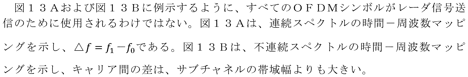
図12Aおよび図12Bならびに図13Aおよび図13Bに例示したような信号の範囲分解能は同じである。OFDMシンボルインデックスに対応する位相補償係数は、図8に記載された受信機における相関を計算する場合に適用される。 The range resolution of the signals illustrated in Figures 12A and 12B and 13A and 13B is the same. The phase compensation coefficients corresponding to the OFDM symbol index are applied when calculating the correlation in the receiver described in Figure 8.
図14Aは、本開示の実施形態による再構成信号1400の分解能の例を示す。図14Aに示す再構成信号1400の例示的な分解能の一実施形態は、例示のみを目的としている。
FIG. 14A illustrates an example of the resolution of a
図14Bは、本開示の実施形態による再構成信号1450の分解能の例を示す。図14Bに示す再構成信号1450の例示的な分解能の一実施形態は、例示のみを目的としている。
FIG. 14B illustrates an example of a resolution of the reconstructed
図14Aは、信号の分解能に対するスペクトルマッピングの影響を示す。連続したサブバンドマッピングのような全帯域幅から信号が再構成される場合、信号は、図14に示されるようにナイキスト比率で再構成される。 Figure 14A shows the effect of spectral mapping on the resolution of a signal. If the signal is reconstructed from the full bandwidth, such as with a contiguous subband mapping, the signal is reconstructed at the Nyquist rate, as shown in Figure 14.

図15は、本開示の実施形態による例示的なレーダおよびコントローラアーキテクチャ1500を示す。図15に示すレーダおよびコントローラアーキテクチャ1500の一実施形態は、例示のみを目的としている。図15に示す構成要素の1つまたは複数は、記載されている機能を実行するように構成された専用回路に実装することができ、または構成要素の1つまたは複数は、記載されている機能を実行するための命令を実行する1つまたは複数のプロセッサによって実装することができる。本開示の範囲から逸脱することなく、他の実施形態が使用される。
FIG. 15 illustrates an exemplary radar and
図15に示すように、レーダおよびコントローラアーキテクチャ1500は、レーダ回路1502(例えば、デジタルレーダ)とコントローラ1520とを含む。デジタルレーダ1502は、TxアンテナDACおよびRF1504と、RxアンテナADCおよびRF1506と、送信機1508と、受信機1510と、MAC1512とを含む。コントローラ1520は、MAC(コントローラ)1522および構成ブロック1530を含む。MAC(コントローラ)1522は、電力制御部1524と、スケジューラ1526と、干渉管理部1528とを含む。構成ブロック1530は、信号構成ブロック1532と、測定構成ブロック1534と、省電力構成ブロック1536とを含む。TxアンテナDACおよびRF1504は、信号を送信するためのアンテナのセットを含み、RxアンテナADCおよびRF1506は、信号を受信するためのアンテナのセットを含む。
15, the radar and
コントローラは、構成エンティティおよび媒体アクセス制御(MAC)エンティティを有する。構成エンティティは、信号構成、測定構成、および省電力構成の設定を担当する。コントローラ内のMACエンティティは、無線リソースを動的に管理する役割を担い、電力制御機能、スケジューラ、および干渉管理回路を備える。 The controller has a configuration entity and a medium access control (MAC) entity. The configuration entity is responsible for setting the signal configuration, measurement configuration, and power saving configuration. The MAC entity in the controller is responsible for dynamically managing the radio resources and includes a power control function, a scheduler, and interference management circuitry.
MACコントローラ内のスケジューラは、時間-周波数リソースおよびシーケンス構成を決定する。 The scheduler in the MAC controller determines the time-frequency resources and sequence configuration.
図15に示すように、ステップ1の一例では、送信電力および最大RF帯域幅などのデバイス能力がデジタルレーダ1502からコントローラ1520に報告される。ステップ2の一例では、ノイズおよび干渉測定などの測定構成がコントローラ1520からデジタルレーダ1502に送信される。ステップ2’の一例では、電力制御構成がコントローラ1520からデジタルレーダ1502に送信される。ステップ3の一例では、デジタルレーダ1502からコントローラ1520に測定結果が報告される。これは、周期的または非周期的であり得る。ステップ4の一例では、MAC構成ブロックおよびスケジューラは、時間-周波数チャネル、シーケンスマッピング、長/短シーケンス選択、シーケンスホッピングおよび周波数ホッピングパターン、ならびにMIMOおよびビーム形成構成を設定する。
As shown in FIG. 15, in one example of
そのような例では、シーケンスおよび時間-周波数リソースは以下のように決定される。シーケンスは送信間隔全体にわたって固定され得、選択されたシーケンスは時間-周波数チャネルごとにランダムに変更され得、選択されたシーケンスは、各サブチャネルの雑音および干渉推定に応じて、レーダMAC内の「スケジューラ」エンティティによってスケジュールされ得る。レーダは、割り当てられた無線リソースに基づいて送信用の信号を構築する。 In such an example, the sequence and time-frequency resources are determined as follows: the sequence may be fixed for the entire transmission interval, the selected sequence may be randomly changed for each time-frequency channel, and the selected sequence may be scheduled by a "scheduler" entity in the radar MAC depending on the noise and interference estimates for each subchannel. The radar constructs the signal for transmission based on the assigned radio resources.
4G、5G、またはWiFi通信システムでは、スケジューラは、レーダ信号の送受信のための時間-周波数リソースを割り当てる。あるいは、構成回路は、レーダ信号送信のための時間-周波数リソースを決定する。 In a 4G, 5G, or WiFi communication system, a scheduler allocates time-frequency resources for transmitting and receiving radar signals. Alternatively, the configuration circuitry determines the time-frequency resources for radar signal transmission.
図16は、UE(例えば、111~116)、BS(例えば、101~103)、または個別の独立したレーダシステムなどのUEまたは基地局にインストールされていないスタンドアロンシステムによって実行され得るような、本開示の実施形態による高分解能デジタルレーダ用の時間-周波数拡散波形のための方法1600のフローチャートを示す。図16に示す方法1600の実施形態は、例示のみを目的としている。図16に示す構成要素の1つまたは複数は、記載されている機能を実行するように構成された専用回路に実装することができ、または構成要素の1つまたは複数は、記載されている機能を実行するための命令を実行する1つまたは複数のプロセッサによって実装することができる。本開示の範囲から逸脱することなく、他の実施形態が使用される。 FIG. 16 illustrates a flow chart of a method 1600 for time-frequency spreading waveforms for high resolution digital radar according to an embodiment of the present disclosure, as may be performed by a UE (e.g., 111-116), a BS (e.g., 101-103), or a standalone system not installed in a UE or base station, such as a separate independent radar system. The embodiment of method 1600 illustrated in FIG. 16 is for illustrative purposes only. One or more of the components illustrated in FIG. 16 may be implemented in dedicated circuitry configured to perform the described functions, or one or more of the components may be implemented by one or more processors executing instructions to perform the described functions. Other embodiments may be used without departing from the scope of the present disclosure.
図16に例示されるように、方法1600は、ステップ1602で開始される。ステップ1602において、装置は、複数のセグメントを含む長一定振幅ゼロ自己相関(CAZAC)シーケンスの離散フーリエ変換(DFT)を識別する。
As illustrated in FIG. 16, the method 1600 begins at
続いて、装置は、ステップ1604において、MACコントローラを介して、複数のセグメントの時間-周波数リソースを識別する。
Then, in
続いて、装置は、ステップ1606において、時間-周波数リソース内の時間-周波数サブチャネルのセットを識別する。
Then, in
次に、装置は、ステップ1608において、複数のセグメントの各々を時間-周波数サブチャネルのセットの各々に順次マッピングする。
The device then sequentially maps each of the multiple segments to each of the set of time-frequency subchannels in
最後に、装置は、ステップ1610において、時間-周波数サブチャネルのセットに基づいて第1の信号を送信する。
Finally, in
一実施形態では、装置は、複数のセグメントの各々を時間-周波数サブチャネルのセットの各々にランダムにマッピングするためにシーケンスホッピング動作を実行し、および/または複数のセグメントの各々をランダムに選択された時間-周波数サブチャネルのセットの各々にマッピングするために周波数ホッピング動作を実行する。 In one embodiment, the device performs a sequence hopping operation to randomly map each of the multiple segments to each of a set of time-frequency subchannels, and/or performs a frequency hopping operation to map each of the multiple segments to each of a set of randomly selected time-frequency subchannels.
一実施形態では、装置は、短いCAZACシーケンスのセットのDFTを識別し、短いCAZACシーケンスのセットの時間-周波数リソースを識別し、時間-周波数リソースは、時間-周波数領域の連続した時間-周波数リソースまたは不連続な時間-周波数リソースを含む。 In one embodiment, the device identifies a DFT of a set of short CAZAC sequences and identifies time-frequency resources of the set of short CAZAC sequences, the time-frequency resources including contiguous time-frequency resources or discontinuous time-frequency resources in the time-frequency domain.
一実施形態では、装置は、時間-周波数リソース内の時間-周波数サブチャネルのセットを識別し、短いCAZACシーケンスのセットの各々を時間-周波数サブチャネルのセットの各々に順次マッピングする。 In one embodiment, the device identifies a set of time-frequency subchannels within a time-frequency resource and sequentially maps each of the set of short CAZAC sequences to each of the set of time-frequency subchannels.
一実施形態では、装置は、短いCAZACシーケンスのセットの各々を時間-周波数サブチャネルのセットの各々にランダムにマッピングするためにシーケンスホッピング動作を実行し、および/または短いCAZACシーケンスのセットの各々をランダムに選択された時間-周波数サブチャネルのセットの各々にマッピングするために周波数ホッピング動作を実行する。 In one embodiment, the device performs a sequence hopping operation to randomly map each of the set of short CAZAC sequences to each of the set of time-frequency subchannels, and/or performs a frequency hopping operation to map each of the set of short CAZAC sequences to each of the set of randomly selected time-frequency subchannels.
一実施形態では、装置は、複数のガードシンボル期間の1つにおいて第2の信号を受信し、第2の信号は第1の信号の反射信号であり、第2の信号の周波数領域変換動作を実行し、周波数領域変換された第2の信号の位相オフセット補償動作を実行し、位相オフセット補償動作は、周波数領域における時間-周波数サブチャネルのセットに対応する。 In one embodiment, the device receives a second signal in one of a plurality of guard symbol periods, the second signal being a reflected signal of the first signal, performs a frequency domain transformation operation on the second signal, and performs a phase offset compensation operation on the frequency domain transformed second signal, the phase offset compensation operation corresponding to a set of time-frequency subchannels in the frequency domain.
一実施形態では、装置は、高速フーリエ変換(FFT)演算を実行する前に、またはFFT演算の計算演算中に、時間領域において第2の信号の位相オフセット補償動作を実行する。 In one embodiment, the device performs a phase offset compensation operation of the second signal in the time domain prior to performing a Fast Fourier Transform (FFT) operation or during the computational operation of the FFT operation.
そのような実施形態では、時間-周波数リソースは、時間-周波数領域における連続した時間-周波数リソースおよび不連続な時間-周波数リソースを含む。 In such an embodiment, the time-frequency resources include contiguous and non-contiguous time-frequency resources in the time-frequency domain.
そのような実施形態では、無線リソースは、送信機が第1の信号を送信するための媒体アクセス制御(MAC)コントローラによって構成される。 In such an embodiment, the radio resources are configured by a medium access control (MAC) controller for the transmitter to transmit the first signal.
そのような実施形態では、無線リソースは、CAZACシーケンスを含むシーケンス情報、連続した時間-周波数リソースと不連続な時間-周波数リソースとを含む時間-周波数リソース情報、時間-周波数リソース内の時間-周波数サブチャネルのセットを含むサブチャネル情報、ならびにCAZACシーケンスに含まれる複数のセグメントを含むシーケンスセグメント情報を含む。 In such an embodiment, the radio resources include sequence information including the CAZAC sequence, time-frequency resource information including contiguous and non-contiguous time-frequency resources, subchannel information including a set of time-frequency subchannels within the time-frequency resources, and sequence segment information including a number of segments included in the CAZAC sequence.
本特許文書全体で使用される特定の単語および語句の定義を説明することが有利であり得る。「アプリケーション」および「プログラム」という用語は、適切なコンピュータコード(ソースコード、オブジェクトコード、または実行可能コードを含む)での実装に適合された、1つまたは複数のコンピュータプログラム、ソフトウェアコンポーネント、命令セット、手順、機能、オブジェクト、クラス、インスタンス、関連データ、またはそれらの一部を指す。「通信する」という用語、ならびにそれらの派生語は、直接的および間接的な通信の両方を包含する。「含む(include)」および「備える(comprise)」という用語、ならびにそれらの派生語は、限定されない包含を意味する。「または」という用語は、包括的であり、および/またはを意味する。「~と関連付けられる」という語句ならびにその派生語は、含む、~内に含まれる、~と相互接続する、~を含有する、~内に含有される、~にもしくは~と接続する、~にもしくは~と結合する、~と通信可能である、~と協働する、インターリーブする、並置する、~に近接する、~にもしくは~と結合される、有する、~の特性を有する、~との関係を有する、などを意味し得る。「~のうちの少なくとも1つ」という語句は、項目のリストと共に使用される場合、列挙された項目のうちの1つまたは複数の異なる組み合わせが使用されてもよく、リスト内の1つの項目のみが必要であってもよいことを意味する。例えば、「A、B、およびCのうちの少なくとも1つ」は、以下の組み合わせのいずれかを含む:A、B、C、AおよびB、AおよびC、BおよびC、ならびにAおよびBおよびC。 It may be advantageous to explain definitions of certain words and phrases used throughout this patent document. The terms "application" and "program" refer to one or more computer programs, software components, instruction sets, procedures, functions, objects, classes, instances, associated data, or portions thereof, adapted for implementation in suitable computer code (including source code, object code, or executable code). The term "communicate" and its derivatives encompass both direct and indirect communication. The terms "include" and "comprise" and their derivatives imply an inclusion without limitation. The term "or" is inclusive and/or. The phrase "associated with" and its derivatives can mean including, contained within, interconnected with, containing, contained within, connected to or with, coupled to or with, communicable with, cooperate with, interleave, juxtapose, adjacent to, coupled to or with, having, having the property of, having a relationship with, and the like. The phrase "at least one of," when used with a list of items, means that different combinations of one or more of the listed items may be used, and only one item in the list may be necessary. For example, "at least one of A, B, and C" includes any of the following combinations: A, B, C, A and B, A and C, B and C, and A and B and C.
本出願における説明は、任意の特定の要素、ステップ、または機能が、特許請求の範囲に含まれなければならない必須または重要な要素であることを暗示するものとして読まれるべきではない。特許になる主題の範囲は、許容される特許請求の範囲によってのみ定義される。さらに、「のための手段(means for)」または「のためのステップ(step for)」という正確な単語が特定の請求項で明示的に使用され、その後にファンクションを識別する特定のフレーズが続く場合を除き、請求項のいずれも、添付の請求項または請求項の要素のいずれかに関して35U.S.C.§112(f)を呼び出すことを意図していない。特許請求の範囲内の「機構」、「モジュール」、「デバイス」、「ユニット」、「構成要素」、「要素」、「部材」、「装置」、「機械」、「システム」、「プロセッサ」、または「コントローラ」などの用語の使用は、特許請求の範囲自体の特徴によってさらに修正または強化されるように、当業者に知られている構造を指すと理解および意図されており、35U.S.C.§112(f)を引き起こすことを意図していない。 No description in this application should be read as implying that any particular element, step, or function is an essential or critical element that must be included in the claims. The scope of patentable subject matter is defined solely by the scope of the allowed claims. Furthermore, none of the claims are intended to invoke 35 U.S.C. §112(f) with respect to any of the appended claims or claim elements, unless the precise words "means for" or "step for" are expressly used in a particular claim, followed by a specific phrase identifying the function. The use of terms such as "mechanism," "module," "device," "unit," "component," "element," "member," "apparatus," "machine," "system," "processor," or "controller" in the claims is understood and intended to refer to structures known to those skilled in the art, as further modified or enhanced by the features of the claims themselves, and is not intended to trigger 35 U.S.C. §112(f).
本開示は特定の実施形態ならびに一般に関連する方法を記載しているが、これらの実施形態および方法の変更および置換は当業者には明らかであろう。したがって、例示的な実施形態の上記の説明は、本開示を定義または限定するものではない。以下の特許請求の範囲によって定義されるように、本開示の範囲から逸脱することなく、他の変更、置換、および改変も可能である。
Although the present disclosure describes certain embodiments and generally related methods, modifications and substitutions of these embodiments and methods will be apparent to those skilled in the art. Therefore, the above description of exemplary embodiments does not define or limit the present disclosure. Other modifications, substitutions, and alterations are possible without departing from the scope of the present disclosure, as defined by the following claims.
Claims (20)
送受信用のアンテナのセットと、送信機と、受信機と、媒体アクセス制御(MAC)コントローラとを含むレーダ回路と、
前記レーダ回路に動作可能に接続されたコントローラであって、前記コントローラが、
複数のセグメントを含む長一定振幅ゼロ自己相関(CAZAC)シーケンスの離散フーリエ変換(DFT)を識別し、
前記MACコントローラを介して、前記複数のセグメントの時間-周波数リソースを識別し、
前記時間-周波数リソース内の時間-周波数サブチャネルのセットを識別し、
前記複数のセグメントの各々を前記時間-周波数サブチャネルのセットの各々に順次マッピングする
ように構成された、コントローラと
を備え、
前記レーダ回路が、前記送信機を介して、前記時間-周波数サブチャネルのセットに基づいて第1の信号を送信するように構成される、装置。 An apparatus for an advanced wireless system, comprising:
a radar circuit including a set of antennas for transmitting and receiving, a transmitter, a receiver, and a medium access control (MAC) controller;
a controller operatively connected to the radar circuitry, the controller comprising:
Identifying a discrete Fourier transform (DFT) of a long constant amplitude zero autocorrelation (CAZAC) sequence comprising a plurality of segments;
Identifying, via the MAC controller, time-frequency resources of the plurality of segments;
identifying a set of time-frequency subchannels within the time-frequency resource;
a controller configured to sequentially map each of the plurality of segments to each of the set of time-frequency subchannels;
The apparatus, wherein the radar circuitry is configured to transmit, via the transmitter, a first signal based on the set of time-frequency subchannels.
前記複数のセグメントの各々を前記時間-周波数サブチャネルのセットの各々にランダムにマッピングするためにシーケンスホッピング動作を実行する、または
前記複数のセグメントの各々をランダムに選択された前記時間-周波数サブチャネルのセットの各々にマッピングするために周波数ホッピング動作を実行する
ようにさらに構成される、請求項1に記載の装置。 The controller:
13. The apparatus of claim 1, further configured to: perform a sequence hopping operation to randomly map each of the plurality of segments to each of the set of time-frequency subchannels; or perform a frequency hopping operation to map each of the plurality of segments to each of the set of randomly selected time-frequency subchannels.
短いCAZACシーケンスのセットのDFTを識別し、
前記短いCAZACシーケンスのセットの前記時間-周波数リソースを前記MACコントローラを介して識別し、前記時間-周波数リソースが、時間-周波数領域の連続した時間-周波数リソースまたは不連続な時間-周波数リソースを含む
ようにさらに構成される、請求項1に記載の装置。 The controller:
Identifying the DFT of a set of short CAZAC sequences;
2. The apparatus of claim 1, further configured to: identify, via the MAC controller, the time-frequency resources of the set of short CAZAC sequences, the time-frequency resources including contiguous time-frequency resources or discontinuous time-frequency resources in a time-frequency domain.
前記時間-周波数リソース内の前記時間-周波数サブチャネルのセットを識別し、
前記短いCAZACシーケンスのセットの各々を前記時間-周波数サブチャネルのセットの各々に順次マッピングする
ようにさらに構成される、請求項3に記載の装置。 The controller:
identifying a set of time-frequency subchannels within the time-frequency resource;
The apparatus of claim 3 , further configured to sequentially map each of the set of short CAZAC sequences to each of the set of time-frequency subchannels.
前記短いCAZACシーケンスのセットの各々を前記時間-周波数サブチャネルのセットの各々にランダムにマッピングするためにシーケンスホッピング動作を実行する、または
前記短いCAZACシーケンスのセットの各々をランダムに選択された前記時間-周波数サブチャネルのセットの各々にマッピングするために周波数ホッピング動作を実行する
ようにさらに構成される、請求項4に記載の装置。 The controller:
5. The apparatus of claim 4, further configured to: perform a sequence hopping operation to randomly map each of the set of short CAZAC sequences to each of the set of time-frequency subchannels; or perform a frequency hopping operation to map each of the set of short CAZAC sequences to each of the set of randomly selected time-frequency subchannels.
前記コントローラが、
前記第2の信号の周波数領域変換動作を実行し、
前記周波数領域変換された第2の信号の位相オフセット補償動作を実行し、前記位相オフセット補償動作が、周波数領域における前記時間-周波数サブチャネルのセットに対応する
ようにさらに構成される、請求項1に記載の装置。 the radar circuit is further configured to receive, via the receiver, a second signal during one of a plurality of guard symbol periods, the second signal being a reflection of the first signal;
The controller:
performing a frequency domain transform operation of said second signal;
The apparatus of claim 1 , further configured to: perform a phase offset compensation operation on the frequency domain transformed second signal, the phase offset compensation operation corresponding to the set of time-frequency subchannels in the frequency domain.
CAZACシーケンスを含むシーケンス情報と、
連続した時間-周波数リソースと不連続な時間-周波数リソースとを含む時間-周波数リソース情報と、
前記時間-周波数リソース内の前記時間-周波数サブチャネルのセットを含むサブチャネル情報と、
前記CAZACシーケンスに含まれる前記複数のセグメントを含むシーケンスセグメント情報と
を含む、請求項9に記載の装置。 The radio resources are
sequence information including a CAZAC sequence;
time-frequency resource information including contiguous time-frequency resources and discontinuous time-frequency resources;
subchannel information including the set of time-frequency subchannels within the time-frequency resource; and
and sequence segment information including the plurality of segments included in the CAZAC sequence.
複数のセグメントを含む長一定振幅ゼロ自己相関(CAZAC)シーケンスの離散フーリエ変換(DFT)を識別するステップと、
前記複数のセグメントの時間-周波数リソースを識別するステップと、
前記時間-周波数リソース内の時間-周波数サブチャネルのセットを識別するステップと、
前記複数のセグメントの各々を前記時間-周波数サブチャネルのセットの各々に順次マッピングするステップと、
前記時間-周波数サブチャネルのセットに基づいて第1の信号を送信するステップと
を含む、方法。 1. An apparatus method for an advanced wireless system, comprising:
Identifying a discrete Fourier transform (DFT) of a long constant amplitude zero autocorrelation (CAZAC) sequence comprising a plurality of segments;
identifying time-frequency resources of the plurality of segments;
identifying a set of time-frequency subchannels within the time-frequency resource;
sequentially mapping each of the plurality of segments to each of the set of time-frequency subchannels;
transmitting a first signal based on the set of time-frequency subchannels.
前記複数のセグメントの各々をランダムに選択された前記時間-周波数サブチャネルのセットの各々にマッピングするために周波数ホッピング動作を実行するステップ
をさらに含む、請求項11に記載の方法。 12. The method of claim 11, further comprising: performing a sequence hopping operation to randomly map each of the plurality of segments to each of the set of time-frequency subchannels; or performing a frequency hopping operation to map each of the plurality of segments to each of the set of randomly selected time-frequency subchannels.
前記短いCAZACシーケンスのセットの前記時間-周波数リソースを識別するステップであって、前記時間-周波数リソースが、時間-周波数領域の連続した時間-周波数リソースまたは不連続な時間-周波数リソースを含む、ステップと
をさらに含む、請求項11に記載の方法。 Identifying the DFT of a set of short CAZAC sequences;
and identifying the time-frequency resources of the set of short CAZAC sequences, the time-frequency resources including contiguous or discontinuous time-frequency resources in a time-frequency domain.
前記短いCAZACシーケンスのセットの各々を前記時間-周波数サブチャネルのセットの各々に順次マッピングするステップと
をさらに含む、請求項13に記載の方法。 identifying the set of time-frequency subchannels within the time-frequency resource;
and sequentially mapping each of the set of short CAZAC sequences to each of the set of time-frequency subchannels.
前記短いCAZACシーケンスのセットの各々をランダムに選択された前記時間-周波数サブチャネルのセットの各々にマッピングするために周波数ホッピング動作を実行するステップ
をさらに含む、請求項14に記載の方法。 15. The method of claim 14, further comprising: performing a sequence hopping operation to randomly map each of the set of short CAZAC sequences to each of the set of time-frequency subchannels; or performing a frequency hopping operation to map each of the set of short CAZAC sequences to each of the set of randomly selected time-frequency subchannels.
前記第2の信号の周波数領域変換動作を実行するステップと、
前記周波数領域変換された第2の信号の位相オフセット補償動作を実行するステップであって、前記位相オフセット補償動作が、周波数領域における前記時間-周波数サブチャネルのセットに対応する、ステップと
をさらに含む、請求項11に記載の方法。 receiving a second signal during one of a plurality of guard symbol periods, the second signal being a reflected signal of the first signal;
performing a frequency domain transform operation of said second signal;
and performing a phase offset compensation operation on the frequency domain transformed second signal, the phase offset compensation operation corresponding to the set of time-frequency subchannels in the frequency domain.
CAZACシーケンスを含むシーケンス情報と、
連続した時間-周波数リソースと不連続な時間-周波数リソースとを含む時間-周波数リソース情報と、
前記時間-周波数リソース内の前記時間-周波数サブチャネルのセットを含むサブチャネル情報と、
前記CAZACシーケンスに含まれる前記複数のセグメントを含むシーケンスセグメント情報と
を含む、請求項19に記載の方法。
The radio resource is
sequence information including a CAZAC sequence;
time-frequency resource information including contiguous time-frequency resources and discontinuous time-frequency resources;
subchannel information including the set of time-frequency subchannels within the time-frequency resource; and
and sequence segment information including the plurality of segments included in the CAZAC sequence.
Applications Claiming Priority (3)
| Application Number | Priority Date | Filing Date | Title |
|---|---|---|---|
| US202062961079P | 2020-01-14 | 2020-01-14 | |
| US62/961,079 | 2020-01-14 | ||
| PCT/US2021/070043 WO2021146755A1 (en) | 2020-01-14 | 2021-01-14 | Time-frequency spread waveform for high-resolution digital radar |
Publications (2)
| Publication Number | Publication Date |
|---|---|
| JP2023510583A JP2023510583A (en) | 2023-03-14 |
| JP7596388B2 true JP7596388B2 (en) | 2024-12-09 |
Family
ID=76864517
Family Applications (1)
| Application Number | Title | Priority Date | Filing Date |
|---|---|---|---|
| JP2022543135A Active JP7596388B2 (en) | 2020-01-14 | 2021-01-14 | Time-frequency spread waveforms for high resolution digital radar. |
Country Status (6)
| Country | Link |
|---|---|
| US (1) | US12360201B2 (en) |
| EP (1) | EP4088396B1 (en) |
| JP (1) | JP7596388B2 (en) |
| KR (1) | KR20230004431A (en) |
| CN (1) | CN115152165B (en) |
| WO (1) | WO2021146755A1 (en) |
Families Citing this family (6)
| Publication number | Priority date | Publication date | Assignee | Title |
|---|---|---|---|---|
| WO2023000196A1 (en) * | 2021-07-21 | 2023-01-26 | Oppo广东移动通信有限公司 | Signal processing method and apparatus, device, and storage medium |
| WO2023114589A1 (en) * | 2021-12-15 | 2023-06-22 | Qualcomm Incorporated | Resource allocation in data communications systems |
| US12111385B2 (en) * | 2021-12-23 | 2024-10-08 | Gm Cruise Holdings Llc | Radar sensor processing chain |
| US12360203B2 (en) * | 2022-04-04 | 2025-07-15 | Nxp B.V. | Phase noise reduction for symmetric bistatic radar |
| KR102618581B1 (en) * | 2023-03-30 | 2023-12-27 | 엘아이지넥스원 주식회사 | Apparatus for estimating signal of notch bandwidth for ultra high resolution radar and method thereof |
| CN119583283B (en) * | 2024-12-03 | 2025-11-07 | 东南大学 | Design method for long-distance high-precision general sense integrated detection waveform |
Citations (4)
| Publication number | Priority date | Publication date | Assignee | Title |
|---|---|---|---|---|
| CN108562883A (en) | 2017-12-29 | 2018-09-21 | 南京航空航天大学 | A kind of maximum likelihood distance estimating algorithm of overloading wave radar system |
| WO2019241390A1 (en) | 2018-06-12 | 2019-12-19 | Aura Intelligent Systems, Inc. | Method and apparatus for an advanced radio system |
| US20200007260A1 (en) | 2017-03-03 | 2020-01-02 | Telefonaktiebolaget Lm Ericsson (Publ) | Sequence Generation |
| US20200003866A1 (en) | 2018-06-29 | 2020-01-02 | Imec Vzw | System and method for performing spillover cancellation |
Family Cites Families (10)
| Publication number | Priority date | Publication date | Assignee | Title |
|---|---|---|---|---|
| US20070183386A1 (en) | 2005-08-03 | 2007-08-09 | Texas Instruments Incorporated | Reference Signal Sequences and Multi-User Reference Signal Sequence Allocation |
| CN101340273B (en) | 2007-07-04 | 2011-01-05 | 华为技术有限公司 | Multiple access method, device and system |
| GB0717031D0 (en) * | 2007-08-31 | 2007-10-10 | Raymarine Uk Ltd | Digital radar or sonar apparatus |
| US8625568B2 (en) | 2007-09-21 | 2014-01-07 | Lg Electronics Inc. | Method of mapping physical resource to logical resource in wireless communication system |
| CN104521294B (en) * | 2013-01-18 | 2019-05-10 | 华为技术有限公司 | Method and device for sending and detecting discovery reference signal |
| US10694392B2 (en) * | 2014-11-06 | 2020-06-23 | Sharp Kabushiki Kaisha | Terminal device, base station device, and method |
| CN109561496B (en) * | 2015-11-06 | 2020-01-03 | 华为技术有限公司 | LAA-LTE system data transmission method, terminal and base station |
| US9930513B2 (en) | 2015-11-23 | 2018-03-27 | Qualcomm Incorporated | Resource allocation for the relaying of device-to-device discovery messages |
| US9689967B1 (en) | 2016-04-07 | 2017-06-27 | Uhnder, Inc. | Adaptive transmission and interference cancellation for MIMO radar |
| WO2018027909A1 (en) | 2016-08-12 | 2018-02-15 | 富士通株式会社 | Mapping and multiplexing method and apparatus for demodulation reference signal, and communication system |
-
2021
- 2021-01-14 JP JP2022543135A patent/JP7596388B2/en active Active
- 2021-01-14 KR KR1020227027569A patent/KR20230004431A/en active Pending
- 2021-01-14 EP EP21740801.2A patent/EP4088396B1/en active Active
- 2021-01-14 WO PCT/US2021/070043 patent/WO2021146755A1/en not_active Ceased
- 2021-01-14 CN CN202180016122.8A patent/CN115152165B/en active Active
- 2021-01-14 US US17/758,879 patent/US12360201B2/en active Active
Patent Citations (4)
| Publication number | Priority date | Publication date | Assignee | Title |
|---|---|---|---|---|
| US20200007260A1 (en) | 2017-03-03 | 2020-01-02 | Telefonaktiebolaget Lm Ericsson (Publ) | Sequence Generation |
| CN108562883A (en) | 2017-12-29 | 2018-09-21 | 南京航空航天大学 | A kind of maximum likelihood distance estimating algorithm of overloading wave radar system |
| WO2019241390A1 (en) | 2018-06-12 | 2019-12-19 | Aura Intelligent Systems, Inc. | Method and apparatus for an advanced radio system |
| US20200003866A1 (en) | 2018-06-29 | 2020-01-02 | Imec Vzw | System and method for performing spillover cancellation |
Also Published As
| Publication number | Publication date |
|---|---|
| CN115152165B (en) | 2024-05-28 |
| US20230033995A1 (en) | 2023-02-02 |
| US12360201B2 (en) | 2025-07-15 |
| KR20230004431A (en) | 2023-01-06 |
| EP4088396C0 (en) | 2025-04-02 |
| EP4088396A4 (en) | 2024-01-17 |
| EP4088396B1 (en) | 2025-04-02 |
| EP4088396A1 (en) | 2022-11-16 |
| JP2023510583A (en) | 2023-03-14 |
| WO2021146755A1 (en) | 2021-07-22 |
| CN115152165A (en) | 2022-10-04 |
Similar Documents
| Publication | Publication Date | Title |
|---|---|---|
| JP7596388B2 (en) | Time-frequency spread waveforms for high resolution digital radar. | |
| US11936477B2 (en) | Sub-band and multi-band coded OFDM for high-resolution radar | |
| JP7605759B2 (en) | Multi-stream MIMO/Beamforming Radar | |
| JP7801208B2 (en) | Power saving in digital radar | |
| US20240255608A1 (en) | Signal structure designs for wireless communication and sensing | |
| KR20230130707A (en) | Transmitter and receiver for high-resolution subband coded time-frequency waveform radar system using bandpass sampling | |
| CN118075901A (en) | Signal transmission method, device and communication equipment | |
| CN117595958A (en) | A communication method and device | |
| US12506527B2 (en) | Coexistence schemes for wireless communication and sensing | |
| US20250274160A1 (en) | Signal sending method and apparatus | |
| WO2024254751A1 (en) | Methods, apparatuses, and devices for communication in integrated sensing and communication systems | |
| CN120345218A (en) | Method and apparatus for transmitting a single carrier signal |
Legal Events
| Date | Code | Title | Description |
|---|---|---|---|
| A621 | Written request for application examination |
Free format text: JAPANESE INTERMEDIATE CODE: A621 Effective date: 20240112 |
|
| A977 | Report on retrieval |
Free format text: JAPANESE INTERMEDIATE CODE: A971007 Effective date: 20241017 |
|
| TRDD | Decision of grant or rejection written | ||
| A01 | Written decision to grant a patent or to grant a registration (utility model) |
Free format text: JAPANESE INTERMEDIATE CODE: A01 Effective date: 20241029 |
|
| A61 | First payment of annual fees (during grant procedure) |
Free format text: JAPANESE INTERMEDIATE CODE: A61 Effective date: 20241127 |
|
| R150 | Certificate of patent or registration of utility model |
Ref document number: 7596388 Country of ref document: JP Free format text: JAPANESE INTERMEDIATE CODE: R150 |