JP7594421B2 - Printing device, printing system, and program - Google Patents
Printing device, printing system, and program Download PDFInfo
- Publication number
- JP7594421B2 JP7594421B2 JP2020200507A JP2020200507A JP7594421B2 JP 7594421 B2 JP7594421 B2 JP 7594421B2 JP 2020200507 A JP2020200507 A JP 2020200507A JP 2020200507 A JP2020200507 A JP 2020200507A JP 7594421 B2 JP7594421 B2 JP 7594421B2
- Authority
- JP
- Japan
- Prior art keywords
- output profile
- page
- type
- decoration
- Prior art date
- Legal status (The legal status is an assumption and is not a legal conclusion. Google has not performed a legal analysis and makes no representation as to the accuracy of the status listed.)
- Active
Links
- 238000007639 printing Methods 0.000 title claims description 160
- 238000005034 decoration Methods 0.000 claims description 137
- 238000000034 method Methods 0.000 claims description 125
- 230000008569 process Effects 0.000 claims description 112
- 238000012545 processing Methods 0.000 claims description 85
- 230000010365 information processing Effects 0.000 claims description 65
- 238000006243 chemical reaction Methods 0.000 claims description 62
- 230000006870 function Effects 0.000 description 65
- 238000004458 analytical method Methods 0.000 description 42
- 238000010586 diagram Methods 0.000 description 33
- 239000000123 paper Substances 0.000 description 24
- 239000003086 colorant Substances 0.000 description 11
- 230000006835 compression Effects 0.000 description 7
- 238000007906 compression Methods 0.000 description 7
- 238000004891 communication Methods 0.000 description 6
- WBMKMLWMIQUJDP-STHHAXOLSA-N (4R,4aS,7aR,12bS)-4a,9-dihydroxy-3-prop-2-ynyl-2,4,5,6,7a,13-hexahydro-1H-4,12-methanobenzofuro[3,2-e]isoquinolin-7-one hydrochloride Chemical compound Cl.Oc1ccc2C[C@H]3N(CC#C)CC[C@@]45[C@@H](Oc1c24)C(=O)CC[C@@]35O WBMKMLWMIQUJDP-STHHAXOLSA-N 0.000 description 4
- 230000006837 decompression Effects 0.000 description 4
- 238000012805 post-processing Methods 0.000 description 4
- 230000004044 response Effects 0.000 description 4
- 230000005540 biological transmission Effects 0.000 description 3
- 230000015572 biosynthetic process Effects 0.000 description 3
- 238000003475 lamination Methods 0.000 description 3
- 239000011111 cardboard Substances 0.000 description 2
- 230000008859 change Effects 0.000 description 2
- 238000012937 correction Methods 0.000 description 2
- 238000011161 development Methods 0.000 description 2
- 238000007599 discharging Methods 0.000 description 2
- 239000010408 film Substances 0.000 description 2
- 238000012986 modification Methods 0.000 description 2
- 230000004048 modification Effects 0.000 description 2
- 239000011087 paperboard Substances 0.000 description 2
- 230000000717 retained effect Effects 0.000 description 2
- 238000012546 transfer Methods 0.000 description 2
- 230000007704 transition Effects 0.000 description 2
- 102100029968 Calreticulin Human genes 0.000 description 1
- 101100326671 Homo sapiens CALR gene Proteins 0.000 description 1
- 238000007405 data analysis Methods 0.000 description 1
- 230000007423 decrease Effects 0.000 description 1
- 238000012217 deletion Methods 0.000 description 1
- 230000037430 deletion Effects 0.000 description 1
- 230000001419 dependent effect Effects 0.000 description 1
- 238000005516 engineering process Methods 0.000 description 1
- 229910052736 halogen Inorganic materials 0.000 description 1
- 150000002367 halogens Chemical class 0.000 description 1
- 239000000463 material Substances 0.000 description 1
- 230000002093 peripheral effect Effects 0.000 description 1
- 229920000740 poly(D-lysine) polymer Polymers 0.000 description 1
- 238000007781 pre-processing Methods 0.000 description 1
Images


Classifications
-
- G—PHYSICS
- G06—COMPUTING; CALCULATING OR COUNTING
- G06F—ELECTRIC DIGITAL DATA PROCESSING
- G06F3/00—Input arrangements for transferring data to be processed into a form capable of being handled by the computer; Output arrangements for transferring data from processing unit to output unit, e.g. interface arrangements
- G06F3/12—Digital output to print unit, e.g. line printer, chain printer
- G06F3/1201—Dedicated interfaces to print systems
- G06F3/1202—Dedicated interfaces to print systems specifically adapted to achieve a particular effect
- G06F3/1203—Improving or facilitating administration, e.g. print management
-
- H—ELECTRICITY
- H04—ELECTRIC COMMUNICATION TECHNIQUE
- H04N—PICTORIAL COMMUNICATION, e.g. TELEVISION
- H04N1/00—Scanning, transmission or reproduction of documents or the like, e.g. facsimile transmission; Details thereof
- H04N1/46—Colour picture communication systems
- H04N1/56—Processing of colour picture signals
- H04N1/60—Colour correction or control
- H04N1/6097—Colour correction or control depending on the characteristics of the output medium, e.g. glossy paper, matt paper, transparency or fabrics
-
- G—PHYSICS
- G06—COMPUTING; CALCULATING OR COUNTING
- G06F—ELECTRIC DIGITAL DATA PROCESSING
- G06F3/00—Input arrangements for transferring data to be processed into a form capable of being handled by the computer; Output arrangements for transferring data from processing unit to output unit, e.g. interface arrangements
- G06F3/12—Digital output to print unit, e.g. line printer, chain printer
- G06F3/1201—Dedicated interfaces to print systems
- G06F3/1202—Dedicated interfaces to print systems specifically adapted to achieve a particular effect
- G06F3/1203—Improving or facilitating administration, e.g. print management
- G06F3/1208—Improving or facilitating administration, e.g. print management resulting in improved quality of the output result, e.g. print layout, colours, workflows, print preview
-
- G—PHYSICS
- G06—COMPUTING; CALCULATING OR COUNTING
- G06F—ELECTRIC DIGITAL DATA PROCESSING
- G06F3/00—Input arrangements for transferring data to be processed into a form capable of being handled by the computer; Output arrangements for transferring data from processing unit to output unit, e.g. interface arrangements
- G06F3/12—Digital output to print unit, e.g. line printer, chain printer
- G06F3/1201—Dedicated interfaces to print systems
- G06F3/1202—Dedicated interfaces to print systems specifically adapted to achieve a particular effect
- G06F3/1211—Improving printing performance
-
- G—PHYSICS
- G06—COMPUTING; CALCULATING OR COUNTING
- G06F—ELECTRIC DIGITAL DATA PROCESSING
- G06F3/00—Input arrangements for transferring data to be processed into a form capable of being handled by the computer; Output arrangements for transferring data from processing unit to output unit, e.g. interface arrangements
- G06F3/12—Digital output to print unit, e.g. line printer, chain printer
- G06F3/1201—Dedicated interfaces to print systems
- G06F3/1223—Dedicated interfaces to print systems specifically adapted to use a particular technique
- G06F3/1237—Print job management
- G06F3/1253—Configuration of print job parameters, e.g. using UI at the client
- G06F3/1257—Configuration of print job parameters, e.g. using UI at the client by using pre-stored settings, e.g. job templates, presets, print styles
-
- G—PHYSICS
- G06—COMPUTING; CALCULATING OR COUNTING
- G06F—ELECTRIC DIGITAL DATA PROCESSING
- G06F3/00—Input arrangements for transferring data to be processed into a form capable of being handled by the computer; Output arrangements for transferring data from processing unit to output unit, e.g. interface arrangements
- G06F3/12—Digital output to print unit, e.g. line printer, chain printer
- G06F3/1201—Dedicated interfaces to print systems
- G06F3/1278—Dedicated interfaces to print systems specifically adapted to adopt a particular infrastructure
- G06F3/1285—Remote printer device, e.g. being remote from client or server
- G06F3/1288—Remote printer device, e.g. being remote from client or server in client-server-printer device configuration
-
- H—ELECTRICITY
- H04—ELECTRIC COMMUNICATION TECHNIQUE
- H04N—PICTORIAL COMMUNICATION, e.g. TELEVISION
- H04N1/00—Scanning, transmission or reproduction of documents or the like, e.g. facsimile transmission; Details thereof
- H04N1/46—Colour picture communication systems
- H04N1/56—Processing of colour picture signals
- H04N1/60—Colour correction or control
-
- G—PHYSICS
- G06—COMPUTING; CALCULATING OR COUNTING
- G06F—ELECTRIC DIGITAL DATA PROCESSING
- G06F3/00—Input arrangements for transferring data to be processed into a form capable of being handled by the computer; Output arrangements for transferring data from processing unit to output unit, e.g. interface arrangements
- G06F3/12—Digital output to print unit, e.g. line printer, chain printer
- G06F3/1201—Dedicated interfaces to print systems
- G06F3/1202—Dedicated interfaces to print systems specifically adapted to achieve a particular effect
- G06F3/1203—Improving or facilitating administration, e.g. print management
- G06F3/1204—Improving or facilitating administration, e.g. print management resulting in reduced user or operator actions, e.g. presetting, automatic actions, using hardware token storing data
Landscapes
- Engineering & Computer Science (AREA)
- Theoretical Computer Science (AREA)
- Human Computer Interaction (AREA)
- Physics & Mathematics (AREA)
- General Engineering & Computer Science (AREA)
- General Physics & Mathematics (AREA)
- Quality & Reliability (AREA)
- Multimedia (AREA)
- Signal Processing (AREA)
- Accessory Devices And Overall Control Thereof (AREA)
- Color Image Communication Systems (AREA)
- Image Processing (AREA)
- Color, Gradation (AREA)
- Facsimile Image Signal Circuits (AREA)
Description
本発明は、印刷装置、印刷システム、およびプログラムに関するものである。 The present invention relates to a printing device, a printing system, and a program.
商業印刷においては、グラフィックソフトウェアなどで作成した印刷ファイル(PDL(Page Description Language)で記述されたファイル)が印刷会社に入稿される。この場合、グラフィックソフトウェアで用いられる色空間であるRGB色空間で表現できる色域と、印刷に用いられる色空間であるCMYK色空間で表現できる色域の差異によって、入稿したPDLの色味と実際の印刷物の色味が異なってしまうことがある。また、RGB色空間やCMYK色空間は、出力デバイスに依存する色空間であるため、同じ色空間、同じ色値であっても出力デバイスによって色味が異なる。 In commercial printing, print files (files written in PDL (Page Description Language)) created using graphic software are submitted to a printing company. In this case, the colors in the submitted PDL may differ from the colors in the actual printout due to differences between the color gamut that can be expressed in the RGB color space used in the graphic software, and the CMYK color space used in printing. Furthermore, because the RGB color space and CMYK color space are color spaces that depend on the output device, the colors may differ depending on the output device, even if the same color space and color values are used.
上記の課題を解決するために、プロファイルと呼ばれる、デバイスに非依存な色空間との対応テーブルを用いて色の変換を行うことで、入力データと出力物の色味の誤差を抑える方法が知られている。ここで、デバイスに非依存な色空間とは、例えばLab色空間などである。 To solve the above problem, a method is known that reduces the color error between the input data and the output by converting colors using a correspondence table with a device-independent color space called a profile. Here, the device-independent color space is, for example, the Lab color space.
上記の変換を行う際には、入力側の色空間やデバイス特性を考慮して作成された入力プロファイルによって入力データをデバイス非依存の色空間で表現された中間データに変換する。そして、出力側の色空間やデバイス特性を考慮して作成された出力プロファイルによって中間データを出力データに変換する。 When performing the above conversion, the input data is converted into intermediate data expressed in a device-independent color space using an input profile created with consideration of the input's color space and device characteristics. The intermediate data is then converted into output data using an output profile created with consideration of the output's color space and device characteristics.
このとき、正確な色味で印刷するためには、出力プロファイルはデバイス特性だけでなく、印刷メディアの表面性や厚さなども考慮して作成する必要があるため、印刷メディア毎に用意することが望ましい。 In order to print with accurate colors, the output profile must be created taking into account not only the device characteristics but also the surface properties and thickness of the printing media, so it is advisable to prepare one for each printing medium.
上記の複数用意されたプロファイルを適切に使用するため、印刷メディアに対して出力プロファイルをあらかじめ紐づけておくことで、ジョブ毎に出力プロファイルを設定することなく紐づけた出力プロファイルを自動的に適用する一方策が提案されている。以後、この機能によりメディアに紐づいたプロファイルをMLP(Media Link Profile)と記載する。 In order to use the multiple prepared profiles appropriately, a method has been proposed in which an output profile is linked to the print media in advance, and the linked output profile is automatically applied without having to set an output profile for each job. Hereafter, a profile linked to media using this function will be referred to as an MLP (Media Link Profile).
それによれば、出力プロファイルを含む画像処理情報を印刷メディアの表裏面それぞれに紐づけて保管しておき、画像に対して、その画像が記録される面に紐づけられた画像処理情報に基づいた画像処理を施す。 According to this method, image processing information including an output profile is stored in association with each of the front and back sides of a print medium, and the image is subjected to image processing based on the image processing information associated with the side on which the image is recorded.
上記の従来技術によると、両面印刷や複数種類の用紙への印刷の際に、各画像が印刷されるページのメディア特性を逐一把握した上でそれぞれに画像処理情報を設定する必要がなくなるため、設定が容易になり、設定の誤りもなくなる。しかし、印刷メディアへの加飾に伴い、出力プロファイルの調整が必要となる場合への対応が考慮されていないという課題がある。 The above-mentioned conventional technology eliminates the need to understand the media characteristics of each page on which an image is printed and set image processing information for each when printing on both sides or multiple types of paper, making settings easier and eliminating setting errors. However, there is an issue in that it does not take into consideration cases where adjustments to the output profile are required when decorating the print media.
前述のとおり、基本的にはMLPを使用することで設定が容易になるが、印刷メディアに対してラミネート処理などの加飾を施した場合、MLPでは期待通りの色味が再現できなくなってしまうことがある。 As mentioned above, using MLP generally makes setup easier, but if you apply decoration to the print media, such as lamination, MLP may not be able to reproduce the colors as expected.
上記のように印刷メディアに加飾が施される場合、従来だとMLPを使用する設定を変更して、改めて各ページに出力プロファイルを設定する必要があった。これでは、例えばただ1ページにのみ加飾を使用した場合などでも、全ページに対して出力プロファイルを設定し直す必要があり、MLPを十分活用できていなかった。 When decoration is applied to print media as described above, it was previously necessary to change the settings for using MLP and set the output profile again for each page. This meant that even if decoration was used on only one page, for example, it was necessary to set the output profile again for all pages, and MLP could not be fully utilized.
本発明は上記従来例に鑑みて成されたもので、良好な発色のために適した出力プロファイルを簡易に設定し、高品質の印刷物を作成することを目的とする。 The present invention was made in consideration of the above-mentioned conventional examples, and aims to easily set an output profile suitable for good color development and create high-quality printed matter.
上記目的を達成するため、本発明は以下の構成を備える。すなわち、本発明の一態様によれば、印刷メディアの種類を出力プロファイルに関連付けたテーブルを格納する格納手段と、
処理対象の印刷ジョブに含まれたページそれぞれについて、前記出力プロファイルが設定されているページであれば当該出力プロファイルを用いて色変換を行い、前記出力プロファイルが設定されていないページであれば、前記テーブルを参照して当該ページについて設定された前記印刷メディアの種類に関連付けられた前記出力プロファイルを用いて色変換を行って印刷を実行する処理手段と
を有する印刷装置が提供される。
In order to achieve the above object, the present invention has the following configuration: That is, according to one aspect of the present invention, a storage unit for storing a table that associates types of print media with output profiles;
A printing device is provided that has a processing means for, for each page included in a print job to be processed, performing color conversion using the output profile if the page has an output profile set therefor, and for a page to which the output profile is not set, referring to the table and performing color conversion using the output profile associated with the type of print media set for the page, thereby executing printing.
あるいは、他の態様によれば、印刷ジョブを作成する情報処理装置と印刷ジョブを実行して印刷を行う印刷装置とを含む印刷システムであって、
前記情報処理装置は、
印刷メディアの種類と加飾処理の種類と出力プロファイルとを関連付けた第1のテーブルを格納する格納手段と、
ページごとの前記印刷メディアの種類と前記加飾処理の種類とを設定し、前記第1のテーブルを参照して前記加飾処理が設定されたページの出力プロファイルを設定した印刷ジョブを作成する作成手段と、
前記印刷装置に前記印刷ジョブを送信する手段とを有し、
前記印刷装置は、
印刷メディアの種類を出力プロファイルに関連付けた第2のテーブルを格納する格納手段と、
処理対象の印刷ジョブに含まれたページそれぞれについて、前記出力プロファイルが設定されているページであれば当該出力プロファイルを用いて色変換を行い、前記出力プロファイルが設定されていないページであれば、前記第2のテーブルを参照して当該ページについて設定された前記印刷メディアの種類に関連付けられた前記出力プロファイルを用いて色変換を行って印刷を実行する処理手段とを有する印刷システムが提供される。
According to another aspect, there is provided a printing system including an information processing device that creates a print job and a printing device that executes the print job and performs printing,
The information processing device includes:
a storage means for storing a first table that associates types of print media, types of decoration processing, and output profiles;
a creating means for creating a print job in which a type of the print medium and a type of the decoration processing are set for each page, and an output profile for the page on which the decoration processing is set is set by referring to the first table;
means for transmitting the print job to the printing device;
The printing device includes:
a storage means for storing a second table that associates types of print media with output profiles;
A printing system is provided which has a processing means for performing color conversion using the output profile for each page included in the print job to be processed if the page has an output profile set therefor, and for a page to which the output profile is not set, referring to the second table and performing color conversion using the output profile associated with the type of print media set for the page, thereby executing printing.
さらに他の態様によれば、印刷ジョブを作成する情報処理装置であって、
印刷メディアの種類と加飾処理の種類と出力プロファイルとを関連付けたテーブルを格納する格納手段と、
ページごとの前記印刷メディアの種類と前記加飾処理の種類とを設定し、前記テーブルを参照して前記加飾処理が設定されたページの出力プロファイルを設定した印刷ジョブを作成する作成手段と、
前記印刷装置に前記印刷ジョブを送信する手段とを有する
情報処理装置が提供される。
According to yet another aspect, there is provided an information processing apparatus for creating a print job, comprising:
a storage means for storing a table that associates types of print media, types of decoration processing, and output profiles;
a creating means for creating a print job by setting the type of print medium and the type of decoration processing for each page, and by referring to the table and setting an output profile for the page on which the decoration processing is set;
and means for transmitting the print job to the printing device.
本発明によれば、良好な発色のために適した出力プロファイルを簡易に設定し、高品質の印刷物を作成することができる。 The present invention makes it possible to easily set an output profile suitable for good color development and produce high-quality printed material.
以下、添付図面を参照して実施形態を詳しく説明する。なお、以下の実施形態は特許請求の範囲に係る発明を限定するものでない。実施形態には複数の特徴が記載されているが、これらの複数の特徴の全てが発明に必須のものとは限らず、また、複数の特徴は任意に組み合わせられてもよい。さらに、添付図面においては、同一若しくは同様の構成に同一の参照番号を付し、重複した説明は省略する。 The following embodiments are described in detail with reference to the attached drawings. Note that the following embodiments do not limit the invention according to the claims. Although the embodiments describe multiple features, not all of these multiple features are necessarily essential to the invention, and multiple features may be combined in any manner. Furthermore, in the attached drawings, the same reference numbers are used for the same or similar configurations, and duplicate explanations are omitted.
<システム構成の説明>
図1は、本発明の実施形態に係る印刷処理システムを示すブロック図である。本実施形態では印刷装置101の一例としてMFP(Multifunction Peripheral)を、情報処理装置の一例として情報処理装置102を説明する。MFPは多機能複写機とも呼ばれ、画像形成機能に着目して画像形成装置と呼ばれることもある。また印刷処理システムのことを印刷システムあるいは画像形成システムと呼ぶこともある。印刷処理システムでは、印刷装置101と情報処理装置102がネットワーク100を介して通信可能に接続されている。
<System configuration>
1 is a block diagram showing a print processing system according to an embodiment of the present invention. In this embodiment, an MFP (Multifunction Peripheral) is described as an example of a
なお、図1においては、1つの情報処理装置102が印刷処理システムに設けられた場合を例示しているが、印刷装置101と複数の情報処理装置がネットワーク100を介して通信可能に接続されていてもよく、情報処理装置の数に特に制限はない。また、本実施形態の印刷処理システムは、印刷装置と情報処理装置とを含む場合を例示しているが、これに限定されるものではない。例えば、印刷装置を印刷処理システムとしてもよい。この場合には本実施形態における情報処理装置102が果たす機能を印刷装置101が果たす。
Note that FIG. 1 illustrates an example in which one
●情報処理装置
まず情報処理装置102について説明する。情報処理装置102は、印刷ジョブ(以下、単にジョブと呼ぶことがある)を投入するアプリケーションプログラム等の各種のプログラムを実行することができる。また、情報処理装置102には、文書や画像等の元データを、印刷装置101に対応するプリンタ言語で記述された印刷データに変換する機能を有するプリンタドライバがインストールされている。印刷を行いたいユーザは各種のアプリケーションなどから印刷指示を行うことができる。プリンタドライバは印刷指示に基づいてアプリケーションが出力するデータを印刷装置101が解釈可能な印刷データに変換し、ネットワーク100に接続された印刷装置101に印刷データを送信することができる。
Information Processing Device First, the
なお、本実施形態では、情報処理装置の一例としてPCを例示しているが、例えばスマートフォンやタブレット端末などの携帯情報端末などであってもよい。なお、印刷データを印刷装置に送信する方法は適宜変形できる。印刷用のアプリケーション又はドライバを介して印刷装置101に印刷データを送信するようにしてもよいし、印刷データをクラウドサーバー経由で印刷装置101へ送信するようにしてもよい。
In this embodiment, a PC is used as an example of an information processing device, but it may also be a mobile information terminal such as a smartphone or a tablet terminal. The method of sending print data to the printing device may be modified as appropriate. The print data may be sent to the
●印刷装置
次に印刷装置101について説明する。印刷装置101はシート上の画像を読み取る読取機能、シートに画像を印刷する印刷機能を有する。また、印刷装置101は、画像が印刷された複数のシートをとじたり、複数のシートを揃えたり、複数のシートの排出先を複数のトレイに分けたりする後処理機能を有する。なお、シートには、普通紙や厚紙などの用紙や、フィルムなどが含まれる。
Printing Device Next, the
本実施形態では印刷装置の一例として印刷装置101を説明するが、例えば、読取機能を有さないプリンタ等の印刷装置であってもよい。また、印刷装置101が有する機能の一部やその他の付属的な機能を有する装置103をMFPに付加した構成を取っても構わない。この場合、情報処理装置102からは、ネットワーク100を経由して、装置103が印刷装置101の機能を提供しているように見なすことが可能である。装置103は、例えばモニタ105等の、情報処理装置102が備えるのと同様の各種入出力装置が付随されうる。また、このような付随する装置103が装着されていた場合であっても、印刷装置101は、ネットワークケーブル104を使用して、直接ネットワーク100に接続可能なように構成されていても構わない。
In this embodiment, the
印刷装置101は、複数の異なる役割を持つ装置が相互に連結され、複雑なシート処理が可能なように構成されている。以下、この印刷装置101を構成する各部位に関して説明する。
The
プリンタ部201は、画像データに基づいて、給紙部から給紙されたシートにトナーを用いて画像を形成(印刷)する。このプリンタ部201の構成及び動作原理は以下のとおりである。
The
画像データに応じて変調された、例えばレーザ光などの光線を回転多面鏡(ポリゴンミラー等)により反射し、その反射光が感光ドラム上を走査露光する。このレーザ光により感光ドラム上に形成された静電潜像はトナーによって現像され、転写ドラムに貼り付けられたシートに、そのトナー像が転写される。この一連の画像形成プロセスをイエロー(Y)、マゼンタ(M)、シアン(C)、ブラック(K)のトナーに対して順次実行することにより、シート上にフルカラー画像が形成される。また、これら4色に加え、特色と呼ぶトナーや、透明トナーなどを転写可能とする構成としても良い。こうしてフルカラー画像が形成された転写ドラム上のシートは定着器へ搬送される。定着器は、ローラやベルト等を含み、ローラ内にハロゲンヒータなどの熱源を内蔵し、トナー像が転写されたシート上のトナーを、熱と圧力によって溶解してシートに定着させる。 A beam of light, such as a laser beam, modulated according to image data is reflected by a rotating polygon mirror (polygon mirror, etc.), and the reflected light scans and exposes the photosensitive drum. The electrostatic latent image formed on the photosensitive drum by this laser beam is developed with toner, and the toner image is transferred to a sheet attached to the transfer drum. A full-color image is formed on the sheet by sequentially executing this series of image formation processes for yellow (Y), magenta (M), cyan (C), and black (K) toners. In addition to these four colors, a configuration may be adopted in which toners called special colors and transparent toners can be transferred. The sheet on the transfer drum on which the full-color image has been formed in this way is transported to a fixing device. The fixing device includes rollers, belts, etc., and has a heat source such as a halogen heater built into the roller, and uses heat and pressure to melt the toner on the sheet on which the toner image has been transferred and fix it to the sheet.
なお、本実施形態に係る印刷装置101のプリンタ部201には、スキャナ203、及びプリンタ部201の上面に配置された操作部204が備え付けられている。操作部204は、実施形態に係るプリンタ部201の各種設定や操作などをユーザが行う場合の各種インタフェースを提供する。本実施形態における操作部204は、図11に記載の印刷装置の設定、すなわち「メディアリンクプロファイル使用指定」「出力プロファイル指定」「加飾時の出力プロファイル指定」を含む。これらの設定の詳細については後述する。
The
更にこの印刷装置101は、プリンタ部201に加え各種付随装置が装着可能なよう構成されている。
Furthermore, this
大容量給紙装置220は、プリンタ部201に脱着可能な給紙装置である。これら給紙装置は、複数の給紙部223を備える。このような構成により、プリンタ部201は、大容量のシートへの印刷処理を行うことができる。
The large-capacity
インサータ221は、プリンタ部201によって作成されたシートに対して画像形成を伴わないシートを成果物に挿入する際に用いられる装置である。同図においては2つのトレイ224,225を備える形態の装置を示している。
The
この印刷装置101は、プリンタ部201を境界とし、大きく3つの部位に分けることができる。図1において、プリンタ部201より右側に配置される参照符号200の機器は、給紙系装置と呼ばれる。給紙系装置の主な役割は内部に装填されているシートを適切なタイミングで連続的にプリンタ部201に供給することである。また、給紙系装置は、内部に装填されているシート残量の検知なども行う。プリンタ部201の内部にも給紙部223が存在し、機能的には給紙系装置と同等のことを実行することができる。プリンタ部201が備えるこれら給紙部についても説明の上では給紙系装置と呼ぶこととする。
This
一方、図1において、プリンタ部201よりも左側に配置される参照符号202の機器は、シート加工装置と呼ばれる。また、シート処理装置、または後処理装置とも呼ばれる。シート加工装置は、印刷処理が完了したシートに各種加工処理を加える、または集積するなどの処理を行う。前述の給紙系装置200及びシート加工装置202を併せて以後の説明においてシート処理装置200、202と呼ぶ。
On the other hand, in FIG. 1, the device with
画像形成が完了しし、設定に応じた後処理が施された印刷済みシート(印刷物)や、挿入されたシートは、設定に応じて排紙トレイ226,227や排紙デッキ228に排出される。
After image formation is complete, the printed sheet (printed matter) that has been subjected to post-processing according to the settings, or the inserted sheet, is discharged to the
<印刷装置101の説明>
図2は、印刷装置101のハードウェア構成について説明する図である。印刷装置101は、シート上の画像を読み取る読取機能、シートに画像を印刷する印刷機能を有する。また、印刷装置101は、画像が印刷された複数のシートを綴じたり、複数のシートを揃えたり、複数のシートの排出先を複数のトレイに分けたりする後処理機能を有する。なお、シートには、普通紙や厚紙などの用紙、フィルムシートなどが含まれる。
<Description of
2 is a diagram for explaining the hardware configuration of the
同図に示す印刷装置101は、複数の異なる役割を持つ装置が相互に連結され、複雑なシート処理が可能なよう構成されている。
The
また印刷装置101は、スキャナ部203から受付けたデータをHDD209に記憶し、そのHDD209から読み出してプリンタ部201で印刷するコピー機能を有する。また、外部装置から通信部の一例である外部I/F部210ユニットを介して受信したジョブデータをHDD209に記憶し、HDD209から読み出してプリンタ部201で印刷する印刷機能等を有する。印刷装置101は、このような複数の機能を備えた多機能処理装置(MFP)(印刷装置とも呼ぶ)である。尚、この印刷装置101は、カラープリント可能、或いはモノクロプリント可能のいずれでも良い。
The
スキャナ部203は、原稿画像を読み取り、その原稿を読み取って得られた画像データを画像処理して出力する。
The
制御装置205のCPUがROM207及びHDD209に記憶されているプログラムを読み出して実行することにより、本実施形態に係る各種動作を印刷装置101により実行させる。また制御装置205が、外部I/F210を介して外部装置から受信したページ記述言語(以下PDLと略す)データを解釈し、ラスタイメージデータ(ビットマップ画像データ)に展開する動作を実行するプログラム等もROM207に記憶されている。同様に、制御装置205が、外部I/F210を介して外部装置から受信したジョブを解釈して処理するためのプログラム等もROM207に記憶されている。ROM207は読み出し専用のメモリで、ブートシーケンスやフォント情報等のプログラムや上記のプログラム等の各種プログラムを予め記憶している。ROM207に格納される各種プログラムの詳細については後述する。RAM208は読み出し及び書き込み可能なメモリで、スキャナ203や外部I/F210より送られてきた画像データや、各種プログラムや設定情報等を記憶する。
The CPU of the
またHDD209は、圧縮展開部206によって圧縮された画像データを記憶する。このHDD209は、処理対象となるジョブのプリントデータ等の複数のデータを保持可能に構成されている。制御装置205は、スキャナ部203や外部I/F210等の各種入力ユニットを介して入力された処理対象となるジョブのデータを、このHDD209に格納し、HDD209から読み出してプリンタ部201に出力してプリントする。又、制御装置205は、HDD209から読み出したジョブデータを、外部I/F210を介して外部装置へ送信できるようにも制御する。このように制御装置205は、HDD209に格納した処理対象ジョブのデータの各種出力処理を実行する。圧縮展開部206は、JBIGやJPEG等といった各種圧縮方式によってRAM208、HDD209に記憶されている画像データ等を圧縮したり伸張したりする。また制御装置205は、シート処理装置200、202の動作も制御する。シート処理装置200、202は、図1で説明した給紙系装置及びシート加工装置に相当する。
The
外部I/F210は、ファクシミリ、ネットワーク接続機器、外部専用装置と画像データなどを送受信する。HDD209には、この印刷装置101によって永続的に記憶及び変更、管理される各種管理情報なども格納される。又、印刷装置101は、HDD209に記憶された印刷対象のジョブのデータの印刷処理を実行するプリンタ部201を備える。印刷装置101は、ユーザインタフェース部の一例に該当する、表示部を有する操作部204も備えている。印刷装置101が備える制御装置の一例に該当する制御装置205は図示しないCPUを有し、この印刷装置101が備える各種ユニットの処理や動作等を統括的に制御する。ROM207には、制御装置205により実行される後述するフローチャートの各種処理等を実行するためのプログラムを含む、本実施形態で必要な各種の制御プログラムが記憶されている。又、ROM207には、ユーザインタフェース画面(以下、UI画面)を含む、操作部204の表示部に各種のUI画面を表示させるための表示制御プログラムも記憶されている。
The external I/
<情報処理装置102の説明>
図3は、実施形態に係る情報処理装置(PC)102の構成を示すブロック図である。
<Description of
FIG. 3 is a block diagram showing the configuration of the information processing apparatus (PC) 102 according to the embodiment.
同図において、CPU301は、ROM303のプログラム用ROMに記憶された、或いはHDD311からRAM302にロードされたOSや一般アプリケーション、製本アプリケーション等のプログラムを実行する。ROM303は、またフォントROMやデータROMを有している。RAM302は、CPU301の主メモリ、ワークエリア等として機能する。キーボードコントローラ(KBC)305は、キーボード(KB)309やポインティングデバイス(不図示)からの入力を制御する。表示コントローラ(CRTC)306は、表示部(CRT)310への表示を制御する。ディスクコントローラ(DKC)307は、ブートプログラム、種々のアプリケーション、フォントデータ、ユーザファイル等を記憶するHDD311等とのアクセスを制御する。ネットワークコントローラ(NC)312は、ネットワーク100に接続されて、そのネットワーク100に接続された他の機器との通信制御処理を実行する。バス304は、CPU301とRAM302、ROM303及び各種コントローラ等を接続して、データ信号や制御信号を搬送している。
In the figure, the
<印刷装置101のソフトウェア構成図>
図4は、実施形態に係る印刷装置101のプログラムを説明する図である。これらプログラムはROM207に格納され、印刷装置101が備える制御装置205、特にそのCPUあるいはプロセッサーにより読み出されて実行される。
<Software configuration of the
4 is a diagram for explaining programs of the
オペレーティングシステム401は、印刷装置101の機能を実現する各種プログラムの実行環境を提供することを目的としたプログラムである。これは、主に印刷装置101のメモリ、即ちROM207やRAM208,HDD209等の資源管理、及び図2に示す各部の基本的な入出力制御等の機能を提供する。
The
データ送受信プログラム402は、外部I/F210を経由してデータの入出力要求が発生した際に行われる送受信処理を行う。具体的には、TCP/IP等のプロトコルスタックを内包し、ネットワーク100経由で接続される外部機器等との間で交わされる各種データの通信を制御する。ここで行われる通信処理は、データパケットの送受信レベルやHTTPサーバー等の通信処理に特化した処理で、後述する受信したデータの内容に関する解析処理は含まない。データの解析処理は、制御装置205によって別プログラムの記述内容に基づいて実行される。
The data transmission/
コピー機能プログラム403は、印刷装置101ユーザが、操作部204からコピーファンクションの実行を指示した際に、その操作部204からの指示により制御装置205によって実行されるコピー機能を実行するためのプログラムである。制御装置205によって行われるコピー機能では、印刷装置101の資源を、このプログラムに記述された処理順序、処理条件に基づいて制御装置205によって適切な順序でこれら各デバイスの動作を順次指示する。それにより最終的にコピー処理が実行されるように制御される。これら各デバイスには、スキャナ部203やプリンタ部201、シート処理装置200、202、HDD209、圧縮伸張部206、RAM208等が含まれる。
The
スキャン機能プログラム404は、印刷装置101のユーザが操作部204からスキャン機能の実行を指示した際に、操作部204からの指示により制御装置205によって実行されるスキャン機能を実行するためのプログラムである。スキャナ部203、HDD209、圧縮伸張部206、RAM208等のモジュールが、このプログラムに記述された処理順序、処理条件に従って制御装置205によって制御される。その際に、適切な順序でこれら各デバイスの動作を順次指示することにより最終的にスキャン処理が実行されるように制御される。
The
PDL機能プログラム405は、PDLデータ(印刷ジョブデータ)が外部I/F210経由で印刷装置101によって受信された場合に、制御装置205によって実行されるPDL機能を実行する。制御装置205によって行われるPDL機能では、指定されたPDLファイルの解析処理を行い、印刷画像を作成する。PDLファイルの解析処理にはJDF(Job Description Format)機能プログラム406がJDFを解析して得られた印刷設定を使用する。JDFとは、面付け、給紙、排紙、仕上げ、プロファイルなど、印刷に関わる様々な指定を行うことのできるジョブチケットのフォーマットの一つである。
The
JDF機能プログラム406は、JDFジョブデータが外部I/F210経由で印刷装置101に受信された場合に、外部I/F210の指示で制御装置205によって実行されるJDF機能を実行するプログラムである。制御装置205によって行われるJDF機能では、受信したJDFの解析処理を行い、印刷に使用する印刷設定を作成する。本実施形態におけるJDF機能プログラム406は、JDFのうちPDL部812のみを解析し、PDLのURLを取得する機能を有する。また、図7のフローチャートに記載の各種設定を作成する機能を有する。解析した結果JDFに正しくない設定が含まれるか否かの判別処理、及び正しくない設定を解消するための設定変更等を行うプログラムも含まれている。
The
BOX機能プログラム407は、印刷装置101のユーザが操作部204からBOXファンクションの実行を指示した際に、操作部204からの指示により制御装置205によって実行されるBOX機能を実行する。このBOX機能では、このプログラムに記述された処理順序、処理条件に基づいて制御装置205によって適切な順序でこれら各デバイスの動作を順次指示することによりBOX処理が実行される。これらデバイスには、スキャナ部203やプリンタ部201、シート処理装置200、202、HDD209、圧縮伸張部206、RAM208等が含まれる。また、このボックス機能によりHDD209に格納されたジョブデータを、格納時のそのジョブの設定を変更して、そのジョブを実行できる。
When the user of the
ホールド機能プログラム408は、印刷装置101のユーザが操作部204からホールド機能の実行を指示した際に、制御装置205によって実行されるプログラムである。ホールド機能は、印刷装置101のHDD209に印刷対象のデータをユーザから印刷指示があるまで記憶しておき、その後、ユーザから印刷指示を受け付けたデータに従って印刷を実行する機能である。ホールド機能では、このプログラムに記述された処理順序、処理条件に基づいて制御装置205によって適切な順序でこれら各デバイスの動作を順次指示することによりジョブホールドによる印刷処理が実行される。これらデバイスには、プリンタ部201、シート処理装置200、202、HDD209、圧縮伸張部206、RAM208等が含まれる。格納されたジョブデータに対して、格納時の設定を変更して実行することが可能である。
The
UI機能プログラム409は、操作部204の制御用プログラムである。UI機能プログラム409は、印刷装置101のユーザが操作部204から入力した内容を識別し、適切な画面遷移及び制御装置205に対する処理依頼指示を行う。
The
メディア管理プログラム410は、印刷装置101が利用可能なシートに関連する管理機能を実行するためのプログラムである。このプログラムによって管理されるシート関連情報は、HDD209に格納される。
The
ジョブ管理プログラム411は、印刷装置101がコピー機能プログラム404、PDL機能プログラム405,JDF機能プログラム406などのプログラムによって作成された一連の処理をジョブとして管理するプログラムである。ジョブに含まれる一連の処理にはリップ処理、印刷処理といった同時に実行可能な数が限られたものが存在する。ジョブ管理プログラムはこれらの処理の順番を制御し、実行結果(ログ)などの管理も行う。
The
ジョブは、制御装置205によって実行される。ジョブ受信時の制御装置205の制御の流れは、図6の説明にて後述する。
The job is executed by the
<情報処理装置102のソフトウェア構成図>
図5は、実施形態に係る情報処理装置102が有するプログラムの構成を例示した図である。
<Software configuration diagram of
FIG. 5 is a diagram illustrating an example of a program configuration of the
オペレーティングシステム501は、情報処理装置102の機能を実現する各種プログラムの実行環境を提供することを目的としたプログラムである。これは、情報処理装置のメモリ、即ちROM303やRAM302,HDD311等の資源管理等の機能を提供する。
The
デバイスドライバ502は、情報処理装置102に接続される各種ハードウェアを制御するためのプログラムである。このデバイスドライバ502には、KBC305、表示コントローラ306、DKC307等を制御するためのプログラムも含まれる。
The
印刷アプリケーションプログラム503は、情報処理装置102上で動作し、印刷システムのユーザに各種機能やサービスを提供することを目的としたプログラムの総称である。印刷アプリケーションプログラム503は、印刷ジョブのデータを作成もしくは編集する機能を有する。また印刷アプリケーションプログラム503は、そのアプリケーション503の図示しない設定画面より設定された各種印刷仕様から、対応する印刷設定に変換する機能を持つ。更に、印刷アプリケーションプログラム503は、HDD311に保存されている印刷設定ファイルを選択し、印刷ジョブデータを作成する機能も有する。印刷設定として、PDLコマンド形式若しくはJDFなどのジョブチケットに変換し、ジョブチケット単体、もしくは印刷対象データと合成するなどして印刷ジョブデータを作成する能力を有する。
The
ネットワーク制御プログラム504は、印刷アプリケーションプログラム503によって作成された印刷ジョブデータを、ネットワーク100を介して接続される印刷装置101に対して送信する際に実行されるプログラムである。このプログラム504は、印刷データの送信、送信後は、印刷装置101により実行される印刷ジョブの進捗情報を取得するなどの機能をも有するように構成可能である。情報の取得は例えば要求とそれに対する応答により実現されてよい。
The
その他のプログラム505は、上記のいずれにも該当しないプログラム群が含まれるが、それらの詳細な説明は省略する。
<印刷ジョブ受付時のフロー図>
図6は、印刷ジョブ受信時の印刷装置101の制御装置205の制御の流れを示すフローチャートである。情報処理装置102から外部I/F210を介して、印刷ジョブを受け付けたところからフローを開始する。図6は受け付けた印刷ジョブを中心に見た時の処理の流れを説明している。
<Flow chart when accepting a print job>
6 is a flowchart showing the flow of control of the
S601にて、制御装置205は外部I/F210を介して情報処理装置102から送信された印刷ジョブデータのうち、JMF(Job Messaging Format)パートを受信し、JDF機能プログラム406を実行することで解析する。JMFとは、ワークフローに接続される機器を統一したコマンド体系に基づき制御するための通信関連の仕様である。JMFで提供される機能を利用して、ジョブを投入したり、デバイスから各種情報を取得したりすることが可能となる。印刷ジョブデータの構造に関しては図10Aを用いて説明をする。JMFパートを受信、解析したら、制御装置205は処理をS602に進める。
In S601, the
S602にて、制御装置205は、JMFパートを解析した結果、受信したJMFが印刷指示のメッセージであるかを判定する。印刷指示のメッセージはCommand-SubmitQueueEntryである。制御装置205は、受信したJMFが印刷指示のメッセージであると判定した場合は処理をS603に進め、そうでない場合にはフローを終了する。なお、JMFにエラーがある場合にもフローを終了する。
In S602, the
S603にて、制御装置205はジョブを生成し、生成後に処理をS604に進める。
In S603, the
S604にて、制御装置205は外部I/F210を介して情報処理装置102から送信された印刷ジョブデータのうち、JDFパートを受信し、ファイルに保存する。この後、制御装置205は処理をS605に進める。
In S604, the
S605にて、制御装置205は、JDFのうちPDL部のみを解析し、必要な値を記憶する。記憶する値には少なくともPDLのURLと、ファイルの種類を指定する属性の値が含まれる。JDFのPDL部については、図10Bを参照して後述する。JDFの解析は、S604で保存したJDFファイルを読み出して行ってもよく、S604で外部I/F210から読み出したデータに対し直接実施しても良い。制御装置205は、PDL部の解析を終えると、処理をS606に進める。
In S605, the
S606にて、制御装置205は、S605のPDL解析でエラーが発生したかを判定する。エラーが発生していると判定した場合、制御装置205は処理をS614に分岐し、発生していないと判定した場合はS607に処理を進める。S605で検出されるエラーについては後述の図10Bの説明で記載しているが、その記載の内容に限定するものではない。
In S606, the
S607にて、制御装置205は、S605で記憶したPDLのURLを参照し、PDLファイルが印刷ジョブデータに含めて送信する指定がされているかを判定する。複数のPDLが指定されている場合には、指定されている順番に判定対象とするものとし、処理は1つずつ進める。JDFではURL属性に"cid:"で始まる値が指定されている場合には印刷ジョブデータに含めて送信する指定となる。印刷ジョブデータに含める指定がされていると判定した場合、制御装置205は処理をS609に、そうでない場合にはS608に処理を進める。
In S607, the
S608にて、制御装置205は、S605で記憶したファイルのURLを参照し、配置されたPDLファイルを取得する。取得する手段にはHTTPやSMB、WEBDAVなどがあり、URLで指定された方法を用いる。
In S608, the
S609にて、制御装置205は、印刷ジョブデータに未取得のデータがあるかを判定する。JDFをHTTPで送信する場合には印刷ジョブデータはMIMEという形式で送信される。MIMEはデータごとにパートとして区別できるようになっている。印刷ジョブデータに未取得のデータがあると判定した場合、制御装置205はS611に、全て取得したと判定した場合はS614に処理を進める。
In S609, the
S610にて、制御装置205は、S608で実施したPDLの取得でエラーが発生したかを判定する。制御装置205は、エラーが発生したと判定した場合にはS614に、発生していないと判定した場合はS612に処理を進める。S610で判定されるエラーの一例としては、PDLが取得できなかった場合などがあるが、それに限定するものではない。
In S610, the
S611にて、制御装置205は印刷ジョブデータに含まれる未取得のデータのファイルの種類が、S605で取得したJDFで指定されたファイルの種類と一致しているかを判定する。ファイルの種類は、MIME形式ではパート先頭のヘッダーの内、"Content-Type"の値を参照することで、判定することができる。制御装置205は、ファイルの種類が一致していると判定した場合はS613に、不一致であると判定した場合はS614に処理を進める。
In S611, the
S612にて、制御装置205は、取得したPDLをPDL機能プログラム405が制御装置205に実行されることによって作成されるPDL解析部に送信する。実際にはPDLは既定量だけ読みだしたら順次PDL解析部に送信することで、ストレージおよびメモリの使用を抑える。制御装置205は、PDLのPDL解析部への送信を終えると、S615に処理を進める。なお、PDL解析部は、制御装置205のCPUがROM207またはHDD209に記憶されているプログラムを読み出して実行することで実現するものとするが、制御装置205とは独立したハードウェアで実現させても構わない。
In S612, the
S613にて、制御装置205は、印刷ジョブデータから取得したPDLをPDL解析部に送信する。MIME形式で送信する場合には、base64などの形式でエンコードされているため送信前にデコードを行う必要がある。ここでも同様に、制御装置205は、規定量ずつ、PDL解析部に送信する。この後、制御装置205は、処理をS615に進める。
In S613, the
S614にて、制御装置205は、受け付けた印刷ジョブをキャンセルする。制御装置205は、PDLデータの取得を中止し、ジョブ管理プログラム411が制御装置205に実行されることによって作成されるジョブ管理部に登録したジョブ指示の削除依頼を行う。またPDL解析部にPDLファイルを送信している場合にはPDL解析部にPDLファイルの削除指示を行う。制御装置205は、印刷ジョブをキャンセルしたら、処理をS616に進める。
In S614, the
S615にて、制御装置205は未取得のPDLがあるか否かを判定する。制御装置205は、未取得のPDLがあると判定した場合は処理をS607に戻し、次のPDLに関して処理を行う。一方、制御装置205は、未取得のPDLが無いと判定した場合は処理をS617に進める。
In S615, the
S617にて、制御装置205は、JDF解析済みジョブが規定数未満であるかを判定する。JDF解析済みジョブの規定数はリソース上の制約によって必要となる値であり、JDF全体を解析し値を記憶しておくことができるジョブの個数である。JDFはS619で解析され、S628でジョブが破棄されることによってJDF解析済みジョブ数が増減する。制御装置205は、JDF解析済みジョブが規定数未満であると判定した場合はS619に、そうでない場合にはS618に処理を進める。
In S617, the
S618にて、制御装置205は、JDF解析済みジョブが規定数未満になるまで待機をする。JDF解析済みジョブの数は、先行してJDFが解析されたジョブにおいてS630でジョブを破棄することによって減少する。こうして、制御装置205は、JDF解析済みジョブが規定数未満になったと判定した場合は処理をS619に進める。
In S618, the
S619にて、制御装置205は、S604でファイルに保存したJDFを解析する。S605でPDL部のみを解析、記憶したときと異なり、ここで行う解析の方法に制限はない。制御装置205は、JDF全体を解析し、値を記憶する。このとき記憶される値は、後述する図7で用いられる入力プロファイルおよび出力プロファイルによる色変換で用いるプロファイル情報を含む。制御装置205は、解析を終えると、S620に処理を進める。
In S619, the
S620にて、制御装置205は、S619のJDF解析においてエラーが発生したかを判定する。エラーにはXMLの構文解析、実施できないジョブの指定、禁則の指定などが含まれる。制御装置205は、エラーが発生したと判定した場合はS627に、発生していないと判定した場合はS621に処理を進める。
In S620, the
S621にて、制御装置205は、PDL解析部の解析実施リソースが空いているかを判定する。解析実施リソースは同時に解析可能なジョブ数などによって規定される。制御装置205は、PDL解析実施リソースに空きがあると判定した場合はS623に、無いと判定した場合はS622に処理を進める。
In S621, the
S622にて、制御装置205は、PDL解析部の解析実施リソースに空きができるまで待機する。先行してPDL解析を行っているジョブの解析処理が完了することによって空きが発生する。そこで、制御装置205は、解析実施リソースに空きができたと判定した場合、処理をS623に進める。
In S622, the
S623にて、制御装置205は、PDL解析部を用いて、ジョブに紐付けられたPDLファイルの解析を実施する。PDL解析はJDFで指定された印刷設定および操作部204で設定されている印刷設定を反映させて、印刷画像を作成するリップ処理などによって構成される。このとき、JDFで指定された印刷設定とは、S619にて記憶されたJDF設定値のことである。後述する図7で説明している入力プロファイルおよび出力プロファイルを用いたPDLの印刷データへの変換はS623で行われる。制御装置205は、PDL解析を完了すると、処理をS624に進める。
In S623, the
S624にて、制御装置205は、プリンタ部201の印刷リソースに空きがあるかを判定する。通常印刷リソースはジョブ管理部に登録されているジョブのうち、最も早く受け付けたジョブ1つに与えられる。制御装置205は、印刷リソースに空きがあると判定した場合はS626に、空きが無いと判定した場合はS625に処理を進める。
In S624, the
S625にて、制御装置205はプリンタ部201の印刷リソースに空きができるまで待機する。先行して印刷を行っているジョブ印刷が完了することによって空きが発生する。したがって、制御装置205は、印刷リソースに空きができた場合、処理をS626に進める。
In S625, the
S626にて、制御装置205は、S623で作成した印刷画像を用紙上に形成する印刷処理を行う。印刷処理には印刷画像作成後の前処理、すなわち面付などの処理が含まれることもある。制御装置205は、印刷処理を完了した場合、処理をS627に進める。
In S626, the
S627にて、制御装置205は、印刷結果を示すレポート情報を指定の送信先に送信する。送信先は印刷ジョブデータを受け付けた情報処理装置102でもよく、ネットワーク上の他のデバイスでも良い。レポート情報には、少なくとも印刷が正常に完了したか、エラーの発生、キャンセル操作の受付などにより途中で終了したかを示す情報が含まれる。JDFを用いる場合には、送信先はJMF内のReturnJMF属性の値として指定される。
In S627, the
S628にて、制御装置205は、ジョブ管理部に登録されている当該ジョブを削除する。これにより解析済みJDFジョブ数の値が減少する。制御装置205は、ジョブを破棄すると、このフローを終了する。
In S628, the
<入出力プロファイルを用いたPDLの印刷データへの変換>
図7を参照して、S623で行われるPDL解析のうち、入力プロファイルと出力プロファイルを用いた色変換について説明する。
<Conversion of PDL into print data using input/output profiles>
With reference to FIG. 7, the color conversion using the input profile and the output profile during the PDL analysis performed in S623 will be described.
S701にて、制御装置205は、保持されたJDFから入力プロファイルの設定値を読み取り、色変換に用いる入力プロファイルを特定する。なお、JDFに入力プロファイルの設定が無いか、もしくは誤った値が設定されていた場合は、印刷装置であらかじめ設定された入力プロファイルを色変換に用いる。色変換に用いる入力プロファイルを特定した後、S702に進む。
In S701, the
S702にて、制御装置205は、特定した入力プロファイルでPDLファイルを変換する。本実施形態では、デバイスに非依存な色空間としてLab色空間に変換している。なお、変換前のPDLデータの色空間としては、RGB色空間やCMYK色空間などが考えられる。Lab色空間に変換した後、S703に進む。
In S702, the
S703にて、制御装置205は、保持されたJDFから出力プロファイルの設定値を読み取り、色変換に用いる出力プロファイルを特定する。なお、JDFに出力プロファイルの設定が無いか、もしくは誤った値が設定されていた場合は、印刷装置であらかじめ設定された出力プロファイルを色変換に用いる。JDFの出力プロファイル設定値に基づいて色変換に用いる出力プロファイルを切り替える処理の詳細については、S806~S812にて後述している。色変換に用いる出力プロファイルを特定した後、S704に進む。
In S703, the
S704にて、制御装置205は、特定した出力プロファイルでPDLファイルを再変換する。本実施形態では、デバイスに非依存な色空間であるLab色空間を、印刷装置101の表現できる色域に依存した色空間であるDeviceCMYK色空間に変換している。
In step S704, the
制御装置は、PDLを印刷装置101に依存した色空間に変換したのち色変換の処理を終了する。
The control device converts the PDL into a color space that depends on the
<出力プロファイルに関するジョブ設定を行う流れを説明するフロー図:ページごとの加飾の有無を情報処理装置102で判断する場合>
図8を参照して、情報処理装置での印刷ジョブ作成から制御装置205でのジョブ設定までのフローを説明する。このフローにより、MLPを適用しつつ加飾ページに対しては別の出力プロファイル指定する際に、情報処理装置102でページごとの出力プロファイルを指定した印刷ジョブが作成される。
<Flow diagram for explaining a flow of performing job settings related to an output profile: When the
8, a flow from print job creation in the information processing device to job setting in the
S801にて、情報処理装置102は、印刷するPDLの情報を読み込む。読み込んだPDLの情報を保持、展開したうえでS802に進む。図はPDFの場合を示している。
In S801, the
S802にて、情報処理装置102は印刷シートごとの使用メディアを設定する。ここで、S802はページごとの片面・両面印刷設定といった面付設定を含む。設定画面例については、後述する図9Aにて説明する。使用メディアと面付の設定を行った後、S803に進む。
In S802, the
S803にて、情報処理装置102は加飾情報の設定を行う。ここで、加飾とはメディアの表面性を変化させることで印刷画像の色味に変化を生じさせるような処理のことを指し、例えばラミネート加工、クリアトナーやホワイトトナーといった特殊トナーのことである。加飾情報はPDLデータを基に設定しても、情報処理装置102で新たに設定してもよい。加飾情報を印刷ページごとに設定した後、S804に進む。
In S803, the
S804にて、情報処理装置102はS803にて加飾を設定した印刷ページに対して出力プロファイルの設定を行う。なお、加飾を設定した印刷ページに出力プロファイルを設定しないことも可能であるし、加飾を設定していない印刷ページに出力プロファイルを設定することも可能である。出力プロファイルの設定は、ユーザが任意のプロファイルを選択してもよいし、メディアと加飾の組み合わせごとに登録された出力プロファイルを選択してもよい。S803およびS804の設定画面例については図9B、メディアと加飾の組み合わせごとに登録された出力プロファイル情報を保持したテーブルの例は図9Cで後述する。印刷ページの出力プロファイルを設定した後、S805に進む。
In S804, the
S805にて、情報処理装置はS802~S804で設定した情報を基に印刷ジョブを作成し、外部I/F210を介して印刷装置101に印刷ジョブを送信する。印刷ジョブの送信後、S806に進む。
In S805, the information processing device creates a print job based on the information set in S802 to S804, and transmits the print job to the
S806以降で、印刷装置101内の制御装置205が、印刷ページごとに出力プロファイルを設定するフローを示す。なお、S806~S812における"出力プロファイル(MLPも含む)を適用する"という表現は、S619のJDF全解析で解析した結果、S623のPDL解析にて色変換に使用する出力プロファイルをJDF設定値として保持しておく、という意味である。適用された出力プロファイルが、例えば図7の処理において色変換のために使用される。
From S806 onwards, the
S806にて、制御装置205は、出力プロファイルを設定中の印刷ページに対して、印刷ジョブにて出力プロファイルの指定がされているか否かを判定する。具体的には、後述の図10Bの色変換部1014の"ColorSpaceConversionParams"要素直下の"FileSpec"要素のUserFileName属性で出力プロファイルが指定されているかを判定する。出力プロファイルが指定されている場合はS807に進み、指定されていない場合はS808に進む。
In S806, the
S807にて、制御装置205は設定中の印刷ページに対して、印刷ジョブにて指定された出力プロファイルを適用する。その後、S811に進む。
In S807, the
S808にて、制御装置205は設定中の印刷ページに対して、印刷ジョブにてメディアの指定がされているか否かを判定する。具体的には、後述の図10Bのメディア指定部1017の"DigitalPrintingParams"要素直下の"MediaRef"要素のrRef属性で、メディア情報指定部1018で登録したメディアのIDが指定されているかを判定する。メディアの指定がされている場合はS809に進み、指定がされていない場合はS810に進む。
In S808, the
S809にて、制御装置205は設定中の印刷ページに対してMLPを適用する。ただし、MLPは操作部204などを介して登録メディアに対して事前に紐づけられてHDD209に保管されているものであり、この紐づけが行われていない、つまりMLPが存在しない場合は、MLPは適用されない。MLPを適用した後、S811に進む。
In S809, the
S810にて、制御装置205は設定中の印刷ページに対して、印刷装置で設定されている出力プロファイルを適用する。ここで、印刷装置で設定されている出力プロファイルとは、操作部204の出力プロファイル設定で指定されている出力プロファイルのことである。S810で使用される出力プロファイルをデフォルトの出力プロファイルと呼ぶことがある。
In S810, the
S811にて、制御装置205は設定中の印刷ページの次のページがあるか否かを判定する。次の印刷ページが存在する場合はS812に進み、存在しない場合は処理を終了する。
In S811, the
S812にて、制御装置205は設定中の印刷ページの次の印刷ページに処理を進め、S806に進む。
In S812, the
<図8の処理における情報処理装置のUIと出力プロファイルテーブル>
図9Aを参照して、S802にて情報処理装置102が印刷に使用するメディアの選択と面付の設定の設定画面例を説明する。また図9Bを参照して、S803にて加飾と加飾時の出力プロファイルを設定する際の設定画面例を説明する。さらに図9Cを参照して、S804においてメディアと加飾の組み合わせごとに使用する出力プロファイルを登録しておくためのテーブルについて説明する。
<UI and output profile table of information processing device in the process of FIG. 8>
An example of a setting screen for selecting the medium used by the
●面付設定
図9Aは、8ページのPDLのメディアの種類および面付の設定を行う画面の例を示した図である。左にページ番号、シート番号、メディアタイプ(使用するメディアの種類)といった用紙設定を表示して、右には左の設定を反映させた印刷画像のプレビューを表示する。ここで、シートの番号はページ番号が2増えるごとに1増えているが、これはページがシートの表裏面に対して面付けされることを意味する。また、メディアタイプについても1ページにのみ記載されているが、これは以降のページに対しても同じメディアを使用することを意味する。異なるメディアを指定したい場合は、当該ページのメディアタイプ欄にメディアタイプを設定すればよい。例えば図9Aの設定状況で、3ページと4ページに"Paper2"を指定した場合は、3ページのメディアタイプ欄に"Paper2"、5ページのメディアタイプ欄に"Paper1"と追加で表示されるようになる。なお、メディアタイプを指定しない場合には"指定しない"設定を行うことが出来る。
●Imposition Settings FIG. 9A is a diagram showing an example of a screen for setting the media type and imposition of a PDL for
また、ページごとの設定901から当該ページの前にシートを挿入したり、当該ページを削除したりすることもできる。ページごとの設定901のうち、"ページの詳細設定"を選択すると、図9Bのページの詳細設定画面に遷移する。
You can also insert a sheet before the page or delete the page from the
●ページ詳細設定
図9Bは、図9Aにて"ページの詳細設定"を選択した結果遷移する画面であり、当該ページに対してメディアタイプや加飾、入出力プロファイルの設定を行う。
●Page Detail Settings FIG. 9B is a screen to which you transition when you select "Page Detail Settings" in FIG. 9A, and is used to set the media type, decoration, and input/output profile for the page.
メディアタイプ指定部911は、当該ページのメディアタイプを設定することが出来る。なお、ここで設定したメディアタイプは図9Aのメディアタイプ設定にも反映される。
The media
PDL情報を用いた加飾情報指定部912は、PDLに付与されている加飾情報をもとに当該ページの加飾情報を設定する。チェックボックスで当該機能を有効化でき、チェックしない場合は無効化され図9Bのように加飾情報表示部分がグレーアウトされる。
The decoration
ユーザ指定による加飾情報指定部913は、ユーザ自身が当該ページに用いる加飾情報を設定する。PDL情報を用いた加飾情報指定部912を有効化している場合は無効化され、グレーアウトする。
The user-specified decoration
入力プロファイルと出力プロファイルの設定は、印刷装置で設定されているものを用いる場合はそれぞれ指定部914、916の"デバイスの設定に従う"という項目をチェックする。一方、ユーザ指定によって設定する場合はそれぞれプルダウンメニュー915、918から任意の入力または出力プロファイルを選択する。また、出力プロファイルについては、指定部916、918の他に、メディアと加飾に紐づいた出力プロファイル指定部917により設定できる。指定部917がチェックされた場合、メディアタイプ指定部911で指定されたメディアタイプと、加飾情報指定部912または913で指定された加飾との組み合わせに紐づいた出力プロファイルを、別途保持している登録テーブルから読み込むことができる。保持するテーブルの構造については後述の図9Cで示す。
When using the input profile and output profile settings set on the printing device, check the "Follow device settings" item in the
なお出力プロファイルについて指定部917が設定された場合には、加飾が設定されていないページについては印刷装置101で設定されているMLPを適用してよい。そのために、JDF中の当該ページについて印刷メディアの種類を設定する。もちろん複数ページについてまとめて指定されている場合には、当該ページをその設定の対象として含めればよい。またたとえば出力プロファイルについて指定部916が設定された場合には、印刷ジョブの該当するページには出力プロファイルを設定しなくてよい。印刷装置101で出力プロファイルが設定されていないページを処理する際には、印刷装置101で設定された出力プロファイルを用いればよい。印刷装置101における出力プロファイルの設定は例えば図15を参照して後述する。この設定には、印刷メディアの種類に関連付けたMLPと、印刷メディアの種類と加飾処理の種類とに関連付けた加飾用出力プロファイルの設定を含む。さらに、印刷メディアの種類が指定されていないページに対して使用する既定の(あるいは所定の)出力プロファイルの設定を含めてもよい。
When the
●加飾用出力プロファイルテーブル
図9Cを参照して、メディアごとに、加飾の種類に応じた出力プロファイルの登録情報を保持しているテーブル(加飾用出力プロファイルテーブル)の構造を説明する。
Decoration Output Profile Table The structure of a table (decoration output profile table) that holds registration information of output profiles corresponding to the types of decoration for each medium will be described with reference to FIG. 9C.
メディアテーブル921は、登録されているメディアタイプをリスト化して保持している。また、各々のメディアタイプに対して、加飾の種類に応じた出力プロファイルのリストを紐づけて保持することが出来る。 The media table 921 stores a list of registered media types. In addition, for each media type, it is possible to store a list of output profiles corresponding to the type of decoration.
加飾に応じた出力プロファイルテーブル922、923、924は、前述のとおりメディアテーブルのメディアタイプごとに紐づく。なお、ここで加飾が存在しない場合に使用する出力プロファイル、つまり通常のMLPを登録してもよい。また、加飾に応じた出力プロファイルを登録しないでもよい。出力プロファイルを登録しなかった場合、当該メディアと加飾の組み合わせに対しては、メディアと加飾に紐づいた出力プロファイル指定部917を設定することが出来ない。
As described above, the output profile tables 922, 923, and 924 corresponding to the decoration are linked to each media type in the media table. Note that an output profile to be used when no decoration is present, that is, a normal MLP, may be registered here. Also, an output profile corresponding to the decoration may not be registered. If an output profile is not registered, the output
図9Cのテーブルは、たとえば情報処理装置102により、印刷装置101で使用可能な印刷メディアの種類、利用可能な加飾の種類、利用可能なプロファイルに基づいて設定されてよい。そのために例えば、それぞれのリストを表示し、そのリストの中からオペレータが所望の組み合わせを選択して、それらを紐づけて加飾用出力プロファイルテーブルとして保存してよい。あるいは、加飾処理した印刷物のサンプルをスキャナにより読み取り、読み取った色と入稿された原稿の色とを比較して補正用のプロファイルを作成する。そして作成した補正用のプロファイルを、サンプルの印刷時に使用した出力プロファイルと合成して新たな出力プロファイルを作成してもよい。その作成された新たな出力プロファイルが、印刷物で使用された加飾処理の種類と印刷メディアの種類とに関連付けて加飾用出力プロファイルテーブルとして保存されてよい。
The table in FIG. 9C may be set by the
<印刷ジョブデータの構成およびS805にて送信されるJDFの模式図>
図10A、図10Bを参照して、情報処理端末102から受信する印刷ジョブデータの構造とJDFについて説明する。
<Schematic diagram of print job data configuration and JDF transmitted in S805>
The structure of print job data received from the
図10Aは、JDFを使用した印刷指示要求である時の印刷ジョブデータの構成を表している。 Figure 10A shows the structure of print job data when a print instruction request is made using JDF.
MIMEデータ1000は、印刷ジョブデータを構成するJMF、JDF、PDLファイルをMIMEと呼ばれる形式で連結したものである。MIMEは電子メールで様々なファイルを扱えるように考案された方式である。MIMEを構成する各ファイルはboundaryと呼ばれる文字列で区切られたパートとして連結されている。各パートの冒頭にはパートヘッダーがあり、パートヘッダーにはパートに含まれるファイルの情報などが記載されている。
JMFパート1001は、JMFファイルを格納したMIMEパートである。本実施形態で扱うのはJMFが印刷指示を行うCommand-SubmitQueueEntryの場合である。また実施形態で実施する上でMIMEに必ず含まれていなくてはいけないのはJMFパートのみである。JMFパート1001は必ずMIMEの最初のパートに含まれていなくてはならない。ただしJMFパートのみの場合、必ずしもMIME形式にする必要もない。
JDFパート1002は、JDFファイルを格納したMIMEパートである。JDFには印刷の指定に係るあらゆる指定を記述することができる。このJDFは図10Bの例を用いて説明をする。なおJMFではJDFを同時に送信せずに、JDFが配置されているURLを指定する方法がある。この指定方法を行った場合にはMIME1000にJDFパートは含まれない。
The
PDLパート1003は、PDLファイルを格納したMIMEパートである。図はPDFの場合を示している。JMF、JDFとは異なり、MIME1000には複数のPDLパート1003を含めることができ、また1つも含めないことも可能である。PDLパート1003の数は、PDL部1012(図10B参照)に記載されたPDLファイル指定の内、同時送信が指定されたファイル数となる。PDL部1012の指定と数が合わず、PDLパートの数が足りない場合、S609でエラーとして検出される。PDLパートがバイナリデータである場合には、必ずbase64などの形式によりエンコードされていなくてはならない。
図10Bは、S805にて送信される印刷ジョブのJDF部分の例を示したものである。JDFには多種多様な印刷指定を行うことができるが、ここでは実施形態に関連する部位だけを説明する。つまり、指定できる要素は記載の内容に限定されるものではない。また、指定する属性やその値も一例であり、記載されるものに限定されない。なお、図10Bに記載のJDFは、省略している部分が存在するため、このままジョブとして送信するとJDF解析にてエラーが検出されることになる。 Figure 10B shows an example of the JDF portion of the print job sent in S805. A wide variety of print specifications can be made in the JDF, but only the parts relevant to the embodiment will be explained here. In other words, the elements that can be specified are not limited to the contents described. In addition, the attributes and their values specified are also examples, and are not limited to those described. Note that because some parts are omitted in the JDF shown in Figure 10B, if it is sent as a job in this state, an error will be detected during JDF analysis.
JDF部1011は、JDF要素によって記載される部位である。JDFは必ずJDF部1011から記載を始めなくてはならない。ルート要素がJDFではない場合、S605にてXML構文エラーが検出されることになる。
The
PDL部1012は、印刷に使用するPDLファイルを指定する部位である。本実施形態ではPDL部の指定は必須である。PDL部1012の指定がない場合、S605にてPDL指定なしエラーが検出されることになる。
The
面付部1013は、メディアに対してPDLをどのように面付けするかを指定する部位である。ここでは、Sides属性において"TwoSideFlipY"を指定しており、表面と裏面の画像の向きをそろえて両面に面付を行うことを意味する。
The
色変換部1014は、"ColorSpaceConversionParams"をルート要素としている。そして、ルート要素と同じ"ColorSpaceConversionParams"を入れ子にしているページごとの色変換部1015、1016の2つの要素を持つ。ルート要素の色変換部1014は1つのみ指定可能だが、ページごとの色変換部は複数指定可能である。PartIDKeys属性で、入れ子にしている色変換部の適用範囲を特定するための属性を設定している。
The
ページごとの色変換部1015は、"ColorSpaceConversionParams"要素内のRunIndex属性でPDLページ番号、"FileSpec"要素内のUserFileName属性で出力プロファイルをそれぞれ設定している。ページごとの色変換部1016も同様である。RunIndex属性において指定するPDLページ番号は、PDLページの最初のページを0として設定する。図10BではPDLページ番号を"0~1"、"7~7"と記載しているため、それぞれ1ページ目から2ページ目と8ページ目を指定していることになる。なお、指定するページは連続していて且つPDL部で指定したPDLファイルの合計ページ数の範囲内である必要がある。
The color conversion unit for each
メディア指定部1017は、印刷に使用するメディアを指定する部位であり、"MediaRef"要素内のrRef属性で使用するメディアを指定している。ここではrRef属性に"MED_000"を指定しているが、これは後述するメディア情報指定部で設定したメディア情報に割り当たっているIDである。なお、メディア指定部1017も色変換部1014と同様に、子要素を持つことでページごとのメディア指定を行うことが可能だが、メディア指定部1017ではPDL全体に対して"MED_000"を指定している。
The
メディア情報指定部1018は、印刷に使用するメディア情報を指定する部位である。図10Bでは"Media"要素内のDimension属性でメディアサイズ、DescriptiveName属性でメディア名称、ID属性でメディアのIDを設定している。図10Bではメディア情報を1つのみ設定しているが、複数のメディアを用いて印刷を行う場合は、"Media"要素を複数設定する。そのうえで、メディア指定部1017でページごとの色変換部1015,1016と同様にページごとに用いるメディアをメディアIDによって指定する。したがって、要素それぞれのIDは一意になるように設定する必要がある。
The media
<出力プロファイルに関するジョブ設定を行う流れを説明するフロー図:ページごとの加飾の有無を制御装置205で判断する場合>
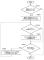
図8では情報処理装置102でページごとの加飾の有無を判断し出力プロファイルの指定まで行っているが、加飾の有無の判断はMFP側で行ってもよい。図11を参照して、MLPを適用しつつ加飾ページに対しては別の出力プロファイル指定する際に、情報処理装置102でメディアごとに加飾タイプごとの出力プロファイルを指定した印刷ジョブを作成する場合のジョブ設定のフローを説明する。
<Flow diagram for explaining a flow of performing job settings related to an output profile: When the
In Fig. 8, the
S1101にて、情報処理装置102は印刷シートごとの使用メディアを設定する。メディアを設定した後、S1102に進む。
In S1101, the
S1102にて、情報処理装置102はS1101で設定した使用メディアに対して紐づいている加飾ごとに使用する出力プロファイルを設定する。メディアと加飾の組み合わせから出力プロファイルを設定する方法については図12および図13Bにて後述する。使用メディアの加飾に対する出力プロファイルを設定した後、S1103に進む。
In S1102, the
S1103にて、情報処理装置はS1101~S1103で設定した情報を基に印刷ジョブを作成し、外部I/F210を介して印刷装置101に印刷ジョブを送信する。印刷ジョブの送信後、S1104に進む。
In S1103, the information processing device creates a print job based on the information set in S1101 to S1103, and transmits the print job to the
S1104以降、制御装置205が、印刷ページごとに出力プロファイルを設定するフローを示す。なお、S1104~S1111における"出力プロファイル(MLPも含む)を適用する"とは、S619のJDF全解析で解析した結果、S623のPDL解析にて色変換に使用する出力プロファイルをJDF設定値として保持しておく、という意味である。
The flow from S1104 onwards shows how the
S1104にて制御装置205は、受信したPDLから加飾情報を読み込む。図はPDFの場合を示している。PDLの加飾情報は、例えばプロパティやメタデータとして保有することが考えられるが、これに限定されるものではない。加飾情報を読み込んだ後、S1105に進む。
In S1104, the
S1105にて、制御装置205は、出力プロファイルを設定中の印刷ページに対して、S1104で読み込んだ加飾情報が設定されているか否かを判定する。加飾情報が設定されている場合はS1106に進み、指定されていない場合はS1107に進む。
In S1105, the
S1106にて、制御装置205は設定中の印刷ページに対して、JDFにて指定されたメディアごとの加飾に応じた出力プロファイルを適用する。なお、PDLに設定された加飾情報が、JDFにて当該メディアに指定された加飾と一致しない場合や加飾の指定自体が存在しない場合は処理を省略する。出力プロファイルを適用後、S1110に進む。
In S1106, the
S1107にて、制御装置205は設定中の印刷ページに対して、印刷ジョブにてメディアの指定がされているか否かを判定する。メディアの指定がされている場合はS1108に進み、指定がされていない場合はS1109に進む。
In S1107, the
S1108にて、制御装置205は設定中の印刷ページに対してMLPを適用する。ただし、MLPは操作部204などを介して登録メディアに対して事前に紐づけられてHDD209に保管されているものであり、この紐づけが行われていない、つまりMLPが存在しない場合は、MLPは適用されない。MLPを適用した後、S1110に進む。
In S1108, the
S1109にて、制御装置205は設定中の印刷ページに対して、印刷装置で設定されている出力プロファイルを適用する。ここで、印刷装置で設定されている出力プロファイルとは、操作部204の出力プロファイル設定で指定されている出力プロファイルのことである。
In step S1109, the
S1110にて、制御装置205は設定中の印刷ページの次のページがある否かを判定する。次の印刷ページが存在する場合はS1111に進み、存在しない場合は処理を終了する。
In S1110, the
S1111にて、制御装置205は設定中の印刷ページの次の印刷ページに処理を進め、S1105に進む。なお、図11ではS1105に進んでいるが、PDLの加飾情報のデータ形式などによってはS1104に進んでもよい。その場合、S1104の処理は印刷ページごとに行うことになる。
In S1111, the
<S1101およびS1102の設定画面>
図12を参照して、S1101およびS1102で設定を行う情報処理装置の設定画面例を説明する。各シートに対して使用するメディアタイプを設定するのは図9Aと同様である。
<Setting screen for S1101 and S1102>
An example of a setting screen of the information processing apparatus for performing settings in S1101 and S1102 will be described with reference to Fig. 12. Setting the media type to be used for each sheet is similar to Fig. 9A.
メディアタイプを設定すると、設定画面下部の"登録されたテーブルに基づいた出力プロファイルを使用"という項目が設定可能になる。そのチェックボックスで有効化することで、図9Cと同様のテーブルから、メディアに紐づいた加飾ごとのプロファイル情報を取得し、印刷ジョブ設定に反映する。 When you set the media type, the item "Use output profile based on registered table" becomes configurable at the bottom of the settings screen. By enabling this check box, profile information for each decoration linked to the media is obtained from a table similar to that shown in Figure 9C, and reflected in the print job settings.
<S1103にて送信されるJDFの模式図>
図13Aおよび図13Bを参照して、S1103にて送信される印刷ジョブのJDF部分の例と、その作成方法について説明する。
<Schematic diagram of JDF transmitted in S1103>
An example of the JDF portion of the print job sent in S1103 and a method for creating the JDF portion will be described with reference to FIGS. 13A and 13B.
図13Aは、S1103にて送信される印刷ジョブのJDF部分の例を示したものである。なお、主に図10Bとの差異部分を抜粋しており、省略部分に関しては図10Bと同様である。以下、色変換部のみについて説明する。 Figure 13A shows an example of the JDF portion of the print job sent in S1103. Note that mainly the differences from Figure 10B are excerpted, and the omitted parts are the same as Figure 10B. Below, only the color conversion section will be explained.
色変換部1301は、子要素としてメディアと加飾の種類ごとの色変換部1302、1303の2つの要素を持つ。
The
メディアと加飾の種類ごとの色変換部1302、1303では、cj:Scope_Decorationg属性で加飾の種類、cj:Media_ID属性で出力プロファイルを適用するメディアをそれぞれ指定している。また、ページごとの色変換部1015、1016と同様に、"FileSpec"要素内のUserFileName属性でメディアと加飾の種類ごとに適用する出力プロファイルをそれぞれ設定している。メディアと加飾の種類ごとの色変換部は、メディアテーブル921の使用するメディアに対して紐づいた加飾に応じた出力プロファイルテーブルの項目数の数だけ作成されることになる。
In the
図13Bは、図13Aの色変換部を情報処理装置102で作成するフローを示したものである。
Figure 13B shows the flow for creating the color conversion unit of Figure 13A using the
S1311にて、情報処理装置102は、図12の設定画面においてメディアタイプが設定されているかどうかを判定する。いずれかのシートに対してメディアタイプが設定されていた場合はS1312に進み、どのシートに対してもメディアタイプが指定されていない場合は、処理を終了する。
In S1311, the
S1312にて、情報処理装置102は、設定されているメディアタイプのうち、最初に印刷するメディアに対する色変換部の作成に進む。その後、処理をS1313に進める。
In S1312, the
S1313にて、情報処理装置102は、色変換部を作成中のメディアに対して加飾に応じた出力プロファイルテーブルが紐づいているかを判定する。紐づいていた場合はS1314に進み、紐づいていなかった場合はS1315に進む。
In S1313, the
S1314にて、情報処理装置102は、メディアタイプおよび加飾の種類を、出力プロファイルを適用する際の判断材料とする色変換部を作成する。色変換部を作成した後、S1315に進む。
In S1314, the
S1315にて、情報処理装置102は、他に色変換部の作成を行っていないメディアが存在するか否かを判定する。設定されているメディアのうち、色変換部の作成を行っていないメディアが存在すれば処理をS1316に進め、全ての設定されているメディアに対して色変換部の作成処理を行っていた場合には処理を終了する。
In S1315, the
S1316にて、情報処理装置102は、現在設定していたメディアの次に印刷するメディアに対する色変換部の作成に進む。その後、処理をS1313に進める。
In S1316, the
<図10Bおよび図13AのJDFの適用結果を示す図>
図14は、計8ページのPDFに対して、図8のフローに従い情報処理装置102が生成した図10BのJDFを、前記フローに従って制御装置205が解析した場合の出力プロファイルの適用結果を示す図である。なお、メディア情報指定部1018で情報を指定しているメディアであるPaper1には、操作部204にてMLPとしてProfileXが登録されているものとする。
<Diagram showing the result of applying the JDF of FIG. 10B and FIG. 13A>
Fig. 14 is a diagram showing the result of applying an output profile to a PDF of eight pages in total when the
1シート目にラミネート加工を施し、8ページ目にクリアトナーを使用する場合を想定すると、ラミネート加工を行うシートに対してはProfileA、クリアトナーを使用するページに対してはProfileBをそれぞれ適用することができる。また、加飾をせずに通常のMLPを使用するページに対してはMLPであるProfileXを適用することが出来る。 Assuming that the first sheet is laminated and the eighth page uses clear toner, Profile A can be applied to the sheet that is laminated, and Profile B can be applied to the page that uses clear toner. Additionally, Profile X, which is an MLP, can be applied to pages that do not use decoration and use normal MLP.
なお、図14は、1ページ目と2ページ目にラミネート加工を施し8ページ目にクリアトナーを用いる、という情報を持った計8ページのPDFに対して適用される出力プロファイルを示す図と考えてもよい。適用される出力プロファイルは、図11のフローに従い情報処理装置102が生成した図13AのJDFを、前記フローに従って制御装置205が解析することで特定される。
Note that FIG. 14 can also be considered to be a diagram showing an output profile to be applied to a PDF of eight pages in total, which contains information indicating that the first and second pages are to be laminated and that clear toner is to be used on the eighth page. The output profile to be applied is identified by the
<図13Aの出力プロファイル設定を操作部204で行う場合の設定例>
図15は、図13AでJDFにて設定しているメディアと加飾の種類ごとの出力プロファイル指定および通常のMLPの指定を印刷装置101の操作部204で行う場合の設定例である。このように、印刷ジョブではなく操作部204において加飾に対するプロファイルを指定できるようにしてもよい。
<Example of setting when the output profile setting in FIG. 13A is performed by the
Fig. 15 shows a setting example in which the output profile designation for each type of media and decoration set in the JDF in Fig. 13A and the normal MLP designation are performed on the
図15の画面では、デフォルト(加飾なし)の出力プロファイルのほか、加飾の種類ごとの出力プロファイルを候補の中から選択して設定できる。ただし図15の設定はメディアの種類毎に行えるので、デフォルトとは設定対象のメディの種類に対するMLP(メディアリンクプロファイル)を意味する。図15のように操作部204で出力プロファイルが設定された場合には、設定されたメディア種類と加飾の種類と出力プロファイルの識別情報とを関連付けて例えばHDD209に保存しておく。保存の形式は図9Cに示した加飾用出力プロファイルテーブルと同じであってよい。
In the screen of FIG. 15, in addition to the default output profile (no decoration), an output profile for each type of decoration can be selected from candidates and set. However, since the settings in FIG. 15 can be made for each type of media, default means the MLP (Media Link Profile) for the type of media to be set. When an output profile is set on the
そしてたとえば図7のS703において、印刷ジョブに含まれた各ページについて、出力プロファイルが設定されていなければ、図15の画面から設定され印刷装置101に保存された出力プロファイルテーブルを参照する。そして、該当する出力プロファイルを特定し、特定した出力プロファイルを用いてS704で色変換処理を行う。ここで、たとえばまずJDFに印刷メディアの種類と加飾処理の種類とが設定されているか判定し、その設定に該当する出力プロファイルを特定する。該当するものがないか、または印刷メディアの種類だけが設定されていれば、使用する出力プロファイルとしてMLPを特定する。印刷メディアの種類も設定されていないか、或いはMLPが設定されていなければ、既定の(デフォルトの、または所定の)出力プロファイルを特定して使用してよい。なお図15の画面で、JDF等においてメディアの種類が設定されていないページに対する既定の出力プロファイルを設定してもよい。
For example, in S703 of FIG. 7, if an output profile has not been set for each page included in the print job, the output profile table set from the screen of FIG. 15 and stored in the
以上の構成により本実施形態によれば、印刷メディアの種類と加飾処理の種類とに紐づけて出力プロファイルを設定することができる。そして、印刷時には、設定された印刷メディアの種類および加飾の種類に該当するページがあれば、そのページについては設定された出力プロファイルで色変換が行われる。一方、それ以外のページについては、デフォルトの出力プロファイルまたはメディアの種類に応じた出力プロファイルで色変換が行われる。このため、印刷された色の、入稿した原稿における色からの加飾によるずれを抑制できる。さらに、そのためには印刷ジョブを生成する際に印刷メディアの種類および加飾の種類を出力プロファイルと関連付けておき、またメディアリンクプロファイルを定めておけばよいので、加飾の設定と併せて簡易な操作で出力プロファイルを設定できる。 According to the present embodiment, with the above configuration, an output profile can be set in association with the type of print media and the type of decoration processing. Then, when printing, if there is a page that corresponds to the set type of print media and type of decoration, the color conversion for that page is performed using the set output profile. On the other hand, for other pages, color conversion is performed using the default output profile or an output profile corresponding to the type of media. This makes it possible to suppress deviations in printed colors from the colors in the submitted document due to decoration. Furthermore, in order to achieve this, it is necessary to associate the type of print media and the type of decoration with the output profile when generating a print job, and also to define a media link profile, so that the output profile can be set with simple operations along with the decoration settings.
(変形例)
なお、上記までの実施形態ではページごとに出力プロファイルを指定することを想定しているが、加飾をページの一部のみに行う場合などに、ページ内のオブジェクト単体もしくはオブジェクト属性ごとに出力プロファイル指定を行ってもよい。図13Aと同様のJDFを印刷装置101が受け取った後の制御装置205の処理を変更することでオブジェクトごと、もしくはオブジェクトの属性ごとに適用する出力プロファイルを設定することが可能である。
(Modification)
In the above embodiment, it is assumed that an output profile is specified for each page, but when decoration is performed only on a part of a page, an output profile may be specified for each object or object attribute in the page. By changing the process of the
<S1101~S1103にて生成されるJDFジョブ自体は変更せずに、制御装置205でオブジェクトごとに出力プロファイルを適用するフロー図>
図16を参照して、オブジェクトの属性ごとに適用する出力プロファイルを設定するフローを説明する。なお、基本的な流れは図11と同様であるため、図11と処理が変わらない部分に関しては説明を省略する。
<Flow diagram for applying an output profile to each object by the
A flow for setting an output profile to be applied for each attribute of an object will be described with reference to Fig. 16. Note that since the basic flow is similar to Fig. 11, a description of the same process as in Fig. 11 will be omitted.
S1601~S1603はそれぞれS1101~S1103と同様の処理である。 S1601 to S1603 are the same processes as S1101 to S1103, respectively.
S1604にて、制御装置205は、受信したPDLの解析処理中の印刷ページの加飾情報を読み込む。図16ではPDFの場合を示している。なお、ここでの加飾情報とは。印刷ページ中の各オブジェクトが保持しているものとする。オブジェクトが加飾情報を保持する方法としては、例えばオブジェクトメタデータとして保持することが考えられるが、これに限定されるものではない。加飾情報を読み込んだ後、S1605に進む。
In S1604, the
S1605にて、制御装置205は、S1604にて読み込んだ情報をもとに解析処理中の印刷ページに加飾情報が付帯したオブジェクト(加飾オブジェクト)が存在するか否かを判断する。加飾オブジェクトが存在した場合はS1606に進み、存在しなかった場合はS1607に進む。
In S1605, the
S1607~S1611はそれぞれS1107~S1111と同様の処理である。 S1607 to S1611 are the same processes as S1107 to S1111, respectively.
S1606にて、制御装置205は、PDLから読み込んだ解析処理中の加飾オブジェクトについて、その加飾の種類と、処理対象の印刷ジョブにて指定された、印刷ページに使用されるメディアタイプとを、S1602で設定した値と照合する。S1602で設定した値はたとえば受信したJDFを参照してよい。照合することで、メディアタイプと加飾の種類とに対応する出力プロファイルを特定する。こうして出力プロファイルを特定し、該加飾オブジェクトに対して特定した出力プロファイルを適用する。
In S1606, the
メディアタイプと加飾の種類との組み合わせがPDLの加飾情報と印刷ジョブの設定とで一致しなかった場合は、処理を省略する。なお、ここでの"適用する"という表現は、S619のJDF全解析で解析した結果、S623のPDL解析にて色変換に使用する出力プロファイルをJDF設定値として保持しておく、という意味である。解析処理中の加飾オブジェクトに対して出力プロファイルを適用した後、S1612に処理を進める。 If the combination of media type and decoration type does not match between the PDL decoration information and the print job settings, the process is omitted. Note that the expression "apply" here means that the output profile used for color conversion in the PDL analysis of S623, as a result of the analysis in the full JDF analysis of S619, is retained as a JDF setting value. After the output profile is applied to the decoration object being analyzed, the process proceeds to S1612.
S1612にて、制御装置205は、解析処理中の印刷ページに解析処理を行っていない加飾オブジェクトが存在するかを判定する。解析処理を行っていない加飾オブジェクトが存在する場合はS1613に進み、存在しない場合はS1610に進む。
In S1612, the
S1613にて、制御装置205は、次の解析処理を行っていない加飾オブジェクトの解析処理に進む。その後、S1606に処理を進める。
In S1613, the
なお、図16のフローにおいて、「オブジェクト」をテキストやグラフィックといった「オブジェクト属性」に言い換えても同様の処理が可能である。その場合。加飾情報はオブジェクトメタデータではなくPDL全体のプロパティなどで保持することになる。 In the flow of Figure 16, the same processing can be performed even if "object" is replaced with "object attributes" such as text or graphics. In that case, the decoration information is stored in the properties of the entire PDL rather than in object metadata.
このように、本変形例では、加飾オブジェクトごとに、その加飾の種類に紐づけられた出力プロファイルが適用される。なお加飾の種類によってオブジェクト単位で加飾処理ができる物やページ単位でしかできないものがある。たとえばラミネートはページ単位(あるいはシート単位)となる。したがって加飾の種類によっては加飾オブジェクトを特定せず、ページ単位で加飾に紐づけられた出力プロファイルを適用してよいこともある。 In this manner, in this modified example, an output profile linked to the type of decoration is applied to each decoration object. Note that depending on the type of decoration, some decoration processes can be performed on an object-by-object basis, while others can only be performed on a page-by-page basis. For example, lamination is performed on a page-by-page basis. Therefore, depending on the type of decoration, it may be possible to apply an output profile linked to the decoration on a page-by-page basis without specifying a decoration object.
以上説明したように、本実施形態によれば、メディアに紐づいた出力プロファイルを用いつつ、加飾ページや加飾オブジェクトに対しては別の出力プロファイルを用いることを可能にすることで加飾による色味の変化を防ぐことができる。それによりユーザに望む色味に対してより柔軟に訴求することを可能にする。 As described above, according to this embodiment, it is possible to prevent changes in color due to decoration by using an output profile associated with the media while making it possible to use a different output profile for decorated pages and decorated objects. This allows users to be more flexible in appealing to their desired colors.
(その他の実施例)
本発明は、上述の実施形態の1以上の機能を実現するプログラムを、ネットワーク又は記憶媒体を介してシステム又は装置に供給し、そのシステム又は装置のコンピュータにおける1つ以上のプロセッサーがプログラムを読出し実行する処理でも実現可能である。また、1以上の機能を実現する回路(例えば、ASIC)によっても実現可能である。
Other Examples
The present invention can also be realized by a process in which a program for implementing one or more of the functions of the above-described embodiments is supplied to a system or device via a network or a storage medium, and one or more processors in a computer of the system or device read and execute the program. The present invention can also be realized by a circuit (e.g., ASIC) that implements one or more of the functions.
発明は上記実施形態に制限されるものではなく、発明の精神及び範囲から離脱することなく、様々な変更及び変形が可能である。従って、発明の範囲を公にするために請求項を添付する。 The invention is not limited to the above-described embodiment, and various modifications and variations are possible without departing from the spirit and scope of the invention. Therefore, the following claims are appended to disclose the scope of the invention.
100...ネットワーク、101...印刷装置、102...情報処理装置、200、202...シート処理装置、201...プリンタ部 100...network, 101...printing device, 102...information processing device, 200, 202...sheet processing device, 201...printer unit
Claims (10)
処理対象の印刷ジョブに含まれたページそれぞれについて、前記出力プロファイルが設定されているページであれば当該出力プロファイルを用いて色変換を行い、前記出力プロファイルが設定されていないページであれば、前記テーブルを参照して当該ページについて設定された前記印刷メディアの種類に関連付けられた前記出力プロファイルを用いて色変換を行って印刷を実行する処理手段と
を有する印刷装置。 a storage means for storing a table relating types of print media to output profiles;
a processing means for performing color conversion using the output profile for each page included in the print job to be processed if the page has an output profile set therefor, and for performing color conversion using the output profile associated with the type of print media set for the page by referencing the table for the page if the output profile is not set therefor, and then executing printing.
前記テーブルは、印刷メディアの種類と加飾処理の種類と出力プロファイルとの関連付けをさらに含み、
前記処理手段は、前記処理対象の印刷ジョブに含まれたページについて、前記印刷メディアの種類と前記加飾処理の種類とが設定され、かつ前記出力プロファイルが設定されていなければ、前記テーブルを参照して当該ページについて設定された前記印刷メディアの種類と前記加飾処理の種類とに関連付けられた前記出力プロファイルを用いて色変換を行う、
印刷装置。 2. The printing device according to claim 1,
The table further includes an association between a type of print medium, a type of decoration process, and an output profile;
the processing means, when the type of print medium and the type of decoration processing are set for a page included in the print job to be processed and the output profile is not set, refers to the table and performs color conversion using the output profile associated with the type of print medium and the type of decoration processing set for the page.
Printing device.
前記処理手段は、前記処理対象の印刷ジョブに含まれたページについて、前記テーブルに前記印刷メディアの種類と前記加飾処理の種類とに関連付けられた出力プロファイルが前記テーブルになければ、前記印刷メディアの種類に関連付けられた出力プロファイルを用いて色変換を行う、
印刷装置。 3. The printing device according to claim 2,
the processing means performs color conversion using an output profile associated with the type of print medium for a page included in the print job to be processed, if the table does not contain an output profile associated with the type of print medium and the type of decoration processing;
Printing device.
前記処理手段は、前記処理対象の印刷ジョブに含まれたページについて、前記テーブルに前記印刷メディアの種類に関連付けられた出力プロファイルが前記テーブルになければ、所定の出力プロファイルを用いて色変換を行う、
印刷装置。 4. The printing device according to claim 3,
the processing means performs color conversion using a predetermined output profile for a page included in the print job to be processed if there is no output profile associated with the type of print medium in the table;
Printing device.
前記処理手段は、前記処理対象の印刷ジョブに含まれたページについて、前記印刷メディアの種類が設定されておらず、かつ前記出力プロファイルが設定されていなければ、所定の出力プロファイルを用いて色変換を行う、
印刷装置。 A printing device according to any one of claims 1 to 4,
the processing means performs color conversion using a predetermined output profile when the type of print medium is not set and the output profile is not set for the page included in the print job to be processed;
Printing device.
前記印刷メディアの種類と、該印刷メディアの種類に関連する前記出力プロファイルとを選択し、選択した前記印刷メディアの種類を選択した前記出力プロファイルに関連付けて前記テーブルに格納する設定手段を更に有する、
印刷装置。 A printing device according to any one of claims 1 to 5 ,
a setting unit for selecting the type of print medium and the output profile related to the type of print medium, and storing the selected type of print medium in the table in association with the selected output profile;
Printing device.
前記設定手段により、加飾処理の種類をさらに選択し、選択した前記加飾処理の種類を選択した前記印刷メディアの種類と選択した前記出力プロファイルとにさらに関連付けて前記テーブルに格納する、
印刷装置。 7. The printing device according to claim 6 ,
a type of decoration processing is further selected by the setting means, and the selected type of decoration processing is further associated with the selected type of print medium and the selected output profile and stored in the table;
Printing device.
前記情報処理装置は、
印刷メディアの種類と加飾処理の種類と出力プロファイルとを関連付けた第1のテーブルを格納する格納手段と、
ページごとの前記印刷メディアの種類と前記加飾処理の種類とを設定し、前記第1のテーブルを参照して前記加飾処理が設定されたページの出力プロファイルを設定した印刷ジョブを作成する作成手段と、
前記印刷装置に前記印刷ジョブを送信する手段とを有し、
前記印刷装置は、
印刷メディアの種類を出力プロファイルに関連付けた第2のテーブルを格納する格納手段と、
処理対象の印刷ジョブに含まれたページそれぞれについて、前記出力プロファイルが設定されているページであれば当該出力プロファイルを用いて色変換を行い、前記出力プロファイルが設定されていないページであれば、前記第2のテーブルを参照して当該ページについて設定された前記印刷メディアの種類に関連付けられた前記出力プロファイルを用いて色変換を行って印刷を実行する処理手段とを有する
印刷システム。 A printing system including an information processing device that creates a print job and a printing device that executes the print job and performs printing,
The information processing device includes:
a storage means for storing a first table that associates types of print media, types of decoration processing, and output profiles;
a creating means for creating a print job in which a type of the print medium and a type of the decoration processing are set for each page, and an output profile for the page on which the decoration processing is set is set by referring to the first table;
means for transmitting the print job to the printing device;
The printing device includes:
a storage means for storing a second table that associates types of print media with output profiles;
and a processing means for performing color conversion using the output profile for each page included in the print job to be processed if the page has an output profile set therefor, and for performing color conversion using the output profile associated with the type of print media set for the page by referring to the second table for the page not having the output profile set therefor, and then executing printing.
印刷メディアの種類と加飾処理の種類と出力プロファイルとを関連付けたテーブルを格納する格納手段と、
ページごとの前記印刷メディアの種類と前記加飾処理の種類とを設定し、前記テーブルを参照して前記加飾処理が設定されたページの出力プロファイルを設定した印刷ジョブを作成する作成手段と、
印刷装置に前記印刷ジョブを送信する手段とを有する
情報処理装置。 An information processing apparatus for creating a print job,
a storage means for storing a table that associates types of print media, types of decoration processing, and output profiles;
a creating means for creating a print job by setting the type of print medium and the type of decoration processing for each page, and by referring to the table and setting an output profile for the page on which the decoration processing is set;
and means for transmitting the print job to a printing device.
Priority Applications (5)
| Application Number | Priority Date | Filing Date | Title |
|---|---|---|---|
| JP2020200507A JP7594421B2 (en) | 2020-12-02 | 2020-12-02 | Printing device, printing system, and program |
| GB2116217.7A GB2605229B (en) | 2020-12-02 | 2021-11-11 | Printing apparatus, printing system, information processing apparatus and program |
| DE102021212871.8A DE102021212871A1 (en) | 2020-12-02 | 2021-11-16 | PRINTING DEVICE, PRINTING SYSTEM, INFORMATION PROCESSING DEVICE AND PROGRAM |
| US17/529,381 US11675548B2 (en) | 2020-12-02 | 2021-11-18 | Printing apparatus, printing system, information processing apparatus and medium |
| CN202111438977.8A CN114579064A (en) | 2020-12-02 | 2021-11-29 | Printing apparatus, printing system, information processing apparatus, and medium |
Applications Claiming Priority (1)
| Application Number | Priority Date | Filing Date | Title |
|---|---|---|---|
| JP2020200507A JP7594421B2 (en) | 2020-12-02 | 2020-12-02 | Printing device, printing system, and program |
Publications (2)
| Publication Number | Publication Date |
|---|---|
| JP2022088201A JP2022088201A (en) | 2022-06-14 |
| JP7594421B2 true JP7594421B2 (en) | 2024-12-04 |
Family
ID=79163665
Family Applications (1)
| Application Number | Title | Priority Date | Filing Date |
|---|---|---|---|
| JP2020200507A Active JP7594421B2 (en) | 2020-12-02 | 2020-12-02 | Printing device, printing system, and program |
Country Status (5)
| Country | Link |
|---|---|
| US (1) | US11675548B2 (en) |
| JP (1) | JP7594421B2 (en) |
| CN (1) | CN114579064A (en) |
| DE (1) | DE102021212871A1 (en) |
| GB (1) | GB2605229B (en) |
Families Citing this family (1)
| Publication number | Priority date | Publication date | Assignee | Title |
|---|---|---|---|---|
| US11914912B2 (en) * | 2022-01-25 | 2024-02-27 | Kyocera Document Solutions Inc. | Hot folders with enhanced print ticketing functionality |
Citations (7)
| Publication number | Priority date | Publication date | Assignee | Title |
|---|---|---|---|---|
| JP2010263368A (en) | 2009-05-01 | 2010-11-18 | Konica Minolta Business Technologies Inc | Color conversion setting program, color conversion setting method, color conversion processing program, color conversion processing apparatus |
| JP2012218319A (en) | 2011-04-11 | 2012-11-12 | Canon Inc | Image forming apparatus and information processor |
| JP2013131169A (en) | 2011-12-22 | 2013-07-04 | Konica Minolta Business Technologies Inc | Print job processor, print system, print job processing system, and program |
| JP2015109598A (en) | 2013-12-05 | 2015-06-11 | コニカミノルタ株式会社 | Image processor, image processing method, and image processing program |
| JP2017041663A (en) | 2015-08-17 | 2017-02-23 | コニカミノルタ株式会社 | Color verification system and program |
| JP2019213024A (en) | 2018-06-04 | 2019-12-12 | コニカミノルタ株式会社 | Image processing apparatus and image processing method |
| JP2020183073A (en) | 2019-05-08 | 2020-11-12 | キヤノン株式会社 | Image formation device, control method for the same and program |
Family Cites Families (7)
| Publication number | Priority date | Publication date | Assignee | Title |
|---|---|---|---|---|
| JP2007025775A (en) | 2005-07-12 | 2007-02-01 | Fujifilm Holdings Corp | Image processor and image processing program |
| JP4689431B2 (en) * | 2005-10-14 | 2011-05-25 | キヤノン株式会社 | Information processing apparatus, image processing method, and computer program |
| JP4898337B2 (en) * | 2006-07-28 | 2012-03-14 | キヤノン株式会社 | Printing system, printing apparatus, and printing method |
| US20080180727A1 (en) * | 2007-01-30 | 2008-07-31 | Ehud Chatow | Print workflow methods and printing system apparatuses |
| JP5457776B2 (en) * | 2009-09-30 | 2014-04-02 | 富士フイルム株式会社 | Profile generation apparatus, method and program thereof, and printing system |
| JP5578147B2 (en) * | 2011-08-11 | 2014-08-27 | コニカミノルタ株式会社 | Printing system, printing method, and printing program |
| JP6759987B2 (en) * | 2016-11-04 | 2020-09-23 | セイコーエプソン株式会社 | Print management device, printing device, print management program and image processing program |
-
2020
- 2020-12-02 JP JP2020200507A patent/JP7594421B2/en active Active
-
2021
- 2021-11-11 GB GB2116217.7A patent/GB2605229B/en active Active
- 2021-11-16 DE DE102021212871.8A patent/DE102021212871A1/en active Pending
- 2021-11-18 US US17/529,381 patent/US11675548B2/en active Active
- 2021-11-29 CN CN202111438977.8A patent/CN114579064A/en active Pending
Patent Citations (7)
| Publication number | Priority date | Publication date | Assignee | Title |
|---|---|---|---|---|
| JP2010263368A (en) | 2009-05-01 | 2010-11-18 | Konica Minolta Business Technologies Inc | Color conversion setting program, color conversion setting method, color conversion processing program, color conversion processing apparatus |
| JP2012218319A (en) | 2011-04-11 | 2012-11-12 | Canon Inc | Image forming apparatus and information processor |
| JP2013131169A (en) | 2011-12-22 | 2013-07-04 | Konica Minolta Business Technologies Inc | Print job processor, print system, print job processing system, and program |
| JP2015109598A (en) | 2013-12-05 | 2015-06-11 | コニカミノルタ株式会社 | Image processor, image processing method, and image processing program |
| JP2017041663A (en) | 2015-08-17 | 2017-02-23 | コニカミノルタ株式会社 | Color verification system and program |
| JP2019213024A (en) | 2018-06-04 | 2019-12-12 | コニカミノルタ株式会社 | Image processing apparatus and image processing method |
| JP2020183073A (en) | 2019-05-08 | 2020-11-12 | キヤノン株式会社 | Image formation device, control method for the same and program |
Also Published As
| Publication number | Publication date |
|---|---|
| CN114579064A (en) | 2022-06-03 |
| GB2605229A (en) | 2022-09-28 |
| US11675548B2 (en) | 2023-06-13 |
| GB2605229B (en) | 2023-08-02 |
| DE102021212871A1 (en) | 2022-06-02 |
| JP2022088201A (en) | 2022-06-14 |
| GB202116217D0 (en) | 2021-12-29 |
| US20220171582A1 (en) | 2022-06-02 |
Similar Documents
| Publication | Publication Date | Title |
|---|---|---|
| EP0991228B1 (en) | A method, a data processing device, a system and a storage medium enabling direct communication between an image reading device and an image output device | |
| JP4646740B2 (en) | Printing apparatus and control method thereof, job processing method, printing system, and program | |
| JP4646741B2 (en) | Printing system, printing apparatus, image processing apparatus, control method therefor, and program | |
| JP5043715B2 (en) | Image processing device | |
| CN101738897A (en) | Printing system, print job processing method, information processing device and method | |
| JP4632442B2 (en) | Controller device, control method therefor, and printing system | |
| JP7594421B2 (en) | Printing device, printing system, and program | |
| JP2014238887A (en) | Print processing apparatus, control method of print processing apparatus and program | |
| JP4757355B2 (en) | Printing apparatus, control method therefor, and program | |
| JP2003050689A (en) | Image forming system, image forming method, and server device | |
| JP5110945B2 (en) | Image processing apparatus, control method therefor, and program | |
| JP2004259058A (en) | Network device control method | |
| JP2004255745A (en) | Network device control method | |
| JP4109766B2 (en) | Image forming system | |
| US20240126485A1 (en) | Controlling apparatus, control method, and non-transitory computer-readable storage medium storing program | |
| JP7337578B2 (en) | IMAGE FORMING APPARATUS, IMAGE FORMING APPARATUS CONTROL METHOD, AND PROGRAM | |
| JP2022011819A (en) | Printer, control method of printer and program | |
| JP2003330667A (en) | Network device controller | |
| JP2003303084A (en) | Printing control system, printing control method, storage medium, and program | |
| JP2016084184A (en) | Control method for image formation system comprising image formation apparatus and post-processing device connected to the same, and program | |
| JP2003050688A (en) | Image forming system, image forming method, and server device | |
| JP2006215751A (en) | Image forming apparatus, control method for the same, computer program, and storage medium | |
| JP2008154269A (en) | Printing system and control method thereof, storage medium, and information processing apparatus | |
| JP2007004246A (en) | Image forming device | |
| JP2002182882A (en) | Image forming system, image forming method, image forming apparatus, storage medium and program |
Legal Events
| Date | Code | Title | Description |
|---|---|---|---|
| RD02 | Notification of acceptance of power of attorney |
Free format text: JAPANESE INTERMEDIATE CODE: A7422 Effective date: 20210103 |
|
| A521 | Request for written amendment filed |
Free format text: JAPANESE INTERMEDIATE CODE: A523 Effective date: 20210113 |
|
| RD04 | Notification of resignation of power of attorney |
Free format text: JAPANESE INTERMEDIATE CODE: A7424 Effective date: 20210316 |
|
| A621 | Written request for application examination |
Free format text: JAPANESE INTERMEDIATE CODE: A621 Effective date: 20231204 |
|
| A977 | Report on retrieval |
Free format text: JAPANESE INTERMEDIATE CODE: A971007 Effective date: 20240717 |
|
| A131 | Notification of reasons for refusal |
Free format text: JAPANESE INTERMEDIATE CODE: A131 Effective date: 20240802 |
|
| A521 | Request for written amendment filed |
Free format text: JAPANESE INTERMEDIATE CODE: A523 Effective date: 20240926 |
|
| TRDD | Decision of grant or rejection written | ||
| A01 | Written decision to grant a patent or to grant a registration (utility model) |
Free format text: JAPANESE INTERMEDIATE CODE: A01 Effective date: 20241025 |
|
| A61 | First payment of annual fees (during grant procedure) |
Free format text: JAPANESE INTERMEDIATE CODE: A61 Effective date: 20241122 |
|
| R150 | Certificate of patent or registration of utility model |
Ref document number: 7594421 Country of ref document: JP Free format text: JAPANESE INTERMEDIATE CODE: R150 |