JP7593797B2 - Analysis device, analysis system, and analysis method - Google Patents
Analysis device, analysis system, and analysis method Download PDFInfo
- Publication number
- JP7593797B2 JP7593797B2 JP2020203331A JP2020203331A JP7593797B2 JP 7593797 B2 JP7593797 B2 JP 7593797B2 JP 2020203331 A JP2020203331 A JP 2020203331A JP 2020203331 A JP2020203331 A JP 2020203331A JP 7593797 B2 JP7593797 B2 JP 7593797B2
- Authority
- JP
- Japan
- Prior art keywords
- plaque
- shape
- time point
- blood vessel
- state
- Prior art date
- Legal status (The legal status is an assumption and is not a legal conclusion. Google has not performed a legal analysis and makes no representation as to the accuracy of the status listed.)
- Active
Links
Images


Classifications
-
- G—PHYSICS
- G06—COMPUTING OR CALCULATING; COUNTING
- G06T—IMAGE DATA PROCESSING OR GENERATION, IN GENERAL
- G06T7/00—Image analysis
- G06T7/0002—Inspection of images, e.g. flaw detection
- G06T7/0012—Biomedical image inspection
-
- G—PHYSICS
- G06—COMPUTING OR CALCULATING; COUNTING
- G06V—IMAGE OR VIDEO RECOGNITION OR UNDERSTANDING
- G06V10/00—Arrangements for image or video recognition or understanding
- G06V10/20—Image preprocessing
- G06V10/255—Detecting or recognising potential candidate objects based on visual cues, e.g. shapes
-
- G—PHYSICS
- G06—COMPUTING OR CALCULATING; COUNTING
- G06T—IMAGE DATA PROCESSING OR GENERATION, IN GENERAL
- G06T2207/00—Indexing scheme for image analysis or image enhancement
- G06T2207/10—Image acquisition modality
- G06T2207/10072—Tomographic images
- G06T2207/10081—Computed x-ray tomography [CT]
-
- G—PHYSICS
- G06—COMPUTING OR CALCULATING; COUNTING
- G06T—IMAGE DATA PROCESSING OR GENERATION, IN GENERAL
- G06T2207/00—Indexing scheme for image analysis or image enhancement
- G06T2207/10—Image acquisition modality
- G06T2207/10072—Tomographic images
- G06T2207/10088—Magnetic resonance imaging [MRI]
-
- G—PHYSICS
- G06—COMPUTING OR CALCULATING; COUNTING
- G06T—IMAGE DATA PROCESSING OR GENERATION, IN GENERAL
- G06T2207/00—Indexing scheme for image analysis or image enhancement
- G06T2207/10—Image acquisition modality
- G06T2207/10072—Tomographic images
- G06T2207/10104—Positron emission tomography [PET]
-
- G—PHYSICS
- G06—COMPUTING OR CALCULATING; COUNTING
- G06T—IMAGE DATA PROCESSING OR GENERATION, IN GENERAL
- G06T2207/00—Indexing scheme for image analysis or image enhancement
- G06T2207/10—Image acquisition modality
- G06T2207/10072—Tomographic images
- G06T2207/10108—Single photon emission computed tomography [SPECT]
-
- G—PHYSICS
- G06—COMPUTING OR CALCULATING; COUNTING
- G06T—IMAGE DATA PROCESSING OR GENERATION, IN GENERAL
- G06T2207/00—Indexing scheme for image analysis or image enhancement
- G06T2207/30—Subject of image; Context of image processing
- G06T2207/30004—Biomedical image processing
- G06T2207/30101—Blood vessel; Artery; Vein; Vascular
- G06T2207/30104—Vascular flow; Blood flow; Perfusion
Landscapes
- Engineering & Computer Science (AREA)
- Physics & Mathematics (AREA)
- Theoretical Computer Science (AREA)
- General Physics & Mathematics (AREA)
- Medical Informatics (AREA)
- Radiology & Medical Imaging (AREA)
- Quality & Reliability (AREA)
- Computer Vision & Pattern Recognition (AREA)
- Nuclear Medicine, Radiotherapy & Molecular Imaging (AREA)
- Health & Medical Sciences (AREA)
- General Health & Medical Sciences (AREA)
- Multimedia (AREA)
- Apparatus For Radiation Diagnosis (AREA)
- Measuring And Recording Apparatus For Diagnosis (AREA)
Description
本明細書及び図面に開示の実施形態は、解析装置、解析システム及び解析方法に関する。 The embodiments disclosed in this specification and the drawings relate to an analysis device, an analysis system, and an analysis method.
医師が、血管壁に形成されたプラークが将来どのような状態になるかを知ることは、血管の疾患の治療戦略を立てる上で重要である。特に、医師が、プラークが破断することにより冠動脈を詰まらせてしまう急性冠症候群になるかどうかを知ることは、患者の生命予後の向上のために非常に重要である。 It is important for doctors to know what state plaque formed on blood vessel walls will be in the future in order to develop treatment strategies for vascular diseases. In particular, it is extremely important for doctors to know whether plaque will rupture and cause acute coronary syndrome, which would block the coronary artery, in order to improve the patient's life prognosis.
近年、冠動脈等の血管の血管壁に形成されたプラークにかかるずり応力(WSS(Wall Shear Stress)、壁せん断応力)が、プラークが大きくなるか否かを予測する指標として注目されている。例えば、WSSの大きさに基づいて、現時点のプラークの大きさから、比較的近い未来(例えば、半年後又は1年後等)において、プラークが大きくなるか否かを予測することができる。このWSSは、例えば、CT(Computed Tomography)画像データ等の医用画像データから患者のプラークや石灰化を含む血管の形状を抽出し、抽出された血管の形状を用いて、有限要素シミュレーションや等価回路モデルを用いたシミュレーション等の各種のシミュレーションを実行することにより計算される。 In recent years, the shear stress (WSS (Wall Shear Stress)) acting on plaque formed on the walls of blood vessels such as coronary arteries has been attracting attention as an index for predicting whether plaque will grow. For example, based on the size of the WSS, it is possible to predict whether plaque will grow in the relatively near future (e.g., six months or one year from now) from the current size of the plaque. This WSS is calculated, for example, by extracting the shape of the patient's blood vessels, including plaque and calcification, from medical image data such as CT (Computed Tomography) image data, and using the extracted blood vessel shape to perform various simulations, such as finite element simulations and simulations using equivalent circuit models.
本明細書及び図面に開示の実施形態が解決しようとする課題の一つは、比較的遠い未来(例えば、2年後等の数年後等)におけるプラークの状態を予測することである。ただし、本明細書及び図面に開示の実施形態により解決しようとする課題は上記課題に限られない。後述する実施形態に示す各構成による各効果に対応する課題を他の課題として位置付けることもできる。 One of the problems that the embodiments disclosed in this specification and the drawings attempt to solve is to predict the state of plaque in the relatively distant future (e.g., several years from now, such as two years from now). However, the problems that the embodiments disclosed in this specification and the drawings attempt to solve are not limited to the above problem. Problems corresponding to the effects of each configuration shown in the embodiments described below can also be positioned as other problems.
実施形態に係る解析装置は、抽出部と、計算部と、予測部と、表示制御部とを備える。抽出部は、医用画像データから被検体の血管の形状及び前記血管に形成されたプラークの形状を抽出する。計算部は、第1の時点を次々に変更しつつ、前記血管の形状及び当該第1の時点における前記プラークの形状に基づいて、当該第1の時点における前記プラークに関する力学的指標を計算する。予測部は、前記第1の時点における前記力学的指標に基づいて、前記第1の時点の次の第2の時点における前記プラークの形状を予測する。表示制御部は、前記プラークが特定の状態になる場合の前記第2の時点における前記予測されたプラークの形状を表示部に表示させる。 The analysis device according to the embodiment includes an extraction unit, a calculation unit, a prediction unit, and a display control unit. The extraction unit extracts the shape of the subject's blood vessel and the shape of the plaque formed in the blood vessel from medical image data. The calculation unit calculates a mechanical index for the plaque at a first time point based on the shape of the blood vessel and the shape of the plaque at the first time point while successively changing the first time point. The prediction unit predicts the shape of the plaque at a second time point following the first time point based on the mechanical index at the first time point. The display control unit causes the display unit to display the predicted shape of the plaque at the second time point when the plaque is in a specific state.
以下、図面を参照しながら、解析装置、解析システム及び解析方法の各実施形態及び各変形例について詳細に説明する。なお、実施形態は、内容に矛盾が生じない範囲で従来技術、他の実施形態又は他の変形例との組み合わせが可能である。同様に、変形例は、内容に矛盾が生じない範囲で従来技術、他の実施形態又は他の変形例との組み合わせが可能である。また、以下の説明において、同様の構成要素には共通の符号を付与するとともに、重複する説明を省略する場合がある。 Below, each embodiment and each modified example of the analysis device, analysis system, and analysis method will be described in detail with reference to the drawings. Note that the embodiments can be combined with conventional technology, other embodiments, or other modified examples to the extent that no contradictions arise in the content. Similarly, the modified examples can be combined with conventional technology, other embodiments, or other modified examples to the extent that no contradictions arise in the content. In addition, in the following description, similar components are given common reference symbols, and duplicate descriptions may be omitted.
(第1の実施形態)
図1は、第1の実施形態に係る解析システム100及び解析装置150の構成の一例を示す図である。例えば、図1に示すように、第1の実施形態に係る解析システム100は、X線CT(Computed Tomography)装置110と、医用画像保管装置120と、電子カルテシステム130と、医用情報表示装置140と、解析装置150とを含む。ここで、X線CT装置110、医用画像保管装置120、電子カルテシステム130、医用情報表示装置140及び解析装置150は、ネットワーク160を介して通信可能に接続されている。
(First embodiment)
Fig. 1 is a diagram showing an example of the configuration of an
なお、解析システム100は、X線CT装置110の他に、磁気共鳴イメージング(Magnetic Resonance Imaging:MRI)装置や超音波診断装置、PET(Positron Emission Tomography)装置、SPECT(Single Photon Emission Computed Tomography)装置等の他の医用画像診断装置をさらに含んでもよい。また、解析システム100は、電子カルテシステム130の他に、HIS(Hospital Information System)やRIS(Radiology Information System)等の他のシステムをさらに含んでもよい。
In addition to the X-ray CT device 110, the
X線CT装置110は、被検体に関するCT画像データを生成する。図1に示すように、X線CT装置110は、処理回路111を備える。処理回路111は、例えば、プロセッサにより実現される。処理回路111は、生成機能111aを備える。ここで、例えば、図1に示す処理回路111の構成要素である生成機能111aは、コンピュータによって実行可能なプログラムの形態でX線CT装置110が備える記憶回路に記憶されている。処理回路111は、プログラムを記憶回路から読み出し、読み出したプログラムを実行することでプログラムに対応する生成機能111aを実現する。換言すると、プログラムを読み出した状態の処理回路111は、図1の処理回路111内に示された生成機能111aを有することとなる。生成機能111aは、生成部の一例である。
The X-ray CT device 110 generates CT image data related to a subject. As shown in FIG. 1, the X-ray CT device 110 includes a processing circuit 111. The processing circuit 111 is realized, for example, by a processor. The processing circuit 111 includes a
X線CT装置110は、被検体を囲む円軌道上でX線管及びX線検出器を旋回移動させることで、被検体を透過したX線の分布を表す投影データを収集する。そして、X線CT装置110の生成機能111aは、収集された投影データに基づいて、CT画像データを生成する。例えば、生成機能111aは、被検体の血管及び血管の血管壁に形成されたプラークが描出された2次元又は3次元のCT画像データ152aを生成する。例えば、CT画像データ152aには、血管の一例として冠動脈が描出されている。なお、CT画像データ152aに描出される血管は冠動脈以外の血管であってもよい。
The X-ray CT device 110 collects projection data representing the distribution of X-rays that have passed through the subject by rotating the X-ray tube and X-ray detector on a circular orbit that surrounds the subject. The
本実施形態では、CT画像データ152aは、X線CT装置110により時点T0で撮影されたCT画像データである。そのため、CT画像データ152aに描出される血管及びプラークは、時点T0における血管及び時点T0におけるプラークである。 In this embodiment, the CT image data 152a is CT image data captured at time T0 by the X-ray CT device 110. Therefore, the blood vessels and plaque depicted in the CT image data 152a are the blood vessels and plaque at time T0 .
そして、X線CT装置110は、CT画像データ152aをネットワーク160を介して医用画像保管装置120及び解析装置150に送信する。CT画像データ152aは、医用画像データの一例である。 Then, the X-ray CT device 110 transmits the CT image data 152a to the medical image storage device 120 and the analysis device 150 via the network 160. The CT image data 152a is an example of medical image data.
医用画像保管装置120は、被検体に関する各種の医用画像データを保管する。具体的には、医用画像保管装置120は、ネットワーク160を介してX線CT装置110からCT画像データを取得し、取得されたCT画像データを医用画像保管装置120が備える記憶回路に記憶させて保管する。例えば、医用画像保管装置120は、サーバやワークステーション等のコンピュータ機器によって実現される。また、例えば、医用画像保管装置120は、PACS(Picture Archiving and Communication System)等によって実現され、DICOM(Digital Imaging and Communications in Medicine)に準拠した形式でCT画像データを保管する。 The medical image storage device 120 stores various medical image data related to subjects. Specifically, the medical image storage device 120 acquires CT image data from the X-ray CT device 110 via the network 160, and stores the acquired CT image data in a memory circuit provided in the medical image storage device 120. For example, the medical image storage device 120 is realized by a computer device such as a server or a workstation. Also, for example, the medical image storage device 120 is realized by a PACS (Picture Archiving and Communication System) or the like, and stores CT image data in a format compliant with DICOM (Digital Imaging and Communications in Medicine).
電子カルテシステム130は、被検体の診療記録や患者情報に関する各種の診療データを保管する。具体的には、電子カルテシステム130は、被検体に関する診療データを生成、又は、ネットワーク160を介して他の装置から取得し、取得された診療データを電子カルテシステム130が備える記憶回路に記憶させて保管する。例えば、電子カルテシステム130は、サーバやワークステーション等のコンピュータ機器によって実現される。 The electronic medical record system 130 stores various medical data related to the subject's medical records and patient information. Specifically, the electronic medical record system 130 generates medical data related to the subject or acquires the medical data from other devices via the network 160, and stores the acquired medical data in a memory circuit provided in the electronic medical record system 130. For example, the electronic medical record system 130 is realized by computer equipment such as a server or a workstation.
医用情報表示装置140は、被検体に関する各種の医用情報を表示する。具体的には、医用情報表示装置140は、ネットワーク160を介して解析装置150からCT画像データや画像処理の処理結果等の医用情報を取得し、取得された医用情報を医用情報表示装置140が備えるディスプレイに表示する。例えば、医用情報表示装置140は、ワークステーションやパーソナルコンピュータ、タブレット端末等のコンピュータ機器によって実現される。
The medical
解析装置150は、CT画像データ等の医用画像データに対して各種の解析及び各種の画像処理を行う。具体的には、解析装置150は、ネットワーク160を介してX線CT装置110又は医用画像保管装置120からCT画像データを取得し、取得されたCT画像データに対して各種の解析及び各種の画像処理を行う。例えば、解析装置150は、サーバやワークステーション等のコンピュータ機器によって実現される。 The analysis device 150 performs various analyses and various image processing on medical image data such as CT image data. Specifically, the analysis device 150 acquires CT image data from the X-ray CT device 110 or the medical image storage device 120 via the network 160, and performs various analyses and various image processing on the acquired CT image data. For example, the analysis device 150 is realized by computer equipment such as a server or a workstation.
図1に示すように、解析装置150は、ネットワーク(NetWork:NW)インタフェース151と、記憶回路152と、入力インタフェース153と、ディスプレイ154と、処理回路155とを備える。
As shown in FIG. 1, the analysis device 150 includes a network (NW)
NWインタフェース151は、解析装置150と、解析装置150にネットワーク160を介して接続された他の装置又は電子カルテシステム130との間で送受信される各種データの伝送及び通信を制御する。具体的には、NWインタフェース151は、処理回路155に接続されており、他の装置から受信したデータを処理回路155に送信、又は、処理回路155から受信したデータを他の装置又は電子カルテシステム130に送信する。例えば、NWインタフェース151は、ネットワークカードやネットワークアダプタ、NIC(Network Interface Controller)等によって実現される。
The
記憶回路152は、各種データ及び各種プログラムを記憶する。具体的には、記憶回路152は、処理回路155に接続されており、処理回路155による制御を受けて各種のデータを記憶する。また、記憶回路152に記憶されているデータは、処理回路155により取得される(読み出される)。例えば、記憶回路152は、RAM(Random Access Memory)、フラッシュメモリ等の半導体メモリ素子や、ハードディスク、光ディスク等によって実現される。 The memory circuitry 152 stores various data and various programs. Specifically, the memory circuitry 152 is connected to the processing circuitry 155 and stores various data under the control of the processing circuitry 155. In addition, the data stored in the memory circuitry 152 is acquired (read) by the processing circuitry 155. For example, the memory circuitry 152 is realized by a semiconductor memory element such as a random access memory (RAM) or a flash memory, a hard disk, an optical disk, etc.
入力インタフェース153は、解析システム100の使用者から各種指示及び各種情報の入力操作を受け付ける。具体的には、入力インタフェース153は、処理回路155に接続されており、使用者から受け取った入力操作を電気信号へ変換して処理回路155に送信する。例えば、入力インタフェース153は、トラックボール、スイッチボタン、マウス、キーボード、操作面へ触れることで入力操作を行うタッチパッド、表示画面とタッチパッドとが一体化されたタッチスクリーン、光学センサを用いた非接触入力インタフェース、及び音声入力インタフェース等によって実現される。なお、本明細書において、入力インタフェース153は、マウス、キーボード等の物理的な操作部品を備えるものだけに限られない。例えば、解析装置150とは別体に設けられた外部の入力機器から入力操作に対応する電気信号を受け取り、この電気信号を処理回路155へ送信する電気信号の処理回路も入力インタフェース153の例に含まれる。かかる処理回路は、例えば、プロセッサにより実現される。入力インタフェース153は、受付部の一例である。
The
ディスプレイ154は、各種の画像、各種の情報及び各種のデータを表示する。具体的には、ディスプレイ154は、処理回路155に接続されており、処理回路155から受信した各種の画像データに基づく画像、各種の情報及び各種のデータを表示する。例えば、ディスプレイ154は、液晶モニタやCRT(Cathode Ray Tube)モニタ、タッチパネル等によって実現される。ディスプレイ154は、表示部の一例である。
The
処理回路155は、解析装置150の全体を制御する。例えば、処理回路155は、入力インタフェース153を介して使用者から受け付けた入力操作に応じて、各種処理を行う。また、例えば、処理回路155は、他の装置により送信されたデータをNWインタフェース151を介して受信し、受信したデータを記憶回路152に記憶させる。例えば、処理回路155の後述する取得機能155aは、X線CT装置110から送信されたCT画像データ152aをNWインタフェース151を介して受信(取得)し、受信したCT画像データ152aを図1に示すように記憶回路152に記憶させる。また、例えば、処理回路155は、記憶回路152から取得したデータを他の装置又は電子カルテシステム130に送信するようにNWインタフェース151を制御する。これにより、NWインタフェース151は、このデータを他の装置又は電子カルテシステムに送信する。また、例えば、処理回路155は、記憶回路152から取得したデータをディスプレイ154に表示させる。処理回路155は、例えば、プロセッサにより実現される。
The processing circuitry 155 controls the entire analysis device 150. For example, the processing circuitry 155 performs various processes in response to input operations received from a user via the
以上、本実施形態に係る解析システム100及び解析装置150の構成例について説明した。例えば、本実施形態に係る解析システム100及び解析装置150は、病院や診療所等の医療施設に設置され、医師等の使用者によって行われる冠動脈等の血管の疾患に関する診断や治療計画の策定等を支援する。
A configuration example of the
例えば、一般的に、冠動脈等の血管の血管壁に形成されたプラークにかかるずり応力(WSS(Wall Shear Stress)、壁せん断応力)は、プラークが大きくなるか否かを予測する指標として用いられる。以下の説明では、「プラークにかかるずり応力」のことを、「プラークにかかるWSS」と表記する。例えば、プラークにかかるWSSの大きさに基づいて、現時点のプラークの大きさから、比較的近い未来(例えば、半年後又は1年後等)において、プラークが大きくなるか否かを予測することができる。しかしながら、比較的遠い未来(例えば、2年後等の数年後等)におけるプラークの状態を予測することは困難である。 For example, the shear stress (WSS (Wall Shear Stress)) applied to plaque formed on the vascular wall of a blood vessel such as a coronary artery is generally used as an index for predicting whether the plaque will grow. In the following explanation, "shear stress applied to plaque" is referred to as "WSS applied to plaque." For example, based on the size of the WSS applied to the plaque, it is possible to predict whether the plaque will grow in the relatively near future (e.g., six months or one year from now) from the current size of the plaque. However, it is difficult to predict the state of the plaque in the relatively distant future (e.g., several years from now, such as two years from now).
このようなことから、本実施形態に係る解析システム100及び解析装置150は、以下に説明するように、比較的遠い未来におけるプラークの状態を予測することができるように構成されている。
For this reason, the
例えば、図1に示すように、処理回路155は、取得機能155aと、抽出機能155bと、計算機能155cと、予測機能155dと、表示制御機能155eとを備える。取得機能155aは取得部の一例である。抽出機能155bは抽出部の一例である。計算機能155cは計算部の一例である。予測機能155dは予測部の一例である。表示制御機能155eは表示制御部の一例である。
For example, as shown in FIG. 1, the processing circuit 155 includes an acquisition function 155a, an
ここで、例えば、図1に示す処理回路155の構成要素である取得機能155a、抽出機能155b、計算機能155c、予測機能155d及び表示制御機能155eの各処理機能は、コンピュータによって実行可能なプログラムの形態で記憶回路152に記憶されている。処理回路155は、各プログラムを記憶回路152から読み出し、読み出した各プログラムを実行することで各プログラムに対応する機能を実現する。換言すると、各プログラムを読み出した状態の処理回路155は、図1の処理回路155内に示された各機能を有することとなる。
Here, for example, each of the processing functions of the processing circuitry 155 shown in FIG. 1, namely, the acquisition function 155a, the
図2は、第1の実施形態に係る解析装置150が実行する解析処理の一例の流れを示すフローチャートである。解析処理は、CT画像データ152aに対して、比較的遠い未来におけるプラークの状態の予測結果を得るための解析を行う処理である。例えば、解析処理は、記憶回路152がCT画像データ152aを記憶した状態で、入力インタフェース153を介して医師等の使用者から解析処理を実行するための指示を処理回路155が受信した場合に実行される。
Figure 2 is a flowchart showing an example of the flow of the analysis process executed by the analysis device 150 according to the first embodiment. The analysis process is a process in which the CT image data 152a is analyzed to obtain a prediction result of the state of plaque in the relatively distant future. For example, the analysis process is executed when the processing circuitry 155 receives an instruction to execute the analysis process from a user such as a doctor via the
図2に示すように、取得機能155aは、変数Nに初期値として「0」を設定する(ステップS101)。そして、取得機能155aは、記憶回路152から時点T0のCT画像データ152aを取得する(ステップS102)。 2, the acquisition function 155a sets a variable N to an initial value of "0" (step S101). Then, the acquisition function 155a acquires the CT image data 152a at time T0 from the memory circuitry 152 (step S102).
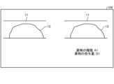
そして、抽出機能155bは、CT画像データ152aから時点T0における血管の形状及び時点T0におけるプラークの形状を抽出する(ステップS103)。図3は、第1の実施形態に係る解析装置150が実行する処理の一例を説明するための図である。例えば、ステップS103では、図3に示すように、抽出機能155bは、CT画像データ152aから時点T0における血管11の形状及び時点T0におけるプラーク12の形状を抽出する。
Then, the
そして、計算機能155cは、時点T0における血管11の形状及び時点TNにおけるプラーク12の形状に基づいて、時点TNにおけるプラーク12にかかるWSSを計算する(ステップS104)。例えば、変数Nに初期値「0」が設定されている場合、ステップS104では、計算機能155cは、時点T0における血管11の形状及び時点T0におけるプラーク12の形状に基づいて、時点T0におけるプラーク12にかかるWSSを計算する。プラーク12にかかるWSSは、ずり応力の一例であり、このようなずり応力を示す力学的指標の一例でもある。
Then, the
ここで、WSSを計算する様々な方法が、公知技術として知られている。ステップS104では、計算機能155cは、このような公知技術を用いて、プラーク12にかかるWSSを計算する。例えば、血管11に流入する単位時間あたりの血液の量、血管11に流入する血液が流れる速度、血管11から流出する単位時間あたりの血液の量、血管11から流出する血液が流れる速度、血管11の流入位置における血管の断面積、血管11の流出位置における血管の断面積、血管11の流入位置における血液の圧力、及び、血管11の流出位置における血液の圧力等の各種のパラメータの値が予め定められている。そして、計算機能155cは、これら各種のパラメータを用いて、プラーク12にかかるWSSを計算するための各種のシミュレーションを行う。これにより、プラーク12にかかるWSSが計算される。例えば、計算機能155cは、各種のパラメータを用いて、血管11の形状及びプラーク12の形状に基づいて、血流に対する有限要素シミュレーションまたは等価回路モデルを用いたシミュレーション等を実行することにより、プラーク12にかかるWSSを計算する。なお、血管11に流入する単位時間あたりの血液の量、血管11に流入する血液が流れる速度及び血管11の流入位置における血液の圧力は、血管11に流入する血液に関するパラメータである。また、血管11から流出する単位時間あたりの血液の量、血管11から流出する血液が流れる速度及び血管11の流出位置における血液の圧力は、血管11から流出する血液に関するパラメータである。
Here, various methods for calculating the WSS are known as publicly known techniques. In step S104, the
そして、予測機能155dは、時点TNにおけるプラーク12にかかるWSSに基づいて、時点TN+1におけるプラーク12の形状を予測する(ステップS105)。ここで、例えば、時点TNと、時点TNの次の時点TN+1との間の時間間隔(タイムステップ)は、例えば、1ヶ月である。すなわち、ステップS105では、予測機能155dは、時点TNにおけるプラーク12にかかるWSSに基づいて、時点TNから1ヶ月後の未来の時点TN+1におけるプラーク12の形状を予測する。より具体的には、例えば、変数Nに初期値「0」が設定されている場合、予測機能155dは、時点T0におけるプラーク12にかかるWSSに基づいて、時点T0から1ヶ月後の未来の時点T1におけるプラーク12の形状を予測する。
Then, the
ステップS105で予測機能155dにより実行される処理の具体例を説明する。図4は、第1の実施形態に係る解析装置150が実行する処理の一例を説明するための図である。図4には、時点TNにおけるプラーク12が破線で示され、時点TN+1におけるプラーク12が実線で示されている。
A specific example of the process executed by the
ステップS105では、まず、予測機能155dは、時点TNにおけるプラーク12にかかるWSSの大きさが、第1の閾値αを下回るか否かを判定する。ここで、例えば、WSSの大きさが第1の閾値αを下回るとは、WSSの大きさが第1の閾値α未満であることを意味する。WSSの大きさが第1の閾値αを下回る場合、プラーク12が成長して大きくなると考えられる。そこで、WSSの大きさが第1の閾値αを下回る場合、図4に示すように、予測機能155dは、時点TNにおけるプラーク12の表面の複数の位置12aのそれぞれの法線方向に、複数の位置12aのそれぞれから所定の大きさだけプラーク12の形状を大きくすることにより得られたプラーク12の形状を、時点TN+1におけるプラーク12の形状として予測する。ここで、所定の大きさは、例えば、0.01mmである。このようにして、予測機能155dは、時点TNにおけるプラーク12の形状を大きくすることにより、時点TN+1におけるプラーク12の形状を予測する。すなわち、予測機能155dは、時点TN+1におけるプラーク12の形状を時点TNにおけるプラーク12の形状よりも大きくすることにより、時点TN+1におけるプラーク12の形状を予測する。
In step S105, the
なお、プラーク12にかかるWSSの大きさが第1の閾値αを下回り、かつ、1拍動におけるWSSの差の最大値が第2の閾値βを上回る場合にも、プラーク12が成長して大きくなると考えられる。そこで、ステップS105において、予測機能155dは、時点TNにおけるプラーク12にかかるWSSの大きさが第1の閾値αを下回り、かつ、1拍動におけるWSSの差の最大値が第2の閾値βを上回るか否かを判定してもよい。ここでいう1拍動におけるWSSの差の最大値とは、例えば、1拍動におけるWSSの最大値と最小値との差である。また、WSSの差の最大値が第2の閾値βを上回るとは、WSSの差の最大値が第2の閾値βよりも大きいことを意味する。この場合、予測機能155dは、時点TNにおけるプラーク12にかかるWSSの大きさが第1の閾値αを下回り、かつ、1拍動におけるWSSの差の最大値が第2の閾値βを上回る場合に、上述したように、時点TNにおけるプラーク12の形状を大きくすることにより、時点TN+1におけるプラーク12の形状を予測してもよい。
It is also considered that the
なお、WSSの大きさが第1の閾値αを下回る場合、又は、第1の閾値αを下回り、かつ、1拍動におけるWSSの差の最大値が第2の閾値βを上回る場合、予測機能155dは、上述した方法以外の方法によって時点TNにおけるプラーク12の形状を大きくしてもよい。
In addition, when the size of the WSS falls below the first threshold value α, or when the size of the WSS falls below the first threshold value α and the maximum value of the difference in WSS in one beat exceeds the second threshold value β, the
例えば、予測機能155dは、時点TNにおけるプラーク12の体積を1%増加させることにより、時点TNにおけるプラーク12の形状を大きくしてもよい。その際、予測機能155dは、プラーク12の形状を、血管11に接していない各領域において、プラーク12の表面の法線方向に一定の割合で大きくなるようしてもよい。
For example, the
また、例えば、予測機能155dは、時点TNにおけるプラーク12の表面の複数の位置12aのそれぞれの法線方向に、複数の位置12aのそれぞれからWSSの大きさに応じた大きさだけプラーク12の形状を大きくしてもよい。ここで、「WSSの大きさに応じた大きさ」とは、例えば、WSSの大きさが「P」である場合、「0.01×C1×1/P」mmである。ただし、「C1」は、正の値の係数である。
Furthermore, for example, the
図2の説明に戻り、予測機能155dは、時点TNにおけるプラーク12にかかるWSSに基づいて、時点TN+1におけるプラーク12の物性を設定する(ステップS106)。
Returning to the explanation of FIG. 2, the
ステップS106で実行される処理の具体例を説明する。例えば、時点TNにおけるプラーク12にかかるWSSの大きさが、第1の閾値α以上である場合、プラーク12の表面に繊維性被膜が発達すると考えられる。例えば、プラーク12は、繊維性被膜、カルシウム及び脂質を含む複数の成分により形成されている。したがって、WSSの大きさが第1の閾値α以上である場合、複数の成分に対する線維性被膜の割合が大きくなると考えられる。繊維性被膜は、脂質と比較すると、硬い成分である。そのため、複数の成分に対する線維性被膜の割合が大きくなると、プラーク12は硬くなる。
A specific example of the process executed in step S106 will be described. For example, if the size of the WSS on the
そこで、ステップS106では、WSSの大きさが第1の閾値α以上である場合、予測機能155dは、時点TNにおけるプラーク12よりも時点TN+1におけるプラーク12のほうが硬くなるように、時点TN+1におけるプラーク12の物性を設定する。例えば、予測機能155dは、時点TNにおけるプラーク12を構成する全ての成分に対する線維性被膜の割合よりも時点TN+1におけるプラーク12を構成する全ての成分に対する線維性被膜の割合が大きくなるように、時点TNにおけるプラーク12の物性を変更することにより、時点TN+1におけるプラーク12の物性を設定する。
Therefore, in step S106, when the magnitude of WSS is equal to or greater than the first threshold value α, the
例えば、予測機能155dは、時点TNにおけるプラーク12の表面に含まれる全ての脂質のうち所定数の脂質を繊維性被膜に変更することにより、時点TN+1におけるプラーク12の物性を設定する。なお、予測機能155dは、時点TNにおけるプラーク12の表面を複数の領域に分割し、複数の領域の中からランダムに領域を選択し、選択された領域に含まれる成分を繊維性被膜に変更することにより、時点TN+1におけるプラーク12の物性を設定してもよい。
For example, the
また、ステップS106では、予測機能155dは、時点TNにおけるプラーク12にかかるWSSの大きさが、第1の閾値αよりも小さい第3の閾値γ以下であるか否かを判定する。WSSの大きさが第3の閾値γ以下である場合、プラーク12は、脂質をより多く含むように成長すると考えられる。したがって、WSSの大きさが第3の閾値γ以下である場合、複数の成分に対する脂質の割合が大きくなると考えられる。脂質は、カルシウム及び繊維性被膜と比較すると、柔らかい成分である。そのため、複数の成分に対する脂質の割合が大きくなると、プラーク12は柔らかくなる。
Also, in step S106, the
そこで、ステップS106では、WSSの大きさが第3の閾値γ以下である場合、予測機能155dは、時点TNにおけるプラーク12よりも時点TN+1におけるプラーク12のほうが柔らかくなるように、時点TN+1におけるプラーク12の物性を設定する。例えば、予測機能155dは、時点TNにおけるプラーク12を構成する全ての成分に対する脂質の割合よりも時点TN+1におけるプラーク12を構成する全ての成分に対する脂質の割合が大きくなるように、時点TNにおけるプラーク12の物性を変更することにより、時点TN+1におけるプラーク12の物性を設定する。
Therefore, in step S106, when the size of WSS is equal to or smaller than the third threshold value γ, the
例えば、予測機能155dは、時点TNにおけるプラーク12に含まれる全ての繊維性被膜及びカルシウムのうち所定数の繊維性被膜及びカルシウムを脂質に変更することにより、時点TN+1におけるプラーク12の物性を設定する。なお、予測機能155dは、時点TNにおけるプラーク12を複数の領域に分割し、複数の領域の中からランダムに領域を選択し、選択された領域に含まれる成分を脂質に変更することにより、時点TN+1におけるプラーク12の物性を設定してもよい。
For example, the
そして、計算機能155cは、時点TN+1においてプラーク12が特定の状態となるか否かを判定する(ステップS107)。
Then, the
ステップS107で計算機能155cにより実行される処理の具体例を説明する。図5は、第1の実施形態に係る解析装置150が実行する処理の一例を説明するための図である。例えば、ステップS107では、計算機能155cは、図5に示すように、時点TN+1において、プラーク12の成長が収束したか否かを判定する。例えば、計算機能155cは、時点TNにおけるプラーク12の複数の位置12aのそれぞれと時点TN+1におけるプラーク12の複数の位置12aのそれぞれとの距離を計算する。これにより、複数の距離が計算される。そして、計算機能155cは、複数の距離の平均値を計算する。そして、計算機能155cは、平均値が所定の閾値δ以下であるか否かを判定する。平均値が所定の閾値δ以下である場合、計算機能155cは、時点TN+1において、プラーク12の成長が収束したと判定する。また、平均値が所定の閾値δよりも大きい場合、計算機能155cは、時点TN+1において、プラーク12の成長が収束していないと判定する。
A specific example of the process executed by the
なお、ステップS107において、計算機能155cは、時点TNにおけるプラーク12にかかるWSSの大きさが、閾値(例えば、第1の閾値α)以上である場合、プラーク12の成長が収束したと判定してもよい。一方、計算機能155cは、時点TNにおけるプラーク12にかかるWSSの大きさが、閾値(例えば、第1の閾値α)を下回る場合、プラーク12の成長が収束していないと判定してもよい。また、ステップS107において、計算機能155cは、1拍動におけるWSSの差の最大値が第2の閾値β以下である場合、プラーク12の成長が収束したと判定してもよい。一方、計算機能155cは、1拍動におけるWSSの差の最大値が第2の閾値βを上回る場合、プラーク12の成長が収束していないと判定してもよい。
In step S107, the
時点TN+1においてプラーク12が特定の状態になっていない場合(ステップS107:No)、すなわち、時点TN+1においてプラーク12の成長が収束していない場合、計算機能155cは、変数Nの値を1つインクリメントする(ステップS108)。ここで、計算機能155cは、変数Nの値を1つインクリメントすることにより、時点TN(このNは1つインクリメントされる前のN)の次の時点を新たな時点TN(このNは1つインクリメントされた後のN)として導出する。例えば、変数Nの値が「0」である場合、計算機能155cは、変数Nの値を1つインクリメントすることにより、時点T0の次の時点T1を導出する。同様に、変数Nの値が「k(kは1以上の整数)」である場合、計算機能155cは、変数Nの値を1つインクリメントすることにより、時点Tkの次の時点Tk+1を導出する。時点T0以降の各時点は、第1の時点の一例である。また、このような第1の時点の次の時点は、第2の時点の一例である。
If the
そして、計算機能155cは、ステップS108からステップS104に戻る。そして、計算機能155c及び予測機能155dは、再び、ステップS104からステップS107までの各処理を実行する。
Then, the
なお、ステップS108からステップS104に戻った場合、ステップS104では、計算機能155cは、時点T0における血管の形状、及び、ステップS105で予測された時点TNにおけるプラーク12の形状を用いて、時点TNにおけるプラーク12にかかるWSSを計算する。
In addition, when returning from step S108 to step S104, in step S104, the
したがって、プラーク12が特定の状態となる(ステップS107:Yes)まで、ステップS108で変数Nの値を1つインクリメントすることが繰り返し行われ、変数Nの値が1つインクリメントされる度に、ステップS104からステップS107までの各処理が実行される。例えば、プラーク12の成長が収束するまで、変数Nの値が1つインクリメントされる度に、ステップS104からステップS107までの各処理が実行される。
Therefore, until the
また、第1の実施形態では、予測機能155dは、プラーク12の成長が収束するまで、時点Tkにおいてプラーク12にかかるWSSが計算される度に、計算された当該WSSに基づいて時点Tkの次の時点Tk+1におけるプラーク12の形状を予測する。
Furthermore, in the first embodiment, the
図6は、第1の実施形態に係る解析装置150が実行する処理の一例を説明するための図である。図6を参照して、時点TN+1においてプラーク12が特定の状態になった場合(ステップS107:Yes)、すなわち、時点TN+1においてプラーク12の成長が収束した場合に表示制御機能155eが実行する処理の一例について説明する。この場合(ステップS107:Yes)、表示制御機能155eは、図6に示すように、ステップS105で予測された時点TN+1におけるプラーク12の形状をディスプレイ154に表示させる(ステップS109)。
Fig. 6 is a diagram for explaining an example of processing executed by the analysis device 150 according to the first embodiment. With reference to Fig. 6, an example of processing executed by the display control function 155e when the
すなわち、ステップS109では、表示制御機能155eは、プラーク12が特定の状態となる時点(プラーク12が特定の状態となる場合の時点)TN+1におけるプラーク12の形状をディスプレイ154に表示させる。具体的には、表示制御機能155eは、プラーク12の成長が収束した時点TN+1におけるプラーク12の形状をディスプレイ154に表示させる。そして、表示制御機能155eは、解析処理を終了する。
That is, in step S109, the display control function 155e causes the
以上、第1の実施形態に係る解析装置150及び解析システム100について説明した。解析装置150及び解析システム100は、プラーク12が特定の状態となる時点TN+1におけるプラーク12の形状を予測する。具体的には、解析装置150及び解析システム100は、プラーク12の成長が収束した時点TN+1におけるプラーク12の形状を予測する。ここで、例えば、時点TN+1は、時点T0から2年後等の数年後等の時点である。したがって、第1の実施形態によれば、比較的遠い未来(例えば、数年後等)におけるプラーク12の状態を予測することができる。
The analysis device 150 and the
また、解析装置150及び解析システム100は、プラーク12が特定の状態となる時点TN+1におけるプラーク12の形状を表示する。具体的には、解析装置150及び解析システム100は、プラーク12の成長が収束した時点TN+1におけるプラーク12の形状を表示する。したがって、第1の実施形態によれば、比較的遠い未来におけるプラーク12の状態を医師等の使用者に確認させることができる。その結果、医師等の使用者によって行われる冠動脈等の血管の疾患に関する診断や治療計画の策定等を支援することができる。
Furthermore, the analysis device 150 and the
(第1の実施形態の第1の変形例)
上述した第1の実施形態では、ステップS104で、計算機能155cが、時点TNにおけるプラーク12にかかるWSSを計算する際に、時点T0における血管11の形状を用いる場合について説明した。このように、第1の実施形態では、解析処理において、血管11の形状が一定であり変化しない。しかしながら、計算機能155cは、血管11の形状を修正してもよい。そして、計算機能155cは、修正された時点TNにおける血管11の形状を用いて、時点TNにおけるプラーク12にかかるWSSを計算してもよい。
(First Modification of the First Embodiment)
In the above-described first embodiment, a case has been described in which in step S104, the
そこで、このような変形例を第1の実施形態の第1の変形例として説明する。なお、第1の実施形態の第1の変形例の説明では、主に、第1の実施形態と異なる点について説明し、第1の実施形態と同様の構成の説明については省略する場合がある。例えば、第1の実施形態の第1の変形例の説明では、第1の実施形態と同様の構成については同一の符号を付して、第1の実施形態と同様の構成の説明を省略する場合がある。 Therefore, such a modification will be described as a first modification of the first embodiment. Note that in the description of the first modification of the first embodiment, differences from the first embodiment will be mainly described, and a description of configurations similar to those of the first embodiment may be omitted. For example, in the description of the first modification of the first embodiment, configurations similar to those of the first embodiment may be given the same reference numerals, and a description of configurations similar to those of the first embodiment may be omitted.
図7は、第1の実施形態の第1の変形例に係る解析装置150が実行する解析処理の一例の流れを示すフローチャートである。図7に示す第1の実施形態の第1の変形例に係る解析処理では、ステップS103とステップS104との間、及び、ステップS108とステップS104との間に、ステップS121~S125の各処理が実行される点が、図2に示す第1の実施形態に係る解析処理と異なる。 Figure 7 is a flowchart showing the flow of an example of an analysis process executed by the analysis device 150 according to the first modification of the first embodiment. The analysis process according to the first modification of the first embodiment shown in Figure 7 differs from the analysis process according to the first embodiment shown in Figure 2 in that the processes of steps S121 to S125 are executed between steps S103 and S104, and between steps S108 and S104.
図7に示すように、ステップS103又はステップS108の処理が実行された後に、表示制御機能155eは、時点TNにおける血管11の形状及び時点TNにおけるプラーク12の形状をディスプレイ154に表示させる(ステップS121)。
As shown in FIG. 7, after the processing of step S103 or step S108 is executed, the display control function 155e causes the
そして、計算機能155cは、使用者から入力される修正指示であって、時点TNにおける血管11の形状を修正するための修正指示を入力インタフェース153が受け付けたか否かを判定する(ステップS122)。
Then, the
入力インタフェース153が修正指示を受け付けていない場合(ステップS122:No)、計算機能155cは、使用者から入力される修正不要の指示であって、時点TNにおける血管11の形状の修正が不要であることを示す修正不要の指示を入力インタフェース153が受け付けたか否かを判定する(ステップS123)。入力インタフェース153が修正不要の指示を受け付けた場合(ステップS123:Yes)、計算機能155cは、ステップS104に進み、ステップS104の処理を実行する。
If the
第1の実施形態の第1の変形例では、ステップS104において、変数Nの値が「0」である場合、計算機能155cは、時点T0における血管11の形状及び時点T0におけるプラーク12の形状に基づいて、時点T0におけるプラーク12にかかるWSSを計算する。また、ステップS104において、変数Nの値が「k(kは1以上の整数)」である場合、計算機能155cは、時点TNにおける血管11の形状及び時点TNにおけるプラーク12の形状に基づいて、時点TNにおけるプラーク12にかかるWSSを計算する。ここでいう時点TNにおける血管11の形状は、例えば、ステップS104又はステップS125において計算機能155cにより時点TN-1におけるプラーク12にかかるWSSが計算される際に用いられた時点TN-1における血管11の形状である。
In a first modified example of the first embodiment, when the value of the variable N is "0" in step S104, the
また、入力インタフェース153が修正不要の指示を受け付けていない場合(ステップS123:No)、計算機能155cは、ステップS122に戻り、ステップS122の処理を再び実行する。
Also, if the
また、入力インタフェース153が修正指示を受け付けた場合(ステップS122:Yes)、計算機能155cは、修正指示に基づいて時点TNにおける血管11の形状を修正する(ステップS124)。
Furthermore, when the
そして、計算機能155cは、修正された時点TNにおける血管11の形状及び時点TNにおけるプラーク12の形状に基づいて、時点TNにおけるプラーク12にかかるWSSを計算する(ステップS125)。計算機能155cは、ステップS125からステップS105に進んだ場合、ステップS105において、ステップS125において計算されたWSSに基づいて、時点TN+1におけるプラーク12の形状を予測する。
Then, the
また、第1の実施形態の第1の変形例において、ステップS108からステップS121に戻った場合について説明する。この場合、ステップS121では、表示制御機能155eは、時点TN-1におけるプラーク12にかかるWSSが計算される際に用いられた時点TN-1における血管11の形状を時点TNにおける血管11の形状として、時点TNにおける血管11の形状及び時点TNにおけるプラーク12の形状をディスプレイ154に表示させる。
A case where the process returns from step S108 to step S121 in the first modified example of the first embodiment will be described below. In this case, in step S121, the display control function 155e sets the shape of the
なお、図7に示す解析処理では、計算機能155cが、WSSを計算する際に用いられる時点TNにおける血管11の形状を修正する場合について説明した。ここで、血管11に流入する血液に関するパラメータ及び血管11から流出する血液に関するパラメータも、WSSを計算する際に用いられる。そこで、計算機能155cは、時点TNにおける血管11の形状を修正する方法と同様の方法で、血管11に流入する血液に関するパラメータ及び血管11から流出する血液に関するパラメータを修正してもよい。血管11に流入する血液に関するパラメータは、第1のパラメータの一例である。また、血管11から流出する血液に関するパラメータは、第2のパラメータの一例である。
In the analysis process shown in FIG. 7, the
すなわち、入力インタフェース153は、時点TNにおける血管11の形状を修正するための指示、血管11に流入する血液に関するパラメータを修正するための指示、及び、血管11から流出する血液に関するパラメータを修正するための指示のうち少なくとも1つの指示を受け付ける。そして、計算機能155cは、入力インタフェース153により受け付けられた少なくとも1つの指示に基づいて修正された、時点TNにおける血管11の形状、血管11に流入する血液に関するパラメータ及び血管11から流出する血液に関するパラメータの少なくとも1つに基づいて、時点TNにおけるプラーク12にかかるWSSを計算する。
That is, the
以上、第1の実施形態の第1の変形例に係る解析装置150及び解析システム100について説明した。第1の実施形態の第1の変形例によれば、プラーク12にかかるWSSを計算する際に用いられる血管11の形状が正確な形状でない場合には、使用者により血管11の形状が正確な形状に修正されることで、精度良くWSSを計算することができる。同様に、プラーク12にかかるWSSを計算する際に用いられる各種のパラメータの値が正確でない場合には、使用者によりパラメータの値が正確な値に修正されることで、精度良くWSSを計算することができる。
The above describes the analysis device 150 and
(第1の実施形態の第2の変形例)
なお、ステップS105において、予測機能155dは、上述した第1の実施形態で説明した方法とは異なる他の方法で、時点TN+1におけるプラーク12の形状を予測してもよい。例えば、プラーク12は、比較的柔らかい物体である。このため、プラーク12は、血流から受ける力(圧力)によって変形することが考えられる。そこで、予測機能155dが、プラーク12の形状を予測する際に、血流から受ける力に基づいてプラーク12を変形させてもよい。そこで、このような変形例を第1の実施形態の第2の変形例として説明する。
(Second Modification of the First Embodiment)
In step S105, the
なお、第1の実施形態の第2の変形例の説明では、主に、第1の実施形態と異なる点について説明し、第1の実施形態と同様の構成の説明については省略する場合がある。例えば、第1の実施形態の第2の変形例の説明では、第1の実施形態と同様の構成については同一の符号を付して、第1の実施形態と同様の構成の説明を省略する場合がある。 In the description of the second modified example of the first embodiment, differences from the first embodiment will be mainly described, and descriptions of configurations similar to those of the first embodiment may be omitted. For example, in the description of the second modified example of the first embodiment, configurations similar to those of the first embodiment may be given the same reference numerals, and descriptions of configurations similar to those of the first embodiment may be omitted.
図8及び図9を参照して、第1の実施形態の第2の変形例に係る予測機能155dが時点TN+1におけるプラーク12の形状を予測する方法について説明する。図8及び図9は、第1の実施形態の第2の変形例に係る解析装置150が実行する処理の一例を説明するための図である。
A method for predicting the shape of the
WSSの大きさが第1の閾値αを下回る場合、又は、第1の閾値αを下回り、かつ、1拍動におけるWSSの差の最大値が第2の閾値βを上回る場合、予測機能155dは、時点TNにおけるプラーク12の表面の複数の位置12aのそれぞれの法線方向と、図8に示す矢印13により示される方向であって血管11内の血液が流れる方向との成す角度を計算する。例えば、予測機能155dは、複数の位置12aのそれぞれについて0度以上180度以下の範囲で角度を計算する。
When the magnitude of WSS falls below the first threshold value α, or when it falls below the first threshold value α and the maximum difference in WSS in one pulse exceeds the second threshold value β, the
図8の例では、5つの位置12aのうち図8において最も左側の位置12aの法線方向と、矢印13により示される血液が流れる方向との成す角度は、180度である。また、5つの位置12aのうち左右方向において真ん中の位置12aの法線方向と、矢印13により示される血液が流れる方向との成す角度は、90度である。5つの位置12aのうち図8において最も右側の位置12aの法線方向と、矢印13により示される血液が流れる方向との成す角度は、0度である。
In the example of Figure 8, the angle between the normal direction of the
ここで、位置12aが血流による受ける力は、角度が小さくなるにつれて小さくなり、角度が大きくなるにつれて大きくなる。このため、プラーク12の位置12aの部分の成長は、角度が小さくなるにつれて促進され、角度が大きくなるにつれて抑制される。
Here, the force that position 12a receives from the blood flow decreases as the angle decreases and increases as the angle increases. Therefore, the growth of the portion of
そこで、図9に示すように、予測機能155dは、複数の位置12aのそれぞれの法線方向に、角度に応じた大きさだけプラーク12の形状を大きくする。そして、予測機能155dは、このようにして得られたプラーク12の形状を、時点TN+1におけるプラーク12の形状として予測する。ここで、角度に応じた大きさとは、例えば、角度が小さくなるにつれて大きくなる大きさであり、角度が大きくなるにつれて小さくなる大きさである。したがって、第1の実施形態の第2の変形例によれば、予測機能155dは、血流から受ける力によってどのようにプラーク12が変形するかを予測することができる。
9, the
以上、第1の実施形態の第2の変形例に係る解析装置150及び解析システム100について説明した。第1の実施形態の第2の変形例では、上述したように、予測機能155dは、時点TNにおけるプラーク12の表面の複数の位置12aのそれぞれの法線方向に、複数の位置12aのそれぞれの法線方向と血管11内の血液が流れる方向との成す角度に応じた大きさだけプラーク12の形状を大きくすることにより、時点TN+1におけるプラーク12の形状を予測する。したがって、第1の実施形態の第2の変形例によれば、上述したように、血流から受ける力によってプラーク12がどのように変形するかを予測することができる。
The analysis device 150 and the
なお、血流から受ける力によってプラーク12がどのように変形するかを予測する方法は、上述した方法に限られない。そこで、血流から受ける力によってプラーク12がどのように変形するかを予測する他の方法について説明する。
Note that the method for predicting how
例えば、予測機能155dは、第1の実施形態と同様に、先の図4に示すように、時点TNにおけるプラーク12の表面の複数の位置12aのそれぞれの法線方向に、複数の位置12aのそれぞれから所定の大きさだけプラーク12の形状を大きくする。
For example, as in the first embodiment, the
そして、予測機能155dは、血流の圧力をプラーク12にかけたときにどのようにプラーク12が変形するかを流体構造錬成シミュレーション等を用いて予測する。例えば、予測機能155dは、まず、プラーク12の柔らかさの空間分布を定義する。例えば、予測機能155dは、CT画像データ152aからプラーク12のCT値の分布を取得する。そして、予測機能155dは、プラーク12のCT値の分布に基づいてプラーク12の柔らかさの空間分布を定義する。
The
そして、予測機能155dは、血流によってプラーク12の各位置12aが受ける圧力の大きさ及び向き、プラーク12の形状及びプラーク12の柔らかさの空間分布に基づいて、プラーク12がどのように変形するかをシミュレートし、変形後のプラーク12の形状を得る。
Then, the
そして、予測機能155dは、得られたプラーク12の形状を、時点TN+1におけるプラーク12の形状として予測する。
Then, the
(第2の実施形態)
第1の実施形態では、解析装置150が、プラーク12が特定の状態になる時点としてプラーク12の成長が収束した時点を用いる場合について説明した。そして、第1の実施形態では、解析装置150が、プラーク12の成長が収束した時点におけるプラーク12の形状を予測し、予測されたプラーク12の形状を表示する場合について説明した。しかしながら、解析装置150は、プラーク12が特定の状態になる時点として、プラーク12が被検体にリスクを発生させる状態になる時点を用いても良い。そして、解析装置150は、プラーク12が被検体にリスクを発生させる状態になる時点におけるプラーク12の形状を予測し、予測されたプラーク12の形状を表示してもよい。そこで、このような実施形態を第2の実施形態として説明する。
Second Embodiment
In the first embodiment, a case has been described in which the analysis device 150 uses the time point at which the growth of the
なお、第2の実施形態の説明では、主に、第1の実施形態と異なる点について説明し、第1の実施形態と同様の構成の説明については省略する場合がある。例えば、第2の実施形態の説明では、第1の実施形態と同様の構成については同一の符号を付して、第1の実施形態と同様の構成の説明を省略する場合がある。 In the description of the second embodiment, differences from the first embodiment will be mainly described, and descriptions of configurations similar to those of the first embodiment may be omitted. For example, in the description of the second embodiment, configurations similar to those of the first embodiment may be given the same reference numerals, and descriptions of configurations similar to those of the first embodiment may be omitted.
図10は、第2の実施形態に係る解析装置150が実行する処理の一例を説明するための図である。例えば、第2の実施形態において、ステップS107では、計算機能155cは、図10に示すように、時点TN+1において、プラーク12が被検体にリスクを発生させる状態になるか否かを判定する。具体的には、ステップS107で、計算機能155cは、時点TN+1において、プラーク12が破断した状態になるか否かを判定する。
Fig. 10 is a diagram for explaining an example of processing executed by the analysis device 150 according to the second embodiment. For example, in the second embodiment, in step S107, the
ステップS107で実行される処理の具体例について説明する。例えば、計算機能155cは、プラーク12にかかる流体の力を計算する。そして、計算機能155cは、プラーク12の形状とプラーク12の物性(例えば柔らかさ)から、プラーク12に一定の力以上の力がかかった時点で、プラーク12が破断した状態になると判定する。また、計算機能155cは、プラーク12にかかる力が一定の力よりも小さい力である場合、プラーク12が破断した状態にならないと判定する。なお、計算機能155cは、破壊力学を用いて、プラーク12が破断する状態になるか否かを判定してもよい。
A specific example of the process executed in step S107 will be described. For example, the
計算機能155cは、プラーク12が破断した状態になると判定することにより、プラーク12が被検体にリスクを発生させる状態になると判定する。また、計算機能155cは、プラーク12が破断した状態にならないと判定することにより、プラーク12が被検体にリスクを発生させる状態にならないと判定する。
The
プラーク12が被検体にリスクを発生させる状態になる場合(ステップS107:Yes)、表示制御機能155eは、ステップS109に進み、ステップS109の処理を実行する。一方、プラーク12が被検体にリスクを発生させる状態にならない場合(ステップS107:No)、計算機能155cは、ステップS108に進み、ステップS108の処理を実行する。
If the
したがって、第2の実施形態では、計算機能155cは、プラーク12が被検体にリスクを発生させる状態になるまで、時点Tkを導出する度に、時点Tkにおいてプラーク12にかかるWSSを計算する。そして、予測機能155dは、プラーク12が被検体にリスクを発生させる状態になるまで、時点Tkにおいてプラーク12にかかるWSSが計算される度に、計算された当該WSSに基づいて時点Tkの次の時点Tk+1におけるプラーク12の形状を予測する。そして、表示制御機能155eは、プラーク12が被検体にリスクを発生させる状態になる時点Tk+1におけるプラーク12の形状をディスプレイ154に表示させる。
Therefore, in the second embodiment, the
具体的には、計算機能155cは、プラーク12が破断する状態になるまで、時点Tkを導出する度に、時点Tkにおいてプラーク12にかかるWSSを計算する。そして、予測機能155dは、プラーク12が破断する状態になるまで、時点Tkにおいてプラーク12にかかるWSSが計算される度に、計算された当該WSSに基づいて時点Tkの次の時点Tk+1におけるプラーク12の形状を予測する。そして、表示制御機能155eは、プラーク12が破断する状態になる時点Tk+1におけるプラーク12の形状をディスプレイ154に表示させる。
Specifically, the
以上、第2の実施形態に係る解析装置150及び解析システム100について説明した。第2の実施形態によれば、比較的遠い未来においてプラーク12が被検体にリスクを発生させる状態となることを予測することができる。また、比較的遠い未来においてプラーク12が破断する状態となることを予測することができる。
The above describes the analysis device 150 and
また、第2の実施形態によれば、比較的遠い未来においてプラーク12が被検体にリスクを発生させる状態となることを医師等の使用者に確認させることができる。また、第2の実施形態によれば、比較的遠い未来においてプラーク12が破断する状態となることを医師等の使用者に確認させることができる。その結果、医師等の使用者によって行われる冠動脈等の血管の疾患に関する診断や治療計画の策定等を支援することができる。
Furthermore, according to the second embodiment, it is possible to allow a user such as a doctor to confirm that in the relatively distant future, the
(第3の実施形態)
上述した第2の実施形態では、解析装置150が、プラーク12が被検体にリスクを発生させる状態になる時点として、プラーク12が破断する状態になる時点を用いる場合について説明した。また、第2の実施形態では、解析装置150が、プラーク12が破断する状態になる時点におけるプラーク12の形状を予測し、予測されたプラーク12の形状を表示する場合について説明した。しかしながら、解析装置150は、プラーク12が被検体にリスクを発生させる状態になる時点として、プラーク12が血管11内の血流を妨げる状態になる時点を用いても良い。そして、解析装置150は、プラーク12が血管11内の血流を妨げる状態になる時点におけるプラーク12の形状を予測し、予測されたプラーク12の形状を表示してもよい。そこで、このような実施形態を第3の実施形態として説明する。
Third Embodiment
In the above-described second embodiment, a case has been described in which the analysis device 150 uses the time when the
なお、第3の実施形態の説明では、主に、第1の実施形態と異なる点について説明し、第1の実施形態と同様の構成の説明については省略する場合がある。例えば、第3の実施形態の説明では、第1の実施形態と同様の構成については同一の符号を付して、第1の実施形態と同様の構成の説明を省略する場合がある。 Note that in the description of the third embodiment, differences from the first embodiment will be mainly described, and descriptions of configurations similar to those of the first embodiment may be omitted. For example, in the description of the third embodiment, configurations similar to those of the first embodiment may be given the same reference numerals, and descriptions of configurations similar to those of the first embodiment may be omitted.
図11は、第3の実施形態に係る解析装置150が実行する処理の一例を説明するための図である。例えば、第3の実施形態において、ステップS107では、計算機能155cは、図11に示すように、時点TN+1において、プラーク12が被検体にリスクを発生させる状態になるか否かを判定する。具体的には、ステップS107で、計算機能155cは、時点TN+1において、プラーク12が血管11内の血流を妨げる状態になるか否かを判定する。
Fig. 11 is a diagram for explaining an example of processing executed by the analysis device 150 according to the third embodiment. For example, in the third embodiment, in step S107, the
ステップS107で実行される処理の具体例について説明する。例えば、計算機能155cは、時点TNにおける血管11内の血流予備量比(Fractional Flow Reserve:FFR)を計算する。例えば、計算機能155cは、FFRを計算する公知技術を用いて、FFRを計算する。例えば、計算機能155cは、時点T0における血管11の形状、時点TNにおけるプラーク12の形状、血管11に流入する血液に関するパラメータ及び血管11から流出する血液に関するパラメータに基づいて、時点TNにおけるFFRを計算する。
A specific example of the process executed in step S107 will be described. For example, the
そして、計算機能155cは、時点TNにおけるFFRの値が所定値(例えば、0.85)未満であるか否かを判定する。時点TNにおけるFFRの値が所定値未満である場合、計算機能155cは、時点TN+1において、プラーク12が血管11内の血流を妨げる状態になると判定する。一方、時点TNにおけるFFRの値が所定値以上である場合、計算機能155cは、時点TN+1において、プラーク12が血管11内の血流を妨げる状態にならないと判定する。
Then, the
計算機能155cは、プラーク12が血管11内の血流を妨げる状態になると判定することにより、プラーク12が被検体にリスクを発生させる状態になると判定する。また、計算機能155cは、プラーク12が血管11内の血流を妨げる状態にならないと判定することにより、プラーク12が被検体にリスクを発生させる状態にならないと判定する。
The
プラーク12が被検体にリスクを発生させる状態になる場合(ステップS107:Yes)、表示制御機能155eは、ステップS109に進み、ステップS109の処理を実行する。一方、プラーク12が被検体にリスクを発生させる状態にならない場合(ステップS107:No)、計算機能155cは、ステップS108に進み、ステップS108の処理を実行する。
If the
したがって、第3の実施形態では、計算機能155cは、プラーク12が血管11内の血流を妨げる状態になるまで、時点Tkを導出する度に、時点Tkにおいてプラーク12にかかるWSSを計算する。そして、予測機能155dは、プラーク12が血管11内の血流を妨げる状態になるまで、時点Tkにおいてプラーク12にかかるWSSが計算される度に、計算された当該WSSに基づいて時点Tkの次の時点Tk+1におけるプラーク12の形状を予測する。そして、表示制御機能155eは、プラーク12が血管11内の血流を妨げる状態になる時点Tk+1におけるプラーク12の形状をディスプレイ154に表示させる。
Therefore, in the third embodiment, the
以上、第3の実施形態に係る解析装置150及び解析システム100について説明した。第3の実施形態によれば、比較的遠い未来においてプラーク12が被検体にリスクを発生させる状態となることを予測することができる。また、比較的遠い未来においてプラーク12が血管11内の血流を妨げる状態となることを予測することができる。
The above describes the analysis device 150 and
また、第3の実施形態によれば、比較的遠い未来においてプラーク12が被検体にリスクを発生させる状態となることを医師等の使用者に確認させることができる。また、第3の実施形態によれば、比較的遠い未来においてプラーク12が血管11内の血流を妨げる状態となることを医師等の使用者に確認させることができる。その結果、医師等の使用者によって行われる冠動脈等の血管の疾患に関する診断や治療計画の策定等を支援することができる。
Furthermore, according to the third embodiment, it is possible to allow a user such as a doctor to confirm that in the relatively distant future,
(第4の実施形態)
第1の実施形態では、解析装置150は、血管11内に治療用のステントが留置されていない状態で、プラーク12が特定の状態になる時点TN+1におけるプラーク12の形状を予測する場合について説明した。しかしながら、解析装置150は、更に、血管11内に治療用のステントが留置されている状態で、プラーク12が特定の状態になる時点TN+1におけるプラーク12の形状を予測してもよい。そして、解析装置150は、血管11内にステントが留置されていない状態で予測されたプラーク12の形状、及び、血管11内にステントが留置されている状態で予測されたプラーク12の形状を表示してもよい。そこで、このような実施形態を第4の実施形態として説明する。
(Fourth embodiment)
In the first embodiment, the analysis device 150 predicts the shape of the
なお、第4の実施形態の説明では、主に、第1の実施形態と異なる点について説明し、第1の実施形態と同様の構成の説明については省略する場合がある。例えば、第4の実施形態の説明では、第1の実施形態と同様の構成については同一の符号を付して、第1の実施形態と同様の構成の説明を省略する場合がある。 Note that in the description of the fourth embodiment, differences from the first embodiment will be mainly described, and descriptions of configurations similar to those of the first embodiment may be omitted. For example, in the description of the fourth embodiment, configurations similar to those of the first embodiment may be given the same reference numerals, and descriptions of configurations similar to those of the first embodiment may be omitted.
第4の実施形態では、解析装置150は、まず、第1の実施形態と同様に、血管11内にステントが留置されていない状態で、プラーク12が特定の状態になる時点TN+1におけるプラーク12の形状を予測する。第4の実施形態についての説明では、以下、「血管11内にステントが留置されていない状態」を「第1の状態」と表記する。例えば、解析装置150は、図2に示すステップS101~S108の各処理を実行することにより、第1の状態で、プラーク12が特定の状態になる時点TN+1におけるプラーク12の形状を予測する。
In the fourth embodiment, similarly to the first embodiment, the analysis device 150 first predicts the shape of the
図12は、第4の実施形態に係る解析装置150が実行する処理の一例を説明するための図である。図12の例では、ステント治療が行われている場合が示されている。図12に示すように、プラーク12により狭窄した血管11の狭窄部分がステント14により広げられている。解析装置150は、更に、図12に示すように血管11内にステント14が留置された状態で、プラーク12が特定の状態になる時点TN+1におけるプラーク12の形状を予測する。第4の実施形態についての説明では、以下、「血管11内にステント14が留置されている状態」を「第2の状態」と表記する。例えば、解析装置150は、図2に示すステップS101~S108の処理と同様の処理を実行することにより、第2の状態で、プラーク12が特定の状態になる時点TN+1におけるプラーク12の形状を予測する。ただし、ステップS104において、計算機能155cは、時点T0における血管11の形状及び時点TNにおけるプラーク12の形状に加えてステント14の形状に基づいて、時点TNにおけるプラーク12にかかるWSSを計算する。ステント14の形状は、解析処理において全ての時点で一定であり、変化しない。
FIG. 12 is a diagram for explaining an example of a process executed by the analysis device 150 according to the fourth embodiment. In the example of FIG. 12, a case where a stent treatment is performed is shown. As shown in FIG. 12, a narrowed portion of a
図13は、第4の実施形態に係る解析装置150が実行する処理の一例を説明するための図である。図13に示すように、表示制御機能155eは、第1の状態においてプラーク12が特定の状態になる時点TN+1におけるプラーク12の形状、及び、第2の状態においてプラーク12が特定の状態となる時点TN+1におけるプラーク12の形状を並べてディスプレイ154に表示させる。これにより、ステント14を用いたステント治療を行った場合のプラーク12の形状についての予測結果と、ステント治療を行わない場合のプラーク12の形状についての予測結果とを医師等の使用者に確認させることができる。その結果、医師等の使用者によって行われる冠動脈等の血管の疾患に関する診断や治療計画の策定等を支援することができる。
Fig. 13 is a diagram for explaining an example of processing executed by the analysis device 150 according to the fourth embodiment. As shown in Fig. 13, the display control function 155e causes the
また、図13に示すように、表示制御機能155eは、ステント14の位置「P1」及びステント14の長さ「L1」をディスプレイ154に表示させる。これにより、ステント治療の際に用いられたステント14の位置及び長さを医師等の使用者に確認させることができる。したがって、この点からも、医師等の使用者によって行われる冠動脈等の血管の疾患に関する診断や治療計画の策定等を支援することができる。
Also, as shown in FIG. 13, the display control function 155e causes the position "P1" of the
また、表示制御機能155eは、第1の状態においてプラーク12が特定の状態になる時点TN+1、及び、第2の状態においてプラーク12が特定の状態になる時点TN+1をディスプレイ154に表示させてもよい。なお、第1の状態においてプラーク12が特定の状態になる時点TN+1と、第2の状態においてプラーク12が特定の状態になる時点TN+1とは、同一の時点である場合もあれば、異なる時点である場合もある。これにより、医師等の使用者は、第1の状態及び第2の状態のそれぞれにおいて、プラーク12が特定の状態になる時点を確認することができる。したがって、この点からも、医師等の使用者によって行われる冠動脈等の血管の疾患に関する診断や治療計画の策定等を支援することができる。
Furthermore, the display control function 155e may display on the
なお、第4の実施形態において、プラーク12が特定の状態になる時点とは、例えば、プラーク12の成長が収束する時点、又は、プラーク12が被検体にリスクを発生させる状態になる時点(例えば、プラーク12が破断する時点又はプラーク12が血管11内の血流を妨げる状態になる時点)である。
In the fourth embodiment, the time when the
ここで、第4の実施形態において、プラーク12が特定の状態になる時点が、例えば、プラーク12が、時点T0から所定時間後(例えば、数年後等)の特定の時点のプラークとなる特定の時点であってもよい。かかる特定の時点は、第3の時点の一例である。
Here, in the fourth embodiment, the time point at which the
以上、第4の実施形態に係る解析装置150及び解析システム100について説明した。第4の実施形態によれば、上述したように、医師等の使用者によって行われる冠動脈等の血管の疾患に関する診断や治療計画の策定等を支援することができる。
The above describes the analysis device 150 and
(第5の実施形態)
第4の実施形態では、解析装置150が、ステント14を用いたステント治療を行った場合のプラーク12の形状についての予測結果、及び、ステント治療を行わない場合のプラーク12の形状についての予測結果を表示する場合について説明した。しかしながら、解析装置150は、血管11内に留置されたステント14の位置及び長さの少なくとも1つが互いに異なる、血管11内にステント14が留置された複数の状態のそれぞれの状態において予測されたプラーク12の形状を表示してもよい。そこで、このような実施形態を第5の実施形態として説明する。
Fifth Embodiment
In the fourth embodiment, a case has been described in which the analysis device 150 displays a predicted result of the shape of the
なお、第5の実施形態の説明では、主に、第4の実施形態と異なる点について説明し、第4の実施形態と同様の構成の説明については省略する場合がある。例えば、第5の実施形態の説明では、第4の実施形態と同様の構成については同一の符号を付して、第4の実施形態と同様の構成の説明を省略する場合がある。 Note that in the description of the fifth embodiment, differences from the fourth embodiment will be mainly described, and descriptions of configurations similar to those of the fourth embodiment may be omitted. For example, in the description of the fifth embodiment, configurations similar to those of the fourth embodiment may be given the same reference numerals, and descriptions of configurations similar to those of the fourth embodiment may be omitted.
第5の実施形態では、解析装置150は、血管11内にステント14が留置された複数の状態のそれぞれの状態において、第4の実施形態と同様の方法で、プラーク12が特定の状態になる時点TN+1におけるプラーク12の形状を予測する。かかる複数の状態とは、血管11内に留置されたステント14の位置及び長さの少なくとも1つが互いに異なる複数の状態である。以下、かかる複数の状態として2つの状態を例に挙げて説明するが、複数の状態は3つ以上の状態であってもよい。
In the fifth embodiment, the analysis device 150 predicts the shape of the
例えば、血管11内の位置「P2」に、長さが「L2」であるステント14が留置された状態、及び、血管11内の位置「P3」に、長さが「L3」であるステント14が留置された状態の2つの状態を例に挙げて説明する。この場合、解析装置150は、かかる2つの状態のそれぞれの状態で、プラーク12が特定の状態になる時点TN+1におけるプラーク12の形状を予測する。
For example, two states will be described: a state in which a
第5の実施形態の説明において、以下、「血管11内の位置「P2」に長さが「L2」であるステント14が留置された状態」を「第1の状態」と表記する。また、第5の実施形態の説明において、以下、「血管11内の位置「P3」に長さが「L3」であるステント14が留置された状態」を「第2の状態」と表記する。
In the following description of the fifth embodiment, the state in which a
図14は、第5の実施形態に係る解析装置150が実行する処理の一例を説明するための図である。図14に示すように、表示制御機能155eは、第1の状態においてプラーク12が特定の状態になる時点TN+1におけるプラーク12の形状、及び、第2の状態においてプラーク12が特定の状態となる時点TN+1におけるプラーク12の形状を並べてディスプレイ154に表示させる。なお、第1の状態においてプラーク12が特定の状態になる時点TN+1と、第2の状態においてプラーク12が特定の状態になる時点TN+1とは、同一の時点である場合もあれば、異なる時点である場合もある。これにより、第1の状態でステント治療を行った場合のプラーク12の形状についての予測結果と、第2の状態でステント治療を行った場合のプラーク12の形状についての予測結果とを医師等の使用者に確認させることができる。その結果、医師等の使用者によって行われる冠動脈等の血管の疾患に関する診断や治療計画の策定等を支援することができる。
14 is a diagram for explaining an example of a process executed by the analysis device 150 according to the fifth embodiment. As shown in FIG. 14, the display control function 155e causes the
また、図14に示すように、表示制御機能155eは、ステント14の位置「P2」及びステント14の長さ「L2」、並びに、ステント14の位置「P3」及びステント14の長さ「L3」ディスプレイ154に表示させる。
Also, as shown in FIG. 14, the display control function 155e causes the position "P2" of the
ここで、第5の実施形態において、プラーク12が特定の状態になる時点とは、例えば、プラーク12が、時点T0から所定時間後(例えば、数年後等)の特定の時点のプラークとなる特定の時点であってもよい。かかる特定の時点は、第3の時点の一例である。この場合、表示制御機能155eは、特定の時点における複数のプラーク12の形状のうち、プラーク12が被検体にリスクを発生させないプラーク12の形状をディスプレイ154に表示させてもよい。
Here, in the fifth embodiment, the time point at which the
以上、第5の実施形態に係る解析装置150及び解析システム100について説明した。第5の実施形態によれば、上述したように、医師等の使用者によって行われる冠動脈等の血管の疾患に関する診断や治療計画の策定等を支援することができる。
The above describes the analysis device 150 and
(第6の実施形態)
第1の実施形態では、被検体にスタチン又はPCSK9阻害薬等の血液中のコレステロール値を低減させる薬物が投与されていない。したがって、第1の実施形態では、解析装置150は、薬物が投与されていない状態で、プラーク12が特定の状態になる時点TN+1におけるプラーク12の形状を予測する場合について説明した。しかしながら、解析装置150は、更に、被検体に上述した薬物が投与された状態で、プラーク12が特定の状態になる時点TN+1におけるプラーク12の形状を予測してもよい。そして、解析装置150は、被検体に薬物が投与されていない状態で予測されたプラーク12の形状、及び、被検体に薬物が投与された状態で予測されたプラーク12の形状を表示してもよい。そこで、このような実施形態を第6の実施形態として説明する。
Sixth Embodiment
In the first embodiment, the subject is not administered with a drug that reduces cholesterol levels in the blood, such as a statin or a PCSK9 inhibitor. Therefore, in the first embodiment, the analysis device 150 predicts the shape of the
なお、第6の実施形態の説明では、主に、第1の実施形態と異なる点について説明し、第1の実施形態と同様の構成の説明については省略する場合がある。例えば、第6の実施形態の説明では、第1の実施形態と同様の構成については同一の符号を付して、第1の実施形態と同様の構成の説明を省略する場合がある。 In the description of the sixth embodiment, differences from the first embodiment will be mainly described, and descriptions of configurations similar to those of the first embodiment may be omitted. For example, in the description of the sixth embodiment, configurations similar to those of the first embodiment may be given the same reference numerals, and descriptions of configurations similar to those of the first embodiment may be omitted.
第6の実施形態では、解析装置150は、まず、第1の実施形態と同様に、被検体に薬物が投与されていない状態で、プラーク12が特定の状態になる時点TN+1におけるプラーク12の形状を予測する。第6の実施形態についての説明では、以下、「被検体に薬物が投与されていない状態」を「第1の状態」と表記する。例えば、解析装置150は、図2に示すステップS101~S108の各処理を実行することにより、第1の状態でプラーク12が特定の状態になる時点TN+1におけるプラーク12の形状を予測する。
In the sixth embodiment, similarly to the first embodiment, the analysis device 150 first predicts the shape of the
解析装置150は、更に、被検体に薬物が投与された状態で、プラーク12が特定の状態になる時点TN+1におけるプラーク12の形状を予測する。第6の実施形態についての説明では、以下、「被検体に薬物が投与された状態」を「第2の状態」と表記する。例えば、解析装置150は、図2に示すステップS101~S108の処理と同様の処理を実行することにより、第2の状態で、プラーク12が特定の状態になる時点TN+1におけるプラーク12の形状を予測する。ただし、ステップS105において、予測機能155dは、プラーク12の形状を予測する際に、薬物の種類及び投与量等に応じた影響を考慮する。
The analysis device 150 further predicts the shape of the
図15は、第6の実施形態に係る解析装置150が実行する処理の一例を説明するための図である。図15に示すように、表示制御機能155eは、第1の状態においてプラーク12が特定の状態になる時点TN+1におけるプラーク12の形状、及び、第2の状態においてプラーク12が特定の状態となる時点TN+1におけるプラーク12の形状を並べてディスプレイ154に表示させる。なお、第1の状態においてプラーク12が特定の状態になる時点TN+1と、第2の状態においてプラーク12が特定の状態になる時点TN+1とは、同一の時点である場合もあれば、異なる時点である場合もある。これにより、薬物治療を行った場合のプラーク12の形状についての予測結果と、薬物治療を行わない場合のプラーク12の形状についての予測結果とを医師等の使用者に確認させることができる。その結果、医師等の使用者によって行われる冠動脈等の血管の疾患に関する診断や治療計画の策定等を支援することができる。
FIG. 15 is a diagram for explaining an example of a process executed by the analysis device 150 according to the sixth embodiment. As shown in FIG. 15, the display control function 155e causes the
また、図15に示すように、表示制御機能155eは、被検体に投与された薬物の種類「K1」及び薬物の投与量「D1」をディスプレイ154に表示させる。これにより、薬物治療の際に用いられた薬物の種類及び投与量を医師等の使用者に確認させることができる。したがって、この点からも、医師等の使用者によって行われる冠動脈等の血管の疾患に関する診断や治療計画の策定等を支援することができる。
Also, as shown in FIG. 15, the display control function 155e causes the type of drug "K1" administered to the subject and the drug dosage "D1" to be displayed on the
また、表示制御機能155eは、第1の状態においてプラーク12が特定の状態になる時点TN+1及び第2の状態においてプラーク12が特定の状態になる時点TN+1をディスプレイ154に表示させてもよい。
The display control function 155e may also cause the
なお、第6の実施形態において、プラーク12が特定の状態になる時点とは、例えば、第4の実施形態と同様である。
In the sixth embodiment, the point in time when the
以上、第6の実施形態に係る解析装置150及び解析システム100について説明した。第6の実施形態によれば、上述したように、医師等の使用者によって行われる冠動脈等の血管の疾患に関する診断や治療計画の策定等を支援することができる。
The above describes the analysis device 150 and
(第7の実施形態)
第6の実施形態では、解析装置150が、薬物治療を行う場合のプラーク12の形状についての予測結果、及び、薬物治療を行わない場合のプラーク12の形状についての予測結果を表示する場合について説明した。しかしながら、解析装置150は、被検体に投与される薬物の種類及び投与量の少なくとも1つが互いに異なる、被検体に薬物が投与された複数の状態のそれぞれの状態において予測されたプラーク12の形状を表示してもよい。そこで、このような実施形態を第7の実施形態として説明する。
Seventh Embodiment
In the sixth embodiment, the analysis device 150 displays the predicted shape of the
なお、第7の実施形態の説明では、主に、第6の実施形態と異なる点について説明し、第6の実施形態と同様の構成の説明については省略する場合がある。例えば、第7の実施形態の説明では、第6の実施形態と同様の構成については同一の符号を付して、第6の実施形態と同様の構成の説明を省略する場合がある。 In the description of the seventh embodiment, differences from the sixth embodiment will be mainly described, and descriptions of configurations similar to those of the sixth embodiment may be omitted. For example, in the description of the seventh embodiment, configurations similar to those of the sixth embodiment may be given the same reference numerals, and descriptions of configurations similar to those of the sixth embodiment may be omitted.
第7の実施形態では、解析装置150は、被検体に薬物が投与された複数の状態のそれぞれの状態において、第6の実施形態と同様の方法で、プラーク12が特定の状態になる時点TN+1におけるプラーク12の形状を予測する。かかる複数の状態とは、被検体に投与された薬物の種類及び薬物の投与量の少なくとも1つが互いに異なる複数の状態である。以下、かかる複数の状態として2つの状態を例に挙げて説明するが、複数の状態は3つ以上の状態であってもよい。
In the seventh embodiment, the analysis device 150 predicts the shape of the
例えば、種類が「K2」である薬物が被検体に投与量「D2」だけ投与された状態、及び、種類が「K3」である薬物が被検体に投与量「D3」だけ投与された状態の2つの状態を例に挙げて説明する。第7の実施形態では、解析装置150は、かかる2つの状態のそれぞれの状態で、プラーク12が特定の状態になる時点TN+1におけるプラーク12の形状を予測する。
For example, two states will be described below: a state where a drug of type "K2" is administered to a subject at a dose "D2", and a state where a drug of type "K3" is administered to a subject at a dose "D3". In the seventh embodiment, the analysis device 150 predicts the shape of the
第7の実施形態の説明において、以下、「種類が「K2」である薬物が被検体に投与量「D2」だけ投与された状態」を「第1の状態」と表記する。また、第7の実施形態の説明において、以下、「種類が「K3」である薬物が被検体に投与量「D3」だけ投与された状態」を「第2の状態」と表記する。 In the following description of the seventh embodiment, the state in which a drug of type "K2" is administered to a subject in a dose of "D2" is referred to as the "first state." In the following description of the seventh embodiment, the state in which a drug of type "K3" is administered to a subject in a dose of "D3" is referred to as the "second state."
図16は、第7の実施形態に係る解析装置150が実行する処理の一例を説明するための図である。図16に示すように、表示制御機能155eは、第1の状態においてプラーク12が特定の状態になる時点TN+1におけるプラーク12の形状、及び、第2の状態においてプラーク12が特定の状態となる時点TN+1におけるプラーク12の形状を並べてディスプレイ154に表示させる。なお、第1の状態においてプラーク12が特定の状態になる時点TN+1と、第2の状態においてプラーク12が特定の状態になる時点TN+1とは、同一の時点である場合もあれば、異なる時点である場合もある。これにより、第1の状態で薬物治療を行った場合のプラーク12の形状についての予測結果と、第2の状態で薬物治療を行った場合のプラーク12の形状についての予測結果とを医師等の使用者に確認させることができる。その結果、医師等の使用者によって行われる冠動脈等の血管の疾患に関する診断や治療計画の策定等を支援することができる。
FIG. 16 is a diagram for explaining an example of a process executed by the analysis device 150 according to the seventh embodiment. As shown in FIG. 16, the display control function 155e causes the
また、図16に示すように、表示制御機能155eは、薬物の種類「K2」及び薬物の投与量「D2」、並びに、薬物の種類「K3」及び薬物の投与量「D3」ディスプレイ154に表示させる。
Also, as shown in FIG. 16, the display control function 155e causes the drug type "K2" and drug dosage "D2", as well as the drug type "K3" and drug dosage "D3" to be displayed on the
なお、第7の実施形態において、プラーク12が特定の状態になる時点は、例えば、第6の実施形態と同様である。例えば、第7の実施形態において、プラーク12が特定の状態になる時点とは、例えば、プラーク12が、時点T0から所定時間後(例えば、数年後等)の特定の時点のプラークとなる特定の時点である。この場合、表示制御機能155eは、特定の時点における複数のプラーク12の形状のうち、プラーク12が被検体にリスクを発生させないプラーク12の形状をディスプレイ154に表示させてもよい。
In the seventh embodiment, the time when the
以上、第7の実施形態に係る解析装置150及び解析システム100について説明した。第7の実施形態によれば、上述したように、医師等の使用者によって行われる冠動脈等の血管の疾患に関する診断や治療計画の策定等を支援することができる。
The above describes the analysis device 150 and
(他の実施形態)
なお、上述した実施形態及び変形例では、医用画像データとして、CT画像データを用いる場合の例を説明したが、実施形態はこれに限られない。例えば、血管の形状及びプラークの形状が抽出可能な種類の医用画像データであれば、どのような種類の医用画像データが用いられてもよい。例えば、超音波診断画像によって得られた超音波画像データや、MRI装置によって得られたMR画像データ等が用いられてもよい。
Other Embodiments
In the above-mentioned embodiment and modified example, an example in which CT image data is used as medical image data has been described, but the embodiment is not limited thereto. For example, any type of medical image data may be used as long as it is a type of medical image data from which the shape of blood vessels and the shape of plaque can be extracted. For example, ultrasound image data obtained by an ultrasound diagnostic image, MR image data obtained by an MRI device, etc. may be used.
また、上述した実施形態の説明で用いた「プロセッサ」という文言は、例えば、CPU(Central Processing Unit)、GPU(Graphics Processing Unit)、又は、特定用途向け集積回路(Application Specific Integrated Circuit:ASIC)、プログラマブル論理デバイス(例えば、単純プログラマブル論理デバイス(Simple Programmable Logic Device:SPLD)、複合プログラマブル論理デバイス(Complex Programmable Logic Device:CPLD)、及びフィールドプログラマブルゲートアレイ(Field Programmable Gate Array:FPGA))等の回路を意味する。ここで、記憶回路152にプログラムを保存する代わりに、プロセッサの回路内にプログラムを直接組み込むように構成しても構わない。この場合には、プロセッサは回路内に組み込まれたプログラムを読み出し実行することで機能を実現する。また、各プロセッサは、プロセッサごとに単一の回路として構成される場合に限らず、複数の独立した回路を組み合わせて一つのプロセッサとして構成され、その機能を実現するようにしてもよい。 The term "processor" used in the description of the above-mentioned embodiment means, for example, a circuit such as a CPU (Central Processing Unit), a GPU (Graphics Processing Unit), an Application Specific Integrated Circuit (ASIC), a programmable logic device (for example, a Simple Programmable Logic Device (SPLD), a Complex Programmable Logic Device (CPLD), and a Field Programmable Gate Array (FPGA)). Here, instead of storing a program in the memory circuit 152, the program may be directly embedded in the processor circuit. In this case, the processor realizes its function by reading and executing the program embedded in the circuit. In addition, each processor is not limited to being configured as a single circuit for each processor, and may be configured as a single processor by combining multiple independent circuits to realize its function.
ここで、プロセッサによって実行されるプログラムは、ROM(Read Only Memory)や記憶回路等に予め組み込まれて提供される。なお、このプログラムは、これらの装置にインストール可能な形式又は実行可能な形式のファイルでCD(Compact Disk)-ROM、FD(Flexible Disk)、CD-R(Recordable)、DVD(Digital Versatile Disk)等のコンピュータで読み取り可能な非一過性の記憶媒体に記録されて提供されてもよい。また、このプログラムは、インターネット等のネットワークに接続されたコンピュータ上に格納され、ネットワーク経由でダウンロードされることによって提供又は配布されてもよい。例えば、このプログラムは、上述した各処理機能を含むモジュールで構成される。実際のハードウェアとしては、CPUが、ROM等の記憶媒体からプログラムを読み出して実行することにより、各モジュールが主記憶装置上にロードされて、主記憶装置上に生成される。 Here, the program executed by the processor is provided in advance in a ROM (Read Only Memory) or a storage circuit. The program may be provided in a format that can be installed in these devices or in a format that can be executed, recorded on a non-transient storage medium that can be read by a computer, such as a CD (Compact Disk)-ROM, a FD (Flexible Disk), a CD-R (Recordable), or a DVD (Digital Versatile Disk). The program may also be provided or distributed by being stored on a computer connected to a network, such as the Internet, and downloaded via the network. For example, the program is composed of modules including each of the above-mentioned processing functions. In terms of actual hardware, the CPU reads and executes the program from a storage medium, such as a ROM, so that each module is loaded onto a main storage device and generated on the main storage device.
また、上述した実施形態及び変形例において、図示した各装置の各構成要素は機能概念的なものであり、必ずしも物理的に図示の如く構成されていることを要しない。すなわち、各装置の分散又は統合の具体的形態は図示のものに限られず、その全部又は一部を、各種の負荷や使用状況等に応じて、任意の単位で機能的又は物理的に分散又は統合して構成することができる。更に、各装置にて行なわれる各処理機能は、その全部又は任意の一部が、CPU及び当該CPUにて解析実行されるプログラムにて実現され、或いは、ワイヤードロジックによるハードウェアとして実現され得る。 In addition, in the above-mentioned embodiment and modified examples, each component of each device shown in the figures is a functional concept, and does not necessarily have to be physically configured as shown in the figures. In other words, the specific form of distribution or integration of each device is not limited to that shown in the figures, and all or part of it can be functionally or physically distributed or integrated in any unit depending on various loads, usage conditions, etc. Furthermore, each processing function performed by each device can be realized in whole or in any part by a CPU and a program analyzed and executed by the CPU, or can be realized as hardware using wired logic.
また、上述した実施形態及び変形例において説明した各処理のうち、自動的に行なわれるものとして説明した処理の全部又は一部を手動的に行なうこともでき、或いは、手動的に行なわれるものとして説明した処理の全部又は一部を公知の方法で自動的に行なうこともできる。この他、上記文書中や図面中で示した処理手順、制御手順、具体的名称、各種のデータやパラメータを含む情報については、特記する場合を除いて任意に変更することができる。 Furthermore, among the processes described in the above-mentioned embodiments and variations, all or part of the processes described as being performed automatically can be performed manually, or all or part of the processes described as being performed manually can be performed automatically using known methods. In addition, the information including the processing procedures, control procedures, specific names, various data, and parameters shown in the above documents and drawings can be changed as desired unless otherwise specified.
以上説明した少なくとも1つの実施形態又は少なくとも1つの変形例によれば、比較的遠い未来におけるプラークの状態を予測することができる。 According to at least one embodiment or at least one modified example described above, it is possible to predict the state of plaque in the relatively distant future.
いくつかの実施形態を説明したが、これらの実施形態は、例として提示したものであり、発明の範囲を限定することは意図していない。これら実施形態は、その他の様々な形態で実施されることが可能であり、発明の要旨を逸脱しない範囲で、種々の省略、置き換え、変更を行うことができる。これら実施形態やその変形は、発明の範囲や要旨に含まれると同様に、特許請求の範囲に記載された発明とその均等の範囲に含まれるものである。 Although several embodiments have been described, these embodiments are presented as examples and are not intended to limit the scope of the invention. These embodiments can be implemented in various other forms, and various omissions, substitutions, and modifications can be made without departing from the spirit of the invention. These embodiments and their modifications are within the scope of the invention and its equivalents as set forth in the claims, as well as the scope and spirit of the invention.
100 解析システム
150 解析装置
153 入力インタフェース
152a CT画像データ
154 ディスプレイ
155 処理回路
155a 取得機能
155b 抽出機能
155c 計算機能
155d 予測機能
155e 表示制御機能
100 Analysis system 150
Claims (19)
第1の時点を次々に変更しつつ、前記血管の形状及び当該第1の時点における前記プラークの形状に基づいて、当該第1の時点における前記プラークに関する力学的指標を計算する計算部と、
前記第1の時点における前記力学的指標に基づいて、前記第1の時点の次の第2の時点における前記プラークの形状を予測する予測部と、
前記プラークが特定の状態になる場合の前記第2の時点における前記予測されたプラークの形状を表示部に表示させる表示制御部と、
を備える、解析装置。 an extraction unit that extracts a shape of a blood vessel of a subject and a shape of plaque formed in the blood vessel from medical image data;
a calculation unit that calculates a mechanical index related to the plaque at a first time point based on a shape of the blood vessel and a shape of the plaque at the first time point while successively changing the first time point;
a prediction unit that predicts a shape of the plaque at a second time point subsequent to the first time point based on the mechanical index at the first time point;
a display control unit that causes a display unit to display the predicted shape of the plaque at the second time point when the plaque will be in a specific state; and
An analysis device comprising:
請求項1に記載の解析装置。 the display control unit causes the display unit to display the predicted shape of the plaque at the second time point when the growth of the plaque converges.
The analysis device according to claim 1 .
請求項1に記載の解析装置。 the display control unit causes the display unit to display the predicted shape of the plaque at the second time point when the plaque will become in a state that causes a risk to the subject.
The analysis device according to claim 1 .
請求項3に記載の解析装置。 The display control unit causes the display unit to display the predicted shape of the plaque at the second time point when the plaque is in a ruptured state.
The analysis device according to claim 3.
請求項3に記載の解析装置。 The display control unit causes the display unit to display the predicted shape of the plaque at the second time point when the plaque will obstruct blood flow in the blood vessel.
The analysis device according to claim 3.
前記計算部は、前記受付部により受け付けられた前記少なくとも1つの指示に基づいて修正された前記血管の形状、前記第1のパラメータ及び前記第2のパラメータの少なくとも1つに基づいて、前記力学的指標を計算する、
請求項1~5のいずれか1つに記載の解析装置。 a receiving unit that receives at least one of an instruction to modify a shape of the blood vessel, an instruction to modify a first parameter related to blood flowing into the blood vessel, and an instruction to modify a second parameter related to blood flowing out of the blood vessel,
the calculation unit calculates the mechanical index based on at least one of the shape of the blood vessel corrected based on the at least one instruction received by the reception unit, the first parameter, and the second parameter;
The analysis device according to any one of claims 1 to 5.
請求項1~6のいずれか1つに記載の解析装置。 the prediction unit predicts the shape of the plaque at the second time point by making the shape of the plaque at the second time point larger than the shape of the plaque at the first time point when a magnitude of the shear stress applied to the plaque at the first time point indicated by the mechanical index at the first time point is below a first threshold value.
The analysis device according to any one of claims 1 to 6.
請求項1~6のいずれか1つに記載の解析装置。 the prediction unit predicts the shape of the plaque at the second time point by making the shape of the plaque at the second time point larger than the shape of the plaque at the first time point when the magnitude of the shear stress applied to the plaque at the first time point indicated by the mechanical index at the first time point is below a first threshold value and a maximum value of the difference of the shear stress in one beat exceeds a second threshold value.
The analysis device according to any one of claims 1 to 6.
請求項7又は8に記載の解析装置。 the prediction unit predicts the shape of the plaque at the second time point by enlarging the shape of the plaque by a predetermined size from each of a plurality of positions on the surface of the plaque at the first time point in a normal direction of each of the plurality of positions.
The analysis device according to claim 7 or 8.
請求項7又は8に記載の解析装置。 the prediction unit predicts the shape of the plaque at the second time point by enlarging the shape of the plaque from each of a plurality of positions on the surface of the plaque at the first time point in a normal direction of each of the plurality of positions by a magnitude corresponding to the magnitude of the shear stress.
The analysis device according to claim 7 or 8.
請求項7又は8に記載の解析装置。 the prediction unit predicts the shape of the plaque at the second time point by enlarging the shape of the plaque in a normal direction of each of a plurality of positions on the surface of the plaque at the first time point by a size corresponding to an angle between the normal direction of each of the plurality of positions and a direction in which blood flows in the blood vessel.
The analysis device according to claim 7 or 8.
請求項7~11のいずれか1つに記載の解析装置。 The prediction unit further sets a physical property of the plaque at the second time point such that the plaque at the second time point is harder than the plaque at the first time point when the magnitude of the shear stress is equal to or greater than the first threshold value.
The analysis device according to any one of claims 7 to 11.
請求項7~12のいずれか1つに記載の解析装置。 The prediction unit further sets a physical property of the plaque at the second time point such that the plaque at the second time point is softer than the plaque at the first time point when the magnitude of the shear stress is equal to or less than a third threshold value that is smaller than the first threshold value.
The analysis device according to any one of claims 7 to 12.
前記予測部は、前記第1の状態及び前記第2の状態のそれぞれの状態で、前記プラークの形状を予測し、
前記表示制御部は、前記第1の状態において前記プラークが前記特定の状態になる場合の前記第2の時点における前記予測された前記プラークの形状、及び、前記第2の状態において前記プラークが前記特定の状態になる場合の前記第2の時点における前記予測された前記プラークの形状を前記表示部に表示させる、
請求項1に記載の解析装置。 the calculation unit calculates the mechanical index in each of a first state in which a stent is not placed in the blood vessel and a second state in which the stent is placed in the blood vessel;
The prediction unit predicts a shape of the plaque in each of the first state and the second state,
the display control unit causes the display unit to display the predicted shape of the plaque at the second time point when the plaque will become the specific state in the first state, and the predicted shape of the plaque at the second time point when the plaque will become the specific state in the second state.
The analysis device according to claim 1 .
前記予測部は、前記複数の状態のそれぞれの状態で、前記プラークの形状を予測し、
前記表示制御部は、前記複数の状態のそれぞれの状態において前記プラークが前記特定の状態になる場合の前記第2の時点における前記予測された前記プラークの形状を前記表示部に表示させる、
請求項1に記載の解析装置。 the calculation unit calculates the mechanical index in each of a plurality of states in which a stent is placed in the blood vessel, the states being different from each other in at least one of a position of the stent placed in the blood vessel and a length of the stent;
The prediction unit predicts a shape of the plaque in each of the plurality of states,
the display control unit causes the display unit to display the predicted shape of the plaque at the second time point when the plaque will be in the specific state in each of the plurality of states.
The analysis device according to claim 1 .
前記予測部は、前記第1の状態及び前記第2の状態のそれぞれの状態で、前記プラークの形状を予測し、
前記表示制御部は、前記第1の状態において前記プラークが前記特定の状態になる場合の前記第2の時点における前記予測された前記プラークの形状、及び、前記第2の状態において前記プラークが前記特定の状態になる場合の前記第2の時点における前記予測された前記プラークの形状を前記表示部に表示させる、
請求項1に記載の解析装置。 The calculation unit calculates the mechanical index in each of a first state in which a drug is not administered to the subject and a second state in which the drug is administered to the subject;
The prediction unit predicts a shape of the plaque in each of the first state and the second state,
the display control unit causes the display unit to display the predicted shape of the plaque at the second time point when the plaque will become the specific state in the first state, and the predicted shape of the plaque at the second time point when the plaque will become the specific state in the second state.
The analysis device according to claim 1 .
前記予測部は、前記複数の状態のそれぞれの状態で、前記プラークの形状を予測し、
前記表示制御部は、前記複数の状態のそれぞれの状態において前記プラークが前記特定の状態になる場合の前記第2の時点における予測された前記プラークの形状を前記表示部に表示させる、
請求項1に記載の解析装置。 the calculation unit calculates the mechanical index in each of a plurality of states in which the drug is administered to the subject, the states being different from each other in at least one of a type of the drug administered to the subject and a dosage of the drug;
The prediction unit predicts a shape of the plaque in each of the plurality of states,
The display control unit causes the display unit to display a predicted shape of the plaque at the second time point when the plaque will be in the specific state in each of the plurality of states.
The analysis device according to claim 1 .
医用画像データから被検体の血管の形状及び前記血管に形成されたプラークの形状を抽出し、
第1の時点を次々に変更しつつ、前記血管の形状及び当該第1の時点における前記プラークの形状に基づいて、当該第1の時点における前記プラークに関する力学的指標を計算し、
前記第1の時点における前記力学的指標に基づいて、前記第1の時点の次の第2の時点における前記プラークの形状を予測し、
前記プラークが特定の状態になる場合の前記第2の時点における前記予測されたプラークの形状を表示部に表示させる、
ことを含む、解析方法。 1. A processor-implemented analysis method, comprising:
Extracting the shape of the blood vessel of the subject and the shape of plaque formed in the blood vessel from the medical image data;
calculating a mechanical index for the plaque at a first time point based on the shape of the blood vessel and the shape of the plaque at the first time point while successively changing the first time point;
predicting a shape of the plaque at a second time point subsequent to the first time point based on the mechanical index at the first time point;
displaying on a display unit the predicted shape of the plaque at the second time point when the plaque will be in a specific state;
The analysis method includes:
前記医用画像診断装置は、
被検体の血管及び前記血管に形成されたプラークが描出された医用画像データを生成する生成部を備え、
前記解析装置は、
前記医用画像データを取得する取得部と、
前記医用画像データから被検体の血管の形状及び前記血管に形成されたプラークの形状を抽出する抽出部と、
第1の時点を次々に変更しつつ、前記血管の形状及び当該第1の時点における前記プラークの形状に基づいて、当該第1の時点における前記プラークに関する力学的指標を計算する計算部と、
前記第1の時点における前記力学的指標に基づいて、前記第1の時点の次の第2の時点における前記プラークの形状を予測する予測部と、
前記プラークが特定の状態になる場合の前記第2の時点における前記予測されたプラークの形状を表示部に表示させる表示制御部と、を備える、
解析システム。 An analysis system including a medical image diagnostic device and an analysis device,
The medical image diagnostic apparatus includes:
A generating unit generates medical image data in which a blood vessel of a subject and plaque formed in the blood vessel are depicted,
The analysis device includes:
An acquisition unit that acquires the medical image data;
an extraction unit that extracts a shape of a blood vessel of a subject and a shape of plaque formed in the blood vessel from the medical image data;
a calculation unit that calculates a mechanical index related to the plaque at a first time point based on a shape of the blood vessel and a shape of the plaque at the first time point while successively changing the first time point;
a prediction unit that predicts a shape of the plaque at a second time point subsequent to the first time point based on the mechanical index at the first time point;
and a display control unit that causes a display unit to display the predicted shape of the plaque at the second time point when the plaque is in a specific state.
Analysis system.
Priority Applications (4)
| Application Number | Priority Date | Filing Date | Title |
|---|---|---|---|
| JP2020203331A JP7593797B2 (en) | 2020-12-08 | 2020-12-08 | Analysis device, analysis system, and analysis method |
| DE202021106654.7U DE202021106654U1 (en) | 2020-12-08 | 2021-12-07 | Analysis device and analysis system |
| US17/457,967 US12094111B2 (en) | 2020-12-08 | 2021-12-07 | Analysis device, analysis system, and analysis method |
| DE102021132133.6A DE102021132133A1 (en) | 2020-12-08 | 2021-12-07 | ANALYSIS DEVICE; ANALYTICAL SYSTEM AND METHODS |
Applications Claiming Priority (1)
| Application Number | Priority Date | Filing Date | Title |
|---|---|---|---|
| JP2020203331A JP7593797B2 (en) | 2020-12-08 | 2020-12-08 | Analysis device, analysis system, and analysis method |
Publications (2)
| Publication Number | Publication Date |
|---|---|
| JP2022090798A JP2022090798A (en) | 2022-06-20 |
| JP7593797B2 true JP7593797B2 (en) | 2024-12-03 |
Family
ID=81655351
Family Applications (1)
| Application Number | Title | Priority Date | Filing Date |
|---|---|---|---|
| JP2020203331A Active JP7593797B2 (en) | 2020-12-08 | 2020-12-08 | Analysis device, analysis system, and analysis method |
Country Status (3)
| Country | Link |
|---|---|
| US (1) | US12094111B2 (en) |
| JP (1) | JP7593797B2 (en) |
| DE (2) | DE102021132133A1 (en) |
Citations (7)
| Publication number | Priority date | Publication date | Assignee | Title |
|---|---|---|---|---|
| JP2008523877A (en) | 2004-12-17 | 2008-07-10 | コーニンクレッカ フィリップス エレクトロニクス エヌ ヴィ | System and method for predicting physical characteristics of an aneurysm from a three-dimensional model of the aneurysm |
| US20120041322A1 (en) | 2010-08-12 | 2012-02-16 | Heartflow, Inc. | Method and system for patient-specific modeling of blood flow |
| JP2014097237A (en) | 2012-11-15 | 2014-05-29 | Toshiba Corp | Aneurysm rupture risk analysis program and system |
| JP2016529037A (en) | 2013-08-27 | 2016-09-23 | ハートフロー, インコーポレイテッド | System and method for predicting site, onset and / or change of coronary lesions |
| JP2017140365A (en) | 2016-02-05 | 2017-08-17 | 東芝メディカルシステムズ株式会社 | Image processing apparatus and medical diagnostic imaging apparatus |
| JP2017528181A (en) | 2014-08-05 | 2017-09-28 | ハートフロー, インコーポレイテッド | System and method for treatment planning based on plaque progression and regression curves |
| US20180336319A1 (en) | 2017-05-19 | 2018-11-22 | Siemens Healthcare Gmbh | Learning based methods for personalized assessment, long-term prediction and management of atherosclerosis |
Family Cites Families (10)
| Publication number | Priority date | Publication date | Assignee | Title |
|---|---|---|---|---|
| US7175597B2 (en) * | 2003-02-03 | 2007-02-13 | Cleveland Clinic Foundation | Non-invasive tissue characterization system and method |
| AU2008247388A1 (en) * | 2007-05-03 | 2008-11-13 | Centocor Ortho Biotech Inc. | Matrix marker model and methods for assessing and treating arthritis and related disorders |
| US9785748B2 (en) | 2015-07-14 | 2017-10-10 | Heartflow, Inc. | Systems and methods for estimating hemodynamic forces acting on plaque and monitoring patient risk |
| US12008751B2 (en) * | 2015-08-14 | 2024-06-11 | Elucid Bioimaging Inc. | Quantitative imaging for detecting histopathologically defined plaque fissure non-invasively |
| US10278662B2 (en) * | 2016-02-05 | 2019-05-07 | Toshiba Medical Systems Corporation | Image processing apparatus and medical image diagnostic apparatus |
| EP3559907A1 (en) * | 2016-12-23 | 2019-10-30 | HeartFlow, Inc. | Systems and methods for probabilistic segmentation in anatomical image processing |
| US11398023B2 (en) | 2017-05-04 | 2022-07-26 | Koninklijke Philips N.V. | System and method for concurrent visualization and quantification of wall shear stress in blood vessels |
| CN109979593B (en) * | 2018-09-24 | 2021-04-13 | 北京科亚方舟医疗科技股份有限公司 | Prediction method of healthy radius of vascular path, prediction method of candidate stenosis of vascular path, vascular stenosis degree prediction device |
| GB201906103D0 (en) * | 2019-05-01 | 2019-06-12 | Cambridge Entpr Ltd | Method and apparatus for analysing intracoronary images |
| JP2020203331A (en) | 2019-06-14 | 2020-12-24 | 工機ホールディングス株式会社 | Power tool |
-
2020
- 2020-12-08 JP JP2020203331A patent/JP7593797B2/en active Active
-
2021
- 2021-12-07 DE DE102021132133.6A patent/DE102021132133A1/en active Pending
- 2021-12-07 US US17/457,967 patent/US12094111B2/en active Active
- 2021-12-07 DE DE202021106654.7U patent/DE202021106654U1/en active Active
Patent Citations (7)
| Publication number | Priority date | Publication date | Assignee | Title |
|---|---|---|---|---|
| JP2008523877A (en) | 2004-12-17 | 2008-07-10 | コーニンクレッカ フィリップス エレクトロニクス エヌ ヴィ | System and method for predicting physical characteristics of an aneurysm from a three-dimensional model of the aneurysm |
| US20120041322A1 (en) | 2010-08-12 | 2012-02-16 | Heartflow, Inc. | Method and system for patient-specific modeling of blood flow |
| JP2014097237A (en) | 2012-11-15 | 2014-05-29 | Toshiba Corp | Aneurysm rupture risk analysis program and system |
| JP2016529037A (en) | 2013-08-27 | 2016-09-23 | ハートフロー, インコーポレイテッド | System and method for predicting site, onset and / or change of coronary lesions |
| JP2017528181A (en) | 2014-08-05 | 2017-09-28 | ハートフロー, インコーポレイテッド | System and method for treatment planning based on plaque progression and regression curves |
| JP2017140365A (en) | 2016-02-05 | 2017-08-17 | 東芝メディカルシステムズ株式会社 | Image processing apparatus and medical diagnostic imaging apparatus |
| US20180336319A1 (en) | 2017-05-19 | 2018-11-22 | Siemens Healthcare Gmbh | Learning based methods for personalized assessment, long-term prediction and management of atherosclerosis |
Also Published As
| Publication number | Publication date |
|---|---|
| US20220180511A1 (en) | 2022-06-09 |
| US12094111B2 (en) | 2024-09-17 |
| DE102021132133A1 (en) | 2022-06-09 |
| DE202021106654U1 (en) | 2022-05-10 |
| JP2022090798A (en) | 2022-06-20 |
Similar Documents
| Publication | Publication Date | Title |
|---|---|---|
| US11694330B2 (en) | Medical image processing apparatus, system, and method | |
| Steinman et al. | How patient specific are patient-specific computational models of cerebral aneurysms? An overview of sources of error and variability | |
| CN109964256B (en) | Method and system for visualizing risky cardiac tissue | |
| EP2925216B1 (en) | Stenosis therapy planning | |
| JP7361505B2 (en) | Medical information processing device and medical information processing method | |
| US10278662B2 (en) | Image processing apparatus and medical image diagnostic apparatus | |
| US11464571B2 (en) | Virtual stent placement apparatus, virtual stent placement method, and virtual stent placement program | |
| CN102177519A (en) | Determination and/or Presentation of Health Risk Metrics | |
| JP7786920B2 (en) | Medical information processing device, medical information processing system, and medical information processing method | |
| US20220068468A1 (en) | Medical image processing apparatus, system, and method | |
| JP2017140365A (en) | Image processing apparatus and medical diagnostic imaging apparatus | |
| Mill et al. | Domain expert evaluation of advanced visual computing solutions and 3D printing for the planning of the left atrial appendage occluder interventions | |
| JP7593797B2 (en) | Analysis device, analysis system, and analysis method | |
| JP7626589B2 (en) | Medical information processing device and medical information processing program | |
| JP7451305B2 (en) | Medical image processing device and medical image processing method | |
| JP7776495B2 (en) | Machine learning model creation support device, operating method for machine learning model creation support device, and operating program for machine learning model creation support device | |
| JP7772537B2 (en) | Medical image processing device, method, and program | |
| WO2019068536A1 (en) | Method for setting a medical imaging protocol, system for setting a medical instrument, computer program and computer-readable medium | |
| US20210082139A1 (en) | Diagnostic imaging support apparatus, diagnostic imaging support method, and diagnostic imaging support program | |
| EP4595891A1 (en) | Medical image processing device, medical image processing method, and program | |
| JP7701193B2 (en) | Medical image processing device and method | |
| JP7548755B2 (en) | Medical image processing device, system and method | |
| KR102538508B1 (en) | Apparatus for managing electronic chart linked with medical imaging module and method thereof | |
| JP7601585B2 (en) | Medical image display device | |
| US20240386564A1 (en) | Image processing apparatus, image processing method, and medium |
Legal Events
| Date | Code | Title | Description |
|---|---|---|---|
| A621 | Written request for application examination |
Free format text: JAPANESE INTERMEDIATE CODE: A621 Effective date: 20231025 |
|
| A977 | Report on retrieval |
Free format text: JAPANESE INTERMEDIATE CODE: A971007 Effective date: 20240607 |
|
| A131 | Notification of reasons for refusal |
Free format text: JAPANESE INTERMEDIATE CODE: A131 Effective date: 20240703 |
|
| A521 | Request for written amendment filed |
Free format text: JAPANESE INTERMEDIATE CODE: A523 Effective date: 20240823 |
|
| TRDD | Decision of grant or rejection written | ||
| A01 | Written decision to grant a patent or to grant a registration (utility model) |
Free format text: JAPANESE INTERMEDIATE CODE: A01 Effective date: 20241023 |
|
| A61 | First payment of annual fees (during grant procedure) |
Free format text: JAPANESE INTERMEDIATE CODE: A61 Effective date: 20241121 |
|
| R150 | Certificate of patent or registration of utility model |
Ref document number: 7593797 Country of ref document: JP Free format text: JAPANESE INTERMEDIATE CODE: R150 |