JP7590513B1 - Control device, USB cable, control method and program - Google Patents
Control device, USB cable, control method and program Download PDFInfo
- Publication number
- JP7590513B1 JP7590513B1 JP2023134701A JP2023134701A JP7590513B1 JP 7590513 B1 JP7590513 B1 JP 7590513B1 JP 2023134701 A JP2023134701 A JP 2023134701A JP 2023134701 A JP2023134701 A JP 2023134701A JP 7590513 B1 JP7590513 B1 JP 7590513B1
- Authority
- JP
- Japan
- Prior art keywords
- control
- state
- path
- instruction
- connection path
- Prior art date
- Legal status (The legal status is an assumption and is not a legal conclusion. Google has not performed a legal analysis and makes no representation as to the accuracy of the status listed.)
- Active
Links
Images


Landscapes
- Information Transfer Systems (AREA)
Abstract
【課題】 物理的にケーブルの挿抜を行わず、かつ、他のポートを介した接続に影響を与えずに、対象ポートを介した接続の切断と再接続とを行うことができる制御装置等を提供する。【解決手段】 本開示の一態様に係る制御装置は、USB(Universal Serial Bus)のケーブルの二つのコネクタの間の機器接続用経路の状態である経路状態を指示する制御指示を、前記二つのコネクタのうち一方のコネクタに接続されたホスト機器から、前記一方のコネクタの制御用経路を介して受け取る指示受取手段と、前記制御指示に従って、前記機器接続用経路の前記経路状態を接続状態にするか切断状態にするかを制御する制御手段と、を備える。【選択図】 図1[Problem] To provide a control device etc. capable of disconnecting and reconnecting a connection through a target port without physically plugging or unplugging a cable and without affecting connections through other ports. [Solution] A control device according to one aspect of the present disclosure includes an instruction receiving means for receiving a control instruction indicating a path state, which is the state of an equipment connection path between two connectors of a USB (Universal Serial Bus) cable, from a host device connected to one of the two connectors via the control path of the one connector, and a control means for controlling whether the path state of the equipment connection path is a connected state or a disconnected state in accordance with the control instruction. [Selected Figure] Figure 1
Description
本開示は、制御装置、USBケーブル、制御方法及びプログラムに関する。 This disclosure relates to a control device, a USB cable, a control method, and a program.
USB(Universal Serial Bus)のインタフェースを搭載する機器では、ホスト機器とデバイス機器それぞれにコントローラーが搭載されている。そして、USBケーブルを用いて、ホスト機器とデバイス機器の接続が行われる。 In devices equipped with a USB (Universal Serial Bus) interface, the host device and the device device each have a controller. The host device and the device device are then connected using a USB cable.
接続が行われる際、まず、ケーブルによってホスト機器とデバイス機器とが接続される。そして、デバイス機器がホスト機器に挿入されてから、ホスト機器と通信をするフローであるエニュメレーションが行われる。これにより、接続が確立され、ホスト機器とデバイス機器間のデータ転送を行うことが可能となる。 When a connection is made, the host device and device are first connected by a cable. Then, the device is inserted into the host device, and enumeration, which is the process of communicating with the host device, is performed. This establishes a connection, making it possible to transfer data between the host device and device.
USB通信に、エニュメレーションでの失敗や転送中のデータの送信の失敗などの、何かしらのエラーがある場合、再度、接続し直すことが求められる。また、任意に切断・再接続を行いたい場合もある。一般的に使用されるUSBケーブルのデータ転送において、通信の切断及び再接続は、ホスト機器ではホストコントローラ自体のOFFとONとを行うことによって可能になる。また、通信の切断及び再接続は、デバイス機器では、機器本体の電源のOFFとONとを行うことによって可能になる。 If there is an error in USB communication, such as a failure in enumeration or a failure to send data during transfer, you will be required to reconnect. There may also be cases where you want to disconnect and reconnect at will. In commonly used USB cable data transfers, disconnection and reconnection of communication is possible in the host device by turning the host controller itself OFF and ON. Also, disconnection and reconnection of communication is possible in the device device by turning the power of the device itself OFF and ON.
特許文献1には、USBケーブルを介したUSB通信によって接続された上位ユニットと下位ユニットとを含むサービスロボットが記載されている。上位ユニットは、USB通信を介して下位ユニットの駆動部を制御する。下位ユニットを緊急停止させる際には、上位ユニットは、USBケーブルが接続されたUSBポートの電源出力を停止する。下位ユニットは、USBケーブルの電源線から電源出力されてないことを検知すると、駆動部への駆動電源の供給を遮断する。 Patent Document 1 describes a service robot including a host unit and a lower unit connected by USB communication via a USB cable. The host unit controls the drive unit of the lower unit via USB communication. When an emergency stop is made on the lower unit, the host unit stops the power output of the USB port to which the USB cable is connected. When the lower unit detects that no power is being output from the power line of the USB cable, it cuts off the supply of drive power to the drive unit.
一般に、ホスト機器においてホストコントローラのOFFとONとを行う場合、全てのUSBポートの切断と再接続とが行われてしまうため、切断と再接続とを行いたいUSBポートのみを切断することができない。全てのUSBポートの切断と再接続とが行われた場合、接続済みである他デバイスの接続状態は維持されない。また、デバイス機器では、機器本体に電源のOFFとONとを行う機能がない場合、デバイス機器は、接続の制御を行えない。そのため、ホスト機器のUSBポートと、そのUSBポートに接続されているデバイス機器との間の切断と再接続とを、ホスト機器の他のUSBポートの接続に影響を与えずに行うためには、物理的にケーブルの挿抜を行う必要が生じる。 In general, when the host controller is turned OFF and ON in a host device, all USB ports are disconnected and reconnected, making it impossible to disconnect only the USB port that you want to disconnect and reconnect. If all USB ports are disconnected and reconnected, the connection state of other connected devices will not be maintained. Furthermore, if a device does not have the function to turn the power OFF and ON, the device cannot control the connection. Therefore, in order to disconnect and reconnect between a USB port of a host device and a device device connected to that USB port without affecting the connections of the other USB ports of the host device, it becomes necessary to physically insert and remove a cable.
特許文献1の技術では、物理的にケーブルの挿抜を行わず、かつ、他のポートを介した接続に影響を与えずに、ホスト機器が対象のポートを介した接続の切断と再接続とを行うことはできない。 The technology in Patent Document 1 does not allow the host device to disconnect and reconnect a connection through a target port without physically plugging or unplugging a cable and without affecting connections through other ports.
本開示の目的の1つは、物理的にケーブルの挿抜を行わず、かつ、他のポートを介した接続に影響を与えずに、対象ポートを介した接続の切断と再接続とを行うことができる制御装置、USBケーブル、制御方法及びプログラムを提供することである。 One of the objectives of the present disclosure is to provide a control device, USB cable, control method, and program that can disconnect and reconnect a connection through a target port without physically inserting or removing a cable and without affecting connections through other ports.
本開示の一態様に係る制御装置は、USB(Universal Serial Bus)のケーブルの二つのコネクタの間の機器接続用経路の状態である経路状態を指示する制御指示を、前記二つのコネクタのうち一方のコネクタに接続されたホスト機器から、前記一方のコネクタの制御用経路を介して受け取る指示受取手段と、前記制御指示に従って、前記機器接続用経路の前記経路状態を接続状態にするか切断状態にするかを制御する制御手段と、を備える。 A control device according to one aspect of the present disclosure includes an instruction receiving means for receiving a control instruction indicating a path state, which is the state of a device connection path between two connectors of a USB (Universal Serial Bus) cable, from a host device connected to one of the two connectors via the control path of the one connector, and a control means for controlling whether the path state of the device connection path is in a connected state or a disconnected state in accordance with the control instruction.
本開示の一態様に係る制御方法は、USB(Universal Serial Bus)のケーブルの二つのコネクタの間の機器接続用経路の状態である経路状態を指示する制御指示を、前記二つのコネクタのうち一方のコネクタに接続されたホスト機器から、前記一方のコネクタの制御用経路を介して受け取り、前記制御指示に従って、前記機器接続用経路の前記経路状態を接続状態にするか切断状態にするかを制御する。 A control method according to one aspect of the present disclosure receives a control instruction indicating the path state of a device connection path between two connectors of a USB (Universal Serial Bus) cable from a host device connected to one of the two connectors via the control path of the one connector, and controls whether the path state of the device connection path is in a connected state or a disconnected state according to the control instruction.
本開示の一態様に係るプログラムは、USB(Universal Serial Bus)のケーブルの二つのコネクタの間の機器接続用経路の状態である経路状態を指示する制御指示を、前記二つのコネクタのうち一方のコネクタに接続されたホスト機器から、前記一方のコネクタの制御用経路を介して受け取る指示受取処理と、前記制御指示に従って、前記機器接続用経路の前記経路状態を接続状態にするか切断状態にするかを制御する制御処理と、をコンピュータに実行させる。 A program according to one aspect of the present disclosure causes a computer to execute an instruction receiving process for receiving a control instruction indicating a path state, which is the state of a device connection path between two connectors of a USB (Universal Serial Bus) cable, from a host device connected to one of the two connectors via the control path of the one connector, and a control process for controlling whether the path state of the device connection path is in a connected state or a disconnected state in accordance with the control instruction.
本開示には、物理的にケーブルの挿抜を行わず、かつ、他のポートを介した接続に影響を与えずに、対象ポートを介した接続の切断と再接続とを行うことが可能になるという効果がある。 The present disclosure has the advantage of making it possible to disconnect and reconnect a connection through a target port without physically inserting or removing a cable and without affecting connections through other ports.
以下では、本開示の実施形態について、図面を使用して詳細に説明する。 Embodiments of the present disclosure are described in detail below with reference to the drawings.
<第1の実施形態>
図1は、本開示の実施形態に係る制御装置の構成の例を表すブロック図である。
First Embodiment
FIG. 1 is a block diagram illustrating an example of the configuration of a control device according to an embodiment of the present disclosure.
本開示の第1の実施形態について、図1を使用して詳細に説明する。 The first embodiment of the present disclosure will be described in detail using FIG. 1.
図1に示す例では、制御装置10は、指示受取部110と、制御部120と、を備える。
In the example shown in FIG. 1, the
指示受取部110は、USBのケーブルの二つのコネクタの間の機器接続用経路の状態である経路状態を指示する制御指示を、前記二つのコネクタのうち一方のコネクタに接続されたホスト機器から、前記一方のコネクタの制御用経路を介して受け取る。
The
制御部120は、前記制御指示に従って、前記機器接続用経路の前記経路状態を接続状態にするか切断状態にするかを制御する。
The
本実施形態では、USBのケーブルは、例えば、USBType-Cの規格に従った、ケーブルの両端の2つのコネクタと、2つのコネクタを接続するケーブルとを含むUSBケーブルである。 In this embodiment, the USB cable is, for example, a USB cable that conforms to the USB Type-C standard and includes two connectors on both ends of the cable and a cable that connects the two connectors.
一般に、USBType-Cケーブルとは、USBType-Cの規格に対応したケーブルである。USBType-Cケーブルは、他の規格のUSBケーブル(例えば、USBType-AやUSBType-Bのケーブル)とは異なり、コネクタの表裏を意識せずに差し込み可能となっている。また、USBType-Cケーブルは、最大20Gbps(Gigabit per second)の高速なデータ通信、Alternate Mode、USB Power Deliveryにも対応している。Alternate Modeは、Display PortやHDMI(Hidh―Definition Multimedia Interface)(登録商標)などの映像信号も流せるモードである。USB Power Deliveryは、最大100W(Watt)までの給電が可能となる規格である。 Generally speaking, a USB Type-C cable is a cable that complies with the USB Type-C standard. Unlike other USB cables (e.g., USB Type-A or USB Type-B cables), a USB Type-C cable can be inserted without having to worry about the front or back of the connector. USB Type-C cables also support high-speed data communication of up to 20 Gbps (Gigabit per second), Alternate Mode, and USB Power Delivery. Alternate Mode is a mode that can also transmit video signals such as Display Port and HDMI (Hidh-Definition Multimedia Interface) (registered trademark). USB Power Delivery is a standard that allows power supply up to 100W (Watts).
このUSBType-Cケーブルには、転送用の信号線が、コネクタ内の基板の表裏に2レーンある。そして、信号線は、コネクタ内でほぼ対象に配置されている。そのため、USBType-Cケーブルは、コネクタの表裏を意識せずに使用可能となっている。 This USB Type-C cable has two lanes of signal lines for transmission, one on the front and one on the back of the board inside the connector. The signal lines are also arranged almost symmetrically inside the connector. Therefore, the USB Type-C cable can be used without having to worry about the front and back of the connector.
また、USBType-Cケーブルでは、1レーンに対して、最大5Gbps(SuperSpeed)のGen1、及びと、最大10GbpsのGen2の転送が可能である。そのため、2レーンあるUSBType-Cケーブルでは、これらの2つのレーンを組み合わせた転送が可能である。具体的には、可能な転送は、USB3.2 Gen1の1レーンを使用した5Gbpsの転送、USB3.2 Gen2の1レーンを使用した10Gbpsの転送、USB3.2 Gen1の2レーンを使用した10Gbpsの転送、USB3.2 Gen2の2レーンを使用した20Gbpsの転送である。
In addition, a USB Type-C cable can transfer data at up to 5 Gbps (SuperSpeed) in Gen1 and up to 10 Gbps in Gen2 per lane. Therefore, a two-lane USB Type-C cable can transfer data using a combination of these two lanes. Specifically, the possible transfers are 5 Gbps transfers using one lane of USB 3.2
本実施形態では、USBケーブルのコネクタとして、USBType-Cのコネクタが使用される。そして、2レーンの信号線のうち、1つのレーンの信号線が、一方のコネクタに接続されるホスト機器と、他方のコネクタに接続される機器(デバイス)との間の通信(すなわち、データ転送)に使用される。そして、ホスト機器は、USB3.2Gen1の1レーン、又は、USB3.2Gen2の1レーン等の、1レーンを使用する規格で、デバイスと接続される。データ転送に使用されるレーンが、上述の機器接続用経路である。制御装置10は、例えば、USBケーブルのコネクタに搭載される。そして、USBケーブルの機器接続用経路ではない方の1レーンの信号線は、ホスト機器と制御装置10との間の接続(例えば、制御信号の転送)に使用される。ホスト機器と制御装置10との間の接続に使用されるレーンが、上述の制御用経路である。
In this embodiment, a USB Type-C connector is used as the USB cable connector. One of the two lane signal lines is used for communication (i.e., data transfer) between a host device connected to one connector and a device (device) connected to the other connector. The host device is connected to the device using a standard that uses one lane, such as one lane of USB3.2 Gen1 or one lane of USB3.2 Gen2. The lane used for data transfer is the device connection path described above. The
本実施形態では、上述の制御指示は、例えば、経路状態を接続状態にする指示(接続指示と表記)、又は、経路状態を切断状態にする指示(切断指示と表記)である。 In this embodiment, the above-mentioned control instruction is, for example, an instruction to change the path state to a connected state (referred to as a connection instruction) or an instruction to change the path state to a disconnected state (referred to as a disconnection instruction).
本実施形態では、USBケーブルの機器接続用経路の状態(すなわち、経路状態)は、例えば、機器接続用経路が切断された状態である切断状態と、機器接続用経路が接続された状態である接続状態と、になりうる。 In this embodiment, the state of the device connection path of the USB cable (i.e., the path state) can be, for example, a disconnected state in which the device connection path is disconnected, and a connected state in which the device connection path is connected.
接続状態は、機器接続用経路が接続された状態である。切断状態は、機器接続用経路が切断された状態である。機器接続用経路が接続された状態は、例えば、機器接続用経路に接続されている他の機器が接続されていると、ホスト機器によって判定される状態である。切断状態は、例えば、機器接続用経路に接続されている他の機器が接続されていないと、ホスト機器によって判定される状態である。 The connected state is a state in which the device connection path is connected. The disconnected state is a state in which the device connection path is disconnected. The connected state of the device connection path is, for example, a state in which the host device determines that another device connected to the device connection path is connected. The disconnected state is, for example, a state in which the host device determines that another device connected to the device connection path is not connected.
機器接続用経路が接続された状態(すなわち、接続状態)は、例えば、機器接続用経路の信号線のうち、少なくとも通信に使用される信号線と電源線とが接続されている状態である。この通信に使用される信号線は、機器接続用経路に他の機器が接続された場合に、ホスト機器と他の機器との間で送受信される少なくともいずれかの信号が経由する信号線である。接続状態は、機器接続用経路の全ての信号線が接続されている状態であってもよい。機器接続用経路が切断された状態(すなわち、切断状態)は、機器接続用経路の全ての信号線のうち、少なくとも電源線(電源ラインとも表記)が切断されている状態である。切断状態は、機器接続用経路の信号線のうち、電源線が切断された状態であってもよい。この電源線は、具体的には、VBUSラインと呼ばれる信号線である。 The state in which the device connection path is connected (i.e., the connected state) is, for example, a state in which at least the signal line used for communication and the power line of the device connection path are connected. The signal line used for this communication is a signal line through which at least one of the signals transmitted and received between the host device and the other device passes when another device is connected to the device connection path. The connected state may be a state in which all the signal lines of the device connection path are connected. The state in which the device connection path is disconnected (i.e., the disconnected state) is a state in which at least the power line (also written as the power line) of all the signal lines of the device connection path is disconnected. The disconnected state may be a state in which the power line of the signal lines of the device connection path is disconnected. Specifically, this power line is a signal line called a VBUS line.
本実施形態では、制御部120は、例えば、機器接続用経路の経路状態を、接続状態と切断状態との間で切り替えるように構成されたスイッチング回路を制御することによって、機器接続用経路の経路状態を制御する。
In this embodiment, the
スイッチング回路は、上述のように、機器接続用経路の経路状態を、接続状態と切断状態との間で切り替えるように構成された回路である。スイッチング回路は、例えば、USBケーブルの、例えば制御装置10が搭載されるコネクタに搭載される。スイッチング回路は、制御装置10による制御に従って、機器接続用経路の状態を切り替える。スイッチング回路は、制御装置10が搭載されるコネクタ以外の部分に搭載されていてもよい。その場合、本実施形態のUSBケーブルは、制御装置10とスイッチング回路とを接続する信号線を含む。
As described above, the switching circuit is a circuit configured to switch the path state of the device connection path between a connected state and a disconnected state. The switching circuit is mounted, for example, on a connector of a USB cable, for example, on which the
制御装置10は、2つのコネクタの一方に搭載されていてもよい。その場合、USBケーブルは、ホスト機器が2つのコネクタのどちらに接続されても、ホスト機器と制御装置10との間の通信が可能であるように構成されていてもよい。ホスト機器が接続されるコネクタは、2つのコネクタのうちいずれか一方に定められていてもよい。その場合、USBケーブルは、ホスト機器が、定められている方のコネクタに接続されている場合、ホスト機器と制御装置10との間の通信が可能であるように構成される。
The
制御装置10は、2つのコネクタの両方に搭載されていてもよい。そして、USBケーブルは、2つのコネクタの一方のコネクタがホスト機器と接続された場合、例えば、ホスト機器と接続されたコネクタではないコネクタに搭載されている制御装置10が、制御用経路を介してホスト機器と接続されるように構成されていてもよい。USBケーブルは、2つのコネクタの一方のコネクタがホスト機器と接続された場合、例えば、ホスト機器と接続されたコネクタに搭載されている制御装置10が、制御用経路を介してホスト機器と接続されるように構成されていてもよい。
The
制御指示は、機器接続用経路が切断された状態にした後に、機器接続用経路が接続された状態にする指示(再接続指示と表記)であってもよい。制御指示が再接続指示である場合については、第2の実施形態の第2の変形例として後で説明する。 The control instruction may be an instruction to connect the device connection path after the device connection path is disconnected (referred to as a reconnect instruction). A case in which the control instruction is a reconnect instruction will be described later as a second modified example of the second embodiment.
<動作>
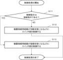
図2は、本開示の実施形態に係る制御装置の動作の例を表すフローチャートである。
<Operation>
FIG. 2 is a flowchart illustrating an example of the operation of the control device according to the embodiment of the present disclosure.
本開示の第1の実施形態に係る制御装置10の動作について、図2を使用して詳細に説明する。
The operation of the
図2に示す例では、指示受取部110が、USBケーブルの二つのコネクタの間の機器接続用経路の経路状態を指示する制御指示を受け取る(ステップS11)。次に、制御部120が、制御指示に従って、機器接続用経路の経路状態を接続状態にするか切断状態にするかを制御する(ステップS12)。
In the example shown in FIG. 2, the
<効果>
以上で説明した本実施形態には、物理的にケーブルの挿抜を行わず、かつ、他のポートを介した接続に影響を与えずに、対象ポートを介した接続の切断と再接続とを行うことが可能になるという効果がある。その理由は、指示受取部110が、USBのケーブルの二つのコネクタの間の機器接続用経路の経路状態を指示する制御指示を、二つのコネクタのうち一方のコネクタに接続されたホスト機器から、一方のコネクタの制御用経路を介して受け取るからである。そして、制御部120は、制御指示に従って、機器接続用経路の経路状態を接続状態にするか切断状態にするかを制御するからである。
<Effects>
The present embodiment described above has the advantage that it is possible to disconnect and reconnect a connection through a target port without physically inserting or removing a cable and without affecting connections through other ports. This is because the
<第2の実施形態>
以下では、本開示の第2の実施形態について、図面を使用して詳細に説明する。
Second Embodiment
The second embodiment of the present disclosure will be described in detail below with reference to the drawings.
<構成>
図3は、本開示の実施形態に係る制御装置100の構成の例を表すブロック図である。
<Configuration>
FIG. 3 is a block diagram illustrating an example of the configuration of the
図3に示す例では、制御装置100は、指示受取部110と、制御部120と、スイッチ部130とを含む。指示受取部110及び制御部120は、第1の実施形態の指示受取部110及び制御部120と同じである。指示受取部110及び制御部120は、それぞれ、第1の実施形態の指示受取部110及び制御部120と同様に動作する。本実施形態のスイッチ部130は、第1の実施形態のスイッチング回路と同じである。本実施形態の制御装置100は、スイッチ部130を含む点において、第1の実施形態の制御装置10と異なる。
In the example shown in FIG. 3, the
<指示受取部110>
指示受取部110は、USBのケーブルの二つのコネクタの間の機器接続用経路の経路状態を指示する制御指示を、二つのコネクタのうち一方のコネクタに接続されたホスト機器から、一方のコネクタの制御用経路を介して受け取る。
<
The
本実施形態のUSBのケーブルは、制御装置10の代わりに制御装置100が搭載される点を除いて、第1の実施形態のUSBケーブルと同様である。本実施形態では、制御装置10の代わりに制御装置100が、USBケーブル(例えば、USBケーブルのコネクタ部)に搭載される。
The USB cable of this embodiment is similar to the USB cable of the first embodiment, except that the
<制御部120>
制御部120は、制御指示に従って、機器接続用経路の経路状態を接続状態にするか切断状態にするかを制御する。
<
The
本実施形態では、経路状態は、例えば、機器接続用経路が切断された状態である切断状態と、機器接続用経路が接続された状態である接続状態と、のいずれかである。制御指示は、機器接続用経路が切断された状態にする指示であってもよい。制御指示は、機器接続用経路が接続された状態にする指示であってもよい。制御指示は、機器接続用経路が切断された状態にした後に、機器接続用経路が接続された状態にする指示であってもよい。 In this embodiment, the path state is, for example, either a disconnected state in which the device connection path is disconnected, or a connected state in which the device connection path is connected. The control instruction may be an instruction to put the device connection path in a disconnected state. The control instruction may be an instruction to put the device connection path in a connected state. The control instruction may be an instruction to put the device connection path in a disconnected state, and then put the device connection path in a connected state.
制御部120は、例えば、機器接続用経路の電源線が接続された状態と機器接続用経路の電源線が切断された状態との間で、機器接続用経路の電源線の状態を切り替える、後述のスイッチ部130を制御することによって、機器接続用経路の接続状態を制御する。
The
<スイッチ部130>
スイッチ部130は、制御部120による制御に従って、機器接続用経路の経路状態を変更する。スイッチ部130は、具体的には、機器接続用経路の経路状態を、機器接続用経路が切断された状態である切断状態と、機器接続用経路が接続された状態である接続状態と、の間で切り替える。具体的には、機器接続用経路が切断された状態である切断状態は、例えば、機器接続用経路の電源線が切断された状態である。機器接続用経路が接続された状態である接続状態は、例えば、機器接続用経路の電源線が接続された状態である。すなわち、スイッチ部130は、例えば、機器接続用経路の接続状態を、機器接続用経路の電源線が切断された状態と、機器接続用経路の電源線が接続された状態と、の間で切り替える。
<
The
スイッチ部130は、機器接続用経路の電源線が接続された状態と機器接続用経路の電源線が切断された状態との間で、機器接続用経路の電源線の状態を切り替えるスイッチング回路によって実現される。
The
本実施形態の制御装置100は、例えば、USBケーブルのコネクタ部に含まれていてよい。本実施形態の説明では、コネクタ部は、USBケーブルのコネクタを含む、例えば樹脂等によって実現される部分である。コネクタ部は、USBケーブルの両端の、ケーブルではない部分を指す。コネクタは、USBケーブルがホスト機器又は電子機器等に接続された場合に、接続先の機器のコネクタと嵌合する部分の部品である。制御装置100は、USBケーブルのコネクタの制御用経路の端子に通信可能に接続される。
The
<動作>
図4は、本開示の実施形態に係る制御装置の動作の例を表すフローチャートである。
<Operation>
FIG. 4 is a flowchart illustrating an example of the operation of the control device according to an embodiment of the present disclosure.
以下では、本開示の第2の実施形態に係る制御装置100の動作について、図4を使用して説明する。制御装置100は、例えば、制御装置100が含まれるUSBケーブルがホスト機器に接続されると、図4に示す動作を実行する。
The operation of the
図4に示す例では、指示受取部110は、制御指示の送信を待つ(ステップS101)。すなわち、指示受取部110は、ホスト機器によって送信された制御指示を待つ。制御指示が送信されていない場合(ステップS102においてNO)、指示受取部110は、制御指示の送信を待ち続ける(ステップS101)。
In the example shown in FIG. 4, the
制御指示が送信された場合(ステップS102においてYES)、指示受取部110は、制御指示を受け取る(ステップS103)。そして、制御装置100は、制御処理を実行する(ステップS104)。制御指示については、後で詳細に説明する。
If a control instruction has been sent (YES in step S102), the
例えば指示受取部110は、ホスト機器とコネクタとの接続を判定する(ステップS105)。具体的には、指示受取部110は、制御装置が含まれるUSBケーブルの、ホスト機器に接続されているコネクタと、ホスト機器(具体的にはホスト機器のコネクタ)との間の接続が、接続されているか否かを判定する。指示受取部110は、例えば、USBの信号線がホスト機器と接続されているか否かを判定してよい。接続が切断された場合(ステップS106においてYES)、制御装置100は、図4に示す動作を終了する。接続が切断されていない場合(ステップS106においてNO)、図4に示す動作では、制御装置100は、ステップS101以降の動作を続ける。
For example, the
図4に示す例では、ステップS105及びステップS106の動作は、ステップS104の動作の後に行われる。しかし、制御装置100は、ステップS105及びステップS106の動作を、ステップS101からステップS104までの動作と並列に行ってよい。
In the example shown in FIG. 4, the operations of steps S105 and S106 are performed after the operation of step S104. However, the
次に、制御処理について説明する。 Next, we will explain the control process.
図5は、本開示の実施形態に係る制御装置の制御処理の動作の例を表すフローチャートである。図5に示す例では、制御指示は、機器接続用経路が切断状態になるように指示する切断指示、又は、機器接続用経路が接続状態になるように指示する接続指示である。 FIG. 5 is a flowchart showing an example of the operation of the control process of the control device according to an embodiment of the present disclosure. In the example shown in FIG. 5, the control instruction is a disconnect instruction that instructs the device connection path to be in a disconnected state, or a connect instruction that instructs the device connection path to be in a connected state.
以下では、本開示の第2の実施形態に係る制御装置100の制御処理の動作について、図5を使用して説明する。
The following describes the operation of the control process of the
制御指示が接続指示ではない場合(ステップS111においてNO)、制御指示は、切断指示である。この場合、制御部120は、機器接続用経路が切断状態になるようにスイッチ部130を制御する(ステップS112)。
If the control instruction is not a connection instruction (NO in step S111), the control instruction is a disconnection instruction. In this case, the
制御指示が接続指示である場合(ステップS111においてYES)、機器接続用経路が接続状態になるようにスイッチ部130を制御する(ステップS113)。
If the control instruction is a connection instruction (YES in step S111), the
<効果>
本実施形態には、第1の実施形態の効果と同じ効果がある。その理由は、第1の実施形態の効果が生じる理由と同じである。
<Effects>
This embodiment has the same effects as the first embodiment, for the same reasons that the effects of the first embodiment are obtained.
<第2の実施形態の第1の変形例>
本変形例では、機器接続用経路が接続された状態(すなわち、接続状態)は、例えば、機器接続用経路の信号線のうち、少なくとも通信に使用される信号線と電源線とが接続されている状態である。この通信に使用される信号線は、機器接続用経路に他の機器が接続された場合に、ホスト機器と他の機器との間で送受信される少なくともいずれかの信号が経由する信号線である。機器接続用経路が切断された状態(すなわち、切断状態)は、機器接続用経路の全ての信号線のうち、少なくとも電源線(電源ラインとも表記)が切断されている状態である。
<First Modification of the Second Embodiment>
In this modified example, a state in which the device connection path is connected (i.e., a connected state) is, for example, a state in which at least the signal line used for communication and the power line of the device connection path are connected. The signal line used for this communication is a signal line through which at least one of the signals transmitted and received between the host device and the other device passes when another device is connected to the device connection path. A state in which the device connection path is disconnected (i.e., a disconnected state) is a state in which at least the power line (also referred to as the power line) of all the signal lines of the device connection path is disconnected.
本変形例では、スイッチ部130は、機器接続用経路の電源線の状態の変更とは独立に、さらに、機器接続用経路のデータ転送用の通信線の状態を変更できるように構成される。具体的には、スイッチ部130は、機器接続用経路の全ての通信線が接続されている状態と、機器接続用経路のUSB2.0による通信では使用されない信号線が切断された状態との間で、機器接続用経路のデータ転送用の通信線の状態を変更できるように構成される。USB2.0による通信では使用されない信号線は、例えば、TXライン及びRXラインである。
In this modified example, the
以下の説明において、USB2.0による通信の速度を、第1速度とも表記する。機器接続用経路を介して、USB2.0による通信が可能であり、USB2.0の速度よりも高速な通信が可能な規格による通信が可能ではない状態を、第1通信可能状態と表記する。USB2.0の速度よりも高速な通信が可能な規格は、例えば、USB3.2Gen1、USB3.2Gen2などである。USB2.0の速度よりも高速な通信が可能な規格は、これらの例に限られない。USB2.0の速度よりも高速な通信が可能な規格は、USB3.2以外の規格の、USB2.0の速度よりも高速な通信が可能な規格であってもよい。USB2.0の速度よりも高速な通信が可能な規格による通信の速度を、第2速度とも表記する。機器接続用経路を介して、USB2.0の速度よりも高速な通信が可能な規格による通信が可能である状態を、第2通信可能状態と表記する。 In the following description, the communication speed by USB 2.0 is also referred to as the first speed. A state in which communication by USB 2.0 is possible through the device connection path, but communication by a standard capable of communication at a speed faster than USB 2.0 is not possible is referred to as the first communication possible state. Standards capable of communication at a speed faster than USB 2.0 include, for example, USB 3.2 Gen 1 and USB 3.2 Gen 2. Standards capable of communication at a speed faster than USB 2.0 are not limited to these examples. A standard capable of communication at a speed faster than USB 2.0 may be a standard other than USB 3.2 that is capable of communication at a speed faster than USB 2.0. A communication speed by a standard capable of communication at a speed faster than USB 2.0 is also referred to as the second speed. A state in which communication is possible via a device connection path using a standard that allows communication at speeds faster than USB 2.0 is referred to as a second communication possible state.
本変形例では、第1通信可能状態は、例えば、機器接続用経路のUSB2.0による通信では使用されない信号線(例えば、TXライン及びRXライン)が切断された状態である。また、第2通信可能状態は、例えば、機器接続用経路の全てのデータ転送用の信号線が接続された状態である。 In this modified example, the first communication-enabled state is, for example, a state in which signal lines (e.g., the TX line and the RX line) that are not used for communication via USB 2.0 on the device connection path are disconnected. The second communication-enabled state is, for example, a state in which all signal lines for data transfer on the device connection path are connected.
本変形例では、制御指示は、機器接続用経路の状態を、機器接続用経路のUSB2.0による通信では使用されない信号線が切断された状態に設定する指示である低速状態指示(第1速度状態指示とも表記)であってもよい。制御指示は、機器接続用経路の状態を、機器接続用経路の全てのデータ転送用の信号線が接続された状態に設定する指示である高速状態指示(第2速度状態指示とも表記)であってもよい。 In this modified example, the control instruction may be a low-speed state instruction (also referred to as a first-speed state instruction) that is an instruction to set the state of the device connection path to a state in which signal lines not used in USB 2.0 communication on the device connection path are disconnected. The control instruction may be a high-speed state instruction (also referred to as a second-speed state instruction) that is an instruction to set the state of the device connection path to a state in which all data transfer signal lines on the device connection path are connected.
指示受取部110が、制御指示として低速状態指示を受け取った場合、制御部120は、機器接続用経路の状態が、機器接続用経路のUSB2.0による通信では使用されない信号線が切断された状態になるように、スイッチ部130を制御する。この場合、スイッチ部130は、制御部120の制御に従って、機器接続用経路の状態を、機器接続用経路のUSB2.0による通信では使用されない信号線が切断された状態(第1速度状態、低速状態とも表記)にする。その際、スイッチ部130は、機器接続用経路のUSB2.0による通信では使用されない信号線が接続されている場合、機器接続用経路のUSB2.0による通信では使用されない信号線の状態を、切断された状態に変更する。スイッチ部130は、機器接続用経路のUSB2.0による通信では使用されない信号線が切断された状態である場合、機器接続用経路のUSB2.0による通信では使用されない信号線の状態を変更しない。
When the
指示受取部110が、制御指示として高速状態指示を受け取った場合、制御部120は、機器接続用経路の状態が、機器接続用経路の全てのデータ転送用の信号線が接続された状態(高速状態、第2速度状態とも表記)になるように、スイッチ部130を制御する。この場合、スイッチ部130は、制御部120の制御に従って、機器接続用経路の状態を、機器接続用経路の全てのデータ転送用の信号線が接続された状態にする。その際、スイッチ部130は、機器接続用経路の全てのデータ転送用の信号線が接続された状態である場合、機器接続用経路の全てのデータ転送用の信号線の状態を変更しない。スイッチ部130は、機器接続用経路の全てのデータ転送用の信号線のいずれかが切断された状態である場合、機器接続用経路の全てのデータ転送用の信号線の状態を、全てのデータ転送用の信号線が接続された状態に変更する。
When the
なお、本変形例では、制御指示として低速状態指示を受け取った場合、及び、指示受取部110が、制御指示として高速状態指示を受け取った場合、制御部120は及びスイッチ部130は、電源線(すなわち、VBUSライン)の状態を変更しない。
In this modified example, when a low-speed state instruction is received as a control instruction, and when the
さらに、本変形例では、制御指示は、切断指示及び接続指示のいずれかであってもよい。本変形例の制御部120及びスイッチ部130の、制御指示として切断指示を受け取った場合の動作は、第2の実施形態の制御部120及びスイッチ部130の、制御指示として切断指示を受け取った場合の動作と同様である。本変形例の制御部120及びスイッチ部130の、制御指示として接続指示を受け取った場合の動作は、第2の実施形態の制御部120及びスイッチ部130の、制御指示として接続指示を受け取った場合の動作と同様である。
Furthermore, in this modified example, the control instruction may be either a disconnection instruction or a connection instruction. The operation of the
すなわち、制御指示が切断指示である場合、制御部120は、機器接続用経路の電源線が切断された状態になるように、スイッチ部130を制御する。この場合、スイッチ部130は、機器接続用経路の電源線の状態を、機器接続用経路の電源線が切断された状態にする。
制御指示が接続指示である場合、制御部120は、機器接続用経路の電源線が接続された状態になるように、スイッチ部130を制御する。この場合、スイッチ部130は、機器接続用経路の電源線の状態を、機器接続用経路の電源線が接続された状態にする。
That is, when the control instruction is a disconnection instruction, the
When the control instruction is a connection instruction, the
上述の第1通信可能状態は、機器接続用経路の状態が、接続状態であり、かつ、低速状態である、状態である。第2通信可能状態は、機器接続用経路の状態が、接続状態であり、かつ、高速状態である、状態である。 The first communication possible state described above is a state in which the state of the device connection path is a connected state and a low-speed state. The second communication possible state is a state in which the state of the device connection path is a connected state and a high-speed state.
本変形例の制御装置100の動作は、図4を使用して説明した、第2の実施形態の制御装置100の動作と同じである。
The operation of the
図6及び図7は、本開示の実施形態に係る制御装置の制御処理の動作の例を表すフローチャートである。図6及び図7に示す例では、制御指示は、切断指示、接続指示、低速状態指示、又は、高速状態指示である。上述のように、切断指示は、機器接続用経路が切断状態になるように指示する指示である。接続指示は、機器接続用経路が接続状態になるように指示する指示である。低速状態指示は、機器接続用経路の状態を、機器接続用経路のUSB2.0による通信では使用されない信号線が切断された状態に設定する指示である。高速状態指示は、機器接続用経路の状態を、機器接続用経路の全てのデータ転送用の信号線が接続された状態に設定する指示である。 Figures 6 and 7 are flowcharts showing an example of the operation of the control process of the control device according to the embodiment of the present disclosure. In the examples shown in Figures 6 and 7, the control instructions are a disconnect instruction, a connect instruction, a low-speed state instruction, or a high-speed state instruction. As described above, a disconnect instruction is an instruction to set the device connection path to a disconnected state. A connect instruction is an instruction to set the device connection path to a connected state. A low-speed state instruction is an instruction to set the state of the device connection path to a state in which signal lines not used in USB 2.0 communication on the device connection path are disconnected. A high-speed state instruction is an instruction to set the state of the device connection path to a state in which all data transfer signal lines on the device connection path are connected.
以下では、本開示の第2の実施形態の第1の変形例に係る制御装置100の制御処理の動作について、図6及び図7を使用して説明する。
The following describes the operation of the control process of the
図6において、制御指示が切断指示である場合(ステップS121においてYES)、制御部120は、機器接続用経路が切断状態になるようにスイッチ部130を制御する(ステップS122)。
In FIG. 6, if the control instruction is a disconnection instruction (YES in step S121), the
制御指示が切断指示ではなく(ステップS121においてNO)、制御指示が接続指示である場合(ステップS123においてYES)、制御部120は、機器接続用経路が接続状態になるようにスイッチ部130を制御する(ステップS124)。
If the control instruction is not a disconnection instruction (NO in step S121) but a connection instruction (YES in step S123), the
制御指示が接続指示ではなく(図6のステップS123においてNO)、制御指示が高速状態指示である場合(図7のステップS125においてYES)、制御部120は、機器接続用経路が高速状態になるようにスイッチ部130を制御する(ステップS126)。
If the control instruction is not a connection instruction (NO in step S123 in FIG. 6) but is a high-speed state instruction (YES in step S125 in FIG. 7), the
図7のステップS125において、接続指示が高速状態指示ではない場合(ステップS125においてNO)、制御指示は、低速状態指示である。この場合、制御部120は、機器接続用経路が低速状態になるようにスイッチ部130を制御する(ステップS127)。
In step S125 of FIG. 7, if the connection instruction is not a high-speed state instruction (NO in step S125), the control instruction is a low-speed state instruction. In this case, the
<第2の実施形態の第2の変形例>
上述のように、制御指示は、機器接続用経路を切断状態にした後、機器接続用経路を接続状態にする指示である再接続指示であってもよい。その場合、制御部120は、制御指示として再接続指示を受け取ると、機器接続用経路が切断状態になるようにスイッチ部130を制御する。そして、制御部120は、機器接続用経路が切断状態になるようにスイッチ部130を制御してから所定時間が経過した後、機器接続用経路が接続状態になるようにスイッチ部130を制御する。
<Second Modification of the Second Embodiment>
As described above, the control instruction may be a reconnect instruction, which is an instruction to connect the device connection path after disconnecting the device connection path. In this case, when the
言い換えると、制御部120は、制御指示として再接続指示を受け取ると、図5に示すステップS112の動作を行い、ステップS112の動作を行ってから所定時間が経過した後に、図5に示すステップS113の動作を行う。この所定時間は、予め設定されている時間である。
In other words, when the
本変形例は、第2の実施形態に適用できる。本変形例は、第2の実施形態の第1の変形例にも適用できる。 This modification can be applied to the second embodiment. This modification can also be applied to the first modification of the second embodiment.
<第3の実施形態>
次に、本開示の第3の実施形態に係る情報処理システムについて、図面を使用して詳細に説明する。
Third Embodiment
Next, an information processing system according to a third embodiment of the present disclosure will be described in detail with reference to the drawings.
<構成>
図8は、本開示の実施形態に係る情報処理システムの構成の例を模式的に表すブロック図である。
<Configuration>
FIG. 8 is a block diagram illustrating an example of the configuration of an information processing system according to an embodiment of the present disclosure.
以下では、本開示の第3の実施形態に係る情報処理システムの構成について、図8を使用して説明する。 Below, the configuration of an information processing system according to the third embodiment of the present disclosure will be described with reference to FIG. 8.
図8に示す例では、情報処理システム1は、ホスト機器200と、制御装置100を含むUSBケーブル300と、機器400とを含む。ホスト機器200は、制御装置100と通信可能に接続されている。具体的には、ホスト機器200は、USBケーブル300の制御用経路を介して、制御装置100と接続されている。ホスト機器200は、さらに、USBケーブル300(具体的には、USBケーブル300の機器接続用経路)を介して、機器400と接続されている。本実施形態の制御装置100は、第2の実施形態の制御装置100と同じである。本実施形態のUSBケーブル300は、第2の実施形態のUSBケーブルと同じである。
In the example shown in FIG. 8, the information processing system 1 includes a
ホスト機器200は、受取部210と、制御指示送信部220とを含む。
The
<受取部210>
受取部210は、USBケーブル300を介して接続されている機器400とホスト機器200との間の接続状態の設定指示を受け取る。本実施形態では、受取部210は、設定指示として、機器400とホスト機器200との間の接続状態を切断状態にする指示、及び、機器400とホスト機器200との間の接続状態を接続状態にする指示を受け取る。
<Receiving
The receiving
<制御指示送信部220>
制御指示送信部220は、受取部210が設定指示を受け取った場合、設定指示に応じた制御指示を、制御装置100(具体的には、制御装置100の指示受取部110)に送信する。
制御指示送信部220は、受取部210が設定指示として接続状態を切断状態にする指示を受け取った場合、制御指示として、切断指示を制御装置100(具体的には、制御装置100の指示受取部110)に送信する。
制御指示送信部220は、受取部210が設定指示として接続状態を接続状態にする指示を受け取った場合、制御指示として、接続指示を制御装置100(具体的には、制御装置100の指示受取部110)に送信する。
<Control
When the receiving
When the receiving
When the receiving
<動作>
次に、本開示の第3の実施形態に係るホスト機器200の動作について、図面を使用して詳細に説明する。
<Operation>
Next, the operation of the
図9は、本開示の実施形態に係るホスト機器の動作の例を表すフローチャートである。 Figure 9 is a flowchart showing an example of the operation of a host device according to an embodiment of the present disclosure.
以下では、本開示の第3の実施形態に係るホスト機器200の動作について、図9を使用して説明する。図9に示す例では、受取部210が、USBケーブル300を介して接続されている機器400とホスト機器200との間の接続状態の設定指示を受け取る(ステップS201)。次に、制御指示送信部220が、設定指示に応じた制御指示を、制御装置100に送信する(ステップS202)。
The operation of the
<効果>
以上で説明した本実施形態には、第1の実施形態の効果と同じ効果がある。その理由は、第1の実施形態の効果が生じる理由と同じである。
<Effects>
The present embodiment described above has the same effects as the first embodiment, for the same reasons as those for the first embodiment.
<第3の実施形態の第1の変形例>
第2の実施形態の第1の変形例を、第3の実施形態に係る制御装置100に適用することもできる。
<First Modification of the Third Embodiment>
The first modified example of the second embodiment can also be applied to the
その場合、受取部210は、設定指示として、さらに、機器400とホスト機器200との間の接続状態を高速状態にする指示、及び、機器400とホスト機器200との間の接続状態を低速状態にする指示を受け取る。
In this case, the receiving
また、制御指示送信部220は、受取部210が設定指示として接続状態を高速状態にする指示を受け取った場合、制御指示として、高速状態指示を、制御装置100(具体的には、制御装置100の指示受取部110)に送信する。制御指示送信部220は、受取部210が設定指示として接続状態を低速状態にする指示を受け取った場合、制御指示として、低速状態指示を、制御装置100(具体的には、制御装置100の指示受取部110)に送信する。
In addition, when the receiving
<第3の実施形態の第2の変形例>
第2の実施形態の第2の変形例を、第3の実施形態に係る制御装置100に適用することもできる。
<Second Modification of the Third Embodiment>
The second modified example of the second embodiment can also be applied to the
その場合、受取部210は、設定指示として、機器400とホスト機器200との間の経路状態を、切断状態にした後、機器400とホスト機器200との間の経路状態を、接続状態にする、再接続を行う指示を受け取る。
In this case, the receiving
また、制御指示送信部220は、受取部210が設定指示として再接続を行う指示を受け取った場合、制御指示として、再接続指示を、制御装置100(具体的には、制御装置100の指示受取部110)に送信する。なお、本開示の実施形態の説明及び変形例の説明において、再接続は、機器400とホスト機器200との間の経路状態を、切断状態にし、その後、機器400とホスト機器200との間の経路状態を、接続状態にすることを表す。
When the receiving
本変形例は、第3の実施形態の第1の変形例にも適用できる。 This modification can also be applied to the first modification of the third embodiment.
<実装例>
以下では、本開示の実装例について、図面を使用して詳細に説明する。
<Implementation example>
Hereinafter, implementation examples of the present disclosure will be described in detail with reference to the drawings.
図10は、本開示の実装例を表す図である。 Figure 10 shows an example implementation of this disclosure.
本開示の実装例は、図10のように、Type-Cケーブルの両端のコネクタ部に制御用IC(Integrated Circuit)チップを搭載し、ホスト機器に制御用ICチップを制御するソフトウェアを搭載することによって実現される。図10では、ホスト機器はHostと表記されている。図10に示す例では、Type-Cケーブルの一方のコネクタ部にホスト機器が接続され、他方のコネクタに機器(Deviceと表記)が接続されている。図10において「Device」と表記されている機器は、以下の説明において、デバイス機器とも表記される。 As shown in FIG. 10, an implementation example of the present disclosure is realized by mounting control IC (Integrated Circuit) chips on the connectors at both ends of a Type-C cable, and mounting software that controls the control IC chips in a host device. In FIG. 10, the host device is written as Host. In the example shown in FIG. 10, a host device is connected to one connector of a Type-C cable, and a device (written as Device) is connected to the other connector. The device written as "Device" in FIG. 10 is also written as device device in the following description.
制御用ICチップは、第1の実施形態の制御装置10と、第2の実施形態及び第3の実施形態の制御装置100に対応する。Type-Cケーブルは、第1の実施形態及び第2の実施形態のUSBケーブルと、第3の実施形態のUSBケーブル300に対応する。ホスト機器は、第1の実施形態及び第2の実施形態のホスト機器と、第3の実施形態のホスト機器200に対応する。デバイス機器は、第1の実施形態及び第2の実施形態の他の機器と、第3の実施形態の機器400とに対応する。後述されるように、図10の2つのレーンのうち「1レーン」がデータ転送用のレーンとして使用される。図10の「2レーン」が、ICチップ制御用のレーンとして使用される。データ転送用のレーンは、上述の実施形態における機器接続用経路に対応する。ICチップ制御用のレーンは、上述の実施形態における制御用レーンに対応する。本実装例のType-Cケーブルは、ICチップ制御用のレーンがホスト機器と制御用ICチップとの間の通信に使用され、ホスト機器と機器との間の通信に使用されない点を除いて、USBType-Cの規格に準拠したUSBケーブルと同じである。
The control IC chip corresponds to the
図11は、本開示の実装例に係るホスト機器とデバイス機器との間のデータ転送を模式的に表す図である。 Figure 11 is a diagram that illustrates data transfer between a host device and a device device according to an implementation example of the present disclosure.
図12は、本開示の実装例に係るホスト機器と制御用ICチップとの間のデータ転送を模式的に表す図である。 Figure 12 is a diagram that shows a schematic diagram of data transfer between a host device and a control IC chip according to an implementation example of the present disclosure.
本実装例においては、ホスト機器は、一方のレーンでは、図11のように制御用ICチップの機能を使用せずに、デバイス機器の本来のプロトコル仕様で、ホスト機器とデバイス機器との間のデータ転送を行う。ホスト機器は、もう一方のレーンでは、図12のようにホスト機器に搭載されている制御用ソフトウェアとデバイス機器側のコネクタに搭載された制御用ICチップとの間で、制御用ICチップのプロトコル仕様のデータ転送を行う。デバイス機器は、USB3.2Gen1の1レーン、又は、USB3.2 Gen2の1レーンで、データ転送を行う機器である。 In this implementation example, the host device transfers data between the host device and the device device in one lane using the original protocol specifications of the device device without using the functions of the control IC chip as shown in FIG. 11. In the other lane, the host device transfers data in accordance with the protocol specifications of the control IC chip between the control software installed in the host device and the control IC chip installed in the connector on the device device side as shown in FIG. 12. The device device transfers data in one lane of USB 3.2 Gen 1 or one lane of USB 3.2 Gen 2.
また、ホスト機器は、ホスト機器に搭載されている制御用ソフトウェアによる制御によって、Type-CケーブルのICチップ制御用のレーンのデータ転送用ラインを使用して、制御命令データを制御用ICチップに送信する。デバイス機器側のコネクタ部に搭載されている制御用ICチップが、送信された制御命令データを受信する。制御命令データは、上述の実施形態の制御指示のデータに対応する。デバイス機器側のコネクタ部に搭載されている制御用ICチップは、送信された制御命令データを受信した後、電気的にコネクタ部の制御を行う。本実装例では、Type-Cケーブルの両端のコネクタ部の両方に制御用ICチップが搭載されている。そして、デバイス機器側のコネクタ部に搭載されている制御用ICチップが、ホスト機器から制御命令データに従って動作する。 The host device transmits control command data to the control IC chip using the data transfer line of the IC chip control lane of the Type-C cable under the control of the control software installed in the host device. The control IC chip installed in the connector on the device side receives the transmitted control command data. The control command data corresponds to the control instruction data of the above-mentioned embodiment. After receiving the transmitted control command data, the control IC chip installed in the connector on the device side electrically controls the connector. In this implementation example, a control IC chip is installed in both connectors on both ends of the Type-C cable. Then, the control IC chip installed in the connector on the device side operates according to the control command data from the host device.
図12に示す例では、制御用ICチップのスイッチング回路が、第1の実施形態のスイッチング回路、及び、第2の実施形態及び第3の実施形態のスイッチ部130に対応する。制御用ICチップのファームウェアが、第1から第3の実施形態の指示受取部110及び制御部120の機能を実現する。すなわち、制御用ICチップのファームウェアによる制御により、制御用ICチップは、第1から第3の実施形態の指示受取部110及び制御部120として動作する。
In the example shown in FIG. 12, the switching circuit of the control IC chip corresponds to the switching circuit of the first embodiment and the
図13は、USB Type-Cのコネクタにおける端子の配置を表す図である。 Figure 13 shows the arrangement of terminals in a USB Type-C connector.
図13に示されている、各ラインの割り当ては以下のとおりである。「TX1+」「TX1-」「TX2+」「TX2-」「RX1+」「RX1-」「RX2+」「RX2-」ラインはデータ転送信号線である。これらのラインによって、USB3.0デバイス機器やDisplayPortなどのUSB以外のプロトコルのデータ転送を行うことが可能である。「VBUS」ラインは、電源供給ラインである。「CC1」「CC2」「SUB1」「SUB2」ラインはストリームの向きの検出や電流/電圧の各端子の役割を確定するネゴシエーションなどの接続コンフィグレーション用ラインである。「D+」「D-」ラインは、USB2.0転送信号線である。 The assignment of each line shown in Figure 13 is as follows. The "TX1+", "TX1-", "TX2+", "TX2-", "RX1+", "RX1-", "RX2+", and "RX2-" lines are data transfer signal lines. These lines make it possible to transfer data for USB 3.0 devices and protocols other than USB, such as DisplayPort. The "VBUS" line is a power supply line. The "CC1", "CC2", "SUB1", and "SUB2" lines are connection configuration lines used for detecting the stream direction and for negotiation to determine the role of each current/voltage terminal. The "D+" and "D-" lines are USB 2.0 transfer signal lines.
本実装例ではコネクタ部に組み込まれた制御用ICチップと制御用ソフトウェアを搭載することで、これらのUSBType-Cケーブルの各信号線の制御を実現する。 In this implementation example, the connector is equipped with a control IC chip and control software, enabling control of each signal line of these USB Type-C cables.
図14は、本実装例に係る情報処理システムにおける動作の例を表すフローチャートである。 Figure 14 is a flowchart showing an example of the operation of an information processing system according to this implementation example.
本実装例における制御用ICチップでのVBUSラインの切断及び再接続の動作について、図14を使用して説明する。 The operation of disconnecting and reconnecting the VBUS line on the control IC chip in this implementation example is explained using Figure 14.
上述のように、制御用ICチップは、内部にスイッチング回路とファームウェアを持つ。ファームウェアは、USBのベンダクラスデバイスとしての機能を有する。まず、例えばユーザが、ホスト機器とデバイス機器をType-Cケーブルで接続する(ステップS301)。このType-Cケーブルは、制御用ICチップが搭載されているType-Cケーブルである。ホスト機器とデバイス機器との間において、Type-Cケーブルを用いてSuperSpeed接続が行われると、1つのレーン(上述の1レーン)では、デバイス機器が、USBの規格に従ったプロトコルでデータ転送用のデバイスとして認識される。さらに、もう1つのレーン(上述の2レーン)では、ホスト機器にある制御用ソフトウェアと制御用ICチップ内のファームウェアとによって、ホスト機器は、制御用ICチップを、ベンダクラスデバイスとして認識する。これにより、制御用ICチップは、ホスト機器の制御用ソフトウェアと接続する(ステップS302)。なお、本開示の説明において、制御用ソフトウェアを実行するホスト機器の、制御用ソフトウェアの制御による動作を、制御用ソフトウェアの動作として説明することがある。制御用ソフトウェアの動作として説明されている動作は、制御用ソフトウェアを実行するホスト機器の、制御用ソフトウェアの制御による動作である。また、ファームウェアの制御による制御用ICチップの動作を、ファームウェアの動作として説明することがある。ファームウェアの動作として説明されている動作は、ファームウェアの制御による制御用ICチップの動作である。 As described above, the control IC chip has a switching circuit and firmware inside. The firmware has the function of a USB vendor class device. First, for example, a user connects a host device and a device device with a Type-C cable (step S301). This Type-C cable is a Type-C cable equipped with a control IC chip. When a SuperSpeed connection is made between the host device and the device device using the Type-C cable, in one lane (the above-mentioned lane 1), the device device is recognized as a device for data transfer using a protocol that complies with the USB standard. Furthermore, in the other lane (the above-mentioned lane 2), the host device recognizes the control IC chip as a vendor class device using the control software in the host device and the firmware in the control IC chip. As a result, the control IC chip connects to the control software of the host device (step S302). In the description of this disclosure, the operation of the host device that executes the control software under the control of the control software may be described as the operation of the control software. The operation described as the operation of the control software is the operation of the host device that executes the control software under the control of the control software. In addition, the operation of the control IC chip under the control of the firmware may be described as the operation of the firmware. The operation described as the operation of the firmware is the operation of the control IC chip under the control of the firmware.
データ転送用レーンのデバイスの切断を行う場合、制御用ソフトウェアは、制御用ICチップ内のファームウェアに、ICチップ制御用のレーンのデータ転送信号線を使用して、切断命令を表すクラスリクエストを転送する。制御用ICチップ内のファームウェアは、制御用ソフトウェアからクラスリクエストを受信する(ステップS303)。具体的には、制御用ICチップは、制御用ソフトウェアの制御によって動作するホスト機器から、クラスリクエストを受信する。この場合、制御用ICチップが受信したクラスリクエストは、切断命令を表すクラスリクエストである。制御命令データがVBUSをOFFにする切断命令である場合(ステップS304においてOFF)、切断命令を受信した制御用ICチップ内のファームウェアは、制御用ICチップ内のスイッチング回路をOFFに切り替える(ステップS305)。これによって、制御用ICチップ内のファームウェアは、制御用ICチップが搭載されているコネクタ部のVBUSラインを電気的に切断する(ステップS306)。これによって、制御用ICチップ内のファームウェアは、ホスト機器とデバイス機器との間を切断する(ステップS307)。この場合のコネクタ部のVBUSラインは、データ転送用のレーンのVBUSラインである。また、VBUSをOFFにするとは、VBUSを電気的に切断することである。スイッチング回路をOFFに切り替えるとは、スイッチング回路を、データ転送用のレーンのVBUSが電気的に切断された状態にすることである。 When disconnecting a device of the data transfer lane, the control software transfers a class request representing a disconnection command to the firmware in the control IC chip using the data transfer signal line of the IC chip control lane. The firmware in the control IC chip receives the class request from the control software (step S303). Specifically, the control IC chip receives a class request from a host device that operates under the control of the control software. In this case, the class request received by the control IC chip is a class request representing a disconnection command. If the control command data is a disconnection command to turn off the VBUS (OFF in step S304), the firmware in the control IC chip that received the disconnection command switches the switching circuit in the control IC chip to OFF (step S305). As a result, the firmware in the control IC chip electrically disconnects the VBUS line of the connector part on which the control IC chip is mounted (step S306). As a result, the firmware in the control IC chip disconnects between the host device and the device (step S307). In this case, the VBUS line of the connector is the VBUS line of the data transfer lane. Turning the VBUS OFF means electrically disconnecting the VBUS. Switching the switching circuit OFF means putting the switching circuit in a state in which the VBUS of the data transfer lane is electrically disconnected.
同様に、制御用ソフトウェアが、制御用ICチップに接続命令を表すクラスリクエストを転送すると、制御用ICチップ内のファームウェアは、制御用ソフトウェアから接続命令を表すクラスリクエストを受信する(ステップS303)。この場合、制御用ICチップが受信したクラスリクエストは、切断命令を表すクラスリクエストである。受信した制御命令データがVBUSをONにする接続命令である場合(ステップS304においてON)、接続命令を受信した制御用ICチップ内のファームウェアは、制御用ICチップ内のスイッチング回路をONに切り替える(ステップS308)。これによって、制御用ICチップ内のファームウェアは、VBUSラインを電気的に接続する(ステップS309)。これによって、制御用ICチップ内のファームウェアは、ホスト機器とデバイス機器との間を再接続する(ステップS310)。この場合のコネクタ部のVBUSラインは、データ転送用のレーンのVBUSラインである。また、VBUSをONにするとは、VBUSを電気的に接続することである。スイッチング回路をONに切り替えるとは、スイッチング回路を、データ転送用のレーンのVBUSが電気的に接続された状態にすることである。なお、本実装例の説明では、再接続は、電気的に接続されている状態から電気的に切断された状態なった信号線を、再び、電気的に接続されている状態にすることである。 Similarly, when the control software transfers a class request representing a connection command to the control IC chip, the firmware in the control IC chip receives the class request representing a connection command from the control software (step S303). In this case, the class request received by the control IC chip is a class request representing a disconnection command. If the received control command data is a connection command to turn on the VBUS (ON in step S304), the firmware in the control IC chip that received the connection command switches the switching circuit in the control IC chip to ON (step S308). As a result, the firmware in the control IC chip electrically connects the VBUS line (step S309). As a result, the firmware in the control IC chip reconnects between the host device and the device device (step S310). In this case, the VBUS line of the connector is the VBUS line of the data transfer lane. Also, turning on the VBUS means electrically connecting the VBUS. Switching the switching circuit to ON means putting the switching circuit in a state in which the VBUS of the data transfer lane is electrically connected. In the description of this implementation example, reconnection refers to taking a signal line that has gone from an electrically connected state to an electrically disconnected state and returning it to an electrically connected state again.
このように、制御用ソフトウェアから制御命令を転送し、ケーブル内で電気的にデータ転送用のレーンのVBUSのOFF/ONを切り替えることによって、ホスト機器とデバイス機器間でケーブルを物理的に接続されている状態においても、ホスト機器のポートのみの切断と再接続とが可能となる。また、制御用ソフトウェアが、選択されたポートの制御用ICチップに制御命令を送信することによって、選択されたポートの切断・再接続が可能となる。そして、制御用ソフトウェアは、本実装例のType-Cケーブルが接続された任意のポートを選択することが可能である。 In this way, by transferring a control command from the control software and electrically switching the VBUS of the data transfer lane within the cable OFF/ON, it is possible to disconnect and reconnect only the host device port even when the cable is physically connected between the host device and the device device. In addition, the control software can send a control command to the control IC chip of the selected port, thereby disconnecting and reconnecting the selected port. The control software can then select any port to which the Type-C cable of this implementation example is connected.
また、制御用ソフトウェアは、VBUSラインのON/OFFを制御する制御命令とは異なる制御命令も送信できるように構成されていてもよい。制御用ソフトウェアが、送信する制御命令を、他の信号線に対する制御を行う制御命令に変更することによって、VBUSラインだけでなく他の信号線に対する制御も可能である。 The control software may also be configured to be able to send control commands other than those that control the ON/OFF of the VBUS line. By changing the control command sent by the control software to a control command that controls other signal lines, it is possible to control not only the VBUS line but also other signal lines.
制御命令は、例えば、データ転送用レーンのTXラインとRXラインとを無効にする制御命令であってもよい。データ転送用レーンのTXラインとRXラインとを無効にする制御命令は、言い換えると、データ転送用レーンのTXラインとRXラインとをOFFにする制御命令である。データ転送用レーンのTXラインとRXラインとを無効にする制御命令は、さらに言い換えると、データ転送用レーンのTXラインとRXラインとを電気的に切断された状態にする制御命令である。このような制御命令は、上述の低速状態指示に対応する。 The control command may be, for example, a control command to disable the TX line and RX line of the data transfer lane. In other words, the control command to disable the TX line and RX line of the data transfer lane is a control command to turn off the TX line and RX line of the data transfer lane. In further words, the control command to disable the TX line and RX line of the data transfer lane is a control command to electrically disconnect the TX line and RX line of the data transfer lane. Such a control command corresponds to the above-mentioned low-speed state instruction.
制御命令は、例えば、データ転送用レーンのTXラインとRXラインとを有効にする制御命令であってもよい。データ転送用レーンのTXラインとRXラインとを有効にする制御命令は、言い換えると、データ転送用レーンのTXラインとRXラインとをONにする制御命令である。データ転送用レーンのTXラインとRXラインとを有効にする制御命令は、さらに言い換えると、データ転送用レーンのTXラインとRXラインとを電気的に接続された状態にする制御命令である。このような制御命令は、上述の高速状態指示に対応する。 The control command may be, for example, a control command to enable the TX line and RX line of the data transfer lane. In other words, the control command to enable the TX line and RX line of the data transfer lane is a control command to turn on the TX line and RX line of the data transfer lane. In further words, the control command to enable the TX line and RX line of the data transfer lane is a control command to electrically connect the TX line and RX line of the data transfer lane. Such a control command corresponds to the high-speed state instruction described above.
制御用ソフトウェアから、データ転送用レーンのTXラインとRXラインとを無効にする制御命令を受け取った場合、制御用ICチップは、図12に示すデータ転送用レーンのデータ転送信号線であるTXラインとRXラインとを無効になるように制御する。データ転送用レーンのデータ転送信号線であるTXラインとRXラインとが無効になることによって、データ転送に使用できる信号線は、Dラインのみとなる。そのため、データ転送用レーンを介するデータ転送は、USB2.0の転送となる。 When a control command to disable the TX line and RX line of the data transfer lane is received from the control software, the control IC chip controls the TX line and RX line, which are the data transfer signal lines of the data transfer lane shown in Figure 12, to be disabled. By disabling the TX line and RX line, which are the data transfer signal lines of the data transfer lane, the only signal line that can be used for data transfer is the D line. Therefore, data transfer via the data transfer lane becomes a USB 2.0 transfer.
制御用ソフトウェアから、データ転送用レーンのTXラインとRXラインとを有効にする制御命令を受け取った場合、制御用ICチップは、図12に示すデータ転送用レーンのデータ転送信号線であるTXラインとRXラインとを有効になるように制御する。データ転送用レーンのデータ転送信号線であるTXラインとRXラインとが有効になることによって、データ転送に使用できる信号線は、TXライン、RXライン及びDラインとなる。そのため、データ転送用レーンを介するデータ転送は、USB3.2Gen1の1レーンのデータ転送、及び、USB3.2 Gen2の1レーンのデータ転送が可能となる。 When a control command to enable the TX line and RX line of the data transfer lane is received from the control software, the control IC chip controls the TX line and RX line, which are the data transfer signal lines of the data transfer lane shown in FIG. 12, to be enabled. By enabling the TX line and RX line, which are the data transfer signal lines of the data transfer lane, the signal lines that can be used for data transfer are the TX line, RX line, and D line. Therefore, data transfer via the data transfer lane becomes possible in one lane of USB3.2 Gen1 and one lane of USB3.2 Gen2.
したがって、制御用ソフトウェアと制御用ICチップを用いることによって、USBの転送速度についても制御可能となる。 Therefore, by using control software and a control IC chip, it is possible to control the USB transfer speed as well.
このように、Type-Cケーブルでの接続及び転送速度の制御が可能となることによって、本体に電源機能を持たない市販デバイスにおいても物理的なケーブルの挿抜をせずにUSBの再接続及び転送速度の変更が可能となる。 In this way, by making it possible to connect and control the transfer speed using a Type-C cable, it is possible to reconnect the USB and change the transfer speed without physically plugging and unplugging the cable, even on commercially available devices that do not have a built-in power supply function.
一般に、Type-Cケーブルを使用したシステムでUSBの切断・再接続を行う場合、現地で直接ケーブルの挿抜を行う必要がある。しかし、本実装例を利用することによって、ソフトウェアでの接続制御が可能となりケーブル操作が不要となる。そのため、近年増加しているテレワーク環境等でも、ハードウェアが設置されている場所に赴いてケーブル操作を行うことなく、USBの切断・再接続が可能となる。 Generally, when disconnecting and reconnecting a USB in a system that uses a Type-C cable, it is necessary to manually plug and unplug the cable on-site. However, by using this implementation example, connection control can be performed by software, eliminating the need to operate the cable. Therefore, even in telework environments, which have become more common in recent years, it is possible to disconnect and reconnect the USB without having to go to the location where the hardware is installed and operate the cable.
また、一般に、デバイス機器のUSBケーブル挿抜を多数回繰り返す評価において、膨大な時間を割いて手作業で挿抜を行うか、ケーブル間に高額な専用装置を経由させて自動で切断・再接続を行うことが求められる。しかし、本実装例を利用することによって、デバイス機器のUSBケーブル挿抜を多数回繰り返す評価の、Type-Cケーブルと専用のソフトウェアとによる自動実行が可能となる。デバイス機器のUSBケーブル挿抜を多数回繰り返す評価において、手作業や専用装置が不要となる。 In addition, in general, when evaluating a device by repeatedly plugging and unplugging the USB cable, it is necessary to either spend a huge amount of time manually plugging and unplugging the cable, or to automatically disconnect and reconnect the cable using expensive dedicated equipment. However, by using this implementation example, it is possible to automatically perform evaluations of a device by repeatedly plugging and unplugging the USB cable using a Type-C cable and dedicated software. When evaluating a device by repeatedly plugging and unplugging the USB cable, manual work or dedicated equipment is no longer necessary.
また、一般に、USB3.2のデバイスに対してUSB2.0の接続を行ことによって転送速度を変化させる場合、接続に使用するUSBケーブルをUSB2.0仕様のものにするか、USB2.0ポートにケーブルを挿し替えることが求められる。しかし、本実装例を利用したType-CケーブルでUSB3.2のデバイスを接続しておくことによって、制御用ソフトウェアを使用して任意に転送速度を変化させることができる。 In addition, generally, when changing the transfer speed by connecting a USB 2.0 to a USB 3.2 device, it is necessary to either use a USB 2.0 cable for the connection, or to plug the cable into a USB 2.0 port. However, by connecting a USB 3.2 device with a Type-C cable using this implementation example, it is possible to change the transfer speed as desired using control software.
<他の実施形態>
本開示の実施形態に係る制御装置及びホスト機器は、記憶媒体から読み出されたプログラムがロードされたメモリと、そのプログラムを実行するプロセッサとを含むコンピュータによって実現することができる。本開示の実施形態に係る制御装置及びホスト機器は、専用のハードウェアによって実現することもできる。本開示の実施形態に係る制御装置及びホスト機器は、前述のコンピュータと専用のハードウェアとの組み合わせによって実現することもできる。
<Other embodiments>
The control device and the host device according to the embodiment of the present disclosure can be realized by a computer including a memory into which a program read from a storage medium is loaded and a processor that executes the program. The control device and the host device according to the embodiment of the present disclosure can also be realized by dedicated hardware. The control device and the host device according to the embodiment of the present disclosure can also be realized by a combination of the above-mentioned computer and dedicated hardware.
図15は、本開示の実施形態に係る制御装置及びホスト機器を実現することができる、コンピュータ1000のハードウェア構成の一例を表す図である。図15に示す例では、コンピュータ1000は、プロセッサ1001と、メモリ1002と、記憶装置1003と、I/O(Input/Output)インタフェース1004とを含む。また、コンピュータ1000は、記憶媒体1005にアクセスすることができる。メモリ1002と記憶装置1003は、例えば、RAM(Random Access Memory)、ハードディスクなどの記憶装置である。記憶媒体1005は、例えば、RAM、ハードディスクなどの記憶装置、ROM(Read Only Memory)、可搬記憶媒体である。記憶装置1003が記憶媒体1005であってもよい。プロセッサ1001は、メモリ1002と、記憶装置1003に対して、データやプログラムの読み出しと書き込みを行うことができる。プロセッサ1001は、I/Oインタフェース1004を介して、例えば、他の装置にアクセスすることができる。プロセッサ1001は、記憶媒体1005にアクセスすることができる。記憶媒体1005には、コンピュータ1000を、本開示の実施形態に係る制御装置として動作させるプログラム、又は、本開示の実施形態に係るホスト機器が格納されている。
15 is a diagram showing an example of a hardware configuration of a
プロセッサ1001は、記憶媒体1005に格納されている、コンピュータ1000を、本開示の実施形態に係る制御装置として動作させるプログラムを、メモリ1002にロードする。そして、プロセッサ1001が、メモリ1002にロードされたプログラムを実行することにより、コンピュータ1000は、本開示の実施形態に係る制御装置として動作する。
The
プロセッサ1001は、記憶媒体1005に格納されている、コンピュータ1000を、本開示の実施形態に係るホスト機器として動作させるプログラムを、メモリ1002にロードする。そして、プロセッサ1001が、メモリ1002にロードされたプログラムを実行することにより、コンピュータ1000は、本開示の実施形態に係るホスト機器として動作する。
The
指示受取部110,制御部120、スイッチ部130、受取部210、制御指示送信部220は、例えば、メモリ1002ロードされたプログラムを実行するプロセッサ1001によって実現できる。指示受取部110,制御部120、スイッチ部130、受取部210、制御指示送信部220の一部又は全部を、各部の機能を実現する専用の回路によって実現することもできる。
The
また、上記の実施形態の一部又は全部は、以下の付記のようにも記載されうるが、以下には限られない。 In addition, some or all of the above embodiments can be described as follows, but are not limited to the following:
(付記1)
USB(Universal Serial Bus)のケーブルの二つのコネクタの間の機器接続用経路の状態である経路状態を指示する制御指示を、前記二つのコネクタのうち一方のコネクタに接続されたホスト機器から、前記一方のコネクタの制御用経路を介して受け取る指示受取手段と、
前記制御指示に従って、前記機器接続用経路の前記経路状態を接続状態にするか切断状態にするかを制御する制御手段と、
を備える制御装置。
(Appendix 1)
an instruction receiving means for receiving a control instruction indicating a path state, which is a state of a device connection path between two connectors of a USB (Universal Serial Bus) cable, from a host device connected to one of the two connectors via the control path of the one connector;
a control means for controlling whether the path state of the device connection path is a connected state or a disconnected state in accordance with the control instruction;
A control device comprising:
(付記2)
前記接続状態は、前記機器接続用経路に接続されている他の機器が接続されていると前記ホスト機器によって判定される状態であり、
前記切断状態は、前記機器接続用経路に接続されている他の機器が接続されていないと前記ホスト機器によって判定される状態である
付記1に記載の制御装置。
(Appendix 2)
the connection state is a state in which the host device determines that another device connected to the device connection path is connected,
The control device according to claim 1, wherein the disconnected state is a state in which the host device determines that another device connected to the device connection path is not connected.
(付記3)
前記制御手段は、前記機器接続用経路の電源ラインを切断することによって、前記経路状態を前記切断状態に設定し、前記機器接続用経路の電源ラインを接続することによって、前記経路状態を前記接続状態に設定する、
付記1又は2に記載の制御装置。
(Appendix 3)
the control means sets the path state to the disconnected state by disconnecting a power supply line of the device connection path, and sets the path state to the connected state by connecting a power supply line of the device connection path.
3. The control device according to claim 1 or 2.
(付記4)
前記制御手段は、前記経路状態を、前記機器接続用経路を介した通信の速度が第1速度に制限される第1速度状態と、前記機器接続用経路を介した前記第1速度よりも速い第2速度での通信が可能である第2速度状態と、のうち、前記制御指示が示す状態に設定する
付記1又は2に記載の制御装置。
(Appendix 4)
The control device according to claim 1 or 2, wherein the control means sets the path state to one of a first speed state in which a speed of communication via the device connection path is limited to a first speed, and a second speed state in which communication via the device connection path at a second speed faster than the first speed is possible, whichever is indicated by the control instruction.
(付記5)
前記制御手段は、前記機器接続用経路を介して前記第2速度で通信を行う場合に使用され前記機器接続用経路を介して前記第1速度で通信を行う場合に使用されないデータ転送用経路を切断することによって、前記経路状態を前記第1速度状態に設定し、前記データ転送用経路を接続することによって、前記経路状態を前記第2速度状態に設定する
付記4に記載の制御装置。
(Appendix 5)
The control device described in Appendix 4, wherein the control means sets the path state to the first speed state by disconnecting a data transfer path that is used when communicating at the second speed via the equipment connection path and is not used when communicating at the first speed via the equipment connection path, and sets the path state to the second speed state by connecting the data transfer path.
(付記6)
付記1又は2に記載の制御装置を含み、
前記制御装置は、前記一方のコネクタの前記制御用経路の端子に接続される
USBケーブル。
(Appendix 6)
The control device according to claim 1 or 2,
The control device is connected to a terminal of the control path of the one connector via a USB cable.
(付記7)
付記1又は2に記載の制御装置を含み、
前記制御装置は、前記一方のコネクタの前記制御用経路の端子に接続され、前記二つのコネクタのうち他方のコネクタを含むコネクタ部に含まれる
USBケーブル。
(Appendix 7)
The control device according to claim 1 or 2,
The control device is connected to a terminal of the control path of the one of the connectors, and is included in a connector portion including the other of the two connectors.
(付記8)
それぞれ付記1又は2に記載の制御装置である二つの制御装置を含み、
前記二つの制御装置の一方の制御装置は、前記一方のコネクタの前記制御用経路の端子に接続され、前記二つのコネクタのうち他方のコネクタを含むコネクタ部に含まれ、
前記二つの制御装置の他方の制御装置は、前記他方のコネクタの前記制御用経路の端子に接続され、前記一方のコネクタを含むコネクタ部に含まれる、
USBケーブル。
(Appendix 8)
Two control devices, each of which is a control device according to claim 1 or 2,
one of the two control devices is connected to a terminal of the control path of the one of the connectors and is included in a connector section including the other of the two connectors;
The other of the two control devices is connected to a terminal of the control path of the other connector and is included in a connector unit including the one connector.
USB cable.
(付記9)
付記1又は2に記載の制御装置を含み、
前記制御装置は、前記一方のコネクタの前記制御用経路の端子と、前記二つのコネクタのうち他方のコネクタの前記制御用経路の端子と、に接続される
USBケーブル。
(Appendix 9)
The control device according to claim 1 or 2,
The control device includes a USB cable connected to a terminal of the control path of the one connector and to a terminal of the control path of the other connector of the two connectors.
(付記10)
付記1又は2に記載の制御装置と、
当該制御装置を含むUSBケーブルと、
前記USBケーブルの前記一方のコネクタの制御用経路の端子を介して前記制御装置と接続された前記ホスト機器と、を含み、
前記ホスト機器は、
前記USBケーブルの前記機器接続用経路の前記経路状態の設定指示を受け取る受取手段と、
前記設定指示を受け取った場合、前記設定指示に応じた前記制御指示を、前記制御装置に送信する制御指示送信手段と、
を備える情報処理システム。
(Appendix 10)
A control device according to claim 1 or 2;
a USB cable including the control device;
the host device connected to the control device via a terminal of a control path of the one connector of the USB cable;
The host device includes:
a receiving means for receiving a setting instruction for the path state of the device connection path of the USB cable;
a control instruction transmitting means for transmitting, when the setting instruction is received, the control instruction corresponding to the setting instruction to the control device;
An information processing system comprising:
(付記11)
USB(Universal Serial Bus)のケーブルの二つのコネクタの間の機器接続用経路の状態である経路状態を指示する制御指示を、前記二つのコネクタのうち一方のコネクタに接続されたホスト機器から、前記一方のコネクタの制御用経路を介して受け取り、
前記制御指示に従って、前記機器接続用経路の前記経路状態を接続状態にするか切断状態にするかを制御する、
制御方法。
(Appendix 11)
receiving a control instruction indicating a path state, which is a state of a device connection path between two connectors of a USB (Universal Serial Bus) cable, from a host device connected to one of the two connectors via a control path of the one connector;
Controlling whether the path state of the device connection path is in a connected state or a disconnected state according to the control instruction.
Control methods.
(付記12)
前記接続状態は、前記機器接続用経路に接続されている他の機器が接続されていると前記ホスト機器によって判定される状態であり、
前記切断状態は、前記機器接続用経路に接続されている他の機器が接続されていないと前記ホスト機器によって判定される状態である
付記11に記載の制御方法。
(Appendix 12)
the connection state is a state in which the host device determines that another device connected to the device connection path is connected,
The control method according to claim 11, wherein the disconnected state is a state in which the host device determines that another device connected to the device connection path is not connected.
(付記13)
前記機器接続用経路の電源ラインを切断することによって、前記経路状態を前記切断状態に設定し、前記機器接続用経路の電源ラインを接続することによって、前記経路状態を前記接続状態に設定する、
付記11又は12に記載の制御方法。
(Appendix 13)
setting the path state to the disconnected state by disconnecting a power line of the device connection path, and setting the path state to the connected state by connecting a power line of the device connection path.
13. The control method according to claim 11 or 12.
(付記14)
前記経路状態を、前記機器接続用経路を介した通信の速度が第1速度に制限される第1速度状態と、前記機器接続用経路を介した前記第1速度よりも速い第2速度での通信が可能である第2速度状態と、のうち、前記制御指示が示す状態に設定する
付記11又は12に記載の制御方法。
(Appendix 14)
The control method according to claim 11 or 12, wherein the route state is set to one of a first speed state in which a speed of communication via the device connection route is limited to a first speed, and a second speed state in which communication via the device connection route at a second speed faster than the first speed is possible, as indicated by the control instruction.
(付記15)
前記機器接続用経路を介して前記第2速度で通信を行う場合に使用され前記機器接続用経路を介して前記第1速度で通信を行う場合に使用されないデータ転送用経路を切断することによって、前記経路状態を前記第1速度状態に設定し、前記データ転送用経路を接続することによって、前記経路状態を前記第2速度状態に設定する
付記14に記載の制御方法。
(Appendix 15)
The control method described in Appendix 14, wherein the path state is set to the first speed state by disconnecting a data transfer path that is used when communicating at the second speed via the device connection path and is not used when communicating at the first speed via the device connection path, and the path state is set to the second speed state by connecting the data transfer path.
(付記16)
前記ケーブルに含まれる制御装置が、付記11又は12に記載の制御方法を実行し、
前記ケーブルの前記一方のコネクタの制御用経路の端子を介して前記制御装置と接続された前記ホスト機器が、
前記ケーブルの前記機器接続用経路の前記経路状態の設定指示を受け取り、
前記設定指示を受け取った場合、前記設定指示に応じた前記制御指示を、前記制御装置に送信する、
情報処理システム制御方法。
(Appendix 16)
A control device included in the cable executes the control method described in Supplementary Note 11 or 12,
The host device connected to the control device via a terminal of a control path of the one connector of the cable,
receiving an instruction to set the path state of the device connection path of the cable;
When the setting instruction is received, the control instruction corresponding to the setting instruction is transmitted to the control device.
Information processing system control method.
(付記17)
USB(Universal Serial Bus)のケーブルの二つのコネクタの間の機器接続用経路の状態である経路状態を指示する制御指示を、前記二つのコネクタのうち一方のコネクタに接続されたホスト機器から、前記一方のコネクタの制御用経路を介して受け取る指示受取処理と、
前記制御指示に従って、前記機器接続用経路の前記経路状態を接続状態にするか切断状態にするかを制御する制御処理と、
をコンピュータに実行させるプログラム。
(Appendix 17)
an instruction receiving process for receiving a control instruction indicating a path state, which is a state of a device connection path between two connectors of a USB (Universal Serial Bus) cable, from a host device connected to one of the two connectors via the control path of the one connector;
a control process for controlling whether the path state of the device connection path is in a connected state or a disconnected state in accordance with the control instruction;
A program that causes a computer to execute the following.
(付記18)
前記接続状態は、前記機器接続用経路に接続されている他の機器が接続されていると前記ホスト機器によって判定される状態であり、
前記切断状態は、前記機器接続用経路に接続されている他の機器が接続されていないと前記ホスト機器によって判定される状態である
付記17に記載のプログラム。
(Appendix 18)
the connection state is a state in which the host device determines that another device connected to the device connection path is connected,
The program according to claim 17, wherein the disconnected state is a state in which the host device determines that another device connected to the device connection path is not connected.
(付記19)
前記制御処理は、前記機器接続用経路の電源ラインを切断することによって、前記経路状態を前記切断状態に設定し、前記機器接続用経路の電源ラインを接続することによって、前記経路状態を前記接続状態に設定する、
付記17又は18に記載のプログラム。
(Appendix 19)
The control process sets the path state to the disconnected state by disconnecting a power line of the device connection path, and sets the path state to the connected state by connecting a power line of the device connection path.
19. The program according to claim 17 or 18.
(付記20)
前記制御処理は、前記経路状態を、前記機器接続用経路を介した通信の速度が第1速度に制限される第1速度状態と、前記機器接続用経路を介した前記第1速度よりも速い第2速度での通信が可能である第2速度状態と、のうち、前記制御指示が示す状態に設定する
付記17又は18に記載のプログラム。
(Appendix 20)
The program described in Appendix 17 or 18, wherein the control process sets the path state to one of a first speed state in which a speed of communication via the device connection path is limited to a first speed, and a second speed state in which communication via the device connection path at a second speed faster than the first speed is possible, whichever is indicated by the control instruction.
(付記21)
前記制御処理は、前記機器接続用経路を介して前記第2速度で通信を行う場合に使用され前記機器接続用経路を介して前記第1速度で通信を行う場合に使用されないデータ転送用経路を切断することによって、前記経路状態を前記第1速度状態に設定し、前記データ転送用経路を接続することによって、前記経路状態を前記第2速度状態に設定する
付記20に記載のプログラム。
(Appendix 21)
The program described in Appendix 20, wherein the control process sets the path state to the first speed state by disconnecting a data transfer path that is used when communicating at the second speed via the device connection path and is not used when communicating at the first speed via the device connection path, and sets the path state to the second speed state by connecting the data transfer path.
以上、実施形態を参照して本開示を説明したが、本開示は上記実施形態に限定されるものではない。本開示の構成や詳細には、本開示のスコープ内で当業者が理解し得る様々な変更をすることができる。 Although the present disclosure has been described above with reference to the embodiments, the present disclosure is not limited to the above-described embodiments. Various modifications that can be understood by a person skilled in the art can be made to the configuration and details of the present disclosure within the scope of the present disclosure.
1 情報処理システム
10 制御装置
100 制御装置
110 指示受取部
120 制御部
130 スイッチ部
200 ホスト機器
210 受取部
220 制御指示送信部
300 USBケーブル
400 機器
1000 コンピュータ
1001 プロセッサ
1002 メモリ
1003 記憶装置
1004 I/Oインタフェース
1005 記憶媒体
REFERENCE SIGNS LIST 1
Claims (10)
前記制御指示に従って、前記機器接続用経路の前記経路状態を接続状態にするか切断状態にするかを制御する制御手段と、
を備える制御装置。 an instruction receiving means for receiving a control instruction indicating a path state, which is a state of a device connection path between two connectors of a USB (Universal Serial Bus) cable, from a host device connected to one of the two connectors via the control path of the one connector;
a control means for controlling whether the path state of the device connection path is a connected state or a disconnected state in accordance with the control instruction;
A control device comprising:
前記切断状態は、前記機器接続用経路に接続されている他の機器が接続されていないと前記ホスト機器によって判定される状態である
請求項1に記載の制御装置。 the connection state is a state in which the host device determines that another device connected to the device connection path is connected,
The control device according to claim 1 , wherein the disconnected state is a state in which the host device determines that another device connected to the device connection path is not connected.
請求項1又は2に記載の制御装置。 the control means sets the path state to the disconnected state by disconnecting a power supply line of the device connection path, and sets the path state to the connected state by connecting a power supply line of the device connection path.
The control device according to claim 1 or 2.
請求項1又は2に記載の制御装置。 The control device according to claim 1 or 2, wherein the control means sets the path state to one of a first speed state in which the speed of communication via the device connection path is limited to a first speed, and a second speed state in which communication at a second speed faster than the first speed via the device connection path is possible, as indicated by the control instruction.
請求項4に記載の制御装置。 The control device according to claim 4, wherein the control means sets the path state to the first speed state by disconnecting a data transfer path that is used when communicating at the second speed via the equipment connection path and is not used when communicating at the first speed via the equipment connection path, and sets the path state to the second speed state by connecting the data transfer path.
前記制御装置は、前記一方のコネクタの前記制御用経路の端子に接続される
USBケーブル。 The control device according to claim 1 or 2,
The control device is connected to a terminal of the control path of the one connector via a USB cable.
前記制御装置は、前記一方のコネクタの前記制御用経路の端子に接続され、前記二つのコネクタのうち他方のコネクタを含むコネクタ部に含まれる
USBケーブル。 The control device according to claim 1 or 2,
The control device is connected to a terminal of the control path of the one of the connectors, and is included in a connector portion including the other of the two connectors.
前記二つの制御装置の一方の制御装置は、前記一方のコネクタの前記制御用経路の端子に接続され、前記二つのコネクタのうち他方のコネクタを含むコネクタ部に含まれ、
前記二つの制御装置の他方の制御装置は、前記他方のコネクタの前記制御用経路の端子に接続され、前記一方のコネクタを含むコネクタ部に含まれる、
USBケーブル。 Two control devices, each of which is a control device according to claim 1 or 2,
one of the two control devices is connected to a terminal of the control path of the one of the connectors and is included in a connector section including the other of the two connectors;
The other of the two control devices is connected to a terminal of the control path of the other connector and is included in a connector unit including the one connector.
USB cable.
前記制御指示に従って、前記機器接続用経路の前記経路状態を接続状態にするか切断状態にするかを制御する、
制御方法。 receiving a control instruction indicating a path state, which is a state of a device connection path between two connectors of a USB (Universal Serial Bus) cable, from a host device connected to one of the two connectors via a control path of the one connector;
Controlling whether the path state of the device connection path is in a connected state or a disconnected state according to the control instruction.
Control methods.
前記制御指示に従って、前記機器接続用経路の前記経路状態を接続状態にするか切断状態にするかを制御する制御処理と、
をコンピュータに実行させるプログラム。 an instruction receiving process for receiving a control instruction indicating a path state, which is a state of a device connection path between two connectors of a USB (Universal Serial Bus) cable, from a host device connected to one of the two connectors via the control path of the one connector;
a control process for controlling whether the path state of the device connection path is in a connected state or a disconnected state in accordance with the control instruction;
A program that causes a computer to execute the following.
Priority Applications (1)
| Application Number | Priority Date | Filing Date | Title |
|---|---|---|---|
| JP2023134701A JP7590513B1 (en) | 2023-08-22 | 2023-08-22 | Control device, USB cable, control method and program |
Applications Claiming Priority (1)
| Application Number | Priority Date | Filing Date | Title |
|---|---|---|---|
| JP2023134701A JP7590513B1 (en) | 2023-08-22 | 2023-08-22 | Control device, USB cable, control method and program |
Publications (2)
| Publication Number | Publication Date |
|---|---|
| JP7590513B1 true JP7590513B1 (en) | 2024-11-26 |
| JP2025029838A JP2025029838A (en) | 2025-03-07 |
Family
ID=93588074
Family Applications (1)
| Application Number | Title | Priority Date | Filing Date |
|---|---|---|---|
| JP2023134701A Active JP7590513B1 (en) | 2023-08-22 | 2023-08-22 | Control device, USB cable, control method and program |
Country Status (1)
| Country | Link |
|---|---|
| JP (1) | JP7590513B1 (en) |
Citations (5)
| Publication number | Priority date | Publication date | Assignee | Title |
|---|---|---|---|---|
| JP2001154973A (en) | 1999-11-24 | 2001-06-08 | Sankyo Seiki Mfg Co Ltd | Usb data cable with usb plug |
| JP2006235993A (en) | 2005-02-24 | 2006-09-07 | Sharp Corp | Electric device system, electric device, and method for controlling connection |
| US20110208503A1 (en) | 2007-08-14 | 2011-08-25 | Michael Stritt | Apparatus and method for emulating removal and insertion of a plug-in device |
| JP2011232973A (en) | 2010-04-28 | 2011-11-17 | Buffalo Inc | Peripheral device and method of connecting peripheral device with host device |
| JP2018073189A (en) | 2016-10-31 | 2018-05-10 | 住友電気工業株式会社 | Connection device and method for changing contents of operation of connection device |
-
2023
- 2023-08-22 JP JP2023134701A patent/JP7590513B1/en active Active
Patent Citations (5)
| Publication number | Priority date | Publication date | Assignee | Title |
|---|---|---|---|---|
| JP2001154973A (en) | 1999-11-24 | 2001-06-08 | Sankyo Seiki Mfg Co Ltd | Usb data cable with usb plug |
| JP2006235993A (en) | 2005-02-24 | 2006-09-07 | Sharp Corp | Electric device system, electric device, and method for controlling connection |
| US20110208503A1 (en) | 2007-08-14 | 2011-08-25 | Michael Stritt | Apparatus and method for emulating removal and insertion of a plug-in device |
| JP2011232973A (en) | 2010-04-28 | 2011-11-17 | Buffalo Inc | Peripheral device and method of connecting peripheral device with host device |
| JP2018073189A (en) | 2016-10-31 | 2018-05-10 | 住友電気工業株式会社 | Connection device and method for changing contents of operation of connection device |
Also Published As
| Publication number | Publication date |
|---|---|
| JP2025029838A (en) | 2025-03-07 |
Similar Documents
| Publication | Publication Date | Title |
|---|---|---|
| US11232057B2 (en) | Terminal device and control method thereof | |
| CN107111588B (en) | Data transfer using PCIe protocol via USB port | |
| EP3657778B1 (en) | Terminal device and control method therefor | |
| CN108666826B (en) | Adapter, terminal equipment and adapter system | |
| AU2012258500B2 (en) | Adapter for electronic devices | |
| US8832329B2 (en) | USB peripheral device comprising limited function USB host controller | |
| TWI782919B (en) | Usb multi-host endpoint reflector hub | |
| KR100660763B1 (en) | Communication bus systems and apparatus for use in communication bus systems | |
| US10380049B2 (en) | Multi-host supported universal serial bus hub and automobile head unit using the same | |
| US20170255585A1 (en) | Method and system for switching role of usb otg device and otg device thereof | |
| JP7114286B2 (en) | System, electronic device and connection control method | |
| CN114428756B (en) | USB devices, USB cables and their USB repeaters | |
| US6715019B1 (en) | Bus reset management by a primary controller card of multiple controller cards | |
| JP7590513B1 (en) | Control device, USB cable, control method and program | |
| US11513978B2 (en) | Dual data ports with shared detection line | |
| TWI714938B (en) | Control method and electronic system | |
| CN101030911B (en) | Information processing apparatus | |
| CN218298992U (en) | Interface conversion device, interface conversion suite and equipment test system | |
| JP2024123289A (en) | CONTROL DEVICE, ELECTRONIC DEVICE SYSTEM, AND CONTROL METHOD | |
| TW202503552A (en) | Simplified pcie channel switchs, data transmission systems, electronic equipments and methods | |
| JP5636009B2 (en) | Method for controlling connection of display and function expansion device | |
| CN115776310A (en) | Communication circuit, V2X device, vehicle and communication method | |
| JP2003282187A (en) | Apparatus | |
| JP2005100326A (en) | Control program and control method |
Legal Events
| Date | Code | Title | Description |
|---|---|---|---|
| A621 | Written request for application examination |
Free format text: JAPANESE INTERMEDIATE CODE: A621 Effective date: 20230822 |
|
| TRDD | Decision of grant or rejection written | ||
| A01 | Written decision to grant a patent or to grant a registration (utility model) |
Free format text: JAPANESE INTERMEDIATE CODE: A01 Effective date: 20241022 |
|
| A61 | First payment of annual fees (during grant procedure) |
Free format text: JAPANESE INTERMEDIATE CODE: A61 Effective date: 20241114 |
|
| R150 | Certificate of patent or registration of utility model |
Ref document number: 7590513 Country of ref document: JP Free format text: JAPANESE INTERMEDIATE CODE: R150 |