JP7577608B2 - Location determination device, location determination method, and location determination system - Google Patents
Location determination device, location determination method, and location determination system Download PDFInfo
- Publication number
- JP7577608B2 JP7577608B2 JP2021094448A JP2021094448A JP7577608B2 JP 7577608 B2 JP7577608 B2 JP 7577608B2 JP 2021094448 A JP2021094448 A JP 2021094448A JP 2021094448 A JP2021094448 A JP 2021094448A JP 7577608 B2 JP7577608 B2 JP 7577608B2
- Authority
- JP
- Japan
- Prior art keywords
- dynamic
- unit
- frames
- input video
- frame
- Prior art date
- Legal status (The legal status is an assumption and is not a legal conclusion. Google has not performed a legal analysis and makes no representation as to the accuracy of the status listed.)
- Active
Links
Images


Landscapes
- Image Analysis (AREA)
Description
本開示は、位置特定装置、位置特定方法及び位置特定システムに関する。 The present disclosure relates to a location determination device, a location determination method, and a location determination system.
近年、IT化の進展に伴い、社会に多数のセンサが配置され、極めて大量のデータが蓄積されている。そうした中、集積された映像データを活用する様々な方策が検討されている。特に、写真、動画、画像等の映像コンテンツが増えるにつれ、これらの映像コンテンツから、環境地図を生成し、当該環境内で移動する移動体の位置を正確に特定する手段が望まれている。 In recent years, with the advancement of IT, numerous sensors have been installed in society and an extremely large amount of data has been accumulated. In this context, various methods for utilizing accumulated video data are being considered. In particular, as the amount of video content such as photographs, videos, and images increases, there is a demand for a means to generate an environmental map from this video content and accurately identify the position of a moving object moving within that environment.
従来から、自己位置推定と環境地図の作成を同時に実行する手段として、いわゆるSLAM(Simultaneous Localization and Mapping)が知られている。SLAMでは、Lidarなどのセンサを搭載した移動体は、走行を行いながら周囲の環境をセンシングすることで、二次元もしくは三次元の環境地図の作成を行う。
SLAMを活用することで、移動体が未知の環境下で環境地図を作成することができる。また、このように生成した地図情報を用いて障害物などを回避しつつ、特定のタスクを遂行することができる。
Conventionally, so-called Simultaneous Localization and Mapping (SLAM) has been known as a method for simultaneously performing self-location estimation and creating an environmental map. In SLAM, a mobile object equipped with a sensor such as Lidar senses the surrounding environment while traveling, thereby creating a two-dimensional or three-dimensional environmental map.
SLAM allows a mobile object to create an environmental map in an unknown environment, and then use the map information to avoid obstacles and complete a specific task.
しかし、SLAMでは、映像における静的オブジェクト(例えば、建物、家具、壁等の動かない物体)のみが環境地図の作成に用いられており、動的オブジェクト(例えば、人間、動物、自動車等の動く物体)が映像において存在する場合、地図作成に必要な静的オブジェクトや背景が部分的に隠され、地図の精度が低下してしまう。
そのため、SLAMを用いて高精度の環境地図を生成するためには、映像における動的オブジェクトを特定し、SLAM処理から排除することが重要である。
However, in SLAM, only static objects in the image (e.g., non-moving objects such as buildings, furniture, and walls) are used to create the environmental map; when dynamic objects (e.g., moving objects such as humans, animals, and automobiles) are present in the image, the static objects and background necessary for map creation are partially hidden, reducing the accuracy of the map.
Therefore, in order to generate a highly accurate environmental map using SLAM, it is important to identify dynamic objects in the image and exclude them from the SLAM process.
映像における動的オブジェクトを特定し、SLAM処理から排除する方法については、従来からいくつかの提案がなされている。
例えば、中国特許出願公開第111950561号明細書(特許文献1)には、「本発明は、セマンティックセグメンテーションに基づいてセマンティックSLAM動的ポイントを除去する方法を開示し、以下のステップを含む:1)PSPNetセマンティックセグメンテーションネットワークを用いて画像フレームに対してセマンティックセグメンテーションを実行し、ピクセルセグメンテーション結果に従って分類を行う。新しいフレームIのORB特徴を抽出し、記述子を計算してから、新しいフレームIをFと一致させる。3)しきい値Mを設定する。4)動的ポイントと静的ポイントのモーションeに従って特徴ポイントを分類する。5)セマンティックラベルを分類された静的ポイントセットに関連付けて、ローカルセマンティックマップを構築する。6)ステップ1)からステップ5)を繰り返し、すべてのローカルマップが作成され、グローバルマップが取得されるまで、ローカルセマンティックマップを更新する。この方法では、システムの精度に大きな影響を与える環境内の動的な特徴点を排除し、静的な特徴点を用いて、高精度で意味的な情報で解釈可能なオクトマップを構築することができる」技術が記載されている。
Several methods have been proposed for identifying dynamic objects in video and excluding them from SLAM processing.
For example, Chinese Patent Publication No. 111950561 (Patent Document 1) describes a technique that "The present invention discloses a method for removing semantic SLAM dynamic points based on semantic segmentation, including the following steps: 1) perform semantic segmentation on image frames using a PSPNet semantic segmentation network, and perform classification according to the pixel segmentation result. Extract ORB features of the new frame I, calculate the descriptor, and then match the new frame I with F. 3) Set a threshold M. 4) Classify the feature points according to the motion e of the dynamic points and static points. 5) Associate semantic labels with the classified static point set to construct a local semantic map. 6) Repeat steps 1) to 5) to update the local semantic map until all local maps are created and a global map is obtained. In this method, dynamic feature points in the environment that have a significant impact on the accuracy of the system can be eliminated, and static feature points can be used to build an octomap that can be interpreted with semantic information with high accuracy."
特許文献1に記載の手段では、対象の映像を構成する全てのフレームに対してセマンティックセグメンテーションを実行することで、動的オブジェクトを特定し、排除することができる。このように、動的オブジェクトを排除した後、静的オブジェクトを用いてSLAM処理を行うことで、環境地図を生成することができる。
The method described in
しかし、特許文献1に記載の手段では、セマンティックセグメンテーションが入力映像の全てのフレームに対して実行されるため、膨大なコンピューティング資源量が必要になる。このため、例えばスマートデバイス等の使用可能なコンピューティング資源が限られている場合、特許文献1の手段の導入は困難となる。また、多くの場合、動的オブジェクトが入力映像の一部のフレームのみに存在するため、動的オブジェクトが存在しないフレームに対してもセマンティックセグメンテーションを実行することは無駄となってしまう。
更に、特許文献1に記載の手段では、オブジェクトが動的か静的かとの判定は、オブジェクトの移動量のみに基づいて行われる。このため、例えば人間、動物、自動車等の移動が可能な物体(以下、「動的クラスのオブジェクト」)が一次的に移動を止めた場合には、当該物体が静的オブジェクトと誤認されてしまうことがある。その後、SLAM処理において、静的オブジェクトとして誤認された動的クラスのオブジェクトを用いて環境地図を生成すると、環境地図の正確性が大幅に損なわれ、精度が低下してしまう。
However, in the method described in
Furthermore, in the method described in
そこで、本開示は、入力映像において動的内容を含む可能性が高いフレーム(以下、「動的フレーム」という。)を予測し、これらの動的フレームのみに対して動的オブジェクト分割処理を施すことで、必要なコンピューティング資源量を抑制しつつ、高精度の環境地図を生成し、移動体の位置を特定することが可能な位置特定手段を提供することを目的とする。 Therefore, the present disclosure aims to provide a position identification means capable of generating a highly accurate environmental map and identifying the position of a moving object while reducing the amount of required computing resources by predicting frames (hereinafter referred to as "dynamic frames") that are likely to contain dynamic content in an input video and performing dynamic object segmentation processing only on these dynamic frames.
上記の課題を解決するために、代表的な本開示の位置特定装置の一つは、任意の環境において移動する移動体の位置を特定する位置特定装置であって、前記環境を示す入力映像を解析し、前記入力映像に含まれる複数のフレームのそれぞれについて、特徴を抽出する画像特徴抽出部と、前記入力映像に含まれる前記複数のフレーム間の移動量、前記入力映像を取得した撮影部の移動速度、及び前記フレームにおいて動的クラスに対応するオブジェクトの画素の比率のいずれかに基づいて、前記入力映像の中から、動的内容を含む動的フレームを予測する選択的分割判定部と、前記動的フレームに対して、動的オブジェクト分割処理を施し、前記動的フレームにおける各画素について、当該画素が動的クラスに対応するオブジェクトに属するか静的クラスに対応するオブジェクトに属するかを示す画像の意味的情報を生成する動的オブジェクト分割部と、前記画像の意味的情報と、前記特徴とに基づいて、各特徴を動的特徴又は静的特徴として分類する特徴分類部と、前記静的特徴と、前記画像の意味的情報とに基づいて、前記環境を立体的に示す3次元地図と、前記移動体の位置及び向きを示す第1の移動体位置情報とを生成するSLAM部とを含む。 In order to solve the above problem, one representative positioning device disclosed herein is a positioning device that identifies the position of a moving object moving in an arbitrary environment, and includes an image feature extraction unit that analyzes an input video showing the environment and extracts features for each of a plurality of frames included in the input video; a selective division determination unit that predicts a dynamic frame including dynamic content from the input video based on any one of the amount of movement between the plurality of frames included in the input video, the movement speed of the imaging unit that captured the input video, and the ratio of pixels of an object corresponding to a dynamic class in the frame; a dynamic object division unit that performs a dynamic object division process on the dynamic frame and generates image semantic information indicating whether the pixel belongs to an object corresponding to a dynamic class or an object corresponding to a static class for each pixel in the dynamic frame; a feature classification unit that classifies each feature as a dynamic feature or a static feature based on the semantic information of the image and the features; and a SLAM unit that generates a three-dimensional map showing the environment in a three-dimensional manner and first moving object position information indicating the position and orientation of the moving object based on the static features and the semantic information of the image.
本開示によれば、入力映像において動的内容を含む可能性が高い動的フレームを予測し、これらの動的フレームのみに対して動的オブジェクト分割処理を施すことで、必要なコンピューティング資源量を抑制しつつ、高精度の環境地図を生成し、移動体の位置を特定することが可能な位置特定手段を提供することができる。
上記以外の課題、構成及び効果は、以下の発明を実施するための形態における説明により明らかにされる。
According to the present disclosure, by predicting dynamic frames in an input video that are likely to contain dynamic content and performing dynamic object segmentation processing only on these dynamic frames, it is possible to provide a position identification means that can generate a highly accurate environmental map and identify the position of a moving object while reducing the amount of computing resources required.
Other objects, configurations and effects will become apparent from the following description of the preferred embodiment of the invention.
以下、図面を参照して、本発明の実施例について説明する。なお、この実施例により本発明が限定されるものではない。また、図面の記載において、同一部分には同一の符号を付して示している。 Below, an embodiment of the present invention will be described with reference to the drawings. Note that the present invention is not limited to this embodiment. In addition, in the description of the drawings, the same parts are indicated by the same reference numerals.
まず、図1を参照して、本開示の実施例を実施するためのコンピュータシステム100について説明する。本明細書で開示される様々な実施例の機構及び装置は、任意の適切なコンピューティングシステムに適用されてもよい。コンピュータシステム100の主要コンポーネントは、1つ以上のプロセッサ102、メモリ104、端末インターフェース112、ストレージインタフェース113、I/O(入出力)デバイスインタフェース114、及びネットワークインターフェース115を含む。これらのコンポーネントは、メモリバス106、I/Oバス108、バスインターフェースユニット109、及びI/Oバスインターフェースユニット110を介して、相互的に接続されてもよい。
First, referring to FIG. 1, a
コンピュータシステム100は、プロセッサ102と総称される1つ又は複数の汎用プログラマブル中央処理装置(CPU)102A及び102Bを含んでもよい。ある実施例では、コンピュータシステム100は複数のプロセッサを備えてもよく、また別の実施例では、コンピュータシステム100は単一のCPUシステムであってもよい。各プロセッサ102は、メモリ104に格納された命令を実行し、オンボードキャッシュを含んでもよい。
ある実施例では、メモリ104は、データ及びプログラムを記憶するためのランダムアクセス半導体メモリ、記憶装置、又は記憶媒体(揮発性又は不揮発性のいずれか)を含んでもよい。メモリ104は、本明細書で説明する機能を実施するプログラム、モジュール、及びデータ構造のすべて又は一部を格納してもよい。例えば、メモリ104は、位置特定アプリケーション150を格納していてもよい。ある実施例では、位置特定アプリケーション150は、後述する機能をプロセッサ102上で実行する命令又は記述を含んでもよい。
In some embodiments,
ある実施例では、位置特定アプリケーション150は、プロセッサベースのシステムの代わりに、またはプロセッサベースのシステムに加えて、半導体デバイス、チップ、論理ゲート、回路、回路カード、および/または他の物理ハードウェアデバイスを介してハードウェアで実施されてもよい。ある実施例では、位置特定アプリケーション150は、命令又は記述以外のデータを含んでもよい。ある実施例では、カメラ、センサ、または他のデータ入力デバイス(図示せず)が、バスインターフェースユニット109、プロセッサ102、またはコンピュータシステム100の他のハードウェアと直接通信するように提供されてもよい。
In some embodiments, the
コンピュータシステム100は、プロセッサ102、メモリ104、表示システム124、及びI/Oバスインターフェースユニット110間の通信を行うバスインターフェースユニット109を含んでもよい。I/Oバスインターフェースユニット110は、様々なI/Oユニットとの間でデータを転送するためのI/Oバス108と連結していてもよい。I/Oバスインターフェースユニット110は、I/Oバス108を介して、I/Oプロセッサ(IOP)又はI/Oアダプタ(IOA)としても知られる複数のI/Oインタフェースユニット112,113,114、及び115と通信してもよい。
表示システム124は、表示コントローラ、表示メモリ、又はその両方を含んでもよい。表示コントローラは、ビデオ、オーディオ、又はその両方のデータを表示装置126に提供することができる。また、コンピュータシステム100は、データを収集し、プロセッサ102に当該データを提供するように構成された1つまたは複数のセンサ等のデバイスを含んでもよい。
The
例えば、コンピュータシステム100は、心拍数データやストレスレベルデータ等を収集するバイオメトリックセンサ、湿度データ、温度データ、圧力データ等を収集する環境センサ、及び加速度データ、運動データ等を収集するモーションセンサ等を含んでもよい。これ以外のタイプのセンサも使用可能である。表示システム124は、単独のディスプレイ画面、テレビ、タブレット、又は携帯型デバイスなどの表示装置126に接続されてもよい。
For example,
I/Oインタフェースユニットは、様々なストレージ又はI/Oデバイスと通信する機能を備える。例えば、端末インタフェースユニット112は、ビデオ表示装置、スピーカテレビ等のユーザ出力デバイスや、キーボード、マウス、キーパッド、タッチパッド、トラックボール、ボタン、ライトペン、又は他のポインティングデバイス等のユーザ入力デバイスのようなユーザI/Oデバイス116の取り付けが可能である。ユーザは、ユーザインターフェースを使用して、ユーザ入力デバイスを操作することで、ユーザI/Oデバイス116及びコンピュータシステム100に対して入力データや指示を入力し、コンピュータシステム100からの出力データを受け取ってもよい。ユーザインターフェースは例えば、ユーザI/Oデバイス116を介して、表示装置に表示されたり、スピーカによって再生されたり、プリンタを介して印刷されたりしてもよい。
The I/O interface unit provides the ability to communicate with various storage or I/O devices. For example, the
ストレージインタフェース113は、1つ又は複数のディスクドライブや直接アクセスストレージ装置117(通常は磁気ディスクドライブストレージ装置であるが、単一のディスクドライブとして見えるように構成されたディスクドライブのアレイ又は他のストレージ装置であってもよい)の取り付けが可能である。ある実施例では、ストレージ装置117は、任意の二次記憶装置として実装されてもよい。メモリ104の内容は、ストレージ装置117に記憶され、必要に応じてストレージ装置117から読み出されてもよい。I/Oデバイスインタフェース114は、プリンタ、ファックスマシン等の他のI/Oデバイスに対するインターフェースを提供してもよい。ネットワークインターフェース115は、コンピュータシステム100と他のデバイスが相互的に通信できるように、通信経路を提供してもよい。この通信経路は、例えば、ネットワーク130であってもよい。
The
ある実施例では、コンピュータシステム100は、マルチユーザメインフレームコンピュータシステム、シングルユーザシステム、又はサーバコンピュータ等の、直接的ユーザインターフェースを有しない、他のコンピュータシステム(クライアント)からの要求を受信するデバイスであってもよい。他の実施例では、コンピュータシステム100は、デスクトップコンピュータ、携帯型コンピュータ、ノートパソコン、タブレットコンピュータ、ポケットコンピュータ、電話、スマートフォン、又は任意の他の適切な電子機器であってもよい。
In some embodiments,
次に、図2を参照して、本開示の実施例1に係る位置特定装置のハードウェア構成について説明する。 Next, the hardware configuration of the location identification device according to the first embodiment of the present disclosure will be described with reference to FIG. 2.
図2は、本開示の実施例1に係る位置特定装置200のハードウェア構成の一例を示す図である。
図2に示す位置特定装置200は、本開示の実施例に係る位置特定手段を実行するように構成された装置であり、例えばスマートフォン、タブレット、ノートパソコン、専用回路等として実現されてもよいが、特に限定されない。
また、本開示の実施例に係る位置特定装置200は、移動体275に備えられており、移動体275と共に環境内で移動することを前提としている。この移動体275は、例えば人間、動物、自動運転機能を備えたロボット等、自律的な移動が可能なものであれば特に限定されない。更に、位置特定装置200の形態は、移動体275に応じて決定されてもよい。例えば、移動体275が人間の場合、位置特定装置200はスマートフォン、タブレット、又はノートパソコン等の個人用端末として実現されてもよく、移動体275がロボットの場合、位置特定装置200はロボットに含まれる専用回路であってもよい。
FIG. 2 is a diagram illustrating an example of a hardware configuration of the position identifying device 200 according to the first embodiment of the present disclosure.
The location determination device 200 shown in FIG. 2 is a device configured to execute the location determination means according to an embodiment of the present disclosure, and may be realized, for example, as a smartphone, tablet, laptop, dedicated circuit, etc., but is not limited thereto.
In addition, the positioning device 200 according to the embodiment of the present disclosure is provided in a moving object 275 and is assumed to move in an environment together with the moving object 275. The moving object 275 is not particularly limited as long as it is capable of autonomous movement, such as a human being, an animal, or a robot with an automatic driving function. Furthermore, the form of the positioning device 200 may be determined according to the moving object 275. For example, when the moving object 275 is a human being, the positioning device 200 may be realized as a personal terminal such as a smartphone, a tablet, or a notebook computer, and when the moving object 275 is a robot, the positioning device 200 may be a dedicated circuit included in the robot.
また、本開示での「環境」とは、地図の生成や移動体275の位置特定の対象となる環境を意味し、例えば街、公園、工場、オフィスビル、駅、空港等、任意の環境を含んでもよい。
また、本開示での「環境地図」とは、建物や構造物、固定物、高低差や移動に影響を与える障害物の有無などの周辺環境の情報を記述した地図を意味する。
In addition, in this disclosure, "environment" refers to the environment that is the subject of map generation and location identification of a moving object 275, and may include any environment, such as a city, a park, a factory, an office building, a station, an airport, etc.
In addition, in this disclosure, an "environmental map" refers to a map that describes information about the surrounding environment, such as buildings, structures, fixed objects, elevation differences, and the presence or absence of obstacles that affect movement.
図2に示すように、位置特定装置200は、撮影部205、プロセッサ210、メモリ215、画像特徴抽出部220、選択的分割判定部225、動的オブジェクト分割部230、特徴分類部235、SLAM部240、位置特定部245及びインターフェース部250を含む。
As shown in FIG. 2, the position identification device 200 includes a photographing
撮影部205は、環境を示す映像(以下、「入力映像」という)を取得するための機能部である。例えば、撮影部205は、レーザーレンジスキャナー(測域センサ、Lidar)、カメラ(RGBカメラ、赤外線カメラ、360度カメラ)、エンコーダ等であってもよい。一例として、位置特定装置200をスマートフォンを用いて実現した場合、撮影部205は、当該スマートフォンに内蔵されているカメラであってもよい。また、撮影部205は、位置特定装置200が移動しながら環境の画像を撮影可能に配置されることが望ましい。
この入力映像は、例えば環境を示す動画等、複数のフレームを含むデータであってもよい。ここでのフレームとは、入力映像を構成する一枚一枚の静止画である。
なお、図2では、撮影部205が位置特定装置200に搭載されている構成を一例として示しているが、本開示はこれに限定されない。例えば、位置特定装置200自体は、その環境から地理的に離れている遠隔サーバとして設置し、撮影部205を、環境内で移動する移動体275に備えたシステム構成とすることも可能である。
The photographing
The input video may be data including a number of frames, such as a moving image showing an environment, where a frame is each still image that constitutes the input video.
2 shows an example of a configuration in which the
また、図2では、単独の撮影部205を含む位置特定装置200の構成を一例として示しているが、本開示はこれに限定されない。例えば、位置特定装置200は、異なる角度を撮影するように配置した複数の撮影部205や、複数の異なる種類の撮影部205(RGBカメラ及びLidar等)を含んでもよい。一例として、位置特定装置200は、移動体275の前方を撮影する第1の撮影部と後方を撮影する第2の撮影部を含む構成や、移動体275の周囲360度を撮影可能な360度カメラとLidarを含む構成であってもよい。このように、移動体275の前方のみならず、周囲を撮影するカメラを用いることで、より精度の高い3次元地図の生成が可能となる。
2 shows an example of a configuration of the position identification device 200 including a single
プロセッサ210は、位置特定装置200の各機能部の機能を実現するための命令を実行する演算装置であり、例えば図1に示すプロセッサ102と実質的に同様であるため、ここではその説明を省略する。
The
メモリ215は、位置特定装置200の各機能部に用いられるデータやプログラム命令を記憶するランダムアクセス半導体メモリ、記憶装置、又は記憶媒体(揮発性又は不揮発性のいずれか)であり、例えば図1に示すメモリ104と実質的に同様であるため、ここではその説明を省略する。
画像特徴抽出部220は、撮影部205によって取得された入力映像を解析し、当該入力映像に含まれる複数のフレームのそれぞれについて特徴を抽出するための機能部である。ここでの特徴とは、フレームにおけるオブジェクトの特徴を表す情報(ベクトル等)であり、例えば色、大きさ、形状等を含んでもよい。また、ここでの画像特徴抽出部220は、例えばSIFT(Scale Invariant Feature Transform)やORB(Oriented FAST and Rotated BRIEF)等、任意の既存の手段を用いてもよい。
The image
選択的分割判定部225は、撮影部205によって取得された入力映像に含まれる複数のフレームの中から、動的内容(Dynamic content)を含む可能性が高いフレームを、動的オブジェクト分割処理(いわゆるセマンティックセグメンテーション)の対象となる動的フレームとして予測する機能部である。より具体的には、選択的分割判定部225は、入力映像に含まれる複数のフレーム間の移動量、入力映像を取得した撮影部205の移動速度、及びフレームにおいて動的クラスに対応するオブジェクトの画素の比率のいずれかに基づいて、入力映像の中から、動的内容を含む動的フレームを予測する。
なお、ここでの動的内容とは、移動することができる動的オブジェクト(例えば、人間、動物、自動車等)に対応する画像情報を意味する。一方、静的内容とは、移動することができない静的オブジェクト(例えば、建物、家具、壁等)に対応する画像情報を意味する。
選択的分割判定部225の処理の詳細については後述するため、ここではその説明を省略する。
The selective
In this context, dynamic content refers to image information corresponding to dynamic objects that can be moved (e.g., humans, animals, automobiles, etc.), whereas static content refers to image information corresponding to static objects that cannot be moved (e.g., buildings, furniture, walls, etc.).
The details of the process of the selective
動的オブジェクト分割部230は、選択的分割判定部225によって予測された動的フレームに対して、動的オブジェクト分割処理を施し、動的フレームにおける各画素について、当該画素が動的クラスに対応するオブジェクトに属するか静的クラスに対応するオブジェクトに属するかを示す画像の意味的情報(Image semantic information)を生成する機能部である。
ここでの動的オブジェクト分割部230は、例えばMask R-CNN(Mask Region-Based Convolutional Neural Network)、PSPNet(Pyramid Scene Parsing Network)及びBiSeNet(Bilateral Segmentation Network)等、任意の既存の手段を用いてもよい。
The
The dynamic
特徴分類部235は、動的オブジェクト分割部230によって生成される画像の意味的情報と、画像特徴抽出部220によって抽出された特徴とに基づいて、入力映像のフレームの各特徴を動的特徴(つまり、動的オブジェクトに属する特徴)又は静的特徴(つまり、静的オブジェクトに属する特徴)として分類する機能部である。
ある実施例では、特徴分類部235は、フレーム間における特徴の移動量に基づいて特徴を静的特徴又は動的特徴として分類してもよい。なお、「フレーム間の移動量」との表現は、移動体275に移動によって発生する、複数のフレームの差分(例えば、画素情報の差分)を意味する。
The
In some embodiments, the
SLAM部240は、特徴分類部235によって分類された静的特徴と、動的オブジェクト分割部230によって生成された画像の意味的情報とに基づいて、環境を立体的に示す3次元地図を生成する機能部である。
ここでのSLAM部240は、既存のSimultaneous Localization and Mapping手段を用いてもよく、本開示では特に限定されない。
The
The
位置特定部245は、SLAM部240によって生成される環境の3次元地図と、特徴分類部235によって分類される静的特徴と、動的オブジェクト分割部230によって生成される画像の意味的情報とに基づいて、移動体275の環境における位置を特定するための機能部である。
The
インターフェース部250は、各種情報を位置特定装置200のユーザに提供すると共に、ユーザからの入力を受け付けるための機能部である。一例として、インターフェース部250は、タッチ画面であってもよい。インターフェース部250は、例えばSLAM部240によって生成される3次元地図を表示したり、当該3次元地図における移動体275の位置を表示したり、移動体の目的地の入力を受け付けたり、当該目的地までの推奨の経路を表示したりしてもよい。
The
以上説明したように構成した位置特定装置200によれば、入力映像において、動的内容を含む可能性が高い動的フレームを予測し、これらの動的フレームのみに対して動的オブジェクト分割処理を施すことで、必要なコンピューティング資源量を抑制しつつ、高精度の環境地図を生成し、移動体の位置を特定することが可能な位置特定手段を提供することができる。 The position identification device 200 configured as described above can predict dynamic frames in the input video that are likely to contain dynamic content, and perform dynamic object segmentation processing only on these dynamic frames, thereby providing a position identification means that can generate a highly accurate environmental map and identify the position of a moving object while reducing the amount of computing resources required.
次に、図3を参照して、本開示の実施例1に係る位置特定装置における地図生成処理の流れについて説明する。 Next, the flow of the map generation process in the position identification device according to the first embodiment of the present disclosure will be described with reference to FIG.
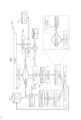
図3は、本開示の実施例1に係る位置特定装置200における地図生成処理300の流れを示すブロック図である。図3に示す地図生成処理300は、位置特定装置200を備える移動体(例えば、図2に示す移動体275)が移動する環境の3次元地図を生成するための処理であり、位置特定装置200の各機能部によって実行される。
FIG. 3 is a block diagram showing the flow of a
まず、撮影部(例えば、図2に示す位置特定装置200における撮影部205、図3には図示せず)は、入力映像305を取得する。上述したように、この入力映像305は、移動体が移動する環境を示す映像であり、複数のフレームから構成されている。一例として、ここでは、撮影部は、環境を撮影可能な状態で移動体に配置され、移動体が移動しながら環境を撮影することで入力映像305を取得してもよい。
撮影部によって取得される入力映像305は、画像特徴抽出部220及び選択的分割判定部225に入力される。
First, an image capturing unit (for example, the
An
画像特徴抽出部220は、撮影部によって取得された入力映像305を入力した後、当該入力映像305を解析し、各フレームの特徴を抽出する。上述したように、ここでの特徴とは、フレームにおけるオブジェクトの特徴を表す情報(ベクトル等)であり、例えば色、大きさ、形状等を含んでもよい。
画像特徴抽出部220によって抽出される特徴は、選択的分割判定部225に入力される。
The image
The features extracted by the image
選択的分割判定部225は、撮影部によって取得された入力映像305に含まれる複数のフレームの中から、動的内容(Dynamic content)を含む可能性が高いフレームを、動的オブジェクト分割処理の対象となる動的フレームとして予測する。より具体的には、選択的分割判定部225は、入力映像305と、画像特徴抽出部220によって抽出された各フレームの特徴と、後述する移動体位置履歴情報310(なお、地図生成処理300が初めて行われる場合は、当該移動体位置履歴情報310は存在しない)を入力し、入力映像305に含まれる複数のフレーム間の移動量、入力映像305を取得した撮影部の移動速度、及びフレームにおいて動的クラスに対応するオブジェクトの画素の比率のいずれかに基づいて、入力映像305の中から、動的内容を含む動的フレームを予測する。
動的内容を含むと予測される動的フレームは、動的オブジェクト分割部230に入力され、動的内容を含まないと予測される非動的フレームは、特徴分類部235に入力される。
選択的分割判定部225の処理の詳細については後述するため、ここではその説明を省略する。
The selective
Dynamic frames that are predicted to contain dynamic content are input to a
The details of the process of the selective
動的オブジェクト分割部230は、選択的分割判定部225によって予測された動的フレームに対して、動的オブジェクト分割処理を施し、動的フレームにおける各画素について、当該画素が動的クラスに対応するオブジェクトに属するか静的クラスに対応するオブジェクトに属するかを示す画像の意味的情報320を生成する。ここでは、動的オブジェクト分割部230は、動的クラスとみなされるオブジェクトの情報を示す動的クラス情報315に基づいて当該画素が動的クラスに対応するオブジェクトに属するか静的クラスに対応するオブジェクトに属するかを判定してもよい。
動的オブジェクト分割部230によって生成される画像の意味的情報320はSLAM部240及び特徴分類部235に入力される。
The dynamic
The image
特徴分類部235は、動的オブジェクト分割部230によって生成された画像の意味的情報320と、画像特徴抽出部220によって抽出された特徴とに基づいて、入力映像305のフレームの各特徴を動的特徴(つまり、動的オブジェクトに属する特徴)又は静的特徴(つまり、静的オブジェクトに属する特徴)として分類する。ある実施例では、特徴分類部235は、フレーム間における特徴の移動量に基づいて特徴を静的特徴又は動的特徴として分類してもよい。
静的特徴として分類された特徴はSLAM部240に入力され、動的特徴として分類された特徴は外れ値として扱われ、SLAM部240の処理から排除される。
The
Features classified as static features are input to the
SLAM部240は、特徴分類部235によって分類された静的特徴と、動的オブジェクト分割部230によって生成された画像の意味的情報320とに基づいて3次元地図325と、第1の移動体位置情報330とを生成する。
ここでの3次元地図325は、入力映像305に示された環境に対応する3次元地図である。図3に示す地図生成処理300を、同じ環境の異なる部分を示す入力映像に基づいて行い、生成するそれぞれの3次元地図を結合することで、環境の全体を示す3次元地図を生成することができる。
The
The
また、ここでの第1の移動体位置情報330は、移動体の位置(例えば、地理的座標等)及び向き(北、東、西、南等)を示す情報である。実際には、この第1の移動体位置情報330は、撮影部によって取得された入力映像から導出された撮影部の位置及び向きを示す情報であるが、撮影部は移動体に備えられているため、移動体の位置及び向きを示す情報でもある。
また、この第1の移動体位置情報330に示されている、複数の異なるフレームにおける移動体/撮影部の位置の変化から、移動体/撮影部の移動を時系列に示す移動体位置履歴情報310を生成することができる。後述するように、この移動体位置履歴情報310は、動的フレームを予測する際に用いられてもよい。
SLAM部240によって生成される3次元地図325及び第1の移動体位置情報330は、インターフェース部250に入力される。
The first moving
Furthermore, it is possible to generate moving object
The three-
インターフェース部250は、SLAM部240によって生成される3次元地図325及び第1の移動体位置情報330を出力する。一例として、インターフェース部250は、3次元地図325を表示すると共に、当該3次元地図325における移動体の位置を表示してもよい。また、ある実施例では、インターフェース部250は、移動体の目的地の入力を受け付けた後、当該目的地までの推奨の経路を表示してもよい。
The
以上説明した地図生成処理300によれば、動的内容を含む可能性が高い動的フレームを予測し、これらの動的フレームのみに対して動的オブジェクト分割処理を施すことで、必要なコンピューティング資源量を抑制しつつ、高精度の環境地図を構築することができる。
According to the
次に、図4を参照して、本開示の実施例1に係る位置特定装置における位置特定処理の流れについて説明する。 Next, the flow of the location identification process in the location identification device according to the first embodiment of the present disclosure will be described with reference to FIG.
図4は、本開示の実施例1に係る位置特定装置200における位置特定処理400の流れを示す図である。図4に示す位置特定処理400は、図3を参照して説明した地図生成処理300によって予め生成された3次元地図325を用いて、位置特定装置200を備える移動体(人間、ロボット等)の任意の環境における位置を特定するための処理であり、位置特定装置200の各機能部によって実行される。
なお、図4に示す位置特定処理400は、3次元地図325を生成するSLAM部に代えて、予め作成された3次元地図325に基づいて移動体の位置を特定する位置特定部245を用いる点以外、基本的な処理の流れは図3を参照して説明した地図生成処理300と同様であるため、繰り返しとなる説明を省略する。
Fig. 4 is a diagram showing a flow of a
Note that the basic process flow of the
位置特定部245は、特徴分類部235によって分類される静的特徴と、動的オブジェクト分割部230によって生成される画像の意味的情報320と、図3を参照して説明した地図生成処理300によって生成され、メモリ215に格納される3次元地図325とを入力し、解析することで、3次元地図325における移動体の位置(例えば、地理的座標等)及び向き(北、東、西、南等)を示す第1の移動体位置情報330を生成する。
この第1の移動体位置情報330は、インターフェース部250に転送され、インターフェース部250にて出力される。
The
This first mobile
以上説明した位置特定処理400によれば、動的内容を含む可能性が高い動的フレームを予測し、これらの動的フレームのみに対して動的オブジェクト分割処理を施すことで、必要なコンピューティング資源量を抑制しつつ、移動体の環境における位置を正確に特定することができる。
According to the
次に、図5を参照して、本開示の実施例1に係る位置特定装置における動的内容判定処理の流れについて説明する。 Next, the flow of the dynamic content determination process in the location identification device according to the first embodiment of the present disclosure will be described with reference to FIG.
上述したように、本開示では、映像フレームを構成する複数のフレームの中から、動的内容を含むと予測される動的フレームのみに対して動的オブジェクト分割処理を施し、動的内容を含まないと予測される非動的フレームを動的オブジェクト分割処理から排除することで、必要なコンピューティング資源量を抑制しつつ、移動体の環境における位置を正確に特定することができる。
より具体的には、本開示の実施例に係る動的内容の判定は、スキップマスクパラメータ550に基づいて行われる。このスキップマスクパラメータ550は、入力映像において、動的オブジェクト分割処理から排除するフレーム数を指定するパラメータである。このスキップマスクパラメータ550は、入力映像に含まれる複数のフレーム間の移動量、入力映像を取得した撮影部の移動速度、及びフレームにおいて動的クラスに対応するオブジェクトの画素の比率に基づいて設定及び更新をすることができる。
このスキップマスクパラメータ550を用いることで、動的内容を含む可能性が低いフレームがスキップ(つまり、動的オブジェクト分割処理から排除)され、動的内容を含む可能性が高いフレームのみが動的オブジェクト分割処理の対象となるため、入力映像の全てのフレームに対して動的オブジェクト分割処理を行った場合に比べて、コンピューティング資源を大幅に節約することができる。
As described above, in the present disclosure, from among the multiple frames that make up a video frame, dynamic object segmentation processing is performed only on dynamic frames that are predicted to contain dynamic content, and non-dynamic frames that are predicted not to contain dynamic content are excluded from the dynamic object segmentation processing, thereby making it possible to accurately identify the position of a moving object in an environment while reducing the amount of computing resources required.
More specifically, the determination of dynamic content according to the embodiment of the present disclosure is based on a
By using this
図5は、本開示の実施例1に係る位置特定装置における動的内容判定処理500の流れを示すブロック図である。図5に示す動的内容判定処理500は、スキップマスクパラメータ550を用いて動的内容を含む可能性が高い動的フレームを予測するための処理であり、主に画像特徴抽出部、選択的分割判定部、及び動的オブジェクト分割部によって実行される。
FIG. 5 is a block diagram showing the flow of a dynamic
まず、入力映像305は、選択的分割判定部225及び画像特徴抽出部220に入力される。
First, the
上述したように、画像特徴抽出部220は、撮影部によって取得された入力映像305を入力した後、当該入力映像305を解析し、各フレームの特徴を抽出する。これらの特徴は、後述する移動量推定の際に用いられる。
As described above, the image
選択的分割判定部225は、入力映像305を構成する各フレーム毎に、当該フレームの順番を示す画像指標(image index)とスキップマスクパラメータ550を用いて除算演算(modulo operation)を行い、余りが「0」の場合(つまり、画像指標のスキップマスクパラメータ550による除算の余りが0の場合)、当該フレームを動的フレームとし、動的オブジェクト分割部230に入力する。一方、除算演算の余りが「0」でない場合、当該フレームに対して後述の移動量推定を実行する。
ここでは、この除算演算を用いることで、スキップマスクパラメータに設定されているフレーム数毎に、フレームが動的オブジェクト分割部に入力され、それ以外のフレームについては、後述の移動量推定が実行される。
なお、入力映像における1番目のフレームについては、スキップマスクパラメータ550はまだ未設定であるため、この1番目のフレームは直接に動的オブジェクト分割部230に入力される。
The selective
Here, by using this division operation, a frame is input to the dynamic object division unit for each number of frames set in the skip mask parameters, and for the remaining frames, the movement amount estimation described below is performed.
Note that since the
次に、選択的分割判定部225は、除算演算の余りが「0」のフレームについて、画像特徴抽出部220によって抽出された特徴及び対象のフレームの、入力映像における前のフレーム510の情報(以下、「前フレーム」という)に基づいて、移動量推定を行う。
ここでは、選択的分割判定部225は、対象のフレームと、前フレーム510との特徴を比較することで、フレーム間の移動量eを推定する。上述したように、ここでのフレーム間の移動量eは、移動体の移動によって発生する複数のフレームの差分(例えば、画素情報の差分)を意味する。推定した移動量eが所定の移動量基準Mを超える場合、この対象のフレームは動的フレームとみなされ、動的オブジェクト分割部230に入力される。
一方、推定した移動量eが所定の移動量基準M以下の場合、この対象のフレームは非動的フレームとみなされ、特徴分類部(図5には図示せず)に入力される。
このように、非動的フレームに対して移動量推定を行うことで、仮にスキップマスクパラメータの設定によって排除されたフレームの中で動的内容が存在した場合でも、当該動的内容を検出し、この動的内容を含むフレームを動的フレームとして再分類することができる。このように、動的内容を含むフレームをSLAM部から高い精度で排除することができるため、高精度の3次元地図の生成が可能となる。
Next, for frames where the remainder of the division operation is "0", the selective
Here, the selective
On the other hand, if the estimated movement amount e is less than or equal to the predetermined movement amount reference M, the target frame is regarded as a non-dynamic frame and is input to a feature classifier (not shown in FIG. 5).
In this way, by performing motion estimation on non-dynamic frames, even if dynamic content is present among frames that have been excluded by setting the skip mask parameters, the dynamic content can be detected and the frames containing this dynamic content can be reclassified as dynamic frames. In this way, frames containing dynamic content can be excluded from the SLAM unit with high accuracy, making it possible to generate a highly accurate 3D map.
動的オブジェクト分割部230は、上述したように、動的クラス情報315を用いて、選択的分割判定部225によって予測された動的フレームに対して、動的オブジェクト分割処理を施し、動的フレームにおける各画素について、当該画素が動的クラスに対応するオブジェクトに属するか静的クラスに対応するオブジェクトに属するかを示す画像の意味的情報320を生成する。
As described above, the dynamic
次に、選択的分割判定部225は、動的オブジェクト分割部230によって生成された画像の意味的情報320を用いて、当該フレームにおける動的内容の比率に基づいてスキップマスクパラメータ550を設定する。より具体的には、ここでは、選択的分割判定部225は、当該フレームの全画素数に対して、動的クラスに対応するオブジェクトの画素数の比率を計算し、計算した比率が所定の動的内容の割合に関する基準を満たすか否かを判定する。
計算した比率が所定の動的内容の割合に関する基準を満たさない場合、スキップマスクパラメータ550を設定・更新しない。一方、計算した比率が所定の動的内容の割合に関する基準を満たす場合、スキップマスクパラメータ550は「1」に設定される。
Next, the selective
If the calculated ratio does not meet the predetermined dynamic content percentage criteria, the
また、選択的分割判定部225は、移動体位置履歴情報310を用いてスキップマスクパラメータ550を設定してもよい。上述したように、この移動体位置履歴情報310は、複数の異なるフレームにおける移動体/撮影部の位置を示す情報である。選択的分割判定部225は、この移動体位置履歴情報310に示されている移動体/撮影部の位置の変化に基づいて、移動体/撮影部の移動速度を推定する。その後、選択的分割判定部225は、推定した移動速度に基づいて、スキップマスクパラメータ550を設定・更新してもよい。ここでは、原則として、選択的分割判定部225は、移動体/撮影部の移動速度が早ければ早い程、スキップマスクパラメータ550をより大きい値とし、移動体/撮影部の移動速度が遅ければ遅い程、スキップマスクパラメータ550をより小さい値とすることが望ましい。
例えば、ある実施例では、選択的分割判定部225は、計算した移動体/撮影部の移動速度を事前に設定された閾値に基づいて「Fast」、「Medium」、「Slow」等のカテゴリーのいずれかに分類し、カテゴリーに応じてスキップマスクパラメータ550を設定してもよい。一例として、選択的分割判定部225は、移動体/撮影部の移動速度を「Fast」と判定した場合、スキップマスクパラメータ550を「2」に設定し、移動体/撮影部の移動速度を「Medium」と判定した場合、スキップマスクパラメータ550を「5」に設定し、移動体/撮影部の移動速度を「Slow」と判定した場合、スキップマスクパラメータ550を「10」に設定してもよい。
In addition, the selective
For example, in one embodiment, the selective
以上説明した動的内容判定処理500によれば、入力映像に含まれる複数のフレーム間の移動量、入力映像を取得した撮影部の移動速度、及びフレームにおいて動的クラスに対応するオブジェクトの画素の比率に基づいてスキップマスクパラメータ550を設定及び更新することができる。また、このスキップマスクパラメータ550を用いて入力映像を処理することで、動的内容を含まない非動的フレーム(例えば、フレーム間移動が少ないフレーム、移動体/撮影部の移動速度が遅いフレーム、動的オブジェクトに対応する画素が少ないフレーム等)をスキップしつつ、動的内容を含む可能性が高い動的フレーム(例えば、フレーム間移動が多いフレーム、移動体/撮影部の移動速度が速いフレーム、動的オブジェクトに対応する画素が多いフレーム等)を判定することができる。
According to the dynamic
次に、図6を参照して、本開示の実施例1に係る位置特定装置における特徴分類処理の流れについて説明する。 Next, the flow of the feature classification process in the location identification device according to the first embodiment of the present disclosure will be described with reference to FIG.
図6は、本開示の実施例1に係る位置特定装置における特徴分類処理600の流れを示すブロック図である。図6に示す特徴分類処理600は、入力映像の特徴を静的特徴か動的特徴かに分類するための処理であり、主に画像特徴抽出部220、選択的分割判定部225、及び特徴分類部235によって実行される。
Figure 6 is a block diagram showing the flow of
まず、入力映像305は、選択的分割判定部225及び画像特徴抽出部220に入力される。
First, the
上述したように、画像特徴抽出部220は、撮影部によって取得された入力映像305を入力した後、当該入力映像305を解析し、各フレームの特徴615を抽出する。これらの特徴615は、後述する移動量推定及び特徴分類の際に用いられる。
As described above, the image
選択的分割判定部225は、入力映像305を構成する各フレーム毎に、当該フレームの順番を示す画像指標(image index)とスキップマスクパラメータ550を用いて除算演算(modulo operation)を行い、余りが「0」の場合(つまり、画像指標のスキップマスクパラメータ550による除算の余りが0の場合)、当該フレームを動的フレームとし、動的オブジェクト分割部230に入力する。一方、除算演算の余りが「0」でない場合、当該フレームの特徴に対して特徴分類を実行する。
なお、入力映像における1番目のフレームの場合、スキップマスクパラメータ550はまだ未設定であるため、この1番目のフレームは直接に動的オブジェクト分割部230に入力される。
The selective
In addition, in the case of the first frame in the input video, the
動的オブジェクト分割部230は、上述したように、予め作成された動的クラス情報315を用いて、選択的分割判定部225によって予測された動的フレームに対して、動的オブジェクト分割処理を施し、動的フレームにおける各画素について、当該画素が動的クラスに対応するオブジェクトに属するか静的クラスに対応するオブジェクトに属するかを示す画像の意味的情報320を生成する。
この画像の意味的情報320は、特徴分類部235に入力される。
As described above, the
This image
特徴分類部235は、動的オブジェクト分割部230によって生成された画像の意味的情報320と、画像特徴抽出部220によって抽出された特徴615とに基づいて、入力映像のフレームの各特徴を動的特徴622又は静的特徴の候補624として分類する。ここで、動的特徴622として分類された特徴は外れ値として扱われ、SLAM部240の処理から排除される。
一方、静的特徴の候補624として分類された特徴については、特徴分類部235は、上述したフレーム間の移動量eに基づいて、更なる特徴分類を行ってもよい。より具体的には、特徴分類部235は、対象のフレームと、前フレーム510との特徴の比較に基づいて推定された移動量eを所定の移動量基準Mに比較し、移動量eが所定の移動量基準Mを超える場合、当該特徴を動的特徴622として分類し、移動量eが所定の移動量基準M以下の場合、当該特徴を静的特徴632として分類する。
The
On the other hand, for features classified as
以上説明した特徴分類処理600によれば、入力映像の特徴を静的特徴631または動的特徴622のいずれかに分類することができる。更に、以上説明したように、特徴分類を画像の意味的情報320と、フレーム間の移動量とに基づいて二重に行うことにより、スキップマスクパラメータの設定によりスキップされた非動的フレームに存在する動的内容を特定することができると共に、画像の意味的情報320に基づいた判定により誤認されたオブジェクト(動的クラスに対応するのに移動していないオブジェクトや、静的クラスに対応するのに移動したオブジェクト)を正しく分類することができる。
According to the
次に、図7を参照して、本開示の実施例2に係る位置特定装置のハードウェア構成について説明する。 Next, the hardware configuration of the location identification device according to the second embodiment of the present disclosure will be described with reference to FIG. 7.
図7は、本開示の実施例2に係る位置特定装置700のハードウェア構成の一例を示す図である。
上述したように、本開示の実施例1に係るSLAM部240及び位置特定部245は、任意の環境の3次元地図において、移動体275の位置及び向きを示す第1の移動体位置情報を生成する。本開示の実施例2に係る位置特定装置700は、この第1の移動体位置情報と、移動体の移動に関する移動センサデータから導出される第2の移動位置情報とに基づいて、移動体275の位置及び向きをより正確に示す補正済み位置情報を生成することができる。
なお、本開示の実施例2に係る位置特定装置700は、上述した実施例1に係る位置特定装置200の構成に加えて、慣性計測部705、GPS部710、フィルタ部715、及び位置情報補正部720を含む点以外は、実施例1に係る位置特定装置200と実質的に同様の構成であるため、以下では、繰り返しとなる説明を省略する。
FIG. 7 is a diagram illustrating an example of a hardware configuration of a
As described above, the
In addition, the
慣性計測部(inertial measurement unit)705は、運動を司る3軸の角度(または角速度)と加速度とを移動センサデータとして検出するための機能部である。慣性計測部705は、取得した3軸のジャイロと3方向の加速度計によって、移動体275の3次元の角速度及び加速度を計算することができる。
The
GPS(Global Positioning System)部710は、GPS衛星からの信号に基づいて、移動体275の地理的位置情報(座標等)を取得するための機能部である。
The GPS (Global Positioning System)
フィルタ部715は、慣性計測部705によって取得された移動センサデータに対して所定のフィルタ処理を施すことで、当該移動センサデータからノイズを除去するための機能部である。
The
位置情報補正部720は、上述したSLAM部240又は位置特定部245によって生成される第1の移動体位置情報と、慣性計測部705によって取得される移動センサデータから導出される第2の移動体位置情報とに基づいて、移動体275の位置及び向きをより正確に示す補正済み移動体位置情報を生成するための機能部である。
The position
以上説明したように構成した、本開示の実施例2に係る位置特定装置700によれば、実施例1に係る位置特定装置200に比べて、移動体275の位置をより正確に特定することができると共に、SLAM部240によって生成される3次元地図をGPSデータに連携させることができる。
The
次に、図8を参照して、本開示の実施例2に係る位置特定装置における移動体位置情報補正処理の流れについて説明する。 Next, the flow of the mobile object position information correction process in the position identification device according to the second embodiment of the present disclosure will be described with reference to FIG.
図8は、本開示の実施例2に係る位置特定装置における移動体位置情報補正処理800の流れを示すブロック図である。図8に示す移動体位置情報補正処理800は、SLAM部240又は位置特定部245によって生成される第1の移動体位置情報と、慣性計測部によって生成される第2の移動体位置情報とに基づいて、移動体275の位置及び向きをより正確に示す補正済み移動体位置情報を生成するための処理である。そして、移動体位置情報補正処理800は、SLAM部240、位置特定部245、慣性計測部705、フィルタ部715、及び位置情報補正部720によって実行される。
FIG. 8 is a block diagram showing the flow of a moving object position
まず、撮影部によって取得される入力映像305は、位置特定装置のSLAM部240又は位置特定部245に入力される。SLAM部240又は位置特定部245は、図3に示す地図生成処理300又は図4に示す位置特定処理400を行うことで、移動体の位置(例えば、地理的座標等)及び向き(北、東、西、南等)を示す第1の移動体位置情報330を生成する。
First, the
また、慣性計測部705は、移動体が移動しながら、慣性計測部705を含む位置特定装置を備えた移動体の3次元の角速度及び加速度を示す移動センサデータ805を取得する。
The
次に、フィルタ部715は、慣性計測部705によって取得された移動センサデータ805に対して、所定のフィルタ処理を施すことで、当該センサデータからノイズを除去し、フィルタ済みデータ810を生成する。
ここでは、移動センサデータ805からノイズを除去するために、任意の既存のノイズ除去手段を用いてもよく、本開示では特に限定されない。
Next, the
Here, any existing noise removal means may be used to remove noise from the
次に、位置情報補正部720は、フィルタ部715によって生成されたフィルタ済みデータ810に基づいて、移動体の位置及び向きを示す第2の移動体位置情報830を生成する。なお、実際には、この第2の移動体位置情報830は、慣性計測部705によって取得された移動センサデータから導出された慣性計測部705の位置及び向きを示す情報である。そして、この第2の移動体位置情報830は、慣性計測部705は移動体に備えられているため、移動体の位置及び向きを示す情報でもある。
ここでは、フィルタ済みデータ810から移動体の位置及び向きを導出するためには、位置情報補正部720は、任意の既存の手段を用いてもよく、本開示では特に限定されない。
Next, the position
Here, in order to derive the position and orientation of the moving object from the filtered
次に、位置情報補正部720は、上述した第1の移動体位置情報330と、第2の移動体位置情報830とに基づいて、移動体の位置及び向きを第1の移動体位置情報330又は第2の移動体位置情報830よりも正確に示すことができる補正済み移動体位置情報850を生成する。
ここで生成される補正済み移動体位置情報850は、例えば位置特定装置のインターフェース部(例えば図7に示す位置特定装置700のインターフェース部250)を介して出力されてもよい。
Next, the position
The corrected mobile
以上説明したように、本開示の実施例2に係る位置特定装置において、SLAM部240又は位置特定部245によって生成された第1の移動体位置情報330と、慣性計測部705によって生成される第2の移動体位置情報830とに基づいて、移動体の位置及び向きをより正確に示す補正済み移動体位置情報を生成することができる。
As described above, in the position determination device according to the second embodiment of the present disclosure, corrected moving body position information that more accurately indicates the position and orientation of the moving body can be generated based on the first moving
次に、図9を参照して、本開示の実施例2に係る位置特定装置におけるGPS対応付け処理及び地図読み込み処理の流れについて説明する。 Next, the flow of the GPS association process and the map reading process in the position identification device according to the second embodiment of the present disclosure will be described with reference to FIG.
上述したように、本開示の実施例2に係る位置特定装置700は、GPS部710を備える。このGPS部710を用いて、GPSデータをSLAM部240によって生成される3次元地図に対応付けることで、所定の環境における移動体の位置のみならず、移動体の全地球における位置(Global Position)を特定することが可能となる。
As described above, the
図9は、本開示の実施例2に係る位置特定装置におけるGPS対応付け処理900及び地図読み込み処理950の流れを示すブロック図である。
Figure 9 is a block diagram showing the flow of the
まず、GPS対応付け処理900について説明する。GPS対応付け処理900とは、GPSデータをSLAM部240によって生成される3次元地図に対応付けて地図データベース925格納するための処理である。
First, the
まず、SLAM部240は、例えば図3に示す地図生成処理300に従って、入力映像305に対応する3次元地図325を生成する。
First, the
3次元地図325が作成された後、GPS部710は、移動体の全地球における位置(Global Position)を示すGPSデータ905を取得する。その後、GPS部710は、取得したGPSデータ905を、3次元地図325に対応付ける。ここで、GPSデータ905を3次元地図325に対応付ける手段として、GPS部710は、3次元地図325において、特定の地点(公園、オフィスビル、駅等)に対して、当該地点の地理的座標(緯度、経度)を示すジオタグを追加してもよい。
その後、GPS部710は、GPSデータ905を対応付けた3次元地図325を、インターネット等の通信ネットワーク915を介して、地理的に離れた場所に設置されているサーバ装置(クラウドサーバ等)に管理されている地図データベース(以下、「地図DB」)925に格納する。
After the three-
Thereafter, the
次に、地図読み込み処理950について説明する。地図読み込み処理950は、GPSデータに対応付けられている3次元地図を読み込むための処理である。この地図読み込み処理950は、GPSデータ905を対応付けた3次元地図325が既に作成されており、地図DB925に格納されている環境の中に移動体が入場した際に自動的に行われてもよい。
Next, the
移動体のGPS部710は、位置特定装置700(つまり、移動体)の地理的情報(緯度、経度等)955を含む地図要求を、通信ネットワーク915を介して、地図DB925に送信する。なお、本開示において「地図要求」とは、移動体の現在の地理的情報に対応する、予め作成されている環境地図(例えば、上述したGPS対応付け処理900によって地図DB925に格納された3次元地図)を要求する情報である。
その後、地図DB925は、位置特定装置700から受信した地図要求に含まれる地理的情報955に対応する3次元地図325を検索し、検索した3次元地図325を、通信ネットワーク915を介して送信する。その後、3次元地図325を受信した位置特定装置700は、この3次元地図325を用いて、例えば図4を参照して説明した位置特定処理400を行うことで、位置特定装置700を備えた移動体の全地球における位置を特定することができる。
The
Thereafter, the
以上説明したGPS対応付け処理900及び地図読み込み処理950によれば、GPSデータをSLAM部240によって生成される環境の3次元地図に対応付けて格納しておくことで、後に当該環境に入場する移動体は、予め生成された3次元地図を地図DB925から取得し、利用することができるため、何もない状態から3次元地図を生成することが不要となる上、移動体の全地球における位置を特定することができる。
According to the
次に、図10を参照して、本開示の実施例3に係る位置特定装置のハードウェア構成について説明する。 Next, the hardware configuration of the location identification device according to the third embodiment of the present disclosure will be described with reference to FIG. 10.
図10は、本開示の実施例3に係る位置特定装置1000のハードウェア構成の一例を示す図である。
上述したように、本開示の実施例1及び実施例2に係る位置特定装置は、任意の環境の3次元地図において、移動体275の位置及び向きを示す移動体位置情報を生成することができる。本開示の実施例3に係る位置特定装置1000は、この移動体位置情報と、環境におけるリスクを示すリスク位置情報とに基づいて、移動体275に対して影響を及ぼす可能性があるリスクを知らせることができる。
なお、本開示の実施例3に係る位置特定装置1000は、上述した実施例2に係る位置特定装置700の構成に加えて、リスク管理部1010及び通知部1020を含む点以外、構成が実施例2に係る位置特定装置700と実質的に同様であるため、以下では、繰り返しとなる説明を省略する。
FIG. 10 is a diagram illustrating an example of a hardware configuration of a position identifying device 1000 according to a third embodiment of the present disclosure.
As described above, the positioning devices according to the first and second embodiments of the present disclosure can generate mobile object position information indicating the position and orientation of the mobile object 275 in a three-dimensional map of an arbitrary environment. The positioning device 1000 according to the third embodiment of the present disclosure can notify the mobile object 275 of a risk that may affect the mobile object 275 based on the mobile object position information and risk position information indicating a risk in the environment.
In addition, the location identification device 1000 according to the third embodiment of the present disclosure has a configuration substantially similar to that of the
リスク管理部1010は、移動体275の環境における位置及び向きを示す補正済み移動体位置情報と、リスクの候補の位置を示すリスク位置情報とに基づいて、移動体275に対して影響を及ぼす可能性があるリスクを判定するための機能部である。ここでのリスクとは、例えば、移動体275の移動を阻止したり、移動体275にダメージや障害を与える危険性を有する物事を意味し、例えば大型機械、有害物質、治安が悪い領域等を含んでもよい。
The
通知部1020は、リスク管理部1010によって判定されたリスクを移動体275に知らせるためのリスク通知を生成し、出力するための機能部である。ある実施例では、この通知は、移動体275に影響を及ぼす可能性があると判定されたリスクの位置(地理的座標等)や、当該リスクを回避するための指示等を含んでもよい。
The
以上説明したように、本開示の実施例3に係る位置特定装置1000によれば、移動体275が移動する環境において存在するリスクを判定すると共に、当該リスクを移動体275に知らせることができる。これにより、当該環境における移動体275の安全性を向上させることができる。 As described above, the positioning device 1000 according to the third embodiment of the present disclosure can determine the risks present in the environment in which the mobile object 275 moves and can notify the mobile object 275 of the risks. This can improve the safety of the mobile object 275 in the environment.
次に、図11を参照して、本開示の実施例3に係る位置特定装置におけるリスク管理処理の流れについて説明する。 Next, the flow of risk management processing in the location identification device according to the third embodiment of the present disclosure will be described with reference to FIG. 11.
図11は、本開示の実施例3に係る位置特定装置におけるリスク管理処理1100の流れを示すブロック図である。リスク管理処理1100は、移動体に対して影響を及ぼす可能性があるリスクを判定し、当該リスクを知らせる通知を出力するための処理であり、図10に示す位置特定装置1000におけるリスク管理部1010及び通知部1020によって実行される。
FIG. 11 is a block diagram showing the flow of a
まず、リスク管理部1010は、SLAM部240によって生成された3次元地図325と、位置情報補正部720によって生成される補正済み移動体位置情報850と、当該環境におけるリスクの位置を示すリスク位置情報1115を取得する。ここでのリスク位置情報1115は、例えばインターネット等の通信ネットワークを介してアクセス可能なサーバ装置に格納されていてもよい。一例として、対象となる環境が工場の場合、リスク位置情報1115は、工場のサーバに格納されていてもよい。
また、ここでは、補正済み移動体位置情報850を用いる場合を一例として説明するが、本開示はこれに限定されず、補正済み移動体位置情報850の代わりに、第1の移動体位置情報や第2の移動体位置情報を用いてもよい。ただし、補正済み移動体位置情報850は、第1の移動体位置情報及び第2の移動体位置情報に比べて精度が高いため、補正済み移動体位置情報850を用いることが望ましい。
First, the
In addition, although a case where the corrected moving
次に、リスク管理部1010は、取得した3次元地図325、補正済み移動体位置情報850及びリスク位置情報1115に基づいて、移動体に対して影響を及ぼす可能性があるリスクを判定する。ここでは、リスク管理部1010は、例えば、リスク位置情報1115に示されているリスクの候補の中から、移動体の現在位置に対する距離が所定の距離基準未満のリスクの候補を、移動体に対して影響を及ぼす可能性があるリスクとして判定してもよい。
Next, the
その後、通知部1020は、リスク管理部1010によって判定されたリスクを移動体に知らせるためのリスク通知を生成し、出力する。上述したように、この通知は、移動体に影響を及ぼす可能性があると判定されたリスクの位置(地理的座標等)や、当該リスクを回避するための指示等を含んでもよい。
ある実施例では、通知部1020は、作成したリスク通知を、インターフェース部(例えば、図3に示す位置特定装置1000におけるインターフェース部250)に出力し、タッチ画面等を介してユーザに表示してもよい。
Thereafter, the
In one embodiment, the
以上説明したリスク管理処理1100によれば、移動体が移動する環境において存在するリスクを判定すると共に、当該リスクを移動体に知らせることができる。これにより、当該環境における移動体の安全性を向上させることができる。
The
次に、図12を参照して、本開示の実施例に係るインターフェース部の機能について説明する。 Next, the function of the interface unit according to the embodiment of the present disclosure will be described with reference to FIG.
上述したように、本開示の実施例に係るインターフェース部は、各種情報をユーザ(例えば、移動体が位置特定装置を備えた個人用端末を持つ人(人間)のユーザの場合)に提供すると共に、ユーザからの入力を受け付けるための機能部である。一例として、インターフェース部250は、タッチ画面であってもよい。インターフェース部250は、例えばSLAM部によって生成された3次元地図を表示したり、当該3次元地図における移動体の位置(つまり、ユーザの位置)を表示したり、移動体の目的地の入力を受け付けたり、当該目的地までの推奨の経路を表示したりしてもよい。
図12は、本開示の実施例に係るインターフェース部250の機能を示すブロック図である。図12に示すように、インターフェース部250は、3次元地図表示機能1205、移動体位置表示機能1210、目的地設定機能1215、経路案内機能1220、地図検索機能1225、地図読み込み機能1230及びリスク表示機能1235を含む。
As described above, the interface unit according to the embodiment of the present disclosure is a functional unit for providing various information to a user (e.g., in the case where the mobile object is a human user having a personal terminal equipped with a position identification device) and accepting input from the user. As an example, the
12 is a block diagram showing functions of an
3次元地図表示機能1205は、図3を参照して説明した地図生成処理300よって生成される3次元地図、又は地図データベースから取得される3次元地図を表示するための機能である。ここで、インターフェース部250は、3次元地図を、例えばタッチ画面等を介してユーザに表示してもよい。
The three-dimensional
移動体位置表示機能1210は、3次元地図における移動体の位置を表示するための機能である。ここで、移動体位置表示機能1210は、上述した第1の移動体位置情報、第2の移動体位置情報、及び補正済み移動体位置情報のいずれかに従って移動体の位置を3次元地図に表示してもよいが、補正済み移動体位置情報は、第1の移動体位置情報及び第2の移動体位置情報に比べて精度が高いため、補正済み移動体位置情報を用いることが望ましい。
The mobile object
目的地設定機能1215は、ユーザ(例えば、移動体が位置特定装置を備えた個人用端末を持つ人間ユーザの場合)の入力に基づいて、移動体(つまり、ユーザ)の目的地を設定するための機能である。例えば、ここでは、人のユーザは、インターフェース部250によってタッチ画面等で表示される3次元地図に対して、希望の目的地を指等で選択することにより、目的地を設定してもよい。
The
経路案内機能1220は、移動体を、目的地設定機能1215で設定された目的地まで案内するための推奨の経路を判定し、表示するための機能である。ここでは、経路案内1220は、例えば既存の自動運転機能等に従って経路を判定してもよい。
The
地図検索機能1225は、上述したGPS部等によって取得された移動体の地理的情報に基づいて、当該地理的情報に対応する作成済みの3次元地図を、サーバに保存される地図DB(例えば、図9に示す地図DB925)から取得するための機能である。
The
地図読み込み機能1230は、地図検索機能1225によって地図DBから取得された作成済みの3次元地図を読み込んでインターフェース部を介して表示するための機能である。
The
リスク表示機能1235は、図11を参照して説明したリスク管理処理1100によって判定され、通知されたリスクを表示するための機能である。ここで、移動体に対して影響を及ぼす可能性があるリスクの情報は、インターフェース部を介して表示される3次元地図において表示されてもよい。
The
以上説明したインターフェース部によれば、環境内で移動する人のユーザは、位置特定装置に出力される各種情報を容易に確認することができる。 The interface unit described above allows a human user moving around within the environment to easily check the various pieces of information output to the positioning device.
次に、図13を参照して、本開示の実施例に係るスキップマスクパラメータの使用例について説明する。 Next, referring to FIG. 13, we will explain an example of how to use the skip mask parameters according to an embodiment of the present disclosure.
上述したように、本開示の実施例に係る動的内容判定処理(例えば、図5に示す動的内容判定処理500)は、スキップマスクパラメータに基づいて行われる。このスキップマスクパラメータは、入力映像において、動的オブジェクト分割処理から排除するフレーム数を指定するパラメータである。このスキップマスクパラメータを用いることで、動的内容を含む可能性が低いフレームがスキップ(つまり、動的オブジェクト分割処理から排除)され、動的内容を含む可能性が高いフレームのみが動的オブジェクト分割処理の対象となるため、入力映像の全てのフレームに対して動的オブジェクト分割処理を行った場合に比べて、コンピューティング資源を大幅に節約することができる。
なお、このスキップマスクパラメータは、入力映像に含まれる複数のフレーム間の移動量、入力映像を取得した撮影部の移動速度、及びフレームにおいて動的クラスに対応するオブジェクトの画素の比率に基づいて設定及び更新される。
図13は、本開示の実施例に係るスキップマスクパラメータの使用例を示す図である。説明の便宜上、以下の使用例では、フレームの動的内容の比率に基づいてスキップマスクパラメータを設定する場合を説明するが、上述したように、本開示はこれに限定されず、スキップマスクパラメータは動的内容の比率のみならず、移動体/撮影部の移動速度、フレーム間の移動等に応じて設定されてもよい。
As described above, the dynamic content determination process according to the embodiment of the present disclosure (e.g., the dynamic
The skip mask parameters are set and updated based on the amount of movement between multiple frames included in the input video, the movement speed of the image capture unit that captured the input video, and the ratio of pixels of objects corresponding to the dynamic class in the frames.
13 is a diagram showing an example of using skip mask parameters according to an embodiment of the present disclosure. For convenience of explanation, the following example of use describes a case where the skip mask parameters are set based on the ratio of dynamic content of a frame, but as described above, the present disclosure is not limited thereto, and the skip mask parameters may be set according to not only the ratio of dynamic content but also the moving speed of the moving body/image capture unit, the movement between frames, etc.
まず、フレーム1301、フレーム1307、フレーム1308、フレーム1309及びフレーム1310等の複数のフレームを少なくとも含む入力映像1300が取得され、本開示の実施例に係る位置特定装置に入力され、動的内容判定処理の対象となるとする。上述したように、動的内容判定処理が初めて行われる場合、スキップマスクパラメータはまだ未設定であるため、選択的分割判定部は、最初のフレームであるフレーム1301を直接に動的オブジェクト分割部に入力する。
First, an
フレーム1301は、動的オブジェクト分割部によって解析された結果、人間等の動的オブジェクトは存在しないため、動的内容の比率が低く、動的内容割合基準を満たさないと判定される。このため、スキップマスクパラメータは、例えば「5フレーム」等の所定の値に設定される。ここで、スキップマスクパラメータの値は、例えば位置特定装置の管理者によって設定されてもよく、過去に地図生成に用いられた入力映像に基づいて決定されてもよい。
As a result of analyzing
次に、選択的分割判定部は、スキップマスクパラメータに従って、入力映像1300において、フレーム1301から5フレーム(つまり、図13に図示されないフレーム1302~1306)をスキップし、フレーム1307を動的オブジェクト分割部に入力する。
Next, the selective split determination unit skips five frames from frame 1301 (i.e., frames 1302 to 1306, not shown in FIG. 13) in the
フレーム1307は、動的オブジェクト分割部によって解析された結果、動的オブジェクト(人間)が存在するため、動的内容の比率が高く、動的内容割合基準を満たすと判定される。このため、スキップマスクパラメータは、例えば「0フレーム」に更新される。
次に、選択的分割判定部は、スキップマスクパラメータに従って、入力映像1300において、フレーム1307からフレームをスキップしないで、次のフレームであるフレーム1308を動的オブジェクト分割部に入力する。
Next, the selective split determination unit inputs the next frame,
フレーム1308は、動的オブジェクト分割部によって解析された結果、フレーム1307と同様に、動的オブジェクト(人間)が存在するため、動的内容の比率が高く、動的内容割合基準を満たすと判定される。このため、スキップマスクパラメータは、変更されず、「0フレーム」のままに維持される。
As a result of analyzing
フレーム1309は、フレーム1307及びフレーム1308と同様に、動的オブジェクト(人間)が存在するため、動的内容の比率が高く、動的内容割合基準を満たすと判定される。このため、スキップマスクパラメータは、変更されず、「0フレーム」に維持される。
このように、選択的分割判定部は、フレームが動的内容割合基準を満たさなくなるまで、フレームをスキップせず、各フレームを動的オブジェクト分割部に入力する。
In this manner, the selective split decision unit inputs each frame to the dynamic object splitter without skipping any frames until the frame no longer meets the dynamic content proportion criterion.
一方、フレーム1310が動的オブジェクト分割部に入力され、解析された結果、当該フレーム1310は、人間等の動的オブジェクトを含まないため、動的内容の比率が低く、動的内容割合基準を満たさないと判定される。従って、スキップマスクパラメータは、例えば「5フレーム」等の所定の値に設定され、選択的分割判定部は、スキップマスクパラメータに従って、入力映像1300において、フレーム1310から5フレームをスキップした後、次のフレーム(図13には図示せず)を動的オブジェクト分割部に入力する。
On the other hand, when
このように、スキップマスクパラメータを用いることで、動的内容を含まない非動的フレームをスキップしつつ、動的内容を含む可能性が高い動的フレームを判定することができる。これによれば、非動的フレームを地図生成のためにスキップ部に入力しながら、動的フレームを動的オブジェクト分割処理から排除することができるため、入力映像の全てのフレームに対して動的オブジェクト分割処理を行った場合に比べて、コンピューティング資源を大幅に節約することができる。 In this way, by using the skip mask parameters, it is possible to determine dynamic frames that are likely to contain dynamic content while skipping non-dynamic frames that do not contain dynamic content. This allows dynamic frames to be excluded from the dynamic object segmentation process while non-dynamic frames are input to the skip unit for map generation, thereby significantly saving computing resources compared to performing dynamic object segmentation on all frames of the input video.
以上、本発明の実施の形態について説明したが、本発明は、上述した実施の形態に限定されるものではなく、本発明の要旨を逸脱しない範囲において種々の変更が可能である。 Although the embodiment of the present invention has been described above, the present invention is not limited to the above-mentioned embodiment, and various modifications are possible without departing from the gist of the present invention.
200、700、1000 位置特定装置
205 撮影部
210 プロセッサ
215 メモリ
220 画像特徴抽出部
225 選択的分割判定部
230 動的オブジェクト分割部
235 特徴分類部
240 SLAM部
245 位置特定部
250 インターフェース部
705 慣性計測部
710 GPS部
715 フィルタ部
720 位置情報補正部
1010 リスク管理部
1020 通知部
200, 700, 1000
Claims (12)
前記環境を示す入力映像を解析し、前記入力映像に含まれる複数のフレームのそれぞれについて、特徴を抽出する画像特徴抽出部と、
前記入力映像に含まれる前記複数のフレーム間の移動量、前記入力映像を取得した撮影部の移動速度、及び前記フレームにおいて動的クラスに対応するオブジェクトの画素の比率のいずれかに基づいて、前記入力映像の中から、動的内容を含む動的フレームを予測する選択的分割判定部と、
前記動的フレームに対して、動的オブジェクト分割処理を施し、前記動的フレームにおける各画素について、当該画素が動的クラスに対応するオブジェクトに属するか静的クラスに対応するオブジェクトに属するかを示す画像の意味的情報を生成する動的オブジェクト分割部と、
前記画像の意味的情報と、前記特徴とに基づいて、各特徴を動的特徴又は静的特徴として分類する特徴分類部と、
前記静的特徴と、前記画像の意味的情報とに基づいて、前記環境を立体的に示す3次元地図と、前記移動体の位置及び向きを示す第1の移動体位置情報とを生成するSLAM部と、
を含むことを特徴とする位置特定装置。 A position determining device for determining the position of a moving object in an arbitrary environment, comprising:
an image feature extraction unit that analyzes an input video showing the environment and extracts features for each of a plurality of frames included in the input video;
a selective division determination unit that predicts a dynamic frame including dynamic content from the input video based on any one of an amount of movement between the plurality of frames included in the input video, a movement speed of a shooting unit that captured the input video, and a ratio of pixels of an object corresponding to a dynamic class in the frame; and
a dynamic object segmentation unit that performs a dynamic object segmentation process on the dynamic frame and generates, for each pixel in the dynamic frame, semantic information of the image that indicates whether the pixel belongs to an object corresponding to a dynamic class or an object corresponding to a static class;
a feature classification unit that classifies each feature as a dynamic feature or a static feature based on semantic information of the image and the features;
a SLAM unit that generates a three-dimensional map that stereoscopically illustrates the environment and first moving object position information that indicates a position and an orientation of the moving object based on the static features and semantic information of the image;
A location determination device comprising:
前記複数のフレームにおいて、前記入力映像を取得した前記撮影部の位置の変化に基づいて、前記撮影部の移動速度を推定し、
前記撮影部の移動速度に基づいて、前記入力映像において、前記動的オブジェクト分割処理から排除するフレーム数を指定するスキップマスクパラメータを設定し、
前記スキップマスクパラメータに基づいて、前記入力映像を処理することで、動的内容を含まない非動的フレームをスキップすると共に前記動的フレームを予測する、
ことを特徴とする、請求項1に記載の位置特定装置。 The selective division determination unit is
estimating a moving speed of the imaging unit based on a change in a position of the imaging unit that acquired the input video in the plurality of frames;
setting a skip mask parameter that specifies a number of frames to be excluded from the dynamic object segmentation process in the input video based on a moving speed of the image capture unit;
processing the input video based on the skip mask parameters to skip non-dynamic frames that do not include dynamic content and to predict the dynamic frames;
2. The position determining device according to claim 1 .
前記非動的フレームから抽出した前記特徴と、前記入力映像における前記非動的フレームの直前のフレームの特徴とを比較することで、前記フレーム間の移動量を判定し、
前記フレーム間の移動量が所定の移動量基準を満たす場合、前記非動的フレームを動的フレームとする、
ことを特徴とする、請求項2に記載の位置特定装置。 The selective division determination unit is
determining an amount of motion between the frames by comparing the features extracted from the non-motion frame with features of a frame immediately preceding the non-motion frame in the input video;
If the amount of movement between the frames satisfies a predetermined movement amount criterion, the non-dynamic frame is determined to be a dynamic frame.
3. The position determining device according to claim 2 .
前記静的特徴の前記フレーム間の移動量を判定し、
前記静的特徴の内、前記フレーム間の移動量が所定の移動量基準を満たさない特徴のみを前記SLAM部に入力する、
ことを特徴とする、請求項3に記載の位置特定装置。 The feature classification unit is
determining the amount of movement of the static features between the frames;
inputting, into the SLAM unit, only those static features whose inter-frame movement amount does not satisfy a predetermined movement amount criterion;
4. The position determining device according to claim 3 .
前記画像の意味的情報に基づいて、前記入力映像に含まれる対象フレームにおいて、動的クラスに対応するオブジェクトの画素の比率が所定の動的内容割合基準を満たす場合、
前記スキップマスクパラメータをより低い値に設定する、
ことを特徴とする、請求項4に記載の位置特定装置。 The selective division determination unit is
According to the semantic information of the image, if the ratio of pixels of the object corresponding to the dynamic class in the target frame included in the input video meets a predetermined dynamic content ratio criterion;
setting the skip mask parameter to a lower value;
5. The position determining device according to claim 4.
前記移動体の移動に関する移動センサデータを取得する慣性計測部と、
前記移動センサデータに対するフィルタ処理を施し、フィルタ済み移動センサデータを生成するフィルタ部と、
前記フィルタ済み移動センサデータに基づいて、前記移動体の位置及び向きを示す第2の移動体位置情報を生成し、
前記第1の移動体位置情報と、前記第2の移動体位置情報とに基づいて、前記移動体の位置及び向きをより正確に示す補正済み移動体位置情報を生成する位置情報補正部と、
を更に含むことを特徴とする、請求項1に記載の位置特定装置。 The location identification device is
an inertial measurement unit for acquiring movement sensor data relating to the movement of the moving object;
a filter unit that performs a filtering process on the movement sensor data to generate filtered movement sensor data;
generating second mobile object position information indicative of a position and an orientation of the mobile object based on the filtered motion sensor data;
a position information correction unit that generates corrected moving object position information that more accurately indicates a position and an orientation of the moving object based on the first moving object position information and the second moving object position information;
The location determination device of claim 1 further comprising:
リスク管理部と、
通知部と、
を更に含み、
前記リスク管理部は、
前記補正済み移動体位置情報と、リスクの候補の位置を示すリスク位置情報とに基づいて、前記移動体に対して影響を及ぼす可能性があるリスクを判定し、
前記リスクを回避する指示を示すリスク通知を生成し、出力する、
ことを特徴とする、請求項6に記載の位置特定装置。 The location identification device is
Risk Management Department,
A notification unit;
Further comprising:
The risk management department
determining a risk that may affect the moving object based on the corrected moving object position information and risk position information indicating the position of a risk candidate;
generating and outputting a risk notification indicating instructions for avoiding said risk;
7. The position determining device according to claim 6,
前記移動体の全地球における位置を示すGPSデータを取得し、
前記GPSデータを、前記3次元地図に対応付けて地図データベースに格納するGPS部を更に含む、
ことを特徴とする、請求項7に記載の位置特定装置。 The location identification device is
acquiring GPS data indicative of the location of said mobile object on the globe;
a GPS unit that stores the GPS data in a map database in association with the three-dimensional map;
8. The position determining device according to claim 7,
前記環境を示す入力映像を解析し、前記入力映像に含まれる複数のフレームのそれぞれについて、特徴を抽出する工程と、
前記入力映像に含まれる前記複数のフレーム間の移動量、前記入力映像を取得した撮影部の移動速度、及び前記フレームにおいて動的クラスに対応するオブジェクトの画素の比率のいずれかに基づいて、動的オブジェクト分割処理から排除するフレーム数を指定するスキップマスクパラメータを設定する工程と、
前記スキップマスクパラメータに基づいて、前記入力映像を処理することで、動的内容を含まない非動的フレームをスキップすると共に動的内容を含む動的フレームを予測する工程と、
前記動的フレームに対して、動的オブジェクト分割処理を施し、前記動的フレームにおける各画素について、当該画素が動的クラスに対応するオブジェクトに属するか静的クラスに対応するオブジェクトに属するかを示す画像の意味的情報を生成する工程と、
前記画像の意味的情報と、前記特徴とに基づいて、各特徴を動的特徴又は静的特徴として分類する工程と、
前記静的特徴の前記フレーム間の移動量を判定する工程と、
前記静的特徴の内、前記フレーム間の移動量が所定の移動量基準を満たさない特徴と、前記画像の意味的情報とに基づいて、前記環境を立体的に示す3次元地図と、前記移動体の位置及び向きを示す第1の移動体位置情報とを生成する工程と、
を含むことを特徴とする位置特定方法。 A method for determining a location of a moving object in an arbitrary environment, comprising:
analyzing an input video showing the environment and extracting features for each of a plurality of frames included in the input video;
setting a skip mask parameter that specifies the number of frames to be excluded from a dynamic object segmentation process based on any one of an amount of movement between the plurality of frames included in the input video, a moving speed of a shooting unit that captured the input video, and a ratio of pixels of an object corresponding to a dynamic class in the frames;
processing the input video based on the skip mask parameters to skip non-dynamic frames that do not contain dynamic content and to predict dynamic frames that contain dynamic content;
performing a dynamic object segmentation process on the dynamic frame to generate, for each pixel in the dynamic frame, image semantic information indicating whether the pixel belongs to an object corresponding to a dynamic class or an object corresponding to a static class;
classifying each feature as a dynamic feature or a static feature based on semantic information of the image and the features;
determining the amount of movement of the static features between the frames;
generating a three-dimensional map showing the environment in a three-dimensional manner and first moving object position information showing a position and an orientation of the moving object based on the static features, among the static features, a feature where the movement amount between the frames does not satisfy a predetermined movement amount criterion and semantic information of the image;
A location determination method comprising:
前記移動体に設置され、前記環境を示す3次元地図を生成する位置特定装置と、
前記3次元地図を格納する地図データベースとが通信ネットワークを介して接続されており、
前記位置特定装置は、
前記環境を示す入力映像を解析し、前記入力映像に含まれる複数のフレームのそれぞれについて、特徴を抽出する画像特徴抽出部と、
前記入力映像に含まれる前記複数のフレーム間の移動量、前記入力映像を取得した撮影部の移動速度、及び前記フレームにおいて動的クラスに対応するオブジェクトの画素の比率のいずれかに基づいて、前記入力映像の中から、動的内容を含む動的フレームを予測する選択的分割判定部と、
前記動的フレームに対して、動的オブジェクト分割処理を施し、前記動的フレームにおける各画素について、当該画素が動的クラスに対応するオブジェクトに属するか静的クラスに対応するオブジェクトに属するかを示す画像の意味的情報を生成する動的オブジェクト分割部と、
前記画像の意味的情報と、前記特徴とに基づいて、各特徴を動的特徴又は静的特徴として分類する特徴分類部と、
前記静的特徴と、前記画像の意味的情報とに基づいて、前記環境を立体的に示す前記3次元地図と、前記移動体の位置及び向きを示す第1の移動体位置情報とを生成し、前記通信ネットワークを介して前記3次元地図を前記地図データベースに格納するSLAM部と、
を含むことを特徴とする位置特定システム。 A location determination system for determining the location of a moving object in an arbitrary environment, comprising:
a position determination device installed on the mobile object and configured to generate a three-dimensional map showing the environment;
a map database for storing the three-dimensional map is connected via a communication network;
The location identification device is
an image feature extraction unit that analyzes an input video showing the environment and extracts features for each of a plurality of frames included in the input video;
a selective division determination unit that predicts a dynamic frame including dynamic content from the input video based on any one of an amount of movement between the plurality of frames included in the input video, a movement speed of a shooting unit that captured the input video, and a ratio of pixels of an object corresponding to a dynamic class in the frame; and
a dynamic object segmentation unit that performs a dynamic object segmentation process on the dynamic frame and generates, for each pixel in the dynamic frame, semantic information of the image that indicates whether the pixel belongs to an object corresponding to a dynamic class or an object corresponding to a static class;
a feature classification unit that classifies each feature as a dynamic feature or a static feature based on semantic information of the image and the features;
a SLAM unit that generates the three-dimensional map that stereoscopically shows the environment and first mobile object position information that shows a position and an orientation of the mobile object based on the static features and semantic information of the image, and stores the three-dimensional map in the map database via the communication network;
A location determination system comprising:
前記移動体の全地球における位置を示すGPSデータを取得し、
前記GPSデータを、前記3次元地図に対応付けて前記地図データベースに格納するGPS部を更に含む、
ことを特徴とする、請求項10に記載の位置特定システム。 The location identification device is
acquiring GPS data indicative of the location of said mobile object on the globe;
a GPS unit that stores the GPS data in the map database in association with the three-dimensional map;
11. The location system according to claim 10,
前記通信ネットワークを介して、前記移動体の全地球における位置を示すGPSデータを含む地図要求を前記地図データベースに送信し、
前記前記移動体の全地球における位置に対応する3次元地図を前記地図データベースから受信する、
ことを特徴とする、請求項11に記載の位置特定システム。 The GPS unit includes:
transmitting a map request to said map database via said communications network, said map request including GPS data indicating a global position of said mobile unit;
receiving from the map database a three-dimensional map corresponding to the global location of the moving object;
12. The location system according to claim 11,
Priority Applications (1)
| Application Number | Priority Date | Filing Date | Title |
|---|---|---|---|
| JP2021094448A JP7577608B2 (en) | 2021-06-04 | 2021-06-04 | Location determination device, location determination method, and location determination system |
Applications Claiming Priority (1)
| Application Number | Priority Date | Filing Date | Title |
|---|---|---|---|
| JP2021094448A JP7577608B2 (en) | 2021-06-04 | 2021-06-04 | Location determination device, location determination method, and location determination system |
Publications (2)
| Publication Number | Publication Date |
|---|---|
| JP2022186299A JP2022186299A (en) | 2022-12-15 |
| JP7577608B2 true JP7577608B2 (en) | 2024-11-05 |
Family
ID=84441910
Family Applications (1)
| Application Number | Title | Priority Date | Filing Date |
|---|---|---|---|
| JP2021094448A Active JP7577608B2 (en) | 2021-06-04 | 2021-06-04 | Location determination device, location determination method, and location determination system |
Country Status (1)
| Country | Link |
|---|---|
| JP (1) | JP7577608B2 (en) |
Families Citing this family (1)
| Publication number | Priority date | Publication date | Assignee | Title |
|---|---|---|---|---|
| CN116630265B (en) * | 2023-05-23 | 2025-08-22 | 中国人民解放军国防科技大学 | An intelligent detection method for infrared small targets based on multi-frame difference |
-
2021
- 2021-06-04 JP JP2021094448A patent/JP7577608B2/en active Active
Non-Patent Citations (2)
| Title |
|---|
| Chao Yu,外6名,"DS-SLAM: A Semantic Visual SLAM towards Dynamic Environments",2018 IEEE/RSJ International Conference on Intelligent Robots and Systems (IROS),2018年10月01日,pp. 1168-1174 |
| Yubao Liu,外1名,"RDS-SLAM: Real-Time Dynamic SLAM Using Semantic Segmentation Methods",IEEE Access,2021年01月11日,Volume. 9, 2021,pp. 23772-23785 |
Also Published As
| Publication number | Publication date |
|---|---|
| JP2022186299A (en) | 2022-12-15 |
Similar Documents
| Publication | Publication Date | Title |
|---|---|---|
| CN109840586B (en) | Deep learning-based real-time detection and correction of faulty sensors in autonomous machines | |
| JP7190842B2 (en) | Information processing device, control method and program for information processing device | |
| US11313684B2 (en) | Collaborative navigation and mapping | |
| US10726264B2 (en) | Object-based localization | |
| US10606824B1 (en) | Update service in a distributed environment | |
| CN111323024B (en) | Positioning method and device, equipment, storage medium | |
| IL269560A (en) | Distributed device mapping | |
| US11430199B2 (en) | Feature recognition assisted super-resolution method | |
| Maffra et al. | Real-time wide-baseline place recognition using depth completion | |
| CN109583290B (en) | System and method for improving visual feature detection using motion-related data | |
| WO2022206414A1 (en) | Three-dimensional target detection method and apparatus | |
| KR20130060339A (en) | An adaptable framework for cloud assisted augmented reality | |
| CN110443247A (en) | A kind of unmanned aerial vehicle moving small target real-time detecting system and method | |
| CN115375742B (en) | Methods and systems for generating depth images | |
| JP7525220B2 (en) | Estimation device, learning device, estimation method, and program | |
| CN116721139A (en) | Generate depth images of image data | |
| CN114185073A (en) | Pose display method, device and system | |
| WO2025045113A1 (en) | Method and apparatus for path planning and global localization in mapping | |
| CN114120301A (en) | Pose determination method, device and equipment | |
| Wang et al. | iNavigation: an image based indoor navigation system | |
| CN119779294A (en) | A method and system for object identification to determine the flight path of a drone | |
| US11308324B2 (en) | Object detecting system for detecting object by using hierarchical pyramid and object detecting method thereof | |
| Sambolek et al. | Person detection and geolocation estimation in drone images | |
| KR102383567B1 (en) | Method and system for localization based on processing visual information | |
| JP7577608B2 (en) | Location determination device, location determination method, and location determination system |
Legal Events
| Date | Code | Title | Description |
|---|---|---|---|
| A621 | Written request for application examination |
Free format text: JAPANESE INTERMEDIATE CODE: A621 Effective date: 20240126 |
|
| A977 | Report on retrieval |
Free format text: JAPANESE INTERMEDIATE CODE: A971007 Effective date: 20241003 |
|
| TRDD | Decision of grant or rejection written | ||
| A01 | Written decision to grant a patent or to grant a registration (utility model) |
Free format text: JAPANESE INTERMEDIATE CODE: A01 Effective date: 20241015 |
|
| A61 | First payment of annual fees (during grant procedure) |
Free format text: JAPANESE INTERMEDIATE CODE: A61 Effective date: 20241023 |
|
| R150 | Certificate of patent or registration of utility model |
Ref document number: 7577608 Country of ref document: JP Free format text: JAPANESE INTERMEDIATE CODE: R150 |