JP7565465B2 - Base station and method - Google Patents
Base station and method Download PDFInfo
- Publication number
- JP7565465B2 JP7565465B2 JP2024016411A JP2024016411A JP7565465B2 JP 7565465 B2 JP7565465 B2 JP 7565465B2 JP 2024016411 A JP2024016411 A JP 2024016411A JP 2024016411 A JP2024016411 A JP 2024016411A JP 7565465 B2 JP7565465 B2 JP 7565465B2
- Authority
- JP
- Japan
- Prior art keywords
- port
- ports
- combinations
- dmrs
- base station
- Prior art date
- Legal status (The legal status is an assumption and is not a legal conclusion. Google has not performed a legal analysis and makes no representation as to the accuracy of the status listed.)
- Active
Links
- 238000000034 method Methods 0.000 title claims description 16
- 238000013507 mapping Methods 0.000 claims description 130
- 230000005540 biological transmission Effects 0.000 claims description 58
- 125000004122 cyclic group Chemical group 0.000 claims description 24
- 239000010410 layer Substances 0.000 description 74
- 230000011664 signaling Effects 0.000 description 38
- 238000004891 communication Methods 0.000 description 14
- 238000013468 resource allocation Methods 0.000 description 10
- 230000008901 benefit Effects 0.000 description 9
- 238000005516 engineering process Methods 0.000 description 8
- 238000010586 diagram Methods 0.000 description 7
- 101150069124 RAN1 gene Proteins 0.000 description 5
- 101100355633 Salmo salar ran gene Proteins 0.000 description 5
- 230000007774 longterm Effects 0.000 description 4
- 210000001520 comb Anatomy 0.000 description 3
- 238000013461 design Methods 0.000 description 3
- 230000007246 mechanism Effects 0.000 description 3
- 238000012544 monitoring process Methods 0.000 description 2
- 101100411667 Arabidopsis thaliana RAN4 gene Proteins 0.000 description 1
- 101150014328 RAN2 gene Proteins 0.000 description 1
- 101150074586 RAN3 gene Proteins 0.000 description 1
- 230000001413 cellular effect Effects 0.000 description 1
- 239000002131 composite material Substances 0.000 description 1
- 238000004590 computer program Methods 0.000 description 1
- 238000003745 diagnosis Methods 0.000 description 1
- 239000002355 dual-layer Substances 0.000 description 1
- 230000000694 effects Effects 0.000 description 1
- 230000008030 elimination Effects 0.000 description 1
- 238000003379 elimination reaction Methods 0.000 description 1
- 230000036541 health Effects 0.000 description 1
- 238000007726 management method Methods 0.000 description 1
- 238000005259 measurement Methods 0.000 description 1
- 238000012545 processing Methods 0.000 description 1
- 230000005855 radiation Effects 0.000 description 1
- 230000009467 reduction Effects 0.000 description 1
- 230000004044 response Effects 0.000 description 1
- 230000007480 spreading Effects 0.000 description 1
- 238000012360 testing method Methods 0.000 description 1
- 230000009466 transformation Effects 0.000 description 1
- 208000037918 transfusion-transmitted disease Diseases 0.000 description 1
- 238000011282 treatment Methods 0.000 description 1
Images


Classifications
-
- H—ELECTRICITY
- H04—ELECTRIC COMMUNICATION TECHNIQUE
- H04L—TRANSMISSION OF DIGITAL INFORMATION, e.g. TELEGRAPHIC COMMUNICATION
- H04L5/00—Arrangements affording multiple use of the transmission path
- H04L5/003—Arrangements for allocating sub-channels of the transmission path
- H04L5/0048—Allocation of pilot signals, i.e. of signals known to the receiver
- H04L5/0051—Allocation of pilot signals, i.e. of signals known to the receiver of dedicated pilots, i.e. pilots destined for a single user or terminal
-
- H—ELECTRICITY
- H04—ELECTRIC COMMUNICATION TECHNIQUE
- H04W—WIRELESS COMMUNICATION NETWORKS
- H04W72/00—Local resource management
- H04W72/12—Wireless traffic scheduling
- H04W72/1263—Mapping of traffic onto schedule, e.g. scheduled allocation or multiplexing of flows
- H04W72/1273—Mapping of traffic onto schedule, e.g. scheduled allocation or multiplexing of flows of downlink data flows
-
- H—ELECTRICITY
- H04—ELECTRIC COMMUNICATION TECHNIQUE
- H04L—TRANSMISSION OF DIGITAL INFORMATION, e.g. TELEGRAPHIC COMMUNICATION
- H04L27/00—Modulated-carrier systems
- H04L27/26—Systems using multi-frequency codes
- H04L27/2601—Multicarrier modulation systems
- H04L27/2602—Signal structure
- H04L27/2605—Symbol extensions, e.g. Zero Tail, Unique Word [UW]
- H04L27/2607—Cyclic extensions
-
- H—ELECTRICITY
- H04—ELECTRIC COMMUNICATION TECHNIQUE
- H04L—TRANSMISSION OF DIGITAL INFORMATION, e.g. TELEGRAPHIC COMMUNICATION
- H04L5/00—Arrangements affording multiple use of the transmission path
- H04L5/0001—Arrangements for dividing the transmission path
- H04L5/0014—Three-dimensional division
- H04L5/0023—Time-frequency-space
-
- H—ELECTRICITY
- H04—ELECTRIC COMMUNICATION TECHNIQUE
- H04L—TRANSMISSION OF DIGITAL INFORMATION, e.g. TELEGRAPHIC COMMUNICATION
- H04L5/00—Arrangements affording multiple use of the transmission path
- H04L5/003—Arrangements for allocating sub-channels of the transmission path
- H04L5/0048—Allocation of pilot signals, i.e. of signals known to the receiver
- H04L5/005—Allocation of pilot signals, i.e. of signals known to the receiver of common pilots, i.e. pilots destined for multiple users or terminals
-
- H—ELECTRICITY
- H04—ELECTRIC COMMUNICATION TECHNIQUE
- H04W—WIRELESS COMMUNICATION NETWORKS
- H04W72/00—Local resource management
- H04W72/04—Wireless resource allocation
- H04W72/044—Wireless resource allocation based on the type of the allocated resource
- H04W72/0446—Resources in time domain, e.g. slots or frames
-
- H—ELECTRICITY
- H04—ELECTRIC COMMUNICATION TECHNIQUE
- H04W—WIRELESS COMMUNICATION NETWORKS
- H04W72/00—Local resource management
- H04W72/50—Allocation or scheduling criteria for wireless resources
- H04W72/56—Allocation or scheduling criteria for wireless resources based on priority criteria
- H04W72/563—Allocation or scheduling criteria for wireless resources based on priority criteria of the wireless resources
-
- H—ELECTRICITY
- H04—ELECTRIC COMMUNICATION TECHNIQUE
- H04W—WIRELESS COMMUNICATION NETWORKS
- H04W76/00—Connection management
- H04W76/20—Manipulation of established connections
- H04W76/27—Transitions between radio resource control [RRC] states
Landscapes
- Engineering & Computer Science (AREA)
- Signal Processing (AREA)
- Computer Networks & Wireless Communication (AREA)
- Mobile Radio Communication Systems (AREA)
Description
本開示は、通信システムのリソースにおけるデータおよび/または参照信号の送信および受信に関する。 The present disclosure relates to the transmission and reception of data and/or reference signals in resources of a communication system.
現在、第3世代パートナーシッププロジェクト(3GPP:the 3rd Generation Partnership Project)は、次世代のセルラー技術(第5世代(5G)とも称される)の技術仕様の次のリリース(リリース15)に取り組んでいる。3GPPの技術仕様グループ(TSG:Technical Specification Group)の無線アクセスネットワーク(RAN:Radio Access network)会合#71(2016年3月、Gothenburg)において、RAN1、RAN2、RAN3、およびRAN4が関与する、5Gの最初の検討項目「Study on New Radio Access Technology(新しい無線アクセス技術に関する検討)」が承認され、5Gの最初の標準規格を定義するリリース15の作業項目になるものと予測される。 Currently, the 3rd Generation Partnership Project (3GPP) is working on the next release (Release 15) of technical specifications for the next generation of cellular technology, also known as the fifth generation (5G). At 3GPP's Technical Specification Group (TSG) Radio Access network (RAN) meeting #71 (March 2016, Gothenburg), the first study item for 5G, "Study on New Radio Access Technology", involving RAN1, RAN2, RAN3, and RAN4, was approved and is expected to become the Release 15 work item that will define the first standards for 5G.
5G NR(新無線)の1つの目的は、非特許文献1(3GPPのウェブサイト(www.3gpp.org)で入手可能であり、その全体が参照により本明細書に組み込まれている)に定義されているすべての使用シナリオ、要件、および配置シナリオに対処し、少なくとも、高度モバイルブロードバンド(eMBB:enhanced mobile broadband)、超高信頼・低遅延通信(URLLC:ultra-reliable low-latency communications)、大規模マシンタイプ通信(mMTC:massive machine type communication)を含む、単一の技術的枠組みを提供することである。例えば、eMBBの配置シナリオには、屋内のホットスポット、密集都市部、郊外、都市部、および高速が含まれうる。URLLCの配置シナリオには、産業制御システム、モバイル健康管理(遠隔モニタリング、診断、および治療)、車両のリアルタイム制御、スマートグリッドの広域監視・制御システムが含まれうる。mMTCには、スマートウェアラブルやセンサネットワークなど遅延の影響が小さいデータ伝送による多数の装置を使用するシナリオが含まれうる。 One objective of 5G NR (New Radio) is to provide a single technical framework that addresses all usage scenarios, requirements, and deployment scenarios defined in 3GPP Recommendation 1 (available at the 3GPP website (www.3gpp.org) and incorporated herein by reference in its entirety) and includes at least enhanced mobile broadband (eMBB), ultra-reliable low-latency communications (URLLC), and massive machine type communication (mMTC). For example, deployment scenarios for eMBB may include indoor hotspots, dense urban, suburban, urban, and high-speed. Deployment scenarios for URLLC may include industrial control systems, mobile health management (remote monitoring, diagnosis, and treatment), real-time control of vehicles, and wide-area monitoring and control systems for smart grids. mMTC may include scenarios using a large number of devices with low latency sensitive data transmission, such as smart wearables and sensor networks.
別の目的は、上位互換性である。ロングタームエボリューション(LTE)との下位互換性は要求されず、これにより、まったく新しいシステムの設計および/または新規の特徴の導入が促進される。 Another objective is forward compatibility. Backward compatibility with Long Term Evolution (LTE) is not required, which facilitates the design of entirely new systems and/or the introduction of new features.
NR(新無線)の検討項目の技術報告書の1つ(非特許文献2)に要約されているように、物理層の基本的な信号波形は、直交周波数分割多重(OFDM:Orthogonal Frequency Division Multiplexing)に基づく。ダウンリンクおよびアップリンクの両方において、サイクリックプレフィックスを使用するOFDM(CP-OFDM)をベースとする波形がサポートされる。少なくとも、40GHzまでのeMBBのアップリンクでは、CP-OFDM波形の補助として、離散フーリエ変換(DFT:Discrete Fourier Transformation)拡散OFDM(DFT-S-OFDM)をベースとする波形もサポートされる。 As summarized in one of the technical reports of the NR (New Radio) study items (Non-Patent Document 2), the basic signal waveform of the physical layer is based on Orthogonal Frequency Division Multiplexing (OFDM). In both the downlink and uplink, waveforms based on OFDM with Cyclic Prefix (CP-OFDM) are supported. At least for eMBB uplink up to 40 GHz, waveforms based on Discrete Fourier Transformation (DFT) spread OFDM (DFT-S-OFDM) are also supported as an adjunct to CP-OFDM waveforms.
NRにおける設計目標の1つは、ダウンリンク、アップリンク、およびサイドリンクのための、できる限り共通の波形を模索することである。アップリンク送信のいくつかのケースでは、DFT拡散を導入する必要がないかもしれないと考えられている。用語「ダウンリンク」は、上位のノードから下位のノードへの(例えば、基地局から中継ノード、基地局からUE、中継ノードからUE、など)通信を意味する。用語「アップリンク」は、下位のノードから上位のノードへの(例えば、UEから中継ノード、UEから基地局、中継ノードから基地局、など)通信を意味する。用語「サイドリンク」は、同じレベルのノード間の通信(例えば、2基のUE間、2基の中継ノード間、または2基の基地局間)を意味する。 One of the design goals in NR is to seek waveforms for downlink, uplink, and sidelink that are as common as possible. It is considered that in some cases of uplink transmission, it may not be necessary to introduce DFT spreading. The term "downlink" means communication from a higher-level node to a lower-level node (e.g., from a base station to a relay node, from a base station to a UE, from a relay node to a UE, etc.). The term "uplink" means communication from a lower-level node to a higher-level node (e.g., from a UE to a relay node, from a UE to a base station, from a relay node to a base station, etc.). The term "sidelink" means communication between nodes at the same level (e.g., between two UEs, between two relay nodes, or between two base stations).
用語「空間レイヤ(またはレイヤ)」は、空間多重化によって生成される複数の異なるストリームの1つを意味する。レイヤは、送信アンテナポートへのシンボルのマッピングとして説明することができる。各レイヤは、送信アンテナポートの数に等しいサイズのプリコーディングベクトルによって識別され、放射パターンに関連付けることができる。送信のランクは、送信されるレイヤの数である。コードワードは、送信機の媒体アクセス制御(MAC:Medium Access Control)層から物理層に渡される1つのトランスポートブロック(TB:Transport Block)に対応する、独立して符号化されるデータブロックであり、巡回冗長検査(CRC)によって保護される。一般的には、レイヤは送信時間間隔(TTI)ごとに割り当てられ、送信時間間隔(TTI)は、LTEではサブフレームに相当する。しかしながらNRでは、URLLCかeMBBに応じて異なるTTIを採用することができる。特に、NRでは、TTIは、スロット、ミニスロット、またはサブフレームとすることができる。レイヤ、ランク、およびコードワードについては、非特許文献3の11.2.2.2節(参照により本明細書に組み込まれている)も参照されたい。 The term "spatial layer (or layer)" refers to one of several different streams generated by spatial multiplexing. A layer can be described as a mapping of symbols to transmit antenna ports. Each layer can be identified by a precoding vector of size equal to the number of transmit antenna ports and associated with a radiation pattern. The rank of the transmission is the number of layers transmitted. A codeword is an independently coded data block that corresponds to one transport block (TB) passed from the transmitter's Medium Access Control (MAC) layer to the physical layer and is protected by a cyclic redundancy check (CRC). In general, a layer is assigned per transmission time interval (TTI), which corresponds to a subframe in LTE. However, in NR, different TTIs can be adopted depending on the URLLC or eMBB. In particular, in NR, a TTI can be a slot, a minislot, or a subframe. For information on layers, ranks, and codewords, see also Section 11.2.2.2 of Non-Patent Document 3, which is incorporated herein by reference.
基地局におけるアンテナポート(またはポート)から、参照信号パターン(RS)が送信される。ポートは、1つの物理的送信アンテナとして、または複数の物理的アンテナ要素の組合せとして、送信に使用することができる。いずれの場合にも、各アンテナポートから送信された信号は、UEの受信機によってさらに分解されるようには設計されていない。所与のアンテナポートに対応する送信された参照信号パターン(RS)は、UEの観点からのアンテナポートを定義し、アンテナポートが1つの物理的アンテナからの1つの無線チャネルに相当するか、そのアンテナポートを一緒に含む多数の物理的アンテナ要素からの複合チャネルに相当するかにかかわらず、UEが、そのアンテナポート上で送信されたすべてのデータに対するチャネル推定を導くことを可能にする。ポートについては、非特許文献3の8.2節(参照により本明細書に組み込まれている)も参照されたい。 From an antenna port (or ports) at the base station, a reference signal pattern (RS) is transmitted. A port can be used for transmission as one physical transmit antenna or as a combination of multiple physical antenna elements. In either case, the signal transmitted from each antenna port is not designed to be further resolved by the UE's receiver. The transmitted reference signal pattern (RS) corresponding to a given antenna port defines the antenna port from the UE's perspective and allows the UE to derive a channel estimate for all data transmitted on that antenna port, regardless of whether the antenna port corresponds to one radio channel from one physical antenna or a composite channel from multiple physical antenna elements that together include the antenna port. For ports, see also Section 8.2 of 3GPP TS 2011-01-13 (incorporated herein by reference).
LTEでは、UEにおけるデータの送信および受信は、ダウンリンク制御情報(DCI:Downlink Control Information)として知られるメッセージ(UEまたはUEのグループを対象とするリソース割当ておよび他の制御情報を含む)を伝える物理ダウンリンク制御チャネル(PDCCH:Physical Downlink Control Channel)を用いて、eNBによってスケジューリングされる。一般的には、サブフレーム内でいくつかのPDCCHを送信することができる。 In LTE, data transmission and reception at a UE is scheduled by the eNB using a Physical Downlink Control Channel (PDCCH) that carries messages known as Downlink Control Information (DCI), including resource allocations and other control information targeted to a UE or group of UEs. Typically, several PDCCHs can be transmitted within a subframe.
制御チャネルメッセージの必要な内容は、システムの配置およびUEの設定に依拠する。例えば、インフラストラクチャがMIMOをサポートしない、またはUEが、MIMOを伴わない送信モードに設定されている場合には、MIMO送信の場合にのみ要求されるパラメータをシグナリングする必要はない。したがって、シグナリングオーバーヘッドを最小にする目的で、いくつかの異なるメッセージフォーマット(それぞれが特定のシナリオの場合に要求される最小限のペイロードを含む)が利用可能であることが望ましい。その一方で、実装およびテストが複雑すぎることを回避するため、多すぎるフォーマットを規定しないことが望ましい。以下に、LTEに規定されているDCIメッセージのフォーマットのセットを記載しておく。 The required content of the control channel message depends on the system deployment and the UE configuration. For example, if the infrastructure does not support MIMO or the UE is configured in a transmission mode without MIMO, there is no need to signal parameters that are only required for MIMO transmission. Therefore, in order to minimize the signaling overhead, it is desirable to have several different message formats available, each containing the minimum payload required for a particular scenario. On the other hand, it is desirable not to specify too many formats to avoid overly complex implementation and testing. Below is a set of formats for DCI messages specified for LTE.
上に挙げた技術規格または非特許文献4の9.3.5節(参照により本明細書に組み込まれている)を参照されたい。
- フォーマット0: DCIフォーマット0は、アップリンク送信モード1または2におけるシングルアンテナポート送信を使用するPUSCHのためのリソースグラントの送信に使用される。
- フォーマット1: DCIフォーマット1は、単一コードワードPDSCH送信(ダウンリンク送信モード1,2,7)のためのリソース割当ての送信に使用される。
- フォーマット1A: DCIフォーマット1Aは、単一コードワードPDSCH送信のためのリソース割当てをコンパクトにシグナリングする目的と、競合のないランダムアクセスのために専用プリアンブルシグネチャ(dedicated preamble signature)を移動端末に割り当てる目的とに使用される(すべての送信モード)。
- フォーマット1B: DCIフォーマット1Bは、ランク1送信による閉ループプリコーディングを使用してのPDSCH送信(ダウンリンク送信モード6)のためのリソース割当てをコンパクトにシグナリングするために使用される。送信される情報はフォーマット1Aと同じであるが、それらに加えて、PDSCHの送信に適用されるプリコーディングベクトルのインジケータが含まれる。
- フォーマット1C: DCIフォーマット1Cは、PDSCH割当てを極めてコンパクトに送信するために使用される。フォーマット1Cが使用されるとき、PDSCH送信は、QPSK変調の使用に制約される。このフォーマットは、例えば、ページングメッセージやブロードキャストシステム情報メッセージをシグナリングするために使用される。
- フォーマット1D: DCIフォーマット1Dは、マルチユーザMIMOを使用してのPDSCH送信のためのリソース割当てをコンパクトにシグナリングするために使用される。送信される情報はフォーマット1Bの場合と同じであるが、プリコーディングベクトルのインジケータのビットのうちの1つの代わりに、データシンボルに電力オフセットが適用されるかを示すための1個のビットが存在する。この特徴は、2基のUEの間で送信電力が共有されるか否かを示すために必要である。LTEの今後のバージョンでは、この特徴は、より多くの数のUEの間で電力を共有する場合に拡張されうる。
- フォーマット2: DCIフォーマット2は、閉ループMIMO動作の場合にPDSCHのためのリソース割当てを送信するために使用される(送信モード4)。
- フォーマット2A: DCIフォーマット2Aは、開ループMIMO動作の場合にPDSCHのためのリソース割当てを送信するために使用される。送信される情報はフォーマット2の場合と同じであるが、例外として、eNodeB(LTEにおける基地局の名称)が2つの送信アンテナポートを有する場合にはプリコーディング情報が存在せず、4つのアンテナポートの場合には、送信ランクを示すために2ビットが使用される(送信モード3)。
- フォーマット2B: リリース9において導入され、デュアルレイヤ・ビームフォーミングの場合にPDSCHのためのリソース割当てを送信するために使用される(送信モード8)。
- フォーマット2C: リリース10において導入され、閉ループシングルユーザMIMO動作またはマルチユーザMIMO動作(最大8レイヤ)の場合にPDSCHのためのリソース割当てを送信するために使用される(送信モード9)。
- フォーマット2D: リリース11において導入され、最大8レイヤの送信に使用される。主としてCoMP(協調マルチポイント:Cooperative Multipoint)において使用される(送信モード10)。
- フォーマット3および3A: DCIフォーマット3および3Aは、それぞれ、2ビットまたは1ビットの電力調整を有する、PUCCHおよびPUSCHのための電力制御コマンドを送信するために使用される。これらのDCIフォーマットは、UEのグループのための個々の電力制御コマンドを含む。
- フォーマット4: DCIフォーマット4は、アップリンク送信モード2における閉ループ空間多重化送信を使用する、PUSCHのスケジューリングに使用される。
Please refer to the above-listed technical standards or to section 9.3.5 of IEEE 802.11b, which is incorporated herein by reference.
- Format 0: DCI format 0 is used for transmission of resource grants for PUSCH using single antenna port transmission in
- Format 1:
- Format 1A: DCI Format 1A is used for compact signaling of resource allocation for single codeword PDSCH transmission and for allocating dedicated preamble signatures to mobile terminals for contention-free random access (all transmission modes).
- Format 1B: DCI Format 1B is used for compact signaling of resource allocation for PDSCH transmission (downlink transmission mode 6) using closed-loop precoding with rank-1 transmission. The transmitted information is the same as in Format 1A, but in addition an indicator of the precoding vector applied for the PDSCH transmission is included.
- Format 1C: DCI Format 1C is used for a very compact transmission of PDSCH assignments. When Format 1C is used, PDSCH transmissions are constrained to use QPSK modulation. This format is used, for example, to signal paging messages and broadcast system information messages.
- Format 1D: DCI format 1D is used to compactly signal resource allocation for PDSCH transmission using multi-user MIMO. The transmitted information is the same as in format 1B, but instead of one of the bits of the indicator of the precoding vector, there is one bit to indicate if a power offset is applied to the data symbols. This feature is needed to indicate whether the transmission power is shared between two UEs or not. In future versions of LTE, this feature can be extended to the case of power sharing between a larger number of UEs.
- Format 2:
- Format 2A: DCI format 2A is used to transmit resource allocations for PDSCH in case of open loop MIMO operation. The transmitted information is the same as in
- Format 2B: Introduced in Release 9 and is used for transmitting resource allocations for PDSCH in case of dual layer beamforming (transmission mode 8).
- Format 2C: Introduced in Release 10 and is used for transmitting resource allocations for PDSCH in case of closed-loop single-user MIMO operation or multi-user MIMO operation (up to 8 layers) (transmission mode 9).
- Format 2D: Introduced in Release 11 and used for transmission of up to 8 layers. Mainly used in CoMP (Cooperative Multipoint) (transmission mode 10).
- Formats 3 and 3A: DCI formats 3 and 3A are used to transmit power control commands for PUCCH and PUSCH with 2-bit or 1-bit power adjustment, respectively. These DCI formats contain individual power control commands for groups of UEs.
- Format 4: DCI format 4 is used for scheduling PUSCH using closed-loop spatial multiplexing transmission in
サーチスペースは、UEが自身へのPDCCHを見つけることのできる一連のCCE位置を示す。各PDCCHは、1つのDCIを伝え、DCIに付加されたCRCにおいて暗黙的に符号化されたRNTI(無線ネットワーク一時識別子)によって識別される。UEは、設定されている(1つまたは複数の)サーチスペースのCCEを、ブラインド復号してCRCをチェックすることによって監視する。サーチスペースは、共通サーチスペースおよびUE固有サーチスペースとすることができる。UEは、共通サーチスペースとUE固有サーチスペース(これらは重なり合うことがある)の両方を監視する必要がある。共通サーチスペースは、システム情報(SI-RNTIを使用する)、ページング(P-RNTI)、PRACH応答(RA-RNTI)、またはUL TPCコマンド(TPC-PUCCH/PUSCH-RNTI)など、すべてのUEに共通であるDCIを伝える。UE固有サーチスペースは、UEに固有な割当て(UEに割り振られたC-RNTIを使用する)、セミパーシステントスケジューリング(SPS C-RNTI)、または初期割当て(一時的なC-RNTI)のためのDCIを伝える。 A search space indicates a set of CCE locations where a UE can find a PDCCH to itself. Each PDCCH carries one DCI and is identified by an RNTI (Radio Network Temporary Identifier) implicitly coded in the CRC attached to the DCI. The UE monitors the CCEs of the configured search space(s) by blind decoding and checking the CRC. The search spaces can be common and UE-specific search spaces. The UE needs to monitor both the common and UE-specific search spaces (which may overlap). The common search space carries DCI that is common to all UEs, such as system information (using SI-RNTI), paging (P-RNTI), PRACH response (RA-RNTI), or UL TPC commands (TPC-PUCCH/PUSCH-RNTI). The UE-specific search space carries DCI for UE-specific assignment (using the C-RNTI assigned to the UE), semi-persistent scheduling (SPS C-RNTI), or initial assignment (temporary C-RNTI).
このようにDCIは、UEがデータを受信または送信するためのリソースを指定する(送信および受信の設定を含む)。 Thus, the DCI specifies the resources for the UE to receive or transmit data (including transmission and reception settings).
非限定的かつ例示的な一実施形態は、穏当なシグナリングオーバーヘッドを維持しながら、ポートへのレイヤの柔軟なマッピングと、複数の異なる前方配置DMRS(front-loaded DMRS)構成内での1シンボルDMRSまたは2シンボルDMRSを柔軟に設定することを促進する。 A non-limiting, exemplary embodiment facilitates flexible mapping of layers to ports and flexible configuration of 1-symbol or 2-symbol DMRS in multiple different front-loaded DMRS configurations while maintaining reasonable signaling overhead.
一般的な一態様においては、本明細書に開示されている技術は、通信システムにおいて、複数のアンテナを使用して、基地局にデータを送信する、および/または、基地局からのデータを受信する、ユーザ装置であって、回路を備えており、この回路が、動作時、参照信号を伝えるためのそれぞれのリソースをポートに割り当てるための規則を定義するパラメータ、を受信し、ユーザ装置および基地局に既知であるマッピングに基づいて、ポートへのレイヤのマッピングの組合せのセットを生成し、ポートへのレイヤのマッピングの組合せのセットのうち、データの送信および/または受信に適用されるべき1つの組合せ、を示す制御情報を、基地局から受信する、ユーザ装置、を提供する。 In one general aspect, the techniques disclosed herein provide a user equipment in a communication system for transmitting data to and/or receiving data from a base station using multiple antennas, the user equipment including circuitry that, in operation, receives parameters defining rules for allocating respective resources to ports for carrying reference signals, generates a set of layer-to-port mapping combinations based on mappings known to the user equipment and the base station, and receives control information from the base station indicating one combination of the set of layer-to-port mapping combinations to be applied for transmitting and/or receiving data.
なお、一般的な実施形態または特定の実施形態は、システム、方法、集積回路、コンピュータプログラム、記憶媒体、またはこれらの任意の選択的な組合せとして、実施できることに留意されたい。 It should be noted that the general or specific embodiments may be implemented as a system, a method, an integrated circuit, a computer program, a storage medium, or any selective combination thereof.
開示されている実施形態のさらなる恩恵および利点は、本明細書および図面から明らかになるであろう。これらの恩恵および/または利点は、本明細書および図面のさまざまな実施形態および特徴によって個別に得ることができ、ただしこのような恩恵および/または利点の1つまたは複数を得るために、これらの特徴すべてを設ける必要はない。 Further benefits and advantages of the disclosed embodiments will become apparent from the specification and drawings. These benefits and/or advantages may be obtained individually through the various embodiments and features of the specification and drawings, and it is not necessary for all of these features to be present in order to obtain one or more of such benefits and/or advantages.
第3世代パートナーシッププロジェクトの新無線(3GPP NR)では、幅広い要件およびユースケースを満たすため、参照信号が再設計されている。チャネル推定の目的に使用される復調参照信号(DMRS)も、サイクリックプレフィックス直交周波数分割多重(CP-OFDM)波形を使用するアップリンクおよびダウンリンクの両方において、均一な構造を有するように設計中である。本開示は、(データチャネルの先頭における)前方配置DMRSのポートのマッピングおよび関連するシグナリングの態様に関する。前方配置DMRSの2つの構成(直交DMRSポートの多重化方式が異なる)がサポートされることと、各構成において1シンボルDMRSまたは2シンボルDMRSを使用する柔軟性を有することとが、すでに合意されている。現在のLTEには、直交DMRSポートの多重化方式が1種類である固定された構成が存在し、かなり柔軟性の低い、ポートへのレイヤのマッピングが許可される。しかしながらNRでは、直交DMRSポートの複数の異なる多重化方式の恩恵を生かすために、ポートへのレイヤの柔軟なマッピングを有することが期待される。本開示では、ポートのインデクシング(indexing)を柔軟に設定し、ポートへのレイヤのマッピングを生成し、テーブルのインデックスと一緒に各構成における1シンボルDMRSまたは2シンボルDMRSを示す方法に関する枠組みを提供する。 In the 3rd Generation Partnership Project New Radio (3GPP NR), reference signals are being redesigned to meet a wide range of requirements and use cases. Demodulation Reference Signals (DMRS), used for channel estimation purposes, are also being designed to have a uniform structure in both uplink and downlink using Cyclic Prefix Orthogonal Frequency Division Multiplexing (CP-OFDM) waveforms. This disclosure relates to port mapping of forward-placed DMRS (at the beginning of a data channel) and related signaling aspects. It has already been agreed that two configurations of forward-placed DMRS (with different multiplexing schemes for the orthogonal DMRS ports) are supported, with the flexibility to use one-symbol DMRS or two-symbol DMRS in each configuration. In current LTE, there is a fixed configuration with one type of multiplexing scheme for the orthogonal DMRS ports, which allows a fairly inflexible mapping of layers to ports. However, in NR, it is expected to have a flexible mapping of layers to ports to take advantage of the benefits of multiple different multiplexing schemes for the orthogonal DMRS ports. This disclosure provides a framework for how to flexibly configure port indexing, generate a mapping of layers to ports, and indicate 1-symbol or 2-symbol DMRS in each configuration together with the index of the table.
本開示は、NRの技術に関する。NRのアクセス技術に関する進行中の作業項目については、非特許文献5を参照されたい。より具体的には、本開示は、CP-OFDM波形を使用するダウンリンクおよびアップリンクの両方における前方配置DMRSの態様を扱う。RAN1 NR#2からの議長メモ(chairman notes)(非特許文献6(参照により本明細書に組み込まれている))には、DMRSに関連する最新の合意事項すべてが記録されており、本開示は、まだ検討されていないかまたはさらに検討する余地のある面のいくつかを扱う。本開示は、DMRSポートへのレイヤの柔軟なマッピングと、前方配置DMRS構成それぞれにおける1シンボルDMRSまたは2シンボルDMRSのシグナリング、のための枠組みを提供する。 This disclosure relates to NR technology. For ongoing work items on NR access technology, see NR Access Technologies, 2011. More specifically, this disclosure addresses aspects of forward-located DMRS in both downlink and uplink using CP-OFDM waveforms. The chairman notes from RAN1 NR#2 (2011.06.21, incorporated herein by reference) document all the latest agreements related to DMRS, and this disclosure addresses some of the aspects that have not yet been considered or are open to further consideration. This disclosure provides a framework for flexible mapping of layers to DMRS ports and signaling of 1-symbol DMRS or 2-symbol DMRS in each forward-located DMRS configuration.
前述したように、3GPP NRでは、ダウンリンクおよびアップリンクの両方において復調参照信号(DMRS)が再設計される。 As mentioned above, in 3GPP NR, the demodulation reference signal (DMRS) will be redesigned in both the downlink and uplink.
最新の合意によれば、CP-OFDM波形を使用するダウンリンクおよびアップリンクにおいて、前方配置DMRSの2つの構成がサポートされ、これらは図1A~図1Dに示してある。前方配置参照信号は、1シンボルDMRSが使用される場合には、TTIのうちのシグナリングセクション(シグナリングセクションは例えば2個のシンボルから成る)に隣接する最初のデータシンボルに割り当てられ、2シンボルDMRSが使用される場合には、最初の2個のデータシンボルに割り当てられる。特に、NR DMRSに関係する以下の関連する合意事項が、非特許文献7(参照により本明細書に組み込まれている)に提案されており、参照により本明細書に組み込まれている議長メモ(3GPPのウェブサイト(www.3gpp.org)で入手可能である)において更新および合意される。 According to the latest agreement, two configurations of forward positioned DMRS are supported in the downlink and uplink using CP-OFDM waveforms, which are shown in Figures 1A-1D. The forward positioned reference signal is assigned to the first data symbol adjacent to the signaling section of the TTI (e.g., the signaling section consists of two symbols) when one-symbol DMRS is used, and to the first two data symbols when two-symbol DMRS is used. In particular, the following relevant agreements related to NR DMRS are proposed in 3GPP Recommendation 3 (which is incorporated herein by reference) and are updated and agreed upon in the Chairman's Note (available on the 3GPP website at www.3gpp.org), which is incorporated herein by reference:
DM-RSに関してRAN1#89においてなされた想定は、CP-OFDMの場合に以下のように更新および合意されている。すなわちUEは、ダウンリンク/アップリンクにおいて前方配置DMRS構成タイプ1からのDMRSパターン、または前方配置DMRS構成タイプ2からのDMRSパターンを使用するように、上位層によって設定される。
The assumptions made in RAN1#89 regarding DM-RS are updated and agreed upon for CP-OFDM as follows: UE is configured by higher layers to use DMRS patterns from forward-placed
図1A~図1Dそれぞれは、14個のシンボルと12本のサブキャリアのスロットに対応する例示的なグリッドを示している。各図における左側の最初の2個のシンボルは、スロットのシグナリングセクションに相当する。シグナリングセクションでは、物理ダウンリンク制御チャネル(PDCCH)がシグナリングされる。LTEでは、サブフレームは常に2つのスロットを含む。しかしながら一般的な通信システムでは、サブフレームは、1つのスロットに対応する、または3つ以上のスロットを含むことができる。さらに本開示は、14個のシンボルおよび12本のサブキャリアを有するスロットに限定されない。 Each of Figures 1A-1D shows an example grid corresponding to a slot of 14 symbols and 12 subcarriers. The first two symbols on the left side of each figure correspond to the signaling section of the slot, in which the Physical Downlink Control Channel (PDCCH) is signaled. In LTE, a subframe always contains two slots. However, in a typical communication system, a subframe may correspond to one slot or may contain more than two slots. Furthermore, the present disclosure is not limited to slots having 14 symbols and 12 subcarriers.
図1Aおよび図1Bには、構成タイプ1に対応する第1の前方配置DMRS構成を示してある。この構成は、シングルユーザ多入力多出力(SU-MIMO:Single-User Multiple Input Multiple Output)またはマルチユーザ多入力多出力(MU-MIMO:Multi-User Multiple Input Multiple Output)の場合の最大8つの直交ポートのサポートを目的としている。この第1の構成は、図1Aに示したように1個のシンボルのDMRSが使用される場合、最大4つの直交ポートをサポートする。具体的には、2つのコーム(comb)および2つの巡回シフト(CS)を組み合わせて最大4つの成分セット(component set)を形成することができ、結果としての各成分セットを最大4つのポートにそれぞれ割り当てることができる。図1Bに示したように2個のシンボルのDMRSが使用される場合、2つのコームおよび2つの巡回シフトを、2つの時分割直交カバーコード(TD-OCC:time division Orthogonal Cover Codes)(特にウォルシュ-アダマール(Walsh-Hadamard)TD-OCC)({1,1}および{1,-1})とさらに組み合わせることができ、最大8つの直交ポートをサポートすることができる。しかしながら2シンボルDMRSの場合に、{1,1}および{1,-1}の両方を使用することなく最大4つのポートをスケジューリングすることも可能であるべきである。
1A and 1B show a first forward-distributed DMRS configuration corresponding to
図1Cおよび図1Dには、構成タイプ2に対応する第2の前方配置DMRS構成を示してある。この構成は、SU-MIMOまたはMU-MIMOの場合の最大12の直交ポートのサポートを提供する。特に、周波数領域における隣り合うRE(リソースエレメント)にまたがってそれぞれ適用される2つの(ウォルシュ-アダマール)周波数分割直交カバーコード(FD-OCC)によって、6つの成分セットが形成される。図1Cおよび図1Dから理解できるように、12本のサブキャリアの場合、隣り合うRE(リソースエレメント)のペアが、3つの周波数分割多重(FDM:Frequency Division Multiplexing)グループにグループ化される。したがって、3つのFDMグループにそれぞれ適用される2つのFD-OCC({1,1}および{1,-1}の両方)から、6つの成分セットが形成される。1シンボルDMRSの場合(図1C)には、結果としての6つの各成分セットを、最大6つの直交ポートに割り当てることができる。2シンボルDMRSの場合には、これらの6つの成分セットを2つのTD-OCCとさらに組み合わせることができ、結果として、最大12の直交ポートをサポートすることが可能である(図1D)。
1C and 1D show a second forward-located DMRS configuration corresponding to
図1A~図1Dを参照しながら上述したように、コーム、巡回シフト、FD-OCC、FDM、およびTD-OCCが、参照信号(特に、前方配置DMRS)のリソース成分(resource component)を構成する。これらのリソース成分は、第1の前方配置DMRS構成または第2の前方配置DMRS構成に従って組み合わされ、結果としての成分セットがそれぞれ直交ポートに割り当てられる。しかしながら、低いランクの場合にも2シンボルDMRSの使用が可能であるべきである。1シンボルDMRSまたは2シンボルDMRSの場合における特定の構成によってサポートされる成分セットの一部のみが、ポートの割当て用に使用される必要がある。特に、2シンボルの場合にも、{1,1}および{1,-1}の両方を使用することなく最大6つのポートをスケジューリングすることが可能であるべきである。 As described above with reference to Figures 1A-1D, the comb, cyclic shift, FD-OCC, FDM, and TD-OCC constitute the resource components of the reference signal (particularly, forward-placed DMRS). These resource components are combined according to a first forward-placed DMRS configuration or a second forward-placed DMRS configuration, and the resulting component sets are assigned to orthogonal ports, respectively. However, the use of 2-symbol DMRS should also be possible for the lower rank case. Only a part of the component set supported by a particular configuration in the 1-symbol DMRS or 2-symbol DMRS case needs to be used for port assignment. In particular, it should be possible to schedule up to 6 ports in the 2-symbol case without using both {1,1} and {1,-1}.
ユーザ機器(UE)の観点からは、周波数領域符号分割多重(CDM:code division multiplexing)によって多重化されるDMRSポートは、疑似的に同じ場所に配置されている(quasi co-located)。 From the user equipment (UE) perspective, the DMRS ports multiplexed by frequency domain code division multiplexing (CDM) are quasi co-located.
UEを対象とする前方配置DMRS構成タイプがアップリンクとダウンリンクとで異なることができるか否かについては、依然として今後さらに検討される。さらに、上の合意に伴って複雑さ/動作性能の重大な問題がある場合、縮小した選択が検討されることもありうる。 Whether the forward-positioned DMRS configuration type targeted to the UE can be different for uplink and downlink remains to be further explored. Furthermore, if there are significant complexity/performance issues with the above agreement, reduced options may be considered.
さらには、低ランクの場合の2シンボルDMRSの使用に関連して、以下の合意もなされた(これらの合意については非特許文献8(参照により本明細書に組み込まれている)を参照されたい)。UEに割り当てられるDMRSポートの数がN(Nは、構成1の場合には4、構成2の場合には6)に等しいかまたはそれより小さいときに、前方配置DMRSシンボルの数を1または2とすることができる。1シンボルDMRSが使用されるか2シンボルDMRSが使用されるかの決定の詳細は、依然として今後さらに検討される。
Furthermore, the following agreements have also been made in relation to the use of 2-symbol DMRS for low rank (see 3GPP TS 2013-0101122, incorporated herein by reference): When the number of DMRS ports assigned to a UE is equal to or less than N (N is 4 for
[現在のLTEのDMRS構成]
NRにおける上述したDMRS構成は、LTEとは異なり、LTEには、最大で合計8つの直交ポート/レイヤをサポートするための、図7に示したダウンリンクにおける1つの構成(ウォルシュ-アダマール直交カバーコードを用いて周波数および時間における符号分割多重を使用する)が主として存在する。図7の構成と、LTEにおけるDMRS構成に関するさらなる詳細は、非特許文献3の29.1.1節(参照により本明細書に組み込まれている)に記載されている。
Current LTE DMRS Configuration
The above-mentioned DMRS configurations in NR are different from LTE, which mainly has one configuration in the downlink shown in Figure 7 (using code division multiplexing in frequency and time with Walsh-Hadamard orthogonal cover codes) to support a total of up to eight orthogonal ports/layers. The configuration of Figure 7 and further details regarding the DMRS configuration in LTE are described in Section 29.1.1 of Non-Patent Document 3 (incorporated herein by reference).
次の表1は、現在のLTEにおけるポートへのレイヤのマッピングのテーブル(非特許文献9(表5.3.3.1.5C-2)からの引用である)を示している。

現在のLTEでは、ダウンリンクにおいて最大8つの直交DMRSポートがサポートされており、これらの直交DMRSポートは、1種類の多重化方式(すなわち時間/周波数におけるOCC)を主として使用する。したがって、所与のシナリオにおける動作性能に影響を及ぼすことなく、ポートの任意の組合せを使用してレイヤをマッピングすることができる。さらには、所与のレイヤ数において、リソースの使用(DMRSオーバーヘッド)は、ポートのいずれの組合せでも同じである。 Currently, LTE supports up to eight orthogonal DMRS ports in the downlink, which mainly use one type of multiplexing scheme (i.e., OCC in time/frequency). Therefore, any combination of ports can be used to map layers without affecting the performance in a given scenario. Furthermore, for a given number of layers, the resource usage (DMRS overhead) is the same for any combination of ports.
さらに、現在のLTEでは、MU-MIMOの限られたサポートが提供される。また、固定されたDMRS構成がサポートされる。したがって、動的に設定するための追加のシグナリングは必要ない。 Furthermore, current LTE provides limited support for MU-MIMO and supports fixed DMRS configurations, so no additional signaling is required for dynamic configuration.
さらには、表1から理解できるように、ポートへのレイヤのマッピングに許可される組合せは極めて限られている。現在のLTEでは、所与のユーザを対象とするポートへのレイヤのマッピングをシグナリングするために、長さ4のビットマップが定義されており、すなわちポートへのレイヤのマッピングにおいて最小限の数のポートの組合せがサポートされる。特に、2レイヤまでの場合、マッピングのためのポートのインデクシングは、連続的であり重複しない。3~8レイヤの場合、インデクシングは連続的であり重複せず、固定された開始点としてのインデックス0から始まる。マッピングはポートの1つの組合せに限定される。 Furthermore, as can be seen from Table 1, the combinations allowed for mapping layers to ports are very limited. In current LTE, a bitmap of length 4 is defined to signal the mapping of layers to ports for a given user, i.e. a minimum number of port combinations are supported in the mapping of layers to ports. In particular, for up to 2 layers, the indexing of ports for mapping is consecutive and non-overlapping. For 3-8 layers, the indexing is consecutive and non-overlapping, starting from index 0 as a fixed starting point. The mapping is limited to one combination of ports.
[NRにおけるDMRSの要件]
NRでは、次段落で説明する課題の理由で、このようなサポートは十分ではない。我々の認識によれば、主たる理由として現在の合意事項は極めて最近であるため、NRにおけるDMRSポートのマッピングおよび関連するシグナリングに関係する問題に対しては、具体的に対処する以外に利用可能な解決策は存在しない。
[DMRS requirements in NR]
In NR, such support is not sufficient due to the challenges described in the next paragraph. As per our knowledge, mainly because the current agreements are quite recent, there is no solution available other than specifically addressing the issues related to DMRS port mapping and related signaling in NR.
NRでは、DMRS構成が、幅広いシナリオ(特に、アップリンク、ダウンリンク、さまざまなキャリア周波数、および低レイテンシを含む)をサポートすることが要求される。直交DMRSポートへのユーザのレイヤのマッピングは、以下の理由から柔軟であることが期待される。第一に、異なるポートが、異なるシナリオにおいて動作性能が変わりうる異なるタイプの多重化方式に対応することがある。第二に、ポートへのレイヤのマッピングが異なる方法で行われる場合、所与のレイヤ数におけるリソースの使用(DMRSオーバーヘッド)が異なりうる。第三に、現在のLTE(ロングタームエボリューション)におけるMU-MIMOのサポートと比較して、MU-MIMOの改良されたサポートが期待される。前方配置DMRS構成それぞれにおいて、1シンボルDMRSまたは2シンボルDMRSを柔軟に設定することが期待される。 In NR, DMRS configurations are required to support a wide range of scenarios (including uplink, downlink, various carrier frequencies, and low latency, among others). The mapping of user layers to orthogonal DMRS ports is expected to be flexible for the following reasons. First, different ports may correspond to different types of multiplexing schemes whose operating performance may vary in different scenarios. Second, if the mapping of layers to ports is done in different ways, the resource usage (DMRS overhead) for a given number of layers may be different. Third, improved support for MU-MIMO is expected compared to the current support for MU-MIMO in LTE (Long Term Evolution). It is expected to flexibly configure 1-symbol DMRS or 2-symbol DMRS in each forward-placed DMRS configuration.
さまざまなシナリオにおける、ポートへのレイヤの柔軟なマッピングをサポートするためには、より多くのポートの組合せを許可する必要があり、結果としてシグナリングオーバーヘッドが増大する。さらに、所与の前方配置DMRS構成タイプにおいて1シンボルDMRSまたは2シンボルDMRSのいずれかを選択することにより、シグナリングオーバーヘッドがさらに増大する。 To support flexible mapping of layers to ports in various scenarios, more port combinations need to be allowed, resulting in increased signaling overhead. Furthermore, selecting either 1-symbol DMRS or 2-symbol DMRS for a given forward-positioned DMRS configuration type further increases signaling overhead.
これらの要件に基づき、穏当なシグナリングオーバーヘッドを可能にしながら、ポートへのレイヤの柔軟なマッピングと、複数の異なる前方配置DMRS構成内での1シンボルDMRSまたは2シンボル以上のDMRSの柔軟な設定とをサポートする必要がある。 Based on these requirements, there is a need to support flexible mapping of layers to ports and flexible configuration of 1-symbol DMRS or 2+symbol DMRS in multiple different forward-located DMRS configurations while allowing for reasonable signaling overhead.
[実施形態の説明]
本開示は、穏当なシグナリングオーバーヘッドを可能にしながら、ポートへのレイヤの柔軟なマッピングと、複数の異なる前方配置DMRS構成内での1シンボルDMRSまたは2シンボル以上のDMRSの柔軟な設定とをサポートすることを促進する。
[Description of the embodiment]
The present disclosure facilitates supporting flexible mapping of layers to ports and flexible configuration of one-symbol DMRS or two or more-symbol DMRS in multiple different forward-located DMRS configurations while allowing for reasonable signaling overhead.
例示的な一実施形態においては、図2に示したように、本開示は、通信システムにおいて、複数のアンテナを使用して、基地局260にデータを送信する、および/または、基地局260からのデータを受信する、ユーザ装置210、を提供する。本ユーザ装置は、LTEおよびNRにおける通常の呼称であるユーザ機器(UE)に相当しうる。送信および/または受信には、通常では無線チャネルが使用される。本ユーザ装置は回路230を備えており、この回路230は、参照信号用のリソースをポートに割り当てるために使用されるパラメータを受信し、ポートへのレイヤのマッピングの組合せのセットを生成し、これらのマッピングの組合せのうち、データの送信および/または受信に適用されるべき1つの組合せ、を示す制御情報を、基地局260から受信する、ように構成されている。
In an exemplary embodiment, as shown in FIG. 2, the present disclosure provides a
特に、回路230は、動作時、参照信号を伝えるためのそれぞれのリソースをポートに割り当てるための規則を定義するパラメータ、を受信する。ポートに割り当てられるリソースは、一般には少なくとも2つのリソース成分を含む。例えば、これらのリソース成分は、図1A~図1Dに示したそれぞれの構成に従って、コーム、巡回シフト、FD-OCC、FDMに相当する。
In particular, in operation, the
ユーザ装置210の回路230は、動作時、ユーザ装置210および基地局260に既知であるマッピングに基づいて、ポートへのレイヤのマッピングの組合せのセットを生成する。この場合、ポートへのレイヤのマッピングの組合せは、ユーザ装置210などの特定のユーザ端末によってデータの送信または受信に使用されるレイヤが、所与のポート構成において利用可能であるポートにどのようにマッピングされるかを、TTIごとに指定する。
In operation, the
さらに、ユーザ装置210の回路230は、動作時、ポートへのレイヤのマッピングの組合せのセットのうち、TTIごとにデータの送信および/または受信に適用されるべき、ポートへのレイヤのマッピングの1つの特定の組合せ、を示す制御情報を、基地局260から受信する。すなわち、ポートへのレイヤのマッピングの、示された組合せは、データの送信および/または受信のためにユーザ装置210によって使用されるレイヤがマッピングされるポートを定義する。この場合、TTIは、例えばスロット、ミニスロット、またはサブフレームとすることができる。
Further, in operation, the
ポートへのレイヤのマッピングの1つの組合せを示す制御情報は、例えば、PDCCHにおいてDCIの中で送信することができ、ポートへのレイヤのマッピングのその特定の組合せをデータの送信および/または受信に適用するように端末に通知する、スケジューリング設定の一部とすることができる。DCIは、一般的には、アップリンクまたはダウンリンクのデータ送信をスケジューリングする役割を果たしうる(一般には両方をスケジューリングすることも可能である)。UEは、DCIを受信すると、受信された、ポートへのレイヤのマッピングの組合せに従って、レイヤおよびポートを設定し、それに応じて、スケジューリングされたリソースにおいてデータを受信または送信する。 The control information indicating one combination of layer-to-port mapping can be transmitted, for example, in a DCI on the PDCCH and can be part of a scheduling configuration informing the terminal to apply that particular combination of layer-to-port mapping for data transmission and/or reception. The DCI can generally serve to schedule uplink or downlink data transmission (although generally both are also possible). Upon receiving the DCI, the UE configures the layers and ports according to the received combination of layer-to-port mapping and receives or transmits data in the scheduled resources accordingly.
図2に示したように、ユーザ装置210は、送受信機220(すなわち無線チャネルを通じて電波を送信する送信機および受信する受信機)を備えている。送受信機220は、動作時、基地局から受信された制御情報によって指示された、ポートへのレイヤのマッピングの示された組合せを適用して、データの送信および/または受信を実行する。
As shown in FIG. 2, the
ユーザ装置210の回路230の構造は、図6に示してある。ユーザ装置の回路230は、シグナリング情報受信ユニット232と、マッピング生成ユニット231とを備えている。シグナリング情報受信ユニット232は、参照信号を伝えるためのそれぞれのリソースをポートに割り当てるための規則を定義するパラメータ、を受信するように構成されている。マッピング生成ユニット231は、ユーザ装置および基地局に既知であるマッピングに基づいて、ポートへのレイヤのマッピングの組合せのセットを生成するように構成されている。シグナリング情報受信ユニット232は、ポートへのレイヤのマッピングの組合せのセットのうち、データの送信および/または受信に適用されるべき1つの組合せ、を示す制御情報を、基地局260から受信するようにさらに構成されている。なお、ユーザ装置210の送受信機220は、基地局260によって無線チャネルを通じて送信された電波を受信することに留意されたい。ユーザ装置の回路230は、下位層からのすでに復調されたデータおよび/または制御データを受け取る。
The structure of the
ユーザ装置210に対応して、本開示は、通信システムにおいて、ユーザ装置からのデータを受信する、および/または、ユーザ装置にデータを送信する、基地局260、をさらに提供する。本基地局は、例えば、eNodeB(eNB)、またはNRにおける類似するエンティティ(現時点ではgNBと称されている)とすることができる。さらに本開示は、中継ノード(本明細書に記載されている基地局として扱われる中継ノード、または本明細書に記載されているユーザ装置として扱われる中継ノードのいずれか)にも適用可能である。基地局260(または、より具体的には基地局260に含まれている送受信機270)は、複数のアンテナを備えており、これらのアンテナは、動作時、データを送信する、または受信する。さらに、基地局260は回路280を備えており、この回路280は、動作時、参照信号を伝えるためのそれぞれのリソースをポートに割り当てるための規則を定義するパラメータを、送受信機270を介して送信する。さらに基地局260の回路280は、動作時、ユーザ装置および基地局に既知であるマッピングに基づいて、ポートへのレイヤのマッピングの組合せのセットを生成する。したがって基地局は、UEのスケジューリングを実行することができ、すなわち、送信または受信のためのリソースをUEに割り当てて、送信パラメータおよび受信パラメータに適用される対応する設定(DCIに関して上述した、変調、符号化、レイヤおよびポートの設定など)をUEに提供することができる。基地局は、1基または複数基のUEに対してスケジューリングを実行することができる。さらに基地局260の回路280は、動作時、ポートへのレイヤのマッピングの組合せのセットのうち、データの受信および/または送信のためにユーザ装置210によって適用されるべき1つの組合せ、を示す制御情報を、送受信機270を介して送信する。制御情報は、DCIに類似したものとすることができる。基地局は、ダウンリンクにおけるUEへのデータの送信をスケジューリングする制御情報を送信した後には、ポートとレイヤの組合せを使用して、割り当てたリソースにおいてダウンリンクでデータを送信する。アップリンクにおけるUEのデータ送信をスケジューリングする制御情報を送信した後には、基地局は、割り当てたリソースにおける、ポートへのレイヤのマッピングの組合せを使用してのデータを、アップリンクでUEから受信する。
Corresponding to the
図2に示したように、基地局260は、送受信機270(すなわち無線チャネルを通じて電波を送信する送信機および受信する受信機)を備えている。送受信機270は、動作時、ユーザ装置210(基地局から受信された制御情報によって指示された、ポートへのレイヤのマッピングの示された組合せを適用する)によって送信されたデータの受信、および/または、データの送信、を実行する。送受信機270は、基地局の複数のアンテナを備えている。
As shown in FIG. 2, the
例えば、基地局260の回路280は、参照信号を伝えるためのそれぞれのリソースをポートに割り当てるための規則を定義するパラメータ、をさらに設定する。例えば基地局260は、回路280を使用して、ポート割当ての規則を定義するパラメータを設定し、このパラメータを複数のユーザ装置に送信する。
For example, the
さらには、例えば基地局260の回路280は、ユーザ装置210または複数のユーザ装置に適用される制御情報を、ユーザ装置210または複数のユーザ装置のそれぞれのレイヤ数に従ってさらに設定することができる。したがって基地局は、例えば、各ユーザ装置にそれぞれの制御情報を送る。
Furthermore, the
参照信号用のそれぞれのリソースをポートに割り当てるための規則(ポート割当て規則)は、例えば、ポートのインデクシング(具体的にはポートのインデクシング列/ナンバリング列)をさらに定義する。すなわち各ポート(したがって所与のポートに割り当てられるリソース成分の特定のセット)に対して、ポートのインデクシング列によってポート番号(インデックス)が決まる。このようなポートのインデクシング列が定義されている場合、ポートへのレイヤのマッピングの組合せが基づくマッピングにおいて、ポートをそれらのインデックスによって示すことができる。 The rules for allocating the respective resources for the reference signals to the ports (port allocation rules) further define, for example, the port indexing (specifically the port indexing/numbering sequence). That is, for each port (and thus for the particular set of resource components allocated to a given port), the port indexing sequence determines the port number (index). When such a port indexing sequence is defined, the ports can be indicated by their indexes in the mapping on which the layer-to-port mapping combination is based.
特に、ポート割当て規則によってポートのインデクシングが定義される場合、マッピングは、例えば以下を指定することができる。
1) ポートへのレイヤのマッピングの各組合せのレイヤは、連続的にインデックス化されたポートにマッピングされる(「連続的なマッピング」)。すなわち、ポートへのレイヤのマッピングの各組合せにおいて、ポートインデックスの間に間隔があかない。
2) 第2の構成より高いランクを有する第1の構成の各レイヤは、第2の構成の任意のレイヤがマッピングされる各ポートより小さいインデックスを有するポートにマッピングされる(ランクは構成のレイヤ数である)(「より高いランクの優先性」)。すなわち、より高いランクを有する(すなわち、ポートにマッピングされる、より多くのレイヤ(例えば少なくとも2つのレイヤ)を有する)ユーザ端末が、「最初に」(すなわち、より低いランク(例えば1つのみのレイヤ)を有する別のユーザ端末より小さいポート番号のポートに)マッピングされる。
In particular, if the port allocation rules define the indexing of ports, the mapping may specify, for example:
1) The layers in each combination of layer-to-port mappings are mapped to consecutively indexed ports ("consecutive mapping"), i.e., there are no gaps between the port indexes in each combination of layer-to-port mappings.
2) Each layer of the first configuration that has a higher rank than the second configuration is mapped to a port with a lower index (where rank is the number of layers in the configuration) than each port to which any layer of the second configuration is mapped ("higher rank priority"). That is, a user terminal with a higher rank (i.e., having more layers (e.g., at least two layers) mapped to a port) is mapped "first" (i.e., to a port with a lower port number than another user terminal with a lower rank (e.g., only one layer)).
ポートへのレイヤのマッピングにおける柔軟性が高まるとき、上のマッピング原則1)および原則2)によって、ポートへのレイヤのマッピングの利用可能な組合せの総数が減少する。したがって、ポートへのレイヤのマッピングの組合せがインデックス化されている場合、ポートへのレイヤのマッピングの組合せのインデックスの数が減少し、制御情報において、ポートへのレイヤのマッピングの組合せに対応するそれぞれのインデックスを示してシグナリングするために必要なビットがより少ない。 When there is increased flexibility in layer-to-port mapping, the above mapping principles 1) and 2) reduce the total number of available layer-to-port mapping combinations. Thus, when layer-to-port mapping combinations are indexed, the number of indexes for layer-to-port mapping combinations is reduced, and fewer bits are required in the control information to indicate and signal each index corresponding to a layer-to-port mapping combination.
ポートへのレイヤのマッピングの原則1)および原則2)の適用の例を、表2に示してある。各行において、インデックスは、ポートへのレイヤのマッピングの組合せ(すなわち、所与のユーザ装置のレイヤの数と、これらのレイヤをマッピングすることのできるポート(ポートインデックス/番号)を示す。原則1)および原則2)を通じて除外されるマッピングの組合せには、取り消し線を付してある。表2は、NR用に提案されるDMRS構成1の例えば1シンボルDMRSに対応する4つの直交ポートを示している。

例えば、マッピング原則1)および2)が組み合わされる。表2において、連続的なマッピング(原則1))の理由で利用できないマッピング設定には、アスタリスク(*)を付してある。原則1)に加えて原則2)(「より高いランクの優先性」)が適用される理由で利用できない設定には、ハッシュ記号(#)を付してある(原則1)かつ原則2))。 For example, mapping principles 1) and 2) are combined. In Table 2, mapping configurations that are not available because of consecutive mappings (principle 1)) are marked with an asterisk (*). Configurations that are not available because principle 1) plus principle 2) ("higher rank priority") apply are marked with a hash sign (#) (principle 1) and principle 2)).
しかしながら別の例として、上記の、ポートへのレイヤのマッピングの原則1)および原則2)のそれぞれを、単独で適用することができる。 However, as another example, each of the above principles 1) and 2) of mapping layers to ports can be applied alone.
さらには、原則1)および原則2)の適用は、表2に示したような1シンボルDMRS構成1に限定されない。より大きいポート数の別のDMRS構成にも、原則1および原則2)を同様に適用することができ、この場合には減少効果はさらに著しく、なぜなら、合計ポート数が大きいほど、原則1および原則2)のいずれかを通じた除外の対象となる、ポートへのレイヤのマッピングの利用可能な組合せが多いためである。これと同時に、残りの利用可能なポートと、DMRS構成タイプ1およびタイプ2が利用可能であることにより提供される柔軟性の理由で、十分な柔軟性を提供することができる。
Furthermore, the application of principles 1) and 2) is not limited to the 1-
参照信号は、例えば、前方配置参照信号(特に、前方配置DMRS)である。したがって、データを復調する前に、DMRSに基づくチャネル品質推定を実行することができ、したがって、データ復調の低レイテンシを達成することができる。しかしながら本開示は、前方配置参照信号に限定されない。データフレームの任意のシンボルにDMRSを配置することもできる。 The reference signal is, for example, a forward-placed reference signal (particularly, a forward-placed DMRS). Thus, a channel quality estimation based on the DMRS can be performed before demodulating the data, and thus low latency of data demodulation can be achieved. However, the present disclosure is not limited to forward-placed reference signals. The DMRS can also be placed in any symbol of the data frame.
参照信号を伝えるリソースは、時間領域における1つまたは複数のシンボルに位置する。例えば、参照信号は、NRに関してなされた合意に従って、1シンボルDMRSまたは2シンボルDMRSに相当することができる。2シンボルDMRSの場合、TD-OCCが、参照信号を伝えるリソースの1つを構成する。しかしながら本開示は、1シンボルの参照信号または2シンボルの参照信号に限定されず、データセクションの最初(前方配置)または他の位置に参照信号を割り当てるための3以上のシンボル数を使用することができる。 The resource carrying the reference signal is located in one or more symbols in the time domain. For example, the reference signal can correspond to a one-symbol DMRS or a two-symbol DMRS, according to the agreement made on NR. In the case of a two-symbol DMRS, the TD-OCC constitutes one of the resources carrying the reference signal. However, the present disclosure is not limited to a one-symbol reference signal or a two-symbol reference signal, and a number of symbols greater than two for allocating the reference signal at the beginning (forward placement) or at other positions of the data section can be used.
ユーザ装置210および基地局260に既知であるマッピングは、例えば、ポートへのレイヤのマッピングの組合せのインデクシングを暗黙的に含む。表2の例では、ポートへのレイヤのマッピングの組合せの、結果としてのインデックスは、表の「インデックス」列内の数に相当する。表2の例では、ポートへのレイヤのマッピングの、15個のインデックス化された組合せが存在し、これらの組合せのすべてが1シンボルDMRSに対応する。
The mapping known to the
しかしながら別の例では、ポートへのレイヤのマッピングの組合せが、時間領域における1個のシンボルを使用する組合せと2個以上のシンボルを使用する組合せの両方を含めて、連続的にインデックス化される。すなわち、1シンボルを使用する組合せと、2シンボルを使用する組合せの両方を通じた、共通のインデックスが形成される。例えば、最初の方の(小さい)インデックスが1シンボルの組合せを示し(例:インデックス1~15)、そのあとに、2シンボルの設定のインデックス(例:インデックス16~63)が続き、そのあとに、3シンボルの組合せ(利用可能な場合)が続く(以下同様)。1シンボルの参照信号を使用するマッピングの組合せと、2個以上のシンボルの参照信号を使用するマッピングの組合せの両方を含む、このような連続的なインデックスを有する場合、特定のマッピング設定を示すことによって、1シンボルの参照信号が存在するのか、2シンボルの参照信号が存在するのか、または任意の別の数のシンボルの参照信号が存在するのかが、暗黙的に示される。 However, in another example, the layer-to-port mapping combinations are indexed consecutively, including both combinations using one symbol in the time domain and combinations using two or more symbols. That is, a common index is formed that spans both combinations using one symbol and combinations using two symbols. For example, the first (smaller) index indicates a one-symbol combination (e.g., index 1-15), followed by an index of a two-symbol configuration (e.g., index 16-63), followed by a three-symbol combination (if available), and so on. With such consecutive indexes, including both mapping combinations using one symbol reference signal and mapping combinations using two or more symbol reference signals, indicating a particular mapping configuration implicitly indicates whether there is a one-symbol reference signal, a two-symbol reference signal, or any other number of symbols.
ポートに割り当てられるリソースは、例えば、第1のリソース成分構成または第2のリソース成分構成に従って、2つのリソース成分を含む。第1のリソース成分構成は、リソース成分として、コームおよび巡回シフトを含む。コームは、サブキャリアの区別を定義し、1つおきのサブキャリアインデックスを有するサブキャリアが、相異なるコームにグループ化される。したがって第1のコームは、奇数のサブキャリアインデックスを有するサブキャリアから成り、第2のコームは、偶数のサブキャリアインデックスを有するサブキャリアから成る。第2のリソース成分構成は、周波数分割多重および周波数分割直交カバーコード(OCC)を含む。特に、第1のリソース成分構成および第2のリソース成分構成は、上述した構成タイプ1および構成タイプ2にそれぞれ対応する。基地局260は、動作時、第1のリソース成分構成および第2のリソース成分構成のどちらが使用されるかを設定し、第1のリソース成分構成が使用されるのか第2のリソース成分構成が使用されるのかを示すインジケータ(すなわちシグナリング情報)を、ユーザ装置210に送信する。ユーザ装置210の回路230は、動作時、このインジケータをユーザ装置の送受信機220を介して受信する。リソース成分構成のインジケータは、例えば、システム情報、測定の設定および報告など複数の機能領域をカバーする無線リソース制御(RRC:Radio Resource Control)プロトコルを介して、送信/受信される。
The resources allocated to the port include two resource components, for example according to a first resource component configuration or a second resource component configuration. The first resource component configuration includes a comb and a cyclic shift as resource components. The comb defines a subcarrier distinction, and subcarriers with every other subcarrier index are grouped into different combs. Thus, the first comb consists of subcarriers with odd subcarrier indexes, and the second comb consists of subcarriers with even subcarrier indexes. The second resource component configuration includes frequency division multiplexing and frequency division orthogonal cover code (OCC). In particular, the first resource component configuration and the second resource component configuration correspond to the above-mentioned
より一般的には、参照信号を伝えるためのそれぞれのリソースをポートに割り当てるための規則を定義するパラメータは、例えば、RRCプロトコルを介して基地局によって送信され、送信機によって受信される。 More generally, parameters defining the rules for allocating the ports to their respective resources for carrying reference signals are transmitted by the base station, for example via the RRC protocol, and received by the transmitter.
ポートに割り当てられるリソースは、例えば、巡回シフトまたは周波数分割直交カバーコードのいずれかを含む。基地局260の回路280は、例えば、第1のポートに適用される第1の巡回シフトまたは周波数分割直交カバーコードの割当てと、この第1の巡回シフトまたは周波数分割直交カバーコードとは異なる、第2のポートに適用される第2の巡回シフトまたは周波数分割直交カバーコードの割当てと、を設定する。複数のアンテナのうちの第1のアンテナは、動作時、第1のポートを使用してデータを受信または送信し、複数のアンテナのうちの第2のアンテナは、動作時、第2のポートを使用してデータを受信または送信する。参照信号は、1シンボル参照信号または2個以上のシンボルの参照信号とすることができ、2個以上のシンボルの参照信号の場合、ポートに割り当てられるリソースは、例えば、TD-OCCをさらに含む。
The resources assigned to the ports include, for example, either a cyclic shift or a frequency division orthogonal cover code. The
本開示の例によれば、基地局260は、ユーザ装置210による送信および/または受信用に割り当てられる1つまたは複数のキャリア周波数を決定し、どのキャリア周波数が割り当てられるかを示すインジケータを送信する。ユーザ装置210はこのインジケータを受信する。ユーザ装置210の回路230は、送信および/または受信用に割り当てられたキャリア周波数に従って、各ポートが1個のシンボルにマッピングされるのか、ポートが1個または2個のシンボルにマッピングされるのかを設定する。
According to an example of the present disclosure, the
したがって、各ポートに対して1シンボルDMRSを使用するか、1シンボルDMRSおよび/または2シンボルDMRSの両方が使用可能であるかに関して、2つのバリエーションを開示する。バリエーション1では、すべての周波数において多重化方式に関する制約が指定されない。したがってポートは、1個または2個のシンボルにマッピングされる。これに対してバリエーション2では、特定のしきい値(例えば6GHz)より高いキャリア周波数の場合に2シンボルDMRS(したがってTD-OCC)が許可されない。
Therefore, two variations are disclosed regarding whether one-symbol DMRS is used for each port or whether both one-symbol DMRS and/or two-symbol DMRS can be used. In
例えば、基地局260が、送信/受信用に割り当てられるキャリア周波数を指定するキャリアインジケータフィールド(CIF)を送信し、ユーザ装置210がこれを受信する。したがってユーザ装置210の回路230は、動作時、上のバリエーション2に従って各ポートが1個のシンボルにマッピングされるのか、バリエーション2に従ってポートが1個または2個のシンボルにマッピングされるのかを、CIFを介してシグナリングされた周波数(または周波数間隔)に基づいて設定する。
For example, the
さらに本開示は、通信システムにおいて、複数のアンテナを使用して、ユーザ装置210によって基地局260にデータを送信する、および/または、ユーザ装置210によって基地局260からのデータを受信する、方法、を提供する。本方法は、参照信号を伝えるためのそれぞれのリソースをポートに割り当てるための規則を定義するパラメータ、を受信するステップと、ユーザ装置および基地局に既知であるマッピングに基づいて、ポートへのレイヤのマッピングの組合せのセットを生成するステップと、ポートへのレイヤのマッピングの組合せのセットのうち、データの送信および/または受信に適用されるべき1つの組合せを示す制御情報を、基地局から受信するステップと、を含む。
The present disclosure further provides a method for transmitting data by a
さらに、本開示は、複数のアンテナを使用して、基地局260によってユーザ装置210からのデータを受信する、および/または、基地局260によってユーザ装置210にデータを送信する、方法であって、参照信号を伝えるためのそれぞれのリソースをポートに割り当てるための規則を定義するパラメータ、を送信するステップと、ユーザ装置および基地局に既知であるマッピングに基づいて、ポートへのレイヤのマッピングの組合せのセットを生成するステップと、ポートへのレイヤのマッピングの組合せのセットのうち、データの受信および/または送信に適用されるべき1つの組合せを示す制御情報を、ユーザ装置に送信するステップと、を含む、方法、を提供する。
Furthermore, the present disclosure provides a method for receiving data from a
本開示の非限定的かつ例示的な実施形態においては、システムレベルの情報、RRCシグナリング、および/またはPDCCHシグナリングから入力パラメータを取得して、これらのパラメータを利用し、事前定義された規則/原則に基づいて、前方配置DMRSポートのインデクシング列、ポートへのレイヤのマッピング、および、所与の構成タイプにおける1シンボルの前方配置DMRSまたは2シンボルの前方配置DMRSの指示情報、を生成する、枠組み、を提案する。本開示は、以下を含む。
1. 新規のパラメータ(DMRSポートのインデクシングタイプ)の定義およびシグナリング
2. ポートへのレイヤのマッピングの柔軟な組合せを生成するための原則
3. 1シンボル前方配置DMRSまたは2シンボル前方配置DMRSを示すシグナリング
In a non-limiting and exemplary embodiment of the present disclosure, a framework is proposed that takes input parameters from system level information, RRC signaling, and/or PDCCH signaling, and utilizes these parameters to generate forward placed DMRS port indexing sequence, layer to port mapping, and indication information of 1-symbol forward placed DMRS or 2-symbol forward placed DMRS in a given configuration type based on predefined rules/principles.
1. Definition and signaling of a new parameter (DMRS port indexing type) 2. Principles for creating flexible combinations of layer to port mappings 3. Signaling to indicate 1-symbol forward positioned DMRS or 2-symbol forward positioned DMRS
図3は、DMRSポートのインデクシング、ポートへのレイヤのマッピング、および、前方配置DMRS構成それぞれにおける1シンボルDMRSまたは2シンボルDMRSの指示情報、のための例示的な枠組み、を示している。以下のステップが図3に示してある。
1. 以下のパラメータまたはより多くのパラメータの値が、送信機/受信機220,270の両方の側に(すなわち、ユーザ装置210および/または基地局260によるデータの送信および/または受信用に)示される。
a) キャリア周波数は、送信機または受信機に既知であるシステム情報を構成する。
b) 前方配置DMRS構成タイプは、RRCを介して送信機/受信機にシグナリングされる。
c) DMRSポートのインデクシングタイプは、新規のパラメータによってRRCまたはPDCCHを介して送信機/受信機にシグナリングされる。
c)による新規のパラメータがRRCを介して設定される場合、このパラメータによって、ポートへのレイヤのマッピングの組合せの数を、制御シグナリングのオーバーヘッドを増大させることなく2倍に増やすことができる。
2. 上のパラメータに基づいて、ポートのインデクシング列が定義され、それに応じて直交DMRSポートがナンバリングされる。
3. これに続いて、ポートへのレイヤのマッピングの組合せのセットをリストする、ポートへのレイヤのマッピングテーブルが、(1つまたは複数の)事前定義された規則に基づいて生成される。これらの規則は、特に、マッピング原則1)および原則2)を意味する。
これにより、特に多数の直交ポートの場合に(例えば、ポートが割り当てられるリソースが2シンボルDMRSを含むとき)、オーバーヘッドを穏当に維持しながら、従来技術と比較して増大した柔軟性を提供することができる。さらに、MU-MIMOのための直交マッピングを達成することができる。
4. テーブルのサイズに基づいて、組合せを格納するためのビットマップのサイズが定義される。
5. 次に、任意の所与のシナリオにおいて、ポートへのレイヤのインデクシング(layer-to-port indexing)をPDCCHシグナリングを使用してユーザに示す。
3 shows an example framework for DMRS port indexing, layer to port mapping, and indication of 1-symbol DMRS or 2-symbol DMRS in each forward-located DMRS configuration. The following steps are shown in FIG.
1. Values of the following parameters or more are indicated on both sides of the transmitter/
a) The carrier frequency constitutes the system information that is known to the transmitter or receiver.
b) The forward placement DMRS configuration type is signaled to the transmitter/receiver via RRC.
c) The indexing type of the DMRS port is signaled to the transmitter/receiver via RRC or PDCCH by a new parameter.
When the new parameter according to c) is configured via RRC, it allows the number of combinations of layer-to-port mappings to be doubled without increasing the control signaling overhead.
2. Based on the above parameters, a port indexing sequence is defined and the orthogonal DMRS ports are numbered accordingly.
3. Following this, a layer to port mapping table is generated, which lists a set of layer to port mapping combinations, based on (one or more) predefined rules. These rules imply, among other things, mapping principle 1) and principle 2).
This can provide increased flexibility compared to the prior art while keeping overhead reasonable, especially in the case of a large number of orthogonal ports (e.g., when the resources to which the ports are assigned include 2-symbol DMRS). Furthermore, orthogonal mapping for MU-MIMO can be achieved.
4. Based on the size of the table, the size of the bitmap for storing the combinations is defined.
5. Secondly, in any given scenario, layer-to-port indexing is indicated to the user using PDCCH signaling.
図3に示したように、本開示の一態様は、DMRSポートのインデクシング列を扱う。現在のLTEでは、DMRSポートには、シナリオにかかわらず固定された番号が割り当てられる。例えば、非特許文献3の29.1.1節に示されているように、LTEのダウンリンクでは、ポート番号p7~p14のポートが直交DMRSポートに割り当てられる。しかしながら本開示によれば、NRではポート番号の割当てが柔軟であるべきであり、なぜなら異なるポートにおいて多重化方式が異なるためである。ポートインデックスを柔軟に割り当てることができることにより、ポートへのレイヤのマッピングの組合せの課題に別の次元が加わる。実際に、ポートへのレイヤのマッピングテーブルは、DMRSポートインデクシングに関するこの柔軟性に透過的である。これにより、恩恵として、RRCによって設定されるときには制御シグナリングのオーバーヘッドを増大させることなく、ポートへのレイヤのマッピングの組合せの数が2倍に増える。 As shown in FIG. 3, one aspect of the present disclosure deals with the indexing sequence of DMRS ports. In current LTE, DMRS ports are assigned fixed numbers regardless of the scenario. For example, as shown in Section 29.1.1 of 3GPP TS 2010-010116, in the LTE downlink, ports with port numbers p7 to p14 are assigned to orthogonal DMRS ports. However, according to the present disclosure, in NR, the assignment of port numbers should be flexible because the multiplexing schemes are different for different ports. The ability to flexibly assign port indexes adds another dimension to the challenge of layer-to-port mapping combinations. In fact, the layer-to-port mapping table is transparent to this flexibility regarding DMRS port indexing. This has the benefit of doubling the number of layer-to-port mapping combinations without increasing the control signaling overhead when configured by RRC.
これに続いて、十分な柔軟性を維持しながら、ポートへのレイヤの組合せの数を相当に減らすための(1つまたは複数の)規則を定義することを開示する。組合せの数を減らすための単一の規則または一連の規則のいずれかを定義することができる。全般的な原則を単独で適用する、または、より厳しい規則と組み合わせて組合せの数をさらに減らすことができる。LTEでは、所与のユーザのコードワードの数に応じて、2つの個別のテーブルが定義されている。提案する全般的な原則は、このように1つまたは複数のコードワード用に個別のテーブルを有し得ることと両立して使用できるように適用される。 Following this, it is disclosed to define a rule(s) to significantly reduce the number of layer to port combinations while maintaining sufficient flexibility. Either a single rule or a set of rules to reduce the number of combinations can be defined. The general principle can be applied alone or combined with more stringent rules to further reduce the number of combinations. In LTE, two separate tables are defined depending on the number of codewords for a given user. The proposed general principle is thus applied in such a way that it can be used in conjunction with possibly having separate tables for one or more codewords.
以下では、所与の前方配置DMRS構成における1シンボルDMRSまたは2シンボルDMRSの存在を示すためのシグナリングがどのように扱われるかについて説明する。提案するメカニズムの完全な例を以下に示す。この例では、本メカニズムは、図1Cおよび図1Dに示した構成タイプ2のDMRS構成に適用される。しかしながら本開示によれば、本メカニズムは、構成タイプ1の設定にも同様に適用することができる。
In the following, we will explain how the signaling to indicate the presence of 1-symbol DMRS or 2-symbol DMRS in a given forward-positioned DMRS configuration is handled. A complete example of the proposed mechanism is provided below. In this example, the mechanism is applied to the
1. 最初に、RRCが、例えば以下のパラメータ値をシグナリングする。
・ キャリア周波数: 4GHz
・ 前方配置DMRS構成タイプ: 2
1. First, the RRC signals, for example, the following parameter values:
・ Carrier frequency: 4GHz
Forward-deployed DMRS configuration type: 2
これらのパラメータに基づく、前方配置DMRS構成タイプ2の場合の1シンボルDMRSおよび2シンボルDMRSそれぞれにおける2つのDMRSポートインデクシングタイプ(すなわちポートナンバリングタイプ)を、以下に示す。
・ 図4Aに示した1シンボルDMRSポートのインデクシングタイプ1(FDM->FD-OCC)。このナンバリングタイプは、2つのポートまたは3つのポートの場合に、周波数領域における、より大きなダイバーシチを利用するために適している。
・ 図4Bに示した1シンボルDMRSポートのインデクシングタイプ2(FD-OCC->FDM)。このナンバリングタイプは、2つのポート、3つのポート、または4つのポートの場合にデータ多重化のためのリソースを残すために適している。
・ 図5Aに示した2シンボルDMRSポートのインデクシングタイプ1(FDM->FD-OCC+TD-OCC)。このナンバリングタイプは、2つのポートまたは3つのポートの場合に、周波数領域における、より大きなダイバーシチを利用するために適している。
・ 図5Bに示した2シンボルDMRSポートのインデクシングタイプ2(FD-OCC+TD-OCC->FDM)。このナンバリングタイプは、4つのポートまたは8つのポートの場合に、周波数領域における、より大きなダイバーシチを利用するために適している。
Based on these parameters, two DMRS port indexing types (i.e., port numbering types) for 1-symbol DMRS and 2-symbol DMRS, respectively, for forward-located
1-symbol DMRS port indexing type 1 (FDM->FD-OCC) as shown in Fig. 4A. This numbering type is suitable for exploiting larger diversity in the frequency domain in the case of two or three ports.
1-symbol DMRS port indexing type 2 (FD-OCC->FDM) as shown in Fig. 4B. This numbering type is suitable for leaving resources for data multiplexing in the case of two, three or four ports.
Indexing type 1 (FDM->FD-OCC+TD-OCC) for 2-symbol DMRS ports as shown in Fig. 5A. This numbering type is suitable for exploiting larger diversity in the frequency domain in the case of two or three ports.
2-symbol DMRS port indexing type 2 (FD-OCC+TD-OCC->FDM) as shown in Fig. 5B. This numbering type is suitable for exploiting larger diversity in frequency domain in the case of 4 or 8 ports.
図4A、図4B、図5A、および図5Bにおいて、それぞれのFDMグループは、図1Cおよび図1Dにおけるそれぞれの表示内容に従って示してある。 In Figures 4A, 4B, 5A, and 5B, each FDM group is shown according to its respective representation in Figures 1C and 1D.
2. 2番目に、例えばRRCまたはPDCCHによって設定されるDMRSポートインデクシングタイプ1を選択する。インデクシングタイプ1の場合、ポートのインデクシング列は、順序FDM→FD-OCC(1シンボルDMRS)または順序FDM→FD-OCC+TD-OCC(2シンボルDMRS)に従って、生成される。例えば「FDM→FD-OCC」は、最初にポートインデックス(P1~P3)が、同じFD-OCC(例えば{1,1})を有するポートを対象にすべてのFDMグループにわたり順に値が大きくなり、次にポートインデックス(P4~P6)が、他方のFD-OCC({1,-1})を有するポートを対象に同じ順序でFDMグループにわたり再び順に値が大きくなることを意味する。同様に、FD-OCC→FDMの場合には、最初にインデックスが、例えばすべてのFDMグループを有する{1,1}ポートにわたり順に値が大きくなり、次に、FDMグループの同じ順序を維持しながらすべての{1,-1}ポートにわたり順に値が大きくなる。本開示は、FDMグループまたはFD-OCCの特定の順序に限定されず、例えばFD-OCCの順序は、上記に代えて最初に{1,-1}、2番目に{1,1}でもよい。
2. Secondly, select DMRS
3. 次に、ポートへのレイヤのマッピングを含むテーブルを生成する。原則「より高いランクが、連続するDMRSポートに最初にマッピングされ、その後に、より低いランクが連続的にマッピングされる」(すなわちポートへのレイヤのマッピングの前述した原則1)および原則2)の組合せ)に基づいて、以下のテーブルが、1シンボルDMRS(テーブル3)および2シンボルDMRS(テーブル4)の両方を対象にそれぞれ生成される。これらのテーブルにおいて、「状態」は、ポートへのレイヤのマッピング設定のインデックスを示す(表2の「インデックス」列に対応する)。


表3および表4から理解できるように、1シンボルDMRSは、4ビットのフィールドによって示すことのできる15個の状態を有し、2シンボルDMRSは、6ビットのフィールドによって示すことのできる48個の状態を有する(いくつかの状態は予約される)。さらに、1シンボルDMRSおよび2シンボルDMRSの両方の状態が結合される(すなわち1シンボルマッピング設定および2シンボルマッピング設定の両方にわたり順に値が大きくなるインデックスによって連続的にインデックス化される)ならば、合計数は63であり、これは依然として6ビットのフィールドによって示すことができる。表3の1シンボルのポートへのレイヤのマッピングの組合せと、表4の2シンボルのポートへのレイヤのマッピングの組合せとを結合するインデクシング列を生成し、結合されたインデクシング列からインデックスを選択することによって、1シンボルDMRSが使用されるのか2シンボルDMRSが使用されるのかが、暗黙的に示される。したがって、1シンボルDMRSの存在または2シンボルDMRSの存在を明示的にシグナリングするための追加のビットが必要ない。そうではなく、所与の結合の1シンボルDMRSおよび2シンボルDMRSの両方について、データ送信に適用されるレイヤとポートの対応(layer-to-port)をシグナリングするために、1つのビットマップが使用される。したがって、1シンボルDMRSが存在するのか2シンボルDMRSが存在するのかを、追加のビット(例えば1シンボルDMRS/2シンボルDMRSを示すフラグ)を必要とせずに暗黙的に示す方法である。 As can be seen from Tables 3 and 4, 1-symbol DMRS has 15 states that can be indicated by a 4-bit field, and 2-symbol DMRS has 48 states that can be indicated by a 6-bit field (some states are reserved). Furthermore, if both 1-symbol DMRS and 2-symbol DMRS states are combined (i.e., indexed consecutively by increasing indices across both 1-symbol and 2-symbol mapping configurations), the total number is 63, which can still be indicated by a 6-bit field. By generating an indexing column that combines the combination of layer mapping to 1-symbol port in Table 3 and the combination of layer mapping to 2-symbol port in Table 4, and selecting an index from the combined indexing column, it is implicitly indicated whether 1-symbol DMRS or 2-symbol DMRS is used. Therefore, no additional bits are needed to explicitly signal the presence of 1-symbol DMRS or 2-symbol DMRS. Instead, a single bitmap is used to signal the layer-to-port correspondence that applies to data transmission for both 1-symbol and 2-symbol DMRS of a given combination. Thus, it is an implicit way to indicate whether 1-symbol or 2-symbol DMRS is present without requiring an additional bit (e.g., a flag indicating 1-symbol DMRS/2-symbol DMRS).
以下では、上のパラメータを使用する例示的なケースとして、3つのユーザ/ユーザ装置が存在するケースを考える。ユーザ1は4つのレイヤを有し、ユーザ2は6つのレイヤを有し、ユーザ3は2つのレイヤを有する。これに応じて、ユーザ2がP1~P6にマッピングされ、ユーザ1(すなわちユーザ1のレイヤ)がP7~P10にマッピングされ、ユーザ3がP11~P12にマッピングされ、以下のビットマップが各ユーザにそれぞれ送信される(1つのビットマップを使用して状態が結合されている)。
・ ユーザ1: インデックス(15+34)49->110001
・ ユーザ2: インデックス(15+41)55->110111
・ ユーザ3: インデックス(15+22)37->100101
In the following, as an exemplary case using the above parameters, consider the case where there are three users/user devices:
User 1: Index (15 + 34) 49 -> 110001
User 2: Index (15 + 41) 55 -> 110111
User 3: Index (15 + 22) 37 -> 100101
以下では、構成タイプおよびキャリア周波数に従ってのポートへのリソースの割当ての非限定的な例を提供する。 The following provides non-limiting examples of resource allocation to ports according to configuration type and carrier frequency:
センチメートル波/ミリ波の周波数帯域(すなわち6GHzより高い周波数の周波数帯域)および前方配置DMRS構成タイプ1の場合には、ポートの順序のシグナリングに応じて、TD-OCCが許可されないときには)「コーム->CS」または「CS->コーム」が選択され、許可される場合には「コーム->TD-OCC->CS」または「TD-OCC->CS->コーム」が選択され、より高いランクが、連続するDMRSポートに最初にマッピングされ、そのあとに、より低いランクが連続的にマッピングされ、シグナリングには単一のビットマップが使用される。
For centimeter/mm-wave frequency bands (i.e. frequency bands higher than 6 GHz) and forward-located
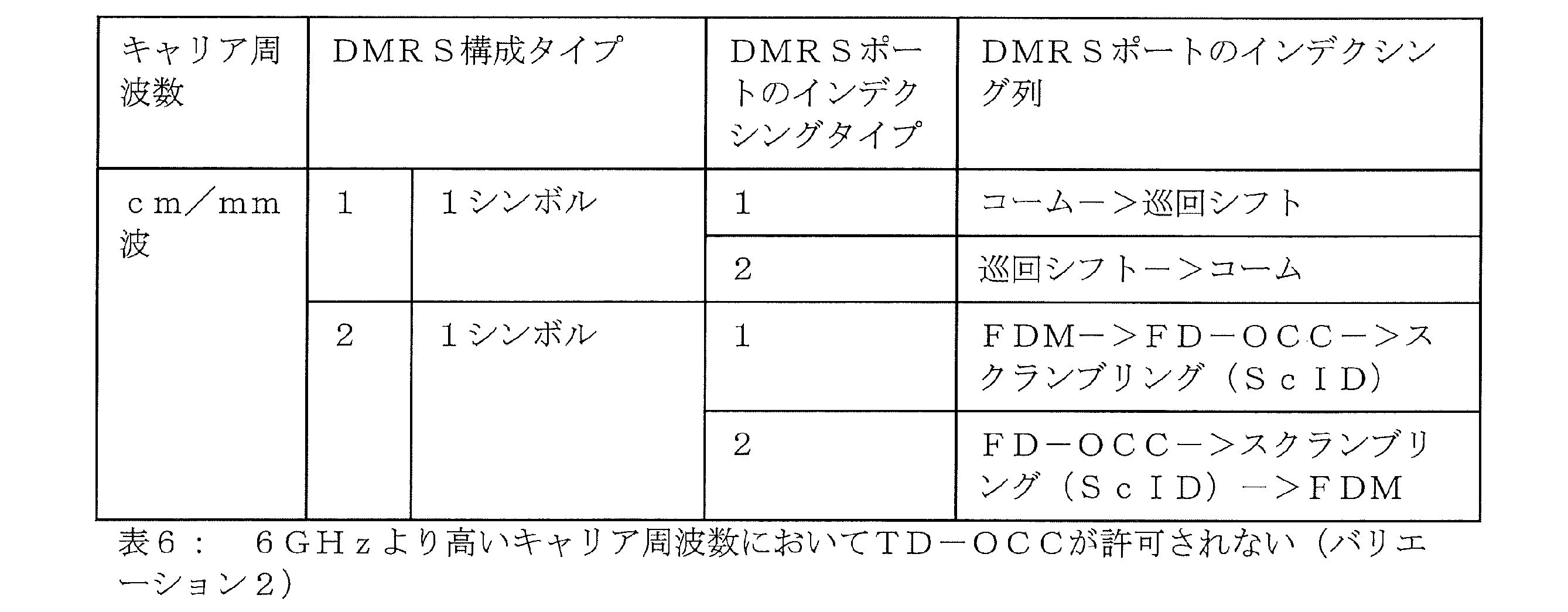
センチメートル波/ミリ波の周波数帯域および前方配置DMRS構成タイプ2の場合には、ポートの順序のシグナリングに応じて、TD-OCCが許可されないときには「FDM->FD-OCC->ScID」または「FD-OCC->ScID->FDM」が選択され、許可される場合には「FDM->FD-OCC->TD-OCC」または「FD-OCC->TD-OCC->FDM」が選択され、より高いランクが、連続するDMRSポートに最初にマッピングされ、そのあとに、より低いランクが連続的にマッピングされ、シグナリングには単一のビットマップが使用される。
For centimeter/mm-wave frequency bands and forward-located
センチメートル波/ミリ波の周波数帯域より低い周波数および前方配置DMRS構成タイプ1の場合には、ポートの順序のシグナリングに応じて、「コーム->TD-OCC->CS」または「TD-OCC->CS->コーム」が選択され、より高いランクが、連続するDMRSポートに最初にマッピングされ、そのあとに、より低いランクが連続的にマッピングされ、シグナリングには単一のビットマップが使用される。
For frequencies below the centimeter/mm-wave frequency bands and forward-distributed
センチメートル波/ミリ波の周波数帯域より低い周波数および前方配置DMRS構成タイプ2の場合には、ポートの順序のシグナリングに応じて、「FDM->FD-OCC->TD-OCC」または「FD-OCC->TD-OCC->FDM」が選択され、より高いランクが、連続するDMRSポートに最初にマッピングされ、そのあとに、より低いランクが連続的にマッピングされ、シグナリングには単一のビットマップが使用される。
For frequencies below the centimeter/mm-wave frequency bands and forward-distributed
表5および表6にも、DMRSポートのインデクシングタイプが示してある。さらなるオプションも可能であるが、必ずしも必要ではない。

一般的な一態様においては、本開示は、通信システムにおいて、複数のアンテナを使用して、基地局にデータを送信する、および/または、基地局からのデータを受信する、ユーザ装置、を提供する。本ユーザ装置は回路を備えており、この回路は、動作時、参照信号を伝えるためのそれぞれのリソースをポートに割り当てるための規則を定義するパラメータ、を受信し、ユーザ装置および基地局に既知であるマッピングに基づいて、ポートへのレイヤのマッピングの組合せのセットを生成し、ポートへのレイヤのマッピングの組合せのセットのうち、データの送信および/または受信に適用されるべき1つの組合せ、を示す制御情報を、基地局から受信する。 In one general aspect, the present disclosure provides a user equipment for transmitting data to and/or receiving data from a base station using multiple antennas in a communication system. The user equipment includes circuitry that, in operation, receives parameters defining rules for allocating respective resources to ports for carrying reference signals, generates a set of layer-to-port mapping combinations based on mappings known to the user equipment and the base station, and receives control information from the base station indicating one of the set of layer-to-port mapping combinations to be applied for transmitting and/or receiving data.
これにより、穏当なシグナリングオーバーヘッドを維持しながら、ポートへのレイヤの柔軟なマッピングと、さまざまな前方配置DMRS構成内での1シンボルDMRSまたは2シンボルDMRSを柔軟に設定することが促進される。 This facilitates flexible mapping of layers to ports and flexible configuration of 1-symbol DMRS or 2-symbol DMRS in various forward-placed DMRS configurations while maintaining reasonable signaling overhead.
例えば、規則は、ポートのインデクシング列をさらに定義し、マッピングは、各組合せのレイヤが、連続的にインデックス化されるポートにマッピングされることを指定する。 For example, the rule further defines an indexing sequence of ports, and the mapping specifies that each combination of layers is mapped to ports that are indexed consecutively.
例えば、マッピングは、第2の構成より高いランクを有する第1の構成の各レイヤが、第2の構成の任意のレイヤがマッピングされる各ポートより小さいインデックスを有するポートにマッピングされることをさらに指示し、ランクは構成のレイヤの数である。 For example, the mapping may further indicate that each layer of the first configuration having a higher rank than the second configuration is mapped to a port having a lower index than each port to which any layer of the second configuration is mapped, where the rank is the number of layers of the configuration.
これらの規則は、ポートへのレイヤのマッピングの組合せの穏当な数を維持する一方で、同時に、ポートへのレイヤのマッピングの柔軟な組合せを提供することを促進する。 These rules facilitate maintaining a reasonable number of layer-to-port mapping combinations, while at the same time providing flexible combinations of layer-to-port mappings.
いくつかの実施形態においては、参照信号を伝えるリソースは、時間領域における1つまたは複数のシンボル上に位置する。 In some embodiments, the resource carrying the reference signal is located on one or more symbols in the time domain.
マッピングは、例えば、ポートへのレイヤのマッピングの組合せをインデックス化することを暗黙的に含み、これらの組合せは、時間領域における1個のシンボルを使用する組合せと2個以上のシンボルを使用する組合せの両方を含めて連続的にインデックス化される。 The mapping, for example, implicitly includes indexing combinations of layer-to-port mappings, where these combinations are indexed consecutively, including both combinations using one symbol in the time domain and combinations using two or more symbols.
これにより、1つの参照信号を使用する組合せが使用されるのか2つ以上の参照信号を使用する組合せが使用されるのかを暗黙的に伝える方法が提供される。 This provides a way to implicitly communicate whether a combination using one reference signal or a combination using two or more reference signals is being used.
いくつかの例示的な実施形態においては、ポートに割り当てられるリソースは2つのリソース成分を含み、第1のリソース成分構成が、参照信号のコームおよび巡回シフトを含み、コームは、奇数のサブキャリアインデックスを有するサブキャリアまたは偶数のサブキャリアインデックスを有するサブキャリアのいずれかから構成され、第2のリソース成分構成が、周波数分割多重および周波数分割直交カバーコード(OCC)を含み、ユーザ装置の回路は、動作時、第1のリソース成分構成が使用されるのか第2のリソース成分構成が使用されるのかを示すインジケータを、基地局からさらに受信する。 In some exemplary embodiments, the resources assigned to the port include two resource components, a first resource component configuration includes a comb and a cyclic shift of a reference signal, the comb being composed of either subcarriers with odd subcarrier indices or subcarriers with even subcarrier indices, and a second resource component configuration includes frequency division multiplexing and a frequency division orthogonal cover code (OCC), and the user equipment circuitry further receives an indicator from the base station in operation indicating whether the first or second resource component configuration is used.
例えば、参照信号を伝えるためのそれぞれのリソースをポートに割り当てるための規則を定義するパラメータは、無線リソース制御(RRC)プロトコルを介して受信される。 For example, parameters defining the rules for allocating respective resources to ports for carrying reference signals are received via a Radio Resource Control (RRC) protocol.
これにより、ポートへのレイヤのマッピングの組合せの数を、シグナリングオーバーヘッドを増大させることなく増やすことが促進される。 This facilitates increasing the number of layer-to-port mapping combinations without increasing signaling overhead.
いくつかの実施形態においては、ユーザ装置の処理回路は、動作時、送信および/または受信用に割り当てられたキャリア周波数に従って、各ポートが1個のシンボルにマッピングされるのか、ポートが1個または2個のシンボルにマッピングされるのかを設定する。 In some embodiments, the user equipment processing circuitry, during operation, configures whether each port is mapped to one symbol, or whether the ports are mapped to one or two symbols, depending on the carrier frequency assigned for transmission and/or reception.
例えば、ユーザ装置の回路は、動作時、キャリア周波数を指定するキャリアインジケータフィールド(CIF)をさらに受信する。 For example, the user equipment circuitry, in operation, further receives a carrier indicator field (CIF) that specifies the carrier frequency.
いくつかの実施形態においては、参照信号は、前方配置復調参照信号である。 In some embodiments, the reference signal is a forward-distributed demodulation reference signal.
いくつかの実施形態においては、ユーザ装置は送受信機をさらに備えており、送受信機は、動作時、ポートへのレイヤのマッピングの示された組合せを適用して、データの送信および/または受信を実行する。 In some embodiments, the user device further comprises a transceiver that, in operation, applies the indicated combination of layer-to-port mappings to transmit and/or receive data.
通信システムにおいて、ユーザ装置からのデータを受信する、および/または、ユーザ装置にデータを送信する、基地局であって、動作時にデータを送信または受信する複数のアンテナと、動作時、参照信号を伝えるためのそれぞれのリソースをポートに割り当てるための規則を定義するパラメータ、を送信し、ユーザ装置および基地局に既知であるマッピングに基づいて、ポートへのレイヤのマッピングの組合せのセットを生成し、ポートへのレイヤのマッピングの組合せのセットのうち、データの受信および/または送信に適用されるべき1つの組合せを示す制御情報を、ユーザ装置に送信する、回路と、を備えている、基地局、をさらに提供する。 Further provided is a base station for receiving data from and/or transmitting data to a user device in a communication system, the base station comprising: a plurality of antennas for transmitting or receiving data in operation; and a circuit for transmitting parameters in operation defining rules for allocating respective resources for carrying reference signals to ports, generating a set of combinations of layer-to-port mappings based on mappings known to the user device and the base station, and transmitting control information to the user device indicating one combination of the set of layer-to-port mapping combinations to be applied to data reception and/or transmission.
いくつかの実施形態においては、参照信号を伝えるためのそれぞれのリソースをポートに割り当てるための規則を定義するパラメータは、無線リソース制御(RRC)プロトコルを介して送信される。 In some embodiments, parameters defining the rules for allocating ports to their respective resources for carrying reference signals are transmitted via a Radio Resource Control (RRC) protocol.
さらに、いくつかの実施形態においては、基地局の回路は、動作時、参照信号を伝えるためのそれぞれのリソースをポートに割り当てるための規則を定義するパラメータ、をさらに設定する。 Furthermore, in some embodiments, the base station circuitry further configures, during operation, parameters that define rules for allocating respective resources to ports for carrying reference signals.
例えば、ポートに割り当てられるリソースは、巡回シフトまたは周波数分割直交カバーコードのいずれかを含み、回路が、動作時、第1のポートに適用される第1の巡回シフトまたは周波数分割直交カバーコードの割当てと、この第1の巡回シフトまたは周波数分割直交カバーコードとは異なる、第2のポートに適用される第2の巡回シフトまたは周波数分割直交カバーコードの割当てと、をさらに設定し、複数のアンテナのうちの第1のアンテナが、動作時、第1のポートを使用してデータを受信または送信し、複数のアンテナのうちの第2のアンテナが、動作時、第2のポートを使用してデータを受信または送信する。 For example, the resources assigned to the ports include either a cyclic shift or a frequency division orthogonal cover code, and the circuit further configures, in operation, an assignment of a first cyclic shift or frequency division orthogonal cover code to be applied to a first port and an assignment of a second cyclic shift or frequency division orthogonal cover code to be applied to a second port, the second cyclic shift or frequency division orthogonal cover code being different from the first cyclic shift or frequency division orthogonal cover code, and a first antenna of the multiple antennas, in operation, receives or transmits data using the first port, and a second antenna of the multiple antennas, in operation, receives or transmits data using the second port.
一般的な別の態様によれば、通信システムにおいて、複数のアンテナを使用して、ユーザ装置によって基地局にデータを送信する、および/または、ユーザ装置によって基地局からのデータを受信する、方法であって、参照信号を伝えるためのそれぞれのリソースをポートに割り当てるための規則を定義するパラメータ、を受信する方法ステップと、ユーザ装置および基地局に既知であるマッピングに基づいて、ポートへのレイヤのマッピングの組合せのセットを生成する方法ステップと、ポートへのレイヤのマッピングの組合せのセットのうち、データの送信および/または受信に適用されるべき1つの組合せを示す制御情報を、基地局から受信する方法ステップと、を含む、方法、を開示する。 According to another general aspect, a method for transmitting data by a user equipment to a base station and/or receiving data from a base station using multiple antennas in a communication system is disclosed, the method including the method steps of receiving parameters defining rules for allocating respective resources for carrying reference signals to ports, generating a set of layer-to-port mapping combinations based on mappings known to the user equipment and the base station, and receiving control information from the base station indicating one combination of the set of layer-to-port mapping combinations to be applied for transmitting and/or receiving data.
複数のアンテナを使用して、基地局によってユーザ装置からのデータを受信する、および/または、基地局によってユーザ装置にデータを送信する、方法であって、参照信号を伝えるためのそれぞれのリソースをポートに割り当てるための規則を定義するパラメータ、を送信するステップと、ユーザ装置および基地局に既知であるマッピングに基づいて、ポートへのレイヤのマッピングの組合せのセットを生成するステップと、ポートへのレイヤのマッピングの組合せのセットのうち、データの受信および/または送信に適用されるべき1つの組合せを示す制御情報を、ユーザ装置に送信するステップと、を含む、方法、をさらに開示する。 Further disclosed is a method for receiving data from a user equipment by a base station and/or transmitting data to a user equipment by a base station using multiple antennas, the method including the steps of: transmitting parameters defining rules for allocating respective resources for carrying reference signals to ports; generating a set of layer-to-port mapping combinations based on mappings known to the user equipment and the base station; and transmitting control information to the user equipment indicating one combination of the set of layer-to-port mapping combinations to be applied for receiving and/or transmitting data.
要約すれば、本開示は、ユーザ装置と、基地局と、ユーザ装置によってデータを送信/受信する方法と、基地局によってデータを受信/送信する方法と、を開示する。ユーザ装置は回路を備えており、この回路は、動作時、参照信号を伝えるためのそれぞれのリソースをポートに割り当てるための規則を定義するパラメータ、を受信し、ユーザ装置および基地局に既知であるマッピングに基づいて、ポートへのレイヤのマッピングの組合せのセットを生成し、ポートへのレイヤのマッピングの組合せのセットのうち、データの送信および/または受信に適用されるべき1つの組合せ、を示す制御情報を、基地局から受信する。 In summary, the present disclosure discloses a user device, a base station, a method for transmitting/receiving data by the user device, and a method for receiving/transmitting data by the base station. The user device includes a circuit that, in operation, receives parameters defining rules for allocating respective resources for carrying reference signals to ports, generates a set of layer-to-port mapping combinations based on mappings known to the user device and the base station, and receives control information from the base station indicating one combination of the set of layer-to-port mapping combinations to be applied for transmitting and/or receiving data.
Claims (5)
ユーザ装置および基地局に既知であるマッピングに基づくポートへのレイヤのマッピングの組合せのセットのうち、データの受信および/または送信に適用されるべき1つの組合せを示す制御情報を、前記ユーザ装置に送信する、
回路、
を備え、
前記参照信号を伝える前記リソースが、時間領域における1つまたは複数のシンボル上に位置し、
前記マッピングが、ポートへのレイヤのマッピングの前記組合せをインデックス化することを暗黙的に含み、前記組合せが、時間領域における1個のシンボルを使用する組合せと2個以上のシンボルを使用する組合せの両方を含めて連続的にインデックス化され、
前記ポートへのレイヤのマッピングの組合せのセットに含まれる前記組合せのうち、前記2個以上のシンボルを使用するレイヤ数が2以上の場合の組合せは、ポート番号が連続しており、かつ、同じレイヤ数における前記セットに含まれる別な組合せとポートが重複している組合せを含む、
基地局。 transmit parameters defining rules for allocating respective resources to ports for carrying reference signals;
transmitting control information to the user equipment indicating a combination of a set of layer-to-port mapping combinations based on mappings known to the user equipment and the base station to be applied for data reception and/or transmission;
circuit,
Equipped with
the resource carrying the reference signal is located on one or more symbols in the time domain;
The mapping implicitly includes indexing the combinations of mappings of layers to ports, the combinations being indexed consecutively, including both combinations using one symbol in the time domain and combinations using two or more symbols;
Among the combinations included in the set of combinations of mapping of layers to ports, when the number of layers using the two or more symbols is two or more, the combination includes a combination in which port numbers are consecutive and a port overlaps with another combination included in the set for the same number of layers.
Base station.
第1のポートに適用される第1の巡回シフトまたは周波数分割直交カバーコードの割当てと、
前記第1の巡回シフトまたは周波数分割直交カバーコードとは異なる、第2のポートに適用される第2の巡回シフトまたは周波数分割直交カバーコードの割当てと、
をさらに設定し、
前記第1のポートを使用して前記データを受信または送信し、
前記第2のポートを使用して前記データを受信または送信する、
請求項1に記載の基地局。 the resources assigned to the ports include either a cyclic shift or a frequency division orthogonal cover code, the circuit
an assignment of a first cyclic shift or frequency division orthogonal cover code to be applied to a first port;
assigning a second cyclic shift or frequency division orthogonal cover code to be applied to a second port, the second cyclic shift or frequency division orthogonal cover code being different from the first cyclic shift or frequency division orthogonal cover code;
Further set
receiving or transmitting the data using the first port;
receiving or transmitting the data using the second port;
The base station according to claim 1 .
参照信号を伝えるためのそれぞれのリソースをポートに割り当てるための規則を定義するパラメータ、を送信することと、
ユーザ装置および前記基地局に既知であるマッピングに基づくポートへのレイヤのマッピングの組合せのセットのうち、データの受信および/または送信に適用されるべき1つの組合せを示す制御情報を、前記ユーザ装置に送信することと、
を含み、
前記参照信号を伝える前記リソースが、時間領域における1つまたは複数のシンボル上に位置し、
前記マッピングが、ポートへのレイヤのマッピングの前記組合せをインデックス化することを暗黙的に含み、前記組合せが、時間領域における1個のシンボルを使用する組合せと2個以上のシンボルを使用する組合せの両方を含めて連続的にインデックス化され、
前記ポートへのレイヤのマッピングの組合せのセットに含まれる前記組合せのうち、前記2個以上のシンボルを使用するレイヤ数が2以上の場合の組合せは、ポート番号が連続しており、かつ、同じレイヤ数における前記セットに含まれる別な組合せとポートが重複している組合せを含む、
方法。 1. A method performed by a base station, comprising:
transmitting parameters defining rules for allocating ports to respective resources for carrying reference signals;
transmitting control information to the user equipment indicating a combination of a set of layer-to-port mapping combinations based on mappings known to the user equipment and the base station to be applied for data reception and/or transmission;
Including,
the resource carrying the reference signal is located on one or more symbols in the time domain;
The mapping implicitly includes indexing the combinations of mappings of layers to ports, the combinations being indexed consecutively, including both combinations using one symbol in the time domain and combinations using two or more symbols;
Among the combinations included in the set of combinations of mapping of layers to ports, when the number of layers using the two or more symbols is two or more, the combination includes a combination in which port numbers are consecutive and a port overlaps with another combination included in the set for the same number of layers.
method.
Priority Applications (2)
| Application Number | Priority Date | Filing Date | Title |
|---|---|---|---|
| JP2024016411A JP7565465B2 (en) | 2017-08-11 | 2024-02-06 | Base station and method |
| JP2024170246A JP2025000846A (en) | 2017-08-11 | 2024-09-30 | Integrated circuit |
Applications Claiming Priority (4)
| Application Number | Priority Date | Filing Date | Title |
|---|---|---|---|
| PCT/CN2017/097072 WO2019028827A1 (en) | 2017-08-11 | 2017-08-11 | New radio (nr) demodulation reference signal (dmrs) ports mapping and related signaling |
| JP2020504695A JP7197562B2 (en) | 2017-08-11 | 2017-08-11 | New Radio (NR) Demodulation Reference Signal (DMRS) Port Mapping and Associated Signaling |
| JP2022200377A JP7433405B2 (en) | 2017-08-11 | 2022-12-15 | Communication systems, methods and integrated circuits |
| JP2024016411A JP7565465B2 (en) | 2017-08-11 | 2024-02-06 | Base station and method |
Related Parent Applications (1)
| Application Number | Title | Priority Date | Filing Date |
|---|---|---|---|
| JP2022200377A Division JP7433405B2 (en) | 2017-08-11 | 2022-12-15 | Communication systems, methods and integrated circuits |
Related Child Applications (1)
| Application Number | Title | Priority Date | Filing Date |
|---|---|---|---|
| JP2024170246A Division JP2025000846A (en) | 2017-08-11 | 2024-09-30 | Integrated circuit |
Publications (2)
| Publication Number | Publication Date |
|---|---|
| JP2024054220A JP2024054220A (en) | 2024-04-16 |
| JP7565465B2 true JP7565465B2 (en) | 2024-10-10 |
Family
ID=65272783
Family Applications (4)
| Application Number | Title | Priority Date | Filing Date |
|---|---|---|---|
| JP2020504695A Active JP7197562B2 (en) | 2017-08-11 | 2017-08-11 | New Radio (NR) Demodulation Reference Signal (DMRS) Port Mapping and Associated Signaling |
| JP2022200377A Active JP7433405B2 (en) | 2017-08-11 | 2022-12-15 | Communication systems, methods and integrated circuits |
| JP2024016411A Active JP7565465B2 (en) | 2017-08-11 | 2024-02-06 | Base station and method |
| JP2024170246A Pending JP2025000846A (en) | 2017-08-11 | 2024-09-30 | Integrated circuit |
Family Applications Before (2)
| Application Number | Title | Priority Date | Filing Date |
|---|---|---|---|
| JP2020504695A Active JP7197562B2 (en) | 2017-08-11 | 2017-08-11 | New Radio (NR) Demodulation Reference Signal (DMRS) Port Mapping and Associated Signaling |
| JP2022200377A Active JP7433405B2 (en) | 2017-08-11 | 2022-12-15 | Communication systems, methods and integrated circuits |
Family Applications After (1)
| Application Number | Title | Priority Date | Filing Date |
|---|---|---|---|
| JP2024170246A Pending JP2025000846A (en) | 2017-08-11 | 2024-09-30 | Integrated circuit |
Country Status (5)
| Country | Link |
|---|---|
| US (5) | US11330614B2 (en) |
| EP (1) | EP3665797A4 (en) |
| JP (4) | JP7197562B2 (en) |
| CN (2) | CN111183600B (en) |
| WO (1) | WO2019028827A1 (en) |
Cited By (1)
| Publication number | Priority date | Publication date | Assignee | Title |
|---|---|---|---|---|
| JP2025000846A (en) * | 2017-08-11 | 2025-01-07 | パナソニック インテレクチュアル プロパティ コーポレーション オブ アメリカ | Integrated circuit |
Families Citing this family (10)
| Publication number | Priority date | Publication date | Assignee | Title |
|---|---|---|---|---|
| CN109391359B (en) * | 2017-08-11 | 2022-05-10 | 华为技术有限公司 | Method, network device and terminal device for data transmission |
| US11985083B2 (en) * | 2019-08-02 | 2024-05-14 | Qualcomm Incorporated | Operation modes for sidelink relay |
| US12232183B2 (en) * | 2020-08-12 | 2025-02-18 | Qualcomm Incorporated | Alternative demodulation reference signal for repetitions of a random access response physical downlink control channel communication |
| WO2022077471A1 (en) * | 2020-10-16 | 2022-04-21 | Apple Inc. | Adaptive applications of orthogonal cover codes on resource elements for wireless communication systems |
| CA3222552A1 (en) * | 2022-01-28 | 2023-08-03 | Zte Corporation | Systems and methods for reference signaling for wireless communication |
| CN118679817A (en) * | 2022-01-28 | 2024-09-20 | 中兴通讯股份有限公司 | Systems and methods for reference signaling for wireless communications |
| CN116938403B (en) * | 2022-03-31 | 2025-11-28 | 华为技术有限公司 | Communication method and communication device |
| EP4327501A4 (en) * | 2022-04-28 | 2024-07-31 | ZTE Corporation | METHOD FOR DISPLAYING REFERENCE SIGNAL CONNECTIONS |
| CN120188552A (en) * | 2023-10-17 | 2025-06-20 | 北京小米移动软件有限公司 | Perception method, device and perception system |
| JP7654884B1 (en) | 2024-10-11 | 2025-04-01 | 株式会社インターネットイニシアティブ | COMMUNICATION MANAGEMENT DEVICE, COMMUNICATION MANAGEMENT METHOD, AND COMMUNICATION MANAGEMENT SYSTEM |
Citations (5)
| Publication number | Priority date | Publication date | Assignee | Title |
|---|---|---|---|---|
| JP2013509739A (en) | 2009-10-29 | 2013-03-14 | 日本電気株式会社 | Downlink control signaling for downlink MIMO |
| US20160227491A1 (en) | 2014-01-24 | 2016-08-04 | Lg Electronics Inc. | Method for controlling transmission power of sounding reference signal on special subframe in tdd-type wireless communication system and device therefor |
| JP2016527767A (en) | 2013-06-24 | 2016-09-08 | エルジー エレクトロニクス インコーポレイティド | Method and apparatus for controlling transmission power of sounding reference signal in wireless communication system |
| CN106470088A (en) | 2015-08-14 | 2017-03-01 | 中兴通讯股份有限公司 | Method and device for notifying and determining DMRS port or mapping relationship |
| WO2019030894A1 (en) | 2017-08-10 | 2019-02-14 | 三菱電機株式会社 | Transmission device |
Family Cites Families (17)
| Publication number | Priority date | Publication date | Assignee | Title |
|---|---|---|---|---|
| US9031008B2 (en) * | 2009-10-30 | 2015-05-12 | Samsung Electronics Co., Ltd. | Methods and apparatus for multi-user MIMO transmissions in wireless communication systems |
| US8908617B2 (en) * | 2009-12-31 | 2014-12-09 | Samsung Electronics Co., Ltd. | Uplink demodulation reference signal design for MIMO transmission |
| CN102088429B (en) | 2010-02-11 | 2013-09-18 | 电信科学技术研究院 | Method and device for mapping demodulation reference symbol port |
| CN102158319B (en) * | 2010-02-12 | 2015-12-16 | 中兴通讯股份有限公司 | A kind of method for precoding based on hybrid multiplex demodulation reference mark and device |
| KR20110095823A (en) * | 2010-02-19 | 2011-08-25 | 엘지전자 주식회사 | Method and apparatus for mapping a plurality of layers to a plurality of antenna ports in a wireless communication system |
| EP2707970A4 (en) * | 2011-04-29 | 2015-08-12 | Intel Corp | SYSTEM AND METHOD FOR MANAGING WIRELESS COMMUNICATIONS WITH MULTIPLE TRANSMISSION POINTS |
| CN103973397B (en) * | 2013-01-29 | 2019-01-08 | 中兴通讯股份有限公司 | Sending and receiving method, base station and the terminal of ACK/NACK information |
| US10250366B2 (en) | 2014-09-24 | 2019-04-02 | Lg Electronics Inc. | Method for transmitting and receiving reference signal in wireless communication system and apparatus therefor |
| US10142075B2 (en) * | 2014-11-03 | 2018-11-27 | Lg Electronics Inc. | Method and apparatus for transmitting reference signal in wireless communication system based on multiple antennas |
| EP3232594B1 (en) * | 2014-12-08 | 2020-02-05 | LG Electronics Inc. | Method and user equipment for transmitting pucch when more than five cells are used according to carrier aggregation |
| WO2016127309A1 (en) * | 2015-02-10 | 2016-08-18 | Qualcomm Incorporated | Dmrs enhancement for higher order mu-mimo |
| CN106470087B (en) * | 2015-08-19 | 2020-06-26 | 中国移动通信集团公司 | DMRS (demodulation reference signal) indication method, system, base station and user equipment |
| CN106549695A (en) * | 2015-09-21 | 2017-03-29 | 北京信威通信技术股份有限公司 | The sending method and device of detection reference signal |
| WO2018027908A1 (en) * | 2016-08-12 | 2018-02-15 | Qualcomm Incorporated | Dynamic multi-beam transmission for new radio technology multiple-input multiple-output |
| US10608800B2 (en) * | 2017-01-09 | 2020-03-31 | Lg Electronics Inc. | Method for transmitting reference signal and device therefor in wireless communication system |
| WO2018225927A1 (en) * | 2017-06-09 | 2018-12-13 | 엘지전자(주) | Method for transmitting/receiving reference signal in wireless communication system, and device therefor |
| JP7197562B2 (en) * | 2017-08-11 | 2022-12-27 | パナソニック インテレクチュアル プロパティ コーポレーション オブ アメリカ | New Radio (NR) Demodulation Reference Signal (DMRS) Port Mapping and Associated Signaling |
-
2017
- 2017-08-11 JP JP2020504695A patent/JP7197562B2/en active Active
- 2017-08-11 CN CN201780093657.9A patent/CN111183600B/en active Active
- 2017-08-11 WO PCT/CN2017/097072 patent/WO2019028827A1/en not_active Ceased
- 2017-08-11 EP EP17920959.8A patent/EP3665797A4/en active Pending
- 2017-08-11 CN CN202211215108.3A patent/CN115765944B/en active Active
-
2020
- 2020-02-10 US US16/786,727 patent/US11330614B2/en active Active
-
2022
- 2022-04-11 US US17/718,099 patent/US11716722B2/en active Active
- 2022-12-15 JP JP2022200377A patent/JP7433405B2/en active Active
-
2023
- 2023-06-08 US US18/331,708 patent/US11937237B2/en active Active
-
2024
- 2024-02-06 JP JP2024016411A patent/JP7565465B2/en active Active
- 2024-02-12 US US18/439,447 patent/US12192998B2/en active Active
- 2024-09-30 JP JP2024170246A patent/JP2025000846A/en active Pending
- 2024-12-03 US US18/966,565 patent/US20250097943A1/en active Pending
Patent Citations (5)
| Publication number | Priority date | Publication date | Assignee | Title |
|---|---|---|---|---|
| JP2013509739A (en) | 2009-10-29 | 2013-03-14 | 日本電気株式会社 | Downlink control signaling for downlink MIMO |
| JP2016527767A (en) | 2013-06-24 | 2016-09-08 | エルジー エレクトロニクス インコーポレイティド | Method and apparatus for controlling transmission power of sounding reference signal in wireless communication system |
| US20160227491A1 (en) | 2014-01-24 | 2016-08-04 | Lg Electronics Inc. | Method for controlling transmission power of sounding reference signal on special subframe in tdd-type wireless communication system and device therefor |
| CN106470088A (en) | 2015-08-14 | 2017-03-01 | 中兴通讯股份有限公司 | Method and device for notifying and determining DMRS port or mapping relationship |
| WO2019030894A1 (en) | 2017-08-10 | 2019-02-14 | 三菱電機株式会社 | Transmission device |
Non-Patent Citations (2)
| Title |
|---|
| Nokia, Alcatel-Lucent Shanghai Bell,On design of DL DM-RS for NR physical data channels[online],3GPP TSG RAN WG1 NR Ad-Hoc#2 R1-1711305,Internet<URL:http://www.3gpp.org/ftp/tsg_ran/WG1_RL1/TSGR1_AH/NR_AH_1706/Docs/R1-1711305.zip> ,2017年06月27日 |
| ZTE,Discussion on downlink DMRS design[online],3GPP TSG RAN WG1 NR Ad-Hoc#2 R1-1710196,Internet<URL:http://www.3gpp.org/ftp/tsg_ran/WG1_RL1/TSGR1_AH/NR_AH_1706/Docs/R1-1710196.zip>,2017年06月27日 |
Cited By (1)
| Publication number | Priority date | Publication date | Assignee | Title |
|---|---|---|---|---|
| JP2025000846A (en) * | 2017-08-11 | 2025-01-07 | パナソニック インテレクチュアル プロパティ コーポレーション オブ アメリカ | Integrated circuit |
Also Published As
| Publication number | Publication date |
|---|---|
| US11937237B2 (en) | 2024-03-19 |
| US20230319825A1 (en) | 2023-10-05 |
| JP2024054220A (en) | 2024-04-16 |
| CN111183600A (en) | 2020-05-19 |
| US20220240285A1 (en) | 2022-07-28 |
| EP3665797A1 (en) | 2020-06-17 |
| JP2023036731A (en) | 2023-03-14 |
| WO2019028827A1 (en) | 2019-02-14 |
| CN115765944B (en) | 2025-04-01 |
| US20200178281A1 (en) | 2020-06-04 |
| US12192998B2 (en) | 2025-01-07 |
| US11330614B2 (en) | 2022-05-10 |
| CN115765944A (en) | 2023-03-07 |
| US20250097943A1 (en) | 2025-03-20 |
| JP7197562B2 (en) | 2022-12-27 |
| JP2020533832A (en) | 2020-11-19 |
| CN111183600B (en) | 2022-10-25 |
| EP3665797A4 (en) | 2021-03-24 |
| JP2025000846A (en) | 2025-01-07 |
| US11716722B2 (en) | 2023-08-01 |
| JP7433405B2 (en) | 2024-02-19 |
| US20240188080A1 (en) | 2024-06-06 |
Similar Documents
| Publication | Publication Date | Title |
|---|---|---|
| JP7565465B2 (en) | Base station and method | |
| US12081318B2 (en) | Signaling aspects for indication of co-scheduled DMRS ports in MU-MIMO | |
| US20220149996A1 (en) | Method and apparatus for scheduling and hybrid automatic repeat request feedback in communication system | |
| KR20220137473A (en) | Method and apparatus for transmitting uplink channel in a wirelss communication system | |
| KR20220135577A (en) | Method and apparatus for transmitting uplink channel in a wirelss communication system |
Legal Events
| Date | Code | Title | Description |
|---|---|---|---|
| A621 | Written request for application examination |
Free format text: JAPANESE INTERMEDIATE CODE: A621 Effective date: 20240206 |
|
| TRDD | Decision of grant or rejection written | ||
| A01 | Written decision to grant a patent or to grant a registration (utility model) |
Free format text: JAPANESE INTERMEDIATE CODE: A01 Effective date: 20240903 |
|
| A61 | First payment of annual fees (during grant procedure) |
Free format text: JAPANESE INTERMEDIATE CODE: A61 Effective date: 20240930 |
|
| R150 | Certificate of patent or registration of utility model |
Ref document number: 7565465 Country of ref document: JP Free format text: JAPANESE INTERMEDIATE CODE: R150 |