JP7546799B1 - Ships - Google Patents
Ships Download PDFInfo
- Publication number
- JP7546799B1 JP7546799B1 JP2024002765A JP2024002765A JP7546799B1 JP 7546799 B1 JP7546799 B1 JP 7546799B1 JP 2024002765 A JP2024002765 A JP 2024002765A JP 2024002765 A JP2024002765 A JP 2024002765A JP 7546799 B1 JP7546799 B1 JP 7546799B1
- Authority
- JP
- Japan
- Prior art keywords
- gas
- recesses
- gas supply
- recess
- width direction
- Prior art date
- Legal status (The legal status is an assumption and is not a legal conclusion. Google has not performed a legal analysis and makes no representation as to the accuracy of the status listed.)
- Active
Links
Images


Classifications
-
- B—PERFORMING OPERATIONS; TRANSPORTING
- B63—SHIPS OR OTHER WATERBORNE VESSELS; RELATED EQUIPMENT
- B63B—SHIPS OR OTHER WATERBORNE VESSELS; EQUIPMENT FOR SHIPPING
- B63B1/00—Hydrodynamic or hydrostatic features of hulls or of hydrofoils
- B63B1/32—Other means for varying the inherent hydrodynamic characteristics of hulls
- B63B1/34—Other means for varying the inherent hydrodynamic characteristics of hulls by reducing surface friction
- B63B1/38—Other means for varying the inherent hydrodynamic characteristics of hulls by reducing surface friction using air bubbles or air layers gas filled volumes
-
- B—PERFORMING OPERATIONS; TRANSPORTING
- B63—SHIPS OR OTHER WATERBORNE VESSELS; RELATED EQUIPMENT
- B63B—SHIPS OR OTHER WATERBORNE VESSELS; EQUIPMENT FOR SHIPPING
- B63B1/00—Hydrodynamic or hydrostatic features of hulls or of hydrofoils
- B63B1/02—Hydrodynamic or hydrostatic features of hulls or of hydrofoils deriving lift mainly from water displacement
- B63B1/04—Hydrodynamic or hydrostatic features of hulls or of hydrofoils deriving lift mainly from water displacement with single hull
- B63B1/042—Hydrodynamic or hydrostatic features of hulls or of hydrofoils deriving lift mainly from water displacement with single hull the underpart of which being partly provided with channels or the like, e.g. catamaran shaped
-
- B—PERFORMING OPERATIONS; TRANSPORTING
- B63—SHIPS OR OTHER WATERBORNE VESSELS; RELATED EQUIPMENT
- B63B—SHIPS OR OTHER WATERBORNE VESSELS; EQUIPMENT FOR SHIPPING
- B63B1/00—Hydrodynamic or hydrostatic features of hulls or of hydrofoils
- B63B1/02—Hydrodynamic or hydrostatic features of hulls or of hydrofoils deriving lift mainly from water displacement
- B63B1/04—Hydrodynamic or hydrostatic features of hulls or of hydrofoils deriving lift mainly from water displacement with single hull
- B63B1/06—Shape of fore part
Landscapes
- Physics & Mathematics (AREA)
- Fluid Mechanics (AREA)
- Chemical & Material Sciences (AREA)
- Engineering & Computer Science (AREA)
- Combustion & Propulsion (AREA)
- Mechanical Engineering (AREA)
- Ocean & Marine Engineering (AREA)
- Filling Or Discharging Of Gas Storage Vessels (AREA)
Abstract

【課題】船体と水との摩擦を効果的に低減することができる船舶を提供する。
【解決手段】船舶10は、船体20と、前記船体の船底25に気体を供給する気体供給装置40と、を含む。前記船底に、前記気体を供給される複数の窪み30が設けられている。前記複数の窪みは、幅方向に互いから離間している。前記複数の窪みの各々は、前後方向に延びる。
【選択図】図1
A ship capable of effectively reducing friction between the hull and water is provided.
A vessel (10) includes a hull (20) and a gas supply device (40) that supplies gas to a bottom (25) of the hull. A plurality of depressions (30) to which the gas is supplied are provided in the bottom. The plurality of depressions are spaced apart from one another in the width direction. Each of the plurality of depressions extends in the fore-and-aft direction.
[Selected Figure] Figure 1
Description
本発明は、船舶に関する。 The present invention relates to a ship.
特許文献1には、船舶の船体と水との摩擦を低減する摩擦低減装置が提案されている。特許文献1の摩擦低減装置は、船底に設けられた空気噴出孔群から気体を噴出する。噴出された気体が船底に気泡の膜を形成することにより、船体と水との間の摩擦を低減することができる。摩擦を低減することにより、燃費が向上し、環境負荷の低減を図ることができる。
特許文献1に開示された船舶では、船底の広い領域で気体を噴出することを目的として、空気噴出孔群の形成位置が工夫されている。その一方で、船底には工夫がなされていない。したがって、噴出された気体が船底からすぐに水面まで浮かび上がってしまい、摩擦を有効に低減できない。
In the ship disclosed in
本発明は、以上の点を考慮してなされたものであり、船体と水との摩擦を効果的に低減することができる船舶の提供を目的とする。 The present invention was made in consideration of the above points, and aims to provide a ship that can effectively reduce friction between the hull and water.
本実施の形態による船舶は、
船体と、
前記船体の船底に気体を供給する気体供給装置と、を備え、
前記船底に、前記気体を供給される複数の窪みが設けられ、
前記複数の窪みは、幅方向に互いから離間し、
前記複数の窪みの各々は、前後方向に延びる。
The ship according to this embodiment has:
The hull and
A gas supply device that supplies gas to the bottom of the hull,
The bottom of the vessel is provided with a plurality of recesses to which the gas is supplied,
The recesses are spaced apart from one another in a width direction,
Each of the plurality of recesses extends in the front-rear direction.
本発明によれば、船体と水との摩擦を効果的に低減することができる。 The present invention can effectively reduce friction between the hull and the water.
本開示の一実施の形態は、次の<1>~<12>に関する。 One embodiment of the present disclosure relates to the following <1> to <12>.
<1>
船体と、
前記船体の船底に気体を供給する気体供給装置と、を備え、
前記船底に、前記気体を供給される複数の窪みが設けられ、
前記複数の窪みは、幅方向に互いから離間し、
前記複数の窪みの各々は、前後方向に延びる、船舶。
<1>
The hull and
A gas supply device that supplies gas to the bottom of the hull,
The bottom of the vessel is provided with a plurality of recesses to which the gas is supplied,
The recesses are spaced apart from one another in a width direction,
Each of the plurality of recesses extends in a fore-aft direction.
<2>
前記複数の窪みの一部は、前記船底の前記幅方向における一方の側に設けられ、
前記複数の窪みの残りは、前記船底の前記幅方向における他方の側に設けられている、<1>に記載の船舶。
<2>
Some of the recesses are provided on one side of the bottom in the width direction,
The remainder of the plurality of recesses is provided on the other side of the bottom in the width direction.
<3>
前記気体供給装置は、前記気体を供給する気体供給源と、前記気体供給源から供給される前記気体を前記窪みに向けて供給する気体供給筒部と、を含み、
前記気体供給筒部は、前記船体から船外へ延び出している、<1>又は<2>に記載の船舶。
<3>
the gas supply device includes a gas supply source that supplies the gas, and a gas supply tube that supplies the gas supplied from the gas supply source toward the recess,
The ship described in <1> or <2>, wherein the gas supply tube portion extends outside the ship from the hull.
<4>
前記気体供給筒部は、前記前後方向における後側に向けて開口した吐出端部を含む、<3>に記載の船舶。
<4>
The marine vessel according to <3>, wherein the gas supply tube portion includes a discharge end portion that opens toward the rear side in the fore-and-aft direction.
<5>
前記気体供給装置は、前記気体を供給する気体供給源と、前記気体供給源から供給される前記気体を前記窪みに向けて供給する気体供給筒部と、を含み、
前記気体供給筒部は、前記前後方向における後側に向けて開口した吐出端部を含む、<1>~<4>のいずれか一項に記載の船舶。
<5>
the gas supply device includes a gas supply source that supplies the gas, and a gas supply tube that supplies the gas supplied from the gas supply source toward the recess,
The ship described in any one of <1> to <4>, wherein the gas supply tube portion includes a discharge end portion that opens toward the rear side in the fore-and-aft direction.
<6>
前記気体供給装置は、前記気体を供給する気体供給源と、前記気体供給源から供給される前記気体を前記窪みに向けて供給する気体供給筒部と、を含み、
前記気体供給筒部は、複数の枝筒部を含み、
複数の枝筒部の各々は、前記複数の窪みに含まれる別の窪みに前記気体を供給する、<1>~<5>のいずれか一項に記載の船舶。
<6>
the gas supply device includes a gas supply source that supplies the gas, and a gas supply tube that supplies the gas supplied from the gas supply source toward the recess,
The gas supply tube portion includes a plurality of branch tube portions,
The ship according to any one of <1> to <5>, wherein each of a plurality of branch tube portions supplies the gas to another recess included in the plurality of recesses.
<7>
前記複数の窪みは、前記幅方向の中心を通って上下方向に延びる面を中心として、対称的に配置されている、<1>~<6>のいずれか一項に記載の船舶。
<7>
The ship according to any one of <1> to <6>, wherein the plurality of recesses are arranged symmetrically with respect to a plane that passes through the center in the width direction and extends in the up-down direction.
<8>
前記船体は、スクリューを含み、
前記スクリューは、前記複数の窪みの各々の延長線上に位置していない、<1>~<7>のいずれか一項に請求項1に記載の船舶。
<8>
The hull includes a screw,
The ship according to any one of claims <1> to <7>, wherein the screw is not positioned on an extension line of each of the plurality of recesses.
<9>
前記複数の窪みに含まれる一以上の窪みは、前記前後方向における後側において、前記幅方向における外側に曲がる、<1>~<8>のいずれか一項に記載の船舶。
<9>
The ship according to any one of <1> to <8>, wherein one or more of the recesses included in the plurality of recesses are curved outward in the width direction at a rear side in the fore-and-aft direction.
<10>
前記複数の窪みに含まれる一以上の窪みは、前記前後方向における後側において上下方向における上側に曲がる、<1>~<9>のいずれか一項に記載の船舶。
<10>
The ship according to any one of <1> to <9>, wherein one or more of the recesses included in the plurality of recesses are curved upward in the up-down direction at a rear side in the fore-and-aft direction.
<11>
前記船底は、前記前後方向に直交する断面において前記幅方向に対してなす角度が30°以下となる低傾斜部を含み、
前記複数の窪みに含まれる一以上の窪みは、前記船底の低傾斜部に設けられている、<1>~<10>のいずれか一項に記載の船舶。
<11>
The bottom of the vessel includes a low inclination portion that forms an angle of 30° or less with respect to the width direction in a cross section perpendicular to the fore-aft direction,
The ship according to any one of <1> to <10>, wherein one or more of the recesses included in the plurality of recesses are provided in a low inclined portion of the ship bottom.
<12>
前記複数の窪みに含まれる一以上の窪みは、前記前後方向に直交する断面において鋭角又は直角の隅部を含まない、<1>~<11>のいずれか一項に記載の船舶。
<12>
The ship according to any one of <1> to <11>, wherein one or more of the recesses included in the plurality of recesses does not include an acute angle or a right angle corner in a cross section perpendicular to the fore-aft direction.
以下、図面を参照して本開示の一実施の形態について説明する。本件明細書に添付する図面において、理解のしやすさの便宜上、適宜縮尺および縦横の寸法比等を、実物のそれらから変更し誇張してある。一部の図において示された構成等が、他の図において省略されていることもある。図面間で、縮尺および縦横の寸法比等が異なることもある。 An embodiment of the present disclosure will be described below with reference to the drawings. In the drawings attached to this specification, the scale and aspect ratios have been appropriately altered and exaggerated from those of the actual objects for ease of understanding. Configurations shown in some drawings may be omitted in other drawings. The scale and aspect ratios may differ between drawings.
本明細書において、形状や幾何学的条件ならびにそれらの程度を特定する、例えば、「直交」等の用語や長さや角度の値等については、厳密な意味に限定されることなく、同様の機能を期待し得る程度の範囲を含めて解釈する。 In this specification, terms such as "orthogonal" and values of length and angle that specify shapes, geometric conditions, and the extent of those conditions are not limited to their strict meanings, but are interpreted to include the range in which similar functions can be expected.
方向の関係を図面間で明確にするため、いくつかの図面には、共通する符号を付した矢印により共通する前後方向D1、幅方向D2、及び上下方向D3を示している。矢印の先端側が、各方向の第1側である。矢印の先端とは反対側が、各方向の第2側である。図面の紙面に垂直な方向に沿って紙面から手前に向かう矢印を、例えば図2に示すように、円の中に点を設けた記号により示した。図面の紙面に垂直な方向に沿って紙面から奥に向かう矢印を、例えば図4に示すように、円の中に×を設けた記号により示した。 To clarify the directional relationships between the drawings, some drawings use arrows with common symbols to indicate the common front-to-rear direction D1, width direction D2, and up-down direction D3. The tip of the arrow is the first side in each direction. The side opposite the tip of the arrow is the second side in each direction. An arrow pointing from the paper surface toward the viewer in a direction perpendicular to the paper surface of the drawing is indicated by a symbol with a dot in a circle, as shown in Figure 2, for example. An arrow pointing from the paper surface toward the viewer in a direction perpendicular to the paper surface of the drawing is indicated by a symbol with an x in a circle, as shown in Figure 4, for example.
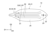
図1~図10は一実施の形態を説明するための図である。図1は、船舶10の一具体例を概略的に示す斜視図である。図2は、図1に示された船舶10を前後方向D1における前側から示す図である。図3は、図1に示された船舶10を幅方向D2における外側から示す図である。図4は、図1に示された船舶10を上下方向D3における下側から示す図である。
Figures 1 to 10 are diagrams for explaining one embodiment. Figure 1 is a perspective view that shows a schematic example of a
本明細書中において、船舶10及びその構成要素に対する「前」、「後」、「上」、「下」、「前後方向」、「幅方向」、及び「上下方向」の用語は、特に指示がない場合、水に浮かんだ姿勢を基準とした「前」、「後」、「上」、「下」、「前後方向」、「幅方向」、及び「上下方向」を意味する。「前後方向」とは、船の直進時の進行方向である。「前」とは、船の直進時における「前」である。「上下方向」は、水に浮かんだ船舶10の鉛直方向である。「幅方向」は、「前後方向」及び「上下方向」の両方に直交する方向である。
In this specification, the terms "forward," "rearward," "upward," "downward," "fore-and-aft direction," "width direction," and "vertical direction" with respect to the
図1~図4に示すように、船舶10は、船体20及び気体供給装置40を含む。船体20は、木や金属によって形成されている。船体20は、浮力を発生して水に浮かぶことができる。船舶10が浮かぶ水は、海水でもよい。船舶10が浮かぶ水は淡水でもよい。図3には、船舶10とともに水面WLが示されている。
As shown in Figures 1 to 4, the
船体20は、公知の船と同様に構成されてもよい。図3及び図4に示すように、船体20は、本体21と、本体21に保持された舵22及びスクリュー23と、を含んでもよい。船体20は、特に限定されない。船体20は、小型船でもよく、中型線でもよく、大型船でもよい。船体20は、漁船でもよく、旅客船や貨物船等の商船でもよく、作業船でもよく、航空母艦やイージス艦等の艦船でもよい。
The
図1~図4に示すように、船体20は、船底25を含む。船底25は、船舶10が水に浮かんだ状態で水中に位置する部分である。図1~図5に示すように、船底25には、複数の窪み30が設けられている。窪み30は、船底25の外面において凹んだ部分である。すなわち、窪み30は、船底25の外面に設けられた凹部である。図5は、図1に示された船体20の一つの窪み30を拡大して前後方向D1における後側から示している。
As shown in Figures 1 to 4, the
気体供給装置40は、船体20の船底25に気体を供給する。気体供給装置40は、窪み30内に気体を供給する。気体供給装置40は、窪み30のうちの前後方向D1における前側に位置する前側領域に、気体を供給してもよい。気体は、空気でもよい。気体は、窒素、酸素、及び二酸化炭素の一以上でもよい。
The
図3に示すように、気体供給装置40は、気体供給源45及び気体供給筒部50を含んでもよい。図示された例において、気体供給源45は、気体を供給する。気体供給筒部50は、気体の流路を形成する。図3に示すように、気体供給源45は、気体供給筒部50と接続している。気体供給源45は、気体供給筒部50に気体を供給する。気体供給筒部50は、気体供給源45から供給される気体を窪み30に向けて排出する。
As shown in FIG. 3, the
気体供給源45は、気体を供給できる公知な装置でもよい。気体供給源45は、気体を吹き出すブロワでもよい。気体供給源45は、電動機及び送風機を含んでもよい。気体供給源45は、電動機及びコンプレッサを含んでもよい。送風機やコンプレッサは電動機によって駆動されることにより、気体を吸引し吸引した気体を吐出する。
The
図2に示すように、気体供給源45は、船体20の本体21内において、前後方向D1における前側に配置されてもよい。気体供給源45から窪み30の前後方向D1における前側領域までの距離を短くすることによって、気体供給筒部50内での圧力損失を低減することができる。
As shown in FIG. 2, the
気体供給筒部50は、金属又は樹脂製のパイプ52によって構成されてもよい。気体供給筒部50は、気体供給源45からの気体を窪み30まで案内する。気体供給筒部50は、窪み30のうちの前後方向D1における前側に位置する前側領域に気体を排出してもよい。この例によれば、窪み30内における気体の移動距離が長くなり、気体が長期間に亘って窪み30内に位置し得る。すなわち、窪み30内の気体を効率的に利用することができる。
The
図3~図5に示すように、気体供給筒部50は、吐出端部51を含む。吐出端部51は、気体供給筒部50における気体の流路における最下流部である。気体供給源45から気体供給筒部50に供給された気体は、吐出端部51から窪み30に向けて排出される。
As shown in Figures 3 to 5, the
図3及び図4に示すように、吐出端部51は、窪み30内に位置してもよい。これにより、気体供給装置40から窪み30内に安定して気体を供給することができ、気体をより効率的に使用できる。
As shown in Figures 3 and 4, the
図3~図5に示すように、気体供給筒部50の吐出端部51は、前後方向D1における後側に向けて開口してもよい。吐出端部51は、吐出端部51が設置されている領域における船底25の外面に沿った方向に開口してもよい。すなわち、吐出端部51は、吐出端部51が設置されている領域における船底25の外面に沿った方向に気体を吐出してもよい。吐出端部51は、幅方向D2からの観察において、窪み30の気体を供給されるべき領域において窪み30が延びる方向に、開口してもよい。吐出端部51は、幅方向D2からの観察において、窪み30の気体を供給されるべき領域において窪み30が延びる方向に気体を吐出してもよい。これらの構成によれば、気体供給装置40から船底25の窪み30に供給された気体が、すぐさま水面に浮かび上がることを抑制することができる。すなわち、窪み30内の気体をより効率的に利用することができる。
As shown in Figures 3 to 5, the discharge end 51 of the
図3に示すように、気体供給筒部50は、船体20の船内から船外へ延び出してもよい。図3に示された例において、窪み30は、前後方向D1における前側に開口している。窪み30の吐出端部51は、前後方向D1における前側の開口から窪み30内に挿入されている。
As shown in FIG. 3, the
気体供給装置40は、気体を細かい気泡として水中に供給してもよい。細かい気泡として供給された気体は、船底25に気泡膜を形成し易い。気泡膜は、船底25と水との間の摩擦をより効果的に低減することができる。
The
図5に示された例において、気体供給筒部50は、パイプ52及び調整板53を含む。調整板53には、多数の孔53aが形成されている。孔53aが、吐出端部51における開口部として機能する。気体が孔53aから吐出されることによって、窪み30内において気体は微細な気泡となり易い。
In the example shown in FIG. 5, the
調整板53は、吐出端部51となるパイプ52の端部に設けられている。調整板53は、パイプ52とは別個の部材として、パイプ52取り付けられてもよい。調整板53は、パイプ52と一体的に成形されてもよい。
The
気体供給筒部50は、複数の枝筒部55を含んでもよい。枝筒部55は、パイプ52によって構成されてもよい。複数の枝筒部55の各々は、前後方向D1における後側に向けて開口した吐出端部51を含んでもよい。すなわち、各枝筒部55は、前後方向D1における後側に向けて開口した吐出端部51を含んでもよい。
The gas
複数の枝筒部55に含まれる二以上の枝筒部55は、気体の流路に沿った全区間において、別個に設けられてもよい。すなわち、複数の枝筒部55に含まれる二以上の枝筒部55は、気体の流路に沿った全区間において、合流していなくてもよい。
Two or more
複数の枝筒部55に含まれる二以上の枝筒部55は、気体の流路に沿った一区間において、合流していてもよい。複数の枝筒部55に含まれる二以上の枝筒部55は、気体の流路に沿った上流側において、合流していてもよい。図1~図4に示された例において、気体供給筒部50は二本の枝筒部55を含む。二本の枝筒部55は、合流して気体供給源45に接続してもよい。
Two or more
気体供給装置40は、図1~図4に示された例に限られない。例えば図6に示すように、気体供給筒部50は、船外に延び出していなくてもよい。図6に示すように、気体供給筒部50は、排出端部51において、水中に露出してもよい。気体供給筒部50の排出端部51は、前後方向D1における後側に向けて開口してもよい。
The
図6に示された例において、気体供給筒部50は排出端部51にチャンバーを含んでもよい。すなわち、気体供給筒部50は、チャンバーを形成するチャンバー箱部を、排出端部51に含んでもよい。チャンバー箱部に、多数の孔53aを含む調整板53が取り付けられてもよい。チャンバー箱部に、多数の孔53aが直接形成されてもよい。チャンバー箱部を設けることにより、気体供給装置40から窪み30に向けた気体の吐出を安定させることができる。
In the example shown in FIG. 6, the
気体供給筒部50は、逆止弁を含んでもよい。逆止弁は、気体供給筒部50のパイプ52に設置されてもよい。図2や図3に示された例において、逆止弁は、パイプ52のうちの船体20の船外に延び出した部分に設置されてもよい。この例において、パイプ52の長い区間(気体供給源45から逆止弁までの区間)に亘って気体を封入することができ、この気体は船舶10の浮力上昇に寄与し得る。図2や図3に示された例において、逆止弁は、パイプ52のうちの船体20の船内に位置する部分に設置されてもよい。
The
気体供給筒部50に圧力調整チャンバーを含んでもよい。気体供給筒部50は、圧力調整チャンバーを形成するチャンバー箱部を含んでもよい。チャンバー箱部を設けることにより、気体の流路に沿ってチャンバー箱部より下流側となる領域において、気体の圧力が安定し、気体供給装置40から窪み30に向けた気体の吐出を安定させることができる。
The
次に、船底25に設けられた複数の窪み30について更に詳述する。
Next, we will provide further details about the
図4によく示されているように、複数の窪み30は、幅方向D2に互いから離間している。複数の窪み30の各々は、すなわち各窪み30は、前後方向D1に延びる。前後方向D1に延びるとは、前後方向D1と平行に延びるだけでなく、前後方向D1に長さを有することも意味する。窪み30は、前後方向D1に対して45°未満の角度を形成してもよい。窪み30の長手方向と前後方向D1との間の角度は、45°未満でもよいし、30°以下でもよく、20°以下でもよい、10°以下でもよい。窪み30の長手方向と前後方向D1との間の角度の下限は特に設定されない。窪み30の長手方向と前後方向D1との間は、0°以上でもよく、0°より大きくてもよい。
As shown in FIG. 4, the
図3に示すように、幅方向D2からの観察において、一以上又は全ての窪み30は曲がっていてもよい。一以上又は全ての窪み30は、幅方向D2からの観察において、湾曲してもよいし、屈曲してもよい。図3に示すように、一以上又は全ての窪み30は、前後方向D1に沿って、上下方向D3における位置を変化させてもよい。
As shown in FIG. 3, one or more or all of the
さらに、一以上又は全ての窪み30は、前後方向D1における後方において、上下方向D3における上側に曲がってもよい。すなわち、一以上又は全ての窪み30は、前後方向D1における後方において、上下方向D3における上側に位置してもよい。この例において、一以上又は全ての窪み30は、前後方向D1における後方部分において、その他の部分より、上下方向D3における上側に位置してもよい。或いは、一以上又は全ての窪み30は、前後方向D1における後側になるにつれて、上下方向D3における上側に位置してもよい。一以上又は全ての窪み30は、前後方向D1における後側になるにつれて、上下方向D3における上側に位置するように、全長に亘って曲がっていてもよい。
Furthermore, one or more or all of the
図4に示すように、上下方向D3における下側からの観察において、一以上又は全ての窪み30は曲がっていてもよい。一以上又は全ての窪み30は、上下方向D3における下側からの観察において、湾曲してもよいし、屈曲してもよい。図4に示すように、一以上又は全ての窪み30は、前後方向D1に沿って、幅方向D2における位置を変化させてもよい。
As shown in FIG. 4, one or more or all of the
さらに、一以上又は全ての窪み30は、前後方向D1における後方において、幅方向D2における外側に曲がってもよい。すなわち、一以上又は全ての窪み30は、前後方向D1における後方において、幅方向D2における外側に位置してもよい。この例において、一以上又は全ての窪み30は、前後方向D1における後方部分において、その他の部分より、幅方向D2における外側に位置してもよい。或いは、一以上又は全ての窪み30は、前後方向D1における後側になるにつれて、幅方向D2における外側に位置してもよい。更に、一以上又は全ての窪み30は、前後方向D1における後側になるにつれて、幅方向D2における外側に位置するように、全長に亘って曲がっていてもよい。
Furthermore, one or more or all of the
幅方向D2における外側とは、幅方向D2における中心D2Cから離れた側である。幅方向D2における内側とは、幅方向D2における中心D2Cから近い側である。 The outer side in the width direction D2 is the side away from the center D2C in the width direction D2. The inner side in the width direction D2 is the side closer to the center D2C in the width direction D2.
図4に示すように、複数の窪み30の一部は、船底25の幅方向D2における一方の側に設けられてもよい。複数の窪み30の残りは、船底25の幅方向D2における他方の側に設けられてもよい。
As shown in FIG. 4, some of the
図4に示すように、複数の窪み30は、幅方向D2の中心D2Cを通って上下方向D3に延びる中心上下面CPを中心として、対称的に配置されてもよい。船底25の幅方向D2における一方の側に設けられた窪み30の配置位置と、船底25の幅方向D2における他方の側に設けられた窪み30の配置位置とは、中心上下面CPを中心として面対称な関係を有してもよい。
As shown in FIG. 4, the
図4に示すように、複数の窪み30は、幅方向D2の中心D2Cを通って上下方向D3に延びる中心上下面CPを中心として、対称的な構成を有してもよい。船底25の幅方向D2における一方の側に設けられた窪み30と、船底25の幅方向D2における他方の側に設けられた窪み30とは、中心上下面CPを中心として面対称な関係を有してもよい。
As shown in FIG. 4, the
図4に示すように、スクリュー23は、複数の窪み30の各々の延長線上に位置しなくてもよい。すなわち、スクリュー23は、各窪み30の延長線上に位置しなくてもよい。言い換えると、スクリュー23は、各窪み30の延長線から幅方向D2にずれて位置してもよい。
As shown in FIG. 4, the
図1~図4に示された例において、船底25は、2本の窪み30を含む。窪み30の数は2本に限られない。例えば、窪み30の数は、図7に示すように4本でもよく、6本でもよく、8本でもよい。窪み30の数は、奇数でもよく、3本でもよく、5本でもよく、7本でもよく、9本でもよい。窪み30の数が奇数の場合、幅方向D2における中心D2C上に一本の窪み30が設けられてもよい。
In the example shown in Figures 1 to 4, the ship bottom 25 includes two
窪み30の断面形状は特に限定されない。図1及び図5に示すように、一以上又は全ての窪み30は、前後方向D1に直交する断面において、湾曲した輪郭を有してもよい。一以上又は全ての窪み30は、前後方向D1に直交する断面において、円の一部分の沿った輪郭を有してもよい。一以上又は全ての窪み30は、前後方向D1に直交する断面において、半円形状の輪郭を有してもよい。一以上又は全ての窪み30は、前後方向D1に直交する断面において、楕円の一部分の沿った輪郭を有してもよい。一以上又は全ての窪み30は、前後方向D1に直交する断面において、半楕円形状の輪郭を有してもよい。
The cross-sectional shape of the
図8に示すように、一以上又は全ての窪み30は、前後方向D1に直交する断面において、直線を含む輪郭を有してもよい。図8に示すように、一以上又は全ての窪み30は、前後方向D1に直交する断面において、折れ線状の輪郭を有してもよい。
As shown in FIG. 8, one or more or all of the
図9及び図10に示すように、一以上又は全ての窪み30は、前後方向D1に直交する断面において鋭角又は直角の隅部を含まないようにしてもよい。図9に示された窪み30は、面取した隅部32Aを含んでいる。図9に示された窪み30は、直角を面取した隅部32Aを含む。図10に示された窪み30は、鈍角の隅部32Bを含む。
As shown in Figures 9 and 10, one or more or all of the
船体20の船底25は、平坦でもよい。船体20の船底25は、図2に示すように、傾斜していてもよい。緩斜した船底25に、一以上又は全ての窪み30が設けられてもよい。船底25が低傾斜部26を含み、一以上又は全ての窪み30は低傾斜部26に設けられてもよい。低傾斜部26は、船底25のうちの、船底傾斜角度θ25が30°以下となる部分である。船底傾斜角度θ25は、前後方向D1に直交する断面における船底25と幅方向D2との間の角度(°)である。
The bottom 25 of the
なお、窪み30は深さが浅くなって終了してもよい。窪み30の下流側端(後側端)は、船底傾斜角度θ25が大きくなる領域、例えば船底傾斜角度θ25が45°以上となる領域に位置してもよい。この例によれば、窪み30の下流側端(後側端)に到達した気体は、水流を不必要に乱すことなく、水面WLまで浮上する。
The
次に、以上のような構成からなる船舶10の作用について説明する。
Next, we will explain the operation of the
船舶10は、舵22及びスクリュー23を含む船体20の機能により、水上を移動することができる。船舶10の移動中、気体供給装置40が船体20の船底25に気体を供給する。具体的には、気体供給源45が空気を気体供給筒部50に供給し、気体供給筒部50から気体が船底25に向けて排出される。
The
船底25に排出された気体は、船底25と水との間に位置することで、船底25と水との間の摩擦を低減することができる。船底25と水との間の摩擦を低減することにより、燃費を向上させることができる。船底25と水との間の摩擦が低減されることにより、船舶10の速度を上昇させることができる。さらに、船底の気体は、船舶の浮力を上昇させることができ、この点からも、船舶の速度を上昇させることができる。これらにより、環境の負荷の低減することができる。
The gas discharged to the bottom of the
ところで、従来技術(JP2010-120607A)では、上下方向における下方に向けて船底から気体が噴出されていた。このような従来技術では、船底から噴出された気体がすぐさま船底から幅方向に移動して水面に浮かび上がり易い。したがって、大量の気体を噴出し続けない限り、気体による摩擦低減や浮力上昇といった有効な作用効果を期待することができない。 However, in the conventional technology (JP2010-120607A), gas was ejected from the bottom of the vessel in a vertically downward direction. With this conventional technology, the gas ejected from the bottom of the vessel tends to immediately move widthwise from the bottom of the vessel and rise to the water surface. Therefore, unless a large amount of gas is continuously ejected, it is not possible to expect effective effects such as reduced friction or increased buoyancy due to the gas.
一方、本実施の形態では、船底25に、気体を供給される複数の窪み30が設けられている。複数の窪み30は、幅方向D2に互いから離間している。複数の窪み30の各々は、前後方向D1に延びている。
On the other hand, in this embodiment, the vessel bottom 25 is provided with a plurality of
したがって、窪み30に供給された気体は、窪み30内において前後方向D1に流れることができる。すなわち、気体供給装置40から船底25に供給された気体が、すぐさま、船底25から幅方向D2に移動して水面に浮かび上がってしまうことを抑制することができる。窪み30に供給された気体は、窪み30内を前後方向D1に流れる比較的長期間に亘って、摩擦低減及び浮力増加に寄与することができる。
Therefore, the gas supplied to the
また、船底25には複数の窪み30が設けられている。複数の窪み30は幅方向D2に離間して位置する。すなわち、幅方向D2における複数の部分において、船底25と水との摩擦が低減され且つ浮力が付与される。複数の窪み30の幅方向D2における位置を調節しておくことにより、複数の窪み30内の気体に起因した摩擦低減によって船舶10の直進性が害されることを抑制できる。また、複数の窪み30内の気体に起因した浮力によって船舶10の姿勢が崩れることを抑制することができる。
The bottom 25 of the vessel is provided with a plurality of
これらにより、本実施の形態による船舶10によれば、気体供給装置40から窪み30内に供給された気体を有効に利用して、船底25と水との間の摩擦をより効率的に低減することができ、かつ船舶10の浮力を上昇させることができる。
As a result, the
上述した一具体例において、複数の窪み30の一部は、船底25の幅方向D2における一方の側に設けられている。複数の窪み30の残りは、船底25の幅方向D2における他方の側に設けられている。この具体例によれば、船底25のうちの幅方向D2における中心D2Cの両側に窪み30が形成される。したがって、幅方向D2における中心D2Cの両側において、船体20と水との摩擦を低減することができる。幅方向D2における中心D2Cの両側において、船舶10の浮力を上昇させることができる。結果として、複数の窪み30内の気体に起因した摩擦低減によって船舶10の直進性が害されることを抑制することができる。また、複数の窪み30内の気体に起因した浮力によって船舶10の姿勢が崩れることを抑制することができる。
In the above-mentioned specific example, some of the
上述した一具体例において、複数の窪み30は、幅方向D2の中心D2Cを通って上下方向D3に延びる面(中心上下面)CPを中心として、対称的に配置されている。この具体例によれば、複数の窪み30内の気体に起因した摩擦低減によって船舶10の直進性が害されることをより効果的に抑制することができる。また、窪み30内の気体に起因した浮力によって船舶10の姿勢が崩れることをより効果的に抑制することができる。
In the specific example described above, the
上述した一具体例において、気体供給装置40は、気体を供給する気体供給源45と、気体供給源45から供給される気体を窪み30に向けて供給する気体供給筒部50と、を含む。気体供給筒部50は、船体20から船外へ延び出している。この具体例によれば、船内から船外へ延び出す気体供給筒部50によって、窪み30内に気体を誘導することができる。気体供給筒部50から窪み30に向けて気体の供給方向(吐出方向)を高い自由度で調節することができる。したがって、気体供給装置40から窪み30内に安定して気体を供給することができる。窪み30に供給された気体が、すぐさま、窪み30から幅方向に漏れ出すことを抑制することができる。窪み30内での前後方向D1における(例えば、前側から後側に向けた)気体及び水の流れを安定させることができる。これらにより、気体供給装置40から窪み30内に供給された気体を有効に利用して、気体による摩擦低減や浮力上昇をより効果的に実現することができる。
In the above-mentioned specific example, the
上述した一具体例において、気体供給装置40は、気体を供給する気体供給源45と、気体供給源45から供給される気体を窪み30に向けて供給する気体供給筒部50と、を含む。気体供給筒部50は、前後方向D1における後側に向けて開口した吐出端部51を含む。この具体例によれば、気体供給装置40から窪み30内に安定して気体を供給することができる。窪み30に供給された気体が、すぐさま、窪み30から幅方向に漏れ出すことを抑制することができる。また、窪み30内での前後方向D1における(例えば、前側から後側に向けた)気体及び水の流れを安定させることができる。これらにより、気体供給装置40から窪み30内に供給された気体を有効に利用して、気体による摩擦低減や浮力上昇をより効果的に実現することができる。
In the above-mentioned specific example, the
上述した一具体例において、気体供給筒部50は、複数の枝筒部55を含む。複数の枝筒部55の各々は、複数の窪み30に含まれる別の窪み30に気体を供給する。すなわち、複数の枝筒部55を用いて、各窪み30に気体を安定して供給することができる。これにより、気体供給装置40から窪み30内に供給された気体を有効に利用して、気体による摩擦低減や浮力上昇をより効果的に実現することができる。
In the specific example described above, the gas
上述した一具体例において、船体20はスクリュー23を含む。スクリュー23は、複数の窪み30の各々の延長線上に位置していない。この具体例によれば、スクリュー23が窪み30から排出された気体を巻き込むことにより、スクリュー23の回転による推進力が低下することを抑制することができる。
In the specific example described above, the
上述した一具体例において、複数の窪み30に含まれる一以上の窪み30又は全部の窪み30は、前後方向D1における後側において、幅方向D2における外側に曲がっている。この具体例によれば、窪み30から前後方向D1における後側に吐出された気体がスクリュー23に巻き込まれることを抑制することができる。これにより、スクリュー23の回転による推進力が低下することを抑制することができる。
In the specific example described above, one or more of the
上述した一具体例において、複数の窪み30に含まれる一以上の窪み30又は全部の窪み30は、前後方向D1における後側において上下方向D3における上側に曲がっている。この具体例によれば、水内での気体の浮力を利用して、窪み30内での前後方向D1における前側から後側に向けた気体の流れをより安定させることができる。したがって、窪み30内での前後方向D1における(例えば、前側から後側に向けた)気体及び水の流れを安定させることができる。すなわち、窪み内が気体及び水の流れが乱れて、窪み30の前後方向における中間部分から気体が漏れ出すことを抑制できる。これにより、気体供給装置40から窪み30内に供給された気体を有効に利用して、気体による摩擦低減や浮力上昇をより効果的に実現することができる。
In the above-mentioned specific example, one or more of the
上述した一具体例において、船底25は、前後方向D1に直交する断面において幅方向D2に対してなす角度が30°以下となる低傾斜部26を含む。複数の窪み30に含まれる一以上の窪み30又は全部の窪み30は、船底25の低傾斜部26に設けられている。この具体例によれば、低傾斜部26に設けられた窪み30によれば、浅い窪みであっても比較的大量の気体を安定して収容することができる。これにより、気体供給装置40から窪み30内に供給された気体を有効に利用して、気体による摩擦低減や浮力上昇をより効果的に実現することができる。また、窪み30を浅くすることができるので、船底25の剛性を向上させることができる。
In the specific example described above, the ship bottom 25 includes a low inclination portion 26 that forms an angle of 30° or less with respect to the width direction D2 in a cross section perpendicular to the longitudinal direction D1. One or more of the
上述した一具体例において、複数の窪み30に含まれる一以上の窪み30又は全部の窪み30は、前後方向D1に直交する断面において鋭角又は直角の隅部を含まない。この具体例によれば、窪み30内に淀みが形成されることを抑制することができ、窪み30内での前後方向D1における(例えば、前側から後側に向けた)気体及び水の流れを安定させることができる。すなわち、窪み内が気体及び水の流れが乱れて、窪み30の前後方向における中間部分から気体が漏れ出すことを抑制できる。これにより、気体供給装置40から窪み30内に供給された気体を有効に利用して、気体による摩擦低減や浮力上昇をより効果的に実現することができる。また、窪み30を浅くすることができるので、船底25の剛性を向上させることができる。
In the above-mentioned specific example, one or more of the
以上に説明してきた一実施の形態において、船舶10は、船体20と、船体20の船底25に気体を供給する気体供給装置40と、を含む。船底25に、気体を供給される複数の窪み30が設けられている。複数の窪み30は幅方向D2に互いから離間している。複数の窪み30の各々は前後方向D1に延びる。
In the embodiment described above, the
本実施の形態によれば、窪み30は前後方向D1に線状に延びる。気体は、窪み30内において前後方向D1に流れる。すなわち、気体供給装置40から船底25に供給された気体が、すぐさま、船底25から幅方向に移動して水面に浮かび上がってしまうことを抑制することができる。気体が窪み30内を前後方向に流れている比較的長期間に亘って、気体による摩擦低減や浮力上昇を実現することができる。すなわち、気体供給装置40から窪み30内に供給された気体を有効に利用して、気体による摩擦低減や浮力上昇を実現することができる。
According to this embodiment, the
具体例を参照しながら一実施の形態を説明してきたが、上述の具体例が一実施の形態を限定しない。上述した一実施の形態は、その他の様々な具体例で実施でき、その要旨を逸脱しない範囲で、種々の省略、置き換え、変更、追加等を行うことができる。 One embodiment has been described with reference to specific examples, but the above-mentioned specific examples do not limit the embodiment. The above-mentioned one embodiment can be implemented with various other specific examples, and various omissions, substitutions, changes, additions, etc. can be made within the scope of the gist of the embodiment.
D1:前後方向D1、D2:幅方向D2、D3:上下方向D3、D2C:中心、CP:面(中心上下面)、θ25:船底傾斜角度、10:船舶、20:船体、21:本体、22:舵、23:スクリュー、25:船底、26:低傾斜部、30:窪み、32A:隅部、32B:隅部、40:気体供給装置、45:気体供給源、50:気体供給筒部、51:吐出端部、52:パイプ、53:調整板、
53a:孔、55:枝筒部
D1: longitudinal direction D1, D2: width direction D2, D3: vertical direction D3, D2C: center, CP: surface (central upper and lower surface), θ25: ship bottom inclination angle, 10: ship, 20: hull, 21: main body, 22: rudder, 23: screw, 25: ship bottom, 26: low inclination portion, 30: recess, 32A: corner, 32B: corner, 40: gas supply device, 45: gas supply source, 50: gas supply tube, 51: discharge end, 52: pipe, 53: adjustment plate,
53a: hole, 55: branch tube part
Claims (9)
前記船体の船底に気体を供給する気体供給装置と、を備え、
前記船底に、前記気体を供給される複数の窪みが設けられ、
前記複数の窪みは、幅方向に互いから離間し、
前記複数の窪みの各々は、前後方向に延び、
前記気体供給装置は、前記気体を供給する気体供給源と、前記気体供給源から供給される前記気体を前記窪みに向けて供給する気体供給筒部と、を含み、
前記気体供給筒部は、前記前後方向における後側に向けて開口した吐出端部を含み、
前記窪みは前記前後方向における前方に開口し、
前記気体供給筒部は、前記船体から前方に延び出し、
前記船体の外部に延び出した前記気体供給筒部は、前記前後方向における前記窪みの前方の開口から前記窪みに挿入され、
前記吐出端部は前記窪み内に位置する、船舶。 The hull and
A gas supply device that supplies gas to the bottom of the hull,
The bottom of the vessel is provided with a plurality of recesses to which the gas is supplied,
The recesses are spaced apart from one another in a width direction,
Each of the plurality of recesses extends in a front-rear direction,
the gas supply device includes a gas supply source that supplies the gas, and a gas supply tube that supplies the gas supplied from the gas supply source toward the recess,
the gas supply tube portion includes a discharge end portion that opens toward a rear side in the front-rear direction,
The recess opens forward in the front-rear direction,
The gas supply tube portion extends forward from the hull,
The gas supply tube portion extending outside the hull is inserted into the recess from a front opening of the recess in the front-rear direction ,
The discharge end is located within the recess .
前記複数の窪みの残りは、前記船底の前記幅方向における他方の側に設けられている、請求項1に記載の船舶。 Some of the recesses are provided on one side of the bottom in the width direction,
The watercraft according to claim 1 , wherein the remainder of the plurality of recesses are provided on the other side of the bottom in the width direction.
複数の枝筒部の各々は、前記複数の窪みに含まれる別の窪みに前記気体を供給する、請求項1に記載の船舶。 The gas supply tube portion includes a plurality of branch tube portions,
The vessel according to claim 1 , wherein each of the plurality of branch tube portions supplies the gas to another recess included in the plurality of recesses.
前記スクリューは、前記複数の窪みの各々の延長線上に位置していない、請求項1に記載の船舶。 The hull includes a screw,
The vessel according to claim 1 , wherein the screw is not located on an extension line of each of the plurality of recesses.
前記複数の窪みに含まれる一以上の窪みは、前記船底の低傾斜部に設けられている、請
求項1に記載の船舶。 The bottom of the vessel includes a low inclination portion that forms an angle of 30° or less with respect to the width direction in a cross section perpendicular to the fore-aft direction,
The watercraft according to claim 1 , wherein one or more of the plurality of recesses is provided in a low inclined portion of the vessel bottom.
Priority Applications (1)
| Application Number | Priority Date | Filing Date | Title |
|---|---|---|---|
| JP2024002765A JP7546799B1 (en) | 2024-01-11 | 2024-01-11 | Ships |
Applications Claiming Priority (1)
| Application Number | Priority Date | Filing Date | Title |
|---|---|---|---|
| JP2024002765A JP7546799B1 (en) | 2024-01-11 | 2024-01-11 | Ships |
Publications (1)
| Publication Number | Publication Date |
|---|---|
| JP7546799B1 true JP7546799B1 (en) | 2024-09-06 |
Family
ID=92593138
Family Applications (1)
| Application Number | Title | Priority Date | Filing Date |
|---|---|---|---|
| JP2024002765A Active JP7546799B1 (en) | 2024-01-11 | 2024-01-11 | Ships |
Country Status (1)
| Country | Link |
|---|---|
| JP (1) | JP7546799B1 (en) |
Citations (5)
| Publication number | Priority date | Publication date | Assignee | Title |
|---|---|---|---|---|
| JP2001233292A (en) | 2000-02-23 | 2001-08-28 | Mitsubishi Heavy Ind Ltd | Underwater discharge device for exhaust gas from ship |
| JP2004284546A (en) | 2003-03-25 | 2004-10-14 | Summer Time:Kk | Ship energy saving device |
| JP2008114710A (en) | 2006-11-02 | 2008-05-22 | National Maritime Research Institute | Hull frictional resistance reduction device |
| JP2011136609A (en) | 2009-12-25 | 2011-07-14 | Mitsubishi Heavy Ind Ltd | Resistance reducing device of ship |
| CN110758633A (en) | 2019-10-30 | 2020-02-07 | 西安交通大学 | A Venturi System for Bubble Drag Reduction in Ship Hull |
-
2024
- 2024-01-11 JP JP2024002765A patent/JP7546799B1/en active Active
Patent Citations (5)
| Publication number | Priority date | Publication date | Assignee | Title |
|---|---|---|---|---|
| JP2001233292A (en) | 2000-02-23 | 2001-08-28 | Mitsubishi Heavy Ind Ltd | Underwater discharge device for exhaust gas from ship |
| JP2004284546A (en) | 2003-03-25 | 2004-10-14 | Summer Time:Kk | Ship energy saving device |
| JP2008114710A (en) | 2006-11-02 | 2008-05-22 | National Maritime Research Institute | Hull frictional resistance reduction device |
| JP2011136609A (en) | 2009-12-25 | 2011-07-14 | Mitsubishi Heavy Ind Ltd | Resistance reducing device of ship |
| CN110758633A (en) | 2019-10-30 | 2020-02-07 | 西安交通大学 | A Venturi System for Bubble Drag Reduction in Ship Hull |
Similar Documents
| Publication | Publication Date | Title |
|---|---|---|
| KR101377025B1 (en) | ship | |
| KR101532852B1 (en) | Frictional resistance reduction ship and frictional resistance reduction apparatus for ship | |
| US8011310B2 (en) | Ship with reduced frictional resistance and its operation method | |
| KR20110050534A (en) | Hull friction resistance reduction device | |
| KR101733869B1 (en) | Air lubrication device for ships | |
| US6609472B2 (en) | Stable efficient air lubricated ship | |
| ES2357416T3 (en) | BOAT MULTIPLE HELMET. | |
| JP7546799B1 (en) | Ships | |
| US20210331769A1 (en) | Hull surface air lubrication structure for marine vehicles | |
| KR20150073901A (en) | Full ship | |
| JP2002002582A (en) | Friction drag reduction ship | |
| JP2017178182A (en) | Bottom structure, and ship | |
| JP2012224108A (en) | Frictional resistance reduction type ship | |
| JP2001106171A (en) | Friction resistance reducing ship and method for reducing frictional resistance of hull | |
| JP2018154199A (en) | Vessel | |
| WO2018168585A1 (en) | Ship | |
| JP2000168673A (en) | Friction drag reduction ship | |
| GB2382801A (en) | Vessel hull air lubrication means | |
| JP2003160091A (en) | Ship friction reduction device | |
| KR20130102135A (en) | Apparatus and method for reducing fluid drag on a submerged surface | |
| JP2023148982A (en) | Friction reduction device | |
| JP2018065543A (en) | Shape of high speed vessel | |
| US7281480B2 (en) | Frictionally reduced hull | |
| JP2011088515A (en) | Frictional resistance reducing ship | |
| EP0017910A1 (en) | Hull for small-size marine craft having reduced drag |
Legal Events
| Date | Code | Title | Description |
|---|---|---|---|
| A621 | Written request for application examination |
Free format text: JAPANESE INTERMEDIATE CODE: A621 Effective date: 20240115 |
|
| A871 | Explanation of circumstances concerning accelerated examination |
Free format text: JAPANESE INTERMEDIATE CODE: A871 Effective date: 20240115 |
|
| A131 | Notification of reasons for refusal |
Free format text: JAPANESE INTERMEDIATE CODE: A131 Effective date: 20240312 |
|
| A521 | Request for written amendment filed |
Free format text: JAPANESE INTERMEDIATE CODE: A523 Effective date: 20240419 |
|
| A131 | Notification of reasons for refusal |
Free format text: JAPANESE INTERMEDIATE CODE: A131 Effective date: 20240521 |
|
| A521 | Request for written amendment filed |
Free format text: JAPANESE INTERMEDIATE CODE: A523 Effective date: 20240618 |
|
| TRDD | Decision of grant or rejection written | ||
| A01 | Written decision to grant a patent or to grant a registration (utility model) |
Free format text: JAPANESE INTERMEDIATE CODE: A01 Effective date: 20240628 |
|
| A601 | Written request for extension of time |
Free format text: JAPANESE INTERMEDIATE CODE: A601 Effective date: 20240722 |
|
| A61 | First payment of annual fees (during grant procedure) |
Free format text: JAPANESE INTERMEDIATE CODE: A61 Effective date: 20240827 |
|
| R150 | Certificate of patent or registration of utility model |
Ref document number: 7546799 Country of ref document: JP Free format text: JAPANESE INTERMEDIATE CODE: R150 |