JP7539801B2 - Substrate Processing Equipment - Google Patents
Substrate Processing Equipment Download PDFInfo
- Publication number
- JP7539801B2 JP7539801B2 JP2020146353A JP2020146353A JP7539801B2 JP 7539801 B2 JP7539801 B2 JP 7539801B2 JP 2020146353 A JP2020146353 A JP 2020146353A JP 2020146353 A JP2020146353 A JP 2020146353A JP 7539801 B2 JP7539801 B2 JP 7539801B2
- Authority
- JP
- Japan
- Prior art keywords
- substrate
- liquid
- holding unit
- guard
- less
- Prior art date
- Legal status (The legal status is an assumption and is not a legal conclusion. Google has not performed a legal analysis and makes no representation as to the accuracy of the status listed.)
- Active
Links
- 239000000758 substrate Substances 0.000 title claims description 329
- 238000012545 processing Methods 0.000 title claims description 265
- 239000007788 liquid Substances 0.000 claims description 327
- 230000002093 peripheral effect Effects 0.000 claims description 25
- 239000002585 base Substances 0.000 description 50
- 239000000126 substance Substances 0.000 description 45
- 239000007789 gas Substances 0.000 description 31
- 230000032258 transport Effects 0.000 description 24
- 230000007246 mechanism Effects 0.000 description 14
- 238000005192 partition Methods 0.000 description 12
- 238000000034 method Methods 0.000 description 10
- 230000008569 process Effects 0.000 description 10
- 239000003595 mist Substances 0.000 description 7
- IJGRMHOSHXDMSA-UHFFFAOYSA-N Atomic nitrogen Chemical compound N#N IJGRMHOSHXDMSA-UHFFFAOYSA-N 0.000 description 6
- 238000010586 diagram Methods 0.000 description 6
- 229910001873 dinitrogen Inorganic materials 0.000 description 6
- 238000001035 drying Methods 0.000 description 6
- 238000002474 experimental method Methods 0.000 description 6
- ABKJCDILEUEJSH-MHWRWJLKSA-N 2-[(e)-(6-carboxyhexanoylhydrazinylidene)methyl]benzoic acid Chemical compound OC(=O)CCCCCC(=O)N\N=C\C1=CC=CC=C1C(O)=O ABKJCDILEUEJSH-MHWRWJLKSA-N 0.000 description 5
- 239000012530 fluid Substances 0.000 description 5
- XLYOFNOQVPJJNP-UHFFFAOYSA-N water Substances O XLYOFNOQVPJJNP-UHFFFAOYSA-N 0.000 description 5
- QAOWNCQODCNURD-UHFFFAOYSA-N Sulfuric acid Chemical compound OS(O)(=O)=O QAOWNCQODCNURD-UHFFFAOYSA-N 0.000 description 4
- 238000004140 cleaning Methods 0.000 description 4
- WGTYBPLFGIVFAS-UHFFFAOYSA-M tetramethylammonium hydroxide Chemical compound [OH-].C[N+](C)(C)C WGTYBPLFGIVFAS-UHFFFAOYSA-M 0.000 description 4
- QTBSBXVTEAMEQO-UHFFFAOYSA-N Acetic acid Chemical compound CC(O)=O QTBSBXVTEAMEQO-UHFFFAOYSA-N 0.000 description 3
- VEXZGXHMUGYJMC-UHFFFAOYSA-N Hydrochloric acid Chemical compound Cl VEXZGXHMUGYJMC-UHFFFAOYSA-N 0.000 description 3
- MUBZPKHOEPUJKR-UHFFFAOYSA-N Oxalic acid Chemical compound OC(=O)C(O)=O MUBZPKHOEPUJKR-UHFFFAOYSA-N 0.000 description 3
- KRKNYBCHXYNGOX-UHFFFAOYSA-N citric acid Chemical compound OC(=O)CC(O)(C(O)=O)CC(O)=O KRKNYBCHXYNGOX-UHFFFAOYSA-N 0.000 description 3
- 239000000203 mixture Substances 0.000 description 3
- VHUUQVKOLVNVRT-UHFFFAOYSA-N Ammonium hydroxide Chemical compound [NH4+].[OH-] VHUUQVKOLVNVRT-UHFFFAOYSA-N 0.000 description 2
- XKRFYHLGVUSROY-UHFFFAOYSA-N Argon Chemical compound [Ar] XKRFYHLGVUSROY-UHFFFAOYSA-N 0.000 description 2
- KRHYYFGTRYWZRS-UHFFFAOYSA-N Fluorane Chemical compound F KRHYYFGTRYWZRS-UHFFFAOYSA-N 0.000 description 2
- MHAJPDPJQMAIIY-UHFFFAOYSA-N Hydrogen peroxide Chemical compound OO MHAJPDPJQMAIIY-UHFFFAOYSA-N 0.000 description 2
- 235000011114 ammonium hydroxide Nutrition 0.000 description 2
- 238000013459 approach Methods 0.000 description 2
- 238000012993 chemical processing Methods 0.000 description 2
- 239000011261 inert gas Substances 0.000 description 2
- 238000011084 recovery Methods 0.000 description 2
- 239000004065 semiconductor Substances 0.000 description 2
- 235000012431 wafers Nutrition 0.000 description 2
- UFHFLCQGNIYNRP-UHFFFAOYSA-N Hydrogen Chemical compound [H][H] UFHFLCQGNIYNRP-UHFFFAOYSA-N 0.000 description 1
- GRYLNZFGIOXLOG-UHFFFAOYSA-N Nitric acid Chemical compound O[N+]([O-])=O GRYLNZFGIOXLOG-UHFFFAOYSA-N 0.000 description 1
- 239000003513 alkali Substances 0.000 description 1
- 230000000454 anti-cipatory effect Effects 0.000 description 1
- 229910052786 argon Inorganic materials 0.000 description 1
- SWXQKHHHCFXQJF-UHFFFAOYSA-N azane;hydrogen peroxide Chemical compound [NH4+].[O-]O SWXQKHHHCFXQJF-UHFFFAOYSA-N 0.000 description 1
- 238000007664 blowing Methods 0.000 description 1
- 239000000969 carrier Substances 0.000 description 1
- 239000000919 ceramic Substances 0.000 description 1
- 238000006243 chemical reaction Methods 0.000 description 1
- 238000011109 contamination Methods 0.000 description 1
- 238000005260 corrosion Methods 0.000 description 1
- 230000007797 corrosion Effects 0.000 description 1
- 238000005401 electroluminescence Methods 0.000 description 1
- -1 etc.) Substances 0.000 description 1
- 230000006870 function Effects 0.000 description 1
- 239000001257 hydrogen Substances 0.000 description 1
- 229910052739 hydrogen Inorganic materials 0.000 description 1
- QOSATHPSBFQAML-UHFFFAOYSA-N hydrogen peroxide;hydrate Chemical compound O.OO QOSATHPSBFQAML-UHFFFAOYSA-N 0.000 description 1
- 230000002209 hydrophobic effect Effects 0.000 description 1
- 239000003112 inhibitor Substances 0.000 description 1
- 150000002500 ions Chemical class 0.000 description 1
- 239000004973 liquid crystal related substance Substances 0.000 description 1
- 238000012986 modification Methods 0.000 description 1
- 230000004048 modification Effects 0.000 description 1
- 229910017604 nitric acid Inorganic materials 0.000 description 1
- 230000003287 optical effect Effects 0.000 description 1
- 150000007524 organic acids Chemical class 0.000 description 1
- 235000006408 oxalic acid Nutrition 0.000 description 1
- 238000005086 pumping Methods 0.000 description 1
- 239000004094 surface-active agent Substances 0.000 description 1
Images


Landscapes
- Cleaning Or Drying Semiconductors (AREA)
Description
この発明は、基板を処理する基板処理装置に関する。処理の対象となる基板には、たとえば、半導体ウエハ、液晶表示装置および有機EL(Electroluminescence)表示装置等のFPD(Flat Panel Display)用基板、光ディスク用基板、磁気ディスク用基板、光磁気ディスク用基板、フォトマスク用基板、セラミック基板、太陽電池用基板等が含まれる。 This invention relates to a substrate processing apparatus for processing substrates. Substrates to be processed include, for example, semiconductor wafers, substrates for FPDs (Flat Panel Displays) such as liquid crystal displays and organic EL (Electroluminescence) displays, substrates for optical disks, substrates for magnetic disks, substrates for magneto-optical disks, substrates for photomasks, ceramic substrates, substrates for solar cells, etc.
下記特許文献1に開示された基板処理装置は、スピンチャックによって保持された基板を回転させながら基板の上面に洗浄液を供給して基板を洗浄する。回転遠心力により基板から飛散する洗浄液は、基板を取り囲むカップの傾斜面によって受けられる。
The substrate processing apparatus disclosed in the following
特許文献1には、基板に対するカップの傾斜面の角度を30°~60°とすることで、ミストの飛散を防止できることが開示されている。しかしながら、特許文献1では、カップの傾斜面によって受けられる際の衝撃によって洗浄液が斜め上方に向かって跳ね返ることについては、一切考慮されていない。そのため、実際の基板処理において、洗浄液の跳ね返りによって基板が汚染されるおそれがある。
そこで、この発明の1つの目的は、基板から飛散する処理液を液受け部材によって充分に受けることができ、かつ、液受け部材によって受けた処理液の跳ね返りによる基板の汚染を抑制できる基板処理装置を提供することである。 Therefore, one object of the present invention is to provide a substrate processing apparatus that can adequately receive processing liquid splashed from a substrate using a liquid receiving member and can suppress contamination of the substrate caused by the processing liquid rebounding received by the liquid receiving member.
この発明の一実施形態は、基板を水平に保持する基板保持ユニットと、前記基板保持ユニットによって保持されている基板を回転させる基板回転ユニットと、前記基板保持ユニットによって保持されている基板に処理液を供給する処理液供給ユニットと、前記基板保持ユニットによって保持されている基板から飛散する処理液を受ける液受け部材とを備える、基板処理装置を提供する。 One embodiment of the present invention provides a substrate processing apparatus including a substrate holding unit that holds a substrate horizontally, a substrate rotation unit that rotates the substrate held by the substrate holding unit, a processing liquid supply unit that supplies processing liquid to the substrate held by the substrate holding unit, and a liquid receiving member that receives processing liquid that splashes from the substrate held by the substrate holding unit.
この基板処理装置では、前記液受け部材が、前記基板保持ユニットを取り囲む筒状部と、前記筒状部の上端部から前記筒状部の中心側に向かって延びる延設部であって、前記中心側に向かうにしたがって上方へ向かうように水平方向に対して傾斜する傾斜部を有する延設部と、前記中心側における前記延設部の端部から下方に延びる垂下部とを含む。そして、水平方向に対する前記傾斜部の傾斜角度が25°以上で、かつ、30°未満である。 In this substrate processing apparatus, the liquid receiving member includes a cylindrical portion surrounding the substrate holding unit, an extension portion extending from the upper end of the cylindrical portion toward the center of the cylindrical portion, the extension portion having an inclined portion inclined with respect to the horizontal direction so as to face upward toward the center, and a hanging portion extending downward from the end of the extension portion on the center side. The inclination angle of the inclined portion with respect to the horizontal direction is 25° or more and less than 30°.
この装置によれば、液受け部材の傾斜部の傾斜角度は25°以上で、かつ、30°未満である。この範囲の角度であれば傾斜部の傾斜角度が充分に小さいため、基板から飛散した処理液が傾斜部に衝突した際に発生する処理液の跳ね上がりを充分に低減できる。逆に、傾斜部の高さ寸法が小さくなり過ぎることもないため、鉛直方向の広範囲に亘って、傾斜部によって処理液を受けることができる。 According to this device, the inclination angle of the inclined portion of the liquid receiving member is equal to or greater than 25° and less than 30°. Within this range, the inclination angle of the inclined portion is small enough to sufficiently reduce the splashing of the processing liquid that occurs when the processing liquid that has splashed from the substrate hits the inclined portion. Conversely, the height dimension of the inclined portion does not become too small, so the processing liquid can be received by the inclined portion over a wide range in the vertical direction.
さらに、液受け部材には、筒状部の中心側における延設部の端部から下方に延びる垂下部が設けられている。そのため、基板の上面から飛散した処理液を延設部の傾斜部によって受けることによって処理液が上方に跳ね返った場合であっても、基板への処理液の飛散を垂下部によって抑制できる。
この発明の一実施形態では、前記液受け部材が、前記基板保持ユニットに保持されている基板から飛散する処理液を受ける液受け位置に位置するとき、前記垂下部は前記基板よりも上に位置し、かつ前記傾斜部の下端部は前記基板よりも下に位置する。
この発明の一実施形態では、前記基板保持ユニットが、平面視において基板よりも大径の円形状を有するベースを含む。そして、前記中心側における前記延設部の端部と、前記ベースの周端部との間の水平距離が、3mm以上で、かつ、19mm以下である。
Furthermore, the liquid receiving member is provided with a hanging portion that extends downward from the end of the extension portion on the center side of the cylindrical portion. Therefore, when the treatment liquid splashed from the upper surface of the substrate is received by the inclined portion of the extension portion, even if the treatment liquid bounces upward, the hanging portion can suppress the treatment liquid from splashing onto the substrate.
In one embodiment of the present invention, when the liquid receiving member is positioned at a liquid receiving position to receive processing liquid splashed from a substrate held by the substrate holding unit, the hanging portion is positioned above the substrate, and the lower end of the inclined portion is positioned below the substrate.
In one embodiment of the present invention, the substrate holding unit includes a base having a circular shape with a diameter larger than that of the substrate in a plan view, and a horizontal distance between an end of the extension part on the center side and a peripheral end of the base is 3 mm or more and 19 mm or less.
筒状部の中心側における延設部の端部(以下では、「延設部の中心側端部」ということがある。)とベースの周縁部との間の水平距離が短過ぎると、ベースと延設部とが接触するおそれがある。一方、延設部の中心側端部とベースの周縁部との間の水平距離が長過ぎると、基板から飛散する処理液を液受け部材が充分に捕集することができない。
延設部の中心側端部とベースの周縁部との間の水平距離が3mm以上で、かつ、19mm以下の範囲であれば、ベースと延設部との接触を避けつつ、基板から飛散する処理液を液受け部材によって充分に捕集することができる。
If the horizontal distance between the end of the extension part on the center side of the cylindrical part (hereinafter sometimes referred to as the "center side end of the extension part") and the peripheral part of the base is too short, the base and the extension part may come into contact. On the other hand, if the horizontal distance between the center side end of the extension part and the peripheral part of the base is too long, the liquid receiving member cannot sufficiently collect the processing liquid splashed from the substrate.
If the horizontal distance between the central end of the extension portion and the peripheral edge of the base is in the range of 3 mm or more and 19 mm or less, the processing liquid that splashes from the substrate can be sufficiently collected by the liquid receiving member while avoiding contact between the base and the extension portion.
たとえば、ベースの外径が、316mmである場合、延設部の内径は、319mm以上であり、かつ、335mm以下であることが好ましい。
延設部の高さ寸法、特に傾斜部の高さ寸法は、水平方向に対する傾斜部の傾斜角度、延設部の内径、および筒状部の内径によって定まる。延設部の内径と筒状部の内径との差が大きいほど傾斜部の高さ寸法は大きい。
For example, when the outer diameter of the base is 316 mm, the inner diameter of the extension portion is preferably not less than 319 mm and not more than 335 mm.
The height of the extension, particularly the height of the inclined portion, is determined by the inclination angle of the inclined portion relative to the horizontal direction, the inner diameter of the extension, and the inner diameter of the cylindrical portion. The greater the difference between the inner diameter of the extension and the inner diameter of the cylindrical portion, the greater the height of the inclined portion.
筒状部が、458mm以上で、かつ、518mm以下であれば、傾斜部の高さ寸法を充分に長くすることができる。そうであれば、基板から離れるにしたがって上下に拡散する基板から飛散した処理液のミストを充分に捕集することができる。筒状部の内径は、特に、458mm以上で、かつ、486mm以下であることが好ましい。
この発明の一実施形態では、前記基板保持ユニットが、前記ベースに設けられ、基板の周縁部を水平方向から把持する複数の把持ピンを含む。
If the cylindrical portion is 458 mm or more and 518 mm or less, the height dimension of the inclined portion can be made sufficiently long. In this case, the mist of the treatment liquid scattered from the substrate, which diffuses upward and downward as it moves away from the substrate, can be sufficiently collected. It is particularly preferable that the inner diameter of the cylindrical portion is 458 mm or more and 486 mm or less.
In one embodiment of the present invention, the substrate holding unit is provided on the base and includes a plurality of gripping pins for horizontally gripping a peripheral portion of the substrate.
基板の上面に着液した処理液は、基板の回転に基づく遠心力の作用によって、基板の周縁部に向かって基板の上面を移動し、基板の上面の周縁部から外部に飛散する。基板の周縁部を水平方向から把持する把持ピンがベースに設けられている構成では、基板の上面を周縁部に向かって移動する処理液が、把持ピンに衝突する。そのため、基板保持ユニットに把持ピンが設けられていない構成と比較して、処理液の飛散範囲が広い。 The processing liquid that has landed on the upper surface of the substrate moves along the upper surface of the substrate toward the periphery of the substrate due to the centrifugal force caused by the rotation of the substrate, and is then scattered to the outside from the periphery of the upper surface of the substrate. In a configuration in which gripping pins that grip the periphery of the substrate from the horizontal direction are provided on the base, the processing liquid moving along the upper surface of the substrate toward the periphery collides with the gripping pins. Therefore, the processing liquid is scattered over a wider range than in a configuration in which the substrate holding unit does not have gripping pins.
このような場合であっても、延設部の中心側端部とベースの周縁部との間の水平距離が3mm以上で、かつ、19mm以下の範囲であり、水平方向に対する傾斜部の傾斜角度が25°以上で、かつ、30°未満であれば、基板から飛散する処理液を液受け部材によって充分に受けることができる。
この発明の一実施形態では、前記傾斜部の下端部と前記垂下部の下端部との間の鉛直距離が、前記基板保持ユニットに保持されている基板から飛散する処理液の90%以上を捕集するために必要な基準鉛直幅と同じまたは前記基準鉛直幅よりも大きい。そのため、基板から飛散する処理液を液受け部材によって充分に捕集できる。具体的には、基準鉛直幅は、たとえば、18mmであるため、傾斜部の下端部と垂下部の下端部との間の鉛直距離が18mm以上であればよい。仮に、鉛直距離が20mm以上で、かつ、35mm以下であれば、基板から飛散する処理液の大部分を液受け部材によって捕集することができる。
Even in such a case, if the horizontal distance between the central end of the extension portion and the peripheral edge of the base is in the range of 3 mm or more and 19 mm or less, and the inclination angle of the inclined portion relative to the horizontal direction is 25° or more and less than 30°, the processing liquid splashed from the substrate can be adequately received by the liquid receiving member.
In one embodiment of the present invention, the vertical distance between the lower end of the inclined portion and the lower end of the hanging portion is equal to or greater than a reference vertical width required to collect 90% or more of the processing liquid splashed from the substrate held by the substrate holding unit. Therefore, the processing liquid splashed from the substrate can be sufficiently collected by the liquid receiving member. Specifically, since the reference vertical width is, for example, 18 mm, it is sufficient that the vertical distance between the lower end of the inclined portion and the lower end of the hanging portion is 18 mm or more. If the vertical distance is 20 mm or more and 35 mm or less, most of the processing liquid splashed from the substrate can be collected by the liquid receiving member.
この発明の一実施形態では、前記延設部が、前記筒状部の内周面の上端部と前記傾斜部の内周面の下端部とを段差なく連結する湾曲面を有する連結部を有する。そのため、傾斜部によって受けられた処理液は、連結部に沿って、スムーズに筒状部に移動し、筒状部を下方に流れる。したがって、傾斜部に残存する処理液の量を低減できるので、基板から新たに飛散する処理液と、傾斜部に残存する処理液との衝突によって、傾斜部から処理液が飛散することを抑制できる。その結果、液受け部材によって一層充分に処理液を捕集できる。 In one embodiment of the invention, the extension portion has a connecting portion with a curved surface that seamlessly connects the upper end of the inner circumferential surface of the cylindrical portion to the lower end of the inner circumferential surface of the inclined portion. Therefore, the processing liquid received by the inclined portion moves smoothly along the connecting portion to the cylindrical portion and flows downward through the cylindrical portion. This reduces the amount of processing liquid remaining in the inclined portion, thereby preventing the processing liquid from scattering from the inclined portion due to collision between the processing liquid newly scattered from the substrate and the processing liquid remaining on the inclined portion. As a result, the processing liquid can be more sufficiently collected by the liquid receiving member.
この発明の一実施形態では、前記延設部が、前記傾斜部よりも上方で水平に延び、前記垂下部の上端部に連結される水平部を有する。
傾斜部によって受けられた処理液の一部は、傾斜部に沿って上方に移動する。この構成とは異なり、水平部が設けられていない構成では、垂下部が傾斜部に直接接続される。この場合、傾斜部と垂下部との間の隙間が小さく、傾斜部によって受けられた処理液が、傾斜部と垂下部との間に残存しやすい。そのため、傾斜部に沿って上方に移動する処理液と傾斜部と垂下部との間に残存する処理液との衝突によって、処理液が飛散しやすい。
In one embodiment of the present invention, the extension portion extends horizontally above the inclined portion and has a horizontal portion connected to an upper end of the hanging portion.
A portion of the processing liquid received by the inclined portion moves upward along the inclined portion. In contrast to this configuration, in a configuration in which a horizontal portion is not provided, the hanging portion is directly connected to the inclined portion. In this case, the gap between the inclined portion and the hanging portion is small, and the processing liquid received by the inclined portion is likely to remain between the inclined portion and the hanging portion. Therefore, the processing liquid is likely to be scattered due to collision between the processing liquid moving upward along the inclined portion and the processing liquid remaining between the inclined portion and the hanging portion.
一方、垂下部の上端部に水平部が連結される構成であれば、水平部が設けられていない構成と比較して傾斜部と垂下部との間の空間が広いため、傾斜部と垂下部との間に処理液が残存しにくい。したがって、液受け部材によって一層充分に処理液を捕集できる。
この発明の別の実施形態は、基板を水平に保持する基板保持ユニットと、前記基板保持ユニットによって保持されている基板を回転させる基板回転ユニットと、前記基板保持ユニットによって保持されている基板に処理液を供給する処理液供給ユニットと、前記基板保持ユニットによって保持されている基板から飛散する処理液を受ける第1液受け部材と、前記基板保持ユニットによって保持されている基板から飛散する処理液を受ける第2液受け部材とを備える、基板処理装置を提供する。
On the other hand, in a configuration in which the horizontal portion is connected to the upper end of the hanging portion, the space between the inclined portion and the hanging portion is larger than in a configuration in which a horizontal portion is not provided, and therefore the treatment liquid is less likely to remain between the inclined portion and the hanging portion, and therefore the treatment liquid can be more efficiently collected by the liquid receiving member.
Another embodiment of the present invention provides a substrate processing apparatus comprising a substrate holding unit for holding a substrate horizontally, a substrate rotation unit for rotating the substrate held by the substrate holding unit, a processing liquid supply unit for supplying a processing liquid to the substrate held by the substrate holding unit, a first liquid receiving member for receiving processing liquid splashed from the substrate held by the substrate holding unit, and a second liquid receiving member for receiving processing liquid splashed from the substrate held by the substrate holding unit.
この基板処理装置では、前記第1液受け部材が、前記基板保持ユニットを取り囲む第1筒状部と、前記第1筒状部の上端部から前記第1筒状部の中心側に向かって延びる第1延設部であって、前記中心側に向かうにしたがって上方へ向かうように水平方向に対して傾斜する第1傾斜部を有する第1延設部と、前記中心側における前記第1延設部の端部から下方に延びる第1垂下部とを有する。 In this substrate processing apparatus, the first liquid receiving member has a first cylindrical portion that surrounds the substrate holding unit, a first extension portion that extends from the upper end of the first cylindrical portion toward the center of the first cylindrical portion and has a first inclined portion that inclines upward relative to the horizontal direction as it approaches the center, and a first hanging portion that extends downward from the end of the first extension portion on the center side.
また、前記第2液受け部材が、前記第1筒状部よりも前記中心側で前記基板保持ユニットを取り囲む第2筒状部と、前記第2筒状部の上端部から前記中心側に向かって延び、前記第1延設部に下方から対向する第2延設部であって、前記中心側に向かうにしたがって上方へ向かうように水平方向に対して傾斜する第2傾斜部を有する第2延設部と、前記中心側における前記第2延設部の端部から下方に延びる第2垂下部とを有する。 The second liquid receiving member has a second cylindrical portion that surrounds the substrate holding unit closer to the center than the first cylindrical portion, a second extension portion that extends from an upper end of the second cylindrical portion toward the center and faces the first extension portion from below, the second extension portion having a second inclined portion that inclines upward relative to the horizontal direction toward the center, and a second hanging portion that extends downward from the end of the second extension portion on the center side.
さらに、水平方向に対する前記第1傾斜部の傾斜角度が25°以上で、かつ、30°未満であり、水平方向に対する前記第2傾斜部の傾斜角度が25°以上で、かつ、30°未満である。
この装置によれば、第1液受け部材の第1傾斜部の傾斜角度、および、第2液受け部材の第2傾斜部の傾斜角度は、いずれも、25°以上で、かつ、30°未満である。この範囲の角度であれば傾斜角度が充分に小さいため、基板から飛散した処理液が傾斜部(第1傾斜部、第2傾斜部)に衝突した際に発生する処理液の跳ね上がりを充分に低減できる。逆に、傾斜部の高さ寸法が小さくなり過ぎることもないため、鉛直方向の広範囲に亘って傾斜部によって処理液を受けることができる。
Furthermore, the inclination angle of the first inclined portion with respect to the horizontal direction is 25° or more and less than 30°, and the inclination angle of the second inclined portion with respect to the horizontal direction is 25° or more and less than 30°.
According to this device, the inclination angle of the first inclined portion of the first liquid receiving member and the inclination angle of the second inclined portion of the second liquid receiving member are both equal to or greater than 25° and less than 30°. Within this range, the inclination angle is small enough to sufficiently reduce the splashing of the processing liquid that occurs when the processing liquid splashed from the substrate collides with the inclined portions (first inclined portion, second inclined portion). Conversely, the height dimension of the inclined portions does not become too small, so the processing liquid can be received by the inclined portions over a wide range in the vertical direction.
さらに、第1液受け部材の第1延設部および第2液受け部材の第2延設部のいずれにも、垂下部(第1垂下部、第2垂下部)が設けられている。そのため、基板の上面から飛散した処理液を傾斜部によって受けることによって処理液が上方に跳ね返った場合であっても、基板への処理液の飛散を垂下部によって抑制することができる。
前記第1液受け部材が、前記基板保持ユニットに保持されている基板から飛散する処理液を受ける第1液受け位置に位置するとき、前記第1垂下部は前記基板よりも上に位置し、かつ前記第1傾斜部の下端部は前記基板よりも下に位置することが好ましい。
また、前記第1傾斜部の下端部と前記第1垂下部の下端部との間の鉛直距離が、前記基板保持ユニットに保持されている基板から飛散する処理液の90%以上を捕集するために必要な基準鉛直幅と同じまたは前記基準鉛直幅よりも大きいことが好ましい。
また、前記第2液受け部材が、前記基板保持ユニットに保持されている基板から飛散する処理液を受ける第2液受け位置に位置するとき、前記第2垂下部は前記基板よりも上に位置し、かつ前記第2傾斜部の下端部は前記基板よりも下に位置することが好ましい。
また、前記第2傾斜部の下端部と前記第2垂下部の下端部との間の鉛直距離が、前記基板保持ユニットに保持されている基板から飛散する処理液の90%以上を捕集するために必要な基準鉛直幅と同じまたは前記基準鉛直幅よりも大きいことが好ましい。
この発明の別の実施形態では、前記基板保持ユニットが、平面視において基板よりも大径の円形状を有するベースを有する。そして、前記中心側における前記第1延設部の端部と、前記ベースの周端部との間の水平距離が、3mm以上で、かつ、10mm以下であり、前記中心側における前記第2延設部の端部と、前記ベースの周端部との間の水平距離が、3mm以上で、かつ、19mm以下である。
Furthermore, both the first extension portion of the first liquid receiving member and the second extension portion of the second liquid receiving member are provided with hanging portions (first hanging portion, second hanging portion). Therefore, even if the processing liquid splashed from the upper surface of the substrate is received by the inclined portion and the processing liquid bounces upward, the hanging portions can suppress the processing liquid from splashing onto the substrate.
When the first liquid receiving member is positioned at a first liquid receiving position to receive processing liquid splashed from the substrate held by the substrate holding unit, it is preferable that the first hanging portion is positioned above the substrate and the lower end of the first inclined portion is positioned below the substrate.
It is also preferable that the vertical distance between the lower end of the first inclined portion and the lower end of the first hanging portion is the same as or greater than the standard vertical width required to capture 90% or more of the processing liquid splashed from the substrate held in the substrate holding unit.
Furthermore, when the second liquid receiving member is positioned at a second liquid receiving position to receive processing liquid splashed from the substrate held by the substrate holding unit, it is preferable that the second hanging portion is positioned above the substrate and the lower end of the second inclined portion is positioned below the substrate.
It is also preferable that the vertical distance between the lower end of the second inclined portion and the lower end of the second hanging portion is the same as or greater than the standard vertical width required to capture 90% or more of the processing liquid splashed from the substrate held in the substrate holding unit.
In another embodiment of the present invention, the substrate holding unit has a base having a circular shape with a diameter larger than that of the substrate in a plan view, the horizontal distance between an end of the first extension part on the center side and a peripheral edge of the base is 3 mm or more and 10 mm or less, and the horizontal distance between an end of the second extension part on the center side and a peripheral edge of the base is 3 mm or more and 19 mm or less.
筒状部(第1筒状部、第2筒状部)の中心側における延設部(第1延設部、第2延設部)の端部(以下では、「延設部の中心側端部」ということがある。)とベースの周縁部との間の水平距離が短過ぎると、ベースと延設部とが接触するおそれがある。一方、延設部の中心側端部とベースの周縁部との間の水平距離が長過ぎると、基板から飛散する処理液を液受け部材が充分に捕集することができない。 If the horizontal distance between the end (hereinafter sometimes referred to as the "center-side end of the extension portion") of the extension portion (first extension portion, second extension portion) on the center side of the cylindrical portion (first cylindrical portion, second cylindrical portion) and the peripheral portion of the base is too short, there is a risk of the base and the extension portion coming into contact. On the other hand, if the horizontal distance between the center-side end of the extension portion and the peripheral portion of the base is too long, the liquid receiving member will not be able to adequately collect the processing liquid that splashes from the substrate.
第1延設部の中心側端部とベースの周縁部との間の水平距離が3mm以上で、かつ、10mm以下の範囲であれば、ベースと第1延設部との接触を避けつつ、基板から飛散する処理液を第1液受け部材によって充分に捕集することができる。
第2延設部の中心側端部とベースの周縁部との間の水平距離が3mm以上で、かつ、19mm以下の範囲であれば、ベースと延設部との接触を避けつつ、基板から飛散する処理液を第2液受け部材によって充分に捕集することができる。
If the horizontal distance between the central end of the first extension portion and the peripheral edge of the base is in the range of 3 mm or more and 10 mm or less, contact between the base and the first extension portion can be avoided while the first liquid receiving member can sufficiently collect the processing liquid that splashes from the substrate.
If the horizontal distance between the central end of the second extension portion and the peripheral edge of the base is in the range of 3 mm or more and 19 mm or less, the processing liquid that splashes from the substrate can be sufficiently collected by the second liquid receiving member while avoiding contact between the base and the extension portion.
たとえば、ベースの外径が、316mmである場合、第1延設部の内径が、319mm以上であり、かつ、326mm以下であり、第2延設部の内径が、319mm以上であり、かつ、335mm以下であることが好ましい。
さらに、第1筒状部の内径が、486mm以上で、かつ、518mm以下であれば、第1延設部の高さ寸法、特に、第1傾斜部の高さ寸法を充分に長くできる。第2筒状部の内径が、458mm以上で、かつ、470mm以下であれば、第2延設部の高さ寸法、特に、第2傾斜部の高さ寸法を充分に長くできる。そうであれば、基板から離れるにしたがって上下に拡散する基板から飛散した処理液のミストを充分に捕集することができる。特に、第1筒状部の内径が486mmであり、第2筒状部が458mmであることが好ましい。
For example, when the outer diameter of the base is 316 mm, it is preferable that the inner diameter of the first extension portion is 319 mm or more and 326 mm or less, and the inner diameter of the second extension portion is 319 mm or more and 335 mm or less.
Furthermore, if the inner diameter of the first cylindrical portion is 486 mm or more and 518 mm or less, the height dimension of the first extension portion, particularly the height dimension of the first inclined portion, can be sufficiently long. If the inner diameter of the second cylindrical portion is 458 mm or more and 470 mm or less, the height dimension of the second extension portion, particularly the height dimension of the second inclined portion, can be sufficiently long. In this case, the mist of the processing liquid scattered from the substrate, which diffuses up and down as it moves away from the substrate, can be sufficiently collected. In particular, it is preferable that the inner diameter of the first cylindrical portion is 486 mm and the second cylindrical portion is 458 mm.
以下では、この発明の実施の形態を、添付図面を参照して説明する。
図1は、この発明の一実施形態に基板処理装置1の内部構成を示す図解的な平面図である。図2は、図1のII-II線から見た図解的な縦断面図である。
基板処理装置1は、インデクサブロック2と、インデクサブロック2の横方向(水平方向)に隣接された処理ブロック3と、基板処理装置1を制御するコントローラ4(後述する図5を参照)とを含む。
Hereinafter, an embodiment of the present invention will be described with reference to the accompanying drawings.
Fig. 1 is a schematic plan view showing the internal configuration of a
The
インデクサブロック2は、複数(この実施形態では4個)のロードポートLPと、インデクサロボットIRとを含む。
ロードポートLPは、水平方向に沿って配列されている。各ロードポートLPは、一つのキャリヤCを保持できるように構成されている。キャリヤCは、処理対象の基板W(製品基板)を収容する基板収容器である。基板Wは、たとえば、半導体ウエハである。
The
The load ports LP are arranged in a horizontal direction. Each load port LP is configured to be able to hold one carrier C. The carrier C is a substrate container that accommodates a substrate W (product substrate) to be processed. The substrate W is, for example, a semiconductor wafer.
インデクサロボットIRは、複数のロードポートLPにそれぞれ保持されるキャリヤCにアクセスして、基板Wを搬入/搬出し、処理ブロック3との間で基板Wを搬送できるように構成されている。この実施形態では、インデクサロボットIRは、多関節アームを備えた多関節アームロボットである。
処理ブロック3は、複数(この実施形態では、12個)の処理ユニット5と、複数の基板載置部6(第1基板載置部6Uおよび第2基板載置部6L)と、複数の主搬送ロボットCR(第1主搬送ロボットCRUおよび第2主搬送ロボットCRL)とを含む。
The indexer robot IR is configured to access the carriers C held on the multiple load ports LP, respectively, to load/unload the substrate W and transport the substrate W between the
The
複数の処理ユニット5は、基板Wに対して処理を行う。この実施形態では、各処理ユニット5は、基板Wを1枚ずつ処理する枚葉型処理ユニットである。
複数の処理ユニット5は、複数の主搬送ロボットCRによって基板Wが搬送される搬送空間8に沿って当該搬送空間8の両側に配列され、搬送空間8に臨んでいる。搬送空間8は、平面視において、インデクサブロック2から離れる方向に直線的に延びている。
The plurality of
The
複数の処理ユニット5は、複数(この実施形態では、4個)の処理タワーTWを構成している。平面視において搬送空間8の両側方のそれぞれには、複数(この実施形態では、2個)の処理タワーTWが配置されている。各処理タワーTWは、上下方向に積層された複数段(この実施形態では6段)の処理ユニット5を含む。この実施形態では、24個の処理ユニット5が4つの処理タワーTWに6個ずつ分かれて配置されている。全ての処理ユニット5は、搬送空間8に臨む位置に基板搬出/搬入口5aを有している。
The
各処理タワーTWの側方には、流体供給部9および排気部10が配置されている。流体供給部9は、処理タワーTWを構成する複数の処理ユニット5で用いられる処理流体を供給するための配管類や、配管内の液体を送るためのポンプ類を収容する。排気部10は、処理タワーTWを構成する複数の処理ユニット5の内部の雰囲気を排気するための配管類を収容する。
A
処理流体は、基板処理装置1で使用される液体(処理液)や気体のことである。処理液としては後述する薬液、リンス液等が挙げられる。
排気部10には、平面視において、対応する処理タワーTWを構成する複数の処理ユニット5からの排気を基板処理装置1外の排気設備に導くための排気配管11が収容されている。排気部10は、さらに、処理ユニット5内での処理の種類(より具体的には処理液の種類)に応じて、排気配管11を切り換える切り換え機構12が併せて収容されていてもよい。図示は省略するが、排気部10には、切り換え機構12を駆動するアクチュエータ類が収容されている。
The processing fluid refers to a liquid (processing liquid) or gas used in the
In plan view, the
複数の処理ユニット5は、下層の処理ユニット5または上層の処理ユニット5に分類される。この実施形態では、下側3段の処理ユニット5が下層の処理ユニット5であり、上側3段の処理ユニット5が上層の処理ユニット5である。
第1基板載置部6Uおよび第2基板載置部6Lは、上下方向に並んで配置されている。第1主搬送ロボットCRUおよび第2主搬送ロボットCRLは、搬送空間8において上下方向に並んで配置されている。
The
The
第1基板載置部6Uは、インデクサロボットIRと第1主搬送ロボットCRUとの間で受け渡しされる基板Wを一時保持する。第2基板載置部6Lは、インデクサロボットIRと第2主搬送ロボットCRLとの間で受け渡しされる基板Wを一時保持する。
第1主搬送ロボットCRUは、第1基板載置部6Uと上層の処理ユニット5との間で基板Wを搬送する。第2主搬送ロボットCRLは、第2基板載置部6Lと下層の処理ユニット5との間で基板Wを搬送する。
The
The first main transport robot CRU transports substrates W between the
処理ユニット5は、基板Wを水平に保持しながら回転軸線A1(鉛直軸線)まわりに基板Wを回転させるスピンチャック15と、平面視でスピンチャック15を取り囲む処理カップ16と、スピンチャック15および処理カップ16を収容する処理チャンバ17とを含む。回転軸線A1は、基板Wの中央部を通る鉛直な直線である。
処理チャンバ17は、下壁17A、複数(この実施形態では4個)の側壁17Bおよび上壁17C(後述する図3を参照)を含んでおり、これらによって、処理チャンバ17の内部空間101が区画されている。基板搬出/搬入口5aは、処理チャンバ17の側壁17Bに形成されている。
The
The
図3は、処理ユニット5の構成例を説明するための図解的な断面図である。
スピンチャック15は、基板保持回転ユニットの一例である。スピンチャック15は、複数のチャックピン20と、スピンベース21(ベース)と、回転軸22と、スピンモータ23とを含む。
スピンベース21は、水平方向に沿う円板形状を有している。スピンベース21は、平面視において基板Wよりも大径の円形状を有する。スピンベース21の上面には、基板Wの周縁を把持する複数のチャックピン20が、スピンベース21の周方向に間隔を空けて配置されている。チャックピン20は、把持ピンともいう。
FIG. 3 is a schematic cross-sectional view for explaining an example of the configuration of the
The
The
スピンベース21および複数のチャックピン20は、基板Wを水平に保持する基板保持ユニットを構成している。基板保持ユニットは、基板ホルダともいう。
回転軸22は、回転軸線A1に沿って鉛直方向に延びている。回転軸22の上端部は、スピンベース21の下面中央に結合されている。スピンモータ23は、回転軸22に回転力を与える。スピンモータ23によって回転軸22が回転されることにより、スピンベース21が回転される。これにより、基板Wが回転軸線A1のまわりに回転される。スピンモータ23は、回転軸線A1まわりに基板Wを回転させる基板回転ユニットの一例である。
The
The
処理ユニット5は、複数の処理液ノズル30、および、FFU(Fan Filter Unit)26を含む。複数の処理液ノズル30は、処理チャンバ17に収容されている。
FFU26は、処理チャンバ17の上壁17Cに設けられた開口17aに取り付けられており、清浄空気を処理チャンバ17内に送る送風ユニットの一例である。FFU26は、処理チャンバ17外から処理チャンバ17内に向かう気流を発生させるファン(図示せず)と、気流中に含まれる異物を除去するためのフィルタ(図示せず)と、ファンを駆動させるモータ等のアクチュエータ(図示せず)とを含む。
The
The
各処理液ノズル30は、基板Wに処理液を供給する処理液供給ユニットの一例である。複数の処理液ノズル30には、基板Wの上面に向けて薬液を吐出する薬液ノズル31と、基板Wの上面に向けてリンス液を吐出する上側リンス液ノズル32と、基板Wの下面に向けてリンス液を吐出する下側リンス液ノズル33とが含まれる。
薬液ノズル31は、薬液ノズル31に薬液を案内する薬液配管41に接続されている。薬液配管41には、その流路を開閉する薬液バルブ51と、薬液ノズル31に薬液を送る薬液ポンプ61とが介装されている。薬液バルブ51が開かれると、薬液が、薬液ノズル31から下方に連続流で吐出される。
Each processing
The
この実施形態では、薬液ノズル31は、第1ノズル移動ユニット71によって水平方向および鉛直方向に移動される移動ノズルである。薬液ノズル31は、中心位置とホーム位置(退避位置)との間で水平方向に移動するように構成されている。薬液ノズル31が中央位置に位置するときに薬液バルブ51が開かれると、薬液が基板Wの上面の中央領域に供給される。
In this embodiment, the
第1ノズル移動ユニット71は、薬液ノズル31に結合されて水平に延びるアーム71Aと、アーム71Aに結合され鉛直方向に沿って延びる回動軸71Bと、回動軸を昇降させる回動軸駆動ユニット71Cとを含んでいてもよい。
回動軸駆動ユニット71Cは、鉛直方向に延びる回動軸線A2まわりに回動軸71Bを回動させることによってアーム71Aを揺動させる駆動モータ(図示せず)と、回動軸71Bを鉛直方向に沿って昇降させることにより、アーム71Aを昇降させるアームリフタ(図示せず)とを含む。アームリフタは、たとえば、ボールねじ機構またはラックアンドピニオン機構である。
The first
The rotating
薬液ノズル31は、この実施形態とは異なり、水平方向および鉛直方向に位置が固定された固定ノズルであってもよい。
薬液ノズル31から吐出される薬液は、たとえば、硫酸、酢酸、硝酸、塩酸、フッ酸、アンモニア水、過酸化水素水、有機酸(たとえば、クエン酸、蓚酸等)、有機アルカリ(たとえば、TMAH:テトラメチルアンモニウムハイドロオキサイド等)、界面活性剤、腐食防止剤のうちの少なくとも1つを含む液であってもよい。これらを混合した薬液の例としては、SPM(sulfuric acid/hydrogen peroxide mixture:硫酸過酸化水素水混合液)、SC1(ammonia-hydrogen peroxide mixture:アンモニア過酸化水素水混合液)等が挙げられる。
Unlike this embodiment, the chemical
The chemical solution discharged from the
上側リンス液ノズル32は、上側リンス液ノズル32にリンス液を案内する上側リンス液配管42に接続されている。上側リンス液配管42には、その流路を開閉する上側リンス液バルブ52と、上側リンス液ノズル32にリンス液を送る上側リンス液ポンプ62とが介装されている。上側リンス液バルブ52が開かれると、リンス液が、上側リンス液ノズル32から下方に連続流で吐出される。
The upper rinse
この実施形態では、上側リンス液ノズル32は、第2ノズル移動ユニット72によって水平方向および鉛直方向に移動される移動ノズルである。上側リンス液ノズル32は、中心位置とホーム位置(退避位置)との間で水平方向に移動するように構成されている。上側リンス液ノズル32が中央位置に位置するときに上側リンス液バルブ52が開かれると、リンス液が基板Wの上面の中央領域に供給される。
In this embodiment, the upper rinse
第2ノズル移動ユニット72は、上側リンス液ノズル32に結合されて水平に延びるアーム72Aと、アーム72Aに結合され鉛直方向に沿って延びる回動軸72Bと、回動軸72Bを昇降させる回動軸駆動ユニット72Cとを含んでいてもよい。
回動軸駆動ユニット72Cは、鉛直方向に延びる回動軸線A3まわりに回動軸72Bを回動させることによってアーム72Aを揺動させる駆動モータ(図示せず)と、回動軸を鉛直方向に沿って昇降することにより、アーム72Aを昇降させるアームリフタ(図示せず)とを含む。アームリフタは、たとえば、ボールねじ機構またはラックアンドピニオン機構である。
The second
The rotating
上側リンス液ノズル32は、この実施形態とは異なり、水平方向および鉛直方向に位置が固定された固定ノズルであってもよい。
下側リンス液ノズル33は、基板Wの下面中央部に向けてリンス液を吐出する固定ノズルである。下側リンス液ノズル33は、スピンベース21の上面中央部で開口する貫通孔21aと、貫通孔21aに連通される回転軸22の内部空間22aとに挿入されている。下側リンス液ノズル33の吐出口33aは、スピンベース21の上面から露出されている。
Unlike this embodiment, the upper rinsing
The lower
下側リンス液ノズル33は、下側リンス液ノズル33にリンス液を案内する下側リンス液配管43に接続されている。下側リンス液配管43には、その流路を開閉する下側リンス液バルブ53と、下側リンス液ノズル33にリンス液を送る下側リンス液ポンプ63とが介装されている。下側リンス液バルブ53が開かれると、リンス液が、下側リンス液ノズル33から上方に連続流で吐出される。
The lower rinse
リンス液は、DIW、炭酸水、電解イオン水、希釈濃度(たとえば、1ppm~100ppm程度)の塩酸水、希釈濃度(たとえば、1ppm~100ppm程度)のアンモニア水、還元水(水素水)等が挙げられる。
下側リンス液ノズル33とスピンベース21の貫通孔21aとの間の空間によって、下側気体流路25が形成されている。下側気体流路25は、回転軸22の内周面と下側リンス液ノズル33との間において内部空間22aに挿通された下側気体配管44に接続されている。下側気体配管44に介装された下側気体バルブ54が開かれると、窒素ガス(N2ガス)等の気体が、基板Wの下面とスピンベース21の上面との間の空間に向けて下側気体流路25から吐出される。
Examples of the rinse liquid include DIW, carbonated water, electrolytic ion water, diluted hydrochloric acid water (eg, about 1 ppm to 100 ppm), diluted ammonia water (eg, about 1 ppm to 100 ppm), reduced water (hydrogen water), and the like.
A lower
下側気体流路25から吐出される気体は、窒素ガスに限られない。下側気体流路25から吐出される気体は、空気であってもよい。また、下側気体流路25から吐出される気体は、窒素ガス以外の不活性ガスであってもよい。窒素ガス以外の不活性ガスは、たとえば、アルゴンである。
処理カップ16は、スピンチャック15に保持された基板Wから外方に飛散する液体を受け止める複数のガード80と、複数のガード80によって下方に案内された液体を受け止める複数のカップ90と、平面視において、複数のガード80および複数のカップ90を取り囲む排気桶100とを含む。ガード80は、基板Wから飛散する処理液を受ける液受け部材の一例である。
The gas discharged from the lower
Processing
この実施形態では、2つのガード80(第1ガード80Aおよび第2ガード80B)と、2つのカップ90(第1カップ90Aおよび第2カップ90B)とが設けられている例を示している。
第1カップ90Aおよび第2カップ90Bのそれぞれは、上向きに開放された環状溝の形態を有している。
In this embodiment, an example is shown in which two guards 80 (a
Each of the
第1ガード80Aおよび第2ガード80Bは、それぞれ、ほぼ円筒形状を有しており、各ガード80の上端部は、ガード80の中心側に向かうように内方に傾斜している。第1ガード80Aは、スピンベース21を取り囲むように配置されている。第2ガード80B(内側ガード)は、第1ガード80A(外側ガード)よりも第1ガード80Aの中心側でスピンベース21を取り囲むように配置されている。
The
第1ガード80Aの中心側(以下では、「ガード内側IS」という。)は、基板Wの回転径方向の内側でもある。第1ガード80Aの中心側とは反対側(以下では、「ガード外側OS」という。)は、基板Wの回転径方向の外側でもある。第1ガード80Aおよび第2ガード80Bは、同軸上に配置されており、第1ガード80Aの中心側は、第2ガード80Bの中心側でもある。
The center side of the
第1カップ90Aは、第2ガード80Bと一体に形成されており、第1ガード80Aによって下方に案内された処理液を受け止める。第2カップ90Bは、第2ガード80Bによって下方に案内された処理液を受け止める。第1カップ90Aによって受けられた処理液は、第1カップ90Aの下端に連結された第1処理液回収路(図示せず)によって回収される。第2カップ90Bによって受けられた処理液は、第2カップ90Bの下端に連結された第2処理液回収路(図示せず)によって回収される。
The
処理ユニット5は、第1ガード80Aおよび第2ガード80Bを別々に昇降させるガード昇降ユニット95を含む。ガード昇降ユニット95は、下位置と上位置との間で第1ガード80Aを昇降させる。ガード昇降ユニット95は、下位置と上位置との間で第2ガード80Bを昇降させる。
第1ガード80Aおよび第2ガード80Bがともに上位置に位置するとき、基板Wから飛散する処理液は、第2ガード80Bによって受けられる。第2ガード80Bが下位置に位置し、第1ガード80Aが上位置に位置するとき、基板Wから飛散する処理液は、第1ガード80Aによって受けられる。第1ガード80Aは、第1液受け部材の一例である。第2ガード80Bは、第2液受け部材の一例である。
The
When
第1ガード80Aおよび第2ガード80Bがともに下位置に位置するときには、対応する主搬送ロボットCRが、処理チャンバ17内に基板Wを搬入したり処理チャンバ17内から基板Wを搬出したりすることができる。
ガード昇降ユニット95は、第1ガード80Aを昇降させる第1ガード昇降ユニットと、第2ガード80Bを昇降させる第2ガード昇降ユニットとを含む。第1ガード昇降ユニットは、たとえば、第1ガード80Aに結合された第1昇降機構(図示せず)に駆動力を与える第1アクチュエータ(図示せず)である。第1昇降機構は、たとえば、ボールねじ機構またはラックアンドピニオン機構である。第2ガード昇降ユニットは、第2ガード80Bに結合された第2昇降機構(図示せず)に駆動力を与える第2アクチュエータ(図示せず)である。第2昇降機構は、たとえば、ボールねじ機構またはラックアンドピニオン機構である。
When the
The
ガード昇降ユニット95は、ガードリフタともいう。同様に、第1ガード昇降ユニットは、第1ガードリフタであり、第2ガード昇降ユニットは、第2ガードリフタである。
処理チャンバ17の内部空間101は、第1ガード80Aよりもガード内側ISのガード内空間102と、ガード内空間102以外のガード外空間103とに分けられている。処理チャンバ17の少なくともいずれかの側壁17Bには、処理チャンバ17のガード外空間103を上下に仕切る仕切り板104が設けられている。すなわち、ガード外空間103は、仕切り板104によって、仕切り板104よりも上側の上空間103Aと、仕切り板104よりも下側の下空間103Bとに分けられている。仕切り板104は、排気桶100によって支持されている。
The
The
上空間103Aは、仕切り板104よりも上側で、かつ第1ガード80Aよりもガード内側ISの空間と、仕切り板104よりも上側で、かつ、第1ガード80Aよりもガード外側OSの空間とを含む。
下空間103Bは、排気桶100よりもガード内側ISの内側下空間105と、排気桶100よりもガード外側OSの外側下空間106とに分けられる。
The
The
処理チャンバ17内の雰囲気は、処理チャンバ17の側壁17Bおよび排気桶100を貫通する排気接続管45を介して排気される。排気接続管45は、排気部10に配置された排気配管11(図1を参照)に接続されている。
FFU26は、処理チャンバ17の内部空間101に清浄空気を送ることによって、気流Fを形成する。気流Fは、上空間103Aからガード内空間102または下空間103Bを通って、排気部10の排気接続管45に送られる。気流Fは、ガード内側ISにおける仕切り板104の端部と第1ガード80Aとの間の隙間G1、または、ガード外側OSにおける仕切り板104の端部に形成された隙間G2を通って、下空間103Bに流入する。
The atmosphere in the
The
隙間G1を通って内側下空間105に流入した気流F1は、内側下空間105から排気接続管45に流入する。
隙間G2を通って外側下空間106に流入した気流F2は、排気桶100に形成された開口100aを介して、内側下空間105に流入し、その後、排気接続管45に流入する。ガード内空間102に流入した気流F3は、ガード内空間102から排気接続管45に流入する。
The airflow F1 that has flowed into the inner
The airflow F2 that flows into the outer
第1ガード80Aの高さ位置を調整することによって、仕切り板104と第1ガード80Aとの間の隙間G1のサイズを調整できる。隙間G1のサイズを調整することで気流F1~F3の流量を調整することができる。
図4Aは、第1ガード80Aおよび第2ガード80Bの構成を説明するための模式的な断面図である。図4Bは、図4Aに示すIVB領域の拡大図である。
By adjusting the height position of the
Fig. 4A is a schematic cross-sectional view for explaining the configuration of
図4Aを参照して、各ガード80は、筒状部81、延設部82、垂下部83を含む。第1ガード80Aに備えられる筒状部81、延設部82、および、垂下部83を、それぞれ、第1筒状部81A、第1延設部82A、および第1垂下部83Aと表現することがある。同様に、第2ガード80Bに備えられる筒状部81、延設部82、および、垂下部83を、それぞれ、第2筒状部81B、第2延設部82B、および第2垂下部83Bと表現することがある。後述する傾斜部84、下側連結部85、水平部86、下側湾曲面87、上側連結部88、上側湾曲面89、中心側端部82a、傾斜角度θ等についても同様である(図4Bを参照)。
Referring to FIG. 4A, each
第1筒状部81Aは、平面視において円形状である円筒部である。第1筒状部81Aは、スピンベース21を取り囲む。第1筒状部81Aの中心側は、ガード内側ISでもあり、第1筒状部81Aの中心側とは反対側は、ガード外側OSでもある。
第1延設部82Aは、平面視円環状を有する。第1延設部82Aは、第1筒状部81Aの上端部に接続され、第1筒状部81Aの上端部から第1筒状部81Aの中心側に向かって延びる。
The first
The
第1垂下部83Aは、第1筒状部81Aの中心側における第1延設部82Aの端部(以下では、「第1中心側端部82Aa」という。)に直接接続され、第1中心側端部82Aaから下方に延びる。第1垂下部83Aは、平面視円環状を有する。第1垂下部83Aは、下方に向かうにしたがって幅が狭くなる先細り形状を有している。第1垂下部83Aは、断面視三角形状である。
The
図4Bを参照して、第1延設部82Aは、ガード内側ISに向かうにしたがって上方へ向かうように水平方向に対して傾斜する第1傾斜部84Aと、第1傾斜部84Aおよび第1筒状部81Aを連結する第1下側連結部85Aと、第1傾斜部84Aよりも上方で水平に延び、第1垂下部83Aの上端部に連結される第1水平部86Aと、第1傾斜部84Aと第1水平部86Aとを連結する第1上側連結部88Aとを有する。
Referring to FIG. 4B, the
第1下側連結部85Aは、第1筒状部81Aの内周面81Aaの上端部と第1傾斜部84Aの内周面84Abの下端部とを段差なく連結する第1下側湾曲面87Aを有する。第1筒状部81Aの内周面81Aaは、鉛直方向に延びる円筒面である。第1傾斜部84Aの内周面84Abは、ガード内側ISに向かうに従って水平方向に対して傾斜する傾斜面である。第1上側連結部88Aは、第1傾斜部84Aの内周面84Abの上端部と、第1水平部86Aの下面のガード内側端部とを段差なく連結する第1上側湾曲面89Aを有する。
The first lower connecting
図4Aを参照して、第2筒状部81Bは、平面視において円形状である円筒部である。第2筒状部81Bの中心側は、ガード内側ISでもあり、第2筒状部81Bの中心側とは反対側は、ガード外側OSでもある。第2筒状部81Bは、第1筒状部81Aよりもガード内側ISでスピンベース21を取り囲む。
第2延設部82Bは、平面視円環状を有する。第2延設部82Bは、第2筒状部81Bの上端部に接続され、第2筒状部81Bの上端部からガード内側ISに向かって延びる。第2延設部82Bは、第1延設部82Aに下方から対向する。
4A, the second
The
第2垂下部83Bは、第1筒状部81Aの中心側における第2延設部82Bの端部(以下では、「第2中心側端部82Ba」という。)に直接接続され、第2中心側端部82Baから下方に延びる。第2垂下部83Bは、平面視円環状を有する。第2垂下部83Bは、下方に向かうにしたがって幅が狭くなる先細り形状を有している。第2垂下部83B、断面視三角形状である。第2垂下部83Bは、第1垂下部83Aよりもガード外側OSに位置する。そのため、第1延設部82Aの下面と第2延設部82Bの上面とが接触するように第1ガード80Aと第2ガード80Bとを近接させることができる。
The
図4Bを参照して、第2延設部82Bは、ガード内側ISに向かうにしたがって上方へ向かうように水平方向に対して傾斜する第2傾斜部84Bと、第2傾斜部84Bおよび第2筒状部81B連結する第2下側連結部85Bと、第2傾斜部84Bの上端部から水平に延び、第2垂下部83Bの上端部に連結される第2水平部86Bと、第2傾斜部84Bと第2水平部86Bとを連結する第2上側連結部88Bとを有する。
Referring to FIG. 4B, the
第2下側連結部85Bは、第2筒状部81Bの内周面81Baの上端部と第2傾斜部84Bの内周面84Bbの下端部とを段差なく連結する第2下側湾曲面87Bを有する。第2筒状部81Bの内周面81Baは、鉛直方向に延びる円筒面である。第2傾斜部84Bの内周面84Bbは、ガード内側ISに向かうに従って水平方向に対して傾斜する傾斜面である。第2上側連結部88Bは、第2傾斜部84Bの内周面84Bbの上端部と、ガード外側OSにおける第2水平部86Bの下面の端部とを段差なく連結する第2上側湾曲面89Bを有する。
The second lower connecting
図4Aを参照して、第1筒状部81Aの内径IDT1は、たとえば、486mm以上で、かつ、518mm以下である。第1筒状部81Aの内径IDT1は、486mm以上で、かつ、500mm以下であることが好ましい。第1筒状部81Aの内径IDT1は、486mmであることが一層好ましい。
スピンベース21の外径ODは、たとえば、316mmであり、基板Wの外径(直径)は、たとえば、300mmである。第1延設部82Aの内径IDE1が、319mmよりも大きく326mm以下である。
4A , the inner diameter IDT1 of the first
The outer diameter OD of the
図4Bを参照して、第1中心側端部82Aaとスピンベース21の周端部との間の水平距離HD1は、たとえば、3mm以上で、かつ、10mm以下である。水平距離HD1は、5mm以上で、かつ、10mm以下であることが好ましい。水平距離HD1は、5mmであることが一層好ましい。水平距離HD1は、平面視における、スピンベース21の側面と、第1ガード80Aの内端面との間の距離でもある。
Referring to FIG. 4B, the horizontal distance HD1 between the first center end 82Aa and the peripheral end of the
水平方向に対する第1傾斜部84Aの傾斜角度θ(第1傾斜角度θ1)は、25°以上で、かつ、30°未満である。第1傾斜角度θ1は、25°以上で、かつ、28°以下であることが好ましい。第1傾斜角度θ1は、28°であることが一層好ましい。
図4Aを参照して、第2筒状部81Bの内径IDT2は、たとえば、458mm以上で、かつ、470mm以下である。第2筒状部81Bの内径IDT2は、458mm以上で、かつ、465mm以下であることが好ましい。第2筒状部81Bの内径IDT2は、458mmであることが一層好ましい。
The inclination angle θ (first inclination angle θ1) of the first
4A , the inner diameter IDT2 of the second
第1筒状部81Aの内径IDT1および第2筒状部81Bの内径IDT2は、第2筒状部81Bの内径IDT2が第1筒状部81Aの内径IDT1よりも小さくなるように設定される。
第2延設部82Bの内径IDE2が、たとえば、319mm以上であり、かつ、335mm以下である。第1延設部82Aの内径IDE1および第2延設部82Bの内径IDE2は、第2延設部82Bの内径IDE2が第1延設部82Aの内径IDE1よりも大きくなるように設定される。
The inner diameter IDT1 of the first
The inner diameter IDE2 of the
図4Bを参照して、第2中心側端部82Baとスピンベース21の周端部との間の水平距離HD2は、3mm以上で、かつ、19mm以下である。水平距離HD2は、5mm以上で、かつ、10mm以下であることが好ましい。水平距離HD2は、10mmであることが一層好ましい。水平距離HD2は、平面視における、スピンベース21の側面と、第2ガード80Bの内端面との間の距離でもある。
Referring to FIG. 4B, the horizontal distance HD2 between the second center side end 82Ba and the peripheral end of the
水平方向に対する第2傾斜部84Bの傾斜角度θ(第2傾斜角度θ2)は、25°以上で、かつ、30°未満である。第2傾斜角度θ2は、25°以上で、かつ、28°以下であることが好ましい。第2傾斜角度θ2は、28°であることが一層好ましい。第2傾斜角度θ2は、第1傾斜角度θ1と等しいことが好ましい。
傾斜部84の下端部と垂下部83の下端部との間の鉛直距離VDは、基板Wから飛散する処理液の90%以上を捕集するために必要な基準鉛直幅VWよりも大きいことが好ましい。基準鉛直幅VWは、たとえば、18mmである。
The inclination angle θ of the second
The vertical distance VD between the lower end of the
第1垂下部83Aの高さ寸法T1(第1水平部86Aの下面からの突出量)は、たとえば、1mm以上で、かつ、10mm以下である。第2垂下部83Bの高さ寸法T2(第2水平部86Bの下面からの突出量)は、たとえば、1mm以上で、かつ、5mm以下である。
第1傾斜部84Aの下端部と第1垂下部83Aの下端部との間の鉛直距離VD1、および、第2傾斜部84Bの下端部と第2垂下部83Bの下端部との間の鉛直距離VD2は、いずれも、20mm以上で、かつ、35mm以下である。すなわち、鉛直距離VDは、基準鉛直幅VW(たとえば、18mm)よりも大きい。
Height dimension T1 of first hanging
A vertical distance VD1 between the lower end of first
図5は、基板処理装置1の主要部の電気的構成を示すブロック図である。コントローラ4は、マイクロコンピュータを備え、所定の制御プログラムに従って基板処理装置1に備えられた制御対象を制御する。
具体的には、コントローラ4は、プロセッサ(CPU)4Aと、制御プログラムが格納されたメモリ4Bとを含むコンピュータであってもよい。コントローラ4は、プロセッサ4Aが制御プログラムを実行することによって、基板処理のための様々な制御を実行するように構成されている。
5 is a block diagram showing an electrical configuration of the main parts of the
Specifically, the
コントローラ4の制御対象には、インデクサロボットIRおよび複数の主搬送ロボットCRが含まれる。コントローラ4の制御対象には、排気部10に配置されたアクチュエータ類、流体供給部9に配置されたバルブ(薬液バルブ51、上側リンス液バルブ52、下側リンス液バルブ53、下側気体バルブ54)およびポンプ(薬液ポンプ61、上側リンス液ポンプ62、下側リンス液ポンプ63)が含まれる。
The objects controlled by the
コントローラ4の制御対象には、さらに、処理ユニットに備えられた各部材(スピンモータ23、第1ノズル移動ユニット71、第2ノズル移動ユニット72、ガード昇降ユニット95、FFU26)が含まれる。
図6は、基板処理装置1による基板処理の一例を説明するための流れ図である。基板処理装置1による基板処理では、たとえば、図6に示すように、薬液処理工程(ステップS1)、リンス処理工程(ステップS2)、およびスピンドライ工程(ステップS3)がこの順番で実行される。
The objects controlled by the
6 is a flow chart for explaining an example of substrate processing by the
以下では、主に図3および図6を参照する。まず、未処理の基板Wは、インデクサロボットIR(図1参照)と、複数の主搬送ロボットCRのいずれか(図1参照)とによってキャリヤCから処理ユニット5に搬入され、スピンチャック15に渡される。これにより、基板Wは、スピンチャック15によって水平に保持される(基板保持工程)。
スピンチャック15による基板Wの保持は、スピンドライ工程(ステップS3)が終了するまで継続される。基板保持工程が開始されてからスピンドライ工程(ステップS3)が終了するまでの間、ガード昇降ユニット95は、少なくとも一つのガード80が上位置に位置するように、第1ガード80Aおよび第2ガード80Bの高さ位置を調整する。基板Wがスピンチャック15に保持された状態で、スピンモータ23が、スピンベース21を回転させる。これにより、水平に保持された基板Wの回転が開始される(基板回転工程)。基板Wの回転速度は、たとえば、1200rpmである。
3 and 6 will be mainly referred to below. First, an unprocessed substrate W is carried from the carrier C into the
The
そして、下側気体バルブ54が開かれて下側気体流路25から気体が吐出される(期待吐出工程)。下側気体バルブ54は、スピンドライ工程(ステップS3)が終了するまで開かれた状態で維持される。下側気体流路25からの気体の流量は、たとえば、50L/minである。下側気体流路25からの気体の供給、および、FFU26による気体の流入によって、排気流量が調整されて、処理チャンバ17の内圧が所定の圧力に調整される。排気流量は、たとえば、3m3/minである。この場合、処理チャンバ17の内圧は、-30Paに調整される。
Then, the
次に、基板Wの上面を薬液で処理する薬液処理工程(ステップS1)が実行される。
具体的には、第1ノズル移動ユニット71が、薬液ノズル31を処理位置に移動させる。薬液ノズル31の処理位置は、たとえば、中央位置である。
薬液ノズル31が処理位置に位置する状態で、薬液バルブ51が開かれる。これにより、回転状態の基板Wの上面の中央領域に向けて、薬液ノズル31から薬液が供給(吐出)される(薬液供給工程)。
Next, a chemical liquid processing step (step S1) is performed in which the upper surface of the substrate W is processed with a chemical liquid.
Specifically, the first
With the
基板Wの上面に供給された薬液は、遠心力を受けて放射状に広がり、基板Wの上面の全体に行き渡る。薬液は、遠心力によって、基板Wの上面の周縁から排出される。これにより、基板Wの上面の全体が薬液で処理される。基板Wの上面から排出された薬液は、第1ガード80Aおよび第2ガード80Bのいずれかによって受けられる。
次に、基板Wをリンス液で洗浄するリンス処理工程(ステップS2)が実行される。具体的には、薬液バルブ51が閉じられた後、第1ノズル移動ユニット71が、薬液ノズル31をホーム位置に移動させる。薬液バルブ51が閉じられた後、第2ノズル移動ユニット72が、上側リンス液ノズル32を処理位置に移動させる。上側リンス液ノズル32の処理位置は、たとえば、中央位置である。
The chemical liquid supplied to the upper surface of the substrate W spreads radially due to the centrifugal force, and spreads over the entire upper surface of the substrate W. The chemical liquid is discharged from the periphery of the upper surface of the substrate W by the centrifugal force. In this way, the entire upper surface of the substrate W is treated with the chemical liquid. The chemical liquid discharged from the upper surface of the substrate W is received by either the
Next, a rinse process (step S2) is performed to clean the substrate W with a rinse liquid. Specifically, after the chemical
上側リンス液ノズル32が処理位置に位置する状態で、上側リンス液バルブ52が開かれる。これにより、回転状態の基板Wの上面の中央領域に向けて、上側リンス液ノズル32からリンス液が供給(吐出)される(上側リンス液供給工程)。
基板Wの上面に供給されたリンス液は、遠心力を受けて放射状に広がり、基板Wの上面の全体に行き渡る。リンス液は、遠心力によって、基板Wの上面の周縁から排出される。これにより、基板Wの上面の全体がリンス液で洗い流される(上側リンス工程)。基板Wの上面から排出されたリンス液は、第1ガード80Aおよび第2ガード80Bのいずれかによって受けられる。
With the upper rinsing
The rinsing liquid supplied to the upper surface of the substrate W spreads radially due to centrifugal force and spreads over the entire upper surface of the substrate W. The rinsing liquid is discharged from the periphery of the upper surface of the substrate W by centrifugal force. As a result, the entire upper surface of the substrate W is washed away with the rinsing liquid (upper-side rinsing process). The rinsing liquid discharged from the upper surface of the substrate W is received by either the
基板Wの上面にリンス液を供給する際、下側リンス液バルブ53を開いて、下側リンス液ノズル33からリンス液を吐出させてもよい(下側リンス液供給工程)。これにより、基板Wの下面がリンス液で洗い流される(下側リンス工程)。
その後、基板Wを高速回転させて基板Wの上面を乾燥させるスピンドライ工程(ステップS3)が実行される。具体的には、上側リンス液バルブ52および下側リンス液バルブ53が閉じられる。これにより、基板Wへのリンス液の供給が停止される。そして、第2ノズル移動ユニット72が、上側リンス液ノズル32をホーム位置に移動させる。
When the rinsing liquid is supplied to the upper surface of the substrate W, the lower
Thereafter, a spin dry process (step S3) is performed in which the substrate W is rotated at high speed to dry the upper surface of the substrate W. Specifically, the upper rinse
そして、スピンモータ23が基板Wの回転を加速し、基板Wを高速度(たとえば、1500rpm)で回転させる。それによって、大きな遠心力が基板Wの上面および下面に残存する液体に作用し、基板Wに付着している液体が基板Wの周囲に振り切られる。基板Wから振り切られる液体は、第1ガード80Aおよび第2ガード80Bのいずれかによって受けられる。
Then, the
そして、スピンモータ23が基板Wの回転を停止させる。ガード昇降ユニット95が第1ガード80Aおよび第2ガード80Bを下位置に移動させる。その後、主搬送ロボットCRが、処理ユニット5に進入して、スピンチャック15のチャックピン20から処理済みの基板Wをすくい取って、処理ユニット5外へと搬出する。その基板Wは、主搬送ロボットCRからインデクサロボットIRへと渡され、インデクサロボットIRによって、キャリヤCに収納される。
Then, the
図7Aは、基板処理において、基板Wから飛散する処理液が第1ガード80Aによって受けられる様子について説明するための模式図である。図7Bは、基板処理において、基板Wから飛散する処理液が第2ガード80Bによって受けられる様子について説明するための模式図である。
図7Aおよび図7Bを参照して、ガード80によって処理液を受ける際、ガード80は、上位置と下位置との間の所定の液受け位置に位置していることが好ましい。第1ガード80Aの液受け位置を第1液受け位置といい、第2ガード80Bの液受け位置を第2液受け位置という。
Fig. 7A is a schematic diagram for explaining how the processing liquid splashed from the substrate W is received by the
7A and 7B, when the
上述した薬液処理工程(ステップS1)が開始されてからスピンドライ工程(ステップS3)が終了するまでの間、いずれかのガード80が液受け位置に位置している状態が維持されていることが好ましい(液受け位置維持工程)。第1ガード80Aおよび第2ガード80Bのうち、液受け位置に配置されないガード80は、上位置、下位置、または、上位置と下位置との間の適切な位置に位置している。
It is preferable that one of the
ただし、液受け位置に位置するガード80は、工程毎に異なっていてもよい。たとえば、薬液処理工程では第1ガード80Aが第1液受け位置に配置され、リンス処理工程およびスピンドライ工程では第2ガード80Bが第2液受け位置に配置されるように基板処理が実行されてもよい。
たとえば、ガード80が液受け位置に位置するとき、基板Wの上面と垂下部83の下端部との鉛直距離(上側距離UD)は、基板Wの上面と傾斜部84との下端部との鉛直距離(下側距離LD)と同じである。この実施形態とは異なり、上側距離UDは、下側距離LDよりも短くてもよいし、長くてもよい。
However, the
For example, when the
図7Aに示すように、たとえば、第1ガード80Aが第1液受け位置に位置するとき、基板Wの上面と第1垂下部83Aの下端部との鉛直距離(上側距離UD1)は、基板Wの上面と第1傾斜部84Aとの下端部との鉛直距離(下側距離LD1)と同じである。上側距離UD1は、下側距離LD1よりも短くてもよいし、長くてもよい。
図7Bに示すように、第2ガード80Bが第2液受け位置に位置するとき、基板Wの上面と第2垂下部83Bの下端部との鉛直距離(上側距離UD2)は、基板Wの上面と第2傾斜部84Bとの下端部との鉛直距離(下側距離LD2)と同じである。この実施形態とは異なり、上側距離UD2は、下側距離LD2よりも短くてもよいし、長くてもよい。
7A , for example, when
7B , when
ガード80が液受け位置に位置するとき、基板Wから飛散する処理液は、主に傾斜部84によって受けられる。傾斜部84に衝突した処理液の一部は、傾斜部84および下側連結部85に沿って下方へ移動し、対応するカップ90によって受けられる。
傾斜部84に衝突した処理液の一部は、傾斜部84および水平部86に沿って上方へ移動する。基板Wの上面から飛散した処理液が傾斜部84によって受けられて処理液が上方に跳ね返った場合であっても、基板Wへの処理液の飛散を垂下部83によって抑制することができる。そのため、垂下部83は、傾斜部84からのガード内側ISへの処理液の飛散を遮る遮蔽部として機能する。
When the
A part of the processing liquid that collides with
この実施形態によれば、傾斜部84の傾斜角度θは25°以上で、かつ、30°未満である。この範囲の角度であれば、傾斜部84の傾斜角度θは充分に小さい。そのため、基板Wから飛散した処理液が傾斜部84に衝突した際に発生する処理液の跳ね上がりを充分に低減できる。逆に、傾斜部84の高さ寸法(鉛直距離VDと垂下部83の高さ寸法Tとの和とほぼ同等)が小さくなり過ぎることもないため、鉛直方向に広範囲に亘って傾斜部84によって処理液を受けることができる。
According to this embodiment, the inclination angle θ of the
延設部82の中心側端部82aと、スピンベース21の周端部との間の水平距離HDが短過ぎると、スピンベース21と延設部82とが接触するおそれがある。一方、水平距離HDが長過ぎると、基板Wから飛散する処理液をガード80が充分に捕集することができない。
この実施形態では、水平距離HDが3mm以上で、かつ、19mm以下の範囲である。詳しくは、水平距離HD1が3mm以上で、かつ、10mm以下の範囲であり、水平距離HD2が3mm以上で、かつ、19mm以下の範囲である。そのため、スピンベース21と延設部82との接触を避けつつ、基板Wから飛散する処理液をガード80によって充分に捕集することができる。
If the horizontal distance HD between the
In this embodiment, the horizontal distance HD is in the range of 3 mm or more and 19 mm or less. More specifically, the horizontal distance HD1 is in the range of 3 mm or more and 10 mm or less, and the horizontal distance HD2 is in the range of 3 mm or more and 19 mm or less. Therefore, the processing liquid splashed from the substrate W can be sufficiently collected by the
この実施形態では、基板Wの回転の遠心力の作用によって基板Wの上面を周縁部に向かって移動する処理液が、複数のチャックピン20に衝突する。そのため、チャックピン20が設けられていない構成、すなわち、スピンベース21に吸着させて基板Wを水平に保持するバキュームチャックを用いる構成と比較して、処理液の飛散範囲が鉛直方向に広い。このような場合であっても、水平距離HDが3mm以上で、かつ、19mm以下の範囲であり、水平方向に対する傾斜部84の傾斜角度θが25°以上で、かつ、30°未満であれば、基板Wから飛散する処理液をガード80によって充分に受けることができる。
In this embodiment, the processing liquid moving toward the periphery of the upper surface of the substrate W due to the centrifugal force of the rotation of the substrate W collides with the multiple chuck pins 20. Therefore, the processing liquid is scattered over a wider range in the vertical direction than in a configuration in which the chuck pins 20 are not provided, i.e., a configuration in which a vacuum chuck is used to hold the substrate W horizontally by adsorbing it to the
延設部82の高さ寸法、特に傾斜部84の高さ寸法は、傾斜角度θ、延設部82の内径IDE、および筒状部81の内径IDTによって定まる。延設部82の内径IDEと筒状部81の内径IDTとの差が大きいほど傾斜部84の高さ寸法は大きい。厳密には、傾斜部84の高さ寸法には、垂下部83の高さ寸法Tも影響する。
この実施形態では、第1延設部82Aの内径IDE1が、319mm以上であり、かつ、326mm以下であり、第1筒状部81Aの内径IDT1が、486mm以上で、かつ、518mm以下である。そのため、第1傾斜部84Aの高さ寸法を充分に長くできる。そうであれば、基板Wから飛散した処理液のミストを充分に捕集することができる。第1筒状部81Aの内径IDT1が486mm以上で、かつ、518mm以下の範囲であれば、第1ガード80Aの水平寸法を抑制しつつ、処理液のミストを充分に捕集できる。
The height dimension of the
In this embodiment, the inner diameter IDE1 of the
第2延設部82Bの内径IDE2が、319mm以上であり、かつ、335mm以下であり、第2筒状部81Bの内径IDT2が、458mm以上で、かつ、470mm以下であれば、第2傾斜部84Bの高さ寸法を充分に長くできる。そうであれば、基板Wから飛散した処理液のミストを充分に捕集することができる。第2筒状部81Bの内径IDT2が458mm以上で、かつ、470mm以下の範囲であれば、第2ガード80Bの水平寸法を抑制しつつ、処理液のミストを充分に捕集できる。
If the inner diameter IDE2 of the
この実施形態によれば、基板Wから飛散する処理液の90%以上を捕集するために必要な基準鉛直幅VWよりも、鉛直距離VDが大きい。そのため、基板Wから飛散する処理液をガード80によって充分に捕集できる。具体的には、基準鉛直幅VWは、たとえば、18mmであるため、鉛直距離VDは、18mm以上であればよい。仮に、鉛直距離VDが20mm以上で、かつ、35mm以下であれば、基板Wから飛散する処理液の大部分をガード80によって捕集することができる。
According to this embodiment, the vertical distance VD is greater than the reference vertical width VW required to collect 90% or more of the processing liquid splashed from the substrate W. Therefore, the
この実施形態では、延設部82の下側連結部85が、筒状部81の内周面81aの上端部と傾斜部84の内周面84bの下端部とを段差なく連結する下側湾曲面87を有する。そのため、傾斜部84によって受けられた処理液は、下側連結部85に沿って、スムーズに筒状部81に移動し、筒状部81を下方に流れる。したがって、傾斜部84に残存する処理液の量を低減できるので、基板Wから新たに飛散する処理液と、傾斜部84に残存する処理液との衝突によって、傾斜部84から処理液が飛散することを抑制できる。その結果、ガード80によって一層充分に処理液を捕集できる。
In this embodiment, the lower connecting
傾斜部84によって受けられた処理液の一部は、傾斜部84に沿って上方に移動する。この実施形態とは異なり、水平部86および上側連結部88が設けられていない構成では、傾斜部84と垂下部83とが直接接続される。この場合、傾斜部84と垂下部83とがなす角度が狭い。すなわち、傾斜部84と垂下部83との間の隙間が小さい。そのため、傾斜部84によって受けられた処理液が、傾斜部84と垂下部83との間に残存しやすい。そのため、傾斜部に82沿って上方に移動する処理液と傾斜部84と垂下部83との間に残存する処理液との衝突によって、処理液が飛散しやすい。
A part of the processing liquid received by the
この実施形態では、延設部82が、傾斜部84の上方で水平に延び垂下部83の上端部に連結される水平部86を有する。そのため、この実施形態とは異なり水平部86が設けられていない構成と比較して傾斜部84と垂下部83との間の空間が広いため、傾斜部84と垂下部83との間に処理液が残存しにくい。したがって、ガード80によって一層充分に処理液を捕集できる。
In this embodiment, the
また、この実施形態では、延設部82の上側連結部88が、傾斜部84の内周面84bの下端部とガード外側OSにおける第2水平部86Bの下面の端部とを段差なく連結する第2上側湾曲面89Bを有する。そのため、傾斜部84によって受けられた処理液は、上側連結部88に沿って、スムーズに水平部86に移動し、垂下部83に受けられる。したがって、傾斜部84に残存する処理液の量を低減できるので、基板Wから新たに飛散する処理液と、傾斜部84に残存する処理液との衝突によって、傾斜部84から処理液が飛散することを抑制できる。その結果、ガード80によって一層充分に処理液を捕集できる。
In addition, in this embodiment, the upper connecting
傾斜部84の内周面84b(傾斜面)および下側湾曲面87は、疎水性であることが好ましい。そうであれば、傾斜部84の内周面84bに付着した処理液が、下側湾曲面87を介してスムーズに下方に流れる。これにより、基板Wから飛散する処理液と内周面84bに付着している処理液との衝突によって、傾斜部84の内周面84bから基板Wに向けて処理液が飛び散ることを抑制できる。
The inner
<処理液飛散実験>
次に、基板から飛散する処理液の飛散範囲について調べる処理液飛散実験の結果について説明する。
処理液飛散実験は、以下の条件で基板から飛散させた処理液をハイスピードカメラで撮影し、その分布を測定する実験である。
<Treatment liquid scattering experiment>
Next, the results of a processing liquid scattering experiment to examine the scattering range of the processing liquid scattering from the substrate will be described.
The treatment liquid scattering experiment was an experiment in which the treatment liquid scattered from a substrate under the following conditions was photographed with a high-speed camera and its distribution was measured.
基板回転速度:1200rpm
DIW(処理液)流量:基板の上面および下面のそれぞれに対して2L/min
排気流量:3m3/min
窒素ガス流量(下側気体流路25から吐出される窒素ガスの流量):50L/min
処理チャンバ内圧:-30Pa
図8は、基板から飛散する処理液の飛散範囲について調べる処理液飛散実験の結果を示すグラフである。詳しくは、図8のグラフは、処理液の飛散位置と、各飛散位置に到達する処理液の比率との関係を示している。
Substrate rotation speed: 1200 rpm
DIW (processing liquid) flow rate: 2 L/min for each of the upper and lower surfaces of the substrate
Exhaust flow rate: 3 m3/min
Nitrogen gas flow rate (flow rate of nitrogen gas discharged from the lower gas flow passage 25): 50 L/min
Pressure inside the processing chamber: -30 Pa
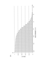
8 is a graph showing the results of a treatment liquid scattering experiment to investigate the scattering range of the treatment liquid scattering from the substrate. In detail, the graph in FIG. 8 shows the relationship between the scattering positions of the treatment liquid and the ratio of the treatment liquid that reaches each scattering position.
図8に示すグラフの横軸は、処理液の飛散位置を示している。飛散位置とは、基板から飛散する処理液が基板の周縁部から水平方向に30mm離れた位置に到達した際の、当該処理液の鉛直位置である。横軸の値が0mmであるとき、飛散した処理液の鉛直位置は、基板の上面と同じ鉛直位置であることを意味する。横軸の値が正であるとき、飛散した処理液の鉛直位置が基板の上面よりも上方であることを意味し、横軸の値が負であるとき、飛散した処理液の鉛直位置が基板の上面よりも下方であることを意味する。
The horizontal axis of the graph shown in FIG. 8 indicates the splash position of the treatment liquid. The splash position is the vertical position of the treatment liquid splashed from the substrate when the treatment liquid reaches a
図8に示すグラフの縦軸は、基板から飛散する処理液の全量に対する、各鉛直位置に達する処理液の比率(飛散比率)を示している。当該割合は、鉛直位置が低くなるにしたがって割合が増大するように積算されている。たとえば、鉛直位置が0mmであるときの飛散比率は、0.2であり、鉛直位置が-2mmであるときの飛散比率は、0.38である。そのため、基板から飛散する処理液の量を1とした場合に、鉛直位置が0mm~-2mmの範囲に飛散する処理液量は0.18であることを意味する。すなわち、基板から飛散する処理液のうちの約18%が、鉛直位置が0mm~-2mmの範囲に飛散する。 The vertical axis of the graph shown in Figure 8 indicates the ratio (scattering ratio) of the processing liquid that reaches each vertical position to the total amount of processing liquid that splashes from the substrate. This ratio is integrated so that the ratio increases as the vertical position becomes lower. For example, the scattering ratio when the vertical position is 0 mm is 0.2, and the scattering ratio when the vertical position is -2 mm is 0.38. This means that if the amount of processing liquid that splashes from the substrate is 1, the amount of processing liquid that splashes in the vertical position range of 0 mm to -2 mm is 0.18. In other words, approximately 18% of the processing liquid that splashes from the substrate splashes in the vertical position range of 0 mm to -2 mm.
図8に示すグラフによれば、たとえば、基板から飛散する処理液の95%以上が、鉛直位置が4mm~-16mmの範囲に飛散する。基板から飛散する処理液の90%以上が、鉛直位置が2mm~-16mmの範囲に飛散する。したがって、傾斜部84の下端部と垂下部83の下端部との間の鉛直距離VDが18mm以上であれば、基板Wから飛散する処理液の90%以上をガード80によって受けられることを意味する。
According to the graph shown in FIG. 8, for example, 95% or more of the processing liquid splashing from the substrate splashes in a vertical position range of 4 mm to -16 mm. 90% or more of the processing liquid splashing from the substrate splashes in a vertical position range of 2 mm to -16 mm. Therefore, if the vertical distance VD between the bottom end of the
たとえば、筒状部81の内径IDTが486mmであり、傾斜部84の傾斜角度θが28°であり、延設部82の内径IDEが326mmであれば、傾斜部84の下端部と垂下部83の下端部との間の鉛直距離VDは、34.5mmである。この場合、基板から飛散する処理液の95%以上をガード80によって受けることができる。
筒状部81の内径IDTが458mmであり、傾斜部84の傾斜角度θが28°であり、延設部82の内径IDEが335mmであれば、傾斜部84の下端部と垂下部83の下端部との間の鉛直距離VDは、27.2mmである。この場合も、基板から飛散する処理液の95%以上をガード80によって受けることができる。
For example, if the inner diameter IDT of
If the inner diameter IDT of
<その他の実施形態>
この発明は、以上に説明した実施形態に限定されるものではなく、さらに他の形態で実施することができる。
たとえば、上述の実施形態では、2つのガード80(第1ガード80Aおよび第2ガード80B)が設けられている。しかしながら、上述の実施形態とは異なり、いずれかのガード80のみが設けられていてもよい。
<Other embodiments>
The present invention is not limited to the above-described embodiment, and can be embodied in other forms.
For example, in the above-described embodiment, two guards 80 (the
すなわち、筒状部81の内径IDTが、486mm以上で、かつ、518mm以下であり、延設部82の内径IDEが、319mm以上であり、かつ、326mm以下であり、傾斜角度θが、25°以上で、かつ、30°未満であるガード80のみが設けられていてもよい。あるいは、筒状部81の内径IDTが、458mm以上で、かつ、470mm以下であり、延設部82の内径IDEが、319mm以上であり、335mm以下であり、傾斜角度θが、25°以上で、かつ、30°未満であるガード80のみが設けられていてもよい。
That is, only a
また、上述の実施形態では、延設部82が、傾斜部84、下側連結部85、水平部86および上側連結部88を有している。しかしながら、上述の実施形態とは異なり、水平部86および上側連結部88が設けられておらず、ガード内側ISにおける傾斜部84の端部(傾斜部84の上端部)と垂下部83の上端部とが直接連結される構成であってもよい。この場合であっても、水平部86が設けられている構成と比較して、処理液捕集性能は劣るものの、処理液を充分に捕集することができる。
In addition, in the above-described embodiment, the
また、上述の実施形態とは異なり、上側連結部88が設けられておらず、ガード内側ISにおける傾斜部84の端部(傾斜部84の上端部)とガード外側OSにおける水平部86の端部とが直接連結される構成であってもよい。この場合であっても、上側連結部88が設けられている構成と比較して、処理液捕集性能は劣るものの、処理液を充分に捕集することができる。
Also, unlike the above-described embodiment, the upper connecting
また、上述の実施形態とは異なり、下側連結部85が設けられておらず、ガード外側OSにおける傾斜部84の端部(傾斜部の下端部)と筒状部81の上端部とが直接連結される構成であってもよい。この場合であっても、下側連結部85が設けられている構成と比較して、処理液捕集性能は劣るものの、処理液を充分に捕集することができる。
また、上述の実施形態では、下側気体流路25から吐出される気体は、基板Wの下面に向けて吹き付けられる。しかしながら、上述の実施形態とは異なり、下側気体流路25から吐出される方向を水平方向に変換する気流変換部材(図示せず)が下側気体流路25の上端部、すなわち、スピンベースの上面に設けられていてもよい。
Also, unlike the above-described embodiment, the lower connecting
Furthermore, in the above-described embodiment, the gas discharged from the lower
また、上述の実施形態では、仕切り板104が設けられている。しかしながら、上述の実施形態とは異なり、仕切り板104が設けられておらず、ガード外空間103が上下に仕切られていない構成であってもよい。この場合、排気接続管45は、処理チャンバ17の側壁17Bに開口される。
その他、特許請求の範囲に記載した範囲で種々の変更を行うことができる。
In the above embodiment, the
In addition, various modifications can be made within the scope of the claims.
1 :基板処理装置
20 :チャックピン(基板保持ユニット、把持ピン)
21 :スピンベース(基板保持ユニット、ベース)
23 :スピンモータ
80 :ガード
80A :第1ガード
80B :第2ガード
81 :筒状部
81A :第1筒状部
81B :第2筒状部
82 :延設部
82A :第1延設部
82B :第2延設部
82a :中心側端部(中心側における延設部の端部)
82Aa :第1中心側端部(中心側における第1延設部の端部)
82Ba :第2中心側端部(中心側における第2延設部の端部)
83 :垂下部
83A :第1垂下部
83B :第2垂下部
84 :傾斜部
84A :第1傾斜部
84Ab :内周面
84B :第2傾斜部
84Bb :内周面
84b :内周面
85 :下側連結部
85A :第1下側連結部
85B :第2下側連結部
86 :水平部
86A :第1水平部
86B :第2水平部
87 :下側湾曲面
87A :第1下側湾曲面
87B :第2下側湾曲面
HD :水平距離
HD1 :水平距離
HD2 :水平距離
IDE :内径
IDE1 :内径
IDE2 :内径
IDT :内径
IDT1 :内径
IDT2 :内径
OD :外径
IS :ガード内側(筒状部の中心側)
VD :鉛直距離
VD1 :鉛直距離
VD2 :鉛直距離
VW :基準鉛直幅
W :基板
θ :傾斜角度
θ1 :第1傾斜角度
θ2 :第2傾斜角度
1: Substrate processing apparatus 20: Chuck pin (substrate holding unit, gripping pin)
21: Spin base (substrate holding unit, base)
23: Spin motor 80:
82Aa: First center side end (end of the first extension part on the center side)
82Ba: Second center side end (end of the second extension part on the center side)
83: Hanging
VD: Vertical distance VD1: Vertical distance VD2: Vertical distance VW: Reference vertical width W: Substrate θ: Inclination angle θ1: First inclination angle θ2: Second inclination angle
Claims (14)
前記基板保持ユニットによって保持されている基板を回転させる基板回転ユニットと、
前記基板保持ユニットによって保持されている基板に処理液を供給する処理液供給ユニットと、
前記基板保持ユニットによって保持されている基板から飛散する処理液を受ける液受け部材とを備え、
前記液受け部材が、
前記基板保持ユニットを取り囲む筒状部と、
前記筒状部の上端部から前記筒状部の中心側に向かって延びる延設部であって、前記中心側に向かうにしたがって上方へ向かうように水平方向に対して傾斜する傾斜部を有する延設部と、
前記中心側における前記延設部の端部から下方に延びる垂下部とを含み、
水平方向に対する前記傾斜部の傾斜角度が25°以上で、かつ、30°未満であり、
前記液受け部材が、前記基板保持ユニットに保持されている基板から飛散する処理液を受ける液受け位置に位置するとき、前記垂下部は前記基板よりも上に位置し、かつ前記傾斜部の下端部は前記基板よりも下に位置し、
前記傾斜部の下端部と前記垂下部の下端部との間の鉛直距離が、前記基板保持ユニットに保持されている基板から飛散する処理液の90%以上を捕集するために必要な基準鉛直幅と同じまたは前記基準鉛直幅よりも大きい、基板処理装置。 a substrate holding unit that holds the substrate horizontally;
a substrate rotation unit that rotates the substrate held by the substrate holding unit;
a processing liquid supply unit that supplies a processing liquid to the substrate held by the substrate holding unit;
a liquid receiving member for receiving a processing liquid splashed from the substrate held by the substrate holding unit,
The liquid receiving member is
A cylindrical portion surrounding the substrate holding unit;
an extension portion extending from an upper end portion of the cylindrical portion toward a center side of the cylindrical portion, the extension portion having an inclined portion inclined with respect to a horizontal direction so as to extend upward toward the center side;
a hanging portion extending downward from an end of the extension portion on the center side,
The inclination angle of the inclined portion with respect to the horizontal direction is 25° or more and less than 30°,
when the liquid receiving member is located at a liquid receiving position where it receives processing liquid splashed from the substrate held by the substrate holding unit, the hanging portion is located above the substrate and a lower end of the inclined portion is located below the substrate,
A substrate processing apparatus, wherein the vertical distance between the lower end of the inclined portion and the lower end of the hanging portion is the same as or greater than a standard vertical width required to capture 90% or more of the processing liquid splashed from the substrate held in the substrate holding unit.
前記中心側における前記延設部の端部と、前記ベースの周端部との間の水平距離が、3mm以上で、かつ、19mm以下である、請求項1に記載の基板処理装置。 the substrate holding unit includes a base having a circular shape with a diameter larger than that of the substrate in a plan view,
2 . The substrate processing apparatus according to claim 1 , wherein a horizontal distance between an end of said extension portion on said center side and a peripheral end of said base is not less than 3 mm and not more than 19 mm.
前記延設部の内径が、319mm以上であり、かつ、335mm以下である、請求項2に記載の基板処理装置。 The outer diameter of the base is 316 mm;
The substrate processing apparatus according to claim 2 , wherein the inner diameter of the extension portion is not less than 319 mm and not more than 335 mm.
前記基板保持ユニットによって保持されている基板を回転させる基板回転ユニットと、
前記基板保持ユニットによって保持されている基板に処理液を供給する処理液供給ユニットと、
前記基板保持ユニットによって保持されている基板から飛散する処理液を受ける第1液受け部材と、
前記基板保持ユニットによって保持されている基板から飛散する処理液を受ける第2液受け部材とを含み、
前記第1液受け部材が、
前記基板保持ユニットを取り囲む第1筒状部と、
前記第1筒状部の上端部から前記第1筒状部の中心側に向かって延びる第1延設部であって、前記中心側に向かうにしたがって上方へ向かうように水平方向に対して傾斜する第1傾斜部を有する第1延設部と、
前記中心側における前記第1延設部の端部から下方に延びる第1垂下部とを含み、
前記第2液受け部材が、
前記第1筒状部よりも前記中心側で前記基板保持ユニットを取り囲む第2筒状部と、
前記第2筒状部の上端部から前記中心側に向かって延び、前記第1延設部に下方から対向する第2延設部であって、前記中心側に向かうにしたがって上方へ向かうように水平方向に対して傾斜する第2傾斜部を有する第2延設部と、
前記中心側における前記第2延設部の端部から下方に延びる第2垂下部とを含み、
水平方向に対する前記第1傾斜部の傾斜角度が25°以上で、かつ、30°未満であり、
水平方向に対する前記第2傾斜部の傾斜角度が25°以上で、かつ、30°未満であり、
前記第1液受け部材が、前記基板保持ユニットに保持されている基板から飛散する処理液を受ける第1液受け位置に位置するとき、前記第1垂下部は前記基板よりも上に位置し、かつ前記第1傾斜部の下端部は前記基板よりも下に位置し、
前記第1傾斜部の下端部と前記第1垂下部の下端部との間の鉛直距離が、前記基板保持ユニットに保持されている基板から飛散する処理液の90%以上を捕集するために必要な基準鉛直幅と同じまたは前記基準鉛直幅よりも大きく、
前記第2液受け部材が、前記基板保持ユニットに保持されている基板から飛散する処理液を受ける第2液受け位置に位置するとき、前記第2垂下部は前記基板よりも上に位置し、かつ前記第2傾斜部の下端部は前記基板よりも下に位置し、
前記第2傾斜部の下端部と前記第2垂下部の下端部との間の鉛直距離が、前記基板保持ユニットに保持されている基板から飛散する処理液の90%以上を捕集するために必要な基準鉛直幅と同じまたは前記基準鉛直幅よりも大きい、基板処理装置。 a substrate holding unit that holds the substrate horizontally;
a substrate rotation unit that rotates the substrate held by the substrate holding unit;
a processing liquid supply unit that supplies a processing liquid to the substrate held by the substrate holding unit;
a first liquid receiving member for receiving a processing liquid splashed from the substrate held by the substrate holding unit;
a second liquid receiving member for receiving a processing liquid splashed from the substrate held by the substrate holding unit,
The first liquid receiving member is
A first cylindrical portion surrounding the substrate holding unit;
a first extending portion extending from an upper end of the first cylindrical portion toward a center side of the first cylindrical portion, the first extending portion having a first inclined portion inclined with respect to a horizontal direction so as to extend upward toward the center side;
a first hanging portion extending downward from an end portion of the first extension portion on the center side,
The second liquid receiving member is
a second cylindrical portion surrounding the substrate holding unit on the central side relative to the first cylindrical portion;
a second extension portion extending from an upper end of the second cylindrical portion toward the center and facing the first extension portion from below, the second extension portion having a second inclined portion inclined upward with respect to a horizontal direction toward the center;
a second hanging portion extending downward from an end of the second extension portion on the center side,
The inclination angle of the first inclined portion with respect to the horizontal direction is equal to or greater than 25° and less than 30°,
The inclination angle of the second inclined portion with respect to the horizontal direction is 25° or more and less than 30° ,
when the first liquid receiving member is located at a first liquid receiving position where it receives processing liquid splashed from the substrate held by the substrate holding unit, the first hanging portion is located above the substrate and a lower end of the first inclined portion is located below the substrate,
a vertical distance between a lower end of the first inclined portion and a lower end of the first hanging portion is equal to or larger than a reference vertical width required to collect 90% or more of the processing liquid splashed from the substrate held by the substrate holding unit,
when the second liquid receiving member is located at a second liquid receiving position where it receives processing liquid splashed from the substrate held by the substrate holding unit, the second hanging portion is located above the substrate and a lower end of the second inclined portion is located below the substrate,
A substrate processing apparatus, wherein the vertical distance between the lower end of the second inclined portion and the lower end of the second hanging portion is the same as or greater than a standard vertical width required to capture 90% or more of the processing liquid splashed from the substrate held in the substrate holding unit .
前記中心側における前記第1延設部の端部と、前記ベースの周端部との間の水平距離が、3mm以上で、かつ、10mm以下であり、
前記中心側における前記第2延設部の端部と、前記ベースの周端部との間の水平距離が、3mm以上で、かつ、19mm以下である、請求項10に記載の基板処理装置。 the substrate holding unit has a base having a circular shape with a diameter larger than that of the substrate in a plan view,
A horizontal distance between an end of the first extension portion on the center side and a peripheral end of the base is 3 mm or more and 10 mm or less,
The substrate processing apparatus according to claim 10 , wherein a horizontal distance between an end of the second extension portion on the center side and a peripheral end of the base is equal to or greater than 3 mm and equal to or less than 19 mm.
前記第1延設部の内径が、319mm以上であり、かつ、326mm以下であり、
前記第2延設部の内径が、319mm以上であり、かつ、335mm以下である、請求項11に記載の基板処理装置。 The outer diameter of the base is 316 mm;
The inner diameter of the first extension portion is 319 mm or more and 326 mm or less,
The substrate processing apparatus of claim 11 , wherein the second extension portion has an inner diameter of 319 mm or more and 335 mm or less.
前記第2筒状部の内径が、458mm以上で、かつ、470mm以下である、請求項11~12のいずれか一項に記載の基板処理装置。 The inner diameter of the first cylindrical portion is 486 mm or more and 518 mm or less,
The substrate processing apparatus according to claim 11 , wherein the inner diameter of the second cylindrical portion is not less than 458 mm and not more than 470 mm.
前記第2筒状部の内径が、458mmである、請求項13に記載の基板処理装置。 The inner diameter of the first cylindrical portion is 486 mm.
The substrate processing apparatus according to claim 13 , wherein the second cylindrical portion has an inner diameter of 458 mm.
Priority Applications (1)
| Application Number | Priority Date | Filing Date | Title |
|---|---|---|---|
| JP2020146353A JP7539801B2 (en) | 2020-08-31 | 2020-08-31 | Substrate Processing Equipment |
Applications Claiming Priority (1)
| Application Number | Priority Date | Filing Date | Title |
|---|---|---|---|
| JP2020146353A JP7539801B2 (en) | 2020-08-31 | 2020-08-31 | Substrate Processing Equipment |
Publications (2)
| Publication Number | Publication Date |
|---|---|
| JP2022041256A JP2022041256A (en) | 2022-03-11 |
| JP7539801B2 true JP7539801B2 (en) | 2024-08-26 |
Family
ID=80499733
Family Applications (1)
| Application Number | Title | Priority Date | Filing Date |
|---|---|---|---|
| JP2020146353A Active JP7539801B2 (en) | 2020-08-31 | 2020-08-31 | Substrate Processing Equipment |
Country Status (1)
| Country | Link |
|---|---|
| JP (1) | JP7539801B2 (en) |
Families Citing this family (1)
| Publication number | Priority date | Publication date | Assignee | Title |
|---|---|---|---|---|
| JP7369227B2 (en) * | 2022-03-22 | 2023-10-25 | 株式会社Screenホールディングス | developing device |
Citations (4)
| Publication number | Priority date | Publication date | Assignee | Title |
|---|---|---|---|---|
| JP2002166216A (en) | 2000-11-29 | 2002-06-11 | Shibaura Mechatronics Corp | Spin treatment apparatus and anti-scattering cup |
| JP2006012881A (en) | 2004-06-22 | 2006-01-12 | Dainippon Screen Mfg Co Ltd | Substrate processor and substrate processing method |
| JP2010177372A (en) | 2009-01-28 | 2010-08-12 | Dainippon Screen Mfg Co Ltd | Substrate treatment device |
| JP2017143141A (en) | 2016-02-09 | 2017-08-17 | 信越半導体株式会社 | Single-wafer cleaning apparatus and wafer cleaning method |
-
2020
- 2020-08-31 JP JP2020146353A patent/JP7539801B2/en active Active
Patent Citations (4)
| Publication number | Priority date | Publication date | Assignee | Title |
|---|---|---|---|---|
| JP2002166216A (en) | 2000-11-29 | 2002-06-11 | Shibaura Mechatronics Corp | Spin treatment apparatus and anti-scattering cup |
| JP2006012881A (en) | 2004-06-22 | 2006-01-12 | Dainippon Screen Mfg Co Ltd | Substrate processor and substrate processing method |
| JP2010177372A (en) | 2009-01-28 | 2010-08-12 | Dainippon Screen Mfg Co Ltd | Substrate treatment device |
| JP2017143141A (en) | 2016-02-09 | 2017-08-17 | 信越半導体株式会社 | Single-wafer cleaning apparatus and wafer cleaning method |
Also Published As
| Publication number | Publication date |
|---|---|
| JP2022041256A (en) | 2022-03-11 |
Similar Documents
| Publication | Publication Date | Title |
|---|---|---|
| JP6229933B2 (en) | Processing cup cleaning method, substrate processing method, and substrate processing apparatus | |
| TWI709169B (en) | Substrate processing method and substrate processing apparatus | |
| KR101810748B1 (en) | Substrate processing apparatus and substrate processing method | |
| US8864937B2 (en) | Substrate treatment apparatus | |
| US10639683B2 (en) | Recovery piping cleaning method and substrate processing apparatus | |
| JP6057334B2 (en) | Substrate processing equipment | |
| KR100945768B1 (en) | Substrate processing apparatus, substrate processing method and cleaning method of drainage cup | |
| JP4757882B2 (en) | Substrate cleaning apparatus, substrate cleaning method, substrate processing system, and recording medium | |
| US20090320885A1 (en) | Substrate treatment apparatus | |
| JP7628434B2 (en) | Substrate processing apparatus and method for processing cylindrical guard | |
| JP6363876B2 (en) | Substrate processing method and substrate processing apparatus | |
| JP6718714B2 (en) | Substrate processing method and substrate processing apparatus | |
| WO2018037982A1 (en) | Substrate processing device and substrate processing method | |
| TWI753789B (en) | Substrate processing method and substrate processing apparatus | |
| KR20190022357A (en) | Substrate processing apparatus, substrate processing method, and storage medium | |
| JP6512554B2 (en) | Substrate processing method and substrate processing apparatus | |
| KR100787996B1 (en) | Substrate processing apparatus and method of recovering processing liquid from the apparatus | |
| JP6814653B2 (en) | Substrate processing method and substrate processing equipment | |
| KR101317109B1 (en) | Liquid processing method, liquid processing apparatus and storage medium | |
| JP7539801B2 (en) | Substrate Processing Equipment | |
| JP2018157129A (en) | Substrate processing apparatus and substrate processing method | |
| JP5080885B2 (en) | Substrate processing apparatus and processing chamber cleaning method | |
| KR101605713B1 (en) | Substrate processing apparatus | |
| JP7372084B2 (en) | Substrate processing equipment and substrate processing method | |
| JP2023117776A (en) | Substrate processing apparatus, and method for cleaning processing cup |
Legal Events
| Date | Code | Title | Description |
|---|---|---|---|
| A621 | Written request for application examination |
Free format text: JAPANESE INTERMEDIATE CODE: A621 Effective date: 20230620 |
|
| A977 | Report on retrieval |
Free format text: JAPANESE INTERMEDIATE CODE: A971007 Effective date: 20240228 |
|
| A131 | Notification of reasons for refusal |
Free format text: JAPANESE INTERMEDIATE CODE: A131 Effective date: 20240314 |
|
| A521 | Request for written amendment filed |
Free format text: JAPANESE INTERMEDIATE CODE: A523 Effective date: 20240509 |
|
| TRDD | Decision of grant or rejection written | ||
| A01 | Written decision to grant a patent or to grant a registration (utility model) |
Free format text: JAPANESE INTERMEDIATE CODE: A01 Effective date: 20240725 |
|
| A61 | First payment of annual fees (during grant procedure) |
Free format text: JAPANESE INTERMEDIATE CODE: A61 Effective date: 20240814 |
|
| R150 | Certificate of patent or registration of utility model |
Ref document number: 7539801 Country of ref document: JP Free format text: JAPANESE INTERMEDIATE CODE: R150 |