JP7537078B2 - Optical sorting machine - Google Patents
Optical sorting machine Download PDFInfo
- Publication number
- JP7537078B2 JP7537078B2 JP2019209821A JP2019209821A JP7537078B2 JP 7537078 B2 JP7537078 B2 JP 7537078B2 JP 2019209821 A JP2019209821 A JP 2019209821A JP 2019209821 A JP2019209821 A JP 2019209821A JP 7537078 B2 JP7537078 B2 JP 7537078B2
- Authority
- JP
- Japan
- Prior art keywords
- chute
- sorted
- sorting
- optical
- ejector
- Prior art date
- Legal status (The legal status is an assumption and is not a legal conclusion. Google has not performed a legal analysis and makes no representation as to the accuracy of the status listed.)
- Active
Links
Images


Classifications
-
- B—PERFORMING OPERATIONS; TRANSPORTING
- B07—SEPARATING SOLIDS FROM SOLIDS; SORTING
- B07C—POSTAL SORTING; SORTING INDIVIDUAL ARTICLES, OR BULK MATERIAL FIT TO BE SORTED PIECE-MEAL, e.g. BY PICKING
- B07C5/00—Sorting according to a characteristic or feature of the articles or material being sorted, e.g. by control effected by devices which detect or measure such characteristic or feature; Sorting by manually actuated devices, e.g. switches
- B07C5/34—Sorting according to other particular properties
- B07C5/342—Sorting according to other particular properties according to optical properties, e.g. colour
- B07C5/3425—Sorting according to other particular properties according to optical properties, e.g. colour of granular material, e.g. ore particles, grain
-
- B—PERFORMING OPERATIONS; TRANSPORTING
- B07—SEPARATING SOLIDS FROM SOLIDS; SORTING
- B07C—POSTAL SORTING; SORTING INDIVIDUAL ARTICLES, OR BULK MATERIAL FIT TO BE SORTED PIECE-MEAL, e.g. BY PICKING
- B07C5/00—Sorting according to a characteristic or feature of the articles or material being sorted, e.g. by control effected by devices which detect or measure such characteristic or feature; Sorting by manually actuated devices, e.g. switches
- B07C5/36—Sorting apparatus characterised by the means used for distribution
- B07C5/363—Sorting apparatus characterised by the means used for distribution by means of air
- B07C5/365—Sorting apparatus characterised by the means used for distribution by means of air using a single separation means
- B07C5/366—Sorting apparatus characterised by the means used for distribution by means of air using a single separation means during free fall of the articles
-
- B—PERFORMING OPERATIONS; TRANSPORTING
- B65—CONVEYING; PACKING; STORING; HANDLING THIN OR FILAMENTARY MATERIAL
- B65G—TRANSPORT OR STORAGE DEVICES, e.g. CONVEYORS FOR LOADING OR TIPPING, SHOP CONVEYOR SYSTEMS OR PNEUMATIC TUBE CONVEYORS
- B65G11/00—Chutes
Landscapes
- Sorting Of Articles (AREA)
- Chutes (AREA)
Description
本発明は、穀粒や樹脂ペレット等の粒状物を色彩等に基づいて選別する光学式選別機に関する。 The present invention relates to an optical sorting machine that sorts granular materials such as grains and resin pellets based on color, etc.
従来、米や小麦等の穀粒、樹脂ペレット、コーヒー豆、その他の粒状物からなる原料を色彩等により良品と不良品に選別したり、原料に混入する異物を色彩等により除去したりする光学式選別機が知られている。(特許文献1,2参照。)。
Conventionally, optical sorting machines are known that sort raw materials consisting of grains such as rice and wheat, resin pellets, coffee beans, and other granular materials into good and bad products by color or the like, and remove foreign matter mixed into the raw materials by color or the like (see
特許文献1,2に記載された光学式選別機は、傾斜状のシュートを備え、前記シュートの下端から一定の軌跡を描いて落下する粒状物に光源から光を照射し、前記粒状物からの反射光や透過光をセンサにより受光して不良品や異物等を検出し、当該検出した不良品や異物等をエジェクターにより吹き飛ばすことで良否選別するものである。
The optical sorting machines described in
ところで、前記光学式選別機において、前記シュートの下端から落下する粒状物の中には、形状や大きさの違い、空中での飛行姿勢の違い等により一定の落下軌跡から外れるものがあり、この場合、不良品や異物等を精度よく検出することができず、選別性能に影響を及ぼす問題がある。 However, in the optical sorting machine, some of the granular objects falling from the bottom end of the chute deviate from a fixed falling trajectory due to differences in shape, size, flying attitude in the air, etc. In such cases, defective products, foreign objects, etc. cannot be detected accurately, which creates a problem that affects sorting performance.
そこで、本発明は、被選別物の不良品や異物等を精度よく検出することができ、選別性能を向上させることができる光学式選別機を提供することを目的とする。 The present invention aims to provide an optical sorting machine that can accurately detect defective products and foreign objects in the items being sorted, thereby improving sorting performance.
上記目的を達成するため、本発明は、
被選別物を流下させるために傾斜配置したシュートと、
前記被選別物を検出位置において検出する光学検出手段と、
前記光学検出手段による検出結果に基づいて前記被選別物を選別除去するエジェクター手段と、
前記エジェクター手段により選別された被選別物を各別に排出する排出ホッパを備えるとともに、
前記光学検出手段は、
前記検出位置を照明する照明手段と、
前記検出位置において前記被選別物を撮像する撮像手段と、を備えた光学式選別機において、
前記シュートには、前記被選別物の流下方向に直交して光学検出用スリットが設けられ、前記光学検出用スリットは前記シュートの幅方向に連続的に開口し、前記光学検出手段は、前記光学検出用スリットが設けられる位置を前記検出位置として、前記シュート上を流下する前記被選別物を前記撮像手段により撮像し、
前記シュートには、前記光学検出用スリットの下流側に前記被選別物の流下方向に直交して選別除去用スリットが設けられ、前記選別除去用スリットは前記シュートの幅方向に連続的又は断続的に開口し、
前記シュートは、その下端が前記排出ホッパの良品排出路内に延出して位置し、前記選別除去用スリットが前記良品排出路の上方に位置するように配置され、
前記エジェクター手段は、前記シュートの下面側にあって、前記エジェクター手段のエジェクターノズルの先端が前記シュートの下面側に当接し、前記エジェクターノズルの複数のノズル孔が前記選別除去用スリットに直接的に連通するように配設し、前記シュート上を流下する被選別物の中で前記撮像手段の撮像信号に基づいて不良品と判別されたものを、前記選別除去用スリットを介して前記シュートの上面側へ噴風し前記排出ホッパの不良品排出路へ選別除去することを特徴とする。
In order to achieve the above object, the present invention provides
A chute arranged at an incline to allow the objects to be sorted to flow downward;
an optical detection means for detecting the object at a detection position;
an ejector means for selectively removing the objects based on the detection result by the optical detection means;
a discharge hopper for discharging each of the objects to be sorted by the ejector means;
The optical detection means includes:
an illumination means for illuminating the detection position;
an imaging means for imaging the object at the detection position,
an optical detection slit is provided in the chute perpendicular to the flow direction of the objects to be sorted, the optical detection slit is continuously open in the width direction of the chute , the optical detection means takes an image of the objects to be sorted flowing down the chute using the imaging means, with the position where the optical detection slit is provided being the detection position;
a sorting and removal slit is provided in the chute on the downstream side of the optical detection slit and perpendicular to the flow direction of the objects to be sorted, the sorting and removal slit being open continuously or intermittently in the width direction of the chute;
the chute is disposed such that a lower end thereof extends into the non-defective product discharge path of the discharge hopper, and the sorting and removal slit is positioned above the non-defective product discharge path;
The ejector means is located on the underside of the chute, with the tip of an ejector nozzle of the ejector means abutting the underside of the chute and multiple nozzle holes of the ejector nozzle being directly connected to the sorting and removal slits, and any items determined to be defective based on the imaging signal of the imaging means among the items to be sorted flowing down the chute are sprayed onto the upper side of the chute through the sorting and removal slits, and are sorted and removed into the defective item discharge path of the discharge hopper.
本発明は、
前記光学検出手段が、前記シュートの上面側及び下面側に一対が設けられ、前記シュート上を流下する前記被選別物を前記シュートの上面側及び下面側から撮像することが好ましい。
The present invention relates to
It is preferable that a pair of the optical detection means is provided on the upper and lower sides of the chute, and images of the objects to be sorted flowing down the chute are captured from the upper and lower sides of the chute.
本発明は、
前記シュートには、前記光学検出用スリットの下流側に前記被選別物の流下方向に直交して選別除去用スリットが設けられ、
前記エジェクター手段が、前記シュート上を流下する前記被選別物を、前記選別除去用スリットを介して前記シュートの上面側へ選別除去する。
The present invention relates to
The chute is provided with a sorting and removal slit on the downstream side of the optical detection slit and perpendicular to the flow direction of the objects to be sorted,
The ejector means separates and removes the objects flowing down the chute to the upper surface side of the chute through the separation and removal slit.
参考発明は、
前記エジェクター手段が、前記シュートの下面側に設けられ、前記シュート上を流下する前記被選別物を、前記選別除去用スリットを介して前記シュートの下面側へ吸引して除去することが好ましい。
The reference invention is
It is preferable that the ejector means is provided on the underside of the chute and removes the objects to be sorted flowing down the chute by sucking them through the sorting and removal slits to the underside of the chute.
参考発明は、
前記エジェクター手段が、前記シュートの上面側に設けられ、前記シュート上を流下する前記被選別物を、前記選別除去用スリットを介して前記シュートの上面側へ吸引し又は前記シュートの下面側へ噴風して除去することが好ましい。
The reference invention is
It is preferable that the ejector means is provided on the upper side of the chute and removes the sorted material flowing down the chute by sucking it to the upper side of the chute through the sorting and removal slit or by blowing air onto the lower side of the chute.
本発明は、
前記エジェクター手段により選別された被選別物を各別に排出する排出ホッパを備え、
前記シュートは、その下端が前記排出ホッパの良品排出路内に延出して位置し、前記選別除去用スリットが前記良品排出路の上方に位置するように配置され、
前記エジェクター手段が、前記シュート上を流下する前記被選別物の中で前記撮像手段の撮像信号に基づいて不良品と判別されたものを、前記選別除去用スリットを介して前記排出ホッパの不良品排出路へ選別除去する。
The present invention relates to
a discharge hopper for discharging each of the objects to be sorted by the ejector means,
the chute is disposed such that a lower end thereof extends into the non-defective product discharge path of the discharge hopper, and the sorting and removal slit is positioned above the non- defective product discharge path ;
The ejector means sorts out and removes items determined to be defective based on the imaging signal from the imaging means from the sorting and removal slits and sends them to the defective product discharge path of the discharge hopper among the items to be sorted flowing down the chute.
参考発明は、
前記エジェクター手段が、前記シュートの下端から落下する前記被選別物の落下軌跡に対向する位置に設けられ、前記シュートの下端から落下する前記被選別物を、前記落下軌跡から選別除去することが好ましい。
The reference invention is
It is preferable that the ejector means is provided at a position opposite to the falling trajectory of the objects falling from the lower end of the chute, and sorts and removes the objects falling from the lower end of the chute from the falling trajectory.
参考発明は、
前記エジェクター手段が、前記シュートの下端に隣接する位置に設けられ、前記シュートの下端から落下する前記被選別物を、前記シュートの上面側又は下面側へ選別除去することが好ましい。
The reference invention is
It is preferable that the ejector means is provided at a position adjacent to the lower end of the chute, and sorts and removes the objects dropping from the lower end of the chute to the upper side or lower side of the chute.
参考発明は、
前記エジェクター手段が、前記シュートの下面側に設けられ、前記シュートの下端から落下する前記被選別物を、前記シュートの上面側へ噴風し又は前記シュートの下面側へ吸引して除去することが好ましい。
The reference invention is
It is preferable that the ejector means is provided on the underside of the chute and removes the sorted objects dropping from the lower end of the chute by blowing air onto the upper side of the chute or by sucking the objects onto the underside of the chute.
参考発明は、
前記エジェクター手段が、前記シュートの上面側に設けられ、前記シュートの下端から落下する前記被選別物を、前記シュートの上面側へ吸引し又は前記シュートの下面側へ噴風して除去することが好ましい。
The reference invention is
It is preferable that the ejector means is provided on the upper side of the chute and removes the sorted objects dropping from the lower end of the chute by sucking them onto the upper side of the chute or by blowing air onto the lower side of the chute.
本発明は、
前記撮像手段がラインセンサを内蔵するものであることが好ましい。
The present invention relates to
It is preferable that the imaging means has a built-in line sensor.
本発明は、
前記照明手段がLED光源であることが好ましい。
The present invention relates to
Preferably, the illumination means is an LED light source.
本発明の光学式選別機は、前記シュートには前記被選別物の流下方向に直交して光学検出用スリットが設けられ、前記光学検出手段は、前記光学検出用スリットが設けられる位置を前記検出位置として、前記シュート上を流下する前記被選別物を前記撮像手段により撮像するので、従来の光学式選別機のように、シュートの下端から落下する途中の被選別物を検出する場合と異なり、前記シュート上を常に一定の軌跡で流下する被選別物を検出することができる。
したがって、本発明の光学式選別機によれば、従来の光学式選別機に比べ、被選別物の不良品や異物等を精度よく検出することができるので、選別性能を向上させることができる。
In the optical sorting machine of the present invention, an optical detection slit is provided in the chute perpendicular to the flow direction of the sorted materials, and the optical detection means uses the position where the optical detection slit is provided as the detection position, and images the sorted materials flowing down the chute using the imaging means.Therefore, unlike conventional optical sorting machines which detect the sorted materials as they fall from the bottom end of the chute, it is possible to detect the sorted materials that always flow down the chute in a constant trajectory.
Therefore, the optical sorting machine of the present invention can detect defective products, foreign objects, etc. of the objects to be sorted with higher accuracy than conventional optical sorting machines, thereby improving sorting performance.
本発明の光学式選別機は、前記シュートには、前記光学検出用スリットの下流側に前記被選別物の流下方向に直交して選別除去用スリットが設けられ、前記エジェクター手段が、前記シュート上を流下する前記被選別物を、前記選別除去用スリットを介して前記シュートの上面側へ選別除去するので、従来の光学式選別機のように、シュートの下端から落下する途中の被選別物を選別除去する場合と異なり、前記シュート上を常に一定の軌跡で流下する被選別物を選別除去することができる。
したがって、本発明の光学式選別機によれば、従来の光学式選別機に比べ、被選別物の不良品や異物等を精度よく選別除去することができるので、選別性能をさらに向上させることができる。
In the optical sorting machine of the present invention, the chute is provided with a sorting and removal slit downstream of the optical detection slit, perpendicular to the flow direction of the sorted materials, and the ejector means sorts and removes the sorted materials flowing down the chute to the upper surface side of the chute via the sorting and removal slit.Therefore, unlike conventional optical sorting machines which sort and remove the sorted materials as they fall from the bottom end of the chute, it is possible to sort and remove the sorted materials that always flow down the chute in a constant trajectory.
Therefore, according to the optical sorting machine of the present invention, defective products, foreign matter, etc. can be sorted and removed with higher accuracy than conventional optical sorting machines, thereby further improving sorting performance.
本発明の光学式選別機は、前記シュートは、その下端が前記排出ホッパの良品排出路内に延出して位置し、前記選別除去用スリットが前記良品排出路の上方に位置するように配置され、前記エジェクター手段が、前記シュート上を流下する前記被選別物の中で前記撮像手段の撮像信号に基づいて不良品と判別されたものを、前記選別除去用スリットを介して前記排出ホッパの不良品排出路へ選別除去するので、前記被選別物を前記排出ホッパの前記良品排出路と前記不良品排出路に簡単かつ確実に仕分けして排出することができる。
In the optical sorting machine of the present invention, the chute is positioned so that its lower end extends into the good product discharge path of the discharge hopper and the sorting and removal slit is positioned above the good product discharge path , and the ejector means sorts and removes those sorted objects flowing down the chute that are determined to be defective based on the imaging signal of the imaging means into the defective product discharge path of the discharge hopper via the sorting and removal slit, so that the sorted objects can be easily and reliably sorted and discharged into the good product discharge path and the defective product discharge path of the discharge hopper.
参考発明の光学式選別機は、前記エジェクター手段が、前記シュートの下端から落下する前記被選別物の落下軌跡に対向する位置に設けられ、前記シュートの下端から落下する前記被選別物を、前記落下軌跡から選別除去することとすれば、従来の光学式選別機と異なり、前記エジェクター手段を前記シュートの下端近傍位置に配設することができるため、前記エジェクター手段による選別位置において被選別物の落下軌跡にバラツキが生じにくい。
したがって、参考発明の光学式選別機によれば、従来の光学式選別機に比べ、被選別物の不良品や異物等を精度よく選別除去することができるので、選別性能をさらに向上させることができる。
In the optical sorting machine of the reference invention, the ejector means is provided at a position opposite the fall trajectory of the sorted objects falling from the lower end of the chute, and the sorted objects falling from the lower end of the chute are sorted and removed from the fall trajectory.Unlike conventional optical sorting machines, the ejector means can be arranged at a position near the lower end of the chute, so that variation is less likely to occur in the fall trajectory of the sorted objects at the sorting position by the ejector means.
Therefore, according to the optical sorting machine of the reference invention, defective products, foreign objects, etc. can be sorted and removed more accurately than conventional optical sorting machines, thereby further improving sorting performance.
参考発明の光学式選別機は、前記エジェクター手段が、前記シュートの下端に隣接する位置に設けられ、前記シュートの下端から落下する前記被選別物を、前記シュートの上面側又は下面側へ選別除去することとすれば、従来の光学式選別機と異なり、前記エジェクター手段による選別位置において被選別物の落下軌跡にバラツキが生じない。
したがって、参考発明の光学式選別機によれば、従来の光学式選別機に比べ、被選別物の不良品や異物等を精度よく選別除去することができるので、選別性能をさらに向上させることができる。
In the optical sorting machine of the reference invention, the ejector means is provided at a position adjacent to the lower end of the chute, and the sorted objects falling from the lower end of the chute are sorted and removed to the upper or lower side of the chute.Unlike conventional optical sorting machines, there is no variation in the falling trajectory of the sorted objects at the sorting position by the ejector means.
Therefore, according to the optical sorting machine of the reference invention, defective products, foreign objects, etc. can be sorted and removed more accurately than conventional optical sorting machines, thereby further improving sorting performance.
本発明の光学式選別機は、前記撮像手段がラインセンサを内蔵するものであれば、前記光学検出用スリットの幅を小さくすることができる。 If the imaging means of the optical sorting machine of the present invention has a built-in line sensor, the width of the optical detection slit can be reduced.
本発明の光学式選別機は、前記照明手段がLED光源であれば、光が発散しにくいため、前記光学検出用スリットの幅が小さくても前記検出位置における光量を十分に確保することができる。 If the illumination means of the optical sorting machine of the present invention is an LED light source, the light is less likely to diverge, so even if the width of the optical detection slit is small, a sufficient amount of light can be ensured at the detection position.
本発明の実施の形態を図面に基づいて説明する。
図1は光学式選別機の一例であって概略側断面図を示す。
本発明の実施の形態において、光学式選別機1は、原料となる粒状物を供給する粒状物供給部2、傾斜状に配置されて前記粒状物を流下させるシュート3、前記シュート3上を流下する粒状物を検出し、該検出結果に基づいて良品と不良品に選別する光学選別部4、前記光学選別部4で選別された粒状物を良品と不良品に分けて排出する排出ホッパ5を備える。
An embodiment of the present invention will be described with reference to the drawings.
FIG. 1 is a schematic cross-sectional side view of an example of an optical sorting machine.
In an embodiment of the present invention, an
前記粒状物供給部2は、図示しない原料タンクと、前記原料タンクに貯留する粒状物を前記シュート3に供給する振動フィーダ21を備える。
The granular
前記シュート3は、所定幅を有して前記振動フィーダ21の先端側下方位置に傾斜した状態で配置され、前記振動フィーダ21から供給される粒状物を自然流下させる。
The
前記光学選別部4は、前記シュート3の上面側及び下面側に配設される一対の光学検出装置41a,41b、前記光学検出装置41a,41bの撮像信号に基づいて前記粒状物を良品と不良品に判別する判別装置42、前記判別装置42の判別結果に基づいて前記不良品を除去し前記粒状物を良品と不良品に選別するエジェクター装置43を備える。
The
前記排出ホッパ5は、前記エジェクター装置43により選別された粒状物を良品と不良品に分別して排出する良品排出路51及び不良品排出路52を備える。
The
前記光学式選別機1において、前記粒状物供給部2の原料タンクに貯留される粒状物は、前記振動フィーダ21により前記シュート3に連続して供給され、該シュート3の表面上を幅方向に広がる状態で連続状に自然流下する。
In the
前記シュート3上を流下する粒状物は、前記光学選別部4において、一対の前記光学検出装置41a,41bにおける撮像手段により撮像され、前記判別装置42において前記撮像手段の撮像信号における光量や色成分等の信号レベルがしきい値と比較されて良品と不良品のいずれかに判別され、前記判別装置42から送られる除去信号に基づいて前記エジェクター装置43におけるエアの噴射により不良品が除去され、良品と不良品に選別される。
The granular material flowing down the
そして、前記良品に選別された粒状物は前記排出ホッパ5の良品排出路51、前記不良品に選別された粒状物は前記排出ホッパ5の不良品排出路52からそれぞれ排出される。
The granular materials selected as non-defective products are discharged from the non-defective
[実施例1]
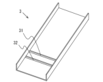
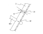
図2は実施例1における光学選別部の概略説明図を示す。図3は実施例1におけるシュートの概略斜視図を示す。図4は実施例1の光学選別部において、エジェクター装置により不良品を選別除去する例の説明図を示す。
実施例1における光学選別部4において、前記シュート3には、粒状物の流下方向に直交して前記シュート3の幅方向に連続的に開口する光学検出用スリット31が設けられる。
また、前記シュート3には、前記光学検出用スリット31の下流側に前記粒状物の流下方向に直交して前記シュート3の幅方向に連続的に開口する選別除去用スリット32が設けられる。
前記シュート3は、その下端が前記排出ホッパ5の前記良品排出路51内に延出して位置し、前記選別除去用スリット32が前記良品排出路51よりも上方に位置するように配設される。
[Example 1]
Fig. 2 shows a schematic explanatory diagram of the optical sorting unit in Example 1. Fig. 3 shows a schematic perspective view of the chute in Example 1. Fig. 4 shows an explanatory diagram of an example in which defective products are sorted and removed by an ejector device in the optical sorting unit in Example 1.
In the
The
The
前記光学選別部4において、前記光学検出装置41a,41bは、前記シュート3上を幅方向に広がる状態で流下する粒状物に対応できるCCD等のラインセンサやエリアセンサを内蔵し、近赤外線(NIR)、可視光又は紫外線等の波長域の光を受光可能とするCCDカメラ等の撮像手段411a,411bと、前記粒状物が流下する前記シュート3上の検出位置Oを照明するLED光源や蛍光灯等の照明手段412a,412bと、前記検出位置Oにおいて前記撮像手段411a,411bにより前記粒状物を撮像する際の背景となるバックグラウンドとを備える。
In the
また、前記エジェクター装置43は、前記光学検出装置41a,41bと同様に、前記シュート3上を幅方向に広がる状態で流下する粒状物に対応できるものであって、前記幅方向に形成される複数のノズル孔から選択的にエアを噴射することができるエジェクターノズル431と、前記判別装置から送られる除去信号に基づいて前記エジェクターノズル431からエアを噴射させる図示しないエジェクター駆動装置を備える。
The
前記光学検出装置41a,41bは、前記シュート3上の前記光学検出用スリット31が設けられる位置が前記検出位置Oとなるように配設されており、前記シュート3上を流下する粒状物を、前記検出位置Oにおいて前記シュートの上面側及び下面側から前記照明手段412a,412bにより照明し、前記撮像手段411a,411bにより撮像する。
The
また、前記エジェクター装置43は、前記エジェクターノズル431の先端が前記シュート3の下面側に当接又は近接し、前記エジェクターノズル431の複数のノズル孔が前記選別除去用スリット32に直接又は間接的に連通するように配設されており、前記シュート3上を流下する粒状物の中で不良品と判別されたものを、前記選別除去用スリット32を介して前記シュート3の上面側へエアの噴射により除去する。
The
そして、前記シュート3上を流下する粒状物の中で良品と判別されたものは、前記排出ホッパ5の前記良品排出路51から排出され、不良品と判別されたものは前記排出ホッパ5の前記不良品排出路52から排出される。
Then, among the granular materials flowing down the
ここで、前記撮像手段411a,411bは、ラインセンサやエリアセンサを内蔵するものとしたが、ラインセンサを内蔵するものであれば、エリアセンサを内蔵するものと比べ、前記光学検出用スリット31の幅を小さくした場合でも不良品等を精度よく検出することができる。 Here, the imaging means 411a, 411b are assumed to have built-in line sensors or area sensors, but if they have built-in line sensors, they can detect defective products and the like with high accuracy compared to those with built-in area sensors even if the width of the optical detection slit 31 is reduced.
また、前記照明手段412a,412bは、LED光源や蛍光灯等を用いることとしたが、LED光源を用いれば、その特性から光が発散しにくいため、前記検出位置Oにおいて前記シュート3上を流下する粒状物を前記撮像手段411a,411bにより撮像するに際し、前記光学検出用スリット31の幅が小さくても十分な光量を確保することができる。
なお、前記照明手段412a,412bとして蛍光灯を用いる場合でも、集光させることで、LED光源と同等の効果を得ることができる。
In addition, the lighting means 412a, 412b are configured to use LED light sources, fluorescent lamps, etc., and when an LED light source is used, the light is less likely to disperse due to its characteristics. Therefore, when imaging the granular material flowing down the
Even when fluorescent lamps are used as the illumination means 412a and 412b, the same effect as that of an LED light source can be obtained by concentrating the light.
前記シュート3に設けられる前記光学検出用スリット31の幅は、センサ素子のサイズ、前記センサが受光する光量、前記シュートの傾斜角度、前記シュート上を流下する粒状物の重量や大きさ等を考慮して設定することができ、例えば米粒の場合には1~2mmとすることができる。
The width of the optical detection slit 31 provided in the
また、前記シュート3に設けられる前記選別除去用スリット32の幅は、粒状物の不良品を確実に選別除去できる幅に設定することができる。
なお、前記選別除去用スリット32は、前記シュート3の幅方向に連続状に開口することとしたが、前記エジェクターノズル431の複数のノズル孔に対応させて前記シュート3の幅方向に断続的に開口することもできる。
The width of the sorting and removal slit 32 provided in the
Although the sorting and removal slits 32 are opened continuously in the width direction of the
前記シュート3には、粒状物の跳ねを防ぐために表面上にカバーを設けることができる。前記シュート3の表面上にカバーを設ければ、豆類等の跳ねやすい粒状物であっても、前記シュート3上を常に一定の軌跡で流下させることができる。
A cover can be provided on the surface of the
なお、図4に示す例では、前記エジェクター装置43は、前記エジェクターノズル431の先端が前記シュート3の下面側に当接又は近接するように配設され、前記シュート3上を流下する不良品を、前記シュート3の上面側へエアの噴射により除去することとしたが、これに代えて、エジェクター装置として吸引装置を用いることで、前記シュート3上を流下する不良品を、前記選別除去用スリット32を介して前記シュート3の下面側へ吸引して除去することもできる。
In the example shown in FIG. 4, the
図5は実施例1の光学選別部の変形例であって、エジェクター装置により不良品を選別除去する他の例の説明図を示す。
図4に示す例では、前記エジェクター装置43は、前記エジェクターノズル431が前記シュート3の下面側に配設されるものであったが、図5に示すように、エジェクターノズル431をシュート3の上面側であって前記シュート3上を流下する粒状粒と干渉しない高さ位置に配設することで、前記シュート3上を流下する不良品を、前記選別除去用スリット32を介して前記シュート3の下面側へエアの噴射により除去することもできる。また、エジェクター装置として吸引装置を用いることで、前記シュート3上を流下する不良品を、前記シュート3の上面側へ吸引して除去することもできる。
FIG. 5 is a modified example of the optical sorting unit of the first embodiment, and shows an explanatory diagram of another example in which defective products are sorted and removed by an ejector device.
In the example shown in Fig. 4, the
図6は実施例1の光学選別部の他の変形例の概略説明図を示す。
図2に示す例では、前記光学選別部4において、前記シュート3は、その下端が排出ホッパ5の良品排出路51内に延出して位置するように配設されるものであったが、図6に示すように、前記シュート3の下端を前記排出ホッパ5の前記良品排出路51内に延出しないものとすることもできる。
前記光学選別部4において、前記シュート3の下端が前記排出ホッパ5の前記良品排出路51内に延出しない場合でも、良品と判別されたものは前記排出ホッパ5の前記良品排出路51、不良品と判別されたものは前記排出ホッパ5の前記不良品排出路52からそれぞれ排出することができる。
FIG. 6 is a schematic explanatory diagram of another modified example of the optical sorting unit of the first embodiment.
In the example shown in Figure 2, in the
In the
本発明の実施の形態において、実施例1における光学式選別機は、前記シュート3には、粒状物の流下方向に直交して前記シュート3の幅方向に連続的に開口する光学検出用スリット31が設けられ、前記光学検出装置41a,41bは、前記光学検出用スリット31が設けられる位置を前記検出位置Oとして、前記シュート3上を流下する前記粒状物を前記撮像手段411a,411bにより撮像するので、従来の光学式選別機のように、シュートの下端から落下する途中の粒状物を検出する場合と異なり、前記シュート3上を常に一定の軌跡で流下する粒状物を検出することができる。
したがって、実施例1における光学式選別機によれば、従来の光学式選別機に比べ、粒状物の不良品を精度よく検出することができるので、選別性能を向上させることができる。
In an embodiment of the present invention, in the optical sorting machine of Example 1, the
Therefore, according to the optical sorting machine of Example 1, defective granular objects can be detected with higher accuracy than the conventional optical sorting machine, and therefore sorting performance can be improved.
本発明の実施の形態において、実施例1における光学式選別機は、前記シュート3には、前記光学検出用スリット31の下流側に前記粒状物の流下方向に直交して前記シュート3の幅方向に連続的又は断続的に開口する選別除去用スリット32が設けられ、前記エジェクター装置43が、前記シュート3上を流下する前記粒状物を、前記選別除去用スリット32を介して前記シュート3の上面側又は下面側へ選別除去するので、従来の光学式選別機のように、シュートの下端から落下する途中の粒状物を選別除去する場合と異なり、前記シュート3上を常に一定の軌跡で流下する粒状物を選別除去することができる。
したがって、実施例1における光学式選別機によれば、従来の光学式選別機に比べ、粒状物の不良品を精度よく選別除去することができるので、選別性能をさらに向上させることができる。
In an embodiment of the present invention, the optical sorting machine in Example 1 is provided with a sorting and removal slit 32 on the
Therefore, according to the optical sorting machine of Example 1, defective granular materials can be sorted and removed with higher accuracy than the conventional optical sorting machine, and therefore the sorting performance can be further improved.
また、本発明の実施の形態において、実施例1における光学式選別機は、従来の光学式選別機のように、シュートの下端から落下する途中の粒状物を選別除去する場合と異なり、前記シュート3上を常に一定の軌跡で流下する粒状物を選別除去するので、エジェクターノズル431の位置調整が不要となり作業性が向上する。
In addition, in the embodiment of the present invention, unlike conventional optical sorters that sort and remove granular matter as it falls from the bottom end of the chute, the optical sorter in Example 1 sorts and removes granular matter that always flows down the
本発明の実施の形態において、実施例1における光学式選別機は、前記シュート3が、その下端が前記排出ホッパ5の良品排出路51内に延出して位置し、前記選別除去用スリット32が前記良品排出路51の上方に位置するように配置され、前記エジェクター装置43が、前記シュート3上を流下する前記粒状物を、前記選別除去用スリット32を介して不良品排出路52へ選別除去するものであれば、前記粒状物を前記排出ホッパ5の前記良品排出路51と前記不良品排出路52に簡単かつ確実に仕分けして排出することができる。
In the embodiment of the present invention, the optical sorting machine in Example 1 is arranged so that the
[参考例]
図7は参考例における光学選別部の概略説明図を示す。
参考例における光学選別部4において、前記シュート3には、粒状物の流下方向に直交して前記シュート3の幅方向に連続的に開口する光学検出用スリット31が設けられる点で実施例1における光学選別部と共通するが、前記光学検出用スリット31の下流側に選別除去用スリット32が設けられるものでない点で前記実施例1における光学選別部と相違する。
[ Reference Example ]
FIG. 7 is a schematic explanatory diagram of the optical sorting unit in the reference example .
The
参考例における光学選別部4において、前記エジェクター装置43は、前記エジェクターノズル431の先端が前記シュート3の下面側であって前記シュート3の下端に隣接する位置に配設されており、前記シュート3上を流下する粒状物の中で不良品と判別されたものであって、前記シュート3の下端から正に落下する瞬間の粒状物を前記シュート3の上面側へエアの噴射により除去する。
In the
なお、図面からも理解できるように、参考例における光学選別部4において、他の構成は実施例1における光学選別部4と共通するので、ここでの説明は省略する。
As can be seen from the drawings, the
図7に示す例では、前記エジェクター装置43は、前記エジェクターノズル431の先端が前記シュート3の下面側であって前記シュート3の下端に隣接する位置に配設され、前記シュート3の下端から正に落下する瞬間の不良品を前記シュート3の上面側へエアの噴射により除去することとしたが、これに代えて、エジェクター装置として吸引装置を用いることで、前記シュート3の下端から落下する瞬間の不良品を前記シュート3の下面側へ吸引して除去することもできる。
In the example shown in FIG. 7, the
また、前記エジェクター装置43は、前記エジェクターノズル431の先端を、前記シュート3の上面側であって前記シュート3の下端に隣接する位置で、かつ、前記シュート3の下端から落下する粒状物と干渉しない高さ位置に配設することで、前記シュート3の下端から落下する瞬間の不良品を前記シュート3の下面側へエアの噴射により除去することもできる。さらに、エジェクター装置として吸引装置を用いることで、前記シュート3の下端から落下する瞬間の不良品を、前記シュート3の上面側へ吸引して除去することもできる。
The
本発明の実施の形態において、参考例における光学式選別機は、前記エジェクターノズル431の先端が、前記シュート3の下端に隣接する位置に設けられ、前記シュート3の下端から落下する瞬間の粒状物を、前記シュート3の上面側又は下面側へ選別除去するので、従来の光学式選別機と異なり、前記エジェクター装置43による選別位置において粒状物の落下軌跡にバラツキが生じない。
したがって、参考例における光学式選別機によれば、従来の光学式選別機に比べ、粒状物の不良品を精度よく選別除去することができるので、選別性能をさらに向上させることができる。
In an embodiment of the present invention, the optical sorter in the reference example has the tip of the
Therefore, according to the optical sorting machine of the reference example , defective granular materials can be sorted and removed with higher accuracy than conventional optical sorting machines, and sorting performance can be further improved.
図7に示す例では、前記エジェクター装置43は、前記エジェクターノズル431の先端が前記シュート3の下端に隣接する位置に配設されるものであったが、前記エジェクターノズル431を、前記シュート3の下端に隣接する位置を含め、前記シュート3の下端から落下する粒状物の落下軌跡に対向する位置に配設することで、前記シュート3の下端から落下する不良品をエアの噴射により除去することができる。また、エジェクター装置43として吸引装置を用いることで、前記シュート3の下端から落下する不良品を吸引して除去することもできる。
In the example shown in FIG. 7, the
本発明の実施の形態において、参考例における光学式選別機は、前記エジェクターノズル431が、前記シュート3の下端から落下する粒状物の落下軌跡に対向する位置に設けられ、前記シュート3の下端から落下する不良品を、前記落下軌跡から選別除去することとした場合、従来の光学式選別機と異なり、前記エジェクターノズル431を前記シュート3の下端近傍位置に配設することができるため、前記エジェクターノズル431による選別位置において粒状物の落下軌跡にバラツキが生じにくい。
したがって、参考例における光学式選別機によれば、従来の光学式選別機に比べ、粒状物の不良品を精度よく選別除去することができるので、選別性能をさらに向上させることができる。
In an embodiment of the present invention, the optical sorting machine in the reference example has the
Therefore, according to the optical sorting machine of the reference example , defective granular materials can be sorted and removed with higher accuracy than conventional optical sorting machines, and sorting performance can be further improved.
上記本発明の実施の形態において、前記光学選別部4は、不良品を除去することとしたが、良品を除去することで粒状物を良品と不良品に選別することもできる、また、原料に混入する異物を除去することで原料と異物を選別することもできる。
In the above embodiment of the present invention, the
上記本発明の実施の形態において、前記エジェクター装置43は、エジェクターノズル431を有し、粒状物をエアの噴射により除去するものを例としたが、粒状物を吸引装置による吸引により除去するものや、粒状物を機械的動作により除去するものとすることもできる。
In the above embodiment of the present invention, the
以上、本発明の実施の形態について説明したが、本発明は、上記実施の形態に限定されるものでなく、発明の範囲を逸脱しない限りにおいて構成を適宜変更することができる。 Although the embodiment of the present invention has been described above, the present invention is not limited to the above embodiment, and the configuration can be modified as appropriate without departing from the scope of the invention.
本発明の光学式選別機は、粒状物の不良品や異物等を精度よく検出することができるので、選別性能を向上させることができる。また、本発明の光学式選別機は、粒状物の不良品や異物等を精度よく選別除去することができるので、選別性能をさらに向上させることができる。 The optical sorting machine of the present invention can accurately detect defective granular products, foreign objects, etc., and therefore can improve sorting performance. In addition, the optical sorting machine of the present invention can accurately select and remove defective granular products, foreign objects, etc., and therefore can further improve sorting performance.
1 光学式選別機
2 粒状物供給部
21 振動フィーダ
3 シュート
31 光学検出用スリット
32 選別除去用スリット
4 光学選別部
41a,41b 光学検出装置
411a,411b 撮像手段
412a,412b 照明手段
42 判別装置
43 エジェクター装置
431 エジェクターノズル
5 排出ホッパ
51 良品排出路(第1排出部)
52 不良品排出路(第2排出部)
1
52 Defective product discharge path (second discharge section)
Claims (2)
前記被選別物を検出位置において検出する光学検出手段と、
前記光学検出手段による検出結果に基づいて前記被選別物を選別除去するエジェクター手段と、
前記エジェクター手段により選別された被選別物を各別に排出する排出ホッパを備えるとともに、
前記光学検出手段は、
前記検出位置を照明する照明手段と、
前記検出位置において前記被選別物を撮像する撮像手段と、を備えた光学式選別機において、
前記シュートには、前記被選別物の流下方向に直交して光学検出用スリットが設けられ、前記光学検出用スリットは前記シュートの幅方向に連続的に開口し、前記光学検出手段は、前記光学検出用スリットが設けられる位置を前記検出位置として、前記シュート上を流下する前記被選別物を前記撮像手段により撮像し、
前記シュートには、前記光学検出用スリットの下流側に前記被選別物の流下方向に直交して選別除去用スリットが設けられ、前記選別除去用スリットは前記シュートの幅方向に連続的又は断続的に開口し、
前記シュートは、その下端が前記排出ホッパの良品排出路内に延出して位置し、前記選別除去用スリットが前記良品排出路の上方に位置するように配置され、
前記エジェクター手段は、前記シュートの下面側にあって、前記エジェクター手段のエジェクターノズルの先端が前記シュートの下面側に当接し、前記エジェクターノズルの複数のノズル孔が前記選別除去用スリットに直接的に連通するように配設し、前記シュート上を流下する被選別物の中で前記撮像手段の撮像信号に基づいて不良品と判別されたものを、前記選別除去用スリットを介して前記シュートの上面側へ噴風し前記排出ホッパの不良品排出路へ選別除去することを特徴とする光学式選別機。
A chute arranged at an incline to allow the objects to be sorted to flow downward;
an optical detection means for detecting the object at a detection position;
an ejector means for selectively removing the objects based on the detection result by the optical detection means;
a discharge hopper for discharging each of the objects to be sorted by the ejector means;
The optical detection means includes:
an illumination means for illuminating the detection position;
an imaging means for imaging the object at the detection position,
an optical detection slit is provided in the chute perpendicular to the flow direction of the objects to be sorted, the optical detection slit is continuously open in the width direction of the chute , the optical detection means takes an image of the objects to be sorted flowing down the chute using the imaging means, with the position where the optical detection slit is provided being the detection position;
a sorting and removal slit is provided in the chute on the downstream side of the optical detection slit and perpendicular to the flow direction of the objects to be sorted, the sorting and removal slit being open continuously or intermittently in the width direction of the chute;
the chute is disposed such that a lower end thereof extends into the non-defective product discharge path of the discharge hopper, and the sorting and removal slit is positioned above the non-defective product discharge path;
The ejector means is located on the underside of the chute, with the tip of the ejector nozzle of the ejector means abutting the underside of the chute and multiple nozzle holes of the ejector nozzle being directly connected to the sorting and removal slits, and any items determined to be defective based on the imaging signal of the imaging means among the items to be sorted flowing down the chute are sprayed onto the upper side of the chute through the sorting and removal slits, and are sorted and removed into the defective item discharge path of the discharge hopper, characterized in that this optical sorting machine.
Priority Applications (8)
| Application Number | Priority Date | Filing Date | Title |
|---|---|---|---|
| JP2019209821A JP7537078B2 (en) | 2019-11-20 | 2019-11-20 | Optical sorting machine |
| CN202080080004.9A CN114761146A (en) | 2019-11-20 | 2020-10-15 | Optical sorting machine |
| BR112022009640A BR112022009640A2 (en) | 2019-11-20 | 2020-10-15 | OPTICAL CLASSIFIER |
| EP20890777.4A EP4063031A4 (en) | 2019-11-20 | 2020-10-15 | Optical sorter |
| KR1020227017430A KR20220097916A (en) | 2019-11-20 | 2020-10-15 | optical sorter |
| PCT/JP2020/038906 WO2021100372A1 (en) | 2019-11-20 | 2020-10-15 | Optical sorter |
| US17/777,697 US20230001454A1 (en) | 2019-11-20 | 2020-10-15 | Optical sorter |
| TW109139626A TW202120203A (en) | 2019-11-20 | 2020-11-13 | Optical sorter |
Applications Claiming Priority (1)
| Application Number | Priority Date | Filing Date | Title |
|---|---|---|---|
| JP2019209821A JP7537078B2 (en) | 2019-11-20 | 2019-11-20 | Optical sorting machine |
Publications (2)
| Publication Number | Publication Date |
|---|---|
| JP2021079343A JP2021079343A (en) | 2021-05-27 |
| JP7537078B2 true JP7537078B2 (en) | 2024-08-21 |
Family
ID=75963686
Family Applications (1)
| Application Number | Title | Priority Date | Filing Date |
|---|---|---|---|
| JP2019209821A Active JP7537078B2 (en) | 2019-11-20 | 2019-11-20 | Optical sorting machine |
Country Status (8)
| Country | Link |
|---|---|
| US (1) | US20230001454A1 (en) |
| EP (1) | EP4063031A4 (en) |
| JP (1) | JP7537078B2 (en) |
| KR (1) | KR20220097916A (en) |
| CN (1) | CN114761146A (en) |
| BR (1) | BR112022009640A2 (en) |
| TW (1) | TW202120203A (en) |
| WO (1) | WO2021100372A1 (en) |
Families Citing this family (2)
| Publication number | Priority date | Publication date | Assignee | Title |
|---|---|---|---|---|
| JP7608784B2 (en) * | 2020-10-28 | 2025-01-07 | 株式会社サタケ | Optical sorting machine and rice hulling and preparation equipment equipped with said optical sorting machine |
| BR112023022942A2 (en) | 2021-05-07 | 2024-03-12 | Denso Corp | COMMUNICATION APPARATUS, BASE STATION, AND METHODS EXECUTED BY A COMMUNICATION APPARATUS AND A BASE STATION |
Citations (2)
| Publication number | Priority date | Publication date | Assignee | Title |
|---|---|---|---|---|
| JP2005270914A (en) | 2004-03-26 | 2005-10-06 | Masaru Hattori | Color sorting apparatus |
| WO2013179758A1 (en) | 2012-06-01 | 2013-12-05 | 株式会社サタケ | Color-sorting machine |
Family Cites Families (12)
| Publication number | Priority date | Publication date | Assignee | Title |
|---|---|---|---|---|
| EP0045576B1 (en) * | 1980-08-06 | 1985-05-22 | Satake Engineering Co., Ltd. | Device for preventing scattering of particles for colour sorting apparatus |
| JPS58101777A (en) * | 1981-12-15 | 1983-06-17 | 井関農機株式会社 | Paddy/brown rice discrimination device |
| GB2151018B (en) * | 1983-12-06 | 1987-07-22 | Gunsons Sortex Ltd | Sorting machine and method |
| CA1242260A (en) * | 1986-04-24 | 1988-09-20 | Leonard Kelly | Multisorting method and apparatus |
| JP3737154B2 (en) | 1995-03-16 | 2006-01-18 | 株式会社安西総合研究所 | Ejector nozzle for multi-row photoelectric separator |
| DE19516569B4 (en) * | 1995-05-05 | 2009-04-23 | TRüTZSCHLER GMBH & CO. KG | Device for separating foreign substances, eg. B. metallic impurities, from a fiber transport route in the spinning preparation |
| JPH10174938A (en) * | 1996-12-19 | 1998-06-30 | Kubota Corp | Inspection device for granular material |
| JPH10323630A (en) * | 1997-05-23 | 1998-12-08 | Satake Eng Co Ltd | Color sorter |
| JPH1190345A (en) * | 1997-09-24 | 1999-04-06 | Kubota Corp | Inspection device for granular material |
| JP5082676B2 (en) | 2007-08-23 | 2012-11-28 | 株式会社サタケ | Optical grain sorter |
| KR20190062287A (en) * | 2017-11-28 | 2019-06-05 | 주식회사 코글릭스 | Pharmaceutical Photographing System |
| JP7151089B2 (en) * | 2018-02-06 | 2022-10-12 | 株式会社サタケ | optical sorter |
-
2019
- 2019-11-20 JP JP2019209821A patent/JP7537078B2/en active Active
-
2020
- 2020-10-15 US US17/777,697 patent/US20230001454A1/en not_active Abandoned
- 2020-10-15 EP EP20890777.4A patent/EP4063031A4/en not_active Withdrawn
- 2020-10-15 CN CN202080080004.9A patent/CN114761146A/en active Pending
- 2020-10-15 WO PCT/JP2020/038906 patent/WO2021100372A1/en not_active Ceased
- 2020-10-15 KR KR1020227017430A patent/KR20220097916A/en not_active Withdrawn
- 2020-10-15 BR BR112022009640A patent/BR112022009640A2/en not_active IP Right Cessation
- 2020-11-13 TW TW109139626A patent/TW202120203A/en unknown
Patent Citations (2)
| Publication number | Priority date | Publication date | Assignee | Title |
|---|---|---|---|---|
| JP2005270914A (en) | 2004-03-26 | 2005-10-06 | Masaru Hattori | Color sorting apparatus |
| WO2013179758A1 (en) | 2012-06-01 | 2013-12-05 | 株式会社サタケ | Color-sorting machine |
Also Published As
| Publication number | Publication date |
|---|---|
| EP4063031A1 (en) | 2022-09-28 |
| US20230001454A1 (en) | 2023-01-05 |
| WO2021100372A1 (en) | 2021-05-27 |
| EP4063031A4 (en) | 2023-11-29 |
| JP2021079343A (en) | 2021-05-27 |
| KR20220097916A (en) | 2022-07-08 |
| TW202120203A (en) | 2021-06-01 |
| BR112022009640A2 (en) | 2022-08-16 |
| CN114761146A (en) | 2022-07-15 |
Similar Documents
| Publication | Publication Date | Title |
|---|---|---|
| JP5807448B2 (en) | Chute for optical sorter and optical sorter | |
| JP5846348B2 (en) | Optical sorter | |
| TWI860440B (en) | Optical sorter | |
| CN111655388B (en) | Optical sorting machine | |
| JP7176386B2 (en) | optical sorter | |
| JP7537078B2 (en) | Optical sorting machine | |
| JP5673109B2 (en) | Optical sorter and sorting method using optical sorter | |
| JP7404849B2 (en) | Particulate matter detection method and optical sorter used in the method | |
| JP7608784B2 (en) | Optical sorting machine and rice hulling and preparation equipment equipped with said optical sorting machine | |
| JP7549800B2 (en) | Optical sorting machine | |
| JP2006231110A (en) | Sorting result preserving mechanism for particulate material color sorting machine | |
| JP2001314822A (en) | Screening machine |
Legal Events
| Date | Code | Title | Description |
|---|---|---|---|
| A621 | Written request for application examination |
Free format text: JAPANESE INTERMEDIATE CODE: A621 Effective date: 20220913 |
|
| RD02 | Notification of acceptance of power of attorney |
Free format text: JAPANESE INTERMEDIATE CODE: A7422 Effective date: 20221004 |
|
| A131 | Notification of reasons for refusal |
Free format text: JAPANESE INTERMEDIATE CODE: A131 Effective date: 20231031 |
|
| A521 | Request for written amendment filed |
Free format text: JAPANESE INTERMEDIATE CODE: A523 Effective date: 20231225 |
|
| A131 | Notification of reasons for refusal |
Free format text: JAPANESE INTERMEDIATE CODE: A131 Effective date: 20240319 |
|
| A521 | Request for written amendment filed |
Free format text: JAPANESE INTERMEDIATE CODE: A523 Effective date: 20240426 |
|
| TRDD | Decision of grant or rejection written | ||
| A01 | Written decision to grant a patent or to grant a registration (utility model) |
Free format text: JAPANESE INTERMEDIATE CODE: A01 Effective date: 20240709 |
|
| A61 | First payment of annual fees (during grant procedure) |
Free format text: JAPANESE INTERMEDIATE CODE: A61 Effective date: 20240722 |
|
| R150 | Certificate of patent or registration of utility model |
Ref document number: 7537078 Country of ref document: JP Free format text: JAPANESE INTERMEDIATE CODE: R150 |