[go: up one dir, main page]

JP7536489B2 - Power transmitting device, power receiving device, control method, and program - Google Patents

Power transmitting device, power receiving device, control method, and program Download PDF

Info

Publication number
JP7536489B2
JP7536489B2 JP2020064204A JP2020064204A JP7536489B2 JP 7536489 B2 JP7536489 B2 JP 7536489B2 JP 2020064204 A JP2020064204 A JP 2020064204A JP 2020064204 A JP2020064204 A JP 2020064204A JP 7536489 B2 JP7536489 B2 JP 7536489B2
Authority
JP
Japan
Prior art keywords
power
receiving device
power receiving
value
transmitting device
Prior art date
Legal status (The legal status is an assumption and is not a legal conclusion. Google has not performed a legal analysis and makes no representation as to the accuracy of the status listed.)
Active
Application number
JP2020064204A
Other languages
Japanese (ja)
Other versions
JP2021164283A5 (en
JP2021164283A (en
Inventor
元 岩瀬
Current Assignee (The listed assignees may be inaccurate. Google has not performed a legal analysis and makes no representation or warranty as to the accuracy of the list.)
Canon Inc
Original Assignee
Canon Inc
Priority date (The priority date is an assumption and is not a legal conclusion. Google has not performed a legal analysis and makes no representation as to the accuracy of the date listed.)
Filing date
Publication date
Priority to JP2020064204A priority Critical patent/JP7536489B2/en
Application filed by Canon Inc filed Critical Canon Inc
Priority to EP21781832.7A priority patent/EP4131723A4/en
Priority to KR1020227036328A priority patent/KR102805037B1/en
Priority to KR1020257014438A priority patent/KR20250069967A/en
Priority to PCT/JP2021/008184 priority patent/WO2021199867A1/en
Priority to CN202510891992.XA priority patent/CN120638685A/en
Priority to CN202180026730.7A priority patent/CN115428298B/en
Publication of JP2021164283A publication Critical patent/JP2021164283A/en
Priority to US17/935,417 priority patent/US12074456B2/en
Publication of JP2021164283A5 publication Critical patent/JP2021164283A5/ja
Priority to US18/774,183 priority patent/US20240372409A1/en
Priority to JP2024129115A priority patent/JP7756766B2/en
Application granted granted Critical
Publication of JP7536489B2 publication Critical patent/JP7536489B2/en
Priority to JP2025169643A priority patent/JP2025188143A/en
Active legal-status Critical Current
Anticipated expiration legal-status Critical

Links

Images

Classifications

    • GPHYSICS
    • G01MEASURING; TESTING
    • G01RMEASURING ELECTRIC VARIABLES; MEASURING MAGNETIC VARIABLES
    • G01R31/00Arrangements for testing electric properties; Arrangements for locating electric faults; Arrangements for electrical testing characterised by what is being tested not provided for elsewhere
    • G01R31/28Testing of electronic circuits, e.g. by signal tracer
    • G01R31/282Testing of electronic circuits specially adapted for particular applications not provided for elsewhere
    • G01R31/2822Testing of electronic circuits specially adapted for particular applications not provided for elsewhere of microwave or radiofrequency circuits
    • G01R31/2824Testing of electronic circuits specially adapted for particular applications not provided for elsewhere of microwave or radiofrequency circuits testing of oscillators or resonators
    • HELECTRICITY
    • H02GENERATION; CONVERSION OR DISTRIBUTION OF ELECTRIC POWER
    • H02JCIRCUIT ARRANGEMENTS OR SYSTEMS FOR SUPPLYING OR DISTRIBUTING ELECTRIC POWER; SYSTEMS FOR STORING ELECTRIC ENERGY
    • H02J50/00Circuit arrangements or systems for wireless supply or distribution of electric power
    • H02J50/60Circuit arrangements or systems for wireless supply or distribution of electric power responsive to the presence of foreign objects, e.g. detection of living beings
    • GPHYSICS
    • G01MEASURING; TESTING
    • G01RMEASURING ELECTRIC VARIABLES; MEASURING MAGNETIC VARIABLES
    • G01R19/00Arrangements for measuring currents or voltages or for indicating presence or sign thereof
    • G01R19/12Measuring rate of change
    • HELECTRICITY
    • H02GENERATION; CONVERSION OR DISTRIBUTION OF ELECTRIC POWER
    • H02JCIRCUIT ARRANGEMENTS OR SYSTEMS FOR SUPPLYING OR DISTRIBUTING ELECTRIC POWER; SYSTEMS FOR STORING ELECTRIC ENERGY
    • H02J50/00Circuit arrangements or systems for wireless supply or distribution of electric power
    • H02J50/10Circuit arrangements or systems for wireless supply or distribution of electric power using inductive coupling
    • H02J50/12Circuit arrangements or systems for wireless supply or distribution of electric power using inductive coupling of the resonant type
    • HELECTRICITY
    • H02GENERATION; CONVERSION OR DISTRIBUTION OF ELECTRIC POWER
    • H02JCIRCUIT ARRANGEMENTS OR SYSTEMS FOR SUPPLYING OR DISTRIBUTING ELECTRIC POWER; SYSTEMS FOR STORING ELECTRIC ENERGY
    • H02J50/00Circuit arrangements or systems for wireless supply or distribution of electric power
    • H02J50/80Circuit arrangements or systems for wireless supply or distribution of electric power involving the exchange of data, concerning supply or distribution of electric power, between transmitting devices and receiving devices
    • HELECTRICITY
    • H02GENERATION; CONVERSION OR DISTRIBUTION OF ELECTRIC POWER
    • H02JCIRCUIT ARRANGEMENTS OR SYSTEMS FOR SUPPLYING OR DISTRIBUTING ELECTRIC POWER; SYSTEMS FOR STORING ELECTRIC ENERGY
    • H02J7/00Circuit arrangements for charging or depolarising batteries or for supplying loads from batteries
    • H02J7/02Circuit arrangements for charging or depolarising batteries or for supplying loads from batteries for charging batteries from AC mains by converters
    • H02J7/42

Landscapes

  • Engineering & Computer Science (AREA)
  • Power Engineering (AREA)
  • Computer Networks & Wireless Communication (AREA)
  • Physics & Mathematics (AREA)
  • General Physics & Mathematics (AREA)
  • General Engineering & Computer Science (AREA)
  • Charge And Discharge Circuits For Batteries Or The Like (AREA)

Description

本発明は、無線電力伝送における異物検出技術に関する。 The present invention relates to foreign object detection technology in wireless power transmission.

無線電力伝送システムの技術開発が広く行われており、標準化団体Wireless Power Consortium(WPC)が無線充電規格として策定した規格(WPC規格)が広く知られている。このような無線電力伝送では、送電装置が電力を伝送可能な範囲に異物が存在する場合に、その異物を検出して送受電を制御することが肝要になる。異物とは、受電装置とは異なる物体である。特許文献1では、WPC規格に準拠した送受電装置の近傍に異物が存在する場合に、その異物を検出して送受電を制限する手法が記載されている。特許文献2には、無線電力伝送システムのコイルを短絡させて異物検出を行う技術が開示されている。また、特許文献3には、無線電力伝送システムの送電コイルに一定期間高周波信号を印加して測定したそのコイルのQ値(Quality factor)の変化によって異物を検出する技術が記載されている。 Technical development of wireless power transmission systems is being widely carried out, and the standard (WPC standard) established by the standardization organization Wireless Power Consortium (WPC) as a wireless charging standard is widely known. In such wireless power transmission, when a foreign object is present within the range where a power transmitting device can transmit power, it is essential to detect the foreign object and control power transmission and reception. A foreign object is an object different from a power receiving device. Patent Document 1 describes a method of detecting a foreign object and restricting power transmission and reception when a foreign object is present near a power transmitting and receiving device that complies with the WPC standard. Patent Document 2 discloses a technology for detecting a foreign object by shorting a coil of a wireless power transmission system. Patent Document 3 also describes a technology for detecting a foreign object by a change in the Q value (Quality factor) of a power transmitting coil of a wireless power transmission system measured by applying a high-frequency signal for a certain period of time to the coil.

特開2017-070074号公報JP 2017-070074 A 特開2017-034972号公報JP 2017-034972 A 特開2013-132133号公報JP 2013-132133 A

本発明は、WPC規格に準拠した送電装置および受電装置において、受電装置とは異なる物体の検出をより高精度に実行可能とする技術を提供する。 The present invention provides a technology that enables detection of objects other than the power receiving device with higher accuracy in a power transmitting device and a power receiving device that comply with the WPC standard.

本発明の一態様による送電装置は、受電装置に無線で電力を送る送電手段と、前記受電装置と通信する通信手段と、前記送電装置から前記受電装置へ送電を行うフェーズにおいて、当該送電を制限する期間で測定されるQuality factorに基づいて、異物の検出処理を行う検出手段と、前記通信手段によって前記受電装置から受信した情報に基づいて、前記Quality factorに基づく前記検出処理を実行するかを決定する決定手段と、を有し、前記決定手段は、前記情報が前記検出処理に関する所定の処理を前記受電装置が実行可能でないことを示す場合、前記検出処理を実行しないことを決定する。


A power transmission device according to one embodiment of the present invention comprises a power transmission means for wirelessly transmitting power to a power receiving device, a communication means for communicating with the power receiving device, a detection means for performing a foreign object detection process based on a quality factor measured during a period in which power transmission is restricted during a phase in which power is transmitted from the power transmitting device to the power receiving device, and a decision means for deciding whether to perform the detection process based on the quality factor based on information received from the power receiving device by the communication means, wherein the decision means decides not to perform the detection process when the information indicates that the power receiving device is not capable of performing a specified process related to the detection process .


本発明によれば、WPC規格に準拠した送電装置および受電装置において、受電装置とは異なる物体の検出をより高精度に実行することができる。 According to the present invention, in a power transmitting device and a power receiving device that comply with the WPC standard, it is possible to detect an object different from the power receiving device with a higher degree of accuracy.

無線電力伝送システムの構成例を示す図である。FIG. 1 is a diagram illustrating a configuration example of a wireless power transmission system. 受電装置の構成例を示す図である。FIG. 2 is a diagram illustrating a configuration example of a power receiving device. 送電装置の構成例を示す図である。FIG. 2 is a diagram illustrating a configuration example of a power transmitting device. 送電装置の制御部の機能構成例を示す図である。4 is a diagram illustrating an example of a functional configuration of a control unit of the power transmitting device. FIG. 受電装置の制御部の機能構成例を示す図である。2 is a diagram illustrating an example of a functional configuration of a control unit of a power receiving device; 従来の送電装置と受電装置とが実行する処理の流れの例を示す図である。1 is a diagram illustrating an example of a flow of processes executed by a conventional power transmitting device and a power receiving device. 実施形態に係る送電装置と受電装置とが実行する処理の流れの例を示す図である。5 is a diagram illustrating an example of a flow of a process executed by a power transmitting device and a power receiving device according to an embodiment. 送電装置による第3異物検出処理の流れの例を示す図である。FIG. 11 is a diagram illustrating an example of the flow of a third foreign object detection process performed by the power transmitting device. 受電装置による第3異物検出処理の流れの例を示す図である。FIG. 11 is a diagram illustrating an example of the flow of a third foreign object detection process performed by the power receiving device. 送電装置による第2Q値の測定処理の流れの例を示す図である。11 is a diagram illustrating an example of a flow of a measurement process of a second Q value by a power transmitting device. 受電装置による第2Q値の測定処理の流れの例を示す図である。11 is a diagram illustrating an example of a flow of a measurement process of a second Q value by a power receiving device. パワーロス手法による異物検出を説明する図である。FIG. 13 is a diagram illustrating foreign object detection using a power loss method. 時間領域におけるQ値測定方法を説明する図である。FIG. 1 is a diagram illustrating a method for measuring a Q value in the time domain. Configuration Packetのフレームフォーマットを示す図である。FIG. 13 is a diagram showing the frame format of a Configuration Packet.

以下、添付図面を参照して実施形態を詳しく説明する。なお、以下の実施形態は特許請求の範囲に係る発明を限定するものでない。実施形態には複数の特徴が記載されているが、これらの複数の特徴の全てが発明に必須のものとは限らず、また、複数の特徴は任意に組み合わせられてもよい。さらに、添付図面においては、同一若しくは同様の構成に同一の参照番号を付し、重複した説明は省略する。 The following embodiments are described in detail with reference to the attached drawings. Note that the following embodiments do not limit the invention according to the claims. Although the embodiments describe multiple features, not all of these multiple features are necessarily essential to the invention, and multiple features may be combined in any manner. Furthermore, in the attached drawings, the same reference numbers are used for the same or similar configurations, and duplicate explanations are omitted.

(システム構成)
図1に、本実施形態に係る無線電力伝送システムの構成例を示す。本無線電力伝送システムは、一例において、送電装置100と受電装置102とを含んで構成される。送電装置100と受電装置102は、WPC(Wireless Power Consortium)規格に準拠しているものとする。送電装置100は、例えば自装置上に載置された受電装置102に対して無線で送電する電子機器である。送電装置100は、送電コイル101を介して受電装置102へ無線で電力を送る。受電装置102は、例えば、送電装置100から受電して内蔵バッテリに充電を行う電子機器である。また、受電装置102は、他の装置(カメラ、スマートフォン、タブレットPC、ラップトップ、自動車、ロボット、医療機器、プリンター)に内蔵され、それらの装置に電力を供給するように構成されてもよい。送電装置100がスマートフォンなどであってもよい。この場合、例えば受電装置102は、別のスマートフォンであってもよいし、無線イヤホンであってもよい。また、受電装置102は、自動車等の車両や輸送機であってもよいし、送電装置100は自動車等の車両や輸送機のコンソール等に設置される充電器であってもよい。
(System Configuration)
FIG. 1 shows an example of the configuration of a wireless power transmission system according to the present embodiment. In one example, the wireless power transmission system includes a power transmission device 100 and a power receiving device 102. The power transmission device 100 and the power receiving device 102 are compliant with the Wireless Power Consortium (WPC) standard. The power transmission device 100 is, for example, an electronic device that wirelessly transmits power to a power receiving device 102 placed on the power transmission device 100. The power transmission device 100 wirelessly transmits power to the power receiving device 102 via a power transmission coil 101. The power receiving device 102 is, for example, an electronic device that receives power from the power transmission device 100 and charges an internal battery. The power receiving device 102 may be built into other devices (cameras, smartphones, tablet PCs, laptops, automobiles, robots, medical equipment, printers) and configured to supply power to those devices. The power transmission device 100 may be a smartphone or the like. In this case, for example, the power receiving device 102 may be another smartphone or a wireless earphone. The power receiving device 102 may be a vehicle such as an automobile or a transport device, and the power transmitting device 100 may be a charger installed in the console of the vehicle such as an automobile or the transport device.

また、図1は、導電性の異物103が、送電コイル101から出力される無線電力が影響を及ぼす範囲(operating volume)に存在している状況を例示している。このような異物103がoperating volume内に存在すると、送受電の効率が劣化し、場合によっては発熱等の問題が生じうる。このため、送電装置100と受電装置102は、このような異物103を検出して、送受電制御を実行することが重要となる。そこで、本実施形態では、送電装置100および受電装置102が、WPC規格に準拠する制御の範囲内で、送電コイル内部の電圧の時間変化からQ値(Quality factor)を測定して、このような異物103を検出して、送受電の制御を行う。以下では、このような手順を実行する装置の構成と処理の流れの例について詳細に説明する。なお、異物103は、受電装置とは異なる物体である。異物103としては、例えば、金属片やICカードのような導電性の物体である。 Also, FIG. 1 illustrates a situation in which a conductive foreign object 103 exists within the range (operating volume) affected by the wireless power output from the power transmission coil 101. If such a foreign object 103 exists within the operating volume, the efficiency of power transmission and reception may deteriorate, and in some cases problems such as heat generation may occur. For this reason, it is important for the power transmission device 100 and the power receiving device 102 to detect such a foreign object 103 and execute power transmission and reception control. Therefore, in this embodiment, the power transmission device 100 and the power receiving device 102 measure the Q value (Quality factor) from the time change of the voltage inside the power transmission coil within the range of control conforming to the WPC standard, detect such a foreign object 103, and control power transmission and reception. Below, an example of the configuration of the device that executes such a procedure and the process flow will be described in detail. Note that the foreign object 103 is an object different from the power receiving device. The foreign object 103 is, for example, a conductive object such as a metal piece or an IC card.

(装置の構成)
図2に、受電装置102の構成例を示す。受電装置102は、例えば、制御部200、受電コイル201、整流部202、電圧制御部203、通信部204、充電部205、バッテリ206、共振コンデンサ207、および、スイッチ208を含んで構成される。制御部200は、受電装置102の全体を制御する。制御部200は、例えばCPU(Central Processing Unit)やMPU(Micro Processing Unit)等の1つ以上のプロセッサを含んで構成される。なお、制御部200は、例えば、RAM(Random Access Memory)やROM(Read Only Memory)等の1つ以上の記憶装置を含んでもよい。そして、制御部200は、例えば、記憶装置に記憶されたプログラムをプロセッサによって実行することにより、後述の各処理を実行するように構成されうる。受電コイル201は、送電装置100の送電コイル101から電力を受電する際に用いられるコイルである。整流部202は、受電コイル201を介して受電した交流電圧および交流電流を、直流電圧および直流電流に変換する。電圧制御部203は、整流部202から入力された直流電圧のレベルを、制御部200および充電部205などが動作するのに適した(過大でもなく過少でもない)直流電圧のレベルに変換する。また、電圧制御部203は、変換されたレベルの電圧を充電部205へ供給する。充電部205は、電圧制御部203から供給された電圧によりバッテリ206を充電する。通信部204は、送電装置100との間で、WPC規格に基づいた無線充電の制御通信を行う。この制御通信は、受電コイル201で受電した交流電圧および交流電流を負荷変調することにより行われる。
(Device Configuration)
FIG. 2 shows a configuration example of the power receiving device 102. The power receiving device 102 includes, for example, a control unit 200, a power receiving coil 201, a rectification unit 202, a voltage control unit 203, a communication unit 204, a charging unit 205, a battery 206, a resonant capacitor 207, and a switch 208. The control unit 200 controls the entire power receiving device 102. The control unit 200 includes, for example, one or more processors such as a CPU (Central Processing Unit) or an MPU (Micro Processing Unit). The control unit 200 may include, for example, one or more storage devices such as a RAM (Random Access Memory) or a ROM (Read Only Memory). The control unit 200 can be configured to execute each process described below by, for example, executing a program stored in the storage device by the processor. The receiving coil 201 is a coil used when receiving power from the transmitting coil 101 of the power transmitting device 100. The rectifying unit 202 converts the AC voltage and AC current received through the receiving coil 201 into a DC voltage and DC current. The voltage control unit 203 converts the level of the DC voltage input from the rectifying unit 202 into a DC voltage level (neither too high nor too low) suitable for the control unit 200 and the charging unit 205 to operate. The voltage control unit 203 also supplies the converted voltage level to the charging unit 205. The charging unit 205 charges the battery 206 with the voltage supplied from the voltage control unit 203. The communication unit 204 performs control communication of wireless charging based on the WPC standard with the power transmitting device 100. This control communication is performed by load modulating the AC voltage and AC current received by the receiving coil 201.

また、受電コイル201は、共振コンデンサ207と接続され、特定の周波数F2で共振するように構成される。スイッチ208は、受電コイル201と共振コンデンサ207を短絡するためのスイッチであり、制御部200によって制御される。スイッチ208がオンとされると、受電コイル201と共振コンデンサ207が直列共振回路を構成する。このとき、受電コイル201と共振コンデンサ207およびスイッチ208の閉回路にのみ電流が流れ、整流部202や電圧制御部203には電流が流れなくなる。これに対して、スイッチ208がオフとされると、受電コイル201および共振コンデンサ207を介して、整流部202および電圧制御部203に電流が流れるようになる。 The receiving coil 201 is also connected to the resonant capacitor 207 and configured to resonate at a specific frequency F2. The switch 208 is a switch for shorting the receiving coil 201 and the resonant capacitor 207, and is controlled by the control unit 200. When the switch 208 is turned on, the receiving coil 201 and the resonant capacitor 207 form a series resonant circuit. At this time, current flows only through the closed circuit of the receiving coil 201, the resonant capacitor 207, and the switch 208, and no current flows through the rectifier unit 202 or the voltage control unit 203. On the other hand, when the switch 208 is turned off, current flows through the rectifier unit 202 and the voltage control unit 203 via the receiving coil 201 and the resonant capacitor 207.

図3に、送電装置100の構成例を示す、送電装置100は、例えば、制御部300、電源部301、送電部302、送電コイル303、通信部304、メモリ305、共振コンデンサ306、およびスイッチ307を含んで構成される。制御部300は、送電装置100の全体を制御する。制御部300は、例えばCPUやMPU等の1つ以上のプロセッサを含んで構成される。なお、制御部300は、例えば、後述のメモリ305や制御部300に内蔵された記憶装置に記憶されたプログラムをプロセッサによって実行することにより、後述の各処理を実行するように構成されうる。電源部301は、各機能ブロックに電源を供給する。電源部301は、例えば、商用電源又はバッテリである。バッテリには、例えば、商用電源から供給される電力が蓄電されうる。 Figure 3 shows an example of the configuration of the power transmission device 100. The power transmission device 100 includes, for example, a control unit 300, a power supply unit 301, a power transmission unit 302, a power transmission coil 303, a communication unit 304, a memory 305, a resonant capacitor 306, and a switch 307. The control unit 300 controls the entire power transmission device 100. The control unit 300 includes, for example, one or more processors such as a CPU or an MPU. The control unit 300 can be configured to execute each process described below, for example, by executing a program stored in a memory 305 described below or a storage device built into the control unit 300 by the processor. The power supply unit 301 supplies power to each functional block. The power supply unit 301 is, for example, a commercial power source or a battery. The battery can store power supplied from a commercial power source, for example.

送電部302は、電源部301から入力された直流又は交流電力を、無線電力伝送に用いる周波数帯の交流電力に変換し、その交流電力を送電コイル303へ入力し、これにより受電装置102に受電させるための電磁波を送電コイル303から発生させる。例えば、送電部302は、電源部301により供給される直流電圧を、FET(Field Effect Transister)を使用したハーフブリッジ又はフルブリッジ構成のスイッチング回路で交流電圧に変換する。この場合、送電部302は、FETのON/OFFを制御するゲ-トドライバを含む。また、送電部302は、送電コイル303に入力する電圧(送電電圧)と電流(送電電流)との少なくともいずれか、または、周波数を調節することにより、出力させる電磁波の強度や周波数を制御する。例えば、送電部302は、送電電圧又は送電電流を大きくすることにより電磁波の強度を強くし、送電電圧又は送電電流を小さくすることにより電磁波の強度を弱くする。ここで、送電部302は、WPC規格に対応した受電装置102の充電部205に対して15ワット(W)の電力を出力するだけの電力を供給する能力があるものとする。また、送電部302は、制御部300の指示に基づいて、送電コイル303による電磁波の出力が開始又は停止されるように、交流電力の出力制御を行う。 The power transmission unit 302 converts the DC or AC power input from the power supply unit 301 into AC power in a frequency band used for wireless power transmission, inputs the AC power to the power transmission coil 303, and generates electromagnetic waves from the power transmission coil 303 for receiving the power at the power receiving device 102. For example, the power transmission unit 302 converts the DC voltage supplied by the power supply unit 301 into an AC voltage using a half-bridge or full-bridge switching circuit using a FET (Field Effect Transistor). In this case, the power transmission unit 302 includes a gate driver that controls the ON/OFF of the FET. The power transmission unit 302 also controls the intensity and frequency of the electromagnetic waves to be output by adjusting at least one of the voltage (power transmission voltage) and current (power transmission current) input to the power transmission coil 303, or the frequency. For example, the power transmitting unit 302 increases the intensity of the electromagnetic waves by increasing the transmission voltage or current, and decreases the intensity of the electromagnetic waves by decreasing the transmission voltage or current. Here, the power transmitting unit 302 is assumed to have the capacity to supply 15 watts (W) of power to the charging unit 205 of the power receiving device 102 that complies with the WPC standard. The power transmitting unit 302 also controls the output of AC power based on instructions from the control unit 300 so that the output of electromagnetic waves by the power transmitting coil 303 is started or stopped.

通信部304は、送電コイル303を介して、受電装置102との間で、WPC規格に基づく送電制御のための通信を行う。通信部304は、送電部302から出力される交流電圧および交流電流を周波数変調(FSK(Frequency Shift Keying))を用いて変調し、受電装置102へ情報を伝送する。また、通信部304は、受電装置102の通信部204による負荷変調で変調された交流電圧および交流電流を復調して、受電装置102が送信した情報を取得する。すなわち、通信部304は、送電部302から送電される電磁波に受電装置102へ送信すべき情報を重畳し、その電磁波に対して受電装置102によって重畳された受信信号を検出することによって、受電装置102と通信する。また、通信部304は、送電コイル303とは異なるコイル(又はアンテナ)を用いて、WPC規格とは異なる規格に従って受電装置102と通信を行ってもよい。また、通信部304は、複数の通信機能を選択的に用いて受電装置102と通信してもよい。メモリ305は、例えば、制御部300によって実行される制御プログラムや、送電装置100及び受電装置102の状態などの情報を記憶する。例えば、送電装置100の状態は制御部300により取得される。また、受電装置102の状態は、受電装置102の制御部200により取得されて通信部205から送信され、送電装置100は、通信部304を介してこの状態を示す情報を取得する。 The communication unit 304 communicates with the power receiving device 102 via the power transmitting coil 303 for power transmission control based on the WPC standard. The communication unit 304 modulates the AC voltage and AC current output from the power transmitting unit 302 using frequency modulation (FSK (Frequency Shift Keying)) and transmits information to the power receiving device 102. The communication unit 304 also demodulates the AC voltage and AC current modulated by load modulation by the communication unit 204 of the power receiving device 102 to obtain information transmitted by the power receiving device 102. That is, the communication unit 304 superimposes information to be transmitted to the power receiving device 102 on the electromagnetic waves transmitted from the power transmitting unit 302, and communicates with the power receiving device 102 by detecting the received signal superimposed by the power receiving device 102 on the electromagnetic waves. The communication unit 304 may also communicate with the power receiving device 102 according to a standard other than the WPC standard, using a coil (or antenna) different from the power transmission coil 303. The communication unit 304 may also selectively use a plurality of communication functions to communicate with the power receiving device 102. The memory 305 stores, for example, a control program executed by the control unit 300 and information such as the status of the power transmitting device 100 and the power receiving device 102. For example, the status of the power transmitting device 100 is acquired by the control unit 300. The status of the power receiving device 102 is acquired by the control unit 200 of the power receiving device 102 and transmitted from the communication unit 205, and the power transmitting device 100 acquires information indicating this status via the communication unit 304.

また、送電コイル303は、共振コンデンサ306と接続され、特定の周波数F1で共振するように構成される。スイッチ307は、送電コイル303と共振コンデンサ306とを短絡するためのスイッチであり、制御部300によって制御される。スイッチ307がオンとされると、送電コイル303と共振コンデンサ306が直列共振回路を構成する。このとき、送電コイル303と共振コンデンサ306およびスイッチ307の閉回路にのみ電流が流れる。スイッチ208がオフとされると、送電コイル303および共振コンデンサ306には、送電部302から電力が供給される。 The power transmission coil 303 is connected to the resonant capacitor 306 and configured to resonate at a specific frequency F1. The switch 307 is a switch for shorting the power transmission coil 303 and the resonant capacitor 306, and is controlled by the control unit 300. When the switch 307 is turned on, the power transmission coil 303 and the resonant capacitor 306 form a series resonant circuit. At this time, current flows only through the closed circuit of the power transmission coil 303, the resonant capacitor 306, and the switch 307. When the switch 208 is turned off, power is supplied from the power transmission unit 302 to the power transmission coil 303 and the resonant capacitor 306.

図4は、送電装置100の制御部300によって実現される機能構成例を示している。制御部300は、例えば、第1Q値測定部400、第2Q値測定部401、Calibration処理部402、第1異物検出処理部403、第2異物検出処理部404、第3異物検出処理部405、および送電処理部406の各機能部として動作しうる。第1Q値測定部400は、後述のようにして、周波数領域におけるQ値の測定(第1Q値測定)を行う。第2Q値測定部401は、後述のようにして、時間領域におけるQ値の測定(第2Q値測定)を行う。Calibration処理部402は、後述のようにして、Calibration data Pointの取得およびCalibrationカーブの作成処理を行う。第1異物検出処理部403は、第1Q値測定部400により測定された第1Q値に基づく異物検出処理(第1異物検出処理)を実行する。第2異物検出処理部404は、後述するパワーロス手法に基づく異物検出処理(第2異物検出処理)を実行する。第3異物検出処理部405は、第2Q値測定部401により測定された第2Q値に基づく異物検出処理(第3異物検出処理)を実行する。送電処理部406は、送電部302の送電開始、送電停止、送電電力の増減に関する処理を行う。図4に示される各処理部は、例えば、それぞれが独立した複数のプログラムとして構成され、イベント処理等により、これらの複数のプログラム間の同期をとりながら並行して動作しうる。 Figure 4 shows an example of a functional configuration realized by the control unit 300 of the power transmission device 100. The control unit 300 can operate as, for example, each of the functional units of the first Q value measurement unit 400, the second Q value measurement unit 401, the calibration processing unit 402, the first foreign object detection processing unit 403, the second foreign object detection processing unit 404, the third foreign object detection processing unit 405, and the power transmission processing unit 406. The first Q value measurement unit 400 measures the Q value in the frequency domain (first Q value measurement) as described later. The second Q value measurement unit 401 measures the Q value in the time domain (second Q value measurement) as described later. The calibration processing unit 402 acquires the calibration data point and creates a calibration curve as described later. The first foreign object detection processing unit 403 executes a foreign object detection process (first foreign object detection process) based on the first Q value measured by the first Q value measurement unit 400. The second foreign object detection processing unit 404 executes a foreign object detection process (second foreign object detection process) based on a power loss method described later. The third foreign object detection processing unit 405 executes a foreign object detection process (third foreign object detection process) based on the second Q value measured by the second Q value measurement unit 401. The power transmission processing unit 406 performs processing related to the start and stop of power transmission by the power transmission unit 302, and the increase and decrease of the transmission power. Each processing unit shown in FIG. 4 is, for example, configured as a plurality of independent programs, and these programs can operate in parallel while being synchronized by event processing or the like.

図5は、受電装置102の制御部200によって実現される機能構成例を示している。制御部200は、例えば、第2Q値測定部500と受電処理部501の各機能部として動作しうる。第2Q値測定部500は、後述のようにして、時間領域におけるQ値の測定(第2Q値測定)を行う。受電処理部501は、受電部303の受電開始、受電停止、送電装置100に対して要求する電力の増減に関する処理を行う。図5に示す各処理部は、それぞれが独立したプログラムとして構成され、イベント処理等によりプログラム間の同期をとりながら並行して動作しうる。 Figure 5 shows an example of a functional configuration realized by the control unit 200 of the power receiving device 102. The control unit 200 can operate as, for example, each functional unit of a second Q value measurement unit 500 and a power receiving processing unit 501. The second Q value measurement unit 500 measures the Q value in the time domain (second Q value measurement) as described below. The power receiving processing unit 501 performs processing related to the start of power reception by the power receiving unit 303, the stop of power reception, and the increase or decrease of power requested from the power transmitting device 100. Each processing unit shown in Figure 5 is configured as an independent program, and can operate in parallel while synchronizing between the programs by event processing, etc.

(WPC規格における異物検出方法)
続いて、WPC(Wireless Power Consortium)規格で規定されている異物検出方法について、送電装置100と受電装置102を例として用いて説明する。ここでは、周波数領域で測定されたQ値に基づく異物検出方法(第1異物検出方法)と、パワーロス手法に基づく異物検出方法(第2異物検出方法)について説明する。
(Foreign object detection method in WPC standard)
Next, foreign object detection methods defined in the Wireless Power Consortium (WPC) standard will be described using the power transmitting device 100 and the power receiving device 102 as examples. Here, a foreign object detection method based on a Q value measured in the frequency domain (first foreign object detection method) and a foreign object detection method based on a power loss technique (second foreign object detection method) will be described.

(1)周波数領域で測定されたQ値に基づく異物検出方法(第1異物検出方法)
第1異物検出方法では、まず、送電装置100が、異物の影響によって変化するQ値の周波数領域における測定(第1Q値測定)を行う。この測定は、送電装置100がAnalog Pingを送電してから、Digital Pingを送電するまでの間に実行される(図6AのF601を参照)。例えば、送電部302は、Q値を測定するために、送電コイル303が出力する無線電力の周波数を掃引し、第1Q値測定部400は送電コイルと直列(または並列)に接続される共振コンデンサ306の端部の電圧値を測定する。そして、第1Q値測定部400は、その電圧値がピークとなる共振周波数を探索し、共振周波数で測定されるピークの電圧値から3dB下がった電圧値を示す周波数と、その共振周波数とから、送電コイル303のQ値を算出する。
(1) Foreign object detection method based on Q value measured in the frequency domain (first foreign object detection method)
In the first foreign object detection method, first, the power transmitting device 100 performs a measurement (first Q value measurement) in the frequency domain of the Q value that changes due to the influence of a foreign object. This measurement is performed between when the power transmitting device 100 transmits an Analog Ping and when it transmits a Digital Ping (see F601 in FIG. 6A). For example, in order to measure the Q value, the power transmitting unit 302 sweeps the frequency of the wireless power output by the power transmitting coil 303, and the first Q value measurement unit 400 measures the voltage value at the end of the resonant capacitor 306 connected in series (or in parallel) with the power transmitting coil. Then, the first Q value measurement unit 400 searches for a resonant frequency at which the voltage value is a peak, and calculates the Q value of the power transmitting coil 303 from the frequency indicating a voltage value 3 dB lower than the peak voltage value measured at the resonant frequency and the resonant frequency.

また、別の方法でQ値を測定してもよい。例えば、送電部302は、送電コイル303が出力する無線電力の周波数を掃引し、第1Q値測定部400は送電コイル303と直列に接続される共振コンデンサ306の端部の電圧値を測定して、その電圧値がピークとなる共振周波数を探索する。そして、第1Q値測定部400は、その共振周波数においてその共振コンデンサ306の両端の電圧値を測定し、その両端の電圧値の比から送電コイル303のQ値を算出する。 The Q value may also be measured using a different method. For example, the power transmission unit 302 sweeps the frequency of the wireless power output by the power transmission coil 303, and the first Q value measurement unit 400 measures the voltage value at the end of the resonant capacitor 306 connected in series with the power transmission coil 303, and searches for the resonant frequency at which the voltage value is at its peak. The first Q value measurement unit 400 then measures the voltage value at both ends of the resonant capacitor 306 at that resonant frequency, and calculates the Q value of the power transmission coil 303 from the ratio of the voltage values at both ends.

送電コイル303のQ値を算出した後、送電装置100の第1異物検出処理部403は、通信部304を介して、異物検出の判断基準となるQ値を受電装置102から取得する。例えば、第1異物検出処理部403は、WPC規格で規定された送電コイル上に受電装置が置かれた場合の送電コイルのQ値(第1の特性値)を、受電装置102から受信する。このQ値は、受電装置102が送信するFOD(Foreign Object Detection) Statusパケットに格納されて、送電装置100は、このFOD Statusパケットを受信することによりこのQ値を取得する。第1異物検出処理部403は、取得したQ値から、送電装置100上に受電装置102が置かれた場合の、送電コイル303のQ値を推定する。本実施形態では、推定されたQ値を第1基準Q値と呼ぶ。なお、FOD Statusパケットに格納されるQ値は、あらかじめ受電装置102の不揮発メモリ(不図示)に記憶されうる。すなわち、受電装置102は、事前に記憶していたQ値を送電装置100へ通知しうる。なお、このQ値は、後述するQ1に対応する。 After calculating the Q value of the power transmission coil 303, the first foreign object detection processing unit 403 of the power transmission device 100 acquires the Q value, which is the criterion for foreign object detection, from the power receiving device 102 via the communication unit 304. For example, the first foreign object detection processing unit 403 receives the Q value (first characteristic value) of the power transmission coil when the power receiving device is placed on the power transmission coil specified by the WPC standard from the power receiving device 102. This Q value is stored in a Foreign Object Detection (FOD) Status packet transmitted by the power receiving device 102, and the power transmission device 100 acquires this Q value by receiving this FOD Status packet. The first foreign object detection processing unit 403 estimates the Q value of the power transmission coil 303 when the power receiving device 102 is placed on the power transmission device 100 from the acquired Q value. In this embodiment, the estimated Q value is referred to as a first reference Q value. The Q value stored in the FOD Status packet can be stored in advance in a non-volatile memory (not shown) of the power receiving device 102. In other words, the power receiving device 102 can notify the power transmitting device 100 of the Q value that has been stored in advance. This Q value corresponds to Q1, which will be described later.

送電装置100の第1異物検出処理部403は、第1基準Q値と、第1Q値測定部400により測定されたQ値とを比較し、比較結果に基づいて異物の有無を判定する。例えば、第1異物検出処理部403は、第1基準Q値に対して、a%(第1の割合)低下したQ値を閾値として、測定されたQ値がその閾値より低い場合に、異物がある可能性が高いと判定し、そうでない場合は異物がない可能性が高いと判定する。 The first foreign object detection processing unit 403 of the power transmission device 100 compares the first reference Q value with the Q value measured by the first Q value measurement unit 400, and determines the presence or absence of a foreign object based on the comparison result. For example, the first foreign object detection processing unit 403 sets a Q value that is a % (first percentage) lower than the first reference Q value as a threshold value, and determines that there is a high possibility that a foreign object is present if the measured Q value is lower than the threshold value, and otherwise determines that there is a high possibility that there is no foreign object.

(2)パワーロス手法に基づく異物検出方法(第2異物検出方法)
続いて、WPC規格で規定されているパワーロス手法に基づく異物検出方法について、図11を参照して説明する。図11は、パワーロス手法による異物検出の概念図であり、横軸は送電装置100の送電電力を示し、縦軸は受電装置102の受電電力を示す。なお、送電装置100の送電部302による送電電力の制御は、送電処理部406により行われうる。
(2) Foreign object detection method based on power loss technique (second foreign object detection method)
Next, a foreign object detection method based on the power loss method defined in the WPC standard will be described with reference to Fig. 11. Fig. 11 is a conceptual diagram of foreign object detection using the power loss method, in which the horizontal axis indicates the transmitted power of the power transmitting device 100 and the vertical axis indicates the received power of the power receiving device 102. Note that the control of the transmitted power by the power transmitting unit 302 of the power transmitting device 100 can be performed by the power transmission processing unit 406.

まず、送電装置100の送電部302は、受電装置102に対してDigital Pingを送電する。そして、送電装置100の通信部304は、受電装置102における受電電力値Pr1(Light Loadという)を、Received Power Packet(mode1)により受信する。なお、以下では、Received Power Packet(mode1)を「RP1」と呼ぶ。Pr1は、受電装置102が受電電力を負荷(充電部205とバッテリ206など)に供給していない場合の受電電力値である。送電装置100の制御部300は、受信したPr1と、Pr1が得られたときの送電電力値Pt1との関係(図11の点1100)を、メモリ305に記憶する。これにより、送電装置100は、送電電力としてPt1を送電したときの、送電装置100と受電装置102との間の電力損失量がPt1-Pr1(Ploss1)であることを認識することができる。 First, the power transmission unit 302 of the power transmission device 100 transmits a Digital Ping to the power receiving device 102. Then, the communication unit 304 of the power transmission device 100 receives the received power value Pr1 (called Light Load) of the power receiving device 102 by Received Power Packet (mode 1). In the following, Received Power Packet (mode 1) is called "RP1". Pr1 is the received power value when the power receiving device 102 is not supplying the received power to the load (such as the charging unit 205 and the battery 206). The control unit 300 of the power transmitting device 100 stores in the memory 305 the relationship between the received Pr1 and the transmission power value Pt1 when Pr1 was obtained (point 1100 in FIG. 11). This allows the power transmitting device 100 to recognize that the amount of power loss between the power transmitting device 100 and the power receiving device 102 when Pt1 is transmitted as the transmission power is Pt1-Pr1 (Ploss1).

次に、送電装置100の通信部304は、受電装置102における受電電力値Pr2(Connected Loadという)の値を、Received Power Packet(mode2)で受電装置102から受信する。なお、以下では、Received Power Packet(mode2)を「RP2」と呼ぶ。Pr2は、受電装置102が受電電力を負荷に供給している場合の受電電力値である。そして送電装置100の制御部300は、受信したPr2と、Pr2が得られたときの送電電力値Pt2との関係(図11の点1101)を、メモリ305に記憶する。これにより、送電装置100は、送電電力としてPt2を送電したときの、送電装置100と受電装置102との間の電力損失量がPt2-Pr2(Ploss2)であることを認識することができる。 Next, the communication unit 304 of the power transmitting device 100 receives the value of the received power value Pr2 (called Connected Load) at the power receiving device 102 from the power receiving device 102 in Received Power Packet (mode 2). In the following, Received Power Packet (mode 2) is called "RP2". Pr2 is the received power value when the power receiving device 102 is supplying the received power to the load. Then, the control unit 300 of the power transmitting device 100 stores in the memory 305 the relationship between the received Pr2 and the transmitted power value Pt2 when Pr2 was obtained (point 1101 in FIG. 11). This allows the power transmission device 100 to recognize that the amount of power loss between the power transmission device 100 and the power receiving device 102 when transmitting Pt2 as the transmission power is Pt2-Pr2 (Ploss2).

そして送電装置100のCalibration処理部402は、点1100と点1101とを直線補間し、直線1102を作成する。直線1102は、送電装置100と受電装置102の周辺に異物が存在しない状態における、送電電力と受電電力の関係に対応する。このため、送電装置100は、送電電力値と直線1102とから、異物がない可能性が高い状態における受電電力を予想することができる。例えば、送電装置100は、送電電力値がPt3の場合について、送電電力値がPt3である場合に対応する直線1102上の点1103から、受電電力値がPr3であると予想することができる。 Then, the calibration processing unit 402 of the power transmitting device 100 linearly interpolates between points 1100 and 1101 to create a straight line 1102. The straight line 1102 corresponds to the relationship between the transmitted power and the received power in a state in which no foreign object is present around the power transmitting device 100 and the power receiving device 102. Therefore, the power transmitting device 100 can predict the received power in a state in which there is a high possibility of no foreign object, from the transmitted power value and the straight line 1102. For example, when the transmitted power value is Pt3, the power transmitting device 100 can predict that the received power value is Pr3 from point 1103 on the straight line 1102 that corresponds to the case in which the transmitted power value is Pt3.

ここで、送電装置100の送電部302が、Pt3の送電電力で受電装置102に対して送電した場合に、通信部304が受電装置102から受電電力値Pr3’という値を受信したとする。送電装置100の第2異物検出処理部404は、異物が存在しない状態における受電電力値Pr3から、実際に受電装置102から受信した受電電力値Pr3’を引いた値Pr3-Pr3’(=Ploss_FO)を算出する。このPloss_FOは、送電装置100と受電装置102との間に異物が存在する場合に、その異物で消費される電力損失と考えることができる。このため、第2異物検出処理部404は、異物で消費されたであろう電力Ploss_FOがあらかじめ決められた閾値を超えた場合に、異物が存在すると判断することができる。この閾値は、例えば、点1100と点1101との関係に基づいて導出される。 Here, assume that when the power transmission unit 302 of the power transmission device 100 transmits power to the power receiving device 102 with a transmission power of Pt3, the communication unit 304 receives a value of a received power value Pr3' from the power receiving device 102. The second foreign object detection processing unit 404 of the power transmission device 100 calculates a value Pr3-Pr3' (=Ploss_FO) by subtracting the received power value Pr3' actually received from the power receiving device 102 from the received power value Pr3 in a state where no foreign object is present. This Ploss_FO can be considered as the power loss consumed by a foreign object when a foreign object is present between the power transmission device 100 and the power receiving device 102. Therefore, the second foreign object detection processing unit 404 can determine that a foreign object is present when the power Ploss_FO that would have been consumed by the foreign object exceeds a predetermined threshold value. This threshold value is derived, for example, based on the relationship between the point 1100 and the point 1101.

また、送電装置100の第2異物検出処理部404は、事前に、異物が存在しない状態における受電電力値Pr3から、送電装置100と受電装置102間の電力損失量Pt3-Pr3(Ploss3)を求めておく。そして、第2異物検出処理部404は、異物が存在するか不明な状態において受電装置102から受信した受電電力値Pr3’から、異物が存在する状態での送電装置100と受電装置102間の電力損失量Pt3-Pr3’(Ploss3’)を算出する。そして、第2異物検出処理部404は、Ploss3’-Ploss3を算出し、この値があらかじめ決められた閾値を超えた場合に、異物が存在すると判断することができる。なお、Ploss3’-Ploss3=Pt3-Pr3’-Pt3+Pr3=Pr3-Pr3’である。このため、電力損失量の比較により、異物で消費されたと予測される電力Ploss_FOを推定することもできる。 The second foreign object detection processing unit 404 of the power transmitting device 100 calculates the amount of power loss Pt3-Pr3 (Ploss3) between the power transmitting device 100 and the power receiving device 102 in advance from the received power value Pr3 in a state where no foreign object is present. The second foreign object detection processing unit 404 then calculates the amount of power loss Pt3-Pr3' (Ploss3') between the power transmitting device 100 and the power receiving device 102 in a state where a foreign object is present from the received power value Pr3' received from the power receiving device 102 in a state where it is unclear whether a foreign object is present. The second foreign object detection processing unit 404 then calculates Ploss3'-Ploss3, and when this value exceeds a predetermined threshold value, it can determine that a foreign object is present. Note that Ploss3'-Ploss3=Pt3-Pr3'-Pt3+Pr3=Pr3-Pr3'. Therefore, by comparing the amount of power loss, it is also possible to estimate the power Ploss_FO that is predicted to be consumed by the foreign object.

以上のように、異物で消費されたであろう電力Ploss_FOは、受電電力の差Pr3-Pr3’として算出されてもよいし、電力損失の差Ploss3’-Ploss3(=Ploss_FO)として算出されてもよい。 As described above, the power that would have been consumed by the foreign object Ploss_FO may be calculated as the difference in received power Pr3-Pr3', or as the difference in power loss Ploss3'-Ploss3 (=Ploss_FO).

Calibration処理部402により直線1102が取得されたのち、送電装置100の第2異物検出処理部404は、通信部304を介して、受電装置102から定期的に現在の受電電力値(例えば上記のPr3’)を受信する。受電装置102が定期的に送信する現在の受電電力値は、Received Power Packet(mode0)として送電装置100に送信される。送電装置100の第2異物検出処理部404は、Received Power Packet(mode0)に格納されている受電電力値と、直線1102とに基づいて異物検出を行う。なお、以下では、Received Power Packet(mode0)を「RP0」と呼ぶ。 After the calibration processing unit 402 acquires the line 1102, the second foreign object detection processing unit 404 of the power transmitting device 100 periodically receives the current received power value (e.g., Pr3' above) from the power receiving device 102 via the communication unit 304. The current received power value periodically transmitted by the power receiving device 102 is transmitted to the power transmitting device 100 as a Received Power Packet (mode 0). The second foreign object detection processing unit 404 of the power transmitting device 100 performs foreign object detection based on the received power value stored in the Received Power Packet (mode 0) and the line 1102. In the following, the Received Power Packet (mode 0) is referred to as "RP0".

なお、送電装置100と受電装置102の周辺に異物が存在しない状態における送電電力と受電電力の関係である直線1102を取得するための点1100および点1101を、本実施形態では「Calibration data Point」と呼ぶ。また、少なくとも2つのCalibration data Pointを補間して取得される線分(直線1102)を「Calibrationカーブ」と呼ぶ。Calibration data PointおよびCalibrationカーブ(第2の基準)は、第2異物検出処理部404による異物検出処理のために使用される。 In this embodiment, points 1100 and 1101 for obtaining line 1102, which is the relationship between transmitted power and received power when no foreign object is present around power transmitting device 100 and power receiving device 102, are called "calibration data points." Also, the line segment (straight line 1102) obtained by interpolating at least two calibration data points is called a "calibration curve." The calibration data points and the calibration curve (second criterion) are used for foreign object detection processing by second foreign object detection processing unit 404.

(時間領域におけるQ値測定方法)
時間領域におけるQ値の測定方法について、図12(A)及び図12(B)を用いて説明する。図12(A)及び図12(B)は、時間領域におけるQ値の測定(第2Q値測定)の方法を説明するための概念図である。本実施形態では、第2Q値に基づく異物検出方法を第3異物検出方法と呼ぶ。第2Q値測定は、第2Q値測定部401により行われる。また、送電装置100の送電部302による送電電力の制御は、送電処理部406により行われる。第2Q値測定では、送電装置100と受電装置102が、同じ期間にスイッチをオンとして、送電を瞬断させたうえで、受電電力を負荷に届けないようにする。これによれば、例えばコイルに印加される電圧が徐々に減少する。そして、この減少の仕方によって第2Q値が算出される。
(Method of measuring Q-factor in the time domain)
A method for measuring the Q value in the time domain will be described with reference to FIG. 12(A) and FIG. 12(B). FIG. 12(A) and FIG. 12(B) are conceptual diagrams for explaining a method for measuring the Q value in the time domain (second Q value measurement). In this embodiment, the foreign object detection method based on the second Q value is called the third foreign object detection method. The second Q value measurement is performed by the second Q value measurement unit 401. In addition, the control of the transmitted power by the power transmission unit 302 of the power transmission device 100 is performed by the power transmission processing unit 406. In the second Q value measurement, the power transmission device 100 and the power receiving device 102 turn on the switch during the same period, interrupting the power transmission, and preventing the received power from being delivered to the load. According to this, for example, the voltage applied to the coil gradually decreases. Then, the second Q value is calculated according to the manner of this decrease.

図12(A)における波形1200は、送電装置100の送電コイル303又は共振コンデンサ306の端部に印加される高周波電圧の値(以下では、単に「送電コイルの電圧値」と呼ぶ。)の時間経過を示している。なお、図12(A)及び図12(B)において、横軸は時間を示しており、縦軸は電圧値を示している。時間T0において高周波電圧の印加(送電)が停止される。点1201は、高周波電圧の包絡線上の一点であり、時間T1における高周波電圧である。図12(A)における(T1、A1)は、時間T1における電圧値がA1であることを示す。同様に、点1202は、高周波電圧の包絡線上の一点であり、時間T2における高周波電圧である。図12(A)における(T2、A2)は、時間T2における電圧値がA2であることを示す。 A waveform 1200 in FIG. 12A shows the time course of the value of the high-frequency voltage applied to the end of the power transmission coil 303 or the resonant capacitor 306 of the power transmission device 100 (hereinafter, simply referred to as the "voltage value of the power transmission coil"). In FIG. 12A and FIG. 12B, the horizontal axis shows time, and the vertical axis shows voltage value. At time T0 , the application (power transmission) of the high-frequency voltage is stopped. Point 1201 is a point on the envelope of the high-frequency voltage, and is the high-frequency voltage at time T1 . ( T1 , A1 ) in FIG. 12A indicates that the voltage value at time T1 is A1 . Similarly, point 1202 is a point on the envelope of the high-frequency voltage, and is the high-frequency voltage at time T2 . ( T2 , A2 ) in FIG. 12A indicates that the voltage value at time T2 is A2 .

Q値測定は、時間T0以降の電圧値の時間変化に基づいて実行される。例えば、Q値は、電圧値の包絡線である点1201および点1202の時間、電圧値、および、高周波電圧の角速度ω(ω=2πf、fは高周波電圧の動作周波数)に基づいて、(式1)により算出される。

Figure 0007536489000001
(式1) The Q value measurement is performed based on the time change of the voltage value after time T0 . For example, the Q value is calculated by (Equation 1) based on the time, voltage value, and angular velocity ω (ω=2πf, f is the operating frequency of the high frequency voltage) of points 1201 and 1202 which are the envelope of the voltage values.
Figure 0007536489000001
(Equation 1)

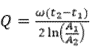
次に、本実施形態で送電装置100が時間領域でQ値を測定するための処理について図12(B)を参照して説明する。波形1203は、送電コイル303に印加される高周波電圧の値を示しており、その周波数は、Qi規格で使用される110kHzから148.5kHzの間の周波数である。また、点1204および点1205は、電圧値の包絡線の一部である。送電装置100の送電部302は、時間T0からT5の区間、送電を停止する。送電装置100の第2Q値測定部401は、時間T3における電圧値A3(点1204)、時間T4における電圧値A4(点1205)および高周波電圧の動作周波数と(式1)に基づいて、Q値を測定する。なお、送電装置100の送電部302は、時間T5において送電を再開する。このように、第2Q値測定は、送電装置100が送電を瞬断し時間経過と電圧値および動作周波数に基づいてQ値を測定することにより行われる。 Next, the process for the power transmitting device 100 to measure the Q value in the time domain in this embodiment will be described with reference to FIG. 12B. A waveform 1203 shows the value of the high-frequency voltage applied to the power transmitting coil 303, and the frequency is between 110 kHz and 148.5 kHz used in the Qi standard. Points 1204 and 1205 are part of the envelope of the voltage value. The power transmitting unit 302 of the power transmitting device 100 stops power transmission during the period from time T0 to T5 . The second Q value measuring unit 401 of the power transmitting device 100 measures the Q value based on the voltage value A3 (point 1204) at time T3 , the voltage value A4 (point 1205) at time T4 , the operating frequency of the high-frequency voltage, and (Equation 1). The power transmitting unit 302 of the power transmitting device 100 resumes power transmission at time T5 . In this way, the second Q value measurement is performed by the power transmitting device 100 momentarily interrupting power transmission and measuring the Q value based on the elapsed time, the voltage value, and the operating frequency.

なお、第3異物検出方法において、(T3、A3)、(T4、A4)を測定すればよく、第2Q値を測定しなくてもよい。すなわち、(式1)で示すように、T4-T3の値と、A3に対するA4の比率(A4/A3)またはA3のA4に対する比率(A3/A4)の値に基づく指標を用いることで、異物の有無を検出するようにしてもよい。具体的には、その指標と閾値とを比較することにより、異物の有無を検出すればよい。 In the third foreign object detection method, it is only necessary to measure ( T3 , A3 ) and ( T4 , A4 ), and it is not necessary to measure the second Q value. That is, as shown in (Equation 1), the presence or absence of a foreign object may be detected by using an index based on the value of T4 - T3 and the ratio of A4 to A3 ( A4 / A3 ) or the ratio of A3 to A4 ( A3 / A4 ). Specifically, the presence or absence of a foreign object may be detected by comparing the index with a threshold value.

また、第3異物検出方法において、電圧値の代わりに電流値を測定し、その電流値の比に基づく指標を用いて、異物の有無を検出してもよい。すなわち、T3における電流値、及び、時間T4における電流値を測定すればよい。また、電流値に基づいて第2Q値を取得してもよい。 In the third foreign object detection method, the current value may be measured instead of the voltage value, and the presence or absence of a foreign object may be detected using an index based on the ratio of the current values. That is, the current value at time T3 and the current value at time T4 may be measured. The second Q value may be obtained based on the current value.

(従来の送電装置および受電装置の動作)
従来の送電装置100と受電装置102の動作について図6Aを用いて説明する。図6Aの説明では、送電装置100と受電装置102は、それぞれ、WPC規格v1.2.3に準拠した送電装置および受電装置であるとする。
(Operation of conventional power transmitting device and power receiving device)
The operation of the conventional power transmitting device 100 and power receiving device 102 will be described with reference to Fig. 6A. In the description of Fig. 6A, it is assumed that the power transmitting device 100 and power receiving device 102 are, respectively, power transmitting device and power receiving device compliant with WPC standard v1.2.3.

送電装置100は、送電コイル303の近傍に存在する物体を検出する為にAnalog Pingを送電する(F600)。Analog Pingは、パルス状の電力で、物体を検出するための電力である。また、Analog Pingは、受電装置102がこれを受電したとしても、制御部200を起動することができない程度の微小な電力である。送電装置100は、Analog Pingにより、送電コイル303の近傍に存在する物体に起因する送電コイル303内部の電圧値の共振周波数のシフトや、送電コイル303を流れる電圧値・電流値の変化によって物体を検出する。送電装置100は、Analog Pingにより物体を検出すると、上述の第1Q値測定により送電コイル303のQ値を測定する(F601)。そして、送電装置100は、第1Q値測定に続いて、Digital Pingの送電を開始する(F602)。Digital Pingは、受電装置102の制御部200を起動させるための電力であり、Analog Pingよりも大きい電力である。また、Digital Pingは、以降、連続的に送電される。すなわち、送電装置100は、Digital Pingの送電を開始してから(F602)、受電装置102から後述のEPT(End Power Transfer)パケットの受信(F622)まで、Digital Ping以上の電力を送電し続ける。 The power transmitting device 100 transmits an Analog Ping to detect an object in the vicinity of the power transmitting coil 303 (F600). The Analog Ping is a pulsed power for detecting an object. Even if the power receiving device 102 receives the Analog Ping, the Analog Ping is a very small power that cannot start the control unit 200. The power transmitting device 100 detects an object by the Analog Ping, based on a shift in the resonant frequency of the voltage value inside the power transmitting coil 303 caused by an object in the vicinity of the power transmitting coil 303, or a change in the voltage value and current value flowing through the power transmitting coil 303. When the power transmitting device 100 detects an object by the Analog Ping, it measures the Q value of the power transmitting coil 303 by the first Q value measurement described above (F601). Then, following the first Q value measurement, the power transmitting device 100 starts transmitting a Digital Ping (F602). The Digital Ping is power for starting the control unit 200 of the power receiving device 102, and is a power greater than that of the Analog Ping. The Digital Ping is transmitted continuously thereafter. That is, the power transmitting device 100 continues to transmit power equal to or greater than that of the Digital Ping from the time when it starts transmitting the Digital Ping (F602) until it receives an End Power Transfer (EPT) packet (described later) from the power receiving device 102 (F622).

受電装置102は、Digital Pingを受電して起動すると、受電したDigital Pingの電圧値をSignal Strengthパケットに格納して送電装置100へ送信する(F603)。続いて、受電装置102は、受電装置102が準拠しているWPC規格のバージョン情報やデバイス識別情報を含むIDを格納したIDパケットを送電装置100へ送信する(F604)。さらに、受電装置102は、電圧制御部203が負荷(充電部205)へ供給する電力の最大値等の情報を含んだConfigurationパケットを送電装置100へ送信する(F605)。送電装置100は、IDパケットおよびConfigurationパケットを受信する。そして、送電装置100は、これらのパケットによって受電装置102がWPC規格v1.2以降の(後述のNegotiationを含む)拡張プロトコルに対応していると判定すると、ACKで応答する(F606)。 When the power receiving device 102 receives a Digital Ping and starts up, it stores the voltage value of the received Digital Ping in a Signal Strength packet and transmits it to the power transmitting device 100 (F603). Next, the power receiving device 102 transmits to the power transmitting device 100 an ID packet that stores an ID including version information of the WPC standard to which the power receiving device 102 complies and device identification information (F604). Furthermore, the power receiving device 102 transmits to the power transmitting device 100 a Configuration packet that includes information such as the maximum value of the power that the voltage control unit 203 supplies to the load (charging unit 205) (F605). The power transmitting device 100 receives the ID packet and the Configuration packet. If the power transmitting device 100 determines from these packets that the power receiving device 102 supports an extended protocol (including Negotiation, described below) of the WPC standard v1.2 or later, it responds with an ACK (F606).

受電装置102は、ACKを受信すると、送受電する電力の交渉などを行うNegotiationフェーズに遷移する。まず、受電装置102は、送電装置100に対してFOD Statusパケットを送信する(F607)。本実施形態では、このFOD Statusパケットを「FOD(Q1)」と呼ぶ。送電装置100は、受信したFOD(Q1)に格納されているQ値(周波数領域で測定されたQ値)と第1Q値測定で測定したQ値とに基づいて、第1異物検出方法により異物検出を行う。そして、送電装置100は、異物がない可能性が高いと判定した場合に、その判定結果を示すACKを受電装置102に送信する(F608)。 When the power receiving device 102 receives the ACK, it transitions to the Negotiation phase in which it negotiates the power to be transmitted and received. First, the power receiving device 102 transmits an FOD Status packet to the power transmitting device 100 (F607). In this embodiment, this FOD Status packet is called "FOD (Q1)". The power transmitting device 100 performs foreign object detection using the first foreign object detection method based on the Q value (Q value measured in the frequency domain) stored in the received FOD (Q1) and the Q value measured in the first Q value measurement. Then, if the power transmitting device 100 determines that there is a high possibility that there is no foreign object, it transmits an ACK indicating the determination result to the power receiving device 102 (F608).

受電装置102は、ACKを受信すると、受電装置102が受電を要求する電力値の最大値であるGuaranteed Power(GP)の交渉を行う。Guaranteed Powerは、送電装置100との間で合意された、受電装置102の負荷電力(バッテリ206が消費する電力)を示す。この交渉は、WPC規格で規定されているSpecific Requestのうち、受電装置102が、要求するGuaranteed Powerの値を格納したパケットを送電装置100へ送信することにより実現される(F609)。本実施形態では、このパケットを「SRQ(GP)」と呼ぶ。送電装置100は、自装置の送電能力等を考慮して、SRQ(GP)に応答する。送電装置100は、Guaranteed Powerを受け入れ可能であると判断した場合、その要求を受入れたことを示すACKを送信する(F610)。本実施形態では、受電装置102が、SRQ(GP)により、Guaranteed Powerとして15ワットを要求したものとする。受電装置102は、Guaranteed Powerを含む複数のパラメータの交渉が終了すると、Specific Requestのうち、交渉の終了(End Negotiation)を要求する「SRQ(EN)」を送電装置に送信する(F611)。そして、送電装置100は、SRQ(EN)に対してACKを送信し(F612)、Negotiationを終了して、Guaranteed Powerで定められた電力の送受電を行うPower Transferフェーズに遷移する。 When the power receiving device 102 receives the ACK, it negotiates Guaranteed Power (GP), which is the maximum power value that the power receiving device 102 requests to receive. Guaranteed Power indicates the load power of the power receiving device 102 (power consumed by the battery 206) agreed upon with the power transmitting device 100. This negotiation is realized by the power receiving device 102 transmitting a packet that stores the requested Guaranteed Power value from the Specific Request defined in the WPC standard to the power transmitting device 100 (F609). In this embodiment, this packet is called "SRQ (GP)". The power transmitting device 100 responds to the SRQ (GP) taking into account the power transmitting capacity of its own device, etc. When the power transmitting device 100 determines that the Guaranteed Power is acceptable, the power transmitting device 100 transmits an ACK indicating that the request has been accepted (F610). In this embodiment, it is assumed that the power receiving device 102 has requested 15 watts as the Guaranteed Power by SRQ (GP). When the power receiving device 102 finishes the negotiation of a plurality of parameters including the Guaranteed Power, the power receiving device 102 transmits, to the power transmitting device, an "SRQ (EN)" requesting the end of the negotiation (End Negotiation) among the Specific Requests (F611). Then, the power transmitting device 100 transmits an ACK in response to the SRQ (EN) (F612), ends the negotiation, and transitions to the Power Transfer phase in which the power determined by the Guaranteed Power is transmitted and received.

続いて、送電装置100は、上述したパワーロス手法に基づく異物検出(第2異物検出方法)を実行する。まず、送電装置100は、RP1を受電装置102から受信する(F613)。送電装置100は、RP1に格納されている受電電力値と、その受電電力が得られたときの送電装置100の送電電力値を、Calibration data Point(図11の点1100に対応)として受け入れる。そして、送電装置100は、Calibration data Pointの受け入れを示すACKを、受電装置102へ送信する(F614)。 Then, the power transmitting device 100 executes foreign object detection based on the power loss method described above (second foreign object detection method). First, the power transmitting device 100 receives RP1 from the power receiving device 102 (F613). The power transmitting device 100 accepts the received power value stored in RP1 and the transmitted power value of the power transmitting device 100 when the received power was obtained as a calibration data point (corresponding to point 1100 in FIG. 11). Then, the power transmitting device 100 transmits an ACK indicating the acceptance of the calibration data point to the power receiving device 102 (F614).

受電装置102は、ACKを受信後、送電装置100に対して受電電圧(または受電電流、受電電力)の増減を要求するControl Error(以後、CEと表現する)を送電装置100に送信する。CEには、符号および数値が格納され、符号がプラスであれば、電力を上げることを要求することを、マイナスであれば電力を下げることを要求することを、数値がゼロであれば電力の維持を要求することを、それぞれ意味する。ここでは、受電装置102は、電力を上げることを示すCE(+)を、送電装置100に送信する(F615)。 After receiving the ACK, the power receiving device 102 transmits a Control Error (hereafter referred to as CE) to the power transmitting device 100, requesting that the power transmitting device 100 increase or decrease the receiving voltage (or receiving current, receiving power). A sign and a value are stored in CE, and a positive sign indicates a request to increase the power, a negative sign indicates a request to decrease the power, and a zero value indicates a request to maintain the power. Here, the power receiving device 102 transmits a CE (+), indicating an increase in power, to the power transmitting device 100 (F615).

送電装置100は、CE(+)を受信すると、送電部302の設定値を変更して、送電電力を上げる(F616)。受電装置102は、CE(+)に応答して受電電力が上昇すると、受電した電力を負荷(充電部205やバッテリ206)に供給し、RP2を送電装置100に送信する(F617)。送電装置100は、RP2に格納されている受電電力値とその時の送電装置100の送電電力値を、Calibration data Point(図11の点1101に対応)として受け入れる。そして、送電装置100は、Calibration data Pointの受け入れを示すACKを、受電装置102へ送信する(F618)。この時点で、送電装置100は、2つのCalibration data Point(図11の点1100と点1101)を取得しているため、Calibrationカーブ(図11の直線1102)を導出することができる。 When the power transmitting device 100 receives CE(+), it changes the setting value of the power transmitting unit 302 to increase the transmission power (F616). When the power receiving device 102 increases the received power in response to CE(+), it supplies the received power to the load (the charging unit 205 or the battery 206) and transmits RP2 to the power transmitting device 100 (F617). The power transmitting device 100 accepts the received power value stored in RP2 and the transmission power value of the power transmitting device 100 at that time as a Calibration data point (corresponding to point 1101 in FIG. 11). Then, the power transmitting device 100 transmits an ACK indicating the acceptance of the Calibration data point to the power receiving device 102 (F618). At this point, the power transmission device 100 has acquired two calibration data points (points 1100 and 1101 in FIG. 11), so it is possible to derive a calibration curve (straight line 1102 in FIG. 11).

送電装置100および受電装置102は、この時点でPower Transferフェーズに遷移しており、送電装置100は、受電装置102がNegotiationフェーズで交渉した最大15ワットを受電可能な電力を送電している。受電装置102は、送電装置100に対して、送電電力の維持を要求するCEおよび現在の受電電力値を格納したRP0を送電装置100に定期的に送信する(F619、F620)。送電装置100は、受電装置102からRP0を受信すると、上述の第2異物検出方法に基づいて、異物検出を行う。送電装置100は、異物検出の結果、異物がない可能性が高いと判定した場合、ACKを受電装置102に送信する(F621)。その後、受電装置102は、バッテリ206への充電が終了すると、送電装置100に対して送電を停止することを要求するEPT(End Power Transfer)パケットを送信する(F622)。 At this point, the power transmitting device 100 and the power receiving device 102 have transitioned to the Power Transfer phase, and the power transmitting device 100 is transmitting the maximum 15 watts of power that the power receiving device 102 can receive, negotiated in the Negotiation phase. The power receiving device 102 periodically transmits to the power transmitting device 100 a CE requesting the power transmitting device 100 to maintain the transmitted power, and an RP0 that stores the current received power value (F619, F620). When the power transmitting device 100 receives RP0 from the power receiving device 102, it performs foreign object detection based on the second foreign object detection method described above. If the power transmitting device 100 determines that there is a high possibility that there is no foreign object as a result of the foreign object detection, it transmits an ACK to the power receiving device 102 (F621). After that, when charging of the battery 206 is completed, the power receiving device 102 transmits an EPT (End Power Transfer) packet to the power transmitting device 100 requesting that power transmission be stopped (F622).

以上のようにして、WPC規格v1.2.3に準拠した送電装置100と受電装置102との間で無線電力伝送が行われる。 In this manner, wireless power transmission is performed between the power transmitting device 100 and the power receiving device 102 that comply with the WPC standard v1.2.3.

図6Aの処理例に示すように、Power Transferフェーズの間は、Power Loss法による異物検出が行われる。しかし、1つの異物検出方法のみでは、異物がないにも関わらず異物があると誤検出することや、反対に異物があるにも関わらず異物がないと判定されてしまう可能性が一定程度残ってしまう。これに対して、複数の異物検出方法を組み合わせて実行すれば、異物検出の精度向上が期待できる。特に、Power Transferフェーズは、TXが送電を行うフェーズであり、送電中に、TXとRXの間に異物があすると、異物からの発熱等が大きくなる。なお、異物はTXとRXの間になくても、送電可能範囲に存在することで、電力を受けて発熱してしまう。このため、このフェーズにおいて複数の異物検出を実行して、異物検出精度を向上させるメリットは大きい。そこで、本実施形態では、Power Transferフェーズにおいて、Power Loss法とは異なる異物検出方法を導入する。 As shown in the processing example of FIG. 6A, foreign object detection is performed by the Power Loss method during the Power Transfer phase. However, with only one foreign object detection method, there is a certain degree of possibility that a foreign object may be erroneously detected as being present when there is no foreign object, or conversely, that a foreign object may be determined to be absent when there is a foreign object. In contrast, by combining and executing multiple foreign object detection methods, it is possible to expect an improvement in the accuracy of foreign object detection. In particular, the Power Transfer phase is a phase in which the TX transmits power, and if a foreign object is present between the TX and the RX during power transmission, the heat generated by the foreign object increases. Note that even if a foreign object is not between the TX and the RX, it will receive power and generate heat if it is present within the range in which power can be transmitted. For this reason, there is a great advantage in improving the accuracy of foreign object detection by performing multiple foreign object detections in this phase. Therefore, in this embodiment, a foreign object detection method different from the Power Loss method is introduced in the Power Transfer phase.

ここで、周波数領域において測定されたQ値(第1Q値)に基づく異物検出(第1異物検出方法)は、測定のたびに共振周波数を探すために周波数を掃引する。送電装置100がDigital PingやPower Transferフェーズのなど比較的大きな電力を送電中にこのような掃引が実行されると、送電部302のスイッチングノイズの増大の原因となりうる。一方で、時間領域において測定されたQ値(第2Q値)に基づく異物検出(第3異物検出方法)は、単一の周波数で実行可能であり、周波数を掃引する必要がない。このため、Digital PingやPower Transferフェーズの送電時の動作周波数で実行可能であり、スイッチングノイズへの影響が少ない。本実施形態では、第2Q値測定において、送電装置が送電を停止した際に、スイッチ208をオンにし、受電コイル201と共振コンデンサ207を含む閉回路を構成する制御を行う。これにより、受電装置102における負荷の変動の影響を取り除いた状態で、第2Q値の測定を行う。 Here, in the foreign object detection based on the Q value (first Q value) measured in the frequency domain (first foreign object detection method), the frequency is swept to search for the resonant frequency each time the measurement is performed. If such a sweep is performed while the power transmitting device 100 is transmitting relatively large power such as in the Digital Ping or Power Transfer phase, it may cause an increase in switching noise of the power transmitting unit 302. On the other hand, the foreign object detection based on the Q value (second Q value) measured in the time domain (third foreign object detection method) can be performed at a single frequency and does not require frequency sweeping. Therefore, it can be performed at the operating frequency during power transmission in the Digital Ping or Power Transfer phase, and has little effect on switching noise. In this embodiment, in the second Q value measurement, when the power transmitting device stops transmitting power, the switch 208 is turned on and a closed circuit including the receiving coil 201 and the resonant capacitor 207 is controlled to be formed. This allows the second Q value to be measured while removing the effects of load fluctuations in the power receiving device 102.

第3異物検出方法をWPC規格に適用する場合、受電装置102の装置構成は様々な態様が想定されるため、送電装置100が、受電装置102の能力に応じて行う処理を適切に制御する必要がある。例えば、送電装置100が閉回路を構成する制御ができない受電装置102に対して第2Q値測定を実行すると、その測定が、受電装置102の負荷の変動の影響を受けて、Q値を正しく測定することができない。また、第2Q値の測定は、受電装置102側において実行されることも想定されうるが、送電装置100は、受電装置102の能力がわからないと、自装置において第2Q値の測定を行うべきか否かを判定することができない。例えば、受電装置102が閉回路を構成可能であるが第2Q値の測定を実行することができない場合、送電装置100が第2Q値の測定を行わないと、異物の有無を判定することができない。同様に、受電装置102の能力がわからないと、送電装置100は、第2Q値の測定結果を受電装置102から受信する否かを判定することができない。例えば、受電装置102が第2Q値の測定を実行できないにも関わらず送電装置100が受電装置102から測定結果を受信しようとすると、不要な待機時間が発生してしまう。一方で、受電装置102が第2Q値の測定ができるにも関わらず、送電装置100が測定結果を受電装置102から受信しないと、送電装置100と受電装置102の間に状態ずれが発生してしまう。このため、本実施形態では、第2Q値の測定に基づく第3異物検出方法を適切にWPC規格に適用するための制御手法を使用する。以下では、この制御手法について説明する。 When applying the third foreign object detection method to the WPC standard, various configurations of the power receiving device 102 are assumed, so it is necessary for the power transmitting device 100 to appropriately control the processing performed according to the capabilities of the power receiving device 102. For example, if the power transmitting device 100 performs the second Q value measurement on the power receiving device 102 that cannot be controlled to form a closed circuit, the measurement will be affected by fluctuations in the load of the power receiving device 102 and the Q value cannot be measured correctly. It can also be assumed that the second Q value measurement will be performed on the power receiving device 102 side, but if the power transmitting device 100 does not know the capabilities of the power receiving device 102, it cannot determine whether or not to measure the second Q value in its own device. For example, if the power receiving device 102 can form a closed circuit but cannot perform the second Q value measurement, the power transmitting device 100 must measure the second Q value to determine the presence or absence of a foreign object. Similarly, if the capability of the power receiving device 102 is unknown, the power transmitting device 100 cannot determine whether to receive the measurement result of the second Q value from the power receiving device 102. For example, if the power transmitting device 100 attempts to receive the measurement result from the power receiving device 102 even though the power receiving device 102 cannot perform the measurement of the second Q value, unnecessary waiting time occurs. On the other hand, if the power transmitting device 100 does not receive the measurement result from the power receiving device 102 even though the power receiving device 102 can measure the second Q value, a state mismatch occurs between the power transmitting device 100 and the power receiving device 102. For this reason, in this embodiment, a control method is used to appropriately apply the third foreign object detection method based on the measurement of the second Q value to the WPC standard. This control method will be described below.

(第3異物検出方法をWPC規格に適用した場合の動作説明)
図6Bに本実施形態に係る送電装置100及び受電装置102によって実行される処理の流れの例を示す。なお、図6Aと同じ処理については同じ符号を付して説明を省略する。F600~F604の処理の実行後、受電装置102は、Configurationパケットを送電装置100に送信する(F623)。本実施形態では、このConfiguration Packetにおいて、受電装置102の能力情報が送電装置100へ通知される。通知される能力情報として、本実施形態では、Configuration Packet内に、Short Ability bitとMeasure Ability bitとを定義する。Short Ability bitは、受電装置102が第2Q値測定のために受電コイル201と共振コンデンサ207を含む閉回路を構成する制御が可能であるか否かを示す情報である。受電装置102は、例えば、自装置が第2Q値測定のために閉回路を構成する制御を行う能力を持っている場合はShort Ability bitに「1」を、そうでない場合は「0」を格納する。また、Measure Ability bitは、受電装置102が受電回路の第2Q値の測定を実行可能であるか否かを示す情報である。受電装置102は、例えば、自装置が受電回路の第2Q値の測定する能力を持っている場合はMeasure Ability bitに「1」を、そうでない場合は「0」を格納する。なお、これらの情報は、送電装置100によって実行される第2Q値の測定に基づく異物判定に関連付けられた所定の処理を、受電装置102が実行可能であるかを示す情報でありうる。すなわち、閉回路が構成可能であるか否かや、受電回路の第2Q値の測定を実行可能であるかは、この所定の処理の一類型に過ぎず、これら以外の処理についての情報ビットが受電装置102から送電装置100へ送信されてもよい。
(Description of operation when the third foreign object detection method is applied to the WPC standard)
6B shows an example of the flow of processing executed by the power transmitting device 100 and the power receiving device 102 according to this embodiment. Note that the same processes as those in FIG. 6A are denoted by the same reference numerals and will not be described. After executing the processes of F600 to F604, the power receiving device 102 transmits a Configuration packet to the power transmitting device 100 (F623). In this embodiment, the capability information of the power receiving device 102 is notified to the power transmitting device 100 in this Configuration Packet. In this embodiment, a Short Ability bit and a Measure Ability bit are defined in the Configuration Packet as the capability information to be notified. The Short Ability bit is information indicating whether the power receiving device 102 is capable of controlling the configuration of a closed circuit including the power receiving coil 201 and the resonant capacitor 207 for the second Q value measurement. For example, if the power receiving device 102 has the ability to control the configuration of a closed circuit for the second Q value measurement, the Short Ability bit stores "1" and if not, stores "0". The Measure Ability bit is information indicating whether the power receiving device 102 is capable of measuring the second Q value of the power receiving circuit. For example, if the power receiving device 102 has the ability to measure the second Q value of the power receiving circuit, the Measure Ability bit stores "1" and if not, stores "0". These pieces of information may be information indicating whether the power receiving device 102 can execute a predetermined process associated with a foreign object determination based on the measurement of the second Q value executed by the power transmitting device 100. In other words, whether a closed circuit can be configured or whether the measurement of the second Q value of the power receiving circuit can be executed is merely one type of this predetermined process, and information bits regarding processes other than these may be transmitted from the power receiving device 102 to the power transmitting device 100.

図13に、WPC規格v1.2.3のConfiguration Packetの構成を示す。なお、ここでは、本実施形態と関連しない部分の説明については省略する。WPC規格v1.2.3のConfiguration Packetは、複数のReserved領域を含んでいる。すなわち、Bank1のbit0からbit7の領域1300、Bank2のbit4からbit6の領域1301、Bank4のbit0からbit2の領域1302が、それぞれReserved領域である。本実施形態では、一例として、Short Ability bitをBank4のbit2に配置し、Measure Ability bitをBank4のbit1に配置する。なお、他のReserved領域にこれらのビットが配置されてもよい。また、これらのビットに代えて、WPC規格のバージョンを示す情報などがReserved領域に配置されてもよい。この場合、バージョンによって、受電装置102が第2Q値測定のために受電コイル201と共振コンデンサ207を含む閉回路を構成する制御が可能であるか否か、及び、受電装置102が受電回路の第2Q値の測定を実行可能であるか否か、が示されうる。例えば、将来のWPC規格のバージョンにおいて、そのバージョン準拠の受電装置102がこれらの機能を有することが必須であると規定されうる。この場合、Configuration Packetで、受電装置102のバージョン情報が通知されることによって、送電装置100は、その受電装置102がこれらの機能を有するか否かを特定することができる。なお、WPC規格v1.2.3では、上述のReserved領域のビットはいずれも0である。また、第3異物検出方法を使用できない送電装置100は、これらのReserved領域に格納されている値については無視する。 Figure 13 shows the configuration of the Configuration Packet of the WPC standard v1.2.3. Note that the description of the parts that are not related to this embodiment will be omitted here. The Configuration Packet of the WPC standard v1.2.3 includes multiple Reserved areas. That is, the area 1300 from bit 0 to bit 7 of Bank 1, the area 1301 from bit 4 to bit 6 of Bank 2, and the area 1302 from bit 0 to bit 2 of Bank 4 are each Reserved areas. In this embodiment, as an example, the Short Ability bit is placed in bit 2 of Bank 4, and the Measure Ability bit is placed in bit 1 of Bank 4. Note that these bits may be placed in other Reserved areas. In place of these bits, information indicating the version of the WPC standard may be placed in the reserved area. In this case, the version may indicate whether the power receiving device 102 is capable of controlling the power receiving device 102 to configure a closed circuit including the power receiving coil 201 and the resonant capacitor 207 for measuring the second Q value, and whether the power receiving device 102 is capable of measuring the second Q value of the power receiving circuit. For example, a future version of the WPC standard may specify that the power receiving device 102 conforming to that version must have these functions. In this case, the version information of the power receiving device 102 is notified in the Configuration Packet, so that the power transmitting device 100 can identify whether the power receiving device 102 has these functions. In the WPC standard v1.2.3, all of the bits in the reserved area described above are 0. In addition, a power transmitting device 100 that cannot use the third foreign object detection method ignores the values stored in these reserved areas.

なお、ここでは、Short Ability bitおよびMeasure Ability bitがConfiguration Packetに設定されて受電装置102から送電装置100に送信される場合について説明するが、これに限られない。例えば、WPC規格に規定されていない新たなパケットにこれらの情報が含められて送受信されてもよい。また、WPC規格に規定されている他のパケットにこれらの情報が含められて送受信されてもよい。 Here, a case will be described in which the Short Ability bit and the Measure Ability bit are set in the Configuration Packet and transmitted from the power receiving device 102 to the power transmitting device 100, but this is not limited thereto. For example, this information may be included in a new packet that is not defined in the WPC standard and transmitted/received. Also, this information may be included in another packet defined in the WPC standard and transmitted/received.

本実施形態では、受電装置102が、第2Q値測定のために受電コイル201と共振コンデンサ207を含む閉回路を構成する制御が可能であり、かつ、受電回路の第2Q値の測定を実行可能であるものとする。このため、受電装置102は、Short Ability bitに「1」を設定すると共に、Measure Ability bitにも「1」を設定したConfiguration Packetを、F623において送信する。送電装置100は、受信したConfiguration Packetに含まれるShort Ability bitおよびMeasure Ability bitを参照し、それらの値をメモリ305に記憶する。 In this embodiment, the power receiving device 102 is capable of controlling the configuration of a closed circuit including the power receiving coil 201 and the resonant capacitor 207 for measuring the second Q value, and is capable of measuring the second Q value of the power receiving circuit. For this reason, the power receiving device 102 sets the Short Ability bit to "1" and transmits a Configuration Packet in which the Measure Ability bit is also set to "1" in F623. The power transmitting device 100 refers to the Short Ability bit and the Measure Ability bit included in the received Configuration Packet, and stores these values in the memory 305.

送電装置100は、Configuration Packetの受信後、ACKで応答する(F606)。そして、受電装置102は、Configuration Packetに対するACKを受信すると、Negotiationフェーズに遷移する。そして、送電装置100および受電装置102は、Negotiationフェーズにおいて、第3異物検出に関する交渉を行う。受電装置102は、第2Q値測定において、送電装置100の送電部302が送電を停止までの時間である測定開始時間の交渉を行う。この交渉は、WPC規格で規定されているSpecific Requestのうち、要求する測定開始時間の値が格納されたパケットを受電装置102が送電装置100に送信することにより行われる(F631)。受電装置102は、自身の処理能力等に基づいて、要求する測定開始時間の値を決定して、送電装置100に対してその測定開始時間の値を格納したパケットを送信する。ここでは、このパケットを「SRQ(M1)」と呼ぶ。送電装置100は、自装置の処理能力等を考慮して、SRQ(M1)に応答する。送電装置100は、SRQ(M1)で示された値の測定開始時間を受け入れられると判定した場合はACKを、その測定開始時間を受け入れられないと判定した場合はNAKを、それぞれ送信する。ここでは、送電装置100が測定開始時間を受け入れられると判定してACKを送信したものとする(F632)。なお、ここでは、一例として、受電装置102が、SRQ(M1)においてQ値の測定開始時間として50msを要求したものとする。 After receiving the Configuration Packet, the power transmitting device 100 responds with an ACK (F606). Then, when the power receiving device 102 receives the ACK for the Configuration Packet, it transitions to the Negotiation phase. Then, in the Negotiation phase, the power transmitting device 100 and the power receiving device 102 negotiate regarding the third foreign object detection. In the second Q value measurement, the power receiving device 102 negotiates the measurement start time, which is the time until the power transmitting unit 302 of the power transmitting device 100 stops transmitting power. This negotiation is performed by the power receiving device 102 transmitting to the power transmitting device 100 a packet that stores the value of the requested measurement start time from the Specific Request defined in the WPC standard (F631). The power receiving device 102 determines the value of the requested measurement start time based on its own processing capacity, etc., and transmits a packet storing the value of the measurement start time to the power transmitting device 100. Here, this packet is called "SRQ (M1)". The power transmitting device 100 responds to the SRQ (M1) taking into account its own processing capacity, etc. If the power transmitting device 100 determines that the measurement start time indicated in the SRQ (M1) is acceptable, it transmits an ACK, and if it determines that the measurement start time is not acceptable, it transmits a NAK. Here, it is assumed that the power transmitting device 100 determines that the measurement start time is acceptable and transmits an ACK (F632). Note that, as an example, it is assumed that the power receiving device 102 requests 50 ms as the measurement start time of the Q value in the SRQ (M1).

受電装置102は、第2Q値測定において送電装置100の送電部302が送電を停止する区間(時間T0から時間T5までの区間)の区間長であるWindow長の交渉を行う。この交渉は、WPC規格で規定されているSpecific Requestのうち、受電装置102が、要求するWindow長の値が格納されたパケットを送電装置100に送信することにより行われる(F633)。ここでは、このパケットを「SRQ(M2)」と呼ぶ。受電装置102は、自装置の処理能力等に基づいてWindow長の値を決定して、送電装置100に対して、決定したWindow長の値を格納したパケットを送信する。送電装置100は、自装置の処理能力等を考慮して、SRQ(M2)に応答する。送電装置100は、SRQ(M2)において示された値のWindow長を受け入れられると判定した場合はACKを、そのWindow長を受け入れられないと判定した場合はNAKを、それぞれ送信する。ここで、送電装置100は、Window長を受け入れられると判定してACKを送信したものとする(F634)。なお、ここでは、一例として、受電装置102が、SRQ(M2)においてWindow長として100msを要求したものとする。 The power receiving device 102 negotiates a window length, which is the length of the section (the section from time T0 to time T5 ) during which the power transmitting unit 302 of the power transmitting device 100 stops transmitting power in the second Q value measurement. This negotiation is performed by the power receiving device 102 transmitting a packet containing the requested window length value of the Specific Request defined in the WPC standard to the power transmitting device 100 (F633). Here, this packet is called "SRQ (M2)". The power receiving device 102 determines the window length value based on the processing capacity of its own device, and transmits a packet containing the determined window length value to the power transmitting device 100. The power transmitting device 100 responds to the SRQ (M2) taking into account the processing capacity of its own device, etc. If the power transmitting device 100 determines that the window length indicated in the SRQ (M2) is acceptable, it transmits an ACK, and if it determines that the window length is unacceptable, it transmits a NAK. Here, it is assumed that the power transmitting device 100 determines that the window length is acceptable and transmits an ACK (F634). Note that, as an example, it is assumed here that the power receiving device 102 requests a window length of 100 ms in the SRQ (M2).

また、受電装置102は、第2Q値測定において受電装置102が計測したQ値を送電装置100が受電装置102から受け付ける時間である、タイムアウト長に関する交渉を行う。この交渉は、WPC規格で規定されているSpecific Requestのうち、要求するタイムアウト長の値が格納されたパケットを受電装置102が送電装置100に送信することにより行われる(F635)。ここでは、このパケットを「SRQ(M3)」と呼ぶ。受電装置102は、自装置の処理能力等に基づいてタイムアウト長の値を決定して、送電装置100に対して、そのタイムアウト長の値を格納したパケットを送信する。送電装置100は、自装置の処理能力等を考慮して、SRQ(M3)に応答する。送電装置100は、タイムアウト長を受け入れられると判定した場合はACKを、タイムアウト長を受け入れられないと判定した場合はNAKを、それぞれ送信する。ここで送電装置100は、タイムアウト長を受け入れられると判断し、ACKを送信する(F636)。本実施形態では、受電装置102がSRQ(M3)でタイムアウト長として500msを要求したとする。 In addition, the power receiving device 102 negotiates the timeout length, which is the time for the power transmitting device 100 to accept the Q value measured by the power receiving device 102 in the second Q value measurement from the power receiving device 102. This negotiation is performed by the power receiving device 102 transmitting a packet in which the requested timeout length value is stored, among the Specific Requests defined in the WPC standard, to the power transmitting device 100 (F635). Here, this packet is called "SRQ (M3)". The power receiving device 102 determines the value of the timeout length based on the processing capabilities of its own device, etc., and transmits a packet in which the timeout length value is stored to the power transmitting device 100. The power transmitting device 100 responds to the SRQ (M3) taking into account the processing capabilities of its own device, etc. If the power transmitting device 100 determines that the timeout length is acceptable, it transmits an ACK, and if it determines that the timeout length is not acceptable, it transmits a NAK. Here, the power transmitting device 100 determines that the timeout length is acceptable and transmits an ACK (F636). In this embodiment, it is assumed that the power receiving device 102 has requested a timeout length of 500 ms in the SRQ (M3).

ここで、一例において、Specific Requestのうちのv1.2.3で定義されていないTypeを、測定開始時間、Window長、タイムアウト長のそれぞれのネゴシエーションに割り当てうる。Measure Delay Reqは、測定開始時間の変更を送電装置100に要求するパケットである。Window Length Reqは、Window長の変更を送電装置100に要求するパケットである。Timeout Reqは、タイムアウト長の変更を送電装置100に要求するパケットである。これらの3つのパケットは、WPC規格v1.2.3においてパケットタイプが規定されていないReserved Packetである。本実施形態では、これらのReserved Packetのうち、パケットヘッダが0x40のパケットをMeasure Delay Reqパケットとして定義する。同様に、パケットヘッダが0x41のパケットをWindow Length Reqパケットとして定義し、パケットヘッダが0x42のパケットをTimeout Reqパケットとして定義する。 Here, in one example, a Type of Specific Request that is not defined in v1.2.3 may be assigned to each negotiation of the measurement start time, window length, and timeout length. Measure Delay Req is a packet that requests the power transmitting device 100 to change the measurement start time. Window Length Req is a packet that requests the power transmitting device 100 to change the window length. Timeout Req is a packet that requests the power transmitting device 100 to change the timeout length. These three packets are Reserved Packets whose packet types are not specified in the WPC standard v1.2.3. In this embodiment, among these Reserved Packets, packets with a packet header of 0x40 are defined as Measure Delay Req packets. Similarly, packets with a packet header of 0x41 are defined as Window Length Req packets, and packets with a packet header of 0x42 are defined as Timeout Req packets.

また、WPC規格v1.2.3で定義されているパケットのうちSpecific RequestやGeneral Requestではなく、タイプが定義されていないパケットを、上述の3つのパケットとして定義してもよい。例えば、Specific RequestやGeneral Requestではなく、Packet typeが未定義のReserved PacketやProprietary Packetパケットが、上述の3つのパケットとして定義されうる。また、WPC規格v1.2.3で定義されているGeneral RequestやSpecific Requestのうち、Packet typeが未定義のパケットを、上述の3つのパケットとして定義してもよい。すなわち、General RequestやSpecific RequestのうちのPacket typeが未定義のReserved PacketやProprietary Packetが、上述の3つのパケットとして定義されうる。 In addition, among the packets defined in the WPC standard v1.2.3, packets whose type is not defined, other than Specific Request or General Request, may be defined as the above three packets. For example, instead of Specific Request or General Request, packets whose packet type is not defined, such as Reserved Packet or Proprietary Packet, may be defined as the above three packets. In addition, among the packets defined in the WPC standard v1.2.3, packets whose packet type is not defined, such as General Request or Specific Request, may be defined as the above three packets. In other words, General Request and Specific Request, which have an undefined packet type, such as Reserved Packet or Proprietary Packet, can be defined as the three packets mentioned above.

図6Bに戻り、Negotiationフェーズにおいて、F607からF612までの処理が実行されると、Negotiationフェーズが終了し、Power Transferフェーズに遷移する。Power Transferフェーズでは、上述のF613からF617までの処理が実行される。ここで、受電装置102がF618でACKを受信した直後に、Operating Volumeに異物が置かれたものとする。受電装置102は、送電装置100に対して、送電電力の維持を要求するCEおよび現在の受電電力値を格納したRP0を送電装置100に送信する(F619、F620)。 Returning to FIG. 6B, when the processes from F607 to F612 are executed in the Negotiation phase, the Negotiation phase ends and the system transitions to the Power Transfer phase. In the Power Transfer phase, the processes from F613 to F617 described above are executed. Here, it is assumed that a foreign object is placed on the Operating Volume immediately after the power receiving device 102 receives an ACK in F618. The power receiving device 102 transmits to the power transmitting device 100 a CE requesting the power transmitting device 100 to maintain the transmitted power, and an RP0 that stores the current received power value (F619, F620).

送電装置100は、受電装置102からRP0を受信すると、上述の第2異物検出方法に基づいて異物検出を行う。送電装置100は、異物検出の結果、異物がある可能性が高いと判定し、NAKを受電装置102に送信する(F624)。受電装置102は、送電装置100からNAKを受信すると、異物の有無をより詳細に測定するため、第3異物検出の開始を要求するパケットであるQ2Rを送電装置100に送信する(F625)。Q2Rパケットは、例えば、WPC規格におけるReceived PowerパケットのReservedビットにQ2Rパケットであることを示す値を設定したパケットであるが、これに限られない。例えば、受電装置102は、未定義のReceived Powerパケットのモードを用いて第3異物検出の開始を要求してもよいし、新たなパケットを定義して第3異物検出の開始を要求してもよい。また、本実施形態では、受電装置102がQ2Rパケットを用いて第3異物検出の開始を要求する場合について説明しているが、Q2Rパケットを用いずに、RP2に対するNAK応答を契機に第3異物検出が開始されてもよい。 When the power transmitting device 100 receives RP0 from the power receiving device 102, it performs foreign object detection based on the second foreign object detection method described above. As a result of the foreign object detection, the power transmitting device 100 determines that there is a high possibility of a foreign object, and transmits a NAK to the power receiving device 102 (F624). When the power receiving device 102 receives a NAK from the power transmitting device 100, it transmits a Q2R, which is a packet requesting the start of third foreign object detection, to the power transmitting device 100 in order to measure the presence or absence of a foreign object in more detail (F625). The Q2R packet is, for example, a packet in which a value indicating that it is a Q2R packet is set in the Reserved bit of a Received Power packet in the WPC standard, but is not limited to this. For example, the power receiving device 102 may request the start of third foreign object detection using an undefined Received Power packet mode, or may define a new packet to request the start of third foreign object detection. Also, in this embodiment, a case is described in which the power receiving device 102 requests the start of third foreign object detection using a Q2R packet, but third foreign object detection may be started in response to a NAK response to RP2 without using a Q2R packet.

送電装置100は、Q2Rを受信すると、第3異物検出を実行するか否かを判定し、実行すると判定した場合はACKを、実行しないと判定した場合はNAKを、受電装置102に対して送信する。ここでは、送電装置100は、第3異物検出を行うと判定したものとする。この場合、送電装置100は、受電装置102へACKを送信する(F626)。ACKの送信が完了すると、送電装置100及び受電装置102は、第3異物検出を開始する。第3異物検出において、送電装置100および受電装置102は、第2Q値の測定を行う(F629、F630)。受電装置102は、第2Q値の測定後、自装置において測定した第2Q値をパケット(QRS)に格納し、送電装置100に対してこのQRSを送信する(F627)。なお、QRSは、少なくとも受電装置102が測定した第2Q値を含むパケットであるが、現在の受電電力値など他の情報を含んでもよい。送電装置100は、受電装置102からQRSを受信すると、受信した受電装置102の第2Q値と、自装置において測定した第2Q値とに基づいて、異物の有無を判定する。送電装置100で測定された第2Q値に加え、受電装置102で測定された第2Q値を加えて異物の有無を判定することにより、より高い精度で異物の有無を判断することができる。送電装置100は異物があると判定した場合は受電装置102に対してNAKを送信し、異物がないと判定した場合は受電装置102に対してACKを送信する。ここでは、送電装置100は異物があると判定したものとする。この場合、送電装置100は、受電装置102へ、NAKを送信する(F628)。その後、送電装置100は、送電を停止する。 When the power transmitting device 100 receives Q2R, it determines whether or not to perform the third foreign object detection, and transmits an ACK to the power receiving device 102 if it determines to perform the third foreign object detection, or a NAK if it determines not to perform the third foreign object detection. Here, it is assumed that the power transmitting device 100 has determined to perform the third foreign object detection. In this case, the power transmitting device 100 transmits an ACK to the power receiving device 102 (F626). When the transmission of the ACK is completed, the power transmitting device 100 and the power receiving device 102 start the third foreign object detection. In the third foreign object detection, the power transmitting device 100 and the power receiving device 102 measure the second Q value (F629, F630). After measuring the second Q value, the power receiving device 102 stores the second Q value measured by the device itself in a packet (QRS) and transmits this QRS to the power transmitting device 100 (F627). The QRS is a packet including at least the second Q value measured by the power receiving device 102, but may include other information such as the current received power value. When the power transmitting device 100 receives the QRS from the power receiving device 102, the power transmitting device 100 determines whether or not there is a foreign object based on the received second Q value of the power receiving device 102 and the second Q value measured by the power receiving device 102 itself. By determining whether or not there is a foreign object by adding the second Q value measured by the power transmitting device 100 to the second Q value measured by the power receiving device 102, the presence or absence of a foreign object can be determined with higher accuracy. If the power transmitting device 100 determines that there is a foreign object, it transmits a NAK to the power receiving device 102, and if it determines that there is no foreign object, it transmits an ACK to the power receiving device 102. Here, it is assumed that the power transmitting device 100 determines that there is a foreign object. In this case, the power transmitting device 100 transmits a NAK to the power receiving device 102 (F628). After that, the power transmitting device 100 stops transmitting power.

(送電装置100における第3異物検出処理の流れ)
続いて、送電装置100における第3異物検出処理の流れの例について、図7を用いて説明する。送電装置100は、第3異物検出要求を受信した後、受電装置102が第2Q値測定のために受電コイル201と共振コンデンサ207とを含む閉回路を構成する制御を実行可能であるか否かを判定する(S701)。送電装置100は、例えば、Configurationフェーズにおいてメモリに保存したShort Ability bitを参照し、値が1であった場合、そのような制御が可能であると判定し(S701でYES)、処理をS702へ進める。一方、送電装置100は、Short Ability bitの値が0であった場合、そのような制御が可能でないと判定し(S701でNO)、NAKを送信して(S708)、処理を終了する。
(Flow of third foreign object detection process in power transmitting device 100)
Next, an example of the flow of the third foreign object detection process in the power transmitting device 100 will be described with reference to FIG. 7. After receiving the third foreign object detection request, the power transmitting device 100 determines whether the power receiving device 102 can execute control to configure a closed circuit including the power receiving coil 201 and the resonant capacitor 207 for measuring the second Q value (S701). For example, the power transmitting device 100 refers to the Short Ability bit stored in the memory in the Configuration phase, and if the value is 1, determines that such control is possible (YES in S701) and proceeds to S702. On the other hand, if the value of the Short Ability bit is 0, the power transmitting device 100 determines that such control is not possible (NO in S701), transmits a NAK (S708), and ends the process.

送電装置100は、S702において、受電装置102が受電回路の第2Q値の測定を実行可能であるか否かを判定する。送電装置100は、例えば、Configurationフェーズにおいてメモリに保存したMeasure Ability bitを参照し、値が0であった場合、第2Q値の測定が可能でないと判定し(S702でNO)、処理をS709へ進める。そして、送電装置100は、自装置において第2Q値を測定し(S709)、処理をS706へ進める。一方、送電装置100は、Measure Ability bitの値が1であった場合、第2Q値の測定が可能であると判定し(S702でYES)、処理をS703へ進める。 In S702, the power transmitting device 100 determines whether the power receiving device 102 is capable of measuring the second Q value of the power receiving circuit. For example, the power transmitting device 100 refers to the Measure Ability bit stored in memory in the Configuration phase, and if the value is 0, determines that the second Q value cannot be measured (NO in S702) and proceeds to S709. The power transmitting device 100 then measures the second Q value in its own device (S709) and proceeds to S706. On the other hand, if the value of the Measure Ability bit is 1, the power transmitting device 100 determines that the second Q value can be measured (YES in S702) and proceeds to S703.

送電装置100は、S703において、自装置が送電回路の第2Q値の測定を行うか否かを判定する。送電装置100は、自装置が測定を行うと判定した場合(S703でYES)、第2Q値の測定を実行し(S704)、処理をS705に進める。一方、送電装置100は、自装置が測定を行わないと判定した場合(S703でNO)、第2Q値の測定を実行せずに、処理をS705に進める。送電装置100は、S705において、受電装置から第2Q値を受信し、処理をS706に進める。この時、送電装置100は、F626においてACKを送信してから、タイムアウト長時間が経過するまでに受電装置から第2Q値を受信できなかった場合、処理を終了し送電を停止する。タイムアウト長を設定することにより、受電装置102から第2Q値が送られてこない場合に適切に処理を進行させ又は停止させることができる。また、このときに、上述のようにして交渉によって受電装置102の処理能力に応じた適切なタイムアウト長が決定されて設定されることにより、処理能力が低い受電装置102であっても、タイムアウトまでに第2Q値の送信を完了することが可能になる。 In S703, the power transmitting device 100 determines whether or not the device itself will measure the second Q value of the power transmitting circuit. If the power transmitting device 100 determines that the device itself will perform the measurement (YES in S703), it performs the measurement of the second Q value (S704) and proceeds to processing S705. On the other hand, if the power transmitting device 100 determines that the device itself will not perform the measurement (NO in S703), it does not perform the measurement of the second Q value and proceeds to processing S705. In S705, the power transmitting device 100 receives the second Q value from the power receiving device and proceeds to processing S706. At this time, if the power transmitting device 100 has not received the second Q value from the power receiving device within the timeout long time after transmitting the ACK in F626, it ends the processing and stops power transmission. By setting the timeout length, it is possible to appropriately proceed or stop the processing when the second Q value is not sent from the power receiving device 102. At this time, an appropriate timeout length is determined and set according to the processing capacity of the power receiving device 102 through negotiation as described above, so that even a power receiving device 102 with low processing capacity can complete transmission of the second Q value before the timeout.

送電装置100は、S706において、S704で測定した第2Q値とS705で受信した第2Q値との少なくともいずれかを利用して、異物の有無を判定する。送電装置100は、異物が存在すると判定した場合(S706でYES)、受電装置102へNAKを送信し(S708)、一方で、異物が存在しないと判定した場合(S706でNO)、受電装置102へACKを送信して(S707)、処理を終了する。 In S706, the power transmitting device 100 uses at least one of the second Q value measured in S704 and the second Q value received in S705 to determine the presence or absence of a foreign object. If the power transmitting device 100 determines that a foreign object is present (YES in S706), it transmits a NAK to the power receiving device 102 (S708). On the other hand, if the power transmitting device 100 determines that a foreign object is not present (NO in S706), it transmits an ACK to the power receiving device 102 (S707) and ends the process.

図6Bで説明した処理例においては、送電装置100は、S701において、Short Ability bitの値が1であることを確認し、受電装置102が閉回路を構成する制御を実行可能であると判定して、処理をS702へ進める。そして、送電装置100は、S702において、Measure Ability bitの値が1であることを確認し、受電装置102が第2Q値を測定可能であると判定して、処理をS703へ進める。そして、送電装置100は、S703において、自装置においても第2Q値を測定することを決定して処理をS704へ進める。送電装置100は、S704において自装置が第2Q値を測定すると共に、S705において受電装置102によって測定された第2Q値を受信して、処理をS706へ進める。続いて、送電装置100は、S706において、受電装置102から受信した第2Q値と自装置が測定した第2Q値とを用いて、異物があると判断して、S708において、受電装置102に対してNAKを送信し、処理を終了する。 In the processing example described in FIG. 6B, the power transmitting device 100 confirms in S701 that the value of the Short Ability bit is 1, determines that the power receiving device 102 can execute control to configure a closed circuit, and proceeds to processing in S702. Then, in S702, the power transmitting device 100 confirms that the value of the Measure Ability bit is 1, determines that the power receiving device 102 can measure the second Q value, and proceeds to processing in S703. Then, in S703, the power transmitting device 100 decides to measure the second Q value in its own device as well, and proceeds to processing in S704. In S704, the power transmitting device 100 measures the second Q value, and in S705, receives the second Q value measured by the power receiving device 102, and proceeds to processing in S706. Next, in S706, the power transmitting device 100 determines that a foreign object is present using the second Q value received from the power receiving device 102 and the second Q value measured by the power transmitting device 100 itself, and in S708, transmits a NAK to the power receiving device 102 and ends the process.

図7の処理では、S701において、送電装置100が、閉回路を構成する制御を受電装置102が実行可能であるか否かを判定することによって、そのような制御を実行できない受電装置102に対して第2Q値を測定することを防ぐことができる。この結果、送電装置100は、適切でない条件でQ値を測定してしまうことにより誤った制御を実行してしまうことを防ぐことができる。 In the process of FIG. 7, in S701, the power transmitting device 100 determines whether the power receiving device 102 is capable of executing control to configure a closed circuit, thereby preventing the power transmitting device 100 from measuring the second Q value for a power receiving device 102 that is unable to execute such control. As a result, the power transmitting device 100 can prevent erroneous control from being executed due to measuring the Q value under inappropriate conditions.

なお、本実施形態では、受電装置102が閉回路を構成する制御を実行可能でないとS701において判定された場合に、送電装置100がNAKを送信して処理を終了すると説明したが、これに限られない。例えば、送電装置100は、受電装置102が閉回路を構成していない状態において第2Q値を測定し、測定した第2Q値に基づいて異物の有無を判定するようにしてもよい。ただし、閉回路を構成しない状態で第2Q値を測定した場合、測定された値は受電装置の負荷の変動の影響を受けることが想定される。このため、このような第2Q値の測定が用いられる場合、閉回路が構成可能な場合の第2Q値の測定結果による異物の有無の判定基準とは異なる基準を用いて、異物の有無が判定される。 In the present embodiment, when it is determined in S701 that the power receiving device 102 cannot execute control to configure a closed circuit, the power transmitting device 100 transmits a NAK and ends the process, but this is not limited to the above. For example, the power transmitting device 100 may measure the second Q value when the power receiving device 102 does not configure a closed circuit, and determine the presence or absence of a foreign object based on the measured second Q value. However, when the second Q value is measured when a closed circuit is not configured, it is expected that the measured value will be affected by fluctuations in the load of the power receiving device. For this reason, when such a measurement of the second Q value is used, the presence or absence of a foreign object is determined using a criterion different from the criterion for determining the presence or absence of a foreign object based on the measurement result of the second Q value when a closed circuit can be configured.

また、S702において、送電装置100が、送電回路の第2Q値の測定を行う能力を受電装置102が有しているか否かを判定する。これにより、送電装置100は、受電装置102が第2Q値を測定することができないにも関わらず、自装置が第2Q値の測定を行わずに、異物検出のフローが失敗することを防ぐことができる。また、送電装置100は、受電装置102が第2Q値を測定することができないにも関わらず、受電装置102から第2Q値の測定結果が送られてくるのを不必要に待機することを防ぐことができる。また、送電装置100は、受電装置102が第2Q値を測定できる場合に、受電装置102から送信される第2Q値を受信せず、状態ずれが発生することを防ぐことができる。 In addition, in S702, the power transmitting device 100 determines whether the power receiving device 102 has the ability to measure the second Q value of the power transmitting circuit. This allows the power transmitting device 100 to prevent the foreign object detection flow from failing because the power receiving device 102 does not measure the second Q value even though the power receiving device 102 is unable to measure the second Q value. In addition, the power transmitting device 100 can prevent the power receiving device 102 from unnecessarily waiting for the measurement result of the second Q value to be sent from the power receiving device 102 even though the power receiving device 102 is unable to measure the second Q value. In addition, when the power receiving device 102 is able to measure the second Q value, the power transmitting device 100 can prevent a state deviation from occurring because the power receiving device 102 does not receive the second Q value sent from the power receiving device 102.

さらに、S704において、送電装置100は、受電装置102に加え自装置においても第2Q値を測定することにより、ノイズなどの影響を低減した、精度の高い異物検出を行うことができる。また、送電装置100は、S703において、自装置が第2Q値の測定を行わないと決定することにより、自装置における第2Q値の測定を省略し、受電装置102から受信した第2Q値を用いて異物の判定を行いうる。これによれば、送電装置100と受電装置102とで、同時にQ値を測定することによる不要な計測の発生を抑制することができる。 Furthermore, in S704, the power transmitting device 100 measures the second Q value in its own device as well as in the power receiving device 102, thereby enabling highly accurate foreign object detection with reduced influence of noise, etc. Also, in S703, the power transmitting device 100 determines that its own device will not measure the second Q value, thereby omitting measurement of the second Q value in its own device and determining whether a foreign object exists using the second Q value received from the power receiving device 102. This makes it possible to prevent unnecessary measurements from occurring due to simultaneous Q value measurements in the power transmitting device 100 and the power receiving device 102.

(受電装置102における第3異物検出処理の流れ)
続いて、受電装置102における第3異物検出処理の流れの例について、図8を用いて説明する。受電装置102は、受電装置102が第2Q値の測定のために受電コイル201と共振コンデンサ207を含む閉回路を構成する制御が可能か否かを判定する(S801)。受電装置102は、閉回路を構成する制御が可能であると判定した場合(S801でYES)、処理をS802に進め、閉回路を構成する制御が可能でないと判定した場合(S801でNO)、処理をS805に進める。受電装置102は、S802において、自装置が受電回路の第2Q値の測定が可能であるか否かを判定する。そして、受電装置102は、第2Q値の測定が可能である場合(S802でYES)は、処理をS803に進め、第2Q値の測定が可能でない場合(S802でNO)は、処理をS805に進める。受電装置102は、S803において第2Q値を測定し、その後、S804においてS803で測定したQ値を送電装置100に送信し、処理をS805に進める。そして、受電装置102は、S805において、送電装置100から異物検出の結果を受信し処理を終了する。
(Flow of Third Foreign Object Detection Process in Power Receiving Device 102)
Next, an example of the flow of the third foreign object detection process in the power receiving device 102 will be described with reference to FIG. 8. The power receiving device 102 determines whether or not the power receiving device 102 can control the power receiving device 102 to configure a closed circuit including the power receiving coil 201 and the resonant capacitor 207 to measure the second Q value (S801). If the power receiving device 102 determines that the power receiving device 102 can control the power receiving device 102 to configure a closed circuit (YES in S801), the process proceeds to S802. If the power receiving device 102 determines that the power receiving device 102 cannot control the power receiving device 102 to configure a closed circuit (NO in S801), the process proceeds to S805. In S802, the power receiving device 102 determines whether or not the power receiving device 102 can measure the second Q value of the power receiving circuit. If the power receiving device 102 can measure the second Q value (YES in S802), the process proceeds to S803. If the power receiving device 102 cannot measure the second Q value (NO in S802), the process proceeds to S805. The power receiving device 102 measures the second Q value in S803, and then transmits the Q value measured in S803 to the power transmitting device 100 in S804, and proceeds to S805. Then, in S805, the power receiving device 102 receives a result of the foreign object detection from the power transmitting device 100 and ends the process.

図6Bで説明した処理例においては、受電装置102は、S801において、第2Q値の測定のために受電コイル201と共振コンデンサ207を含む閉回路を構成する制御が可能であると判定する。また、受電装置102は、S802において、自装置が受電回路の第2Q値を測定可能であると判定する。そして、受電装置102は、S803からS805までの処理を実行して、図8の処理を終了する。 In the processing example described in FIG. 6B, the power receiving device 102 determines in S801 that it is possible to control the power receiving device 102 to configure a closed circuit including the power receiving coil 201 and the resonant capacitor 207 in order to measure the second Q value. In addition, the power receiving device 102 determines in S802 that it is possible to measure the second Q value of the power receiving circuit. Then, the power receiving device 102 executes the processes from S803 to S805, and ends the process in FIG. 8.

(送電装置100における第2Q値測定処理の流れ)
上述のS704又はS709において実行される、送電装置100の第2Q値の測定処理の流れの例について図9を用いて説明する。送電装置100は、例えばF626でACKを送信完了して(ACKの時間領域における後端の送出を完了して)から、測定開始時間の交渉で交渉された値である50ms以内に送電を停止する(S901)。送電装置100は、時間T3で送電コイルの電圧値A3を測定し(S902)、また、時間T4で送電コイルの電圧値A4を測定する(S903)。送電装置100は、動作周波数、計測を行った時間及び電圧値から、上述のようにしてQ値を算出する(S904)。そして、送電装置100は、S901の送電の停止から、Window長の交渉で交渉された値である100ms以上時間が経過した後に送電を再開し(S905)、処理を終了する。
(Flow of second Q value measurement process in power transmitting device 100)
An example of the flow of the measurement process of the second Q value of the power transmitting device 100 executed in the above-mentioned S704 or S709 will be described with reference to FIG. 9. The power transmitting device 100 stops power transmission within 50 ms, which is the value negotiated in the negotiation of the measurement start time, after completing the transmission of ACK at F626 (after completing the transmission of the rear end of the ACK time domain), for example (S901). The power transmitting device 100 measures the voltage value A3 of the power transmitting coil at time T3 (S902), and measures the voltage value A4 of the power transmitting coil at time T4 (S903). The power transmitting device 100 calculates the Q value as described above from the operating frequency, the time when the measurement was performed, and the voltage value (S904). Then, the power transmitting device 100 resumes power transmission after 100 ms or more, which is the value negotiated in the negotiation of the window length, has elapsed since the power transmission stop in S901 (S905), and ends the process.

(受電装置102における第2Q値測定処理の流れ)
S803において実行される、受電装置102の第2Q値の測定処理の流れの例について図10を用いて説明する。受電装置102は、F626でACKを受信完了して(ACKの時間領域における後端を受信して)から、測定開始時間の交渉で交渉された値である50ms以内に送電を停止したことを検出する。そして、受電装置102は、受電コイル201と共振コンデンサ207とを含む閉回路を構成する制御を実行する(S1001)。受電装置102は、時間T3で受電コイルの電圧値A3を測定し(S1002)、また、時間T4で受電コイルの電圧値A4を測定する(S1003)。そして、受電装置102は、動作周波数、計測を行った時間及び電圧値からQ値を算出する(S1004)。その後、受電装置102は、S1001で検出された送電の停止から、Window長の交渉で交渉された値である100msが経過する前に負荷を再接続して(S1005)、処理を終了する。なお、負荷の再接続は、スイッチ208をオフにすることによって行われる。
(Flow of second Q value measurement process in power receiving device 102)
An example of the flow of the measurement process of the second Q value of the power receiving device 102 executed in S803 will be described with reference to FIG. 10. The power receiving device 102 detects that the power transmission has stopped within 50 ms, which is the value negotiated in the measurement start time negotiation, after completing the reception of the ACK at F626 (receiving the rear end of the ACK time domain). Then, the power receiving device 102 executes control to configure a closed circuit including the power receiving coil 201 and the resonant capacitor 207 (S1001). The power receiving device 102 measures the voltage value A3 of the power receiving coil at time T3 (S1002), and also measures the voltage value A4 of the power receiving coil at time T4 (S1003). Then, the power receiving device 102 calculates the Q value from the operating frequency, the time when the measurement was performed, and the voltage value (S1004). Thereafter, the power receiving device 102 reconnects the load before 100 ms, which is the value negotiated in the window length negotiation, elapses from the stop of power transmission detected in S1001 (S1005), and ends the process. Note that the reconnection of the load is performed by turning off the switch 208.

図7~図10の処理は、例えば、送電装置100の制御部300や受電装置102の制御部200が、事前に記憶されたプログラムを読み出して実行することによって実現されうる。ただし、これに限られず、これらの処理の少なくとも一部が、ハードウェアにより実現されてもよい。ハードウェアにより実現する場合、例えば、所定のコンパイラを用いることにより、各処理ステップを実現するためのプログラムからFPGA上に自動的に専用回路が生成されうる。ここで、FPGAとは、Field Programmable Gate Arrayの頭字語である。また、FPGAと同様にして、Gate Array回路を形成し、上述の処理の少なくとも一部を実行するハードウェアが実現されるようにしてもよい。 The processes in Figures 7 to 10 can be realized, for example, by the control unit 300 of the power transmitting device 100 or the control unit 200 of the power receiving device 102 reading and executing a program stored in advance. However, this is not limited to this, and at least a part of these processes may be realized by hardware. When realized by hardware, for example, by using a specified compiler, a dedicated circuit can be automatically generated on the FPGA from a program for realizing each processing step. Here, FPGA is an acronym for Field Programmable Gate Array. Also, in the same manner as FPGA, a gate array circuit may be formed to realize hardware that executes at least a part of the above-mentioned processes.

本実施形態では、あらかじめ測定開始時間の交渉が行われるため、受電装置102は、送電装置100が送電を停止するタイミングを認識することができ、適切に第2Q値の測定を開始することができる。このとき、測定開始時間の交渉によって、受電装置102が実行する処理やその処理能力に応じて適切な測定開始時間が設定されるため、受電装置102に適したタイミングで第2Q値の測定を開始することができるようになる。例えば、受電装置102が第2Q値の測定を行う時間付近で他のパケットを送信する必要がある場合、パケットの送信が始まる前までに第2Q値測定を完了できるように測定開始時間が交渉されうる。これにより、受電装置102が他のパケットを送信中に、第2Q値の測定のための送電の瞬断が行われてしまうことを回避し、送電の効率劣化を防ぐことができる。また、受電装置102のハードウェア構成や処理能力に起因して受電装置102が第2Q値の測定を開始するのに時間がかかる場合は、受電装置102の能力に応じて、測定開始時間が後のタイミングとなるように決定される。これにより、例えば、受電装置102が閉回路の構成等を完了して第2Q値の測定処理を開始できるようになったタイミングにおいて、送電装置100が送電を停止することができる。 In this embodiment, since the measurement start time is negotiated in advance, the power receiving device 102 can recognize the timing when the power transmitting device 100 stops transmitting power, and can appropriately start measuring the second Q value. At this time, the measurement start time is negotiated, and an appropriate measurement start time is set according to the processing performed by the power receiving device 102 and its processing capacity, so that the measurement of the second Q value can be started at a timing suitable for the power receiving device 102. For example, if it is necessary to transmit another packet near the time when the power receiving device 102 measures the second Q value, the measurement start time can be negotiated so that the second Q value measurement can be completed before the transmission of the packet begins. This makes it possible to avoid a momentary interruption in power transmission for measuring the second Q value while the power receiving device 102 is transmitting another packet, and to prevent deterioration in the efficiency of power transmission. In addition, if it takes a long time for the power receiving device 102 to start measuring the second Q value due to the hardware configuration or processing capacity of the power receiving device 102, the measurement start time is determined to be a later timing according to the capacity of the power receiving device 102. This allows the power transmitting device 100 to stop transmitting power, for example, at the timing when the power receiving device 102 has completed the configuration of a closed circuit and is able to start the measurement process of the second Q value.

また、本実施形態では、あらかじめWindow長の交渉が行われるため、受電装置102は、適切なタイミングで受電コイル201を負荷に再接続できるようになる。すなわち、受電装置102において、閉回路が構成されている間に送電が再開されると、受電コイル201および共振コンデンサ207に過大な電流が流れてしまいうる。これに対して、本実施形態では、Window長が交渉によって事前決定されるため、このような事態が生じることを防ぐことができる。また、第2Q値の測定のために必要な時間は、受電装置102の性能や求められる測定精度によって異なりうる。これに対して、本実施形態の受電装置102は、自装置の性能や求められる測定精度に応じてWindow長の交渉を行うことにより、十分な測定期間を確保して、測定の失敗や、測定精度の低下を防ぐことができる。 In addition, in this embodiment, the window length is negotiated in advance, so that the power receiving device 102 can reconnect the power receiving coil 201 to the load at an appropriate timing. That is, if power transmission is resumed while a closed circuit is formed in the power receiving device 102, an excessive current may flow through the power receiving coil 201 and the resonant capacitor 207. In contrast, in this embodiment, the window length is determined in advance by negotiation, so that such a situation can be prevented from occurring. In addition, the time required to measure the second Q value may differ depending on the performance of the power receiving device 102 and the required measurement accuracy. In contrast, the power receiving device 102 of this embodiment negotiates the window length according to its own performance and the required measurement accuracy, thereby ensuring a sufficient measurement period and preventing measurement failures and deterioration of measurement accuracy.

なお、上述の説明では、測定の開始タイミングと、測定の期間長と、受電装置における第2Q値の測定報告までの期間(タイムアウト時間)とが全て交渉によって決定されるとしたが、これらのうちの少なくともいずれかが交渉されるようにしてもよい。すなわち、例えばいずれか1つの交渉だけが行われてもよいし、これらのうちの2つの交渉のみが行われてもよい。すなわち、これらの要素は、それぞれ独立して使用されてもよく、常にこれらの全てが使用されなければならないわけではない。 In the above description, the timing to start the measurement, the length of the measurement period, and the period until the measurement report of the second Q value in the power receiving device (timeout time) are all determined by negotiation, but at least any of these may be negotiated. That is, for example, only one of these may be negotiated, or only two of these may be negotiated. That is, each of these elements may be used independently, and it is not necessary that all of them must be used at all times.

(その他の実施形態)
本発明は、上述の実施形態の1以上の機能を実現するプログラムを、ネットワーク又は記憶媒体を介してシステム又は装置に供給し、そのシステム又は装置のコンピュータにおける1つ以上のプロセッサがプログラムを読出し実行する処理でも実現可能である。また、1以上の機能を実現する回路(例えば、ASIC)によっても実現可能である。
Other Embodiments
The present invention can also be realized by a process in which a program for implementing one or more of the functions of the above-described embodiments is supplied to a system or device via a network or a storage medium, and one or more processors in a computer of the system or device read and execute the program. The present invention can also be realized by a circuit (e.g., ASIC) that implements one or more of the functions.

300:制御部、303:送電コイル、304:通信部、401:第2Q値測定部、403:Calibration処理部、405:第3異物検出処理部 300: control unit, 303: power transmission coil, 304: communication unit, 401: second Q value measurement unit, 403: calibration processing unit, 405: third foreign object detection processing unit

Claims (12)

送電装置であって
受電装置に無線で電力を送る送電手段と、
前記受電装置と通信する通信手段と、
前記送電装置から前記受電装置へ送電を行うフェーズにおいて、当該送電を制限する期間で測定されるQuality factorに基づいて、異物の検出処理を行う検出手段と、
前記通信手段によって前記受電装置から受信した情報に基づいて、前記Quality factorに基づく前記検出処理を実行するかを決定する決定手段と、
を有し、
前記決定手段は、前記情報が前記検出処理に関する所定の処理を前記受電装置が実行可能でないことを示す場合、前記検出処理を実行しないことを決定する、ことを特徴とする送電装置。
A power transmitting device, comprising: a power transmitting unit for wirelessly transmitting power to a power receiving device;
A communication means for communicating with the power receiving device;
a detection unit that performs a foreign object detection process based on a quality factor measured during a period in which the power transmission is restricted in a phase in which the power transmission device transmits power to the power receiving device;
a determination means for determining whether to execute the detection process based on the Quality factor based on information received from the power receiving device by the communication means;
having
The power transmitting device , wherein the decision means decides not to execute the detection process when the information indicates that the power receiving device is not capable of executing a predetermined process related to the detection process.
送電装置であって
受電装置に無線で電力を送る送電手段と、
前記受電装置と通信する通信手段と、
前記送電装置から前記受電装置へ送電を行うフェーズにおいて、当該送電を制限する期間で測定されるQuality factorに基づいて、異物の検出処理を行う検出手段と、
前記通信手段によって前記受電装置から受信した情報に基づいて、前記Quality factorに基づく前記検出処理を実行するかを決定する決定手段と、
を有し、
前記決定手段は、前記情報が前記検出処理に関する所定の処理を前記受電装置が実行可能であることを示す場合、前記検出処理を実行することを決定する、ことを特徴とする送電装置。
A power transmission device
A power transmitting means for wirelessly transmitting power to a power receiving device;
A communication means for communicating with the power receiving device;
a detection unit that performs a foreign object detection process based on a quality factor measured during a period in which the power transmission is restricted in a phase in which the power transmission device transmits power to the power receiving device;
a determination means for determining whether to execute the detection process based on the Quality factor based on information received from the power receiving device by the communication means;
having
The power transmitting device, wherein the decision means decides to execute the detection process when the information indicates that the power receiving device is capable of executing a predetermined process related to the detection process.
前記所定の処理は、前記受電装置における受電コイルと共振コンデンサによる閉回路を構成する処理である、ことを特徴とする請求項又はに記載の送電装置。 3. The power transmitting device according to claim 1 , wherein the predetermined process is a process of forming a closed circuit by a power receiving coil and a resonant capacitor in the power receiving device. 前記情報は、前記受電装置の構成を示す情報に含まれて受信される、ことを特徴とする請求項1からのいずれか1項に記載の送電装置。 The power transmitting device according to claim 1 , wherein the information is received as being included in information indicating a configuration of the power receiving device. 前記通信手段は、前記Quality factorの測定に関する時間について前記受電装置と交渉を行う、ことを特徴とする請求項1からのいずれか1項に記載の送電装置。 5. The power transmitting device according to claim 1, wherein the communication means negotiates with the power receiving device regarding a time for measuring the quality factor. 前記通信手段は、前記Quality factorの測定が開始されてから終了するまでの時間の長さについて前記受電装置と交渉を行う、ことを特徴とする請求項1からのいずれか1項に記載の送電装置。 6. The power transmitting device according to claim 1, wherein the communication means negotiates with the power receiving device regarding a length of time from when measurement of the quality factor starts to when it ends. 受電装置であって
送電装置から無線で電力を受ける受電手段と、
前記送電装置から前記受電装置へ送電を行うフェーズにおいて、所定の処理を前記受電装置が実行可能か否かを示す情報を前記送電装置へ送信する通信手段と、
を有し、
前記所定の処理は、前記送電を行うフェーズにおいて前記送電を制限する期間で前記送電装置が測定するQuality factorに基づいて行う異物の検出処理である、
ことを特徴とする受電装置。
A power receiving device having power receiving means for wirelessly receiving power from a power transmitting device;
a communication means for transmitting information indicating whether the power receiving device is capable of executing a predetermined process to the power transmitting device in a phase in which the power transmitting device transmits power to the power receiving device;
having
the predetermined process is a process of detecting a foreign object based on a quality factor measured by the power transmitting device during a period in which the power transmission is restricted in the power transmission phase;
A power receiving device comprising:
受電装置に無線で電力を送ることができると共に前記受電装置と通信することができる送電装置によって実行される制御方法であって、
前記送電装置から前記受電装置へ送電を行うフェーズにおいて、当該送電を制限する期間で測定されるQuality factorに基づいて、異物の検出処理を行うことができるように構成され、
前記制御方法は、
前記受電装置から受信した情報に基づいて、前記Quality factorに基づく前記検出処理を実行するかを決定することであって、前記情報が前記検出処理に関する所定の処理を前記受電装置が実行可能でないことを示す場合、前記検出処理を実行しないことを決定することを含むことを特徴とする制御方法。
1. A control method executed by a power transmitting device capable of wirelessly transmitting power to a power receiving device and communicating with the power receiving device, comprising:
In a phase in which power is transmitted from the power transmitting device to the power receiving device, a foreign object detection process can be performed based on a quality factor measured during a period in which the power transmission is restricted,
The control method includes:
A control method comprising: determining whether to execute the detection process based on the Quality factor based on information received from the power receiving device , and deciding not to execute the detection process if the information indicates that the power receiving device is not capable of executing a specified process related to the detection process .
受電装置に無線で電力を送ることができると共に前記受電装置と通信することができる送電装置によって実行される制御方法であって、1. A control method executed by a power transmitting device capable of wirelessly transmitting power to a power receiving device and communicating with the power receiving device, comprising:
前記送電装置から前記受電装置へ送電を行うフェーズにおいて、当該送電を制限する期間で測定されるQuality factorに基づいて、異物の検出処理を行うことができるように構成され、In a phase in which power is transmitted from the power transmitting device to the power receiving device, a foreign object detection process can be performed based on a quality factor measured during a period in which the power transmission is restricted,
前記制御方法は、The control method includes:
前記受電装置から受信した情報に基づいて、前記Quality factorに基づく前記検出処理を実行するかを決定することであって、前記情報が前記検出処理に関する所定の処理を前記受電装置が実行可能であることを示す場合、前記検出処理を実行することを決定することを含むことを特徴とする制御方法。A control method comprising: determining whether to execute the detection process based on the Quality factor based on information received from the power receiving device, and determining to execute the detection process if the information indicates that the power receiving device is capable of executing a specified process related to the detection process.
送電装置から無線で電力を受ける受電装置によって実行される制御方法であって、
前記送電装置から前記受電装置へ送電を行うフェーズにおいて、所定の処理を前記受電装置が実行可能か否かを示す情報を前記送電装置へ送信することを含み、
前記所定の処理は、前記送電を行うフェーズにおいて前記送電を制限する期間で前記送電装置が測定するQuality factorに基づいて行う異物の検出処理である、ことを特徴とする制御方法。
A control method executed by a power receiving device that wirelessly receives power from a power transmitting device, comprising:
transmitting, to the power transmitting device, information indicating whether or not the power receiving device is capable of executing a predetermined process in a phase in which power is transmitted from the power transmitting device to the power receiving device;
The control method according to claim 1, wherein the predetermined process is a foreign object detection process that is performed based on a quality factor that is measured by the power transmitting device during a period in which the power transmission is restricted in the power transmission phase.
コンピュータを、請求項1からのいずれか1項に記載の送電装置として機能させるためのプログラム。 A program for causing a computer to function as the power transmitting device according to claim 1 . コンピュータを、請求項に記載の受電装置として機能させるためのプログラム。 A program for causing a computer to function as the power receiving device according to claim 7 .
JP2020064204A 2020-03-31 2020-03-31 Power transmitting device, power receiving device, control method, and program Active JP7536489B2 (en)

Priority Applications (11)

Application Number Priority Date Filing Date Title
JP2020064204A JP7536489B2 (en) 2020-03-31 2020-03-31 Power transmitting device, power receiving device, control method, and program
KR1020227036328A KR102805037B1 (en) 2020-03-31 2021-03-03 Transmission device, receiving device, control method, and computer-readable storage medium
KR1020257014438A KR20250069967A (en) 2020-03-31 2021-03-03 Power transmission apparatus, method for power transmission apparatus, and non-transitory computer-readable storage medium
PCT/JP2021/008184 WO2021199867A1 (en) 2020-03-31 2021-03-03 Power transmission device, power reception device, control method, and program
CN202510891992.XA CN120638685A (en) 2020-03-31 2021-03-03 Power transmission device, method used by power transmission device, storage medium and computer program product
CN202180026730.7A CN115428298B (en) 2020-03-31 2021-03-03 Power transmitting apparatus, power receiving apparatus, control method, and computer-readable storage medium
EP21781832.7A EP4131723A4 (en) 2020-03-31 2021-03-03 Power transmission device, power reception device, control method, and program
US17/935,417 US12074456B2 (en) 2020-03-31 2022-09-26 Power transmission apparatus, power reception apparatus, control method, and computer-readable storage medium
US18/774,183 US20240372409A1 (en) 2020-03-31 2024-07-16 Power transmission apparatus, power reception apparatus, control method, and computer-readable storage medium
JP2024129115A JP7756766B2 (en) 2020-03-31 2024-08-05 Power transmission device, method, and program
JP2025169643A JP2025188143A (en) 2020-03-31 2025-10-07 Power transmission device, method, and program

Applications Claiming Priority (1)

Application Number Priority Date Filing Date Title
JP2020064204A JP7536489B2 (en) 2020-03-31 2020-03-31 Power transmitting device, power receiving device, control method, and program

Related Child Applications (1)

Application Number Title Priority Date Filing Date
JP2024129115A Division JP7756766B2 (en) 2020-03-31 2024-08-05 Power transmission device, method, and program

Publications (3)

Publication Number Publication Date
JP2021164283A JP2021164283A (en) 2021-10-11
JP2021164283A5 JP2021164283A5 (en) 2023-04-04
JP7536489B2 true JP7536489B2 (en) 2024-08-20

Family

ID=77930297

Family Applications (3)

Application Number Title Priority Date Filing Date
JP2020064204A Active JP7536489B2 (en) 2020-03-31 2020-03-31 Power transmitting device, power receiving device, control method, and program
JP2024129115A Active JP7756766B2 (en) 2020-03-31 2024-08-05 Power transmission device, method, and program
JP2025169643A Pending JP2025188143A (en) 2020-03-31 2025-10-07 Power transmission device, method, and program

Family Applications After (2)

Application Number Title Priority Date Filing Date
JP2024129115A Active JP7756766B2 (en) 2020-03-31 2024-08-05 Power transmission device, method, and program
JP2025169643A Pending JP2025188143A (en) 2020-03-31 2025-10-07 Power transmission device, method, and program

Country Status (6)

Country Link
US (2) US12074456B2 (en)
EP (1) EP4131723A4 (en)
JP (3) JP7536489B2 (en)
KR (2) KR20250069967A (en)
CN (2) CN115428298B (en)
WO (1) WO2021199867A1 (en)

Families Citing this family (5)

* Cited by examiner, † Cited by third party
Publication number Priority date Publication date Assignee Title
US20230246483A1 (en) * 2020-05-22 2023-08-03 Lg Electronics Inc. Wireless power transmission device, wireless power transmission method by wireless power transmission device, wireless power reception device, and wireless power reception method by wireless power reception device
US11081911B1 (en) * 2020-08-21 2021-08-03 Apple Inc. Enhanced wireless power transfer
US12431745B2 (en) * 2021-03-29 2025-09-30 Lg Electronics Inc. Calibration method and apparatus in wireless power transmission system
US20230163635A1 (en) * 2021-11-19 2023-05-25 Samsung Electronics Co., Ltd. Wireless power transmission device and operating method of wireless power transmitter
JP7707088B2 (en) * 2022-01-14 2025-07-14 キヤノン株式会社 Power receiving device and method

Citations (10)

* Cited by examiner, † Cited by third party
Publication number Priority date Publication date Assignee Title
JP5071574B1 (en) 2011-07-05 2012-11-14 ソニー株式会社 Sensing device, power receiving device, non-contact power transmission system, and sensing method
JP2013027255A (en) 2011-07-25 2013-02-04 Sony Corp Detection device, electricity receiver, electricity transmitter, contactless power transmission system, and detection method
JP2013070580A (en) 2011-09-26 2013-04-18 Sony Corp Power receiving device, power transmitting device, wireless power transfer system, and wireless power transfer method
JP2015165761A (en) 2014-02-10 2015-09-17 ローム株式会社 Wireless power receiving apparatus and control circuit thereof, electronic device using the same, and abnormality detection method
JP2016007124A (en) 2014-05-27 2016-01-14 パナソニックIpマネジメント株式会社 Wireless power transmission system and power transmission device for wireless power transmission system
JP2018117483A (en) 2017-01-20 2018-07-26 キヤノン株式会社 Power supply apparatus, control method, and program
JP2018133993A (en) 2013-08-28 2018-08-23 ソニー株式会社 Power feeding device, power receiving device, power feeding system, and method for controlling power feeding device
JP2019097383A (en) 2019-01-09 2019-06-20 ソニー株式会社 Power reception device and power transmission system
JP2019187043A (en) 2018-04-06 2019-10-24 キヤノン株式会社 Power reception device, power transmission device, wireless power transmission system, and method for controlling the same
WO2019221532A1 (en) 2018-05-16 2019-11-21 엘지이노텍(주) Wireless power transmission control method and apparatus

Family Cites Families (20)

* Cited by examiner, † Cited by third party
Publication number Priority date Publication date Assignee Title
JP2010104097A (en) * 2008-10-21 2010-05-06 Seiko Epson Corp Authentication processing apparatus, power transmitter, power receiver and electronic apparatus
JP2012135127A (en) 2010-12-22 2012-07-12 Panasonic Corp Wireless power transmission system, power transmission apparatus and power reception apparatus used for the same, and wireless power transmission method
TWI570427B (en) * 2015-10-28 2017-02-11 富達通科技股份有限公司 Inductive power supply and metal foreign matter detecting method thereof
JP6029278B2 (en) 2011-12-21 2016-11-24 ソニー株式会社 Power receiving device and non-contact power transmission system
JP6019581B2 (en) * 2011-12-26 2016-11-02 ソニー株式会社 Detection device, detection system, power transmission device, non-contact power transmission system, and detection method
CN105191060B (en) 2013-03-26 2018-12-25 富士通株式会社 Wireless power transmission system and wireless power transmission method
JP6497614B2 (en) * 2014-05-26 2019-04-10 パナソニックIpマネジメント株式会社 Power transmission device and wireless power transmission system
CN106410991B (en) 2015-07-30 2021-08-27 松下知识产权经营株式会社 Foreign object detection device, wireless power transmission device, and wireless power transmission system
CN106451815B (en) * 2015-08-06 2021-06-11 松下知识产权经营株式会社 Power transmission device and wireless power transmission system
JP6632299B2 (en) 2015-09-29 2020-01-22 ローム株式会社 Wireless power transmission device, control circuit thereof, charger, and method of calibrating foreign object detection by power loss method
JP6569810B2 (en) * 2016-06-06 2019-09-04 富士通株式会社 Power transmission system
CN109952503B (en) * 2016-07-01 2022-09-09 Lg伊诺特有限公司 Method and apparatus and system for detecting foreign objects
JP7136693B2 (en) * 2016-07-29 2022-09-13 ソニーセミコンダクタソリューションズ株式会社 power supply
KR102248264B1 (en) 2016-11-15 2021-05-06 엘지전자 주식회사 Wireless power transmission method and apparatus therefor
KR101897646B1 (en) 2017-01-09 2018-09-12 엘지이노텍 주식회사 Wireless charging apparatus and method thereof
JP7037276B2 (en) 2017-02-08 2022-03-16 キヤノン株式会社 Power receiving equipment, power transmission equipment, methods, and programs
US10770921B2 (en) * 2017-02-10 2020-09-08 Apple Inc. Wireless charging system with start-up negotiation
WO2019088760A1 (en) 2017-11-02 2019-05-09 엘지이노텍 주식회사 Wireless charging method and apparatus therefor
KR20200028593A (en) 2018-09-07 2020-03-17 엘지이노텍 주식회사 Method and Apparatus for Wireless Power Transmission
JP7317487B2 (en) 2018-10-18 2023-07-31 ショーボンド建設株式会社 Sound absorbing structure and installation method of sound absorbing structure

Patent Citations (10)

* Cited by examiner, † Cited by third party
Publication number Priority date Publication date Assignee Title
JP5071574B1 (en) 2011-07-05 2012-11-14 ソニー株式会社 Sensing device, power receiving device, non-contact power transmission system, and sensing method
JP2013027255A (en) 2011-07-25 2013-02-04 Sony Corp Detection device, electricity receiver, electricity transmitter, contactless power transmission system, and detection method
JP2013070580A (en) 2011-09-26 2013-04-18 Sony Corp Power receiving device, power transmitting device, wireless power transfer system, and wireless power transfer method
JP2018133993A (en) 2013-08-28 2018-08-23 ソニー株式会社 Power feeding device, power receiving device, power feeding system, and method for controlling power feeding device
JP2015165761A (en) 2014-02-10 2015-09-17 ローム株式会社 Wireless power receiving apparatus and control circuit thereof, electronic device using the same, and abnormality detection method
JP2016007124A (en) 2014-05-27 2016-01-14 パナソニックIpマネジメント株式会社 Wireless power transmission system and power transmission device for wireless power transmission system
JP2018117483A (en) 2017-01-20 2018-07-26 キヤノン株式会社 Power supply apparatus, control method, and program
JP2019187043A (en) 2018-04-06 2019-10-24 キヤノン株式会社 Power reception device, power transmission device, wireless power transmission system, and method for controlling the same
WO2019221532A1 (en) 2018-05-16 2019-11-21 엘지이노텍(주) Wireless power transmission control method and apparatus
JP2019097383A (en) 2019-01-09 2019-06-20 ソニー株式会社 Power reception device and power transmission system

Non-Patent Citations (1)

* Cited by examiner, † Cited by third party
Title
WIRELESS POWER CONSORTIUM,The Qi Wireless Power Transfer System, Power Class 0 Specification,Parts 1 and 2: Interface Definitions,Version 1.2.3,2017年02月,pp. 129-139,インターネット <URL:https://faculty-web.msoe.edu/johnsontimoj/EE4980/files4980/Qi-PC0-part1&2-v1.2.3a.pdf>

Also Published As

Publication number Publication date
JP7756766B2 (en) 2025-10-20
JP2025188143A (en) 2025-12-25
US20240372409A1 (en) 2024-11-07
KR102805037B1 (en) 2025-05-12
WO2021199867A1 (en) 2021-10-07
US12074456B2 (en) 2024-08-27
KR20220156885A (en) 2022-11-28
KR20250069967A (en) 2025-05-20
CN120638685A (en) 2025-09-12
CN115428298B (en) 2025-07-18
JP2021164283A (en) 2021-10-11
CN115428298A (en) 2022-12-02
EP4131723A4 (en) 2024-11-06
US20230198315A1 (en) 2023-06-22
EP4131723A1 (en) 2023-02-08
JP2024149690A (en) 2024-10-18

Similar Documents

Publication Publication Date Title
JP7536489B2 (en) Power transmitting device, power receiving device, control method, and program
JP7565692B2 (en) Power transmission device, method performed by the power transmission device, and program
US12142943B2 (en) Power reception apparatus, control method, and computer-readable storage medium
JP7802811B2 (en) Power transmitting device and power receiving device
JP7749402B2 (en) Power receiving device, power transmitting device, wireless power transmission method, and program
EP4510423A1 (en) Power-receiving device and method for controlling same, power-feeding device and method for controlling same, program, and storage medium
JP2021164284A (en) Transmission equipment, power receiving equipment, control methods, and programs
JP2022135501A (en) Power receiving device, control method for the same, and program
JP7581088B2 (en) Power transmission device, power transmission device control method, and program
JP2023156217A (en) Power receiving device and control method of the same, power transmitting device and control method of the same, and program
JP2023016438A (en) Power receiving device, method for controlling power receiving device, and program
WO2023090126A1 (en) Power receiving device, wireless power transmission system, and power receiving device control method

Legal Events

Date Code Title Description
RD01 Notification of change of attorney

Free format text: JAPANESE INTERMEDIATE CODE: A7421

Effective date: 20210103

A521 Request for written amendment filed

Free format text: JAPANESE INTERMEDIATE CODE: A523

Effective date: 20210113

A521 Request for written amendment filed

Free format text: JAPANESE INTERMEDIATE CODE: A523

Effective date: 20230327

A621 Written request for application examination

Free format text: JAPANESE INTERMEDIATE CODE: A621

Effective date: 20230327

A131 Notification of reasons for refusal

Free format text: JAPANESE INTERMEDIATE CODE: A131

Effective date: 20240510

A521 Request for written amendment filed

Free format text: JAPANESE INTERMEDIATE CODE: A523

Effective date: 20240702

TRDD Decision of grant or rejection written
A01 Written decision to grant a patent or to grant a registration (utility model)

Free format text: JAPANESE INTERMEDIATE CODE: A01

Effective date: 20240708

A61 First payment of annual fees (during grant procedure)

Free format text: JAPANESE INTERMEDIATE CODE: A61

Effective date: 20240807

R150 Certificate of patent or registration of utility model

Ref document number: 7536489

Country of ref document: JP

Free format text: JAPANESE INTERMEDIATE CODE: R150