JP7535499B2 - Structured abrasive article and method of making same - Google Patents
Structured abrasive article and method of making same Download PDFInfo
- Publication number
- JP7535499B2 JP7535499B2 JP2021507696A JP2021507696A JP7535499B2 JP 7535499 B2 JP7535499 B2 JP 7535499B2 JP 2021507696 A JP2021507696 A JP 2021507696A JP 2021507696 A JP2021507696 A JP 2021507696A JP 7535499 B2 JP7535499 B2 JP 7535499B2
- Authority
- JP
- Japan
- Prior art keywords
- abrasive
- micrometers
- shaped abrasive
- slurry
- parts
- Prior art date
- Legal status (The legal status is an assumption and is not a legal conclusion. Google has not performed a legal analysis and makes no representation as to the accuracy of the status listed.)
- Active
Links
Images


Classifications
-
- B—PERFORMING OPERATIONS; TRANSPORTING
- B24—GRINDING; POLISHING
- B24B—MACHINES, DEVICES, OR PROCESSES FOR GRINDING OR POLISHING; DRESSING OR CONDITIONING OF ABRADING SURFACES; FEEDING OF GRINDING, POLISHING, OR LAPPING AGENTS
- B24B37/00—Lapping machines or devices; Accessories
- B24B37/11—Lapping tools
- B24B37/20—Lapping pads for working plane surfaces
- B24B37/22—Lapping pads for working plane surfaces characterised by a multi-layered structure
-
- B—PERFORMING OPERATIONS; TRANSPORTING
- B24—GRINDING; POLISHING
- B24D—TOOLS FOR GRINDING, BUFFING OR SHARPENING
- B24D11/00—Constructional features of flexible abrasive materials; Special features in the manufacture of such materials
- B24D11/001—Manufacture of flexible abrasive materials
- B24D11/005—Making abrasive webs
-
- B—PERFORMING OPERATIONS; TRANSPORTING
- B24—GRINDING; POLISHING
- B24D—TOOLS FOR GRINDING, BUFFING OR SHARPENING
- B24D11/00—Constructional features of flexible abrasive materials; Special features in the manufacture of such materials
- B24D11/001—Manufacture of flexible abrasive materials
-
- B—PERFORMING OPERATIONS; TRANSPORTING
- B24—GRINDING; POLISHING
- B24D—TOOLS FOR GRINDING, BUFFING OR SHARPENING
- B24D18/00—Manufacture of grinding tools or other grinding devices, e.g. wheels, not otherwise provided for
- B24D18/0009—Manufacture of grinding tools or other grinding devices, e.g. wheels, not otherwise provided for using moulds or presses
-
- B—PERFORMING OPERATIONS; TRANSPORTING
- B24—GRINDING; POLISHING
- B24D—TOOLS FOR GRINDING, BUFFING OR SHARPENING
- B24D18/00—Manufacture of grinding tools or other grinding devices, e.g. wheels, not otherwise provided for
- B24D18/0072—Manufacture of grinding tools or other grinding devices, e.g. wheels, not otherwise provided for using adhesives for bonding abrasive particles or grinding elements to a support, e.g. by gluing
-
- B—PERFORMING OPERATIONS; TRANSPORTING
- B24—GRINDING; POLISHING
- B24D—TOOLS FOR GRINDING, BUFFING OR SHARPENING
- B24D3/00—Physical features of abrasive bodies, or sheets, e.g. abrasive surfaces of special nature; Abrasive bodies or sheets characterised by their constituents
- B24D3/02—Physical features of abrasive bodies, or sheets, e.g. abrasive surfaces of special nature; Abrasive bodies or sheets characterised by their constituents the constituent being used as bonding agent
- B24D3/20—Physical features of abrasive bodies, or sheets, e.g. abrasive surfaces of special nature; Abrasive bodies or sheets characterised by their constituents the constituent being used as bonding agent and being essentially organic
- B24D3/28—Resins or natural or synthetic macromolecular compounds
-
- C—CHEMISTRY; METALLURGY
- C09—DYES; PAINTS; POLISHES; NATURAL RESINS; ADHESIVES; COMPOSITIONS NOT OTHERWISE PROVIDED FOR; APPLICATIONS OF MATERIALS NOT OTHERWISE PROVIDED FOR
- C09K—MATERIALS FOR MISCELLANEOUS APPLICATIONS, NOT PROVIDED FOR ELSEWHERE
- C09K3/00—Materials not provided for elsewhere
- C09K3/14—Anti-slip materials; Abrasives
- C09K3/1409—Abrasive particles per se
- C09K3/1418—Abrasive particles per se obtained by division of a mass agglomerated by sintering
-
- C—CHEMISTRY; METALLURGY
- C09—DYES; PAINTS; POLISHES; NATURAL RESINS; ADHESIVES; COMPOSITIONS NOT OTHERWISE PROVIDED FOR; APPLICATIONS OF MATERIALS NOT OTHERWISE PROVIDED FOR
- C09K—MATERIALS FOR MISCELLANEOUS APPLICATIONS, NOT PROVIDED FOR ELSEWHERE
- C09K3/00—Materials not provided for elsewhere
- C09K3/14—Anti-slip materials; Abrasives
- C09K3/1436—Composite particles, e.g. coated particles
Landscapes
- Engineering & Computer Science (AREA)
- Mechanical Engineering (AREA)
- Chemical & Material Sciences (AREA)
- Manufacturing & Machinery (AREA)
- Materials Engineering (AREA)
- Organic Chemistry (AREA)
- Composite Materials (AREA)
- Polishing Bodies And Polishing Tools (AREA)
Description
本開示は、概括的に言えば、裏材に接着された複数の成形研磨複合体を含有する研磨物品、並びにそれを製造する方法及び使用する方法に関する。 The present disclosure generally relates to abrasive articles that contain a plurality of shaped abrasive composites adhered to a backing, and methods of making and using the same.
構造化研磨ディスク及びベルトは、研磨技術において広く使用されている。これらなどの構造化研磨物品は、典型的には、裏材の主表面に固定された成形研磨複合体(多くの場合、成形研磨複合体の密充填されたアレイ)を有する研磨層を含む。各成形研磨複合体は、裏材と接触する底面と、裏材から外向きに延びる遠位端とを有する。成形研磨複合体は、バインダー(有機又はガラス質)を含むバインダーマトリックス中に分散された研磨粒子を含む。成形研磨複合体は、通常、アレイ状に配設される。構造化研磨物品の1つの一般的な構成では、成形研磨複合体は、角錐(例えば、3、4、又は6側面)、切頭角錐(例えば、3、4、又は6側面)、プリズム(例えば、3、4、又は6側面)である。多くのこのような構造化研磨物品は、3M Company(St.Paul,Minnesota)により商品名「TRIZACT」で販売されている。 Structured abrasive discs and belts are widely used in the abrading art. Structured abrasive articles such as these typically include an abrasive layer having shaped abrasive composites (often a close-packed array of shaped abrasive composites) secured to a major surface of a backing. Each shaped abrasive composite has a bottom surface that contacts the backing and a distal end that extends outwardly from the backing. The shaped abrasive composites include abrasive particles dispersed in a binder matrix that includes a binder (organic or glassy). The shaped abrasive composites are typically arranged in an array. In one common configuration of a structured abrasive article, the shaped abrasive composites are pyramids (e.g., 3, 4, or 6 sided), truncated pyramids (e.g., 3, 4, or 6 sided), prisms (e.g., 3, 4, or 6 sided). Many such structured abrasive articles are sold under the trade name "TRIZACT" by 3M Company (St. Paul, Minnesota).
成形研磨複合体は、用途に応じて、非常に小さい(例えば、自動車のクリアコート仕上げの場合)、又はかなり大きい(例えば、ストック除去)範囲でサイズを有することができる。 The shaped abrasive composites can range in size from very small (e.g., for automotive clear coat finishes) to quite large (e.g., stock removal) depending on the application.
多くの構造化研磨物品は、微細仕上げ用途のために設計され、微細グレードの希釈剤粉砕研磨粒子のみを含有する。しかしながら、このような構造化研磨物品は、典型的には、切削性能が比較的貧弱である。 Many structured abrasive articles are designed for fine finishing applications and contain only fine grade diluent ground abrasive particles. However, such structured abrasive articles typically have relatively poor cutting performance.
本開示は、特定のサイズの成形研磨複合体に特定のサイズ等級の磁化不可能な成形研磨小板を含むことにより、磁化不可能な成形研磨小板及び成形研磨複合体の他のサイズの組み合わせと比較して、予想外に、優れた切削性能をもたらすことを実証するものである。加えて、優れた切削性能には、同等の切削速度を有する他の研磨製品の深い引っ掻き特性を伴わない。 The present disclosure demonstrates that the inclusion of a particular size grade of non-magnetizable molded abrasive platelets in a particular size molded abrasive composite unexpectedly results in superior cutting performance compared to other size combinations of non-magnetizable molded abrasive platelets and molded abrasive composites. In addition, the superior cutting performance is not accompanied by the deep scratching characteristics of other abrasive products with comparable cutting speeds.
一態様では、本開示は、
第1及び第2の両主表面を有する裏材と、
裏材の第1の主表面に固定して結合された研磨層と、を含み、
研磨層は、成形研磨複合体を含み、各成形研磨複合体は、4つの側面、高さ、及び裏材の第1の主表面に面する基部を有し、成形研磨複合体は、410~650マイクロメートルの平均高さと、550~1450マイクロメートルの基部における平均辺長さとを有し、成形研磨複合体は、磁化不可能な成形研磨小板を含み、磁化不可能な成形研磨小板は、150~350マイクロメートルの平均辺長さと、40~120マイクロメートルの平均厚さとを有する、構造化研磨物品を提供する。
In one aspect, the present disclosure provides a method for producing a method for manufacturing a semiconductor device comprising:
a backing having first and second major surfaces;
an abrasive layer fixedly attached to the first major surface of the backing;
The abrasive layer comprises shaped abrasive composites, each shaped abrasive composite having four sides, a height, and a base facing the first major surface of the backing, the shaped abrasive composites having an average height of 410 to 650 micrometers and an average side length at the base of 550 to 1450 micrometers, and the shaped abrasive composites comprise non-magnetizable shaped abrasive platelets, the non-magnetizable shaped abrasive platelets having an average side length of 150 to 350 micrometers and an average thickness of 40 to 120 micrometers.
別の態様では、本開示は、構造化研磨物品を製造する方法であって、
a)410~650マイクロメートルの深さ及び550~1450マイクロメートルのモールド表面における辺長さを有する複数の精密成形されたキャビティを画定するモールド表面を有する製造ツールを提供する工程と、
b)精密成形されたキャビティの少なくとも大部分を、硬化性有機バインダー前駆体材料中に分散された磁化不可能な成形研磨小板を含むスラリーで充填する工程であって、磁化不可能な成形研磨小板は、150~350マイクロメートルの辺長さと、40~120マイクロメートルの厚さとを有する、充填する工程と、
c)スラリーが精密成形されたキャビティの当該少なくとも大部分内に配置されている間に、裏材の主表面上に配置された結合層を、製造ツールのモールド表面と接触させる工程と、
d)硬化性有機バインダー前駆体材料を少なくとも部分的に硬化させて、裏材の主表面に固定された成形研磨複合体を形成する工程と、
e)成形研磨複合体を製造ツールから分離する工程と、を含み、
方法が、意図的に適用された外部磁場の影響を伴わずに実行される、方法を提供する。
In another aspect, the present disclosure provides a method of making a structured abrasive article, comprising:
a) providing a manufacturing tool having a mold surface defining a plurality of precision shaped cavities having a depth of 410-650 micrometers and a side length at the mold surface of 550-1450 micrometers;
b) filling at least a majority of the precision shaped cavity with a slurry including non-magnetizable shaped abrasive platelets dispersed in a curable organic binder precursor material, the non-magnetizable shaped abrasive platelets having a side length of 150 to 350 micrometers and a thickness of 40 to 120 micrometers;
c) contacting the bonding layer disposed on a major surface of the backing with a mold surface of a production tool while the slurry is disposed within at least the majority of the precision molded cavity;
d) at least partially curing the curable organic binder precursor material to form shaped abrasive composites secured to a major surface of the backing;
e) separating the shaped abrasive composites from the production tool;
A method is provided in which the method is carried out without the influence of an intentionally applied external magnetic field.
本明細書で使用される場合、
「セラミック」という用語は、酸素、炭素、窒素、又は硫黄と組み合わされた、少なくとも1つの金属元素(ケイ素を含んでもよい)で作製された、様々な硬質、脆性、耐熱性及び耐食性材料のいずれかを指す。セラミックスは、例えば、結晶質又は多結晶質であってもよい。
As used herein,
The term "ceramic" refers to any of a variety of hard, brittle, heat- and corrosion-resistant materials made of at least one metallic element (which may include silicon) in combination with oxygen, carbon, nitrogen, or sulfur. Ceramics may be, for example, crystalline or polycrystalline.
「フェリ磁性の」という用語は、フェリ磁性を呈する材料を指す。フェリ磁性は、固体中で生じる永久的な磁気の種類であり、個々の原子に関連する磁場がそれ自体を自発的に、いくらかは平行又は同じ方向に(強磁性の場合)、他のものは全般に反平行、又は反対方向に対をなす(反強磁性の場合)ように整列させる。フェリ磁性材料の単結晶の磁気挙動は、平行な整列に起因し得、反平行配列におけるそれらの原子の希釈効果は、これらの材料の磁気強度を、金属鉄などの純粋な強磁性固体の磁気強度よりも概ね低く保つ。フェリ磁性は、主にフェライトとして知られる磁性酸化物で生じる。フェリ磁性を生成する自発的な整列は、各フェリ磁性材料の特性であるキュリー点と呼ばれる温度よりも上で完全に破壊される。材料の温度がキュリー点よりも下になると、フェリ磁性が回復する。 The term "ferrimagnetic" refers to materials that exhibit ferrimagnetism. Ferrimagnetism is a type of permanent magnetism that occurs in solids in which the magnetic fields associated with individual atoms align themselves spontaneously, some in parallel or the same direction (in the case of ferromagnetism) and others in pairs in generally antiparallel or opposite directions (in the case of antiferromagnetism). The magnetic behavior of single crystals of ferrimagnetic materials can be attributed to the parallel alignment, and the dilution effect of their atoms in the antiparallel arrangement keeps the magnetic strength of these materials generally lower than that of pure ferromagnetic solids such as metallic iron. Ferrimagnetism occurs primarily in magnetic oxides known as ferrites. The spontaneous alignment that creates ferrimagnetism is completely destroyed above a temperature called the Curie point, which is characteristic of each ferrimagnetic material. When the temperature of the material is brought below the Curie point, the ferrimagnetism is restored.
「強磁性の」という用語は、強磁性を呈する材料を指す。強磁性は、特定の帯電していない材料が他を強く誘引する物理的現象である。他の物質とは対照的に、強磁性材料は容易に磁化され、強い磁場では、磁化は飽和と呼ばれる明確な限界に近づく。磁場が適用され、次いで除去されると、磁化はその元の値に戻らない。この現象を、「ヒステリシス」と呼ぶ。キュリー点(概して各物質で異なる)と呼ばれる特定の温度まで加熱されると、強磁性材料は、その特徴的な特性を失い、磁性を失うが、それらは再び冷却することで強磁性になる。 The term "ferromagnetic" refers to a material that exhibits ferromagnetism. Ferromagnetism is a physical phenomenon in which certain uncharged materials strongly attract others. In contrast to other substances, ferromagnetic materials are easily magnetized, and in strong magnetic fields, the magnetization approaches a well-defined limit called saturation. When a magnetic field is applied and then removed, the magnetization does not return to its original value; this phenomenon is called "hysteresis." When heated to a certain temperature, called the Curie point (which is generally different for each substance), ferromagnetic materials lose their characteristic properties and become magnetic, but they become ferromagnetic again when cooled.
用語「磁気/磁性」及び「磁化された」は、特に指定のない限り、20℃で強磁性又はフェリ磁性であるか、又はそのようにすることができることを意味する。好ましくは、本開示による磁化可能な層は、適用された磁場に曝露されることによって、少なくとも0.001電磁単位(emu)、より好ましくは少なくとも0.005emu、より好ましくは0.01emu、最大0.1emuの磁気モーメントを有するか、又はそれを有するようにされ得るが、これは必須ではない。 The terms "magnetic" and "magnetized" mean, unless otherwise specified, that is, or can be made, ferromagnetic or ferrimagnetic at 20°C. Preferably, but not required, a magnetizable layer according to the present disclosure has, or can be made to have, a magnetic moment of at least 0.001 electromagnetic units (emu), more preferably at least 0.005 emu, more preferably 0.01 emu, and up to 0.1 emu, upon exposure to an applied magnetic field.
「磁場」という用語は、任意の天体(例えば、地球又は太陽)によって生成されない、又は電気配線若しくは回路によって偶発的に生成されない磁場を指す。 The term "magnetic field" refers to a magnetic field that is not produced by any celestial body (e.g., the Earth or the Sun) or that is not accidentally produced by electrical wiring or circuits.
「磁化可能」という用語は、磁化することができるか、又は既に磁化状態にあることを意味する。 The term "magnetizable" means capable of being magnetized or already in a magnetized state.
「磁化不可能」という用語は、磁化可能でないことを意味する。 The term "non-magnetizable" means not magnetizable.
「精密成形セラミック体」という用語は、セラミック体の少なくとも一部分が、所定の形状を有し、この所定の形状は、前駆体精密成形セラミック体を形成するために使用されるモールドキャビティから複製され、この前駆体精密成形セラミック体は、精密成形セラミック体を形成するために焼結されるセラミック体を指す。精密成形セラミック体は、概ね、成形研磨粒子を形成するために使用されたモールドキャビティを実質的に複製する所定の幾何学的形状を有することになる。 The term "precision shaped ceramic body" refers to a ceramic body in which at least a portion of the ceramic body has a predetermined shape that is replicated from a mold cavity used to form a precursor precision shaped ceramic body that is sintered to form the precision shaped ceramic body. The precision shaped ceramic body will generally have a predetermined geometric shape that substantially replicates the mold cavity used to form the shaped abrasive particles.
「精密成形研磨複合体」という用語は、得られる研磨複合体がキャビティの表面仕上げ及び/又は形状を実質的に複製するように、モールド内のキャビティ内に存在するスラリーを少なくとも部分的に硬化させてから、モールドから除去するプロセスにより形成される成形研磨複合体を指す。 The term "precision molded abrasive composite" refers to a molded abrasive composite formed by a process in which a slurry present in a cavity in a mold is at least partially cured and then removed from the mold such that the resulting abrasive composite substantially replicates the surface finish and/or shape of the cavity.
「成形研磨複合体」という用語は、得られる成形研磨複合体が非ランダム形状であるように、その調製中のある時点で意図的に成形(例えば、押出成形、ダイカット、成形、スクリーン印刷)された研磨複合体を指す。本明細書で使用される場合、「成形研磨複合体」という用語は、機械的粉砕作業又はミリング作業によって得られる成形研磨複合体を除外する。 The term "shaped abrasive composite" refers to an abrasive composite that has been purposefully shaped (e.g., extruded, die cut, molded, screen printed) at some point during its preparation such that the resulting shaped abrasive composite is of a non-random shape. As used herein, the term "shaped abrasive composite" excludes shaped abrasive composites obtained by mechanical crushing or milling operations.
「成形セラミック体」という用語は、得られるセラミック体が非ランダム形状であるように、その調製中のある時点で意図的に成形(例えば、押出成形、ダイカット、成形、スクリーン印刷)されたセラミック体を指す。本明細書で使用される場合、「成形セラミック体」という用語は、機械的粉砕作業又はミリング作業によって得られる磁化不可能な成形研磨小板を除外する。 The term "shaped ceramic body" refers to a ceramic body that has been purposefully shaped (e.g., extruded, die cut, molded, screen printed) at some point during its preparation such that the resulting ceramic body is of a non-random shape. As used herein, the term "shaped ceramic body" excludes non-magnetizable shaped polished platelets obtained by mechanical crushing or milling operations.
「長さ」という用語は、物体の最長寸法を指す。 The term "length" refers to the longest dimension of an object.
「幅」という用語は、その長さに対して垂直な物体の最長寸法を指す。 The term "width" refers to the longest dimension of an object perpendicular to its length.
「厚さ」という用語は、その長さ及び幅の両方に対して垂直な物体の最長寸法を指す。 The term "thickness" refers to the longest dimension of an object perpendicular to both its length and width.
「アスペクト比」という用語は、物体の長さ/厚さの比を指す。 The term "aspect ratio" refers to the length/thickness ratio of an object.
「~を本質的に含まない」という用語は、参照される物体の合計重量に基づいて、その5重量パーセント未満(例えば4、3、2、1、0.1重量パーセント未満、又は更には0.01重量パーセント未満、又は更には全く含まない)を含むことを意味する。 The term "essentially free of" means containing less than 5 weight percent (e.g., less than 4, 3, 2, 1, 0.1 weight percent, or even less than 0.01 weight percent, or even none) of the referenced object based on the total weight of the object.
「実質的に」という用語は、参照される属性の35パーセント以内(好ましくは30パーセント以内、より好ましくは25パーセント以内、より好ましくは20パーセント以内、より好ましくは10パーセント以内、より好ましくは5パーセント以内)を意味する。 The term "substantially" means within 35 percent (preferably within 30 percent, more preferably within 25 percent, more preferably within 20 percent, more preferably within 10 percent, more preferably within 5 percent) of the referenced attribute.
接尾辞「(複数可)」は、修飾された単語が単数又は複数であり得ることを示す。 The suffix "(s)" indicates that the modified word may be singular or plural.
本開示の特徴及び利点は、詳細な説明並びに添付の特許請求の範囲を考察することによって更に理解されるであろう。 The features and advantages of the present disclosure will be further understood by considering the detailed description and the appended claims.
明細書及び図面中の参照文字が繰り返して使用されている場合、本開示の同じ又は類似の特徴又は要素を表すことを意図している。当業者は多くの他の修正形態及び実施形態を考案することができ、それらは本開示の原理の範囲及び趣旨の範疇であることを理解されたい。図は、縮尺通りに描かれていないことがある。 Repeat use of reference characters in the specification and drawings is intended to represent the same or analogous features or elements of the present disclosure. It is to be understood that those skilled in the art can devise many other modifications and embodiments which are within the scope and spirit of the principles of the present disclosure. The figures may not be drawn to scale.
ここで図1を参照すると、例示的な構造化研磨物品100は、複数の精密成形された角錐状研磨複合体135を含み、裏材110上に配置された任意選択の結合層111の第1の主表面125上に配置され固定された研磨層137を形成する。成形研磨複合体135は、磁化不可能な成形研磨小板150と、有機バインダー140中に保持された希釈剤粉砕研磨粒子152とを含む。任意選択の取り付け層155は、任意選択の接着剤層170によって、第1の主表面125の反対側の裏材110の第2の主表面127に固定される。
1, an exemplary structured
研磨層は、各々が有機バインダー中に分散された磁化不可能な成形研磨小板を含む、成形研磨複合体を含む。構造化研磨層は、連続的であっても不連続であってもよく、例えば、成形研磨複合体を含まない領域を有してもよい。 The abrasive layer includes shaped abrasive composites, each of which includes non-magnetizable shaped abrasive platelets dispersed in an organic binder. The structured abrasive layer may be continuous or discontinuous, e.g., may have areas that do not include shaped abrasive composites.
典型的には、研磨層を形成する成形研磨複合体は、所定のパターン又はアレイに従って裏材上に配設されるが、これは必須ではない。成形研磨複合体は、実質的に同一の形状及び/若しくはサイズ、又は様々な形状及び/若しくはサイズの混合を有してもよい。典型的には、本質的に全ての研磨層内の成形研磨複合体は、同じサイズ及び形状を有し、製造公差を見越してある(例えば、一部の成形研磨複合体又は存在し得る余分な材料の欠落部分に関して)が、異なる形状及びサイズも許容可能である。 Typically, the shaped abrasive composites forming the abrasive layer are arranged on the backing according to a predetermined pattern or array, although this is not required. The shaped abrasive composites may have substantially the same shape and/or size, or a mixture of different shapes and/or sizes. Typically, essentially all of the shaped abrasive composites in the abrasive layer have the same size and shape, allowing for manufacturing tolerances (e.g., with respect to missing portions of some shaped abrasive composites or excess material that may be present), although different shapes and sizes are acceptable.
好ましい実施形態では、成形研磨複合体は「精密成形研磨複合体」であるが、これは必須ではない。これは、精密成形研磨複合体が、比較的平滑な表面を有する側面によって画定され、この側面が、様々な側面の交差によって画定される明瞭な終端を含む明瞭な縁部長を有する明確に画定された縁部によって境界付けられ接合していることを意味する。「境界付けられた」及び「境界」という用語は、各精密成形研磨複合体の実際の三次元形状の範囲を定め画定する、各複合体の露出表面及び縁部を指す。これらの境界は、走査型電子顕微鏡下で研磨物品の断面を見ると容易に視認可能であり、認識可能である。複合体の底面における共通の境界に沿って複合体が互いに当接する場合であっても、これらの境界は別個であり、1つの精密成形研磨複合体を別のものと区別する。比較すると、精密な形状を有していない成形研磨複合体において、境界及び縁部は明確に画定されない(例えば、研磨複合体がその硬化の完了前に沈下する場合)。 In a preferred embodiment, the shaped abrasive composites are "precision shaped abrasive composites," although this is not required. This means that the precision shaped abrasive composites are defined by sides having relatively smooth surfaces, which are bounded and joined by clearly defined edges having distinct edge lengths including distinct terminal ends defined by the intersection of the various sides. The terms "bounded" and "boundary" refer to the exposed surfaces and edges of each composite that delimit and define the actual three-dimensional shape of each precision shaped abrasive composite. These boundaries are readily visible and discernible when viewing a cross-section of an abrasive article under a scanning electron microscope. Even when the composites abut each other along a common boundary at the bottom surface of the composites, these boundaries are distinct and distinguish one precision shaped abrasive composite from another. By comparison, in a shaped abrasive composite that does not have a precise shape, the boundaries and edges are not clearly defined (e.g., when the abrasive composite sinks before completing its hardening).
いくつかの実施形態では、研磨層は、精密成形研磨複合体から本質的になる(すなわち、製造欠陥に起因する形状以外)。本明細書で使用される場合、「製造欠陥」という用語は、ある成形研磨複合体から次の成形研磨複合体まで位置及び/又はサイズが典型的に変化する、成形研磨複合体の表面の形状における意図しないくぼみ、空気空隙、又は気泡を指す。研磨物品における多くの成形研磨複合体の全体的な形状及びパターンを見ることによって、成形研磨複合体の欠陥は、研磨層内の個々の成形研磨複合体を比較すると容易に認識可能である。成形研磨材の研磨層は、一続きであっても一続きでなくてもよい。 In some embodiments, the abrasive layer consists essentially of precision shaped abrasive composites (i.e., other than shapes resulting from manufacturing defects). As used herein, the term "manufacturing defects" refers to unintentional depressions, air voids, or bubbles in the shape of the surface of the shaped abrasive composites that typically vary in location and/or size from one shaped abrasive composite to the next. By looking at the overall shape and pattern of many shaped abrasive composites in an abrasive article, defects in the shaped abrasive composites are readily discernible when comparing individual shaped abrasive composites within the abrasive layer. The abrasive layer of a shaped abrasive may or may not be continuous.
成形研磨複合体は、密充填されたアレイを含んでもよいが、成形研磨複合体を分離して、構造化研磨物品の耐荷重領域を制御することが有用であり得る。本明細書で使用される場合、「耐荷重領域」という用語(百分率で表示)は、全ての成形研磨複合体の全ての底面の組み合わせ領域を、裏材の第1の表面の総面積で割ったものを指す。典型的には、耐荷重領域は、10~約100パーセントの範囲、より典型的には60~98パーセントの範囲、更により典型的には80~95パーセントの範囲であるが、これは必須ではない。100パーセント未満の耐荷重領域は、例えば、個々の成形研磨複合体間に、又は成形研磨複合体の密充填されたアレイの間にチャネルを含むことによって達成され得る。 Although the shaped abrasive composites may comprise a close-packed array, it may be useful to separate the shaped abrasive composites to control the load-bearing area of the structured abrasive article. As used herein, the term "load-bearing area" (expressed as a percentage) refers to the combined area of all the bottom surfaces of all the shaped abrasive composites divided by the total area of the first surface of the backing. Typically, the load-bearing area is in the range of 10 to about 100 percent, more typically in the range of 60 to 98 percent, and even more typically in the range of 80 to 95 percent, although this is not required. A load-bearing area of less than 100 percent may be achieved, for example, by including channels between individual shaped abrasive composites or between close-packed arrays of shaped abrasive composites.
成形(精密成形を含む)研磨複合体は、研磨層の露出表面上の隆起した特徴部又は凹部のうちの少なくとも1つをもたらす形状を有する。有用な形状としては、例えば、正方形プリズム、矩形プリズム、四角錐、矩形角錐、切頭四角錐、及び切頭矩形角錐が挙げられる。異なる形状及び/又はサイズの研磨複合体の組み合わせもまた、使用することができる。成形研磨複合体は、例えば、平らな側面及び/又は湾曲側面を有してもよい。好ましくは、成形研磨複合体は、四角錐又は矩形角錐のうちの少なくとも1つを含む。 Molded (including precision molded) abrasive composites have a shape that results in at least one of raised features or recesses on the exposed surface of the abrasive layer. Useful shapes include, for example, square prisms, rectangular prisms, square pyramids, rectangular pyramids, truncated square pyramids, and truncated rectangular pyramids. Combinations of abrasive composites of different shapes and/or sizes can also be used. Molded abrasive composites may have, for example, flat sides and/or curved sides. Preferably, the shaped abrasive composites include at least one of a square pyramid or a rectangular pyramid.
いくつかの好ましい実施形態では、成形研磨複合体の少なくともいくつかは、それぞれにおいて、4つの側面が単一の頂点で合流する。いくつかの好ましい実施形態では、成形研磨複合体は、四角錐を含む(又は更にはそれからなる)。 In some preferred embodiments, at least some of the shaped abrasive composites each have four sides that meet at a single apex. In some preferred embodiments, the shaped abrasive composites comprise (or even consist of) a square pyramid.
研磨層は成形研磨複合体を含み、各成形研磨複合体は、4つの側面、高さ、及び裏材の第1の主表面に面する基部を有する。いくつかの好ましい実施形態では、成形研磨複合体は、410~650マイクロメートル(より好ましくは440マイクロメートル~640マイクロメートル、より好ましくは460~640マイクロメートル、及び更により好ましくは460マイクロメートル~510マイクロメートル)の平均高さと、550~1500マイクロメートル(より好ましくは550マイクロメートル~800マイクロメートル、より好ましくは600~800マイクロメートル、及び更により好ましくは625マイクロメートル~770マイクロメートル)の基部における平均辺長さと、を有する。前述の範囲は、例えば、任意のサブコンビネーションで、又はそれぞれで取られてもよい。 The abrasive layer comprises shaped abrasive composites, each having four sides, a height, and a base facing the first major surface of the backing. In some preferred embodiments, the shaped abrasive composites have an average height of 410 to 650 micrometers (more preferably 440 micrometers to 640 micrometers, more preferably 460 to 640 micrometers, and even more preferably 460 micrometers to 510 micrometers) and an average side length at the base of 550 to 1500 micrometers (more preferably 550 micrometers to 800 micrometers, more preferably 600 to 800 micrometers, and even more preferably 625 micrometers to 770 micrometers). The foregoing ranges may be taken, for example, in any subcombination or individually.
成形研磨複合体は、有機バインダー中に保持された、磁化不可能な成形研磨小板を含む。有機バインダー(例えば、架橋有機ポリマー)は、概して、樹脂性有機バインダー前駆体を硬化(すなわち、架橋)することによって調製される。好適な有機バインダー前駆体の例には、熱硬化性樹脂及び放射線硬化性樹脂が含まれ得、これらを、例えば熱的に及び/又は放射線への曝露により硬化することができる。例示的な有機バインダー前駆体としては、にかわ、フェノール樹脂、アミノプラスト樹脂、尿素-ホルムアルデヒド樹脂、メラミン-ホルムアルデヒド樹脂、ウレタン樹脂、アクリル樹脂(例えば、ペンダントα、β-不飽和基を有するアミノプラスト樹脂、アクリル化ウレタン、アクリル化エポキシ樹脂、アクリル化イソシアヌレート)、アクリルモノマー/オリゴマー樹脂、エポキシ樹脂(例えば、ビスマレイミド変性エポキシ樹脂及びフルオレン変性エポキシ樹脂を含む)、イソシアヌレート樹脂、これらの組み合わせが挙げられる。 The shaped abrasive composites include non-magnetizable shaped abrasive platelets held in an organic binder. The organic binder (e.g., crosslinked organic polymer) is generally prepared by curing (i.e., crosslinking) a resinous organic binder precursor. Examples of suitable organic binder precursors can include thermosetting and radiation curable resins, which can be cured, for example, thermally and/or by exposure to radiation. Exemplary organic binder precursors include glue, phenolic resins, aminoplast resins, urea-formaldehyde resins, melamine-formaldehyde resins, urethane resins, acrylic resins (e.g., aminoplast resins with pendant α,β-unsaturated groups, acrylated urethanes, acrylated epoxy resins, acrylated isocyanurates), acrylic monomer/oligomer resins, epoxy resins (including, for example, bismaleimide-modified epoxy resins and fluorene-modified epoxy resins), isocyanurate resins, and combinations thereof.
例えば、熱開始剤、触媒、光開始剤、及びハードナーなどのキュラティブは、典型的には、選択された樹脂系に従って選択され有効量で、有機バインダー前駆体に添加されてもよい。キュラティブの選択及びその量は、当業者の能力の範囲内である。 For example, curatives such as thermal initiators, catalysts, photoinitiators, and hardeners may be added to the organic binder precursor in effective amounts typically selected according to the resin system selected. The selection of curatives and their amounts are within the ability of one of ordinary skill in the art.
典型的には、有機バインダーは、有機バインダー前駆体を架橋(例えば、少なくとも部分的に硬化及び/又は重合)することによって調製される。構造化研磨物品の製造中に、有機バインダー前駆体が、有機バインダー前駆体の重合(典型的には、架橋を含む)の開始を助けるエネルギー源に曝露され得る。エネルギー源の例としては、熱エネルギー及び放射エネルギー(電子ビーム、紫外光、及び可視光が含まれる)が挙げられる。電子ビームエネルギー源の場合、電子ビーム自体がフリーラジカルを発生させるため、キュラティブは必ずしも必要とされない。 Typically, the organic binder is prepared by crosslinking (e.g., at least partially curing and/or polymerizing) an organic binder precursor. During the manufacture of the structured abrasive article, the organic binder precursor may be exposed to an energy source that helps initiate polymerization (which typically includes crosslinking) of the organic binder precursor. Examples of energy sources include thermal energy and radiant energy (including electron beam, ultraviolet light, and visible light). In the case of an electron beam energy source, a curative is not necessarily required since the electron beam itself generates free radicals.
この重合プロセスの後、有機バインダー前駆体は、固化した有機バインダーに変換される。あるいは、熱可塑性有機バインダー前駆体の場合、研磨物品の製造中、熱可塑性有機バインダー前駆体は、有機バインダー前駆体の固化をもたらす程度まで冷却される。バインダー前駆体の固化時に、研磨複合体が形成される。 After this polymerization process, the organic binder precursor is converted to a solidified organic binder. Alternatively, in the case of a thermoplastic organic binder precursor, during manufacture of the abrasive article, the thermoplastic organic binder precursor is cooled to a degree that results in solidification of the organic binder precursor. Upon solidification of the binder precursor, an abrasive composite is formed.
有機バインダー前駆体、縮合重合性樹脂、及び付加重合性樹脂に好ましくは含まれ得る重合性樹脂には2つの主な部類が存在する。付加重合性樹脂は、放射線エネルギーへの曝露によって容易に硬化されるため、有利である。付加重合性樹脂は、例えば、カチオン機構又はフリーラジカル機構を通して重合することができる。利用されるエネルギー源及びバインダー前駆体の化学的性質に応じて、硬化剤(curing agent)、開始剤、又は触媒は、重合の開始を助けるために有用であり得る。 There are two main classes of polymerizable resins that may be preferably included in the organic binder precursor, condensation polymerizable resins and addition polymerizable resins. Addition polymerizable resins are advantageous because they are easily cured by exposure to radiation energy. Addition polymerizable resins can be polymerized, for example, through a cationic mechanism or a free radical mechanism. Depending on the energy source utilized and the chemistry of the binder precursor, curing agents, initiators, or catalysts may be useful to help initiate the polymerization.
典型的なバインダー前駆体の例としては、フェノール樹脂、尿素-ホルムアルデヒド樹脂、アミノプラスト樹脂、ウレタン樹脂、メラミンホルムアルデヒド樹脂、シアネート樹脂、イソシアヌレート樹脂、(メタ)アクリレート樹脂(例えば、(メタ)アクリル化ウレタン、(メタ)アクリル化エポキシ、エチレン性不飽和フリーラジカル重合性化合物、ペンダントα、β-不飽和カルボニル基を有するアミノプラスト誘導体、少なくとも1つのペンダントアクリレート基を有するイソシアヌレート誘導体、及び少なくとも1つのペンダントアクリレート基を有するイソシアネート誘導体)、ビニルエーテル、エポキシ樹脂、並びにこれらの混合物及び組み合わせが挙げられる。本明細書で使用される場合、用語「(メタ)アクリル」は、アクリル及び/又はメタクリルを包含する。 Examples of typical binder precursors include phenolic resins, urea-formaldehyde resins, aminoplast resins, urethane resins, melamine formaldehyde resins, cyanate resins, isocyanurate resins, (meth)acrylate resins (e.g., (meth)acrylated urethanes, (meth)acrylated epoxies, ethylenically unsaturated free radically polymerizable compounds, aminoplast derivatives having pendant α,β-unsaturated carbonyl groups, isocyanurate derivatives having at least one pendant acrylate group, and isocyanate derivatives having at least one pendant acrylate group), vinyl ethers, epoxy resins, and mixtures and combinations thereof. As used herein, the term "(meth)acrylic" encompasses acrylic and/or methacrylic.
フェノール樹脂は良好な熱特性及び可用性を有し、比較的コストが低く取扱いが容易である。2つの種類のフェノール樹脂、レゾール及びノボラックが存在する。レゾールフェノール樹脂は、ホルムアルデヒド対フェノールのモル比が1対1以上、典型的には1.5:1.0~3.0:1.0である。ノボラック樹脂は、ホルムアルデヒド対フェノールのモル比が1対1未満である。市販のフェノール樹脂の例としては、Occidental Chemicals Corp.(Dallas,Texas)製の商品名DUREZ及びVARCUMで、Monsanto Co.(Saint Louis,Missouri)製のRESINOXで、及びAshland Specialty Chemical Co.(Dublin,Ohio)製のAEROFENE及びAROTAPで知られているものが挙げられる。 Phenolic resins have good thermal properties and availability, and are relatively low in cost and easy to handle. There are two types of phenolic resins, resole and novolac. Resole phenolic resins have a molar ratio of formaldehyde to phenol of 1 to 1 or greater, typically 1.5:1.0 to 3.0:1.0. Novolac resins have a molar ratio of formaldehyde to phenol of less than 1 to 1. Examples of commercially available phenolic resins include those sold under the trade names DUREZ and VARCUM by Occidental Chemicals Corp. (Dallas, Texas), RESINOX by Monsanto Co. (Saint Louis, Missouri), and Ashland Specialty Chemical Co. (Ashland, Texas). Examples include those known as AEROFENE and AROTAP manufactured by Epson Corporation (Dublin, Ohio).
(メタ)アクリル化ウレタンとしては、ヒドロキシル基末端NCO延長ポリエステル又はポリエーテルのジ(メタ)アクリレートエステルが挙げられる。市販のアクリル化ウレタンの例としては、Cytec Industries(West Paterson,New Jersey)からCMD 6600、CMD 8400、及びCMD 8805として入手可能なものが挙げられる。 (Meth)acrylated urethanes include di(meth)acrylate esters of hydroxyl terminated NCO extended polyesters or polyethers. Examples of commercially available acrylated urethanes include those available as CMD 6600, CMD 8400, and CMD 8805 from Cytec Industries, West Paterson, New Jersey.
(メタ)アクリル化エポキシとしては、ビスフェノールAエポキシ樹脂のジアクリレートエステルなどのエポキシ樹脂のジ(メタ)アクリレートエステルが挙げられる。市販のアクリル化エポキシの例としては、Cytec IndustriesからCMD 3500、CMD 3600、及びCMD 3700として入手可能なものが挙げられる。 (Meth)acrylated epoxies include di(meth)acrylate esters of epoxy resins, such as diacrylate esters of bisphenol A epoxy resin. Examples of commercially available acrylated epoxies include those available from Cytec Industries as CMD 3500, CMD 3600, and CMD 3700.
エチレン性不飽和ラジカル重合性化合物としては、炭素、水素、及び酸素、並びに任意選択的に窒素及びハロゲンの原子を含有する、モノマー及びポリマーの化合物が挙げられる。酸素原子若しくは窒素原子、又はその両方は、概して、エーテル基、エステル基、ウレタン基、アミド基、及び尿素基中に存在している。エチレン性不飽和ラジカル重合性化合物は、典型的には約4,000g/モル未満の分子量を有し、典型的には、単一の脂肪族ヒドロキシル基又は複数の脂肪族ヒドロキシル基を含有する化合物と、アクリル酸、メタクリル酸、イタコン酸、クロトン酸、イソクロトン酸、マレイン酸などの不飽和カルボン酸との反応から作られるエステルである。エチレン性不飽和ラジカル重合性化合物の代表例としては、メチルメタクリレート、エチルメタクリレート、スチレン、ジビニルベンゼン、ビニルトルエン、エチレングリコールジアクリレート、エチレングリコールメタクリレート、ヘキサンジオールジアクリレート、トリエチレングリコールジアクリレート、トリメチロールプロパントリアクリレート、グリセロールトリアクリレート、ペンタエリスリトールトリアクリレート、ペンタエリスリトールメタクリレート、及びペンタエリスリトールテトラアクリレートが挙げられる。他のエチレン性不飽和樹脂としては、モノアリルエステル、ポリアリルエステル、及びポリメタリルエステル、並びに、カルボン酸のアミド、例えば、フタル酸ジアリル、アジピン酸ジアリル、及びN,N-ジアリルアジパミドが挙げられる。更に他の窒素含有化合物としては、トリス(2-アクリロイル-オキシエチル)イソシアヌレート、1,3,5-トリス(2-メチアクリロキシエチル)-s-トリアジン、アクリルアミド、N-メチルアクリルアミド、N,N-ジメチルアクリルアミド、N-ビニルピロリドン、及びN-ビニルピペリドンが挙げられる。 Ethylenically unsaturated radically polymerizable compounds include monomeric and polymeric compounds that contain atoms of carbon, hydrogen, and oxygen, and optionally nitrogen and halogens. The oxygen or nitrogen atoms, or both, are generally present in ether, ester, urethane, amide, and urea groups. Ethylenically unsaturated radically polymerizable compounds typically have a molecular weight of less than about 4,000 g/mol and are typically esters made from the reaction of a compound containing a single aliphatic hydroxyl group or multiple aliphatic hydroxyl groups with an unsaturated carboxylic acid, such as acrylic acid, methacrylic acid, itaconic acid, crotonic acid, isocrotonic acid, maleic acid, and the like. Representative examples of ethylenically unsaturated radically polymerizable compounds include methyl methacrylate, ethyl methacrylate, styrene, divinylbenzene, vinyltoluene, ethylene glycol diacrylate, ethylene glycol methacrylate, hexanediol diacrylate, triethylene glycol diacrylate, trimethylolpropane triacrylate, glycerol triacrylate, pentaerythritol triacrylate, pentaerythritol methacrylate, and pentaerythritol tetraacrylate. Other ethylenically unsaturated resins include monoallyl esters, polyallyl esters, and polymethallyl esters, as well as amides of carboxylic acids, such as diallyl phthalate, diallyl adipate, and N,N-diallyladipamide. Further nitrogen-containing compounds include tris(2-acryloyl-oxyethyl)isocyanurate, 1,3,5-tris(2-methacryloxyethyl)-s-triazine, acrylamide, N-methylacrylamide, N,N-dimethylacrylamide, N-vinylpyrrolidone, and N-vinylpiperidone.
有用なアミノプラスト樹脂は、分子又はオリゴマー当たり少なくとも1つのペンダントα,β-不飽和カルボニル基を有する。これらの不飽和カルボニル基は、アクリレート型、メタクリレート型、又はアクリルアミド型の基とすることができる。かかる材料の例としては、N-(ヒドロキシメチル)アクリルアミド、N,N’-オキシジメチレンビスアクリルアミド、オルト及びパラ-アクリルアミドメチル化フェノール、アクリルアミドメチル化フェノールのノボラック、並びにこれらの組み合わせが挙げられる。これらの材料については、米国特許第4,903,440号及び同第5,236,472号(いずれもKirkら)に更に記載されている。 Useful aminoplast resins have at least one pendant α,β-unsaturated carbonyl group per molecule or oligomer. These unsaturated carbonyl groups can be acrylate, methacrylate, or acrylamide type groups. Examples of such materials include N-(hydroxymethyl)acrylamide, N,N'-oxydimethylenebisacrylamide, ortho- and para-acrylamidomethylated phenol, novolaks of acrylamidomethylated phenol, and combinations thereof. These materials are further described in U.S. Pat. Nos. 4,903,440 and 5,236,472, both to Kirk et al.
少なくとも1つのペンダントアクリレート基を有するイソシアヌレート誘導体及び少なくとも1つのペンダントアクリレート基を有するイソシアネート誘導体は、更に米国特許第4,652,274号(Boettcherら)に記載されている。あるイソシアヌレート材料の例は、トリス(ヒドロキシエチル)イソシアヌレートのトリアクリレートである。 Isocyanurate derivatives having at least one pendant acrylate group and isocyanate derivatives having at least one pendant acrylate group are further described in U.S. Pat. No. 4,652,274 (Boettcher et al.). An example of one isocyanurate material is the triacrylate of tris(hydroxyethyl)isocyanurate.
エポキシ樹脂は1つ以上のエポキシ基を有し、これらはエポキシ基の開環によって重合され得る。かかるエポキシ樹脂としては、モノマーエポキシ樹脂及びオリゴマーエポキシ樹脂が挙げられる。有用なエポキシ樹脂の例としては、2,2-ビス[4-(2,3-エポキシプロポキシ)フェニルプロパン](ビスフェノールのジグリシジルエーテル)、並びに、Momentive Specialty Chemicals(Columbus,Ohio)からEPON 828、EPON 1004、及びEPON 1001Fとして、並びに、Dow Chemical Co.(Midland,Michigan)からDER-331、DER-332、及びDER-334として入手可能な材料が挙げられる。他の好適なエポキシ樹脂としては、Dow Chemical Co.からDEN-431及びDEN-428として市販されている、フェノールホルムアルデヒドノボラックのグリシジルエーテルが挙げられる。 Epoxy resins have one or more epoxy groups, which can be polymerized by ring opening of the epoxy groups. Such epoxy resins include monomeric and oligomeric epoxy resins. Examples of useful epoxy resins include 2,2-bis[4-(2,3-epoxypropoxy)phenylpropane] (diglycidyl ether of bisphenol) and materials available from Momentive Specialty Chemicals (Columbus, Ohio) as EPON 828, EPON 1004, and EPON 1001F, and from Dow Chemical Co. (Midland, Michigan) as DER-331, DER-332, and DER-334. Other suitable epoxy resins include those available from Dow Chemical Co. Examples include glycidyl ethers of phenol formaldehyde novolac, available commercially as DEN-431 and DEN-428 from Epson.
エポキシ樹脂は、適切なカチオン硬化剤の添加によってカチオン機構を介して重合し得る。カチオン硬化剤は、エポキシ樹脂の重合を開始する酸源を生成する。これらのカチオン硬化剤としては、金属又は半金属の錯体アニオンを含有する、オニウムカチオンとハロゲンとを有する塩を挙げることができる。エポキシ樹脂及びフェノール樹脂に対して、他の硬化剤(例えば、アミン硬化剤及びグアニジン)を使用してもよい。 Epoxy resins may be polymerized via a cationic mechanism by the addition of a suitable cationic curing agent. The cationic curing agent generates an acid source that initiates the polymerization of the epoxy resin. These cationic curing agents may include salts having an onium cation and a halogen, containing a metal or metalloid complex anion. Other curing agents (e.g., amine curing agents and guanidines) may be used for epoxy and phenolic resins.
他のカチオン硬化剤としては、有機金属錯体カチオンと金属又は半金属のハロゲン含有錯体アニオンとを有する塩が挙げられ、これらについては米国特許第4,751,138号(Tumeyら)に更に記載されている。別の例は、米国特許第4,985,340号(Palazzottoら)、同第5,086,086号(Brown-Wensleyら)、及び同第5,376,428号(Palazzottoら)に記載されている、有機金属塩及びオニウム塩である。更に他のカチオン硬化剤としては、金属が周期表のIVB族、VB族、VIB族、VIIB族、及びVIIIB族の元素から選択される、有機金属錯体のイオン性塩が挙げられ、これについては米国特許第5,385,954号(Palazzottoら)に記載されている。 Other cationic curing agents include salts having an organometallic complex cation and a halogen-containing complex anion of a metal or metalloid, as further described in U.S. Pat. No. 4,751,138 (Tumey et al.). Other examples are the organometallic and onium salts described in U.S. Pat. Nos. 4,985,340 (Palazzotto et al.), 5,086,086 (Brown-Wensley et al.), and 5,376,428 (Palazzotto et al.). Still other cationic curing agents include ionic salts of organometallic complexes in which the metal is selected from elements of Groups IVB, VB, VIB, VIIB, and VIIIB of the Periodic Table, as further described in U.S. Pat. No. 5,385,954 (Palazzotto et al.).
フリーラジカル熱開始剤の例としては、過酸化物、例えば、過酸化ベンゾイル及びアゾ化合物が挙げられる。 Examples of free radical thermal initiators include peroxides, such as benzoyl peroxide, and azo compounds.
化学作用を有する電磁放射線に曝露されるとフリーラジカル源を生成する化合物は全般に、光開始剤と称される。光開始剤の例としては、ベンゾイン及びその誘導体、例えば、α-メチルベンゾイン、α-フェニルベンゾイン、α-アリルベンゾイン、α-ベンジルベンゾイン、ベンゾインエーテル、例えば、ベンジルジメチルケタール(例えば、Ciba Specialty Chemicals(Tarrytown,New York)からIRGACURE 651として市販されているもの)、ベンゾインメチルエーテル、ベンゾインエチルエーテル、ベンゾインn-ブチルエーテル、アセトフェノン及びその誘導体、例えば、2-ヒドロキシ-2-メチル-1-フェニル-1-プロパノン(例えば、Ciba Specialty ChemicalsのDAROCUR 1173)、及び1-ヒドロキシシクロヘキシルフェニルケトン(例えば、Ciba Specialty Chemicals製のIRGACURE 184)、2-メチル-1-[4-(メチルチオ)フェニル]-2-(4-モルホリニル)-1-プロパノン(例えば、Ciba Specialty Chemicals製のIRGACURE 907、2-ベンジル-2-(ジメチルアミノ)-1-[4-(4-モルホリニル)フェニル]-1-ブタノン(例えば、Ciba Specialty Chemicals製のIRGACURE 369)が挙げられる。他の有用な光開始剤としては、例えば、ピバロインエチルエーテル、アニソインエチルエーテル、アントラキノン類(例えば、アントラキノン、2-エチルアントラキノン、1-クロロアントラキノン、1、4-ジメチルアントラキノン、1-メトキシアントラキノン、又はベンズアントラキノン)、ハロメチルトリアジン、ベンゾフェノン及びその誘導体、ヨードニウム塩及びスルホニウム塩、チタン錯体(例えばビス(η5-2,4-シクロペンタジエン-1-イル)-ビス[2,6-ジフルオロ-3-(1H-ピロール-1-イル)フェニル]チタン(例えば、Ciba Specialty Chemicals製のCGI784DC)、ハロニトロベンゼン(例えば4-ブロモメチルニトロベンゼン)、モノ及びビスアシルホスフィン(例えばCiba Specialty Chemicals製の、IRGACURE1700、IRGACURE1800、IRGACURE1850、及びDAROCUR4265)が挙げられる。光開始剤の組み合わせを使用してもよい。例えば、特定の化学線源に対する光開始剤の感度を上げるために、光開始剤と併せて1種以上の分光増感剤(例えば、染料)を使用してもよい。 Compounds that generate a source of free radicals when exposed to actinic electromagnetic radiation are generally referred to as photoinitiators. Examples of photoinitiators include benzoin and its derivatives, such as α-methylbenzoin, α-phenylbenzoin, α-allylbenzoin, α-benzylbenzoin, benzoin ethers, such as benzil dimethyl ketal (e.g., available as IRGACURE 651 from Ciba Specialty Chemicals, Tarrytown, New York), benzoin methyl ether, benzoin ethyl ether, benzoin n-butyl ether, acetophenone and its derivatives, such as 2-hydroxy-2-methyl-1-phenyl-1-propanone (e.g., DAROCUR 1173 from Ciba Specialty Chemicals), and 1-hydroxycyclohexyl phenyl ketone (e.g., IRGACURE 1174 from Ciba Specialty Chemicals). 184), 2-methyl-1-[4-(methylthio)phenyl]-2-(4-morpholinyl)-1-propanone (e.g., IRGACURE 907 from Ciba Specialty Chemicals), 2-benzyl-2-(dimethylamino)-1-[4-(4-morpholinyl)phenyl]-1-butanone (e.g., IRGACURE 907 from Ciba Specialty Chemicals), 369). Other useful photoinitiators include, for example, pivaloin ethyl ether, anisoin ethyl ether, anthraquinones (e.g., anthraquinone, 2-ethylanthraquinone, 1-chloroanthraquinone, 1,4-dimethylanthraquinone, 1-methoxyanthraquinone, or benzanthraquinone), halomethyltriazines, benzophenone and its derivatives, iodonium and sulfonium salts, titanium complexes (e.g., bis(η 5 -2,4-cyclopentadiene-1-yl)-bis[2,6-difluoro-3-(1H-pyrrol-1-yl)phenyl]titanium (e.g., CGI 784DC from Ciba Specialty Chemicals), halonitrobenzenes (e.g., 4-bromomethylnitrobenzene), mono- and bisacylphosphines (e.g., 4-bromomethylnitrobenzene from Ciba Specialty Chemicals), and the like. Examples of photoinitiators include IRGACURE 1700, IRGACURE 1800, IRGACURE 1850, and DAROCUR 4265 from IRGACURE Chemicals. Combinations of photoinitiators may be used. For example, one or more spectral sensitizers (e.g., dyes) may be used in conjunction with a photoinitiator to increase the sensitivity of the photoinitiator to a particular source of actinic radiation.
上記のバインダーと研磨粒子(例えば、磁化不可能な成形研磨小板及び/又は希釈剤粉砕研磨粒子)との間の会合架橋を促進するために、研磨粒子及び有機バインダー前駆体のスラリー中に、シランカップリング剤が、典型的には約0.01~5重量パーセントの量で、より典型的には約0.01~3重量パーセントの量で、より典型的には約0.01~1重量パーセントの量で含まれてもよいが、例えば研磨粒子のサイズに応じて、他の量を使用してもよい。好適なシランカップリング剤としては、例えば、メタクリルオキシプロピルシラン、ビニルトリエトキシシラン、ビニルトリス(2-メトキシエトキシ)シラン、3,4-エポキシシクロヘキシルメチルトリメトキシシラン、γ-グリシドキシプロピルトリメトキシシラン、及びγ-メルカプトプロピルトリメトキシシラン(例えば、Witco Corp.(Greenwich,Connecticut)からそれぞれ商品名A-174、A-151、A-172、A-186、A-187、及びA-189で入手可能なもの)、アリルトリエトキシシラン、ジアリルジクロロシラン、ジビニルジエトキシシラン、及びメタ、パラスチリルエチルトリメトキシシラン(例えば、United Chemical Industries(Bristol,Pennsylvania)からそれぞれ商品名A0564、D4050、D6205、及びS1588として市販のもの)、ジメチルジエトキシシラン、ジヒドロキシジフェニルシラン、トリエトキシシラン、トリメトキシシラン、トリエトキシシラノール、3-(2-アミノエチルアミノ)プロピルトリメトキシシラン、メチルトリメトキシシラン、ビニルトリアセトキシシラン、メチルトリエトキシシラン、テトラエチルオルトシリケート、テトラメチルオルトシリケート、エチルトリエトキシシラン、アミルトリエトキシシラン、エチルトリクロロシラン、アミルトリクロロシラン、フェニルトリクロロシラン、フェニルトリエトキシシラン、メチルトリクロロシラン、メチルジクロロシラン、ジメチルジクロロシラン、ジメチルジエトキシシラン、並びにこれらの混合物が挙げられる。 To promote association and bridging between the binder and the abrasive particles (e.g., non-magnetizable shaped abrasive platelets and/or diluent ground abrasive particles), a silane coupling agent may be included in the slurry of abrasive particles and organic binder precursor, typically in an amount of about 0.01 to 5 weight percent, more typically in an amount of about 0.01 to 3 weight percent, and more typically in an amount of about 0.01 to 1 weight percent, although other amounts may be used, depending, for example, on the size of the abrasive particles. Suitable silane coupling agents include, for example, methacryloxypropyl silane, vinyl triethoxy silane, vinyl tris(2-methoxyethoxy) silane, 3,4-epoxycyclohexylmethyl trimethoxy silane, gamma-glycidoxypropyl trimethoxy silane, and gamma-mercaptopropyl trimethoxy silane (e.g., those available from Witco Corp., Greenwich, Connecticut under the trade names A-174, A-151, A-172, A-186, A-187, and A-189, respectively), allyl triethoxy silane, diallyl dichloro silane, divinyl diethoxy silane, and meta, para styryl ethyl trimethoxy silane (e.g., those available from United Chemical Industries, Ltd. commercially available from Epson Industries, Bristol, Pennsylvania under the trade names A0564, D4050, D6205, and S1588, respectively), dimethyldiethoxysilane, dihydroxydiphenylsilane, triethoxysilane, trimethoxysilane, triethoxysilanol, 3-(2-aminoethylamino)propyltrimethoxysilane, methyltrimethoxysilane, vinyltriacetoxysilane, methyltriethoxysilane, tetraethylorthosilicate, tetramethylorthosilicate, ethyltriethoxysilane, amyltriethoxysilane, ethyltrichlorosilane, amyltrichlorosilane, phenyltrichlorosilane, phenyltriethoxysilane, methyltrichlorosilane, methyldichlorosilane, dimethyldichlorosilane, dimethyldiethoxysilane, and mixtures thereof.
有機バインダー前駆体は、任意選択的に、添加剤、例えば、着色剤、研削助剤、希釈剤粉砕研磨粒子、充填剤、湿潤剤、分散剤、光安定剤、及び酸化防止剤など、を含有してもよい。 The organic binder precursor may optionally contain additives, such as colorants, grinding aids, diluents, ground abrasive particles, fillers, wetting agents, dispersants, light stabilizers, and antioxidants.
有機バインダー前駆体を介して研磨層に任意選択的に含まれ得る研削助剤は、有機化合物及び無機化合物の両方を含む多種多様な異なる材料を包含する。研削助剤として有効な化合物のサンプルとしては、ワックス、有機ハライド化合物、ハライド塩、並びに金属及び合金が挙げられる。研削助剤として有効な特定のワックスとしては、具体的には、ハロゲン化ワックスのテトラクロロナフタレン及びペンタクロロナフタレンが挙げられるが、これらに限定されない。他の有効な研削助剤としては、ハロゲン化熱可塑性樹脂、スルホン化熱可塑性樹脂、ワックス、ハロゲン化ワックス、スルホン化ワックス、及びこれらの混合物が挙げられる。研削助剤として有効な他の有機材料としては、具体的には、ポリ塩化ビニル及びポリ塩化ビニリデンが挙げられるが、これらに限定されない。研削助剤として全般に有効なハライド塩の例としては、塩化ナトリウム、カリウムクリオライト、ナトリウムクリオライト、アンモニウムクリオライト、テトラフルオロホウ酸カリウム、テトラフルオロホウ酸ナトリウム、フッ化ケイ素、塩化カリウム、及び塩化マグネシウムが挙げられる。研削助剤として使用されるハライド塩は、典型的には、100マイクロメートル未満の平均粒径を有し、25マイクロメートル未満の粒子が好ましい。研削助剤として全般に有効な金属の例としては、アンチモン、ビスマス、カドミウム、コバルト、鉄、鉛、スズ、及びチタンが挙げられる。他の一般的に使用される研削助剤としては、硫黄、有機硫黄化合物、黒鉛、及び金属硫化物が挙げられる。これらの研削助剤の組み合わせもまた、用いることができる。 Grinding aids that may be optionally included in the abrasive layer via the organic binder precursor encompass a wide variety of different materials, including both organic and inorganic compounds. Examples of compounds that are effective as grinding aids include waxes, organic halide compounds, halide salts, and metals and alloys. Specific waxes that are effective as grinding aids include, but are not limited to, the halogenated waxes tetrachloronaphthalene and pentachloronaphthalene. Other effective grinding aids include halogenated thermoplastics, sulfonated thermoplastics, waxes, halogenated waxes, sulfonated waxes, and mixtures thereof. Other organic materials that are effective as grinding aids include, but are not limited to, polyvinyl chloride and polyvinylidene chloride. Examples of halide salts that are generally effective as grinding aids include sodium chloride, potassium cryolite, sodium cryolite, ammonium cryolite, potassium tetrafluoroborate, sodium tetrafluoroborate, silicon fluoride, potassium chloride, and magnesium chloride. Halide salts used as grinding aids typically have an average particle size of less than 100 micrometers, with particles less than 25 micrometers being preferred. Examples of metals generally useful as grinding aids include antimony, bismuth, cadmium, cobalt, iron, lead, tin, and titanium. Other commonly used grinding aids include sulfur, organic sulfur compounds, graphite, and metal sulfides. Combinations of these grinding aids can also be used.
磁化不可能な成形研磨小板及び/又は希釈剤粉砕研磨粒子に使用することができる有用な研磨材としては、例えば、溶融酸化アルミニウム、熱処理酸化アルミニウム、白色溶融酸化アルミニウム、3M Company(St.Paul,Minnesota)から3Mセラミック砥粒として市販されているものなどのセラミック酸化アルミニウム材料、黒色炭化ケイ素、緑色炭化ケイ素、二ホウ化チタン、炭化ホウ素、炭化タングステン、炭化チタン、立方晶窒化ホウ素、ガーネット、溶融アルミナジルコニア、ゾル-ゲル由来セラミックス(例えば、クロミア、セリア、ジルコニア、チタニア、シリカ、及び/又は酸化スズでドープされたアルミナセラミック)、シリカ(例えば、石英、ガラスビーズ、ガラスバブル、及びガラス繊維)、長石、又はフリントが挙げられる。好ましい研磨材は、ゾル-ゲル又はスラリープロセスに由来するα-アルミナを含む。ゾル-ゲル由来研磨粒子の例は、米国特許第4,314,827号(Leitheiserら)、同第4,623,364号(Cottringerら);同第4,744,802号(Schwabel)、同第4,770,671号(Monroeら);及び同第4,881,951号(Monroeら);同第5,152,917号(Pieperら)、同第5,213,591号(Celikkayaら)、同第5,435,816号(Spurgeonら)、同第5,672,097号(Hoopmanら)、同第5,946,991号(Hoopmanら)、同第5,975,987号(Hoopmanら)、及び同第6,129,540号(Hoopmanら)、並びに米国特許出願公開第2009/0165394号(Cullerら)、及び同第2009/0169816(A1)号(Ericksonら)に見ることができる。米国特許出願公開第2015/0267097号(Rosenflanzら)には、スラリー由来研磨粒子について記載されている。 Useful abrasives that can be used in the non-magnetizable shaped abrasive platelets and/or diluent milled abrasive particles include, for example, fused aluminum oxide, heat treated aluminum oxide, white fused aluminum oxide, ceramic aluminum oxide materials such as those commercially available as 3M Ceramic Abrasive Grain from 3M Company, St. Paul, Minnesota, black silicon carbide, green silicon carbide, titanium diboride, boron carbide, tungsten carbide, titanium carbide, cubic boron nitride, garnet, fused alumina zirconia, sol-gel derived ceramics (e.g., alumina ceramics doped with chromia, ceria, zirconia, titania, silica, and/or tin oxide), silica (e.g., quartz, glass beads, glass bubbles, and glass fibers), feldspar, or flint. Preferred abrasives include alpha-alumina derived from sol-gel or slurry processes. Examples of sol-gel derived abrasive particles are described in U.S. Pat. Nos. 4,314,827 (Leitheiser et al.), 4,623,364 (Cottringer et al.); 4,744,802 (Schwabel), 4,770,671 (Monroe et al.); and 4,881,951 (Monroe et al.); 5,152,917 (Pieper et al.), 5,213,591 (Celikkaya et al.), 5,221,592 (Celikkaya et al.), and 5,312,711 (Celikkaya et al.). Nos. 435,816 (Spurgeon et al.), 5,672,097 (Hoopman et al.), 5,946,991 (Hoopman et al.), 5,975,987 (Hoopman et al.), and 6,129,540 (Hoopman et al.), as well as U.S. Patent Application Publication Nos. 2009/0165394 (Culler et al.), and 2009/0169816(A1) (Erickson et al.). Slurry-derived abrasive particles are described in U.S. Patent Application Publication No. 2015/0267097 (Rosenflanz et al.).
精密な磁化不可能な成形研磨小板を含む磁化不可能な成形研磨小板は、米国特許第5,201,916号(Berg)、同第5,366,523号(Rowenhorst(Re 35,570))、及び同第5,984,988号(Berg)に記載されるような、ゾル-ゲル技術を用いた成形プロセスによって調製することができる。米国特許第8,034,137号(Ericksonら)には、特定の形状に形成されてから粉砕されて、元の形状特徴の一部分を保持する破片を形成する、アルミナ粒子について記載されている。いくつかの実施形態では、磁化不可能な成形研磨小板は、精密成形されている(すなわち、磁化不可能な成形研磨小板は、それを作製するのに使用される製造ツール内のキャビティの形状によって少なくとも部分的に決定される形状を有する)。 Non-magnetizable shaped abrasive strips, including precision non-magnetizable shaped abrasive strips, can be prepared by a molding process using sol-gel techniques, such as those described in U.S. Pat. Nos. 5,201,916 (Berg), 5,366,523 (Rowenhorst (Re 35,570)), and 5,984,988 (Berg). U.S. Pat. No. 8,034,137 (Erickson et al.) describes alumina particles that are formed into a particular shape and then crushed to form pieces that retain some of the original shape characteristics. In some embodiments, the non-magnetizable shaped abrasive strips are precision molded (i.e., the non-magnetizable shaped abrasive strips have a shape that is determined at least in part by the shape of a cavity in the manufacturing tool used to make it).
磁化不可能な成形研磨小板の例示的な形状としては、切頭角錐(例えば、3、4、5、又は6側面の切頭角錐)及びプリズム(例えば、3、4、5、又は6側面のプリズム)が挙げられる。いくつかの好ましい実施形態では、磁化不可能な成形研磨小板は、三角形プリズム、切頭三角錐、又はこれらの組み合わせを含む。 Exemplary shapes of non-magnetizable shaped abrasive platelets include truncated pyramids (e.g., 3-, 4-, 5-, or 6-sided truncated pyramids) and prisms (e.g., 3-, 4-, 5-, or 6-sided prisms). In some preferred embodiments, the non-magnetizable shaped abrasive platelets include triangular prisms, truncated triangular pyramids, or combinations thereof.
好ましくは、成形研磨複合体は、四角錐又は矩形角錐のうちの少なくとも1つを含む。磁化不可能な成形研磨小板及びそれを製造する方法に関する例示的な詳細は、例えば米国特許第8,142,531号(Adefrisら)、同第8,142,891号(Cullerら)及び同第8,142,532号(Ericksonら)、並びに米国特許出願公開第2012/0227333号(Adefrisら)、同第2013/0040537号(Schwabelら)、及び同第2013/0125477号(Adefris)に見ることができる。 Preferably, the shaped abrasive composites include at least one of a square pyramid or a rectangular pyramid. Exemplary details regarding non-magnetizable shaped abrasive platelets and methods of making same can be found, for example, in U.S. Pat. Nos. 8,142,531 (Adefris et al.), 8,142,891 (Culler et al.), and 8,142,532 (Erickson et al.), as well as U.S. Patent Application Publication Nos. 2012/0227333 (Adefris et al.), 2013/0040537 (Schwabel et al.), and 2013/0125477 (Adefris).
本開示による磁化不可能な成形研磨小板及び任意選択の希釈剤粉砕研磨粒子は、研磨業界で認識された指定の公称等級に従って、独立してサイズ決定されてもよい。研磨業界で認知されている例示的等級規格としては、ANSI(American National Standards Institute、米国国家規格協会)、FEPA(Federation of European Producers of Abrasives、欧州研磨材生産者連盟)及びJIS(Japanese Industrial Standard、日本工業規格)によって公布されているものが挙げられる。ANSI等級指定(すなわち、指定された公称等級)としては、例えば、ANSI 120、ANSI 150、ANSI 180、及びANSI 220が挙げられる。FEPA等級の表記としては、例えば、F120、F150、F180、F220が挙げられる。JIS等級の表記としては、例えば、JIS120、JIS150、JIS180、及びJIS220が挙げられる。
The non-magnetizable shaped abrasive platelets and optional diluent ground abrasive particles according to the present disclosure may be independently sized according to designated nominal grades recognized in the abrasives industry. Exemplary grade standards recognized in the abrasives industry include those promulgated by ANSI (American National Standards Institute), FEPA (Federation of European Producers of Abrasives), and JIS (Japanese Industrial Standard). ANSI grade designations (i.e., designated nominal grades) include, for example, ANSI 120,
あるいは、磁化不可能な研磨小板及び/又は任意選択の希釈剤粉砕研磨粒子は、ASTM E-11「試験目的のワイヤクロス及びふるいの標準仕様(Standard Specification for Wire Cloth and Sieves for Testing Purposes)」に準拠した米国標準試験用ふるいを用いて公称スクリーニング等級に等級付けすることができる。ASTM E-11は、指定された粒径に従って材料を分級するための、フレーム中に取り付けられた織金網の媒体を使用した試験ふるいの設計及び構造に対する要求事項を規定している。典型的な表記は、-100+120のように表され得、これは、成形研磨粒子がASTM E-11の100号ふるいの規格に一致する試験用ふるいを通過するものであり、ASTM E-11の120号ふるいの規格に一致する試験用ふるい上に残るものであることを意味する。例示的なこのような等級は、-100+120、-120+150、-150+180、-180+220を含んでもよいが、他の組み合わせが使用されてもよい。 Alternatively, the non-magnetizable abrasive platelets and/or optional diluent ground abrasive particles can be graded to a nominal screening grade using US standard test sieves conforming to ASTM E-11 "Standard Specification for Wire Cloth and Sieves for Testing Purposes". ASTM E-11 specifies requirements for the design and construction of test sieves using woven wire mesh media mounted in a frame to classify materials according to specified particle sizes. A typical designation may be expressed as -100+120, which means that the shaped abrasive particles pass through a test sieve conforming to ASTM E-11 No. 100 sieve specification and are retained on a test sieve conforming to ASTM E-11 No. 120 sieve specification. Exemplary such grades may include -100+120, -120+150, -150+180, -180+220, although other combinations may be used.
磁化不可能な成形研磨小板は、150~350マイクロメートル(好ましくは、180~330マイクロメートル、より好ましくは260~330マイクロメートル)の平均辺長さと、40~120マイクロメートル(好ましくは、40~100マイクロメートル、より好ましくは60~100マイクロメートル)の平均厚さとを有する。前述の範囲は、例えば、任意のサブコンビネーションで、又はそれぞれで取られてもよい。 The non-magnetizable molded abrasive platelets have an average side length of 150 to 350 micrometers (preferably 180 to 330 micrometers, more preferably 260 to 330 micrometers) and an average thickness of 40 to 120 micrometers (preferably 40 to 100 micrometers, more preferably 60 to 100 micrometers). The foregoing ranges may be taken, for example, in any subcombination or individually.
磁化不可能な成形研磨小板は、磁化可能な層又は含有物を有していない必要がある。いくつかの実施形態では、磁化不可能な成形研磨小板は、様々な粒径調整剤(例えば、アルミナ、酸化鉄、ネオジム、又は他の希土類塩)を含有してもよいが、成形研磨小板を磁化可能にするのに十分な量である必要がある。いくつかの好ましい実施形態では、磁化不可能な成形研磨小板は、添加鉄又は希土類粒径調整剤を含まない。 The non-magnetizable shaped abrasive platelets should be free of magnetizable layers or inclusions. In some embodiments, the non-magnetizable shaped abrasive platelets may contain various grain size modifiers (e.g., alumina, iron oxide, neodymium, or other rare earth salts), but in sufficient amounts to render the shaped abrasive platelets magnetizable. In some preferred embodiments, the non-magnetizable shaped abrasive platelets do not contain added iron or rare earth grain size modifiers.
好ましくは、少なくとも一部分、好ましくは少なくとも60パーセント、少なくとも70パーセント、少なくとも80パーセント、少なくとも90パーセント、又は更には全ての磁化不可能な成形研磨小板は、磁化不可能な三角形研磨小板を含む。 Preferably, at least a portion, preferably at least 60 percent, at least 70 percent, at least 80 percent, at least 90 percent, or even all of the non-magnetizable shaped abrasive platelets comprise non-magnetizable triangular abrasive platelets.
いくつかの好ましい実施形態では、構造化研磨複合体は、希釈剤粉砕研磨粒子を更に含み、この希釈剤粉砕研磨粒子は、上述の研磨材を含んでもよい。存在する場合、希釈剤粉砕研磨粒子は、好ましくは、磁化不可能な成形研磨小板と同じ以下のサイズ等級(例えば、ふるいサイズによって決定される)であるが、これは必須ではない。存在する場合、磁化不可能な成形研磨小板と希釈剤粉砕研磨粒子との比は、好ましくは0.67~1.5、より好ましくは約1.0であるが、これは必須ではない。 In some preferred embodiments, the structured abrasive composite further comprises diluent ground abrasive particles, which may comprise an abrasive material as described above. If present, the diluent ground abrasive particles are preferably of the same or smaller size grade (e.g., as determined by sieve size) as the non-magnetizable shaped abrasive platelets, although this is not required. If present, the ratio of non-magnetizable shaped abrasive platelets to diluent ground abrasive particles is preferably 0.67 to 1.5, more preferably about 1.0, although this is not required.
一実施形態では、有機バインダー前駆体中に、磁化不可能な成形研磨粒子と、任意選択的に希釈剤粉砕(好ましくは、磁化不可能な)研磨粒子とを含む、研磨粒子のスラリーは、成形されたキャビティ(好ましくは、鋭利な角度で交差する平面で形成されたキャビティ)を有する製造ツール上に直接コーティングされ、裏材(又は存在する場合、裏材上の任意選択の結合層)と接触させることができる。キャビティは、最終的に得られる構造研磨物品(structural abrasive article)において、研磨層の作業面の設計された形状に相補的であるような形状及び寸法にされる。すなわち、キャビティは、対応する成形研磨複合体の公称寸法及び位置を有する。次に、スラリーを少なくとも部分的に硬化させて、裏材の主表面上に、また更に製造ツールのモールド表面のキャビティ内に配置された成形研磨複合体を形成する。この実施形態では、スラリーは、典型的には、製造ツールのキャビティ内に存在している間に固化される(例えば、少なくとも部分的に硬化される)。最後に、成形研磨複合体は、製造ツールから分離され、それによって本開示による構造化研磨物品を提供する。 In one embodiment, a slurry of abrasive particles, including non-magnetizable shaped abrasive particles and optionally diluent-ground (preferably non-magnetizable) abrasive particles in an organic binder precursor, can be coated directly onto a production tool having shaped cavities (preferably cavities formed by planes intersecting at an acute angle) and contacted with the backing (or optional bonding layer on the backing, if present). The cavities are shaped and dimensioned to be complementary to the designed shape of the working surface of the abrasive layer in the final resulting structural abrasive article. That is, the cavities have the nominal dimensions and locations of the corresponding shaped abrasive composites. The slurry is then at least partially cured to form shaped abrasive composites disposed on the major surface of the backing and further within the cavities of the mold surface of the production tool. In this embodiment, the slurry is typically solidified (e.g., at least partially cured) while in the cavities of the production tool. Finally, the shaped abrasive composites are separated from the production tool, thereby providing a structured abrasive article according to the present disclosure.
製造ツールは、ベルト、シート、連続シート若しくはウェブ、輪転グラビアなどのコーティングロール、コーティングロール上に取り付けられたスリーブ、又はダイとすることができる。製造ツールは、金属(例えば、ニッケル)、金属合金、又はプラスチックから構成され得る。金属製造ツールは、例えば、彫刻、ボビング、電鋳法、又はダイヤモンド旋削などの任意の従来技術によって製造することができる。熱可塑性ツールは、金属マスターツールから複製することができる。マスターツールは、製造ツールに望ましい逆パターンを有することになる。マスターツールは、製造ツールと同一の方法で作製することもできる。マスターツールは、好ましくは、金属、例えばニッケルで作製し、ダイヤモンド旋削される。熱可塑性シート材料は、マスターツールとともに加熱されることにより、2つを一緒に加圧成形することにより熱可塑性材料がマスターツールパターンでエンボス加工することができる。熱可塑性材料はまた、マスターツール上に押出成形され又はキャストされ、次いでプレスされてもよい。熱可塑性材料を冷却し、固化させ製造ツールを生産する。熱可塑性製造ツール材料の例としては、ポリエステル、ポリカーボネート、ポリ塩化ビニル、ポリプロピレン、ポリエチレン、及びこれらの組み合わせが挙げられる。熱可塑性製造ツールを利用する場合、典型的には、熱可塑性製造ツールを歪め得る過度の熱を発生させないよう注意が必要である。 The production tool can be a belt, a sheet, a continuous sheet or web, a coating roll such as a rotogravure, a sleeve mounted on a coating roll, or a die. The production tool can be made of metal (e.g., nickel), a metal alloy, or a plastic. Metal production tools can be made by any conventional technique, such as engraving, bobbing, electroforming, or diamond turning. Thermoplastic tools can be replicated from a metal master tool. The master tool will have the inverse pattern desired for the production tool. The master tool can also be made in the same manner as the production tool. The master tool is preferably made of a metal, such as nickel, and diamond turned. The thermoplastic sheet material can be heated along with the master tool to press the two together to emboss the thermoplastic material with the master tool pattern. Thermoplastic material can also be extruded or cast onto the master tool and then pressed. The thermoplastic material is cooled and solidified to produce the production tool. Examples of thermoplastic production tool materials include polyester, polycarbonate, polyvinyl chloride, polypropylene, polyethylene, and combinations thereof. When utilizing thermoplastic manufacturing tools, care must typically be taken to avoid generating excessive heat that can distort the thermoplastic manufacturing tool.
製造ツールはまた、製造ツールからの研磨物品のより容易な剥離を可能にする剥離コーティングを含有してもよい。金属のためのこのような剥離コーティングの例としては、硬質炭化物、窒化物、又はホウ化物コーティングが挙げられる。熱可塑性樹脂の剥離コーティングの例としては、シリコーン、及びフルオロケミカルが挙げられる。 The production tool may also contain a release coating that allows for easier release of the abrasive article from the production tool. Examples of such release coatings for metals include hard carbide, nitride, or boride coatings. Examples of thermoplastic release coatings include silicones, and fluorochemicals.
好ましくは、上記の方法は、存在し得る任意の磁性粒子を整列させる傾向があり得る、意図的に適用された外部磁場の影響を伴わずに実行される。 Preferably, the above method is carried out without the effect of an intentionally applied external magnetic field, which may tend to align any magnetic particles that may be present.
精密成形研磨複合体を有する構造化研磨物品を製造する方法に関する更なる詳細は、例えば、米国特許第5,152,917号(Pieperら);同第5,435,816号(Spurgeonら);同第5,672,097号(Hoopman);同第5,681,217号(Hoopmanら);同第5,454,844号(Hibbardら);同第5,851,247号(Stoetzelら);及び同第6,139,594号(Kincaidら)に見ることができる。 Further details regarding methods of making structured abrasive articles having precision-shaped abrasive composites can be found, for example, in U.S. Pat. Nos. 5,152,917 (Pieper et al.); 5,435,816 (Spurgeon et al.); 5,672,097 (Hoopman); 5,681,217 (Hoopman et al.); 5,454,844 (Hibbard et al.); 5,851,247 (Stoetzel et al.); and 6,139,594 (Kincaid et al.).
有用な裏材の例としては、フィルム、発泡体(連続気泡又は独立気泡)、紙、箔、及び布地が挙げられる。裏材は、例えば、様々な添加剤を含有し得る熱可塑性ポリマーを含む熱可塑性フィルムであってもよい。好適な添加剤の例としては、着色剤、加工助剤、強化繊維、熱安定剤、紫外線安定剤、及び抗酸化剤が挙げられる。有用な充填剤の例としては、粘土、炭酸カルシウム、ガラスビーズ、タルク、粘土、雲母、木粉、及びカーボンブラックが挙げられる。裏材は、複合フィルム、例えば、2つ以上の別個の層を有する共押出フィルムであってもよい。 Examples of useful backings include films, foams (open or closed cell), papers, foils, and fabrics. The backing may be, for example, a thermoplastic film comprising a thermoplastic polymer that may contain various additives. Examples of suitable additives include colorants, processing aids, reinforcing fibers, heat stabilizers, UV stabilizers, and antioxidants. Examples of useful fillers include clay, calcium carbonate, glass beads, talc, clay, mica, wood flour, and carbon black. The backing may be a composite film, for example, a coextruded film having two or more separate layers.
任意選択的に、コーティングされた研磨物品に使用される裏材は、1つ以上の適用されたコーティングで処理されてもよい。典型的な裏材処理の例は、バックサイズ層(すなわち、裏材の研磨層と反対側の主表面上のコーティング)、プレサイズ層若しくは結合層(すなわち、研磨層と裏材との間に配置された裏材上のコーティング)、及び/又は裏材を飽和する飽和剤である。サブサイズは、以前処理された裏材に適用されることを除いて、飽和剤と類似している。 Optionally, the backing used in the coated abrasive article may be treated with one or more applied coatings. Examples of typical backing treatments are a backsize layer (i.e., a coating on the major surface of the backing opposite the abrasive layer), a presize or bonding layer (i.e., a coating on the backing disposed between the abrasive layer and the backing), and/or a saturant that saturates the backing. A subsize is similar to a saturant, except that it is applied to a previously treated backing.
例示的な結合層としては、典型的には、フリーラジカル重合開始剤(例えば、熱又は光開始剤)の存在下で、フリーラジカル重合性モノマー及び/又はオリゴマーを含む硬化性結合コーティングを少なくとも部分的に硬化させることによって形成されるアクリルポリマーが挙げられる。例示的なアクリルポリマー並びに対応する前駆体及びキュラティブは、本明細書の他の箇所で議論される。結合層及びそれらを製造する方法はまた、例えば、米国特許第7150,770号(Keipertら)に開示されている。 Exemplary tie layers include acrylic polymers that are typically formed by at least partially curing a curable tie coating that includes free radically polymerizable monomers and/or oligomers in the presence of a free radical polymerization initiator (e.g., thermal or photoinitiator). Exemplary acrylic polymers and corresponding precursors and curatives are discussed elsewhere herein. Tie layers and methods for making them are also disclosed, for example, in U.S. Pat. No. 7,150,770 (Keipert et al.).
好適な熱可塑性ポリマーとしては、例えば、ポリオレフィン(例えば、ポリエチレン及びポリプロピレン)、ポリエステル(例えば、ポリエチレンテレフタレート)、ポリアミド(例えば、ナイロン-6及びナイロン-6,6)、ポリイミド、ポリカーボネート、並びにこれらの組み合わせ及びブレンドが挙げられる。 Suitable thermoplastic polymers include, for example, polyolefins (e.g., polyethylene and polypropylene), polyesters (e.g., polyethylene terephthalate), polyamides (e.g., nylon-6 and nylon-6,6), polyimides, polycarbonates, and combinations and blends thereof.
典型的には、裏材の平均厚さは、少なくとも1ミル(25マイクロメートル)~100ミル(2.5mm)の範囲であるが、この範囲外の厚さも使用されてもよい。 Typically, the average thickness of the backing ranges from at least 1 mil (25 micrometers) to 100 mils (2.5 mm), although thicknesses outside this range may also be used.
任意選択のスーパーサイズは、研磨層の少なくとも一部分に配置することができる。例えば、スーパーサイズは、成形研磨複合体上にのみ(例えば、その上面上に)配置されてもよいが、それらの間のチャネル上にも配置されてもよい。スーパーサイズの例としては、アルカリ金属テトラフルオロホウ酸塩、脂肪酸の金属塩(例えば、ステアリン酸亜鉛又はステアリン酸カルシウム)、及びリン酸エステルの塩(例えば、ベヘニルリン酸カリウム)などの二次研削助剤、リン酸エステル、尿素-ホルムアルデヒド樹脂、鉱油、架橋シラン、架橋シリコーン、及び/又はフルオロケミカル;繊維状材料;帯電防止剤;潤滑剤;界面活性剤;顔料;染料;カップリング剤;可塑剤:耐荷重剤;離型剤;懸濁化剤;レオロジー変性剤;硬化剤;並びにこれらの混合物からなる群から選択される1つ以上の化合物が挙げられる。二次研削助剤は、好ましくは、塩化ナトリウム、六フッ化アルミニウムカリウム、六フッ化アルミニウムナトリウム、六フッ化アルミニウムアンモニウム、テトラフルオロホウ酸カリウム、テトラフルオロホウ酸ナトリウム、フッ化ケイ素、塩化カリウム、塩化マグネシウム、及びこれらの混合物の群から選択される。いくつかの実施形態では、脂肪酸(例えば、ステアリン酸亜鉛)の1つ以上の金属塩は、スーパーサイズに有用に含むことができる。 An optional supersize can be disposed on at least a portion of the abrasive layer. For example, the supersize may be disposed only on the shaped abrasive composites (e.g., on their top surfaces) but also on the channels between them. Examples of supersizes include one or more compounds selected from the group consisting of secondary grinding aids such as alkali metal tetrafluoroborates, metal salts of fatty acids (e.g., zinc stearate or calcium stearate), and salts of phosphate esters (e.g., potassium behenyl phosphate), phosphate esters, urea-formaldehyde resins, mineral oils, crosslinked silanes, crosslinked silicones, and/or fluorochemicals; fibrous materials; antistatic agents; lubricants; surfactants; pigments; dyes; coupling agents; plasticizers: load bearing agents; release agents; suspending agents; rheology modifiers; hardeners; and mixtures thereof. The secondary grinding aid is preferably selected from the group of sodium chloride, potassium aluminum hexafluoride, sodium aluminum hexafluoride, ammonium aluminum hexafluoride, potassium tetrafluoroborate, sodium tetrafluoroborate, silicon fluoride, potassium chloride, magnesium chloride, and mixtures thereof. In some embodiments, one or more metal salts of fatty acids (e.g., zinc stearate) can be usefully included in the supersize.
構造化研磨物品は、任意選択的に、使用中に構造化研磨物品をツール又はバックアップパッドに固着して裏材に固定した、例えば、フック付きフィルム、ループ状布地、又は感圧性接着剤などの取り付け界面層を含んでもよい。 The structured abrasive article may optionally include an attachment interface layer, such as, for example, a hooked film, a looped fabric, or a pressure-sensitive adhesive, that secures the structured abrasive article to a tool or back-up pad and thus to a backing during use.
有用な感圧性接着剤(PSA)としては、例えば、ホットメルトPSA、溶媒系PSA、及びラテックス系PSAが挙げられる。感圧性接着剤は、広く市販されており、例えば、3M Companyから入手可能である。PSA層は、存在する場合、例えば、スプレー、ナイフコーティング、及び押出コーティングを含む任意の好適な技術で裏材上にコーティングすることができる。いくつかの実施形態では、感圧層上に剥離ライナーを配置して、使用前にそれを保護することができる。剥離ライナーの例としては、ポリオレフィンフィルム及びシリコーン処理紙が挙げられる。 Useful pressure sensitive adhesives (PSA) include, for example, hot melt PSAs, solvent-based PSAs, and latex-based PSAs. Pressure sensitive adhesives are widely available commercially, for example, from 3M Company. The PSA layer, if present, can be coated onto the backing by any suitable technique, including, for example, spraying, knife coating, and extrusion coating. In some embodiments, a release liner can be placed over the pressure sensitive layer to protect it prior to use. Examples of release liners include polyolefin films and silicone-treated papers.
本開示による構造化研磨物品は、例えば、例えばランダム軌道サンダーなどのツールに固定されたバックアップパッドなどの支持構造体に固定されてもよい。任意選択の取り付け界面層は、例えば、接着剤(例えば、感圧性接着剤)層、両面接着テープ、フック及びループ取り付け用のループ布地(例えば、フック構造を有するバックアップパッド又は支持パッドに固着させるために使用)、フック及びループ取り付け用のフック構造(例えば、ループ布地を有するバックアップパッド又は支持パッドに固着させるために使用)、又は相互噛合取り付け界面層(例えば、バックアップパッド又は支持パッド上のキノコ様の型のインターロック締結具と噛合するように設計されたキノコ型インターロック締結具)であり得る。このような取り付け界面層に関する更なる詳細は、例えば、米国特許第5,152,917号(Pieperら);同第5,254,194号(Ott);同第5,454,844号(Hibbardら);及び同第5,681,217号(Hoopmanら);並びに米国特許出願公開第2003/0143938号(Braunschweigら)、及び同第2003/0022604号(Annenら)に見ることができる。 A structured abrasive article according to the present disclosure may be secured to a support structure, such as, for example, a back-up pad secured to a tool, such as, for example, a random orbital sander. The optional attachment interface layer may be, for example, an adhesive (e.g., a pressure sensitive adhesive) layer, a double-sided adhesive tape, a loop fabric for hook and loop attachment (e.g., for use in attaching to a back-up pad or back-up pad having a hook structure), a hook structure for hook and loop attachment (e.g., for use in attaching to a back-up pad or back-up pad having a loop fabric), or an interlocking attachment interface layer (e.g., a mushroom-type interlocking fastener designed to interlock with a mushroom-type interlocking fastener on a back-up pad or back-up pad). Further details regarding such attachment interface layers can be found, for example, in U.S. Pat. Nos. 5,152,917 (Pieper et al.); 5,254,194 (Ott); 5,454,844 (Hibbard et al.); and 5,681,217 (Hoopman et al.); and U.S. Patent Application Publication Nos. 2003/0143938 (Braunschweig et al.) and 2003/0022604 (Annen et al.).
同様に、裏材の第2の主表面は、例えば、米国特許第5,672,186号(Chesleyら)に記載されるように、そこから突出する複数の一体的に形成されたフックを有してもよい。次いで、これらのフックは、構造化研磨物品と、それに固着されたループ布地を有するバックアップパッドとの間の係合を提供する。 Similarly, the second major surface of the backing may have a plurality of integrally formed hooks projecting therefrom, for example, as described in U.S. Pat. No. 5,672,186 (Chesley et al.). These hooks then provide engagement between the structured abrasive article and a back-up pad having a loop fabric affixed thereto.
本開示による構造化研磨物品は、任意の形態(例えば、シート、ベルト、又はディスクとして)で提供されてもよく、任意の全体寸法であってもよい。エンボス加工された構造化研磨ディスクは、任意の直径を有してもよいが、典型的には、0.5センチメートル~15.2センチメートルの範囲の直径を有する。構造化研磨物品は、内部にスロット又はスリットを有してもよく、そうでなければ穿孔を備えていてもよい。 Structured abrasive articles according to the present disclosure may be provided in any form (e.g., as a sheet, belt, or disc) and may be of any overall dimensions. Embossed structured abrasive discs may have any diameter, but typically have diameters ranging from 0.5 centimeters to 15.2 centimeters. Structured abrasive articles may have slots or slits therein or may otherwise be perforated.
本開示による構造化研磨物品は、全般に、加工物、特に硬化したポリマー層をその上に有する加工物を研磨するのに有用である。加工物は、任意の材料を含んでもよく、任意の形態を有してもよい。加工物材料の例としては、金属、金属合金、外来の(exotic)金属合金、セラミック、塗装表面、プラスチック、ポリマーコーティング、石、多結晶ケイ素、木材、大理石、及びこれらの組み合わせが挙げられる。加工物の例としては、成型(molded)物品及び/又は成形(shaped)物品(例えば、光学レンズ、自動車車体パネル、艇体、カウンタ、及びシンク)、ウェハ、シート、及びブロックが挙げられる。 The structured abrasive articles according to the present disclosure are generally useful for abrading workpieces, particularly workpieces having a hardened polymer layer thereon. The workpiece may comprise any material and may have any form. Examples of workpiece materials include metals, metal alloys, exotic metal alloys, ceramics, painted surfaces, plastics, polymer coatings, stone, polycrystalline silicon, wood, marble, and combinations thereof. Examples of workpieces include molded and/or shaped articles (e.g., optical lenses, automotive body panels, boat hulls, counters, and sinks), wafers, sheets, and blocks.
研磨作業中に、構造化研磨物品と共に潤滑流体を使用することができる。例としては、油、水、及び界面活性剤水溶液(例えば、アニオン性又は非イオン性界面活性剤水溶液)が挙げられる。 A lubricating fluid can be used with the structured abrasive article during the abrading operation. Examples include oil, water, and aqueous surfactant solutions (e.g., anionic or nonionic surfactant solutions).
本開示の選択実施形態
第1の実施形態では、本開示は、構造化研磨物品であって、
第1及び第2の両主表面を有する裏材と、
裏材の第1の主表面に固定して結合された研磨層と、を含み、
研磨層は、成形研磨複合体を含み、各成形研磨複合体は、4つの側面、高さ、及び裏材の第1の主表面に面する基部を有し、成形研磨複合体は、410~650マイクロメートルの平均高さと、550~1450マイクロメートルの基部における平均辺長さとを有し、成形研磨複合体は、磁化不可能な成形研磨小板を含み、磁化不可能な成形研磨小板は、150~350マイクロメートルの平均辺長さと、40~120マイクロメートルの平均厚さとを有する、構造化研磨物品を提供する。
SELECT EMBODIMENTS OF THE DISCLOSURE In a first embodiment, the present disclosure provides a structured abrasive article, comprising:
a backing having first and second major surfaces;
an abrasive layer fixedly attached to the first major surface of the backing;
The abrasive layer comprises shaped abrasive composites, each shaped abrasive composite having four sides, a height, and a base facing the first major surface of the backing, the shaped abrasive composites having an average height of 410 to 650 micrometers and an average side length at the base of 550 to 1450 micrometers, and the shaped abrasive composites comprise non-magnetizable shaped abrasive platelets, the non-magnetizable shaped abrasive platelets having an average side length of 150 to 350 micrometers and an average thickness of 40 to 120 micrometers.
第2の実施形態では、本開示は、裏材と研磨層との間に配置された結合層を更に含み、成形研磨複合体の少なくともいくつかは、それぞれにおいて、4つの側面が単一の頂点で合流する、第1の実施形態に記載の構造化研磨物品を提供する。 In a second embodiment, the present disclosure provides a structured abrasive article as described in the first embodiment, further comprising a bonding layer disposed between the backing and the abrasive layer, and at least some of the shaped abrasive composites each have four sides that meet at a single apex.
第3の実施形態では、本開示は、成形研磨複合体の少なくともいくつかは、それぞれにおいて、4つの側面が単一の頂点で合流する、第1の実施形態又は第2の実施形態に記載の構造化研磨物品を提供する。 In a third embodiment, the present disclosure provides a structured abrasive article as described in the first or second embodiment, wherein at least some of the shaped abrasive composites each have four sides that meet at a single apex.
第4の実施形態では、本開示は、磁化不可能な成形研磨小板の少なくとも一部分が、磁化不可能な三角形研磨小板を含む、第1の実施形態~第3の実施形態のいずれか1つに記載の構造化研磨物品を提供する。 In a fourth embodiment, the present disclosure provides a structured abrasive article according to any one of the first to third embodiments, wherein at least a portion of the non-magnetizable shaped abrasive platelets comprises non-magnetizable triangular abrasive platelets.
第5の実施形態では、本開示は、研磨層が、成形研磨複合体のアレイを含む、第1の実施形態~第4の実施形態のいずれか1つに記載の構造化研磨物品を提供する。 In a fifth embodiment, the present disclosure provides a structured abrasive article according to any one of the first to fourth embodiments, wherein the abrasive layer comprises an array of shaped abrasive composites.
第6の実施形態では、本開示は、アレイが、密充填されたアレイを含む、第5の実施形態に記載の構造化研磨物品を提供する。 In a sixth embodiment, the present disclosure provides a structured abrasive article as described in the fifth embodiment, wherein the array comprises a close-packed array.
第7の実施形態では、本開示は、構造化研磨複合体が、希釈剤粉砕研磨粒子を更に含む、第1の実施形態~第6の実施形態のいずれか1つに記載の構造化研磨物品を提供する。 In a seventh embodiment, the present disclosure provides a structured abrasive article according to any one of the first to sixth embodiments, wherein the structured abrasive composite further comprises diluent ground abrasive particles.
第8の実施形態では、本開示は、磁化不可能な成形研磨小板と希釈剤粉砕研磨粒子との比が、0.67~1.5である、第7の実施形態に記載の構造化研磨物品を提供する。 In an eighth embodiment, the present disclosure provides a structured abrasive article according to the seventh embodiment, in which the ratio of non-magnetizable shaped abrasive platelets to diluent ground abrasive particles is between 0.67 and 1.5.
第9の実施形態では、本開示は、成形研磨複合体が、460~640マイクロメートルの平均高さと、550~800マイクロメートルの基部における平均辺長さとを有する、第1の実施形態~第8の実施形態のいずれか1つに記載の構造化研磨物品を提供する。 In a ninth embodiment, the present disclosure provides a structured abrasive article according to any one of the first to eighth embodiments, wherein the shaped abrasive composites have an average height of 460 to 640 micrometers and an average edge length at the base of 550 to 800 micrometers.
第10の実施形態では、本開示は、成形研磨複合体が、460~510マイクロメートルの平均高さと、600~800マイクロメートルの基部における平均辺長さとを有する、第1の実施形態~第8の実施形態のいずれか1つに記載の構造化研磨物品を提供する。 In a tenth embodiment, the present disclosure provides a structured abrasive article according to any one of the first to eighth embodiments, wherein the shaped abrasive composites have an average height of 460 to 510 micrometers and an average edge length at the base of 600 to 800 micrometers.
第11の実施形態では、本開示は、裏材が可撓性である、第1の実施形態~第10の実施形態のいずれか1つに記載の構造化研磨物品を提供する。 In an eleventh embodiment, the present disclosure provides a structured abrasive article according to any one of the first to tenth embodiments, wherein the backing is flexible.
第12の実施形態では、本開示は、裏材がポリマーフィルムである、第11の実施形態に記載の構造化研磨物品を提供する。 In a twelfth embodiment, the present disclosure provides a structured abrasive article as described in the eleventh embodiment, wherein the backing is a polymeric film.
第13の実施形態では、本開示は、構造化研磨物品を製造する方法であって、
a)410~650マイクロメートルの深さ及び550~1450マイクロメートルのモールド表面における辺長さを有する、複数の精密成形されたキャビティを画定するモールド表面を有する製造ツールを提供する工程と、
b)精密成形されたキャビティの少なくとも大部分を、硬化性有機バインダー前駆体材料中に分散された磁化不可能な成形研磨小板を含むスラリーで充填する工程であって、磁化不可能な成形研磨小板は、150~350マイクロメートルの辺長さと、40~120マイクロメートルの厚さとを有する、充填する工程と、
c)スラリーが精密成形されたキャビティの当該少なくとも大部分内に配置されている間に、裏材の主表面上に配置された結合層を、製造ツールのモールド表面と接触させる工程と、
d)硬化性有機バインダー前駆体材料を少なくとも部分的に硬化させて、裏材の主表面に固定された成形研磨複合体を形成する工程と、
e)成形研磨複合体を製造ツールから分離する工程と、を含み、
方法が、意図的に適用された外部磁場の影響を伴わずに実行される、方法を提供する。
In a thirteenth embodiment, the present disclosure provides a method of making a structured abrasive article, comprising:
a) providing a manufacturing tool having a mold surface defining a plurality of precision shaped cavities having a depth of 410-650 micrometers and a side length at the mold surface of 550-1450 micrometers;
b) filling at least a majority of the precision shaped cavity with a slurry including non-magnetizable shaped abrasive platelets dispersed in a curable organic binder precursor material, the non-magnetizable shaped abrasive platelets having a side length of 150 to 350 micrometers and a thickness of 40 to 120 micrometers;
c) contacting the bonding layer disposed on a major surface of the backing with a mold surface of a production tool while the slurry is disposed within at least the majority of the precision molded cavity;
d) at least partially curing the curable organic binder precursor material to form shaped abrasive composites secured to a major surface of the backing;
e) separating the shaped abrasive composites from the production tool;
A method is provided in which the method is carried out without the influence of an intentionally applied external magnetic field.
第14の実施形態では、本開示は、成形研磨複合体が、460~640マイクロメートルの平均高さと、550~800マイクロメートルの基部における平均辺長さとを有する、第13の実施形態に記載の構造化研磨物品を製造する方法を提供する。 In a fourteenth embodiment, the present disclosure provides a method of making a structured abrasive article as described in the thirteenth embodiment, in which the shaped abrasive composites have an average height of 460 to 640 micrometers and an average edge length at the base of 550 to 800 micrometers.
第15の実施形態では、本開示は、成形研磨複合体が、460~510マイクロメートルの平均高さと、600~800マイクロメートルの基部における平均辺長さとを有する、第13の実施形態又は第14の実施形態に記載の構造化研磨物品を製造する方法を提供する。 In a fifteenth embodiment, the present disclosure provides a method of making a structured abrasive article according to the thirteenth or fourteenth embodiment, in which the shaped abrasive composites have an average height of 460 to 510 micrometers and an average edge length at the base of 600 to 800 micrometers.
第16の実施形態では、本開示は、成形研磨複合体が、密充填されたアレイを形成する、第13の実施形態~第15の実施形態のいずれか1つに記載の構造化研磨物品を製造する方法を提供する。 In a sixteenth embodiment, the present disclosure provides a method of manufacturing a structured abrasive article according to any one of the thirteenth to fifteenth embodiments, in which the shaped abrasive composites form a close-packed array.
本開示の目的及び利点は以下の非限定的な実施例によって更に例証されるが、これらの実施例に引用される具体的な材料及びそれらの量、並びに他の条件及び詳細は、本開示を過度に制限しないものと解釈されるべきである。 Objects and advantages of the present disclosure are further illustrated by the following non-limiting examples, but the specific materials and amounts thereof recited in these examples, as well as other conditions and details, should not be construed as unduly limiting the present disclosure.
特に記載のない限り、実施例及び本明細書のその他の箇所における全ての部、百分率、比などは、重量によるものである。実施例で使用される材料を以下の表1に記載する。
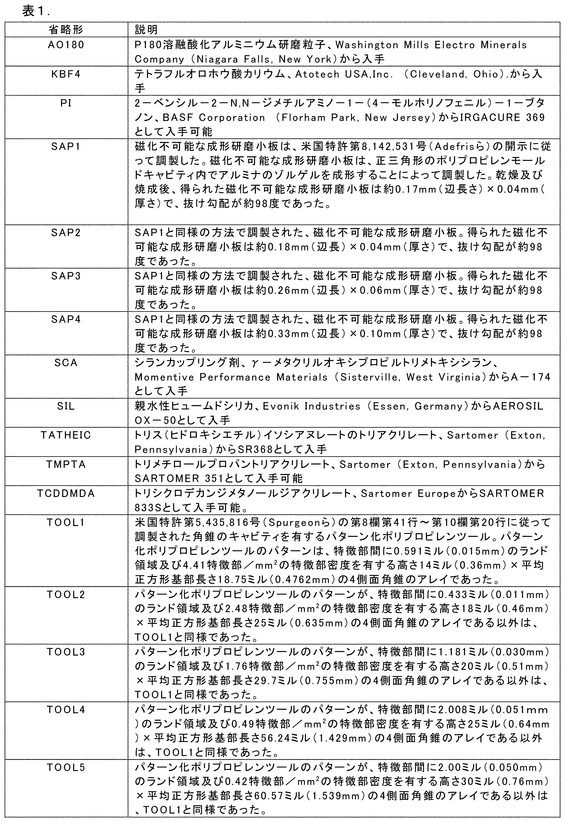
比較例A
研磨スラリーを次のように調製した。23.68部のTCDDMDA、0.84部のSCA、0.24部のPI、0.84部のSIL、16.4部のKBF4、29部のAO180、及び29部のSAP1を、機械的ミキサーを用いて1時間均質に分散させた。得られたスラリーを、75mm(3インチ)幅の金属スクレーパを使用してTOOL1にコーティングした。
Comparative Example A
An abrasive slurry was prepared as follows: 23.68 parts of TCDDMDA, 0.84 parts of SCA, 0.24 parts of PI, 0.84 parts of SIL, 16.4 parts of KBF4, 29 parts of AO180, and 29 parts of SAP1 were homogeneously dispersed using a mechanical mixer for 1 hour. The resulting slurry was coated onto TOOL1 using a 75 mm (3 inch) wide metal scraper.
別個に、99部のTCDDMDA、及び1部のIrgacure 651からなるUV硬化性結合コーティングを、10μm巻線バーコータを使用して、Tencel J-weightクロスのサンプル上にコーティングした。 Separately, a UV-curable bond coating consisting of 99 parts TCDDMDA and 1 part Irgacure 651 was coated onto samples of Tencel J-weight cloth using a 10 μm wire-wound bar coater.
次に、スラリーを担持するTOOL1の表面を、J-weightクロスの結合コーティング表面と接触させ、ハンドローラーを使用して圧力を適用して、スラリーが均一に分布し、全てのツール特徴部が充填されたことを確認した。次に、得られたツール、スラリー、布積層体を、100%の電力のD型電球を使用するPrimarc Minicure UV Conveyor System UV Conveyor Systemに5m/分のベルト速度で通過させて、380ナノメートルで最大強度を有するUV光に供して硬化させた。次に、TOOL1を硬化したスラリーから剥がして、構造化研磨サンプルを得た。 The surface of TOOL1 carrying the slurry was then contacted with the bonded coating surface of the J-weight cloth and pressure was applied using a hand roller to ensure that the slurry was evenly distributed and filled all tool features. The resulting tool, slurry, and fabric laminate was then cured by passing it through a Primarc Miniure UV Conveyor System UV Conveyor System using a D-type bulb at 100% power at a belt speed of 5 m/min and subjecting it to UV light with a maximum intensity at 380 nanometers. TOOL1 was then peeled from the cured slurry to obtain a structured abrasive sample.
実施例1
研磨スラリーを次のように調製した。23.68部のTCDDMDA、0.84部のSCA、0.24部のPI、0.84部のSIL、16.4部のKBF4、29部のAO180、及び29部のSAP1を、機械的ミキサーを用いて1時間均質に分散させた。得られたスラリーを、75mm(3インチ)幅の金属スクレーパを使用してTOOL2にコーティングした。
Example 1
An abrasive slurry was prepared as follows: 23.68 parts of TCDDMDA, 0.84 parts of SCA, 0.24 parts of PI, 0.84 parts of SIL, 16.4 parts of KBF4, 29 parts of AO180, and 29 parts of SAP1 were homogeneously dispersed using a mechanical mixer for 1 hour. The resulting slurry was coated onto TOOL2 using a 75 mm (3 inch) wide metal scraper.
別個に、99部のTCDDMDA、及び1部のIrgacure 651からなるUV硬化性結合コーティングを、10μm巻線バーコータを使用して、Tencel J-weightクロスのサンプル上にコーティングした。 Separately, a UV-curable bond coating consisting of 99 parts TCDDMDA and 1 part Irgacure 651 was coated onto samples of Tencel J-weight cloth using a 10 μm wire-wound bar coater.
次に、スラリーを担持するTOOL2の表面を、J-weightクロスの結合コーティング表面と接触させ、ハンドローラーを使用して圧力を適用して、スラリーが均一に分布し、全てのツール特徴部が充填されたことを確認した。次に、得られたツール、スラリー、布積層体を、100%の電力のD型電球を使用するPrimarc Minicure UV Conveyor Systemに5m/分のベルト速度で通過させて、380ナノメートルで最大強度を有するUV光に供して硬化させた。次に、TOOL2を硬化したスラリーから剥がして、構造化研磨サンプルを得た。 The surface of TOOL2 bearing the slurry was then contacted with the bonded coating surface of the J-weight cloth and pressure was applied using a hand roller to ensure that the slurry was evenly distributed and filled all tool features. The resulting tool, slurry, and fabric laminate was then cured by passing it through a Primarc Miniure UV Conveyor System using a D-type bulb at 100% power at a belt speed of 5 m/min and subjecting it to UV light with maximum intensity at 380 nanometers. The TOOL2 was then peeled from the cured slurry to obtain a structured abrasive sample.
実施例2
研磨スラリーを次のように調製した。23.68部のTCDDMDA、0.84部のSCA、0.24部のPI、0.84部のSIL、16.4部のKBF4、29部のAO180、及び29部のSAP1を、機械的ミキサーを用いて1時間均質に分散させた。得られたスラリーを、75mm(3インチ)幅の金属スクレーパを使用してTOOL3にコーティングした。
Example 2
An abrasive slurry was prepared as follows: 23.68 parts of TCDDMDA, 0.84 parts of SCA, 0.24 parts of PI, 0.84 parts of SIL, 16.4 parts of KBF4, 29 parts of AO180, and 29 parts of SAP1 were homogeneously dispersed using a mechanical mixer for 1 hour. The resulting slurry was coated onto TOOL3 using a 75 mm (3 inch) wide metal scraper.
別個に、99部のTCDDMDA、及び1部のIrgacure 651からなるUV硬化性結合コーティングを、10μm巻線バーコータを使用して、Tencel J-weightクロスのサンプル上にコーティングした。 Separately, a UV-curable bond coating consisting of 99 parts TCDDMDA and 1 part Irgacure 651 was coated onto samples of Tencel J-weight cloth using a 10 μm wire-wound bar coater.
次に、スラリーを担持するTOOL3の表面を、J-weightクロスの結合コーティング表面と接触させ、ハンドローラーを使用して圧力を適用して、スラリーが均一に分布し、全てのツール特徴部が充填されたことを確認した。次に、得られたツール、スラリー、布積層体を、100%の電力のD型電球を使用するPrimarc Minicure UV Conveyor Systemに5m/分のベルト速度で通過させて、380ナノメートルで最大強度を有するUV光に供して硬化させた。次に、TOOL3を硬化したスラリーから剥がして、構造化研磨サンプルを得た。 The surface of the TOOL3 bearing the slurry was then contacted with the bonded coating surface of the J-weight cloth and pressure was applied using a hand roller to ensure that the slurry was evenly distributed and filled all tool features. The resulting tool, slurry, and fabric laminate was then cured by passing it through a Primarc Miniure UV Conveyor System using a D-type bulb at 100% power at a belt speed of 5 m/min and subjecting it to UV light with maximum intensity at 380 nanometers. The TOOL3 was then peeled from the cured slurry to obtain a structured abrasive sample.
実施例3
研磨スラリーを次のように調製した。23.68部のTCDDMDA、0.84部のSCA、0.24部のPI、0.84部のSIL、16.4部のKBF4、29部のAO180、及び29部のSAP1を、機械的ミキサーを用いて1時間均質に分散させた。得られたスラリーを、75mm(3インチ)幅の金属スクレーパを使用してTOOL4にコーティングした。
Example 3
An abrasive slurry was prepared as follows: 23.68 parts of TCDDMDA, 0.84 parts of SCA, 0.24 parts of PI, 0.84 parts of SIL, 16.4 parts of KBF4, 29 parts of AO180, and 29 parts of SAP1 were homogeneously dispersed using a mechanical mixer for 1 hour. The resulting slurry was coated onto TOOL4 using a 75 mm (3 inch) wide metal scraper.
別個に、99部のTCDDMDA、及び1部のIrgacure 651からなるUV硬化性結合コーティングを、10μm巻線バーコータを使用して、Tencel J-weightクロスのサンプル上にコーティングした。 Separately, a UV-curable bond coating consisting of 99 parts TCDDMDA and 1 part Irgacure 651 was coated onto samples of Tencel J-weight cloth using a 10 μm wire-wound bar coater.
次に、スラリーを担持するTOOL4の表面を、J-weightクロスの結合コーティング表面と接触させ、ハンドローラーを使用して圧力を適用して、スラリーが均一に分布し、全てのツール特徴部が充填されたことを確認した。次に、得られたツール、スラリー、布積層体を、100%の電力のD型電球を使用するPrimarc Minicure UV Conveyor Systemに5m/分のベルト速度で通過させて、380ナノメートルで最大強度を有するUV光に供して硬化させた。次に、TOOL4を硬化したスラリーから剥がして、構造化研磨サンプルを得た。 The surface of the TOOL4 bearing the slurry was then contacted with the bonded coating surface of the J-weight cloth and pressure was applied using a hand roller to ensure that the slurry was evenly distributed and filled all tool features. The resulting tool, slurry, and fabric laminate was then cured by passing it through a Primarc Miniure UV Conveyor System using a D-type bulb at 100% power at a belt speed of 5 m/min and subjecting it to UV light with maximum intensity at 380 nanometers. The TOOL4 was then peeled from the cured slurry to obtain a structured abrasive sample.
比較例B
研磨スラリーを次のように調製した。23.68部のTCDDMDA、0.84部のSCA、0.24部のPI、0.84部のSIL、16.4部のKBF4、29部のAO180、及び29部のSAP2を、機械的ミキサーを用いて1時間均質に分散させた。得られたスラリーを、75mm(3インチ)幅の金属スクレーパを使用してTOOL1にコーティングした。
Comparative Example B
An abrasive slurry was prepared as follows: 23.68 parts of TCDDMDA, 0.84 parts of SCA, 0.24 parts of PI, 0.84 parts of SIL, 16.4 parts of KBF4, 29 parts of AO180, and 29 parts of SAP2 were homogeneously dispersed using a mechanical mixer for 1 hour. The resulting slurry was coated onto TOOL1 using a 75 mm (3 inch) wide metal scraper.
別個に、99部のTCDDMDA、及び1部のIrgacure 651からなるUV硬化性結合コーティングを、10μm巻線バーコータを使用して、Tencel J-weightクロスのサンプル上にコーティングした。 Separately, a UV-curable bond coating consisting of 99 parts TCDDMDA and 1 part Irgacure 651 was coated onto samples of Tencel J-weight cloth using a 10 μm wire-wound bar coater.
次に、スラリーを担持するTOOL1の表面を、J-weightクロスの結合コーティング表面と接触させ、ハンドローラーを使用して圧力を適用して、スラリーが均一に分布し、全てのツール特徴部が充填されたことを確認した。次に、得られたツール、スラリー、布積層体を、100%の電力のD型電球を使用するPrimarc Minicure UV Conveyor Systemに5m/分のベルト速度で通過させて、380ナノメートルで最大強度を有するUV光に供して硬化させた。次に、TOOL1を硬化したスラリーから剥がして、構造化研磨サンプルを得た。 The surface of TOOL1 carrying the slurry was then contacted with the bonded coating surface of the J-weight cloth and pressure was applied using a hand roller to ensure that the slurry was evenly distributed and filled all tool features. The resulting tool, slurry, and fabric laminate was then cured by passing it through a Primarc Miniure UV Conveyor System using a D-type bulb at 100% power at a belt speed of 5 m/min and subjecting it to UV light with maximum intensity at 380 nanometers. TOOL1 was then peeled from the cured slurry to obtain a structured abrasive sample.
実施例4
研磨スラリーを次のように調製した。23.68部のTCDDMDA、0.84部のSCA、0.24部のPI、0.84部のSIL、16.4部のKBF4、29部のAO180、及び29部のSAP2を、機械的ミキサーを用いて1時間均質に分散させた。得られたスラリーを、75mm(3インチ)幅の金属スクレーパを使用してTOOL2にコーティングした。
Example 4
An abrasive slurry was prepared as follows: 23.68 parts of TCDDMDA, 0.84 parts of SCA, 0.24 parts of PI, 0.84 parts of SIL, 16.4 parts of KBF4, 29 parts of AO180, and 29 parts of SAP2 were homogeneously dispersed using a mechanical mixer for 1 hour. The resulting slurry was coated onto TOOL2 using a 75 mm (3 inch) wide metal scraper.
別個に、99部のTCDDMDA、及び1部のIrgacure 651からなるUV硬化性結合コーティングを、10μm巻線バーコータを使用して、Tencel J-weightクロスのサンプル上にコーティングした。 Separately, a UV-curable bond coating consisting of 99 parts TCDDMDA and 1 part Irgacure 651 was coated onto samples of Tencel J-weight cloth using a 10 μm wire-wound bar coater.
次に、スラリーを担持するTOOL2の表面を、J-weightクロスの結合コーティング表面と接触させ、ハンドローラーを使用して圧力を適用して、スラリーが均一に分布し、全てのツール特徴部が充填されたことを確認した。次に、得られたツール、スラリー、布積層体を、100%の電力のD型電球を使用するPrimarc Minicure UV Conveyor Systemに5m/分のベルト速度で通過させて、380ナノメートルで最大強度を有するUV光に供して硬化させた。次に、TOOL2を硬化したスラリーから剥がして、構造化研磨サンプルを得た。 The surface of TOOL2 bearing the slurry was then contacted with the bonded coating surface of the J-weight cloth and pressure was applied using a hand roller to ensure that the slurry was evenly distributed and filled all tool features. The resulting tool, slurry, and fabric laminate was then cured by passing it through a Primarc Miniure UV Conveyor System using a D-type bulb at 100% power at a belt speed of 5 m/min and subjecting it to UV light with maximum intensity at 380 nanometers. The TOOL2 was then peeled from the cured slurry to obtain a structured abrasive sample.
実施例5
研磨スラリーを次のように調製した。23.68部のTCDDMDA、0.84部のSCA、0.24部のPI、0.84部のSIL、16.4部のKBF4、29部のAO180、及び29部のSAP2を、機械的ミキサーを用いて1時間均質に分散させた。得られたスラリーを、75mm(3インチ)幅の金属スクレーパを使用してTOOL3にコーティングした。
Example 5
An abrasive slurry was prepared as follows: 23.68 parts of TCDDMDA, 0.84 parts of SCA, 0.24 parts of PI, 0.84 parts of SIL, 16.4 parts of KBF4, 29 parts of AO180, and 29 parts of SAP2 were homogeneously dispersed using a mechanical mixer for 1 hour. The resulting slurry was coated onto TOOL3 using a 75 mm (3 inch) wide metal scraper.
別個に、99部のTCDDMDA、及び1部のIrgacure 651からなるUV硬化性結合コーティングを、10μm巻線バーコータを使用して、Tencel J-weightクロスのサンプル上にコーティングした。 Separately, a UV-curable bond coating consisting of 99 parts TCDDMDA and 1 part Irgacure 651 was coated onto samples of Tencel J-weight cloth using a 10 μm wire-wound bar coater.
次に、スラリーを担持するTOOL3の表面を、J-weightクロスの結合コーティング表面と接触させ、ハンドローラーを使用して圧力を適用して、スラリーが均一に分布し、全てのツール特徴部が充填されたことを確認した。次に、得られたツール、スラリー、布積層体を、100%の電力のD型電球を使用するPrimarc Minicure UV Conveyor Systemに5m/分のベルト速度で通過させて、380ナノメートルで最大強度を有するUV光に供して硬化させた。次に、TOOL3を硬化したスラリーから剥がして、構造化研磨サンプルを得た。 The surface of the TOOL3 bearing the slurry was then contacted with the bonded coating surface of the J-weight cloth and pressure was applied using a hand roller to ensure that the slurry was evenly distributed and filled all tool features. The resulting tool, slurry, and fabric laminate was then cured by passing it through a Primarc Miniure UV Conveyor System using a D-type bulb at 100% power at a belt speed of 5 m/min and subjecting it to UV light with maximum intensity at 380 nanometers. The TOOL3 was then peeled from the cured slurry to obtain a structured abrasive sample.
実施例6
研磨スラリーを次のように調製した。23.68部のTCDDMDA、0.84部のSCA、0.24部のPI、0.84部のSIL、16.4部のKBF4、29部のAO180、及び29部のSAP2を、機械的ミキサーを用いて1時間均質に分散させた。得られたスラリーを、75mm(3インチ)幅の金属スクレーパを使用してTOOL4にコーティングした。
Example 6
An abrasive slurry was prepared as follows: 23.68 parts of TCDDMDA, 0.84 parts of SCA, 0.24 parts of PI, 0.84 parts of SIL, 16.4 parts of KBF4, 29 parts of AO180, and 29 parts of SAP2 were homogeneously dispersed using a mechanical mixer for 1 hour. The resulting slurry was coated onto TOOL4 using a 75 mm (3 inch) wide metal scraper.
別個に、99部のTCDDMDA、及び1部のIrgacure 651からなるUV硬化性結合コーティングを、10μm巻線バーコータを使用して、Tencel J-weightクロスのサンプル上にコーティングした。 Separately, a UV-curable bond coating consisting of 99 parts TCDDMDA and 1 part Irgacure 651 was coated onto samples of Tencel J-weight cloth using a 10 μm wire-wound bar coater.
次に、スラリーを担持するTOOL4の表面を、J-weightクロスの結合コーティング表面と接触させ、ハンドローラーを使用して圧力を適用して、スラリーが均一に分布し、全てのツール特徴部が充填されたことを確認した。次に、得られたツール、スラリー、布積層体を、100%の電力のD型電球を使用するPrimarc Minicure UV Conveyor Systemに5m/分のベルト速度で通過させて、380ナノメートルで最大強度を有するUV光に供して硬化させた。次に、TOOL4を硬化したスラリーから剥がして、構造化研磨サンプルを得た。 The surface of the TOOL4 bearing the slurry was then contacted with the bonded coating surface of the J-weight cloth and pressure was applied using a hand roller to ensure that the slurry was evenly distributed and filled all tool features. The resulting tool, slurry, and fabric laminate was then cured by passing it through a Primarc Miniure UV Conveyor System using a D-type bulb at 100% power at a belt speed of 5 m/min and subjecting it to UV light with maximum intensity at 380 nanometers. The TOOL4 was then peeled from the cured slurry to obtain a structured abrasive sample.
比較例C
研磨スラリーを次のように調製した。23.68部のTCDDMDA、0.84部のSCA、0.24部のPI、0.84部のSIL、16.4部のKBF4、29部のAO180、及び29部のSAP3を、機械的ミキサーを用いて1時間均質に分散させた。得られたスラリーを、75mm(3インチ)幅の金属スクレーパを使用してTOOL1にコーティングした。
Comparative Example C
An abrasive slurry was prepared as follows: 23.68 parts of TCDDMDA, 0.84 parts of SCA, 0.24 parts of PI, 0.84 parts of SIL, 16.4 parts of KBF4, 29 parts of AO180, and 29 parts of SAP3 were homogeneously dispersed using a mechanical mixer for 1 hour. The resulting slurry was coated onto TOOL1 using a 75 mm (3 inch) wide metal scraper.
別個に、99部のTCDDMDA、及び1部のIrgacure 651からなるUV硬化性結合コーティングを、10μm巻線バーコータを使用して、Tencel J-weightクロスのサンプル上にコーティングした。 Separately, a UV-curable bond coating consisting of 99 parts TCDDMDA and 1 part Irgacure 651 was coated onto samples of Tencel J-weight cloth using a 10 μm wire-wound bar coater.
次に、スラリーを担持するTOOL1の表面を、J-weightクロスの結合コーティング表面と接触させ、ハンドローラーを使用して圧力を適用して、スラリーが均一に分布し、全てのツール特徴部が充填されたことを確認した。次に、得られたツール、スラリー、布積層体を、100%の電力のD型電球を使用するPrimarc Minicure UV Conveyor Systemに5m/分のベルト速度で通過させて、380ナノメートルで最大強度を有するUV光に供して硬化させた。次に、TOOL1を硬化したスラリーから剥がして、構造化研磨サンプルを得た。 The surface of TOOL1 carrying the slurry was then contacted with the bonded coating surface of the J-weight cloth and pressure was applied using a hand roller to ensure that the slurry was evenly distributed and filled all tool features. The resulting tool, slurry, and fabric laminate was then cured by passing it through a Primarc Miniure UV Conveyor System using a D-type bulb at 100% power at a belt speed of 5 m/min and subjecting it to UV light with maximum intensity at 380 nanometers. TOOL1 was then peeled from the cured slurry to obtain a structured abrasive sample.
実施例7
研磨スラリーを次のように調製した。23.68部のTCDDMDA、0.84部のSCA、0.24部のPI、0.84部のSIL、16.4部のKBF4、29部のAO180、及び29部のSAP3を、機械的ミキサーを用いて1時間均質に分散させた。得られたスラリーを、75mm(3インチ)幅の金属スクレーパを使用してTOOL2にコーティングした。
Example 7
An abrasive slurry was prepared as follows: 23.68 parts of TCDDMDA, 0.84 parts of SCA, 0.24 parts of PI, 0.84 parts of SIL, 16.4 parts of KBF4, 29 parts of AO180, and 29 parts of SAP3 were homogeneously dispersed using a mechanical mixer for 1 hour. The resulting slurry was coated onto TOOL2 using a 75 mm (3 inch) wide metal scraper.
別個に、99部のTCDDMDA、及び1部のIrgacure 651からなるUV硬化性結合コーティングを、10μm巻線バーコータを使用して、Tencel J-weightクロスのサンプル上にコーティングした。 Separately, a UV-curable bond coating consisting of 99 parts TCDDMDA and 1 part Irgacure 651 was coated onto samples of Tencel J-weight cloth using a 10 μm wire-wound bar coater.
次に、スラリーを担持するTOOL2の表面を、J-weightクロスの結合コーティング表面と接触させ、ハンドローラーを使用して圧力を適用して、スラリーが均一に分布し、全てのツール特徴部が充填されたことを確認した。次に、得られたツール、スラリー、布積層体を、100%の電力のD型電球を使用するPrimarc Minicure UV Conveyor Systemに5m/分のベルト速度で通過させて、380ナノメートルで最大強度を有するUV光に供して硬化させた。次に、TOOL2を硬化したスラリーから剥がして、構造化研磨サンプルを得た。 The surface of TOOL2 bearing the slurry was then contacted with the bonded coating surface of the J-weight cloth and pressure was applied using a hand roller to ensure that the slurry was evenly distributed and filled all tool features. The resulting tool, slurry, and fabric laminate was then cured by passing it through a Primarc Miniure UV Conveyor System using a D-type bulb at 100% power at a belt speed of 5 m/min and subjecting it to UV light with maximum intensity at 380 nanometers. The TOOL2 was then peeled from the cured slurry to obtain a structured abrasive sample.
実施例8
研磨スラリーを次のように調製した。23.68部のTCDDMDA、0.84部のSCA、0.24部のPI、0.84部のSIL、16.4部のKBF4、29部のAO180、及び29部のSAP3を、機械的ミキサーを用いて1時間均質に分散させた。得られたスラリーを、75mm(3インチ)幅の金属スクレーパを使用してTOOL3にコーティングした。
Example 8
An abrasive slurry was prepared as follows: 23.68 parts of TCDDMDA, 0.84 parts of SCA, 0.24 parts of PI, 0.84 parts of SIL, 16.4 parts of KBF4, 29 parts of AO180, and 29 parts of SAP3 were homogeneously dispersed using a mechanical mixer for 1 hour. The resulting slurry was coated onto TOOL3 using a 75 mm (3 inch) wide metal scraper.
別個に、99部のTCDDMDA、及び1部のIrgacure 651を含むUV硬化性結合コーティングを、10μm巻線バーコータを使用して、Tencel J-weightクロスのサンプル上にコーティングした。 Separately, a UV-curable bond coating containing 99 parts TCDDMDA and 1 part Irgacure 651 was coated onto samples of Tencel J-weight cloth using a 10 μm wire-wound bar coater.
次に、スラリーを担持するTOOL3の表面を、J-weightクロスの結合コーティング表面と接触させ、ハンドローラーを使用して圧力を適用して、スラリーが均一に分布し、全てのツール特徴部が充填されたことを確認した。次に、得られたツール、スラリー、布積層体を、100%の電力のD型電球を使用するPrimarc Minicure UV Conveyor Systemに5m/分のベルト速度で通過させて、380ナノメートルで最大強度を有するUV光に供して硬化させた。次に、TOOL3を硬化したスラリーから剥がして、構造化研磨サンプルを得た。 The surface of the TOOL3 bearing the slurry was then contacted with the bonded coating surface of the J-weight cloth and pressure was applied using a hand roller to ensure that the slurry was evenly distributed and filled all tool features. The resulting tool, slurry, and fabric laminate was then cured by passing it through a Primarc Miniure UV Conveyor System using a D-type bulb at 100% power at a belt speed of 5 m/min and subjecting it to UV light with maximum intensity at 380 nanometers. The TOOL3 was then peeled from the cured slurry to obtain a structured abrasive sample.
実施例9
研磨スラリーを次のように調製した。23.68部のTCDDMDA、0.84部のSCA、0.24部のPI、0.84部のSIL、16.4部のKBF4、29部のAO180、及び29部のSAP3を、機械的ミキサーを用いて1時間均質に分散させた。得られたスラリーを、75mm(3インチ)幅の金属スクレーパを使用してTOOL4にコーティングした。
Example 9
An abrasive slurry was prepared as follows: 23.68 parts of TCDDMDA, 0.84 parts of SCA, 0.24 parts of PI, 0.84 parts of SIL, 16.4 parts of KBF4, 29 parts of AO180, and 29 parts of SAP3 were homogeneously dispersed using a mechanical mixer for 1 hour. The resulting slurry was coated onto TOOL4 using a 75 mm (3 inch) wide metal scraper.
別個に、99部のTCDDMDA、及び1部のIrgacure 651を含むUV硬化性結合コーティングを、10μm巻線バーコータを使用して、Tencel J-weightクロスのサンプル上にコーティングした。 Separately, a UV-curable bond coating containing 99 parts TCDDMDA and 1 part Irgacure 651 was coated onto samples of Tencel J-weight cloth using a 10 μm wire-wound bar coater.
次に、スラリーを担持するTOOL4の表面を、J-weightクロスの結合コーティング表面と接触させ、ハンドローラーを使用して圧力を適用して、スラリーが均一に分布し、全てのツール特徴部が充填されたことを確認した。次に、得られたツール、スラリー、布積層体を、100%の電力のD型電球を使用するPrimarc Minicure UV Conveyor Systemに5m/分のベルト速度で通過させて、380ナノメートルで最大強度を有するUV光に供して硬化させた。次に、TOOL4を硬化したスラリーから剥がして、構造化研磨サンプルを得た。 The surface of the TOOL4 bearing the slurry was then contacted with the bonded coating surface of the J-weight cloth and pressure was applied using a hand roller to ensure that the slurry was evenly distributed and filled all tool features. The resulting tool, slurry, and fabric laminate was then cured by passing it through a Primarc Miniure UV Conveyor System using a D-type bulb at 100% power at a belt speed of 5 m/min and subjecting it to UV light with maximum intensity at 380 nanometers. The TOOL4 was then peeled from the cured slurry to obtain a structured abrasive sample.
比較例D
研磨スラリーを次のように調製した。23.68部のTCDDMDA、0.84部のSCA、0.24部のPI、0.84部のSIL、16.4部のKBF4、29部のAO180、及び29部のSAP4を、機械的ミキサーを用いて1時間均質に分散させた。得られたスラリーを、75mm(3インチ)幅の金属スクレーパを使用してTOOL1にコーティングした。
Comparative Example D
An abrasive slurry was prepared as follows: 23.68 parts of TCDDMDA, 0.84 parts of SCA, 0.24 parts of PI, 0.84 parts of SIL, 16.4 parts of KBF4, 29 parts of AO180, and 29 parts of SAP4 were homogeneously dispersed using a mechanical mixer for 1 hour. The resulting slurry was coated onto TOOL1 using a 75 mm (3 inch) wide metal scraper.
別個に、99部のTCDDMDA、及び1部のIrgacure 651を含むUV硬化性結合コーティングを、10μm巻線バーコータを使用して、Tencel J-weightクロスのサンプル上にコーティングした。 Separately, a UV-curable bond coating containing 99 parts TCDDMDA and 1 part Irgacure 651 was coated onto samples of Tencel J-weight cloth using a 10 μm wire-wound bar coater.
次に、スラリーを担持するTOOL1の表面を、J-weightクロスの結合コーティング表面と接触させ、ハンドローラーを使用して圧力を適用して、スラリーが均一に分布し、全てのツール特徴部が充填されたことを確認した。次に、得られたツール、スラリー、布積層体を、100%の電力のD型電球を使用するPrimarc Minicure UV Conveyor Systemに5m/分のベルト速度で通過させて、380ナノメートルで最大強度を有するUV光に供して硬化させた。次に、TOOL1を硬化したスラリーから剥がして、構造化研磨サンプルを得た。 The surface of TOOL1 carrying the slurry was then contacted with the bonded coating surface of the J-weight cloth and pressure was applied using a hand roller to ensure that the slurry was evenly distributed and filled all tool features. The resulting tool, slurry, and fabric laminate was then cured by passing it through a Primarc Miniure UV Conveyor System using a D-type bulb at 100% power at a belt speed of 5 m/min and subjecting it to UV light with maximum intensity at 380 nanometers. TOOL1 was then peeled from the cured slurry to obtain a structured abrasive sample.
実施例10
研磨スラリーを次のように調製した。23.68部のTCDDMDA、0.84部のSCA、0.24部のPI、0.84部のSIL、16.4部のKBF4、29部のAO180、及び29部のSAP4を、機械的ミキサーを用いて1時間均質に分散させた。得られたスラリーを、75mm(3インチ)幅の金属スクレーパを使用してTOOL2にコーティングした。
Example 10
An abrasive slurry was prepared as follows: 23.68 parts of TCDDMDA, 0.84 parts of SCA, 0.24 parts of PI, 0.84 parts of SIL, 16.4 parts of KBF4, 29 parts of AO180, and 29 parts of SAP4 were homogeneously dispersed using a mechanical mixer for 1 hour. The resulting slurry was coated onto TOOL2 using a 75 mm (3 inch) wide metal scraper.
別個に、99部のTCDDMDA、及び1部のIrgacure 651からなるUV硬化性結合コーティングを、10μm巻線バーコータを使用して、Tencel J-weightクロスのサンプル上にコーティングした。 Separately, a UV-curable bond coating consisting of 99 parts TCDDMDA and 1 part Irgacure 651 was coated onto samples of Tencel J-weight cloth using a 10 μm wire-wound bar coater.
次に、スラリーを担持するTOOL2の表面を、J-weightクロスの結合コーティング表面と接触させ、ハンドローラーを使用して圧力を適用して、スラリーが均一に分布し、全てのツール特徴部が充填されたことを確認した。次に、得られたツール、スラリー、布積層体を、100%の電力のD型電球を使用するPrimarc Minicure UV Conveyor Systemに5m/分のベルト速度で通過させて、380ナノメートルで最大強度を有するUV光に供して硬化させた。次に、TOOL2を硬化したスラリーから剥がして、構造化研磨サンプルを得た。 The surface of TOOL2 bearing the slurry was then contacted with the bonded coating surface of the J-weight cloth and pressure was applied using a hand roller to ensure that the slurry was evenly distributed and filled all tool features. The resulting tool, slurry, and fabric laminate was then cured by passing it through a Primarc Miniure UV Conveyor System using a D-type bulb at 100% power at a belt speed of 5 m/min and subjecting it to UV light with maximum intensity at 380 nanometers. The TOOL2 was then peeled from the cured slurry to obtain a structured abrasive sample.
実施例11
研磨スラリーを次のように調製した。23.68部のTCDDMDA、0.84部のSCA、0.24部のPI、0.84部のSIL、16.4部のKBF4、29部のAO180、及び29部のSAP4を、機械的ミキサーを用いて1時間均質に分散させた。得られたスラリーを、75mm(3インチ)幅の金属スクレーパを使用してTOOL3にコーティングした。
Example 11
An abrasive slurry was prepared as follows: 23.68 parts of TCDDMDA, 0.84 parts of SCA, 0.24 parts of PI, 0.84 parts of SIL, 16.4 parts of KBF4, 29 parts of AO180, and 29 parts of SAP4 were homogeneously dispersed using a mechanical mixer for 1 hour. The resulting slurry was coated onto TOOL3 using a 75 mm (3 inch) wide metal scraper.
別個に、99部のTCDDMDA、及び1部のIrgacure 651からなるUV硬化性結合コーティングを、10μm巻線バーコータを使用して、Tencel J-weightクロスのサンプル上にコーティングした。 Separately, a UV-curable bond coating consisting of 99 parts TCDDMDA and 1 part Irgacure 651 was coated onto samples of Tencel J-weight cloth using a 10 μm wire-wound bar coater.
次に、スラリーを担持するTOOL3の表面を、J-weightクロスの結合コーティング表面と接触させ、ハンドローラーを使用して圧力を適用して、スラリーが均一に分布し、全てのツール特徴部が充填されたことを確認した。次に、得られたツール、スラリー、布積層体を、100%の電力のD型電球を使用するPrimarc Minicure UV Conveyor Systemに5m/分のベルト速度で通過させて、380ナノメートルで最大強度を有するUV光に供して硬化させた。次に、TOOL3を硬化したスラリーから剥がして、構造化研磨サンプルを得た。 The surface of the TOOL3 bearing the slurry was then contacted with the bonded coating surface of the J-weight cloth and pressure was applied using a hand roller to ensure that the slurry was evenly distributed and filled all tool features. The resulting tool, slurry, and fabric laminate was then cured by passing it through a Primarc Miniure UV Conveyor System using a D-type bulb at 100% power at a belt speed of 5 m/min and subjecting it to UV light with maximum intensity at 380 nanometers. The TOOL3 was then peeled from the cured slurry to obtain a structured abrasive sample.
実施例12
研磨スラリーを次のように調製した。23.68部のTCDDMDA、0.84部のSCA、0.24部のPI、0.84部のSIL、16.4部のKBF4、29部のAO180、及び29部のSAP4を、機械的ミキサーを用いて1時間均質に分散させた。得られたスラリーを、75mm(3インチ)幅の金属スクレーパを使用してTOOL4にコーティングした。
Example 12
An abrasive slurry was prepared as follows: 23.68 parts of TCDDMDA, 0.84 parts of SCA, 0.24 parts of PI, 0.84 parts of SIL, 16.4 parts of KBF4, 29 parts of AO180, and 29 parts of SAP4 were homogeneously dispersed using a mechanical mixer for 1 hour. The resulting slurry was coated onto TOOL4 using a 75 mm (3 inch) wide metal scraper.
別個に、99部のTCDDMDA、及び1部のIrgacure 651からなるUV硬化性結合コーティングを、10μm巻線バーコータを使用して、Tencel J-weightクロスのサンプル上にコーティングした。 Separately, a UV-curable bond coating consisting of 99 parts TCDDMDA and 1 part Irgacure 651 was coated onto samples of Tencel J-weight cloth using a 10 μm wire-wound bar coater.
次に、スラリーを担持するTOOL4の表面を、J-weightクロスの結合コーティング表面と接触させ、ハンドローラーを使用して圧力を適用して、スラリーが均一に分布し、全てのツール特徴部が充填されたことを確認した。次に、得られたツール、スラリー、布積層体を、100%の電力のD型電球を使用するPrimarc Minicure UV Conveyor Systemに5m/分のベルト速度で通過させて、380ナノメートルで最大強度を有するUV光に供して硬化させた。次に、TOOL4を硬化したスラリーから剥がして、構造化研磨サンプルを得た。 The surface of the TOOL4 bearing the slurry was then contacted with the bonded coating surface of the J-weight cloth and pressure was applied using a hand roller to ensure that the slurry was evenly distributed and filled all tool features. The resulting tool, slurry, and fabric laminate was then cured by passing it through a Primarc Miniure UV Conveyor System using a D-type bulb at 100% power at a belt speed of 5 m/min and subjecting it to UV light with maximum intensity at 380 nanometers. The TOOL4 was then peeled from the cured slurry to obtain a structured abrasive sample.
比較例E
研磨スラリーを次のように調製した。23.68部のTCDDMDA、0.84部のSCA、0.24部のPI、0.84部のSIL、16.4部のKBF4、58部のAO180を、機械的ミキサーを用いて1時間均質に分散させた。得られたスラリーを、75mm(3インチ)幅の金属スクレーパを使用してTOOL1にコーティングした。
Comparative Example E
The abrasive slurry was prepared as follows: 23.68 parts of TCDDMDA, 0.84 parts of SCA, 0.24 parts of PI, 0.84 parts of SIL, 16.4 parts of KBF4, and 58 parts of AO180 were homogeneously dispersed using a mechanical mixer for 1 hour. The resulting slurry was coated onto TOOL1 using a 75 mm (3 inch) wide metal scraper.
別個に、99部のTCDDMDA、及び1部のIrgacure 651からなるUV硬化性結合コーティングを、10μm巻線バーコータを使用して、Tencel J-weightクロスのサンプル上にコーティングした。 Separately, a UV-curable bond coating consisting of 99 parts TCDDMDA and 1 part Irgacure 651 was coated onto samples of Tencel J-weight cloth using a 10 μm wire-wound bar coater.
次に、スラリーを担持するTOOL1の表面を、J-weightクロスの結合コーティング表面と接触させ、ハンドローラーを使用して圧力を適用して、スラリーが均一に分布し、全てのツール特徴部が充填されたことを確認した。次に、得られたツール、スラリー、布積層体を、100%の電力のD型電球を使用するPrimarc Minicure UV Conveyor Systemに5m/分のベルト速度で通過させて、380ナノメートルで最大強度を有するUV光に供して硬化させた。次に、TOOL1を硬化したスラリーから剥がして、構造化研磨サンプルを得た。 The surface of TOOL1 carrying the slurry was then contacted with the bonded coating surface of the J-weight cloth and pressure was applied using a hand roller to ensure that the slurry was evenly distributed and filled all tool features. The resulting tool, slurry, and fabric laminate was then cured by passing it through a Primarc Miniure UV Conveyor System using a D-type bulb at 100% power at a belt speed of 5 m/min and subjecting it to UV light with maximum intensity at 380 nanometers. TOOL1 was then peeled from the cured slurry to obtain a structured abrasive sample.
比較例F
比較例Eと同様に、研磨スラリーを調製し、TOOL2上にコーティングした。
Comparative Example F
Similar to Comparative Example E, an abrasive slurry was prepared and coated onto TOOL2.
別個に、99部のTCDDMDA、及び1部のIrgacure 651からなるUV硬化性結合コーティングを、10μm巻線バーコータを使用して、Tencel J-weightクロスのサンプル上にコーティングした。 Separately, a UV-curable bond coating consisting of 99 parts TCDDMDA and 1 part Irgacure 651 was coated onto samples of Tencel J-weight cloth using a 10 μm wire-wound bar coater.
次に、スラリーを担持するTOOL2の表面を、J-weightクロスの結合コーティング表面と接触させ、ハンドローラーを使用して圧力を適用して、スラリーが均一に分布し、全てのツール特徴部が充填されたことを確認した。次に、得られたツール、スラリー、布積層体を、100%の電力のD型電球を使用するPrimarc Minicure UV Conveyor Systemに5m/分のベルト速度で通過させて、380ナノメートルで最大強度を有するUV光に供して硬化させた。次に、TOOL2を硬化したスラリーから剥がして、構造化研磨サンプルを得た。 The surface of TOOL2 bearing the slurry was then contacted with the bonded coating surface of the J-weight cloth and pressure was applied using a hand roller to ensure that the slurry was evenly distributed and filled all tool features. The resulting tool, slurry, and fabric laminate was then cured by passing it through a Primarc Miniure UV Conveyor System using a D-type bulb at 100% power at a belt speed of 5 m/min and subjecting it to UV light with maximum intensity at 380 nanometers. The TOOL2 was then peeled from the cured slurry to obtain a structured abrasive sample.
比較例G
比較例Eと同様に、研磨スラリーを調製し、TOOL3上にコーティングした。
Comparative Example G
Similar to Comparative Example E, an abrasive slurry was prepared and coated onto TOOL3.
別個に、99部のTCDDMDA、及び1部のIrgacure 651からなるUV硬化性結合コーティングを、10μm巻線バーコータを使用して、Tencel J-weightクロスのサンプル上にコーティングした。 Separately, a UV-curable bond coating consisting of 99 parts TCDDMDA and 1 part Irgacure 651 was coated onto samples of Tencel J-weight cloth using a 10 μm wire-wound bar coater.
次に、スラリーを担持するTOOL3の表面を、J-weightクロスの結合コーティング表面と接触させ、ハンドローラーを使用して圧力を適用して、スラリーが均一に分布し、全てのツール特徴部が充填されたことを確認した。次に、得られたツール、スラリー、布積層体を、100%の電力のD型電球を使用するPrimarc Minicure UV Conveyor Systemに5m/分のベルト速度で通過させて、380ナノメートルで最大強度を有するUV光に供して硬化させた。次に、TOOL3を硬化したスラリーから剥がして、構造化研磨サンプルを得た。 The surface of the TOOL3 bearing the slurry was then contacted with the bonded coating surface of the J-weight cloth and pressure was applied using a hand roller to ensure that the slurry was evenly distributed and filled all tool features. The resulting tool, slurry, and fabric laminate was then cured by passing it through a Primarc Miniure UV Conveyor System using a D-type bulb at 100% power at a belt speed of 5 m/min and subjecting it to UV light with maximum intensity at 380 nanometers. The TOOL3 was then peeled from the cured slurry to obtain a structured abrasive sample.
比較例H
比較例Eと同様に、研磨スラリーを調製し、TOOL4上にコーティングした。
Comparative Example H
Similar to Comparative Example E, an abrasive slurry was prepared and coated onto TOOL4.
別個に、99部のTCDDMDA、及び1部のIrgacure 651からなるUV硬化性結合コーティングを、10μm巻線バーコータを使用して、Tencel J-weightクロスのサンプル上にコーティングした。 Separately, a UV-curable bond coating consisting of 99 parts TCDDMDA and 1 part Irgacure 651 was coated onto samples of Tencel J-weight cloth using a 10 μm wire-wound bar coater.
次に、スラリーを担持するTOOL4の表面を、J-weightクロスの結合コーティング表面と接触させ、ハンドローラーを使用して圧力を適用して、スラリーが均一に分布し、全てのツール特徴部が充填されたことを確認した。次に、得られたツール、スラリー、布積層体を、100%の電力のD型電球を使用するPrimarc Minicure UV Conveyor Systemに5m/分のベルト速度で通過させて、380ナノメートルで最大強度を有するUV光に供して硬化させた。次に、TOOL4を硬化したスラリーから剥がして、構造化研磨サンプルを得た。 The surface of the TOOL4 bearing the slurry was then contacted with the bonded coating surface of the J-weight cloth and pressure was applied using a hand roller to ensure that the slurry was evenly distributed and filled all tool features. The resulting tool, slurry, and fabric laminate was then cured by passing it through a Primarc Miniure UV Conveyor System using a D-type bulb at 100% power at a belt speed of 5 m/min and subjecting it to UV light with maximum intensity at 380 nanometers. The TOOL4 was then peeled from the cured slurry to obtain a structured abrasive sample.
比較例I
比較例Eと同様に、研磨スラリーを調製し、TOOL5上にコーティングした。
Comparative Example I
Similar to Comparative Example E, an abrasive slurry was prepared and coated onto TOOL5.
別個に、99部のTCDDMDA、及び1部のIrgacure 651からなるUV硬化性結合コーティングを、10μm巻線バーコータを使用して、Tencel J-weightクロスのサンプル上にコーティングした。 Separately, a UV-curable bond coating consisting of 99 parts TCDDMDA and 1 part Irgacure 651 was coated onto samples of Tencel J-weight cloth using a 10 μm wire-wound bar coater.
次に、スラリーを担持するTOOL5の表面を、J-weightクロスの結合コーティング表面と接触させ、ハンドローラーを使用して圧力を適用して、スラリーが均一に分布し、全てのツール特徴部が充填されたことを確認した。次に、得られたツール、スラリー、布積層体を、100%の電力のD型電球を使用するPrimarc Minicure UV Conveyor Systemに5m/分のベルト速度で通過させて、380ナノメートルで最大強度を有するUV光に供して硬化させた。次に、TOOL5を硬化したスラリーから剥がして、構造化研磨サンプルを得た。 The surface of the TOOL5 bearing the slurry was then contacted with the bonded coating surface of the J-weight cloth and pressure was applied using a hand roller to ensure that the slurry was evenly distributed and filled all tool features. The resulting tool, slurry, and fabric laminate was then cured by passing it through a Primarc Miniure UV Conveyor System using a D-type bulb at 100% power at a belt speed of 5 m/min and subjecting it to UV light with maximum intensity at 380 nanometers. The TOOL5 was then peeled from the cured slurry to obtain a structured abrasive sample.
単一ディスク試験
ループ取り付けシステムを有する非屈曲構造化研磨物品を、6インチ(15.2cm)ディスクに変換した。これらのディスクを、単一ディスク試験機の内部に装着されたバックアップパッドに取り付け、2000rpmまで回転させた。次に、静止した10mm×10mm×300mmの303ステンレス鋼加工物を、20Nの適用力で、構造化研磨材によって10秒間研磨する。これを更に24回繰り返し、その後10秒間隔毎に失われた質量を記録し、これにより、250秒にわたってストック除去プロファイルを提供する。
Single Disc Testing The non-flexed structured abrasive articles with loop attachment system were converted to 6 inch (15.2 cm) discs. These discs were attached to a back-up pad mounted inside the single disc tester and rotated to 2000 rpm. A stationary 10 mm x 10 mm x 300 mm 303 stainless steel workpiece is then abraded with the structured abrasive for 10 seconds with an applied force of 20 N. This is repeated 24 more times, after which the mass lost at every 10 second interval is recorded, thereby providing a stock removal profile over 250 seconds.
実施例13~16
実施例3、6、9、及び12と同様に、研磨スラリーを調製し、TOOL5上にコーティングした。
Examples 13 to 16
Similar to Examples 3, 6, 9, and 12, an abrasive slurry was prepared and coated onto TOOL5.
各場合において、99部のTCDDMDA、及び1部のIrgacure 651からなるUV硬化性結合コーティングを、10μm巻線バーコータを使用して、Tencel J-weightクロスのサンプル上にそれぞれコーティングした。 In each case, a UV-curable bond coating consisting of 99 parts TCDDMDA and 1 part Irgacure 651 was coated onto each sample of Tencel J-weight cloth using a 10 μm wire-wound bar coater.
次に、スラリーを担持するTOOL5の表面を、J-weightクロスの結合コーティング表面と接触させ、ハンドローラーを使用して圧力を適用して、スラリーが均一に分布し、全てのツール特徴部が充填されたことを確認した。次に、得られたツール、スラリー、布積層体を、100%の電力のD型電球を使用するPrimarc Minicure UV Conveyor Systemに5m/分のベルト速度で通過させて、380ナノメートルで最大強度を有するUV光に供して硬化させた。次に、TOOL5を硬化したスラリーから剥がして、構造化研磨サンプルを得た。 The surface of the TOOL5 bearing the slurry was then contacted with the bonded coating surface of the J-weight cloth and pressure was applied using a hand roller to ensure that the slurry was evenly distributed and filled all tool features. The resulting tool, slurry, and fabric laminate was then cured by passing it through a Primarc Miniure UV Conveyor System using a D-type bulb at 100% power at a belt speed of 5 m/min and subjecting it to UV light with maximum intensity at 380 nanometers. The TOOL5 was then peeled from the cured slurry to obtain a structured abrasive sample.
性能試験
実施例1~16及び比較例A~Dから得られた研磨物品を、3M 300LSE感圧性接着剤、及び各サンプルから切出した6インチ(15.2cm)のディスクを使用して、ループ取り付けシステムに積層した。研磨ディスクを、単一ディスク試験機(20N力、2000rpm)上で10×10mmの303ステンレス鋼バーでのストック除去について試験した。以下の表2に、性能データを表にした。
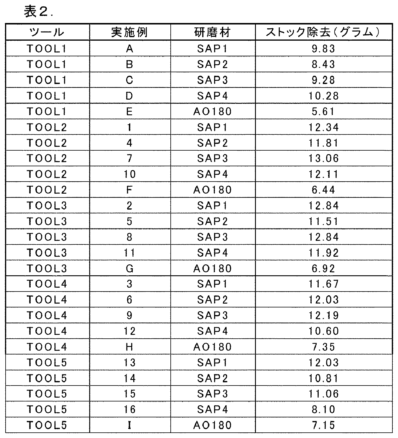
図2は、様々なサイズの研磨粒子及び成形された複合体サイズの上述の単一ディスク試験結果のプロットを示す。 Figure 2 shows a plot of the above single disk test results for various sizes of abrasive particles and molded composite sizes.
上記の特許出願において引用された全ての参考文献、特許文献又は特許出願は、一貫した形でその全文が参照により本明細書に組み込まれる。組み込まれた参照文献の一部と本出願との間に不一致又は矛盾がある場合、前述の記載における情報が優先するものとする。前述の記載は、当業者が、特許請求の範囲に記載の開示を実践することを可能にするためのものであり、本開示の範囲を限定するものと解釈すべきではなく、本開示の範囲は特許請求の範囲及びその全ての等価物によって定義される。 All references, patent documents or patent applications cited in the above patent application are incorporated herein by reference in their entirety for consistency. In the event of any inconsistency or contradiction between any of the incorporated references and this application, the information in the foregoing description shall prevail. The foregoing description is intended to enable a person skilled in the art to practice the disclosure as set forth in the claims, and should not be construed as limiting the scope of the present disclosure, which is defined by the claims and all equivalents thereof.
Claims (15)
第1及び第2の両主表面を有する裏材と、
前記裏材の前記第1の主表面に固定して結合された研磨層と、
を含み、
前記研磨層は、成形研磨複合体を含み、各成形研磨複合体は、4つの側面、高さ、及び、前記裏材の前記第1の主表面に面する基部を有し、前記成形研磨複合体は、410~650マイクロメートルの平均高さと、550~1450マイクロメートルの前記基部における平均辺長さとを有し、前記成形研磨複合体は、磁化不可能な成形研磨小板を含み、前記磁化不可能な成形研磨小板は、170~330マイクロメートルの平均辺長さと、40~100マイクロメートルの平均厚さとを有し、前記磁化不可能な成形研磨小板の少なくとも60%が、磁化不可能な三角形研磨小板を含む、構造化研磨物品。 1. A structured abrasive article comprising:
a backing having first and second major surfaces;
an abrasive layer fixedly bonded to the first major surface of the backing;
Including,
1. A structured abrasive article comprising: said abrasive layer comprising shaped abrasive composites, each shaped abrasive composite having four sides, a height, and a base facing the first major surface of the backing, said shaped abrasive composites having an average height of 410 to 650 micrometers and an average side length at the base of 550 to 1450 micrometers; said shaped abrasive composites comprising non-magnetizable shaped abrasive platelets, said non-magnetizable shaped abrasive platelets having an average side length of 170 to 330 micrometers and an average thickness of 40 to 100 micrometers; and at least 60% of the non-magnetizable shaped abrasive platelets comprising non-magnetizable triangular abrasive platelets .
a)410~650マイクロメートルの深さ及び550~1450マイクロメートルのモールド表面における辺長さを有する、複数の精密成形されたキャビティを画定する前記モールド表面を有する製造ツールを提供する工程と、
b)前記精密成形されたキャビティの少なくとも大部分を、硬化性有機バインダー前駆体材料中に分散された磁化不可能な成形研磨小板を含むスラリーで充填する工程であって、前記磁化不可能な成形研磨小板は、170~330マイクロメートルの平均辺長さと、40~100マイクロメートルの平均厚さとを有し、前記磁化不可能な成形研磨小板の少なくとも60%が、磁化不可能な三角形研磨小板を含む、充填する工程と、
c)前記スラリーが前記精密成形されたキャビティの前記少なくとも大部分内に配置されている間に、裏材の主表面上に配置された結合層を、前記製造ツールの前記モールド表面と接触させる工程と、
d)前記硬化性有機バインダー前駆体材料を少なくとも部分的に硬化させて、前記裏材の前記主表面に固定された成形研磨複合体を形成する工程と、
e)前記成形研磨複合体を前記製造ツールから分離する工程と、を含み、
前記方法が、意図的に適用された外部磁場の影響を伴わずに実行される、方法。 1. A method of making a structured abrasive article, comprising:
a) providing a manufacturing tool having a mold surface defining a plurality of precision shaped cavities having a depth at the mold surface of 410 to 650 micrometers and a side length at the mold surface of 550 to 1450 micrometers;
b) filling at least a majority of the shaped cavities with a slurry comprising non-magnetizable shaped abrasive platelets dispersed in a curable organic binder precursor material, the non-magnetizable shaped abrasive platelets having an average side length of 170 to 330 micrometers and an average thickness of 40 to 100 micrometers, and at least 60% of the non-magnetizable shaped abrasive platelets comprising non-magnetizable triangular abrasive platelets ;
c) contacting a bonding layer disposed on a major surface of a backing with a mold surface of the production tool while the slurry is disposed within at least the majority of the precision molded cavity;
d) at least partially curing the curable organic binder precursor material to form shaped abrasive composites affixed to the major surface of the backing;
e) separating the shaped abrasive composites from the production tool;
A method, wherein the method is performed without the influence of an intentionally applied external magnetic field.
Applications Claiming Priority (3)
| Application Number | Priority Date | Filing Date | Title |
|---|---|---|---|
| US201862718149P | 2018-08-13 | 2018-08-13 | |
| US62/718,149 | 2018-08-13 | ||
| PCT/IB2019/056723 WO2020035764A1 (en) | 2018-08-13 | 2019-08-07 | Structured abrasive article and method of making the same |
Publications (2)
| Publication Number | Publication Date |
|---|---|
| JP2021534006A JP2021534006A (en) | 2021-12-09 |
| JP7535499B2 true JP7535499B2 (en) | 2024-08-16 |
Family
ID=68072872
Family Applications (1)
| Application Number | Title | Priority Date | Filing Date |
|---|---|---|---|
| JP2021507696A Active JP7535499B2 (en) | 2018-08-13 | 2019-08-07 | Structured abrasive article and method of making same |
Country Status (5)
| Country | Link |
|---|---|
| US (1) | US20210308832A1 (en) |
| EP (1) | EP3837086B1 (en) |
| JP (1) | JP7535499B2 (en) |
| CN (1) | CN112566753B (en) |
| WO (1) | WO2020035764A1 (en) |
Families Citing this family (28)
| Publication number | Priority date | Publication date | Assignee | Title |
|---|---|---|---|---|
| KR20170018102A (en) | 2011-12-30 | 2017-02-15 | 생-고뱅 세라믹스 앤드 플라스틱스, 인코포레이티드 | Shaped abrasive particle and method of forming same |
| CA2860755C (en) | 2012-01-10 | 2018-01-30 | Saint-Gobain Ceramics & Plastics, Inc. | Abrasive particles having complex shapes and methods of forming same |
| KR101813466B1 (en) | 2012-05-23 | 2017-12-29 | 생-고뱅 세라믹스 앤드 플라스틱스, 인코포레이티드 | Shaped abrasive particles and methods of forming same |
| KR101736085B1 (en) | 2012-10-15 | 2017-05-16 | 생-고뱅 어브레이시브즈, 인코포레이티드 | Abrasive particles having particular shapes and methods of forming such particles |
| EP2978566B1 (en) | 2013-03-29 | 2024-04-24 | Saint-Gobain Abrasives, Inc. | Abrasive particles having particular shapes and methods of forming such particles |
| AU2014324453B2 (en) | 2013-09-30 | 2017-08-03 | Saint-Gobain Ceramics & Plastics, Inc. | Shaped abrasive particles and methods of forming same |
| MX380754B (en) | 2013-12-31 | 2025-03-12 | Saint Gobain Abrasives Inc | ABRASIVE ARTICLE INCLUDING PROFILED ABRASIVE PARTICLES. |
| US9771507B2 (en) | 2014-01-31 | 2017-09-26 | Saint-Gobain Ceramics & Plastics, Inc. | Shaped abrasive particle including dopant material and method of forming same |
| JP6321209B2 (en) | 2014-04-14 | 2018-05-09 | サン−ゴバン セラミックス アンド プラスティクス,インコーポレイティド | Abrasive articles containing shaped abrasive particles |
| US9914864B2 (en) | 2014-12-23 | 2018-03-13 | Saint-Gobain Ceramics & Plastics, Inc. | Shaped abrasive particles and method of forming same |
| WO2016161157A1 (en) | 2015-03-31 | 2016-10-06 | Saint-Gobain Abrasives, Inc. | Fixed abrasive articles and methods of forming same |
| TWI634200B (en) | 2015-03-31 | 2018-09-01 | 聖高拜磨料有限公司 | Fixed abrasive article and method of forming same |
| EP3307483B1 (en) | 2015-06-11 | 2020-06-17 | Saint-Gobain Ceramics&Plastics, Inc. | Abrasive article including shaped abrasive particles |
| CN109415615A (en) | 2016-05-10 | 2019-03-01 | 圣戈本陶瓷及塑料股份有限公司 | Abrasive particles and methods of forming the same |
| KR102422875B1 (en) | 2016-05-10 | 2022-07-21 | 생-고뱅 세라믹스 앤드 플라스틱스, 인코포레이티드 | Abrasive particles and methods of forming same |
| US11230653B2 (en) | 2016-09-29 | 2022-01-25 | Saint-Gobain Abrasives, Inc. | Fixed abrasive articles and methods of forming same |
| US10563105B2 (en) | 2017-01-31 | 2020-02-18 | Saint-Gobain Ceramics & Plastics, Inc. | Abrasive article including shaped abrasive particles |
| WO2018236989A1 (en) | 2017-06-21 | 2018-12-27 | Saint-Gobain Ceramics & Plastics, Inc. | PARTICULATE MATERIALS AND METHODS OF FORMATION THEREOF |
| CN119238386A (en) | 2019-12-27 | 2025-01-03 | 圣戈本陶瓷及塑料股份有限公司 | Abrasive article and method of forming the same |
| KR102877276B1 (en) | 2019-12-27 | 2025-10-28 | 세인트-고바인 세라믹스 앤드 플라스틱스, 인크. | Abrasive article and method for forming same |
| EP4081370A4 (en) | 2019-12-27 | 2024-04-24 | Saint-Gobain Ceramics & Plastics Inc. | Abrasive articles and methods of forming same |
| CN113305749B (en) * | 2021-06-25 | 2022-04-01 | 江苏锋芒复合材料科技集团有限公司 | Sand planting method for magnetic polymeric abrasive |
| EP4457055A4 (en) | 2021-12-30 | 2025-12-24 | Saint Gobain Abrasives Inc | Grinding articles and methods for shaping them |
| KR20240148817A (en) | 2021-12-30 | 2024-10-11 | 세인트-고바인 아브라시브즈 인크. | Abrasive article and method of forming same |
| US12496686B2 (en) | 2021-12-30 | 2025-12-16 | Saint-Gobain Abrasives, Inc. | Abrasive articles and methods of forming same |
| WO2025144860A1 (en) * | 2023-12-27 | 2025-07-03 | Saint-Gobain Abrasives, Inc. | Structured abrasive article with improved backing |
| WO2025144854A1 (en) * | 2023-12-27 | 2025-07-03 | Saint-Gobain Abrasives, Inc. | Structured abrasive article with interlayer |
| CN121240953A (en) * | 2023-12-28 | 2025-12-30 | 圣戈班磨料磨具有限公司 | Grinding wheel and method of making and using the same |
Citations (4)
| Publication number | Priority date | Publication date | Assignee | Title |
|---|---|---|---|---|
| JP2001512373A (en) | 1997-02-24 | 2001-08-21 | ミネソタ・マイニング・アンド・マニュファクチャリング・カンパニー | Structured abrasive products suitable for polishing mild steel workpieces |
| JP2013215859A (en) | 2012-04-11 | 2013-10-24 | Three M Innovative Properties Co | Polishing sheet, abrasive roll and polishing tool |
| JP2016500581A (en) | 2012-10-31 | 2016-01-14 | スリーエム イノベイティブ プロパティズ カンパニー | Molded abrasive particles, method for producing the same, and abrasive articles containing the same |
| WO2018080765A1 (en) | 2016-10-25 | 2018-05-03 | 3M Innovative Properties Company | Structured abrasive articles and methods of making the same |
Family Cites Families (47)
| Publication number | Priority date | Publication date | Assignee | Title |
|---|---|---|---|---|
| US35570A (en) | 1862-06-10 | Eufus sibley | ||
| US4314827A (en) | 1979-06-29 | 1982-02-09 | Minnesota Mining And Manufacturing Company | Non-fused aluminum oxide-based abrasive mineral |
| US5191101A (en) | 1982-11-22 | 1993-03-02 | Minnesota Mining And Manufacturing Company | Energy polymerizable compositions containing organometallic initiators |
| US4623364A (en) | 1984-03-23 | 1986-11-18 | Norton Company | Abrasive material and method for preparing the same |
| CA1254238A (en) | 1985-04-30 | 1989-05-16 | Alvin P. Gerk | Process for durable sol-gel produced alumina-based ceramics, abrasive grain and abrasive products |
| US4652274A (en) | 1985-08-07 | 1987-03-24 | Minnesota Mining And Manufacturing Company | Coated abrasive product having radiation curable binder |
| US4770671A (en) | 1985-12-30 | 1988-09-13 | Minnesota Mining And Manufacturing Company | Abrasive grits formed of ceramic containing oxides of aluminum and yttrium, method of making and using the same and products made therewith |
| US4751138A (en) | 1986-08-11 | 1988-06-14 | Minnesota Mining And Manufacturing Company | Coated abrasive having radiation curable binder |
| DE3627339C1 (en) * | 1986-08-12 | 1987-07-02 | Alfred Gutmann Ges Fuer Maschb | Device for accelerating ferromagnetic, granular abrasive |
| US4881951A (en) | 1987-05-27 | 1989-11-21 | Minnesota Mining And Manufacturing Co. | Abrasive grits formed of ceramic containing oxides of aluminum and rare earth metal, method of making and products made therewith |
| US5086086A (en) | 1987-08-28 | 1992-02-04 | Minnesota Mining And Manufacturing Company | Energy-induced curable compositions |
| US4950696A (en) | 1987-08-28 | 1990-08-21 | Minnesota Mining And Manufacturing Company | Energy-induced dual curable compositions |
| US5254194A (en) | 1988-05-13 | 1993-10-19 | Minnesota Mining And Manufacturing Company | Coated abrasive sheet material with loop material for attachment incorporated therein |
| US4985340A (en) | 1988-06-01 | 1991-01-15 | Minnesota Mining And Manufacturing Company | Energy curable compositions: two component curing agents |
| US4903440A (en) | 1988-11-23 | 1990-02-27 | Minnesota Mining And Manufacturing Company | Abrasive product having binder comprising an aminoplast resin |
| US5213590A (en) * | 1989-12-20 | 1993-05-25 | Neff Charles E | Article and a method for producing an article having a high friction surface |
| US5181939A (en) * | 1989-12-20 | 1993-01-26 | Charles Neff | Article and a method for producing an article having a high friction surface |
| US5152917B1 (en) | 1991-02-06 | 1998-01-13 | Minnesota Mining & Mfg | Structured abrasive article |
| US5236472A (en) | 1991-02-22 | 1993-08-17 | Minnesota Mining And Manufacturing Company | Abrasive product having a binder comprising an aminoplast binder |
| US5201916A (en) | 1992-07-23 | 1993-04-13 | Minnesota Mining And Manufacturing Company | Shaped abrasive particles and method of making same |
| RU95105160A (en) | 1992-07-23 | 1997-01-10 | Миннесота Майнинг энд Мануфакчуринг Компани (US) | Method of preparing abrasive particles, abrasive articles and articles with abrasive coating |
| US5366523A (en) | 1992-07-23 | 1994-11-22 | Minnesota Mining And Manufacturing Company | Abrasive article containing shaped abrasive particles |
| US5213591A (en) | 1992-07-28 | 1993-05-25 | Ahmet Celikkaya | Abrasive grain, method of making same and abrasive products |
| US5435816A (en) | 1993-01-14 | 1995-07-25 | Minnesota Mining And Manufacturing Company | Method of making an abrasive article |
| CN1067315C (en) | 1993-09-13 | 2001-06-20 | 美国3M公司 | Abrasive article, method of manufacture of same, method of using same for finishing, and a production tool |
| US5454844A (en) | 1993-10-29 | 1995-10-03 | Minnesota Mining And Manufacturing Company | Abrasive article, a process of making same, and a method of using same to finish a workpiece surface |
| US5505747A (en) | 1994-01-13 | 1996-04-09 | Minnesota Mining And Manufacturing Company | Method of making an abrasive article |
| WO1995022436A1 (en) | 1994-02-22 | 1995-08-24 | Minnesota Mining And Manufacturing Company | Abrasive article, a method of making same, and a method of using same for finishing |
| US5975987A (en) | 1995-10-05 | 1999-11-02 | 3M Innovative Properties Company | Method and apparatus for knurling a workpiece, method of molding an article with such workpiece, and such molded article |
| US5946991A (en) | 1997-09-03 | 1999-09-07 | 3M Innovative Properties Company | Method for knurling a workpiece |
| US6139594A (en) | 1998-04-13 | 2000-10-31 | 3M Innovative Properties Company | Abrasive article with tie coat and method |
| US20030022604A1 (en) | 2001-05-07 | 2003-01-30 | 3M Innovative Properties Company | Abrasive product and method of making and using the same |
| GB2374084A (en) * | 2001-04-03 | 2002-10-09 | Fourwinds Group Inc | Alloys having bistable magnetic behaviour |
| US6846232B2 (en) | 2001-12-28 | 2005-01-25 | 3M Innovative Properties Company | Backing and abrasive product made with the backing and method of making and using the backing and abrasive product |
| US7150770B2 (en) * | 2004-06-18 | 2006-12-19 | 3M Innovative Properties Company | Coated abrasive article with tie layer, and method of making and using the same |
| US7410413B2 (en) * | 2006-04-27 | 2008-08-12 | 3M Innovative Properties Company | Structured abrasive article and method of making and using the same |
| US8123828B2 (en) | 2007-12-27 | 2012-02-28 | 3M Innovative Properties Company | Method of making abrasive shards, shaped abrasive particles with an opening, or dish-shaped abrasive particles |
| WO2009085841A2 (en) | 2007-12-27 | 2009-07-09 | 3M Innovative Properties Company | Shaped, fractured abrasive particle, abrasive article using same and method of making |
| US8142531B2 (en) | 2008-12-17 | 2012-03-27 | 3M Innovative Properties Company | Shaped abrasive particles with a sloping sidewall |
| US8142532B2 (en) | 2008-12-17 | 2012-03-27 | 3M Innovative Properties Company | Shaped abrasive particles with an opening |
| US8142891B2 (en) | 2008-12-17 | 2012-03-27 | 3M Innovative Properties Company | Dish-shaped abrasive particles with a recessed surface |
| JP5651190B2 (en) | 2009-12-02 | 2015-01-07 | スリーエム イノベイティブ プロパティズ カンパニー | Dual taper shaped abrasive particles |
| CA2797096C (en) | 2010-04-27 | 2018-07-10 | 3M Innovative Properties Company | Ceramic shaped abrasive particles, methods of making the same, and abrasive articles containing the same |
| KR101879884B1 (en) | 2010-08-04 | 2018-07-18 | 쓰리엠 이노베이티브 프로퍼티즈 컴파니 | Intersecting plate shaped abrasive particles |
| CN103764348B (en) * | 2011-09-07 | 2017-12-29 | 3M创新有限公司 | The method of grinding workpiece |
| CN105050770B (en) * | 2013-03-12 | 2018-08-17 | 3M创新有限公司 | Bonded abrasive article |
| EP3194118B1 (en) * | 2014-09-15 | 2023-05-03 | 3M Innovative Properties Company | Methods of making abrasive articles and bonded abrasive wheel preparable thereby |
-
2019
- 2019-08-07 JP JP2021507696A patent/JP7535499B2/en active Active
- 2019-08-07 WO PCT/IB2019/056723 patent/WO2020035764A1/en not_active Ceased
- 2019-08-07 US US17/266,366 patent/US20210308832A1/en active Pending
- 2019-08-07 CN CN201980052590.3A patent/CN112566753B/en active Active
- 2019-08-07 EP EP19779121.3A patent/EP3837086B1/en active Active
Patent Citations (4)
| Publication number | Priority date | Publication date | Assignee | Title |
|---|---|---|---|---|
| JP2001512373A (en) | 1997-02-24 | 2001-08-21 | ミネソタ・マイニング・アンド・マニュファクチャリング・カンパニー | Structured abrasive products suitable for polishing mild steel workpieces |
| JP2013215859A (en) | 2012-04-11 | 2013-10-24 | Three M Innovative Properties Co | Polishing sheet, abrasive roll and polishing tool |
| JP2016500581A (en) | 2012-10-31 | 2016-01-14 | スリーエム イノベイティブ プロパティズ カンパニー | Molded abrasive particles, method for producing the same, and abrasive articles containing the same |
| WO2018080765A1 (en) | 2016-10-25 | 2018-05-03 | 3M Innovative Properties Company | Structured abrasive articles and methods of making the same |
Also Published As
| Publication number | Publication date |
|---|---|
| EP3837086A1 (en) | 2021-06-23 |
| CN112566753B (en) | 2023-06-27 |
| WO2020035764A1 (en) | 2020-02-20 |
| CN112566753A (en) | 2021-03-26 |
| EP3837086B1 (en) | 2024-09-25 |
| JP2021534006A (en) | 2021-12-09 |
| US20210308832A1 (en) | 2021-10-07 |
Similar Documents
| Publication | Publication Date | Title |
|---|---|---|
| JP7535499B2 (en) | Structured abrasive article and method of making same | |
| US8425278B2 (en) | Structured abrasive article and method of using the same | |
| US11253972B2 (en) | Structured abrasive articles and methods of making the same | |
| KR102450209B1 (en) | Open Coat Abrasive Articles and Abrasive Methods | |
| EP2012972B1 (en) | Structured abrasive article and method of making and using the same | |
| EP2176031B1 (en) | Structured abrasive with overlayer, and method of making and using the same | |
| KR102290663B1 (en) | Structured abrasive articles and methods of using the same | |
| JP2004338088A (en) | Abrasive article, process of making the same, and method of using the same to finish workpiece surface | |
| EP2007551A2 (en) | Embossed structured abrasive article and method of making and using the same | |
| EP3541573A1 (en) | Structured abrasive article including features with improved structural integrity | |
| EP3768795A1 (en) | Structured abrasives containing polishing materials for use in the home |
Legal Events
| Date | Code | Title | Description |
|---|---|---|---|
| RD03 | Notification of appointment of power of attorney |
Free format text: JAPANESE INTERMEDIATE CODE: A7423 Effective date: 20220519 |
|
| A621 | Written request for application examination |
Free format text: JAPANESE INTERMEDIATE CODE: A621 Effective date: 20220805 |
|
| A131 | Notification of reasons for refusal |
Free format text: JAPANESE INTERMEDIATE CODE: A131 Effective date: 20230620 |
|
| A977 | Report on retrieval |
Free format text: JAPANESE INTERMEDIATE CODE: A971007 Effective date: 20230621 |
|
| A601 | Written request for extension of time |
Free format text: JAPANESE INTERMEDIATE CODE: A601 Effective date: 20230914 |
|
| A521 | Request for written amendment filed |
Free format text: JAPANESE INTERMEDIATE CODE: A523 Effective date: 20231010 |
|
| A131 | Notification of reasons for refusal |
Free format text: JAPANESE INTERMEDIATE CODE: A131 Effective date: 20231107 |
|
| A601 | Written request for extension of time |
Free format text: JAPANESE INTERMEDIATE CODE: A601 Effective date: 20240206 |
|
| A521 | Request for written amendment filed |
Free format text: JAPANESE INTERMEDIATE CODE: A523 Effective date: 20240402 |
|
| TRDD | Decision of grant or rejection written | ||
| A01 | Written decision to grant a patent or to grant a registration (utility model) |
Free format text: JAPANESE INTERMEDIATE CODE: A01 Effective date: 20240709 |
|
| A61 | First payment of annual fees (during grant procedure) |
Free format text: JAPANESE INTERMEDIATE CODE: A61 Effective date: 20240805 |
|
| R150 | Certificate of patent or registration of utility model |
Ref document number: 7535499 Country of ref document: JP Free format text: JAPANESE INTERMEDIATE CODE: R150 |