JP7533516B2 - Laser Gas Analyzer - Google Patents
Laser Gas Analyzer Download PDFInfo
- Publication number
- JP7533516B2 JP7533516B2 JP2022062873A JP2022062873A JP7533516B2 JP 7533516 B2 JP7533516 B2 JP 7533516B2 JP 2022062873 A JP2022062873 A JP 2022062873A JP 2022062873 A JP2022062873 A JP 2022062873A JP 7533516 B2 JP7533516 B2 JP 7533516B2
- Authority
- JP
- Japan
- Prior art keywords
- light
- laser
- gas
- measured
- light receiving
- Prior art date
- Legal status (The legal status is an assumption and is not a legal conclusion. Google has not performed a legal analysis and makes no representation as to the accuracy of the status listed.)
- Active
Links
Images


Classifications
-
- G—PHYSICS
- G01—MEASURING; TESTING
- G01N—INVESTIGATING OR ANALYSING MATERIALS BY DETERMINING THEIR CHEMICAL OR PHYSICAL PROPERTIES
- G01N21/00—Investigating or analysing materials by the use of optical means, i.e. using sub-millimetre waves, infrared, visible or ultraviolet light
- G01N21/17—Systems in which incident light is modified in accordance with the properties of the material investigated
- G01N21/25—Colour; Spectral properties, i.e. comparison of effect of material on the light at two or more different wavelengths or wavelength bands
- G01N21/31—Investigating relative effect of material at wavelengths characteristic of specific elements or molecules, e.g. atomic absorption spectrometry
- G01N21/39—Investigating relative effect of material at wavelengths characteristic of specific elements or molecules, e.g. atomic absorption spectrometry using tunable lasers
-
- G—PHYSICS
- G01—MEASURING; TESTING
- G01N—INVESTIGATING OR ANALYSING MATERIALS BY DETERMINING THEIR CHEMICAL OR PHYSICAL PROPERTIES
- G01N21/00—Investigating or analysing materials by the use of optical means, i.e. using sub-millimetre waves, infrared, visible or ultraviolet light
- G01N21/17—Systems in which incident light is modified in accordance with the properties of the material investigated
- G01N21/25—Colour; Spectral properties, i.e. comparison of effect of material on the light at two or more different wavelengths or wavelength bands
- G01N21/31—Investigating relative effect of material at wavelengths characteristic of specific elements or molecules, e.g. atomic absorption spectrometry
-
- G—PHYSICS
- G01—MEASURING; TESTING
- G01N—INVESTIGATING OR ANALYSING MATERIALS BY DETERMINING THEIR CHEMICAL OR PHYSICAL PROPERTIES
- G01N21/00—Investigating or analysing materials by the use of optical means, i.e. using sub-millimetre waves, infrared, visible or ultraviolet light
- G01N21/01—Arrangements or apparatus for facilitating the optical investigation
-
- G—PHYSICS
- G01—MEASURING; TESTING
- G01N—INVESTIGATING OR ANALYSING MATERIALS BY DETERMINING THEIR CHEMICAL OR PHYSICAL PROPERTIES
- G01N33/00—Investigating or analysing materials by specific methods not covered by groups G01N1/00 - G01N31/00
- G01N33/0004—Gaseous mixtures, e.g. polluted air
- G01N33/0009—General constructional details of gas analysers, e.g. portable test equipment
- G01N33/0027—General constructional details of gas analysers, e.g. portable test equipment concerning the detector
-
- G—PHYSICS
- G01—MEASURING; TESTING
- G01N—INVESTIGATING OR ANALYSING MATERIALS BY DETERMINING THEIR CHEMICAL OR PHYSICAL PROPERTIES
- G01N21/00—Investigating or analysing materials by the use of optical means, i.e. using sub-millimetre waves, infrared, visible or ultraviolet light
- G01N21/17—Systems in which incident light is modified in accordance with the properties of the material investigated
- G01N21/25—Colour; Spectral properties, i.e. comparison of effect of material on the light at two or more different wavelengths or wavelength bands
- G01N21/31—Investigating relative effect of material at wavelengths characteristic of specific elements or molecules, e.g. atomic absorption spectrometry
- G01N21/39—Investigating relative effect of material at wavelengths characteristic of specific elements or molecules, e.g. atomic absorption spectrometry using tunable lasers
- G01N2021/396—Type of laser source
- G01N2021/399—Diode laser
-
- G—PHYSICS
- G01—MEASURING; TESTING
- G01N—INVESTIGATING OR ANALYSING MATERIALS BY DETERMINING THEIR CHEMICAL OR PHYSICAL PROPERTIES
- G01N21/00—Investigating or analysing materials by the use of optical means, i.e. using sub-millimetre waves, infrared, visible or ultraviolet light
- G01N21/17—Systems in which incident light is modified in accordance with the properties of the material investigated
- G01N21/25—Colour; Spectral properties, i.e. comparison of effect of material on the light at two or more different wavelengths or wavelength bands
- G01N21/31—Investigating relative effect of material at wavelengths characteristic of specific elements or molecules, e.g. atomic absorption spectrometry
- G01N21/35—Investigating relative effect of material at wavelengths characteristic of specific elements or molecules, e.g. atomic absorption spectrometry using infrared light
- G01N21/3504—Investigating relative effect of material at wavelengths characteristic of specific elements or molecules, e.g. atomic absorption spectrometry using infrared light for analysing gases, e.g. multi-gas analysis
-
- G—PHYSICS
- G01—MEASURING; TESTING
- G01N—INVESTIGATING OR ANALYSING MATERIALS BY DETERMINING THEIR CHEMICAL OR PHYSICAL PROPERTIES
- G01N2201/00—Features of devices classified in G01N21/00
- G01N2201/06—Illumination; Optics
- G01N2201/061—Sources
- G01N2201/06113—Coherent sources; lasers
-
- G—PHYSICS
- G01—MEASURING; TESTING
- G01N—INVESTIGATING OR ANALYSING MATERIALS BY DETERMINING THEIR CHEMICAL OR PHYSICAL PROPERTIES
- G01N2201/00—Features of devices classified in G01N21/00
- G01N2201/06—Illumination; Optics
- G01N2201/062—LED's
Landscapes
- Physics & Mathematics (AREA)
- Chemical & Material Sciences (AREA)
- Health & Medical Sciences (AREA)
- Life Sciences & Earth Sciences (AREA)
- Spectroscopy & Molecular Physics (AREA)
- General Health & Medical Sciences (AREA)
- Analytical Chemistry (AREA)
- Biochemistry (AREA)
- General Physics & Mathematics (AREA)
- Immunology (AREA)
- Pathology (AREA)
- Engineering & Computer Science (AREA)
- Optics & Photonics (AREA)
- Combustion & Propulsion (AREA)
- Food Science & Technology (AREA)
- Medicinal Chemistry (AREA)
- Investigating Or Analysing Materials By Optical Means (AREA)
Description
本発明は、レーザガス分析計に関する。 The present invention relates to a laser gas analyzer.
レーザガス分析計は、測定対象のガスに特定の波長帯のレーザ光を照射し、測定対象のガスを通過したレーザ光の光量を測定し、特定の波長帯のレーザ光の減衰量を算出することによって、測定対象のガスに含まれる成分の濃度を算出する(例えば、特許文献1)。 A laser gas analyzer irradiates the gas to be measured with laser light of a specific wavelength band, measures the amount of laser light that passes through the gas to be measured, and calculates the amount of attenuation of the laser light of the specific wavelength band, thereby calculating the concentration of components contained in the gas to be measured (for example, Patent Document 1).
ところで、レーザガス分析計には、レーザ光を照射しているにも関わらずレーザ光の受光部がレーザ光に対して出力しない場合に、受光部の故障と判定するものがある。しかしながら、特許文献1に記載のレーザガス分析計では、測定対象のガスに粉塵などのレーザ光の光路を遮る障害物が一定以上存在する場合にも、受光素子の出力がなくなり又は極端に小さくなり、受光素子の故障と判定してしまう可能性がある。このように、特許文献1のレーザガス分析計の構成では、受光素子の故障を正確に判定することができなかった。
Some laser gas analyzers determine that the light receiving element is faulty when the laser light receiving element does not output any laser light even though the laser light is being emitted. However, in the laser gas analyzer described in
そこで、本発明は、受光部の故障を正確に判定することが可能なレーザガス分析計を提供する。 Therefore, the present invention provides a laser gas analyzer that can accurately determine failure of the light receiving unit.
本発明のレーザガス分析計は、測定対象のガスにレーザ光を照射する第1の照射手段と、測定対象のガスを通過したレーザ光を受光する受光手段と、受光手段によって受光されたレーザ光の光量に基づいて測定対象のガスに含まれる成分の濃度を算出する算出手段と、測定対象のガスを通過することなく受光手段によって受光されるよう光を照射する第2の照射手段と、を備える。 The laser gas analyzer of the present invention comprises a first irradiation means for irradiating a gas to be measured with laser light, a light receiving means for receiving the laser light that has passed through the gas to be measured, a calculation means for calculating the concentration of a component contained in the gas to be measured based on the amount of laser light received by the light receiving means, and a second irradiation means for irradiating light so that the light is received by the light receiving means without passing through the gas to be measured.
本発明によれば、受光部の故障を正確に判定することができる。 The present invention makes it possible to accurately determine if the light receiving unit is faulty.
以下、本発明を実施するための形態に係るレーザガス分析計について図面を用いて説明する。 The following describes a laser gas analyzer according to an embodiment of the present invention with reference to the drawings.
<実施例1>
図1は、実施例1のレーザガス分析計のブロック図である。図1を参照して、実施例1のレーザガス分析計について説明する。レーザガス分析計1は、TDLAS(Tunable Diode Laser Absorption Spectroscopy:波長可変ダイオードレーザ吸収分光)式レーザガス分析計である。レーザガス分析計1は、測定対象のガスに特定の波長帯のレーザ光を照射し、測定対象のガスを通過したレーザ光の光量を測定し、特定の波長の減衰量に基づいて測定対象のガスに含まれる成分の濃度を算出する。レーザガス分析計1は、特定の波長帯のレーザ光を照射する発光部10と、測定対象のガスが供給される被測定部20と、測定対象のガスを通過したレーザ光を受光する受光部30と、測定対象のガスに含まれる成分の濃度を算出する演算部40と、を備える。なお、レーザガス分析計1は、被測定部20を備えてなくてもよい。例えば、レーザガス分析計1を使用するユーザの測定対象のガスが供給される設備に対して発光部10や受光部30を取り付けて使用する場合には、レーザガス分析計1は被測定部20を備えなくても構わない。また、演算部40は、レーザガス分析計1に内蔵されるコンピュータシステムであってもよいし、レーザガス分析計1と通信可能なコンピュータシステム(例えば、クラウドサーバ)であってもよい。
Example 1
FIG. 1 is a block diagram of a laser gas analyzer according to a first embodiment. The laser gas analyzer according to the first embodiment will be described with reference to FIG. 1. The
(発光部10)
発光部10は、出力コントローラ11と、DAC(Digital Analog Converter)12と、電圧電流変換回路13と、レーザダイオード14と、を有する。出力コントローラ11は、後述する受光部30の入力コントローラ34からの同期信号に従って、レーザ駆動電流のパターンを生成し、出力する。DAC12は、出力コントローラ11が出力したレーザ駆動電流のパターン(デジタル信号)をアナログ信号に変換し、出力する。電圧電流変換回路13は、DAC12が出力したアナログ信号に従って、レーザ駆動電流を出力する。レーザダイオード14は、電圧電流変換回路13から出力されたレーザ駆動電流に従って、特定の波長帯のレーザ光を照射する。レーザダイオード14は、測定対象のガスにレーザ光を照射する第1の照射手段である。レーザダイオード14から照射されたレーザ光は、被測定部20に供給される測定対象のガスを通過して、受光部30のフォトダイオード31で受光される。
(Light emitting unit 10)
The
(被測定部20)
被測定部20は、測定対象のガスを供給する。測定対象のガスは、例えば燃料排ガスやプロセスガスである。レーザガス分析計1は、測定対象のガスに含まれるO2、CO、CH4、CO2及びNH3などの成分の濃度を算出することが可能である。
(Measurement target unit 20)
The
(受光部30)
受光部30は、フォトダイオード31と、フィルタ/アンプ回路32と、ADC(Analog Digital Converter)33と、入力コントローラ34と、メモリ35と、LED36と、を有する。フォトダイオード31は、レーザダイオード14から照射され、被測定部20に供給される測定対象のガスを通過したレーザ光を受光し、受光したレーザ光の光量に対応するアナログ信号を出力する。フォトダイオード31は、測定対象のガスを通過したレーザ光を受光する受光手段である。フォトダイオード31は、被測定部20を挟んで発光部10のレーザダイオード14と対向するように配置される。フィルタ/アンプ回路32は、受信したアナログ信号に含まれる所定周波数成分をフィルタし、増幅する。ADC33は、フィルタ/アンプ回路32から受信したアナログ信号をデジタル信号に変換して、出力する。入力コントローラ34は、ADC33から受信したデジタル信号に対して積算処理などの一次演算処理を施し、メモリ35に格納する。メモリ35に格納されたデジタル信号は、測定対象のガスを通過したレーザ光の受光量の波形を示す。以下適宜、メモリ35に格納されたデジタル信号を受光信号波形と呼ぶ。
(Light receiving unit 30)
The
LED36は、被測定部20よりフォトダイオード31側に配置される。LED36は、測定対象のガスを通過することなくフォトダイオード31によって受光されるよう光を照射する第2の照射手段である。LED36から照射された光は、測定対象のガスを通過することなくフォトダイオード31によって受光される。したがって、LED36から照射された光は、測定対象のガスに粉塵などの障害物があったとしても、これらの障害物の影響を受けることなく、フォトダイオード31によって受光される。LED36の発光タイミングは、入力コントローラ34によって制御される。
The
演算部40は、メモリ35に格納された受光信号波形を読み出し、測定対象のガスに含まれる成分の濃度を算出する。演算部40は、フォトダイオード31によって受光されたレーザ光の光量に基づいて測定対象のガスに含まれる成分の濃度を算出する算出手段である。演算部40は、コンピュータであって、プロセッサ(例えばCPU(Central Processing Unit)、FPGA(field-programmable gate array)、又はDSP(Digital signal processor))、メモリ(例えばRAM(Random Access Memory))、補助記憶部(例えばHDD(Hard Disk Drive)やSSD(Solid State Drive))、外部機器への情報出力手段(例えば電流出力、接点出力、又はEthernet通信)及び表示部などを有する。プロセッサは、例えば、濃度を算出するためのプログラムを補助記憶部から読み出して、メモリに展開して実行する。表示部は、例えば、算出した濃度を表示し、情報出力手段は、例えば、算出した濃度を外部機器へ出力する。また、プロセッサは、例えば、受光部30の故障の有無を判定するためのプログラムを補助記憶部から読み出して、メモリに展開して実行する。
The
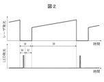
図2は、実施例1のレーザダイオード及びLEDの発光タイミングを示した図である。図2に示すように、区間(a)はレーザ光が無発光の区間であり、区間(d)はレーザ光が発光する区間である。レーザダイオード14は、所定区間(区間(a))を空けてレーザ光を間欠的に照射する。区間(a)は、例えば約0.1msである。区間(d)は測定対象ガスにより異なり、例えば約1ms~3msの範囲である。区間(a)の前半(b)はフォトダイオード31の出力が静定するのを待つ静定待ち区間であり、後半(c)は暗電流を計測するための暗電流計測区間である。すなわち、前半(b)は演算部40による演算に使用されない区間である。後半(c)は演算部40による演算の基準値を算出するために使用される区間である。静定待ち区間は、予め決められた時間であってもよいし、フォトダイオード31の出力が閾値以下で所定時間経過したと判定するまでの時間であってもよい。暗電流計測区間は、予め決められた時間である。
2 is a diagram showing the light emission timing of the laser diode and the LED in the first embodiment. As shown in FIG. 2, the section (a) is a section in which the laser light is not emitted, and the section (d) is a section in which the laser light is emitted. The
LED36は、前半(b)の受光信号の静定待ち区間で発光する。演算部40は、前半(b)における受光信号波形にLED36の発光によるスパイク信号の有無を常時観察することによって、受光部30の健全性を確認する。
The
図3A~図3Dは、実施例1の受光信号波形を示した図である。
受光信号波形は、以下の4パターンに分けられる。
パターンA:レーザダイオード14が照射したレーザ光に対応する信号、及びLED36から照射された光に対応するスパイク信号の両方を含むパターン(図3A参照)
パターンB:レーザダイオード14が照射したレーザ光に対応する信号がなく、LED36から照射された光に対応するスパイク信号を含むパターン(図3B参照)
パターンC:レーザダイオード14が照射したレーザ光に対応する信号を含むが、LED36から照射された光に対応するスパイク信号がないパターン(図3C参照)
パターンD:レーザダイオード14が照射したレーザ光に対応する信号、及びLED36から照射された光に対応するスパイク信号の両方がないパターン(図3D参照)
3A to 3D are diagrams showing received light signal waveforms in the first embodiment.
The received light signal waveform can be divided into the following four patterns.
Pattern A: A pattern including both a signal corresponding to the laser light emitted by the
Pattern B: A pattern in which there is no signal corresponding to the laser light emitted by the
Pattern C: A pattern including a signal corresponding to the laser light emitted by the
Pattern D: A pattern in which there is neither a signal corresponding to the laser light emitted by the
演算部40は、レーザダイオード14によって照射されるレーザ光、及びLED36によって照射される光の両方を受光するフォトダイオード31の出力に基づいて、フォトダイオード31の故障の有無を判定する演算手段である。演算部40は、図3Aに示したパターンAの受光信号波形を確認した場合、発光部10及び受光部30の両方が正常であると判定する。また、演算部40は、図3Bに示したパターンBの受光信号波形を確認した場合、発光部10及び受光部30の両方が正常であると判定する。この場合、レーザダイオード14が照射したレーザ光に対応する信号を確認できないが、測定対象のガスにレーザ光の光路を遮る障害物が一定以上存在することが考えられる。また、演算部40は、図3Cに示したパターンCの受光信号波形を確認した場合、発光部10は正常だが、受光部30のLED36が異常であると判定する。また、演算部40は、図3Dに示したパターンDの受光信号波形を確認した場合、発光部10は正常だが、受光部30のフォトダイオード31、フィルタ/アンプ回路32及びADC33の少なくとも一つが異常であると判定する。なお、各判定結果は、演算部40の表示部に表示可能である。また、各判定結果は、情報出力手段を介して外部機器へ伝達可能である。
The
(実施例1の効果)
LED36から照射された光は、測定対象のガスを通過することなくフォトダイオード31によって受光される。これにより、測定対象のガスの影響を受けることなく、フォトダイオード31は、LED36から照射された光を受光することができる。その結果、測定対象のガス中に一定以上の障害物があったとしても、受光部30の健全性が確認可能となる。その結果、故障検出の信頼性が高まり、故障検出率の向上につながる。さらには、故障検出率は、機能安全的に重要な指標であるから機能安全規格上も有益である。
(Effects of Example 1)
The light emitted from the
入力コントローラ34は、LED36を静定待ち区間(図2の前半(b))の所定のタイミングで発光させる。これにより、レーザガス分析計1における通常の動作中の演算に使用されない区間を利用して、受光部30の故障を判定することができる。つまり、実施例1では、レーザガス分析計1の通常の動作を停止することなく、受光部30の故障を判定することができる。
The
<実施例2>
図4は、実施例2のレーザダイオード及びLEDの発光タイミングを示した図である。実施例1と実施例2とでは、LED36の発光タイミングが反転している。実施例1では、受光信号の静定待ち区間(b)の所定のタイミングでLED36は光を照射する。実施例2では、受光信号の静定待ち区間(b)の所定のタイミングでLED36が消灯する。実施例2では、所定のタイミング以外の区間ではLED36は光を常時照射する。演算部40は、前半(b)において、受光信号波形にLED36の消灯による負のスパイク信号があるか否かを常時観察し、受光部30の健全性を確認する。
Example 2
4 is a diagram showing the light emission timing of the laser diode and the LED in the second embodiment. The light emission timing of the
(実施例2の効果)
LED36を所定のタイミング以外の区間で常時発光させることによってフォトダイオード31の受光量にLED36の発光によるオフセット光量が加わる。LED36から照射される光の光量を調整することによって、フォトダイオード31は、フォトダイオード31の入力に対する出力の精度が高いレンジでレーザ光を受光し、出力することが可能となる。その結果、フォトダイオード31は、受光したレーザ光に対して精度の高い値を出力することができる。その他の効果は、実施例1と同様であるので、その説明を省略する。
(Effects of Example 2)
By constantly emitting light from the
<実施例3>
図5は、実施例3のレーザガス分析計のブロック図である。図5を参照して、実施例3のレーザガス分析計5について説明する。実施例3のレーザガス分析計5は、実施例1のレーザガス分析計1と同様に、発光部10と、被測定部20と、受光部30と、演算部40と、を備える。レーザガス分析計5の被測定部20は、測定対象のガスを取り込むプローブである。また、レーザガス分析計5は、レーザ光を反射する反射部50を備える。レーザダイオード14から照射されたレーザ光は、被測定部20に供給されるガスを通過して、反射部50で反射する。反射したレーザ光は、フォトダイオード31によって受光される。実施例3の発光部10及び受光部は、被測定部20に対して同じ側に配置される。
Example 3
FIG. 5 is a block diagram of a laser gas analyzer of the third embodiment. The
(実施例3の効果)
プローブタイプの被測定部20を有するレーザガス分析計5において、実施例1と同様の効果を得ることができる。
(Effects of Example 3)
In the
以上、本発明を実施形態と共に説明したが、上記実施形態は本発明を実施するにあたっての具体化の例を示したものに過ぎず、これらによって本発明の技術的範囲が限定的に解釈されてはならないものである。すなわち、本発明はその技術思想、又はその主要な特徴から逸脱することなく、様々な形で実施することができる。 The present invention has been described above with reference to embodiments, but the above embodiments are merely examples of concrete ways of implementing the present invention, and the technical scope of the present invention should not be interpreted in a limiting manner based on these. In other words, the present invention can be implemented in various forms without departing from its technical concept or main features.
例えば、実施例1~3のLED36は、1つであったが、2つ以上であってもよい。
For example, although there was only one
また、実施例1~3のLED36は、レーザダイオードなど他の発光体であってもよいし、発光体から照射される光の光量や波長を変化可能であってもよい。発光体から照射される光の光量や波長を変化させて、フォトダイオード31によって検出される光量の変化を評価することによって、フォトダイオード31の健全性や性能を評価することが可能となる。上記した波長の変化は、複数の発光体の点灯及び消灯の組み合わせで実現してもよい。
The
また、実施例1~3のレーザガス分析計がAuto Gain機能を有する場合、LED36によるパルス信号にAuto Gain機能が働かないようにするのが好ましい。
In addition, if the laser gas analyzer of Examples 1 to 3 has an Auto Gain function, it is preferable to prevent the Auto Gain function from working on the pulse signal from
また、実施例2のようにLED36を常時点灯とした場合、ACカプリングを利用するのが好ましい。
In addition, if
また、実施例1~3では、静定待ち区間を利用して受光部30の故障を判定したが、例えば、レーザガス分析計に故障診断モードを用意し、当該故障診断モードにおいてフォトダイオード31及びLED36を発光させればよい。
In addition, in the first to third embodiments, a malfunction of the
<比較例>
図6は、比較例のレーザガス分析計を示したブロック図である。図6を参照して、比較例のレーザガス分析計100の回路構成と動作とを説明する。
Comparative Example
6 is a block diagram showing a laser gas analyzer of a comparative example. The circuit configuration and operation of the
発光部110において、出力コントローラ111は、受光部130の入力コントローラ134からの同期信号を受けてレーザ駆動電流のパターンを生成する。このパターンは、DAC(Digital Analog Converter)112及び電圧電流変換回路113を介して、レーザダイオード114に駆動電流として供給される。これにより、レーザダイオード114がレーザ光を照射する。レーザ光は、測定対象のガスを通過した後、受光部130のフォトダイオード131により検出される。フォトダイオード131の出力は、フィルタ/アンプ回路132及びADC(Analog Digital Converter)133を介して、入力コントローラ134に入力される。入力コントローラ134は、フォトダイオード131の出力をメモリ135に逐次格納する。演算部140は、メモリ135に格納されたフォトダイオード131の出力を読み出し、濃度値を算出する。
In the
図7は、比較例のレーザガス分析計によって検出された受光信号波形を示した図である。図7を参照して、レーザ光の発光タイミングを説明する。図7の区間(a)はレーザ光が無発光の区間であり、区間(d)はレーザ光が発光する区間である。レーザ光の発光及び無発光が交互に繰り返される。 Figure 7 shows the waveform of a received light signal detected by a laser gas analyzer of a comparative example. The timing of emitting laser light will be explained with reference to Figure 7. Section (a) in Figure 7 is a section in which no laser light is emitted, and section (d) is a section in which laser light is emitted. Laser light emission and non-emission are repeated alternately.
次に、レーザガス分析計100における受光部130のフォトダイオード131、フィルタ/アンプ回路132及びADC133の比較例の故障診断の方法について説明する。フォトダイオード131、フィルタ/アンプ回路132及びADC133のいずれかが故障した場合、ADC133の出力値がある一定値に張り付く可能性が高い。そのため、比較例のレーザガス分析計100において、ADC133の出力の変動が一定範囲の場合は、受光部130(フォトダイオード131、フィルタ/アンプ回路132及びADC133のいずれか)の故障と判定する。
Next, a comparative example method of diagnosing a fault in the
しかしながら、フォトダイオード131、フィルタ/アンプ回路132及びADC133のいずれかが故障した場合だけでなく、測定対象のガスに粉塵などのレーザ光の光路を遮る障害物が一定以上存在する場合にも、ADC133の出力の変動が一定範囲となり得る。したがって、比較例の故障診断の方法では、測定対象のガスに粉塵などのレーザ光の光路を遮る障害物が一定以上存在する場合にも受光部130の故障と判定してしまうため、受光部130の故障を正確に判定することができなかった。
However, the output of
1:レーザガス分析計、 10:発光部、 11:出力コントローラ、 12:DAC、 13:電圧電流変換回路、 14:レーザダイオード、 20:被測定部、 30:受光部、 31:フォトダイオード、 32:フィルタ/アンプ回路、 33:ADC、 34:入力コントローラ、 35:メモリ、 36:LED、 40:演算部、 50:反射部 1: Laser gas analyzer, 10: Light emitting unit, 11: Output controller, 12: DAC, 13: Voltage-current conversion circuit, 14: Laser diode, 20: Measured unit, 30: Light receiving unit, 31: Photodiode, 32: Filter/amplifier circuit, 33: ADC, 34: Input controller, 35: Memory, 36: LED, 40: Calculation unit, 50: Reflection unit
Claims (4)
前記測定対象のガスを通過した前記レーザ光を受光する受光手段と、
前記受光手段によって受光された前記レーザ光の光量に基づいて前記測定対象のガスに含まれる成分の濃度を算出する算出手段と、
前記測定対象のガスを通過することなく前記受光手段によって受光されるよう光を照射する第2の照射手段と、を備え、
前記第1の照射手段は、所定区間を空けてレーザ光を間欠的に照射し、前記第2の照射手段は、前記所定区間の所定のタイミングで光を照射し、
前記所定区間は、前記受光手段の出力が静定するのを待つ静定待ち区間と、暗電流を計測するための暗電流計測区間とを含み、
前記第2の照射手段は、前記静定待ち区間に光を照射する
ことを特徴とするレーザガス分析計。 a first irradiation means for irradiating a gas to be measured with a laser beam;
a light receiving means for receiving the laser light that has passed through the gas to be measured;
a calculation means for calculating a concentration of a component contained in the gas to be measured based on the amount of the laser light received by the light receiving means;
a second irradiating means for irradiating light so that the light is received by the light receiving means without passing through the gas to be measured ;
the first irradiation means intermittently irradiates a laser beam at a predetermined interval, and the second irradiation means irradiates the laser beam at a predetermined timing within the predetermined interval;
the predetermined period includes a stabilization waiting period for waiting for an output of the light receiving means to stabilize, and a dark current measurement period for measuring a dark current,
The second irradiating means irradiates light to the settling waiting period.
A laser gas analyzer characterized by:
前記測定対象のガスを通過した前記レーザ光を受光する受光手段と、
前記受光手段によって受光された前記レーザ光の光量に基づいて前記測定対象のガスに含まれる成分の濃度を算出する算出手段と、
前記測定対象のガスを通過することなく前記受光手段によって受光されるよう光を照射する第2の照射手段と、
前記第1の照射手段によって照射されるレーザ光、及び前記第2の照射手段によって照射される光の両方を受光する前記受光手段の出力に基づいて、前記受光手段の故障の有無を判定する演算手段と、
を備えることを特徴とするレーザガス分析計。 a first irradiation means for irradiating a gas to be measured with a laser beam;
a light receiving means for receiving the laser light that has passed through the gas to be measured;
a calculation means for calculating a concentration of a component contained in the gas to be measured based on the amount of the laser light received by the light receiving means;
a second irradiating means for irradiating light so that the light is received by the light receiving means without passing through the gas to be measured;
a calculation means for determining whether or not the light receiving means has a malfunction based on an output of the light receiving means that receives both the laser light irradiated by the first irradiating means and the light irradiated by the second irradiating means;
A laser gas analyzer comprising:
前記測定対象のガスを通過した前記レーザ光を受光する受光手段と、
前記受光手段によって受光された前記レーザ光の光量に基づいて前記測定対象のガスに含まれる成分の濃度を算出する算出手段と、
前記測定対象のガスを通過することなく前記受光手段によって受光されるよう光を照射する第2の照射手段と、を備え、
前記第1の照射手段は、所定区間を空けてレーザ光を間欠的に照射し、前記第2の照射手段は、前記所定区間の所定のタイミングで光の照射を停止し、その他の区間では光を常時照射する
ことを特徴とするレーザガス分析計。 a first irradiation means for irradiating a gas to be measured with a laser beam;
a light receiving means for receiving the laser light that has passed through the gas to be measured;
a calculation means for calculating a concentration of a component contained in the gas to be measured based on the amount of the laser light received by the light receiving means;
a second irradiating means for irradiating light so that the light is received by the light receiving means without passing through the gas to be measured ;
The first irradiation means irradiates laser light intermittently at a predetermined interval, and the second irradiation means stops irradiating light at a predetermined timing in the predetermined interval and constantly irradiates light in the other intervals.
A laser gas analyzer characterized by:
Priority Applications (4)
| Application Number | Priority Date | Filing Date | Title |
|---|---|---|---|
| JP2022062873A JP7533516B2 (en) | 2022-04-05 | 2022-04-05 | Laser Gas Analyzer |
| EP23166591.0A EP4257953B1 (en) | 2022-04-05 | 2023-04-04 | Laser gas analyzer |
| US18/131,047 US20230314311A1 (en) | 2022-04-05 | 2023-04-05 | Laser gas analyzer |
| CN202310363937.4A CN116893159A (en) | 2022-04-05 | 2023-04-06 | Laser gas analyzer |
Applications Claiming Priority (1)
| Application Number | Priority Date | Filing Date | Title |
|---|---|---|---|
| JP2022062873A JP7533516B2 (en) | 2022-04-05 | 2022-04-05 | Laser Gas Analyzer |
Publications (2)
| Publication Number | Publication Date |
|---|---|
| JP2023153537A JP2023153537A (en) | 2023-10-18 |
| JP7533516B2 true JP7533516B2 (en) | 2024-08-14 |
Family
ID=85873729
Family Applications (1)
| Application Number | Title | Priority Date | Filing Date |
|---|---|---|---|
| JP2022062873A Active JP7533516B2 (en) | 2022-04-05 | 2022-04-05 | Laser Gas Analyzer |
Country Status (4)
| Country | Link |
|---|---|
| US (1) | US20230314311A1 (en) |
| EP (1) | EP4257953B1 (en) |
| JP (1) | JP7533516B2 (en) |
| CN (1) | CN116893159A (en) |
Citations (3)
| Publication number | Priority date | Publication date | Assignee | Title |
|---|---|---|---|---|
| US20060119851A1 (en) | 2002-09-06 | 2006-06-08 | Bounaix Fabrice M S | Method and device for detecting gases by absorption spectroscopy |
| US20070007449A1 (en) | 2005-06-23 | 2007-01-11 | Gfg Gesellschaft Fuer Geraetebau Mbh | Optical analysis device |
| CN202994654U (en) | 2012-11-05 | 2013-06-12 | 煤炭科学研究总院 | Double light source four detector infrared gas sensor |
Family Cites Families (8)
| Publication number | Priority date | Publication date | Assignee | Title |
|---|---|---|---|---|
| JPS6133192U (en) * | 1984-07-31 | 1986-02-28 | ホーチキ株式会社 | Scattered light smoke detector test equipment |
| JP3336057B2 (en) * | 1993-01-07 | 2002-10-21 | ホーチキ株式会社 | Disaster prevention monitoring device |
| US6067840A (en) * | 1997-08-04 | 2000-05-30 | Texas Instruments Incorporated | Method and apparatus for infrared sensing of gas |
| GB0221221D0 (en) * | 2002-09-13 | 2002-10-23 | Delphi Tech Inc | Exhaust gas sensor |
| JP4853255B2 (en) | 2006-11-27 | 2012-01-11 | 横河電機株式会社 | Gas analyzer |
| JP7056627B2 (en) * | 2019-05-17 | 2022-04-19 | 横河電機株式会社 | Spectroscopic analyzer and spectroscopic analysis method |
| RU2710083C1 (en) * | 2019-06-04 | 2019-12-24 | Общество с ограниченной ответственностью "Центр Инновационных Технологий-Плюс" (ООО "ЦИТ-Плюс") | Infrared optical gas analyzer with automatic temperature correction |
| KR102733863B1 (en) * | 2020-03-13 | 2024-11-26 | 가부시키가이샤 후지킨 | Concentration measurement method and concentration measurement device |
-
2022
- 2022-04-05 JP JP2022062873A patent/JP7533516B2/en active Active
-
2023
- 2023-04-04 EP EP23166591.0A patent/EP4257953B1/en active Active
- 2023-04-05 US US18/131,047 patent/US20230314311A1/en active Pending
- 2023-04-06 CN CN202310363937.4A patent/CN116893159A/en active Pending
Patent Citations (3)
| Publication number | Priority date | Publication date | Assignee | Title |
|---|---|---|---|---|
| US20060119851A1 (en) | 2002-09-06 | 2006-06-08 | Bounaix Fabrice M S | Method and device for detecting gases by absorption spectroscopy |
| US20070007449A1 (en) | 2005-06-23 | 2007-01-11 | Gfg Gesellschaft Fuer Geraetebau Mbh | Optical analysis device |
| CN202994654U (en) | 2012-11-05 | 2013-06-12 | 煤炭科学研究总院 | Double light source four detector infrared gas sensor |
Also Published As
| Publication number | Publication date |
|---|---|
| US20230314311A1 (en) | 2023-10-05 |
| CN116893159A (en) | 2023-10-17 |
| EP4257953A1 (en) | 2023-10-11 |
| EP4257953B1 (en) | 2025-12-03 |
| JP2023153537A (en) | 2023-10-18 |
Similar Documents
| Publication | Publication Date | Title |
|---|---|---|
| US8830469B2 (en) | Method for detection of gases by laser spectroscopy, and gas sensor | |
| JP6513762B2 (en) | Analyzer, program for analyzer and analysis method | |
| US5002391A (en) | Method and system for (trace) gas analysis | |
| CN104422668B (en) | Methods and systems for detecting components in fluids | |
| US9952143B2 (en) | Method and system for gas detection | |
| JP3939782B2 (en) | Light scatterer measurement device | |
| US10976254B2 (en) | Fire detection system, receiver, and fire detection method | |
| JP6075372B2 (en) | Material property measuring device | |
| US10702196B2 (en) | Pulse photometer | |
| CN104422658A (en) | Method and system for detecting components in fluid | |
| JP7533516B2 (en) | Laser Gas Analyzer | |
| JP6059484B2 (en) | High-resolution measuring device for substance concentration in fluid media | |
| JP2004309391A (en) | Gas concentration detection method and gas concentration detection device | |
| JP6230017B2 (en) | Component concentration analyzer using light emitting diode | |
| JP2008256663A (en) | Urea concentration detector | |
| JPWO2015129025A1 (en) | Measuring device, pulse oximeter, measuring method, computer program, and recording medium | |
| JP5096975B2 (en) | Gas detector | |
| EP3304661B1 (en) | Enhanced eye-safe laser based lighting | |
| JP3995615B2 (en) | Spectroscopic concentration measuring apparatus and light source stability determination method thereof | |
| JP2021137606A (en) | Measuring device | |
| CN114527112A (en) | Diagnostic Test Methods for Spectrometers | |
| CN120558905A (en) | A laser gas sensor module with an ultra-wide concentration detection range | |
| JP2018134470A (en) | Measuring device | |
| JPH09105717A (en) | Spectrometer | |
| JP2015010990A (en) | Fluorescence measuring device |
Legal Events
| Date | Code | Title | Description |
|---|---|---|---|
| A621 | Written request for application examination |
Free format text: JAPANESE INTERMEDIATE CODE: A621 Effective date: 20230418 |
|
| A977 | Report on retrieval |
Free format text: JAPANESE INTERMEDIATE CODE: A971007 Effective date: 20240222 |
|
| A131 | Notification of reasons for refusal |
Free format text: JAPANESE INTERMEDIATE CODE: A131 Effective date: 20240305 |
|
| A521 | Request for written amendment filed |
Free format text: JAPANESE INTERMEDIATE CODE: A523 Effective date: 20240424 |
|
| TRDD | Decision of grant or rejection written | ||
| A01 | Written decision to grant a patent or to grant a registration (utility model) |
Free format text: JAPANESE INTERMEDIATE CODE: A01 Effective date: 20240702 |
|
| A61 | First payment of annual fees (during grant procedure) |
Free format text: JAPANESE INTERMEDIATE CODE: A61 Effective date: 20240715 |
|
| R150 | Certificate of patent or registration of utility model |
Ref document number: 7533516 Country of ref document: JP Free format text: JAPANESE INTERMEDIATE CODE: R150 |