JP7513886B2 - Laser device and method of operating a laser device - Google Patents
Laser device and method of operating a laser device Download PDFInfo
- Publication number
- JP7513886B2 JP7513886B2 JP2020165045A JP2020165045A JP7513886B2 JP 7513886 B2 JP7513886 B2 JP 7513886B2 JP 2020165045 A JP2020165045 A JP 2020165045A JP 2020165045 A JP2020165045 A JP 2020165045A JP 7513886 B2 JP7513886 B2 JP 7513886B2
- Authority
- JP
- Japan
- Prior art keywords
- light
- mirror
- resonator
- laser
- laser device
- Prior art date
- Legal status (The legal status is an assumption and is not a legal conclusion. Google has not performed a legal analysis and makes no representation as to the accuracy of the status listed.)
- Active
Links
Images


Classifications
-
- H—ELECTRICITY
- H01—ELECTRIC ELEMENTS
- H01S—DEVICES USING THE PROCESS OF LIGHT AMPLIFICATION BY STIMULATED EMISSION OF RADIATION [LASER] TO AMPLIFY OR GENERATE LIGHT; DEVICES USING STIMULATED EMISSION OF ELECTROMAGNETIC RADIATION IN WAVE RANGES OTHER THAN OPTICAL
- H01S3/00—Lasers, i.e. devices using stimulated emission of electromagnetic radiation in the infrared, visible or ultraviolet wave range
- H01S3/05—Construction or shape of optical resonators; Accommodation of active medium therein; Shape of active medium
- H01S3/08—Construction or shape of optical resonators or components thereof
- H01S3/08059—Constructional details of the reflector, e.g. shape
-
- H—ELECTRICITY
- H01—ELECTRIC ELEMENTS
- H01S—DEVICES USING THE PROCESS OF LIGHT AMPLIFICATION BY STIMULATED EMISSION OF RADIATION [LASER] TO AMPLIFY OR GENERATE LIGHT; DEVICES USING STIMULATED EMISSION OF ELECTROMAGNETIC RADIATION IN WAVE RANGES OTHER THAN OPTICAL
- H01S3/00—Lasers, i.e. devices using stimulated emission of electromagnetic radiation in the infrared, visible or ultraviolet wave range
- H01S3/10—Controlling the intensity, frequency, phase, polarisation or direction of the emitted radiation, e.g. switching, gating, modulating or demodulating
- H01S3/102—Controlling the intensity, frequency, phase, polarisation or direction of the emitted radiation, e.g. switching, gating, modulating or demodulating by controlling the active medium, e.g. by controlling the processes or apparatus for excitation
- H01S3/1022—Controlling the intensity, frequency, phase, polarisation or direction of the emitted radiation, e.g. switching, gating, modulating or demodulating by controlling the active medium, e.g. by controlling the processes or apparatus for excitation by controlling the optical pumping
-
- H—ELECTRICITY
- H01—ELECTRIC ELEMENTS
- H01S—DEVICES USING THE PROCESS OF LIGHT AMPLIFICATION BY STIMULATED EMISSION OF RADIATION [LASER] TO AMPLIFY OR GENERATE LIGHT; DEVICES USING STIMULATED EMISSION OF ELECTROMAGNETIC RADIATION IN WAVE RANGES OTHER THAN OPTICAL
- H01S3/00—Lasers, i.e. devices using stimulated emission of electromagnetic radiation in the infrared, visible or ultraviolet wave range
- H01S3/05—Construction or shape of optical resonators; Accommodation of active medium therein; Shape of active medium
- H01S3/06—Construction or shape of active medium
- H01S3/0602—Crystal lasers or glass lasers
-
- H—ELECTRICITY
- H01—ELECTRIC ELEMENTS
- H01S—DEVICES USING THE PROCESS OF LIGHT AMPLIFICATION BY STIMULATED EMISSION OF RADIATION [LASER] TO AMPLIFY OR GENERATE LIGHT; DEVICES USING STIMULATED EMISSION OF ELECTROMAGNETIC RADIATION IN WAVE RANGES OTHER THAN OPTICAL
- H01S3/00—Lasers, i.e. devices using stimulated emission of electromagnetic radiation in the infrared, visible or ultraviolet wave range
- H01S3/05—Construction or shape of optical resonators; Accommodation of active medium therein; Shape of active medium
- H01S3/08—Construction or shape of optical resonators or components thereof
- H01S3/08013—Resonator comprising a fibre, e.g. for modifying dispersion or repetition rate
-
- H—ELECTRICITY
- H01—ELECTRIC ELEMENTS
- H01S—DEVICES USING THE PROCESS OF LIGHT AMPLIFICATION BY STIMULATED EMISSION OF RADIATION [LASER] TO AMPLIFY OR GENERATE LIGHT; DEVICES USING STIMULATED EMISSION OF ELECTROMAGNETIC RADIATION IN WAVE RANGES OTHER THAN OPTICAL
- H01S3/00—Lasers, i.e. devices using stimulated emission of electromagnetic radiation in the infrared, visible or ultraviolet wave range
- H01S3/05—Construction or shape of optical resonators; Accommodation of active medium therein; Shape of active medium
- H01S3/08—Construction or shape of optical resonators or components thereof
- H01S3/08018—Mode suppression
- H01S3/0804—Transverse or lateral modes
- H01S3/08045—Single-mode emission
-
- H—ELECTRICITY
- H01—ELECTRIC ELEMENTS
- H01S—DEVICES USING THE PROCESS OF LIGHT AMPLIFICATION BY STIMULATED EMISSION OF RADIATION [LASER] TO AMPLIFY OR GENERATE LIGHT; DEVICES USING STIMULATED EMISSION OF ELECTROMAGNETIC RADIATION IN WAVE RANGES OTHER THAN OPTICAL
- H01S3/00—Lasers, i.e. devices using stimulated emission of electromagnetic radiation in the infrared, visible or ultraviolet wave range
- H01S3/05—Construction or shape of optical resonators; Accommodation of active medium therein; Shape of active medium
- H01S3/08—Construction or shape of optical resonators or components thereof
- H01S3/081—Construction or shape of optical resonators or components thereof comprising three or more reflectors
- H01S3/083—Ring lasers
-
- H—ELECTRICITY
- H01—ELECTRIC ELEMENTS
- H01S—DEVICES USING THE PROCESS OF LIGHT AMPLIFICATION BY STIMULATED EMISSION OF RADIATION [LASER] TO AMPLIFY OR GENERATE LIGHT; DEVICES USING STIMULATED EMISSION OF ELECTROMAGNETIC RADIATION IN WAVE RANGES OTHER THAN OPTICAL
- H01S3/00—Lasers, i.e. devices using stimulated emission of electromagnetic radiation in the infrared, visible or ultraviolet wave range
- H01S3/09—Processes or apparatus for excitation, e.g. pumping
- H01S3/091—Processes or apparatus for excitation, e.g. pumping using optical pumping
-
- H—ELECTRICITY
- H01—ELECTRIC ELEMENTS
- H01S—DEVICES USING THE PROCESS OF LIGHT AMPLIFICATION BY STIMULATED EMISSION OF RADIATION [LASER] TO AMPLIFY OR GENERATE LIGHT; DEVICES USING STIMULATED EMISSION OF ELECTROMAGNETIC RADIATION IN WAVE RANGES OTHER THAN OPTICAL
- H01S3/00—Lasers, i.e. devices using stimulated emission of electromagnetic radiation in the infrared, visible or ultraviolet wave range
- H01S3/09—Processes or apparatus for excitation, e.g. pumping
- H01S3/097—Processes or apparatus for excitation, e.g. pumping by gas discharge of a gas laser
- H01S3/0971—Processes or apparatus for excitation, e.g. pumping by gas discharge of a gas laser transversely excited
- H01S3/0973—Processes or apparatus for excitation, e.g. pumping by gas discharge of a gas laser transversely excited having a travelling wave passing through the active medium
-
- H—ELECTRICITY
- H01—ELECTRIC ELEMENTS
- H01S—DEVICES USING THE PROCESS OF LIGHT AMPLIFICATION BY STIMULATED EMISSION OF RADIATION [LASER] TO AMPLIFY OR GENERATE LIGHT; DEVICES USING STIMULATED EMISSION OF ELECTROMAGNETIC RADIATION IN WAVE RANGES OTHER THAN OPTICAL
- H01S3/00—Lasers, i.e. devices using stimulated emission of electromagnetic radiation in the infrared, visible or ultraviolet wave range
- H01S3/10—Controlling the intensity, frequency, phase, polarisation or direction of the emitted radiation, e.g. switching, gating, modulating or demodulating
- H01S3/10084—Frequency control by seeding
- H01S3/10092—Coherent seed, e.g. injection locking
-
- H—ELECTRICITY
- H01—ELECTRIC ELEMENTS
- H01S—DEVICES USING THE PROCESS OF LIGHT AMPLIFICATION BY STIMULATED EMISSION OF RADIATION [LASER] TO AMPLIFY OR GENERATE LIGHT; DEVICES USING STIMULATED EMISSION OF ELECTROMAGNETIC RADIATION IN WAVE RANGES OTHER THAN OPTICAL
- H01S3/00—Lasers, i.e. devices using stimulated emission of electromagnetic radiation in the infrared, visible or ultraviolet wave range
- H01S3/10—Controlling the intensity, frequency, phase, polarisation or direction of the emitted radiation, e.g. switching, gating, modulating or demodulating
- H01S3/13—Stabilisation of laser output parameters, e.g. frequency or amplitude
- H01S3/139—Stabilisation of laser output parameters, e.g. frequency or amplitude by controlling the mutual position or the reflecting properties of the reflectors of the cavity, e.g. by controlling the cavity length
- H01S3/1394—Stabilisation of laser output parameters, e.g. frequency or amplitude by controlling the mutual position or the reflecting properties of the reflectors of the cavity, e.g. by controlling the cavity length by using an active reference, e.g. second laser, klystron or other standard frequency source
-
- H—ELECTRICITY
- H01—ELECTRIC ELEMENTS
- H01S—DEVICES USING THE PROCESS OF LIGHT AMPLIFICATION BY STIMULATED EMISSION OF RADIATION [LASER] TO AMPLIFY OR GENERATE LIGHT; DEVICES USING STIMULATED EMISSION OF ELECTROMAGNETIC RADIATION IN WAVE RANGES OTHER THAN OPTICAL
- H01S3/00—Lasers, i.e. devices using stimulated emission of electromagnetic radiation in the infrared, visible or ultraviolet wave range
- H01S3/05—Construction or shape of optical resonators; Accommodation of active medium therein; Shape of active medium
- H01S3/08—Construction or shape of optical resonators or components thereof
- H01S3/08072—Thermal lensing or thermally induced birefringence; Compensation thereof
-
- H—ELECTRICITY
- H01—ELECTRIC ELEMENTS
- H01S—DEVICES USING THE PROCESS OF LIGHT AMPLIFICATION BY STIMULATED EMISSION OF RADIATION [LASER] TO AMPLIFY OR GENERATE LIGHT; DEVICES USING STIMULATED EMISSION OF ELECTROMAGNETIC RADIATION IN WAVE RANGES OTHER THAN OPTICAL
- H01S3/00—Lasers, i.e. devices using stimulated emission of electromagnetic radiation in the infrared, visible or ultraviolet wave range
- H01S3/05—Construction or shape of optical resonators; Accommodation of active medium therein; Shape of active medium
- H01S3/08—Construction or shape of optical resonators or components thereof
- H01S3/081—Construction or shape of optical resonators or components thereof comprising three or more reflectors
- H01S3/0813—Configuration of resonator
- H01S3/0816—Configuration of resonator having 4 reflectors, e.g. Z-shaped resonators
-
- H—ELECTRICITY
- H01—ELECTRIC ELEMENTS
- H01S—DEVICES USING THE PROCESS OF LIGHT AMPLIFICATION BY STIMULATED EMISSION OF RADIATION [LASER] TO AMPLIFY OR GENERATE LIGHT; DEVICES USING STIMULATED EMISSION OF ELECTROMAGNETIC RADIATION IN WAVE RANGES OTHER THAN OPTICAL
- H01S3/00—Lasers, i.e. devices using stimulated emission of electromagnetic radiation in the infrared, visible or ultraviolet wave range
- H01S3/09—Processes or apparatus for excitation, e.g. pumping
- H01S3/091—Processes or apparatus for excitation, e.g. pumping using optical pumping
- H01S3/094—Processes or apparatus for excitation, e.g. pumping using optical pumping by coherent light
- H01S3/094038—End pumping
-
- H—ELECTRICITY
- H01—ELECTRIC ELEMENTS
- H01S—DEVICES USING THE PROCESS OF LIGHT AMPLIFICATION BY STIMULATED EMISSION OF RADIATION [LASER] TO AMPLIFY OR GENERATE LIGHT; DEVICES USING STIMULATED EMISSION OF ELECTROMAGNETIC RADIATION IN WAVE RANGES OTHER THAN OPTICAL
- H01S3/00—Lasers, i.e. devices using stimulated emission of electromagnetic radiation in the infrared, visible or ultraviolet wave range
- H01S3/10—Controlling the intensity, frequency, phase, polarisation or direction of the emitted radiation, e.g. switching, gating, modulating or demodulating
- H01S3/102—Controlling the intensity, frequency, phase, polarisation or direction of the emitted radiation, e.g. switching, gating, modulating or demodulating by controlling the active medium, e.g. by controlling the processes or apparatus for excitation
- H01S3/1028—Controlling the intensity, frequency, phase, polarisation or direction of the emitted radiation, e.g. switching, gating, modulating or demodulating by controlling the active medium, e.g. by controlling the processes or apparatus for excitation by controlling the temperature
-
- H—ELECTRICITY
- H01—ELECTRIC ELEMENTS
- H01S—DEVICES USING THE PROCESS OF LIGHT AMPLIFICATION BY STIMULATED EMISSION OF RADIATION [LASER] TO AMPLIFY OR GENERATE LIGHT; DEVICES USING STIMULATED EMISSION OF ELECTROMAGNETIC RADIATION IN WAVE RANGES OTHER THAN OPTICAL
- H01S3/00—Lasers, i.e. devices using stimulated emission of electromagnetic radiation in the infrared, visible or ultraviolet wave range
- H01S3/14—Lasers, i.e. devices using stimulated emission of electromagnetic radiation in the infrared, visible or ultraviolet wave range characterised by the material used as the active medium
- H01S3/16—Solid materials
- H01S3/1601—Solid materials characterised by an active (lasing) ion
- H01S3/162—Solid materials characterised by an active (lasing) ion transition metal
- H01S3/1625—Solid materials characterised by an active (lasing) ion transition metal titanium
-
- H—ELECTRICITY
- H01—ELECTRIC ELEMENTS
- H01S—DEVICES USING THE PROCESS OF LIGHT AMPLIFICATION BY STIMULATED EMISSION OF RADIATION [LASER] TO AMPLIFY OR GENERATE LIGHT; DEVICES USING STIMULATED EMISSION OF ELECTROMAGNETIC RADIATION IN WAVE RANGES OTHER THAN OPTICAL
- H01S3/00—Lasers, i.e. devices using stimulated emission of electromagnetic radiation in the infrared, visible or ultraviolet wave range
- H01S3/14—Lasers, i.e. devices using stimulated emission of electromagnetic radiation in the infrared, visible or ultraviolet wave range characterised by the material used as the active medium
- H01S3/16—Solid materials
- H01S3/163—Solid materials characterised by a crystal matrix
- H01S3/1631—Solid materials characterised by a crystal matrix aluminate
- H01S3/1636—Al2O3 (Sapphire)
Landscapes
- Physics & Mathematics (AREA)
- Electromagnetism (AREA)
- Engineering & Computer Science (AREA)
- Plasma & Fusion (AREA)
- Optics & Photonics (AREA)
- Chemical & Material Sciences (AREA)
- Crystallography & Structural Chemistry (AREA)
- Lasers (AREA)
Description
本発明は、レーザ装置、及びレーザ装置の動作方法に関する。 The present invention relates to a laser device and a method for operating a laser device.
縦モード、及び横モードが単一のハイパワーレーザは、量子情報処理、精密分光などで重要な役割を担う。単一モードで発振可能なレーザのひとつに、固体レーザがある。固体レーザは、複数枚のミラーと、レーザ媒質(遷移元素イオンをドープした固体結晶)で構成されるレーザである。固体レーザの出力パワーを高めるには、レーザ媒質(たとえばチタンサファイア結晶)に励起光を集光し、結晶で吸収された光を効率良くレーザ出力光に変換することが重要である。 High-power lasers with a single longitudinal and transverse mode play an important role in quantum information processing, precision spectroscopy, and other fields. One type of laser that can oscillate in a single mode is the solid-state laser. A solid-state laser is a laser that is composed of multiple mirrors and a laser medium (a solid crystal doped with transition element ions). To increase the output power of a solid-state laser, it is important to focus the excitation light on the laser medium (for example, a titanium sapphire crystal) and efficiently convert the light absorbed by the crystal into laser output light.
ロッド型固体レーザのスロープ効率を高めるには、励起光のレイリー長ZRと、レーザ媒質(結晶)の励起光に対する吸収係数αを乗算した「ZR×α」の値を最適化することが重要である。スロープ効率は励起光出力の増加に対する出力光の増加量(微分値)である。レイリー長ZRは、ビーム断面積が焦点でのビーム断面積の2倍になる位置までの距離である。レイリー長ZRは、焦点でのビーム半径wと波長λとレーザ結晶の屈折率nを用いて、ZR=nπw2/λと表される。光がレイリー長ZRの距離を伝搬する間に、ビーム径は√2倍に拡がる。励起光のビーム径が拡散すると、励起光を効率的にレーザ出力光に変換することができない。数値解析により、レーザ結晶長Lに対して、α×L>1.89を満たす場合、「ZR×α」の値は1/2よりも大きい最適値を持つことが知られている(たとえば、非特許文献1参照)。 In order to increase the slope efficiency of a rod-type solid-state laser, it is important to optimize the value of " ZR x α", which is the product of the Rayleigh length ZR of the pumping light and the absorption coefficient α of the laser medium (crystal) for the pumping light. The slope efficiency is the increase (differential value) of the output light relative to the increase in the pumping light output. The Rayleigh length ZR is the distance to the position where the beam cross-sectional area is twice the beam cross-sectional area at the focus. The Rayleigh length ZR is expressed as ZR = nπw2 /λ, using the beam radius w at the focus, the wavelength λ, and the refractive index n of the laser crystal. While the light propagates the distance of the Rayleigh length ZR , the beam diameter expands by √2 times. If the beam diameter of the pumping light is diffused, the pumping light cannot be efficiently converted into laser output light. It is known from numerical analysis that when α x L>1.89 is satisfied for the laser crystal length L, the value of " ZR x α" has an optimal value greater than 1/2 (see, for example, Non-Patent Document 1).
パルス発振させる場合、複数のミラーで共振器を構成し、共振器内でビームが細く絞られる光パス以外の光パスにレーザ媒質を配置して、共振器の光損傷を防止し、かつ単一横モード発振を維持するレーザ共振器が提案されている(たとえば、特許文献1参照)。なお、連続光発振させる場合は、細く絞られる光パスにレーザ媒質を配置する方法が一般的である。 When oscillating in pulses, a laser resonator has been proposed in which a resonator is formed using multiple mirrors and a laser medium is placed in an optical path other than the optical path where the beam is narrowed within the resonator, thereby preventing optical damage to the resonator and maintaining single transverse mode oscillation (see, for example, Patent Document 1). Note that when oscillating in continuous light, it is common to place a laser medium in the optical path where the beam is narrowed.
固体レーザを構成する際の課題として、上述した励起光のビーム径の拡散に加えて、励起光の吸収にともなうマルチモード化がある。励起光の吸収によって結晶中に空間的な温度分布が生じ、屈折率分布が生じる。この屈折率分布は伝搬モードに影響し、共振器の構成を変化させ、出力光の横モードをマルチモードにする。 In addition to the aforementioned spread of the pump light beam diameter, the challenge in constructing a solid-state laser is the multi-mode phenomenon that occurs as the pump light is absorbed. The absorption of the pump light creates a spatial temperature distribution in the crystal, which in turn creates a refractive index distribution. This refractive index distribution affects the propagation mode, changes the resonator configuration, and makes the transverse mode of the output light multi-mode.
本発明は、単一横モードが維持され、光変換効率が向上したレーザ装置を提供することを目的とする。 The present invention aims to provide a laser device that maintains a single transverse mode and improves light conversion efficiency.
本発明のひとつの側面では、レーザ装置は、
第1ミラーと第2ミラーを含む進行波型の共振器と、
前記第1ミラーと前記第2ミラーの間に配置されるレーザ媒質と、
を有し、
前記第1ミラーと前記第2ミラーは、前記共振器を周回する周回光が前記レーザ媒質の内部に焦点を結ぶように配置され、
前記共振器に入射される励起光が前記焦点で前記周回光に重畳されて前記周回光よりも細くしぼられ、
前記励起光のレイリー長をZR、前記レーザ媒質の前記励起光に対する吸収係数をαとすると、ZR×α<0.5であり、前記共振器の周回Gouy位相シフトは2π×n/m(mは15未満の整数、nはm以下の整数)を除く値を有する。
In one aspect of the invention, a laser apparatus includes:
a traveling wave type resonator including a first mirror and a second mirror;
a laser medium disposed between the first mirror and the second mirror;
having
the first mirror and the second mirror are arranged so that the circulating light circulating in the resonator is focused inside the laser medium;
the excitation light incident on the resonator is superimposed on the circulating light at the focal point and narrowed to a smaller diameter than the circulating light,
When the Rayleigh length of the pump light is Z R and the absorption coefficient of the laser medium for the pump light is α, Z R ×α<0.5, and the circular Gouy phase shift of the resonator has a value other than 2π×n/m (m is an integer less than 15, n is an integer equal to or less than m).
単一横モードが維持され、光変換効率が向上したレーザ装置が得られる。 A laser device is obtained that maintains a single transverse mode and has improved optical conversion efficiency.
実施形態では、一般的な固体レーザであるチタンサファイアレーザよりも高い励起光密度でレーザ媒質を照射し、単一横モード、かつ基本モードが90%以上維持される横モードで、約50%の光変換効率を達成する。良好な構成例では注入同期を適用し、レーザ装置を構成する共振器の共振器長を、注入されるシード光の波長の整数倍に制御することで縦モードも単一にして、縦横単一モードを実現する。注入同期を用いない場合は、共振器内の光路の適切な個所にアイソレータを配置することで光の分裂を抑制することも可能である。 In an embodiment, the laser medium is irradiated with a higher excitation light density than that of a titanium sapphire laser, which is a typical solid-state laser, and an optical conversion efficiency of approximately 50% is achieved in a single transverse mode, with the fundamental mode maintained at 90% or more. In a good configuration example, injection locking is applied, and the resonator length of the resonator that constitutes the laser device is controlled to an integer multiple of the wavelength of the injected seed light, making the longitudinal mode also single, thereby realizing a longitudinal and transverse single mode. If injection locking is not used, it is also possible to suppress light splitting by placing an isolator at an appropriate location in the optical path inside the resonator.
単一モード、かつ高い光変換効率を実現するために、共振器を
ZR×α<0.5
となる配置構成にして、励起光をレーザ媒質内で細く絞って周回光に重畳する。ここで、ZRは励起光のレイリー長、αはレーザ媒質の励起光に対する吸収係数である。以下、図面を参照して、実施形態のレーザ装置の構成と動作を具体的に説明する。
To achieve a single mode and high optical conversion efficiency, the resonator is designed to satisfy Z R ×α<0.5
In this arrangement, the pumping light is narrowed in the laser medium and superimposed on the circulating light. Here, ZR is the Rayleigh length of the pumping light, and α is the absorption coefficient of the laser medium for the pumping light. Hereinafter, the configuration and operation of the laser device of the embodiment will be specifically described with reference to the drawings.
図1は、実施形態のレーザ装置10の模式図である。レーザ装置10は、第1ミラー111、第2ミラー112、ミラー113、及びミラー114で形成される進行波型の共振器11と、第1ミラー111と第2ミラー112の間に配置されるレーザ媒質13とを有する。この例で、第1ミラー111と第2ミラー112は凹面ミラー、ミラー113とミラー114は平面ミラーである。
Figure 1 is a schematic diagram of a
第1ミラー111と第2ミラー112の反射面、及びミラー113の反射面には、周回光の波長に対して高い反射率をもつ高反射膜が形成されていてもよい。かつ、ミラー111の両面には励起光の波長に対して、低反射膜が形成されていてもよい。ミラー114の光入射面は低反射コーティングされていてもよい。ミラー114の光入射面は、反射面の反対側の面である。
The reflective surfaces of the
複数のミラーで構成される共振器11は、この例ではボウタイ型の共振器であり、光は一方向に周回する。共振器11は、進行波型、すなわち定在波にならないリング共振器であればどのような配置でもよい。進行波型の共振器11にする理由は、定在波共振器内のレーザ媒質中には、周期的に光の明暗が生じ、光の強いところでは誘導放出が飽和し、弱いところでは誘導放出が抑制されるため、光変換効率が低下するためである(空間ホールバーニング)。実施形態では、高効率のレーザ発振のため、共振器11を進行波型の配置とする。
In this example, the
第1ミラー111と第2ミラー112は、共振器11を周回する周回光(図中、グレーラインで描かれている)がレーザ媒質13の内部に焦点を結ぶように配置されている。第1ミラー111の凹面と、第2ミラー112の凹面によって、共振器11内を周回する光は第1ミラー111と第2ミラー112の間に焦点、またはビームウエストをもつ。
The
たとえば、第1ミラー111と第2ミラー112を、その凹面の曲率半径よりも少し長く離れた位置に配置し、第1ミラー111と第2ミラー112の間にレーザ媒質13を配置することで、周回光はレーザ媒質13の内部に焦点を結ぶ。周回光の焦点に、励起光Lpumpが重畳される。
For example, the
図1の例では、励起光Lpumpは、第1ミラー111から共振器11に入射し、レーザ媒質13を照射する。レーザ媒質13から自然放出された光は、第2ミラー112、ミラー113、ミラー114、第1ミラー111、第2ミラー112の順で周回し、一周するごとにレーザ媒質13で増幅される。周回光の焦点に重畳された励起光Lpumpと周回光は、光吸収によりレーザ媒質13内に生じた屈折率分布で生成される熱レンズにより、励起光のパワーを上げるにつれてさらに細く絞られる。
In the example of FIG. 1, the excitation light Lpump enters the
細く絞られた高密度の励起光でレーザ媒質13を照射して、レーザ媒質13で効率的に誘導放出をさせるために、励起光のレイリー長ZRとレーザ媒質13の励起光に対する吸収係数αの積「ZR×α」は、0.5未満に設計されている。レイリー長ZRが短いと、ビーム径の拡散も早くなるが、実施形態では励起光自体の吸収によりレーザ媒質13内に形成される熱レンズを利用して、レーザ媒質13の内部で励起光が細く絞られた状態を維持する。熱レンズは、上述のように、細く絞られた高密度の励起光がレーザ媒質13で吸収されることによって生じる屈折率分布で形成される。この屈折率分布は、第1ミラー111の方向から入射して周回光の焦点に重畳される励起光にとって、凸レンズのように作用し、励起光のビーム径の拡散を抑制する効果を奏すると考えられる。
In order to irradiate the
レーザ装置10は、注入同期により縦モードが制御されてもよい。図1の構成例では、ミラー114からシード光Lseedが注入される。共振器11の共振器長、すなわち共振器11内を一周するパスの長さは、シード光の波長の整数倍になるように調整されている。これにより、共振器11の共振周波数またはレーザ出力光Loutの縦モードが、シード光の周波数でロックされる。注入同期を用いない場合は、共振器11内の光路の適切な個所にアイソレータを挿入して、周回光の分裂を抑制してもよい。
The longitudinal mode of the
図2は、レーザ媒質13内に形成される熱レンズの焦点距離と共振器11の周回Gouy位相シフト(θ)の関係を示す。周回Gouy位相シフトとは、共振器を一周したときのGouy位相シフトである。実線はサジタル成分のGouy位相シフトθs、破線はタンジェンシャル成分のGouy位相シフトθtである。θ=2π×n/mを満たすとき(mは15未満の整数、nはm以下の整数)、m次のモードと基本モードがともに共振器に共鳴し、横マルチモードとなる。図中に3π/2、11π/7、及び8π/5に相当する焦点距離を曲線と直線との交点で示す。後述するように、ここに相当すると思われる励起光パワーにおいて、マルチモード化が起きることが確認された。
Figure 2 shows the relationship between the focal length of the thermal lens formed in the
図2の計算は、第1ミラー111と第2ミラー112の間の光路長を131.2mmとする。これは空間光路96mmと結晶長35.2mmの和である。結晶、すなわちレーザ媒質13の入射面を第1ミラー111から51mmの位置に配置した構成を前提としている。レーザ媒質13の焦点(レーザ媒質の入射面から5mmの位置と想定)の近傍に、1つの熱レンズが発生したとするモデルで、共振器11の周回Gouy位相シフト(θtとθsを合わせて「θt,s」とする)を計算する。
For the calculation of Figure 2, the optical path length between the
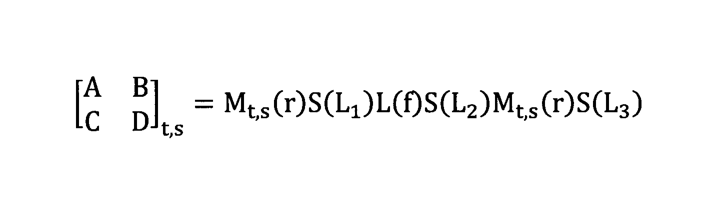
周回Gouy位相シフトθt,sは、共振器11の一周に相当する光線行列(またはABCD行列)を
The circular Gouy phase shift θt,s is the ray matrix (or ABCD matrix) corresponding to one revolution of the
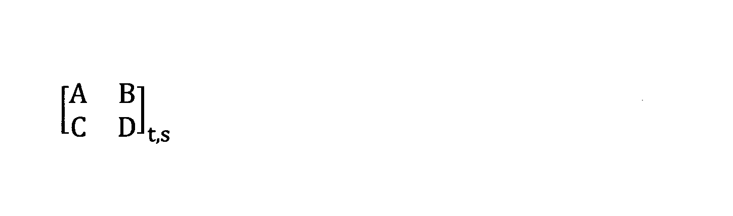
θt,s=arccos((A+D)/2)
で与えられる。ここで、θtはタンジェンタル成分、θsはサジタル成分を表し、Bが正の時は0<θt,s<πの範囲の値をとり、負の時はπ<θt,s<2πの範囲の値をとる。
θt,s=arccos((A+D)/2)
Here, θt represents the tangential component, θs represents the sagittal component, and when B is positive, it takes a value in the range of 0<θt,s<π, and when it is negative, it takes a value in the range of π<θt,s<2π.
共振器11の光線行列は、各要素の積として計算される。
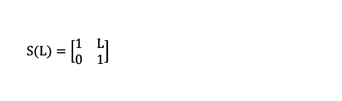
長さLの空間を伝播する際の光線行列S(L)は、
The ray matrix of the
The ray matrix S(L) when propagating through a space of length L is
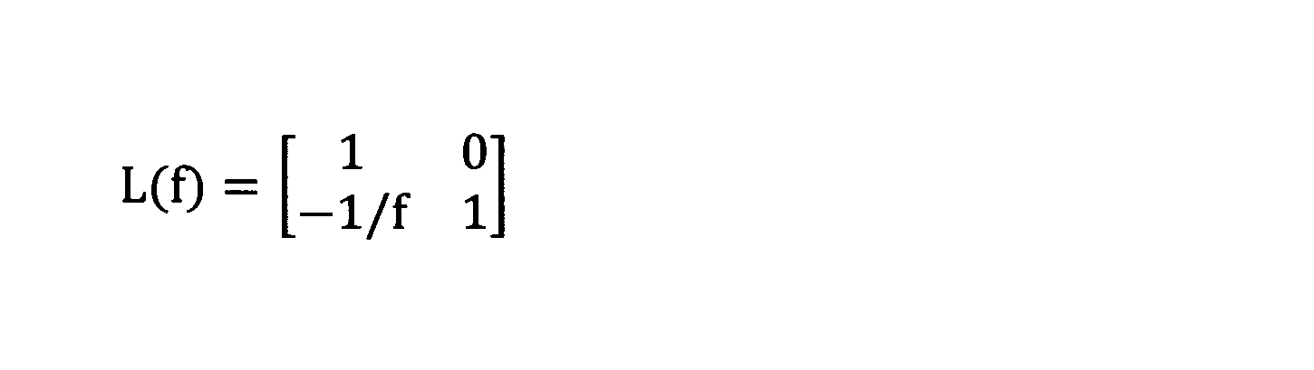
焦点距離fのレンズの光線行列L(f)は、 The ray matrix L(f) of a lens with focal length f is:
周回Gouy位相シフトθは、平面波とガウシアンビームが共振器を1周した時に生じる光の位相の差を表している。0次モード(ガウシアンビーム)とm次の横モードが光共振器を1周した時、位相変化の差はm×θであらわされる。したがって、θ=2π×n/m(mは15未満の整数、nはm以下の整数)を満たすとき、0次モードとm次モードの周回位相変化量が2πの整数倍となり、どちらも共振器に共鳴するため、マルチモード発振する。励起光がガウシアンビームである場合、周回光のmが大きくなるほど空間的な重なりが悪くなって発振が抑制されると考えられる。実施例では11π/7と考えられるマルチモード化が観測された。 The circular Gouy phase shift θ represents the difference in the phase of light that occurs when a plane wave and a Gaussian beam make one revolution around the resonator. When the zeroth mode (Gaussian beam) and the mth transverse mode make one revolution around the optical resonator, the difference in phase change is expressed as m × θ. Therefore, when θ = 2π × n/m (m is an integer less than 15, n is an integer equal to or less than m), the circular phase change amount of the zeroth mode and the mth mode is an integer multiple of 2π, and both resonate with the resonator, resulting in multimode oscillation. When the excitation light is a Gaussian beam, it is believed that the larger m of the circular light is, the worse the spatial overlap becomes, suppressing oscillation. In the embodiment, multimode generation that is thought to be 11π/7 was observed.
レーザ媒質13を照射する励起光パワーが強いほど、屈折率分布は急峻になり、熱レンズの焦点距離fは短くなる。実施例では、タンジェンシャル成分のθtが3π/2となる焦点距離(約20mm)より短くなったと思われる点で、スロープ効率の上昇が観測された。
The stronger the power of the excitation light irradiating the
焦点距離fが20mm以下の範囲でサジタル成分、タンジェンタル成分ともに共振モードが存在する条件は、3mm以上、20mm以下の範囲である。この中で、θt,s=2π×n/mを除いた焦点距離に対し、スロープ効率の上昇とシングル横モードが両立可能となる。 When the focal length f is in the range of 20 mm or less, the condition for the existence of resonant modes for both the sagittal and tangential components is the range of 3 mm or more and 20 mm or less. Among these, for focal lengths other than θt,s = 2π × n/m, both an increase in slope efficiency and a single transverse mode can be achieved.
この範囲の焦点距離fを実現するために、励起光のパワーを徐々に上げて、θtを3π/2に近づける。図2の例では、fが約20mmのときに3π/2となる。この地点で横モードが縮退し、マルチモード発振すると考えられる。 To achieve a focal length f in this range, the power of the excitation light is gradually increased to bring θt closer to 3π/2. In the example in Figure 2, θt reaches 3π/2 when f is approximately 20 mm. At this point, the transverse modes are thought to degenerate, resulting in multimode oscillation.
その後、励起光のパワーをさらに上げて、タンジェンシャル成分のθtを3π/2から遠ざける。このときの熱レンズの焦点距離は6~13mm未満である。 Then, the power of the excitation light is further increased to move the tangential component θt away from 3π/2. At this time, the focal length of the thermal lens is less than 6 to 13 mm.
励起光の拡散を抑制して光吸収の効率を上げるために、θtを3π/2にとなったところから励起光パワーをさらに上げてθtを3π/2から遠ざけると、θt=2π×n/m(m>3)となる地点で、共振器のマルチモード化が再度始まる可能性がある。しかし、このときに共振器に共鳴する光がより高次となるため、θt=3π/2の時よりもマルチモードになる割合は少なく、励起パワーを少し変えて熱レンズの焦点距離をずらすことや、後述するように、レーザ媒質の温度を制御することで回復可能である。横モードの回復については、図5を参照して後述する。 In order to suppress the diffusion of the pump light and increase the efficiency of light absorption, if the pump light power is further increased from the point where θt is 3π/2 to move θt away from 3π/2, the resonator may begin to become multi-mode again at the point where θt = 2π × n/m (m > 3). However, since the light that resonates with the resonator at this time is of a higher order, the rate of becoming multi-mode is smaller than when θt = 3π/2, and this can be recovered by slightly changing the pump power to shift the focal length of the thermal lens, or by controlling the temperature of the laser medium, as described below. The recovery of the transverse mode will be described later with reference to Figure 5.
共振器11に入射する励起光のパワーを上記のように制御することで、熱レンズの効果により励起光の拡散を抑制し、スロープ効率を高めて、従来よりも高い出力パワーのレーザ装置10を実現することができる。
By controlling the power of the excitation light incident on the
図3は、レーザ装置10の構成例を、測定セットアップとともに示す図である。レーザ装置10は、図1を参照して説明したように、共振器11と、共振器11内に配置されるレーザ媒質13を有する。共振器11は、第1ミラー111、第2ミラー112、ミラー113、ミラー114で形成される進行波型の共振器である。レーザ媒質13は、凹面を有する円形の第1ミラー111と第2ミラー112の間に配置されている。
Figure 3 shows an example of the configuration of the
一例として、第1ミラー111と第2ミラー112の凹面の曲率半径は100mm、第1ミラー111と第2ミラー112の間の距離は116mmである。レーザ媒質13として、入射面から出射面までの光軸方向の実効的な長さL=20mmのチタンサファイア結晶が、第1ミラー111と第2ミラー112の間に配置されている。ここで「実効的な長さ」とはレーザ媒質13を通過する光が感じる長さであり、レーザ媒質13の物理長と屈折率、波長等で決まる。チタンサファイア結晶の入射面と出射面の直径は5mmである。レーザ媒質13の入射面は、第1ミラー111から51mmの位置にある。第1ミラー111の凹面によって入射光のビーム径は15μm程度にまで絞られる。
As an example, the radius of curvature of the concave surfaces of the
レーザ装置10は、レーザ媒質13の温度を制御する温度制御機構55を有していてもよい。温度制御機構55は、レーザ媒質13を保持するホルダと、ホルダの温度を調整する温度調整器とを含んでいてもよい。レーザ媒質13の温度を直接変えることは困難なので、例えばレーザ媒質13を保持するホルダの温度を変えて、レーザ媒質13の温度を制御する。レーザ媒質13を保持するホルダの温度を変えることで、レーザ媒質13内に生成される熱レンズの効果を調整できる。この温度制御機構55は、後述するように、熱レンズ効果の影響を調整でき、レーザ媒質13を通過する周回光のマルチモード化を回復する。
The
熱レンズの効果とは、細く絞られた励起光を細く絞ったままレーザ媒質13内を伝搬させる効果である。レーザ媒質13が励起光を吸収することで内部に生じた熱レンズで、励起光の拡散を抑えながら導波させることから、熱レンズの効果を「自己導波効果」、もしくは「自己収束効果」と呼んでもよい。
The thermal lens effect is the effect of propagating narrowly focused excitation light through the
第2ミラー112からミラー113とミラー114と経て第1ミラー111に戻るまでの距離L3は、この構成例では395mmである。周回光は、ミラー114から第1ミラー111に18度の入射角で入射し、第1ミラー111で反射されてレーザ媒質13内に集光される。図3で、素子間を結ぶ実線と二重線は光パスを表し、点線の矢印は電気信号パスを示す。
The distance L3 from the
レーザ装置10は、励起光源31を有していてもよいし、外部から光ファイバ等で共振器11に励起光を入射してもよい。この例で、励起光は、1064nmレーザの2倍波の波長532nmの光である。共振器11は、レーザ媒質13に入射する励起光のレイリー長ZRが2.2mm、励起光に対するレーザ媒質13の実効的な長さLは20mmで吸収係数αが1.8cm-1となるように設計されている。「L×α」の値は3.6であり、1.89を超えている。「ZR×α」の値は0.396であり、0.5未満である。
The
励起光のパワーは、レーザ媒質13の内部に形成される熱レンズの焦点距離fによって変化する周回Gouy位相シフトが、θt,s≠2π×n/mを満たすように制御されている。上述したように、共振器11のθtを3π/2となるまで励起光のパワーを上げ、その後さらに励起光パワーを上げて、θtを3π/2よりも大きくなるレベルに設定されている。励起光源31を用いる場合、励起光源31の出射側で励起光パワーをモニタしてもよい(測定(a))。
The power of the excitation light is controlled so that the circular Gouy phase shift, which changes depending on the focal length f of the thermal lens formed inside the
励起光源31と第1ミラー111の間にレンズ36が配置されていてもよい。レンズ36は、励起光がレーザ媒質13内の焦点で周回光に重畳されるように、励起光を共振器内に入射する。レンズ36の傾きを調整することで、縦方向と横方向の少なくとも一方に1~3mm程度の収差を与えてもよい。
A
レーザ装置10は、シード光源32を有していてもよいし、外部から光ファイバ等で共振器11にシード光を入射してもよい。シード光源32として、たとえば、低出力であるが安定的な波長780nmの連続波外部共振器型半導体レーザを用いることができる。
The
シード光は、注入同期光としてミラー114から共振器11に入射される。図3の例では、シード光源32から出力されたシード光に含まれる特定の偏波成分(たとえばTE成分)が、偏光ビームスプリッタ(図中、「PBS」と表記)33を透過して、電気光学変調器(EOM)34とミラー35を介して、ミラー114に入射する。ミラー114の入射側で、シード光の注入パワーを測定してもよい(測定(b))。
The seed light is incident on the
共振器11の出力パワーを共振器長にフィードバックする縦モード調整回路40を設けてもよい。共振器11の出力の一部をビームスプリッタ(図中、「BS」と表記)15で分岐して、フォトダイオード41で検出する。たとえば、ミラー113をアクチュエータ等で位置調整可能に構成し、フォトダイオード41の出力に基づいて、共振器長がシード光の波長の整数倍となるようにミラー113の位置を調整する。これにより、単一縦モードが維持される。
A longitudinal
周波数ジェネレータ(FG)43で10~20MHzの周波数を生成し、電気光学変調器34に入力することで、シード光の位相の変調をかけてもよい。乗算器42にて、フォトダイオード41で検出された信号に含まれる高周波成分を、変調周波数で同期検波してもよい。同期検波の結果をミラー113の位置調整にフィードバックすることで、共振器11の共振周波数は、シード光の周波数にロックされる。
A frequency of 10 to 20 MHz may be generated by a frequency generator (FG) 43 and input to an electro-
光共振器11を逆走する光が電気光学変調器34とシード光源32に戻らないように、シード光源32と偏光ビームスプリッタ33の間、及び電気光学変調器34とミラー35の間に、光アイソレータを挿入してもよい。また、共振器11からの出力光の保護のため、ビームスプリッタ15と波長板47の間にも光アイソレータを挿入してもよい。また出力光の収差の補正のため、ビームスプリッタ15と波長板47の間にシリンドリカルレンズペアを挿入してもよい。
To prevent the light traveling backward through the
共振器11の出力光は、ビームスプリッタ15を通過して出力される。この出力光が、レーザ装置10の出力である。出力光のパワーをモニタしてもよい(測定(c))。図3の測定セットアップでは、レーザ出力光の特性を評価するために、ビームスプリッタ15の透過光を1/2波長板47を介して偏光ビームスプリッタ16に導き、偏光ビームスプリッタ16でレーザ出力光を2つの偏波に分離する。一方の偏波成分(たとえばTE成分)を、共振器長を掃引した光共振器(図中、「RES」と表記)53に入射し、透過光をフォトダイオード46で検出して、共振器長毎に共鳴する横モードが異なることを利用して横モードの分布を検出し、基本モードの割合を測定する(横モード測定(d))。
The output light of the
光共振器63への入射光の一部をハーフミラー62で分岐して、カメラ61でビーム形状を観察する。偏光ビームスプリッタ16を透過した他方の偏波成分を、1/2波長板48を介して偏光ビームスプリッタ17に導き、偏光ビームスプリッタ17で2つの偏波成分に分離する。偏光ビームスプリッタ17で取り出された偏波成分(たとえばTE成分)は、光スペクトラムアナライザ51でスペクトル観測される。偏光ビームスプリッタ17で取り出されたTM成分は、ハーフミラー(HM)18に導かれて、シード光のTM成分と合波される。合波された光は、フォトダイオード19で検波されて電気スペクトラムアナライザ52で、ビート周波数が計測される。
A part of the light incident on the
横モード測定(d)、光スペクトラムアナライザ51によるスペクトル観測、及び電気スペクトラムアナライザ52によるビート計測と、これらの測定サイトまでの光学系は、レーザ出力光の特性評価のためのものであり、レーザ装置10には含まれない。
Transverse mode measurement (d), spectrum observation by the
図4は、励起光パワーと、レーザ特性の関係を示す図である。下段は、励起光パワーとレーザ出力光パワーの関係を示す。上段は、励起光パワーと基本モード(Fundamental Mode)結合率との関係を示す。基本モードは、ビームの中央部で強度が最も強くなるガウス分布型の強度分布のTEM00モードである。 Figure 4 shows the relationship between excitation light power and laser characteristics. The lower part shows the relationship between excitation light power and laser output light power. The upper part shows the relationship between excitation light power and fundamental mode coupling rate. The fundamental mode is the TEM00 mode, which has a Gaussian intensity distribution with the strongest intensity in the center of the beam.
励起光パワーは、図3の励起光パワー測定(a)で測定されている。レーザ出力パワーは、図3の出力パワー測定(c)で測定されている。基本モードへの結合率は、横モードに含まれる基本モードの割合で表され、図3のレーザ出力光の横モード測定(d)で得られている。 The pump light power is measured by pump light power measurement (a) in Figure 3. The laser output power is measured by output power measurement (c) in Figure 3. The coupling rate to the fundamental mode is expressed as the proportion of the fundamental mode contained in the transverse modes, and is obtained by transverse mode measurement of the laser output light in Figure 3 (d).
黒丸は、レーザ媒質13を保持するホルダの温度を23℃に設定し、注入同期すなわちシード光の注入をオンにしたときのデータである。グレイの四角は、レーザ媒質13を保持するホルダの温度を20℃に設定し、注入同期をオンにしたときのデータである。白丸は、レーザ媒質13を保持するホルダの温度を23℃に設定し、注入同期をオフにしたときのデータである。注入同期をオフにしたときは光が2方向にでるので、2つの光を合わせた値を提示している。
The black circles represent data when the temperature of the holder holding the
ホルダ温度23℃で、励起光のパワーを0Wから8W程度まで上げていくと、ほぼリニアな関係で、レーザ出力パワーが増大する。この傾向は、注入同期の有無によらずに同じであるが、注入同期を行っているほうが、出力パワーは高い。 When the power of the excitation light is increased from 0 W to approximately 8 W at a holder temperature of 23°C, the laser output power increases in an almost linear relationship. This trend is the same regardless of whether or not injection locking is performed, but the output power is higher when injection locking is performed.
励起光パワーをさらに上げていくと、レーザ出力パワーはリニアな関係で上昇する。注目すべきは、励起光パワーの低い第1パワー領域と、励起光パワーの高い第2パワー領域で、スロープ効率が異なる点である。 As the pump light power is further increased, the laser output power increases in a linear relationship. It is noteworthy that the slope efficiency is different between the first power region where the pump light power is low and the second power region where the pump light power is high.
スロープ効率は、励起光パワー上昇に対するレーザ出力パワー上昇の比を表し、すなわち、レーザ装置10の光変換効率と相関する。注入同期オンのとき、第1パワー領域でのスロープ効率は、30%以上、40%未満であり、線形フィットした際の傾きでは約38%である。これに対し、第2パワー領域でのスロープ効率は、45%以上、60%以下であり、線形フィットした際の傾きでは、50%を超える。レーザ出力光のリニアな増大傾向は、注入同期の有無にかかわらず同じであるが、注入同期オンのときの方が、同じ励起光パワーに対するレーザ出力パワーが高い。励起光パワー増分に対する出力光パワー増分の比率で表されるスロープ効率は、励起光パワーが所定のレベル(この例では8W)以下の第1パワー領域よりも、所定のレベルよりも高い第2パワー領域のほうが高いことがわかる。
The slope efficiency represents the ratio of the laser output power increase to the pump light power increase, i.e., it correlates with the optical conversion efficiency of the
第2パワー領域で、ホルダ温度が20℃の条件でレーザ発振すると、ホルダ温度が23℃のときと同じパワーのレーザ光を出力し、同じスロープ効率が達成される。 When the laser oscillates in the second power region with the holder temperature at 20°C, it outputs laser light with the same power as when the holder temperature is 23°C, and achieves the same slope efficiency.
一般に市販されている注入同期のないチタンサファイアレーザは、励起光パワー18Wで5W程度の出力しか得られない。これに対し、実施形態の構成では、注入同期を行う場合、励起光パワー18Wで、8W以上のレーザ出力パワーが得られている。従来のチタンサファイアレーザと比較して、出力パワーが30~60%も向上することがわかる。 Titanium sapphire lasers that are generally available on the market without injection locking can only achieve an output of about 5 W with an excitation light power of 18 W. In contrast, with the configuration of the embodiment, when injection locking is performed, a laser output power of 8 W or more can be achieved with an excitation light power of 18 W. It can be seen that the output power is improved by 30 to 60% compared to conventional titanium sapphire lasers.
次に、基本モードへの結合率を参照すると、第1パワー領域で、80%以上の横モードが得られている。第2パワー領域の中でも、13Wを超えるパワーでは、90%以上の横モードが得られている。しかし、第1パワー領域と第2パワー領域の境界で、基本モード結合率が急激に悪化している。基本モード結合率が急激に落ち込む地点は、スロープの傾きが変わる変化点と一致している。変化点での励起光パワーは、正確には7.88Wである。この点が、周回Gouy位相シフトθtが3π/2となった点であると考えられる。 Next, looking at the coupling rate to the fundamental mode, 80% or more of the transverse mode is obtained in the first power region. In the second power region, at powers exceeding 13 W, 90% or more of the transverse mode is obtained. However, at the boundary between the first and second power regions, the fundamental mode coupling rate suddenly deteriorates. The point where the fundamental mode coupling rate suddenly drops coincides with the inflection point where the slope changes. The pump light power at the inflection point is 7.88 W to be precise. This point is thought to be the point where the circular Gouy phase shift θt becomes 3π/2.
図4のマルチモードとなる点、またはスロープの変化点は、図2でθt=3π/2となる励起光パワーであり、レーザ媒質13内に、焦点距離fが約20mmの熱レンズが形成されていることが示唆されている。θt=3π/2となるところから、さらに励起光パワーを上げることで、θt≠2π×n/mとなり、横モードが回復し、かつ光変換効率が向上する。
The point where the multimode occurs in Figure 4, or the point where the slope changes, is the excitation light power where θt = 3π/2 in Figure 2, suggesting that a thermal lens with a focal length f of approximately 20 mm is formed within the
図5は、図4と同じ3通りの条件で光共振器53の近くに設置したカメラ61で得られた画像である。励起光パワーを、5.67W、7.88W、13.44W、17.89W、22.36Wと上げていく。
Figure 5 shows images obtained by a
励起光パワーが7.88W以下のとき、ホルダ温度が23℃の条件では、5.67Wの励起光パワーで、同期注入の有無によらずに良好なビーム形状が得られている。励起光を7.88Wに上げると、注入同期オンのときに特にビームが横方向に分裂し、マルチモード化する。これはタンジェンシャル成分の周回Gouy位相シフトθtが3π/2となり、マルチモード発振したことを意味する。 When the pump light power is 7.88 W or less and the holder temperature is 23°C, a good beam shape is obtained with a pump light power of 5.67 W, regardless of whether or not synchronous injection is used. When the pump light is increased to 7.88 W, the beam splits laterally, especially when injection locking is on, and becomes multimode. This means that the circular Gouy phase shift θt of the tangential component becomes 3π/2, resulting in multimode oscillation.
励起光パワーを13.44Wにすると、ビーム形状が横方向に乱れている。同じ励起光パワーで、ホルダ温度が23℃では、7.88Wのときと比較してビーム形状がやや改善されているが、横モードの悪化が残っている。これはθt=2π×n/mの条件が再び満たされたことを意味する。計算によって、θt=11π/7であることが示唆される。 When the pump light power is increased to 13.44 W, the beam shape is disturbed laterally. At the same pump light power and holder temperature of 23°C, the beam shape is slightly improved compared to 7.88 W, but the deterioration of the transverse mode remains. This means that the condition θt = 2π × n/m is satisfied again. Calculations suggest that θt = 11π/7.
励起光パワーを17.89Wにすると、ホルダ温度20、23℃の条件ともに、ビーム形状がきれいに整っている。励起光パワーを22.36Wにすると、ホルダ温度23℃の条件では、ビーム形状が再度悪化するが、ホルダ温度20℃で、ビーム形状が回復されている。これはホルダ温度23℃の条件ではθt=2π×n/mの条件が満たされたが、ホルダ温度20℃に変えたことによって焦点距離がわずかに変わって、条件が満たされなくなったことを示唆する。 When the excitation light power is set to 17.89 W, the beam shape is neatly aligned for both holder temperatures of 20 and 23°C. When the excitation light power is set to 22.36 W, the beam shape deteriorates again at a holder temperature of 23°C, but is restored at a holder temperature of 20°C. This suggests that the condition θt = 2π x n/m was met at a holder temperature of 23°C, but changing the holder temperature to 20°C caused a slight change in the focal length, meaning that the condition was no longer met.
図5の観察結果から、マルチモード化はホルダ温度、すなわちレーザ媒質13の温度を制御することで、チューニングまたは回復可能であることがわかる。温度制御機構55を設けることで、励起光の吸収によりレーザ媒質13を通過する周回光のマルチモード化を回復することができる。
The observation results in Figure 5 show that the multi-mode can be tuned or restored by controlling the holder temperature, i.e., the temperature of the
図6は、光スペクトラムアナライザ51の測定結果である。上段は、22.5W励起で注入同期オンのときのスペクトル、下段は22.5W励起で注入同期オフのときのスペクトルである。
Figure 6 shows the measurement results of the
上段の注入同期オンのとき、単一縦モードが得られている。このときのレーザ出力光パワーは9.8Wである。注入同期のない下段では、完全にマルチモード発振している。 When injection locking is on in the upper row, a single longitudinal mode is obtained. The laser output optical power at this time is 9.8 W. In the lower row, where injection locking is not present, complete multimode oscillation is obtained.
図7は、レーザ出力光とシード光のビート計測結果である。図3の電気スペクトラムアナライザ52で計測されている。図7は、図6の上段のスペクトルをより狭い範囲でみたものである。線幅が十分に細く、シード光のモードを劣化させずにハイパワー化されていることがわかる。
Figure 7 shows the results of beat measurement of the laser output light and the seed light. This was measured using the
図8は、レーザ装置10の動作方法のフローチャートである。進行型の共振器11で、凹面をもつ第1ミラー111と第2ミラー112の間にレーザ媒質13を配置する(S11)。共振器11を周回する周回光がレーザ媒質13の内部に焦点を結ぶように、第1ミラー111と第2ミラー112の位置を決定する(S12)。第1ミラー111、第2ミラー112、及びレーザ媒質13の配置位置は、第1ミラー111と第2ミラー112の曲率半径、レーザ媒質13の実効的な長さL等に基づいて決定される。ここで、レーザ媒質13の励起光に対する吸収係数αとLは、L×α>1.89の関係を満たす。
Figure 8 is a flowchart of the operation method of the
励起光をレーザ媒質13内の焦点で周回光に重畳し、励起光を周回光よりも細く集光して、ZR×α<0.5でレーザ装置10を動作させる(S13)。周回光に重畳された励起光は、レーザ媒質13内に形成される熱レンズの効果で拡散が抑制され、スロープ効率が向上する。レーザ装置10の動作が終了するまで(S14でYES)、ステップS13のレーザ出力動作は継続される。
The pumping light is superimposed on the circulating light at a focal point in the
図9は、図8のステップS13のフローチャートである。励起光のパワーを0から上げて、共振器11のθt=3π/2に近づける(S131)。θt=3π/2としたところから、さらに励起光のパワーを上げて、θtをさらに上昇させる(S132)。θt≠2π×n/mとなる点で励起光パワーを固定してもよい。ここでmは最大14までを考慮すれば十分である。また、レーザ媒質13の温度、もしくは、励起光パワーを制御して周回Gouy位相シフトθtが2π×n/m(mは15未満の整数、nはm以下の整数)とならないように制御して、レーザ媒質13を通過する周回光がマルチモード発振することを回避してもよい。これにより高い光変換効率のレーザ装置が実現される。
Figure 9 is a flowchart of step S13 in Figure 8. The power of the pumping light is increased from 0 to approach θt = 3π/2 of the resonator 11 (S131). From the point where θt = 3π/2, the power of the pumping light is further increased to further increase θt (S132). The pumping light power may be fixed at a point where θt ≠ 2π × n/m. Here, it is sufficient to consider m up to a maximum of 14. In addition, the temperature of the
このように、レーザ装置10の動作方法は、
第1ミラー111と第2ミラー112を含む複数のミラーで進行波型の共振器11を形成し、第1ミラー111と第2ミラー112の間にレーザ媒質13を配置し、共振器11を周回する周回光がレーザ媒質13の内部に焦点を結ぶように第1ミラー111と第2ミラー112の位置を決定し、共振器11に励起光を入射して励起光をレーザ媒質13内の焦点で周回光に重畳し、励起光を周回光よりも細く集光し、
共振器の周回Gouy位相シフトが2π×n/m(mは15未満の整数、nはm以下の整数)とならないように制御し、
励起光のレイリー長をZR、前記レーザ媒質による前記光の吸収係数をαとすると、
ZR×α<0.5
の条件で動作させる。
Thus, the method of operation of the
A traveling
The circular Gouy phase shift of the resonator is controlled so as not to be 2π×n/m (where m is an integer less than 15 and n is an integer equal to or less than m);
If the Rayleigh length of the excitation light is Z R and the absorption coefficient of the light by the laser medium is α, then
ZR × α<0.5
Operate under the following conditions.
より好ましい例では、励起光に対するレーザ媒質13の実効的な長さをLとすると、
L×α>1.89
かつ、ZR×α<0.5
である。
In a more preferable example, when the effective length of the
L×α>1.89
And ZR × α<0.5
It is.
上述のように、励起光はレーザ媒質13内に生成される熱レンズにより集光される。励起光のパワーを上げて、熱レンズの焦点距離を短縮し、共振器11の周回Gouy位相を3π/2に近づけ、さらに励起光のパワーを上げて前記熱レンズの焦点距離を短縮して、周回Gouy位相シフトを3π/2よりさらに上昇させる。これにより、スロープ効率が向上する。レーザ媒質13の温度、もしくは、励起光パワーを制御して周回Gouy位相シフトθが2π×n/m(mは15未満の整数、nはm以下の整数)とならないように制御することで、周回光のマルチモード発振を抑制することができる。
As described above, the pump light is focused by the thermal lens generated in the
以上、特定の構成例に基づいて実施例を説明したが、本発明は上述した構成例に限定されない。励起光のレイリー長ZR、励起光に対するレーザ媒質の吸収係数αは、L×α>1.89かつZR×α<0.5を満たす範囲で、適切に選択される。共振器11は、用いる凹面ミラーの曲率半径、レーザ媒質のサイズ等に応じて、適切な配置で構成される。励起光の波長、シード光の波長は、目的とするレーザ出力光に応じて選択される。いずれの場合も、従来構成と比較して高い光変換効率のレーザ装置を実現できる。
Although the embodiment has been described above based on a specific configuration example, the present invention is not limited to the above-mentioned configuration example. The Rayleigh length ZR of the pumping light and the absorption coefficient α of the laser medium for the pumping light are appropriately selected within a range that satisfies L×α>1.89 and ZR ×α<0.5. The
10 レーザ装置
11 共振器
111 第1ミラー
112 第2ミラー
113、114 ミラー
13 レーザ媒質
31 励起光源
32 シード光源
36 レンズ
40 縦モード調整回路
55 温度制御機構
ZR 励起光のレイリー長
α レーザ媒質の励起光に対する吸収係数
L 励起光に対するレーザ媒質の実効的な長さ
θ 周回Gouy位相シフト
10
Claims (13)
前記第1ミラーと前記第2ミラーの間に配置されるレーザ媒質と、
を有し、
前記第1ミラーと前記第2ミラーは、前記共振器を周回する周回光が前記レーザ媒質の内部に焦点を結ぶように配置され、
前記共振器に入射される励起光が前記焦点で前記周回光に重畳されて前記周回光よりも細くしぼられ、
前記励起光のレイリー長をZR、前記レーザ媒質の前記励起光に対する吸収係数をαとすると、
ZR×α<0.5
であり、前記共振器の周回Gouy位相シフトは2π×n/m(mは15未満の整数、nはm以下の整数)を除く値を有する、
レーザ装置。 a traveling wave type resonator including a first mirror and a second mirror;
a laser medium disposed between the first mirror and the second mirror;
having
the first mirror and the second mirror are arranged so that the circulating light circulating in the resonator is focused inside the laser medium;
the excitation light incident on the resonator is superimposed on the circulating light at the focal point and narrowed to a smaller diameter than the circulating light,
When the Rayleigh length of the pump light is Z R and the absorption coefficient of the laser medium with respect to the pump light is α,
ZR × α<0.5
and the circular Gouy phase shift of the resonator has a value other than 2π×n/m (where m is an integer less than 15 and n is an integer equal to or less than m);
Laser device.
L×α>1.89
である、請求項1に記載のレーザ装置。 If the effective length of the laser medium with respect to the excitation light is L, then
L×α>1.89
2. The laser device according to claim 1 ,
を有する請求項1または2に記載のレーザ装置。 the laser device includes a temperature control mechanism for controlling a temperature of the laser medium;
3. The laser device according to claim 1, further comprising:
請求項3に記載のレーザ装置。 4. The laser device according to claim 3, wherein the temperature control mechanism includes a holder for holding the laser medium, and a temperature regulator for adjusting a temperature of the holder.
請求項3または4に記載のレーザ装置。 The temperature control mechanism recovers the multi-mode of the circulating light passing through the laser medium by absorbing the excitation light.
5. The laser device according to claim 3 or 4.
前記共振器の共振器長を前記シード光の波長の整数倍に制御する縦モード調整回路と、
を有する、請求項1~5のいずれか1項に記載のレーザ装置。 The laser device further includes a seed light source that inputs seed light into the resonator.
a longitudinal mode adjustment circuit that controls a cavity length of the cavity to an integer multiple of the wavelength of the seed light;
The laser device according to any one of claims 1 to 5, comprising:
請求項1~6のいずれか1項に記載のレーザ装置。 a slope efficiency expressed as a ratio of an increment of output light power to an increment of pump light power is higher in a second power region in which the pump light power is higher than a predetermined level than in a first power region in which the pump light power is equal to or lower than the predetermined level;
The laser device according to any one of claims 1 to 6.
請求項7に記載のレーザ装置。 the slope efficiency in the first power region is greater than or equal to 30% and less than 40%;
8. The laser device according to claim 7.
請求項7または8に記載のレーザ装置。 the slope efficiency in the second power region is 45% or more and 60% or less;
9. The laser device according to claim 7 or 8.
前記第1ミラーと前記第2ミラーの間にレーザ媒質を配置し、
前記共振器を周回する周回光が前記レーザ媒質の内部に焦点を結ぶように前記第1ミラーと前記第2ミラーの位置を決定し、
前記共振器に励起光を入射して前記励起光を前記焦点で前記周回光に重畳し、前記励起光を前記周回光よりも細く集光し、
前記共振器の周回Gouy位相シフトが2π×n/m(mは15未満の整数、nはm以下の整数)とならないように制御し、
前記励起光のレイリー長をZR、前記レーザ媒質の前記励起光に対する吸収係数をαとすると
ZR×α<0.5
の条件で動作するレーザ装置の動作方法。 forming a traveling wave type resonator with a plurality of mirrors including a first mirror and a second mirror;
A laser medium is disposed between the first mirror and the second mirror;
determining positions of the first mirror and the second mirror so that the circulating light circulating in the resonator is focused inside the laser medium;
An excitation light is input to the resonator, the excitation light is superimposed on the circulating light at the focal point, and the excitation light is focused to be thinner than the circulating light;
Controlling the circular Gouy phase shift of the resonator so as not to be 2π×n/m (where m is an integer less than 15 and n is an integer equal to or less than m);
When the Rayleigh length of the pumping light is Z R and the absorption coefficient of the laser medium with respect to the pumping light is α, Z R ×α<0.5
A method for operating a laser device that operates under the above conditions.
L×α>1.89
の条件で動作する、請求項10に記載のレーザ装置の動作方法。 When the effective length of the laser medium with respect to the pumping light is L, the laser device satisfies the following: L×α>1.89
The method of claim 10, wherein the laser device is operated under the condition:
請求項10または11に記載のレーザ装置の動作方法。 The excitation light is focused by a thermal lens generated within the laser medium.
A method for operating a laser device according to claim 10 or 11.
請求項12に記載のレーザ装置の動作方法。 increasing the power of the pump light to shorten the focal length of the thermal lens and bring the circular Gouy phase shift of the resonator closer to 3π/2, and further increasing the power of the pump light to shorten the focal length of the thermal lens and further increase the circular Gouy phase shift beyond 3π/2;
13. A method for operating a laser device according to claim 12.
Priority Applications (3)
| Application Number | Priority Date | Filing Date | Title |
|---|---|---|---|
| JP2020165045A JP7513886B2 (en) | 2020-09-30 | 2020-09-30 | Laser device and method of operating a laser device |
| GB2113775.7A GB2599500A (en) | 2020-09-30 | 2021-09-27 | Laser device and method for operating laser device |
| US17/489,537 US12249802B2 (en) | 2020-09-30 | 2021-09-29 | Laser device and method for operating laser device |
Applications Claiming Priority (1)
| Application Number | Priority Date | Filing Date | Title |
|---|---|---|---|
| JP2020165045A JP7513886B2 (en) | 2020-09-30 | 2020-09-30 | Laser device and method of operating a laser device |
Publications (2)
| Publication Number | Publication Date |
|---|---|
| JP2022057009A JP2022057009A (en) | 2022-04-11 |
| JP7513886B2 true JP7513886B2 (en) | 2024-07-10 |
Family
ID=78399556
Family Applications (1)
| Application Number | Title | Priority Date | Filing Date |
|---|---|---|---|
| JP2020165045A Active JP7513886B2 (en) | 2020-09-30 | 2020-09-30 | Laser device and method of operating a laser device |
Country Status (3)
| Country | Link |
|---|---|
| US (1) | US12249802B2 (en) |
| JP (1) | JP7513886B2 (en) |
| GB (1) | GB2599500A (en) |
Citations (9)
| Publication number | Priority date | Publication date | Assignee | Title |
|---|---|---|---|---|
| JP2003500861A (en) | 1999-05-21 | 2003-01-07 | ギガオプティクス・ゲーエムベーハー | Passive mode-locked femtosecond laser |
| JP2007288166A (en) | 2006-03-20 | 2007-11-01 | National Institute Of Advanced Industrial & Technology | High beam quality laser |
| JP2008227378A (en) | 2007-03-15 | 2008-09-25 | Keyence Corp | Laser beam machine and solid-state laser resonator |
| JP2010034413A (en) | 2008-07-30 | 2010-02-12 | Hamamatsu Photonics Kk | Solid-state laser apparatus |
| US20140002892A1 (en) | 2011-01-10 | 2014-01-02 | Peter Russbuldt | Optical resonator with direct geometric access to the optical axis |
| WO2016103483A1 (en) | 2014-12-26 | 2016-06-30 | 学校法人東京理科大学 | Titanium-sapphire laser apparatus, laser apparatus for exposure apparatus, and titanium-sapphire amplifier |
| JP2017516160A (en) | 2014-05-15 | 2017-06-15 | フラウンホッファー−ゲゼルシャフト ツァ フェルダールング デァ アンゲヴァンテン フォアシュンク エー.ファオ | Spectral broadening method and arrangement of laser pulses for nonlinear pulse compression |
| JP2018074105A (en) | 2016-11-04 | 2018-05-10 | 株式会社リコー | Laser device, ignition device and internal combustion engine |
| CN109586150A (en) | 2018-11-29 | 2019-04-05 | 山西大学 | A kind of single resonance chamber realization continuous single frequency all-solid-state laser of hectowatt grade |
Family Cites Families (26)
| Publication number | Priority date | Publication date | Assignee | Title |
|---|---|---|---|---|
| US5007717A (en) * | 1988-05-11 | 1991-04-16 | Antonello Cutolo | Real time analyzer for pulsed laser systems |
| US5097471A (en) * | 1990-12-21 | 1992-03-17 | Coherent, Inc. | Mode-locked laser using non-linear self-focusing element |
| US5638397A (en) * | 1994-02-04 | 1997-06-10 | Spectra-Physics Lasers, Inc. | Confocal-to-concentric diode pumped laser |
| JPH08181369A (en) * | 1994-12-27 | 1996-07-12 | Fuji Photo Film Co Ltd | Laser diode excitation solid state laser |
| JP3831993B2 (en) * | 1996-10-28 | 2006-10-11 | ソニー株式会社 | Laser light generator |
| JPH11261137A (en) * | 1998-03-12 | 1999-09-24 | Seitai Hikarijoho Kenkyusho:Kk | Laser |
| JP2000221549A (en) | 1999-02-02 | 2000-08-11 | Japan Science & Technology Corp | Ultrashort pulse light generating method and apparatus using Raman resonator |
| DE10052461B4 (en) * | 2000-10-23 | 2007-09-06 | Lumera Laser Gmbh | Device for generating laser light |
| US6750421B2 (en) | 2002-02-19 | 2004-06-15 | Gsi Lumonics Ltd. | Method and system for laser welding |
| WO2007118269A1 (en) | 2006-04-13 | 2007-10-25 | Macquarie University | Continuous-wave laser |
| JP2008028379A (en) * | 2006-06-22 | 2008-02-07 | Fujifilm Corp | Mode-locked laser device |
| WO2008070890A1 (en) * | 2006-12-14 | 2008-06-19 | The Australian National University | Optical system and method |
| US7864821B2 (en) * | 2007-09-28 | 2011-01-04 | Fujifilm Corporation | Mode-locked solid-state laser apparatus |
| US8542712B2 (en) * | 2009-01-21 | 2013-09-24 | University Of Dundee | Photonic devices based on conical refraction |
| EP2711121B1 (en) | 2011-05-19 | 2015-12-16 | Murata Machinery, Ltd. | Laser processing machine |
| JP2014531777A (en) | 2011-10-07 | 2014-11-27 | マツクス−プランク−ゲゼルシヤフト ツール フエルデルング デル ヴイツセンシヤフテン エー フアウMAX−PLANCK−GESELLSCHAFT ZUR FOeRDERUNG DER WISSENSCHAFTEN E.V. | Laser device using mode locking based on Kerr effect and its operation |
| EP3751684A1 (en) * | 2013-03-15 | 2020-12-16 | Cynosure, Inc. | Picosecond optical radiation systems and methods of use |
| JP2017059683A (en) | 2015-09-16 | 2017-03-23 | 国立大学法人 東京大学 | Laser oscillator and spectroscopic device equipped with laser oscillator, optical coherence tomography device, asynchronous optical sampling device, long-range absolute distance measuring device, CW laser high-speed and high-resolution spectroscopic device |
| US10281278B2 (en) * | 2016-01-07 | 2019-05-07 | Frederick Ira MOXLEY, III | Room-temperature exciton-polariton superfluid quantum interference device and quatron-polariton superconducting quantum interference device |
| WO2018092813A1 (en) | 2016-11-16 | 2018-05-24 | 国立大学法人電気通信大学 | Laser resonator and method for designing laser resonator |
| AU2017375481A1 (en) | 2016-12-16 | 2019-06-20 | Quantum-Si Incorporated | Compact mode-locked laser module |
| CN107565360B (en) | 2017-08-21 | 2018-05-22 | 华中科技大学 | A kind of kerr lens mode locking ti sapphire laser of diode-end-pumped |
| US10724946B2 (en) * | 2017-09-19 | 2020-07-28 | Sparrow Detect, Inc. | Tunable light source cavity detection using a plurality of axial-plus-transverse modes |
| GB2566997A (en) * | 2017-09-29 | 2019-04-03 | Oclaro Tech Ltd | Combined frequency and mode filter |
| CN108767642B (en) * | 2018-03-08 | 2020-09-15 | 上海交通大学 | Method for generating low-repetition-frequency high-energy pulse from mode-locked laser |
| CN109742648A (en) | 2019-01-28 | 2019-05-10 | 河海大学 | Infrared Solid State Laser Based on External Cavity Optical Parametric Oscillation and Stimulated Raman Scattering |
-
2020
- 2020-09-30 JP JP2020165045A patent/JP7513886B2/en active Active
-
2021
- 2021-09-27 GB GB2113775.7A patent/GB2599500A/en active Pending
- 2021-09-29 US US17/489,537 patent/US12249802B2/en active Active
Patent Citations (9)
| Publication number | Priority date | Publication date | Assignee | Title |
|---|---|---|---|---|
| JP2003500861A (en) | 1999-05-21 | 2003-01-07 | ギガオプティクス・ゲーエムベーハー | Passive mode-locked femtosecond laser |
| JP2007288166A (en) | 2006-03-20 | 2007-11-01 | National Institute Of Advanced Industrial & Technology | High beam quality laser |
| JP2008227378A (en) | 2007-03-15 | 2008-09-25 | Keyence Corp | Laser beam machine and solid-state laser resonator |
| JP2010034413A (en) | 2008-07-30 | 2010-02-12 | Hamamatsu Photonics Kk | Solid-state laser apparatus |
| US20140002892A1 (en) | 2011-01-10 | 2014-01-02 | Peter Russbuldt | Optical resonator with direct geometric access to the optical axis |
| JP2017516160A (en) | 2014-05-15 | 2017-06-15 | フラウンホッファー−ゲゼルシャフト ツァ フェルダールング デァ アンゲヴァンテン フォアシュンク エー.ファオ | Spectral broadening method and arrangement of laser pulses for nonlinear pulse compression |
| WO2016103483A1 (en) | 2014-12-26 | 2016-06-30 | 学校法人東京理科大学 | Titanium-sapphire laser apparatus, laser apparatus for exposure apparatus, and titanium-sapphire amplifier |
| JP2018074105A (en) | 2016-11-04 | 2018-05-10 | 株式会社リコー | Laser device, ignition device and internal combustion engine |
| CN109586150A (en) | 2018-11-29 | 2019-04-05 | 山西大学 | A kind of single resonance chamber realization continuous single frequency all-solid-state laser of hectowatt grade |
Also Published As
| Publication number | Publication date |
|---|---|
| US12249802B2 (en) | 2025-03-11 |
| GB2599500A (en) | 2022-04-06 |
| US20220102931A1 (en) | 2022-03-31 |
| JP2022057009A (en) | 2022-04-11 |
| GB202113775D0 (en) | 2021-11-10 |
Similar Documents
| Publication | Publication Date | Title |
|---|---|---|
| JP5290958B2 (en) | Laser wavelength converter | |
| KR101324265B1 (en) | A laser apparatus | |
| JP5649548B2 (en) | Non-critical phase matching in CLBO to generate sub-213 nm wavelengths | |
| JP4636315B2 (en) | One-dimensional illumination device and image generation device | |
| ES2885203T3 (en) | Optical intracavity parametric oscillator | |
| JP6807897B2 (en) | Reduction of laser spectral bandwidth | |
| US7778291B2 (en) | Wavelength converting laser device | |
| US8542712B2 (en) | Photonic devices based on conical refraction | |
| US20070291810A1 (en) | Low speckle noise monolithic microchip rgb lasers | |
| KR102344775B1 (en) | High Efficiency Laser System for Third Harmonic Generation | |
| KR20150129021A (en) | Highly Efficient, Single-Pass, Harmonic Generator with Round Output Beam | |
| US20120044959A1 (en) | Terahertz source | |
| Goth et al. | Limitations of homogeneous and segmented single-crystal compact TEM00-mode Ho3+: YAG laser resonators: K. Goth et al. | |
| JP2001168429A (en) | Solid state laser oscillator | |
| JP7513886B2 (en) | Laser device and method of operating a laser device | |
| Kwiatkowski | Highly efficient high power CW and Q-switched Ho: YLF laser | |
| US7760775B2 (en) | Apparatus and method of generating laser beam | |
| JP2008283189A (en) | Diode-pumped laser device using anisotropic laser crystal | |
| Ostermeyer et al. | 50 Watt average output power with 1.2* DL beam quality from a single rod Nd: YALO laser with phase-conjugating SBS mirror | |
| JP4862960B2 (en) | Wavelength conversion laser device and image display device | |
| Vodchits et al. | Eye-safe radiation source based on an optical parametric oscillator | |
| RU2346367C2 (en) | Solid-state single-pulse laser and two-wave laser beam generator | |
| My et al. | Single-frequency operation of an orange avalanche upconversion laser for high-resolution laser spectroscopy | |
| JP2025515286A (en) | Intracavity frequency conversion in solid-state laser resonators with end pumping. | |
| US20210028599A1 (en) | Laser wavelength stabilization apparatus |
Legal Events
| Date | Code | Title | Description |
|---|---|---|---|
| A621 | Written request for application examination |
Free format text: JAPANESE INTERMEDIATE CODE: A621 Effective date: 20230830 |
|
| A977 | Report on retrieval |
Free format text: JAPANESE INTERMEDIATE CODE: A971007 Effective date: 20240410 |
|
| TRDD | Decision of grant or rejection written | ||
| A01 | Written decision to grant a patent or to grant a registration (utility model) |
Free format text: JAPANESE INTERMEDIATE CODE: A01 Effective date: 20240528 |
|
| A61 | First payment of annual fees (during grant procedure) |
Free format text: JAPANESE INTERMEDIATE CODE: A61 Effective date: 20240610 |
|
| R150 | Certificate of patent or registration of utility model |
Ref document number: 7513886 Country of ref document: JP Free format text: JAPANESE INTERMEDIATE CODE: R150 |