JP7484447B2 - Method, program and system for deploying services on a cluster system - Patents.com - Google Patents
Method, program and system for deploying services on a cluster system - Patents.com Download PDFInfo
- Publication number
- JP7484447B2 JP7484447B2 JP2020097641A JP2020097641A JP7484447B2 JP 7484447 B2 JP7484447 B2 JP 7484447B2 JP 2020097641 A JP2020097641 A JP 2020097641A JP 2020097641 A JP2020097641 A JP 2020097641A JP 7484447 B2 JP7484447 B2 JP 7484447B2
- Authority
- JP
- Japan
- Prior art keywords
- service
- node
- run
- cluster
- services
- Prior art date
- Legal status (The legal status is an assumption and is not a legal conclusion. Google has not performed a legal analysis and makes no representation as to the accuracy of the status listed.)
- Active
Links
- 238000000034 method Methods 0.000 title claims description 84
- 238000010586 diagram Methods 0.000 description 37
- 230000008569 process Effects 0.000 description 11
- 238000004891 communication Methods 0.000 description 10
- 230000006870 function Effects 0.000 description 9
- 238000012545 processing Methods 0.000 description 7
- 230000008859 change Effects 0.000 description 4
- 238000013515 script Methods 0.000 description 4
- 230000001419 dependent effect Effects 0.000 description 3
- 239000000284 extract Substances 0.000 description 3
- 238000004364 calculation method Methods 0.000 description 2
- 238000005401 electroluminescence Methods 0.000 description 2
- 238000005516 engineering process Methods 0.000 description 2
- 230000005540 biological transmission Effects 0.000 description 1
- 238000012790 confirmation Methods 0.000 description 1
- 238000009434 installation Methods 0.000 description 1
- 239000004973 liquid crystal related substance Substances 0.000 description 1
- 238000012986 modification Methods 0.000 description 1
- 230000004048 modification Effects 0.000 description 1
- 239000007787 solid Substances 0.000 description 1
- 230000003068 static effect Effects 0.000 description 1
- 230000001360 synchronised effect Effects 0.000 description 1
- 230000000007 visual effect Effects 0.000 description 1
Images


Classifications
-
- H—ELECTRICITY
- H04—ELECTRIC COMMUNICATION TECHNIQUE
- H04L—TRANSMISSION OF DIGITAL INFORMATION, e.g. TELEGRAPHIC COMMUNICATION
- H04L67/00—Network arrangements or protocols for supporting network services or applications
- H04L67/50—Network services
- H04L67/51—Discovery or management thereof, e.g. service location protocol [SLP] or web services
-
- G—PHYSICS
- G06—COMPUTING; CALCULATING OR COUNTING
- G06F—ELECTRIC DIGITAL DATA PROCESSING
- G06F9/00—Arrangements for program control, e.g. control units
- G06F9/06—Arrangements for program control, e.g. control units using stored programs, i.e. using an internal store of processing equipment to receive or retain programs
- G06F9/46—Multiprogramming arrangements
- G06F9/50—Allocation of resources, e.g. of the central processing unit [CPU]
- G06F9/5061—Partitioning or combining of resources
- G06F9/5072—Grid computing
-
- G—PHYSICS
- G06—COMPUTING; CALCULATING OR COUNTING
- G06F—ELECTRIC DIGITAL DATA PROCESSING
- G06F8/00—Arrangements for software engineering
- G06F8/60—Software deployment
- G06F8/61—Installation
-
- G—PHYSICS
- G06—COMPUTING; CALCULATING OR COUNTING
- G06F—ELECTRIC DIGITAL DATA PROCESSING
- G06F8/00—Arrangements for software engineering
- G06F8/60—Software deployment
- G06F8/65—Updates
-
- G—PHYSICS
- G06—COMPUTING; CALCULATING OR COUNTING
- G06F—ELECTRIC DIGITAL DATA PROCESSING
- G06F9/00—Arrangements for program control, e.g. control units
- G06F9/06—Arrangements for program control, e.g. control units using stored programs, i.e. using an internal store of processing equipment to receive or retain programs
- G06F9/44—Arrangements for executing specific programs
- G06F9/4401—Bootstrapping
-
- H—ELECTRICITY
- H04—ELECTRIC COMMUNICATION TECHNIQUE
- H04L—TRANSMISSION OF DIGITAL INFORMATION, e.g. TELEGRAPHIC COMMUNICATION
- H04L67/00—Network arrangements or protocols for supporting network services or applications
- H04L67/01—Protocols
- H04L67/10—Protocols in which an application is distributed across nodes in the network
Landscapes
- Engineering & Computer Science (AREA)
- Software Systems (AREA)
- Theoretical Computer Science (AREA)
- General Engineering & Computer Science (AREA)
- Physics & Mathematics (AREA)
- General Physics & Mathematics (AREA)
- Computer Networks & Wireless Communication (AREA)
- Signal Processing (AREA)
- Computer Security & Cryptography (AREA)
- Mathematical Physics (AREA)
- Stored Programmes (AREA)
- Information Retrieval, Db Structures And Fs Structures Therefor (AREA)
Description
本開示は、クラスターシステム上でサービスをデプロイするための方法に関し、より特定的には、サービスのデプロイ順序の制御に関する。 The present disclosure relates to a method for deploying services on a cluster system, and more particularly to controlling the deployment order of services.
近年、クラスターシステムにおいて、アプリケーションのデプロイ(インストールおよび/または起動を含み得る)は、宣言式が主流となっている。宣言式のデプロイをサポートするクラスターシステムとして、Kubernetes等が知られている。宣言式のデプロイは、コマンドまたはスクリプトを使用する従来のコマンド式とは異なり、サービスのレプリカ数等のメタ情報を記述したマニフェストファイルに基づいて、サービスのデプロイまたは終了等の処理を制御する。 In recent years, declarative deployment (which may include installation and/or startup) of applications in cluster systems has become mainstream. Kubernetes and other systems are known as cluster systems that support declarative deployment. Unlike conventional command-based deployment that uses commands or scripts, declarative deployment controls processes such as deploying or terminating a service based on a manifest file that describes meta-information such as the number of replicas of the service.
管理者は、宣言式のデプロイに対応したクラスターシステムを採用することにより、コマンドまたはスクリプトの知識がなくても容易にサービスをクラスターシステムにデプロイするための設定を作成することができる。その一方で、宣言式のデプロイに対応したクラスターシステムは、スクリプトを用いた詳細な設定方法を提供していないことがある。その場合、管理者は、サービス間の依存関係に基づいて、各サービスを特定の順番でデプロイするための設定を容易に作成することができない。そこで、サービス間の依存関係に基づいて、クラスターシステムにサービスを順番にデプロイする技術が必要とされている。 By adopting a cluster system that supports declarative deployment, an administrator can easily create settings for deploying services to a cluster system without knowledge of commands or scripts. On the other hand, a cluster system that supports declarative deployment may not provide a detailed configuration method using scripts. In such cases, an administrator cannot easily create settings for deploying each service in a specific order based on the dependencies between the services. Therefore, there is a need for a technology that can deploy services in a cluster system in order based on the dependencies between the services.
サービスのデプロイに関し、例えば、特開2013-089093号公報(特許文献1)は、「アプリ起動確認機能部が、起動順序データベースから抽出した起動情報の順序番号が小さい順から仮想サーバの複数回の電源オンの確認を行うと共に、該複数回の電源オンが確認された仮想サーバのアプリケーションプログラムによって開通する通信ポートに対する疎通の複数回の確認を行った後に、順序番号が次に大きい他の仮想サーバの電源オン及びポート疎通を確認した後に次の順序番号の仮想サーバの起動を行うことによって、先行アプリケーションプログラムの起動完了後に後続アプリケーションプログラムを起動する」仮想サーバの起動順序管理方法を開示している([要約]参照)。 Regarding service deployment, for example, Japanese Patent Application Publication No. 2013-089093 (Patent Document 1) discloses a method for managing the startup order of virtual servers, in which "an application startup confirmation function unit checks the power-on of virtual servers multiple times in the order of the lowest sequence number of startup information extracted from a startup order database, and checks multiple times the communication of the communication port opened by the application program of the virtual server for which the multiple power-on has been confirmed, and then checks the power-on and port communication of another virtual server with the next highest sequence number before starting the virtual server with the next sequence number, thereby starting a subsequent application program after the startup of the preceding application program has been completed" (see [Abstract]).
また、サービスのデプロイに関する他の技術が、例えば、特許文献2~特許文献5に開示されている。 Other technologies related to service deployment are disclosed, for example, in Patent Documents 2 to 5.
特許文献1~5に開示された技術によると、サービス間の依存関係に基づいて、サービスのデプロイ順序を決定することができない。したがって、サービス間の依存関係に基づいて、サービスのデプロイ順序を決定するための技術が必要とされている。
The techniques disclosed in
本開示は、上記のような背景に鑑みてなされたものであって、ある局面における目的は、サービス間の依存関係に基づいて、サービスのデプロイ順序を決定するための技術を提供することにある。 The present disclosure has been made in consideration of the above-mentioned background, and an objective of one aspect is to provide a technique for determining the deployment order of services based on the dependencies between the services.
ある実施の形態に従うと、クラスターシステムにサービスをデプロイするための方法が提供される。この方法は、第1のノードの第1のランレベルを取得するステップと、第2のノードの第2のランレベルを取得するステップと、サービスの要求ランレベルを取得するステップと、要求ランレベルと、第1および第2のランレベルとを比較するステップと、比較の結果に基づいて、サービスを第1および第2のノードの各々にデプロイ可能か否かを判定するステップと、サービスを第1および第2のノードの少なくとも片方にデプロイしたことに基づいて、第1および第2のランレベルの少なくとも片方を更新するステップとを含む。 According to one embodiment, a method for deploying a service to a cluster system is provided. The method includes the steps of obtaining a first runlevel of a first node, obtaining a second runlevel of a second node, obtaining a requested runlevel of the service, comparing the requested runlevel with the first and second runlevels, determining whether the service can be deployed to each of the first and second nodes based on a result of the comparison, and updating at least one of the first and second runlevels based on the deployment of the service to at least one of the first and second nodes.
ある局面において、サービスを第1および第2のノードの各々にデプロイ可能か否かを判定するステップは、第1および第2のノードの各々のランレベルが、サービスの要求ランレベル以上であることに基づいて、サービスを第1および第2のノードの各々にデプロイ可能であると判定することを含む。 In one aspect, the step of determining whether the service can be deployed to each of the first and second nodes includes determining that the service can be deployed to each of the first and second nodes based on the runlevels of each of the first and second nodes being equal to or greater than the required runlevel of the service.
ある局面において、方法は、デプロイ済みの1または複数のサービスのランレベルに基づいて、デプロイ済みの1または複数のサービスの終了順序を決定するステップと、1または複数のサービスの少なくとも1つを終了したことに基づいて、少なくとも第1および第2のランレベルの片方を更新するステップとをさらに含む。 In one aspect, the method further includes determining a termination order for the deployed one or more services based on the runlevels of the deployed one or more services, and updating at least one of the first and second runlevels based on the termination of at least one of the one or more services.
ある局面において、第1および第2のランレベルには、ノードごとに個別のノードランレベルが設定されている。要求ランレベルと、第1および第2のランレベルとを比較するステップは、要求ランレベルおよび第1のランレベルの比較と、要求ランレベルおよび第2のランレベルとの比較とを個別に実行することを含む。 In one aspect, the first and second runlevels are set as individual node runlevels for each node. The step of comparing the requested runlevel with the first and second runlevels includes separately comparing the requested runlevel with the first runlevel and comparing the requested runlevel with the second runlevel.
ある局面において、第1および第2のランレベルの少なくとも片方を更新するステップは、第1のノードにデプロイ済みの1または複数のサービスの中で最も要求ランレベルが高いサービスの要求ランレベルに基づいて、第1のランレベルを更新するステップと、第2のノードにデプロイ済みの1または複数のサービスの中で最も要求ランレベルが高いサービスの要求ランレベルに基づいて第2のランレベルを更新するステップとを含む。 In one aspect, the step of updating at least one of the first and second runlevels includes a step of updating the first runlevel based on the required runlevel of the service having the highest required runlevel among one or more services deployed to the first node, and a step of updating the second runlevel based on the required runlevel of the service having the highest required runlevel among one or more services deployed to the second node.
ある局面において、方法は、サービスの設定ファイルを参照して複製数の設定を取得するステップをさらに含む。第1および第2のランレベルの少なくとも片方を更新するステップは、デプロイ条件を満たすサービスを複製数の設定で指定される回数デプロイしたことに基づいて、第1および第2のランレベルの少なくとも片方を更新するステップを含む。 In one aspect, the method further includes a step of obtaining a copy count setting by referencing a configuration file of the service. The step of updating at least one of the first and second runlevels includes a step of updating at least one of the first and second runlevels based on the fact that the service that satisfies the deployment condition has been deployed a number of times specified by the copy count setting.
ある局面において、第1および第2のランレベルには、クラスターシステム内において共通であるクラスターランレベルが設定されている。要求ランレベルと、第1および第2のランレベルとを比較するステップは、要求ランレベルと、クラスターランレベルとを比較するステップを含む。 In one aspect, a cluster run level that is common within the cluster system is set for the first and second run levels. The step of comparing the requested run level with the first and second run levels includes the step of comparing the requested run level with the cluster run level.
ある局面において、第1および第2のランレベルの少なくとも片方を更新するステップは、第1または第2のノードにデプロイ済みの1または複数のサービスの中で最も要求ランレベルが高いサービスの要求ランレベルに基づいて、クラスターランレベルを更新するステップを含む。 In one aspect, the step of updating at least one of the first and second runlevels includes a step of updating the cluster runlevel based on the required runlevel of the service having the highest required runlevel among one or more services deployed to the first or second node.
ある局面において、方法は、サービスの設定ファイルを参照して複製数の設定を取得するステップをさらに含む。第1および第2のランレベルの少なくとも片方を更新するステップは、デプロイ条件を満たすサービスを複製数の設定で指定される回数デプロイしたことに基づいて、クラスターランレベルを更新するステップを含む。 In one aspect, the method further includes a step of referencing a configuration file of the service to obtain a replica count setting. The step of updating at least one of the first and second runlevels includes a step of updating the cluster runlevel based on the fact that the service that satisfies the deployment condition has been deployed a number of times specified by the replica count setting.
ある局面において、方法は、要求ランレベルと、第1および第2のランレベルとを管理するための管理サービスを第1および第2のノードのいずれかにデプロイするステップをさらに含む。 In one aspect, the method further includes deploying a management service on either the first or second node for managing the requested runlevel and the first and second runlevels.
ある局面において、方法は、管理サービスにより、要求ランレベルに基づいて、クラスターシステムのコントローラーに、サービスのデプロイ条件を含むフィルタを設定するステップをさらに含む。 In one aspect, the method further includes a step of setting, by the management service, a filter including deployment conditions for the service in the controller of the cluster system based on the requested run level.
他の実施の形態に従うと、上記のいずれかの方法を1つ以上のプロセッサーに実行させるためのプログラムが提供される。 According to another embodiment, a program is provided for causing one or more processors to execute any of the above methods.
他の実施の形態に従うと、1つ以上のプロセッサーと、上記のいずれかに記載の方法を1つ以上のプロセッサーに実行させるためのプログラムを格納したメモリーとを備える、システムが提供される。 According to another embodiment, a system is provided that includes one or more processors and a memory that stores a program for causing the one or more processors to execute any of the methods described above.
ある実施の形態に従うと、サービス間の依存関係に基づいて、サービスのデプロイ順序を決定することが可能である。 In accordance with one embodiment, it is possible to determine the deployment order of services based on dependencies between the services.
この開示内容の上記および他の目的、特徴、局面および利点は、添付の図面と関連して理解される本開示に関する次の詳細な説明から明らかとなるであろう。 The above and other objects, features, aspects and advantages of this disclosure will become apparent from the following detailed description of the disclosure taken in conjunction with the accompanying drawings.
以下、図面を参照しつつ、本開示に係る技術思想の実施の形態について説明する。以下の説明では、同一の部品には同一の符号を付してある。それらの名称および機能も同じである。したがって、それらについての詳細な説明は繰り返さない。 Below, an embodiment of the technical concept of the present disclosure will be described with reference to the drawings. In the following description, the same components are given the same reference numerals. Their names and functions are also the same. Therefore, detailed descriptions thereof will not be repeated.
<A.クラスターシステム>
図1は、本実施の形態に従うクラスターシステム100の構成の一例を示す図である。図1を参照して、クラスターシステムの構成要素について説明する。クラスターシステム100は、複数のノード101A,101Bおよび101C(総称する場合は「ノード101」と表現する)から構成される。ノード101は、クラスターシステム100内の計算用のノードである。ノード101は、サーバー装置、または仮想サーバー装置等によって構成され得る。各ノード101上では、OS(Operating System)が動作しており、当該OS上でデプロイされたサービスが実行される。
<A. Cluster System>
FIG. 1 is a diagram showing an example of the configuration of a
クラスターシステム100は、サービス102と、クラスターコントロールプレーン103とを含む。サービス102は、各ノード101にデプロイされたサービス全般を指す。サービス102は、OS上で稼働するアプリケーションまたは仮想環境におけるコンテナ等を含み得る。
The
クラスターコントロールプレーン103は、クラスターシステム100の機能(主にサービスの起動及び終了等)を提供するための機能群であり、複数のノード101間に分散配置されていてもよい。言い換えれば、クラスターシステム100は、多数の計算リソースからなる巨大なシステムである。図1に示すクラスターシステム100は、一例であり、クラスターシステム100の構成はこれに限定されるものではない。ある局面において、クラスターシステム100は、任意の数のノード101を含んでいてもよい。
The
クラスターシステム100は、各ノード101にサービスをデプロイすることができる。「サービス」は、アプリケーションであり、個々のノード101上で実行される。「デプロイ」は、アプリケーションをノード101上にインストールすること、またはインストールして起動することを意味する。
The
クラスターシステム100は、サービスごとに作成されたマニフェストファイルに基づいて、サービスをいずれかのノード101にデプロイする。「マニフェストファイル」は、サービスのレプリカ数(デプロイ回数/作成されるインスタンス数)等のメタデータを含む設定ファイルである。また、マニフェストファイルは、サービスの要求ランレベルを含む。「要求ランレベル」は、サービスごとに割り当てられた値であり、デプロイマネージャー110により、クラスターシステム100全体のランレベルまたは個々のノード101のランレベルと比較するために使用される。「ランレベル」は、クラスターシステム100全体または各ノード101に設定されており、各ノード101上で稼働している1以上のサービスの要求ランレベルの中で最も高い要求ランレベルに基づいて決定される。ノード101上でサービスが稼働していない場合、ノード101のランレベルは最低値(例えば0)となる。サービスは、自身に割り当てられた要求ランレベル以上の値のランレベルで稼働しているノードにのみデプロイが可能となる。ランレベルおよび要求ランレベルについては図2を参照して後述する。
The
ユーザーは、サービスを起動するノード101を指定する必要はなく、クラスターシステム100にマニフェストファイルを設置するだけでよい。ユーザーから見た場合、巨大なサーバー(クラスターシステム100)に設定ファイル(マニフェストファイル)を設置するだけで、巨大なサーバーが、要求ランレベルに基づいて自動でサービスを起動するように見える。ある局面において、ユーザーは、自身の端末等からクラスターシステム100にマニフェストファイルを送信し得る。ある局面において、クラスターマネージメントコンポーネント113にマニフェストファイルが投入されたことに基づいて、サービスのデプロイが開始されてもよい。
The user does not need to specify the
クラスターシステム100は、上記のマニフェストファイルに基づいて、サービスを各ノード101にデプロイするために、デプロイマネージャー110と、クラスターランタイムコンポーネント111と、ノードメタデータ&ステート112と、クラスターマネージメントコンポーネント113と、クラスターメタデータ&ステート114とを備える。
The
デプロイマネージャー110は、サービスのノード101上へのデプロイの順序を制御する。デプロイマネージャー110自体もノード101上で稼働するサービスである。デプロイマネージャー110は、いずれか1つのノード101上で稼働していればよい。図1に示す例では、デプロイマネージャー110は、ノード101A上にデプロイされているが、全てのノード101に対するサービスのデプロイ順序を制御することができる。デプロイ順序の制御については、図3以降を参照して後述する。
The
デプロイマネージャー110は、クラスターコントロールプレーン103と通信することで、クラスターシステム100、各ノード101または各サービスの状態を取得することができる。さらに、デプロイマネージャー110は、クラスターコントロールプレーン103に、サービスのデプロイ順序を制御するためのフィルターを設定することができる。
The
クラスターランタイムコンポーネント111は、クラスターシステム100上で実行されるサービスのデプロイまたは終了等を実行する。クラスターランタイムコンポーネント111は、各ノード101のOS上で稼働し、自身が稼働しているノード101のOSまたは仮想環境と通信し、サービスのライフサイクルを制御する。クラスターランタイムコンポーネント111は、クラスターコントロールプレーン103にノードの状態を通知する。また、クラスターランタイムコンポーネント111は、サービスからの要求を受け付けることができる。
The
ノードメタデータ&ステート112は、クラスターランタイムコンポーネント111によって参照されるデータベースであり、各ノード101のメタ情報およびステートを格納する。ある局面において、ノードメタデータ&ステート112は、個別のノード101のランレベル(これ以降、「ノードランレベル」と表す)を格納してもよい。
Node Metadata &
クラスターマネージメントコンポーネント113は、クラスターシステム100全体の状態を管理し、ユーザーの宣言的な指示(マニフェストファイルの設定等)を受けて、クラスターランタイムコンポーネント111に、サービスのデプロイまたは終了の指示を送信する。また、クラスターマネージメントコンポーネント113は、ノードメタデータ&ステート112を更新し得る。
The
クラスターマネージメントコンポーネント113は、いずれのノード101上で実行されていてもよく、さらに、複数のノード101上に分散配置されていてもよい。クラスターマネージメントコンポーネント113は、複数のノード101上に分散配置されている場合、全てのインスタンスが同期している。
The
クラスターメタデータ&ステート114は、クラスターマネージメントコンポーネント113によって参照されるデータベースである。クラスターメタデータ&ステート114は、デプロイマネージャー110またはクラスターマネージメントコンポーネント113によって参照される各サービスのマニフェストファイルを格納する。ある局面において、クラスターメタデータ&ステート114は、クラスターシステム100に関する情報、状態等をさらに格納し得る。また、他の局面において、クラスターメタデータ&ステート114は、クラスター全体のランレベル(これ以降、「クラスターランレベル」と表す)を格納してもよい。
Cluster metadata &
クラスターメタデータ&ステート114は、いずれのノード101上で実行されていてもよく、さらに、複数のノード101上に分散配置されていてもよい。また、クラスターメタデータ&ステート114は、クラスターマネージメントコンポーネント113と同じノード101上で実行されている必要はない。
The cluster metadata &
ある局面において、クラスターシステム100は、ノードランレベルまたはクラスターランレベルの両方を保有してもよい。他の局面において、クラスターシステム100は、ノードランレベルまたはクラスターランレベルのいずれか片方のみを保有してもよい。
In some aspects, the
<B.サービスの要求ランレベルおよびノードのランレベル>
図2は、クラスターシステム100におけるノード101およびサービスの一例を示す図である。図2を参照して、サービスに設定された要求ランレベルおよび各ノード101のランレベルとの関係について説明する。
B. Required runlevel of service and runlevel of node
Fig. 2 is a diagram showing an example of the
クラスターシステム100が4つのノード101A~101Dを含んでいるとする。また、デプロイされるべきサービスA~Cが存在するとする。さらに、各サービスの優先度はC,AおよびBの順に高いとする。
Let us assume that the
各サービスには、要求ランレベルが設定されている。この要求ランレベルは、サービスの優先度に相当する。図2に示す例では、要求ランレベルが低い程優先度が高いサービスとなる。また、各サービスには、複製数(レプリカ数)が設定されている。「複製数」は、サービスが各ノード101上にデプロイされる回数を示す。デプロイされたサービスは、各ノード101上でインスタンスとして稼働する。すなわち、複製数は、インスタンスの個数であるとも言える。
A required run level is set for each service. This required run level corresponds to the priority of the service. In the example shown in FIG. 2, the lower the required run level, the higher the priority of the service. In addition, a number of copies (replicas) is set for each service. The "number of copies" indicates the number of times the service is deployed on each
また、各ノード101には、ランレベルが設定されている。このランレベルは、各ノード101上で稼働しているサービスの要求ランレベルによって決まる。ノード101上でサービスが稼働していない場合、ノード101のランレベルは最も低い値(例えば、ランレベル0)になる。各ノード101のランレベルは、サービスがデプロイされることにより上がる。ある局面において、各ノード101は、共通のランレベル(クラスターランレベル)が設定さてもよいし、個別のランレベル(ノードランレベル)が設定されてもよい。クラスターランレベルおよびノードランレベルの差異については図3以降を参照して後述する。
Each
各サービスは、自身に割り当てられた要求ランレベル以上のランレベルで稼働しているノード101にのみデプロイされる。図2の例では、最初、全てのノード101A~101Dのノードランレベルは0である。このとき要求ランレベルが0以下のサービスは、サービスCのみになる。そこで、現状では、サービスCのみがデプロイ可能となる。
Each service is deployed only to
サービスがデプロイされたノード101のランレベルは、デプロイされたサービスの要求ランレベルに基づいて上がる。例えば、サービスCがノード101Aにデプロイされた場合、ノード101Aのランレベルは上がり、1(サービスCの要求ランレベル0+1)になる。このように各ノード101は、サービスがデプロイされることによりランレベルが上がっていき、より優先度の低い(要求ランレベルが高い)サービスのデプロイが可能になる。クラスターシステム100は、当該処理により、例えば、複数のサービス間に依存関係がある場合でも、依存関係を解消する順番で、各サービスをデプロイすることができる。
The run level of a
図2に示す例では、ノード101のランレベルをデプロイされたサービスの要求ランレベル+1として説明したが、ノード101のランレベルの実現方法はこれに限られない。ある局面において、ノード101のランレベルは、要求ランレベルと等しくてもよいし、要求ランレベルに任意の計算を加えたものであってもよい。
In the example shown in FIG. 2, the run level of
上記の処理を実現するために、デプロイマネージャー110は、クラスターメタデータ&ステート114に格納されたマニフェストファイルを参照し、各サービスの要求ランレベルおよび複製数を取得する。さらに、デプロイマネージャー110は、少なくとも要求ランレベルに基づいて、クラスターコントロールプレーン103にサービスの起動フィルタを設定する。ある局面において、デプロイマネージャー110は、要求ランレベルおよびランレベルに基づいて、クラスターコントロールプレーン103にサービスの起動フィルタを設定してもよい。当該フィルタは、例えば、図2を参照して説明したデプロイのルールを含み得る。
To achieve the above process, the
クラスターコントロールプレーン103は、ノードメタデータ&ステート112に格納されたノードランレベルと、当該起動フィルタとに参照することで、要求ランレベルに基づいて、サービスをいずれかのノード101に順次デプロイすることができる。
The
<C.サービスのデプロイの第1の手順>
次に、図3~図6を参照して、サービスのデプロイの第1の手順の例について説明する。図3~図6の各々は、図2の初期状態からの変化を示す。第1の手順において、各ノード101には、個別のランレベル(ノードランレベル)が設定されている。ノードランレベルを使用するモードをノードベースランレベルモード(Node-based run level mode)と呼ぶ。
C. First Step in Deploying a Service
Next, an example of a first procedure for deploying a service will be described with reference to Fig. 3 to Fig. 6. Each of Fig. 3 to Fig. 6 shows a change from the initial state of Fig. 2. In the first procedure, an individual run level (node run level) is set for each
また、第1の手順において、クラスターシステム100は、優先度に係わらずデプロイの条件を満たしたサービスを順次または並列的にデプロイしていく。このように、条件を満たしたサービスを優先度に関係なくデプロイするモードをクイックサーブモード(Quick serve mode)と呼ぶ。すなわち、第1の手順は、ノードベースランレベルモードおよびクイックサーブモードを使用したサービスのデプロイ手順となる。
In the first procedure, the
図3は、サービスのデプロイの第1の手順における状態1の一例を示す図である。図3に示す例では、図2の初期状態から、最も要求ランレベルが低い(優先度が高い)サービスCがノード101Aおよび101Bにデプロイされている。
Figure 3 is a diagram showing an example of
図2の初期状態において、全てのノード101のランレベルは0である。この場合、クラスターシステム100は、全てのノード101に対して、要求ランレベルが0以下であるサービスCのみをデプロイ可能である。
In the initial state of FIG. 2, the run level of all
クラスターシステム100は、デプロイ可能なサービス(サービスC)に設定された複製数の範囲内で、デプロイ可能なサービスを任意の回数デプロイできる。例えば、図2の初期状態において、サービスCの複製数は3であるため、クラスターシステム100は、サービスCを3回までデプロイできる。
The
クラスターシステム100は、図3に示す例において、サービスCをノード101Aおよび101Bにデプロイしている。この場合、サービスCは、2回デプロイされたため、複製数の残りが1になる。言い換えれば、2つのサービスCのインスタンスが、いずれかのノード101上で稼働していることになる。
In the example shown in FIG. 3, the
サービスCが、ノード101Aおよび101Bにデプロイされたことにより、ノード101Aおよび101Bのランレベルは、1(サービスCの要求ランレベル0+1)に上がる。その結果、ノード101Aおよび101Bのランレベルは、サービスAの要求ランレベル1以上になり、ノード101Aおよび101BへのサービスAのデプロイが可能になる。
As a result of service C being deployed to
図4は、サービスのデプロイの第1の手順における状態2の一例を示す図である。図4に示す例では、図3の状態1から、さらにサービスAがノード101Bにデプロイされている。
Figure 4 is a diagram showing an example of state 2 in the first procedure of deploying a service. In the example shown in Figure 4, service A has been further deployed to
図3の状態1において、ノード101Aおよび101Bのランレベルは1であり、ノード101Cおよび101Dのランレベルは0である。この場合、クラスターシステム100は、ノード101Aおよび101Bに対して、要求ランレベルが1以下であるサービスAおよびCをデプロイ可能である。また、クラスターシステム100は、ノード101Cおよび101Dに対して、要求ランレベルが0以下であるサービスCをデプロイ可能である。
In
クラスターシステム100は、デプロイ可能なサービス(サービスAおよびC)に設定された複製数の範囲内で、デプロイ可能なサービスを任意の回数デプロイできる。例えば、図3の状態1において、サービスAの複製数は2であるため、クラスターシステム100は、サービスAを2回までデプロイできる。また、サービスCは既に2回デプロイされているため、クラスターシステム100は、サービスCを残り1回までデプロイできる。
The
クラスターシステム100は、図4に示す例において、サービスAをノード101Bにデプロイしている。この場合、サービスAは、1回デプロイされたため、複製数の残りが1になる。言い換えれば、1つのサービスAのインスタンスが、いずれかのノード101上で稼働していることになる。
In the example shown in FIG. 4, the
サービスAがノード101Bにデプロイされたことにより、ノード101Bのランレベルは、2(サービスAの要求ランレベル1+1)に上がる。その結果、ノード101Bのランレベルは、サービスBの要求ランレベル2以上になり、ノード101BへのサービスBのデプロイが可能になる。
As a result of service A being deployed to
図5は、サービスのデプロイの第1の手順における状態3の一例を示す図である。図5に示す例では、図4の状態2から、さらにサービスCがノード101Cにデプロイされている。
Figure 5 is a diagram showing an example of
図4の状態2において、ノード101Aのランレベルは1であり、ノード101Bのランレベルは2であり、ノード101Cおよび101Dのランレベルは0である。この場合、クラスターシステム100は、ノード101Aに対して、要求ランレベルが1以下であるサービスAおよびCをデプロイ可能である。また、クラスターシステム100は、ノード101Bに対して、要求ランレベルが2以下であるサービスA~Cをデプロイ可能である。また、クラスターシステム100は、ノード101Cおよび101Dに対して、要求ランレベルが0以下であるサービスCをデプロイ可能である。
In state 2 of FIG. 4, the run level of
クラスターシステム100は、デプロイ可能なサービス(サービスA~C)に設定された複製数の範囲内で、デプロイ可能なサービスを任意の回数デプロイできる。例えば、図4の状態2において、サービスAは既に1回デプロイされているため、クラスターシステム100は、サービスAを残り1回までデプロイできる。また、サービスBの複製数は4であるため、クラスターシステム100は、サービスAを4回までデプロイできる。また、サービスCは既に2回デプロイされているため、クラスターシステム100は、サービスCを残り1回までデプロイできる。
The
クラスターシステム100は、図5に示す例において、サービスCをノード101Cにデプロイしている。この場合、サービスCは、合計3回デプロイされたため、複製数の残りが0になる。
In the example shown in FIG. 5, the
ノード101Cは、サービスCをデプロイされたことにより、ランレベルが1(サービスCの要求ランレベル0+1)に上がる。その結果、ノード101Cのランレベルは、サービスAの要求ランレベル1以上になり、ノード101CへのサービスAのデプロイが可能になる。この状態では、図5に示すように、ノード101Bに、サービスBがデプロイ可能であり、ノード101Aおよび101Bに、サービスAがデプロイ可能であり、ノード101A~101Dに、サービスCがデプロイ可能である。
As a result of service C being deployed to
図6は、サービスのデプロイの第1の手順における状態4の一例を示す図である。図6に示す例では、図5の状態3から、さらにサービスAおよびBがノード101Aにデプロイされている。
Figure 6 is a diagram showing an example of state 4 in the first procedure of deploying a service. In the example shown in Figure 6, services A and B have been further deployed to
図5の状態3において、ノード101Aおよび101Cのランレベルは1であり、ノード101Bのランレベルは2であり、ノード101Dのランレベルは0である。この場合、クラスターシステム100は、ノード101Aおよび101Cに対して、要求ランレベルが1以下であるサービスAおよびCをデプロイ可能である。また、クラスターシステム100は、ノード101Bに対して、要求ランレベルが2以下であるサービスA~Cをデプロイ可能である。また、クラスターシステム100は、ノード101Dに対して、要求ランレベルが0以下であるサービスCをデプロイ可能である。
In
クラスターシステム100は、デプロイ可能なサービス(サービスA~C)に設定された複製数の範囲内で、デプロイ可能なサービスを任意の回数デプロイできる。例えば、図5の状態3において、サービスAは既に1回デプロイされているため、クラスターシステム100は、サービスAを残り1回までデプロイできる。また、サービスBの複製数は4であるため、クラスターシステム100は、サービスBを4回までデプロイできる。また、サービスCは既に2回デプロイされているため、クラスターシステム100は、サービスCを残り1回までデプロイできる。
The
クラスターシステム100は、図6に示す例において、サービスCをノード101Cにデプロイしている。この場合、サービスCは、合計3回デプロイされたため、複製数の残りが0になる。また、クラスターシステム100は、サービスAをノード101Aにデプロイした後、サービスBをノード101Aに2回デプロイしている。この場合、サービスAは、合計2回デプロイされたため、複製数の残りが0になる。また、サービスBは、合計2回デプロイされたため、複製数の残りが2になる。
In the example shown in FIG. 6, the
サービスCがノード101Cにデプロイされたことにより、ノード101Cのランレベルが1(サービスCの要求ランレベル0+1)に上がる。その結果、ノード101Cのランレベルは、サービスAの要求ランレベル1以上になり、ノード101CへのサービスAのデプロイが可能になる。また、サービスAおよびBがノード101Aにデプロイされたことにより、ノード101Aのランレベルが3(サービスBの要求ランレベル2+1)に上がる。以降同様に、クラスターシステム100は、各サービスの要求ランレベルと、各ノード101のランレベルとを比較して、順次デプロイ可能なサービスを各ノード101にデプロイしていく。
As a result of service C being deployed to
<D.サービスのデプロイの第2の手順>
次に、図7~図10を参照して、サービスのデプロイの第2の手順の例について説明する。図7~図10の各々は、図2の初期状態からの変化を示す。第2の手順において、各ノード101には、共通のランレベル(クラスターランレベル)が設定されている。クラスターランレベルを使用するモードをクラスターベースランレベルモード(Cluster-based run level mode)と呼ぶ。クラスターベースランレベルモードにおいて、各ノード101のランレベルは、デプロイ済みのサービスの中で最も高い要求ランレベルによって決まる。
D. Second Step of Deploying a Service
Next, an example of the second procedure for deploying a service will be described with reference to Fig. 7 to Fig. 10. Each of Fig. 7 to Fig. 10 shows a change from the initial state of Fig. 2. In the second procedure, a common run level (cluster run level) is set to each
また、第2の手順において、クラスターシステム100は、クイックサーブモードを使用する。すなわち、第2の手順は、クラスターベースランレベルモードおよびクイックサーブモードを使用したサービスのデプロイ手順となる。
In addition, in the second procedure, the
図7は、サービスのデプロイの第2の手順における状態1の一例を示す図である。図7に示す例では、図2の初期状態から、最も要求ランレベルが低い(優先度が高い)サービスCがノード101Aにデプロイされている。
Figure 7 is a diagram showing an example of
図2の初期状態において、全てのノード101のランレベルは0である。この場合、クラスターシステム100は、全てのノード101に対して、要求ランレベルが0以下であるサービスCをデプロイ可能である。
In the initial state of FIG. 2, the run level of all
クラスターシステム100は、デプロイ可能なサービス(サービスC)に設定された複製数の範囲内で、デプロイ可能なサービスを任意の回数デプロイできる。例えば、図2の初期状態において、サービスCの複製数は3であるため、クラスターシステム100は、サービスCを3回までデプロイできる。
The
クラスターシステム100は、図7に示す例において、サービスCをノード101Aにデプロイしている。この場合、サービスCは、1回デプロイされたため、複製数の残りが2になる。言い換えれば、1つのサービスCのインスタンスが、いずれかのノード101上で稼働していることになる。
In the example shown in FIG. 7, the
サービスCをデプロイされたことにより、デプロイ済みのサービス(サービスCのみ)の中で最大の要求ランレベルを有するのはサービスCになる。この場合、第1の手順と異なり、全てのノード101のランレベルは、1(サービスCの要求ランレベル0+1)に上がる。その結果、全てのノード101のランレベルは、サービスAの要求ランレベル1以上になり、全てのノード101へのサービスAのデプロイが可能になる。
As a result of deploying service C, service C becomes the one with the highest required runlevel among the deployed services (only service C). In this case, unlike the first procedure, the runlevels of all
図8は、サービスのデプロイの第2の手順における状態2の一例を示す図である。図8に示す例では、図7の状態1から、さらにサービスAがノード101Bにデプロイされている。図7の状態1において、全てのノード101のランレベルは1である。この場合、クラスターシステム100は、全てのノード101に対して、要求ランレベルが1以下であるサービスAおよびCをデプロイ可能である。
Figure 8 is a diagram showing an example of state 2 in the second procedure of deploying a service. In the example shown in Figure 8, service A is further deployed to
クラスターシステム100は、デプロイ可能なサービス(サービスAおよびC)に設定された複製数の範囲内で、デプロイ可能なサービスを任意の回数デプロイできる。例えば、図7の状態1において、サービスAの複製数は2であるため、クラスターシステム100は、サービスAを2回までデプロイできる。また、サービスCは既に1回デプロイされているため、クラスターシステム100は、サービスCを残り2回までデプロイできる。クラスターシステム100は、図8に示す例において、サービスAをノード101Bにデプロイしている。この場合、サービスAは、1回デプロイされたため、複製数の残りが1になる。
The
サービスAがデプロイされたことにより、デプロイ済みのサービス(サービスAおよびC)の中で最大の要求ランレベルを有するのはサービスAになる。そのため、全てのノード101のランレベルが2(サービスAのランレベル1+1)に上がる。その結果、全てのノード101のランレベルは、サービスBの要求ランレベル2以上になり、全てのノード101へのサービスBのデプロイが可能になる。
As a result of Service A being deployed, Service A has the highest required runlevel among the deployed services (Services A and C). Therefore, the runlevels of all
図9は、サービスのデプロイの第2の手順における状態3の一例を示す図である。図9に示す例では、図8の状態2から、さらにサービスCがノード101Aにデプロイされている。
Figure 9 is a diagram showing an example of
図8の状態2において、全てのノード101のランレベルは2である。この場合、クラスターシステム100は、全てのノード101に対して、要求ランレベルが2以下であるサービスA~Cをデプロイ可能である。
In state 2 of FIG. 8, the run level of all
クラスターシステム100は、デプロイ可能なサービス(サービスA~C)に設定された複製数の範囲内で、デプロイ可能なサービスを任意の回数デプロイできる。例えば、図8の状態2において、サービスAは既に1回デプロイされているため、クラスターシステム100は、サービスAを残り1回までデプロイできる。また、サービスBの複製数は4であるため、クラスターシステム100は、サービスBを4回までデプロイできる。また、サービスCは既に1回デプロイされているため、クラスターシステム100は、サービスCを残り2回までデプロイできる。
The
クラスターシステム100は、図9に示す例において、サービスCをノード101Aにデプロイしている。この場合、サービスCは、2回デプロイされたため、複製数の残りが1になる。
In the example shown in FIG. 9, the
サービスCが新たにデプロイされても、デプロイ済みのサービス(サービスAおよびC)の中で最大の要求ランレベルを有するのはサービスAのままである。そのため、全てのノード101のランレベルは変化しない。この状態では、図9に示すように、全てのノード101に対して、全てのサービスのデプロイが可能である。
Even if service C is newly deployed, service A remains the service that has the highest required run level among the deployed services (services A and C). Therefore, the run levels of all
図10は、サービスのデプロイの第2の手順における状態4の一例を示す図である。図10に示す例では、図9の状態3から、さらにサービスBおよびCがノード101Cに、サービスAおよびBがノード101Dに各々デプロイされている。
Figure 10 is a diagram showing an example of state 4 in the second procedure of deploying a service. In the example shown in Figure 10, from
図9の状態3において、全てのノード101のランレベルは2である。この場合、クラスターシステム100は、全てのノード101に対して、要求ランレベルが2以下であるサービスA~Cをデプロイ可能である。
In
クラスターシステム100は、デプロイ可能なサービス(サービスA~C)に設定された複製数の範囲内で、デプロイ可能なサービスを任意の回数デプロイできる。例えば、図9の状態3において、サービスAは既に1回デプロイされているため、クラスターシステム100は、サービスAを残り1回までデプロイできる。また、サービスBの複製数は4であるため、クラスターシステム100は、サービスBを4回までデプロイできる。また、サービスCは既に2回デプロイされているため、クラスターシステム100は、サービスCを残り1回までデプロイできる。
The
クラスターシステム100は、図10に示す例において、サービスBおよびCをノード101Cに、サービスAおよびBをノード101Dに各々デプロイしている。この場合、サービスAは、2回デプロイされたため、複製数の残りが0になる。また、サービスBは、2回デプロイされたため、複製数の残りが2になる。また、サービスCは、3回デプロイされたため、複製数の残りが0になる。
In the example shown in FIG. 10, the
サービスBが新たにデプロイされたため、デプロイ済みのサービス(サービスA~C)の中で最大の要求ランレベルを有するのはサービスBになる。そのため、全てのノード101のランレベルが3(サービスBの要求ランレベル2+1)に上がる。以降同様に、クラスターシステム100は、各サービスの要求ランレベルと、クラスターランレベルとを比較して、順次デプロイ可能なサービスを各ノード101にデプロイしていく。
As service B has been newly deployed, it becomes service B that has the highest required runlevel among the deployed services (services A to C). As a result, the runlevels of all
<E.サービスのデプロイの第3の手順>
次に、図11~図14を参照して、サービスのデプロイの第3の手順の例について説明する。図11~図14の各々は、図2の初期状態からの変化を示す。第3の手順において、各ノード101には、クラスターランレベルが設定されている。
E. Third step in deploying a service
Next, an example of the third procedure of deploying a service will be described with reference to Fig. 11 to Fig. 14. Each of Fig. 11 to Fig. 14 shows a change from the initial state of Fig. 2. In the third procedure, a cluster run level is set in each
また、第3の手順において、クラスターシステム100は、優先度の高い(ランレベルが低い)サービスから優先してデプロイしてく。このように、優先度(ランレベル)に基づいてデプロイするモードをステイブルサーブモード(Stable serve mode)と呼ぶ。すなわち、第3の手順は、クラスターベースランレベルモードおよびステイブルサーブモードを使用したサービスのデプロイ手順となる。
In addition, in the third procedure, the
図11は、サービスのデプロイの第3の手順における状態1の一例を示す図である。図11に示す例では、図2の初期状態から、最も要求ランレベルが低い(優先度が高い)サービスCがノード101Aおよび101Bにデプロイされている。
Figure 11 is a diagram showing an example of
ステイブルサーブモードにおいては、現在デプロイ可能なサービスのインスタンス数が複製数以上になった場合にのみ、ノード101のランレベルが更新される。例えば、サービスCの複製数は3である。よって、サービスCのインスタンス数(デプロイ回数)が3以上になった場合に、全てのノード101のランレベルが1(サービスCの要求ランレベル0+1)に上がる。図11に示す例では、サービスCのインスタンス数は2であり、サービスCの複製数3未満であるため、全てのノード101のランレベルは0のままとなる。
In stable serve mode, the runlevel of
図12は、図11の状態1におけるデプロイ可能なサービスを示す図である。ノード101A~101Dのランレベルは、全て0であるため、サービスCのみがデプロイ要件を満たしている。全てのノード101のランレベルは同じであるため、クラスターシステム100は、いずれのノード101に対しても、サービスCをデプロイすることができる。図12に示すように、ステイブルサーブモードでは、クイックサーブモードと異なり、複製数で指定された回数デプロイされていないサービスの中から最も要求ランレベルが低いサービスがデプロイされる。
Figure 12 is a diagram showing deployable services in
図13は、サービスのデプロイの第3の手順における状態2の一例を示す図である。図13に示す例では、図11の状態1から、さらにサービスCがノード101Cにデプロイされ、その後に、サービスAがノード101Dにデプロイされている。
Figure 13 is a diagram showing an example of state 2 in the third procedure of service deployment. In the example shown in Figure 13, from
図13の状態2において、サービスCのインスタンス数は3であり、サービスCの複製数3以上である。また、サービスAのインスタンス数は1であり、サービスAの複製数2未満である。よって、全てのノード101のランレベルは1(サービスCの要求ランレベル0+1)になる。
In state 2 of FIG. 13, the number of instances of service C is 3, which means that the number of copies of service C is 3 or more. Also, the number of instances of service A is 1, which means that the number of copies of service A is less than 2. Therefore, the runlevel of all
図14は、サービスのデプロイの第3の手順における状態3の一例を示す図である。図13に示す例では、図13の状態2から、さらにサービスAがノード101Cにデプロイされている。
Figure 14 is a diagram showing an example of
図14の状態3において、サービスAのインスタンス数は2であり、サービスAの複製数2以上である。よって、全てのノード101のランレベルは2(サービスAのランレベル1+1)になる。ノード101のランレベルが上がったことにより、クラスターシステム100は、全てノード101に対して、サービスBをデプロイ可能になる。以降同様に、クラスターシステム100は、各サービスの要求ランレベルと、クラスターランレベルとを比較して、順次デプロイ可能なサービスを各ノード101にデプロイしていく。
In
上記のように、クラスターシステム100は、ノード101のランレベルの設定方法として、ノードベースランレベルモードおよびクラスターベースランレベルモードのいずれかを使用することができる。また、クラスターシステム100は、サービスのデプロイ方式として、クイックサーブモードおよびステイブルサーブモードのいずれかを使用することができる。
As described above, the
また、クラスターシステム100は、上記の第1~第3の手順以外にも、ノードベースランレベルモードおよびステイブルサーブモードを組み合わせた第4の手順により、サービスをデプロイすることができる。また、クラスターシステム100は、サービスの要求ランレベルに基づいて、ノード101上で稼働しているサービスを順番に終了することができる。クラスターシステム100は、例えば、ノード101上で稼働している各サービスの要求ランレベルを参照し、要求ランレベルが高いサービスから順番に終了してもよい。
In addition to the first to third procedures described above, the
クラスターシステム100は、ノード101上で稼働するサービスを終了した場合、ノード101のランレベルを更新する。例えば、各ノード101がノードベースランレベルモードで動作しているとする。また、ノード101A上でサービスAおよびCが稼働しているとする。この場合、ノード101Aのランレベルは2である。クラスターシステム100は、ノード101A上で稼働するサービスAを終了すると、ノード101Aのランレベルを1に変更する。また、他の例として、各ノード101がクラスターベースランレベルモードで動作しているとする。さらに、ノード101A上でのみサービスAおよびCが稼働しており、他のノード101上ではサービスは稼働していないとする。この場合、クラスターシステム100は、ノード101A上で稼働するサービスAを終了すると、全てのノード101のランレベルを1に変更する。
When a service running on a
図2~14を参照した説明において、サービスの優先度が高いほど、当該サービスの要求ランレベルが低くなる例を示したが、ランレベルの実現方法はこれに限られるものではない。ある局面において、サービスの優先度が高いほど、当該サービスの要求ランレベルが高くなってもよい。その場合、サービスがノード101にデプロイされたとき、ノード101のランレベルは、当該デプロイされたサービスの要求ランレベルに基づいて下がる。
In the explanation with reference to Figures 2 to 14, an example was given in which the higher the priority of a service, the lower the required run level of that service, but the method of realizing the run level is not limited to this. In some situations, the higher the priority of a service, the higher the required run level of that service may be. In that case, when a service is deployed to
<F.各モードの比較>
図15は、クイックサーブモードおよびステイブルサーブモードの比較の一例を示す図である。状態1501A~1504Aは、クイックサーブモードにおける各サービスのデプロイ状況の一例を示している。また、状態1501B~1503Bは、ステイブルサーブモードにおける各サービスのデプロイ状況の一例を示している。
<F. Comparison of each mode>
15 is a diagram showing an example of a comparison between the quick serve mode and the stable serve mode.
クイックサーブモードにおいて、クラスターシステム100は、デプロイ条件が満たされたサービスを要求ランレベルの大小によらずデプロイすることができる。例えば、全てのサービスCがデプロイされていなくても、いずれかのノード101のランレベルがサービスAおよびBの要求ランレベル以上であれば、クラスターシステム100は、サービスAおよびBをデプロイすることができる。
In quick serve mode, the
一方で、ステイブルサーブモードにおいて、クラスターシステム100は、必ず要求ランレベルが低いサービスを優先してデプロイする。例えば、クラスターシステム100は、サービスCを複製数で指定された回数分デプロイするまで、サービスAおよびBをデプロイしない。
On the other hand, in stable serve mode, the
サービスA~Cが連係してユーザーに何らかの機能を提供する場合、クイックサーブモードは、全てのサービスA~Cを素早くデプロイすることができるため、迅速にユーザーに機能を提供することができる。一方で、ステイブルサーブモードは、要求ランレベルが低い(優先度の高い)サービスのデプロイを優先して完了させるため、サービス全体の動作が安定し易い。 When services A to C work together to provide some functionality to the user, the quick-serve mode can quickly deploy all of services A to C, making it possible to provide the functionality to the user quickly. On the other hand, the stable-serve mode prioritizes and completes the deployment of services with low required run levels (high priority), making it easier for the overall service to operate stably.
図16は、ノードベースランレベルモードおよびクラスターベースランレベルモードの比較の一例を示す図である。デプロイ状況1601は、ノードベースランレベルモードにおける各サービスのデプロイ状況の一例を示す。デプロイ状況1602は、クラスターベースランレベルモードにおける各サービスのデプロイ状況の一例を示す。
Figure 16 is a diagram showing an example of a comparison between the node-based run-level mode and the cluster-based run-level mode.
ノードベースランレベルモードにおいて、クラスターシステム100は、各ノード101に個別のランレベルを設定する。そのため、サービスをデプロイされたノード101のランレベルは、サービスをデプロイされていない他のノード101のランレベルよりも大きくなる。クラスターシステム100は、サービスをデプロイされたノード101に対して要求ランレベルが高いサービスもデプロイ可能になるが、サービスをデプロイされていない他のノード101に対して要求ランレベルが高いサービスをデプロイできないままとなる。その結果、サービスは、特定のノード101に集中的にデプロイされ易くなる。
In the node-based runlevel mode, the
クラスターベースランレベルモードにおいて、各ノード101には共通のランレベルが設定される。そのため、どのノード101にサービスがデプロイされても、全てノード101のランレベルは共通のままである。そのため、常に、各ノード101にデプロイ可能なサービスに差は発生しない。その結果、サービスは、各ノード101に分散的にデプロイされ易くなる。
In the cluster-based runlevel mode, a common runlevel is set for each
クラスターシステム100は、ノードベースランレベルモードで動作することで、例えば、関連するサービスを同じノード101に集中的にデプロイしてノード101間の通信負荷を削減することができる。また、クラスターシステム100は、クラスターベースランレベルモードで動作することで、例えば、同じ機能のサービスを複数のノード101に分散配置して、各ノード101の処理負荷を削減することができる。
By operating in the node-based run-level mode, the
<G.マニフェストファイルおよびノードのメタデータ>
図17は、マニフェストファイルの一例を示す図である。マニフェストファイル1710は、サービスの1つであるアイデンティティ管理(Identity-management)のマニフェストファイルである。マニフェストファイル1720は、サービスの1つであるアクティブディレクトリ(Active-directory)のマニフェストファイルである。各マニフェストファイルは、サービスの要求ランレベルおよび複製数等の各種情報を含む。
G. Manifest Files and Node Metadata
17 is a diagram showing an example of a manifest file. A
アイデンティティ管理は、アクティブディレクトリを参照する。そのため、アクティブディレクトリの要求ランレベル1721は、アイデンティティ管理の要求ランレベル1711よりも低い値になっている。
Identity management references active directory. Therefore, active directory's required
図18は、各ノード101に設定されるメタデータ1800の一例を示す図である。メタデータ1800は、各ノード101に設定されたラベルおよび現在のランレベル1801を含む。ある局面において、ノードメタデータ&ステート112は、当該メタデータ1800を格納し得る。他の局面において、メタデータ1800に含まれるランレベル1801がクラスターランレベルの場合、クラスターメタデータ&ステート114が、当該メタデータ1800を格納し得る。
Figure 18 is a diagram showing an example of
図19は、デプロイマネージャー110の動作の様子の一例を示す図である。デプロイマネージャー110は、マニフェストファイル1710,1720およびノード101のメタデータ1800の全てまたは一部を参照し、クラスターコントロールプレーン103にフィルタを設定する。当該フィルタは、サービスのデプロイ順序を制御するための各種情報を含む。
Figure 19 is a diagram showing an example of the operation of the
クラスターコントロールプレーン103は、当該フィルタに従って各サービスを要求ランレベルに基づいてデプロイまたは終了する。また、クラスターコントロールプレーン103は、サービスのデプロイまたは終了の実行と共に、ノード101のメタデータ1800のランレベルを更新する。図19に示す例では、デプロイマネージャー110は、アクティブディレクトリ1902、アイデンティティ管理1900の順番にデプロイされるように、クラスターコントロールプレーン103にフィルタを設定する。
The
上記のように、デプロイマネージャー110は、マニフェストファイル1710および1720と、ノード101のメタデータ1800とに基づいて、クラスターコントロールプレーン103にフィルタを設定する。当該機能により、クラスターコントロールプレーン103は、依存関係のあるサービスを適切な順番でデプロイまたは終了することができる。
As described above, the
<H.フローチャート>
図20は、クラスターシステム100のサービスのデプロイ処理のフローチャートの一例を示す図である。図20の各処理は、図1に示すデプロイマネージャー110,クラスターランタイムコンポーネント111およびクラスターマネージメントコンポーネント113が相互に連係することで実現し得る。ある局面において、クラスターマネージメントコンポーネント113は、デプロイマネージャー110によって設定されたフィルタを参照し、下記の処理を実行してもよい。
<H. Flowchart>
Fig. 20 is a diagram showing an example of a flowchart of a deployment process of a service in the
ステップS2010において、クラスターシステム100は、各ノード101の現在のランレベルを取得する。ある局面において、クラスターシステム100は、ノードメタデータ&ステート112から、各ノード101のノードランレベルを取得してもよい。他の局面において、クラスターシステム100は、クラスターメタデータ&ステート114から、全てのノード101に共通のクラスターランレベルを取得してもよい。
In step S2010, the
ステップS2020において、クラスターシステム100は、各サービスの要求ランレベルを取得する。より具体的には、クラスターシステム100は、各サービスのマニフェストファイルを参照することで、要求ランレベルを取得する。
In step S2020, the
ステップS2030において、クラスターシステム100は、各サービスの要求ランレベルと、各ノード101の現在のランレベルとを比較して、デプロイ可能なサービスと、当該サービスをデプロイ可能なノード101との組み合わせを決定する。当該組み合わせは、複数存在し得る。
In step S2030, the
ステップS2040において、クラスターシステム100は、ステップS2030にて決定した組み合わせの中からランダムでサービスおよびノード101のペアを選択する。クラスターシステム100は、選択されたサービスを選択されたノード101にデプロイする。ある局面において、クラスターシステム100は、サービスの優先度および/またはノード101の負荷等に基づいて、サービスおよびノード101のペアを選択してもよい。
In step S2040, the
ステップS2050において、クラスターシステム100は、サービスのデプロイが完了したか否かを判定する。より具体的には、例えば、クラスターマネージメントコンポーネント113が、クラスターランタイムコンポーネント111と通信して、サービスの状態を取得し、サービスのデプロイが完了したか否かを判定してもよい。
In step S2050, the
クラスターシステム100は、サービスのデプロイが完了したと判定した場合(ステップS2050にてYES)、制御をステップS2060に移す。そうでない場合(ステップS2050にてNO)、クラスターシステム100は、ステップS2050の処理を繰り返す。
If the
ステップS2060において、クラスターシステム100は、全サービスのデプロイが完了したか否かを判定する。全サービスのデプロイの完了とは、全てのサービスが、各サービスのマニフェストファイルに基づいて、複製数で設定された回数分デプロイされた状態を指す。クラスターシステム100は、全サービスのデプロイが完了したと判定した場合(ステップS2060にてYES)、処理を終了する。そうでない場合(ステップS2060にてNO)、クラスターシステム100は、制御をステップS2010に移す。
In step S2060, the
図21は、クラスターシステム100における各ノード101のランレベルの更新のフローチャートの一例を示す図である。図21の各処理は、図1に示すデプロイマネージャー110,クラスターランタイムコンポーネント111およびクラスターマネージメントコンポーネント113が相互に連係することで実現し得る。ある局面において、クラスターマネージメントコンポーネント113は、デプロイマネージャー110によって設定されたフィルタを参照し、下記の処理を実行してもよい。また、他の局面において、クラスターシステム100は、図20および図21に示す処理を並列または非同期的に実行してもよい。
Figure 21 is a diagram showing an example of a flowchart for updating the run level of each
ステップS2105において、クラスターシステム100は、各ノード上で稼働しているサービスのリストを取得する。ステップS2110において、クラスターシステム100は、クラスターシステム100のランレベルのモードが、クラスターベースランレベルモードであるか、またはノードベースランレベルモードであるかを判定する。クラスターシステム100は、クラスターシステム100のランレベルのモードが、クラスターベースランレベルモードであると判定した場合(ステップS2110にてYES)、制御をステップS2115に移す。そうでない場合(ステップS2110にてNO)、制御をステップS2140に移す。
In step S2105, the
ステップS2115において、クラスターシステム100は、リスト内から最も要求ランレベルの高いサービスの情報を抽出する。ここでの最も要求ランレベルの高いサービスとは、現在いずれかのノード101にデプロイされている全てのサービスの中で最も要求ランレベルの高いサービスである。
In step S2115, the
ステップS2120において、クラスターシステム100は、クラスターシステム100のデプロイのモードが、クイックサーブモードであるか、またはステイブルサーブモードであるかを判定する。クラスターシステム100は、クラスターシステム100のデプロイのモードが、クイックサーブモードであると判定した場合(ステップS2120にてYES)、制御をステップS2130に移す。そうでない場合(ステップS2120にてNO)、クラスターシステム100は、制御をステップS2125に移す。
In step S2120, the
ステップS2125において、クラスターシステム100は、ステップS2115にて情報を抽出したサービスのインスタンス数が複製数以上であるか否かを判定する。すなわち、クラスターシステム100は、ステップS2115にて情報を抽出したサービスが、マニフェストファイルに記述された複製数だけデプロイされているか否かを判定する。クラスターシステム100は、ステップS2115にて情報を抽出したサービスのインスタンス数が複製数以上であると判定した場合(ステップS2125にてYES)、制御をステップS2130に移す。そうでない場合(ステップS2125にてNO)、クラスターシステム100は、制御をステップS2105に移す。
In step S2125, the
ステップS2130において、クラスターシステム100は、ステップS2115にて情報を抽出したサービスの要求ランレベルに基づいて、全てのノード101のランレベルを更新する。ステップS2135において、クラスターシステム100は、全サービスのデプロイが完了したか否かを判定する。クラスターシステム100は、全サービスのデプロイが完了したと判定した場合(ステップS2135にてYES)、処理を終了する。そうでない場合(ステップS2135にてNO)、クラスターシステム100は、制御をステップS2105に移す。
In step S2130, the
ステップS2140において、クラスターシステム100は、各ノード101上で最も要求ランレベルが高いサービスの情報を抽出する。例えば、クラスターシステム100が4つのノード101A~101Dを含んでいる場合、クラスターシステム100は、各ノード101の最も要求ランレベルが高いサービスの4つの情報を抽出する。
In step S2140, the
ステップS2145において、クラスターシステム100は、クラスターシステム100のデプロイのモードが、クイックサーブモードであるか、またはステイブルサーブモードであるかを判定する。クラスターシステム100は、クラスターシステム100のデプロイのモードが、クイックサーブモードであると判定した場合(ステップS2145にてYES)、制御をステップS2155に移す。そうでない場合(ステップS2145にてNO)、クラスターシステム100は、制御をステップS2150に移す。
In step S2145, the
ステップS2150において、クラスターシステム100は、ステップS2140にて情報を抽出した各サービスのインスタンス数が複製数以上であるか否かを判定する。クラスターシステム100は、ステップS2140にて情報を抽出したサービスのインスタンス数が複製数以上であると判定した場合(ステップS2150にてYES)、制御をステップS2155に移す。そうでない場合(ステップS2150にてNO)、クラスターシステム100は、制御をステップS2105に移す。
In step S2150, the
ステップS2155において、クラスターシステム100は、ステップS2140にて情報を抽出した各サービスの要求ランレベルに基づいて、各サービスを稼働している各ノード101のランレベルを更新する。
In step S2155, the
<I.ハードウェア構成>
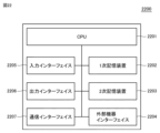
図22は、クラスターシステム100を構成する装置2200の一例を示す図である。クラスターシステム100は、1以上の装置2200から構成され得る。装置2200は、CPU(Central Processing Unit)2201と、1次記憶装置2202と、2次記憶装置2203と、外部機器インターフェイス2204と、入力インターフェイス2205と、出力インターフェイス2206と、通信インターフェイス2207とを含む。
<I. Hardware Configuration>
22 is a diagram showing an example of a
CPU2201は、装置2200の各種機能を実現するためのプログラムを実行し得る。CPU2201は、例えば、少なくとも1つの集積回路によって構成される。集積回路は、例えば、少なくとも1つのCPU、少なくとも1つのFPGA(Field Programmable Gate Array)、またはこれらの組み合わせ等によって構成されてもよい。
The
1次記憶装置2202は、CPU2201によって実行されるプログラムと、CPU2201によって参照されるデータとを格納する。ある局面において、1次記憶装置2202は、DRAM(Dynamic Random Access Memory)またはSRAM(Static Random Access Memory)等によって実現されてもよい。
The
2次記憶装置2203は、不揮発性メモリーであり、CPU2201によって実行されるプログラムおよびCPU2201によって参照されるデータを格納してもよい。その場合、CPU2201は、2次記憶装置2203から1次記憶装置2202に読み出されたプログラムを実行し、2次記憶装置2203から1次記憶装置2202に読み出されたデータを参照する。ある局面において、2次記憶装置2203は、HDD(Hard Disk Drive)、SSD(Solid State Drive)、EPROM(Erasable Programmable Read Only Memory)、EEPROM(Electrically Erasable Programmable Read Only Memory)またはフラッシュメモリー等によって実現されてもよい。
The
外部機器インターフェイス2204は、プリンター、スキャナーおよび外付けHDD等の任意の外部機器に接続され得る。ある局面において、外部機器インターフェイス2204は、USB(Universal Serial Bus)端子等によって実現されてもよい。
The
入力インターフェイス2205は、キーボード、マウス、タッチパッドまたはゲームパッド等の任意の入力装置に接続され得る。ある局面において、入力インターフェイス2205は、USB端子、PS/2端子およびBluetooth(登録商標)モジュール等によって実現されてもよい。
The
出力インターフェイス2206は、ブラウン管ディスプレイ、液晶ディスプレイまたは有機EL(electro-luminescence)ディスプレイ等の任意の出力装置に接続され得る。ある局面において、出力インターフェイス2206は、USB端子、D-sub端子、DVI(Digital Visual Interface)端子およびHDMI(登録商標)(High-Definition Multimedia Interface)端子等によって実現されてもよい。
The
通信インターフェイス2207は、有線または無線のネットワーク機器と接続される。ある局面において、通信インターフェイス2207は、有線LAN(Local Area Network)ポートおよびWi-Fi(登録商標)(Wireless Fidelity)モジュール等によって実現されてもよい。他の局面において、通信インターフェイス2207は、TCP/IP(Transmission Control Protocol/Internet Protocol)、UDP(User Datagram Protocol)等の通信プロトコルを用いてデータを送受信してもよい。
The
ある局面において、CPU2201は、図20および図21の処理を行うためのプログラムを2次記憶装置2203から1次記憶装置2202に読み込んで、当該プログラムを実行してもよい。他の局面において、当該処理の一部または全部は、当該処理を実行するように構成された回路素子の組み合わせとしても実現され得る。
In one aspect, the
また、他の局面において、図1に示す全ての構成要素は、プログラムまたはデータとして、1以上の装置2200内の1次記憶装置2202に分散されて格納されていてもよい。
In another aspect, all of the components shown in FIG. 1 may be stored as programs or data in a distributed manner in the
以上説明したように、本実施の形態に従うクラスターシステム100は、マニフェストファイル1710および1720と、ノード101のメタデータ1800とに基づいて、依存関係のあるサービスを適切な順番でデプロイまたは終了することができる。当該機能により、ユーザーは、クラスターシステム100に依存関係のあるサービスをデプロイさせるために詳細なスクリプト等を用意する必要はなく、各サービスのマニフェストファイルに、要求ランレベルを設定するだけでよい。
As described above, the
さらに、クラスターシステム100は、ノードベースランレベルモードまたはクラスターベースランレベルモードと、クイックサーブモードまたはステイブルサーブモードとを適宜組み合わせて使用することができる。当該機能により、クラスターシステム100は、適宜、各サービスを特定のノード101に集中的にデプロイしたり、または、各サービスを複数のノード101に分散してデプロイしたりできる。
Furthermore, the
今回開示された実施の形態は全ての点で例示であって制限的なものではないと考えられるべきである。本開示の範囲は上記した説明ではなくて特許請求の範囲によって示され、特許請求の範囲と均等の意味及び範囲内で全ての変更が含まれることが意図される。また、実施の形態および各変形例において説明された開示内容は、可能な限り、単独でも、組合わせても、実施することが意図される。 The embodiments disclosed herein should be considered to be illustrative in all respects and not restrictive. The scope of the present disclosure is indicated by the claims rather than the above description, and is intended to include all modifications within the meaning and scope of the claims. Furthermore, it is intended that the disclosure contents described in the embodiments and each modified example may be implemented, as far as possible, either alone or in combination.
100 クラスターシステム、101 ノード、102 サービス、103 クラスターコントロールプレーン、110 デプロイマネージャー、111 クラスターランタイムコンポーネント、112 ノードメタデータ&ステート、113 クラスターマネージメントコンポーネント、114 クラスターメタデータ&ステート、1710,1720 マニフェストファイル、1711,1721 要求ランレベル、1800 メタデータ、1801 ランレベル、1900 アイデンティティ管理、1902 アクティブディレクトリ、2200 装置、2201 CPU、2202 1次記憶装置、2203 2次記憶装置、2204 外部機器インターフェイス、2205 入力インターフェイス、2206 出力インターフェイス、2207 通信インターフェイス。 100 Cluster system, 101 Node, 102 Service, 103 Cluster control plane, 110 Deployment manager, 111 Cluster runtime component, 112 Node metadata & state, 113 Cluster management component, 114 Cluster metadata & state, 1710, 1720 Manifest file, 1711, 1721 Requested run level, 1800 Metadata, 1801 Run level, 1900 Identity management, 1902 Active directory, 2200 Device, 2201 CPU, 2202 Primary storage device, 2203 Secondary storage device, 2204 External device interface, 2205 Input interface, 2206 Output interface, 2207 Communication interface.
Claims (13)
第1のノードの第1のランレベルを取得するステップと、
第2のノードの第2のランレベルを取得するステップと、
前記サービスの優先度に相当する要求ランレベルを取得するステップと、
前記要求ランレベルと、前記第1および第2のランレベルとを比較するステップと、
比較の結果に基づいて、前記サービスを前記第1および第2のノードの各々にデプロイ可能か否かを判定するステップと、
前記サービスを前記第1および第2のノードの少なくとも片方にデプロイしたことに基づいて、前記第1および第2のランレベルの少なくとも片方を更新するステップとを含む、方法。 1. A method for deploying a service to a cluster system, comprising:
obtaining a first runlevel of a first node;
obtaining a second runlevel of a second node;
obtaining a required run-level corresponding to a priority of the service;
comparing the requested run-level with the first and second run-levels;
determining whether the service can be deployed on each of the first and second nodes based on a result of the comparison;
updating at least one of the first and second runlevels based on deploying the service to at least one of the first and second nodes.
1または複数の前記サービスの少なくとも1つを終了したことに基づいて、少なくとも前記第1および第2のランレベルの片方を更新するステップとをさらに含む、請求項1または2に記載の方法。 determining a termination order for the one or more deployed services based on a run level of the one or more deployed services;
3. The method of claim 1, further comprising: updating at least one of the first and second runlevels based on terminating at least one of the one or more services.
前記要求ランレベルと、前記第1および第2のランレベルとを比較するステップは、前記要求ランレベルおよび前記第1のランレベルの比較と、前記要求ランレベルおよび前記第2のランレベルとの比較とを個別に実行することを含む、請求項1~3のいずれかに記載の方法。 The first and second runlevels are each set with an individual node runlevel for each node;
The method according to any one of claims 1 to 3, wherein the step of comparing the requested run level with the first and second run levels includes separately performing a comparison of the requested run level with the first run level and a comparison of the requested run level with the second run level.
前記第1のノードにデプロイ済みの1または複数の前記サービスの中で最も前記要求ランレベルが高い前記サービスの前記要求ランレベルに基づいて、前記第1のランレベルを更新するステップと、
前記第2のノードにデプロイ済みの1または複数の前記サービスの中で最も前記要求ランレベルが高い前記サービスの前記要求ランレベルに基づいて前記第2のランレベルを更新するステップとを含む、請求項4に記載の方法。 The step of updating at least one of the first and second runlevels includes:
updating the first run-level based on the requested run-level of the service having the highest requested run-level among the one or more services deployed on the first node;
and updating the second run-level based on the requested run-level of the service having the highest requested run-level among one or more of the services deployed on the second node.
前記第1および第2のランレベルの少なくとも片方を更新するステップは、デプロイ条件を満たす前記サービスを前記複製数の設定で指定される回数デプロイしたことに基づいて、前記第1および第2のランレベルの少なくとも片方を更新するステップを含む、請求項4に記載の方法。 The method further includes the step of obtaining a number of copies by referencing a configuration file of the service;
5. The method of claim 4, wherein updating at least one of the first and second runlevels comprises updating at least one of the first and second runlevels based on having deployed the service that satisfies a deployment condition a number of times specified by a setting of the number of copies.
前記要求ランレベルと、前記第1および第2のランレベルとを比較するステップは、前記要求ランレベルと、前記クラスターランレベルとを比較するステップを含む、請求項1~3のいずれかに記載の方法。 a cluster runlevel that is common to the first and second runlevels in the cluster system is set;
The method according to any one of claims 1 to 3, wherein the step of comparing the requested run-level with the first and second run-levels includes the step of comparing the requested run-level with the cluster run-level.
前記第1および第2のランレベルの少なくとも片方を更新するステップは、デプロイ条件を満たす前記サービスを前記複製数の設定で指定される回数デプロイしたことに基づいて、前記クラスターランレベルを更新するステップを含む、請求項7に記載の方法。 The method further includes the step of obtaining a number of copies by referencing a configuration file of the service;
8. The method of claim 7, wherein updating at least one of the first and second runlevels comprises updating the cluster runlevel based on deploying the service that satisfies a deployment condition a number of times specified by the number of copies setting.
請求項1~11のいずれかに記載の方法を前記1つ以上のプロセッサーに実行させるためのプログラムを格納したメモリーとを備える、システム。 one or more processors;
A memory storing a program for causing said one or more processors to execute the method according to any one of claims 1 to 11.
Priority Applications (4)
| Application Number | Priority Date | Filing Date | Title |
|---|---|---|---|
| JP2020097641A JP7484447B2 (en) | 2020-06-04 | 2020-06-04 | Method, program and system for deploying services on a cluster system - Patents.com |
| EP21175984.0A EP3920028A1 (en) | 2020-06-04 | 2021-05-26 | Method for deploying service in cluster system, program, and system |
| US17/333,606 US11637905B2 (en) | 2020-06-04 | 2021-05-28 | Method for deploying service in cluster system, program, and system |
| CN202110598422.3A CN113760309A (en) | 2020-06-04 | 2021-05-31 | Method, program, and system for deploying services on a cluster system |
Applications Claiming Priority (1)
| Application Number | Priority Date | Filing Date | Title |
|---|---|---|---|
| JP2020097641A JP7484447B2 (en) | 2020-06-04 | 2020-06-04 | Method, program and system for deploying services on a cluster system - Patents.com |
Publications (2)
| Publication Number | Publication Date |
|---|---|
| JP2021189999A JP2021189999A (en) | 2021-12-13 |
| JP7484447B2 true JP7484447B2 (en) | 2024-05-16 |
Family
ID=76137989
Family Applications (1)
| Application Number | Title | Priority Date | Filing Date |
|---|---|---|---|
| JP2020097641A Active JP7484447B2 (en) | 2020-06-04 | 2020-06-04 | Method, program and system for deploying services on a cluster system - Patents.com |
Country Status (4)
| Country | Link |
|---|---|
| US (1) | US11637905B2 (en) |
| EP (1) | EP3920028A1 (en) |
| JP (1) | JP7484447B2 (en) |
| CN (1) | CN113760309A (en) |
Families Citing this family (2)
| Publication number | Priority date | Publication date | Assignee | Title |
|---|---|---|---|---|
| CN114281352A (en) * | 2020-09-28 | 2022-04-05 | 京东方科技集团股份有限公司 | Service deployment method and related equipment |
| CN114995900B (en) * | 2022-05-23 | 2024-05-14 | 中国联合网络通信集团有限公司 | Method and device for deploying multiple micro-service modules and computer-readable storage medium |
Citations (2)
| Publication number | Priority date | Publication date | Assignee | Title |
|---|---|---|---|---|
| US20170257432A1 (en) | 2011-02-09 | 2017-09-07 | Cliqr Technologies Inc. | Apparatus, systems and methods for container based service deployment |
| US20190370121A1 (en) | 2018-04-30 | 2019-12-05 | Nutanix, Inc. | Context-based disaster recovery |
Family Cites Families (16)
| Publication number | Priority date | Publication date | Assignee | Title |
|---|---|---|---|---|
| JP2687860B2 (en) | 1993-12-28 | 1997-12-08 | 日本電気株式会社 | System start / stop control system for distributed processing system |
| JP2005043962A (en) | 2003-07-22 | 2005-02-17 | Nippon Telegr & Teleph Corp <Ntt> | Distributed server system, server, application process activation control method, and program |
| GB0524008D0 (en) * | 2005-11-25 | 2006-01-04 | Ibm | Method and system for controlling the processing of requests for web resources |
| US10673952B1 (en) * | 2014-11-10 | 2020-06-02 | Turbonomic, Inc. | Systems, apparatus, and methods for managing computer workload availability and performance |
| JP2011018223A (en) | 2009-07-09 | 2011-01-27 | Canon Inc | System and method for communicating information |
| US9442810B2 (en) * | 2009-07-31 | 2016-09-13 | Paypal, Inc. | Cloud computing: unified management console for services and resources in a data center |
| CN101694631B (en) * | 2009-09-30 | 2016-10-05 | 曙光信息产业(北京)有限公司 | Real time job dispatching patcher and method |
| US9749441B2 (en) * | 2009-12-08 | 2017-08-29 | Sap Se | Application server runlevel framework |
| JP2013089093A (en) | 2011-10-20 | 2013-05-13 | Hitachi Systems Ltd | Activation order management method of virtual server, activation order management program of virtual server and virtual computer system |
| US9232020B2 (en) * | 2011-12-14 | 2016-01-05 | Siemens Aktiengesellschaft | Deploying services during fulfillment of a service request |
| US9292354B2 (en) * | 2013-10-18 | 2016-03-22 | Microsoft Technology Licensing, Llc | Self-adjusting framework for managing device capacity |
| US9672123B2 (en) * | 2014-12-31 | 2017-06-06 | Oracle International Corporation | Deploying services on application server cloud with high availability |
| US10200261B2 (en) * | 2015-04-30 | 2019-02-05 | Microsoft Technology Licensing, Llc | Multiple-computing-node system job node selection |
| US10789267B1 (en) * | 2017-09-21 | 2020-09-29 | Amazon Technologies, Inc. | Replication group data management |
| JP2019164621A (en) | 2018-03-20 | 2019-09-26 | 三菱電機株式会社 | Start control unit, control system, and start control method |
| CN108536518A (en) * | 2018-03-28 | 2018-09-14 | 深圳市银之杰科技股份有限公司 | Method and system, reference platform, service terminal and the memory of task scheduling |
-
2020
- 2020-06-04 JP JP2020097641A patent/JP7484447B2/en active Active
-
2021
- 2021-05-26 EP EP21175984.0A patent/EP3920028A1/en active Pending
- 2021-05-28 US US17/333,606 patent/US11637905B2/en active Active
- 2021-05-31 CN CN202110598422.3A patent/CN113760309A/en active Pending
Patent Citations (2)
| Publication number | Priority date | Publication date | Assignee | Title |
|---|---|---|---|---|
| US20170257432A1 (en) | 2011-02-09 | 2017-09-07 | Cliqr Technologies Inc. | Apparatus, systems and methods for container based service deployment |
| US20190370121A1 (en) | 2018-04-30 | 2019-12-05 | Nutanix, Inc. | Context-based disaster recovery |
Non-Patent Citations (1)
| Title |
|---|
| 中井悦司,[改訂新版] プロのためのLinuxシステム構築・運用技術,初版,株式会社技術評論社,2016年10月25日,特に、p. 189-194 |
Also Published As
| Publication number | Publication date |
|---|---|
| US20210385288A1 (en) | 2021-12-09 |
| EP3920028A1 (en) | 2021-12-08 |
| JP2021189999A (en) | 2021-12-13 |
| US11637905B2 (en) | 2023-04-25 |
| CN113760309A (en) | 2021-12-07 |
Similar Documents
| Publication | Publication Date | Title |
|---|---|---|
| US7516206B2 (en) | Management of software images for computing nodes of a distributed computing system | |
| US11297126B2 (en) | System and method for image file generation and management | |
| US8387037B2 (en) | Updating software images associated with a distributed computing system | |
| US8327350B2 (en) | Virtual resource templates | |
| US8832028B2 (en) | Database cloning | |
| US8793344B2 (en) | System and method for generating a response plan for a hypothetical event | |
| US8954557B2 (en) | Assigning server categories to server nodes in a heterogeneous cluster | |
| TWI287713B (en) | System and method for computer cluster virtualization using dynamic boot images and virtual disk | |
| US8752039B1 (en) | Dynamic upgrade of operating system in a network device | |
| WO2019154202A1 (en) | Security protection method and apparatus | |
| JP7484447B2 (en) | Method, program and system for deploying services on a cluster system - Patents.com | |
| US11615006B2 (en) | Virtual network life cycle management | |
| US9769007B1 (en) | Passive data protection system migration | |
| US11271999B2 (en) | Flexible associativity in multitenant clustered environments | |
| US8229980B2 (en) | State buckets | |
| EP3647947B1 (en) | Enhanced data storage of virtual nodes in a data processing environment | |
| US11526468B2 (en) | Management system and control method | |
| US7640328B1 (en) | Method and apparatus for prioritizing provisioning data in a provisioning server | |
| US20240054000A1 (en) | Container scheduling and deployment method and apparatus, and domain controller system | |
| CN119025254A (en) | A method and device for deploying load balancing service | |
| US11100000B2 (en) | Embedded image management | |
| CN116980301A (en) | Desktop management method, device, equipment and readable storage medium | |
| CN114721765A (en) | Container deployment method, apparatus, electronic device, and computer-readable storage medium |
Legal Events
| Date | Code | Title | Description |
|---|---|---|---|
| A621 | Written request for application examination |
Free format text: JAPANESE INTERMEDIATE CODE: A621 Effective date: 20230317 |
|
| A131 | Notification of reasons for refusal |
Free format text: JAPANESE INTERMEDIATE CODE: A131 Effective date: 20240220 |
|
| A521 | Request for written amendment filed |
Free format text: JAPANESE INTERMEDIATE CODE: A523 Effective date: 20240314 |
|
| TRDD | Decision of grant or rejection written | ||
| A01 | Written decision to grant a patent or to grant a registration (utility model) |
Free format text: JAPANESE INTERMEDIATE CODE: A01 Effective date: 20240402 |
|
| A61 | First payment of annual fees (during grant procedure) |
Free format text: JAPANESE INTERMEDIATE CODE: A61 Effective date: 20240415 |
|
| R150 | Certificate of patent or registration of utility model |
Ref document number: 7484447 Country of ref document: JP Free format text: JAPANESE INTERMEDIATE CODE: R150 |