JP7481434B2 - A Smart Device-Based Radar System Using Spatio-Temporal Neural Networks to Perform Gesture Recognition - Google Patents
A Smart Device-Based Radar System Using Spatio-Temporal Neural Networks to Perform Gesture Recognition Download PDFInfo
- Publication number
- JP7481434B2 JP7481434B2 JP2022515765A JP2022515765A JP7481434B2 JP 7481434 B2 JP7481434 B2 JP 7481434B2 JP 2022515765 A JP2022515765 A JP 2022515765A JP 2022515765 A JP2022515765 A JP 2022515765A JP 7481434 B2 JP7481434 B2 JP 7481434B2
- Authority
- JP
- Japan
- Prior art keywords
- radar
- data
- neural network
- user
- composite
- Prior art date
- Legal status (The legal status is an assumption and is not a legal conclusion. Google has not performed a legal analysis and makes no representation as to the accuracy of the status listed.)
- Active
Links
Images


Classifications
-
- G—PHYSICS
- G06—COMPUTING OR CALCULATING; COUNTING
- G06F—ELECTRIC DIGITAL DATA PROCESSING
- G06F3/00—Input arrangements for transferring data to be processed into a form capable of being handled by the computer; Output arrangements for transferring data from processing unit to output unit, e.g. interface arrangements
- G06F3/01—Input arrangements or combined input and output arrangements for interaction between user and computer
- G06F3/017—Gesture based interaction, e.g. based on a set of recognized hand gestures
-
- G—PHYSICS
- G06—COMPUTING OR CALCULATING; COUNTING
- G06V—IMAGE OR VIDEO RECOGNITION OR UNDERSTANDING
- G06V40/00—Recognition of biometric, human-related or animal-related patterns in image or video data
- G06V40/20—Movements or behaviour, e.g. gesture recognition
- G06V40/28—Recognition of hand or arm movements, e.g. recognition of deaf sign language
-
- G—PHYSICS
- G01—MEASURING; TESTING
- G01S—RADIO DIRECTION-FINDING; RADIO NAVIGATION; DETERMINING DISTANCE OR VELOCITY BY USE OF RADIO WAVES; LOCATING OR PRESENCE-DETECTING BY USE OF THE REFLECTION OR RERADIATION OF RADIO WAVES; ANALOGOUS ARRANGEMENTS USING OTHER WAVES
- G01S13/00—Systems using the reflection or reradiation of radio waves, e.g. radar systems; Analogous systems using reflection or reradiation of waves whose nature or wavelength is irrelevant or unspecified
- G01S13/02—Systems using reflection of radio waves, e.g. primary radar systems; Analogous systems
- G01S13/06—Systems determining position data of a target
-
- G—PHYSICS
- G01—MEASURING; TESTING
- G01S—RADIO DIRECTION-FINDING; RADIO NAVIGATION; DETERMINING DISTANCE OR VELOCITY BY USE OF RADIO WAVES; LOCATING OR PRESENCE-DETECTING BY USE OF THE REFLECTION OR RERADIATION OF RADIO WAVES; ANALOGOUS ARRANGEMENTS USING OTHER WAVES
- G01S7/00—Details of systems according to groups G01S13/00, G01S15/00, G01S17/00
- G01S7/02—Details of systems according to groups G01S13/00, G01S15/00, G01S17/00 of systems according to group G01S13/00
- G01S7/35—Details of non-pulse systems
- G01S7/352—Receivers
-
- G—PHYSICS
- G01—MEASURING; TESTING
- G01S—RADIO DIRECTION-FINDING; RADIO NAVIGATION; DETERMINING DISTANCE OR VELOCITY BY USE OF RADIO WAVES; LOCATING OR PRESENCE-DETECTING BY USE OF THE REFLECTION OR RERADIATION OF RADIO WAVES; ANALOGOUS ARRANGEMENTS USING OTHER WAVES
- G01S7/00—Details of systems according to groups G01S13/00, G01S15/00, G01S17/00
- G01S7/02—Details of systems according to groups G01S13/00, G01S15/00, G01S17/00 of systems according to group G01S13/00
- G01S7/41—Details of systems according to groups G01S13/00, G01S15/00, G01S17/00 of systems according to group G01S13/00 using analysis of echo signal for target characterisation; Target signature; Target cross-section
- G01S7/417—Details of systems according to groups G01S13/00, G01S15/00, G01S17/00 of systems according to group G01S13/00 using analysis of echo signal for target characterisation; Target signature; Target cross-section involving the use of neural networks
-
- G—PHYSICS
- G06—COMPUTING OR CALCULATING; COUNTING
- G06F—ELECTRIC DIGITAL DATA PROCESSING
- G06F18/00—Pattern recognition
- G06F18/20—Analysing
- G06F18/24—Classification techniques
- G06F18/241—Classification techniques relating to the classification model, e.g. parametric or non-parametric approaches
- G06F18/2413—Classification techniques relating to the classification model, e.g. parametric or non-parametric approaches based on distances to training or reference patterns
- G06F18/24133—Distances to prototypes
-
- G—PHYSICS
- G06—COMPUTING OR CALCULATING; COUNTING
- G06F—ELECTRIC DIGITAL DATA PROCESSING
- G06F3/00—Input arrangements for transferring data to be processed into a form capable of being handled by the computer; Output arrangements for transferring data from processing unit to output unit, e.g. interface arrangements
- G06F3/01—Input arrangements or combined input and output arrangements for interaction between user and computer
- G06F3/011—Arrangements for interaction with the human body, e.g. for user immersion in virtual reality
- G06F3/014—Hand-worn input/output arrangements, e.g. data gloves
-
- G—PHYSICS
- G06—COMPUTING OR CALCULATING; COUNTING
- G06N—COMPUTING ARRANGEMENTS BASED ON SPECIFIC COMPUTATIONAL MODELS
- G06N3/00—Computing arrangements based on biological models
- G06N3/02—Neural networks
- G06N3/04—Architecture, e.g. interconnection topology
- G06N3/044—Recurrent networks, e.g. Hopfield networks
- G06N3/0442—Recurrent networks, e.g. Hopfield networks characterised by memory or gating, e.g. long short-term memory [LSTM] or gated recurrent units [GRU]
-
- G—PHYSICS
- G06—COMPUTING OR CALCULATING; COUNTING
- G06N—COMPUTING ARRANGEMENTS BASED ON SPECIFIC COMPUTATIONAL MODELS
- G06N3/00—Computing arrangements based on biological models
- G06N3/02—Neural networks
- G06N3/04—Architecture, e.g. interconnection topology
- G06N3/0499—Feedforward networks
-
- G—PHYSICS
- G06—COMPUTING OR CALCULATING; COUNTING
- G06N—COMPUTING ARRANGEMENTS BASED ON SPECIFIC COMPUTATIONAL MODELS
- G06N3/00—Computing arrangements based on biological models
- G06N3/02—Neural networks
- G06N3/08—Learning methods
- G06N3/09—Supervised learning
-
- G—PHYSICS
- G06—COMPUTING OR CALCULATING; COUNTING
- G06V—IMAGE OR VIDEO RECOGNITION OR UNDERSTANDING
- G06V10/00—Arrangements for image or video recognition or understanding
- G06V10/70—Arrangements for image or video recognition or understanding using pattern recognition or machine learning
- G06V10/82—Arrangements for image or video recognition or understanding using pattern recognition or machine learning using neural networks
-
- G—PHYSICS
- G06—COMPUTING OR CALCULATING; COUNTING
- G06V—IMAGE OR VIDEO RECOGNITION OR UNDERSTANDING
- G06V10/00—Arrangements for image or video recognition or understanding
- G06V10/94—Hardware or software architectures specially adapted for image or video understanding
-
- G—PHYSICS
- G01—MEASURING; TESTING
- G01S—RADIO DIRECTION-FINDING; RADIO NAVIGATION; DETERMINING DISTANCE OR VELOCITY BY USE OF RADIO WAVES; LOCATING OR PRESENCE-DETECTING BY USE OF THE REFLECTION OR RERADIATION OF RADIO WAVES; ANALOGOUS ARRANGEMENTS USING OTHER WAVES
- G01S13/00—Systems using the reflection or reradiation of radio waves, e.g. radar systems; Analogous systems using reflection or reradiation of waves whose nature or wavelength is irrelevant or unspecified
- G01S13/02—Systems using reflection of radio waves, e.g. primary radar systems; Analogous systems
- G01S13/06—Systems determining position data of a target
- G01S13/08—Systems for measuring distance only
- G01S13/32—Systems for measuring distance only using transmission of continuous waves, whether amplitude-, frequency-, or phase-modulated, or unmodulated
- G01S13/34—Systems for measuring distance only using transmission of continuous waves, whether amplitude-, frequency-, or phase-modulated, or unmodulated using transmission of continuous, frequency-modulated waves while heterodyning the received signal, or a signal derived therefrom, with a locally-generated signal related to the contemporaneously transmitted signal
- G01S13/345—Systems for measuring distance only using transmission of continuous waves, whether amplitude-, frequency-, or phase-modulated, or unmodulated using transmission of continuous, frequency-modulated waves while heterodyning the received signal, or a signal derived therefrom, with a locally-generated signal related to the contemporaneously transmitted signal using triangular modulation
-
- G—PHYSICS
- G01—MEASURING; TESTING
- G01S—RADIO DIRECTION-FINDING; RADIO NAVIGATION; DETERMINING DISTANCE OR VELOCITY BY USE OF RADIO WAVES; LOCATING OR PRESENCE-DETECTING BY USE OF THE REFLECTION OR RERADIATION OF RADIO WAVES; ANALOGOUS ARRANGEMENTS USING OTHER WAVES
- G01S13/00—Systems using the reflection or reradiation of radio waves, e.g. radar systems; Analogous systems using reflection or reradiation of waves whose nature or wavelength is irrelevant or unspecified
- G01S13/02—Systems using reflection of radio waves, e.g. primary radar systems; Analogous systems
- G01S13/50—Systems of measurement based on relative movement of target
- G01S13/58—Velocity or trajectory determination systems; Sense-of-movement determination systems
- G01S13/583—Velocity or trajectory determination systems; Sense-of-movement determination systems using transmission of continuous unmodulated waves, amplitude-, frequency-, or phase-modulated waves and based upon the Doppler effect resulting from movement of targets
- G01S13/584—Velocity or trajectory determination systems; Sense-of-movement determination systems using transmission of continuous unmodulated waves, amplitude-, frequency-, or phase-modulated waves and based upon the Doppler effect resulting from movement of targets adapted for simultaneous range and velocity measurements
-
- G—PHYSICS
- G01—MEASURING; TESTING
- G01S—RADIO DIRECTION-FINDING; RADIO NAVIGATION; DETERMINING DISTANCE OR VELOCITY BY USE OF RADIO WAVES; LOCATING OR PRESENCE-DETECTING BY USE OF THE REFLECTION OR RERADIATION OF RADIO WAVES; ANALOGOUS ARRANGEMENTS USING OTHER WAVES
- G01S13/00—Systems using the reflection or reradiation of radio waves, e.g. radar systems; Analogous systems using reflection or reradiation of waves whose nature or wavelength is irrelevant or unspecified
- G01S13/88—Radar or analogous systems specially adapted for specific applications
-
- G—PHYSICS
- G01—MEASURING; TESTING
- G01S—RADIO DIRECTION-FINDING; RADIO NAVIGATION; DETERMINING DISTANCE OR VELOCITY BY USE OF RADIO WAVES; LOCATING OR PRESENCE-DETECTING BY USE OF THE REFLECTION OR RERADIATION OF RADIO WAVES; ANALOGOUS ARRANGEMENTS USING OTHER WAVES
- G01S7/00—Details of systems according to groups G01S13/00, G01S15/00, G01S17/00
- G01S7/02—Details of systems according to groups G01S13/00, G01S15/00, G01S17/00 of systems according to group G01S13/00
- G01S7/35—Details of non-pulse systems
- G01S7/352—Receivers
- G01S7/356—Receivers involving particularities of FFT processing
-
- G—PHYSICS
- G01—MEASURING; TESTING
- G01S—RADIO DIRECTION-FINDING; RADIO NAVIGATION; DETERMINING DISTANCE OR VELOCITY BY USE OF RADIO WAVES; LOCATING OR PRESENCE-DETECTING BY USE OF THE REFLECTION OR RERADIATION OF RADIO WAVES; ANALOGOUS ARRANGEMENTS USING OTHER WAVES
- G01S7/00—Details of systems according to groups G01S13/00, G01S15/00, G01S17/00
- G01S7/48—Details of systems according to groups G01S13/00, G01S15/00, G01S17/00 of systems according to group G01S17/00
- G01S7/4802—Details of systems according to groups G01S13/00, G01S15/00, G01S17/00 of systems according to group G01S17/00 using analysis of echo signal for target characterisation; Target signature; Target cross-section
-
- G—PHYSICS
- G01—MEASURING; TESTING
- G01S—RADIO DIRECTION-FINDING; RADIO NAVIGATION; DETERMINING DISTANCE OR VELOCITY BY USE OF RADIO WAVES; LOCATING OR PRESENCE-DETECTING BY USE OF THE REFLECTION OR RERADIATION OF RADIO WAVES; ANALOGOUS ARRANGEMENTS USING OTHER WAVES
- G01S7/00—Details of systems according to groups G01S13/00, G01S15/00, G01S17/00
- G01S7/52—Details of systems according to groups G01S13/00, G01S15/00, G01S17/00 of systems according to group G01S15/00
- G01S7/539—Details of systems according to groups G01S13/00, G01S15/00, G01S17/00 of systems according to group G01S15/00 using analysis of echo signal for target characterisation; Target signature; Target cross-section
-
- G—PHYSICS
- G06—COMPUTING OR CALCULATING; COUNTING
- G06F—ELECTRIC DIGITAL DATA PROCESSING
- G06F2218/00—Aspects of pattern recognition specially adapted for signal processing
- G06F2218/08—Feature extraction
-
- G—PHYSICS
- G06—COMPUTING OR CALCULATING; COUNTING
- G06F—ELECTRIC DIGITAL DATA PROCESSING
- G06F2218/00—Aspects of pattern recognition specially adapted for signal processing
- G06F2218/12—Classification; Matching
-
- G—PHYSICS
- G06—COMPUTING OR CALCULATING; COUNTING
- G06N—COMPUTING ARRANGEMENTS BASED ON SPECIFIC COMPUTATIONAL MODELS
- G06N3/00—Computing arrangements based on biological models
- G06N3/02—Neural networks
- G06N3/04—Architecture, e.g. interconnection topology
- G06N3/045—Combinations of networks
-
- G—PHYSICS
- G06—COMPUTING OR CALCULATING; COUNTING
- G06N—COMPUTING ARRANGEMENTS BASED ON SPECIFIC COMPUTATIONAL MODELS
- G06N3/00—Computing arrangements based on biological models
- G06N3/02—Neural networks
- G06N3/08—Learning methods
Landscapes
- Engineering & Computer Science (AREA)
- Physics & Mathematics (AREA)
- Theoretical Computer Science (AREA)
- General Physics & Mathematics (AREA)
- General Engineering & Computer Science (AREA)
- Remote Sensing (AREA)
- Radar, Positioning & Navigation (AREA)
- Evolutionary Computation (AREA)
- Artificial Intelligence (AREA)
- Software Systems (AREA)
- Health & Medical Sciences (AREA)
- General Health & Medical Sciences (AREA)
- Data Mining & Analysis (AREA)
- Computer Networks & Wireless Communication (AREA)
- Computing Systems (AREA)
- Human Computer Interaction (AREA)
- Multimedia (AREA)
- Life Sciences & Earth Sciences (AREA)
- Computer Vision & Pattern Recognition (AREA)
- Biophysics (AREA)
- Computational Linguistics (AREA)
- Molecular Biology (AREA)
- Biomedical Technology (AREA)
- Mathematical Physics (AREA)
- Databases & Information Systems (AREA)
- Psychiatry (AREA)
- Social Psychology (AREA)
- Medical Informatics (AREA)
- Bioinformatics & Cheminformatics (AREA)
- Bioinformatics & Computational Biology (AREA)
- Evolutionary Biology (AREA)
- Electromagnetism (AREA)
- Signal Processing (AREA)
- Radar Systems Or Details Thereof (AREA)
- User Interface Of Digital Computer (AREA)
Description
背景
レーダは、対象を検出し得る有用なデバイスである。カメラのような他のタイプのセンサに対して、レーダは、薄暗い光および霧などの異なる環境条件の存在下で、または、移動している対象もしくは重なっている対象を伴う異なる環境条件の存在下で性能の改善を提供し得る。レーダはさらに、バッグまたはポケットなどの1つ以上の遮蔽物(occlusion)を通過して対象を検出し得る。レーダは利点を有し得るが、電子デバイスにレーダを統合することに関連付けられる多くの困難が存在する。
2. Background Radar is a useful device that can detect objects. Relative to other types of sensors, such as cameras, radar can provide improved performance in the presence of different environmental conditions, such as dim light and fog, or with moving or overlapping objects. Radar can also detect objects through one or more occlusions, such as a bag or pocket. Although radar may have advantages, there are many difficulties associated with integrating radar into electronic devices.
1つの困難は、小型電子デバイスまたはモバイル電子デバイス内の電力制約を伴う。いくつかのレーダの動作は、電子デバイスのバッテリを著しく消耗させ、ユーザが電子デバイスを頻繁に再充電することを引き起こす。その結果、利用可能な電力の制限によりレーダの効果的な動作が低減または無効にされ、レーダを利用する利点が実現され得ない。 One difficulty involves power constraints in small or mobile electronic devices. Operation of some radars significantly drains the battery of the electronic device, causing the user to frequently recharge the electronic device. As a result, the effective operation of the radar is reduced or nullified due to limitations in available power, and the advantages of utilizing the radar cannot be realized.
別の困難は、小型のコンシューマデバイスがレーダの設計または動作に課し得る制約を伴う。サイズまたはレイアウト制約を満たすために、たとえば、より少ないアンテナ要素およびさまざまなアンテナ要素間隔が使用され得る。他の制約は、レーダ信号の帯域幅、送信パワー、または、更新レートを制限し得る。その結果、レーダの設計は、信号対雑音比性能の劣化をもたらし得、これにより、いくつかの用途について十分な精度を達成することが困難になり得る。したがって、電子デバイス内に統合されるレーダの性能は、著しく低減され得る。これは、レーダがサポートし得るアプリケーションのタイプ、または、レーダを組み込み得る電子デバイスのタイプを制限し得る。 Another difficulty involves constraints that small consumer devices may impose on radar design or operation. To meet size or layout constraints, for example, fewer antenna elements and different antenna element spacing may be used. Other constraints may limit the bandwidth, transmit power, or update rate of the radar signal. As a result, the radar design may result in degradation of signal-to-noise ratio performance, which may make it difficult to achieve sufficient accuracy for some applications. Thus, the performance of a radar integrated within an electronic device may be significantly reduced. This may limit the types of applications the radar may support or the types of electronic devices into which the radar may be incorporated.
概要
空間時間ニューラルネットワークを使用してジェスチャ認識を実行することが可能なスマートデバイスベースのレーダシステムを実現する技術および装置が記載される。空間時間ニューラルネットワークは、ジェスチャ認識のために複合レーダデータ(たとえば、大きさ情報および位相情報の両方)を分析するよう、マシンラーニングを使用する。大きさ情報および位相情報の両方を分析することによって、空間時間ニューラルネットワークは、大きさ情報を処理する他の信号処理技術、ヒューリスティック技術、または、マシンラーニング技術と比較して、分散した対象を検出し、かつ、ジェスチャを認識するための改善された精度を実現し得る。
Overview Techniques and apparatus are described for implementing a smart device-based radar system capable of performing gesture recognition using a spatio-temporal neural network. The spatio-temporal neural network uses machine learning to analyze combined radar data (e.g., both magnitude and phase information) for gesture recognition. By analyzing both magnitude and phase information, the spatio-temporal neural network may achieve improved accuracy for detecting distributed objects and recognizing gestures compared to other signal processing, heuristic, or machine learning techniques that process magnitude information.
空間時間ニューラルネットワークは、マルチステージマシンラーニングアーキテクチャを使用して実現される。第1のステージにおいて、特徴データを生成するよう、空間再帰ネットワークが、空間ドメインにわたって複合レーダデータを分析する。特徴データは、ユーザによって実行されるジェスチャの1つ以上の特徴(たとえば特性)を識別する。特徴データは、少なくとも時間のある部分の間、サーキュラーバッファのメモリ要素に格納される。時間が進むと、他の特徴データが当該サーキュラーバッファの他のメモリ要素に格納される。第2のステージでは、ジェスチャを認識するよう、時間再帰ネットワークが、時間ドメインにわたって特徴データを分析する。 The spatio-temporal neural network is implemented using a multi-stage machine learning architecture. In a first stage, a spatially recurrent network analyzes the composite radar data over a spatial domain to generate feature data. The feature data identifies one or more features (e.g., characteristics) of a gesture performed by a user. The feature data is stored in a memory element of a circular buffer for at least a portion of time. As time progresses, other feature data is stored in other memory elements of the circular buffer. In a second stage, a temporally recurrent network analyzes the feature data over a time domain to recognize gestures.
このマルチステージ設計は、レーダシステムが、電力を節約し、かつ、(たとえば、ジェスチャが実行されると)リアルタイムでジェスチャを認識することを可能にする。サーキュラーバッファの使用は、たとえば、特徴データを再生成する必要性、または、複合レーダデータを格納する必要性を軽減することによって、レーダシステムが電力およびメモリを節約することを可能にする。さらに、複合レーダデータの代わりに特徴データを格納することにより、ジェスチャを認識するための計算時間が低減される。空間時間ニューラルネットワークはさらに、適応可能であり、かつ、サイズ、計算要件、またはレイテンシーを有意に増加させることなく、スワイプジェスチャおよびリーチジェスチャなどの複数のタイプのジェスチャを認識するように拡張され得る。 This multi-stage design allows the radar system to conserve power and recognize gestures in real-time (e.g., as the gesture is performed). The use of a circular buffer allows the radar system to conserve power and memory, for example, by mitigating the need to regenerate feature data or store composite radar data. Additionally, storing feature data instead of composite radar data reduces computation time to recognize gestures. The spatiotemporal neural network is further adaptable and can be extended to recognize multiple types of gestures, such as swipe and reach gestures, without significantly increasing size, computational requirements, or latency.
以下に記載される局面は、ジェスチャ認識のためのレーダシステムによって実行される方法を含む。当該方法は、レーダシステムのアンテナアレイを使用してレーダ送信信号を送信することを含む。当該方法はさらに、アンテナアレイを使用してレーダ受信信号を受信することを含む。レーダ受信信号は、少なくとも1人のユーザによって反射されるレーダ送信信号のバージョンを含む。当該方法はさらに、レーダ受信信号に基づいて複合レーダデータを生成することと、複合レーダデータをレーダシステムの空間時間ニューラルネットワークに提供することとを含む。空間時間ニューラルネットワークは、マルチステージマシンラーニングアーキテクチャを含む。当該方法はさらに、少なくとも1人のユーザによって実行されるジェスチャを認識するよう、空間時間ニューラルネットワークを使用して複合レーダデータを分析することを含む。 Aspects described below include a method performed by a radar system for gesture recognition. The method includes transmitting a radar transmission signal using an antenna array of the radar system. The method further includes receiving a radar receive signal using the antenna array. The radar receive signal includes a version of the radar transmission signal reflected by at least one user. The method further includes generating composite radar data based on the radar receive signal and providing the composite radar data to a spatio-temporal neural network of the radar system. The spatio-temporal neural network includes a multi-stage machine learning architecture. The method further includes analyzing the composite radar data using the spatio-temporal neural network to recognize gestures performed by the at least one user.
以下に記載される局面はさらに、レーダシステムを含む装置を含む。レーダシステムは、アンテナアレイと、トランシーバとを含む。レーダシステムはさらに、記載される方法のいずれかを実行するように構成されるプロセッサおよびコンピュータ可読記憶媒体を含む。 The aspects described below further include an apparatus including a radar system. The radar system includes an antenna array and a transceiver. The radar system further includes a processor and a computer-readable storage medium configured to perform any of the methods described.
以下に記載される局面は、プロセッサによる実行に応答して、空間時間ニューラルネットワークを実現するコンピュータ実行可能命令を含むコンピュータ可読記憶媒体を含み、空間時間ニューラルネットワークは、少なくとも1つの対象によって反射されるレーダ受信信号に関連付けられる複合レーダデータを受け付けることを行うように構成される。空間時間ニューラルネットワークはさらに、特徴データを生成するよう、マシンラーニングを使用して空間ドメインにわたって複合レーダデータを分析することを行うように構成される。さらに、空間時間ニューラルネットワークは、レーダアプリケーションデータを生成するよう、マシンラーニングを使用して時間ドメインにわたって特徴データを分析することを行うように構成される。空間時間ニューラルネットワークは、レーダアプリケーションデータをレーダベースアプリケーションに渡すことを行うように構成される。 Aspects described below include a computer-readable storage medium including computer-executable instructions that, in response to execution by a processor, implement a spatiotemporal neural network, the spatiotemporal neural network configured to accept composite radar data associated with radar receive signals reflected by at least one object. The spatiotemporal neural network is further configured to analyze the composite radar data across a spatial domain using machine learning to generate feature data. The spatiotemporal neural network is further configured to analyze the feature data across a time domain using machine learning to generate radar application data. The spatiotemporal neural network is configured to pass the radar application data to a radar-based application.
以下に記載される局面はさらに、複合レーダデータに基づいてジェスチャ認識を実行するための空間時間ニューラルネットワーク手段を有するシステムを含む。 Aspects described below further include a system having a spatio-temporal neural network means for performing gesture recognition based on the composite radar data.
空間時間ニューラルネットワークを使用してジェスチャ認識を実行することが可能なスマートデバイスベースのレーダシステムを実現するための装置および技術が以下の図面を参照して記載される。図面全体を通じて、同様の特徴および構成要素を参照するために同じ番号が使用される。 Apparatus and techniques for implementing a smart device-based radar system capable of performing gesture recognition using a spatio-temporal neural network are described with reference to the following drawings, in which like numbers are used to reference like features and components throughout:
詳細な説明
概要
レーダシステムを電子デバイス内に統合することは困難であり得る。電子デバイスは、たとえば、限られた量の利用可能な電力を有し得る。したがって、レーダシステムは、送信パワーを増加させること、または、より高い更新レートを利用できないことがあり得る。いくつかの場合において、電子デバイスのサイズまたはレイアウト制約は、アンテナ要素の量を制限し得るか、または、角度分解能を制限し得る準最適なアンテナ要素間隔をもたらし得る。他のハードウェア制限または周波数制限は、レーダ信号の帯域幅を制限し得、これは、パルス圧縮技術を使用するレーダについてレンジ分解能を制限し得る。これらの制限により、いくつかのレーダが目標精度を達成することは困難であり得る。
DETAILED DESCRIPTION Overview It can be difficult to integrate a radar system into an electronic device. The electronic device may have, for example, a limited amount of available power. Thus, the radar system may not be able to increase the transmit power or take advantage of a higher update rate. In some cases, the size or layout constraints of the electronic device may limit the amount of antenna elements or result in suboptimal antenna element spacing that may limit the angular resolution. Other hardware or frequency limitations may limit the bandwidth of the radar signal, which may limit the range resolution for radars that use pulse compression techniques. These limitations may make it difficult for some radars to achieve target accuracy.
目標精度はさらに、非決定論的なレーダシグネチャを有する分散された対象を検出するために実現することが困難であり得る。分散された対象の例示的なタイプは、人体部分(たとえば、指、手、顔もしくは付属肢)または人体を含む。レーダの観点から、分散された対象は、分散された対象のレーダシグネチャを異なる観察角度にわたって変化させる複数の位相中心(たとえば、散乱点)を有する。分散された対象を観察している間、観察角度は、分散された対象のモーションまたはレーダのモーションによって変化し得る。観察角度が変化すると、レーダシグネチャの振幅または位相が変動し得、これにより、分散されていない対象(たとえば、決定論的なレーダシグネチャを有する対象)について適切なレーダ処理技術を使用して生成される位置データにおける誤差または不確実性が増加される。 Target accuracy may further be difficult to achieve for detecting distributed objects with non-deterministic radar signatures. Exemplary types of distributed objects include human body parts (e.g., fingers, hands, faces or appendages) or human bodies. From a radar perspective, distributed objects have multiple phase centers (e.g., scattering points) that cause the radar signature of the distributed object to change over different observation angles. While observing a distributed object, the observation angle may change due to the motion of the distributed object or the motion of the radar. As the observation angle changes, the amplitude or phase of the radar signature may vary, which increases the error or uncertainty in the position data generated using appropriate radar processing techniques for non-distributed objects (e.g., objects with deterministic radar signatures).
これらの問題に対処するために、本文献は、空間時間ニューラルネットワークを使用してジェスチャ認識を実行することが可能なスマートデバイスベースのレーダシステムを実現する技術およびデバイスを記載する。空間時間ニューラルネットワークは、ジェスチャ認識のために複合レーダデータ(たとえば、大きさ情報および位相情報の両方)を分析するようマシンラーニングを使用する。大きさ情報および位相情報の両方を分析することによって、空間時間ニューラルネットワークは、大きさ情報を処理する他の信号処理技術、ヒューリスティック技術またはマシンラーニング技術に対して、分散された対象を検出することおよびジェスチャを認識することについての精度の改善を実現し得る。本明細書における特定の文脈によって別段示されない限り、精度の向上は、改善の度合いの向上、正解(truth)への適合の向上、または、改善の度合いの向上および正解への適合の向上の両方を指す。 To address these issues, this document describes techniques and devices that enable smart device-based radar systems capable of performing gesture recognition using a spatial-temporal neural network. The spatial-temporal neural network uses machine learning to analyze combined radar data (e.g., both magnitude and phase information) for gesture recognition. By analyzing both magnitude and phase information, the spatial-temporal neural network can achieve improved accuracy in detecting distributed objects and recognizing gestures over other signal processing, heuristic, or machine learning techniques that process magnitude information. Unless otherwise indicated by a particular context in this specification, improved accuracy refers to improved improvement, improved fit to the truth, or both improved improvement and improved fit to the truth.
空間時間ニューラルネットワークは、マルチステージマシンラーニングアーキテクチャを使用して実現される。第1のステージでは、空間再帰ネットワークが、特徴データを生成するよう、空間ドメインにわたって複合レーダデータを分析する。特徴データは、ユーザによって実行されるジェスチャの1つ以上の特徴(たとえば、特性)を識別する。特徴データは、少なくとも時間のある部分の間、サーキュラーバッファのメモリ要素に格納される。時間が進むと、他の特徴データがサーキュラーバッファの他のメモリ要素に格納される。第2のステージでは、時間再帰ネットワークが、ジェスチャを認識するよう、時間ドメインにわたって特徴データを分析する。 The spatio-temporal neural network is implemented using a multi-stage machine learning architecture. In a first stage, a spatially recurrent network analyzes the composite radar data over the spatial domain to generate feature data. The feature data identifies one or more features (e.g., characteristics) of a gesture performed by a user. The feature data is stored in memory elements of a circular buffer for at least a portion of time. As time progresses, other feature data is stored in other memory elements of the circular buffer. In a second stage, a time-recurrent network analyzes the feature data over the time domain to recognize gestures.
このマルチステージ設計は、レーダシステムが、電力を節約し、かつ、(たとえば、ジェスチャが実行されると)リアルタイムでジェスチャを認識することを可能にする。サーキュラーバッファの使用は、たとえば、特徴データを再生成する必要性または複合レーダデータを格納する必要性を軽減することによって、レーダシステムが電力およびメモリを節約することを可能にする。さらに、複合レーダデータの代わりに特徴データを格納することにより、ジェスチャを認識するための計算時間が低減される。空間時間ニューラルネットワークはさらに、適応可能であり得、サイズ、計算要件またはレイテンシーを有意に増加させることなく、スワイプジェスチャおよびリーチジェスチャなどの複数のタイプのジェスチャを認識するように拡張され得る。 This multi-stage design allows the radar system to conserve power and recognize gestures in real-time (e.g., as the gesture is performed). The use of a circular buffer allows the radar system to conserve power and memory, for example, by mitigating the need to regenerate feature data or the need to store composite radar data. Additionally, storing feature data instead of composite radar data reduces computation time to recognize gestures. The spatiotemporal neural network may further be adaptive and extended to recognize multiple types of gestures, such as swipe and reach gestures, without significantly increasing size, computational requirements, or latency.
例示的な環境
図1は、空間時間ニューラルネットワークを使用してジェスチャ認識を実行することが可能なスマートデバイスベースのレーダシステムを使用する技術および当該スマートデバイスベースのレーダシステムを含む装置が具現化され得る例示的な環境100-1~100-6の図である。示される環境100-1~100-6では、スマートデバイス104は、(図2の)空間時間ニューラルネットワークを使用して、1つ以上の対象(たとえば、ユーザ)を検出することが可能なレーダシステム102を含む。スマートデバイス104は、環境100-1~100-5ではスマートフォンであり、環境100-6ではスマート車両であることが示されている。
1 is a diagram of example environments 100-1 through 100-6 in which techniques using a smart device-based radar system capable of performing gesture recognition using a spatiotemporal neural network and apparatus including the smart device-based radar system may be embodied. In the illustrated environments 100-1 through 100-6, a
環境100-1~100-4において、ユーザは、レーダシステム102によって検出される異なるタイプのジェスチャを実行する。いくつかの場合では、ユーザは、付属肢または身体部分を使用してジェスチャを行う。代替的には、ユーザはさらに、スタイラス、手で把持される物体、リング、または、レーダ信号を反射し得る任意のタイプの材料を使用して、ジェスチャを行い得る。
In the environments 100-1 to 100-4, users perform different types of gestures that are detected by the
環境100-1において、ユーザは、(たとえば、スマートデバイス104の左側からスマートデバイス104の右側へ)水平方向に沿ってスマートデバイス104の上で手を動かすことによってスクロールジェスチャを行う。環境100-2において、ユーザは、スマートデバイス104とユーザの手との間の距離を減少させるリーチジェスチャを行う。環境100-3におけるユーザは、スマートデバイス104上でゲームをプレイするためにハンドジェスチャを行う。1つの場合において、ユーザは、(たとえば、スマートデバイス104の底部側からスマートデバイス104の頂部側への)鉛直方向の次元に沿ってスマートデバイス104の上で手を動かすことによってプッシュジェスチャを行う。環境100-4において、スマートデバイス104は、バッグ内に格納され、レーダシステム102は、バッグによって遮られたジェスチャを検出することによって、遮られたジェスチャの認識を提供する。
In environment 100-1, the user performs a scroll gesture by moving the hand over the
レーダシステム102はさらに、図1に示されていない他のタイプのジェスチャまたはモーションを認識し得る。例示的なタイプのジェスチャは、ユーザが指を曲げて、想像上のドアノブを握り、想像上のドアノブを回す動作を模倣するよう時計回りまたは反時計回りに指および手を回転するノブ回転ジェスチャを含む。別の例示的なタイプのジェスチャは、ユーザが親指および少なくとも1本の他の指を一緒に擦ることによって行うスピンドルねじりジェスチャ(spindle-twisting gesture)を含む。当該ジェスチャは、タッチセンシティブディスプレイで使用されるジェスチャ(たとえば、2本指でのピンチ、2本指でのスプレッド、または、タップ)のように、2次元であり得る。ジェスチャはさらに、たとえば、米国手話言語(ASL: American Sign Language)および世界中の他の手話言語のジェスチャといった多くの手話言語ジェスチャのように、3次元であり得る。これらのジェスチャの各々を検出すると、スマートデバイス104は、新しいコンテンツを表示するアクション、カーソルを移動するアクション、1つ以上のセンサをアクティベートするアクション、および、アプリケーションを開くアクションなどのアクションを実行し得る。これにより、レーダシステム102は、スマートデバイス104のタッチフリー制御を提供する。
The
環境100-5において、レーダシステム102は、文脈的な知覚のための周囲環境の3次元マップを生成する。レーダシステム102はさらに、複数のユーザを検出およびトラッキングし、両方のユーザがスマートデバイス104とインタラクションすることを可能にする。レーダシステム102はさらに、バイタルサイン検出を実行し得る。環境100-6において、レーダシステム102は、車両を運転するユーザのバイタルサインを監視する。例示的なバイタルサインは、心拍数および呼吸数を含む。レーダシステム102は、たとえば、運転者が眠っていると判定すると、スマートデバイス104にユーザに対して警告を発させ得る。代替的には、レーダシステム102は、心臓発作のような生命を脅かす緊急事態を検出すると、スマートデバイス104に医療専門家または救急サービスに対して警告を発させ得る。
In environment 100-5,
レーダシステム102のいくつかの実現例は、問題の収束が存在するスマートデバイス104の文脈において適用される際に特に有利である。これは、レーダシステム102の間隔およびレイアウトの制限ならびに低電力についての必要性を含み得る。スマートデバイス104の例示的な全体的な横方向寸法は、たとえば、約8センチメートル×約15センチメートルであり得る。レーダシステム102の例示的な占有面積は、アンテナが含まれた状態で約4ミリメートル×6ミリメートルといったように、さらに限定され得る。レーダシステム102の例示的な電力消費は、数ミリワット~数十ミリワットのオーダ(たとえば、約2ミリワットと20ミリワットとの間)であり得る。レーダシステム102についてのそのような限定された占有面積および電力消費の要件によって、スマートデバイス104が、空間が制限されたパッケージ内に他の望ましい特徴(たとえば、カメラセンサ、指紋センサおよびディスプレイなど)を含むことが可能になる。スマートデバイス104およびレーダシステム102は、図2に関してさらに記載される。
Some implementations of the
図2は、レーダシステム102をスマートデバイス104の部分として示す。スマートデバイス104は、デスクトップコンピュータ104-1、タブレット104-2、ラップトップ104-3、テレビ104-4、コンピューティングウォッチ104-5、コンピューティンググラス104-6、ゲームシステム104-7、電子レンジ104-8、および、車両104-9を含むさまざまな非限定的な例示的デバイスとともに示される。ホームサービスデバイス、スマートスピーカ、スマートサーモスタット、セキュリティカメラ、ベビーモニタ、Wi-Fi(登録商標)ルータ、ドローン、トラックパッド、描画パッド、ネットブック、電子リーダ、ホームオートメーションおよび制御システム、ウォールディスプレイ、ならびに、他の家庭用電化製品など、他のデバイスも使用されてもよい。なお、スマートデバイス104は、ウェアラブル、非ウェアラブルであるがモバイル、または、相対的にモバイルではない(たとえば、デスクトップおよび電化製品)であり得る。レーダシステム102は、スタンドアロンレーダシステムとして使用され得るか、多くの異なるスマートデバイス104もしくは周辺機器とともに使用されるか、または、当該多くの異なるスマートデバイス104もしくは周辺機器に埋め込まれ得、多くの異なるスマートデバイス104もしくは周辺機器の例としては、家庭用電化製品およびシステムを制御する制御パネル内におけるもの、内部機能(たとえば、音量、クルーズコントロール、もしくは、さらには車の運転)を制御する自動車におけるもの、または、ラップトップ上のコンピューティングアプリケーションを制御するラップトップコンピュータへの付加物が存在する。
2 shows the
スマートデバイス104は、1つ以上のコンピュータプロセッサ202と、メモリ媒体および記憶媒体を含む1つ以上のコンピュータ可読媒体204とを含む。コンピュータ可読媒体204上のコンピュータ可読命令として具現化されるアプリケーションおよび/またはオペレーティングシステム(図示せず)は、本明細書において記載される機能のいくつかを提供するよう、コンピュータプロセッサ202によって実行され得る。コンピュータ可読媒体204はさらに、レーダベースアプリケーション206を含み、レーダベースアプリケーション206は、レーダシステム102によって生成されるレーダデータを使用して、存在検出、ジェスチャベースのタッチフリー制御、自律運転のための衝突回避、および、人間のバイタルサイン通知などの機能を実行する。
The
スマートデバイス104はさらに、有線ネットワーク、無線ネットワークまたは光ネットワークを介してデータを通信するためのネットワークインターフェイス208を含み得る。たとえば、ネットワークインターフェイス208は、ローカルエリアネットワーク(LAN: local-area-network)、ワイヤレスローカルエリアネットワーク(WLAN: wireless local-area-network)、パーソナルエリアネットワーク(PAN: personal-area-network)、ワイヤーエリアネットワーク(WAN: wire-area-network)、イントラネット、インターネット、ピアツーピアネットワーク、ポイントツーポイントネットワーク、および、メッシュネットワークなどを介してデータを通信し得る。スマートデバイス104はさらに、ディスプレイ(図示せず)を含み得る。
The
レーダシステム102は、レーダデータをリモートデバイスに送信するために通信インターフェイス210を含むが、これは、レーダシステム102がスマートデバイス104内に統合される場合には使用される必要はない。一般に、通信インターフェイス210によって提供されるレーダデータは、レーダベースアプリケーション206によって使用可能なフォーマットにある。
The
レーダシステム102はさらに、レーダ信号を送信および受信するよう、少なくとも1つのアンテナアレイ212および少なくとも1つのトランシーバ214を含む。アンテナアレイ212は、少なくとも1つの送信アンテナ要素と、少なくとも2つの受信アンテナ要素とを含む。いくつかの状況では、アンテナアレイ212は、所与の時間において複数の別個の波形(たとえば、送信アンテナ要素ごとに異なる波形)を送信することが可能なマルチプルインプットマルチプルアウトプット(MIMO: multiple-input multiple-output)レーダを実現するよう、複数の送信アンテナ要素を含む。アンテナ要素は、円形に分極され得るか、水平に分極され得るか、垂直に分極され得るか、または、これらの組み合わせであり得る。
The
アンテナアレイ212の受信アンテナ要素は、3つ以上の受信アンテナ要素を含む実現例の場合、1次元形状(たとえば、線)に位置決めされ得るか、または、2次元形状(たとえば、長方形配列、三角形配列、もしくは、「L」字型配列)に位置決めされ得る。1次元形状によって、レーダシステム102が1つの角度次元(たとえば、方位角または仰角)を測定することが可能になり、その一方、2次元形状によって、レーダシステム102が2つの角度次元を測定すること(たとえば、対象の方位角および仰角の両方を決定すること)が可能になる。受信アンテナ要素に関連付けられる要素間隔は、レーダ信号の中心波長の半分未満、半分超、または、半分に等しくあり得る。
The receive antenna elements of the
アンテナアレイ212を使用して、レーダシステム102は、ステアリングされたかもしくはステアリングされていないか、広いかもしくは狭いか、または、成形された(たとえば、半球、立方体、扇形、円錐形、円筒形)ビームを形成し得る。ステアリングおよび成形は、アナログビームフォーミングまたはデジタルビームフォーミングを通じて達成され得る。1つ以上の送信アンテナ要素は、たとえば、ステアリングされていない全方向性放射パターンを有し得るか、または、広い体積の空間を照射するよう広いステアリング可能なビームを作り出し得る。目標角度精度および角度分解能を達成するために、受信アンテナ要素は、デジタルビームフォーミングにより数百または数千の狭いステアリングされたビームを生成するよう使用され得る。これにより、レーダシステム102は、外部環境を効率的に監視し、1人以上のユーザを検出し得る。
Using the
トランシーバ214は、アンテナアレイ212を介してレーダ信号を送信および受信するための回路およびロジックを含む。トランシーバ214の構成要素は、増幅器、ミキサ、スイッチ、アナログ-デジタルコンバータ、または、レーダ信号を調節するためのフィルタを含み得る。トランシーバ214はさらに、変調または復調などの同相/直交(I/Q: in phase/quadrature)動作を実行するためのロジックを含む。線形周波数変調、三角周波数変調、段階的周波数変調(stepped frequency modulation)、または、位相変調を含む、さまざまな変調が使用され得る。代替的に、トランシーバ214は、相対的に一定の周波数または単一のトーンを有するレーダ信号を生成し得る。トランシーバ214は、連続波またはパルスレーダ動作をサポートするように構成され得る。
The
レーダ信号を生成するようトランシーバ214が使用する周波数スペクトル(たとえば、周波数範囲)は、1ギガヘルツ(GHz)と400ギガヘルツ(GHz)との間の周波数、4GHzと100GHzとの間の周波数、1GHzと24GHzとの間の周波数、2GHzと4GHzとの間の周波数、57GHzと64GHzとの間の周波数、または、約2.4GHzの周波数を包含し得る。いくつかの場合では、周波数スペクトルは、同様または異なる帯域幅を有する複数のサブスペクトルに分割され得る。帯域幅は、500メガヘルツ(MHz)、1GHzおよび2GHzなどのオーダにあり得る。異なる周波数サブスペクトルは、たとえば、約57GHzと59GHzとの間の周波数、59GHzと61GHzとの間の周波数、または、61GHzと63GHzとの間の周波数を含み得る。上で記載された例示的な周波数サブスペクトルは連続的であるが、他の周波数サブスペクトルは連続的でなくてもよい。コヒーレンスを達成するために、同じ帯域幅を有する複数の周波数サブスペクトル(連続的またはそうでない)が、同時に送信されるかまたは時間的に分離される複数のレーダ信号を生成するようトランシーバ214によって使用され得る。いくつかの状況では、複数の連続する周波数サブスペクトルが、単一のレーダ信号を送信するよう使用され得、これにより、レーダ信号が広い帯域幅を有することが可能になる。
The frequency spectrum (e.g., frequency range) used by the
レーダシステム102はさらに、1つ以上のシステムプロセッサ216および1つ以上のシステム媒体218(たとえば、1つ以上のコンピュータ可読記憶媒体)を含む。システム媒体218は、ハードウェア抽象化モジュール220を随意に含む。システム媒体218はさらに、少なくとも1つの空間時間ニューラルネットワーク222と、少なくとも1つのサーキュラーバッファ224とを含む。ハードウェア抽象化モジュール220、空間時間ニューラルネットワーク222、および、サーキュラーバッファ224は、ハードウェア、ソフトウェア、ファームウェア、または、それらの組み合わせを使用して実現され得る。この例では、システムプロセッサ216は、ハードウェア抽象化モジュール220および空間時間ニューラルネットワーク222を実現する。システムプロセッサ216またはメモリコントローラは、サーキュラーバッファ224を実現および管理し得る。ハードウェア抽象化モジュール220、空間時間ニューラルネットワーク222、および、サーキュラーバッファ224はともに、システムプロセッサ216が、アンテナアレイ212における受信アンテナ要素からの応答を処理してユーザを検出し、対象の位置を決定し、および/または、ユーザ302によって行われるジェスチャを認識することを可能にする。
The
代替的な実現例(図示せず)では、ハードウェア抽象化モジュール220、空間時間ニューラルネットワーク222、または、サーキュラーバッファ224は、コンピュータ可読媒体204内に含まれ、かつ、コンピュータプロセッサ202によって実現される。これにより、レーダシステム102は、コンピュータプロセッサ202がレーダベースアプリケーション206のために生データを処理し得るように、通信インターフェイス210を介してスマートデバイス104に生データを提供することが可能になる。
In an alternative implementation (not shown), the hardware abstraction module 220, the spatio-temporal
ハードウェア抽象化モジュール220は、トランシーバ214によって提供される生データを、空間時間ニューラルネットワーク222によって処理され得るハードウェア非依存の複合レーダデータに変換する。特に、ハードウェア抽象化モジュール220は、さまざまな異なるタイプのレーダ信号からの複合レーダデータを、空間時間ニューラルネットワーク222の予想される入力に準拠させる。これにより、空間時間ニューラルネットワーク222が、周波数変調された連続波レーダ、位相変調された拡散スペクトルレーダ、または、インパルスレーダのための異なる変調スキームを利用するレーダ信号を含む、レーダシステム102によって受信された異なるタイプのレーダ信号を処理することが可能になる。ハードウェア抽象化モジュール220はさらに、異なる中心周波数、帯域幅、送信パワーレベル、または、パルス幅を有するレーダ信号からの複合レーダデータを正規化し得る。
The hardware abstraction module 220 converts the raw data provided by the
さらに、ハードウェア抽象化モジュール220は、異なるハードウェアアーキテクチャを使用して生成される複合レーダデータに準拠する。異なるハードウェアアーキテクチャは、スマートデバイス104の異なる表面上に位置決めされる異なるアンテナアレイ212を含み得るか、または、アンテナアレイ212内のアンテナ要素の異なるセットを含み得る。ハードウェア抽象化モジュール220を使用することによって、空間時間ニューラルネットワーク222は、異なるゲインを有するアンテナ要素の異なるセット、さまざまな量のアンテナ要素の異なるセット、または異なるアンテナ要素間隔を有するアンテナ要素の異なるセットによって生成される複合レーダデータを処理し得る。
Furthermore, the hardware abstraction module 220 complies with composite radar data generated using different hardware architectures. The different hardware architectures may include
ハードウェア抽象化モジュール220を使用することによって、空間時間ニューラルネットワーク222は、利用可能なレーダ変調スキーム、送信パラメータ、または、ハードウェアアーキテクチャのタイプに影響を及ぼす異なる制限を有するレーダシステム102において動作し得る。ハードウェア抽象化モジュール220は、図6-1~図6-2に関してさらに記載される。
By using the hardware abstraction module 220, the spatio-temporal
空間時間ニューラルネットワーク222は、マシンラーニングを使用して、ハードウェア非依存の複合レーダデータを分析し、レーダベースアプリケーション206のためのレーダアプリケーションデータを生成する。例示的なタイプのレーダアプリケーションデータは、ユーザの位置、ユーザの動き、ユーザによって実行されるジェスチャのタイプ、ユーザの測定されたバイタルサイン、または、対象の特性を含む。空間時間ニューラルネットワーク222は、大きさ情報を処理する他の信号処理技術、ヒューリスティック技術、または、マシンラーニング技術に対して、分散された対象を検出するための精度を改善するよう、複合レーダデータの大きさ情報および位相情報の両方を分析する。
The spatio-temporal
ジェスチャ認識について、空間時間ニューラルネットワーク222は、図1に関して上で記載したもののように、特定のジェスチャまたは複数のジェスチャを認識するように設計され得る。いくつかの場合では、空間時間ニューラルネットワーク222は、スマートデバイス104またはレーダベースアプリケーション206のタイプに従って個々に選択され得るマシンラーニングアーキテクチャのスイートを含む。マシンラーニングアーキテクチャの設計は、異なる量の利用可能なメモリ、異なる量の利用可能な電力、または、異なる計算能力を有するスマートデバイス104をサポートするように調整され得る。たとえば、低パワーの非計算集約的な空間時間ニューラルネットワーク222は、より少ない量の受信チャネル(たとえば、2~4つの受信チャネル)からの情報を処理するか、より少ない隠れ層を有するか、または、圧縮されている入力データに対して動作し得る。対照的に、高パワーの計算集約的な空間時間ニューラルネットワーク222は、より多い量の受信チャネル(たとえば、4つを超える受信チャネル)からの情報を処理するか、実行するか、より多い量の隠れ層を有するか、または、圧縮されていない入力データに対して動作し得る。
For gesture recognition, the spatiotemporal
サーキュラーバッファ224は、システム媒体218内のメモリの割り当てられた部分を使用して実現される固定サイズのメモリバッファである。サーキュラーバッファ224は、複数のメモリ要素を含み、データがメモリ要素を使用して順次格納されアクセスされる先入先出キュー(first-in-first-out queue)を提供する。ひとたびメモリ要素のすべてがデータを格納すると、サーキュラーバッファ224内に格納された最も古いデータが上書きされる。サーキュラーバッファ224は、空間時間ニューラルネットワーク222の2つのステージ間で実現される。したがって、サーキュラーバッファ224は、空間時間ニューラルネットワーク222の第1のステージによって生成されるデータを格納し、空間時間ニューラルネットワーク222の第2のステージが当該格納されたデータにアクセスすることを可能にする。サーキュラーバッファ224は、図7-3に関してさらに記載される。
Circular buffer 224 is a fixed-size memory buffer implemented using an allocated portion of memory in system medium 218. Circular buffer 224 includes multiple memory elements and provides a first-in-first-out queue in which data is stored and accessed sequentially using the memory elements. Once all of the memory elements have stored data, the oldest data stored in circular buffer 224 is overwritten. Circular buffer 224 is implemented between two stages of spatiotemporal
空間時間ニューラルネットワーク222は、マルチステージマシンラーニングアーキテクチャを使用して実現される。第1のステージでは、空間再帰ネットワークが、特徴データを生成するよう、空間ドメインにわたって複合レーダデータを分析する。特徴データは、ユーザによって実行されるジェスチャの1つ以上の特徴(たとえば、特性)を識別する。言い換えれば、特徴データは、複合レーダデータの凝縮された表現である。特徴データのより小さい構成要素を使用して複合レーダデータを表すことによって、空間時間ニューラルネットワーク222内の後のステージの複雑さが著しく低減され得る。これによって、空間時間ニューラルネットワーク222が、メモリが制約されたまたは計算が制約されたデバイス内で実現されることが可能になり得る。
The spatiotemporal
特徴データは、少なくともある時間の部分の間、サーキュラーバッファ224のメモリ要素に格納される。時間が進むと、他の特徴データがサーキュラーバッファ224の他のメモリ要素に格納される。第2ステージでは、時間再帰ネットワークが、ジェスチャを認識するよう、サーキュラーバッファ224内の複数のメモリ要素にわたる特徴データを分析する。サーキュラーバッファ224および第2のステージはともに、サーキュラーバッファ224に格納されている特徴データ内に含まれるローカル情報からグローバルまたは時間的情報を抽出する。空間時間ニューラルネットワーク222は、図7-1~図7-4に関してさらに記載される。
The feature data is stored in memory elements of the circular buffer 224 for at least a portion of time. As time progresses, other feature data is stored in other memory elements of the circular buffer 224. In a second stage, a time-recurrent network analyzes the feature data across multiple memory elements in the circular buffer 224 to recognize gestures. Together, the circular buffer 224 and the second stage extract global or temporal information from the local information contained within the feature data stored in the circular buffer 224. The spatio-temporal
図3-1は、レーダシステム102の例示的な動作を示す。示される構成では、レーダシステム102は、周波数変調された連続波レーダとして実現される。しかしながら、図2に関して上述したように、他のタイプのレーダアーキテクチャが実現され得る。環境300において、ユーザ302はレーダシステム102から特定の傾斜範囲304に位置する。ユーザ302は、複数の位相中心305(たとえば、複数の散乱点)を有する分散された対象を表す。例として、ユーザ302の手は、特定の観察角度において5つの位相中心305を有する。観察角度は、レーダシステム102が対象(たとえば、ユーザ302の手)を「見る」視線に対する入射角である。観察角度はさらに、対象の速度ベクトルの向きが観察角度を識別すると考えられる場合、アスペクト角と考えられ得る。
Figure 3-1 illustrates an exemplary operation of the
位相中心305の量およびそれぞれの位置は、異なる観察角度において変動し得る。たとえば、ユーザ302がジェスチャを実行する間のように、観察角度が変化すると、レーダシグネチャの振幅または位相は変動し得る。スペックルとしても既知であるこの変動により、大きさ情報を処理する他の信号処理技術、ヒューリスティック技術またはマシンラーニング技術を使用してジェスチャを認識することが困難になり得る。
The amount and respective positions of phase centers 305 may vary at different viewing angles. For example, as the viewing angle changes, such as while
ユーザ302を検出するために、レーダシステム102はレーダ送信信号306を送信する。レーダ送信信号306の少なくとも部分は、ユーザ302によって反射される。この反射された部分はレーダ受信信号308を表す。レーダシステム102は、レーダ受信信号308を受信し、レーダ受信信号308を処理してレーダベースアプリケーション206のためのデータを抽出する。示されるように、レーダ受信信号308の振幅は、伝搬および反射の間に被る損失により、レーダ送信信号306の振幅より小さい。
To detect the
レーダ送信信号306は、チャープ310-1~310-Nのシーケンスを含み、Nは1より大きい正の整数を表す。レーダシステム102は、図3-2に関してさらに記載されるように、チャープ310-1~310-Nを連続的なバースト(continuous burst)で送信するか、または、チャープ310-1~310-Nを時間分離されたパルスとして送信し得る。各チャープ310-1~310-Nの持続時間は、たとえば、数十または数千マイクロ秒(たとえば、約30マイクロ秒(μs)と5ミリ秒(ms)との間)のオーダであり得る。
The
チャープ310-1~310-Nの個々の周波数は、時間にわたって増加または減少し得る。示される例では、レーダシステム102は、時間にわたってチャープ310-1~310-Nの周波数を線形に増加および線形に減少するように、2スロープサイクル(たとえば、三角周波数変調)を採用する。2スロープサイクルによって、レーダシステム102はユーザ302のモーションによって引き起こされるドップラー周波数シフトを測定することが可能になる。一般に、チャープ310-1~310-N(たとえば、帯域幅、中心周波数、持続時間および送信パワー)の送信特性は、ユーザ302の1つ以上の特性またはユーザ302によって行われる1つ以上のアクションを検出するための特定の検出範囲、範囲分解能、または、ドップラー感度を達成するように調整され得る。
The individual frequencies of the chirps 310-1 to 310-N may increase or decrease over time. In the illustrated example, the
レーダシステム102において、レーダ受信信号308は、レーダ送信信号306の遅延バージョンを表す。遅延量は、レーダシステム102のアンテナアレイ212からユーザ302までの傾斜範囲304(たとえば、距離)に比例する。特に、この遅延は、レーダ送信信号306がレーダシステム102からユーザ302に伝搬するのにかかる時間と、レーダ受信信号308がユーザ302からレーダシステム102に伝搬するのにかかる時間との合計を表す。ユーザ302が移動している場合、レーダ受信信号308は、ドップラー効果によりレーダ送信信号306に対して周波数がシフトされる。レーダ送信信号306と同様に、レーダ受信信号308は、チャープ310-1~310-Nのうちの1つ以上から構成される。
At the
複数のチャープ310-1~310-Nによって、レーダシステム102は所定の期間にわたってユーザ302の複数の観察を行うことが可能になる。レーダフレーミング構造は、図3-2に関してさらに記載されるように、チャープ310-1~310-Nのタイミングを決定する。
The multiple chirps 310-1 through 310-N allow the
図3-2は、ジェスチャ認識のための例示的なレーダフレーミング構造312を示す。示される構成では、レーダフレーミング構造312は、3つの異なるタイプのフレームを含む。トップレベルでは、レーダフレーミング構造312は、アクティブ状態または非アクティブ状態にあり得るメインフレーム314のシーケンスを含む。一般的に言うと、アクティブ状態は、非アクティブ状態に対してより多くの量の電力を消費する。中間レベルでは、レーダフレーミング構造312は、同様にアクティブ状態または非アクティブ状態にあり得る特徴フレーム316のシーケンスを含む。異なるタイプの特徴フレーム316は、パルスモード特徴フレーム318(図3-2の左下に示される)およびバーストモード特徴フレーム320(図3-2の右下に示される)を含む。低レベルでは、レーダフレーミング構造312は、同様にアクティブ状態または非アクティブ状態にあり得るレーダフレーム(RF)322のシーケンスを含む。
Figure 3-2 illustrates an exemplary
レーダシステム102は、アクティブなレーダフレーム322の間にレーダ信号を送信および受信する。いくつかの状況では、レーダフレーム322は、サーチおよびトラッキング、クラッタマップ生成、ならびに、ユーザ位置決定などの基本的なレーダ動作のために個々に分析される。各アクティブなレーダフレーム322の間に収集されるレーダデータは、レーダフレーム322の完了後にバッファに保存され得るか、または、図2のシステムプロセッサ216に直接提供され得る。
The
レーダシステム102は、複数のレーダフレーム322にわたって(たとえば、アクティブな特徴フレーム316に関連付けられるレーダフレーム322のグループにわたって)レーダデータを分析して、1つ以上のレーダ機能(たとえば、ジェスチャ認識、存在検出、衝突回避、または、人間のバイタルサイン検出)に関連付けられる特定の特徴を識別する。例示的なタイプの特徴は、特定のタイプのモーション、特定の付属肢またはジェスチャ装置(たとえば、手、個々の指、または、スタイラス)に関連付けられるモーション、ジェスチャの異なる部分に関連付けられる特徴、および、ユーザまたは別の対象の少なくとも部分の位置を含む。アクティブなメインフレーム314の間にユーザ302によって実行されるジェスチャを認識するために、たとえば、レーダシステム102は、1つ以上のアクティブな特徴フレーム316に関連付けられるレーダデータを分析する。
The
レーダ機能のタイプに依存して、メインフレーム314の持続時間は、ミリ秒または秒のオーダ(たとえば、約10msと10秒(s)との間)であり得る。アクティブなメインフレーム314-1および314-2が発生した後、レーダシステム102は、非アクティブなメインフレーム314-3および314-4によって示されるように非アクティブである。非アクティブなメインフレーム314-3および314-4の持続時間は、数十ミリ秒以上(たとえば、50ms超)のオーダであり得るディープスリープ時間324によって特徴付けられる。例示的な実現例では、レーダシステム102は、ディープスリープ時間324中に電力を節約するために、トランシーバ214内のアクティブな構成要素(たとえば、増幅器、アクティブフィルタ、電圧制御発振器(VCO: voltage-controlled oscillator)、電圧制御バッファ、マルチプレクサ、アナログデジタルコンバータ、位相ロックループ(PLL: phase-lock loop)または水晶発振器)のすべてをオフにする。
Depending on the type of radar function, the duration of the mainframe 314 may be on the order of milliseconds or seconds (e.g., between about 10 ms and 10 seconds (s)). After the active mainframes 314-1 and 314-2 occur, the
示されるレーダフレーミング構造312では、各メインフレーム314はK個の特徴フレーム316を含み、Kは正の整数である。メインフレーム314が非アクティブ状態にある場合、そのメインフレーム314に関連付けられる特徴フレーム316のすべても非アクティブ状態にある。対照的に、アクティブなメインフレーム314は、J個のアクティブな特徴フレーム316と、K-J個の非アクティブな特徴フレーム316とを含み、JはK以下の正の整数である。フレーム316の量は、ジェスチャの複雑性に基づき得、かつ、数個から100個の特徴フレーム316を含み得る(たとえば、Kは2、10、30、60または100に等しくあり得る)。各特徴フレーム316の持続時間は、ミリ秒のオーダ(たとえば、約1msと50msとの間)であり得る。
In the illustrated
電力を節約するために、アクティブな特徴フレーム316-1~316-Jは、非アクティブな特徴フレーム316-(J+1)~316-Kの前に生じる。非アクティブな特徴フレーム316-(J+1)~316-Kの持続時間は、スリープ時間326によって特徴付けられる。これにより、非アクティブな特徴フレーム316-(J+1)~316-Kは、レーダシステム102が、非アクティブな特徴フレーム316-(J+1)~316-Kをアクティブな特徴フレーム316-1~316-Jとインターリーブし得る他の技術に対して、より長い持続時間にわたってパワーダウン状態にあり得るように連続的に実行される。一般的に言うと、スリープ時間326の持続時間を増加させることによって、レーダシステム102が、より長い起動時間を必要とするトランシーバ214内の構成要素をオフにすることが可能になる。
To conserve power, the active feature frames 316-1 to 316-J occur before the inactive feature frames 316-(J+1) to 316-K. The duration of the inactive feature frames 316-(J+1) to 316-K is characterized by a
各特徴フレーム316はL個のレーダフレーム322を含み、LはJまたはKに等しくても等しくなくてもよい正の整数である。いくつかの実現例では、レーダフレーム322の量は、異なる特徴フレーム316にわたって変動し得、数フレームまたは数百フレームを含み得る(たとえば、Lは5、15、30、100または500に等しくあり得る)。レーダフレーム322の持続時間は、数十または数千マイクロ秒(たとえば、約30μsと5msとの間)のオーダであり得る。特定の特徴フレーム316内のレーダフレーム322は、特定の特徴またはジェスチャの検出を促進する所定の検出範囲、範囲分解能、またはドップラー感度のためにカスタマイズされ得る。たとえば、レーダフレーム322は、特定のタイプの変調、帯域幅、周波数、送信パワー、または、タイミングを利用し得る。特徴フレーム316が非アクティブ状態にある場合、その特徴フレーム316に関連付けられるレーダフレーム322のすべても非アクティブ状態にある。 Each feature frame 316 includes L radar frames 322, where L is a positive integer that may or may not be equal to J or K. In some implementations, the amount of radar frames 322 may vary across different feature frames 316 and may include several frames or hundreds of frames (e.g., L may be equal to 5, 15, 30, 100, or 500). The duration of the radar frames 322 may be on the order of tens or thousands of microseconds (e.g., between about 30 μs and 5 ms). The radar frames 322 within a particular feature frame 316 may be customized for a predetermined detection range, range resolution, or Doppler sensitivity that facilitates detection of a particular feature or gesture. For example, the radar frames 322 may utilize a particular type of modulation, bandwidth, frequency, transmission power, or timing. When a feature frame 316 is in an inactive state, all of the radar frames 322 associated with that feature frame 316 are also in an inactive state.
パルスモード特徴フレーム318およびバーストモード特徴フレーム320は、レーダフレーム322の異なるシーケンスを含む。一般的に言うと、アクティブなパルスモード特徴フレーム318内のレーダフレーム322は、所定の量だけ時間が分離されたパルスを送信する。これは、時間にわたって観察を分散させることになり、これにより、バーストモード特徴フレーム320に対してパルスモード特徴フレーム318内の観察されたチャープ310-1~310-Nにおけるより大きい変化により、レーダシステム102がジェスチャを認識することがより容易になり得る。対照的に、アクティブなバーストモード特徴フレーム320内のレーダフレーム322は、バーストモード特徴フレーム320の部分にわたって連続的にパルスを送信する(たとえば、パルスは所定の量の時間だけ分離されない)。これにより、以下にさらに記載されるように、より長い起動時間を有する構成要素を含むより大きな量の構成要素をオフにすることによって、アクティブなバーストモード特徴フレーム320が、パルスモード特徴フレーム318よりも少ない電力を消費することが可能になる。
The pulse
各アクティブなパルスモード特徴フレーム318内では、レーダフレーム322のシーケンスは、アクティブ状態と非アクティブ状態との間で交番する。各アクティブなレーダフレーム322は、三角形によって示されるチャープ310(たとえば、パルス)を送信する。チャープ310の持続時間は、アクティブ時間328によって特徴付けられる。アクティブ時間328の間、トランシーバ214内の構成要素は電源オンされる。アクティブなレーダフレーム322内の残り時間およびその後の非アクティブなレーダフレーム322の持続時間を含む短いアイドル時間330の間、レーダシステム102は、短いアイドル時間330の持続時間内に起動時間を有するトランシーバ214内の1つ以上のアクティブな構成要素をオフにすることによって電力を節約する。
Within each active pulse
アクティブなバーストモード特徴フレーム320は、P個のアクティブなレーダフレーム322と、L-P個の非アクティブなレーダフレーム322とを含み、PはL以下の正の整数である。電力を節約するために、アクティブなレーダフレーム322-1~322-Pは、非アクティブなレーダフレーム322-(P+1)~322-Lの前に生じる。非アクティブなレーダフレーム322-(P+1)~322-Lの持続時間は、長いアイドル時間332によって特徴付けられる。非アクティブなレーダフレーム322(P+1)~322-Lを一緒にグループ化することによって、レーダシステム102は、パルスモード特徴フレーム318の間に生じる短いアイドル時間330に対してより長い持続時間の間、パワーダウン状態にあり得る。さらに、レーダシステム102は、短いアイドル時間330よりも長く、長いアイドル時間332よりも短い起動時間を有するトランシーバ214内の付加的な構成要素をオフにし得る。
The active burst
アクティブなバーストモード特徴フレーム320内の各アクティブなレーダフレーム322は、チャープ310の部分を送信する。この例では、アクティブなレーダフレーム322-1~322-Pは、周波数が増加するチャープ310の部分を送信することと周波数が減少するチャープ310の部分を送信することとの間で交番する。
Each
レーダフレーミング構造312によって、各フレームタイプ内の調整可能なデューティサイクルを通じて電力が節約されることが可能になる。第1のデューティサイクル334は、特徴フレーム316の総量(K)に対するアクティブな特徴フレーム316の量(J)に基づく。第2のデューティサイクル336は、レーダフレーム322の総量(L)に対するアクティブなレーダフレーム322の量(たとえば、L/2またはP)に基づく。第3のデューティサイクル338は、レーダフレーム322の持続時間に対するチャープ310の持続時間に基づく。
The
約2ミリワット(mW)の電力を消費し、かつ、約1ヘルツ(Hz)と4ヘルツ(Hz)との間のメインフレーム更新レートを有する電力状態のための例示的なレーダフレーミング構造312を考える。この例では、レーダフレーミング構造312は、約250msと1秒との間の持続時間を有するメインフレーム314を含む。メインフレーム314は、31個のパルスモード特徴フレーム318(たとえば、Kは31に等しい)を含む。31個のパルスモード特徴フレーム318のうちの1つは、アクティブ状態にある。この結果、デューティサイクル334は3.2%にほぼ等しい。各パルスモード特徴フレーム318の持続時間は、約8msと32msとの間である。各パルスモード特徴フレーム318は、8つのレーダフレーム322(たとえば、Lは8に等しい)から構成される。アクティブなパルスモード特徴フレーム318内では、8つすべてのレーダフレーム322がアクティブ状態にある。この結果、デューティサイクル336は100%に等しい。各レーダフレーム322の持続時間は、約1msと4msとの間である。各アクティブなレーダフレーム322内のアクティブ時間328は、約32μsと128μsとの間である。したがって、結果として生じるデューティサイクル338は、約3.2%である。この例示的なレーダフレーミング構造312は、良好なパフォーマンス結果をもたらすことが分かった。これらの良好なパフォーマンス結果は、良好なジェスチャ認識および存在検出に関するものである一方、低電力状態にあるハンドヘルドスマートフォンの用途の文脈においても良好な電力効率結果をもたらす。(図3-1の)レーダ送信信号306の生成および(図3-1の)レーダ受信信号308の処理が図4に関してさらに記載される。
Consider an exemplary
図4は、レーダシステム102の例示的なアンテナアレイ212および例示的なトランシーバ214を示す。示される構成では、トランシーバ214は、送信機402および受信機404を含む。送信機402は、少なくとも1つの電圧制御発振器406(VCO406)および少なくとも1つの電力増幅器408(PA408)を含む。受信機404は、少なくとも2つの受信チャネル410-1~410-Mを含み、Mは1より大きい正の整数である。各受信チャネル410-1~410-Mは、少なくとも1つの低雑音増幅器412(LNA412)と、少なくとも1つのミキサ414と、少なくとも1つのフィルタ416と、少なくとも1つのアナログデジタルコンバータ418(ADC418)とを含む。
Figure 4 illustrates an
アンテナアレイ212は、少なくとも1つの送信アンテナ要素420と、少なくとも2つの受信アンテナ要素422-1~422-Mとを含む。送信アンテナ要素420は送信機402に結合される。受信アンテナ要素422-1~422-Mは、それぞれ受信チャネル410-1~410-Mに結合される。
The
送信中において、電圧制御発振器406は、無線周波数で周波数変調レーダ信号424を生成する。電力増幅器408は、送信アンテナ要素420を介した送信のために、周波数変調されたレーダ信号424を増幅する。送信された周波数変調レーダ信号424は、図3-2のレーダフレーミング構造312に基づく複数のチャープ310-1~310-Nを含み得るレーダ送信信号306によって表される。例として、レーダ送信信号306は、図3-2のバーストモード特徴フレーム320に従って生成され、16個のチャープ310を含む(たとえば、Nは16に等しい)。
During transmission, the voltage controlled
受信中において、各受信アンテナ要素422-1~422-Mは、レーダ受信信号308-1~308-Mのバージョンを受信する。一般に、レーダ受信信号308-1~308-Mのこれらのバージョン間の相対的な位相差は、受信アンテナ要素422-1~422-Mの位置の違いによる。各受信チャネル410-1~410-M内において、低雑音増幅器412はレーダ受信信号308を増幅し、ミキサ414は当該増幅されたレーダ受信信号308を周波数変調されたレーダ信号424と混合する。特に、ミキサは、ビート信号426を生成するためにレーダ受信信号308をダウンコンバートおよび復調するビーティング動作(beating operation)を実行する。
During reception, each receive antenna element 422-1 to 422-M receives a version of the radar receive signal 308-1 to 308-M. In general, the relative phase difference between these versions of the radar receive signal 308-1 to 308-M is due to the different positions of the receive antenna elements 422-1 to 422-M. Within each receive channel 410-1 to 410-M, a
ビート信号426の周波数は、周波数変調されたレーダ信号424とレーダ受信信号308との間の周波数差を表し、これは図3-1の傾斜範囲304に比例する。示されていないが、ビート信号426は、ユーザ302の異なる部分(たとえば、異なる指、手の異なる部分、もしくは、異なる身体部分)からの反射、または、異なる対象からの反射を表す複数の周波数を含み得る。いくつかの場合では、これらの異なる部分は、異なる速度で移動するか、異なる方向に移動するか、または、レーダシステム102に対して異なる傾斜範囲に位置決めされる。
The frequency of the
フィルタ416は、ビート信号426をフィルタリングし、アナログデジタルコンバータ418は、フィルタリングされたビート信号426をデジタル化する。受信チャネル410-1~410-Mは、処理のためにシステムプロセッサ216に提供されるデジタルビート信号428-1~428-Mをそれぞれ生成する。トランシーバ214の受信チャネル410-1~410-Mは、図5に示されるように、システムプロセッサ216に結合される。
The
図5は、空間時間ニューラルネットワーク222を使用してジェスチャ認識を実行するためにレーダシステム102によって実現される例示的なスキームを示す。示される構成では、システムプロセッサ216は、ハードウェア抽象化モジュール220および空間時間ニューラルネットワーク222を実現する。システムプロセッサ216は、受信チャネル410-1~410-Mに接続される。システムプロセッサ216はさらに、コンピュータプロセッサ202と通信し得る。示されていないが、ハードウェア抽象化モジュール220および/または空間時間ニューラルネットワーク222は、コンピュータプロセッサ202によって実現され得る。
FIG. 5 illustrates an exemplary scheme implemented by the
この例では、ハードウェア抽象化モジュール220は、受信チャネル410-1~410-Mからデジタルビート信号428-1~428-Mを受け付ける。デジタルビート信号428-1~428-Mは、生または未処理の複合レーダデータを表す。ハードウェア抽象化モジュール220は、デジタルビート信号428-1~428-Mに基づいてハードウェア非依存の複合レーダデータ502-1~502Mを生成するために1つ以上の動作を実行する。ハードウェア抽象化モジュール220は、デジタルビート信号428-1~428-Mによって提供される複合レーダデータを、空間時間ニューラルネットワーク222によって予想される形態に変換する。いくつかの場合では、ハードウェア抽象化モジュール220は、異なる送信パワーレベルに関連付けられる振幅を正規化するか、または、複合レーダデータを周波数ドメイン表現に変換する。
In this example, the hardware abstraction module 220 accepts digital beat signals 428-1 to 428-M from the receive channels 410-1 to 410-M. The digital beat signals 428-1 to 428-M represent raw or unprocessed composite radar data. The hardware abstraction module 220 performs one or more operations to generate hardware-independent composite radar data 502-1 to 502-M based on the digital beat signals 428-1 to 428-M. The hardware abstraction module 220 converts the composite radar data provided by the digital beat signals 428-1 to 428-M into a form expected by the spatial-temporal
ハードウェア非依存の複合レーダデータ502-1~502-Mは、大きさ情報および位相情報(たとえば、同相成分および直交成分)の両方を含む。いくつかの実現例では、ハードウェア非依存の複合レーダデータ502-1~502-Mは、各受信チャネル410-1~410-Mについてのレンジドップラーマップおよび特定のアクティブな特徴フレーム316についてのレンジドップラーマップを含む。他の実現例では、ハードウェア非依存の複合レーダデータ502-1~502-Mは、レンジドップラーマップの直交表現である複合干渉測定データを含む。別の例として、ハードウェア非依存の複合レーダデータ502-1~502-Mは、アクティブな特徴フレーム316についてのデジタルビート信号428-1~428-Mの周波数ドメイン表現を含む。示されていないが、レーダシステム102の他の実現例は、デジタルビート信号428-1~428-Mを空間時間ニューラルネットワーク222に直接提供し得る。
The hardware-independent composite radar data 502-1 to 502-M includes both magnitude and phase information (e.g., in-phase and quadrature components). In some implementations, the hardware-independent composite radar data 502-1 to 502-M includes a range-Doppler map for each receive channel 410-1 to 410-M and a range-Doppler map for a particular active feature frame 316. In other implementations, the hardware-independent composite radar data 502-1 to 502-M includes composite interferometric data that is an orthogonal representation of the range-Doppler map. As another example, the hardware-independent composite radar data 502-1 to 502-M includes a frequency domain representation of the digital beat signals 428-1 to 428-M for the active feature frame 316. Although not shown, other implementations of the
空間時間ニューラルネットワーク222は、学習された回帰または分類モデルを使用して、ハードウェア非依存の複合レーダデータ502-1~502-Mを分析し、レーダアプリケーションデータ504を生成する。ジェスチャベースのアプリケーションの場合、レーダアプリケーションデータ504は、ユーザ302によって実行されるジェスチャに関する情報を提供する。たとえば、レーダアプリケーションデータ504は、ユーザ302によって実行されるジェスチャが左スワイプジェスチャであるかまたは右スワイプジェスチャであるかを示す。他の実現例では、レーダアプリケーションデータ504は、スワイプジェスチャの確率およびリーチジェスチャの確率といった、異なるタイプのジェスチャに関連付けられる異なる確率を示す。ジェスチャ認識に関して記載されているが、空間時間ニューラルネットワーク222および空間時間ニューラルネットワーク222のマシンラーニングアーキテクチャによって実行される学習手順は、存在検出、衝突回避、および、人間のバイタルサイン検出を含む他のタイプのアプリケーションをサポートするように適合され得る。
The spatiotemporal
いくつかの実現例では、空間時間ニューラルネットワーク222は、教師あり学習に依拠し、マシンラーニング学習目的のために測定された(たとえば、実際)データを記録する。学習によって、空間時間ニューラルネットワーク222が、ハードウェア非依存の複合レーダデータ502-1~502Mに基づいてレーダアプリケーションデータ504を生成するための非線形マッピング関数をラーニングすることが可能になる。他の実現例では、空間時間ニューラルネットワーク222は、非線形マッピング関数を決定するために教師なし学習に依拠する。
In some implementations, the spatiotemporal
例示的な学習手順は、リーチジェスチャまたはスワイプジェスチャなどの特定のジェスチャを選択および実行するようにユーザ302に促す。当該ジェスチャが実行される間、空間時間ニューラルネットワーク222は、入力(たとえば、ハードウェア非依存の複合レーダデータ502-1~502-Mまたはデジタルビート信号428-1~428-Mである)として提供される複合レーダデータを記録する。空間時間ニューラルネットワーク222は、記録された入力データに基づいてジェスチャを認識するよう、マシンラーニングパラメータ(たとえば、係数、重み、または、バイアス)を調整する。決定されたマシンラーニングパラメータは、将来のジェスチャが認識されることを可能にするよう、システム媒体218によって格納されるか、または、空間時間ニューラルネットワーク222に事前にプログラムされる。いくつかの場合では、このプロセスは、ユーザ302がどのようにジェスチャを実行するかにおけるわずかな変動を空間時間ニューラルネットワーク222が考慮することを可能にするよう、複数回繰り返され得る。
An exemplary learning procedure prompts the
例示的なオフライン学習手順は、空間時間ニューラルネットワーク222を学習させるための正解データを生成するよう、モーションキャプチャシステムを使用する。モーションキャプチャシステムは、腕、手、胴または頭などの人の身体の異なる部分に配置される複数のマーカの位置を測定するよう、赤外線センサまたはカメラなどの複数の光学センサを含み得る。人がレーダシステム102に対して異なる位置に移動するかまたは異なるジェスチャを実行する間、入力データは、モーションキャプチャシステムからの位置データとともに記録される。モーションキャプチャシステムから記録された位置データは、レーダシステム102に対する位置測定に変換され、正解データを表す。付加的または代替的には、正解データは、行われるジェスチャのタイプを含む。空間時間ニューラルネットワーク222は、学習データと正解データとを一緒に分析し、誤差を最小限にするようマシンラーニングパラメータを調整する。いくつかの場合では、オフライン学習手順は、空間時間ニューラルネットワーク222を学習させるための相対的にノイズのない環境および高分解能正解データを提供し得る。
An exemplary offline training procedure uses a motion capture system to generate ground truth data for training the spatiotemporal
付加的または代替的には、リアルタイム学習手順は、スマートデバイス104内の利用可能なセンサを使用して、空間時間ニューラルネットワーク222を学習させるための正解データを生成し得る。この場合、学習手順は、スマートデバイス104のユーザ302によって開始され得る。ユーザ302がスマートデバイス104の周りを動くかまたはジェスチャを実行する間、スマートデバイス104およびレーダシステム102の光センサ(たとえば、カメラまたは赤外線センサ)からのデータが収集され、正解データとして空間時間ニューラルネットワーク222に提供される。リアルタイム学習手順は、空間時間ニューラルネットワーク222が、ユーザ302について調整され、現在の環境条件を考慮し、かつ、スマートデバイス104の現在の位置または向きを考慮することを可能にする。
Additionally or alternatively, the real-time learning procedure may use available sensors in the
空間時間ニューラルネットワーク222は、2つ以上の人工ニューラルネットワーク(たとえば、ニューラルネットワーク)を含む。ニューラルネットワークは、1つ以上の層に組織化された接続されたノード(たとえば、ニューロンまたはパーセプトロン)のグループを含む。例として、空間時間ニューラルネットワーク222は、入力層と、出力層と、入力層と出力層との間に位置決めされる1つ以上の隠れ層とを含むディープニューラルネットワークを含む。ディープニューラルネットワークのノードは、層間で部分的に接続または完全に接続され得る。
The spatiotemporal
いくつかの場合において、ディープニューラルネットワークは、再帰ディープニューラルネットワーク(たとえば、ロングショートタームメモリ(LSTM:long short-term memory)再帰ディープニューラルネットワーク)であり、ノード間の接続が、入力データシーケンスのその後の部分について入力データシーケンスの前の部分からの情報を保持するためのサイクルを形成する。他の場合には、ディープニューラルネットワークは、ノード間の接続がサイクルを形成しないフィードフォワードディープニューラルネットワークである。付加的または代替的には、空間時間ニューラルネットワーク222は、畳み込みニューラルネットワークなどの別のタイプのニューラルネットワークを含み得る。空間時間ニューラルネットワーク222の例示的な実現例が、図7-1に関してさらに記載される。
In some cases, the deep neural network is a recurrent deep neural network (e.g., a long short-term memory (LSTM) recurrent deep neural network) where connections between nodes form cycles to retain information from previous portions of the input data sequence for subsequent portions of the input data sequence. In other cases, the deep neural network is a feed-forward deep neural network where connections between nodes do not form cycles. Additionally or alternatively, the spatiotemporal
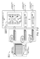
図6-1は、ジェスチャ認識のための例示的なハードウェア抽象化モジュール220を示す。示される構成では、ハードウェア抽象化モジュール220は、前処理ステージ602および信号変換ステージ604を含む。前処理ステージ602は、デジタルビート信号428-1~428-M内において各チャープ310-1~310-Nに対して動作する。言い換えれば、前処理ステージ602は、各アクティブなレーダフレーム322について動作を実行する。この例では、前処理ステージ602は、デジタルビート信号428-1~428-Mをそれぞれ処理する1次元(1D)高速フーリエ変換(FFT: Fast-Fourier Transform)モジュール606-1~606-Mを含む。フーリエ変換モジュールなど、同様の動作を実行する他のタイプのモジュールも可能である。
FIG. 6-1 illustrates an exemplary hardware abstraction module 220 for gesture recognition. In the illustrated configuration, the hardware abstraction module 220 includes a pre-processing stage 602 and a signal transformation stage 604. The pre-processing stage 602 operates on each chirp 310-1 to 310-N within the digital beat signals 428-1 to 428-M. In other words, the pre-processing stage 602 performs operations on each
信号変換ステージ604は、デジタルビート信号428-1~428-Mの各々内においてチャープ310-1~310-Mのシーケンスに対して動作する。言い換えると、信号変換ステージ604は、各アクティブな特徴フレーム316について動作を実行する。この例では、信号変換ステージ604は、バッファ608-1~608-Mと、2次元(2D)FFTモジュール610-1~610-Mとを含む。 The signal transformation stage 604 operates on the sequence of chirps 310-1 to 310-M within each of the digital beat signals 428-1 to 428-M. In other words, the signal transformation stage 604 performs operations on each active feature frame 316. In this example, the signal transformation stage 604 includes buffers 608-1 to 608-M and two-dimensional (2D) FFT modules 610-1 to 610-M.
受信中において、1次元FFTモジュール606-1~606-Mは、デジタルビート信号428-1~428-M内においてチャープ310-1~310-Mに対して個別のFFT動作を行う。レーダ受信信号308-1~308-Mが16個のチャープ310-1~310-N(たとえば、Nは16に等しい)を含むと仮定すると、各1次元FFTモジュール606-1~606-Mは、16個のFFT動作を実行して、チャープ612-1~612-Mごとの前処理された複合レーダデータを生成する。個々の動作が実行されると、バッファ608-1~608-Mは結果を格納する。ひとたびアクティブな特徴フレーム316に関連付けられるチャープ310-1~310-Mのすべてが前処理ステージ602によって処理されると、バッファ608-1~608-Mによって格納される情報は、対応する受信チャネル410-1~410-Mについての特徴フレーム614-1~614-Mごとの前処理された複合レーダデータを表す。 During reception, the 1D FFT modules 606-1 to 606-M perform individual FFT operations on the chirps 310-1 to 310-M within the digital beat signals 428-1 to 428-M. Assuming that the radar receive signals 308-1 to 308-M include 16 chirps 310-1 to 310-N (e.g., N equals 16), each 1D FFT module 606-1 to 606-M performs 16 FFT operations to generate preprocessed composite radar data for each chirp 612-1 to 612-M. As the individual operations are performed, the buffers 608-1 to 608-M store the results. Once all of the chirps 310-1 to 310-M associated with the active feature frame 316 have been processed by the pre-processing stage 602, the information stored by the buffers 608-1 to 608-M represents the pre-processed composite radar data for each feature frame 614-1 to 614-M for the corresponding receive channel 410-1 to 410-M.
2次元FFTモジュール610-1~610-Mはそれぞれ、前処理された複合レーダデータを特徴フレーム614-1~614-Mごとに処理して、ハードウェア非依存の複合レーダデータ502-1~502-Mを生成する。この場合、ハードウェア非依存の複合レーダデータ502-1~502-Mは、図6-2に関してさらに記載されるように、複合レンジドップラーマップを含む。 Two-dimensional FFT modules 610-1 to 610-M process the pre-processed composite radar data for each feature frame 614-1 to 614-M, respectively, to generate hardware-independent composite radar data 502-1 to 502-M, where hardware-independent composite radar data 502-1 to 502-M includes composite range-Doppler maps, as further described with respect to FIG. 6-2.
図6-2は、ジェスチャ認識のためにハードウェア抽象化モジュール220によって生成される例示的なハードウェア非依存の複合レーダデータ502-1を示す。ハードウェア抽象化モジュール220は、受信チャネル410-1に関連付けられるデジタルビート信号428-1を処理するように示される。デジタルビート信号428-1は、時間ドメイン信号であるチャープ310-1~310-Mを含む。チャープ310-1~310-Mは、トランシーバ214によって受信され処理される順序で1次元FFTモジュール606-1に渡される。
FIG. 6-2 illustrates an example hardware-independent composite radar data 502-1 generated by the hardware abstraction module 220 for gesture recognition. The hardware abstraction module 220 is shown to process a digital beat signal 428-1 associated with the receive channel 410-1. The digital beat signal 428-1 includes chirps 310-1 through 310-M, which are time domain signals. The chirps 310-1 through 310-M are passed to a 1-D FFT module 606-1 in the order in which they are received and processed by the
上述したように、1次元FFTモジュール606-1は、第1の時間にデジタルビート信号428-1の第1のチャープ310-1に対してFFT動作を実行する。バッファ608-1は、第1のチャープ310-1に関連付けられる前処理された複合レーダデータ612-1の第1の部分を格納する。1次元FFTモジュール606-1は、その後のチャープ310-2~310-Nを処理し続け、バッファ608-1は、前処理された複合レーダデータ612-1の対応する部分を格納し続ける。この処理は、チャープ310Mに関連付けられる前処理された複合レーダデータ612-Mの最後の部分をバッファ608-1が格納するまで継続する。 As described above, the 1D FFT module 606-1 performs an FFT operation on the first chirp 310-1 of the digital beat signal 428-1 at a first time. The buffer 608-1 stores a first portion of the preprocessed composite radar data 612-1 associated with the first chirp 310-1. The 1D FFT module 606-1 continues to process subsequent chirps 310-2 through 310-N, and the buffer 608-1 continues to store the corresponding portions of the preprocessed composite radar data 612-1. This process continues until the buffer 608-1 stores the last portion of the preprocessed composite radar data 612-M associated with chirp 310M.
この時点において、バッファ608-1は、特定の特徴フレーム614-1に関連付けられる前処理された複合レーダデータを格納する。特徴フレーム614-1ごとの前処理された複合レーダデータは、異なるチャープ310-1~310-Nと、異なるレンジビン616-1~616-Aとにわたる大きさ情報(図示せず)および位相情報(図示せず)を表し、Aは正の整数を表す。 At this point, buffer 608-1 stores the preprocessed composite radar data associated with a particular feature frame 614-1. The preprocessed composite radar data for each feature frame 614-1 represents magnitude information (not shown) and phase information (not shown) across different chirps 310-1 to 310-N and different range bins 616-1 to 616-A, where A represents a positive integer.
2次元FFT610-1は、特徴フレーム614-1ごとの前処理された複合レーダデータを受け取り、レンジドップラーマップを表すハードウェア非依存の複合レーダデータ502-1を形成するよう2次元FFT動作を実行する。レンジドップラーマップは、レンジビン616-1~616-Aおよびドップラービン618-1~618-Bについての複合レーダデータを含み、Bは正の整数を表す。言い換えれば、各レンジビン616-1~616-Aおよびドップラービン618-1~618-Bは、ともに大きさ情報および位相情報を表す実部および虚部を有する複素数を含む。レンジビン616-1~616-Aの量は、64または128のような、数十または数百のオーダであり得る(たとえば、Aは64または128に等しい)。ドップラービンの量は、32、64または124のような、数十または数百のオーダであり得る(たとえば、Bは32、64、または124に等しい)。ハードウェア非依存の複合レーダデータ502-1は、(図6-1の)ハードウェア非依存の複合レーダデータ502-1~502-Mとともに、図7-1に示されるように、空間時間ニューラルネットワーク222に提供される。
The 2D FFT 610-1 receives the pre-processed composite radar data for each feature frame 614-1 and performs a 2D FFT operation to form hardware-independent composite radar data 502-1 representing a range-Doppler map. The range-Doppler map includes composite radar data for range bins 616-1 to 616-A and Doppler bins 618-1 to 618-B, where B represents a positive integer. In other words, each range bin 616-1 to 616-A and Doppler bin 618-1 to 618-B includes a complex number having real and imaginary parts that together represent magnitude and phase information. The amount of range bins 616-1 to 616-A can be on the order of tens or hundreds, such as 64 or 128 (e.g., A is equal to 64 or 128). The amount of Doppler bins can be on the order of tens or hundreds, such as 32, 64, or 124 (e.g., B is equal to 32, 64, or 124). The hardware-independent composite radar data 502-1, along with the hardware-independent composite radar data 502-1 through 502-M (of FIG. 6-1), are provided to the spatiotemporal
図7-1は、ジェスチャ認識を実行するための例示的な空間時間ニューラルネットワーク222を示す。示される構成では、空間時間ニューラルネットワーク222は、空間再帰ネットワーク702および時間再帰ネットワーク704によってそれぞれ実現される2つのステージを含む。空間再帰ネットワーク702は、チャープレベル分析モジュール706および特徴レベル分析モジュール708を含む。一般に、空間再帰ネットワーク702は、各アクティブな特徴フレーム316について空間ドメインにわたってハードウェア非依存の複合レーダデータ502-1~502-Mを分析する。結果として生じるデータは、サーキュラーバッファ224によって格納される。時間再帰ネットワーク704は、2つ以上のアクティブな特徴フレーム316についてサーキュラーバッファ224内に格納されたデータを分析するアプリケーションレベル分析モジュール710を含む。これにより、時間再帰ネットワーク704は、アクティブなメインフレーム314の少なくとも部分について時間ドメインにわたってデータを分析する。いくつかの実現例では、サーキュラーバッファ224のサイズは、アクティブなメインフレーム314のアクティブな特徴フレーム316のすべてを格納することを可能にするために、アクティブなメインフレーム314の持続時間にカスタマイズされる。ジェスチャ認識の場合、アクティブなメインフレーム314の持続時間は、1つ以上のジェスチャの持続時間に関連付けられ得る。一般に、アプリケーションレベル分析モジュール710は、ジェスチャ認識、存在検出、衝突回避、および、人間のバイタルサイン検出を含む1つ以上のレーダベースアプリケーションをサポートするように設計される。
Figure 7-1 illustrates an exemplary spatial-temporal
受信中において、チャープレベル分析モジュール706は、各レンジビン616-1~616-Aにわたる複合レーダデータを処理して、チャネルドップラーデータ712を生成する。特徴レベル分析モジュール708は、チャネルドップラーデータ712を分析して、アプリケーションレベル分析モジュール710に関連する1つ以上の特徴を特徴付ける特徴データ714を生成する。たとえば、特徴データ714は、ジェスチャ認識のために、ユーザ302によって実行されるジェスチャの特徴を特徴付け得る。サーキュラーバッファ224は、特徴データ714を格納する。
During reception, the chirp
時間にわたって、サーキュラーバッファ224は、異なるアクティブな特徴フレーム316に関連付けられる特徴データ714を格納する。2つ以上のアクティブな特徴フレーム316に関連付けられる特徴データ714は、特徴データの時間的セット716と呼ばれる。特徴データの時間的セット716は、アプリケーションレベル分析モジュール710に提供されるか、または、アプリケーションレベル分析モジュール710によってアクセスされる。アプリケーションレベル分析モジュール710は、特徴データの時間的セット716を分析してレーダアプリケーションデータ504を生成する。例として、レーダアプリケーションデータ504は、ユーザ302によって実行されるジェスチャのタイプに関する予測を含む。より大量のアクティブな特徴フレーム316に関連付けられる特徴データ714がサーキュラーバッファ224によって格納されるので、予測の精度が向上する。いくつかの場合では、アプリケーションレベル分析モジュール710は、メインフレーム314に関連付けられるその後の特徴フレーム316が空間再帰ネットワーク702によって処理されると、レーダアプリケーションデータ504を継続的に生成または更新する。代替的には、アプリケーションレベル分析モジュール710は、メインフレーム314に関連付けられる特徴フレーム316のすべて(または少なくとも部分)が空間再帰ネットワーク702によって処理されるまでレーダアプリケーションデータ504の生成を遅延させる。チャープレベル分析モジュール706、特徴レベル分析モジュール708およびアプリケーションレベル分析モジュール710の実現例が、図7-2~図7-4に関してさらに記載される。
Over time, the circular buffer 224 stores feature
図7-2は、空間時間ニューラルネットワーク222の例示的なチャープレベル分析モジュール706を示す。示される構成では、チャープレベル分析モジュール706は、チャネルドップラー処理モジュール718-1~718-Aを含む。各チャネルドップラー処理モジュール718-1~718-Aは、1つ以上の層720-1~720-Qを有するニューラルネットワークを含み、Qは正の整数である。Qの値は、実現例に依存して変動し得る。例として、Qは、2、4または10に等しくあり得る。層720-1~720-Qは、完全に接続され得るか、部分的に接続され得るか、フィードフォワードの態様で接続され得るか、および/または、再帰的な態様で接続され得る。層720-1~720-Q内のノードは、たとえば、非線形正規化活性化関数を実行し得る。チャネルドップラー処理モジュール718-1~718-Aはさらに、加算および乗算を実行し得る。
FIG. 7-2 illustrates an exemplary chirp
チャネルドップラー処理モジュール718-1~718-Aは、レンジビン616-1~616-Aに従ってハードウェア非依存の複合レーダデータ502-1~502-Mのそれぞれの部分を受け付ける。特に、チャネルドップラー処理モジュール718-1は、受信チャネル410-1から410-Mのすべてにわたって、および、ドップラービン618-1から618-Bのすべてにわたって、第1のレンジビン616-1に関連付けられる複合レーダデータを受け付ける。各複素数は、層720-1の個々のノードへの入力として提供される。層720-1~720-Qは、非線形正規化活性化関数を使用してデータを分析して、チャネルドップラーデータ712-1を生成する。同様の動作が、チャネルドップラー処理モジュール718-2~718-Aによっても実行される。組み合わされたチャネルドップラーデータ712-1~712-Aはベクトルを表す。たとえば、3つの受信チャネル410-1~410-M(たとえば、Mは3に等しい)が存在し、32個のドップラービン618-1~618-B(たとえば、Bは32に等しい)が存在し、かつ、16個のレンジビン616-1~616-A(たとえば、Aは16に等しい)が存在しと仮定すると、チャネルドップラーデータ712-1~712-Aは、特徴レベル分析モジュール708がジェスチャの1つ以上の特徴を識別することを可能にするよう、ドップラードメインにおける受信チャネルにわたる関係を表す値の1×16ベクトルを形成する。 The channel Doppler processing modules 718-1 to 718-A accept respective portions of the hardware-independent composite radar data 502-1 to 502-M according to the range bins 616-1 to 616-A. In particular, the channel Doppler processing module 718-1 accepts composite radar data associated with the first range bin 616-1 across all of the receive channels 410-1 to 410-M and across all of the Doppler bins 618-1 to 618-B. Each complex number is provided as an input to an individual node of the layer 720-1. The layers 720-1 to 720-Q analyze the data using a nonlinear normalized activation function to generate the channel Doppler data 712-1. Similar operations are performed by the channel Doppler processing modules 718-2 to 718-A. The combined channel Doppler data 712-1 to 712-A represents a vector. For example, assuming there are three receive channels 410-1 through 410-M (e.g., M equals 3), there are 32 Doppler bins 618-1 through 618-B (e.g., B equals 32), and there are 16 range bins 616-1 through 616-A (e.g., A equals 16), the channel Doppler data 712-1 through 712-A form a 1×16 vector of values that represent relationships across the receive channels in the Doppler domain to enable the feature level analysis module 708 to identify one or more features of a gesture.
図7-3は、空間時間ニューラルネットワーク222の例示的な特徴レベル分析モジュール708を示す。示される構成では、特徴レベル分析モジュール708は、1つ以上の再帰層722-1~722-Vを使用して実現され、Vは正の整数を表す。再帰層722-1~722-V内において、ノード間の接続は、その後のアクティブな特徴フレーム316について以前のアクティブな特徴フレーム316からの情報を保持するサイクルを形成する。再帰層722-1~722-Vを使用して、特徴レベル分析モジュール708は、ロングショートタームメモリ(LSTM)ネットワークまたは何らかの他の時間畳み込みネットワークを実現し得る。
Figure 7-3 illustrates an exemplary feature level analysis module 708 of the spatio-temporal
上に記載されるように、特徴レベル分析モジュール708は、レンジビン616-1~616-Aにわたってチャネルドップラーデータ712-1~712-Aを処理して特徴データ714を生成する。示されていないが、空間再帰ネットワーク702のいくつかの実現例は、再帰層722-Vの出力に接続される付加的な全結合層720を含み得る。チャープレベル分析モジュール706の層720と同様に、これらの層720も非線形変換を実行し得る。
As described above, the feature level analysis module 708 processes the channel Doppler data 712-1 to 712-A across range bins 616-1 to 616-A to generate
時間にわたって、アクティブな特徴フレーム316-1~316-Jに関連付けられる特徴データ714-1~714-Jは、サーキュラーバッファ224によって異なるメモリ要素に順次格納される。特徴データ714-1~714-Jは、図7-4に関してさらに記載されるように、アプリケーションレベル分析モジュール708によって処理される特徴データの時間的セット716を表す。
Over time, feature data 714-1 to 714-J associated with active feature frames 316-1 to 316-J are stored sequentially in different memory elements by circular buffer 224. Feature data 714-1 to 714-J represent a temporal set of
図7-4は、空間時間ニューラルネットワーク222の例示的なアプリケーションレベル分析モジュール710を示す。示される構成では、アプリケーションレベル分析モジュール708は、1つ以上の再帰層724-1~724-Wを使用して実現され、Wは、Vに等しくても等しくなくてもよい正の整数を表す。再帰層724-1~724-Wを使用して、アプリケーションレベル分析モジュール710は、ロングショートタームメモリ(LSTM)ネットワークまたは時間畳み込みネットワークを実現し得る。アプリケーションレベル分析モジュール710は、随意に、アプリケーションレベル分析モジュール710の1つ以上の層を表す分類器モジュール726を含み得る。ジェスチャ認識の場合、分類器モジュール726は、左スワイプジェスチャ、右スワイプジェスチャ、または、リーチジェスチャなどの異なるタイプのジェスチャを区別し得る。いくつかの実現例では、分類器モジュール726は、異なるレーダベースアプリケーションをサポートし得る複数のヘッド(たとえば、複数のサブモジュール)を有する。たとえば、第1のヘッドは、存在検出をサポートするようユーザ302の存在を検出し得、第2のヘッドは、ジェスチャ認識をサポートするようユーザ302によって実行されるジェスチャを検出する。
FIG. 7-4 illustrates an example application level analysis module 710 of the spatio-temporal
アプリケーションレベル分析モジュール710は、サーキュラーバッファ224内に格納される2つ以上の特徴データ714-1~714-Jを処理する。ジェスチャ認識の場合、アプリケーションレベル分析モジュール710は、特徴データ714-1~714-Jのうちの2つ以上に基づいて実行されるジェスチャのタイプに関する予測を形成する。いくつかの場合では、アプリケーションレベル分析モジュール710は、15といったような特定された量の特徴データ714-1~714Jが利用可能になるまで予測を形成するのを待ち得る。アクティブなメインフレーム314が15を超えるアクティブな特徴フレーム316を含む(たとえば、Jが15を超える)場合、アプリケーションレベル分析モジュール710は、最後の15個のアクティブな特徴フレーム316に基づいてその予測を更新し続け得る。一般に、予測の精度は、時間にわたって、または、より多くの量の特徴データ714-1~714-Jが分析される場合、増加する。 The application level analysis module 710 processes two or more pieces of feature data 714-1 to 714-J stored in the circular buffer 224. In the case of gesture recognition, the application level analysis module 710 forms a prediction regarding the type of gesture to be performed based on two or more pieces of feature data 714-1 to 714-J. In some cases, the application level analysis module 710 may wait to form a prediction until a specified amount of feature data 714-1 to 714-J, such as 15, is available. If the active main frame 314 includes more than 15 active feature frames 316 (e.g., J is greater than 15), the application level analysis module 710 may continue to update its prediction based on the last 15 active feature frames 316. In general, the accuracy of the prediction increases over time or when a greater amount of feature data 714-1 to 714-J is analyzed.
分類器モジュール726は随意に、再帰層724-1~724-Wを使用して行われる予測をさらに改良し得る。たとえば、異なる方向性スワイプはスマートデバイス104の向きに関連付けられるので、分類器モジュール726は、当該異なる方向性スワイプ同士を区別し得る。特に、分類器モジュール726は、スワイプジェスチャがポートレートモードでのスワイプアップジェスチャであるか、または、ランドスケープモードでの左スワイプジェスチャであるかを決定し得る。このロジックを実現するために、分類器モジュール726は、分類器モジュール726によって検出されるジェスチャのタイプに従ってアクティベートするクラスノードを有する少なくとも1つの全結合層を含み得る。
Optionally, the
レーダシステムに関して記載されているが、空間時間ニューラルネットワーク222は、他のタイプのセンサまたは電磁システムによって提供されるデータにより動作するように修正され得る。一般に、これらのセンサまたは電磁システムは、信号の振幅、位相または周波数といった、空間を通って伝搬する信号の1つ以上の特性を符号化する能力を有する。例としては、ブルートゥース(登録商標)システム、WiGig(登録商標)システム、超音波センサ、および、ライダーセンサなどが挙げられる。
Although described with respect to a radar system, the spatial-temporal
例示的な方法
図8は、空間時間ニューラルネットワーク222を使用してジェスチャ認識を実行することが可能なスマートデバイスベースのレーダシステムの動作を実行するための例示的な方法800を示す。方法800は、実行される動作(または処置)のセットとして示されるが、必ずしも、当該動作が本明細書において示される順序または組み合わせに限定されない。さらに、当該動作の1つ以上のいずれかが、幅広いさまざまな付加的および/または代替的な方法を提供するよう、繰り返し、組み合わせ、再編成、リンクされてもよい。以下の議論の部分において、図1の環境100-1~100-6および図4または図5に詳述されるエンティティに対して参照がなされ得、それらへの参照は、例示のためにのみ行われる。当該技術は、1つのエンティティまたは1つのデバイス上で動作する複数のエンティティによる実行に限定されない。
Exemplary Methods FIG. 8 illustrates an
802において、レーダ送信信号は、レーダシステムのアンテナアレイを使用して送信される。たとえば、レーダシステム102は、図4に示すように、レーダ送信信号306を送信するよう少なくとも1つの送信アンテナ要素420を使用する。いくつかの実現例では、レーダ送信信号306は、図3に示すように、周波数が変調される複数のチャープ310-1~310-Nを含む。
At 802, a radar transmission signal is transmitted using an antenna array of a radar system. For example, the
804において、アンテナアレイを使用してレーダ受信信号が受信される。レーダ受信信号は、少なくとも1人のユーザによって反射されるレーダ送信信号のバージョンを含む。たとえば、レーダシステム102は、図4に示すように、ユーザ302によって反射されたレーダ受信信号308のバージョンを受信するよう、少なくとも1つの受信アンテナ要素422を使用する。
At 804, a radar receive signal is received using an antenna array. The radar receive signal includes a version of the radar transmission signal reflected by at least one user. For example, the
806において、レーダ受信信号に基づいて複合レーダデータが生成される。たとえば、レーダシステム102の受信チャネル410は、レーダ受信信号308に基づいてデジタルビート信号428を生成する。デジタルビート信号は、複合レーダデータを表し、大きさ情報および位相情報(たとえば、同相および直交情報)の両方を含む。
At 806, composite radar data is generated based on the radar receive signal. For example, the receive
808において、複合レーダデータは、レーダシステムの空間時間ニューラルネットワークに提供される。空間時間ニューラルネットワークは、マルチステージマシンラーニングアーキテクチャを含む。たとえば、受信チャネル410-1~410-Mは、図5に示すように、デジタルビート信号428-1~428-Mを空間時間ニューラルネットワーク222に提供する(たとえば、直接的に提供するか、または、ハードウェア抽象化モジュール220を介して間接的に提供する)。空間時間ニューラルネットワーク222は、図7-1の空間再帰ネットワーク702および時間再帰ネットワーク704を含むマルチステージマシンラーニングアーキテクチャを含む。空間再帰ネットワーク702は、空間時間ニューラルネットワーク222の第1のステージを表し、空間ドメインにわたって複合レーダデータを分析する。時間再帰ネットワーク704は、空間時間ニューラルネットワーク222の第2のステージを表し、時間ドメインにわたって空間時間ネットワーク702によって提供されるデータを分析する。
At 808, the composite radar data is provided to a spatial-temporal neural network of the radar system. The spatial-temporal neural network includes a multi-stage machine learning architecture. For example, the receive channels 410-1 to 410-M provide digital beat signals 428-1 to 428-M to the spatial-temporal neural network 222 (e.g., directly or indirectly via the hardware abstraction module 220) as shown in FIG. 5. The spatial-temporal
810において、複合レーダデータは、少なくとも1人のユーザによって行われるジェスチャを認識するよう、空間時間ニューラルネットワークを使用して分析される。たとえば、空間時間ニューラルネットワーク222は、デジタルビート信号428-1~428-Mまたはハードウェア非依存の複合レーダデータ502-1~502-Mを分析して、ユーザ302によって実行されるジェスチャを識別するレーダアプリケーションデータ504を生成する。ジェスチャ認識について記載されているが、同様の動作が、存在検出、衝突回避およびバイタルサイン検出などを含む他のアプリケーションについても実行され得る。
At 810, the composite radar data is analyzed using a spatio-temporal neural network to recognize gestures performed by at least one user. For example, the spatio-temporal
例示的なコンピューティングシステム
図9は、空間時間ニューラルネットワーク222を使用してジェスチャ認識を実現するよう、前述の図2を参照して記載されたような任意のタイプのクライアント、サーバおよび/またはコンピューティングデバイスとして実現され得る例示的なコンピューティングシステム900のさまざまな構成要素を示す。
Exemplary Computing System FIG. 9 illustrates various components of an exemplary computing system 900, which may be implemented as any type of client, server and/or computing device as described with reference to FIG. 2 above, to achieve gesture recognition using the spatio-temporal
コンピューティングシステム900は、デバイスデータ904(たとえば、受信されたデータ、受信されているデータ、ブロードキャスト送信のためにスケジューリングされているデータ、または、データのデータパケット)の有線通信および/または無線通信を可能にする通信デバイス902を含む。示されていないが、通信デバイス902またはコンピューティングシステム900は、1つ以上のレーダシステム102を含み得る。デバイスデータ904または他のデバイスコンテンツは、デバイスの構成設定、デバイスに格納されたメディアコンテンツ、および/または、デバイスのユーザ302に関連付けられる情報を含み得る。コンピューティングシステム900上に格納されるメディアコンテンツは、任意のタイプのオーディオ、ビデオおよび/または画像データを含み得る。コンピューティングシステム900は、1つ以上のデータ入力906を含み、当該1つ以上のデータ入力906を介して、任意のコンテンツソースおよび/またはデータソースから受信される人間の発話、レーダベースアプリケーション206、ユーザが選択可能な入力(明示的または暗黙的)、メッセージ、音楽、テレビメディアコンテンツ、記録されたビデオコンテンツ、ならびに、任意の他のタイプのオーディオ、ビデオおよび/または画像データといった任意のタイプのデータ、メディアコンテンツおよび/または入力が受信され得る。
The computing system 900 includes a
コンピューティングシステム900はさらに、シリアルおよび/またはパラレルインターフェイス、無線インターフェイス、任意のタイプのネットワークインターフェイス、モデム、ならびに、任意の他のタイプの通信インターフェイスのうちのいずれか1つ以上として実現され得る通信インターフェイス908を含む。通信インターフェイス908は、コンピューティングシステム900と、他の電子デバイス、コンピューティングデバイス、および、通信デバイスがコンピューティングシステム900とデータを通信する通信ネットワークとの間の接続および/または通信リンクを提供する。
The computing system 900 further includes a
コンピューティングシステム900は、1つ以上のプロセッサ910(たとえば、マイクロプロセッサおよびコントローラなどのいずれか)を含み、当該1つ以上のプロセッサ910は、コンピューティングシステム900の動作を制御し、かつ、飽和の存在下でのジェスチャ認識のための技術、または、飽和の存在下でジェスチャ認識が具現化され得る技術を可能にするよう、さまざまなコンピュータ実行可能命令を処理する。代替的または付加的には、コンピューティングシステム900は、一般に912において識別される処理および制御回路に関連して実現されるハードウェア、ファームウェアまたは固定ロジック回路のうちのいずれか1つまたは組み合わせを使用して実現され得る。示されていないが、コンピューティングシステム900は、デバイス内のさまざまな構成要素を結合するシステムバスまたはデータ転送システムを含み得る。システムバスは、メモリバスもしくはメモリコントローラ、周辺バス、ユニバーサルシリアルバス、および/または、さまざまなバスアーキテクチャのいずれかを利用するプロセッサもしくはローカルバスといった異なるバス構造のうちのいずれか1つまたは組み合わせを含み得る。 The computing system 900 includes one or more processors 910 (e.g., any of a microprocessor, controller, etc.) that process various computer-executable instructions to control the operation of the computing system 900 and to enable techniques for gesture recognition in the presence of saturation or techniques in which gesture recognition in the presence of saturation can be implemented. Alternatively or additionally, the computing system 900 may be implemented using any one or combination of hardware, firmware, or fixed logic circuitry implemented in conjunction with processing and control circuitry generally identified at 912. Although not shown, the computing system 900 may include a system bus or data transfer system that couples various components within the device. The system bus may include any one or combination of different bus structures such as a memory bus or memory controller, a peripheral bus, a universal serial bus, and/or a processor or local bus utilizing any of a variety of bus architectures.
コンピューティングシステム900はさらに、永続的および/または非一時的なデータ記憶(すなわち、単なる信号伝送とは対照的である)を可能にする1つ以上のメモリデバイスのようなコンピュータ可読媒体914を含み、その例は、ランダムアクセスメモリ(RAM: random access memory)、不揮発性メモリ(たとえば、リードオンリメモリ(ROM: read-only memory)、フラッシュメモリ、EPROM、EEPROMなどのうちのいずれか1つ以上)、および、ディスク記憶デバイスを含む。ディスク記憶デバイスは、ハードディスクドライブ、記録可能および/または書換可能コンパクトディスク(CD: compact disc)、ならびに、任意のタイプのデジタルバーサタイルディスク(DVD: digital versatile disc)などの任意のタイプの磁気または光学記憶デバイスとして実現されてもよい。コンピューティングシステム900はさらに、大容量記憶媒体デバイス(記憶媒体)916を含み得る。
The computing system 900 further includes a computer-
コンピュータ可読媒体914は、デバイスデータ904と、さまざまなデバイスアプリケーション918と、コンピューティングシステム900の動作的な局面に関係付けられる任意の他のタイプの情報および/またはデータとを格納するよう、データ記憶機構を提供する。たとえば、オペレーティングシステム920は、コンピュータ可読媒体914によりコンピュータアプリケーションとして維持され、プロセッサ910上で実行され得る。デバイスアプリケーション918は、任意の形態の制御アプリケーション、ソフトウェアアプリケーション、信号処理および制御モジュール、特定のデバイスに対してネイティブであるコード、および、特定のデバイスのためのハードウェア抽象化層などといったデバイスマネージャを含み得る。
The computer
デバイスアプリケーション918はさらに、マシンラーニングを使用して角度推定を実現するよう、任意のシステム構成要素、エンジン、または、マネージャを含む。この例では、デバイスアプリケーション918は、図2のレーダベースアプリケーション206および空間時間ニューラルネットワーク222を含む。
The
結論
空間時間ニューラルネットワークを使用してジェスチャ認識を実行するスマートデバイスベースのレーダシステムを使用する技術および当該スマートデバイスベースのレーダシステムを含む装置が、特徴および/または方法に特有の言語で記載されているが、添付の請求の範囲の主題は、必ずしも、記載される特定の特徴または方法に限定されないことが理解されるべきである。むしろ、特定の特徴および方法は、空間時間ニューラルネットワークを使用してジェスチャ認識を実行するスマートデバイスベースのレーダシステムの例示的な実現例として開示される。
Conclusion Although the techniques for using a smart device-based radar system to perform gesture recognition using a spatiotemporal neural network and apparatus including the smart device-based radar system have been described in language specific to features and/or methods, it should be understood that the subject matter of the appended claims is not necessarily limited to the particular features or methods described. Rather, the particular features and methods are disclosed as example implementations of a smart device-based radar system to perform gesture recognition using a spatiotemporal neural network.
いくつかの例を以下に説明する。
例1:レーダシステムによって実行される方法であって、
前記レーダシステムのアンテナアレイを使用してレーダ送信信号を送信することと、
前記アンテナアレイを使用してレーダ受信信号を受信することとを含み、前記レーダ受信信号は、少なくとも1人のユーザによって反射される前記レーダ送信信号のバージョンを含み、
前記方法はさらに、
前記レーダ受信信号に基づいて複合レーダデータを生成することと、
前記複合レーダデータを前記レーダシステムの空間時間ニューラルネットワークに提供することとを含み、前記空間時間ニューラルネットワークは、マルチステージマシンラーニングアーキテクチャを含み、
前記方法はさらに、
前記少なくとも1人のユーザによって実行されるジェスチャを認識するよう、前記空間時間ニューラルネットワークを使用して前記複合レーダデータを分析することを含む、方法。
Some examples are described below.
Example 1: A method performed by a radar system, comprising:
transmitting a radar transmission signal using an antenna array of the radar system;
receiving a radar received signal using the antenna array, the radar received signal including a version of the radar transmitted signal reflected by at least one user;
The method further comprises:
generating composite radar data based on the radar received signals;
providing the composite radar data to a spatio-temporal neural network of the radar system, the spatio-temporal neural network including a multi-stage machine learning architecture;
The method further comprises:
analyzing the combined radar data using the spatio-temporal neural network to recognize gestures performed by the at least one user.
例2:前記複合レーダデータを分析することは、前記ジェスチャを認識するよう、マシンラーニング技術を使用して、前記複合レーダデータの大きさ情報および位相情報の両方を分析することを含む、例1に記載の方法。 Example 2: The method of Example 1, wherein analyzing the combined radar data includes analyzing both magnitude and phase information of the combined radar data using machine learning techniques to recognize the gesture.
例3:前記マルチステージマシンラーニングアーキテクチャは、空間再帰ネットワークと時間再帰ネットワークとを含み、
前記複合レーダデータを分析することは、
前記ジェスチャに関連付けられる特徴データを生成するよう、前記空間再帰ネットワークを使用して、空間ドメインにわたって前記複合レーダデータを分析することと、
前記ジェスチャを認識するよう、前記時間再帰ネットワークを使用して、時間ドメインにわたって特徴データを分析することとを含む、例1または2に記載の方法。
Example 3: The multi-stage machine learning architecture includes a spatially recurrent network and a temporally recurrent network;
Analyzing the composite radar data includes:
analyzing the combined radar data over a spatial domain using the spatial recurrent network to generate feature data associated with the gesture;
and analyzing feature data over a time domain using the time recurrent network to recognize the gesture.
例4:前記特徴データをサーキュラーバッファ内に格納することと、
前記時間再帰ネットワークが、前記サーキュラーバッファ内に格納された前記特徴データにアクセスすることとをさらに含む、例3に記載の方法。
Example 4: storing the feature data in a circular buffer;
4. The method of example 3, further comprising: the time recurrent network accessing the feature data stored in the circular buffer.
例5:前記空間ドメインにわたって前記複合レーダデータを分析することは、
各レンジビンについてチャネルドップラーデータを生成するよう、非線形活性化関数を使用して、異なるレンジビンに関連付けられる前記複合レーダデータの部分を別々に処理することと、
前記特徴データを生成するよう、前記異なるレンジビンにわたって前記チャネルドップラーデータを分析することとを含む、例3または4に記載の方法。
Example 5: Analyzing the composite radar data across the spatial domain comprises:
separately processing portions of the composite radar data associated with different range bins using a nonlinear activation function to generate channel Doppler data for each range bin;
and analyzing the channel Doppler data across the different range bins to generate the feature data.
例6:前記時間ドメインにわたって前記特徴データを分析することは、少なくとも2つの異なる時間フレームに関連付けられる前記特徴データを分析することによって、前記ジェスチャに関する予測を形成することを含む、例3~5のいずれかに記載の方法。 Example 6: The method of any of Examples 3-5, wherein analyzing the feature data across the time domain includes forming a prediction regarding the gesture by analyzing the feature data associated with at least two different time frames.
例7:前記空間再帰ネットワークは、チャープレベル分析モジュールおよび特徴レベル分析モジュールを含む、例3~6のいずれかに記載の方法。 Example 7: The method of any of Examples 3 to 6, wherein the spatially recurrent network includes a chirp level analysis module and a feature level analysis module.
例8:前記時間再帰ネットワークは、アプリケーションレベル分析モジュールを含む、例3~7のいずれかに記載の方法。 Example 8: The method of any of Examples 3 to 7, wherein the time-recurrent network includes an application-level analysis module.
例9:前記複合レーダデータは、
複合レンジ-ドップラーマップ、
複合干渉測定データ、
前記レーダ受信信号に関連付けられる複数のデジタルビート信号、または
前記複数のデジタルビート信号の周波数ドメイン表現
のうちの少なくとも1つを含む、先行する例のいずれかに記載の方法。
Example 9: The composite radar data is
Combined range-Doppler map,
Combined interferometric data,
2. The method of any of the preceding examples, including at least one of: a plurality of digital beat signals associated with the radar receive signal; or a frequency domain representation of the plurality of digital beat signals.
例10:前記ジェスチャは、
スワイプジェスチャ、
リーチジェスチャ、
ノブ回転ジェスチャ、または
スピンドルねじりジェスチャ
のうちの少なくとも1つを含む、先行する例のいずれかに記載の方法。
Example 10: The gesture is:
Swipe gestures,
Reach gestures,
The method of any preceding example, comprising at least one of: a knob rotation gesture; or a spindle twist gesture.
例11:前記レーダ受信信号を受信することは、前記レーダシステムの異なるアンテナ要素を使用して前記レーダ受信信号の複数のバージョンを受信することを含み、
前記複合レーダデータを生成することは、前記レーダシステムのそれぞれの受信チャネルを使用してデジタルビート信号を生成することを含み、前記それぞれの受信チャネルは、それぞれ異なる前記アンテナ要素に接続される、先行する例のいずれかに記載の方法。
Example 11: Receiving the radar receive signal includes receiving multiple versions of the radar receive signal using different antenna elements of the radar system;
2. The method of any preceding example, wherein generating the composite radar data includes generating a digital beat signal using each receive channel of the radar system, each receive channel being connected to a different antenna element.
例12:前記空間再帰ネットワークによって処理される前記特徴データは、前記サーキュラーバッファによって格納され、前記特徴データの時間セットは、前記時間再帰ネットワークによってアクセスされる、例4~11のいずれかに記載の方法。 Example 12: The method of any of Examples 4 to 11, wherein the feature data processed by the spatial recursive network is stored by the circular buffer, and the time sets of the feature data are accessed by the time recursive network.
例13:
レーダシステムを含み、
前記レーダシステムは、
アンテナアレイと、
トランシーバと、
例1~12に記載の方法のいずれかを実行するように構成されるプロセッサおよびコンピュータ可読記憶媒体とを含む、装置。
Example 13:
[0023] Including a radar system,
The radar system includes:
An antenna array;
A transceiver;
An apparatus comprising: a processor and a computer readable storage medium configured to perform any of the methods described in Examples 1-12.
例14:前記装置は、スマートデバイスを含み、
前記スマートデバイスは、
スマートフォン、
スマートウォッチ、
スマートスピーカ、
スマートサーモスタット、
セキュリティカメラ、
車両、または
家庭用電化製品
のうちの1つを含む、例13に記載の装置。
Example 14: The apparatus includes a smart device,
The smart device comprises:
smartphone,
Smartwatch,
Smart speakers,
Smart thermostat,
Security cameras,
The apparatus of example 13, comprising one of: a vehicle; or a consumer electronics device.
例15:プロセッサによる実行に応答して、空間時間ニューラルネットワークを実現するコンピュータ実行可能命令を含むコンピュータ可読記憶媒体であって、
前記空間時間ニューラルネットワークは、
少なくとも1つの対象によって反射されるレーダ受信信号に関連付けられる複合レーダデータを受け付けることと、
特徴データを生成するよう、空間ドメインにわたって前記複合レーダデータを分析することと、
レーダアプリケーションデータを生成するよう、時間ドメインにわたって前記特徴データを分析することと、
前記レーダアプリケーションデータをレーダベースアプリケーションに渡すこととを行うように構成される、コンピュータ可読記憶媒体。
Example 15: A computer-readable storage medium comprising computer-executable instructions for implementing a spatio-temporal neural network in response to execution by a processor, the instructions comprising:
The spatial-temporal neural network comprises:
accepting composite radar data associated with radar receive signals reflected by at least one object;
analyzing the composite radar data across a spatial domain to generate signature data;
analyzing the feature data over a time domain to generate radar application data;
and passing the radar application data to a radar-based application.
例16:前記空間時間ニューラルネットワークはさらに、前記レーダアプリケーションデータを生成するよう、前記複合レーダデータの大きさ情報および位相情報の両方を分析するように構成される、例15に記載のコンピュータ可読記憶媒体。 Example 16: The computer-readable storage medium of Example 15, wherein the spatiotemporal neural network is further configured to analyze both magnitude and phase information of the combined radar data to generate the radar application data.
例17:前記少なくとも1つの対象はユーザを含み、
前記レーダアプリケーションデータは、前記ユーザによって実行されるジェスチャを識別し、
前記コンピュータ実行可能命令は、前記プロセッサによる実行に応答して、前記レーダベースアプリケーションを実現し、
前記レーダベースアプリケーションは、
前記レーダアプリケーションデータを受け付けることと、
識別された前記ジェスチャに基づいて、前記ユーザにコンテンツを表示することとを行うように構成される、例15または16に記載のコンピュータ可読記憶媒体。
Example 17: The at least one object includes a user;
the radar application data identifying a gesture performed by the user;
the computer-executable instructions, responsive to execution by the processor, implement the radar-based application;
The radar-based application includes:
accepting the radar application data;
and displaying content to the user based on the identified gesture.
例18:前記空間時間ニューラルネットワークはさらに、
前記ユーザに前記ジェスチャを実行するように促すことと、
前記ユーザが前記ジェスチャを実行している間に、前記複合レーダデータを学習データとして記録することと、
前記ユーザによって実行される将来のジェスチャを認識するよう、学習手順を実行することとを行うように構成される、例17に記載のコンピュータ可読記憶媒体。
Example 18: The spatiotemporal neural network further comprises:
prompting the user to perform the gesture;
recording the combined radar data as training data while the user is performing the gesture;
and performing a learning procedure to recognize future gestures performed by the user.
例19:前記少なくとも1つの対象はスタイラスを含み、
前記レーダアプリケーションデータは、前記スタイラスを使用してユーザによって実行されるジェスチャを識別する、例15または16に記載のコンピュータ可読記憶媒体。
Example 19: The at least one object includes a stylus;
17. The computer-readable storage medium of example 15 or 16, wherein the radar application data identifies a gesture performed by a user using the stylus.
例20:前記少なくとも1つの対象は、無生物対象とユーザとを含み、
前記レーダアプリケーションデータは、前記無生物対象と前記ユーザとの間の潜在的な衝突を識別し、
前記コンピュータ実行可能命令は、前記プロセッサによる実行に応答して、レーダベースアプリケーションを実現し、
前記レーダベースアプリケーションは、
前記レーダアプリケーションデータを受け付けることと、
前記潜在的な衝突について前記ユーザに警告することとを行うように構成される、例15または16に記載のコンピュータ可読記憶媒体。
Example 20: The at least one object includes an inanimate object and a user;
the radar application data identifies potential collisions between the inanimate object and the user;
The computer-executable instructions, in response to execution by the processor, implement a radar-based application;
The radar-based application includes:
accepting the radar application data;
and warning the user about the potential collision.
例21:前記少なくとも1つの対象はユーザを含み、
前記レーダアプリケーションデータは、前記ユーザの測定されたバイタルサインを含み、
前記コンピュータ実行可能命令は、前記プロセッサによる実行に応答して、レーダベースアプリケーションを実現し、
前記レーダベースアプリケーションは、
前記レーダアプリケーションデータを受け付けることと、
前記測定されたバイタルサインを前記ユーザに知らせることとを行うように構成される、例15または16に記載のコンピュータ可読記憶媒体。
Example 21: The at least one object includes a user;
the radar application data includes measured vital signs of the user;
The computer-executable instructions, in response to execution by the processor, implement a radar-based application;
The radar-based application includes:
accepting the radar application data;
and informing the user of the measured vital signs.
例22:前記コンピュータ実行可能命令は、前記プロセッサによる実行に応答して、ハードウェア抽象化モジュールを実現し、
前記ハードウェア抽象化モジュールは、
前記複合レーダデータに基づいて、ハードウェア非依存の複合レーダデータを生成することと、
前記ハードウェア非依存の複合レーダデータを前記複合レーダデータとして前記空間時間ニューラルネットワークに提供することとを行うように構成される、例15~21のいずれかに記載のコンピュータ可読記憶媒体。
Example 22: The computer-executable instructions, in response to execution by the processor, implement a hardware abstraction module;
The hardware abstraction module includes:
generating hardware independent composite radar data based on the composite radar data;
and providing the hardware-independent composite radar data to the spatio-temporal neural network as the composite radar data.
例23:コンピュータ実行可能命令を含むコンピュータ可読記憶媒体であって、
前記コンピュータ実行可能命令は、プロセッサによる実行に応答して、マルチステージマシンラーニングアーキテクチャを含む空間時間ニューラルネットワークを実現し、
前記空間時間ニューラルネットワークは、
少なくとも1つの対象によって反射されるレーダ受信信号に関連付けられる複合レーダデータを受け付けることと、
前記少なくとも1人のユーザによって行われるジェスチャを認識するよう、前記複合レーダデータを分析することと
を行うように構成される、コンピュータ可読記憶媒体。
Example 23: A computer-readable storage medium comprising computer-executable instructions,
The computer-executable instructions, when executed by a processor, implement a spatio-temporal neural network that includes a multi-stage machine learning architecture;
The spatial-temporal neural network comprises:
accepting composite radar data associated with radar receive signals reflected by at least one object;
and analyzing the combined radar data to recognize gestures performed by the at least one user.
例24:前記空間時間ニューラルネットワークはさらに、
特徴データを生成するよう、空間ドメインにわたって前記複合レーダデータを分析することと、
レーダアプリケーションデータを生成するよう、時間ドメインにわたって前記特徴データを分析することと、
前記レーダアプリケーションデータをレーダベースアプリケーションに渡すことと
を行うように構成される、例23に記載のコンピュータ可読記憶媒体。
Example 24: The spatiotemporal neural network further comprises:
analyzing the composite radar data across a spatial domain to generate signature data;
analyzing the feature data over a time domain to generate radar application data;
and passing the radar application data to a radar-based application.
Claims (18)
前記レーダシステムのアンテナアレイを使用してレーダ送信信号を送信することと、
前記アンテナアレイを使用してレーダ受信信号を受信することとを含み、前記レーダ受信信号は、少なくとも1人のユーザによって反射される前記レーダ送信信号のバージョンを含み、
前記方法はさらに、
前記レーダ受信信号に基づいて複合レーダデータを生成することと、
前記複合レーダデータを前記レーダシステムの空間時間ニューラルネットワークに提供することとを含み、前記空間時間ニューラルネットワークは、空間再帰ネットワークと時間再帰ネットワークとを含み、
前記方法はさらに、
前記少なくとも1人のユーザによって実行されるジェスチャを認識するよう、前記空間時間ニューラルネットワークを使用して前記複合レーダデータを分析することを含み、
前記複合レーダデータを分析することは、
前記複合レーダデータに関連付けられる空間ドメインにわたって前記複合レーダデータを分析することによって、前記空間再帰ネットワークを使用して、前記ジェスチャに関連付けられる特徴データを生成することと、
時間ドメインにわたって前記特徴データの時間的セットを分析することによって、前記時間再帰ネットワークを使用して、前記ジェスチャを認識することとを含む、方法。 1. A method performed by a radar system, comprising:
transmitting a radar transmission signal using an antenna array of the radar system;
receiving a radar received signal using the antenna array, the radar received signal including a version of the radar transmitted signal reflected by at least one user;
The method further comprises:
generating composite radar data based on the radar received signals;
providing the combined radar data to a spatio-temporal neural network of the radar system, the spatio-temporal neural network including a spatially recurrent network and a time-recurrent network;
The method further comprises:
analyzing the combined radar data using the spatio-temporal neural network to recognize gestures performed by the at least one user;
Analyzing the composite radar data includes:
generating feature data associated with the gesture using the spatial recurrent network by analyzing the composite radar data over a spatial domain associated with the composite radar data ;
and recognizing the gesture using the time recurrent network by analyzing the temporal set of feature data over a time domain.
前記時間再帰ネットワークが、前記サーキュラーバッファ内に格納された前記特徴データにアクセスすることとをさらに含む、請求項1または2に記載の方法。 storing said feature data in a circular buffer;
The method of claim 1 or 2, further comprising: the time recurrent network accessing the feature data stored in the circular buffer.
各レンジビンについてチャネルドップラーデータを生成するよう、非線形活性化関数を使用して、異なるレンジビンに関連付けられる前記複合レーダデータの部分を別々に処理することと、
前記特徴データを生成するよう、前記異なるレンジビンにわたって前記チャネルドップラーデータを分析することとを含む、請求項1~3のいずれか1項に記載の方法。 Analyzing the composite radar data across the spatial domain includes:
separately processing portions of the composite radar data associated with different range bins using a nonlinear activation function to generate channel Doppler data for each range bin;
4. A method according to any preceding claim, comprising analysing the channel Doppler data across the different range bins to generate the characteristic data.
複合レンジ-ドップラーマップ、
複合干渉測定データ、
前記レーダ受信信号に関連付けられる複数のデジタルビート信号、または
前記複数のデジタルビート信号の周波数ドメイン表現
のうちの少なくとも1つを含む、請求項1~5のいずれかに記載の方法。 The composite radar data includes:
Combined range-Doppler map,
Combined interferometric data,
The method of any of claims 1 to 5, comprising at least one of: a plurality of digital beat signals associated with the radar receive signal; or a frequency domain representation of the plurality of digital beat signals.
スワイプジェスチャ、
リーチジェスチャ、
ノブ回転ジェスチャ、または
スピンドルねじりジェスチャ
のうちの少なくとも1つを含む、請求項1~6のいずれかに記載の方法。 The gesture may include:
Swipe gestures,
Reach gestures,
The method of any of claims 1 to 6, comprising at least one of: a knob rotation gesture; or a spindle twist gesture.
前記複合レーダデータを生成することは、前記レーダシステムのそれぞれの受信チャネルを使用してデジタルビート信号を生成することを含み、前記それぞれの受信チャネルは、それぞれ異なる前記アンテナ要素に接続される、請求項1~7のいずれかに記載の方法。 receiving the radar receive signal includes receiving multiple versions of the radar receive signal using different antenna elements of the radar system;
8. The method of claim 1, wherein generating the composite radar data includes generating a digital beat signal using each receive channel of the radar system, each receive channel being connected to a different antenna element.
前記レーダシステムは、
アンテナアレイと、
トランシーバと、
請求項1~8のいずれかに記載の方法を実行するように構成されるプロセッサおよびコンピュータ可読記憶媒体とを含む、装置。 [0023] Including a radar system,
The radar system includes:
An antenna array;
A transceiver;
An apparatus comprising a processor and a computer readable storage medium configured to perform the method of any of claims 1 to 8.
前記スマートデバイスは、
スマートフォン、
スマートウォッチ、
スマートスピーカ、
スマートサーモスタット、
セキュリティカメラ、
車両、または
家庭用電化製品
のうちの1つを含む、請求項9に記載の装置。 The apparatus includes a smart device;
The smart device comprises:
smartphone,
Smartwatch,
Smart speakers,
Smart thermostat,
Security cameras,
The apparatus of claim 9 , comprising one of: a vehicle; or a consumer electronics appliance.
前記空間時間ニューラルネットワークは、
少なくとも1つの対象によって反射されるレーダ受信信号に関連付けられる複合レーダデータを受け付けることと、
前記複合レーダデータに関連付けられる空間ドメインにわたって前記複合レーダデータを分析することによって、前記空間再帰ネットワークを使用して、特徴データを生成することと、
時間ドメインにわたって前記特徴データの時間的セットを分析することによって、前記時間再帰ネットワークを使用して、レーダアプリケーションデータを生成することと、
前記レーダアプリケーションデータをレーダベースアプリケーションに渡すこととを行うように構成される、コンピュータプログラム。 1. A computer program comprising computer-executable instructions which, when executed by a processor, implement a spatio-temporal neural network, the spatio-temporal neural network comprising a spatially recurrent network and a timely recurrent network, the computer program comprising:
The spatial-temporal neural network comprises:
accepting composite radar data associated with radar receive signals reflected by at least one object;
generating feature data using the spatially recurrent network by analyzing the composite radar data over a spatial domain associated with the composite radar data ;
generating radar application data using the time recurrent network by analyzing the temporal set of feature data over a time domain ;
and passing the radar application data to a radar-based application.
前記レーダアプリケーションデータは、前記ユーザによって実行されるジェスチャを識別し、
前記コンピュータ実行可能命令は、前記プロセッサによる実行に応答して、前記レーダベースアプリケーションを実現し、
前記レーダベースアプリケーションは、
前記レーダアプリケーションデータを受け付けることと、
識別された前記ジェスチャに基づいて、前記ユーザにコンテンツを表示することとを行うように構成される、請求項11または12に記載のコンピュータプログラム。 the at least one subject includes a user;
the radar application data identifying a gesture performed by the user;
the computer-executable instructions, responsive to execution by the processor, implement the radar-based application;
The radar-based application includes:
accepting the radar application data;
and displaying content to the user based on the identified gesture.
前記ユーザに前記ジェスチャを実行するように促すことと、
前記ユーザが前記ジェスチャを実行している間に、前記複合レーダデータを学習データとして記録することと、
前記ユーザによって実行される将来のジェスチャを認識するよう、学習手順を実行することとを行うように構成される、請求項13に記載のコンピュータプログラム。 The spatio-temporal neural network further comprises:
prompting the user to perform the gesture;
recording the combined radar data as training data while the user is performing the gesture;
and performing a learning procedure to recognize future gestures performed by the user.
前記レーダアプリケーションデータは、前記スタイラスを使用してユーザによって実行されるジェスチャを識別する、請求項11または12に記載のコンピュータプログラム。 the at least one object includes a stylus;
13. A computer program product as claimed in claim 11 or 12, wherein the radar application data identifies gestures performed by a user using the stylus.
前記レーダアプリケーションデータは、前記無生物対象と前記ユーザとの間の潜在的な衝突を識別し、
前記コンピュータ実行可能命令は、前記プロセッサによる実行に応答して、レーダベースアプリケーションを実現し、
前記レーダベースアプリケーションは、
前記レーダアプリケーションデータを受け付けることと、
前記潜在的な衝突について前記ユーザに警告することとを行うように構成される、請求項11または12に記載のコンピュータプログラム。 The at least one object includes an inanimate object and a user;
the radar application data identifies potential collisions between the inanimate object and the user;
The computer-executable instructions, in response to execution by the processor, implement a radar-based application;
The radar-based application includes:
accepting the radar application data;
and warning the user about the potential collision.
前記レーダアプリケーションデータは、前記ユーザの測定されたバイタルサインを含み、
前記コンピュータ実行可能命令は、前記プロセッサによる実行に応答して、レーダベースアプリケーションを実現し、
前記レーダベースアプリケーションは、
前記レーダアプリケーションデータを受け付けることと、
前記測定されたバイタルサインを前記ユーザに知らせることとを行うように構成される、請求項11または12に記載のコンピュータプログラム。 the at least one subject includes a user;
the radar application data includes measured vital signs of the user;
The computer-executable instructions, in response to execution by the processor, implement a radar-based application;
The radar-based application includes:
accepting the radar application data;
13. The computer program product according to claim 11 or 12, configured to: inform the user of the measured vital signs.
前記ハードウェア抽象化モジュールは、
前記複合レーダデータに基づいて、ハードウェア非依存の複合レーダデータを生成することと、
前記ハードウェア非依存の複合レーダデータを前記複合レーダデータとして前記空間時間ニューラルネットワークに提供することとを行うように構成される、請求項11~17のいずれかに記載のコンピュータプログラム。 the computer-executable instructions, in response to execution by the processor, implement a hardware abstraction module;
The hardware abstraction module includes:
generating hardware independent composite radar data based on the composite radar data;
and providing the hardware-independent composite radar data as the composite radar data to the spatio-temporal neural network.
Applications Claiming Priority (3)
| Application Number | Priority Date | Filing Date | Title |
|---|---|---|---|
| US201962928029P | 2019-10-30 | 2019-10-30 | |
| US62/928,029 | 2019-10-30 | ||
| PCT/US2020/056505 WO2021086688A2 (en) | 2019-10-30 | 2020-10-20 | Smart-device-based radar system performing gesture recognition using a space time neural network |
Publications (2)
| Publication Number | Publication Date |
|---|---|
| JP2022553619A JP2022553619A (en) | 2022-12-26 |
| JP7481434B2 true JP7481434B2 (en) | 2024-05-10 |
Family
ID=73402159
Family Applications (1)
| Application Number | Title | Priority Date | Filing Date |
|---|---|---|---|
| JP2022515765A Active JP7481434B2 (en) | 2019-10-30 | 2020-10-20 | A Smart Device-Based Radar System Using Spatio-Temporal Neural Networks to Perform Gesture Recognition |
Country Status (6)
| Country | Link |
|---|---|
| US (1) | US12158991B2 (en) |
| EP (1) | EP4052173A2 (en) |
| JP (1) | JP7481434B2 (en) |
| KR (1) | KR102805216B1 (en) |
| CN (1) | CN114365008B (en) |
| WO (1) | WO2021086688A2 (en) |
Families Citing this family (21)
| Publication number | Priority date | Publication date | Assignee | Title |
|---|---|---|---|---|
| JP7481434B2 (en) | 2019-10-30 | 2024-05-10 | グーグル エルエルシー | A Smart Device-Based Radar System Using Spatio-Temporal Neural Networks to Perform Gesture Recognition |
| CN114661142B (en) * | 2020-12-22 | 2024-08-27 | 华为技术有限公司 | A gesture recognition method and device |
| CN117321604A (en) * | 2021-04-09 | 2023-12-29 | 谷歌有限责任公司 | Radar-based gesture detection in ambient computer environments using machine learning modules |
| JP7634211B2 (en) * | 2021-06-29 | 2025-02-21 | パナソニックIpマネジメント株式会社 | Estimation device and estimation method |
| AU2022322501A1 (en) | 2021-08-05 | 2023-12-14 | Samsung Electronics Co., Ltd. | Electronic apparatus having variable display area and operation method therefor |
| CN115880716A (en) * | 2021-09-28 | 2023-03-31 | 清华大学 | Gesture recognition method and gesture recognition apparatus |
| US11983327B2 (en) * | 2021-10-06 | 2024-05-14 | Fotonation Limited | Method for identifying a gesture |
| CN113918019A (en) * | 2021-10-19 | 2022-01-11 | 亿慧云智能科技(深圳)股份有限公司 | Gesture recognition control method and device for terminal equipment, terminal equipment and medium |
| US12293023B2 (en) | 2021-12-02 | 2025-05-06 | SoftEye, Inc. | Systems, apparatus, and methods for gesture-based augmented reality, extended reality |
| US20230368328A1 (en) | 2022-05-11 | 2023-11-16 | SoftEye, Inc. | Methods and apparatus for scalable processing |
| CN115761872A (en) * | 2022-09-09 | 2023-03-07 | 中国科学院上海微系统与信息技术研究所 | Radar identification method device, storage medium and terminal based on cyclic neural network |
| US12510631B2 (en) | 2022-10-14 | 2025-12-30 | Motional Ad Llc | Object detection using radar sensors |
| WO2024081122A1 (en) * | 2022-10-14 | 2024-04-18 | Motional Ad Llc | Object detection using radar sensors |
| CN115345908B (en) * | 2022-10-18 | 2023-03-07 | 四川启睿克科技有限公司 | Human body posture recognition method based on millimeter wave radar |
| SE547890C2 (en) * | 2022-10-25 | 2025-12-16 | Xfinder Sweden Ab | Millimeter radar for interrogation, classification and localization of target objects having a non-linear frequency dependent frequency response, enhanced by wideband chaos generating material (wcgm) |
| US12373038B2 (en) | 2022-11-29 | 2025-07-29 | Samsung Electronics Co., Ltd. | Electronic device for recognizing gesture and method for operating the same |
| CN116074835B (en) * | 2023-01-16 | 2024-09-10 | 上海物骐微电子有限公司 | WiFi-based gesture recognition method and device, electronic device, and storage medium |
| US12306408B2 (en) | 2023-05-11 | 2025-05-20 | SoftEye, Inc. | Applications for anamorphic lenses |
| US20250110213A1 (en) * | 2023-09-28 | 2025-04-03 | Nvidia Corporation | Self-supervised velocity learning for autonomous systems and applications |
| CN117724094B (en) * | 2024-02-07 | 2024-05-07 | 浙江大华技术股份有限公司 | Vital Signs Detection Methods |
| CN119310566A (en) * | 2024-10-29 | 2025-01-14 | 南京邮电大学 | A method for through-wall human posture estimation based on MIMO radar |
Citations (2)
| Publication number | Priority date | Publication date | Assignee | Title |
|---|---|---|---|---|
| JP2018170003A (en) | 2017-03-30 | 2018-11-01 | 富士通株式会社 | Event detecting device, method and image processing device in video |
| WO2019104228A1 (en) | 2017-11-21 | 2019-05-31 | Google Llc | Low-power ambient computing system with machine learning |
Family Cites Families (15)
| Publication number | Priority date | Publication date | Assignee | Title |
|---|---|---|---|---|
| US9024958B2 (en) * | 2012-01-30 | 2015-05-05 | Lenovo (Singapore) Pte. Ltd. | Buffering mechanism for camera-based gesturing |
| US20140002338A1 (en) * | 2012-06-28 | 2014-01-02 | Intel Corporation | Techniques for pose estimation and false positive filtering for gesture recognition |
| WO2014130871A1 (en) * | 2013-02-22 | 2014-08-28 | Thalmic Labs Inc. | Methods and devices that combine muscle activity sensor signals and inertial sensor signals for gesture-based control |
| WO2016090483A1 (en) * | 2014-12-08 | 2016-06-16 | Rohit Seth | Wearable wireless hmi device |
| EP3497546B1 (en) * | 2016-08-09 | 2021-10-06 | Google LLC | Radar-based gestural interface |
| JP2018164252A (en) * | 2017-03-24 | 2018-10-18 | 日本電産株式会社 | Slot array antenna, and radar having the same |
| US10795009B2 (en) * | 2017-05-31 | 2020-10-06 | Google Llc | Digital beamforming for radar sensing using wireless communication chipset |
| US20190049558A1 (en) * | 2017-08-08 | 2019-02-14 | KC Sense Limited | Hand Gesture Recognition System and Method |
| CA3076015A1 (en) * | 2017-10-06 | 2019-04-11 | Tellus You Care, Inc. | Non-contact activity sensing network for elderly care |
| US10108903B1 (en) * | 2017-12-08 | 2018-10-23 | Cognitive Systems Corp. | Motion detection based on machine learning of wireless signal properties |
| CN111433627B (en) * | 2018-04-05 | 2023-09-22 | 谷歌有限责任公司 | Smart device-based radar system using machine learning to perform angle estimation |
| US11579629B2 (en) * | 2019-03-15 | 2023-02-14 | Nvidia Corporation | Temporal information prediction in autonomous machine applications |
| US11126885B2 (en) * | 2019-03-21 | 2021-09-21 | Infineon Technologies Ag | Character recognition in air-writing based on network of radars |
| CN110208793B (en) * | 2019-04-26 | 2022-03-11 | 纵目科技(上海)股份有限公司 | Auxiliary driving system, method, terminal and medium based on millimeter wave radar |
| JP7481434B2 (en) | 2019-10-30 | 2024-05-10 | グーグル エルエルシー | A Smart Device-Based Radar System Using Spatio-Temporal Neural Networks to Perform Gesture Recognition |
-
2020
- 2020-10-20 JP JP2022515765A patent/JP7481434B2/en active Active
- 2020-10-20 KR KR1020227008000A patent/KR102805216B1/en active Active
- 2020-10-20 US US17/634,857 patent/US12158991B2/en active Active
- 2020-10-20 WO PCT/US2020/056505 patent/WO2021086688A2/en not_active Ceased
- 2020-10-20 CN CN202080064138.1A patent/CN114365008B/en active Active
- 2020-10-20 EP EP20807201.7A patent/EP4052173A2/en active Pending
Patent Citations (2)
| Publication number | Priority date | Publication date | Assignee | Title |
|---|---|---|---|---|
| JP2018170003A (en) | 2017-03-30 | 2018-11-01 | 富士通株式会社 | Event detecting device, method and image processing device in video |
| WO2019104228A1 (en) | 2017-11-21 | 2019-05-31 | Google Llc | Low-power ambient computing system with machine learning |
Non-Patent Citations (1)
| Title |
|---|
| YONG WANG,TS-I3D Based Hand Gesture Recognition Method With Radar Sensor,IEEE ACCESS,2019年03月04日,第7巻,pp.22902-22913 |
Also Published As
| Publication number | Publication date |
|---|---|
| US12158991B2 (en) | 2024-12-03 |
| WO2021086688A2 (en) | 2021-05-06 |
| JP2022553619A (en) | 2022-12-26 |
| KR102805216B1 (en) | 2025-05-13 |
| CN114365008B (en) | 2025-04-08 |
| WO2021086688A3 (en) | 2021-06-10 |
| CN114365008A (en) | 2022-04-15 |
| EP4052173A2 (en) | 2022-09-07 |
| KR20220044809A (en) | 2022-04-11 |
| US20220326367A1 (en) | 2022-10-13 |
Similar Documents
| Publication | Publication Date | Title |
|---|---|---|
| JP7481434B2 (en) | A Smart Device-Based Radar System Using Spatio-Temporal Neural Networks to Perform Gesture Recognition | |
| CN111812633B (en) | Detecting reference frame changes in smart device-based radar systems | |
| CN111433627B (en) | Smart device-based radar system using machine learning to perform angle estimation | |
| CN111830503B (en) | Intelligent device-based radar system performing symmetric Doppler interference mitigation | |
| US10698603B2 (en) | Smartphone-based radar system facilitating ease and accuracy of user interactions with displayed objects in an augmented-reality interface | |
| US20240027600A1 (en) | Smart-Device-Based Radar System Performing Angular Position Estimation | |
| WO2021177956A1 (en) | Smart-device-based radar system performing near-range detection | |
| CN113454481A (en) | Smart device based radar system to detect user gestures in the presence of saturation | |
| US20240337746A1 (en) | Multi-Radar System | |
| US20240280669A1 (en) | Radar Application Programming Interface | |
| US20250189629A1 (en) | Providing Radar Sensing for Multiple Applications |
Legal Events
| Date | Code | Title | Description |
|---|---|---|---|
| A521 | Request for written amendment filed |
Free format text: JAPANESE INTERMEDIATE CODE: A523 Effective date: 20220425 |
|
| A621 | Written request for application examination |
Free format text: JAPANESE INTERMEDIATE CODE: A621 Effective date: 20220425 |
|
| A131 | Notification of reasons for refusal |
Free format text: JAPANESE INTERMEDIATE CODE: A131 Effective date: 20230627 |
|
| A521 | Request for written amendment filed |
Free format text: JAPANESE INTERMEDIATE CODE: A523 Effective date: 20230919 |
|
| A131 | Notification of reasons for refusal |
Free format text: JAPANESE INTERMEDIATE CODE: A131 Effective date: 20231226 |
|
| A521 | Request for written amendment filed |
Free format text: JAPANESE INTERMEDIATE CODE: A523 Effective date: 20240311 |
|
| TRDD | Decision of grant or rejection written | ||
| A01 | Written decision to grant a patent or to grant a registration (utility model) |
Free format text: JAPANESE INTERMEDIATE CODE: A01 Effective date: 20240402 |
|
| A61 | First payment of annual fees (during grant procedure) |
Free format text: JAPANESE INTERMEDIATE CODE: A61 Effective date: 20240425 |
|
| R150 | Certificate of patent or registration of utility model |
Ref document number: 7481434 Country of ref document: JP Free format text: JAPANESE INTERMEDIATE CODE: R150 |