JP7481257B2 - Storage battery module and battery with multiple modules - Google Patents
Storage battery module and battery with multiple modules Download PDFInfo
- Publication number
- JP7481257B2 JP7481257B2 JP2020541358A JP2020541358A JP7481257B2 JP 7481257 B2 JP7481257 B2 JP 7481257B2 JP 2020541358 A JP2020541358 A JP 2020541358A JP 2020541358 A JP2020541358 A JP 2020541358A JP 7481257 B2 JP7481257 B2 JP 7481257B2
- Authority
- JP
- Japan
- Prior art keywords
- battery
- chamber
- flange
- opening
- module
- Prior art date
- Legal status (The legal status is an assumption and is not a legal conclusion. Google has not performed a legal analysis and makes no representation as to the accuracy of the status listed.)
- Active
Links
- 238000003860 storage Methods 0.000 title claims description 43
- 239000007788 liquid Substances 0.000 claims description 22
- 230000000712 assembly Effects 0.000 claims description 12
- 238000000429 assembly Methods 0.000 claims description 12
- 239000000463 material Substances 0.000 claims description 9
- 239000000853 adhesive Substances 0.000 claims description 6
- 230000001070 adhesive effect Effects 0.000 claims description 6
- 238000004519 manufacturing process Methods 0.000 claims description 6
- 238000000034 method Methods 0.000 claims description 6
- 230000006835 compression Effects 0.000 claims description 5
- 238000007906 compression Methods 0.000 claims description 5
- 238000005304 joining Methods 0.000 claims description 3
- 239000002826 coolant Substances 0.000 description 23
- -1 LFP Chemical compound 0.000 description 8
- HBBGRARXTFLTSG-UHFFFAOYSA-N Lithium ion Chemical compound [Li+] HBBGRARXTFLTSG-UHFFFAOYSA-N 0.000 description 6
- 239000004020 conductor Substances 0.000 description 6
- 229910001416 lithium ion Inorganic materials 0.000 description 6
- XLYOFNOQVPJJNP-UHFFFAOYSA-N water Substances O XLYOFNOQVPJJNP-UHFFFAOYSA-N 0.000 description 6
- RYGMFSIKBFXOCR-UHFFFAOYSA-N Copper Chemical compound [Cu] RYGMFSIKBFXOCR-UHFFFAOYSA-N 0.000 description 4
- LYCAIKOWRPUZTN-UHFFFAOYSA-N Ethylene glycol Chemical compound OCCO LYCAIKOWRPUZTN-UHFFFAOYSA-N 0.000 description 4
- 230000003750 conditioning effect Effects 0.000 description 4
- 238000001816 cooling Methods 0.000 description 4
- 239000000110 cooling liquid Substances 0.000 description 4
- 229910052802 copper Inorganic materials 0.000 description 4
- 239000010949 copper Substances 0.000 description 4
- 238000010438 heat treatment Methods 0.000 description 4
- 238000012545 processing Methods 0.000 description 4
- 238000003466 welding Methods 0.000 description 4
- OKKJLVBELUTLKV-UHFFFAOYSA-N Methanol Chemical compound OC OKKJLVBELUTLKV-UHFFFAOYSA-N 0.000 description 3
- 229930040373 Paraformaldehyde Natural products 0.000 description 3
- 239000004696 Poly ether ether ketone Substances 0.000 description 3
- XAGFODPZIPBFFR-UHFFFAOYSA-N aluminium Chemical compound [Al] XAGFODPZIPBFFR-UHFFFAOYSA-N 0.000 description 3
- 229910052782 aluminium Inorganic materials 0.000 description 3
- 230000033228 biological regulation Effects 0.000 description 3
- 230000006870 function Effects 0.000 description 3
- 238000012986 modification Methods 0.000 description 3
- 230000004048 modification Effects 0.000 description 3
- 239000003921 oil Substances 0.000 description 3
- 229920002530 polyetherether ketone Polymers 0.000 description 3
- 229920006324 polyoxymethylene Polymers 0.000 description 3
- 238000007789 sealing Methods 0.000 description 3
- LFQSCWFLJHTTHZ-UHFFFAOYSA-N Ethanol Chemical compound CCO LFQSCWFLJHTTHZ-UHFFFAOYSA-N 0.000 description 2
- PXHVJJICTQNCMI-UHFFFAOYSA-N Nickel Chemical compound [Ni] PXHVJJICTQNCMI-UHFFFAOYSA-N 0.000 description 2
- 229920002302 Nylon 6,6 Polymers 0.000 description 2
- 150000002148 esters Chemical class 0.000 description 2
- 239000012530 fluid Substances 0.000 description 2
- WGCNASOHLSPBMP-UHFFFAOYSA-N hydroxyacetaldehyde Natural products OCC=O WGCNASOHLSPBMP-UHFFFAOYSA-N 0.000 description 2
- 238000012544 monitoring process Methods 0.000 description 2
- 230000035515 penetration Effects 0.000 description 2
- BOSAWIQFTJIYIS-UHFFFAOYSA-N 1,1,1-trichloro-2,2,2-trifluoroethane Chemical compound FC(F)(F)C(Cl)(Cl)Cl BOSAWIQFTJIYIS-UHFFFAOYSA-N 0.000 description 1
- LWRNQOBXRHWPGE-UHFFFAOYSA-N 1,1,2,2,3,3,4,4,4a,5,5,6,6,7,7,8,8a-heptadecafluoro-8-(trifluoromethyl)naphthalene Chemical compound FC1(F)C(F)(F)C(F)(F)C(F)(F)C2(F)C(C(F)(F)F)(F)C(F)(F)C(F)(F)C(F)(F)C21F LWRNQOBXRHWPGE-UHFFFAOYSA-N 0.000 description 1
- QIROQPWSJUXOJC-UHFFFAOYSA-N 1,1,2,2,3,3,4,4,5,5,6-undecafluoro-6-(trifluoromethyl)cyclohexane Chemical compound FC(F)(F)C1(F)C(F)(F)C(F)(F)C(F)(F)C(F)(F)C1(F)F QIROQPWSJUXOJC-UHFFFAOYSA-N 0.000 description 1
- 239000004952 Polyamide Substances 0.000 description 1
- 229910000831 Steel Inorganic materials 0.000 description 1
- KFDQGLPGKXUTMZ-UHFFFAOYSA-N [Mn].[Co].[Ni] Chemical compound [Mn].[Co].[Ni] KFDQGLPGKXUTMZ-UHFFFAOYSA-N 0.000 description 1
- 230000006978 adaptation Effects 0.000 description 1
- 238000004026 adhesive bonding Methods 0.000 description 1
- NDPGDHBNXZOBJS-UHFFFAOYSA-N aluminum lithium cobalt(2+) nickel(2+) oxygen(2-) Chemical compound [Li+].[O--].[O--].[O--].[O--].[Al+3].[Co++].[Ni++] NDPGDHBNXZOBJS-UHFFFAOYSA-N 0.000 description 1
- DMFGNRRURHSENX-UHFFFAOYSA-N beryllium copper Chemical compound [Be].[Cu] DMFGNRRURHSENX-UHFFFAOYSA-N 0.000 description 1
- 230000000295 complement effect Effects 0.000 description 1
- 238000004590 computer program Methods 0.000 description 1
- 238000007599 discharging Methods 0.000 description 1
- 238000009826 distribution Methods 0.000 description 1
- 239000012777 electrically insulating material Substances 0.000 description 1
- 238000001125 extrusion Methods 0.000 description 1
- GELKBWJHTRAYNV-UHFFFAOYSA-K lithium iron phosphate Chemical compound [Li+].[Fe+2].[O-]P([O-])([O-])=O GELKBWJHTRAYNV-UHFFFAOYSA-K 0.000 description 1
- 229910002102 lithium manganese oxide Inorganic materials 0.000 description 1
- VLXXBCXTUVRROQ-UHFFFAOYSA-N lithium;oxido-oxo-(oxomanganiooxy)manganese Chemical compound [Li+].[O-][Mn](=O)O[Mn]=O VLXXBCXTUVRROQ-UHFFFAOYSA-N 0.000 description 1
- 238000012423 maintenance Methods 0.000 description 1
- 230000014759 maintenance of location Effects 0.000 description 1
- 239000002480 mineral oil Substances 0.000 description 1
- 229910052759 nickel Inorganic materials 0.000 description 1
- 229960004624 perflexane Drugs 0.000 description 1
- 229950011087 perflunafene Drugs 0.000 description 1
- LOQGSOTUHASIHI-UHFFFAOYSA-N perfluoro-1,3-dimethylcyclohexane Chemical compound FC(F)(F)C1(F)C(F)(F)C(F)(F)C(F)(F)C(F)(C(F)(F)F)C1(F)F LOQGSOTUHASIHI-UHFFFAOYSA-N 0.000 description 1
- UWEYRJFJVCLAGH-IJWZVTFUSA-N perfluorodecalin Chemical compound FC1(F)C(F)(F)C(F)(F)C(F)(F)[C@@]2(F)C(F)(F)C(F)(F)C(F)(F)C(F)(F)[C@@]21F UWEYRJFJVCLAGH-IJWZVTFUSA-N 0.000 description 1
- ZJIJAJXFLBMLCK-UHFFFAOYSA-N perfluorohexane Chemical compound FC(F)(F)C(F)(F)C(F)(F)C(F)(F)C(F)(F)C(F)(F)F ZJIJAJXFLBMLCK-UHFFFAOYSA-N 0.000 description 1
- 229920013639 polyalphaolefin Polymers 0.000 description 1
- 229920002647 polyamide Polymers 0.000 description 1
- 239000010959 steel Substances 0.000 description 1
- CYRMSUTZVYGINF-UHFFFAOYSA-N trichlorofluoromethane Chemical compound FC(Cl)(Cl)Cl CYRMSUTZVYGINF-UHFFFAOYSA-N 0.000 description 1
- 229940029284 trichlorofluoromethane Drugs 0.000 description 1
- 238000009827 uniform distribution Methods 0.000 description 1
- 239000002023 wood Substances 0.000 description 1
Images


Classifications
-
- H—ELECTRICITY
- H01—ELECTRIC ELEMENTS
- H01M—PROCESSES OR MEANS, e.g. BATTERIES, FOR THE DIRECT CONVERSION OF CHEMICAL ENERGY INTO ELECTRICAL ENERGY
- H01M10/00—Secondary cells; Manufacture thereof
- H01M10/60—Heating or cooling; Temperature control
- H01M10/61—Types of temperature control
- H01M10/617—Types of temperature control for achieving uniformity or desired distribution of temperature
-
- H—ELECTRICITY
- H01—ELECTRIC ELEMENTS
- H01M—PROCESSES OR MEANS, e.g. BATTERIES, FOR THE DIRECT CONVERSION OF CHEMICAL ENERGY INTO ELECTRICAL ENERGY
- H01M10/00—Secondary cells; Manufacture thereof
- H01M10/60—Heating or cooling; Temperature control
- H01M10/61—Types of temperature control
- H01M10/613—Cooling or keeping cold
-
- H—ELECTRICITY
- H01—ELECTRIC ELEMENTS
- H01M—PROCESSES OR MEANS, e.g. BATTERIES, FOR THE DIRECT CONVERSION OF CHEMICAL ENERGY INTO ELECTRICAL ENERGY
- H01M10/00—Secondary cells; Manufacture thereof
- H01M10/05—Accumulators with non-aqueous electrolyte
- H01M10/052—Li-accumulators
- H01M10/0525—Rocking-chair batteries, i.e. batteries with lithium insertion or intercalation in both electrodes; Lithium-ion batteries
-
- H—ELECTRICITY
- H01—ELECTRIC ELEMENTS
- H01M—PROCESSES OR MEANS, e.g. BATTERIES, FOR THE DIRECT CONVERSION OF CHEMICAL ENERGY INTO ELECTRICAL ENERGY
- H01M10/00—Secondary cells; Manufacture thereof
- H01M10/60—Heating or cooling; Temperature control
- H01M10/64—Heating or cooling; Temperature control characterised by the shape of the cells
- H01M10/643—Cylindrical cells
-
- H—ELECTRICITY
- H01—ELECTRIC ELEMENTS
- H01M—PROCESSES OR MEANS, e.g. BATTERIES, FOR THE DIRECT CONVERSION OF CHEMICAL ENERGY INTO ELECTRICAL ENERGY
- H01M10/00—Secondary cells; Manufacture thereof
- H01M10/60—Heating or cooling; Temperature control
- H01M10/65—Means for temperature control structurally associated with the cells
- H01M10/656—Means for temperature control structurally associated with the cells characterised by the type of heat-exchange fluid
- H01M10/6567—Liquids
-
- H—ELECTRICITY
- H01—ELECTRIC ELEMENTS
- H01M—PROCESSES OR MEANS, e.g. BATTERIES, FOR THE DIRECT CONVERSION OF CHEMICAL ENERGY INTO ELECTRICAL ENERGY
- H01M50/00—Constructional details or processes of manufacture of the non-active parts of electrochemical cells other than fuel cells, e.g. hybrid cells
- H01M50/20—Mountings; Secondary casings or frames; Racks, modules or packs; Suspension devices; Shock absorbers; Transport or carrying devices; Holders
- H01M50/204—Racks, modules or packs for multiple batteries or multiple cells
- H01M50/207—Racks, modules or packs for multiple batteries or multiple cells characterised by their shape
- H01M50/213—Racks, modules or packs for multiple batteries or multiple cells characterised by their shape adapted for cells having curved cross-section, e.g. round or elliptic
-
- H—ELECTRICITY
- H01—ELECTRIC ELEMENTS
- H01M—PROCESSES OR MEANS, e.g. BATTERIES, FOR THE DIRECT CONVERSION OF CHEMICAL ENERGY INTO ELECTRICAL ENERGY
- H01M50/00—Constructional details or processes of manufacture of the non-active parts of electrochemical cells other than fuel cells, e.g. hybrid cells
- H01M50/20—Mountings; Secondary casings or frames; Racks, modules or packs; Suspension devices; Shock absorbers; Transport or carrying devices; Holders
- H01M50/244—Secondary casings; Racks; Suspension devices; Carrying devices; Holders characterised by their mounting method
-
- H—ELECTRICITY
- H01—ELECTRIC ELEMENTS
- H01M—PROCESSES OR MEANS, e.g. BATTERIES, FOR THE DIRECT CONVERSION OF CHEMICAL ENERGY INTO ELECTRICAL ENERGY
- H01M50/00—Constructional details or processes of manufacture of the non-active parts of electrochemical cells other than fuel cells, e.g. hybrid cells
- H01M50/50—Current conducting connections for cells or batteries
- H01M50/502—Interconnectors for connecting terminals of adjacent batteries; Interconnectors for connecting cells outside a battery casing
- H01M50/503—Interconnectors for connecting terminals of adjacent batteries; Interconnectors for connecting cells outside a battery casing characterised by the shape of the interconnectors
-
- H—ELECTRICITY
- H01—ELECTRIC ELEMENTS
- H01M—PROCESSES OR MEANS, e.g. BATTERIES, FOR THE DIRECT CONVERSION OF CHEMICAL ENERGY INTO ELECTRICAL ENERGY
- H01M50/00—Constructional details or processes of manufacture of the non-active parts of electrochemical cells other than fuel cells, e.g. hybrid cells
- H01M50/50—Current conducting connections for cells or batteries
- H01M50/502—Interconnectors for connecting terminals of adjacent batteries; Interconnectors for connecting cells outside a battery casing
- H01M50/521—Interconnectors for connecting terminals of adjacent batteries; Interconnectors for connecting cells outside a battery casing characterised by the material
- H01M50/522—Inorganic material
-
- H—ELECTRICITY
- H01—ELECTRIC ELEMENTS
- H01M—PROCESSES OR MEANS, e.g. BATTERIES, FOR THE DIRECT CONVERSION OF CHEMICAL ENERGY INTO ELECTRICAL ENERGY
- H01M10/00—Secondary cells; Manufacture thereof
- H01M10/60—Heating or cooling; Temperature control
- H01M10/64—Heating or cooling; Temperature control characterised by the shape of the cells
- H01M10/647—Prismatic or flat cells, e.g. pouch cells
-
- H—ELECTRICITY
- H01—ELECTRIC ELEMENTS
- H01M—PROCESSES OR MEANS, e.g. BATTERIES, FOR THE DIRECT CONVERSION OF CHEMICAL ENERGY INTO ELECTRICAL ENERGY
- H01M10/00—Secondary cells; Manufacture thereof
- H01M10/60—Heating or cooling; Temperature control
- H01M10/65—Means for temperature control structurally associated with the cells
- H01M10/656—Means for temperature control structurally associated with the cells characterised by the type of heat-exchange fluid
- H01M10/6567—Liquids
- H01M10/6568—Liquids characterised by flow circuits, e.g. loops, located externally to the cells or cell casings
-
- H—ELECTRICITY
- H01—ELECTRIC ELEMENTS
- H01M—PROCESSES OR MEANS, e.g. BATTERIES, FOR THE DIRECT CONVERSION OF CHEMICAL ENERGY INTO ELECTRICAL ENERGY
- H01M50/00—Constructional details or processes of manufacture of the non-active parts of electrochemical cells other than fuel cells, e.g. hybrid cells
- H01M50/50—Current conducting connections for cells or batteries
- H01M50/502—Interconnectors for connecting terminals of adjacent batteries; Interconnectors for connecting cells outside a battery casing
- H01M50/514—Methods for interconnecting adjacent batteries or cells
- H01M50/516—Methods for interconnecting adjacent batteries or cells by welding, soldering or brazing
-
- Y—GENERAL TAGGING OF NEW TECHNOLOGICAL DEVELOPMENTS; GENERAL TAGGING OF CROSS-SECTIONAL TECHNOLOGIES SPANNING OVER SEVERAL SECTIONS OF THE IPC; TECHNICAL SUBJECTS COVERED BY FORMER USPC CROSS-REFERENCE ART COLLECTIONS [XRACs] AND DIGESTS
- Y02—TECHNOLOGIES OR APPLICATIONS FOR MITIGATION OR ADAPTATION AGAINST CLIMATE CHANGE
- Y02E—REDUCTION OF GREENHOUSE GAS [GHG] EMISSIONS, RELATED TO ENERGY GENERATION, TRANSMISSION OR DISTRIBUTION
- Y02E60/00—Enabling technologies; Technologies with a potential or indirect contribution to GHG emissions mitigation
- Y02E60/10—Energy storage using batteries
-
- Y—GENERAL TAGGING OF NEW TECHNOLOGICAL DEVELOPMENTS; GENERAL TAGGING OF CROSS-SECTIONAL TECHNOLOGIES SPANNING OVER SEVERAL SECTIONS OF THE IPC; TECHNICAL SUBJECTS COVERED BY FORMER USPC CROSS-REFERENCE ART COLLECTIONS [XRACs] AND DIGESTS
- Y02—TECHNOLOGIES OR APPLICATIONS FOR MITIGATION OR ADAPTATION AGAINST CLIMATE CHANGE
- Y02P—CLIMATE CHANGE MITIGATION TECHNOLOGIES IN THE PRODUCTION OR PROCESSING OF GOODS
- Y02P70/00—Climate change mitigation technologies in the production process for final industrial or consumer products
- Y02P70/50—Manufacturing or production processes characterised by the final manufactured product
Landscapes
- Chemical & Material Sciences (AREA)
- Chemical Kinetics & Catalysis (AREA)
- Electrochemistry (AREA)
- General Chemical & Material Sciences (AREA)
- Engineering & Computer Science (AREA)
- Manufacturing & Machinery (AREA)
- Inorganic Chemistry (AREA)
- Materials Engineering (AREA)
- Secondary Cells (AREA)
- Battery Mounting, Suspending (AREA)
- Connection Of Batteries Or Terminals (AREA)
Description
本発明は一般に、直列及び/又は並列に接続された蓄電池とも称される、蓄電素子の電池に関する。 The present invention generally relates to batteries of storage elements, also called storage batteries, connected in series and/or parallel.
電池は、一又は複数の相互に接続された電池モジュールを備えている。各電池モジュールは、電気接続素子によって互いに接続された蓄電池の組立体を有している。 The battery comprises one or more interconnected battery modules. Each battery module has an assembly of accumulator cells connected together by electrical connection elements.
電池は、蓄電池を冷却又は加熱して電池の性能及び寿命を高めることが可能な、蓄電池の熱調整システムを備えてもよい。空気、水若しくはグリコール水、又は誘電性液体を用いた熱調整システムがある。 The battery may also include a battery thermal conditioning system that can cool or heat the battery to enhance battery performance and life. Thermal conditioning systems may use air, water or glycol water, or a dielectric liquid.
空気を用いた熱調整システムの不利点は、冷却性能が低いことである。水を用いた熱調整システムの不利点は、水及びグリコール水の絶縁耐力が低いことである。そのため、冷却液を電池の全ての導電体から物理的に分離すべきである。その結果、電池の構造が複雑になって、冷却性能が不十分になる場合がある。更に、衝撃がある場合、電池内の漏水が漏電又は短絡さえ生じさせる場合がある。 The disadvantage of air-based thermal conditioning systems is their low cooling performance. The disadvantage of water-based thermal conditioning systems is the low dielectric strength of water and glycol water. Therefore, the coolant should be physically separated from all conductors in the battery. This can result in a complex battery structure and insufficient cooling performance. Furthermore, in the event of impact, water leakage in the battery can cause electrical leakage or even short circuits.
誘電性液体を用いた熱調整システムは、冷却液が導電体及び蓄電池と直接接してもよいという利点を有する。米国特許出願公開第2017/0005384 号明細書には、誘電性液体を使用することができる熱調整システムを備えた電池が記載されている。米国特許出願公開第2017/0005384 号明細書に記載されている電池の不利点は、電池の構造が複雑であるということである。更に、電池の製造方法は、蓄電池を接着する工程を含む場合があるため、分解作業及び/又は保守作業を困難にする場合がある。 A thermal regulation system using a dielectric liquid has the advantage that the cooling liquid may be in direct contact with the electrical conductor and the battery. US 2017/0005384 describes a battery with a thermal regulation system that may use a dielectric liquid. A disadvantage of the battery described in US 2017/0005384 is that the structure of the battery is complex. Furthermore, the manufacturing method of the battery may include a step of gluing the battery, which may make disassembly and/or maintenance difficult.
従って、実施形態の目的は、前述した電池の不利点を少なくとも部分的に克服することである。 The object of the embodiment is therefore to at least partially overcome the disadvantages of the batteries mentioned above.
実施形態は、誘電性液体を使用した、蓄電池の熱調整システムを備えた電池を提供することを目的とする。 The present embodiment aims to provide a battery equipped with a thermal regulation system for a storage battery using a dielectric liquid.
実施形態は、単純な構造の電池を提供することを目的とする。 The embodiment aims to provide a battery with a simple structure.
実施形態は、接着する工程を含まない電池の組立方法を提供することを目的とする。 The embodiment aims to provide a battery assembly method that does not include an adhesive step.
実施形態は、リチウムイオン蓄電池に適合された電池を提供することを目的とする。 The embodiment aims to provide a battery adapted for lithium-ion storage batteries.
実施形態は、分解作業及び/又は保守作業が簡単な電池を提供することを目的とする。 The embodiment aims to provide a battery that is easy to disassemble and/or maintain.
実施形態は、電池のためのモジュールであって、
第1の端部、第2の端部及び前記第1の端部と前記第2の端部とを結合する中間部分を夫々有する蓄電池と、
前記蓄電池の第1の端部が接着されずに固定されている第1の貫通開口部を有する第1のフランジと、
複数の第1の蓄電池組立体の内の第1の蓄電池組立体の蓄電池の第1の端部に夫々接続されている第1の導電性プレートと、
前記蓄電池の第2の端部が接着されずに固定されている第2の貫通開口部を有する第2のフランジと、
複数の第2の蓄電池組立体の内の第2の蓄電池組立体の蓄電池の第2の端部に夫々接続されている第2の導電性プレートと、
前記蓄電池、前記第1のフランジ、前記第2のフランジ、前記第1の導電性プレート及び前記第2の導電性プレートを収容し、誘電性液体を含むように構成された第1のチャンバ、第2のチャンバ及び第3のチャンバを前記第1のフランジ及び前記第2のフランジと共に画定する筐体と
を備えており、
前記第1のフランジは前記第1のチャンバ及び前記第2のチャンバを分離しており、前記第2のフランジは前記第2のチャンバ及び前記第3のチャンバを分離しており、
前記第1のフランジは、誘電性液体のための第1の通路を前記第1のチャンバと前記第2のチャンバとの間に有しており、前記第2のフランジは、誘電性液体のための第2の通路を前記第2のチャンバと前記第3のチャンバとの間に有していることを特徴とするモジュールを提供する。
An embodiment is a module for a battery, comprising:
a storage battery having a first end, a second end, and an intermediate portion connecting the first end and the second end;
a first flange having a first through opening to which a first end of the battery is secured without being glued;
a first conductive plate connected to a first end of a battery of each of the first battery assemblies of the plurality of first battery assemblies;
a second flange having a second through opening to which the second end of the battery is secured without being glued;
a second conductive plate connected to a second end of each of the batteries in each of the second battery assemblies of the plurality of second battery assemblies;
a housing that houses the battery, the first flange, the second flange, the first conductive plate, and the second conductive plate, and that defines, together with the first flange and the second flange, a first chamber, a second chamber, and a third chamber configured to contain a dielectric liquid;
the first flange separating the first chamber and the second chamber, the second flange separating the second chamber and the third chamber;
The module is characterized in that the first flange has a first passage for a dielectric liquid between the first chamber and the second chamber, and the second flange has a second passage for a dielectric liquid between the second chamber and the third chamber.
実施形態によれば、前記第1の導電性プレートは、前記第1の通路の内の1つに夫々対向する第1の孔を夫々有しており、前記第2の導電性プレートは、前記第2の通路の内の1つに夫々対向する第2の孔を夫々有している。 According to an embodiment, the first conductive plates each have a first hole that faces one of the first passages, and the second conductive plates each have a second hole that faces one of the second passages.
実施形態によれば、前記第1のフランジは前記第1のチャンバに突出するピンを有しており、前記ピンは前記第1の孔を横切っている。 According to an embodiment, the first flange has a pin that protrudes into the first chamber, the pin traversing the first hole.
実施形態によれば、前記第1のフランジは、前記第1の貫通開口部とは異なる、冷却液の通路のための第3の開口部を前記第1のチャンバと前記第2のチャンバとの間に有しており、前記第2のフランジは、前記第2の貫通開口部とは異なる、冷却液の通路のための第4の開口部を前記第2のチャンバと前記第3のチャンバとの間に有している。 According to an embodiment, the first flange has a third opening between the first chamber and the second chamber for the passage of a cooling liquid, which is different from the first through opening, and the second flange has a fourth opening between the second chamber and the third chamber for the passage of a cooling liquid, which is different from the second through opening.
実施形態によれば、前記第1の導電性プレート及び前記第2の導電性プレートは、異なる材料で形成された少なくとも第1の導電層及び第2の導電層の積層体を夫々有しており、前記第1の導電層は前記蓄電池の内の少なくとも2つと機械的に接しており、前記第2の導電層は、前記少なくとも2つに対向して開口している。 According to an embodiment, the first conductive plate and the second conductive plate each have a laminate of at least a first conductive layer and a second conductive layer formed of different materials, the first conductive layer is in mechanical contact with at least two of the storage batteries, and the second conductive layer is open facing the at least two.
実施形態によれば、前記筐体は、第1の側方パネル、第2の側方パネル、及び前記第1の側方パネルと前記第2の側方パネルとの間に配置されている管状の中央部を有しており、前記第1の側方パネル及び前記第2の側方パネルは、前記モジュールの内部と対向する表面と、前記モジュールの外側の夫々の端部で開口している貫通管と、前記貫通管と連通して前記表面に開口しているポートとを夫々有しており、前記第1の側方パネルの前記ポートは前記第1のチャンバに開口しており、前記第2の側方パネルの前記ポートは前記第3のチャンバに開口している。 According to an embodiment, the housing has a first side panel, a second side panel, and a tubular central portion disposed between the first side panel and the second side panel, and the first side panel and the second side panel each have a surface facing the interior of the module, a through-hole opening at each end on the exterior of the module, and a port communicating with the through-hole opening on the surface, the port of the first side panel opening into the first chamber, and the port of the second side panel opening into the third chamber.
実施形態は、上記に定義されているような複数のモジュールの積層体を備えていることを特徴とする電池を更に提供する。 The embodiment further provides a battery comprising a stack of a plurality of modules as defined above.
実施形態によれば、前記電池は、前記積層体のモジュールを圧縮するための圧縮システムを備えている。 According to an embodiment, the battery includes a compression system for compressing the stacked modules.
実施形態によれば、前記第1の側方パネル及び前記第2の側方パネルは少なくとも1つの第5の貫通開口部を夫々有しており、前記積層体の前記モジュールの第5の貫通開口部は互いに一列に並んでおり、前記圧縮システムは前記モジュールの第5の貫通開口部を横切る少なくとも1本のロッドを有している。 According to an embodiment, the first side panel and the second side panel each have at least one fifth through opening, the fifth through openings of the modules of the stack are aligned with each other, and the compression system has at least one rod that crosses the fifth through opening of the module.
実施形態は、電池のためのモジュールを製造する方法であって、
第1の端部、第2の端部及び前記第1の端部と前記第2の端部とを結合する中間部分を夫々有する蓄電池を、第1の貫通開口部を有する第1のフランジに組み立て、前記蓄電池の第1の端部を前記第1の貫通開口部に接着せずに固定する工程、
第2の貫通開口部を有する第2のフランジに前記蓄電池を組み立て、前記蓄電池の第2の端部を前記第2の貫通開口部に接着せずに固定する工程、
複数の第1の蓄電池組立体の内の第1の蓄電池組立体の蓄電池の第1の端部に第1の導電性プレートを夫々接続して、前記第1の導電性プレートを前記蓄電池に固定する工程、
複数の第2の蓄電池組立体の内の第2の蓄電池組立体の蓄電池の第2の端部に第2の導電性プレートを夫々接続して、前記第2の導電性プレートを前記蓄電池に固定する工程、及び
誘電性液体を含むように構成された第1のチャンバ、第2のチャンバ及び第3のチャンバを前記第1のフランジ及び前記第2のフランジと共に画定する筐体内に、前記蓄電池、前記第1のフランジ、前記第2のフランジ、前記第1の導電性プレート及び前記第2の導電性プレートを配置し、前記第1のフランジは前記第1のチャンバ及び前記第2のチャンバを分離し、前記第2のフランジは前記第2のチャンバ及び前記第3のチャンバを分離する工程
を有し、
前記第1のフランジは、誘電性液体のための第1の通路を前記第1のチャンバと前記第2のチャンバとの間に有し、前記第2のフランジは、誘電性液体のための第2の通路を前記第2のチャンバと前記第3のチャンバとの間に有することを特徴とする方法を更に提供する。
An embodiment is a method of manufacturing a module for a battery, comprising the steps of:
assembling a storage battery having a first end, a second end and an intermediate portion joining the first end and the second end to a first flange having a first through opening, and non-adhesively fastening the first end of the storage battery to the first through opening;
assembling the battery to a second flange having a second through opening and non-adhesively fastening a second end of the battery to the second through opening;
connecting a first conductive plate to a first end of a battery of a first battery assembly of the plurality of first battery assemblies to secure the first conductive plate to the battery;
connecting a second conductive plate to a second end of a battery in a second battery assembly of a plurality of second battery assemblies to secure the second conductive plate to the battery; and disposing the battery, the first flange, the second flange, the first conductive plate and the second conductive plate within a housing that, together with the first flange and the second flange, defines a first chamber, a second chamber and a third chamber configured to contain a dielectric liquid, the first flange separating the first chamber and the second chamber and the second flange separating the second chamber and the third chamber,
The present invention further provides a method, characterized in that the first flange has a first passage for a dielectric liquid between the first chamber and the second chamber, and the second flange has a second passage for a dielectric liquid between the second chamber and the third chamber.
前述及び他の特徴及び利点は、添付図面を参照して本発明を限定するものではない実例として与えられる以下の特定の実施形態に詳細に記載されている。 The above and other features and advantages are described in detail in the following specific embodiments, given as non-limiting examples of the invention with reference to the accompanying drawings.
同一の要素は異なる図面で同一の参照番号で示されている。明瞭化のために、記載された実施形態の理解に有用な要素のみが示され詳述されている。更に、様々な図面は正しい縮尺で示されていない。 Identical elements are designated by the same reference numbers in different drawings. For clarity, only those elements that are useful for understanding the described embodiments are shown and described in detail. Furthermore, the various drawings are not drawn to scale.
以下の記載では、「上側」、「下側」、「側方」又は「上方」のような絶対位置又は相対位置を特定する用語を参照する場合、図面の向き、又は通常の使用位置での電池を指す。特に指定されていない場合、「約」、「略」、「実質的に」及び「程度」という用語は、該当する値の10%の範囲内、好ましくは5%の範囲内を表す。 In the following description, when reference is made to terms identifying absolute or relative positions, such as "upper", "lower", "side" or "above", it refers to the battery in its orientation in the drawing or in its normal position of use. Unless otherwise specified, the terms "about", "approximately", "substantially" and "to the extent of" refer to within 10% of the applicable value, preferably within 5%.
図1~3は夫々、蓄電池モジュール10の実施形態を示す斜視図、断面図及び分解斜視図である。図4は、図1に示されている蓄電池モジュール10の一部を示す斜視図である。(Ox, Oy, Oz)を直交基準座標系と称する。図2は、面Oxz と平行な2つの異なる半平面の2つの断面図を含む。
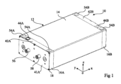
Figures 1-3 are a perspective view, a cross-sectional view, and an exploded perspective view, respectively, of an embodiment of a
蓄電池モジュール10は、中央部14及び2つの側方パネル16A, 16Bによって形成された筐体12を備えている。図4は側方パネル16B を示している。中央部14は、方向Oxに沿って延びる一般的な管の形状を有し、好ましくは方向Oxに沿って実質的に一定の断面積を有する。中央部14は、例えば押出しによってアルミニウムで形成されてもよい。中央部14は、側方パネル16A, 16Bによって2つの反対側の端部で閉じられている。本開示の残り部分では、側方パネル16A, 16Bの同様の形状及び/又は機能を有する要素を示すために、添え字A が続く同一の数字を使用して側方パネル16A の要素を示し、添え字B が続く同一の数字を使用して側方パネル16B の要素を示す。側方パネル16A, 16Bは、ねじ18によって中央部14に固定されてもよい。実施形態によれば、筐体12は、方向Oxに沿って200 mm~400 mmの範囲内、例えば略300 mmの大きさを有し、方向Oyに沿って140 mm~250 mmの範囲内、例えば略200 mmの大きさを有し、方向Ozに沿って70mm~110 mmの範囲内、例えば略90mmの大きさを有する直方体内に内接する。中央部14は、方向Oxに沿って延びて中央部14の内部に突出している、図3に示されていない突部を有してもよい。
The
蓄電池モジュール10のある要素は、面Oxy と平行な対称面に対して対称である。本開示の残り部分では、この対称面に対して少なくとも部分的に対称な蓄電池モジュール10の要素を示すために、参照として添え字C が続く同一の数字を使用して対称面の一側に配置された要素を示し、添え字D が続く同一の数字を使用して対称面の反対側に配置された要素を示す。
Certain elements of the
蓄電池モジュール10は、筐体12内に、
複数の蓄電池20と、
蓄電池20を保持するための上側フランジ22C 及び下側フランジ22D と、
上側フランジ22C に置かれて蓄電池20を電気的に結合する複数の上側接続プレート24C 、及び下側フランジ22D に置かれて蓄電池20を電気的に結合する複数の下側接続プレート24D と
を備えている。
The
A plurality of
an
The
蓄電池モジュール10は2~500 の蓄電池20を備えてもよい。図2に示されているように、各蓄電池20は、第1の端部26C 、第2の端部26D 、及び第1の端部26C と第2の端部26D との間に延びている中間部分28を有している。蓄電池20は、例えば特に円形の基部を有する一般的な円筒形状、又は軸芯Ozの角柱形状を有する。蓄電池20は、例えばリチウムイオン蓄電池、特にリン酸鉄リチウム、つまりLFP 蓄電池タイプのリチウムイオン蓄電池、ニッケルマンガンコバルト、つまりNMC 蓄電池タイプのリチウムイオン蓄電池、リチウムニッケルコバルトアルミニウム酸化物、つまりNCA 蓄電池タイプのリチウムイオン蓄電池、又はリチウムマンガン酸化物、つまりLMO 蓄電池タイプのリチウムイオン蓄電池である。軸芯Ozに沿った蓄電池20の長さは、30mm~110 mmの範囲内であってもよく、例えば略65mmであってもよい。円形の基部を有する円筒状の蓄電池20の場合、各蓄電池20の直径は10mm~27mmの範囲内であってもよく、例えば略18mmであってもよい。各蓄電池20は、第1の電気端子30C 及び第2の電気端子30D を更に有している。蓄電池20毎に、第1の電気端子30C は、好ましくは第1の端部26C に配置されており、第2の電気端子30D は、好ましくは第2の端部26D に配置されている。
The
方向Oxに沿った各フランジ22C, 22Dの大きさは、方向Oxに沿った中央部14の大きさと実質的に等しい。方向Oyに沿った各フランジ22C, 22Dの大きさは、中央部14の内部体積の方向Oyに沿った最大の大きさと実質的に等しい。各フランジ22C, 22Dは、中央部14の突部を収容する、図面に示されていない溝を有してもよい。フランジ22C, 22Dは、例えばポリオキシメチレン(POM) 、ポリアミド(PA、特にPA66)、ポリエーテルエーテルケトン(PEEK)のような優れた機械的強度を有するあらゆる電気絶縁性材料で形成されてもよいが、更に木材に基づく材料で形成されてもよい。
The size of each
各フランジ22C, 22Dは、蓄電池20の端部26C, 26Dを収容する、図2に示されている貫通開口部32C, 32Dを有している。より具体的には、蓄電池20毎に、蓄電池20の端部26C が上側フランジ22C の貫通開口部32C の内の1つに収容されており、蓄電池20の端部26D が下側フランジ22D の貫通開口部32D の内の1つに収容されている。実施形態によれば、貫通開口部32D は方向Ozに沿って設けられており、蓄電池20の端部26C, 26Dの形状に相補的な形状を有する。蓄電池20の所望の接続に応じて、蓄電池20毎に、蓄電池20の正端子は上側フランジ22C 又は下側フランジ22D のレベルに配置されてもよい。蓄電池20は五点形に配置されてもよい。2つの隣り合う蓄電池の軸芯間の距離は18.5mm~22mmの範囲内であってもよく、例えば略20mmであってもよい。2つの隣り合う蓄電池20間の最小間隔は0.5 mm~4mmの範囲内であってもよく、例えば略2mmであってもよい。
Each
実施形態によれば、各蓄電池20は、関連付けられた貫通開口部32C, 32D内に緊密に組み立てられている。蓄電池20をフランジ22C, 22Dに固定すべく使用される接着剤がないことが好ましい。
According to an embodiment, each
上側フランジ22C は、筐体12の中央部14と共に上側チャンバ34C を画定している。下側フランジ22D は、中央部14と共に下側チャンバ34D を画定している。フランジ22C, 22Dは共に中間チャンバ36を画定している。チャンバ34C, 34D, 36は図2に示されている。
The
各接続プレート24C, 24Dは、第1組立体の蓄電池20の正又は負の端子を第2組立体の蓄電池20の負又は正の端子と結合している。蓄電池20及び接続プレート24C, 24Dの組立体は、蓄電池20が第1のアクセスノードと第2のアクセスノードとの間で直列及び/又は並列に接続されている電気回路を形成しており、各アクセスノードは複数の接続プレート24A 又は複数の接続プレート24B の内の1つに対応する。蓄電池20の向き並びに接続プレート24C, 24Dの配置及び大きさによって、蓄電池20の所望の直列/並列接続が可能になる。実施形態によれば、各接続プレート24C, 24Dに接続された蓄電池20の個数は2~500 の範囲内である。実施形態によれば、各接続プレート24C, 24Dは、1~500 の蓄電池20の正端子、及び1~500 の蓄電池20の負端子に接続されている。2つの隣り合う接続プレート24C 又は接続プレート24D は、特に蓄電池モジュール10によって供給される電圧に応じて決められる距離、例えば蓄電池モジュールによって供給される60Vの電圧では好ましくは少なくとも2mmの距離、蓄電池モジュールによって供給される400 Vの電圧では好ましくは少なくとも6mmの距離、離隔している。
Each
各フランジ22C, 22Dは、方向Ozに沿って設けられた更なる貫通開口部38C, 38Dを有している。実施形態によれば、更なる貫通開口部38C, 38Dは夫々、円形の基部を有する軸芯Ozの円筒状である。更なる貫通開口部38C, 38Dの直径は夫々0.5 mm~5mmの範囲内である。
Each
接続プレート24C, 24Dは、貫通孔39C, 39Dを更なる貫通開口部38C, 38Dと一列に有している。中間チャンバ36は、更なる貫通開口部38C 及び貫通孔39C のみを介して上側チャンバ34C と連通し、中間チャンバ36は、更なる貫通開口部38D 及び貫通孔39D のみを介して下側チャンバ34D と連通する。実施形態によれば、各貫通孔39C, 39Dは、円形の基部を有する軸芯Ozの円筒状である。各貫通孔39C, 39Dの直径は、更なる貫通開口部38C, 38Dの直径と実質的に等しくてもよい。接続プレート24C, 24Dを同一のプレートに切断してもよい。
The connecting
実施形態によれば、2つの側方パネル16A, 16Bは、特に冷却液の流れに関して少なくとも部分的に対称な構造を有する。実施形態によれば、各側方パネル16A, 16Bは直方体内に内接しており、2つの対向する主面40A, 40B, 41A, 41Bと主面を結合する縁部とを有しており、縁部は上側縁部42A, 42B及び上側縁部42A, 42Bに対向する下側縁部43A, 43Bを含んでいる。主面40A, 40Bは蓄電池モジュール10の内部の方を向いている。側方パネル16A, 16Bは、十分な機械抵抗(例えば蓄電池モジュール及びオイルコレクタの105 Pa(1バール)の内圧に対する抵抗)を有して、使用される誘電流体と適合するあらゆるタイプの材料(例えばPOM 、PA66又はPEEK)で形成されてもよい。側方パネルの電力経路を電気的に絶縁するために特定の予防策を講じる場合、導電性材料(例えば注入されたアルミニウム)の使用が可能である。
According to an embodiment, the two
実施形態によれば、各側方パネル16A, 16Bは、方向Ozに沿って延びて上側縁部42A, 42B及び下側縁部43A, 43Bに開口している貫通管44A, 44B、例えば円形の基部を有する円筒状の管を有している。貫通管44A, 44Bは、筐体12の内部に向かって表面40A, 40Bに開口している細長いポート45A, 45Bと連通している。ポート45A, 45Bの細長い形状によって、チャンバ34C, 34D内の冷却液のより均一な分散が可能になる。変形例として、細長いポート45A, 45Bは点状のポートと取り替えられてもよい。細長いポート45A, 45Bは、例えば方向Oyに沿って延びている。側方パネル16A の細長いポート45A が上側チャンバ34C に開口し、側方パネル16B の細長いポート45B が下側チャンバ34D に開口するように、側方パネル16A, 16Bは蓄電池モジュール10に配置されている。実施形態によれば、各側方パネル16A, 16Bは、下側縁部43A, 43B側の端部に貫通管44A, 44Bと一列に末端部52A, 52Bを有している。変形例として、末端部52A, 52Bは設けられず、Oリングと取り替えられる。図2及び図4に示されているように、各側方パネル16A, 16Bは、表面40A, 40Bから蓄電池モジュール10の内部に向かって延びて中央部14に嵌まり込む縁部46A, 46Bを有している。各側方パネル16A, 16Bは、図2に示されていない密閉環を表面40A, 40Bに有しており、密閉環48B のみが図4に示されている。縁部46A, 46B及び密閉環48B によって、側方パネル16A, 16Bと中央部14との緊密な接続が可能になる。
According to an embodiment, each
動作中、誘電性の冷却液が蓄電池モジュール10を通って流れるように構成されている。誘電性の冷却液は、合成油、ポリアルファオレフィン油、天然エステル、合成エステル、変圧器鉱油、及びシステムのあらゆる使用状況でセルを互いに絶縁することができる絶縁耐力を有するあらゆる他の流体を含む群から選択されてもよい。非制限例として、誘電性の冷却液は、ペルフルオロヘキサン、ペルフルオロメチルシクロヘキサン、ペルフルオロ-1,3- ジメチルシクロヘキサン、ペルフルオロデカリン、ペルフルオロメチルデカリン、トリクロロフルオロメタン、トリクロロトリフルオロエタン、メタノール及びエタノールを含む群から選択されている。図2に示されているように、冷却液は貫通管44A を通って蓄電池モジュール10内に入り込む(矢印A)。次に、冷却液は、蓄電池モジュール10から出る(矢印C)まで貫通管44A を通って進み続ける(矢印B)部分と、細長いポート45A を通って上側チャンバ34C 内に入り込む(矢印D)部分とに分かれる。その後、冷却液は、上側チャンバ34C から更なる貫通開口部38C 及び貫通孔39C を通って中間チャンバ36内に入り込む。その後、冷却液は、蓄電池20と接する中間チャンバ36を通って流れる(矢印E)。中間チャンバ36では、冷却液の大部分が方向Ozに沿って流れる。その後、冷却液は、中間チャンバ36から更なる貫通開口部38D 及び貫通孔39D を通って下側チャンバ34D 内に入り込む。冷却液は、下側チャンバ34D から、細長いポート45B を介して貫通管44B に流入する(矢印F)。細長いポート45B からの冷却液は、貫通管44B を通って流れる(矢印G)冷却液と混合し、蓄電池モジュール10を出る(矢印H)。蓄電池20と接する冷却液の流れによって、最適な冷却性能を得ることができる。冷却液の流れが中間チャンバ36内で実質的に均一であるように、更なる貫通開口部38C, 38Dの大きさ及び分散配置が選択されている。
During operation, a dielectric coolant is configured to flow through the
各側方パネル16A, 16Bは、方向Ozに沿って延びている、例えば円形の基部を有する円筒状の少なくとも2つの貫通開口部54A, 54Bを更に有している。以下に更に詳細に記載されるように、貫通開口部54A, 54Bは、複数の蓄電池モジュール10を共に固定するために使用される。
Each
側方パネル16A は、例えば側方パネル16A の広い表面41A に配置された2つの電気端子56, 58を更に有している。電気端子56は、複数の蓄電池20によって形成された電気回路の第1のアクセスノードに対応する上側接続プレート24C 又は下側接続プレート24D に、図面に示されていない導電体によって電気的に結合されており、電気端子58は、複数の蓄電池20によって形成された電気回路の第2のアクセスノードに対応する上側接続プレート24C 又は下側接続プレート24D に、図面に示されていない導電体によって電気的に結合されている。
The
蓄電池モジュール10は、蓄電池モジュール10の動作中に様々な信号を測定することができる不図示のセンサを更に備えてもよい。例として、センサは、蓄電池20の近傍で温度を測定するための少なくとも1つの温度センサを含んでもよい。蓄電池モジュール10は複数の温度センサを備えていることが好ましい。例として、センサは、蓄電池20の電圧用のセンサを含んでもよい。蓄電池モジュール10は、蓄電池20を加熱するために使用される少なくとも1つの加熱素子を更に備えてもよい。
The
実施形態によれば、蓄電池モジュール10は、センサ及び/又は加熱素子が設けられている不図示のプリント回路、例えばフレキシブルプリント回路を備えてもよい。そのため、フレキシブルプリント回路は、例えば銅で形成された導電性トラックを支持膜上に有しており、電子部品又は電子回路は導電性トラックに固定されている。例として、フレキシブルプリント回路が蓄電池20を加熱するために使用される加熱素子を有する場合、加熱素子は、電流が流れるときに熱を発生させるために適宜の断面及び長さを有する抵抗性トラック又は銅のトラックに相当してもよい。実施形態によれば、フレキシブルプリント回路はRFID(無線周波数識別)タグを含んでもよい。フレキシブルプリント回路は蓄電池20に接続されてもよい。プリント回路は、図3及び図4に示されている開口部を有する側方パネル16B を横切る導電体、特にフレキシブルシートによって、例えば蓄電池モジュール10の外側又は内側に配置された処理モジュールに結合されてもよい。
According to an embodiment, the
各接続プレート24C, 24Dの最大の厚さは0.2 mm~2mmの範囲内である。本実施形態では、各接続プレート24C, 24Dは、図2に示されている少なくとも第1の導電層60C, 60D及び第2の導電層62C, 62Dの積層体を有している。第1の導電層60C, 60Dは蓄電池20と機械的に接している。第2の導電層62C, 62Dは、蓄電池20に対向して開口部64C, 64Dを有している。実施形態によれば、第1の導電層60C, 60Dは、ニッケルめっきを施した鋼、ニッケル、ニッケルめっきを施した銅、及び蓄電池への容易な溶接を可能にするあらゆる材料を含む群から選択された材料で形成されている。第1の導電層60C, 60Dの厚さは0.1 mm~0.5 mmの範囲内である。実施形態によれば、第2の導電層62C, 62Dは、銅、アルミニウム、ベリリウム銅、及び十分な導電率を有するあらゆる材料を含む群から選択された材料で形成されている。第2の導電層62C, 62Dの厚さは0.2 mm~2mmの範囲内である。接続プレート24C, 24Dの導電率特性が第2の導電層62C, 62Dによって基本的に保証される一方、第1の導電層60C, 60Dを形成する材料は、蓄電池20との高品質な電気接続部を得るため、特に蓄電池20への第1の導電層60C, 60Dの溶接を容易にするために特に選択されている。
The maximum thickness of each
蓄電池モジュール10を製造する方法の実施形態は、
蓄電池20を上側フランジ22C の内の1つに配置し、次に下側フランジ22D を追加する工程、
各接続プレート24C を上側フランジ22C 上に配置して各接続プレート24C を、例えば電気溶接によって蓄電池に固定し、各接続プレート24D を下側フランジ22D 上に配置して各接続プレート24C を、例えば電気溶接によって蓄電池20に固定する工程、
蓄電池20、フランジ22C, 22D及び接続プレート24C, 24Dを有する組立体を中央部14に挿入する工程、及び
側方パネル16A, 16Bを中央部14に固定する工程
を有する。
An embodiment of a method for manufacturing the
placing the
placing each of the
The method includes inserting an assembly including the
複数の蓄電池20によって形成される電気回路は、筐体12又はフランジ22C, 22Dを変更することなく、接続プレート24C, 24Dの配置及び大きさを変えることにより、及び/又は蓄電池20の向きを変えることにより容易に変更され得る。従って、蓄電池モジュール10は様々な用途に適合するように容易に変更され得る。
The electrical circuit formed by the
フランジ22C, 22Dと筐体12の中央部14との機械的な接続、フランジ22C, 22Dと蓄電池20との機械的な接続、及び接続プレート24C, 24Dと蓄電池20との機械的な接続により、組立体の剛性及び蓄電池20の保持が保証される。
The mechanical connection between the
図5及び図6は夫々、電池70の実施形態を示す斜視図及び分解斜視図である。電池70は、積層体72の端部の内の1つに配置された蓄電池モジュールの側方パネル16A, 16Bを除いて、各側方パネル16A の末端部52A が積層体72の次の側方パネル16A の貫通管44A 内に入り込んで、各側方パネル16B の末端部52B が積層体72の次の側方パネル16B の貫通管44B 内に入り込むように配置された9つの蓄電池モジュール10の積層体72を備えている。そのため、側方パネル16A の貫通開口部54A が互いに一列に配置されており、側方パネル16B の貫通開口部54B が互いに一列に配置されている。
5 and 6 are perspective and exploded perspective views, respectively, of an embodiment of a
蓄電池モジュール10は、貫通開口部54A, 54B内に延びているロッド74によって互いに固定されている。ロッド74の端部に設けられたナット76及びワッシャ78によって、蓄電池モジュール10を圧縮することができる。蓄電池モジュール10はロッド74によって互いに対して押圧されると、各末端部52A, 52Bは、末端部が入り込む貫通管44A, 44Bと共に、冷却液に対して緊密な接続部を形成することが有利である。
The
図5に示されているように、電池70は、積層体72の各端部に配置されてロッド74を介して積層体72に固定される端プレート80, 81を備えてもよい。端プレート80, 81は、電池70を不図示の支持体に固定することを可能にし得る。各端プレート80, 81は、端プレート80, 81を完全に横断する開口部を有する管状要素82, 83を有している。端プレート80の管状要素82は、隣接する側方パネル16A の貫通管44A と一列に配置されている一方、端プレート80は、隣接する側方パネル16B の貫通管44B を完全に遮断する。端プレート81の管状要素83は、隣接する側方パネル16B の貫通管44B と一列に配置され、末端部52B は管状要素83に入り込むことができる一方、端プレート81は、隣接する側方パネル16A の貫通管44A を完全に遮断する。
5, the
実施形態によれば、電池70は、蓄電池モジュール10を互いに電気的に結合して蓄電池モジュール10の外側に配置された図5に示されている電気コネクタ84を備えている。本実施形態では、蓄電池モジュール10は直列接続されており、すなわち、積層体72の端部に配置された2つの蓄電池モジュールを除いて蓄電池モジュール10毎に、第1の電気コネクタ84は、電気端子56を2つの隣り合う蓄電池モジュール10の内の一方の電気端子58に結合し、第2の電気コネクタ84は、電気端子58を2つの隣り合う蓄電池モジュール10の内の他方の電気端子56に結合する。2つの電気コネクタ86が、別の蓄電池モジュール10に接続されない積層体72の端部に配置された蓄電池モジュール10の電気端子56, 58に結合されている。ヒューズ87が電気コネクタ86の内の1つに設けられてもよい。
According to an embodiment, the
電池70は、端プレート80, 81に加えて、又は端プレート80, 81の一方及び/若しくは他方の代わりに、蓄電池モジュール10内の冷却液を駆動することができる液圧ポンプ、特に冷却液を冷却するための熱交換器、又は電気接続ブロックのような、ロッド74によって積層体72に固定されてもよい少なくとも1つの更なる要素を備えてもよい。
The
蓄電池モジュール10内の冷却液は、冷却液を管状要素82を通して注入する不図示のポンプによって流れる。その後、冷却液は、連通する貫通管44A を介して各蓄電池モジュール10に供給される。前述したように、冷却液は、各蓄電池モジュール10を横切った後、貫通管44B で回収され、管状要素83によって放出される。
The coolant in the
各蓄電池モジュール10がセンサを備えている場合、蓄電池モジュールの全てのセンサは処理部に結合されてもよい。処理部は専用回路に相当してもよく、又はメモリに記憶されたコンピュータプログラムの命令を実行することができるプロセッサ、例えばマイクロプロセッサ又はマイクロコントローラを有してもよい。処理部は、例えば認められた動作範囲内に維持するために蓄電池20の電圧をモニタし、蓄電池20の充電レベルをモニタし、場合によっては、これらの充電の均衡を保ち、再充電期間中の充電電流を調節し、放電電流を調節することなどができる電池を制御するためのシステムの役割を果たしてもよい。
If each
電池70を製造する方法の実施形態は、
前述したように電池70を形成する蓄電池モジュール10を製造する工程、
蓄電池モジュール10の積層体72を形成する工程、
ロッド74を挿入して蓄電池モジュール10を圧縮する工程、及び
電気コネクタ84, 86を配置する工程
を有する。
An embodiment of a method for manufacturing
manufacturing a
forming a
The steps include inserting
図5に示されている構造を有し、場合によっては異なる数の蓄電池モジュール10を備えた少なくとも2つの電池70が、対象とする用途に応じて直列及び/又は並列に接続されてもよい。
At least two
例として、電池の直列接続された蓄電池20の数は、特に12V程度の電圧を供給する電池70では4から、特に700 V又は1,000 Vより大きい電圧を供給する電池では100を超える数の範囲内であってもよい。電池70は、例えばラップトップコンピュータ、例えば4つの直列接続された蓄電池を備えた無線スクリューガン、電動アシスト自転車、電気自動車又は別の電動の乗り物に電力を供給するために使用されるように構成されている。
By way of example, the number of series-connected
図7は、筐体12が図示されていない蓄電池モジュール90の別の実施形態を部分的に簡略化して示す斜視略図である。蓄電池モジュール90は、蓄電池モジュール10の全ての要素を備えている。各フランジ22C, 22Dは、接続プレート24C, 24Dの方に向いたピン92C, 92Dを更に有している。一部のピン92C, 92Dは、接続プレート24C, 24Dの貫通孔39C, 39Dを通過して延びている。ピン92C, 92Dによって、特に接続プレート24C, 24Dが蓄電池20に固定される前に、接続プレート24C, 24Dの位置決めを容易にすることができる。更なる貫通開口部38C, 38Dは、実質的にピン92C, 92Dの中心でフランジ22C, 22Dを横断してもよい。
Fig. 7 is a partially simplified perspective view of another embodiment of the accumulator module 90, in which the
図8及び図9は夫々、図7に示されている蓄電池モジュール90の上側フランジ22C を部分的に簡略化して示す斜視図及び平面図である。図9に示されているように、上側フランジ22C の側部に配置されたピン92C を除いて、各ピン92C は、平面視で正三角形内に内接する断面を有する。更に各ピン92C は、貫通開口部32C, 32Dの内の少なくとも1つの上に突出している。従って、ピン92C は、蓄電池20がフランジ22C, 22Dに配置されるとき、方向Ozに沿った停止部の機能を果たす。
8 and 9 are respectively a perspective view and a plan view showing the
図10は、蓄電池20の蓄電池モジュール10のフランジ22C の別の実施形態を部分的且つ概略的に示す断面図であり、フランジ22D は同一の構造を有してもよい。断面は面Oxy と平行である。本実施形態では、フランジ22C は更なる貫通開口部38C を有していない。更に、各貫通開口部32C は、貫通開口部32C が受ける蓄電池20と緊密な接続部分を形成しない。各貫通開口部32C は、蓄電池20と接して蓄電池20と共に通路96C を画定する突部94C を有している。通路96C は、更なる貫通開口部38C, 38Dと同一の機能を果たす。蓄電池20は、貫通開口部32C 内に緊密に組み立てられ、突部94C によって保持されている。
10 is a partial schematic cross-sectional view of another embodiment of the
様々な実施形態が述べられている。当業者にとって様々な変更及び調整が想起される。特に、前述した実施形態では、蓄電池モジュール10の圧縮をロッド74を介して行っているが、蓄電池モジュール10を圧縮するためのあらゆるシステムを使用してもよいことが明らかなはずである。例として、ロッド74は、蓄電池モジュールを互いに締める締め具、又は蓄電池モジュール10の積層体72を囲むストラップと取り替えられてもよい。
Various embodiments have been described. Various modifications and adaptations will occur to those skilled in the art. In particular, while in the above-described embodiment compression of the
異なる変形例を有する様々な実施形態が上記に述べられている。当業者は、いかなる進歩性も示さずにこれらの様々な実施形態及び変形例を組み合わせてもよいことに注目すべきである。 Various embodiments with different modifications have been described above. It should be noted that a person skilled in the art may combine these various embodiments and modifications without showing any inventive step.
本特許出願は、参照によって本明細書に組み込まれている仏国特許出願第18/50671 号明細書の優先権を主張している。 This patent application claims priority to French Patent Application No. 18/50671, the specification of which is incorporated herein by reference.
Claims (10)
第1の端部、第2の端部及び前記第1の端部と前記第2の端部とを結合する中間部分を夫々有する蓄電池と、
前記蓄電池の第1の端部が、接着剤を用いることなく固定されている第1の貫通開口部を有する第1のフランジと、
複数の第1の蓄電池組立体の内の第1の蓄電池組立体の蓄電池の第1の端部に夫々接続されている第1の導電性プレートと、
前記蓄電池の第2の端部が、接着剤を用いることなく固定されている第2の貫通開口部を有する第2のフランジと、
複数の第2の蓄電池組立体の内の第2の蓄電池組立体の蓄電池の第2の端部に夫々接続されている第2の導電性プレートと、
前記蓄電池、前記第1のフランジ、前記第2のフランジ、前記第1の導電性プレート及び前記第2の導電性プレートを収容し、誘電性液体を含むように構成された第1のチャンバ、第2のチャンバ及び第3のチャンバを前記第1のフランジ及び前記第2のフランジと共に画定する筐体と
を備えており、
前記第1のフランジは前記第1のチャンバ及び前記第2のチャンバを分離しており、前記第2のフランジは前記第2のチャンバ及び前記第3のチャンバを分離しており、
前記第1の導電性プレートは前記第1のチャンバに設けられており、前記第2の導電性プレートは前記第3のチャンバに設けられており、前記蓄電池の中間部分は前記第2のチャンバに設けられており、
前記第1のフランジは、誘電性液体のための第1の通路を前記第1のチャンバと前記第2のチャンバとの間に有しており、前記第2のフランジは、誘電性液体のための第2の通路を前記第2のチャンバと前記第3のチャンバとの間に有しており、
前記誘電性液体は、あらゆる使用状況で前記蓄電池を互いに絶縁することができる液体であることを特徴とするモジュール。 1. A module for a battery, comprising:
a storage battery having a first end, a second end, and an intermediate portion connecting the first end and the second end;
a first flange having a first through opening to which a first end of the battery is secured without the use of an adhesive ;
a first conductive plate connected to a first end of a battery of each of the first battery assemblies of the plurality of first battery assemblies;
a second flange having a second through opening to which the second end of the battery is secured without the use of adhesive ;
a second conductive plate connected to a second end of each of the batteries in each of the second battery assemblies of the plurality of second battery assemblies;
a housing that houses the battery, the first flange, the second flange, the first conductive plate, and the second conductive plate, and that defines, together with the first flange and the second flange, a first chamber, a second chamber, and a third chamber configured to contain a dielectric liquid;
the first flange separating the first chamber and the second chamber, the second flange separating the second chamber and the third chamber;
the first conductive plate is disposed in the first chamber, the second conductive plate is disposed in the third chamber, and a middle portion of the battery is disposed in the second chamber;
the first flange having a first passage for a dielectric liquid between the first chamber and the second chamber, and the second flange having a second passage for a dielectric liquid between the second chamber and the third chamber ;
The module is characterized in that the dielectric liquid is a liquid that can insulate the storage batteries from each other under all conditions of use .
前記第2の導電性プレートは、前記第2の通路の内の1つに夫々対向する第2の孔を夫々有していることを特徴とする請求項1に記載のモジュール。 the first conductive plates each have a first hole facing one of the first passages;
2. The module of claim 1, wherein said second conductive plates each have a second hole that faces a respective one of said second passages.
前記第2のフランジは、前記第2の貫通開口部とは異なる、誘電性液体の通路のための第4の開口部を前記第2のチャンバと前記第3のチャンバとの間に有していることを特徴とする請求項1~3のいずれか1つに記載のモジュール。 the first flange has a third opening between the first chamber and the second chamber for passage of a dielectric liquid, the third opening being different from the first through opening;
4. The module of claim 1, wherein the second flange has a fourth opening between the second chamber and the third chamber, different from the second through opening, for the passage of a dielectric liquid.
前記第1の側方パネル及び前記第2の側方パネルは、前記モジュールの内部と対向する表面と、前記モジュールの外側の夫々の端部で開口している貫通管と、前記貫通管と連通して前記表面に開口しているポートとを夫々有しており、
前記第1の側方パネルの前記ポートは前記第1のチャンバに開口しており、
前記第2の側方パネルの前記ポートは前記第3のチャンバに開口していることを特徴とする請求項1~5のいずれか1つに記載のモジュール。 the housing has a first side panel, a second side panel, and a tubular central portion disposed between the first side panel and the second side panel;
the first side panel and the second side panel each have a surface facing the interior of the module, a through-hole opening at an end of each of the panels on the exterior side of the module, and a port communicating with the through-hole opening on the surface;
the port in the first side panel opens into the first chamber;
The module of any one of claims 1 to 5, wherein the port in the second side panel opens into the third chamber.
前記圧縮システムは前記モジュールの第5の貫通開口部を横切る少なくとも1本のロッドを有していることを特徴とする請求項8に記載の電池。 Each module is a module according to claim 6, wherein the first side panel and the second side panel each have at least one fifth through opening, and the fifth through openings of the modules of the stack are aligned with each other,
9. The battery of claim 8, wherein said compression system includes at least one rod that traverses a fifth through opening of said module.
第1の端部、第2の端部及び前記第1の端部と前記第2の端部とを結合する中間部分を夫々有する蓄電池を、第1の貫通開口部を有する第1のフランジに組み立て、前記蓄電池の第1の端部を前記第1の貫通開口部に、接着剤を用いることなく固定する工程、
第2の貫通開口部を有する第2のフランジに前記蓄電池を組み立て、前記蓄電池の第2の端部を前記第2の貫通開口部に、接着剤を用いることなく固定する工程、
複数の第1の蓄電池組立体の内の第1の蓄電池組立体の蓄電池の第1の端部に第1の導電性プレートを夫々接続して、前記第1の導電性プレートを前記蓄電池に固定する工程、
複数の第2の蓄電池組立体の内の第2の蓄電池組立体の蓄電池の第2の端部に第2の導電性プレートを夫々接続して、前記第2の導電性プレートを前記蓄電池に固定する工程、及び
誘電性液体を含むように構成された第1のチャンバ、第2のチャンバ及び第3のチャンバを前記第1のフランジ及び前記第2のフランジと共に画定する筐体内に、前記蓄電池、前記第1のフランジ、前記第2のフランジ、前記第1の導電性プレート及び前記第2の導電性プレートを配置し、前記第1のフランジは前記第1のチャンバ及び前記第2のチャンバを分離し、前記第2のフランジは前記第2のチャンバ及び前記第3のチャンバを分離し、前記第1の導電性プレートを前記第1のチャンバに設けて、前記第2の導電性プレートを前記第3のチャンバに設けて、前記蓄電池の中間部分を前記第2のチャンバに設ける工程
を有し、
前記第1のフランジは、誘電性液体のための第1の通路を前記第1のチャンバと前記第2のチャンバとの間に有し、前記第2のフランジは、誘電性液体のための第2の通路を前記第2のチャンバと前記第3のチャンバとの間に有し、
前記誘電性液体は、あらゆる使用状況で前記蓄電池を互いに絶縁することができる液体であることを特徴とする方法。 1. A method of manufacturing a module for a battery, comprising:
assembling a storage battery having a first end, a second end, and an intermediate portion joining the first end and the second end to a first flange having a first through opening, and fixing the first end of the storage battery to the first through opening without the use of an adhesive ;
assembling the battery to a second flange having a second through opening and fastening a second end of the battery to the second through opening without the use of adhesive ;
connecting a first conductive plate to a first end of a battery of a first battery assembly of the plurality of first battery assemblies to secure the first conductive plate to the battery;
connecting a second conductive plate to a second end of a battery in a second battery assembly of a plurality of second battery assemblies to secure the second conductive plate to the battery; and disposing the battery, the first flange, the second flange, the first conductive plate and the second conductive plate within a housing that, together with the first flange and the second flange, defines a first chamber, a second chamber and a third chamber configured to contain a dielectric liquid, the first flange separating the first chamber and the second chamber, the second flange separating the second chamber and the third chamber, the first conductive plate being disposed in the first chamber, the second conductive plate being disposed in the third chamber and a middle portion of the battery being disposed in the second chamber,
the first flange having a first passage for a dielectric liquid between the first chamber and the second chamber, and the second flange having a second passage for a dielectric liquid between the second chamber and the third chamber ;
The method according to claim 1, wherein the dielectric liquid is a liquid capable of insulating the batteries from each other under all conditions of use .
Applications Claiming Priority (3)
| Application Number | Priority Date | Filing Date | Title |
|---|---|---|---|
| FR1850671A FR3077431B1 (en) | 2018-01-29 | 2018-01-29 | ELECTRIC ACCUMULATOR AND BATTERY MODULE CONSISTING OF SEVERAL MODULES |
| FR1850671 | 2018-01-29 | ||
| PCT/FR2019/050168 WO2019145652A1 (en) | 2018-01-29 | 2019-01-25 | Electric storage cell module and battery comprising a plurality of modules |
Publications (2)
| Publication Number | Publication Date |
|---|---|
| JP2021511641A JP2021511641A (en) | 2021-05-06 |
| JP7481257B2 true JP7481257B2 (en) | 2024-05-10 |
Family
ID=62683282
Family Applications (1)
| Application Number | Title | Priority Date | Filing Date |
|---|---|---|---|
| JP2020541358A Active JP7481257B2 (en) | 2018-01-29 | 2019-01-25 | Storage battery module and battery with multiple modules |
Country Status (6)
| Country | Link |
|---|---|
| US (1) | US12211980B2 (en) |
| EP (1) | EP3747065A1 (en) |
| JP (1) | JP7481257B2 (en) |
| CN (1) | CN111656561A (en) |
| FR (1) | FR3077431B1 (en) |
| WO (1) | WO2019145652A1 (en) |
Families Citing this family (5)
| Publication number | Priority date | Publication date | Assignee | Title |
|---|---|---|---|---|
| KR20230037635A (en) * | 2020-07-15 | 2023-03-16 | 시오 테크놀로지 게엠베하 | Energy storage module for storing electrical energy |
| SE545205C2 (en) * | 2021-05-06 | 2023-05-16 | Apr Tech Ab | A liquid cooled module with a restricting member |
| TWI802079B (en) * | 2021-11-15 | 2023-05-11 | 達宇電能科技股份有限公司 | Connection component by low-pressure molding and detachable battery pack having the connection component |
| DE102021131506A1 (en) | 2021-12-01 | 2023-06-01 | Bayerische Motoren Werke Aktiengesellschaft | Battery pack and motor vehicle with such |
| FR3149138A1 (en) | 2023-05-26 | 2024-11-29 | Commissariat A L'energie Atomique Et Aux Energies Alternatives | Battery module or battery pack with stacked accumulators with a housing incorporating a removable sliding partition as a means of mechanically holding the housing, Method for producing an associated module or battery pack |
Citations (6)
| Publication number | Priority date | Publication date | Assignee | Title |
|---|---|---|---|---|
| JP2005285455A (en) | 2004-03-29 | 2005-10-13 | Sanyo Electric Co Ltd | Power supply apparatus |
| JP2010277863A (en) | 2009-05-28 | 2010-12-09 | Sanyo Electric Co Ltd | Battery system for vehicle and vehicle equipped with this battery system |
| JP2012022830A (en) | 2010-07-13 | 2012-02-02 | Nissan Motor Co Ltd | Power supply device for vehicle |
| JP2015172997A (en) | 2012-07-13 | 2015-10-01 | 三洋電機株式会社 | Battery system, and vehicle and power storage device comprising battery system |
| US20170005384A1 (en) | 2015-06-30 | 2017-01-05 | Faraday&Future Inc. | Battery module for vehicle energy-storage systems |
| JP2017174792A (en) | 2016-03-25 | 2017-09-28 | 行競科技股▲フン▼有限公司 | Battery module |
Family Cites Families (19)
| Publication number | Priority date | Publication date | Assignee | Title |
|---|---|---|---|---|
| JP4123541B2 (en) | 1997-07-02 | 2008-07-23 | 株式会社デンソー | Battery cooling device |
| DE10223782B4 (en) * | 2002-05-29 | 2005-08-25 | Daimlerchrysler Ag | Battery with at least one electrochemical storage cell and a cooling device and use of a battery |
| US8535842B2 (en) * | 2005-04-22 | 2013-09-17 | GM Global Technology Operations LLC | Combustion-thawed fuel cell |
| US20070009787A1 (en) * | 2005-05-12 | 2007-01-11 | Straubel Jeffrey B | Method and apparatus for mounting, cooling, connecting and protecting batteries |
| JP2007165200A (en) * | 2005-12-15 | 2007-06-28 | Toyota Motor Corp | Battery pack |
| JP4640348B2 (en) | 2007-02-01 | 2011-03-02 | トヨタ自動車株式会社 | Power supply |
| JP4434237B2 (en) | 2007-06-20 | 2010-03-17 | トヨタ自動車株式会社 | Power storage device for vehicle and vehicle |
| KR101091211B1 (en) * | 2008-02-28 | 2011-12-07 | 주식회사 엘지화학 | Jet Type Battery Pack for Electric Vehicles |
| FR2939969B1 (en) * | 2008-12-16 | 2010-12-10 | Saft Groupe Sa | SYSTEM FOR MAINTAINING ELECTROCHEMICAL BATTERIES |
| US8663828B2 (en) | 2009-04-30 | 2014-03-04 | Lg Chem, Ltd. | Battery systems, battery module, and method for cooling the battery module |
| FR2963485B1 (en) * | 2010-07-29 | 2013-03-22 | Commissariat Energie Atomique | BATTERY OF ACCUMULATORS DESIGNED AND MOUNTED FACILITIES |
| US20120094163A1 (en) | 2010-10-13 | 2012-04-19 | Braille Battery, Inc. | High Rate Lithium Cell Carbon-Fiber Cased SLI Battery |
| FR2966288B1 (en) | 2010-10-19 | 2013-03-29 | Commissariat Energie Atomique | BATTERY OF AN ELECTRIC MOTORIZATION OF A MOTOR VEHICLE |
| KR101338258B1 (en) * | 2010-11-17 | 2013-12-06 | 주식회사 엘지화학 | Battery Pack Providing Improved Distribution Uniformity of Coolant |
| US8852772B2 (en) | 2011-11-15 | 2014-10-07 | GM Global Technology Operations LLC | Lithium ion battery cooling system comprising dielectric fluid |
| DE102012111969B4 (en) * | 2012-12-07 | 2024-11-07 | Dr. Ing. H.C. F. Porsche Aktiengesellschaft | Battery arrangement for use in a motor vehicle |
| DE102012111970A1 (en) * | 2012-12-07 | 2014-06-12 | Dr. Ing. H.C. F. Porsche Aktiengesellschaft | Battery assembly and method for cooling a battery |
| DE102014206646A1 (en) * | 2014-04-07 | 2015-10-08 | Robert Bosch Gmbh | Energy storage unit, in particular battery module, and energy storage system with a plurality of energy storage units |
| JP6256439B2 (en) | 2015-09-15 | 2018-01-10 | 株式会社デンソー | Battery pack |
-
2018
- 2018-01-29 FR FR1850671A patent/FR3077431B1/en active Active
-
2019
- 2019-01-25 CN CN201980010732.XA patent/CN111656561A/en active Pending
- 2019-01-25 US US15/733,426 patent/US12211980B2/en active Active
- 2019-01-25 JP JP2020541358A patent/JP7481257B2/en active Active
- 2019-01-25 WO PCT/FR2019/050168 patent/WO2019145652A1/en unknown
- 2019-01-25 EP EP19710023.3A patent/EP3747065A1/en active Pending
Patent Citations (6)
| Publication number | Priority date | Publication date | Assignee | Title |
|---|---|---|---|---|
| JP2005285455A (en) | 2004-03-29 | 2005-10-13 | Sanyo Electric Co Ltd | Power supply apparatus |
| JP2010277863A (en) | 2009-05-28 | 2010-12-09 | Sanyo Electric Co Ltd | Battery system for vehicle and vehicle equipped with this battery system |
| JP2012022830A (en) | 2010-07-13 | 2012-02-02 | Nissan Motor Co Ltd | Power supply device for vehicle |
| JP2015172997A (en) | 2012-07-13 | 2015-10-01 | 三洋電機株式会社 | Battery system, and vehicle and power storage device comprising battery system |
| US20170005384A1 (en) | 2015-06-30 | 2017-01-05 | Faraday&Future Inc. | Battery module for vehicle energy-storage systems |
| JP2017174792A (en) | 2016-03-25 | 2017-09-28 | 行競科技股▲フン▼有限公司 | Battery module |
Also Published As
| Publication number | Publication date |
|---|---|
| JP2021511641A (en) | 2021-05-06 |
| US20210098836A1 (en) | 2021-04-01 |
| EP3747065A1 (en) | 2020-12-09 |
| CN111656561A (en) | 2020-09-11 |
| FR3077431A1 (en) | 2019-08-02 |
| FR3077431B1 (en) | 2020-07-31 |
| US12211980B2 (en) | 2025-01-28 |
| WO2019145652A1 (en) | 2019-08-01 |
Similar Documents
| Publication | Publication Date | Title |
|---|---|---|
| JP7481257B2 (en) | Storage battery module and battery with multiple modules | |
| JP7481258B2 (en) | Battery module and battery with multiple modules | |
| US7879485B2 (en) | Housing member for battery module | |
| EP2154740B1 (en) | Method and apparatus for mounting, cooling, connecting and protecting batteries | |
| TWI336532B (en) | Novel bus bar for electric connection and middle and battery module comprising the same | |
| JP5122573B2 (en) | Battery module and medium or large battery pack including the same | |
| US8674703B2 (en) | Car battery system | |
| EP2562842B1 (en) | Battery module | |
| EP3836270B1 (en) | Battery pack | |
| EP2330657A1 (en) | Battery module and battery pack including the same | |
| WO2014192087A1 (en) | Laminate-type lithium-ion secondary battery module | |
| JP2008524798A (en) | Sensing board assembly for secondary battery module | |
| US20120189887A1 (en) | Electrical energy storage device made of flat cells and frame elements with a supply channel | |
| US10068714B2 (en) | Energy storage module comprising a plurality of energy storage assemblies | |
| US20170077466A1 (en) | High voltage battery submodule | |
| CN107634169B (en) | Battery cell, battery module and method for producing | |
| CN114051672B (en) | Battery support for layered battery pack | |
| US10587017B2 (en) | Battery modules having a plurality of submodules | |
| JP4745122B2 (en) | Secondary battery, battery pack and battery module | |
| WO2021060219A1 (en) | Power storage module | |
| US20230344060A1 (en) | A battery block | |
| KR20120074426A (en) | Unit module of novel structure and battery module comprising the same | |
| US9843027B1 (en) | Battery cell having package anode plate in contact with a plurality of dies | |
| CN114696046A (en) | Energy storage device | |
| CN116365087A (en) | Battery module cooling |
Legal Events
| Date | Code | Title | Description |
|---|---|---|---|
| A621 | Written request for application examination |
Free format text: JAPANESE INTERMEDIATE CODE: A621 Effective date: 20220107 |
|
| A131 | Notification of reasons for refusal |
Free format text: JAPANESE INTERMEDIATE CODE: A131 Effective date: 20221227 |
|
| A521 | Request for written amendment filed |
Free format text: JAPANESE INTERMEDIATE CODE: A523 Effective date: 20230327 |
|
| A131 | Notification of reasons for refusal |
Free format text: JAPANESE INTERMEDIATE CODE: A131 Effective date: 20230704 |
|
| A601 | Written request for extension of time |
Free format text: JAPANESE INTERMEDIATE CODE: A601 Effective date: 20230929 |
|
| A521 | Request for written amendment filed |
Free format text: JAPANESE INTERMEDIATE CODE: A523 Effective date: 20231220 |
|
| TRDD | Decision of grant or rejection written | ||
| A01 | Written decision to grant a patent or to grant a registration (utility model) |
Free format text: JAPANESE INTERMEDIATE CODE: A01 Effective date: 20240402 |
|
| A61 | First payment of annual fees (during grant procedure) |
Free format text: JAPANESE INTERMEDIATE CODE: A61 Effective date: 20240425 |
|
| R150 | Certificate of patent or registration of utility model |
Ref document number: 7481257 Country of ref document: JP Free format text: JAPANESE INTERMEDIATE CODE: R150 |