JP7480161B2 - Direct Cardiac Pressure Monitoring - Google Patents
Direct Cardiac Pressure Monitoring Download PDFInfo
- Publication number
- JP7480161B2 JP7480161B2 JP2021546346A JP2021546346A JP7480161B2 JP 7480161 B2 JP7480161 B2 JP 7480161B2 JP 2021546346 A JP2021546346 A JP 2021546346A JP 2021546346 A JP2021546346 A JP 2021546346A JP 7480161 B2 JP7480161 B2 JP 7480161B2
- Authority
- JP
- Japan
- Prior art keywords
- sensor
- implant
- anchor
- pressure
- implant device
- Prior art date
- Legal status (The legal status is an assumption and is not a legal conclusion. Google has not performed a legal analysis and makes no representation as to the accuracy of the status listed.)
- Active
Links
Images


Classifications
-
- A—HUMAN NECESSITIES
- A61—MEDICAL OR VETERINARY SCIENCE; HYGIENE
- A61B—DIAGNOSIS; SURGERY; IDENTIFICATION
- A61B5/00—Measuring for diagnostic purposes; Identification of persons
- A61B5/02—Detecting, measuring or recording for evaluating the cardiovascular system, e.g. pulse, heart rate, blood pressure or blood flow
- A61B5/021—Measuring pressure in heart or blood vessels
- A61B5/02141—Details of apparatus construction, e.g. pump units or housings therefor, cuff pressurising systems, arrangements of fluid conduits or circuits
-
- A—HUMAN NECESSITIES
- A61—MEDICAL OR VETERINARY SCIENCE; HYGIENE
- A61B—DIAGNOSIS; SURGERY; IDENTIFICATION
- A61B17/00—Surgical instruments, devices or methods
- A61B17/0057—Implements for plugging an opening in the wall of a hollow or tubular organ, e.g. for sealing a vessel puncture or closing a cardiac septal defect
-
- A—HUMAN NECESSITIES
- A61—MEDICAL OR VETERINARY SCIENCE; HYGIENE
- A61B—DIAGNOSIS; SURGERY; IDENTIFICATION
- A61B17/00—Surgical instruments, devices or methods
- A61B17/12—Surgical instruments, devices or methods for ligaturing or otherwise compressing tubular parts of the body, e.g. blood vessels or umbilical cord
- A61B17/12022—Occluding by internal devices, e.g. balloons or releasable wires
- A61B17/12027—Type of occlusion
- A61B17/12031—Type of occlusion complete occlusion
-
- A—HUMAN NECESSITIES
- A61—MEDICAL OR VETERINARY SCIENCE; HYGIENE
- A61B—DIAGNOSIS; SURGERY; IDENTIFICATION
- A61B17/00—Surgical instruments, devices or methods
- A61B17/12—Surgical instruments, devices or methods for ligaturing or otherwise compressing tubular parts of the body, e.g. blood vessels or umbilical cord
- A61B17/12022—Occluding by internal devices, e.g. balloons or releasable wires
- A61B17/12099—Occluding by internal devices, e.g. balloons or releasable wires characterised by the location of the occluder
- A61B17/12122—Occluding by internal devices, e.g. balloons or releasable wires characterised by the location of the occluder within the heart
-
- A—HUMAN NECESSITIES
- A61—MEDICAL OR VETERINARY SCIENCE; HYGIENE
- A61B—DIAGNOSIS; SURGERY; IDENTIFICATION
- A61B5/00—Measuring for diagnostic purposes; Identification of persons
- A61B5/0002—Remote monitoring of patients using telemetry, e.g. transmission of vital signals via a communication network
- A61B5/0031—Implanted circuitry
-
- A—HUMAN NECESSITIES
- A61—MEDICAL OR VETERINARY SCIENCE; HYGIENE
- A61B—DIAGNOSIS; SURGERY; IDENTIFICATION
- A61B5/00—Measuring for diagnostic purposes; Identification of persons
- A61B5/02—Detecting, measuring or recording for evaluating the cardiovascular system, e.g. pulse, heart rate, blood pressure or blood flow
- A61B5/021—Measuring pressure in heart or blood vessels
- A61B5/0215—Measuring pressure in heart or blood vessels by means inserted into the body
- A61B5/02158—Measuring pressure in heart or blood vessels by means inserted into the body provided with two or more sensor elements
-
- A—HUMAN NECESSITIES
- A61—MEDICAL OR VETERINARY SCIENCE; HYGIENE
- A61B—DIAGNOSIS; SURGERY; IDENTIFICATION
- A61B5/00—Measuring for diagnostic purposes; Identification of persons
- A61B5/07—Endoradiosondes
- A61B5/076—Permanent implantation
-
- A—HUMAN NECESSITIES
- A61—MEDICAL OR VETERINARY SCIENCE; HYGIENE
- A61B—DIAGNOSIS; SURGERY; IDENTIFICATION
- A61B5/00—Measuring for diagnostic purposes; Identification of persons
- A61B5/68—Arrangements of detecting, measuring or recording means, e.g. sensors, in relation to patient
- A61B5/6846—Arrangements of detecting, measuring or recording means, e.g. sensors, in relation to patient specially adapted to be brought in contact with an internal body part, i.e. invasive
- A61B5/6847—Arrangements of detecting, measuring or recording means, e.g. sensors, in relation to patient specially adapted to be brought in contact with an internal body part, i.e. invasive mounted on an invasive device
- A61B5/686—Permanently implanted devices, e.g. pacemakers, other stimulators, biochips
-
- A—HUMAN NECESSITIES
- A61—MEDICAL OR VETERINARY SCIENCE; HYGIENE
- A61B—DIAGNOSIS; SURGERY; IDENTIFICATION
- A61B5/00—Measuring for diagnostic purposes; Identification of persons
- A61B5/68—Arrangements of detecting, measuring or recording means, e.g. sensors, in relation to patient
- A61B5/6846—Arrangements of detecting, measuring or recording means, e.g. sensors, in relation to patient specially adapted to be brought in contact with an internal body part, i.e. invasive
- A61B5/6847—Arrangements of detecting, measuring or recording means, e.g. sensors, in relation to patient specially adapted to be brought in contact with an internal body part, i.e. invasive mounted on an invasive device
- A61B5/6861—Capsules, e.g. for swallowing or implanting
-
- A—HUMAN NECESSITIES
- A61—MEDICAL OR VETERINARY SCIENCE; HYGIENE
- A61B—DIAGNOSIS; SURGERY; IDENTIFICATION
- A61B5/00—Measuring for diagnostic purposes; Identification of persons
- A61B5/68—Arrangements of detecting, measuring or recording means, e.g. sensors, in relation to patient
- A61B5/6846—Arrangements of detecting, measuring or recording means, e.g. sensors, in relation to patient specially adapted to be brought in contact with an internal body part, i.e. invasive
- A61B5/6867—Arrangements of detecting, measuring or recording means, e.g. sensors, in relation to patient specially adapted to be brought in contact with an internal body part, i.e. invasive specially adapted to be attached or implanted in a specific body part
- A61B5/6869—Heart
-
- A—HUMAN NECESSITIES
- A61—MEDICAL OR VETERINARY SCIENCE; HYGIENE
- A61B—DIAGNOSIS; SURGERY; IDENTIFICATION
- A61B5/00—Measuring for diagnostic purposes; Identification of persons
- A61B5/68—Arrangements of detecting, measuring or recording means, e.g. sensors, in relation to patient
- A61B5/6846—Arrangements of detecting, measuring or recording means, e.g. sensors, in relation to patient specially adapted to be brought in contact with an internal body part, i.e. invasive
- A61B5/6879—Means for maintaining contact with the body
- A61B5/6882—Anchoring means
-
- A—HUMAN NECESSITIES
- A61—MEDICAL OR VETERINARY SCIENCE; HYGIENE
- A61F—FILTERS IMPLANTABLE INTO BLOOD VESSELS; PROSTHESES; DEVICES PROVIDING PATENCY TO, OR PREVENTING COLLAPSING OF, TUBULAR STRUCTURES OF THE BODY, e.g. STENTS; ORTHOPAEDIC, NURSING OR CONTRACEPTIVE DEVICES; FOMENTATION; TREATMENT OR PROTECTION OF EYES OR EARS; BANDAGES, DRESSINGS OR ABSORBENT PADS; FIRST-AID KITS
- A61F2/00—Filters implantable into blood vessels; Prostheses, i.e. artificial substitutes or replacements for parts of the body; Appliances for connecting them with the body; Devices providing patency to, or preventing collapsing of, tubular structures of the body, e.g. stents
- A61F2/02—Prostheses implantable into the body
- A61F2/24—Heart valves ; Vascular valves, e.g. venous valves; Heart implants, e.g. passive devices for improving the function of the native valve or the heart muscle; Transmyocardial revascularisation [TMR] devices; Valves implantable in the body
- A61F2/2409—Support rings therefor, e.g. for connecting valves to tissue
-
- A—HUMAN NECESSITIES
- A61—MEDICAL OR VETERINARY SCIENCE; HYGIENE
- A61F—FILTERS IMPLANTABLE INTO BLOOD VESSELS; PROSTHESES; DEVICES PROVIDING PATENCY TO, OR PREVENTING COLLAPSING OF, TUBULAR STRUCTURES OF THE BODY, e.g. STENTS; ORTHOPAEDIC, NURSING OR CONTRACEPTIVE DEVICES; FOMENTATION; TREATMENT OR PROTECTION OF EYES OR EARS; BANDAGES, DRESSINGS OR ABSORBENT PADS; FIRST-AID KITS
- A61F2/00—Filters implantable into blood vessels; Prostheses, i.e. artificial substitutes or replacements for parts of the body; Appliances for connecting them with the body; Devices providing patency to, or preventing collapsing of, tubular structures of the body, e.g. stents
- A61F2/02—Prostheses implantable into the body
- A61F2/24—Heart valves ; Vascular valves, e.g. venous valves; Heart implants, e.g. passive devices for improving the function of the native valve or the heart muscle; Transmyocardial revascularisation [TMR] devices; Valves implantable in the body
- A61F2/2412—Heart valves ; Vascular valves, e.g. venous valves; Heart implants, e.g. passive devices for improving the function of the native valve or the heart muscle; Transmyocardial revascularisation [TMR] devices; Valves implantable in the body with soft flexible valve members, e.g. tissue valves shaped like natural valves
- A61F2/2418—Scaffolds therefor, e.g. support stents
-
- A—HUMAN NECESSITIES
- A61—MEDICAL OR VETERINARY SCIENCE; HYGIENE
- A61F—FILTERS IMPLANTABLE INTO BLOOD VESSELS; PROSTHESES; DEVICES PROVIDING PATENCY TO, OR PREVENTING COLLAPSING OF, TUBULAR STRUCTURES OF THE BODY, e.g. STENTS; ORTHOPAEDIC, NURSING OR CONTRACEPTIVE DEVICES; FOMENTATION; TREATMENT OR PROTECTION OF EYES OR EARS; BANDAGES, DRESSINGS OR ABSORBENT PADS; FIRST-AID KITS
- A61F2/00—Filters implantable into blood vessels; Prostheses, i.e. artificial substitutes or replacements for parts of the body; Appliances for connecting them with the body; Devices providing patency to, or preventing collapsing of, tubular structures of the body, e.g. stents
- A61F2/02—Prostheses implantable into the body
- A61F2/24—Heart valves ; Vascular valves, e.g. venous valves; Heart implants, e.g. passive devices for improving the function of the native valve or the heart muscle; Transmyocardial revascularisation [TMR] devices; Valves implantable in the body
- A61F2/2442—Annuloplasty rings or inserts for correcting the valve shape; Implants for improving the function of a native heart valve
- A61F2/246—Devices for obstructing a leak through a native valve in a closed condition
-
- A—HUMAN NECESSITIES
- A61—MEDICAL OR VETERINARY SCIENCE; HYGIENE
- A61F—FILTERS IMPLANTABLE INTO BLOOD VESSELS; PROSTHESES; DEVICES PROVIDING PATENCY TO, OR PREVENTING COLLAPSING OF, TUBULAR STRUCTURES OF THE BODY, e.g. STENTS; ORTHOPAEDIC, NURSING OR CONTRACEPTIVE DEVICES; FOMENTATION; TREATMENT OR PROTECTION OF EYES OR EARS; BANDAGES, DRESSINGS OR ABSORBENT PADS; FIRST-AID KITS
- A61F2/00—Filters implantable into blood vessels; Prostheses, i.e. artificial substitutes or replacements for parts of the body; Appliances for connecting them with the body; Devices providing patency to, or preventing collapsing of, tubular structures of the body, e.g. stents
- A61F2/02—Prostheses implantable into the body
- A61F2/24—Heart valves ; Vascular valves, e.g. venous valves; Heart implants, e.g. passive devices for improving the function of the native valve or the heart muscle; Transmyocardial revascularisation [TMR] devices; Valves implantable in the body
- A61F2/2472—Devices for testing
-
- A—HUMAN NECESSITIES
- A61—MEDICAL OR VETERINARY SCIENCE; HYGIENE
- A61F—FILTERS IMPLANTABLE INTO BLOOD VESSELS; PROSTHESES; DEVICES PROVIDING PATENCY TO, OR PREVENTING COLLAPSING OF, TUBULAR STRUCTURES OF THE BODY, e.g. STENTS; ORTHOPAEDIC, NURSING OR CONTRACEPTIVE DEVICES; FOMENTATION; TREATMENT OR PROTECTION OF EYES OR EARS; BANDAGES, DRESSINGS OR ABSORBENT PADS; FIRST-AID KITS
- A61F2/00—Filters implantable into blood vessels; Prostheses, i.e. artificial substitutes or replacements for parts of the body; Appliances for connecting them with the body; Devices providing patency to, or preventing collapsing of, tubular structures of the body, e.g. stents
- A61F2/02—Prostheses implantable into the body
- A61F2/24—Heart valves ; Vascular valves, e.g. venous valves; Heart implants, e.g. passive devices for improving the function of the native valve or the heart muscle; Transmyocardial revascularisation [TMR] devices; Valves implantable in the body
- A61F2/2478—Passive devices for improving the function of the heart muscle, i.e. devices for reshaping the external surface of the heart, e.g. bags, strips or bands
-
- A—HUMAN NECESSITIES
- A61—MEDICAL OR VETERINARY SCIENCE; HYGIENE
- A61F—FILTERS IMPLANTABLE INTO BLOOD VESSELS; PROSTHESES; DEVICES PROVIDING PATENCY TO, OR PREVENTING COLLAPSING OF, TUBULAR STRUCTURES OF THE BODY, e.g. STENTS; ORTHOPAEDIC, NURSING OR CONTRACEPTIVE DEVICES; FOMENTATION; TREATMENT OR PROTECTION OF EYES OR EARS; BANDAGES, DRESSINGS OR ABSORBENT PADS; FIRST-AID KITS
- A61F2/00—Filters implantable into blood vessels; Prostheses, i.e. artificial substitutes or replacements for parts of the body; Appliances for connecting them with the body; Devices providing patency to, or preventing collapsing of, tubular structures of the body, e.g. stents
- A61F2/82—Devices providing patency to, or preventing collapsing of, tubular structures of the body, e.g. stents
- A61F2/86—Stents in a form characterised by the wire-like elements; Stents in the form characterised by a net-like or mesh-like structure
- A61F2/90—Stents in a form characterised by the wire-like elements; Stents in the form characterised by a net-like or mesh-like structure characterised by a net-like or mesh-like structure
-
- A—HUMAN NECESSITIES
- A61—MEDICAL OR VETERINARY SCIENCE; HYGIENE
- A61B—DIAGNOSIS; SURGERY; IDENTIFICATION
- A61B17/00—Surgical instruments, devices or methods
- A61B17/04—Surgical instruments, devices or methods for suturing wounds; Holders or packages for needles or suture materials
- A61B17/0401—Suture anchors, buttons or pledgets, i.e. means for attaching sutures to bone, cartilage or soft tissue; Instruments for applying or removing suture anchors
-
- A—HUMAN NECESSITIES
- A61—MEDICAL OR VETERINARY SCIENCE; HYGIENE
- A61B—DIAGNOSIS; SURGERY; IDENTIFICATION
- A61B17/00—Surgical instruments, devices or methods
- A61B2017/00017—Electrical control of surgical instruments
- A61B2017/00022—Sensing or detecting at the treatment site
-
- A—HUMAN NECESSITIES
- A61—MEDICAL OR VETERINARY SCIENCE; HYGIENE
- A61B—DIAGNOSIS; SURGERY; IDENTIFICATION
- A61B17/00—Surgical instruments, devices or methods
- A61B17/0057—Implements for plugging an opening in the wall of a hollow or tubular organ, e.g. for sealing a vessel puncture or closing a cardiac septal defect
- A61B2017/00575—Implements for plugging an opening in the wall of a hollow or tubular organ, e.g. for sealing a vessel puncture or closing a cardiac septal defect for closure at remote site, e.g. closing atrial septum defects
- A61B2017/00592—Elastic or resilient implements
-
- A—HUMAN NECESSITIES
- A61—MEDICAL OR VETERINARY SCIENCE; HYGIENE
- A61B—DIAGNOSIS; SURGERY; IDENTIFICATION
- A61B17/00—Surgical instruments, devices or methods
- A61B17/0057—Implements for plugging an opening in the wall of a hollow or tubular organ, e.g. for sealing a vessel puncture or closing a cardiac septal defect
- A61B2017/00575—Implements for plugging an opening in the wall of a hollow or tubular organ, e.g. for sealing a vessel puncture or closing a cardiac septal defect for closure at remote site, e.g. closing atrial septum defects
- A61B2017/00597—Implements comprising a membrane
-
- A—HUMAN NECESSITIES
- A61—MEDICAL OR VETERINARY SCIENCE; HYGIENE
- A61B—DIAGNOSIS; SURGERY; IDENTIFICATION
- A61B17/00—Surgical instruments, devices or methods
- A61B17/0057—Implements for plugging an opening in the wall of a hollow or tubular organ, e.g. for sealing a vessel puncture or closing a cardiac septal defect
- A61B2017/00575—Implements for plugging an opening in the wall of a hollow or tubular organ, e.g. for sealing a vessel puncture or closing a cardiac septal defect for closure at remote site, e.g. closing atrial septum defects
- A61B2017/00606—Implements H-shaped in cross-section, i.e. with occluders on both sides of the opening
-
- A—HUMAN NECESSITIES
- A61—MEDICAL OR VETERINARY SCIENCE; HYGIENE
- A61B—DIAGNOSIS; SURGERY; IDENTIFICATION
- A61B17/00—Surgical instruments, devices or methods
- A61B17/0057—Implements for plugging an opening in the wall of a hollow or tubular organ, e.g. for sealing a vessel puncture or closing a cardiac septal defect
- A61B2017/00575—Implements for plugging an opening in the wall of a hollow or tubular organ, e.g. for sealing a vessel puncture or closing a cardiac septal defect for closure at remote site, e.g. closing atrial septum defects
- A61B2017/00615—Implements with an occluder on one side of the opening and holding means therefor on the other
-
- A—HUMAN NECESSITIES
- A61—MEDICAL OR VETERINARY SCIENCE; HYGIENE
- A61B—DIAGNOSIS; SURGERY; IDENTIFICATION
- A61B17/00—Surgical instruments, devices or methods
- A61B17/0057—Implements for plugging an opening in the wall of a hollow or tubular organ, e.g. for sealing a vessel puncture or closing a cardiac septal defect
- A61B2017/00575—Implements for plugging an opening in the wall of a hollow or tubular organ, e.g. for sealing a vessel puncture or closing a cardiac septal defect for closure at remote site, e.g. closing atrial septum defects
- A61B2017/00623—Introducing or retrieving devices therefor
-
- A—HUMAN NECESSITIES
- A61—MEDICAL OR VETERINARY SCIENCE; HYGIENE
- A61B—DIAGNOSIS; SURGERY; IDENTIFICATION
- A61B17/00—Surgical instruments, devices or methods
- A61B17/0057—Implements for plugging an opening in the wall of a hollow or tubular organ, e.g. for sealing a vessel puncture or closing a cardiac septal defect
- A61B2017/00575—Implements for plugging an opening in the wall of a hollow or tubular organ, e.g. for sealing a vessel puncture or closing a cardiac septal defect for closure at remote site, e.g. closing atrial septum defects
- A61B2017/00628—T-shaped occluders
-
- A—HUMAN NECESSITIES
- A61—MEDICAL OR VETERINARY SCIENCE; HYGIENE
- A61B—DIAGNOSIS; SURGERY; IDENTIFICATION
- A61B17/00—Surgical instruments, devices or methods
- A61B2017/00831—Material properties
- A61B2017/00867—Material properties shape memory effect
-
- A—HUMAN NECESSITIES
- A61—MEDICAL OR VETERINARY SCIENCE; HYGIENE
- A61B—DIAGNOSIS; SURGERY; IDENTIFICATION
- A61B17/00—Surgical instruments, devices or methods
- A61B17/04—Surgical instruments, devices or methods for suturing wounds; Holders or packages for needles or suture materials
- A61B17/0401—Suture anchors, buttons or pledgets, i.e. means for attaching sutures to bone, cartilage or soft tissue; Instruments for applying or removing suture anchors
- A61B2017/0427—Suture anchors, buttons or pledgets, i.e. means for attaching sutures to bone, cartilage or soft tissue; Instruments for applying or removing suture anchors having anchoring barbs or pins extending outwardly from the anchor body
- A61B2017/0437—Suture anchors, buttons or pledgets, i.e. means for attaching sutures to bone, cartilage or soft tissue; Instruments for applying or removing suture anchors having anchoring barbs or pins extending outwardly from the anchor body the barbs being resilient or spring-like
-
- A—HUMAN NECESSITIES
- A61—MEDICAL OR VETERINARY SCIENCE; HYGIENE
- A61B—DIAGNOSIS; SURGERY; IDENTIFICATION
- A61B17/00—Surgical instruments, devices or methods
- A61B17/04—Surgical instruments, devices or methods for suturing wounds; Holders or packages for needles or suture materials
- A61B17/0401—Suture anchors, buttons or pledgets, i.e. means for attaching sutures to bone, cartilage or soft tissue; Instruments for applying or removing suture anchors
- A61B2017/044—Suture anchors, buttons or pledgets, i.e. means for attaching sutures to bone, cartilage or soft tissue; Instruments for applying or removing suture anchors with a threaded shaft, e.g. screws
- A61B2017/0441—Suture anchors, buttons or pledgets, i.e. means for attaching sutures to bone, cartilage or soft tissue; Instruments for applying or removing suture anchors with a threaded shaft, e.g. screws the shaft being a rigid coil or spiral
-
- A—HUMAN NECESSITIES
- A61—MEDICAL OR VETERINARY SCIENCE; HYGIENE
- A61B—DIAGNOSIS; SURGERY; IDENTIFICATION
- A61B2560/00—Constructional details of operational features of apparatus; Accessories for medical measuring apparatus
- A61B2560/04—Constructional details of apparatus
- A61B2560/0462—Apparatus with built-in sensors
-
- A—HUMAN NECESSITIES
- A61—MEDICAL OR VETERINARY SCIENCE; HYGIENE
- A61B—DIAGNOSIS; SURGERY; IDENTIFICATION
- A61B2560/00—Constructional details of operational features of apparatus; Accessories for medical measuring apparatus
- A61B2560/06—Accessories for medical measuring apparatus
- A61B2560/063—Devices specially adapted for delivering implantable medical measuring apparatus
- A61B2560/066—Devices specially adapted for delivering implantable medical measuring apparatus catheters therefor
-
- A—HUMAN NECESSITIES
- A61—MEDICAL OR VETERINARY SCIENCE; HYGIENE
- A61B—DIAGNOSIS; SURGERY; IDENTIFICATION
- A61B2562/00—Details of sensors; Constructional details of sensor housings or probes; Accessories for sensors
- A61B2562/02—Details of sensors specially adapted for in-vivo measurements
- A61B2562/0247—Pressure sensors
Landscapes
- Health & Medical Sciences (AREA)
- Life Sciences & Earth Sciences (AREA)
- Cardiology (AREA)
- Engineering & Computer Science (AREA)
- Biomedical Technology (AREA)
- Veterinary Medicine (AREA)
- Public Health (AREA)
- Heart & Thoracic Surgery (AREA)
- Animal Behavior & Ethology (AREA)
- General Health & Medical Sciences (AREA)
- Surgery (AREA)
- Medical Informatics (AREA)
- Molecular Biology (AREA)
- Vascular Medicine (AREA)
- Pathology (AREA)
- Biophysics (AREA)
- Physics & Mathematics (AREA)
- Oral & Maxillofacial Surgery (AREA)
- Transplantation (AREA)
- Physiology (AREA)
- Nuclear Medicine, Radiotherapy & Molecular Imaging (AREA)
- Reproductive Health (AREA)
- Computer Networks & Wireless Communication (AREA)
- Prostheses (AREA)
- Measuring Pulse, Heart Rate, Blood Pressure Or Blood Flow (AREA)
- Surgical Instruments (AREA)
- Measuring And Recording Apparatus For Diagnosis (AREA)
Description
関連出願
本出願は、参照によりその全体が本明細書に組み込まれている、2019年2月8日に出願した米国仮出願第62/803,182号、名称「DIRECT CARDIAC PRESSURE MONITORING」の優先権を主張するものである。
RELATED APPLICATIONS This application claims priority to U.S. Provisional Application No. 62/803,182, entitled "DIRECT CARDIAC PRESSURE MONITORING," filed February 8, 2019, which is incorporated by reference in its entirety.
本開示は、一般的に医療インプラントデバイス(medical implant device)の分野に関する。 This disclosure relates generally to the field of medical implant devices.
様々な医学的手技は、心臓の解剖学的構造内に医療インプラントデバイスを植え込むことを伴う。流体圧力などの、そのような解剖学的構造に関連付けられているいくつかの生理学的パラメータは、患者の健康に影響を及ぼし得る。 Various medical procedures involve the implantation of medical implant devices within cardiac anatomical structures. Several physiological parameters associated with such anatomical structures, such as fluid pressure, can affect the health of a patient.
本明細書において説明されるのは、心臓解剖における圧力感知を円滑にするための1つもしくは複数の方法および/またはデバイスである。いくつかの実装形態において、本開示は、1つまたは複数の組織アンカー特徴を含むフレームと、閉塞膜(occluding membrane)と、閉塞膜に取り付けられている圧力センサーデバイスとを備える中隔閉鎖デバイス(septal closure device)に関する。 Described herein are one or more methods and/or devices for facilitating pressure sensing in a cardiac anatomy. In some implementations, the present disclosure relates to a septal closure device comprising a frame including one or more tissue anchor features, an occluding membrane, and a pressure sensor device attached to the occluding membrane.
いくつかの実施形態において、圧力センサーデバイスは、閉塞膜の第1の側に配設されている第1の部分と、閉塞膜の第2の側に配設されている第2の部分とを備える。たとえば、圧力センサーデバイスの第1の部分は、第1の圧力センサー要素を備え、圧力センサーデバイスの第2の部分は、第2の圧力センサー要素を備える。 In some embodiments, the pressure sensor device includes a first portion disposed on a first side of the occlusion membrane and a second portion disposed on a second side of the occlusion membrane. For example, the first portion of the pressure sensor device includes a first pressure sensor element and the second portion of the pressure sensor device includes a second pressure sensor element.
閉塞膜は、布からなるものとしてよい。閉塞膜は、バイオスパンポリマー(bio-spun polymer)からなるものとしてよい。また、圧力センサーデバイスは、剛性円筒体からなるものとしてよい。たとえば、圧力センサーデバイスの本体部は、それに関連付けられている1つまたは複数の半径方向突出特徴を有し得る。いくつかの実施形態において、閉塞膜は、センサーデバイスを保持するように構成されているカフ特徴を備える。たとえば、中隔閉鎖デバイスは、閉塞膜のカフ特徴の周りに少なくとも部分的に巻き付けられた縫合糸カラーをさらに備え得る。 The occlusion membrane may be comprised of a fabric. The occlusion membrane may be comprised of a bio-spun polymer. The pressure sensor device may be comprised of a rigid cylinder. For example, the body of the pressure sensor device may have one or more radially protruding features associated therewith. In some embodiments, the occlusion membrane comprises a cuff feature configured to retain the sensor device. For example, the septal closure device may further comprise a suture collar at least partially wrapped around the cuff feature of the occlusion membrane.
いくつかの実装形態では、本開示は、弁尖スペーサーフォーム(leaflet spacer form)と、弁尖スペーサーフォームの第1の端部に取り付けられている第1のテザーと、第1のテザーに取り付けられている組織アンカーと、弁尖スペーサーフォームに結合されている第1の圧力センサーデバイスとを備えるインプラントデバイスに関するものである。いくつかの実施形態において、弁尖スペーサーフォームは、その中に配設された発泡充填剤を有する。いくつかの実施形態において、弁尖スペーサーフォームは、外部陥凹部を有し、第1の圧力センサーデバイスは、少なくとも部分的に陥凹部内に配設される。いくつかの実施形態において、第1の圧力センサーデバイスは、少なくとも部分的に弁尖スペーサーフォーム内に配設される。 In some implementations, the present disclosure relates to an implant device comprising a leaflet spacer form, a first tether attached to a first end of the leaflet spacer form, a tissue anchor attached to the first tether, and a first pressure sensor device coupled to the leaflet spacer form. In some embodiments, the leaflet spacer form has a foam filler disposed therein. In some embodiments, the leaflet spacer form has an exterior recess, and the first pressure sensor device is at least partially disposed within the recess. In some embodiments, the first pressure sensor device is at least partially disposed within the leaflet spacer form.
インプラントデバイスは、弁尖スペーサーフォームの第2の端部に取り付けられている第2のテザーと、第2のテザーに取り付けられている第2の圧力センサーデバイスと、第2のセンサーデバイスに取り付けられているアンカーとをさらに備え得る。アンカーは、第2のセンサーデバイスを少なくとも部分的に血管内に固定するように構成される。血管は、下大静脈であってよく、第2のテザーは、第2の圧力センサーデバイスを、右心房を通して弁尖スペーサーフォームに結合するように構成される。 The implant device may further include a second tether attached to a second end of the leaflet spacer form, a second pressure sensor device attached to the second tether, and an anchor attached to the second sensor device. The anchor is configured to secure the second sensor device at least partially within a blood vessel. The blood vessel may be the inferior vena cava, and the second tether is configured to couple the second pressure sensor device to the leaflet spacer form through the right atrium.
いくつかの実装形態において、本開示は、第1のクラスプ部材と、第2のクラスプ部材と、第1のクラスプ部材と第2のクラスプ部材との間に配設されるスペーサーであって、第1および第2のクラスプ部材に結合される心室基部と、心房端部とを有するスペーサーと、スペーサーと一体化されている圧力センサーデバイスとを備える縁同士接する弁尖修復デバイスに関するものである。いくつかの実施形態において、圧力センサーデバイスは、スペーサーの端部から突起する圧力センサー要素を備える。いくつかの実施形態において、弁尖修復デバイスは、スペーサーの基部に関連付けられている第2の圧力センサー要素をさらに備える。 In some implementations, the present disclosure relates to an edge-to-edge leaflet repair device comprising a first clasp member, a second clasp member, a spacer disposed between the first and second clasp members, the spacer having a ventricular base coupled to the first and second clasp members and an atrial end, and a pressure sensor device integrated with the spacer. In some embodiments, the pressure sensor device comprises a pressure sensor element protruding from an end of the spacer. In some embodiments, the leaflet repair device further comprises a second pressure sensor element associated with the base of the spacer.
いくつかの実装形態において、本開示は、近位端部分および遠位端部分を有する円筒形細長センサーデバイスと、センサーデバイスに結合されている組織アンカーであって、組織アンカーは複数の湾曲した遠位アームであって、複数の遠位アームはセンサーデバイスに関して近位方向に凹状であり、展開構成において近位方向を向くそれぞれの組織接触端部を有する、複数の湾曲した遠位アームと、複数の少なくとも部分的に真っ直ぐな近位アームであって、複数の近位アームはセンサーデバイスから離れる方向に逸らされ、センサーデバイスに関して遠位方向に突出している、複数の近位アームとを備える、組織アンカーとを備えるインプラントデバイスに関するものである。 In some implementations, the present disclosure relates to an implant device comprising a cylindrical elongated sensor device having a proximal end portion and a distal end portion, and a tissue anchor coupled to the sensor device, the tissue anchor comprising a plurality of curved distal arms, the plurality of distal arms being concave in a proximal direction relative to the sensor device and having respective tissue contacting ends facing in a proximal direction in a deployed configuration, and a plurality of at least partially straight proximal arms, the plurality of proximal arms being deflected away from the sensor device and projecting in a distal direction relative to the sensor device.
インプラントデバイスは、センサーデバイスに関連付けられている1つまたは複数の突出特徴をさらに備え得る。たとえば、センサーデバイスは、ガラス製シリンダー本体部を備えるものとしてよく、1つまたは複数の突出特徴は、接着剤によってシリンダー本体部に取り付けられ得る。いくつかの実施形態において、センサーデバイスは、遠位端部分に関連付けられている第1のセンサー要素と、近位端部分に関連付けられている第2のセンサー要素とを備える。 The implant device may further include one or more protruding features associated with the sensor device. For example, the sensor device may include a glass cylindrical body, and the one or more protruding features may be attached to the cylindrical body by an adhesive. In some embodiments, the sensor device includes a first sensor element associated with the distal end portion and a second sensor element associated with the proximal end portion.
いくつかの実装形態において、本開示は、第1の直径を有する第1および第2のコイル部分と、第1のコイル部分と第2のコイル部分との間に配設され、第1の直径よりも小さい第2の直径を有する中間コイル部分とを備えるアンカーに関するものである。いくつかの実施形態において、アンカーは、形状記憶合金を含み、第1および第2のコイル部分は、圧縮状態で送達カテーテル内に配設され、送達カテーテルから展開されたときに第1の直径の複数のコイルを形成するように構成されている。アンカーは、シリンダーフォーム(cylinder form)をさらに備えるものとしてよく、このシリンダーフォームはシリンダーフォームに関連付けられている1つまたは複数の突出特徴によって中間コイル部分の1つまたは複数のコイルに結合される。たとえば、シリンダーフォームは、圧力センサーデバイスであってもよい。 In some implementations, the present disclosure relates to an anchor comprising first and second coil portions having a first diameter and an intermediate coil portion disposed between the first and second coil portions and having a second diameter smaller than the first diameter. In some embodiments, the anchor comprises a shape memory alloy, and the first and second coil portions are disposed within a delivery catheter in a compressed state and configured to form multiple coils of the first diameter when deployed from the delivery catheter. The anchor may further comprise a cylinder form coupled to one or more coils of the intermediate coil portion by one or more protruding features associated with the cylinder form. For example, the cylinder form may be a pressure sensor device.
本明細書では、本開示の概要を示すために、いくつかの態様、利点、および新規の特徴が説明されている。必ずしもそのようなすべての利点が特定の実施形態に従って達成されるとは限らないことは理解されるべきである。したがって、開示されている実施形態は、本明細書において教示されるか、または示唆され得るような他の利点を必ずしも達成することなく本明細書において教示されているような1つの利点または複数の利点の群を達成するか、または最適化する形で実施され得る。 Certain aspects, advantages, and novel features are described herein to provide an overview of the present disclosure. It is to be understood that not necessarily all such advantages may be achieved in accordance with any particular embodiment. Thus, the disclosed embodiments may be implemented in a manner that achieves or optimizes one or more advantages as taught herein without necessarily achieving other advantages as may be taught or suggested herein.
様々な実施形態が、例示することを目的として添付図面に示されており、決して本発明の範囲を制限するものとして解釈されるべきでない。それに加えて、異なる開示されている実施形態の様々な特徴を組み合わせることで、本開示の一部となる、追加の実施形態を形成することができる。図面全体を通し、参照要素の間の対応関係を指示するために参照番号が再利用され得る。しかしながら、複数の図面に関連して類似の参照番号を使用することは、それに関連付けられているそれぞれの実施形態の間の類似性を必ずしも暗示するわけではないことは理解されるべきである。さらに、それぞれの図面の特徴は、必ずしも縮尺通りに描かれているわけではなく、その例示されているサイズは、その発明態様を例示することを目的として提示されていることは理解されるべきである。一般的に、例示されている特徴のいくつかは、いくつかの実施形態または構成において例示されるものよりも相対的に小さくてもよい。 Various embodiments are shown in the accompanying drawings for illustrative purposes and should not be construed as limiting the scope of the present invention in any way. In addition, various features of different disclosed embodiments may be combined to form additional embodiments that are part of this disclosure. Reference numbers may be reused throughout the drawings to indicate correspondence between referenced elements. However, it should be understood that the use of similar reference numbers in connection with multiple drawings does not necessarily imply similarities between the respective embodiments associated therewith. Furthermore, it should be understood that features in the respective drawings are not necessarily drawn to scale and that the illustrated sizes are presented for the purpose of illustrating the inventive aspects thereof. In general, some of the illustrated features may be relatively smaller than those illustrated in some embodiments or configurations.
本明細書で用意されている見出しは、便宜上のものにすぎず、請求されている発明の範囲または意味に必ずしも影響しない。 The headings provided herein are for convenience only and do not necessarily affect the scope or meaning of the claimed invention.
本開示は、心臓インプラントおよび/または他の医療インプラントデバイスおよび/または手技に関連して遠隔測定圧力監視を行うためのシステム、デバイス、および方法に関する。そのような圧力監視は、一体化された圧力センサーおよび/または関連するコンポーネントを有する心臓インプラントデバイスを使用して実行され得る。 The present disclosure relates to systems, devices, and methods for performing telemetric pressure monitoring in connection with cardiac implants and/or other medical implant devices and/or procedures. Such pressure monitoring may be performed using cardiac implant devices having integrated pressure sensors and/or associated components.
以下では特定の好ましい実施形態および例が開示されているが、本発明の主題は、具体的に開示されている実施形態を超えて、他の代替的実施形態および/または用途、ならびにその修正形態および等価物に拡大適用される。そこで、ここから生じ得る請求項の範囲は、以下で説明されている特定の実施形態のどれにも制限されない。たとえば、本明細書で開示されている方法またはプロセスにおいて、この方法またはプロセスの活動または動作は、好適な順序で実行されるものとしてよく、必ずしも特定の開示されている順序に制限されない。様々な動作は、次いでいくつかの実施形態の理解に役立ち得る形で、複数の離散的な動作として記述され得るが、記述の順序は、これらの動作が順序に依存することを意味すると解釈されるべきでない。それに加えて、本明細書で説明されている構造、システム、および/またはデバイスは、一体化されたコンポーネントとして、または個別のコンポーネントとして具現化され得る。様々な実施形態を比較することを目的として、これらの実施形態のいくつかの態様および利点が説明される。必ずしもそのようなすべての態様または利点が特定の実施形態によって達成されるとは限らない。そこで、たとえば、様々な実施形態は、本明細書でも教示または示唆され得るような他の態様または利点を必ずしも達成することなく本明細書で教示されているような1つの利点または複数の利点の群を達成または最適化する形で実施され得る。 Although certain preferred embodiments and examples are disclosed below, the subject matter of the present invention extends beyond the specifically disclosed embodiments to other alternative embodiments and/or applications, as well as modifications and equivalents thereof. Thus, the scope of the claims that may arise herefrom is not limited to any of the specific embodiments described below. For example, in any method or process disclosed herein, the activities or operations of the method or process may be performed in any suitable order and are not necessarily limited to the specific disclosed order. Various operations may then be described as multiple discrete operations in a manner that may aid in the understanding of some embodiments, but the order of description should not be construed to imply that these operations are order-dependent. In addition, the structures, systems, and/or devices described herein may be embodied as integrated components or as separate components. For purposes of comparing various embodiments, certain aspects and advantages of these embodiments are described. It is not necessarily the case that all such aspects or advantages are achieved by a particular embodiment. Thus, for example, various embodiments may be implemented in a manner that achieves or optimizes one or more advantages as taught herein without necessarily achieving other aspects or advantages that may also be taught or suggested herein.
本明細書では、好ましい実施形態に関して、動物、すなわち人間の解剖学的構造を参照するために、配置に関するいくつかの標準的な解剖学用語が使用される。「外側」、「内側」、「上側」、「下側」、「より下」、「より上」、「垂直」、「水平」、「頂部」、「底部」、および類似の用語などの、いくつかの空間的相対語が、本明細書において、一方のデバイス/要素または解剖学的構造と他方のデバイス/要素または解剖学的構造に関する空間的関係を記述するために使用されているが、これらの用語は、図面に例示されているように、要素/構造間の位置関係を記述するために、説明しやすいように本明細書において使用されることは理解される。空間的相対語は、図面に描かれている配向に加えて、使用時または動作時に、要素/構造の異なる配向を包含することを意図されていることは理解されるべきである。たとえば、別の要素/構造「より上にある」と記述されている要素/構造は、対象患者または要素/構造の代替的配向に関して、そのような他の要素/構造より下または横にある位置を表すものとしてよく、またその逆もあり得る。 In the present specification, certain standard anatomical terms of position are used to refer to animal, i.e. human, anatomical structures in relation to the preferred embodiment. Although certain spatial relative terms, such as "outer", "inner", "upper", "lower", "lower", "upper", "vertical", "horizontal", "top", "bottom" and similar terms, are used herein to describe the spatial relationship of one device/element or anatomical structure to another, it is understood that these terms are used herein for ease of description to describe the positional relationship between the elements/structures as illustrated in the drawings. It should be understood that the spatial relative terms are intended to encompass different orientations of the elements/structures in use or operation in addition to the orientation depicted in the drawings. For example, an element/structure described as "above" another element/structure may represent a position that is below or to the side of such other element/structure, and vice versa, with respect to the intended patient or alternative orientations of the elements/structures.
本開示の実施形態は、圧力センサー機能などの、センサー機能と一体化されたインプラントデバイスを含む心臓圧力監視ソリューションに関する。たとえば、本開示の実施形態による圧力監視ソリューションは、急性うっ血性心不全などの、様々な形態の心不全に罹患している患者に対して適用可能であり得る。本明細書において開示されているような圧力監視ソリューションは、心臓の状態に関係する診断および/または通知の改善を可能にし得る。たとえば、本開示の実施形態は、術後の患者の心臓圧力監視を可能にし、圧力監視は、副作用または有害事象を結果として引き起こすか、またはそれに関連付けられ得る圧力傾向(または本開示により監視される1つまたは複数の他の生理学的パラメータに関連付けられている傾向)の追跡および/または通知を伴い得る。本明細書において開示されている様々な実施形態は、心臓系の様々な血管または室内に植え込まれたセンサー一体化インプラントデバイスを伴う。さらに、本明細書において開示されている様々な実施形態は、中隔閉鎖または閉塞器デバイス、弁尖修復スペーサー、弁尖クリップデバイス、および同様のものを含む、様々なタイプのセンサー一体化インプラントに関する。 Embodiments of the present disclosure relate to cardiac pressure monitoring solutions that include implant devices integrated with sensor functionality, such as pressure sensor functionality. For example, pressure monitoring solutions according to embodiments of the present disclosure may be applicable to patients suffering from various forms of heart failure, such as acute congestive heart failure. Pressure monitoring solutions as disclosed herein may enable improved diagnosis and/or notification related to cardiac conditions. For example, embodiments of the present disclosure may enable cardiac pressure monitoring of patients post-operatively, where pressure monitoring may involve tracking and/or notification of pressure trends (or trends associated with one or more other physiological parameters monitored by the present disclosure) that may result in or be associated with side effects or adverse events. Various embodiments disclosed herein involve sensor-integrated implant devices implanted in various vessels or chambers of the cardiac system. Additionally, various embodiments disclosed herein relate to various types of sensor-integrated implants, including septal closure or occluder devices, leaflet repair spacers, leaflet clip devices, and the like.
いくつかの実施形態は、心臓インプラントデバイスの文脈において本明細書で開示されている。しかしながら、本明細書において開示されているいくつかの原理は、心臓の解剖学的構造に特に適用可能であるが、本開示によるセンサーインプラントデバイスは、任意の適切なもしくは望ましい解剖学的構造内に植え込まれるか、または植え込むように構成され得ることは理解されるべきである。 Some embodiments are disclosed herein in the context of a cardiac implant device. However, although some principles disclosed herein are particularly applicable to cardiac anatomy, it should be understood that a sensor implant device according to the present disclosure may be implanted or configured for implantation in any suitable or desired anatomical structure.
本明細書において開示されているいくつかの発明的概念の理解を助けるために、心臓の解剖学的構造が以下で説明されている。人間および他の脊椎動物では、心臓は、一般的に、4つのポンプ室を有する筋肉性の器官を含み、その流れは、少なくとも部分的に様々な心臓弁、すなわち、大動脈弁、僧帽弁(二尖弁)、三尖弁、および肺動脈弁によって制御される。これらの弁は、心周期の様々な段階(たとえば、弛緩および収縮)において存在する圧較差に応答して開閉し、心臓のそれぞれの領域および/または血管(たとえば、肺動脈幹、大動脈など)への血液の流れを少なくとも部分的に制御するように構成され得る。様々な心筋の収縮は、以下で詳細に説明されている、心臓の電気系統によって生成される信号によって促進され得る。本明細書において開示されているいくつかの実施形態は、心房細動などの心臓の状態、および/またはそれに関連する合併症もしくは解決手段に関する。しかしながら、本開示の実施形態は、より一般的には、体液補充を伴う任意の外科手術の後に結果として術後に生じ得るような、患者の体液過剰に関係する任意の健康合併症に関する。すなわち、本明細書において説明されているような心房の伸展の検出は、体液過剰状態を検出し/決定するために実施されてよく、これは、心房細動および/または体液過剰によって少なくとも一部は引き起こされる任意の他の状態に関係する治療または補償作用を指示するものとしてよい。 To aid in understanding some of the inventive concepts disclosed herein, the anatomy of the heart is described below. In humans and other vertebrates, the heart generally comprises a muscular organ having four pumping chambers, the flow of which is controlled at least in part by various heart valves, namely the aortic valve, the mitral valve (bicuspid valve), the tricuspid valve, and the pulmonary valve. These valves may be configured to open and close in response to pressure gradients present during various phases of the cardiac cycle (e.g., relaxation and systole) to at least in part control the flow of blood to respective regions and/or vessels of the heart (e.g., the pulmonary trunk, the aorta, etc.). Contraction of the various cardiac muscles may be facilitated by signals generated by the electrical system of the heart, which is described in detail below. Some embodiments disclosed herein relate to cardiac conditions, such as atrial fibrillation, and/or complications or solutions associated therewith. However, embodiments of the present disclosure relate more generally to any health complications related to fluid overload in a patient, such as may result postoperatively following any surgical procedure involving fluid replacement. That is, detection of atrial stretching as described herein may be performed to detect/determine a fluid overload condition, which may indicate therapeutic or compensatory actions related to atrial fibrillation and/or any other condition caused at least in part by fluid overload.
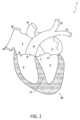
図1は、本発明の開示のいくつかの実施形態に関連する様々な特徴を有する心臓1の表現例を示す。心臓1は、4つの室、すなわち、左心房2、左心室3、右心室4、および右心房5を備えている。血流の観点から、血液は一般的に右心室4から肺動脈に、肺動脈弁9を介して流れ込み、この弁は右心室4を肺動脈11から隔てており、収縮期に開いて血液が肺の方へポンプで送られ、拡張期に閉じて血液が肺動脈11から心臓内に漏れて逆流するのを防ぐように構成されている。肺動脈11は、非酸素化血液を心臓の右側から肺に運ぶ。肺動脈11は、図示されているように、肺動脈幹と、肺動脈幹から分岐する左肺動脈15および右肺動脈13を含む。肺動脈弁9に加えて、心臓1は、三尖弁8、大動脈弁7、および僧帽弁6を含む、血液が中で循環するのを助ける3つの追加の弁を含む。三尖弁8は、右心房5を右心室4から隔てる。三尖弁8は、一般的に、3つの先端または弁尖を有し、一般的に、心室収縮(すなわち、収縮期)に閉鎖し、心室拡張(すなわち、拡張期)に開くものとしてよい。僧帽弁6は、一般的に、2つの先端/弁尖を有し、左心房2を左心室3から隔てる。僧帽弁6は、左心房2内の血液が左心室3内に流れ込み得るように拡張期に開き、適切に機能しているときに、血液が左心房2内に漏れて逆流するのを防ぐために拡張期に閉じるように構成される。大動脈弁7は、左心室3を大動脈12から隔てる。大動脈弁7は、血液が左心室3を出て大動脈12内に入るのを許すように収縮期に開き、血液が漏れて左心室3内に逆流するのを防ぐために拡張期に閉じるように構成される。
FIG. 1 illustrates an example representation of a heart 1 having various features associated with some embodiments of the present disclosure. The heart 1 includes four chambers, namely, the
心臓弁は、一般的に、本明細書において輪と称される、比較的密度の高い線維輪、さらには輪に取り付けられている複数の弁尖または先端を備え得る。一般的に、弁尖または先端のサイズは、心臓が収縮したときにその結果対応する心腔内に生じる血圧増大が弁尖を少なくとも部分的に開かせて心腔からの流れを許すようなサイズであり得る。心腔内の圧力が正常なレベルに戻るにつれ、その後の室または血管内の圧力は支配的なものとなり、再び弁尖を圧迫するようになり得る。その結果、弁尖/先端は互いに同格になり、それによって、流路を閉じる。心臓弁および/または関連する弁尖の機能不全(たとえば、肺動脈弁機能不全)の結果、弁の漏れおよび/または他の健康合併症を生じ得る。 Heart valves may generally comprise a relatively dense fibrous ring, referred to herein as an annulus, as well as multiple leaflets or tips attached to the annulus. Generally, the leaflets or tips may be sized such that when the heart contracts, the resulting increase in blood pressure within the corresponding heart chamber causes the leaflets to at least partially open to permit flow from the heart chamber. As pressure within the heart chamber returns to normal levels, the pressure within the subsequent chamber or vessel may become dominant and again compress the leaflets. As a result, the leaflets/tips apposition each other, thereby closing the flow path. Incompetence of a heart valve and/or associated leaflets (e.g., pulmonary valve insufficiency) may result in valve leakage and/or other health complications.
房室心臓弁(すなわち、僧帽弁および三尖弁)は、それぞれの弁の弁尖を固定して、弁尖の適切な接合を促進しおよび/または円滑にし、その脱出を防止するための、腱索および乳頭筋の集合体(図示せず)をさらに含み得る。乳頭筋は、たとえば、心室壁からの指状の突出部を一般的に備え得る。弁尖は、腱索によって乳頭筋に接続されている。中隔と呼ばれる筋肉17の壁が、左心房2および右心房5と、左心室3および右室4とを隔てる。
The atrioventricular heart valves (i.e., mitral and tricuspid) may further include a collection of chordae tendineae and papillary muscles (not shown) to secure the leaflets of the respective valves, promote and/or facilitate proper coaptation of the leaflets, and prevent their prolapse. The papillary muscles may, for example, typically comprise finger-like projections from the ventricular wall. The leaflets are connected to the papillary muscles by the chordae tendineae. A
上で言及されているように、心臓解剖学的構造に関連するいくつかの生理学的状態またはパラメータは、患者の健康に影響を及ぼし得る。たとえば、うっ血性心不全は、心臓および/または身体を通る血液の動きが比較的遅いことに関連する状態であり、これは、心臓の1つまたは複数の室内の流体圧力を上昇させる可能性がある。その結果、心臓は身体が必要とする条件を満たすのに十分な酸素を含んだ血液を送り出せなくなる。心臓の様々な室は、体内にポンプで通す血液をより多く保持するために伸長することによって、または比較的硬くおよび/または厚くなることによって圧力増大に応答し得る。心臓の壁は最終的に弱くなり、効率的なポンプ機能を果たせなくなる。いくつかの場合において、腎臓は、身体に体液を保持させることによって心臓不効率に応じ得る。腕、脚、足首、足、肺、および/または他の臓器内の体液貯留は、身体のうっ血を引き起こす可能性があり、これはうっ血性心不全と称される。急性非代償性うっ血性心不全は、罹患率および死亡率の主要な原因であり、したがって、うっ血性心不全の治療および/または予防は、医療における重要な関心事である。 As mentioned above, several physiological conditions or parameters related to the cardiac anatomy can affect the health of a patient. For example, congestive heart failure is a condition associated with relatively slow movement of blood through the heart and/or body, which can increase fluid pressure in one or more chambers of the heart. As a result, the heart is unable to pump enough oxygenated blood to meet the body's needs. The various chambers of the heart may respond to the increased pressure by stretching to hold more blood to pump through the body, or by becoming relatively stiffer and/or thicker. The walls of the heart eventually weaken and are unable to perform an efficient pumping function. In some cases, the kidneys may respond to cardiac inefficiency by causing the body to retain fluid. Fluid retention in the arms, legs, ankles, feet, lungs, and/or other organs can cause congestion of the body, which is referred to as congestive heart failure. Acute decompensated congestive heart failure is a major cause of morbidity and mortality, and therefore, the treatment and/or prevention of congestive heart failure is a major concern in healthcare.
心不全(たとえば、うっ血性心不全)の治療および/または予防は、有利には、心臓または他の解剖学的構造の1つまたは複数の室または領域内の圧力の監視を伴い得る。上で説明されているように、心臓の1つまたは複数の室または領域内の圧力上昇は、うっ血性心不全に関連付けられ得る。心臓圧力を直接的にまたは間接的に監視しない場合、うっ血性心不全の存在または発生を推測する、決定する、または予測することが困難であり得る。たとえば、直接的もしくは間接的な圧力監視を伴わない治療またはアプローチは、体重の測定、胸部インピーダンスの測定、右心カテーテル検査、または同様のものなど、患者の他の現在の生理学的状態を測定すること、または観察することを伴い得る。 Treatment and/or prevention of heart failure (e.g., congestive heart failure) may advantageously involve monitoring pressure within one or more chambers or regions of the heart or other anatomical structures. As explained above, elevated pressure within one or more chambers or regions of the heart may be associated with congestive heart failure. Without direct or indirect monitoring of cardiac pressure, it may be difficult to infer, determine, or predict the presence or occurrence of congestive heart failure. For example, treatments or approaches that do not involve direct or indirect pressure monitoring may involve measuring or observing other current physiological conditions of the patient, such as measuring body weight, measuring thoracic impedance, right heart catheterization, or the like.
うっ血性心不全を識別し、および/または治療するための様々な方法が、うっ血性心不全症状の悪化および/または体重の変化を観察することを伴う。しかしながら、そのような兆候は、比較的遅くに出現し、および/または比較的信頼できないことがある。たとえば、毎日の体重測定は、著しく変動する可能性があり(たとえば、最大9%以上)、心臓関連の合併症の前兆を示すには信頼性に欠ける可能性がある。さらに、兆候、症状、体重、および/または他のバイオマーカーを監視することによって導かれる治療は、臨床転帰を実質的に改善するとは示されていない。それに加えて、退院した患者については、そのような治療は離れた場所からの遠隔医療システムを必要とし得る。いくつかの状況において、うっ血性心不全は、2~3週間などの、一定期間にわたる体液貯留に起因し得る。したがって、体液貯留の最初の数日または1週間以内に体液貯留を検出し、および/または決定することは、長期間にわたる体液貯留からうっ血性心不全の発症を予防するのに役立ち得る。 Various methods for identifying and/or treating congestive heart failure involve observing worsening congestive heart failure symptoms and/or changes in weight. However, such signs may appear relatively late and/or may be relatively unreliable. For example, daily weight measurements may vary significantly (e.g., up to 9% or more) and may be unreliable in predicting cardiac-related complications. Furthermore, treatments guided by monitoring signs, symptoms, weight, and/or other biomarkers have not been shown to substantially improve clinical outcomes. Additionally, for discharged patients, such treatments may require telemedicine systems from a remote location. In some circumstances, congestive heart failure may result from fluid retention over a period of time, such as 2-3 weeks. Thus, detecting and/or determining fluid retention within the first few days or weeks of fluid retention may help prevent the development of congestive heart failure from long-term fluid retention.
本開示は、再入院、罹患率を低減し、および/または他の何らかの形で患者の健康見通しを改善するために、左心房内の、または圧力測定が左心房圧を示す他の室もしくは血管内の圧力を、少なくとも一部は直接的に監視することによって、うっ血性心不全の治療に関係する薬剤の投与を誘導するためのシステム、デバイス、および方法を提供する。 The present disclosure provides systems, devices, and methods for directing administration of medications related to the treatment of congestive heart failure, at least in part, by directly monitoring pressure in the left atrium, or in other chambers or vessels where pressure measurements are indicative of left atrial pressure, to reduce re-hospitalizations, morbidity, and/or otherwise improve patient health outlook.
心臓圧力監視
本開示の実施形態による心臓圧力監視は、うっ血性心不全を予防するか、または治療するための予防的介入メカニズムを提供し得る。一般的に、拡張期および/または収縮期心不全に関連する心室充満圧の上昇は、入院につながる症状の発生前に起こり得る。たとえば、心臓圧力指標は、一部の患者に関しては入院の数週間前に現れることがある。したがって、本開示の実施形態による圧力監視システムは、有利には、心不全の発症前に薬剤の適切または望ましい滴定および/または投与を誘導することによって入院の症例を減らすために実施され得る。
Cardiac Pressure Monitoring Cardiac pressure monitoring according to embodiments of the present disclosure may provide a preventative intervention mechanism to prevent or treat congestive heart failure. Generally, elevated ventricular filling pressures associated with diastolic and/or systolic heart failure may occur prior to the onset of symptoms leading to hospitalization. For example, cardiac pressure indicators may appear several weeks prior to hospitalization for some patients. Thus, pressure monitoring systems according to embodiments of the present disclosure may be advantageously implemented to reduce cases of hospitalization by guiding appropriate or desirable titration and/or administration of medications prior to the onset of heart failure.
上で言及されているように、心臓圧力に関して、左心房内の圧力上昇は、特に心不全と相関し得る。図2は、1つまたは複数の実施形態による心臓の様々な室および血管に関連する例示的な圧力波形を示している。図2に示されている様々な波形は、1つまたは複数の圧力センサーを、心臓の例示され、ラベル付けされたそれぞれの室または血管に送るために、右心カテーテル法を使用して得られる波形を表し得る。図2に例示されているように、左心房圧を表す波形225は、うっ血性心不全の早期検出のための最良のフィードバックを提供すると考えられ得る。さらに、一般的に、左心房圧の上昇と肺のうっ血との間には、比較的強い相関関係があると考えられ得る。 As mentioned above, with respect to cardiac pressure, elevated pressure in the left atrium may be particularly correlated with heart failure. FIG. 2 illustrates exemplary pressure waveforms associated with various chambers and blood vessels of the heart according to one or more embodiments. The various waveforms illustrated in FIG. 2 may represent waveforms obtained using right heart catheterization to deliver one or more pressure sensors to the illustrated and labeled respective chambers or blood vessels of the heart. As illustrated in FIG. 2, a waveform 225 representing left atrial pressure may be considered to provide the best feedback for early detection of congestive heart failure. Furthermore, generally, it may be considered that there is a relatively strong correlation between elevated left atrial pressure and pulmonary congestion.
左心房圧監視などの心圧監視は、うっ血性心不全を治療し、および/または予防するための薬剤の投与を誘導するメカニズムを提供することができる。そのような治療は、再入院および罹患率を有利に減少させ、さらには他の利点も提供し得る。本開示の実施形態による植え込まれた圧力センサーは、心不全の症状またはマーカー(たとえば、呼吸困難)が現れる2週間以上前までに心不全を予測するために使用され得る。心不全予測因子が、本開示による心臓圧力センサー実施形態を使用して認識されたときに、患者の投薬計画の修正などの、薬剤介入を含む、いくつかの予防対策が講じられ得るが、これは心機能異常の影響を防ぐか、または軽減するのを助け得る。左心房内の直接圧力測定は、有利には、心不全または他の合併症につながる可能性のある圧力上昇の正確な指標を提供することができる。たとえば、心房圧上昇の傾向は、心機能異常の発症を決定するか、または予測するために分析されるか、または使用され得、圧力低下を引き起こし、さらなる合併症を防止するか、または軽減するために、薬物または他の治療が強化され得る。 Cardiac pressure monitoring, such as left atrial pressure monitoring, can provide a mechanism to guide administration of medications to treat and/or prevent congestive heart failure. Such treatment may advantageously reduce re-hospitalization and morbidity rates, as well as provide other benefits. An implanted pressure sensor according to an embodiment of the present disclosure may be used to predict heart failure up to two weeks or more before symptoms or markers of heart failure (e.g., dyspnea) appear. When a heart failure predictor is recognized using a cardiac pressure sensor embodiment according to the present disclosure, some preventative measures may be taken, including pharmaceutical intervention, such as modification of the patient's medication regimen, which may help prevent or mitigate the effects of the cardiac dysfunction. Direct pressure measurement in the left atrium can advantageously provide an accurate indicator of pressure rise that may lead to heart failure or other complications. For example, a trend in atrial pressure rise may be analyzed or used to determine or predict the onset of cardiac dysfunction, and drugs or other treatments may be intensified to cause pressure reduction and prevent or mitigate further complications.
本開示のセンサー一体化インプラントデバイスは、人体解剖学的構造の様々な配置に実装され得る。たとえば、様々な心臓解剖学的配置が、心臓血管系内の血行動態圧力測定を目的とするセンサー一体化インプラントデバイスの植え込みに使用され得る。本明細書において開示されているインプラントデバイスは、シャント術、組織閉鎖/閉塞、修復、またはいくつかの心臓解剖学的構造および/または状態を他の何らかの形で治療することなどの、圧力監視に加えた1つまたは複数の追加の目的を果たすインプラント構造と一体化された1つまたは複数のセンサーを備えるものとしてよい。本開示によるインプラントデバイスは、上大静脈、下大静脈、右心房、左心房、右心室、左心室、肺動脈、肺静脈、冠状静脈洞、および/または同様のものを含む、任意の心臓血管または室内に植え込まれ得る。 The sensor-integrated implant devices of the present disclosure may be implemented in a variety of locations in the human anatomy. For example, a variety of cardiac anatomical locations may be used for implantation of a sensor-integrated implant device for hemodynamic pressure measurement in the cardiovascular system. The implant devices disclosed herein may include one or more sensors integrated with the implant structure that serves one or more additional purposes in addition to pressure monitoring, such as shunting, tissue closure/occlusion, repair, or otherwise treating some cardiac anatomical structures and/or conditions. The implant devices according to the present disclosure may be implanted in any cardiac vessel or chamber, including the superior vena cava, the inferior vena cava, the right atrium, the left atrium, the right ventricle, the left ventricle, the pulmonary artery, the pulmonary veins, the coronary sinus, and/or the like.
センサー一体化インプラントデバイス
本開示の実施形態は、1つまたは複数のセンサー一体化インプラントデバイスによって感知された患者の左心房圧および/または他の生理学的状態を監視することによって患者への薬剤の投与を誘導するためのメカニズムを提供し得る。うっ血性心不全患者に関して、そのような監視は、再入院および/または罹患率を下げるのに役立ち得る。いくつかの実装形態において、センサー一体化インプラントデバイスは、呼吸困難などの、心不全に関係する症状が現れる1週間以上前に心不全または他の状態を示すまたは予測する生理学的パラメータまたは状態を検出するように構成され得る。したがって、本開示の実施形態は、投薬計画または他の治療法を比較的早期に修正することを有利に円滑にし、より深刻な状態または症状が発生するのを潜在的に防ぎ得る。たとえば、左心房内の圧力上昇の早期検出は、圧力上昇の傾向を決定するために使用されてよく、さらなる合併症を防ぐために、検出されるか、または予測されたときに、薬物療法が、左心房圧を低下させるように増強され得る。肺への体液貯留に関係する心不全に関して、そのような体液貯留は、典型的には、1週間以上かけて徐々に進行することがあり、したがって、そのような体液貯留につながる可能性のある圧力上昇の予備検出は、比較的早期の介入および/または予防を可能にし得る。
Sensor-Integrated Implant Devices The presently disclosed embodiments may provide a mechanism for guiding administration of medication to a patient by monitoring the patient's left atrial pressure and/or other physiological conditions sensed by one or more sensor-integrated implant devices. For congestive heart failure patients, such monitoring may help reduce re-hospitalization and/or morbidity. In some implementations, the sensor-integrated implant device may be configured to detect physiological parameters or conditions indicative of or predicting heart failure or other conditions one or more weeks before symptoms related to heart failure appear, such as dyspnea. Thus, the presently disclosed embodiments may advantageously facilitate relatively early modification of medication regimens or other therapies, potentially preventing more serious conditions or symptoms from developing. For example, early detection of pressure rise in the left atrium may be used to determine a trend for pressure rise, and when detected or predicted, drug therapy may be augmented to reduce left atrial pressure to prevent further complications. With respect to heart failure related to fluid accumulation in the lungs, such fluid accumulation may typically develop gradually over a period of a week or more, and thus early detection of elevated pressures that may lead to such fluid accumulation may allow for relatively early intervention and/or prevention.
図3は、1つまたは複数の実施形態による心房中隔18内に植え込まれたセンサーインプラントデバイス310を示している。心房中隔壁内の特定の位置は、インプラント310に対する比較的安全なアンカー配置をもたらし、さらには血栓のリスクを比較的低く抑えるように選択されるか、または決定され得る。さらに、センサーインプラントデバイス310は、将来の介入のために中隔壁18の将来の再交差を考慮して望ましい位置に植え込まれ得る。心房中隔壁18内にセンサーインプラントデバイス310を植え込むことは、有利には、左心房2と右心房5との間の連通を可能にし得る。心房中隔18内にデバイス310があれば、センサーインプラントデバイス310のセンサー要素311、312は、有利には、右心房5、左心房2、または両心房の圧力を測定するように構成され得る。2つのセンサー要素311、312が図示されているが、いくつかの実施形態では、センサーインプラント310は、単一のセンサー要素、または3つ以上のセンサー要素を備える。両方の心房内の圧力を測定するための圧力センサー機能により、センサーインプラントデバイス310は、有利には、心房間の差圧を決定するために使用され得るセンサー信号を提供するように構成されてよい。差圧の決定は、うっ血性心不全に関連付けられ得る、肺内の体液貯留を監視するのに役立ち得る。
FIG. 3 illustrates a
図示されているように、センサー310は心房中隔18内に植え込まれるかまたは配設されている状態で、圧力が、右心房5および左心房2のいずれかまたは両方で監視され得る。両方の心房内に配設されている圧力センサートランスデューサを含むセンサーの実施形態では、インプラントデバイス310は、心房間の差圧を測定する能力を備え得、これは、上で説明されているようにうっ血性心不全に関連付けられる、肺の中の体液貯留を監視するときに役立ち得る。
As shown, with the
一般的に、心房中隔壁18は、圧力センサー310のための良好な固定配置をもたらし得る。センサーデバイス310は、有利には、心房壁18内の安全な配置に固定されてよい。さらに、センサー310は、左心房2内に配設されているセンサーデバイス310の部分に関して血栓のリスクが比較的低くなるように構成され、および/または製作されることが望ましいことがある。いくつかの実施形態において、本開示は、心房中隔壁18内に植え込まれ得るセンサー一体化インプラントデバイスを提供し、インプラントデバイスは、将来の医療介入のために中隔壁18を再交差するためにアクセスする機構を提供する。
In general, the atrial
いくつかの実装形態において、本開示は、心臓インプラントデバイスに関連付けられるか、または心臓インプラントデバイスと一体化される圧力センサーに関する。そのようなセンサー一体化心臓インプラントデバイスは、心不全を治療し、予防するための制御されたおよび/またはより効果的な療法を提供するために使用され得る。図4は、心臓インプラント構造420を備えるインプラントデバイス400を示すブロック図である。いくつかの実施形態において、心臓インプラント構造420は、センサーデバイス410と物理的に一体化され、および/またはセンサーデバイス410に接続される。センサーデバイス410は、たとえば、圧力センサー、または他のタイプのセンサーであってよい。いくつかの実施形態において、センサー410は、圧力トランスデューサなどのトランスデューサ412、さらには、たとえば特定用途向け集積回路(ASIC)で具現化され得る、特定の制御回路414を備える。制御回路414は、トランスデューサ412から受信された信号を処理し、および/またはアンテナ418を使用して生体組織を通してそれに関連付けられている信号をワイヤレス方式で通信するように構成され得る。アンテナ418は、銅線または同様のものなどの導電性材料の1つもしくは複数のコイルまたはループを備え得る。いくつかの実施形態において、トランスデューサ412、制御回路414、および/またはアンテナ418の少なくとも一部は、センサーハウジング416内に少なくとも部分的に配設されるか、または収容され、これは、任意の種類の材料を含むものとしてよく、有利には、少なくとも部分的に密封され得る。たとえば、ハウジング416は、いくつかの実施形態では、ガラスまたは他の剛体材料を含むものとしてよく、これは中に収納されているコンポーネントの機械的安定性および/または保護を提供し得る。いくつかの実施形態において、ハウジング416は、少なくとも部分的な可撓性を有する。たとえば、ハウジングは、ポリマーまたは他の可撓性構造/材料を含むものとしてよく、これは、カテーテルまたは他の導入手段を通してそれの輸送を可能にするために、センサー410の折り重ね、曲げ、または折り畳みを有利に可能にし得る。 In some implementations, the present disclosure relates to a pressure sensor associated with or integrated with a cardiac implant device. Such a sensor-integrated cardiac implant device may be used to provide a controlled and/or more effective therapy for treating and preventing heart failure. FIG. 4 is a block diagram illustrating an implant device 400 comprising a cardiac implant structure 420. In some embodiments, the cardiac implant structure 420 is physically integrated with and/or connected to a sensor device 410. The sensor device 410 may be, for example, a pressure sensor, or other type of sensor. In some embodiments, the sensor 410 comprises a transducer 412, such as a pressure transducer, as well as specific control circuitry 414, which may be embodied, for example, in an application specific integrated circuit (ASIC). The control circuitry 414 may be configured to process signals received from the transducer 412 and/or communicate signals associated therewith in a wireless manner through biological tissue using an antenna 418. The antenna 418 may comprise one or more coils or loops of conductive material, such as copper wire or the like. In some embodiments, at least a portion of the transducer 412, control circuitry 414, and/or antenna 418 are at least partially disposed or housed within a sensor housing 416, which may comprise any type of material and may advantageously be at least partially hermetically sealed. For example, the housing 416 may comprise glass or other rigid material in some embodiments, which may provide mechanical stability and/or protection for the components housed therein. In some embodiments, the housing 416 is at least partially flexible. For example, the housing may comprise a polymer or other flexible structure/material, which may advantageously allow the sensor 410 to fold, bend, or collapse to enable its transport through a catheter or other introduction means.
トランスデューサ412は、任意のタイプのセンサー手段またはメカニズムを備え得る。たとえば、トランスデューサ412は、フォースコレクタタイプ(force-collector-type)圧力センサーであってよい。いくつかの実施形態において、トランスデューサ412は、ダイヤフラム、ピストン、ブルドン管、ベローズ、または他の歪みもしくは撓み測定コンポーネントを備えており、その領域/表面上に印加される歪みまたは撓みを測定する。トランスデューサ412は、ハウジング416に関連付けられるものとしてよく、その少なくとも一部がハウジング316内に収容されるか、またはハウジング316に取り付けられる。「関連する(付けられる)」という言い回しは、本明細書では、その広い、通常の意味で使用される。センサーデバイス/コンポーネントがステントまたは他のインプラント構造に「関連付けられている」ことに関して、そのような言い回しは、センサーデバイスまたはコンポーネントがインプラント構造に物理的に結合されるか、取り付けられるか、もしくは接続されるか、またはインプラント構造と一体化されていることを指すものとしてよい。 The transducer 412 may comprise any type of sensor means or mechanism. For example, the transducer 412 may be a force-collector-type pressure sensor. In some embodiments, the transducer 412 comprises a diaphragm, piston, Bourdon tube, bellows, or other strain or deflection measuring component to measure the strain or deflection applied over its area/surface. The transducer 412 may be associated with the housing 416, at least a portion of which is contained within or attached to the housing 316. The term "associated" is used herein in its broad, ordinary sense. With respect to a sensor device/component being "associated" with a stent or other implant structure, such a term may refer to the sensor device or component being physically coupled, attached, or connected to the implant structure, or being integral with the implant structure.
いくつかの実施形態において、トランスデューサ412は、ピエゾ抵抗歪みゲージを備えるか、またはそのコンポーネントであり、これは、印加された圧力による歪みを検出するために結合されるか、または形成された歪みゲージを使用するように構成されるものとしてよく、そこで、抵抗は圧力がコンポーネント/材料を変形させると高くなる。トランスデューサ412は、限定はしないが、シリコン(たとえば、単結晶)、ポリシリコン薄膜、貼り合わされた金属箔、厚膜、シリコンオンサファイア、スパッタリングされた薄膜、および/または同様のものを含む、任意の種類の材料を組み込み得る。 In some embodiments, the transducer 412 comprises or is a component of a piezoresistive strain gauge, which may be configured to use a bonded or formed strain gauge to detect strain due to applied pressure, where the resistance increases as the pressure deforms the component/material. The transducer 412 may incorporate any type of material, including, but not limited to, silicon (e.g., single crystal), polysilicon thin film, laminated metal foil, thick film, silicon on sapphire, sputtered thin film, and/or the like.
いくつかの実施形態において、トランスデューサ412は、ダイヤフラムに印加される圧力による歪みを検出するための可変コンデンサを形成するように構成されているダイヤフラムおよび圧力キャビティを備える容量圧力センサーを具備するか、またはそのコンポーネントである。容量圧力センサーの静電容量は、圧力がダイヤフラムを変形させると一般的には減少し得る。ダイヤフラムは、限定はしないが金属、セラミック、シリコンまたは他の半導体、および同様のものを含む、任意の材料を含み得る。いくつかの実施形態において、トランスデューサ412は、電磁圧力センサーを備えるか、または電磁圧力センサーのコンポーネントであり、これはインダクタンスの変化、線形可変変位トランスデューサ(LVDT)機能、ホール効果、または渦電流検出を用いてダイヤフラムの変位を測定するように構成され得る。いくつかの実施形態において、トランスデューサ412は、圧電歪みセンサーを備えるか、または圧電歪みセンサーのコンポーネントである。たとえば、そのようなセンサーは、石英などの、いくつかの材料における圧電効果に基づき感知メカニズム上の歪み(たとえば、圧力)を決定し得る。この技術は、高度に動態的な圧力の測定に一般に採用されている。 In some embodiments, the transducer 412 comprises or is a component of a capacitive pressure sensor comprising a diaphragm and a pressure cavity configured to form a variable capacitor for detecting strain due to pressure applied to the diaphragm. The capacitance of a capacitive pressure sensor may generally decrease as pressure deforms the diaphragm. The diaphragm may comprise any material, including but not limited to metal, ceramic, silicon or other semiconductors, and the like. In some embodiments, the transducer 412 comprises or is a component of an electromagnetic pressure sensor, which may be configured to measure the displacement of the diaphragm using a change in inductance, a linear variable displacement transducer (LVDT) function, Hall effect, or eddy current detection. In some embodiments, the transducer 412 comprises or is a component of a piezoelectric strain sensor. For example, such a sensor may determine strain (e.g., pressure) on a sensing mechanism based on the piezoelectric effect in some materials, such as quartz. This technique is commonly employed to measure highly dynamic pressures.
いくつかの実施形態において、トランスデューサ412は、歪みゲージを備えるか、または歪みゲージのコンポーネントである。たとえば、歪みゲージの実施形態は、トランスデューサ412の露出表面上の、またはそれに関連付けられている感圧素子を備え得る。いくつかの実施形態において、金属歪みゲージがセンサー表面に付着しているか、または薄膜ゲージがスパッタリングもしくは他の技術によってセンサー上に貼り付けられてよい。測定要素またはメカニズムは、ダイヤフラムまたは金属箔を含み得る。トランスデューサ412は、光学センサー、電位差センサー、共振センサー、熱センサー、イオン化センサー、または他のタイプの歪みもしくは圧力センサーなどの、他のタイプのセンサーもしくは圧力センサーを含み得る。 In some embodiments, the transducer 412 comprises or is a component of a strain gauge. For example, a strain gauge embodiment may comprise a pressure sensitive element on or associated with an exposed surface of the transducer 412. In some embodiments, a metallic strain gauge may be attached to the sensor surface or a thin film gauge may be applied onto the sensor by sputtering or other techniques. The measuring element or mechanism may include a diaphragm or metal foil. The transducer 412 may include other types of sensors or pressure sensors, such as optical sensors, potentiometric sensors, resonant sensors, thermal sensors, ionization sensors, or other types of strain or pressure sensors.
いくつかの実施形態において、センサー410は、外部リーダー(たとえば、コイル)を含む外部(たとえば、植え込み不可能)デバイスまたはシステムと通信するように構成され、これは特定の制御回路に電気的および/または通信可能に結合されているワイヤレストランシーバを含み得る。いくつかの実施形態において、センサー410および外部サブシステムは両方とも、センサー410が患者に植え込まれたときに、間に配設される患者組織を通してワイヤレス通信および/または送電を行うための対応するコイルアンテナを備える。 In some embodiments, the sensor 410 is configured to communicate with an external (e.g., non-implantable) device or system that includes an external reader (e.g., a coil), which may include a wireless transceiver electrically and/or communicatively coupled to a specific control circuit. In some embodiments, the sensor 410 and the external subsystem both include corresponding coil antennas for wireless communication and/or power transmission through patient tissue disposed therebetween when the sensor 410 is implanted in a patient.
外部リーダー/モニター(図示せず)は、ワンドデバイスまたは他のハンドヘルドリーダーもしくはデバイスなど、外部アンテナを使用して、ワイヤレス信号伝送を受信し、および/またはワイヤレス電力を供給することができる。外部トランシーバは、センサー410から信号を受信し増幅するように構成されている高周波(RF)フロントエンド回路を備えることができ、そのような回路は、1つまたは複数のフィルタ(たとえば、バンドパスフィルタ)、増幅器(たとえば、低雑音増幅器)、アナログ/デジタルコンバータ(ADC)および/またはデジタル制御インターフェース回路、位相ロックループ(PLL)回路、信号ミキサー、または同様のものを含み得る。外部トランシーバは、ネットワークの信号をリモートモニターサブシステムまたはデバイスに伝送するようにさらに構成され得る。外部トランシーバのRF回路は、ネットワーク上の伝送された信号の処置/処理のため、および/またはセンサー410から信号を受信するためにデジタル/アナログコンバータ(DAC)回路、電力増幅器、ローパスフィルタ、アンテナスイッチモジュール、アンテナ、または同様のもののうちの1つもしくは複数をさらに備えることができる。いくつかの実施形態において、外部モニターは、センサー410から受信された信号の処理を実行するための制御回路を備える。いくつかの実施形態において、外部モニターは、スマートフォン、ラップトップコンピュータ、もしくは他のモバイルコンピューティングデバイス、または他のタイプのコンピューティングデバイスである。 An external reader/monitor (not shown) may use an external antenna, such as a wand device or other handheld reader or device, to receive wireless signal transmissions and/or provide wireless power. The external transceiver may comprise radio frequency (RF) front-end circuitry configured to receive and amplify signals from the sensor 410, which may include one or more filters (e.g., bandpass filters), amplifiers (e.g., low noise amplifiers), analog-to-digital converters (ADCs) and/or digital control interface circuits, phase-locked loop (PLL) circuits, signal mixers, or the like. The external transceiver may further be configured to transmit signals of the network to a remote monitor subsystem or device. The RF circuitry of the external transceiver may further comprise one or more of a digital-to-analog converter (DAC) circuitry, a power amplifier, a low-pass filter, an antenna switch module, an antenna, or the like, for processing/processing the transmitted signals on the network and/or for receiving signals from the sensor 410. In some embodiments, the external monitor comprises control circuitry for performing processing of signals received from the sensor 410. In some embodiments, the external monitor is a smartphone, laptop computer, or other mobile computing device, or other type of computing device.
いくつかの実施形態において、センサー410は、揮発性および/または不揮発性データストレージをいくつか備える。たとえば、そのようなデータストレージは、フローティングゲートトランジスタのアレイを利用するソリッドステートメモリ、または同様のものを含むことができる。制御回路414は、一定期間にわたって収集された感知データを記憶するためにデータストレージを利用するものとしてよく、記憶されたデータは、定期的に外部モニターまたは他の外部サブシステムに伝送され得る。いくつかの実施形態において、センサー410は、いかなるデータストレージをも備えない。制御回路414は、センサートランスデューサ412によって生成されるデータ、またはそれに関連付けられている他のデータのワイヤレス伝送を円滑にするように構成される。制御回路414は、外部リーダー(たとえば、ワンドデバイス)から、またはたとえば通信ネットワーク(たとえば、インターネット)上のリモートモニターからなど、1つまたは複数の外部サブシステムから入力を受信するようにさらに構成され得る。たとえば、センサー410は、1つまたは複数のコンポーネントもしくはセンサーをアクティベート/デアクティベートすること、またはセンサー410の動作もしくは実行に他の何らかの形で影響を及ぼすこと、などによって、センサー410の動作を少なくとも部分的に制御する信号を受信するように構成され得る。 In some embodiments, the sensor 410 includes some volatile and/or non-volatile data storage. For example, such data storage may include solid-state memory utilizing an array of floating gate transistors, or the like. The control circuitry 414 may utilize data storage to store sensed data collected over a period of time, which may be periodically transmitted to an external monitor or other external subsystem. In some embodiments, the sensor 410 does not include any data storage. The control circuitry 414 is configured to facilitate wireless transmission of data generated by the sensor transducer 412, or other data associated therewith. The control circuitry 414 may further be configured to receive inputs from one or more external subsystems, such as from an external reader (e.g., a wand device) or from a remote monitor over a communications network (e.g., the Internet). For example, the sensor 410 may be configured to receive signals that at least partially control the operation of the sensor 410, such as by activating/deactivating one or more components or sensors, or otherwise affecting the operation or performance of the sensor 410.
センサー410の1つまたは複数のコンポーネントは、1つまたは複数の電源(図示せず)によって給電され得る。サイズ、コスト、および/または電気系統の複雑さの問題により、そのような電源は本質的に比較的ミニマリスティックであることが望ましいことがある。たとえば、センサー410における大電力駆動電圧および/または電流は、インプラントデバイス400に関連付けられている心臓もしくは他の身体部分の動作に悪影響を及ぼすか、または干渉し得る。いくつかの実施形態において、センサー410は、短距離、または近距離ワイヤレス電力伝送、または他の電磁結合メカニズムの使用などを通して、センサー410の受動回路によってワイヤレス方式で外部ソースから受電するように構成される。たとえば、外部デバイスは、電力をセンサー410に供給することができるRF場を能動的に発生するイニシエータとして使用され、それによってインプラントデバイス400の電源回路が比較的単純なフォームファクタをとることを可能にし得る。いくつかの実施形態において、インプラントデバイス400は、流体流、運動、または同様のものなどの、環境的発生源からエネルギーを収穫するように構成される。それに加えて、または代替的に、インプラントデバイス400は、監視期間(たとえば、1、2、3、5、10、20、30、60、もしくは90日間、または他の期間)にわたって必要に応じて十分な電力を供給するように有利に構成され得る、バッテリを備えることができる。 One or more components of the sensor 410 may be powered by one or more power sources (not shown). Due to issues of size, cost, and/or electrical system complexity, it may be desirable for such power sources to be relatively minimalistic in nature. For example, high power driving voltages and/or currents in the sensor 410 may adversely affect or interfere with the operation of the heart or other body parts associated with the implant device 400. In some embodiments, the sensor 410 is configured to receive power from an external source in a wireless manner by passive circuitry of the sensor 410, such as through the use of short-range or near-field wireless power transmission, or other electromagnetic coupling mechanisms. For example, an external device may be used as an initiator to actively generate an RF field that can provide power to the sensor 410, thereby allowing the power circuitry of the implant device 400 to take on a relatively simple form factor. In some embodiments, the implant device 400 is configured to harvest energy from environmental sources, such as fluid flow, motion, or the like. Additionally or alternatively, the implant device 400 may include a battery that may be advantageously configured to provide sufficient power as needed for a monitoring period (e.g., 1, 2, 3, 5, 10, 20, 30, 60, or 90 days, or other period).
いくつかの実施形態では、センサー410は、ウェアラブル通信デバイス、または患者およびセンサー410に近接して容易に配設され得る他のデバイスを備えるローカルリーダー/モニターとともに動作するように構成される。そのような外部リーダー/モニターデバイス/システムは、センサー410に連続的に、定期的に、または散発的にインテロゲートし、それによりセンサーベースの情報を抜き出すか、または要求するように構成され得る。いくつかの実施形態において、ユーザインターフェースが実装され、このユーザインターフェースは、ユーザがインターフェースを利用してセンサーデータを表示するか、センサーデータを要求するか、またはセンサー410を他の何らかの形でインタラクティブに操作することを可能にする。 In some embodiments, the sensor 410 is configured to operate with a local reader/monitor comprising a wearable communication device or other device that may be readily disposed in proximity to the patient and the sensor 410. Such an external reader/monitor device/system may be configured to continuously, periodically, or sporadically interrogate the sensor 410 and thereby extract or request sensor-based information. In some embodiments, a user interface is implemented that allows a user to utilize the interface to view sensor data, request sensor data, or otherwise interact with the sensor 410.
いくつかの実施形態において、外部リーダー/モニターは、内部インプラントデバイス410のアンテナ418と誘導的にペアリングされるようにマッチングおよび/またはチューニングされるコイルアンテナを備える。いくつかの実施形態において、センサー410は、外部モニターシステムからワイヤレス超音波電力充電および/またはデータ通信を受けるように構成される。 In some embodiments, the external reader/monitor includes a coil antenna that is matched and/or tuned to inductively pair with the antenna 418 of the internal implant device 410. In some embodiments, the sensor 410 is configured to receive wireless ultrasonic power charging and/or data communication from the external monitor system.
図5は、1つまたは複数の実施形態によるセンサーインプラントデバイス500の斜視図を例示している。センサーインプラントデバイス500は、センサー510を備え、これは、その1つまたは複数の部分に関して大まかに円筒形の形態を有し得る。しかしながら、本明細書では、特定の実施形態が円筒形のセンサーデバイスの文脈において開示されているが、本開示の原理は、任意の適切なもしくは望ましい形状、形態、または構成を有するセンサーを備えるセンサーインプラントデバイスに関するものであることは理解されるべきである。
FIG. 5 illustrates a perspective view of a
センサーデバイス510は、圧力トランスデューサなどの1つまたは複数のセンサー511、512を備えるものとしてよく、これらは、センサー510の1つまたは複数の遠位端部分または近位端部分に関連付けられ得る。たとえば、センサー510は、遠位センサー要素と見なされてよい第1のセンサー要素512、さらにはいくつかの実施形態において近位センサー要素と見なされてよい第2のセンサー要素511を備え得る。センサーインプラントデバイス500は、センサーインプラントデバイス500を心房中隔壁などの、組織壁に固定するための1つまたは複数のアーム521、522を備え得る、アンカー520を具備する。アンカー520は、形状記憶合金または他の材料を含むものとしてよく、センサー510に何らかの方式で固定されるか、または取り付けられ得る。アンカー520のアンカーアーム521、522は、以下でさらに詳細に説明されている、1つまたは複数の遠位アーム521および1つまたは複数の近位アーム522を含み得る。いくつかの実施形態において、センサー510は、つまみ、突出部、延長部、歯、溝、支柱、または同様のものを含み得る、1つまたは複数の突出特徴517を含むか、または関連付けられており、センサー510を送達システム(図示せず)の1つまたは複数のコンポーネントに、またはアンカー520の1つまたは複数の特徴に固定するために使用され得る。
The sensor device 510 may include one or
アンカー520は、中隔壁、または他の組織内に、センサーインプラントデバイス500を直接的に取り付けるか、または植え込むことを可能にし得る。図6は、心房中隔壁などの、組織壁18内に植え込まれたセンサーインプラントデバイス500を示している。本明細書のいくつかの図および説明は、心房中隔壁内に植え込まれているセンサーインプラントデバイス500の文脈において説明されているが、本開示の実施形態により、センサーインプラントデバイス500が任意の生物組織または組織壁内に植え込まれ得ることは理解されるべきである。
The
いくつかの実施形態において、センサーインプラントデバイス500は、図示されているように、近位センサー要素511および遠位センサー要素512を備える。中隔壁18内に植え込まれているセンサーインプラントデバイス500において、近位センサー要素および遠位センサー要素の各々は、それぞれの心房内に配設され得る。たとえば、図6の例示されている実施形態の配向に関して、近位センサー要素511は右心房内に配設され、一方、遠位センサー要素512は左心房2内に配設され得る。
In some embodiments, the
アンカー520は、任意の数の遠位および/または近位アームを備え得る。遠位アーム521は、その端部分が、展開された構成において少なくとも部分的に近位方向を向くように湾曲するものとしてよい。近位アーム522は、少なくとも部分的に真っ直ぐであってよく、センサーデバイスの長手方向軸および/またはセンサーデバイスそれ自体から離れる方向に少なくとも部分的に偏向され、少なくとも部分的に遠位方向に突出し得る。さらに、近位アーム522の端部分は、組織損傷のリスクを低減するために、少なくとも部分的に湾曲しているか、丸みを帯びているか、または組織壁表面との接触のための鈍的な表面を提供するように他の何らかの形で構成され得る。
The
アンカー520は、3つまたはそれ以上の遠位アームおよび3つまたはそれ以上の近位アームを有するように例示されている。いくつかの実施形態において、アンカー520は、4つまたはそれ以上の近位アームおよび4つまたはそれ以上の遠位アームを備え得る。いくつかの実施形態において、センサーインプラントデバイス500は、植え込まれた後、代替的な介入のために中隔壁の将来の交差を妨げない十分に小さいサイズを有する。
The
いくつかの実施形態において、センサー510は、ガラスまたは他の少なくとも部分的に剛性のある材料から作られ得る、剛体ハウジングを備える。突出特徴517は、センサー510のハウジング516と同じ材料から作られてもよい。たとえば、ハウジング516が円筒形ガラス管を備える場合、突出特徴517は、ハウジング516と一体的形態となるそれの突出部であってもよい。代替的に、突出特徴517は、任意の好適なまたは望ましい方式でハウジング516に取り付けられるか、または固定されてよい。
In some embodiments, the sensor 510 comprises a rigid housing, which may be made from glass or other at least partially rigid material. The
一般的に、センサーハウジング516がガラスを含む場合、センサー510は、望ましい生体適合性および/またはガス抜け防止特性を有し得る。たとえば、センサーハウジング516に使用されているような特定の材料に関して、ガス抜けは、センサー510の内部配設電子機器、または同様のものなどから、ハウジング516を通して少なくとも一部は生じ得る。ハウジング516は、有利には、センサー510および/またはその内部回路もしくはコンポーネントのための十分な気密バリアシールを形成する。いくつかの実施形態において、アンカー520は、ニチノールまたは同様のものなどの、形状記憶合金フレームを備える。アンカー520は、摩擦嵌めを通して、または生体適合性接着剤、溶接、もしくは他の取り付けメカニズムを含む、他の好適なもしくは望ましい取り付けメカニズムを使用して、センサー510に固定され得る。
In general, when the
図7は、本開示の1つまたは複数の実施形態によるセンサーインプラントデバイスを植え込むためのプロセス700を例示する流れ図である。図8は、図7のプロセス700の様々なステップに対応するセンサーインプラントデバイスおよび/または関連する送達システムのコンポーネントの状態を例示している。図7および図8は、中隔壁内のセンサーインプラントデバイスの植え込みに関係するが、送達カテーテルおよび/またはセンサーインプラントデバイスの挿入または植え込みのために中隔壁に開口を形成するのに使用され得る、中隔壁の初期穿刺および/またはその拡張(たとえば、バルーンまたは他のメカニズムを使用して)は、詳細に図示または説明されていないことは理解されるべきである。
FIG. 7 is a flow diagram illustrating a
プロセス700のステップに関連して、ターゲットの植え込み配置へのアクセスは、任意の好適なまたは望ましい方式で達成され得る。たとえば、右心房へのアクセスは、いくつかの実装形態において、大腿静脈を介して行われ得る。ブロック702において、プロセス700は、送達カテーテル730を中隔壁18内の開口に通して左心房内に導入することを伴う。ブロック704において、プロセス700は、図8の状態802で示されているように、送達カテーテル730の内部プッシャーまたはイジェクタコンポーネント(図示せず)を前進させて、それによってセンサーインプラントデバイス700の遠位部分を送達カテーテル730の遠位端から展開するか、または排出することを伴う。センサーインプラントデバイス700は、1つまたは複数の遠位アンカーアーム721を備えるものとしてよく、これは、図5および図6に示されている遠位アーム521に類似するものであってよい。さらにブロック704に関連して、プロセス700は、遠位アーム721を露出させるのにかろうじて十分であるが、センサーインプラントデバイスに関連付けられている近位アームを送達カテーテルから排出するのには十分でないように、送達カテーテル730からセンサーデバイス700を排出することを伴い得る。
In connection with the steps of
遠位アーム721が送達カテーテル730から排出された状態で、プロセス700は、ブロック706において、図8の状態803に示されるように、送達システムを引っ込めて遠位アーム721を中隔壁18に対してセットすることを伴う。たとえば、送達カテーテル730の遠位端731は、いくつかの実装形態による、遠位アーム721を中隔壁18の左心房側に対してセットするために、右心房5内に引き戻され得る。遠位アーム721が中隔壁に対してセットされると、プロセス700は、ブロック708において、送達システム730をさらに引っ込めて、センサーインプラントデバイス700に関連付けられているアンカー720の近位アーム722を中隔壁18の右心房側に対して展開することを伴い得る。送達カテーテル730を引っ込めて近位アーム(たとえば、ニチノールアーム)を露出させると、これは、その後、中隔壁の例示されている配向に関して中隔壁18の右側に係合し得る。いくつかの実装形態において、遠位アーム721および/または近位アーム722は、図8の状態804で示されているようにセンサーインプラントデバイスが完全に展開されたときに中隔壁18に対して張力を与えるように構成されるか、または形成され得る。いくつかの実装形態において、遠位アーム721は、本明細書において示されているように、湾曲した形態または形状を有してもよく、一方、近位アーム722は、少なくとも部分的に真っ直ぐな形態または形状を備え得る。
With the
図8の状態804で示されているようにセンサーインプラントデバイス700が植え込まれた状態で、センサー要素712は、左心房2内に展開され、それに関連付けられている圧力または他の測定値を提供するように構成され得る。いくつかの実施形態において、センサー710の近位端または部分に関連付けられている追加のセンサー要素711は、右心房5内に配設され、右心房5に関連付けられている圧力または他の生理学的パラメータ測定値を提供するために使用されてよく、これは、差圧測定および/または他の測定に使用され得る。
With the
いくつかの実施形態において、本開示によるセンサーインプラントデバイスは、センサーインプラントデバイスの再捕捉または取り外しを円滑にするように構成され、整形され、および/または設計され得る。図9は、1つまたは複数の実施形態による以前に植え込まれたセンサーインプラントデバイス900を取り外すためのシステムを例示している。図9のシステムは、送達/吸引カテーテル930を備え、これは、センサーインプラントデバイス900を送達し、および/または取り外すか、もしくは抜き出すために使用され得る。システムは、プッシャーまたは抜き出しデバイス935をさらに含み、これは、いくつかの実施形態において、送達カテーテル930内で移動可能であり得る。
In some embodiments, a sensor implant device according to the present disclosure may be configured, shaped, and/or designed to facilitate recapture or removal of the sensor implant device. FIG. 9 illustrates a system for removing a previously implanted
本明細書において詳細に説明されているように、センサーデバイス910は、植え込みおよび/または抜き出しのためのセンサーデバイス910の係合を円滑にする1つまたは複数の突出部917または他の係合特徴を備え得る。いくつかの実施形態において、プッシャー/抜き出しデバイス935は、突出係合特徴937を含む。たとえば、プッシャー/抜き出しデバイス935は、センサー910の周りに少なくとも部分的に嵌合するように構成および寸法設定された少なくとも部分的に中空の円筒形の形態を有していてもよく、プッシャー/抜き出しデバイス935の係合特徴937の間隙939は、プッシャー/抜き出しデバイス935が突出特徴917を長手方向に通されることを可能にし、プッシャー/抜き出しデバイス935の回転は、係合特徴(たとえば、伸長部材)937が突出特徴917と円周方向に重なることを可能にする。図9に示されているようにプッシャー/抜き出しデバイス935が回転させられると、プッシャー/抜き出しデバイス935を引っ込めることにより、センサーインプラントデバイス900、またはそのセンサー910コンポーネントが右心房の方向に引き寄せられ得る。したがって、プッシャー/抜き出しデバイス935は、突出特徴917と選択的に係合され、突出特徴917から解放され得るバヨネット式係合メカニズムを提供し得る。単一の突出特徴917が、図9に示されているが、センサーインプラントデバイス900は、任意の数の突出特徴を有していてもよく、さらにプッシャー/抜き出しデバイス935は任意の数のそれぞれの突出係合特徴を有していてもよいことは理解されるべきである。
As described in detail herein, the
いくつかの実施形態において、アンカー920の遠位アーム921の形状または形態は、アームがより真っ直ぐな構成/形態になるように引っ張られることを可能にして、アンカー920が中隔壁18内の開口を通して引っ張られるか、または引き出されることを可能にし得る。したがって、送達カテーテル930および/または抜き出しデバイス935を例示されている方向にさらに引っ込めることによって、センサーインプラントデバイス900は、中隔壁18内のその植え込まれた位置から取り出され得る。アンカー920の遠位アーム921および近位アーム922の形状は、アンカー920の再捕捉を円滑にし得る。センサーインプラントデバイス900の再捕捉/取り外しは、必要になった場合または望まれた場合に、手技と手技との間に、または後で、実行されてよい。
In some embodiments, the shape or configuration of the
プッシャー/抜き出しデバイス935は、センサーインプラントデバイス900および/またはセンサーコンポーネント916の取り外しに関して説明されているが、プッシャー/抜き出しデバイス935は、いくつかの実施形態において、センサーインプラントデバイス900および/またはセンサーコンポーネント916を植え込むために利用されてもよい。たとえば、プッシャー935は、インプラントデバイス900を、これが展開されるときに操作するために使用され得る。展開に使用されるとき、プッシャーデバイス935は、センサー突出特徴917を押して、図示されているようにセンサーインプラントデバイス900および中隔壁を係合するものとしてよく、その後、プッシャーデバイス935を回転させて、係合特徴937を突出特徴917から係脱して、センサーインプラントデバイス900からのプッシャーデバイス935の引き出しを可能にし得る。
Although the pusher/
図5~図9は、上で説明されているように、遠位アームおよび近位アームを備える特定の構成のアンカーを有するセンサーインプラントデバイスを例示している。図10は、上で説明されているものとは異なる形態および/または構成を有するアンカー1020を有するセンサーインプラントデバイス1000を例示している。特に、図10に示されているセンサーインプラントデバイス1000のアンカー1020は、心臓の左心房内など、心臓または他の解剖学的構造に関連付けられている室または血管内にセンサー1010を植え込むことを可能にするものとしてよく、センサーデバイス1010の全体は、単一の血管または室内に配設されるが、アンカー1020のアーム1027は、もっぱら、センサー1010をアンカーアーム1027から隔てる組織壁の反対側の室または血管内に維持される。
5-9 illustrate a sensor implant device having a particular configuration of anchor with a distal arm and a proximal arm, as described above. FIG. 10 illustrates a
図11は、中隔壁18内に植え込まれたセンサーインプラントデバイス1000を示している。いくつかの実施形態において、センサーインプラントデバイス1000を所望の組織壁に植え込むときに円筒形または他の形状のセンサー1010がアンカー部材として使用される。植え込まれるときに、アンカーアーム1027は、少なくとも一部は中隔壁18の反対側の側面117上に圧力または力を印加することによって、センサー1010を中隔壁18の第1の側面119に当てて保持する働きをし得る。したがって、植え込まれるときに、センサー1010は、中隔壁18の比較的近くに保持され得る。センサーが室2(たとえば、左心房)内に配設され、固定された状態で、それのセンサー要素は、室2内の圧力または別の生理学的パラメータを検出するために使用され得る。図11は、左心房2内に配設されたセンサー1010を示しているが、いくつかの実施形態では、センサーは、右心房5、または他の血管もしくは室内に配設され得るが、アンカーアーム1027は、もっぱら、左心房2内に配設され得る。いくつかの実施形態において、インプラントデバイス1000は、アンカー1020のフレームに取り付けられ、中隔壁18内の開口部115の少なくとも一部を覆う閉塞膜または布(たとえば、ポリマー繊維布)を備える。
FIG. 11 shows the
図10をさらに参照すると、アンカー1020は、ニチノール、または同様のものなどの、形状記憶合金、および/または他の少なくとも部分的に剛性のある材料を含み得る。いくつかの実施形態では、アンカー1020の1つまたは複数のアームまたは特徴は、1つまたは複数のアイレットまたは同様のものなどの組織または縫合糸取り付け特徴1025を備える。たとえば、植え込まれた後、アンカーフレーム1020のアイレット1025は、組織壁に縫い付けられ、それによってセンサーインプラントデバイス1000を植え込み位置に固定し得る。アンカー1020が複数のアイレットまたは他の取り付け特徴を備える場合、望ましい取り付けを行うために、各それぞれの特徴に縫合糸が通されるものとしてよい。代替的に、アイレットまたは他の縫合糸係合特徴は、アンカーフレーム1020を取り出し、移動し、および/または引っ込めるために使用され得る。たとえば、それの展開の前に、アンカーフレーム1020が折り畳まれた状態で送達カテーテル内に配設された状態で、縫合糸が、図示されているアイレット特徴1025の各々に係合されるものとしてよく、少なくとも1つのアイレットまたは他の縫合糸係合特徴は、各それぞれのアンカーアーム1027に関連付けられる。センサーインプラントデバイス1000を留置しているときに、アンカーフレームおよび/またはセンサー1010の位置が何らかの点で不十分である場合、アイレットまたは他の縫合糸係合特徴1025に取り付けられている縫合糸は、送達カテーテルを通して引っ張られ、それによってアーム1027を少なくとも部分的に折り畳まれた状態にし、これは、センサーデバイス1000の再配置、および/またはセンサーインプラントデバイス1000および/またはアンカー1020を送達カテーテル内に引き込むことを可能にし得る。
10, the
アンカーアーム1027の例示されている半円形状は、アンカーアーム1027をターゲット配置のところの組織と固定するのに役立ち得る。たとえば、アンカー1020のコーナー特徴1029は、ターゲット組織との望ましい係合および/またはターゲット組織内への埋め込みをもたらし得る。さらに、アンカーアーム1027の例示されている形状は、アンカーが送達カテーテル内に引っ込められ、および/または引き出されることを容易にする働きをし得る。
The illustrated semicircular shape of the
図11の植え込まれた構成では、組織成長侵入は、アンカーフレームアーム1027およびセンサー1010のいずれかまたは両方において中隔壁18の片側または両側に生じる可能性がある。いくつかの実施形態において、その上の組織成長侵入を抑制する働きをするコーティングまたは材料が、センサー1010に関連して追加されるか、または使用され得る。そのような材料またはコーティングは、有利には、センサー要素のダイナミクスに実質的に影響を及ぼさないようなものであってよい。
In the implanted configuration of FIG. 11, tissue ingrowth may occur on one or both sides of the
図12は、本開示の1つまたは複数の実施形態による図10および図11に例示されているセンサーインプラントデバイス1000に、いくつかの点で類似しているセンサーインプラントデバイスを植え込むためのプロセス1200を例示する流れ図である。図13は、プロセス1200の様々な状態における、インプラントセンサーデバイス600および関連する送達システム、さらにはターゲット植え込み部位解剖学的構造を例示している。
FIG. 12 is a flow diagram illustrating a
ブロック1202において、プロセス1200は、送達カテーテル630を左心房2内に送り込む/導入することを伴う。たとえば、左心房2へのアクセスは、下大静脈29、右心房5を通して、および右心房5を左心房2から隔てる中隔壁18を通して達成され得る。下大静脈29へのアクセスは、大腿静脈または他のアクセスポートを通して達成され得る。
At
送達カテーテル630の遠位端が左心房2内に配設されている状態で、プロセス1200は、ブロック1204において、送達カテーテル630からセンサーインプラントデバイス600のセンサー610を排出することを伴う。プロセス1200は、有利には、まず、図13の状態602および603に示されているように、関連付けられているアンカーフォーム620の少なくとも一部が送達カテーテル630内に残っている間に、センサー要素610のみを排出することを伴うものとしてよい。いくつかの実施形態において、プッシャーデバイス635が、送達カテーテル630からセンサー610を排出するために使用され得る。
With the distal end of the
ブロック1206において、プロセス1200は、送達カテーテル630に関して長手方向に整列された配向で送達カテーテルから最初に排出され得る、センサーデバイス610を回すか、または枢動させて、図13の状態603に示されているように、送達カテーテル630の遠位端の長手方向軸に実質的に垂直である配向をとらせることを伴う。センサー610について図示され、説明されているような垂直な配向であるが、センサー610を回すか、または枢動させるステップは、センサーを垂直な配向にするのではなく、単にセンサー610に送達カテーテルの遠位端との同軸配向に比べてより垂直である配向をとらせる得ることが理解されるべきである。いくつかの実施形態において、アンカーフレーム620は、形状記憶合金(たとえば、ニチノール)を含み、これは、センサー610を、図示されているように枢動させる/回すように予め整形され得る。すなわち、アンカーフレーム620は、センサー610の一部に取り付けられるものとしてよく、送達カテーテル630から排出された後、フレームの形状記憶特性により、センサー610は図示されているように枢動するまたは回る。
In block 1206, the
ブロック1208において、プロセス1200は、送達カテーテルを引っ込めて、センサー(たとえば、圧力センサー)を中隔壁18に当てて位置決めすることを伴う。センサー610は、それによって、その片側の中隔壁に対して所望の位置に自己固定する働きをし得る。
At block 1208, the
ブロック1210において、プロセス1200は、送達カテーテル630をさらに引っ込めて、アンカーフレーム620のアンカーアーム627を圧力センサー610に関して中隔壁18の反対側に展開することを伴う。アーム627が送達カテーテル630から展開されているときに、これらは、図示されているように、外側にスイングして中隔壁18に接触し、インプラントデバイス600を所望の位置に固定する引張力をもたらし得る。たとえば、フレーム620は、送達カテーテル630から展開されたときにアーム627が外側にフレア状に広がるように事前整形され得る。いくつかの実施形態において、アンカーアーム627は、縫合糸640をそれに結合するための、アイレットまたは同様のものなどの、縫合糸係合特徴を有する。そのような縫合糸は、有利には、センサーデバイス600を取り外すか、引っ込めるか、または再配置することが望まれる場合に、フレームアーム627が、送達カテーテル630に再入するように比較的真っ直ぐな形態に引き戻されることを可能にし得る。所望の植え込み位置に達したときに、縫合糸は、アンカーアーム627の縫合糸係合特徴を通して引き出され、それによってアンカー620を送達システムから解放し得る。図13にはアンカーアームの各々に対して別々の縫合糸が図示されているが、いくつかの実施形態では、単一の縫合糸が両方のアンカーアームに結合される。
At block 1210, the
本開示の実施形態によるセンサーアンカーは、近位端および遠位端のところに複数のコイルスタックを備えるものとしてよく、間にある小径のコイルは円筒形センサー上の突起部または突出部に係合してセンサーをコイルに固定するように構成されている。図14は、本開示の1つまたは複数の実施形態によるセンサーアンカー220の一実施形態を例示している。アンカー220は、異なる直径を有する複数の螺旋状部分を有するワイヤ形態を含む。たとえば、いくつかの実施形態において、アンカー220は、近位大直径部分222および遠位大直径部分224を含む2つの大直径螺旋状部分を備え、そのうちの1つまたは複数は、図示されているように直径d1を有し得る。アンカー220は、直径d1よりも小さい直径d2を有する中間小直径螺旋状部分223をさらに備え得る。アンカーワイヤフォーム220は、有利には、例示されている複雑な螺旋状コイルに形成された単一の一体ワイヤを含み得る。代替的に、ワイヤフォーム220は、アンカー220を形成するように結合されるか、または一体化されている複数の別々のワイヤコンポーネントを含み得る。
A sensor anchor according to an embodiment of the present disclosure may comprise multiple coil stacks at the proximal and distal ends, with smaller diameter coils in between configured to engage protrusions or projections on the cylindrical sensor to secure the sensor to the coil. FIG. 14 illustrates one embodiment of a
図15は、中隔壁18内に植え込まれたアンカー220を示しており、アンカー220は、センサーデバイス210と係合し、それによりアンカー220は、センサーデバイス210を図示されている植え込み位置に固定して定着させる。たとえば、いくつかの実施形態において、アンカー220は、円筒形センサーデバイス210がアンカー220の小直径中間部分223内に保持され、固定され得るように構成され、および/または寸法設定され得るが、遠位大直径部分222および近位大直径部分224は、インプラントデバイス200を中隔壁18に当てて保持し得る。たとえば、小直径コイル部分223は、有利には、中隔壁18の開口/開口部内に嵌合するように寸法設定されてよいが、大直径部分222、224は、拡張された形態のときに中隔壁開口部よりも大きい直径を有し得る。
15 shows an
アンカー220は、圧縮された構成の送達カテーテルに入れてターゲット植え込み部位に送達され得る。たとえば、ワイヤフォーム220は、実質的に真っ直ぐな構成で、または比較的きつく巻かれた構成で送達されてよく、送達カテーテルからの展開後、ワイヤフォームアンカー220は、図14および図15に示されている形状および構成をとるように構成される。いくつかの実施形態において、アンカー220は、センサー210の周りに巻かれるか、またはセンサー210に取り付けられるような構成で送達カテーテルに入れて送達される。代替的に、アンカーは、センサーとは別に送達されてもよい。たとえば、ワイヤフォームアンカー220は、図示されているように中隔壁18内に植え込まれてよく、その後、円筒形センサー210は、中間の小直径螺旋状部分223の1つまたは複数のコイルの中心を通して押し込まれ、小直径コイルが円筒形センサー本体部(たとえば、ガラス製の円筒形本体部)の周りに比較的きつく巻き付けられるように小直径コイル部分との締まり嵌めを達成し得る。
The
いくつかの実施形態において、センサー210は、アンカー220の小直径部分223と係合する、および/または固定されるようにするための1つまたは複数の係合特徴を備える。たとえば、図16に示されているように、センサー210は、上で説明されているように1つまたは複数の突出特徴217を備え得る。そのような突出特徴217は、センサー210の本体部と一体化され得るか、または接着剤もしくは他の取り付けメカニズムを使用してそれに取り付けられ得る。突出部217は、突出部が小直径コイル部分223のコイルの間に絡み合うか、または通過するときに、突出部とワイヤコイルとの間の接触が、センサーをアンカー220との相対的な位置に保持するかもしくは維持する働きをするような寸法および/または位置に設定され得る。いくつかの実施形態において、突出部217は、センサー210が中間部分223を通してセンサーを回転させるか、または巻くことによってアンカー220に係合させられ得るように構成される。したがって、センサー210の取り外しは、センサー210を巻き戻して突出特徴217を小直径中間コイル223から係脱することを通じて達成され得る。そのような取り外しにより、小直径コイル223の間の開口部を通して左心房にアクセスすることが可能になり得る。さらに、センサー210の取り外しは、センサーが正常に機能しないか、または他の何らかの形で交換されるか、もしくは取り外される必要がある場合に望ましいことがある。いくつかの実施形態において、ワイヤフォームアンカー220は、例示されているように、所望のコイル形状に予成形された形状記憶合金ワイヤを含む。
In some embodiments, the
様々な実施形態が本明細書において心房中隔壁内に植え込まれたセンサーインプラントデバイスに関連して例示され、説明されているが、本開示の実施形態は、心室中隔壁内のセンサーインプラントデバイスの植え込みを含む、他の植え込み部位に適用可能であることは理解されるべきである。図17は、本開示の態様によるセンサーインプラントデバイスの一実施形態を例示している。図17は、心室中隔壁17内の圧力センサーデバイス1710、または他のタイプのセンサーデバイスを示している。センサーインプラントデバイス1700は、センサー1710と、中隔壁17内の所望の位置にセンサー1710を固定するように構成されている1つまたは複数のアンカー特徴(図示せず)とを備える。
Although various embodiments are illustrated and described herein with respect to a sensor implant device implanted in the atrial septal wall, it should be understood that embodiments of the present disclosure are applicable to other implantation sites, including implantation of a sensor implant device in the ventricular septal wall. FIG. 17 illustrates one embodiment of a sensor implant device according to aspects of the present disclosure. FIG. 17 shows a
センサーインプラントデバイス1700は、右心室4および/または左心室3内の圧力を監視するためのセンサー読取値を提供するように構成され得る。たとえば、センサー1710は、1つまたは複数のセンサー要素1711、1712を含んでいてもよく、その各々は、図17に示されているように植え込まれたときに心臓1のそれぞれの心室内に配設され得る。いくつかの実施形態において、センサー1710は、単一のセンサー要素のみを含み、1つの心室のみに対する圧力センサー読取値を提供するように構成される。心室圧力監視は、特定の心不全患者を診断し、および/または治療するのに有用であり得る。センサーインプラントデバイスの本明細書において開示されている他の実施形態についても言えることだが、センサーインプラントデバイス1700は、有利には、本明細書において詳細に説明されているように、ワイヤレスデータおよび/または電力を受信し、および/または伝送するためのワイヤレス伝送機能を備え得る。
The
センサー一体化組織閉鎖デバイス
いくつかの実施形態において、本開示によるセンサーインプラントデバイスは、中隔閉鎖デバイス、または他の組織閉鎖デバイスと一体化されたセンサーを備え得る。いくつかの実施形態は、中隔閉鎖デバイスの文脈において以下で開示されているが、そのような開示は、他のタイプの組織閉鎖デバイスと一体化された1つまたは複数のセンサーを含むセンサー一体化インプラントデバイスに適用可能であることは理解されるべきである。図18は、本開示の1つまたは複数の実施形態によるセンサー一体化中隔閉鎖デバイスの正面図を示している。図19は、組織壁18内に植え込まれた図18のセンサー一体化中隔閉鎖デバイスの斜視図を示している。図18に示されているように、センサー一体化中隔閉鎖デバイス100は、血液閉塞膜138を支持するように構成されているフレーム112を備えることができる。図19に関して、中隔閉鎖デバイス100は、中隔壁18内に植え込まれて、中隔壁を横切るシャントを閉鎖するものとしてよく、このシャントは、先天性のものであり得るか、または介入手技の際に形成されたものであり得る。いくつかの実施形態において、中隔閉塞器フレームおよび閉塞膜138が最初に中隔壁18に植え込まれ、その後、閉塞膜138を穿刺してその中にセンサーデバイス110を通すなどして、センサーデバイス110が中隔閉鎖装置に取り付けられてもよい。
Sensor-Integrated Tissue Closure Device In some embodiments, a sensor implant device according to the present disclosure may include a sensor integrated with a septal closure device or other tissue closure device. Although some embodiments are disclosed below in the context of a septal closure device, it should be understood that such disclosure is applicable to a sensor-integrated implant device including one or more sensors integrated with other types of tissue closure devices. FIG. 18 illustrates a front view of a sensor-integrated septal closure device according to one or more embodiments of the present disclosure. FIG. 19 illustrates a perspective view of the sensor-integrated septal closure device of FIG. 18 implanted within a
例示されている構成のフレーム112は、中央部分114と、中央部分114から半径方向外向きに延在する複数のアンカーアーム116とを含む一般的に平面状の本体部を備え得る。たとえば、例示されている実施形態に示されているように、少なくとも4本のアームが中央部分114から延在し得るが、フレームは、他の実施形態では、4本よりも多いアーム116または3本よりも少ないアーム116を有することができる。アーム116が図示され、説明されているが、中隔閉鎖デバイス100および/またはフレームは、任意のタイプの組織アンカー特徴を備え得ることは理解されるべきである。
The
4本のアーム116は、中央部分114から延在する、対向するアーム118の第1のセットと対向するアーム120の第2のセットとを含み得る。閉鎖デバイスは、望ましくは(必ずしもそうではないが)、デバイスが植え込まれるときにアームが加えるクランプ力が中隔に対して均等に分散されるように第1および第2セットにおいて同じ数のアームを有する。例示されている実施形態において、たとえば、アーム118の第1のセットは、中央閉塞膜138の対向する側から延在するちょうど2本のアームを含み、アーム120の第2のセットは、中央閉塞部138の対向する側から延在するちょうど2本のアームを含む。他の実施形態では、アームの第1または第2のセットは、たった1つのアーム、または4本以上のアームを含むことができる。
The four
展開されたまたは拡大された構成において、アーム116は、中央閉塞部分138から半径方向外向きに延在することができる。アーム116は、デバイス100が中隔壁18内に植え込まれるときに心房中隔18がアーム118の第1のセットとアーム120の第2のセットとの間で圧縮されるか、または間に挟まれ得るようにデバイス100の中心軸(中隔閉鎖デバイスと一体化されたセンサーデバイス110の中心を通って延在し、ページの平面に対して垂直である中心軸)に対して垂直に、または実質的に垂直に延在することができる。言い換えると、デバイス110が植え込まれたときに、アーム118の第1のセットは、中隔壁18の一方の側にあり、アーム120の第2のセットは、心房中隔の他方の側にあり、中央部分138は、中隔の開口部または欠損部内に配設され得る。
In the deployed or expanded configuration, the
例示されている実施形態におけるフレーム112は、血栓を回避するか、または最小限度に抑えるために、比較的薄く、平坦な輪郭を有する。したがって、そのような目的のために、アーム116は、角度に関して相隔てて並ぶ配置で中央閉塞膜138の外周に関連付けられているフレーム114の中央部分に取り付けられるものとしてよく、取り付け配置は、中心軸に垂直な共通平面と交差する、言い換えると、例示されている実施形態におけるアーム116はすべて、中央フレーム部分114によって画成される円周経路に沿って中央フレーム部分114に取り付けられ得る。
The
いくつかの実施形態において、アーム116および中央フレーム部分114は、デバイス100がその完全に拡張された非偏向形状になったときに互いに同一平面上にあるものとしてよい、すなわち、アーム116は、中央フレーム部分114から軸方向に離れるように延在する部分を有しない。植え込まれた後、アーム118の第1のセットおよびアーム120の第2のセットは、中隔18の厚さによって互いから軸方向にわずかに離れて曲げられ、もはや同一平面上にあり得ないことは理解されるべきである。それにもかかわらず、いくつかの実施形態におけるデバイス110は、デバイスが非偏向状態にあるときに互いに、および中央フレーム部分114と同一平面上にあるアームを備える平坦な輪郭を有すると言うことができる。しかしながら、他の実施形態では、アームまたはその一部は、非偏向状態において互いから、または中央フレーム部分114から軸方向に離れて延在するように熱硬化されるか、または他の何らかの形で整形され得る。
In some embodiments, the
フレーム112は、送達カテーテル/システムにおける心臓への送達のための送達構成に、半径方向に圧縮されるか、または収縮され得る。たとえば、送達構成では、フレーム112は、アーム118の第1のセットがデバイス100の中心軸に沿って互いの方へ折り重ねられ、アーム120の第2のセットがデバイス100の中心軸に沿って互いの方へ折り重ねられ、アーム118の第1のセットおよびアーム120の第2のセットは、それぞれ、軸方向120に、互いに平行に延在する一般的に圧縮された構成で留置され、保持され得る。送達構成で留置されたときに、フレーム112は、また、展開された構成に関して半径方向に圧縮され得る。
The
フレーム112は、以下でさらに説明されているように、1つまたは複数の取り付け縫合糸を介して閉鎖デバイス100を送達システムに結合するために1つまたは複数のアームの遠位端に配設されているアイレット130を備えることができる。アイレットは、18および19に図示されているように、中央部分114の方へ突出するか、または中央部分114から離れる方向に突出することができる。
The
フレーム112は、自己拡張可能であってよく、ニチノールなどの形状記憶材料から形成され得るので、フレーム112は、送達装置から解放されるか、または展開されるときに送達構成から展開構成へと自己拡張する。代替的な実施形態において、フレーム112は、ステンレス鋼またはコバルトクロム合金などの可塑的拡張可能材料から形成され、膨張可能なバルーンなどの、拡張デバイスによって送達構成から展開構成へと可塑的に拡張されるように構成され得る。フレーム112は、ニチノールなどの、金属の平らなシートからレーザー切断法または他の何らかの方法で形成され得る。代替的に、フレーム112は、1つまたは複数の金属ワイヤを図示されている形態に曲げることによって形成され得る。
The
閉塞膜138は、右心房と左心房との間の血液の流れを遮断するように構成され得る。成人の場合、右心房圧の正常範囲は約2~6mmHgであり、左心房圧の正常範囲は約4~12mmHgである。したがって、心臓周期のほとんど全体を通して、左心房圧は右心房圧よりも大きい。いくつかの実施形態において、閉塞膜138は、少なくとも左心房から右心房への血液の流れを遮断するように構成され得る。他の実施形態では、閉塞膜138は、心臓周期全体を通して両方向の右心房と左心房との間の血液の流れを遮断するように構成され得る。
The
特定の実施形態において、閉塞膜138は、フレーム112を通る血液の流れを少なくとも部分的に遮断するか、または妨げる1つまたは複数の材料シートまたは材料片を含むことができる。たとえば、閉塞膜138は、組織成長侵入を促すように構成され、時間の経過とともに分解して、中央フレーム部分114内に再生された組織だけを残すことができる生体吸収性材料、フィルム、または布の1つまたは複数の断片を含むことができる。たとえば、閉塞膜138は、ポリラクチド(PLA)、ポリラクチドグリコリド(PLGA)、ポリカプロラクトン(PLC)、ポリアクリロニトリル(PAN)、ポリ(ラクチド-co-カプロラクトン)(PLCL)、ポリグリコネート、およびポリペプチドなどの生体吸収性エレクトロスパンポリマー材料の1つまたは複数の断片を含み得る。織布と比較して、エレクトロスパンポリマーは、より速い組織成長侵入を促進し、より短い生分解時間を有し、潜在的に血栓形成が少なく、より弱く形成され、したがって、閉鎖デバイスのその後の再交差時に医療器具で容易に穿刺され得る。
In certain embodiments, the
いくつかの実施形態において、閉塞膜138は、様々な合成繊維(たとえば、ポリエチレンテレフタレート(PET))または天然組織(たとえば、心膜)のいずれかなどの、非生体吸収性材料の断片の1つまたは複数のシートを含み得る。いくつかの実施形態において、閉塞膜138は、血液に対して完全にまたは実質的に不浸透性であり得る。他の実施形態では、閉塞膜138は、血流に対して半多孔質であり得る(たとえば、多孔質の布地)。多孔質材料は、多孔質のままであるか、または時間の経過とともに血液に対して、詰まり、不浸透性または非多孔質になるように選択され得る。特定の実装形態において、閉塞膜は、約0.05~1.5ミクロンの間の繊維サイズおよび約50~80%の間の多孔率を有するバイオスパンポリウレタンから作ることができる。閉塞膜138の厚さは、約100~200ミクロンの間であってよい。別の実装形態では、閉塞膜は、類似の繊維サイズおよび多孔率を有する、ポリウレタン/PETの70/30%ブレンドなどの、ポリウレタンおよびPETを含むバイオスパンポリマーブレンドから作ることができる。いくつかの実施形態において、閉塞膜138は、ポリウレタン、PET、シリコーン、またはポリエチレン発泡体などの生体適合性発泡体から作ることができる。
In some embodiments, the occluding
閉塞膜138は、中隔の隣接組織と実質的に流体密封シールを形成するように構成され得る。いくつかの実施形態において、閉塞膜138は、少なくとも最初は、残留シャントをもたらすように心房の間に少量の血流を許すように構成される。時間の経過とともに、閉塞膜138は、組織成長進入を促進し、中隔の開口部を実質的に完全に閉じ、心房間の残留シャントを防止することができる。閉塞膜138は、図18および図19に示されているように、中央フレーム部分114を完全に覆うことができるか、または閉塞膜138は、中央フレーム部分114内の開口部の一部を覆うことができる。閉塞膜138は、中隔18の開口部が、閉塞膜138の分解前または分解後のいずれかに欠損部を通しての再入のためにアクセスされ得るように構成され得る。
The
閉塞膜138は、熱かしめ、縫合、成形、接着、編み込み、および/または本開示の恩恵を受ける当業者に知られている他の手段を介して、フレーム112に取り付けられ得る。たとえば、閉塞膜138の外縁は、中央フレーム部分114の上に折り重ねられ、次いで、閉塞膜138のより中央に近い領域に溶接されて、閉塞膜138をフレーム112に固定することができる。閉塞膜138は、中央フレーム部分114の周縁を、たとえば最大2mmを超えて、延在し得る。いくつかの実施形態において、閉塞膜138は、フレーム112に取り付ける前に一般的に円形の形状を有していてもよい。
The
閉塞膜138は、有利には、比較的薄い布を含むものとしてよく、これは、将来の介入に関連して必要が生じた場合に左心房へのアクセスを得るために貫通され得る。さらに、フレーム112は、有利には、フレーム112を通しての、特に中央フレーム部分114を通しての左心房へのアクセスが行えるように、比較的大きな直径のカテーテルを収容できるように伸びて開くように構成され得る。
The
上で言及されているように、図18および図19のインプラントデバイス100は、閉塞膜138に取り付けられるか、または他の何らかの形で閉塞膜138と一体化されたセンサーデバイス110を備える。センサーデバイス110は、本明細書において説明されているように、1つまたは複数のセンサー要素を含む圧力センサーであってもよい。たとえば、センサーデバイス110は、一般的に円筒形の形状を有していてもよく、センサー110の遠位端部分および近位端部分が中隔閉鎖デバイス100の反対側に露出されるように閉塞膜138を貫通し得る。
As mentioned above, the
植え込んだ後のセンサーデバイス110の取り外しは、左心房にアクセスするための閉塞膜138を通してのアクセスを可能にし得る。たとえば、中隔閉鎖デバイス100のフレーム112は、介入デバイスの通過を許すように比較的容易に変形される形状記憶合金または他の材料を含むものとしてよい。いくつかの実装形態において、センサーデバイス110はその中に配設されたままか、またはそれと一体化されている状態で、介入デバイスは、閉塞膜138を通過するものとしてよい。いくつかの実装形態において、センサー一体化インプラントデバイス100は、センサー110がすでに中隔閉鎖デバイスと一体化された状態で送達されてもよい。
Removal of the
図20は、中隔閉鎖デバイスと一体化されたセンサー2010を備えるセンサーインプラントデバイス2000を例示している。中隔閉鎖デバイスは、本明細書において詳細に説明されているように、複数のアームを備えるフレーム2012に接続されている閉塞布または膜2038を備える。センサー一体化インプラントデバイス2000の意図されている機能を維持するために、本明細書において開示されている実施形態は、センサー2010を中隔閉鎖インプラントに貼り付けるための手段を利用する。いくつかの実施形態において、閉塞膜1038は、センサーデバイス2010を保持する形状を有する1つまたは複数のスリーブ/カフ2039に形成された布(たとえば、バイオスパンポリマー布)膜を含み得る。たとえば、円筒形のセンサーデバイス2010に関して、スリーブ/カフ2039は、少なくとも部分的に円筒形であってもよく、円筒形のセンサー2010をフレーム2012に貼り付ける働きをし得る。閉塞膜/布2038のスリーブ/カフ2039は、縫合糸カラー2037を使用してセンサーデバイス2010に固定されるものとしてよく、この縫合糸カラー2037は、スリーブ/カフ2039およびセンサーデバイス2010の周りに巻き付けられ、スリーブ/カフ2039をセンサーデバイス2010に固定し得る。
FIG. 20 illustrates a
上で説明されているように、閉塞膜2038は、バイオスパンポリマーを含むものとしてよく、これは、布またはスカフォールドの幾何学的形状などの、任意の好適なまたは望ましい幾何学的形状で作られ得る。いくつかの実施形態において、閉塞膜2038は、時間の経過とともに進む組織成長侵入を通じて生体組織と徐々に一体化されるように構成される。そのような膜は、有利には、膜を貫通するのに必要な力が植え込み位置/部位からフレーム2012を外すのに必要な量の力よりも小さくなるような性質を有するものとしてよい。いくつかの実施形態において、本明細書で詳細に説明されているように、センサーデバイス2010は、1つまたは複数の突出特徴2017を備えており、これは、センサー2010の本体と一体化された形態であり得るか、または生体適合性接着剤、もしくは他の取り付け手段を使用して取り付けられるか、もしくは接着され得る。
As described above, the occlusion membrane 2038 may include a biospun polymer, which may be fabricated in any suitable or desired geometry, such as a fabric or scaffold geometry. In some embodiments, the occlusion membrane 2038 is configured to gradually integrate with living tissue through progressive tissue ingrowth over time. Such a membrane may advantageously have properties such that the force required to penetrate the membrane is less than the amount of force required to dislodge the
本明細書において説明されているようなセンサー一体化中隔閉鎖デバイスの植え込み後に左心房へのアクセスを得る能力を維持するために、センサーインプラントデバイス取り外しカテーテルが利用されてもよい。図21は、本開示の実施形態によるセンサーインプラントデバイスを取り外すためのプロセス2100を例示している。図22は、センサーインプラントデバイスおよび関連する取り外しシステム、さらには図21のプロセスステップに対応する様々な状態の心臓解剖学的構造を例示している。ブロック2102において、プロセス2100は、取り外しカテーテル2103を右心室に導入し、取り外しカテーテルをセンサーインプラントデバイス2200が植え込まれている心房中隔壁18に送ることを伴う。取り外しカテーテル2230は、円筒形センサー2210をそれと一体化されている中隔閉鎖デバイスから安全に取り外すために、またはセンサー一体化中隔閉鎖デバイス2200全体を取り外すために使用され得る。センサー2210は、有利には、1つまたは複数の突起部または他の係合特徴2217を備えるものとしてよく、これらはセンサー2210を取り外すために使用され得る。突起特徴2217は、センサー本体部2210の外面から半径方向に突出し得る。突起特徴が本明細書において説明されているが、センサー2210上に保持するか、または把持する他の手段は本開示の実施形態により実装され得ることは理解されるべきである。
To maintain the ability to gain access to the left atrium after implantation of a sensor-integrated septal closure device as described herein, a sensor implant device removal catheter may be utilized. FIG. 21 illustrates a
ブロック2104において、プロセス2100は、抜き出しデバイス2235を取り出しカテーテル2230内で前進させることを伴う。いくつかの実施形態において、プッシャー/抜き出しデバイス2235は、突出係合特徴2237を含む。たとえば、ブロック2106において、プロセス2100は、図22の状態2203に示されるように、係合特徴2237をセンサー2210の突出特徴2217と係合させることを伴う。プッシャー/抜き出しデバイス2235は、センサー2210の周りに少なくとも部分的に嵌合するように構成および寸法設定された少なくとも部分的に中空の円筒形管形態を有していてもよく、プッシャー/抜き出しデバイス2235の係合特徴2237の間隙2239は、プッシャー/抜き出しデバイス2235が突出特徴2217の上を長手方向に送られることを可能にし、プッシャー/抜き出しデバイス2235の回転は、伸長/係合特徴2237が突出特徴2217と円周方向に重なりそれとの係合をもたらすことを可能にする。
At block 2104, the
ブロック2108において、プロセス2100は、取り出しカテーテル2230を引き出して、それによってセンサー2210を中隔閉鎖インプラント2211から取り外すことを伴う。たとえば、図22の状態2203で示されているようにプッシャー/抜き出しデバイス2235が回転させられると、プッシャー/抜き出しデバイス2235を引っ込めることにより、センサー2010および/または中隔閉鎖インプラントデバイス2200が右心房の方向に引き寄せられ得る。したがって、プッシャー/抜き出しデバイス2235は、突出特徴2217と選択的に係合されるか、または突出特徴2217から解放され得るバヨネット式係合メカニズムを提供し得る。単一の突出特徴2217が、図22に示されているが、センサーインプラントデバイス2200は、任意の数の突出特徴を有してもよく、さらにプッシャー/抜き出しデバイス2235は任意の数のそれぞれの突出係合特徴を有していてもよいことは理解されるべきである。いくつかの実施形態において、プッシャー/抜き出しデバイス2235が突出特徴2217と係合されているときに、取り外しカテーテル2230の遠位端2231は、センサー2210の抜き出し時に中隔閉鎖デバイス2200が外れるのを防ぐために中隔閉鎖デバイス2200に当てて保持され得る。
At block 2108, the
図22の状態2204は、そこからセンサーデバイス2210が取り外された状態の中隔閉鎖インプラントデバイス2200を示している。しかしながら、いくつかの実施形態において、センサー一体化中隔閉鎖デバイス2200全体は、プロセス2100に関連して取り外され得ることは理解されるべきである。センサー2210が中隔閉鎖デバイス2200から取り外された後、比較的弱い閉塞膜2238(たとえば、バイオスパンポリマー)は、標準的なデバイスカテーテルを使用して比較的容易に横断され得る。
22 shows the septal
プッシャー/抜き出しデバイス2235は、センサーインプラントデバイス2200の取り外しに関して説明されているが、プッシャー/抜き出しデバイス2235は、いくつかの実施形態において、センサーインプラントデバイス2200を植え込むために利用され得る。たとえば、プッシャー2235は、インプラントデバイス2200を、これが展開されるときに操作するために使用され得る。展開に使用されるとき、プッシャーデバイス2235は、センサー突出特徴2217を押して、図示されているようにセンサーインプラントデバイス2200および中隔壁を係合するものとしてよく、その後、プッシャーデバイス2235を回転させて、係合特徴2237を突出特徴2217から係脱して、センサーインプラントデバイス2200からのプッシャーデバイス2235の引き出を可能にし得る。
Although the pusher/
追加のセンサー一体化心臓インプラントデバイス
いくつかの実施形態において、センサーインプラントデバイスは、心臓弁スペーサーデバイスと一体化されたセンサーを備え得る。図23に示されているように、弁スペーサーデバイス2300、2301は、三尖弁8または僧帽弁6の能力を向上するために心臓1内に植え込まれ得る。以下の説明は、その能力を改善するために右心室4に植え込まれ、三尖弁8内に嵌合するように位置決めされているセンサー一体化スペーサーインプラントデバイス2300に焦点を当てているが、以下の説明は、任意の弁および/または左心室にも植え込まれるセンサー一体化スペーサーインプラントデバイスにも適用可能であることは理解されるべきである。このスペーサーインプラントデバイス2300は、自然弁尖の間の逆流性オリフィス領域を占有し、弁尖接合のための表面を提供することによって、弁逆流を低減するように設計され得る。センサー一体化スペーサーインプラントデバイス2300は、スペーサーフォーム2320と、心室頂点26のところ、またはその近くなどで、右心室4に固定されるテザー2325とからなる。スペーサーフォーム2320は、スペーサー室内の1つまたは複数の開口部を介して受動的に拡張するように構成されている少なくとも部分的に充填されたポリマー(たとえば、発泡体充填)バルーンを含み得る。スペーサーフォーム2320内への開口部は、いくつかの実施形態では、スペーサーフォームの対向する長手方向の端に位置決めされてよい。スペーサーフォーム2320内の開口部は、カテーテルベースの送達性のためにスペーサーフォーム2320が圧縮されることを可能にし得る。いくつかの実施形態において、スペーサーインプラント2300は、蛍光透視法を使用してスペーサーを位置決めするのに役立つ1つまたは複数の放射線不透過性マーカーを含む。スペーサーフォーム2320は、直径約12mmまたは15mm、長さ約42mm、または他の寸法値などの、任意の好適なまたは望ましいサイズを有し得る。
Additional Sensor-Integrated Cardiac Implant Devices In some embodiments, the sensor implant device may include a sensor integrated with a heart valve spacer device. As shown in FIG. 23, a
いくつかの実施形態において、インプラントデバイス2300は、組織アンカー2327を使用して、右(または左)心室筋内の遠位端に固定される。組織アンカー2327は、任意の好適な、または望ましい形態を有し得る。たとえば、いくつかの実施形態において、アンカー2327は、心外膜面の貫通および/または心室内でのプロング露出のリスクを最小にするように設計されているプロング付きの金属アンカーを備える。いくつかの実施形態において、インプラントデバイス2300は、右心房5を貫通し、皮下ポケット(図示せず)内に貫入する過剰なデバイス長(図示せず)を含み得る。いくつかの実施形態において、アンテナおよび/またはワイヤレス通信チップおよび/または回路のうちの1つまたは複数は、皮下ポケット内に収容され得る。そのようなアンテナおよび/または回路は、インプラントデバイス2300のセンサー機能に関係するデータおよび/または電力をワイヤレス方式で通信し、および/または処理するように構成され得る。
In some embodiments, the
スペーサーフォーム2310の充填は、いくつかの実施形態では、弾性発泡体を含み、これは、好適または望ましい圧縮および減圧特性を提供し得る。インプラントデバイス2300は、センサー2310を含み、このセンサーは、任意の好適なまたは望ましい方式でスペーサーフォーム2320と一体化されてもよい。たとえば、いくつかの実装形態において、スペーサーフォーム2320は、外部スペーサーフォームおよび/または内部発泡体もしくは室の外部スロットまたは陥凹部を備える。センサー2310は、心室4および/または心房5内の圧力読取値を決定するようにセンサー要素が位置決めされるようにインプラントデバイス2300内に構成され、および/または位置決めされ得る。センサー2310がスペーサー2320の外部バルーンフォーム内に配設されている実施形態では、センサー2010の圧力センサーダイヤフラムは、圧力センサーダイヤフラムがスペーサーフォーム2320の外部にある流体圧力を決定するために使用され得るようにスペーサーフォーム2320から少なくとも部分的に突出し得る。
The filling of the
いくつかの実施形態において、スペーサーフォーム2320は、スペーサーフォーム2320の外部の流体圧力が、スペーサーフォーム内の流体圧力に少なくとも部分的に伝達されるか、または何らかの方式で変換されるように流体充填される。いくつかの実施形態において、スペーサーフォーム2320の内部圧力は、心臓周期において弁尖がスペーサーフォームにどれだけ強く当たるかを示す情報を提供する。すなわち、いくつかの実施形態において、センサー2310は、心臓1の1つまたは複数の室内の圧力、さらにはスペーサーフォームに加えられる弁尖接触力を測定するように構成される。弁尖接触力は、インプラントデバイス2300の機能的摩耗を決定するために測定され得る。いくつかの実施形態において、スペーサーフォーム2320は、その1つまたは複数の長手方向の端のところに1つまたは複数の開口部を有し、その開口部を通してセンサー要素が外部流体圧力に曝され得る。
In some embodiments, the
いくつかの実施形態において、バッテリまたは他の電源が2320内に維持される。さらに、ワイヤレス伝送および/または制御回路は、1つまたは複数のアンテナ、チップ、導体、および/または同様のものを含む、2320および/またはセンサー2310内に収容され得る。そのようなコンポーネントおよび回路は、センサー2310に関連付けられているセンサー機能に関係するデータおよび/または電力をワイヤレス方式で通信し、および/または処理するように構成され得る。いくつかの実施形態において、センサー一体化インプラント2300は、心房圧読取値、さらには肺動脈圧に関係する圧力読取値を提供するように構成され、これは弁および心室の両方の性能を記述する情報を提供し得る。
In some embodiments, a battery or other power source is maintained within 2320. Additionally, wireless transmission and/or control circuitry may be housed within 2320 and/or
図24は、センサー一体化スペーサーインプラントデバイス2400と、テザー付きの別個のセンサーデバイス2415とを備えるセンサーアセンブリを例示しており、これはアンカー2417を使用して下大静脈または他の血管もしくは解剖学的構造に固定され得る。センサー2415は、例示されているように、テザー2419を介してスペーサーインプラントデバイス2400に繋がれるものとしてよい。スペーサーインプラントデバイス2400は、センサー2410と一体化されているように図示されているが、いくつかの実施形態では、スペーサー2400はセンサーを含まない。スペーサーインプラントデバイス2400は、テザー2425および/または組織アンカー2427によって心室壁に固定され得る。
24 illustrates a sensor assembly including a sensor integrated
下大静脈29内に固定されているテザー付き圧力センサー2415は、有利には、中心静脈圧測定値を提供するものとしてよく、これは静脈性うっ血の良好な尺度、または他の有益な測定値を提供し得る。アンカー2417は、有利には、圧力センサー2415を血管29内の中央に位置決めするように構成され得、これは望ましい圧力測定位置を設け得る。さらに、アンカー2417および/またはセンサー2415は、有利には、センサー2415のセンサー要素上への組織過成長を制限するように構成され、および/または、制限する働きをする材料を含み得る。アンカー2417は、弁スペーサーインプラント2400に対する追加の固定機能をさらに提供するものとしてよく、これは、弁スペーサーインプラント2400をその所望の位置にさらに固定し得る。
The
いくつかの実施形態において、弁スペーサーインプラントデバイス2400の圧力センサー2410は、右心室および/または右心房の圧力を測定し得るが、センサー2415は、下大静脈の圧力の測定値を提供するものとしてよく、組み合わせることで、右側の心臓の能力の比較的完全な画像を提供し得る。代替的に、スペーサーデバイス内のセンサーは、心臓の左側に同様の方式で植え込まれ得る。
In some embodiments, the
いくつかの実施形態において、本開示によるインプラントデバイスは、左心耳インプラントデバイスと一体化されたセンサーを備え得る。図25は、左心耳閉塞器インプラントデバイス2520と一体化されたセンサー2510を備えるセンサー一体化心臓インプラントデバイス2500を例示している。インプラントデバイス2500は、心臓の左心耳49に植え込まれ得る。インプラントデバイス2500は、左心耳49および/または左心房2内の圧力を測定するように位置決めすることができる。一般的に、左心房圧の測定は、上で詳細に説明されているように、うっ血性心不全に関連する肺の体液貯留を監視するのに有用であり得る。センサーインプラントデバイス2510は、センサー2510をインプラント2520に固定するための接着、縫合糸ラッピング、または他の取り付け手段を含む、任意の取り付けもしくは一体化メカニズムを介して、またはそれを使用して、左心耳閉鎖インプラントデバイス2520に恒久的に貼り付けられ得る。センサー一体化インプラントデバイス2500は、有利には、心房圧監視センサー2510を固定するための安全な場所を提供し得る。センサー2510は、有利には、左心房内の血栓のリスクが比較的低いことを提示するように位置決めされ、および/または構成され得る。
In some embodiments, an implant device according to the present disclosure may include a sensor integrated with the left atrial appendage implant device. FIG. 25 illustrates a sensor-integrated
いくつかの実施形態において、本開示によるセンサー一体化インプラントデバイスは、弁逆流を低減するために弁尖を互いに固定するように構成されている弁修復クリップまたはデバイスと一体化されたセンサーを備える。図26および図27は、本開示の1つまたは複数の実施形態による僧帽弁修復のための縁同士接する弁尖取り付けを提供するように構成されているセンサー一体化弁修復インプラント2600の側面図および上面図をそれぞれ示している。
In some embodiments, a sensor-integrated implant device according to the present disclosure includes a sensor integrated with a valve repair clip or device configured to secure the leaflets together to reduce valve regurgitation. FIGS. 26 and 27 show side and top views, respectively, of a sensor-integrated
インプラントデバイス2600を使用して実装される縁同士接する弁尖修復は、有利には、僧帽弁6の前尖62の自由縁を後尖62の対応する自由縁に固定することによって少なくとも部分的に弁能力を回復させることができ、それによって、図27に示されているように、二重オリフィス弁を形成することができる。インプラントデバイス2600は、経カテーテルアプローチを使用して送達可能であり、したがって、外科的弁修復ソリューションに対するリスクが高い患者に適している場合がある。
Edge-to-edge leaflet repair implemented using
インプラントデバイス2600は、第1のクラスプ部材2621、第2のクラスプ部材2622、およびスペーサー2620を備える。インプラント2600は、図示されているように、クラスプ2621、2622とスペーサー2620との間で弁尖を捕捉するように構成され得、比較的短い後尖または比較的大きい弁尖脱出間隙の場合に特に良好であり得る。スペーサーは、基部2609と端部2607とを備える。基部2609は、インプラントデバイス2600が植え込まれるときに心室内に配設され、および/または心室に露出され得るので、スペーサーの心室または心室部分と見なされ得る。端部2607は、インプラントデバイス2600が植え込まれるときに心房内に配設され、および/または心房に露出され得るので、スペーサーの心房または心房部分と見なされ得る。
The
インプラント2600は、センサー2610をさらに備え、これは、図示されているように、スペーサー2620内に配設され、および/またはスペーサー2620と一体化され得る。たとえば、いくつかの実施形態において、センサー2610は、左心房圧を示す圧力読取値を生成するように位置決めされ、および/または構成されている露出したセンサー要素を有する。さらに、いくつかの実施形態において、インプラントデバイス2600は、左(または三尖弁修復の場合には右)心室圧を示す圧力センサー読取値を提供するように位置決めされ、および/または構成されている1つまたは複数のセンサー要素を備える。たとえば、そのようなセンサー要素は、スペーサー2620および/またはインプラントデバイス2600の基部2609の心室部分のところ、またはその近くに配設され得る。いくつかの実施形態において、センサー2610は、スペーサー2620に埋め込まれている。
The
センサー要素2601(たとえば、本明細書において説明されているような圧力センサー要素)は、スペーサー2620の端部2607から露出され、および/または突出するものとしてよく、それにより、センサー要素は弁6の心房側に関連する圧力読取値を生成できる。左心房圧および/または左心室圧の測定に加えて、センサー2610は、修復弁6の長期的性能を測定するために使用され得る。たとえば、センサー2610は、弁6を横切る勾配および/または左心房内への逆流を測定するように構成されている二重要素センサーを備え得る。
The sensor element 2601 (e.g., a pressure sensor element as described herein) may be exposed and/or protruding from the
図28は、弁修復センサーアセンブリ2801を形成するために僧帽弁修復インプラント2800と一体化されたセンサー2810の別の実施形態を示している。アセンブリ2801は、圧力センサー2810を弁修復インプラント2800に繋ぐことによって左心房圧を測定するためのメカニズムを提供し得る。アセンブリ2801は、圧力センサーが修復クリップインプラントのスペーサーまたは他のコンポーネントと一体化されている実施形態と比較して、簡素化された、圧力センサー機能を僧帽弁尖修復インプラントと一体化するためのインプラントデバイスを提供し得る。いくつかの実施形態において、センサー一体化アセンブリ2801は、支持支柱2805をさらに備え、これは、何らかの方式でセンサー2810に結合されるか、または取り付けられ、センサー2810を所望の位置および/または位置の範囲内にさらに固定する働きをし得る。いくつかの実施形態において、支柱2805は、少なくとも部分的に剛体である。支柱2805の遠位端2806は、支柱およびセンサー2810を固定するために組織内に埋め込まれ得る。
28 illustrates another embodiment of a
図29は、弁修復センサーアセンブリ2901を形成するために僧帽弁修復インプラント2900と一体化されたセンサー2910のさらに別の実施形態を示している。図29の実施形態では、センサー2910は、アンカー機能2917によって下大静脈29に固定される。アンカー2917は、本開示の実施形態による任意の好適なまたは望ましいアンカーであってよい。いくつかの実施形態において、アンカー2917は、形状記憶合金ワイヤフレームを含む。僧帽弁修復デバイス2900は、左心房2への経中隔アクセスを使用して植え込まれ得る。そのような手技に関連して、センサー2910は、下大静脈または右心房内に少なくとも部分的に固定されてよく、センサー2910を弁修復デバイス2900に結合するテザー2905は、心房中隔壁18を貫通する。
29 illustrates yet another embodiment of a
いくつかの実施形態において、本開示によるセンサー一体化インプラントデバイスは、本明細書において詳細に説明されているように、圧力センサーなどのセンサーをそれと一体化している弁輪縮小インプラントデバイスを含む。図30は、圧力センサーなどの、センサー3010に機械的に結合されている弁輪縮小管3020を備える、センサー一体化弁輪縮小インプラント3000を例示している。いくつかの実装形態において、インプラントデバイス3000は、自然僧帽弁輪上にまたはそれに隣接して植え込まれるように構成される。
In some embodiments, a sensor-integrated implant device according to the present disclosure includes an annulus reduction implant device having a sensor, such as a pressure sensor, integrated therewith, as described in detail herein. FIG. 30 illustrates a sensor-integrated
弁輪縮小管3020は、関連する弁を修復するために、自然弁輪に縫合されるか、または他の何らかの形で固定されるように構成され、その有効直径を縮小するように締め付けられる織物管を含むものとしてよい。いくつかの実施形態において、センサー一体化インプラントデバイス3000は、センサー3010に結合され、植え込まれたときにセンサー3010をさらに支持するように構成されているアンカーワイヤ3005を備える。たとえば、アンカー3005は、センサー3010の支持体となる比較的大きい直径のワイヤ(たとえば、ニチノールなどの形状記憶合金)を含み得る。アンカー3005は、任意の方式で、または任意の取り付けメカニズムを使用してセンサー3010に取り付けられ得る。たとえば、例示されているように、アンカーワイヤ3005は、センサー3010の少なくとも一部に巻き付けられ得る。アンカー3005は、半径方向に拡張して左心房または他の室もしくは血管内で支持体となるように構成され得る。いくつかの実施形態において、アンカーワイヤ3005は、組織内に埋め込まれるように構成されるか、または組織アンカー要素に結合される。
The
いくつかの実施形態において、センサー3005の遠位端は、アンカー3005によって固定されるが、センサー3010の近位端は、管3020のスリーブまたは他の取り付け特徴に定着または固定される。たとえば、管3020は、径違い継手特徴3001または他の取り付けメカニズムを備え得る。径違い継手3001は、センサーの周りで径違い継手3001を締め付けるために縫合糸または他の締め付け特徴を巻き付けて、それによってセンサー3010を管3020に固定するものとしてよい。一般的に、センサー3010を弁輪縮小インプラントと一緒に組み込むことによって、弁輪縮小インプラントを自然弁輪に貼り付けることに関わる手技ステップへの影響は、比較的小さく抑えられ得る。
In some embodiments, the distal end of the
図31は、置換僧帽弁インプラント3120に結合されているセンサー3110を例示している。センサー3110、置換弁3120、および結合構造3105の組合せは、心房圧読取値さらには弁の修復または機能を提供するように構成され得るセンサー一体化インプラントデバイスを提供し得る。いくつかの実施形態において、置換弁3120は、経カテーテル心臓弁である。
FIG. 31 illustrates a
一般的に、比較的大きな送達システムが、図31に例示されている経カテーテル心臓弁3120を送達するために必要とされ得る。たとえば、ターゲット植え込み部位へのアクセスが心房中隔壁18を通して達成される場合、中隔壁内のそのようなアクセス開口部または開口は、直径約6~18mmの間、またはそれ以上であってもよい。したがって、中隔壁内に中隔閉鎖デバイスを留置して、中隔開口部を通る流れを少なくとも部分的に閉塞することが望ましい場合がある。本明細書において詳細に説明されているのは、中隔閉鎖インプラントと一体化された圧力センサーデバイスである。例示されているアセンブリ3101は、有利には、センサーデバイス3110が一体化されている中隔閉鎖構造3103を含んでいてもよく、それによって、圧力監視および弁修復または機能に加えて中隔閉鎖機能を提供する。それに加えて、または代替的に、結合構造3105は、置換弁3120のフレーム内に組み込まれるテザーとしての働きをし、圧力センサー3110を心房中隔18内に、または少なくとも部分的に左心房内の他の位置に固定するためのアンカーとして使用され得る。弁置換3120は僧帽弁置換として説明され、心房2は左心房として説明されているが、開示され図31に示されている原理は、置換三尖弁、大動脈弁、および/または肺動脈弁を含む、他の置換弁に適用されることは理解されるべきである。
Generally, a relatively large delivery system may be required to deliver the
図32は、組織壁18(たとえば、中隔壁)内のセンサーに対する代替的アンカーメカニズムを有する弁修復および圧力センサーアセンブリを例示している。いくつかの実施形態において、センサー3210の固定では、例示されているように、置換弁3220のフレームからの1つの固定点、さらには中隔壁からの別の固定点が得られるものとしてよい。組織壁アンカー3217は、一方の端のところでコイルに、他方の端のところでフックに整形されたワイヤを含み得る。たとえば、ワイヤアンカー3217の近位端3218は、センサー3210の周りにコイル状に巻かれ、それによってセンサー3210を少なくとも部分的に固定し得る。アンカー3217の遠位端部分3219は、組織に埋め込まれ、および/または図示されているように、より大きな直径のコイルを形成してもよく、自由端を有していてもよい。
32 illustrates a valve repair and pressure sensor assembly having an alternative anchoring mechanism for the sensor in the tissue wall 18 (e.g., the septal wall). In some embodiments, the
図32のアセンブリ3201は、置換弁3220を最初に配置するのに必要な経中隔アクセスを利用するものとしてよい。すなわち、手技に関して、アクセス、中隔交差、およびガイドワイヤは、センサー3210および関連するアンカー3217を搬送するためのカテーテルの導入が手技に実質的な複雑さを加えないように置換弁3220の留置に関連してすでに確立されているものとしてよい。さらに、いくつかの実施形態において、アンカー3217およびセンサー3210は、中隔欠損閉鎖デバイスとしても機能し得る。
The assembly 3201 of FIG. 32 may utilize the transseptal access necessary to initially place the
いくつかの実施形態において、圧力センサーデバイスなどの、センサーデバイスは、心房または心臓の他の室内に植え込まれ、1つまたは複数の半径方向に拡張するアンカー特徴またはコイルを少なくとも一部は使用して固定され得る。図33は、心臓の左心房2に吊り下げられたセンサーデバイス3310を例示している。いくつかの実施形態が左心房の文脈の下で本明細書において開示されているが、本開示によるセンサーは、右心房、または心臓もしくは身体の他の室もしくは血管内に植え込まれ得ることは理解されるべきである。センサー3310は、半径方向に拡張するワイヤ3305を含む比較的大きい半径方向に拡張するアンカーシステムに装着されるか、または取り付けられる。ワイヤ3305は、拡張されるときに心房2の内壁の少なくとも一部に接触するように構成され得る。いくつかの実施形態において、ワイヤ3305は、心房の壁に外向きの半径方向の力を与え、それによってセンサーデバイス3305を心房の中央部分もしくは所望の部分に固定するか、または吊り下げるように構成される。さらに、ワイヤ3305は、心臓周期に関連する心房の収縮および拡張に応答して収縮および/または拡張を可能にする少なくとも部分的な可撓性および/または弾性を有し得る。
In some embodiments, a sensor device, such as a pressure sensor device, may be implanted in the atrium or other chamber of the heart and secured at least in part using one or more radially expanding anchor features or coils. FIG. 33 illustrates a
センサー3310は、いくつかの実施形態において、心房組織内に固定されるか、または埋め込まれ得る。たとえば、センサー3310は、任意の好適なもしくは望ましい位置および/またはその部分のところで心房壁の組織内に埋め込まれるように構成され、および寸法設定されているセンサーアンカー3317をそれに関連付けているものとしてよい。図34Aおよび図34Bは、関連付けられているか、または一体化された組織アンカーを有する圧力センサーの例示的な実施形態を示している。たとえば、図34Aに示されているように、圧力センサー3410は、例示されているように、複数のプロングを有する組織アンカーに関連付けられるか、または一体化され得る。さらに、図34Bに示されているように、圧力センサー3411は、コークスクリュー型アンカー3418に関連付けられるか、または一体化され得る。図34Aおよび図34Bのアンカーは、それぞれのセンサーの遠位端に組み込まれてもよく、図33に例示されているように、センサーに対して安定性を加えるために、整形されたワイヤ(たとえば、形状記憶合金ワイヤ)がそれぞれのセンサーの近位端に取り付けられ得る。
The
いくつかの実施形態において、本開示によるセンサー一体化心臓インプラントデバイスは、置換心臓弁をドッキングするためのドッキング装置などの、ドッキングデバイス、または他のインプラントデバイスと一体化された圧力センサーを備える。コイル状のアンカーまたはドッキングデバイスなどの、様々なアンカーおよびドッキングデバイスは、植え込み部位のところで人工弁をより確実に植え込み、保持するために、自然弁輪(たとえば、僧帽弁輪または三尖弁輪)のところで経カテーテル心臓弁と併用することができる。図35は、圧力センサーなどの、センサー3510と一体化されたドッキングデバイス3507を備えるセンサー一体化インプラントデバイス3500を例示している。
In some embodiments, a sensor-integrated cardiac implant device according to the present disclosure includes a pressure sensor integrated with a docking device, such as a docking apparatus for docking a replacement heart valve, or other implant device. Various anchors and docking devices, such as coiled anchors or docking devices, can be used in conjunction with transcatheter heart valves at the native annulus (e.g., mitral or tricuspid annulus) to more securely implant and retain the prosthetic valve at the implantation site. FIG. 35 illustrates a sensor-integrated
固定/ドッキングデバイス3507は、植え込み部位のところでより円形の、および/または安定した弁輪を提供することができ、その中で、円形の、または円筒形の形状の弁フレームもしくはステントを有する人工弁が拡張されるか、または他の何らかの形で植え込まれ得る。人工弁のための固定部位を設けることに加えて、固定/ドッキングデバイス3507は、自然弁(たとえば、僧帽弁、三尖弁、など)の解剖学的構造を半径方向内向きに締め付けるか、または引き寄せるようなサイズおよび形状を有することができる。この方式で、弁逆流(たとえば、機能性僧帽弁逆流)の主要な原因の1つ、具体的には、心臓(たとえば、左心室)および/または弁輪の肥大、およびその結果としての自然弁(たとえば、僧帽弁)輪の伸張は、少なくとも部分的に相殺されるか、または打ち消され得る。いくつかの実施形態において、固定/ドッキングデバイス3507は、たとえば、その中の人工弁の拡張の間および/または後にドッキングデバイスの位置または形状をより適切に保持するように整形され、および/または修正された特徴をさらに備える。
The fixation/
ドッキングデバイス3507は、ドッキングデバイスの中心軸に沿って延在する複数の巻きを有するコイルを備える。コイルは、連続的であってよく、様々な異なるサイズおよび形状のセクションを有して、一般的に螺旋状に延在することができる。図35に示されているドッキングデバイス3507は、僧帽弁位置のところで最も適切に嵌合するように構成され得るが、他の自然弁位置でもより適切に収容できるように他の実施形態では類似のまたは異なる形状を持たせることができる。
The
圧力センサー3510は、ドッキングデバイス3507の近位端3503と一体化されるか、または近位端3503に取り付けられ得る。ドッキング/センサーアセンブリ3500を植え込む際に、センサー3510は、ドッキングデバイス3507と係合するように前進させられ得る。追加の固定機能(図示せず)が、センサー3510の近位端を心房2の中隔壁または他の壁に固定するために追加され得る。いくつかの実施形態において、センサー3510は、中隔壁に固定され、本明細書において説明されているような中隔閉鎖デバイスと一体化される。いくつかの実施形態において、ドッキングデバイス3507は、1つまたは複数の近位コイルまたはループ3506を備え、これらは心房2の内壁の1つまたは複数の部分に接触し、それによってセンサー3510を所望の位置に少なくとも部分的に固定することができる形状をとるように構成され得る。単一の近位コイル/ループ3506が図示されているが、ドッキングデバイス3507は、センサー3510を固定するか、または安定化させるための任意の好適なもしくは望ましい数のコイル/ループ、または他の形状および/もしくは構成特徴を有し得る。
The
図36Aおよび図36Bは、本開示の1つまたは複数の実施形態によるセンサー一体化心臓インプラントデバイス3600a、3600bを例示している。心臓インプラントデバイス3600a、3600bは、心臓インプラント構造3620a、3620bを備え、これらは肺動脈11内に植え込まれ、および/または固定される。心臓インプラント構造は、肺動脈弁置換デバイス3620bおよび/または肺動脈ステントデバイス3620aを含み得る。たとえば、経皮肺動脈弁置換術3620bは、欠陥のある肺動脈弁の弁機能を回復させるための有効な手段となり得る。いくつかの場合において、肺動脈は少なくとも部分的に拡張していることがあり、そのため、レデューサーステント3620aは、望ましくは、置換弁の経皮留置に先立って肺動脈内に留置され得る。したがって、心臓インプラント構造3620aは、レデューサーステントを備えるものとしてよく、これは、圧力センサー3610aの感知要素が肺動脈11の中心のところ、またはその近くに位置決めされるように圧力センサー3610aを固定し、位置決めするように構成され、設計されている支柱を備え得る。そのような目的のために、心臓インプラント構造3620a、3620bは、アームまたは支柱3605a、3605bを備えるものとしてよく、これらは、1つもしくは複数のバンド、ストラップ、特徴、係止特徴、および/または他の取り付け手段などの、センサー3610a、3610bを取り付けるための1つもしくは複数の取り付け特徴3601a、3601bを有し得る。いくつかの実施形態において、支柱またはアーム特徴3605は、センサー3610を受け入れ、および/または固定するように整形されている形状記憶合金を含む。ステント構造3620は、弁置換デバイスを中に留置しておくようなサイズであってよい。さらに、ステントが図36に示されているが、いくつかの実施形態では、心臓インプラント構造3620は置換肺動脈弁デバイスを含むことは理解されるべきである。
36A and 36B illustrate sensor-integrated
本明細書において開示されている様々な実施形態は、任意の心室または血管内に植え込まれ得る、センサー一体化心臓インプラントデバイスに関する。左もしくは右心房の1つもしくは複数、および/または左右心室の1つもしくは複数、または1つもしくは複数の心房もしくは心室を通してアクセスされる1つもしくは複数の血管内に植え込まれるインプラントデバイスに関係する実施形態に関して、そのようなアクセスは、任意の好適または望ましい方式で達成されてよい。たとえば、図37は、下大静脈29または上大静脈19を通って、右心房5から、中隔壁(図示せず)を通り、左心房2へと進み得る、経中隔アクセス3701を含む、ターゲット心臓解剖学的構造へのアクセスが達成され得る際に通る様々なアクセス経路を例示している。経大動脈アクセス3702については、送達カテーテルは、下行大動脈、大動脈弓12、上行大動脈、および大動脈弁7に通され得る。経心尖アクセス3703については、心尖を直接通り、左心室3または右心室4内に入るアクセスがなされ得る。
Various embodiments disclosed herein relate to sensor-integrated cardiac implant devices that may be implanted in any cardiac chamber or blood vessel. For embodiments that relate to an implant device implanted in one or more of the left or right atria, and/or one or more of the left and right ventricles, or one or more blood vessels accessed through one or more atria or ventricles, such access may be achieved in any suitable or desirable manner. For example, FIG. 37 illustrates various access routes through which access to the target cardiac anatomy may be achieved, including
追加の実施形態
実施形態に応じて、本明細書で説明されているプロセスまたはアルゴリズムのうちのどれかの特定の活動、事象、または機能は、異なる順序で実行されてよく、追加されるか、マージされるか、または完全に省略され得る。したがって、いくつかの実施形態において、すべての説明されている活動または事象がプロセスの実施に必要なわけではない。
Depending on the embodiment, certain activities, events, or functions of any of the processes or algorithms described herein may be performed in a different order, added, merged, or omitted entirely. Thus, in some embodiments, not all described activities or events are required for the implementation of a process.
本明細書で使用されている条件付きの言い回し、とりわけ、「できる」、「できた」、「し得た」、「し得る」、「してよい」、「するものとしてよい」、「たとえば」および同様の言い回しは、特に断りのない限り、または使用されている文脈内で他の意味に理解されるべきでない限り、通常の意味で意図されており、一般的に、いくつかの特徴、要素、および/またはステップを、いくつかの実施形態に含むが、他の実施形態には含まない、ことを伝達することを意図されている。したがって、そのような条件付きの言い回しは、特徴、要素、および/またはステップがいかなる形でも1つまたは複数の実施形態に対して必要であること、または1つまたは複数の実施形態が必ず、オーサー入力またはプロンプトあり、またはなしで、これらの特徴、要素、および/またはステップが、特定の実施形態に含まれるか、または特定の実施形態において実行されるべきであるかを決定するための論理を含むことを意味することを意図されていない。「含む」、「備える」、および「有する」という言い回しおよび同様の言い回しは同義語であり、通常の意味で使用され、制約されることなく、包含的に使用され、追加の要素、特徴、活動、動作、などを除外しない。また、「または」という言い回しは、たとえば、要素のリストを連結するために使用されたときに、「または」という言い回しは、そのリスト内の要素の1つ、いくつか、またはすべてを意味するように包含的な意味で(および排他的な意味でなく)使用される。「X、Y、およびZのうちの少なくとも1つ」という語句などの連言的な言い回しは、特に断りのない限り、一般に、項目、用語、要素などがX、Y、またはZのいずれかであり得ることを伝えるために使用されるような文脈により理解される。したがって、そのような連言的な言い回しは、いくつかの実施形態がXの少なくとも1つ、Yの少なくとも1つ、およびZの少なくとも1つが各々存在していることを必要とすることを意味することを一般的に意図されていることはない。 Conditional phrases used herein, particularly "can," "could," "could," "could," "may," "may," "for example," and similar phrases, are intended in their ordinary sense unless otherwise indicated or should be understood otherwise within the context in which they are used, and are generally intended to convey that certain features, elements, and/or steps are included in some embodiments but not in other embodiments. Thus, such conditional phrases are not intended to imply that the features, elements, and/or steps are in any way required for one or more embodiments, or that one or more embodiments necessarily include logic for determining, with or without author input or prompting, whether those features, elements, and/or steps are included in or should be performed in a particular embodiment. The terms "including," "comprising," and "having" and similar phrases are synonymous and are used in their ordinary sense, inclusively, without restriction, and do not exclude additional elements, features, activities, operations, etc. Also, the term "or" is used in an inclusive sense (and not an exclusive sense) to mean one, some, or all of the elements in the list, for example, when used to connect a list of elements. Conjunctional phrases such as "at least one of X, Y, and Z" are generally understood by the context in which they are used to convey that an item, term, element, etc. can be either X, Y, or Z, unless otherwise noted. Thus, such conjunctive phrases are not generally intended to mean that some embodiments require that at least one of X, at least one of Y, and at least one of Z are each present.
実施形態の上記の説明において、様々な特徴は、開示を合理化し、様々な発明の態様のうちの1つまたは複数の理解を助けるために、ときには、その単一の実施形態、図、または説明にひとまとめにされていることがあることは理解されるであろう。しかし、この開示方法は、請求項がその請求項において明示的に述べられている以上の特徴を必要とする意図を反映するものとして解釈されるべきでない。さらに、本明細書の特定の実施形態において例示され、および/または説明されているコンポーネント、特徴、またはステップは、他の実施形態に適用されるか、または使用され得る。さらに、いかなるコンポーネント、特徴、ステップ、またはコンポーネント、特徴、もしくはステップのグループも、各実施形態に対して必要または必須であるということはない。したがって、本明細書に開示され以下で請求される発明の範囲は、上記に説明した特定の実施形態によって限定されるべきではないことが意図され、以下の請求項を公平に読むことによってのみ決定されるべきである。 In the above description of the embodiments, it will be understood that various features may sometimes be grouped together in a single embodiment, figure, or description thereof to streamline the disclosure and aid in understanding one or more of the various inventive aspects. However, this method of disclosure should not be interpreted as reflecting an intention that a claim requires more features than are expressly recited in that claim. Moreover, components, features, or steps illustrated and/or described in a particular embodiment herein may be applied to or used in other embodiments. Moreover, no component, feature, step, or group of components, features, or steps is necessary or essential to each embodiment. Thus, it is not intended that the scope of the inventions disclosed herein and claimed below should be limited by the particular embodiments described above, but should be determined solely by a fair reading of the following claims.
いくつかの序数詞(たとえば、「第1」または「第2」)は、参照を容易にするために与えられることがあり、必ずしも物理的特性または順序付けを意味するものではないことは理解されるべきである。したがって、本明細書において使用されているように、構造、コンポーネント、動作などの、要素を修正するために使用される序数詞(たとえば、「第1」、「第2」、「第3」など)は、必ずしも他の要素に関する要素の優先順位または順序を示すものではなく、むしろ、(序数詞の使用を除いて)類似のまたは同一の名称を有する別の要素から要素を一般的に区別するものとしてよい。それに加えて、本明細書において使用されているように、英語原文中の不定冠詞(「a」および「an」)は、「1つ」よりはむしろ「1つまたは複数」を示し得る。さらに、ある条件または事象に「基づき」実行される操作または動作は、明示的に言及されていない1つもしくは複数の他の条件または事象に基づき実行され得る。 It should be understood that some ordinal numbers (e.g., "first" or "second") may be provided for ease of reference and do not necessarily imply physical characteristics or ordering. Thus, as used herein, ordinal numbers (e.g., "first," "second," "third," etc.) used to modify an element, such as a structure, component, operation, etc., do not necessarily indicate the priority or order of the element with respect to other elements, but rather may generally distinguish the element from another element having a similar or identical name (except for the use of the ordinal number). In addition, as used herein, the indefinite articles ("a" and "an") in the English original may indicate "one or more" rather than "one." Furthermore, an operation or action performed "based on" a condition or event may be performed based on one or more other conditions or events not explicitly mentioned.
断りのない限り、本明細書で使用されるすべての用語(技術および科学用語を含む)は、例示的な実施形態が属している技術分野の当業者に通常理解される意味と同じ意味を有する。一般に使用されている辞書で定義されている用語などの用語は、関連する技術の文脈においてそれらの意味と一致する意味を有するものとして解釈されるべきであり、本明細書で明示的にそう定義されない限り、理想化されたまたは過度に形式的な意味で解釈されないこともさらに理解される。 Unless otherwise noted, all terms (including technical and scientific terms) used herein have the same meaning as commonly understood by one of ordinary skill in the art to which the exemplary embodiments belong. Terms, such as those defined in commonly used dictionaries, should be interpreted as having a meaning consistent with their meaning in the context of the relevant technology, and are further understood not to be interpreted in an idealized or overly formal sense unless expressly defined as such in this specification.
空間的相対語である「外側」、「内側」、「上側」、「下側」、「より下」「より上」、「垂直」、「水平」、および類似の語は、本明細書において、説明を容易にするために使用され、図面に例示されているように、1つの要素またはコンポーネントと別の要素またはコンポーネントとの間の関係を記述するものとしてよい。空間的相対語は、図面に示されている向きに加えて使用されている、または動作しているデバイスの異なる向きを包含することを意図されていることは理解されるであろう。たとえば、図面に示されているデバイスがひっくり返っている場合、別のデバイス「より下」または「の真下」に位置決めされたデバイスは、別のデバイス「より上」に留置されるものとしてよい。したがって、例示的な語「より下」は、下側の位置と上側の位置の両方を含み得る。デバイスは、他の方向に向いていてもよく、したがって、空間的相対語は、方向に応じて異なる解釈がなされてもよい。 Spatial relative terms such as "outside," "inside," "upper," "lower," "above," "vertical," "horizontal," and similar terms may be used herein for ease of description and to describe the relationship between one element or component and another element or component as illustrated in the drawings. It will be understood that the spatial relative terms are intended to encompass different orientations of the device in use or operation in addition to the orientation shown in the drawings. For example, if the device shown in the drawings is upside down, a device positioned "below" or "directly below" another device may be placed "above" another device. Thus, the exemplary term "below" may include both a lower position and an upper position. The devices may be oriented in other directions, and thus the spatial relative terms may be interpreted differently depending on the orientation.
特に断りのない限り、「より少ない」、「より多い」、「より大きい」、および同様の言い回しなどの、比較および/または量に関する語は、同等の概念を包含することを意図されている。たとえば、「より少ない」は、厳密な数学的意味での「より少ない」だけでなく、「以下」も意味するものとしてよい。 Unless otherwise indicated, comparisons and/or quantities, such as "less," "more," "greater," and similar phrases, are intended to encompass equivalent concepts. For example, "less" may mean "less than" as well as "less than" in the strict mathematical sense.
1 心臓
2 左心房
3 左心室
4 右心室
5 右心房
6 僧帽弁
7 大動脈弁
8 三尖弁
9 肺動脈弁
11 肺動脈
12 大動脈
13 右肺動脈
15 左肺動脈
17 筋肉
17 心室中隔壁
18 心房中隔
19 上大静脈
26 心室頂点
29 下大静脈
49 左心耳
62 前尖
62 後尖
100 センサー一体化中隔閉鎖デバイス
110 センサーデバイス
112 フレーム
114 中央部分
115 開口部
116 アンカーアーム
117 側面
118 アーム
119 第1の側面
120 アーム
130 アイレット
138 血液閉塞膜
210 円筒形センサーデバイス
217 突出特徴
220 アンカー
222 近位大直径部分
223 中間小直径螺旋状部分
224 遠位大直径部分
225 波形
310 センサーインプラントデバイス
311、312 センサー要素
316 ハウジング
400 インプラントデバイス
410 センサー
412 トランスデューサ
414 制御回路
416 センサーハウジング
418 アンテナ
420 心臓インプラント構造
500 センサーインプラントデバイス
510 センサー
511、512 センサー
516 ハウジング
517 突出特徴
520 アンカー
521、522 アーム
600 センサーインプラントデバイス
602、603 状態
610 センサー
620 アンカーフォーム
627 アンカーアーム
630 送達カテーテル
635 プッシャーデバイス
640 縫合糸
700 プロセス
711 センサー要素
712 センサー要素
721 遠位アンカーアーム
722 近位アーム
730 送達カテーテル
731 遠位端
802 状態
803 状態
804 状態
900 センサーインプラントデバイス
910 センサーデバイス
916 センサーコンポーネント
917 突出部
920 アンカー
921 遠位アーム
922 近位アーム
930 送達カテーテル
935 プッシャーまたは抜き出しデバイス
937 突出係合特徴
939 間隙
1000 センサーインプラントデバイス
1010 センサー
1020 アンカー
1025 組織または縫合糸取り付け特徴
1025 アイレット
1027 アーム
1029 コーナー特徴
1038 閉塞膜
1200 プロセス
1700 センサーインプラントデバイス
1710 圧力センサーデバイス
1711、1712 センサー要素
2000 センサーインプラントデバイス
2010 センサー
2012 フレーム
2017 突出特徴
2037 縫合糸カラー
2038 閉塞布または膜
2039 スリーブ/カフ
2100 プロセス
2103 取り外しカテーテル
2200 センサーインプラントデバイス
2203 状態
2204 状態
2210 円筒形センサー
2211 中隔閉鎖インプラント
2217 係合特徴
2230 取り外しカテーテル
2231 遠位端
2235 抜き出しデバイス
2237 突出係合特徴
2238 閉塞膜
2239 間隙
2300、2301 弁スペーサーデバイス
2300 センサー一体化スペーサーインプラントデバイス
2310 スペーサーフォーム
2320 スペーサーフォーム
2325 テザー
2327 組織アンカー
2400 センサー一体化スペーサーインプラントデバイス
2410 センサー
2415 テザー付きの別個のセンサーデバイス
2417 アンカー
2419 テザー
2425 テザー
2427 組織アンカー
2500 センサー一体化心臓インプラントデバイス
2510 センサー
2520 左心耳閉塞器インプラントデバイス
2600 センサー一体化弁修復インプラント
2601 センサー要素
2607 端部
2609 基部
2610 センサー
2620 スペーサー
2621 第1のクラスプ部材
2622 第2のクラスプ部材
2800 僧帽弁修復インプラント
2801 弁修復センサーアセンブリ
2805 支柱
2806 遠位端
2810 センサー
2900 僧帽弁修復インプラント
2901 弁修復センサーアセンブリ
2905 テザー
2910 センサー
2917 アンカー機能
3000 センサー一体化弁輪縮小インプラント
3001 径違い継手
3005 アンカーワイヤ
3010 センサー
3020 弁輪縮小管
3101 アセンブリ
3103 中隔閉鎖構造
3105 結合構造
3110 センサー
3120 置換僧帽弁インプラント
3120 経カテーテル心臓弁
3120 置換弁
3201 アセンブリ
3210 センサー
3217 組織壁アンカー
3218 近位端
3219 遠位端部分
3220 置換弁
3305 半径方向に拡張するワイヤ
3310 センサーデバイス
3317 センサーアンカー
3410 圧力センサー
3411 圧力センサー
3418 コークスクリュー型アンカー
3500 センサー一体化インプラントデバイス
3503 近位端
3506 近位コイルまたはループ
3507 ドッキングデバイス
3510 センサー
3600a、3600b 心臓インプラントデバイス
3601a、3601b 取り付け特徴
3605 支柱またはアーム特徴
3605a、3605b アームまたは支柱
3610 センサー
3620 ステント構造
3620a、3620b 心臓インプラント構造
3701 経中隔アクセス
3702 経大動脈アクセス
3703 経心尖アクセス
1. Heart
2. Left Atrium
3. Left Ventricle
4 Right Ventricle
5 Right Atrium
6. Mitral Valve
7. Aortic Valve
8 Tricuspid Valve
9 Pulmonary valve
11 Pulmonary artery
12 Aorta
13 Right pulmonary artery
15 Left pulmonary artery
17 Muscle
17 Ventricular septum
18 Atrial septum
19 Superior vena cava
26 Ventricular apex
29 Inferior vena cava
49 Left atrial appendage
62 Anterior apex
62 Posterior apex
100 Sensor-integrated septal closure device
110 Sensor Devices
112 frames
114 Central section
115 Opening
116 Anchor Arm
117 Side
118 Arm
119 First Aspect
120 Arm
130 Eyelet
138 Blood-occluding membrane
210 Cylindrical Sensor Device
217 Prominent Features
220 Anchor
222 Proximal large diameter part
223 Intermediate small diameter spiral section
224 Distal large diameter part
225 Waveforms
310 Sensor implant device
311, 312 Sensor elements
316 Housing
400 Implant Devices
410 Sensor
412 Transducer
414 Control circuit
416 Sensor Housing
418 Antenna
420 Cardiac Implant Structure
500 Sensor Implant Device
510 Sensor
511, 512 Sensors
516 Housing
517 Prominent Features
520 Anchor
521, 522 Arm
600 Sensor Implant Device
602, 603 Status
610 Sensor
620 Anchor Form
627 Anchor Arm
630 Delivery Catheter
635 Pusher Device
640 Sutures
700 processes
711 Sensor Element
712 Sensor Element
721 Distal Anchor Arm
722 Proximal Arm
730 Delivery Catheter
731 Distal end
802 Status
803 Status
804 Status
900 Sensor Implant Device
910 Sensor Device
916 Sensor Components
917 Protrusion
920 Anchor
921 Distal Arm
922 Proximal Arm
930 Delivery Catheter
935 Pusher or Extraction Device
937 Protruding engagement features
939 Gap
1000 Sensor Implant Device
1010 Sensor
1020 Anchor
1025 Tissue or suture attachment features
1025 Eyelet
1027 Arm
1029 Corner Features
1038 Obstructing membrane
1200 processes
1700 Sensor Implant Device
1710 Pressure Sensor Device
1711, 1712 Sensor elements
2000 Sensor Implant Device
2010 Sensor
2012 Frame
2017 Outstanding Features
2037 Suture Collar
2038 Cloth or membrane
2039 Sleeve/Cuff
2100 Process
2103 Removable catheter
2200 Sensor Implant Device
2203 Status
2204 Status
2210 Cylindrical Sensor
2211 Septal Closure Implant
2217 Engagement Features
2230 Removable catheter
2231 Distal end
2235 Extraction Device
2237 Protruding engagement features
2238 Obstructing membrane
2239 Gap
2300, 2301 Valve spacer device
2300 Sensor integrated spacer implant device
2310 Spacer Form
2320 Spacer Form
2325 Tether
2327 Tissue Anchor
2400 Sensor integrated spacer implant device
2410 Sensor
2415 Separate tethered sensor device
2417 Anchor
2419 Tether
2425 Tether
2427 Tissue Anchor
2500 Sensor-integrated cardiac implant device
2510 Sensor
2520 Left atrial appendage occluder implant device
2600 Sensor Integrated Valve Repair Implant
2601 Sensor element
2607 End
2609 Base
2610 Sensor
2620 Spacer
2621 First clasp member
2622 Second clasp member
2800 Mitral Valve Repair Implant
2801 Valve Repair Sensor Assembly
2805 Support
2806 Distal end
2810 Sensor
2900 Mitral valve repair implant
2901 Valve Repair Sensor Assembly
2905 Tether
2910 Sensor
2917 Anchor Function
3000 Sensor-integrated annulus reduction implant
3001 Reducing joint
3005 Anchor Wire
3010 Sensor
3020 Annular reduction tube
3101 Assembly
3103 Septal Closure Structure
3105 Bonding Structure
3110 Sensor
3120 Replacement mitral valve implant
3120 Transcatheter heart valves
3120 Replacement valve
3201 Assembly
3210 Sensor
3217 Tissue wall anchor
3218 Proximal end
3219 Distal end part
3220 Replacement valve
3305 Radially Expanding Wire
3310 Sensor Device
3317 Sensor Anchor
3410 Pressure Sensor
3411 Pressure Sensor
3418 Corkscrew anchor
3500 Sensor integrated implant device
3503 Proximal end
3506 Proximal Coil or Loop
3507 Docking Device
3510 Sensor
3600a, 3600b Cardiac Implant Devices
3601a, 3601b Mounting Features
3605 Post or Arm Features
3605a, 3605b Arms or Supports
3610 Sensor
3620 Stent structure
3620a, 3620b Cardiac implant structure
3701 Transseptal access
3702 Transaortic Access
3703 Transapical Access
Claims (8)
閉塞膜と、
1つまたは複数の組織アンカー特徴を備え、前記閉塞膜を支持するよう構成されたフレームと、
前記閉塞膜に取り付けられている圧力センサーデバイスとを具備し、
前記圧力センサーデバイスは、
前記閉塞膜の第1の側に配設されている第1の部分と、
前記閉塞膜の第2の側に配設されている第2の部分とを備える、中隔閉鎖デバイス。 1. A septal closure device comprising:
An occluding membrane;
a frame including one or more tissue anchoring features and configured to support the occlusion membrane ;
a pressure sensor device attached to the occlusion membrane ;
The pressure sensor device comprises:
a first portion disposed on a first side of the occlusion membrane;
and a second portion disposed on a second side of the occlusion membrane .
Priority Applications (2)
| Application Number | Priority Date | Filing Date | Title |
|---|---|---|---|
| JP2024069818A JP7719234B2 (en) | 2019-02-08 | 2024-04-23 | Direct cardiac pressure monitoring |
| JP2025124126A JP2025156390A (en) | 2019-02-08 | 2025-07-24 | Direct cardiac pressure monitoring |
Applications Claiming Priority (3)
| Application Number | Priority Date | Filing Date | Title |
|---|---|---|---|
| US201962803182P | 2019-02-08 | 2019-02-08 | |
| US62/803,182 | 2019-02-08 | ||
| PCT/US2020/015319 WO2020163112A1 (en) | 2019-02-08 | 2020-01-28 | Direct cardiac pressure monitoring |
Related Child Applications (1)
| Application Number | Title | Priority Date | Filing Date |
|---|---|---|---|
| JP2024069818A Division JP7719234B2 (en) | 2019-02-08 | 2024-04-23 | Direct cardiac pressure monitoring |
Publications (2)
| Publication Number | Publication Date |
|---|---|
| JP2022519740A JP2022519740A (en) | 2022-03-24 |
| JP7480161B2 true JP7480161B2 (en) | 2024-05-09 |
Family
ID=69740595
Family Applications (3)
| Application Number | Title | Priority Date | Filing Date |
|---|---|---|---|
| JP2021546346A Active JP7480161B2 (en) | 2019-02-08 | 2020-01-28 | Direct Cardiac Pressure Monitoring |
| JP2024069818A Active JP7719234B2 (en) | 2019-02-08 | 2024-04-23 | Direct cardiac pressure monitoring |
| JP2025124126A Pending JP2025156390A (en) | 2019-02-08 | 2025-07-24 | Direct cardiac pressure monitoring |
Family Applications After (2)
| Application Number | Title | Priority Date | Filing Date |
|---|---|---|---|
| JP2024069818A Active JP7719234B2 (en) | 2019-02-08 | 2024-04-23 | Direct cardiac pressure monitoring |
| JP2025124126A Pending JP2025156390A (en) | 2019-02-08 | 2025-07-24 | Direct cardiac pressure monitoring |
Country Status (6)
| Country | Link |
|---|---|
| US (2) | US12383202B2 (en) |
| EP (3) | EP4666960A2 (en) |
| JP (3) | JP7480161B2 (en) |
| CN (2) | CN113507882B (en) |
| ES (1) | ES2976012T3 (en) |
| WO (1) | WO2020163112A1 (en) |
Families Citing this family (55)
| Publication number | Priority date | Publication date | Assignee | Title |
|---|---|---|---|---|
| CN104971390B (en) | 2004-02-03 | 2018-03-16 | V波有限公司 | Apparatus and method for pressure in control volume |
| US10517719B2 (en) | 2008-12-22 | 2019-12-31 | Valtech Cardio, Ltd. | Implantation of repair devices in the heart |
| US12453626B2 (en) | 2009-05-04 | 2025-10-28 | V-Wave Ltd. | Shunt for redistributing atrial blood volume |
| US9034034B2 (en) | 2010-12-22 | 2015-05-19 | V-Wave Ltd. | Devices for reducing left atrial pressure, and methods of making and using same |
| US11135054B2 (en) | 2011-07-28 | 2021-10-05 | V-Wave Ltd. | Interatrial shunts having biodegradable material, and methods of making and using same |
| US9439763B2 (en) | 2013-02-04 | 2016-09-13 | Edwards Lifesciences Corporation | Prosthetic valve for replacing mitral valve |
| US9622863B2 (en) | 2013-11-22 | 2017-04-18 | Edwards Lifesciences Corporation | Aortic insufficiency repair device and method |
| EP3226810A4 (en) | 2014-12-04 | 2018-08-15 | Edwards Lifesciences Corporation | Percutaneous clip for repairing a heart valve |
| US11833034B2 (en) | 2016-01-13 | 2023-12-05 | Shifamed Holdings, Llc | Prosthetic cardiac valve devices, systems, and methods |
| US10653862B2 (en) | 2016-11-07 | 2020-05-19 | Edwards Lifesciences Corporation | Apparatus for the introduction and manipulation of multiple telescoping catheters |
| US11291807B2 (en) | 2017-03-03 | 2022-04-05 | V-Wave Ltd. | Asymmetric shunt for redistributing atrial blood volume |
| US11224511B2 (en) | 2017-04-18 | 2022-01-18 | Edwards Lifesciences Corporation | Heart valve sealing devices and delivery devices therefor |
| IL269799B2 (en) | 2017-04-18 | 2023-10-01 | Edwards Lifesciences Corp | Heart valve sealing devices and delivery devices therefor |
| US10799312B2 (en) | 2017-04-28 | 2020-10-13 | Edwards Lifesciences Corporation | Medical device stabilizing apparatus and method of use |
| US11051940B2 (en) | 2017-09-07 | 2021-07-06 | Edwards Lifesciences Corporation | Prosthetic spacer device for heart valve |
| US11065117B2 (en) | 2017-09-08 | 2021-07-20 | Edwards Lifesciences Corporation | Axisymmetric adjustable device for treating mitral regurgitation |
| US10123873B1 (en) | 2018-01-09 | 2018-11-13 | Edwards Lifesciences Corporation | Native valve repair devices and procedures |
| US10111751B1 (en) | 2018-01-09 | 2018-10-30 | Edwards Lifesciences Corporation | Native valve repair devices and procedures |
| US11744589B2 (en) | 2018-01-20 | 2023-09-05 | V-Wave Ltd. | Devices and methods for providing passage between heart chambers |
| CA3279869A1 (en) | 2018-08-21 | 2025-11-29 | Shifamed Holdings Llc | Prosthetic cardiac valve devices, systems, and methods |
| CA3115270A1 (en) | 2018-10-05 | 2020-04-09 | Shifamed Holdings, Llc | Prosthetic cardiac valve devices, systems, and methods |
| WO2020082039A1 (en) | 2018-10-19 | 2020-04-23 | Shifamed Holdings, Llc | Adjustable medical device |
| SG11202105160XA (en) | 2018-11-20 | 2021-06-29 | Edwards Lifesciences Corp | Deployment tools and methods for delivering a device to a native heart valve |
| EP3883499A1 (en) | 2018-11-21 | 2021-09-29 | Edwards Lifesciences Corporation | Heart valve sealing devices, delivery devices therefor, and retrieval devices |
| ES2989492T3 (en) | 2018-11-29 | 2024-11-26 | Edwards Lifesciences Corp | Catheterization device |
| EP3906085A4 (en) | 2019-01-04 | 2022-09-28 | Shifamed Holdings, LLC | INTERNAL RECHARGING SYSTEMS AND USE PROCEDURES |
| CA3131522A1 (en) | 2019-02-25 | 2020-09-03 | Edwards Lifesciences Corporation | Heart valve sealing devices |
| EP3941391B1 (en) | 2019-03-19 | 2024-12-04 | Shifamed Holdings, LLC | Prosthetic cardiac valve devices, systems |
| WO2021040726A1 (en) | 2019-08-29 | 2021-03-04 | Integrated Sensing Systems, Incorporated | Anchors and anchoring methods for implantable devices |
| US12151071B2 (en) | 2019-09-09 | 2024-11-26 | Shifamed Holdings, Llc | Adjustable shunts and associated systems and methods |
| CR20220218A (en) | 2019-11-14 | 2022-08-22 | Edwards Lifesciences Corp | Transcatheter medical implant delivery |
| US12440656B2 (en) | 2020-04-23 | 2025-10-14 | Shifamed Holdings, Llc | Power management for interatrial shunts and associated systems and methods |
| WO2022046921A1 (en) | 2020-08-25 | 2022-03-03 | Shifamed Holdings, Llc | Adjustable interatrial shunts and associated systems and methods |
| US12053371B2 (en) | 2020-08-31 | 2024-08-06 | Shifamed Holdings, Llc | Prosthetic valve delivery system |
| WO2022103973A1 (en) | 2020-11-12 | 2022-05-19 | Shifamed Holdings, Llc | Adjustable implantable devices and associated methods |
| US11234702B1 (en) * | 2020-11-13 | 2022-02-01 | V-Wave Ltd. | Interatrial shunt having physiologic sensor |
| EP4247302A1 (en) | 2020-11-20 | 2023-09-27 | Half Moon Medical, Inc. | Tricuspid valve repair devices and associated systems and methods |
| US12329635B2 (en) | 2020-12-04 | 2025-06-17 | Shifamed Holdings, Llc | Flared prosthetic cardiac valve delivery devices and systems |
| US12446887B2 (en) * | 2021-01-14 | 2025-10-21 | Boston Scientific Scimed, Inc. | Medical system for treating a left atrial appendage |
| EP4304700A4 (en) | 2021-03-09 | 2025-03-19 | Shifamed Holdings, LLC | SHAPE MEMORY ACTUATORS FOR ADJUSTABLE DIVERTER SYSTEMS AND RELATED SYSTEMS AND METHODS |
| EP4280939A1 (en) * | 2021-03-15 | 2023-11-29 | Edwards Lifesciences Corporation | Shunt implant devices with offset sensor arms |
| CN117098492A (en) * | 2021-03-15 | 2023-11-21 | 爱德华兹生命科学公司 | Shunt implant device with sensor arm on channel |
| US12201521B2 (en) | 2021-03-22 | 2025-01-21 | Shifamed Holdings, Llc | Anchor position verification for prosthetic cardiac valve devices |
| CN115381596A (en) * | 2021-05-21 | 2022-11-25 | 爱德华兹生命科学公司 | Sensor implant device anchoring |
| AU2022276425A1 (en) * | 2021-05-21 | 2023-11-30 | Edwards Lifesciences Corporation | Implant-adjacent sensor anchoring |
| US20240252792A1 (en) * | 2021-05-21 | 2024-08-01 | Shifamed Holdings, Llc | Implantable medical devices having canisters enclosed in anchors with cavities, and associated systems and methods |
| CN115363548A (en) * | 2021-05-21 | 2022-11-22 | 爱德华兹生命科学公司 | Embedded sensor implant device |
| US12446782B2 (en) * | 2021-07-19 | 2025-10-21 | Cardiac Pacemakers, Inc. | Devices and methods for assessing pulmonary congestion using optical sensing |
| AU2022332190B2 (en) * | 2021-08-27 | 2025-06-26 | Uim Pressure Implant Inc. | Anchors and wireless sensor attachment |
| JP7711326B2 (en) * | 2021-08-27 | 2025-07-22 | ダブリュ.エル.ゴア アンド アソシエイツ,インコーポレイティド | Implantable medical devices and wireless sensor attachments |
| CN120225127A (en) * | 2022-11-15 | 2025-06-27 | 波士顿科学医学有限公司 | Implantable medical devices for irregular anatomies |
| CN115715690A (en) * | 2022-11-30 | 2023-02-28 | 广东脉搏医疗科技有限公司 | Patent foramen ovale plugging device |
| WO2024137816A2 (en) * | 2022-12-22 | 2024-06-27 | Shifamed Holdings, Llc | Systems and methods for selectively adjusting implantable shunting systems |
| USD1071198S1 (en) | 2023-06-28 | 2025-04-15 | Edwards Lifesciences Corporation | Cradle |
| WO2025083586A1 (en) | 2023-10-18 | 2025-04-24 | V-Wave Ltd. | Hybrid devices with dimensions that can be adjusted in vivo and methods of manufacturing thereof |
Citations (6)
| Publication number | Priority date | Publication date | Assignee | Title |
|---|---|---|---|---|
| JP2003061917A (en) | 2001-06-08 | 2003-03-04 | Biosense Inc | Transplantable medical device |
| US20050065589A1 (en) | 2003-07-25 | 2005-03-24 | Schneider Richard Lee | Method and anchor for medical implant placement, and method of anchor manufacture |
| US20110303229A1 (en) | 2009-12-05 | 2011-12-15 | Integrated Sensing Systems, Inc. | Delivery system, method, and anchor for medical implant placement |
| US20140275865A1 (en) | 2013-03-15 | 2014-09-18 | Microtech Medical Technologies Ltd. | Sheathed rivet |
| US20180098772A1 (en) | 2015-05-07 | 2018-04-12 | Vectorious Medical Technologies Ltd | Deploying and fixating an implant across an organ wall |
| WO2018213230A1 (en) | 2017-05-16 | 2018-11-22 | Edwards Lifesciences Corporation | Trans-septal closure device |
Family Cites Families (22)
| Publication number | Priority date | Publication date | Assignee | Title |
|---|---|---|---|---|
| US6746404B2 (en) * | 2000-12-18 | 2004-06-08 | Biosense, Inc. | Method for anchoring a medical device between tissue |
| WO2002056763A2 (en) * | 2001-01-22 | 2002-07-25 | Integrated Sensing Systems, Inc. | Mems capacitive sensor for physiologic parameter measurement |
| US6855115B2 (en) | 2002-01-22 | 2005-02-15 | Cardiomems, Inc. | Implantable wireless sensor for pressure measurement within the heart |
| US8303511B2 (en) | 2002-09-26 | 2012-11-06 | Pacesetter, Inc. | Implantable pressure transducer system optimized for reduced thrombosis effect |
| DE10362223B4 (en) * | 2003-01-21 | 2010-02-04 | pfm Produkte für die Medizin AG | Basic coil shape |
| US7340288B1 (en) * | 2005-02-07 | 2008-03-04 | Pacesetter, Inc. | Trans-septal intra-cardiac lead system |
| US20070049980A1 (en) | 2005-08-30 | 2007-03-01 | Zielinski Todd M | Trans-septal pressure sensor |
| US20070073351A1 (en) | 2005-09-27 | 2007-03-29 | Zielinski Todd M | Trans-septal anchoring system and method |
| US7682313B2 (en) | 2005-11-23 | 2010-03-23 | Vital Sensors Holding Company, Inc. | Implantable pressure monitor |
| US7909770B2 (en) * | 2006-07-05 | 2011-03-22 | Cardiomems, Inc. | Method for using a wireless pressure sensor to monitor pressure inside the human heart |
| US20090024042A1 (en) * | 2007-07-03 | 2009-01-22 | Endotronix, Inc. | Method and system for monitoring ventricular function of a heart |
| US20130165967A1 (en) * | 2008-03-07 | 2013-06-27 | W.L. Gore & Associates, Inc. | Heart occlusion devices |
| DE202009014247U1 (en) * | 2009-06-09 | 2010-03-04 | Bentley Surgical Gmbh | Medical implant for closing vascular openings |
| US8715300B2 (en) * | 2009-12-05 | 2014-05-06 | Integrated Sensing Systems, Inc. | Delivery system, method, and anchor for medical implant placement |
| US20150157268A1 (en) | 2012-07-04 | 2015-06-11 | Vectorious Medical Technologies Ltd | Organ wall retention mechanism for implants |
| DE102013200154A1 (en) * | 2013-01-08 | 2014-07-10 | AdjuCor GmbH | A heart support device having a shell and first and second sheaths |
| US10098551B2 (en) | 2013-01-31 | 2018-10-16 | Pacesetter, Inc. | Wireless MEMS left atrial pressure sensor |
| US20150112383A1 (en) * | 2013-10-21 | 2015-04-23 | Cook Medical Technologies Llc | Closure device |
| WO2016141174A1 (en) * | 2015-03-04 | 2016-09-09 | TransCaval Solutions, Inc. | Multi-vessel closure system and methods of closing vessels |
| EP4371597B1 (en) * | 2015-09-23 | 2025-05-21 | ResMed Pty Ltd | Patient interface with a seal-forming structure having varying thickness |
| US10478067B2 (en) * | 2016-05-09 | 2019-11-19 | Integrated Sensing Systems, Inc. | Implantable sensing devices and anchoring methods therefor |
| EP3490444B1 (en) | 2016-07-28 | 2023-06-07 | Evalve, Inc. | Systems and methods for intra-procedural cardiac pressure monitoring |
-
2020
- 2020-01-28 EP EP25214950.5A patent/EP4666960A2/en active Pending
- 2020-01-28 JP JP2021546346A patent/JP7480161B2/en active Active
- 2020-01-28 WO PCT/US2020/015319 patent/WO2020163112A1/en not_active Ceased
- 2020-01-28 CN CN202080017862.9A patent/CN113507882B/en active Active
- 2020-01-28 CN CN202410843901.0A patent/CN118717071A/en active Pending
- 2020-01-28 EP EP24150011.5A patent/EP4374795B1/en active Active
- 2020-01-28 ES ES20708795T patent/ES2976012T3/en active Active
- 2020-01-28 EP EP20708795.8A patent/EP3920774B1/en active Active
-
2021
- 2021-08-04 US US17/394,180 patent/US12383202B2/en active Active
-
2024
- 2024-04-23 JP JP2024069818A patent/JP7719234B2/en active Active
-
2025
- 2025-07-21 US US19/275,030 patent/US20250345000A1/en active Pending
- 2025-07-24 JP JP2025124126A patent/JP2025156390A/en active Pending
Patent Citations (6)
| Publication number | Priority date | Publication date | Assignee | Title |
|---|---|---|---|---|
| JP2003061917A (en) | 2001-06-08 | 2003-03-04 | Biosense Inc | Transplantable medical device |
| US20050065589A1 (en) | 2003-07-25 | 2005-03-24 | Schneider Richard Lee | Method and anchor for medical implant placement, and method of anchor manufacture |
| US20110303229A1 (en) | 2009-12-05 | 2011-12-15 | Integrated Sensing Systems, Inc. | Delivery system, method, and anchor for medical implant placement |
| US20140275865A1 (en) | 2013-03-15 | 2014-09-18 | Microtech Medical Technologies Ltd. | Sheathed rivet |
| US20180098772A1 (en) | 2015-05-07 | 2018-04-12 | Vectorious Medical Technologies Ltd | Deploying and fixating an implant across an organ wall |
| WO2018213230A1 (en) | 2017-05-16 | 2018-11-22 | Edwards Lifesciences Corporation | Trans-septal closure device |
Also Published As
| Publication number | Publication date |
|---|---|
| US12383202B2 (en) | 2025-08-12 |
| EP4666960A2 (en) | 2025-12-24 |
| ES2976012T3 (en) | 2024-07-19 |
| US20250345000A1 (en) | 2025-11-13 |
| EP4374795B1 (en) | 2025-11-12 |
| CN118717071A (en) | 2024-10-01 |
| EP3920774B1 (en) | 2024-01-03 |
| JP2022519740A (en) | 2022-03-24 |
| CN113507882B (en) | 2024-07-09 |
| EP4374795A3 (en) | 2024-07-17 |
| WO2020163112A1 (en) | 2020-08-13 |
| US20210361238A1 (en) | 2021-11-25 |
| EP4374795A2 (en) | 2024-05-29 |
| JP2025156390A (en) | 2025-10-14 |
| JP2024096198A (en) | 2024-07-12 |
| CN113507882A (en) | 2021-10-15 |
| JP7719234B2 (en) | 2025-08-05 |
| EP3920774A1 (en) | 2021-12-15 |
Similar Documents
| Publication | Publication Date | Title |
|---|---|---|
| JP7719234B2 (en) | Direct cardiac pressure monitoring | |
| AU2020372841B2 (en) | Sensor integration in cardiac implant devices | |
| US20250366725A1 (en) | Blood-vessel-anchored cardiac sensor | |
| CN115363823A (en) | Implant adjacent sensor anchoring | |
| JP2024513703A (en) | Shunt implantation device with offset sensor arm | |
| US20240277981A1 (en) | Shunt with offset anchor arms | |
| CN118742268A (en) | Shunt implant device with adjustable cartridge | |
| JP2024508265A (en) | Implant device with shunt channel sensor | |
| CN116113354A (en) | sensor stabilizer | |
| CN117098492A (en) | Shunt implant device with sensor arm on channel | |
| HK40065819A (en) | Direct cardiac pressure monitoring | |
| HK40065819B (en) | Direct cardiac pressure monitoring | |
| HK40083855A (en) | Implant-adjacent sensor anchoring |
Legal Events
| Date | Code | Title | Description |
|---|---|---|---|
| A621 | Written request for application examination |
Free format text: JAPANESE INTERMEDIATE CODE: A621 Effective date: 20230111 |
|
| A977 | Report on retrieval |
Free format text: JAPANESE INTERMEDIATE CODE: A971007 Effective date: 20230920 |
|
| A131 | Notification of reasons for refusal |
Free format text: JAPANESE INTERMEDIATE CODE: A131 Effective date: 20231002 |
|
| A521 | Request for written amendment filed |
Free format text: JAPANESE INTERMEDIATE CODE: A523 Effective date: 20231207 |
|
| TRDD | Decision of grant or rejection written | ||
| A01 | Written decision to grant a patent or to grant a registration (utility model) |
Free format text: JAPANESE INTERMEDIATE CODE: A01 Effective date: 20240325 |
|
| A61 | First payment of annual fees (during grant procedure) |
Free format text: JAPANESE INTERMEDIATE CODE: A61 Effective date: 20240424 |
|
| R150 | Certificate of patent or registration of utility model |
Ref document number: 7480161 Country of ref document: JP Free format text: JAPANESE INTERMEDIATE CODE: R150 |