[go: up one dir, main page]

JP7477003B2 - Image forming apparatus, method, program, and recording medium - Google Patents

Image forming apparatus, method, program, and recording medium Download PDF

Info

Publication number
JP7477003B2
JP7477003B2 JP2023033746A JP2023033746A JP7477003B2 JP 7477003 B2 JP7477003 B2 JP 7477003B2 JP 2023033746 A JP2023033746 A JP 2023033746A JP 2023033746 A JP2023033746 A JP 2023033746A JP 7477003 B2 JP7477003 B2 JP 7477003B2
Authority
JP
Japan
Prior art keywords
image forming
user
information
identification information
recording medium
Prior art date
Legal status (The legal status is an assumption and is not a legal conclusion. Google has not performed a legal analysis and makes no representation as to the accuracy of the status listed.)
Active
Application number
JP2023033746A
Other languages
Japanese (ja)
Other versions
JP2023076453A (en
Inventor
淳 坂上
直人 桜井
弘司 佐々木
大也 宮坂
朋子 西澤
康彦 津川
洋平 小野
Current Assignee (The listed assignees may be inaccurate. Google has not performed a legal analysis and makes no representation or warranty as to the accuracy of the list.)
Ricoh Co Ltd
Original Assignee
Ricoh Co Ltd
Priority date (The priority date is an assumption and is not a legal conclusion. Google has not performed a legal analysis and makes no representation as to the accuracy of the date listed.)
Filing date
Publication date
Application filed by Ricoh Co Ltd filed Critical Ricoh Co Ltd
Priority to JP2023033746A priority Critical patent/JP7477003B2/en
Publication of JP2023076453A publication Critical patent/JP2023076453A/en
Priority to JP2024037085A priority patent/JP2024061806A/en
Application granted granted Critical
Publication of JP7477003B2 publication Critical patent/JP7477003B2/en
Active legal-status Critical Current
Anticipated expiration legal-status Critical

Links

Images

Classifications

    • YGENERAL TAGGING OF NEW TECHNOLOGICAL DEVELOPMENTS; GENERAL TAGGING OF CROSS-SECTIONAL TECHNOLOGIES SPANNING OVER SEVERAL SECTIONS OF THE IPC; TECHNICAL SUBJECTS COVERED BY FORMER USPC CROSS-REFERENCE ART COLLECTIONS [XRACs] AND DIGESTS
    • Y02TECHNOLOGIES OR APPLICATIONS FOR MITIGATION OR ADAPTATION AGAINST CLIMATE CHANGE
    • Y02DCLIMATE CHANGE MITIGATION TECHNOLOGIES IN INFORMATION AND COMMUNICATION TECHNOLOGIES [ICT], I.E. INFORMATION AND COMMUNICATION TECHNOLOGIES AIMING AT THE REDUCTION OF THEIR OWN ENERGY USE
    • Y02D10/00Energy efficient computing, e.g. low power processors, power management or thermal management

Landscapes

  • Accessory Devices And Overall Control Thereof (AREA)
  • Facsimiles In General (AREA)

Description

本発明は、複合機を含む画像形成装置における処理の管理を行う画像形成装置、方法、プログラム、記録媒体に関する。 The present invention relates to an image forming apparatus, a method, a program , and a recording medium for managing processing in an image forming apparatus including a multifunction peripheral.

近年、企業等の組織内において、画像形成装置(FAX機能、スキャナ機能、コピー機能等を有する複合機も含む)と複数のコンピュータ端末をネットワーク上で接続し、この画像形成装置を共有する場合が多く見られる。このような環境においては、ネットワーク上で取り扱われる画像データの機密性を維持する必要がある。また、画像形成装置は複数のユーザに共有されて使用されるので、使用効率の向上が望まれている。 In recent years, it is becoming common for image forming devices (including multifunction devices with fax, scanner, copy, etc.) to be connected to multiple computer terminals over a network within organizations such as companies, and for the image forming device to be shared. In such an environment, it is necessary to maintain the confidentiality of image data handled over the network. In addition, since image forming devices are shared and used by multiple users, there is a demand for improved usage efficiency.

例えば、特開2004-222141号公報(特許文献1)に記載の発明では、ネットワークスキャナ装置において、ネットワークを介して配信する各宛先毎に、少なくともユーザ名、パスワード、配信情報及び当該宛先のユーザが利用可能な他の宛先からなる宛先情報を設定登録する宛先情報記憶手段と、当該宛先情報記憶手段のユーザ名とパスワードの組に基づいてユーザ認証を行って、当該ユーザ認証で認証に成功したユーザにのみ利用が許可されるネットワークスキャナ装置が開示されている。
特開2004-222141号公報
For example, the invention described in JP 2004-222141 A (Patent Document 1) discloses a network scanner device which includes a destination information storage means for setting and registering destination information consisting of at least a user name, password, delivery information, and other destinations available to the user of each destination to be distributed via a network, and which performs user authentication based on a pair of user name and password in the destination information storage means, and which allows use of the network scanner device only by users who are successfully authenticated.
JP 2004-222141 A

しかしながら、特許文献1に開示された発明では、読み取った原稿の画像データを宛先に転送するため、転送先の端末を複数のユーザで共有している場合、他の人に画像データを閲覧される可能性がある。 However, in the invention disclosed in Patent Document 1, image data of the scanned document is transferred to a destination, so if the destination terminal is shared by multiple users, there is a possibility that the image data may be viewed by other users.

また、特許文献1の開示された発明では、ユーザ認証されたユーザすべてにネットワークスキャナ装置の利用を許可している。近年の画像形成装置では、スキャナ機能の他にFAX機能、コピー機能なども有しており、この画像形成装置の自由な利用を許可した場合、予期しない目的で画像形成装置を利用される可能性がある。 In addition, the invention disclosed in Patent Document 1 allows all authenticated users to use the network scanner device. Recent image forming devices have fax and copy functions in addition to the scanner function, and if free use of such image forming devices is permitted, there is a possibility that the image forming device will be used for unexpected purposes.

本発明は、このような問題点を鑑みて、これらを解決すべくなされたものであり、画像形成装置において、情報の機密性を維持することを目的とするものである。 SUMMARY OF THE PRESENT DISCLOSURE The present invention has been made in consideration of the above problems and aims to solve them, and has as its object to maintain the confidentiality of information in an image forming apparatus.

本発明は、上記の目的を達成するために、以下の如き構成を採用した。 To achieve the above objective, the present invention adopts the following configuration.

本発明は、記録媒体から読み取られる記録媒体識別情報、又は、ユーザによって入力されるユーザ識別情報及びパスワード、を用いたログイン処理の実行が可能な画像形成装置であって、前記ログイン処理が実行される前の待ち受け画面を表示する表示部であって、前記ユーザ識別情報及びパスワードを入力する入力画面の表示の指示を受け付ける指示ボタン、を前記待ち受け画面に表示させるか否かの設定が、前記指示ボタンを表示する設定である場合、前記待ち受け画面に前記指示ボタンを表示する前記表示部と、を有し、前記画像形成装置は、前記待ち受け画面が表示されているときに前記記録媒体から当該記録媒体を識別する前記記録媒体識別情報が読み取られた場合、読み取られた前記記録媒体識別情報を用いて前記ログイン処理を実行し、前記指示ボタンが受け付けた指示により表示される前記入力画面を介して前記ユーザ識別情報及びパスワードが入力された場合、入力された前記ユーザ識別情報及びパスワードを用いて前記ログイン処理を実行し、前記表示部は、前記設定が、前記指示ボタンを表示しない設定である場合、前記待ち受け画面に前記指示ボタンを表示しない、ことを特徴とする。 The present invention is an image forming device capable of executing a login process using recording medium identification information read from a recording medium, or user identification information and password input by a user, the image forming device having a display unit that displays a standby screen before the login process is executed, and when a setting for whether to display an instruction button for accepting an instruction to display an input screen for inputting the user identification information and password on the standby screen is a setting to display the instruction button, the display unit displays the instruction button on the standby screen, and when the recording medium identification information that identifies the recording medium is read from the recording medium while the standby screen is displayed, the image forming device executes the login process using the read recording medium identification information, and when the user identification information and password are input via the input screen displayed by an instruction accepted by the instruction button, the image forming device executes the login process using the input user identification information and password, and the display unit does not display the instruction button on the standby screen when the setting is a setting not to display the instruction button .

本発明によれば、ユーザ毎に前記画像形成装置の使用機能を制限するのでユーザ情報に係る管理の安全性が強化され、情報の機密性を維持することができる。 According to the present invention, the functions that can be used on the image forming device are restricted for each user, which strengthens the security of the management of user information and maintains the confidentiality of information.

本発明の管理装置及び画像形成装置管理システムは、取得されたユーザ識別情報と対応した画像形成装置の使用に係る使用制限情報を取得し、前記使用制限情報に基づき画像形成装置における処理を実行させるものである。
(第一の実施形態)
以下に図面を参照して本発明の第一の実施形態について説明する。
The management device and image forming device management system of the present invention acquire usage restriction information relating to the use of the image forming device corresponding to the acquired user identification information, and execute processing in the image forming device based on the usage restriction information.
(First embodiment)
A first embodiment of the present invention will be described below with reference to the drawings.

図1は本発明の第一の実施形態における画像形成装置管理システム10のシステム構成図である。画像形成装置管理システム10は、管理サーバ11、ActiveDrectoryサーバ(以下、ADサーバ)13、ユーザ端末15、印刷サーバ16、画像形成装置17とがネットワークを介して接続された構成となっている。 Figure 1 is a system configuration diagram of an image forming device management system 10 in a first embodiment of the present invention. The image forming device management system 10 is configured such that a management server 11, an Active Directory server (hereinafter, AD server) 13, a user terminal 15, a print server 16, and an image forming device 17 are connected via a network.

画像形成装置管理システム10では、画像形成装置17で取得されたユーザ識別情報が管理サーバ11へ送信される。管理サーバ11では、このユーザ識別情報に基づき、ユーザ毎の画像形成装置17における使用制限情報を取得する。そして、管理サーバ11は、取得した使用制限情報を画像形成装置17へ送信する。画像形成装置17では、この使用制限情報を受けて、ユーザ毎の画像形成装置17の使用に係る制御を行うものである。 In the image forming device management system 10, user identification information acquired by the image forming device 17 is sent to the management server 11. The management server 11 acquires usage restriction information for the image forming device 17 for each user based on this user identification information. The management server 11 then transmits the acquired usage restriction information to the image forming device 17. The image forming device 17 receives this usage restriction information and controls the use of the image forming device 17 for each user.

管理サーバ11は、ユーザ情報の管理や画像形成装置17の使用に関する制御を司る管理装置である。管理サーバ11についての詳細は後述する。ADサーバ13には、画像形成装置17のユーザを識別するためのユーザID情報が保持されている。ここで、ADサーバ13で保持されているユーザID情報は、画像形成装置管理システム10の管理者またはユーザなどにより、ユーザ端末15等を用いて予め登録されたものであっても良い。 The management server 11 is a management device that manages user information and controls the use of the image forming device 17. Details of the management server 11 will be described later. The AD server 13 holds user ID information for identifying the user of the image forming device 17. Here, the user ID information held by the AD server 13 may be information that has been registered in advance by an administrator or user of the image forming device management system 10 using a user terminal 15, etc.

管理サーバ11では、ユーザに画像形成装置17の使用を許可するためのユーザ認証処理において、ADサーバ13に保持されたユーザID情報に基づきユーザ認証処理を行うかどうかを管理サーバ11の設定により選択することが可能である。 In the user authentication process for permitting a user to use the image forming device 17, the management server 11 can select whether to perform user authentication based on the user ID information stored in the AD server 13 by configuring the management server 11.

ユーザ端末15は、画像形成装置17において印刷処理を行う文書の選択や、印刷指示等を行うものであり、CPUやメモリなどを有するコンピュータなどである。また、ユーザ端末15では、ブラウザを使用して管理サーバ11の各種設定条件を変更することができる。印刷サーバ16は、ユーザ端末15より送信された、画像形成装置17で実行される印刷処理命令である印刷ジョブを一時的に保持する。印刷サーバ16の詳細は後述する。 The user terminal 15 is a computer having a CPU, memory, etc., which selects documents to be printed on the image forming device 17 and issues print instructions. The user terminal 15 can also use a browser to change various settings of the management server 11. The print server 16 temporarily holds print jobs sent from the user terminal 15, which are print processing commands to be executed on the image forming device 17. Details of the print server 16 will be described later.

画像形成装置17は、FAX機能、スキャナ機能、コピー機能、プリント機能等が実現可能な複合機(Multi Function Peripheral)である。画像形成装置17は、ICカードリーダを有し、このICカードリーダによりICカード固有の情報であるICカード識別情報を取得する。 The image forming device 17 is a multi-function peripheral capable of performing functions such as a fax function, a scanner function, a copy function, and a print function. The image forming device 17 has an IC card reader, and acquires IC card identification information, which is information unique to an IC card, by using the IC card reader.

以下に、図2から図4を参照して、画像形成装置17、管理サーバ11、印刷サーバ16の詳細を説明する。 The image forming device 17, management server 11, and print server 16 are described in detail below with reference to Figures 2 to 4.

図2は、本実施形態における画像形成装置17の機能ブロック図である。画像形成装置17は、制御部171、表示操作装置172、記録装置173、ICカードリーダ174、情報形式変換部175、通信部176、実行処理履歴格納部177、個別情報格納部178、パスワード生成部179とを有する。 Figure 2 is a functional block diagram of the image forming device 17 in this embodiment. The image forming device 17 has a control unit 171, a display operation device 172, a recording device 173, an IC card reader 174, an information format conversion unit 175, a communication unit 176, an execution process history storage unit 177, an individual information storage unit 178, and a password generation unit 179.

制御部171は、上述したFAX機能、スキャナ機能、コピー機能、プリント機能等の各種機能を実現させる処理の実行や、これらの処理の制御を司る。表示操作装置172は、画像形成装置17を操作するものであって、例えはテンキーや操作パネルなどである。表示操作装置172には、画像形成装置17の装置の状態や、画像形成装置17で実行される処理の一欄等をユーザに閲覧可能に表示する表示部が設けられていることが好ましい。 The control unit 171 is responsible for executing processes to realize various functions such as the above-mentioned fax function, scanner function, copy function, and print function, and for controlling these processes. The display operation device 172 is for operating the image forming device 17, and is, for example, a numeric keypad or an operation panel. It is preferable that the display operation device 172 is provided with a display unit that displays the device status of the image forming device 17, a list of processes executed by the image forming device 17, etc. so that the user can view them.

記録装置173には、画像形成装置17の設定値や画像形成装置17において読み込まれた画像データや電子文書等が記録されている。ICカードリーダ174は、ユーザの所有するICカードに記録された、ICカード固有のICカード識別情報を取得する。本実施形態では、ICカードリーダ174は、ICカードと接触せずともICカード情報を取得することが可能な非接触型のICカードリーダとしたが、ICカードを接触させてICカード情報を取得する接触型ICカードリーダであっても良い。また、本実施形態ではICカードリーダ174は画像形成装置17が有する構成としたが、ICカードリーダ174は適切な接続方法により画像形成装置17の外部に接続されていても良い。 The recording device 173 records the settings of the image forming device 17, image data and electronic documents read by the image forming device 17, etc. The IC card reader 174 acquires IC card identification information unique to the IC card recorded on the IC card owned by the user. In this embodiment, the IC card reader 174 is a non-contact type IC card reader that can acquire IC card information without contacting the IC card, but it may be a contact type IC card reader that acquires IC card information by contacting the IC card. Also, in this embodiment, the IC card reader 174 is configured to be included in the image forming device 17, but the IC card reader 174 may be connected to the outside of the image forming device 17 by an appropriate connection method.

情報形式変換部175は、ICカードリーダ174により取得されたICカード識別情報の形式の変換制御を行う。例えば本実施形態において使用されるICカードはFelica(登録商標)カードであり、ICカードリーダ174から取得されるICカード識別情報は、Felica(登録商標)に対応した形式の情報となっている。そして、本実施形態で実行される処理で用いられるICカード識別情報は、Felica(登録商標)カードの形式を有するICカード識別情報である。 The information format conversion unit 175 controls the conversion of the format of the IC card identification information acquired by the IC card reader 174. For example, the IC card used in this embodiment is a Felica (registered trademark) card, and the IC card identification information acquired from the IC card reader 174 is information in a format compatible with Felica (registered trademark). The IC card identification information used in the processing executed in this embodiment is IC card identification information having the format of a Felica (registered trademark) card.

ここで、例えば使用されるICカードがFelica(登録商標)カードでない場合、使用されるICカードのICカード識別情報の形式は、Felica(登録商標)カードの有するICカード識別情報と異なる形式であることが考えられる。このような場合に、情報形式変換部175は、このICカードから取得されたICカード識別情報の形式を、例えばFelica(登録商標)カードのICカード識別情報と同様の形式に変換するプラグインを実行可能としても良い。 Here, for example, if the IC card used is not a Felica (registered trademark) card, it is conceivable that the format of the IC card identification information of the IC card used will be a different format from that of the IC card identification information of the Felica (registered trademark) card. In such a case, the information format conversion unit 175 may be capable of executing a plug-in that converts the format of the IC card identification information acquired from this IC card into, for example, a format similar to that of the IC card identification information of the Felica (registered trademark) card.

通信部176は、管理装置11やユーザ端末15との通信を行うものである。実行処理履歴格納部177は、画像形成装置17において実行された処理の履歴を記録するものである。実行処理履歴格納部177は、記録装置173内に設けられていても良い。実行処理履歴格納部177では、画像形成装置17において実行された処理の履歴は、例えばユーザ識別情報や処理の種類と関連付けられて記録されており、ユーザ識別情報や処理の種類で、実行された処理の履歴を検索することができる。この検索結果は、例えば表示操作装置172に設けられた表示部に、ユーザが閲覧可能に表示されるものであっても良い。 The communication unit 176 communicates with the management device 11 and the user terminal 15. The execution process history storage unit 177 records the history of processes executed in the image forming device 17. The execution process history storage unit 177 may be provided in the recording device 173. In the execution process history storage unit 177, the history of processes executed in the image forming device 17 is recorded in association with, for example, user identification information or the type of process, and the history of executed processes can be searched for by user identification information or the type of process. The search results may be displayed so that the user can view them, for example, on a display unit provided in the display operation device 172.

また、実行処理履歴格納部177には、例えばプリント機能の実行履歴、画像形成装置17を使用したユーザのユーザID、画像形成装置17に付けられた名前、実行すべき処理を受け付けた時刻、処理が完了した時刻、画像形成装置17で処理された電子文書または画像データのページ数などの情報が格納される。 In addition, the execution process history storage unit 177 stores information such as the execution history of the print function, the user ID of the user who used the image forming device 17, the name given to the image forming device 17, the time when the process to be executed was accepted, the time when the process was completed, and the number of pages of the electronic document or image data processed by the image forming device 17.

ここで、実行処理履歴格納部177に格納された実行処理履歴は、通信部176を介して定期的に管理サーバ11へアップロードされ、管理サーバ11内でも保持される。 Here, the execution process history stored in the execution process history storage unit 177 is periodically uploaded to the management server 11 via the communication unit 176 and is also held within the management server 11.

個別情報格納部178には、ユーザ毎の個別情報が格納されている。この個別情報は、例えば画像形成装置17におけるユーザ毎の設定情報、アドレス帳、画像形成装置17で処理される、あるいは処理された画像データや電子文書等である。個別情報はユーザ識別情報と対応した情報であり、画像形成装置17において、後述する「個人メニュー」が選択された場合に読み出される。画像形成装置17において、この「個人メニュー」が選択されて個別情報が読み出されると、制御部171はこの個別情報に基づいて画像形成装置17での処理を実行する。尚個別情報格納部178は、記録装置173内に設けられていても良い。 The individual information storage unit 178 stores individual information for each user. This individual information is, for example, setting information for each user in the image forming device 17, an address book, image data and electronic documents that are processed or have been processed by the image forming device 17, etc. The individual information is information that corresponds to user identification information, and is read out when the "personal menu" described below is selected in the image forming device 17. When this "personal menu" is selected in the image forming device 17 and the individual information is read out, the control unit 171 executes processing in the image forming device 17 based on this individual information. The individual information storage unit 178 may be provided in the recording device 173.

パスワード生成部179は、ユーザ識別情報に基づきある特定のアルゴリズムに従ってパスワードを生成するものであり、ここで一度生成されたパスワードは、個別情報格納部178に格納される。 The password generation unit 179 generates a password based on user identification information in accordance with a specific algorithm, and once the password is generated, it is stored in the individual information storage unit 178.

画像形成装置17において、例えば情報形式変換部175、実行処理履歴格納部177、個別情報格納部178及びパスワード生成部179は、各部の機能を実現させるアプリケーションが画像形成装置17から着脱可能な記録媒体に記録されていても良い。この場合画像形成装置17には、この記録媒体を読み込む記録媒体読込部が設けられていることが好ましく、画像形成装置17は、この記録媒体に記録されたアプリケーションを読み込み、実行することで上記各部の機能を実現させるものであっても良い。さらに、この記録媒体は、例えばSD(Secure Digital)メモリカード等であっても良い。 In the image forming device 17, for example, the information format conversion unit 175, the execution process history storage unit 177, the individual information storage unit 178, and the password generation unit 179 may have applications that realize the functions of each unit recorded on a recording medium that is removable from the image forming device 17. In this case, the image forming device 17 is preferably provided with a recording medium reading unit that reads this recording medium, and the image forming device 17 may realize the functions of each of the above-mentioned units by reading and executing the applications recorded on this recording medium. Furthermore, this recording medium may be, for example, an SD (Secure Digital) memory card, etc.

図3は、本実施形態における管理サーバ11の機能ブロック図である。管理サーバ11は、ユーザ情報格納装置120、制御部111、使用制限情報取得部112、表示装置113、通信部114とを有する。 Figure 3 is a functional block diagram of the management server 11 in this embodiment. The management server 11 has a user information storage device 120, a control unit 111, a usage restriction information acquisition unit 112, a display device 113, and a communication unit 114.

ユーザ情報格納装置120には、ユーザ情報として、ICカード識別情報121、ユーザID情報122、使用制限情報123が予め格納されている。ICカード識別情報121はICカードリーダ174により取得されるICカード識別情報を予め取得したものである。ユーザID情報122は、ICカード識別情報121にひも付けされた情報であり、ICカード識別情報121に基づいて、制御部111により引き出されるものである。本実施形態では、ユーザ識別情報とは、このICカード識別情報121と、このICカード識別情報121に対応したユーザID情報122が組になった情報を示す。 The user information storage device 120 stores IC card identification information 121, user ID information 122, and usage restriction information 123 in advance as user information. The IC card identification information 121 is previously acquired IC card identification information acquired by the IC card reader 174. The user ID information 122 is information linked to the IC card identification information 121, and is extracted by the control unit 111 based on the IC card identification information 121. In this embodiment, the user identification information refers to information that is a set of this IC card identification information 121 and the user ID information 122 that corresponds to this IC card identification information 121.

使用制限情報123は、ユーザが画像形成装置17において使用可能な機能または設定条件などを示すものであり、ユーザID情報122に対応した情報である。使用制限情報は、具体的には、例えば画像形成装置17のスキャン機能の使用の可否、FAX機能の使用の可否、モノクロ印刷機能の使用の可否、カラー印刷機能の可否などである。本実施形態の画像形成装置17では、使用制限情報に基づき、例えばユーザAに対しては、スキャン機能、FAX機能、モノクロ印刷機能、カラー印刷機能の使用を許可し、ユーザBには、スキャン機能、プリント機能のみの使用を許可する、といった制御を行うことができる。ユーザ情報格納装置120に保持されているこれらの情報は、例えば画像形成装置管理システム10の管理者や、ユーザにより予め登録されたものである。 The usage restriction information 123 indicates functions or setting conditions that the user can use in the image forming device 17, and corresponds to the user ID information 122. The usage restriction information specifically indicates, for example, whether the scan function of the image forming device 17 can be used, whether the fax function can be used, whether the monochrome printing function can be used, and whether the color printing function can be used. In the image forming device 17 of this embodiment, based on the usage restriction information, for example, user A can be permitted to use the scan function, fax function, monochrome printing function, and color printing function, and user B can be permitted to use only the scan function and print function. This information stored in the user information storage device 120 is, for example, registered in advance by the administrator of the image forming device management system 10 or a user.

制御部111は、管理サーバ11内で実行される処理の制御を司るものである。使用制限情報取得部112は、ユーザ情報格納装置120に保持された使用制限情報123を取得する。表示装置113は、管理サーバ11の装置状態や、管理サーバ11に接続されている他の機器の状態など、画像形成装置管理システム10の状態に係る情報を表示する。表示装置113は、例えば管理サーバ11に設けられた液晶パネルなどでも良いし、管理サーバ11の外部に適切な手段で接続された液晶ディスプレイなどであっても良い。通信部114は、印刷サーバ16、画像形成装置17との通信を行う。 The control unit 111 is responsible for controlling the processes executed within the management server 11. The usage restriction information acquisition unit 112 acquires usage restriction information 123 stored in the user information storage device 120. The display device 113 displays information related to the status of the image forming device management system 10, such as the device status of the management server 11 and the status of other devices connected to the management server 11. The display device 113 may be, for example, a liquid crystal panel provided in the management server 11, or a liquid crystal display connected to the outside of the management server 11 by appropriate means. The communication unit 114 communicates with the print server 16 and the image forming device 17.

図4は、本実施形態における印刷サーバ16の機能ブロック図である。印刷サーバ16は、印刷命令保持部161、印刷制御部162、通信部163を有する。印刷命令保持部161は、ユーザ端末15から送信される印刷処理命令である印刷ジョブを一時的に保持する。印刷制御部162は、ユーザにより、ユーザ端末15または画像形成装置17において印刷指示がだされると、印刷命令保持部161に保持された印刷ジョブを画像形成装置17へ送信し、画像形成装置17において印刷ジョブを実行させる。通信部163は、管理サーバ11と画像形成装置17との通信を行う。 Figure 4 is a functional block diagram of the print server 16 in this embodiment. The print server 16 has a print command storage unit 161, a print control unit 162, and a communication unit 163. The print command storage unit 161 temporarily stores a print job, which is a print processing command sent from the user terminal 15. When a print instruction is issued by the user on the user terminal 15 or the image forming device 17, the print control unit 162 transmits the print job stored in the print command storage unit 161 to the image forming device 17 and causes the image forming device 17 to execute the print job. The communication unit 163 communicates between the management server 11 and the image forming device 17.

本実施形態の印刷サーバ16では、例えば画像形成装置管理システム10に複数台の画像形成装置が接続されていた場合に、印刷命令保持部161に保持された印刷ジョブの送信先となる画像形成装置を選択することができる。例えば、複数の画像形成装置のうち1台の画像形成装置で別の処理が実行されている場合、印刷制御部162はこの画像形成装置を避けて、他の画像形成装置を選択し、この画像形成装置において速やかに印刷ジョブを実行させることができる。 In the print server 16 of this embodiment, for example, when multiple image forming devices are connected to the image forming device management system 10, it is possible to select an image forming device to which a print job stored in the print command storage unit 161 is to be sent. For example, when another process is being executed in one of the multiple image forming devices, the print control unit 162 can avoid this image forming device and select another image forming device, and promptly execute the print job in this image forming device.

また、この印刷サーバ16は、1台の画像形成装置に対して最大4台接続することができる。このように複数台の印刷サーバを接続することにより、印刷サーバにより多くの印刷ジョブを保持させることができる。また、上述したように、本実施形態の印刷サーバは、速やかに印刷ジョブを実行可能な状態にある画像形成装置を選択して印刷ジョブを実行させることができるので、画像形成装置の負荷を増大させることなく保持された印刷ジョブは速やかに実行させることができる。また、例えば複数台の印刷サーバのうち1台が故障した場合でも、他の印刷サーバを稼働させることにより画像形成装置管理システム全体の動作を停止させることなく印刷サーバの修理、補修及び点検等を行うことができる。 In addition, up to four print servers 16 can be connected to one image forming device. By connecting multiple print servers in this way, the print server can hold more print jobs. As described above, the print server of this embodiment can quickly select an image forming device that is ready to execute a print job and execute the print job, so that the held print job can be executed quickly without increasing the load on the image forming device. Also, for example, even if one of the multiple print servers breaks down, the other print servers can be operated, allowing the print server to be repaired, maintained, inspected, etc. without stopping the operation of the entire image forming device management system.

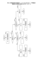
次に、図5を参照して、画像形成装置管理システム10におけるユーザ認証処理について説明する。図5は画像形成装置管理システム10におけるユーザ認証処理を説明するフローチャートである。 Next, the user authentication process in the image forming device management system 10 will be described with reference to FIG. 5. FIG. 5 is a flowchart illustrating the user authentication process in the image forming device management system 10.

画像形成装置17は、ICカードリーダ174よりICカード識別情報を取得し、通信部176により取得されたICカード識別情報を管理サーバ11へ送信する。管理サーバ11において、通信部114によりこのICカード識別情報を受けると、制御部111はこのICカード識別情報に基づき、ユーザ情報格納装置120内のICカード識別情報121を検索する。そして、該当するICカード識別情報がICカード識別情報121に保持されているかを判断する(S51)。 The image forming device 17 acquires IC card identification information from the IC card reader 174, and transmits the acquired IC card identification information via the communication unit 176 to the management server 11. When the management server 11 receives this IC card identification information via the communication unit 114, the control unit 111 searches for the IC card identification information 121 in the user information storage device 120 based on this IC card identification information. Then, it is determined whether the corresponding IC card identification information is held in the IC card identification information 121 (S51).

取得されたICカード識別情報がICカード識別情報121に保持されていた場合、制御部111は、次に、取得されたICカード識別情報に対応したユーザIDをユーザID情報122内より引き出す。そして、管理サーバ11において、ADサーバ13を用いたユーザ認証処理を行う設定となっているどうかを判断する(S52)。 If the acquired IC card identification information is stored in the IC card identification information 121, the control unit 111 next extracts the user ID corresponding to the acquired IC card identification information from the user ID information 122. Then, the control unit 11 determines whether the management server 11 is set to perform user authentication processing using the AD server 13 (S52).

S52において、ADサーバ13を用いたユーザ認証処理を行う設定となっていた場合、制御部111は、ADサーバ13にアクセスし、ADサーバ13に保持されているユーザID情報の中に、引き出されたユーザIDが存在するかどうかを確認する(S53)。 If the setting is such that user authentication processing is to be performed using the AD server 13 in S52, the control unit 111 accesses the AD server 13 and checks whether the extracted user ID is present in the user ID information held in the AD server 13 (S53).

ここで、ADサーバ13内に該当するユーザIDが存在した場合、制御部111はユーザを認証したものとする(S54)。尚、S52において、管理サーバ11でADサーバ13を用いたユーザ認証処理を行う設定がされていない場合、制御部111は、S51においてユーザ情報格納装置120に該当するユーザ情報が保持されていた時点でユーザが認証されたものと判断する。 Here, if the corresponding user ID exists in the AD server 13, the control unit 111 determines that the user has been authenticated (S54). Note that, if the management server 11 is not set to perform user authentication processing using the AD server 13 in S52, the control unit 111 determines that the user has been authenticated at the point in time when the corresponding user information is held in the user information storage device 120 in S51.

S53において、ADサーバ13によるユーザIDの存在確認処理がエラーとなった場合、制御部111は、該当するユーザIDに対応する使用制限情報123に基づき、このユーザIDに対して画像形成装置17の利用を許可するかどうかを判断する(S55)。ここで、利用が許可されたユーザIDであった場合、制御部111はユーザが認証されたものとする。そして、利用が許可されていないユーザIDであった場合、制御部111はログイン処理を失敗したものとしてユーザ認証処理を終了する(S56)。 If an error occurs in the user ID existence confirmation process by the AD server 13 in S53, the control unit 111 determines whether or not to permit the user ID to use the image forming device 17 based on the usage restriction information 123 corresponding to the user ID (S55). If the user ID is permitted for use, the control unit 111 determines that the user has been authenticated. If the user ID is not permitted for use, the control unit 111 determines that the login process has failed and ends the user authentication process (S56).

S54でユーザ認証処理がなされると、管理サーバ11において、制御部111は、使用制限情取得部112により使用制限情報123から認証されたユーザに対応した使用制限情報を取得する。そして、制御部111は、通信部114によりこの取得された使用制限情報を画像形成装置17へ送信する。 When the user authentication process is performed in S54, in the management server 11, the control unit 111 acquires the use restriction information corresponding to the authenticated user from the use restriction information 123 by the use restriction information acquisition unit 112. Then, the control unit 111 transmits the acquired use restriction information to the image forming device 17 by the communication unit 114.

画像形成装置17において、制御部171は、この使用制限情報を受けて、認証されたユーザが使用できる機能のみを実現させるよう、画像形成装置17の処理を制御する。 In the image forming device 17, the control unit 171 receives this usage restriction information and controls the processing of the image forming device 17 so as to realize only the functions that can be used by the authenticated user.

次に、図6、図7を参照して上述した画像形成装置17で実行される個人メニュー処理について説明する。本実施形態でいう「個人メニュー」とは、画像形成装置17に予めユーザIDとパスワードが登録されたユーザだけが使用できる機能の名称である。「個人メニュー」で実行可能な機能は、例えば画像形成装置17内にユーザ毎に蓄積された画像データや電子文書へのアクセス、閲覧、ユーザ個別のアドレス帳の使用、ユーザ個別のメール文書の閲覧などである。さらに、個人メニューが選択された場合は、表示操作装置172に設けられた表示部における表示や、画像形成装置17の設定状態をユーザが個別にカスタマイズすることができる。また、ここで言う個人メニュー処理とは、この個人メニューが選択されたときに画像形成装置17で実行される処理を示すものとする。 Next, the personal menu processing executed by the image forming device 17 described above will be described with reference to Figures 6 and 7. In this embodiment, the "personal menu" is the name of a function that can be used only by a user whose user ID and password have been registered in advance in the image forming device 17. Functions that can be executed using the "personal menu" include, for example, accessing and viewing image data and electronic documents stored for each user in the image forming device 17, using an address book for each user, and viewing email documents for each user. Furthermore, when the personal menu is selected, the user can individually customize the display on the display unit provided in the display operation device 172 and the setting state of the image forming device 17. Moreover, the personal menu processing referred to here refers to the processing executed by the image forming device 17 when this personal menu is selected.

図6は、本実施形態の画像形成装置17における個人メニュー処理の動作を説明するフローチャートである。図7は、個人メニュー処理が選択された際の表示操作装置172の状態を説明する図であり、図7(A)は個人メニューへのログイン前の表示操作装置172の状態を示し、図7(B)は個人メニューへのログイン後の表示操作装置172の状態を示すものである。 Figure 6 is a flowchart explaining the operation of personal menu processing in the image forming device 17 of this embodiment. Figure 7 is a diagram explaining the state of the display operation device 172 when personal menu processing is selected, where Figure 7(A) shows the state of the display operation device 172 before logging in to the personal menu, and Figure 7(B) shows the state of the display operation device 172 after logging in to the personal menu.

画像形成装置17において、ユーザがICカードをICカードリーダ174に翳すことにより、図5で説明したユーザ認証処理が実行される(S61)。ここで、画像形成装置17は、ユーザ認証がなされるまでは表示操作装置172による操作が不可能な状態(以下、この状態をハードキーロックという。)となっている。 When the user holds the IC card over the IC card reader 174 in the image forming device 17, the user authentication process described in FIG. 5 is executed (S61). At this point, the image forming device 17 is in a state in which operation via the display operation device 172 is not possible until user authentication is completed (hereinafter, this state is referred to as the hard key lock).

S61にてユーザ認証がなされ、且つ画像形成装置17の使用を許可されたユーザであった場合、制御部171はこのハードキーロック状態を解除する(S62)。そして、制御部171は、管理サーバ11より送信されたユーザの使用制限情報に基づき、画像形成装置17の状態をユーザの使用可能な機能を実行できる状態へ遷移させる(S63)。 If user authentication is performed in S61 and the user is permitted to use the image forming device 17, the control unit 171 releases the hard key lock state (S62). Then, based on the user's usage restriction information transmitted from the management server 11, the control unit 171 transitions the state of the image forming device 17 to a state in which the functions available to the user can be executed (S63).

ここで、ユーザにより「個人メニュー」処理への実行が選択された場合(S64)、制御部171は、図7(A)に示すように、表示操作装置172に設けられた表示部に「個人メニュー」が選択された旨を表示する(S65)。尚、図6、図7で言う「it機能」とは画像形成装置においてネットワークを介して直接情報の送受信を行う機能の総称であり、本実施形態では個人メニュー処理で実現できる機能も「it機能」に含まれるものとした。 If the user selects to execute the "personal menu" process (S64), the control unit 171 displays on the display unit provided on the display operation device 172 a message indicating that the "personal menu" has been selected (S65), as shown in FIG. 7 (A). Note that the "IT function" in FIG. 6 and FIG. 7 is a general term for functions in the image forming device that directly transmit and receive information via a network, and in this embodiment, the functions that can be realized by the personal menu process are also included in the "IT function".

次に画像形成装置17の制御部171は、個人メニューへのログイン処理を行う(S66)。画像形成装置17では、S61においてICカード識別情報により引き出されたユーザIDに基づいて、パスワード生成部179によりパスワードを生成する。このとき、画像形成装置17内には、予めユーザにより登録されたユーザIDと、このユーザIDに基づいてパスワード生成部179で生成されたパスワードが保持されている。 Next, the control unit 171 of the image forming device 17 performs a login process to the personal menu (S66). In the image forming device 17, the password generation unit 179 generates a password based on the user ID extracted from the IC card identification information in S61. At this time, the image forming device 17 holds the user ID registered in advance by the user and the password generated by the password generation unit 179 based on this user ID.

制御部171は、この保持されているユーザIDとパスワードと、S61で取得されたユーザID及びこのユーザIDから生成されたパスワードが一致しているかどうかを判断する(S67)。 The control unit 171 determines whether the stored user ID and password match the user ID acquired in S61 and the password generated from this user ID (S67).

S67において、画像形成装置17内に該当するユーザIDが保持されていない場合、制御部171はユーザ登録がなされていない新規のユーザと判断し、表示操作装置172にユーザ登録画面を表示させ、ユーザ登録処理へと移行する(S68)。 If the corresponding user ID is not stored in the image forming device 17 in S67, the control unit 171 determines that the user is a new user who has not been registered, and causes the display operation device 172 to display a user registration screen and proceeds to the user registration process (S68).

S67において、パスワードが不正であった場合、制御部171は、表示操作装置172のオンデマンドキー以外のハードキーをロックする(S69)。尚ここで、オンデマンドキーとは、表示操作装置172内に配設された操作部の一つであり、すでに画像形成装置17内に保持された状態の印刷ジョブに対して印刷指示を出すための操作キーである。 If the password is invalid in S67, the control unit 171 locks the hard keys of the display operation device 172 other than the on-demand key (S69). Note that the on-demand key is one of the operation units arranged in the display operation device 172, and is an operation key for issuing a print instruction for a print job that is already held in the image forming device 17.

画像形成装置17において発生するパスワードの不正とは、個人名メニューへのログインに必要な初期パスワードであって、パスワード生成部179により生成されるパスワードを、ユーザがユーザ独自のパスワードへ変更した場合に発生する。そこで、制御部171は、表示操作装置172にパスワードを入力可能なタッチパネルの画面等を表示し、変更後のパスワードの入力が必要である旨を表示する(S70)。S70において、ユーザにより正しいパスワードが入力されると、制御部171は使用制限情報に従ってハードキーロックの状態を解除(S71)し、再度画像形成装置17内に保持されている、予め登録されたユーザIDと変更後のパスワードと、S61で取得されたユーザIDとS70で入力されたパスワードが一致しているか判断する処理へ戻る。 An illegal password occurring in the image forming device 17 is an initial password required for logging in to the personal name menu, and occurs when the user changes the password generated by the password generating unit 179 to a password unique to the user. The control unit 171 then displays a touch panel screen or the like on the display operation device 172 into which a password can be input, and displays a message indicating that the input of the changed password is required (S70). When the user inputs the correct password in S70, the control unit 171 releases the hard key lock state in accordance with the usage restriction information (S71), and returns to the process of determining whether the preregistered user ID and changed password stored in the image forming device 17 match the user ID acquired in S61 and the password input in S70.

S67において、何らかの原因によりログイン処理がエラーとなった場合、制御部171は、S65において表示操作装置172に表示させた「個人メニュー」が選択された旨を消去する(S72)。そして、制御部171は、表示操作装置172に個人メニューへのログイン処理がエラーになった旨を表示する(S73)。 If an error occurs in the login process for some reason in S67, the control unit 171 erases the indication that the "personal menu" displayed on the display operation device 172 in S65 was selected (S72). The control unit 171 then displays on the display operation device 172 a message indicating that an error occurred in the login process to the personal menu (S73).

その後、制御部171は、使用制限情報に基づいて、ユーザが個人メニューにログインしていない状態で使用可能な機能を実現させるべく画像形成装置17を制御する。 Then, the control unit 171 controls the image forming device 17 based on the usage restriction information to realize functions that can be used when the user is not logged in to the personal menu.

S67において、画像形成装置17内に保持されたユーザIDとパスワードと、S61で取得されたユーザID及びこのユーザIDから生成されたパスワードが一致した場合、制御部171はこのユーザの個人メニューへのログインを成功したものとし、個別情報格納部178よりユーザIDに対応した個別情報を取得する。そして、制御部171は、この個別情報に基づき、画像形成装置17の使用に係る設定条件などの制限を行う(S74)。 In S67, if the user ID and password stored in the image forming device 17 match the user ID acquired in S61 and the password generated from this user ID, the control unit 171 determines that the user has successfully logged in to the personal menu, and acquires individual information corresponding to the user ID from the individual information storage unit 178. Then, based on this individual information, the control unit 171 imposes restrictions on the setting conditions and the like related to the use of the image forming device 17 (S74).

次に、制御部171は、表示操作装置172の個人メニュー機能時に使用される操作キーを使用可能な状態とし(S75)、S65において表示操作装置172に表示させた「個人メニュー」が選択された旨を消去する(S76)。そして、制御部171は、パスワード生成部179により生成されたパスワードの情報をユーザが閲覧可能である旨を表示操作装置172に表示する(S77)。これにより、画像形成装置17における個人メニューへのログイン処理が完了し、表示操作装置172には、図7(B)に示すようにユーザ毎の個人メニューが表示される。 Next, the control unit 171 enables the operation keys used during the personal menu function of the display operation device 172 (S75), and erases the indication that the "personal menu" displayed on the display operation device 172 in S65 was selected (S76). The control unit 171 then displays on the display operation device 172 an indication that the user can view the password information generated by the password generation unit 179 (S77). This completes the login process to the personal menu in the image forming device 17, and the display operation device 172 displays the personal menu for each user as shown in FIG. 7(B).

尚本実施形態では、画像形成装置17において、登録されたユーザIDと対応したユーザ名が登録されていても良く、ユーザのログインが完了した直後の画面にユーザ名を表示させても良い。 In this embodiment, a user name corresponding to the registered user ID may be registered in the image forming device 17, and the user name may be displayed on the screen immediately after the user completes login.

S64において、ユーザにより「個人メニュー」処理への実行が選択されない場合、制御部171は、S61で管理サーバ11から取得した使用制限情報の基づき画像形成装置17の制御を行う(S79)。これにより、ユーザは画像形成装置17の使用が可能となる。 If the user does not select to execute the "Personal Menu" process in S64, the control unit 171 controls the image forming device 17 based on the usage restriction information acquired from the management server 11 in S61 (S79). This allows the user to use the image forming device 17.

また、S77において表示操作装置172に表示される、ユーザが閲覧可能なパスワードの情報とは、パスワード生成部179により生成された初期パスワードや、この初期パスワードをユーザ独自のバスワードに変更する際の設定変更に係る情報などである。本実施形態では、S77における表示操作装置172の画面から、パスワード変更を行う設定画面などに遷移することが可能であっても良いし、すでにパスワードを変更済みのユーザであれは、初期パスワードを再度ユーザに通知可能な画面へ遷移させても良い。さらに、ユーザにパスワードを通知する際は、表示操作装置172にパスワードが表示されてから所定の時間が経過すると、表示されたパスワードが自動的に消去される設定となっていても良い。 The password information that is displayed on the display operation device 172 in S77 and that can be viewed by the user includes the initial password generated by the password generation unit 179 and information related to setting changes when changing this initial password to the user's own password. In this embodiment, it may be possible to transition from the screen of the display operation device 172 in S77 to a setting screen for changing the password, or, if the user has already changed the password, to a screen that can notify the user of the initial password again. Furthermore, when notifying the user of the password, the display operation device 172 may be set to automatically erase the displayed password when a predetermined time has elapsed since the password was displayed.

以上に説明したように、本発明の第一の実施形態では、管理サーバによりユーザ識別情報を管理し、このユーザ識別情報に基づいて画像形成装置の使用可能な機能を制限するため、画像形成装置内に保持されているユーザ情報についても、ユーザ情報の管理の安全性が強化され、情報の機密性を維持することができる。 As described above, in the first embodiment of the present invention, user identification information is managed by a management server, and the functions available to the image forming device are restricted based on this user identification information, so that the security of the management of user information stored in the image forming device is enhanced and the confidentiality of the information can be maintained.

また、ユーザ毎に使用可能な制限のみを使用させるため、画像形成装置において無駄な処理が実行されることがなく、使用効率が良い。また、非接触型のICカードによりユーザIDを取得するため、ユーザがログインするたびにユーザIDを入力する必要がなく、操作性を向上させることができる。また、ユーザIDからパスワードを生成するパスワード生成部を有することで、パスワード自体を保持する必要がなくなるため、万が一ユーザ識別情報に係る情報が漏洩した場合でも、パスワードが漏洩することを防止できる。 In addition, because only the available restrictions are used for each user, no unnecessary processing is performed on the image forming device, resulting in good usage efficiency. In addition, because the user ID is obtained using a contactless IC card, there is no need for the user to enter the user ID every time they log in, improving operability. In addition, by having a password generation unit that generates a password from the user ID, there is no need to store the password itself, so even if information related to user identification information is leaked, the password can be prevented from being leaked.

また、本実施形態によれば、ICカードの種類が変更されて、ICカード識別情報の形式が変更された場合でも対応可能である。 In addition, this embodiment can also accommodate cases where the type of IC card is changed and the format of the IC card identification information is changed.

また、本実施形態によれば、画像形成装置で実行された処理が、ユーザ識別情報毎、あるいは実行された処理の種類毎に分類されて記録されるため、画像形成装置で実行された処理の把握が容易となる。 In addition, according to this embodiment, the processes performed on the image forming device are classified and recorded by user identification information or by the type of process performed, making it easy to understand the processes performed on the image forming device.

さらに、本実施形態では、画像形成装置管理システム全体の状態をユーザが閲覧可能に表示させる表示させることが可能であるため、システム全体の動作や、接続されている各機器の状態の把握が容易となる。
(第二の実施形態)
以下に図面を参照して本発明の第二の実施形態について説明する。第二の実施形態は、第一の実施形態を改良したものである。第二の実施形態の説明では、第一の実施形態と同様の機能構成を有するものには第一の実施形態の説明で用いた符号と同様の符号を付与し、説明を省略する。
Furthermore, in this embodiment, the status of the entire image forming device management system can be displayed so that the user can view it, making it easy to understand the operation of the entire system and the status of each connected device.
Second Embodiment
A second embodiment of the present invention will be described below with reference to the drawings. The second embodiment is an improvement of the first embodiment. In the description of the second embodiment, the same reference numerals as those used in the description of the first embodiment are used to designate components having the same functional configuration as those in the first embodiment, and the description thereof will be omitted.

図8は、本発明の第二の実施形態の画像形成装置管理システム10Aのシステム構成図である。画像形成装置管理システム10Aは、管理サーバ11A、ADサーバ13A、ユーザ端末15、印刷サーバ16A、画像形成装置(MFP)17A、管理サーバ11Aを制御する管理端末18とがネットワークを介して接続されて構成される。 Figure 8 is a system configuration diagram of an image forming device management system 10A according to a second embodiment of the present invention. The image forming device management system 10A is configured by connecting a management server 11A, an AD server 13A, a user terminal 15, a print server 16A, an image forming device (MFP) 17A, and a management terminal 18 that controls the management server 11A via a network.

以下に本実施形態の画像形成装置管理システム10Aを構成する各装置について説明する。 The following describes each device that makes up the image forming device management system 10A of this embodiment.

図9は、第二の実施形態の管理サーバ11Aの機能構成図である。 Figure 9 is a functional configuration diagram of the management server 11A in the second embodiment.

管理サーバ11Aは、例えば演算処理装置と記憶装置とを有する一般のコンピュータに、管理サーバ11A用のプログラムをインストールすることにより実現できる。以下に説明する管理サーバ11Aの有する各部は、このプログラムにより実現される機能を示す。 The management server 11A can be realized, for example, by installing a program for the management server 11A on a general computer having a processor and a storage device. Each part of the management server 11A described below indicates the function realized by this program.

管理サーバ11Aは、第一の実施形態の管理サーバ11の有する各部に加え、ユーザ情報管理部130、印刷ジョブ削除指示部140、印刷順序変更部150、ユーザ情報更新ファイル取得部160とを有する。 In addition to the components of the management server 11 of the first embodiment, the management server 11A also includes a user information management unit 130, a print job deletion instruction unit 140, a print order change unit 150, and a user information update file acquisition unit 160.

ユーザ情報管理部130は、ユーザ情報登録部132、ユーザ情報削除部133、ユーザ情報更新部134とを有する。 The user information management unit 130 has a user information registration unit 132, a user information deletion unit 133, and a user information update unit 134.

ユーザ情報登録部132は、ユーザ情報格装置120にユーザ情報を登録する。ユーザ情報削除部133は、ユーザ情報格納装置120からユーザ情報を削除する。ユーザ情報更新部134は、後述するユーザ情報更新情報に基づきユーザ情報格納装置120に格納されているユーザ情報を更新する。 The user information registration unit 132 registers user information in the user information storage device 120. The user information deletion unit 133 deletes user information from the user information storage device 120. The user information update unit 134 updates the user information stored in the user information storage device 120 based on user information update information described below.

印刷ジョブ削除指示部140は、印刷サーバ16Aに蓄積された印刷ジョブを一括で削除させる印刷ジョブ削除指示を生成する。印刷順序変更指示部150は、印刷サーバ16Aに蓄積された印刷ジョブの実行順序を変更させる実行順序変更指示を生成する。 The print job deletion instruction unit 140 generates a print job deletion instruction to collectively delete print jobs stored in the print server 16A. The print order change instruction unit 150 generates an execution order change instruction to change the execution order of print jobs stored in the print server 16A.

ユーザ情報更新ファイル取得部160は、ユーザ情報格納装置120に格納されたユーザ情報を更新するための更新ファイルを取得する。更新ファイルは、例えば管理サーバ11Aにネットワークを介して接続された他の装置により作成されても良い。この場合、管理サーバ11Aは、更新ファイルをダウンロードすることにより取得することができる。また更新ファイルは、例えば管理サーバ11Aと接続されていない一般のコンピュータにより作成されて記録媒体に記録されても良い。この場合管理サーバ11Aは、記録媒体から更新ファイルを読み出すことにより更新ファイルを取得できる。 The user information update file acquisition unit 160 acquires an update file for updating the user information stored in the user information storage device 120. The update file may be created, for example, by another device connected to the management server 11A via a network. In this case, the management server 11A can acquire the update file by downloading it. The update file may also be created, for example, by a general computer that is not connected to the management server 11A and recorded on a recording medium. In this case, the management server 11A can acquire the update file by reading it from the recording medium.

次に図10を参照して本実施形態のADサーバ13Aについて説明する。図10は、第二の実施形態のADサーバ13Aの機能構成図である。 Next, the AD server 13A of this embodiment will be described with reference to FIG. 10. FIG. 10 is a functional configuration diagram of the AD server 13A of the second embodiment.

ADサーバ13Aには、認証情報格納部135と認証処理部138とを有する。認証情報格納部135には、ICカード識別情報121と、このICカード識別情報121に対応したユーザID情報122が組になった情報であるユーザ識別情報136と、ユーザID情報122と紐付けられたパスワード137とが格納されている。ユーザ識別情報136は、例えばシステム管理者などにより予め登録されて格納される。認証処理部138は、認証情報格納部135に格納されたユーザ識別情報が有効か否かを判定してユーザを認証する認証処理を行う。 The AD server 13A has an authentication information storage unit 135 and an authentication processing unit 138. The authentication information storage unit 135 stores user identification information 136, which is a set of IC card identification information 121 and user ID information 122 corresponding to this IC card identification information 121, and a password 137 linked to the user ID information 122. The user identification information 136 is registered and stored in advance, for example, by a system administrator. The authentication processing unit 138 performs authentication processing to determine whether the user identification information stored in the authentication information storage unit 135 is valid and authenticate the user.

次に図11を参照して本実施形態の印刷サーバ16Aについて説明する。図11は、第二の実施形態の印刷サーバ16Aの機能構成図である。 Next, the print server 16A of this embodiment will be described with reference to FIG. 11. FIG. 11 is a functional configuration diagram of the print server 16A of the second embodiment.

印刷サーバ16Aは、第一の実施形態の印刷サーバ16の有する各部に加え、印刷ジョブ削除部164、印刷順序変更部165とを有する。印刷ジョブ削除部164は管理サーバ11Aからの印刷ジョブ削除指示を受けて、印刷命令保持部161に保持されている印刷ジョブを一括削除する。印刷順序変更部165は、管理サーバ11Aからの印刷順序変更指示を受けて、印刷命令保持部161に保持された印刷ジョブの実行順序を変更する。 The print server 16A has a print job deletion unit 164 and a print order change unit 165 in addition to the units of the print server 16 of the first embodiment. The print job deletion unit 164 receives a print job deletion instruction from the management server 11A and deletes all print jobs stored in the print command storage unit 161 at once. The print order change unit 165 receives a print order change instruction from the management server 11A and changes the execution order of the print jobs stored in the print command storage unit 161.

次に、図12を参照して本実施形態の画像形成装置17Aについて説明する。図12は、第二の実施形態の画像形成装置17Aの機能構成図である。 Next, the image forming device 17A of this embodiment will be described with reference to FIG. 12. FIG. 12 is a functional configuration diagram of the image forming device 17A of the second embodiment.

本実施形態の画像形成装置17Aは、ICカードから情報を読み取る際に、任意に設定された領域に記録された情報を読み取ることができる。画像形成装置17Aは、演算処理装置と記憶装置とを有し、画像形成装置17A用のプログラムを演算処理装置に実行させることにより、以下に説明する各部の有する機能を実現する。 When reading information from an IC card, the image forming device 17A of this embodiment can read information recorded in an arbitrarily set area. The image forming device 17A has an arithmetic processing device and a storage device, and by having the arithmetic processing device execute a program for the image forming device 17A, the functions of each part described below are realized.

画像形成装置17Aは、第一の実施形態の画像形成装置17の有する各部に加え、領域設定情報取得部181、領域設定部182、カードリーダ制御部183とを有する。 In addition to the components of the image forming device 17 of the first embodiment, the image forming device 17A also includes an area setting information acquisition unit 181, an area setting unit 182, and a card reader control unit 183.

本実施形態では、画像形成装置17Aの有する領域設定情報取得部181、領域設定部182、カードリーダ制御部183及び情報形式変換部175は、プラグイン180を構成する。プラグイン180は、例えばネットワークを介して画像形成装置17Aと接続された装置からダウンロードされても良い。またプラグイン180は、例えばUSBメモリなどの記録媒体に記録されていても良い。画像形成装置17Aは、例えばUSBメモリスティックの差し込み口などが設けられていることが好ましい。画像形成装置17Aでは、記録媒体に記録されたプラグイン180を読み込んで起動させることでプラグイン180の機能を実現しても良い。 In this embodiment, the area setting information acquisition unit 181, area setting unit 182, card reader control unit 183, and information format conversion unit 175 of the image forming device 17A constitute the plug-in 180. The plug-in 180 may be downloaded from a device connected to the image forming device 17A, for example, via a network. The plug-in 180 may also be recorded on a recording medium such as a USB memory. The image forming device 17A is preferably provided with an insertion port for a USB memory stick, for example. The image forming device 17A may realize the function of the plug-in 180 by reading and starting the plug-in 180 recorded on the recording medium.

以下にプラグイン180を構成する各部について説明する。領域設定情報取得部181は、後述する管理端末18で生成された領域設定情報を取得する。領域設定部182は、領域設定情報取得部181により取得した領域設定情報に基づき領域設定を行う。具体的には領域設定部182は、取得した領域設定情報を記録装置173の領域設定情報格納部184へ格納する。 The components constituting the plug-in 180 are explained below. The area setting information acquisition unit 181 acquires area setting information generated by the management terminal 18, which will be described later. The area setting unit 182 sets areas based on the area setting information acquired by the area setting information acquisition unit 181. Specifically, the area setting unit 182 stores the acquired area setting information in the area setting information storage unit 184 of the recording device 173.

カードリーダ制御部183は、ICカードリーダ174による情報の読み取りを制御する。ICカードリーダ174は、ICカードの情報を読み取る際に領域設定情報格納部184を参照し、設定された領域の情報を読み取る。 The card reader control unit 183 controls the reading of information by the IC card reader 174. When reading information from an IC card, the IC card reader 174 refers to the area setting information storage unit 184 and reads the information of the set area.

情報形式変換部175は、第一の実施形態で説明した通りである。すなわち、ICカードリーダ174から読み取られた情報の形式を、本実施形態の画像形成装置管理システム10Aで取り扱い可能な情報の形式に変換する。 The information format conversion unit 175 is as described in the first embodiment. That is, it converts the format of the information read from the IC card reader 174 into an information format that can be handled by the image forming device management system 10A of this embodiment.

係る構成により、本実施形態の画像形成装置17Aは、異なる規格により情報が記録された複数種類のICカードに対応することができる。尚本実施形態の画像形成装置17Aは、領域設定情報を管理端末18から取得するものとしたが、これに限定されるものではない。領域設定情報は、例えばプラグイン180と同様に記録媒体に記録されていても良い。領域設定情報取得部181は、記録媒体から記録された領域設定情報を取得しても良い。 With this configuration, the image forming device 17A of this embodiment can handle multiple types of IC cards on which information is recorded according to different standards. Note that while the image forming device 17A of this embodiment is configured to acquire area setting information from the management terminal 18, this is not limited to this. The area setting information may be recorded on a recording medium, for example, in the same way as the plug-in 180. The area setting information acquisition unit 181 may acquire the area setting information recorded from the recording medium.

次に、図13を参照して本実施形態の管理端末18について説明する。図13は、第二の実施形態の管理端末18の機能構成図である。 Next, the management terminal 18 of this embodiment will be described with reference to FIG. 13. FIG. 13 is a functional configuration diagram of the management terminal 18 of the second embodiment.

管理端末18は、演算処理装置と記憶装置とを有する一般のコンピュータに、管理端末18用のプログラムをインストールすることにより実現できる。管理端末18の有する各部は、プログラムにより実現される機能を示すものである。 The management terminal 18 can be realized by installing a program for the management terminal 18 on a general computer having a processor and a storage device. Each part of the management terminal 18 represents a function realized by the program.

管理端末18は、表示装置190、制御部191、記憶装置192、領域設定情報生成部193、通信部194とを有する。 The management terminal 18 has a display device 190, a control unit 191, a storage device 192, an area setting information generation unit 193, and a communication unit 194.

表示装置190は、例えば液晶ディスプレイ等であり、管理端末18での処理結果などが表示される。制御部191は、管理端末18で実行される各種の処理の制御を司る。記憶装置192は、演算処理装置による演算結果や、管理端末18の設定情報などが格納される。領域設定情報生成部193は、領域設定情報を生成する。領域設定情報生成部193の処理は、後に図面を参照して詳細に説明する。通信部194は、管理端末18とネットワークを介して接続された各装置との通信を行う。 The display device 190 is, for example, a liquid crystal display, and displays the processing results of the management terminal 18. The control unit 191 controls the various processes executed by the management terminal 18. The storage device 192 stores the results of calculations by the arithmetic processing unit, setting information for the management terminal 18, and the like. The area setting information generation unit 193 generates area setting information. The processing of the area setting information generation unit 193 will be explained in detail later with reference to the drawings. The communication unit 194 communicates with each device connected to the management terminal 18 via the network.

以下に図面を参照して領域情報設定部193における領域設定情報の生成処理について説明する。 The process of generating region setting information in the region information setting unit 193 is described below with reference to the drawings.

図14は、ICカードを説明する図である。図14(A)はICカードAの情報記録フォーマットを説明する図であり、図14(B)は、ICカードAに記録された情報を示す図である。 Figure 14 is a diagram explaining an IC card. Figure 14 (A) is a diagram explaining the information recording format of IC card A, and Figure 14 (B) is a diagram showing the information recorded on IC card A.

ICカードAでは、図14(A)に示すようなフォーマットで情報が記録されている。図14(A)に示す例では、ICカード識別情報が先頭に記録されており、ブロック1に社員番号の情報、ブロック2にはICカードAの発行回数の情報、ブロック3にはICカードAの発行日の情報、ブロック4にはICカードAの有効期限の情報が記録されている。 In IC card A, information is recorded in the format shown in Figure 14 (A). In the example shown in Figure 14 (A), IC card identification information is recorded at the beginning, employee number information is recorded in block 1, information on the number of times IC card A has been issued is recorded in block 2, information on the issue date of IC card A is recorded in block 3, and information on the expiration date of IC card A is recorded in block 4.

図14(A)に示すフォーマットは、ICカードの規格毎に異なるものであり、ICカードを発行する発行業者により予め決められている。またICカードに記録されている情報の形式もICカードの規格毎に異なる。例えばFelica(登録商標)カードであればFelica(登録商標)カード専用のフォーマットにFelica(登録商標)カードの情報形式で情報が記録されている。また例えばeLWISEカードであれば、eLWISEカード専用のフォーマットにeLWISEカードの情報形式で情報が記録されている。 The format shown in FIG. 14(A) differs for each IC card standard and is predetermined by the issuer that issues the IC card. The format of the information recorded on the IC card also differs for each IC card standard. For example, in the case of a Felica (registered trademark) card, information is recorded in a Felica (registered trademark) card information format in a format specifically for Felica (registered trademark) cards. Also, for example, in the case of an eLWISE card, information is recorded in an eLWISE card information format in a format specifically for eLWISE cards.

図14(B)では、ICカードAに記録された各情報の領域の場所を示している。例えば社員番号が記録された領域であるブロック1は、アドレス0から開始し、アドレス9で終了することがわかる。 Figure 14 (B) shows the location of each information area recorded on IC card A. For example, it can be seen that block 1, which is the area in which employee numbers are recorded, starts at address 0 and ends at address 9.

本実施形態の管理端末18では、図14に示すようなICカードAのフォーマット情報を用いて領域設定情報を生成する。尚ICカードAのフォーマット情報は、予めICカード発行業者から提供されているものとした。 In this embodiment, the management terminal 18 generates area setting information using the format information of IC card A as shown in FIG. 14. Note that the format information of IC card A is assumed to be provided in advance by the IC card issuer.

管理端末18の有する領域設定情報生成部193は、領域設定プログラムにより実現される機能である。管理端末18では、管理端末18を操作するユーザにより領域設定情報の生成が指示されると、領域設定プログラムが起動する。 The area setting information generation unit 193 of the management terminal 18 is a function realized by an area setting program. When a user operating the management terminal 18 instructs the management terminal 18 to generate area setting information, the area setting program is started.

領域設定プログラムでは、ICカードAから情報を読み取る領域を設定することができる。領域設定プログラムは、管理端末18の表示装置190に読取情報の領域を設定する設定画面を表示させる。図15に、情報を読み取る領域の種類を設定する設定画面の一例を示す。本実施形態の領域設定プログラムでは、図15に示すように、ICカードAから情報を読み取る領域の種類として、カード識別情報記録領域、ICカードA内の任意の領域、規格フォーマットのしたがった領域のいずれを選択して設定することができる。 The area setting program can set the area from which information is read from IC card A. The area setting program displays a setting screen for setting the area for reading information on the display device 190 of the management terminal 18. FIG. 15 shows an example of a setting screen for setting the type of area from which information is read. As shown in FIG. 15, the area setting program of this embodiment can select and set the type of area from which information is read from IC card A as either a card identification information recording area, any area within IC card A, or an area conforming to a standard format.

また本実施形態では、1種類のICカードにつき、4パターンの領域設定情報を設定することができる。尚、ICカードの種類とは、ICカードの規格の種類を示す。 In this embodiment, four patterns of area setting information can be set for one type of IC card. Note that the type of IC card refers to the type of IC card standard.

図15の設定画面において、情報を読み取る領域にICカード識別情報が選択された場合、領域設定プログラムは、情報を読み取る領域をICカードA記録された先頭の領域にとする。ICカード識別情報の記録領域は、システム管理者などにより、予め設定されていても良い。本実施形態の領域設定プログラムでは、情報を読み取る領域にICカード識別情報が選択された場合、この設定に基づき情報を読み取る領域をICカード識別情報が記録された領域とする。 When IC card identification information is selected as the area from which information is to be read on the setting screen of FIG. 15, the area setting program sets the area from which information is to be read to the first area recorded on IC card A. The recording area of the IC card identification information may be set in advance by a system administrator or the like. In the area setting program of this embodiment, when IC card identification information is selected as the area from which information is to be read based on this setting, the area from which information is to be read is set to the area in which the IC card identification information is recorded.

また図15の設定画面において、情報を読み取る領域に規格フォーマットのしたがった領域が選択された場合、領域設定プログラムは、情報を読み取る領域を規格フォーマットにしたがった領域とする。規格フォーマットは、予めICカードAの発行業者からシステム管理者に提供されており、管理端末18に設定されている。具体的には規格フォーマットにしたがった場合に、例えばICカード識別情報が記録されている領域を示す情報、社員番号が記録されている領域を示す情報などがフォーマット情報として管理端末18に格納されている。領域設定プログラムは、管理端末18に格納されたフォーマット情報に基づき情報を読み取る領域を設定する。 In addition, when an area conforming to a standard format is selected as the area from which information is to be read on the setting screen of FIG. 15, the area setting program sets the area from which information is to be read to an area conforming to the standard format. The standard format is provided in advance to the system administrator by the issuer of IC card A and is set in the management terminal 18. Specifically, when the standard format is followed, information indicating the area in which IC card identification information is recorded, information indicating the area in which an employee number is recorded, etc., is stored in the management terminal 18 as format information. The area setting program sets the area from which information is to be read based on the format information stored in the management terminal 18.

次に、図15の設定画面においてICカードAから情報を読み取る領域の種類として、ICカードA内の任意の領域が選択された場合について説明する。 Next, we will explain what happens when an arbitrary area on IC card A is selected as the type of area from which information is to be read from IC card A on the setting screen in Figure 15.

以下に図16を参照して、ICカードAの領域設定について説明する。図16は、ICカードAの領域設定情報を生成する領域設定情報生成画面が表示された例を示す図である。図16には、ICカード内に記録された情報を読み取る場合の領域設定情報生成画面を示している。 Below, the area setting of IC card A will be explained with reference to FIG. 16. FIG. 16 is a diagram showing an example of an area setting information generation screen that generates area setting information for IC card A. FIG. 16 shows the area setting information generation screen when reading information recorded in an IC card.

領域設定情報生成画面には、情報を読み取るブロックを指定するブロック指定部190A、指定されたブロック内の位置を指定する位置指定部190B、読み取られる情報の項目が表示される情報一覧部190Cとが設けられている。図16に示す例では、ブロック指定部190AにおいてICカードAのブロック1、ブロック3が指定されている。また位置指定部190Bにおいて、ブロック1、ブロック3の全データが指定されている。したがって本実施形態では、ICカードのブロック1及びブロック3に記録された全データを取得することを示す領域設定情報が生成される。 The area setting information generation screen is provided with a block designation section 190A for designating a block from which information is to be read, a position designation section 190B for designating a position within the designated block, and an information list section 190C in which the items of information to be read are displayed. In the example shown in FIG. 16, blocks 1 and 3 of IC card A are designated in block designation section 190A. Furthermore, all data in blocks 1 and 3 is designated in position designation section 190B. Therefore, in this embodiment, area setting information is generated that indicates that all data recorded in blocks 1 and 3 of the IC card will be acquired.

情報一覧部190Cには、領域設定情報により取得される情報の項目として、ブロック1に記録された全データである社員番号と、ブロック3に記録された全データである有効期限とが表示される。よって本実施形態の領域設定プログラムによれば、領域設定情報生成画面により、読み取られる情報の項目を確認しながらブロックの指定及びブロック内の情報の位置指定を行うことができる。このため、例えばシステム管理者などにより領域設定情報が生成される際に、簡単な操作で領域設定情報を生成することができる。 Information list section 190C displays the employee number, which is all data recorded in block 1, and the expiration date, which is all data recorded in block 3, as items of information obtained by the area setting information. Therefore, according to the area setting program of this embodiment, the area setting information generation screen allows the user to specify a block and the position of the information within the block while checking the items of information to be read. Therefore, when area setting information is generated by a system administrator, for example, the area setting information can be generated with simple operations.

管理端末18において生成された領域設定情報は、例えばネットワークを介して画像形成装置17Aに提供される。また領域設定情報は、管理端末18においてUSBメモリなどの記録媒体に記録されても良い。画像形成装置17Aは、記録媒体に記録された領域設定情報を読み取り、領域設定情報を取得する。また本実施形態では、領域設定プログラムは管理端末18にインストールされるものとしたが、これに限定されるものではない。領域設定プログラムは、例えばユーザ端末15にインストールされても良い。また領域設定プログラムは、画像形成装置17Aと接続されていない、一般のコンピュータにインストールされており、生成された領域設定情報が記録媒体に記録されて画像形成装置17Aに提供されても良い。 The area setting information generated in the management terminal 18 is provided to the image forming device 17A, for example, via a network. The area setting information may also be recorded on a recording medium such as a USB memory in the management terminal 18. The image forming device 17A reads the area setting information recorded on the recording medium and acquires the area setting information. In the present embodiment, the area setting program is installed in the management terminal 18, but this is not limited to this. The area setting program may also be installed in the user terminal 15, for example. The area setting program may also be installed in a general computer that is not connected to the image forming device 17A, and the generated area setting information may be recorded on a recording medium and provided to the image forming device 17A.

次に、本実施形態の画像形成装置17Aにおけるプラグイン180の動作について説明する。画像形成装置17Aでは、プログラムラグイン180が動作することにより、領域設定情報に基づく情報をICカードから読み取ることができる。図17は、画像形成装置17Aにおけるプラグイン180の動作を説明するフローチャートである。 Next, the operation of the plug-in 180 in the image forming device 17A of this embodiment will be described. In the image forming device 17A, the program plug-in 180 operates to read information based on the area setting information from the IC card. FIG. 17 is a flowchart that describes the operation of the plug-in 180 in the image forming device 17A.

プラグイン180は、ステップS170において、実行されるプランインとして選択されると処理を開始する。以下にプラグインの選択について説明する。 When the plugin 180 is selected as the plugin to be executed in step S170, it starts processing. The selection of the plugin is explained below.

本実施形態の画像形成装置17Aは、プラグイン180の他にもICカードからの情報の読み取りを制御するための複数種類のプラグインを有する。システム管理者は、画像形成装置17Aで実行するプラグインを選択することができる。プラグインの選択は、例えば画像形成装置管理システム10Aを管理するための管理者ツールにより行われる。管理者ツールは、管理端末18が備えていても良いし、画像形成装置17Aが備えていても良い。 In this embodiment, the image forming device 17A has multiple types of plug-ins for controlling the reading of information from IC cards in addition to the plug-in 180. A system administrator can select the plug-in to be executed by the image forming device 17A. The selection of the plug-in is performed, for example, by an administrator tool for managing the image forming device management system 10A. The administrator tool may be provided in the management terminal 18 or in the image forming device 17A.

画像形成装置17Aの有する他のプラグインとしては、例えばSSFC(Shared Security Formats Cooperation)の規格に沿ったSSFCプラグインや、eLWISEカードの規格に沿ったeLWISEプラグインなどがある。例えばSSFC(登録商標)プラグインが選択された場合には、SSFC(登録商標)プラインが実行されて、画像形成装置17AはICカードからSSFC(登録商標)の規格フォーマットにしたがって情報を読み取る。尚本実施形態のプラグイン180は、例えばFelica(登録商標)の規格に沿ったFelica(登録商標)プラグインとして適用されても良い。 Other plug-ins that the image forming device 17A has include, for example, an SSFC plug-in that complies with the SSFC (Shared Security Formats Cooperation) standard, and an eLWISE plug-in that complies with the eLWISE card standard. For example, when the SSFC (registered trademark) plug-in is selected, the SSFC (registered trademark) plug-in is executed, and the image forming device 17A reads information from the IC card in accordance with the SSFC (registered trademark) standard format. Note that the plug-in 180 of this embodiment may also be applied as, for example, a Felica (registered trademark) plug-in that complies with the Felica (registered trademark) standard.

図18は、画像形成装置17Aで実行されるプラグインの選択画面の一例を示す図である。この選択画面は、管理サーバ11Aを制御する管理端末18の備える表示装置に表示されても良いし、画像形成装置17Aの表示操作装置172に表示されても良い。本実施形態の画像形成装置17Aは、図18に示す選択画面においてプラグイン180が選択されると、この選択指示を実行指示としてプラグイン180を実行させる。 Figure 18 is a diagram showing an example of a selection screen for a plug-in to be executed by the image forming device 17A. This selection screen may be displayed on a display device provided in the management terminal 18 that controls the management server 11A, or may be displayed on the display operation device 172 of the image forming device 17A. When a plug-in 180 is selected on the selection screen shown in Figure 18, the image forming device 17A of this embodiment executes the plug-in 180, taking the selection instruction as an execution instruction.

画像形成装置17Aは、ステップS170に続いてステップS171へ進む。画像形成装置17Aにおいてプラグイン180が実行されると、領域設定情報取得部181が領域設定情報を取得する。領域設定情報取得部181は、管理端末18からネットワークを介して領域設定情報を取得しても良いし、記録媒体に記録された領域設定情報を取得しても良い。ステップS171に続いてステップS172へ進み、領域設定部182は、取得した領域設定情報を画像形成装置17Aに設定する。すなわち領域設定部182は、選択された領域設定情報を領域設定情報格納部184に格納する。ここで画像形成装置17Aにおける領域設定情報の設定が完了する。 After step S170, the image forming device 17A proceeds to step S171. When the plug-in 180 is executed in the image forming device 17A, the area setting information acquisition unit 181 acquires the area setting information. The area setting information acquisition unit 181 may acquire the area setting information from the management terminal 18 via a network, or may acquire the area setting information recorded on a recording medium. After step S171, the process proceeds to step S172, where the area setting unit 182 sets the acquired area setting information in the image forming device 17A. That is, the area setting unit 182 stores the selected area setting information in the area setting information storage unit 184. This completes the setting of the area setting information in the image forming device 17A.

ステップS172に続いてステップS173へ進み、ICカードAがICカードリーダ174に翳されると、ICカードリーダ174はカードリーダ制御部183の制御に基づきICカードAの設定された領域に記録された情報を読み取る。カードリーダ制御部183は、領域設定情報格納部184に格納された領域設定情報を参照し、参照した領域設定情報に基づきICカードリーダ174の情報の読み取りを制御する。尚ICカードリーダ174は、ICカードAが翳されたときにICカードAのフォーマット情報を取得しても良い。 Proceeding to step S173 following step S172, when IC card A is held up to IC card reader 174, IC card reader 174 reads the information recorded in the set area of IC card A under the control of card reader control unit 183. Card reader control unit 183 refers to the area setting information stored in area setting information storage unit 184, and controls IC card reader 174 to read information based on the referred area setting information. Note that IC card reader 174 may obtain format information of IC card A when IC card A is held up.

尚本実施形態の領域設定プログラムでは、1種類のICカードに対し4パターンの領域設定情報を生成することができる。したがって画像形成装置17Aでは、複数パターンの領域設定情報を取得して設定する場合がある。画像形成装置17Aにおいて複数パターンの領域設定情報が設定された場合、カードリーダ制御部183は、最初に取得した領域設定情報から順に、各領域設定情報がICカードAのフォーマットと対応しているか否かを判別する。カードリーダ制御部183は、ICカードのフォーマットと対応すると判別された領域設定情報に基づき、ICカードリーダ174による情報の読み取りを制御する。 In the area setting program of this embodiment, four patterns of area setting information can be generated for one type of IC card. Therefore, the image forming device 17A may acquire and set multiple patterns of area setting information. When multiple patterns of area setting information are set in the image forming device 17A, the card reader control unit 183 determines whether each piece of area setting information corresponds to the format of IC card A, starting from the area setting information acquired first. The card reader control unit 183 controls the reading of information by the IC card reader 174, based on the area setting information that is determined to correspond to the IC card format.

ステップS173に続いてステップS174へ進み、ICカードリーダ174により情報が読み取られると、情報形式変換部175は、読み取られた情報を所定の情報の形式へ変換する。所定の形式とは、本実施形態の画像形成装置管理システム10Aにおいて取り扱われる情報の形式であり画像形成装置17Aにおいて処理可能な情報の形式である。例えば画像形成装置17AがFelica(登録商標)カードの形式の情報に対応した仕様であった場合に、ICカードリーダ174から読み取った情報がeLWISEカードの形式であった場合、情報形式変換部175は読み取った情報の形式をFelica(登録商標)カードの形式へ変換する。尚ICカードリーダ174により読み取った情報が画像形成装置17Aで処理可能な形式の情報であった場合、情報形式変換部175は情報形式の変換処理は行わなくてもよい。 After step S173, the process proceeds to step S174, where information is read by IC card reader 174, and information format conversion unit 175 converts the read information into a predetermined information format. The predetermined format is an information format handled by image forming device management system 10A of this embodiment and an information format that can be processed by image forming device 17A. For example, if image forming device 17A has specifications compatible with information in Felica (registered trademark) card format, and the information read from IC card reader 174 is in eLWISE card format, information format conversion unit 175 converts the format of the read information into the Felica (registered trademark) card format. Note that if the information read by IC card reader 174 is in a format that can be processed by image forming device 17A, information format conversion unit 175 does not need to convert the information format.

ステップS174に続いてステップS175へ進み、画像形成装置17Aは、情報形式変換部175により形式が変更された情報を管理サーバ11Aへ送信する。管理サーバ11Aは、画像形成装置17Aから送信された情報を用いてユーザのログイン処理を実行する。 After step S174, the process proceeds to step S175, where the image forming device 17A transmits the information whose format has been changed by the information format conversion unit 175 to the management server 11A. The management server 11A executes the user login process using the information transmitted from the image forming device 17A.

以上に説明したように、本実施形態の画像形成装置17Aでは、ICカードにおいて情報を読み取る領域を設定し、設定された領域に記録された情報を読み取ることができる。このため画像形成装置17Aでは、画像形成装置管理システム10Aの使用環境に合わせてICカードから読み取る情報を設定することができる。また本実施形態の画像形成装置17Aでは、読み取った情報の形式を画像形成装置17Aで処理可能な形式へ変換することができる。したがって本実施形態の画像形成装置17Aによれば、規格の異なる複数種類のICカードリーダに対応することができる。このため画像形成装置17Aの汎用性を向上させることができる。 As described above, the image forming device 17A of this embodiment can set an area on the IC card from which information is to be read, and can read the information recorded in the set area. Therefore, the image forming device 17A can set the information to be read from the IC card according to the usage environment of the image forming device management system 10A. Furthermore, the image forming device 17A of this embodiment can convert the format of the read information into a format that can be processed by the image forming device 17A. Therefore, the image forming device 17A of this embodiment can support multiple types of IC card readers with different standards. This can improve the versatility of the image forming device 17A.

次に本実施形態のログイン処理について説明する。本実施形態の画像形成装置管理システム10Aでは、例えばユーザがICカードを忘れた場合にも、ユーザID情報とパスワードとを入力することによりログインすることができる。 Next, the login process of this embodiment will be described. In the image forming device management system 10A of this embodiment, even if a user forgets his or her IC card, the user can still log in by entering user ID information and a password.

図19は、第二の実施形態におけるログイン処理を説明するフローチャートである。 Figure 19 is a flowchart explaining the login process in the second embodiment.

画像形成装置17Aの表示操作装置172には、ログイン処理が開始される前の待ち受け画面には、キーボード画面の表示を指示する指示ボタン172Aが設けられている。
図20は、第二の実施形態の画像形成装置17Aにおける表示画面の一例を示す図であり、図20(A)に表示操作装置172に表示された待ち受け画面の一例を示す。また図20(B)に表示操作装置172に表示されたキーボード画面の一例を示す。図20(A)に示すように、本実施形態の画像形成装置17Aでは、待ち受け画面にキーボード入力指示ボタン172Aが設けられている。
The display operation device 172 of the image forming apparatus 17A has an instruction button 172A for instructing the display of a keyboard screen on the standby screen before the login process is started.
Fig. 20 is a diagram showing an example of a display screen in the image forming apparatus 17A of the second embodiment, and Fig. 20(A) shows an example of a standby screen displayed on the display operation device 172. Fig. 20(B) shows an example of a keyboard screen displayed on the display operation device 172. As shown in Fig. 20(A), in the image forming apparatus 17A of this embodiment, a keyboard input instruction button 172A is provided on the standby screen.

画像形成装置17Aは、ステップS191においてキーボード入力指示ボタン172Aによりキーボード入力指示がなされるとステップS192へ進み、図20(B)に示すようなキーボード画面を表示操作装置172に表示させる。 When a keyboard input instruction is given by using the keyboard input instruction button 172A in step S191, the image forming device 17A proceeds to step S192 and displays a keyboard screen such as that shown in FIG. 20(B) on the display operation device 172.

ステップS192に続いてステップS193へ進み、画像形成装置17Aはキーボード画面から入力されたユーザID情報とパスワードとを取得する。ステップS193に続いてステップS194へ進み、ADサーバ13Aにおいて取得したユーザID情報とパスワードの認証処理を行う。画像形成装置17Aは、取得したユーザID情報とパスワードとを管理サーバ11Aを介してADサーバ13Aへ送信する。ADサーバ13Aでは、認証情報格納部135に格納された情報と認証処理部138により、取得したユーザID情報とパスワードと有効であるか否かを判断する。ADサーバ13Aは、取得したユーザID情報とパスワードと有効であったとき、ユーザを認証する。 After step S192, the process proceeds to step S193, where the image forming device 17A acquires the user ID information and password entered from the keyboard screen. After step S193, the process proceeds to step S194, where the AD server 13A performs authentication processing of the acquired user ID information and password. The image forming device 17A transmits the acquired user ID information and password to the AD server 13A via the management server 11A. The AD server 13A determines whether the acquired user ID information and password are valid based on the information stored in the authentication information storage unit 135 and the authentication processing unit 138. If the acquired user ID information and password are valid, the AD server 13A authenticates the user.

ステップS195においてユーザが認証された場合、ステップS196へ進んで管理サーバ11Aはユーザのログインを許可し、ログイン処理を終了する。 If the user is authenticated in step S195, the process proceeds to step S196, where the management server 11A permits the user to log in and terminates the login process.

ステップS195においてユーザが認証されない場合、ステップS197へ進み、画像形成装置17Aの表示操作装置172に認証エラーのメッセージを表示させる。ステップS197からステップS198へ進み、画像形成装置17Aは、認証エラーの履歴情報を取得して、実行履歴情報格納部177へ格納する。尚認証エラー履歴情報は、管理サーバ11Aに格納されても良い。 If the user is not authenticated in step S195, the process proceeds to step S197, where an authentication error message is displayed on the display operation device 172 of the image forming device 17A. The process proceeds from step S197 to step S198, where the image forming device 17A obtains authentication error history information and stores it in the execution history information storage unit 177. The authentication error history information may also be stored in the management server 11A.

このように本実施形態の画像形成装置17Aでは、ICカードを所持していなくてもキーボートによりユーザID情報とパスワードを入力することによりログイン処理を行うことができる。したがって本実施形態では、例えばユーザがICカードを忘れた場合でも、臨時のICカードなどを発行せずに、ユーザの使用制限情報に基づいて画像形成装置17Aを使用させることができる。 In this way, in the image forming device 17A of this embodiment, even if the user does not have an IC card, the login process can be performed by inputting user ID information and a password via the keyboard. Therefore, in this embodiment, even if the user forgets his or her IC card, the image forming device 17A can be used based on the user's usage restriction information without issuing a temporary IC card or the like.

尚本実施形態の画像形成装置管理システム10Aでは、ADサーバ13Aを4台まで設置することができる。係る構成によれば、例えば一台のADサーバ13Aが動作不良を起こした場合にも他のADサーバ13Aで対応することができる。また本実施形態では、画像形成装置17Aの表示操作装置172に指示ボタン172Aを表示させるか否かが、システム管理者により予め設定されていても良い。画像形成装置管理システム10Aにおいて、指示ボタン172Aを表示させる設定となっていた場合には、ADサーバ13Aは、キーボード画面から入力されたユーザ識別情報の認証を行う。 In the image forming device management system 10A of this embodiment, up to four AD servers 13A can be installed. With this configuration, for example, if one AD server 13A malfunctions, the other AD servers 13A can handle it. Also, in this embodiment, the system administrator may set in advance whether or not to display the instruction button 172A on the display operation device 172 of the image forming device 17A. If the image forming device management system 10A is set to display the instruction button 172A, the AD server 13A authenticates the user identification information entered from the keyboard screen.

次に本実施形態の管理サーバ11Aにおけるユーザ情報の管理について説明する。 Next, we will explain how to manage user information in the management server 11A of this embodiment.

本実施形態の管理サーバ11Aでは、ユーザ情報格納装置120に格納されているユーザ情報の登録、削除、更新を行うことができる。 In this embodiment, the management server 11A can register, delete, and update user information stored in the user information storage device 120.

図21は、第二の実施形態の管理サーバ11Aにおけるユーザ情報の登録及び削除を説明するフローチャートである。 Figure 21 is a flowchart explaining the registration and deletion of user information in the management server 11A of the second embodiment.

管理サーバ11Aは、画像形成装置17AにおいてICカードリーダ174がICカード識別情報121を読み取ると、ステップS211に進み、画像形成装置17AからICカード識別情報を取得する。 When the IC card reader 174 in the image forming device 17A reads the IC card identification information 121, the management server 11A proceeds to step S211 and acquires the IC card identification information from the image forming device 17A.

ステップS211に続いてステップS212へ進み、管理サーバ11Aは取得したICカード識別情121報とユーザ情報格納装置120に格納されたユーザ情報とに基づき、取得したICカード識別情報121の認証処理を行う。S212においてICカード識別情報121が認証されなかった場合、管理サーバ11AはこのICカード識別情報をADサーバ13Aへ送信する。ステップS213に進み、ADサーバ13Aの認証処理部138は、取得したICカード識別情報とユーザ識別情報135とに基づき、取得したICカード識別情報121の認証処理を行う。 Proceeding to step S212 following step S211, the management server 11A performs authentication processing of the acquired IC card identification information 121 based on the acquired IC card identification information 121 information and the user information stored in the user information storage device 120. If the IC card identification information 121 is not authenticated in S212, the management server 11A transmits this IC card identification information to the AD server 13A. Proceeding to step S213, the authentication processing unit 138 of the AD server 13A performs authentication processing of the acquired IC card identification information 121 based on the acquired IC card identification information and user identification information 135.

ステップS213において、ADサーバ13Aが取得したICカード識別情報121を認証しなかった場合、ADサーバ13Aは管理サーバ11Aを介して画像形成装置17Aに認証エラーのメッセージを送信する。ステップS214へ進み、画像形成装置17Aの表示操作装置172には認証エラーのメッセージが表示される。 In step S213, if the AD server 13A does not authenticate the acquired IC card identification information 121, the AD server 13A sends an authentication error message to the image forming device 17A via the management server 11A. The process proceeds to step S214, where the authentication error message is displayed on the display operation device 172 of the image forming device 17A.

ステップS213において、ADサーバ13Aが取得したICカード識別情報121を認証した場合、管理サーバ11Aは、ADサーバ13Aからユーザが認証された旨を示すメッセージを受けとる。管理サーバ11Aはこのメッセージを受けて、ステップS215へ進み、ユーザをログインさせる。 In step S213, if the AD server 13A authenticates the acquired IC card identification information 121, the management server 11A receives a message from the AD server 13A indicating that the user has been authenticated. Upon receiving this message, the management server 11A proceeds to step S215 and logs in the user.

ステップS215に続いてステップS216へ進み、管理サーバ11Aは、ユーザ情報登録部132により、ADサーバ13Aで認証されたICカード識別情報121に対応したユーザ識別情報136をユーザ情報格納部120へ登録する。 After step S215, the process proceeds to step S216, where the management server 11A causes the user information registration unit 132 to register the user identification information 136 corresponding to the IC card identification information 121 authenticated by the AD server 13A in the user information storage unit 120.

具体的にはユーザ情報登録部132は、ADサーバ13AにおいてICカード識別情報121が認証された旨のメッセージを受けて、ADサーバ13Aから認証されたICカード識別情報121に対応したユーザID情報122を取得する。そしてユーザ情報登録部132は、ICカード識別情報121とユーザID情報122(ユーザ識別情報136)とに使用制限情報を紐付けしてユーザ情報格納装置120へ格納する。ユーザ識別情報136に紐付けされる使用制限情報は、初期設定として予めユーザ情報格納装置120に格納されている情報である。本実施形態では、使用制限情報が初期設定の状態である場合、画像形成装置17Aの全ての機能が使用可能となる。 Specifically, the user information registration unit 132 receives a message that the IC card identification information 121 has been authenticated by the AD server 13A, and obtains the user ID information 122 corresponding to the authenticated IC card identification information 121 from the AD server 13A. The user information registration unit 132 then links the use restriction information to the IC card identification information 121 and the user ID information 122 (user identification information 136) and stores them in the user information storage device 120. The use restriction information linked to the user identification information 136 is information that is stored in advance in the user information storage device 120 as an initial setting. In this embodiment, when the use restriction information is in the initial setting state, all functions of the image forming device 17A are available.

このように本実施形態では、ICカード識別情報121が管理サーバ11Aにおいて認証されず、ADサーバ13Aにおいて認証された場合、ユーザが認証されたものとする。そして管理サーバ11Aは、ICカード識別情報121に対応したユーザID情報122をADサーバ13Aから取得し、初期設定の使用制限情報と紐付けして管理サーバ11Aのユーザ情報格納装置120へ登録する。 In this manner, in this embodiment, if the IC card identification information 121 is not authenticated by the management server 11A but is authenticated by the AD server 13A, the user is deemed to be authenticated. The management server 11A then obtains the user ID information 122 corresponding to the IC card identification information 121 from the AD server 13A, links it to the initial setting usage restriction information, and registers it in the user information storage device 120 of the management server 11A.

よってシステム管理者は、画像形成装置管理システム10Aの新たなユーザの情報を登録する際に、ユーザ識別情報136をADサーバ13Aにのみ登録すれば良い。このため本実施形態の画像形成装置管理システム10Aは、ADサーバ13A及び管理サーバ11Aの両方にユーザ識別情報を登録する必要がなくなり、システム管理者の負担を軽減することができる。 Therefore, when registering information about a new user in the image forming device management system 10A, the system administrator only needs to register the user identification information 136 in the AD server 13A. As a result, the image forming device management system 10A of this embodiment eliminates the need to register user identification information in both the AD server 13A and the management server 11A, reducing the burden on the system administrator.

ステップS212において、管理サーバ11AでICカード識別情報121を認証した場合、管理サーバ11Aは、ICカード識別情報121と、ICカード識別情報121とユーザID情報122とからなるユーザ識別情報136をADサーバ13Aへ送信する。ステップS212に続いてステップS217へ進み、ADサーバ13Aは、ユーザ識別情報136の認証処理を行う。ADサーバ13Aがユーザ識別情報136を認証した場合、ステップS218へ進み、管理サーバ11Aはユーザをログインさせる。 In step S212, if the management server 11A authenticates the IC card identification information 121, the management server 11A transmits the IC card identification information 121 and user identification information 136 consisting of the IC card identification information 121 and the user ID information 122 to the AD server 13A. Following step S212, the process proceeds to step S217, where the AD server 13A performs authentication processing of the user identification information 136. If the AD server 13A authenticates the user identification information 136, the process proceeds to step S218, where the management server 11A logs in the user.

ステップS217においてADサーバ13Aがユーザ識別情報136を認証しない場合、ステップS219へ進み、管理サーバ11AはこのICカード識別情報121を無効として認証エラーのメッセージを画像形成装置17Aへ送信する。ステップS219に続いてステップS220へ進み、管理サーバ11Aにおいてユーザ情報削除部133は、ユーザ情報格納装置120から、ADサーバ13Aで認証されなかったICカード識別情報121と、これに対応したユーザID情報122及び使用制限情報とを削除する。 If the AD server 13A does not authenticate the user identification information 136 in step S217, the process proceeds to step S219, where the management server 11A invalidates the IC card identification information 121 and sends an authentication error message to the image forming device 17A. Following step S219, the process proceeds to step S220, where the user information deletion unit 133 in the management server 11A deletes from the user information storage device 120 the IC card identification information 121 that was not authenticated by the AD server 13A, as well as the corresponding user ID information 122 and usage restriction information.

したがって本実施形態によれば、管理サーバ11A内に無効なユーザ情報が格納されていた場合に、これを自動的に削除することができる。 Therefore, according to this embodiment, if invalid user information is stored in the management server 11A, it can be automatically deleted.

また本実施形態では、ユーザ情報更新部134により、上述したユーザ情報の登録及び削除を含むユーザ情報の更新を行うことができる。 In addition, in this embodiment, the user information update unit 134 can update user information, including registering and deleting the user information described above.

図21で説明したユーザ情報の登録及び削除処理では、登録及び削除処理の対象となるユーザのICカード識別情報を取得した場合にのみ実行する。これに対しユーザ情報更新部134は、定期的にユーザ情報格納装置120に格納されたユーザ情報を更新する。 The user information registration and deletion process described in FIG. 21 is executed only when the IC card identification information of the user who is the target of the registration and deletion process is obtained. In response to this, the user information update unit 134 periodically updates the user information stored in the user information storage device 120.

管理サーバ11Aでは、更新ファイル取得部160により、予め作成されたユーザ情報を更新するための更新ファイルを定期的に取得する。更新ファイルを取得すると、ユーザ情報更新部134は、更新ファイルに基づきユーザ情報格納装置120に格納されたユーザ情報を書き換えて更新する。 In the management server 11A, the update file acquisition unit 160 periodically acquires an update file for updating pre-created user information. When the update file is acquired, the user information update unit 134 rewrites and updates the user information stored in the user information storage device 120 based on the update file.

ここで、更新ファイルについて説明する。 Now let's explain about the update files.

更新ファイルは、主にICカード識別情報とユーザID情報とに関する情報を有する。更新ファイルの情報は、ADサーバ13Aに格納されたユーザ識別情報136と対応した情報である。ADサーバ13Aは、ADサーバ13Aに格納されたユーザ識別情報136を定期的に所定の形式のファイルとして書き出し、管理サーバ11Aへ提供する。所定の形式とは、管理サーバ11Aで処理可能なフォーマットを示す。本実施形態では、例えばCSV形式のファイルなどである。 The update file mainly contains information relating to IC card identification information and user ID information. The information in the update file corresponds to the user identification information 136 stored in the AD server 13A. The AD server 13A periodically writes out the user identification information 136 stored in the AD server 13A as a file in a specified format and provides it to the management server 11A. The specified format refers to a format that can be processed by the management server 11A. In this embodiment, it is, for example, a file in CSV format.

管理サーバ11Aは、ADサーバ13Aから定期的に提供される更新ファイルを取得し、取得した更新ファイルに基づきユーザ情報を更新する。管理サーバ11Aでは、この更新処理によりユーザ情報格納装置120内のユーザ情報をADサーバ13A内の情報と対応させることができる。管理サーバ11Aにおけるユーザ情報の更新は、使用制限情報の更新も含む。 The management server 11A obtains update files provided periodically from the AD server 13A, and updates the user information based on the obtained update files. This update process enables the management server 11A to match the user information in the user information storage device 120 with the information in the AD server 13A. Updating the user information in the management server 11A also includes updating the usage restriction information.

例えば更新ファイルに新たなユーザ識別情報136が追加されていた場合、ユーザ情報更新部134は、初期設定の使用制限情報を新たに追加されたユーザ識別情報136と紐付けしてユーザ情報格納装置120へ格納する。更新ファイルからユーザ識別情報136が削除されていた場合、ユーザ情報更新部134は、ユーザ情報格納装置120内から、削除されたユーザ識別情報に対応した使用制限情報を削除する。 For example, if new user identification information 136 has been added to the update file, the user information update unit 134 links the initial setting usage restriction information to the newly added user identification information 136 and stores it in the user information storage device 120. If user identification information 136 has been deleted from the update file, the user information update unit 134 deletes the usage restriction information corresponding to the deleted user identification information from the user information storage device 120.

このように本実施形態の管理サーバ11Aでは、ユーザ情報をADサーバ13Aに対応させて定期的に更新させることができる。したがって、ADサーバ13A内のユーザ識別情報136の管理及び管理サーバ11A内のユーザ情報の管理という二重の情報管理を行う必要がない。このためシステム管理者の情報管理の負担を軽減することができる。 In this way, the management server 11A of this embodiment can periodically update user information in correspondence with the AD server 13A. Therefore, there is no need to perform duplicate information management, that is, management of the user identification information 136 in the AD server 13A and management of user information in the management server 11A. This reduces the burden of information management on the system administrator.

また本実施形態の管理サーバ11Aでは、印刷サーバ16Aに蓄積された印刷ジョブを一括で削除させることができる。 In addition, in this embodiment, the management server 11A can delete all print jobs stored in the print server 16A at once.

管理サーバ11Aにおいて、印刷ジョブ削除指示部140が印刷ジョブ削除指示を生成し、印刷サーバ16Aへ送信する。印刷サーバ16Aは、この指示を受けて印刷ジョブ削除部164が印刷命令保持部161に保持された印刷ジョブを削除する。 In the management server 11A, the print job deletion instruction unit 140 generates a print job deletion instruction and sends it to the print server 16A. In response to this instruction, the print job deletion unit 164 of the print server 16A deletes the print job stored in the print command storage unit 161.

管理サーバ11Aでは、印刷ジョブ削除指示が定期的に生成されて印刷サーバ16Aへ送信されても良い。印刷ジョブ削除指示部140は、システム管理者により予め設定された期間毎に印刷ジョブ削除指示を生成し、印刷サーバ16Aへ送信する。ここで生成される印刷ジョブ削除指示は、印刷ジョブの一括削除であっても良い。この場合印刷サーバ16Aでは、印刷ジョブ削除指示を受ける度に印刷命令保持部161に保持された印刷ジョブを一括して全て削除する。 The management server 11A may periodically generate print job deletion instructions and send them to the print server 16A. The print job deletion instruction unit 140 generates print job deletion instructions at intervals preset by the system administrator and sends them to the print server 16A. The print job deletion instruction generated here may be for the bulk deletion of print jobs. In this case, the print server 16A collectively deletes all print jobs stored in the print command storage unit 161 each time it receives a print job deletion instruction.

また管理サーバ11Aでは、例えばシステム管理者により設定された所定期間に蓄積された印刷ジョブを削除させる印刷ジョブ削除指示が生成されても良い。例えばシステム管理者により、10日前から2日前までの8日間で蓄積された印刷ジョブを削除する設定がなされたとする。この場合印刷ジョブ削除指示部140は、印刷ジョブ削除指示と、システム管理者により設定された期間情報とを印刷サーバ16Aへ送信する。印刷サーバ16Aでは、期間情報にしたがって設定された期間中に蓄積された印刷ジョブを削除する。 The management server 11A may also generate a print job deletion instruction to delete print jobs that have been accumulated for a specified period set by, for example, a system administrator. For example, assume that the system administrator has set a setting to delete print jobs that have been accumulated for 8 days, from 10 days ago to 2 days ago. In this case, the print job deletion instruction unit 140 sends a print job deletion instruction and period information set by the system administrator to the print server 16A. The print server 16A deletes the print jobs that have been accumulated for the period set in accordance with the period information.

尚印刷ジョブ削除指示部140は、期間情報の設定や印刷ジョブの削除指示を促す設定画面を管理サーバ11Aの表示装置113に表示させてもよい。システム管理者は、設定画面にしたがって期間を設定し、印刷ジョブの削除指示を行うことにより、印刷ジョブ削除指示を生成することができる。 The print job deletion instruction unit 140 may also display a setting screen on the display device 113 of the management server 11A, which prompts the user to set period information and to instruct the system administrator to delete the print job. The system administrator can generate a print job deletion instruction by setting the period according to the setting screen and instructing the system administrator to delete the print job.

このように本実施形態によれば、印刷サーバ16Aに膨大なデータ量が蓄積されることを防止でき、印刷サーバ16Aの容量を低減することができる。
また本実施形態の管理サーバ11Aでは、印刷順序変更指示部150により、印刷サーバ16Aに蓄積された印刷ジョブの実行順序を変更することができる。
As described above, according to this embodiment, it is possible to prevent a huge amount of data from being accumulated in the print server 16A, and it is possible to reduce the capacity of the print server 16A.
Furthermore, in the management server 11A of this embodiment, the print order change instruction unit 150 can change the execution order of print jobs stored in the print server 16A.

本実施形態では、例えば印刷サーバ16Aにおいて、印刷ジョブを受信した日時が新しい順に印刷ジョブを実行する設定となっていた場合に、印刷順序変更指示部150により、印刷サーバ16Aの設定を変更することができる。管理サーバ11Aは、印刷順序変更指示部150により、印刷ジョブを受信した日時が古い順に印刷ジョブを実行する設定に変更する指示を生成する。管理サーバ11Aは、生成した印刷順序変更指示を印刷サーバ16Aへ送信する。印刷サーバ16Aはこの印刷順序変更指示を受けて、印刷ジョブの実行順序の設定を変更する。 In this embodiment, for example, if print server 16A is set to execute print jobs in order of the most recent received date and time, the print order change instruction unit 150 can change the setting of print server 16A. Management server 11A uses print order change instruction unit 150 to generate an instruction to change the setting to execute print jobs in order of the oldest received date and time. Management server 11A sends the generated print order change instruction to print server 16A. Print server 16A receives this print order change instruction and changes the setting of the execution order of print jobs.

尚印刷順序変更指示部150は、印刷順序の変更設定を促す設定画面を管理サーバ11Aの表示装置113に表示させてもよい。システム管理者は、設定画面にしたがって印刷順序の設定を行うことにより、印刷順序変更指示を生成することができる。 The print order change instruction unit 150 may display a setting screen on the display device 113 of the management server 11A, which prompts the user to change the print order. The system administrator can generate a print order change instruction by setting the print order according to the setting screen.

このように本実施形態では、印刷ジョブの実行順序を変更することができるので、画像形成装置管理システム10Aの運用に合わせて適切な順序で印刷サーバ16Aに印刷ジョブを実行させることができる。
(第三の実施形態)
図22を参照して本発明の第三の実施形態について説明する。図22は本発明の第三の実施形態における画像形成装置管理システム20のシステム構成図である。図22に示す第三の実施形態の画像形成装置管理システム20の構成要素において、第一の実施形態と同様の機能や構成を有するものは図1と同様の符号を付与し、ここではその説明は省略する。以下に、図22において第一の実施形態と異なる部分のみ説明する。
In this manner, in this embodiment, the execution order of the print jobs can be changed, so that the print server 16A can execute the print jobs in an appropriate order in accordance with the operation of the image forming device management system 10A.
Third Embodiment
A third embodiment of the present invention will be described with reference to Fig. 22. Fig. 22 is a system configuration diagram of an image forming device management system 20 in the third embodiment of the present invention. Among the components of the image forming device management system 20 of the third embodiment shown in Fig. 22, those having the same functions and configurations as those in the first embodiment are given the same reference numerals as in Fig. 1, and their description will be omitted here. Only the parts in Fig. 22 that are different from the first embodiment will be described below.

第三の実施形態の画像形成装置管理システム20では、第二の実施形態の画像形成装置17Aに該当する部分を、画像形成装置17a、画像形成装置17aを操作する操作端末21、操作端末21の外部に接続されたICカードリーダ174aにより構成した。図23は画像形成装置17a、操作端末21、ICカードリーダ174aの構成を説明する図である。 In the image forming device management system 20 of the third embodiment, the portion corresponding to the image forming device 17A of the second embodiment is configured by the image forming device 17a, the operation terminal 21 that operates the image forming device 17a, and the IC card reader 174a connected to the outside of the operation terminal 21. Figure 23 is a diagram explaining the configuration of the image forming device 17a, the operation terminal 21, and the IC card reader 174a.

画像形成装置17aとICカードリーダ174aは、操作端末21に接続されており、操作端末21が画像形成装置管理システム20を構成するネットワークへ接続されている。本実施形態では、画像形成装置17aはRS232C等により操作端末21へシリアル接続されている。ICカードリーダ174aはUSB等により操作端末21に接続されている。 The image forming device 17a and the IC card reader 174a are connected to an operation terminal 21, and the operation terminal 21 is connected to a network that constitutes the image forming device management system 20. In this embodiment, the image forming device 17a is serially connected to the operation terminal 21 via RS232C or the like. The IC card reader 174a is connected to the operation terminal 21 via USB or the like.

画像形成装置17aは、制御部171a、表示操作装置172a、記録装置173a、通信部176aを有する。制御部171aは、画像形成装置17aで実現可能なプリント機能、スキャン機能、コピー機能などを実現させる処理の実行またはこれらの処理の制御を司る。表示操作装置172aは画像形成装置17aの操作を行うもので、例えばテンキーや操作パネル等である。記録装置173aには、画像形成装置17aの設定値等が記録されている。通信部176aは、操作端末21との通信を行う。 The image forming device 17a has a control unit 171a, a display operation device 172a, a recording device 173a, and a communication unit 176a. The control unit 171a is responsible for executing processes to realize functions such as printing, scanning, and copying that can be realized by the image forming device 17a, or for controlling these processes. The display operation device 172a is used to operate the image forming device 17a, and is, for example, a numeric keypad or an operation panel. The recording device 173a records settings and the like for the image forming device 17a. The communication unit 176a communicates with the operation terminal 21.

操作端末21は、例えばコンピュータなどであり、制御部211、通信部212、記録装置213、表示部214、操作部215、プラグイン180を有する。制御部211は、操作端末21の機能を実現させる処理の実行またはこれらの処理の制御を司る。通信部212は、画像形成装置17a、ICカードリーダ174a、及びネットワークに接続された各機器との通信を行う。プラグイン180は、第二の実施形態で説明した通りである。また本実施形態の操作端末21は、第二の実施形態で説明した領域設定情報生成部193を備えていても良い。すなわち操作端末21には領域設定プログラムがインストールされていても良い。 The operation terminal 21 is, for example, a computer, and has a control unit 211, a communication unit 212, a recording device 213, a display unit 214, an operation unit 215, and a plug-in 180. The control unit 211 is responsible for executing processes that realize the functions of the operation terminal 21 or controlling these processes. The communication unit 212 communicates with the image forming device 17a, the IC card reader 174a, and each device connected to the network. The plug-in 180 is as described in the second embodiment. The operation terminal 21 of this embodiment may also be equipped with the area setting information generation unit 193 described in the second embodiment. In other words, an area setting program may be installed in the operation terminal 21.

記録装置213は、操作端末21の設定値が格納されており、制御部211で実行された処理結果である演算値などを一時的に記録しても良い。記録装置213には、操作端末21が管理サーバ11及び印刷サーバ16と通信できなくなった場合に備えて、画像形成装置管理システム20のシステムの設定に係る情報、ICカード識別情報とユーザIDからなるユーザ識別情報と、このユーザ識別情報に対応した使用制限情報、画像形成装置17aを使用したユーザの履歴を示す情報などが記録されており、これらの情報は定期的に管理サーバ11へ送信される。 The recording device 213 stores the setting values of the operation terminal 21, and may temporarily record calculation values that are the results of processing executed by the control unit 211. In preparation for the case in which the operation terminal 21 is unable to communicate with the management server 11 and the print server 16, the recording device 213 records information related to the system settings of the image forming device management system 20, user identification information consisting of IC card identification information and a user ID, use restriction information corresponding to this user identification information, information showing the history of users who have used the image forming device 17a, and the like, and this information is periodically transmitted to the management server 11.

表示部214は、操作端末21で実行される処理の結果や、画像形成装置17aの状態などを表示するものであり、例えば操作端末21の外部に接続された液晶ディスプレスなどであっても良い。操作部215は、操作端末215を操作するためのものであり、例えば操作端末21の外部に接続されたキーボードやマウスなどであっても良い。ICカードリーダ174aは第二の実施形態と同様の機能を有するものであるから説明を省略する。 The display unit 214 displays the results of processing executed by the operation terminal 21 and the status of the image forming device 17a, and may be, for example, a liquid crystal display connected to the outside of the operation terminal 21. The operation unit 215 is used to operate the operation terminal 215 and may be, for example, a keyboard or mouse connected to the outside of the operation terminal 21. The IC card reader 174a has the same functions as in the second embodiment, so a description thereof will be omitted.

以下に第三の実施形態におけるユーザ認証処理について説明する。まず、ICカードリーダ174aによりユーザの保有するICカード識別情報を取得する。操作端末21の制御部211は、このICカード識別情報をICカードリーダ174aより取得する。そして、通信部212により取得したICカード識別情報を管理サーバ11へ送信する。管理サーバ11では、このICカード識別情報に基づき、このICカード識別情報に対応したユーザIDを引き出し、引き出されたユーザIDに対応した使用制限情報を取得する。 The user authentication process in the third embodiment will be described below. First, IC card identification information held by the user is obtained by the IC card reader 174a. The control unit 211 of the operation terminal 21 obtains this IC card identification information from the IC card reader 174a. Then, the control unit 212 transmits the obtained IC card identification information to the management server 11. Based on this IC card identification information, the management server 11 extracts the user ID corresponding to this IC card identification information, and obtains the usage restriction information corresponding to the extracted user ID.

そして、管理サーバ11は、通信部114によりこの取得した使用制限情報を操作端末21へ送信する。操作端末21は、この使用制限情報を通信部212を介して取得し、この使用制限情報に基づいて画像形成装置17aを制御するものである。 Then, the management server 11 transmits this acquired usage restriction information to the operation terminal 21 via the communication unit 114. The operation terminal 21 acquires this usage restriction information via the communication unit 212, and controls the image forming device 17a based on this usage restriction information.

本発明の第三の実施形態では、このようにして画像形成装置17aを操作する操作端末21と管理サーバ11により画像形成装置の管理を行うものである。 In the third embodiment of the present invention, the image forming device is managed by the operation terminal 21 that operates the image forming device 17a and the management server 11 in this manner.

尚、本実施形態において、プラグイン180、第一の実施形態で説明した実行処理履歴格納部177、個別情報格納部178及びパスワード生成部179の各部の機能を実現させるアプリケーションが操作端末21で読み取り可能な記録媒体に記録されていても良い。この場合、操作端末21は図示しない記録媒体読込部を有し、この記録媒体を読み込むことにより、上記各部の機能を有することができる。その場合、操作端末21は、画像形成装置17aで実現可能な機能に応じて上記各部による処理を行い、画像形成装置17aを制御する。
(第四の実施形態)
図24を参照して本発明の第四の実施形態について説明する。図24は本発明の第四の実施形態における画像形成装置管理システム30のシステム構成図である。図24に示す第四の実施形態の画像形成装置管理システム30の構成要素において、第一の実施形態と同様の機能や構成を有するものは図1と同様の符号を付与し、ここではその説明は省略する。以下に、図24において第一の実施形態と異なる部分のみ説明する。
In this embodiment, applications for realizing the functions of each of the plug-in 180, the execution process history storage unit 177, the individual information storage unit 178, and the password generation unit 179 described in the first embodiment may be recorded on a recording medium readable by the operation terminal 21. In this case, the operation terminal 21 has a recording medium reading unit (not shown) and can have the functions of each of the above-mentioned units by reading this recording medium. In this case, the operation terminal 21 controls the image forming device 17a by performing processing by each of the above-mentioned units according to the functions that can be realized by the image forming device 17a.
(Fourth embodiment)
A fourth embodiment of the present invention will be described with reference to Fig. 24. Fig. 24 is a system configuration diagram of an image forming device management system 30 in the fourth embodiment of the present invention. Among the components of the image forming device management system 30 of the fourth embodiment shown in Fig. 24, those having the same functions and configurations as those in the first embodiment are given the same reference numerals as in Fig. 1, and their description will be omitted here. Only the parts in Fig. 24 that are different from the first embodiment will be described below.

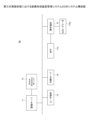
第四の実施形態の画像形成装置管理システム30では、第一の実施形態の画像形成装置17に該当する部分を、画像形成装置であるレーザプリンタ17b、レーザプリンタ17bを制御する制御端末31、制御端末31の設定を行う設定端末32、制御端末の外部に接続されたICカードリーダ174bにより構成した。図25はレーザプリンタ17b、制御端末31、設定端末32、ICカードリーダ174bの構成を説明する図である。 In the image forming device management system 30 of the fourth embodiment, the portion corresponding to the image forming device 17 of the first embodiment is configured by a laser printer 17b which is an image forming device, a control terminal 31 which controls the laser printer 17b, a setting terminal 32 which sets the control terminal 31, and an IC card reader 174b connected to the outside of the control terminal. Figure 25 is a diagram explaining the configuration of the laser printer 17b, the control terminal 31, the setting terminal 32, and the IC card reader 174b.

レーザプリンタ17bは、プリンタ機能を有する画像形成装置である。制御端末31は、制御部311、通信部312、表示部313、記録装置314、プラグイン180を有する。制御部311は、制御端末31の機能を実現させるための処理またはこれらの処理の制御を司る。通信部312は、画像形成装置管理システム30を構成する各機器との通信及びレーザプリンタ17bとの通信を行う。表示部313は画像形成装置管理システム30におけるシステム全体の状態や、制御端末31と各機器との通信状態などを表示する。プラグイン180は第二の実施形態で説明した通りである。また本実施形態の制御端末31は、第二の実施形態で説明した領域設定情報生成部193を備えていても良い。すなわち制御端末31には領域設定プログラムがインストールされていても良い。
表示部313は、3色の発光素子であるLED(Light Emitting Diode)であり、これら3色のLEDを組み合わせて本実施形態の画像形成装置管理システム30のシステム状態や、制御端末31と管理サーバ11及び印刷サーバ16との通信状態、管理サーバ11及び印刷サーバ16の装置の状態をユーザに対して表示する。この表示方法の詳細は後述する。
The laser printer 17b is an image forming device having a printer function. The control terminal 31 has a control unit 311, a communication unit 312, a display unit 313, a recording device 314, and a plug-in 180. The control unit 311 is responsible for processing to realize the functions of the control terminal 31 or for controlling these processes. The communication unit 312 communicates with each device constituting the image forming device management system 30 and with the laser printer 17b. The display unit 313 displays the overall system status in the image forming device management system 30, the communication status between the control terminal 31 and each device, and the like. The plug-in 180 is as described in the second embodiment. The control terminal 31 of this embodiment may also include the area setting information generation unit 193 described in the second embodiment. That is, an area setting program may be installed in the control terminal 31.
The display unit 313 is an LED (Light Emitting Diode) that is a three-color light-emitting element, and by combining these three color LEDs, the system status of the image forming device management system 30 of this embodiment, the communication status between the control terminal 31 and the management server 11 and the print server 16, and the device status of the management server 11 and the print server 16 are displayed to the user. The display method will be described in detail later.

記録装置314には、制御端末31の設定値などが記録されている。また、記録装置314には、制御端末31が管理サーバ11及び印刷サーバ16と通信できなくなった場合に備えて、画像形成装置管理システム30のシステムの設定に係る情報、ICカード識別情報とユーザIDからなるユーザ識別情報と、このユーザ識別情報に対応した使用制限情報、レーザプリンタ17bを使用したユーザの履歴を示す情報などが記録されており、これらの情報は定期的に管理サーバ11へ送信される。 The recording device 314 records the settings of the control terminal 31, etc. In addition, in preparation for the case in which the control terminal 31 is unable to communicate with the management server 11 and the print server 16, the recording device 314 records information related to the system settings of the image forming device management system 30, user identification information consisting of IC card identification information and a user ID, use restriction information corresponding to this user identification information, information showing the history of users who have used the laser printer 17b, etc., and this information is periodically transmitted to the management server 11.

ICカードリーダ174bは第二の実施形態のICカードリーダ174aと同様の機能を有し、USB等により制御端末31に接続されている。設定端末32は制御端末31における各種設定を行うものであり、例えばコンピュータなどである。設定端末32は、クロスケーブルなどにより制御端末31と接続されている。 The IC card reader 174b has the same functions as the IC card reader 174a in the second embodiment, and is connected to the control terminal 31 via a USB or the like. The setting terminal 32 performs various settings in the control terminal 31, and is, for example, a computer. The setting terminal 32 is connected to the control terminal 31 via a cross cable or the like.

以下に、本実施形態におけるユーザ認証処理について説明する。まず、ICカードリーダ174bによりユーザの保有するICカードのICカード識別情報を取得する。制御端末31の制御部311は、このICカード識別情報をICカードリーダ174bより取得する。そして、通信部312により取得したICカード識別情報を管理サーバ11へ送信する。管理サーバ11では、このICカード識別情報に基づき、このICカード識別情報にひも付けされたユーザIDを引き出し、引き出されたユーザIDに対応した使用制限情報を取得する。 The user authentication process in this embodiment will be described below. First, IC card identification information of an IC card held by a user is obtained by IC card reader 174b. The control unit 311 of the control terminal 31 obtains this IC card identification information from IC card reader 174b. Then, the control unit 312 transmits the obtained IC card identification information to the management server 11. Based on this IC card identification information, the management server 11 extracts the user ID linked to this IC card identification information, and obtains usage restriction information corresponding to the extracted user ID.

そして、管理サーバ11は、通信部114によりこの取得した使用制限情報を制御端末31へ送信する。制御端末31は、この使用制限情報を通信部312を介して取得し、この使用制限情報に基づいてレーザプリンタ17bを制御するものである。 Then, the management server 11 transmits this acquired usage restriction information to the control terminal 31 via the communication unit 114. The control terminal 31 acquires this usage restriction information via the communication unit 312, and controls the laser printer 17b based on this usage restriction information.

例えば使用制限情報によりユーザ認証されたユーザがレーザプリンタ17bの使用を制限されていた場合、制御部311は、レーザプリンタ17bに備えられた操作キーを、使用不可の状態であるハードキーロック状態とする。また、使用制限情報により、ユーザ認証されたユーザが、レーザプリンタ17bの使用を許可されていた場合、制御部311は、レーザプリンタ17bのハードキーロック状態が解除された状態とする。こうすれば、ユーザはレーザプリンタ17bの操作キーにより印刷処理を実行することができる。 For example, if the use of laser printer 17b is restricted for a user who has been authenticated based on the usage restriction information, control unit 311 sets the operation keys on laser printer 17b to a hard key lock state, which means that the keys cannot be used. Also, if the use restriction information indicates that the user who has been authenticated is permitted to use laser printer 17b, control unit 311 sets the hard key lock state of laser printer 17b to an unlocked state. This allows the user to execute printing processes using the operation keys on laser printer 17b.

本実施形態において、制御端末31及び管理サーバ11は以上のようにして画像形成装置であるレーザプリンタ17bの使用に係る制限及び管理を行う。このような構成とすることで、高価な画像形成装置ではなく、より安価でユーザにとって入手が容易と想像されるレーザプリンタなどの管理においても、本発明を適用することが可能であり、本発明で奏する効果を得ることができる。 In this embodiment, the control terminal 31 and management server 11 restrict and manage the use of the laser printer 17b, which is an image forming device, in the manner described above. With this configuration, the present invention can be applied to the management of laser printers and other devices that are less expensive and more easily available to users than expensive image forming devices, and the effects of the present invention can be obtained.

次に、本実施形態における表示部313で行われる表示方法について、図26、図27を参照して説明する。 Next, the display method performed by the display unit 313 in this embodiment will be described with reference to Figures 26 and 27.

図26は、表示部313における画像形成装置管理システム30の状態を示す表示方法を説明する図である。図27は第四の実施形態において印刷サーバ16が複数台接続された場合の2台目の印刷サーバの状態を示す表示方法を説明する図である。図26、図27において、横方向を時間の経過を示すものとし、1マスを1秒と換算するものとして、紙面上左側に1マスずれる毎に1秒経過した状態の表示部313を示すものとした。 Figure 26 is a diagram explaining a display method showing the state of the image forming device management system 30 on the display unit 313. Figure 27 is a diagram explaining a display method showing the state of the second print server when multiple print servers 16 are connected in the fourth embodiment. In Figures 26 and 27, the horizontal direction indicates the passage of time, with one square equivalent to one second, and each shift of one square to the left on the page indicates that one second has passed on the display unit 313.

制御端末31の表示部313は、緑色、赤色、黄色の3色のLEDを有する。本実施形態では、LED1は緑色のLEDであり、制御端末31の電源状態を示す。LED1は、制御端末31の電源がON状態のとき点灯する。LED2は赤色のLEDであり、主に制御端末31の装置の状態を示す。LED3は黄色のLEDであり、主に管理サーバ11と印刷サーバ16の装置の状態と、制御端末31と管理サーバ11、印刷サーバ16との通信状態を示す。以下に図26を参照してLED2、LED3の点滅方法について説明する。 The display unit 313 of the control terminal 31 has three LEDs of different colors: green, red, and yellow. In this embodiment, LED1 is a green LED and indicates the power status of the control terminal 31. LED1 is lit when the power of the control terminal 31 is ON. LED2 is a red LED and mainly indicates the device status of the control terminal 31. LED3 is a yellow LED and mainly indicates the device status of the management server 11 and print server 16, and the communication status between the control terminal 31 and the management server 11 and print server 16. The method of blinking LED2 and LED3 will be explained below with reference to FIG. 26.

図26(A)は、表示部313において制御端末31内サービスの通信状態の異常が示された状態の図である。尚ここで言うサービスとは、制御端末31内でのデータ送受信を意味する。制御端末31内サービスの通信状態に異常があるとき、表示部313ではLED2が5秒ごとに1回点滅する。すなわち、LED2が1秒間点灯したのち、いずれのLEDも点灯しない休止期間が4秒間継続する。そしてまたLED2の点滅に戻る。このようにして表示部313は制御端末31内サービスの通信異常をユーザに通知する。 Figure 26 (A) shows a state in which an abnormality in the communication status of a service within the control terminal 31 is indicated on the display unit 313. Note that the service referred to here means data transmission and reception within the control terminal 31. When there is an abnormality in the communication status of a service within the control terminal 31, LED 2 on the display unit 313 flashes once every 5 seconds. That is, after LED 2 lights up for 1 second, there is a pause of 4 seconds during which none of the LEDs are lit. LED 2 then returns to flashing. In this way, the display unit 313 notifies the user of the communication abnormality in the service within the control terminal 31.

図26(B)は、表示部313において制御端末31のローカルディスクのディスク容量警告が示された図である。制御端末31のディスク容量の残りの容量が所定以下になると、LED2は、1秒おきに2回点滅し、その後休止期間が4秒間継続する。そしてまた、LED2の1秒おきの点滅に戻る。このようにして表示部313は制御端末31のローカルディスクのディスク容量警告をユーザに通知する。 Figure 26 (B) is a diagram showing a disk capacity warning for the local disk of the control terminal 31 displayed on the display unit 313. When the remaining disk capacity of the control terminal 31 falls below a predetermined level, LED2 flashes twice at one second intervals, followed by a pause of four seconds. LED2 then returns to flashing once every second. In this way, the display unit 313 notifies the user of the disk capacity warning for the local disk of the control terminal 31.

図26(C)は、表示部313においてICカードリーダ174bの装置の異常が示された図である。この場合、LED2が1秒おきに3回点滅し、その後休止期間が4秒間継続する。そしてまた、LED2の1秒おきの点滅に戻る。このようにして表示部313はICカードリーダ174bの装置の異常をユーザに通知する。 Figure 26 (C) is a diagram showing an abnormality in the IC card reader 174b device on the display unit 313. In this case, LED2 blinks three times at one second intervals, followed by a pause of four seconds. LED2 then returns to blinking at one second intervals. In this way, the display unit 313 notifies the user of an abnormality in the IC card reader 174b device.

図26(D)は、表示部313において制御端末31の機器状態の異常が示された図である。制御端末31の機器状態の異常とは、制御端末31の故障などであり、データの通信が行えない状態を意味する。この場合、LED3が5秒ごとに1回点滅する。すなわち、LED3が1秒間点灯したのち、いずれのLEDも点灯しない休止期間が4秒間継続する。このようにして表示部313は制御端末31の機器状態の異常をユーザに通知する。 Figure 26 (D) is a diagram showing an abnormality in the device status of the control terminal 31 on the display unit 313. An abnormality in the device status of the control terminal 31 means a state in which data communication is not possible due to a malfunction of the control terminal 31, etc. In this case, LED 3 blinks once every five seconds. That is, after LED 3 lights up for one second, a pause period during which none of the LEDs lights up continues for four seconds. In this way, the display unit 313 notifies the user of an abnormality in the device status of the control terminal 31.

図26(E)は、表示部313において印刷サーバ16との通信状態の異常が示された図である。この場合、LED3は1秒ごとに2回点滅し、その後休止期間が4秒間継続する。そしてまた、LED3の1秒おきの点滅に戻る。このようにして表示部313は印刷サーバ16と制御端末31との通信状態の異常をユーザに通知する。 Figure 26 (E) is a diagram showing an abnormality in the communication state with the print server 16 on the display unit 313. In this case, LED 3 blinks twice every second, followed by a pause of four seconds. LED 3 then returns to blinking every second. In this way, the display unit 313 notifies the user of an abnormality in the communication state between the print server 16 and the control terminal 31.

図26(F)は、表示部313において管理サーバ11との通信状態の異常が示された図である。この場合、LED3は1秒おきに3回点滅し、その後休止期間が4秒間継続する。そしてまた、LED3の1秒おきの点滅に戻る。このようにして表示部313は管理サーバ11と制御端末31との通信状態の異常をユーザに通知する。 Figure 26 (F) is a diagram showing an abnormality in the communication status with the management server 11 on the display unit 313. In this case, LED 3 flashes three times at one-second intervals, followed by a pause of four seconds. LED 3 then returns to flashing once every second. In this way, the display unit 313 notifies the user of an abnormality in the communication status between the management server 11 and the control terminal 31.

図26(G)は、表示部313において制御端末31の内部エラーが示された図である。内部エラーとは、例えば制御端末31内で実行される処理がなんらかの理由で実行できなかった場合を意味する。この場合、LED2とLED3が、同じタイミングで1秒ごとの点滅を繰り返す。このようにして表示部313は制御端末31の内部エラー異常をユーザに通知する。 Figure 26 (G) is a diagram showing an internal error of the control terminal 31 on the display unit 313. An internal error means, for example, that a process being executed within the control terminal 31 cannot be executed for some reason. In this case, LED2 and LED3 flash once per second at the same timing. In this way, the display unit 313 notifies the user of an internal error abnormality in the control terminal 31.

図26(H)は、表示部313において印刷サーバ16内のサービスの通信状態の異常が示された図である。この場合、LED3は、1秒ごとに4回点滅し、その後休止期間が4秒間継続する。そしてまた、LED3の1秒おきの点滅に戻る。このようにして表示部313は、印刷サーバ16内のサービスの通信状態の異常をユーザに通知する。 Figure 26 (H) is a diagram showing an abnormality in the communication status of the service in the print server 16 on the display unit 313. In this case, LED 3 blinks four times every second, followed by a pause of four seconds. LED 3 then returns to blinking every second. In this way, the display unit 313 notifies the user of an abnormality in the communication status of the service in the print server 16.

図26(I)は、表示部313において印刷サーバ16のディスク容量警告が示された図である。印刷サーバ16内のディスク容量の残りの容量が所定以下になると、LED3は、1秒おきに5回点滅し、その後休止期間が4秒間継続する。そしてまた、LED3の1秒おきの点滅に戻る。このようにして表示部313は印刷サーバ16のディスク容量警告をユーザに通知する。 Figure 26 (I) is a diagram showing a disk capacity warning for the print server 16 on the display unit 313. When the remaining disk capacity in the print server 16 falls below a predetermined level, LED 3 flashes five times at one-second intervals, followed by a pause of four seconds. LED 3 then returns to flashing once every second. In this way, the display unit 313 notifies the user of the disk capacity warning for the print server 16.

図26(J)は、表示部313において印刷サーバ16のデータベース容量警告が示された図である。印刷サーバ16のデータベースとは、例えば印刷サーバ16内で各種のデータが格納されるデータ格納領域のことを意味する。印刷サーバ16内のデータベースの残りの容量が所定以下になると、この場合、LED3は、1秒おきに6回点滅し、その後休止期間が4秒間継続する。そしてまた、LED3の1秒おきの点滅に戻る。このようにして表示部313は印刷サーバ16のデータベース容量警告をユーザに通知する。 Figure 26 (J) is a diagram showing a database capacity warning for the print server 16 on the display unit 313. The database of the print server 16 means, for example, a data storage area in the print server 16 where various data are stored. When the remaining capacity of the database in the print server 16 falls below a predetermined level, in this case, LED 3 flashes six times at one-second intervals, followed by a pause period of four seconds. LED 3 then returns to flashing once every second. In this way, the display unit 313 notifies the user of the database capacity warning for the print server 16.

図26(K)は、表示部313において管理サーバ11内のサービスの通信状態の異常が示された図である。この場合、LED3は、1秒おきに7回点滅し、その後休止期間が4秒間継続する。そしてまた、LED3の1秒おきの点滅に戻る。このようにして表示部313は、管理サーバ11内のサービスの通信状態の異常をユーザに通知する。 Figure 26 (K) is a diagram showing an abnormality in the communication status of a service in the management server 11 displayed on the display unit 313. In this case, LED 3 flashes seven times at one-second intervals, followed by a pause of four seconds. LED 3 then returns to flashing once every second. In this way, the display unit 313 notifies the user of an abnormality in the communication status of a service in the management server 11.

図26(L)は、表示部313において管理サーバ11のディスク容量警告が示された図である。管理サーバ11内のディスク容量の残りの容量が所定以下になると、LED3は、1秒おきに8回点滅し、その後休止期間が4秒間継続する。そしてまた、LED3の1秒おきの点滅に戻る。このようにして表示部313は管理サーバ11のディスク容量警告をユーザに通知する。 Figure 26 (L) is a diagram showing a disk capacity warning for the management server 11 on the display unit 313. When the remaining disk capacity in the management server 11 falls below a specified level, the LED 3 flashes eight times at one-second intervals, followed by a pause of four seconds. The LED 3 then returns to flashing once every second. In this way, the display unit 313 notifies the user of the disk capacity warning for the management server 11.

図26(M)は、表示部313において管理サーバ11のデータベース容量警告が示された図である。管理サーバ11のデータベースとは、例えば管理サーバ11内で各種のデータが格納されるデータ格納領域のことを意味する。管理サーバ11内のデータベースの残りの容量が所定以下になると、この場合、LED3は、1秒おきに9回点滅し、その後休止期間が4秒間継続する。そしてまた、LED3の1秒おきの点滅に戻る。このようにして表示部313は管理サーバ11のデータベース容量警告をユーザに通知する。 Figure 26 (M) is a diagram showing a database capacity warning for the management server 11 on the display unit 313. The database of the management server 11 means, for example, a data storage area in which various data are stored within the management server 11. When the remaining capacity of the database in the management server 11 falls below a predetermined level, in this case LED 3 flashes nine times at one-second intervals, followed by a pause period of four seconds. LED 3 then returns to flashing once every second. In this way, the display unit 313 notifies the user of the database capacity warning for the management server 11.

このようにして、制御端末31の表示部313では、制御端末31、管理サーバ11及び印刷サーバ16の装置状態と、制御端末31と管理サーバ11及び印刷サーバ16との通信状態をユーザが把握可能に表示している。 In this way, the display unit 313 of the control terminal 31 displays the device status of the control terminal 31, management server 11, and print server 16, as well as the communication status between the control terminal 31 and the management server 11 and print server 16, so that the user can understand them.

また、本実施形態の画像形成装置管理システム30では、印刷サーバ16を複数台設けることができる。この場合の2台目の印刷サーバ(図示せず)に係る情報の表示方法について、図27を参照して説明する。なお、図27において「!」のマークはLEDの点灯時間が1秒未満の素早い点滅を示す。例えば「●!●」であれば、LEDは点灯時間が1秒未満の点滅を2回繰り返すことを意味する。 In addition, in the image forming device management system 30 of this embodiment, multiple print servers 16 can be provided. A method for displaying information related to a second print server (not shown) in this case will be described with reference to FIG. 27. Note that in FIG. 27, the "!" mark indicates that the LED flashes quickly with a lighting time of less than one second. For example, "●!●" means that the LED flashes twice with a lighting time of less than one second.

図27(A)は、表示部313において2台目の印刷サーバと制御端末31との通信状態の異常が示された図である。この場合、LED3は1秒ごとに2回点滅し、その後の4秒間の間に点灯時間が1秒未満の点滅を2回繰り返す。そしてそのあと、LED3は1秒ごとの点滅に戻る。このようにして、表示部313は2台目の印刷サーバとの通信状態の異常をユーザに通知する。 Figure 27 (A) is a diagram showing an abnormality in the communication status between the second print server and the control terminal 31 on the display unit 313. In this case, LED 3 flashes twice every second, and then flashes twice with a lighting time of less than one second over the next four seconds. After that, LED 3 returns to flashing once every second. In this way, the display unit 313 notifies the user of an abnormality in the communication status with the second print server.

図27(B)は、表示部313において2台目の印刷サーバ内のサービスの通信状態の異常が示された図である。この場合、LED3は1秒ごとに4回点滅し、その後の4秒間の間に点灯時間が1秒未満の点滅を2回繰り返す。そしてそのあと、LED3は1秒ごとの点滅に戻る。このようにして、表示部313は2台目の印刷サーバ内のサービスの通信状態の異常をユーザに通知する。 Figure 27 (B) is a diagram showing an abnormality in the communication status of the service in the second print server on the display unit 313. In this case, LED 3 blinks four times every second, and then during the next four seconds, it blinks twice with the illumination time of less than one second. After that, LED 3 returns to blinking every second. In this way, the display unit 313 notifies the user of an abnormality in the communication status of the service in the second print server.

図27(C)は、表示部313において2台目の印刷サーバのディスク容量警告が示された図である。2台目の印刷サーバ内のディスク容量の残りの容量が所定以下になると、この場合、LED3は1秒ごとに5回点滅し、その後の4秒間の間に点灯時間が1秒未満の点滅を2回繰り返す。そしてそのあと、LED3は1秒ごとの点滅に戻る。このようにして、表示部313は2台目の印刷サーバのディスク容量警告をユーザに通知する。 Figure 27 (C) is a diagram showing a disk capacity warning for the second print server on the display unit 313. When the remaining disk capacity in the second print server falls below a predetermined level, in this case, LED 3 flashes five times every second, and then flashes twice for less than one second over the next four seconds. After that, LED 3 returns to flashing once every second. In this way, the display unit 313 notifies the user of the disk capacity warning for the second print server.

図27(D)は、表示部313において2台目の印刷サーバのデータベース容量警告が示された図である。2台目の印刷サーバのデータベースとは、例えば印刷サーバ内で各種のデータが格納されるデータ格納領域のことを意味する。2台目の印刷サーバ内のディスク容量の残りの容量が所定以下になると、この場合、LED3は1秒ごとに6回点滅し、その後の4秒間の間に点灯時間が1秒未満の点滅を2回繰り返す。そしてそのあと、LED3は1秒ごとの点滅に戻る。このようにして、表示部313は2台目の印刷サーバのデータベース容量警告をユーザに通知する。 Figure 27 (D) is a diagram showing a database capacity warning for the second print server on the display unit 313. The database of the second print server means, for example, a data storage area in the print server where various data are stored. When the remaining disk capacity of the second print server falls below a predetermined level, in this case, LED 3 flashes six times every second, and then flashes twice for less than one second over the next four seconds. After that, LED 3 returns to flashing once every second. In this way, the display unit 313 notifies the user of the database capacity warning for the second print server.

このようにして、本実施形態の制御端末31は複数の印刷サーバが接続されていた場合でも、表示部313においてその複数台目の印刷サーバの装置状態や、制御端末31との通信状態を示す情報をユーザが把握可能に表示することができる。 In this way, even if multiple print servers are connected to the control terminal 31 of this embodiment, the display unit 313 can display information indicating the device status of the multiple print servers and the communication status with the control terminal 31 in a manner that allows the user to grasp the information.

また、以上に説明した各実施形態における管理サーバ11、11Aの各機能を実現する手順は、コンピュータに読み取り可能な画像形成装置管理プログラムとして記録媒体に記録されていても良い。 In addition, the procedures for realizing each function of the management servers 11 and 11A in each of the embodiments described above may be recorded on a recording medium as a computer-readable image forming device management program.

図28は各実施形態で説明した管理サーバ11、11Aの各機能を実現させるプログラムが記録された記録媒体を説明する図である。記録媒体410に記録されたプログラムが、コンピュータ500に読み込まれて実行されることにより、本実施形態で説明した各機能を実現することができる。 Figure 28 is a diagram illustrating a recording medium on which a program that realizes each function of the management servers 11, 11A described in each embodiment is recorded. The program recorded on the recording medium 410 is loaded into the computer 500 and executed, thereby realizing each function described in this embodiment.

例えばコンピュータ500は、CPU510、ハードディスク520、メモリ530、表示部540、入力部550、通信部560、記録媒体読込部570を備えている。CPU510は演算処理装置であって、コンピュータ500において実行される演算や処理を実行する。ハードディスク520は、データを格納する記憶手段であって、コンピュータ500上で動作するアプリケーションや、このアプリケーションにより作成されたデータなどが格納されている。メモリ530には、コンピュータ500に係る各種の設定値や、CPU510での演算結果などが格納される。 For example, computer 500 includes a CPU 510, a hard disk 520, a memory 530, a display unit 540, an input unit 550, a communication unit 560, and a recording medium reading unit 570. CPU 510 is an arithmetic processing device that executes calculations and processes executed in computer 500. Hard disk 520 is a storage means for storing data, and stores applications that run on computer 500 and data created by these applications. Memory 530 stores various setting values related to computer 500, calculation results by CPU 510, etc.

表示部540はディスプレイなどであり、コンピュータ500において作成されたデータなどをユーザに閲覧可能に表示する。入力部550は例えばキーボードやマウスであって、ユーザの操作により各種データが入力される。通信部560は例えばネットワークコントロールユニットなどであり、コンピュータ500が外部の装置と通信を行うためのものである。記録媒体読み込み部570は、各種記録媒体に記録されたデータやプログラムなどを読み込むものであり、例えばフロッピー(登録商標)ディスクドライバなどである。 The display unit 540 is a display or the like, and displays data created in the computer 500 so that the user can view it. The input unit 550 is, for example, a keyboard or mouse, and various data is input by user operation. The communication unit 560 is, for example, a network control unit, and enables the computer 500 to communicate with external devices. The recording medium reading unit 570 reads data and programs recorded on various recording media, for example, a floppy (registered trademark) disk driver.

記録媒体410は、本実施形態の各機能を実現させる画像形成装置管理プログラム400が記録されている。この画像形成装置管理プログラム400は、記録媒体読込部570により読み込まれてCPU510において実行される。記録媒体410は、例えばフロッピー(登録商標)ディスクやCD-ROM(Compact Disk Read Only Memory)等であっても良く、コンピュータ500において読み取り可能なに媒体であれば良い。また、画像形成装置管理プログラム400はネットワークを介して通信部560により受信されて、ハードディスク520等に格納されても良い。 The recording medium 410 records the image forming device management program 400 that realizes each function of this embodiment. This image forming device management program 400 is read by the recording medium reading unit 570 and executed by the CPU 510. The recording medium 410 may be, for example, a floppy disk or a CD-ROM (Compact Disk Read Only Memory), and may be any medium that can be read by the computer 500. The image forming device management program 400 may also be received by the communication unit 560 via a network and stored on the hard disk 520, etc.

また、以上に説明した各実施形態における画像形成装置17、17A、17aの各機能を実現する手順は、コンピュータに読み取り可能な画像形成プログラムとして記録媒体に記録されていても良い。 In addition, the procedures for realizing each function of the image forming devices 17, 17A, and 17a in each of the embodiments described above may be recorded on a recording medium as a computer-readable image forming program.

図29は各実施形態で説明した画像形成装置17、17A、17aの各機能を実現させるプログラムが記録された記録媒体を説明する図である。記録媒体710に記録されたプログラムが、画像形成装置600に読み込まれて実行されることにより、本実施形態で説明した各機能を実現することができる。 Figure 29 is a diagram illustrating a recording medium on which a program that realizes each function of the image forming apparatus 17, 17A, and 17a described in each embodiment is recorded. The program recorded on the recording medium 710 is read into the image forming apparatus 600 and executed, thereby realizing each function described in this embodiment.

例えば画像形成装置600は、CPU610、ハードディスク620、メモリ630、表示操作部640、スキャナ部650、通信部660、記録媒体読込部670、プロッタ部680を備えている。CPU610は演算処理装置であって、画像形成装置600において実行される演算や処理を実行する。ハードディスク620は、データを格納する記憶手段であって、画像形成装置600上で動作するアプリケーションや、このアプリケーションにより作成されたデータなどが格納されている。メモリ630には、画像形成装置600に係る各種の設定値や、CPU610での演算結果などが格納される。 For example, image forming device 600 includes a CPU 610, a hard disk 620, a memory 630, a display operation unit 640, a scanner unit 650, a communication unit 660, a recording medium reading unit 670, and a plotter unit 680. CPU 610 is an arithmetic processing device that executes calculations and processes executed in image forming device 600. Hard disk 620 is a storage means for storing data, and stores applications that run on image forming device 600 and data created by these applications. Memory 630 stores various setting values related to image forming device 600, calculation results by CPU 610, etc.

表示操作部640は表示部を有する操作パネルなどであり、画像形成装置600の操作や装置状態や処理の進捗などの表示が行われる。スキャナ部650はスキャナとスキャナエンジン等により構成され、紙文書をスキャンして画像データとする。通信部660は例えばネットワークコントロールユニットなどであり、画像形成装置600が外部の装置と通信を行うためのものである。記録媒体読込部670は、各種記録媒体に記録されたデータやプログラムなどを読み込むものであり、例えばフロッピー(登録商標)ディスクドライバなどである。プロッタ部680は、プロッタとプロッタエンジン等により構成され、画像データを印刷出力する。 The display operation unit 640 is an operation panel having a display unit, and displays operations of the image forming device 600, the device status, the progress of processing, etc. The scanner unit 650 is composed of a scanner and a scanner engine, etc., and scans paper documents to generate image data. The communication unit 660 is, for example, a network control unit, etc., and enables the image forming device 600 to communicate with external devices. The recording medium reading unit 670 reads data and programs recorded on various recording media, such as a floppy (registered trademark) disk driver. The plotter unit 680 is composed of a plotter and a plotter engine, etc., and prints out image data.

記録媒体710は、本実施形態の各機能を実現させる画像形成プログラム700が記録されている。この画像形成プログラム700は、記録媒体読込部670により読み込まれてCPU610において実行される。記録媒体710は、例えばフロッピー(登録商標)ディスクやCD-ROM(Compact Disk Read Only Memory)等であっても良く、画像形成装置600において読み取り可能なに媒体であれば良い。また、画像形成プログラム700はネットワークを介して通信部660により受信されて、ハードディスク620等に格納されても良い。 The recording medium 710 records an image forming program 700 that realizes each function of this embodiment. This image forming program 700 is read by the recording medium reading unit 670 and executed by the CPU 610. The recording medium 710 may be, for example, a floppy disk or a CD-ROM (Compact Disk Read Only Memory), and may be any medium that can be read by the image forming device 600. The image forming program 700 may also be received by the communication unit 660 via a network and stored on the hard disk 620, etc.

以上、各実施形態に基づき本発明の説明を行ってきたが、上記実施形態に示した要件に本発明が限定されるものではない。これらの点に関しては、本発明の主旨をそこなわない範囲で変更することができ、その応用形態に応じて適切に定めることができる。 The present invention has been described above based on each embodiment, but the present invention is not limited to the requirements shown in the above embodiments. These points can be changed without departing from the spirit of the present invention, and can be appropriately determined according to the application form.

第一の実施形態における画像形成装置管理システム10のシステム構成図である。1 is a system configuration diagram of an image forming apparatus management system 10 according to a first embodiment. 第一の実施形態における画像形成装置17の機能ブロック図である。FIG. 2 is a functional block diagram of an image forming apparatus 17 according to the first embodiment. 第一の実施形態における管理サーバ11の機能ブロック図である。FIG. 2 is a functional block diagram of a management server 11 according to the first embodiment. 第一の実施形態における印刷サーバ16の機能ブロック図である。FIG. 2 is a functional block diagram of a print server 16 according to the first embodiment. 画像形成装置管理システム10におけるユーザ認証処理を説明するフローチャートである。4 is a flowchart illustrating a user authentication process in the image forming apparatus management system 10. 第一の実施形態の画像形成装置17における個人メニュー処理の動作を説明するフローチャートである。6 is a flowchart illustrating an operation of a personal menu process in the image forming apparatus 17 according to the first embodiment. 個人メニュー処理が選択された際の表示操作装置172の状態を説明する図である。13 is a diagram illustrating the state of the display operation device 172 when individual menu processing is selected. FIG. 本発明の第二の実施形態の画像形成装置管理システム10Aのシステム構成図である。FIG. 11 is a system configuration diagram of an image forming apparatus management system 10A according to a second embodiment of the present invention. 第二の実施形態の管理サーバ11Aの機能構成図である。FIG. 11 is a functional configuration diagram of a management server 11A according to a second embodiment. 第二の実施形態のADサーバ13Aの機能構成図である。FIG. 11 is a functional configuration diagram of an AD server 13A according to a second embodiment. 第二の実施形態の印刷サーバ16Aの機能構成図である。FIG. 10 is a functional configuration diagram of a print server 16A according to a second embodiment. 第二の実施形態の画像形成装置17Aの機能構成図である。FIG. 11 is a functional configuration diagram of an image forming apparatus 17A according to a second embodiment. 第二の実施形態の管理端末18の機能構成図である。FIG. 11 is a functional configuration diagram of a management terminal 18 according to the second embodiment. ICカードを説明する図である。FIG. 1 is a diagram illustrating an IC card. 報を読み取る領域の種類を設定する設定画面の一例を示す図である。FIG. 13 is a diagram showing an example of a setting screen for setting the type of area from which information is read. ICカードAの領域設定情報を生成する領域設定情報生成画面が表示された例を示す図である。13 is a diagram showing an example of a region setting information generation screen for generating region setting information for an IC card A. FIG. 画像形成装置17Aにおけるプラグイン180の動作を説明するフローチャートである。11 is a flowchart illustrating an operation of a plug-in 180 in the image forming apparatus 17A. 画像形成装置17Aで実行されるプラグインの選択画面の一例を示す図である。FIG. 13 is a diagram showing an example of a selection screen for a plug-in executed in the image forming apparatus 17A. 第二の実施形態におけるログイン処理を説明するフローチャートである。13 is a flowchart illustrating a login process according to the second embodiment. 二の実施形態の画像形成装置17Aにおける表示画面の一例を示す図である。FIG. 13 is a diagram showing an example of a display screen in an image forming apparatus according to the second embodiment. 第二の実施形態の管理サーバ11Aにおけるユーザ情報の登録及び削除を説明するフローチャートである。11 is a flowchart illustrating registration and deletion of user information in a management server 11A according to a second embodiment. 第三の実施形態における画像形成装置管理システム20のシステム構成図である。FIG. 13 is a system configuration diagram of an image forming apparatus management system 20 according to a third embodiment. 画像形成装置17a、操作端末21、ICカードリーダ174aの構成を説明する図である。2 is a diagram illustrating the configuration of an image forming apparatus 17a, an operation terminal 21, and an IC card reader 174a. 第四の実施形態における画像形成装置管理システム30のシステム構成図である。FIG. 13 is a system configuration diagram of an image forming apparatus management system 30 according to a fourth embodiment. レーザプリンタ17b、制御端末31、設定端末32、ICカードリーダ174bの構成を説明する図である。1 is a diagram for explaining the configuration of a laser printer 17b, a control terminal 31, a setting terminal 32, and an IC card reader 174b. 表示部313における画像形成装置管理システム30の状態を示すLEDの状態を説明する図である。3A to 3C are diagrams illustrating the states of LEDs on a display unit 313 that indicate the state of the image forming apparatus management system 30. 第四の実施形態において印刷サーバ16が複数台接続された場合の2台目の印刷サーバの状態を示すLEDの状態を説明する図である。FIG. 13 is a diagram illustrating the state of an LED indicating the state of a second print server when a plurality of print servers 16 are connected in the fourth embodiment. 各実施形態で説明した管理サーバ11、11Aの各機能を実現させるプログラムが記録された記録媒体を説明する図である。2 is a diagram illustrating a recording medium on which a program for realizing each function of the management servers 11 and 11A described in each embodiment is recorded. FIG. 各実施形態で説明した画像形成装置17、17A、17aの各機能を実現させるプログラムが記録された記録媒体を説明する図である。FIG. 2 is a diagram illustrating a recording medium on which a program for realizing each function of the image forming apparatuses 17, 17A, and 17a described in each embodiment is recorded.

10、20、30 画像形成装置管理システム
11、11A 管理サーバ
13 ADサーバ
15 ユーザ端末
16、16A 印刷サーバ
17、17A、17a 画像形成装置
17b レーザプリンタ
21 操作端末
31 制御端末
111、171、211、311 制御部
130 ユーザ情報管理部
140 印刷ジョブ削除指示部
150 印刷順序変更指示部
160 更新ファイル取得部
174、174a、174b ICカードリーダ
180 プラグイン
193 領域設定情報生成部
10, 20, 30 Image forming device management system 11, 11A Management server 13 AD server 15 User terminal 16, 16A Print server 17, 17A, 17a Image forming device 17b Laser printer 21 Operation terminal 31 Control terminal 111, 171, 211, 311 Control unit 130 User information management unit 140 Print job deletion instruction unit 150 Print order change instruction unit 160 Update file acquisition unit 174, 174a, 174b IC card reader 180 Plug-in 193 Area setting information generation unit

Claims (16)

記録媒体から読み取られる記録媒体識別情報、又は、ユーザによって入力されるユーザ識別情報及びパスワード、を用いたログイン処理の実行が可能な画像形成装置であって、
前記ログイン処理が実行される前の待ち受け画面を表示する表示部であって、前記ユーザ識別情報及びパスワードを入力する入力画面の表示の指示を受け付ける指示ボタン、を前記待ち受け画面に表示させるか否かの設定が、前記指示ボタンを表示する設定である場合、前記待ち受け画面に前記指示ボタンを表示する前記表示部と、を有し、
前記画像形成装置は、前記待ち受け画面が表示されているときに前記記録媒体から当該記録媒体を識別する前記記録媒体識別情報が読み取られた場合、読み取られた前記記録媒体識別情報を用いて前記ログイン処理を実行し、前記指示ボタンが受け付けた指示により表示される前記入力画面を介して前記ユーザ識別情報及びパスワードが入力された場合、入力された前記ユーザ識別情報及びパスワードを用いて前記ログイン処理を実行し、
前記表示部は、前記設定が、前記指示ボタンを表示しない設定である場合、前記待ち受け画面に前記指示ボタンを表示しない、
画像形成装置。
An image forming apparatus capable of executing a login process using recording medium identification information read from a recording medium, or user identification information and a password input by a user, comprising:
a display unit that displays a standby screen before the login process is executed, and that displays an instruction button for receiving an instruction to display an input screen for inputting the user identification information and the password on the standby screen when a setting as to whether or not to display the instruction button on the standby screen is a setting to display the instruction button,
when the standby screen is displayed and the recording medium identification information identifying the recording medium is read from the recording medium, the image forming apparatus executes the login process using the read recording medium identification information, and when the user identification information and password are input via the input screen displayed in response to an instruction received by the instruction button, the image forming apparatus executes the login process using the input user identification information and password.
When the setting is a setting not to display the instruction button, the display unit does not display the instruction button on the standby screen.
Image forming device.
前記入力画面は、キーボード画面である、請求項1に記載の画像形成装置。 The image forming device according to claim 1, wherein the input screen is a keyboard screen. 前記記録媒体は、ICカードであり、前記記録媒体識別情報はICカード識別情報である、請求項1又は2に記載の画像形成装置。 The image forming device according to claim 1 or 2, wherein the recording medium is an IC card, and the recording medium identification information is IC card identification information. 前記表示部は、前記ログイン処理が実行され、前記ログイン処理の結果が成功であった場合、メニュー画面を表示する、請求項1乃至3の何れか一項に記載の画像形成装置。 The image forming apparatus according to claim 1 , wherein the display unit displays a menu screen when the login process is executed and the login process is successful . 記録媒体から読み取られる記録媒体識別情報、又は、ユーザによって入力されるユーザ識別情報及びパスワード、を用いたログイン処理の実行が可能な画像形成装置による方法であって、
前記画像形成装置が、
前記ユーザ識別情報及びパスワードを入力する入力画面の表示の指示を受け付ける指示ボタンを、前記ログイン処理が実行される前に表示部に表示される待ち受け画面に表示させるか否かの設定が、前記指示ボタンを表示する設定である場合、前記待ち受け画面に前記指示ボタンを表示し、
前記画像形成装置が、
前記待ち受け画面が表示されているときに前記記録媒体から当該記録媒体を識別する前記記録媒体識別情報が読み取られた場合、読み取られた前記記録媒体識別情報を用いて前記ログイン処理を実行し、前記指示ボタンが受け付けた指示により表示される前記入力画面を介して前記ユーザ識別情報及びパスワードが入力された場合、入力された前記ユーザ識別情報及びパスワードを用いて前記ログイン処理を実行し、
前記表示部に、前記設定が、前記指示ボタンを表示しない設定である場合、前記待ち受け画面に前記指示ボタンを表示しない、方法。
A method for an image forming apparatus capable of executing a login process using recording medium identification information read from a recording medium, or user identification information and a password input by a user, comprising:
The image forming apparatus,
When a setting as to whether or not to display an instruction button for receiving an instruction to display an input screen for inputting the user identification information and the password on a standby screen displayed on a display unit before the login process is executed is a setting for displaying the instruction button, displaying the instruction button on the standby screen;
The image forming apparatus,
when the recording medium identification information for identifying the recording medium is read from the recording medium while the standby screen is being displayed, the login process is executed using the read recording medium identification information, and when the user identification information and password are input via the input screen displayed in response to an instruction received by the instruction button, the login process is executed using the input user identification information and password,
When the setting on the display unit is a setting not to display the instruction button, the instruction button is not displayed on the standby screen.
前記入力画面は、キーボード画面である、請求項5に記載の方法。 The method of claim 5, wherein the input screen is a keyboard screen. 前記記録媒体は、ICカードであり、前記記録媒体識別情報はICカード識別情報である、請求項5又は6に記載の方法。 The method according to claim 5 or 6, wherein the recording medium is an IC card, and the recording medium identification information is IC card identification information. 前記ログイン処理が実行され、前記ログイン処理の結果が成功であった場合、前記表示部に、メニュー画面を表示する、請求項5乃至7の何れか一項に記載の方法。 The method according to claim 5 , further comprising the step of: displaying a menu screen on the display unit when the login process is executed and the login process is successful . 記録媒体から読み取られる記録媒体識別情報、又は、ユーザによって入力されるユーザ識別情報及びパスワード、を用いたログイン処理の実行が可能な画像形成装置に、
前記ユーザ識別情報及びパスワードを入力する入力画面の表示の指示を受け付ける指示ボタンを、前記ログイン処理が実行される前に表示部に表示される待ち受け画面に表示させるか否かの設定が、前記指示ボタンを表示する設定である場合、前記待ち受け画面に前記指示ボタンを表示し、
前記待ち受け画面が表示されているときに前記記録媒体から当該記録媒体を識別する前記記録媒体識別情報が読み取られた場合、読み取られた前記記録媒体識別情報を用いて前記ログイン処理を実行し、前記指示ボタンが受け付けた指示により表示される前記入力画面を介して前記ユーザ識別情報及びパスワードが入力された場合、入力された前記ユーザ識別情報及びパスワードを用いて前記ログイン処理を実行し、
前記表示部に、前記設定が、前記指示ボタンを表示しない設定である場合、前記待ち受け画面に前記指示ボタンを表示しない、処理を実行させる、プログラム。
An image forming apparatus capable of executing a login process using recording medium identification information read from a recording medium, or user identification information and a password input by a user,
When a setting as to whether or not to display an instruction button for receiving an instruction to display an input screen for inputting the user identification information and the password on a standby screen displayed on a display unit before the login process is executed is a setting for displaying the instruction button, displaying the instruction button on the standby screen;
when the standby screen is displayed and the recording medium identification information for identifying the recording medium is read from the recording medium, the login process is executed using the read recording medium identification information; and when the user identification information and password are input via the input screen displayed in response to an instruction received by the instruction button, the login process is executed using the input user identification information and password.
The program causes the display unit to execute a process of not displaying the instruction button on the standby screen when the setting is a setting of not displaying the instruction button.
前記入力画面は、キーボード画面である、請求項9に記載のプログラム。 The program according to claim 9, wherein the input screen is a keyboard screen. 前記記録媒体は、ICカードであり、前記記録媒体識別情報はICカード識別情報である、請求項9又は10に記載のプログラム。 The program according to claim 9 or 10, wherein the recording medium is an IC card, and the recording medium identification information is IC card identification information. 前記ログイン処理が実行され、前記ログイン処理の結果が成功であった場合、前記表示部に、メニュー画面を表示する、請求項9乃至11の何れか一項に記載のプログラム。 12. The program according to claim 9, further comprising: displaying a menu screen on the display unit when the login process is executed and the login process is successful . 可搬型の記録媒体から読み取られる記録媒体識別情報、又は、ユーザによって入力されるユーザ識別情報及びパスワード、を用いたログイン処理の実行が可能な画像形成装置に、
前記ユーザ識別情報及びパスワードを入力する入力画面の表示の指示を受け付ける指示ボタンを、前記ログイン処理が実行される前に表示部に表示される待ち受け画面に表示させるか否かの設定が、前記指示ボタンを表示する設定である場合、前記待ち受け画面に前記指示ボタンを表示し、
前記待ち受け画面が表示されているときに前記可搬型の記録媒体から当該記録媒体を識別する前記記録媒体識別情報が読み取られた場合、読み取られた前記記録媒体識別情報を用いて前記ログイン処理を実行し、前記指示ボタンが受け付けた指示により表示される前記入力画面を介して前記ユーザ識別情報及びパスワードが入力された場合、入力された前記ユーザ識別情報及びパスワードを用いて前記ログイン処理を実行し、
前記表示部に、前記設定が、前記指示ボタンを表示しない設定である場合、前記待ち受け画面に前記指示ボタンを表示しない、処理を実行させるプログラムが記録された、コンピュータ読み取り可能な記録媒体。
An image forming apparatus capable of executing a login process using recording medium identification information read from a portable recording medium or user identification information and a password input by a user,
When a setting as to whether or not to display an instruction button for receiving an instruction to display an input screen for inputting the user identification information and the password on a standby screen displayed on a display unit before the login process is executed is a setting for displaying the instruction button, displaying the instruction button on the standby screen;
When the standby screen is displayed, if the recording medium identification information for identifying the portable recording medium is read from the portable recording medium, the login process is executed using the read recording medium identification information; and when the user identification information and password are input via the input screen displayed in response to an instruction received by the instruction button, the login process is executed using the input user identification information and password.
A computer-readable recording medium having recorded thereon a program for causing the display unit to execute a process of not displaying the instruction button on the standby screen when the setting is a setting of not displaying the instruction button.
前記入力画面は、キーボード画面である、請求項13に記載の記録媒体。 The recording medium according to claim 13, wherein the input screen is a keyboard screen. 前記可搬型の記録媒体は、ICカードであり、前記記録媒体識別情報はICカード識別情報である、請求項13又は14に記載の記録媒体。 The recording medium according to claim 13 or 14, wherein the portable recording medium is an IC card, and the recording medium identification information is IC card identification information. 前記ログイン処理が実行され、前記ログイン処理の結果が成功であった場合、前記表示部に、メニュー画面を表示する、請求項13乃至15の何れか一項に記載の記録媒体。 The recording medium according to claim 13 , wherein when the login process is executed and the result of the login process is successful , a menu screen is displayed on the display unit.
JP2023033746A 2021-01-22 2023-03-06 Image forming apparatus, method, program, and recording medium Active JP7477003B2 (en)

Priority Applications (2)

Application Number Priority Date Filing Date Title
JP2023033746A JP7477003B2 (en) 2021-01-22 2023-03-06 Image forming apparatus, method, program, and recording medium
JP2024037085A JP2024061806A (en) 2021-01-22 2024-03-11 Image forming device, method, program, and recording medium

Applications Claiming Priority (2)

Application Number Priority Date Filing Date Title
JP2021008617A JP7283490B2 (en) 2021-01-22 2021-01-22 Image forming apparatus, program, authentication method
JP2023033746A JP7477003B2 (en) 2021-01-22 2023-03-06 Image forming apparatus, method, program, and recording medium

Related Parent Applications (1)

Application Number Title Priority Date Filing Date
JP2021008617A Division JP7283490B2 (en) 2021-01-22 2021-01-22 Image forming apparatus, program, authentication method

Related Child Applications (1)

Application Number Title Priority Date Filing Date
JP2024037085A Division JP2024061806A (en) 2021-01-22 2024-03-11 Image forming device, method, program, and recording medium

Publications (2)

Publication Number Publication Date
JP2023076453A JP2023076453A (en) 2023-06-01
JP7477003B2 true JP7477003B2 (en) 2024-05-01

Family

ID=75965393

Family Applications (3)

Application Number Title Priority Date Filing Date
JP2021008617A Active JP7283490B2 (en) 2021-01-22 2021-01-22 Image forming apparatus, program, authentication method
JP2023033746A Active JP7477003B2 (en) 2021-01-22 2023-03-06 Image forming apparatus, method, program, and recording medium
JP2024037085A Pending JP2024061806A (en) 2021-01-22 2024-03-11 Image forming device, method, program, and recording medium

Family Applications Before (1)

Application Number Title Priority Date Filing Date
JP2021008617A Active JP7283490B2 (en) 2021-01-22 2021-01-22 Image forming apparatus, program, authentication method

Family Applications After (1)

Application Number Title Priority Date Filing Date
JP2024037085A Pending JP2024061806A (en) 2021-01-22 2024-03-11 Image forming device, method, program, and recording medium

Country Status (1)

Country Link
JP (3) JP7283490B2 (en)

Citations (2)

* Cited by examiner, † Cited by third party
Publication number Priority date Publication date Assignee Title
JP2006350497A (en) 2005-06-14 2006-12-28 Canon Marketing Japan Inc Print server, print management server, printer, print system, print data storage method, print management method, printing method, program and recording medium
JP2007048080A (en) 2005-08-10 2007-02-22 Ricoh Co Ltd Service providing device, method and program

Family Cites Families (8)

* Cited by examiner, † Cited by third party
Publication number Priority date Publication date Assignee Title
JPH06214992A (en) * 1993-01-18 1994-08-05 Toshiba Corp Entrance/exit management device
JP3483993B2 (en) * 1995-08-31 2004-01-06 ホーチキ株式会社 Access control device
JPH09146725A (en) * 1995-11-20 1997-06-06 Hitachi Ltd Printing system
JP2002163101A (en) * 2000-11-29 2002-06-07 Sato Corp Label printer monitoring system
JP4650789B2 (en) * 2005-06-22 2011-03-16 富士ゼロックス株式会社 Authentication device and management device
JP2007034647A (en) * 2005-07-27 2007-02-08 Fuji Xerox Co Ltd Display device, display method, image forming device and electronic equipment
JP2007048079A (en) * 2005-08-10 2007-02-22 Ricoh Co Ltd Service providing device, method and program
JP2007058546A (en) * 2005-08-24 2007-03-08 Canon Inc Authentication system having authentication means-categorized access control function

Patent Citations (2)

* Cited by examiner, † Cited by third party
Publication number Priority date Publication date Assignee Title
JP2006350497A (en) 2005-06-14 2006-12-28 Canon Marketing Japan Inc Print server, print management server, printer, print system, print data storage method, print management method, printing method, program and recording medium
JP2007048080A (en) 2005-08-10 2007-02-22 Ricoh Co Ltd Service providing device, method and program

Also Published As

Publication number Publication date
JP2024061806A (en) 2024-05-08
JP2021082312A (en) 2021-05-27
JP7283490B2 (en) 2023-05-30
JP2023076453A (en) 2023-06-01

Similar Documents

Publication Publication Date Title
US12200179B2 (en) Image forming apparatus management system, image forming apparatus, managing apparatus, terminal apparatus, image forming apparatus managing method, and image forming program
JP4801468B2 (en) Management apparatus and image forming apparatus management system
US8553245B2 (en) Management of image forming apparatus based on user authentication
JP6795108B2 (en) Management device, management method, program, management system
JP6573854B2 (en) System and method
JP7477003B2 (en) Image forming apparatus, method, program, and recording medium
JP5440631B2 (en) Information processing apparatus, authentication method, program, and authentication system
JP6950791B2 (en) Image forming device management system, management device, management method, program
JP6367764B2 (en) Management apparatus, management method, and management program
JP5737451B2 (en) Authentication system, image forming apparatus, authentication method, and program
JP6769502B2 (en) System, management device, management method, management program
JP5561242B2 (en) Electronic device, authentication management method, authentication management program, and storage medium
JP6797086B2 (en) Information processing equipment, information processing methods, recording media, programs and systems
JP6409901B2 (en) Information processing apparatus, authentication method, program, and authentication system
JP2015043217A (en) Information processing device, authentication method, program, and authentication system
JP2014059879A (en) Information processing apparatus and system

Legal Events

Date Code Title Description
A621 Written request for application examination

Free format text: JAPANESE INTERMEDIATE CODE: A621

Effective date: 20230405

A521 Request for written amendment filed

Free format text: JAPANESE INTERMEDIATE CODE: A523

Effective date: 20230417

A977 Report on retrieval

Free format text: JAPANESE INTERMEDIATE CODE: A971007

Effective date: 20231227

A131 Notification of reasons for refusal

Free format text: JAPANESE INTERMEDIATE CODE: A131

Effective date: 20240109

A521 Request for written amendment filed

Free format text: JAPANESE INTERMEDIATE CODE: A523

Effective date: 20240311

TRDD Decision of grant or rejection written
A01 Written decision to grant a patent or to grant a registration (utility model)

Free format text: JAPANESE INTERMEDIATE CODE: A01

Effective date: 20240319

A61 First payment of annual fees (during grant procedure)

Free format text: JAPANESE INTERMEDIATE CODE: A61

Effective date: 20240401

R150 Certificate of patent or registration of utility model

Ref document number: 7477003

Country of ref document: JP

Free format text: JAPANESE INTERMEDIATE CODE: R150