JP7476932B2 - Valve and gas control device - Google Patents
Valve and gas control device Download PDFInfo
- Publication number
- JP7476932B2 JP7476932B2 JP2022143199A JP2022143199A JP7476932B2 JP 7476932 B2 JP7476932 B2 JP 7476932B2 JP 2022143199 A JP2022143199 A JP 2022143199A JP 2022143199 A JP2022143199 A JP 2022143199A JP 7476932 B2 JP7476932 B2 JP 7476932B2
- Authority
- JP
- Japan
- Prior art keywords
- plate
- hole
- valve
- air hole
- flow path
- Prior art date
- Legal status (The legal status is an assumption and is not a legal conclusion. Google has not performed a legal analysis and makes no representation as to the accuracy of the status listed.)
- Active
Links
- 238000004891 communication Methods 0.000 claims description 64
- 238000009423 ventilation Methods 0.000 claims description 3
- 239000007789 gas Substances 0.000 description 38
- 239000000853 adhesive Substances 0.000 description 26
- 230000001070 adhesive effect Effects 0.000 description 26
- 230000004048 modification Effects 0.000 description 20
- 238000012986 modification Methods 0.000 description 20
- 238000010586 diagram Methods 0.000 description 8
- 229920001971 elastomer Polymers 0.000 description 7
- 239000002184 metal Substances 0.000 description 6
- 125000006850 spacer group Chemical group 0.000 description 5
- 239000000758 substrate Substances 0.000 description 5
- 230000002159 abnormal effect Effects 0.000 description 4
- 239000011347 resin Substances 0.000 description 4
- 229920005989 resin Polymers 0.000 description 4
- 230000036772 blood pressure Effects 0.000 description 3
- 239000000463 material Substances 0.000 description 3
- 229920002943 EPDM rubber Polymers 0.000 description 2
- 238000009530 blood pressure measurement Methods 0.000 description 2
- 230000002452 interceptive effect Effects 0.000 description 2
- 239000000565 sealant Substances 0.000 description 2
- 239000003566 sealing material Substances 0.000 description 2
- 239000010409 thin film Substances 0.000 description 2
- 239000012790 adhesive layer Substances 0.000 description 1
- 239000002390 adhesive tape Substances 0.000 description 1
- 230000005540 biological transmission Effects 0.000 description 1
- 230000000903 blocking effect Effects 0.000 description 1
- 238000009792 diffusion process Methods 0.000 description 1
- 210000005069 ears Anatomy 0.000 description 1
- 238000005530 etching Methods 0.000 description 1
- 239000000203 mixture Substances 0.000 description 1
- 229920001296 polysiloxane Polymers 0.000 description 1
- 239000013464 silicone adhesive Substances 0.000 description 1
- 230000007704 transition Effects 0.000 description 1
Images


Classifications
-
- F—MECHANICAL ENGINEERING; LIGHTING; HEATING; WEAPONS; BLASTING
- F04—POSITIVE - DISPLACEMENT MACHINES FOR LIQUIDS; PUMPS FOR LIQUIDS OR ELASTIC FLUIDS
- F04B—POSITIVE-DISPLACEMENT MACHINES FOR LIQUIDS; PUMPS
- F04B45/00—Pumps or pumping installations having flexible working members and specially adapted for elastic fluids
- F04B45/04—Pumps or pumping installations having flexible working members and specially adapted for elastic fluids having plate-like flexible members, e.g. diaphragms
- F04B45/047—Pumps having electric drive
-
- F—MECHANICAL ENGINEERING; LIGHTING; HEATING; WEAPONS; BLASTING
- F16—ENGINEERING ELEMENTS AND UNITS; GENERAL MEASURES FOR PRODUCING AND MAINTAINING EFFECTIVE FUNCTIONING OF MACHINES OR INSTALLATIONS; THERMAL INSULATION IN GENERAL
- F16K—VALVES; TAPS; COCKS; ACTUATING-FLOATS; DEVICES FOR VENTING OR AERATING
- F16K7/00—Diaphragm valves or cut-off apparatus, e.g. with a member deformed, but not moved bodily, to close the passage ; Pinch valves
- F16K7/12—Diaphragm valves or cut-off apparatus, e.g. with a member deformed, but not moved bodily, to close the passage ; Pinch valves with flat, dished, or bowl-shaped diaphragm
- F16K7/14—Diaphragm valves or cut-off apparatus, e.g. with a member deformed, but not moved bodily, to close the passage ; Pinch valves with flat, dished, or bowl-shaped diaphragm arranged to be deformed against a flat seat
- F16K7/17—Diaphragm valves or cut-off apparatus, e.g. with a member deformed, but not moved bodily, to close the passage ; Pinch valves with flat, dished, or bowl-shaped diaphragm arranged to be deformed against a flat seat the diaphragm being actuated by fluid pressure
-
- F—MECHANICAL ENGINEERING; LIGHTING; HEATING; WEAPONS; BLASTING
- F04—POSITIVE - DISPLACEMENT MACHINES FOR LIQUIDS; PUMPS FOR LIQUIDS OR ELASTIC FLUIDS
- F04B—POSITIVE-DISPLACEMENT MACHINES FOR LIQUIDS; PUMPS
- F04B39/00—Component parts, details, or accessories, of pumps or pumping systems specially adapted for elastic fluids, not otherwise provided for in, or of interest apart from, groups F04B25/00 - F04B37/00
- F04B39/0027—Pulsation and noise damping means
-
- F—MECHANICAL ENGINEERING; LIGHTING; HEATING; WEAPONS; BLASTING
- F04—POSITIVE - DISPLACEMENT MACHINES FOR LIQUIDS; PUMPS FOR LIQUIDS OR ELASTIC FLUIDS
- F04B—POSITIVE-DISPLACEMENT MACHINES FOR LIQUIDS; PUMPS
- F04B39/00—Component parts, details, or accessories, of pumps or pumping systems specially adapted for elastic fluids, not otherwise provided for in, or of interest apart from, groups F04B25/00 - F04B37/00
- F04B39/10—Adaptations or arrangements of distribution members
- F04B39/1073—Adaptations or arrangements of distribution members the members being reed valves
-
- F—MECHANICAL ENGINEERING; LIGHTING; HEATING; WEAPONS; BLASTING
- F04—POSITIVE - DISPLACEMENT MACHINES FOR LIQUIDS; PUMPS FOR LIQUIDS OR ELASTIC FLUIDS
- F04B—POSITIVE-DISPLACEMENT MACHINES FOR LIQUIDS; PUMPS
- F04B45/00—Pumps or pumping installations having flexible working members and specially adapted for elastic fluids
- F04B45/04—Pumps or pumping installations having flexible working members and specially adapted for elastic fluids having plate-like flexible members, e.g. diaphragms
-
- F—MECHANICAL ENGINEERING; LIGHTING; HEATING; WEAPONS; BLASTING
- F16—ENGINEERING ELEMENTS AND UNITS; GENERAL MEASURES FOR PRODUCING AND MAINTAINING EFFECTIVE FUNCTIONING OF MACHINES OR INSTALLATIONS; THERMAL INSULATION IN GENERAL
- F16K—VALVES; TAPS; COCKS; ACTUATING-FLOATS; DEVICES FOR VENTING OR AERATING
- F16K27/00—Construction of housing; Use of materials therefor
- F16K27/02—Construction of housing; Use of materials therefor of lift valves
- F16K27/0236—Diaphragm cut-off apparatus
-
- F—MECHANICAL ENGINEERING; LIGHTING; HEATING; WEAPONS; BLASTING
- F16—ENGINEERING ELEMENTS AND UNITS; GENERAL MEASURES FOR PRODUCING AND MAINTAINING EFFECTIVE FUNCTIONING OF MACHINES OR INSTALLATIONS; THERMAL INSULATION IN GENERAL
- F16K—VALVES; TAPS; COCKS; ACTUATING-FLOATS; DEVICES FOR VENTING OR AERATING
- F16K31/00—Actuating devices; Operating means; Releasing devices
- F16K31/12—Actuating devices; Operating means; Releasing devices actuated by fluid
- F16K31/126—Actuating devices; Operating means; Releasing devices actuated by fluid the fluid acting on a diaphragm, bellows, or the like
Landscapes
- Engineering & Computer Science (AREA)
- General Engineering & Computer Science (AREA)
- Mechanical Engineering (AREA)
- Physics & Mathematics (AREA)
- Fluid Mechanics (AREA)
- Reciprocating Pumps (AREA)
- Measuring Pulse, Heart Rate, Blood Pressure Or Blood Flow (AREA)
Description
この発明は、気体の流れを調節するバルブ及びそれを備えた気体制御装置に関する。 This invention relates to a valve that regulates the flow of gas and a gas control device equipped with the valve.
従来、気体の流れを制御する気体制御装置が各種考案されている。例えば、特許文献1には、圧電ポンプとバルブとカフとを備える気体制御装置が開示されている。バルブ内のダイヤフラムが弁座に対して接触又は離間することで逆止弁として機能している。また、ダイヤフラムが第2バルブ室から排気路に連通する開口に接触又は離間することで排気弁として機能している。 Various types of gas control devices have been devised to control the flow of gas. For example, Patent Document 1 discloses a gas control device equipped with a piezoelectric pump, a valve, and a cuff. A diaphragm in the valve functions as a check valve by contacting or separating from the valve seat. The diaphragm also functions as an exhaust valve by contacting or separating from an opening that communicates with the exhaust path from the second valve chamber.
しかしながら、従来のバルブから排気する際に、音鳴りが発生する。この音鳴りは、ダイヤフラムが排気路に連通する開口をシールした状態から離間する状態へ遷移する際に、ダイヤフラムと開口の間を気体が流れることにより発生する。気体制御装置が静かな環境で用いられる場合、この音鳴りがユーザにとって騒音として聞こえ、耳障りであった。 However, when exhausting from conventional valves, noise occurs. This noise occurs when gas flows between the diaphragm and the opening that communicates with the exhaust path when the diaphragm transitions from a sealed state to a separated state. When the gas control device is used in a quiet environment, this noise is heard as noise by the user and is unpleasant to the ears.
したがって、本発明の目的は、排気時の音鳴りを低減したバルブ及び気体制御装置を提供することにある。 Therefore, the object of the present invention is to provide a valve and gas control device that reduces noise during exhaust.
上記目的を達成するために、本発明の一態様によるバルブは、
第1通気孔を有する第1板と、
前記第1板の主面に対向して位置し第2通気孔を有する第2板と、
前記第1板と前記第2板との間に位置するバルブ室と、
前記第1板と前記第2板の間に位置し、第3通気孔を備え、前記第3通気孔の周縁が前記第1板又は前記第2板に接触しているときに前記第1通気孔と前記第2通気孔とを非連通状態とし、前記第3通気孔の周縁が前記第1板及び前記第2板から離間しているときに前記第1通気孔と前記第2通気孔とを連通状態とする弁体と、
前記第2板と前記弁体との間に位置し、前記弁体との間に第1流路を形成し、前記第2板との間に第2流路を形成し、前記第1流路と前記第2流路を連通する第4通気孔を備える排気路形成板と、
前記第2板に設けられる第5通気孔と、を備え、
前記第1流路は前記第2通気孔と前記第4通気孔とを連通し、前記第2流路は前記第4通気孔と前記第5通気孔とを連通し、
前記弁体は前記第4通気孔の周縁に接触しているときに前記第1流路と前記第2流路とを非連通状態とし、前記第4通気孔の周縁から離間しているときに前記第1流路と前記第2流路とを連通状態とし、
前記第4通気孔の開口の断面積よりも、前記第2流路の最小断面積又は前記第5通気孔の断面積の方が小さく、
前記第4通気孔の延びる方向と前記第2流路の延びる方向とが異なる。
In order to achieve the above object, a valve according to one aspect of the present invention comprises:
a first plate having a first vent hole;
a second plate positioned opposite the main surface of the first plate and having a second air hole;
a valve chamber located between the first plate and the second plate;
a valve body located between the first plate and the second plate, the valve body having a third air hole, the valve body putting the first air hole and the second air hole in a non-communicating state when a periphery of the third air hole is in contact with the first plate or the second plate, and putting the first air hole and the second air hole in a communicative state when a periphery of the third air hole is separated from the first plate and the second plate;
an exhaust passage forming plate located between the second plate and the valve body, forming a first passage between the second plate and the valve body, forming a second passage between the second plate and the exhaust passage forming plate, and including a fourth vent hole connecting the first passage and the second passage;
a fifth vent hole provided in the second plate ;
the first flow passage communicates between the second vent hole and the fourth vent hole, the second flow passage communicates between the fourth vent hole and the fifth vent hole,
the valve body brings the first flow passage and the second flow passage into a non-communicating state when in contact with a periphery of the fourth air hole, and brings the first flow passage into a communicative state when separated from the periphery of the fourth air hole,
The minimum cross-sectional area of the second flow path or the cross-sectional area of the fifth air hole is smaller than the cross-sectional area of the opening of the fourth air hole,
The fourth air hole extends in a direction different from the direction in which the second flow passage extends.
また、本発明の一態様による気体制御装置は、
上述したバルブと、
前記バルブ室に接続されるポンプと、
前記第1流路に接続される容器と、を備える。
Further, a gas control device according to one aspect of the present invention includes:
The valve as described above;
A pump connected to the valve chamber;
a container connected to the first flow path.
本発明に係るバルブによれば、排気時の音鳴りを低減したバルブ及び気体制御装置を提供することができる。 The valve of the present invention can provide a valve and gas control device that reduces noise during exhaust.
本発明の一態様のバルブは、第1通気孔を有する第1板と、前記第1板の主面に対向して位置し第2通気孔を有する第2板と、前記第1板と前記第2板との間に位置するバルブ室と、前記第1板と前記第2板の間に位置し、第3通気孔を備え、前記第3通気孔の周縁が前記第1板及び前記第2板に接触しているときに前記第1通気孔と前記第2通気孔とを非連通状態とし、前記第3通気孔の周縁が前記第1板及び前記第2板から離間しているときに前記第1通気孔と前記第2通気孔とを連通状態とする弁体と、前記第2板と前記弁体との間に位置し、前記弁体との間に第1流路を形成し、前記第2板との間に第2流路を形成し、前記第2板に設けられる第5通気孔と、を備え、前記第1流路は前記第2通気孔と前記第4通気孔とを連通し、前記第2流路は前記第4通気孔と前記第5通気孔とを連通し、前記弁体は前記第4通気孔の周縁に接触しているときに前記第1流路と前記第2流路とを非連通状態とし、前記第4通気孔の周縁から離間しているときに前記第1流路と前記第2流路とを連通状態とし、前記第4通気孔の開口の断面積よりも、前記第2流路の最小断面積又は前記第5通気孔の断面積の方が小さく、前記第4通気孔の延びる方向と前記第2流路の延びる方向とが異なる。 A valve according to one aspect of the present invention includes a first plate having a first air vent hole, a second plate facing a main surface of the first plate and having a second air vent hole, a valve chamber located between the first plate and the second plate, a valve body located between the first plate and the second plate and having a third air vent hole, the first air vent hole and the second air hole being in a non-communicating state when an edge of the third air vent hole is in contact with the first plate and the second plate, and the first air hole and the second air hole being in a communicating state when an edge of the third air hole is spaced from the first plate and the second plate, and a valve body located between the second plate and the valve body, forming a first flow path between the valve body and the valve body, a fifth air hole provided in the second plate, forming a second flow path between the second plate and the first flow path; and a fifth air hole provided in the second plate , wherein the first flow path connects the second air hole and the fourth air hole, and the second flow path connects the fourth air hole and the fifth air hole, the first flow path and the second flow path are in a non-communicating state when the valve body is in contact with the periphery of the fourth air hole, and the first flow path and the second flow path are in a communicating state when the valve body is away from the periphery of the fourth air hole, the minimum cross-sectional area of the second flow path or the cross-sectional area of the fifth air hole is smaller than the cross-sectional area of the opening of the fourth air hole, and the extension direction of the fourth air hole and the extension direction of the second flow path are different.
このような構成によれば、容器から第5通気孔までの排気路において、第1流路と第2流路とを連通する第4通気孔の断面積よりも、第2流路の最小断面積又は第5通気孔の断面積の方が小さい。したがって、第5通気孔から排気される気体の流速は、第2流路の最小断面積部分又は第5通気孔で最も速くなり、第4通気孔を通過する気体の流速を低減することができる。したがって、排気時に離れ始めた弁体と第4通気孔との隙間を流れる気体の流速を低減することができ、この隙間において音鳴りが発生するのを低減することができる。また、弁体が第4通気孔の中に入ったとしても、第4通気孔の延びる方向と第2流路の延びる方向とが異なるので、弁体が第2流路にまで延びるのを防止することができ、排気時の弁体の移動を円滑に行うことができる。 According to this configuration, in the exhaust path from the container to the fifth vent hole, the minimum cross-sectional area of the second flow path or the cross-sectional area of the fifth vent hole is smaller than the cross-sectional area of the fourth vent hole that connects the first flow path and the second flow path. Therefore, the flow rate of the gas exhausted from the fifth vent hole is the fastest at the minimum cross-sectional area of the second flow path or the fifth vent hole, and the flow rate of the gas passing through the fourth vent hole can be reduced. Therefore, the flow rate of the gas flowing through the gap between the valve body and the fourth vent hole that begin to separate during exhaust can be reduced, and the generation of noise in this gap can be reduced. In addition, even if the valve body enters the fourth vent hole, the direction in which the fourth vent hole extends is different from the direction in which the second flow path extends, so that the valve body can be prevented from extending to the second flow path, and the valve body can be moved smoothly during exhaust.
また、前記第5通気孔の開口の断面積よりも、前記第2流路の前記最小断面積の方が小さくてもよい。このような構成によれば、音鳴りは、第5通気孔ではなく、第2流路で発生する。第4通気孔の延びる方向と、第2流路の延びる方向とが異なるので、第2流路で発生した音が内部で反射しやすくなり、音が第5通気孔を通じて出にくくなる。これにより、騒音低減を図ることができる。 The minimum cross-sectional area of the second flow path may be smaller than the cross-sectional area of the opening of the fifth air vent. With this configuration, noise occurs in the second flow path, not in the fifth air vent. Because the direction in which the fourth air vent extends is different from the direction in which the second flow path extends, sound generated in the second flow path is more likely to be reflected internally, making it more difficult for sound to escape through the fifth air vent. This allows for noise reduction.
また、前記第2流路は、狭窄部を有してもよい。このような構成によれば、狭窄部が形成する流路の断面積の大きさによって排気時間を調整することができるので、排気時間の設計を容易に行うことができる。 The second flow path may also have a narrowed portion. With this configuration, the exhaust time can be adjusted by changing the cross-sectional area of the flow path formed by the narrowed portion, making it easy to design the exhaust time.
また、前記バルブは、複数の前記第5通気孔を有してもよい。このような構成によれば、弁体の異常変形を防止し、さらに、ポンプ振動を阻害しないようにすることができる。 The valve may also have a plurality of the fifth vent holes. This configuration can prevent abnormal deformation of the valve body and also prevent the pump vibration from being hindered.
また、前記バルブは、複数の前記第2流路を有してもよい。複数の第2流路が設けられているので、1つの第2流路に流れる流速を下げることができ、第4通気孔の大きさを小さくすることができる。 The valve may also have a plurality of the second flow paths. By providing a plurality of second flow paths, the flow rate through one second flow path can be reduced, and the size of the fourth air hole can be reduced.
また、前記第2板は、前記バルブを収容するケースの一部分を兼ねてもよい。この構成によれば、バルブの低背化をより実現することができる。 The second plate may also serve as part of the case that houses the valve. This configuration makes it possible to further reduce the height of the valve.
また、前記第1板は、第1通気孔の周囲に形成された溝を有してもよい。この構成によれば、第1板と排気路形成板との接着に、例えば接着剤を用いる場合、過剰な接着剤が充填されても接着剤が溝に流れ込むので、接着剤がバルブ動作やポンプ動作を妨げるのを防止することができる。 The first plate may also have a groove formed around the first air hole. With this configuration, if an adhesive is used to bond the first plate to the exhaust passage forming plate, even if an excess of adhesive is applied, the adhesive will flow into the groove, preventing the adhesive from interfering with the valve operation or pump operation.
前記第1板は、複数の第1通気孔を有してもよい。この構成によれば、ダイヤフラム120の異常変形を防止し、さらに、バルブに接続されるポンプの振動を阻害しないようにすることができる。
The first plate may have a plurality of first air holes. This configuration can prevent abnormal deformation of the
また、上述されたバルブと、前記バルブ室に接続されるポンプと、前記第1流路に接続される容器と、を備えた、気体制御装置を構成してもよい。このような構成によれば、排気時の音鳴りを低減した気体制御装置を実現することができる。 A gas control device may be configured that includes the valve described above, a pump connected to the valve chamber, and a container connected to the first flow path. With this configuration, a gas control device that reduces noise during exhaust can be realized.
以下、本発明に係るバルブ及び気体制御装置について、図面を参照しながら説明する。なお、図面において、実質的に同じ機能、構成を有する部材については同一の符号を付して、明細書においてはその説明を省略する場合がある。また、図面は理解しやすくするために、それぞれの構成要素を主体に模式的に示している。 The valve and gas control device according to the present invention will be described below with reference to the drawings. In the drawings, components having substantially the same functions and configurations are given the same reference numerals, and their description may be omitted in the specification. In addition, the drawings mainly show each component in a schematic manner to make it easier to understand.
なお、以下で説明する実施形態は、いずれも本発明の一具体例を示すものであり、本発明がこの構成に限定されるものではない。また、以下の実施形態において具体的に示される数値、形状、構成、ステップ、ステップの順序などは、一例を示すものであり、本発明を限定するものではない。以下の実施形態における構成要素のうち、最上位概念を示す独立請求項に記載されていない構成要素については、任意の構成要素として説明される。また、全ての実施形態において、各変形例における構成も同様であり、各変形例に記載した構成をそれぞれ組み合わせてもよい。 Note that each of the embodiments described below shows a specific example of the present invention, and the present invention is not limited to this configuration. Furthermore, the numerical values, shapes, configurations, steps, and order of steps specifically shown in the following embodiments show only examples, and do not limit the present invention. Among the components in the following embodiments, components that are not described in an independent claim that shows the highest concept are described as optional components. Furthermore, in all embodiments, the configurations in each modified example are the same, and the configurations described in each modified example may be combined with each other.
(実施形態1)
最初に、気体制御装置について図1から図3を参照して説明する。図1は、実施形態1における気体制御装置100の要部の断面図である。図2は、実施形態1におけるポンプ10及びバルブ101の分解斜視図である。図3は、バルブ101の縦断面から見た斜視図である。X軸方向は、逆止弁160、及び排気弁170の配設方向を示している。Z軸方向は、ポンプ10及びバルブ101を構成する部材の積層方向(高さ方向)を示している。Y軸方向は、Z軸方向及びX軸方向に対して垂直な方向を示している。
(Embodiment 1)
First, the gas control device will be described with reference to Figs. 1 to 3. Fig. 1 is a cross-sectional view of the main parts of the
1.気体制御装置
気体制御装置100は、ポンプ10と、バルブ101と、カフ109と、制御部115と、を備える。気体制御装置100は、例えば、被検者の血圧を測定する血圧計に設けられる。
1. Gas Control Device The
バルブ101は、第1通気孔111を有する第1板191と、ケース190と、を有する。ケース190は、第2通気孔112が設けられた第2板192と、第2板192とともに、第5通気孔としての排気孔113及び第2流路133を形成する排気路形成板193とを有する。
The
バルブ101は、逆止弁160と排気弁170とを構成している。カフ109の腕帯ゴム管109aが第2板192における第2通気孔112の周囲に、例えば、接着剤によって接合されることにより、バルブ101がカフ109に接続される。腕帯ゴム管109aと第2板192との接続は、接着剤の他に、両面テープや接着テープを用いてもよい。排気孔113は大気に開放されている。なお、カフ109が本発明の「容器」の一例に相当する。
The
ポンプ10は、第1通気孔に接続されるポンプ筐体80を有する。ポンプ筐体80の上面は、バルブ101の第1板191の底面に接合されている。
The
制御部115は、例えばマイクロコンピュータ、CPU、又は、FGPAで構成され、気体制御装置100の各部の動作を制御する。制御部115は、ポンプ10に接続されており、ポンプ10に制御信号を送信する。制御部115は、電源から交流の駆動電圧を生成して、給電板70を介してポンプ10に印加し、ポンプ10を駆動する。そして、制御部115は、カフ109に収容される空気の圧力に基づいて血圧を測定する。カフ109に収容される空気の圧力値は、不図示の圧力センサによって検知され、制御部115に入力される。
The
2.ポンプの構造
次に、ポンプ10の構造について詳述する。なお、ポンプ10の構造については、従来と同様であるので、概略を説明し、詳細な説明を省略する。
2. Structure of the Pump Next, a detailed description will be given of the structure of the
ポンプ10は、基板91、流路形成板50、可撓板51、振動板ユニット60、圧電アクチュエータ40、スペーサ53、給電板70、を備え、これらが順に積層された構造を有する。基板91、可撓板51、振動板ユニット60の一部、スペーサ53、及び、給電板70は、ポンプ筐体80を構成している。ポンプ筐体80の内部空間は、ポンプ室45に相当する。
The
振動板41は連結部62で枠板61に対して例えば、3点で柔軟に弾性支持されている。円板状の振動板41の上面には圧電素子42が配置されている。振動板41と圧電素子42とによって円板状の圧電アクチュエータ40が構成される。
The
枠板61の上面には、樹脂製のスペーサ53が設けられている。スペーサ53は、給電板70と振動板ユニット60とを電気的に絶縁する。
A
スペーサ53の上面には、金属製の給電板70が設けられている。給電板70は、ほぼ円形に開口した枠部位71と、この開口内に突出する内部端子73と、外部へ突出する外部端子72とを有する。内部端子73の先端は圧電素子42の表面にはんだで接合される。給電板70の上面は、バルブ101の下面と接触する。
A metal
枠板61の下面には、可撓板51が設けられている。可撓板51の中心には吸引孔52が設けられている。可撓板51は、基板91に固定された固定部57と、固定部57より中心側に位置し、開口部92に面する可動部58と、を有する。可撓板51の下面には、流路形成板50が設けられている。
A
流路形成板50の中央部には、円柱形の開口部50aが形成されている。この開口部50aから放射状に外方に向けて直線状の流路50bが形成されている。流路50bの端部は、基板91の開口部92と連通している。
A
外部端子72及び可撓板51の端子に交流の駆動電圧が制御部115により印加されると、圧電アクチュエータ40が同心円状に屈曲振動する。さらに、圧電アクチュエータ40の振動に伴って可撓板51の可動部58も振動する。これにより、ポンプ10は、外部と連通する開口部92、開口部92に連通する流路50b、及び、吸引孔52を介して空気をポンプ室45へ吸引する。さらに、ポンプ10は、ポンプ室45の空気を第1通気孔111からバルブ101内へ吐出する。吸引孔52と第1通気孔111とは常時連通している。
When an AC driving voltage is applied to the
3.バルブの構造
バルブ101は、図1から図3に示すように、第1板191と、枠部材195と、楕円形状の薄膜からなるダイヤフラム120と、楕円形状の薄膜からなるシール材152と、排気路形成板193と、第2板192と、を備え、それらが順に積層された構造を有している。これにより、第2板192の内面と、排気路形成板193と、ダイヤフラム120、によって第1流路114が形成される。第2板192は、第1板191の一方の主面191gに対向して位置する。なお、ダイヤフラム120とシール材152は、枠部材195の開口領域に設けられる。また、バルブ101は、第1板191と第2板192との間に位置するバルブ室131を備える。
3. Valve Structure As shown in Fig. 1 to Fig. 3, the
枠部材195は、板状の部材でもよいし、シート状の部材でもよい。シート状の枠部材195は、例えば、両面テープのような粘着層が挙げられる。
The
排気路形成板193は、外側方に部分的に突出した突出部193aを有する。また、第2板192も、外側方に部分的に突出した突出部192aを有する。排気路形成板193、及び、枠部材195は、突出部193a、192aを除いて、それぞれの外側面が面一になるように積層されている。
The exhaust
なお、排気路形成板193と、枠部材195とのそれぞれの外側面が面一でなくてもよく、例えば、階段形状であってもよい。
The outer surfaces of the exhaust
第2通気孔112は、第2板192に設けられた貫通孔である。したがって、第2通気孔112の開口面は、第2板192の外面と同一平面又は略同一平面である。
The
排気路形成板193は、積層方向において第2板192とダイヤフラム120との間に位置する。排気路形成板193は、ダイヤフラム120との間に、及び、第2板192とダイヤフラム120とともに、第1流路114を形成する。排気路形成板193は、第2板192との間に第2流路を形成する。また、排気路形成板193は、第1流路114と第2流路133を連通する第4通気孔としての連通孔134を備える。第1流路114の一端は、第2板に形成された第2通気孔112に連通する。第1流路114の他端は、連通孔134を介して第2流路133に連通する。第2流路133における第2板192側の開口は、第2板192によって覆われている。実施形態において、連通孔134の延びる方向と第2流路133の延びる方向とは異なっており、例えば、直交しているが、これに限られず、互いに斜め方向に交差してもよい。
The exhaust
排気路形成板193と第2板192とが上述の関係で配置されているので、第2流路133における枠部材195側の開口は、一端及び他端を除いて、排気路形成板193によって覆われている。したがって、排気路形成板193に形成された第2流路133の一端は、枠部材195側に開口している。この開口部が第5通気孔としての排気孔113となる。排気孔113は、排気路形成板193と第2板192との間に設けられる。第2流路133は、連通孔134と排気孔113とを連通する。また、排気路形成板193の突出部193aを第1板191側(Z軸マイナス方向)へ延ばして、排気路形成板193と第1板191との間に排気孔113を設けてもよい。
Since the exhaust
なお、排気路形成板193において第2流路133の他端に対向する部分には、連通孔134が設けられており、この他端の連通孔134は第1流路114に連通している。第1流路114は一方主面がバルブ101の天面を形成する第2板192の他方主面によって部分的に形成されている。したがって、面内方向の第1流路114を形成しながらも、バルブ101の薄型化が可能となる。
A
枠部材195は、排気路形成板193、第2板192及び第1板191とともにバルブ101の内部空間を形成する。バルブ101の内部空間にはダイヤフラム120が配置されている。なお、ダイヤフラム120が本発明の「弁体」の一例を構成する。
The
第1板191とケース190との材料は例えば、金属、樹脂、又はそれらの混合物である。第2板192と、排気路形成板193と、枠部材195と、第1板191との各接合は例えば、両面テープ、熱拡散接合、接着剤等によって行われる。
The material of the
第2板192は、図1、図3に示すように、カフ109に連通する複数の第2通気孔112を有する。第2板192は、例えば金属製又は樹脂製である。
As shown in Figures 1 and 3, the
第1板191は、図1、図3に示すように、ポンプ10に連通する第1通気孔111を有する。第1板191は、例えば金属製であり、ハーフエッチングで形成される。第1板191は、カフ109側に突出した弁座138を有する。
As shown in Figures 1 and 3, the
ダイヤフラム120には、図1、図2に示すように、弁座138に対向する領域の中心部に第3通気孔としての円形の孔121が設けられている。孔121の直径は、弁座138におけるダイヤフラム120に接触する面の直径よりも小さく設けられている。ダイヤフラム120の外周は、第1板191と第2板192のそれぞれの外周より小さい。ダイヤフラム120は、例えばEPDM(エチレンプロピレンジエンゴム)やシリコーンなどのゴムからなる。
As shown in Figs. 1 and 2, the
ダイヤフラム120は、シール材152を介して第1板191及び排気路形成板193に挟持されている。これにより、ダイヤフラム120の一部が排気路形成板193の連通孔134に接触することも、ダイヤフラム120における孔121の周縁が弁座138に接触することも可能である。弁座138は、ダイヤフラム120における孔121の周囲を与圧するよう第1板191に設けられている。弁座138は、例えば金属製である。
The
ダイヤフラム120は、第2板192及び第1板191と枠部材195とによって形成される内部空間を分割する。この内部空間における第1板191側は、バルブ室(第1室)131となり、この内部空間における第2板192側は、第1流路(第2室)114となる。ダイヤフラム120に接触する弁座138の面の直径は例えば1.5mmである。
The
バルブ101では、第1流路114内にシール材152の一部が位置する。シール材152は、例えば両面テープや接着剤からなる。
In the
次に、バルブ101が構成する逆止弁160と排気弁170とについて説明する。
Next, we will explain the
まず、逆止弁160は、ダイヤフラム120における孔121の周縁と、その周縁に接触して孔121を被覆する弁座138と、によって構成されている。逆止弁160では、バルブ室131の圧力と第1流路114の圧力とに基づいてダイヤフラム120が弁座138に対して接触又は離間する。ダイヤフラム120は、孔121の周縁が第1板191に接触することで第1通気孔111と第2通気孔112とを非連通状態とする。また、ダイヤフラム120は、孔121の周縁が第1板191から離間することで第1通気孔111と第2通気孔112とを連通状態とする。
First, the
次に、排気弁170は、ダイヤフラム120の一部と、連通孔134のダイヤフラム120と対向する開口部134a周辺によって構成されている。排気弁170では、バルブ室131の圧力と第1流路114の圧力とに基づいてダイヤフラム120の一部が連通孔134の開口部134a周辺に対して接触又は離間する。
Next, the
次に、図6及び図7を参照して、第1板191を詳細に説明する。図6は、カフ109側から見た第1板の斜視図であり、図7はポンプ10側から見た第1板の斜視図である。第1板191は、ケース190との接着に用いられる過剰な接着剤を溜める溝191a、191b、及び191cを有する。接着剤は、枠部材195とダイヤフラム120の間に充填され、第1板191とケース190とが強く接着される。接着剤は、例えば、シリコーン接着剤が用いられる。溝191a、191b、及び191cは、複数の第1通気孔111の周囲に形成されている。カフ109側の第1板191において、溝191aは、複数の第1通気孔111の外側方を囲むように形成されている。ポンプ10側の第1板191において、溝191aよりも中心側に円弧状の溝191bと、半円状の溝191cとが形成されている。これらの溝191a、191b、及び191cにより、過剰な接着剤が第1板191から溢れるのを防止することができる。このように、バルブ収納部に接着剤のバッファを設けることで、バッファに接着剤が流れ込むので、接着剤がバルブ動作やポンプ動作を妨げるのを防止することができる。
Next, the
溝191cの中心側は、開口191dと繋がっている。開口191dは、給電板70の給電端子との接触を避けるために、貫通孔が空けられている。また、第1板191は、第1板191の外周囲をポンプ10側に延びる壁部191eを有する。壁部191eは、カフ109側に窪んだ凹部191fを複数個有する。凹部191fは、振動板ユニット60の振動が伝わるのを低減する。また、第1通気孔111を複数個形成することで、ダイヤフラム120の異常変形を防止し、さらに、ポンプ振動を阻害しないようにすることができる。
The center side of the
次に、気体制御装置100を血圧測定に用いた際の動作について説明する。
Next, we will explain how the
図8は、図1に示すポンプ10が駆動している間における気体制御装置100の空気の流れを示す説明図である。制御部115は、血圧の測定を開始するとき、ポンプ10をオンする。ポンプ10が駆動すると、まず空気が開口部92及び吸引孔52からポンプ10内のポンプ室45に流入する。次に、空気が第1通気孔111から吐出され、バルブ101のバルブ室131に流入する。
Figure 8 is an explanatory diagram showing the air flow in the
これにより、排気弁170では、バルブ室131の圧力が第1流路114の圧力より高くなる。このため、図8に示すように、ダイヤフラム120が連通孔134をシールして第2通気孔112と第2流路133との接続を遮断する。
As a result, in the
また、逆止弁160では、バルブ室131の圧力が第1流路114の圧力より高くなる。このため、ダイヤフラム120における孔121の周囲が弁座138から離間し、第1通気孔111と第2通気孔112とが孔121を介して接続する。
In addition, in the
この結果、空気がポンプ10からバルブ101の第1通気孔111、孔121、及び第2通気孔112、を経由してカフ109へ送出され、カフ109内の圧力(空気圧)が高まっていく。なお、ダイヤフラム120が大きく変形することにより第2板192に当接することもある。
As a result, air is sent from the
ダイヤフラム120は、ダイヤフラム120の孔121の周縁が弁座138に接触するよう排気路形成板193及び第1板191に固定されている。そして、この弁座138は、ダイヤフラム120における孔121の周囲を与圧している。
The
これにより、バルブ101の第1通気孔111を経由して孔121から流出する空気は、ポンプ10の吐出圧力より若干低い圧力となって、孔121から第1流路114に流入する。一方、バルブ室131にはポンプ10の吐出圧力が加わる。
As a result, the air flowing out of the
この結果、バルブ101では、バルブ室131の圧力が第1流路114の圧力より若干勝り、ダイヤフラム120が連通孔134をシールして孔121を開放した状態が維持される。
As a result, in the
図9は、図1に示すポンプ10が駆動を停止した後における、気体制御装置100の空気の流れを示す説明図である。血圧の測定が終了すると、制御部115は、ポンプ10をオフする。ここで、ポンプ10の駆動が停止すると、ポンプ室45とバルブ室131の空気は、ポンプ10の吸引孔52及び開口部92から気体制御装置100の外部へ速やかに排気される。また、第1流路114には、カフ109の圧力が第2通気孔112から加わる。
Figure 9 is an explanatory diagram showing the air flow in the
この結果、逆止弁160では、バルブ室131の圧力が第1流路114の圧力より低下する。ダイヤフラム120は、弁座138に接触して孔121をシールする。また、排気弁170では、バルブ室131の圧力が第1流路114の圧力より低下する。ダイヤフラム120は、連通孔134の開口部134aから離間して第2流路133を開放する。即ち、バルブ101では、第2通気孔112と第2流路133とが第1流路114及び連通孔134を介して接続する。
As a result, in the
上述のように、排気孔113がポンプ筐体80側に開口しているので、カフ109内の空気は、第2通気孔112、第1流路114、連通孔134及び第2流路133を経由して排気孔113からポンプ筐体80へ向けて急速に排出される。
As described above, since the
以上のように、バルブ101は、第1通気孔111を有する第1板191と、第1板191の主面に対向して位置し第2通気孔112を有する第2板192と、第1板191と第2板192との間に位置するバルブ室131と、第1板191と第2板192の間に位置し、第3通気孔としての孔121を備え、孔121の周縁が第1板191及び第2板192に接触しているときに第1通気孔111と第2通気孔112とを非連通状態とし、孔121の周縁が第1板191及び第2板192から離間しているときに第1通気孔111と第2通気孔112とを連通状態とする弁体としてのダイヤフラム120と、第2板192とダイヤフラム120との間に位置し、ダイヤフラム120との間に第1流路114を形成し、第2板192との間に第2流路133を形成し、第1流路114と第2流路133を連通する第4通気孔としての連通孔134を備える排気路形成板193と、第1板191と排気路形成板193との間、又は排気路形成板193と第2板192との間に設けられる第5通気孔としての排気孔113と、を備え、第1流路114は第2通気孔112と連通孔134とを連通し、第2流路133は連通孔134と排気孔113とを連通し、ダイヤフラム120は連通孔134の周縁に接触しているときに第1流路114と第2流路133とを非連通状態とし、連通孔134の周縁から離間しているときに第1流路114と第2流路133とを連通状態とし、連通孔134の開口の断面積Cs1よりも、第2流路133の最小断面積Cs2又は排気孔113の断面積の方が小さく、連通孔134の延びる方向と第2流路133の延びる方向とが異なる。この構成により、カフ109から排気孔113までの排気路において、第1流路114と第2流路133とを連通する連通孔134の断面積Cs1よりも、第2流路133の最小断面積Cs2又は排気孔113の断面積の方が小さい。したがって、排気される気体の流速は、第2流路133の最小断面積Cs2又は排気孔113で最も速くなり、連通孔134を通過する気体の流速を低減することができる。したがって、排気時に離れ始めたダイヤフラム120と連通孔134との隙間を流れる気体の流速を低減することができ、この隙間において音鳴りが発生するのを低減することができる。また、ダイヤフラム120が連通孔134の中に入ったとしても、連通孔134の延びる方向と第2流路133の延びる方向とが異なるので、ダイヤフラム120が第2流路133にまで延びるのを防止することができ、排気時のダイヤフラム120の移動を円滑に行うことができる。
As described above, the
また、排気時間は、第2流路133の最小断面積Cs2又は排気孔113の断面積によって決められるので、連通孔134の断面積Cs1を従来より大きくすることができる。連通孔134の断面積Cs1が大きいと、ダイヤフラム120が離れる時に開口部134a近くを流れる空気の流速を低減することができる。また、第2流路133の最小断面積Cs2又は排気孔113の断面積を連通孔134の断面積よりも小さくすることで、連通孔134を通過する気体の流速を遅くすることができ、ダイヤフラム120が連通孔134に再び引き寄せられるのを防止することができる。これにより、排気時におけるダイヤフラム120の振動を低減することができ、ダイヤフラム120の振動により連通孔134の開口部134aで発生する騒音を低減することができる。
In addition, since the exhaust time is determined by the minimum cross-sectional area Cs2 of the
連通孔134の断面積Cs1は第1板191の主面から第2板192の主面方向に対して垂直な向きまたは略垂直な向きにおける面積である。第2流路133の断面積Cs2は第1板191の主面から第2板192の主面方向において流路断面を見た場合の面積である。
The cross-sectional area Cs1 of the
また、排気孔113の断面積よりも、第2流路133の最小断面積Cs2の方が小さい。これにより、噴流騒音を低減することができる。連通孔134の延びる方向と、第2流路133の延びる方向とが異なるので、第2流路133で発生した音がバルブ101の内部で反射しやすくなり、音が排気孔113を通じて出にくくなる。これにより、騒音低減を図ることができる。
In addition, the minimum cross-sectional area Cs2 of the
また、第1板191は、複数の第1通気孔111を有することで、ダイヤフラム120の異常変形を防止し、さらに、ポンプ振動を阻害しないようにすることができる。
In addition, the
(変形例1)
次に、実施形態1の変形例におけるバルブについて図10から図12を参照して説明する。図10は、変形例1における排気路形成板193Aの第2流路133周辺の概略平面図である。図11、図12は、変形例1における連通孔134B、Cの概略平面図である。
(Variation 1)
Next, a valve in a modification of the first embodiment will be described with reference to Fig. 10 to Fig. 12. Fig. 10 is a schematic plan view of the periphery of the
排気路形成板193に形成された連通孔134の横断面の形状は、円に限られない。例えば、図10に示す様に、連通孔134の横断面の形状は、正方形でもよいし、長方形でもよいし、これらを含む矩形でもよい。また、連通孔134の横断面の形状は、矩形以外にも、三角形、多角形、星形、ヘキサグラム形、などでもよい。
The cross-sectional shape of the
また、連通孔134の横断面の形状は、中心が貫通していない環状でもよい。図11に示す様に、横断面の形状として、中心が貫通していないC形の連通孔134Bを採用してもよい。さらには、図12に示すように、横断面の形状として、複数個に分割された、中心が貫通していない環状形状の連通孔134Cを採用してもよい。
The cross-sectional shape of the
(変形例2)
次に、実施形態1の変形例におけるバルブについて図13を参照して説明する。図13は、変形例2における排気路形成板193Bの第2流路133周辺の概略平面図である。変形例2において、第2流路133Aは、連通孔134の断面積よりも小さい断面積Cs3の狭窄部136を有する。第2流路133Aが狭窄部136を有することで、第2流路133Aの最小断面積Cs2は、狭窄部136の断面積Cs3となる。したがって、第2流路133Aの狭窄部136の箇所以外の断面積が連通孔134の断面積Cs1よりも大きくてもよいので、連通孔134及び第2流路133Aの設計の自由度が向上する。また、狭窄部136が形成する流路の断面積Cs3の大きさによって排気時間を調整することができるので、排気時間の設計を容易に行うことができる。
(Variation 2)
Next, a valve in a modified example of the first embodiment will be described with reference to FIG. 13. FIG. 13 is a schematic plan view of the
狭窄部136により形成される流路は、例えば、第2流路133Aにおける排気路形成板193Bの内壁から狭められた流路である。狭窄部136は、例えば、排気路形成板193Bの内壁から流路中心方向に延びる壁136aと、壁136aに接続された断面積Cs3の縦方向に延びる壁136b又パイプを有してもよいし、単に断面積Cs3の貫通孔が空けられた壁136aを有してもよい。狭窄部136の断面積Cs3は、連通孔134の断面積Cs1よりも小さく、Cs1>Cs3の関係にある。
The flow path formed by the narrowing
また、図14に示す様に、第2流路133Bにおいて、第2板192の下面に狭窄部136Aを配置してもよい。狭窄部136Aは、第2板192からダイヤフラム120側へ突出した突出部でもよいし、第2板192の下面に取り付けられる別体の樹脂又は金属体でもよい。
Also, as shown in FIG. 14, in the
狭窄部136Aにより、第2流路133Bの最小断面積Cs4は、連通孔134の断面積Cs1よりも小さくなる。
Due to the narrowed
また、図15に示す様に、狭窄部136Bを連通孔134と第2流路133との境界に配置してもよい。また、図16に示すように、狭窄部136Cを連通孔134と第2流路133とにまたがって配置してもよい。
Also, as shown in FIG. 15, the narrowing
(変形例3)
次に、実施形態1の変形例におけるバルブについて図17を参照して説明する。図17は、変形例3における排気路形成板193Cの第2流路133周辺の概略平面図である。変形例3において、第2流路133は、2つの排気孔113に接続されている。すなわち、排気路形成板193Cは、同一の突出部193aにおいて、2つの排気孔113を有する。この様に複数の場所に穴を設けることにより、いずれかが塞がった場合でも排気することができる。
(Variation 3)
Next, a valve in a modified example of the first embodiment will be described with reference to Fig. 17. Fig. 17 is a schematic plan view of the periphery of the
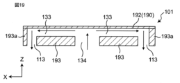
また、図18、図19に示すように、排気路形成板193Dは、2つの突出部193aを有し、それぞれの突出部193aに設けられた排気孔113にそれぞれ接続される2つの第2流路133を形成してもよい。バルブ101が、2つの第2流路133を備える場合、それぞれの第2流路133の最小断面積の合計値が連通孔134の断面積よりも小さければよい。
Also, as shown in Figures 18 and 19, the exhaust
また、図20に示すように、連通孔134、第2流路133、及び、排気孔113で形成される排気路を2組備えていてもよい。複数の排気路を設けることでひとつあたりの流速を下げられるため、連通孔134の大きさを小さくすることができる。
Also, as shown in FIG. 20, two sets of exhaust paths formed by the
(変形例4)
次に、実施形態1の変形例におけるバルブについて図21を参照して説明する。図21は、変形例4におけるバルブ101の部分縦断面図である。変形例4における、排気孔113Aは、第2流路133Cから外側方に向けて解放されており、ポンプ10側を向いていない。したがって、排気路形成板193Dは、突出部193aを有していない。また、図22に示すように、排気孔113Aを第2板192Aに設けて、第2流路133Dからカフ側に排気してもよい。変形例4にかかる構成は、ケース190がバルブ101に装着される装置の筐体である場合には、バルブ101の装着を容易に実施することができる。
(Variation 4)
Next, a valve in a modification of the first embodiment will be described with reference to FIG. 21. FIG. 21 is a partial vertical cross-sectional view of the
次に、図23を参照して、実施の形態1における、バルブ101とカフ109の腕帯ゴム管109aとの接着を説明する。バルブ101と接着対象物としての腕帯ゴム管109aとは、接着物110を介して貼り合わされてもよい。接着物110は、例えば、両面テープである。腕帯ゴム管109a及び接着物110は、それぞれの中心部に、第2通気孔112と連通する孔109b及び孔110aを有する。
Next, referring to FIG. 23, the adhesion between the
接着物110の形状は、バルブ101の四隅を固定する矩形形状でもよいが、バルブ101の四隅を固定しない形状の方がより好ましい。四隅を固定しない形状の接着物として、例えば、図24に示すような、四角より多い多角形状の接着物110Aや、円形状の接着物が挙げられる。接着物110Aも、中心部に、第2通気孔112と連通する孔110Aaを有する。
The shape of the adhesive 110 may be a rectangle that fixes the four corners of the
バルブ101を介して伝わる振動板ユニット60の振動漏れは、バルブ101の上面の中でも、その四隅が最も振動する。接着物110Aの形状がバルブ101の四隅を固定しない形状であることにより、バルブ101から接着物110Aを介して接着対象物へ伝わる振動を緩和することができる。これにより、ポンプ特性を向上させることができる。
The vibration leakage of the
本発明は、上記実施の形態のものに限らず、次のように変形実施することができる。 The present invention is not limited to the above embodiment, but can be modified as follows:
(1)上記各実施形態において、気体として空気を用いているが、これに限られない。空気以外の気体に対してのバルブ及び気体制御装置として用いてもよい。 (1) In each of the above embodiments, air is used as the gas, but this is not limited to this. The valve and gas control device may be used for gases other than air.
(2)上記各実施形態において、枠部材195は、板部材に限らず、シート状の部材でもよく、例えば、両面テープでもよい。
(2) In each of the above embodiments, the
(3)上記実施形態1の変形例2において、第2流路133Aに狭窄部136が設けられていたが、狭窄部136の形態はこれに限らない。例えば、図25に示すように、第2流路133Aの一部が、複数の狭窄部136dにより、複数の流路に分割されていてもよい。この場合の第2流路133Aの最小断面積Cs2は、分割された各流路のそれぞれの断面積をCs3aとすると、分割された各流路の断面積Cs3aの合計値となる。分割された各流路の断面積の合計値は、連通孔134の断面積Cs1よりも小さい。図25の例では、4×Cs3a<Cs1の関係となる。
(3) In the second modification of the first embodiment, the
第2流路133に矩形状の複数の狭窄部136dが配置される構成以外にも、第2流路133に、矩形状の狭窄部が互い違いに配置されてもよいし、円筒状の狭窄部が配置されてもよい。
In addition to the configuration in which multiple
また、図17に示すように、バルブ室131が1つの連通孔134と、1つの第2流路133と、2つの排気孔113を有する場合、連通孔134の断面積Cs1が、第2流路133の断面積Cs2または排気孔113の断面積よりも大きい。また、図18に示すように、バルブ室131が1つの連通孔134と、複数の第2流路133と複数の排気孔113を有する場合、連通孔134の断面積Cs1は、複数の第2流路の断面積Cs2の合計値又は複数の排気孔113の断面積の合計値よりも大きい。また、図20に示すように、バルブ室131が複数の連通孔134と、複数の第2流路133と、複数の排気孔113を有する場合、複数の連通孔134の断面積Cs1の合計値が、複数の第2流路133の断面積Cs2の合計値または複数の排気孔113の断面積の合計値よりも大きい。
17, when the
本発明は、バルブ及びバルブを備える気体制御装置に適用可能である。 The present invention is applicable to valves and gas control devices equipped with valves.
10 ポンプ
40 圧電アクチュエータ
41 振動板
42 圧電素子
50 流路形成板
50a 開口部
50b 流路
51 可撓板
58 可動部
60 振動板ユニット
61 枠板
70 給電板
91 基板
92 開口部
100 気体制御装置
101 バルブ
109 カフ
109a 腕帯ゴム管
109b 孔
110、110A 接着物
110a、110Aa 孔
111 第1通気孔
112 第2通気孔
113、113A 排気孔
114 第1流路
115 制御部
120 ダイヤフラム
121 孔
131 バルブ室
133、133A 第2流路
134 連通孔
134a 開口部
136 狭窄部
138 弁座
152 シール材
160 逆止弁
170 排気弁
190 ケース
191 第1板
191a、191b、191c 溝
191d 開口
191e 壁部
192 第2板
192a 突出部
193、193A、193B、193C 排気路形成板
193a 突出部
195 枠部材
10
Claims (10)
前記第1板の主面に対向して位置し第2通気孔を有する第2板と、
前記第1板と前記第2板との間に位置するバルブ室と、
前記第1板と前記第2板の間に位置し、第3通気孔を備え、前記第3通気孔の周縁が前記第1板又は前記第2板に接触しているときに前記第1通気孔と前記第2通気孔とを非連通状態とし、前記第3通気孔の周縁が前記第1板及び前記第2板から離間しているときに前記第1通気孔と前記第2通気孔とを連通状態とする弁体と、
前記第2板と前記弁体との間に位置し、前記弁体との間に第1流路を形成し、前記第2板との間に第2流路を形成し、前記第1流路と前記第2流路を連通する第4通気孔を備える排気路形成板と、
前記第2板に設けられる第5通気孔と、を備え、
前記第1流路は前記第2通気孔と前記第4通気孔とを連通し、前記第2流路は前記第4通気孔と前記第5通気孔とを連通し、
前記弁体は前記第4通気孔の周縁に接触しているときに前記第1流路と前記第2流路とを非連通状態とし、前記第4通気孔の周縁から離間しているときに前記第1流路と前記第2流路とを連通状態とし、
前記第4通気孔の開口の断面積よりも、前記第2流路の最小断面積又は前記第5通気孔の断面積の方が小さく、
前記第4通気孔の延びる方向と前記第2流路の延びる方向とが異なる、
バルブ。 a first plate having a first vent hole;
a second plate positioned opposite to the main surface of the first plate and having a second air hole;
a valve chamber located between the first plate and the second plate;
a valve body located between the first plate and the second plate, the valve body having a third air hole, the valve body putting the first air hole and the second air hole in a non-communicating state when a periphery of the third air hole is in contact with the first plate or the second plate, and putting the first air hole and the second air hole in a communicative state when a periphery of the third air hole is separated from the first plate and the second plate;
an exhaust passage forming plate located between the second plate and the valve body, forming a first passage between the second plate and the valve body, forming a second passage between the second plate and the exhaust passage forming plate, and including a fourth vent hole connecting the first passage and the second passage;
a fifth vent hole provided in the second plate;
the first flow passage communicates between the second vent hole and the fourth vent hole, the second flow passage communicates between the fourth vent hole and the fifth vent hole,
the valve body brings the first flow passage and the second flow passage into a non-communicating state when in contact with a periphery of the fourth air hole, and brings the first flow passage into a communicative state when separated from the periphery of the fourth air hole,
The minimum cross-sectional area of the second flow path or the cross-sectional area of the fifth air hole is smaller than the cross-sectional area of the opening of the fourth air hole,
The fourth air hole extends in a direction different from the second flow path.
valve.
請求項1に記載のバルブ。2. The valve of claim 1.
請求項1又は2に記載のバルブ。 The minimum cross-sectional area of the second flow path is smaller than a cross-sectional area of an opening of the fifth air hole.
3. A valve as claimed in claim 1 or 2 .
請求項1から3のいずれか1つに記載のバルブ。 The second flow path has a narrowed portion.
A valve according to any one of claims 1 to 3 .
前記第1板の主面に対向して位置し第2通気孔を有する第2板と、
前記第1板と前記第2板との間に位置するバルブ室と、
前記第1板と前記第2板の間に位置し、第3通気孔を備え、前記第3通気孔の周縁が前記第1板又は前記第2板に接触しているときに前記第1通気孔と前記第2通気孔とを非連通状態とし、前記第3通気孔の周縁が前記第1板及び前記第2板から離間しているときに前記第1通気孔と前記第2通気孔とを連通状態とする弁体と、
前記第2板と前記弁体との間に位置し、前記弁体との間に第1流路を形成し、前記第2板との間に第2流路を形成し、前記第1流路と前記第2流路を連通する第4通気孔を備える排気路形成板と、
前記第2板に設けられる複数の第5通気孔と、を備え、
前記第1流路は前記第2通気孔と前記第4通気孔とを連通し、前記第2流路は前記第4通気孔と前記第5通気孔とを連通し、
前記弁体は前記第4通気孔の周縁に接触しているときに前記第1流路と前記第2流路とを非連通状態とし、前記第4通気孔の周縁から離間しているときに前記第1流路と前記第2流路とを連通状態とし、
複数の前記第5通気孔の断面積の合計が前記第4通気孔の開口の断面積より小さく、
前記第4通気孔の延びる方向と前記第2流路の延びる方向とが異なる、
バルブ。 a first plate having a first vent hole;
a second plate positioned opposite to the main surface of the first plate and having a second air hole;
a valve chamber located between the first plate and the second plate;
a valve body located between the first plate and the second plate, the valve body having a third air hole, the valve body putting the first air hole and the second air hole in a non-communicating state when a periphery of the third air hole is in contact with the first plate or the second plate, and putting the first air hole and the second air hole in a communicative state when a periphery of the third air hole is separated from the first plate and the second plate;
an exhaust passage forming plate located between the second plate and the valve body, forming a first passage between the second plate and the valve body, forming a second passage between the second plate and the exhaust passage forming plate, and including a fourth vent hole connecting the first passage and the second passage;
a plurality of fifth air holes provided in the second plate;
the first flow passage communicates between the second vent hole and the fourth vent hole, the second flow passage communicates between the fourth vent hole and the fifth vent hole,
the valve body brings the first flow passage and the second flow passage into a non-communicating state when in contact with a periphery of the fourth air hole, and brings the first flow passage into a communicative state when separated from the periphery of the fourth air hole,
a sum of cross-sectional areas of the plurality of fifth vent holes is smaller than a cross-sectional area of an opening of the fourth vent hole;
The fourth air hole extends in a direction different from the direction in which the second flow passage extends.
valve.
前記第1板の主面に対向して位置し第2通気孔を有する第2板と、
前記第1板と前記第2板との間に位置するバルブ室と、
前記第1板と前記第2板の間に位置し、第3通気孔を備え、前記第3通気孔の周縁が前記第1板又は前記第2板に接触しているときに前記第1通気孔と前記第2通気孔とを非連通状態とし、前記第3通気孔の周縁が前記第1板及び前記第2板から離間しているときに前記第1通気孔と前記第2通気孔とを連通状態とする弁体と、
前記第2板と前記弁体との間に位置し、前記弁体との間に第1流路を形成し、前記第2板との間に複数の第2流路を形成し、前記第1流路と複数の前記第2流路を連通する第4通気孔を備える排気路形成板と、
前記第2板に設けられる複数の第5通気孔と、を備え、
前記第1流路は前記第2通気孔と前記第4通気孔とを連通し、前記第2流路は前記第4通気孔と前記第5通気孔とを連通し、
前記弁体は前記第4通気孔の周縁に接触しているときに前記第1流路と前記第2流路とを非連通状態とし、前記第4通気孔の周縁から離間しているときに前記第1流路と前記第2流路とを連通状態とし、
複数の前記第2流路の断面積の合計が前記第4通気孔の開口の断面積より小さく、又は、複数の前記第5通気孔の断面積の合計が前記第4通気孔の開口の断面積より小さく、
前記第4通気孔の延びる方向と前記第2流路の延びる方向とが異なる、
バルブ。 a first plate having a first vent hole;
a second plate positioned opposite the main surface of the first plate and having a second air hole;
a valve chamber located between the first plate and the second plate;
a valve body located between the first plate and the second plate, the valve body having a third air hole, the valve body putting the first air hole and the second air hole in a non-communicating state when a periphery of the third air hole is in contact with the first plate or the second plate, and putting the first air hole and the second air hole in a communicative state when a periphery of the third air hole is separated from the first plate and the second plate;
an exhaust passage forming plate located between the second plate and the valve body, forming a first passage between the second plate and the valve body, forming a plurality of second passages between the second plate and the exhaust passage forming plate, and including a fourth vent hole connecting the first passage and the plurality of second passages;
a plurality of fifth air holes provided in the second plate;
the first flow passage communicates between the second vent hole and the fourth vent hole, the second flow passage communicates between the fourth vent hole and the fifth vent hole,
the valve body brings the first flow passage and the second flow passage into a non-communicating state when in contact with a periphery of the fourth air hole, and brings the first flow passage into a communicative state when separated from the periphery of the fourth air hole,
A sum of cross-sectional areas of the plurality of second flow paths is smaller than a cross-sectional area of an opening of the fourth vent hole, or a sum of cross-sectional areas of the plurality of fifth vent holes is smaller than a cross-sectional area of an opening of the fourth vent hole,
The fourth air hole extends in a direction different from the direction in which the second flow passage extends.
valve.
請求項1から6のいずれか1つに記載のバルブ。 The second plate also serves as a part of a case that houses the valve.
7. A valve according to any one of claims 1 to 6 .
請求項1から7のいずれか1つに記載のバルブ。 The first plate has a groove formed around the first air hole.
A valve according to any one of claims 1 to 7 .
請求項1から8のいずれか1つに記載のバルブ。 The first plate has a plurality of first ventilation holes.
A valve according to any one of claims 1 to 8 .
前記バルブ室に接続されるポンプと、
前記第1流路に接続される容器と、を備える、
気体制御装置。 A valve according to any one of claims 1 to 9 ;
A pump connected to the valve chamber;
A container connected to the first flow path.
Gas control device.
Applications Claiming Priority (4)
| Application Number | Priority Date | Filing Date | Title |
|---|---|---|---|
| JP2018198385 | 2018-10-22 | ||
| JP2018198385 | 2018-10-22 | ||
| PCT/JP2019/037182 WO2020084978A1 (en) | 2018-10-22 | 2019-09-24 | Valve and gas control device |
| JP2020552990A JP7140203B2 (en) | 2018-10-22 | 2019-09-24 | valve and gas regulator |
Related Parent Applications (1)
| Application Number | Title | Priority Date | Filing Date |
|---|---|---|---|
| JP2020552990A Division JP7140203B2 (en) | 2018-10-22 | 2019-09-24 | valve and gas regulator |
Publications (2)
| Publication Number | Publication Date |
|---|---|
| JP2022174203A JP2022174203A (en) | 2022-11-22 |
| JP7476932B2 true JP7476932B2 (en) | 2024-05-01 |
Family
ID=70331329
Family Applications (2)
| Application Number | Title | Priority Date | Filing Date |
|---|---|---|---|
| JP2020552990A Active JP7140203B2 (en) | 2018-10-22 | 2019-09-24 | valve and gas regulator |
| JP2022143199A Active JP7476932B2 (en) | 2018-10-22 | 2022-09-08 | Valve and gas control device |
Family Applications Before (1)
| Application Number | Title | Priority Date | Filing Date |
|---|---|---|---|
| JP2020552990A Active JP7140203B2 (en) | 2018-10-22 | 2019-09-24 | valve and gas regulator |
Country Status (5)
| Country | Link |
|---|---|
| US (2) | US11365816B2 (en) |
| JP (2) | JP7140203B2 (en) |
| CN (2) | CN112771295B (en) |
| DE (1) | DE112019004803T5 (en) |
| WO (1) | WO2020084978A1 (en) |
Families Citing this family (7)
| Publication number | Priority date | Publication date | Assignee | Title |
|---|---|---|---|---|
| DE112019004803T5 (en) * | 2018-10-22 | 2021-07-08 | Murata Manufacturing Co., Ltd. | VALVE AND GAS CONTROL DEVICE |
| TW202217146A (en) | 2020-10-20 | 2022-05-01 | 研能科技股份有限公司 | Thin profile gas transporting device |
| CN114382686B (en) * | 2020-10-20 | 2024-09-27 | 研能科技股份有限公司 | Thin gas delivery device |
| TWI763286B (en) * | 2021-01-29 | 2022-05-01 | 研能科技股份有限公司 | Micro gas transmission apparatus |
| TWI768809B (en) * | 2021-04-06 | 2022-06-21 | 研能科技股份有限公司 | Miniature gas transportation device |
| JPWO2022234778A1 (en) * | 2021-05-06 | 2022-11-10 | ||
| JPWO2023167284A1 (en) * | 2022-03-04 | 2023-09-07 |
Citations (3)
| Publication number | Priority date | Publication date | Assignee | Title |
|---|---|---|---|---|
| JP5156957B2 (en) | 2006-03-17 | 2013-03-06 | 苓州建設工業株式会社 | Antibacterial and deodorizing equipment |
| WO2018021099A1 (en) | 2016-07-29 | 2018-02-01 | 株式会社村田製作所 | Valve, gas control device, and sphygmomanometer |
| JP7145874B2 (en) | 2017-04-14 | 2022-10-03 | バイオジェン・エムエイ・インコーポレイテッド | Benzazepine analogues as inhibitors of Bruton's tyrosine kinase |
Family Cites Families (10)
| Publication number | Priority date | Publication date | Assignee | Title |
|---|---|---|---|---|
| JPH07145874A (en) * | 1993-11-25 | 1995-06-06 | Matsushita Electric Works Ltd | Exhauster |
| JP5185475B2 (en) * | 2011-04-11 | 2013-04-17 | 株式会社村田製作所 | Valve, fluid control device |
| GB2515239B (en) * | 2012-04-19 | 2018-12-19 | Murata Manufacturing Co | Valve and fluid control apparatus |
| JP5761455B2 (en) | 2012-05-09 | 2015-08-12 | 株式会社村田製作所 | Cooling device, heating cooling device |
| WO2016194564A1 (en) | 2015-05-29 | 2016-12-08 | 株式会社村田製作所 | Suction device |
| CN105134568B (en) * | 2015-08-27 | 2017-08-25 | 广东乐心医疗电子股份有限公司 | Air inflation and exhaust integrated air pump and electronic sphygmomanometer comprising same |
| WO2018020882A1 (en) | 2016-07-29 | 2018-02-01 | 株式会社村田製作所 | Valve, gas control device, and sphygmomanometer |
| DE112019004803T5 (en) * | 2018-10-22 | 2021-07-08 | Murata Manufacturing Co., Ltd. | VALVE AND GAS CONTROL DEVICE |
| JP7568077B2 (en) * | 2021-04-27 | 2024-10-16 | 株式会社村田製作所 | Pumping equipment |
| JPWO2022234778A1 (en) * | 2021-05-06 | 2022-11-10 |
-
2019
- 2019-09-24 DE DE112019004803.1T patent/DE112019004803T5/en active Pending
- 2019-09-24 WO PCT/JP2019/037182 patent/WO2020084978A1/en active Application Filing
- 2019-09-24 CN CN201980063178.1A patent/CN112771295B/en active Active
- 2019-09-24 JP JP2020552990A patent/JP7140203B2/en active Active
- 2019-09-24 CN CN202311027926.5A patent/CN117146007A/en active Pending
-
2021
- 2021-02-16 US US17/176,343 patent/US11365816B2/en active Active
-
2022
- 2022-05-19 US US17/664,055 patent/US11686396B2/en active Active
- 2022-09-08 JP JP2022143199A patent/JP7476932B2/en active Active
Patent Citations (3)
| Publication number | Priority date | Publication date | Assignee | Title |
|---|---|---|---|---|
| JP5156957B2 (en) | 2006-03-17 | 2013-03-06 | 苓州建設工業株式会社 | Antibacterial and deodorizing equipment |
| WO2018021099A1 (en) | 2016-07-29 | 2018-02-01 | 株式会社村田製作所 | Valve, gas control device, and sphygmomanometer |
| JP7145874B2 (en) | 2017-04-14 | 2022-10-03 | バイオジェン・エムエイ・インコーポレイテッド | Benzazepine analogues as inhibitors of Bruton's tyrosine kinase |
Also Published As
| Publication number | Publication date |
|---|---|
| WO2020084978A1 (en) | 2020-04-30 |
| CN112771295B (en) | 2023-09-05 |
| JP7140203B2 (en) | 2022-09-21 |
| US20210164575A1 (en) | 2021-06-03 |
| DE112019004803T5 (en) | 2021-07-08 |
| JP2022174203A (en) | 2022-11-22 |
| US20220275872A1 (en) | 2022-09-01 |
| US11686396B2 (en) | 2023-06-27 |
| JPWO2020084978A1 (en) | 2021-09-02 |
| CN117146007A (en) | 2023-12-01 |
| CN112771295A (en) | 2021-05-07 |
| US11365816B2 (en) | 2022-06-21 |
Similar Documents
| Publication | Publication Date | Title |
|---|---|---|
| JP7476932B2 (en) | Valve and gas control device | |
| JP5185475B2 (en) | Valve, fluid control device | |
| JPWO2018021099A1 (en) | Valve, gas control device, and sphygmomanometer | |
| US10502328B2 (en) | Valve and fluid control appratus | |
| JP6260662B2 (en) | Valve, fluid control device, and blood pressure measurement device | |
| JP6394706B2 (en) | Valve, fluid control device and blood pressure monitor | |
| WO2018021099A1 (en) | Valve, gas control device, and sphygmomanometer | |
| WO2019171736A1 (en) | Valve, and fluid control device with valve | |
| WO2007055136A1 (en) | Pump using unimorph vibration diaphragm | |
| JP5668582B2 (en) | Fluid control device | |
| CN112752906B (en) | Pump and method of operating the same | |
| JP6288395B1 (en) | Valve, fluid control device and blood pressure monitor | |
| JP5500310B2 (en) | Active valve, fluid control device | |
| WO2023167284A1 (en) | Valve, and fluid control device |
Legal Events
| Date | Code | Title | Description |
|---|---|---|---|
| A521 | Request for written amendment filed |
Free format text: JAPANESE INTERMEDIATE CODE: A523 Effective date: 20221004 |
|
| A621 | Written request for application examination |
Free format text: JAPANESE INTERMEDIATE CODE: A621 Effective date: 20221004 |
|
| A977 | Report on retrieval |
Free format text: JAPANESE INTERMEDIATE CODE: A971007 Effective date: 20230830 |
|
| A131 | Notification of reasons for refusal |
Free format text: JAPANESE INTERMEDIATE CODE: A131 Effective date: 20231003 |
|
| A521 | Request for written amendment filed |
Free format text: JAPANESE INTERMEDIATE CODE: A523 Effective date: 20231129 |
|
| TRDD | Decision of grant or rejection written | ||
| A01 | Written decision to grant a patent or to grant a registration (utility model) |
Free format text: JAPANESE INTERMEDIATE CODE: A01 Effective date: 20240319 |
|
| A61 | First payment of annual fees (during grant procedure) |
Free format text: JAPANESE INTERMEDIATE CODE: A61 Effective date: 20240401 |
|
| R150 | Certificate of patent or registration of utility model |
Ref document number: 7476932 Country of ref document: JP Free format text: JAPANESE INTERMEDIATE CODE: R150 |