JP7473923B2 - Drug Injection Device - Google Patents
Drug Injection Device Download PDFInfo
- Publication number
- JP7473923B2 JP7473923B2 JP2022542203A JP2022542203A JP7473923B2 JP 7473923 B2 JP7473923 B2 JP 7473923B2 JP 2022542203 A JP2022542203 A JP 2022542203A JP 2022542203 A JP2022542203 A JP 2022542203A JP 7473923 B2 JP7473923 B2 JP 7473923B2
- Authority
- JP
- Japan
- Prior art keywords
- movable
- drug injection
- injection device
- main body
- hole
- Prior art date
- Legal status (The legal status is an assumption and is not a legal conclusion. Google has not performed a legal analysis and makes no representation as to the accuracy of the status listed.)
- Active
Links
Images


Classifications
-
- A—HUMAN NECESSITIES
- A61—MEDICAL OR VETERINARY SCIENCE; HYGIENE
- A61M—DEVICES FOR INTRODUCING MEDIA INTO, OR ONTO, THE BODY; DEVICES FOR TRANSDUCING BODY MEDIA OR FOR TAKING MEDIA FROM THE BODY; DEVICES FOR PRODUCING OR ENDING SLEEP OR STUPOR
- A61M39/00—Tubes, tube connectors, tube couplings, valves, access sites or the like, specially adapted for medical use
- A61M39/02—Access sites
- A61M39/0247—Semi-permanent or permanent transcutaneous or percutaneous access sites to the inside of the body
-
- A—HUMAN NECESSITIES
- A61—MEDICAL OR VETERINARY SCIENCE; HYGIENE
- A61B—DIAGNOSIS; SURGERY; IDENTIFICATION
- A61B90/00—Instruments, implements or accessories specially adapted for surgery or diagnosis and not covered by any of the groups A61B1/00 - A61B50/00, e.g. for luxation treatment or for protecting wound edges
- A61B90/10—Instruments, implements or accessories specially adapted for surgery or diagnosis and not covered by any of the groups A61B1/00 - A61B50/00, e.g. for luxation treatment or for protecting wound edges for stereotaxic surgery, e.g. frame-based stereotaxis
- A61B90/11—Instruments, implements or accessories specially adapted for surgery or diagnosis and not covered by any of the groups A61B1/00 - A61B50/00, e.g. for luxation treatment or for protecting wound edges for stereotaxic surgery, e.g. frame-based stereotaxis with guides for needles or instruments, e.g. arcuate slides or ball joints
-
- A—HUMAN NECESSITIES
- A61—MEDICAL OR VETERINARY SCIENCE; HYGIENE
- A61B—DIAGNOSIS; SURGERY; IDENTIFICATION
- A61B17/00—Surgical instruments, devices or methods
- A61B17/34—Trocars; Puncturing needles
- A61B17/3415—Trocars; Puncturing needles for introducing tubes or catheters, e.g. gastrostomy tubes, drain catheters
-
- A—HUMAN NECESSITIES
- A61—MEDICAL OR VETERINARY SCIENCE; HYGIENE
- A61B—DIAGNOSIS; SURGERY; IDENTIFICATION
- A61B17/00—Surgical instruments, devices or methods
- A61B17/34—Trocars; Puncturing needles
- A61B17/3478—Endoscopic needles, e.g. for infusion
-
- A—HUMAN NECESSITIES
- A61—MEDICAL OR VETERINARY SCIENCE; HYGIENE
- A61B—DIAGNOSIS; SURGERY; IDENTIFICATION
- A61B90/00—Instruments, implements or accessories specially adapted for surgery or diagnosis and not covered by any of the groups A61B1/00 - A61B50/00, e.g. for luxation treatment or for protecting wound edges
- A61B90/10—Instruments, implements or accessories specially adapted for surgery or diagnosis and not covered by any of the groups A61B1/00 - A61B50/00, e.g. for luxation treatment or for protecting wound edges for stereotaxic surgery, e.g. frame-based stereotaxis
- A61B2090/103—Cranial plugs for access to brain
-
- A—HUMAN NECESSITIES
- A61—MEDICAL OR VETERINARY SCIENCE; HYGIENE
- A61M—DEVICES FOR INTRODUCING MEDIA INTO, OR ONTO, THE BODY; DEVICES FOR TRANSDUCING BODY MEDIA OR FOR TAKING MEDIA FROM THE BODY; DEVICES FOR PRODUCING OR ENDING SLEEP OR STUPOR
- A61M39/00—Tubes, tube connectors, tube couplings, valves, access sites or the like, specially adapted for medical use
- A61M39/02—Access sites
- A61M2039/0205—Access sites for injecting media
-
- A—HUMAN NECESSITIES
- A61—MEDICAL OR VETERINARY SCIENCE; HYGIENE
- A61M—DEVICES FOR INTRODUCING MEDIA INTO, OR ONTO, THE BODY; DEVICES FOR TRANSDUCING BODY MEDIA OR FOR TAKING MEDIA FROM THE BODY; DEVICES FOR PRODUCING OR ENDING SLEEP OR STUPOR
- A61M39/00—Tubes, tube connectors, tube couplings, valves, access sites or the like, specially adapted for medical use
- A61M39/02—Access sites
- A61M39/0247—Semi-permanent or permanent transcutaneous or percutaneous access sites to the inside of the body
- A61M2039/025—Semi-permanent or permanent transcutaneous or percutaneous access sites to the inside of the body through bones or teeth, e.g. through the skull
-
- A—HUMAN NECESSITIES
- A61—MEDICAL OR VETERINARY SCIENCE; HYGIENE
- A61M—DEVICES FOR INTRODUCING MEDIA INTO, OR ONTO, THE BODY; DEVICES FOR TRANSDUCING BODY MEDIA OR FOR TAKING MEDIA FROM THE BODY; DEVICES FOR PRODUCING OR ENDING SLEEP OR STUPOR
- A61M39/00—Tubes, tube connectors, tube couplings, valves, access sites or the like, specially adapted for medical use
- A61M39/02—Access sites
- A61M39/0247—Semi-permanent or permanent transcutaneous or percutaneous access sites to the inside of the body
- A61M2039/027—Semi-permanent or permanent transcutaneous or percutaneous access sites to the inside of the body having a particular valve, seal or septum
-
- A—HUMAN NECESSITIES
- A61—MEDICAL OR VETERINARY SCIENCE; HYGIENE
- A61M—DEVICES FOR INTRODUCING MEDIA INTO, OR ONTO, THE BODY; DEVICES FOR TRANSDUCING BODY MEDIA OR FOR TAKING MEDIA FROM THE BODY; DEVICES FOR PRODUCING OR ENDING SLEEP OR STUPOR
- A61M39/00—Tubes, tube connectors, tube couplings, valves, access sites or the like, specially adapted for medical use
- A61M39/02—Access sites
- A61M39/0247—Semi-permanent or permanent transcutaneous or percutaneous access sites to the inside of the body
- A61M2039/0282—Semi-permanent or permanent transcutaneous or percutaneous access sites to the inside of the body with implanted tubes connected to the port
-
- A—HUMAN NECESSITIES
- A61—MEDICAL OR VETERINARY SCIENCE; HYGIENE
- A61M—DEVICES FOR INTRODUCING MEDIA INTO, OR ONTO, THE BODY; DEVICES FOR TRANSDUCING BODY MEDIA OR FOR TAKING MEDIA FROM THE BODY; DEVICES FOR PRODUCING OR ENDING SLEEP OR STUPOR
- A61M2210/00—Anatomical parts of the body
- A61M2210/06—Head
- A61M2210/0693—Brain, cerebrum
Landscapes
- Health & Medical Sciences (AREA)
- Life Sciences & Earth Sciences (AREA)
- Heart & Thoracic Surgery (AREA)
- Animal Behavior & Ethology (AREA)
- Veterinary Medicine (AREA)
- Public Health (AREA)
- Engineering & Computer Science (AREA)
- Biomedical Technology (AREA)
- General Health & Medical Sciences (AREA)
- Surgery (AREA)
- Biophysics (AREA)
- Gastroenterology & Hepatology (AREA)
- Pulmonology (AREA)
- Anesthesiology (AREA)
- Hematology (AREA)
- Molecular Biology (AREA)
- Medical Informatics (AREA)
- Pathology (AREA)
- Oral & Maxillofacial Surgery (AREA)
- Nuclear Medicine, Radiotherapy & Molecular Imaging (AREA)
- Infusion, Injection, And Reservoir Apparatuses (AREA)
Description
本発明は薬物注入装置に関し、肥満、脳卒中、脊椎神経、認知症などの脳神経疾患を有する患者の頭蓋骨に薬物の繰り返し投与のための脳内薬物注入装置を長期的に設けることにより、より正確な位置に投与できるようにする薬物注入装置に関する。 The present invention relates to a drug injection device, and more particularly to a drug injection device that allows for more accurate administration of drugs by providing an intracerebral drug injection device for repeated administration to the skull of patients with neurological disorders such as obesity, stroke, spinal nerve disease, and dementia for a long period of time.
近年、生活の質を低下させる疾患において、特に社会経済的費用を増加させる脳関連疾患が多くの社会的問題となっている。脳関連疾患、例えば、退行性脳疾患、精神系疾患、脳腫瘍及びストローク、肥満、脊椎神経などは年々増加する傾向である。脳疾患を有する末期癌及び慢性疼痛を有する患者の場合、持続的かつ繰り返しの鎮痛剤の投与及び服用を通じて疼痛を軽減する必要がある。そして、アルツハイマー病(Alzheimer's disease)のような退行性脳疾患またはパーキンソン病(Parkinson's disease)のような精神系疾患を患う認知症患者の場合、治療効果を最大化するために化学薬物、幹細胞などのような治療剤を持続的かつ繰り返し投与する必要がある。 In recent years, brain-related diseases, which reduce the quality of life and increase socio-economic costs, have become a major social problem. Brain-related diseases, such as degenerative brain diseases, psychiatric diseases, brain tumors and strokes, obesity, spinal nerves, etc., tend to increase year by year. Patients with terminal cancer and chronic pain who have brain diseases need to reduce pain through continuous and repeated administration and use of painkillers. And, dementia patients who suffer from degenerative brain diseases such as Alzheimer's disease or psychiatric diseases such as Parkinson's disease need to continuously and repeatedly administer therapeutic agents such as chemical drugs and stem cells to maximize the therapeutic effect.
現在、脳関連疾患の治療効果を高めるために、持続的な期間に繰り返し経口投与及び静脈投与を通じて治療する方法が多く用いられている。しかしながら、既存の方法は消化器官が弱くなった場合、薬物の服用が難しくなることがあり、治療剤の全身的循環による副作用が多数誘発されることがあり、入院治療や治療剤の投与などに伴う患者の身体的苦痛と経済的負担が大きいという限界がある。 Currently, in order to improve the effectiveness of treatment for brain-related diseases, treatment methods that involve repeated oral and intravenous administration over a sustained period of time are widely used. However, existing methods have limitations, such as difficulty in taking medication when the digestive organs are weak, the induction of numerous side effects due to the systemic circulation of the therapeutic agent, and the physical pain and economic burden on patients that are associated with hospitalization and administration of therapeutic agents.
一方、脳に直接投与する方法は既存の方法に比べて効果に優れるが、薬物の全身的循環による副作用はほとんどない利点がある。脳内直接投与方法は、例えば、認知症疾患の患者の場合、海馬(Hippocampus)であるターゲットポイントに化学薬物、幹細胞などの治療剤を直接投与して治療することができる。しかしながら、脳をターゲットとする薬物は必ずしも脳血管障壁(BBB:Blood-Brain Barrier)を通過しなければならない。そして、治療効果を高めるためには、正確なターゲットポイントに繰り返し投与する必要がある。 On the other hand, the method of administering drugs directly into the brain is more effective than existing methods, and has the advantage of having almost no side effects due to the systemic circulation of drugs. For example, in the case of a patient with dementia, the direct administration method into the brain can treat the patient by directly administering therapeutic agents such as chemical drugs or stem cells to the target point, the hippocampus. However, drugs that target the brain must necessarily pass through the blood-brain barrier (BBB). Furthermore, to improve the therapeutic effect, repeated administration to the exact target point is necessary.
したがって、従来技術は脳に長期間移植され、正確なターゲットポイントに繰り返し投与できる薬物注入装置を開発している。しかしながら、ガイドチューブの位置が変わったり、一方向にのみ挿入されて正確な位置に再び薬物を投入することができないため、施術の精度が低くなるという限界がある。特に脳実質内のような病巣に繰り返し投与するとき、ガイドチューブの精度が低くなって、薬物注入装置を繰り返し移植する手術をしなければならない場合、患者の経済的費用の負担が増加し、満足できる治療効果が減少する限界がある。 Conventional technologies have therefore developed drug injection devices that can be implanted in the brain for long periods of time and repeatedly administered to precise target points. However, there are limitations in that the position of the guide tube changes or it is inserted only in one direction, making it impossible to inject drugs again at the precise location, resulting in low precision of the procedure. In particular, when repeatedly administering to a lesion such as the brain parenchyma, the precision of the guide tube decreases, and surgery must be performed to repeatedly implant the drug injection device, resulting in increased financial burden on the patient and reduced satisfactory therapeutic effects.
本発明は前記の点に鑑みて創案されたものであり、本発明の目的は、認知症治療の他に肥満、ストローク、脊椎神経など脳疾患を治療するための脳内直接注入が可能な薬物注入装置のガイドチューブを病巣であるターゲットポイントに近接するように正確に位置決めし、中心軸に基づいて方向転換を可能にする薬物注入装置を提供することである。 The present invention has been devised in light of the above points, and the object of the present invention is to provide a drug injection device capable of direct intracerebral injection to treat brain diseases such as obesity, stroke, and spinal nerves in addition to dementia, and capable of accurately positioning the guide tube of the device close to the target point, which is the lesion, and enabling direction changes based on the central axis.
また、本発明の他の目的は、薬物を繰り返し投与するとき、全身麻酔による外科手術を行わずに移植された部位を切開して移植位置を容易に識別することができ、その位置に薬物を繰り返し投与させる薬物注入装置を提供することである。 Another object of the present invention is to provide a drug injection device that, when administering a drug repeatedly, can easily identify the transplantation location by incising the transplanted area without performing a surgical procedure under general anesthesia, and can repeatedly administer the drug to that location.
本発明のさらに他の目的は、頭蓋骨の外部及び脳実質の内部をシーリング部及び可動栓部で二重遮断することによって、繰り返し投与による薬物の逆流及び外部からの汚染物質の侵入を防止する薬物注入装置を提供することである。 A further object of the present invention is to provide a drug injection device that prevents the backflow of drugs due to repeated administration and the intrusion of contaminants from the outside by providing a double barrier between the outside of the skull and the inside of the brain parenchyma with a sealing section and a movable plug section.
前記目的を達成するために、患者の頭蓋骨と頭皮との間に移植固定されて薬物を注入させる薬物注入装置において、前記頭蓋骨と接して移植固定され、内部孔が形成される本体と、前記本体と隣接する内部孔が形成され、前記本体に対向して結合固定させて締結する本体固定部と、前記本体と前記本体固定部との間に位置し、中央には薬物注入孔が形成されてターゲットポイントに方向転換が可能な可動部と、前記可動部の薬物注入孔を密閉するように設けられ、薬物を注射するための注射針が挿入されるシーリング部と、前記シーリング部の上部に位置して前記可動部を密閉固定し、前記シーリング部が外部から離脱しないように遮断することができ、前記薬物注入装置の移植位置を識別して繰り返し投与点を案内する可動栓部と、前記本体の上部と前記本体固定部の上部を頭蓋骨に締結する少なくとも2つの締結部材と、を含み、前記本体は前記頭蓋骨の上部に位置して支持する支持部を含み、前記支持部の外径は前記本体固定部の外径より小さく、前記可動部の外径よりも大きく、前記本体固定部と隣り合うように結合して前記本体の内部孔に前記可動部を収容及び固定することができる。 In order to achieve the above object, a drug injection device that is implanted and fixed between the patient's skull and scalp to inject drugs comprises a main body that is implanted and fixed in contact with the skull and has an internal hole formed therein, a main body fixing part that has an internal hole adjacent to the main body and is connected and fixed opposite to the main body to fasten it, a movable part that is located between the main body and the main body fixing part and has a drug injection hole formed in the center and can be redirected to a target point, a sealing part that is provided to seal the drug injection hole of the movable part and into which an injection needle for injecting drugs is inserted, and an upper part of the sealing part. and a movable plug part that can seal and fix the movable part and block the sealing part from coming off from the outside, and that can identify the implantation position of the drug injection device and repeatedly guide the administration point, and at least two fastening members that fasten the upper part of the body and the upper part of the body fixing part to the skull, and the body includes a support part that is located on the upper part of the skull and supports it, and the outer diameter of the support part is smaller than the outer diameter of the body fixing part and larger than the outer diameter of the movable part, and can be connected adjacent to the body fixing part to accommodate and fix the movable part in the internal hole of the body.
前記薬物注入装置は、前記可動部と連結されて脳実質内に入ってターゲットに近い位置まで挿入され、前記ターゲットポイントに薬物を注入する注射針をターゲットの方向にガイドするガイドチューブをさらに含むことができる。 The drug injection device may further include a guide tube that is connected to the movable part, inserted into the brain parenchyma to a position close to the target, and guides the injection needle, which injects the drug into the target point, in the direction of the target.
前記ガイドチューブは、前記薬物注入孔の下端に取り付けられ、前記可動部と前記ガイドチューブとの間を連結し、前記ガイドチューブの内部と延びる孔が形成されるチューブ連結部をさらに含むことができる。 The guide tube may further include a tube connection part that is attached to the lower end of the drug injection hole, connects the movable part and the guide tube, and has a hole formed therein that extends to the inside of the guide tube.
前記支持部は、前記本体の上部に位置し、前記締結部材が挿入されて動かないように固定する少なくとも1つの第1締結孔と、前記本体固定部と結合するように固定する少なくとも1つの固定突起と、を含むことができる。 The support part is located on the upper part of the main body and may include at least one first fastening hole into which the fastening member is inserted to fix it so as not to move, and at least one fixing protrusion that fixes it so as to be coupled with the main body fixing part.
前記本体固定部は、上部が曲面に突出して前記薬物注入装置の移植位置を識別する識別部と、中心に前記可動部が動かないように外部を固定する固定孔と、上部の周りに前記締結部材が挿入されて動かないように固定する少なくとも1つの第2締結孔と、下部が曲面に凹んで形成され、前記本体の支持部と一致する形状に合わせて結合が容易な結合溝と、前記結合溝の内部には前記固定突起と対向して結合される少なくとも1つの固定溝が形成されることができる。 The main body fixing part may have an identification part whose upper part protrudes into a curved surface to identify the implantation position of the drug injection device, a fixing hole in the center to fix the outside so that the movable part does not move, at least one second fastening hole around the upper part into which the fastening member is inserted to fix it so that it does not move, a coupling groove whose lower part is formed into a curved surface and whose shape matches the support part of the main body to facilitate coupling, and at least one fixing groove formed inside the coupling groove to face and couple with the fixing protrusion.
前記可動部は、前記可動収容孔に位置し、外形が曲面からなり方向転換が可能な可動本体部を含み、前記可動本体部は、内部の中央が中空であり、ターゲットポイントに薬物が注入されるように案内する薬物注入孔が形成されることができる。 The movable part is located in the movable receiving hole and includes a movable main body part having a curved outer shape and capable of changing direction, and the movable main body part may be hollow in the center and have a drug injection hole formed therein to guide the drug to be injected at the target point.
前記薬物注入孔は、前記可動部の内部孔に位置するシーリング部を収容する第1収容部と、前記第1収容部と連結されて前記可動部の内部の下端に位置し、薬物の注入時に挿入される前記ガイドチューブと注射針を収容する第2収容部と、を含むことができる。 The drug injection hole may include a first receiving portion that receives a sealing portion located in the internal hole of the movable portion, and a second receiving portion that is connected to the first receiving portion and is located at the lower end of the interior of the movable portion, and receives the guide tube and injection needle that are inserted when injecting drugs.
前記第1収容部は、前記可動部の内部孔の開始から前記シーリング部が収容される点までねじ山で形成されることができる。 The first receiving portion may be formed with a thread from the start of the internal bore of the movable portion to the point where the sealing portion is received.
前記可動部は、0.03mm未満の真球度からなる球状に形成されることができる。 The movable part can be formed into a spherical shape with a sphericity of less than 0.03 mm.
前記シーリング部はシリコーン素材からなることができる。 The sealing portion can be made of a silicone material.
前記可動栓部は、中央に注射針が注入されるように下に行くほど傾斜した孔である針収容部が形成され、前記針収容部を内部に含み、前記可動部の外部に位置する栓上端部と、前記栓上端部に連結され、外部はねじ山が形成されて前記薬物注入孔と雌雄をなすねじ山で締結される栓締結部と、を含むことができる。 The movable stopper part has a needle accommodating part formed in the center, which is a hole that slopes downward so that an injection needle can be injected, and includes the needle accommodating part inside, a stopper upper end part located outside the movable part, and a stopper fastening part connected to the stopper upper end part and having a screw thread formed on the outside to fasten with the drug injection hole by a male-female screw thread.
前記締結部材は、前記本体と前記本体固定部のうち少なくともいずれかを頭蓋骨内に植設固定させるボディ部と、前記ボディ部に連結されて取り付けられたヘッド部と、を含み、前記ヘッド部は、中央に位置して締結時に締結機構と水平に締結されるようにする水平溝と、前記水平溝を基準として横軸と縦軸を分ける線形に識別可能に形成された識別溝と、を含むことができる。 The fastening member includes a body portion that implants and fixes at least one of the main body and the main body fixing portion into the skull, and a head portion that is connected and attached to the body portion, and the head portion can include a horizontal groove located in the center to allow the head portion to be fastened horizontally to the fastening mechanism when fastened, and a linearly identifiable identification groove that divides the horizontal axis and the vertical axis based on the horizontal groove.
前記ボディ部は、頭蓋骨内に固定され、端部までねじ山がテーパー状に形成され、少なくとも1つの圧力低減溝が形成されることができる。 The body portion can be secured within the skull, have a tapered thread to an end, and can have at least one pressure reducing groove.
前記ガイドチューブは、片側または両側に薬物が不均一に流れるように少なくとも1つの薬物投与孔が形成され、前記ガイドチューブの端部の内径及び外径が曲線で形成されて、頭蓋骨内に挿入されるときの組織の損傷を最小限に抑える形状を有することができる。 The guide tube may have at least one drug administration hole formed on one or both sides to allow for uneven drug flow, and the inner and outer diameters of the ends of the guide tube may be curved to minimize tissue damage when inserted into the skull.
前記薬物注入装置は、前記本体、前記本体固定部、前記可動部、前記可動栓部及び前記ガイドチューブの少なくともいずれか1つはポリエーテルエーテルケトンからなることができる。 At least one of the main body, the main body fixing part, the movable part, the movable plug part and the guide tube of the drug injection device may be made of polyether ether ketone.
前記締結部材はチタン素材からなることができる。 The fastening member can be made of titanium material.
前記シーリング部は、内部の異物の投入を防止するフィルタをさらに含み、前記フィルタと前記シーリング部が一体化されて交換及び設置が一度に容易な一体型シーリングフィルタ膜を含むことができる。 The sealing part may further include a filter that prevents foreign objects from entering the interior, and may include an integrated sealing filter membrane in which the filter and the sealing part are integrated to facilitate easy replacement and installation in one go.
前記ガイドチューブは、前記頭蓋骨と接する面を基準として中心軸から左右側のターゲットポイントの方向に回転して変形する最大角度が60°以内であり得る。 The guide tube can rotate and deform within a maximum angle of 60° from the central axis toward the left and right target points based on the surface that contacts the skull.
本発明に係る薬物注入装置は、一度移植した後、治療効果を高めるために薬物を繰り返し投与するとき、全身麻酔による外科手術をせずに移植された部位を切開して移植位置を容易に識別することができ、その位置に薬物を投与できるため、経済的、時間的な負担を減らし、繰り返し投与による治療の効果を高めることができる。 When the drug injection device of the present invention is implanted once and then repeatedly administered to enhance the therapeutic effect, the implanted site can be incised without surgery under general anesthesia, making it easy to identify the implantation location and administer the drug to that location, thereby reducing the financial and time burden and enhancing the therapeutic effect of repeated administration.
また、本発明に係る薬物注入装置は、方向転換が可能な可動部と、その内部に挿入されたガイドチューブを病巣であるターゲットポイントの方向に回転させ、ガイドチューブの内部を介して注射針を挿入して薬物を正確にターゲットポイントに投与するようにガイドできるため、薬物投与の精度を向上させることができる。 In addition, the drug injection device of the present invention has a movable part that can be changed in direction, and a guide tube inserted inside the movable part can be rotated in the direction of the target point, which is the lesion, and an injection needle can be inserted through the inside of the guide tube to guide the drug to be accurately administered to the target point, thereby improving the accuracy of drug administration.
さらに、本発明に係る薬物注入装置は、頭蓋骨の外部と脳実質の内部をシーリング部及び可動栓部で二重遮断することにより、繰り返し投与による薬物の逆流及び外部からの汚染物質の侵入を防止できて感染による副作用を減らすことができる。 Furthermore, the drug injection device of the present invention provides a double barrier between the outside of the skull and the inside of the brain parenchyma with a sealing section and a movable plug section, thereby preventing drug reflux due to repeated administration and the intrusion of contaminants from the outside, thereby reducing side effects due to infection.
さらに、本発明による薬物注入装置は、移植後に脳組織と結着しない生体適合性素材で製造されて移植安定性が高いため、長期間移植されても患者が免疫的拒絶反応なしに日常活動することができる。 Furthermore, the drug injection device according to the present invention is made of a biocompatible material that does not bind to brain tissue after implantation, and has high implant stability, so patients can continue their daily activities without experiencing immune rejection even after long-term implantation.
以下、添付の図面を参照して本発明の実施形態による定位ガイド機構を詳細に説明する。ここで、添付の図面は、技術の構成及び作用の説明及び理解の便宜及び明確性のために部分を誇張または簡略化して示したものであり、各構成要素が実際のサイズと正確に一致するものではない。 Hereinafter, a positioning guide mechanism according to an embodiment of the present invention will be described in detail with reference to the accompanying drawings. Hereinafter, the accompanying drawings are shown with parts exaggerated or simplified for convenience and clarity in explaining and understanding the configuration and operation of the technology, and each component does not exactly correspond to the actual size.
図1は本発明の実施形態による薬物注入装置を概略的に示した組立斜視図である。 Figure 1 is an assembled perspective view showing a drug injection device according to an embodiment of the present invention.
図1を参照すると、薬物注入装置100は、患者Pの頭蓋骨1と頭皮3との間に移植固定されて薬物を注入することができる。薬物注入装置100は、本体110と、本体固定部150と、可動部130と、シーリング部160と、可動栓部180と、締結部材170と、を含むことができる。
Referring to FIG. 1, the
本体110は頭蓋骨1と接して移植固定され、内部孔を形成することができる。また、本体110は、本体固定部150と隣接して結合して本体110の内部孔に可動部130を収容固定することができる。本体110は、支持部115と、挿入部113と、可動収容孔110aと、を含むことができる。本体110は頭蓋骨1の上部に位置して支持する支持部115を含み、支持部115の外径は本体固定部150の外径より小さく、可動部130の外径よりも大きくてもよい。支持部115は、本体固定部150と隣接して結合して本体110の内部孔に可動部130を収容固定することができる。支持部115は本体110の上部に位置するものであり、締結部材170が挿入されて動かないように固定する少なくとも1つの第1締結孔110bと、本体固定部150と結合するように固定する少なくとも1つの固定突起117と、を含むことができる。挿入部113は頭蓋骨1に挿入されるものであって、接して位置することができる。可動収容孔110aは、本体110の内部に可動部130を収容することができる。
The
本体固定部150は、本体110と隣り合う内部孔が形成され、本体110と対向して結合固定して締結することができる。また、本体固定部150は、識別部157と、固定孔150aと、第2締結孔150bと、支持結合溝157aと、を含むことができる。識別部157は、上部が曲面に突出しており、前記薬物注入装置100の移植位置を識別することができる。固定孔150aは、可動部130が中心に移動しないように外部を固定することができる。第2締結孔150bは少なくとも1つからなり、上部の周辺に締結部材170が挿入されて動かないように固定することができる。支持結合溝157aは、支持部115と接する面が支持部115と一致する形状に凹状の溝で形成され、支持部115との結合が容易である。また、支持結合溝157aは、ヘッド収容溝157b及び突起収容溝157cのうち少なくとも一つをさらに形成することもできる。ヘッド収容溝157bは、支持部115と締結される締結部材170のヘッド部175が上部に突出したものを収容する溝であり、本体110が本体固定部150と結合するとき、支持部115と取付部155とが接する面の摩擦を低減することができる。また、ヘッド収容溝157bは、本体110と締結される締結部材170のヘッド部175が干渉することにより、本体固定部150との締結固定力が減少することを防止でき、本体固定部150と合わせて容易に結合されることができる。突起収容溝157cは、支持結合溝157aに少なくとも一つとして形成され、支持部115の固定突起117に対向して位置し、これを収容して結合することができる。
The
したがって、本体固定部150は、本体110と結合する際、第2締結孔150b、支持結合溝157a及び突起収容溝157cを含む少なくとも3点以上の結合力を有するため、頭蓋骨1に長期間移植されていても、互いに分離されず固定力が向上することができる。
Therefore, when the main
可動部130は、本体110と本体固定部150との間に位置し、中央に薬物注入孔133が形成されてターゲットポイント7に方向転換が可能である。可動部130は、可動収容孔110aに位置し、外形が曲面からなり方向転換が可能な可動本体131を含み、この可動本体131の内部に中央が中空であり、ターゲットポイント7に薬物が注入されるように案内する薬物注入孔133を形成することができる。可動部130は、0.03mm未満の真球度からなる球状に形成することができる。可動部130が0.03mmを超えると、本体110の可動収容孔110aと当接する面が不均一であり、所望のターゲットポイント7の方向に回転しにくいことがある。また、可動部130の表面粗さRaは、0.1μmを超え、0.5μm未満の範囲を有することができる。0.1μm以下の場合、微細に真球度を逸脱して固定力が低下する問題が発生することがあり、0.5μm以上の場合、表面が粗くなって、本体110との接触時に摩擦を起こすため、固定力が弱くなることがある。つまり、角度調整時に完全な回転になりにくい限界がある。また、薬物注入装置100の組み立て時の不良率が高いことがある。
The
前記薬物注入孔133は、第1収容部133aと第2収容部133bとを含むことができる。第1収容部133aは、可動部130の内部孔に位置するシーリング部160を収容することができる。第2収容部133bは、第1収容部133aと連結されて可動部130の内部下端に位置し、薬物注入時に挿入されるガイドチューブ140及び注射針191を収容することができる。第1収容部133aは、可動部130の内部孔の開始からシーリング部160が収容される点までねじ山で形成されることができる。シーリング部160は、可動部130の薬物注入孔133を密閉するように設けられ、薬物を注射するための注射針191が挿入されることができる。シーリング部160はシリコーン(Silicone)で製造され、これに限定されるものではなく、合成樹脂材料のうちの少なくともいずれか1つの材料からなることができる。シーリング部160は、注射針191が挿入されても元の形態に戻すことができる。したがって、シーリング部160は可動部130内に挿入されて外部からの汚染物質を遮断し、薬物注入装置100の脳移植後に感染されることを防止することができる。
The
可動栓部180は、シーリング部160の上部に位置して可動部130を密閉固定し、シーリング部160が外部から分離離脱しないように遮断することができる。可動栓部180は、針収容部180aと、位置表示部185と、可動締結部183と、を含むことができる。針収容部180aは、中央に注射針191が注入されるように下方に向かうにつれて傾斜した孔が形成されることができる。位置表示部185は、針収容部180aを内部に含み、可動部130の外部に位置することができる。可動締結部183は位置表示部185と連結されており、外部にはねじ山が形成されて薬物注入孔133と雌雄をなすねじ山で締結されることができる。
The
図1を参照すると、薬物注入装置100はガイドチューブ140をさらに含むことができる。ガイドチューブ140は、可動部130と連結されて脳実質5内に入ってターゲットポイント7に近い位置まで挿入され、そのターゲットポイント7に薬物を注入する注射針191をターゲットポイント7の方向に案内することができる。可動部130と結合されたガイドチューブ140は、頭蓋骨1と当接する点を基準にして中心軸CLからターゲットポイント7の方向に挿入されることができる。ガイドチューブ140は、薬物注入孔133の下端に取り付けられ、可動部130とガイドチューブ140との間を連結するチューブ連結部145を含むことができる。チューブ連結部145には、ガイドチューブ140の内部と延びる孔が形成されることができる。
Referring to FIG. 1, the
本発明に係る薬物注入装置100においては、本体110、本体固定部150、可動部130、可動栓部180及びガイドチューブ140のうちの少なくともいずれか一つがポリエーテルエーテルケトン(PEEK)で製造されることができるが、これに限定されるものではなく、身体移植接合性を有する素材なら、多様に適用して製造することができる。
In the
締結部材170は、本体110の上部と本体固定部150の上部を頭蓋骨1に締結する少なくとも2つを含むことができる。締結部材170は、ボディ部173とヘッド部175とを含むことができる。ボディ部173は、本体110及び本体固定部150のうち少なくともいずれかを頭蓋骨1内に植設固定することができる。ボディ部173は、頭蓋骨1内に植設固定され、端部までねじ山がテーパ状に形成され、少なくとも1つの圧力低減溝173aが形成されることができる。ヘッド部175はボディ部173と連結され、中央に位置して締結時に締結機構と水平に締結されるようにする水平溝175bと、水平溝175bを基準に横軸と縦軸を分ける線形に識別可能に形成された識別溝175aと、を含むことができる。また、締結部材170は、チタン素材からなることができるが、これに限定されるものではなく、身体移植接合性及び移植安定性を有する素材なら、多様に適用して製造されることができる。
The
図2は、図1の薬物注入装置を定位ガイド機構を用いて患者の頭蓋骨内のターゲットポイントの位置を見つけて設置する施術の様子を示した図であり、図3は、図2の薬物注入装置が設置された後、薬物を注入する様子を示した断面図である。 Figure 2 shows the procedure of locating and setting the target point in the patient's skull using the drug injection device of Figure 1 using a stereotactic guide mechanism, and Figure 3 is a cross-sectional view showing the process of injecting drugs after the drug injection device of Figure 2 has been set up.
図2及び図3を参照すると、脳内に薬物注入が必要な脳疾患関連患者Pを対象に施術する際に、定位ガイド装置10を用いて薬物注入装置100の挿入をガイドすることができる。ここで、脳疾患は、例えば、脳腫瘍、ストローク、認知症疾患であるアルツハイマー(Alzheimer's)、精神系疾患であるパーキンソン病、うつ病、精神分裂などに関連する。薬物注入装置100は、患者Pの頭蓋骨3を穿孔して移植するために、頭蓋骨3のうち、側頭骨、頭頂骨などの位置に「U」字状に切開することができる。また、薬物注入装置100は、本体110と、可動部130と、ガイドチューブ140と、本体固定部150と、シーリング部160と、可動栓部180と、を含むことができる。本体110は頭蓋骨3に埋め込まれており、本体110の上端は頭皮5と頭蓋骨3との間に位置し、本体110の下端は頭蓋骨3内に挿入されて位置することができる。可動部130は、本体110の内部に挿入されるものであって、上部が開放された球状を有し、脳実質内の病巣であるターゲットポイント7に方向転換することができる。
2 and 3, when performing treatment on a brain disease-related patient P who needs to inject a drug into the brain, the
図2を参照すると、定位ガイド装置10は、可動部130と結合して中心軸CLに位置するガイドチューブ140を中心CLから方向転換してターゲットポイント7に位置するようにガイドできる。ここで、定位ガイド装置10は、ガイドハンドル13と、位置調整部15と、位置調整ハンドル部17と、ボルト部19と、を含むことができる。詳細には、ガイドハンドル13を可動部130に設け、その内部に長いロッド状の位置調整部15にガイドチューブ140を結合設置して挿入することができる。挿入時に位置調整部15が揺れたり折れたりすることを防止するために、位置調整部15の端部に位置調整ハンドル部17を結合設置することができる。定位ガイド機構100は、ガイドチューブ140をターゲットポイント7にできるだけ近づけて配置した後、頭蓋骨3から分離除去することができる。
Referring to FIG. 2, the
一方、図2は、定位ガイド機構100を用いてガイドチューブ140がターゲットポイント7に位置する最終的な様子のみを示したものである。これに限定されず、図面には示されていないが、定位ガイド装置10は、連結ガイド部(図示せず)をさらに含むことができる。連結ガイド部は、ガイドチューブ140のガイドハンドル13内に正確に挿入されるようにガイドすることができる。連結ガイド部は、パイプ状の少なくとも一対で構成され、取り外し可能であり、ガイドハンドル13の上端にさらに設けられることができる。また、連結ガイド部は、一端がガイドハンドル13の内部に挿入され、他端がガイドハンドル13の上部に取り付けられて、ガイドチューブ140が挿入されることをさらにガイドすることができる。連結ガイド部は、挿入されるチューブ連結部145と接する状態になると、分離除去されることができる。除去された後、図2に示したように、位置調整ハンドル部17の先端は、チューブ連結部145を押しながら可動部130の下端に位置させることができる。
Meanwhile, FIG. 2 shows only the final state where the
図3に示したように、ガイドチューブ140には、脳疾患関連薬物を内部に投入する注射針191が挿入されることができる。ここで、注射針191は、例えば、トロカール針、検査用針などを内部に収容することができる。しかしながら、これに限定されるものではなく、種々の施術器具及び装置、例えば、ナビゲーションプローブ、刺激リード、切除プローブまたはカテーテル、注射または流体送達装置、生検針、抽出ツール等が挿入されて診断及び/又は治療手順を実行できる。
As shown in FIG. 3, an
また、薬物注入装置100を用いて様々な脳疾患関連薬物を注入することができる。例えば、アミロイド仮説(β-アミロイドタンパク質の生成を抑制する物質)、Aβタンパク質凝集抑制剤、タウ凝集抑制剤、コリン分解酵素抑制剤、NMDA収容体またはアンタゴニスト、コリン性前駆物質、抗酸化物質、糖治療薬などの認知症関連化学薬物、ヒト臍帯血細胞、ヒト臍帯血由来間葉系幹細胞、神経幹細胞、骨髄幹細胞などの幹細胞、パーキンソン病、うつ病、精神分裂などの精神系疾患治療薬、脳腫瘍及びストローク関連治療薬などが含まれることができる。
In addition, various brain disease-related drugs can be injected using the
図2及び図3を参照すると、以下のように本発明による薬物注入装置100を設置する施術方法について詳細に説明する。
Referring to Figures 2 and 3, the procedure for installing the
<施術方法> <Treatment method>
ナビゲーション装置(図示せず)を用いて、MRI撮影を通じてターゲットポイント7となる位置を探し、座標上の頭蓋骨1に位置を表示して施術前準備工程を行う(S10)。
Using a navigation device (not shown), the location of the
施術前準備工程(S10)は、ナビゲーションプローブを用いて位置を入力してMRI装置で映像及び写真を送信する工程を含むことができる(S11)。 The pre-treatment preparation process (S10) may include a process of inputting a position using a navigation probe and transmitting images and photos to an MRI device (S11).
MRI撮影された画像または写真に基づいて患者P、すなわち、人間の脳内のターゲットポイント7となる位置を見つけ、頭皮3、すなわち、皮下層に基準となる複数の区間をマーキングする工程を含むことができる(S13)。
This may include a step of locating a
ナビゲーションプローブの種類は、測定用プローブと検証用プローブに分類することができる。このうち、検証用プローブを用いて格子する前の経路を確認した後、患者Pの頭皮3にマーキングすることができる。マーキング部位に位置する患者Pの頭皮3を、例えば、「L」、「¬」、「S」などの形状に切開する工程を含むことができる(S15)。
The types of navigation probes can be classified into measurement probes and verification probes. Of these, the verification probe can be used to check the path before gridding, and then mark the
切開後、穿孔のための空間を確保するために切開部位を広げ、切開した皮下層5を施術用糸を用いて束ねて引っ張ることができ、施術中に広がらないように固定する工程を含むことができる(S17)。この際、鉗子(forceps)などを利用して固定及び広げることができる。また、施術中に視野及び可視距離を確保するために、必要に応じて生理食塩水と共に吸引カテーテル(suction catheter)を用いて異物、血液等を吸入して視野を確保する工程を含むことができる(S17a)。 After the incision, the incision site can be widened to secure space for perforation, and the incised subcutaneous layer 5 can be tied and pulled using surgical thread, and a process can be included in which the incision site is fixed so as not to spread during the procedure (S17). At this time, forceps or the like can be used to fix and widen the site. In addition, in order to secure the field of view and visual distance during the procedure, a process can be included in which a suction catheter is used, together with saline, to aspirate foreign matter, blood, etc., to secure the field of view (S17a).
切開されて露出した頭蓋骨1に穿孔した(Burr hole)後、ピンセットで骨削り屑または残留物を除去する工程を含むことができる(S19)。
After making a burr hole in the exposed
患者Pの頭皮5を切開して頭蓋骨1に穴(Burr hole)を出して薬物注入装置100を穿孔部位に移植する工程を行うことができる(S20)。
A process can be performed in which the scalp 5 of patient P is incised, a burr hole is drilled in the
まず、本体110を頭蓋骨1に移植固定して締結した後、可動収容孔110aに可動部130を挿入し、第1締結孔110bに少なくとも2つの締結部材170を設けることができる(S30)。
First, the
可動部130を挟んで本体110の上部に本体固定部150に対向して設けることができる。また、本体固定部150に形成された固定孔150aと本体110の可動収容孔110aとが可動部130を収容しながら連通するように設けることができる(S40)。
The
次に、本体固定部150に形成された第2締結孔150bに少なくとも2つの締結部材170を設ける。このとき、締結部材170は、可動部130が移動する程度だけ固定させ、可動部130にガイドハンドル13を設ける工程を行うことができる(S50)。
Next, at least two
ガイドハンドル13の内部に光ガイド部123が組み立てられたプローブ収容部(図示せず)を設け、その内部にナビゲーションプローブ(図示せず)を挿入して方向転換しながらターゲットポイント7を探すために調整する工程を実施することができる(S60)。
A probe receiving section (not shown) assembled with the light guide section 123 is provided inside the
正確なターゲットポイント7が設定されると、ナビゲーションプローブ(図示せず)とプローブ収容部(図示せず)をガイドハンドル13から分離除去することができる(S70)。
Once the
チューブ連結部145を含むガイドチューブ140を準備する。次に、位置調整部15に位置調整ハンドル部17とボルト部19とを締結して一組として準備する。このとき、位置調整ハンドル部17がチューブ連結部145と接する部分まで到達すると、ボルト部19を位置調整ハンドル部17の締結収容部179に締結して固定させることができる(S80)。
A
前記ガイドハンドル13の上端に一対の分離可能な連結ガイド部(図示せず)を設け、その内部の中心に位置調整部15を含むガイドチューブ140が挿入されることをさらに案内することができる。チューブ連結部145が連結ガイド部(図示せず)に当たると、連結ガイド部(図示せず)を分離除去し、位置調整ハンドル部17の先端がチューブ連結部145を押しながら可動部130の下端に配置するまで挿入する工程を実施する(S90)。
A pair of detachable connecting guide parts (not shown) can be provided at the upper end of the guide handle 13 to further guide the insertion of the
前記位置調整部15がガイドチューブ140の端部に位置して一緒に移動しながら、脳実質5内のターゲットポイント7の方向に回転し、ガイドチューブ140よりも先にターゲットポイント7に到達するように位置調整ハンドル部17を調整することができる(S100)。
The position
ガイドチューブ140がターゲットポイント7に近接して位置すると、位置調整部15のセットをガイドハンドル13から分離除去し、最終的にガイドハンドル13も可動部130から分離除去することができる(S110)。
When the
一方、脳実質5内のターゲットポイント7の方向に回転させる方法において、S50乃至S110に含まれる位置調整ハンドル部17を用いてガイドチューブ140を位置させることに限定されるものではない。S50乃至S110を省略し、ガイドチューブ140が挿入された可動部130のみを最大角度60°以内に回転させてターゲットポイント7に位置させることもできる。
Meanwhile, the method of rotating in the direction of the
脳実質5内のターゲットポイント7の方向に回転された可動部130の内部にシーリング部160を挿入し、その上部に可動栓部180を専用ドライバ(図示せず)を用いて締結設置することができる。また、本体110の上部に緩く位置する締結部材170を再び締結して患者Pの頭蓋骨1上に薬物注入装置100を固定することができる(S120)。
The sealing
薬物注入装置100の初期移植が完了した後、可動栓部180の位置表示部185を外観識別して位置を見つけることができる(S130)。
After the initial implantation of the
治療剤195を含む注射針191は、可動栓部180の針収容部180a、シーリング部160、チューブ連結部145の挿入ガイド孔145a及びガイドチューブ140の方向に沿って順次挿入してターゲットポイント7に挿入し、治療剤195を長期間にわたって繰り返し投与することができる(S140)。
The
詳しくは、薬物注入工程(S140)は、治療剤195の薬物を含む注射針191が可動栓部180、針収容部180a、シーリング部160、挿入ガイド孔145a及びガイドチューブ140の順に通過して最終のターゲットポイント7に到達して薬物を投与することを含むことができる(S145)。ここで、挿入ガイド孔145a及び針収容部180aのそれぞれは、漏斗のように下端に向かって狭くなる形状を有し、薬物がガイドチューブ140内に円滑に流入するように形成されることができる。また、治療剤195の薬物を含む注射針191が最終のターゲットポイントに到達して、長期間にわたって複数回の繰り返し投与を行うことを含むことができる(S147)。このとき、ガイドチューブ140の端部に薬物が溜まらないように少なくとも1つ以上の薬物投与孔140aを形成して、薬物が端部に溜まらずターゲットポイント7に均等に分散して薬物を投入する工程を含むことができる(S149)。
In detail, the drug injection process (S140) may include the
図4は、図3の薬物注入装置を完全に組み立てて稼動できる動作を概略的に示した側断面図である。 Figure 4 is a cross-sectional side view that shows the drug injection device of Figure 3 in a fully assembled and operational state.
図4を参照すると、本発明による薬物注入装置100は、本体110と、可動部130と、本体固定部150と、ガイドチューブ140と、シーリング部160と、可動栓部180と、を含み、完全に組み立てられることができる。本体110は、下端が頭蓋骨1に挿入される挿入部113であり、上端が頭蓋骨1の上部を水平に支持する支持部115を含むことができる。支持部115に本体固定部150の取付部155が当接して設けられることができる。このとき、本体110と本体固定部150との間の結合固定力をさらに高めるために、その間に締結部材170をさらに設けることができる。詳しくは、支持部115の一端に第2締結孔150bが形成され、第2締結孔150bに締結部材170が設けられることができる。また、支持部115の他端には、本体110の第1締結孔110bと対向して接するヘッド収容溝157bが形成され、第1締結孔110bに締結された締結部材170のヘッド部175が安着されることができる。したがって、薬物注入装置100は、第1締結孔110bと第2締結孔150bとが互いに異なる少なくとも3箇所に形成されている。すなわち、本体110と本体固定部150との締結時に少なくとも6箇所に締結部材170を設けることができる。したがって、薬物注入装置100は、移植の後、本体110と本体固定部150との分離離脱が容易ではなく、初期移植固定力を維持することができる。
Referring to FIG. 4, the
また、本体110の中央に形成された可動収容孔110aには、外形が曲面からなり、方向転換が可能な可動本体131が設けられることができる。この可動本体131の内部に中央が中空であり、ターゲットポイント7に薬物が注入されるようにガイドする薬物注入孔133を形成することができる。この薬物注入孔133の下端にガイドチューブ140が設けられ、ターゲットポイント7の方向に回転されることができる。すなわち、可動部130と結合されたガイドチューブ140は、頭蓋骨1と接する面を基準として中心軸CLから左右側のターゲットポイント7の方向に回転できる可動範囲の最大角度が60°以内であることができる。最大角度が60°を超えると、支持部115と結合された取付部155の一側面に過剰な負荷が生じて、結合バランスが崩れるため、取付部155が分離離脱することができる。また、可動部130に設けられたガイドチューブ140がターゲットポイント7の方向に位置が確定されるとき、薬物注入孔133にチューブ連結部145が着座し、チューブ連結部145の上部にシーリング部160が設けられることができる。ここで、シーリング部160は、可動部130の内部に挿入されるように一定の高さL6及び外径の大きさD10を有することができる。シーリング部160の条件範囲は、図8で後述する。シーリング部160の上部には、可動栓部180の可動締結部材170を設けることができる。可動栓部180は、中央に中空の針収容部180aが形成されることができる。また、可動栓部180の位置表示部185は六角形に形成されて移植された位置を表示することができる。したがって、薬物注入装置100を頭蓋骨1に移植した後、頭皮3を覆って縫合したときに位置表示部185を介して移植された位置を探し、注射針191が針収容部180a、シーリング部160、チューブ連結部145の挿入ガイド孔145a及びガイドチューブ140の順に挿入されることができる。
In addition, the
図5(a)乃至図5(c)は、本発明の実施形態に係る薬物注入装置の構成のうち本体を示した平面図、側面図及び側断面図である。 Figures 5(a) to 5(c) are a plan view, a side view, and a cross-sectional side view showing the main body of the drug injection device according to an embodiment of the present invention.
図5(a)乃至図5(c)を参照すると、本体110は、内部に前記可動部130を収容する可動収容孔110aを形成することができる。そして、本体110は、頭蓋骨1の上部に位置し、患者Pの頭蓋骨1に固定支持する支持部115と、頭蓋骨1に挿入される挿入部113と、を含むことができる。
Referring to FIG. 5(a) to FIG. 5(c), the
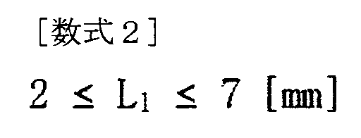
また、本体110は、下記の数式1及び数式2のうち少なくともいずれかを満たすことができる。
Furthermore, the
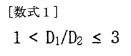
ここで、D1は挿入部113の外径の大きさ、D2は可動収容孔110aの内径の大きさ、L1は挿入部113の挿入高さである。
Here, D 1 is the outer diameter of the
数式1の下限値を外れる場合、本体110をなす厚さが薄くなって可動部130を固定しにくくなり、数式1の上限値を外れる場合、可動部130が安着せず外部に露出することがあるため、感染などの危険性が高まる可能性がある。したがって、数式1の条件範囲を満たす場合、本体110は頭蓋骨1と頭皮3との間に位置することができ、可動収容孔110aに可動部130が安着して結合され得る適切な厚さを有することができる。
If the lower limit of
一方、数式2の下限値を外れる場合、挿入部113は頭蓋骨1の厚さより低い高さを有することにより、可動部130を収容する空間を得ることができず、数式2の上限値を外れる場合、本体110が頭蓋骨1の厚さを逸脱して脳実質5を圧迫する挿入部113の厚さを有することができるため、施術後の患者Pに頭痛、めまいなどの副作用を招くことがある。したがって、数式2の条件範囲を満たす場合、挿入部113が頭蓋骨1に挿入されて脳実質5を圧迫しない適正の高さを有することができる。
On the other hand, if the lower limit of
支持部115は、第1締結孔110bと固定突起117とを含むことができる。第1締結孔110bは少なくとも一つであり、本体110の上部に位置し、締結部材170が挿入されて動かないように固定されることができる。固定突起117は、少なくとも1つからなり、本体固定部150と結合するように固定させることができる。
The
少なくとも1つの固定突起117及び第1締結孔110bが形成されて、下記の数式3を満たすことができる。
At least one fixing
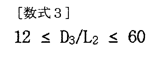
ここで、D3は支持部115の外径の大きさであり、L2は支持部115の高さである。
Here, D3 is the outer diameter of the
数式3の下限値を外れる場合、支持部115の外径と比較して高さが高いため、頭蓋骨1に安定して安着しにくくなり、数式3の上限値を外れる場合、支持部115の外径が大きくなるので、第1締結孔110bの間の距離が遠くなり、時間が経つにつれて固定力が弱くなることがある。したがって、数式3の条件範囲を満たす場合、支持部115は頭蓋骨1に挿入された挿入部113を取り付けることが容易であり、固定突起117及び第1締結孔110bを形成することに最適な直径及び高さを有することができるため、固定力及び安定性を確保することができる。
If the lower limit of
固定突起117は、下記の数4を満たすことができる。
The fixed

ここで、D4は固定突起117の外径の大きさであり、L3は固定突起117の高さである。
Here, D4 is the outer diameter of the fixed
数式4の下限値を外れる場合、固定突起117の高さが高くなって、本体固定部150と結合するときに破損しやすく、締結されても、本体固定部150の一部が上方に浮かんで可動部130が固定されないという問題が発生することがあり、数式4の上限値を超える場合、固定突起117の高さが低くなるにつれて固定突起117を固定する機能が失われる可能性がある。したがって、数式4の条件範囲を満たす場合、本体固定部150と締結後、支持部115が回転または離脱することなく時間が経っても固定力を維持することができる。
If the lower limit of Formula 4 is not met, the height of the fixing
図6(a)乃至図6(d)は、本発明の実施形態による薬物注入装置の構成のうち、本体固定部を示した平面図、底面図、c-c'側断面図及びd-d'側断面図である。 Figures 6(a) to 6(d) are a plan view, a bottom view, a cc' side cross-sectional view, and a dd' side cross-sectional view showing the main body fixing part of the configuration of a drug injection device according to an embodiment of the present invention.
図6(a)乃至図6(d)を参照すると、本体固定部150は、本体110と対向して結合固定して締結することができる。本体固定部150は、可動部130が移動しないように外部を固定する固定孔150aが中心に形成されることができる。また、本体固定部150は、上部の周りに締結部材170が挿入されて動かないように固定する少なくとも1つの第2締結孔150bが形成されることができる。
Referring to FIG. 6(a) to FIG. 6(d), the
図6(c)は、本体固定部150の平面図(a)をc-c’のように切断したときの側断面図である。本体固定部150の上端には中央に固定孔150aが形成され、本体110に対向して位置する取付部155には第2締結孔150bが形成されて、締結部材170が設置結合されることができる。
Figure 6(c) is a side cross-sectional view of the main
図6(d)は、本体固定部150の底面図(b)をd-d’のように切断したときの側断面図である。本体固定部150は、中央に固定孔150aが形成され、外部から見て移植位置を判別することができる識別部157を含むことができる。識別部157は、取付部155と比較した際に凸状に突出した形状を有し、その底面には本体110の第1締結孔110bと対向するヘッド収容溝157bが形成されることができる。このヘッド収容溝157bは、第1締結孔110bに設けられる締結部材170のヘッド部175が位置することができる。
6(d) is a side cross-sectional view of the main
固定孔150a及び本体固定部150は、下記の数式5及び/又は本体固定部150の高さが1mm~9mmのうちの少なくともいずれか一つを満たすことができる。
The fixing
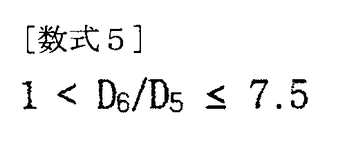
ここで、D5は固定孔150aの外径の大きさであり、D6は本体固定部150の外径の大きさである。
Here, D5 is the outer diameter of the fixing
数式5の下限値を外れる場合、本体固定部150の中心の固定孔150aが大きくなると、外部から露出する部分が多くなり感染問題が発生することがあり、数式5の上限値を外れる場合、本体固定部150の中心の固定孔150aが小さすぎるため、シーリング部160及び可動部130のうちの少なくとも一方が固定孔150aに挿入されにくい場合がある。したがって、数式5の条件範囲を満たす場合、本体110と結合して固定力を維持しやすく、固定孔150aにシーリング部160及び可動部130が挿入されて、外部から汚染物質を遮断して感染を防ぐことができる。
If the lower limit of Equation 5 is exceeded, the fixing
また、本体固定部150の高さが1mm~9mmの範囲から外れる場合、患者Pの頭皮3の高さよりも高くなり、移植後の外観が突出形成することができるため、患者Pの日常生活に不便をもたらすことができる。したがって、本体固定部150の高さが1mm~9mmの範囲を満たす場合、移植後の外観上特に差がないため、患者Pが感じる不快感が軽減され、外部衝撃による損傷が減少し、患者Pの円滑な日常生活を維持することができる。
Furthermore, if the height of the main
図6(a)及び図6(b)を参照すると、本体固定部150は、識別部157と、固定孔150aと、第2締結孔150bと、支持結合溝157aと、を含むことができる。識別部157は、上部が曲面状に突出しており、薬物注入装置100の移植位置を識別することができる。固定孔150aは、可動部130が中心に移動しないように外部を固定することができる。第2締結孔150bは、上部の周りに締結部材170が挿入されて動かないように固定する少なくとも1つで構成することができる。支持結合溝157aは、下部が曲面状に凹んで形成され、本体110の支持部115の形状と一致し、結合が容易である。また、支持結合溝157aは、内部に固定突起117と対向して結合される少なくとも1つの突起収容溝157cを含み、支持結合溝157aは、下記の数式6を満たすことができる。
6(a) and 6(b), the main
ここで、R1は支持結合溝157aの半径を意味する。
Here, R1 means the radius of the
数式6の下限値を外れる場合、本体110と結合する際に支持部115を収容しにくいため、固定力が弱くなることがあり、数式6の上限値を外れる場合、本体110を収容しても残る空間が発生して本体110との結合固定力が弱くなる。したがって、数式6の条件範囲を満たす場合、支持結合溝157aは円を三等分する際に生じる一定の面積を有することができるため、支持部115の形状に合わせて長期間結合しても分離離脱することなく固定力を維持できる。
If the lower limit of Formula 6 is exceeded, it may be difficult to accommodate the
図7(a)及び図7(b)は、本発明の実施形態に係る薬物注入装置の構成のうち可動部を示した側面図及び側断面図である。 Figures 7(a) and 7(b) are a side view and a cross-sectional side view showing the movable parts of the configuration of a drug injection device according to an embodiment of the present invention.
図7(a)及び図7(b)を参照すると、可動部130は本体110と本体固定部150との間に位置し、中央には薬物注入孔133が形成されてターゲットポイント7に位置調整が可能である。可動部130は、可動部130と薬物注入孔133とを含むことができる。可動部130は、可動収容溝110aと固定孔150aとの間に位置し、曲面で可動部130の外形をなして位置調整が可能である。薬物注入孔133は、頭蓋骨1内に薬物が注入されるように内部の孔を形成することができる。
Referring to FIG. 7(a) and FIG. 7(b), the
可動部130は、下記の数式7を満たすことができる。
The

ここで、D8は可動部130の外径の大きさであり、L5は可動部130の高さである。
Here, D8 is the outer diameter of the
数式7の下限値を外れる場合、可動部130の高さが高くなるため、シーリング部160を挿入できる内部空間を設けることに限界があり、回転が難しくなることがあり、数式7の上限値を外れる場合、可動部130の外径が大きくなるにつれて、本体固定部150が上部に締結されにくい。また、脳実質5を圧迫して施術後の患者Pに不快感や副作用を誘発させることができる。したがって、数式7の条件範囲を満たす場合、可動部130は球状で本体110と本体固定部150との間に位置してターゲットポイント7の方向に回転が可能である。
When the lower limit of
薬物注入孔133は、可動部130の内部孔に位置するシーリング部160を収容する第1収容部133aと、第1収容部133aと連結されて可動部130の内部下端に位置し、薬物の注入時に挿入される注射針を収容する第2収容部133bと、を含むことができる。第1収容部133aは、可動部130の内部孔の開始からシーリング部160が収容される点までねじ山で形成されることができる。
The
第1収容部133a及び第2収容部133bは、それぞれ、下記の数式8及び数式9のうち少なくともいずれかを満たすことができる。
The
ここで、V1は第1収容部133aの内部空間体積であり、D9は第2収容部133bの内径の大きさである。
Here, V1 is the internal space volume of the first
数式8の下限値を外れる場合、第2収容部133bの内径の大きさよりも第1収容部133aの内部空間体積が大きくなり、ガイドチューブ140の挿入時に第2収容部133bを探して挿入し難くなり、数式8の上限値を外れる場合、第2収容部133bの内径の大きさが第1収容部133aの内部空間体積より大きくなり、ガイドチューブ140の挿入時の位置決めが難しくなることがあり、移植の後、時間が経つにつれて固定力が低下する可能性がある。したがって、数式8の条件範囲を満たす場合、第1収容部133aにシーリング部160が収容されて外部から汚染物質を遮断して脳実質5に浸透しないように保護することができる。また、第1収容部133aに薬物を保管できる空間が確保できるため、認知症治療剤、脳疾患関連疼痛治療剤等の一定量で繰り返し投与が必要な薬物が溜まってガイドチューブ140を通過しながらターゲットポイント7に投与されることができる。これにより、数式8の条件範囲を満たす可動部130の第1及び第2収容部133bは、薬物注入装置100の繰り返し投与機能を向上させることができる。
If the lower limit of formula 8 is exceeded, the internal space volume of the
一方、数式9の下限値から外れる場合、第2収容部133bへのガイドチューブ140の挿入が困難であり、数式9の上限値から外れる場合、第2収容部133bの内径がガイドチューブ140の外径より大きくなるにつれて、余分な空間である隙間が生じることがある。その間隙に薬物が注入されるとき、ターゲットポイント7以外の脳実質5の部分に投与されて副作用を引き起こす可能性がある。したがって、数式9の条件範囲を満たす場合、第2収容部133bの内径がガイドチューブ140の外径に合わせて結合されるので、薬物の注入時にターゲットポイント7に精密かつ正確に投与されることができる。
On the other hand, if the lower limit of Equation 9 is not met, it is difficult to insert the
第1収容部133aは、側面が可動部130の内部孔の開始からシーリング部160が収容される点までねじ山で形成されることができる。
The
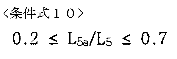
ここで、ねじ山が形成される高さは、下記の数式10を満たすことができる。
Here, the height at which the thread is formed can satisfy the following
ここで、L5は第1収容部133aと第2収容部133bの全体の高さを意味し、L5aはねじ山で形成される高さを意味する。
Here, L5 means the total height of the
数式10の下限値を外れる場合、ねじ山で形成される高さは可動栓部180と締結設置されにくい場合があり、数式10の上限値を外れる場合、第1及び第2収容部133a、133bの全体高さの大部分がねじ山で形成される高さと同じであるため、第2収容部133bの内部にシーリング部160が収容されにくく、収容されても、側面のねじ山の部分によってシーリング部160が損傷することがある。したがって、数式10の条件範囲を満たす場合、第1及び第2収容部133a、133bの全高はシーリング部160及びガイドチューブ140を収容することができ、ねじ山で形成される高さは可動栓部180と締結されて外部からの汚染物質を遮断することができる。
If the lower limit of
図8(a)乃至図8(c)は、それぞれ、本発明の実施形態に係る薬物注入装置の構成のうち可動栓部を示した平面図、側面図及び側断面図である。 Figures 8(a) to 8(c) are a plan view, a side view, and a cross-sectional side view, respectively, showing the movable plug portion of the configuration of a drug injection device according to an embodiment of the present invention.
図8(a)乃至図8(c)を参照すると、可動栓部180は、針収容部180aと、位置表示部185と、可動締結部183と、を含むことができる。針収容部180aは、可動栓部180の中央に注射針191が注入される孔であり、どの方向に注射針191が挿入されても中央に挿入できるように内部に行くほど狭くなる漏斗形状を有することができる。位置表示部185は、可動部130の上部に位置して六角形に形成され、六角形の角部は成形されることができる。しかしながら、これに限定されず、位置を表示することができる様々な形状に適用されることができる。したがって、位置表示部185は、薬物注入装置100を介して薬物を繰り返し投与する際に、針収容部180a部分が施術者の手に触れて薬物注入位置を発見できるように識別する機能を有する。可動締結部183は位置表示部185と連結されており、外部にはねじ山が形成されて薬物注入孔133と雌雄をなすねじ山で締結されることができる。
8(a) to 8(c), the
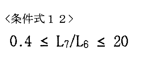
シーリング部160及び可動栓部180は、下記の数式11及び数式12の少なくともいずれかを満たすことができる。
The sealing

ここで、D10はシーリング部160の外径の大きさ、D11は可動栓部180の外径の大きさ、L6はシーリング部160の高さ、L7は可動栓部180の高さである。
Here, D 10 is the outer diameter of sealing
数式11の下限値を外れる場合、シーリング部160の外径が大きくなり、その上部を遮断する可動栓部180を押し出すことができ、その押し出した隙間の間に外部からの異物が浸透して副作用を誘発することができる。数式11の上限値を外れる場合、シーリング部160は比較的小さくなるので、可動部130内に固定位置しないことがあり、可動栓部180を介して挿入された注射針191をシーリング部160に通すのは困難であり得る。したがって、数式11の条件範囲を満たす場合、可動栓部180はシーリング部160を常に遮断することができ、外部からの異物の浸透を防止することができる。
When the lower limit of Equation 11 is not satisfied, the outer diameter of the sealing
一方、数式12の下限値を外れる場合、シーリング部160の高さが相対的に大きくなるため、可動栓部180が可動部130の内部に締結されにくい限界があり、数式12の上限値を外れた場合、可動栓部180の高さが相対的に大きくなるにつれて、可動部130と締結後、本体固定部150の固定孔150aから外れて目立つように頭皮3より高く突出することがある。このような状態は、薬物注入装置100の移植後に患者Pが日常生活に不快感を感じることがあり、さらにひどくなると痛み誘発症状などの副作用を招く可能性がある。したがって、数式12の条件範囲を満たす場合、シーリング部160は可動部130の内部への収容に適し、その上部に可動栓部180が遮断されることにより外部からの異物や汚染を遮断することができるため、移植の適合性及び安定性を有することができる。また、適正高さを有するシーリング部160及び可動栓部180は突出せずに頭蓋骨1と頭皮3との間に位置して、移植後の患者Pが日常生活を円滑にすることができる。
On the other hand, when the lower limit of formula 12 is not satisfied, the height of the sealing
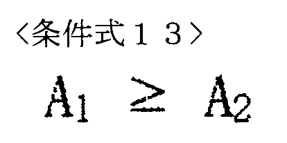
針収容部180aは、下記の数式13を満たすことができる。
The
ここで、A1は中心軸を基準に左右をなす角度のうち、前記針収容部180aの上端部の角度を意味し、A2は前記針収容部180aの中間部分の角度を意味する。
Here, A1 refers to the angle of the upper end of the
数式13の条件範囲を外れる場合、注射針191が針収容部180aの上端を通過するとき、中間部分の角度が急激に大きくなるにつれて、注射針191の経路方向が変わって折れたり挿入が難しくなることがある。数式13の条件範囲を満たす場合、注射針191が外部から針収容部180aの上端に接するとき、どの方向に注射針191を挿入しても最終的に針収容部180aの下端部を通過して所望のターゲットポイント7の方向に挿入することができる。
If the condition range of
位置表示部185は、下記の数式14を満たすことができる。
The
ここで、L7は可動栓部180の全高を意味し、L7aは位置表示部185の高さを意味する。
Here, L7 means the total height of the
数式14の下限値を外れる場合、可動栓部180で可動締結部183が大部分を占めるため、可動部130との締結は容易であるが、設置、分離除去過程で可動部130から可動栓部180を分離することが困難であり、数式14の上限値を外れる場合、可動栓部180で可動締結部183がほとんど占める割合がないため、可動部130との締結が困難である。したがって、数式14の条件範囲を満たす場合、可動栓部180は可動部130に締結されて外部から汚染物質の流入を遮断でき、結合及び分離離脱が容易である。
When the lower limit of Equation 14 is not satisfied, the
図9(a)及び図9(b)は、それぞれ、本発明の実施形態に係る薬物注入装置の構成のうち締結部材を示した平面図及び側面図である。 Figures 9(a) and 9(b) are plan and side views, respectively, showing the fastening member of the configuration of a drug injection device according to an embodiment of the present invention.
図9(a)及び図9(b)を参照すると、締結部材170は、本体110の上部と本体固定部150の上部を頭蓋骨1に締結する少なくとも2つを含むことができる。締結部材170は、頭蓋骨内に植設固定されたボディ部173と、ボディ部173と連結されて取り付けられるヘッド部175とを含むことができる。
9(a) and 9(b), the
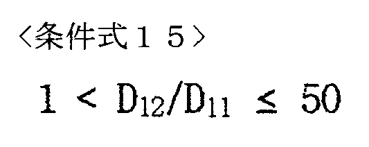
ボディ部173及びヘッド部175は、下記の数式15及び数式16の少なくともいずれかを満たすことができる。
The
ここで、D11は前記ボディ部173の外径の大きさを意味し、D12は前記ヘッド部175の外径の大きさを意味し、L9は前記ボディ部173の長さを意味し、L8は前記ヘッド部175の長さを意味する。
Here, D11 means the outer diameter of the
数式15の下限値を外れる場合、ボディ部173の直径がヘッド部175の直径よりも大きくなることにより、締結後に取付けられず、締結される孔に落ち込むことができ、数式15の上限値を外れる場合、ヘッド部175が相対的に大きくなることができて本体固定部150による干渉が発生して締結が困難であり、相対的にボディ部173の力が弱くなって固定力が低下し、安定した締結が不可能になる。したがって、数式15の条件範囲を満たす場合、締結部材170は、本体110及び本体固定部150を固定することができ、薬物注入装置100の移植安定性及び固定力を向上させることができる。
When the lower limit of
一方、数式16の下限値を外れる場合、ヘッド部175の長さが相対的に長くなるにつれて移植されるボディ部173を固定支持することが困難であり、数式16の上限値を外れる場合、ボディ部173が比較的長くなるにつれて、頭蓋骨1を離れて脳実質5まで圧迫して、移植後に副作用を引き起こす可能性がある。したがって、数式16の条件範囲を満たす場合、締結部材170がヘッド部175とボディ部173との間の適切な割合を有することにより、頭蓋骨1に植設されて薬物注入装置100を固定させることができる。
On the other hand, if the lower limit of Equation 16 is not satisfied, the
ヘッド部175は、中央に位置して締結時に締結機構と水平に締結されるようにする水平溝175bと、水平溝175bを基準に横軸と縦軸を分ける線形で識別可能に形成された識別溝175aと、を含むことができる。
The
水平溝175b及び識別溝175aは、下記の数式17を満たすことができる。
The
ここで、L8aは識別溝175aの深さを意味し、D13は水平溝175bの外径の大きさを意味する。
Here, L8a denotes the depth of the
数式17の下限値を外れる場合、識別溝175aの長さが相対的に長くなるにつれて水平溝175bの機能が失われることがあり、数式17の上限値を外れる場合、水平溝175bの外径の大きさが比較的大きくなるにつれて、識別溝175aの識別機能が減少する可能性がある。したがって、数式17の条件範囲を満たす場合、ヘッド部175は、識別溝175aの識別機能と、水平溝175bの締結部材170を水平に合わせて締結する機能との両方を有することができる。
When the lower limit of
ボディ部173は、頭蓋骨内に植設固定され、端部までねじ山がテーパ状に形成され、下記の数式18を満たす少なくとも1つの圧力低減溝173aを形成することができる。
The
ここで、L9はボディ部173の長さを意味し、L9aは圧力低減溝173aが形成された部分の長さを意味する。
Here, L9 refers to the length of the
数式18の下限値を外れる場合、圧力低減溝173aがボディ部173の長さより相対的に長く設計されるため、締結部材170の機能が失われて固定力が弱くなることがあり、数式18の上限値を外れる場合、締結部材170は圧力低減溝173aをほとんど持たないため、植設時に骨組織に圧力を増加させることができる。このように長期間移植される場合、骨組織が損傷して炎症を引き起こす可能性があり、ひどいと移植手術の副作用を引き起こす可能性がある。したがって、数式18の条件範囲を満たす場合、圧力低減溝173aが形成された締結部材170が骨に植立されるときに骨組織を損傷する圧力を比較的弱くして骨の損傷を最小化することができる。
When the lower limit of Equation 18 is exceeded, the
図10(a)乃至図10(c)は、それぞれ、本発明の実施形態に係る薬物注入装置の構成のうち、ガイドチューブを示した平面図、側面図及び側断面図である。 Figures 10(a) to 10(c) are a plan view, a side view, and a cross-sectional side view, respectively, showing a guide tube in the configuration of a drug injection device according to an embodiment of the present invention.
図10(a)乃至図10(c)を参照すると、ガイドチューブ140は、ターゲットポイント7に薬物を注入する注射針をターゲットの方向にガイドすることができる。そして、ガイドチューブ140は、脳実質5を通過するときの損傷を最小限に抑えるために表面が滑らかであり得る。
Referring to FIG. 10(a) to FIG. 10(c), the
また、ガイドチューブ140は、長さが10mm~300mmの範囲を含むことができ、下記の数式19を満たすことができる。
Furthermore, the
ここで、D14aはガイドチューブ140の内径の大きさを意味し、D14bはガイドチューブ140の外径の大きさを意味する。
Here, D 14 a means the inner diameter of the
数式19の下限値を外れると、注射針191の挿入時のガイドチューブ140の厚さが薄いため、注射針191が通過するときにガイドチューブ140の内部が裂けたり破損することがある。また、ガイドチューブ140が脳実質5に挿入されるときに強度が弱すぎて脳実質5に癒着して副作用を引き起こしたり、注射針191を収容してガイドする機能が失われたりすることができ、数式19の上限値を外れる場合、ガイドチューブ140の厚さが厚くなり、注射針191の挿入が困難になる可能性がある。また、ガイドチューブ140は、厚さに応じた挿入強度が強くなるため、脳実質5への挿入時に損傷を起こすことがある。したがって、数式19の条件範囲を満たす場合、ガイドチューブ140は、まず脳実質5の損傷が最小になるように挿入され、次に注射針191がガイドチューブ140内に収容されるときにターゲットポイント7の方向に投入されるように案内することができる。
If the lower limit of
一方、ガイドチューブ140は、チューブ連結部145をさらに含むことができる。チューブ連結部145は、薬物注入孔133の下端に取り付けられ、可動部130とガイドチューブ140との間を連結し、内部ガイドチューブ140の内部と延びる挿入ガイド孔145aを形成することができる。この挿入ガイド孔145aは、下方に向かって狭くなる漏斗形状を有することができるが、これに限定されず、中心方向に案内可能な様々な形状に形成されることができる。したがって、挿入ガイド孔145aは、注射針191が針収容部180aを通過したときに中心とは異なる方向にねじられても、ターゲット支点7に正確に挿入されるように針収容部180aと共に中心方向に二重ガイドする役割をすることができる。
Meanwhile, the
チューブ連結部145は、下記の数式20及び数式21の少なくともいずれかを満たすことができる。
The

ここで、D15はチューブ連結部145の外径の大きさ、D16はチューブ連結部145の内径の大きさ、L10はチューブ連結部145の高さである。
Here, D 15 is the outer diameter of
数式20の下限値を外れる場合、チューブ連結部145の内径が相対的に大きくなるにつれてチューブ連結部145の厚さが薄くなることがあるため、注射針191の挿入時に破れたり破損することがあり、数式20の上限値を外れる場合、チューブ連結部145の厚さが大きくなるため、内部の空間が小さくなり、注射針191の挿入と分離が困難になることがある。したがって、数式20の条件範囲を満たす場合、チューブ連結部145が可動部130の下端に支持固定されるので、分離離脱することなく安定して結合されることができる。また、チューブ連結部145は、内部に注射針191が通過するにつれてターゲットポイント7の方向に案内することができる。
When the lower limit of Equation 20 is exceeded, the thickness of the
一方、数式21の下限値を外れる場合、チューブ連結部145の高さが相対的に低くなり、支持する固定力が弱くなることがあるため、脳実質5から離脱分離されて副作用を招くことができ、数式21の上限値を外れる場合、チューブ連結部145の高さが相対的に高くなり、可動部130の内部にシーリング部160と共に収容されることに限界がある。したがって、数式21の条件範囲を満たす場合、チューブ連結部145は可動部130の内部に設けられて固定力で支持され、その上部にシーリング部160を設けて外部から汚染物質を遮断させることができる。
On the other hand, if the lower limit of Equation 21 is not satisfied, the height of the
ガイドチューブ140は、片側または両側に薬物が不均一に流れるように少なくとも1つの薬物投与孔140aを形成することができる。また、ガイドチューブ140は、端部の内径及び外径が曲線状に形成されて頭蓋骨1内に挿入されるときに組織の損傷を最小限に抑える形状を有することができる。
The
薬物注入装置100において、本体110、本体固定部150、可動部130、可動栓部180及びガイドチューブ140の少なくともいずれか一つがポリエーテルエーテルケトン(PEEK)からなることができる。
In the
締結部材170はチタン材料で形成されることができる。しかしながら、これに限定されるものではなく、薬物注入装置100及び締結部材170は、身体移植適合性及び安定性があり、硬くて外部汚染に強い素材なら多様に適用することができる。
The
図11は、本発明に係る薬物注入装置のシーリング部の第1変形例を示した斜視図及び側断面図である。 Figure 11 shows an oblique view and a cross-sectional side view of a first modified example of the sealing part of a drug injection device according to the present invention.
図11を参照すると、シーリング部160は、中央に中央案内溝160aをさらに形成することができる。中央案内溝160aは、注射針191が他の方向に挿入されても正中央に向かうように案内することができる。その中央案内溝160aには、中心点を基準にして少なくとも3点が切開されることができる。詳しくは、切開線は「Y」または「X」形状にすることができるが、これに限定されず、中心点を基準に様々な形状に切開することができる。
Referring to FIG. 11, the sealing
したがって、中央案内溝160aは、シーリング部160の他の点が損傷されることを防ぎ、注射針191をガイドチューブ140に向けるように導通を継続する効果がある。
Therefore, the
図12は、本発明に係る薬物注入装置のシーリング部にフィルタが一体化された第2変形例を示した側断面図である。 Figure 12 is a side cross-sectional view showing a second modified example of a drug injection device according to the present invention in which a filter is integrated into the sealing portion.
図12を参照すると、シーリング部160は、内部の異物の投入を防止するシーリングフィルタ膜165をさらに含むことができる。シーリングフィルタ膜165は、フィルタ及びシーリング部160が一体化されて交換及び設置が一度に容易な一体型であることができる。シーリングフィルタ膜165は、上部外側を囲んで折り曲げられたヒンジ部165aを形成することができる。ヒンジ部165aは、シーリングフィルタ膜165の交換時にその部分を把持して取り出し易くすることができる。したがって、シーリングフィルタ膜165は、消耗品であるシーリング部160の交換時の離脱を防止することができ、時間の経過に伴うシーリング部160の汚染を二次的に防止できるため、感染する副作用を低減させることができる。
Referring to FIG. 12, the sealing
一方、シーリング部160は、第1混合物及び第2混合物のうちの少なくともいずれかを含むことができる。
Meanwhile, the sealing
第1混合物は、シロキサン、シリコーン、ジメチル及びビニル基系列は55~60重量%、シランアミン、1.1.1-トリメチルアミントリメチルシリル及びシリカ加水分解生成物は25~30重量%、シロキサンシリコーン、ジメチル及びメチルビニルは5~7重量%を混合することができる。 The first mixture can be a mixture of 55-60% by weight of siloxane, silicone, dimethyl and vinyl group series, 25-30% by weight of silane amine, 1.1.1-trimethylamine trimethylsilyl and silica hydrolysis products, and 5-7% by weight of siloxane silicone, dimethyl and methyl vinyl.
第2混合物は、シロキサン、シリコーン、ジメチル及びビニル基系列は55~60重量%、シランアミン、1.1.1-トリメチルアミントリメチルシリル及びシリカ加水分解生成物は25~30重量%、シロキサンシリコーン、ジメチル及びメチルビニルは5~7重量%、シロキサンシリコーン、ジメチル及びメチル水素は1~5重量%を混合することができる。 The second mixture can be a mixture of 55-60% by weight of siloxane, silicone, dimethyl and vinyl group series, 25-30% by weight of silane amine, 1.1.1-trimethylamine trimethylsilyl and silica hydrolysis products, 5-7% by weight of siloxane silicone, dimethyl and methyl vinyl, and 1-5% by weight of siloxane silicone, dimethyl and methyl hydrogen.
したがって、シーリング部160は、第1混合物及び第2混合物が下記の数式1(コメント事項)を満たすことができる。
Therefore, the sealing

ここで、M1は第1の混合物を意味し、M2は第2の混合物を意味する。 Here, M1 refers to the first mixture and M2 refers to the second mixture.
数式22の下限値を外れる場合、シーリング部160の密度が弱くなり、これにより、時間が経つと、分離離脱することができ、混合物を倍率するときに固めたり脱水することができる。そして、シーリング部160表面の気泡発生が多く、注射針191の注入時にシリコーン粒子が一緒に脳実質5に浸透することができるため、移植後に副作用を招くことがある。また、数式22の上限値を外れる場合、シーリング部160の密度が強くなって、注射針191の挿入が難しくなったり、注射針191が折れたりすることがある。したがって、数式22の条件範囲を満たす場合、シーリング部160は、最も適正な倍率を有するにつれて、その表面に注射針191を挿入しやすく、シリコーン粒子間の結合が強くてシーリング部160表面の気泡発生がほとんどない。
When the lower limit of Formula 22 is exceeded, the density of the sealing
図13は、本発明に係る薬物注入装置のガイドチューブの端部が変形したことを示した側断面図である。 Figure 13 is a cross-sectional side view showing the deformation of the end of the guide tube of the drug injection device according to the present invention.
図13を参照すると、ガイドチューブ140は、片側または両側に薬物、すなわち、治療剤195が流れるように少なくとも1つの薬物投与孔140aを形成することができる。薬物投与孔140aは円形であり、様々な形状に形成されてもよい。さらに、ガイドチューブ140の端部の内径及び外径が曲線状に形成されているので、注射針191と共に脳実質5を通過するとき、組織の損傷を最小限に抑えることができる。
Referring to FIG. 13, the
図14は、本発明による第2実施形態の薬物注入装置を示した側断面図である。 Figure 14 is a side cross-sectional view showing a drug injection device of a second embodiment according to the present invention.
図14を参照すると、本発明による第2実施形態の薬物注入装置200は、本体210と、本体固定部250と、シーリング部260と、を含むことができる。本体210は、内部中央が中空であるシーリング収容孔210aが形成され、シーリング収容孔210aと連結されて注射針191が挿入される針挿入孔210bが形成されることができる。そして、本体210の上部は支持部215を含み、支持部215には少なくとも2つの締結孔210bが形成されることができる。シーリング収容孔210aにはシーリング部260を収容することができる正方形の空間があり、その空間には注射針191が通過することができる。本体固定部250は、内部中央に固定孔250aが形成され、その側面には本体210の内部に締結されるようにねじ山で形成された本体シーリング部253が形成されることができる。図1の薬物注入装置100と比較すると、注射針191は薬物注入装置200を介して一方向にのみ挿入することができる。注射針191は固定孔250aを通過してシーリング部260を介してシーリング収容孔210aに挿入される。したがって、本発明に係る第2実施形態の薬物注入装置200は、構造が簡単であり、設置及び分離除去に要する時間が少なくシーリング部260の交換が容易である。
14, the
図15は、本発明に係る第3実施形態の薬物注入装置を示した側断面図である。 Figure 15 is a side cross-sectional view showing a drug injection device of a third embodiment of the present invention.
図15を参照すると、本発明による第3実施形態の薬物注入装置300は、本体310と、本体固定部350と、シーリング部360と、を含むことができる。本体310は、内部中央が中空であるシーリング収容孔310aが形成されるものであって、シーリング収容孔310aと連結されて注射針191が挿入される針挿入孔310bが形成されることができる。そして、本体310の上部は支持部315を含み、支持部315には少なくとも2つの締結孔310bが形成されることができる。シーリング収容孔310aには正方形の空間があり、その空間には注射針191が通過することができる。図14と比較すると、本体固定部350は内部の中央に固定孔350aが形成され、固定孔350aはシーリング部360を含むことができる。本体固定部350の側面には、本体310の内部に締結されるようにねじ山で形成された本体シーリング部353が形成されることができる。図1の薬物注入装置100と比較すると、注射針191は薬物注入装置300を介して一方向にのみ挿入されることができる。注射針191は固定孔350aを通過してシーリング部360を介してシーリング収容孔310aに挿入されることができる。したがって、本発明に係る第3実施形態の薬物注入装置300は、構造が簡単であり、シーリング部360を交換する際に本体固定部350のみを締結分離すれば容易に交換することができる。また、設置及び分離除去する所要時間を短縮することができる。
Referring to FIG. 15, the
図16は、本発明に係る第4実施形態の薬物注入装置を示した正面図である。 Figure 16 is a front view showing a drug injection device of a fourth embodiment of the present invention.
図16を参照すると、本発明による第4実施形態の薬物注入装置400は、本体410と、可動部430と、本体固定部450と、シーリング部460と、可動栓部480と、を含むことができる。本体410は、内部中央が中空であり、可動部430を収容する可動収容孔410aが形成されることができる。また、本体410は、内部の下端に可動収容孔410aと連結されて注射針191が挿入される針挿入孔410bをさらに形成することができる。そして、本体410は、頭蓋骨1に挿入される挿入部413と、頭蓋骨1の上部に取り付けられる支持部415とを含むことができる。この支持部415には、少なくとも2つの締結孔410cが形成されることができる。図1の薬物注入装置100と比較すると、可動部430は中心軸CLを基準として左右側に回転できるため、ターゲットポイント7の方向に注射針191を案内することができ、内部に孔が形成される点も同様である。したがって、可動部430と可動栓部480との間にシーリング部460を収容して外部から二重遮断されるため、外部の汚染物質からの感染を防止することができる。また、本体固定部450は、中央に薬物が注入される固定孔450aが形成される点が同様である。
Referring to FIG. 16, the
一方、図1との相違点を見ると、可動部430は半球状に形成されるものであり、可動栓部480と対向して締結された後、完全な球状をなして中心軸CLを基準に左右側に回転することができる。また、本体固定部450は、少なくとも2箇所に第2締結孔450bが形成され、本体410の締結孔410cと対向して位置することができる。したがって、本体410と本体固定部450との間の結合は、少なくとも3箇所で締結部材170を締結することができる。
On the other hand, the difference from FIG. 1 is that the
上述した実施形態は例示的なものに過ぎず、本発明が属する技術分野で通常の知識を有する者であれば、これから様々な変形及び均等な他の実施形態が可能である。したがって、本発明の真の技術的保護範囲は、特許請求の範囲に記載された発明の技術的思想によって定められるべきである。 The above-described embodiments are merely illustrative, and various modifications and equivalent embodiments are possible for a person with ordinary knowledge in the technical field to which the present invention pertains. Therefore, the true technical scope of protection of the present invention should be determined by the technical idea of the invention described in the claims.
Claims (28)
前記頭蓋骨に接して移植固定され、内部に可動収容孔が形成される本体と、
前記本体と隣接する内部孔が形成され、前記本体に対向して結合固定させて締結する本体固定部と、
前記本体と前記本体固定部との間に位置し、中央には薬物注入孔が形成されてターゲットポイントに方向転換可能な可動部と、
前記可動部の薬物注入孔を密閉するように設けられ、薬物を注射するための注射針が挿入されるシーリング部と、
前記シーリング部の上部に位置して前記可動部を密閉固定し、前記シーリング部が外部から離脱しないように遮断することができ、前記薬物注入装置の移植位置を識別して繰り返し投与点を案内する可動栓部と、
前記本体の上部及び前記本体固定部の上部を頭蓋骨に締結する少なくとも2つの締結部材と、を含み、
前記本体は、
前記頭蓋骨の上部に位置して支持する支持部を含み、
前記支持部の外径は前記本体固定部の外径より小さく、前記可動部の外径よりも大きく、
前記本体固定部と隣り合うように結合して前記本体の内部孔に前記可動部を収容及び固定することを特徴とする薬物注入装置。 A drug injection device that is implanted and fixed between a patient's skull and scalp to inject a drug,
A main body that is implanted and fixed in contact with the skull and has a movable receiving hole formed therein;
a body fixing part having an inner hole adjacent to the body and adapted to face the body and be fastened to the body;
a movable part located between the body and the body fixing part, the movable part having a drug injection hole formed in the center and capable of redirecting to a target point;
a sealing part provided to seal the drug injection hole of the movable part and into which an injection needle for injecting a drug is inserted;
a movable plug portion located on the sealing portion to hermetically fix the movable portion and to prevent the sealing portion from being removed from the outside, and which identifies an implantation position of the drug injection device and repeatedly guides an administration point;
At least two fastening members for fastening the upper portion of the main body and the upper portion of the main body fixing portion to the skull,
The body includes:
a support portion for supporting the skull at an upper portion of the skull;
The outer diameter of the support portion is smaller than the outer diameter of the main body fixed portion and is larger than the outer diameter of the movable portion,
A drug injection device, characterized in that the movable part is housed and fixed in an internal hole of the main body by being adjacently connected to the main body fixed part.
前記頭蓋骨に挿入される挿入部をさらに含み、
下記の条件式1及び条件式2のうち少なくともいずれかを満たすことを特徴とする、請求項1に記載の薬物注入装置。
Further comprising an insert portion to be inserted into the skull,
2. The drug injection device according to claim 1, which satisfies at least one of the following conditional expressions 1 and 2.
前記本体の上部に位置し、前記締結部材が挿入されて動かないように固定する少なくとも1つの第1締結孔と、
前記本体固定部と結合するように固定する少なくとも1つの固定突起と、を含み、
下記の条件式3を満足することを特徴とする、請求項1に記載の薬物注入装置。
At least one first fastening hole is located on an upper portion of the body and receives the fastening member to fix the fastening member in place;
At least one fixing protrusion that is fixed to be coupled with the main body fixing portion,
2. The drug injection device according to claim 1, which satisfies the following conditional expression 3:
下記の条件式4を満足することを特徴とする、請求項3に記載の薬物注入装置。
4. The drug injection device according to claim 3, which satisfies the following conditional expression 4:
中心に前記可動部が動かないように外部を固定する固定孔が形成され、
上部の周りに前記締結部材が挿入されて動かないように固定する少なくとも1つの第2締結孔が形成され、
前記固定孔及び前記本体固定部は、下記の条件式5及び/又は前記本体固定部の高さが1mm~9mmのうち少なくともいずれか一つを満たすことを特徴とする、請求項1に記載の薬物注入装置薬物注入装置。

A fixing hole is formed in the center to fix the exterior so that the movable part does not move,
At least one second fastening hole is formed around the upper portion, into which the fastening member is inserted to fix the upper portion against movement;
The drug injection device of claim 1, wherein the fixing hole and the main body fixing part satisfy at least one of the following conditional formula 5 and/or the height of the main body fixing part is 1 mm to 9 mm.
上部が曲面に突出して識別が可能な識別部と、
下部が曲面に凹んで形成され、前記支持部の形状に合わせて結合が容易な支持結合溝と、を含み、
前記支持結合溝は、
前記本体と対向して結合される少なくとも1つの突起収容溝及びヘッド収容溝が形成されることができ、
下記の条件式6を満足することを特徴とする、請求項5に記載の薬物注入装置薬物注入装置。
an identification part whose upper part protrudes into a curved surface for identification;
a support coupling groove formed in a curved surface at a lower portion thereof to easily fit the shape of the support part ;
The support coupling groove is
At least one protrusion receiving groove and a head receiving groove may be formed to face and be coupled to the main body,
6. The drug injection device according to claim 5, which satisfies the following conditional expression 6:
前記可動収容孔に位置し、外形が曲面からなり方向転換が可能な可動本体部を含み、
前記可動本体部は、
内部中央が中空であり、ターゲットポイントに薬物が注入されるようにガイドする薬物注入孔が形成されることを特徴とする、請求項1に記載の薬物注入装置薬物注入装置。 The movable part is
a movable body portion that is located in the movable receiving hole and has a curved outer shape and is capable of changing direction;
The movable main body portion is
2. The drug injection device according to claim 1, characterized in that the inside center is hollow and a drug injection hole is formed to guide the drug to be injected to the target point.
前記頭蓋骨内に薬物が注入されるように内部の孔が形成される薬物注入孔を含み、
前記可動部は、下記の条件式7を満たすことを特徴とする、請求項1に記載の薬物注入装置薬物注入装置。

A drug injection hole is formed in the skull so that a drug can be injected into the skull.
2. The drug injection device according to claim 1, wherein the movable part satisfies the following conditional expression 7:
0.03mm未満の真球度からなる球状に形成されることを特徴とする、請求項8に記載の薬物注入装置。 The movable part is
9. The drug injection device of claim 8, characterized in that it is formed into a spherical shape with a sphericity of less than 0.03 mm.
前記可動部の内部孔に位置するシーリング部を収容する第1収容部と、
前記第1収容部と連結されて前記可動部の内部の下端に位置し、薬物の注入時に挿入される注射針を収容する第2収容部と、を含み、
前記第1収容部及び第2収容部のそれぞれは、下記の条件式8及び条件式9のうち少なくともいずれかを満たすことを特徴とする、請求項8に記載の薬物注入装置。
a first receiving portion for receiving a sealing portion located in an internal hole of the movable portion;
a second receiving portion connected to the first receiving portion and located at a lower end inside the movable portion, the second receiving portion receiving an injection needle inserted during injection of a drug,
9. The drug injection device according to claim 8, wherein each of the first storage section and the second storage section satisfies at least one of the following conditional expressions 8 and 9.
前記可動部の内部孔に位置するシーリング部を収容する第1収容部と、
前記第1収容部と連結されて前記可動部の内部の下端に位置し、薬物の注入時に挿入される注射針を収容する第2収容部と、を含み、
前記第1収容部は、
側面は、前記可動部の内部孔の開始から前記シーリング部が収容される点までねじ山で形成され、
前記ねじ山が形成される高さは、下記の条件式10を満たすことを特徴とする、請求項8に記載の薬物注入装置。
a first receiving portion for receiving a sealing portion located in an internal hole of the movable portion;
a second receiving portion connected to the first receiving portion and located at a lower end inside the movable portion, the second receiving portion receiving an injection needle inserted during injection of a drug,
The first storage section is
the side surface is threaded from the beginning of the internal bore of the movable part to the point where the sealing part is received;
9. The drug injection device of claim 8, wherein the height at which the screw thread is formed satisfies the following conditional expression 10.
前記シーリング部及び前記可動栓部は、下記の条件式11及び条件式12のうち少なくともいずれかを満たすことを特徴とする、請求項1に記載の薬物注入装置。

2. The drug injection device according to claim 1, wherein the sealing portion and the movable plug portion satisfy at least one of the following conditional expressions 11 and 12.
シリコーン素材からなることを特徴とする、請求項12に記載の薬物注入装置。 The sealing portion is
13. The drug injection device of claim 12, which is made of a silicone material.
中央に注射針が注入される孔が形成された注射針収容部と、
前記注射針収容部を内部に含み、前記可動部の外部に位置する位置表示部と、
前記位置表示部と連結され、外部にねじ山が形成されて前記薬物注入孔と雌雄をなすねじ山で締結される可動締結部材と、を含むことを特徴とする、請求項1に記載の薬物注入装置。 The movable plug portion is
a needle receiving portion having a hole formed in the center through which the needle is inserted;
a position indicator portion including the injection needle housing portion therein and positioned outside the movable portion;
2. The drug injection device of claim 1, further comprising: a movable fastening member connected to the position display unit and having an external thread formed thereon to fasten to the drug injection hole with male and female threads.
下記の条件式13を満たすことを特徴とする、請求項14に記載の薬物注入装置。
15. The drug injection device according to claim 14, which satisfies the following conditional expression 13:
下記の条件式14を満たすことを特徴とする、請求項14に記載の薬物注入装置。

15. The drug injection device according to claim 14, wherein the following conditional expression 14 is satisfied:
頭蓋骨内に植立固定されるボディ部と、
前記ボディ部と連結されて取付けられるヘッド部と、を含み、
前記ボディ部及び前記ヘッド部は、下記の条件式15及び条件式16のうち少なくともいずれかを満たすことを特徴とする、請求項1に記載の薬物注入装置。
A body part that is implanted and fixed in the skull;
a head portion attached to and connected with the body portion,
2. The drug injection device according to claim 1, wherein the body portion and the head portion satisfy at least one of the following conditional expressions 15 and 16.
中央に位置して締結時に締結機構と水平に締結されるようにする水平溝と、
前記水平溝を基準として横軸と縦軸を分ける直線状に識別可能に形成された識別溝と、を含み、
前記水平溝及び前記識別溝は、下記の条件式17を満たすことを特徴とする、請求項17に記載の薬物注入装置。
a horizontal groove located at the center to allow the fastening mechanism to be fastened horizontally when fastened;
a discrimination groove formed in a linear manner so as to be identifiable, the discrimination groove dividing a horizontal axis and a vertical axis based on the horizontal groove;
18. The drug injection device of claim 17, wherein the horizontal groove and the discrimination groove satisfy the following conditional expression 17:
頭蓋骨内に植設固定され、端部までねじ山がテーパー状に形成され、
以下の条件式18を満たす少なくとも1つの圧力低減溝が形成されることを特徴とする、請求項17に記載の薬物注入装置。
It is fixed in the skull and the threads are tapered to the end.
18. The drug injection device of claim 17, wherein at least one pressure reducing groove is formed which satisfies the following conditional expression 18:
前記薬物注入孔の下端に取り付けられ、前記可動部と前記ガイドチューブとの間を連結し、前記ガイドチューブの内部と延びる孔が形成されるチューブ連結部をさらに含むことを特徴とする、請求項20に記載の薬物注入装置。 The guide tube is
The drug injection device of claim 20, further comprising a tube connection part attached to a lower end of the drug injection hole, connecting between the movable part and the guide tube, and having a hole extending into the inside of the guide tube.
下記条件式19を満たすことを特徴とする、請求項20に記載の薬物注入装置。

21. The drug injection device according to claim 20, wherein the following conditional expression 19 is satisfied:
10mm~300mmの長さを含むことを特徴とする、請求項20に記載の薬物注入装置。 The guide tube is
21. A drug injection device according to claim 20, characterized in that it comprises a length between 10 mm and 300 mm.
下記の条件式20及び条件式21のうち少なくともいずれかを満たすことを特徴とする、請求項21に記載の薬物注入装置。
22. The drug injection device according to claim 21, which satisfies at least one of the following conditional expressions 20 and 21.
片側または両側に薬物が不均一に流れるように少なくとも1つの薬物投与孔が形成され、前記ガイドチューブの端部の内径及び外径が曲線で形成されて、頭蓋骨内に挿入されるときに組織の損傷を最小化する形状を有することを特徴とする、請求項20に記載の薬物注入装置。 The guide tube is
The drug injection device of claim 20, characterized in that at least one drug administration hole is formed on one or both sides to allow the drug to flow unevenly, and the inner and outer diameters of the end of the guide tube are formed with curves to have a shape that minimizes tissue damage when inserted into the skull.
前記頭蓋骨と接する面を基準として中心軸から左右側のターゲットポイントの方向に回転して変形する最大角度が60°以内であることを特徴とする、請求項20乃至25のうちいずれか一項に記載の薬物注入装置。 The guide tube is
The drug injection device according to any one of claims 20 to 25, characterized in that the maximum angle of rotation and deformation from the central axis in the direction of the left and right target points based on the surface in contact with the skull is within 60°.
前記締結部材はチタン素材からなることを特徴とする、請求項1乃至19のうちいずれか一項に記載の薬物注入装置。 At least one of the main body, the main body fixing portion, the movable portion, and the movable plug portion is made of polyether ether ketone,
20. The drug injection device of claim 1, wherein the fastening member is made of titanium.
ポリエーテルエーテルケトンからなることを特徴とする、請求項20~25のうちいずれか一項に記載の薬物注入装置。 The guide tube is
A drug injection device according to any one of claims 20 to 25, characterized in that it is made of polyetheretherketone.
Applications Claiming Priority (5)
| Application Number | Priority Date | Filing Date | Title |
|---|---|---|---|
| KR1020200003716A KR102305032B1 (en) | 2020-01-10 | 2020-01-10 | Apparatus For Medicine Infusion |
| KR1020200003713A KR102305031B1 (en) | 2020-01-10 | 2020-01-10 | Apparatus For Medicine Infusion |
| KR10-2020-0003716 | 2020-01-10 | ||
| KR10-2020-0003713 | 2020-01-10 | ||
| PCT/KR2020/018759 WO2021141281A1 (en) | 2020-01-10 | 2020-12-21 | Drug injection device |
Publications (2)
| Publication Number | Publication Date |
|---|---|
| JP2023519075A JP2023519075A (en) | 2023-05-10 |
| JP7473923B2 true JP7473923B2 (en) | 2024-04-24 |
Family
ID=76787605
Family Applications (1)
| Application Number | Title | Priority Date | Filing Date |
|---|---|---|---|
| JP2022542203A Active JP7473923B2 (en) | 2020-01-10 | 2020-12-21 | Drug Injection Device |
Country Status (4)
| Country | Link |
|---|---|
| US (1) | US20230045506A1 (en) |
| JP (1) | JP7473923B2 (en) |
| CN (1) | CN114945401B (en) |
| WO (1) | WO2021141281A1 (en) |
Families Citing this family (1)
| Publication number | Priority date | Publication date | Assignee | Title |
|---|---|---|---|---|
| FR3147496A1 (en) * | 2023-04-05 | 2024-10-11 | Commissariat A L'energie Atomique Et Aux Energies Alternatives | Device for fixing an optical probe for intracerebral stimulation |
Citations (3)
| Publication number | Priority date | Publication date | Assignee | Title |
|---|---|---|---|---|
| JP2001517530A (en) | 1997-09-16 | 2001-10-09 | エレクタ・イ・ジェ・エス・ソシエテ・アノニム | Apparatus and method for setting stereotactically and endoscopically positioned appliances |
| US20030040753A1 (en) | 1997-06-19 | 2003-02-27 | Wolfgang Daum | Cranial guide device and methods |
| US20140276418A1 (en) | 2013-03-12 | 2014-09-18 | Medtronic, Inc. | Socketed Portal Anchors and Methods of Using Same |
Family Cites Families (14)
| Publication number | Priority date | Publication date | Assignee | Title |
|---|---|---|---|---|
| US4681103A (en) * | 1985-03-11 | 1987-07-21 | Diasonics, Inc. | Ultrasound guided surgical instrument guide and method |
| US4809694A (en) * | 1987-05-19 | 1989-03-07 | Ferrara Vincent L | Biopsy guide |
| US5954687A (en) * | 1995-04-28 | 1999-09-21 | Medtronic, Inc. | Burr hole ring with catheter for use as an injection port |
| WO2002013714A1 (en) * | 2000-08-17 | 2002-02-21 | Image Guided Neurologies, Inc. | Trajectory guide with instrument immobilizer |
| US20070122764A1 (en) * | 2005-11-28 | 2007-05-31 | Ace Surgical Supply Co., Inc. | Orthodontic bone screw |
| GB0719608D0 (en) * | 2007-10-08 | 2007-11-14 | Renishaw Plc | Medical Apparatus |
| KR101100526B1 (en) * | 2009-06-29 | 2011-12-30 | 국립암센터 | Drug infusion port |
| US10252032B2 (en) * | 2013-03-12 | 2019-04-09 | Medtronic, Inc. | Socketed portal anchors and methods of using same |
| KR101614881B1 (en) * | 2013-05-22 | 2016-04-22 | 사회복지법인 삼성생명공익재단 | Intracerebral drug injection device, the assembly for installing the injection device |
| JP6228485B2 (en) * | 2014-02-21 | 2017-11-08 | テルモ株式会社 | Insertion fixture |
| KR101920829B1 (en) * | 2017-04-26 | 2018-11-21 | 국립암센터 | Auto drainage system of cerebrospinal fluid FOR IMPLANTING SKULL |
| KR102223085B1 (en) * | 2017-11-01 | 2021-03-04 | 사회복지법인 삼성생명공익재단 | Apparatus for intracerebral injection of drugs and method for intracerebral injection of drugs |
| KR102501996B1 (en) * | 2018-02-20 | 2023-02-22 | 주식회사 인성메디칼 | Ventricular Port Assembly |
| US10493233B1 (en) * | 2018-06-05 | 2019-12-03 | Duke University | Bi-directional access to tumors |
-
2020
- 2020-12-21 CN CN202080092593.2A patent/CN114945401B/en active Active
- 2020-12-21 JP JP2022542203A patent/JP7473923B2/en active Active
- 2020-12-21 WO PCT/KR2020/018759 patent/WO2021141281A1/en not_active Ceased
- 2020-12-21 US US17/791,898 patent/US20230045506A1/en active Pending
Patent Citations (3)
| Publication number | Priority date | Publication date | Assignee | Title |
|---|---|---|---|---|
| US20030040753A1 (en) | 1997-06-19 | 2003-02-27 | Wolfgang Daum | Cranial guide device and methods |
| JP2001517530A (en) | 1997-09-16 | 2001-10-09 | エレクタ・イ・ジェ・エス・ソシエテ・アノニム | Apparatus and method for setting stereotactically and endoscopically positioned appliances |
| US20140276418A1 (en) | 2013-03-12 | 2014-09-18 | Medtronic, Inc. | Socketed Portal Anchors and Methods of Using Same |
Also Published As
| Publication number | Publication date |
|---|---|
| US20230045506A1 (en) | 2023-02-09 |
| JP2023519075A (en) | 2023-05-10 |
| CN114945401A (en) | 2022-08-26 |
| CN114945401B (en) | 2023-12-26 |
| WO2021141281A1 (en) | 2021-07-15 |
Similar Documents
| Publication | Publication Date | Title |
|---|---|---|
| JP4929318B2 (en) | Catheter and guide tube for intracerebral application | |
| US8313453B2 (en) | Burr hole sealing device for preventing brain shift | |
| US10517732B2 (en) | Burr hole covers and methods for using same | |
| US7972308B2 (en) | Intracranial catheter assembly for precise treatment of brain tissue | |
| US10363049B2 (en) | Cranial drill system | |
| US20050027234A1 (en) | Surgical implant and method of accessing cerebrospinal fluid | |
| KR101614881B1 (en) | Intracerebral drug injection device, the assembly for installing the injection device | |
| AU2017213481A1 (en) | Catheter with depth electrode for dual-purpose use | |
| US20220361999A1 (en) | Drug injection device | |
| CN111295220A (en) | Intracerebral drug injection device and intracerebral drug injection method | |
| Aziz et al. | Targeting the subthalamic nucleus | |
| Chen et al. | Subthalamic deep brain stimulation in Parkinson’s disease under different anesthetic modalities: a comparative cohort study | |
| JP7473923B2 (en) | Drug Injection Device | |
| Shimizu et al. | Anatomy-oriented stereotactic approach to cerebrospinal fluid collection in mice | |
| KR102305031B1 (en) | Apparatus For Medicine Infusion | |
| Sakas et al. | Technical aspects and considerations of deep brain stimulation surgery for movement disorders | |
| KR102305032B1 (en) | Apparatus For Medicine Infusion | |
| KR102201828B1 (en) | Apparatus for position guide | |
| US20050059922A1 (en) | Surgical implant and method of accessing cerebrospinal fluid | |
| Lee et al. | The role of the supramammillary commissure in MR localization of the subthalamic nucleus | |
| Goodrich | Electrophysiologic measurements: intraoperative evoked potential monitoring | |
| Ogura | Stimulation of globus pallidus | |
| KR20220090605A (en) | Screw For Implantable Medical Device | |
| Nishibayashi et al. | Surgical Technique of Brain Stimulation | |
| Rosenow et al. | Surgical technique and complication avoidance |
Legal Events
| Date | Code | Title | Description |
|---|---|---|---|
| A621 | Written request for application examination |
Free format text: JAPANESE INTERMEDIATE CODE: A621 Effective date: 20220707 |
|
| A521 | Request for written amendment filed |
Free format text: JAPANESE INTERMEDIATE CODE: A523 Effective date: 20230411 |
|
| A131 | Notification of reasons for refusal |
Free format text: JAPANESE INTERMEDIATE CODE: A131 Effective date: 20230619 |
|
| A601 | Written request for extension of time |
Free format text: JAPANESE INTERMEDIATE CODE: A601 Effective date: 20230919 |
|
| A521 | Request for written amendment filed |
Free format text: JAPANESE INTERMEDIATE CODE: A523 Effective date: 20231114 |
|
| A521 | Request for written amendment filed |
Free format text: JAPANESE INTERMEDIATE CODE: A523 Effective date: 20231206 |
|
| A131 | Notification of reasons for refusal |
Free format text: JAPANESE INTERMEDIATE CODE: A131 Effective date: 20240205 |
|
| A521 | Request for written amendment filed |
Free format text: JAPANESE INTERMEDIATE CODE: A523 Effective date: 20240209 |
|
| TRDD | Decision of grant or rejection written | ||
| A01 | Written decision to grant a patent or to grant a registration (utility model) |
Free format text: JAPANESE INTERMEDIATE CODE: A01 Effective date: 20240402 |
|
| A61 | First payment of annual fees (during grant procedure) |
Free format text: JAPANESE INTERMEDIATE CODE: A61 Effective date: 20240404 |
|
| R150 | Certificate of patent or registration of utility model |
Ref document number: 7473923 Country of ref document: JP Free format text: JAPANESE INTERMEDIATE CODE: R150 |