JP7459244B2 - Bioreactors or fermentors for the cultivation of cells or microorganisms in suspension on an industrial scale - Google Patents
Bioreactors or fermentors for the cultivation of cells or microorganisms in suspension on an industrial scale Download PDFInfo
- Publication number
- JP7459244B2 JP7459244B2 JP2022521076A JP2022521076A JP7459244B2 JP 7459244 B2 JP7459244 B2 JP 7459244B2 JP 2022521076 A JP2022521076 A JP 2022521076A JP 2022521076 A JP2022521076 A JP 2022521076A JP 7459244 B2 JP7459244 B2 JP 7459244B2
- Authority
- JP
- Japan
- Prior art keywords
- sparger
- bioreactor
- fermenter
- spargers
- gas
- Prior art date
- Legal status (The legal status is an assumption and is not a legal conclusion. Google has not performed a legal analysis and makes no representation as to the accuracy of the status listed.)
- Active
Links
- 244000005700 microbiome Species 0.000 title claims description 47
- 239000000725 suspension Substances 0.000 title claims description 11
- 239000007789 gas Substances 0.000 claims description 221
- QVGXLLKOCUKJST-UHFFFAOYSA-N atomic oxygen Chemical compound [O] QVGXLLKOCUKJST-UHFFFAOYSA-N 0.000 claims description 89
- 239000001301 oxygen Substances 0.000 claims description 89
- 229910052760 oxygen Inorganic materials 0.000 claims description 89
- 238000000034 method Methods 0.000 claims description 81
- 239000007788 liquid Substances 0.000 claims description 78
- 239000007791 liquid phase Substances 0.000 claims description 59
- 238000011049 filling Methods 0.000 claims description 47
- 230000008569 process Effects 0.000 claims description 42
- 238000012258 culturing Methods 0.000 claims description 22
- 230000012010 growth Effects 0.000 claims description 12
- 238000004519 manufacturing process Methods 0.000 claims description 11
- 238000003756 stirring Methods 0.000 claims description 8
- MYMOFIZGZYHOMD-UHFFFAOYSA-N Dioxygen Chemical compound O=O MYMOFIZGZYHOMD-UHFFFAOYSA-N 0.000 claims description 6
- 229910001882 dioxygen Inorganic materials 0.000 claims description 6
- 230000002503 metabolic effect Effects 0.000 claims description 6
- 230000035899 viability Effects 0.000 claims description 6
- 230000003068 static effect Effects 0.000 claims description 2
- 241000239290 Araneae Species 0.000 claims 1
- 230000001737 promoting effect Effects 0.000 claims 1
- CURLTUGMZLYLDI-UHFFFAOYSA-N Carbon dioxide Chemical compound O=C=O CURLTUGMZLYLDI-UHFFFAOYSA-N 0.000 description 434
- 229910002092 carbon dioxide Inorganic materials 0.000 description 217
- 238000012546 transfer Methods 0.000 description 153
- 239000001569 carbon dioxide Substances 0.000 description 75
- 238000005259 measurement Methods 0.000 description 69
- 210000004027 cell Anatomy 0.000 description 56
- 239000002609 medium Substances 0.000 description 42
- 239000012071 phase Substances 0.000 description 36
- 230000004044 response Effects 0.000 description 30
- 230000000694 effects Effects 0.000 description 27
- 238000011156 evaluation Methods 0.000 description 27
- 238000002347 injection Methods 0.000 description 24
- 239000007924 injection Substances 0.000 description 24
- 238000002474 experimental method Methods 0.000 description 20
- 238000006243 chemical reaction Methods 0.000 description 19
- 238000009826 distribution Methods 0.000 description 18
- 238000005273 aeration Methods 0.000 description 14
- 230000000052 comparative effect Effects 0.000 description 14
- 230000006872 improvement Effects 0.000 description 14
- 230000036961 partial effect Effects 0.000 description 12
- 229920006395 saturated elastomer Polymers 0.000 description 10
- 230000008901 benefit Effects 0.000 description 9
- 230000007423 decrease Effects 0.000 description 9
- 230000009467 reduction Effects 0.000 description 8
- XLYOFNOQVPJJNP-UHFFFAOYSA-N water Substances O XLYOFNOQVPJJNP-UHFFFAOYSA-N 0.000 description 8
- IJGRMHOSHXDMSA-UHFFFAOYSA-N Atomic nitrogen Chemical compound N#N IJGRMHOSHXDMSA-UHFFFAOYSA-N 0.000 description 7
- 238000004113 cell culture Methods 0.000 description 7
- 238000007726 management method Methods 0.000 description 7
- 238000002156 mixing Methods 0.000 description 7
- 238000013459 approach Methods 0.000 description 6
- 239000001963 growth medium Substances 0.000 description 6
- 238000011031 large-scale manufacturing process Methods 0.000 description 6
- 239000006185 dispersion Substances 0.000 description 5
- 230000014509 gene expression Effects 0.000 description 5
- 230000000630 rising effect Effects 0.000 description 5
- 239000000126 substance Substances 0.000 description 5
- 238000004364 calculation method Methods 0.000 description 4
- 230000003833 cell viability Effects 0.000 description 4
- 230000001276 controlling effect Effects 0.000 description 4
- 238000013461 design Methods 0.000 description 4
- LOKCTEFSRHRXRJ-UHFFFAOYSA-I dipotassium trisodium dihydrogen phosphate hydrogen phosphate dichloride Chemical compound P(=O)(O)(O)[O-].[K+].P(=O)(O)([O-])[O-].[Na+].[Na+].[Cl-].[K+].[Cl-].[Na+] LOKCTEFSRHRXRJ-UHFFFAOYSA-I 0.000 description 4
- 239000002953 phosphate buffered saline Substances 0.000 description 4
- 230000002829 reductive effect Effects 0.000 description 4
- FAPWRFPIFSIZLT-UHFFFAOYSA-M Sodium chloride Chemical compound [Na+].[Cl-] FAPWRFPIFSIZLT-UHFFFAOYSA-M 0.000 description 3
- 230000002411 adverse Effects 0.000 description 3
- 238000010923 batch production Methods 0.000 description 3
- 230000009286 beneficial effect Effects 0.000 description 3
- 229960000074 biopharmaceutical Drugs 0.000 description 3
- 238000003889 chemical engineering Methods 0.000 description 3
- 230000003247 decreasing effect Effects 0.000 description 3
- 238000010586 diagram Methods 0.000 description 3
- 210000003527 eukaryotic cell Anatomy 0.000 description 3
- 238000000855 fermentation Methods 0.000 description 3
- 230000004151 fermentation Effects 0.000 description 3
- 239000012530 fluid Substances 0.000 description 3
- 229910052757 nitrogen Inorganic materials 0.000 description 3
- 229920001983 poloxamer Polymers 0.000 description 3
- 108090000623 proteins and genes Proteins 0.000 description 3
- 102000004169 proteins and genes Human genes 0.000 description 3
- 230000002285 radioactive effect Effects 0.000 description 3
- 238000013341 scale-up Methods 0.000 description 3
- 238000013022 venting Methods 0.000 description 3
- 101100007418 Caenorhabditis elegans cox-5A gene Proteins 0.000 description 2
- 241000699802 Cricetulus griseus Species 0.000 description 2
- 102000007056 Recombinant Fusion Proteins Human genes 0.000 description 2
- 108010008281 Recombinant Fusion Proteins Proteins 0.000 description 2
- 239000003242 anti bacterial agent Substances 0.000 description 2
- 229940088710 antibiotic agent Drugs 0.000 description 2
- 230000015572 biosynthetic process Effects 0.000 description 2
- 239000006143 cell culture medium Substances 0.000 description 2
- 230000010261 cell growth Effects 0.000 description 2
- 230000004663 cell proliferation Effects 0.000 description 2
- RWGFKTVRMDUZSP-UHFFFAOYSA-N cumene Chemical compound CC(C)C1=CC=CC=C1 RWGFKTVRMDUZSP-UHFFFAOYSA-N 0.000 description 2
- 230000009977 dual effect Effects 0.000 description 2
- 230000007613 environmental effect Effects 0.000 description 2
- 235000013305 food Nutrition 0.000 description 2
- 230000002401 inhibitory effect Effects 0.000 description 2
- 229910052500 inorganic mineral Inorganic materials 0.000 description 2
- 238000009434 installation Methods 0.000 description 2
- NOESYZHRGYRDHS-UHFFFAOYSA-N insulin Chemical compound N1C(=O)C(NC(=O)C(CCC(N)=O)NC(=O)C(CCC(O)=O)NC(=O)C(C(C)C)NC(=O)C(NC(=O)CN)C(C)CC)CSSCC(C(NC(CO)C(=O)NC(CC(C)C)C(=O)NC(CC=2C=CC(O)=CC=2)C(=O)NC(CCC(N)=O)C(=O)NC(CC(C)C)C(=O)NC(CCC(O)=O)C(=O)NC(CC(N)=O)C(=O)NC(CC=2C=CC(O)=CC=2)C(=O)NC(CSSCC(NC(=O)C(C(C)C)NC(=O)C(CC(C)C)NC(=O)C(CC=2C=CC(O)=CC=2)NC(=O)C(CC(C)C)NC(=O)C(C)NC(=O)C(CCC(O)=O)NC(=O)C(C(C)C)NC(=O)C(CC(C)C)NC(=O)C(CC=2NC=NC=2)NC(=O)C(CO)NC(=O)CNC2=O)C(=O)NCC(=O)NC(CCC(O)=O)C(=O)NC(CCCNC(N)=N)C(=O)NCC(=O)NC(CC=3C=CC=CC=3)C(=O)NC(CC=3C=CC=CC=3)C(=O)NC(CC=3C=CC(O)=CC=3)C(=O)NC(C(C)O)C(=O)N3C(CCC3)C(=O)NC(CCCCN)C(=O)NC(C)C(O)=O)C(=O)NC(CC(N)=O)C(O)=O)=O)NC(=O)C(C(C)CC)NC(=O)C(CO)NC(=O)C(C(C)O)NC(=O)C1CSSCC2NC(=O)C(CC(C)C)NC(=O)C(NC(=O)C(CCC(N)=O)NC(=O)C(CC(N)=O)NC(=O)C(NC(=O)C(N)CC=1C=CC=CC=1)C(C)C)CC1=CN=CN1 NOESYZHRGYRDHS-UHFFFAOYSA-N 0.000 description 2
- 238000006241 metabolic reaction Methods 0.000 description 2
- 239000011707 mineral Substances 0.000 description 2
- 235000015097 nutrients Nutrition 0.000 description 2
- 210000001672 ovary Anatomy 0.000 description 2
- 239000000700 radioactive tracer Substances 0.000 description 2
- 238000011160 research Methods 0.000 description 2
- HPALAKNZSZLMCH-UHFFFAOYSA-M sodium;chloride;hydrate Chemical compound O.[Na+].[Cl-] HPALAKNZSZLMCH-UHFFFAOYSA-M 0.000 description 2
- 239000007790 solid phase Substances 0.000 description 2
- 239000002904 solvent Substances 0.000 description 2
- 230000001225 therapeutic effect Effects 0.000 description 2
- 238000011144 upstream manufacturing Methods 0.000 description 2
- 238000009423 ventilation Methods 0.000 description 2
- 244000063299 Bacillus subtilis Species 0.000 description 1
- 235000014469 Bacillus subtilis Nutrition 0.000 description 1
- 241000894006 Bacteria Species 0.000 description 1
- 101100378191 Caenorhabditis elegans aco-2 gene Proteins 0.000 description 1
- XDTMQSROBMDMFD-UHFFFAOYSA-N Cyclohexane Chemical compound C1CCCCC1 XDTMQSROBMDMFD-UHFFFAOYSA-N 0.000 description 1
- 239000004338 Dichlorodifluoromethane Substances 0.000 description 1
- 102000004190 Enzymes Human genes 0.000 description 1
- 108090000790 Enzymes Proteins 0.000 description 1
- 241000588724 Escherichia coli Species 0.000 description 1
- WQZGKKKJIJFFOK-GASJEMHNSA-N Glucose Natural products OC[C@H]1OC(O)[C@H](O)[C@@H](O)[C@@H]1O WQZGKKKJIJFFOK-GASJEMHNSA-N 0.000 description 1
- 241000238631 Hexapoda Species 0.000 description 1
- 102000004877 Insulin Human genes 0.000 description 1
- 108090001061 Insulin Proteins 0.000 description 1
- 241000235058 Komagataella pastoris Species 0.000 description 1
- 240000004808 Saccharomyces cerevisiae Species 0.000 description 1
- 241000607479 Yersinia pestis Species 0.000 description 1
- 238000010521 absorption reaction Methods 0.000 description 1
- 238000009825 accumulation Methods 0.000 description 1
- 230000002378 acidificating effect Effects 0.000 description 1
- 239000013543 active substance Substances 0.000 description 1
- 230000002730 additional effect Effects 0.000 description 1
- 150000001413 amino acids Chemical class 0.000 description 1
- -1 antibodies Substances 0.000 description 1
- 230000001174 ascending effect Effects 0.000 description 1
- 230000003851 biochemical process Effects 0.000 description 1
- 238000006065 biodegradation reaction Methods 0.000 description 1
- 230000033228 biological regulation Effects 0.000 description 1
- 230000001413 cellular effect Effects 0.000 description 1
- 230000004098 cellular respiration Effects 0.000 description 1
- 230000008859 change Effects 0.000 description 1
- 230000000739 chaotic effect Effects 0.000 description 1
- 238000001311 chemical methods and process Methods 0.000 description 1
- 210000004978 chinese hamster ovary cell Anatomy 0.000 description 1
- 238000004140 cleaning Methods 0.000 description 1
- 238000012937 correction Methods 0.000 description 1
- 210000004748 cultured cell Anatomy 0.000 description 1
- 230000007812 deficiency Effects 0.000 description 1
- 230000001627 detrimental effect Effects 0.000 description 1
- PXBRQCKWGAHEHS-UHFFFAOYSA-N dichlorodifluoromethane Chemical compound FC(F)(Cl)Cl PXBRQCKWGAHEHS-UHFFFAOYSA-N 0.000 description 1
- 235000019404 dichlorodifluoromethane Nutrition 0.000 description 1
- 235000014113 dietary fatty acids Nutrition 0.000 description 1
- 238000009792 diffusion process Methods 0.000 description 1
- 229910001873 dinitrogen Inorganic materials 0.000 description 1
- 229940079593 drug Drugs 0.000 description 1
- 239000003814 drug Substances 0.000 description 1
- 239000003344 environmental pollutant Substances 0.000 description 1
- 229930195729 fatty acid Natural products 0.000 description 1
- 239000000194 fatty acid Substances 0.000 description 1
- 150000004665 fatty acids Chemical class 0.000 description 1
- 230000002349 favourable effect Effects 0.000 description 1
- 239000012526 feed medium Substances 0.000 description 1
- 238000005188 flotation Methods 0.000 description 1
- 230000004927 fusion Effects 0.000 description 1
- 238000002309 gasification Methods 0.000 description 1
- 239000008103 glucose Substances 0.000 description 1
- 229940088597 hormone Drugs 0.000 description 1
- 239000005556 hormone Substances 0.000 description 1
- 210000005260 human cell Anatomy 0.000 description 1
- 230000004941 influx Effects 0.000 description 1
- 229940125396 insulin Drugs 0.000 description 1
- 239000000543 intermediate Substances 0.000 description 1
- 238000012007 large scale cell culture Methods 0.000 description 1
- 238000011068 loading method Methods 0.000 description 1
- 238000012423 maintenance Methods 0.000 description 1
- 210000004962 mammalian cell Anatomy 0.000 description 1
- 238000000691 measurement method Methods 0.000 description 1
- 230000037323 metabolic rate Effects 0.000 description 1
- 239000002207 metabolite Substances 0.000 description 1
- 238000009629 microbiological culture Methods 0.000 description 1
- 239000000203 mixture Substances 0.000 description 1
- 238000009828 non-uniform distribution Methods 0.000 description 1
- 102000039446 nucleic acids Human genes 0.000 description 1
- 108020004707 nucleic acids Proteins 0.000 description 1
- 150000007523 nucleic acids Chemical class 0.000 description 1
- 238000010943 off-gassing Methods 0.000 description 1
- 230000003287 optical effect Effects 0.000 description 1
- 230000003647 oxidation Effects 0.000 description 1
- 238000007254 oxidation reaction Methods 0.000 description 1
- 230000010412 perfusion Effects 0.000 description 1
- 231100000719 pollutant Toxicity 0.000 description 1
- 229920003229 poly(methyl methacrylate) Polymers 0.000 description 1
- 239000004926 polymethyl methacrylate Substances 0.000 description 1
- 230000008092 positive effect Effects 0.000 description 1
- 238000013404 process transfer Methods 0.000 description 1
- 102000004196 processed proteins & peptides Human genes 0.000 description 1
- 108090000765 processed proteins & peptides Proteins 0.000 description 1
- 238000012545 processing Methods 0.000 description 1
- 239000013587 production medium Substances 0.000 description 1
- 210000001236 prokaryotic cell Anatomy 0.000 description 1
- 230000001105 regulatory effect Effects 0.000 description 1
- 238000012552 review Methods 0.000 description 1
- 238000005070 sampling Methods 0.000 description 1
- 238000000926 separation method Methods 0.000 description 1
- 239000011780 sodium chloride Substances 0.000 description 1
- 239000000243 solution Substances 0.000 description 1
- 238000000638 solvent extraction Methods 0.000 description 1
- 229910001220 stainless steel Inorganic materials 0.000 description 1
- 239000010935 stainless steel Substances 0.000 description 1
- 230000004083 survival effect Effects 0.000 description 1
- 238000003786 synthesis reaction Methods 0.000 description 1
- 231100000331 toxic Toxicity 0.000 description 1
- 230000002588 toxic effect Effects 0.000 description 1
- 230000007704 transition Effects 0.000 description 1
- 230000005514 two-phase flow Effects 0.000 description 1
- 239000002699 waste material Substances 0.000 description 1
- 238000004065 wastewater treatment Methods 0.000 description 1
- 210000005253 yeast cell Anatomy 0.000 description 1
Images


Classifications
-
- C—CHEMISTRY; METALLURGY
- C12—BIOCHEMISTRY; BEER; SPIRITS; WINE; VINEGAR; MICROBIOLOGY; ENZYMOLOGY; MUTATION OR GENETIC ENGINEERING
- C12M—APPARATUS FOR ENZYMOLOGY OR MICROBIOLOGY; APPARATUS FOR CULTURING MICROORGANISMS FOR PRODUCING BIOMASS, FOR GROWING CELLS OR FOR OBTAINING FERMENTATION OR METABOLIC PRODUCTS, i.e. BIOREACTORS OR FERMENTERS
- C12M41/00—Means for regulation, monitoring, measurement or control, e.g. flow regulation
- C12M41/30—Means for regulation, monitoring, measurement or control, e.g. flow regulation of concentration
- C12M41/34—Means for regulation, monitoring, measurement or control, e.g. flow regulation of concentration of gas
-
- C—CHEMISTRY; METALLURGY
- C12—BIOCHEMISTRY; BEER; SPIRITS; WINE; VINEGAR; MICROBIOLOGY; ENZYMOLOGY; MUTATION OR GENETIC ENGINEERING
- C12M—APPARATUS FOR ENZYMOLOGY OR MICROBIOLOGY; APPARATUS FOR CULTURING MICROORGANISMS FOR PRODUCING BIOMASS, FOR GROWING CELLS OR FOR OBTAINING FERMENTATION OR METABOLIC PRODUCTS, i.e. BIOREACTORS OR FERMENTERS
- C12M29/00—Means for introduction, extraction or recirculation of materials, e.g. pumps
- C12M29/06—Nozzles; Sprayers; Spargers; Diffusers
-
- C—CHEMISTRY; METALLURGY
- C12—BIOCHEMISTRY; BEER; SPIRITS; WINE; VINEGAR; MICROBIOLOGY; ENZYMOLOGY; MUTATION OR GENETIC ENGINEERING
- C12M—APPARATUS FOR ENZYMOLOGY OR MICROBIOLOGY; APPARATUS FOR CULTURING MICROORGANISMS FOR PRODUCING BIOMASS, FOR GROWING CELLS OR FOR OBTAINING FERMENTATION OR METABOLIC PRODUCTS, i.e. BIOREACTORS OR FERMENTERS
- C12M27/00—Means for mixing, agitating or circulating fluids in the vessel
- C12M27/02—Stirrer or mobile mixing elements
-
- C—CHEMISTRY; METALLURGY
- C12—BIOCHEMISTRY; BEER; SPIRITS; WINE; VINEGAR; MICROBIOLOGY; ENZYMOLOGY; MUTATION OR GENETIC ENGINEERING
- C12N—MICROORGANISMS OR ENZYMES; COMPOSITIONS THEREOF; PROPAGATING, PRESERVING, OR MAINTAINING MICROORGANISMS; MUTATION OR GENETIC ENGINEERING; CULTURE MEDIA
- C12N5/00—Undifferentiated human, animal or plant cells, e.g. cell lines; Tissues; Cultivation or maintenance thereof; Culture media therefor
- C12N5/06—Animal cells or tissues; Human cells or tissues
- C12N5/0602—Vertebrate cells
- C12N5/0652—Cells of skeletal and connective tissues; Mesenchyme
- C12N5/0655—Chondrocytes; Cartilage
-
- C—CHEMISTRY; METALLURGY
- C12—BIOCHEMISTRY; BEER; SPIRITS; WINE; VINEGAR; MICROBIOLOGY; ENZYMOLOGY; MUTATION OR GENETIC ENGINEERING
- C12N—MICROORGANISMS OR ENZYMES; COMPOSITIONS THEREOF; PROPAGATING, PRESERVING, OR MAINTAINING MICROORGANISMS; MUTATION OR GENETIC ENGINEERING; CULTURE MEDIA
- C12N2501/00—Active agents used in cell culture processes, e.g. differentation
- C12N2501/10—Growth factors
- C12N2501/115—Basic fibroblast growth factor (bFGF, FGF-2)
-
- C—CHEMISTRY; METALLURGY
- C12—BIOCHEMISTRY; BEER; SPIRITS; WINE; VINEGAR; MICROBIOLOGY; ENZYMOLOGY; MUTATION OR GENETIC ENGINEERING
- C12N—MICROORGANISMS OR ENZYMES; COMPOSITIONS THEREOF; PROPAGATING, PRESERVING, OR MAINTAINING MICROORGANISMS; MUTATION OR GENETIC ENGINEERING; CULTURE MEDIA
- C12N2501/00—Active agents used in cell culture processes, e.g. differentation
- C12N2501/10—Growth factors
- C12N2501/15—Transforming growth factor beta (TGF-β)
-
- C—CHEMISTRY; METALLURGY
- C12—BIOCHEMISTRY; BEER; SPIRITS; WINE; VINEGAR; MICROBIOLOGY; ENZYMOLOGY; MUTATION OR GENETIC ENGINEERING
- C12N—MICROORGANISMS OR ENZYMES; COMPOSITIONS THEREOF; PROPAGATING, PRESERVING, OR MAINTAINING MICROORGANISMS; MUTATION OR GENETIC ENGINEERING; CULTURE MEDIA
- C12N2506/00—Differentiation of animal cells from one lineage to another; Differentiation of pluripotent cells
- C12N2506/13—Differentiation of animal cells from one lineage to another; Differentiation of pluripotent cells from connective tissue cells, from mesenchymal cells
- C12N2506/1307—Differentiation of animal cells from one lineage to another; Differentiation of pluripotent cells from connective tissue cells, from mesenchymal cells from adult fibroblasts
-
- C—CHEMISTRY; METALLURGY
- C12—BIOCHEMISTRY; BEER; SPIRITS; WINE; VINEGAR; MICROBIOLOGY; ENZYMOLOGY; MUTATION OR GENETIC ENGINEERING
- C12N—MICROORGANISMS OR ENZYMES; COMPOSITIONS THEREOF; PROPAGATING, PRESERVING, OR MAINTAINING MICROORGANISMS; MUTATION OR GENETIC ENGINEERING; CULTURE MEDIA
- C12N2513/00—3D culture
Landscapes
- Chemical & Material Sciences (AREA)
- Health & Medical Sciences (AREA)
- Engineering & Computer Science (AREA)
- Life Sciences & Earth Sciences (AREA)
- Organic Chemistry (AREA)
- Bioinformatics & Cheminformatics (AREA)
- Wood Science & Technology (AREA)
- Zoology (AREA)
- Biomedical Technology (AREA)
- Biotechnology (AREA)
- Genetics & Genomics (AREA)
- General Health & Medical Sciences (AREA)
- General Engineering & Computer Science (AREA)
- Biochemistry (AREA)
- Microbiology (AREA)
- Sustainable Development (AREA)
- Analytical Chemistry (AREA)
- Rheumatology (AREA)
- Cell Biology (AREA)
- Apparatus Associated With Microorganisms And Enzymes (AREA)
- Micro-Organisms Or Cultivation Processes Thereof (AREA)
Description
本発明は、産業規模での懸濁液中の細胞又は微生物の培養のためのバイオリアクタ又は発酵槽に関する。 The present invention relates to bioreactors or fermentors for the cultivation of cells or microorganisms in suspension on an industrial scale.
生物薬剤学的プロセスでは、産業規模に到達することが常に特別な関心事である。培養状態の維持は大規模培養を行う可能性を制限することが多いため、バイオリアクタ容積の増大度合いは、培養されるべき細胞の細胞性能の低下をもたらすことが多い。大規模生産に加えて、製造される製品の品質基準が満たされなければならず、同時に市場に供給するための信頼できる能力が提供されなければならない。したがって、一貫した高い生成物力価及び高い生成物収率を達成するために、細胞培養性能のサイズ依存性を低減又は排除することが常に関心事である。予期されるように、提供される増大したバイオリアクタ又は発酵槽の容積のより高い容量利用は、生産性の向上をもたらす。 In biopharmaceutical processes, reaching industrial scale is always of special interest. Since maintenance of culture conditions often limits the possibility of performing large-scale cultivation, the degree of increase in bioreactor volume often results in a reduction in the cellular performance of the cells to be cultured. In addition to large-scale production, quality standards of the manufactured products must be met, and at the same time reliable capacity to supply the market must be provided. Therefore, it is always of interest to reduce or eliminate size dependence of cell culture performance in order to achieve consistently high product titers and high product yields. As expected, the provided higher capacity utilization of the increased bioreactor or fermenter volume results in improved productivity.
細胞の培養のためには、理想的な増殖状態を確保することが極めて重要である。これに関して、所望の溶存酸素含有量、培養pH値、温度などの好ましい物理化学的環境を維持することが重要である。しかしながら、細胞はそれらの環境に代謝的に応答することが知られている。特に、濃度勾配は、大規模バイオリアクタにおける細胞の細胞増殖を阻害し得る。また、例えば、pH値は、周囲の培地に大きな影響を与える。攪拌されたバイオリアクタ又は発酵槽において、代謝的に活性な細胞はCO2を分泌し、このCO2は、周囲の液体培地で溶解し、その環境からO2を吸収して細胞呼吸を完了する。例えば、液体培地中のCO2の以下の反応を観察することができる(pH<8.0):
CO2(ガス)+H2O⇔H2CO3⇔HCO3
-+H+
For cell culture, it is extremely important to ensure ideal growth conditions. In this regard, it is important to maintain a favorable physicochemical environment such as desired dissolved oxygen content, culture pH value, temperature, etc. However, cells are known to respond metabolically to their environment. In particular, concentration gradients can inhibit cell proliferation of cells in large scale bioreactors. Also, for example, the pH value has a large effect on the surrounding medium. In a stirred bioreactor or fermentor, metabolically active cells secrete CO2 , which dissolves in the surrounding liquid medium and absorbs O2 from its environment to complete cellular respiration. . For example, the following reaction of CO2 in a liquid medium can be observed (pH < 8.0):
CO 2 (gas) + H 2 O⇔H 2 CO 3 ⇔HCO 3 - +H +
したがって、バイオリアクタ又は発酵槽の液相へのCO2の流入は、pH値の低下に起因する酸性環境をもたらす。逆に、CO2のガス放出はpH値を上昇させる。したがって、「スパージャ」と呼ばれるガス供給源又はガス供給ユニットを介して酸素ガスをバイオリアクタ又は発酵槽に供給することが通常の手段である。 Thus, the influx of CO2 into the liquid phase of a bioreactor or fermenter results in an acidic environment due to a drop in the pH value. Conversely, the out-gassing of CO2 increases the pH value. Therefore, it is common practice to supply oxygen gas to the bioreactor or fermenter via a gas supply or gas supply unit called a "sparger."
したがって、一般に、高い製品品質及び効率を達成するためには、一定の酸素供給並びにいわゆる(CO2-)ストリッピングによる溶存二酸化炭素の明確な枯渇が確保されなければならない。これは、任意のサイズのバイオリアクタ又は発酵槽が培養されるべき任意の細胞又は微生物における信頼できるスケールアップを可能にするために想定し得るべきである。 Therefore, in general, in order to achieve high product quality and efficiency, a constant oxygen supply and a definite depletion of dissolved carbon dioxide by so-called (CO 2 −) stripping must be ensured. This should allow bioreactors or fermenters of any size to be envisaged to allow reliable scale-up in any cells or microorganisms to be cultured.
バイオリアクタ内又は発酵槽内の従来のガス供給ユニットは、ガス供給源として純O2が使用される場合、最初は純O2から成る液相に気泡を侵入させる。細胞又は微生物を収容するリアクタ内の気泡の滞留中及び上昇中、O2は気相から液相に移行し(反応(1))、逆に、代謝反応で形成されるCO2は、液相から気相に、すなわち、気泡へと移行する(反応(2))。Henryの法則定数(例えば、Christian SieblistらのInsights into large-scale cell-culture reactors:II.Gas-phase mixing and CO2 stripping、Biotechnol.J.2011、6、1547-1556によって規定される)に起因して、O2及びCO2の転移はそれぞれ異なる速度で起こる。 Conventional gas supply units in bioreactors or fermenters introduce air bubbles into the liquid phase, which initially consists of pure O 2 when pure O 2 is used as the gas source. During the residence and rise of air bubbles in the reactor containing cells or microorganisms, O 2 passes from the gas phase to the liquid phase (reaction (1)), and conversely, the CO 2 formed in metabolic reactions moves into the liquid phase. to the gas phase, that is, to bubbles (reaction (2)). Henry's law constant (e.g., Christian Sieblist et al.'s Insights into large-scale cell-culture reactors: II. Gas-phase mixing and CO 2 stripping, Biot echnol. J. 2011, 6, 1547-1556) Thus, O 2 and CO 2 transfer occur at different rates.
例示として、バイオリアクタ又は発酵槽で行われる対象のプロセス及び反応が図1に示される。図1は、例えば、攪拌器(図示せず)に近い底部に純O2を供給するガス供給源を有する概略的なバイオリアクタ又は発酵槽における溶存CO2の分布を例示する。図1に示される気泡10は、液体中で上昇している間の3つの異なる状態で、すなわち、出発単純気泡10.1として、中間セクションでは気泡10.2として、及び、バイオリアクタ又は発酵槽の上側セクションでは気泡10.3として示される。したがって、バイオリアクタの下部におけるガス供給源を発端として、O2含有気泡10.1が液体培地中を表面まで上昇し始める。図1の中央セクションでは、発生するプロセス及び反応が概略的に示され、すなわち、O2ガスが気泡10.2から液相へと移行し(反応(1))、CO2ガスが液相から気泡10.2へと移動する(反応(2))。O2ガス及びCO2ガスのそれぞれに関するヘンリーの法則定数は、著しく異なる(Sieblistら;loc.cit.)。同じ条件下で測定した場合、O2に関する値は約0.0013mol/(kg*bar)であり、CO2に関する値は約0.034mol/(kg*bar)であり、すなわち、約25倍高く、つまり、CO2に関する値が大きくなり、それにより、加速拡散が生じる。したがって、反応(2)の速度は、反応(1)の速度と比較してはるかに速い(図1に異なる矢印の太さで示される)。CO2に関するヘンリーの定数はO2に関する対応する値よりも高いため、気泡の二酸化炭素濃度は、リアクタを通過する途中でO2に関する値が減少するよりも急速に増大する。その結果、気泡の上昇中にCO2物質移動の駆動力が低下している。
By way of example, the processes and reactions of interest taking place in a bioreactor or fermenter are shown in FIG. 1. FIG. 1 illustrates the distribution of dissolved CO2 in a schematic bioreactor or fermenter, for example with a gas source supplying pure O2 at the bottom close to the agitator (not shown). The
実際に、気泡10は数分間にわたって液相に酸素を供給することができるが、その二酸化炭素取り込みは数秒以内にCO2飽和に起因して停止する。気泡がCO2で飽和されると、気泡はもはやCO2を吸い上げない。これは、図1に気泡10.3で示される。数秒後、気泡10.3は依然として培養物に酸素を供給するが、それ以上CO2を吸収する能力はない。したがって、バイオリアクタの液体培地中に供給される気泡は、CO2ストリッピングのために一部の時間でのみ活性である。したがって、気泡は、バイオリアクタ内又は発酵槽内の特定の上昇高さの後にCO2の飽和濃度に達する。そのため、図1の上部では、気泡10.3がもはやCO2ガスを吸収せず、O2ガスのみが気泡10.3から液相へ移行する。結果として、図1の下部から上部に向かって、状態10.1の気泡から状態10.2を経て状態10.3に至るまで、液体培地中へのO2の送達は減少するが、気泡中のCO2の濃度は飽和濃度に達するまで増大する。これは、図1の右側の三角形の矢印に概略的に示され、すなわち、幅広部分から矢じりへと向かう矢印(3)は、培養培地への、すなわち、気相から液相へのO2の相対的な送達傾向が減少していることを象徴する。図1の矢印(4)は、矢じりから幅広部分へと向かうCO2による気泡の飽和の増大を象徴し、それにより、CO2が液相から気相に移行し、これはO2の送達よりもはるかに速く進行する。正方形(5)は、気泡10.3がCO2の飽和濃度に達してしまっているため、液相から気泡10.3への溶解したCO2の取り込みがそれ以上不可能な領域を示す。
In fact, the
したがって、非常に短時間の後、気泡10.3は、CO2ガスで飽和され、もはや液相からより多くのCO2を吸い上げることはできず、気泡10.3は依然としてO2ガスを液体環境に放出することができる。ガス供給が恒久的に行われるバイオリアクタ又は発酵槽では、液相に入って液相内のCO2の勾配に寄与する一連の気泡全体が与えられる。下部では、気泡は、CO2を吸い上げることができる能力、すなわち、気泡が上部に上昇する過程でますます失われる能力を有する。 Therefore, after a very short time bubble 10.3 becomes saturated with CO 2 gas and can no longer siphon more CO 2 from the liquid phase, bubble 10.3 still absorbs O 2 gas into the liquid environment. can be released to In bioreactors or fermenters where the gas supply is permanent, there is a whole series of air bubbles that enter the liquid phase and contribute to the CO 2 gradient within the liquid phase. At the bottom, the bubbles have the ability to suck up CO2 , which is lost more and more in the process of the bubbles rising to the top.
特に大規模生産のバイオリアクタ又は発酵槽において、ストリッピングは、ガス供給システムから上端へと向かうバイオリアクタ又は発酵槽を通じた気泡の移動中の気泡のガス組成の変化によって主に影響を受けるため、培養物からのCO2除去が大きな問題であることが知られている。 Especially in large-scale production bioreactors or fermenters, stripping is mainly affected by changes in the gas composition of the bubbles during their movement through the bioreactor or fermenter from the gas supply system to the top; It is known that CO2 removal from cultures is a major problem.
したがって、前述したように、O2-濃度及びCO2-濃度の管理は、生物薬剤学的プロセス、特に大規模生物薬剤学的プロセスにおいて特に興味深い。大規模システム用のCO2のストリッピングの制御及び調整の改善を可能にする戦略を開発するために、酸素及び二酸化炭素の物質移動性能を詳細に評価しなければならない。CO2ガスに関連して観察されるべきパラメータは、(体積)二酸化炭素物質移動係数kLaCO2であり、式中、kLはCO2における輸送係数であり、aは比界面積であり、a=A/VL、すなわち、培養体積VL当たりの総物質移動断面積A(Christian Sieblistら、loc.cit.を参照)である。O2ガスに関連して観察されるべきパラメータは、(体積)酸素物質移動係数kLaO2である。物質移動係数は、体積に基づくことができ、この場合には体積物質移動係数である。 Therefore, as mentioned above, the management of O 2 - and CO 2 - concentrations is of particular interest in biopharmaceutical processes, especially large-scale biopharmaceutical processes. Oxygen and carbon dioxide mass transfer performance must be evaluated in detail in order to develop strategies that allow improved control and regulation of CO 2 stripping for large-scale systems. The parameter to be observed in connection with CO 2 gas is the (volume) carbon dioxide mass transfer coefficient k L a CO 2 , where k L is the transport coefficient in CO 2 and a is the specific interfacial area. , a=A/V L , ie the total mass transfer cross section A per culture volume V L (see Christian Sieblist et al., loc.cit.). The parameter to be observed in connection with O2 gas is the (volume) oxygen mass transfer coefficient k L a O2 . The mass transfer coefficient can be based on volume, in which case it is a volumetric mass transfer coefficient.
更に、一方では、過剰な濃度レベルの溶存CO2を回避しなければならず、CO2を除去する必要がある。大型バイオリアクタ又は発酵槽(すなわち、気泡が上昇するための高さが大きく、したがって距離が長いもの)におけるCO2ストリッピングが不十分であると、溶存CO2が蓄積することが多く、それにより、液相中のCO2濃度が高くなり、細胞増殖及び生成物形成が阻害される。一方、核酸の合成には二酸化炭素が必要であり、その量は少なすぎてはならない。したがって、CO2のストリッピングは、培養されるべき細胞又は微生物にいかなる悪影響も及ぼさないものとすることに留意すべきである。 Moreover, on the one hand, excessive concentration levels of dissolved CO 2 must be avoided and it is necessary to remove CO 2 . Inadequate CO2 stripping in large bioreactors or fermenters (i.e. those with large heights and therefore long distances for bubbles to rise) often results in the accumulation of dissolved CO2 , which , the CO 2 concentration in the liquid phase increases, inhibiting cell proliferation and product formation. On the other hand, carbon dioxide is required for the synthesis of nucleic acids, and its amount should not be too small. It should therefore be noted that stripping of CO 2 should not have any negative effects on the cells or microorganisms to be cultured.
その結果、酸素物質移動係数kLaO2に大きく影響することなく、大規模システムの二酸化炭素物質移動係数kLaCO2を強化し、制御及び調整できるようにする戦略を開発する必要がある。 As a result, there is a need to develop strategies that allow for enhancement, control and tuning of the carbon dioxide mass transfer coefficient, kL a CO2 , in large-scale systems without significantly affecting the oxygen mass transfer coefficient, kL a O2 .
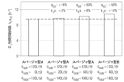
CO2及びO2の物質移動の相互関係を調査及び解明するために、様々な動作条件の影響を特定するために様々な研究を行った。特に、実験室規模及び産業規模でのCO2の混合効率及び物質移動性能が詳細に検討されてきた。結果を図2及び図3に要約する。 In order to investigate and elucidate the interrelationship of CO 2 and O 2 mass transfer, various studies were conducted to identify the effects of different operating conditions. In particular, the mixing efficiency and mass transfer performance of CO 2 on laboratory and industrial scales have been investigated in detail. The results are summarized in Figures 2 and 3.
図2及び図3は、実験室規模及び産業規模でそれぞれ異なる手動で与えられたガス空塔速度w0 gに関する2つの異なる体積での体積攪拌器電力入力P/Vの依存性における二酸化炭素に関する体積物質移動係数kLaCO2を示す。具体的には、図2は、2L(cm範囲の高さ)の体積を有する曝気攪拌バイオリアクタ又は発酵槽における実験室規模での実験を示し、図3は、12,000Lの体積(m範囲の高さ)を有する曝気攪拌バイオリアクタ又は発酵槽における産業規模での実験を示す。 Figures 2 and 3 relate to the dependence of the volumetric stirrer power input P/V on carbon dioxide at two different volumes with respect to different manually given gas superficial velocities w 0 g at laboratory and industrial scales, respectively. Indicates the volumetric mass transfer coefficient k L a CO2 . Specifically, Figure 2 shows a laboratory-scale experiment in an aerated stirred bioreactor or fermentor with a volume of 2L (height in the cm range), and Figure 3 shows a volume of 12,000L (height in the m range). We present experiments on an industrial scale in an aerated stirred bioreactor or fermenter with a height of
予期され得るように、図2及び図3は、二酸化炭素の体積物質移動係数kLaCO2が、両方の実験、すなわち、実験室規模並びに産業規模で、ガス空塔速度w0 gが増加するのと同程度に増加することを示す。更に、二酸化炭素の物質移動性能は、産業規模のプロセスと比較して実験室規模でかなり異なることが分かった。しかしながら、体積攪拌器電力入力が実験室規模に大きな影響を及ぼすが、産業規模には最小限の影響しか及ぼさないことは予想外であった。図2及び図3から分かるように、産業規模のリアクタの体積物質移動係数kLaCO2は、実験室規模のリアクタと比較して最大10倍低い。 As can be expected, FIGS. 2 and 3 show that the volumetric mass transfer coefficient of carbon dioxide, k L a CO2 , increases as the gas superficial velocity w 0 g increases in both experiments, i.e., on the laboratory scale as well as on the industrial scale. It shows that the increase is the same as that of . Furthermore, the mass transfer performance of carbon dioxide was found to be significantly different at laboratory scale compared to industrial scale processes. However, it was unexpected that volumetric stirrer power input had a large impact on the laboratory scale, but only a minimal impact on the industrial scale. As can be seen from FIGS. 2 and 3, the volumetric mass transfer coefficient k L a CO2 of industrial scale reactors is up to 10 times lower compared to laboratory scale reactors.
実験室規模の実験と産業規模の実験との間の違いをより良く説明するために、図4を参照すると、ここには、実験室規模と産業規模との間の二酸化炭素における物質移動係数kLaCO2の比較が示される。図4は、体積電力入力P/V=21Wm-3で測定された体積物質移動係数と比較した、体積二酸化炭素物質移動係数に対する比電力入力の相対的な影響を示す。実験室規模と産業規模との間の体積二酸化炭素物質移動係数kLaCO2を比較すると、産業規模においては体積電力入力P/Vを増加させても物質移動性能を大幅に向上させることはできないが、実験室規模においてはCO2における物質移動性能を21から168Wm-3まで最大70%向上させることができることは明らかである。したがって、図4は、実験室規模(2Lシステム)では攪拌器入力の増加に伴うkLaCO2の+70%の増加を実証するが、産業規模ではkLaCO2の+5%の増加しか観察することができない(12,000Lシステム)。 To better illustrate the difference between laboratory-scale and industrial-scale experiments, refer to Figure 4, which shows the mass transfer coefficient k in carbon dioxide between laboratory and industrial scales. A comparison of L a CO2 is shown. Figure 4 shows the relative influence of specific power input on the volumetric carbon dioxide mass transfer coefficient compared to the volumetric mass transfer coefficient measured at a volumetric power input P/V = 21 Wm -3 . Comparing the volumetric carbon dioxide mass transfer coefficient k L a CO2 between laboratory scale and industrial scale, it is found that increasing the volumetric power input P/V cannot significantly improve mass transfer performance at industrial scale. However, it is clear that on a laboratory scale the mass transfer performance in CO2 can be improved by up to 70% from 21 to 168 Wm -3 . Thus, while Figure 4 demonstrates a +70% increase in k L a CO2 with increasing stirrer input at the laboratory scale (2L system), we observe only a +5% increase in k L a CO2 at the industrial scale. (12,000L system)
したがって、図2~図4に基づく産業規模のバイオリアクタ又は発酵槽においては、体積電力入力P/Vの増加に伴ってCO2における物質移動性能を大幅に向上させることはできないが、実験室規模では、CO2の物質移動性能を最大70%向上させることができることが明らかになる(図4参照)。 Therefore, the mass transfer performance in CO 2 cannot be significantly improved with increasing volumetric power input P/V in industrial scale bioreactors or fermenters based on Figures 2-4, but in laboratory scale It becomes clear that the mass transfer performance of CO 2 can be improved by up to 70% (see FIG. 4).
上記で既に説明したように、2つのシステムの異なる挙動は、基本的に、システム内の気相の滞留時間によって説明することができる。産業規模では、気泡と液体との間のCO2濃度の平衡は、気泡が表面に到達するはるか前に達するが、実験室規模では、滞留時間が短すぎて平衡に達することができない。したがって、攪拌器の周波数を増加させて界面積を増加させると、実験室規模ではより高い物質移動係数が得られるが、大規模では、「死気泡」(すなわち、CO2飽和を伴う気泡)のより強い分散は役に立たない。 As already explained above, the different behavior of the two systems can basically be explained by the residence time of the gas phase within the system. On an industrial scale, equilibrium in the CO2 concentration between bubbles and liquid is reached long before the bubbles reach the surface, but on a laboratory scale, the residence time is too short to reach equilibrium. Therefore, increasing the frequency of the stirrer to increase the interfacial area will yield higher mass transfer coefficients at the laboratory scale, but at larger scales it will reduce the Stronger dispersion is useless.
酸素物質移動の場合、更なる実験により、産業規模であっても平衡に達しないことが分かった。したがって、体積電力入力が高いほど、界面積が大きくなり、したがって、体積物質移動係数kLaO2が大きくなる。したがって、二酸化炭素における体積物質移動係数は、より高いガス流量でのみ著しく向上させることができるが、より高い体積電力入力では向上させることができないと結論付けられる。 In the case of oxygen mass transfer, further experiments showed that equilibrium is not reached even on an industrial scale. Therefore, the higher the volumetric power input, the larger the interfacial area and therefore the larger the volumetric mass transfer coefficient k L a O2 . Therefore, it is concluded that the volumetric mass transfer coefficient in carbon dioxide can be significantly improved only at higher gas flow rates, but not at higher volumetric power inputs.
産業規模での二酸化炭素のストリッピングの困難さは、主に、バイオリアクタ又は発酵槽の底部又はその近くに設けられた水中ガス供給源のすぐ上方でのみ気相が二酸化炭素で既に飽和されるという事実に関連している。したがって、二酸化炭素における物質移動性能を高めるための明らかに最も実現可能な選択肢は、ガス流量を増加させることである。しかしながら、これは、酸素物質移動速度のしばしば望ましくない増加ももたらし、したがって、バイオリアクタ内又は発酵槽内のO2-濃度及びCO2-濃度の独立した管理は不可能である。 Difficulties in stripping carbon dioxide on an industrial scale are mainly due to the fact that the gas phase is already saturated with carbon dioxide only immediately above the submerged gas supply located at or near the bottom of the bioreactor or fermentor. It is related to the fact that Therefore, clearly the most viable option to enhance mass transfer performance in carbon dioxide is to increase the gas flow rate. However, this also results in an often undesirable increase in the oxygen mass transfer rate, so that independent control of the O 2 - and CO 2 - concentrations within the bioreactor or fermentor is not possible.
従来技術では、2つのスパージャを有するリアクタが既に知られており、市販されている。例えば、欧州特許出願公開第0 099 634号明細書には、円筒状容器、ドラフトチューブ、円錐底部、及び、ガススパージャシステムを備える、気相、固相、及び、液相の間の多相接触のための反応装置が記載されている。ガススパージャ16が、粒子状固相が容器内に含まれて懸濁されている連続液相へ気泡形態の少なくとも1つのガスを流入させるために容器の下端で、内壁と円錐形表面周囲との間の隙間に配置される。リングスパージャ34の形態の補助ガススパージャが、ドラフトチューブを取り囲み、その径方向外側から液相へと気泡形態のガスを放出するように構成される。欧州特許出願公開第0 099 634号明細書は、2つのスパージャ間の距離に関しては全く言及していない。
In the prior art, reactors with two spargers are already known and commercially available. For example, European Patent Application No. 0 099 634 discloses a multiphase contact between gas, solid and liquid phases comprising a cylindrical vessel, a draft tube, a conical bottom and a gas sparger system. A reactor for this is described. A
国際公開第2002/33048号パンフレットには、発酵容器内で好気条件下で微生物を培養する方法であって、培養液のカオス的挙動を引き起こす不均一な流れで容器の下部に第1の酸素含有ガスを注入することと、第2の酸素含有ガスを容器内に導入することとを含む方法において、注入部位で乱流状態をもたらす培養液の流れの方向とは無関係に、容器内で可能な全ての方向に移動する気泡の不均一な流れとして、及び、不均一なサイズ及び広いサイズ分布の一組の気泡として、第2の酸素含有ガスを導入することを特徴とする方法が開示される。2つのスパージャ間の距離は、明細書本文の4頁20-24行目に概説されているように第2の酸素含有ガス流の入口位置に関して制限がないため、言及されておらず、重要ではない。
WO 2002/33048 pamphlet describes a method for culturing microorganisms under aerobic conditions in a fermentation vessel, in which a first oxygen source is introduced at the bottom of the vessel with an uneven flow that causes chaotic behavior of the culture solution. a method comprising injecting a containing gas and introducing a second oxygen-containing gas into the container, independent of the direction of flow of the culture medium resulting in turbulent flow conditions at the injection site. A method is disclosed, characterized in that the second oxygen-containing gas is introduced as a non-uniform stream of bubbles moving in all directions and as a set of bubbles of non-uniform size and wide size distribution. Ru. The distance between the two spargers is not mentioned and is not important as there is no restriction regarding the inlet position of the second oxygen-containing gas stream as outlined on
Sen Xuらの’’A practical approach in bioreactor scale-up and process transfer using a combination of constant P/V and vvm as the criterion’’、Biotechnology Progress,Vol.33,No.4,2017,pp.1146-1159では、モノクローナル抗体(MAb)などの治療用タンパク質の産生における重要な工程としてのバイオリアクタのスケールアップが評価される。例えば、異なるスパージャを有するある範囲のバイオリアクタスケール(3~2,000L)からのスパージャkLa及びkLaCO2(CO2体積物質移動係数)が調べられる。この関係においては、シングルスパージャシステム及びデュアルスパージャシステムがその幾何学的形状に関するいかなる開示もなく記載される。一般に、デュアルスパージャシステムでは、両方のスパージャが、ほぼ同じ位置にあり、異なる高さにはない。 Sen Xu et al., "A practical approach in bioreactor scale-up and process transfer using a combination of constant P/V and vvm as the criterion", Biotechnology Progress, Vol. 33, No. 4, 2017, pp. 1146-1159, evaluates bioreactor scale-up as a critical step in the production of therapeutic proteins such as monoclonal antibodies (MAbs). For example, sparger k L a and k L a CO2 ( CO2 volumetric mass transfer coefficient) from a range of bioreactor scales (3-2,000 L) with different spargers are examined. In this context, single and dual sparger systems are described without any disclosure regarding their geometry. Generally, in a dual sparger system, both spargers are in approximately the same position and are not at different heights.
更に、有機化学の分野からの米国特許第5 994 567号明細書は、気泡塔リアクタへの直接的な酸素注入、すなわち、第1の酸素含有ガスが酸化可能な有機液体を含有する気泡塔リアクタ容器の下部に注入される液相酸化プロセスを対象としている。第2の酸素含有ガスが、前記注入の前に液体が溶存酸素を実質的に使い果たす1つ以上のポイントでリアクタに更に注入される。第1及び第2の酸素含有ガスの両方からの酸素は、クメン又はシクロヘキサンなどの有機液体を酸化するために使用される。したがって、細胞又は微生物を培養するための攪拌タンクバイオリアクタ又は発酵槽は記載されていないが、化学反応は記載され、それにより、培養された生細胞によって生成されるCO2のストリッピングは重要でない。 Furthermore, US Pat. No. 5,994,567 from the field of organic chemistry teaches direct oxygen injection into a bubble column reactor, i.e. a bubble column reactor in which the first oxygen-containing gas contains an oxidizable organic liquid. It is intended for liquid phase oxidation processes that are injected into the bottom of the vessel. A second oxygen-containing gas is further injected into the reactor at one or more points where the liquid is substantially depleted of dissolved oxygen prior to said injection. Oxygen from both the first and second oxygen-containing gases is used to oxidize an organic liquid such as cumene or cyclohexane. Therefore, stirred tank bioreactors or fermenters for culturing cells or microorganisms are not described, but chemical reactions are described, whereby stripping of the CO 2 produced by the cultured living cells is not important. .
国際公開第2008/088371号パンフレットの開示は、化学的、生化学的及び/又は生物学的反応を実行するためのリアクタとして使用することができる支持された折り畳み式バッグを伴うシステム及び方法を含む、流体を収容及び操作するためのシステムに関する。一態様において、容器に収容された流体は、例えば、流体が容器のコンテナ内に導かれるようにスパージングすることができ、場合によっては、スパージングは、必要に応じてスパージングの程度を急速に活性化又は変更することによって制御することができる。場合によっては、複数のスパージャが使用されてもよいことが言及される。しかしながら、この文献は、それらの特定の幾何学的配列については言及していない。記載された異なるスパージャ47又は301は、図1によれば、リアクタの底部において同じ高さに位置されるが、その物理化学的影響に関する特定の教示はない。 The disclosure of WO 2008/088371 includes systems and methods involving supported collapsible bags that can be used as reactors for carrying out chemical, biochemical and/or biological reactions. , relates to systems for containing and manipulating fluids. In one aspect, the fluid contained in the container can be sparged, e.g., such that the fluid is directed into the container of the container, and in some cases, the sparging rapidly activates the degree of sparging as needed. Or it can be controlled by changing. It is mentioned that in some cases multiple spargers may be used. However, this document does not mention their specific geometry. The different spargers 47 or 301 described are located at the same height at the bottom of the reactor according to FIG. 1, but there is no specific teaching regarding their physicochemical influence.
攪拌器に対するスパージャの想定し得る位置、形態及びサイズは、Sardeingらの’’Gas-liquid mass transfer’’、Chemical Engineering Research and Design,Elsevier,Amsterdam,NL,Vol.82,No.9,2004,pp.1161-1168;Birchらの’’The Influence of Sparger Design and Location on Gas Dispersion in Stirred Vessels’’、Chemical Engineering Research and Design,Elsevier,Amsterdam,NL,Vol.75,No.5,1997,pp.487-496及び、Rewatkar V.B.らの’’Role of sparger design on gas dispersion in mechanically agitated gas-liquid contactors’’、Canadian Journal of Chemical Engineering,1993,Vol.71,No.2,pp.278-291において評価されて論じられている。効果を評価するために、単一のスパージャのみが使用される。同時にリアクタ内に2つのスパージャが存在し、それらの間の距離は関連性がなく、言及されていない。 Possible positions, shapes and sizes of the sparger relative to the stirrer are described in Sardeing et al., ``Gas-liquid mass transfer'', Chemical Engineering Research and Design, Elsevier, Amsterdam, NL, Vo. l. 82, No. 9, 2004, pp. 1161-1168; Birch et al., ``The Influence of Sparger Design and Location on Gas Dispersion in Stirred Vessels'', Chemical Engineering Research and Design, Elsevier, Amsterdam, NL, Vol. 75, No. 5, 1997, pp. 487-496 and Rewatkar V. B. ``Role of sparger design on gas dispersion in mechanically agitated gas-liquid contactors'', Canadian Journal of Chemica l Engineering, 1993, Vol. 71, No. 2, pp. Evaluated and discussed in 278-291. Only a single sparger is used to evaluate effectiveness. There are two spargers in the reactor at the same time, the distance between them is irrelevant and not mentioned.
したがって、本発明の目的は、従来技術の欠点を克服するとともに、産業規模で曝気攪拌バイオリアクタ内又は発酵槽内の酸素濃度から独立して二酸化炭素濃度を管理できるようにする改変バイオリアクタ又は発酵槽を提供することである。 It is therefore an object of the present invention to provide a modified bioreactor or fermenter which overcomes the drawbacks of the prior art and which makes it possible to control the carbon dioxide concentration independently of the oxygen concentration in an aerated stirred bioreactor or in a fermenter on an industrial scale. It is to provide a tank.
更に、産業規模で曝気攪拌バイオリアクタ内又は発酵槽内の二酸化炭素濃度及び酸素濃度の独立した管理によって細胞培養又は発酵プロセスを制御する方法を提供することが更なる目的である。 Furthermore, it is a further object to provide a method for controlling cell culture or fermentation processes by independent management of carbon dioxide and oxygen concentrations in an aerated stirred bioreactor or fermenter on an industrial scale.
驚くべきことに、従来技術から知られている欠点を克服でき、特に、第2のガス供給源(又は場合により多くのガス供給源)がバイオリアクタ内の第1のガス供給源から所定の距離を隔てて配置される場合に、産業規模の曝気攪拌バイオリアクタ又は発酵槽におけるO2-濃度及びCO2-濃度の独立した管理を達成できることが分かった。 Surprisingly, the drawbacks known from the prior art can be overcome, in particular when the second gas source (or possibly more gas sources) is located at a predetermined distance from the first gas source in the bioreactor. It has been found that independent control of O 2 - and CO 2 - concentrations in industrial scale aerated stirred bioreactors or fermenters can be achieved when the O 2 - and CO 2 - concentrations are arranged apart.
したがって、前述の欠点を克服するために、産業規模で液体培地中の懸濁液中で細胞又は微生物を培養するための改変され、それにより改善されたバイオリアクタ又は発酵槽が提供される。産業規模で液体培地中の懸濁液中で細胞又は微生物を培養するためのバイオリアクタ又は発酵槽100であって、
決定された充填高さを有する液体培地中の培養物を収容する容器102と、
液体培地を攪拌するために容器内に設けられる攪拌器120と、
気泡10,10.1,10.2,10.3を液体培地に連続的に供給するように設けられる容器102の底部105に配置される第1のスパージャ150であって、気体が空気及び/又は酸素ガスから選択される、第1のスパージャ150と、
容器102内に配置されるとともに、更なる気泡及び/又は更なる酸素気泡20,20.1,20.2,20.3を液体培地に連続的に供給するために第1のスパージャ150の上方に設けられる第2のスパージャ160と、
を備え、
第2のスパージャ160は、バイオリアクタ内又は発酵槽100内の第1のスパージャ150の上方の距離ηの位置に配置され、ここで、ηは、第1のスパージャ150の少なくとも約0.4m上からバイオリアクタ又は発酵槽100の充填高さの最大約0.5m下まで、又は、
第1のスパージャの約0.4m上からバイオリアクタ若しくは発酵槽100の充填高さの約2/3まで、又は、
第1のスパージャの約0.4m上からバイオリアクタ若しくは発酵槽100の充填高さの約1/2まで、又は、
第1のスパージャの約0.4m上~第1のスパージャの約3.0m上又は約0.4m~約2.5m、又は約0.4m~約2.0m又は約0.4m~約1.5m又は約0.4~約1.0m又は約0.45~約0.90m又は約0.5~約0.80m又は約0.55~約0.70mの範囲内にあるように又は約0.6mにあるように選択される、バイオリアクタ又は発酵槽100。
Therefore, in order to overcome the aforementioned drawbacks, a modified and thereby improved bioreactor or fermentor for culturing cells or microorganisms in suspension in a liquid medium on an industrial scale is provided. A bioreactor or
a
a
A
located within the
Equipped with
The
from about 0.4 m above the first sparger to about 2/3 of the fill height of the bioreactor or
from about 0.4 m above the first sparger to about 1/2 the fill height of the bioreactor or
about 0.4 m above the first sparger to about 3.0 m above the first sparger, or about 0.4 m to about 2.5 m, or about 0.4 m to about 2.0 m, or about 0.4 m to about 1 .5 m or about 0.4 to about 1.0 m or about 0.45 to about 0.90 m or about 0.5 to about 0.80 m or about 0.55 to about 0.70 m; A bioreactor or
したがって、CO2における物質移動性能を向上させ、それと同時にO2の物質移動性能に悪影響を及ぼさないようにするために、本発明によれば、水中スパージャ又は第1のスパージャから供給されるガスと比較して、供給される更なるガスのはるかに短い滞留時間を達成するために、第1のスパージャよりも高い位置にあるバイオリアクタ又は発酵槽内に更なる第2のガススパージャが距離ηで設けられる。第2のスパージャによって注入されるガスの滞留時間が短いため、より少量の酸素が液相に移動する一方で、増加した量のCO2を取り去ることができる。 Therefore, in order to improve the mass transfer performance in CO2 and at the same time not adversely affect the mass transfer performance in O2 , according to the invention, the gas supplied from the submersible sparger or the first sparger and In comparison, in order to achieve a much shorter residence time of the further gas fed, a further second gas sparger is placed in the bioreactor or fermenter at a distance η which is located higher than the first sparger. provided. Due to the short residence time of the gas injected by the second sparger, an increased amount of CO2 can be removed while less oxygen is transferred to the liquid phase.
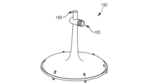
一実施形態によれば、第2のスパージャは、サイドスパージャ、すなわち、側壁の近くに更なる気泡を供給するスパージャであってもよい。 According to one embodiment, the second sparger may be a side sparger, i.e., a sparger that provides additional bubbles near the sidewall.
従来技術及び本発明の実施形態は、添付の図面を参照して例として説明されるが、添付の図面は概略的なものであり、原寸に関して正確な幾何学的値の仮定を行うことができないように縮尺通りに描かれることを意図していない。本開示の図は、本明細書に組み込まれ、本明細書の一部を構成し、記載された特定の実施形態に限定されない本発明の実施形態も示す。図面は、一般的な説明及び詳細な説明と共に、本開示の原理を説明するのに役立つ。同じ特徴は、図面全体を通して同じ参照符号で示される。 The prior art and embodiments of the invention will be described by way of example with reference to the accompanying drawings, which are schematic and no assumptions of exact geometrical values can be made to scale. Not intended to be drawn to scale. The figures of this disclosure are incorporated into and constitute a part of this specification, and also illustrate embodiments of the invention that are not limited to the particular embodiments described. The drawings, together with the general description and detailed description, serve to explain the principles of the disclosure. Like features are designated with the same reference numerals throughout the drawings.
幾つかの図に対する詳細な説明は、本明細書の最後で行われる。 Detailed explanations for some of the figures are provided at the end of this specification.
本明細書で具体的に定義されていない用語には、本開示及び文脈に照らして当業者によってそれらに与えられるであろう意味が与えられるべきである。 Terms not specifically defined herein should be given the meanings that would be given to them by one of ordinary skill in the art in light of this disclosure and context.
「バイオリアクタ」は、生物、特に細菌及び真核細胞が有用な物質を増殖及び/又は合成し、それによって培養培地から栄養素を消費し、また、好気性細胞又は微生物の場合にはスパージャのような技術的手段によって供給されるO2を消費するデバイス又は装置である。本開示において、バイオリアクタは、産業規模のバイオリアクタである。バイオリアクタは、生物及び/又はそのような生物に由来する生化学的活性物質を含む化学的又は生化学的方法が実行される生体適合性容器からなるか、又はそれを含み得る。バイオリアクタは、細胞の培養及び増殖を特に可能にする更なる機器、例えば攪拌器、バッフル、1つ以上のスパージャ(例えば本発明の対象として)及び/又はポートを使用する。一般に、バイオリアクタは、2つの端部を有する円筒管の形態であり、端部はバイオリアクタの上部及び底部を形成する。バイオリアクタは、リットルから立方メートルのサイズの範囲であり、しばしばステンレス鋼で作られる。本開示に係るバイオリアクタは、大規模生産に用いられる。 A "bioreactor" is a device or apparatus in which organisms, especially bacteria and eukaryotic cells, grow and/or synthesize useful substances, thereby consuming nutrients from the culture medium and, in the case of aerobic cells or microorganisms, O2 supplied by technical means such as spargers. In the present disclosure, a bioreactor is an industrial-scale bioreactor. A bioreactor may consist of or include a biocompatible vessel in which a chemical or biochemical process involving organisms and/or biochemically active substances derived from such organisms is carried out. A bioreactor uses further equipment, such as an agitator, baffles, one or more spargers (e.g. as subject of the present invention) and/or ports, that in particular allow the cultivation and growth of cells. Generally, a bioreactor is in the form of a cylindrical tube with two ends, the ends forming the top and the bottom of the bioreactor. Bioreactors range in size from liters to cubic meters and are often made of stainless steel. A bioreactor according to the present disclosure is used for large-scale production.
培養細胞、特にチャイニーズハムスター卵巣(CHO)などの真核細胞又は酵母細胞は、例えば、治療的使用のためのモノクローナル抗体などの抗体及び/又は組換えタンパク質などの組換えタンパク質を産生するために使用される。あるいは、細胞は、例えば、ペプチド、アミノ酸、脂肪酸又は他の有用な生化学的中間体若しくは代謝産物又は任意の他の有用な物質を産生し得る。 Cultured cells, particularly eukaryotic cells such as Chinese Hamster Ovary (CHO) or yeast cells, are used to produce recombinant proteins, such as antibodies and/or recombinant proteins, e.g. monoclonal antibodies for therapeutic use. be done. Alternatively, the cells may produce, for example, peptides, amino acids, fatty acids or other useful biochemical intermediates or metabolites or any other useful substances.
「発酵槽」は、微生物が有用な物質を合成し、それによって微生物の増殖に適した条件が維持されるデバイス又は装置である。バイオリアクタについての上記の事項は、必要な変更を加えて適用される。本開示の発酵槽は、大規模発酵に使用される。大規模発酵槽の既知の市販品は、例えば、そのような細胞又は微生物によって合成される抗生物質、抗体、ホルモン又は酵素である。 A "fermenter" is a device or apparatus in which microorganisms synthesize useful substances, whereby conditions suitable for the growth of microorganisms are maintained. The above regarding bioreactors applies mutatis mutandis. The fermentor of the present disclosure is used for large scale fermentation. Known commercial products of large-scale fermenters are, for example, antibiotics, antibodies, hormones or enzymes synthesized by such cells or microorganisms.
産生された微生物は、廃水処理、食品製造のための食品産業、抗生物質若しくはインスリンなどの薬物製造のためのバイオテクノロジー部門、有害生物防除、又は廃棄物、汚染物質、例えば油汚染の生分解などの様々な目的に有用である。 The produced microorganisms are useful for various purposes such as wastewater treatment, the food industry for food production, the biotechnology sector for the production of drugs such as antibiotics or insulin, pest control or biodegradation of waste, pollutants, e.g. oil pollution.
本開示において、「産業規模」又は「大規模」という表現は、交換可能かつ同義的に使用され、大量の生産量で得られる製品に関し、この場合、規模が増大するにつれて出力単位当たりのコストが減少するというコスト上の利点があることが多い。大きな製造ユニットは、小さなユニットよりも出力単位当たりのコストが低くなると予想され、他の要因は全て同じである。産業規模は、約2,000L以上の使用されるバイオリアクタの体積を有するように細胞を培養することに関連して理解され得る。産業規模は、約1,000L以上の使用される発酵槽の体積を有するように微生物を培養することに関連して理解され得る。更なる実施形態によれば、産業規模で使用されるバイオリアクタ又は発酵槽の体積は、6,000、8,000、10,000、12,000、15,000L以上であってもよい。 In this disclosure, the expressions "industrial scale" or "large scale" are used interchangeably and interchangeably and relate to products obtained in large production quantities, where the cost per unit of output increases as the scale increases. There is often a cost advantage of reducing Larger manufacturing units are expected to have lower cost per unit of output than smaller units, all other factors being equal. Industrial scale may be understood in relation to culturing cells to have a used bioreactor volume of about 2,000 L or more. Industrial scale may be understood in connection with culturing microorganisms to have a used fermenter volume of about 1,000 L or more. According to further embodiments, the volume of a bioreactor or fermenter used on an industrial scale may be 6,000, 8,000, 10,000, 12,000, 15,000 L or more.
「攪拌器」は、マグネチック攪拌器などの攪拌に使用される物体又は機械的装置である。細胞又は微生物の培養に一般的に使用される任意の種類の攪拌器を使用することができる。使用され得る攪拌器は、例えば、インペラ、Rushton-Turbine、攪拌パドル、ピッチドブレード攪拌器などのブレード攪拌器などである。 "Agitator" is an object or mechanical device used for stirring, such as a magnetic stirrer. Any type of stirrer commonly used for culturing cells or microorganisms can be used. Agitators that may be used are, for example, impellers, Rushton-Turbines, stirring paddles, blade agitators such as pitched blade agitators, and the like.
「スパージャ」は、液相中に酸素及び/又は気泡を供給し、細胞又は微生物が培養される液相中に存在するバイオリアクタ又は発酵槽で使用されるガス供給源又は供給装置である。従来技術に係るバイオリアクタ又は発酵槽は、通常その底部に又はその近くに配置されるただ1つのスパージャを有する。本開示では、このスパージャは「第1のスパージャ」又は「水中スパージャ」とも呼ばれ、両方の表現は互換的かつ同義的に使用される。 A "sparger" is a gas source or supply device used in a bioreactor or fermenter that provides oxygen and/or gas bubbles into the liquid phase and is present in the liquid phase in which cells or microorganisms are cultured. Prior art bioreactors or fermenters usually have only one sparger located at or near the bottom. In this disclosure, this sparger is also referred to as the "first sparger" or "submerged sparger", both terms being used interchangeably and synonymously.
本開示によれば、所定の距離ηで第1のスパージャの上方に配置され、更なる気泡及び/又は更なる酸素気泡を液体培地に連続的に供給する更なるスパージャ、すなわち第2のスパージャを設けると、上記及び以下の説明から当業者には明らかな培養プロセスのための様々な利点を有することが分かった。 According to the present disclosure, a further sparger, i.e. a second sparger, is arranged above the first sparger at a predetermined distance η and continuously supplies further air bubbles and/or further oxygen bubbles to the liquid medium. It has been found that the provision has various advantages for the culture process which will be apparent to those skilled in the art from the above and below description.
以下では、本開示に係るバイオリアクタ又は発酵槽で行われるプロセス及び反応をより詳細に説明する。 In the following, processes and reactions carried out in bioreactors or fermenters according to the present disclosure will be described in more detail.
通常はバイオリアクタ又は発酵槽の下部又は底部に1つのガス供給装置のみが存在するバイオリアクタ又は発酵槽では、液相に入る気泡は細胞培養培地からCO2を取り込む能力を有するが、そのような能力は気泡の上昇の過程でますます失われる。バイオリアクタ又は発酵槽の上部又は上部では、上記で説明したように高さに応じて、液相からの気泡の溶解CO2の取り込みはそれ以上起こらない。したがって、CO2含有量は、バイオリアクタ又は発酵槽の底部から上部に向かって増加し、それによって液相内にCO2の勾配をもたらす。 In bioreactors or fermenters where there is only one gas supply, usually at the bottom or bottom of the bioreactor or fermenter, the gas bubbles entering the liquid phase have the ability to take up CO2 from the cell culture medium, but such ability is increasingly lost in the course of the bubbles' rise. At the top or upper part of the bioreactor or fermenter, depending on the height as explained above, the gas bubbles no longer take up dissolved CO2 from the liquid phase. Therefore, the CO2 content increases from the bottom to the top of the bioreactor or fermenter, thereby resulting in a gradient of CO2 in the liquid phase.
バイオリアクタ又は発酵槽の液相に通常存在するCO2勾配及びこのようなCO2の不均一な分布に関連する欠点は、本開示によって克服することができ、本開示によれば、第2のスパージャが、大規模なバイオリアクタ又は発酵槽の液相の第1のスパージャから離間した第1のスパージャの距離η上方に設けられる。第2のスパージャは、もはやCO2を吸収することができない気泡のCO2飽和の確立を打ち消すために設けられる。第2のスパージャは、O2及びCO2を通過するプロセスが第1のスパージャの上方で更に再び進行することができるように、液相に新しい気泡を追加する。 The disadvantages associated with CO 2 gradients and non-uniform distribution of such CO 2 that normally exist in the liquid phase of a bioreactor or fermenter can be overcome by the present disclosure, according to which the second A sparger is provided a distance η above a first sparger spaced from the first sparger of the liquid phase of the large-scale bioreactor or fermenter. A second sparger is provided to counteract the establishment of CO2 saturation of the bubbles, which can no longer absorb CO2 . The second sparger adds new bubbles to the liquid phase so that the process of passing O 2 and CO 2 can proceed again above the first sparger.
例示として、大規模なバイオリアクタ又は発酵槽内の液相で行われる対象のプロセス及び反応を図5に概略的に示す。図5は、左側のセクションAにおいて、攪拌器(図示せず)の近くにただ1つのガス供給装置又はスパージャを有する概略的なバイオリアクタ又は発酵槽における溶存CO2の分布を例示する。スパージャは、バイオリアクタ又は発酵槽の底部又はその近くに配置される。1つのスパージャのみを用いた標準ガス処理は、明らかにCO2勾配をもたらす。特定の高さに達した後、気泡10.2をCO2で飽和させる。したがって、図5の下部(セクションA)では、CO2のストリッピング性能は良好であるが、上部では、CO2ストリッピングは不十分で許容できない。 By way of example, the subject processes and reactions carried out in the liquid phase in a large-scale bioreactor or fermenter are schematically depicted in FIG. Figure 5 illustrates the distribution of dissolved CO2 in a schematic bioreactor or fermenter with only one gas supply or sparger near the agitator (not shown) in section A on the left. The sparger is placed at or near the bottom of the bioreactor or fermenter. Standard gas treatment with only one sparger clearly results in a CO2 gradient. After reaching a certain height, the bubble 10.2 is saturated with CO2 . Therefore, in the lower part of Fig. 5 (section A), the CO2 stripping performance is good, but in the upper part, the CO2 stripping is poor and unacceptable.
図5の右側のセクションBは、第1のスパージャの上に設けられた更なる第2のガス供給装置又は第2のスパージャの結果としての大規模での概略的なバイオリアクタ又は発酵槽内の溶存CO2の分布を示す。図5のセクションBから導出され得るように、第2のスパージャは、液体培地中の表面まで上昇し始める気泡20.1を供給する。気泡20.2に示すように、O2ガスは気泡20.2から液相に移行し(反応(1))、CO2ガスは液相から気泡20.2に移行する(反応(2))。これにより、異なるヘンリー定数により、反応速度(2)は反応速度(1)(図5に異なる矢印の太さで示されている)と比較してはるかに速い。したがって、セクションBにおける液相の中央部及び上部におけるCO2のストリッピングは、セクションAにおける図5の左側に示されるような液相の下部におけるCO2ストリッピングと同様である。したがって、液体培地中の上昇する高さ全体にわたるCO2勾配が回避される。バイオリアクタ又は発酵槽内に存在する細胞又は微生物は、より一貫した環境を経験し、細胞又は微生物の代謝反応に反映され得る液体培地の変動の程度がはるかに低い。 Section B on the right side of Figure 5 shows a schematic bioreactor or fermentor in a large scale as a result of a further second gas supply or second sparger provided above the first sparger. The distribution of dissolved CO2 is shown. As can be derived from section B of FIG. 5, the second sparger supplies air bubbles 20.1 which begin to rise to the surface in the liquid medium. As shown in bubble 20.2, O2 gas moves from the bubble 20.2 to the liquid phase (reaction (1)), and CO2 gas moves from the liquid phase to the bubble 20.2 (reaction (2)). . Thereby, reaction rate (2) is much faster compared to reaction rate (1) (indicated by different arrow thicknesses in Figure 5) due to different Henry's constants. Therefore, the stripping of CO 2 in the middle and top of the liquid phase in section B is similar to the stripping of CO 2 in the bottom of the liquid phase as shown on the left side of FIG. 5 in section A. Thus, a CO 2 gradient throughout the rising height in the liquid medium is avoided. Cells or microorganisms residing within a bioreactor or fermentor experience a more consistent environment and a much lower degree of variation in the liquid medium that can be reflected in the metabolic reactions of the cells or microorganisms.
第2のスパージャは、気泡が液相を通って上昇する間にCO2で飽和され得ることを回避するように、気泡の絶対上昇高さを短くするために、第1のスパージャの上方に設けられる。加えて、液相内の第2のスパージャから生じる気泡の滞留時間が減少し、気泡は攪拌器によって分散されないため、液面に対して比較的速く上昇する。したがって、CO2ストリッピング性能は、バイオリアクタ又は発酵槽の上部においても良好である。 A second sparger is provided above the first sparger to shorten the absolute rise height of the bubbles to avoid that the bubbles can become saturated with CO2 while rising through the liquid phase. It will be done. In addition, the residence time of the bubbles originating from the second sparger in the liquid phase is reduced and the bubbles are not dispersed by the agitator and therefore rise relatively quickly relative to the liquid level. Therefore, the CO2 stripping performance is also good in the upper part of the bioreactor or fermenter.
更なる実施形態によれば、第3のスパージャ及び更なるスパージャが第2のスパージャなどの上方に存在してもよく、その結果、3つのスパージャ、4つ以上のスパージャがバイオリアクタ又は発酵槽内に同時に存在する。第2のスパージャについての上記の説明は、それに応じて第3、第4、第5及び更なるスパージャに適用される。 According to further embodiments, a third sparger and further spargers may be present above the second sparger, etc., so that three spargers, four or more spargers are present within the bioreactor or fermenter. exist at the same time. The above description of the second sparger applies accordingly to the third, fourth, fifth and further spargers.
その結果、大規模バイオリアクタ又は発酵槽は、液相中のCO2分布に直接影響を及ぼすために、スパージャがそれぞれ配置された異なる部分区画に細分される。この種のより小さな単位での大規模なバイオリアクタ又は発酵槽の「分離」は、比較可能性の改善、したがって実験室規模に対する産業規模での培養の予測可能性の改善、及びその逆、好適には代謝率の上昇、生存率の増加及び/又は生産性の増加をもたらす。 As a result, a large-scale bioreactor or fermenter is subdivided into different subcompartments, each with a sparger arranged in order to directly influence the CO2 distribution in the liquid phase. This kind of "separation" of large-scale bioreactors or fermenters into smaller units is preferred because of improved comparability and thus improved predictability of cultivation on an industrial scale versus a laboratory scale, and vice versa. results in increased metabolic rate, increased survival rate and/or increased productivity.
大規模な生産規模で稼働するバイオリアクタ又は発酵槽内に第2のスパージャ又は随意的な第3の更なるスパージャを設けると、使用される大容量にもかかわらず、培養される細胞又は微生物の物理化学的環境条件の調和をもたらす。したがって、本概念は、CO2分布が液相全体にわたってより均一であるという点で、産業規模を実験室規模に適合させる手法である。 The provision of a second sparger or an optional third additional sparger in a bioreactor or fermenter operating at a large production scale provides a harmonization of the physicochemical environmental conditions of the cells or microorganisms being cultured, despite the large volumes used. This concept is therefore an approach that adapts the industrial scale to the laboratory scale in that the CO2 distribution is more uniform throughout the liquid phase.
更に、液相中の溶存CO2濃度は、第2のスパージャ又は随意的な第3のスパージャ及び更なるスパージャの存在により、適切な濃度又はレベルに低下させることができる。CO2濃度が特に高濃度で細胞培養性能に影響を及ぼし、それによって高CO2濃度が好気性細胞の増殖を阻害する(David R.Grayet al.,CO2 in large-scale and high-density CHO cell perfusion culture,Cytotechnology 1996,22,65-78参照。)ことに留意して、細胞培養培地自体で高CO2濃度を回避しなければならない。第2のスパージャ及び更なる第3又は更なるスパージャは、液相中のこのような望ましくない高CO2含有量の発生を防止するのに役立つ。 Furthermore, the dissolved CO2 concentration in the liquid phase can be reduced to an appropriate concentration or level by the presence of the second sparger or the optional third and further spargers. High CO2 concentrations must be avoided in the cell culture medium itself, bearing in mind that CO2 concentrations, especially at high concentrations, affect cell culture performance, whereby high CO2 concentrations inhibit the growth of aerobic cells (see David R. Gray et al., CO2 in large-scale and high-density CHO cell perfusion culture, Cytotechnology 1996, 22, 65-78). The second sparger and further third or further spargers help to prevent the occurrence of such undesirable high CO2 content in the liquid phase.
更に、更なる気泡及び/又は更なる酸素気泡を液体培地に連続的に供給する更なる第2及び第3及び更なるスパージャはまた、液相全体にわたってより均一なO2分布をもたらす。 Additionally, the additional second and third and additional spargers continuously supplying additional gas bubbles and/or additional oxygen bubbles to the liquid medium also results in a more uniform O2 distribution throughout the liquid phase.
したがって、更なる実施形態によれば、第1、第2及び第3のスパージャの上方に設けられた1つ又は複数の更なるスパージャが存在してもよい。 According to further embodiments, there may therefore be one or more further spargers provided above the first, second and third spargers.
第2のスパージャ及び更なるスパージャの位置は、液相中のO2-濃度及びCO2-濃度の管理を考慮して、培養の性能及び効率にプラスの影響を及ぼし得ることが分かった。 It has been found that the location of the second and further spargers can have a positive impact on the performance and efficiency of the culture, taking into account the management of O 2 - and CO 2 -concentrations in the liquid phase.
第1のスパージャがバイオリアクタ又は発酵槽の底部又は下部に又はその近くに位置すると仮定すると、第2のスパージャは、常に第1のスパージャの上方、例えばバイオリアクタ又は発酵槽の中央部又は上部に位置する。第2のスパージャの位置を更に検証するために、基本的には、バイオリアクタ又は発酵槽内の第2のスパージャの位置を大規模に変化させるための2つの主な方向が存在する。1つの主な方向は、垂直方向、すなわち、スパージャの位置をバイオリアクタ又は発酵槽の底部から上部に変化させる方向である。すなわち、第2のスパージャは、例えばバイオリアクタ又は発酵槽の底部の近く又は上部の近くに、又はそれらの間の任意の距離に配置することができる。これに関して、気泡は存在する液相内に供給されるため、バイオリアクタ又は発酵槽の充填高さは観察されなければならず、その絶対容積ではない。 Assuming that the first sparger is located at or near the bottom or bottom of the bioreactor or fermentor, the second sparger is always located above the first sparger, e.g. in the middle or top of the bioreactor or fermentor. To position. To further verify the position of the second sparger, there are basically two main directions for changing the position of the second sparger within the bioreactor or fermenter on a large scale. One main direction is the vertical direction, ie the direction that changes the position of the sparger from the bottom of the bioreactor or fermenter to the top. That is, the second sparger can be placed, for example, near the bottom or near the top of the bioreactor or fermenter, or any distance therebetween. In this regard, the filling height of the bioreactor or fermenter must be observed, and not its absolute volume, since the air bubbles are fed into the existing liquid phase.
本発明の一実施形態によれば、バイオリアクタ又は発酵槽は、約8~約20m又は約9~約15m又は約9、5~約12m又は約10mの範囲の充填高さを含む。 According to one embodiment of the invention, the bioreactor or fermenter comprises a filling height in the range of about 8 to about 20 m, or about 9 to about 15 m, or about 9, 5 to about 12 m, or about 10 m.
考慮され得る第2の主方向は、水平方向、すなわち、側壁とバイオリアクタ又は発酵槽の中心軸との間のスパージャの位置である。中心軸は、円筒形状を有すると推定され、周囲の側壁との間隔がどこでも等しいか、又はほぼどこでも等しいバイオリアクタ又は発酵槽内の仮想線である。すなわち、第2のスパージャは、例えば側壁の近くに、又はバイオリアクタ若しくは発酵槽の中心軸の近くに、又はそれらの間の任意の距離に配置されてもよい。 The second main direction that can be considered is the horizontal direction, ie the position of the sparger between the side wall and the central axis of the bioreactor or fermenter. The central axis is assumed to have a cylindrical shape and is an imaginary line within the bioreactor or fermentor with equal or nearly equal spacing everywhere from the surrounding side walls. That is, the second sparger may be placed, for example, near the sidewall or near the central axis of the bioreactor or fermenter, or any distance therebetween.
更なる実施形態によれば、連続したスパージャを垂直方向に上下に正確に配置することができる。別の実施形態によれば、連続するスパージャはまた、垂直方向に関して互いに横方向にシフトして配置されてもよい。 According to a further embodiment, successive spargers can be precisely positioned vertically one above the other. According to another embodiment, successive spargers may also be arranged laterally shifted from each other with respect to the vertical direction.
したがって、本発明によれば、第2のスパージャは、第1のスパージャから距離ηだけ離れたバイオリアクタ又は発酵槽の容器内の位置に配置される。距離ηは、第2のスパージャが第1のスパージャの上方の距離ηに位置するように、例えばバイオリアクタ又は発酵槽の側壁に沿った垂直距離として理解されるべきである。距離ηは、第1のスパージャの少なくとも約0.4m上方からバイオリアクタ若しくは発酵槽の充填高さの最大約0.5m下方までの範囲内、又は
第1のスパージャの約0.4m上からバイオリアクタ若しくは発酵槽の充填高さの約2/3までの範囲内、又は
第1のスパージャの約0.4m上からバイオリアクタ若しくは発酵槽の充填高さの約1/2までの範囲内、又は
約0.4m~約3.0m、又は約0.4m~約2.5m、又は約0.4m~約2.0m、又は約0.4m~約1.5mの範囲内、又は
約0.4~約1.0m又は約0.45~約0.90m又は約0.5~約0.80m又は約0.55~約0.70mの範囲内又は第1のスパージャの上方約0.6mのそれぞれ、
となるように選択される。
According to the invention, therefore, the second sparger is arranged at a position in the bioreactor or fermenter vessel at a distance η from the first sparger. The distance η is to be understood as the vertical distance, for example along the side wall of the bioreactor or fermenter, such that the second sparger is located at a distance η above the first sparger. The distance η ranges from at least about 0.4 m above the first sparger to up to about 0.5 m below the fill height of the bioreactor or fermenter, or from about 0.4 m above the first sparger to within about 2/3 of the fill height of the reactor or fermenter, or from about 0.4 m above the first sparger to about 1/2 of the fill height of the bioreactor or fermenter, or within the range of about 0.4 m to about 3.0 m, or about 0.4 m to about 2.5 m, or about 0.4 m to about 2.0 m, or about 0.4 m to about 1.5 m, or about 0. 4 to about 1.0 m or about 0.45 to about 0.90 m or about 0.5 to about 0.80 m or about 0.55 to about 0.70 m or about 0.6 m above the first sparger Each of the
is selected so that
したがって、第1のスパージャと第2のスパージャとの間の距離ηは、第1のスパージャよりも約0.4m高い下限と、バイオリアクタ又は発酵槽の充填高さよりも約0.5m低い上限とを有する。「液体高さ」と同義に使用される「充填高さ」という表現は、培養プロセスの開始時にバイオリアクタ又は発酵槽内に存在する液体の充填レベルを意味すると理解されるべきであり、これは液体の表面又は存在する液体の公称体積によって更に定義される。したがって、バイオリアクタ又は発酵槽の充填高さの0.5m下は、培養プロセスの開始時にバイオリアクタ又は発酵槽内に存在する液体の表面の0.5m下と同義である。 Therefore, the distance η between the first sparger and the second sparger has a lower limit of about 0.4 m above the first sparger and an upper limit of about 0.5 m below the filling height of the bioreactor or fermenter. has. The expression "filling height" used synonymously with "liquid height" should be understood to mean the filling level of liquid present in the bioreactor or fermenter at the beginning of the cultivation process, which is It is further defined by the surface of the liquid or the nominal volume of liquid present. 0.5 m below the filling height of the bioreactor or fermenter is therefore synonymous with 0.5 m below the surface of the liquid present in the bioreactor or fermenter at the beginning of the cultivation process.
例えば、総充填高さが10mである場合、充填高さの0.5m下は9.5mである。次いで、距離ηは、約0.4m~約9.5mの範囲で選択される。この範囲の下限及び上限は、本発明の臨界値であると考えられる。 For example, if the total filling height is 10 m, 0.5 m below the filling height is 9.5 m. The distance η is then selected in the range of about 0.4 m to about 9.5 m. The lower and upper limits of this range are considered critical values for this invention.
バイオリアクタ自体に2つのスパージャが存在すると、CO2ストリッピングが行われる液体培地の面積が増加する。第2のスパージャが液体の表面付近、例えばバイオリアクタ又は発酵槽の充填高さより約0.5m下に配置される場合、第2のスパージャは下流の領域を取り去ることができ、一方、バイオリアクタの底部付近に配置される第1のスパージャは液体培地の上流の領域を取り去ることができる。要するに、バイオリアクタ又は発酵槽の全充填高さにCO2ストリッピングを施す。 The presence of two spargers in the bioreactor itself increases the area of liquid medium over which CO2 stripping takes place. If the second sparger is placed near the surface of the liquid, e.g. about 0.5 m below the filling height of the bioreactor or fermenter, the second sparger can remove the downstream area, while A first sparger placed near the bottom can remove the upstream region of the liquid medium. In short, the entire filling height of the bioreactor or fermenter is subjected to CO2 stripping.
距離ηは、第1のスパージャの約0.4m上方からバイオリアクタ又は発酵槽の充填高さの約2/3の範囲内になるように選択することができる。「バイオリアクタ又は発酵槽の充填高さの約2/3」という表現は、第2のスパージャが、全充填高さの約2/3が達成される位置に配置されることを意味すると理解されるべきである。例えば、総充填高さが12mである場合、総充填高さの2/3は8.0mである。次いで、距離ηは、約0.4m~約8.0mの範囲で選択される。 The distance η can be selected to be from about 0.4 m above the first sparger to within about 2/3 of the fill height of the bioreactor or fermenter. The expression "approximately 2/3 of the filling height of the bioreactor or fermenter" is understood to mean that the second sparger is placed in a position such that approximately 2/3 of the total filling height is achieved. Should. For example, if the total filling height is 12 m, 2/3 of the total filling height is 8.0 m. The distance η is then selected in the range of about 0.4 m to about 8.0 m.
また、距離ηは、第1のスパージャの約0.4m上方からバイオリアクタ又は発酵槽の充填高さの約1/2の範囲内になるように選択されてもよい。「バイオリアクタ又は発酵槽の充填高さの約1/2」という表現は、第2のスパージャが、全充填高さの約1/2又は液体体積の約0.5倍が存在する位置に配置されることを意味すると理解されるべきである。例えば、総充填高さが11mである場合、総充填高さの1/2は5.5mである。次いで、距離ηは、約0.4m~約5.5mの範囲で選択される。 The distance η may also be selected to be within about 0.4 m above the first sparger to about 1/2 the fill height of the bioreactor or fermenter. The expression "about 1/2 the fill height of the bioreactor or fermenter" means that the second sparger is placed in a position where there is about 1/2 the total fill height or about 0.5 times the liquid volume. should be understood to mean that For example, if the total filling height is 11 m, 1/2 of the total filling height is 5.5 m. The distance η is then selected in the range of about 0.4 m to about 5.5 m.
また、距離ηは、約0.4m~約3.0m又は約0.4m~約2.5m又は約0.4m~約2.0m又は約0.4m~約1.5m又は約0.4~約1.0m又は約0.45~約0.90m又は約0.5~約0.80m又は約0.55~約0.70m又は約0.6mの範囲内にあるように選択されてもよい。したがって、距離ηは、第1のスパージャの約3.0m、約2.9m、約2.8m、約2.7m、約2.6m、約2.5m、約2.4m、約2.3m、約2.2m、約2.1m、約2.0m、約1.9m、約1.8m、約1.7m、約1.6m、約1.5m、約1.4m、約1.3m、約1.2m、約1.1m、約1.0m、約0.95m、約0.90m、約0.85m、約0.80m、約0.75m、約0.70m、約0.65、約0.6m、約0.55、約0.45、及び約0.4m上方となるように選択されてもよい。 Further, the distance η is approximately 0.4 m to approximately 3.0 m, approximately 0.4 m to approximately 2.5 m, approximately 0.4 m to approximately 2.0 m, approximately 0.4 m to approximately 1.5 m, or approximately 0.4 m. to about 1.0 m, or about 0.45 to about 0.90 m, or about 0.5 to about 0.80 m, or about 0.55 to about 0.70 m, or about 0.6 m. Good too. Therefore, the distance η is approximately 3.0 m, approximately 2.9 m, approximately 2.8 m, approximately 2.7 m, approximately 2.6 m, approximately 2.5 m, approximately 2.4 m, approximately 2.3 m from the first sparger. , about 2.2m, about 2.1m, about 2.0m, about 1.9m, about 1.8m, about 1.7m, about 1.6m, about 1.5m, about 1.4m, about 1.3m , about 1.2m, about 1.1m, about 1.0m, about 0.95m, about 0.90m, about 0.85m, about 0.80m, about 0.75m, about 0.70m, about 0.65 , about 0.6 m, about 0.55 m, about 0.45 m, and about 0.4 m above.
更なる実施形態では、距離ηは、第1のスパージャの少なくとも約0.6m上方からバイオリアクタ若しくは発酵槽の充填高さの最大約0.5m下方までの範囲内、又は
第1のスパージャの約0.6m上からバイオリアクタ若しくは発酵槽の充填高さの約2/3までの範囲内、又は
第1のスパージャの約0.6m上方又はバイオリアクタ若しくは発酵槽の充填高さの約1/2、又は
第1のスパージャの約0.6m~約3.0m上方又は第1のスパージャの約0.6m~約2.5m上方又は第1のスパージャの約0.6m~約2.0m上方又は第1のスパージャの約0.6m~約1.5m上方、又は
第1のスパージャの約0.6m~約1.0m上方又は第1のスパージャの約0.6m~約0.90m上方又は第1のスパージャの約0.6m~約0.80m上方又は第1のスパージャの約0.6m~約0.70m上方又は第1のスパージャの約0.6m上方、
となるように選択されてもよい。
In further embodiments, the distance η is in a range from at least about 0.6 m above the first sparger to up to about 0.5 m below the fill height of the bioreactor or fermenter, or about 0.6 m above and about 2/3 of the fill height of the bioreactor or fermenter, or about 0.6 m above the first sparger or about 1/2 of the fill height of the bioreactor or fermenter. , or about 0.6 m to about 3.0 m above the first sparger, or about 0.6 m to about 2.5 m above the first sparger, or about 0.6 m to about 2.0 m above the first sparger, or about 0.6 m to about 1.5 m above the first sparger, or about 0.6 m to about 1.0 m above the first sparger, or about 0.6 m to about 0.90 m above the first sparger, or about 0.6 m to about 0.90 m above the first sparger; about 0.6 m to about 0.80 m above the first sparger, or about 0.6 m to about 0.70 m above the first sparger, or about 0.6 m above the first sparger;
It may be selected so that.
値が続く「約」という用語は、値±5%又は値±4%又は値±3%又は値±2%又は値±1%を意味すると理解されるべきである。 The term "about" followed by a value is to be understood to mean ±5% of the value or ±4% of the value or ±3% of the value or ±2% of the value or ±1% of the value.
距離を決定するために、スパージャのガス出口開口の位置、すなわち気泡が液相に入る開口が重要な基準であることはもちろんである。1つのスパージャに幾つかの開口が存在する場合、平均値を使用して適切な距離を決定することができる。 To determine the distance, the location of the gas outlet opening of the sparger is of course an important criterion, i.e. the opening through which the gas bubbles enter the liquid phase. If there are several openings in one sparger, an average value can be used to determine the appropriate distance.
距離ηについての上述の範囲及び値は、様々な実験、計算、及び評価の結果であり、それらにしたがって、第1のスパージャから距離を隔てて又は気泡がCO2気相飽和濃度に到達してしまった又はすぐに到達するであろう第1のスパージャの上方の上行高さでバイオリアクタ又は発酵槽内に第2のスパージャが設けられる。
産業規模の曝気攪拌バイオリアクタ又は発酵槽の高さにわたるCO2気相飽和濃度の評価は、以下の考慮事項に基づいて行われている。
The above-mentioned ranges and values for the distance η are the result of various experiments, calculations and evaluations, according to which the distance from the first sparger or when the bubble reaches the CO 2 gas phase saturation concentration is A second sparger is provided in the bioreactor or fermentor at an ascending height above the first sparger which is stowed or soon to be reached.
Evaluation of CO 2 gas phase saturation concentration over the height of an industrial scale aerated stirred bioreactor or fermenter has been performed based on the following considerations.
本発明者らの実験(図2~図4参照)によれば、12,000Lの産業規模の曝気攪拌バイオリアクタ又は発酵槽における二酸化炭素に関する体積物質移動係数kLaCO2は、実験室規模(2L)における二酸化炭素に関する体積物質移動係数kLaCO2よりも約10倍低い。これに対し、両方のシステムの体積酸素物質移動係数kLaO2の量は同等である。 According to our experiments (see Figures 2-4), the volumetric mass transfer coefficient k L a CO2 for carbon dioxide in a 12,000 L industrial scale aerated stirred bioreactor or fermenter is 2L) is about 10 times lower than the volumetric mass transfer coefficient k L a CO2 for carbon dioxide. In contrast, the amount of volumetric oxygen mass transfer coefficient k L a O2 for both systems is comparable.
周知のように、また、酸素物質移動とは対照的に、連続液相から気相への二酸化炭素の物質移動は、短時間後に既に完了している。システム内の気相の滞留時間が気泡の飽和が起こるまでの時間よりも長い場合、これらの気泡はもはやCO2物質移動に利用できない。結果として、この効果は、産業規模ではリアクタでのみ生じるが、実験室規模では生じない。 As is well known, and in contrast to the oxygen mass transfer, the mass transfer of carbon dioxide from the continuous liquid phase to the gas phase is already complete after a short time. If the residence time of the gas phase in the system is longer than the time until saturation of the bubbles occurs, these bubbles are no longer available for CO2 mass transfer. As a result, this effect only occurs in reactors on an industrial scale, but not on a laboratory scale.
作動中に産業規模のシステム(例えば12,000L)で気泡がCO2で飽和し、気泡がもはやCO2のストリッピングに寄与しない期間を評価するために、比空間境界界面並びにCO2物質移動係数kLaCO2を考慮する必要がある。
したがって、最初に、気相の滞留時間分布の評価を以下のように行った。
In order to evaluate the period during which the bubble becomes saturated with CO2 in an industrial scale system (e.g. 12,000 L) and the bubble no longer contributes to the stripping of CO2 during operation, the specific spatial boundary interface as well as the CO2 mass transfer coefficient k L a CO2 needs to be taken into consideration.
Therefore, first, the residence time distribution of the gas phase was evaluated as follows.
気相滞留時間は、実験の項で詳細に説明するステップ応答法「Sprungantwortmethodode」によって決定されている。結果の詳細を実験の項に示す。ステップ関数応答法は、2つの異なるガスの使用に基づいており、酸素などの一方のガスを使用して水などの液体を飽和させ、二酸化炭素又は窒素ガスなどの他方のガスを使用してそれを置換し、それを液相から追い出す。ガスの添加は、バイオリアクタ又は発酵槽の底部から行われ、押し出されたガスは、液相内のリアクタの上部付近で測定される。当業者は、気相滞留時間を測定するためのこの方法に精通している。 The gas phase residence time has been determined by the step response method "Sprungantwort method" which will be explained in detail in the experimental section. Details of the results are shown in the experimental section. The step function response method is based on the use of two different gases, where one gas, such as oxygen, is used to saturate a liquid, such as water, and the other gas, such as carbon dioxide or nitrogen gas, is used to saturate it. and expel it from the liquid phase. Gas addition is performed from the bottom of the bioreactor or fermenter, and the displaced gas is measured near the top of the reactor in the liquid phase. Those skilled in the art are familiar with this method for measuring gas phase residence time.
したがって、ステップ関数応答法を使用して、実験室規模(30L)でのバイオリアクタ又は発酵槽の気相滞留時間は5秒であると決定され、産業規模(12,000L)でのバイオリアクタ又は発酵槽の気相滞留時間は21秒であることが分かった。 Therefore, using the step function response method, the gas phase residence time for a bioreactor or fermenter at laboratory scale (30 L) was determined to be 5 seconds, and for a bioreactor or fermenter at industrial scale (12,000 L). The gas phase residence time in the fermenter was found to be 21 seconds.
次いで、実験の項に記載される更なる実験的測定及び評価によれば、CO2の物質移動係数は、実験室規模のバイオリアクタ又は発酵槽(2L)において4±0.68h-1であると特定された。 Then, according to further experimental measurements and evaluations described in the experimental section, the mass transfer coefficient of CO2 was determined to be 4±0.68 h -1 in a laboratory scale bioreactor or fermenter (2 L).
12,000L系における気泡の大きさの単分散分布がd=5mmであると仮定して、単一気泡における理論上の二酸化炭素プロファイルを計算することができる。気泡中のCO2の濃度プロファイルは、二酸化炭素物質移動係数kLaCO2=4±0.68h-1が以下のように産業規模にも適用されると仮定して計算することができる。

実施例6に示す実験(図20に示す)から、約3.5秒後に約95%の気泡の飽和が観察され得ると推定することができた。 From the experiment in Example 6 (shown in Figure 20), it could be estimated that about 95% bubble saturation can be observed after about 3.5 seconds.
同じ実施例に係る産業規模のバイオリアクタ又は発酵槽で測定された約21秒の平均気相滞留時間(図20)及び3.6mの気泡が移動した決定された総距離に基づいて、平均気泡上昇速度は0.17m/秒であると決定され得る(速度=距離/時間)。結果として、約h=0.6m(3,5s×0.17m/s)の高さの後、気相はCO2で飽和し、したがって、それ以上のCO2のストリッピングは観察され得ない。 Based on an average gas phase residence time of approximately 21 seconds measured in an industrial scale bioreactor or fermenter according to the same example (Figure 20) and a determined total distance traveled by the bubbles of 3.6 m, the average bubble The rate of climb can be determined to be 0.17 m/s (velocity=distance/time). As a result, after a height of approximately h = 0.6 m (3,5 s x 0.17 m/s), the gas phase becomes saturated with CO 2 and therefore no further stripping of CO 2 can be observed. .
上記の評価、測定及び計算は幾つかの評価及び推定を含むため、得られた0.6mの結果は距離ηの近似値にすぎず、これは、第1のスパージャの少なくとも約0.4m上方からバイオリアクタ又は発酵槽の充填高さの最大約0.5m下方までの範囲によってより良く表される。 Since the above evaluations, measurements and calculations involve several evaluations and estimates, the result of 0.6 m obtained is only an approximation of the distance η, which is at least about 0.4 m above the first sparger. to up to about 0.5 m below the filling height of the bioreactor or fermenter.
更に、距離ηに設けられた第2のスパージャの存在は、産業規模で液体培地中の懸濁液中の細胞又は微生物を培養するための特定の利点を有することが実験で見出された。上記範囲で選択された距離ηで第1のスパージャの上方に位置する第2のスパージャの存在は、CO2ストリッピングにプラスの影響を及ぼすことが予想され得る。第2のスパージャの存在は、バイオリアクタ又は発酵槽の培養物(液体培地)中のCO2の分圧の低下を引き起こすと推定することができる。すなわち、2つのバイオリアクタ/発酵槽が互いに比較され、それによって両方が同じ液体培地を用いて同じ条件下で動作され、同じ細胞又は微生物がそれぞれ培養され、両方のバイオリアクタ/発酵槽の間の唯一の違いは、一方のバイオリアクタ/発酵槽では1つのスパージャが使用され(したがって、技術水準を反映する)、本発明に係る他方のバイオリアクタ/発酵槽では、距離ηに位置する2つのスパージャが使用されることである。次いで、CO2の分圧は、2つのスパージャを有するバイオリアクタ/発酵槽において、1つのスパージャを有するものと比較して、少なくとも約0.5%、又は少なくとも約1%、又は少なくとも約2%から約20%まで減少していると予想することができる。CO2分圧の低下の程度は、バイオリアクタ又は発酵槽の下部、中間部及び上部に存在するO2及びCO2の含有量に関する結論を引き出すことを可能にする2つのスパージャが使用された(実施例2~6参照)評価測定に関連して、1つのスパージャ(比較例1及び図21参照)を用いて行われた実験に基づいて推定することができる。 Furthermore, it has been experimentally found that the presence of a second sparger located at a distance η has particular advantages for culturing cells or microorganisms in suspension in a liquid medium on an industrial scale. The presence of a second sparger located above the first sparger at a distance η selected in the above range can be expected to have a positive influence on CO 2 stripping. It can be assumed that the presence of the second sparger causes a decrease in the partial pressure of CO2 in the culture (liquid medium) of the bioreactor or fermenter. That is, two bioreactors/fermenters are compared with each other, whereby both are operated under the same conditions with the same liquid medium, the same cells or microorganisms are respectively cultured, and the difference between both bioreactors/fermenters is The only difference is that in one bioreactor/fermenter one sparger is used (thus reflecting the state of the art) and in the other bioreactor/fermenter according to the invention two spargers located at a distance η are used. is to be used. The partial pressure of CO2 is then at least about 0.5%, or at least about 1%, or at least about 2% in a bioreactor/fermenter with two spargers compared to one with one sparger. It can be expected that the amount will decrease from 20% to 20%. The degree of reduction in the partial pressure of CO 2 allowed to draw conclusions about the content of O 2 and CO 2 present in the lower, middle and upper parts of the bioreactor or fermentor. Two spargers were used ( In relation to the evaluation measurements (see Examples 2 to 6), estimation can be made based on experiments conducted using one sparger (see Comparative Example 1 and FIG. 21).
更に、本発明に係るように第2のスパージャが存在する場合、ただ1つのスパージャが使用されるバイオリアクタ又は発酵槽と比較して、より高い生成物力価及びより高い生成物収率が予期され得る。もたらされた生成物力価又は生成物収率は、1つのスパージャのみが使用される同じ条件下などで動作される同じバイオリアクタ又は発酵槽よりも、少なくとも約1%、又は少なくとも約5%、又は少なくとも約10%から約30%高いと推定することができる。生成物力価又は収率の程度は、バイオリアクタ又は発酵槽の下部、中間部及び上部に存在するO2及びCO2の含有量に関する結論を引き出すことを可能にする2つのスパージャが使用された(実施例2~6参照)評価測定に関連して、1つのスパージャ(比較例1及び図21参照)を用いて行われた実験に基づいて推定することができる。大規模に商業的に使用されるプロセスのわずかな改善も、解決されるべき価値のある技術的問題を表すことに留意すべきである。数百万個の例えばタンパク質産生細胞/mlを有する10.000L以上の代表的な大規模バイオリアクタの総体積を考えると、収率又は他の産業的特性のわずかな改善であっても、大規模生産の非常に関連する改善を意味し、重要であるとみなされなければならない。
Moreover, when a second sparger is present as in the present invention, a higher product titer and a higher product yield can be expected compared to a bioreactor or fermenter in which only one sparger is used. The resulting product titer or product yield can be estimated to be at least about 1%, or at least about 5%, or at least about 10% to about 30% higher than the same bioreactor or fermenter operated under the same conditions, etc., in which only one sparger is used. The extent of the product titer or yield can be estimated based on experiments carried out with one sparger (see Comparative Example 1 and FIG. 21 ) in conjunction with evaluation measurements in which two spargers were used (see Examples 2-6) that allow conclusions to be drawn regarding the
したがって、本発明によれば、記載された1つ以上の範囲における距離ηの選択は、顕著な利点及び技術的効果又は利益を有し、特に、バイオリアクタの培養物(液体培地)中のCO2分圧の減少及び生成物力価の増加がそれぞれ生じることが見出された。 According to the invention, therefore, the selection of the distance η in one or more of the ranges described has significant advantages and technical effects or benefits, in particular CO It was found that a decrease in the partial pressure and an increase in the product titer occurred, respectively.
本発明に係るバイオリアクタ又は発酵槽に2つのスパージャが存在すると、CO2ストリッピングが行われる液体培地の総面積が増加する。第2のスパージャを距離ηで配置することができ、この場合、ηは、第1及び第2のスパージャによってCO2ストリッピングが実行される領域がある程度重なり合うように選択することができる。一方では、スパージャの面積の重なり合いの程度を増大させることにより、有利な効果が大幅に改善されることが予期され得る。一方、距離ηが0.4m未満又は0.3m未満又は更に小さいなど、2つのスパージャが接近しすぎている場合、第2のスパージャは、第1のスパージャに次第に小さくなる更なる効果を与える可能性が最も高い。 The presence of two spargers in a bioreactor or fermentor according to the invention increases the total area of liquid medium over which CO 2 stripping takes place. The second sparger can be arranged at a distance η, where η can be chosen such that the areas where the CO 2 stripping is performed by the first and second spargers overlap to some extent. On the one hand, by increasing the degree of overlap of the sparger areas, it can be expected that the beneficial effects will be significantly improved. On the other hand, if the two spargers are too close together, such as when the distance η is less than 0.4 m or less than 0.3 m or even smaller, the second sparger can have an additional effect that becomes smaller and smaller on the first sparger. highest in gender.
距離ηが、第1のスパージャの約0.4m上方からバイオリアクタ又は発酵槽の充填高さの約2/3までの範囲になるように選択される場合、有利な技術的効果がより顕著になることが予期できる。 The advantageous technical effects are more pronounced if the distance η is selected to range from about 0.4 m above the first sparger to about 2/3 of the filling height of the bioreactor or fermenter. can be expected to happen.
距離ηが、第1のスパージャの約0.4m上方からバイオリアクタ又は発酵槽の充填高さの約1/2までの範囲になるように選択される場合、有利な技術的効果が更に顕著になることが予期できる。 The advantageous technical effect can be expected to be even more pronounced if the distance η is selected to be in the range from about 0.4 m above the first sparger to about 1/2 the filling height of the bioreactor or fermenter.
距離ηが、第1のスパージャの約0.4m~約3.0m上方、より好ましくは第1のスパージャの約0.4m~約2.5m上方、又は第1のスパージャの約0.4m~約2.0m上方、又は第1のスパージャの約0.4m~約1.5m上方、又は最も好ましくは第1のスパージャの約0.4~約1.0m上方、又は第1のスパージャの約0.45~約0.90m上方、又は第1のスパージャの約0.5~約0.80m上方、又は第1のスパージャの約0.55~約0.70m上方の範囲内、又は第1のスパージャの約0.6m上方にあるように選択される場合、有利な技術的効果が特に強くなることが予期され得る。 The distance η is from about 0.4 m to about 3.0 m above the first sparger, more preferably from about 0.4 m to about 2.5 m above the first sparger, or from about 0.4 m to about 0.4 m above the first sparger. about 2.0 m above, or about 0.4 m to about 1.5 m above the first sparger, or most preferably about 0.4 m to about 1.0 m above the first sparger, or about within a range of 0.45 to about 0.90 m above the first sparger, or about 0.5 to about 0.80 m above the first sparger, or about 0.55 to about 0.70 m above the first sparger; It can be expected that the advantageous technical effect will be particularly strong if the sparger is selected to be approximately 0.6 m above the sparger.
したがって、第1のスパージャ及び第2のスパージャと、存在する場合には全ての更なるスパージャとの間の距離ηは、それぞれ、上述したような1つ以上の範囲内にあるように選択される。 Therefore, the distance η between the first sparger and the second sparger and all further spargers, if any, is each selected to be within one or more ranges as described above. .
したがって、幾つかのスパージャが存在する場合、一実施形態では、第2のスパージャは、第1のスパージャの0.4~10m上方の距離η1、2に配置されてもよく、第3のスパージャは、第2のスパージャの0.4~10m上方の距離η2、3などに配置されてもよい。異なる距離を区別するために、第1のスパージャと第2のスパージャとの間の距離ηがη1、2で示され、第2のスパージャと第3のスパージャとの間の距離がη2、3などと示される。
Thus, if several spargers are present, in one embodiment the second sparger may be placed at a distance η 1,2 between 0.4 and 10 m above the first, and the third sparger may be located at a
したがって、一方が他方の上に配置された2つの連続するスパージャ間の距離は、ηになるように選択され得る。 Therefore, the distance between two successive spargers, one above the other, can be chosen to be η.
距離ηは、存在する全てのスパージャ間で同じであっても異なっていてもよいが、常に開示されている範囲から選択される。
より良く理解するために、以下の例が提示される。
The distance η may be the same or different between all spargers present, but is always selected from the disclosed ranges.
For better understanding, the following example is presented.
バイオリアクタ又は発酵槽は、容器を備え、10mの充填高さを有する。第1のスパージャは、バイオリアクタ又は発酵槽の底部近くに存在する。第2のスパージャは、第1のスパージャと第2のスパージャとの間のη1、2としても示される距離ηで発酵槽のバイオリアクタ内に配置されてもよく、この場合、距離η1、2は、第1のスパージャから約0.6m離間するように選択される(気泡が液相に入る両方のスパージャのそれぞれの開口間の距離として決定される)。
第3のスパージャは、第2のスパージャと第3のスパージャとの間に距離η2、3を伴う位置に配置される。この例では、η2、3も0.6mになる。すなわち、第2のスパージャは、第1のスパージャの位置の0.6m上方に位置し、第3のスパージャは、第2のスパージャの0.6m上方に位置する。したがって、第3のスパージャは、第1のスパージャの2×η上方の距離に配置される。したがって、スパージャ間のη1、2及びη2、3は等しく大きい。存在する更なるスパージャは、η3、4、η4、5、η5、6、...とすることができる距離を有することができる。
The bioreactor or fermenter comprises a vessel and has a filling height of 10 m. The first sparger is near the bottom of the bioreactor or fermenter. The second sparger may be placed in the fermenter bioreactor with a distance η, also indicated as η 1,2 between the first and second sparger, where the distance η 1,2 is selected to be about 0.6 m away from the first sparger (determined as the distance between the respective openings of both spargers where the gas bubbles enter the liquid phase).
The third sparger is placed at a position with a distance η 2,3 between the second and third sparger. In this example, η 2,3 is also 0.6 m. That is, the second sparger is placed 0.6 m above the position of the first sparger and the third sparger is placed 0.6 m above the second sparger. The third sparger is therefore placed at a distance of 2×η above the first sparger. Thus, η 1,2 and η 2,3 between the spargers are equally large. Any further spargers present may have distances that may be η 3,4 , η 4,5 , η 5,6 , ...
しかしながら、全ての距離が同じ値を有する必要はなく、上記の開示された範囲から互いに独立して選択されてもよい。換言すれば、η1、2、η2、3、η3、4、η4、5、η5、6、...は、互いに独立して選択されてもよく、同じであっても異なっていてもよい。 However, all distances need not have the same value and may be selected independently of each other from the above disclosed ranges. In other words, η 1,2 , η 2,3 , η 3,4 , η 4,5 , η 5,6 , . .. .. may be selected independently of each other and may be the same or different.
第2の主方向によれば、第2のスパージャは、第2のスパージャから供給された気泡及び/又は酸素気泡がバイオリアクタ又は発酵槽の側壁に近い又は中心軸に近い液相に入るように、バイオリアクタ又は発酵槽の側壁に近い又は中心軸に近い位置に配置されてもよい。 According to the second main direction, the second sparger is configured such that the air bubbles and/or oxygen bubbles supplied from the second sparger enter the liquid phase close to the side walls or close to the central axis of the bioreactor or fermenter. , may be located close to the side wall or close to the central axis of the bioreactor or fermenter.
別の実施形態によれば、第2のスパージャはまた、スパージャがバイオリアクタ又は発酵槽の側壁及び中心軸に対して同時にほぼ同じ距離を有する位置に配置されてもよい。 According to another embodiment, the second sparger may also be placed in a position where the sparger has at the same time approximately the same distance to the side wall and central axis of the bioreactor or fermenter.
したがって、一実施形態によれば、スパージャは、中央スパージャ又はサイドスパージャであってもよい。 Thus, according to one embodiment, the sparger may be a center sparger or a side sparger.
「中央スパージャ」は、スパージャからの気泡及び/又は酸素気泡が水平方向に関してバイオリアクタ又は発酵槽の側壁よりも中心軸に近い液相に供給されるように中央スパージャが設計されているという意味で、本開示において理解されなければならない。 "Central sparger" in the sense that the central sparger is designed such that the air and/or oxygen bubbles from the sparger are fed horizontally into the liquid phase closer to the central axis than to the side walls of the bioreactor or fermenter. , should be understood in this disclosure.
「サイドスパージャ」は、本開示において、気泡及び/又は酸素気泡が水平方向に関してバイオリアクタ又は発酵槽の中心軸よりも側壁の近くに供給されるように設計されたスパージャとして理解されなければならない。 A “side sparger” is to be understood in this disclosure as a sparger designed so that air and/or oxygen bubbles are fed closer to the side wall than the central axis of the bioreactor or fermenter with respect to the horizontal direction.
一実施形態によれば、第1のスパージャは、中央スパージャ又はサイドスパージャであってもよい。 According to one embodiment, the first sparger may be a central sparger or a side sparger.
別の実施形態によれば、第1のスパージャは中央スパージャであってもよく、第2のスパージャは中央スパージャであってもよい。 According to another embodiment, the first sparger may be a central sparger and the second sparger may be a central sparger.
別の実施形態によれば、第1のスパージャは中央スパージャであってもよく、第2のスパージャはサイドスパージャであってもよい。 According to another embodiment, the first sparger may be a central sparger and the second sparger may be a side sparger.
更なる実施形態によれば、第1及び第2のスパージャは、それぞれサイドスパージャであってもよい。 According to further embodiments, the first and second spargers may each be side spargers.
一実施形態によれば、随意的な第3のスパージャは、中央スパージャ又はサイドスパージャであってもよい。 According to one embodiment, the optional third sparger may be a central sparger or a side sparger.
別の実施形態によれば、第1のスパージャは中央スパージャであってもよく、第2のスパージャは中央スパージャであってもよく、随意的な第3のスパージャは中央スパージャであってもよい。 According to another embodiment, the first sparger may be a center sparger, the second sparger may be a center sparger, and the optional third sparger may be a center sparger.
別の実施形態によれば、第1のスパージャは中央スパージャであってもよく、第2のスパージャはサイドスパージャであってもよく、第3のスパージャはサイドスパージャであってもよい。 According to another embodiment, the first sparger may be a center sparger, the second sparger may be a side sparger, and the third sparger may be a side sparger.
別の実施形態によれば、第1のスパージャは中央スパージャであってもよく、他の全てのスパージャはサイドスパージャであってもよい。 According to another embodiment, the first sparger may be a central sparger and all other spargers may be side spargers.
別の実施形態によれば、第1のスパージャはサイドスパージャであってもよく、他の全てのスパージャはサイドスパージャであってもよい。 According to another embodiment, the first sparger may be a side sparger and all other spargers may be side spargers.
一実施形態では、第2のスパージャがサイドスパージャである場合、本明細書に開示される有利な技術的効果が大幅に増加し得ることが分かっている。 In one embodiment, it has been found that the advantageous technical effects disclosed herein can be significantly increased when the second sparger is a side sparger.
別の実施形態によれば、第2のスパージャは、その開口部が下方に向けられるように、すなわち気泡がバイオリアクタ又は発酵槽の底部への方向に供給されるように構成されてもよい。 According to another embodiment, the second sparger may be configured such that its opening is directed downwards, ie the air bubbles are fed in the direction towards the bottom of the bioreactor or fermenter.
バイオリアクタ又は発酵槽内のスパージャの総数は、必要に応じて、存在する充填高さに応じて選択することができる。スパージャは、バイオリアクタ又は発酵槽の充填高さ全体にわたって、又はその一部のみにわたって存在してもよい。使用されるスパージャの数は、選択される細胞又は微生物の種類、バイオリアクタ又は発酵槽の寸法、培養条件などに依存する。当業者は、本明細書に開示される説明及び記述に基づいて、使用される任意の培養システムに適した数のスパージャを容易に選択することができる。 The total number of spargers in the bioreactor or fermenter can be selected depending on the filling height present, if necessary. The sparger may be present over the entire filling height of the bioreactor or fermenter or over only a portion thereof. The number of spargers used depends on the type of cells or microorganisms selected, the dimensions of the bioreactor or fermentor, culture conditions, etc. One skilled in the art can readily select the appropriate number of spargers for any culture system used based on the descriptions and descriptions disclosed herein.
更なる実施形態によれば、バイオリアクタ又は発酵槽内に存在する攪拌器の位置が、第1及び/又は第2及び随意的な更なるスパージャに関して考慮されることが有利であることが分かった。使用される攪拌器は何ら限定されないが、選択されるいずれの攪拌器も、バイオリアクタ又は発酵槽を貫く中心軸Aの周りに位置する攪拌器半径rsを有する。幾つかの実験によれば、供給された気泡が攪拌器半径rs以下の距離で液体培地に入るように第1のスパージャがバイオリアクタ又は発酵槽の中心軸Aから一定の距離に配置されることが好ましいことが分かった。これに関連して、第1のスパージャが中央スパージャであるかサイドスパージャであるかは問題ではない。そのような場合、スパージャは、攪拌器の翼端に最大の乱流がもたらされるように、攪拌器の近くに気泡を供給する。このような液体と気体の高エネルギー混合は、細胞や微生物の培養に有利であると考えられている。 According to a further embodiment, it has been found advantageous that the position of the agitator present in the bioreactor or fermenter is taken into account with respect to the first and/or second and optionally further sparger. . The agitator used is not limited in any way, but any agitator selected has an agitator radius r s located around a central axis A passing through the bioreactor or fermenter. According to some experiments, the first sparger is placed at a certain distance from the central axis A of the bioreactor or fermenter such that the supplied air bubbles enter the liquid medium at a distance less than or equal to the stirrer radius r. I found this to be preferable. In this connection, it does not matter whether the first sparger is a central sparger or a side sparger. In such cases, the sparger supplies air bubbles close to the agitator so that maximum turbulence is provided at the tips of the agitator blades. Such high-energy mixing of liquid and gas is thought to be advantageous for culturing cells and microorganisms.
更なる実験によれば、供給される気泡が攪拌器の動きの外側又は明らかに外側にあるように第2のスパージャ及び随意的な更なるスパージャが攪拌器の半径rsよりも大きな距離で中心から取り付けられることが好ましいことが分かった。すなわち、第2のスパージャ及び随意的な更なるスパージャは、供給された気泡が攪拌器半径rsよりも大きい距離で液相に入るように、中心軸Aから距離を置いて配置される。これに関連して、第2のスパージャ(及び更なるスパージャ)が中央スパージャであるかサイドスパージャであるかは問題ではない。この場合、第2のスパージャは、供給された気泡を変形又は損傷する可能性がある乱流が回避されるように、攪拌器から離間した気泡を供給する。したがって、液体と気体との高エネルギー混合は、CO2ストリッピングの性能及び生成物の収率などの有益な技術的効果が悪影響を受ける可能性があるため、第2及び随意的な更なるスパージャの有効性にとって不利であると考えられる。 Further experiments have shown that the second sparger and optional further sparger are centered at a distance greater than the radius r s of the stirrer so that the air bubbles fed are outside or clearly outside the movement of the stirrer. It has been found that it is preferable to attach the That is, the second sparger and the optional further sparger are placed at a distance from the central axis A such that the supplied air bubbles enter the liquid phase at a distance greater than the stirrer radius rs . In this connection, it does not matter whether the second sparger (and further spargers) are central spargers or side spargers. In this case, the second sparger supplies the bubbles spaced from the agitator so that turbulence that could deform or damage the supplied bubbles is avoided. Therefore, high-energy mixing of liquid and gas requires the addition of a second and optional further sparger, since the performance of CO2 stripping and the beneficial technical effects such as product yield may be adversely affected. This is considered to be detrimental to the effectiveness of
図6aでは、バイオリアクタ又は発酵槽100の容器102内の第1のスパージャ150及び第2のスパージャ160の位置が例示的に示されている。バイオリアクタ又は発酵槽100は、底部105及び側壁110を有し、直径Dを有する。ガス供給管140又は幾つかのガス供給管(図示せず)が、第1のスパージャ150及び第2のスパージャ160を形成するように設計及び設置される側壁110の近くに配置される。第1のスパージャ150は、バイオリアクタ又はその下部の発酵槽100の底部105又はその近くに配置される。図示の実施形態では、第1のスパージャ150は中央スパージャであり、すなわち、気泡は、水平方向に関して側壁110よりも中心軸Aに近い液相に入る。しかしながら、既に説明したように、第1のスパージャ150がサイドスパージャであってもよいことも想定し得る。
In Figure 6a, the position of a
第2のスパージャ160は、第1のスパージャ150の上方に設けられている。図示の実施形態では、第2のスパージャ160はサイドスパージャであり、すなわち、液相に入る気泡は、水平方向に関して中心軸Aに対する間隔と比較して、バイオリアクタ又は発酵槽100の側壁110の近くに位置する。しかしながら、既に説明したように、第2のスパージャ160が中央スパージャであってもよいことも想定し得る。
The
図7は、サイドスパージャ150,160,170として使用され得る例示的なタイプのスパージャの概略図を示す。もちろん、他の有用なスパージャタイプも市販されており、使用することができる。
FIG. 7 shows a schematic diagram of an exemplary type of sparger that may be used as a
図6aでは、第2のスパージャ160は、バイオリアクタ又は発酵槽100内の第1のスパージャ150の上方の高さ又は距離η1、2に配置される。距離η1、2は、第1のスパージャ150の少なくとも約0.4m上方からバイオリアクタ若しくは発酵槽100の充填高さの最大約0.5m下方の範囲内、又は
第1のスパージャの約0.4m上からバイオリアクタ若しくは発酵槽100の充填高さの約2/3までの範囲内、又は
第1のスパージャの約0.4m上からバイオリアクタ若しくは発酵槽100の充填高さの約1/2までの範囲内、又は
第1のスパージャの約0.4m~約3.0m上方又は第1のスパージャの約0.4m~約2.5m上方又は第1のスパージャの約0.4m~約2.0m上方又は第1のスパージャの約0.4m~約1.5m上方又は第1のスパージャの約0.4~約1.0m上方又は第1のスパージャの約0.45~約0.90m上方又は第1のスパージャの約0.5~約0.80m上方又は第1のスパージャの約0.55~約0.70m上方の範囲内又は第1のスパージャの約0.6m上方にあるように選択される。図6aにおいて、第2のスパージャ160は、バイオリアクタ又は発酵槽100の充填高さの約1/2に位置される。図6aに示すように、第2のスパージャ160は、液相からCO2を吸収することができる「新たな」気泡を利用可能にする。結果として、溶解したCO2のより良好な除去が可能である。液相では、CO2の全体的な勾配が大幅に回避される。したがって、産業規模のバイオリアクタ又は発酵槽内の環境条件は、気泡が上方に向かってCO2飽和濃度に達しない小規模のバイオリアクタ又は発酵槽により類似するように調整される。したがって、培養懸濁液からの成長阻害溶解CO2のストリッピングがより効率的に行われる。したがって、図6aの右側では、幅広部分から矢じりまでの2つの矢印(6)はそれぞれ、液相から気相へのCO2の吸収能力を記号化しており、これは減少している。図6aの矢印(7)は、矢じりから幅広部分へのCO2による気泡の飽和度の増加を表しており、この場合、CO2は液相から気相に移行し、この移行はO2の送達よりもはるかに速く進行する。更なるスパージャの存在により、培養される細胞又は微生物の環境は、より均一に調整される。
In FIG. 6a, the
更に、図6a及び図示の典型的な実施形態を参照すると、攪拌器半径rsを有する攪拌器120が設けられ、この場合、攪拌軸又は回転軸は中心軸Aに対応する。攪拌器120は、3つの攪拌器R1、R2、及びR3から構成される。第1の攪拌器R1は、バイオリアクタ又は発酵槽100の底部105又は下部に位置付けられる第1のスパージャ150の上方に位置される。また、第1の攪拌器R1に加えて2つの更なる攪拌器R2,R3が設けられており、更なる攪拌器R2,R3は第2のスパージャ160の上下に位置される。別の実施形態によれば、第1の攪拌器R1のみを設けること、又は第1の攪拌器R1及び第2の攪拌器R2を同時に設けることも可能である。3つを超える攪拌器を有する実施形態も可能である。
Further, referring to FIG. 6a and the exemplary embodiment shown, a
図6aに示す実施形態では、攪拌器120は、攪拌器直径dsをもたらす、バイオリアクタ又は発酵槽100を通る中心軸Aの周りに対称的に配置された攪拌器半径rsを有する。第1のスパージャ150は、図6aの破線d1及びd2で概略的に示されているように、供給された気泡が攪拌器直径ds又は攪拌器半径rs以下の距離で液相に入るように、中心軸Aから距離を隔てて配置される(すなわち、第1のスパージャの開口が距離を隔てて配置される)。この知見は、Klaas Van’t Riet,Review of Measuring Methods and Results in Mass Transfer in Stirred Vessels Nonviscous Gas-Liquid,Ind.エンジニア化学プロセスDes.Dev.,Vol.18,No.3,1979,p.357~364に記載されており、スパージャは、中心から攪拌器半径よりも大きい距離を隔てて取り付けられなくてもよい。第1のスパージャが中心軸から攪拌器半径rs以下の距離を隔てて取り付けられる場合、最大の乱流が攪拌器の翼端にもたらされることが有利であると考えられる。また、液体と気体の高エネルギー混合は、細胞や微生物の培養に有利であると考えられる。したがって、本実施形態には利点があると考えられる。
In the embodiment shown in Figure 6a, the
図6aでは、全ての攪拌器R1、R2、及びR3は同じ寸法を有し、その結果、攪拌器半径rs及び直径dsは、バイオリアクタ又は発酵槽100の全体積にわたって3つ全ての攪拌器R1、R2、及びR3について同じである。他の実施形態も可能である。
In Figure 6a, all agitators R1, R2, and R3 have the same dimensions, so that the agitator radius rs and diameter ds are the same for all three agitators R1, R2, and R3 throughout the entire volume of the bioreactor or
図示の例示的な実施形態では、攪拌器は、攪拌器半径rs、したがってバイオリアクタ又は発酵槽100を通る中心軸Aの周りに対称的に配置された攪拌器直径dsを有し、それにより、第2のスパージャ160は、供給された気泡が攪拌器半径rs又は攪拌器直径dsよりも大きい距離で液相に入るように、中心軸Aから距離を隔てて配置される。第2の随意的な更なる1つ又は複数のスパージャが攪拌器から離間した気泡を供給する場合には、供給された気泡を変形又は損傷する可能性がある乱流が回避される。したがって、液体と気体との高エネルギー混合は、CO2ストリッピングの性能及び生成物の収率などの有益な技術的効果が悪影響を受ける可能性があるため、第2及び随意的な更なるスパージャの有効性にとってあまり有利ではないと考えられる。
In the exemplary embodiment shown, the stirrer has a stirrer radius r s and therefore a stirrer diameter d s symmetrically arranged around the central axis A through the bioreactor or
幾つかの攪拌器が存在する場合、攪拌器の半径又は直径は、通常、対象のスパージャの隣に位置する攪拌器に関連する。 If several agitators are present, the radius or diameter of the agitator is usually related to the agitator located next to the sparger in question.
図6bを参照すると、第1のスパージャ150及び第2のスパージャ160に加えて、第3のスパージャ170が設けられ、第3のスパージャ170は、バイオリアクタ又は発酵槽100内の第2のスパージャ160の上方の高さ又は距離η2、3に配置される。距離η2、3は、第2のスパージャ160の上に規定された本明細書の範囲から選択されてもよい。図6bにおいて、第2のスパージャ160は、充填高さの約1/3に位置し、第3のスパージャ170は、バイオリアクタ又は発酵槽100の充填高さの約2/3に位置する。
Referring to FIG. 6b, in addition to the
本発明に係る第2のスパージャの存在は、(最新技術を反映して)ただ1つのスパージャを有するバイオリアクタ/発酵槽と比較して、CO2の分圧を少なくとも約0.5%、又は少なくとも約1%、又は少なくとも約2%から最大約20%有意に減少させることが予想される。更に、1つのスパージャのみが使用されるバイオリアクタ又は発酵槽と比較して、少なくとも約1%又は少なくとも約5%又は少なくとも約10%から最大約30%の増加した生成物力価及び増加した生成物収率が得られると予想される。上記のように、本発明のように産業規模で使用されるプロセスのわずかな改善でさえ、例えばプロセス全体の可能な期間(フェドバッチプロセスの数時間から最大1日、2日又は更には3日までの延長)、生細胞密度(細胞の生存率)又は生成物の得られた力価に関して有意な改善を表す。 The presence of a second sparger according to the invention reduces the partial pressure of CO2 by at least about 0.5%, or A significant reduction is expected to be at least about 1%, or at least about 2% up to about 20%. Further, increased product titer and increased product by at least about 1% or at least about 5% or at least about 10% up to about 30% compared to a bioreactor or fermentor where only one sparger is used. Yields are expected to be obtained. As mentioned above, even small improvements in processes used on an industrial scale, such as in the present invention, can be achieved for example over the possible duration of the entire process (from a few hours for a fed-batch process to up to 1, 2 or even 3 days). This represents a significant improvement in terms of the cell density (cell viability) or the obtained titer of the product.
更に、大規模に動作されるバイオリアクタ又は発酵槽において、第1のスパージャに加えて、第2のスパージャ及び場合により更なるスパージャを設けることにより、バイオリアクタ又は発酵槽内のO2-濃度及びCO2-濃度の独立した管理を確立できる可能性を既に与えることが分かっている。 Furthermore, in bioreactors or fermenters operated on a large scale, the O 2 concentration and the It has already been found that it offers the possibility of establishing an independent control of the CO 2 -concentration.
したがって、液体培地中の培養物を収容する容器102を備える産業規模で懸濁液中で細胞又は微生物を培養するためのバイオリアクタ内又は発酵槽100内の液体培地中の溶存CO2の含有量及び溶存O2の含有量を制御及び調整するプロセスであって、
液体培地を攪拌するステップと、
容器102の底部105に配置される第1のスパージャ150から液体培地に気泡10,10.1,10.2,10.3を連続的に供給するステップであって、気体が空気及び/又は酸素ガスから選択される、ステップと、
容器102内に配置される第2のスパージャ160から液体培地に気泡20,20.1,20.2,20.3を連続的に供給するステップであって、気体が空気及び/又は酸素ガスから選択され、第2のスパージャ160が第1のスパージャ150の上方に配置され、第2のスパージャ160がサイドスパージャである、ステップと、
水中スパージャ又は第1のスパージャ150のガス流量qsubとサイドスパージャ又は第2のスパージャ160のガス流量qsideとに基づいて、いずれも培養プロセスに適した、修正ガス流量qmod(O2)を選択及び調整し、修正ガス流量qmod(CO2)を選択及び調整するステップと、
を含み、以下の方程式、すなわち、
qmod(O2)=qsub+CO2×qside [1a]
及び
qmod(CO2)=qsub+CCO2×qside [1b]
が適用され、
ここで、
qsubは、水中又は第1のスパージャ150のガス流量を表し、
qsideは、サイド又は第2のスパージャ160のガス流量を表し、
CO2は体積酸素物質移動の影響係数Cを表し、
CO2=0.15であり、及び、
CCO2は、体積二酸化炭素物質移動の影響係数Cを表し、
CCO2=0.6である、
プロセスが提供される。
Therefore, the content of dissolved CO 2 in the liquid medium in a bioreactor or in a
stirring the liquid medium;
continuously supplying air bubbles 10, 10.1, 10.2, 10.3 to the liquid medium from a
continuously supplying air bubbles 20, 20.1, 20.2, 20.3 to the liquid medium from a
Based on the gas flow rate q sub of the underwater sparger or
and the following equation, i.e.
q mod (O 2 )=q sub +C O2 ×q side [1a]
and q mod (CO 2 )=q sub +C CO2 ×q side [1b]
is applied,
here,
q sub represents the gas flow rate in water or in the
q side represents the gas flow rate of the side or
C O2 represents the influence coefficient C of volumetric oxygen mass transfer;
C O2 =0.15, and
C CO2 represents the influence coefficient C of volumetric carbon dioxide mass transfer;
C CO2 =0.6,
Process provided.
産業規模で懸濁液中の細胞又は微生物を培養するためのバイオリアクタ又は発酵槽内の液体培地中の溶存CO2の含有量及び溶存O2の含有量を制御及び調整する上記のプロセスを以下に詳細に説明する。 The above process of controlling and regulating the content of dissolved CO2 and the content of dissolved O2 in a liquid medium in a bioreactor or fermenter for culturing cells or microorganisms in suspension on an industrial scale is described in detail below.
産業規模の曝気攪拌バイオリアクタ又は発酵槽の酸素物質移動性能及び二酸化炭素物質移動性能のより正確な予測は、詳細な研究に基づいてのみ行うことができることが認識されてきた。したがって、第1のスパージャのみが存在する多数の実験が行われてきた。あるいは、更なる第2のスパージャの影響が調べられている。酸素物質移動係数kLaO2は、スパージャが1つしか存在しない場合、ガス流量に正比例することが分かっている。すなわち、ガス流量を2倍にすると、物質移動係数もほぼ2倍になる。すなわち、1つのスパージャは、培養物の酸素要求量を満たすのに十分な酸素物質移動(kLaO2を特徴とする)を既にもたらし得る。 It has been recognized that more accurate predictions of the oxygen and carbon dioxide mass transfer performance of industrial scale aerated stirred bioreactors or fermenters can only be made on the basis of detailed studies. Therefore, numerous experiments have been conducted in which only the first sparger is present. Alternatively, the influence of an additional second sparger is being investigated. It has been found that the oxygen mass transfer coefficient k L a O2 is directly proportional to the gas flow rate when only one sparger is present. That is, doubling the gas flow rate almost doubles the mass transfer coefficient. That is, one sparger can already provide enough oxygen mass transfer (characterized by k L a O2 ) to meet the oxygen demand of the culture.
更に、驚くべきことに、更なるサイドスパージャ、したがって更なるサイドエアレーションの存在は、酸素物質移動係数kLaO2にほとんど影響を及ぼさないか、又はわずかな影響しか及ぼさないことが分かった。したがって、バイオリアクタ又は発酵槽内の水中又は第1のスパージャのガス流量のみが、酸素の物質移動係数kLaO2に関して重要である。その結果、水中曝気の影響が酸素物質移動に支配的であると考えられる。 Moreover, it has surprisingly been found that the presence of further side spargers and thus further side aeration has little or only a slight influence on the oxygen mass transfer coefficient k L a O2 . Therefore, only the gas flow rate of the water or the first sparger in the bioreactor or fermentor is important with respect to the mass transfer coefficient of oxygen k L a O2 . As a result, the influence of underwater aeration is considered to be dominant on oxygen mass transfer.
更に、サイド注入は、酸素に関する物質移動性能のわずかな増加をもたらすが、二酸化炭素に関する物質移動性能は著しく増加することが観察されている。本発明の別の態様を実証するこの発見もまた、完全に予想外であった。実際に、サイドスパージャは、二酸化炭素に関する物質移動係数に非常に強い影響を及ぼし、これはサイド注入の増加に伴ってはるかに強く増加する。その結果、二酸化炭素の物質移動にとってサイドエアレーションの影響は支配的であると考えられる。 Furthermore, it has been observed that side injection results in a slight increase in mass transfer performance for oxygen, but a significant increase in mass transfer performance for carbon dioxide. This discovery, demonstrating another aspect of the invention, was also completely unexpected. In fact, the side sparger has a very strong influence on the mass transfer coefficient for carbon dioxide, which increases much more strongly with increasing side injection. As a result, the effect of side aeration is considered to be dominant for carbon dioxide mass transfer.
産業規模の曝気攪拌バイオリアクタ又は発酵槽におけるガスのサイド注入は、酸素及び二酸化炭素の物質移動係数に異なる影響を及ぼすため、酸素濃度及び二酸化炭素濃度の独立した管理を行うことが可能である。独立した管理は、2つの原理、すなわち、総ガス流量が一定であればCO2物質移動がほぼ一定であること、及び側方通気がCO2物質移動及びO2物質移動に異なる影響を及ぼすことに基づいてもよい。 Side injection of gas in industrial scale aerated stirred bioreactors or fermenters affects the mass transfer coefficients of oxygen and carbon dioxide differently, thus allowing independent control of oxygen and carbon dioxide concentrations. The independent controls are based on two principles: that CO2 mass transfer is approximately constant if the total gas flow rate is constant, and that lateral venting affects CO2 mass transfer and O2 mass transfer differently. May be based on.
幾つかの評価測定では、ガスの側方噴射のガス流量を単に水中ガス流量に加えることはできないことが分かっている。実際には、「修正」ガス流量が想定されなければならない。したがって、二酸化炭素に関する修正ガス流量(qmod(CO2))及び酸素に関する修正ガス流量(qmod(O2))は、それぞれ物質移動係数(kLaO2又はkLaCO2)に比例すると考えられる修正ガス流量を考慮に入れなければならない。したがって、ガス流量は、培養プロセスのCO2物質移動及びO2物質移動にそれぞれ直接的な影響を与えるために使用され得る。実験(図10及び図11により示される)によれば、「修正」ガス流量を以下の式で表すことができることが分かった。
酸素の場合:
qmod(O2)=qsub+CO2×qside [1a]
ここで、CO2=0.15である。
二酸化炭素の場合:
qmod(CO2)=qsub+CCO2×qside [1b]
ここで、CCO2=0.6である。
Some evaluation measurements have shown that the gas flow rate of the lateral injection of gas cannot simply be added to the underwater gas flow rate. In practice, a "corrected" gas flow rate must be assumed. Therefore, the corrected gas flow rate for carbon dioxide (q mod (CO 2 )) and the corrected gas flow rate for oxygen (q mod (O 2 )) are proportional to the mass transfer coefficient (k L a O2 or k L a CO2 ), respectively. Possible correction gas flow rates must be taken into account. Therefore, gas flow rates can be used to directly influence CO 2 mass transfer and O 2 mass transfer, respectively, of the cultivation process. Experiments (as illustrated by FIGS. 10 and 11) have shown that the "corrected" gas flow rate can be expressed as:
For oxygen:
q mod (O 2 )=q sub +C O2 ×q side [1a]
Here, C O2 =0.15.
For carbon dioxide:
q mod (CO 2 )=q sub +C CO2 ×q side [1b]
Here, C CO2 =0.6.
前記修正ガス流量は、水中曝気qsubと、影響係数Cで変更及び重み付けされた側方曝気qsideとを含む。係数Cが高いほど、物質移動性能に対する側方曝気の影響が高い。係数Cは、物質移動が溶存ガス流量に比例すると仮定して計算することができる。影響係数Cの詳細な計算は、実施例セクション(実施例3)で説明及び実証される。 The modified gas flow rate includes submersible aeration q sub and side aeration q side modified and weighted by an influence factor C. The higher the coefficient C, the higher the impact of lateral aeration on mass transfer performance. The coefficient C can be calculated assuming that mass transfer is proportional to dissolved gas flow rate. The detailed calculation of the influence factor C is explained and demonstrated in the Examples section (Example 3).
結果は、ガスのサイド注入が0.15の影響係数CO2だけ酸素の物質移動係数の増加をもたらす一方で、二酸化炭素の物質移動係数は0.6の影響係数CCO2によって高めることができることを示している。すなわち、酸素に関する物質移動性能のわずかな増加が観察されるが、二酸化炭素に関する物質移動性能は著しく増加する。 The results show that side injection of gas results in an increase in the mass transfer coefficient of oxygen by an influence factor of 0.15 CO2 , while the mass transfer coefficient of carbon dioxide can be enhanced by an influence factor of 0.6 CO2 . It shows. That is, a slight increase in mass transfer performance for oxygen is observed, but a significant increase in mass transfer performance for carbon dioxide.
この手法により、産業規模の曝気攪拌バイオリアクタ又は発酵槽における二酸化炭素及び酸素の独立した管理が可能になる。言い換えれば、二酸化炭素の影響係数(kLaCO2)は、ガスの側方噴射では、水中曝気と比較して約4倍高い。したがって、酸素及び二酸化炭素の実際のガス流量又は修正ガス流量は、培養システムにおいて最適な条件を有するように選択及び調整され得る。 This approach allows independent management of carbon dioxide and oxygen in industrial scale aerated stirred bioreactors or fermenters. In other words, the carbon dioxide influence factor (k L a CO2 ) is about 4 times higher with lateral injection of gas compared to submerged aeration. Accordingly, the actual or modified gas flow rates of oxygen and carbon dioxide can be selected and adjusted to have optimal conditions in the culture system.
以下の典型的な事例は、上記の知見を以下のように明らかにする。
水中又は第1のスパージャのガス流量qsubは、以下の値を有するように選択される:qsub=120L/min。
第2のスパージャ又はサイドスパージャのガス流量qsideは、以下の値を有するように選択される:qside=60L/min。
The following typical case illustrates the above findings as follows.
The submersible or first sparger gas flow rate q sub is selected to have the following value: q sub =120 L/min.
The gas flow rate q side of the second sparger or side sparger is selected to have the following value: q side =60 L/min.
次に、酸素物質移動に関する修正ガス流量qmod(O2)は、以下の式[1a]に従って計算することができる。
qmod(O2)=120L/min+0.15×60L/min=129L/min
The corrected gas flow rate q mod (O 2 ) for oxygen mass transfer can then be calculated according to equation [1a] below.
q mod (O 2 )=120L/min+0.15×60L/min=129L/min
更に、二酸化炭素物質移動に関する修正ガス流量qmod(CO2)は、以下の式[1b]に従って計算することができる。
qmod(CO2)=120L/min+0.6×60L/min=156L/min
Furthermore, the corrected gas flow rate q mod (CO 2 ) for carbon dioxide mass transfer can be calculated according to equation [1b] below.
q mod (CO 2 )=120L/min+0.6×60L/min=156L/min
qmod(O2)は、物質移動係数kLaO2に比例すると考えられる修正された総ガス流量を表すので、当業者は、酸素の物質移動に対する影響について直接的な尺度を有する。更に、qmod(CO2)は、物質移動係数kLaCO2に比例すると考えられる修正された総ガス流量を表し、当業者は二酸化炭素の物質移動への影響についても直接的な尺度を有する。結果として、上記の式[1a]及び式[1b]は、それぞれ選択されたガス流量に基づいてO2含有量及びCO2含有量を制御及び調整することを可能にする。当業者は、個々の培養プロセスに最適であって細胞又は微生物の培養性能に直接的な影響を与える適切で所望のqmod(O2)及びqmod(CO2)を容易に選択及び調整することができる。 Since q mod (O 2 ) represents the modified total gas flow rate which is considered to be proportional to the mass transfer coefficient k L a O 2 , one skilled in the art has a direct measure of the effect of oxygen on mass transfer. Furthermore, q mod (CO 2 ) represents the modified total gas flow rate, which is considered to be proportional to the mass transfer coefficient k L a CO 2 , and one skilled in the art also has a direct measure of the effect of carbon dioxide on mass transfer. . As a result, Equation [1a] and Equation [1b] above allow controlling and adjusting the O2 content and CO2 content, respectively, based on the selected gas flow rates. Those skilled in the art will readily select and adjust the appropriate and desired q mod (O 2 ) and q mod (CO 2 ) that are optimal for the particular culture process and have a direct impact on the culture performance of cells or microorganisms. be able to.
したがって、この手法では、サイドスパージャの形態の第2のスパージャが設けられる場合、産業規模の通気攪拌バイオリアクタ又は発酵槽で二酸化炭素及び酸素の独立した管理を実行することが可能である。更に、当業者は、kLaO2及びkLaCO2が細胞又は微生物の培養の任意の特定のプロセスのために制御及び調整され得るように、第1及び第2のスパージャのガス流量を調整及び選択する可能性を有する。 Thus, in this approach it is possible to carry out independent management of carbon dioxide and oxygen in an industrial scale aerated stirred bioreactor or fermenter if a second sparger in the form of a side sparger is provided. Furthermore, those skilled in the art will be able to adjust the gas flow rates of the first and second spargers so that k L a O2 and k L a CO2 can be controlled and adjusted for any particular process of culturing cells or microorganisms. and have the possibility to choose.
本発明の一実施形態によれば、第1のスパージャのガス流量qsubは、第2のスパージャのガス流量qsideよりも大きくなるように選択されてもよいが、qsubがqsideよりも大きくなるように調整される(qside>qsub)ことを選択することも可能である。 According to an embodiment of the invention, the gas flow rate q sub of the first sparger may be selected to be greater than the gas flow rate q side of the second sparger, but if q sub is greater than q side It is also possible to choose to be adjusted to be large (q side > q sub ).
一実施形態によれば、既に説明したように、第1の水中スパージャと第2のサイドスパージャとの間の距離η1、2は、本明細書で定義される範囲内にあるように選択されてもよい。したがって、第2のスパージャを、気泡がCO2気相飽和濃度に到達したか又はすぐに到達する第1のスパージャの上方の高さに配置することが可能である。 According to one embodiment, as already explained, the distance η 1,2 between the first underwater sparger and the second side sparger is selected to be within the range defined herein. You can. It is therefore possible to place the second sparger at a height above the first sparger where the bubbles have reached or will soon reach the CO 2 gas phase saturation concentration.
更なる実施形態では、第3のスパージャ170及び随意的な1つ又は複数の更なるスパージャが、第1のスパージャ150及び第2のスパージャ160の上方のバイオリアクタ又は発酵槽100に設けられ、一方が他方の上方に配置された2つの連続するスパージャ150,160及び/又は160,170の間の距離は、ηになるように選択される。
In a further embodiment, a
第1の水中スパージャ及び第2のサイドスパージャに加えて、既に説明したように、バイオリアクタ又は発酵槽内に更なるスパージャが存在してもよい。スパージャ間の距離η1、2、η2、3、η3、4は、既に開示されているように上記範囲で選択されてもよい。更なるスパージャは、各スパージャに対して個別に決定される中央スパージャ又はサイドスパージャであってもよい。CO2及びO2の独立した管理に関する上記の知見及び説明に基づいて、一実施形態によれば、更なるスパージャは全てサイドスパージャである。 In addition to the first submerged sparger and the second side sparger, there may be additional spargers in the bioreactor or fermenter, as already described. The distances between the spargers η 1,2 , η 2,3 , η 3,4 may be selected in the above ranges, as already disclosed. The additional spargers may be central or side spargers, which are determined individually for each sparger. Based on the above findings and explanations regarding the independent management of CO 2 and O 2 , according to one embodiment, the additional spargers are all side spargers.
したがって、更なる実施形態によれば、第1のスパージャは中央スパージャ又はサイドスパージャであり、第2のスパージャ及び随意的な第3のスパージャ及び更なるスパージャはサイドスパージャである。更なる実施形態によれば、第1のスパージャは中央スパージャであり、第2のスパージャ及び随意的な第3のスパージャ及び更なるスパージャはサイドスパージャである。 Thus, according to a further embodiment, the first sparger is a central sparger or a side sparger, and the second sparger and optionally the third sparger and the further sparger are side spargers. According to a further embodiment, the first sparger is a central sparger and the second and optional third sparger and further spargers are side spargers.
使用されるスパージャのガス流量の変化に加えて、例えば、温度、pH又は特定の栄養素の濃度、攪拌器の種類、攪拌器の速度、スパージャの種類、スパージャのサイズ、スパージャの形状...など、細胞又は微生物の培養性能を改善するのを助けることができる他のパラメータ及び条件が存在する。当業者は、これらのパラメータ及びそれらを変更する方法に精通している。 In addition to varying the gas flow rate of the sparger used, there are other parameters and conditions that can help improve cell or microbial culture performance, such as temperature, pH or concentration of certain nutrients, agitator type, agitator speed, sparger type, sparger size, sparger shape, etc. Those skilled in the art are familiar with these parameters and how to modify them.
当業者は、細胞又は微生物の培養プロセスに使用される、先行技術から公知の任意のスパージャを選択し得る。しかしながら、使用されるスパージャのタイプは、酸素及び二酸化炭素の物質移動性能に影響を及ぼし得る。存在する開口の数及びサイズ、選択されたスパージャの幾何学的形状及びサイズは、一部を果たし得る。より大きな開口、高い気泡上昇速度、したがってガスと媒体との間の短い接触時間の結果としてのより大きな気泡は、弱い酸素供給のみで二酸化炭素のより強い除去を可能にすると推定される。したがって、当業者は、各培養プロセスに有利な当業者の平均的な技術に基づいて適切なスパージャを容易に選択することができる。 A person skilled in the art can select any sparger known from the prior art for use in cell or microorganism culture processes. However, the type of sparger used can affect oxygen and carbon dioxide mass transfer performance. The number and size of apertures present, the geometry and size of the sparger selected may play a part. It is assumed that larger bubbles as a result of larger openings, higher bubble rise rates and therefore shorter contact times between gas and medium allow stronger removal of carbon dioxide with only weak oxygen supply. Therefore, a person skilled in the art can easily select an appropriate sparger based on his or her average skill advantageous for each culture process.
一実施形態によれば、第1、第2及び随意的な更なるスパージャは、パイプ形状を有するスパージャ、例えば、オープンチューブスパージャ、焼結プレート、有孔スラブ、リングスパージャ、スパイダ・タイプ・スパージャ、ディスクタイプのスパージャ、シートタイプのスパージャ、カップタイプのスパージャ、及びブッシング・タイプ・スパージャなどのチューブタイプのスパージャから選択される静的スパージャである。 According to one embodiment, the first, second and optional further spargers are static spargers selected from spargers having a pipe shape, for example, tube-type spargers such as open tube spargers, sinter plates, perforated slabs, ring spargers, spider-type spargers, disk-type spargers, seat-type spargers, cup-type spargers, and bushing-type spargers.
更なる実施形態では、第1、第2及び随意的な更なるスパージャは、同じ又は異なるスパージャである。 In further embodiments, the first, second and optional further spargers are the same or different spargers.
更なる実施形態によれば、第1、第2及び随意的な更なるスパージャは、パイプ形状を有するスパージャ、例えばオープンチューブスパージャなどのチューブ型スパージャである。 According to a further embodiment, the first, second and optional further spargers are spargers having a pipe shape, for example tube-type spargers, such as open tube spargers.
更なる実施形態では、第1の更なるスパージャ、第2の更なるスパージャ、及び随意的な更なるスパージャは、それぞれ三日月管型スパージャである。 In a further embodiment, the first further sparger, the second further sparger, and the optional further sparger are each crescent-shaped spargers.
更なる実施形態によれば、第1の更なるスパージャ、第2の更なるスパージャ、及び随意的な更なるスパージャは、それぞれ三日月形のオープンチューブスパージャである。 According to a further embodiment, the first further sparger, the second further sparger, and the optional further sparger are each crescent-shaped open tube spargers.
チューブ型スパージャ、特に三日月形オープンチューブスパージャなどのオープンチューブスパージャは、良好な洗浄能力の利点を有し、また、所定位置でのより容易な洗浄(CIP)及び所定位置での滅菌(SIP)の利点を与える。 Tube-type spargers, especially open-tube spargers such as crescent-shaped open-tube spargers, have the advantage of good cleaning ability and are also easier to clean in place (CIP) and sterilize in place (SIP). give an advantage.
更に、バイオリアクタ又は発酵槽は、本開示に従って限定されない。既知の任意の通気攪拌バイオリアクタ又は発酵槽を使用することができる。また、気泡塔トリクルベッドリアクタ、ループリアクタなどを使用してもよい。 Furthermore, bioreactors or fermenters are not limited according to this disclosure. Any known aerated stirred bioreactor or fermenter can be used. Alternatively, a bubble column trickle bed reactor, loop reactor, etc. may be used.
また、使用される細胞は、本開示に従って限定されない。本開示の一実施形態では、細胞は、哺乳動物細胞、特に酵母(出芽酵母(S.cerevisia)、ピキア・パストリス(Pichia pastoris))、チャイニーズハムスター卵巣(CHO)細胞、ヒト細胞(例えば、HEK 293)又は昆虫細胞などの真核細胞であり得る。また、他の細胞を用いてもよい。 Also, the cells used are not limited according to this disclosure. In one embodiment of the present disclosure, the cells are mammalian cells, particularly yeast (S. cerevisia, Pichia pastoris), Chinese hamster ovary (CHO) cells, human cells (e.g., HEK 293). ) or eukaryotic cells such as insect cells. Also, other cells may be used.
微生物も本開示に従って限定されない。本開示の一実施形態では、微生物は、大腸菌又は枯草菌などの原核細胞であり得る。 Microorganisms are also not limited according to this disclosure. In one embodiment of the present disclosure, the microorganism may be a prokaryotic cell such as E. coli or Bacillus subtilis.
本開示はまた、既に記載されたようなバイオリアクタ内又は発酵槽内で細胞又は微生物を培養するプロセスであって、培養されるべき細胞又は微生物の増殖、生存率、生産性及び/又は任意の他の代謝状態を促進するために規定された距離ηで第2のスパージャがバイオリアクタ内又は発酵槽内に設けられるプロセスに関する。 The present disclosure also relates to a process of culturing cells or microorganisms in a bioreactor or in a fermentor as previously described, which improves the growth, viability, productivity and/or any It relates to a process in which a second sparger is provided within the bioreactor or fermentor at a defined distance η to promote other metabolic conditions.
本開示はまた、既に記載されたように、バイオリアクタ内又は発酵槽内で細胞又は微生物を培養するプロセスであって、第1及び第2のスパージャに加えて、培養されるべき細胞又は微生物の増殖、生存率、生産性及び/又は任意の他の代謝状態を促進するために、バイオリアクタ内又は発酵槽内にそれぞれ規定されるように、1つ又は複数の更なるスパージャが距離ηで設けられるプロセスに関する。 The present disclosure also relates to a process of culturing cells or microorganisms in a bioreactor or fermentor, as previously described, in which, in addition to first and second spargers, the cells or microorganisms to be cultured are One or more further spargers are provided at a distance η, as defined within the bioreactor or within the fermentor, respectively, to promote growth, viability, productivity and/or any other metabolic conditions. related to the process of
本開示はまた、既に記載されたように、細胞又は微生物を培養するためのバイオリアクタ内又は発酵槽内に設けられる第2のスパージャであって、第2のスパージャが、培養されるべき細胞又は微生物の増殖、生存率、生産性及び/又は任意の他の代謝状態を促進するためにバイオリアクタ内又は発酵槽内に設けられ、第2のスパージャが、第1のスパージャよりも距離γだけ上方のバイオリアクタ内又は発酵槽内の位置に配置され、ηが、第1のスパージャよりも少なくとも約0.4m上方からバイオリアクタ又は発酵槽の充填高さよりも最大で約0.5m下方まで、又は、第1のスパージャの約0.4m上からバイオリアクタ若しくは発酵槽の充填高さの約2/3まで、又は、
第1のスパージャの約0.4m上からバイオリアクタ若しくは発酵槽の充填高さの約1/2まで、又は、
それぞれ、第1のスパージャの約0.4m~約3.0m上、又は、第1のスパージャの約0.4m~約2.5m上、又は、約0.4m~約2.0m上、又は、約0.4m~約1.5m上、又は、約0.4~約1.0m上、又は、約0.45~約0.90m上、又は、約0.5~約0.80m上、又は、約0.55~約0.70m上、又は、約0.6m上、
になるように選択される、第2のスパージャに関する。
The present disclosure also relates to a second sparger provided in a bioreactor or fermenter for culturing cells or microorganisms, as previously described, wherein the second sparger comprises cells or microorganisms to be cultured. a second sparger is provided within the bioreactor or fermentor to promote growth, viability, productivity and/or any other metabolic condition of the microorganism, a second sparger being a distance γ above the first sparger; located in the bioreactor or fermenter at a location in the bioreactor or fermenter, where η is at least about 0.4 m above the first sparger and up to about 0.5 m below the fill height of the bioreactor or fermentor; , from about 0.4 m above the first sparger to about 2/3 of the fill height of the bioreactor or fermenter, or
from about 0.4 m above the first sparger to about 1/2 the fill height of the bioreactor or fermenter, or
about 0.4 m to about 3.0 m above the first sparger, or about 0.4 m to about 2.5 m above the first sparger, or about 0.4 m to about 2.0 m, respectively, or , about 0.4 m to about 1.5 m, or about 0.4 to about 1.0 m, or about 0.45 to about 0.90 m, or about 0.5 to about 0.80 m , or about 0.55 to about 0.70 m above, or about 0.6 m above,
The second sparger is selected to be.
本開示はまた、既に記載されたように、細胞又は微生物を培養するためのバイオリアクタ又は発酵槽内に設けられる第2のスパージャ及び更なる1つ又は複数のスパージャであって、第2のスパージャ及び更なる1つ又は複数のスパージャが、培養されるべき細胞又は微生物の増殖、生存率、生産性及び/又は任意の他の代謝状態を促進するためにバイオリアクタ内又は発酵槽内に設けられ、第2のスパージャが、第1のスパージャよりも距離ηだけ上方のバイオリアクタ内又は発酵槽内の位置に配置され、ηが、第1のスパージャの少なくとも約0.4m上方からバイオリアクタ又は発酵槽の充填高さの最大約0.5m下方まで、
又は第1のスパージャの約0.4m上からバイオリアクタ若しくは発酵槽の充填高さの約2/3まで、又は
第1のスパージャの約0.4m上からバイオリアクタ若しくは発酵槽の充填高さの約1/2まで、又は
それぞれ、第1のスパージャの約0.4m~約3.0m上方、又は第1のスパージャの約0.4m~約2.5m、又は約0.4m~約2.0m、又は約0.4m~約1.5m、又は約0.4~約1.0m、又は約0.45~約0.90m、又は約0.5~約0.80m、又は約0.55~約0.70m上方、又は約0.6m上方、
になるように選択される、第2のスパージャ及び更なる1つ又は複数のスパージャに関する。
The present disclosure also provides a second sparger and a further one or more spargers provided within a bioreactor or fermentor for culturing cells or microorganisms, as previously described, wherein the second sparger and one or more additional spargers are provided within the bioreactor or fermentor to promote growth, viability, productivity and/or any other metabolic conditions of the cells or microorganisms to be cultured. , a second sparger is positioned within the bioreactor or fermentor at a distance η above the first sparger, and η is at least about 0.4 m above the first sparger. Up to approximately 0.5m below the filling height of the tank.
or from about 0.4 m above the first sparger to about 2/3 of the fill height of the bioreactor or fermenter, or from about 0.4 m above the first sparger to about 2/3 of the fill height of the bioreactor or fermentor. or from about 0.4 m to about 3.0 m above the first sparger, or from about 0.4 m to about 2.5 m above the first sparger, or from about 0.4 m to about 2.0 m, respectively. 0 m, or about 0.4 m to about 1.5 m, or about 0.4 to about 1.0 m, or about 0.45 to about 0.90 m, or about 0.5 to about 0.80 m, or about 0. 55 to about 0.70m above, or about 0.6m above,
a second sparger and one or more further spargers selected to be spargers;
その結果、例えば大きな気泡、高い気泡上昇速度、したがってガスと培地との間の短い接触時間を伴う更なるサイド注入などの、より高い位置でのガスの更なる注入は、細胞培養プロセスにおける性能の改善をもたらす。 As a result, further injections of gas at higher positions, e.g. further side injections with large bubbles, high bubble rise rates, and therefore short contact times between gas and medium, can lead to poor performance in cell culture processes. bring improvement.
更に、本発明によれば、酸素物質移動係数kLaO2に大きく影響することなく、大規模システムの体積二酸化炭素物質移動係数kLaCO2を高めることが可能である。したがって、単純化された形態では、第1のスパージャを使用してO2物質移動を制御及び調整し、また、サイドスパージャの形態を成す第2のスパージャ及び随意的な更なる1つ又は複数のスパージャを使用してCO2物質移動を制御及び調整することができる。詳細には、第1のスパージャは、培養プロセスにより多くのO2を供給するために主に使用されてもよく、一方、第2及び随意的な1つ又は複数の更なるスパージャは、CO2含有量を低下させるために主に使用されてもよい。 Furthermore, according to the invention, it is possible to increase the volumetric carbon dioxide mass transfer coefficient k L a CO2 of large-scale systems without significantly affecting the oxygen mass transfer coefficient k L a O2 . Thus, in a simplified form, a first sparger is used to control and regulate the O2 mass transfer, and a second sparger in the form of a side sparger and optionally a further one or more A sparger can be used to control and regulate CO2 mass transfer. In particular, the first sparger may be primarily used to supply more O2 to the cultivation process, while the second and optional one or more further spargers may be used to supply more O2 to the cultivation process, while the second and optional further sparger or It may be used primarily to lower the content.
実施例
実施例1:kLaCO2の決定
体積物質移動係数kLaCO2の決定には、動的方法が使用される。使用される方法では、バイオリアクタは、15%の飽和に達するまで二酸化炭素でガス化される。続いて、所望の攪拌器周波数n及び所望のガス発生速度qを設定し、二酸化炭素濃度の減少を記録している。対応する時間tに対する記録された二酸化炭素レベルのプロットは、体積物質移動係数kLaCO2及び飽和濃度c*を伴う以下の式[2]であり、以下に従って説明することができる。

この式は、時刻t’における濃度c’CO2及び時刻t’’における濃度c’’CO2を伴う以下のような対数式に変換することができる。

式[3]は、二酸化炭素プロットの対数関数の傾きとしてkLaCO2の値を与える。例示的な評価を図8に見出すことができる。図8を参照すると、kLaCO2値の評価は、cCO2=14%の濃度からcCO2=6%まで行った。したがって、CO2の減少が起こるため、kLaCO2は負の値であることが示される。その結果、決定された曲線の対数表現の傾きからkLa値が導出される。
EXAMPLES Example 1: Determination of kLaCO2 A dynamic method is used to determine the volumetric mass transfer coefficient kLaCO2 . In the method used, the bioreactor is gasified with carbon dioxide until 15% saturation is reached. The desired agitator frequency n and the desired gas generation rate q are then set and the decrease in carbon dioxide concentration is recorded. A plot of the recorded carbon dioxide level against the corresponding time t is the following equation [2] with the volumetric mass transfer coefficient kLaCO2 and the saturation concentration c*, which can be described according to:
This equation can be converted to a logarithmic equation with concentrations c'CO2 at time t' and c''CO2 at time t'' as follows:
Equation [3] gives the value of kLaCO2 as the slope of the logarithmic function of the carbon dioxide plot. An exemplary evaluation can be found in Figure 8. With reference to Figure 8, the evaluation of the kLaCO2 value was performed from a concentration of cCO2 = 14% down to cCO2 = 6%. Thus, it is shown that kLaCO2 is a negative value since a decrease in CO2 occurs. The kLa value is then derived from the slope of the logarithmic representation of the determined curve.
実施例2:第1の評価測定
産業規模の曝気攪拌バイオリアクタ又は発酵槽の酸素物質移動性能を調べるために、サイドスパージャの形態の第2のスパージャが設計され、リアクタに設置されている。測定は、0.9%(w/v)NaCl/H2Oを約12kL(以下の表1を参照)充填した15kLバイオリアクタで行った。使用した15kLバイオリアクタの技術図及び更なるサイドスパージャの取り付け位置を図9に示す。これらの測定において、更なるサイドスパージャ160は、充填高さがリアクタ容積の半分に相当する位置に取り付けられる。VFillは、バイオリアクタ100の容器の充填容積を表す。すなわち、サイドスパージャ160は、充填容積(1/2VFill)の0.5倍に相当する位置に配置され、充填容積(1/2VFill)の0.5倍は、この場合には、バイオリアクタ又は発酵槽の形状は円筒形であるため、バイオリアクタ又は発酵槽の充填高さの約1/2である。
Example 2: First Evaluation Measurement To investigate the oxygen mass transfer performance of an industrial scale aerated stirred bioreactor or fermenter, a second sparger in the form of a side sparger is designed and installed in the reactor. Measurements were performed in a 15 kL bioreactor filled with approximately 12 kL (see Table 1 below) of 0.9% (w/v) NaCl/H 2 O. A technical drawing of the 15 kL bioreactor used and the additional installation position of the side sparger are shown in Figure 9. In these measurements, a
これらの測定に使用される水中又は第1のスパージャ(図示せず)は、31×2mmのドリル、すなわち31個の開口を有するチューブ型スパージャの形態のサイドスパージャであり、各開口は2mmの直径を有する。
The submersible or first sparger (not shown) used for these measurements is a side sparger in the form of a 31 x 2 mm drill, i.e. a tube-shaped sparger with 31 apertures, each
これらの測定に使用される第2のスパージャはまた、15×3mmのドリル、すなわち15個の開口を有するチューブ型スパージャの形態のサイドスパージャであり、各開口は3mmの直径を有する。 The second sparger used for these measurements is also a side sparger in the form of a 15 x 3 mm drill, i.e. a tube-type sparger with 15 openings, each opening having a diameter of 3 mm.
水中スパージャ(第1のスパージャ)及びサイドスパージャ(第2のスパージャ)で使用されるガスは空気である。 The gas used in the underwater sparger (first sparger) and side sparger (second sparger) is air.
最初の評価測定は、n=60rpmの攪拌器周波数でガス流量に依存して酸素の物質移動速度を測定するために行われた。調査した動作条件及びガス化戦略の詳細な概要を表1に示す。 Initial evaluation measurements were carried out to determine the mass transfer rate of oxygen as a function of the gas flow rate at a stirrer frequency of n=60 rpm. A detailed overview of the investigated operating conditions and gasification strategies is shown in Table 1.

したがって、測定1~4では、攪拌器の速度を一定に維持しながら、ガス流量を変化させた。
Therefore, in
測定1では、水中スパージャ又は第1のスパージャのガス流量は、120L/分に設定されている。サイドスパージャ又は第2のスパージャは、液体培地に空気を供給しない、すなわち、第2のスパージャのガス流量は、0L/分である。したがって、測定1の全体又は全体のガス流量(qtotal)は、以下の通りである。
qsub+qside=120mL/min+0mL/min=120mL/min
In
q sub + q side = 120 mL/min + 0 mL/min = 120 mL/min
測定2では、水中スパージャ又は第1のスパージャのガス流量は100L/分に設定されている。サイドスパージャ又は第2のスパージャのガス流量は20L/分に設定されており、その場合、総ガス流量は120L/分である。
In
測定3では、水中スパージャ又は第1のスパージャのガス流量は120L/分に設定されている。サイドスパージャ又は第2のスパージャのガス流量は20L/分に設定されており、ガス流量の合計は140L/分である。
In
測定4では、水中スパージャ又は第1のスパージャのガス流量は120L/分に設定されている。サイドスパージャ又は第2のスパージャのガス流量は60L/分に設定されており、ガス流量の合計は180L/分である。
In
側面ガス処理が発生しない測定1を標準とし、この標準測定に関連して測定2~4の体積物質移動係数kLaO2を決定した。体積物質移動係数kLaO2は、酸素の物質移動速度の直接的な尺度を表す。
更なる測定では、物質移動係数kLaO2はガス流量に正比例することが分かった。ガス流量が2倍になると、物質移動係数もほぼ2倍になる。この知見は、水中スパージャのガス流量が120L/minから100L/minに減少した測定2で確認されている。測定1及び測定2では、それぞれ総ガス流量が120l/minの一定レベルに維持されているが、測定2では、測定1と比較して物質移動係数kLaO2が-18%の値に減少している。ガス流量が20L/minのサイドスパージャは、物質移動係数kLaO2に実質的に影響を与えない。したがって、水中スパージャ(第1のスパージャ)のガス流量のみがkLaO2の役割を果たす。したがって、水中曝気の影響は、酸素物質移動にとって支配的であると考えられる。
Further measurements showed that the mass transfer coefficient k L a O2 is directly proportional to the gas flow rate. Doubling the gas flow rate nearly doubles the mass transfer coefficient. This finding is confirmed in
実際に、測定1~4において、物質移動係数は、ガスの更なるサイド注入によって大きく影響されない。そのため、酸素物質移動係数kLaO2に対する影響は、ほとんどないか、又は小さいことが確認された。
Indeed, in
例示目的のために、表1で得られた結果を図10に示し、実施された4つの測定値の比較を示す。図10では、測定1と比較して測定2で水中曝気を16%減少させると、総曝気速度が測定1及び2で一定であっても、O2の物質移動係数に大きな影響を及ぼすことが分かる。しかしながら、測定1と比較して測定3における16%のサイド注入の向上は、測定3における2%の酸素物質移動係数kLaO2の増加のみを示し、測定4におけるたった8%の50%の向上のみを示す。
For illustrative purposes, the results obtained in Table 1 are shown in FIG. 10, which shows a comparison of the four measurements performed. In Figure 10, reducing submerged aeration by 16% in
したがって、第1の評価測定は、空気のサイド注入が酸素物質移動性能にわずかな影響しか及ぼさないことを確認する。 Therefore, the first evaluation measurement confirms that side injection of air has only a slight effect on oxygen mass transfer performance.
実施例3:第2の評価測定
第1の評価測定と同じ測定を行ったが、二酸化炭素の体積物質移動係数kLaCO2を決定した(図11参照)。図11から、二酸化炭素の物質移動係数は、酸素の物質移動係数(8%)(図10参照)と比較して、サイド注入が増加するにつれて(測定4で最大23%)はるかに強く増加していることが導き出され得る。
Example 3: Second evaluation measurement The same measurements as the first evaluation measurement were carried out, but the volumetric mass transfer coefficient k L a CO2 of carbon dioxide was determined (see FIG. 11). From Fig. 11, the mass transfer coefficient of carbon dioxide increases much more strongly with increasing side injection (up to 23% in measurement 4) compared to the mass transfer coefficient of oxygen (8%) (see Fig. 10). It can be derived that
第1及び第2の評価測定は、サイド注入が酸素及び二酸化炭素の物質移動係数に異なる影響を及ぼすため、水中ガス流量に単純に追加することはできないことを確認する。結果として、産業規模の通気攪拌バイオリアクタ又は発酵槽へのガスのサイド注入は、それぞれ酸素濃度及び二酸化炭素濃度の独立した管理を可能にする。 The first and second evaluation measurements confirm that side injection cannot simply be added to the underwater gas flow rate because it affects the oxygen and carbon dioxide mass transfer coefficients differently. As a result, side injection of gas into industrial scale aerated stirred bioreactors or fermenters allows independent control of oxygen and carbon dioxide concentrations, respectively.
上記の評価から、「修正」ガス流量が存在すると結論付けることができる。「修正」ガス流量のより良い説明については、以下の式で表すことができる。
qmod=qsub+C×qside [1]
From the above evaluation, it can be concluded that a "corrected" gas flow rate exists. A better description of the "corrected" gas flow rate can be expressed as:
q mod = q sub +C×q side [1]
すなわち、影響係数Cで重み付けされた水中曝気qsub及び側方曝気qsideを含む修正ガス流量を導入することができる。係数Cが高いほど、物質移動性能に対する側方曝気の影響が高い。係数Cは、物質移動が溶存ガス流量に比例すると仮定して計算することができる。この知見は、図12a及び図12bに示されている。図12a及び図12bから、CO2=0.15のサイド注入係数を、酸素の体積物質移動係数kLaO2について計算することができるが、二酸化炭素の係数(kLaCO2)は、CCO2=0.6で4倍高いことが導出され得る。 That is, a modified gas flow rate including underwater aeration q sub and side aeration q side weighted by an influence coefficient C can be introduced. The higher the coefficient C, the higher the impact of side aeration on mass transfer performance. The coefficient C can be calculated assuming that mass transfer is proportional to the dissolved gas flow rate. This finding is illustrated in Figures 12a and 12b. From Figures 12a and 12b, it can be derived that a side injection coefficient of C O2 =0.15 can be calculated for the volumetric mass transfer coefficient of oxygen k L a O2 , while the coefficient for carbon dioxide (k L a CO2 ) is four times higher with C CO2 =0.6.
その結果、更なるサイド注入は、酸素に対する物質移動性能のわずかな増加をもたらすが、二酸化炭素に対する物質移動性能は著しく増加する。実際には、ガスのサイド注入は、酸素の物質移動係数の0.15倍の増加のみをもたらすが、二酸化炭素の物質移動係数は0.6倍増加させることができる。 As a result, further side injection results in a small increase in mass transfer performance for oxygen, but a significant increase in mass transfer performance for carbon dioxide. In fact, side injection of gas results in only a 0.15-fold increase in the mass transfer coefficient for oxygen, but can increase the mass transfer coefficient for carbon dioxide by a factor of 0.6.
実施例4:第3の評価測定
第1及び第2の評価測定と同じ測定を行ったが、異なるサイドスパージャ(第2のスパージャ)を使用した。サイドスパージャ型Aは10×3mmのドリルを有し、サイドスパージャ型Bは32×5mmのドリルを有する。サイドスパージャタイプBは、タイプAと比較してより多くの開口を有し、各開口はより大きい直径を有する。
Example 4: Third Evaluation Measurement The same measurements as the first and second evaluation measurements were performed, but a different side sparger (second sparger) was used. Side sparger type A has a 10 x 3 mm drill and side sparger type B has a 32 x 5 mm drill. Side sparger type B has more openings compared to type A, and each opening has a larger diameter.
得られた結果を図13a及び図13bに示す。図13a及び図13bを参照すると、総ガス流量が一定である場合、CO2物質移動もほぼ一定であることが確認される。更に、側方通気は、O2物質移動と比較して、CO2物質移動に対してより大きな効果を有する。詳細には、サイドスパージャ型Bの二酸化炭素の体積物質移動係数kLaCO2は、二酸化炭素の物質移動係数の第2の評価測定値と比較して、サイド注入(図13bを参照:測定4で最大30%)の増加と共にはるかに強く増加している。すなわち、スパージャ型Bを選択することにより、CO2の物質移動を更に増加させることができる。 The results obtained are shown in Figures 13a and 13b. With reference to Figures 13a and 13b, it is confirmed that when the total gas flow rate is constant, the CO2 mass transfer is also approximately constant. Furthermore, side ventilation has a greater effect on CO2 mass transfer compared to O2 mass transfer. In particular, the carbon dioxide volumetric mass transfer coefficient kL aCO2 for side sparger type B increases much stronger with increasing side injection (see Figure 13b: up to 30% in measurement 4) compared to the second evaluation measurement of the carbon dioxide mass transfer coefficient. That is, by selecting sparger type B, the CO2 mass transfer can be further increased.
したがって、より多数のより大きな気泡、すなわちより高い気泡上昇速度を有するより高い位置でのガスの更なるサイド注入、したがってガスと培地との間の短い接触時間が、細胞培養プロセスにおける改善された性能をもたらすと推定される。 Therefore, a larger number of larger bubbles, i.e. an additional side injection of gas at a higher position with a higher bubble rise rate, and therefore a shorter contact time between the gas and the medium, lead to improved performance in the cell culture process. It is estimated that
実施例5:第4の評価測定
二酸化炭素の物質移動係数kLaCO2及び酸化物の物質移動係数kLaO2の攪拌器周波数及びガス流量に対する依存性を検証するために、更なる測定を行った。結果を図14a及び図14b並びに図15a及び図15bに示す。
図14a、図14b、図15a、図15bの凡例(説明の最後に提供)において、結果は、プラス記号(「+」)を使用して要約されている。凡例のプラス記号は、以下の意味を有する。
+.........影響小
+++.......影響大
Example 5: Fourth evaluation measurement Further measurements were carried out to verify the dependence of the mass transfer coefficient of carbon dioxide k L a CO2 and of the oxide mass transfer coefficient k L a O2 on stirrer frequency and gas flow rate. went. The results are shown in Figures 14a and 14b and 15a and 15b.
In the legends of Figures 14a, 14b, 15a, 15b (provided at the end of the description), results are summarized using a plus sign ("+"). The plus sign in the legend has the following meaning.
+. .. .. .. .. .. .. .. .. Small impact +++. .. .. .. .. .. .. Big impact
図14a及び図14bでは、1つのスパージャのみが使用され、これは容器の底部に配置された水中スパージャである。 In Figures 14a and 14b only one sparger is used, which is an underwater sparger located at the bottom of the vessel.
他の実験によれば、図14aでは、比電力入力は、プラス記号(+)で表される二酸化炭素の物質移動係数kLaCO2に対する影響が小さいが、ガス空塔流量は、二酸化炭素の物質移動係数kLaCO2に対する影響が大きい(+++)ことが分かった。 Other experiments showed that in FIG. 14a, the specific power input has a small effect on the carbon dioxide mass transfer coefficient k L a CO2 , represented by a plus sign (+), while the gas superficial flow rate has a large effect (+++) on the carbon dioxide mass transfer coefficient k L a CO2 .
図14bを参照すると、酸化物kLaO2の物質移動係数は、比電力入力の増加及びガス空塔流量の増加と共に上昇する。 Referring to FIG. 14b, the mass transfer coefficient of the oxide k L a O2 increases with increasing specific power input and increasing gas superficial flow rate.
図15a及び図15bでは、使用される第2のスパージャはサイドスパージャである。他の実験によれば、図15aでは、比電力入力は、プラス記号(+)で表される二酸化炭素の物質移動係数kLaCO2に対する影響が小さいが、ガス空塔流量は、二酸化炭素の物質移動係数kLaCO2に対する影響が大きい(+++)ことが分かった。 In Figures 15a and 15b, the second sparger used is a side sparger. According to other experiments, in Fig. 15a, the specific power input has a small effect on the mass transfer coefficient kL a CO2 of carbon dioxide, denoted by a plus sign (+), but the gas superficial flow rate It was found that the influence on the mass transfer coefficient k L a CO2 is large (+++).
図15bを参照すると、酸化物kLaO2の物質移動係数は、比電力入力が増加するにつれて上昇する。しかしながら、ガス空塔流量の増加は、酸化物kLaO2の物質移動係数にわずかな影響しか及ぼさない。 Referring to FIG. 15b, the mass transfer coefficient of the oxide k L a O2 increases as the specific power input increases. However, increasing the gas superficial flow rate has only a small effect on the mass transfer coefficient of the oxide k L a O2 .
この手法に基づいて、産業規模の曝気攪拌バイオリアクタ又は発酵槽における二酸化炭素及び酸素の独立した管理が可能である。独立した管理は、2つの原理、すなわち、総ガス流量が一定であればCO2物質移動がほぼ一定であること、及び側方通気がCO2物質移動及びO2物質移動に異なる影響を及ぼすことに基づいてもよい。 Based on this approach, independent management of carbon dioxide and oxygen in industrial scale aerated stirred bioreactors or fermenters is possible. The independent controls are based on two principles: that CO2 mass transfer is approximately constant if the total gas flow rate is constant, and that lateral venting affects CO2 mass transfer and O2 mass transfer differently. May be based on.
実施例6:距離ηの評価
第1のスパージャと第2のスパージャとの間の距離ηは、η1、2とも呼ばれ、気泡のCO2飽和濃度と、産業規模で気泡がバイオリアクタ又は発酵槽内のCO2飽和濃度に達する時間とによって決定される。したがって、リアクタの高さにわたる気相滞留時間は、ステップ応答法(「スプランガントワーム(Sprungantwortmethode)」)によって決定されており、この方法の本質的な問題を以下に説明する。
Example 6: Evaluation of the distance η The distance η between the first sparger and the second sparger, also referred to as η 1, 2 , is determined by the CO2 saturation concentration of the bubbles and whether the bubbles are in bioreactors or fermenters on an industrial scale. It is determined by the time required to reach the saturated concentration of CO2 in the tank. The gas phase residence time over the height of the reactor has therefore been determined by the step response method ("Sprungantwort method"), and the essential problems of this method are explained below.
6.1.ステップ応答法による曝気攪拌タンクリアクタ内の気相滞留時間の測定
気相滞留時間の決定を扱うごく少数の刊行物しか入手できない(Wachi S.and Nojima Y.,Gas-Phase Dispersion in Bubble Columns,Chemical Engineering Science,Vol.45,No.4,pp.901-905,1990;Yianatos J.B.及びBergh L.G.、International Journal of Mineral Processing、36(1992)、p.81-91)。二相流中の気相滞留時間分布は、インパルス又はステップ応答法によって決定することができる。しかしながら、記載されたインパルス応答法は、放射性又は毒性トレーサガスのいずれかが使用されるため、適応することが困難である。更に、曝気攪拌タンクリアクタにおける気相滞留時間分布に関する調査はこれまで公開されていない。したがって、本明細書では、気相滞留時間を決定するためのステップ応答法に基づく修正された測定技術が使用される。
6.1. Determination of Gas-Phase Dispersion in Bubble Columns by the Step-Response Method Only a few publications dealing with the determination of gas-phase residence times are available (Wachi S. and Nojima Y., Gas-Phase Dispersion in Bubble Columns, Chemical Engineering Science, Vol. 45, No. 4, pp. 901-905, 1990; Yianatos J.B. and Bergh L.G., International Journal of Mineral Processing, 36 (1999) 2), p.81-91). The gas phase residence time distribution in a two-phase flow can be determined by impulse or step response methods. However, the described impulse response method is difficult to adapt because either radioactive or toxic tracer gases are used. Furthermore, no studies regarding the gas phase residence time distribution in aerated stirred tank reactors have been published to date. Therefore, herein a modified measurement technique based on a step response method for determining gas phase residence time is used.
制御理論によれば、システムの挙動は、インパルス応答法又はステップ応答法のいずれかによって決定することができる。両方の方法の違いは、システムに関する取得された情報である。滞留時間分布はインパルス応答法で求めることができ、滞留時間自体はステップ応答法で求めることができる。例えば、ステップ入力に応じたシステムの出力が図16a及び図16bに示されている。図16a及び図16bは、ステップ応答方法を示しており、Leigh,J.R.(2004).Control Theory 2.ed.,IET control engineering series,Londonにしたがったシステムへの入力(図16a)及びシステムの出力(図16b)が示されている。
According to control theory, the behavior of the system can be determined either by impulse response methods or step response methods. The difference between both methods is the information obtained about the system. The residence time distribution can be determined by the impulse response method, and the residence time itself can be determined by the step response method. For example, the output of the system in response to a step input is shown in Figures 16a and 16b. Figures 16a and 16b illustrate the step response method, described by Leigh, J. R. (2004).
システムの出力で測定された信号として、放射性ガストレーサの放射(Yianatos J.B.,Bergh,L.G.,Duran,O.U.,Diaz,F.J.,Heresi,N.M.(1994)、Measurement of Residence Time Distribution of the Gas Phase in Flotation Columns,Minerals Engineering Vol.7,p.333-344)又はDichlorodifluoromethane(Wachi S.及びNojima Y.,loc.cit.)が使用される。実用上の理由から、放射性ガストレーサを使用して入力インパルスを実現することはできないことが多い。更に、この場合、滞留時間(分布ではなく)に関する情報のみで十分である。 Radioactive gas tracer emissions (Yianatos J.B., Bergh, L.G., Duran, O.U., Diaz, F.J., Heresi, N.M.) as signals measured at the output of the system. 1994), Measurement of Residence Time Distribution of the Gas Phase in Flotation Columns, Minerals Engineering Vol. 7, p. 333-344 ) or Dichlorodifluoromethane (Wachi S. and Nojima Y., loc. cit.). For practical reasons, it is often not possible to realize the input impulse using radioactive gas tracers. Moreover, in this case only information regarding the residence time (and not the distribution) is sufficient.
したがって、12kLのアクリルガラス攪拌タンクリアクタでの本発明者らの用途では、通気中にガスの種類のみを変更して、システムにステップ信号を誘導する。 Therefore, in our application in a 12 kL acrylic glass stirred tank reactor, we only change the gas type during venting to induce a step signal in the system.
ステップ応答法を適用するために、曝気攪拌タンクリアクタは、溶存酸素濃度の平衡に達するまで、安定したプロセス条件、例えば曝気下で動作すべきである。定常運転中、続いて通気は純粋な窒素に変換される。酸素濃度は、リアクタの入口及び出口で連続的に測定される。リアクタのヘッドスペース内のガス混合の影響を最小限に抑えるために、漏斗が水面上の「気泡キャッチャ」として設置される。リアクタのヘッドスペースの影響を最小限に抑えるそのような気泡キャッチャ(漏斗)180が、図17に例示的に示されている。気泡キャッチャ(漏斗)180は、断面にわたって気泡を取り込み、収集されたガスをガスセンサに導くように設計されている。リアクタの入口及び出口のガスセンサとして、tresponse<2秒の非常に低い応答時間を伴う光学酸素センサスポット(PreSens Precision Sensing GmbH)がこの場合に使用されている。図17の図示の気泡キャッチャ(漏斗)180には、PreSensポート185及びオフガス189が示されている。
In order to apply the step-response method, the aerated stirred tank reactor should be operated under stable process conditions, e.g. aeration, until equilibrium of the dissolved oxygen concentration is reached. During steady-state operation, the ventilation is then converted to pure nitrogen. Oxygen concentration is measured continuously at the inlet and outlet of the reactor. To minimize the effects of gas mixing within the reactor headspace, a funnel is installed as a "bubble catcher" above the water surface. Such a bubble catcher (funnel) 180 that minimizes reactor headspace effects is exemplarily shown in FIG. 17. A bubble catcher (funnel) 180 is designed to trap air bubbles across its cross section and direct the collected gas to the gas sensor. As gas sensor at the inlet and outlet of the reactor, an optical oxygen sensor spot (PreSens Precision Sensing GmbH) with a very low response time of t response <2 seconds is used in this case. The illustrated bubble catcher (funnel) 180 of FIG. 17 shows a
水中スパージャ及び漏斗それぞれの酸素濃度から12kLの曝気攪拌タンクリアクタに適用されるステップ応答法からの対応する出力信号を有する典型的な入力信号を図18に示す。 Typical input signals with corresponding output signals from a step response method applied to a 12 kL aerated stirred tank reactor from the oxygen concentration of the submersible sparger and funnel, respectively, are shown in FIG.
滞留時間スケールが物質移動時間スケールよりも著しく小さいと仮定すると、気相滞留時間は、ステップ入力と排気中の酸素濃度が1%を超えて低下した時間との間の時間として定義される。この仮定は、100%及び50%のステップ入力から生じるシステム応答を比較することによって証明することができる。図19には、100%及び50%の投入ステップから生じる漏斗でのステップ応答の比較がそれぞれ示されている。図19に関して、出力酸素信号が最初に低下する時間に関して応答信号の差を検出することはできない。 Assuming that the residence time scale is significantly smaller than the mass transfer time scale, the gas phase residence time is defined as the time between the step input and the time that the oxygen concentration in the exhaust drops by more than 1%. This assumption can be proven by comparing the system response resulting from 100% and 50% step inputs. FIG. 19 shows a comparison of step responses in the funnel resulting from 100% and 50% input steps, respectively. With respect to FIG. 19, no difference in response signals can be detected with respect to the time at which the output oxygen signal first drops.
応答ステップ方法は、幾つかの欠陥に関連しており、これらは、この場合、以下の理由のために重要ではない。
第1の気泡が漏斗に到達している場合、信号は低下し始める。気泡サイズ分布に応じて、これは非常に早期に(大きなサイズの気泡によって)起こり得るが、最大量の小さな気泡はシステム内ではるかに長く留まる可能性がある。しかし、溶媒(リン酸緩衝生理食塩水+1g/L Pluronic)としてPBS及びPluronicを使用するため、気泡サイズ分布は非常に狭く、この方法は許容可能な精度を有するべきである。
不均一な流れ条件下では、主気泡プルームが漏斗によって捕捉されないことが起こり得る。この場合、滞留時間は過大評価される。
酸素気泡と窒素気泡との間の溶存酸素と窒素の交換が起こり、更に融着及び崩壊が起こり得る。この効果は無視できるものとする。
The response step method is associated with several deficiencies, which are not important in this case for the following reasons.
If the first bubble has reached the funnel, the signal will begin to drop. Depending on the bubble size distribution, this can happen very early (with large sized bubbles), but the largest amount of small bubbles can stay in the system much longer. However, due to the use of PBS and Pluronic as solvents (phosphate buffered saline + 1 g/L Pluronic), the bubble size distribution is very narrow and this method should have acceptable accuracy.
Under non-uniform flow conditions, it may happen that the main bubble plume is not captured by the funnel. In this case the residence time is overestimated.
An exchange of dissolved oxygen and nitrogen between the oxygen and nitrogen bubbles occurs, and further fusion and collapse may occur. This effect is assumed to be negligible.
要約すると、気相滞留時間を決定するためのステップ応答方法は、記載されたシステム及び条件に対して許容可能な精度を有する容易に適用可能な方法である。 In summary, the step-response method for determining gas phase residence time is an easily applicable method with acceptable accuracy for the system and conditions described.
ステップ応答法で使用した溶媒は、PBS(リン酸緩衝生理食塩水)及び1,0g/L Pluronicであった。 The solvents used in the step response method were PBS (phosphate buffered saline) and 1,0 g/L Pluronic.
ステップ応答法の結果を図20に示す。図20では、酸素濃度[%]がサンプリング時間t[s]に対してプロットされている。30Lを有する実験室規模のバイオリアクタ又は発酵槽を、12,000Lを有する産業規模のバイオリアクタ又は発酵槽と比較した。[rpm]の攪拌器周波数n及び[L h-1]のガス流量は、各システムの同等の電力入力を得るために実験室規模から産業規模に変更されている。したがって、産業規模システムの攪拌器周波数は300rpmであり、実験室規模の攪拌器周波数は80rpmである。実験室システムのガス流量は1L min-1であり、産業規模のガス流量は60L min-1である。 The results of the step response method are shown in Figure 20, where the oxygen concentration [%] is plotted against the sampling time t [s]. A laboratory scale bioreactor or fermenter with 30 L was compared to an industrial scale bioreactor or fermenter with 12,000 L. The agitator frequency n in [rpm] and the gas flow rate in [L h -1 ] were changed from laboratory scale to industrial scale to obtain comparable power input of each system. Thus, the agitator frequency of the industrial scale system is 300 rpm and that of the laboratory scale is 80 rpm. The gas flow rate of the laboratory system is 1 L min -1 and that of the industrial scale is 60 L min -1 .
図20には、実験室規模(30L)の2つの曲線及び産業規模(12,000L)の2つの曲線がそれぞれ示されている。曲線1及び2は産業規模の測定値を示し、曲線3及び4は実験室規模の測定値を示す。ガス濃度は、バイオリアクタ又は発酵槽の底部(供給部)及びバイオリアクタ又は発酵槽の上部(上部)のガス供給部で測定される。曲線から導き出され得るように、滞留時間trは以下の通りである。
tr,30L=5s
tr,12kL=21s.
FIG. 20 shows two laboratory scale (30L) curves and two industrial scale (12,000L) curves, respectively.
t r,30L =5s
t r, 12kL = 21s.
したがって、実験室規模でのバイオリアクタ又は発酵槽の気相滞留時間は5秒であると決定され、産業規模でのバイオリアクタ又は発酵槽の気相滞留時間は21秒であることが分かった。 Accordingly, the gas phase residence time of a bioreactor or fermenter on a laboratory scale was determined to be 5 seconds, and the gas phase residence time of a bioreactor or fermenter on an industrial scale was found to be 21 seconds.
6.2.CO2物質移動係数kLaCO2の評価
CO2物質移動係数kLaCO2の評価は以下のように行った:
2Lバイオリアクタ又は発酵槽における比ガス境界界面及び体積CO2物質移動係数kLaCO2の測定を行った。結果を以下の表2にまとめた。
6.2. Evaluation of the CO 2 mass transfer coefficient k L a CO2 The evaluation of the CO 2 mass transfer coefficient k L a CO2 was performed as follows:
Measurements of the specific gas interface and volumetric CO 2 mass transfer coefficient k L a CO 2 in a 2L bioreactor or fermentor were performed. The results are summarized in Table 2 below.

上記の測定に基づいて、CO2の物質移動係数は、2Lのバイオリアクタ又は発酵槽において4±0.68h-1であると特定された。 Based on the above measurements, the mass transfer coefficient of CO 2 was determined to be 4±0.68 h −1 in a 2 L bioreactor or fermenter.
6.3.平均気泡上昇速度の推定
12,000L系における気泡の大きさの単分散分布がd=5mmであり、上記のような二酸化炭素物質移動係数kLaCO2=4±0.68h-1が産業規模にも適用されるという仮定の下で、37℃での単一気泡における理論的な二酸化炭素プロファイルは、以下のように計算することができる。

CCO2 二酸化炭素の濃度
C*CO2 二酸化炭素の飽和濃度
kL 物質移動係数
a 比界面積、ここでa=A/V、
Abubble 気泡の表面
Vbubble 気泡の体積
t 時間
6.3. Estimation of average bubble rising speed The monodisperse distribution of bubble size in the 12,000 L system is d = 5 mm, and the carbon dioxide mass transfer coefficient k L a CO2 = 4 ± 0.68 h -1 as above is industrial scale. The theoretical carbon dioxide profile in a single bubble at 37° C. can be calculated as follows:
C concentration of CO2 carbon dioxide C* saturation concentration of CO2 carbon dioxide k L mass transfer coefficient a specific interfacial area, where a=A/V,
A bubble surface V bubble volume t time
約3.5秒後に気泡の95%飽和に達すると推定することができる。 It can be estimated that 95% saturation of the bubbles is reached after about 3.5 seconds.
したがって、約21秒の産業規模のバイオリアクタ又は発酵槽における測定された平均気相滞留時間及び3.6mの気泡が移動した総測定距離に基づいて、平均気泡上昇速度を以下のように計算することができる。
速度u=距離/時間:u=0.17m/s。
Therefore, based on a measured average gas phase residence time in an industrial scale bioreactor or fermenter of approximately 21 seconds and a measured total distance traveled by the bubbles of 3.6 m, the average bubble rise velocity can be calculated as follows:
Speed u = distance/time: u = 0.17 m/s.
結果として、約h=0.6m(3.6m×0.17m/s)の高さの後、気相はCO2で飽和し、したがって、それ以上のCO2のストリッピングは観察され得ない。 As a result, after a height of about h = 0.6 m (3.6 m x 0.17 m/s), the gas phase becomes saturated with CO 2 and therefore no further stripping of CO 2 can be observed. .
上記の評価、測定及び計算は幾つかの評価及び推定を含むため、0.6mの得られた結果は、特許請求されるような範囲によってより良く表される距離ηの近似値にすぎない。 Because the above evaluations, measurements and calculations involve some evaluations and estimations, the obtained result of 0.6 m is only an approximation of the distance η, which is better represented by the range as claimed.
比較例1:1つのスパージャのみを備えるバイオリアクタ
抗体様タンパク質を発現する独自のBI HEX(Boehringer-Ingelheim High Expression)CHO-DG 44由来細胞株を、市販の12.000Lバイオリアクタ内で従来のフェドバッチプロセスで11日間培養した。バイオリアクタは、ラシュトン及びピッチブレードアジテータを含み、2:1のH/D(高さ/直径比)を有していた。下側インペラと上側インペラとの間の距離は1.8mであった。公称体積では、バイオリアクタ内の液体高さ(=充填高さ)は4.2mであった。スパージャは、最も低い攪拌器の下に位置していた。独自のBI-HEX(登録商標)プラットフォームに由来する増殖培地、生産培地及び供給培地をこの実験に使用した。培養は9,000Lで開始し、飼料の添加によって約1,100Lで終了した。プロセス全体を通して、培養温度を36.5±0.5℃に制御し、pHを7±0.6の範囲に維持し、グルコース濃度を0~10g/Lの範囲に維持した。酸素供給は、空気及び酸素をスパージングすることによって行われた。溶存酸素濃度は30%に維持した。
Comparative Example 1: Bioreactor with only one sparger A proprietary BI HEX (Boehringer-Ingelheim High Expression) CHO-DG 44-derived cell line expressing antibody-like proteins was cultured in a commercially available 12.000 L bioreactor using conventional fed The culture was carried out in a batch process for 11 days. The bioreactor contained a Rushton and pitch blade agitator and had a 2:1 H/D (height/diameter ratio). The distance between the lower and upper impellers was 1.8 m. At nominal volume, the liquid height (=filling height) in the bioreactor was 4.2 m. The sparger was located below the lowest stirrer. Growth, production and feed media derived from the proprietary BI-HEX® platform were used in this experiment. Culture started at 9,000 L and ended at approximately 1,100 L by addition of feed. Throughout the process, the culture temperature was controlled at 36.5±0.5°C, the pH was maintained in the range of 7±0.6, and the glucose concentration was maintained in the range of 0-10 g/L. Oxygen supply was performed by sparging air and oxygen. Dissolved oxygen concentration was maintained at 30%.
結果を以下の表A~Dに示し、図21A~Dにグラフで示す。細胞は5日目まで指数関数的に増殖し、その後細胞数はほぼ一定のままであった。細胞生存率は、11日間の培養の間、常に低下し、80%をわずかに下回って終了した。生成物力価を3日目から測定し、11日目まで有意に増加させた。培養のpCO2プロファイルは約10%で開始し、4日目まで急激に減少し、その後、pCO2は11日目に開始値に達するまで再び増加した。
The results are shown in Tables AD below and graphically shown in Figures 21A-D. Cells grew exponentially until


上記の表A~Dの結果を図21に示す。図は、比較例1による例示的な12,000L製造工程からの培養データを示す。(A)では、正常な生細胞増殖曲線を11日間の培養について示す。データは、この実行で到達した最大細胞密度のパーセントで与えられる。(B)には、培養のための細胞生存率が示されている。(C)細胞によって産生された抗体誘導体の濃度曲線を示す。値は、実行中に到達した最大生成物濃度のパーセントで与えられる。(D)では、バイオリアクタ内のCO2の分圧が示されている。 The results of Tables A to D above are shown in FIG. The figure shows culture data from an exemplary 12,000 L manufacturing process according to Comparative Example 1. In (A), normal live cell growth curves are shown for 11 days of culture. Data are given as percent of the maximum cell density reached in this run. In (B), cell viability for culture is shown. (C) Shows the concentration curve of antibody derivatives produced by the cells. Values are given in percent of the maximum product concentration reached during the run. In (D) the partial pressure of CO2 inside the bioreactor is shown.
実施例7:第1のスパージャ及び第2のスパージャを備えるバイオリアクタ
比較例1による実験を行うことができるが、本発明によるように、ただ1つのスパージャの代わりに2つのスパージャを使用することができる。第1のスパージャは、最も低い攪拌器の下方に位置することができ、中央又はサイドスパージャとすることができる。第2のスパージャは、第1のスパージャより距離η上方のバイオリアクタ又は発酵槽内の位置に配置することができ、ηは、バイオリアクタ又は発酵槽の充填高さよりも少なくとも約0.4m~最大約0.5mの範囲内になるように選択される。第2のスパージャは、中央又はサイドスパージャである。
Example 7: Bioreactor with a first sparger and a second sparger An experiment according to Comparative Example 1 can be carried out, but as according to the invention two spargers can be used instead of just one sparger. can. The first sparger can be located below the lowest agitator and can be a central or side sparger. The second sparger may be positioned within the bioreactor or fermenter at a distance η above the first sparger, where η is at least about 0.4 m and up to It is selected to be within a range of about 0.5 m. The second sparger is a center or side sparger.
バイオリアクタ内に2つのスパージャが存在すると、CO2ストリッピングが行われる液体培地内の面積が増加する。第2のスパージャが液体の表面付近、例えばバイオリアクタ又は発酵槽の充填高さより約0.5m下に配置される場合、第2のスパージャは下流の領域を取り去ることができ、一方、バイオリアクタの底部付近に配置される第1のスパージャは液体培地の上流の領域を取り去ることができる。要するに、バイオリアクタ又は発酵槽の全充填高さにCO2ストリッピングを施す。 The presence of two spargers in the bioreactor increases the area within the liquid medium where CO2 stripping takes place. If the second sparger is placed near the surface of the liquid, e.g. about 0.5 m below the filling height of the bioreactor or fermenter, the second sparger can remove the downstream area, while A first sparger placed near the bottom can remove the upstream region of the liquid medium. In short, the entire filling height of the bioreactor or fermenter is subjected to CO2 stripping.
上記の範囲内で選択された距離ηで第1のスパージャの上方に位置する第2のスパージャの存在は、CO2ストリッピングに大きな影響を与えることが予想され得る。すなわち、比較例1の実施形態と比較して、バイオリアクタの培養物(液体培地)中のCO2分圧の少なくとも約0.5%、又は少なくとも約1%、又は少なくとも約2%から約20%までの減少を推定することができる。 The presence of a second sparger located above the first sparger at a distance η selected within the above range can be expected to have a significant impact on CO2 stripping. That is, compared to the embodiment of Comparative Example 1, the partial pressure of CO2 in the culture (liquid medium) of the bioreactor is at least about 0.5%, or at least about 1%, or at least about 2% to about 20%. It is possible to estimate a reduction of up to %.
更に、比較例1と比較して、より高い生成物力価及びより高い生成物収率が予期される。細胞によって産生される抗体又は抗体誘導体の濃度は、比較例1の実施形態と比較して、少なくとも約1%、又は少なくとも約5%、又は少なくとも約10%から約30%まで増加すると推定することができる。 Additionally, higher product titer and higher product yield compared to Comparative Example 1 are expected. It is estimated that the concentration of antibody or antibody derivative produced by the cells is increased by at least about 1%, or at least about 5%, or at least about 10% to about 30% compared to the embodiment of Comparative Example 1. I can do it.
少なくとも約0.5%又は少なくとも約1%など、この場合のように大規模に商業的に使用されるプロセスにおける小さな改善も、意味のある貢献を表す。ストリッピング性能及び歩留まりなどのプロセスの小さな改善でさえ、大規模生産において非常に関連する改善であり、重要であるとみなされなければならない。 Even small improvements in processes used commercially on a large scale, such as at least about 0.5% or at least about 1%, as in this case, represent a meaningful contribution. Even small improvements in processes such as stripping performance and yield are highly relevant improvements in large scale production and must be considered important.
第2のスパージャがサイドスパージャであるように選択される場合、本明細書に開示される有利な技術的効果、特にバイオリアクタの培養物(液体培地)中のCO2の分圧の減少及び生成物の力価の増加がそれぞれより顕著になることが予想され得る。 If the second sparger is chosen to be a side sparger, the advantageous technical effects disclosed herein, in particular the reduction and production of the partial pressure of CO 2 in the culture (liquid medium) of the bioreactor. It can be expected that the increase in the potency of each product will become more pronounced.
実施例8:第1のスパージャと第2のスパージャとの間の距離ηの変化
第1のスパージャと第2のスパージャとの間の距離ηを変化させる実施例7による実験を実行することができる。第1のスパージャは、最も低い攪拌器の下方に位置することができ、第2のスパージャは、バイオリアクタ内又は発酵槽内の第1のスパージャの上方の距離ηの位置に配置することができる。第2のスパージャは、バイオリアクタ又は発酵槽の充填高さの約2/3、バイオリアクタ又は発酵槽の充填高さの約1/2、約3.0m、約2.9m、約2.8m、約2.7m、約2.6m、約2.5m、約2.4m、約2.3m、約2.2m、約2.1m、約2.0m、約1.9m、約1.8m、約1.7m、約1.6m、約1.5m、約1.4m、約1.3m、約1.2m、約1.1m、約1.0m、約0.95m、約0.90m、約0.85m、約0.80m、約0.75m、約0.70m、約0.65、約0.6m、約0.55、約0.45及び約0.4mである距離ηで第1のスパージャの上方に配置される。
Example 8: Varying the distance η between the first sparger and the second sparger Experiments according to example 7 can be carried out in which the distance η between the first sparger and the second sparger is varied. . The first sparger may be located below the lowest agitator and the second sparger may be located a distance η above the first sparger in the bioreactor or fermenter. . The second sparger is about 2/3 of the filling height of the bioreactor or fermenter, about 1/2 of the filling height of the bioreactor or fermenter, about 3.0 m, about 2.9 m, about 2.8 m , about 2.7m, about 2.6m, about 2.5m, about 2.4m, about 2.3m, about 2.2m, about 2.1m, about 2.0m, about 1.9m, about 1.8m , about 1.7m, about 1.6m, about 1.5m, about 1.4m, about 1.3m, about 1.2m, about 1.1m, about 1.0m, about 0.95m, about 0.90m , with distances η being about 0.85 m, about 0.80 m, about 0.75 m, about 0.70 m, about 0.65, about 0.6 m, about 0.55, about 0.45 and about 0.4 m. Disposed above the first sparger.
バイオリアクタ内に2つのスパージャが存在すると、CO2ストリッピングが行われる液体培地内の面積が増加する。第2のスパージャを距離ηで配置することができ、この場合、ηは、第1及び第2のスパージャによってCO2ストリッピングが実行される領域がある程度重なり合うように選択することができる。 The presence of two spargers in the bioreactor increases the area within the liquid medium where CO2 stripping takes place. The second sparger can be arranged at a distance η, where η can be chosen such that the areas where the CO 2 stripping is performed by the first and second spargers overlap to some extent.
したがって、上述の値のうちの1つを有する距離ηにおいて第1のスパージャの上方に位置する第2のスパージャの存在は、CO2ストリッピングに大きな影響を及ぼすことが予想され得る。すなわち、比較例1の実施形態と比較して、バイオリアクタの培養物(液体培地)中のCO2分圧の少なくとも約0.5%、又は少なくとも約1%、又は少なくとも約2%から約20%までの減少を推定することができる。 Therefore, the presence of a second sparger located above the first sparger at a distance η with one of the above-mentioned values can be expected to have a significant impact on CO2 stripping. That is, compared to the embodiment of Comparative Example 1, the partial pressure of CO2 in the culture (liquid medium) of the bioreactor is at least about 0.5%, or at least about 1%, or at least about 2% to about 20%. It is possible to estimate a reduction of up to %.
更に、比較例1と比較して、より高い生成物力価及びより高い生成物収率が予期できる。細胞によって産生された抗体誘導体の濃度は、比較例1の実施形態と比較して、少なくとも約1%、又は少なくとも約5%、又は少なくとも約10%から約30%まで増加すると仮定することができる。 Furthermore, compared to Comparative Example 1, higher product titers and higher product yields can be expected. It can be assumed that the concentration of antibody derivative produced by the cells is increased by at least about 1%, or at least about 5%, or at least about 10% to about 30% compared to the embodiment of Comparative Example 1. .
少なくとも約0.5%又は少なくとも約1%など、この場合のように大規模に商業的に使用されるプロセスにおける小さな改善も、意味のある貢献を表す。ストリッピング性能及び歩留まりなどのプロセスの小さな改善でさえ、大規模生産において非常に関連する改善であり、重要であるとみなされなければならない。 Even small improvements in processes used commercially on a large scale, such as at least about 0.5% or at least about 1%, as in this case, represent a meaningful contribution. Even small improvements in processes such as stripping performance and yield are highly relevant improvements in large scale production and must be considered important.
第2のスパージャがサイドスパージャであるように選択される場合、本明細書に開示される有利な技術的効果、特にバイオリアクタの培養物(液体培地)中のCO2の分圧の減少及び生成物の力価の増加がそれぞれより顕著になることが予想され得る。 If the second sparger is chosen to be a side sparger, the advantageous technical effects disclosed herein, in particular the reduction and production of the partial pressure of CO 2 in the culture (liquid medium) of the bioreactor. It can be expected that the increase in the potency of each product will become more pronounced.
比較例2:2つのスパージャを備えるが、距離ηが特許請求の範囲外であるバイオリアクタ
第1のスパージャと第2のスパージャとの間の距離ηが特許請求の範囲外である実施例7に係る実験を実行することができる。詳細には、距離ηは、0.35m又は0.3m又は0.2m又は0.1mなど、0.4m未満である。第2のスパージャの存在による技術的効果が達成されないこと、すなわち、バイオリアクタの培養物(液体培地)中のCO2の分圧の減少、並びにより高い生成物力価及びより高い生成物収率から生じる利点が得られないことが予期され得る。バイオリアクタ内に同時に存在する2つのスパージャのプラスの効果は生じない。実際には、バイオリアクタの性能は、比較例1に記載されているように、ただ1つのスパージャを有するバイオリアクタに近づく。したがって、下限値の0.4mは臨界値であると考えることができる。
Comparative Example 2: Bioreactor with two spargers, but the distance η is outside the claimed range Example 7 where the distance η between the first sparger and the second sparger is outside the claimed range Such experiments can be carried out. In particular, the distance η is less than 0.4 m, such as 0.35 m or 0.3 m or 0.2 m or 0.1 m. The technical effect due to the presence of the second sparger is not achieved, i.e. from the reduction of the partial pressure of CO 2 in the culture (liquid medium) of the bioreactor, as well as from higher product titer and higher product yield. It can be expected that the resulting benefits will not be obtained. The positive effect of two spargers simultaneously present in the bioreactor does not occur. In fact, the performance of the bioreactor approaches that of a bioreactor with only one sparger, as described in Comparative Example 1. Therefore, the lower limit of 0.4 m can be considered to be a critical value.
10,10.1,10.2,10.3 第1のスパージャからの気泡
20,20.1,20.2,20.3 第2のスパージャからの気泡
100 バイオリアクタ又は発酵槽
102 容器
105 底部
110 側壁
120 攪拌器
140 ガス供給管
150 第1のスパージャ
160 第2のスパージャ
170 第3のスパージャ
180 気泡キャッチャ(漏斗)
185 PreSensポート
189 オフガス
A 中心軸
rs 攪拌器半径
ds 攪拌器直径
d1,d2 攪拌器半径rsによって規定される距離
D バイオリアクタ又は発酵槽の直径
R1,R2,R3,R4 攪拌器
η 2つのスパージャ間の距離
η1,2 第1のスパージャと第2のスパージャとの間の距離
η2,3 第2のスパージャと第3のスパージャとの間の距離
η3,4 第3のスパージャと第4のスパージャとの間の距離
10, 10.1, 10.2, 10.3 Bubbles from the
185
幾つかの図面の説明
物質移動測定値:
システム:0.9% NaCl-水/空気
攪拌器:ラシュトン/ピッチドブレード
容量:2L
温度:37℃
物質移動測定値:
システム:0.9% NaCl-水/空気
攪拌器:ラシュトン/ピッチドブレード
容量:12000L
温度:37℃
図4
物質移動測定値:
システム:0.9% NaCl-水/空気
攪拌器:ラシュトン/ピッチドブレード
ガス空塔速度:0.96mm s-1
容量:12000L、2L
温度:37℃

図18
滞留時間の測定値:
充填量:12m3
攪拌器:ラシュトン/ピッチドブレード
攪拌器周波数:60rpm
ガス流量:60L/min
培地:DI-水
温度:T=37℃
図19
滞留時間の測定値:
充填量:12m3
攪拌器:ラシュトン/ピッチドブレード
攪拌器周波数:60rpm
ガス流量:60L/min
培地:DI-水
温度:T=37℃
図20
-1- n=300rpm/q=1l min-1 Feed
-2- n=300rpm/q=1l min-1 Top
-3- n=80rpm/q=60l min-1 Feed
-4- n=80rpm/q=60l min-1 Top
Description of some drawings
Mass Transfer Measurements:
System: 0.9% NaCl - water/air Agitator: Rushton/pitched blade Capacity: 2L
Temperature: 37°C
Mass Transfer Measurements:
System: 0.9% NaCl-water/air Agitator: Rushton/pitched blade Capacity: 12000L
Temperature: 37°C
FIG.
Mass Transfer Measurements:
System: 0.9% NaCl-water/air Agitator: Rushton/pitched blade Gas superficial velocity: 0.96 mm s -1
Capacity: 12000L, 2L
Temperature: 37°C
FIG.
Residence time measurements:
Filling volume: 12m3
Agitator: Rushton/pitched blade Agitator frequency: 60 rpm
Gas flow rate: 60 L/min
Culture medium: DI water Temperature: T = 37°C
FIG.
Residence time measurements:
Filling volume: 12m3
Agitator: Rushton/pitched blade Agitator frequency: 60 rpm
Gas flow rate: 60 L/min
Culture medium: DI water Temperature: T = 37°C
FIG.
-1- n = 300 rpm/q = 1 l min -1 Feed
-2- n = 300 rpm/q = 1 l min -1 Top
-3- n = 80 rpm/q = 60 l min -1 Feed
-4- n = 80 rpm/q = 60 l min -1 Top
Claims (12)
決定された充填高さを有する液体培地中の培養物を収容する容器(102)と、
前記液体培地を攪拌するために前記容器内に設けられる攪拌器(120)と、
気泡(10,10.1,10.2,10.3)を前記液体培地に連続的に供給するように設けられる前記容器(102)の底部(105)に配置される第1のスパージャ(150)であって、前記気泡が空気及び/又は酸素ガスから選択される、第1のスパージャ(150)と、
前記容器(102)内に配置されるとともに、更なる気泡及び/又は更なる酸素気泡(20,20.1,20.2)を前記液体培地に連続的に供給するために前記第1のスパージャ(150)の上方に設けられる第2のスパージャ(160)と、
を備え、
前記第2のスパージャ(160)は、前記バイオリアクタ内又は発酵槽(100)内の前記第1のスパージャ(150)の上方の距離ηの位置に配置され、
ここで、ηは、前記第1のスパージャ(150)の少なくとも0.4m上から前記バイオリアクタ又は発酵槽(100)の充填高さの最大0.5m下まで、又は、
前記第1のスパージャの0.4m上から前記バイオリアクタ若しくは発酵槽(100)の充填高さの2/3まで、又は、
前記第1のスパージャの0.4m上から前記バイオリアクタ若しくは発酵槽(100)の充填高さの1/2までの範囲内にあるように選択される、バイオリアクタ又は発酵槽(100)。 A bioreactor or fermenter (100) for culturing aerobic cells or microorganisms in suspension in a liquid medium on an industrial scale with a volume of 2000 L or more , comprising:
a container (102) containing a culture in a liquid medium having a determined filling height;
a stirrer (120) provided in the container to stir the liquid medium;
a first sparger (150) located at the bottom (105) of the container (102) provided to continuously supply air bubbles (10, 10.1, 10.2, 10.3) to the liquid medium; ), wherein the gas bubbles are selected from air and/or oxygen gas;
said first sparger being arranged within said container (102) and for continuously supplying further air bubbles and/or further oxygen bubbles (20, 20.1, 20.2) to said liquid medium; a second sparger (160) provided above the (150);
Equipped with
the second sparger (160) is located within the bioreactor or fermenter (100) at a distance η above the first sparger (150);
Here, η is at least 0 . 4 m above and up to 0.5 m below the filling height of said bioreactor or fermenter (100), or
0.0 of said first sparger. from 4 m above to 2/3 of the filling height of said bioreactor or fermenter (100), or
0.0 of said first sparger. A bioreactor or fermenter (100) selected to be within a range from 4 m above to 1/2 of the filling height of said bioreactor or fermenter (100).
ことを特徴とする
請求項1に記載のバイオリアクタ又は発酵槽(100)。 The bioreactor or fermenter (100) has a length of 8-20m or 9-15m or 9.5m . Bioreactor or fermentor (100) according to claim 1, characterized in that it comprises a filling height in the range from 5 to 12 m or 10 m.
ことを特徴とする
請求項1又は2に記載のバイオリアクタ又は発酵槽(100)。 Bioreactor or fermenter (100) according to claim 1 or 2, characterized in that the second sparger (160) is a side sparger.
ことを特徴とする
請求項1~3のいずれか一項記載のバイオリアクタ又は発酵槽(100)。 A third sparger (170) and optional one or more additional spargers are in the bioreactor or fermenter (100) above the first sparger (150) and second sparger (160). according to claims 1 to 3, characterized in that the distance between two consecutive spargers (150, 160) (160, 170) arranged one above the other is selected to be η. A bioreactor or fermentor (100) according to any one of the claims.
前記第1のスパージャ(150)は、供給される気泡(10,10.1,10.2,10.3)が前記攪拌器半径rs以下の距離で前記液体培地に入るように、前記バイオリアクタ又は発酵槽(100)の中心軸Aから距離を隔てて配置され
及び/又は、
前記第2のスパージャ(160)及び随意的な更なるスパージャは、供給される気泡(20,20.1,20.2)が攪拌器半径rsよりも大きい距離で液相に入るように、前記中心軸Aから距離を隔てて配置される、
ことを特徴とする
請求項1~4のいずれか一項記載のバイオリアクタ又は発酵槽(100)。 the agitator (120) has an agitator radius r s located around a central axis A passing through the bioreactor or fermenter (100);
The first sparger (150) is arranged so that the supplied air bubbles (10, 10.1, 10.2, 10.3) enter the liquid medium at a distance less than or equal to the stirrer radius rs . arranged at a distance from the central axis A of the reactor or fermenter (100), and/or
Said second sparger (160) and optional further spargers are arranged such that the supplied air bubbles (20, 20.1, 20.2) enter the liquid phase at a distance greater than the stirrer radius rs . arranged at a distance from the central axis A;
Bioreactor or fermenter (100) according to any one of claims 1 to 4, characterized in that:
ことを特徴とする
請求項1~5のいずれか一項記載のバイオリアクタ又は発酵槽(100)。 In addition to said agitator (120, R1) one or more further agitators (R2, R3, R4) are provided, said further agitator (R2, R3, R4) being connected to said second sparger ( Bioreactor or fermentor (100) according to any one of claims 1 to 5, characterized in that it is located above and/or below (160).
ことを特徴とする
請求項1~6のいずれか一項記載のバイオリアクタ又は発酵槽(100)。 The first sparger (150), the second sparger (160) and the optional further sparger (170) may be open tube spargers, sintered plates, perforated slabs, ring spargers, spider type spargers, etc. a static sparger selected from a tube type sparger that is a sparger, a disc type sparger, a sheet type sparger, a cup type sparger, and a bushing type sparger. A bioreactor or fermenter (100) according to any one of 1 to 6.
ことを特徴とする
請求項1~7のいずれか一項記載のバイオリアクタ又は発酵槽(100)。 characterized in that said first sparger (150) is a central sparger or a side sparger, and said second sparger (160) and optional third sparger (170) and further spargers are side spargers. The bioreactor or fermenter (100) according to any one of claims 1 to 7.
決定された充填高さを有する液体培地中の培養物を収容する容器(102)と、a container (102) containing a culture in a liquid medium having a determined filling height;
前記液体培地を攪拌するために前記容器内に設けられる攪拌器(120)と、a stirrer (120) provided in the container to stir the liquid medium;
気泡(10,10.1,10.2,10.3)を前記液体培地に連続的に供給するように設けられる前記容器(102)の底部(105)に配置される第1のスパージャ(150)であって、前記気泡が空気及び/又は酸素ガスから選択される、第1のスパージャ(150)と、a first sparger (150) located at the bottom (105) of the container (102) provided to continuously supply air bubbles (10, 10.1, 10.2, 10.3) to the liquid medium; ), wherein the gas bubbles are selected from air and/or oxygen gas;
前記容器(102)内に配置されるとともに、更なる気泡及び/又は更なる酸素気泡(20,20.1,20.2)を前記液体培地に連続的に供給するために前記第1のスパージャ(150)の上方に設けられる第2のスパージャ(160)と、said first sparger being arranged within said container (102) and for continuously supplying further air bubbles and/or further oxygen bubbles (20, 20.1, 20.2) to said liquid medium; a second sparger (160) provided above the (150);
を備え、Equipped with
前記第2のスパージャ(160)は、前記バイオリアクタ内又は発酵槽(100)内の前記第1のスパージャ(150)の上方の距離ηの位置に配置され、the second sparger (160) is located within the bioreactor or fermenter (100) at a distance η above the first sparger (150);
ここで、ηは、前記第1のスパージャの0.4m~3.0m上又は前記第1のスパージャの0.4m~2.5m上又は前記第1のスパージャの0.4m~2.0m上又は前記第1のスパージャの0.4m~1.5m上、の範囲内にあるように選択される、バイオリアクタ又は発酵槽(100)。Here, η is 0.4 m to 3.0 m above the first sparger, 0.4 m to 2.5 m above the first sparger, or 0.4 m to 2.0 m above the first sparger. or a bioreactor or fermenter (100) selected to be within the range of 0.4 m to 1.5 m above said first sparger.
決定された充填高さを有する液体培地中の培養物を収容する容器(102)と、a container (102) containing a culture in a liquid medium having a determined filling height;
前記液体培地を攪拌するために前記容器内に設けられる攪拌器(120)と、a stirrer (120) provided in the container to stir the liquid medium;
気泡(10,10.1,10.2,10.3)を前記液体培地に連続的に供給するように設けられる前記容器(102)の底部(105)に配置される第1のスパージャ(150)であって、前記気泡が空気及び/又は酸素ガスから選択される、第1のスパージャ(150)と、a first sparger (150) arranged at the bottom (105) of said vessel (102) adapted to continuously supply gas bubbles (10, 10.1, 10.2, 10.3) to said liquid medium, said gas bubbles being selected from air and/or oxygen gas;
前記容器(102)内に配置されるとともに、更なる気泡及び/又は更なる酸素気泡(20,20.1,20.2)を前記液体培地に連続的に供給するために前記第1のスパージャ(150)の上方に設けられる第2のスパージャ(160)と、said first sparger being arranged within said container (102) and for continuously supplying further air bubbles and/or further oxygen bubbles (20, 20.1, 20.2) to said liquid medium; a second sparger (160) provided above the (150);
を備え、Equipped with
前記第2のスパージャ(160)は、前記バイオリアクタ内又は発酵槽(100)内の前記第1のスパージャ(150)の上方の距離ηの位置に配置され、the second sparger (160) is located within the bioreactor or fermenter (100) at a distance η above the first sparger (150);
ここで、ηは、前記第1のスパージャの0.4~1.0m上又は前記第1のスパージャの0.45~0.90m上又は前記第1のスパージャの0.5~0.80m上又は前記第1のスパージャの0.55~0.70m上又は前記第1のスパージャの0.6m上、の範囲内にあるように選択される、バイオリアクタ又は発酵槽(100)。Here, η is 0.4 to 1.0 m above the first sparger, 0.45 to 0.90 m above the first sparger, or 0.5 to 0.80 m above the first sparger. or a bioreactor or fermentor (100) selected to be within the range of 0.55 to 0.70 m above said first sparger or 0.6 m above said first sparger.
Priority Applications (1)
| Application Number | Priority Date | Filing Date | Title |
|---|---|---|---|
| JP2024043522A JP2024073613A (en) | 2019-10-09 | 2024-03-19 | Bioreactor or fermenter for culturing of cells or microorganisms in suspension in industrial scale |
Applications Claiming Priority (3)
| Application Number | Priority Date | Filing Date | Title |
|---|---|---|---|
| EP19202145.9 | 2019-10-09 | ||
| EP19202145 | 2019-10-09 | ||
| PCT/EP2020/077797 WO2021069353A1 (en) | 2019-10-09 | 2020-10-05 | Bioreactor or fermenter for the culturing of cells or microorganisms in suspension in industrial scale |
Related Child Applications (1)
| Application Number | Title | Priority Date | Filing Date |
|---|---|---|---|
| JP2024043522A Division JP2024073613A (en) | 2019-10-09 | 2024-03-19 | Bioreactor or fermenter for culturing of cells or microorganisms in suspension in industrial scale |
Publications (2)
| Publication Number | Publication Date |
|---|---|
| JP2022553511A JP2022553511A (en) | 2022-12-23 |
| JP7459244B2 true JP7459244B2 (en) | 2024-04-01 |
Family
ID=68242425
Family Applications (2)
| Application Number | Title | Priority Date | Filing Date |
|---|---|---|---|
| JP2022521076A Active JP7459244B2 (en) | 2019-10-09 | 2020-10-05 | Bioreactors or fermentors for the cultivation of cells or microorganisms in suspension on an industrial scale |
| JP2024043522A Pending JP2024073613A (en) | 2019-10-09 | 2024-03-19 | Bioreactor or fermenter for culturing of cells or microorganisms in suspension in industrial scale |
Family Applications After (1)
| Application Number | Title | Priority Date | Filing Date |
|---|---|---|---|
| JP2024043522A Pending JP2024073613A (en) | 2019-10-09 | 2024-03-19 | Bioreactor or fermenter for culturing of cells or microorganisms in suspension in industrial scale |
Country Status (8)
| Country | Link |
|---|---|
| US (1) | US20240101950A1 (en) |
| EP (1) | EP4041857A1 (en) |
| JP (2) | JP7459244B2 (en) |
| KR (1) | KR20220079643A (en) |
| CN (1) | CN114502711A (en) |
| AU (1) | AU2020362911A1 (en) |
| CA (1) | CA3152432A1 (en) |
| WO (1) | WO2021069353A1 (en) |
Families Citing this family (3)
| Publication number | Priority date | Publication date | Assignee | Title |
|---|---|---|---|---|
| US20230332084A1 (en) * | 2022-03-02 | 2023-10-19 | Regeneron Pharmaceuticals, Inc. | Bioreactor for antibody production |
| US12157876B2 (en) | 2022-04-25 | 2024-12-03 | Ark Biotech Inc. | Airlifting bioreactor |
| KR102689516B1 (en) * | 2023-12-07 | 2024-07-29 | (주)셀텍 | Method for producing rumen fluid microbial culture fluid and feed additive containing the same |
Citations (9)
| Publication number | Priority date | Publication date | Assignee | Title |
|---|---|---|---|---|
| WO2006101074A1 (en) | 2005-03-22 | 2006-09-28 | Suntory Limited | Ventilating/stirring culture tank |
| JP2008182899A (en) | 2007-01-26 | 2008-08-14 | Hitachi Plant Technologies Ltd | Cell culture method and cell culture apparatus |
| JP2009539408A (en) | 2006-06-16 | 2009-11-19 | エクセレレックス インク. | Gas supply structure, foam control system, foldable bag container, bioreactor bag forming method, and article |
| US20100093050A1 (en) | 2007-01-04 | 2010-04-15 | Elias Eino Hakalehto | Biotechnical and microbiological production method and equipment |
| CN201678670U (en) | 2010-05-28 | 2010-12-22 | 南京工业大学 | A stirred oxygen bioreactor |
| US20130078689A1 (en) | 2011-09-23 | 2013-03-28 | Coskata, Inc. | Processes for enhancing the performance of large-scale, stirred tank anaerobic fermentors and apparatus therefor |
| CN203855575U (en) | 2014-03-14 | 2014-10-01 | 广东人芝宝生物农科有限公司 | Culture fermentation tank for lucid ganoderma strain |
| CN104073430A (en) | 2014-06-22 | 2014-10-01 | 浙江长城减速机有限公司 | Aeration mixing device of high-viscosity fermentation system |
| CN107619777A (en) | 2016-12-09 | 2018-01-23 | 济南航晨生物科技有限公司 | A kind of high-viscosity products dedicated liquid fermentation tank |
Family Cites Families (4)
| Publication number | Priority date | Publication date | Assignee | Title |
|---|---|---|---|---|
| DE3368953D1 (en) | 1982-06-07 | 1987-02-12 | Univ Waterloo | Reactor apparatus for multiphase contacting |
| JP2661848B2 (en) * | 1992-09-22 | 1997-10-08 | 工業技術院長 | Culture method and culture device |
| ID19133A (en) | 1996-12-12 | 1998-06-18 | Praxair Technology Inc | FILLING OXYGEN DIRECTLY INTO THE BULLET ROOM REACTORS |
| PT1341898E (en) | 2000-10-19 | 2010-10-14 | Lesaffre & Cie | Aerobic fermentation method |
-
2020
- 2020-10-05 KR KR1020227015615A patent/KR20220079643A/en active Pending
- 2020-10-05 US US17/766,880 patent/US20240101950A1/en active Pending
- 2020-10-05 JP JP2022521076A patent/JP7459244B2/en active Active
- 2020-10-05 WO PCT/EP2020/077797 patent/WO2021069353A1/en active Application Filing
- 2020-10-05 EP EP20785978.6A patent/EP4041857A1/en active Pending
- 2020-10-05 CN CN202080068469.2A patent/CN114502711A/en active Pending
- 2020-10-05 AU AU2020362911A patent/AU2020362911A1/en active Pending
- 2020-10-05 CA CA3152432A patent/CA3152432A1/en active Pending
-
2024
- 2024-03-19 JP JP2024043522A patent/JP2024073613A/en active Pending
Patent Citations (9)
| Publication number | Priority date | Publication date | Assignee | Title |
|---|---|---|---|---|
| WO2006101074A1 (en) | 2005-03-22 | 2006-09-28 | Suntory Limited | Ventilating/stirring culture tank |
| JP2009539408A (en) | 2006-06-16 | 2009-11-19 | エクセレレックス インク. | Gas supply structure, foam control system, foldable bag container, bioreactor bag forming method, and article |
| US20100093050A1 (en) | 2007-01-04 | 2010-04-15 | Elias Eino Hakalehto | Biotechnical and microbiological production method and equipment |
| JP2008182899A (en) | 2007-01-26 | 2008-08-14 | Hitachi Plant Technologies Ltd | Cell culture method and cell culture apparatus |
| CN201678670U (en) | 2010-05-28 | 2010-12-22 | 南京工业大学 | A stirred oxygen bioreactor |
| US20130078689A1 (en) | 2011-09-23 | 2013-03-28 | Coskata, Inc. | Processes for enhancing the performance of large-scale, stirred tank anaerobic fermentors and apparatus therefor |
| CN203855575U (en) | 2014-03-14 | 2014-10-01 | 广东人芝宝生物农科有限公司 | Culture fermentation tank for lucid ganoderma strain |
| CN104073430A (en) | 2014-06-22 | 2014-10-01 | 浙江长城减速机有限公司 | Aeration mixing device of high-viscosity fermentation system |
| CN107619777A (en) | 2016-12-09 | 2018-01-23 | 济南航晨生物科技有限公司 | A kind of high-viscosity products dedicated liquid fermentation tank |
Also Published As
| Publication number | Publication date |
|---|---|
| JP2024073613A (en) | 2024-05-29 |
| WO2021069353A1 (en) | 2021-04-15 |
| JP2022553511A (en) | 2022-12-23 |
| US20240101950A1 (en) | 2024-03-28 |
| KR20220079643A (en) | 2022-06-13 |
| CA3152432A1 (en) | 2021-04-15 |
| EP4041857A1 (en) | 2022-08-17 |
| AU2020362911A1 (en) | 2022-03-24 |
| CN114502711A (en) | 2022-05-13 |
Similar Documents
| Publication | Publication Date | Title |
|---|---|---|
| JP7459244B2 (en) | Bioreactors or fermentors for the cultivation of cells or microorganisms in suspension on an industrial scale | |
| CA2733152C (en) | System and method for controlling a mammalian cell culture process using upward directed culture medium flow | |
| US9012210B2 (en) | Cell culture and mixing vessel | |
| EP1451290B1 (en) | A unit and a process for carrying out high cell density fermentation | |
| Singh et al. | Bioreactors–technology & design analysis | |
| Wang et al. | Bioreactor engineering | |
| US9499290B2 (en) | Stationary bubble reactors | |
| US9181521B2 (en) | Bioreactor with upward flowing impeller system for use in a mammalian cell culture process | |
| AU2002333739A1 (en) | A unit and a process for carrying out high cell density fermentation | |
| Gaikwad et al. | Designing of Fermenter and its utilization in food industries | |
| JP7177278B2 (en) | Bioreactor for growing microorganisms | |
| de Souza Vandenberghe et al. | Engineering aspects for scale-up of bioreactors | |
| EP2126036B1 (en) | Biotechnical and microbiological production method and equipment | |
| CN102272285A (en) | Method for reducing deposits during the cultivation of organisms | |
| Regonesi | Bioreactors: A Complete Review | |
| Singhal et al. | Fermentation technology prospecting on bioreactors/fermenters: design and types | |
| Boodhoo et al. | Intensification of gas–liquid mass transfer using a rotating bed of porous packings for application to an E. coli batch fermentation process | |
| Dutta et al. | Bioprocess strategies for enhanced performance in single‐use bioreactors for biomolecule synthesis: A biokinetic approach | |
| WO2024156725A1 (en) | Foam destruction device and a process for foam destruction |
Legal Events
| Date | Code | Title | Description |
|---|---|---|---|
| A621 | Written request for application examination |
Free format text: JAPANESE INTERMEDIATE CODE: A621 Effective date: 20220531 |
|
| A131 | Notification of reasons for refusal |
Free format text: JAPANESE INTERMEDIATE CODE: A131 Effective date: 20230704 |
|
| A601 | Written request for extension of time |
Free format text: JAPANESE INTERMEDIATE CODE: A601 Effective date: 20230911 |
|
| A521 | Request for written amendment filed |
Free format text: JAPANESE INTERMEDIATE CODE: A523 Effective date: 20231211 |
|
| TRDD | Decision of grant or rejection written | ||
| A01 | Written decision to grant a patent or to grant a registration (utility model) |
Free format text: JAPANESE INTERMEDIATE CODE: A01 Effective date: 20240220 |
|
| A61 | First payment of annual fees (during grant procedure) |
Free format text: JAPANESE INTERMEDIATE CODE: A61 Effective date: 20240319 |
|
| R150 | Certificate of patent or registration of utility model |
Ref document number: 7459244 Country of ref document: JP Free format text: JAPANESE INTERMEDIATE CODE: R150 |