JP7443952B2 - Signal processing device, signal processing program, and signal processing method - Google Patents
Signal processing device, signal processing program, and signal processing method Download PDFInfo
- Publication number
- JP7443952B2 JP7443952B2 JP2020106307A JP2020106307A JP7443952B2 JP 7443952 B2 JP7443952 B2 JP 7443952B2 JP 2020106307 A JP2020106307 A JP 2020106307A JP 2020106307 A JP2020106307 A JP 2020106307A JP 7443952 B2 JP7443952 B2 JP 7443952B2
- Authority
- JP
- Japan
- Prior art keywords
- signal
- delay
- delay length
- frequency
- delayed
- Prior art date
- Legal status (The legal status is an assumption and is not a legal conclusion. Google has not performed a legal analysis and makes no representation as to the accuracy of the status listed.)
- Active
Links
- 238000012545 processing Methods 0.000 title claims description 58
- 238000003672 processing method Methods 0.000 title claims description 10
- 230000003111 delayed effect Effects 0.000 claims description 59
- 238000000034 method Methods 0.000 claims description 9
- 230000001629 suppression Effects 0.000 claims description 7
- 238000004364 calculation method Methods 0.000 description 20
- 238000004088 simulation Methods 0.000 description 11
- 238000010586 diagram Methods 0.000 description 9
- 230000015654 memory Effects 0.000 description 7
- 238000006243 chemical reaction Methods 0.000 description 6
- 230000006870 function Effects 0.000 description 4
- 230000005236 sound signal Effects 0.000 description 4
- 238000004891 communication Methods 0.000 description 3
- 238000001228 spectrum Methods 0.000 description 3
- 150000001875 compounds Chemical class 0.000 description 2
- 238000007796 conventional method Methods 0.000 description 2
- 238000013461 design Methods 0.000 description 2
- 230000000694 effects Effects 0.000 description 2
- 238000000926 separation method Methods 0.000 description 2
- 238000013518 transcription Methods 0.000 description 2
- 230000035897 transcription Effects 0.000 description 2
- 230000003044 adaptive effect Effects 0.000 description 1
- 230000001934 delay Effects 0.000 description 1
- 238000005516 engineering process Methods 0.000 description 1
- 230000010365 information processing Effects 0.000 description 1
- 230000010355 oscillation Effects 0.000 description 1
- 238000011160 research Methods 0.000 description 1
- 238000005070 sampling Methods 0.000 description 1
- 230000001568 sexual effect Effects 0.000 description 1
- 230000002123 temporal effect Effects 0.000 description 1
- 230000001755 vocal effect Effects 0.000 description 1
- 230000003936 working memory Effects 0.000 description 1
Images


Landscapes
- Circuit For Audible Band Transducer (AREA)
- Filters That Use Time-Delay Elements (AREA)
Description
この発明は、信号処理装置、信号処理プログラム及び信号処理方法に関し、例えば、収音した音から所定の成分(例えば、雑音の成分等)を抑圧する装置に適用し得る。 The present invention relates to a signal processing device, a signal processing program, and a signal processing method, and can be applied, for example, to a device that suppresses a predetermined component (such as a noise component) from collected sound.
音には純音と複合音があり、純音は1つの周波数で構成されている音で、複合音は複数の純音が重なった音である。複合音の中でも、特に、整数倍の周波数成分を持つ純音が重なった音を調波複合音と呼ぶ。 There are two types of sound: pure tones and compound tones. A pure tone is a sound made up of one frequency, and a compound tone is a sound made up of multiple pure tones. Among complex sounds, sounds in which pure tones with frequency components that are integral multiples of each other are overlapped are called harmonic complex sounds.
このような調波複合音の一例として、音声の母音やハウリング、サイレン音などがある。サイレン音は基本周波数成分のみの純音として発振されるが、発振装置等の非線形性の影響により、基本周波数成分の整数倍の高調波成分を生じる。 Examples of such harmonic complex sounds include vocal vowels, howling sounds, and siren sounds. A siren sound is oscillated as a pure tone with only a fundamental frequency component, but due to the influence of nonlinearity of the oscillation device, etc., harmonic components that are integral multiples of the fundamental frequency component are generated.
このような調波複合音が問題となる一例として、受話器での音声通話が挙げられる。音声通話(電話通話)では、音声のみだけでなく周囲の音も収音するので、サイレン音といった雑音や、ハウリング現象のように受音信号などが混在する場合に通話の妨げとなる。そのため、このような調波複合音を抑圧するためには、基本周波数成分を抑圧するだけでなく高調波成分も抑圧する必要がある。 An example of where such harmonic complex sounds pose a problem is voice calls using a telephone receiver. In a voice call (telephone call), not only the voice but also surrounding sounds are collected, so if noise such as a siren or received signals such as howling phenomenon are mixed, the call will be disturbed. Therefore, in order to suppress such harmonic complex sounds, it is necessary to suppress not only the fundamental frequency component but also the harmonic components.
特許文献1には、一つの狭い周波数帯域を除去するノッチフィルタのフィルタ係数を適応的に更新することで、ハウリングを抑圧する技術(いわゆる「適応型ノッチフィルタ」)について記載されている。また、複数の周波数帯域を除去するには、ノッチフィルタを多段にすることで対応できる。 Patent Document 1 describes a technique (so-called "adaptive notch filter") that suppresses howling by adaptively updating filter coefficients of a notch filter that removes one narrow frequency band. Furthermore, removing a plurality of frequency bands can be handled by using multi-stage notch filters.
また、調波複合音を抑圧/抽出できる従来技術としてコムフィルタが存在する。このコムフィルタは、入力信号から、ある遅延長だけ時間遅延させた入力信号を差し引くことで抑圧信号を出力するため、設定した周波数帯域とその整数倍の周波数帯域を抑圧もしくは抽出できる。コムフィルタを用いて特定の成分を抑圧/抽出する従来技術としては、非特許文献1の記載技術が存在する。非特許文献1の記載技術では、自動採譜において、コムフィルタを用いて複数楽器による混合音和音から調波複合音を抽出することによって、入力音階ならびに演奏楽器の同定を行う音源分離を行うことを実現している。 Furthermore, a comb filter exists as a conventional technique capable of suppressing/extracting harmonic complex sounds. Since this comb filter outputs a suppression signal by subtracting an input signal delayed by a certain delay length from the input signal, it is possible to suppress or extract a set frequency band and frequency bands that are integral multiples thereof. As a conventional technique for suppressing/extracting a specific component using a comb filter, there is a technique described in Non-Patent Document 1. The technique described in Non-Patent Document 1 involves performing sound source separation to identify the input scale and the playing instrument by extracting harmonic complex tones from a mixed chord of multiple instruments using a comb filter in automatic music transcription. It has been realized.
しかしながら、従来のノッチフィルタを用いた抑圧処理では、基本周波数を抑圧することはできるが、その高調波成分を抑圧できないという課題が存在する。また、従来の多段ノッチフィルタでは、複数の周波数帯域に対応できるが、段数の設計が容易でないという課題が存在する。 However, in the conventional suppression processing using a notch filter, although it is possible to suppress the fundamental frequency, there is a problem in that its harmonic components cannot be suppressed. Further, although conventional multi-stage notch filters can support multiple frequency bands, there is a problem in that it is not easy to design the number of stages.
一方、従来のコムフィルタでは、調波複合音を抑圧することはできるが、遅延長として設定可能な値が整数であるため、任意の除去周波数に応じた遅延長を設定できない。つまり、従来のコムフィルタでは、抑圧する周波数を離散的にしか設定できないため、周波数が時間変化に応じて連続的に変化するような調波複合音を抑圧できないという課題が存在する。 On the other hand, conventional comb filters can suppress harmonic complex sounds, but because the values that can be set as delay lengths are integers, it is not possible to set delay lengths according to arbitrary removal frequencies. In other words, in the conventional comb filter, since the frequency to be suppressed can only be set discretely, there is a problem in that it is not possible to suppress a harmonic complex sound whose frequency changes continuously over time.
以上の問題を鑑みて、周波数が時間変化に応じて連続的に変化する調波複合音を抑圧できる信号処理装置、信号処理プログラム及び信号処理方法が望まれている。 In view of the above problems, there is a need for a signal processing device, a signal processing program, and a signal processing method that can suppress harmonic complex sounds whose frequencies change continuously over time.
第1の本発明は、(1)入力信号に分数遅延フィルタを用いた遅延処理を行って遅延信号を取得する遅延信号取得手段と、(2)前記入力信号と前記遅延信号との差分に基づいて出力信号を取得する出力信号取得手段と、(3)前記遅延信号取得手段の前記分数遅延フィルタに適用する前記遅延信号の遅延長を決定するものであって、前記出力信号取得手段で前記入力信号から抑圧される音の周波数である除去周波数と抑圧対象となる目的音の周波数との差がより小さくなる前記遅延長を決定する遅延長決定手段とを有し、(4)前記遅延長決定手段は、前記出力信号のパワーが最小となるような除去周波数に対応する前記遅延長を決定することを特徴とする。 A first aspect of the present invention provides: (1) delayed signal acquisition means for performing delay processing using a fractional delay filter on an input signal to obtain a delayed signal; and (2) based on a difference between the input signal and the delayed signal. (3) determining a delay length of the delayed signal to be applied to the fractional delay filter of the delayed signal acquiring means, the output signal acquiring means acquiring an output signal from the input signal; (4) delay length determining means for determining the delay length at which the difference between the removal frequency, which is the frequency of the sound to be suppressed from the signal, and the frequency of the target sound to be suppressed is smaller; The means is characterized in that the delay length is determined corresponding to a cancellation frequency at which the power of the output signal is minimized .
第2の本発明の信号処理プログラムは、コンピュータを、(1)入力信号に分数遅延フィルタを用いた遅延処理を行って遅延信号を取得する遅延信号取得手段と、(2)前記入力信号と前記遅延信号との差分に基づいて出力信号を取得する出力信号取得手段と、(3)前記遅延信号取得手段の前記分数遅延フィルタに適用する前記遅延信号の遅延長を決定するものであって、前記出力信号取得手段で前記入力信号から抑圧される音の周波数である除去周波数と抑圧対象となる目的音の周波数との差がより小さくなる前記遅延長を決定する遅延長決定手段として機能させ、(4)前記遅延長決定手段は、前記出力信号のパワーが最小となるような除去周波数に対応する前記遅延長を決定することを特徴とする。 A signal processing program according to a second aspect of the present invention provides a computer with: (1) delayed signal acquisition means for performing delay processing using a fractional delay filter on an input signal to obtain a delayed signal; (2) the input signal and the (3) output signal acquisition means for acquiring an output signal based on a difference from a delayed signal; and (3) determining a delay length of the delayed signal to be applied to the fractional delay filter of the delayed signal acquisition means, The output signal acquisition means functions as a delay length determining means for determining the delay length at which the difference between the removal frequency, which is the frequency of the sound to be suppressed from the input signal, and the frequency of the target sound to be suppressed becomes smaller ; 4) The delay length determining means is characterized in that the delay length determining means determines the delay length corresponding to a removal frequency that minimizes the power of the output signal .
第3の本発明は、信号処理装置が行う信号処理方法において、(1)前記信号処理装置は、遅延信号取得手段、出力信号取得手段、及び遅延長決定手段を有し、(2)前記遅延信号取得手段は、入力信号に分数遅延フィルタを用いた遅延処理を行って遅延信号を取得し、(3)前記出力信号取得手段は、前記入力信号と前記遅延信号との差分に基づいて出力信号を取得し、(4)前記遅延長決定手段は、前記遅延信号取得手段の前記分数遅延フィルタに適用する前記遅延信号の遅延長を決定するものであって、前記出力信号取得手段で前記入力信号から抑圧される音の周波数である除去周波数と抑圧対象となる目的音の周波数との差がより小さくなる前記遅延長を決定し、(5)前記遅延長決定手段は、前記出力信号のパワーが最小となるような除去周波数に対応する前記遅延長を決定することを特徴とする。
A third aspect of the present invention is a signal processing method performed by a signal processing device, in which (1) the signal processing device has a delayed signal acquisition means, an output signal acquisition means, and a delay length determination means, and (2) the delay The signal acquisition means performs delay processing on the input signal using a fractional delay filter to acquire a delayed signal, and (3) the output signal acquisition means acquires an output signal based on the difference between the input signal and the delayed signal. (4) The delay length determining means determines the delay length of the delayed signal to be applied to the fractional delay filter of the delayed signal acquiring means, and the output signal acquiring means determines the delay length of the input signal. (5) the delay length determining means determines the delay length such that the difference between the removal frequency, which is the frequency of the sound to be suppressed, and the frequency of the target sound to be suppressed is smaller; The method is characterized in that the delay length corresponding to the minimum removal frequency is determined .
本発明によれば、周波数が時間変化に応じて連続的に変化する調波複合音を抑圧する信号処理装置、信号処理プログラム及び信号処理方法を提供することができる。 According to the present invention, it is possible to provide a signal processing device, a signal processing program, and a signal processing method that suppress harmonic complex sounds whose frequencies change continuously in accordance with time changes.
(A)主たる実施形態
以下、本発明による信号処理装置、信号処理プログラム及び信号処理方法の一実施形態を、図面を参照しながら詳述する。
(A) Main Embodiment Hereinafter, one embodiment of a signal processing device, a signal processing program, and a signal processing method according to the present invention will be described in detail with reference to the drawings.
(A-1)実施形態の構成
図1は、実施形態に係る信号処理装置100の機能的構成を示すブロック図である。
(A-1) Configuration of Embodiment FIG. 1 is a block diagram showing the functional configuration of a
信号処理装置100は、入力信号(音響信号)から所定の目的音の成分を抑圧する処理(以下、「抑圧処理」と呼ぶ)を含む信号処理を施した信号を生成し、出力信号として出力する装置である。また、この実施形態では、信号処理装置100自体には、マイクロホンは備えないものとして説明するが、入力信号は図示しないマイクロホンで収音された音響信号であるものとして説明する。
The
ここでは、信号処理装置100に供給される入力信号は、デジタル形式の音響信号(以下、単に「デジタル信号」とも呼ぶ)であるものとする。また、ここでは、信号処理装置100から出力される出力信号もデジタル信号であるものとする。以下では、入力信号をx(n)、出力信号をy(n)(nは時間(時系列)順のサンプル番号)とそれぞれ表すものとする。
Here, it is assumed that the input signal supplied to the
なお、入力信号及び出力信号の形式は限定されないものであり、アナログ形式の音響信号としてもよい。その場合、信号処理装置100は、アナログ形式の入力信号をデジタル形式に変換する変換手段(A/D変換手段)や、抑圧処理等施したデジタル形式の信号をアナログ形式に変換する手段(D/A変換手段)を別途備えるようにしてもよい。
Note that the formats of the input signal and output signal are not limited, and may be analog audio signals. In that case, the
また、信号処理装置100に供給される入力信号のデータ形式(ソースの形式)は限定されないものである。例えば、信号処理装置100に供給される入力信号は、リアルタイムに図示しないマイクロホンで収音された音響信号(音声ストリームのデータ)であってもよいし、任意の形式の音響信号のデータファイルであってもよい。
Furthermore, the data format (source format) of the input signal supplied to the
次に、信号処理装置100の内部構成について説明する。
Next, the internal configuration of the
図1に示す通り、信号処理装置100は、出力信号算出部110、遅延信号算出部120、及び遅延長決定部130を有している。また、遅延信号算出部120は、遅延器121を有している。
As shown in FIG. 1, the
信号処理装置100は、全てハードウェア(例えば、専用チップ等)により構成するようにしてもよいし一部又は全部についてソフトウェア(プログラム)として構成するようにしてもよい。信号処理装置100は、例えば、プロセッサ及びメモリを有するコンピュータにプログラム(実施形態の信号処理プログラムを含む)をインストールすることにより構成するようにしてもよい。
The
次に、図2を用いて、信号処理装置100のハードウェア構成の一例について説明する。
Next, an example of the hardware configuration of the
図2は、信号処理装置100のハードウェア構成の例について示したブロック図である。
FIG. 2 is a block diagram showing an example of the hardware configuration of the
図2では、信号処理装置100を、ソフトウェア(コンピュータ)を用いて構成する際のハードウェア構成の例について示している。
FIG. 2 shows an example of a hardware configuration when the
図2に示す信号処理装置100は、ハードウェア的な構成要素として、プログラム(実施形態の信号処理プログラムを含む)がインストールされたコンピュータ200を有している。なお、コンピュータ200に、アナログ信号とデジタル信号を相互に変換する手段(A/D変換手段及びD/A変換手段)を別途搭載するようにしてもよい。また、コンピュータ200は、信号処理プログラム専用のコンピュータとしてもよいし、他の機能のプログラムと共用される構成としてもよい。
The
図2に示すコンピュータ200は、プロセッサ201、一次記憶部202、及び二次記憶部203を有している。一次記憶部202は、プロセッサ201の作業用メモリ(ワークメモリ)として機能する記憶手段であり、例えば、DRAM(Dynamic Random Access Memory)等の高速動作するメモリを適用することができる。二次記憶部203は、OS(Operating System)やプログラムデータ(実施形態に係る信号処理プログラムのデータを含む)等の種々のデータを記録する記憶手段であり、例えば、FLASHメモリやHDD等の不揮発性メモリを適用することができる。この実施形態のコンピュータ200では、プロセッサ201が起動する際、二次記憶部203に記録されたOSやプログラム(実施形態に係る信号処理プログラムを含む)を読み込み、一次記憶部202上に展開して実行する。
The
なお、コンピュータ200の具体的な構成は図2の構成に限定されないものであり、種々の構成を適用することができる。例えば、一次記憶部202が不揮発メモリ(例えば、FLASHメモリ等)であれば、二次記憶部203については除外した構成としてもよい。
Note that the specific configuration of the
(A-2)実施形態の動作
次に、以上のような構成を有するこの実施形態の信号処理装置100の動作(実施形態に係る信号処理方法)を説明する。
(A-2) Operation of Embodiment Next, the operation of the
信号処理装置100では、遅延信号算出部120が入力信号を遅延(遅延器121を用いて遅延)させた遅延信号(以下、「u(n)」と表す)を蓄積し、出力信号算出部110が入力信号と遅延信号から出力信号を算出して出力し、遅延長決定部130が出力信号に基づき遅延器121による遅延処理に設定する遅延長を決定する。
In the
次に、遅延信号算出部120における処理の詳細について説明する。
Next, details of the processing in the delayed
遅延信号算出部120が備える遅延器121は、入力信号に分数遅延フィルタをかけて遅延信号を取得する。言い換えると、遅延器121は分数遅延フィルタとして機能する。なお、この実施形態の例では、分数遅延を表現するために、sinc関数を用いてフィルタ係数を決定(設計)するものとして説明する。
The
また、遅延器121は、現時点から過去L個分の入力信号x(n)(直近のL個分の入力信号x(n)のサンプル)を蓄積する。例えば、Lは、遅延信号算出部120(遅延器121)に設定されている目的音の最低周波数から算出された最低限必要な遅延長とするようにしてもよい。例えば、仮にサンプリング周波数を16000Hzとし、目的音成分(調波複合音)の基本周波数が200Hz~800Hzで連続して変化する場合、必要な遅延長は20(=16000/800)~80(=16000/200)なる。この場合、遅延信号算出部120において、最低周波数でも抑圧可能とするために、Lとして80を設定するようにしてもよい。
Furthermore, the
次に、遅延信号算出部120は、遅延器121に適用する分数遅延フィルタのフィルタ係数を決定する。分数遅延フィルタは、入力信号を遅延長d(実数遅延長)だけ遅延させるフィルタである。例えば、遅延器121に適用する分数遅延フィルタのフィルタ係数h(i;d)は以下の(1)式のようにsinc関数を用いて算出するようにしてもよい。

遅延信号算出部120は、遅延器121で蓄積された入力信号と、フィルタ係数との畳み込み演算から遅延信号(以下では、「u(n)」と表す)を算出する。この場合、遅延信号算出部120では、時間nにおける遅延信号u(n)を、以下の(2)式に従って求めるようにしてもよい。

次に、出力信号算出部110における処理の詳細について説明する。
Next, details of the processing in the output
出力信号算出部110では、入力信号x(n)から、遅延信号u(n)を差し引いた出力信号y(n)を算出する。具体的には、出力信号算出部110は、以下の(3)式のように、入力信号x(n)から、遅延信号u(n)を差し引いた出力信号y(n)を算出するようにしてもよい。この実施形態では、出力信号算出部110で抑圧される音(入力信号から除去される音)の周波数を「除去周波数」と呼ぶものとする。
![]()
![]()
次に、遅延長決定部130における処理の詳細について説明する。
Next, details of the processing in the delay
遅延長決定部130は、目的音の周波数と除去周波数との誤差が小さくなるような遅延長dを決定(更新)して、遅延信号算出部120(遅延器121)に設定する。例えば、遅延長決定部130は、出力信号y(n)のパワーが最小となるような除去周波数に対応する遅延長dを決定するようにしてもよい。入力信号x(n)に目的音としての調波複合音が含まれているとすれば、出力信号y(n)のパワーが最小となるような除去周波数に対応する遅延長dを決定することで、当該目的音(調波複合音)の周波数と除去周波数の誤差も少なくなる傾向とすることができる。
The delay
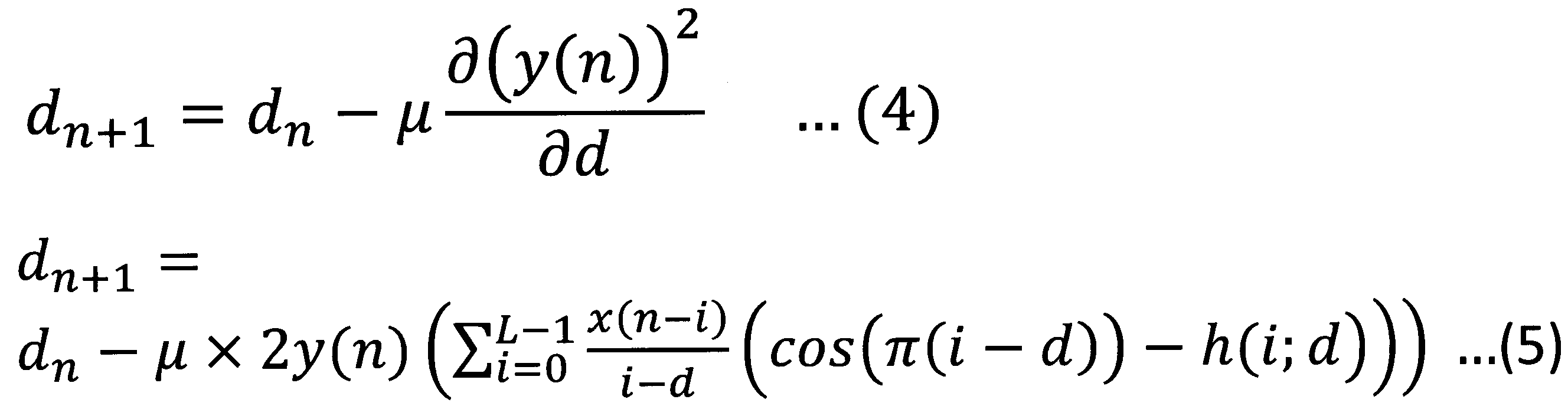
遅延長決定部130が、出力信号y(n)のパワーが最小となるような除去周波数に対応する遅延長を決定する具体的な手段(算出方法)は限定されないものである。この実施形態の例において、遅延長決定部130は、出力信号算出部110が算出した出力信号y(n)に基づいて勾配法を用いることで、除去周波数と目的音の周波数との誤差がより小さくなるように設定するものとする。これにより、遅延長決定部130では、上記のような除去周波数に応じた遅延長を設定できる。例えば、遅延長決定部130は、出力信号y(n)の二乗誤差が最小となるようにするために、現時点での遅延長dnからこの微分結果を差し引くことで、次時点での遅延長dn+1を(4)式のように更新するようにしてもよい。
The specific means (calculation method) by which the delay
(5)式は、(4)式に(1)式~(3)式を代入した結果を示している。ここで、μは、更新する速度を調整するために微分値に乗算するステップ幅である。μに設定する値は限定されないものである。例えば、実験(シミュレーション)や設計等により予め好適なμの値を求めておき、遅延長決定部130に設定するようにしてもよい。
(A-3)実施形態の効果
この実施形態によれば、以下のような効果を奏することができる。
(A-3) Effects of Embodiment According to this embodiment, the following effects can be achieved.
遅延信号算出部120では、遅延器121(分数遅延フィルタ)に任意の除去周波数に対応した遅延長を設定できるという性質を利用して、目的音の周波数に応じた遅延信号を出力することができる。従来技術のように、整数遅延フィルタ(遅延長に整数の値のみを設定可能なフィルタを用いた遅延処理)を用いた抑圧処理では、任意の除去周波数に対応した実数値の遅延長を表現することができないため、目的音の周波数が時間変化に応じて連続的に変化する場合には断続的にしか抑圧することができない。しかし、この実施形態の信号処理装置100では、分数遅延フィルタを用いることで、任意の除去周波数に対応した遅延長を設定できるため、目的音の周波数に応じて抑圧(目的音の周波数に応じた除去周波数で抑圧)できる。
The delayed
また、遅延長決定部130では、時間変化(目的音の周波数の時間的変化)に応じて除去周波数の遅延長を適応的に決定可能であるため、遅延器121に対して目的音の周波数に応じた遅延長を決定できる。
In addition, since the delay
さらに、この実施形態の遅延長決定部130では、出力信号を基にした勾配法を用いることによって、時間変化に応じて除去周波数の遅延長を適応的に決定できるため、正確に目的音の周波数に応じた除去周波数に対応した遅延長を決定できる。
Furthermore, in the delay
以上から、この実施形態の信号処理装置100では、周波数が連続的に変化する調波複合音を抑圧できるような、信号処理方法を提供できる。
As described above, the
次に、この実施形態の信号処理装置100を用いて、調波複合音の成分を含む入力信号のサンプルから当該長は復号音の成分を抑圧する処理のシミュレーション(以下、「本シミュレーション」と呼ぶ)の結果について説明する。
Next, using the
図3は、本シミュレーションにおける入力信号と出力信号(シミュレーション結果)について示した図である。 FIG. 3 is a diagram showing input signals and output signals (simulation results) in this simulation.
図3(a)は、本シミュレーションにおいて用いられる入力信号のサンプルのスペクトログラムを示した図であり、図3(b)は図3(a)に示す入力信号をこの実施形態の信号処理装置100を用いて処理した出力信号のスペクトログラム(本シミュレーションの結果)を示した図である。 FIG. 3(a) is a diagram showing a spectrogram of a sample of an input signal used in this simulation, and FIG. 3(b) is a diagram showing a spectrogram of a sample of an input signal used in this simulation. FIG. 3 is a diagram showing a spectrogram (results of this simulation) of an output signal processed using the above method.
本シミュレーションで用いた入力信号には、調波複合音として消防車のサイレン音の成分が含まれるものとして説明する。 The input signal used in this simulation will be explained as including a component of a fire engine siren sound as a harmonic complex sound.
図3の各図では、横軸が時間を示しており、縦軸が周波数を示している。そして、図3の各図では、各領域(時間と周波数の組合せ)に対応するスペクトルの大きさ(パワー)を点描の疎密のパターン(画像)で図示している。つまり、図3の各図では、点描が密な領域ほどスペクトルの大きさ(パワー)が大きいことを示しており、点描が疎な領域ほどスペクトルの大きさ(パワー)が小さいことを示している。 In each figure in FIG. 3, the horizontal axis represents time, and the vertical axis represents frequency. In each figure in FIG. 3, the magnitude (power) of the spectrum corresponding to each region (combination of time and frequency) is illustrated by a dotted sparse pattern (image). In other words, in each figure in Figure 3, the denser the dots are, the larger the spectrum (power) is, and the sparser the dots are, the smaller the spectrum (power) is. .
図3(a)の入力信号では、ストライプ状(縞模様状)のパターンで調波複合音の成分が含まれていることが示されており、図3(b)の出力信号では全体的に当該ストライプ状のパターンが薄まっており調波複合音の成分が抑圧されていることが分かる。 The input signal in Fig. 3(a) shows that harmonic complex sound components are included in a striped pattern, and the output signal in Fig. 3(b) shows that the components are contained in a striped pattern. It can be seen that the striped pattern has become thinner and the harmonic complex sound components have been suppressed.
以上のように、図3のシミュレーション結果からこの実施形態の信号処理装置100では、周波数が連続的に変化する調波複合音を抑圧することができることが証明された。
As described above, the simulation results shown in FIG. 3 prove that the
(B)他の実施形態
本発明は、上記の各実施形態に限定されるものではなく、以下に例示するような変形実施形態も挙げることができる。
(B) Other Embodiments The present invention is not limited to the above embodiments, and may include modified embodiments as exemplified below.
(B-1)上記の実施形態では、本発明の信号処理装置を単独の装置として実現する例について説明したが、本発明の信号処理装置のハードウェア構成や処理対象の信号については限定されないものである。例えば、本発明の信号処理装置を、電話装置(例えば、スマートホンやタブレット等の電話通信ソフトを搭載可能な情報処理端末や、専用の電話装置等)や、電話通信の信号(音響信号)を中継する中継装置(例えば、電話通信の信号/パケットを中継するゲートウェイ等)に搭載するようにしてもよい。 (B-1) In the above embodiment, an example was explained in which the signal processing device of the present invention is realized as a single device, but the hardware configuration of the signal processing device of the present invention and the signals to be processed are not limited. It is. For example, the signal processing device of the present invention may be used to transmit telephone communication signals (acoustic signals) to telephone devices (for example, information processing terminals that can be equipped with telephone communication software such as smartphones and tablets, and dedicated telephone devices). It may be installed in a relay device that relays (for example, a gateway that relays telephone communication signals/packets).
100…信号処理装置、110…出力信号算出部、111…遅延器、120…遅延信号算出部、130…遅延長決定部。
DESCRIPTION OF
Claims (4)
前記入力信号と前記遅延信号との差分に基づいて出力信号を取得する出力信号取得手段と、
前記遅延信号取得手段の前記分数遅延フィルタに適用する前記遅延信号の遅延長を決定するものであって、前記出力信号取得手段で前記入力信号から抑圧される音の周波数である除去周波数と抑圧対象となる目的音の周波数との差がより小さくなる前記遅延長を決定する遅延長決定手段とを有し、
前記遅延長決定手段は、前記出力信号のパワーが最小となるような除去周波数に対応する前記遅延長を決定する
ことを特徴とする信号処理装置。 Delayed signal acquisition means for performing delay processing using a fractional delay filter on an input signal to obtain a delayed signal;
output signal acquisition means for acquiring an output signal based on a difference between the input signal and the delayed signal;
Determines the delay length of the delayed signal to be applied to the fractional delay filter of the delayed signal acquisition means, the removal frequency being the frequency of the sound to be suppressed from the input signal by the output signal acquisition means and the suppression target. and delay length determining means for determining the delay length such that the difference from the frequency of the target sound becomes smaller ;
The delay length determining means determines the delay length corresponding to a removal frequency that minimizes the power of the output signal.
A signal processing device characterized by:
入力信号に分数遅延フィルタを用いた遅延処理を行って遅延信号を取得する遅延信号取得手段と、
前記入力信号と前記遅延信号との差分に基づいて出力信号を取得する出力信号取得手段と、
前記遅延信号取得手段の4記分数遅延フィルタに適用する前記遅延信号の遅延長を決定するものであって、前記出力信号取得手段で前記入力信号から抑圧される音の周波数である除去周波数と抑圧対象となる目的音の周波数との差がより小さくなる前記遅延長を決定する遅延長決定手段として機能させ、
前記遅延長決定手段は、前記出力信号のパワーが最小となるような除去周波数に対応する前記遅延長を決定する
ことを特徴とする信号処理プログラム。 computer,
Delayed signal acquisition means for performing delay processing using a fractional delay filter on an input signal to obtain a delayed signal;
output signal acquisition means for acquiring an output signal based on a difference between the input signal and the delayed signal;
The delay length of the delayed signal to be applied to the quadrature fractional delay filter of the delayed signal acquisition means is determined, and the suppression frequency is the frequency of the sound to be suppressed from the input signal by the output signal acquisition means. Functioning as a delay length determining means for determining the delay length that has a smaller difference from the frequency of the target sound,
The delay length determining means determines the delay length corresponding to a removal frequency that minimizes the power of the output signal.
A signal processing program characterized by:
前記信号処理装置は、遅延信号取得手段、出力信号取得手段、及び遅延長決定手段を有し、
前記遅延信号取得手段は、入力信号に分数遅延フィルタを用いた遅延処理を行って遅延信号を取得し、
前記出力信号取得手段は、前記入力信号と前記遅延信号との差分に基づいて出力信号を取得し、
前記遅延長決定手段は、前記遅延信号取得手段の前記分数遅延フィルタに適用する前記遅延信号の遅延長を決定するものであって、前記出力信号取得手段で前記入力信号から抑圧される音の周波数である除去周波数と抑圧対象となる目的音の周波数との差がより小さくなる前記遅延長を決定し、
前記遅延長決定手段は、前記出力信号のパワーが最小となるような除去周波数に対応する前記遅延長を決定する
ことを特徴とする信号処理方法。 In the signal processing method performed by the signal processing device,
The signal processing device includes a delayed signal acquisition means, an output signal acquisition means, and a delay length determination means,
The delayed signal acquisition means performs delay processing on the input signal using a fractional delay filter to obtain a delayed signal,
The output signal acquisition means acquires an output signal based on a difference between the input signal and the delayed signal,
The delay length determining means determines the delay length of the delayed signal to be applied to the fractional delay filter of the delayed signal acquiring means, and the delay length determining means determines the delay length of the delayed signal to be applied to the fractional delay filter of the delayed signal acquiring means, and the delay length determining means determines the delay length of the delayed signal to be applied to the fractional delay filter of the delayed signal acquiring means, and the delay length determining means determines the delay length of the delayed signal applied to the fractional delay filter of the delayed signal acquiring means, the frequency of the sound being suppressed from the input signal by the output signal acquiring means Determine the delay length at which the difference between the removal frequency and the frequency of the target sound to be suppressed is smaller;
The delay length determining means determines the delay length corresponding to a removal frequency that minimizes the power of the output signal.
A signal processing method characterized by:
Priority Applications (1)
| Application Number | Priority Date | Filing Date | Title |
|---|---|---|---|
| JP2020106307A JP7443952B2 (en) | 2020-06-19 | 2020-06-19 | Signal processing device, signal processing program, and signal processing method |
Applications Claiming Priority (1)
| Application Number | Priority Date | Filing Date | Title |
|---|---|---|---|
| JP2020106307A JP7443952B2 (en) | 2020-06-19 | 2020-06-19 | Signal processing device, signal processing program, and signal processing method |
Publications (2)
| Publication Number | Publication Date |
|---|---|
| JP2022002361A JP2022002361A (en) | 2022-01-06 |
| JP7443952B2 true JP7443952B2 (en) | 2024-03-06 |
Family
ID=79244380
Family Applications (1)
| Application Number | Title | Priority Date | Filing Date |
|---|---|---|---|
| JP2020106307A Active JP7443952B2 (en) | 2020-06-19 | 2020-06-19 | Signal processing device, signal processing program, and signal processing method |
Country Status (1)
| Country | Link |
|---|---|
| JP (1) | JP7443952B2 (en) |
Families Citing this family (1)
| Publication number | Priority date | Publication date | Assignee | Title |
|---|---|---|---|---|
| WO2023170756A1 (en) * | 2022-03-07 | 2023-09-14 | ヤマハ株式会社 | Acoustic processing method, acoustic processing system, and program |
Citations (1)
| Publication number | Priority date | Publication date | Assignee | Title |
|---|---|---|---|---|
| WO2017056781A1 (en) | 2015-09-30 | 2017-04-06 | ソニー株式会社 | Signal processing device, signal processing method and program |
Family Cites Families (5)
| Publication number | Priority date | Publication date | Assignee | Title |
|---|---|---|---|---|
| US4251831A (en) * | 1979-10-26 | 1981-02-17 | Kamath Bantval Y | Filter and system incorporating the filter for processing discrete samples of composite signals |
| JPH04178696A (en) * | 1990-11-13 | 1992-06-25 | Roland Corp | Return nose remover |
| JPH04345550A (en) * | 1991-05-23 | 1992-12-01 | Alpine Electron Inc | Noise suppressor |
| JPH064077A (en) * | 1992-06-22 | 1994-01-14 | Roland Corp | Digital filter |
| JP3351687B2 (en) * | 1996-08-05 | 2002-12-03 | 株式会社東芝 | Filter operation device and filter operation method used for noise cancellation |
-
2020
- 2020-06-19 JP JP2020106307A patent/JP7443952B2/en active Active
Patent Citations (1)
| Publication number | Priority date | Publication date | Assignee | Title |
|---|---|---|---|---|
| WO2017056781A1 (en) | 2015-09-30 | 2017-04-06 | ソニー株式会社 | Signal processing device, signal processing method and program |
Non-Patent Citations (1)
| Title |
|---|
| 迫 和孝、外2名,ノッチ周波数可変な櫛型フィルタの設計,電子情報通信学会2014年総合大会,一般社団法人電子情報通信学会,2014年03月04日,p. 58 |
Also Published As
| Publication number | Publication date |
|---|---|
| JP2022002361A (en) | 2022-01-06 |
Similar Documents
| Publication | Publication Date | Title |
|---|---|---|
| CN100492493C (en) | Noise suppression method and apparatus | |
| JP5561195B2 (en) | Noise removing apparatus and noise removing method | |
| JP6136995B2 (en) | Noise reduction device | |
| JP2001175298A (en) | Noise suppression device | |
| CN110402463A (en) | Active noise reduction apparatus and active noise reduction method | |
| JPWO2007029536A1 (en) | Noise suppression method and apparatus, and computer program | |
| JP2010122617A (en) | Noise gate and sound collecting device | |
| JP6160519B2 (en) | Noise reduction device | |
| EP2385711A1 (en) | Howling suppressing apparatus, howling suppressing method, program, and integrated circuit | |
| JP6677662B2 (en) | Sound processing device, sound processing method and program | |
| JP5153389B2 (en) | Acoustic signal processing device | |
| JP7443952B2 (en) | Signal processing device, signal processing program, and signal processing method | |
| US11967304B2 (en) | Sound pick-up device, sound pick-up method and non-transitory computer-readable recording medium recording sound pick-up program | |
| JP5086442B2 (en) | Noise suppression method and apparatus | |
| JP4094455B2 (en) | Howling suppression device | |
| EP3667662B1 (en) | Acoustic echo cancellation device, acoustic echo cancellation method and acoustic echo cancellation program | |
| JP2008052117A (en) | Noise eliminating device, method and program | |
| JP2007006525A (en) | Method and apparatus for removing noise | |
| WO2023032472A1 (en) | Signal-processing system, signal-processing method, and signal-processing program | |
| JP6559576B2 (en) | Noise suppression device, noise suppression method, and program | |
| JP2008072600A (en) | Acoustic signal processing apparatus, acoustic signal processing program, and acoustic signal processing method | |
| JPH07143361A (en) | Ringing eliminating device | |
| EP4485970A1 (en) | Interference sound suppressing device, interference sound suppressing method, and interference sound suppressing program | |
| JP4729072B2 (en) | Echo erasing device, echo erasing method, echo erasing program, and recording medium | |
| JPH0863173A (en) | Noise elimination device |
Legal Events
| Date | Code | Title | Description |
|---|---|---|---|
| A621 | Written request for application examination |
Free format text: JAPANESE INTERMEDIATE CODE: A621 Effective date: 20230207 |
|
| A977 | Report on retrieval |
Free format text: JAPANESE INTERMEDIATE CODE: A971007 Effective date: 20230921 |
|
| A131 | Notification of reasons for refusal |
Free format text: JAPANESE INTERMEDIATE CODE: A131 Effective date: 20230926 |
|
| A521 | Request for written amendment filed |
Free format text: JAPANESE INTERMEDIATE CODE: A523 Effective date: 20231121 |
|
| TRDD | Decision of grant or rejection written | ||
| A01 | Written decision to grant a patent or to grant a registration (utility model) |
Free format text: JAPANESE INTERMEDIATE CODE: A01 Effective date: 20240123 |
|
| A61 | First payment of annual fees (during grant procedure) |
Free format text: JAPANESE INTERMEDIATE CODE: A61 Effective date: 20240205 |
|
| R150 | Certificate of patent or registration of utility model |
Ref document number: 7443952 Country of ref document: JP Free format text: JAPANESE INTERMEDIATE CODE: R150 |