JP7440412B2 - Multipurpose medical equipment - Google Patents
Multipurpose medical equipment Download PDFInfo
- Publication number
- JP7440412B2 JP7440412B2 JP2020519368A JP2020519368A JP7440412B2 JP 7440412 B2 JP7440412 B2 JP 7440412B2 JP 2020519368 A JP2020519368 A JP 2020519368A JP 2020519368 A JP2020519368 A JP 2020519368A JP 7440412 B2 JP7440412 B2 JP 7440412B2
- Authority
- JP
- Japan
- Prior art keywords
- force
- suction
- gauge
- handle
- medical device
- Prior art date
- Legal status (The legal status is an assumption and is not a legal conclusion. Google has not performed a legal analysis and makes no representation as to the accuracy of the status listed.)
- Active
Links
- 238000000034 method Methods 0.000 claims description 57
- 230000000638 stimulation Effects 0.000 claims description 55
- 239000012530 fluid Substances 0.000 claims description 23
- 238000005452 bending Methods 0.000 claims description 20
- 238000004140 cleaning Methods 0.000 claims description 19
- 230000000007 visual effect Effects 0.000 claims description 16
- 238000004891 communication Methods 0.000 claims description 14
- 210000001519 tissue Anatomy 0.000 description 41
- 238000005259 measurement Methods 0.000 description 34
- 230000006870 function Effects 0.000 description 21
- 230000002262 irrigation Effects 0.000 description 16
- 238000003973 irrigation Methods 0.000 description 16
- 238000001356 surgical procedure Methods 0.000 description 14
- 239000000463 material Substances 0.000 description 12
- 238000005286 illumination Methods 0.000 description 10
- 230000008859 change Effects 0.000 description 7
- 210000005036 nerve Anatomy 0.000 description 7
- 229910001220 stainless steel Inorganic materials 0.000 description 7
- 239000010935 stainless steel Substances 0.000 description 7
- 230000008901 benefit Effects 0.000 description 5
- 238000011088 calibration curve Methods 0.000 description 5
- 238000012549 training Methods 0.000 description 5
- 238000013459 approach Methods 0.000 description 4
- 230000006835 compression Effects 0.000 description 4
- 238000007906 compression Methods 0.000 description 4
- 230000008878 coupling Effects 0.000 description 4
- 238000010168 coupling process Methods 0.000 description 4
- 238000005859 coupling reaction Methods 0.000 description 4
- 238000002955 isolation Methods 0.000 description 4
- 239000002699 waste material Substances 0.000 description 4
- 210000004556 brain Anatomy 0.000 description 3
- 210000005013 brain tissue Anatomy 0.000 description 3
- 238000000576 coating method Methods 0.000 description 3
- 230000001537 neural effect Effects 0.000 description 3
- 230000003287 optical effect Effects 0.000 description 3
- 230000001954 sterilising effect Effects 0.000 description 3
- 238000004659 sterilization and disinfection Methods 0.000 description 3
- 208000004550 Postoperative Pain Diseases 0.000 description 2
- 230000009471 action Effects 0.000 description 2
- 210000001124 body fluid Anatomy 0.000 description 2
- 238000004364 calculation method Methods 0.000 description 2
- 239000011248 coating agent Substances 0.000 description 2
- 239000003086 colorant Substances 0.000 description 2
- 230000006378 damage Effects 0.000 description 2
- 210000003811 finger Anatomy 0.000 description 2
- 230000005484 gravity Effects 0.000 description 2
- 208000015181 infectious disease Diseases 0.000 description 2
- 230000000977 initiatory effect Effects 0.000 description 2
- 208000014674 injury Diseases 0.000 description 2
- 230000003993 interaction Effects 0.000 description 2
- 230000007246 mechanism Effects 0.000 description 2
- 238000012986 modification Methods 0.000 description 2
- 230000004048 modification Effects 0.000 description 2
- 238000012544 monitoring process Methods 0.000 description 2
- 210000000578 peripheral nerve Anatomy 0.000 description 2
- 229920001296 polysiloxane Polymers 0.000 description 2
- 230000008569 process Effects 0.000 description 2
- 230000004044 response Effects 0.000 description 2
- 238000012360 testing method Methods 0.000 description 2
- 210000003813 thumb Anatomy 0.000 description 2
- RYGMFSIKBFXOCR-UHFFFAOYSA-N Copper Chemical compound [Cu] RYGMFSIKBFXOCR-UHFFFAOYSA-N 0.000 description 1
- 208000012661 Dyskinesia Diseases 0.000 description 1
- 208000015592 Involuntary movements Diseases 0.000 description 1
- 208000028389 Nerve injury Diseases 0.000 description 1
- 208000035965 Postoperative Complications Diseases 0.000 description 1
- FAPWRFPIFSIZLT-UHFFFAOYSA-M Sodium chloride Chemical compound [Na+].[Cl-] FAPWRFPIFSIZLT-UHFFFAOYSA-M 0.000 description 1
- 229910000831 Steel Inorganic materials 0.000 description 1
- 239000004809 Teflon Substances 0.000 description 1
- 229920006362 Teflon® Polymers 0.000 description 1
- 208000027418 Wounds and injury Diseases 0.000 description 1
- 230000004913 activation Effects 0.000 description 1
- 239000000853 adhesive Substances 0.000 description 1
- 230000001070 adhesive effect Effects 0.000 description 1
- 238000013528 artificial neural network Methods 0.000 description 1
- 230000000740 bleeding effect Effects 0.000 description 1
- 210000004204 blood vessel Anatomy 0.000 description 1
- 239000010839 body fluid Substances 0.000 description 1
- 230000006931 brain damage Effects 0.000 description 1
- 208000029028 brain injury Diseases 0.000 description 1
- 150000001720 carbohydrates Chemical class 0.000 description 1
- 239000000919 ceramic Substances 0.000 description 1
- 239000004020 conductor Substances 0.000 description 1
- 238000010276 construction Methods 0.000 description 1
- 229910052802 copper Inorganic materials 0.000 description 1
- 239000010949 copper Substances 0.000 description 1
- 230000009849 deactivation Effects 0.000 description 1
- 238000013461 design Methods 0.000 description 1
- 238000006073 displacement reaction Methods 0.000 description 1
- 238000005553 drilling Methods 0.000 description 1
- 230000000694 effects Effects 0.000 description 1
- 238000005516 engineering process Methods 0.000 description 1
- 238000002474 experimental method Methods 0.000 description 1
- 230000008713 feedback mechanism Effects 0.000 description 1
- 239000000835 fiber Substances 0.000 description 1
- 210000004247 hand Anatomy 0.000 description 1
- 210000003128 head Anatomy 0.000 description 1
- 239000011796 hollow space material Substances 0.000 description 1
- 230000006872 improvement Effects 0.000 description 1
- 230000002452 interceptive effect Effects 0.000 description 1
- 230000001788 irregular Effects 0.000 description 1
- 238000005304 joining Methods 0.000 description 1
- 239000007788 liquid Substances 0.000 description 1
- 230000007774 longterm Effects 0.000 description 1
- 238000010801 machine learning Methods 0.000 description 1
- 238000003754 machining Methods 0.000 description 1
- 238000004519 manufacturing process Methods 0.000 description 1
- 210000003205 muscle Anatomy 0.000 description 1
- 230000017311 musculoskeletal movement, spinal reflex action Effects 0.000 description 1
- 230000008764 nerve damage Effects 0.000 description 1
- 210000000944 nerve tissue Anatomy 0.000 description 1
- 230000007935 neutral effect Effects 0.000 description 1
- 230000035515 penetration Effects 0.000 description 1
- 230000000704 physical effect Effects 0.000 description 1
- 230000005855 radiation Effects 0.000 description 1
- 230000009467 reduction Effects 0.000 description 1
- 238000012552 review Methods 0.000 description 1
- 239000012266 salt solution Substances 0.000 description 1
- 239000011780 sodium chloride Substances 0.000 description 1
- 239000000243 solution Substances 0.000 description 1
- 210000000278 spinal cord Anatomy 0.000 description 1
- 210000001032 spinal nerve Anatomy 0.000 description 1
- 239000010959 steel Substances 0.000 description 1
- 230000008685 targeting Effects 0.000 description 1
- 230000000451 tissue damage Effects 0.000 description 1
- 231100000827 tissue damage Toxicity 0.000 description 1
- 238000012546 transfer Methods 0.000 description 1
- 230000008733 trauma Effects 0.000 description 1
- 230000000472 traumatic effect Effects 0.000 description 1
- 238000012800 visualization Methods 0.000 description 1
- XLYOFNOQVPJJNP-UHFFFAOYSA-N water Substances O XLYOFNOQVPJJNP-UHFFFAOYSA-N 0.000 description 1
Images


Classifications
-
- A—HUMAN NECESSITIES
- A61—MEDICAL OR VETERINARY SCIENCE; HYGIENE
- A61B—DIAGNOSIS; SURGERY; IDENTIFICATION
- A61B17/00—Surgical instruments, devices or methods
- A61B17/02—Surgical instruments, devices or methods for holding wounds open, e.g. retractors; Tractors
- A61B17/0218—Surgical instruments, devices or methods for holding wounds open, e.g. retractors; Tractors for minimally invasive surgery
-
- A—HUMAN NECESSITIES
- A61—MEDICAL OR VETERINARY SCIENCE; HYGIENE
- A61B—DIAGNOSIS; SURGERY; IDENTIFICATION
- A61B17/00—Surgical instruments, devices or methods
- A61B17/02—Surgical instruments, devices or methods for holding wounds open, e.g. retractors; Tractors
-
- A—HUMAN NECESSITIES
- A61—MEDICAL OR VETERINARY SCIENCE; HYGIENE
- A61B—DIAGNOSIS; SURGERY; IDENTIFICATION
- A61B17/00—Surgical instruments, devices or methods
- A61B17/02—Surgical instruments, devices or methods for holding wounds open, e.g. retractors; Tractors
- A61B17/025—Joint distractors
-
- A—HUMAN NECESSITIES
- A61—MEDICAL OR VETERINARY SCIENCE; HYGIENE
- A61B—DIAGNOSIS; SURGERY; IDENTIFICATION
- A61B17/00—Surgical instruments, devices or methods
- A61B2017/00017—Electrical control of surgical instruments
- A61B2017/00022—Sensing or detecting at the treatment site
-
- A—HUMAN NECESSITIES
- A61—MEDICAL OR VETERINARY SCIENCE; HYGIENE
- A61B—DIAGNOSIS; SURGERY; IDENTIFICATION
- A61B17/00—Surgical instruments, devices or methods
- A61B2017/00017—Electrical control of surgical instruments
- A61B2017/00022—Sensing or detecting at the treatment site
- A61B2017/00039—Electric or electromagnetic phenomena other than conductivity, e.g. capacity, inductivity, Hall effect
-
- A—HUMAN NECESSITIES
- A61—MEDICAL OR VETERINARY SCIENCE; HYGIENE
- A61B—DIAGNOSIS; SURGERY; IDENTIFICATION
- A61B17/00—Surgical instruments, devices or methods
- A61B2017/00017—Electrical control of surgical instruments
- A61B2017/00115—Electrical control of surgical instruments with audible or visual output
- A61B2017/00128—Electrical control of surgical instruments with audible or visual output related to intensity or progress of surgical action
-
- A—HUMAN NECESSITIES
- A61—MEDICAL OR VETERINARY SCIENCE; HYGIENE
- A61B—DIAGNOSIS; SURGERY; IDENTIFICATION
- A61B17/00—Surgical instruments, devices or methods
- A61B17/00234—Surgical instruments, devices or methods for minimally invasive surgery
- A61B2017/00353—Surgical instruments, devices or methods for minimally invasive surgery one mechanical instrument performing multiple functions, e.g. cutting and grasping
-
- A—HUMAN NECESSITIES
- A61—MEDICAL OR VETERINARY SCIENCE; HYGIENE
- A61B—DIAGNOSIS; SURGERY; IDENTIFICATION
- A61B17/00—Surgical instruments, devices or methods
- A61B2017/00535—Surgical instruments, devices or methods pneumatically or hydraulically operated
- A61B2017/00557—Surgical instruments, devices or methods pneumatically or hydraulically operated inflatable
-
- A—HUMAN NECESSITIES
- A61—MEDICAL OR VETERINARY SCIENCE; HYGIENE
- A61B—DIAGNOSIS; SURGERY; IDENTIFICATION
- A61B90/00—Instruments, implements or accessories specially adapted for surgery or diagnosis and not covered by any of the groups A61B1/00 - A61B50/00, e.g. for luxation treatment or for protecting wound edges
- A61B90/06—Measuring instruments not otherwise provided for
- A61B2090/064—Measuring instruments not otherwise provided for for measuring force, pressure or mechanical tension
- A61B2090/065—Measuring instruments not otherwise provided for for measuring force, pressure or mechanical tension for measuring contact or contact pressure
-
- A—HUMAN NECESSITIES
- A61—MEDICAL OR VETERINARY SCIENCE; HYGIENE
- A61B—DIAGNOSIS; SURGERY; IDENTIFICATION
- A61B2217/00—General characteristics of surgical instruments
- A61B2217/002—Auxiliary appliance
- A61B2217/005—Auxiliary appliance with suction drainage system
-
- A—HUMAN NECESSITIES
- A61—MEDICAL OR VETERINARY SCIENCE; HYGIENE
- A61B—DIAGNOSIS; SURGERY; IDENTIFICATION
- A61B2217/00—General characteristics of surgical instruments
- A61B2217/002—Auxiliary appliance
- A61B2217/007—Auxiliary appliance with irrigation system
Landscapes
- Health & Medical Sciences (AREA)
- Life Sciences & Earth Sciences (AREA)
- Surgery (AREA)
- Molecular Biology (AREA)
- Engineering & Computer Science (AREA)
- Biomedical Technology (AREA)
- Heart & Thoracic Surgery (AREA)
- Medical Informatics (AREA)
- Nuclear Medicine, Radiotherapy & Molecular Imaging (AREA)
- Animal Behavior & Ethology (AREA)
- General Health & Medical Sciences (AREA)
- Public Health (AREA)
- Veterinary Medicine (AREA)
- Surgical Instruments (AREA)
- External Artificial Organs (AREA)
- Media Introduction/Drainage Providing Device (AREA)
Description
本願は、2017年10月5日に出願された米国仮特許出願第62/568,363号に基づき米国特許法第119条の規定による優先権を主張するものであり、当該仮特許出願の内容は全て参照により本願明細書に組み込まれているものとする。 This application claims priority under 35 U.S.C. 119 based on U.S. Provisional Patent Application No. 62/568,363 filed on October 5, 2017, and the content of the provisional patent application is are hereby incorporated by reference in their entirety.
本願にて提供されている一部の実施形態は一般的に多目的医療機器に関するものであり、具体的には、限定列挙ではないが退避、吸引、力センシング、ユーザフィードバック、照明、神経刺激、及び/又は洗浄を含めた複数の機能を提供する医療機器に関するものとすることができる。 Some embodiments provided herein relate generally to multipurpose medical devices, and specifically include, but are not limited to, retraction, suction, force sensing, user feedback, lighting, neural stimulation, and and/or may relate to medical devices that provide multiple functions including cleaning.
例えば頭部、脊髄及び末梢神経手術等の複雑な処置において使用される従来の医療機器は、当該機器を使用する医療関係者にとって重大な欠点を示すことが多い。例えば従来の機器の中には、従来の吸引機器等のように、吸引と、例えば脳組織又は神経組織等の敏感な組織の退避との双方を提供するプラットフォームとして使用できるものがある。しかし、かかる従来の吸引機器は、医療関係者によって加えられる退避力のレベルが敏感な組織に許容される程度を超えることにより当該組織を損傷し得るという欠点がある。例えば神経外科手術では、過剰な力は出血、術後疼痛、又は修復不可能な負傷の原因となり得る。力の許容可能な印加量の理解は、ケーススタディ及び実地研修を通じて経験により学ぶ必要がある。実地研修環境では、研修指導者は未だ主観的又は質的なフィードバックしか研修生に提供することができない。このように、過剰な力は外科研修生により生じる主な過誤の1つとなっている。 BACKGROUND OF THE INVENTION Conventional medical devices used in complex procedures, such as head, spinal and peripheral nerve surgeries, often present significant drawbacks to the medical personnel using the devices. For example, some conventional devices, such as conventional suction devices, can be used as a platform to provide both suction and evacuation of sensitive tissue, such as brain tissue or neural tissue. However, such conventional suction devices have the disadvantage that the level of retraction force applied by medical personnel can exceed that tolerated by sensitive tissue, thereby damaging the tissue. For example, in neurosurgery, excessive force can cause bleeding, post-operative pain, or irreparable injury. Understanding the acceptable amount of applied force needs to be learned by experience through case studies and on-the-job training. In on-the-job training environments, training instructors are still only able to provide subjective or qualitative feedback to trainees. As such, excessive force has become one of the major errors made by surgical trainees.
さらに、医療関係者は上述のような複雑な処置中に、例えば鉗子、レトラクタ、メス、吸引器等の複数の用具を使用する場合がある。用具の交換は時間を要し、集中力の低下を生じ得る。用具の交換が多くなると、処置室内において感染及び混乱のリスクが増大することにも繋がり得る。さらに、これらの道具の交換を少なくするため、医療関係者はしばしば、指定された機能以外の機能のために道具を使用することも多くなる。例えば、外科医は外科用具をレトラクタとして用いることが多い。というのも、その方が複数の別々のレトラクタを用いるよりも便利だからである。具体的な一例では、外科医は組織の退避と液体の除去とを同時に行うため、手術用吸引パイプを用いることがあり得る。しかし、組織に対するかかる外科用具の力生成をモニタリングする手段は存在しない。このように、数値化できるフィードバックが欠如していることにより、使用される力が過剰になってしまい、これにより術後疼痛又は合併症が生じ得る。 Furthermore, medical personnel may use multiple instruments, such as forceps, retractors, scalpels, suction devices, etc., during complex procedures such as those described above. Changing equipment is time consuming and can cause loss of concentration. Frequent equipment changes can also lead to increased risk of infection and confusion within the procedure room. Additionally, to reduce the need to replace these tools, medical personnel often use them for functions other than their designated functions. For example, surgeons often use surgical instruments as retractors. This is because it is more convenient than using multiple separate retractors. In one specific example, a surgeon may use a surgical suction pipe to simultaneously retract tissue and remove fluid. However, there is no means to monitor the force production of such surgical tools on tissue. This lack of quantifiable feedback can result in excessive force being used, which can lead to post-operative pain or complications.
よって、上述のような複雑な処置を行う医療関係者側における作業を改善するため、力センシングを含めた複数の機能を提供できる多目的医療機器を開発する必要がある。 There is therefore a need to develop multipurpose medical devices that can provide multiple functions, including force sensing, in order to improve the work of medical personnel performing complex procedures such as those described above.
一部の実施形態は、医療処置中にユーザによって使用されるように構成された多目的医療機器を包含する。本機器は、ハンドルと、本体と、吸引システムと、センサと、指示部と、を備えることができる。本体はハンドルに動作可能に結合することができ、本体の長さ方向に延在する中空部を有することができ、本体の少なくとも一部は、医療処置中にレトラクタとして動作するように構成されている。吸引システムは、中空部内に配置された吸引通路を備えることができる。センサは本体に結合することができ、医療処置中に本体にかかる退避力をセンシングするように構成することができる。指示部は、センシングされた退避力に基づきユーザにフィードバックを提供するように構成することができる。 Some embodiments include multipurpose medical devices configured to be used by a user during a medical procedure. The device can include a handle, a body, a suction system, a sensor, and an indicator. The body can be operably coupled to the handle and can have a hollow portion extending the length of the body, and at least a portion of the body is configured to operate as a retractor during a medical procedure. There is. The suction system can include a suction passageway disposed within the hollow space. A sensor can be coupled to the body and configured to sense retraction forces applied to the body during a medical procedure. The instruction unit can be configured to provide feedback to the user based on the sensed retraction force.
一部の実施形態は、術野内において医療処置を行う方法を提供する。本方法は多目的医療機器を設けることを含むことができ、当該多目的医療機器は、レトラクタとして動作するように構成された本体と、中空部を有する本体の内表面と、少なくとも一部が中空部内に配置された吸引システムと、少なくとも一部が本体により支持されるセンシングシステムと、を備えている。本方法はさらに、機器を術野内に配置し、機器を用いて術野内の1つ又は複数の組織を退避することを含むことができる。本方法はさらに、退避中にセンシングシステムのセンサを用いて機器にかかる力をセンシングし、センシングされた力が所定の閾値を超える場合、センシングシステムの指示部を介して指示を提供することと、を含むことができる。 Some embodiments provide a method of performing a medical procedure within a surgical field. The method can include providing a multi-purpose medical device, the multi-purpose medical device having a body configured to operate as a retractor, an inner surface of the body having a hollow portion, and at least a portion within the hollow portion. and a sensing system supported at least in part by the body. The method can further include positioning an instrument within the surgical field and using the instrument to retract one or more tissues within the surgical field. The method further comprises: sensing a force on the equipment using a sensor of the sensing system during evacuation, and providing an indication via an indicator of the sensing system if the sensed force exceeds a predetermined threshold; can include.
他の課題、利点及び新規の構成が以下の説明に記載されており、又は、当業者が以下の詳細な説明及び図面を参酌すれば明らかとなる。 Other objects, advantages, and novel configurations are described in, or will become apparent to, one skilled in the art upon consideration of the following detailed description and drawings.
図面中対応する符号は、対応する要素を示している。図面にて使用されている向きは、特許請求の範囲を限定するものと解してはならない。 Corresponding symbols in the drawings indicate corresponding elements. The orientation used in the drawings shall not be construed as limiting the scope of the claims.
本発明のいずれかの実施形態を詳細に説明する前に、本発明はその出願において、以下の説明に記載され又は以下の図面に示されている構成の詳細及び構成要素の配置に限定されるものではないと解すべきである。本発明は他の実施形態を実施することができ、また、種々の態様で実施することができる。また、本願にて使用されている文言及び用語用法は説明目的のためのものであり、本発明を限定するとみなすべきものではないと解すべきである。本願において「含む」、「有する」又は「備える」との用語及びこれらの変形を使用した場合、これらは、その後に記載されている事項及びその均等事項と、他の事項とを含むという意味である。別段の記載又は限定が無い限り、「取り付ける」、「接続する」、「支持する」及び「結合する」との用語及びこれらの変形は広義で使用され、直接的及び間接的両方の取り付け、接続、支持及び結合を含む。さらに「接続」及び「結合」は、物理的又は機械的な接続又は結合に限定されない。 Before describing any embodiments of the invention in detail, the present invention is limited in its application to the details of construction and the arrangement of components that are described in the following description or shown in the following drawings. It should be understood that it is not a thing. The invention is capable of other embodiments and of being carried out in various ways. It should also be understood that the text and terminology used in this application are for illustrative purposes only and should not be considered as limiting the invention. When the terms "comprising," "having," or "comprising" and variations thereof are used in this application, they are meant to include the matters listed thereafter and their equivalents, as well as other matters. be. Unless otherwise specified or limited, the terms "attaching," "connecting," "supporting," and "coupling" and variations thereof are used broadly and include both direct and indirect attachments and connections. , including support and bonding. Further, "connection" and "coupling" are not limited to physical or mechanical connections or couplings.
以下の説明は、当業者が本発明の実施形態を生産及び使用できるように提供されるものである。当業者は、例示されている実施形態の種々の改良を容易に導き出すことができ、その一般原理は、本発明の実施形態から逸脱しない範囲で、他の実施形態及び用途に適用することができる。よって、本発明の実施形態は、示されている実施形態に限定されることを意図したものではなく、本願にて開示されている原理及び特徴と一致する最も広い範囲と考えるべきである。以下の詳細な説明は図面を参酌して読むべきものであり、図面中、異なる図中の類似の要素には、類似の符号を付している。必ずしも実寸の比率通りでない図面は、選択された実施形態を示しており、本発明の実施形態の範囲を限定することを意図したものではない。通常の知識を有する技術者であれば、本願にて提供されている事例は多くの有用な代替態様を有し、本発明の実施形態の範囲に属することを認識することができる。 The following description is provided to enable any person skilled in the art to make and use embodiments of the invention. Those skilled in the art can readily derive various modifications of the illustrated embodiments, and the general principles can be applied to other embodiments and applications without departing from the embodiments of the invention. . Accordingly, embodiments of the invention are not intended to be limited to those shown, but to be accorded the widest scope consistent with the principles and features disclosed herein. The following detailed description should be read with reference to the drawings, in which similar elements in different figures are provided with similar reference numerals. The drawings, which are not necessarily to scale, depict selected embodiments and are not intended to limit the scope of embodiments of the invention. One of ordinary skill in the art will recognize that the examples provided herein have many useful alternatives and are within the scope of embodiments of the invention.
本願にて使用されている「A,B及びCのうち少なくとも1つ」及びこれに類する他の文言は、別段の記載又は限定が無い限り、A若しくはB若しくはCを意味し、又は、A,B及び/若しくはCの全ての組み合わせを意味する。よって、当該文言及びこれに類する他の文言は、A,B及び/又はCの単数又は複数の実体を含むことができ、A,B及び/又はCのいずれかが要素のカテゴリーを示す場合には、カテゴリーA,B及び/又はCの要素のうちいずれかの要素の単数又は複数の実体を含むことができる。 As used in this application, "at least one of A, B, and C" and other similar phrases mean A or B or C, or A, B, or C, unless otherwise specified or limited. It means all combinations of B and/or C. Therefore, the said text and other similar texts may include single or multiple instances of A, B and/or C, and if any of A, B and/or C indicates a category of elements, may include single or multiple instances of any of the elements of categories A, B, and/or C.
本発明の一部の実施形態は、多目的医療機器を提供する。例えば一部の実施形態では、多目的医療機器は医療処置(例えば外科的処置)中に、外科医又は手術参加者(具体的には本機器のユーザ)等の医療関係者に対して複数の機能を提供するように構成及び配置することができる。とりわけ、従来は1つ又は2つの機能を提供できる手術用機器もあったが、これらの機器も、医療関係者に制限を課す欠点を有し、この欠点は本発明の実施形態によって解決される。 Some embodiments of the invention provide multipurpose medical devices. For example, in some embodiments, a multipurpose medical device performs multiple functions during a medical procedure (e.g., a surgical procedure) to a medical professional, such as a surgeon or a surgical participant (specifically, the user of the device). can be constructed and arranged to provide. In particular, although some surgical instruments have previously been able to provide one or two functions, these instruments also have drawbacks that impose limitations on medical personnel, which drawbacks are overcome by embodiments of the present invention. .
単なる例として、例えば吸引機器等の従来の一部の医療機器は、(例えば体液を除去するために)吸引能力を医療関係者に提供することができ、医療関係者が術野内の組織を退避する何らかの措置をとるために当該従来の医療機器を使用できるような構成になっている場合がある。しかし、この意図されていない目的のために吸引機器を用いると、組織に退避過負荷又は力の過剰印加がなされ、退避された組織に想定外の損傷が生じる場合がある。その上、医療関係者は処置中に、複数の異なる機能のために複数の異なる機器を使用する必要がある場合がある。この場合、従来の機器では医療関係者が用具を複数回及び/又は頻繁に交換する必要が生じることがあり、これにより外科的処置にかかる時間及び複雑性が増すことがある。本願にて記載されている多目的医療機器の1つ又は複数の実施形態は、このような従来の機器の上述の欠点を解消できるという大きな利点を奏する。 By way of example only, some conventional medical devices, such as suction devices, may provide suction capabilities to medical personnel (e.g., to remove body fluids), allowing medical personnel to evacuate tissue within the surgical field. The configuration may be such that the conventional medical device can be used to take some action to However, using a suction device for this unintended purpose may result in retraction overload or application of excessive force to the tissue, resulting in unintended damage to the retracted tissue. Additionally, medical personnel may need to use different equipment for different functions during a procedure. In this case, conventional equipment may require medical personnel to change instruments multiple times and/or frequently, which may increase the time and complexity of the surgical procedure. One or more embodiments of the multi-purpose medical device described herein offers significant advantages in overcoming the above-mentioned drawbacks of such conventional devices.
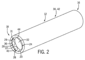
例として図1には、一部の実施形態の多目的医療機器10が示されている。一般的に多目的医療機器10は、手術環境、手術研修環境、又は非手術環境において医療関係者(例えば外科医等)により、1つ又は複数の処置を行うために使用することができる。多目的医療機器10は、限定列挙ではないが退避、吸引、刺激、照明、洗浄、センシング、及び/又はユーザフィードバックのうち1つ又は複数等、複数の機能を提供することができる。
By way of example, FIG. 1 shows some embodiments of a multipurpose
図1に示されているように、一部の実施形態では多目的医療機器10は本体12及びハンドル14を備えることができる。例えば、本体12の少なくとも一部は処置中に組織に接触するように構成することができ、ハンドル14は、処置中に本体12を局部組織環境内へ向けるため、及び/又は1つ若しくは複数の機能を制御するため、医療関係者によって保持されるように構成することができる。一部の側面では、本体12とハンドル14とは動作可能に結合されることができる。例えば、本体12とハンドル14とは、従来の結合技術を用いて結合される別体の要素を備えることができる。一部の実施形態では、動作可能に結合した後にハンドル14と本体12とを互いに結合解除できるように、ハンドル14と本体12とを可逆的に結合することができる。他の側面では、本体12とハンドル14とを互いに実質的又は完全に一体とすることができる。特定の側面では、本体12とハンドル14とを1つのユニットとして製造することができる。
As shown in FIG. 1, in some embodiments, multipurpose
一部の実施形態では、本体12及びハンドル14は無菌手術環境において使用するために適した材料を含むことができる。例えば、本体12及び/又はハンドル14は、1回又は複数回(例えば放射線、熱、圧力等によって)滅菌処理可能な材料を含むことができる。具体的には、本体12及び/又はハンドル14は鋼(例えばステンレス鋼)、ポリマー系材料、セラミック、又はこれらの任意の組み合わせ等の材料を含むことができる。また、本体12とハンドル14とは同一の材料又は異なる材料を含むことができる。
In some embodiments,
一部の側面では、上述の要素を含む材料を最初の唯一の使用前に1回滅菌処理するだけで済むように、本体12及びハンドル14を1回使用のために構成することができる。さらに一部の側面では、多目的医療機器10は、非無菌環境にいて使用するために適したものとすることもできる。例えば上述のように、多目的医療機器10は非手術試験環境において、又は非生物検体での展示目的で使用することができ、かかる場合、本機器10は必ずしも滅菌処理を必要とせず、及び/又は滅菌処理可能とする必要はない。しかし、かかる場合でも本機器10は、1つ又は複数の非手術用途のために滅菌処理できる材料を含むことができる。
In some aspects,
さらに一部の実施形態では、本体12及び/又はハンドル14は、当該本体12及び/又はハンドル14の表面に1つ又は複数の被覆を備えることができる。単なる一例として、一部の側面では本体12はテフロン(登録商標)被覆を備えることができ、このテフロン(登録商標)は、医療関係者が顕微鏡を用いて又は他の態様で術野を観察しているときに機器10からの光反射を低減できるものである。
Further, in some embodiments, the
図1,2及び4Aに示されているように、少なくとも一部の側面の多目的医療機器10は、実質的に円形の断面と概ね円柱状の形態とを有することができる。例えば、本体12の長さの一部又は全部が円形の断面と実質的に円柱状の形態とを有することができる。さらに一部の側面では、本体12の1つ又は複数の一部分が、例えば正方形、五角形、六角形、又は他の形状の断面等の非円形の断面を有することもできる。さらに一部の側面では、ハンドル14の1つ又は複数の一部分が、本体12と同様の形態を有することができる。例えば図7に示されているように、ハンドルは円柱状の形態を有することができる。他の複数の側面では、ハンドル14は本体12に対して異なる形態を有することができる。例えば図1に示されているように、ハンドルは、医療関係者の手で快適に握れるように概ね人間工学的に構成された不規則形状の形態を有することができる。人間工学的観点の有無にかかわらず、ハンドル14及び本体12は、医療関係者により所望される任意の形状、形態及び/又は断面、例えば円形、円柱状、球状、正方形、五角形、六角形、及び、現在又は将来医療関係者により所望される他の任意の種類の形状等、を有することができる。
As shown in FIGS. 1, 2, and 4A, at least some aspects of the multipurpose
一部の実施形態では、本体12は近位端16と遠位端18とを有することができる。例えば一部の実施形態では、本体12が概ね円柱のような形状となり、近位端16及び遠位端18が直線上に互いに反対側にあるように、本体12は実質的に直線状の形態を有することができる。とりわけ一部の側面では、近位端16は、ハンドル14に実質的に隣接して配置された本体12の端部とすることができ、遠位端18はハンドル14を基準として遠位にある本体12の端部に存在する。複数の他の実施形態(例えば、本体12が非直線状又は非円柱状である実施形態)では、近位端16及び遠位端18は、医療関係者により所望される他の任意の態様で配置することができ、及び/又は、これらの要素のうち少なくとも1つを省略することができる。
In some embodiments,
一部の実施形態では、本体12は内表面20を有することができる。例えば一部の側面では、本体12の大半又は全部が中空となるように、内表面20は中空部22を画定することができる。さらに、中空部22は、多目的医療機器10について有利となり得る1つ又は複数の多機能要素を受けるように構成及び配置することができる。さらに一部の実施形態では、中空部22は、本体12の長さ方向に延在して遠位開口端18を成し、一部の実施形態では近位開口端16を成すように、本体12の長さを近位端16から遠位端18まで延在することができる。一部の実施形態では、中空部22が延在する長さは、本体12の全長より短くすることができる。さらに一部の実施形態では、中空部22がハンドル14の凹部又は中空部(不図示)と連通及び/又は接続するように、本体12とハンドル14とを共に形成又は結合することができる。かかる構成により、多機能要素のうち1つ又は複数が本体12とハンドル14とを延在するように配置することができる。他の実施形態では、本体12は複数の中空部22を有することができ、これにより、多目的医療機器10の1つ又は複数の多機能要素をそれぞれ各中空部22内に配置することができる。
In some embodiments,
一部の実施形態では、本体12は、多目的医療機器10が使用される対象の外科的処置に依存して異なるサイズ寸法を有することができる。例えば脊髄関連処置等の処置では、本体12は約5mm(ミリメートル)の外径を有することができ、より繊細な処置(例えば脳に関わる処置等)では、外径は例えば2mm等のより小さいサイズを有することができる。他の複数の実施形態では、多目的医療機器10を使用する医療関係者の要請に依存して、外径は5mm超又は2mm未満のサイズを有することができる。一部の実施形態では、1つのハンドル14について複数の異なるサイズの本体12を交換できるようにすることができ、他の複数の実施形態では、複数の異なるサイズの本体12がそれぞれ専用の固有のハンドル14を有することができる。
In some embodiments,
本体12の内径(例えば中空部22の径)も同様に、多目的医療機器10を使用する医療関係者の要請を充足するように複数の異なるサイズを有することができる。例えば、本体12の外径のサイズ及び/又は多目的医療機器10を使用する医療関係者の要請に依存して、内径は2,3又は4mmのサイズを有することができる。さらに他の複数の実施形態では、本体12の内径は、多目的医療機器10を使用する医療関係者の要請を充足するように、2mm未満又は4mm超のサイズを有することができる。さらに、複数の中空部22を備えた複数の実施形態では、これら複数の中空部22は等しい径とすることができ、又は、それぞれ異なる多機能要素を収容するため異なる径を有することができる。
The inner diameter of the body 12 (e.g., the diameter of the hollow portion 22) may similarly have a plurality of different sizes to meet the needs of medical personnel using the multipurpose
ここで図3A~3Cを参照すると、本体12は様々な形態を有することができる。例えば一部の実施形態では、本体12の遠位端18が本体12の長さの他の部分及び/又はハンドル14と実質的に整列するように、本体12は(図3Aに示されているように)実質的に直線状の真っ直ぐな形態を有することができる。他の複数の側面では、本体12の遠位端18が本体12の長さの他の部分及び/又はハンドル14のうち少なくとも一部を基準として角を成すように、本体12は(図3B及び3Cに示されているように)少なくとも部分的に角を有する形態を有することができる。例えば、その角が本体12の寿命中に変化しないように本体12を形成できるよう、当該角を固定することができる。他の複数の側面では、本体12は、遠位端18が本体12の前記他の部分及び/又はハンドル14のうち少なくとも一部を基準として可動となるように構成及び配置することができる。このようにして、多目的医療機器10を使用する医療関係者の要請に依存して、遠位端18と本体12の前記他の部分(及び/又はハンドル14)との間の角度を約0°(図3Aに示されている)から、浅い角度(図3Bに示されている)、大きい角度(図3Cに示されている)まで変えることができる。さらに一部の実施形態では、本体12は、直線状部分と角付き部分との組み合わせを有する形態とすることができる。
Referring now to FIGS. 3A-3C,
上記のように、多目的医療機器10は1つ又は複数の医療処置中に使用される用具として機能するように構成及び配置することができる。例えば多目的医療機器10は、手術用レトラクタとして使用されるように構成及び配置することができる。とりわけ、医療関係者(例えば外科医)は多目的医療機器10をハンドル14で把持及び操作することができる。さらに、医療関係者は多目的医療機器10を術野内(例えば、外科的処置が行われる又は行われている患者の領域であって滅菌状態に維持される領域内)に入れて配置し、術野内の組織を退避するために機器10を使用して当該組織に力(例えば退避力)を加えることができる。このようにして、機器10の少なくとも一部、例えば本体12の少なくとも一部は、医療処置中にレトラクタとして動作する構成となる。一部の側面では、通常は遮られてしまう組織の可視化を拡大するため、外科医は多目的医療機器10の一部分(例えば本体12の遠位端18又は本体12の長さに沿った他の部分)を用いて1つ又は複数の種類の組織(例えば脳組織、神経組織、筋肉組織、血管等)を退避することができる。換言すると、外科医は一部の実施形態の多目的医療機器10を、その複数の機能の1つとして従来のレトラクタとして使用することもできる。
As mentioned above, multipurpose
本体12は単独で、医療関係者が所望の組織退避を行うために適したものとすることができる。しかし一部の実施形態では、多目的医療機器10はさらに膨張可能部材(不図示)を備えることができる。例えば、膨張可能部材は一般に、多目的医療機器10を使用する医療関係者の要求に応じて滅菌処理及び膨張/収縮可能な医療用レベルの材料を含む膨張可能なバルーンとして構成することができる。一部の実施形態では、膨張可能部材は本体12によって支持され、及び/又は本体12に結合されることができる。さらに、膨張可能部材を遠位端18に、又は遠位端18に隣接する本体12の部分に結合することができ、(例えば本体12の中空部22又は他の管路を介して)流体源と制御可能な流体連通状態におくことができる。多目的医療機器10を使用する外科医はこの流体源を作動して、例えば空気、液体等の流体を膨張可能部材に流すことにより、膨張可能部材を所望の圧力で膨張させることができる。このようにして、膨張可能部材は遠位端18に又は遠位端18付近に配置されたときに、外傷性の影響を及ぼすことなく多目的医療機器10に退避能力を付与することができる。換言すると、膨張可能部材は上記の退避能力を支援するために使用されることができる。さらに、膨張可能部材は、退避される組織にかかる力を低減して上記の退避支援を提供することができ、これによって、医療処置中に外科医が原因の外傷を低減することができる。具体的には一部の実施形態では、処置中に膨張可能部材を退避力の唯一の場所として使用することができ、他の複数の側面では、外科医によって本体12を使用して術野内の組織に発揮される退避力を増大するために膨張可能部材を使用することができる。
図2及び図7を参照すると、本体12は多目的医療機器10の1つ若しくは複数の他の機能システムを支持し、及び/又は1つ若しくは複数の他の機能システムに結合することができる。例えば多目的医療機器10は、吸引システム24、刺激システム26、洗浄システム28、照明システム29及び/又はセンシングシステム30を備えることができる。図2及び図7に示されている多目的医療機器10はこれら全ての機能システムを備えているが、一部の実施形態はこれに代えて、上記機能システムのうち1つ又は複数の機能システムの種々の組み合わせを備えることができる点に留意すべきである。
2 and 7,
一部の実施形態では、吸引システム24、刺激システム26、洗浄システム28、照明システム29及びセンシングシステム30は、少なくとも部分的に本体12によって支持されることができる。例えば一部の実施形態では、吸引システム24、刺激システム26、洗浄システム28、照明システム29及び/又はセンシングシステム30の少なくとも一部を、少なくとも部分的に中空部22内に配置することができる。さらに一部の実施形態では、センシングシステム30の少なくとも一部の部分を、例えば本体12の外表面等の本体12の一部及び/又はハンドル14に結合することができる。さらに図7を参照すると、一部の側面では、吸引システム24、刺激システム26、洗浄システム28、照明システム29及び/又はセンシングシステム30の一部の部分が、ハンドル14の一部又は全部を通って延在し、多機能医療機器10の動作及びモニタリングに必要な他の装置に接続することができる。他の複数の実施形態では、吸引システム24、刺激システム26、洗浄システム28、照明システム及び/又はセンシングシステム30の少なくともいずれかは、多機能医療機器10の動作及びモニタリングに必要な他の装置と少なくとも一部無線で通信することができる。かかる他の装置には、吸引源、廃棄物容器、電流源、流体源、電源、照明光源、及び/又はコンピュータシステム45(図7に示されている)を含むことができるが、これらに限定されない。
In some embodiments,
図2,4A,5,7及び10を参照すると、吸引システム24の少なくとも一部は本体12によって支持されることができ、吸引通路32を備えることができる。一般的に、吸引通路32は中空部22内に配置され、遠位端18から近位端16を通って延在することができ、一部の側面では、さらにハンドルを通って吸引源(不図示)まで延在することができる。
2, 4A, 5, 7, and 10, at least a portion of
例えば、吸引通路32は中空部22の少なくとも一部の内部に配置し、又は実施形態によっては、複数の中空部のうち少なくとも1つの中空部内に配置することができる。吸引通路32が中空部22の一部の内部に配置される一部の実施形態では、吸引通路32は、中空部22の一部の内部に配置できる(例えば当該一部を通って配設できる)別個の要素(例えば管路)を有することができる。他の複数の実施形態では、吸引通路32は中空部22の全部を包含することができる。具体的には、吸引通路32が本体12内及びハンドル14内に配された中空部となることによって、吸引通路32は中空部22を包含することができる。複数の中空部を備えた一部の実施形態では、吸引通路32は複数の中空部のうち少なくとも1つの中空部と実質的若しくは完全に一体とすることができ、又は、複数の中空部のうち1つの中空部内に配された別個の要素とすることができる。さらに吸引通路32は、吸引源(例えば真空源等)から吸引通路32へ吸引流を生じることができる(例えばハンドル14に隣接する)管に接続することができる。
For example, the
一部の実施形態では吸引源は、医療処置に参加している医療関係者のうち一人又は複数人によって制御されることができる。例えば吸引源は、オンオフスイッチ、フットペダル、ハンドスイッチ、又は吸引源の作動及び非作動化を制御する他の任意の手法によって操作されることができる。さらに、一部の実施形態では、吸引源は処置の一部又は全部にわたって起動状態とすることができる。さらに、吸引通路32を介して供給される吸引は、外科医によって選択的に制御することができる。例えば一部の側面では、ハンドル14は、吸引通路32と動作可能に流体連通している(図1に示されているような)吸引制御開口34を形成することができる。よって、吸引制御開口34は吸引通路32と流体連通するようにハンドル14の少なくとも一部を通ることができる。このようにして、外科医が術野内の特定の場所に吸引を供給したい場合、外科医は吸引制御開口34の全部又は一部を(例えば自己の指若しくは親指で、又は他の要素により)塞ぐだけでよく、これによって吸引通路32を介して吸引が供給されて、本体12の遠位端18を介して術野から液体やデブリ(残屑)を除去することができる。外科医が吸引を減少し又は吸引全部を除去したい場合にも、外科医は自己の指若しくは親指又は他の要素を吸引制御開口34の一部又は全部から離すだけでよく、これにより吸引レベルをゼロにすることができる。換言すると、術野に供給される吸引のレベルを制御するために吸引制御開口34を使用することができる。
In some embodiments, the suction source can be controlled by one or more of the medical personnel participating in the medical procedure. For example, the suction source can be operated by an on-off switch, foot pedal, hand switch, or any other means of controlling activation and deactivation of the suction source. Additionally, in some embodiments, the suction source may be activated during part or all of the procedure. Additionally, the suction provided through
このように、吸引システム24を使用して外科的処置中に不所望の流体及び組織を除去するために吸引を供給することができる。さらに、上述の退避能力と組み合わせることにより、多目的医療機器10は術野内に同時又は実質的に同時に退避と吸引との組み合わせを提供することができる。さらに、吸引通路32は1つ又は複数の廃棄物容器(不図示)と流体連通することができる。この1つ又は複数の廃棄物容器は、術野から吸引システム24を介して除去された流体や組織の最終目的地(すなわち、吸引通路32を流れた後の目的地)とすることができる。
Thus,
ここで図2,4A,5,7及び8を参照すると、刺激システム26の少なくとも一部を本体12によって支持することができる。例えば、刺激システム26は刺激路36を備えることができ、これは中空部22の少なくとも一部の内部に配置され、又は実施形態によっては、複数の中空部のうち少なくとも1つの中空部内に配置されている。例えば一部の実施形態では、刺激路36は実質的又は完全に中空部22と(又は複数の中空部のうち少なくとも1つの中空部と)一体とすることができる。他の実施形態では、刺激路36は中空部22の一部の内部に配することができる。例えば、刺激路36は別個の要素(例えば配線等)を有することができ、また、中空部22の一部の内部に(又は複数の中空部のうち1つの中空部の一部の内部に)配置することができる。
Referring now to FIGS. 2, 4A, 5, 7, and 8, at least a portion of the
特に図8を参照すると、一部の実施形態では、一般には刺激システム26、具体的には刺激路36は、電池又は他の電源(不図示)等の電流源から電流を刺激先端38へ伝送するように構成及び配置することができる。より具体的には、刺激路36は電流を電流源から刺激先端38へ流すため、実質的に絶縁された電線(例えば、銅等の導電性材料を含むもの)として構成及び配置することができる。一部の実施形態では、刺激システム26の動作は、当該動作を実施する1人又は複数人の医療関係者によって、例えばオンオフスイッチ、フットペダル、ハンドスイッチ等の従来の任意の制御技術を用いて制御することができる。
With particular reference to FIG. 8, in some embodiments,
一部の実施形態では、刺激先端38は一般に本体12の遠位端18に、又は遠位端18付近に配置することができる。例えば、外科医(又は他の医療関係者)が手術環境内において多目的医療機器10から隣の組織中の1つ又は複数の神経までの近接度を評価したい場合、外科医が刺激システム26を作動して、電流源から刺激路36を介して刺激先端38へ電流を流すことができるように、刺激先端38を位置決めすることができる。このようにすると、刺激先端38が組織に電流を供給するときに刺激先端38が1つ又は複数の神経に概ね隣接する場合、患者の体は電気刺激に対して(例えば小さい不随意運動によって)反応する。機器10が1つ又は複数の神経に過度に近接していると外科医が判断した場合には、外科医は神経の位置を変え、又は術野内における自己の位置を調整することができる。
In some embodiments, the
一部の実施形態では、刺激先端38は刺激システム26の作動状態に依存して動くように構成及び配置することができる。例えば一部の実施形態では、刺激先端38は刺激システム26の作動状態に依存して可動又は付勢可能(例えば後退可能)とすることができる。単なる例として、刺激システム26が非作動状態又は作動状態のいずれかにあるが外科医が1つ又は複数の神経までの近接度を評価するために局部組織に電流を供給したくない場合、刺激先端38は概ね引込み位置(不図示)にあることができる。その後、外科医が1つ又は複数の神経までの近接度を評価したくなった場合、外科医は(図8に示されているように)刺激先端38を引込み位置から離して延出位置へ動かすことができる。この延出位置では、1つ又は複数の神経までの近接度を評価するために局部組織に電流を供給できるように、刺激先端38は遠位端18から延在することができる。一部の側面では、1つ又は複数の付勢可能部材(例えばバネ等)(不図示)又は他の退避機構を用いて刺激先端38を動かすことができる。
In some embodiments,
上記構成により、外科的処置中に神経刺激又は他の刺激を供給するために刺激システム26を使用することができる。さらに、上記の退避能力と組み合わせて、多目的医療機器10は術野内に同時又は実質的に同時に退避と刺激との組み合わせを提供することができる。
The above configuration allows
ここで図2,4A,5,7及び9を参照すると、洗浄システム28の少なくとも一部は本体12によって支持されることができ、洗浄流路40を有することができる。一般的に、洗浄流路40は中空部22内に配置され、遠位端18から近位端16を通って延在することができ、一部の側面では、さらにハンドル14を通って洗浄源(不図示)まで延在することができる。
Referring now to FIGS. 2, 4A, 5, 7, and 9, at least a portion of the
例えば、洗浄流路40は中空部22の少なくとも一部の内部に配置し、又は実施形態によっては、複数の中空部のうち少なくとも1つの中空部内に配置することができる。さらに一部の側面では、洗浄システム28は特定の実施形態の本体12内に、例えば外径が大きい(例えば5mm以上の)本体12内に配置することができる。他の側面では、洗浄システム28は任意のサイズ又は形状の本体12内に配置されるように構成及び配置することができる。洗浄流路40が中空部22の一部の内部に配置される一部の実施形態では、洗浄流路40は、中空部22の一部の内部に配置できる別個の要素(例えば管路)を有することができる。他の複数の実施形態では、洗浄流路40は中空部22の全部を包含することができる。具体的には、洗浄流路40が本体12内及びハンドル14内に配された中空部となることによって、洗浄流路40は中空部22を包含することができる。複数の中空部を備えた一部の実施形態では、洗浄流路40は複数の中空部のうち少なくとも1つの中空部と実質的若しくは完全に一体とすることができ、又は、複数の中空部のうち1つの中空部内に配された別個の要素とすることができる。さらに洗浄流路40は、流体を流体源又は洗浄源から洗浄流路40へ流すことができる(例えばハンドル14に隣接する)管に接続することができる。
For example, the cleaning
構成の如何にかかわらず、洗浄流路40は、流体源から多目的医療機器10内に流体を流して遠位端18から流出させることができるように、近位端16から遠位端18まで本体12を貫通することができる。例えば一部の実施形態では、洗浄システム28の動作は、当該動作を実施する1人又は複数人の医療関係者によって、例えばオンオフスイッチ、フットペダル、ハンドスイッチ等の従来の任意の制御技術を用いて制御することができる。このようにすると、医療関係者が術野の少なくとも一部の洗浄を希望したときに、洗浄システム28を作動して、流体源から洗浄流路40を介して流体(例えば食塩水又は他の塩含有若しくは炭水化物含有溶液)を局部の術野の当該一部へ輸送することができる。
Regardless of the configuration, the
よって、医療関係者は洗浄システム28を使用することにより、洗浄流路40を介して流体を供給することによって局部の不所望の組織又は体液の除去(すなわち洗浄)を助けることができる。さらに、上記の退避能力と組み合わせて、多目的医療機器10は術野内に同時又は実質的に同時に退避と洗浄との組み合わせを提供することができる。
図2,4A,5及び7を参照すると、照明システム29の少なくとも一部は本体12によって支持されることができる。例えば、照明システム29は光チャネル31を有することができ、光チャネル31は中空部22の少なくとも一部の内部に配置し、又は実施形態によっては、複数の中空部のうち少なくとも1つの中空部内に配置することができる。例えば一部の実施形態では、光チャネル31は中空部22(又は複数の中空部のうち少なくとも1つの中空部)と実質的又は完全に一体とすることができる。他の複数の実施形態では、光チャネル31は中空部22の一部の内部に配置することができる。例えば、光チャネル31は別個の要素(例えば配線又は光ファイバケーブル)を備えることができ、中空部22の一部の内部(又は複数の中空部のうち1つの中空部の一部の内部)に配置することができる。さらに、電源又は光源(不図示)を光チャネル31に接続するため、光チャネル31を(例えばハンドル14に隣接する)外部配線に接続することができる。
Referring to FIGS. 2, 4A, 5 and 7, at least a portion of the
一部の実施形態では、一般には照明システム29、具体的には光チャネル31は、本体12の遠位端18から光を放出するように構成及び配置することができる。一部の実施形態では、照明システム29の動作は、当該動作を実施する1人又は複数人の医療関係者によって、例えばオンオフスイッチ、フットペダル、ハンドスイッチ等の従来の任意の制御技術を用いて制御することができる。このようにして、外科医は遠位端18近傍の術野の観察を助けるために照明システム29を作動することができる。
In some embodiments, the
よって、外科的処置中に局部の組織環境に追加の照明を提供するために照明システム29を使用することができる。さらに、上記の退避能力と組み合わせて、多目的医療機器10は術野内に同時又は実質的に同時に退避と照明との組み合わせを提供することができる。
図2,4A,5,7及び11を参照すると、センシングシステム30の少なくとも一部は本体12によって支持されることができる。例えばセンシングシステム30は、本体12に結合され又は他の態様で本体12に沿って配置された少なくとも1つのセンサ42と、(図7及び図11に示されているような)少なくとも1つの指示部43と、を備えることができる。一部の実施形態では、センサ42は、局部環境において加えられている力又は圧力の量をセンシング又は検出するように構成及び配置することができる。例えばセンサ42は、本体12に設けられる1つ又は複数の圧力センサであって、機器10によって術野内において局部組織に加えられている圧力を検出するように構成された1つ又は複数の圧力センサとすることができる。一部の側面では、例えば脳組織等の1つ又は複数の局部組織を移動させ、又は局部組織に力を加えるために多目的医療機器10がレトラクタとして使用されているときに、本体12に加わる特定の力又は圧力(例えば退避力)を検出するためにセンサ42を使用することができる。指示部43は、センシングされた退避力に基づいて外科医(例えば機器10のユーザ)に対してフィードバックを供給するように構成することができる。より具体的には、この退避力をセンシングすることにより、センサ42によって収集された力データを少なくとも1つの指示部43へ伝送することができ、これによって、処置を行っている外科医にフィードバックを提供することができる。このフィードバックは、局部組織に過剰な力が加わるリスクを低減するように外科医を誘導することができる。
Referring to FIGS. 2, 4A, 5, 7, and 11, at least a portion of
よって一部の実施形態では、センサ42は少なくとも1つの指示部43と通信することができる。例えばセンサ42は、少なくとも1つの指示部43と有線通信(例えば図11を参照)又は無線通信することができる。指示部43は以下の形態の指示部のうち1つ又は複数を含むことができる:視覚的指示部(例えば、点滅し又は色を変化できるLED)、触覚的指示部(例えば、小型の振動モータ等の振動触覚信号生成機構)、及び聴覚的指示部(例えば1つ又は複数のノイズを発することができる機器、例えばブザー、ビープ音機器、又は他のノイズ生成機器等)。さらに一部の実施形態では、指示部43を本体12又はハンドル14の外部又は内部に配置することもできる。例えば、図7及び図11では指示部43はハンドル14の近位端にあるのが示されているが、本体12又はハンドル14に沿った任意の位置に配置することができる。さらに一部の実施形態では、本体12及びハンドル14から遠隔の他の場所であって、識別可能なフィードバックを提供するために十分に外科医及び術野に近接している場所に指示部43を配置することができる。例えば、指示部43は外科医にフィードバックを提供するための遠隔の視覚的若しくは聴覚的指示部、又は外科医と接触する遠隔の触覚的指示部とすることができる。
Thus, in some embodiments,
さらに一部の実施形態では、指示部43は、センシングされた退避力が所定の閾値を超える場合にフィードバックを提供することができる。他の複数の実施形態では、指示部43は、センサ42によってセンシングされた退避力のレベルに基づいて異なるフィードバックを提供することができる。例えば、複数の異なる種類の指示部43が、センサ42によって取得された力データのそれぞれ異なるレベルを示すことができ、又は、1つの指示部43が力データの複数の異なるレベルに基づく複数の異なる種類のフィードバックを有することができる。例えば視覚的指示部43は、力データが閾値(例えば上記の所定の閾値)以下の許容可能な力を示す場合には緑色光、力データが閾値を超える過剰な力を示す場合には赤色光等、力データに基づいて異なる色の光を放出することができる。これに代えて、視覚的指示部43は赤色及び緑色以外の別の色を有することができ、又はフィードバックレベル数の増加に対応して追加の色を有することができ、例えば、力データが第1の閾値以下の許容可能な力を示す場合には緑色光を、力データが第1の閾値を超えかつ第2の閾値以下の中間的な力を示す場合には黄色光を、力データが第2の閾値を超える過剰な力を示す場合には赤色光を表示することができる。ここで上記の中間的な力は、未だ許容可能であるが過剰に近づいている力とすることができる。他の一例では、複数の異なる種類又は音量の聴覚的フィードバックを、フィードバックのレベルに基づいて使用することができる。さらに他の一例では、複数の異なる種類又はレベルの触覚的フィードバック(例えば複数の異なる種類又は強度の振動)をフィードバックのレベルに基づいて使用することができる。
Furthermore, in some embodiments, the
一部の実施形態では指示部43は、(図7に示されているように)多機能医療機器10と通信するコンピュータシステム45の一部として設けることができる。換言すると、コンピュータシステム45は遠隔の指示部43として機能することができる。例えば、センサ42によって取得された力データが(例えば図7に示されている有線接続57等を介して)コンピュータシステム45に伝送されるように、多機能医療機器10はコンピュータシステム45と有線通信又は無線通信することができる。コンピュータシステム45はセンサ42から力データを受け取るように構成することができ、また、リアルタイムで力データを解析して、この力データに基づいて(例えば、力データから計算又は導出された力測定値に基づいて)外科医にフィードバック(視覚、聴覚、触覚等)を供給することができる。コンピュータシステム45は、例えば処置後又は研修実習後に後で確認するため、又は他の記録保持目的のために、力データを記憶することもできる。コンピュータシステム45は、多機能医療機器10の他の機能に関連する他のデータを受け取って解析及び/又は記憶することもできる。このことについては下記にて詳述する。
In some embodiments, the
よって一部の実施形態では、術野内の組織の過剰退避に関連する合併症を回避するのに有用な誘導を外科医に供給するため、センシングシステム30を使用することができる。上記測定を行う他、センサ42はセンシングした力、歪み、又は圧力の量を処理し、センシングした力が所定の閾値を超えることを検出した場合に外科医にフィードバックを提供するため、指示部43に指示を供給することができる。代替的に、センサ42は測定データを指示部43(及び/又はコンピュータシステム45)へ伝送し、センシングされた力、歪み又は圧力の量を処理して適切なフィードバックを提供することができる。
Thus, in some embodiments,
一部の実施形態では所定の閾値は、約0.3N(ニュートン)から約1.5Nまでの検出された力を含むことができる。一部の側面では、この検出された力は0.3N未満(例えば0.1N以下等)又は1.5N超(例えば1.84N以上)とすることができる。例えば、脳の比較的敏感な領域をターゲットとする処置等の一部の用途では、0.01N~0.1N程度の低い力を検出することができる。さらに上述のように、外科医が指示部43から複数の信号を受け取ることができるように、所定の閾値は複数の値を含むことができる。例えば、0.3N、0.7N、1.0N及び1.5Nの所定の閾値に達したとき、外科医は一意のフィードバックを受け取ることができる。このようにして、機器10がレトラクタとして用いられる場合、加えられる力の量の指導を受けるために外科医はセンサ42及び指示部43を頼ることができる。さらに一部の側面では、複数の種類の指示部がそれぞれ異なる力レベルを示すこともできる(例えば、1.5Nの場合には聴覚的フィードバック、1.0Nの場合には視覚的フィードバック、0.3Nの場合には触覚的フィードバック)。外科医は、かかるフィードバックを受け取った後、術野内の局部組織に加えられている退避力に必要な任意の変化を行うことができる。
In some embodiments, the predetermined threshold may include a detected force of about 0.3N (Newtons) to about 1.5N. In some aspects, the detected force can be less than 0.3N (eg, 0.1N or less) or greater than 1.5N (eg, 1.84N or more). For example, in some applications, such as procedures targeting relatively sensitive areas of the brain, forces as low as 0.01N to 0.1N can be detected. Further, as discussed above, the predetermined threshold may include multiple values such that the surgeon may receive multiple signals from the
一部の側面では、センサ42は感圧デバイスとして構成及び配置することができ、例えば、(図2,4A,4B,4C及び6~11に示されているように)本体12の外表面44に結合できる感圧フィルム42として構成及び配置することができる。一部の側面ではセンサ42は、力、歪み及び/又は圧力を検出することができる他の任意の技術であって、必ずしも外表面44に結合されることを要しない他の任意の技術として構成することができる(例えば図5には、外表面44にセンサ42を設けずに動作する実施形態が示されている)。さらに一部の側面では、センシングシステム30のうち少なくともいずれかの一部を遠位端18から距離をおいて(例えば5mm)配置することにより、センシングシステム30が刺激システム26又は他の機能システムの動作と干渉しないようにすることができる。他の複数の側面では、センシングシステム30のいずれかの一部を遠位端18に配置することができる。
In some aspects, the
一部の従来機器では、例えばシリコーン製の退避部材等を吸引機器のパイプに取り付けることにより、水の押しのけ又はシリコーンの変形に基づいて力を測定する試みがなされてきた。その精度と、使い捨て可能であることと、滅菌処理容易であることとにより実用可能ではあるものの、この手法は、サイズ上の制約を課すことによって深層組織への侵入を困難にすることにより機器の形状を変化させるので、最適でない場合がある。また、機器の物理的特性を変化させることにより、その取扱いと、これにより生じる組織の相互作用が変化することもある。この手法はまた、組織の損傷を確実に抑えるためにカメラ及び他の道具を使用する必要があり、これによって手術台が散らかってしまう。このように、上述の従来の試みは医療処置のために実用可能な機器を達成するには至らなかった。 In some prior art devices, attempts have been made to measure forces based on water displacement or silicone deformation, for example by attaching a silicone retraction member or the like to the pipe of the suction device. Although practical due to its accuracy, disposable nature, and ease of sterilization, this technique limits the use of devices by imposing size constraints and making deep tissue penetration difficult. Since it changes the shape, it may not be optimal. Also, changing the physical properties of a device may change its handling and resulting tissue interactions. This technique also requires the use of cameras and other tools to ensure tissue damage is limited, which clutters the operating table. Thus, the above-mentioned prior attempts have fallen short of achieving a practical device for medical procedures.
一部の実施形態の多機能医療機器10は、センサ42を1つ又は複数のストレインゲージとすることにより、上記の従来手法に対する改善を達成する。例えばストレインゲージは、負荷(例えば術野内における組織の退避又は他の動き)に対する変形(例えば表面変形)を検出することができる。具体的にはストレインゲージは、電気的なグリッドを支持ベースに取り付けたものから成る。例えば本体12等の表面にストレインゲージを接合することにより、この表面の変形によってストレインゲージのグリッドに変形が生じ、グリッドの電気抵抗の変化に基づいてゲージの軸に沿った歪み測定値が得られる。この歪み測定値は無次元数である。というのも、これは表面の長さの変化と元の長さとの比だからである。その場所に沿った歪みの方向から力の方向を知ることができ、また、表面に加わっているのが張力なのか、圧縮なのか、剪断歪みなのか、ねじりなのか等を知ることができる。
The multifunctional
上記構成により、歪み情報を用いて較正試験及び計算を行うことにより、加わっている負荷の性質及び/又は種類を概ね、実質的に、又は正確に推定することができる。さらに一部の側面では、歪み情報を使用して負荷の相対位置を求めることもできる。一部の側面では、これは間接的な力測定態様と考えることができる。 With the above configuration, the nature and/or type of the applied load can be generally, substantially, or accurately estimated by performing calibration tests and calculations using the strain information. Further, in some aspects, the strain information may also be used to determine the relative position of the load. In some aspects, this can be considered an indirect force measurement aspect.
一部の実施形態では、締結要素、ねじ、又は他の結合構造を本体12又はハンドル14に通すことにより、ストレインゲージ又は他のセンサ42を支持することができる。例えば、貫通孔又は止まり孔をドリルにより開け、又はねじ若しくは他の構造によって他の態様で(例えばねじの中心軸/長軸に沿って)設けることにより、センサ42ゲージをねじ内に配置し、及び/又はねじによって支持することができる。
In some embodiments, strain gauges or
図12A及び12Bを参照すると、一部の実施形態では、センシングシステム30は支持部材46とストレインゲージ48とを備えることができる。例えば、支持部材46のうち1つ又は複数を本体12の少なくとも一部(例えば本体12の外表面44)に結合し、又は他の態様で本体12の少なくとも一部により支持することができる。一部の側面では、図12Aに示されているように、一部又は全部の支持部材46が本体12の長さの一部又は全部に延在することができる。他の複数の実施形態では、支持部材46は他の任意の適切な長さを有することができる。一部の側面では、支持部材46はエンドユーザの要望に応じて丸形、フラット、正多角形又は不規則形状を有することができる(例として図12Bには、複数の支持部材46をフラットな外表面の実質的にT字形とした断面形態を示している)。一部の実施形態では、一部又は全部の支持部材46を遠位端18から既知の距離で外表面44に結合することができる。
Referring to FIGS. 12A and 12B, in some embodiments,
さらに一部の実施形態では、1つ又は複数のストレインゲージ48を複数の支持部材46に(例えば単軸で)結合することができる。かかる構成により、(例えば図12Aに示されているように)外科医が機器10を向けることによって周辺組織に圧力が加わると、支持部材46は僅かに曲がることができ、これによりストレインゲージ48が引張(ストレインゲージ48が支持部材46の外表面に取り付けられている場合)又は圧縮(ストレインゲージが支持部材46の内表面に取り付けられている場合)を検知することができる。さらに、使用前に複数のストレインゲージ48を較正することにより、歪みパターンの特定の組み合わせが、周辺組織に加わる圧縮力の特定の大きさに相当するようにすることができる。このようにして、力又は歪みをセンサ読値に基づいてセンシングすることができる。一部の側面では、この較正は機械学習を用いて(例えばニューラルネットワークを用いて)実施することができる。
Additionally, in some embodiments, one or
図13~18は、センシングシステム30を備えた多機能医療機器10の他の実施形態を示しており、このセンシングシステム30は1つ又は複数の圧力センサ42を備えている。
13-18 show other embodiments of multifunctional
例えば、図13は一部の実施形態のセンシングシステム30を備えた多機能医療機器10を示している。図13の多機能医療機器10は退避、吸引及びセンシング機能を備えることができる。具体的には、医療機器10は本体12と、ハンドル14と、吸引システム24と、センシングシステム30とを備えることができる。
For example, FIG. 13 illustrates a multifunctional
本体12及びハンドル14は、上記にて図1~12Aを参照して記載されているものと同様の特徴を有することができる。例えば、ハンドル14は実質的に円柱状の形状とすることができ、本体12に結合し、又は本体12と一体とすることができる。本体12は、ハンドル14に隣接する近位端16と、ハンドル14から遠位にある遠位端18と、当該本体12内を延在する中空部22(例えば、吸引システム24の吸引通路32として機能する)と、を備えることができる。本体12はまた、近位端のテーパ又は丸み部分50と、近位端16に隣接する(例えばハンドル14と整列している)直線状部分52と、直線状部分52から延在する角付き部分52(例えばハンドル14に対して角を成している)と、を備えることもできる。一実施形態では、ハンドル14はステンレス鋼321を含むことができ、本体12はステンレス鋼304を含むことができる(しかし、一部の実施形態では他の材料も可能である)。さらに、一実施形態では本体12は約4mmの外径を有することもできる。しかし一部の実施形態では、本体の外径は上記のように約2mm~約5mmの範囲とすることができる。
The
吸引システム24は、上記にて図1~12Aを参照して記載されているものと同様の特徴を有することができる。よって、吸引システム24の少なくとも一部は本体12によって支持されることができ、また吸引通路32を有することができる。具体的には、中空部22は本体12内部の吸引通路32として機能することができ、また、吸引通路32はさらにハンドル14内に延在することもできる。吸引通路32はハンドル14から管路に接続することができ、この管路はさらに吸引源に接続されている。ハンドル14はまた、吸引通路32と連通する吸引制御開口56を有することもでき、これによって医療関係者は、上記のように遠位端18からの吸引を選択的に制御することができる。
上記構成により、図13の多機能医療機器10は吸引、退避、及びセンシング/フィードバックの3機能を提供することができる。さらに、図13には示されていないが、一部の実施形態では多機能医療機器10は例えば刺激システム、洗浄システム及び/又は照明システム等の他の機能システムを備えることもできる。
With the above configuration, the multifunctional
センシングシステム30に関しては、多機能医療機器10は1つ又は複数のセンサを備えることができ、具体的には、本体12の外表面44に結合された1つ又は複数のストレインゲージ48を備えることができる。ストレインゲージ48を外表面44に接合することにより、ストレインゲージ48の薄いグリッドにより機器10にサイズ制約が課されても、最小限に抑えられる。さらに一部の実施形態では、ストレインゲージの機能に影響を及ぼすことなく多機能医療機器10の滅菌処理を可能にするため、ストレインゲージ48に被覆及び/又は接着剤を被せることができる。
With respect to
例えば、図13に示されているように、本体12の周面まわり(例えば本体12の角付き部分54の周面まわりに)3つのストレインゲージ48を約90°間隔で配置することができる。しかし一部の実施形態では、例えば本体12の周面による制限等に応じて、使用されるストレインゲージ48を増減することができる。さらに、図13に示されているように、ストレインゲージ48は遠位端18から離れた距離に配置することもできる。一実施形態では、ストレインゲージ48は遠位端18から約6.8cmの位置に配置することができる(しかし、他の実施形態では他の長さも可能である)。さらに一部の実施形態では、図14に示されているように、ストレインゲージ48は例えば外部有線接続部57を備えることができ、これは、コンピュータシステム45又は他のデータ取得システムに接続することができる。他の複数の実施形態では、ストレインゲージ48は中空部22内とハンドル14内とに配線された内部配線(不図示)に結合することができる。
For example, as shown in FIG. 13, three
一部の実施形態では、ストレインゲージ48は単軸ストレインゲージ(すなわち、一方向の歪みを測定できるストレインゲージ)又はロゼットゲージ(すなわち、2つ又は3つ以上のゲージを互いに角度間隔を空けて配置したものであり、2つ又は3つ以上の方向の歪みを測定することができる)を備えることができる。複数のロゼットゲージは一部の実施形態では、間隔を空けることができ、又は重ねることができる。注目すべき点は、積層型のロゼットゲージは、間隔を空けたロゼットゲージより所要表面積を小さくすることができ、また全てのグリッドが1点で重なり合うので、全てのグリッドからの測定値を同一平面とすることができることである。よって、一部の実施形態の多機能医療機器10は任意の数及び種類のゲージ形態を備えることができる。
In some embodiments, the
例えば、図13に示されている複数のストレインゲージ48は単軸ストレインゲージ又はロゼットゲージとすることができ、本体12の曲げ力を検出するように向きを設定することができる。具体的には、単軸ストレインゲージ48の向きは本体12に沿って長手方向(例えば本体12の長手軸に沿った方向)とすることができ、及び/又は、ロゼットゲージ48は、本体12に沿った長手方向の向きの1つのゲージを含むことができる。その結果、ストレインゲージ48は本体12の曲げ力をセンシングすることができる。具体的には、例えば遠位端18に隣接する1点が組織に押し付けられて組織を退避する場合等、本体12に力が加えられた場合、本体12は僅かに変形して、ストレインゲージ48のうち1つ又は複数がこの曲げ歪みをセンシングすることができる。さらにストレインゲージ48は、その力が本体12の曲面に印加されても(すなわち、伝統的な平面に印加されなくても)、当該力をセンシングすることができる。
For example, the plurality of
例えば、図15に示されているように本体12に力Fが加わると、本体12は下方(図15に示されている向きを基準とする)に変形し、本体12の上表面が膨張してゲージ48Aがこの張力を検知すると共に、本体12の下表面が圧縮してゲージ48Bがこの圧縮力を検知する。他のゲージ48Cは一般的に曲げ力を検知せず、又は図15に示されている方向における曲げに対して最小の応答を示す。というのも、断面形状の幾何学的重心では曲げ歪みはゼロだからである。具体的には、本体12の中空部は対称的であり、断面が円形であるから、その幾何学的重心は円の中心を通る横線上にある。この他のゲージ48Cはこの応力/歪みのない線上にあり、この線を「ニュートラル軸」という。また、2つのストレインゲージ48間の1点に力Fが加わった場合、3つ全てのストレインゲージ48が力印加のいずれかの成分を検知することができる。コンピュータシステム45は本体12周囲の複数のストレインゲージ48からの測定結果を組み合わせて、加えられた合力を求めることができる。例えば、歪み測定結果と垂直力印加のそれぞれ異なる角度との関係を求めるために、多機能医療機器10を較正することができる。かかる関係を較正基準として用いることにより、未知の力及び印加角度を予測することができる。よって、複数のストレインゲージ48を本体12の周面まわりに配置して用いることにより、本体12周囲の任意の場所に加えられた力を検出して計算することができる。
For example, when a force F is applied to the
さらに、中空部22内の流体流(例えば、医療処置のための従来の真空圧の吸引等)により生じる歪み測定結果のいかなる変化も、コンピュータシステム45によって考慮して最終的な力測定値からフィルタリング除去することができる。例えば研究により、流体流の開始及び終了によって歪み読値にバイアスが生じることがあるが、流れが開始又は終了した後の流れの圧力の変化が歪み測定結果に与える影響が最小限であることが示されたにもかかわらず、このバイアスを考慮できることが示された。よって一部の実施形態では、コンピュータシステム45は洗浄システム28の動作に関する入力を受け取ることもできる。
Additionally, any changes in the strain measurements caused by fluid flow within the hollow portion 22 (e.g., traditional vacuum aspiration for medical procedures, etc.) are taken into account by the
よって、本体12の曲げ歪みを測定することによって力測定値を得ることができる。しかし、曲げ歪みに基づいて実際の力測定値を求めるためには、モーメントアームが既知でなければならない。すなわち、ストレインゲージ48から力が加わる距離が既知でなければならない。よって、ストレインゲージから既知の距離(例えば、遠位端18から最初の2cmの距離)でのみ力印加が行われるように多機能医療機器10が構成されているならば、曲げ歪みを用いて力測定値を得ることができる。一方、本体12の長さに沿った任意の距離に力印加を行えるように多機能医療機器10が構成されている場合、曲げ力だけでは力を正確に計算するために不十分な場合がある。具体的には、接触面積が既知でないため、モーメントアームに対する依存性が力を求めることを困難にする場合がある。よって、一部の実施形態では追加の歪み測定が必要となり得る。
Thus, force measurements can be obtained by measuring the bending strain of the
例えば、曲げ歪みを測定する他、ロゼットゲージが剪断歪みを測定することができ(すなわち、複数のゲージを複数の方向に備えることにより剪断歪みを測定でき)、この剪断歪みは、加わった力の場所に依存しない。具体的には、本体12の周面に配置されている例えば3軸ロゼットゲージ等の積層型のロゼットゲージは3方向で測定を行うことができ、(単軸ゲージ単独と比較して)より包括的な歪みの測定を周囲で達成することができ、剪断歪み及び曲げ歪みの両方を計算し、両パラメータを使用して較正結果を比較することができる。例えば剪断歪みは、確立された歪み理論原理と、ロゼットゲージ48のスタックの各ゲージの3つの単軸歪みと、を用いて計算することができる。さらに、剪断歪み及び曲げ歪みを共に用いて、未知の力及び未知の印加角度と、ゲージ48からの未知の距離とを予測できるように、多機能医療機器10を較正することもできる。また一部の実施形態では、ロゼットゲージはさらに、最大主歪み及び最小主歪みと、これら主歪みの角度とを求めることができる。
For example, in addition to measuring bending strain, a rosette gauge can measure shear strain (i.e., multiple gauges in multiple directions can measure shear strain), which is the Location independent. Specifically, a laminated rosette gauge, such as a triaxial rosette gauge, placed on the circumferential surface of the
例として図16A及び16Bは、モーメントアームが既知である場合の周面のロゼットゲージ48から求められた較正結果と増分角度実験とを用いて、力及び接触角を計算する一手法を示している。周面の各ロゼットゲージ48は、各ロゼットゲージ48の3つの単軸ゲージのうち1つが中空部の長軸(すなわち本体12の長軸)に沿って位置決めされるように配置され、又は代替的に、単軸ゲージを単独で本手法と共に用いることができる。各ロゼットゲージ48(又は各単軸ゲージ)の本体12の長さに沿ったグリッドからの歪み測定値が、既知のモーメントアームを前提として、加えられた力に基づいて求められている場合(ステップ62)、3つの歪み読値の極性及び相対的な大きさを用いて角度を近似することができる(ステップ64)。歪み対角度の較正結果は、図16Aに示されているように正弦波形の傾向を示す。このようにして、(例えば、全ての曲線を含む領域を正確な極性で発見するために)各読値の極性と、相対的な大きさ(例えば、1つの読値が他の読値より大きい場合には元の領域を、ゲージの曲線が他のゲージの曲線より上にある小さい領域に絞る)と、大きさの交点と等価性(例えば、2つの測定結果の大きさが近く、かつ両測定結果がx軸付近でない場合、上記の絞られた小さい領域をさらに、上記曲線がx軸から離れた場所で交差する点に絞ることができる)と、を用いて、角度を推定することができる。かかる手法を用いることにより、一部の実施形態では±25°以内の角度を推定する指針として上記曲線を使用することができる。その後、これらの歪み測定値は上記の近似した角度のコサインで除算されることにより、単軸歪みすなわち0°の歪みが求められる(ステップ66)。その後、線形ロゼット較正(力が上記角度で印加されるときに行われる)を、正規化された歪み測定値に適用することができる。より具体的には、個々のロゼットとそのグリッドごとに線形較正を用いて所与のモーメントアームに基づいて力を求めることができる(ステップ68)。
As an example, FIGS. 16A and 16B illustrate one approach to calculating force and contact angle using incremental angle experiments and calibration results determined from circumferential rosette gauges 48 when the moment arm is known. . Each
よって一部の実施形態では、図15の多機能医療機器10は本体12の周面まわりに複数のロゼットゲージ48を備えることができ、また、歪み及び曲げ力の両方を測定するように構成することができる。しかし一部の実施形態では、ロゼットゲージ48が本体12に巻き付く距離が過度に長いと、剪断歪み測定値が独立したものにならない(例えば、測定値が剪断以外の負荷を含んでしまう)原因となるので、当該距離が過度に長くならないように本体12の周面を小さくすることができる。よって一部の実施形態では、図17に示されているように、多機能医療機器10はセンシングシステム30と、独立した剪断歪み測定に対する上述の阻害要因を考慮して改良された幾何学的形態の本体と、を備えることができる。
Thus, in some embodiments, the multifunctional
具体的には、図17の多機能医療機器10は本体12と、ハンドル14と、吸引システム24と、センシングシステム30と、を備えることができる。よって多機能医療機器10は、退避、吸引、及びセンシング機能を備えることができる。同図の吸引システム24は、上記にて図1~15を参照して記載されているものと同様の特徴を有することができる。例えば、図17には吸引管61を示しており、吸引管61はハンドル14に結合されている(例えば、ハンドル14内及び本体12内を延在する吸引通路32と連通している)。さらに、図17には示されていないが一部の実施形態では、多機能医療機器10はさらに、刺激システム、洗浄システム及び/又は照明システム等の追加の機能システムを備えることもできる。
Specifically, the multifunctional
一部の実施形態では、本体12及びハンドル14は一般に、上記にて図1~15を参照して記載されているものと同様の特徴を有することができる。例えば、ハンドル14は実質的に円柱状の形状とすることができる。本体12は、ハンドル14に隣接する近位端16と、ハンドル14から遠位にある遠位端18と、当該本体12内を延在する中空部22(例えば、吸引システム24の吸引通路32として機能する)と、を備えることができる。一実施形態では、ハンドル14はステンレス鋼321を含むことができ、本体12はステンレス鋼304を含むことができる(しかし、一部の実施形態では他の材料も可能である)。さらに、一実施形態では本体12は約4mmの外径を有することもできる。しかし一部の実施形態では、本体の外径は上記のように約2mm~約5mmの範囲とすることができる。
In some embodiments, the
本体12はまた、近位端に隣接するテーパ又は丸み部分50と、テーパ部分50に隣接する(例えばハンドル14と整列している)直線状部分52と、直線状部分52から延在する角付き部分52(例えばハンドル14に対して角を成している)と、を備えることもできる。本体12はさらに、ハンドル14に隣接する近位端16に、又は近位端16付近に(又は本体12の長さに沿った他の位置に)、例えば中間部分58を有することができる。図17に示されているように、中間部分58は1つ又は複数の平坦面60を有する。例えば中間部分58は、正方形、五角形、六角形、七角形、八角形、又は1つ若しくは複数の平坦面を有する他の形状の断面を有することができる。
The
図17のセンシングシステム30に関しては、多機能医療機器10は1つ又は複数のセンサを備えることができ、より具体的には、中間部分58の平坦面60に結合された1つ又は複数のストレインゲージ48を備えることができる。例として図17には、平坦面60のうち1つに接合された1つのストレインゲージ48(例えば2軸又は3軸ロゼットゲージ)が示されているが、各平坦面60に(又は平坦面60全部より少ない数の平坦面60に)追加のストレインゲージ48を接合することもできる。例えば一実施形態では、多機能医療機器10は4つのストレインゲージ48を備えており、各ストレインゲージ48が各対応する平坦面60に取り付けられている。他の一実施形態では、多機能医療機器10は8つのストレインゲージ48を備えており、各ストレインゲージ48が各対応する平坦面60に取り付けられている。一部の実施形態では、ストレインゲージ48は例えば外部有線接続部(不図示)を備えることができ、これは、コンピュータシステム45又は他のデータ取得システムに接続することができる。他の複数の実施形態ではストレインゲージ48は、中空部22内及びハンドル14内に配線された内部配線(不図示)に結合することができる。
With respect to the
平坦面60に貼付されることにより、各ストレインゲージ48はより正確でより独立した剪断歪み測定を可能にすることができる。上記のように、剪断荷重測定値を用いて、モーメントアームに依存せずに(すなわち、加えられた力の場所に依存せずに)、加えられた力を求めることができる。このようにして、コンピュータシステム45はストレインゲージ48からの測定結果に基づき、多機能医療機器10によって組織に対して加えられた力を計算して、この計算した力に基づき、機器10を操作する外科医に(コンピュータシステム45を介して、又は別個に接続された指示部43を介して)フィードバックを提供することができる。
By being affixed to a
上記のように、機器10は剪断歪み測定値を得るために複数のストレインゲージ48を備えることができる。一部の実施形態では、複数の異なる機器設計とストレインゲージ48位置決めとにより、機器10(又はその一部)がシェアビーム(剪断梁)型ロードセルと同様に働くようにすることができる。第1の例では、ストレインゲージ48は本体12に直接配置され、上記のように剪断歪みを最大限に検知する向きとなっている。他の一例では、本体12は1つ又は複数の引込み位置(不図示)を有することができる。(例えば機械加工により本体12に形成された)各引込み位置は剪断ウェブを形成することができ、(例えば1つの成分方向において)本体12に加えられた剪断力に比例する出力を生成するため、この剪断ウェブの両側に例えば2軸ロゼットゲージ等のストレインゲージ48が配置される。一部の側面では、対向し合うストレインゲージを接続してフルブリッジ回路とすることにより、出力が軸外荷重成分又は側方荷重に影響を受けにくくすることができる。
As mentioned above,
さらに一部の実施形態では、機器10は、剪断歪みをセンシングするためのストレインゲージ48を備えた追加の構造を有することができる。一例では、ストレインゲージ48は上述のように中間部分58の平坦面60に沿って配置されている。他の一例では、本体12又は中間部分58は、例えば平行な2つ又は3つの弾性梁要素(例えば、剛性のフランジにより接続された平行四辺形の弾性要素となるように配置したもの)等の1つ又は複数の弾性梁要素(不図示)を有することができる。そして、加わった剪断力をセンシングするように、単軸引張/圧縮ストレインゲージ48を上述の梁要素のうち1つ又は複数に結合することができる(例えば、加わった力付近のゲージ48は圧縮をセンシングするのに対し、力から離れた位置のゲージ48は引張をセンシングする)。さらに他の一例では、異なるセンシング方向を有する複数の直交する小さな平行四辺形又は剪断梁要素を直列に組み立てて、ストレインゲージ48を取り付けることができる。一側面では中間部分58は、垂直方向及び水平方向両方の力成分を測定するため、2つの直交する平行四辺形要素を備えることができる。この側面では、本体12は中間部分58(例えば可撓性の管路)を通ってハンドル14まで連続することができるが、ハンドル14ではなく中間部分58へ荷重を伝達することになる。このようにして、中間部分58を介してハンドル14と本体12とを構造的に結合することができ、中間部分58は一般に、力を検出するための「ばね」要素として作用することとなる。一般に、剪断荷重を求めるために本体12及び/又は1つ若しくは複数の他の構造に結合された1つ又は複数のストレインゲージ48を備えた機器10を提供するため、本願開示の範囲内で、本願に具体的に記載されていない他の構成も実施できることに留意すべきである。
Furthermore, in some embodiments, the
さらに図18には、一部の実施形態の多機能医療機器10を示しており、これは、力印加点を予め知ることなく力測定及び計算を行えるように構成されたセンシングシステム30を備えることができる。
Further shown in FIG. 18 is some embodiments of a multifunctional
具体的には、図18の多機能医療機器10は本体12と、ハンドル14と、吸引システム24と、センシングシステム30と、を備えることができる。よって、多機能医療機器10は退避、吸引及びセンシング機能を備えることができる。同図の吸引システム24は、上記にて図1~15及び17を参照して記載されているものと同様の特徴を有することができる。さらに、図18には示されていないが一部の実施形態では、多機能医療機器10は例えば刺激システム、洗浄システム及び/又は照明システム等の他の機能システムを備えることもできる。
Specifically, the multifunctional
一部の実施形態では、本体12及びハンドル14は一般に、上記にて図1~15を参照して記載されているものと同様の特徴を有することができる。例えば、ハンドル14は実質的に円柱状の形状とすることができる。本体12は、ハンドル14に隣接する近位端16と、ハンドル14から遠位にある遠位端18と、当該本体12内を延在する中空部22(例えば、吸引システム24の吸引通路32として機能する)と、を備えることができる。本体12はまた、近位端16に隣接する(例えばハンドル14と整列している)直線状部分52と、直線状部分52から延在する角付き部分54(例えばハンドル14に対して角を成している)と、(さらにオプションとして、近位端16に隣接するテーパ又は丸み部分50と)を備えることもできる。一実施形態では、ハンドル14はステンレス鋼321を含むことができ、本体12はステンレス鋼304を含むことができる(しかし、一部の実施形態では他の材料も可能である)。さらに、一実施形態では本体12は約4mmの外径を有することもできる。しかし一部の実施形態では、本体の外径は上記のように約2mm~約5mmの範囲とすることができる。
In some embodiments, the
図18のセンシングシステム30に関しては、多機能医療機器10は直線に並んだ2つ以上のセンサを備えることができ、より具体的には、本体12に(例えば角付き部分54に)結合され直線に並んだ2つ以上のストレインゲージ48であって、遠位端18からそれぞれ異なる距離に配置され直線に並んだ2つ以上のストレインゲージ48を備えることができる。例として図18は、遠位端18から第1の距離D1で本体12に接合された第1のストレインゲージ48(例えば単軸又は2軸又は3軸のロゼットゲージ)と、第1のストレインゲージ48と同一軸に沿って、かつ遠位端18からより遠い第2の距離D2で本体12に接合された第2のストレインゲージ48(例えば単軸又は2軸又は3軸のロゼットゲージ)と、を示している。一部の実施形態では多機能医療機器10は、上述の直線に並んだ複数対のストレインゲージ48が本体12の周面まわりに配置されている。さらに、一部の実施形態では、ストレインゲージ48は例えば外部有線接続部(不図示)を備えることができ、これは、コンピュータシステム45又は他のデータ取得システムに接続することができる。他の複数の実施形態ではストレインゲージ48は、中空部22内及びハンドル14内に配線された内部配線(不図示)に結合することができる。
With respect to the
ストレインゲージ48は各々独立して曲げ力を測定することができる(ひいては、各ストレインゲージ48を単軸ゲージ又はロゼットゲージとすることができる)。直線に並んだストレインゲージの各対では、D1とD2との間の距離を既知とすることができるので、両ストレインゲージ48からのオフセットの距離における既知の荷重を使用して両ストレインゲージ48の読値を較正することができる。これら既知の荷重及び読値を使用して、較正曲線(例えば歪み対印加されたモーメントの較正曲線)を作成することができる。これにより、ストレインゲージ48ごとに、加えられた曲げの単位Nm(ニュートン・メートル)あたりの歪み出力について、較正曲線の傾きを求めることができる。ここで注目すべき点は、これらの曲線は、直線に並んだストレインゲージごとに異なることである。その理由は、加えられた荷重から各ストレインゲージまでの距離が異なるからである。較正後は、その後にストレインゲージ48からオフセットして本体12に加えられた如何なる未知の力についても、その場所が当初は未知であるにもかかわらず、新たなゲージ読値と較正された傾きとを用いて、力の大きさ(単位N)及び正味力の場所の両方を数学的に求めることができる。
Each
例として、直線に並んだ複数のストレインゲージ48から未知の距離で(例えば、第1のストレインゲージ48から未知の距離x1と、第2のストレインゲージ48から未知の距離x2で)未知の力Fが本体12に加わった場合、ゲージ読値を上記の較正曲線と共に使用することにより、各ストレインゲージ48における各曲げモーメントM1,M2を求めることができる。よって、曲げモーメントはM1=x1F、M2=x2Fとして定義することができる。力はF=(M1-M2)/dとして計算することができ、点dから力印加点までの距離はx1=M1d/(M2-M1)として計算することができ、ここで、d=(x2-x1)はストレインゲージ48間の既知の距離である。よって、較正曲線を用いてモーメントM1,M2を得ることができ、またストレインゲージ48間の距離は既知であるから、ストレインゲージから力の印加点までの距離を計算することができる。
By way of example , the unknown When a force F is applied to the
さらに一部の実施形態では、加えられた力の水平方向成分と垂直方向成分とを求めるために、直線に並んだ複数のストレインゲージ48を本体12の周面まわりに配置することができる。例えば、図15に示されている例では点A及びBに、直線に並んだ複数のストレインゲージ48を配置することができ、これにより、本体12に作用する力の第1の成分(例えば垂直方向成分)が得られ、また、図15に示されている例では点Cと、点Cとは反対側の点とに、直線に並んだ複数のストレインゲージ48を配置することができ、これにより、本体12に作用する力の第2の成分(例えば水平方向成分)が得られる。両成分方向において歪み測定値が得られることにより、その径方向の合力の大きさを求めることができる。
Further, in some embodiments, a plurality of linear strain gauges 48 may be disposed about the circumference of the
よってコンピュータシステム45は、直線に並んだ複数のストレインゲージ48から読値を取得し、これらのストレインゲージ48からの測定値に基づき、多機能医療機器10によって組織に加えられた力を(その加わった力の場所に依存せずに)計算し、計算された力に基づき、機器10を操作する外科医に(コンピュータシステム45又は別個に接続された指示部43のいずれかを介して)フィードバックを提供することができる。
Accordingly, the
さらに、一般的に上記のどの実施形態の多目的医療機器10も、1つ又は複数のコンピュータシステム45と通信することができる。例えば、機器10は複数のコンピュータシステム45と有線通信又は無線通信することができる。一部の実施形態では、コンピュータシステム45は、例えば医用画像保管通信システム(PACSシステム)又は1つ若しくは複数の電子カルテ等の要素を備えることができる。さらに、センシングシステム30がコンピュータシステム45と通信する構成を説明したが、一部の実施形態では、多目的医療機器10の他の機能システムのうち1つ又は複数がコンピュータシステム45と通信することもできる。例えば、一部の実施形態では吸引システム24、センシングシステム30、洗浄システム28及び/又は他の任意の機能システムがコンピュータシステム45と通信することができる。かかる構成により、1つ又は複数のコンピュータシステム45において長期間の記録保存を行うために、上記のシステムの動作からデータを収集することができ、例えばコンピュータシステム45への入力から収集することができる。この収集したデータは、上記のように力印加を求めてフィードバックを提供するために使用することができ、また、患者の看護において及び/又は外科医が処置中に行った行動を理解するために使用することもできる。一部の実施形態では、外科的処置の結果として生じ得る臨床上及び法医学上の問題において支援するために上記データを使用することもできる。
Additionally, general purpose
まとめると、多目的医療機器10の複数の異なるシステムが、従来の機器に対して大きな利点を奏することができる。例えば、吸引システム24、刺激システム26、洗浄システム28、照明システム29及び/又はセンシングシステム30を備えた1つの機器を準備することにより、機器10は、外科医が外科的処置(例えば頭部手術、最小侵襲脊髄手術等の脊髄手術、末梢神経手術、又は他の医療処置等)を有効かつ効率的に行うために使用できる複数の機能の組み合わせを提供する。具体的には、上記利点のうち1つ又は複数を1つの機器にまとめることにより、処置中に用具を交換するために必要な時間を短縮することができ、これにより処置の全時間量も短縮することができる。用具交換と処置の全時間の上述の短縮によって、患者の安全性を(例えば少なくとも外科医の集中力の向上、混乱の最小限化、及び/又は感染リスクの最小限化によって)改善することができる。さらに、少なくとも1つのセンサ42を備えたセンシングシステム30と退避機能とを備えることにより、多機能医療機器10は道具-組織間の相互作用を数値化してリアルタイムでモニタリングし、医療関係者に視覚的、聴覚的及び/又は触覚的フィードバックを提供することができる。その結果、退避の過剰負荷のリスクと、退避が原因で生じる想定外の脳及び神経の損傷のリスクとを減少することができる。さらに、上述のフィードバックメカニズムは、処置中に適切な量の退避力を加える訓練を研修医や外科医に行うために使用することができ、これによって学習曲線が減少し、患者の安全性が向上する。
In summary, the multiple different systems of multipurpose
上記にて特定の実施形態及び例を参照して本発明を説明したが、本発明は必ずしもこれらに限定されるものではなく、数多くの他の実施形態、例、使用、並びに上記の実施形態、例及び使用の改良形態及び派生形態も、添付の特許請求の範囲に含まれることを意図していることは、当業者に明らかである。本願にて引用した各特許及各刊行物の開示内容は全て参照により本願に含まれ、当該各特許又は各刊行物が個別に参照により本願に含まれている場合と同様に扱う。本発明の種々の構成及び利点は、以下の特許請求の範囲に記載されている。 Although the invention has been described above with reference to particular embodiments and examples, the invention is not necessarily limited thereto and may include numerous other embodiments, examples, and uses, as well as the embodiments described above, It will be apparent to those skilled in the art that modifications and derivatives of the examples and uses are also intended to be within the scope of the appended claims. The disclosures of each patent and each publication cited in this application are incorporated herein by reference in their entirety, and are treated as if each such patent or each publication were individually incorporated by reference. Various features and advantages of the invention are set forth in the claims below.
Claims (21)
ハンドルと、
前記ハンドルに動作可能に結合された円柱状又は角柱状の本体であって、前記本体の長さ方向に延在する中空部を有し、前記本体の少なくとも一部は前記医療処置中にレトラクタとして動作するように構成されている本体と、
前記中空部内に配された吸引通路を有する吸引システムと、
前記本体に結合されたセンシングシステムであって、前記医療処置中に組織を退避させるために前記本体にかかる力をセンシングするように構成されたセンシングシステムと、
センシングされた前記力に基づいて前記ユーザへフィードバックを提供するように構成された指示部と、
を備えている多目的医療機器において、
前記センシングシステムは、(a)前記力がかかる場所に依存せずに前記力をセンシングするように構成されていると共に、(b)前記本体の周面まわりに配置された複数の対のゲージであって、前記複数の各対はそれぞれ、前記本体の軸方向に直線に並んだ第1のゲージ及び第2のゲージを含む複数対のゲージを備えており、
前記第1のゲージ及び前記第2のゲージの相互間に既知の距離をおくように、前記第1のゲージは前記本体に第1の場所において結合されており、前記第2のゲージは前記本体に第2の場所において結合されており、
前記多目的医療機器は、前記力がかかる場所と前記第1の場所との間の距離及び前記力がかかる場所と前記第2の場所との間の距離を求めるように構成されている
ことを特徴とする多目的医療機器。 A multipurpose medical device configured for use by a user during a medical procedure, the device comprising:
handle and
a cylindrical or prismatic body operably coupled to the handle, the body having a hollow portion extending longitudinally of the body, at least a portion of the body being used as a retractor during the medical procedure; a body configured to operate;
a suction system having a suction passage disposed within the hollow portion;
a sensing system coupled to the body and configured to sense a force applied to the body to retract tissue during the medical procedure;
an instruction configured to provide feedback to the user based on the sensed force;
In multipurpose medical equipment equipped with
The sensing system is configured to (a) sense the force independent of where the force is applied, and (b) include a plurality of pairs of gauges disposed about a circumference of the body. Each of the plurality of pairs includes a plurality of pairs of gauges including a first gauge and a second gauge arranged in a straight line in the axial direction of the main body,
The first gauge is coupled to the body at a first location, and the second gauge is coupled to the body at a first location such that the first gauge and the second gauge are spaced apart from each other at a known distance. is joined at a second location to
The multipurpose medical device is configured to determine a distance between the place where the force is applied and the first place and a distance between the place where the force is applied and the second place. A multi-purpose medical device.
請求項1記載の機器。 The instruction section includes at least one of a visual instruction section, a tactile instruction section, and an auditory instruction section.
The device according to claim 1.
請求項1記載の機器。 the indicator is configured to provide different feedback to the user based on the level of the force sensed by the sensing system;
The device according to claim 1.
請求項1記載の機器。 the indicator is configured to provide feedback to the user if the force of 0.3N to 1.5N is detected;
The device according to claim 1.
請求項1記載の機器。 the sensing system comprises a pressure sensor coupled to the body;
The device according to claim 1.
請求項5記載の機器。 the pressure sensor includes a uniaxial strain gauge configured to sense bending force along the body;
The device according to claim 5.
請求項5記載の機器。 the pressure sensor includes a rosette gauge configured to sense bending and shear forces along the body;
The device according to claim 5.
請求項5記載の機器。 The pressure sensor includes a pair of strain gauges arranged in a straight line and arranged at different distances from the distal end of the main body.
The device according to claim 5.
請求項1記載の機器。 The body has one of a substantially straight shape and a shape at least partially angled with respect to the handle.
The device according to claim 1.
前記吸引制御開口は、前記吸引通路と動作可能に流体連通していると共に、前記吸引通路を介して供給される吸引を制御するように構成されている、
請求項1記載の機器。 The suction system further includes a suction control opening disposed through at least a portion of the handle;
the suction control opening is in operative fluid communication with the suction passageway and configured to control suction provided through the suction passageway;
The device according to claim 1.
前記コンピュータシステムは、センシングされた前記力に関するデータを前記センシングシステムから受け取るように構成されている、
請求項1記載の機器。 The device further includes a computer system in communication with the sensing system;
the computer system is configured to receive data regarding the sensed force from the sensing system;
The device according to claim 1.
請求項1記載の機器。 The body further supports at least a portion of any one of a stimulation system, a lighting system, and a cleaning system.
The device according to claim 1.
前記刺激先端は、前記医療処置中に組織に電流を供給するように構成されている、
請求項12記載の機器。 The stimulation system includes a stimulation channel disposed at least partially within the cavity and a stimulation tip disposed at a distal end of the body;
the stimulation tip is configured to deliver electrical current to tissue during the medical procedure;
13. The device according to claim 12.
請求項1記載の機器。 The main body has an outer diameter of 2 mm to 5 mm,
The device according to claim 1.
ハンドルと、
前記ハンドルに動作可能に結合された本体であって、前記本体の長さ方向に延在する中空部を有し、前記本体の少なくとも一部は前記医療処置中にレトラクタとして動作するように構成されている本体と、
前記中空部内に配された吸引通路を有する吸引システムと、
前記本体に結合されたセンシングシステムであって、前記医療処置中に組織を退避させるために前記本体にかかる力をセンシングするように構成されたセンシングシステムと、
センシングされた前記力に基づいて前記ユーザへフィードバックを提供するように構成された指示部と、
を備えている多目的医療機器において、
前記センシングシステムは、前記力がかかる場所に依存せずに前記力をセンシングするように構成されており、
前記吸引システムはさらに、前記ハンドルの少なくとも一部を貫通するように設けられた吸引制御開口を有し、
前記吸引制御開口は、前記吸引通路と動作可能に流体連通していると共に、前記吸引通路を介して供給される吸引を制御するように構成されている
ことを特徴とする多目的医療機器。 A multipurpose medical device configured for use by a user during a medical procedure, the device comprising:
handle and
a body operably coupled to the handle, the body having a hollow portion extending longitudinally of the body, at least a portion of the body configured to operate as a retractor during the medical procedure; The main body that is
a suction system having a suction passage disposed within the hollow portion;
a sensing system coupled to the body and configured to sense a force applied to the body to retract tissue during the medical procedure;
an instruction configured to provide feedback to the user based on the sensed force;
In multipurpose medical equipment equipped with
The sensing system is configured to sense the force independent of where the force is applied;
The suction system further includes a suction control opening disposed through at least a portion of the handle;
The multipurpose medical device wherein the suction control opening is in operative fluid communication with the suction passageway and configured to control suction provided through the suction passageway.
前記センシングシステムは、前記本体の周面まわりに配置された複数の対のゲージであって、前記複数の各対はそれぞれ、前記本体の軸方向に直線に並んだ第1のゲージ及び第2のゲージを含む複数対のゲージを備えており、
前記第1のゲージ及び前記第2のゲージの相互間に既知の距離をおくように、前記第1のゲージは前記本体に第1の場所において結合されており、前記第2のゲージは前記本体に第2の場所において結合されており、
前記多目的医療機器は、前記力がかかる場所と前記第1の場所との間の距離及び前記力がかかる場所と前記第2の場所との間の距離を求めるように構成されている、
請求項15記載の機器。 The main body is cylindrical or prismatic,
The sensing system includes a plurality of pairs of gauges arranged around a circumferential surface of the body, each of the plurality of pairs including a first gauge and a second gauge arranged in a straight line in an axial direction of the body. It is equipped with multiple pairs of gauges, including gauges.
The first gauge is coupled to the body at a first location, and the second gauge is coupled to the body at a first location such that the first gauge and the second gauge are spaced apart from each other at a known distance. is joined at a second location to
The multipurpose medical device is configured to determine a distance between the location where the force is applied and the first location and a distance between the location where the force is applied and the second location.
16. The device according to claim 15.
請求項15記載の機器。 The instruction section includes at least one of a visual instruction section, a tactile instruction section, and an auditory instruction section.
16. The device according to claim 15.
請求項15記載の機器。 the indicator is configured to provide different feedback to the user based on the level of the force sensed by the sensing system;
16. The device according to claim 15.
請求項15記載の機器。 the indicator is configured to provide feedback to the user if the force of 0.3N to 1.5N is detected;
The device according to claim 15 .
請求項15記載の機器。 The body further supports at least a portion of any one of a stimulation system, a lighting system, and a cleaning system.
16. The device according to claim 15.
前記刺激先端は、前記医療処置中に組織に電流を供給するように構成されている、
請求項20記載の機器。 The stimulation system includes a stimulation channel disposed at least partially within the cavity and a stimulation tip disposed at a distal end of the body;
the stimulation tip is configured to deliver electrical current to tissue during the medical procedure;
21. The device according to claim 20.
Priority Applications (1)
| Application Number | Priority Date | Filing Date | Title |
|---|---|---|---|
| JP2024020018A JP7717872B2 (en) | 2017-10-05 | 2024-02-14 | Multipurpose medical devices |
Applications Claiming Priority (3)
| Application Number | Priority Date | Filing Date | Title |
|---|---|---|---|
| US201762568363P | 2017-10-05 | 2017-10-05 | |
| US62/568,363 | 2017-10-05 | ||
| PCT/US2018/054716 WO2019071203A1 (en) | 2017-10-05 | 2018-10-05 | Multipurpose medical device |
Related Child Applications (1)
| Application Number | Title | Priority Date | Filing Date |
|---|---|---|---|
| JP2024020018A Division JP7717872B2 (en) | 2017-10-05 | 2024-02-14 | Multipurpose medical devices |
Publications (3)
| Publication Number | Publication Date |
|---|---|
| JP2020536621A JP2020536621A (en) | 2020-12-17 |
| JP2020536621A5 JP2020536621A5 (en) | 2021-11-18 |
| JP7440412B2 true JP7440412B2 (en) | 2024-02-28 |
Family
ID=65994367
Family Applications (2)
| Application Number | Title | Priority Date | Filing Date |
|---|---|---|---|
| JP2020519368A Active JP7440412B2 (en) | 2017-10-05 | 2018-10-05 | Multipurpose medical equipment |
| JP2024020018A Active JP7717872B2 (en) | 2017-10-05 | 2024-02-14 | Multipurpose medical devices |
Family Applications After (1)
| Application Number | Title | Priority Date | Filing Date |
|---|---|---|---|
| JP2024020018A Active JP7717872B2 (en) | 2017-10-05 | 2024-02-14 | Multipurpose medical devices |
Country Status (5)
| Country | Link |
|---|---|
| US (2) | US12262884B2 (en) |
| EP (1) | EP3691544A4 (en) |
| JP (2) | JP7440412B2 (en) |
| CA (1) | CA3078378A1 (en) |
| WO (1) | WO2019071203A1 (en) |
Families Citing this family (4)
| Publication number | Priority date | Publication date | Assignee | Title |
|---|---|---|---|---|
| US11221284B2 (en) * | 2019-05-17 | 2022-01-11 | Douglas Anderson | Structural health monitoring sensor |
| US11918751B2 (en) * | 2019-11-12 | 2024-03-05 | Biosense Webster (Israel) Ltd. | Catheter with vapor deposited features on tip |
| CN116407160B (en) * | 2021-12-29 | 2026-01-23 | 深圳市先健呼吸科技有限公司 | Biopsy device |
| CN119385616A (en) * | 2024-12-19 | 2025-02-07 | 哈尔滨工业大学 | A minimally invasive surgical instrument with an additional end micro force sensor |
Citations (2)
| Publication number | Priority date | Publication date | Assignee | Title |
|---|---|---|---|---|
| US20130053979A1 (en) | 2006-04-28 | 2013-02-28 | Michael G. Leydet | Prosthetic sensing systems and methods |
| JP2016521997A (en) | 2013-03-15 | 2016-07-28 | デピュイ・シンセス・プロダクツ・インコーポレイテッド | Surgical retractor |
Family Cites Families (14)
| Publication number | Priority date | Publication date | Assignee | Title |
|---|---|---|---|---|
| US5514153A (en) | 1990-03-02 | 1996-05-07 | General Surgical Innovations, Inc. | Method of dissecting tissue layers |
| US5342385A (en) | 1991-02-05 | 1994-08-30 | Norelli Robert A | Fluid-expandable surgical retractor |
| JP3940970B2 (en) | 1997-09-12 | 2007-07-04 | 株式会社東京測器研究所 | Strain measurement module |
| WO2003005887A2 (en) * | 2001-07-11 | 2003-01-23 | Nuvasive, Inc. | System and methods for determining nerve proximity, direction, and pathology during surgery |
| US6875173B2 (en) * | 2003-01-17 | 2005-04-05 | Loubert Suddaby | Laminectomy suction and retraction device |
| US8491471B2 (en) | 2006-08-31 | 2013-07-23 | Dignity Health | Inflatable surgical retractor |
| US20080081951A1 (en) | 2006-09-29 | 2008-04-03 | Depuy Spine, Inc. | Inflatable retractor |
| US8814868B2 (en) * | 2007-02-28 | 2014-08-26 | Smith & Nephew, Inc. | Instrumented orthopaedic implant for identifying a landmark |
| US9636096B1 (en) * | 2009-02-04 | 2017-05-02 | Vioptix, Inc. | Retractor systems with closed loop control |
| US8467844B2 (en) | 2009-09-21 | 2013-06-18 | Neurovision Medical Products, Inc. | Electrode for prolonged monitoring of laryngeal electromyography |
| US9326757B2 (en) * | 2009-12-31 | 2016-05-03 | Teleflex Medical Incorporated | Surgical instruments for laparoscopic aspiration and retraction |
| US9307971B2 (en) * | 2010-02-01 | 2016-04-12 | Warsaw Orthopedic, Inc. | Surgical retractor instrument systems and methods of using the same |
| US20160008026A1 (en) * | 2013-03-04 | 2016-01-14 | The Board Of Trustees Of The Leland Stanford Junior University | Apparatus and methods involving elongated-medical instrument for sensing tissue interaction forces |
| KR102886889B1 (en) * | 2014-07-29 | 2025-11-18 | 인튜어티브 서지컬 오퍼레이션즈 인코포레이티드 | Cannula with sensors to measure patient bodywall forces |
-
2018
- 2018-10-05 JP JP2020519368A patent/JP7440412B2/en active Active
- 2018-10-05 WO PCT/US2018/054716 patent/WO2019071203A1/en not_active Ceased
- 2018-10-05 EP EP18864761.4A patent/EP3691544A4/en active Pending
- 2018-10-05 US US16/754,069 patent/US12262884B2/en active Active
- 2018-10-05 CA CA3078378A patent/CA3078378A1/en active Pending
-
2024
- 2024-02-14 JP JP2024020018A patent/JP7717872B2/en active Active
-
2025
- 2025-03-31 US US19/096,693 patent/US20250228542A1/en active Pending
Patent Citations (2)
| Publication number | Priority date | Publication date | Assignee | Title |
|---|---|---|---|---|
| US20130053979A1 (en) | 2006-04-28 | 2013-02-28 | Michael G. Leydet | Prosthetic sensing systems and methods |
| JP2016521997A (en) | 2013-03-15 | 2016-07-28 | デピュイ・シンセス・プロダクツ・インコーポレイテッド | Surgical retractor |
Also Published As
| Publication number | Publication date |
|---|---|
| EP3691544A4 (en) | 2021-06-30 |
| JP2020536621A (en) | 2020-12-17 |
| WO2019071203A1 (en) | 2019-04-11 |
| EP3691544A1 (en) | 2020-08-12 |
| CA3078378A1 (en) | 2019-04-11 |
| JP2024059703A (en) | 2024-05-01 |
| JP7717872B2 (en) | 2025-08-04 |
| US20250228542A1 (en) | 2025-07-17 |
| US12262884B2 (en) | 2025-04-01 |
| US20200323524A1 (en) | 2020-10-15 |
Similar Documents
| Publication | Publication Date | Title |
|---|---|---|
| JP7717872B2 (en) | Multipurpose medical devices | |
| KR101342917B1 (en) | Force and torque sensing for surgical instruments | |
| JP7127128B2 (en) | Surgical robot system and its surgical instrument | |
| JP6931420B2 (en) | Surgical robot system | |
| RU2751753C1 (en) | Robotic surgical system and surgical instrument thereof | |
| KR101840312B1 (en) | Method for presenting force sensor information using cooperative robot control and audio feedback | |
| EP2323564B1 (en) | Modular tool with signal feedback | |
| CN106535809B (en) | Multi-force sensing instrument and method of using a robotic surgical system | |
| US9855102B2 (en) | Force sensor temperature compensation | |
| CN101416867B (en) | Medical device | |
| Seibold et al. | Prototypic force feedback instrument for minimally invasive robotic surgery | |
| US20240130812A1 (en) | Systems and methods for control of a surgical system | |
| Zbyszewski et al. | A novel MRI compatible air-cushion tactile sensor for Minimally Invasive Surgery | |
| Naidu et al. | An autoclavable wireless palpation instrument for minimally invasive surgery | |
| WO2004032752A1 (en) | Robotic assistant for laparoscopic surgery | |
| US20220409307A1 (en) | Systems and methods for detecting skiving in surgical instruments | |
| Dahlen et al. | Force-Sensing Laparoscopic Grasper | |
| TW201300070A (en) | Minimally invasive surgery device |
Legal Events
| Date | Code | Title | Description |
|---|---|---|---|
| A621 | Written request for application examination |
Free format text: JAPANESE INTERMEDIATE CODE: A621 Effective date: 20211004 |
|
| A521 | Request for written amendment filed |
Free format text: JAPANESE INTERMEDIATE CODE: A523 Effective date: 20211008 |
|
| A977 | Report on retrieval |
Free format text: JAPANESE INTERMEDIATE CODE: A971007 Effective date: 20220930 |
|
| A131 | Notification of reasons for refusal |
Free format text: JAPANESE INTERMEDIATE CODE: A131 Effective date: 20221018 |
|
| A601 | Written request for extension of time |
Free format text: JAPANESE INTERMEDIATE CODE: A601 Effective date: 20230116 |
|
| A601 | Written request for extension of time |
Free format text: JAPANESE INTERMEDIATE CODE: A601 Effective date: 20230315 |
|
| A521 | Request for written amendment filed |
Free format text: JAPANESE INTERMEDIATE CODE: A523 Effective date: 20230414 |
|
| A131 | Notification of reasons for refusal |
Free format text: JAPANESE INTERMEDIATE CODE: A131 Effective date: 20230627 |
|
| A601 | Written request for extension of time |
Free format text: JAPANESE INTERMEDIATE CODE: A601 Effective date: 20230926 |
|
| A521 | Request for written amendment filed |
Free format text: JAPANESE INTERMEDIATE CODE: A523 Effective date: 20231122 |
|
| TRDD | Decision of grant or rejection written | ||
| A01 | Written decision to grant a patent or to grant a registration (utility model) |
Free format text: JAPANESE INTERMEDIATE CODE: A01 Effective date: 20240116 |
|
| A61 | First payment of annual fees (during grant procedure) |
Free format text: JAPANESE INTERMEDIATE CODE: A61 Effective date: 20240215 |
|
| R150 | Certificate of patent or registration of utility model |
Ref document number: 7440412 Country of ref document: JP Free format text: JAPANESE INTERMEDIATE CODE: R150 |