JP7434571B2 - Microphones and electronic devices that include them - Google Patents
Microphones and electronic devices that include them Download PDFInfo
- Publication number
- JP7434571B2 JP7434571B2 JP2022540952A JP2022540952A JP7434571B2 JP 7434571 B2 JP7434571 B2 JP 7434571B2 JP 2022540952 A JP2022540952 A JP 2022540952A JP 2022540952 A JP2022540952 A JP 2022540952A JP 7434571 B2 JP7434571 B2 JP 7434571B2
- Authority
- JP
- Japan
- Prior art keywords
- transducer
- microphone
- housing
- film
- damping
- Prior art date
- Legal status (The legal status is an assumption and is not a legal conclusion. Google has not performed a legal analysis and makes no representation as to the accuracy of the status listed.)
- Active
Links
Images


Classifications
-
- H—ELECTRICITY
- H04—ELECTRIC COMMUNICATION TECHNIQUE
- H04R—LOUDSPEAKERS, MICROPHONES, GRAMOPHONE PICK-UPS OR LIKE ACOUSTIC ELECTROMECHANICAL TRANSDUCERS; DEAF-AID SETS; PUBLIC ADDRESS SYSTEMS
- H04R1/00—Details of transducers, loudspeakers or microphones
- H04R1/20—Arrangements for obtaining desired frequency or directional characteristics
- H04R1/22—Arrangements for obtaining desired frequency or directional characteristics for obtaining desired frequency characteristic only
- H04R1/28—Transducer mountings or enclosures modified by provision of mechanical or acoustic impedances, e.g. resonator, damping means
- H04R1/2869—Reduction of undesired resonances, i.e. standing waves within enclosure, or of undesired vibrations, i.e. of the enclosure itself
- H04R1/2876—Reduction of undesired resonances, i.e. standing waves within enclosure, or of undesired vibrations, i.e. of the enclosure itself by means of damping material, e.g. as cladding
-
- H—ELECTRICITY
- H04—ELECTRIC COMMUNICATION TECHNIQUE
- H04R—LOUDSPEAKERS, MICROPHONES, GRAMOPHONE PICK-UPS OR LIKE ACOUSTIC ELECTROMECHANICAL TRANSDUCERS; DEAF-AID SETS; PUBLIC ADDRESS SYSTEMS
- H04R9/00—Transducers of moving-coil, moving-strip, or moving-wire type
- H04R9/08—Microphones
-
- H—ELECTRICITY
- H04—ELECTRIC COMMUNICATION TECHNIQUE
- H04R—LOUDSPEAKERS, MICROPHONES, GRAMOPHONE PICK-UPS OR LIKE ACOUSTIC ELECTROMECHANICAL TRANSDUCERS; DEAF-AID SETS; PUBLIC ADDRESS SYSTEMS
- H04R1/00—Details of transducers, loudspeakers or microphones
- H04R1/005—Details of transducers, loudspeakers or microphones using digitally weighted transducing elements
-
- H—ELECTRICITY
- H04—ELECTRIC COMMUNICATION TECHNIQUE
- H04R—LOUDSPEAKERS, MICROPHONES, GRAMOPHONE PICK-UPS OR LIKE ACOUSTIC ELECTROMECHANICAL TRANSDUCERS; DEAF-AID SETS; PUBLIC ADDRESS SYSTEMS
- H04R1/00—Details of transducers, loudspeakers or microphones
- H04R1/02—Casings; Cabinets ; Supports therefor; Mountings therein
- H04R1/04—Structural association of microphone with electric circuitry therefor
-
- H—ELECTRICITY
- H04—ELECTRIC COMMUNICATION TECHNIQUE
- H04R—LOUDSPEAKERS, MICROPHONES, GRAMOPHONE PICK-UPS OR LIKE ACOUSTIC ELECTROMECHANICAL TRANSDUCERS; DEAF-AID SETS; PUBLIC ADDRESS SYSTEMS
- H04R1/00—Details of transducers, loudspeakers or microphones
- H04R1/08—Mouthpieces; Microphones; Attachments therefor
-
- H—ELECTRICITY
- H04—ELECTRIC COMMUNICATION TECHNIQUE
- H04R—LOUDSPEAKERS, MICROPHONES, GRAMOPHONE PICK-UPS OR LIKE ACOUSTIC ELECTROMECHANICAL TRANSDUCERS; DEAF-AID SETS; PUBLIC ADDRESS SYSTEMS
- H04R7/00—Diaphragms for electromechanical transducers; Cones
- H04R7/26—Damping by means acting directly on free portion of diaphragm or cone
-
- H—ELECTRICITY
- H04—ELECTRIC COMMUNICATION TECHNIQUE
- H04R—LOUDSPEAKERS, MICROPHONES, GRAMOPHONE PICK-UPS OR LIKE ACOUSTIC ELECTROMECHANICAL TRANSDUCERS; DEAF-AID SETS; PUBLIC ADDRESS SYSTEMS
- H04R1/00—Details of transducers, loudspeakers or microphones
- H04R1/10—Earpieces; Attachments therefor ; Earphones; Monophonic headphones
-
- H—ELECTRICITY
- H04—ELECTRIC COMMUNICATION TECHNIQUE
- H04R—LOUDSPEAKERS, MICROPHONES, GRAMOPHONE PICK-UPS OR LIKE ACOUSTIC ELECTROMECHANICAL TRANSDUCERS; DEAF-AID SETS; PUBLIC ADDRESS SYSTEMS
- H04R1/00—Details of transducers, loudspeakers or microphones
- H04R1/20—Arrangements for obtaining desired frequency or directional characteristics
- H04R1/22—Arrangements for obtaining desired frequency or directional characteristics for obtaining desired frequency characteristic only
- H04R1/227—Arrangements for obtaining desired frequency or directional characteristics for obtaining desired frequency characteristic only using transducers reproducing the same frequency band
-
- H—ELECTRICITY
- H04—ELECTRIC COMMUNICATION TECHNIQUE
- H04R—LOUDSPEAKERS, MICROPHONES, GRAMOPHONE PICK-UPS OR LIKE ACOUSTIC ELECTROMECHANICAL TRANSDUCERS; DEAF-AID SETS; PUBLIC ADDRESS SYSTEMS
- H04R1/00—Details of transducers, loudspeakers or microphones
- H04R1/20—Arrangements for obtaining desired frequency or directional characteristics
- H04R1/22—Arrangements for obtaining desired frequency or directional characteristics for obtaining desired frequency characteristic only
- H04R1/24—Structural combinations of separate transducers or of two parts of the same transducer and responsive respectively to two or more frequency ranges
- H04R1/245—Structural combinations of separate transducers or of two parts of the same transducer and responsive respectively to two or more frequency ranges of microphones
-
- H—ELECTRICITY
- H04—ELECTRIC COMMUNICATION TECHNIQUE
- H04R—LOUDSPEAKERS, MICROPHONES, GRAMOPHONE PICK-UPS OR LIKE ACOUSTIC ELECTROMECHANICAL TRANSDUCERS; DEAF-AID SETS; PUBLIC ADDRESS SYSTEMS
- H04R1/00—Details of transducers, loudspeakers or microphones
- H04R1/20—Arrangements for obtaining desired frequency or directional characteristics
- H04R1/22—Arrangements for obtaining desired frequency or directional characteristics for obtaining desired frequency characteristic only
- H04R1/28—Transducer mountings or enclosures modified by provision of mechanical or acoustic impedances, e.g. resonator, damping means
- H04R1/2869—Reduction of undesired resonances, i.e. standing waves within enclosure, or of undesired vibrations, i.e. of the enclosure itself
- H04R1/2892—Mountings or supports for transducers
-
- H—ELECTRICITY
- H04—ELECTRIC COMMUNICATION TECHNIQUE
- H04R—LOUDSPEAKERS, MICROPHONES, GRAMOPHONE PICK-UPS OR LIKE ACOUSTIC ELECTROMECHANICAL TRANSDUCERS; DEAF-AID SETS; PUBLIC ADDRESS SYSTEMS
- H04R17/00—Piezoelectric transducers; Electrostrictive transducers
- H04R17/02—Microphones
-
- H—ELECTRICITY
- H04—ELECTRIC COMMUNICATION TECHNIQUE
- H04R—LOUDSPEAKERS, MICROPHONES, GRAMOPHONE PICK-UPS OR LIKE ACOUSTIC ELECTROMECHANICAL TRANSDUCERS; DEAF-AID SETS; PUBLIC ADDRESS SYSTEMS
- H04R19/00—Electrostatic transducers
- H04R19/04—Microphones
-
- H—ELECTRICITY
- H04—ELECTRIC COMMUNICATION TECHNIQUE
- H04R—LOUDSPEAKERS, MICROPHONES, GRAMOPHONE PICK-UPS OR LIKE ACOUSTIC ELECTROMECHANICAL TRANSDUCERS; DEAF-AID SETS; PUBLIC ADDRESS SYSTEMS
- H04R2410/00—Microphones
- H04R2410/03—Reduction of intrinsic noise in microphones
-
- H—ELECTRICITY
- H04—ELECTRIC COMMUNICATION TECHNIQUE
- H04R—LOUDSPEAKERS, MICROPHONES, GRAMOPHONE PICK-UPS OR LIKE ACOUSTIC ELECTROMECHANICAL TRANSDUCERS; DEAF-AID SETS; PUBLIC ADDRESS SYSTEMS
- H04R2430/00—Signal processing covered by H04R, not provided for in its groups
- H04R2430/03—Synergistic effects of band splitting and sub-band processing
-
- H—ELECTRICITY
- H04—ELECTRIC COMMUNICATION TECHNIQUE
- H04R—LOUDSPEAKERS, MICROPHONES, GRAMOPHONE PICK-UPS OR LIKE ACOUSTIC ELECTROMECHANICAL TRANSDUCERS; DEAF-AID SETS; PUBLIC ADDRESS SYSTEMS
- H04R2460/00—Details of hearing devices, i.e. of ear- or headphones covered by H04R1/10 or H04R5/033 but not provided for in any of their subgroups, or of hearing aids covered by H04R25/00 but not provided for in any of its subgroups
- H04R2460/13—Hearing devices using bone conduction transducers
Landscapes
- Engineering & Computer Science (AREA)
- Physics & Mathematics (AREA)
- Acoustics & Sound (AREA)
- Signal Processing (AREA)
- Health & Medical Sciences (AREA)
- Otolaryngology (AREA)
- Multimedia (AREA)
- Electrostatic, Electromagnetic, Magneto- Strictive, And Variable-Resistance Transducers (AREA)
- Piezo-Electric Transducers For Audible Bands (AREA)
- Diaphragms For Electromechanical Transducers (AREA)
- Details Of Audible-Bandwidth Transducers (AREA)
- Fittings On The Vehicle Exterior For Carrying Loads, And Devices For Holding Or Mounting Articles (AREA)
Description
関連出願の相互参照
本願は、2020年1月17日に提出された中国特許出願第202010051694.7号の優先権を主張し、その内容は参照により組み込まれる。
Cross-reference to related applications This application claims priority to China Patent Application No. 202010051694.7 filed on January 17, 2020, the contents of which are incorporated by reference.
本開示は、一般に、マイクロフォンの技術分野に関する。 TECHNICAL FIELD This disclosure relates generally to the field of microphone technology.
マイクロフォンは、日常の通信装置に広く使用されている。様々な環境で良好な通信品質を実現するために、高い信号対雑音比(SNR)と優れた耐ノイズ性能を備えたマイクロフォンが、ますます普及してきている。優れた性能を備えたマイクロフォンは、通常、滑らかな周波数応答曲線と高いSNRを有する。滑らかな周波数応答曲線を滑らかにするための既存の方法では、通常、マイクロフォンの振動装置の変位共振曲線のフォルマントの前の平坦な領域が使用される。振動装置の共振周波数を大きな値に設定しなければならない場合があるが、その結果、マイクロフォンのSNR又は感度が低下して、マイクロフォンの通信品質が低下する。マイクロフォンのSNR又は感度を向上させるための既存の方法では、通常、共振周波数が音声周波数帯域に設定される。マイクロフォンの振動装置が大きなQ値(又は小さな減衰)を有し、フォルマント周波数(周波数応答曲線の高いピーク)の近くで多くの音信号をピックアップするため、周波数帯域全体における周波数信号の分布が不均一になり、明瞭度が低くなり、さらに音信号の歪みが生じる。従って、高い感度、滑らかな周波数応答曲線、及び広い周波数帯域などの高性能を備えたマイクロフォンを提供することが望ましい。 Microphones are widely used in everyday communication devices. In order to achieve good communication quality in various environments, microphones with high signal-to-noise ratio (SNR) and excellent noise resistance are becoming increasingly popular. Microphones with good performance usually have smooth frequency response curves and high SNR. Existing methods for smoothing frequency response curves typically use a flat region in front of the formant of the displacement resonance curve of the microphone vibrator. The resonant frequency of the vibrating device may have to be set to a large value, which results in a decrease in the SNR or sensitivity of the microphone and thus a decrease in the communication quality of the microphone. Existing methods for improving the SNR or sensitivity of microphones typically set the resonant frequency in the audio frequency band. The vibration device of the microphone has a large Q value (or small attenuation) and picks up more sound signals near the formant frequencies (high peaks of the frequency response curve), so the distribution of frequency signals across the frequency band is uneven , resulting in lower clarity and further distortion of the sound signal. Therefore, it is desirable to provide a microphone with high performance such as high sensitivity, smooth frequency response curve, and wide frequency band.
本開示の一態様は、マイクロフォンを紹介する。前記マイクロフォンは、振動信号を受信するためのハウジングと、前記ハウジング内にある、前記振動信号を電気信号に変換するための変換コンポーネントと、前記電気信号を処理するための処理回路と、を含んでもよい。前記変換コンポーネントは、トランスデューサ、及び前記トランスデューサに取り付けられた少なくとも1つの減衰フィルムを含んでもよい。 One aspect of the present disclosure introduces a microphone. The microphone may include a housing for receiving a vibration signal, a conversion component within the housing for converting the vibration signal into an electrical signal, and a processing circuit for processing the electrical signal. good. The transducer component may include a transducer and at least one attenuating film attached to the transducer.
いくつかの実施形態では、前記少なくとも1つの減衰フィルムは、前記トランスデューサの少なくとも1つの表面の少なくとも一部を覆う。 In some embodiments, the at least one attenuating film covers at least a portion of at least one surface of the transducer.
いくつかの実施形態では、前記トランスデューサの少なくとも1つの表面は、上面、前記トランスデューサの下面、側面、又は内面のうちの少なくとも1つを含む。 In some embodiments, at least one surface of the transducer includes at least one of a top surface, a bottom surface, a side surface, or an interior surface of the transducer.
いくつかの実施形態では、前記少なくとも1つの減衰フィルムは、前記トランスデューサの上面、前記トランスデューサの下面、前記トランスデューサの側面、又は前記トランスデューサの内部を含む少なくとも1つの位置に配置される。 In some embodiments, the at least one attenuating film is disposed in at least one location including a top surface of the transducer, a bottom surface of the transducer, a side of the transducer, or an interior of the transducer.
いくつかの実施形態では、前記少なくとも1つの減衰フィルムは、前記トランスデューサの少なくとも1つの表面に所定の角度で配置される。 In some embodiments, the at least one attenuating film is disposed at an angle on at least one surface of the transducer.
いくつかの実施形態では、前記少なくとも1つの減衰フィルムは、前記ハウジングに接続されない。 In some embodiments, the at least one damping film is not connected to the housing.
いくつかの実施形態では、前記少なくとも1つの減衰フィルムは、前記ハウジングに接続される。 In some embodiments, the at least one damping film is connected to the housing.
いくつかの実施形態では、前記少なくとも1つの減衰フィルムは、少なくとも2つの減衰フィルムを含み、前記少なくとも2つの減衰フィルムは、前記トランスデューサの中心線に対して対称的に配置される。 In some embodiments, the at least one attenuating film includes at least two attenuating films, and the at least two attenuating films are arranged symmetrically about a centerline of the transducer.
いくつかの実施形態では、前記変換コンポーネントは、少なくとも1つの弾性要素をさらに含み、前記少なくとも1つの減衰フィルムは、前記トランスデューサ及び前記少なくとも1つの弾性要素にそれぞれ接続される。 In some embodiments, the transducing component further includes at least one elastic element, and the at least one damping film is connected to the transducer and the at least one elastic element, respectively.
いくつかの実施形態では、前記少なくとも1つの弾性要素及び前記トランスデューサは、所定の分布モードで配置される。 In some embodiments, the at least one elastic element and the transducer are arranged in a predetermined distribution mode.
いくつかの実施形態では、前記所定の分布モードは、水平分布モード、垂直分布モード、アレイ分布モード、又はランダム分布モードのうちの少なくとも1つを含む。 In some embodiments, the predetermined distribution mode includes at least one of a horizontal distribution mode, a vertical distribution mode, an array distribution mode, or a random distribution mode.
いくつかの実施形態では、前記少なくとも1つの減衰フィルムは、前記少なくとも1つの弾性要素の少なくとも1つの表面の少なくとも一部を覆う。 In some embodiments, the at least one damping film covers at least a portion of at least one surface of the at least one elastic element.
いくつかの実施形態では、前記少なくとも1つの減衰フィルムの幅は可変である。 In some embodiments, the width of the at least one damping film is variable.
いくつかの実施形態では、前記少なくとも1つの減衰フィルムの厚さは可変である。 In some embodiments, the at least one damping film has a variable thickness.
いくつかの実施形態では、前記トランスデューサは、ダイアフラム、圧電セラミックプレート、ピエゾフィルム、又は静電フィルムのうちの少なくとも1つを含む。 In some embodiments, the transducer includes at least one of a diaphragm, a piezoceramic plate, a piezo film, or an electrostatic film.
いくつかの実施形態では、前記トランスデューサの構造は、フィルム、カンチレバー、又はプレートのうちの少なくとも1つを含む。 In some embodiments, the transducer structure includes at least one of a film, a cantilever, or a plate.
いくつかの実施形態では、前記振動信号は、気体、液体、又は固体のうちの少なくとも1つによって引き起こされる。 In some embodiments, the vibration signal is caused by at least one of a gas, a liquid, or a solid.
いくつかの実施形態では、前記振動信号は、非接触モード又は接触モードに従って、前記ハウジングから前記変換コンポーネントに送信される。 In some embodiments, the vibration signal is transmitted from the housing to the conversion component according to a non-contact mode or a contact mode.
いくつかの実施形態では、前記トランスデューサと前記少なくとも1つの減衰フィルムは、前記マイクロフォンの周波数応答曲線に応じて設計される。 In some embodiments, the transducer and the at least one attenuating film are designed according to a frequency response curve of the microphone.
本開示の別の態様によれば、マイクロフォンを含む電子機器が提供される。前記マイクロフォンは、振動信号を受信するためのハウジングと、前記ハウジング内にある、前記振動信号を電気信号に変換するための変換コンポーネントと、前記電気信号を処理するための処理回路と、を含んでもよい。前記変換コンポーネントは、トランスデューサ、及び前記トランスデューサに取り付けられた少なくとも1つの減衰フィルムを含んでもよい。 According to another aspect of the present disclosure, an electronic device including a microphone is provided. The microphone may include a housing for receiving a vibration signal, a conversion component within the housing for converting the vibration signal into an electrical signal, and a processing circuit for processing the electrical signal. good. The transducer component may include a transducer and at least one attenuating film attached to the transducer.
以下の説明においては、さらなる特徴の一部が記載され、これらの特徴の一部は、以下の検討や添付図面によって、当業者には明らかになるか又は実施例の製造又は動作によってわかるであろう。本開示の特徴は、以下に説明する具体的な実施例に記載された方法、機器及び組み合わせの様々な態様を実施又は使用することにより、実現及び達成されるであろう。 In the description that follows, some of the additional features will be described, some of which will be apparent to those skilled in the art from the following discussion, the accompanying drawings, or may be learned by manufacture or operation of the embodiments. Dew. The features of the present disclosure may be realized and achieved by implementing or using various aspects of the methods, apparatus, and combinations described in the specific examples described below.
本開示を例示的な実施形態をもとにさらに説明する。これらの例示的な実施形態について、図面を参照して詳細に説明する。これらの実施形態は、非限定的で例示的な実施形態であり、図面のいくつかの図にわたって、同様の参照符号は、類似する構造を示す。 The present disclosure will be further described based on exemplary embodiments. These exemplary embodiments will be described in detail with reference to the drawings. These embodiments are non-limiting, exemplary embodiments, and like reference numerals indicate similar structures throughout the several views of the drawings.
以下の説明は、当業者が本開示を実施及び使用すること可能にするために提示され、特定の用途及びその要件に照らして提供される。開示された実施形態の様々な変形例は、当業者には容易に明らかであり、本明細書で定義された一般原則は、本開示の精神及び範囲から逸脱することなく、他の実施形態及び用途にも適用することができる。従って、本開示は、示された実施形態に限定されるものではなく、特許請求の範囲と一致する最も広い範囲が与えられるべきである。 The following description is presented to enable any person skilled in the art to make and use the disclosure, and is provided in the light of a particular application and its requirements. Various modifications of the disclosed embodiments will be readily apparent to those skilled in the art, and the general principles defined herein can be applied to other embodiments and embodiments without departing from the spirit and scope of this disclosure. It can also be applied to other uses. Accordingly, the present disclosure is not to be limited to the embodiments shown, but is to be accorded the widest scope consistent with the claims.
本明細書において使用される用語は、単に特定の例示的な実施形態を説明するためのものであり、本発明を限定的なものではない。本明細書において使用されるように、単数形「1つの(a)」、「1つの(an)」及び「上記(the)」は、文脈中に特に明示しない限り、同様に複数形も含むことを意図し得る。さらに、本開示において使用される場合、用語「含み/含む(comprises/comprising、includes/including)」が、記載された特徴、整数、ステップ、動作、素子、及び/又は、構成要素の存在を特定するものであるが、1つ以上の他の特徴、整数、ステップ、動作、素子、構成要素、及び/又は、これらのグループの存在や追加を排除するものではないことが理解されよう。 The terminology used herein is for the purpose of describing particular exemplary embodiments only and is not intended to limit the invention. As used herein, the singular forms "a," "an," and "the" include the plural as well, unless the context clearly dictates otherwise. may be intended. Furthermore, as used in this disclosure, the term "comprises/comprising, includes/includes" specifies the presence of the recited feature, integer, step, act, element, and/or component. It will be understood that this does not exclude the presence or addition of one or more other features, integers, steps, acts, elements, components, and/or groups thereof.
本開示のこれら及び他の特徴及び特性、操作の方法、構造の関連する要素及び部品の組み合わせの機能、及び製造上の経済性は、本明細書の一部を形成する添付の図面を参照して以下の記載を検討することによってより明らかとなるであろう。しかしながら、図面は単に例示及び説明のためのものであり、本開示の範囲を限定することを意図するものではないことが明かに理解される。図面は縮尺通りではないことが理解される。 These and other features and characteristics of the present disclosure, methods of operation, features of relevant elements of construction and combinations of parts, and economies of manufacture may be understood by reference to the accompanying drawings, which form a part of this specification. This will become clearer by considering the following description. However, it is clearly understood that the drawings are for purposes of illustration and explanation only and are not intended to limit the scope of the disclosure. It is understood that the drawings are not to scale.
本開示に使用されるフローチャートは、本開示のいくつかの実施形態に従ってシステムが実施する動作を示す。フローチャートの動作は、順番に実行されなくてもよいことが明示的に理解される。逆に、動作は、逆の順序で、又は同時に実行されてもよい。さらに、1つ以上の他の動作は、フローチャートに追加されてもよい。1つ以上の動作は、フローチャートから削除されてもよい。 The flowcharts used in this disclosure illustrate operations performed by the system according to some embodiments of this disclosure. It is expressly understood that the operations in the flowcharts may not be performed in order. Conversely, the operations may be performed in reverse order or simultaneously. Additionally, one or more other operations may be added to the flowchart. One or more operations may be deleted from the flowchart.
本開示の一態様は、マイクロフォン及びそれを有する電子機器に関する。この目的のために、マイクロフォンは、フィルムの形態の減衰材料を使用してトランスデューサの少なくとも1つの表面の少なくとも一部を覆って、振動信号を電気信号に変換するための変換コンポーネントを形成することができる。例えば、トランスデューサは、カンチレバーであってもよく、マイクロフォンは、カンチレバーの少なくとも1つの表面を完全に覆う少なくとも1つの減衰フィルムを含んでもよい。別の例として、少なくとも1つの減衰フィルムは、トランスデューサの少なくとも1つの表面に所定の角度で配置されてもよい。マイクロフォンは、少なくとも1つの弾性要素をさらに含んでもよい。少なくとも1つの減衰フィルムは、トランスデューサ及び少なくとも1つの弾性要素にそれぞれ接続されてもよい。このように、マイクロフォンは、高い感度、滑らかな周波数応答曲線、及び広い周波数帯域などの通信品質において優れた性能を有することができる。さらに、マイクロフォンは、信頼性が高く、簡単に製造することができる。 One aspect of the present disclosure relates to a microphone and an electronic device including the microphone. For this purpose, the microphone may cover at least a portion of at least one surface of the transducer using a damping material in the form of a film to form a conversion component for converting the vibration signal into an electrical signal. can. For example, the transducer may be a cantilever and the microphone may include at least one attenuating film that completely covers at least one surface of the cantilever. As another example, at least one attenuating film may be disposed at an angle on at least one surface of the transducer. The microphone may further include at least one resilient element. The at least one damping film may be connected to the transducer and the at least one elastic element, respectively. Thus, the microphone can have excellent performance in communication quality, such as high sensitivity, smooth frequency response curve, and wide frequency band. Additionally, the microphone is reliable and easy to manufacture.
図1は、本開示のいくつかの実施形態による例示的なマイクロフォン100を示すブロック図である。例えば、マイクロフォン100は、電話、イヤホン、ヘッドホン、ウェアラブルデバイス、スマートモバイルデバイス、仮想現実デバイス、拡張現実デバイス、コンピュータ、ラップトップなどの電子機器のマイクロフォンであってもよい。マイクロフォン100は、ハウジング110、ハウジング110内にある変換コンポーネント120、及び処理回路130を含んでもよい。
FIG. 1 is a block diagram illustrating an
いくつかの実施形態では、ハウジング110は、振動信号を受信するように構成されてもよい。いくつかの実施形態では、ハウジング110は、振動信号を生成する振動源から振動信号を接触モードで受信してもよい。いくつかの実施形態では、ハウジング110は、振動源から振動信号を非接触モードで受信してもよい。例えば、ハウジング110は、空気、固体、液体などの媒体を介して振動信号を受信してもよい。いくつかの実施形態では、振動源は、検出される振動を生成する任意の装置又は個人を含んでもよい。例えば、振動源は、人体、楽器、機械など、又はそれらの任意の組み合わせを含んでもよい。いくつかの実施形態では、振動信号は、空気振動信号、固体振動信号、液体振動信号など、又はそれらの任意の組み合わせを含んでもよい。
In some embodiments,
いくつかの実施形態では、ハウジング110は、振動信号を変換コンポーネント120に接触モード又は非接触モードで送信してもよい。例えば、変換コンポーネント120は、ハウジング110内にあり、ハウジング110に接触してもよい。変換コンポーネント120は、ハウジング110から振動信号を直接受信してもよい。別の例として、変換コンポーネント120は、ハウジング110に接触しなくてもよい。変換コンポーネント120は、空気、固体、液体などの媒体を介してハウジング110から振動信号を受信してもよい。
In some embodiments,
いくつかの実施形態では、変換コンポーネント120は、振動信号を電気信号に変換するように構成されてもよい。いくつかの実施形態では、変換コンポーネント120は、振動信号を受信して、変換コンポーネント120の構造を変形させることによって電気信号を生成してもよい。いくつかの実施形態では、変換コンポーネント120は、少なくとも1つのトランスデューサ122、少なくとも1つの減衰フィルム124、及び少なくとも1つの弾性要素126を含んでもよい。例えば、変換コンポーネント120は、トランスデューサ122のみを含んでもよい。別の例として、変換コンポーネント120は、トランスデューサ122及びトランスデューサ122に取り付けられた減衰フィルム124を含んでもよい。別の例として、変換コンポーネント120は、トランスデューサ122、弾性要素126、及びトランスデューサ122と弾性要素126に接続された減衰フィルム124を含んでもよい。さらに別の例として、変換コンポーネント120は、少なくとも2つのトランスデューサ122、少なくとも2つの弾性要素126、及び少なくとも2つの減衰フィルム124を含んでもよい。
In some embodiments,
いくつかの実施形態では、少なくとも1つのトランスデューサ122は、振動信号を電気信号に変換するように構成されてもよい。例えば、振動信号は、ハウジング110から送信されて、少なくとも1つのトランスデューサ122を変形させて電気信号を出力させてもよい。いくつかの実施形態では、少なくとも1つのトランスデューサ122の信号変換タイプは、電磁型(例えば、可動コイル型、可動鉄片型)、圧電型、逆圧電型、静電型、エレクトレット型、平面磁気型、バランスドアーマチュア型、熱音響型など、又はそれらの任意の組み合わせを含んでもよい。いくつかの実施形態では、少なくとも1つのトランスデューサ122は、ダイアフラム、圧電セラミックプレート、ピエゾフィルム、静電フィルムなど、又はそれらの任意の組み合わせを含んでもよい。いくつかの実施形態では、少なくとも1つのトランスデューサ122の形状は可変であってもよい。例えば、少なくとも1つのトランスデューサ122の形状は、円形、長方形、正方形、楕円形など、又はそれらの任意の組み合わせを含んでもよい。いくつかの実施形態では、少なくとも1つのトランスデューサ122の構造は可変であってもよい。例えば、少なくとも1つのトランスデューサ122の構造は、フィルム、カンチレバー、プレートなど、又はそれらの任意の組み合わせを含んでもよい。
In some embodiments, at least one
いくつかの実施形態では、少なくとも1つのトランスデューサ122のうちの1つのみは電気信号を出力するように構成されてもよく、残りの少なくとも1つのトランスデューサ122は、振動信号に応答して変形する弾性要素として機能するように構成されてもよい。残りの少なくとも1つのトランスデューサ122の各々は、マイクロフォン100の周波数応答曲線の共振ピークに寄与してもよい。
In some embodiments, only one of the at least one
いくつかの実施形態では、少なくとも1つの減衰フィルム124は、変換コンポーネント120の複合減衰及び/又は複合重量を変更して変換コンポーネント120の周波数応答曲線を調整するように構成されてもよい。例えば、少なくとも1つの減衰フィルム124は、変換コンポーネント120の複合減衰を調整して、変換コンポーネント120が所定のQ値及び平坦な周波数応答曲線を有するようにしてもよい。別の例として、少なくとも1つの減衰フィルム124は、変換コンポーネント120の複合重量及び変換コンポーネント120の周波数応答曲線の共振周波数を調整してもよい。なお、少なくとも1つの減衰フィルム124は、単に例示の目的で提供されており、本開示の範囲を限定することを意図するものではない。マイクロフォン100における減衰は、任意の他の構造であってもよい。例えば、マイクロフォン100における減衰の構造は、フィルム、ブロック、複合体構造など、又はそれらの任意の組み合わせを含んでもよい。いくつかの実施形態では、少なくとも1つの減衰フィルム124は、少なくとも1つの弾性要素126の振動を少なくとも1つのトランスデューサ122に伝達するように構成されてもよい。複数の等価な共振ピークは生成されてもよい。
In some embodiments, at least one damping
いくつかの実施形態では、少なくとも1つの弾性要素126は、変換コンポーネント120の振動性能を変更するように構成されてもよい。いくつかの実施形態では、少なくとも1つの減衰フィルム124の材料は、金属、無機非金属、ポリマー材料、複合材料など、又はそれらの任意の組み合わせを含んでもよい。いくつかの実施形態では、少なくとも1つの減衰フィルム124は、少なくとも1つのトランスデューサ122及び少なくとも1つの弾性要素126にそれぞれ接続されてもよい。例えば、少なくとも1つの減衰フィルム124は、少なくとも1つの弾性要素126によって生成された振動信号を少なくとも1つのトランスデューサ122に送信してもよい。
In some embodiments, at least one
いくつかの実施形態では、処理回路130は、電気信号を処理するように構成されてもよい。
In some embodiments,
図2は、本開示のいくつかの実施形態による、変換コンポーネント120の例示的なばね-質量-ダンパシステムを示す概略図である。マイクロフォンにおいて、その変換コンポーネントは、図2に示すようなばね-質量-ダンパシステムに等価に簡略化されてもよい。マイクロフォンが動作すると、ばね-質量-ダンパシステムは、加振力を受けて強制的に振動してもよい。
FIG. 2 is a schematic diagram illustrating an exemplary spring-mass-damper system of
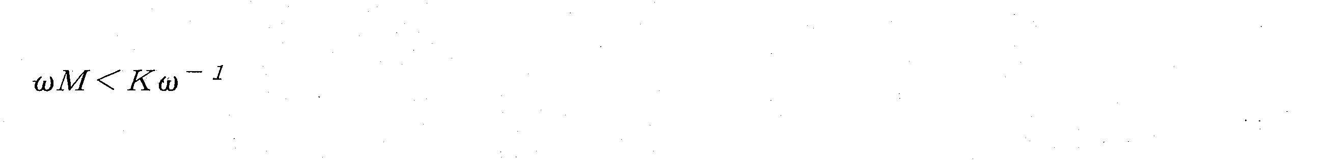
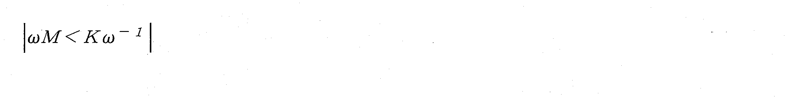
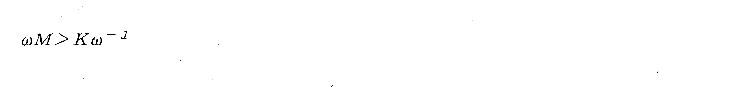
図2に示すように、ばね-質量-ダンパシステムは、微分方程式(1)に従って移動してもよい:

微分方程式(1)を解いて定常状態での変位(2)を得てもよい。
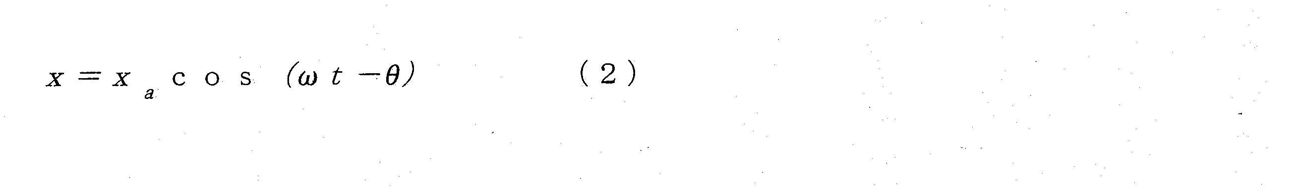

変位振幅の比率Aの正規化は、式(3)として記述されてもよい:

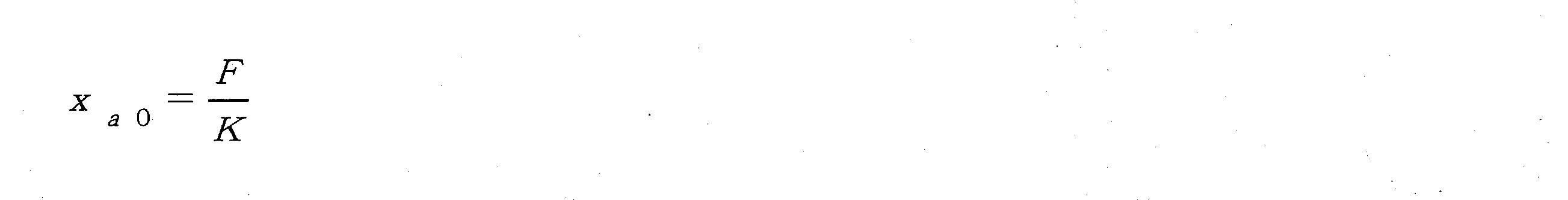
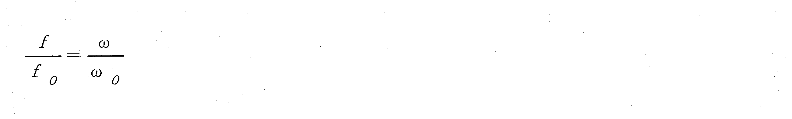


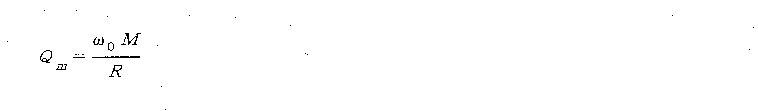
図3は、本開示のいくつかの実施形態による、ばね-質量-ダンパシステムの変位共振曲線の例示的な正規化を示す概略図である。 FIG. 3 is a schematic diagram illustrating an exemplary normalization of a displacement resonance curve of a spring-mass-damper system, according to some embodiments of the present disclosure.
マイクロフォン100は、変換コンポーネント120とハウジング110との間の相対変位によって電圧信号を生成する。例えば、エレクトレットマイクロフォンは、変形したダイアフラムトランスデューサと基板との間の距離変化に応じて電圧信号を生成する。別の例として、カンチレバー骨伝導マイクロフォンは、変形したカンチレバートランスデューサによって引き起こされた逆圧電効果に応じて電気信号を生成してもよい。いくつかの実施形態では、トランスデューサが変形する変位が大きいほど、マイクロフォンが出力する電気信号は大きくなる。図3に示すように、変換コンポーネントの減衰(例えば、材料減衰、構造減衰)が小さいほど、Q値は大きくなり、変位共振曲線の共振ピークでの3dB帯域幅は狭くなる。いくつかの実施形態では、共振ピークは、優れた性能を有するマイクロフォンでは音声周波数範囲に設定されなくてもよい。
図4は、本開示のいくつかの実施形態による、元の変換コンポーネント120の例示的な周波数応答曲線と、元の変換コンポーネント120の共振ピークを前方に移動した後の例示的な周波数応答曲線とを示す概略図である。いくつかの実施形態では、図4に示すように、マイクロフォンの全体的な感度を向上させるために、共振ピークを音声周波数範囲の前方に移動することにより、変換コンポーネント120の固有周波数を前方に移動して、マイクロフォンの、共振ピークの前の感度を向上させてもよい。上記出力変位


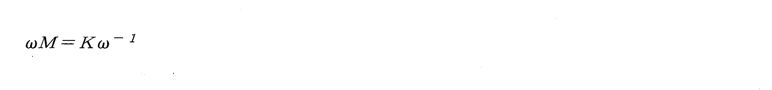


いくつかの実施形態では、共振ピークが前方に移動されるにつれて、共振ピークは、音声周波数範囲に現れる可能性がある。共振ピークの付近で複数の信号をピックアップすると、通信品質が悪くなる可能性がある。いくつかの実施形態では、変換コンポーネント120に減衰を加えると、振動中のエネルギー損失、特に共振ピークの付近でのエネルギー損失が増加する可能性がある。Q値の逆数は、式(5)に従って記述されてもよい:


変換コンポーネント120の減衰が増加するにつれて、Q値は減少し、対応する3dB帯域幅は増加する。いくつかの実施形態では、減衰は、変形プロセス中に一定ではなく、大きな力又は大きな振幅の下で大きくなる可能性がある。非共振領域の振幅は小さく、共振領域の振幅は大きくてもよい。図5は、本開示のいくつかの実施形態による、変換コンポーネント120の共振ピークを前方に移動した後の例示的な周波数応答曲線と、変換コンポーネント120に減衰材料を追加した後の例示的な周波数応答曲線とを示す概略図である。図5に示すように、非共振領域におけるマイクロフォンの感度は低下せず、共振領域におけるQ値は、変換コンポーネント120に適切な減衰を追加することによって減少してもよい。周波数応答曲線は、平坦であってもよい。
As the attenuation of the
いくつかの実施形態では、マイクロフォン100は、様々な適用シーンに応じて設計されてもよい。例えば、マイクロフォン100が、小さな体積及び低い感度を必要とする適用シーンに適用されれば、マイクロフォン100は、ハウジング110内の変換コンポーネント120のトランスデューサ122及び減衰フィルム124を含むように設計されてもよい。
In some embodiments,
図6は、本開示のいくつかの実施形態による、トランスデューサ122及び減衰フィルム124を含む変換コンポーネント120の例示的な等価モデルを示す概略図である。図6に示すように、Rは、トランスデューサ122の減衰を表し、Kは、トランスデューサ122の弾性係数を表し、R1は、減衰フィルム124の追加の減衰を表す。いくつかの実施形態では、変換コンポーネント120の複合減衰は、減衰フィルム124を追加することによって増加してもよい。変換コンポーネント120の減衰は、変更されてもよい。
FIG. 6 is a schematic diagram illustrating an exemplary equivalent model of
図7は、本開示のいくつかの実施形態による、元の変換コンポーネント120の例示的な周波数応答曲線と、元の変換コンポーネント120の共振ピークを前方に移動した後の例示的な周波数応答曲線と、変換コンポーネント120に減衰材料を追加した後の例示的な周波数応答曲線とを示す概略図である。図7に示すように、共振ピークでのQ値は、減少し、共振ピーク以外の周波数の感度は低下せず向上してもよい。いくつかの実施形態では、共振ピークを音声周波数範囲の前方に移動することにより、マイクロフォン100の感度は向上し、周波数応答曲線は平坦になって、これにより、マイクロフォン100の性能が向上する。
FIG. 7 illustrates an example frequency response curve of the
いくつかの実施形態では、マイクロフォン100は、ハウジング110内の変換コンポーネント120の、トランスデューサ122、減衰フィルム124、及び弾性要素126を含むように設計されてもよい。いくつかの実施形態では、弾性要素126及びトランスデューサ122は、それぞれ共振ピークを有してもよい。減衰フィルム124は、弾性要素126及びトランスデューサ122にそれぞれ接続されて、弾性要素126の振動をトランスデューサ122に伝達してもよい。いくつかの実施形態では、トランスデューサ122、減衰フィルム124及び弾性要素126を含むマイクロフォン100は、2つの共振ピークを備えた周波数応答曲線を出力してもよい。
In some embodiments,
図8は、本開示のいくつかの実施形態による、トランスデューサ122の例示的な周波数応答曲線と、弾性要素126の例示的な周波数応答曲線と、トランスデューサ122及び弾性要素126を含む変換コンポーネント120の例示的な周波数応答曲線とを示す概略図である。いくつかの実施形態では、弾性要素126は、様々な適用シーンに応じて設計されてもよい。例えば、弾性要素126は、適切な構造として設計されてもよい。弾性要素126の一次共振周波数は、所定の音声周波数範囲内にあってもよい。弾性要素126は、弾性要素126の一次共振周波数を使用して、マイクロフォン100の共振ピークに寄与してもよい。いくつかの実施形態では、適切な構造を備えた弾性要素126は、所定の音声周波数範囲内の複数の共振ピークに寄与してもよい。いくつかの実施形態では、減衰フィルム124の減衰は、図8に示すように、高い感度、大きなQ値、及びマイクロフォン100の周波数応答曲線における2つの共振ピークを備えたマイクロフォン100を実現するように設計されてもよい。
FIG. 8 shows an example frequency response curve of a
いくつかの実施形態では、マイクロフォン100は、ハウジング110内の変換コンポーネント120の、トランスデューサ122、複数の減衰フィルム124、及び複数の弾性要素126を含むように設計されてもよい。いくつかの実施形態では、各減衰フィルム124は、弾性要素126及びトランスデューサ122にそれぞれ接続されて、対応する弾性要素126の振動をトランスデューサ122に伝達してもよい。いくつかの実施形態では、トランスデューサ122、複数の減衰フィルム124、及び複数の弾性要素126を含むマイクロフォン100は、複数の共振ピークを備えた周波数応答曲線を出力してもよい。いくつかの実施形態では、複数の減衰フィルム124の各々の減衰は、周波数応答曲線の各共振ピークのQ値を調整するように設計されてもよい。
In some embodiments,
図9は、本開示のいくつかの実施形態による、トランスデューサ122の例示的な周波数応答曲線と、1つのトランスデューサ122及び1つの弾性要素126を含む変換コンポーネント120の例示的な周波数応答曲線と、1つのトランスデューサ122及び2つの弾性要素126を含む変換コンポーネント120の例示的な周波数応答曲線と、1つのトランスデューサ122及び3つの弾性要素126を含む変換コンポーネント120の例示的な周波数応答曲線とを示す概略図である。図9に示すように、各弾性要素126の各共振周波数は、互いに異なって、所定の音声周波数範囲内にあってもよい。所定の音声周波数範囲全体内の感度は高くてもよく、マイクロフォン100の周波数応答曲線は平坦であってもよい。
FIG. 9 shows an example frequency response curve of a
いくつかの実施形態では、マイクロフォン100の内部構造及びマイクロフォン100内の各部分のレイアウトは、様々な適用シーンに応じて設計されてもよい。例えば、マイクロフォン100は、マイクロフォン100が置かれる位置(例えば、人間の耳の前、人間の耳の後ろ、人間の首)に応じて設計されてもよい。別の例として、マイクロフォン100は、マイクロフォン100の伝導モード(例えば、骨伝導モード及び気導モード)に応じて設計されてもよい。さらに別の例として、マイクロフォン100は、マイクロフォン100が取得する様々な信号(例えば、人間の音声信号及び機械の音信号)の周波数に応じて設計されてもよい。さらに別の例として、マイクロフォン100は、マイクロフォン100の製造プロセスに応じて設計されてもよい。いくつかの実施形態では、少なくとも1つのトランスデューサ122、少なくとも1つの減衰フィルム124、及び/又は少なくとも1つの弾性要素126のサイズ、形状、設置位置、レイアウト、構造、及び数は、様々な適用シーンに応じて決定されてもよい。例えば、マイクロフォン100のトランスデューサ122及び少なくとも1つの減衰フィルム124は、マイクロフォン100の周波数応答曲線に応じて設計されてもよい。
In some embodiments, the internal structure of the
いくつかの実施形態では、少なくとも1つの減衰フィルム124は、少なくとも1つのトランスデューサ122の任意の位置に配置されてもよい。例えば、少なくとも1つの減衰フィルム124は、少なくとも1つのトランスデューサ122の上面、少なくとも1つのトランスデューサ122の下面、少なくとも1つのトランスデューサ122の側面、少なくとも1つのトランスデューサ122の内部など、又はそれらの任意の組み合わせに配置されてもよい。いくつかの実施形態では、少なくとも1つの減衰フィルム124は、少なくとも1つのトランスデューサ122の少なくとも1つの表面の少なくとも一部を覆ってもよい。例えば、少なくとも1つの減衰フィルム124のうちの1つの減衰フィルム124は、少なくとも1つのトランスデューサ122のうちの1つのトランスデューサ122の全面を覆ってもよい。別の例として、少なくとも1つの減衰フィルム124のうちの1つの減衰フィルム124は、少なくとも1つのトランスデューサ122のうちの1つのトランスデューサ122の表面の一部を覆ってもよい。いくつかの実施形態では、トランスデューサ122の少なくとも1つの表面は、トランスデューサ122の上面、トランスデューサ122の下面、トランスデューサ122の側面、トランスデューサ122の内面など、又はそれらの任意の組み合わせを含んでもよい。
In some embodiments, at least one
いくつかの実施形態では、少なくとも1つの減衰フィルム124は、少なくとも1つのトランスデューサ122に接続してもよく、ハウジング110に接続しなくてもよい。いくつかの実施形態では、マイクロフォン100内の任意の2つの部品間の接続は、接着、リベット留め、ネジ接続、一体成形、吸引接続など、又はそれらの任意の組み合わせを含んでもよい。
In some embodiments, at least one
図10は、本開示のいくつかの実施形態による例示的なマイクロフォン100を示す構造概略図である。図10に示すように、マイクロフォン100は、ハウジング110、ハウジング110に接続するトランスデューサ122、及びトランスデューサ122に接続され、ハウジング110から切断された減衰フィルム124を含んでもよい。トランスデューサ122は、トランスデューサ122の両端でハウジング110に固定されてもよい。減衰フィルム124は、トランスデューサ122の上面の一部を覆ってもよい。
FIG. 10 is a structural schematic diagram illustrating an
図11は、本開示のいくつかの実施形態による例示的なマイクロフォン100を示す構造概略図である。図11に示すように、マイクロフォン100は、ハウジング110、ハウジング110に接続するトランスデューサ122、及びトランスデューサ122に接続され、ハウジング110から切断された減衰フィルム124を含んでもよい。トランスデューサ122は、トランスデューサ122の両端でハウジング110に固定されてもよい。減衰フィルム124は、トランスデューサ122の下面の一部を覆ってもよい。
FIG. 11 is a structural schematic diagram illustrating an
図12は、本開示のいくつかの実施形態による例示的なマイクロフォン100を示す構造概略図である。図12に示すように、マイクロフォン100は、ハウジング110、ハウジング110にそれぞれ接続する2つのトランスデューサ122、及びトランスデューサ122に接続され、ハウジング110から切断された減衰フィルム124を含んでもよい。2つのトランスデューサ122の各々は、トランスデューサ122の両端でハウジング110に固定されてもよい。減衰フィルム124は、2つのトランスデューサ122の一方の上面の一部及び2つのトランスデューサ122の他方の下面の一部を覆ってもよい。図12に示すように、2つのトランスデューサ122及び減衰フィルム124は、サンドイッチ構造を形成してもよい。減衰フィルム124は、2つのトランスデューサ122の間に挟まれてもよい。
FIG. 12 is a structural schematic diagram illustrating an
図13は、本開示のいくつかの実施形態による例示的なマイクロフォン100を示す構造概略図である。図13に示すように、マイクロフォン100は、ハウジング110、ハウジング110に接続するトランスデューサ122、及びトランスデューサ122にそれぞれ接続され、ハウジング110から切断された2つの減衰フィルム124を含んでもよい。トランスデューサ122は、トランスデューサ122の両端でハウジング110に固定されてもよい。2つの減衰フィルム124は、トランスデューサ122の上面及び下面の一部をそれぞれ覆ってもよい。
FIG. 13 is a structural schematic diagram illustrating an
図14は、本開示のいくつかの実施形態による例示的なマイクロフォン100を示す構造概略図である。図14に示すように、マイクロフォン100は、ハウジング110、ハウジング110に接続するカンチレバートランスデューサ122、及びトランスデューサ122に接続され、ハウジング110から切断された減衰フィルム124を含んでもよい。カンチレバートランスデューサ122は、カンチレバートランスデューサ122の一端でハウジング110に固定されてもよい。減衰フィルム124は、カンチレバートランスデューサ122の下面の一部を覆ってもよい。
FIG. 14 is a structural schematic diagram illustrating an
図15は、本開示のいくつかの実施形態による例示的なマイクロフォン100を示す構造概略図である。図15に示すように、マイクロフォン100は、ハウジング110、ハウジング110に接続するカンチレバートランスデューサ122、及びトランスデューサ122に接続され、ハウジング110から切断された減衰フィルム124を含んでもよい。カンチレバートランスデューサ122は、カンチレバートランスデューサ122の一端でハウジング110に固定されてもよい。減衰フィルム124は、カンチレバートランスデューサ122の上面の一部を覆ってもよい。
FIG. 15 is a structural schematic diagram illustrating an
図16は、本開示のいくつかの実施形態による例示的なマイクロフォン100を示す構造概略図である。図16に示すように、マイクロフォン100は、ハウジング110、ハウジング110にそれぞれ接続する2つのカンチレバートランスデューサ122、及びカンチレバートランスデューサ122に接続され、ハウジング110から切断された減衰フィルム124を含んでもよい。2つのカンチレバートランスデューサ122の各々は、各カンチレバートランスデューサ122の一端でハウジング110に固定されてもよい。減衰フィルム124は、2つのカンチレバートランスデューサ122の一方の上面の一部及び2つのカンチレバートランスデューサ122の他方の下面の一部を覆ってもよい。図16に示すように、2つのカンチレバートランスデューサ122及び減衰フィルム124は、サンドイッチ構造を形成してもよい。減衰フィルム124は、2つのカンチレバートランスデューサ122の間に挟まれてもよい。
FIG. 16 is a structural schematic diagram illustrating an
図17は、本開示のいくつかの実施形態による例示的なマイクロフォン100を示す構造概略図である。図17に示すように、マイクロフォン100は、ハウジング110、ハウジング110に接続するカンチレバートランスデューサ122、及びカンチレバートランスデューサ122にそれぞれ接続され、ハウジング110から切断された2つの減衰フィルム124を含んでもよい。カンチレバートランスデューサ122は、カンチレバートランスデューサ122の一端でハウジング110に固定されてもよい。2つの減衰フィルム124は、カンチレバートランスデューサ122の上面及び下面の一部をそれぞれ覆ってもよい。
FIG. 17 is a structural schematic diagram illustrating an
図18は、本開示のいくつかの実施形態による、減衰フィルム124がマイクロフォン100の少なくとも1つのトランスデューサ122から切断されるときのマイクロフォン100の例示的な周波数応答曲線を示す概略図である。減衰フィルム124を備えないマイクロフォン100、4層の減衰フィルム124を含むマイクロフォン100、及び10層の減衰フィルム124を含むマイクロフォン100の周波数応答曲線は、異なる可能性がある。図18に示すように、共振ピークは前方に移動し、共振ピークの前の感度は向上し、共振ピークでのQ値は、減衰フィルム124の層の数が増加するにつれて減少する。減衰フィルム124が多いほど、共振ピークでの周波数は低くなり、共振ピークの前の感度は高くなり、共振ピークでのQ値は小さくなる。従って、マイクロフォン100の実際の要求(例えば、感度、共振ピークでのQ値、共振ピークでの周波数など)を満たすために、マイクロフォン100は、1つの減衰フィルム124又は複数の減衰フィルム124を含むように設計されてもよい。
FIG. 18 is a schematic diagram illustrating an example frequency response curve of
いくつかの実施形態では、少なくとも1つの減衰フィルム124は、少なくとも1つのトランスデューサ122とハウジング110の両方に接続してもよい。いくつかの実施形態では、マイクロフォン100内の任意の2つの部品間の接続は、接着、リベット留め、ネジ接続、一体成形、吸引接続など、又はそれらの任意の組み合わせを含んでもよい。
In some embodiments, at least one
図19は、本開示のいくつかの実施形態による例示的なマイクロフォン100を示す構造概略図である。図19に示すように、マイクロフォン100は、ハウジング110、ハウジング110にそれぞれ接続する2つのトランスデューサ122、及びトランスデューサ122とハウジング110の両方に接続された減衰フィルム124を含んでもよい。2つのトランスデューサ122の各々は、各トランスデューサ122の両端でハウジング110に固定されてもよい。減衰フィルム124は、減衰フィルム124の両端でハウジング110に接続してもよい。減衰フィルム124は、2つのトランスデューサ122の一方の上面全体及び2つのトランスデューサ122の他方の下面全体を覆ってもよい。図19に示すように、2つのトランスデューサ122及び減衰フィルム124は、サンドイッチ構造を形成してもよい。減衰フィルム124は、2つのトランスデューサ122の間に挟まれてもよい。
FIG. 19 is a structural schematic diagram illustrating an
図20は、本開示のいくつかの実施形態による例示的なマイクロフォン100を示す構造概略図である。図20に示すように、マイクロフォン100は、ハウジング110、ハウジング110に接続するトランスデューサ122、及びトランスデューサ122とハウジング110の両方に接続された減衰フィルム124を含んでもよい。トランスデューサ122は、トランスデューサ122の両端でハウジング110に固定されてもよい。減衰フィルム124は、トランスデューサ122の下面全体を覆ってもよい。減衰フィルム124は、減衰フィルム124の両端でハウジング110に接続してもよい。
FIG. 20 is a structural schematic diagram illustrating an
図21は、本開示のいくつかの実施形態による例示的なマイクロフォン100を示す構造概略図である。図21に示すように、マイクロフォン100は、ハウジング110、ハウジング110に接続するトランスデューサ122、及びトランスデューサ122とハウジング110の両方に接続された減衰フィルム124を含んでもよい。トランスデューサ122は、トランスデューサ122の両端でハウジング110に固定されてもよい。減衰フィルム124は、トランスデューサ122の上面全体を覆ってもよい。減衰フィルム124は、減衰フィルム124の両端でハウジング110に接続してもよい。
FIG. 21 is a structural schematic diagram illustrating an
図22は、本開示のいくつかの実施形態による例示的なマイクロフォン100を示す構造概略図である。図22に示すように、マイクロフォン100は、ハウジング110、ハウジング110に接続するカンチレバートランスデューサ122、及びトランスデューサ122とハウジング110の両方に接続された減衰フィルム124を含んでもよい。カンチレバートランスデューサ122は、カンチレバートランスデューサ122の一端でハウジング110に固定されてもよい。減衰フィルム124は、カンチレバートランスデューサ122の下面全体を覆ってもよい。減衰フィルム124は、減衰フィルム124の一端でハウジング110に接続してもよい。
FIG. 22 is a structural schematic diagram illustrating an
図23は、本開示のいくつかの実施形態による例示的なマイクロフォン100を示す構造概略図である。図23に示すように、マイクロフォン100は、ハウジング110、ハウジング110に接続するカンチレバートランスデューサ122、及びトランスデューサ122とハウジング110の両方に接続された減衰フィルム124を含んでもよい。カンチレバートランスデューサ122は、カンチレバートランスデューサ122の一端でハウジング110に固定されてもよい。減衰フィルム124は、カンチレバートランスデューサ122の上面全体を覆ってもよい。減衰フィルム124は、減衰フィルム124の一端でハウジング110に接続してもよい。
FIG. 23 is a structural schematic diagram illustrating an
図24は、本開示のいくつかの実施形態による例示的なマイクロフォン100を示す構造概略図である。図24に示すように、マイクロフォン100は、ハウジング110、ハウジング110にそれぞれ接続する2つのカンチレバートランスデューサ122、及びカンチレバートランスデューサ122とハウジング110の両方に接続された減衰フィルム124を含んでもよい。2つのカンチレバートランスデューサ122の各々は、各カンチレバートランスデューサ122の一端でハウジング110に固定されてもよい。減衰フィルム124は、2つのカンチレバートランスデューサ122の一方の上面全体及び2つのカンチレバートランスデューサ122の他方の下面全体を覆ってもよい。図24に示すように、2つのカンチレバートランスデューサ122及び減衰フィルム124は、サンドイッチ構造を形成してもよい。減衰フィルム124は、2つのカンチレバートランスデューサ122の間に挟まれてもよい。減衰フィルム124は、減衰フィルム124の一端でハウジング110に接続してもよい。
FIG. 24 is a structural schematic diagram illustrating an
図25は、本開示のいくつかの実施形態による、減衰フィルム124がマイクロフォン100の少なくとも1つのトランスデューサ122に接続されるときのマイクロフォン100の例示的な周波数応答曲線を示す概略図である。減衰フィルム124を備えないマイクロフォン100、4層の減衰フィルム124を含むマイクロフォン100、及び10層の減衰フィルム124を含むマイクロフォン100の周波数応答曲線は、異なる可能性がある。図25に示すように、共振ピークは一定であり、共振ピークの前の感度は向上し、共振ピークでのQ値は、減衰フィルム124の層の数が増加するにつれて減少する。減衰フィルム124が多いほど、共振ピークの前の感度は高くなり、共振ピークでのQ値は小さくなる。
FIG. 25 is a schematic diagram illustrating an example frequency response curve of
いくつかの実施形態では、少なくとも1つの減衰フィルム124は、少なくとも1つのトランスデューサ122とハウジング110の両方に接続してもよい。いくつかの実施形態では、少なくとも1つの減衰フィルム124は、トランスデューサの少なくとも1つの表面に所定の角度で配置されてもよい。いくつかの実施形態では、少なくとも1つの減衰フィルム124は、少なくとも2つの減衰フィルム124を含んでもよい。いくつかの実施形態では、少なくとも2つの減衰フィルム124は、トランスデューサ122の中心線に対して対称的に配置されてもよい。いくつかの実施形態では、少なくとも2つの減衰フィルム124は、トランスデューサ122の中心線に対して非対称的に配置されてもよい。いくつかの実施形態では、少なくとも減衰フィルム124の各々の幅は、同じであっても異なっていてもよい。例えば、少なくとも減衰フィルム124の各々の幅は、可変であってもよい。いくつかの実施形態では、少なくとも減衰フィルム124の各々の厚さは、同じであっても異なっていてもよい。例えば、少なくとも減衰フィルム124の各々の厚さは、可変であってもよい。いくつかの実施形態では、少なくとも1つの減衰フィルム124の各々は、少なくとも1つのトランスデューサ122の各々の一部と重なってもよい。
In some embodiments, at least one
図26は、本開示のいくつかの実施形態による例示的なマイクロフォン100を示す構造概略図である。図26に示すように、マイクロフォン100は、ハウジング110、ハウジング110に接続するカンチレバートランスデューサ122、及びカンチレバートランスデューサ122とハウジング110の両方に接続された減衰フィルム124を含んでもよい。カンチレバートランスデューサ122は、カンチレバートランスデューサ122の一端でハウジング110に固定されてもよい。減衰フィルム124は、カンチレバートランスデューサ122の上面全体を覆ってもよい。減衰フィルム124は、減衰フィルム124の両端でハウジング110に接続してもよい。
FIG. 26 is a structural schematic diagram illustrating an
図27は、本開示のいくつかの実施形態による例示的なマイクロフォン100を示す構造概略図である。図27に示すように、マイクロフォン100は、ハウジング110、ハウジング110に接続するカンチレバートランスデューサ122、及びカンチレバートランスデューサ122とハウジング110の両方に接続された減衰フィルム124を含んでもよい。カンチレバートランスデューサ122は、カンチレバートランスデューサ122の一端でハウジング110に固定されてもよい。減衰フィルム124は、カンチレバートランスデューサ122の下面全体を覆ってもよい。減衰フィルム124は、減衰フィルム124の両端でハウジング110に接続してもよい。
FIG. 27 is a structural schematic diagram illustrating an
図28は、本開示のいくつかの実施形態による例示的なマイクロフォン100を示す構造概略図である。図28に示すように、マイクロフォン100は、ハウジング110、ハウジング110にそれぞれ接続する2つのカンチレバートランスデューサ122、及びカンチレバートランスデューサ122とハウジング110の両方に接続された減衰フィルム124を含んでもよい。2つのカンチレバートランスデューサ122の各々は、各カンチレバートランスデューサ122の両端でハウジング110に固定されてもよい。減衰フィルム124は、減衰フィルム124の両端でハウジング110に接続してもよい。減衰フィルム124は、2つのカンチレバートランスデューサ122の一方の上面全体及び2つのカンチレバートランスデューサ122の他方の下面全体を覆ってもよい。図28に示すように、2つのカンチレバートランスデューサ122及び減衰フィルム124は、サンドイッチ構造を形成してもよい。減衰フィルム124は、2つのカンチレバートランスデューサ122の間に挟まれてもよい。
FIG. 28 is a structural schematic diagram illustrating an
図29は、本開示のいくつかの実施形態による例示的なマイクロフォン100を示す構造概略図である。図29に示すように、マイクロフォン100は、ハウジング110、ハウジング110に接続するカンチレバートランスデューサ122、及びカンチレバートランスデューサ122とハウジング110の両方にそれぞれ接続された2つの減衰フィルム124を含んでもよい。カンチレバートランスデューサ122は、カンチレバートランスデューサ122の一端でハウジング110に固定されてもよい。2つの減衰フィルム124の各々は、各減衰フィルム124の両端でハウジング110に接続してもよい。2つの減衰フィルム124は、カンチレバートランスデューサ122の上面全体及び下面全体をそれぞれ覆ってもよい。図29に示すように、2つの減衰フィルム124及びカンチレバートランスデューサ122は、サンドイッチ構造を形成してもよい。カンチレバートランスデューサ122は、2つの減衰フィルム124の間に挟まれてもよい。
FIG. 29 is a structural schematic diagram illustrating an
図30は、本開示のいくつかの実施形態による例示的なマイクロフォン100を示す構造概略図である。図30に示すように、マイクロフォン100は、ハウジング110、ハウジング110に接続するカンチレバートランスデューサ122、及びカンチレバートランスデューサ122とハウジング110の両方にそれぞれ接続された2つの減衰フィルム124を含んでもよい。カンチレバートランスデューサ122は、カンチレバートランスデューサ122の一端でハウジング110に固定されてもよい。2つの減衰フィルム124の各々は、各減衰フィルム124の一端でハウジング110に接続し、各減衰フィルムの他端でカンチレバートランスデューサ122に接続してもよい。2つの減衰フィルム124は、カンチレバートランスデューサ122の上面の一部及び下面の一部をそれぞれ覆ってもよい。図30に示すように、2つの減衰フィルム124は、カンチレバートランスデューサ122の上面及び下面に90°で配置されてもよい。2つの減衰フィルム124とカンチレバートランスデューサ122との重なり部分は、カンチレバートランスデューサ122の固定端以外の一端に近くてもよい。2つの減衰フィルム124の各々の厚さは、一定であり、互いに同じであってもよい。
FIG. 30 is a structural schematic diagram illustrating an
図31は、本開示のいくつかの実施形態による例示的なマイクロフォン100を示す構造概略図である。図31に示すように、マイクロフォン100は、ハウジング110、ハウジング110に接続するカンチレバートランスデューサ122、及びカンチレバートランスデューサ122とハウジング110の両方にそれぞれ接続された2つの減衰フィルム124を含んでもよい。カンチレバートランスデューサ122は、カンチレバートランスデューサ122の一端でハウジング110に固定されてもよい。2つの減衰フィルム124の各々は、各減衰フィルム124の一端でハウジング110に接続し、各減衰フィルムの他端でカンチレバートランスデューサ122に接続してもよい。2つの減衰フィルム124は、カンチレバートランスデューサ122の上面の一部及び下面の一部をそれぞれ覆ってもよい。図31に示すように、2つの減衰フィルム124は、カンチレバートランスデューサ122の上面及び下面に90°で配置されてもよい。2つの減衰フィルム124とカンチレバートランスデューサ122との重なり部分は、カンチレバートランスデューサ122の中心線に近くてもよい。2つの減衰フィルム124の各々の厚さは、一定であり、互いに同じであってもよい。
FIG. 31 is a structural schematic diagram illustrating an
図32は、本開示のいくつかの実施形態による例示的なマイクロフォン100を示す構造概略図である。図32に示すように、マイクロフォン100は、ハウジング110、ハウジング110に接続するカンチレバートランスデューサ122、及びカンチレバートランスデューサ122とハウジング110の両方にそれぞれ接続された2つの減衰フィルム124を含んでもよい。カンチレバートランスデューサ122は、カンチレバートランスデューサ122の一端でハウジング110に固定されてもよい。2つの減衰フィルム124の各々は、各減衰フィルム124の一端でハウジング110に接続し、各減衰フィルムの他端でカンチレバートランスデューサ122に接続してもよい。2つの減衰フィルム124は、カンチレバートランスデューサ122の上面の一部及び下面の一部をそれぞれ覆ってもよい。図32に示すように、2つの減衰フィルム124は、カンチレバートランスデューサ122の上面及び下面に90°で配置されてもよい。2つの減衰フィルム124とカンチレバートランスデューサ122との重なり部分は、カンチレバートランスデューサ122の固定端以外の一端に近くてもよい。2つの減衰フィルム124の各々の厚さは、可変であってもよい。カンチレバートランスデューサ122に接続された減衰フィルム124の厚さは、ハウジング110に接続された減衰フィルム124の厚さよりも薄くてもよい。
FIG. 32 is a structural schematic diagram illustrating an
図33は、本開示のいくつかの実施形態による例示的なマイクロフォン100を示す構造概略図である。図33に示すように、マイクロフォン100は、ハウジング110、ハウジング110に接続するカンチレバートランスデューサ122、及びカンチレバートランスデューサ122とハウジング110の両方にそれぞれ接続された2つの減衰フィルム124を含んでもよい。カンチレバートランスデューサ122は、カンチレバートランスデューサ122の一端でハウジング110に固定されてもよい。2つの減衰フィルム124の各々は、各減衰フィルム124の一端でハウジング110に接続し、各減衰フィルムの他端でカンチレバートランスデューサ122に接続してもよい。2つの減衰フィルム124は、カンチレバートランスデューサ122の上面の一部及び下面の一部をそれぞれ覆ってもよい。図33に示すように、2つの減衰フィルム124は、カンチレバートランスデューサ122の上面及び下面に90°で配置されてもよい。2つの減衰フィルム124とカンチレバートランスデューサ122との重なり部分は、カンチレバートランスデューサ122の固定端以外の一端に近くてもよい。2つの減衰フィルム124の各々の厚さは、可変であってもよい。カンチレバートランスデューサ122に接続された減衰フィルム124の厚さは、ハウジング110に接続された減衰フィルム124の厚さよりも厚くてもよい。
FIG. 33 is a structural schematic diagram illustrating an
図34は、本開示のいくつかの実施形態による例示的なマイクロフォン100を示す構造概略図である。図34に示すように、マイクロフォン100は、ハウジング110、ハウジング110に接続するカンチレバートランスデューサ122、及びカンチレバートランスデューサ122とハウジング110の両方にそれぞれ接続された2つの減衰フィルム124を含んでもよい。カンチレバートランスデューサ122は、カンチレバートランスデューサ122の一端でハウジング110に固定されてもよい。2つの減衰フィルム124の各々は、各減衰フィルム124の一端でハウジング110に接続し、各減衰フィルムの他端でカンチレバートランスデューサ122に接続してもよい。2つの減衰フィルム124は、カンチレバートランスデューサ122の上面の一部及び下面の一部をそれぞれ覆ってもよい。図34に示すように、2つの減衰フィルム124は、カンチレバートランスデューサ122の上面及び下面に60°~90°の間の角度で配置されてもよい。2つの減衰フィルム124とカンチレバートランスデューサ122との重なり部分は、カンチレバートランスデューサ122の固定端以外の一端に近くてもよい。2つの減衰フィルム124の各々の厚さは、一定であり、互いに同じであってもよい。
FIG. 34 is a structural schematic diagram illustrating an
図35は、本開示のいくつかの実施形態による例示的なマイクロフォン100を示す構造概略図である。図35に示すように、マイクロフォン100は、ハウジング110、ハウジング110に接続するカンチレバートランスデューサ122、及びカンチレバートランスデューサ122とハウジング110の両方にそれぞれ接続された2つの減衰フィルム124を含んでもよい。カンチレバートランスデューサ122は、カンチレバートランスデューサ122の一端でハウジング110に固定されてもよい。2つの減衰フィルム124の各々は、各減衰フィルム124の一端でハウジング110に接続し、各減衰フィルムの他端でカンチレバートランスデューサ122に接続してもよい。2つの減衰フィルム124は、カンチレバートランスデューサ122の上面の一部及び下面の一部をそれぞれ覆ってもよい。図35に示すように、2つの減衰フィルム124は、カンチレバートランスデューサ122の上面及び下面に90°で配置されてもよい。2つの減衰フィルム124の一方とカンチレバートランスデューサ122との重なり部分は、カンチレバートランスデューサ122の固定端以外の一端に近くてもよく、2つの減衰フィルム124の他方とカンチレバートランスデューサ122との重なり部分は、カンチレバートランスデューサ122の中心線に近くてもよい。2つの減衰フィルム124の各々の厚さは、一定であり、互いに同じであってもよい。
FIG. 35 is a structural schematic diagram illustrating an
図36は、本開示のいくつかの実施形態による例示的なマイクロフォン100を示す構造概略図である。図36に示すように、マイクロフォン100は、ハウジング110、ハウジング110に接続するカンチレバートランスデューサ122、及びカンチレバートランスデューサ122とハウジング110の両方にそれぞれ接続された6つの減衰フィルム124を含んでもよい。カンチレバートランスデューサ122は、カンチレバートランスデューサ122の一端でハウジング110に固定されてもよい。2つの減衰フィルム124の各々は、各減衰フィルム124の一端でハウジング110に接続し、各減衰フィルムの他端でカンチレバートランスデューサ122に接続してもよい。6つの減衰フィルム124の各々は、カンチレバートランスデューサ122の上面の一部及び下面の一部を覆ってもよい。図36に示すように、6つの減衰フィルム124の各々は、カンチレバートランスデューサ122の上面又は下面に90°で配置されてもよい。6つの減衰フィルム124の各々とカンチレバートランスデューサ122との重なり部分は、カンチレバートランスデューサ122の固定端から他端まで分布してもよい。6つの減衰フィルム124の各々の厚さは、一定であり、互いに同じであってもよい。
FIG. 36 is a structural schematic diagram illustrating an
図37は、本開示のいくつかの実施形態による、減衰フィルムを備えないマイクロフォン100と、カンチレバートランスデューサ122の表面に90°で配置された少なくとも1つの減衰フィルム124を含むマイクロフォン100の例示的な周波数応答曲線を示す概略図である。図37に示すように、少なくとも1つの減衰フィルム124を追加した後、共振周波数は増加し、共振ピークでのQ値は減少する。共振ピーク以外の周波数での感度は、少なくとも1つの減衰フィルム124を追加するか否かに関わらず、一般に一定であってもよい。
FIG. 37 shows exemplary frequencies of a
いくつかの実施形態では、マイクロフォン100は、トランスデューサ122、少なくとも1つの減衰フィルム124、及び少なくとも1つの弾性要素126を含んでもよい。少なくとも1つの減衰フィルムは、トランスデューサ122及び少なくとも1つの弾性要素126にそれぞれ接続されてもよい。いくつかの実施形態では、マイクロフォン100は、複数のトランスデューサ122及び少なくとも1つの減衰フィルム124を含んでもよい。いくつかの実施形態では、マイクロフォン100は、複数のトランスデューサ122、少なくとも1つの減衰フィルム124、及び少なくとも1つの弾性要素126を含んでもよい。少なくとも1つの減衰フィルムは、トランスデューサ122及び少なくとも1つの弾性要素126にそれぞれ接続されてもよい。いくつかの実施形態では、少なくとも1つの弾性要素126及びトランスデューサ122(又は複数のトランスデューサ122)は、所定の分布モードで配置されてもよい。いくつかの実施形態では、上記所定の分布モードは、水平分布モード、垂直分布モード、アレイ分布モード、ランダム分布モードなど、又はそれらの任意の組み合わせを含んでもよい。いくつかの実施形態では、少なくとも1つの減衰フィルム124は、少なくとも1つの弾性要素126の少なくとも1つの表面の少なくとも一部を覆ってもよい。
In some embodiments,
図38は、本開示のいくつかの実施形態による例示的なマイクロフォン100を示す構造概略図である。図38に示すように、マイクロフォン100は、ハウジング110、トランスデューサ122、減衰フィルム124、及び2つの弾性要素126(又は2つのトランスデューサ122、又は弾性要素126及びトランスデューサ122)を含んでもよい。減衰フィルム124は、トランスデューサ122及び/又は弾性要素126の各々の下面全体を覆ってもよい。減衰フィルム124は、ハウジング110に接続しなくてもよい。
FIG. 38 is a structural schematic diagram illustrating an
図39は、本開示のいくつかの実施形態による例示的なマイクロフォン100を示す構造概略図である。図39に示すように、マイクロフォン100は、ハウジング110、トランスデューサ122、減衰フィルム124、及び2つの弾性要素126(又は2つのトランスデューサ122、又は弾性要素126及びトランスデューサ122)を含んでもよい。減衰フィルム124は、トランスデューサ122及び/又は弾性要素126の各々の下面全体を覆ってもよい。減衰フィルム124は、減衰フィルム124の両端でハウジング110に接続してもよい。
FIG. 39 is a structural schematic diagram illustrating an
図40は、本開示のいくつかの実施形態による例示的なマイクロフォン100を示す構造概略図である。図40に示すように、マイクロフォン100は、ハウジング110、2つのトランスデューサ122、減衰フィルム124、及び2つの弾性要素126(又は2つのトランスデューサ122、又は弾性要素126及びトランスデューサ122)を含んでもよい。2つの減衰フィルム124の各々は、トランスデューサ122及び/又は弾性要素126の2つの間に挟まれてもよい。減衰フィルム124は、ハウジング110に接続しなくてもよい。
FIG. 40 is a structural schematic diagram illustrating an
図41は、本開示のいくつかの実施形態による例示的なマイクロフォン100を示す構造概略図である。図41に示すように、マイクロフォン100は、ハウジング110、2つのトランスデューサ122、減衰フィルム124、及び2つの弾性要素126(又は2つのトランスデューサ122、又は弾性要素126及びトランスデューサ122)を含んでもよい。2つの減衰フィルム124の各々は、トランスデューサ122及び/又は弾性要素126の2つの間に挟まれてもよい。2つの減衰フィルム124の各々は、各減衰フィルム124の両端でハウジング110に接続してもよい。
FIG. 41 is a structural schematic diagram illustrating an
図42は、本開示のいくつかの実施形態による例示的なマイクロフォン100を示す構造概略図である。図42に示すように、マイクロフォン100は、ハウジング110、トランスデューサ122、2つの減衰フィルム124、及び2つの弾性要素126(又は2つのトランスデューサ122、又は弾性要素126及びトランスデューサ122)を含んでもよい。2つの減衰フィルム124の各々は、トランスデューサ122及び/又は弾性要素126の一端に接続してもよい。例えば、マイクロフォン100は、順に弾性要素126(又はトランスデューサ122)に接続する減衰フィルム124に接続するトランスデューサ122に接続する減衰フィルム124に接続する弾性要素126(又はトランスデューサ122)を含んでもよい。トランスデューサ122、2つの減衰フィルム124、及び2つの弾性要素126(又は2つのトランスデューサ122、又は弾性要素126及びトランスデューサ122)は、ハウジング110内で類似する「V」字形状を形成してもよい。2つの減衰フィルム124又は2つの弾性要素126(又は2つのトランスデューサ122、又は弾性要素126及びトランスデューサ122)は、トランスデューサ122の中心線に対して対称であってもよい。2つの減衰フィルム124は、ハウジング110に接続しなくてもよい。
FIG. 42 is a structural schematic diagram illustrating an
図43は、本開示のいくつかの実施形態による例示的なマイクロフォン100を示す構造概略図である。図43に示すように、マイクロフォン100は、ハウジング110、トランスデューサ122、4つの減衰フィルム124、及び2つの弾性要素126(又は2つのトランスデューサ122、又は弾性要素126及びトランスデューサ122)を含んでもよい。2つの減衰フィルム124の各々は、トランスデューサ122及び/又は弾性要素126の一端に接続してもよい。例えば、マイクロフォン100は、順に弾性要素126(又はトランスデューサ122)に接続する減衰フィルム124に接続するトランスデューサ122に接続する減衰フィルム124に接続する弾性要素126(又はトランスデューサ122)に接続する減衰フィルム124を含んでもよい。トランスデューサ122、4つの減衰フィルム124、及び2つの弾性要素126(又は2つのトランスデューサ122、又は弾性要素126及びトランスデューサ122)は、ハウジング110内で類似する「V」字形状を形成してもよい。4つの減衰フィルム124のうちの2つ又は2つの弾性要素126(又は2つのトランスデューサ122、又は弾性要素126及びトランスデューサ122)は、トランスデューサ122の中心線に対して対称であってもよい。4つの減衰フィルム124のうちの2つは、ハウジング110にそれぞれ接続してもよい。
FIG. 43 is a structural schematic diagram illustrating an
図44は、本開示のいくつかの実施形態による例示的なマイクロフォン100を示す構造概略図である。図44に示すように、マイクロフォン100は、ハウジング110、トランスデューサ122、4つの減衰フィルム124、及び4つの弾性要素126(又は4つのトランスデューサ122、又は弾性要素126及び3つのトランスデューサ122、又は2つの弾性要素126及び2つのトランスデューサ122、又は3つの弾性要素126及びトランスデューサ122)を含んでもよい。4つの減衰フィルム124の各々は、トランスデューサ122及び/又は弾性要素126の一端に接続してもよい。トランスデューサ122、4つの減衰フィルム124、及び4つの弾性要素126(又は4つのトランスデューサ122、又は弾性要素126及び3つのトランスデューサ122、又は2つの弾性要素126及び2つのトランスデューサ122、又は3つの弾性要素126及びトランスデューサ122)は、ハウジング110内で類似する「X」字形状を形成してもよい。4つの減衰フィルム124のうちの2つ又は4つの弾性要素126のうちの2つ(又は4つのトランスデューサ122、又は弾性要素126及び3つのトランスデューサ122、又は2つの弾性要素126及び2つのトランスデューサ122、又は3つの弾性要素126及びトランスデューサ122)は、トランスデューサ122の中心線に対して対称であってもよい。4つの減衰フィルム124は、ハウジング110に接続しなくてもよい。
FIG. 44 is a structural schematic diagram illustrating an
図45は、本開示のいくつかの実施形態による例示的なマイクロフォン100を示す構造概略図である。図45に示すように、マイクロフォン100は、ハウジング110、トランスデューサ122、6つの減衰フィルム124、及び4つの弾性要素126(又は4つのトランスデューサ122、又は弾性要素126及び3つのトランスデューサ122、又は2つの弾性要素126及び2つのトランスデューサ122、又は3つの弾性要素126及びトランスデューサ122)を含んでもよい。4つの減衰フィルム124の各々は、トランスデューサ122及び/又は弾性要素126の一端に接続してもよい。トランスデューサ122、6つの減衰フィルム124、及び4つの弾性要素126(又は4つのトランスデューサ122、又は弾性要素126及び3つのトランスデューサ122、又は2つの弾性要素126及び2つのトランスデューサ122、又は3つの弾性要素126及びトランスデューサ122)は、ハウジング110内で類似する「X」字形状を形成してもよい。6つの減衰フィルム124のうちの2つ又は4つの弾性要素126のうちの2つ(又は4つのトランスデューサ122、又は弾性要素126及び3つのトランスデューサ122、又は2つの弾性要素126及び2つのトランスデューサ122、又は3つの弾性要素126及びトランスデューサ122)は、トランスデューサ122の中心線に対して対称であってもよい。6つの減衰フィルム124のうちの4つは、ハウジング110に接続してもよい。
FIG. 45 is a structural schematic diagram illustrating an
図46は、本開示のいくつかの実施形態による、トランスデューサ122を含むマイクロフォン100と、トランスデューサ122及び2つの弾性要素126を含むマイクロフォン100の例示的な周波数応答曲線を示す概略図である。図46に示すように、トランスデューサ122及び2つの弾性要素126を含むマイクロフォン100の周波数応答曲線は、3つの共振ピークを含んでもよい。トランスデューサ122を含むマイクロフォン100の周波数応答曲線は、1つの共振ピークのみを含んでもよい。2つの弾性要素126を含むマイクロフォン100の共振ピークの前の感度は、1つのトランスデューサ122のみを含むマイクロフォン100の感度よりも大きくてもよい。2つの弾性要素126を含むマイクロフォン100の共振ピークの前のQ値は、1つのトランスデューサ122のみを含むマイクロフォン100のQ値よりも小さくてもよい。
FIG. 46 is a schematic diagram illustrating an example frequency response curve of a
図47は、本開示のいくつかの実施形態による、トランスデューサ122を含むマイクロフォン100と、2つのトランスデューサ122(1つのトランスデューサ122で出力する)を含むマイクロフォン100の例示的な周波数応答曲線を示す概略図である。図47に示すように、2つのトランスデューサ122を含むマイクロフォン100の周波数応答曲線は、2つの共振ピークを含んでもよい。トランスデューサ122を含むマイクロフォン100の周波数応答曲線は、1つの共振ピークのみを含んでもよい。2つのトランスデューサ122を含むマイクロフォン100の共振ピークの前の感度は、1つのトランスデューサ122のみを含むマイクロフォン100の感度よりも大きくてもよい。2つのトランスデューサ122を含むマイクロフォン100の共振ピークの前のQ値は、1つのトランスデューサ122のみを含むマイクロフォン100のQ値よりも小さくてもよい。
FIG. 47 is a schematic diagram illustrating exemplary frequency response curves for a
なお、本開示で説明される例示的なマイクロフォンは、単に例示の目的で提供されており、本開示の範囲を限定することを意図するものではない。開示された実施形態の様々な変形例は、当業者には容易に明らかであり、本明細書で定義された一般原則は、本開示の精神及び範囲から逸脱することなく、他の実施形態及び用途にも適用することができる。 It should be noted that the example microphones described in this disclosure are provided for purposes of illustration only and are not intended to limit the scope of this disclosure. Various modifications of the disclosed embodiments will be readily apparent to those skilled in the art, and the general principles defined herein can be applied to other embodiments and embodiments without departing from the spirit and scope of this disclosure. It can also be applied to other uses.
このように、基本的な概念を説明したが、当業者であれば、本明細書の詳細な開示を読んだ後、前述の詳細な開示が単なる例として提示されることを意図し、限定的なものではないことが明らかであろう。本明細書に明示的に記載していないが、当業者には、様々な変更、改良及び変形が想到され、意図されるであろう。これらの変更、改良及び変形は、本開示に示唆されることを意図し、本開示の例示的な実施形態の精神及び範囲内にある。 Having thus described the basic concepts, one skilled in the art, after reading the detailed disclosure herein, will understand that the foregoing detailed disclosure is intended to be presented by way of example only, and not by way of limitation. It is clear that this is not the case. Although not explicitly described herein, various changes, improvements, and modifications will occur to and will be contemplated by those skilled in the art. These changes, improvements, and variations are intended to be suggested by this disclosure and are within the spirit and scope of the exemplary embodiments of this disclosure.
また、本開示の実施形態を説明するために所定の用語が使用されている。例えば、「一実施形態」、「1つの実施形態」、及び/又は「いくつかの実施形態」という用語は、実施形態に関連して説明される特定の特徴、構造又は特性が、本開示の少なくとも1つの実施形態に含まれることを意味する。従って、本明細書の様々な部分における「1つの実施形態」、「一実施形態」又は「代替実施形態」への2つ以上の参照は、必ずしも全てが同じ実施形態を参照しているわけではないことが強調され、理解されるべきである。さらに、特定の特徴、構造及び特性は、本開示の1つ以上の実施形態において適宜組み合わせてもよい。 Additionally, certain terminology is used to describe embodiments of the disclosure. For example, the terms "one embodiment," "an embodiment," and/or "some embodiments" may be used to describe a particular feature, structure, or characteristic of the present disclosure. Meant to be included in at least one embodiment. Thus, references in various parts of the specification to "one embodiment," "an embodiment," or "alternative embodiment" are not necessarily all referring to the same embodiment. It should be emphasized and understood that this is not the case. Moreover, the particular features, structures, and characteristics may be combined as appropriate in one or more embodiments of the disclosure.
また、当業者によって理解されるように、本開示の態様は、任意の新規で有用なプロセス、機械、製造工程、若しくは物質の組成、又は任意の新規で有用なその改善を含む、いくつかの特許性のある種類又は状況のうちの任意のものにおいて、本明細書において図示及び説明することができる。従って、本開示の態様は、全体的にハードウェア又はソフトウェア(ファームウェア、常駐ソフトウェア、マイクロコードなどを含む)によって実装されてもよく、又はソフトウェアとハードウェアの組み合わせによって実装されてもよく、これらは全て、本明細書では一般に「ブロック」、「モジュール」、「エンジン」、「ユニット」、「コンポーネント」又は「システム」と呼ぶことができる。さらに、本開示の態様は、そこに具体化されたコンピュータ可読プログラムコードを有する、1つ以上のコンピュータ可読媒体内に具体化されたコンピュータプログラム製品の形態をとってもよい。 Additionally, as will be appreciated by those skilled in the art, aspects of the present disclosure may include any novel and useful process, machine, manufacturing process, or composition of matter, or any novel and useful improvement thereof. Any of the patentable types or situations may be illustrated and described herein. Accordingly, aspects of the present disclosure may be implemented entirely in hardware or software (including firmware, resident software, microcode, etc.), or a combination of software and hardware; All may be referred to generally herein as "blocks," "modules," "engines," "units," "components," or "systems." Additionally, aspects of the present disclosure may take the form of a computer program product embodied in one or more computer-readable media having computer-readable program code embodied therein.
コンピュータ可読信号媒体は、例えば、ベースバンドで、又は搬送波の一部として、コンピュータ可読プログラムコードがその中に具現化された伝搬データ信号を含んでもよい。このような伝搬信号は、電磁的、光学的など、又はこれらの任意の適切な組み合わせを含む様々な形態のいずれをとることができる。コンピュータ可読信号媒体は、コンピュータ可読記憶媒体ではないが、命令実行システム、装置、又はデバイスによって、又はこれらに関連して使用するためのプログラムの通信、伝搬、又は伝送が可能な任意のコンピュータ可読媒体であってもよい。コンピュータ可読信号媒体に具現化されたプログラムコードは、無線、有線、光ファイバケーブル、RFなど、又はこれらの任意の適切な組み合わせを含む任意の適切な媒体を用いて送信されてもよい。 A computer readable signal medium may include a propagating data signal with computer readable program code embodied therein, for example, at baseband or as part of a carrier wave. Such propagated signals can take any of a variety of forms, including electromagnetic, optical, etc., or any suitable combination thereof. A computer-readable signal medium is any computer-readable medium that is not a computer-readable storage medium, but that is capable of communicating, propagating, or transmitting a program for use by or in connection with an instruction execution system, apparatus, or device. It may be. Program code embodied in a computer-readable signal medium may be transmitted using any suitable medium, including wireless, wired, fiber optic cable, RF, etc., or any suitable combination thereof.
本開示の態様における動作を実行するためのコンピュータプログラムコードは、Java、Scala、SmallTalk、Eiffel、JADE、Emerald、C++、C#、VBなどのオブジェクト指向プログラミング言語を含む1つ以上のプログラミング言語の任意の組み合わせで記述されてもよい。NET、Pythonなど、「C」プログラミング言語、Visual Basic、Fortran 1703、Perl、COBOL 1702、PHP、ABAPなどの従来の手続型プログラミング言語、Python、Ruby、Groovyなどの動的プログラミング言語、又はその他のプログラミング言語がある。上記プログラムコードは、その全体がユーザコンピュータ上で実行されるものであってもよく、その一部がスタンドアローンのソフトウェアパッケージとしてユーザコンピュータ上で実行されるものであってもよく、その一部が上記ユーザコンピュータ上で、他の一部がリモートコンピュータ上で実行されるものであってもよく、その全体が上記リモートコンピュータ又はサーバ上で実行されるものであってもよい。後者の場合、上記リモートコンピュータは、ローカルエリアネットワーク(LAN)又はワイドエリアネットワーク(WAN)を含む任意のタイプのネットワークを介して上記ユーザコンピュータに接続されてもよく、この接続は、外部コンピュータ(例えば、インターネットサービスプロバイダを利用したインターネットを介して)やクラウドコンピューティング環境で行われてもよく、サービスとしてのソフトウェア(SaaS)などのサービスとして提供されてもよい。 Computer program code for performing operations in aspects of the present disclosure may be implemented in any one or more programming languages, including object-oriented programming languages such as Java, Scala, SmallTalk, Eiffel, JADE, Emerald, C++, C#, VB, etc. It may also be written in combination. NET, Python, etc., traditional procedural programming languages such as Visual Basic, Fortran 1703, Perl, COBOL 1702, PHP, ABAP, dynamic programming languages such as Python, Ruby, Groovy, or other programming languages. There is a language. The program code may be executed in its entirety on the user's computer, or a portion thereof may be executed as a standalone software package on the user's computer; On the user computer, another part may be executed on a remote computer, or the whole may be executed on the remote computer or server. In the latter case, the remote computer may be connected to the user computer via any type of network, including a local area network (LAN) or a wide area network (WAN), and this connection may be connected to an external computer (e.g. , over the Internet using an Internet service provider) or in a cloud computing environment, and may be provided as a service, such as software as a service (SaaS).
さらに、処理要素もしくはシーケンスの記述された順序、又は数字、文字、もしくはその他の指定の使用は、特許請求の範囲に指定されている場合を除き、特許請求されるプロセス及び方法をいずれの順序に限定することを意図するものではない。上記開示は、本開示の様々な有用な実施形態であると現在のところ考えられる様々な具体例によって議論されているが、そのような詳細事項は説明のためであるに過ぎず、添付の特許請求の範囲は開示される実施形態に限定されず、むしろ、開示される実施形態の精神及び範囲内の変形及び均等な配置を包含するように意図されることが理解されるべきである。例えば、上述した各構成要素の実装は、ハードウェアデバイスに具現化されてもよいが、ソフトウェア-唯一の解決法-例えば、既存のサーバ又はモバイルデバイスへのインストールとして実装されてもよい。 Further, the stated order of processing elements or sequences, or the use of numbers, letters, or other designations, does not imply any order of the claimed processes and methods, except as specified in the claims. It is not intended to be limiting. Although the above disclosure has been discussed in terms of various specific examples presently believed to be various useful embodiments of the disclosure, such details are for illustration only and the accompanying patents It is to be understood that the claims are not limited to the disclosed embodiments, but rather are intended to cover modifications and equivalent arrangements within the spirit and scope of the disclosed embodiments. For example, the implementation of each of the components described above may be embodied in a hardware device, but may also be implemented as a software-only solution - eg, an installation on an existing server or mobile device.
同様に、本開示の実施形態の前述の説明において、様々な特徴は、様々な実施形態のうちの1つ以上の理解を助ける開示を簡略化するために、単一の実施形態、図面、又はその説明にまとめられている場合があることが理解されるべきである。しかしながら、本開示の方法は、特許請求される主題が、各請求項に明示的に記載されたものよりも多くの特徴を必要とするという意図を反映しているものとして解されるべきでない。むしろ、特許請求される主題は、先に開示された単一の実施形態の全ての特徴よりも少ない特徴を含んでもよい。 Similarly, in the foregoing description of embodiments of the present disclosure, various features may be described in a single embodiment, in the drawings, or in order to simplify the disclosure to aid in understanding one or more of the various embodiments. It should be understood that the description may be summarized. This method of disclosure, however, is not to be interpreted as reflecting an intention that the claimed subject matter requires more features than are expressly recited in each claim. Rather, claimed subject matter may include fewer than all features of a single previously disclosed embodiment.
いくつかの実施形態では、本願の特定の実施形態を説明及び特許請求するために使用される量又は特性を表す数字は、場合によっては、「約」、「近似値」又は「実質的に」という用語によって変更されると理解されるべきである。例えば、「約」、「近似値」又は「実質的に」は、特に明記されていない限り、記載されている値の±20%の変動を示してもよい。従って、いくつかの実施形態では、明細書の記載及び添付の特許請求の範囲に示される数値パラメータは、特定の実施形態によって得られるように求められる所望の特性に応じて変化し得る近似値である。いくつかの実施形態では、上記数値パラメータは、報告された有効数字の数に照らして、そして通常の丸め技術を適用することによって解釈されるべきである。本願のいくつかの実施形態の広い範囲を示す数値範囲及びパラメータは近似値であるにも関わらず、特定の例に示される数値は、実行可能な限り正確に報告される。 In some embodiments, numbers expressing quantities or characteristics used to describe and claim particular embodiments of this application may be expressed as "about," "approximately," or "substantially," as the case may be. should be understood as modified by the term. For example, "about," "approximately," or "substantially" may refer to a variation of ±20% of the stated value, unless otherwise specified. Accordingly, in some embodiments, the numerical parameters set forth in the specification and appended claims are approximations that may vary depending on the desired characteristics sought to be obtained by a particular embodiment. be. In some embodiments, the above numerical parameters should be interpreted in light of the number of significant figures reported and by applying normal rounding techniques. Notwithstanding that numerical ranges and parameters expressing broad ranges of some embodiments of this application are approximations, the numerical values set forth in specific examples are reported as precisely as practicable.
本明細書で参照される、特許、特許出願、公開特許公報、及びその他の資料、例えば、論文、書物、仕様書、刊行物、文献、物などの各々は、それらに関連した任意の出願経過書類、本文書と不一致であるか又は矛盾するそれらのいずれか、あるいは本文書と今又は後ほど関連がある請求項の最も広い範囲に関して制限的な影響を及ばし得るそれらのいずれかを除き、この参照により、その全体があらゆる目的で本明細書に組み込まれる。例として、組み込まれている資料のいずれかに関連する記述、定義、及び/又は用語の使用と本文書に関連するものとの間に何らかの不一致又は矛盾がある場合、本文書における記述、定義、及び/又は用語の使用を優先するものとする。 Each of the patents, patent applications, published patent publications, and other materials referred to herein, such as articles, books, specifications, publications, documents, and articles, refers to any application process related thereto. Except for any documents, any of which are inconsistent with or inconsistent with this document, or any of which may have a limiting effect as to the broadest scope of the claims now or later related to this document. Incorporated herein by reference in its entirety for all purposes. By way of example, if there is any inconsistency or inconsistency between the descriptions, definitions, and/or the use of terms in connection with any of the incorporated materials and in connection with this document, the descriptions, definitions, and/or terminology in this document; and/or terminology shall prevail.
最後に、本明細書に開示されている本願の実施形態は本願の実施形態の原理を例示するものであることが理解されるべきである。採用され得る他の変更は、本願の範囲内であり得る。従って、限定するものではなく、例として、本明細書における教示に従って本願の実施形態の代替の構成を利用することができる。従って、本願の実施形態は、示され、記載されているものに正確には限定されない。 Finally, it should be understood that the embodiments of the present application disclosed herein are illustrative of the principles of the embodiments of the present application. Other modifications that may be employed may be within the scope of this application. Thus, by way of example and not limitation, alternative configurations of embodiments of the present application may be utilized in accordance with the teachings herein. Therefore, embodiments of the present application are not limited precisely to what is shown and described.
100 マイクロフォン
110 ハウジング
120 変換コンポーネント
122 トランスデューサ
122 カンチレバートランスデューサ
124 減衰フィルム
126 弾性要素
130 処理回路
100
Claims (9)
前記ハウジング内にある、前記振動信号を電気信号に変換するための変換コンポーネントであって、トランスデューサ、及び前記トランスデューサに取り付けられた少なくとも1つの減衰フィルムであって、前記トランスデューサの少なくとも1つの表面に所定の角度で配置される、少なくとも1つの減衰フィルムを含む変換コンポーネントと、
前記電気信号を処理するための処理回路と、
を含むマイクロフォン。 a housing for receiving vibration signals;
a transducer component within the housing for converting the vibration signal into an electrical signal, the transducer comprising: a transducer; and at least one damping film attached to the transducer; a conversion component comprising at least one damping film disposed at an angle of
a processing circuit for processing the electrical signal;
Including microphone.
前記少なくとも1つの減衰フィルムは、前記トランスデューサ及び前記少なくとも1つの弾性要素にそれぞれ接続される、請求項1~7のいずれか一項に記載のマイクロフォン。 The conversion component further includes at least one elastic element;
Microphone according to any one of the preceding claims, wherein the at least one damping film is connected to the transducer and the at least one elastic element, respectively.
前記ハウジング内にある、前記振動信号を電気信号に変換するための変換コンポーネントであって、トランスデューサ、及び前記トランスデューサに取り付けられた少なくとも1つの減衰フィルムであって、前記トランスデューサの少なくとも1つの表面に所定の角度で配置される、少なくとも1つの減衰フィルムを含む変換コンポーネントと、
前記電気信号を処理するための処理回路と、
を含むマイクロフォンを含む電子機器。 a housing for receiving vibration signals;
a transducer component within the housing for converting the vibration signal into an electrical signal, the transducer comprising: a transducer; and at least one damping film attached to the transducer; a conversion component comprising at least one damping film disposed at an angle of
a processing circuit for processing the electrical signal;
Electronic equipment, including microphones.
Applications Claiming Priority (3)
| Application Number | Priority Date | Filing Date | Title |
|---|---|---|---|
| CN202010051694 | 2020-01-17 | ||
| CN202010051694.7 | 2020-01-17 | ||
| PCT/CN2020/079809 WO2021142913A1 (en) | 2020-01-17 | 2020-03-18 | Microphone and electronic device having the same |
Publications (2)
| Publication Number | Publication Date |
|---|---|
| JP2023509069A JP2023509069A (en) | 2023-03-06 |
| JP7434571B2 true JP7434571B2 (en) | 2024-02-20 |
Family
ID=76857636
Family Applications (1)
| Application Number | Title | Priority Date | Filing Date |
|---|---|---|---|
| JP2022540952A Active JP7434571B2 (en) | 2020-01-17 | 2020-03-18 | Microphones and electronic devices that include them |
Country Status (5)
| Country | Link |
|---|---|
| US (4) | US11297416B2 (en) |
| EP (1) | EP4035416B1 (en) |
| JP (1) | JP7434571B2 (en) |
| KR (1) | KR102858309B1 (en) |
| CN (1) | CN115088271B (en) |
Families Citing this family (2)
| Publication number | Priority date | Publication date | Assignee | Title |
|---|---|---|---|---|
| CN115914935B (en) * | 2021-08-11 | 2025-08-01 | 深圳市韶音科技有限公司 | Microphone |
| WO2023015477A1 (en) * | 2021-08-11 | 2023-02-16 | 深圳市韶音科技有限公司 | Microphone |
Citations (11)
| Publication number | Priority date | Publication date | Assignee | Title |
|---|---|---|---|---|
| JP2003520540A (en) | 2000-01-24 | 2003-07-02 | ニュー トランスデューサーズ リミテッド | converter |
| JP2004506360A (en) | 2000-08-03 | 2004-02-26 | ニュー トランスデューサーズ リミテッド | Bending wave loudspeaker |
| JP2004147319A (en) | 2002-10-21 | 2004-05-20 | Sonitron Nv | Improved transducer |
| JP2006050174A (en) | 2004-08-04 | 2006-02-16 | Iwatsu Electric Co Ltd | An electroacoustic transducer provided with an acoustic damper. |
| DE102005008515A1 (en) | 2005-02-24 | 2006-08-31 | Epcos Ag | Microphone for e.g. signal processing module, has diaphragms, whose acoustic resonances lie in acoustic operating frequency range of microphone, where resonances of diaphragms are shifted against each other and overlap range of microphone |
| JP2007505539A (en) | 2003-09-11 | 2007-03-08 | ニュー トランスデューサーズ リミテッド | Electromechanical force transducer |
| JP2009515457A (en) | 2005-11-09 | 2009-04-09 | エヌエックスピー ビー ヴィ | Configuration for optimizing the frequency response of electroacoustic transducers |
| US20120267900A1 (en) | 2011-04-19 | 2012-10-25 | Huffman James D | Energy harvesting device including mems composite transducer |
| US20180014123A1 (en) | 2016-07-05 | 2018-01-11 | Knowles Electronics, Llc | Microphone assembly with digital feedback loop |
| JP2018519770A (en) | 2015-10-30 | 2018-07-19 | ゴルテック インコーポレイテッド | Acoustic bandpass filter and acoustic sensing device |
| CN108401201A (en) | 2018-05-15 | 2018-08-14 | 歌尔股份有限公司 | A kind of microphone apparatus and the earphone including the microphone apparatus |
Family Cites Families (31)
| Publication number | Priority date | Publication date | Assignee | Title |
|---|---|---|---|---|
| US3098307A (en) * | 1961-09-01 | 1963-07-23 | Acoustron Corp | Language instruction apparatus |
| GB1219561A (en) | 1968-01-22 | 1971-01-20 | Matsushita Electric Industrial Co Ltd | Condenser microphone |
| NL6813996A (en) * | 1968-09-30 | 1970-04-01 | ||
| US5054079A (en) | 1990-01-25 | 1991-10-01 | Stanton Magnetics, Inc. | Bone conduction microphone with mounting means |
| JP3165545B2 (en) * | 1993-03-09 | 2001-05-14 | 日本放送協会 | Ultra-high sensitivity sound collection method and device |
| JPH08195995A (en) * | 1995-01-13 | 1996-07-30 | Mitsubishi Electric Corp | Bone conduction voice vibration detector |
| DK0847666T3 (en) * | 1995-09-02 | 1999-10-04 | New Transducers Ltd | Panel-shaped speakers |
| JPH09163477A (en) * | 1995-12-04 | 1997-06-20 | Mitsubishi Electric Corp | Bone conduction voice vibration detector |
| US20050286729A1 (en) * | 1999-07-23 | 2005-12-29 | George Harwood | Flat speaker with a flat membrane diaphragm |
| US6826285B2 (en) * | 2000-08-03 | 2004-11-30 | New Transducers Limited | Bending wave loudspeaker |
| US6693849B1 (en) * | 2002-10-03 | 2004-02-17 | Adolf Eberl | Piezoelectric audio transducer |
| AU2003304624A1 (en) | 2003-07-09 | 2005-01-28 | Seimei Kakegawa | Piezoelectric vibration generator and vibratory sound transmitter |
| US20050238188A1 (en) * | 2004-04-27 | 2005-10-27 | Wilcox Peter R | Optical microphone transducer with methods for changing and controlling frequency and harmonic content of the output signal |
| GB0500616D0 (en) * | 2005-01-13 | 2005-02-23 | Univ Dundee | Hearing implant |
| CN101646115B (en) | 2008-12-03 | 2012-05-30 | 中国科学院声学研究所 | Silicon micro-piezoelectric microphone based on in-plane polarization of ferroelectric PZT film and its preparation method |
| WO2012001954A1 (en) * | 2010-06-30 | 2012-01-05 | Necカシオモバイルコミュニケーションズ株式会社 | Oscillation device and electronic component |
| US9179214B2 (en) * | 2010-07-23 | 2015-11-03 | Nec Corporation | Audio equipment and oscillation unit |
| KR101367453B1 (en) * | 2012-08-08 | 2014-02-27 | 주식회사 삼전 | Flat pannel speaker having damper film |
| US20150156594A1 (en) * | 2013-11-29 | 2015-06-04 | Cochlear Limited | Medical device having an impulse force-resistant component |
| AT517569A1 (en) | 2015-07-30 | 2017-02-15 | Bhm-Tech Produktionsgesellschaft M B H | Device for storing a bone conduction tube |
| CN105101020B (en) | 2015-08-13 | 2017-04-19 | 深圳市韶音科技有限公司 | Method for improving tone quality of bone conduction speaker and bone conduction speaker |
| CN204887455U (en) | 2015-08-13 | 2015-12-16 | 深圳市韶音科技有限公司 | Improve osteoacusis speaker of osteoacusis speaker tone quality |
| US10063978B2 (en) * | 2016-09-13 | 2018-08-28 | Akustica, Inc. | Cantilevered shear resonance microphone |
| CN206212213U (en) | 2016-09-28 | 2017-05-31 | 山西太微电声科技有限公司 | Noise-reducing microphone device easy to use |
| CN206620274U (en) | 2017-03-03 | 2017-11-07 | 歌尔股份有限公司 | Signal processing apparatus and loudspeaker |
| CN207732943U (en) | 2018-01-25 | 2018-08-14 | 史密斯科技股份有限公司 | Bone conduction structure and bone conduction sound transceiver |
| JP7091142B2 (en) | 2018-05-23 | 2022-06-27 | アルパイン株式会社 | Electro-acoustic converter |
| WO2020084420A1 (en) * | 2018-10-22 | 2020-04-30 | Cochlear Limited | Linear transducer in a flapping and bending apparatus |
| JP2020072386A (en) * | 2018-10-31 | 2020-05-07 | ヤマハ株式会社 | Microphone |
| CN110099342B (en) | 2019-06-11 | 2024-01-05 | 江西联创电声有限公司 | Transmitter unit |
| CN209806082U (en) | 2019-06-11 | 2019-12-17 | 江西联创电声有限公司 | Telephone transmitter |
-
2020
- 2020-03-18 KR KR1020227023940A patent/KR102858309B1/en active Active
- 2020-03-18 JP JP2022540952A patent/JP7434571B2/en active Active
- 2020-03-18 CN CN202080076241.8A patent/CN115088271B/en active Active
- 2020-03-18 EP EP20914271.0A patent/EP4035416B1/en active Active
-
2021
- 2021-02-09 US US17/171,046 patent/US11297416B2/en active Active
-
2022
- 2022-02-18 US US17/651,576 patent/US11671746B2/en active Active
-
2023
- 2023-05-10 US US18/315,481 patent/US12015894B2/en active Active
-
2024
- 2024-06-02 US US18/731,331 patent/US20240323594A1/en active Pending
Patent Citations (11)
| Publication number | Priority date | Publication date | Assignee | Title |
|---|---|---|---|---|
| JP2003520540A (en) | 2000-01-24 | 2003-07-02 | ニュー トランスデューサーズ リミテッド | converter |
| JP2004506360A (en) | 2000-08-03 | 2004-02-26 | ニュー トランスデューサーズ リミテッド | Bending wave loudspeaker |
| JP2004147319A (en) | 2002-10-21 | 2004-05-20 | Sonitron Nv | Improved transducer |
| JP2007505539A (en) | 2003-09-11 | 2007-03-08 | ニュー トランスデューサーズ リミテッド | Electromechanical force transducer |
| JP2006050174A (en) | 2004-08-04 | 2006-02-16 | Iwatsu Electric Co Ltd | An electroacoustic transducer provided with an acoustic damper. |
| DE102005008515A1 (en) | 2005-02-24 | 2006-08-31 | Epcos Ag | Microphone for e.g. signal processing module, has diaphragms, whose acoustic resonances lie in acoustic operating frequency range of microphone, where resonances of diaphragms are shifted against each other and overlap range of microphone |
| JP2009515457A (en) | 2005-11-09 | 2009-04-09 | エヌエックスピー ビー ヴィ | Configuration for optimizing the frequency response of electroacoustic transducers |
| US20120267900A1 (en) | 2011-04-19 | 2012-10-25 | Huffman James D | Energy harvesting device including mems composite transducer |
| JP2018519770A (en) | 2015-10-30 | 2018-07-19 | ゴルテック インコーポレイテッド | Acoustic bandpass filter and acoustic sensing device |
| US20180014123A1 (en) | 2016-07-05 | 2018-01-11 | Knowles Electronics, Llc | Microphone assembly with digital feedback loop |
| CN108401201A (en) | 2018-05-15 | 2018-08-14 | 歌尔股份有限公司 | A kind of microphone apparatus and the earphone including the microphone apparatus |
Also Published As
| Publication number | Publication date |
|---|---|
| CN115088271A (en) | 2022-09-20 |
| KR20220128354A (en) | 2022-09-20 |
| US11671746B2 (en) | 2023-06-06 |
| KR102858309B1 (en) | 2025-09-12 |
| CN115088271B (en) | 2025-05-02 |
| BR112022012943A2 (en) | 2022-09-13 |
| US11297416B2 (en) | 2022-04-05 |
| US20230283946A1 (en) | 2023-09-07 |
| EP4035416A1 (en) | 2022-08-03 |
| US20240323594A1 (en) | 2024-09-26 |
| EP4035416B1 (en) | 2024-10-16 |
| US20210227316A1 (en) | 2021-07-22 |
| JP2023509069A (en) | 2023-03-06 |
| US12015894B2 (en) | 2024-06-18 |
| US20220174401A1 (en) | 2022-06-02 |
| EP4035416C0 (en) | 2024-10-16 |
| EP4035416A4 (en) | 2022-11-09 |
Similar Documents
| Publication | Publication Date | Title |
|---|---|---|
| US8913767B2 (en) | Electro-acoustic transducer, electronic apparatus, electro-acoustic conversion method, and sound wave output method of electronic apparatus | |
| US20240323594A1 (en) | Microphone and electronic device having the same | |
| Chiang et al. | Vibration and sound radiation of an electrostatic speaker based on circular diaphragm | |
| Lang et al. | Piezoelectric bimorph MEMS speakers | |
| WO2021142913A1 (en) | Microphone and electronic device having the same | |
| US20250126405A1 (en) | Microphone and electronic device having the same | |
| RU2793179C1 (en) | Microphone and electronic device with microphone | |
| HK40072402B (en) | Microphone and electronic device having the same | |
| HK40072402A (en) | Microphone and electronic device having the same | |
| KR102921746B1 (en) | Microphone and electronic device comprising the microphone | |
| RU2797564C1 (en) | Microphone and electronic device with microphone | |
| US20230329119A1 (en) | Piezoelectric speakers | |
| US12284477B2 (en) | Acoustic output apparatus | |
| RU2803960C1 (en) | Acoustic output device | |
| JP3246685B2 (en) | Electroacoustic transducer | |
| BR112022012943B1 (en) | Microphone and electronic device containing the same. | |
| BR112022012621B1 (en) | MICROPHONE AND ELECTRONIC DEVICE CONTAINING THE SAME | |
| WO2022142291A1 (en) | Vibration sensor |
Legal Events
| Date | Code | Title | Description |
|---|---|---|---|
| A521 | Request for written amendment filed |
Free format text: JAPANESE INTERMEDIATE CODE: A523 Effective date: 20220701 |
|
| A621 | Written request for application examination |
Free format text: JAPANESE INTERMEDIATE CODE: A621 Effective date: 20220701 |
|
| A977 | Report on retrieval |
Free format text: JAPANESE INTERMEDIATE CODE: A971007 Effective date: 20230728 |
|
| A131 | Notification of reasons for refusal |
Free format text: JAPANESE INTERMEDIATE CODE: A131 Effective date: 20230904 |
|
| A521 | Request for written amendment filed |
Free format text: JAPANESE INTERMEDIATE CODE: A523 Effective date: 20231127 |
|
| TRDD | Decision of grant or rejection written | ||
| A01 | Written decision to grant a patent or to grant a registration (utility model) |
Free format text: JAPANESE INTERMEDIATE CODE: A01 Effective date: 20240129 |
|
| A61 | First payment of annual fees (during grant procedure) |
Free format text: JAPANESE INTERMEDIATE CODE: A61 Effective date: 20240207 |
|
| R150 | Certificate of patent or registration of utility model |
Ref document number: 7434571 Country of ref document: JP Free format text: JAPANESE INTERMEDIATE CODE: R150 |