JP7420048B2 - Control devices, systems, programs, control equipment, aircraft, sensors and system operation methods - Google Patents
Control devices, systems, programs, control equipment, aircraft, sensors and system operation methods Download PDFInfo
- Publication number
- JP7420048B2 JP7420048B2 JP2020177554A JP2020177554A JP7420048B2 JP 7420048 B2 JP7420048 B2 JP 7420048B2 JP 2020177554 A JP2020177554 A JP 2020177554A JP 2020177554 A JP2020177554 A JP 2020177554A JP 7420048 B2 JP7420048 B2 JP 7420048B2
- Authority
- JP
- Japan
- Prior art keywords
- control device
- flying object
- house
- unit
- blind spot
- Prior art date
- Legal status (The legal status is an assumption and is not a legal conclusion. Google has not performed a legal analysis and makes no representation as to the accuracy of the status listed.)
- Active
Links
Images


Classifications
-
- G—PHYSICS
- G05—CONTROLLING; REGULATING
- G05D—SYSTEMS FOR CONTROLLING OR REGULATING NON-ELECTRIC VARIABLES
- G05D1/00—Control of position, course, altitude or attitude of land, water, air or space vehicles, e.g. using automatic pilots
- G05D1/10—Simultaneous control of position or course in three dimensions
- G05D1/101—Simultaneous control of position or course in three dimensions specially adapted for aircraft
- G05D1/106—Change initiated in response to external conditions, e.g. avoidance of elevated terrain or of no-fly zones
-
- G—PHYSICS
- G05—CONTROLLING; REGULATING
- G05D—SYSTEMS FOR CONTROLLING OR REGULATING NON-ELECTRIC VARIABLES
- G05D1/00—Control of position, course, altitude or attitude of land, water, air or space vehicles, e.g. using automatic pilots
- G05D1/10—Simultaneous control of position or course in three dimensions
- G05D1/101—Simultaneous control of position or course in three dimensions specially adapted for aircraft
- G05D1/102—Simultaneous control of position or course in three dimensions specially adapted for aircraft specially adapted for vertical take-off of aircraft
-
- B—PERFORMING OPERATIONS; TRANSPORTING
- B65—CONVEYING; PACKING; STORING; HANDLING THIN OR FILAMENTARY MATERIAL
- B65F—GATHERING OR REMOVAL OF DOMESTIC OR LIKE REFUSE
- B65F3/00—Vehicles particularly adapted for collecting refuse
-
- G—PHYSICS
- G05—CONTROLLING; REGULATING
- G05D—SYSTEMS FOR CONTROLLING OR REGULATING NON-ELECTRIC VARIABLES
- G05D1/00—Control of position, course, altitude or attitude of land, water, air or space vehicles, e.g. using automatic pilots
- G05D1/0011—Control of position, course, altitude or attitude of land, water, air or space vehicles, e.g. using automatic pilots associated with a remote control arrangement
- G05D1/0022—Control of position, course, altitude or attitude of land, water, air or space vehicles, e.g. using automatic pilots associated with a remote control arrangement characterised by the communication link
-
- G—PHYSICS
- G05—CONTROLLING; REGULATING
- G05D—SYSTEMS FOR CONTROLLING OR REGULATING NON-ELECTRIC VARIABLES
- G05D1/00—Control of position, course, altitude or attitude of land, water, air or space vehicles, e.g. using automatic pilots
- G05D1/20—Control system inputs
- G05D1/22—Command input arrangements
- G05D1/221—Remote-control arrangements
- G05D1/226—Communication links with the remote-control arrangements
-
- G—PHYSICS
- G08—SIGNALLING
- G08G—TRAFFIC CONTROL SYSTEMS
- G08G5/00—Traffic control systems for aircraft
- G08G5/30—Flight plan management
-
- G—PHYSICS
- G08—SIGNALLING
- G08G—TRAFFIC CONTROL SYSTEMS
- G08G5/00—Traffic control systems for aircraft
- G08G5/50—Navigation or guidance aids
- G08G5/55—Navigation or guidance aids for a single aircraft
-
- G—PHYSICS
- G08—SIGNALLING
- G08G—TRAFFIC CONTROL SYSTEMS
- G08G5/00—Traffic control systems for aircraft
- G08G5/50—Navigation or guidance aids
- G08G5/59—Navigation or guidance aids in accordance with predefined flight zones, e.g. to avoid prohibited zones
-
- B—PERFORMING OPERATIONS; TRANSPORTING
- B64—AIRCRAFT; AVIATION; COSMONAUTICS
- B64C—AEROPLANES; HELICOPTERS
- B64C39/00—Aircraft not otherwise provided for
- B64C39/02—Aircraft not otherwise provided for characterised by special use
-
- B—PERFORMING OPERATIONS; TRANSPORTING
- B64—AIRCRAFT; AVIATION; COSMONAUTICS
- B64U—UNMANNED AERIAL VEHICLES [UAV]; EQUIPMENT THEREFOR
- B64U2101/00—UAVs specially adapted for particular uses or applications
- B64U2101/60—UAVs specially adapted for particular uses or applications for transporting passengers; for transporting goods other than weapons
- B64U2101/64—UAVs specially adapted for particular uses or applications for transporting passengers; for transporting goods other than weapons for parcel delivery or retrieval
-
- B—PERFORMING OPERATIONS; TRANSPORTING
- B64—AIRCRAFT; AVIATION; COSMONAUTICS
- B64U—UNMANNED AERIAL VEHICLES [UAV]; EQUIPMENT THEREFOR
- B64U2201/00—UAVs characterised by their flight controls
-
- B—PERFORMING OPERATIONS; TRANSPORTING
- B64—AIRCRAFT; AVIATION; COSMONAUTICS
- B64U—UNMANNED AERIAL VEHICLES [UAV]; EQUIPMENT THEREFOR
- B64U2201/00—UAVs characterised by their flight controls
- B64U2201/10—UAVs characterised by their flight controls autonomous, i.e. by navigating independently from ground or air stations, e.g. by using inertial navigation systems [INS]
-
- B—PERFORMING OPERATIONS; TRANSPORTING
- B64—AIRCRAFT; AVIATION; COSMONAUTICS
- B64U—UNMANNED AERIAL VEHICLES [UAV]; EQUIPMENT THEREFOR
- B64U2201/00—UAVs characterised by their flight controls
- B64U2201/20—Remote controls
Landscapes
- Engineering & Computer Science (AREA)
- Aviation & Aerospace Engineering (AREA)
- Physics & Mathematics (AREA)
- General Physics & Mathematics (AREA)
- Radar, Positioning & Navigation (AREA)
- Remote Sensing (AREA)
- Automation & Control Theory (AREA)
- Mechanical Engineering (AREA)
- Control Of Position, Course, Altitude, Or Attitude Of Moving Bodies (AREA)
- Selective Calling Equipment (AREA)
Description
本開示は、制御装置、システム、プログラム、制御機器、飛行体、センサ及びシステムの動作方法に関する。 The present disclosure relates to a control device, a system, a program, a control device, an aircraft, a sensor, and a method of operating the system.
特許文献1には、マンション等の集合住宅のバルコニーに配置されたポートから発着するドローンが開示されている。
集合住宅の周囲をドローン等の飛行体が飛行するときの居住者の快適性を向上させることが求められる。 There is a need to improve the comfort of residents when flying objects such as drones fly around apartment complexes.
本開示は、集合住宅の周囲を飛行体が飛行するときの居住者の快適性の向上を可能にする制御装置等を開示する。 The present disclosure discloses a control device and the like that enables improvement of occupant comfort when an aircraft flies around an apartment complex.
本開示に係る制御装置は、通信部と、前記通信部により情報を送受する制御部とを有し、前記制御部は、飛行体が集合住宅周囲を飛行するときに、前記集合住宅の情報に基づいて、当該集合住宅の内部からの死角に前記飛行体の運搬物が入るような飛行経路の情報を当該飛行体へ送る。 The control device according to the present disclosure includes a communication unit and a control unit that transmits and receives information by the communication unit, and the control unit is configured to receive information about the apartment complex when the flying object flies around the apartment complex. Based on the information, information on a flight path that allows the cargo of the flying object to enter the blind spot from inside the apartment complex is sent to the flying object.
本開示に係るシステムの動作方法は、飛行体と、当該飛行体と情報を送受する制御装置とを有するシステムの動作方法であって、前記制御装置が、前記飛行体が集合住宅周囲を飛行するときに、前記集合住宅の情報に基づいて、当該集合住宅の内部からの死角に前記飛行体の運搬物が入るような飛行経路の情報を当該飛行体へ送る。 A method of operating a system according to the present disclosure is a method of operating a system that includes a flying object and a control device that transmits and receives information to and from the flying object, wherein the control device controls the flying object to fly around an apartment complex. Sometimes, based on the information on the housing complex, information on a flight route that allows the cargo of the aircraft to enter a blind spot from inside the housing complex is sent to the aircraft.
本開示における制御装置等によれば、集合住宅の周囲を飛行体が飛行するときの居住者の快適性の向上が可能になる。 According to the control device and the like in the present disclosure, it is possible to improve the comfort of residents when a flying object flies around an apartment complex.
以下、本開示の一実施形態について、図を参照して説明する。 Hereinafter, one embodiment of the present disclosure will be described with reference to the drawings.
各図中、同一又は相当する部分には、同一符号を付している。本実施形態の説明において、同一又は相当する部分については、説明を適宜省略又は簡略化する。 In each figure, the same or corresponding parts are given the same reference numerals. In the description of this embodiment, the description of the same or corresponding parts will be omitted or simplified as appropriate.
図1は、本実施形態に係るシステムの構成を示す。システム10は、少なくとも1台の制御装置11と、少なくとも1台の飛行体12とを備える。制御装置11は、ネットワーク14を介して、飛行体12と情報通信可能に接続される。また、ネットワーク14には、集合住宅13の各所に設けられるセンサ類が接続される。制御装置11は、センサ類が検知する各種検知結果を示す情報を、ネットワーク14を介して受け取る。制御装置11は、データセンタなどの施設に設置される。制御装置11は、クラウドコンピューティングシステム又はその他のコンピューティングシステムに属するサーバなどのコンピュータである。飛行体12は、例えば、自律飛行ドローンなどのUAV(unmanned aerial vehicle)である。飛行体12は、搭載したバッテリの電力により複数の回転翼を回転させて揚力を発生させ、空中を飛行するドローンである。飛行体12は、本実施形態では自動操縦によって飛行するが、遠隔操作によって飛行してもよい。飛行体12は、運搬物を保持して飛行するための、保持機構を有する。ネットワーク14は、インターネット、少なくとも1つのWAN(wide area network)、少なくとも1つのMAN(metropolitan area network)、又はこれらの任意の組合せを含む。ネットワーク14は、少なくとも1つの無線ネットワーク、少なくとも1つの光ネットワーク、又はこれらの任意の組合せを含んでもよい。無線ネットワークは、例えば、アドホックネットワーク、セルラーネットワーク、無線LAN(local area network)、衛星通信ネットワーク、又は地上マイクロ波ネットワークである。集合住宅13は、例えば、複数の住戸が収容されるマンションである。
FIG. 1 shows the configuration of a system according to this embodiment. The
図2は、本実施形態の概要を示す。飛行体12は、集合住宅13の周囲を飛行するときに、運搬物を保持して運搬する。飛行体12が保持し運搬する運搬物は、ここでは廃棄物(ゴミ袋)22である。制御装置11は、集合住宅13の情報に基づいて、集合住宅13の内部からの死角に飛行体12の運搬物、つまりゴミ袋22が入るような飛行経路の情報を飛行体12へ送る。飛行体12は、一のバルコニー21でゴミ袋22を回収してゴミの集積場所20まで運搬するとき、集合住宅13の内部からの死角を少なくともゴミ袋22通過するので、飛行体12が保持するゴミ袋22が集合住宅13内部の居住者の視野を妨げる蓋然性を低減することができる。よって、居住者の快適性向上が可能となる。
FIG. 2 shows an overview of this embodiment. The
図3は、制御装置11の構成例を示す。制御装置11は、制御部31、記憶部32、通信部33、入力部35、及び出力部36を備える。制御装置11は、例えば、各種機能を実装するサーバとして機能するサーバコンピュータである。制御装置11は、互いに情報通信可能に接続されて連携動作する一以上のサーバコンピュータであってもよい。
FIG. 3 shows an example of the configuration of the
制御部31は、1つ以上のプロセッサ、1つ以上の専用回路、又はこれらの組み合わせを含む。プロセッサは、例えば、CPU(Central Processing Unit)などの汎用プロセッサ、又は特定の処理に特化したGPU(Graphics Processing Unit)等の専用プロセッサである。専用回路は、例えば、FPGA(Field-Programmable Gate Array)、ASIC(Application Specific Integrated Circuit)等である。制御部31は、制御装置11の各部を制御しながら、制御装置11の動作に係る情報処理を実行する。
記憶部32は、例えば、主記憶装置、補助記憶装置、又はキャッシュメモリとして機能する1つ以上の半導体メモリ、1つ以上の磁気メモリ、1つ以上の光メモリ、又はこれらのうち少なくとも2種類の組み合わせを含む。半導体メモリは、例えば、RAM(Random Access Memory)又はROM(Read Only Memory)である。RAMは、例えば、SRAM(Static RAM)又はDRAM(Dynamic RAM)である。ROMは、例えば、EEPROM(Electrically Erasable Programmable ROM)である。記憶部32は、制御装置11の動作に用いられる情報と、制御装置11の動作によって得られた情報とを記憶する。
The
通信部33は、1つ以上の通信用インタフェースを含む。通信用インタフェースは、例えば、LANインタフェースである。通信部33は、制御装置11の動作に用いられる情報を受信し、また制御装置11の動作によって得られる情報を送信する。制御装置11は、通信部33によりネットワーク14に接続され、ネットワーク14経由で他の装置と情報通信を行う。
The
入力部35は、1つ以上の入力用インタフェースを含む。入力用インタフェースは、例えば、物理キー、静電容量キー、ポインティングデバイス、ディスプレイと一体的に設けられたタッチスクリーン、又は音声入力を受け付けるマイクロフォンである。入力インタフェースは、さらに、撮像画像又は画像コードを取り込むカメラ、又はICカードリーダーを含んでもよい。入力部35は、制御装置11の動作に用いられる情報を入力する操作を受け付け、入力される情報を制御部31に送る。
The
出力部36は、1つ以上の出力用インタフェースを含む。出力用インタフェースは、例えば、ディスプレイ又はスピーカである。ディスプレイは、例えば、LCD又は有機ELディスプレイである。出力部36は、制御装置11の動作によって得られる情報を出力する。
The
制御装置11の機能は、制御プログラムを、制御部31に含まれるプロセッサで実行することにより実現される。制御プログラムは、制御装置11の動作に含まれるステップの処理をコンピュータに実行させることで、そのステップの処理に対応する機能をコンピュータに実現させるためのプログラムである。すなわち、制御プログラムは、コンピュータを制御装置11として機能させるためのプログラムである。また、制御装置11の一部又は全ての機能が、制御部31に含まれる専用回路により実現されてもよい。
The functions of the
本実施形態では、記憶部32は、集合住宅13の情報を格納する。集合住宅13の情報は、集合住宅13の地図上の位置、躯体の寸法・形状、内部構造の配置及び寸法・形状、各住戸の間取り、各住戸内の設備等の情報を含む。具体的には、集合住宅13の情報には、集合住宅13の各住戸に設けられるバルコニーの位置、寸法・形状、バルコニーの手摺壁の位置、寸法・形状、各住戸に設けられる窓の位置、寸法・形状等が含まれる。窓は、例えば、腰高窓、バルコニーに通じる掃き出し窓、その他、屋外を眺望し得る窓である。また、集合住宅13の情報には、各窓におけるサッシ、ガラスの種類の情報が含まれる。さらに、集合住宅13の情報には、飛行体12の待機場所の位置、及び集積場所20の位置が含まれる。記憶部32には、複数の集合住宅13について、それぞれの集合住宅13の情報が格納されてもよい。制御部31は、集合住宅13毎に、集合住宅13の情報に基づき、集合住宅13の内部からの死角を決定して飛行体12の飛行経路を求めるための情報処理を行う。
In this embodiment, the
図4は、飛行体12の構成を示す。飛行体12は、制御部41と、記憶部42と、通信部43と、入力部44と、出力部45と、測位部46とを備える。
FIG. 4 shows the configuration of the
制御部41は、少なくとも1つのプロセッサ、少なくとも1つのプログラマブル回路、少なくとも1つの専用回路、又はこれらの任意の組合せを含む。プロセッサは、CPU若しくはGPUなどの汎用プロセッサ、又は特定の処理に特化した専用プロセッサである。プログラマブル回路は、例えば、FPGAである。専用回路は、例えば、ASICである。制御部41は、飛行体12の各部を制御しながら、飛行体12の動作に関わる処理を実行する。
記憶部42は、少なくとも1つの半導体メモリ、少なくとも1つの磁気メモリ、少なくとも1つの光メモリ、又はこれらの任意の組合せを含む。半導体メモリは、例えば、RAM又はROMである。RAMは、例えば、SRAM又はDRAMである。ROMは、例えば、EEPROMである。記憶部42は、例えば、主記憶装置、補助記憶装置、又はキャッシュメモリとして機能する。記憶部42には、飛行体12の動作に用いられるデータと、飛行体12の動作によって得られたデータとが記憶される。
通信部43は、少なくとも1つの通信用インタフェースを含む。通信用インタフェースは、例えば、LTE(Long Term Evolution)、4G(4th generation)規格、若しくは5G(5th generation)規格などの移動通信規格に対応したインタフェース、Bluetooth(登録商標)などの近距離無線通信に対応したインタフェース、又はLANインタフェースである。通信部43は、飛行体12の動作に用いられるデータを受信し、また飛行体12の動作によって得られるデータを送信する。
The
入力部44は、少なくとも1つの入力用インタフェースを含む。入力用インタフェースは、例えば、物理キー、静電容量キー、ポインティングデバイス、ディスプレイと一体的に設けられたタッチスクリーン、カメラ、又はマイクである。入力部44は、飛行体12の動作に用いられるデータを入力する操作を受け付ける。入力部44は、飛行体12に備えられる代わりに、外部の入力機器として飛行体12に接続されてもよい。接続方式としては、例えば、USB、HDMI(登録商標)、又はBluetooth(登録商標)などの任意の方式を用いることができる。
The
出力部45は、少なくとも1つの出力用インタフェースを含む。出力用インタフェースは、例えば、ディスプレイ又はスピーカである。ディスプレイは、例えば、LCD又は有機ELディスプレイである。出力部45は、飛行体12の動作によって得られるデータを出力する。出力部45は、飛行体12に備えられる代わりに、外部の出力機器として飛行体12に接続されてもよい。接続方式としては、例えば、USB、HDMI(登録商標)、又はBluetooth(登録商標)などの任意の方式を用いることができる。
The
測位部46は、少なくとも1つのGNSS(global navigation satellite system)受信機を含む。GNSSは、例えば、GPS(Global Positioning System)、QZSS(Quasi-Zenith Satellite System)、BDS(BeiDou Navigation Satellite System)、GLONASS(Global Navigation Satellite System)、又はGalileoである。測位部46は、飛行体12の位置を測定する。
The
制御部41、記憶部42、通信部43、入力部44、出力部45、及び測位部46は、個別に飛行体12に組み込まれることで飛行体12に備えられてもよいし、又は少なくとも1台の制御機器に組み込まれて、制御機器ごと飛行体12に備えられてもよい。制御機器の機能は、本実施形態に係る制御プログラムを、制御部41としてのプロセッサで実行することにより実現される。すなわち、制御機器の機能は、ソフトウェアにより実現される。制御プログラムは、制御機器の動作をコンピュータに実行させることで、コンピュータを制御機器として機能させる。すなわち、コンピュータは、制御プログラムに従って制御機器の動作を実行することにより制御機器として機能する。制御機器の一部又は全ての機能が、制御部41としてのプログラマブル回路又は専用回路により実現されてもよい。すなわち、制御機器の一部又は全ての機能が、ハードウェアにより実現されてもよい。
The
図5は、集合住宅13に設けられるセンサ類の例を示す図である。集合住宅13の各住戸には、各所にセンサ50が設けられる。センサ50は、集合住宅13内の任意の位置に設けられるゲートウェイ等の中継器51、又は移動体通信モジュールを備えたスマートフォン等の通信機器52と接続される。センサ50は、中継器51又は通信機器52と接続される有線又は無線の通信モジュールを有し、中継器51又は通信機器52を介してネットワーク14と接続され、検知結果をネットワーク14経由で制御装置11へ送る。センサ50は、例えば、各住戸の居室内に設けられる画像センサ、音声センサ、温度センサ、居室内の窓のサッシ及びカーテン、スクリーン、ブラインドその他の遮蔽手段の開閉状態を検知するセンサ等である。また、センサ50は、例えば、居住者により装着されるウェアラブルデバイス等の機器に含まれ、通信機器52と近距離無線で接続される位置センサである。あるいは、センサ50は、通信機器52と一体に構成される位置センサであってもよい。センサ50の検知結果に基づき、制御装置11の制御部31が、居室内での居住者の位置、又は窓・カーテンその他遮蔽手段の開閉状態を検出する。
FIG. 5 is a diagram showing an example of sensors installed in the
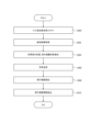
図6を参照して、本実施形態に係るシステム10の動作を説明する。図6は、制御装置11の制御部41が実行する手順を示すフローチャート図である。
The operation of the
図6の手順は、例えば、集合住宅13の居住者がゴミ袋22の回収を求めるときに実行される。ステップS600において、制御装置11の制御部31は、通信部33により、ゴミの回収要求を受ける。回収要求は、例えば、居住者のスマートフォン、PCといった、通信機能を有する情報処理装置から送られる。居住者は、ゴミ袋22を自らの住戸のバルコニーの回収位置に置いて、情報処理装置を操作し回収要求を送出する。又は、例えば、バルコニーに設置されたゴミ回収器が、ゴミ袋22が設置されたことを検知して回収要求を送出してもよい。回収要求には、ゴミ袋22を回収すべきバルコニーの位置を特定するための住戸の識別情報、位置情報等が付随して送られる。
The procedure in FIG. 6 is executed, for example, when a resident of the
ステップS602において、制御部31は、集合住宅13の各住戸のセンサ50から検知結果を取得する。制御部31は、通信部33を介して、検知結果の要求を、センサ50へ送る。この要求に応答して、センサ50は、中継器51又は通信機器52を介して、検知結果を制御装置11へ送る。制御部31は、通信部33を介して、住戸毎に検知結果を受ける。
In step S<b>602 , the
ステップS604において、制御部31は、住戸毎に、居住者の位置、窓及び遮蔽手段の遮蔽状態を導出する。例えば、制御部31は、住戸毎の居室内の撮像画像、音声、又は温度分布により居住者の存在を検出し、集合住宅13の情報を参照して、その住戸内での居住者の位置を導出する。また、制御部31は、窓及び遮蔽手段の開閉状態の検知結果から、住戸毎の窓の遮蔽状態を導出する。
In step S604, the
ステップS606において、制御部31は、集合住宅13の周囲における内部からの死角を決定する。例えば、制御部31は、集合住宅13の情報を用いて、集合住宅13の周囲の空域に評価値を付す。集合住宅13の周囲の空域は、飛行体12が通過し得る空域であって、集合住宅13の寸法、形状に応じた容積を有する。評価値は、各空域における各住戸の内部からの視線が遮蔽される度合いを示す。制御部31は、空域に付した評価値が任意の基準値を満たす場合に、その空域を死角と決定する。
In step S606, the
ここで、図7A~7C及び図8A~8Bを用いて、集合住宅13の周囲の空域と評価値について説明する。
Here, the airspace around the
図7A~7Cは、集合住宅13の周囲の空域を模式的に示す。図7Aは、集合住宅13の正面の外観図である。図7Bは、図7Aにおける集合住宅13の左側面73の外観図である。図7Cは、図7Aにおける集合住宅13の右側面74の外観図である。図7A~図7Cには、集合住宅13の屋上に面した空域75T、集合住宅13の正面に面した空域75F、集合住宅13の左側面に面した空域75L、及び集合住宅13の右側面に面した空域75Rが示される。各空域は略直方体の空間を占めるとともに飛行体12が通過可能な容積を有する。各空域における集合住宅13からの距離(厚み)は、飛行体12の飛行時間を短縮するとともに飛行に係る電力消費を節約するために、飛行体12による飛行の安全性が確保される範囲において短い方が(例えば、数十~百数十センチメートル)望ましい。すなわち、飛行体12は集合住宅13の表面に沿うように、集合住宅13の周囲を飛行する。ここでは、集合住宅13が略直方体形状を呈する場合を例に、3つの空域を示すが、集合住宅13の形状と空域の形状・数はここに示す場合に限られない。集合住宅13の形状は任意でよいし、その形状に応じて集合住宅13の外壁面に面した形状・数の空域が観念される。
7A to 7C schematically show the airspace around the
飛行体12は、集合住宅13の周囲を飛行するとき、一の空域から他の空域に進入して飛行する。例えば、飛行体12が、屋上の待機場所70にて待機しており、居住者の要求に応じて集合住宅13の正面のバルコニー21の一つにおいてゴミ袋を回収し、集合住宅13の左側面の集積場所20にゴミ袋を運搬するとき、飛行体12は、空域75T内をX-Y軸方向に移動して空域75Fに進入し、空域75F内をX-Z軸方向に移動して空域75Lに進入して、空域75L内をY-Z軸方向に移動するような飛行経路で飛行する。また、例えば、飛行体12が、集合住宅13の右側面の待機場所71にて待機しており、居住者の要求に応じて集合住宅13の正面のバルコニー21の一つにおいてゴミ袋を回収し、集合住宅13の左側面の集積場所20にゴミ袋を運搬するとき、飛行体12は、空域75R内をY-Z軸方向に移動して空域75Fに進入し、空域75F内をX-Z軸方向に移動して空域75Lに進入して、空域75L内をY-Z軸方向に移動するような飛行経路で飛行する。
When the flying
図8Aは、図7A~7Cで示した空域75T、75F、75L及び75Rに対し付される評価値の付し方の例を示す。図8Aには、集合住宅13の正面図に空域75T、75F、75L及び75Rが示される。制御部31は、例えば、各住戸の内部からの視線が遮蔽される度合いが高い空域により高い評価値を、視線が遮蔽される度合いが低い空域により低い評価値を付す。図8Aでは、視線が遮蔽される空域がハッチングで示される。例えば、集合住宅13の屋上、左右側面には窓がないため、空域75T、75L及び75Rでは住戸内からの視線は遮蔽されるので、各空域全体に評価値1が付される。集合住宅13の正面では、各住戸のバルコニー21と、バルコニーに通じる掃き出し窓、腰高窓等の窓23が設けられる。窓23の外側の空域750Fは住戸内からの視線が遮蔽されない蓋然性が高い一方、バルコニー21の手摺壁の外側の空域、つまり手摺の高さからバルコニーの床面までに相当する空域、及び住戸間の外壁部分の外側の空域751Fは住戸内からの視線が遮蔽される。よって、空域75Fのうち、視線が遮蔽される空域(ハッチングあり)750Fには評価値1が付され、視線が遮蔽されない空域(ハッチングなし)751Fには評価値-1が付される。制御部41は、例えば、基準値を1として、評価値1が付されるハッチングされた空域75T、75L、75R及び751Fを死角と決定する。
FIG. 8A shows an example of how evaluation values are assigned to the
図8Bは、図8Aの変形例における評価値の付し方の例を示す。各住戸において、窓23を有する居室及びバルコニー21に居住者が位置していないときは視線が存在しないので、窓23の外側の空域であっても住戸内からの視線は遮蔽されるとみなされる。また、窓23がカーテン、ブライド等の遮蔽手段で遮蔽されているときには、窓23の外側の空域であっても住戸内からの視線は遮蔽される。制御部31は、住戸毎に、窓23を有する居室及びバルコニー21に居住者が位置していないかを判定する。また、制御部31は、住戸毎に、窓23の遮蔽手段の開閉状態から、窓23が遮蔽されているかを判定する。そして、窓23を有する居室及びバルコニー21に居住者が位置していないか、又は窓23が遮蔽されていると判定した住戸について、制御部31は、窓23の外側の空域であっても視線が遮蔽されるものとして評価値1を付す。図8Bには、図8Aの場合に加えて、窓23の外側の空域であっても視線が遮蔽されて評価値1が付される場合が示される。ここでは、例えば、住戸80、81、82、83、84及び85における窓23の外側の空域に評価値1が付され、これらの空域も死角と決定される。
FIG. 8B shows an example of how to assign evaluation values in the modified example of FIG. 8A. In each dwelling unit, when no resident is located in the room with the
図6に戻り、ステップS608において、制御部31は、飛行体12の飛行経路を導出する。制御部31は、飛行体12の待機場所からゴミ袋22の回収場所までの飛行経路と、ゴミ袋の回収場所から集積場所20までの飛行経路を導出する。制御部31は、集合住宅13における飛行体12の待機場所、ゴミの回収場所、及びゴミの集積場所の位置を示す情報に基づいて、飛行経路を導出する。また、制御部31は、飛行体12の待機場所の位置に代わり、またはこれに加えて飛行体12から位置情報を受け、飛行体12の位置情報を用いて飛行経路の始点を求めてもよい。飛行経路は、少なくとも飛行体12が保持するゴミ袋22が死角に入るような経路である。飛行経路は、更に、飛行体12自体、又は飛行体12とゴミ袋22とが死角に入るような経路であってもよい。
Returning to FIG. 6, in step S608, the
ここで、図9A及び9Bに、飛行経路の例を示す。 Here, examples of flight paths are shown in FIGS. 9A and 9B.
図9Aは、図8Aで示した死角を通る飛行経路の例を模式的に示す。図9Aでは、住戸90のバルコニーでゴミ袋22を回収する場合において、飛行体12が屋上の待機場所70又は右側面の待機場所17から住戸90のバルコニーへ死角を通過して向かう経路の例が白抜きの矢印で、住戸90のバルコニーから左側面の集積場所20へ死角を通過して向かう経路の例が黒塗りの矢印で示される。このように、飛行体12が集合住宅13の周囲を飛行するとき、特に空域75Fでは死角を通ることで、居住者の視界を飛行体12自体、又は飛行体12が保持するゴミ袋22により妨げる蓋然性を低下させることができる。
FIG. 9A schematically shows an example of a flight path passing through the blind spot shown in FIG. 8A. In FIG. 9A, when collecting
図9Bは、図8Bで示した死角を通る飛行経路の例を模式的に示す。図9Bでは、住戸90のバルコニーでゴミを回収する場合において、飛行体12が屋上の待機場所70又は右側面の待機場所17から住戸90のバルコニーへ死角を通過して向かう経路の例が白抜きの矢印で、住戸90のバルコニーから左側面の集積場所20へ死角を通過して向かう経路の例が黒塗りの矢印で示される。特に、図9Bでは、窓23の外側の空域を死角と決定した住戸の前を飛行体12が横切るような飛行経路の例が示される。ここに示すように、住戸の外側の空域を対角線方向に横切る飛行経路を採用することで、飛行経路を短縮することが可能となる。好適には、制御部31は、ゴミ袋22が死角に入ることを条件として、最短の飛行経路を求める。よって、飛行体12による回収作業の効率改善、飛行にかかる電力消費の抑制が可能となる。
FIG. 9B schematically shows an example of a flight path passing through the blind spot shown in FIG. 8B. In FIG. 9B, when garbage is collected on the balcony of the
制御部31は、任意の経路検索アルゴリズムにより、飛行経路を決定することができる。例えば、通過可能な空域、またはその部分を選択肢とし、空域の可能な組合せのなかから最短の経路を求めてもよいし、移動すべき2点間の物理的な最短経路を求め、その経路が死角でない空域を通過する場合に、部分的な迂回経路を求めてもよい。あるいは、制御部31は、集合住宅13毎に予め死角のパターンに飛行経路が対応付けられた情報を有しており、死角のパターンに応じた飛行経路を選択することで、飛行経路を決定してもよい。
The
図6に戻り、ステップS610において、制御部31は、飛行経路の情報を、通信部33によって飛行体12へ送出する。飛行経路の情報は、飛行体12が自動操縦により集合住宅13の周囲を飛行するときに必要な移動距離、移動方向、高度、座標、集合住宅13からの距離等を含む。
Returning to FIG. 6, in step S610, the
飛行体12の制御部41は、通信部43により飛行経路の情報を受けると、飛行体12を飛行経路に沿って飛行させる制御処理を実行して、飛行体12にゴミ袋22の回収を行わせる。飛行体12は、回収場所のバルコニー21に到着すると、例えば、1対のアームを用いてゴミ袋22を挟み込むことによりゴミ袋22を保持して運搬する。そして、飛行体12は集積場所20に向けて飛行を続行する。飛行体12は、ゴミ袋22を集積場所20まで運搬すると、アームを開放してゴミ袋22を集積所に投下する。そそて、飛行体12は、任意の飛行経路で待機場所まで飛行し、次の回収要求に待機する。
When the
制御装置11は、飛行体12が飛行を開始するときに一回的に図6の手順を実行してもよいし、飛行体12が飛行を開始してからであっても周期的に図6の手順を実行してもよい。例えば、制御装置11は、数秒周期で飛行体12の位置情報を飛行体12から受け、飛行体12の現在位置からその時点での目的場所への飛行経路をその都度導出し、更新された飛行経路の情報を飛行体12に送ってもよい。飛行体12が飛行を開始してから居住者の位置、窓の遮蔽状態が変化し、したがって死角が変化した場合であっても、制御装置11が飛行体12に随時最適な飛行経路を指示することが可能となる。よって、更なる時間短縮、電力削減が可能となる。
The
また、飛行体12が1回のゴミ回収・運搬を終えたとき、待機場所に戻ることなく、次のゴミ回収を実行してもよい。その場合、制御装置11は、飛行体12の現在位置から次の回収のためのバルコニーの位置までの飛行経路を求めて飛行経路の情報を飛行体12へ送る。
Furthermore, when the flying
上述の例では、集合住宅13の正面に面した空域75Fにおいてゴミ袋22が死角に入るような飛行経路が導出される場合を示したが、集合住宅13の他の側面に窓23が設けられている場合には、その側面に面した空域においても上記同様、死角の決定処理と、飛行経路の導出処理とが制御装置11の制御部41により実行される。
In the above example, a flight path is derived in which the
上述の例では、集合住宅13の内部からの視線が遮蔽される場合とされない場合とに二分して、二値的な評価値1、-1が付される場合を示したが、視線の遮蔽の度合いに応じて3段階以上に細分化された評価値を空域に付してもよい。例えば、バルコニーの手摺壁の代わりに、柵又は格子状の手摺が設けられる場合、そのような手摺の外側の空域は手摺壁の場合ほど視線が遮蔽されないので、例えば、中間的な評価値0を付してもよい。また、例えば、窓23に遮蔽性に差がある複数のカーテン、例えば、ドレープカーテンとレースカーテンが設けられており、それぞれの開閉状態をセンサにより検知する場合において、遮蔽性が低いカーテンのみが閉じられている場合には、窓23の外側の空域は遮蔽性が高いカーテンが閉じられている場合ほど視線が遮蔽されないので、中間的な評価値0を付してもよい。また、ブライドの羽根の角度、スクリーンの進展量に応じた視線の遮蔽の度合いに応じ、中間的な評価値を付してもよい。あるいは、遮蔽手段が開いた状態であっても、窓23のサッシのガラスにすりガラス加工が施されており、窓23のサッシが閉じられている場合には、窓23の外側の空域に中間的な評価値を付してもよい。空域に3段階以上の評価値を付した場合には、制御装置11の制御部41は、例えば、空域に付された評価値が任意に定める基準値(例えば0)を満たす場合に、その空域を死角と決定することができる。なお、評価値及び基準値の例は、ここに示す値に限られず、任意であってよい。複数段階の評価値により死角を決定することにより、集合住宅13の状態に応じ、居住者の視線に対する妨げをより少なくするような飛行経路で飛行体12を飛行させることが可能となる。よって、居住者の快適性を向上させることが可能となる。
In the above example, the line of sight from inside the
本開示は上述の実施形態に限定されるものではない。例えば、ブロック図に記載の2つ以上のブロックを統合してもよいし、又は1つのブロックを分割してもよい。フローチャートに記載の2つ以上のステップを記述に従って時系列に実行する代わりに、各ステップを実行する装置の処理能力に応じて、又は必要に応じて、並列的に又は異なる順序で実行してもよい。その他、本開示の趣旨を逸脱しない範囲での変更が可能である。 The present disclosure is not limited to the embodiments described above. For example, two or more blocks depicted in the block diagram may be combined, or one block may be divided. Instead of performing two or more steps described in a flowchart chronologically as described, they may also be performed in parallel or in a different order, depending on the processing power of the device performing each step or as necessary. good. Other changes are possible without departing from the spirit of the present disclosure.
例えば、制御装置11は、飛行体12に備えられてもよい。その場合、飛行体12の動作の一部は、制御装置11により行われてもよい。飛行体12の制御部41、記憶部42、通信部43、入力部44、出力部45、及び測位部46が制御機器に組み込まれる場合、制御機器は、制御装置11に統合されてもよい。また、集合住宅13の代わりに、窓、バルコニーを有する複数の居室が収容され各居室に居住者が居住するような規模の住宅の場合も、本実施形態に含まれる。
For example, the
10 システム
11 制御装置
12 飛行体
13 集合住宅
14 ネットワーク
20 集積場所
21 バルコニー
23 窓
31 制御部
32 記憶部
33 通信部
34 入力部
35 出力部
41 制御部
42 記憶部
43 通信部
44 入力部
45 出力部
46 測位部
50 センサ
51 中継器
52 通信機器
10
Claims (16)
前記通信部により情報を送受する制御部とを有し、
前記制御部は、飛行体が住宅周囲を飛行するときに、前記住宅の情報に基づいて、当該住宅の内部からの死角に前記飛行体の運搬物が入り、かつ前記飛行体が前記運搬物を前記住宅の一のバルコニーから当該運搬物の集積場所に運搬するための最短の経路となるような飛行経路の情報を当該飛行体へ送り、
前記制御部は、前記飛行経路の情報を決定するときに、前記住宅における住戸の窓の遮蔽状態を示す情報を受け、前記窓が遮蔽されている三段階以上の程度に応じた評価値が基準値を満たす場合には当該窓を死角と決定する、
制御装置。 Communication department and
and a control unit that transmits and receives information through the communication unit,
When the flying object flies around the house, the control unit is configured to control, based on the information about the house, whether the object carried by the flying object enters a blind spot from inside the house, and when the flying object flies around the house. Sending information on a flight route that will be the shortest route for transporting the cargo from one balcony of the house to the collection point of the cargo to the aircraft,
When determining the information on the flight route, the control unit receives information indicating the shielding state of the windows of the dwelling unit in the residence, and sets an evaluation value according to the degree to which the windows are shielded in three or more levels as a standard. If the value is satisfied, the window is determined to be a blind spot.
Control device.
前記制御部は、更に、前記住宅における住戸内の居住者の位置を示す情報に基づいて、
前記死角を決定する、
制御装置。 In claim 1,
The control unit further includes, based on information indicating a position of a resident in a dwelling unit in the house,
determining the blind spot;
Control device.
前記制御部は、前記住戸のバルコニーの手摺壁の外側を前記死角と決定する、
制御装置。 In claim 2,
The control unit determines the outside of the handrail wall of the balcony of the dwelling unit as the blind spot.
Control device.
前記制御部は、前記居住者が前記住戸の窓のある居室及び当該窓の外側に設けられるバルコニーに位置しないときは、前記窓の外側を前記死角と決定する、
制御装置。 In claim 2,
The control unit determines the outside of the window as the blind spot when the resident is not located in a room with a window of the dwelling unit and a balcony provided outside the window.
Control device.
前記制御部は、前記居住者の位置を示す情報を、前記住宅内に備えられるセンサ又は前記居住者が携行するセンサから受ける、
制御装置。 In any one of claims 2 to 4,
The control unit receives information indicating the position of the resident from a sensor provided in the house or a sensor carried by the resident.
Control device.
システム。 comprising the control device according to any one of claims 1 to 5 and a flying object,
system.
プログラム。 being executed by a computer, causing the computer to operate as the control device according to any one of claims 1 to 6 ;
program.
前記制御装置が、前記飛行体が住宅周囲を飛行するときに、前記住宅の情報に基づいて、当該住宅の内部からの死角に前記飛行体の運搬物が入り、かつ前記飛行体が前記運搬物を前記住宅の一のバルコニーから当該運搬物の集積場所に運搬するための最短の経路となるような飛行経路の情報を当該飛行体へ送り、
前記制御装置が、前記飛行経路の情報を決定するときに、前記住宅における住戸の窓の遮蔽状態を示す情報を受け、前記窓が遮蔽されている三段階以上の程度に応じた評価値が基準値を満たす場合には当該窓を死角と決定する、
動作方法。 A method for operating a system including a flying object and a control device that transmits and receives information from the flying object, the method comprising:
When the flying object flies around the house, the control device determines, based on information about the house, that the object carried by the flying object enters a blind spot from inside the house, and when the flying object flies around the house. Sending information on a flight route that is the shortest route for transporting objects from one balcony of the house to the collection point of the objects to the flying object,
When the control device determines the flight path information, it receives information indicating the shielding state of the windows of the dwelling units in the residence, and sets an evaluation value according to the degree of shielding of the windows in three or more levels as a standard. If the value is satisfied, the window is determined to be a blind spot.
How it works.
前記制御装置が、更に、前記住宅における住戸内の居住者の位置を示す情報に基づいて、前記死角を決定する、
動作方法。 In claim 11 ,
The control device further determines the blind spot based on information indicating a position of a resident in a dwelling unit in the residence.
How it works.
前記制御装置が、前記住戸のバルコニーの手摺壁の外側を前記死角と決定する、
動作方法。 In claim 12 ,
the control device determines the outside of the handrail wall of the balcony of the dwelling unit as the blind spot;
How it works.
前記制御装置が、前記居住者が前記住戸の窓のある居室及び当該窓の外側に設けられるバルコニーに位置しないときは、前記窓の外側を前記死角と決定する、
動作方法。 In claim 12 ,
The control device determines the outside of the window as the blind spot when the resident is not located in a room with a window of the dwelling unit and a balcony provided outside the window.
How it works.
前記制御装置が、前記居住者の位置を示す情報を、前記住宅内に備えられるセンサ又は前記居住者が携行するセンサから受ける、
動作方法。 In any one of claims 12 to 14 ,
The control device receives information indicating the position of the resident from a sensor provided in the house or a sensor carried by the resident.
How it works.
前記飛行体が、前記飛行経路に沿って飛行する、
動作方法。 In any one of claims 11 to 15 ,
the flying object flies along the flight path;
How it works.
Priority Applications (3)
| Application Number | Priority Date | Filing Date | Title |
|---|---|---|---|
| JP2020177554A JP7420048B2 (en) | 2020-10-22 | 2020-10-22 | Control devices, systems, programs, control equipment, aircraft, sensors and system operation methods |
| CN202110843064.8A CN114384927B (en) | 2020-10-22 | 2021-07-26 | Control device, control equipment, control system operation method, flying body and sensor |
| US17/395,939 US12159542B2 (en) | 2020-10-22 | 2021-08-06 | Control device, system, program, control instrument, flying object, sensor, and method of operating system |
Applications Claiming Priority (1)
| Application Number | Priority Date | Filing Date | Title |
|---|---|---|---|
| JP2020177554A JP7420048B2 (en) | 2020-10-22 | 2020-10-22 | Control devices, systems, programs, control equipment, aircraft, sensors and system operation methods |
Publications (2)
| Publication Number | Publication Date |
|---|---|
| JP2022068718A JP2022068718A (en) | 2022-05-10 |
| JP7420048B2 true JP7420048B2 (en) | 2024-01-23 |
Family
ID=81194631
Family Applications (1)
| Application Number | Title | Priority Date | Filing Date |
|---|---|---|---|
| JP2020177554A Active JP7420048B2 (en) | 2020-10-22 | 2020-10-22 | Control devices, systems, programs, control equipment, aircraft, sensors and system operation methods |
Country Status (3)
| Country | Link |
|---|---|
| US (1) | US12159542B2 (en) |
| JP (1) | JP7420048B2 (en) |
| CN (1) | CN114384927B (en) |
Families Citing this family (2)
| Publication number | Priority date | Publication date | Assignee | Title |
|---|---|---|---|---|
| JP7533337B2 (en) * | 2021-04-22 | 2024-08-14 | トヨタ自動車株式会社 | Method, control device, and system |
| ES2958407B2 (en) * | 2022-07-13 | 2025-02-12 | Genoves Ramirez Pedro | UNMANNED AERIAL SYSTEM FOR AUTONOMOUS DELIVERY AND REMOVAL OF PRODUCTS |
Citations (6)
| Publication number | Priority date | Publication date | Assignee | Title |
|---|---|---|---|---|
| JP2010157119A (en) | 2008-12-26 | 2010-07-15 | Fujitsu Ltd | Monitoring device, monitoring method, and monitoring program |
| JP2017111790A (en) | 2015-12-10 | 2017-06-22 | パナソニック インテレクチュアル プロパティ コーポレーション オブ アメリカPanasonic Intellectual Property Corporation of America | Movement control method, autonomous mobile robot, and program |
| US20180025649A1 (en) | 2016-02-08 | 2018-01-25 | Unmanned Innovation Inc. | Unmanned aerial vehicle privacy controls |
| US20180322794A1 (en) | 2017-05-02 | 2018-11-08 | Here Global B.V. | Method and apparatus for privacy-sensitive routing of an aerial drone |
| US20200061839A1 (en) | 2016-02-09 | 2020-02-27 | Cobalt Robotics Inc. | Inventory management by mobile robot |
| JP2020087134A (en) | 2018-11-28 | 2020-06-04 | 本田技研工業株式会社 | Waste collection management system, waste collection management method and program |
Family Cites Families (5)
| Publication number | Priority date | Publication date | Assignee | Title |
|---|---|---|---|---|
| US10618655B2 (en) * | 2015-10-14 | 2020-04-14 | Flirtey Holdings, Inc. | Package delivery mechanism in an unmanned aerial vehicle |
| US10409292B2 (en) * | 2015-12-10 | 2019-09-10 | Panasonic Intellectual Property Corporation Of America | Movement control method, autonomous mobile robot, and recording medium storing program |
| JP6850133B2 (en) | 2017-01-13 | 2021-03-31 | 三井住友建設株式会社 | Balcony structure of a building with a drone port |
| AU2018210949B2 (en) * | 2017-01-17 | 2022-08-11 | Alarm.Com Incorporated | Dynamic drone navigation |
| CN111268132B (en) * | 2020-03-31 | 2021-09-10 | 上海申雪供应链管理有限公司 | Intelligent logistics service method and system based on urban community |
-
2020
- 2020-10-22 JP JP2020177554A patent/JP7420048B2/en active Active
-
2021
- 2021-07-26 CN CN202110843064.8A patent/CN114384927B/en active Active
- 2021-08-06 US US17/395,939 patent/US12159542B2/en active Active
Patent Citations (6)
| Publication number | Priority date | Publication date | Assignee | Title |
|---|---|---|---|---|
| JP2010157119A (en) | 2008-12-26 | 2010-07-15 | Fujitsu Ltd | Monitoring device, monitoring method, and monitoring program |
| JP2017111790A (en) | 2015-12-10 | 2017-06-22 | パナソニック インテレクチュアル プロパティ コーポレーション オブ アメリカPanasonic Intellectual Property Corporation of America | Movement control method, autonomous mobile robot, and program |
| US20180025649A1 (en) | 2016-02-08 | 2018-01-25 | Unmanned Innovation Inc. | Unmanned aerial vehicle privacy controls |
| US20200061839A1 (en) | 2016-02-09 | 2020-02-27 | Cobalt Robotics Inc. | Inventory management by mobile robot |
| US20180322794A1 (en) | 2017-05-02 | 2018-11-08 | Here Global B.V. | Method and apparatus for privacy-sensitive routing of an aerial drone |
| JP2020087134A (en) | 2018-11-28 | 2020-06-04 | 本田技研工業株式会社 | Waste collection management system, waste collection management method and program |
Also Published As
| Publication number | Publication date |
|---|---|
| US12159542B2 (en) | 2024-12-03 |
| JP2022068718A (en) | 2022-05-10 |
| CN114384927B (en) | 2024-05-14 |
| CN114384927A (en) | 2022-04-22 |
| US20220130259A1 (en) | 2022-04-28 |
Similar Documents
| Publication | Publication Date | Title |
|---|---|---|
| US20230394982A1 (en) | Pre-emptive generation of autonomous unmanned aerial vehicle inspections according to monitored sensor events | |
| CN111656424B (en) | Automatic flying unmanned aerial vehicle system based on big data and automatic flying method thereof | |
| US10281911B1 (en) | System and method for controlling a remote aerial device for up-close inspection | |
| US10802509B2 (en) | Selective processing of sensor data | |
| CN110174903B (en) | System and method for controlling a movable object within an environment | |
| US10394239B2 (en) | Acoustic monitoring system | |
| JP7420048B2 (en) | Control devices, systems, programs, control equipment, aircraft, sensors and system operation methods | |
| CN115202401A (en) | Flight path determination | |
| US20220230133A1 (en) | Server device, system, flying body, and operation method of system | |
| JP6778847B1 (en) | Cargo port management system, cargo port management method, and program | |
| JP6595284B2 (en) | Autonomous mobile robot | |
| WO2019054027A1 (en) | Flight control system and flight control apparatus | |
| JP7216046B2 (en) | patrol inspection system | |
| JP2022100121A (en) | Server, vehicle detection system and vehicle detection method | |
| JP2022066041A (en) | Control device, system, program, control apparatus, flying object, sensor, and operation method of system | |
| US12094350B2 (en) | Control device, unmanned aerial vehicle, and method | |
| US11127170B1 (en) | Multi-level premise mapping with security camera drone | |
| JP7424267B2 (en) | Control devices, systems, aircraft, and transportation methods | |
| US11927971B2 (en) | Control apparatus, uninhabited airborne vehicle, and method | |
| WO2023042601A1 (en) | Information processing device | |
| JP7698364B2 (en) | Information processing system, mobile body, information processing method, and program | |
| JP7319244B2 (en) | Control device, program, system and method | |
| KR20250085094A (en) | Life-saving system using AI drones in high-rise buildings | |
| KR20200079869A (en) | Drawing design system for controlling the behavior of drone |
Legal Events
| Date | Code | Title | Description |
|---|---|---|---|
| A621 | Written request for application examination |
Free format text: JAPANESE INTERMEDIATE CODE: A621 Effective date: 20220920 |
|
| A977 | Report on retrieval |
Free format text: JAPANESE INTERMEDIATE CODE: A971007 Effective date: 20230915 |
|
| A131 | Notification of reasons for refusal |
Free format text: JAPANESE INTERMEDIATE CODE: A131 Effective date: 20231003 |
|
| A521 | Request for written amendment filed |
Free format text: JAPANESE INTERMEDIATE CODE: A523 Effective date: 20231127 |
|
| TRDD | Decision of grant or rejection written | ||
| A01 | Written decision to grant a patent or to grant a registration (utility model) |
Free format text: JAPANESE INTERMEDIATE CODE: A01 Effective date: 20231212 |
|
| A61 | First payment of annual fees (during grant procedure) |
Free format text: JAPANESE INTERMEDIATE CODE: A61 Effective date: 20231225 |
|
| R151 | Written notification of patent or utility model registration |
Ref document number: 7420048 Country of ref document: JP Free format text: JAPANESE INTERMEDIATE CODE: R151 |