JP7367744B2 - Monitoring methods, monitoring systems and computer programs - Google Patents
Monitoring methods, monitoring systems and computer programs Download PDFInfo
- Publication number
- JP7367744B2 JP7367744B2 JP2021176613A JP2021176613A JP7367744B2 JP 7367744 B2 JP7367744 B2 JP 7367744B2 JP 2021176613 A JP2021176613 A JP 2021176613A JP 2021176613 A JP2021176613 A JP 2021176613A JP 7367744 B2 JP7367744 B2 JP 7367744B2
- Authority
- JP
- Japan
- Prior art keywords
- camera
- information
- data
- icon
- temporary
- Prior art date
- Legal status (The legal status is an assumption and is not a legal conclusion. Google has not performed a legal analysis and makes no representation as to the accuracy of the status listed.)
- Active
Links
- 238000000034 method Methods 0.000 title claims description 29
- 238000004590 computer program Methods 0.000 title claims description 16
- 238000012544 monitoring process Methods 0.000 title claims description 14
- 230000000007 visual effect Effects 0.000 claims 2
- 238000007726 management method Methods 0.000 description 27
- 230000001133 acceleration Effects 0.000 description 22
- 238000010586 diagram Methods 0.000 description 12
- 238000013500 data storage Methods 0.000 description 4
- 238000009434 installation Methods 0.000 description 3
- 238000003860 storage Methods 0.000 description 3
- 230000002547 anomalous effect Effects 0.000 description 2
- 230000008901 benefit Effects 0.000 description 2
- 230000003287 optical effect Effects 0.000 description 2
- 239000000126 substance Substances 0.000 description 2
- 230000002159 abnormal effect Effects 0.000 description 1
- 230000005540 biological transmission Effects 0.000 description 1
- 230000001427 coherent effect Effects 0.000 description 1
- 238000004891 communication Methods 0.000 description 1
- 238000001514 detection method Methods 0.000 description 1
- 238000005516 engineering process Methods 0.000 description 1
- 230000006870 function Effects 0.000 description 1
- 238000012432 intermediate storage Methods 0.000 description 1
- 238000004088 simulation Methods 0.000 description 1
Images


Classifications
-
- H—ELECTRICITY
- H04—ELECTRIC COMMUNICATION TECHNIQUE
- H04N—PICTORIAL COMMUNICATION, e.g. TELEVISION
- H04N7/00—Television systems
- H04N7/18—Closed-circuit television [CCTV] systems, i.e. systems in which the video signal is not broadcast
- H04N7/181—Closed-circuit television [CCTV] systems, i.e. systems in which the video signal is not broadcast for receiving images from a plurality of remote sources
-
- G—PHYSICS
- G08—SIGNALLING
- G08B—SIGNALLING OR CALLING SYSTEMS; ORDER TELEGRAPHS; ALARM SYSTEMS
- G08B13/00—Burglar, theft or intruder alarms
- G08B13/18—Actuation by interference with heat, light, or radiation of shorter wavelength; Actuation by intruding sources of heat, light, or radiation of shorter wavelength
- G08B13/189—Actuation by interference with heat, light, or radiation of shorter wavelength; Actuation by intruding sources of heat, light, or radiation of shorter wavelength using passive radiation detection systems
- G08B13/194—Actuation by interference with heat, light, or radiation of shorter wavelength; Actuation by intruding sources of heat, light, or radiation of shorter wavelength using passive radiation detection systems using image scanning and comparing systems
- G08B13/196—Actuation by interference with heat, light, or radiation of shorter wavelength; Actuation by intruding sources of heat, light, or radiation of shorter wavelength using passive radiation detection systems using image scanning and comparing systems using television cameras
- G08B13/19639—Details of the system layout
- G08B13/19641—Multiple cameras having overlapping views on a single scene
- G08B13/19643—Multiple cameras having overlapping views on a single scene wherein the cameras play different roles, e.g. different resolution, different camera type, master-slave camera
-
- H—ELECTRICITY
- H04—ELECTRIC COMMUNICATION TECHNIQUE
- H04N—PICTORIAL COMMUNICATION, e.g. TELEVISION
- H04N23/00—Cameras or camera modules comprising electronic image sensors; Control thereof
- H04N23/60—Control of cameras or camera modules
-
- H—ELECTRICITY
- H04—ELECTRIC COMMUNICATION TECHNIQUE
- H04N—PICTORIAL COMMUNICATION, e.g. TELEVISION
- H04N23/00—Cameras or camera modules comprising electronic image sensors; Control thereof
- H04N23/60—Control of cameras or camera modules
- H04N23/66—Remote control of cameras or camera parts, e.g. by remote control devices
- H04N23/661—Transmitting camera control signals through networks, e.g. control via the Internet
-
- H—ELECTRICITY
- H04—ELECTRIC COMMUNICATION TECHNIQUE
- H04N—PICTORIAL COMMUNICATION, e.g. TELEVISION
- H04N23/00—Cameras or camera modules comprising electronic image sensors; Control thereof
- H04N23/60—Control of cameras or camera modules
- H04N23/69—Control of means for changing angle of the field of view, e.g. optical zoom objectives or electronic zooming
-
- H—ELECTRICITY
- H04—ELECTRIC COMMUNICATION TECHNIQUE
- H04N—PICTORIAL COMMUNICATION, e.g. TELEVISION
- H04N23/00—Cameras or camera modules comprising electronic image sensors; Control thereof
- H04N23/90—Arrangement of cameras or camera modules, e.g. multiple cameras in TV studios or sports stadiums
Landscapes
- Engineering & Computer Science (AREA)
- Multimedia (AREA)
- Signal Processing (AREA)
- Physics & Mathematics (AREA)
- General Physics & Mathematics (AREA)
- Studio Devices (AREA)
- Alarm Systems (AREA)
- Closed-Circuit Television Systems (AREA)
Description
本発明は監視システムに関する。より詳細には、本発明は固定カメラ及び仮設カメラを有する監視システムに関する。 The present invention relates to a monitoring system. More particularly, the present invention relates to a surveillance system having fixed and temporary cameras.
ビデオ監視システムなどの監視システムは、いくつかの地域での日常の監視や事件の発見に使われてきた。テロ行為、暴動、窃盗、喧嘩、火災、自動車事故などの異常な出来事をこのような監視システムで捉えることを意図している。 Surveillance systems, such as video surveillance systems, have been used for routine surveillance and incident detection in some areas. Such surveillance systems are intended to capture unusual events such as acts of terrorism, riots, theft, fights, fires, and car accidents.
しかし、ある状況では、固定カメラは死角、コスト制約及びプライバシーへの懸念のために監視領域内での異常な出来事を捉えることができない。そのため、指令センターの警備員はどの固定カメラもカバーしていない現場で何が起こっているかを確認することはできない。 However, in some situations, fixed cameras are unable to capture unusual events within the surveillance area due to blind spots, cost constraints, and privacy concerns. Therefore, security personnel at the command center cannot see what is happening in the field, which is not covered by any of the fixed cameras.
したがって、必要とされているのは、固定カメラのカバー範囲を広げ、異常な出来事をより良く理解できるように監視領域内での異常な出来事を捉える、改良された監視システムである。更に、他の望ましい特徴及び特性は、添付の図面及び本開示のこの背景技術と併せて、以降の詳細説明及び添付の請求項から明らかになるであろう。 Therefore, what is needed is an improved surveillance system that extends the coverage of fixed cameras and captures anomalous events within a surveillance area for better understanding of anomalous events. Additionally, other desirable features and characteristics will become apparent from the following detailed description and appended claims, taken in conjunction with the accompanying drawings and this background of the disclosure.
本発明の第1の態様において、固定カメラと、1つ又は複数の仮設カメラと、前記固定カメラ及び前記1つ又は複数の仮設カメラに接続された制御手段とを備えた監視システムが開示されている。前記制御手段は、前記固定カメラに接続された前記1つ又は複数の仮設カメラを使って前記固定カメラのカバー範囲を広げるよう構成されている。前記1つ又は複数の仮設カメラのそれぞれは、1つ又は複数のセンサを含み、前記1つ又は複数の仮設カメラの前記1つ又は複数のセンサ及び前記固定カメラと同じ場所に配置された1つ又は複数の固定カメラセンサから取得したセンサデータに基づいて配置調整されるよう構成される。 In a first aspect of the invention, a surveillance system is disclosed, comprising a fixed camera, one or more temporary cameras, and control means connected to the fixed camera and the one or more temporary cameras. There is. The control means is configured to extend the coverage of the fixed camera using the one or more temporary cameras connected to the fixed camera. Each of the one or more temporary cameras includes one or more sensors, one co-located with the one or more sensors of the one or more temporary cameras and the fixed camera. Alternatively, the arrangement is configured to be adjusted based on sensor data obtained from a plurality of fixed camera sensors.
本発明の第2の態様において、固定カメラ及び1つ又は複数の仮設カメラ並びに前記固定カメラ及び前記1つ又は複数の仮設カメラに接続された制御手段を使って1つ又は複数の関心のある領域を監視するための方法が開示されている。この方法は、前記1つ又は複数の仮設カメラの1つ又は複数のセンサ及び前記固定カメラと同じ場所に配置された1つ又は複数の固定カメラセンサからセンサデータを取得することを含む。また、この方法は、さらに、前記固定カメラのカバー範囲を前記1つ又は複数の仮設カメラを使って広げるため、前記取得したセンサデータに基づいて前記1つ又は複数の仮設カメラのそれぞれを配置調整すること、を含む。 In a second aspect of the invention, one or more regions of interest are determined using a fixed camera and one or more temporary cameras and control means connected to said fixed camera and said one or more temporary cameras. A method for monitoring is disclosed. The method includes acquiring sensor data from one or more sensors of the one or more temporary cameras and one or more fixed camera sensors co-located with the fixed camera. The method further includes adjusting the placement of each of the one or more temporary cameras based on the acquired sensor data to extend the coverage area of the fixed camera using the one or more temporary cameras. including doing.
本発明の第3の態様において、固定カメラ及び1つ又は複数の仮設カメラ並びに前記固定カメラ及び前記1つ又は複数の仮設カメラに接続された制御手段を使って1つ又は複数の関心のある領域を監視するための方法を、コンピュータに実行させるプログラム指示を含む非一時的コンピュータ読み取り可能な媒体が開示されている。この方法は、前記1つ又は複数の仮設カメラの1つ又は複数のセンサ及び前記固定カメラと同じ場所に配置された1つ又は複数の固定カメラセンサからセンサデータを取得することを含む。また、この方法は、さらに、前記固定カメラのカバー範囲を前記1つ又は複数の仮設カメラを使って広げるため、前記取得したセンサデータに基づいて前記1つ又は複数の仮設カメラのそれぞれを配置調整すること、を含む。 In a third aspect of the invention, one or more regions of interest are determined using a fixed camera and one or more temporary cameras and control means connected to said fixed camera and said one or more temporary cameras. A non-transitory computer-readable medium containing program instructions for causing a computer to perform a method for monitoring is disclosed. The method includes acquiring sensor data from one or more sensors of the one or more temporary cameras and one or more fixed camera sensors co-located with the fixed camera. The method further includes adjusting the placement of each of the one or more temporary cameras based on the acquired sensor data to extend the coverage area of the fixed camera using the one or more temporary cameras. including doing.
別々の図を通じて同等の参照番号が同一又は機能的に類似の要素を指し、以下の詳細説明と共に本明細書に組み込まれてその一部を成す添付の図は、様々な実施形態を例証し、本実施形態に係る様々な原理及び利点を説明する働きをする。 The accompanying figures, in which like reference numbers refer to identical or functionally similar elements throughout the different figures, and which are incorporated in and constitute a part of this specification, illustrate various embodiments, and in which: It serves to explain various principles and advantages of the present embodiments.
当業者は、図における要素が簡潔、明確とするために示されており、必ずしも縮尺通りに描かれてはいないことを理解するであろう。例えば、可視化したシミュレーションにおける要素のいくつかの大きさ又はフローチャートのステップは、本実施形態をより良く理解するのを助けるために、他の要素に対して誇張されていることがある。 Those skilled in the art will appreciate that elements in the figures are shown for simplicity and clarity and have not necessarily been drawn to scale. For example, the sizes of some of the elements in a visualized simulation or steps in a flowchart may be exaggerated relative to other elements to help better understand the embodiments.
以下の詳細説明は本質的に例示に過ぎず、本発明又は本発明の用途と利用法を制限することを意図するものではない。更に、本発明の前述の背景技術又は以下の詳細説明で提示される理論に制約されるものではない。本実施形態は、事件関連のデータを監視する改良された方法を提示することを意図している。 The following detailed description is exemplary in nature and is not intended to limit the invention or its uses and uses. Furthermore, there is no intention to be bound by the theory presented in the preceding background of the invention or the following detailed description. This embodiment is intended to present an improved method of monitoring incident-related data.
図1は従来の監視システムの固定カメラにより捉えられた事件を示す。図1に示されるように、従来の監視システムの固定カメラ102の視野(FOV:Field of View)106は限られており、事件108の全体の光景110を捉えることはできない。固定カメラ102を有する従来の監視システムでは、限られた情報104だけが指令センターの警備員に入手可能である。したがって、固定カメラ102の視野106で完全には捉えられていない事件108を理解することは困難である。
FIG. 1 shows an incident captured by a fixed camera of a conventional surveillance system. As shown in FIG. 1, the field of view (FOV) 106 of a
固定カメラを有する従来の監視システムを改良するために、本実施形態に従って、仮設カメラが固定カメラのカバー範囲外で、犯罪が増加している、又は大規模な出来事が計画されている場所に配置される。指令センターの指揮官は、事件が固定カメラで捉えられなかった場合に現場で実際に何が起こったのかを知る必要があるため、これは非常に重要である。新たに配置された仮設カメラは、映像が共有されて仮設カメラがどこにあるかを指揮官が知ることができるように、現在のネットワークへ接続して自身を登録する。 To improve conventional surveillance systems with fixed cameras, according to this embodiment, temporary cameras are placed outside the coverage area of fixed cameras and in locations where crime is increasing or large-scale events are planned. be done. This is very important because command center commanders need to know what actually happened at the scene if the incident was not captured by fixed cameras. Newly deployed temporary cameras connect to the current network and register themselves so that footage can be shared and commanders know where the temporary cameras are located.
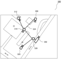
図2は本実施形態に係る固定カメラ及び仮設カメラのカバー範囲の例を示す。固定カメラ202に加えて、4台の仮設カメラ208、212、216及び220が固定カメラのカバー範囲206の外に配置される。結果として、4台の仮設カメラ208、212、216及び220により、監視システムがFOV210、214、218及び222をカバーできるようになる。
FIG. 2 shows an example of the coverage range of the fixed camera and temporary camera according to this embodiment. In addition to the
図3に示されるように、新たに配置された仮設カメラ308、312、316及び320は、例えばデータ中継用のアドホックネットワーク324を介して既存の固定カメラ302に接続される。データ中継用のアドホックネットワーク324は、仮設カメラ308、312、316及び320の配置に関する自由度を監視システムに与える。また、仮設カメラ308、312、316及び320から取得したデータは固定カメラ302に送られ、指令・管理センター326へ転送される。
As shown in FIG. 3, the newly placed
図4は本実施形態に係るシステムの例示のアーキテクチャを示す。登録プロセスについては、各カメラが自動的に自身の位置をシステムへ登録する。位置情報やFOV情報などのいくつかの重要な情報はシステム内で共有される。 FIG. 4 shows an exemplary architecture of a system according to the present embodiment. Regarding the registration process, each camera automatically registers its location with the system. Some important information such as location information and FOV information is shared within the system.
図4に示されるように、仮設カメラ402内のカメラ管理クライアント(CMC:Camera Management Client)416は、位置データ、方向データなどのセンサデータをGPS受信機410、ジャイロスコープ412、加速度センサ414などの仮設カメラ402内のセンサから集め、集められたセンサデータを仮設カメラ402のカメラ408で撮像された監視カメラ画像と共にネットワーク404を介して制御手段406へ送信する。同様に、固定カメラ448のCMC446は、センサ440、442及び444から集められたセンサデータを固定カメラ448のカメラ438で撮像された監視カメラ画像と共にネットワークを介して制御手段406へ送信する。更に、仮設カメラ402は音声データを取得するためのマイクを含むことがある。
As shown in FIG. 4, a camera management client (CMC) 416 in the
制御手段406のカメラ管理サーバ(CMS:Camera Management Server)418はCMC416及び446からデータを受信し、CMC416及び446からのデータを制御手段406に登録する。CMS418は、仮設カメラ402及び固定カメラ448の緯度や経度などの調整データ432をカメラ位置データベース422へ送り、その後FOV推定器420へ転送する。また、CMS418は仮設カメラ402及び固定カメラ448の水平方向434及び垂直方向を含む方向データ430をFOV推定器420へ送る。FOV推定器420は、ジャイロスコープ412、442により推定された水平方向434及び加速度センサ414、444により俯角(垂直方向)より推定された距離436に基づき、カメラ402及び448のFOVを推定する。更に、コンパスが北方向を特定するのに使用される。コンパスはカメラの方向を判定するのに使用される。
A camera management server (CMS) 418 of the control means 406 receives data from the
推定FOVに基づき、状況処理装置424は推定FOVで捉えられなかった領域(死角)を算出する。状況処理装置424で算出された死角に基づき、姿勢調整装置426はネットワーク404を介してカメラ402、448のすべて又は一部にフィードバックを送り、カメラの位置及び/又は方向を調整して死角をカバーする。位置及び/又は方向が調整された後、推定FOVがセキュリティ指揮官のためにアプリケーション428へ送られる。
Based on the estimated FOV, the
図5は本実施形態に係るシステム500の例示のブロック図を示す。この構成では、システム500はセンサデータ受信機502、504によりセンサデータを継続的に受信し、地図に示すべきFOVを推定する。第1ステップでは、位置センサ受信機502がGPS受信機などの位置センサモジュールから調整データを受信する。また、姿勢センサ受信機504がジャイロスコープ、加速度計やコンパスなどの姿勢センサからデータを受信する。第2ステップでは、FOV推定器506がセンサデータを利用してFOVを推定する。第3ステップでは、FOV推定器506が、情報を地図上に表示するため、又は情報を他の形式で提供するために、推定FOVをアプリケーション508へ送信する。
FIG. 5 shows an exemplary block diagram of a
図6は本実施形態に係るシステム600の例示のブロック図を示す。この構成では、登録プロセスの間にカメラ管理クライアント(CMC)610がセンサデータ受信機602、604によりセンサデータを収集し、カメラ管理サーバ(CMS)612でこのセンサデータを分析する。第1ステップでは、位置センサ受信機602が位置センサモジュールから位置データを受信する。また姿勢センサ受信機604が姿勢センサモジュールからデータを受信する。第2ステップでは、CMC610がすべてのセンサデータ受信機602、604からデータを受信し、センサデータをCMS612へ送信する。第3ステップでは、データを利用してFOVを推定するために、CMS612が姿勢データをFOV推定モジュール606へ送信する。第4ステップでは、CMS612が位置データ及び推定FOVをカメラ位置データベース614へ格納する。第5ステップでは、カメラ位置データベース614が、パラメータを計算してカメラがカバーしている領域とカバーしていない領域の両方を特定するため、位置データ及びFOVデータを状況処理モジュール616へ送信する。第6ステップでは、データベース614からの推定FOVデータに基づき、姿勢制御モジュール618が仮設カメラの姿勢を調整して仮設カメラが関心のある領域へ向くように制御する。第7ステップでは、カメラ位置、対象領域、FOVを示し、リアルタイム映像を再生するため、姿勢制御モジュール618が位置データ及びFOVデータをアプリケーション608へ送信する。
FIG. 6 shows an exemplary block diagram of a
図7は本実施形態に係る例1のブロック図を示す。第1ステップでは、位置センサ受信機706がGPSセンサモジュールから位置データを受信する。また姿勢センサ受信機702及び704がコンパスセンサ及び加速度センサからコンパスデータ及び加速度データを受信する。第2ステップでは、上面図718に示されるようにコンパスデータを使ってカメラの方向712を、側面図720に示されるように加速度データを使って俯角を、また俯角及びカメラ設置の典型的な高さを使って距離714を推定することでFOV推定モジュール708がFOVを推定し、地図722上のカメラの地理位置情報716が位置データ724から推定できる。第3ステップでは、カメラ位置、FOVを示し、リアルタイム映像を再生するため、推定FOVがアプリケーション710へ送信される。
FIG. 7 shows a block diagram of Example 1 according to this embodiment. In a first step, the
図8は本実施形態に係る例2のブロック図を示す。第1ステップでは、位置センサ受信機806がGPSセンサモジュールから調整データを受信する。また姿勢センサ受信機802及び804がコンパスセンサ及び加速度センサからコンパスデータ及び加速度データを受信する。第2ステップでは、カメラ管理クライアント(CMC)812、814がGPS受信機モジュール806、コンパスデータ受信機モジュール804及び加速度データ受信機モジュール802から調整データ、コンパスデータ及び加速度データを受信し、その後これらのデータをカメラ管理サーバ(CMS)816へ送信する。
FIG. 8 shows a block diagram of Example 2 according to this embodiment. In a first step, the
第3ステップでは、FOV推定モジュール808がコンパスデータを使ってカメラの方向を、加速度データを使って俯角を、カメラ設置の典型的高さと共に俯角を使って距離を推定することでカメラごとにFOVを推定してその結果をCMS816へ戻すことができるように、カメラ管理サーバ(CMS)816が各カメラ管理クライアント(CMC)812、814からの多数のコンパスデータ及び加速度データをFOV推定モジュール808へ送信する。
In a third step, the
第4ステップでは、カメラ管理サーバ(CMS)816が各カメラのID、地理位置情報調整、推定方向データ及び推定距離データをカメラ位置データベース818へ送信する。第5ステップでは、角度、空間及び位置のパラメータを計算してカメラがカバーしている領域とカバーしていない領域の両方を特定するため、カメラ位置データベース818が、各カメラの地理位置情報及びFOV情報をID(Identification)番号と共に状況処理モジュール820へ送信する。第6ステップでは、姿勢制御モジュール822が3軸ジャイロスコープを使って水平回転角を、3軸加速度計を使って垂直回転角を調整し、圧力・高度センサデータを使って仮設カメラの高さを制御して仮設カメラが関心のある領域へ向くよう制御する。第7ステップでは、カメラの位置及びFOVを示し、リアルタイム映像を再生するため、姿勢制御モジュール822が各カメラの地理位置情報及びFOV情報をID番号と共にアプリケーション810へ送信する。
In a fourth step, camera management server (CMS) 816 sends each camera's ID, geolocation adjustment, estimated direction data, and estimated distance data to
図9は本実施形態に係る例3のブロック図を示す。例3において、システム900は、例1及び2で使われたあらかじめ設定された高さ情報の代わりに高さデータ受信機モジュール934による正確な高さ情報を使用する。正確な高さ情報はFOV推定の精度を高めるのに有用である。
FIG. 9 shows a block diagram of Example 3 according to this embodiment. In Example 3,
第1ステップでは、位置センサ受信機906がGPSセンサモジュールから位置データを受信する。また加速度データ受信機モジュール902、コンパスデータ受信機モジュール904及び高さデータ受信機モジュール934がコンパスセンサ、加速度センサ及び高さセンサからコンパスデータ、加速度データ及び高さ情報を受信する。第2ステップでは、カメラ管理クライアント(CMC)912、914のそれぞれが、GPS受信機モジュール906、コンパスデータ受信機モジュール904、加速度データ受信機モジュール902及び高さデータ受信機モジュール934から調整データ、コンパスデータ、加速度データ及び高さデータを受信し、その後これらのデータをカメラ管理サーバ(CMS)916へ送信する。第3ステップでは、FOV推定モジュール908がコンパスデータを使ってカメラの方向を、加速度データを使って俯角を、カメラ設置の正確な検出高さと共に俯角を使って距離を推定することでカメラ924、926、928、930及び932のFOVを推定してその結果をCMS916へ戻すことができるように、カメラ管理サーバ(CMS)916がカメラ管理クライアント(CMC)912、914のそれぞれからの多数のコンパスデータ、加速度データ及び高さデータをFOV推定モジュール908へ送信する。
In a first step, the
第4ステップでは、カメラ管理サーバ(CMS)916が各カメラのID、地理位置情報調整、並びに推定される方向距離データ及び高さデータをカメラ位置データベース918へ格納する。第5ステップでは、角度、空間及び位置のパラメータを計算してカメラがカバーしている領域とカバーしていない領域の両方を特定するため、カメラ位置データベース918が各カメラの地理位置情報、FOV情報及び高さをID番号と共に状況処理モジュール920へ送信する。
In a fourth step, camera management server (CMS) 916 stores each camera's ID, geolocation adjustment, and estimated directional distance and height data into
第6ステップでは、姿勢制御モジュール922が3軸ジャイロスコープを使って水平回転角を、3軸加速度計を使って垂直回転角を調整し、圧力・高度センサデータを使って仮設カメラの高さを制御して仮設カメラが関心のある領域へ向くよう制御する。第7ステップでは、カメラ924、926、928、930及び932の位置及びFOVを示し、カメラのリアルタイム映像を再生するため、姿勢制御モジュール922が各カメラの地理位置情報及びFOV情報をID番号と共にアプリケーション910へ送信する。
In the sixth step, the
例4及び5は例1、2、3に基づいている。違いはアプリケーション710、810、910に存在する。例4では、アプリケーション710、810、910は指令・管理センター内に存在することができて、1つの特定の、又は多数の仮設カメラの位置をカメラのリアルタイム映像、ID及び監視領域と共に表示する。アプリケーションは異常な事件を捉えた場合は警報を発することができる。
Examples 4 and 5 are based on Examples 1, 2, and 3. Differences exist in
例5では、アプリケーション710、810、910は移動車両向け又はスマートフォン用を含む、モバイルアプリケーションであり得て、1つの特定の、又は多数の仮設カメラの位置をカメラのリアルタイム映像、ID及び監視領域と共に表示し、異常な事件を捉えた場合は警報を発することができる。
In example 5, the
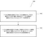
図10は本実施形態に係る方法の例示のフローチャート1000を示す。ステップ1002に示されるように、センサデータは1つ又は複数の仮設カメラの1つ又は複数のセンサ及び固定カメラと同じ場所に配置された1つ又は複数の固定カメラセンサから取得される。そして、ステップ1004に示されるように、1つ又は複数の仮設カメラを使って固定カメラのカバー範囲を広げるため、1つ又は複数の仮設カメラのそれぞれが取得したセンサデータに基づき配置調整される。
FIG. 10 shows an
図11は本実施形態に係る方法の例示のフローチャート1100を示す。センサデータは1つ又は複数の仮設カメラの1つ又は複数のセンサ及び固定カメラと同じ場所に配置された1つ又は複数の固定カメラセンサから取得される(ステップ1102)。そして、固定カメラ及び1つ又は複数の仮設カメラのそれぞれの視野(FOV)は、制御手段のFOV推定器による調整データ、水平方向データ、垂直方向データ及び高さ情報に基づいて推定される(ステップ1104)。その後、関心のある領域内の、固定カメラ及び1つ又は複数の仮設カメラのそれぞれの推定FOVでカバーされていない1つ又は複数の領域が制御手段の状況処理装置によって判定される(ステップ1106)。そして、1つ又は複数の仮設カメラの水平回転角及び/若しくは垂直回転角並びに/又は高さは、関心のある領域内の1つ又は複数の仮設カメラのそれぞれの推定FOVでカバーされていないと状況処理装置により判定された1つ又は複数の領域の一部又はすべてをカバーするため、ジャイロスコープ及び/若しくは加速度計並びに/又は高度センサを使って仮設カメラのそれぞれの1つ又は複数のアクチュエータによって調整される(ステップ1108)。
FIG. 11 shows an
本実施形態に従い、1つ又は複数の仮設カメラは、1つ又は複数の仮設カメラの1つ又は複数のセンサ及び固定カメラと同じ場所に配置された1つ又は複数の固定カメラセンサから取得した調整データ、水平方向データ、垂直方向データ及び高さ情報に応じて再配置される。 According to this embodiment, the one or more temporary cameras have adjustments obtained from one or more sensors of the one or more temporary cameras and one or more fixed camera sensors co-located with the fixed camera. data, horizontal data, vertical data and height information.
1つの例では、指令・管理センターが関心のある領域をより的確に捉えられるように、現場の警備員に指令を送って仮設カメラを追加の場所に移動する、又はカメラを上げる/下げることで仮設カメラを再配置することができる。 In one example, a command and control center can send commands to on-site security personnel to move temporary cameras to additional locations or raise/lower cameras to better capture areas of interest. Temporary cameras can be relocated.
仮設カメラは、三脚上へ設置する、又は高い/低い位置へ取り付ける、若しくは一時的に貼り付けてもよい。仮設カメラは、人間の介入の有無を問わず、柔軟に再配置してよい。関心のある領域が追加の事件の影響で広がった、又は移動した場合、広がった、又は移動した関心のある領域を捉えるため、仮設カメラの一部が再配置される、及び/又は新たな仮設カメラが配置される。また、再配置された、又は新たに配置された仮設カメラ用のアドホックネットワークを設置してもよく、仮設カメラからのデータがアドホックネットワークを介して指令・管理センターへ送信されてもよい。 Temporary cameras may be mounted on tripods, mounted in high/low positions, or temporarily affixed. Temporary cameras may be flexibly repositioned with or without human intervention. If the area of interest expands or moves as a result of additional incidents, some of the temporary cameras may be repositioned and/or new temporary cameras may be installed to capture the expanded or moved area of interest. Camera is placed. Additionally, an ad hoc network may be installed for relocated or newly placed temporary cameras, and data from the temporary cameras may be transmitted to the command and control center via the ad hoc network.
本実施形態に従い、現在の監視システムを柔軟で頑強とし、限られた固定カメラのカバー範囲を強化するため、仮設カメラは、特に死角又は犯罪が予測される場所で固定カメラと比べて補助的な役割を担い、ネットワークインフラのない領域へ配置するのにとても効果的で効率的で、手動設定の時間と作業量を低減する。 According to this embodiment, in order to make current surveillance systems flexible and robust, and to enhance the coverage of limited fixed cameras, temporary cameras can be used as supplementary cameras compared to fixed cameras, especially in blind spots or areas where crime is expected. It is very effective and efficient for deployment in areas without network infrastructure, reducing the time and effort of manual configuration.
本実施形態に従い、自動的な仮設カメラの認識及び登録並びに状況処理及び姿勢調整がなされるように、仮設カメラに統合されたカメラ管理クライアント(CMC)モジュールは指令・管理センターに設置されたカメラ管理サーバ(CMS)と通信を行う。これにより、1台の仮設カメラで固定カメラをサポートするだけでなく、多数の仮設カメラによるネットワーク通信及び自己管理された方法での自己登録が可能になるとともに、関心のある領域を算出する状況処理及び姿勢を調整する遠隔制御機能を含めることができる。 According to the present embodiment, a camera management client (CMC) module integrated with the temporary camera is installed in the camera management center in the command and control center so that automatic temporary camera recognition and registration, situation processing and attitude adjustment are performed. Communicate with the server (CMS). This allows not only one temporary camera to support fixed cameras, but also network communication and self-registration in a self-managed manner by many temporary cameras, as well as situational processing to calculate areas of interest. and remote control functions to adjust posture.
説明した例示の実施形態の方法及びシステムは、図12に概略的に示されるコンピュータシステム1200上に実装できる。コンピュータシステム1200内で実行され、コンピュータシステム1200に例示の実施形態の方法を実行するよう指示するコンピュータプログラムなどのソフトウェアとして実装可能である。
The example embodiment methods and systems described may be implemented on a
この後の説明の一部において、コンピュータメモリ内でのデータ演算のアルゴリズム及び機能的表現又は記号的表現に関して明示的又は暗黙的に示される。これらのアルゴリズムに関する説明及び機能的表現又は記号的表現は、データ処理技術に精通している者が当該技術に精通している他の者へ自分の仕事の内容を効果的に伝えるのに使用する手段である。本明細書では、また概して、アルゴリズムは、所望の結果へと通じる、首尾一貫した一連のステップと考えられる。ステップとは、記憶、転送、合成、比較及び別の方法で操作が可能な電気信号、磁気信号、光学信号などの物理量に対する物理的な操作を必要とするものである。 In some parts of the description that follows, reference is made either explicitly or implicitly to algorithms and functional or symbolic representations of data operations within a computer memory. These algorithmic descriptions and functional or symbolic representations are used by those skilled in data processing arts to effectively convey the substance of their work to others skilled in the art. It is a means. As used herein and generally, an algorithm is conceived of as a coherent series of steps leading to a desired result. The steps are those requiring physical manipulations of physical quantities, such as electrical, magnetic, or optical signals that can be stored, transferred, combined, compared, and otherwise manipulated.
特に明記していない限り、また以下より明らかであるように、本明細書を通して、「走査(scanning)」、「算出(calculating)」、「判定(determining)」、「置換(replacing)」、「生成(generating)」、「初期化(initializing)」、「出力(outputting)」といった用語又は同種の用語を使った議論は、コンピュータシステム内の物理量として表現されるデータを操作して、コンピュータシステム又は他の情報記憶装置、送信装置若しくは表示装置内の物理量として同様に表現される別のデータへと変換するコンピュータシステム又は類似の電子機器の動作及びプロセスについて言及していると理解されるであろう。 Unless stated otherwise, and as will be clear from the following, the terms "scanning", "calculating", "determining", "replacing", " Discussion using terms such as "generating," "initializing," "outputting," or similar terms refers to the use of the computer system or It will be understood to refer to the operations and processes of a computer system or similar electronic equipment that convert information into other data similarly represented as physical quantities in another storage, transmission or display device. .
また、本明細書は方法の操作を行う装置を開示する。このような装置は要求される目的のために特別に作成してもよく、又は汎用コンピュータ若しくはコンピュータに記憶されたコンピュータプログラムにより選択的に作動、若しくは再構成された他の装置を含んでもよい。本明細書で示されるアルゴリズム及び表示は、本質的にはいかなる特定のコンピュータ又は他の装置とも関係しない。様々な汎用機械を本明細書の教示に従うプログラムとともに使用してもよい。あるいは、要求される方法のステップを実行するためのより特殊な装置を作成することが適切になり得る。従来の汎用コンピュータの構造は以下の説明に現われるであろう。 This specification also discloses an apparatus for performing the operations of the method. Such devices may be specially constructed for the required purpose, or may include other devices selectively activated or reconfigured by a general purpose computer or a computer program stored in the computer. The algorithms and displays presented herein are not inherently related to any particular computer or other apparatus. A variety of general purpose machines may be used with programs in accordance with the teachings herein. Alternatively, it may be appropriate to create more specialized equipment to perform the required method steps. The structure of a conventional general purpose computer will appear in the description below.
加えて、本明細書はまた暗黙的にコンピュータプログラムを開示し、その中で、本明細書で説明される方法の個々のステップがコンピュータコードにより実行可能であることが当業者には明らかであろう。コンピュータプログラムは、いかなる特定のプログラミング言語及びその実装に限定されることを意図するものではない。様々なプログラミング言語及びそのコーディングを使って本明細書に含まれる開示の教示を実装できることが理解されるであろう。更に、コンピュータプログラムは、いかなる特定の制御フローに限定されることを意図するものではない。本発明の趣旨及び範囲から逸脱することなく、異なる制御フローを使用可能なコンピュータプログラムの変形例は他に多く存在しうる。 In addition, this specification also implicitly discloses a computer program, in which it will be obvious to those skilled in the art that individual steps of the methods described herein can be performed by computer code. Dew. The computer program is not intended to be limited to any particular programming language and implementation thereof. It will be appreciated that a variety of programming languages and coding thereof may be used to implement the disclosed teachings contained herein. Furthermore, the computer program is not intended to be limited to any particular control flow. There may be many other variations of computer programs that can use different control flows without departing from the spirit and scope of the invention.
更に、コンピュータプログラムの1つ又は複数のステップは、逐次というよりむしろ並列して実行することができる。そのようなコンピュータプログラムは任意のコンピュータ可読媒体に記憶することができる。コンピュータ可読媒体には、磁気ディスク若しくは光学ディスク、メモリチップ、又は汎用コンピュータとインタフェースを介して結合するのに適切な他の記憶装置などの記憶装置を含むことができる。また、コンピュータ可読媒体にはインターネットシステムで例示される有線媒体又はGSM携帯電話システムで例示される無線媒体を含むこともできる。コンピュータプログラムがそのような汎用コンピュータでロードされ効果的に実行された場合、好適な方法のステップを実施する装置となる。 Furthermore, one or more steps of a computer program may be executed in parallel rather than sequentially. Such a computer program can be stored on any computer readable medium. The computer-readable medium can include storage devices such as magnetic or optical disks, memory chips, or other storage devices suitable for interfacing with a general purpose computer. Computer-readable media can also include wired media, such as the Internet system, or wireless media, such as the GSM mobile phone system. When the computer program is loaded and effectively executed on such a general purpose computer, it becomes an apparatus for performing the steps of the preferred method.
コンピュータシステム1200は、コンピュータモジュール1202、キーボード1204やマウス1206などの入力モジュール及びディスプレイ1208やプリンタ1210などの複数の出力装置を含む。
コンピュータモジュール1202は適切な送受信装置1214を介してコンピュータネットワーク1212に接続され、例えばインターネット又はローカルエリアネットワーク(LAN)や広域ネットワーク(WAN)などの他のネットワークシステムへのアクセスを可能とする。
例におけるコンピュータモジュール1202は、処理装置1218、ランダムアクセスメモリ(RAM)1220及び読み出し専用メモリ(ROM)1222を含む。コンピュータモジュール1202はまた多数の入力/出力(I/O)インタフェース、例えばディスプレイ1208へのI/Oインタフェース1224及びキーボード1204へのI/Oインタフェース1226を含む。
コンピュータモジュール1202の構成要素は典型的には相互接続バス1228を介して関連技術に精通している者に既知の方法で通信を行う。
The components of
アプリケーションプログラムは、典型的にはCD-ROMやフラッシュメモリキャリヤなどのデータ記憶媒体に符号化されてコンピュータシステム1200のユーザへ供給され、データ記憶装置1230のデータ記憶媒体に対応するドライブを利用して読み出される。アプリケーションプログラムは、実行中は処理装置1218により読み出され、制御される。プログラムデータの中間記憶はRAM1220を使って行うことができる。
Application programs are typically provided to a user of
例示の実施形態が本発明の前述の詳細説明の中で示されてきたが、膨大な数の変形例が存在するということを理解されたい。例えば、当業者は、他の種類の化学的なセンサの任意の部分に現行技術を適用可能であることを本明細書の教示から認識するであろう。 Although example embodiments have been shown in the foregoing detailed description of the invention, it will be understood that a vast number of variations exist. For example, those skilled in the art will recognize from the teachings herein that current technology is applicable to any part of other types of chemical sensors.
例示の実施形態は単なる例であり、本発明の範囲、適用可能性、操作又は構成を制限することはまったく意図していない。むしろ、前述の詳細説明は、当業者に本発明の例示の実施形態の実装に対する簡便なロードマップを与えるであろう。添付の請求項に記載された本発明の範囲から逸脱することなく、例示の実施形態で説明された機能、要素の配置及び操作方法に対して様々な変更を行うことができるということが理解される。
本願は、2015年7月2日に出願されたシンガポール特許出願番号第10201505251X号に基づき、その優先権の利益を主張し、その開示全体が本明細書に援用される。
The illustrated embodiments are merely examples and are not intended in any way to limit the scope, applicability, operation, or configuration of the invention. Rather, the foregoing detailed description will provide those skilled in the art with a convenient road map for implementing the exemplary embodiments of the invention. It will be appreciated that various changes may be made in the functionality, arrangement of elements and methods of operation described in the exemplary embodiments without departing from the scope of the invention as set forth in the appended claims. Ru.
This application is based on and claims the benefit of priority from Singapore Patent Application No. 10201505251X, filed on 2 July 2015, the entire disclosure of which is incorporated herein by reference.
100 従来の固定カメラで捉えられた事件
102 固定カメラ
104 固定カメラで捉えられた事件
106 固定カメラの視野
108 事件の場所
110 事件の全体
200 固定カメラ及び4台の仮設カメラのカバー範囲
202 固定カメラ
206 固定カメラの視野
208 仮設カメラ1
210 仮設カメラ1の視野
212 仮設カメラ2
214 仮設カメラ2の視野
216 仮設カメラ3
218 仮設カメラ3の視野
220 仮設カメラ4
222 仮設カメラ4の視野
300 固定カメラと4台の仮設カメラの接続
302 固定カメラ
308 仮設カメラ1
312 仮設カメラ2
316 仮設カメラ3
320 仮設カメラ4
324 データ中継用のアドホックネットワーク
326 指令・管理センターへのリンク
400 システムのアーキテクチャ
402 仮設カメラ
404 ネットワーク
406 制御手段
408 カメラ
410 GPS受信機
412 ジャイロスコープ
414 加速度センサ
416 カメラ管理クライアント
418 カメラ管理サーバ
420 FOV推定器
422 カメラ位置データベース
424 状況処理装置
426 姿勢調整装置
428 アプリケーション
430 水平及び垂直方向データ
432 調整データ
434 水平方向
436 距離
438 カメラ
440 GPS受信機
442 ジャイロスコープ
444 加速度センサ
446 カメラ管理クライアント
448 固定カメラ
500 システム
502 位置センサ受信機
504 姿勢センサ受信機
506 FOV推定器
508 アプリケーション
600 システム
602 位置センサ受信機
604 姿勢センサ受信機
606 FOV推定器
608 アプリケーション
610 カメラ管理クライアント
612 カメラ管理サーバ
614 カメラ位置データベース
616 状況処理モジュール
618 姿勢制御装置
700 実施形態の例示のブロック図
702 加速度データ受信機
704 コンパスデータ受信機
706 GPSデータ受信機
708 FOV推定器
710 アプリケーション
712 方向
714 距離
716 地理位置情報
718 上面図
720 側面図
722 地図
724 経度、緯度
800 実施形態の例示のブロック図
802 加速度データ受信機
804 方向データ受信機
806 GPSデータ受信機
808 FOV推定器
810 アプリケーション
812 カメラ管理クライアント#1
814 カメラ管理クライアント#N
816 カメラ管理サーバ
818 カメラ位置データベース
820 状況処理
822 姿勢制御
824 固定カメラ
826 仮設カメラ1
828 仮設カメラ2
830 仮設カメラ3
832 仮設カメラ4
900 システム
902 加速度データ受信機
904 方向データ受信機
906 GPSデータ受信機
908 FOV推定器
910 アプリケーション
912 カメラ管理クライアント#1
914 カメラ管理クライアント#N
916 カメラ管理サーバ
918 カメラ位置データベース
920 状況処理
922 姿勢制御
924 固定カメラ
926 仮設カメラ1
928 仮設カメラ2
930 仮設カメラ3
932 仮設カメラ4
934 高さデータ受信機モジュール
1000 実施形態に係るフローチャート
1002 カメラと同じ場所に配置されたセンサからセンサデータを取得する
1004 取得したセンサデータに基づき仮設カメラを調整する
1100 実施形態に係るフローチャート
1102 センサデータを取得する
1104 カメラのそれぞれのFOVを推定する
1106 カメラの推定FOVでカバーされていない領域を判定する
1108 仮設カメラを調整する
1200 コンピュータシステム
1202 コンピュータモジュール
1204 キーボード
1206 マウス
1208 ディスプレイ
1210 プリンタ
1212 コンピュータネットワーク
1214 適切な送受信装置
1218 処理装置
1220 ランダムアクセスメモリ(RAM)
1222 読み出し専用メモリ(ROM)
1224 ディスプレイへのI/Oインタフェース
1226 キーボードへのI/Oインタフェース
1228 相互接続バス
1230 データ記憶装置
100 Incident captured by conventional fixed
210 Field of view of temporary camera 1 212 Temporary camera 2
214 Field of view of temporary camera 2 216 Temporary camera 3
218 Field of view of temporary camera 3 220 Temporary camera 4
222 Field of view of temporary camera 4 300 Connection between fixed camera and four
312 Temporary camera 2
316 Temporary camera 3
320 Temporary camera 4
324 Ad hoc network for data relay 326 Link to command and control center 400
814 Camera management client #N
816
828 Temporary camera 2
830 Temporary camera 3
832 Temporary camera 4
900
914 Camera management client #N
916
928 Temporary camera 2
930 Temporary camera 3
932 Temporary camera 4
934 Height
1222 Read-only memory (ROM)
1224 I/O interface to display 1226 I/O interface to
Claims (8)
前記第1カメラと前記第2カメラの位置情報を取得し、
前記第1カメラと前記第2カメラの視野情報を取得し、
前記第1カメラと前記第2カメラの前記位置情報、および、前記第1カメラと前記第2カメラの前記視野情報に基づく地図を、前記第2カメラの視野情報と重なる範囲に表示される地図が視認可能な態様で表示装置に表示する制御を行い、
また、前記地図には、前記第1カメラの位置を表す第1アイコンと、前記第2カメラの位置を表す第2アイコンとを表示させ、
前記第2アイコンは、前記第1アイコンよりも小さいアイコンで表示される
監視方法。 A monitoring method for monitoring a monitoring area using a first camera that is fixed and a second camera whose shooting position can be moved, the method comprising:
obtaining position information of the first camera and the second camera;
obtaining field of view information of the first camera and the second camera;
A map based on the position information of the first camera and the second camera and the field of view information of the first camera and the second camera is displayed in an area that overlaps with the field of view information of the second camera. Controls display on a display device in a visible manner ,
Further, a first icon representing the position of the first camera and a second icon representing the position of the second camera are displayed on the map,
The second icon is displayed as a smaller icon than the first icon.
Monitoring method.
前記第1カメラと前記第2カメラの位置情報を取得し、前記第1カメラと前記第2カメラの視野情報を取得し、前記第1カメラと前記第2カメラの前記位置情報、および、前記第1カメラと前記第2カメラの前記視野情報に基づく地図を、前記第2カメラの視野情報と重なる範囲に表示される地図が視認可能な態様で表示装置に表示する制御を行う制御手段を備え、
前記地図には、前記第1カメラの位置を表す第1アイコンと、前記第2カメラの位置を表す第2アイコンとを表示させ、
前記第2アイコンは、前記第1アイコンよりも小さいアイコンで表示される
監視システム。 A surveillance system that monitors a surveillance area using a first camera that is fixed and a second camera whose shooting position can be moved ,
obtain positional information of the first camera and the second camera, obtain field of view information of the first camera and the second camera, and obtain the positional information of the first camera and the second camera; comprising a control means for controlling display of a map based on the field of view information of the first camera and the second camera on a display device in a manner that the map displayed in a range overlapping with the field of view information of the second camera is visible;
Displaying on the map a first icon representing the position of the first camera and a second icon representing the position of the second camera,
The second icon is displayed as a smaller icon than the first icon.
Monitoring system.
前記第1カメラと前記第2カメラの位置情報を取得する処理と、
前記第1カメラと前記第2カメラの視野情報を取得する処理と、
前記第1カメラと前記第2カメラの前記位置情報、および、前記第1カメラと前記第2カメラの前記視野情報に基づく地図を、前記第2カメラの視野情報と重なる範囲に表示される地図が視認可能な態様で表示装置に表示する制御を行う処理とを実行させ、
前記地図には、前記第1カメラの位置を表す第1アイコンと、前記第2カメラの位置を表す第2アイコンとを表示させ、
前記第2アイコンは、前記第1アイコンよりも小さいアイコンで表示される、
コンピュータプログラム。 A computer constituting a monitoring system that monitors a monitoring area using a first camera that is fixed and a second camera whose shooting position can be moved ;
a process of acquiring position information of the first camera and the second camera;
a process of acquiring visual field information of the first camera and the second camera;
A map based on the position information of the first camera and the second camera and the field of view information of the first camera and the second camera is displayed in an area that overlaps with the field of view information of the second camera. perform a process of controlling display on a display device in a visible manner ;
Displaying on the map a first icon representing the position of the first camera and a second icon representing the position of the second camera,
the second icon is displayed as a smaller icon than the first icon;
computer program.
Priority Applications (2)
| Application Number | Priority Date | Filing Date | Title |
|---|---|---|---|
| JP2023115859A JP7586235B2 (en) | 2015-07-02 | 2023-07-14 | Display control device, display control method, and computer program |
| JP2024194292A JP2025010435A (en) | 2015-07-02 | 2024-11-06 | Display control device, display control method, and computer program |
Applications Claiming Priority (4)
| Application Number | Priority Date | Filing Date | Title |
|---|---|---|---|
| SG10201505251X | 2015-07-02 | ||
| SG10201505251XA SG10201505251XA (en) | 2015-07-02 | 2015-07-02 | Surveillance System With Fixed Camera And Temporary Cameras |
| JP2017566420A JP6969389B2 (en) | 2015-07-02 | 2016-07-01 | Surveillance system with fixed and temporary cameras |
| PCT/JP2016/003159 WO2017002373A1 (en) | 2015-07-02 | 2016-07-01 | Surveillance system with fixed camera and temporary cameras |
Related Parent Applications (1)
| Application Number | Title | Priority Date | Filing Date |
|---|---|---|---|
| JP2017566420A Division JP6969389B2 (en) | 2015-07-02 | 2016-07-01 | Surveillance system with fixed and temporary cameras |
Related Child Applications (1)
| Application Number | Title | Priority Date | Filing Date |
|---|---|---|---|
| JP2023115859A Division JP7586235B2 (en) | 2015-07-02 | 2023-07-14 | Display control device, display control method, and computer program |
Publications (2)
| Publication Number | Publication Date |
|---|---|
| JP2022009671A JP2022009671A (en) | 2022-01-14 |
| JP7367744B2 true JP7367744B2 (en) | 2023-10-24 |
Family
ID=57608347
Family Applications (4)
| Application Number | Title | Priority Date | Filing Date |
|---|---|---|---|
| JP2017566420A Active JP6969389B2 (en) | 2015-07-02 | 2016-07-01 | Surveillance system with fixed and temporary cameras |
| JP2021176613A Active JP7367744B2 (en) | 2015-07-02 | 2021-10-28 | Monitoring methods, monitoring systems and computer programs |
| JP2023115859A Active JP7586235B2 (en) | 2015-07-02 | 2023-07-14 | Display control device, display control method, and computer program |
| JP2024194292A Pending JP2025010435A (en) | 2015-07-02 | 2024-11-06 | Display control device, display control method, and computer program |
Family Applications Before (1)
| Application Number | Title | Priority Date | Filing Date |
|---|---|---|---|
| JP2017566420A Active JP6969389B2 (en) | 2015-07-02 | 2016-07-01 | Surveillance system with fixed and temporary cameras |
Family Applications After (2)
| Application Number | Title | Priority Date | Filing Date |
|---|---|---|---|
| JP2023115859A Active JP7586235B2 (en) | 2015-07-02 | 2023-07-14 | Display control device, display control method, and computer program |
| JP2024194292A Pending JP2025010435A (en) | 2015-07-02 | 2024-11-06 | Display control device, display control method, and computer program |
Country Status (4)
| Country | Link |
|---|---|
| US (8) | US10893239B2 (en) |
| JP (4) | JP6969389B2 (en) |
| SG (1) | SG10201505251XA (en) |
| WO (1) | WO2017002373A1 (en) |
Families Citing this family (18)
| Publication number | Priority date | Publication date | Assignee | Title |
|---|---|---|---|---|
| SG10201505251XA (en) | 2015-07-02 | 2017-02-27 | Nec Asia Pacific Pte Ltd | Surveillance System With Fixed Camera And Temporary Cameras |
| JP6812976B2 (en) * | 2015-09-02 | 2021-01-13 | 日本電気株式会社 | Monitoring system, monitoring network construction method, and program |
| US11356349B2 (en) | 2020-07-17 | 2022-06-07 | At&T Intellectual Property I, L.P. | Adaptive resource allocation to facilitate device mobility and management of uncertainty in communications |
| GB2553108B (en) * | 2016-08-22 | 2020-07-15 | Canon Kk | Method, processing device and system for managing copies of media samples in a system comprising a plurality of interconnected network cameras |
| CN110324528A (en) * | 2018-03-28 | 2019-10-11 | 富泰华工业(深圳)有限公司 | Photographic device, image processing system and method |
| US10715714B2 (en) * | 2018-10-17 | 2020-07-14 | Verizon Patent And Licensing, Inc. | Machine learning-based device placement and configuration service |
| CN111212272B (en) * | 2020-01-21 | 2022-04-19 | 浙江大华技术股份有限公司 | Disaster monitoring method and device, storage medium and electronic device |
| US11368991B2 (en) | 2020-06-16 | 2022-06-21 | At&T Intellectual Property I, L.P. | Facilitation of prioritization of accessibility of media |
| US11233979B2 (en) | 2020-06-18 | 2022-01-25 | At&T Intellectual Property I, L.P. | Facilitation of collaborative monitoring of an event |
| US11184517B1 (en) * | 2020-06-26 | 2021-11-23 | At&T Intellectual Property I, L.P. | Facilitation of collaborative camera field of view mapping |
| US11411757B2 (en) | 2020-06-26 | 2022-08-09 | At&T Intellectual Property I, L.P. | Facilitation of predictive assisted access to content |
| US11768082B2 (en) | 2020-07-20 | 2023-09-26 | At&T Intellectual Property I, L.P. | Facilitation of predictive simulation of planned environment |
| KR102260321B1 (en) * | 2020-11-02 | 2021-06-02 | 박성희 | Construction of a management system for a civil engineering construction site and a civil engineering construction site management device using the same |
| JP7608983B2 (en) * | 2021-06-28 | 2025-01-07 | 株式会社Jvcケンウッド | Photographing system, photographing method, and program |
| JP7632248B2 (en) * | 2021-11-26 | 2025-02-19 | トヨタ自動車株式会社 | Vehicle photographing system and vehicle photographing method |
| CN114900651B (en) * | 2022-03-30 | 2023-10-27 | 联想(北京)有限公司 | Information processing method and device and electronic equipment |
| EP4307658A1 (en) * | 2022-07-15 | 2024-01-17 | Honeywell International Inc. | Methods for adding video streams from on-demand cameras that are made available to a video surveillance system by third parties |
| CN116962649B (en) * | 2023-09-19 | 2024-01-09 | 安徽送变电工程有限公司 | Image monitoring and adjustment system and line construction model |
Citations (1)
| Publication number | Priority date | Publication date | Assignee | Title |
|---|---|---|---|---|
| JP2011114580A (en) | 2009-11-26 | 2011-06-09 | Panasonic Corp | Multiple cameras monitoring system, mobile terminal apparatus, center apparatus, and method for monitoring multiple cameras |
Family Cites Families (35)
| Publication number | Priority date | Publication date | Assignee | Title |
|---|---|---|---|---|
| JPH08251467A (en) * | 1995-03-09 | 1996-09-27 | Canon Inc | Camera information display device |
| JP3900870B2 (en) * | 2001-08-07 | 2007-04-04 | オムロン株式会社 | Information collection device, information collection method, and information collection system |
| JP2003329462A (en) | 2002-05-08 | 2003-11-19 | Hitachi Ltd | Video distribution device and video information distribution system |
| US7460148B1 (en) * | 2003-02-19 | 2008-12-02 | Rockwell Collins, Inc. | Near real-time dissemination of surveillance video |
| JP4300060B2 (en) | 2003-05-20 | 2009-07-22 | 株式会社日立製作所 | Monitoring system and monitoring terminal |
| US20050001819A1 (en) | 2003-07-02 | 2005-01-06 | Depue Marshall Thomas | Fuel cell powered optical navigation device |
| JP2005244279A (en) * | 2004-02-24 | 2005-09-08 | Matsushita Electric Ind Co Ltd | Monitoring system, monitoring apparatus and monitoring method |
| JP2005252757A (en) * | 2004-03-05 | 2005-09-15 | Mitsubishi Heavy Ind Ltd | Monitoring camera system |
| JP2005262757A (en) | 2004-03-19 | 2005-09-29 | Seiko Epson Corp | Image processing apparatus, method, program, and recording medium |
| CN100579210C (en) * | 2004-07-12 | 2010-01-06 | 松下电器产业株式会社 | camera control unit |
| US7990422B2 (en) * | 2004-07-19 | 2011-08-02 | Grandeye, Ltd. | Automatically expanding the zoom capability of a wide-angle video camera |
| US8284254B2 (en) * | 2005-08-11 | 2012-10-09 | Sightlogix, Inc. | Methods and apparatus for a wide area coordinated surveillance system |
| US20080284848A1 (en) * | 2005-08-26 | 2008-11-20 | Peter Martin | Security surveillance planning tool kit |
| WO2008001345A2 (en) * | 2006-06-27 | 2008-01-03 | E.V.T. Technologies Ltd | Closed circuit television center monitoring system |
| KR100849689B1 (en) * | 2006-11-17 | 2008-08-01 | 주식회사 도담시스템스 | watching control system having an auto picture pop-up function and controlling method for the same |
| JP2009055180A (en) * | 2007-08-24 | 2009-03-12 | Hitachi Kokusai Electric Inc | Surveillance camera system |
| JP2009157446A (en) | 2007-12-25 | 2009-07-16 | Mitsubishi Electric Corp | Monitoring system |
| JP5566281B2 (en) | 2008-03-03 | 2014-08-06 | Toa株式会社 | Apparatus and method for specifying installation condition of swivel camera, and camera control system provided with the apparatus for specifying installation condition |
| JP2010011307A (en) | 2008-06-30 | 2010-01-14 | Victor Co Of Japan Ltd | Camera information display unit and camera information display method |
| JP5302766B2 (en) | 2009-05-14 | 2013-10-02 | パナソニック株式会社 | Surveillance image display device |
| JP4547040B1 (en) * | 2009-10-27 | 2010-09-22 | パナソニック株式会社 | Display image switching device and display image switching method |
| JP5312371B2 (en) | 2010-02-23 | 2013-10-09 | 三菱電機株式会社 | Video surveillance system and surveillance video display device |
| US9235765B2 (en) * | 2010-08-26 | 2016-01-12 | Blast Motion Inc. | Video and motion event integration system |
| JP5780764B2 (en) * | 2011-01-17 | 2015-09-16 | オリンパス株式会社 | Imaging device |
| KR101228332B1 (en) | 2011-03-31 | 2013-01-31 | 삼성테크윈 주식회사 | Surveillance sustem |
| US9349195B2 (en) * | 2012-03-19 | 2016-05-24 | Google Inc. | Apparatus and method for spatially referencing images |
| JP6047910B2 (en) | 2012-04-12 | 2016-12-21 | 株式会社デンソー | Monitoring device and monitoring center |
| US20130307972A1 (en) * | 2012-05-20 | 2013-11-21 | Transportation Security Enterprises, Inc. (Tse) | System and method for providing a sensor and video protocol for a real time security data acquisition and integration system |
| US9558220B2 (en) * | 2013-03-04 | 2017-01-31 | Fisher-Rosemount Systems, Inc. | Big data in process control systems |
| US10667277B2 (en) | 2013-07-29 | 2020-05-26 | Lenel Systems International, Inc. | Systems and methods for integrated security access control for video and audio streaming |
| JP5613815B1 (en) * | 2013-10-29 | 2014-10-29 | パナソニック株式会社 | Residence status analysis apparatus, residence status analysis system, and residence status analysis method |
| JP2015091055A (en) | 2013-11-06 | 2015-05-11 | キヤノン株式会社 | Imaging apparatus and image processing apparatus |
| SG10201505251XA (en) | 2015-07-02 | 2017-02-27 | Nec Asia Pacific Pte Ltd | Surveillance System With Fixed Camera And Temporary Cameras |
| JP6975416B2 (en) | 2016-10-25 | 2021-12-01 | アウル カメラズ, インコーポレイテッドOwl Cameras, Inc. | Video-based data acquisition, image capture and analysis configuration |
| DE102017201599A1 (en) | 2017-02-01 | 2018-08-02 | Mahle International Gmbh | Internal combustion engine for a motor vehicle |
-
2015
- 2015-07-02 SG SG10201505251XA patent/SG10201505251XA/en unknown
-
2016
- 2016-07-01 WO PCT/JP2016/003159 patent/WO2017002373A1/en not_active Ceased
- 2016-07-01 US US15/741,082 patent/US10893239B2/en active Active
- 2016-07-01 JP JP2017566420A patent/JP6969389B2/en active Active
-
2019
- 2019-05-20 US US16/416,982 patent/US10750130B2/en active Active
- 2019-05-20 US US16/417,022 patent/US10594986B2/en active Active
-
2020
- 2020-12-07 US US17/113,974 patent/US11297282B2/en active Active
-
2021
- 2021-10-28 JP JP2021176613A patent/JP7367744B2/en active Active
-
2022
- 2022-03-02 US US17/684,642 patent/US12035077B2/en active Active
- 2022-03-02 US US17/684,648 patent/US11917334B2/en active Active
-
2023
- 2023-07-14 JP JP2023115859A patent/JP7586235B2/en active Active
-
2024
- 2024-04-16 US US18/636,458 patent/US12356121B2/en active Active
- 2024-11-06 JP JP2024194292A patent/JP2025010435A/en active Pending
-
2025
- 2025-06-12 US US19/236,129 patent/US20250310484A1/en active Pending
Patent Citations (1)
| Publication number | Priority date | Publication date | Assignee | Title |
|---|---|---|---|---|
| JP2011114580A (en) | 2009-11-26 | 2011-06-09 | Panasonic Corp | Multiple cameras monitoring system, mobile terminal apparatus, center apparatus, and method for monitoring multiple cameras |
Also Published As
| Publication number | Publication date |
|---|---|
| WO2017002373A1 (en) | 2017-01-05 |
| JP2023133355A (en) | 2023-09-22 |
| US10750130B2 (en) | 2020-08-18 |
| JP2022009671A (en) | 2022-01-14 |
| JP2025010435A (en) | 2025-01-20 |
| JP2018526849A (en) | 2018-09-13 |
| US12356121B2 (en) | 2025-07-08 |
| US20220191434A1 (en) | 2022-06-16 |
| US11297282B2 (en) | 2022-04-05 |
| US20210092326A1 (en) | 2021-03-25 |
| US20240275924A1 (en) | 2024-08-15 |
| US20250310484A1 (en) | 2025-10-02 |
| JP7586235B2 (en) | 2024-11-19 |
| US10893239B2 (en) | 2021-01-12 |
| US20180192006A1 (en) | 2018-07-05 |
| SG10201505251XA (en) | 2017-02-27 |
| US10594986B2 (en) | 2020-03-17 |
| US12035077B2 (en) | 2024-07-09 |
| US20190273891A1 (en) | 2019-09-05 |
| US11917334B2 (en) | 2024-02-27 |
| US20190281256A1 (en) | 2019-09-12 |
| JP6969389B2 (en) | 2021-11-24 |
| US20220191435A1 (en) | 2022-06-16 |
Similar Documents
| Publication | Publication Date | Title |
|---|---|---|
| JP7367744B2 (en) | Monitoring methods, monitoring systems and computer programs | |
| US9628688B2 (en) | Security camera having a body orientation sensor and method of use | |
| JP2015109641A5 (en) | ||
| KR101880437B1 (en) | Unmanned surface vehicle control system for providing wide viewing angle using real camera image and virtual camera image | |
| KR20160078724A (en) | Apparatus and method for displaying surveillance area of camera | |
| JP7206647B2 (en) | Fire dispatch aid, method and program | |
| KR101523643B1 (en) | System and method for camera control in a surveillance system | |
| US11373334B2 (en) | Camera setting assist system and camera setting assist method | |
| KR102470464B1 (en) | Monitoring system wherein location of object is displayed on map | |
| KR20190114223A (en) | Surveillance system and operation method thereof | |
| KR20170121379A (en) | A position recognition and control device for a remote control device | |
| KR102333760B1 (en) | Intelligent video control method and server apparatus thereof | |
| KR101614386B1 (en) | System for monitoring image | |
| CN111862576A (en) | Methods of tracking suspect targets and corresponding vehicles, servers, systems and media | |
| CN103380618B (en) | System and method for camera control in a surveillance system | |
| WO2022244329A1 (en) | Information processing device, information processing method, and program | |
| KR20210014952A (en) | Method and system for estimating location of aerial vehicle |
Legal Events
| Date | Code | Title | Description |
|---|---|---|---|
| A621 | Written request for application examination |
Free format text: JAPANESE INTERMEDIATE CODE: A621 Effective date: 20211028 |
|
| A131 | Notification of reasons for refusal |
Free format text: JAPANESE INTERMEDIATE CODE: A131 Effective date: 20221108 |
|
| A521 | Request for written amendment filed |
Free format text: JAPANESE INTERMEDIATE CODE: A523 Effective date: 20230104 |
|
| A02 | Decision of refusal |
Free format text: JAPANESE INTERMEDIATE CODE: A02 Effective date: 20230418 |
|
| A521 | Request for written amendment filed |
Free format text: JAPANESE INTERMEDIATE CODE: A523 Effective date: 20230714 |
|
| A911 | Transfer to examiner for re-examination before appeal (zenchi) |
Free format text: JAPANESE INTERMEDIATE CODE: A911 Effective date: 20230725 |
|
| TRDD | Decision of grant or rejection written | ||
| A01 | Written decision to grant a patent or to grant a registration (utility model) |
Free format text: JAPANESE INTERMEDIATE CODE: A01 Effective date: 20230912 |
|
| A61 | First payment of annual fees (during grant procedure) |
Free format text: JAPANESE INTERMEDIATE CODE: A61 Effective date: 20230925 |
|
| R151 | Written notification of patent or utility model registration |
Ref document number: 7367744 Country of ref document: JP Free format text: JAPANESE INTERMEDIATE CODE: R151 |