JP7363892B2 - Interchangeable lens, information processing device, information processing method, and program - Google Patents
Interchangeable lens, information processing device, information processing method, and program Download PDFInfo
- Publication number
- JP7363892B2 JP7363892B2 JP2021514164A JP2021514164A JP7363892B2 JP 7363892 B2 JP7363892 B2 JP 7363892B2 JP 2021514164 A JP2021514164 A JP 2021514164A JP 2021514164 A JP2021514164 A JP 2021514164A JP 7363892 B2 JP7363892 B2 JP 7363892B2
- Authority
- JP
- Japan
- Prior art keywords
- image
- ommatidia
- lens
- information
- unit
- Prior art date
- Legal status (The legal status is an assumption and is not a legal conclusion. Google has not performed a legal analysis and makes no representation as to the accuracy of the status listed.)
- Active
Links
- 230000010365 information processing Effects 0.000 title claims description 41
- 238000003672 processing method Methods 0.000 title claims description 8
- 210000000158 ommatidium Anatomy 0.000 claims description 654
- 238000012545 processing Methods 0.000 claims description 278
- 230000003287 optical effect Effects 0.000 claims description 215
- 238000003860 storage Methods 0.000 claims description 166
- 238000001514 detection method Methods 0.000 claims description 139
- 238000003384 imaging method Methods 0.000 claims description 107
- 238000000605 extraction Methods 0.000 claims description 52
- 239000000284 extract Substances 0.000 claims description 19
- 238000004891 communication Methods 0.000 description 111
- 239000002131 composite material Substances 0.000 description 66
- 238000000034 method Methods 0.000 description 58
- 238000009434 installation Methods 0.000 description 52
- 238000010586 diagram Methods 0.000 description 47
- 230000008569 process Effects 0.000 description 47
- 238000004364 calculation method Methods 0.000 description 34
- 238000012937 correction Methods 0.000 description 34
- 238000012805 post-processing Methods 0.000 description 33
- 238000005516 engineering process Methods 0.000 description 26
- 238000004519 manufacturing process Methods 0.000 description 21
- 230000005540 biological transmission Effects 0.000 description 18
- 230000002093 peripheral effect Effects 0.000 description 16
- 230000008859 change Effects 0.000 description 12
- 230000006870 function Effects 0.000 description 12
- 238000013500 data storage Methods 0.000 description 8
- 238000006243 chemical reaction Methods 0.000 description 7
- 230000005484 gravity Effects 0.000 description 7
- 230000004044 response Effects 0.000 description 7
- 238000005520 cutting process Methods 0.000 description 6
- 230000007423 decrease Effects 0.000 description 5
- 230000009467 reduction Effects 0.000 description 5
- 239000004065 semiconductor Substances 0.000 description 5
- 230000007547 defect Effects 0.000 description 4
- 238000009826 distribution Methods 0.000 description 4
- 230000000694 effects Effects 0.000 description 4
- 238000005401 electroluminescence Methods 0.000 description 4
- 238000007906 compression Methods 0.000 description 3
- 230000006835 compression Effects 0.000 description 3
- 239000004973 liquid crystal related substance Substances 0.000 description 3
- 238000000926 separation method Methods 0.000 description 3
- 230000004075 alteration Effects 0.000 description 2
- 230000000295 complement effect Effects 0.000 description 2
- 238000013461 design Methods 0.000 description 2
- 229910044991 metal oxide Inorganic materials 0.000 description 2
- 150000004706 metal oxides Chemical class 0.000 description 2
- 239000000203 mixture Substances 0.000 description 2
- 238000013519 translation Methods 0.000 description 2
- 238000003491 array Methods 0.000 description 1
- 230000006866 deterioration Effects 0.000 description 1
- 230000002542 deteriorative effect Effects 0.000 description 1
- 238000006073 displacement reaction Methods 0.000 description 1
- 238000005286 illumination Methods 0.000 description 1
- 238000007866 imination reaction Methods 0.000 description 1
- 230000003116 impacting effect Effects 0.000 description 1
- 230000001678 irradiating effect Effects 0.000 description 1
- 230000002427 irreversible effect Effects 0.000 description 1
- 239000011159 matrix material Substances 0.000 description 1
- 230000007246 mechanism Effects 0.000 description 1
- 230000001151 other effect Effects 0.000 description 1
- 238000002360 preparation method Methods 0.000 description 1
Images


Classifications
-
- G—PHYSICS
- G03—PHOTOGRAPHY; CINEMATOGRAPHY; ANALOGOUS TECHNIQUES USING WAVES OTHER THAN OPTICAL WAVES; ELECTROGRAPHY; HOLOGRAPHY
- G03B—APPARATUS OR ARRANGEMENTS FOR TAKING PHOTOGRAPHS OR FOR PROJECTING OR VIEWING THEM; APPARATUS OR ARRANGEMENTS EMPLOYING ANALOGOUS TECHNIQUES USING WAVES OTHER THAN OPTICAL WAVES; ACCESSORIES THEREFOR
- G03B17/00—Details of cameras or camera bodies; Accessories therefor
- G03B17/02—Bodies
- G03B17/12—Bodies with means for supporting objectives, supplementary lenses, filters, masks, or turrets
- G03B17/14—Bodies with means for supporting objectives, supplementary lenses, filters, masks, or turrets interchangeably
-
- G—PHYSICS
- G02—OPTICS
- G02B—OPTICAL ELEMENTS, SYSTEMS OR APPARATUS
- G02B7/00—Mountings, adjusting means, or light-tight connections, for optical elements
- G02B7/02—Mountings, adjusting means, or light-tight connections, for optical elements for lenses
- G02B7/04—Mountings, adjusting means, or light-tight connections, for optical elements for lenses with mechanism for focusing or varying magnification
- G02B7/09—Mountings, adjusting means, or light-tight connections, for optical elements for lenses with mechanism for focusing or varying magnification adapted for automatic focusing or varying magnification
-
- G—PHYSICS
- G03—PHOTOGRAPHY; CINEMATOGRAPHY; ANALOGOUS TECHNIQUES USING WAVES OTHER THAN OPTICAL WAVES; ELECTROGRAPHY; HOLOGRAPHY
- G03B—APPARATUS OR ARRANGEMENTS FOR TAKING PHOTOGRAPHS OR FOR PROJECTING OR VIEWING THEM; APPARATUS OR ARRANGEMENTS EMPLOYING ANALOGOUS TECHNIQUES USING WAVES OTHER THAN OPTICAL WAVES; ACCESSORIES THEREFOR
- G03B15/00—Special procedures for taking photographs; Apparatus therefor
-
- G—PHYSICS
- G03—PHOTOGRAPHY; CINEMATOGRAPHY; ANALOGOUS TECHNIQUES USING WAVES OTHER THAN OPTICAL WAVES; ELECTROGRAPHY; HOLOGRAPHY
- G03B—APPARATUS OR ARRANGEMENTS FOR TAKING PHOTOGRAPHS OR FOR PROJECTING OR VIEWING THEM; APPARATUS OR ARRANGEMENTS EMPLOYING ANALOGOUS TECHNIQUES USING WAVES OTHER THAN OPTICAL WAVES; ACCESSORIES THEREFOR
- G03B17/00—Details of cameras or camera bodies; Accessories therefor
- G03B17/56—Accessories
- G03B17/565—Optical accessories, e.g. converters for close-up photography, tele-convertors, wide-angle convertors
-
- G—PHYSICS
- G03—PHOTOGRAPHY; CINEMATOGRAPHY; ANALOGOUS TECHNIQUES USING WAVES OTHER THAN OPTICAL WAVES; ELECTROGRAPHY; HOLOGRAPHY
- G03B—APPARATUS OR ARRANGEMENTS FOR TAKING PHOTOGRAPHS OR FOR PROJECTING OR VIEWING THEM; APPARATUS OR ARRANGEMENTS EMPLOYING ANALOGOUS TECHNIQUES USING WAVES OTHER THAN OPTICAL WAVES; ACCESSORIES THEREFOR
- G03B19/00—Cameras
- G03B19/02—Still-picture cameras
- G03B19/04—Roll-film cameras
- G03B19/07—Roll-film cameras having more than one objective
-
- G—PHYSICS
- G03—PHOTOGRAPHY; CINEMATOGRAPHY; ANALOGOUS TECHNIQUES USING WAVES OTHER THAN OPTICAL WAVES; ELECTROGRAPHY; HOLOGRAPHY
- G03B—APPARATUS OR ARRANGEMENTS FOR TAKING PHOTOGRAPHS OR FOR PROJECTING OR VIEWING THEM; APPARATUS OR ARRANGEMENTS EMPLOYING ANALOGOUS TECHNIQUES USING WAVES OTHER THAN OPTICAL WAVES; ACCESSORIES THEREFOR
- G03B3/00—Focusing arrangements of general interest for cameras, projectors or printers
- G03B3/02—Focusing arrangements of general interest for cameras, projectors or printers moving lens along baseboard
-
- G—PHYSICS
- G03—PHOTOGRAPHY; CINEMATOGRAPHY; ANALOGOUS TECHNIQUES USING WAVES OTHER THAN OPTICAL WAVES; ELECTROGRAPHY; HOLOGRAPHY
- G03B—APPARATUS OR ARRANGEMENTS FOR TAKING PHOTOGRAPHS OR FOR PROJECTING OR VIEWING THEM; APPARATUS OR ARRANGEMENTS EMPLOYING ANALOGOUS TECHNIQUES USING WAVES OTHER THAN OPTICAL WAVES; ACCESSORIES THEREFOR
- G03B35/00—Stereoscopic photography
- G03B35/08—Stereoscopic photography by simultaneous recording
- G03B35/10—Stereoscopic photography by simultaneous recording having single camera with stereoscopic-base-defining system
-
- H—ELECTRICITY
- H04—ELECTRIC COMMUNICATION TECHNIQUE
- H04N—PICTORIAL COMMUNICATION, e.g. TELEVISION
- H04N23/00—Cameras or camera modules comprising electronic image sensors; Control thereof
- H04N23/50—Constructional details
- H04N23/55—Optical parts specially adapted for electronic image sensors; Mounting thereof
-
- H—ELECTRICITY
- H04—ELECTRIC COMMUNICATION TECHNIQUE
- H04N—PICTORIAL COMMUNICATION, e.g. TELEVISION
- H04N23/00—Cameras or camera modules comprising electronic image sensors; Control thereof
- H04N23/56—Cameras or camera modules comprising electronic image sensors; Control thereof provided with illuminating means
-
- H—ELECTRICITY
- H04—ELECTRIC COMMUNICATION TECHNIQUE
- H04N—PICTORIAL COMMUNICATION, e.g. TELEVISION
- H04N23/00—Cameras or camera modules comprising electronic image sensors; Control thereof
- H04N23/60—Control of cameras or camera modules
- H04N23/66—Remote control of cameras or camera parts, e.g. by remote control devices
- H04N23/663—Remote control of cameras or camera parts, e.g. by remote control devices for controlling interchangeable camera parts based on electronic image sensor signals
-
- G—PHYSICS
- G02—OPTICS
- G02B—OPTICAL ELEMENTS, SYSTEMS OR APPARATUS
- G02B7/00—Mountings, adjusting means, or light-tight connections, for optical elements
- G02B7/02—Mountings, adjusting means, or light-tight connections, for optical elements for lenses
- G02B7/14—Mountings, adjusting means, or light-tight connections, for optical elements for lenses adapted to interchange lenses
-
- G—PHYSICS
- G03—PHOTOGRAPHY; CINEMATOGRAPHY; ANALOGOUS TECHNIQUES USING WAVES OTHER THAN OPTICAL WAVES; ELECTROGRAPHY; HOLOGRAPHY
- G03B—APPARATUS OR ARRANGEMENTS FOR TAKING PHOTOGRAPHS OR FOR PROJECTING OR VIEWING THEM; APPARATUS OR ARRANGEMENTS EMPLOYING ANALOGOUS TECHNIQUES USING WAVES OTHER THAN OPTICAL WAVES; ACCESSORIES THEREFOR
- G03B2206/00—Systems for exchange of information between different pieces of apparatus, e.g. for exchanging trimming information, for photo finishing
- G03B2206/004—Systems for exchange of information between different pieces of apparatus, e.g. for exchanging trimming information, for photo finishing using markings on the photographic material, e.g. to indicate pseudo-panoramic exposure
-
- G—PHYSICS
- G03—PHOTOGRAPHY; CINEMATOGRAPHY; ANALOGOUS TECHNIQUES USING WAVES OTHER THAN OPTICAL WAVES; ELECTROGRAPHY; HOLOGRAPHY
- G03B—APPARATUS OR ARRANGEMENTS FOR TAKING PHOTOGRAPHS OR FOR PROJECTING OR VIEWING THEM; APPARATUS OR ARRANGEMENTS EMPLOYING ANALOGOUS TECHNIQUES USING WAVES OTHER THAN OPTICAL WAVES; ACCESSORIES THEREFOR
- G03B2215/00—Special procedures for taking photographs; Apparatus therefor
- G03B2215/05—Combinations of cameras with electronic flash units
- G03B2215/0564—Combinations of cameras with electronic flash units characterised by the type of light source
- G03B2215/0567—Solid-state light source, e.g. LED, laser
Landscapes
- Physics & Mathematics (AREA)
- General Physics & Mathematics (AREA)
- Engineering & Computer Science (AREA)
- Multimedia (AREA)
- Signal Processing (AREA)
- Optics & Photonics (AREA)
- Structure And Mechanism Of Cameras (AREA)
- Studio Devices (AREA)
Description
本技術は、交換レンズ、情報処理装置、情報処理方法、及び、プログラムに関し、特に、例えば、適切な処理を行うことができるようにする交換レンズ、情報処理装置、情報処理方法、及び、プログラムに関する。 The present technology relates to an interchangeable lens, an information processing device, an information processing method, and a program, and particularly relates to an interchangeable lens, an information processing device, an information processing method, and a program that enable appropriate processing, for example. .
視点が互いに異なる複数の画像からなる多視点画像を用いたサービスの利便性を向上させる技術が提案されている(例えば、特許文献1を参照)。 Techniques have been proposed to improve the convenience of services using multi-view images consisting of a plurality of images with different viewpoints (for example, see Patent Document 1).
多視点画像は、例えば、光軸方向に重ならないように配置された複数のレンズである個眼レンズを有するカメラシステムで撮像することができる。 A multi-view image can be captured, for example, by a camera system having a monocular lens, which is a plurality of lenses arranged so as not to overlap in the optical axis direction.
しかしながら、カメラシステムにおいて、複数の個眼レンズが、光軸方向に繰り出され、フォーカス等が調整される場合、繰り出しの前後で、イメージセンサで撮像された撮像画像上の、個眼レンズにより集光される光線により形成される像に対応する個眼画像の領域が変化することがある。 However, in a camera system, when multiple ommatidia lenses are extended in the optical axis direction and focus etc. are adjusted, light is collected by the ommatidia lenses on the image captured by the image sensor before and after the extension. The area of the ommatidia image corresponding to the image formed by the light rays may change.
個眼画像の領域が変化すると、カメラシステムにおいて処理を適切に行うことが困難になることがある。 When the area of the ommatidia image changes, it may become difficult for the camera system to perform processing appropriately.
本技術は、このような状況に鑑みてなされたものであり、適切な処理を行うことができるようにするものである。 The present technology has been developed in view of this situation, and is intended to enable appropriate processing.
本技術の交換レンズは、鏡筒と、前記鏡筒に対し、光軸に沿って移動可能に構成された可動部と、前記可動部と一体となって移動可能に構成され、各個眼レンズを介して出射される撮像光の出射位置が互いに重ならないように配置された複数の個眼レンズと、前記可動部及び前記複数の個眼レンズと一体となって前記光軸に沿って移動可能に構成され、カメラ本体に設けられたイメージセンサに照射する平行光の出射位置が、前記複数の個眼レンズのそれぞれの撮像光の出射位置と重ならないように配置された1又は複数個の光源とを備える交換レンズである。 The interchangeable lens of the present technology includes a lens barrel, a movable part configured to be movable along the optical axis with respect to the lens barrel, and movable integrally with the movable part, and each ommatidia lens is movable. a plurality of ommatidia lenses arranged such that the emission positions of the imaging light emitted through the lenses do not overlap with each other, and movable along the optical axis together with the movable part and the plurality of ommatidia lenses; one or more light sources configured such that the output position of the parallel light that irradiates the image sensor provided in the camera body does not overlap with the output position of the imaging light of each of the plurality of ommatidia lenses; It is an interchangeable lens equipped with.
本技術の交換レンズにおいては、可動部が、前記鏡筒に対し、光軸に沿って移動可能に構成され、複数の個眼レンズが、前記可動部と一体となって移動可能に構成され、各個眼レンズを介して出射される撮像光の出射位置が互いに重ならないように配置される。さらに、1又は複数個の光源は、前記可動部及び前記複数の個眼レンズと一体となって前記光軸に沿って移動可能に構成され、カメラ本体に設けられたイメージセンサに照射する平行光の出射位置が、前記複数の個眼レンズのそれぞれの撮像光の出射位置と重ならないように配置される。 In the interchangeable lens of the present technology, the movable part is configured to be movable along the optical axis with respect to the lens barrel, and the plurality of ommatidia lenses are configured to be movable integrally with the movable part, The imaging lights are arranged so that the emission positions of the imaging lights emitted through the individual lenses do not overlap with each other. Furthermore, the one or more light sources are configured to be movable along the optical axis integrally with the movable part and the plurality of ommatidia lenses, and the one or more light sources emit parallel light to an image sensor provided in the camera body. is arranged so that the emission position of the plurality of ommatidia lenses does not overlap with the emission position of each imaging light of the plurality of ommatidia lenses.
本技術の情報処理装置、又は、プログラムは、鏡筒と、前記鏡筒に対し、光軸に沿って移動可能に構成された可動部と、前記可動部と一体となって移動可能に構成され、各個眼レンズを介して出射される撮像光の出射位置が互いに重ならないように配置された複数の個眼レンズと、前記可動部及び前記複数の個眼レンズと一体となって前記光軸に沿って移動可能に構成され、カメラ本体に設けられたイメージセンサに照射する平行光の出射位置が、前記複数の個眼レンズのそれぞれの撮像光の出射位置と重ならないように配置された1又は複数個の光源とを備えるレンズ部の前記光源から照射される前記平行光の、前記イメージセンサで撮像される撮像画像上の光像を検出する検出部と、前記検出部の検出結果に応じて、処理を行う処理部とを備える情報処理装置、又は、そのような情報処理装置として、コンピュータを機能させるためのプログラムである。 The information processing device or program of the present technology includes a lens barrel, a movable part configured to be movable along an optical axis with respect to the lens barrel, and movable integrally with the movable part. , a plurality of ommatidia lenses arranged such that the emission positions of the imaging light emitted through each ommatidia lens do not overlap with each other, and the movable part and the plurality of ommatidia lenses are integrally arranged on the optical axis. 1 or 2 configured to be movable along the camera body and arranged so that the output position of the parallel light that irradiates the image sensor provided in the camera body does not overlap with the output position of the imaging light of each of the plurality of ommatidia lenses. a detection unit that detects a light image of the parallel light emitted from the light source of a lens unit including a plurality of light sources on a captured image captured by the image sensor; , a processing unit that performs processing, or a program for causing a computer to function as such an information processing device.
本技術の情報処理方法は、鏡筒と、前記鏡筒に対し、光軸に沿って移動可能に構成された可動部と、前記可動部と一体となって移動可能に構成され、各個眼レンズを介して出射される撮像光の出射位置が互いに重ならないように配置された複数の個眼レンズと、前記可動部及び前記複数の個眼レンズと一体となって前記光軸に沿って移動可能に構成され、カメラ本体に設けられたイメージセンサに照射する平行光の出射位置が、前記複数の個眼レンズのそれぞれの撮像光の出射位置と重ならないように配置された1又は複数個の光源とを備えるレンズ部の前記光源から照射される前記平行光の、前記イメージセンサで撮像される撮像画像上の光像を検出する検出ステップと、前記検出ステップの検出結果に応じて、処理を行う処理ステップとを含む情報処理方法である。 The information processing method of the present technology includes a lens barrel, a movable part configured to be movable along an optical axis with respect to the lens barrel, and a movable part configured to be movable integrally with the movable part, and each monocular lens. a plurality of ommatidia lenses arranged such that the emission positions of the imaging lights emitted through the unit do not overlap with each other, and movable along the optical axis together with the movable part and the plurality of ommatidia lenses; one or more light sources arranged such that the emission position of the parallel light that irradiates the image sensor provided in the camera body does not overlap with the emission position of the imaging light of each of the plurality of ommatidia lenses; a detection step of detecting a light image of the parallel light irradiated from the light source of the lens unit on a captured image captured by the image sensor; and performing processing according to the detection result of the detection step. An information processing method including processing steps.
本技術の情報処理装置、情報処理方法、及び、プログラムにおいては、鏡筒と、前記鏡筒に対し、光軸に沿って移動可能に構成された可動部と、前記可動部と一体となって移動可能に構成され、各個眼レンズを介して出射される撮像光の出射位置が互いに重ならないように配置された複数の個眼レンズと、前記可動部及び前記複数の個眼レンズと一体となって前記光軸に沿って移動可能に構成され、カメラ本体に設けられたイメージセンサに照射する平行光の出射位置が、前記複数の個眼レンズのそれぞれの撮像光の出射位置と重ならないように配置された1又は複数個の光源とを備えるレンズ部の前記光源から照射される前記平行光の、前記イメージセンサで撮像される撮像画像上の光像が検出され、その検出結果に応じて、処理が行われる。 In the information processing device, information processing method, and program of the present technology, a lens barrel, a movable part configured to be movable along an optical axis with respect to the lens barrel, and integrated with the movable part are provided. A plurality of ommatidia lenses configured to be movable and arranged so that the emission positions of imaging light emitted through each ommatidia lens do not overlap with each other, and the movable part and the plurality of ommatidia lenses are integrated. and is configured to be movable along the optical axis so that the output position of the parallel light that irradiates the image sensor provided in the camera body does not overlap with the output position of the imaging light of each of the plurality of ommatidia lenses. A light image of the parallel light irradiated from the light source of the lens unit including one or more light sources arranged on the captured image captured by the image sensor is detected, and according to the detection result, Processing takes place.
なお、情報処理装置は、独立した装置であっても良いし、1つの装置を構成している内部ブロックであっても良い。 Note that the information processing device may be an independent device or may be an internal block forming one device.
また、プログラムは、伝送媒体を介して伝送することにより、又は、記録媒体に記録して、提供することができる。 Further, the program can be provided by being transmitted via a transmission medium or by being recorded on a recording medium.
<本技術を適用したカメラシステムの一実施の形態> <An embodiment of a camera system to which this technology is applied>
図1は、本技術を適用したカメラシステム(撮像装置)の一実施の形態の構成例を示す斜視図である。 FIG. 1 is a perspective view showing a configuration example of an embodiment of a camera system (imaging device) to which the present technology is applied.
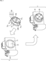
カメラシステム1は、カメラ本体10と多眼交換レンズ20(レンズ部)とで構成される。
The
カメラ本体10は、多眼交換レンズ20が着脱可能なようになっている。すなわち、カメラ本体10は、カメラマウント11を有し、そのカメラマウント11に対して、多眼交換レンズ20(のレンズマウント22)が固定される(取り付けられる)ことで、カメラ本体10に、多眼交換レンズ20が装着される。なお、カメラ本体10に対しては、多眼交換レンズ20以外の一般的な交換レンズも着脱することができる。
A multi-lens
カメラ本体10は、イメージセンサ51を内蔵する。イメージセンサ51は、例えば、CMOS(Complementary Metal Oxide Semiconductor)イメージセンサであり、カメラ本体10(のカメラマウント11)に装着された多眼交換レンズ20その他の交換レンズによって集光される光線を受光して光電変換を行うことにより画像を撮像する。以下、イメージセンサ51の撮像により得られる画像を、撮像画像ともいう。
The
多眼交換レンズ20は、鏡筒21、レンズマウント22、及び、繰り出し部23を有する。繰り出し部23は、鏡筒21に対し、鏡筒21の光軸に沿って移動可能に構成された可動部である。繰り出し部23は、複数としての5個の個眼レンズ310,311,312,313、及び、314を有する。複数の個眼レンズ31iは、繰り出し部23と一体となって移動可能に構成され、各個眼レンズ31iを介して出射される撮像光の出射位置が互いに重ならないように配置される。さらに、繰り出し部23は、光源32L及び32Rを有する。光源32L及び32Rは、繰り出し部23及び複数の個眼レンズ31iと一体となって鏡筒21の光軸に沿って移動可能に構成され、カメラ本体10に設けられたイメージセンサ51に照射する照射光の出射位置が、複数の個眼レンズ31iのそれぞれの撮像光の出射位置と重ならないように配置される。The multi-lens
鏡筒21は、略円筒状をしており、その円筒状の1つの底面側に、レンズマウント22が形成されている。
The
レンズマウント22は、多眼交換レンズ20がカメラ本体10に装着されるときに、カメラ本体10のカメラマウント11に固定される(取り付けられる)。
The
繰り出し部23は、略円柱形状をしており、円筒状の鏡筒21内に収納されている。
The feeding
繰り出し部23には、鏡筒21全体の光軸(鏡筒光軸)の光軸方向に(見て)重ならないように配置された複数としての5個のレンズである個眼レンズ310,311,312,313、及び、314が設けられている。図1では、5個の個眼レンズ310ないし314が、鏡筒光軸に直交する(イメージセンサ51の受光面(撮像面)に平行な)2次元平面上において、個眼レンズ310を中心(重心)として、他の4個の個眼レンズ311ないし314が、正方形の頂点を構成するように配置される形で、繰り出し部23に設けられている。In the feeding
個眼レンズ310ないし314は、多眼交換レンズ20がカメラ本体10に装着されたときに、被写体からの光線をカメラ本体10のイメージセンサ51に集光させる。The monocular lenses 31 0 to 31 4 condense light rays from a subject onto the
なお、ここでは、カメラ本体10は、1個のイメージセンサ51を有する、いわゆる単板式のカメラであるが、カメラ本体10としては、複数のイメージセンサ、すなわち、例えば、RGB(Red, Green, Blue)それぞれ用の3つのイメージセンサを有する、いわゆる3板式のカメラを採用することができる。3板式のカメラでは、個眼レンズ310ないし314が出射する光線は、プリズム等の光学系を利用して、3つのイメージセンサのそれぞれに集光される。なお、3板式に限らず2板式等イメージセンサの数は3つ以外でも良い。また、各イメージセンサはRGBそれぞれ用のものに限らず全てモノクロであっても良いし、全てがベイヤー配列などのカラーフィルタを備えたものであっても良い。Here, the
繰り出し部23には、5個の個眼レンズ310ないし314の他、複数である2個の光源32L及び32Rが設けられている。光源32L及び32Rは、多眼交換レンズ20を正面から見たときに、繰り出し部23の右端及び左端の位置に、それぞれ設けられている。The
光源32L及び32Rは、例えば、LED(Light Emitting Diode)やレーザ等で構成され、多眼交換レンズ20の正面側(光線が入射する側)から背面側に向かってスポット光を照射する。
The
したがって、多眼交換レンズ20がカメラ本体10に装着された場合、光源32L及び32Rが照射するスポット光は、カメラ本体10のイメージセンサ51で受光される。
Therefore, when the multi-lens
繰り出し部23には、以上のように、個眼レンズ310ないし314とともに、光源32L及び32Rが設けられている。As described above, the
繰り出し部23は、円筒状の鏡筒21の内部を、鏡筒光軸の光軸方向に移動(スライド)可能なように構成され、これにより、鏡筒21内を、正面側に繰り出すこと(奥側に引っ込むこと)ができる。
The
したがって、多眼交換レンズ20は、繰り出し部23に設けられた個眼レンズ310ないし314と光源32L及び32Rとが一体的に繰り出す構成になっている。Therefore, the multi-lens
以上のように、個眼レンズ310ないし314と光源32L及び32Rとが一体的に繰り出すので、カメラシステム1では、適切な処理を行うことができる。As described above, since the monocular lenses 310 to 314 and the
すなわち、イメージセンサ51が撮像する撮像画像には、光源32L及び32Rが照射するスポット光の像であるスポット光像が映り、そのスポット光像は、後述するように、多眼交換レンズ20の取り付け誤差を求めることに用いることができる。
That is, the captured image captured by the
多眼交換レンズ20において、個眼レンズ310ないし314は、繰り出し部23に設けられることにより、繰り出し部23とともに繰り出し、これにより、例えば、望遠撮影やマクロ撮影等を行うためのフォーカスの調整を行うことができる。In the multi-lens
この場合、光源32L及び32Rが、多眼交換レンズ20の繰り出し部23以外の部分に設けられていると、個眼レンズ310ないし314が繰り出しても、光源32L及び32Rは繰り出さない。そして、そのような光源32L及び32Rが照射するスポット光のスポット光像を用いるのでは、個眼レンズ310ないし314の繰り出しによって変化する取り付け誤差を精度良く求めることが困難となる。In this case, if the
これに対して、個眼レンズ310ないし314と光源32L及び32Rとが一体的に繰り出す場合には、スポット光像を用いて、個眼レンズ310ないし314の繰り出しによって変化する取り付け誤差を精度良く求める適切な処理を行うことができる。On the other hand, when the ommatidia lenses 31 0 to 31 4 and the
さらに、撮像画像上の、個眼レンズ310ないし314それぞれにより集光される光線により形成される像に対応する個眼画像の領域が、個眼レンズ310ないし314の繰り出しにより変化しても、個眼画像の領域を精度良く特定する適切な処理を行うことができる。Furthermore, the area of the ommatidia image corresponding to the image formed by the light rays condensed by the ommatidia lenses 31 0 to 31 4 on the captured image changes as the ommatidia lenses 31 0 to 31 4 are extended. Even in the case of an ommatidia image, appropriate processing can be performed to accurately identify the area of the ommatidia image.
また、個眼レンズ310ないし314の繰り出しによって変化するレンズ歪みの影響を抑制するキャリブレーションデータを求め、さらには、そのようなキャリブレーションデータを用いて、レンズ歪みの影響を抑制した視差情報を求める等の適切な処理を行うことができる。In addition, calibration data that suppresses the influence of lens distortion that changes as the ommatidia lenses 31 0 to 31 4 are extended is obtained, and furthermore, using such calibration data, parallax information that suppresses the influence of lens distortion is obtained. Appropriate processing such as requesting the following information can be performed.
なお、図1では、多眼交換レンズ20に、5個の個眼レンズ310ないし314が設けられているが、多眼交換レンズ20に設ける個眼レンズの数は、5個に限定されるものではなく、2個や3個、6個以上の任意の複数の数を採用することができる。In addition, in FIG. 1, the multi-lens
さらに、多眼交換レンズ20に設ける複数の個眼レンズは、正方形の中心と頂点の位置に配置する他、2次元平面上の任意の位置に配置することができる。
Furthermore, the plurality of monocular lenses provided in the multi-lens
また、多眼交換レンズ20に設ける複数の個眼レンズとしては、焦点距離やF値、その他の仕様が異なる複数のレンズを採用することができる。但し、ここでは、説明を簡単にするため、仕様が同一の複数のレンズを採用することとする。
Further, as the plurality of monocular lenses provided in the multi-lens
さらに、図1では、多眼交換レンズ20に、2個の光源32L及び32Rが設けられているが、多眼交換レンズ20に設ける光源の数は、2個に限定されるものではなく、必要に応じて、1個や、3個以上の任意の数を採用することができる。
Furthermore, in FIG. 1, the multi-lens
また、多眼交換レンズ20に、複数としての、例えば、2個の光源32L及び32Rを設ける場合には、その2個の光源32L及び32Rは、多眼交換レンズ20の、5個の個眼レンズ310ないし314が配置された平面上、すなわち、図1では、略円柱形の繰り出し部23を正面から見た円上の最も遠い2点を結ぶ線上に配置することができる。この場合、光源32L及び32Rは、繰り出し部23を正面から見た円の中心を通る線上に配置される。後述するように、光源32L及び32Rは、なるべく離して配置することが望ましい。光源32L及び32Rを、繰り出し部23を正面から見た円の中心を通る線上に配置することにより、光源32L及び32Rを最も離して配置することができる。Further, when the multi-lens
多眼交換レンズ20において、複数としての5個の個眼レンズ310ないし314それぞれは、多眼交換レンズ20がカメラ本体10に装着されたときに、個眼レンズ31iの光軸(個眼光軸)がイメージセンサ51の受光面と直交するように配置されている。In the multi-lens
かかる多眼交換レンズ20がカメラ本体10に装着されたカメラシステム1では、イメージセンサ51において、5個の個眼レンズ310ないし314それぞれにより集光される光線によりイメージセンサ51の受光面上に形成される像に対応する画像が撮像される。In the
いま、1個の個眼レンズ31i(ここでは、i=0,1,2,3,4)により集光される光線により形成される像に対応する画像を、個眼画像ということとすると、1個のイメージセンサ51で撮像される撮像画像には、5個の個眼レンズ310ないし314それぞれに対する5個の個眼画像(個眼レンズ310ないし314それぞれにより集光される光線により形成される像に対応する画像)が含まれる。Now, let us say that the image corresponding to the image formed by the light rays condensed by one ommatidia lens 31 i (here, i=0, 1, 2, 3, 4) is an ommatidia image. , the captured image captured by one
個眼レンズ31iに対する個眼画像は、個眼レンズ31iの位置を視点とする画像であり、したがって、個眼レンズ310ないし314それぞれに対する5個の個眼画像は、異なる視点の画像である。The ommatidia image for the ommatidia lens 31 i is an image whose viewpoint is the position of the ommatidia lens 31 i , and therefore, the five ommatidia images for each ommatidia lens 31 0 to 31 4 are images from different viewpoints. It is.
さらに、撮像画像には、2個の光源32L及び32Rそれぞれが照射するスポット光に対応する画像であるスポット光像(スポット光により形成される像)が含まれる。
Furthermore, the captured image includes a spot light image (an image formed by spot light) that is an image corresponding to the spot light emitted by each of the two
ここで、図1のカメラシステム1は、カメラ本体10と、カメラ本体10に着脱可能な多眼交換レンズ20とで構成されるが、本技術は、多眼交換レンズ20がカメラ本体10に固定された、いわばレンズ一体型のカメラシステムにも適用することができる。すなわち、本技術は、例えば、レンズ一体型のカメラに適用することができる。
Here, the
また、1つの個眼レンズ31iは、1枚のレンズで構成する他、複数枚のレンズを鏡筒光軸の光軸方向に並べて構成することができる。Moreover, one monocular lens 31 i can be configured not only by one lens but also by arranging a plurality of lenses in the optical axis direction of the lens barrel optical axis.
さらに、カメラ本体10の後述する領域特定部52、画像処理部53、位置算出部57、スポット光像検出部62、及び、繰り出し量検出部64の処理の一部又は全部は、カメラ本体10以外、例えば、クラウド上のサーバや再生専用機器等で行うことができる。
Further, part or all of the processing of the
また、多眼交換レンズ20の繰り出し部23の繰り出しによれば、フォーカスを調整する他、ズーム倍率を調整することができる。以下では、説明を簡単にするため、繰り出し部23の繰り出しにより、フォーカスが調整されることとする。
Further, by extending the extending
なお、カメラ本体10については、多眼交換レンズ20が装着される側の面、すなわち、カメラマウント11がある面を、正面とする。
Note that, regarding the
<カメラシステム1の電気的構成例>
<Example of electrical configuration of
図2は、図1のカメラシステム1の電気的構成例を示すブロック図である。
FIG. 2 is a block diagram showing an example of the electrical configuration of the
カメラシステム1において、多眼交換レンズ20は、記憶部41、通信部42、及び、制御部43を有する。
In the
記憶部41は、多眼交換レンズ20に関する情報であるレンズ情報を記憶している。レンズ情報には、個体差反映位置情報(既知基準位置)が含まれる。
The
個体差反映位置情報とは、例えば、多眼交換レンズ20がカメラ本体10に装着されたときに(1個の)イメージセンサ51で撮像された既知の距離にある所定の被写体が映る既知撮像画像上の個眼レンズ31iに対する個眼画像上の所定の光線に対応する位置に関する位置情報である。個体差反映位置情報は、多眼交換レンズ20の製造時の製造誤差(製造バラツキ)に起因して、多眼交換レンズ20の個体ごとに異なる量だけ(設計上の位置から)ずれる、所定の光線の、イメージセンサ51への入射位置に関する位置情報であるということができ、多眼交換レンズ20の製造時の個体ごとに異なる製造誤差(による個眼レンズ31iから出射される撮像光の出射位置のずれ)を含む位置情報である。個体差反映位置情報としては、例えば、多眼交換レンズ20がカメラ本体10に装着されたときにイメージセンサ51で撮像された既知の距離にある所定の被写体が映る既知撮像画像上の個眼レンズ31iに対する個眼画像上の所定の光線に対応する位置そのものを採用することができる。The individual difference reflecting position information is, for example, a known captured image in which a predetermined subject at a known distance is captured by (one)
ここで、個眼レンズ31iに対する個眼画像において、個眼レンズ31iの光軸(個眼光軸)を通る光線の像が形成される位置を光軸中心位置ということとする。なお、個眼光軸は、鏡筒21全体の光軸(鏡筒光軸)と平行であったり、距離が一定に定められて配置されているはずだがずれが生じる。Here, in the ommatidia image for the ommatidia lens 31 i , the position where the image of the light ray passing through the optical axis (ommatidium optical axis) of the ommatidia lens 31 i is formed is referred to as the optical axis center position. Note that although the ommatidia optical axis is supposed to be parallel to the optical axis of the entire lens barrel 21 (lens barrel optical axis) or arranged at a constant distance, a deviation occurs.
いま、個眼レンズ31iに対する個眼画像について、所定の光線として、例えば、個眼レンズ31iの個眼光軸を通る光線を採用することとすると、個眼レンズ31iに対する個眼画像の個体差反映位置情報は、その個眼画像の光軸中心位置である。Now, for the ommatidia image for the ommatidia lens 31 i , if we adopt, for example, a light ray passing through the ommatidia optical axis of the ommatidia lens 31 i as the predetermined light ray, the individual ommatidia image for the ommatidia lens 31 i The difference reflection position information is the optical axis center position of the ommatidia image.
なお、所定の光線は、個眼レンズ31iの個眼光軸を通る光線に限定されるものではない。すなわち、所定の光線としては、例えば、個眼レンズ31iの個眼光軸から所定の距離だけ離れた位置を通り、個眼光軸に平行な光線その他を採用することができる。Note that the predetermined light ray is not limited to a light ray that passes through the ommatidia optical axis of the ommatidia lens 31 i . That is, the predetermined light ray may be, for example, a light ray that passes through a position a predetermined distance away from the ommatidia optical axis of the ommatidia lens 31 i and is parallel to the ommatidia optical axis.
レンズ情報には、既知撮像画像上の、個眼レンズ31iに対する個眼画像の個体差反映位置情報の他、既知撮像画像上の光源32L及び32Rそれぞれのスポット光のスポット光像の位置に関する個体差スポット光位置情報(既知光位置)が含まれる。個体差スポット光位置情報としては、既知撮像画像上の光源32L及び32Rそれぞれのスポット光のスポット光像の位置そのものを採用することができる。個体差スポット光位置情報は、個体差反映位置情報と同様に、多眼交換レンズ20の製造時の個体ごとに異なる製造誤差を含む位置情報である。The lens information includes individual difference reflecting position information of the ommatidia image with respect to the ommatidia lens 31 i on the known captured image, as well as individual information regarding the position of the spot light image of each of the
ここで、多眼交換レンズ20に対しては、ユニークなレンズID(Identification)を割り当て、記憶部41に記憶させるレンズ情報としては、多眼交換レンズ20のレンズIDを採用することができる。さらに、この場合、レンズ情報としてのレンズIDと、そのレンズIDによって特定される多眼交換レンズ20の、レンズID以外のレンズ情報としての個体差反映位置情報や個体差スポット光位置情報等とを対応付けたデータベースを用意することができる。この場合、レンズIDをキーワードとして、データベースを検索することにより、そのレンズIDに対応付けられた多眼交換レンズ20の個体差反映位置情報や個体差スポット光位置情報等を取得することができる。
Here, a unique lens ID (Identification) can be assigned to the multi-lens
通信部42は、カメラ本体10の後述する通信部56との間で、有線又は無線による通信を行う。なお、通信部42は、その他、必要に応じて、任意の通信方式により、インターネット上のサーバや、有線又は無線LAN(Local Area Network)上のPC(Personal Computer)、その他の外部のデバイスとの間で通信を行うようにすることができる。
The
通信部42は、例えば、多眼交換レンズ20がカメラ本体10に装着された場合や多眼交換レンズ20がカメラ本体10に装着された状態で電源が入れられた場合に、カメラ本体10の通信部56と通信することで、記憶部41に記憶されたレンズ情報を、通信部56に送信する。
The
また、通信部42は、通信部56から送信されてくるコマンドその他の情報を受信し、制御部43に供給する。制御部43は、通信部42からの情報に応じて、繰り出し部23を繰り出す(移動する)ことによるフォーカスの調整等の多眼交換レンズ20の制御を行う。
The
カメラ本体10は、イメージセンサ51、領域特定部52、画像処理部53、表示部54、記憶部55、通信部56、位置算出部57、制御部61、スポット光像検出部62、繰り出し量情報記憶部63、繰り出し量検出部64を有する。
The
イメージセンサ51は、例えば、図1で説明したように、CMOSイメージセンサであり、イメージセンサ51の受光面には、カメラ本体10に装着された多眼交換レンズ20の個眼レンズ310ないし314それぞれにより集光される光線、並びに、光源32L及び32Rが照射するスポット光としての光線が照射される。The
イメージセンサ51は、個眼レンズ310ないし314それぞれにより集光される光線、並びに、光源32L及び32Rが照射するスポット光としての光線を受光して光電変換を行うことにより、個眼レンズ310ないし314それぞれに対する個眼画像(個眼レンズ310ないし314それぞれにより集光される光線により形成される像に対応する個眼画像)、並びに、光源32L及び32Rそれぞれのスポット光のスポット光像を含む撮像画像を撮像して出力する。イメージセンサ51が出力する撮像画像(他の撮像画像)は、領域特定部52、位置算出部57、スポット光像検出部62に供給される。The
領域特定部52には、イメージセンサ51が出力する撮像画像が供給される他、位置算出部57から、イメージセンサ51が出力する撮像画像に含まれる個眼画像上の位置情報としての装着誤差反映位置情報(未知基準位置)が供給される。
The
装着誤差反映位置情報とは、例えば、多眼交換レンズ20をカメラ本体10に装着した状態の(1個の)イメージセンサ51で任意の被写体(被写体までの距離が既知であるどうかは問わない)を撮像して得られる撮像画像(他の撮像画像)上の個眼レンズ31iに対する個眼画像上の所定の光線に対応する位置に関する位置情報である。装着誤差反映位置情報は、多眼交換レンズ20の装着時に、その多眼交換レンズ20の装着誤差に起因してずれる、所定の光線の、イメージセンサ51への入射位置に関する位置情報であるということができ、多眼交換レンズ20の使用時の装着誤差(による個眼レンズ31iから出射される撮像光の出射位置のずれ)を含む位置情報である。The mounting error reflection position information is, for example, when the multi-lens
装着誤差とは、多眼交換レンズ20がカメラ本体10に着脱可能になっていることに起因して生じる多眼交換レンズ20の取り付け位置(装着位置)のずれを表す。装着誤差は、例えば、多眼交換レンズ20を装着するごとに変化し得る。また、装着誤差は、例えば、多眼交換レンズ20をカメラ本体10に装着したカメラシステム1に衝撃が加わったときに変化することがある。
The mounting error refers to a shift in the mounting position (mounting position) of the multi-lens
装着誤差反映位置情報は、装着誤差の他、製造誤差をも含む位置情報(製造誤差及び装着誤差による個眼レンズ31iから出射される撮像光の出射位置のずれを含む位置情報)である。The positional information reflecting the mounting error is positional information that includes not only the mounting error but also the manufacturing error (positional information that includes the shift in the output position of the imaging light emitted from the monocular lens 31 i due to the manufacturing error and the mounting error).
ここで、個体差反映位置情報として、例えば、撮像画像が既知の距離にある被写体を撮像した既知撮像画像である場合の、その既知撮像画像に含まれる個眼画像上の光軸中心位置を採用する場合には、装着誤差反映位置情報としては、任意の被写体(被写体までの距離が既知であるどうかは問わない)を撮像した撮像画像(他の撮像画像)に含まれる個眼画像上の光軸中心位置を採用することができる。 Here, as the individual difference reflecting position information, for example, when the captured image is a known captured image of a subject at a known distance, the optical axis center position on the ommatidia image included in the known captured image is used. In this case, the mounting error reflection position information is the light on the ommatidia image included in the captured image (other captured images) of an arbitrary subject (regardless of whether the distance to the subject is known or not). An axis center position can be adopted.
領域特定部52は、位置算出部57からの装着誤差反映位置情報に応じて、イメージセンサ51からの撮像画像上の、個眼レンズ310ないし314それぞれに対する個眼画像の領域を特定し、その領域の特定の結果を表す領域特定結果情報を出力する。The
すなわち、領域特定部52は、イメージセンサ51からの撮像画像の、例えば、撮像画像の装着誤差反映位置情報を中心(重心)とする所定のサイズの長方形状の領域を、個眼画像の領域に特定する。
That is, the
ここで、領域特定部52は、例えば、撮像画像全体と、その撮像画像全体上の各個眼画像の領域を表す領域情報とのセットを、領域特定結果情報として出力することができる。また、領域特定部52は、撮像画像から、各個眼画像を抽出し(切り出し)、その各個眼画像を、領域特定結果情報として出力することができる。なお、各個眼画像は、領域情報とセットにして出力することができる。
Here, the
以下では、説明を簡単にするため、例えば、領域特定部52は、撮像画像から抽出した各個眼画像(個眼レンズ310ないし314それぞれに対する個眼画像)を、領域特定結果情報として出力することとする。In the following, to simplify the explanation, for example, the
領域特定部52が出力する個眼レンズ310ないし314それぞれに対する個眼画像は、画像処理部53に供給される。The ommatidia images for each of the ommatidia lenses 31 0 to 31 4 output by the
画像処理部53は、後述するスポット光像検出部62の検出結果に応じて、処理を行う処理部の一部である。画像処理部53は、領域特定部52からの個眼レンズ310ないし314それぞれに対する個眼画像、すなわち、個眼レンズ310ないし314それぞれの位置を視点とする、異なる視点の個眼画像や、繰り出し量検出部64から供給される繰り出し部23の繰り出し量を用いて、例えば、視差情報の生成や、任意の被写体にフォーカスを合わせた画像を生成(再構成)するリフォーカス等の画像処理を行い、その画像処理の結果得られる処理結果画像を、表示部54及び記憶部55に供給する。The
なお、画像処理部53では、その他、欠陥補正や、ノイズリダクション等の一般的な画像処理を行うことができる。また、画像処理部53では、記憶部55に保存する(記憶させる)画像と、表示部54にいわゆるスルー画として表示するだけの画像とのいずれをも、画像処理の対象とすることができる。
Note that the
表示部54は、例えば、液晶パネルや有機EL(Electro Luminescence)パネル等で構成され、カメラ本体10の背面に設けられている。表示部54は、例えば、画像処理部53から供給される処理結果画像等を、スルー画として表示する。スルー画としては、処理結果画像の他、イメージセンサ51で撮像された撮像画像の全部又は一部や、撮像画像から抽出された個眼画像を表示することができる。その他、表示部54は、例えば、メニュー、カメラ本体10の設定等の情報を表示することができる。
The
記憶部55は、図示せぬメモリカード等で構成され、例えば、ユーザの操作等に応じて、画像処理部53から供給される処理結果画像を記憶する。
The
通信部56は、多眼交換レンズ20の通信部42等との間で、有線又は無線による通信を行う。なお、通信部56は、その他、必要に応じて、任意の通信方式により、インターネット上のサーバや、有線又は無線LAN上のPC、その他の外部のデバイスとの間で通信を行うことができる。
The
通信部56は、例えば、多眼交換レンズ20がカメラ本体10に装着されたときに、多眼交換レンズ20の通信部42と通信することで、その通信部42から送信されてくる多眼交換レンズ20のレンズ情報を受信し、位置算出部57及びスポット光像検出部62に供給する。
For example, when the multi-lens
また、通信部56は、例えば、制御部61からのフォーカス(位置)を指定する情報等を、通信部42に送信する。
Further, the
位置算出部57は、通信部56からのレンズ情報に含まれる個体差反映位置情報に応じて、イメージセンサ51から供給される撮像画像に含まれる個眼レンズ31iに対する個眼画像上の光軸中心位置である装着誤差反映位置情報を求め、領域特定部52に供給する。The position calculation unit 57 determines the optical axis on the ommatidia image for the ommatidia lens 31 i included in the captured image supplied from the
なお、図2において、位置算出部57は、イメージセンサ51から供給される撮像画像に含まれる個眼画像上の光軸中心位置である装着誤差反映位置情報を求めるにあたり、レンズ情報に含まれる個体差反映位置情報の他、個体差スポット光位置情報を用いる。
Note that in FIG. 2, the position calculation unit 57 calculates the mounting error reflection position information, which is the optical axis center position on the ommatidia image included in the captured image supplied from the
制御部61は、フォーカスを調整するユーザの操作等に応じて、フォーカス等を制御する。例えば、制御部61は、ユーザの操作に応じて、フォーカスを指定する情報を、通信部56に供給する。
The
スポット光像検出部62は、光源32L及び32Rから照射されるスポット光のイメージセンサ51への入射範囲を検出し、検出結果を、繰り出し量検出部64に供給する。
The spot light
すなわち、スポット光像検出部62は、通信部56からのレンズ情報に含まれる個体差スポット光位置情報に応じて、イメージセンサ51からの撮像画像上のスポット光像を検出する。さらに、スポット光像検出部62は、スポット光像の(スポット)サイズや位置(検出光像位置)等のスポット光像に関するスポット光像情報を検出(生成)し、スポット光像の検出結果として出力する。スポット光像検出部62が出力するスポット光像情報は、スポット光像検出部62の検出結果に応じて処理を行う処理部の他の一部である繰り出し量検出部64に供給される。スポット光像情報としては、撮像画像上のスポット光像のサイズや位置を直接的に表す情報(例えば、サイズや位置そのもの)の他、撮像画像上のスポット光像のサイズや位置を間接的に表す情報(例えば、撮像画像上のスポット光像のサイズ及び位置を維持した状態で、スポット光像が映る画像等)を採用することができる。
That is, the spot light
繰り出し量情報記憶部63は、繰り出し量情報を記憶する。繰り出し量情報とは、繰り出し部23の繰り出し量と、その繰り出し量だけ繰り出し部23が繰り出しているときのスポット光像に関するスポット光像情報とを対応付けた情報である。繰り出し量情報は、あらかじめ生成し、繰り出し量情報記憶部63に記憶させておくことができる。また、繰り出し量情報は、例えば、多眼交換レンズ20と工場から出荷する前等に、あらかじめ生成し、レンズ情報の一部として、記憶部41に記憶させておくことができる。繰り出し量情報を、レンズ情報の一部として、記憶部41に記憶させておく場合には、通信部56が、通信部42と通信を行うことで、記憶部41に記憶されたレンズ情報を取得し、そのレンズ情報に含まれる繰り出し量情報を、繰り出し量情報記憶部63に供給して記憶させる。
The feeding amount
繰り出し量検出部64は、繰り出し量情報記憶部63に記憶された繰り出し量情報において、スポット光像検出部62からのスポット光像情報に対応付けられている繰り出し部23の繰り出し量を検出し、画像処理部53に供給する。
The feeding
<多眼交換レンズ20を用いて行われる撮像の概要>
<Overview of imaging performed using the multi-lens
図3は、多眼交換レンズ20を用いて行われる撮像画像の撮像の概要を説明する図である。
FIG. 3 is a diagram illustrating an overview of capturing images performed using the multi-lens
多眼交換レンズ20が装着されたカメラ本体10のイメージセンサ51では、各個眼レンズ31iにおいて光線が集光されることにより形成される像に対応する個眼画像と、光源32L及び32Rが照射するスポット光のスポット光像とを含む撮像画像が撮像される。The
ここで、本明細書では、個眼レンズ31iの個眼光軸の光軸方向のうちの、カメラ本体10の背面側から正面側に向かう方向をz方向(軸)とするとともに、z方向を向いたときの左から右方向をx方向とし、下から上方向をy方向とする。Here, in this specification, among the optical axis directions of the ommatidia optical axis of the ommatidia lens 31 i , the direction from the back side to the front side of the
さらに、画像に映る被写体の左右と、実空間の被写体の左右とを一致させるとともに、個眼レンズ31iの位置の左右と、その個眼レンズ31iに対する個眼画像の撮像画像上の左右とを一致させるため、以下では、特に断らない限り、z方向、すなわち、カメラ本体10の裏面側から、撮像を行う被写体が存在する撮像方向を向いている状態を基準として、撮像画像上の位置や、個眼レンズ31iの位置、被写体等の左右を記述する。Furthermore, the left and right sides of the subject reflected in the image are matched with the left and right sides of the subject in real space, and the left and right sides of the position of the monocular lens 31 i and the left and right sides of the monocular image for the monocular lens 31 i on the captured image are In order to make the images consistent, in the following, unless otherwise specified, the position on the captured image and , the position of the monocular lens 31 i , the left and right sides of the subject, etc. are described.
なお、1の個眼レンズ31iと他の1の個眼レンズ31j(i≠j)との個眼光軸どうしを結ぶ直線又は線分を、基線ともいい、その個眼光軸どうしの距離を、基線長ともいう。また、基線の方向を表す角度を、基線角ともいう。ここでは、基線角として、例えば、x軸と基線とがなす角度(エピポーラ線の角度)を採用することとする。Note that the straight line or line segment connecting the ommatidia optical axes of one ommatidia 31 i and the other ommatidia 31 j (i≠j) is also referred to as a base line, and the distance between the ommatidia optical axes is , also called baseline length. Further, the angle representing the direction of the baseline is also referred to as the baseline angle. Here, as the baseline angle, for example, the angle between the x-axis and the baseline (the angle of the epipolar line) is adopted.
また、本明細書(及び請求の範囲)において、繰り出し部23の繰り出しとは、広く、繰り出し部23が鏡筒光軸の光軸方向に移動することを意味する。したがって、繰り出し部23の繰り出しとは、繰り出し部が、手前側に移動すること、及び、奥側に移動することのいずれをも含む。
Further, in this specification (and claims), the term "feeding out the feeding
図4は、多眼交換レンズ20における個眼レンズ310ないし314並びに光源32L及び32Rの配置と、その多眼交換レンズ20を用いて撮像される撮像画像との例を示す図である。FIG. 4 is a diagram showing an example of the arrangement of the monocular lenses 31 0 to 31 4 and the
図4のAは、多眼交換レンズ20における個眼レンズ310ないし314並びに光源32L及び32Rの配置の例を示す背面図である。FIG. 4A is a rear view showing an example of the arrangement of the monocular lenses 31 0 to 31 4 and the
図4のAでは、個眼レンズ310ないし314は、図1で説明したように、イメージセンサ51の受光面に平行な2次元平面において、個眼レンズ310を中心として、他の4個の個眼レンズ311ないし314が、正方形の頂点を構成するように配置されている。In A of FIG . 4 , as explained in FIG . The individual lenses 31 1 to 31 4 are arranged to form the vertices of a square.
すなわち、個眼レンズ310ないし314のうちの、例えば、個眼レンズ310を基準とすると、図4では、個眼レンズ311は、個眼レンズ310の右上に配置され、個眼レンズ312は、個眼レンズ310の左上に配置されている。さらに、個眼レンズ313は、個眼レンズ310の左下に配置され、個眼レンズ314は、個眼レンズ310の右下に配置されている。That is, if, for example, the ommatidia lens 31 0 of the ommatidia lenses 31 0 to 31 4 is used as a reference, in FIG . The lens 31 2 is arranged at the upper left of the ommatidia lens 31 0 . Further, the monocular lens 31 3 is arranged at the lower left of the monocular lens 31 0 , and the monocular lens 31 4 is arranged at the lower right of the monocular lens 31 0 .
また、図4のAにおいて、光源32Lは、平面が略円形の多眼交換レンズ20の左端の位置に配置され、光源32Rは、平面が略円形の多眼交換レンズ20の中心(中央)に対して、光源32Lの反対側の右端の位置に配置されている。
In addition, in A of FIG. 4, the
なお、光源32L及び32Rは、多眼交換レンズ20(の繰り出し部23)の任意の異なる位置に配置することができる。
Note that the
但し、光源32L及び32Rは、イメージセンサ51で撮像される撮像画像上の、光源32L及び32Rそれぞれが照射するスポット光のスポット光像PL及びPRが、撮像画像に含まれる個眼画像の領域外(個眼レンズ31iを通過した光が照射される範囲外)に位置するように配置することができる。この場合、スポット光像PLやPRが、個眼画像に重複して映って、個眼画像の画質が低下することを抑制することができる。However, the
図4のBは、図4のAのように個眼レンズ310ないし314並びに光源32L及び32Rが配置された多眼交換レンズ20が装着されたカメラ本体10のイメージセンサ51で撮像される撮像画像の例を示す図である。4B is imaged by the
個眼レンズ310ないし314並びに光源32L及び32Rを有する多眼交換レンズ20が装着されたカメラ本体10のイメージセンサ51で撮像される撮像画像には、個眼レンズ310ないし314それぞれにより集光される光線により形成される像に対応する個眼画像E0,E1,E2,E3,E4と、光源32L及び32Rそれぞれのスポット光のスポット光像PL及びPRとが含まれる。The image captured by the
領域特定部52(図2)は、位置算出部57で求められる各個眼画像E#iの装着誤差反映位置情報である光軸中心位置に基づき、各個眼レンズ31iについて、その個眼レンズ31iを通過した光線が照射される撮像画像上の領域のうちの、個眼画像E#iの装着誤差反映位置情報である光軸中心位置を中心とする所定サイズの長方形状の領域を、個眼画像E#iの領域として特定する。The area specifying unit 52 (FIG. 2) determines the location of each ommatidia lens 31 for each ommatidia lens 31 i based on the optical axis center position which is the mounting error reflection position information of each ommatidia image E#i obtained by the position calculation unit 57. A rectangular area of a predetermined size centered on the optical axis center position, which is the mounting error reflection position information of the ommatidia image E#i, of the area on the captured image that is irradiated with the light beam that has passed through i . Specify as the area of eye image E#i.
これにより、個眼レンズ31iに対する個眼画像E#iは、個眼レンズ31iの位置から、独立のカメラや独立のイメージセンサを用いた撮像を行うことにより得られる撮像画像、すなわち、個眼レンズ31iの位置を視点とする撮像により得られる画像と同様の画像になる。As a result, the ommatidia image E#i for the ommatidia lens 31 i is a captured image obtained by capturing an image using an independent camera or an independent image sensor from the position of the ommatidia lens 31 i . The resulting image is similar to the image obtained by imaging using the position of the eye lens 31 i as a viewpoint.
そのため、個眼レンズ310ないし314それぞれに対する個眼画像E0ないしE4のうちの任意の2個の個眼画像E#iとE#jとの間には、視差が生じる。すなわち、個眼画像E#iとE#jに映る同一の被写体は、視差に応じてずれた位置に映る。Therefore, a parallax occurs between any two ommatidia images E#i and E#j of the ommatidia images E0 to E4 for the ommatidia lenses 31 0 to 31 4 , respectively. That is, the same subject appearing in the ommatidia images E#i and E#j appears at shifted positions according to the parallax.
<多眼交換レンズ20の取り付け誤差>
<Installation error of multi-lens
図5は、多眼交換レンズ20をカメラ本体10に取り付けた(装着した)ときの取り付け誤差を説明する図である。
FIG. 5 is a diagram illustrating an attachment error when the multi-lens
すなわち、図5は、多眼交換レンズ20をカメラ本体10に取り付けたカメラシステム1で撮像される撮像画像の例を示している。
That is, FIG. 5 shows an example of a captured image captured by the
多眼交換レンズ20をカメラ本体10に取り付けた場合、カメラ本体10のイメージセンサ51の受光面に対する多眼交換レンズ20の取り付け位置は、主として、横方向(x方向)、縦方向(y方向)、及び、回転方向のうちの、特に、回転方向にずれ得る。まず、多眼交換レンズ20の取り付け位置は、製造誤差により個体ごとに異なる量だけずれる。さらに、多眼交換レンズ20の取り付け位置は、多眼交換レンズ20の使用時に、多眼交換レンズ20をカメラ本体10に取り付けるときや、多眼交換レンズ20をカメラ本体10に取り付けたカメラシステム1に衝撃が加わったとき等に変化する。
When the multi-lens
いま、例えば、多眼交換レンズ20の設計上の取り付け位置等の所定の位置に対する実際の取り付け位置の誤差を、取り付け誤差ということとする。設計上の取り付け位置を基準とする取り付け誤差は、製造バラツキ等により生じ、多眼交換レンズ20をカメラ本体10に取り付けるときや、多眼交換レンズ20をカメラ本体10に取り付けたカメラシステム1に衝撃が加わったとき等に変化する。
For example, the error in the actual mounting position relative to a predetermined position such as the designed mounting position of the multi-lens
取り付け誤差は、多眼交換レンズ20の実際の取り付け位置の誤差であり、製造誤差及び装着誤差を適宜含む。例えば、多眼交換レンズ20の設計上の取り付け位置を基準とする場合、取り付け誤差は、製造誤差及び装着誤差の両方を含む。また、例えば、多眼交換レンズ20の設計上の取り付け位置から製造誤差だけすれた位置を基準とする場合、取り付け誤差は、製造誤差を含まず、装着誤差を含む。
The attachment error is an error in the actual attachment position of the multi-lens
図4で説明したように、個眼画像E#iは、個眼レンズ31iの位置を視点とする撮像により得られる画像と同様の画像であり、したがって、個眼画像E0ないしE4は、視点の異なる画像である。As explained in FIG. 4, the ommatidia image E#i is an image similar to the image obtained by imaging with the position of the ommatidia lens 31 i as a viewpoint, and therefore the ommatidia images E0 to E4 are These are different images.
視点の異なる画像である個眼画像E0ないしE4を用いて、例えば、視差情報を求める場合、個眼レンズ310ないし314について、図3で説明した基線長と基線角が必要となる。For example, when obtaining parallax information using the ommatidia images E0 to E4, which are images from different viewpoints, the base line length and base line angle explained in FIG. 3 are required for the ommatidia lenses 31 0 to 31 4 .
個眼レンズ310ないし314は、多眼交換レンズ20に固定されているので、基線長は、装着誤差によって変化しない固定の値であり、多眼交換レンズ20の製造後にあらかじめ計測しておくことができる。Since the ommatidia lenses 31 0 to 31 4 are fixed to the multi-lens
一方、基線角は、多眼交換レンズ20の回転方向の取り付け誤差(装着誤差)によって変化する。したがって、個眼画像E0ないしE4を用いて、正確な視差情報を求めるためには、回転方向の取り付け誤差に対処する必要がある。
On the other hand, the baseline angle changes depending on the installation error (installation error) in the rotational direction of the multi-lens
ここで、横方向及び縦方向の取り付け誤差は、個眼レンズ31iのレンズ収差に起因する画像歪みが小さい場合には、問題とならず、無視することができるときもある。但し、レンズ収差に起因する画像歪みが大きく、その画像歪みの歪み補正を行う必要がある場合には、適切な歪み補正を行うために、個眼画像E#iの光軸中心位置を正確に把握する必要がある。個眼画像E#iの光軸中心位置を正確に把握するには、横方向及び縦方向の取り付け誤差(装着誤差)を把握する必要がある。Here, the horizontal and vertical mounting errors do not pose a problem and can sometimes be ignored if the image distortion caused by the lens aberration of the monocular lens 31 i is small. However, if the image distortion caused by lens aberration is large and it is necessary to correct the image distortion, the optical axis center position of the ommatidia image E#i must be accurately adjusted to perform appropriate distortion correction. It is necessary to understand. In order to accurately grasp the optical axis center position of the ommatidia image E#i, it is necessary to grasp the mounting errors (mounting errors) in the horizontal and vertical directions.
いま、図5に示すように、あるxy座標系(2次元座標系)において、個眼画像E0ないしE4の光軸中心位置(の座標)を、(x0, y0), (x1, y1), (x2, y2), (x3, y3), (x4, y4)と表すこととする。 Now, as shown in Fig. 5, in a certain xy coordinate system (two-dimensional coordinate system), the optical axis center position (coordinates) of the ommatidia images E0 to E4 are (x0, y0), (x1, y1), Let them be expressed as (x2, y2), (x3, y3), (x4, y4).
また、個眼レンズ310ないし314のうちの、中央(中心)に位置する個眼レンズ310に対する個眼画像E0を、中央画像E0ともいい、周辺に位置する個眼レンズ311ないし314に対する個眼画像E1ないしE4を、周辺画像E1ないしE4ともいうこととする。Moreover, the ommatidia image E0 for the ommatidia lens 31 0 located at the center (center) of the ommatidia lenses 31 0 to 31 4 is also referred to as the central image E0, and the ommatidia lenses 31 1 to 31 located at the periphery are referred to as central images E0. The ommatidia images E1 to E4 for 4 are also referred to as peripheral images E1 to E4.
個眼画像E0ないしE4のうちの1の個眼画像、すなわち、例えば、中央画像E0を基準とする、周辺画像E1ないしE4それぞれの相対的な光軸中心位置(以下、相対光軸中心位置ともいう) (dx1, dy1), (dx2, dy2), (dx3, dy3), (dx4, dy4)は、式(1)に従って求めることができる。 One of the ommatidia images E0 to E4, that is, the relative optical axis center position (hereinafter also referred to as relative optical axis center position) of each of the peripheral images E1 to E4 with respect to the center image E0, for example. (dx1, dy1), (dx2, dy2), (dx3, dy3), (dx4, dy4) can be obtained according to equation (1).

相対光軸中心位置(dx1, dy1), (dx2, dy2), (dx3, dy3), (dx4, dy4)は、中央画像E0の光軸中心位置(x0, y0)をxy座標系の原点とした場合の周辺画像E1ないしE4の光軸中心位置(x1, y1), (x2, y2), (x3, y3), (x4, y4)に等しい。 The relative optical axis center positions (dx1, dy1), (dx2, dy2), (dx3, dy3), (dx4, dy4) are the optical axis center position (x0, y0) of the central image E0 as the origin of the xy coordinate system. It is equal to the optical axis center position (x1, y1), (x2, y2), (x3, y3), (x4, y4) of the peripheral images E1 to E4 when
相対光軸中心位置(dx#i, dy#i)(ここでは、i=1,2,3,4)は、中央画像E0の光軸中心位置(x0, y0)と、周辺画像E#iの光軸中心位置(x#i, y#i)とを結ぶ基線の方向のベクトルであるとみなすことができ、相対光軸中心位置(dx#i, dy#i)によれば、中央画像E0の光軸中心位置(x0, y0)と周辺画像E#iの光軸中心位置(x#i, y#i)とを結ぶ基線L0#iの方向を表す基線角(tan-1((y#i-y0)/(x#i-x0))=tan-1(dy#i/dx#i))を求めることができる。The relative optical axis center position (dx#i, dy#i) (here, i=1,2,3,4) is the optical axis center position (x0, y0) of the central image E0 and the peripheral image E#i It can be regarded as a vector in the direction of the baseline connecting the optical axis center position (x#i, y#i) of Baseline angle (tan -1 (( y#i-y0)/(x#i-x0))=tan -1 (dy#i/dx#i)) can be found.
したがって、相対光軸中心位置(dx#i, dy#i)を求めることができれば、そのときの基線L0#iの方向を表す基線角を求めることができ、その基線角を用いて、回転方向の取り付け誤差に影響されない正確な視差情報を求めることができる。 Therefore, if the relative optical axis center position (dx#i, dy#i) can be determined, the baseline angle representing the direction of the baseline L0#i at that time can be determined, and using that baseline angle, the rotation direction can be determined. It is possible to obtain accurate parallax information that is not affected by mounting errors.
本技術では、イメージセンサ51で撮像された既知の距離にある所定の被写体が映る既知撮像画像上の個眼画像E0ないしE4それぞれの光軸中心位置(x0, y0)ないし(x4, y4)、すなわち、中央画像E0の光軸中心位置(x0, y0)を原点とする場合には、個眼画像E1ないしE4それぞれの相対光軸中心位置(dx1, dy1)ないし(dx4, dy4)を、個体差反映位置情報として求めておく。さらに、本技術では、個体差反映位置情報((x0, y0)ないし(x4, y4)又は(dx1, dy1)ないし(dx4, dy4))と撮像画像とを用いて、その撮像画像の撮像時の撮像画像上の個眼画像E0ないしE4それぞれの光軸中心位置(x0', y0')ないし(x4', y4')、すなわち、中央画像E0の光軸中心位置(x0', y0')を原点とする場合には、個眼画像E1ないしE4それぞれの相対光軸中心位置(dx1', dy1')ないし(dx4', dy4')を、装着誤差反映位置情報として求める。
In the present technology, the optical axis center positions (x0, y0) to (x4, y4) of the ommatidia images E0 to E4 on the known captured image in which a predetermined subject at a known distance is captured by the
装着誤差反映位置情報としての撮像画像上の個眼画像E1ないしE4それぞれの相対光軸中心位置(dx1', dy1')ないし(dx4', dy4')が得られれば、撮像画像の撮像時の基線角を求め、その基線角を用いて、回転方向の取り付け誤差に影響されない正確な視差情報を求めることができる。 If the relative optical axis center positions (dx1', dy1') or (dx4', dy4') of the ommatidia images E1 to E4 on the captured image are obtained as mounting error reflection position information, the position at the time of capturing the captured image can be obtained. By determining the baseline angle, accurate parallax information that is not affected by installation errors in the rotational direction can be determined using the baseline angle.
図2の位置算出部57は、個体差反映位置情報としての相対光軸中心位置(dx1, dy1)ないし(dx4, dy4)を用い、装着誤差反映位置情報としての撮像画像上の個眼画像E1ないしE4それぞれの相対光軸中心位置(dx1', dy1')ないし(dx4', dy4')を求める。 The position calculation unit 57 in FIG. 2 uses the relative optical axis center positions (dx1, dy1) to (dx4, dy4) as individual difference reflecting position information, and calculates the ommatidia image E1 on the captured image as mounting error reflecting position information. Find the relative optical axis center position (dx1', dy1') or (dx4', dy4') of E4.
<装着誤差反映位置情報としての撮像画像上の個眼画像E#iの相対光軸中心位置(dx#i', dy#i')を求める算出方法> <Calculation method for determining the relative optical axis center position (dx#i', dy#i') of ommatidia image E#i on the captured image as mounting error reflection position information>
図6は、装着誤差反映位置情報としての相対光軸中心位置(dx1', dy1')ないし(dx4', dy4')を求める算出方法を説明する図である。 FIG. 6 is a diagram illustrating a calculation method for determining relative optical axis center positions (dx1', dy1') to (dx4', dy4') as mounting error reflection position information.
ここで、以下では、説明を簡単にするため、中央画像E0の光軸中心位置(x0, y0)を原点とするxy座標系を採用することとする。この場合、上述したように、相対光軸中心位置(dx1, dy1), (dx2, dy2), (dx3, dy3), (dx4, dy4)と、光軸中心位置(x1, y1), (x2, y2), (x3, y3), (x4, y4)とは等しい。 Hereinafter, in order to simplify the explanation, an xy coordinate system with the origin at the optical axis center position (x0, y0) of the central image E0 will be adopted. In this case, as described above, relative optical axis center positions (dx1, dy1), (dx2, dy2), (dx3, dy3), (dx4, dy4) and optical axis center positions (x1, y1), (x2 , y2), (x3, y3), (x4, y4) are equal.
図6のAは、多眼交換レンズ20がカメラ本体10に取り付けられたカメラシステム1において、所定の被写体を撮像した既知撮像画像の例を示している。
A in FIG. 6 shows an example of a known captured image of a predetermined subject in the
既知撮像画像に映る被写体は、例えば、円の中心を通る線分で4等分された円等の所定のチャートが描かれたチャート画像である。既知撮像画像は、例えば、中央画像E0上の所定の点、すなわち、例えば、中央画像E0の光軸中心位置(x0, y0)=(0, 0)に、チャート画像のチャートとしての円の中心が映るように、チャート画像を、個眼レンズ310の個眼光軸上の既知の距離の位置に配置して撮像される。したがって、既知撮像画像は、所定のチャートが描かれたチャート画像を、既知の距離において撮像した画像である。The object shown in the known captured image is, for example, a chart image in which a predetermined chart, such as a circle divided into four equal parts by a line passing through the center of the circle, is drawn. The known captured image is, for example, a predetermined point on the center image E0, that is, for example, the center of the circle as a chart of the chart image at the optical axis center position (x0, y0)=(0, 0) of the center image E0. The chart image is placed at a known distance position on the optical axis of the ommatidia lens 31 0 so that the chart image is captured. Therefore, the known captured image is an image obtained by capturing a chart image on which a predetermined chart is drawn at a known distance.
既知撮像画像は、以上のように撮像されるため、既知撮像画像上の中央画像E0には、チャートとしての円の中心が光軸中心位置(x0, y0)=(0, 0)に位置するチャート画像が映る。また、周辺画像E#iには、中央画像E0と同様に、チャート画像が映る。但し、周辺画像E#iにおいては、チャートとしての円の位置は、中央画像E0との間の視差に応じて、中央画像E0に映るチャートとしての円の位置からずれる。 Since the known captured image is captured as described above, the center of the circle as a chart is located at the optical axis center position (x0, y0) = (0, 0) in the center image E0 on the known captured image. A chart image is displayed. Furthermore, a chart image is reflected in the peripheral image E#i, similarly to the central image E0. However, in the peripheral image E#i, the position of the circle as a chart is shifted from the position of the circle as a chart reflected in the central image E0, depending on the parallax with the central image E0.
したがって、既知撮像画像上の中央画像E0においては、チャートとしての円の中心が、光軸中心位置(x0, y0)=(0, 0)に位置するが、周辺画像E#iにおいては、チャートとしての円の中心が、光軸中心位置(x#i, y#i)から、中央画像E0との間の視差に応じてずれる。 Therefore, in the center image E0 on the known captured image, the center of the circle as a chart is located at the optical axis center position (x0, y0)=(0, 0), but in the peripheral image E#i, the center of the circle as a chart is located at the optical axis center position (x0, y0)=(0, 0). The center of the circle shifts from the optical axis center position (x#i, y#i) according to the parallax between it and the central image E0.
チャート画像は、既知の距離におかれているので、周辺画像E#iと中央画像E0との間の視差は、その既知の距離と、既知撮像画像を撮像したときの個眼レンズ31iと個眼レンズ310との間の基線長及び基線角とから求めることができる。Since the chart image is placed at a known distance, the parallax between the peripheral image E#i and the central image E0 is determined by the known distance and the monocular lens 31 i when the known captured image was captured. It can be determined from the base line length and base line angle between the ommatidia and the ommatidia 310 .
ここで、既知撮像画像の撮像は、例えば、多眼交換レンズ20を工場から出荷する前等に行うことができる。したがって、既知撮像画像の撮像時の基線角は、既知撮像画像の撮像時に測定することができる。又は、既知撮像画像の撮像時に、基線角が設計値等の所定値になるように、鏡筒21への個眼レンズ31iの取り付け(固定)を調整することができる。Here, the known captured image can be captured, for example, before the multi-lens
周辺画像E#iの光軸中心位置(x#i, y#i)は、その周辺画像E#iに映るチャートとしての円の中心から、中央画像E0との間の視差に応じて移動した位置になるので、周辺画像E#iに映るチャートとしての円の中心の位置と、中央画像E0との間の視差とから求めることができる。 The optical axis center position (x#i, y#i) of the peripheral image E#i has moved from the center of the circle as a chart reflected in the peripheral image E#i according to the parallax between it and the central image E0. Since it is the position, it can be determined from the position of the center of the circle as a chart reflected in the peripheral image E#i and the parallax between the central image E0.
また、既知撮像画像上の中央画像E0の光軸中心位置(x0, y0)(=(0, 0))には、チャート画像のチャートとしての円の中心が映っているので、中央画像E0の光軸中心位置(x0, y0)は、中央画像E0から、チャートとしての円の中心の位置を検出することにより求めることができる。 Also, since the center of the circle as a chart in the chart image is reflected at the optical axis center position (x0, y0) (=(0, 0)) of the center image E0 on the known captured image, The optical axis center position (x0, y0) can be determined by detecting the center position of a circle as a chart from the central image E0.
以上のように、既知撮像画像から、その既知撮像画像上の中央画像E0の光軸中心位置(x0, y0)、及び、周辺画像E1ないしE4の光軸中心位置(x1, y1)ないし(x4, y4)を求めることができる。 As described above, from the known captured image, the optical axis center position (x0, y0) of the central image E0 on the known captured image and the optical axis center position (x1, y1) to (x4) of the peripheral images E1 to E4 are determined. , y4) can be obtained.
既知撮像画像上の中央画像E0の光軸中心位置(x0, y0)である個体差反映位置情報、及び、周辺画像E#iの光軸中心位置(x#i, y#i)である個体差反映位置情報によれば、中央画像E0の個体差反映位置情報(x0, y0)を基準とする、周辺画像E#iの相対的な個体差反映位置情報である個体差反映相対位置情報としての相対光軸中心位置(dx#i, dy#i)を求めることができ、その個体差反映相対位置情報としての相対光軸中心位置(dx#i, dy#i)が、レンズ情報として、図2の記憶部41に記憶される。ここで、個体差反映相対位置情報(dx#i, dy#i)に対して、個体差反映位置情報(x#i, y#i)を、個体差反映絶対位置情報ともいう。
Individual difference reflecting position information that is the optical axis center position (x0, y0) of the central image E0 on the known captured image and the individual that is the optical axis center position (x#i, y#i) of the peripheral image E#i According to the difference reflecting position information, as individual difference reflecting relative position information which is relative individual difference reflecting position information of the surrounding image E#i based on the individual difference reflecting position information (x0, y0) of the central image E0. The relative optical axis center position (dx#i, dy#i) of the lens can be obtained, and the relative optical axis center position (dx#i, dy#i) as the relative position information reflecting individual differences can be used as lens information. It is stored in the
なお、レンズ情報としては、個体差反映相対位置情報(相対光軸中心位置)(dx#i, dy#i)(i=1,2,3,4)を採用する他、個体差反映絶対位置情報(光軸中心位置)(x#i, y#i)(i=0,1,2,3,4)を採用することができる。個体差反映相対位置情報(dx#i, dy#i)は、個体差反映絶対位置情報(x#i, y#i)から式(1)に従って求めることができ、個体差反映絶対位置情報(x#i, y#i)と(ほぼ)等価な情報であるからである。 As lens information, in addition to relative position information reflecting individual differences (relative optical axis center position) (dx#i, dy#i) (i=1,2,3,4), absolute position reflecting individual differences is used. Information (optical axis center position) (x#i, y#i) (i=0,1,2,3,4) can be adopted. Relative position information reflecting individual differences (dx#i, dy#i) can be obtained from absolute position information reflecting individual differences (x#i, y#i) according to equation (1), and absolute position information reflecting individual differences ( This is because the information is (almost) equivalent to x#i, y#i).
装着誤差反映位置情報としての相対光軸中心位置(dx1', dy1')ないし(dx4', dy4')を求めるにあたっては、個体差反映相対位置情報(dx#i, dy#i)(又は個体差反映絶対位置情報(x#i, y#i))の他、既知撮像画像上の光源32L及び32Rそれぞれのスポット光のスポット光像PL及びPRの位置である個体差スポット光位置情報(XL, YL)及び(XR, YR)があらかじめ求められる。In order to obtain the relative optical axis center position (dx1', dy1') or (dx4', dy4') as the mounting error reflecting position information, the individual difference reflecting relative position information (dx#i, dy#i) (or the individual In addition to the difference reflection absolute position information (x#i, y#i)), individual difference spot light position information (X L , Y L ) and (X R , Y R ) are determined in advance.
例えば、既知撮像画像上のスポット光像PLの重心の位置を、そのスポット光像PLの個体差スポット光位置情報(XL, YL)として採用することができる。同様に、既知撮像画像上のスポット光像PRの重心の位置を、そのスポット光像PRの個体差スポット光位置情報(XR, YR)として採用することができる。For example, the position of the center of gravity of the spot light image PL on the known captured image can be employed as the individual difference spot light position information (X L , Y L ) of the spot light image PL. Similarly, the position of the center of gravity of the spot light image PR on the known captured image can be employed as the individual difference spot light position information (X R , Y R ) of the spot light image PR.
個体差スポット光位置情報(XL, YL)及び(XR, YR)については、その個体差スポット光位置情報(XL, YL)及び(XR, YR)の中点(XC, YC)が求められ、個体差スポット光位置情報(XL, YL)及び(XR, YR)並びに中点(XC, YC)が、レンズ情報として、図2の記憶部41に記憶される。Regarding the individual difference spot light position information (X L , Y L ) and (X R , Y R ), the midpoint ( X C , Y C ) are obtained, and the individual difference spot light position information (X L , Y L ), (X R , Y R ), and midpoint (X C , Y C ) are used as lens information in Figure 2. It is stored in the
なお、個体差スポット光位置情報(XL, YL)及び(XR, YR)の中点(XC, YC)は、レンズ情報から除外することができる。個体差スポット光位置情報(XL, YL)及び(XR, YR)の中点(XC, YC)は、その個体差スポット光位置情報(XL, YL)及び(XR, YR)から求めることができるからである。Note that the midpoint (X C , Y C ) between the individual difference spot light position information (XL , Y L ) and ( X R , Y R ) can be excluded from the lens information. The midpoint (X C , Y C ) of the individual difference spot light position information (X L , Y L ) and (X R , Y R ) is the individual difference spot light position information (X L , Y L ) and (X This is because it can be found from R , Y R ).
位置算出部57では、個体差反映相対位置情報(以下、単に、個体差反映位置情報ともいう)としての相対光軸中心位置(以下、単に、光軸中心位置ともいう)(dx#i, dy#i)並びに個体差スポット光位置情報(XL, YL)及び(XR, YR)に応じて、未知撮像画像上の装着誤差反映位置情報としての(相対)光軸中心位置(dx1', dy1')ないし(dx4', dy4')が求められる。The position calculation unit 57 calculates the relative optical axis center position (hereinafter also simply referred to as the optical axis center position) (dx#i, dy #i) and the individual difference spot light position information (X L , Y L ) and (X R , Y R ), the (relative) optical axis center position (dx1) as the position information reflecting the mounting error on the unknown captured image ', dy1') or (dx4', dy4') are found.
図6のBは、多眼交換レンズ20がカメラ本体10に取り付けられたカメラシステム1において撮像される未知撮像画像の例を示している。
B in FIG. 6 shows an example of an unknown captured image captured by the
未知撮像画像は、多眼交換レンズ20がカメラ本体10に取り付けられたカメラシステム1において、既知撮像画像を撮像するときのような制約(被写体の距離が既知である等の制約)なしで撮像される画像である。
The unknown captured image is captured by the
未知撮像画像の撮像時には、既知撮像画像の撮像時とは異なる回転方向の取り付け誤差(装着誤差)が生じ得る。 When an unknown captured image is captured, an attachment error (attachment error) in a rotational direction that is different from that when a known captured image is captured may occur.
未知撮像画像上の中央画像E0の光軸中心位置(x0', y0')を原点(0, 0)とするxy座標系において、未知撮像画像上の周辺画像E#iの光軸中心位置(x#i', y#i')(i=1,2,3,4)は、中央画像E0の光軸中心位置(x0', y0')を基準とする周辺画像E#iの相対的な光軸中心位置(dx#i', dy#i')=(x#i', y#i')-(x0', y0')に等しい。 In the xy coordinate system whose origin is the optical axis center position (x0', y0') of the central image E0 on the unknown captured image, the optical axis center position ( x#i', y#i') (i=1,2,3,4) is the relative value of peripheral image E#i with respect to the optical axis center position (x0', y0') of central image E0. is equal to the optical axis center position (dx#i', dy#i')=(x#i', y#i')-(x0', y0').
ここで、未知撮像画像上の光源32L及び32Rそれぞれのスポット光のスポット光像PL及びPRの位置に関する位置情報を、装着誤差スポット光位置情報(未知光位置)ともいう。装着誤差スポット光位置情報は、装着誤差反映位置情報と同様に、多眼交換レンズ20の製造誤差及び装着誤差を含む位置情報である。装着誤差スポット光位置情報としては、未知撮像画像上の光源32L及び32Rそれぞれのスポット光のスポット光像PL及びPRの位置そのものを採用することができる。なお、未知撮像画像上の光源32L及び32Rそれぞれのスポット光のスポット光像PL及びPRの位置を、それぞれ、(XL', YL')及び(XR', YR')と表すこととする。Here, the positional information regarding the positions of the spot light images PL and PR of the
装着誤差スポット光位置情報(XL', YL')及び(XR', YR')は、未知撮像画像上のスポット光像PL及びPRから、個体差スポット光位置情報(XL, YL)及び(XR, YR)と同様に求めることができる。The installation error spot light position information (X L ′, Y L ′) and (X R ′, Y R ′) are obtained from the individual difference spot light position information (X L , It can be obtained in the same way as Y L ) and (X R , Y R ).
また、装着誤差スポット光位置情報(XL', YL')及び(XR', YR')の中点を、(XC', YC')と表すこととする。Furthermore, the midpoint between the mounting error spot light position information (X L ′, Y L ′) and (X R ′, Y R ′) is expressed as (X C ′, Y C ′).
いま、既知撮像画像の撮像時の回転方向の取り付け誤差を基準とする未知撮像画像の撮像時の回転方向の取り付け誤差である相対的な回転誤差をθErrorと表すこととすると、相対的な回転誤差θErrorは、レンズ情報に含まれる個体差スポット光位置情報(XL, YL)及び(XR, YR)、並びに、未知撮像画像から得られる装着誤差スポット光位置情報(XL', YL')及び(XR', YR')を用い、式(2)に従って求めることができる。Now, if we express the relative rotational error, which is the mounting error in the rotational direction when capturing the unknown captured image, based on the mounting error in the rotational direction when capturing the known captured image, as θ Error , then the relative rotation The error θ Error is determined by the individual difference spot light position information (X L , Y L ) and (X R , Y R ) included in the lens information, as well as the installation error spot light position information (X L ') obtained from the unknown captured image. , Y L ') and (X R ', Y R ') according to equation (2).

式(2)によれば、相対的な回転誤差θErrorは、個体差スポット光位置情報(XL, YL)と(XR, YR)とを結ぶ直線の方向を表す角度を基準とする、装着誤差スポット光位置情報(XL', YL')と(XR', YR')とを結ぶ直線の方向を表す角度であり、個体差スポット光位置情報(XL, YL)と(XR, YR)とが離れているほど(装着誤差スポット光位置情報(XL', YL')と(XR', YR')とが離れているほど)、精度が良くなる。したがって、光源32Lと32Rとをなるべく離して配置することで、相対的な回転誤差θErrorを精度良く求めることができる。According to equation (2), the relative rotation error θ Error is based on the angle representing the direction of the straight line connecting the individual difference spot light position information (X L , Y L ) and (X R , Y R ). It is an angle that represents the direction of the straight line connecting the installation error spot light position information (X L ′, Y L ′) and (X R ′, Y R ′), and the individual difference spot light position information (X L , Y The farther apart L _ _ _ Accuracy improves. Therefore, by arranging the
なお、多眼交換レンズ20に3個以上の光源が設けられている場合には、その3個以上の光源から得られる2個の光源のペアそれぞれに対して、式(2)に従って回転誤差θErrorを求め、各ペアに対して求められた回転誤差θErrorの平均値等を、最終的な回転誤差θErrorとして採用することができる。Note that when the multi-lens
相対的な回転誤差θErrorは、装着誤差スポット光位置情報(XL', YL')(又は(XR', YR'))と個体差スポット光位置情報(XL, YL)(又は(XR, YR))との間の回転角であり、個体差反映相対位置情報としての光軸中心位置(dx#i, dy#i)を、式(3)に従い、相対的な回転誤差θErrorに応じて回転させることにより、その相対的な回転誤差θErrorが生じた未知撮像画像上の装着誤差反映位置情報としての相対光軸中心位置(dx#i', dy#i')を求めることができる。The relative rotational error θ Error is the installation error spot light position information (X L ′, Y L ′) (or (X R ′, Y R ′)) and the individual difference spot light position information (X L , Y L ) (or (X R , Y R )), and the optical axis center position (dx#i, dy#i), which is relative position information reflecting individual differences, is calculated as By rotating according to the rotational error θ Error , the relative optical axis center position (dx # i', dy#i ') can be found.

装着誤差反映位置情報としての未知撮像画像上の個眼画像E1ないしE4それぞれの光軸中心位置(dx1', dy1')ないし(dx4', dy4')を、式(2)及び式(3)に従って求める場合には、未知撮像画像上の光源32L及び32Rそれぞれのスポット光像PL及びPRの装着誤差スポット光位置情報(XL', YL')及び(XR', YR')と、既知撮像画像上の光源32L及び32Rそれぞれのスポット光像PL及びPRの個体差スポット光位置情報(XL, YL)及び(XR, YR)との間の平行移動量を求めることで、横方向及び縦方向の取り付け誤差を求めることができる。The optical axis center positions (dx1', dy1') to (dx4', dy4') of the ommatidia images E1 to E4 on the unknown captured image as mounting error reflection position information are calculated using equations (2) and (3). When obtaining according to , find the amount of parallel movement between the individual difference spot light position information (X L , Y L ) and (X R , Y R ) of the spot light images PL and PR of the
すなわち、横方向の取り付け誤差XError及び縦方向の取り付け誤差YErrorは、例えば、式(4)に従って求めることができる。That is, the horizontal mounting error X Error and the vertical mounting error Y Error can be determined according to equation (4), for example.

なお、式(4)では、未知撮像画像上の光源32L及び32Rそれぞれのスポット光像PL及びPRの装着誤差スポット光位置情報(XL', YL')及び(XR', YR')の中点(XC', YC')と、既知撮像画像上の光源32L及び32Rそれぞれのスポット光像PL及びPRの個体差スポット光位置情報(XL, YL)及び(XR, YR)の中点(XC, YC)との間の平行移動量が、横方向の取り付け誤差XError及び縦方向の取り付け誤差YErrorとして求められるが、横方向の取り付け誤差XError及び縦方向の取り付け誤差YErrorとしては、その他、例えば、装着誤差スポット光位置情報(XL', YL')と個体差スポット光位置情報(XL, YL)との間の平行移動量や、装着誤差スポット光位置情報(XR', YR')と個体差スポット光位置情報(XR, YR)との間の平行移動量を求めることができる。In addition, in equation (4), the installation error spot light position information (X L ′, Y L ′) and (X R ′, Y R ′ ) of the spot light images PL and PR of the
カメラシステム1において、装着誤差反映位置情報としての未知撮像画像上の個眼画像E1ないしE4それぞれの光軸中心位置(dx1', dy1')ないし(dx4', dy4')を求めるにあたっては、まず、その光軸中心位置(dx#i', dy#i')を求める場合に必要となる個体差反映相対位置情報としての光軸中心位置(dx#i, dy#i)等を取得する個体差反映位置情報等取得処理が行われる。
In the
個体差反映位置情報等取得処理は、カメラ本体10や後述するコンピュータ等で行うことができる。個体差反映位置情報等取得処理を行う装置を、便宜上、取得処理装置と呼ぶこととする。
The individual difference reflecting position information etc. acquisition process can be performed by the
取得処理装置は、個眼レンズ310の個眼光軸上の既知の距離の位置におかれた所定の被写体としてのチャート画像を、多眼交換レンズ20をカメラ本体10に取り付けたカメラシステム1によって撮像した既知撮像画像を取得する。The acquisition processing device captures a chart image as a predetermined object placed at a position of a known distance on the optical axis of the monocular lens 310 using the
取得処理装置は、既知撮像画像に含まれる各個眼画像E#iに映る所定の被写体としてのチャート画像の所定の点、例えば、チャートとしての円の中心の位置を求める。 The acquisition processing device obtains a predetermined point of a chart image as a predetermined subject appearing in each ommatidia image E#i included in the known captured images, for example, the position of the center of a circle as a chart.
取得処理装置は、被写体としてのチャート画像までの距離、並びに、多眼交換レンズ20の基線長及び基線角を用いて、個眼画像(周辺画像)E1ないしE4それぞれについて、個眼画像E#iに映る被写体としてのチャート画像の所定の点としての円の中心の、個眼画像(中央画像)E0に映る被写体としてのチャート画像の所定の点としての円の中心との間の視差を求める。
The acquisition processing device uses the distance to the chart image as a subject, and the baseline length and baseline angle of the multilens
さらに、取得処理装置は、個眼画像E1ないしE4それぞれについて、個眼画像E#iに映る被写体としてのチャート画像の所定の点としての円の中心の視差に応じて、その円の中心の位置から移動した位置にある個眼画像E#iの光軸中心位置(既知撮像画像上の位置)(x#i, y#i)を、その個眼画像E#iの個体差反映絶対位置情報(x#i, y#i)として求める。また、取得処理装置は、個眼画像E0に映る被写体としてのチャート画像の円の中心の位置である光軸中心位置(x0, y0)を、個眼画像E0の個体差反映絶対位置情報(x0, y0)として求める。 Further, for each of the ommatidia images E1 to E4, the acquisition processing device determines the position of the center of the circle as a predetermined point of the chart image as a subject reflected in the ommatidia image E#i. The optical axis center position (position on the known captured image) (x#i, y#i) of the ommatidia image E#i at the position moved from the ommatidia image E#i is determined as absolute position information reflecting individual differences of the ommatidia image E#i. Find it as (x#i, y#i). In addition, the acquisition processing device converts the optical axis center position (x0, y0), which is the position of the center of the circle of the chart image as the subject reflected in the ommatidia image E0, into absolute position information (x0 , y0).
そして、取得処理装置は、個体差反映絶対位置情報(x#i, y#i)を用い、個眼画像E1ないしE4それぞれについて、式(1)に従って、個眼画像E0の個体差反映絶対位置情報(x0, y0)を基準とする個眼画像E#iの個体差反映相対位置情報(dx#i, dy#i)を求める。 Then, using the individual difference reflecting absolute position information (x#i, y#i), the acquisition processing device calculates the individual difference reflecting absolute position of the ommatidia image E0 for each of the ommatidia images E1 to E4 according to equation (1). Relative position information (dx#i, dy#i) reflecting individual differences is obtained for the ommatidia image E#i using the information (x0, y0) as a reference.
さらに、取得処理装置は、既知撮像画像上の光源32L及び32Rのスポット光のスポット光像PL及びPRそれぞれの重心の位置を、個体差スポット光位置情報(XL, YL)及び(XR, YR)として求める。Furthermore, the acquisition processing device calculates the positions of the centers of gravity of the spot light images PL and PR of the spot lights of the
以上の個体差反映位置情報等取得処理で求められた個体差反映相対位置情報(dx#i, dy#i)、並びに、個体差スポット光位置情報(XL, YL)及び(XR, YR)は、レンズ情報の一部として、図2の記憶部41に記憶される。The individual difference reflecting relative position information (dx#i, dy#i) obtained in the above individual difference reflecting position information acquisition process, as well as the individual difference spot light position information (X L , Y L ) and (X R , Y R ) is stored in the
多眼交換レンズ20がカメラ本体に装着されたカメラシステム1の使用時には、カメラ本体10において、個体差反映相対位置情報(dx#i, dy#i)、並びに、個体差スポット光位置情報(XL, YL)及び(XR, YR)を用いて、装着誤差反映位置情報としての未知撮像画像上の個眼画像E1ないしE4それぞれの相対光軸中心位置(dx1', dy1')ないし(dx4', dy4')等を求める装着誤差反映位置情報算出処理が行われる。When using the
すなわち、カメラ本体10(図2)では、多眼交換レンズ20が装着されると、通信部56が、多眼交換レンズ20の通信部42との間で通信を行い、通信部42から送信されてくる多眼交換レンズ20のレンズ情報を受信して、位置算出部57に供給する。位置算出部57は、以上のようにして通信部56から供給されるレンズ情報を取得する。
That is, in the camera body 10 (FIG. 2), when the multi-lens
位置算出部57は、任意の被写体が映る撮像画像である未知撮像画像が撮像されるのを待って、その未知撮像画像を取得する。すなわち、位置算出部57は、多眼交換レンズ20がカメラ本体10に取り付けられたカメラシステム1において、イメージセンサ51が撮像した撮像画像を、未知撮像画像として取得する。
The position calculation unit 57 waits for an unknown captured image that is a captured image in which an arbitrary subject is captured, and then acquires the unknown captured image. That is, the position calculation unit 57 acquires a captured image captured by the
位置算出部57は、未知撮像画像に含まれる光源32L及び32Rのスポット光のスポット光像PL及びPRを検出し、さらに、スポット光像PL及びPRそれぞれの位置(検出光像位置)、例えば、重心の位置を、装着誤差スポット光位置情報(XL', YL')及び(XR', YR')として検出する。位置算出部57は、スポット光像PL及びPRの検出結果に応じて、処理を行う処理部の一部であり、スポット光像PL及びPRの検出結果としての装着誤差スポット光位置情報(XL', YL')及び(XR', YR')に応じて、未知撮像画像における個眼画像の位置である撮像個眼画像位置を特定する。The position calculation unit 57 detects the spot light images PL and PR of the spot lights of the
すなわち、位置算出部57は、装着誤差スポット光位置情報(XL', YL')(又は(XR', YR'))(検出光像位置)と、レンズ情報に含まれる個体差スポット光位置情報(XL, YL)(又は(XR, YR))(イメージセンサ51に照射される光源32L及び32Rのスポット光のスポット光像PL及びPRの位置を示す記憶光像位置)との(位置)関係に基づいて、撮像個眼画像位置を特定(算出)する。That is, the position calculation unit 57 calculates the mounting error spot light position information (X L ′, Y L ′) (or (X R ′, Y R ′ )) (detected light image position) and the individual difference included in the lens information. Spot light position information (X L , Y L ) (or (X R , Y R )) (memorized light image indicating the position of the spot light images PL and PR of the spot lights of the
例えば、位置算出部57は、装着誤差スポット光位置情報(XL', YL')(又は(XR', YR'))(検出光像位置)と、レンズ情報に含まれる個体差スポット光位置情報(XL, YL)(又は(XR, YR))(記憶光像位置)との(位置)関係に基づいて、レンズ情報に含まれる個体差反映相対位置情報としての相対光軸中心位置(dx#i, dy#i)を(イメージセンサ51における複数の個眼レンズ31iから出射される各撮像光の出射位置を示す記憶個眼画像位置)を補正することで、撮像個眼画像位置、すなわち、未知撮像画像に含まれる個眼画像E1ないしE4それぞれの装着誤差反映位置情報としての(相対)光軸中心位置(dx#i', dy#i')を特定する。For example, the position calculation unit 57 calculates the mounting error spot light position information (X L ′, Y L ′) (or (X R ′, Y R ′)) (detected light image position) and the individual difference included in the lens information. Based on the (positional) relationship with the spot light position information (X L , Y L ) (or (X R , Y R )) (memorized light image position), the relative position information that reflects individual differences included in the lens information is By correcting the relative optical axis center position (dx#i, dy#i) (the stored ommatidia image position indicating the emission position of each imaging light emitted from the plurality of ommatidia lenses 31i in the image sensor 51), , identify the captured ommatidia image position, that is, the (relative) optical axis center position (dx#i', dy#i') as position information reflecting the mounting error of each ommatidia image E1 to E4 included in the unknown captured image. do.
具体的には、まず、位置算出部57は、装着誤差スポット光位置情報(XL', YL')(又は(XR', YR'))と、レンズ情報に含まれる個体差スポット光位置情報(XL, YL)(又は(XR, YR))との間の回転角を、(相対的な)回転誤差をθErrorとして求める。Specifically, first, the position calculation unit 57 calculates the mounting error spot light position information (X L ′, Y L ′) (or (X R ′, Y R ′)) and the individual difference spot included in the lens information. The rotation angle between the light position information (X L , Y L ) (or (X R , Y R )) is determined as a (relative) rotation error θ Error .
例えば、位置算出部57は、式(2)に従って、レンズ情報に含まれる個体差スポット光位置情報(XL, YL)と(XR, YR)とを結ぶ線分の方向を基準とする、装着誤差スポット光位置情報(XL', YL')と(XR', YR')とを結ぶ線分の方向を表す相対的な角度を、回転誤差をθErrorとして求める。For example, the position calculation unit 57 uses the direction of the line segment connecting the individual difference spot light position information (X L , Y L ) and (X R , Y R ) included in the lens information as a reference according to equation (2). Then, the relative angle representing the direction of the line segment connecting the mounting error spot light position information (X L ′, Y L ′) and (X R ′, Y R ′) is determined as the rotation error θ Error .
位置算出部57は、式(3)に従い、式(2)に従って求められた回転誤差θErrorに応じて、レンズ情報に含まれる個体差反映相対位置情報としての相対光軸中心位置(dx#i, dy#i)を回転させることにより、回転誤差θErrorが生じている未知撮像画像に含まれる個眼画像E1ないしE4それぞれの装着誤差反映位置情報としての(相対)光軸中心位置(dx#i', dy#i')を求める。According to equation (3), the position calculation unit 57 calculates a relative optical axis center position (dx#i , dy#i), the (relative) optical axis center position ( dx # i', dy#i').
さらに、位置算出部57は、必要に応じて、レンズ情報に含まれる個体差スポット光位置情報(XL, YL)又は(XR, YR)と、未知撮像画像上の光源32L及び32Rのスポット光像PL及びPRの装着誤差スポット光位置情報(XL', YL')又は(XR', YR')との間の平行移動量を、横方向の取り付け誤差XError及び縦方向の取り付け誤差YErrorとして求める。Further, the position calculation unit 57 uses the individual difference spot light position information ( XL , Y L ) or (X R , Y R ) included in the lens information and the
すなわち、位置算出部57は、例えば、式(4)に従い、個体差スポット光位置情報(XL, YL)及び(XR, YR)の中点(XC, YC)に対する、装着誤差スポット光位置情報(XL', YL')及び(XR', YR')の中点(XC', YC')の平行移動量を、横方向の取り付け誤差XError及び縦方向の取り付け誤差YErrorとして求める。That is, the position calculation unit 57 calculates the mounting position for the midpoint (X C , Y C ) of the individual difference spot light position information (X L , Y L ) and (X R , Y R ), for example , according to equation (4). Error spot light position information (X L ', Y L ') and (X R ', Y R ') midpoint (X C ', Y C ') parallel displacement amount is calculated using horizontal installation error X Error and Calculate the installation error in the vertical direction as Y Error .
カメラ本体(図2)において、領域特定部52は、以上のような装着誤差反映位置情報算出処理で求められた装着誤差反映位置情報としての未知撮像画像上の個眼画像E1ないしE4それぞれの相対光軸中心位置(dx1', dy1')ないし(dx4', dy4')等を用いて、未知撮像画像上の各個眼画像E#iの領域を特定する領域特定処理を行うことができる。
In the camera body (FIG. 2), the
領域特定処理では、領域特定部52は、位置算出部57から供給される、未知撮像画像に含まれる個眼画像E1ないしE4の装着誤差反映位置情報としての相対光軸中心位置(dx#i', dy#i')を取得する。
In the region specifying process, the
そして、領域特定部52は、装着誤差反映位置情報としての光軸中心位置(dx#i', dy#i')に応じて、未知撮像画像上の個眼画像E1ないしE4の領域を特定する。すなわち、領域特定部52は、例えば、個体差反映相対位置情報(dx#i, dy#i)を求めるときのxy座標系において、未知撮像画像上の装着誤差反映位置情報(dx#i', dy#i')を中心とする所定のサイズの長方形状の領域を、個眼画像E#i(i=1,2,3,4)の領域として特定する。さらに、領域特定部52は、未知撮像画像上の原点を中心とする所定のサイズの長方形状の領域を、個眼画像E0の領域として特定する。
Then, the
その後、領域特定部52は、撮像画像から、個眼画像E0ないしE4それぞれを抽出し、領域特定結果情報として出力する。
Thereafter, the
以上のように、鏡筒光軸の光軸方向に(見て)重ならないように配置された個眼レンズ310ないし314とともに、光源32L及び32Rが設けられた繰り出し部23を有する多眼交換レンズ20が装着されたカメラシステム1において、未知撮像画像上の個眼画像E#iについて、個眼画像E#i上の装着誤差反映位置情報としての光軸中心位置(dx#i', dy#i')が求められる。As described above, the multi-lens lens 31 0 to 31 4 arranged so as not to overlap in the optical axis direction of the optical axis of the lens barrel and the extending
したがって、繰り出し部23の繰り出し状態にかかわらず、未知撮影画像から、複数の視点の画像、すなわち、個眼レンズ31iの位置を視点とする個眼画像E#iを容易に得ることができる。Therefore, regardless of the extension state of the
さらに、装着誤差反映位置情報としての光軸中心位置(dx#i', dy#i')から、基線L0#i(図5)の方向を表す基線角(tan-1(dy#i/dx#i))を求めることができ、その基線角を用いて、多眼交換レンズ20の回転方向の取り付け誤差に影響されない正確な視差情報を求めることができる。Furthermore, the baseline angle (tan -1 (dy#i/dx #i)) can be obtained, and using the baseline angle, accurate parallax information that is not affected by installation errors in the rotational direction of the multi-lens
ここで、例えば、既知撮像画像上の個眼画像E0の光軸中心位置(x0, y0)を原点とするxy座標系を採用することとし、横方向の取り付け誤差XError及び縦方向の取り付け誤差YErrorが0であることとする。この場合、未知撮像画像において、個眼画像E0の装着誤差反映位置情報(x0', y0')である光軸中心位置は、原点になり、個眼画像E0の領域は、原点を中心とする領域になる。Here, for example, we will adopt an xy coordinate system whose origin is the optical axis center position (x0, y0) of the ommatidia image E0 on the known captured image, and the horizontal installation error X Error and the vertical installation error It is assumed that Y Error is 0. In this case, in the unknown captured image, the optical axis center position that is the mounting error reflection position information (x0', y0') of the ommatidia image E0 becomes the origin, and the area of the ommatidia image E0 is centered on the origin. Become a territory.
一方、横方向の取り付け誤差XError又は縦方向の取り付け誤差YErrorが0でない場合、未知撮像画像において、個眼画像E0の光軸中心位置は、横方向の取り付け誤差XError及び縦方向の取り付け誤差YErrorの分だけ、原点からずれる。On the other hand, if the horizontal installation error X Error or the vertical installation error Y Error is not 0, in the unknown captured image, the optical axis center position of the ommatidia image E0 will be It deviates from the origin by the amount of error Y Error .
この場合、個眼画像E0の装着誤差反映位置情報(x0', y0')である光軸中心位置が、原点であることを前提として、原点を中心とする所定のサイズの長方形状の領域を、個眼画像E0の領域として特定すると、実際の装着誤差反映位置情報(x0', y0')である光軸中心位置は、原点からずれているため、未知撮像画像上の、個眼画像E0の実際の光軸中心位置からずれた位置を中心とする所定のサイズの長方形状の領域が、個眼画像E0の領域として特定される。 In this case, assuming that the optical axis center position, which is the mounting error reflection position information (x0', y0') of ommatidia image E0, is the origin, a rectangular area of a predetermined size centered on the origin is created. , when specified as the area of the ommatidia image E0, the optical axis center position, which is the actual mounting error reflection position information (x0', y0'), is shifted from the origin, so the ommatidia image E0 on the unknown captured image A rectangular region of a predetermined size centered at a position shifted from the actual optical axis center position is specified as the region of the ommatidia image E0.
その結果、他の個眼画像E1ないしE4それぞれについても、未知撮像画像上の個眼画像E#iの光軸中心位置(x#i', y#i')からずれた位置を中心とする所定のサイズの長方形状の領域が、個眼画像E#iの領域として特定される。 As a result, each of the other ommatidia images E1 to E4 is centered at a position shifted from the optical axis center position (x#i', y#i') of the ommatidia image E#i on the unknown captured image. A rectangular area of a predetermined size is specified as the area of the ommatidia image E#i.
すなわち、横方向の取り付け誤差XError又は縦方向の取り付け誤差YErrorが0でない場合、個眼画像E0ないしE4それぞれについて、未知撮像画像上の個眼画像E#iの光軸中心位置(x#i', y#i')から同じ平行移動量だけずれた位置を中心とする所定のサイズの長方形状の領域が、個眼画像E#iの領域として特定される。That is, if the horizontal installation error X Error or the vertical installation error Y Error is not 0, for each of the ommatidia images E0 to E4, the optical axis center position (x# A rectangular area of a predetermined size centered at a position shifted by the same amount of translation from i', y#i') is specified as the area of the ommatidia image E#i.
但し、横方向の取り付け誤差XError又は縦方向の取り付け誤差YErrorが0でない場合も、横方向の取り付け誤差XError及び縦方向の取り付け誤差YErrorが0である場合も、未知撮像画像の撮像時の基線角(tan-1(dy#i/dx#i))は、個眼画像E0の位置を基準とする相対的な装着誤差反映位置情報としての光軸中心位置(dx#i', dy#i')から求められる。However, even if the horizontal installation error X Error or the vertical installation error Y Error is not 0, or if the horizontal installation error The baseline angle (tan -1 (dy#i/dx#i)) is the optical axis center position (dx#i', dy#i').
したがって、光軸中心位置(x#i', y#i')から同じ平行移動量だけずれた位置を中心とする個眼画像E#iについて得られる基線角は、未知撮像画像上の光軸中心位置(x#i', y#i')を中心とする個眼画像E#iについて得られる基線角と同一になる。 Therefore, the baseline angle obtained for the ommatidia image E#i whose center is shifted from the optical axis center position (x#i', y#i') by the same amount of translation is the optical axis on the unknown captured image. This is the same as the baseline angle obtained for the ommatidia image E#i centered at the center position (x#i', y#i').
すなわち、横方向の取り付け誤差XError又は縦方向の取り付け誤差YErrorが0でない場合でも、横方向の取り付け誤差XError及び縦方向の取り付け誤差YErrorが0である場合と同一の基線角を得ることができる。そして、その基線角を用いて、未知撮像画像上の領域が特定された個眼画像E#iから、多眼交換レンズ20の取り付け誤差に影響されない正確な視差情報を求めることができる。In other words, even if the horizontal installation error X Error or the vertical installation error Y Error is not 0, the same baseline angle is obtained as when the horizontal installation error X Error and the vertical installation error Y Error are 0. be able to. Then, using the baseline angle, accurate parallax information that is not affected by the installation error of the multi-lens
なお、本実施の形態では、多眼交換レンズ20ごとに、個体差反映位置情報及び個体差スポット光位置情報を求め、レンズ情報に含めて記憶しておくこととしたが、個体差反映位置情報及び個体差スポット光位置情報としては、多眼交換レンズ20の機種ごとに共通の値を採用することができる。機種ごとの多眼交換レンズ20について、共通の個体差反映位置情報及び個体差スポット光位置情報を採用する場合、機種ごとの個体差反映相対位置情報(dx#i, dy#i)並びに個体差スポット光位置情報(XL, YL)及び(XR, YR)を、式(2)及び式(3)に組み込んでおくことで、カメラ本体10は、多眼交換レンズ20の機種を認識することができれば、式(2)の回転誤差θError、ひいては、式(3)の装着誤差反映位置情報としての光軸中心位置(dx#i', dy#i')を求めることができる。In addition, in this embodiment, the individual difference reflecting position information and the individual difference spot light position information are determined for each multi-lens
<画像処理部53の構成例>
<Example of configuration of
図7は、図2の画像処理部53の構成例を示すブロック図である。
FIG. 7 is a block diagram showing a configuration example of the
図7は、画像処理部53のうちの、例えば、視差情報を求める画像処理を行う部分の構成例を示している。
FIG. 7 shows a configuration example of a portion of the
図7において、画像処理部53は、キャリブレーションデータ生成部101、キャリブレーションデータ記憶部102、補間部103、及び、視差情報生成部104を有する。
In FIG. 7, the
画像処理部53は、領域特定部52から供給される個眼画像を用いて、視差に関する視差情報を生成する。ここで、視差情報としては、視差を画素数で表したディスパリティ(disparity)や、視差に対応する奥行き方向の距離等がある。
The
個眼画像を用いて求められる視差情報は、個眼レンズ31iの位置やレンズ歪み等の影響を受ける。そこで、画像処理部53は、個眼レンズ31iの位置やレンズ歪み等の影響を取り除くため、個眼レンズ31iの位置やレンズ歪み等に関するパラメータを、キャリブレーションデータとして生成するキャリブレーションを行う。The parallax information obtained using the ommatidia image is affected by the position of the ommatidia lens 31i , lens distortion, etc. Therefore, the
キャリブレーションでは、例えば、既知の被写体であるキャリブレーション用の平面チャート(以下、キャリブレーションチャートともいう)を撮像することにより得られる撮像画像上の各個眼画像であるキャリブレーション画像からキャリブレーションデータが生成される。 In calibration, for example, calibration data is extracted from a calibration image that is an ommatidia image on a captured image obtained by capturing a plane chart for calibration (hereinafter also referred to as a calibration chart) that is a known subject. generated.
すなわち、キャリブレーションでは、カメラシステム1のフォーカス位置がある所定の距離(の位置)に制御され、そのフォーカス位置に設置されたキャリブレーションチャートが撮像される。そして、キャリブレーションチャートの撮像により得られる個眼画像であるキャリブレーション画像を用いて、フォーカス位置がある所定の距離に制御されたカメラシステム1の、そのフォーカス位置に対するキャリブレーションデータが生成される。
That is, in the calibration, the focus position of the
以上のように生成されるキャリブレーションデータは、キャリブレーションチャートが撮像されたときのカメラシステム1のフォーカス位置に対するキャリブレーションデータである。そのため、例えば、一般の被写体を撮像する場合のフォーカス位置と、キャリブレーションチャートを撮像した場合のフォーカス位置とが異なる場合に、一般の被写体を撮像した撮像画像に映る個眼画像を用いた視差情報の算出を、キャリブレーションチャートが撮像されたときのカメラシステム1のフォーカス位置に対するキャリブレーションデータを用いて行うと、視差情報の精度が低下する。
The calibration data generated as described above is calibration data for the focus position of the
そこで、画像処理部53では、キャリブレーションデータを補間することで、高精度の視差情報を求めることができる。
Therefore, the
キャリブレーションデータ生成部101は、領域特定部52から供給される個眼画像を用いて、繰り出し量検出部64から複数の繰り出し量それぞれに対するキャリブレーションデータを生成し、キャリブレーションデータ記憶部102に供給する。
The calibration
すなわち、キャリブレーションデータ生成部101では、キャリブレーションにおいて、繰り出し部23の複数の繰り出し量に対応する複数のフォーカス位置のキャリブレーションチャートを撮像することにより得られる複数のフォーカス位置のキャリブレーション画像としての個眼画像から複数のフォーカス位置に対応する複数の繰り出し量に対するキャリブレーションデータを生成し、キャリブレーションデータ記憶部102に供給する。
That is, in the calibration, the calibration
キャリブレーションデータ記憶部102は、キャリブレーションデータ生成部101から供給される複数の繰り出し量に対するキャリブレーションデータを記憶する。
The calibration
補間部103は、繰り出し量検出部64から供給される繰り出し量のうちの、一般の被写体(キャリブレーションチャート以外の被写体)の撮像(以下、一般撮像ともいう)が行われたときの繰り出し量に対するキャリブレーションデータを、キャリブレーションデータ記憶部102に記憶された複数の繰り出し量に対するキャリブレーションデータを用いた補間等により生成し、視差情報生成部104に供給する。
The
視差情報生成部104は、補間部103からのキャリブレーションデータと、領域特定部52から供給される、一般撮像により撮像された撮像画像(以下、一般撮像画像ともいう)上の個眼画像とを用いて、視差情報を生成する。一般撮像画像は、未知撮像画像と等価である。
The parallax
以上のような画像処理部53を有するカメラシステム1によれば、例えば、一般の一眼カメラの場合と同様の画質の個眼画像としてのRGB画像とDepth情報としての視差情報との同時取得が可能となる。視差情報は、例えば、任意の被写体にフォーカスを合わせた画像を生成(再構成)するリフォーカスや、ユーザが所望する所望被写体にとっての障害物を取り除いた障害物除去画像の生成、任意の特性のレンズをエミュレートするレンズエミュレーション、CGや実写を対象とする奥行を考慮した合成等の画像処理に用いることができる。
According to the
カメラシステム1については、例えば、カメラシステム1の製造後に、カメラシステム1の動作モードがキャリブレーションを行うキャリブレーションモードに設定され、カメラシステム1の製造工場等において、キャリブレーションが行われる。
Regarding the
すなわち、カメラシステム1では、多眼交換レンズ20のフォーカスが、キャリブレーションデータを生成するフォーカス位置(以下、基準フォーカス位置ともいう)に制御され、その基準フォーカス位置にキャリブレーションチャートが設置されて撮像される。そして、カメラシステム1では、キャリブレーションデータ生成部101が、そのキャリブレーションチャートの撮像により得られるキャリブレーション画像から、基準フォーカス位置に対応する繰り出し部23の繰り出し量(以下、基準繰り出し量ともいう)に対するキャリブレーションデータを生成し、キャリブレーションデータ記憶部102に記憶させる。キャリブレーションは、複数の基準フォーカス位置に対して行われ、これにより、複数の基準フォーカス位置に対応する複数の基準繰り出し量に対するキャリブレーションデータが生成される。
That is, in the
キャリブレーションが行われ、カメラシステム1が製造工場から出荷されるときには、カメラシステム1の動作モードは、一般撮像を行う一般撮像モードに設定される。一般撮像モードでは、一般撮像画像が撮像されたときのフォーカス位置(以下、撮像フォーカス位置ともいう)に対応する繰り出し部23の繰り出し量(以下、撮像繰り出し量ともいう)が、繰り出し量検出部64から補間部103に供給される。
When the
補間部103は、キャリブレーションデータ記憶部102に記憶された複数の基準フォーカス位置に対応する複数の基準繰り出し量に対するキャリブレーションデータを用いて、撮像フォーカス位置に対応する撮像繰り出し量に対するキャリブレーションデータを補間により生成し、視差情報生成部104に供給する。なお、全ての位置のキャリブレーションデータがあれば補間不要である。
The
視差情報生成部104は、補間部103からの撮像繰り出し量に対するキャリブレーションデータを用いて、その撮像繰り出し量だけ繰り出し部23が繰り出した状態で撮像された一般撮像画像上の個眼画像から視差情報を生成する。これにより、レンズ歪み等の影響が抑制された、精度のよい視差情報が生成される。
Using the calibration data for the imaging extension amount from the
図8は、カメラシステム1で行われるキャリブレーションを説明する図である。
FIG. 8 is a diagram illustrating calibration performed in the
キャリブレーションでは、カメラシステム1から所定の距離Zmmの位置Pを、基準フォーカス位置Pとして、その基準フォーカス位置Pにキャリブレーションチャートを設置して、カメラシステム1によるキャリブレーションチャートの撮像が行われる。
In the calibration, a position P at a predetermined distance Zmm from the
図8に示されるキャリブレーションチャートは、例えば、格子状の模様が描かれた被写体であるが、キャリブレーションチャートとしては、位置関係等が既知の任意の被写体を採用することができる。 The calibration chart shown in FIG. 8 is, for example, an object on which a grid-like pattern is drawn, but any object whose positional relationship is known can be used as the calibration chart.
キャリブレーションでは、基準フォーカス位置Pのキャリブレーションチャートの撮像により得られるキャリブレーション画像から、基準フォーカス位置Pに対応する繰り出し量Pに対するキャリブレーションデータが生成される。 In the calibration, calibration data for the extension amount P corresponding to the reference focus position P is generated from a calibration image obtained by imaging a calibration chart at the reference focus position P.
カメラシステム1でキャリブレーションチャートを撮像したキャリブレーション画像では、例えば、個眼レンズ31iのレンズ歪み等による位置ずれ(歪み)、すなわち、キャリブレーション画像に被写体が映るべき真の位置(レンズ歪み等がない場合に被写体が本来映るべき位置)と、キャリブレーション画像に被写体が実際に映る位置との位置ずれが生じる。In the calibration image obtained by capturing the calibration chart with the
キャリブレーション画像は、既知の被写体であるキャリブレーションチャートを、既知の位置であるフォーカス位置Pに設置して撮像を行うことにより得られる撮像画像上の個眼画像であるから、キャリブレーション画像において、被写体が映るべき真の位置、すなわち、キャリブレーションチャートの各部(例えば、格子点)が映るべき真の位置は、計算によってあらかじめ求めることができる。 The calibration image is an ommatidia image on the captured image obtained by placing the calibration chart, which is a known object, at the focus position P, which is a known position, and capturing the image. The true position where the subject should appear, that is, the true position where each part of the calibration chart (for example, grid points) should appear, can be determined in advance by calculation.
また、キャリブレーション画像において、被写体が映る実際の位置は、キャリブレーション画像から求めることができる。 Further, in the calibration image, the actual position where the subject appears can be determined from the calibration image.
キャリブレーションデータ生成部101では、キャリブレーション画像から、被写体(例えば、キャリブレーションチャートの格子点)が映る実際の位置が求められる。そして、キャリブレーションデータ生成部101は、被写体が映る実際の位置と、計算によってあらかじめ求めることができる、その被写体が映るべき真の位置との位置ずれに関する情報を、キャリブレーションデータとして生成する。
The calibration
なお、キャリブレーションデータとしては、カメラシステム1のいわゆる内部パラメータ及び外部パラメータを生成することができるが、ここでは、説明を簡単にするため、カメラシステム1でキャリブレーションチャートを撮像することにより得られるキャリブレーション画像における被写体の位置ずれに関する情報がキャリブレーションデータとして生成されることとする。
Note that the so-called internal parameters and external parameters of the
図9は、複数の基準フォーカス位置に対応する複数の繰り出し量に対するキャリブレーションデータの生成を説明する図である。 FIG. 9 is a diagram illustrating generation of calibration data for a plurality of extension amounts corresponding to a plurality of reference focus positions.
複数の基準フォーカス位置に対応する複数の繰り出し量に対するキャリブレーションデータの生成では、初めに、カメラシステム1から所定の距離Z1mmの位置P1を、基準フォーカス位置P1として、その基準フォーカス位置P1にキャリブレーションチャートを設置して、カメラシステム1によるキャリブレーションチャートの撮像が行われる。
In generating calibration data for multiple extension amounts corresponding to multiple reference focus positions, first, a position P1 at a predetermined distance Z1 mm from the
そして、カメラシステム1から距離Z1mmとは異なる距離Z2mmの位置P2を、基準フォーカス位置P2として、その基準フォーカス位置P2にキャリブレーションチャートを設置して、カメラシステム1によるキャリブレーションチャートの撮像が行われる。
Then, a position P2 at a distance Z2mm different from the distance Z1mm from the
さらに、カメラシステム1から距離Z1mm及びZ2mmとは異なる距離Z3mmの位置P3を、基準フォーカス位置P3として、その基準フォーカス位置P3にキャリブレーションチャートを設置して、カメラシステム1によるキャリブレーションチャートの撮像が行われる。
Furthermore, a position P3 at a distance Z3mm different from the distances Z1mm and Z2mm from the
なお、図9では、距離Z1mm、Z2mm、及び、Z3mmは、式Z1mm<Z2mm<Z3mmで表される関係になっている。 In addition, in FIG. 9, the distances Z1mm, Z2mm, and Z3mm have a relationship expressed by the formula Z1mm<Z2mm<Z3mm.
カメラシステム1は、フォーカス位置を、位置P1に制御し、位置P1に設置されたキャリブレーションチャートを撮像する。この撮像により、基準フォーカス位置P1のキャリブレーション画像、すなわち、位置P1を基準フォーカス位置とするキャリブレーション画像が得られる。
The
同様に、カメラシステム1は、フォーカス位置を、位置P2及びP3にそれぞれ制御し、位置P2及びP3に設置されたキャリブレーションチャートをそれぞれ撮像する。これらの撮像により、基準フォーカス位置P2及びP3それぞれのキャリブレーション画像、すなわち、位置P2及びP3をそれぞれ基準フォーカス位置とするキャリブレーション画像が得られる。
Similarly, the
なお、基準フォーカス位置P1、P2、及び、P3に設置されたキャリブレーションチャートを撮像する順番は、特に限定されない。 Note that the order in which the calibration charts placed at the reference focus positions P1, P2, and P3 are imaged is not particularly limited.
また、ここでは、異なる3つの位置P1、P2、及び、P3を、基準フォーカス位置として採用したが、基準フォーカス位置としては、異なる3つの位置の他、異なる2つの位置や、異なる4つ以上の位置を採用することができる。 In addition, here, three different positions P1, P2, and P3 were adopted as the reference focus position, but in addition to the three different positions, the reference focus position can also be two different positions, or four or more different positions. position can be adopted.
カメラシステム1では、以上のように、フォーカス位置が複数の位置(基準フォーカス位置P1、P2、及び、P3)に制御されたカメラシステム1でキャリブレーションチャートをそれぞれ撮像することにより得られるキャリブレーション画像から、複数の基準フォーカス位置(基準フォーカス位置P1、P2、及び、P3)に対応する複数の繰り出し量に対するキャリブレーションデータの生成が行われる。
In the
図10は、カメラシステム1で行われる一般撮像を説明する図である。
FIG. 10 is a diagram illustrating general imaging performed by the
一般撮像では、カメラシステム1において、カメラシステム1から任意の距離Z4mmの位置P4を、撮像フォーカス位置P4として、その撮像フォーカス位置P4に存在する一般の被写体の撮像が行われる。
In general imaging, in the
なお、図10では、位置P4は、位置P1、P2、及び、P3のいずれとも一致しておらず、位置P1より遠く、かつ、位置P2より近い位置になっている。 Note that in FIG. 10, position P4 does not match any of positions P1, P2, and P3, and is farther than position P1 and closer than position P2.
カメラシステム1では、フォーカス位置が撮像フォーカス位置P4に制御されたカメラシステム1で被写体を撮像することにより得られる一般撮像画像に画像処理が行われる。
In the
ここで、カメラシステム1において、一般撮像時の撮像フォーカス位置が、キャリブレーション時の複数の基準フォーカス位置のいずれとも一致しない場合、その複数の基準フォーカス位置に対応する複数の基準繰り出し量のうちのいずれかの基準繰り出し量に対するキャリブレーションデータをそのまま用いて、一般撮像画像に画像処理を行うと、不適切な画像処理が行われる可能性がある。
Here, in the
図10では、撮像フォーカス位置P4が基準フォーカス位置P1、P2、及び、P3のいずれとも一致していないので、基準フォーカス位置P1、P2、及び、P3に対応する基準繰り出し量P1、P2、及び、P3のうちのいずれかの基準繰り出し量に対するキャリブレーションデータをそのまま用いて、フォーカス位置が撮像フォーカス位置P4に制御されたカメラシステム1、つまり、撮像繰り出し量が撮像フォーカス位置P4に対応する繰り出し量になっているカメラシステム1で撮像された一般撮像画像に画像処理を行うと、不適切な画像処理が行われる可能性がある。
In FIG. 10, since the imaging focus position P4 does not match any of the reference focus positions P1, P2, and P3, the reference extension amounts P1, P2, and P3 corresponding to the reference focus positions P1, P2, and P3 are The
そこで、カメラシステム1において、一般撮像画像に適切な画像処理を行うために、補間部153(図7)は、基準フォーカス位置P1、P2、及び、P3に対応する基準繰り出し量P1、P2、及び、P3に対するキャリブレーションデータを用いて、撮像フォーカス位置P4に対応する撮像繰り出し量P4に対するキャリブレーションデータを補間により生成する。
Therefore, in the
すなわち、フォーカス位置、つまり、繰り出し部23の繰り出し量が異なる場合には、カメラシステム1のレンズ条件(レンズ状態)が異なるので、一般撮像画像の同一の画素であっても、繰り出し部23の繰り出し量が、あるフォーカス位置に対応する繰り出し量の場合と他のフォーカス位置に対応する繰り出し量の場合とでは、位置ずれ(量)が異なる。
That is, when the focus position, that is, the amount of extension of the
そのため、撮像繰り出し量と一致しない基準繰り出し量に対するキャリブレーションデータを用い、一般撮像画像を対象とした視差情報の生成を行うと、上述の位置ずれに起因する視差情報の誤差が適切に補正されず、正確な視差情報を求めることができないことがある。 Therefore, when generating parallax information for general captured images using calibration data for a reference extension amount that does not match the imaging extension amount, the error in the parallax information due to the above-mentioned positional deviation will not be properly corrected. , it may not be possible to obtain accurate disparity information.
カメラシステム1は、一般撮像画像に適切な画像処理を行うため、すなわち、例えば、正確な視差情報を求めるため、複数の(異なる)基準フォーカス位置のキャリブレーションチャートを撮像し、その撮像により得られる複数の基準フォーカス位置のキャリブレーション画像から、複数の基準フォーカス位置に対応する複数の基準繰り出し量に対するキャリブレーションデータを生成する。
In order to perform appropriate image processing on the general captured image, that is, for example, to obtain accurate parallax information, the
さらに、カメラシステム1は、複数の基準フォーカス位置に対応する複数の基準繰り出し量に対するキャリブレーションデータを用いて、撮像フォーカス位置に対応する撮像繰り出し量に対するキャリブレーションデータを、補間により生成し、その撮像繰り出し量に対するキャリブレーションデータを用いて、視差情報の生成等の画像処理を行う。
Furthermore, the
図11は、撮像フォーカス位置P4に対応する撮像繰り出し量に対するキャリブレーションデータの補間による生成について説明する図である。 FIG. 11 is a diagram illustrating generation of calibration data by interpolation for the imaging advance amount corresponding to the imaging focus position P4.
図11において、垂直方向(縦軸)は、キャリブレーションデータを表し、水平方向(横軸)は、繰り出し部23の繰り出し量を表す。
In FIG. 11, the vertical direction (vertical axis) represents calibration data, and the horizontal direction (horizontal axis) represents the amount of feeding out of the
図11では、基準フォーカス位置P1、P2、及び、P3に対応する基準繰り出し量P1、P2、及び、P3それぞれに対するキャリブレーションデータが、丸印で示されている。 In FIG. 11, the calibration data for each of the reference extension amounts P1, P2, and P3 corresponding to the reference focus positions P1, P2, and P3 are indicated by circles.
補間部103は、基準繰り出し量P1、P2、及び、P3それぞれに対するキャリブレーションデータのうちの、少なくとも2つ以上の基準繰り出し量に対するキャリブレーションデータを用いて、線形補間やその他の補間を行うことにより、撮像フォーカス位置P4に対応する撮像繰り出し量P4に対するキャリブレーションデータ(図中、三角形で示す部分)を生成する。
The
以上のように、カメラシステム1は、撮像繰り出し量P4に対するキャリブレーションデータを、複数の繰り出し量P1、P2、及び、P3に対するキャリブレーションデータを用いて、補間により生成する。
As described above, the
したがって、撮像繰り出し量P4に対するキャリブレーションデータを用いて、繰り出し部23の繰り出し量が撮像繰り出し量P4である場合の撮像フォーカス位置P4の一般撮像画像に適切な画像処理を行うことができる。
Therefore, using the calibration data for the imaging extension amount P4, it is possible to perform appropriate image processing on the general captured image at the imaging focus position P4 when the extension amount of the
画像処理部53でのキャリブレーションデータを用いた画像処理は、例えば、撮像画像から抽出された個眼画像に(映る被写体に)非線形の歪みがある場合に有用である。画像処理部53でのキャリブレーションデータを用いた画像処理によれば、個眼画像の歪みを是正した画像処理を行うことができる。なお、キャリブレーションにおいて、キャリブレーションデータとしての被写体が映るべき真の位置からの位置ずれに関する情報は、個眼画像の各画素に対して生成する他、一部の画素に対して生成しておき、一般撮像時に、他の画素に対して空間方向の補間を行って生成することができる。
Image processing using calibration data in the
<光源32L及び32Rの構成例>
<Configuration example of
図12は、光源32L及び32Rの構成例を示す断面図である。
FIG. 12 is a sectional view showing a configuration example of the
ここで、以下では、光源32L及び32Rを区別する必要がない限り、光源32と記述する。
Hereinafter, the
図12において、光源32は、筐体121、LED122、及び、レンズ123で構成される。
In FIG. 12, the
筐体121は、例えば、細長い円筒状の筐体で、LED122、及び、レンズ123を内部に収納する。
The
LED122は、スポット光としての光を発光する。
The
レンズ123は、LED122が発光するスポット光を集光する。
The
以上のように構成される光源32では、LED122が発光するスポット光が、レンズ123によって集光される。
In the
したがって、図12の光源32が照射するスポット光は、(理想的には)ある1点に集光され、その後拡がっていくので、非平行光(平行光でない光)である。
Therefore, the spot light emitted by the
ここで、図12の光源32が照射するスポット光としての非平行光が集光する点を、集光点ともいう。
Here, the point where the non-parallel light as a spot light emitted by the
以下では、光源32が、非平行光を、スポット光として照射することとして、繰り出し部23の繰り出し量を検出する検出方法について説明する。
In the following, a detection method for detecting the amount of extension of the
<多眼交換レンズ20の構成例>
<Example of configuration of multi-lens
図13は、多眼交換レンズ20の構成例を示す断面図である。
FIG. 13 is a cross-sectional view showing a configuration example of the multi-lens
図1で説明したように、繰り出し部23には、個眼レンズ31i及び光源32が設けられている。そして、繰り出し部23は、円筒状の鏡筒21の内部を、鏡筒光軸の光軸方向(図中、上下方向)に移動可能なように構成され、最も手前側(イメージセンサ51側)から奥側に繰り出すことができるようになっている。繰り出し部23の繰り出しにより、個眼レンズ31iが移動し、フォーカスが調整される。As explained in FIG. 1, the
<繰り出し量の第1の検出方法> <First method of detecting the amount of feeding>
図14は、繰り出し部23の繰り出し量を検出する第1の検出方法を説明する図である。
FIG. 14 is a diagram illustrating a first detection method for detecting the amount of feeding out of the
図14のAは、繰り出し部23が最も繰り出してない(最も手前側にある)最小繰り出し状態(ワイド端)である場合の多眼交換レンズ20の断面を表している。図14のBは、繰り出し部が最も繰り出している(最も奥側にある)最大繰り出し状態(テレ端)である場合の多眼交換レンズ20の断面を表している。
A in FIG. 14 shows a cross section of the multi-lens
第1の検出方法を採用する場合、カメラシステム1は、イメージセンサ51が、繰り出し部23が最小繰り出し状態であるときにスポット光としての非平行光が集光する集光点と、繰り出し部23が最大繰り出し状態であるときにスポット光としての非平行光が集光する集光点との間に位置するように構成される。
When employing the first detection method, the
さらに、光源32は、鏡筒光軸と同一方向に、スポット光としての非平行光を照射する。
Further, the
上述のように、イメージセンサ51が、繰り出し部23が最小繰り出し状態であるときにスポット光が集光する集光点と、繰り出し部23が最大繰り出し状態であるときにスポット光が集光する集光点との間に位置する場合、最小繰り出し状態のスポット光像のサイズ(以下、スポットサイズともいう)(例えば、スポット光像の径等)と、最大繰り出し状態のスポットサイズとの違いは、最小限になる。
As described above, the
光源32が、スポット光として、非平行光を照射する場合、繰り出し部23の繰り出し量によって、スポットサイズが変化する。したがって、スポットサイズに応じて、繰り出し部23の繰り出し量を検出することができる。
When the
図15は、スポット光としての非平行光のスポットサイズの変化の例を示す(断面)図である。 FIG. 15 is a (cross-sectional) diagram showing an example of a change in spot size of non-parallel light as spot light.
図15に示すように、集光点において、スポットサイズは最小になり、集光点から鏡筒光軸方向に離れるほど、スポットサイズは大になる。 As shown in FIG. 15, the spot size is minimum at the condensing point, and the spot size increases as the distance from the condensing point in the lens barrel optical axis direction increases.
イメージセンサ51が、繰り出し部23が最小繰り出し状態である場合にスポット光が集光する集光点と、繰り出し部23が最大繰り出し状態である場合にスポット光が集光する集光点との間に位置する場合、スポットサイズが同一になる繰り出し量が2つ存在することがある。
The
すなわち、例えば、図15に示すように、集光点から鏡筒光軸方向に同一の距離だけすれた2つの位置については、繰り出し量は異なるが、スポットサイズは同一になる。 That is, for example, as shown in FIG. 15, two positions separated by the same distance from the condensing point in the optical axis direction of the lens barrel have different extension amounts but the same spot size.
以上のように、あるスポットサイズに対して、2つの繰り出し量が存在することを、2値不定性ともいう。 As described above, the existence of two feeding amounts for a certain spot size is also referred to as binary indeterminacy.
あるスポットサイズに対して、2つの繰り出し量が存在する場合には、その2つの繰り出し量から、真の繰り出し量、すなわち、そのスポットサイズのスポット光像が得られている状態の繰り出し量を特定し、2値不定性を解消する必要がある。 If there are two extension amounts for a certain spot size, identify the true extension amount, that is, the extension amount at which a spot light image of that spot size is obtained, from the two extension amounts. However, it is necessary to resolve binary ambiguity.
あるスポットサイズに対して、2つの繰り出し量が存在する場合に、その2つの繰り出し量から、真の繰り出し量を特定する方法としては、スポット光像のテンプレートマッチングを行う方法や、繰り出し量を大きく又は小さく変化させ、繰り出し量の変化の方向に応じて、スポットサイズが大きくなるか、又は、小さくなるかの変化の方向を検出する方法等がある。 When there are two extension amounts for a certain spot size, methods for identifying the true extension amount from the two extension amounts include performing template matching of spot light images, or increasing the extension amount. Alternatively, there is a method of making a small change and detecting whether the spot size becomes larger or smaller depending on the direction of change in the feed amount.
図16は、第1の検出方法により繰り出し量を検出する処理の例を説明するフローチャートである。 FIG. 16 is a flowchart illustrating an example of a process for detecting the amount of delivery using the first detection method.
図16のフローチャートにしたがった処理は、スポット光像のテンプレートマッチングを行うことで、2値不定性を解消するようになっている。 The process according to the flowchart of FIG. 16 is designed to eliminate binary uncertainty by performing template matching of spot light images.
ステップS111において、スポット光像検出部62は、通信部56を介して、多眼交換レンズ20からレンズ情報を取得し、処理は、ステップS112に進む。
In step S111, the spot light
ステップS112では、制御部61は、ユーザがフォーカスを調整するように操作を行うのを待って、その操作に応じて、フォーカスを指定する情報を、通信部56を介して、多眼交換レンズ20に送信する。多眼交換レンズ20では、制御部43が、通信部56を介して送信されてくる、フォーカスを指定する情報に応じて、繰り出し部23を移動し(繰り出し)、処理は、ステップS113に進む。なお、フォーカスの調整は、ユーザの操作によることなく、制御部61が自動的に、オートフォーカスの機能等により行うことができる。
In step S112, the
ステップS113では、イメージセンサ51が撮像画像を撮像し、領域特定部52、位置算出部57、及び、スポット光像検出部62に供給して、処理は、ステップS114に進む。
In step S113, the
ステップS114では、スポット光像検出部62は、多眼交換レンズ20から取得したレンズ情報に含まれる個体差スポット光位置情報に応じて、イメージセンサ51からの撮像画像(の個体差スポット光位置情報の周辺)からスポット光像を検出し、そのスポット光像としての画像を、繰り出し量検出部64に供給して、処理は、ステップS115に進む。
In step S114, the spot light
ここで、図6で説明したように、個体差スポット光位置情報としては、機種ごとの多眼交換レンズ20に共通の値を採用することができる。機種ごとの多眼交換レンズ20について、共通の個体差スポット光位置情報を採用する場合には、その機種ごとの個体差スポット光位置情報を、カメラ本体10にあらかじめ記憶させておくことにより、カメラ本体10では、多眼交換レンズ20から個体差スポット光位置情報(を含むレンズ情報)を取得する必要はない。後述する実施の形態でも同様である。
Here, as described with reference to FIG. 6, a value common to the multi-lens
ステップS115では、繰り出し量検出部64は、繰り出し量情報記憶部63に記憶された繰り出し量情報において繰り出し量と対応付けられているスポット光像情報から、まだ、スポット光像とのマッチングの対象としていないスポット光像情報を取得し、処理は、ステップS116に進む。
In step S115, the feeding
ここで、第1の検出方法を採用する場合には、繰り出し量情報記憶部63には、スポット光像としての画像を、スポット光像情報として、複数の繰り出し量それぞれと、その繰り出し量だけ繰り出し部23が繰り出しているときのスポット光像情報とが対応付けられた繰り出し量情報が記憶される。
Here, when the first detection method is adopted, an image as a spot light image is stored in the feeding amount
ステップS116では、繰り出し量検出部64は、ステップS114で撮像画像から検出されたスポット光像(以下、検出スポット光像ともいう)と、直前のステップS115で取得されたスポット光像情報との(テンプレート)マッチングを行い、処理は、ステップS117に進む。
In step S116, the feeding
ステップS117では、繰り出し量検出部64は、繰り出し量情報記憶部63に記憶された繰り出し量情報において繰り出し量と対応付けられているスポット光像情報のすべてを対象として、検出スポット光像とのマッチングを行ったかどうかを判定する。
In step S117, the feeding
ステップS117において、繰り出し量情報記憶部63に記憶された繰り出し量情報において繰り出し量と対応付けられているスポット光像情報のすべてを対象としていないと判定された場合、処理は、ステップS115に戻る。
In step S117, if it is determined that all of the spot light image information associated with the feeding amount in the feeding amount information stored in the feeding amount
そして、ステップS115では、繰り出し量情報記憶部63に記憶された繰り出し量情報において繰り出し量と対応付けられているスポット光像情報から、まだ、スポット光像とのマッチングの対象としていないスポット光像情報が取得され、以下、同様の処理が繰り返される。
Then, in step S115, from the spot light image information associated with the feeding amount in the feeding amount information stored in the feeding amount
また、ステップS117において、繰り出し量情報記憶部63に記憶された繰り出し量情報において繰り出し量と対応付けられているスポット光像情報のすべてを対象としたと判定された場合、処理は、ステップS118に進む。
If it is determined in step S117 that all of the spot light image information associated with the feeding amount in the feeding amount information stored in the feeding amount
ステップS118では、繰り出し量情報記憶部63に記憶された繰り出し量情報において繰り出し量と対応付けられているスポット光像情報から、検出スポット光像と最もマッチするスポット光像情報を選択し、そのスポット光像情報に対応付けられている繰り出し量を、繰り出し部23の繰り出し量として検出し、画像処理部53に供給して、処理を終了する。ここで、例えば、ステップS112でのフォーカスの調整後のフォーカス位置である現在のフォーカス位置が、繰り出し量情報を生成するときのフォーカス位置として用いられていない場合、現在のフォーカス位置と、ステップS118で検出された繰り出し量を有する繰り出し量情報が生成されたときのフォーカス位置とが完全に一致せず、ステップS118で検出される繰り出し量の精度が落ちることがある。そこで、繰り出し量情報としては、繰り出し量及びスポット光像情報の他に、その繰り出し量だけ繰り出し部23が繰り出しているときのフォーカス位置を対応付けた情報を採用することができる。この場合、ステップS112では、現在のフォーカス位置が、繰り出し量情報が有するフォーカス位置のいずれとも一致しないときには、現在のフォーカス位置を、繰り出し量情報が有するフォーカス位置のうちの、現在のフォーカス位置に最も近いフォーカス位置に引き込む(再調整する)ことができる。これにより、ステップS118において、正確な繰り出し量を検出することができる。
In step S118, the spot light image information that most matches the detected spot light image is selected from the spot light image information associated with the feed amount in the feed amount information stored in the feed amount
なお、図16では、スポット光像としての画像を、スポット光像情報として用い、画像のマッチングを行うことにより、繰り出し量を検出することとしたが、その他、例えば、スポット光像の1次元強度分布や2次元強度分布を、スポット光像情報として用い、その1次元強度分布や2次元強度分布のマッチングを行うことにより、繰り出し量を検出することができる。 In addition, in FIG. 16, the image as a spot light image is used as spot light image information, and the feeding amount is detected by performing image matching. By using the distribution or two-dimensional intensity distribution as spot light image information and matching the one-dimensional intensity distribution or two-dimensional intensity distribution, the amount of delivery can be detected.
また、第1の検出方法は、光源32が1個以上設けられている場合に採用することができる。
Further, the first detection method can be employed when one or more
<繰り出し量の第2の検出方法> <Second detection method of feeding amount>
図17は、繰り出し部23の繰り出し量を検出する第2の検出方法を説明する図である。
FIG. 17 is a diagram illustrating a second detection method for detecting the amount of feeding out of the
第2の検出方法を採用する場合、第1の検出方法と同様に、カメラシステム1は、イメージセンサ51が、繰り出し部23が最小繰り出し状態である場合にスポット光としての非平行光が集光する集光点と、繰り出し部23が最大繰り出し状態である場合にスポット光としての非平行光が集光する集光点との間に位置するように構成される。
When employing the second detection method, similarly to the first detection method, the
さらに、光源32L及び32Rは、第1の検出方法と同様に、鏡筒光軸と同一方向に、スポット光としての非平行光を照射する。
Further, the
但し、第2の検出方法を採用する場合、各繰り出し量での光源32Lが照射するスポット光の集光点と、光源32Rが照射するスポット光の集光点とが、イメージセンサ51からの距離が異なる点に位置するように、カメラシステム1が構成される。
However, when adopting the second detection method, the distance from the
図17では、ある繰り出し量での光源32Lが照射するスポット光の集光点のイメージセンサ51からの距離と、光源32Rが照射するスポット光の集光点のイメージセンサ51からの距離とが異なっている。すなわち、図17では、図中下側にイメージセンサ51が存在し、光源32Lが照射するスポット光の集光点は、光源32Rが照射するスポット光の集光点よりも、イメージセンサ51に近い位置になっている。
In FIG. 17, the distance from the
この場合、光源32L及び32Rのうちの一方が照射するスポット光のスポットサイズだけでは、2値不定性を解消することはできないが、光源32L及び32Rが照射するスポット光のスポットサイズの組み合わせにより、2値不定性を解消することができる。
In this case, the binary uncertainty cannot be resolved only by the spot size of the spot light emitted by one of the
図18は、第2の検出方法により繰り出し量を検出する処理の例を説明するフローチャートである。 FIG. 18 is a flowchart illustrating an example of a process for detecting the amount of delivery using the second detection method.
図18のフローチャートにしたがった処理は、光源32L及び32Rが照射するスポット光のスポットサイズの組み合わせを用いることで、2値不定性を解消するようになっている。
The process according to the flowchart of FIG. 18 is designed to eliminate binary indeterminacy by using a combination of spot sizes of the spot lights emitted by the
ステップS121ないしS123において、図16のステップS111ないしS113とそれぞれ同様の処理が行われる。 In steps S121 to S123, processes similar to steps S111 to S113 in FIG. 16 are performed, respectively.
そして、ステップS124において、スポット光像検出部62は、多眼交換レンズ20から取得したレンズ情報に含まれる個体差スポット光位置情報に応じて、イメージセンサ51からの撮像画像から、光源32Lが照射するスポット光のスポット光像PL(としての画像)と、光源32Rが照射するスポット光のスポット光像PRとを検出し、処理は、ステップS125に進む。
Then, in step S124, the spot light
ステップS125では、スポット光像検出部62は、スポット光像PL及びPRのスポットサイズを検出し、繰り出し量検出部64に供給して、処理は、ステップS126に進む。
In step S125, the spot light
ステップS126では、繰り出し量検出部64は、繰り出し量情報記憶部63に記憶された繰り出し量情報において繰り出し量と対応付けられているスポット光像情報から、ステップS125で検出されたスポット光像PL及びPRのスポットサイズの組み合わせ(以下、検出スポットサイズの組み合わせともいう)に合致するスポット光像情報を選択する。さらに、ステップS126では、繰り出し量検出部64は、検出スポットサイズの組み合わせに合致するスポット光像情報に対応付けられている繰り出し量を、繰り出し部23の繰り出し量として検出し、画像処理部53に供給して、処理を終了する。
In step S126, the feeding
ここで、第2の検出方法を採用する場合には、繰り出し量情報記憶部63には、スポット光像PL及びPRのスポットサイズの組み合わせを、スポット光像情報として、複数の繰り出し量それぞれと、その繰り出し量だけ繰り出し部23が繰り出しているときのスポット光像情報とが対応付けられた繰り出し量情報が記憶される。
Here, when the second detection method is adopted, the feeding amount
第2の検出方法では、複数の繰り出し量それぞれと、その繰り出し量だけ繰り出し部23が繰り出しているときのスポット光像情報としてのスポット光像PL及びPRのスポットサイズの組み合わせとが対応付けられた繰り出し量情報において、検出スポットサイズの組み合わせに合致する、スポット光像PL及びPRのスポットサイズの組み合わせに対応付けられている繰り出し量が、繰り出し部23の繰り出し量として検出される。
In the second detection method, each of the plurality of feeding amounts is associated with a combination of spot sizes of spot light images PL and PR as spot light image information when the
第2の検出方法によれば、2値不定性を解消し、検出スポットサイズ(の組み合わせ)に応じて、繰り出し部23の繰り出し量を検出することができる。
According to the second detection method, binary indeterminacy can be eliminated and the amount of feeding out of the
なお、第2の検出方法は、光源32が2個以上設けられている場合に採用することができる。
Note that the second detection method can be employed when two or more
<繰り出し量の第3の検出方法> <Third detection method of feeding amount>
図19は、繰り出し部23の繰り出し量を検出する第3の検出方法を説明する図である。
FIG. 19 is a diagram illustrating a third detection method for detecting the amount of feeding out of the
図19のAは、繰り出し部23が最も繰り出してない(最も手前側にある)最小繰り出し状態である場合の多眼交換レンズ20の断面を表している。図19のBは、繰り出し部が最も繰り出している(最も奥側にある)最大繰り出し状態である場合の多眼交換レンズ20の断面を表している。
A in FIG. 19 shows a cross section of the multi-lens
第3の検出方法を採用する場合、カメラシステム1は、繰り出し部23を最小繰り出し状態から最大繰り出し状態にまで移動させたときに、スポット光としての非平行光が集光する集光点が、イメージセンサ51を含む手前側及び奥側の一方に位置するように構成される。
When adopting the third detection method, when the
さらに、光源32は、鏡筒光軸と同一方向に、スポット光としての非平行光を照射する。
Further, the
上述のように、繰り出し部23を最小繰り出し状態から最大繰り出し状態にまで移動させた場合に、スポット光としての非平行光が集光する集光点が、イメージセンサ51を含む手前側及び奥側の一方に位置するとき、最小繰り出し状態のスポット光像のスポットサイズと、最大繰り出し状態のスポットサイズとの違いは、最大になる。さらに、繰り出し部23を、最小繰り出し状態から最大繰り出し状態にまで移動させた場合のスポットサイズは、単調減少又は単調増加する。したがって、2値不定性は生じない。
As described above, when the extending
図20は、繰り出し部23を最小繰り出し状態から最大繰り出し状態にまで移動させたときに、スポット光としての非平行光が集光する集光点が、イメージセンサ51上を含む手前側及び奥側の一方に位置する状態を説明する図である。
FIG. 20 shows that when the
図20のAは、繰り出し部23を最小繰り出し状態から最大繰り出し状態にまで移動させたときに、スポット光としての非平行光が集光する集光点が、イメージセンサ51上を含む手前側(個眼レンズ31iが設けられている側と反対側)に位置する状態を示している。A in FIG. 20 shows that when the extending
図20のAでは、繰り出し部23を最小繰り出し状態から最大繰り出し状態にまで移動させたとき、スポットサイズは、単調減少する。
In FIG. 20A, when the
図20のBは、繰り出し部23を最小繰り出し状態から最大繰り出し状態にまで移動させたときに、スポット光としての非平行光が集光する集光点が、イメージセンサ51を含む奥側(個眼レンズ31iが設けられている側)に位置する状態を示している。B in FIG. 20 shows that when the extending
図20のBでは、繰り出し部23を最小繰り出し状態から最大繰り出し状態にまで移動させたとき、スポットサイズは、単調増加する。
In FIG. 20B, the spot size monotonically increases when the
第3の検出方法を採用する場合には、繰り出し量情報記憶部63には、スポット光像のスポットサイズを、スポット光像情報として、複数の繰り出し量それぞれと、その繰り出し量だけ繰り出し部23が繰り出しているときのスポット光像情報とが対応付けられた繰り出し量情報が記憶される。
When the third detection method is adopted, the feeding amount
そして、第3の検出方法では、スポット光像検出部62において、第2の検出方法と同様に、スポット光像のスポットサイズが検出される。
In the third detection method, the spot size of the spot light image is detected in the spot light
さらに、繰り出し量検出部64において、複数の繰り出し量それぞれと、その繰り出し量だけ繰り出し部23が繰り出しているときのスポット光像情報としてのスポット光像のスポットサイズとが対応付けられた繰り出し量情報において、スポット光像検出部62で検出されたスポットサイズに合致するスポット光像情報としてのスポットサイズに対応付けられている繰り出し量が、繰り出し部23の繰り出し量として検出される。
Further, in the feeding
第3の検出方法によれば、2値不定性が生じず、スポットサイズに応じて、繰り出し部23の繰り出し量を検出することができる。
According to the third detection method, binary indeterminacy does not occur, and it is possible to detect the amount of delivery of the
なお、第3の検出方法は、光源32が1個以上設けられている場合に採用することができる。
Note that the third detection method can be employed when one or more
<繰り出し量の第4の検出方法> <Fourth detection method of feeding amount>
図21は、繰り出し部23の繰り出し量を検出する第4の検出方法を説明する図である。なお、第4の検出方法は、スポット光が非平行光である場合の他、スポット光が後述するように平行光である場合であっても適用することができる。
FIG. 21 is a diagram illustrating a fourth detection method for detecting the amount of delivery of the
すなわち、図21は、多眼交換レンズ20の断面を表している。
That is, FIG. 21 shows a cross section of the multi-lens
第4の検出方法を採用する場合、カメラシステム1は、光源32が、鏡筒光軸方向から傾いた斜め方向に、スポット光を照射するように構成される。
When employing the fourth detection method, the
図21では、光源32は、イメージセンサ51の周辺部から中心部に向かう方向に、スポット光を照射するようになっている。
In FIG. 21, the
図22は、繰り出し部23が最小繰り出し状態である場合のスポット光の照射位置と、繰り出し部23が最大繰り出し状態である場合のスポット光の照射位置とを示す図である。
FIG. 22 is a diagram showing the spot light irradiation position when the
図22のAは、繰り出し部23が最小繰り出し状態である場合のスポット光の照射位置を示しており、図22のBは、繰り出し部23が最大繰り出し状態である場合のスポット光の照射位置を示している。
22A shows the spot light irradiation position when the
図22において、繰り出し部23が最小繰り出し状態である場合のスポット光の照射位置、すなわち、光源32L及び32Rが照射するスポット光のスポット光像PL'及びPR'の位置は、スポット光のスポット光像PL及びPRの可動範囲のうち、イメージセンサ51(で撮像される撮像画像)の周辺側に最も近い位置になる。
In FIG. 22, the irradiation position of the spot light when the
繰り出し部23が最小繰り出し状態から最大繰り出し状態に移動していくと、スポット光像PL及びPRは、イメージセンサ51の中心に向かって移動していく。
As the
そして、繰り出し部23が最大繰り出し状態である場合のスポット光の照射位置、すなわち、光源32L及び32Rが照射するスポット光のスポット光像PL''及びPR''の位置は、スポット光のスポット光像PL及びPRの可動範囲のうち、イメージセンサ51の中心側に最も近い位置になる。
The spot light irradiation position when the
図23は、繰り出し部23が最小繰り出し状態である場合のスポット光像PL'及びPR'が映る撮像画像と、繰り出し部23が最大繰り出し状態である場合のスポット光像PL''及びPR''が映る撮像画像との例を示す図である。
FIG. 23 shows captured images showing spot light images PL' and PR' when the
図23において、繰り出し部23が最小繰り出し状態である場合のスポット光像PL'及びPR'は、撮像画像の最も周辺側に位置する。
In FIG. 23, the spot light images PL' and PR' when the
繰り出し部23が最小繰り出し状態から最大繰り出し状態に移動していくと、スポット光像PL及びPRは、撮像画像の中心に向かって移動していく。
As the
そして、繰り出し部23が最大繰り出し状態である場合のスポット光像PL''及びPR''は、撮像画像の最も中心側に位置する。
The spot light images PL'' and PR'' when the
以上のように、光源32L及び32Rが、斜め方向に、スポット光を照射する場合、繰り出し部23の繰り出し量によって、スポット光像PL及びPRの位置が変化する。
As described above, when the
さらに、光源32L及び32Rが、斜め方向としての、例えば、イメージセンサ51の周辺部から中心部に向かう方向に、スポット光を照射する場合、繰り出し部23の繰り出し量によって、スポット光像PL及びPRの位置の他、スポット光像PL及びPR(の位置)の間の距離も変化する。図23では、繰り出し部23が最小繰り出し状態である場合のスポット光像PL'及びPR'の間の距離は、スポット光像PL及びPRの間の距離の最大値となる。また、繰り出し部23が最大繰り出し状態である場合のスポット光像PL''及びPR''の間の距離は、スポット光像PL及びPRの間の距離の最小値となる。
Further, when the
第4の検出方法では、スポット光像PL及びPR(のうちの一方又は両方)の位置や、その位置から求められるスポット光像PL及びPRの間の距離に応じて、繰り出し部23の繰り出し量が検出される。
In the fourth detection method, the amount of extension of the
図24は、第4の検出方法により繰り出し量を検出する処理の例を説明するフローチャートである。 FIG. 24 is a flowchart illustrating an example of a process for detecting the amount of delivery using the fourth detection method.
ステップS131ないしS134において、図18のステップS121ないしS124とそれぞれ同様の処理が行われる。 In steps S131 to S134, the same processes as steps S121 to S124 in FIG. 18 are performed, respectively.
そして、ステップS135において、スポット光像検出部62は、スポット光像PL及びPRの位置(検出光像位置)を検出し、それらの位置どうしの間の距離である光像間距離を検出する。スポット光像検出部62は、光像間距離を、繰り出し量検出部64に供給して、処理は、ステップS135からステップS136に進む。
Then, in step S135, the spot light
ステップS136では、繰り出し量検出部64は、繰り出し量情報記憶部63に記憶された繰り出し量情報において繰り出し量と対応付けられているスポット光像情報から、ステップS135で検出された光像間距離(以下、検出光像間距離ともいう)に合致するスポット光像情報を選択する。さらに、ステップS136では、繰り出し量検出部64は、検出光像間距離に合致するスポット光像情報に対応付けられている繰り出し量を、繰り出し部23の繰り出し量として検出し、画像処理部53に供給して、処理を終了する。
In step S136, the feeding
ここで、第4の検出方法を採用する場合には、繰り出し量情報記憶部63には、光像間距離を、スポット光像情報として、複数の繰り出し量それぞれと、その繰り出し量だけ繰り出し部23が繰り出しているときのスポット光像情報とが対応付けられた繰り出し量情報が記憶される。
Here, when adopting the fourth detection method, the feeding amount
第4の検出方法では、複数の繰り出し量それぞれと、その繰り出し量だけ繰り出し部23が繰り出しているときのスポット光像情報としての光像間距離とが対応付けられた繰り出し量情報において、検出光像間距離に合致する光像間距離に対応付けられている繰り出し量が、繰り出し部23の繰り出し量として検出される。
In the fourth detection method, the detected light is The amount of extension associated with the distance between light images that matches the distance between images is detected as the amount of extension of the
第4の検出方法によれば、2値不定性を生じさせることなく、検出光像間距離に応じて、繰り出し部23の繰り出し量を検出することができる。
According to the fourth detection method, the amount of extension of the
なお、第4の検出方法では、光像間距離に代えて、スポット光像の位置(検出光像位置)を、スポット光像情報として採用することができる。スポット光像の位置を、スポット光像情報として採用する場合、繰り出し量情報記憶部63には、複数の繰り出し量それぞれと、その繰り出し量だけ繰り出し部23が繰り出しているときのスポット光像情報としてのスポット光像の位置とが対応付けられた繰り出し量情報が記憶される。さらに、この場合、スポット光像検出部62において、スポット光像の位置が検出される。
Note that in the fourth detection method, the position of a spot light image (detected light image position) can be employed as the spot light image information instead of the distance between light images. When employing the position of a spot light image as spot light image information, the feeding amount
そして、繰り出し量検出部64では、繰り出し量情報記憶部63に記憶された繰り出し量情報において、スポット光像検出部62で検出されたスポット光像の位置に合致するスポット光像の位置に対応付けられている繰り出し量が、繰り出し部23の繰り出し量として検出される。
Then, the feeding
その他、第4の検出方法では、第1の検出方法と同様に、スポット光像としての画像を、スポット光像情報として採用することや、第2及び第3の検出方法と同様に、スポットサイズを、スポット光像情報として採用することができる。 In addition, in the fourth detection method, similarly to the first detection method, an image as a spot light image is adopted as spot light image information, and similarly to the second and third detection methods, the spot size can be employed as spot light image information.
ここで、第4の検出方法において、光像間距離を、スポット光像情報として採用する場合には、光源32が2個以上設けられている必要がある。但し、2個以上の光源32については、そのすべてが、斜め方向に、スポット光を照射する必要はなく、少なくとも1個の光源32が、斜め方向に、スポット光を照射する光源であればよい。
Here, in the fourth detection method, when the distance between light images is employed as spot light image information, two or more
また、第4の検出方法において、スポット光像の位置を、スポット光像情報として採用する場合には、光源32が1個以上設けられている必要がある。
Furthermore, in the fourth detection method, when the position of a spot light image is employed as spot light image information, one or more
<多眼交換レンズ20の他の構成例>
<Other configuration examples of the multi-lens
図25は、多眼交換レンズ20の他の構成例を示す図である。
FIG. 25 is a diagram showing another example of the configuration of the multi-lens
なお、図中、図4や図13等の場合と対応する部分については、同一の符号を付してあり、以下では、その説明は、適宜省略する。 In addition, in the figure, the same reference numerals are attached to the parts corresponding to those in FIG. 4, FIG. 13, etc., and the description thereof will be omitted as appropriate below.
図25の多眼交換レンズ20は、光源32L及び32Rと同様に構成される光源32U及び32Dが新たに設けられていることを除き、図4や図13等の場合と同様に構成される。
The multi-lens
図25の多眼交換レンズ20は、平面視において、光源32Lと32Rとを結ぶ直線と平行でない直線、例えば、直交する直線上に、複数としての2個の光源32U及び32Dを設けた構成になっている。
The multi-lens
以上のような、光源32Lと32Rとを結ぶ直線と直交する直線上に、2個の光源32U及び32Dを設けた多眼交換レンズ20が、カメラ本体10に装着された場合、多眼交換レンズ20のx軸回りのレンズ倒れや、y軸回りのレンズ倒れがあるときには、レンズ倒れがないときに対して、図25に示すように、光源32L,32R,32U,32Dが照射するスポット光のスポット光像のスポットサイズや位置が変化する。
When the multi-lens
したがって、スポット光像(のスポットサイズや位置)に応じて、多眼交換レンズ20のx軸回りのレンズ倒れや、y軸回りのレンズ倒れを検出することができる。
Therefore, lens inclination around the x-axis and lens inclination around the y-axis of the multi-lens
この場合、許容される量を超える量のレンズ倒れが検出されたときには、ユーザに、多眼交換レンズ20の再取り付けを促すことができる。さらに、レンズ倒れの量を検出し、そのレンズ倒れ量の影響がキャンセルされるように、視差情報を求めることや、個眼画像の領域を特定すること等を行うことができる。
In this case, when an amount of lens inclination exceeding an allowable amount is detected, the user can be prompted to reinstall the multi-lens
<光源32L及び32Rの他の構成例>
<Other configuration examples of
図26は、光源32L及び32Rの他の構成例を示す断面図である。
FIG. 26 is a sectional view showing another example of the configuration of the
なお、図中、図12の場合と対応する部分については、同一の符号を付してあり、以下では、その説明は、適宜省略する。 Note that in the figure, parts corresponding to those in FIG. 12 are denoted by the same reference numerals, and the description thereof will be omitted below as appropriate.
図26において、光源32は、筐体121、LED122、レンズ123及び124で構成される。
In FIG. 26, the
したがって、図26の光源32は、筐体121ないしレンズ123を有する点で、図12の場合と共通し、レンズ124が新たに設けられている点で、図12の場合と相違する。
Therefore, the
レンズ124は、レンズ123の、イメージセンサ51側に設けられており、レンズ123が集光するスポット光を平行光に変換して出射する。
The
したがって、図26の光源32が照射するスポット光は、平行光である。スポット光として、平行光を照射する光源32を、以下、平行光光源32ともいう。
Therefore, the spot light emitted by the
多眼交換レンズ20の繰り出し部23には、平行光光源32を設けることができる。繰り出し部23に、平行光光源32を設ける場合、スポットサイズは、繰り出し部23の繰り出しにかかわらず、一定のサイズとなる。そのため、スポットサイズを小さくすることにより、スポット光として、スポットサイズが変化する非平行光を採用する場合に比較して、スポット光像の重心を、スポット光像の位置として求める際の計算の誤差及び計算量が低減される。したがって、より高精度に、取り付け誤差及び繰り出し量を求めることができるとともに、取り付け誤差及び繰り出し量を求めるときの演算の負荷を軽減することができる。
A collimated
平行光光源32は、スポット光が鏡筒光軸と平行になるように、繰り出し部23に設けることができる。但し、この場合、スポット光(スポット光像)を用いて、取り付け誤差を求めることはできるが、繰り出し量を検出することはできない。
The parallel
平行光光源32は、スポット光が鏡筒光軸方向から傾いた斜め方向に照射されるように、繰り出し部23に設けることで、図21ないし図24で説明した第4の検出方法により、繰り出し量を検出することができる。
The parallel
また、平行光光源32を採用する場合でも、図25の場合と同様に、平面視において、平行光光源32Lと32Rとを結ぶ直線と平行でない直線、例えば、直交する直線上に、複数としての、例えば、2個の平行光光源32U及び32Dを設けることができる。
Moreover, even when employing the parallel
この場合、多眼交換レンズ20が、カメラ本体10に装着されたとき、多眼交換レンズ20のx軸回りのレンズ倒れや、y軸回りのレンズ倒れに応じて、平行光光源32L,32R,32U,32Dが照射するスポット光のスポット光像の位置が変化する。
In this case, when the multi-lens
図27は、レンズ倒れに応じて、平行光光源32が照射する平行光のスポット光像の位置が変化する状態を示す図である。
FIG. 27 is a diagram showing a state in which the position of the spot light image of the parallel light irradiated by the parallel
平行光光源32Lと32Rとを結ぶ直線と直交する直線上に、2個の平行光光源32U及び32Dを設けた多眼交換レンズ20が、カメラ本体10に装着された場合には、多眼交換レンズ20のx軸回りのレンズ倒れや、y軸回りのレンズ倒れに応じて、平行光光源32が照射する平行光のスポット光像の位置が変化する。
When the multi-lens
したがって、スポット光像の位置に応じて、多眼交換レンズ20のx軸回りのレンズ倒れや、y軸回りのレンズ倒れを検出することができる。
Therefore, depending on the position of the spot light image, lens inclination around the x-axis and lens inclination around the y-axis of the multi-lens
この場合、許容される量を超える量のレンズ倒れが検出されたときには、ユーザに、多眼交換レンズ20の再取り付けを促すことができる。さらに、レンズ倒れの量を検出し、そのレンズ倒れ量の影響がキャンセルされるように、視差情報を求めることや、個眼画像の領域を特定すること等を行うことができる。
In this case, when an amount of lens inclination exceeding an allowable amount is detected, the user can be prompted to reinstall the multi-lens
<カメラシステム1の他の電気的構成例>
<Other electrical configuration examples of
図28は、図1のカメラシステム1の他の電気的構成例を示すブロック図である。
FIG. 28 is a block diagram showing another example of the electrical configuration of the
なお、図中、図2の場合と対応する部分については、同一の符号を付してあり、以下では、その説明は、適宜省略する。 Note that in the figure, parts corresponding to those in FIG. 2 are denoted by the same reference numerals, and the description thereof will be omitted below as appropriate.
ここで、本技術を適用したカメラシステム1(又はレンズ一体型のカメラシステム)は、イメージセンサ51で撮像される全体画像(撮像画像)上の各個眼画像の位置を特定する個眼画像位置情報、すなわち、イメージセンサ51における複数の個眼レンズ31iから出射される各撮像光の出射位置を示す個眼画像位置情報を保持している。さらに、カメラシステム1は、光源32のスポット光のスポット光像の位置を特定するスポット光像位置情報を保持している。Here, the camera system 1 (or lens-integrated camera system) to which the present technology is applied uses ommatidia image position information that specifies the position of each ommatidia image on the entire image (captured image) captured by the
ここで、全体画像とは、イメージセンサ51で撮像される撮像画像の全体、又は、その撮像画像の全体から、撮像画像に含まれるすべての個眼画像よりも外側の一部又は全部を削除した画像を意味する。
Here, the whole image refers to the entire captured image captured by the
なお、個眼画像位置情報及びスポット光像位置情報は、カメラシステム1ごとに算出された情報であっても良いし、機種ごとに算出された情報であっても良い。
Note that the ommatidia image position information and the spot light image position information may be information calculated for each
また、個眼画像位置情報は、各個眼画像の絶対的な位置の情報であっても良いし、所定の1個の個眼レンズ31iを基準レンズとして、その基準レンズに対する個眼画像の絶対的な位置の情報と、基準レンズに対する個眼画像の位置を基準とする、他の個眼画像の相対的な位置の情報とであってもよい。Further, the ommatidia image position information may be information on the absolute position of each ommatidia image, or may be information on the absolute position of each ommatidia image with respect to the reference lens, with one predetermined ommatidia lens 31 i as a reference lens. information on the relative position of other ommatidia images with reference to the position of the ommatidia image with respect to the reference lens.
カメラシステム1が保持している個眼画像位置情報及びスポット光像位置情報は、例えば、それぞれ、個体差反映位置情報(既知基準位置)及び個体差スポット光位置情報(既知光位置)と対応するような値としていても良いが、これに限定されない。
The ommatidia image position information and spot light image position information held by the
カメラシステム1は、実撮像時(一般撮像画像(未知撮像画像)の撮像時)の全体画像から検出されるスポット光像の位置(検出スポット光像位置情報)を用いて、個眼画像位置情報を修正する。
The
カメラシステム1の多眼交換レンズ20では、各個眼レンズ31iと光源32とが一体的に繰り出すので、フォーカス(やズーム)の調整により、個眼レンズ31iが繰り出しても、個眼レンズ31iと一体的に繰り出す光源32の検出スポット光像位置情報を用いて、個眼画像位置情報を正確に修正(補正)することができる。In the multi-lens
すなわち、個眼レンズ31iが繰り出すことにより、「様々な理由」で、繰り出し量に応じて異なる位置ずれ量が生じるが、個眼レンズ31iが繰り出しても、個眼画像と光源32との位置関係、すなわち、個眼画像とスポット光像との位置関係は変わらない。そのため、実撮像時の全体画像上のスポット光像の位置(検出スポット光像位置情報)を検出して、カメラシステム1が保持しているスポット光像位置情報とのずれを把握することで、各個眼画像の個眼画像位置情報を、正確に修正することができる。In other words, when the ommatidia lens 31 i extends, a different amount of positional deviation occurs depending on the amount of extension due to "various reasons", but even if the ommatidia lens 31 i extends, the difference between the ommatidia image and the
「様々な理由」とは、例えば、繰り出し時に一体となって動く個眼レンズ31i群(個眼レンズユニット)が傾く、繰り出し時に個眼レンズユニットが回転する、多眼交換レンズ20については、取り付け誤差によって同じ繰り出し量の場合も取り付け時の回転誤差や傾きの誤差等がある、等である。"Various reasons" include, for example, the multi-lens 31 i group (montaticular lens unit) that moves as one when extended, tilts, the monocular lens unit rotates when extended, and the multi-lens
カメラシステム1では、以上のように、個眼画像の個眼画像位置情報を、正確に修正することができるので、その修正後の個眼画像位置情報(修正個眼画像位置情報)を用いて、全体画像から、例えば、光軸中心位置を中心とする所定の範囲を、個眼画像として、正確に抽出する(切り出す)ことや、レンズ歪み等の影響を抑制する処理(視差情報の生成等)を行うことができる。
In the
なお、実撮像時の全体画像から検出される検出スポット光像位置情報は、例えば、装着誤差スポット光位置情報(未知光位置)と対応するような値としていても良いが、これに限定されない。また、検出スポット光像位置情報を用いて、個眼画像位置情報を修正した修正個眼画像位置情報は、例えば、装着誤差反映位置情報(未知基準位置)と対応するような値としていても良いが、これに限定されない。 Note that the detection spot light image position information detected from the entire image during actual imaging may be, for example, a value corresponding to the mounting error spot light position information (unknown light position), but is not limited to this. Further, the corrected ommatidia image position information obtained by correcting the ommatidia image position information using the detection spot light image position information may be set to a value corresponding to the mounting error reflection position information (unknown reference position), for example. However, it is not limited to this.
図28において、領域特定部52は、個眼画像位置情報修正部211及び個眼画像抽出部212を有する。
In FIG. 28, the
個眼画像位置情報修正部211には、通信部56から、多眼交換レンズ20の記憶部41のレンズ情報(の一部)として記憶された個眼画像位置情報及びスポット光像位置情報が供給される。さらに、個眼画像位置情報修正部211には、スポット光像検出部62から、イメージセンサ51で撮像された全体画像(撮像画像)から検出された検出スポット光像位置情報が供給される。
The ommatidia image position
個眼画像位置情報修正部211は、通信部56からのスポット光像位置情報、及び、スポット光像検出部62からの検出スポット光像位置情報を用いて、通信部56からの個眼画像位置情報を修正し、その結果得られる修正個眼画像位置情報を、個眼画像抽出部212及び関連付け部221に供給する。個眼画像位置情報修正部211において、個眼画像位置情報の修正は、位置算出部57(図2)における装着誤差反映位置情報を求める処理と同様にして行われる。
The ommatidia image position
個眼画像抽出部212には、上述したように、個眼画像位置情報修正部211から修正個眼画像位置情報が供給される他、イメージセンサ51から全体画像(撮像画像)が供給される。
As described above, the ommatidia
個眼画像抽出部212は、個眼画像位置情報修正部211からの修正個眼画像位置情報を用いて、イメージセンサ51からの全体画像上の、個眼レンズ310ないし314それぞれに対する個眼画像の領域を表す領域情報を求める。例えば、個眼画像抽出部212は、修正個眼画像位置情報を中心とする矩形の領域を表す情報を、領域情報として求める。The ommatidia
そして、個眼画像抽出部212は、イメージセンサ51からの全体画像から、領域情報が表す領域を、個眼画像として抽出し、必要に応じて、表示部54及び関連付け部221に供給する。
Then, the ommatidia
また、個眼画像抽出部212は、イメージセンサ51からの全体画像を、必要に応じて、表示部54及び関連付け部221に供給する。
Further, the ommatidia
表示部54では、個眼画像抽出部212からの全体画像や個眼画像が表示される。
The
関連付け部221は、個眼画像位置情報修正部211からの修正個眼画像位置情報、及び、個眼画像抽出部212からの個眼画像又は全体画像を対象とした関連付けを行う。
The
関連付け部221は、例えば、個眼画像抽出部212からの、同一の全体画像から抽出された各個眼画像の関連付けを行う。また、関連付け部221は、例えば、個眼画像抽出部212からの、同一の全体画像から抽出された各個眼画像、及び、各個眼画像の抽出に用いられた修正個眼画像位置情報の関連付けを行う。さらに、関連付け部221は、例えば、個眼画像抽出部212からの全体画像(撮像画像)と、個眼画像位置情報修正部211からの、その全体画像から検出された検出スポット光像位置情報を用いて個眼画像位置情報を修正した修正個眼画像位置情報(撮像個眼画像位置)との関連付けを行う。
The
関連付けは、例えば、関連付けの対象を同一の記録媒体に記録することや、関連付けの対象に、同一のID(Identification)を付与すること等により行うことができる。また、関連付けは、例えば、関連付けの対象のメタデータ(修正個眼画像位置情報を関連付ける対象の個眼画像又は全体画像のメタデータ)を用いて行うことができる。 The association can be performed, for example, by recording the objects of association on the same recording medium or by giving the same ID (Identification) to the objects of association. Further, the association can be performed using, for example, metadata of the object of association (metadata of the ommatidia image or the entire image to which the corrected ommatidia image position information is to be associated).
関連付け部221は、関連付けにより関連付けられた情報(関連付け情報)を、まとめて、記録することや伝送することができる。
The
なお、関連付け部221では、その他、例えば、(レンズ情報に含まれる)スポット光像位置情報と、全体画像から検出された検出スポット光像位置情報とを関連付けることができる。
Note that the
また、関連付け部221で得られる関連付け情報は、カメラシステム1や外部機器でのポスト処理の対象とすることができる。ポスト処理では、例えば、全体画像と修正個眼画像位置情報とを関連付けた関連付け情報に含まれる全体画像から、その関連付け情報に含まれる修正個眼画像位置情報を用いて、個眼画像を抽出することができる。
Further, the association information obtained by the
さらに、関連付け部221では、全体画像(撮像画像)、その全体画像から検出された検出スポット光像位置情報(検出光像位置)、スポット光像位置情報(記憶光像位置)、及び、個眼画像位置情報(記憶個眼画像位置)を関連付けることができる。この場合、全体画像、検出スポット光像位置情報、スポット光像位置情報、及び、個眼画像位置情報を関連付けた関連付け情報を対象とするポスト処理では、検出スポット光像位置情報及びスポット光像位置情報を用いて、個眼画像位置情報を修正し、その結果得られる修正個眼画像位置情報を用いて、全体画像から個眼画像を抽出することができる。
Furthermore, the
その他、関連付け部221では、例えば、スポット光像位置情報(記憶光像位置)、スポット光像位置情報と検出スポット光像位置情報との差分(記憶光像位置と検出光像位置との差分)、個眼画像位置情報(記憶個眼画像位置)、及び、全体画像(撮像画像)を関連付けることができる。
In addition, in the
また、関連付け部221では、撮像画像上の個眼画像の位置を特定することができる任意の関連付けを採用することができる。
Further, the
関連付けの対象となる対象画像としては、全体画像や、全体画像から抽出された各個眼画像の他、全体画像から抽出された各個眼画像を並べた1枚の合成画像を採用することができる。 As the target image to be associated, in addition to the entire image, each ommatidia image extracted from the entire image, a single composite image in which ommatidia images extracted from the entire image are arranged can be adopted.
また、対象画像と関連付ける対象の対象情報としては、修正個眼画像位置情報の他、撮像画像上の個眼画像の位置を特定することができる任意の情報を採用することができる。 In addition to the corrected ommatidia image position information, any information that can specify the position of the ommatidia image on the captured image can be used as the target information to be associated with the target image.
対象情報としては、例えば、個眼画像位置情報、スポット光像位置情報、及び、検出スポット光像位置情報のセットを採用することができる。 As the target information, for example, a set of ommatidia image position information, spot light image position information, and detection spot light image position information can be adopted.
対象画像と対象情報との関連付けでは、対象画像と対象情報とを関連付けて、記憶媒体に記憶させることや、伝送媒体を介して送信すること、1つのファイルにすることができる。 In associating the target image and the target information, the target image and the target information can be associated and stored in a storage medium, transmitted via a transmission medium, or made into one file.
ここでは、「関連付け」は、例えば、一方のデータを処理する際に他方のデータを利用し得る(リンクさせ得る)ようにすることを意味する。対象画像及び対象情報のデータ(ファイル)としての形態は任意である。例えば、対象画像と対象情報とが、1つのデータ(ファイル)としてまとめられてもよいし、それぞれ個別のデータ(ファイル)とされてもよい。例えば、対象画像に関連付けられた対象情報は、その対象画像とは別の伝送路上で伝送されるようにしてもよい。また、例えば、対象画像に関連付けられた対象情報は、対象画像とは別の記録媒体、又は、同一の記録媒体の別の記録エリアに記録されるようにしてもよい。対象画像と対象情報とをまとめて、1つのストリームデータにすることや、1つのファイルにすることもできる。 Here, "association" means, for example, that when processing one data, the data of the other can be used (linked). The format of the target image and target information as data (file) is arbitrary. For example, the target image and target information may be combined as one data (file), or may be set as separate data (files). For example, target information associated with a target image may be transmitted on a transmission path different from that of the target image. Further, for example, the target information associated with the target image may be recorded on a different recording medium than the target image, or in a different recording area of the same recording medium. The target image and target information can be combined into one stream data or one file.
対象画像は、静止画でもよいし動画でもよい。動画の場合、各フレームの対象画像と対象情報とを関連付けることができる。 The target image may be a still image or a moving image. In the case of a video, the target image and target information of each frame can be associated.
「関連付け」は、対象画像のデータ全体でなく、データ(ファイル)の一部に対して行うことができる。例えば、対象画像が複数フレームからなる動画である場合、対象情報を、対象画像の、複数フレーム、1フレーム、又は、フレーム内の一部分などの任意の単位に対して関連付けることができる。 "Associating" can be performed not on the entire data of the target image but on a part of the data (file). For example, when the target image is a moving image consisting of multiple frames, the target information can be associated with any unit of the target image, such as multiple frames, one frame, or a portion within a frame.
なお、対象画像と対象情報とが個別のデータ(ファイル)とされる場合は、その対象画像と対象情報の双方に同じID(識別番号)を付与することなどで、両者を関連付けることができる。また、対象画像と対象情報とが1つのファイルにまとめられる場合、例えば、ファイルのヘッダ等に対象情報が付与されるようにしてもよい。 Note that if the target image and target information are separate data (files), they can be associated with each other by giving the same ID (identification number) to both the target image and target information. Further, when the target image and the target information are combined into one file, the target information may be added to the header of the file, for example.
<ポスト処理装置> <Post processing equipment>
図29は、関連付け情報を対象としてポスト処理を行うポスト処理装置の構成例を示すブロック図である。 FIG. 29 is a block diagram illustrating a configuration example of a post-processing device that performs post-processing on association information.
図29において、ポスト処理装置230は、領域特定部231、画像処理部232、表示部233、記録部234、及び、伝送部235を有する。領域特定部231は、個眼画像位置情報修正部241及び個眼画像抽出部242を有する。
In FIG. 29, the
ポスト処理装置230には、全体画像、検出スポット光像位置情報、スポット光像位置情報、及び、個眼画像位置情報を関連付けた関連付け情報が、図示せぬ記録媒体や伝送媒体から供給される。
The
なお、どのような情報を関連付けておき、どう修正するかは多様にあり得る。例えば、検出スポット光像位置情報とスポット光像位置情報からスポット光像位置のずれを示すスポット光像位置ずれ情報を事前に算出し、全体又は個眼画像と、スポット光像位置ずれ情報を関連付けておけば、検出スポット光像位置情報とスポット光像位置情報を全体画像等に関連付けておく必要はない。また、個眼画像位置情報を予め修正して修正個眼画像位置情報と、全体画像又は個眼画像と関連付けておいても良く、この場合はポスト処理での個眼画像位置情報の修正等が不要となる。さらに、検出スポット光像位置情報としては、例えば、全体画像上のスポット光像の位置そのものの他、例えば、全体画像の、スポット光像が映る領域の画像部分の情報を採用することができる。検出スポット光像位置情報として、例えば、全体画像の、スポット光像が映る領域の画像部分の情報を採用する場合には、その情報から、全体画像上のスポット光像の位置が求められる。 Note that there are various possibilities for what information to associate and how to modify it. For example, spot light image position deviation information indicating the deviation of the spot light image position is calculated in advance from the detected spot light image position information and the spot light image position information, and the spot light image position deviation information is associated with the entire or ommatidia image. If this is done, there is no need to associate the detected spot light image position information and the spot light image position information with the entire image or the like. Furthermore, the ommatidia image position information may be modified in advance and the corrected ommatidia image position information may be associated with the whole image or the ommatidia image. In this case, correction of the ommatidia image position information in post-processing, etc. No longer needed. Further, as the detection spot light image position information, for example, in addition to the position of the spot light image on the entire image, for example, information on the image portion of the area where the spot light image is reflected in the entire image can be adopted. For example, when information on an image portion of the entire image in which the spot light image is reflected is employed as the detection spot light image position information, the position of the spot light image on the entire image is determined from that information.
関連付け情報に含まれる検出スポット光像位置情報、スポット光像位置情報、及び、個眼画像位置情報は、個眼画像位置情報修正部241に供給される。関連付け情報に含まれる全体画像は、個眼画像抽出部242に供給される。
The detected spot light image position information, spot light image position information, and ommatidia image position information included in the association information are supplied to the ommatidia image position
個眼画像位置情報修正部241は、関連付け情報に含まれる検出スポット光像位置情報、及び、スポット光像位置情報を用いて、関連付け情報に含まれる個眼画像位置情報を修正し、その結果得られる修正個眼画像位置情報を、個眼画像抽出部242に供給する。個眼画像位置情報修正部241において、個眼画像位置情報の修正は、個眼画像位置情報修正部211(図28)と同様に行われる。
The ommatidia image position
個眼画像抽出部242は、個眼画像位置情報修正部241からの修正個眼画像位置情報を用いて、関連付け情報に含まれる全体画像上の、個眼レンズ310ないし314それぞれに対する個眼画像の領域を表す領域情報を求める。The ommatidia
そして、個眼画像抽出部242は、全体画像から、領域情報が表す領域を、個眼画像として抽出し、必要に応じて、画像処理部232、表示部233、記録部234、及び、伝送部235に供給する。
Then, the ommatidia
なお、個眼画像抽出部242は、画像処理部232、表示部233、記録部234、及び、伝送部235に対して、個眼画像の他、全体画像や、修正個眼画像位置情報を、必要に応じて供給することができる。
In addition, the ommatidia
画像処理部232は、個眼画像抽出部242からの個眼画像の画像処理を行い、その画像処理の結果を、必要に応じて、表示部233、記録部234、及び、伝送部235に供給する。画像処理部232では、例えば、個眼画像抽出部242からの個眼画像、及び、修正個眼画像位置情報を用いて、視差情報を生成し、その視差情報及び個眼画像を用いて、リフォーカスを行うことができる。
The
表示部233は、個眼画像抽出部242からの全体画像や、個眼画像、修正個眼画像位置情報、画像処理部232の画像処理の結果を、必要に応じて表示する。記録部234は、個眼画像抽出部242からの全体画像や、個眼画像、修正個眼画像位置情報、画像処理部232の画像処理の結果を、必要に応じて、図示せぬ記録媒体に記録する。伝送部235は、個眼画像抽出部242からの全体画像や、個眼画像、修正個眼画像位置情報、画像処理部232の画像処理の結果を、必要に応じて、図示せぬ伝送媒体を介して伝送する。
The
ポスト処理装置230では、検出スポット光像位置情報、及び、スポット光像位置情報を用いて、個眼画像位置情報を修正する処理や、個眼画像位置情報の修正により得られる修正個眼画像位置情報を用いて、全体画像から個眼画像を抽出する処理を、ポスト処理として行うことができる。
In the
以上のようなポスト処理装置230は、個眼画像の再生、表示、画像処理を行う装置に設けることができる。
The
図30は、関連付け情報を対象としてポスト処理を行うポスト処理装置の他の構成例を示すブロック図である。 FIG. 30 is a block diagram illustrating another configuration example of a post-processing device that performs post-processing on association information.
なお、図中、図29のポスト処理装置230と対応する部分については、同一の符号を付してあり、以下では、その説明は、適宜省略する。
Note that in the figure, parts corresponding to the
図30において、ポスト処理装置250は、領域特定部231ないし伝送部235を有する。領域特定部231は、個眼画像位置情報修正部241を有する。
In FIG. 30, the
したがって、ポスト処理装置250は、領域特定部231ないし伝送部235を有する点で、図29のポスト処理装置230と共通する。但し、ポスト処理装置250は、領域特定部231が個眼画像抽出部242を有していない点で、ポスト処理装置230と相違する。
Therefore, the
ポスト処理装置250には、複数の個眼画像、検出スポット光像位置情報、スポット光像位置情報、及び、それぞれ複数の個眼画像に対応する複数の個眼画像位置情報を関連付けた関連付け情報が、図示せぬ記録媒体や伝送媒体から供給される。
The
関連付け情報に含まれる検出スポット光像位置情報、スポット光像位置情報、及び、個眼画像位置情報は、個眼画像位置情報修正部241に供給される。関連付け情報に含まれる個眼画像は、必要に応じて、画像処理部232、表示部233、記録部234、及び、伝送部235に供給される。
The detected spot light image position information, spot light image position information, and ommatidia image position information included in the association information are supplied to the ommatidia image position
個眼画像位置情報修正部241は、図29で説明したように、関連付け情報に含まれる検出スポット光像位置情報、及び、スポット光像位置情報を用いて、関連付け情報に含まれる個眼画像位置情報を修正する。個眼画像位置情報修正部241は、個眼画像位置情報の修正により得られる修正個眼画像位置情報を、必要に応じて、画像処理部232、表示部233、記録部234、及び、伝送部235に供給する。
As explained in FIG. 29, the ommatidia image position
画像処理部232は、個眼画像の画像処理を行い、その画像処理の結果を、必要に応じて、表示部233、記録部234、及び、伝送部235に供給する。画像処理部232では、例えば、図29の場合と同様に、個眼画像、及び、修正個眼画像位置情報を用いて、視差情報を生成し、その視差情報及び個眼画像を用いて、リフォーカスを行うことができる。
The
表示部233では、個眼画像抽出部242からの全体画像や、個眼画像、修正個眼画像位置情報、画像処理部232の画像処理の結果、個眼画像位置情報修正部241で得られる修正個眼画像位置情報が、必要に応じて表示される。記録部234では、個眼画像、修正個眼画像位置情報、画像処理部232の画像処理の結果、個眼画像位置情報修正部241で得られる修正個眼画像位置情報が、必要に応じて記録される。伝送部235では、個眼画像、修正個眼画像位置情報、画像処理部232の画像処理の結果、個眼画像位置情報修正部241で得られる修正個眼画像位置情報が、必要に応じて伝送される。
The
ポスト処理装置250では、検出スポット光像位置情報、及び、スポット光像位置情報を用いて、個眼画像位置情報を修正する処理を、ポスト処理として行うことができる。なお、図30において、関連付け情報には、全体画像を含めることができる。全体画像は、画像処理部232ないし伝送部235に供給し、処理の対象とすることができる。
The
以上のようなポスト処理装置250は、個眼画像の再生、表示、画像処理を行う装置に設けることができる。なお、上述したようにポスト処理装置230及びポスト処理装置250は、カメラシステム1内にポスト処理機能として設けられていても良い。
The
<本技術を適用したカメラシステムの他の実施の形態>
<カメラシステムの第1の他の実施の形態><Other embodiments of the camera system applying the present technology>
<First alternative embodiment of camera system>
図31は、本技術を適用したカメラシステムの第1の他の実施の形態の電気的構成例を示すブロック図である。 FIG. 31 is a block diagram showing an example of the electrical configuration of a first alternative embodiment of a camera system to which the present technology is applied.
なお、図中、図2の場合と対応する部分については、同一の符号を付してあり、以下では、その説明は、適宜省略する。 Note that in the figure, parts corresponding to those in FIG. 2 are denoted by the same reference numerals, and the description thereof will be omitted below as appropriate.
図31において、カメラシステム300は、レンズ一体型のカメラシステムである。カメラシステム300は、レンズ部320、イメージセンサ351、RAW信号処理部352、領域抽出部353、カメラ信号処理部354、スルー画像生成部355、領域特定部356、画像再構成処理部357、バス360、表示部361、記憶部362、通信部364、ファイル化部365、制御部381、記憶部382、及び、光学系制御部384を有する。
In FIG. 31, a
レンズ部320は、繰り出し部23を有する。繰り出し部23は、図1及び図2で説明したように、個眼レンズ310ないし314、並びに、光源32L及び32Rを有する。The
繰り出し部23は、図31では図示していない鏡筒21(図1)の内部を、鏡筒光軸の光軸方向に移動する。繰り出し部23の移動とともに、その繰り出し部23が有する個眼レンズ310ないし314、並びに、光源32L及び32Rも一体的に移動する。The feeding
個眼レンズ31iは、それぞれを通過する光の光路が互いに独立するように構成される。つまり、各個眼レンズ31iを通過した光は、他の個眼レンズ31jに入射せずにイメージセンサ351の受光面(例えば有効画素領域)の互いに異なる位置に照射する。少なくとも、各個眼レンズ31iの光軸は、イメージセンサ351の受光面の互いに異なる場所に位置しており、各個眼レンズ31iを通過した光の少なくとも一部が、イメージセンサ351の受光面の互いに異なる位置に照射する。The ommatidia lenses 31 i are configured such that the optical paths of the light passing through them are independent from each other. That is, the light that has passed through each ommatidia lens 31 i is irradiated onto different positions of the light receiving surface (for example, effective pixel area) of the
したがって、イメージセンサ351により生成される撮像画像(イメージセンサ351の出力する画像全体)には、各個眼レンズ31iを介して結像された被写体の像が互いに異なる位置に形成される。換言するに、撮像画像から、各個眼レンズ31iの位置を視点とする画像(個眼画像)が得られる。Therefore, in the captured image generated by the image sensor 351 (the entire image output by the image sensor 351), images of the subject formed through the individual lenses 31 i are formed at different positions. In other words, an image (ommatidium image) whose viewpoint is the position of each ommatidia lens 31 i is obtained from the captured image.
イメージセンサ351は、例えば、イメージセンサ51と同様に、CMOS(Complementary Metal Oxide Semiconductor)イメージセンサであり、被写体を撮像し、撮像画像を生成する。イメージセンサ351の受光面には、個眼レンズ310ないし314それぞれにより集光される光線が照射される。イメージセンサ351は、個眼レンズ310ないし314それぞれからの光線(照射光)を受光して光電変換を行うことにより、各個眼レンズ31iを視点とする個眼画像を含む撮像画像を生成する。The
イメージセンサ351は、イメージセンサ51と同様に、単色(所謂モノクロ)のイメージセンサであってもよいし、画素群に例えばベイヤ配列のカラーフィルタが配置されたカラーイメージセンサであってもよい。つまり、イメージセンサ351が出力する撮像画像は、モノクロ画像であってもよいし、カラー画像であってもよい。以下においては、イメージセンサ351が、カラーイメージセンサであって、RAWフォーマットの撮像画像を生成し、出力するものとして説明する。
The
なお、本実施の形態においてRAWフォーマットとは、イメージセンサ351のカラーフィルタの配置の位置関係を維持した状態の画像を意味し、イメージセンサ351から出力された画像に対して画サイズの変換処理、ノイズリダクション処理、イメージセンサ351の欠陥補正処理等の信号処理や圧縮符号化がなされた画像も含み得るものとする。
Note that in this embodiment, the RAW format means an image that maintains the positional relationship of the color filter arrangement of the
イメージセンサ351は、照射光を光電変換して生成したRAWフォーマットの撮像画像(全体画像)を出力することができる。例えば、イメージセンサ351は、そのRAWフォーマットの撮像画像(全体画像)を、バス360、RAW信号処理部352、領域抽出部353、及び、領域特定部356の内の、少なくともいずれか1つに供給することができる。
The
例えば、イメージセンサ351は、RAWフォーマットの撮像画像(全体画像)を、バス360を介して記憶部362に供給し、記憶媒体363に記憶させることができる。また、イメージセンサ351は、RAWフォーマットの撮像画像(全体画像)を、バス360を介して通信部364に供給し、カメラシステム300の外部へ送信させることができる。さらに、イメージセンサ351は、RAWフォーマットの撮像画像(全体画像)を、バス360を介してファイル化部365に供給し、ファイル化させることができる。また、イメージセンサ351は、RAWフォーマットの撮像画像(全体画像)を、バス360を介して画像再構成処理部357に供給し、画像再構成処理を行わせることができる。
For example, the
なお、イメージセンサ351は、単板式のイメージセンサであってもよいし、例えば3板式のイメージセンサ等、複数のイメージセンサからなる1組のイメージセンサ(複数板式イメージセンサとも称する)であってもよい。
Note that the
なお、複数板式のイメージセンサの場合、各イメージセンサはRGBそれぞれのためのものに限らず全てモノクロであっても良いし、全てがベイヤ配列等のカラーフィルタを備えたものであっても良い。なお、全てがベイヤ配列等のカラーフィルタとする場合、全ての配列を同じものとし、互いの画素の位置関係を合わせておけば例えばノイズリダクションを行うことができ、RGBの各イメージセンサの位置関係をずらしておけば所為空間画素ずらしによる効果を用いて高画質化することも可能である。 In the case of a multi-plate image sensor, each image sensor is not limited to one for each of RGB, and may be all monochrome, or all may be equipped with color filters such as a Bayer array. In addition, if all color filters are Bayer array, etc., if all the arrays are the same and the positional relationship of each pixel is matched, noise reduction can be performed, for example, and the positional relationship of each RGB image sensor If it is shifted, it is also possible to improve the image quality using the effect of spatial pixel shifting.
このような複数板式撮像装置の場合も各イメージセンサ、すなわち1つのイメージセンサから出力された撮像画像内に、複数の個眼画像や複数の視点画像が含まれることになる。 In the case of such a multi-plate imaging device as well, a plurality of ommatidia images and a plurality of viewpoint images are included in the captured image output from each image sensor, that is, one image sensor.
RAW信号処理部352は、RAWフォーマットの画像に対する信号処理に関する処理を行う。例えば、RAW信号処理部352は、イメージセンサ351から供給されるRAWフォーマットの撮像画像(全体画像)を取得することができる。また、RAW信号処理部352は、その取得した撮像画像に対して、所定の信号処理を施すことができる。この信号処理の内容は任意である。例えば、欠陥補正、ノイズリダクション、又は、圧縮(符号化)等であってもよいし、それら以外の信号処理であってもよい。勿論、RAW信号処理部352は、撮像画像に対して複数の信号処理を行うこともできる。なお、RAWフォーマットの画像に対して行うことができる信号処理は、信号処理後の画像が、上述したようにイメージセンサ351のカラーフィルタの配置の位置関係を維持した状態の画像(複数板式撮像装置の場合はR画像、G画像、B画像の状態のままの画像)であるものに限定される。
The RAW
RAW信号処理部352は、信号処理を施したRAWフォーマットの撮像画像(RAW')又は圧縮(符号化)した撮像画像(圧縮RAW)を、バス360を介して記憶部362に供給し、記憶媒体363に記憶させることができる。また、RAW信号処理部352は、信号処理を施したRAWフォーマットの撮像画像(RAW')又は圧縮(符号化)した撮像画像(圧縮RAW)を、バス360を介して通信部364に供給し、送信させることができる。さらに、RAW信号処理部352は、信号処理を施したRAWフォーマットの撮像画像(RAW')又は圧縮(符号化)した撮像画像(圧縮RAW)を、バス360を介してファイル化部365に供給し、ファイル化させることができる。また、RAW信号処理部352は、信号処理を施したRAWフォーマットの撮像画像(RAW')又は圧縮(符号化)した撮像画像(圧縮RAW)を、バス360を介して画像再構成処理部357に供給し、画像再構成処理を行わせることができる。なお、これらの、RAW、RAW'、及び、圧縮RAWを互いに区別して説明する必要が無い場合、RAW画像と称する。
The RAW
領域抽出部353は、RAWフォーマットの撮像画像からの一部の領域の抽出(部分画像の切り出し)に関する処理を行う。例えば、領域抽出部353は、イメージセンサ351からRAWフォーマットの撮像画像(全体画像)を取得することができる。また、領域抽出部353は、領域特定部356から供給される、撮像画像から抽出する領域を示す情報(抽出領域情報とも称する)を取得することができる。そして、領域抽出部353は、その抽出領域情報に基づいて、撮像画像から一部の領域を抽出する(部分画像を切り出す)ことができる。
The
例えば、領域抽出部353は、撮像画像(全体画像)から、各個眼レンズ31iの位置を視点とする個眼画像を切り出すことができる。また、撮像画像において、個眼画像が切り出される領域(個眼画像に対応する領域)を個眼画像領域とも称する。例えば、領域抽出部353は、領域特定部356から供給される、個眼画像領域を特定するために用いられる情報である視点関連情報を、抽出領域情報として取得し、撮像画像から、その視点関連情報において示される各個眼画像領域を抽出すること、すなわち、各個眼画像を切り出すことができる。そして、領域抽出部353は、その切り出した各個眼画像(RAWフォーマット)をカメラ信号処理部354に供給することができる。For example, the
視点関連情報は、例えば、上述の個体差反映位置情報、又は、装着誤差反映位置情報に対応するような値としていても良いが、これに限定されず、個体差や装着誤差といった区別やそれらを補正することを意図して設定する必要はなく、単純に、撮像画像上の個眼画像の領域と、スポット光の位置との関係を示す情報であっても、上述したような誤差その他様々な誤差を加味した修正が可能である。 The viewpoint-related information may be, for example, a value corresponding to the above-mentioned individual difference reflecting position information or wearing error reflecting position information, but is not limited to this. There is no need to set this with the intention of correcting it; even if the information simply indicates the relationship between the area of the ommatidia image on the captured image and the position of the spot light, it may be necessary to set it with the intention of correcting it. It is possible to make corrections that take into account errors.
領域抽出部353は、撮像画像(全体画像)から切り出した各個眼画像を合成し、合成画像を生成することができる。合成画像は、各個眼画像が合成されて、1データ化、又は、1枚の画像とされたものである。例えば、領域抽出部353は、各個眼画像を平面状に並べた1枚の画像を合成画像として生成することができる。領域抽出部353は、その生成した合成画像(RAWフォーマット)をカメラ信号処理部354に供給することができる。
The
また、例えば、領域抽出部353は、全体画像をカメラ信号処理部354に供給することができる。例えば、領域抽出部353は、取得した撮像画像から、全ての個眼画像を含む一部の領域を抽出し(つまり、全ての個眼画像を含む部分画像を切り出し)、その切り出した部分画像(つまり、撮像画像に含まれる全ての個眼画像よりも外側の領域の一部又は全部を削除した画像)を、RAWフォーマットの全体画像としてカメラ信号処理部354に供給することができる。この場合の抽出する領域の場所(範囲)は、領域抽出部353において予め定められていてもよいし、領域特定部356から供給される視点関連情報により指定されるようにしてもよい。
Further, for example, the
また、領域抽出部353は、取得した撮像画像を(すなわち、切り出された全ての個眼画像を含む部分画像ではなく撮像画像全体を)、RAWフォーマットの全体画像としてカメラ信号処理部354に供給することもできる。
In addition, the
なお、領域抽出部353は、上述のように撮像画像から切り出したRAWフォーマットの部分画像(全体画像、個眼画像、又は、合成画像)を、イメージセンサ351の場合と同様に、バス360を介して記憶部362、通信部364、ファイル化部365、又は画像再構成処理部357等に供給することができる。
Note that the
また、領域抽出部353は、RAWフォーマットの部分画像(全体画像、個眼画像、又は、合成画像)を、RAW信号処理部352に供給し、所定の信号処理を施させたり、圧縮(符号化)させたりすることもできる。この場合も、RAW信号処理部352は、信号処理を施したRAWフォーマットの撮像画像(RAW')又は圧縮(符号化)した撮像画像(圧縮RAW)を、バス360を介して記憶部362、通信部364、ファイル化部365、又は画像再構成処理部357等に供給することができる。
In addition, the
つまり、全体画像、個眼画像、及び、合成画像の内の少なくともいずれか1つは、RAW画像であるようにしてもよい。 That is, at least one of the entire image, the ommatidia image, and the composite image may be a RAW image.
カメラ信号処理部354は、画像に対するカメラ信号処理に関する処理を行う。例えば、カメラ信号処理部354は、領域抽出部353から供給される画像(全体画像、個眼画像、又は、合成画像)を取得することができる。また、カメラ信号処理部354は、その取得した画像に対して、カメラ信号処理(カメラプロセス)を施すことができる。例えば、カメラ信号処理部354は、処理対象の画像に対して、RGBの各色を分離してそれぞれ処理対象の画像と同じ画素数のR画像、G画像、及び、B画像を生成する色分離処理(ベイヤ配列等のモザイクカラーフィルタを用いた場合はデモザイク処理)や、その色分離後の画像の色空間をRGBからYC(輝度・色差)に変換するYC変換処理等を行うことができる。また、カメラ信号処理部354は、処理対象の画像に対して、欠陥補正、ノイズリダクション、AWB(Automatic White Balance)、又は、ガンマ補正等の処理を行うことができる。さらに、カメラ信号処理部354は、処理対象の画像を圧縮(符号化)することもできる。勿論、カメラ信号処理部354は、処理対象の画像に対して複数のカメラ信号処理を行うこともできるし、上述した例以外のカメラ信号処理を行うこともできる。
The camera
なお、以下においては、カメラ信号処理部354が、RAWフォーマットの画像を取得し、その画像に対して色分離処理やYC変換を行い、YCフォーマットの画像(YC)を出力するものとする。この画像は、全体画像であってもよいし、各個眼画像であってもよいし、合成画像であってもよい。また、このYCフォーマットの画像(YC)は、符号化されていてもよいし、符号化されていなくてもよい。つまり、カメラ信号処理部354から出力されるデータは、符号化データであってもよいし、符号化されていない画像データであってもよい。
In the following, it is assumed that the camera
つまり、全体画像、個眼画像、及び、合成画像の内の少なくともいずれか1つは、そのYCフォーマットの画像(YC画像とも称する)であるようにしてもよい。 That is, at least one of the entire image, the ommatidia image, and the composite image may be an image in the YC format (also referred to as a YC image).
また、カメラ信号処理部354が出力する画像は、完全な現像処理をしたものではなく、YCフォーマットの画像(YC)として、ガンマ補正やカラーマトリクス等の非可逆的な画質調整(色調整)に関する処理の一部又は全部を施していないものであっても良い。この場合、後段や再生時等において、YCフォーマットの画像(YC)をほぼ劣化なくRAWフォーマットの画像に戻すことができる。
In addition, the image output by the camera
カメラ信号処理部354は、カメラ信号処理を施したYCフォーマットの画像(YC)を、バス360を介して記憶部362に供給し、記憶媒体363に記憶させることができる。さらに、カメラ信号処理部354は、カメラ信号処理を施したYCフォーマットの画像(YC)を、バス360を介して通信部364に供給し、外部に送信させることができる。また、カメラ信号処理部354は、カメラ信号処理を施したYCフォーマットの画像(YC)を、バス360を介してファイル化部365に供給し、ファイル化させることができる。さらに、カメラ信号処理部354は、カメラ信号処理を施したYCフォーマットの画像(YC)を、バス360を介して画像再構成処理部357に供給し、画像再構成処理を行わせることができる。
The camera
また、例えば、カメラ信号処理部354は、YCフォーマットの画像(YC)をスルー画像生成部355に供給することもできる。
Further, for example, the camera
なお、RAWフォーマットの画像(全体画像、個眼画像、又は、合成画像)が記憶媒体363に記憶されている場合、カメラ信号処理部354は、そのRAWフォーマットの画像を記憶媒体363から読み出し、信号処理を施すことができるようにしてもよい。この場合も、カメラ信号処理部354は、カメラ信号処理を施したYCフォーマットの画像(YC)を、バス360を介して表示部361、記憶部362、通信部364、ファイル化部365、又は画像再構成処理部357等に供給することができる。
Note that if a RAW format image (whole image, ommatidia image, or composite image) is stored in the
また、イメージセンサ351から出力されるRAWフォーマットの撮像画像(全体画像)に対してカメラ信号処理部354がカメラ信号処理を施し、そのカメラ信号処理後の撮像画像(全体画像)から、領域抽出部353が一部の領域を抽出するようにしてもよい。
Further, the camera
スルー画像生成部355は、スルー画(像)の生成に関する処理を行う。スルー画は、撮影時又は撮影準備時(非記録時)にユーザが撮影準備中の画像を確認するために表示される画像である。スルー画は、ライブビュー画像やEE(Electronic to Electronic)画とも称される。なお、静止画撮影時は撮影前の画像であるが、動画撮影時は、撮影準備中だけでなく撮影(記録)中の画像に対応するスルー画も表示される。
The through
例えば、スルー画像生成部355は、カメラ信号処理部354から供給される画像(全体画像、個眼画像、又は、合成画像)を取得することができる。また、スルー画像生成部355は、その取得した画像を用いて、例えば表示部361の解像度に応じた画サイズに変換する画サイズ(解像度)変換を行うことで、表示用画像であるスルー画を生成することができる。スルー画像生成部355は、生成したスルー画を、バス360を介して表示部361に供給し、表示させることができる。
For example, the through
領域特定部356は、領域抽出部353が撮像画像から抽出する領域の特定(設定)に関する処理を行う。例えば、領域特定部356は、撮像画像から抽出する領域を特定する視点関連情報VIを取得し、抽出領域情報として、領域抽出部353に供給する。
The
視点関連情報VIは、例えば、上述の個体差反映位置情報に対応するような値としていても良いが、これに限定されない。視点関連情報VIは、例えば、撮影画像における個眼画像の設計上の位置や、既知撮像画像の撮像時の位置等を表す。 The viewpoint-related information VI may be, for example, a value corresponding to the above-mentioned individual difference reflecting position information, but is not limited to this. The viewpoint-related information VI represents, for example, the designed position of the ommatidia image in the captured image, the position of the known captured image at the time of imaging, and the like.
視点関連情報VIは、例えば、撮像画像における個眼画像領域を示す個眼領域情報を含む。個眼領域情報は、個眼画像領域をどのように表してもよい。例えば、撮像画像における個眼レンズ31の光軸に対応する位置(光軸中心位置)を示す座標(個眼画像領域の中心座標とも称する)と個眼画像(個眼画像領域)の解像度(画素数)とにより、個眼画像領域が表されるようにしてもよい。つまり、個眼領域情報が、撮像画像における個眼画像領域の中心座標と個眼画像領域の解像度とを含むようにしてもよい。この場合、個眼画像領域の中心座標とその個眼画像領域の解像度(画素数)から、全体画像の内の個眼画像領域の場所の特定が可能になる。 The viewpoint related information VI includes, for example, ommatidia area information indicating an ommatidia image area in the captured image. The ommatidia area information may represent the ommatidia image area in any way. For example, the coordinates (also referred to as the center coordinates of the ommatidia image area) indicating the position corresponding to the optical axis of the ommatidia lens 31 (optical axis center position) in the captured image and the resolution (pixel The ommatidia image area may be represented by the number). That is, the ommatidia area information may include the center coordinates of the ommatidia image area in the captured image and the resolution of the ommatidia image area. In this case, the location of the ommatidia image area in the entire image can be specified from the center coordinates of the ommatidia image area and the resolution (number of pixels) of the ommatidia image area.
なお、個眼領域情報は、個眼画像領域ごとに設定される。つまり、撮像画像に複数の個眼画像が含まれる場合、視点関連情報VIは、各個眼画像(各個眼画像領域)について、個眼画像(領域)を識別するための視点識別情報(例えばID)と個眼領域情報とを含み得る。 Note that the ommatidia area information is set for each ommatidia image area. In other words, when a captured image includes multiple ommatidia images, the viewpoint-related information VI is, for each ommatidia image (each ommatidia image area), viewpoint identification information (for example, ID) for identifying the ommatidia image (area). and ommatidia area information.
また、視点関連情報VIは、その他の任意の情報を含み得る。例えば、視点関連情報VIが、個眼画像が抽出される撮像画像が撮像された時刻を示す視点時刻情報を含むようにしてもよい。 Additionally, the viewpoint-related information VI may include any other information. For example, the viewpoint related information VI may include viewpoint time information indicating the time when the captured image from which the ommatidia image is extracted was captured.
領域特定部356は、視点関連情報VIをバス360に供給することができる。例えば、領域特定部356は、視点関連情報VIを、バス360を介して記憶部362に供給し、記憶媒体363に記憶させることができる。また、領域特定部356は、視点関連情報VIを、バス360を介して通信部364に供給し、送信させることができる。さらに、領域特定部356は、視点関連情報VIを、バス360を介してファイル化部365に供給し、ファイル化させることができる。また、領域特定部356は、視点関連情報VIを、バス360を介して画像再構成処理部357に供給し、画像再構成処理に利用させることができる。
The
例えば、領域特定部356は、視点関連情報VIを制御部381から取得し、領域抽出部353やバス360に供給してもよい。この場合、制御部381は、記憶媒体383に記憶されている視点関連情報VIを、記憶部382を介して読み出し、領域特定部356に供給する。領域特定部356は、その視点関連情報VIを領域抽出部353やバス360に供給する。
For example, the
このようにバス360を介して記憶部362、通信部364、又はファイル化部365に供給された視点関連情報VIは、そこにおいて画像(全体画像、個眼画像、又は、合成画像)と関連付けられる。例えば、記憶部362は、供給された視点関連情報VIを画像(全体画像、個眼画像、又は、合成画像)と関連付け、記憶媒体363に記憶させることができる。また、通信部364は、供給された視点関連情報VIを画像(全体画像、個眼画像、又は、合成画像)と関連付け、外部に送信することができる。さらに、ファイル化部365は、供給された視点関連情報VIを画像(全体画像、個眼画像、又は、合成画像)と関連付け、それらを含む1つのファイルを生成することができる。
The viewpoint-related information VI thus supplied to the
また、領域特定部356は、イメージセンサ351から供給されるRAWフォーマットの撮像画像を取得し、その撮像画像に基づいて視点関連情報VI'を生成し、その生成した視点関連情報VI'を領域抽出部353やバス360に供給してもよい。この場合、領域特定部356は、撮像画像から各個眼画像領域を特定し、その個眼画像領域を示す(例えば、撮像画像における個眼画像領域の中心座標と個眼画像領域の解像度等により個眼画像領域を示す)視点関連情報VI'を生成する。そして、領域特定部356は、その生成した視点関連情報VI'を領域抽出部353やバス360に供給する。なお、この視点関連情報VI'とともに、領域特定部356が撮像画像に基づいて生成したスポット光情報SI'を供給してもよい。
Further, the
スポット光情報は、スポット光像に関する情報であり、例えば、上述の個体差スポット光位置情報又は装着誤差スポット光位置情報に対応するような値としていても良いが、これに限定されない。 The spot light information is information regarding a spot light image, and may have a value corresponding to, for example, the above-mentioned individual difference spot light position information or mounting error spot light position information, but is not limited thereto.
領域特定部356は、視点関連情報VIを制御部381から取得し、イメージセンサ351から供給されるRAWフォーマットの撮像画像を取得し、その撮像画像に基づいてスポット光情報SI'を生成し、視点関連情報VIにそのスポット光情報SI'を付加し、領域抽出部353やバス360に供給してもよい。この場合、制御部381は、記憶媒体383に記憶されている視点関連情報VIを、記憶部382を介して読み出し、領域特定部356に供給する。領域特定部356は、視点関連情報VIを、スポット光情報SI'を用いて補正し、補正後の視点関連情報VI'を生成する。領域特定部356は、その視点関連情報VI'を領域抽出部353やバス360に供給する。
The
また、領域特定部356は、視点関連情報VIを制御部381から取得し、イメージセンサ351から供給されるRAWフォーマットの撮像画像を取得し、その撮像画像に基づいてスポット光情報SI'を生成し、そのスポット光情報SI'を用いて視点関連情報VIを補正し、補正後の視点関連情報VI'を領域抽出部353やバス360に供給してもよい。この場合、制御部381は、記憶媒体383に記憶されている視点関連情報VIを、記憶部382を介して読み出し、領域特定部356に供給する。領域特定部356は、その視点関連情報VIを、スポット光情報SI'を用いて補正し、視点関連情報VI'を生成する。領域特定部356は、その視点関連情報VI'を領域抽出部353やバス360に供給する。
Further, the
スポット光情報SI'は、例えば、上述の装着誤差スポット光位置情報、又は、スポット光像情報に対応するような値としていても良いが、これに限定されない。スポット光情報SI'は、例えば、撮像画像に映るスポット光像の位置及び/又はスポットサイズ等を表す。 The spot light information SI' may be, for example, a value corresponding to the above-mentioned mounting error spot light position information or spot light image information, but is not limited thereto. The spot light information SI' represents, for example, the position and/or spot size of a spot light image reflected in a captured image.
ここで、イメージセンサ351の受光面に垂直な方向と、繰り出し部23の移動方向とのずれや、繰り出し部23の移動に伴う個眼レンズ31iの回転ずれ等の繰り出し部23の移動に伴う各種のずれに起因して、繰り出し部23の移動に伴い、撮像画像における個眼画像の位置がずれることがある。Here, due to the movement of the
繰り出し部23の移動に伴い、撮像画像における個眼画像の位置がずれた場合、撮像画像の、視点関連情報VIが表す位置から画像を切り出す(抽出する)と、(本来の)個眼画像の個眼画像領域からずれた領域の画像が、個眼画像として切り出される。
If the position of the ommatidia image in the captured image shifts due to the movement of the
そこで、領域特定部356は、撮像画像から生成されたスポット光情報SI'が表すスポット光像の位置及び/又はスポットサイズを用いて、撮像画像における個眼画像の位置ずれ(量)を検出することができる。
Therefore, the
そして、領域特定部356は、個眼画像の位置ずれに応じて、撮像画像から個眼画像を切り出す位置を修正するための情報を得て、領域抽出部353に供給することができる。
Then, the
すなわち、領域特定部356は、個眼画像の位置ずれに応じて、その位置ずれ後の個眼画像の位置を表すように、視点関連情報VIを補正し、その補正により得られる視点関連情報VI'を、領域抽出部353に供給する。
That is, the
ここで、記憶媒体383は、例えば、視点関連情報VI及びスポット光情報SIを記憶している。スポット光情報SIは、例えば、上述の個体差スポット光位置情報に対応するような値としていても良いが、これに限定されない。スポット光情報SIは、例えば、撮影画像におけるスポット光像の設計上の位置及び/又はスポットサイズや、既知撮像画像の撮像時の位置及び/又はスポットサイズ等を表す。
Here, the
視点関連情報VI及びスポット光情報SIは、同一のタイミングで得られる情報である。例えば、視点関連情報VIが、設計上の個眼画像の位置(視点)等を表す情報である場合、スポット光情報SIも、設計上のスポット光像の位置等を表す情報である。また、例えば、視点関連情報VIが、既知撮像画像の撮像時に検出された個眼画像の位置等を表す情報である場合、スポット光情報SIも、既知撮像画像の撮像時に検出されたスポット光像の位置等を表す情報である。 Viewpoint related information VI and spotlight information SI are information obtained at the same timing. For example, when the viewpoint-related information VI is information representing the position (viewpoint) of a designed ommatidia image, the spot light information SI is also information representing the position of a designed spot light image. For example, if the viewpoint-related information VI is information representing the position of the ommatidia image detected when the known captured image was captured, the spot light information SI also includes the spot light image detected when the known captured image was captured. This is information indicating the location, etc.
領域特定部356では、例えば、スポット光情報SIと、撮像画像から生成されたスポット光情報SI'との差を、撮像画像における個眼画像の位置ずれとして検出することができる。そして、領域特定部356では、撮像画像における個眼画像の位置ずれ、すなわち、スポット光情報SIと、撮像画像から生成されたスポット光情報SI'との差を用いて、視点関連情報VIを補正し、撮像画像における個眼画像の位置ずれ分を補正(修正)した視点関連情報VI'を生成することができる。
The
その他、領域特定部356は、撮像画像から生成されたスポット光情報SI'を用いて、繰り出し部23の繰り出し量を検出することができる。
In addition, the
画像再構成処理部357は、画像の再構成に関する処理を行う。例えば、画像再構成処理部357は、バス360を介してカメラ信号処理部354や記憶部362からYCフォーマットの画像(全体画像、個眼画像、又は、合成画像)を取得することができる。また、画像再構成処理部357は、バス360を介して領域特定部356や記憶部362から視点関連情報を取得することができる。
The image
さらに、画像再構成処理部357は、その取得した画像と取得した画像に関連付けられた視点関連情報とを用いて、例えば、奥行情報の生成や、任意の被写体にフォーカスを合わせた画像を生成(再構成)するリフォーカス等の画像処理を行うことができる。例えば、個眼画像を処理対象とする場合、画像再構成処理部357は、その各個眼画像を用いて奥行情報の生成やリフォーカス等の処理を行う。また、撮像画像や合成画像を処理対象とする場合、画像再構成処理部357は、その撮像画像や合成画像から各個眼画像を抽出し、抽出した個眼画像を用いて奥行情報の生成やリフォーカス等の処理を行う。
Furthermore, the image
画像再構成処理部357は、生成した奥行情報やリフォーカスされた画像を処理結果として、バス360を介して記憶部362に供給し、記憶媒体363に記憶させることができる。また、画像再構成処理部357は、生成した奥行情報やリフォーカスされた画像を処理結果として、バス360を介して通信部364に供給し、外部に送信させることができる。さらに、画像再構成処理部357は、生成した奥行情報やリフォーカスされた画像を処理結果として、バス360を介してファイル化部365に供給し、ファイル化させることができる。
The image
バス360には、イメージセンサ351、RAW信号処理部352、領域抽出部353、カメラ信号処理部354、スルー画像生成部355、領域特定部356、画像再構成処理部357、表示部361、記憶部362、通信部364、及び、ファイル化部365が接続される。バス360は、これらのブロック間で授受される各種データの伝送媒体(伝送路)として機能する。なお、このバス360は、有線により実現されてもよいし、無線により実現されてもよい。
The
表示部361は、例えば、液晶パネルや有機EL(Electro Luminescence)パネル等で構成され、カメラシステム300の筐体と一体、又は別体に設けられている。例えば、表示部361は、カメラシステム300の筐体の背面(レンズ部320が設けられている面と反対側の面)に設けられていてもよい。
The
表示部361は、画像の表示に関する処理を行う。例えば、表示部361は、スルー画像生成部355から供給されるYCフォーマットであるスルー画を取得し、RGBフォーマットに変換して表示することができる。その他、表示部361は、例えば、メニュー、カメラシステム300の設定等の情報を表示することもできる。
The
また、表示部361は、記憶部362から供給されるYCフォーマットの画像(全体画像、個眼画像、又は、合成画像)を取得し、表示することができる。また、表示部361は、記憶部362から供給されるYCフォーマットのサムネイル画像を取得し、表示することができる。さらに、表示部361は、カメラ信号処理部354から供給されるYCフォーマットの画像(全体画像、個眼画像、又は、合成画像)を取得し、表示することができる。
Further, the
記憶部362は、例えば、半導体メモリ等よりなる記憶媒体363の記憶を制御する。この記憶媒体363は、リムーバブルな記憶媒体であってもよいし、カメラシステム300に内蔵される記憶媒体であってもよい。例えば、記憶部362は、制御部381やユーザの操作等に応じて、バス360を介して供給される画像(全体画像、個眼画像、又は、合成画像)を記憶媒体363に記憶させることができる。
The
例えば、記憶部362は、イメージセンサ351又は領域抽出部353から供給されるRAWフォーマットの画像(全体画像、個眼画像、又は、合成画像)を取得し、記憶媒体363に記憶させることができる。また、記憶部362は、RAW信号処理部352から供給される信号処理を施したRAWフォーマットの画像(全体画像、個眼画像、又は、合成画像)又は圧縮(符号化)したRAWフォーマットの画像(全体画像、個眼画像、又は、合成画像)を取得し、記憶媒体363に記憶させることができる。さらに、記憶部362は、カメラ信号処理部354から供給されるYCフォーマットの画像(全体画像、個眼画像、又は、合成画像)を取得し、記憶媒体363に記憶させることができる。
For example, the
その際、記憶部362は、領域特定部356から供給される視点関連情報を取得し、上述の画像(全体画像、個眼画像、又は、合成画像)に関連付けることができる。つまり、記憶部362は、画像(全体画像、個眼画像、又は、合成画像)と視点関連情報を互いに関連付けて、記憶媒体363に記憶させることができる。つまり、記憶部362は、全体画像、個眼画像、及び、合成画像の内の少なくとも1つと視点関連情報とを関連付ける関連付け部として機能することになる。
At this time, the
また、例えば、記憶部362は、画像再構成処理部357から供給される奥行情報やリフォーカスされた画像を取得し、記憶媒体363に記憶させることができる。さらに、記憶部362は、ファイル化部365から供給されるファイルを取得し、記憶媒体363に記憶させることができる。このファイルは、例えば、画像(全体画像、個眼画像、又は、合成画像)及び、視点関連情報を含む。つまり、このファイルにおいて、画像(全体画像、個眼画像、又は、合成画像)及び、視点関連情報が互いに関連付けられている。
Further, for example, the
また、例えば、記憶部362は、制御部381やユーザの操作等に応じて、記憶媒体363に記憶されているデータやファイル等を読み出し、バス360を介して、カメラ信号処理部354、表示部361、通信部364、ファイル化部365、又は、画像再構成処理部357等に供給することができる。例えば、記憶部362は、記憶媒体363からYCフォーマットの画像(全体画像、個眼画像、又は、合成画像)を読み出し、表示部361に供給し、表示させることができる。また、記憶部362は、記憶媒体363からRAWフォーマットの画像(全体画像、個眼画像、又は、合成画像)を読み出し、カメラ信号処理部354に供給し、カメラ信号処理を施させることができる。
Further, for example, the
また、記憶部362は、互いに関連付けられて記憶媒体363に記憶されている画像(全体画像、個眼画像、又は、合成画像)及び、視点関連情報のデータ又はファイルを読み出し、他の処理部に供給することができる。例えば、記憶部362は、記憶媒体363から、互いに関連付けられた画像(全体画像、個眼画像、又は、合成画像)及び、視点関連情報を読み出し、それらを画像再構成処理部357に供給し、奥行情報の生成やリフォーカス等の処理を行わせることができる。また、記憶部362は、記憶媒体363から、互いに関連付けられた画像(全体画像、個眼画像、又は、合成画像)及び、視点関連情報を読み出し、それらを通信部364に供給し、送信させることができる。さらに、記憶部362は、記憶媒体363から、互いに関連付けられた画像(全体画像、個眼画像、又は、合成画像)及び、視点関連情報を読み出し、それらをファイル化部365に供給し、ファイル化させることができる。
In addition, the
なお、記憶媒体363は、ROM(Read Only Memory)であってもよいし、RAM(Random Access Memory)やフラッシュメモリ等のような書き換え可能なメモリであってもよい。書き換え可能なメモリの場合、記憶媒体363は、任意の情報を記憶することができる。
Note that the
通信部364は、任意の通信方式により、インターネット上のサーバや、有線又は無線LAN上のPC、その他の外部のデバイス等との間で通信を行う。例えば、通信部364は、制御部381の制御やユーザの操作等に応じて、その通信により、画像(全体画像、個眼画像、又は、合成画像)や視点関連情報等のデータやファイルを、ストリーミング方式やアップロード方式等により、通信相手(外部のデバイス)に送信することができる。
The
例えば、通信部364は、イメージセンサ351や領域抽出部353から供給されるRAWフォーマットの画像(全体画像、個眼画像、又は、合成画像)を取得し、送信することができる。また、通信部364は、RAW信号処理部352から供給される信号処理を施したRAWフォーマットの画像(全体画像、個眼画像、又は、合成画像)や圧縮(符号化)した画像(全体画像、個眼画像、又は、合成画像)を取得し、送信することができる。さらに、通信部364は、カメラ信号処理部354から供給されるYCフォーマットの画像(全体画像、個眼画像、又は、合成画像)を取得し、送信することができる。
For example, the
その際、通信部364は、領域特定部356から供給される視点関連情報を取得し、上述の画像(全体画像、個眼画像、又は、合成画像)に関連付けることができる。つまり、通信部364は、画像(全体画像、個眼画像、又は、合成画像)と視点関連情報を互いに関連付けて、送信することができる。例えば、画像をストリーミング方式で送信する場合、通信部364は、送信する画像(全体画像、個眼画像、又は、合成画像)を、その画像を供給する処理部から取得し、その画像に領域特定部356から供給される視点関連情報を関連付けて送信する処理を繰り返す。つまり、通信部364は、全体画像、個眼画像、及び、合成画像の内の少なくとも1つと視点関連情報とを関連付ける関連付け部として機能することになる。
At this time, the
また、例えば、通信部364は、画像再構成処理部357から供給される奥行情報やリフォーカスされた画像を取得し、送信することができる。さらに、通信部364は、ファイル化部365から供給されるファイルを取得し、送信することができる。このファイルは、例えば、画像(全体画像、個眼画像、又は、合成画像)及び、視点関連情報を含む。つまり、このファイルにおいて、画像(全体画像、個眼画像、又は、合成画像)及び、視点関連情報が互いに関連付けられている。
Furthermore, for example, the
ファイル化部365は、ファイルの生成に関する処理を行う。例えば、ファイル化部365は、イメージセンサ351又は領域抽出部353から供給されるRAWフォーマットの画像(全体画像、個眼画像、又は、合成画像)を取得することができる。また、ファイル化部365は、RAW信号処理部352から供給される信号処理を施したRAWフォーマットの画像(全体画像、個眼画像、又は、合成画像)又は圧縮(符号化)したRAWフォーマットの画像(全体画像、個眼画像、又は、合成画像)を取得することができる。さらに、ファイル化部365は、カメラ信号処理部354から供給されるYCフォーマットの画像(全体画像、個眼画像、又は、合成画像)を取得することができる。また、例えば、ファイル化部365は、領域特定部356から供給される視点関連情報を取得することができる。
The
ファイル化部365は、取得した複数のデータをファイル化して、その複数のデータを含む1つのファイルを生成することにより、その複数のデータを互いに関連付けることができる。例えば、ファイル化部365は、上述の画像(全体画像、個眼画像、又は、合成画像)及び、視点関連情報から1つのファイルを生成することにより、それらを互いに関連付けることができる。つまり、ファイル化部365は、全体画像、個眼画像、及び、合成画像の内の少なくとも1つと視点関連情報とを関連付ける関連付け部として機能することになる。
The
また、例えば、ファイル化部365は、画像再構成処理部357から供給される奥行情報やリフォーカスされた画像を取得し、ファイル化することができる。さらに、ファイル化部365は、記憶部362から供給される、互いに関連付けられた画像(全体画像、個眼画像、又は、合成画像)及び、視点関連情報から1つのファイルを生成することができる。
Further, for example, the
なお、ファイル化部365は、ファイル化する画像(例えば個眼画像)のサムネイル画像を生成し、それを生成したファイルに含めることができる。つまり、ファイル化部365は、ファイル化することにより、このサムネイル画像を、画像(全体画像、個眼画像、又は、合成画像)や視点関連情報に関連付けることができる。
Note that the
ファイル化部365は、生成したファイル(互いに関連付けられた画像、及び、視点関連情報)を、例えば、バス360を介して記憶部362に供給し、記憶媒体363に記憶させることができる。また、ファイル化部365は、生成したファイル(互いに関連付けられた画像、及び、視点関連情報)を、例えば、バス360を介して通信部364に供給し、送信させることができる。
The
これらの記憶部362、通信部364、及び、ファイル化部365を関連付け部70とも称する。関連付け部70は、画像(全体画像、個眼画像、又は、合成画像)と、視点関連情報とを関連付ける。例えば、記憶部362は、全体画像、個眼画像、及び、合成画像の内の少なくとも1つと視点関連情報とを関連付けて記憶媒体363に記憶させることができる。また、通信部364は、全体画像、個眼画像、及び、合成画像の内の少なくとも1つと視点関連情報とを関連付けて送信することができる。さらに、ファイル化部365は、全体画像、個眼画像、及び、合成画像の内の少なくとも1つと視点関連情報とから1つのファイルを生成することにより、それらを関連付けることができる。
These
関連付け部70では、画像(全体画像、個眼画像、又は、合成画像)、及び、視点関連情報の他、スポット光情報も関連付けることができる。 The association unit 70 can associate not only images (whole image, ommatidia image, or composite image) and viewpoint-related information but also spot light information.
制御部381は、カメラシステム300に関する制御処理を行う。つまり、制御部381は、カメラシステム300の各部を制御し、処理を実行させることができる。例えば、制御部381は、光学系制御部384を介してレンズ部320(各個眼レンズ31i)を制御し、絞りやフォーカス位置等の撮像に関する光学系の設定を行わせることができる。また、制御部381は、イメージセンサ351を制御し、イメージセンサ351に撮像(光電変換)を行わせ、撮像画像を生成させることができる。The
さらに、制御部381は、視点関連情報VI、さらには、スポット光情報SIを領域特定部356に供給し、撮像画像から抽出する領域を特定させることができる。制御部381は、記憶媒体383に記憶されている視点関連情報VIやスポット光情報SIを、記憶部382を介して読み出し、領域特定部356に供給することができる。
Further, the
また、制御部381は、バス360を介して画像を取得し、その画像の明るさに基づいて、光学系制御部384を介して絞りを制御することができる。さらに、制御部381は、その画像の鮮鋭度に基づいて、光学系制御部384を介してフォーカスを制御することができる。また、制御部381は、その画像のRGB比率に基づいてカメラ信号処理部354を制御し、ホワイトバランスゲインを制御することができる。
Further, the
記憶部382は、例えば、半導体メモリ等よりなる記憶媒体383の記憶を制御する。記憶媒体383は、リムーバブルな記憶媒体であってもよいし、内蔵メモリであってもよい。記憶媒体383には、例えば、視点関連情報VIが記憶されている。視点関連情報VIは、レンズ部320(の各個眼レンズ31)、及び、イメージセンサ351に対応する情報である。つまり、視点関連情報VIは、このレンズ部320の各個眼レンズ31の位置を視点とする個眼画像に関する情報であり、その個眼画像領域を特定するために用いられる情報である。記憶媒体383には、スポット光情報SIをさらに記憶させておくことができる。
The
例えば、記憶部382は、制御部381やユーザの操作等に応じて、記憶媒体383に記憶されている視点関連情報VIやスポット光情報SIを読み出し、制御部381に供給することができる。
For example, the
なお、記憶媒体383は、ROMであってもよいし、RAMやフラッシュメモリ等のような書き換え可能なメモリであってもよい。書き換え可能なメモリの場合、記憶媒体383は、任意の情報を記憶することができる。
Note that the
また、記憶部382及び記憶媒体383を記憶部362及び記憶媒体363により代用してもよい。つまり、上述した記憶媒体383に記憶させる情報(視点関連情報VI等)を記憶媒体363に記憶させてもよい。その場合、記憶部382及び記憶媒体383は、省略してもよい。
Further, the
光学系制御部384は、制御部381の制御に従って、レンズ部320(の繰り出し部23や各個眼レンズ31i等)を制御する。例えば、光学系制御部384は、各個眼レンズ31iや絞りを制御し、各個眼レンズ31iの焦点距離若しくはF値、又は、その両方を制御することができる。なお、カメラシステム300が電動フォーカス調整機能を有する場合、光学系制御部384は、レンズ部320(の各個眼レンズ31iの)フォーカス(焦点距離)を制御することができる。また、光学系制御部384が、各個眼レンズ31iの絞り(F値)を制御することができるようにしてもよい。The optical
なお、カメラシステム300が、このような電動フォーカス調整機能を備える代わりに、鏡筒に設けられたフォーカスリングを手動により操作することにより、焦点距離を制御する機構(物理的構成)を備えるようにしてもよい。その場合、この光学系制御部384は、省略することができる。
Note that instead of having such an electric focus adjustment function, the
<視点関連情報等の関連付け> <Associating viewpoint-related information, etc.>
カメラシステム300においては、上述のように、レンズ部320(複数の個眼レンズ31i)を介してイメージセンサ351において被写体が撮像され、各個眼レンズ31iに対応する画像である個眼画像を含む撮像画像が生成される。カメラシステム300では、撮像画像から、個眼画像の一部又は全部を抽出することにより、個眼レンズ31iの位置を視点とする個眼画像が生成される。1枚の撮像画像から抽出された複数の個眼画像は互いに異なる視点の画像であるので、これらの個眼画像を用いて、例えば多眼マッチングによる奥行推定や多眼レンズの取り付け誤差抑制のための補正等の処理を行うことができる。ただし、これらの処理を行うためには、各個眼画像間の相対位置等の情報が必要である。In the
そこで、カメラシステム300は、光路が互いに独立している複数の個眼レンズ31iを介して被写体を1つの撮像素子としてのイメージセンサ351で撮像して生成された撮像画像、その撮像画像から抽出された複数の個眼レンズ31iの位置それぞれを視点とする複数の個眼画像、又は、その複数の個眼画像が合成された合成画像に対して、撮像画像における複数の個眼画像の領域を特定するために用いられる情報である視点関連情報を関連付ける。Therefore, the
例えば、関連付け部70は、画像(全体画像、個眼画像、又は、合成画像)に対応する視点関連情報を領域特定部356から取得し、その画像、及び、視点関連情報を関連付ける。例えば、記憶部362が、全体画像、個眼画像、及び、合成画像の内の少なくとも1つと視点関連情報とを関連付けて記憶媒体363に記憶させる。また、通信部364が、全体画像、個眼画像、及び、合成画像の内の少なくとも1つと視点関連情報とを関連付けて送信する。さらに、ファイル化部365が、全体画像、個眼画像、及び、合成画像の内の少なくとも1つと視点関連情報とから1つのファイルを生成することにより、それらを関連付ける。
For example, the association unit 70 obtains viewpoint-related information corresponding to an image (whole image, ommatidia image, or composite image) from the
以上のような関連付けにより、カメラシステム300では勿論、カメラシステム300以外でも、視点関連情報を用い、個眼画像等を対象として高精度の画像処理を行うことができる。
With the above-described association, not only the
関連付けでは、個眼画像等と、視点関連情報VIとを関連付けることができる。また、関連付けでは、個眼画像等と、視点関連情報VIを補正した補正後の視点関連情報VI'とを関連付けることができる。さらに、関連付けでは、個眼画像等と、視点関連情報VI、スポット光情報SI、及び、スポット光情報SI'とを関連付けることができる。また、関連付けでは、個眼画像等と、視点関連情報VI、及び、スポット光情報SIとスポット光情報SI'との差とを関連付けることができる。 In association, an ommatidia image etc. and viewpoint related information VI can be associated. Further, in the association, it is possible to associate the ommatidia image and the like with the corrected viewpoint-related information VI' obtained by correcting the viewpoint-related information VI. Further, in the association, the ommatidia image and the like can be associated with the viewpoint-related information VI, the spot light information SI, and the spot light information SI'. Furthermore, in association, it is possible to associate the ommatidia image and the like with the viewpoint-related information VI and the difference between the spot light information SI and the spot light information SI'.
個眼画像等と視点関連情報VI'とを関連付ける場合、個眼画像等と、視点関連情報VI、スポット光情報SI、及び、スポット光情報SI'とを関連付ける場合、並びに、個眼画像等と、視点関連情報VI、及び、スポット光情報SIとスポット光情報SI'との差とを関連付ける場合、繰り出し部23の移動に伴い、撮像画像における個眼画像の位置ずれが生じても、撮像画像における各個眼画像の位置(視点の位置)を正確に認識することができる。
When associating an ommatidia image, etc. with viewpoint-related information VI', when associating an ommatidia image, etc., with viewpoint-related information VI, spot light information SI, and spot light information SI'; , viewpoint related information VI, and the difference between the spot light information SI and the spot light information SI', even if the position of the ommatidia image in the captured image is shifted due to the movement of the
<レンズ部320の取り付け位置のずれに対する対処>
<Measures against misalignment of the mounting position of the
レンズ一体型のカメラシステム300では、レンズ部320の取り付け位置が、製造誤差によりずれ得る。さらに、レンズ部320の取り付け位置は、繰り出し部23の移動に伴ってずれ得る。レンズ部320の取り付け位置がずれ、その取り付け位置に、取り付け誤差が生じると、撮像画像からの個眼画像の切り出しや、個眼画像を用いた視差情報の算出の処理の精度が低下する。
In the lens-integrated
そこで、領域特定部356では、撮像画像に映るスポット光像を用いて、レンズ部320の取り付け位置のずれ(量)としての取り付け誤差を検出することができる。
Therefore, the
例えば、領域特定部356は、撮像画像から、光源32L及び32Rから照射されるスポット光のイメージセンサ351への入射範囲、すなわち、撮像画像に映るスポット光像を検出し、そのスポット光像に関するスポット光情報SI'を生成(検出)することができる。
For example, the
さらに、領域特定部356は、スポット光情報SI'とスポット光情報SIとの差、例えば、スポット光情報SI'が表すスポット光像の位置とスポット光情報SIが表すスポット光像の位置との差を、取り付け誤差として検出することができる。
Furthermore, the
そして、領域特定部356は、取り付け誤差を用いて、視点関連情報VIを補正し、視点関連情報VI'を生成することができる。例えば、領域特定部356は、視点関連情報VIが表す個眼画像の位置を、スポット光情報SI及びスポット光情報SI'に応じ、スポット光情報SI'が表すスポット光像の位置とスポット光情報SIが表すスポット光像の位置との差だけ補正し、取り付け誤差に応じてずれた個眼画像の位置を特定するための情報としての視点関連情報VI'を生成することができる。
Then, the
領域抽出部353では、視点関連情報VI'を用いて、撮像画像から個眼画像を切り出すことにより、個眼画像を精度良く切り出すことができる。さらに、視点関連情報VI'を用いて、個眼画像の視点の位置を正確に特定し、その視点の位置と個眼画像とを用いて、視差情報を精度良く求めることができる。
The
ここで、撮像画像からスポット光情報SI'を生成する領域特定部356は、光源32L及び32Rから照射されるスポット光のイメージセンサ351への入射範囲を検出する検出部であるということができる。
Here, the
さらに、取り付け誤差としてのスポット光情報SI'とスポット光情報SIとの差を用いて、視点関連情報VIを補正することにより、視点関連情報VI'を生成する領域特定部356は、検出部の検出結果、すなわち、撮像画像上の光像に応じて、視点関連情報VIを補正する処理を行う処理部であるともいうことができる。
Furthermore, the
<カメラシステムの第2の他の実施の形態> <Second other embodiment of camera system>
図31は、本技術を適用したカメラシステムの第2の他の実施の形態の電気的構成例を示すブロック図である。 FIG. 31 is a block diagram showing an example of the electrical configuration of a second alternative embodiment of a camera system to which the present technology is applied.
なお、図中、図2及び図31の場合と対応する部分については、同一の符号を付してあり、以下では、その説明は、適宜省略する。 Note that in the figure, parts corresponding to those in FIGS. 2 and 31 are denoted by the same reference numerals, and the description thereof will be omitted below as appropriate.
図32において、カメラシステム400は、レンズ交換可能なカメラシステムである。カメラシステム400は、カメラ本体410と多眼交換レンズ420(レンズ部)とで構成される。多眼交換レンズ420がカメラ本体410に装着された状態においてカメラシステム400は、カメラシステム300とほぼ同様の構成となり、基本的に同様の処理を行う。つまり、カメラシステム400は、カメラシステム300と同様の、被写体を撮像して撮像画像の画像データを生成する撮像装置として機能する。
In FIG. 32,
カメラ本体410は、カメラ本体10が多眼交換レンズ20等を着脱することができるのと同様に、多眼交換レンズ420その他一般的な交換レンズを着脱することができる構成になっている。
The
多眼交換レンズ420は、繰り出し部23を有する。繰り出し部23は、図1及び図2で説明したように、個眼レンズ310ないし314、並びに、光源32L及び32Rを有する。The multi-lens
繰り出し部23は、図32では図示していない鏡筒21(図1)の内部を、鏡筒光軸の光軸方向に移動する。繰り出し部23の移動とともに、その繰り出し部23が有する個眼レンズ310ないし314、並びに、光源32L及び32Rも一体的に移動する。The feeding
図32において、個眼レンズ31iは、カメラシステム300の場合と同様に、それぞれを通過する光の光路が互いに独立するように構成される。つまり、各個眼レンズ31iを通過した光は、他の個眼レンズ31iに入射せずにイメージセンサ351の受光面(例えば有効画素領域)の互いに異なる位置に照射する。少なくとも、各個眼レンズ31iの光軸は、イメージセンサ351の受光面の互いに異なる場所に位置しており、各個眼レンズ31iを通過した光の少なくとも一部が、イメージセンサ351の受光面の互いに異なる位置に照射する。In FIG. 32, the monocular lenses 31 i are configured so that the optical paths of the light passing through each lens are independent of each other, similarly to the case of the
したがって、カメラシステム400では、カメラシステム300の場合と同様に、イメージセンサ351により生成される撮像画像(イメージセンサ351の出力する画像全体)には、各個眼レンズ31iを介して結像された被写体の画像が互いに異なる位置に形成される。換言するに、その撮像画像から、各個眼レンズ31iの位置を視点とする個眼画像が得られる。つまり、多眼交換レンズ420をカメラ本体410に装着して被写体を撮像することにより、複数の個眼画像を得ることができる。Therefore, in the
カメラシステム400において、カメラ本体410は、イメージセンサ351、RAW信号処理部352、領域抽出部353、カメラ信号処理部354、スルー画像生成部355、領域特定部356、画像再構成処理部357、バス360、表示部361、記憶部362、通信部364、ファイル化部365、制御部381、及び、記憶部382を有する。つまり、カメラ本体410は、カメラシステム300のレンズ部320及び光学系制御部384以外の構成を有する。
In the
なお、カメラ本体410は、上述の構成に加え、通信部441を有する。通信部441は、カメラ本体410に正しく装着された状態の多眼交換レンズ420(の通信部451)と通信を行い、情報の授受等を行う。通信部441は、任意の通信方式で多眼交換レンズ420と通信を行うことができる。その通信は、有線通信であってもよいし、無線通信であってもよい。
Note that the
例えば、通信部441は、制御部381により制御され、多眼交換レンズ420(の通信部451)との通信を行い、多眼交換レンズ420から供給される情報を取得する。また、例えば、通信部441は、多眼交換レンズ420(の通信部451)との通信により、制御部381から供給される情報を多眼交換レンズ420に供給する。通信部441が多眼交換レンズ420と授受する情報は任意である。例えば、データであってもよいし、コマンドや制御パラメータ等の制御情報であってもよい。
For example, the
カメラシステム400において、多眼交換レンズ420は、さらに、光学系制御部384、通信部451、及び、記憶部452を有する。通信部451は、カメラ本体410に正しく装着された状態の多眼交換レンズ420において、通信部441と通信を行う。この通信により、カメラ本体410と多眼交換レンズ420との間の情報の授受を実現する。通信部451の通信方式は、任意であり、有線通信であってもよいし、無線通信であってもよい。また、この通信により授受される情報は、データであってもよいし、コマンドや制御パラメータ等の制御情報であってもよい。
In the
例えば、通信部451は、通信部441を介してカメラ本体410から送信される制御情報その他各種の情報を取得する。通信部451は、このように取得した情報を、必要に応じて、光学系制御部384に供給し、繰り出し部23や各個眼レンズ31i等の制御に利用させることができる。For example, the
また、通信部451は、その取得した情報を記憶部452に供給し、記憶媒体453に記憶させることができる。また、通信部451は、記憶媒体453に記憶されている情報を、記憶部452を介して読み出し、それをカメラ本体410(通信部441)に送信することができる。
Furthermore, the
カメラシステム400において、多眼交換レンズ420に対応する視点関連情報VI及びスポット光情報SIの記憶場所は任意である。例えば、視点関連情報VI及びスポット光情報SIは、多眼交換レンズ420の記憶媒体453に記憶されていてもよい。そして、例えば、カメラ本体410の制御部381が、通信部451、及び、通信部441を介して記憶部452にアクセスし、その記憶媒体453から視点関連情報VI及びスポット光情報SIを読み出させてもよい。そして、制御部381が、視点関連情報VI及びスポット光情報SIを取得した後、領域特定部356に供給し、セットするようにしてもよい。
In the
例えば、多眼交換レンズ420をカメラ本体410に正しく装着した際、カメラシステム400に電源を投入した際、又は、カメラシステム400の駆動モードが、被写体の撮像を行い得る撮像モードに移行した際等の、撮像より時間的に前の任意のタイミング又はきっかけにおいて、このような処理が行われてもよい。
For example, when the multi-lens
このようにすることにより、カメラ本体410は、多眼交換レンズ420に対応する視点関連情報VI及びスポット光情報SIを用いて、撮像画像や個眼画像を対象とする画像処理を行うことができる。
By doing so, the
また、制御部381が、多眼交換レンズ420から取得したその多眼交換レンズ420の視点関連情報VI及びスポット光情報SIを、多眼交換レンズ420のIDとともに記憶部382に供給し、記憶させてもよい。その場合、記憶部382は、供給されたIDと視点関連情報VI及びスポット光情報SIとを対応付けて記憶媒体383に記憶させる。つまり、カメラ本体410において、多眼交換レンズ420の視点関連情報VI及びスポット光情報SIとIDとを管理することができる。カメラ本体410は、複数の多眼交換レンズ420の視点関連情報VI及びスポット光情報SIを管理することができる。
Further, the
このようにすることにより、制御部381は、次回からは多眼交換レンズ420のIDを取得することにより、記憶部382(記憶媒体383)からそのIDに対応する視点関連情報VI及びスポット光情報SIを読み出すことができる。つまり、制御部381は、多眼交換レンズ420に対応する視点関連情報VI及びスポット光情報SIを容易に取得することができる。
By doing this, the
また、記憶媒体383が、あらかじめ、複数の多眼交換レンズ420それぞれについて、視点関連情報VI及びスポット光情報SIを、多眼交換レンズ420のIDに関連付けて記憶していてもよい。つまり、この場合、カメラ本体410が、あらかじめ、複数の多眼交換レンズ420の視点関連情報VI及びスポット光情報SIを管理している。
Further, the
このようにすることにより、制御部381は、カメラ本体410に正しく装着された多眼交換レンズ420のIDを用いて、記憶部382(記憶媒体383)からそのIDに対応する視点関連情報VI及びスポット光情報SIを容易に読み出すことができる。
By doing so, the
<多眼交換レンズ420の取り付け位置のずれに対する対処>
<Countermeasures against misalignment of the mounting position of the multi-lens
レンズ交換可能なカメラシステム400では、レンズ一体型のカメラシステム300と同様に、製造誤差や、繰り出し部23の移動により、多眼交換レンズ420の取り付け位置がずれ得る。さらに、レンズ交換可能なカメラシステム400では、装着誤差によっても、多眼交換レンズ420の取り付け位置がずれ得る。多眼交換レンズ420の取り付け位置がずれ、その取り付け位置に、取り付け誤差が生じると、撮像画像からの個眼画像の切り出しや、個眼画像を用いた視差情報の算出の処理の精度が低下する。
In the lens-
そこで、領域特定部356では、撮像画像に映るスポット光像を用いて、多眼交換レンズ420の取り付け位置のずれ(量)としての取り付け誤差を検出することができる。
Therefore, the
例えば、領域特定部356は、撮像画像から、その撮像画像に映るスポット光像に関するスポット光情報SI'を生成し、そのスポット光情報SI'とスポット光情報SIとの差を、取り付け誤差として検出することができる。
For example, the
さらに、領域特定部356は、取り付け誤差を用いて、視点関連情報VIを補正し、取り付け誤差に応じてずれた個眼画像の位置を特定するための情報としての視点関連情報VI'を生成することができる。
Further, the
そして、領域抽出部353では、視点関連情報VI'を用いて、撮像画像から、個眼画像を精度良く切り出すことができる。さらに、視点関連情報VI'を用いて、個眼画像の視点の位置を正確に特定し、その視点の位置と個眼画像とを用いて、視差情報を精度良く求めることができる。
Then, the
以上のように、カメラシステム300及び400では、個眼レンズ310ないし314と光源32L及び32Rとが一体的に繰り出すので、適切な処理を行うことができる。すなわち、取り付け誤差と装着誤差やその他さまざまな誤差を合わせたものを個眼画像位置誤差ということとすると、個眼レンズ310ないし314と光源32L及び32Rとが繰り出し部23と一体に動くことで、どの繰り出し位置でもどのような原因で生じた個眼画像位置誤差かを気にすることなく、視点関連情報と検出したスポット光の位置からの位置ずれを検出して、全体画像内の個眼画像の正確な位置を特定することができる。As described above, in the
<本技術を適用したコンピュータの説明> <Description of the computer to which this technology is applied>
次に、上述した領域特定部52や、画像処理部53、位置算出部57、スポット光像検出部62、繰り出し量検出部64、領域抽出部353、及び、領域特定部356等の一連の処理は、ハードウェアにより行うこともできるし、ソフトウェアにより行うこともできる。一連の処理をソフトウェアによって行う場合には、そのソフトウェアを構成するプログラムが、汎用のコンピュータ等にインストールされる。
Next, a series of processing is performed by the above-mentioned
図33は、上述した一連の処理を実行するプログラムがインストールされるコンピュータの一実施の形態の構成例を示すブロック図である。 FIG. 33 is a block diagram illustrating an example of the configuration of an embodiment of a computer in which a program that executes the series of processes described above is installed.
プログラムは、コンピュータに内蔵されている記録媒体としてのハードディスク905やROM903に予め記録しておくことができる。
The program can be recorded in advance on a
あるいはまた、プログラムは、ドライブ909によって駆動されるリムーバブル記録媒体911に格納(記録)しておくことができる。このようなリムーバブル記録媒体911は、いわゆるパッケージソフトウエアとして提供することができる。ここで、リムーバブル記録媒体911としては、例えば、フレキシブルディスク、CD-ROM(Compact Disc Read Only Memory),MO(Magneto Optical)ディスク,DVD(Digital Versatile Disc)、磁気ディスク、半導体メモリ等がある。
Alternatively, the program can be stored (recorded) in a
なお、プログラムは、上述したようなリムーバブル記録媒体911からコンピュータにインストールする他、通信網や放送網を介して、コンピュータにダウンロードし、内蔵するハードディスク905にインストールすることができる。すなわち、プログラムは、例えば、ダウンロードサイトから、ディジタル衛星放送用の人工衛星を介して、コンピュータに無線で転送したり、LAN(Local Area Network)、インターネットといったネットワークを介して、コンピュータに有線で転送することができる。
In addition to installing the program on the computer from the
コンピュータは、CPU(Central Processing Unit)902を内蔵しており、CPU902には、バス901を介して、入出力インタフェース910が接続されている。
The computer has a built-in CPU (Central Processing Unit) 902, and an input/
CPU902は、入出力インタフェース910を介して、ユーザによって、入力部907が操作等されることにより指令が入力されると、それに従って、ROM(Read Only Memory)903に格納されているプログラムを実行する。あるいは、CPU902は、ハードディスク905に格納されたプログラムを、RAM(Random Access Memory)904にロードして実行する。
When a user inputs a command through an input/
これにより、CPU902は、上述したフローチャートにしたがった処理、あるいは上述したブロック図の構成により行われる処理を行う。そして、CPU902は、その処理結果を、必要に応じて、例えば、入出力インタフェース910を介して、出力部906から出力、あるいは、通信部908から送信、さらには、ハードディスク905に記録等させる。
Thereby, the
なお、入力部907は、キーボードや、マウス、マイク等で構成される。また、出力部906は、LCD(Liquid Crystal Display)やスピーカ等で構成される。
Note that the
ここで、本明細書において、コンピュータがプログラムに従って行う処理は、必ずしもフローチャートとして記載された順序に沿って時系列に行われる必要はない。すなわち、コンピュータがプログラムに従って行う処理は、並列的あるいは個別に実行される処理(例えば、並列処理あるいはオブジェクトによる処理)も含む。 Here, in this specification, the processing that a computer performs according to a program does not necessarily need to be performed in chronological order in the order described as a flowchart. That is, the processing that a computer performs according to a program includes processing that is performed in parallel or individually (for example, parallel processing or processing using objects).
また、プログラムは、1のコンピュータ(プロセッサ)により処理されるものであっても良いし、複数のコンピュータによって分散処理されるものであっても良い。さらに、プログラムは、遠方のコンピュータに転送されて実行されるものであっても良い。 Furthermore, the program may be processed by one computer (processor) or may be distributed and processed by multiple computers. Furthermore, the program may be transferred to a remote computer and executed.
さらに、本明細書において、システムとは、複数の構成要素(装置、モジュール(部品)等)の集合を意味し、すべての構成要素が同一筐体中にあるか否かは問わない。したがって、別個の筐体に収納され、ネットワークを介して接続されている複数の装置、及び、1つの筐体の中に複数のモジュールが収納されている1つの装置は、いずれも、システムである。 Furthermore, in this specification, a system refers to a collection of multiple components (devices, modules (components), etc.), regardless of whether all the components are located in the same casing. Therefore, multiple devices housed in separate casings and connected via a network, and a single device with multiple modules housed in one casing are both systems. .
なお、本技術の実施の形態は、上述した実施の形態に限定されるものではなく、本技術の要旨を逸脱しない範囲において種々の変更が可能である。 Note that the embodiments of the present technology are not limited to the embodiments described above, and various changes can be made without departing from the gist of the present technology.
例えば、本技術は、1つの機能をネットワークを介して複数の装置で分担、共同して処理するクラウドコンピューティングの構成をとることができる。 For example, the present technology can take a cloud computing configuration in which one function is shared and jointly processed by a plurality of devices via a network.
また、上述のフローチャートで説明した各ステップは、1つの装置で実行する他、複数の装置で分担して実行することができる。 Moreover, each step explained in the above-mentioned flowchart can be executed by one device or can be shared and executed by a plurality of devices.
さらに、1つのステップに複数の処理が含まれる場合には、その1つのステップに含まれる複数の処理は、1つの装置で実行する他、複数の装置で分担して実行することができる。 Furthermore, when one step includes multiple processes, the multiple processes included in that one step can be executed by one device or can be shared and executed by multiple devices.
また、本明細書に記載された効果はあくまで例示であって限定されるものではなく、他の効果があってもよい。 Further, the effects described in this specification are merely examples and are not limited, and other effects may also be present.
なお、本技術は、以下の構成をとることができる。 Note that the present technology can have the following configuration.
<1>
鏡筒と、
前記鏡筒に対し、光軸に沿って移動可能に構成された可動部と、
前記可動部と一体となって移動可能に構成され、各個眼レンズを介して出射される撮像光の出射位置が互いに重ならないように配置された複数の個眼レンズと、
前記可動部及び前記複数の個眼レンズと一体となって前記光軸に沿って移動可能に構成され、カメラ本体に設けられたイメージセンサに照射する平行光の出射位置が、前記複数の個眼レンズのそれぞれの撮像光の出射位置と重ならないように配置された1又は複数個の光源と
を備える交換レンズ。
<2>
前記光源は、前記平行光を、前記光軸から傾いた斜め方向に照射する
<1>に記載の交換レンズ。
<3>
前記光源は、前記可動部の前記光軸中心と異なる位置に配置されており、前記平行光を前記光軸の中心に向かって傾いた斜め方向に照射する
<2>に記載の交換レンズ。
<4>
前記光源を複数個備える
<1>ないし<3>のいずれかに記載の交換レンズ。
<5>
前記イメージセンサに照射される前記光源の位置を示すスポット光位置情報、及び、前記イメージセンサにおける前記複数の個眼レンズから出射される各撮像光の出射位置を示す個眼画像位置情報を記憶する記憶部をさらに備える
<1>ないし<4>のいずれかに記載の交換レンズ。
<6>
鏡筒と、
前記鏡筒に対し、光軸に沿って移動可能に構成された可動部と、
前記可動部と一体となって移動可能に構成され、各個眼レンズを介して出射される撮像光の出射位置が互いに重ならないように配置された複数の個眼レンズと、
前記可動部及び前記複数の個眼レンズと一体となって前記光軸に沿って移動可能に構成され、カメラ本体に設けられたイメージセンサに照射する平行光の出射位置が、前記複数の個眼レンズのそれぞれの撮像光の出射位置と重ならないように配置された1又は複数の光源と
を備えるレンズ部の前記光源から照射される前記平行光の、前記イメージセンサで撮像される撮像画像上の光像を検出する検出部と、
前記検出部の検出結果に応じて、処理を行う処理部と
を備える情報処理装置。
<7>
前記検出部は、前記撮像画像における前記光像の位置である検出光像位置を検出する
<6>に記載の情報処理装置。
<8>
前記処理部は、前記検出光像位置に応じて、前記撮像画像における、前記個眼レンズの位置を視点とする個眼画像の位置である撮像個眼画像位置を特定する
<7>に記載の情報処理装置。
<9>
前記イメージセンサに照射される前記光源の位置を示す記憶光像位置、及び、前記イメージセンサにおける前記複数の個眼レンズから出射される各撮像光の出射位置を示す記憶個眼画像位置を記憶する記憶部をさらに備え、
前記処理部は、前記記憶光像位置と前記検出光像位置との関係に基づいて、前記撮像個眼画像位置を特定する
<8>に記載の情報処理装置。
<10>
前記処理部は、前記記憶光像位置と前記検出光像位置との関係に基づいて、前記記憶個眼画像位置を補正することで、前記撮像個眼画像位置を特定する
<9>に記載の情報処理装置。
<11>
前記撮像画像と前記撮像個眼画像位置とを関連付ける関連付け部をさらに備える
<8>ないし<10>のいずれかに記載の情報処理装置。
<12>
前記記憶光像位置、前記検出光像位置、及び、前記記憶個眼画像位置と、前記撮像画像とを関連付ける関連付け部をさらに備える
<9>又は<10>に記載の情報処理装置。
<13>
前記記憶光像位置、前記記憶光像位置と前記検出光像位置との差分、及び、前記記憶個眼画像位置と、前記撮像画像とを関連付ける関連付け部をさらに備える
<9>又は<10>に記載の情報処理装置。
<14>
前記撮像個眼画像位置に応じて、前記撮像画像から前記個眼画像を抽出する抽出部をさらに備える
<8>ないし<13>のいずれかに記載の情報処理装置。
<15>
前記処理部は、前記検出光像位置に応じて、前記可動部の繰り出し量を検出する
<7>ないし<14>のいずれかに記載の情報処理装置。
<16>
前記検出部は、複数の前記光源からそれぞれ照射される複数の前記平行光のそれぞれに対応した複数の前記光像を検出する
<6>ないし<15>のいずれかに記載の情報処理装置。
<17>
前記レンズ部を備えるレンズ一体型の撮像装置である
<6>ないし<16>のいずれかに記載の情報処理装置。
<18>
前記レンズ部が交換レンズとして装着可能な撮像装置である
<6>ないし<16>のいずれかに記載の情報処理装置。
<19>
鏡筒と、
前記鏡筒に対し、光軸に沿って移動可能に構成された可動部と、
前記可動部と一体となって移動可能に構成され、各個眼レンズを介して出射される撮像光の出射位置が互いに重ならないように配置された複数の個眼レンズと、
前記可動部及び前記複数の個眼レンズと一体となって前記光軸に沿って移動可能に構成され、カメラ本体に設けられたイメージセンサに照射する平行光の出射位置が、前記複数の個眼レンズのそれぞれの撮像光の出射位置と重ならないように配置された1又は複数個の光源と
を備えるレンズ部の前記光源から照射される前記平行光の、前記イメージセンサで撮像される撮像画像上の光像を検出する検出ステップと、
前記検出ステップの検出結果に応じて、処理を行う処理ステップと
を含む情報処理方法。
<20>
鏡筒と、
前記鏡筒に対し、光軸に沿って移動可能に構成された可動部と、
前記可動部と一体となって移動可能に構成され、各個眼レンズを介して出射される撮像光の出射位置が互いに重ならないように配置された複数の個眼レンズと、
前記可動部及び前記複数の個眼レンズと一体となって前記光軸に沿って移動可能に構成され、カメラ本体に設けられたイメージセンサに照射する平行光の出射位置が、前記複数の個眼レンズのそれぞれの撮像光の出射位置と重ならないように配置された1又は複数個の光源と
を備えるレンズ部の前記光源から照射される前記平行光の、前記イメージセンサで撮像される撮像画像上の光像を検出する検出部と、
前記検出部の検出結果に応じて、処理を行う処理部と
して、コンピュータを機能させるためのプログラム。<1>
lens barrel and
a movable part configured to be movable along the optical axis with respect to the lens barrel;
a plurality of ommatidia lenses configured to be movable integrally with the movable part and arranged so that the emission positions of the imaging lights emitted through the ommatidia lenses do not overlap with each other;
It is configured to be movable along the optical axis together with the movable part and the plurality of ommatidia, and the output position of the parallel light irradiated to the image sensor provided in the camera body is set to the plurality of ommatidia. An interchangeable lens comprising: one or more light sources arranged so as not to overlap the emission position of each imaging light of the lens.
<2>
The interchangeable lens according to <1>, wherein the light source emits the parallel light in an oblique direction tilted from the optical axis.
<3>
The interchangeable lens according to <2>, wherein the light source is disposed at a position different from the optical axis center of the movable part, and irradiates the parallel light in an oblique direction tilted toward the optical axis center.
<4>
The interchangeable lens according to any one of <1> to <3>, comprising a plurality of the light sources.
<5>
Spot light position information indicating the position of the light source irradiated onto the image sensor, and ommatidia image position information indicating the emission position of each imaging light emitted from the plurality of ommatidia lenses in the image sensor are stored. The interchangeable lens according to any one of <1> to <4>, further comprising a storage section.
<6>
lens barrel and
a movable part configured to be movable along the optical axis with respect to the lens barrel;
a plurality of ommatidia lenses configured to be movable integrally with the movable part and arranged so that the emission positions of the imaging lights emitted through the ommatidia lenses do not overlap with each other;
It is configured to be movable along the optical axis together with the movable part and the plurality of ommatidia, and the output position of the parallel light irradiated to the image sensor provided in the camera body is set to the plurality of ommatidia. and one or more light sources arranged so as not to overlap with the emission position of each imaging light of the lens, on the captured image captured by the image sensor of the parallel light irradiated from the light source of the lens section. a detection unit that detects an optical image;
An information processing device comprising: a processing section that performs processing according to a detection result of the detection section.
<7>
The information processing device according to <6>, wherein the detection unit detects a detection light image position that is a position of the light image in the captured image.
<8>
The processing unit specifies the captured ommatidia image position, which is the position of the ommatidia image with the position of the ommatidia lens as a viewpoint in the captured image, according to the detected light image position. Information processing device.
<9>
A stored light image position indicating a position of the light source irradiated onto the image sensor, and a stored ommatidia image position indicating an emission position of each imaging light emitted from the plurality of ommatidia lenses in the image sensor are stored. Further equipped with a storage section,
The information processing device according to <8>, wherein the processing unit specifies the captured ommatidia image position based on the relationship between the stored optical image position and the detected optical image position.
<10>
The processing unit specifies the captured ommatidia image position by correcting the stored ommatidia image position based on the relationship between the stored optical image position and the detected optical image position. Information processing device.
<11>
The information processing device according to any one of <8> to <10>, further comprising an association unit that associates the captured image and the position of the captured ommatidia image.
<12>
The information processing device according to <9> or <10>, further comprising an association unit that associates the stored optical image position, the detected optical image position, and the stored ommatidia image position with the captured image.
<13>
In <9> or <10>, further comprising an association unit that associates the stored optical image position, the difference between the stored optical image position and the detected optical image position, and the stored ommatidia image position and the captured image. The information processing device described.
<14>
The information processing device according to any one of <8> to <13>, further comprising an extraction unit that extracts the ommatidia image from the captured image according to the position of the captured ommatidia image.
<15>
The information processing device according to any one of <7> to <14>, wherein the processing section detects the amount of extension of the movable section according to the position of the detected light image.
<16>
The information processing device according to any one of <6> to <15>, wherein the detection unit detects the plurality of light images corresponding to each of the plurality of parallel lights irradiated from the plurality of light sources.
<17>
The information processing device according to any one of <6> to <16>, which is a lens-integrated imaging device including the lens section.
<18>
The information processing device according to any one of <6> to <16>, wherein the lens unit is an imaging device that can be attached as an interchangeable lens.
<19>
lens barrel and
a movable part configured to be movable along the optical axis with respect to the lens barrel;
a plurality of ommatidia lenses configured to be movable integrally with the movable part and arranged so that the emission positions of the imaging lights emitted through the ommatidia lenses do not overlap with each other;
It is configured to be movable along the optical axis together with the movable part and the plurality of ommatidia, and the output position of the parallel light irradiated to the image sensor provided in the camera body is set to the plurality of ommatidia. one or more light sources arranged so as not to overlap with the emission position of each imaging light of the lens; and on the captured image captured by the image sensor of the parallel light irradiated from the light source of the lens section. a detection step of detecting an optical image of the
An information processing method comprising: a processing step of performing processing according to a detection result of the detection step.
<20>
lens barrel and
a movable part configured to be movable along the optical axis with respect to the lens barrel;
a plurality of ommatidia lenses configured to be movable integrally with the movable part and arranged so that the emission positions of the imaging lights emitted through the ommatidia lenses do not overlap with each other;
It is configured to be movable along the optical axis together with the movable part and the plurality of ommatidia, and the output position of the parallel light irradiated to the image sensor provided in the camera body is set to the plurality of ommatidia. one or more light sources arranged so as not to overlap with the emission position of each imaging light of the lens; and on the captured image captured by the image sensor of the parallel light irradiated from the light source of the lens section. a detection unit that detects an optical image of the
A program for causing a computer to function as a processing unit that performs processing according to a detection result of the detection unit.
10 カメラ本体, 11 カメラマウント, 20 多眼交換レンズ, 21 鏡筒, 22 レンズマウント, 23 繰り出し部, 310ないし314 個眼レンズ, 32L,32R,32U,32D 光源, 41 記憶部, 42 通信部, 43 制御部, 51 イメージセンサ, 52 領域特定部, 53 画像処理部, 54 表示部, 55 記憶部, 56 通信部, 57 位置算出部, 61 制御部, 62 スポット光像検出部, 63 繰り出し量情報記憶部, 64 繰り出し量検出部, 101 キャリブレーションデータ生成部, 102 キャリブレーションデータ記憶部, 103 補間部, 104 視差情報生成部, 121 筐体, 122 LED, 123,124 レンズ, 211 個眼画像位置情報修正部, 212 個眼画像抽出部, 221 関連付け部, 230 ポスト処理装置, 231 領域特定部, 232 画像処理部, 233 表示部, 234 記録部, 235 伝送部, 241 個眼画像位置情報修正部, 242 個眼画像抽出部, 250 ポスト処理装置, 300 カメラシステム, 320 レンズ部, 351 イメージセンサ, 352 RAW信号処理部, 353 領域抽出部, 354 カメラ信号処理部, 355 スルー画像生成部, 356 領域特定部, 357 画像再構成処理部, 360 バス, 361 表示部, 362 記憶部, 363 記憶媒体, 364 通信部, 365 ファイル化部, 370 関連付け部, 381 制御部, 382 光学系制御部, 400 カメラシステム, 410 カメラ本体, 420 多眼交換レンズ, 441,451 通信部, 452 記憶部, 453 記憶媒体, 901 バス, 902 CPU, 903 ROM, 904 RAM, 905 ハードディスク, 906 出力部, 907 入力部, 908 通信部, 909 ドライブ, 910 入出力インタフェース, 911 リムーバブル記録媒体10 camera body, 11 camera mount, 20 multi-lens interchangeable lens, 21 lens barrel, 22 lens mount, 23 feeding section, 31 0 to 31 4 -lens, 32L, 32R, 32U, 32D light source, 41 storage section, 42 communication section, 43 control section, 51 image sensor, 52 area identification section, 53 image processing section, 54 display section, 55 storage section, 56 communication section, 57 position calculation section, 61 control section, 62 spot light image detection section, 63 feeding amount information storage unit, 64 feeding amount detection unit, 101 calibration data generation unit, 102 calibration data storage unit, 103 interpolation unit, 104 parallax information generation unit, 121 housing, 122 LED, 123, 124 lens, 211 ommatidia image position information correction unit, 212 ommatidia image extraction unit, 221 association unit, 230 post-processing device, 231 area identification unit, 232 image processing unit, 233 display unit, 234 recording unit, 235 transmission unit, 241 ommatidia image position information correction unit, 242 ommatidia image extraction unit, 250 post processing device, 300 camera system, 320 lens unit, 351 image sensor, 352 RAW signal processing unit, 353 area extraction unit, 354 camera signal processing unit, 355 through image generation unit, 356 area identification unit, 357 image reconstruction processing unit, 360 bus, 361 display unit, 362 storage unit, 363 storage medium, 364 communication unit, 365 filing unit, 370 association unit, 381 control unit, 382 optical system control unit, 400 camera system, 410 camera body, 420 multi-lens interchangeable lens, 441, 451 communication section, 452 storage section, 453 storage medium, 901 bus, 902 CPU, 903 ROM, 904 RAM, 905 hard disk, 906 output section, 907 input section , 908 communication section, 909 drive, 910 input/output interface, 911 removable recording medium
Claims (20)
前記鏡筒に対し、光軸に沿って移動可能に構成された可動部と、
前記可動部と一体となって移動可能に構成され、各個眼レンズを介して出射される撮像光の出射位置が互いに重ならないように配置された複数の個眼レンズと、
前記可動部及び前記複数の個眼レンズと一体となって前記光軸に沿って移動可能に構成され、カメラ本体に設けられたイメージセンサに照射する平行光の出射位置が、前記複数の個眼レンズのそれぞれの撮像光の出射位置と重ならないように配置された1又は複数個の光源と
を備える交換レンズ。lens barrel and
a movable part configured to be movable along the optical axis with respect to the lens barrel;
a plurality of ommatidia lenses configured to be movable integrally with the movable part and arranged so that the emission positions of the imaging lights emitted through the ommatidia lenses do not overlap with each other;
It is configured to be movable along the optical axis together with the movable part and the plurality of ommatidia, and the output position of the parallel light irradiated to the image sensor provided in the camera body is set to the plurality of ommatidia. An interchangeable lens comprising: one or more light sources arranged so as not to overlap the emission position of each imaging light of the lens.
請求項1に記載の交換レンズ。The interchangeable lens according to claim 1, wherein the light source emits the parallel light in an oblique direction tilted from the optical axis.
請求項2に記載の交換レンズ。The interchangeable lens according to claim 2, wherein the light source is disposed at a position different from the center of the optical axis of the movable part, and irradiates the parallel light in an oblique direction tilted toward the center of the optical axis.
請求項1に記載の交換レンズ。The interchangeable lens according to claim 1, comprising a plurality of said light sources.
請求項1に記載の交換レンズ。Spot light position information indicating the position of the light source irradiated onto the image sensor, and ommatidia image position information indicating the emission position of each imaging light emitted from the plurality of ommatidia lenses in the image sensor are stored. The interchangeable lens according to claim 1, further comprising a storage section.
前記鏡筒に対し、光軸に沿って移動可能に構成された可動部と、
前記可動部と一体となって移動可能に構成され、各個眼レンズを介して出射される撮像光の出射位置が互いに重ならないように配置された複数の個眼レンズと、
前記可動部及び前記複数の個眼レンズと一体となって前記光軸に沿って移動可能に構成され、カメラ本体に設けられたイメージセンサに照射する平行光の出射位置が、前記複数の個眼レンズのそれぞれの撮像光の出射位置と重ならないように配置された1又は複数の光源と
を備えるレンズ部の前記光源から照射される前記平行光の、前記イメージセンサで撮像される撮像画像上の光像を検出する検出部と、
前記検出部の検出結果に応じて、処理を行う処理部と
を備える情報処理装置。lens barrel and
a movable part configured to be movable along the optical axis with respect to the lens barrel;
a plurality of ommatidia lenses configured to be movable integrally with the movable part and arranged so that the emission positions of the imaging lights emitted through the ommatidia lenses do not overlap with each other;
It is configured to be movable along the optical axis together with the movable part and the plurality of ommatidia, and the output position of the parallel light irradiated to the image sensor provided in the camera body is set to the plurality of ommatidia. and one or more light sources arranged so as not to overlap with the emission position of each imaging light of the lens, on the captured image captured by the image sensor of the parallel light irradiated from the light source of the lens section. a detection unit that detects an optical image;
An information processing device comprising: a processing section that performs processing according to a detection result of the detection section.
請求項6に記載の情報処理装置。The information processing device according to claim 6, wherein the detection unit detects a detection light image position that is a position of the light image in the captured image.
請求項7に記載の情報処理装置。The processing unit specifies the captured ommatidia image position, which is the position of the ommatidia image with the position of the ommatidia lens as a viewpoint, in the captured image, according to the detected light image position. Information processing device.
前記処理部は、前記記憶光像位置と前記検出光像位置との関係に基づいて、前記撮像個眼画像位置を特定する
請求項8に記載の情報処理装置。A stored light image position indicating a position of the light source irradiated onto the image sensor, and a stored ommatidia image position indicating an emission position of each imaging light emitted from the plurality of ommatidia lenses in the image sensor are stored. Further equipped with a storage section,
The information processing device according to claim 8, wherein the processing unit specifies the captured ommatidia image position based on the relationship between the stored optical image position and the detected optical image position.
請求項9に記載の情報処理装置。The processing unit specifies the captured ommatidia image position by correcting the stored ommatidia image position based on the relationship between the stored optical image position and the detected optical image position. Information processing device.
請求項8に記載の情報処理装置。The information processing device according to claim 8, further comprising an association unit that associates the captured image and the captured ommatidia image position.
請求項9に記載の情報処理装置。The information processing device according to claim 9 , further comprising an association unit that associates the stored optical image position, the detected optical image position, and the stored ommatidia image position with the captured image.
請求項9に記載の情報処理装置。The information processing according to claim 9, further comprising an association unit that associates the stored optical image position, the difference between the stored optical image position and the detected optical image position, and the stored ommatidia image position with the captured image. Device.
請求項8に記載の情報処理装置。The information processing device according to claim 8, further comprising an extraction unit that extracts the ommatidia image from the captured image according to the position of the captured ommatidia image.
請求項7に記載の情報処理装置。The information processing device according to claim 7, wherein the processing section detects the amount of extension of the movable section according to the position of the detected light image.
請求項6に記載の情報処理装置。The information processing device according to claim 6, wherein the detection unit detects the plurality of light images corresponding to each of the plurality of parallel lights irradiated from the plurality of light sources.
請求項6に記載の情報処理装置。The information processing device according to claim 6, which is a lens-integrated imaging device including the lens section.
請求項6に記載の情報処理装置。The information processing device according to claim 6, wherein the lens unit is an imaging device that can be attached as an interchangeable lens.
前記鏡筒に対し、光軸に沿って移動可能に構成された可動部と、
前記可動部と一体となって移動可能に構成され、各個眼レンズを介して出射される撮像光の出射位置が互いに重ならないように配置された複数の個眼レンズと、
前記可動部及び前記複数の個眼レンズと一体となって前記光軸に沿って移動可能に構成され、カメラ本体に設けられたイメージセンサに照射する平行光の出射位置が、前記複数の個眼レンズのそれぞれの撮像光の出射位置と重ならないように配置された1又は複数個の光源と
を備えるレンズ部の前記光源から照射される前記平行光の、前記イメージセンサで撮像される撮像画像上の光像を検出する検出ステップと、
前記検出ステップの検出結果に応じて、処理を行う処理ステップと
を含む情報処理方法。lens barrel and
a movable part configured to be movable along the optical axis with respect to the lens barrel;
a plurality of ommatidia lenses configured to be movable integrally with the movable part and arranged so that the emission positions of the imaging lights emitted through the ommatidia lenses do not overlap with each other;
It is configured to be movable along the optical axis together with the movable part and the plurality of ommatidia, and the output position of the parallel light irradiated to the image sensor provided in the camera body is set to the plurality of ommatidia. one or more light sources arranged so as not to overlap with the emission position of each imaging light of the lens; and on the captured image captured by the image sensor of the parallel light irradiated from the light source of the lens section. a detection step of detecting an optical image of the
An information processing method comprising: a processing step of performing processing according to a detection result of the detection step.
前記鏡筒に対し、光軸に沿って移動可能に構成された可動部と、
前記可動部と一体となって移動可能に構成され、各個眼レンズを介して出射される撮像光の出射位置が互いに重ならないように配置された複数の個眼レンズと、
前記可動部及び前記複数の個眼レンズと一体となって前記光軸に沿って移動可能に構成され、カメラ本体に設けられたイメージセンサに照射する平行光の出射位置が、前記複数の個眼レンズのそれぞれの撮像光の出射位置と重ならないように配置された1又は複数個の光源と
を備えるレンズ部の前記光源から照射される前記平行光の、前記イメージセンサで撮像される撮像画像上の光像を検出する検出部と、
前記検出部の検出結果に応じて、処理を行う処理部と
して、コンピュータを機能させるためのプログラム。lens barrel and
a movable part configured to be movable along the optical axis with respect to the lens barrel;
a plurality of ommatidia lenses configured to be movable integrally with the movable part and arranged so that the emission positions of the imaging lights emitted through the ommatidia lenses do not overlap with each other;
It is configured to be movable along the optical axis together with the movable part and the plurality of ommatidia, and the output position of the parallel light irradiated to the image sensor provided in the camera body is set to the plurality of ommatidia. one or more light sources arranged so as not to overlap with the emission position of each imaging light of the lens; and on the captured image captured by the image sensor of the parallel light irradiated from the light source of the lens section. a detection unit that detects an optical image of the
A program for causing a computer to function as a processing unit that performs processing according to a detection result of the detection unit.
Applications Claiming Priority (3)
| Application Number | Priority Date | Filing Date | Title |
|---|---|---|---|
| JP2019079519 | 2019-04-18 | ||
| JP2019079519 | 2019-04-18 | ||
| PCT/JP2020/016387 WO2020213594A1 (en) | 2019-04-18 | 2020-04-14 | Interchangeable lens, information processing device, information processing method, and program |
Publications (2)
| Publication Number | Publication Date |
|---|---|
| JPWO2020213594A1 JPWO2020213594A1 (en) | 2020-10-22 |
| JP7363892B2 true JP7363892B2 (en) | 2023-10-18 |
Family
ID=72837811
Family Applications (2)
| Application Number | Title | Priority Date | Filing Date |
|---|---|---|---|
| JP2021514164A Active JP7363892B2 (en) | 2019-04-18 | 2020-04-14 | Interchangeable lens, information processing device, information processing method, and program |
| JP2021514165A Active JP7416057B2 (en) | 2019-04-18 | 2020-04-14 | Interchangeable lens, information processing device, information processing method, and program |
Family Applications After (1)
| Application Number | Title | Priority Date | Filing Date |
|---|---|---|---|
| JP2021514165A Active JP7416057B2 (en) | 2019-04-18 | 2020-04-14 | Interchangeable lens, information processing device, information processing method, and program |
Country Status (6)
| Country | Link |
|---|---|
| US (2) | US11868029B2 (en) |
| EP (2) | EP3958056B1 (en) |
| JP (2) | JP7363892B2 (en) |
| KR (2) | KR20210151815A (en) |
| CN (2) | CN113661442B (en) |
| WO (2) | WO2020213594A1 (en) |
Families Citing this family (2)
| Publication number | Priority date | Publication date | Assignee | Title |
|---|---|---|---|---|
| US12008681B2 (en) * | 2022-04-07 | 2024-06-11 | Gm Technology Operations Llc | Systems and methods for testing vehicle systems |
| TWI819894B (en) * | 2022-11-14 | 2023-10-21 | 緯創資通股份有限公司 | Method for storing multi-lens recording file and multi-lens recording apparatus |
Citations (2)
| Publication number | Priority date | Publication date | Assignee | Title |
|---|---|---|---|---|
| WO2015037472A1 (en) | 2013-09-11 | 2015-03-19 | ソニー株式会社 | Image processing device and method |
| JP2015148765A (en) | 2014-02-07 | 2015-08-20 | オリンパス株式会社 | Imaging device, display device, optical device, and imaging system |
Family Cites Families (18)
| Publication number | Priority date | Publication date | Assignee | Title |
|---|---|---|---|---|
| JPH10268391A (en) * | 1997-03-25 | 1998-10-09 | Konica Corp | Camera and illuminator |
| US7236306B2 (en) | 2005-02-18 | 2007-06-26 | Eastman Kodak Company | Digital camera using an express zooming mode to provide expedited operation over an extended zoom range |
| JP4843344B2 (en) * | 2005-03-18 | 2011-12-21 | 株式会社リコー | Illumination device and image reading device |
| CN101310539B (en) | 2005-11-22 | 2010-10-27 | 松下电器产业株式会社 | imaging device |
| JP4773841B2 (en) | 2006-02-17 | 2011-09-14 | キヤノン株式会社 | Imaging device |
| US8072486B2 (en) * | 2006-08-01 | 2011-12-06 | Panasonic Corporation | Camera device, liquid lens, and image pickup method |
| JP2009003190A (en) * | 2007-06-21 | 2009-01-08 | Olympus Corp | Imaging apparatus |
| JP2009003191A (en) * | 2007-06-21 | 2009-01-08 | Olympus Corp | Imaging apparatus |
| KR101445185B1 (en) * | 2008-07-10 | 2014-09-30 | 삼성전자주식회사 | Flexible image capturing apparatus having a plurality of image capturing units and method of manufacturing the same |
| JP5161702B2 (en) * | 2008-08-25 | 2013-03-13 | キヤノン株式会社 | Imaging apparatus, imaging system, and focus detection method |
| CN102131044B (en) | 2010-01-20 | 2014-03-26 | 鸿富锦精密工业(深圳)有限公司 | Camera module |
| EP2571246A1 (en) * | 2010-05-14 | 2013-03-20 | Panasonic Corporation | Camera body, interchangeable lens unit, image capturing device, method for controlling camera body, method for controlling interchangeable lens unit, program, and recording medium on which program is recorded |
| JP2015037472A (en) | 2013-08-17 | 2015-02-26 | セイコーエプソン株式会社 | Image processing system and method for controlling image processing system |
| CN103870805B (en) * | 2014-02-17 | 2017-08-15 | 北京释码大华科技有限公司 | A kind of mobile terminal biological characteristic imaging method and device |
| US10574911B2 (en) * | 2015-06-15 | 2020-02-25 | Agrowing Ltd. | Multispectral imaging apparatus |
| US10151876B2 (en) * | 2015-07-07 | 2018-12-11 | Essilor International | Light collecting device |
| EP3128750A1 (en) * | 2015-08-04 | 2017-02-08 | Thomson Licensing | Plenoptic camera and method of controlling the same |
| JP6702796B2 (en) | 2016-05-16 | 2020-06-03 | キヤノン株式会社 | Image processing device, imaging device, image processing method, and image processing program |
-
2020
- 2020-04-14 WO PCT/JP2020/016387 patent/WO2020213594A1/en active Application Filing
- 2020-04-14 JP JP2021514164A patent/JP7363892B2/en active Active
- 2020-04-14 JP JP2021514165A patent/JP7416057B2/en active Active
- 2020-04-14 CN CN202080027815.2A patent/CN113661442B/en active Active
- 2020-04-14 US US17/602,861 patent/US11868029B2/en active Active
- 2020-04-14 US US17/602,862 patent/US11899342B2/en active Active
- 2020-04-14 CN CN202080027818.6A patent/CN113678060A/en active Pending
- 2020-04-14 WO PCT/JP2020/016388 patent/WO2020213595A1/en active Application Filing
- 2020-04-14 EP EP20792181.8A patent/EP3958056B1/en active Active
- 2020-04-14 KR KR1020217032525A patent/KR20210151815A/en active Search and Examination
- 2020-04-14 KR KR1020217032532A patent/KR20210148172A/en active Search and Examination
- 2020-04-14 EP EP20791227.0A patent/EP3958055B1/en active Active
Patent Citations (2)
| Publication number | Priority date | Publication date | Assignee | Title |
|---|---|---|---|---|
| WO2015037472A1 (en) | 2013-09-11 | 2015-03-19 | ソニー株式会社 | Image processing device and method |
| JP2015148765A (en) | 2014-02-07 | 2015-08-20 | オリンパス株式会社 | Imaging device, display device, optical device, and imaging system |
Also Published As
| Publication number | Publication date |
|---|---|
| EP3958056A4 (en) | 2022-06-15 |
| CN113661442A (en) | 2021-11-16 |
| KR20210148172A (en) | 2021-12-07 |
| CN113678060A (en) | 2021-11-19 |
| KR20210151815A (en) | 2021-12-14 |
| JPWO2020213594A1 (en) | 2020-10-22 |
| US11868029B2 (en) | 2024-01-09 |
| EP3958056A1 (en) | 2022-02-23 |
| JPWO2020213595A1 (en) | 2020-10-22 |
| US20220179291A1 (en) | 2022-06-09 |
| US20220179292A1 (en) | 2022-06-09 |
| WO2020213595A1 (en) | 2020-10-22 |
| CN113661442B (en) | 2025-02-14 |
| WO2020213594A1 (en) | 2020-10-22 |
| US11899342B2 (en) | 2024-02-13 |
| EP3958055A1 (en) | 2022-02-23 |
| EP3958055A4 (en) | 2022-06-15 |
| EP3958056B1 (en) | 2025-02-12 |
| JP7416057B2 (en) | 2024-01-17 |
| EP3958055B1 (en) | 2025-01-15 |
Similar Documents
| Publication | Publication Date | Title |
|---|---|---|
| JP6055332B2 (en) | Image processing apparatus, imaging apparatus, control method, and program | |
| CN1226864C (en) | Image sensing equipment, mask correction method, program and storage medium | |
| US11538193B2 (en) | Methods and systems for calibrating a camera | |
| JP7363892B2 (en) | Interchangeable lens, information processing device, information processing method, and program | |
| JP7180608B2 (en) | Information processing device, information processing method, program, and interchangeable lens | |
| JP2015046019A (en) | Image processing device, imaging device, imaging system, image processing method, program, and storage medium | |
| WO2016052052A1 (en) | Image-processing apparatus, image-capturing apparatus, and image-processing method | |
| JP2021127998A (en) | Distance information acquisition device and distance information acquisition method | |
| JP7118776B2 (en) | IMAGING DEVICE, IMAGE PROCESSING METHOD, IMAGE PROCESSING PROGRAM AND RECORDING MEDIUM | |
| JP2014155071A (en) | Image processing system, imaging apparatus, control method, and program | |
| US11899276B2 (en) | Imaging apparatus, information processing method, program, and interchangeable lens | |
| WO2021124942A1 (en) | Imaging device, information processing method, and program | |
| JP2015080125A (en) | Image processing apparatus, imaging apparatus, image processing method, and program | |
| KR20130019582A (en) | 3-dimension camera using focus variable liquid lens applied and method of the same | |
| JP2018054413A (en) | Processing device, processing system, imaging device, processing method, program, and recording medium | |
| KR20170102755A (en) | Apparatus of autofocusing for light field camera and method thereof | |
| JP2022025360A (en) | Imaging apparatus, method, and program | |
| JP2005216191A (en) | Stereo image processing apparatus and method | |
| KR102737999B1 (en) | Image capturing device, information processing method, and program | |
| WO2021124940A1 (en) | Information processing device and method, imaging device and method, program, and interchangeable lens | |
| JP2023132730A (en) | Image processing device and image processing method | |
| WO2019138925A1 (en) | Information processing device, information processing method, program, and interchangeable lens | |
| JP2020008955A (en) | Processing device, processing system, imaging device, processing method, program, and recording medium |
Legal Events
| Date | Code | Title | Description |
|---|---|---|---|
| A621 | Written request for application examination |
Free format text: JAPANESE INTERMEDIATE CODE: A621 Effective date: 20230131 |
|
| TRDD | Decision of grant or rejection written | ||
| A01 | Written decision to grant a patent or to grant a registration (utility model) |
Free format text: JAPANESE INTERMEDIATE CODE: A01 Effective date: 20230905 |
|
| A61 | First payment of annual fees (during grant procedure) |
Free format text: JAPANESE INTERMEDIATE CODE: A61 Effective date: 20230918 |
|
| R151 | Written notification of patent or utility model registration |
Ref document number: 7363892 Country of ref document: JP Free format text: JAPANESE INTERMEDIATE CODE: R151 |