JP7361834B2 - Communication systems, base stations and communication terminals - Google Patents
Communication systems, base stations and communication terminals Download PDFInfo
- Publication number
- JP7361834B2 JP7361834B2 JP2022074370A JP2022074370A JP7361834B2 JP 7361834 B2 JP7361834 B2 JP 7361834B2 JP 2022074370 A JP2022074370 A JP 2022074370A JP 2022074370 A JP2022074370 A JP 2022074370A JP 7361834 B2 JP7361834 B2 JP 7361834B2
- Authority
- JP
- Japan
- Prior art keywords
- slot
- pdcch
- mapped
- pdsch
- information
- Prior art date
- Legal status (The legal status is an assumption and is not a legal conclusion. Google has not performed a legal analysis and makes no representation as to the accuracy of the status listed.)
- Active
Links
- 238000004891 communication Methods 0.000 title claims description 243
- 230000005540 biological transmission Effects 0.000 claims description 247
- 238000000034 method Methods 0.000 description 430
- 210000004027 cell Anatomy 0.000 description 226
- 101150071746 Pbsn gene Proteins 0.000 description 105
- 238000013507 mapping Methods 0.000 description 105
- 238000010586 diagram Methods 0.000 description 91
- 101100465000 Mus musculus Prag1 gene Proteins 0.000 description 81
- 230000011664 signaling Effects 0.000 description 80
- 230000004048 modification Effects 0.000 description 77
- 238000012986 modification Methods 0.000 description 77
- 208000037918 transfusion-transmitted disease Diseases 0.000 description 64
- 238000012545 processing Methods 0.000 description 45
- 230000008859 change Effects 0.000 description 40
- 238000005259 measurement Methods 0.000 description 34
- 230000008569 process Effects 0.000 description 22
- 238000012508 change request Methods 0.000 description 13
- 230000004044 response Effects 0.000 description 12
- 238000004904 shortening Methods 0.000 description 12
- 101001056707 Homo sapiens Proepiregulin Proteins 0.000 description 11
- 102100025498 Proepiregulin Human genes 0.000 description 11
- 238000007796 conventional method Methods 0.000 description 10
- 230000006866 deterioration Effects 0.000 description 9
- 230000000694 effects Effects 0.000 description 9
- 239000000969 carrier Substances 0.000 description 8
- 230000007423 decrease Effects 0.000 description 8
- 238000013468 resource allocation Methods 0.000 description 7
- 230000002776 aggregation Effects 0.000 description 6
- 238000004220 aggregation Methods 0.000 description 6
- 238000012937 correction Methods 0.000 description 6
- 238000005516 engineering process Methods 0.000 description 6
- 238000007726 management method Methods 0.000 description 6
- 238000006243 chemical reaction Methods 0.000 description 4
- 101150096310 SIB1 gene Proteins 0.000 description 3
- 230000007774 longterm Effects 0.000 description 3
- 230000004913 activation Effects 0.000 description 2
- 230000008901 benefit Effects 0.000 description 2
- 125000004122 cyclic group Chemical group 0.000 description 2
- 238000009795 derivation Methods 0.000 description 2
- 238000011156 evaluation Methods 0.000 description 2
- 230000006870 function Effects 0.000 description 2
- 238000000691 measurement method Methods 0.000 description 2
- 230000007246 mechanism Effects 0.000 description 2
- 238000011017 operating method Methods 0.000 description 2
- 238000013146 percutaneous coronary intervention Methods 0.000 description 2
- 238000001774 stimulated Raman spectroscopy Methods 0.000 description 2
- 230000001360 synchronised effect Effects 0.000 description 2
- 230000007704 transition Effects 0.000 description 2
- 238000012935 Averaging Methods 0.000 description 1
- 230000001413 cellular effect Effects 0.000 description 1
- 239000000470 constituent Substances 0.000 description 1
- 239000013256 coordination polymer Substances 0.000 description 1
- 230000001934 delay Effects 0.000 description 1
- 230000009977 dual effect Effects 0.000 description 1
- 238000005562 fading Methods 0.000 description 1
- 210000004754 hybrid cell Anatomy 0.000 description 1
- 238000012423 maintenance Methods 0.000 description 1
- 230000007257 malfunction Effects 0.000 description 1
- 238000010295 mobile communication Methods 0.000 description 1
- 230000008520 organization Effects 0.000 description 1
- 230000002085 persistent effect Effects 0.000 description 1
- 230000009467 reduction Effects 0.000 description 1
- 238000000926 separation method Methods 0.000 description 1
- 238000011144 upstream manufacturing Methods 0.000 description 1
Images


Classifications
-
- H—ELECTRICITY
- H04—ELECTRIC COMMUNICATION TECHNIQUE
- H04L—TRANSMISSION OF DIGITAL INFORMATION, e.g. TELEGRAPHIC COMMUNICATION
- H04L5/00—Arrangements affording multiple use of the transmission path
- H04L5/003—Arrangements for allocating sub-channels of the transmission path
- H04L5/0044—Allocation of payload; Allocation of data channels, e.g. PDSCH or PUSCH
-
- H—ELECTRICITY
- H04—ELECTRIC COMMUNICATION TECHNIQUE
- H04W—WIRELESS COMMUNICATION NETWORKS
- H04W72/00—Local resource management
- H04W72/04—Wireless resource allocation
- H04W72/044—Wireless resource allocation based on the type of the allocated resource
- H04W72/0446—Resources in time domain, e.g. slots or frames
-
- H—ELECTRICITY
- H04—ELECTRIC COMMUNICATION TECHNIQUE
- H04J—MULTIPLEX COMMUNICATION
- H04J11/00—Orthogonal multiplex systems, e.g. using WALSH codes
- H04J11/0069—Cell search, i.e. determining cell identity [cell-ID]
-
- H—ELECTRICITY
- H04—ELECTRIC COMMUNICATION TECHNIQUE
- H04L—TRANSMISSION OF DIGITAL INFORMATION, e.g. TELEGRAPHIC COMMUNICATION
- H04L1/00—Arrangements for detecting or preventing errors in the information received
- H04L1/12—Arrangements for detecting or preventing errors in the information received by using return channel
- H04L1/16—Arrangements for detecting or preventing errors in the information received by using return channel in which the return channel carries supervisory signals, e.g. repetition request signals
- H04L1/18—Automatic repetition systems, e.g. Van Duuren systems
- H04L1/1812—Hybrid protocols; Hybrid automatic repeat request [HARQ]
-
- H—ELECTRICITY
- H04—ELECTRIC COMMUNICATION TECHNIQUE
- H04L—TRANSMISSION OF DIGITAL INFORMATION, e.g. TELEGRAPHIC COMMUNICATION
- H04L5/00—Arrangements affording multiple use of the transmission path
- H04L5/0001—Arrangements for dividing the transmission path
- H04L5/0003—Two-dimensional division
- H04L5/0005—Time-frequency
- H04L5/0007—Time-frequency the frequencies being orthogonal, e.g. OFDM(A) or DMT
-
- H—ELECTRICITY
- H04—ELECTRIC COMMUNICATION TECHNIQUE
- H04L—TRANSMISSION OF DIGITAL INFORMATION, e.g. TELEGRAPHIC COMMUNICATION
- H04L5/00—Arrangements affording multiple use of the transmission path
- H04L5/003—Arrangements for allocating sub-channels of the transmission path
- H04L5/0048—Allocation of pilot signals, i.e. of signals known to the receiver
-
- H—ELECTRICITY
- H04—ELECTRIC COMMUNICATION TECHNIQUE
- H04L—TRANSMISSION OF DIGITAL INFORMATION, e.g. TELEGRAPHIC COMMUNICATION
- H04L5/00—Arrangements affording multiple use of the transmission path
- H04L5/003—Arrangements for allocating sub-channels of the transmission path
- H04L5/0053—Allocation of signalling, i.e. of overhead other than pilot signals
- H04L5/0055—Physical resource allocation for ACK/NACK
-
- H—ELECTRICITY
- H04—ELECTRIC COMMUNICATION TECHNIQUE
- H04W—WIRELESS COMMUNICATION NETWORKS
- H04W72/00—Local resource management
- H04W72/04—Wireless resource allocation
- H04W72/044—Wireless resource allocation based on the type of the allocated resource
- H04W72/0453—Resources in frequency domain, e.g. a carrier in FDMA
-
- H—ELECTRICITY
- H04—ELECTRIC COMMUNICATION TECHNIQUE
- H04W—WIRELESS COMMUNICATION NETWORKS
- H04W72/00—Local resource management
- H04W72/12—Wireless traffic scheduling
Landscapes
- Engineering & Computer Science (AREA)
- Signal Processing (AREA)
- Computer Networks & Wireless Communication (AREA)
- Databases & Information Systems (AREA)
- Mobile Radio Communication Systems (AREA)
Description
本発明は、移動端末装置などの通信端末装置と基地局装置との間で無線通信を行う通信システムに関する。 The present invention relates to a communication system that performs wireless communication between a communication terminal device such as a mobile terminal device and a base station device.
移動体通信システムの規格化団体である3GPP(3rd Generation Partnership Project)において、無線区間についてはロングタームエボリューション(Long Term Evolution:LTE)と称し、コアネットワークおよび無線アクセスネットワーク(以下、まとめて、ネットワークとも称する)を含めたシステム全体構成については、システムアーキテクチャエボリューション(System Architecture Evolution:SAE)と称される通信方式が検討されている(例えば、非特許文献1~12および特許文献1参照)。この通信方式は3.9G(3.9 Generation)システムとも呼ばれる。
In the 3rd Generation Partnership Project (3GPP), which is a standardization organization for mobile communication systems, the wireless section is called Long Term Evolution (LTE), and is divided into a core network and a radio access network (hereinafter collectively referred to as network). Regarding the overall system configuration including the system architecture, a communication method called System Architecture Evolution (SAE) is being considered (see, for example,
LTEのアクセス方式としては、下り方向はOFDM(Orthogonal Frequency Division Multiplexing)、上り方向はSC-FDMA(Single Carrier Frequency Division Multiple Access)が用いられる。また、LTEは、W-CDMA(Wideband Code Division Multiple Access)とは異なり、回線交換を含まず、パケット通信方式のみになる。 As access methods for LTE, OFDM (Orthogonal Frequency Division Multiplexing) is used in the downlink direction, and SC-FDMA (Single Carrier Frequency Division Multiple Access) is used in the uplink direction. Furthermore, unlike W-CDMA (Wideband Code Division Multiple Access), LTE does not involve circuit switching and is only a packet communication method.
非特許文献1(5章)に記載される、3GPPでの、LTEシステムにおけるフレーム構成に関する決定事項について、図1を用いて説明する。図1は、LTE方式の通信システムで使用される無線フレームの構成を示す説明図である。図1において、1つの無線フレーム(Radio frame)は10msである。無線フレームは10個の等しい大きさのサブフレーム(Subframe)に分割される。サブフレームは、2個の等しい大きさのスロット(slot)に分割される。無線フレーム毎に1番目および6番目のサブフレームに下り同期信号(Downlink Synchronization Signal)が含まれる。同期信号には、第一同期信号(Primary Synchronization Signal:P-SS)と、第二同期信号(Secondary Synchronization Signal:S-SS)とがある。 The matters decided by 3GPP regarding the frame structure in the LTE system, which are described in Non-Patent Document 1 (Chapter 5), will be explained using FIG. 1. FIG. 1 is an explanatory diagram showing the structure of a radio frame used in an LTE communication system. In FIG. 1, one radio frame is 10 ms. A radio frame is divided into 10 equally sized subframes. A subframe is divided into two equally sized slots. A downlink synchronization signal is included in the first and sixth subframes of each radio frame. The synchronization signals include a first synchronization signal (P-SS) and a second synchronization signal (S-SS).
3GPPでの、LTEシステムにおけるチャネル構成に関する決定事項が、非特許文献1(5章)に記載されている。CSG(Closed Subscriber Group)セルにおいてもnon-CSGセルと同じチャネル構成が用いられると想定されている。 Decisions made by 3GPP regarding the channel configuration in the LTE system are described in Non-Patent Document 1 (Chapter 5). It is assumed that the same channel configuration as in non-CSG cells is used in CSG (Closed Subscriber Group) cells as well.
物理報知チャネル(Physical Broadcast Channel:PBCH)は、基地局装置(以下、単に「基地局」という場合がある)から移動端末装置(以下、単に「移動端末」という場合がある)などの通信端末装置(以下、単に「通信端末」という場合がある)への下り送信用のチャネルである。BCHトランスポートブロック(transport block)は、40ms間隔中の4個のサブフレームにマッピングされる。40msタイミングの明白なシグナリングはない。 A physical broadcast channel (PBCH) is a communication terminal device such as a base station device (hereinafter sometimes simply referred to as a "base station") to a mobile terminal device (hereinafter sometimes simply referred to as a "mobile terminal"). This is a channel for downlink transmission to (hereinafter sometimes simply referred to as a "communication terminal"). A BCH transport block is mapped to four subframes in a 40ms interval. There is no explicit signaling of the 40ms timing.
物理制御フォーマットインジケータチャネル(Physical Control Format Indicator Channel:PCFICH)は、基地局から通信端末への下り送信用のチャネルである。PCFICHは、PDCCHsのために用いるOFDM(Orthogonal Frequency Division Multiplexing)シンボルの数を、基地局から通信端末へ通知する。PCFICHは、サブフレーム毎に送信される。 The Physical Control Format Indicator Channel (PCFICH) is a channel for downlink transmission from a base station to a communication terminal. The PCFICH notifies communication terminals from the base station of the number of OFDM (Orthogonal Frequency Division Multiplexing) symbols used for PDCCHs. PCFICH is transmitted every subframe.
物理下り制御チャネル(Physical Downlink Control Channel:PDCCH)は、基地局から通信端末への下り送信用のチャネルである。PDCCHは、後述のトランスポートチャネルの1つである下り共有チャネル(Downlink Shared Channel:DL-SCH)のリソース割り当て(allocation)情報、後述のトランスポートチャネルの1つであるページングチャネル(Paging Channel:PCH)のリソース割り当て(allocation)情報、DL-SCHに関するHARQ(Hybrid Automatic Repeat reQuest)情報を通知する。PDCCHは、上りスケジューリンググラント(Uplink Scheduling Grant)を運ぶ。PDCCHは、上り送信に対する応答信号であるAck(Acknowledgement)/Nack(Negative Acknowledgement)を運ぶ。PDCCHは、L1/L2制御信号とも呼ばれる。 A physical downlink control channel (PDCCH) is a channel for downlink transmission from a base station to a communication terminal. The PDCCH contains resource allocation information for a Downlink Shared Channel (DL-SCH), which is one of the transport channels described later, and a paging channel (PCH), which is one of the transport channels described later. ) and HARQ (Hybrid Automatic Repeat reQuest) information regarding DL-SCH. PDCCH carries an uplink scheduling grant. The PDCCH carries Ack (Acknowledgement)/Nack (Negative Acknowledgement) which is a response signal to uplink transmission. PDCCH is also called L1/L2 control signal.
物理下り共有チャネル(Physical Downlink Shared Channel:PDSCH)は、基地局から通信端末への下り送信用のチャネルである。PDSCHには、トランスポートチャネルである下り共有チャネル(DL-SCH)、およびトランスポートチャネルであるPCHがマッピングされている。 A physical downlink shared channel (PDSCH) is a channel for downlink transmission from a base station to a communication terminal. A downlink shared channel (DL-SCH), which is a transport channel, and a PCH, which is a transport channel, are mapped to the PDSCH.
物理マルチキャストチャネル(Physical Multicast Channel:PMCH)は、基地局から通信端末への下り送信用のチャネルである。PMCHには、トランスポートチャネルであるマルチキャストチャネル(Multicast Channel:MCH)がマッピングされている。 A physical multicast channel (PMCH) is a channel for downlink transmission from a base station to a communication terminal. A multicast channel (MCH), which is a transport channel, is mapped to the PMCH.
物理上り制御チャネル(Physical Uplink Control Channel:PUCCH)は、通信端末から基地局への上り送信用のチャネルである。PUCCHは、下り送信に対する応答信号(response signal)であるAck/Nackを運ぶ。PUCCHは、CQI(Channel Quality Indicator)レポートを運ぶ。CQIとは、受信したデータの品質、もしくは通信路品質を示す品質情報である。またPUCCHは、スケジューリングリクエスト(Scheduling Request:SR)を運ぶ。 A physical uplink control channel (PUCCH) is a channel for uplink transmission from a communication terminal to a base station. PUCCH carries Ack/Nack, which is a response signal for downlink transmission. PUCCH carries a CQI (Channel Quality Indicator) report. CQI is quality information indicating the quality of received data or the quality of a communication channel. The PUCCH also carries a scheduling request (SR).
物理上り共有チャネル(Physical Uplink Shared Channel:PUSCH)は、通信端末から基地局への上り送信用のチャネルである。PUSCHには、トランスポートチャネルの1つである上り共有チャネル(Uplink Shared Channel:UL-SCH)がマッピングされている。 A physical uplink shared channel (PUSCH) is a channel for uplink transmission from a communication terminal to a base station. An uplink shared channel (UL-SCH), which is one of the transport channels, is mapped to the PUSCH.
物理HARQインジケータチャネル(Physical Hybrid ARQ Indicator Channel:PHICH)は、基地局から通信端末への下り送信用のチャネルである。PHICHは、上り送信に対する応答信号であるAck/Nackを運ぶ。物理ランダムアクセスチャネル(Physical Random Access Channel:PRACH)は、通信端末から基地局への上り送信用のチャネルである。PRACHは、ランダムアクセスプリアンブル(random access preamble)を運ぶ。 A physical HARQ indicator channel (Physical Hybrid ARQ Indicator Channel: PHICH) is a channel for downlink transmission from a base station to a communication terminal. PHICH carries Ack/Nack, which is a response signal to uplink transmission. A physical random access channel (PRACH) is a channel for uplink transmission from a communication terminal to a base station. PRACH carries a random access preamble.
下り参照信号(リファレンスシグナル(Reference Signal):RS)は、LTE方式の通信システムとして既知のシンボルである。以下の5種類の下りリファレンスシグナルが定義されている。セル固有参照信号(Cell-specific Reference Signal:CRS)、MBSFN参照信号(MBSFN Reference Signal)、UE固有参照信号(UE-specific Reference Signal)であるデータ復調用参照信号(Demodulation Reference Signal:DM-RS)、位置決定参照信号(Positioning Reference Signal:PRS)、チャネル状態情報参照信号(Channel State Information Reference Signal:CSI-RS)。通信端末の物理レイヤの測定として、リファレンスシグナルの受信電力(Reference Signal Received Power:RSRP)測定がある。 A downlink reference signal (Reference Signal: RS) is a symbol known as an LTE communication system. The following five types of downlink reference signals are defined. Data demodulation reference signal (DM-RS) which is a cell-specific reference signal (CRS), MBSFN reference signal (MBSFN reference signal), and UE-specific reference signal (UE-specific reference signal) , Positioning Reference Signal (PRS), Channel State Information Reference Signal (CSI-RS). As a physical layer measurement of a communication terminal, there is reference signal received power (RSRP) measurement.
非特許文献1(5章)に記載されるトランスポートチャネル(Transport channel)について、説明する。下りトランスポートチャネルのうち、報知チャネル(Broadcast Channel:BCH)は、その基地局(セル)のカバレッジ全体に報知される。BCHは、物理報知チャネル(PBCH)にマッピングされる。 The transport channel described in Non-Patent Document 1 (Chapter 5) will be explained. Among the downlink transport channels, a broadcast channel (BCH) is broadcast throughout the coverage of the base station (cell). The BCH is mapped to a physical broadcast channel (PBCH).
下り共有チャネル(Downlink Shared Channel:DL-SCH)には、HARQ(Hybrid ARQ)による再送制御が適用される。DL-SCHは、基地局(セル)のカバレッジ全体への報知が可能である。DL-SCHは、ダイナミックあるいは準静的(Semi-static)なリソース割り当てをサポートする。準静的なリソース割り当ては、パーシステントスケジューリング(Persistent Scheduling)ともいわれる。DL-SCHは、通信端末の低消費電力化のために通信端末の間欠受信(Discontinuous reception:DRX)をサポートする。DL-SCHは、物理下り共有チャネル(PDSCH)へマッピングされる。 Retransmission control using HARQ (Hybrid ARQ) is applied to the downlink shared channel (DL-SCH). DL-SCH can be broadcast to the entire coverage of a base station (cell). DL-SCH supports dynamic or semi-static resource allocation. Semi-static resource allocation is also called persistent scheduling. DL-SCH supports discontinuous reception (DRX) of communication terminals to reduce power consumption of communication terminals. DL-SCH is mapped to a physical downlink shared channel (PDSCH).
ページングチャネル(Paging Channel:PCH)は、通信端末の低消費電力を可能とするために通信端末のDRXをサポートする。PCHは、基地局(セル)のカバレッジ全体への報知が要求される。PCHは、動的にトラフィックに利用できる物理下り共有チャネル(PDSCH)のような物理リソースへマッピングされる。 A paging channel (PCH) supports DRX of a communication terminal to enable low power consumption of the communication terminal. PCH is required to be broadcast throughout the coverage of a base station (cell). The PCH is dynamically mapped to a physical resource such as a physical downlink shared channel (PDSCH) that is available for traffic.
マルチキャストチャネル(Multicast Channel:MCH)は、基地局(セル)のカバレッジ全体への報知に使用される。MCHは、マルチセル送信におけるMBMS(Multimedia Broadcast Multicast Service)サービス(MTCHとMCCH)のSFN合成をサポートする。MCHは、準静的なリソース割り当てをサポートする。MCHは、PMCHへマッピングされる。 A multicast channel (MCH) is used for broadcasting to the entire coverage of a base station (cell). MCH supports SFN combining of MBMS (Multimedia Broadcast Multicast Service) services (MTCH and MCCH) in multi-cell transmission. MCH supports semi-static resource allocation. MCH is mapped to PMCH.
上りトランスポートチャネルのうち、上り共有チャネル(Uplink Shared Channel:UL-SCH)には、HARQ(Hybrid ARQ)による再送制御が適用される。UL-SCHは、ダイナミックあるいは準静的(Semi-static)なリソース割り当てをサポートする。UL-SCHは、物理上り共有チャネル(PUSCH)へマッピングされる。 Among the uplink transport channels, retransmission control based on HARQ (Hybrid ARQ) is applied to the uplink shared channel (UL-SCH). UL-SCH supports dynamic or semi-static resource allocation. UL-SCH is mapped to a physical uplink shared channel (PUSCH).
ランダムアクセスチャネル(Random Access Channel:RACH)は、制御情報に限られている。RACHは、衝突のリスクがある。RACHは、物理ランダムアクセスチャネル(PRACH)へマッピングされる。 The Random Access Channel (RACH) is limited to control information. RACH is at risk of collision. RACH is mapped to Physical Random Access Channel (PRACH).
HARQについて説明する。HARQとは、自動再送要求(Automatic Repeat reQuest:ARQ)と誤り訂正(Forward Error Correction)との組合せによって、伝送路の通信品質を向上させる技術である。HARQには、通信品質が変化する伝送路に対しても、再送によって誤り訂正が有効に機能するという利点がある。特に、再送にあたって初送の受信結果と再送の受信結果との合成をすることで、更なる品質向上を得ることも可能である。 HARQ will be explained. HARQ is a technology that improves the communication quality of a transmission path through a combination of automatic repeat request (ARQ) and forward error correction. HARQ has the advantage that error correction functions effectively through retransmission even on transmission paths where communication quality changes. In particular, it is possible to further improve the quality by combining the reception results of the first transmission and the retransmission upon retransmission.
再送の方法の一例を説明する。受信側にて、受信データが正しくデコードできなかった場合、換言すればCRC(Cyclic Redundancy Check)エラーが発生した場合(CRC=NG)、受信側から送信側へ「Nack」を送信する。「Nack」を受信した送信側は、データを再送する。受信側にて、受信データが正しくデコードできた場合、換言すればCRCエラーが発生しない場合(CRC=OK)、受信側から送信側へ「Ack」を送信する。「Ack」を受信した送信側は次のデータを送信する。 An example of a retransmission method will be explained. If the receiving side cannot correctly decode the received data, in other words, if a CRC (Cyclic Redundancy Check) error occurs (CRC=NG), the receiving side transmits "Nack" to the transmitting side. The transmitting side that receives "Nack" retransmits the data. If the receiving side can correctly decode the received data, in other words, if no CRC error occurs (CRC=OK), the receiving side transmits "Ack" to the transmitting side. The transmitting side that receives "Ack" transmits the next data.
非特許文献1(6章)に記載される論理チャネル(ロジカルチャネル:Logical channel)について、説明する。報知制御チャネル(Broadcast Control Channel:BCCH)は、報知システム制御情報のための下りチャネルである。論理チャネルであるBCCHは、トランスポートチャネルである報知チャネル(BCH)、あるいは下り共有チャネル(DL-SCH)へマッピングされる。 The logical channel described in Non-Patent Document 1 (Chapter 6) will be explained. The Broadcast Control Channel (BCCH) is a downlink channel for broadcast system control information. The BCCH, which is a logical channel, is mapped to a broadcast channel (BCH), which is a transport channel, or a downlink shared channel (DL-SCH).
ページング制御チャネル(Paging Control Channel:PCCH)は、ページング情報(Paging Information)およびシステム情報(System Information)の変更を送信するための下りチャネルである。PCCHは、通信端末のセルロケーションをネットワークが知らない場合に用いられる。論理チャネルであるPCCHは、トランスポートチャネルであるページングチャネル(PCH)へマッピングされる。 A paging control channel (PCCH) is a downlink channel for transmitting changes in paging information and system information. PCCH is used when the network does not know the cell location of the communication terminal. PCCH, which is a logical channel, is mapped to a paging channel (PCH), which is a transport channel.
共有制御チャネル(Common Control Channel:CCCH)は、通信端末と基地局との間の送信制御情報のためのチャネルである。CCCHは、通信端末がネットワークとの間でRRC接続(connection)を有していない場合に用いられる。下り方向では、CCCHは、トランスポートチャネルである下り共有チャネル(DL-SCH)へマッピングされる。上り方向では、CCCHは、トランスポートチャネルである上り共有チャネル(UL-SCH)へマッピングされる。 A common control channel (CCCH) is a channel for transmission control information between a communication terminal and a base station. CCCH is used when a communication terminal does not have an RRC connection with a network. In the downlink direction, the CCCH is mapped to a downlink shared channel (DL-SCH), which is a transport channel. In the uplink direction, the CCCH is mapped to the uplink shared channel (UL-SCH), which is a transport channel.
マルチキャスト制御チャネル(Multicast Control Channel:MCCH)は、1対多の送信のための下りチャネルである。MCCHは、ネットワークから通信端末への1つあるいはいくつかのMTCH用のMBMS制御情報の送信のために用いられる。MCCHは、MBMS受信中の通信端末のみに用いられる。MCCHは、トランスポートチャネルであるマルチキャストチャネル(MCH)へマッピングされる。 A multicast control channel (MCCH) is a downlink channel for one-to-many transmission. MCCH is used for the transmission of MBMS control information for one or several MTCHs from the network to communication terminals. MCCH is used only by communication terminals receiving MBMS. MCCH is mapped to a multicast channel (MCH), which is a transport channel.
個別制御チャネル(Dedicated Control Channel:DCCH)は、1対1にて、通信端末とネットワークとの間の個別制御情報を送信するチャネルである。DCCHは、通信端末がRRC接続(connection)である場合に用いられる。DCCHは、上りでは上り共有チャネル(UL-SCH)へマッピングされ、下りでは下り共有チャネル(DL-SCH)にマッピングされる。 A dedicated control channel (DCCH) is a channel that transmits dedicated control information between a communication terminal and a network on a one-to-one basis. DCCH is used when a communication terminal has an RRC connection. The DCCH is mapped to the uplink shared channel (UL-SCH) on the uplink, and to the downlink shared channel (DL-SCH) on the downlink.
個別トラフィックチャネル(Dedicated Traffic Channel:DTCH)は、ユーザ情報の送信のための個別通信端末への1対1通信のチャネルである。DTCHは、上りおよび下りともに存在する。DTCHは、上りでは上り共有チャネル(UL-SCH)へマッピングされ、下りでは下り共有チャネル(DL-SCH)へマッピングされる。 A dedicated traffic channel (DTCH) is a channel for one-to-one communication with individual communication terminals for transmitting user information. DTCH exists on both uplink and downlink. DTCH is mapped to an uplink shared channel (UL-SCH) in uplinks, and mapped to a downlink shared channel (DL-SCH) in downlinks.
マルチキャストトラフィックチャネル(Multicast Traffic channel:MTCH)は、ネットワークから通信端末へのトラフィックデータ送信のための下りチャネルである。MTCHは、MBMS受信中の通信端末のみに用いられるチャネルである。MTCHは、マルチキャストチャネル(MCH)へマッピングされる。 A multicast traffic channel (MTCH) is a downlink channel for transmitting traffic data from a network to a communication terminal. MTCH is a channel used only by communication terminals receiving MBMS. MTCH is mapped to a multicast channel (MCH).
CGIとは、セルグローバル識別子(Cell Global Identifier)のことである。ECGIとは、E-UTRANセルグローバル識別子(E-UTRAN Cell Global Identifier)のことである。LTE、後述のLTE-A(Long Term Evolution Advanced)およびUMTS(Universal Mobile Telecommunication System)において、CSG(Closed Subscriber Group)セルが導入される。 CGI stands for Cell Global Identifier. ECGI stands for E-UTRAN Cell Global Identifier. CSG (Closed Subscriber Group) cells are introduced in LTE, LTE-A (Long Term Evolution Advanced), which will be described later, and UMTS (Universal Mobile Telecommunication System).
CSG(Closed Subscriber Group)セルとは、利用可能な加入者をオペレータが特定しているセル(以下「特定加入者用セル」という場合がある)である。特定された加入者は、PLMN(Public Land Mobile Network)の1つ以上のセルにアクセスすることが許可される。特定された加入者がアクセスを許可されている1つ以上のセルを「CSGセル(CSG cell(s))」と呼ぶ。ただし、PLMNにはアクセス制限がある。 A CSG (Closed Subscriber Group) cell is a cell in which an operator has specified available subscribers (hereinafter sometimes referred to as a "specific subscriber cell"). The identified subscribers are allowed to access one or more cells of a PLMN (Public Land Mobile Network). The one or more cells that the identified subscriber is permitted to access are referred to as "CSG cell(s)." However, PLMN has access restrictions.
CSGセルは、固有のCSGアイデンティティ(CSG identity:CSG ID)を報知し、CSGインジケーション(CSG Indication)にて「TRUE」を報知するPLMNの一部である。予め利用登録し、許可された加入者グループのメンバーは、アクセス許可情報であるところのCSG IDを用いてCSGセルにアクセスする。 The CSG cell is a part of the PLMN that broadcasts a unique CSG identity (CSG ID) and broadcasts "TRUE" in CSG indication. Members of the subscriber group who have previously registered for use and are permitted access the CSG cell using the CSG ID, which is access permission information.
CSG IDは、CSGセルまたはセルによって報知される。LTE方式の通信システムにCSG IDは複数存在する。そして、CSG IDは、CSG関連のメンバーのアクセスを容易にするために、通信端末(UE)によって使用される。 The CSG ID is broadcast by the CSG cell or cells. There are multiple CSG IDs in the LTE communication system. The CSG ID is then used by communications terminals (UEs) to facilitate access of CSG-related members.
通信端末の位置追跡は、1つ以上のセルからなる区域を単位に行われる。位置追跡は、待受け状態であっても通信端末の位置を追跡し、通信端末を呼び出す、換言すれば通信端末が着呼することを可能にするために行われる。この通信端末の位置追跡のための区域をトラッキングエリアと呼ぶ。 Location tracking of communication terminals is performed in units of areas consisting of one or more cells. Location tracking is performed to track the location of a communication terminal even when it is in a standby state, and to make a call to the communication terminal, in other words, to enable the communication terminal to receive a call. This area for tracking the location of the communication terminal is called a tracking area.
3GPPにおいて、Home-NodeB(Home-NB;HNB)、Home-eNodeB(Home-eNB;HeNB)と称される基地局が検討されている。UTRANにおけるHNB、およびE-UTRANにおけるHeNBは、例えば家庭、法人、商業用のアクセスサービス向けの基地局である。非特許文献2には、HeNBおよびHNBへのアクセスの3つの異なるモードが開示されている。具体的には、オープンアクセスモード(Open access mode)と、クローズドアクセスモード(Closed access mode)と、ハイブリッドアクセスモード(Hybrid access mode)とが開示されている。
In 3GPP, base stations called Home-NodeB (Home-NB; HNB) and Home-eNodeB (Home-eNB; HeNB) are being considered. HNB in UTRAN and HeNB in E-UTRAN are base stations for home, corporate, and commercial access services, for example.
各々のモードは、以下のような特徴を有する。オープンアクセスモードでは、HeNBおよびHNBは、通常のオペレータのノーマルセルとして操作される。クローズドアクセスモードでは、HeNBおよびHNBは、CSGセルとして操作される。このCSGセルは、CSGメンバーのみアクセス可能なCSGセルである。ハイブリッドアクセスモードでは、HeNBおよびHNBは、非CSGメンバーも同時にアクセス許可されているCSGセルとして操作される。言い換えれば、ハイブリッドアクセスモードのセル(ハイブリッドセルとも称する)は、オープンアクセスモードとクローズドアクセスモードとの両方をサポートするセルである。 Each mode has the following characteristics. In open access mode, HeNBs and HNBs operate as normal cells of a normal operator. In closed access mode, HeNB and HNB operate as CSG cells. This CSG cell is a CSG cell that can only be accessed by CSG members. In hybrid access mode, the HeNB and HNB operate as a CSG cell where non-CSG members are also allowed access at the same time. In other words, a hybrid access mode cell (also referred to as a hybrid cell) is a cell that supports both open access mode and closed access mode.
3GPPでは、全ての物理セル識別子(Physical Cell Identity:PCI)のうち、CSGセルで使用するためにネットワークによって予約されたPCI範囲がある(非特許文献1 10.5.1.1章参照)。PCI範囲を分割することをPCIスプリットと称することがある。PCIスプリットに関する情報(PCIスプリット情報とも称する)は、システム情報によって基地局から傘下の通信端末に対して報知される。基地局の傘下とは、該基地局をサービングセルとすることを意味する。 In 3GPP, among all physical cell identities (PCI), there is a PCI range reserved by the network for use in CSG cells (see Chapter 10.5.1.1 of Non-Patent Document 1). Dividing the PCI range is sometimes referred to as PCI split. Information regarding the PCI split (also referred to as PCI split information) is broadcast from the base station to the communication terminals under its control using system information. Being affiliated with a base station means that the base station is a serving cell.
非特許文献3は、PCIスプリットを用いた通信端末の基本動作を開示する。PCIスプリット情報を有していない通信端末は、全PCIを用いて、例えば504コード全てを用いて、セルサーチを行う必要がある。これに対して、PCIスプリット情報を有する通信端末は、当該PCIスプリット情報を用いてセルサーチを行うことが可能である。
また3GPPでは、リリース10として、ロングタームエボリューションアドヴァンスド(Long Term Evolution Advanced:LTE-A)の規格策定が進められている(非特許文献4、非特許文献5参照)。LTE-Aは、LTEの無線区間通信方式を基本とし、それにいくつかの新技術を加えて構成される。
Further, in 3GPP, the standardization of Long Term Evolution Advanced (LTE-A) is in progress as Release 10 (see
LTE-Aシステムでは、100MHzまでのより広い周波数帯域幅(transmission bandwidths)をサポートするために、二つ以上のコンポーネントキャリア(Component Carrier:CC)を集約する(「アグリゲーション(aggregation)する」とも称する)、キャリアアグリゲーション(Carrier Aggregation:CA)が検討されている。 In LTE-A systems, two or more component carriers (CCs) are aggregated (also called "aggregation") to support wider frequency bandwidths (transmission bandwidths) up to 100MHz. , carrier aggregation (CA) is being considered.
CAが構成される場合、UEはネットワーク(Network:NW)と唯一つのRRC接続(RRC connection)を有する。RRC接続において、一つのサービングセルがNASモビリティ情報とセキュリティ入力を与える。このセルをプライマリセル(Primary Cell:PCell)と呼ぶ。下りリンクで、PCellに対応するキャリアは、下りプライマリコンポーネントキャリア(Downlink Primary Component Carrier:DL PCC)である。上りリンクで、PCellに対応するキャリアは、上りプライマリコンポーネントキャリア(Uplink Primary Component Carrier:UL PCC)である。 When CA is configured, the UE has only one RRC connection with the network (NW). In an RRC connection, one serving cell provides NAS mobility information and security input. This cell is called a primary cell (PCell). In the downlink, the carrier corresponding to PCell is a downlink primary component carrier (DL PCC). In the uplink, the carrier corresponding to PCell is an uplink primary component carrier (UL PCC).
UEの能力(ケーパビリティ(capability))に応じて、セカンダリセル(Secondary Cell:SCell)が、PCellとともに、サービングセルの組を形成するために構成される。下りリンクで、SCellに対応するキャリアは、下りセカンダリコンポーネントキャリア(Downlink Secondary Component Carrier:DL SCC)である。上りリンクで、SCellに対応するキャリアは、上りセカンダリコンポーネントキャリア(Uplink Secondary Component Carrier:UL SCC)である。 Depending on the capabilities of the UE, a secondary cell (SCell) is configured to form a serving cell set together with the PCell. In the downlink, the carrier corresponding to the SCell is a downlink secondary component carrier (DL SCC). In the uplink, the carrier corresponding to the SCell is an uplink secondary component carrier (UL SCC).
一つのPCellと一つ以上のSCellとからなるサービングセルの組が、一つのUEに対して構成される。 A serving cell set consisting of one PCell and one or more SCells is configured for one UE.
また、LTE-Aでの新技術としては、より広い帯域をサポートする技術(Wider bandwidth extension)、および多地点協調送受信(Coordinated Multiple Point transmission and reception:CoMP)技術などがある。3GPPでLTE-Aのために検討されているCoMPについては、非特許文献6に記載されている。 In addition, new technologies in LTE-A include technology that supports wider bandwidth (Wider bandwidth extension) and Coordinated Multiple Point transmission and reception (CoMP) technology. CoMP being considered for LTE-A in 3GPP is described in Non-Patent Document 6.
モバイルネットワークのトラフィック量は、増加傾向にあり、通信速度も高速化が進んでいる。LTEおよびLTE-Aが本格的に運用を開始されると、更に通信速度が高速化されることが見込まれる。 The amount of traffic on mobile networks is on the rise, and communication speeds are also becoming faster. Once LTE and LTE-A begin full-scale operation, it is expected that communication speeds will further increase.
したがって、データの伝送速度の向上の要求から、3GPPでは、遅延時間の削減が検討されている(非特許文献7参照)。遅延時間の削減方法の一つとして、接続状態のUEを対象にした送信時間間隔(Transmission Time Interval:TTI)の短縮が提案されている。現在のLTEの規格において、TTI=1サブフレームであるところを、例えば、TTI=1スロット、あるいは、TTI=1シンボルとすることが提案されている。1サブフレームは1msであり、1スロットは0.5msであり、1シンボルは0.1msである。 Therefore, in response to the demand for increased data transmission speed, 3GPP is considering reducing delay time (see Non-Patent Document 7). As one method for reducing delay time, shortening the transmission time interval (TTI) for UEs in a connected state has been proposed. In the current LTE standard, it has been proposed to change TTI=1 subframe to, for example, TTI=1 slot or TTI=1 symbol. One subframe is 1ms, one slot is 0.5ms, and one symbol is 0.1ms.
特許文献1には、TTIを短縮した場合の運用方法が記載されている。
TTIは送信時間の単位であり、TTI毎にデータがスケジューリングされ、物理リソースにマッピングされて送信される。例えば、現在の規格であるTTI=1サブフレームの場合、1サブフレームの間にデータスケジューリングおよび物理リソースマッピングが行われるように決められている。したがって、現在の規格は、短縮されたTTIには対応していない。 TTI is a unit of transmission time, and data is scheduled for each TTI, mapped to physical resources, and transmitted. For example, in the case of TTI=1 subframe, which is the current standard, data scheduling and physical resource mapping are determined to be performed during one subframe. Therefore, current standards do not support shortened TTIs.
現在のLTEのキャリア上で、従来のTTI規格に対応するレガシーUE(legacy UE)とともに、新たに短縮されたTTIに対応するUE(以下「LR-UE」という)をサポートさせること、すなわち後方互換性(バックワードコンパチブル)を持たせることは、何の工夫もなければ困難である。3GPPでは、これらの問題については、まだ何ら議論されていない。 On current LTE carriers, support UEs that support the newly shortened TTI (hereinafter referred to as "LR-UEs") as well as legacy UEs that support the conventional TTI standard, that is, backward compatibility. It is difficult to provide backward compatibility without some effort. 3GPP has not yet discussed any of these issues.
前述の特許文献1には、TTIを短縮することは記載されているが、依然、TTI=1サブフレーム単位で構成される方法が開示されている。すなわち、従来のサブフレーム単位のスケジューリングと同様である。したがって、特許文献1には、短縮されたTTI、例えば、TTI=1スロット、およびTTI=1シンボルなどでのサポートについては開示されていない。また、LTEの同一キャリア上で、短縮されたTTIをサポートするためには、LR-UEとレガシーUEとの共存が図られなければならない。特許文献1には、従来のTTIと短縮されたTTIとの2種類のデータを、1サブフレーム内でどのようにマッピングして送信するかについての開示は無い。
Although
本発明の目的は、種々の送信時間間隔に対応可能であり、後方互換性を有する通信システムを提供することである。 It is an object of the invention to provide a communication system that is capable of accommodating different transmission time intervals and is backward compatible.
本発明の通信システムは、サブフレームと、前記サブフレームに含まれる複数のスロットと、前記複数のスロットの各々に含まれる複数のシンボルと、を用いて通信する通信システムであって、時分割複信(Time Division Duplex:TDD)において割当てられる複数の送信期間に関する情報であって、スロット単位で設定される下りリンクのための第1の送信期間と、スロット単位で設定される上りリンクのための第2の送信期間とを含む複数の送信期間に関する情報を送信する基地局と、前記基地局から送信された前記複数の送信期間に関する前記情報を受信することを特徴とする。
A communication system of the present invention is a communication system that communicates using a subframe, a plurality of slots included in the subframe, and a plurality of symbols included in each of the plurality of slots, and the communication system is a communication system that uses time division duplication . Information regarding multiple transmission periods allocated in Time Division Duplex (TDD), including a first transmission period for downlink set in slot units and an uplink transmission period set in slot units. A base station transmitting information regarding a plurality of transmission periods including a second transmission period, and receiving the information regarding the plurality of transmission periods transmitted from the base station.
本発明の通信システムによれば、遅延時間の削減を図ることが可能となり、データの伝送速度の向上を図ることができる。 According to the communication system of the present invention, it is possible to reduce delay time and improve data transmission speed.
本発明の目的、特徴、局面、および利点は、以下の詳細な説明と添付図面とによって、より明白となる。 Objects, features, aspects, and advantages of the present invention will become more apparent from the following detailed description and accompanying drawings.
実施の形態1.
図2は、3GPPにおいて議論されているLTE方式の通信システム200の全体的な構成を示すブロック図である。図2について説明する。無線アクセスネットワークは、E-UTRAN(Evolved Universal Terrestrial Radio Access Network)201と称される。通信端末装置である移動端末装置(以下「移動端末(User Equipment:UE)」という)202は、基地局装置(以下「基地局(E-UTRAN NodeB:eNB)」という)203と無線通信可能であり、無線通信で信号の送受信を行う。
FIG. 2 is a block diagram showing the overall configuration of an
ここで、「通信端末装置」とは、移動可能な携帯電話端末装置などの移動端末装置だけでなく、センサなどの移動しないデバイスも含んでいる。以下の説明では、「通信端末装置」を、単に「通信端末」という場合がある。 Here, the term "communication terminal device" includes not only mobile terminal devices such as movable mobile phone terminal devices, but also non-mobile devices such as sensors. In the following description, a "communication terminal device" may be simply referred to as a "communication terminal."
移動端末202に対する制御プロトコル、例えばRRC(Radio Resource Control)と、ユーザプレイン、例えばPDCP(Packet Data Convergence Protocol)、RLC(Radio Link Control)、MAC(Medium Access Control)、PHY(Physical layer)とが基地局203で終端するならば、E-UTRANは1つあるいは複数の基地局203によって構成される。
A control protocol for the
移動端末202と基地局203との間の制御プロトコルRRC(Radio Resource Control)は、報知(Broadcast)、ページング(paging)、RRC接続マネージメント(RRC connection management)などを行う。RRCにおける基地局203と移動端末202との状態として、RRC_IDLEと、RRC_CONNECTEDとがある。
A control protocol RRC (Radio Resource Control) between the
RRC_IDLEでは、PLMN(Public Land Mobile Network)選択、システム情報(System Information:SI)の報知、ページング(paging)、セル再選択(cell re-selection)、モビリティなどが行われる。RRC_CONNECTEDでは、移動端末はRRC接続(connection)を有し、ネットワークとのデータの送受信を行うことができる。またRRC_CONNECTEDでは、ハンドオーバ(Handover:HO)、隣接セル(Neighbour cell)の測定(メジャメント(measurement))などが行われる。 In RRC_IDLE, PLMN (Public Land Mobile Network) selection, system information (SI) broadcast, paging, cell re-selection, mobility, etc. are performed. In RRC_CONNECTED, the mobile terminal has an RRC connection and can send and receive data to and from the network. Furthermore, in RRC_CONNECTED, handover (HO), measurement of neighbor cells, and the like are performed.
基地局203は、eNB207と、Home-eNB206とに分類される。通信システム200は、複数のeNB207を含むeNB群203-1と、複数のHome-eNB206を含むHome-eNB群203-2とを備える。またコアネットワークであるEPC(Evolved Packet Core)と、無線アクセスネットワークであるE-UTRAN201とで構成されるシステムは、EPS(Evolved Packet System)と称される。コアネットワークであるEPCと、無線アクセスネットワークであるE-UTRAN201とを合わせて、「ネットワーク」という場合がある。
The
eNB207は、移動管理エンティティ(Mobility Management Entity:MME)、あるいはS-GW(Serving Gateway)、あるいはMMEおよびS-GWを含むMME/S-GW部(以下「MME部」という場合がある)204とS1インタフェースにより接続され、eNB207とMME部204との間で制御情報が通信される。一つのeNB207に対して、複数のMME部204が接続されてもよい。eNB207間は、X2インタフェースにより接続され、eNB207間で制御情報が通信される。
The
Home-eNB206は、MME部204とS1インタフェースにより接続され、Home-eNB206とMME部204との間で制御情報が通信される。一つのMME部204に対して、複数のHome-eNB206が接続される。あるいは、Home-eNB206は、HeNBGW(Home-eNB GateWay)205を介してMME部204と接続される。Home-eNB206とHeNBGW205とは、S1インタフェースにより接続され、HeNBGW205とMME部204とはS1インタフェースを介して接続される。
Home-
一つまたは複数のHome-eNB206が一つのHeNBGW205と接続され、S1インタフェースを通して情報が通信される。HeNBGW205は、一つまたは複数のMME部204と接続され、S1インタフェースを通して情報が通信される。
One or more Home-
MME部204およびHeNBGW205は、上位装置、具体的には上位ノードであり、基地局であるeNB207およびHome-eNB206と、移動端末(UE)202との接続を制御する。MME部204は、コアネットワークであるEPCを構成する。基地局203およびHeNBGW205は、E-UTRAN201を構成する。
The
さらに3GPPでは、以下のような構成が検討されている。Home-eNB206間のX2インタフェースはサポートされる。すなわち、Home-eNB206間は、X2インタフェースにより接続され、Home-eNB206間で制御情報が通信される。MME部204からは、HeNBGW205はHome-eNB206として見える。Home-eNB206からは、HeNBGW205はMME部204として見える。
Furthermore, in 3GPP, the following configurations are being considered. The X2 interface between Home and
Home-eNB206が、HeNBGW205を介してMME部204に接続される場合および直接MME部204に接続される場合のいずれの場合も、Home-eNB206とMME部204との間のインタフェースは、S1インタフェースで同じである。
In either case, when Home-
基地局203は、1つのセルを構成してもよいし、複数のセルを構成してもよい。各セルは、移動端末202と通信可能な範囲であるカバレッジとして予め定める範囲を有し、カバレッジ内で移動端末202と無線通信を行う。1つの基地局203が複数のセルを構成する場合、1つ1つのセルが、移動端末202と通信可能に構成される。
The
図3は、本発明に係る通信端末である図2に示す移動端末202の構成を示すブロック図である。図3に示す移動端末202の送信処理を説明する。まず、プロトコル処理部301からの制御データ、およびアプリケーション部302からのユーザデータが、送信データバッファ部303へ保存される。送信データバッファ部303に保存されたデータは、エンコーダー部304へ渡され、誤り訂正などのエンコード処理が施される。エンコード処理を施さずに、送信データバッファ部303から変調部305へ直接出力されるデータが存在してもよい。エンコーダー部304でエンコード処理されたデータは、変調部305にて変調処理が行われる。変調されたデータは、ベースバンド信号に変換された後、周波数変換部306へ出力され、無線送信周波数に変換される。その後、アンテナ307から基地局203に送信信号が送信される。
FIG. 3 is a block diagram showing the configuration of
また、移動端末202の受信処理は、以下のように実行される。基地局203からの無線信号がアンテナ307により受信される。受信信号は、周波数変換部306にて無線受信周波数からベースバンド信号に変換され、復調部308において復調処理が行われる。復調後のデータは、デコーダー部309へ渡され、誤り訂正などのデコード処理が行われる。デコードされたデータのうち、制御データはプロトコル処理部301へ渡され、ユーザデータはアプリケーション部302へ渡される。移動端末202の一連の処理は、制御部310によって制御される。よって制御部310は、図3では省略しているが、各部301~309と接続している。
Further, the reception process of the
図4は、本発明に係る基地局である図2に示す基地局203の構成を示すブロック図である。図4に示す基地局203の送信処理を説明する。EPC通信部401は、基地局203とEPC(MME部204など)、HeNBGW205などとの間のデータの送受信を行う。他基地局通信部402は、他の基地局との間のデータの送受信を行う。EPC通信部401および他基地局通信部402は、それぞれプロトコル処理部403と情報の受け渡しを行う。プロトコル処理部403からの制御データ、ならびにEPC通信部401および他基地局通信部402からのユーザデータおよび制御データは、送信データバッファ部404へ保存される。
FIG. 4 is a block diagram showing the configuration of
送信データバッファ部404に保存されたデータは、エンコーダー部405へ渡され、誤り訂正などのエンコード処理が施される。エンコード処理を施さずに、送信データバッファ部404から変調部406へ直接出力されるデータが存在してもよい。エンコードされたデータは、変調部406にて変調処理が行われる。変調されたデータは、ベースバンド信号に変換された後、周波数変換部407へ出力され、無線送信周波数に変換される。その後、アンテナ408より一つもしくは複数の移動端末202に対して送信信号が送信される。
The data stored in the transmission
また、基地局203の受信処理は以下のように実行される。一つもしくは複数の移動端末202からの無線信号が、アンテナ408により受信される。受信信号は、周波数変換部407にて無線受信周波数からベースバンド信号に変換され、復調部409で復調処理が行われる。復調されたデータは、デコーダー部410へ渡され、誤り訂正などのデコード処理が行われる。デコードされたデータのうち、制御データはプロトコル処理部403あるいはEPC通信部401、他基地局通信部402へ渡され、ユーザデータはEPC通信部401および他基地局通信部402へ渡される。基地局203の一連の処理は、制御部411によって制御される。よって制御部411は、図4では省略しているが、各部401~410と接続している。
Further, the reception processing of the
図5は、本発明に係るMMEの構成を示すブロック図である。図5では、前述の図2に示すMME部204に含まれるMME204aの構成を示す。PDN GW通信部501は、MME204aとPDN GWとの間のデータの送受信を行う。基地局通信部502は、MME204aと基地局203との間のS1インタフェースによるデータの送受信を行う。PDN GWから受信したデータがユーザデータであった場合、ユーザデータは、PDN GW通信部501から、ユーザプレイン通信部503経由で基地局通信部502に渡され、1つあるいは複数の基地局203へ送信される。基地局203から受信したデータがユーザデータであった場合、ユーザデータは、基地局通信部502から、ユーザプレイン通信部503経由でPDN GW通信部501に渡され、PDN GWへ送信される。
FIG. 5 is a block diagram showing the configuration of the MME according to the present invention. FIG. 5 shows the configuration of the
PDN GWから受信したデータが制御データであった場合、制御データは、PDN GW通信部501から制御プレイン制御部505へ渡される。基地局203から受信したデータが制御データであった場合、制御データは、基地局通信部502から制御プレイン制御部505へ渡される。
If the data received from the PDN GW is control data, the control data is passed from the PDN
HeNBGW通信部504は、HeNBGW205が存在する場合に設けられ、情報種別によって、MME204aとHeNBGW205との間のインタフェース(IF)によるデータの送受信を行う。HeNBGW通信部504から受信した制御データは、HeNBGW通信部504から制御プレイン制御部505へ渡される。制御プレイン制御部505での処理の結果は、PDN GW通信部501経由でPDN GWへ送信される。また、制御プレイン制御部505で処理された結果は、基地局通信部502経由でS1インタフェースにより1つあるいは複数の基地局203へ送信され、またHeNBGW通信部504経由で1つあるいは複数のHeNBGW205へ送信される。
The
制御プレイン制御部505には、NASセキュリティ部505-1、SAEベアラコントロール部505-2、アイドルステート(Idle State)モビリティ管理部505-3などが含まれ、制御プレインに対する処理全般を行う。NASセキュリティ部505-1は、NAS(Non-Access Stratum)メッセージのセキュリティなどを行う。SAEベアラコントロール部505-2は、SAE(System Architecture Evolution)のベアラの管理などを行う。アイドルステートモビリティ管理部505-3は、待受け状態(アイドルステート(Idle State);LTE-IDLE状態、または、単にアイドルとも称される)のモビリティ管理、待受け状態時のページング信号の生成および制御、傘下の1つあるいは複数の移動端末202のトラッキングエリアの追加、削除、更新、検索、トラッキングエリアリスト管理などを行う。
The control
MME204aは、1つまたは複数の基地局203に対して、ページング信号の分配を行う。また、MME204aは、待受け状態(Idle State)のモビリティ制御(Mobility control)を行う。MME204aは、移動端末が待ち受け状態のとき、および、アクティブ状態(Active State)のときに、トラッキングエリア(Tracking Area)リストの管理を行う。MME204aは、UEが登録されている(registered)追跡領域(トラッキングエリア:Tracking Area)に属するセルへ、ページングメッセージを送信することで、ページングプロトコルに着手する。MME204aに接続されるHome-eNB206のCSGの管理、CSG IDの管理、およびホワイトリストの管理は、アイドルステートモビリティ管理部505-3で行われてもよい。
The
次に通信システムにおけるセルサーチ方法の一例を示す。図6は、LTE方式の通信システムにおいて通信端末(UE)が行うセルサーチから待ち受け動作までの概略を示すフローチャートである。通信端末は、セルサーチを開始すると、ステップST601で、周辺の基地局から送信される第一同期信号(P-SS)、および第二同期信号(S-SS)を用いて、スロットタイミング、フレームタイミングの同期をとる。 Next, an example of a cell search method in a communication system will be described. FIG. 6 is a flowchart schematically showing steps from cell search to standby operation performed by a communication terminal (UE) in an LTE communication system. When the communication terminal starts cell search, in step ST601, the communication terminal determines the slot timing and frame using the first synchronization signal (P-SS) and the second synchronization signal (S-SS) transmitted from surrounding base stations. Synchronize timing.
P-SSとS-SSとを合わせて、同期信号(Synchronization Signal:SS)という。同期信号(SS)には、セル毎に割り当てられたPCIに1対1に対応するシンクロナイゼーションコードが割り当てられている。PCIの数は504通りが検討されている。この504通りのPCIを用いて同期をとるとともに、同期がとれたセルのPCIを検出(特定)する。 P-SS and S-SS are collectively referred to as a synchronization signal (SS). The synchronization signal (SS) is assigned a synchronization code that corresponds one-to-one to the PCI assigned to each cell. 504 types of PCI are being considered. Synchronization is achieved using these 504 PCIs, and the PCI of the synchronized cell is detected (specified).
次に同期がとれたセルに対して、ステップST602で、基地局からセル毎に送信される参照信号(リファレンスシグナル:RS)であるセル固有参照信号(Cell-specific Reference Signal:CRS)を検出し、RSの受信電力(Reference Signal Received Power:RSRP)の測定を行う。参照信号(RS)には、PCIと1対1に対応したコードが用いられている。そのコードで相関をとることによって他セルと分離できる。ステップST601で特定したPCIから、該セルのRS用のコードを導出することによって、RSを検出し、RSの受信電力を測定することが可能となる。 Next, in step ST602, a cell-specific reference signal (CRS), which is a reference signal (RS) transmitted from the base station to each cell, is detected for the synchronized cell. , and measure the RS received power (Reference Signal Received Power: RSRP). The reference signal (RS) uses a code that has a one-to-one correspondence with the PCI. By correlating with that code, it can be separated from other cells. By deriving the code for the RS of the cell from the PCI identified in step ST601, it becomes possible to detect the RS and measure the received power of the RS.
次にステップST603で、ステップST602までで検出された一つ以上のセルの中から、RSの受信品質が最もよいセル、例えば、RSの受信電力が最も高いセル、つまりベストセルを選択する。 Next, in step ST603, a cell with the best RS reception quality, for example, a cell with the highest RS reception power, ie, a best cell, is selected from among the one or more cells detected up to step ST602.
次にステップST604で、ベストセルのPBCHを受信して、報知情報であるBCCHを得る。PBCH上のBCCHには、セル構成情報が含まれるMIB(Master Information Block)がマッピングされる。したがってPBCHを受信してBCCHを得ることで、MIBが得られる。MIBの情報としては、例えば、DL(ダウンリンク)システム帯域幅(送信帯域幅設定(transmission bandwidth configuration:dl-bandwidth)とも呼ばれる)、送信アンテナ数、SFN(System Frame Number)などがある。 Next, in step ST604, the PBCH of the best cell is received to obtain BCCH which is broadcast information. MIB (Master Information Block) including cell configuration information is mapped to the BCCH on the PBCH. Therefore, MIB can be obtained by receiving PBCH and obtaining BCCH. The MIB information includes, for example, the DL (downlink) system bandwidth (also called transmission bandwidth configuration (DL-bandwidth)), the number of transmission antennas, SFN (System Frame Number), and the like.
次にステップST605で、MIBのセル構成情報をもとに該セルのDL-SCHを受信して、報知情報BCCHの中のSIB(System Information Block)1を得る。SIB1には、該セルへのアクセスに関する情報、セルセレクションに関する情報、他のSIB(SIBk;k≧2の整数)のスケジューリング情報が含まれる。また、SIB1には、トラッキングエリアコード(Tracking Area Code:TAC)が含まれる。 Next, in step ST605, the DL-SCH of the cell is received based on the cell configuration information of the MIB, and SIB (System Information Block) 1 in the broadcast information BCCH is obtained. SIB1 includes information regarding access to the cell, information regarding cell selection, and scheduling information of other SIBs (SIBk; an integer of k≧2). SIB1 also includes a tracking area code (TAC).
次にステップST606で、通信端末は、ステップST605で受信したSIB1のTACと、通信端末が既に保有しているトラッキングエリアリスト内のトラッキングエリア識別子(Tracking Area Identity:TAI)のTAC部分とを比較する。トラッキングエリアリストは、TAIリスト(TAI list)とも称される。TAIはトラッキングエリアを識別するための識別情報であり、MCC(Mobile Country Code)と、MNC(Mobile Network Code)と、TAC(Tracking Area Code)とによって構成される。MCCは国コードである。MNCはネットワークコードである。TACはトラッキングエリアのコード番号である。 Next, in step ST606, the communication terminal compares the TAC of SIB1 received in step ST605 with the TAC part of the tracking area identifier (Tracking Area Identity: TAI) in the tracking area list already held by the communication terminal. . The tracking area list is also referred to as a TAI list. TAI is identification information for identifying a tracking area, and is composed of an MCC (Mobile Country Code), an MNC (Mobile Network Code), and a TAC (Tracking Area Code). MCC is the country code. MNC is a network code. TAC is the tracking area code number.
通信端末は、ステップST606で比較した結果、ステップST605で受信したTACがトラッキングエリアリスト内に含まれるTACと同じならば、該セルで待ち受け動作に入る。比較して、ステップST605で受信したTACがトラッキングエリアリスト内に含まれなければ、通信端末は、該セルを通して、MMEなどが含まれるコアネットワーク(Core Network,EPC)へ、TAU(Tracking Area Update)を行うためにトラッキングエリアの変更を要求する。 As a result of the comparison in step ST606, if the TAC received in step ST605 is the same as the TAC included in the tracking area list, the communication terminal enters a standby operation in the cell. In comparison, if the TAC received in step ST605 is not included in the tracking area list, the communication terminal sends a TAU (Tracking Area Update) to the core network (EPC) including the MME etc. through the cell. Request a tracking area change in order to do so.
コアネットワークを構成する装置(以下「コアネットワーク側装置」という場合がある)は、TAU要求信号とともに通信端末から送られてくる該通信端末の識別番号(UE-IDなど)をもとに、トラッキングエリアリストの更新を行う。コアネットワーク側装置は、通信端末に更新後のトラッキングエリアリストを送信する。通信端末は、受信したトラッキングエリアリストに基づいて、通信端末が保有するTACリストを書き換える(更新する)。その後、通信端末は、該セルで待ち受け動作に入る。 Devices that make up the core network (hereinafter sometimes referred to as "core network side devices") perform tracking based on the identification number (UE-ID, etc.) of the communication terminal sent from the communication terminal along with the TAU request signal. Update the area list. The core network side device transmits the updated tracking area list to the communication terminal. The communication terminal rewrites (updates) the TAC list held by the communication terminal based on the received tracking area list. Thereafter, the communication terminal enters a standby operation in the cell.
スマートフォンおよびタブレット型端末装置の普及によって、セルラー系無線通信によるトラフィックが爆発的に増大しており、世界中で無線リソースの不足が懸念されている。これに対応して周波数利用効率を高めるために、小セル化し、空間分離を進めることが検討されている。 With the spread of smartphones and tablet terminal devices, traffic through cellular wireless communication is increasing explosively, and there are concerns about a shortage of wireless resources around the world. In response to this, in order to increase frequency usage efficiency, smaller cells and spatial separation are being considered.
従来のセルの構成では、eNBによって構成されるセルは、比較的広い範囲のカバレッジを有する。従来は、複数のeNBによって構成される複数のセルの比較的広い範囲のカバレッジによって、あるエリアを覆うように、セルが構成されている。 In traditional cell configurations, the cells configured by eNBs have a relatively wide range of coverage. Conventionally, a cell is configured such that a certain area is covered by relatively wide coverage of a plurality of cells configured by a plurality of eNBs.
小セル化された場合、eNBによって構成されるセルは、従来のeNBによって構成されるセルのカバレッジに比べて範囲が狭いカバレッジを有する。したがって、従来と同様に、あるエリアを覆うためには、従来のeNBに比べて、多数の小セル化されたeNBが必要となる。 When miniaturized, a cell configured by an eNB has a narrower coverage compared to the coverage of a cell configured by a conventional eNB. Therefore, as in the past, in order to cover a certain area, a larger number of small cell eNBs are required compared to conventional eNBs.
以下の説明では、従来のeNBによって構成されるセルのように、カバレッジが比較的大きいセルを「マクロセル」といい、マクロセルを構成するeNBを「マクロeNB」という。また、小セル化されたセルのように、カバレッジが比較的小さいセルを「スモールセル」といい、スモールセルを構成するeNBを「スモールeNB」という。 In the following description, a cell with relatively large coverage, such as a cell configured by conventional eNBs, will be referred to as a "macro cell," and the eNBs that constitute the macro cell will be referred to as "macro eNBs." Furthermore, a cell with relatively small coverage, such as a cell that has been made into a small cell, is referred to as a "small cell," and an eNB that constitutes a small cell is referred to as a "small eNB."
マクロeNBは、例えば、非特許文献7に記載される「ワイドエリア基地局(Wide Area Base Station)」であってもよい。
The macro eNB may be, for example, a “Wide Area Base Station” described in
スモールeNBは、例えば、ローパワーノード、ローカルエリアノード、ホットスポットなどであってもよい。また、スモールeNBは、ピコセルを構成するピコeNB、フェムトセルを構成するフェムトeNB、HeNB、RRH(Remote Radio Head)、RRU(Remote Radio Unit)、RRE(Remote Radio Equipment)またはRN(Relay Node)であってもよい。また、スモールeNBは、非特許文献7に記載される「ローカルエリア基地局(Local Area Base Station)」または「ホーム基地局(Home Base Station)」であってもよい。
A small eNB may be, for example, a low power node, a local area node, a hotspot, etc. In addition, a small eNB is a pico eNB that makes up a pico cell, a femto eNB that makes up a femto cell, a HeNB, an RRH (Remote Radio Head), an RRU (Remote Radio Unit), an RRE (Remote Radio Equipment), or an RN (Relay Node). There may be. Further, the small eNB may be a "Local Area Base Station" or a "Home Base Station" described in
図7は、マクロeNBとスモールeNBとが混在する場合のセルの構成の概念を示す図である。マクロeNBによって構成されるマクロセルは、比較的広い範囲のカバレッジ701を有する。スモールeNBによって構成されるスモールセルは、マクロeNB(マクロセル)のカバレッジ701に比べて範囲が小さいカバレッジ702を有する。
FIG. 7 is a diagram illustrating the concept of a cell configuration when macro eNBs and small eNBs coexist. A macro cell configured by a macro eNB has a relatively
複数のeNBが混在する場合、あるeNBによって構成されるセルのカバレッジが、他のeNBによって構成されるセルのカバレッジ内に含まれる場合がある。図7に示すセルの構成では、参照符号「704」または「705」で示されるように、スモールeNBによって構成されるスモールセルのカバレッジ702が、マクロeNBによって構成されるマクロセルのカバレッジ701内に含まれる場合がある。
When a plurality of eNBs coexist, the coverage of a cell configured by a certain eNB may be included within the coverage of a cell configured by another eNB. In the cell configuration shown in FIG. 7, as indicated by reference numeral "704" or "705", a
また、参照符号「705」で示されるように、複数、例えば2つのスモールセルのカバレッジ702が、1つのマクロセルのカバレッジ701内に含まれる場合もある。移動端末(UE)703は、例えばスモールセルのカバレッジ702内に含まれ、スモールセルを介して通信を行う。
Furthermore, as indicated by the reference numeral "705",
また図7に示すセルの構成では、参照符号「706」で示されるように、マクロeNBによって構成されるマクロセルのカバレッジ701と、スモールeNBによって構成されるスモールセルのカバレッジ702とが複雑に重複する場合が生じる。
Furthermore, in the cell configuration shown in FIG. 7, as indicated by reference numeral "706", the
また、参照符号「707」で示されるように、マクロeNBによって構成されるマクロセルのカバレッジ701と、スモールeNBによって構成されるスモールセルのカバレッジ702とが重複しない場合も生じる。
Further, as indicated by reference numeral "707", there may be cases where the
さらには、参照符号「708」で示されるように、多数のスモールeNBによって構成される多数のスモールセルのカバレッジ702が、1つのマクロeNBによって構成される1つのマクロセルのカバレッジ701内に構成される場合も生じる。
Furthermore, as indicated by the reference numeral "708", the
データの伝送速度の向上の要求から、3GPPでは、遅延時間の削減が検討されている(非特許文献7参照)。遅延時間の削減方法の一つとして、接続状態のUEを対象にした送信時間間隔(Transmission Time Interval:TTI)の短縮が提案されている。現在のLTEの規格において、TTI=1サブフレームであるところを、例えば、TTI=1スロット、あるいは、TTI=1シンボルとすることが提案されている。1サブフレームは1msであり、1スロットは0.5msであり、1シンボルは0.1msである。 Due to the demand for improving data transmission speed, 3GPP is considering reducing delay time (see Non-Patent Document 7). As one method for reducing delay time, shortening the transmission time interval (TTI) for UEs in a connected state has been proposed. In the current LTE standard, it has been proposed to change TTI=1 subframe to, for example, TTI=1 slot or TTI=1 symbol. One subframe is 1ms, one slot is 0.5ms, and one symbol is 0.1ms.
TTIは送信時間の単位であり、TTI毎にデータがスケジューリングされ、物理リソースにマッピングされて送信される。例えば、現在の規格であるTTI=1サブフレームの場合、1サブフレームの間にデータスケジューリングおよび物理リソースマッピングが行われるように決められている。したがって、現在の規格は、短縮したTTIには対応していない。 TTI is a unit of transmission time, and data is scheduled for each TTI, mapped to physical resources, and transmitted. For example, in the case of TTI=1 subframe, which is the current standard, data scheduling and physical resource mapping are determined to be performed during one subframe. Therefore, current standards do not support shortened TTIs.
現在のLTEのキャリア上で、従来のTTI規格に対応するレガシーUE(legacy UE)とともに、新たに短縮されたTTIに対応するUE(以下「LR-UE」という)をサポートさせること、すなわち後方互換性(バックワードコンパチブル)を持たせることは、何の工夫もなければ困難である。3GPPでは、これらの問題については、まだ何ら議論されていない。 On current LTE carriers, support UEs that support the newly shortened TTI (hereinafter referred to as "LR-UEs") as well as legacy UEs that support the conventional TTI standard, that is, backward compatibility. It is difficult to provide backward compatibility without some effort. 3GPP has not yet discussed any of these issues.
本実施の形態では、この問題を解決する方法を開示する。 In this embodiment, a method for solving this problem will be disclosed.
PDSCHについて開示する。レガシーUEのデータがマッピングされる共有チャネルであるPDSCHは、サブフレーム単位で物理リソースにマッピングされる。現在のLTE規格においては、レガシーUEのPDSCHは、物理リソースにPRBペア(PRB pair)でマッピングされる。ただし、従来のPDSCHは、PDCCH領域にはマッピングされない。 PDSCH will be disclosed. PDSCH, which is a shared channel to which legacy UE data is mapped, is mapped to physical resources in subframe units. In the current LTE standard, a legacy UE's PDSCH is mapped to physical resources in a PRB pair. However, the conventional PDSCH is not mapped to the PDCCH area.
PRBは、物理リソースブロック(Physical Resource Block)で、周波数軸方向は12サブキャリア、時間軸方向は1スロットの物理リソースからなる。PRBペアは、時間軸上の2つのPRBからなる(非特許文献9参照)。 A PRB is a physical resource block, and consists of physical resources of 12 subcarriers in the frequency axis direction and 1 slot in the time axis direction. A PRB pair consists of two PRBs on the time axis (see Non-Patent Document 9).
図8は、従来のPDSCHの物理リソースへのマッピングについて説明するための図である。図8において、横軸は時間tを示し、縦軸は周波数fを示す。 FIG. 8 is a diagram for explaining the conventional mapping of PDSCH to physical resources. In FIG. 8, the horizontal axis indicates time t, and the vertical axis indicates frequency f.
図8に示す例では、1スロットは7シンボルからなる。したがって、1サブフレームは14シンボルからなる。1サブフレームの先頭の3シンボルには、PDCCHがマッピングされる。先頭から4シンボル以降に、PDSCHがマッピングされる。1PRBは、縦軸である周波数軸方向の12サブキャリアと、横軸である時間軸方向の1スロットの物理リソースとからなる。図8では、PRBを参照符号「11」、「12」、「21」、「22」で示す。 In the example shown in FIG. 8, one slot consists of seven symbols. Therefore, one subframe consists of 14 symbols. PDCCH is mapped to the first three symbols of one subframe. PDSCH is mapped after the fourth symbol from the beginning. One PRB consists of 12 subcarriers in the frequency axis direction (vertical axis) and one slot physical resource in the time axis direction (horizontal axis). In FIG. 8, PRBs are indicated by reference symbols "11", "12", "21", and "22".
図8に示すように、従来のPDSCHは、2つのスロットの2つのPRBからなるPRBペアにマッピングされる。ただし、従来のPDSCHは、PDCCH領域にはマッピングされない。図8に示す例では、1番目のサブフレームであるサブフレーム#1は、周波数領域が同じPRB11,12からなるPRBペア10にマッピングされている。2番目のサブフレームであるサブフレーム#2は、スロット間で周波数領域が異なるPRB21,22からなるPRBペア20にマッピングされている。すなわち、周波数ホッピングがなされる。
As shown in FIG. 8, the conventional PDSCH is mapped to a PRB pair consisting of two PRBs in two slots. However, the conventional PDSCH is not mapped to the PDCCH area. In the example shown in FIG. 8,
また、PDSCHは、PDCCHを用いてスケジューリングされる。PDCCHは、PDCCH領域にマッピングされる。すなわち、PDSCHがマッピングされる物理リソースは、PRBペア単位でスケジューリングされる。時間的には1サブフレーム単位でスケジューリングされることになる。 Furthermore, PDSCH is scheduled using PDCCH. PDCCH is mapped to a PDCCH area. That is, the physical resources to which the PDSCH is mapped are scheduled for each PRB pair. In terms of time, scheduling is performed in units of one subframe.
しかし、短縮されたTTIで動作するUE(LR-UE)は、TTIが1サブフレームより短くなるので、そのPDSCHの物理リソースへのマッピングに、レガシーUEの前記マッピング方法を適用することはできず、何らかの新たな方法が必要とされる。 However, for UEs that operate with shortened TTIs (LR-UEs), the TTI is shorter than one subframe, so the mapping method of legacy UEs cannot be applied to the mapping of PDSCH to physical resources. , some new method is required.
特許文献1には、TTIを短縮した場合の運用方法が記載されている。しかし、特許文献1には、TTIを短縮することは記載されているが、依然、TTI=1サブフレーム単位で構成される方法が開示されている。すなわち、従来のサブフレーム単位のスケジューリングと同様である。したがって、特許文献1には、短縮されたTTI、例えば、TTI=1スロット、およびTTI=1シンボルなどでのサポートについては開示されていない。また、LTEの同一キャリア上で、短縮されたTTIをサポートするためには、LR-UEとレガシーUEとの共存が図られなければならない。特許文献1には、従来のTTIと短縮されたTTIとの2種類のデータを、1サブフレーム内でどのようにマッピングして送信するかについての開示は無い。
LTEの同一キャリア上で、短縮されたTTIをサポートするためには、これらの問題を解決する方法が必要である。本発明では、これらの問題の解決方法を開示する。 In order to support shortened TTI on the same carrier in LTE, a method is needed to solve these problems. The present invention discloses a method for solving these problems.
本実施の形態では、LR-UEのPDSCHを、従来のPDSCHがマッピングされる物理リソース領域にPRB単位でマッピングする。一つのPDSCHに対して、一つまたは複数のPRBを用いてもよい。 In this embodiment, the PDSCH of the LR-UE is mapped to the physical resource area to which the conventional PDSCH is mapped, in PRB units. One or more PRBs may be used for one PDSCH.
LR-UEのPDSCHは、レガシーUEのPDSCHがマッピングされるPRBペアを避けてマッピングする。 The LR-UE's PDSCH is mapped avoiding the PRB pair to which the legacy UE's PDSCH is mapped.
LR-UEのPDSCHは、従来のPDCCHがマッピングされるシンボルを除いたシンボルにマッピングする。 The PDSCH of the LR-UE is mapped to symbols other than those to which the conventional PDCCH is mapped.
図9は、実施の形態1におけるLR-UEのPDSCHの物理リソースへのマッピングについて説明するための図である。図9に示すように、レガシーUEは、2つのPRB31,32、すなわち参照符号「30」で示されるPRBペア単位でマッピングされる。LR-UEは1つのPRB単位でマッピングされる。LR-UE#1とLR-UE#3とは、1番目のスロットであるスロット#0のみにマッピングされる。LR-UE#2は、2番目のスロットであるスロット#1のみにマッピングされる。PDSCHがスケジューリングされないPRBが、PRB単位で発生してもよい。例えば、参照符号「33」で示されるPRBには、PDSCHはスケジューリングされない。PDSCHは、PDCCH領域を除く領域の物理リソースにマッピングされる。このようにPRB内のPDCCH領域は、PDSCHなどがマッピングされる領域から除かれるので、図9以降の図では、PDSCHなどがマッピングされる領域をPRBとして示すこととする。
FIG. 9 is a diagram for explaining mapping of PDSCH of LR-UE to physical resources in the first embodiment. As shown in FIG. 9, the legacy UE is mapped in units of two PRBs 31 and 32, that is, a PRB pair indicated by reference numeral "30". LR-UE is mapped in units of one PRB. LR-
このような方法でLR-UEのPDSCHを物理リソースにマッピングすることによって、LR-UEのPDSCHを1TTI毎に物理リソースにマッピングすることが可能となる。さらに、レガシーUEのPDSCHと、LR-UEのPDSCHとを、1サブフレーム内の物理リソースに、ともにマッピングすることが可能となる。 By mapping the LR-UE's PDSCH to a physical resource in this manner, it becomes possible to map the LR-UE's PDSCH to a physical resource every TTI. Furthermore, it becomes possible to map both the PDSCH of the legacy UE and the PDSCH of the LR-UE to physical resources within one subframe.
PDCCHについて説明する。従来のスケジューリングは、サブフレーム単位で行われる。レガシーUEのPDSCHは、サブフレーム単位でスケジューリングされ、サブフレーム単位で物理リソースにアロケーションされる。スケジューリングのための制御情報は、下り制御情報(Downlink Control Information:DCI)に含まれ、PDCCHにマッピングされる。PDCCHは、サブフレーム毎に先頭から1~4シンボルにマッピングされる。1~4シンボルのうち、いくつのシンボルが用いられるかは、PCFICHで示される。PDCCHは、1サブフレーム内の最初のスロットのみにマッピングされる(非特許文献9,10参照)。
PDCCH will be explained. Conventional scheduling is performed in subframe units. The PDSCH of a legacy UE is scheduled on a subframe basis and allocated to physical resources on a subframe basis. Control information for scheduling is included in downlink control information (DCI) and mapped to the PDCCH. PDCCH is mapped to 1 to 4 symbols from the beginning of each subframe. How many symbols are used among
しかし、LR-UEは、TTIが1サブフレームより短くなり、アロケーションされる物理リソースも1サブフレームより短くなる。したがって、サブフレーム単位で行われる従来のスケジューリング方法を適用することはできない。すなわち、サブフレーム毎のPDCCHでスケジューリングすることはできない。 However, in the LR-UE, the TTI is shorter than one subframe, and the allocated physical resources are also shorter than one subframe. Therefore, the conventional scheduling method performed in subframe units cannot be applied. That is, scheduling cannot be performed using the PDCCH for each subframe.
また、LTEの同一キャリア上で、短縮されたTTIをサポートするためには、LR-UEとレガシーUEとの共存が図られなければならない。これらの問題を解決する方法を以下に開示する。 Furthermore, in order to support shortened TTI on the same LTE carrier, LR-UE and legacy UE must coexist. A method for solving these problems is disclosed below.
LR-UEに対して、短縮したTTIのデータ毎のスケジューリングを行う。LR-UEのPDSCHに対して、短縮したTTI毎にスケジューリングを行う。TTI=1スロットとした場合、スロット単位でスケジューリングを行う。LR-UEのPDSCHに対して、スロット単位で物理リソースへのアロケーションを行う。 Scheduling for each shortened TTI data is performed for the LR-UE. Scheduling is performed for each shortened TTI for the PDSCH of the LR-UE. When TTI=1 slot, scheduling is performed in units of slots. Physical resources are allocated for the PDSCH of the LR-UE in units of slots.
スロット毎のPDCCHを設ける。スロット毎のPDCCHで1TTIデータ毎のスケジューリングを行う。スロット毎のPDCCHでスロット単位のスケジューリングを行う。 A PDCCH is provided for each slot. Scheduling is performed for each TTI data using the PDCCH for each slot. Scheduling is performed on a slot-by-slot basis using a PDCCH for each slot.
スロット毎の下り制御情報(DCI)をPDCCHに含める。DCIには、下り(DL)スケジューリング情報、上り(UL)スケジューリング情報などが含まれる。スケジューリング情報には、物理リソースのアロケーション情報、MCS(Modulation and Coding Scheme)情報などが含まれる。 Downlink control information (DCI) for each slot is included in the PDCCH. The DCI includes downlink (DL) scheduling information, uplink (UL) scheduling information, and the like. The scheduling information includes physical resource allocation information, MCS (Modulation and Coding Scheme) information, and the like.
従来のPDCCHと同様に、スロット毎のPDCCHの物理リソース領域は、スロット内の一つまたは複数のシンボルに、システム帯域全体にわたって設ける。サブフレーム内の1番目のスロットのスロット毎のPDCCHは、従来のPDCCHがマッピングされるシンボルを避けてマッピングしてもよい。これによって、従来のPDCCHとの衝突を避けることができる。 Similar to the conventional PDCCH, the physical resource area of the PDCCH for each slot is provided in one or more symbols within the slot over the entire system band. The PDCCH for each slot of the first slot in a subframe may be mapped while avoiding symbols to which a conventional PDCCH is mapped. By this, collision with the conventional PDCCH can be avoided.
従来のPDCCHがマッピングされるシンボルに続けて次のシンボルからマッピングしてもよい。これによって、PDCCHの物理リソース領域を時間的に連続にすることができる。 The mapping may start from the next symbol following the symbol to which the conventional PDCCH is mapped. This allows the PDCCH physical resource area to be temporally continuous.
サブフレーム内2番目のスロットのスロット毎のPDCCHは、スロット内最初のシンボルからマッピングしてもよい。 The PDCCH for each slot in the second slot in a subframe may be mapped from the first symbol in the slot.
PDCCHの物理リソースへのマッピング方法は、従来のPDCCHと同様の方法を適用するとよい。 As a method for mapping PDCCH to physical resources, it is preferable to apply a method similar to that for conventional PDCCH.
スロット毎のPCFICHを設けてもよい。スロット毎のPCFICHは、スロット毎のPDCCHの用いられるシンボル数を示す。スロット毎のPDCCHがマッピングされる領域の先頭のシンボルにマッピングされるとよい。スロット毎のPCFICHの物理リソースへのマッピング方法は、従来のPCFICHと同様の方法を適用するとよい。 A PCFICH may be provided for each slot. PCFICH for each slot indicates the number of symbols used for PDCCH for each slot. It is preferable that the PDCCH of each slot is mapped to the first symbol of the mapped area. As a method of mapping PCFICH to physical resources for each slot, it is preferable to apply a method similar to that of the conventional PCFICH.
スロット毎のPCFICHで、スロット毎のPDCCHがマッピングされるシンボル数を示す。LR-UEは、スロット毎のPCFICHを受信することによって、スロット毎のPDCCHのシンボル数を認識することができる。 The PCFICH for each slot indicates the number of symbols to which the PDCCH for each slot is mapped. The LR-UE can recognize the number of PDCCH symbols for each slot by receiving the PCFICH for each slot.
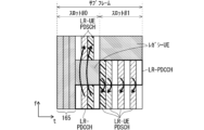
図10は、実施の形態1におけるスロット毎のPDCCHについて説明するための図である。従来のPDCCHが、参照符号「40」で示される1サブフレームの先頭の2シンボルにマッピングされる場合を示す。LR-UE用のPDCCHは、スロット毎にマッピングされる。LR-UE用のPDCCHは、サブフレーム内の1番目のスロットであるスロット#0では、参照符号「41」で示される3シンボル目にマッピングされる。LR-UE用のPDCCHは、サブフレーム内の2番目のスロットであるスロット#1では、参照符号「42」で示される1シンボル目にマッピングされる。サブフレーム内の1番目のスロットであるスロット#0では、従来のPDCCHがマッピングされる領域(以下「PDCCH領域」という場合がある)40を避けて、LR-UEのPDCCHがマッピングされる。
FIG. 10 is a diagram for explaining the PDCCH for each slot in the first embodiment. A case is shown in which the conventional PDCCH is mapped to the first two symbols of one subframe indicated by reference numeral "40". PDCCH for LR-UE is mapped for each slot. In
図10において太い矢印で示すように、従来のPDCCH領域40には、レガシーUEのPDCCHがマッピングされ、該PDCCHで、レガシーUEの1サブフレーム単位のPDSCHのスケジューリングを行う。LR-UEのPDCCHで、スロット単位のPDSCHのスケジューリングを行う。LR-UEのPDCCHで、同一スロットのPDSCHのスケジューリングを行う。
As shown by the thick arrow in FIG. 10, the PDCCH of the legacy UE is mapped to the
図10に示す例では、サブフレーム内の1番目のスロットであるスロット#0の3番目のシンボル41にマッピングされるLR-UEのPDCCHで、LR-UE#1、LR-UE#3のPDSCHのスケジューリングが行われる。サブフレーム内の2番目のスロットであるスロット#1の1番目のシンボル42にマッピングされるLR-UEのPDCCHで、LR-UE#1、LR-UE#2のPDSCHのスケジューリングが行われる。
In the example shown in FIG. 10, the PDCCH of the LR-UE is mapped to the
サブフレーム内の1番目のスロットにマッピングされるスロット毎のPDCCHは、従来のPDCCHがマッピングされるシンボルに多重してマッピングされてもよい。この場合、例えば、LR-UE用のスロット毎のPDCCHと、レガシーUE用の従来のPDCCHとを、従来のPDCCH領域にマッピングするとよい。これによって、スロット毎のPDCCH領域を別途設ける必要がなくなる。 The PDCCH for each slot mapped to the first slot in a subframe may be multiplexed and mapped to a symbol to which a conventional PDCCH is mapped. In this case, for example, the PDCCH for each slot for the LR-UE and the conventional PDCCH for the legacy UE may be mapped to the conventional PDCCH area. This eliminates the need to separately provide a PDCCH area for each slot.
また、サブフレーム内の1番目のスロットでは、スロット毎のPCFICHが不要となる。従来のPCFICHを用いればよい。LR-UEは、レガシーUEと同じく、従来のPCFICHを受信することによって、PDCCHのシンボル数、およびPDSCHがマッピングされる先頭のシンボル番号を認識することが可能となる。 Furthermore, in the first slot in a subframe, a PCFICH for each slot is not required. Conventional PCFICH may be used. By receiving the conventional PCFICH, the LR-UE, like the legacy UE, becomes able to recognize the number of symbols of the PDCCH and the first symbol number to which the PDSCH is mapped.
図11は、実施の形態1におけるマッピング方法を説明するための図である。図11では、スロット毎のPDCCHを従来のPDCCH領域にマッピングする方法について説明する。図11に示す例では、サブフレーム内の1番目のスロットであるスロット#0のLR-UEのPDCCHを、従来のPDCCH領域50にマッピングする。例えば、LR-UEのPDCCHは、スロット#0の1番目のシンボル51にマッピングされる。スロット#0のLR-UEのPDCCHは、従来のPDCCHと多重されてマッピングされる。サブフレーム内の2番目のスロットであるスロット#1のLR-UEのPDCCHは、図10に示す例と同様に、2番目のスロットであるスロット#1の先頭のシンボル52にマッピングされる。
FIG. 11 is a diagram for explaining the mapping method in the first embodiment. In FIG. 11, a method of mapping the PDCCH for each slot to the conventional PDCCH area will be described. In the example shown in FIG. 11, the PDCCH of the LR-UE in
図11に示す例では、サブフレーム内の1番目のスロットであるスロット#0のLR-UE#1、LR-UE#3のPDSCHのスケジューリングは、従来のPDCCH領域50にマッピングされるLR-UEのPDCCHで行われる。サブフレーム内の2番目のスロットであるスロット#1のLR-UE#1、LR-UE#2のPDSCHのスケジューリングは、同じスロット#1にマッピングされるLR-UEのPDCCHで行われる。
In the example shown in FIG. 11, the PDSCH scheduling of LR-
LR-UE用のDCIとして、1TTI=1スロット毎のDCIを新たに設けるとよい。例えば、LR-UE用のDCIフォーマットを新たに設ける。このようにすることによって、PDCCHを用いて、短縮されたTTI毎のスケジューリングを行うことが可能となる。 As the DCI for LR-UE, it is preferable to newly provide a DCI for each 1TTI=1 slot. For example, a new DCI format for LR-UE will be provided. By doing so, it becomes possible to perform shortened scheduling for each TTI using the PDCCH.
また例えば、該DCIに、スロット単位であることを示す情報およびスロットを特定する情報の少なくとも一方の情報を設ける。具体的には、該DCIに、1TTIデータ毎のスケジューリング情報を設けるとよい。スケジューリング情報としては、アロケーション情報およびMCS情報などがある。アロケーション情報としては、PRB単位の物理リソースの情報がある。例えば、PRBの数、PRB番号などである。 Further, for example, the DCI is provided with at least one of information indicating that it is a slot unit and information specifying a slot. Specifically, it is preferable to provide scheduling information for each TTI data in the DCI. Scheduling information includes allocation information and MCS information. As allocation information, there is information on physical resources in PRB units. For example, the number of PRBs, PRB number, etc.
eNBは、LR-UE用に、レガシーUE用のPRBペア以外のPRBをスケジューリングする。 The eNB schedules PRBs other than the PRB pair for legacy UEs for the LR-UE.
LR-UE用のDCIをPDCCHにマッピングする。LR-UE用のPDCCHには、LR-UEのC-RNTI(Cell Radio Network Temporary Identifier)でスクランブルされたCRCを用いるとよい。これによって、従来のUE用のPDCCHと同様に、LR-UE自身のC-RNTIでPDCCHを検出することが可能となる。 Map the DCI for LR-UE to PDCCH. A CRC scrambled with the C-RNTI (Cell Radio Network Temporary Identifier) of the LR-UE may be used for the PDCCH for the LR-UE. This makes it possible to detect the PDCCH using the LR-UE's own C-RNTI, similar to the conventional PDCCH for UE.
PDCCHは、サブフレームの先頭から1番目のシンボルから4番目のシンボルにマッピングされる。PDCCHの物理リソースへのマッピング方法、例えばCCE(Control Channel Element)を用いる方法などは、従来と同じとしてもよい。従来と同じとすることによって、PDCCHの物理リソースへのマッピング方法を新たに決める必要が無く、レガシーUEへのPDCCHとLR-UEへのPDCCHとを混在させることが可能となる。これによって、後方互換性を持たせることができる。 PDCCH is mapped to the first to fourth symbols from the beginning of the subframe. The method of mapping PDCCH to physical resources, for example, the method of using CCE (Control Channel Element), may be the same as the conventional method. By keeping it the same as before, there is no need to newly determine the mapping method of PDCCH to physical resources, and it becomes possible to mix PDCCH to legacy UE and PDCCH to LR-UE. This allows backward compatibility.
LR-UEの動作について開示する。LR-UEは、スロット毎のPCFICHおよび従来のPCFICHの少なくとも一方を受信し、各スロットのPDCCH領域のシンボル数、および各スロットのPDSCH領域先頭のシンボル番号を認識する。 The operation of LR-UE will be disclosed. The LR-UE receives at least one of the PCFICH and the conventional PCFICH for each slot, and recognizes the number of symbols in the PDCCH region of each slot and the symbol number at the beginning of the PDSCH region of each slot.
LR-UEは、スロット毎のPDCCH領域あるいは従来のPDCCH領域を自身のC-RNTIで検出する。これによって、LR-UEは、自身宛てのPDCCHを検出できる。LR-UEは、自身のC-RNTIで検出したPDCCHからDCIを取得する。LR-UEは、DCI中のスケジューリング情報を用いてPDSCHを受信する。どのスロット、どのPRBにPDSCHがアロケーションされているかを認識するために、スロット情報およびスロット毎のPRB情報を用いるとよい。LR-UEは、スケジューリング情報を用いて、受信したPDSCHを復調して、データを取得する。LR-UEは、復調用のRSとして、CRSを用いてもよい。 The LR-UE detects the PDCCH area for each slot or the conventional PDCCH area using its own C-RNTI. This allows the LR-UE to detect the PDCCH addressed to itself. The LR-UE obtains the DCI from the PDCCH detected by its own C-RNTI. The LR-UE receives the PDSCH using the scheduling information in the DCI. In order to recognize which slot and which PRB the PDSCH is allocated to, it is preferable to use slot information and PRB information for each slot. The LR-UE demodulates the received PDSCH using the scheduling information to obtain data. The LR-UE may use CRS as an RS for demodulation.
LR-UEのスロット毎のPDCCHをシステム帯域全体にマッピングすると、レガシーUEのPDSCHと衝突してしまう。図10および図11に示すように、レガシーUEのPDSCHは、1サブフレーム単位でマッピングされている。図10では、該サブフレームの1番目および2番目のスロットにおいて、図11では、該サブフレームの2番目のスロットにおいて、システム帯域全体にわたって、LR-UEのスロット毎のPDCCHがマッピングされるシンボル41,42,52が発生する。 If the PDCCH of each slot of the LR-UE is mapped to the entire system band, it will collide with the PDSCH of the legacy UE. As shown in FIGS. 10 and 11, the PDSCH of the legacy UE is mapped in units of subframes. In the first and second slots of the subframe in FIG. 10 and in the second slot of the subframe in FIG. , 42, 52 occur.
これによって、該シンボル41,42,52において、レガシーUEのPDSCHとスロット毎のPDCCHとが衝突することになる。この衝突によって、該シンボル41,42,52で、レガシーUEのPDSCHが欠落することになる。したがって、レガシーUEによるPDSCHの受信性能は劣化することになる。
This causes the legacy UE's PDSCH and the slot-by-slot PDCCH to collide in
しかし、LR-UEのスロット毎のPDCCHを、比較的少ないシンボル、例えば図10および図11に示すように1シンボルとすることによって、レガシーUEは、CRCチェックなどの復調時の利得によって、データの受信性能の劣化を低減することができる。 However, by setting the PDCCH for each slot of the LR-UE to a relatively small number of symbols, for example, 1 symbol as shown in FIGS. Deterioration of reception performance can be reduced.
また、前述の図11に示すように、1番目のスロットにおいて、従来のPDCCHがマッピングされる領域50に、LR-UEのスロット毎のPDCCHをマッピングする方法を用いることによって、レガシーUEへの影響を、さらに少なくすることができる。これによって、レガシーUEにおけるデータの受信性能の劣化をさらに低減することができる。したがって、レガシーUEは、データを受信することが可能となる。
Furthermore, as shown in FIG. 11 described above, by using a method of mapping the PDCCH for each slot of the LR-UE in the
また、本実施の形態で開示した方法を用いることによって、LR-UEも、スロット毎のPDCCHを受信することが可能となり、同一スロットの、スロット毎のPDSCHを受信することが可能となる。 Furthermore, by using the method disclosed in this embodiment, the LR-UE can also receive PDCCH for each slot, and can receive PDSCH for each slot in the same slot.
したがって、LTEの同一キャリア内に、レガシーUEとLR-UEとの両者を共存させることが可能となる。また、このようにすることによって、従来のマッピング方法と同様の方法を用いることができ、マッピング方法の制御を統一することができる。したがって、実装を容易にすることができる。 Therefore, it is possible to have both legacy UEs and LR-UEs coexist within the same LTE carrier. Moreover, by doing so, a method similar to a conventional mapping method can be used, and control of the mapping method can be unified. Therefore, implementation can be facilitated.
eNBは、レガシーUEのPDSCHに対しては、サブフレーム単位でスケジューリングを行い、LR-UEのPDSCHに対しては、TTIに対応する単位でスケジューリングを行う。eNBは、レガシーUEのPDSCHに対して、サブフレーム内の1番目のスロットであるスロット#0までに、既に、サブフレーム内の2番目のスロットであるスロット#1も含めたサブフレーム単位のスケジューリングを行っている。
The eNB performs scheduling for the legacy UE's PDSCH in units of subframes, and performs scheduling for the LR-UE's PDSCH in units corresponding to TTI. The eNB performs subframe-by-subframe scheduling for the PDSCH of the legacy UE, including
eNBは、サブフレーム内の2番目のスロットであるスロット#1においてLR-UEのPDSCHをスケジューリングする場合、レガシーUEのPDSCHがマッピングされるPRBペアを除いた物理リソースを用いてスケジューリングする。仮に、LR-UEのPDSCHをスケジューリングするために必要となる物理リソースが、レガシーUEのPDSCHがマッピングされるPRBペアを除いた残余の物理リソースでは不足する場合、その後のTTI、例えば、次のサブフレーム内の1番目のスロットであるスロット#0で、スケジューリングできなかったLR-UEのPDSCHをスケジューリングするとよい。このように、eNBは、TTIに対応する単位で、柔軟にスケジューリングを行うことが可能となる。
When scheduling the LR-UE's PDSCH in
eNBは、サブフレーム内の1番目のスロットであるスロット#0において、サブフレーム内の2番目のスロットであるスロット#1にスケジューリングする可能性のあるLR-UEのPDSCHも考慮に入れたスケジューリングを行ってもよい。例えば、接続状態にあるLR-UEの数、LR-UEに対する下り送信バッファに存在するデータ量などを用いて、該スケジューリングを行ってもよい。
In
HARQについて開示する。HARQは、TTI単位で行う。LR-UEに対しては、短縮したTTI、すなわち本実施の形態ではスロット単位で行うとよい。また、レガシーUEに対しては、従来のTTI、すなわちサブフレーム単位で行う。 Disclose HARQ. HARQ is performed in TTI units. For the LR-UE, it is preferable to perform shortened TTI, that is, in this embodiment, in units of slots. Furthermore, for legacy UEs, the conventional TTI, that is, the transmission is performed in units of subframes.
LR-UEに対しては、前述に開示した方法、または後述するPUCCHに関して開示した方法で、短縮したTTI単位でスケジューリングを行うことが可能であるので、下りリンクに対して、短縮したTTI単位でHARQを行うことが可能となる。同様に、LR-UEに対しては、前述に開示した方法で、または後述するPHICHおよびPUSCHに関して開示した方法で、短縮したTTI単位でスケジューリングを行うことが可能であるので、上りリンクに対して、短縮したTTI単位でHARQを行うことが可能となる。 For LR-UE, it is possible to perform scheduling in shortened TTI units using the method disclosed above or the method disclosed for PUCCH described later. Therefore, scheduling can be performed in shortened TTI units for downlink. It becomes possible to perform HARQ. Similarly, for LR-UE, it is possible to perform scheduling in shortened TTI units by the method disclosed above or by the method disclosed for PHICH and PUSCH described later, so it is possible to perform scheduling for uplink. , it becomes possible to perform HARQ in shortened TTI units.
LR-UEのHARQにおいて、RTT(Round Trip Time)を短縮するとよい。短縮したTTI単位でスケジューリングを行うことが可能であるので、RTTを短縮することが可能となる。RTTを短縮させる方法として、例えば、eNBにおける、下りデータの送信タイミングから上りAck/Nackの受信タイミングまでの時間、または該上りAck/Nackの受信タイミングから下りデータの再送タイミングまでの時間を短縮するとよい。また、上りデータのスケジューリングタイミングから上りデータの受信タイミングまでの時間、または該上りデータの受信に対する下りAck/Nackの送信もしくは上り再送データのスケジューリングタイミングまでの時間を短縮するとよい。eNBにおける場合について記載したが、UEにおける場合も同様である。 In HARQ of LR-UE, it is preferable to shorten RTT (Round Trip Time). Since scheduling can be performed in shortened TTI units, it is possible to shorten RTT. As a method for shortening RTT, for example, shortening the time from the transmission timing of downlink data to the reception timing of uplink Ack/Nack, or the time from the reception timing of uplink Ack/Nack to the retransmission timing of downlink data in the eNB. good. Furthermore, it is preferable to shorten the time from the uplink data scheduling timing to the uplink data reception timing, or the time to the downlink Ack/Nack transmission or uplink retransmission data scheduling timing in response to the reception of the uplink data. Although the case in the eNB has been described, the case in the UE is also similar.
RTTを短縮させる場合、従来のRTTにかかるTTI数を同じとしてもよい。従来のTTIに比べて時間が短縮されたTTIが用いられるので、TTI数が同じであっても、RTTの時間は短縮される。例えば、eNBにおける、下りデータの送信タイミングから上りAck/Nackの受信タイミングまでのTTI数、または該上りAck/Nackの受信タイミングから下りデータの再送タイミングまでのTTI数を、従来のTTI数と同じとするとよい。また、上りデータのスケジューリングタイミングから上りデータの受信タイミングまでのTTI数、または該上りデータの受信に対する下りAck/Nackの送信もしくは上り再送データのスケジューリングタイミングまでのTTI数を同じとするとよい。eNBにおける場合について記載したが、UEにおける場合も同様である。 When shortening the RTT, the number of TTIs required for the conventional RTT may be the same. Since a TTI with a shorter time than a conventional TTI is used, the RTT time is reduced even if the number of TTIs is the same. For example, the number of TTIs from the transmission timing of downlink data to the reception timing of uplink Ack/Nack in the eNB, or the number of TTIs from the reception timing of the upstream Ack/Nack to the retransmission timing of downlink data, is the same as the conventional number of TTIs. It is good to say. Further, it is preferable that the number of TTIs from the scheduling timing of uplink data to the reception timing of uplink data, or the number of TTIs until the timing of transmitting a downlink Ack/Nack or scheduling timing of uplink retransmission data in response to the reception of the uplink data, be the same. Although the case in the eNB has been described, the case in the UE is also similar.
以上のようにすることによって、再送制御を高速に行うことが可能となる。これによって、低遅延となり、データの伝送速度を向上させることができる。 By doing the above, it becomes possible to perform retransmission control at high speed. This results in low delay and can improve data transmission speed.
また、短縮したTTI単位のHARQでは、HARQのプロセス数を増大させてもよい。例えば、従来のTTIのHARQのプロセス数が8であった場合、TTI=1スロットの場合のHARQのプロセス数を、2倍の16にする。このようにすることによって、RTTの時間を同じとしても、HARQのプロセス数が増大することになる。HARQのプロセス数を増大させ、データの処理数を増大させることによって、データの伝送速度の向上を図ることができる。 Furthermore, in the shortened TTI unit HARQ, the number of HARQ processes may be increased. For example, if the number of HARQ processes in the conventional TTI is 8, the number of HARQ processes in the case of TTI=1 slot is doubled to 16. By doing this, the number of HARQ processes increases even if the RTT time remains the same. By increasing the number of HARQ processes and increasing the number of data processing, it is possible to improve the data transmission speed.
以上のように本実施の形態によれば、レガシーUEのPDSCHは、サブフレーム単位で物理リソースにマッピングされる。LR-UEのPDSCHは、レガシーUEのPDSCHがマッピングされる物理リソースの領域に、PRB単位でマッピングされる。これによって、LR-UEのPDSCHを、TTI毎に物理リソースにマッピングすることが可能になる。したがって、LR-UEに対するデータの伝送速度を向上させることが可能となる。また、レガシーUEのPDSCHと、LR-UEのPDSCHとを、1つのサブフレーム内の物理リソースに共存させることが可能になる。したがって、種々のTTIに対応可能であり、後方互換性を有する通信システムを実現することができる。 As described above, according to this embodiment, the PDSCH of a legacy UE is mapped to physical resources in subframe units. The PDSCH of the LR-UE is mapped in units of PRBs to the physical resource area to which the PDSCH of the legacy UE is mapped. This makes it possible to map the LR-UE's PDSCH to physical resources on a TTI-by-TTI basis. Therefore, it is possible to improve the data transmission speed to the LR-UE. Furthermore, it becomes possible to make the PDSCH of the legacy UE and the PDSCH of the LR-UE coexist in physical resources within one subframe. Therefore, it is possible to realize a communication system that is compatible with various TTIs and has backward compatibility.
また本実施の形態では、レガシーUEのPDSCHは、PRBペア単位で物理リソースにマッピングされ、LR-UEのPDSCHは、レガシーUEのPDSCHがマッピングされるPRBペアを除いた残余の物理リソースにマッピングされる。これによって、より確実に、レガシーUEのPDSCHと、LR-UEのPDSCHとを、1つのサブフレーム内の物理リソースに共存させることができる。 Furthermore, in this embodiment, the PDSCH of the legacy UE is mapped to physical resources in PRB pair units, and the PDSCH of the LR-UE is mapped to the remaining physical resources excluding the PRB pair to which the PDSCH of the legacy UE is mapped. Ru. This allows the legacy UE PDSCH and the LR-UE PDSCH to coexist in the physical resources within one subframe more reliably.
また本実施の形態では、レガシーUEのPDSCHは、サブフレーム単位でスケジューリングが行われ、LR-UEのPDSCHは、TTIに対応する単位でスケジューリングが行われる。これによって、より確実に、レガシーUEのPDSCHと、LR-UEのPDSCHとを、1つのサブフレーム内の物理リソースに共存させることができる。 Furthermore, in the present embodiment, the PDSCH of the legacy UE is scheduled in units of subframes, and the PDSCH of the LR-UE is scheduled in units corresponding to TTI. This allows the legacy UE PDSCH and the LR-UE PDSCH to coexist in the physical resources within one subframe more reliably.
実施の形態1 変形例1.
実施の形態1では、スロット毎のPDCCHを設けてスロット毎にマッピングする方法を開示した。スロット毎のPDCCHの問題点として、特に2番目のスロットでのレガシーUEのPDSCHとの衝突があることを述べた。
In the first embodiment, a method is disclosed in which a PDCCH is provided for each slot and mapping is performed for each slot. As a problem with the per-slot PDCCH, it was mentioned that there is a collision with the PDSCH of the legacy UE, especially in the second slot.
スロット毎のPDCCHのシンボル数を少なくして、レガシーUEのPDSCH復調時の利得によってデータの受信性能の劣化を低減できることを述べたが、UEとeNBとの間の電波伝播環境およびUEの能力などによっては、受信品質の劣化および受信誤りの増大を引き起こすおそれがある。本変形例では、この問題を解決する方法について開示する。 As mentioned above, it is possible to reduce the deterioration of data reception performance by reducing the number of PDCCH symbols per slot and using the gain during PDSCH demodulation of legacy UEs. Depending on the situation, reception quality may deteriorate and reception errors may increase. In this modification, a method for solving this problem will be disclosed.
実施の形態1では、サブフレーム内の1番目のスロットのスロット毎のPDCCHは、従来のPDCCHがマッピングされるシンボルに多重してマッピングしてもよいことを開示した。 In the first embodiment, it has been disclosed that the PDCCH for each slot of the first slot in a subframe may be multiplexed and mapped onto a symbol to which a conventional PDCCH is mapped.
本変形例では、さらに、サブフレーム内の2番目のスロットのスロット毎のPDCCHを、従来のPDCCHがマッピングされるシンボルに多重してマッピングする。 In this modification, the PDCCH of each slot of the second slot in the subframe is further multiplexed and mapped onto the symbol to which the conventional PDCCH is mapped.
サブフレーム内の2つのスロットのスロット毎のPDCCHを、従来のPDCCHがマッピングされるシンボルに多重してマッピングする。 PDCCH for each slot of two slots in a subframe is multiplexed and mapped onto a symbol to which a conventional PDCCH is mapped.
これによって、サブフレーム内の2番目のスロットにも、スロット毎のPDCCH領域を別途設ける必要がなくなる。 This eliminates the need to separately provide a PDCCH area for each slot in the second slot within the subframe.
従来のPDCCH領域にマッピングされる2つのスロット毎のPDCCHで、同一サブフレーム内の2つのスロットのPDSCHのスケジューリングを行う。任意の一つのLR-UEに対して、2つのスロット毎のPDCCHを用いて2スロット分のスケジューリングを行ってもよい。 Scheduling of PDSCHs for two slots within the same subframe is performed using PDCCHs for every two slots mapped to the conventional PDCCH area. Scheduling for two slots may be performed for any one LR-UE using the PDCCH for every two slots.
図12は、実施の形態1の変形例1におけるマッピング方法を説明するための図である。図12では、2つのスロット毎のPDCCHを従来のPDCCH領域にマッピングする方法について説明する。本変形例では、サブフレーム内の1番目および2番目のスロットであるスロット#0,#1のLR-UEのPDCCHを、従来のPDCCH領域60にマッピングする。LR-UEのPDCCHは、従来のPDCCHと多重されてマッピングされる。図12に示す例では、サブフレーム内の1番目のスロットであるスロット#0のLR-UE#1およびLR-UE#3、ならびにサブフレーム内の2番目のスロットであるスロット#1のLR-UE#2のPDSCHのスケジューリングを行う各LR-UEのPDCCHが、従来のPDCCH領域60にマッピングされる。図12に示す例では、サブフレーム内の2番目のスロットであるスロット#1には、LR-UE#1のPDSCHはマッピングされない。参照符号「61」で示されるPRBには、PDSCHはスケジューリングされない。
FIG. 12 is a diagram for explaining a mapping method in
図13は、実施の形態1の変形例1におけるマッピング方法の他の例を説明するための図である。図13では、2つのスロット毎のPDCCHを従来のPDCCH領域にマッピングする方法の他の例を説明する。図13では、サブフレーム内の1番目のスロットであるスロット#0と2番目のスロットであるスロット#1とに、LR-UE#1のスロット毎のPDSCHがスケジューリングされる場合を示している。各々のスロット毎のPDSCHをスケジューリングする各々のLR-UEのPDCCHは、従来のPDCCH領域60にマッピングされる。レガシーUEは、スロット間で周波数領域が異なるPRB71,72からなるPRBペア70にマッピングされる。
FIG. 13 is a diagram for explaining another example of the mapping method in
LR-UE用のDCIは、実施の形態1と同じく、1TTI=1スロット毎のDCIとするとよい。DCIには、1スロット分のスケジューリング情報が含まれる。 The DCI for the LR-UE is preferably DCI for each 1TTI=1 slot, as in the first embodiment. The DCI includes scheduling information for one slot.
該DCIに、スロット単位であることを示す情報およびスロットを特定する情報の少なくとも一方の情報を設ける。該DCIに、1TTIデータ毎のスケジューリング情報を設けるとよい。スケジューリング情報としては、アロケーション情報およびMCS情報などがある。アロケーション情報としては、PRB単位の物理リソースの情報がある。例えば、PRBの数、PRB番号などである。スケジューリング情報に、TTI番号とスロット番号とを関連付ける情報を設けてもよい。これによって、LR-UEは、どのTTIデータがどのスロットにマッピングされるかを認識することができる。 The DCI is provided with at least one of information indicating that it is a slot unit and information specifying a slot. It is preferable that the DCI is provided with scheduling information for each TTI data. Scheduling information includes allocation information and MCS information. As allocation information, there is information on physical resources in PRB units. For example, the number of PRBs, PRB number, etc. The scheduling information may include information associating TTI numbers and slot numbers. This allows the LR-UE to know which TTI data is mapped to which slot.
スロット毎のDCIを各々スロット毎のPDCCHにマッピングして、該スロット毎のPDCCHで、サブフレーム内の1番目および2番目のスロットのスケジューリングを行う。 The DCI for each slot is mapped onto the PDCCH for each slot, and the first and second slots in the subframe are scheduled using the PDCCH for each slot.
従来のPDCCH領域を用いて、任意のLR-UEに対して、該PDCCH領域が存在するサブフレーム内の2スロット分のスケジューリングを行うことが可能となる。各スロットのスケジューリング情報は異なってもよいし、スロット以外は同じであってもよい。 Using the conventional PDCCH area, it is possible to perform scheduling for two slots in the subframe in which the PDCCH area exists for any LR-UE. The scheduling information for each slot may be different, or the information other than the slot may be the same.
LR-UE用のPDCCHには、LR-UEのC-RNTIでスクランブルされたCRCを用いるとよい。これによって、従来のUE用のPDCCHと同様に、LR-UE自身のC-RNTIでPDCCHを検出することが可能となる。 It is preferable to use a CRC scrambled with the C-RNTI of the LR-UE for the PDCCH for the LR-UE. This makes it possible to detect the PDCCH using the LR-UE's own C-RNTI, similar to the conventional PDCCH for UE.
PDCCHは、サブフレームの先頭から1番目のシンボルから4番目のシンボルにマッピングされる。PDCCHの物理リソースへのマッピング方法、例えばCCEを用いる方法などは、従来と同じとしてもよい。従来と同じとすることによって、PDCCHの物理リソースへのマッピング方法を新たに決める必要が無く、レガシーUEへのPDCCHとLR-UEへのPDCCHとを混在させることが可能となる。これによって、後方互換性を持たせることができる。 PDCCH is mapped to the first to fourth symbols from the beginning of the subframe. The method of mapping PDCCH to physical resources, for example, the method of using CCE, may be the same as the conventional method. By keeping it the same as before, there is no need to newly determine the mapping method of PDCCH to physical resources, and it becomes possible to mix PDCCH to legacy UE and PDCCH to LR-UE. This allows backward compatibility.
LR-UEの動作について開示する。LR-UEは、従来のPCFICHを受信し、従来のPDCCH領域のシンボル数およびPDSCH領域の先頭のシンボル番号を認識する。 The operation of LR-UE will be disclosed. The LR-UE receives the conventional PCFICH and recognizes the number of symbols in the conventional PDCCH region and the symbol number at the beginning of the PDSCH region.
LR-UEは、従来のPDCCH領域を自身のC-RNTIで検出する。これによって、LR-UEは、自身宛てのPDCCHを検出することができる。LR-UEのPDCCHが2スロット分マッピングされている場合は、LR-UEは、自身のC-RNTIで2スロット分のPDCCHを検出する。LR-UEは、自身のC-RNTIで検出したPDCCHからDCIを取得する。LR-UEは、DCI中のスケジューリング情報を用いて、PDSCHを受信する。どのスロット、どのPRBにPDSCHがアロケーションされているかを認識するために、スロット情報およびスロット毎のPRB情報を用いるとよい。また、どのTTIのデータがどのスロットにマッピングされているかを認識するために、TTI情報を用いてもよい。LR-UEは、スケジューリング情報を用いて、受信したPDSCHを復調して、データを取得する。 The LR-UE detects the conventional PDCCH region in its C-RNTI. This allows the LR-UE to detect the PDCCH addressed to itself. If the PDCCH of the LR-UE is mapped for two slots, the LR-UE detects the PDCCH for two slots in its own C-RNTI. The LR-UE obtains the DCI from the PDCCH detected by its own C-RNTI. The LR-UE receives the PDSCH using the scheduling information in the DCI. In order to recognize which slot and which PRB the PDSCH is allocated to, it is preferable to use slot information and PRB information for each slot. Furthermore, TTI information may be used to recognize which TTI data is mapped to which slot. The LR-UE demodulates the received PDSCH using the scheduling information to obtain data.
HARQは、実施の形態1で開示した方法を適用するとよい。ただし、本変形例の場合、LR-UEに対するサブフレーム内の2番目のスロットであるスロット#1のPDSCHのDCIを含むPDCCHを、サブフレーム内の1番目のスロットであるスロット#0のPDCCH領域にマッピングする。したがって、サブフレーム内の2番目のスロットであるスロット#1のPDSCHについては、再送のためのPDSCHのDCIを含むPDCCHをマッピングするタイミングが1スロット早くなる。上りリンクにおいても同様である。
For HARQ, the method disclosed in
処理時間が間に合う場合は問題無いが、処理時間が間に合わないような場合は問題が生じる。また、処理時間が間に合わないだけでなく、他の何らかの理由によって再送タイミングを可変にしたい場合が存在する。このような課題を解決する方法として、非同期(asynchronous)のHARQとするとよい。再送タイミングを予め固定せず、再送データのスケジューリングによってタイミングを決定することによって、再送タイミングを可変にすることができる。したがって、サブフレーム内の2番目のスロットであるスロット#1のPDSCHに対する再送を、サブフレーム内の1番目のスロットであるスロット#0のPDCCH領域を用いてスケジューリングすることが可能となる。上りリンクにおいても同様である。なお、この方法は、実施の形態1にも適用することが可能である。
There is no problem if the processing time is enough, but a problem occurs if the processing time is not enough. Further, there are cases where it is desired to make the retransmission timing variable not only because the processing time is insufficient but also for some other reason. As a method to solve such problems, asynchronous HARQ may be used. By determining the retransmission timing by scheduling retransmission data without fixing the retransmission timing in advance, the retransmission timing can be made variable. Therefore, it is possible to schedule retransmission for the PDSCH in
以上のようにすることによって、再送制御を高速に行うことが可能となる。これによって、低遅延となり、データの伝送速度を向上させることができる。また、データの処理数を増大させることによって、データの伝送速度の向上を図ることができる。また、非同期(asynchronous)のHARQとすることによって、処理時間が間に合わないような場合、および再送タイミングを柔軟に制御したい場合にも、HARQを行うことが可能となる。 By doing the above, it becomes possible to perform retransmission control at high speed. This results in low delay and can improve data transmission speed. Furthermore, by increasing the number of data processes, it is possible to improve the data transmission speed. Further, by using asynchronous HARQ, it becomes possible to perform HARQ even when processing time is insufficient or when it is desired to flexibly control retransmission timing.
本変形例で開示した方法を用いることによって、従来のPDCCH領域に2スロット分のスロット毎のPDCCHをマッピングできるので、1番目および2番目のスロットでスロット毎のPDCCHをマッピングするための物理リソース領域が不要となる。 By using the method disclosed in this modification, it is possible to map the PDCCH for each slot for two slots into the conventional PDCCH area, and therefore the physical resource area for mapping the PDCCH for each slot in the first and second slots. becomes unnecessary.
したがって、スロット毎のPDCCHとレガシーUEのPDSCHとが衝突するようなことはなくなる。したがって、実施の形態1に比べて、前記衝突によるレガシーUEのデータの受信品質の劣化を無くすことが可能となる。
Therefore, there will be no collision between the PDCCH for each slot and the PDSCH of the legacy UE. Therefore, compared to
また、LR-UEも、短縮したTTI、ここではスロット毎のPDCCHを受信することが可能となり、スロット毎のPDSCHを受信することが可能となる。 Furthermore, the LR-UE is also able to receive a shortened TTI, in this case a PDCCH for each slot, and thus a PDSCH for each slot.
したがって、遅延時間の短縮およびデータの伝送速度の向上を図ることができる。 Therefore, it is possible to reduce delay time and improve data transmission speed.
また、LTEの同一キャリア内に、レガシーUEとLR-UEとの両者を共存させることが可能となる。 Furthermore, it is possible to coexist both legacy UEs and LR-UEs within the same LTE carrier.
また、従来のマッピング方法と同様の方法を用いることができ、マッピング方法の制御を統一することができる。したがって、実装を容易にすることができる。 Further, a method similar to a conventional mapping method can be used, and control of the mapping method can be unified. Therefore, implementation can be facilitated.
実施の形態1 変形例2.
実施の形態1の変形例1では、従来のPDCCH領域を用いて、2スロット分のスロット毎のPDCCHを送信する方法を開示した。
本変形例では、従来のPDCCH領域を用いて、LR-UEのPDCCHを送信する他の方法を開示する。 This modification discloses another method of transmitting the PDCCH of the LR-UE using the conventional PDCCH region.
LR-UEのPDSCHに対して、PDCCHで2スロット単位のスケジューリングを行う。PDCCHで2スロット単位の物理リソースへのアロケーションを行う。LR-UEに対するPDCCHで、2TTI=2スロット分のデータをスケジューリングする。 Scheduling is performed in units of 2 slots on the PDCCH for the PDSCH of the LR-UE. Physical resources are allocated in units of 2 slots using PDCCH. Data for 2TTI=2 slots is scheduled on the PDCCH for the LR-UE.
LR-UEのPDSCHに対して、1スロット毎に一つまたは複数のPRBを用いてもよい。2スロットとも同じ数のPRBであってもよいし、各スロットで異なる数のPRBであってもよい。このようにすることによって、短縮したTTI毎のデータに対して柔軟なスケジューリングを行うことが可能となる。 One or more PRBs may be used for each slot for the LR-UE's PDSCH. The two slots may have the same number of PRBs, or each slot may have a different number of PRBs. By doing so, it becomes possible to perform flexible scheduling for data for each shortened TTI.
図14は、実施の形態1の変形例2におけるスケジューリング方法を説明するための図である。図14では、LR-UEのPDCCHで2スロット単位のスケジューリングを行う方法について説明する。図14では、サブフレーム内の1番目のスロットと2番目のスロットに、LR-UE#1のスロット毎のPDSCHがスケジューリングされる場合を示している。各々のスロット毎のPDSCHを、一つのLR-UEのPDCCHでスケジューリングする。該LR-UEのPDCCHは、従来のPDCCH領域80にマッピングされる。
FIG. 14 is a diagram for explaining the scheduling method in the second modification of the first embodiment. In FIG. 14, a method of performing scheduling in units of 2 slots on the PDCCH of the LR-UE will be described. FIG. 14 shows a case where the PDSCH for each slot of LR-
LR-UE用のDCIとして、2TTI=2スロット分のDCIを新たに設けるとよい。一つのDCIに、2スロット分のスケジューリング情報を含めてもよい。各スロットのスケジューリング情報は異なってもよい。一つのDCIに、スロット毎のアロケーション情報を2スロット分含めてもよい。 It is preferable to newly provide a DCI for 2TTI=2 slots as a DCI for the LR-UE. One DCI may include scheduling information for two slots. The scheduling information for each slot may be different. One DCI may include allocation information for each slot for two slots.
該DCIに、2スロット分であることを示す情報が含まれてもよい。あるいは、2スロット分のスケジューリング情報が含まれるDCIフォーマットを、新たなDCIフォーマットとしてもよい。これによって、LR-UEは、2スロット分のスケジューリング情報が含まれることを認識できる。 The DCI may include information indicating that it is for two slots. Alternatively, a DCI format that includes scheduling information for two slots may be used as a new DCI format. This allows the LR-UE to recognize that scheduling information for two slots is included.
該DCIに、1TTIデータ毎のスケジューリング情報を2TTI分含めるとよい。スケジューリング情報として、アロケーション情報およびMCS情報などがある。アロケーション情報としては、PRB単位の物理リソースの情報がある。例えば、PRBの数およびPRB番号などである。 It is preferable that the DCI includes scheduling information for each TTI data for 2 TTIs. Scheduling information includes allocation information, MCS information, and the like. As allocation information, there is information on physical resources in PRB units. For example, the number of PRBs and the PRB number.
DCIに、どのスロットの情報かを特定する情報を設けてもよい。また、TTI番号とスロット番号とを関連付ける情報を設けてもよい。このようにすることによって、LR-UEは、どのTTIデータがどのスロットにマッピングされるかを認識することができる。 The DCI may include information specifying which slot the information belongs to. Furthermore, information that associates the TTI number and slot number may be provided. By doing so, the LR-UE can know which TTI data is mapped to which slot.
2スロット分データが無い場合、スケジューリング無し(no scheduling)あるいは無送信としてもよい。 If there is no data for two slots, no scheduling or no transmission may be performed.
他の方法として、従来のPRBペアのスケジューリング方法を適用してもよい。PRBペアは、1サブフレーム分のスケジューリング情報で特定される。1サブフレームは、2スロットである。したがって、PRBペアのスケジューリング方法を用いることによって、2スロット分のスケジューリングを行うことが可能となる。したがって、新たな方法を用いなくて済むので、通信システムが複雑化することを回避することが可能となる。 Alternatively, a conventional PRB pair scheduling method may be applied. A PRB pair is specified using scheduling information for one subframe. One subframe has two slots. Therefore, by using the PRB pair scheduling method, it is possible to perform scheduling for two slots. Therefore, since there is no need to use a new method, it is possible to avoid complicating the communication system.
eNBは、LR-UE用に、レガシーUE用のPRBペア以外のPRBをスケジューリングする。 The eNB schedules PRBs other than the PRB pair for legacy UEs for the LR-UE.
図15は、実施の形態1の変形例2におけるスケジューリング方法を説明するための図である。図15では、LR-UEのPDCCHに従来のPRBペアのスケジューリング方法を適用して2スロット単位のスケジューリングを行う方法について説明する。 FIG. 15 is a diagram for explaining the scheduling method in the second modification of the first embodiment. In FIG. 15, a method will be described in which a conventional PRB pair scheduling method is applied to the PDCCH of the LR-UE to perform scheduling in units of 2 slots.
図15に示す例では、サブフレーム内の1番目のスロットおよび2番目のスロットのLR-UE#1のPDSCHのスケジューリングを、PRBペアの方法を用いて、一つのLR-UEのPDCCHで行う。また、サブフレーム内の1番目のスロットおよび2番目のスロットのLR-UE#2のPDSCHについても同様に、PRBペアの方法を用いて、一つのLR-UEのPDCCHで行う。
In the example shown in FIG. 15, scheduling of the PDSCH of LR-
図15に示す例では、スロット#0のPRB91とスロット#1のPRB94とからなるPRBペア95に、LR-UE#1がマッピングされる。スロット#0のPRB93とスロット#1のPRB92とからなるPRBペア96のうち、スロット#0のPRB93にLR-UE#2がマッピングされ、スロット#1のPRB92にLR-UE#2がマッピングされる。
In the example shown in FIG. 15, LR-
図14および図15に示す例では、レガシーUEについて記載していないが、レガシーUEのPDSCHがマッピングされてもよい。その場合、該PDSCHのスケジューリングは、レガシーUEのPDCCHで行われる。レガシーUEのPDCCHは、従来のPDCCH領域80,90に、LR-UEのPDCCHと多重されてマッピングされる。以下、レガシーUEについては、特別な事がなければ、説明を省略する。
Although the examples shown in FIGS. 14 and 15 do not describe the legacy UE, the PDSCH of the legacy UE may be mapped. In that case, scheduling of the PDSCH is performed on the legacy UE's PDCCH. The PDCCH of the legacy UE is multiplexed with the PDCCH of the LR-UE and mapped to the
本変形例では、LR-UE用のDCIをPDCCHにマッピングする。LR-UE用のPDCCHには、LR-UEのC-RNTIでスクランブルされたCRCを用いるとよい。これによって、従来のUE用のPDCCHと同様に、LR-UE自身のC-RNTIでPDCCHを検出することが可能となる。 In this modification, the DCI for LR-UE is mapped to the PDCCH. It is preferable to use a CRC scrambled with the C-RNTI of the LR-UE for the PDCCH for the LR-UE. This makes it possible to detect the PDCCH using the LR-UE's own C-RNTI, similar to the conventional PDCCH for UE.
PDCCHは、サブフレームの先頭から1番目のシンボルから4番目のシンボルにマッピングされる。PDCCHの物理リソースへのマッピング方法、例えばCCEを用いる方法などは、従来と同じとしてもよい。従来と同じとすることによって、PDCCHの物理リソースへのマッピング方法を新たに決める必要が無く、レガシーUEへのPDCCHとLR-UEへのPDCCHとを混在させることが可能となる。これによって、後方互換性を持たせることができる。 PDCCH is mapped to the first to fourth symbols from the beginning of the subframe. The method of mapping PDCCH to physical resources, for example, the method of using CCE, may be the same as the conventional method. By keeping it the same as before, there is no need to newly determine the mapping method of PDCCH to physical resources, and it becomes possible to mix PDCCH to legacy UE and PDCCH to LR-UE. This allows backward compatibility.
LR-UEの動作について開示する。LR-UEは、PCFICHを受信し、PDSCH領域の先頭のシンボルを認識する。LR-UEは、PDCCH領域を自身のC-RNTIで検出する。これによって、LR-UEは、自身宛てのPDCCHを検出できる。LR-UEは、自身のC-RNTIで検出したPDCCHからDCIを取得する。LR-UEは、DCI中のスケジューリング情報を用いて、PDSCHを受信する。DCI中に2スロット分のスケジューリング情報がある場合、2スロット分のPDSCHを受信する。どのスロット、どのPRBにPDSCHがアロケーションされているかを認識するために、スロット情報およびスロット毎のPRB情報を用いるとよい。また、どのTTIのデータがどのスロットにマッピングされているかを認識するために、TTI情報を用いてもよい。LR-UEは、スケジューリング情報を用いて、受信したPDSCHを復調して、データを取得する。 The operation of LR-UE will be disclosed. The LR-UE receives the PCFICH and recognizes the first symbol of the PDSCH region. The LR-UE detects the PDCCH region in its own C-RNTI. This allows the LR-UE to detect the PDCCH addressed to itself. The LR-UE obtains the DCI from the PDCCH detected by its own C-RNTI. The LR-UE receives the PDSCH using the scheduling information in the DCI. If there is scheduling information for two slots in the DCI, PDSCH for two slots is received. In order to recognize which slot and which PRB the PDSCH is allocated to, it is preferable to use slot information and PRB information for each slot. Furthermore, TTI information may be used to recognize which TTI data is mapped to which slot. The LR-UE demodulates the received PDSCH using the scheduling information to obtain data.
HARQは、実施の形態1の変形例1で開示した方法を適用するとよい。これによって、実施の形態1の変形例1と同様の効果を得ることができる。他の方法として、HARQは、2TTI単位で行われるようにしてもよい。この場合は、レガシーUEもLR-UEも、HARQが1サブフレーム単位で行われることになるので、スケジューラが複雑化することを回避することができる。
For HARQ, the method disclosed in
本変形例で開示した方法を用いることによって、実施の形態1の変形例1と同様の効果を得ることが可能となる。
By using the method disclosed in this modification, it is possible to obtain the same effects as in
また、一つのDCIに2スロット分のスケジューリング情報を含ませることによって、PDCCH領域にマッピングするLR-UEのPDCCHの数を減らすことができる。したがって、PDCCHへのマッピングによる物理リソースの使用効率を向上させることが可能となる。 Furthermore, by including scheduling information for two slots in one DCI, it is possible to reduce the number of LR-UE PDCCHs mapped to the PDCCH region. Therefore, it is possible to improve the usage efficiency of physical resources by mapping to PDCCH.
また、LR-UEは、従来のPDCCH領域から一つのPDCCHを検出して受信することによって、2スロット分のスケジューリング情報を受信することが可能となる。これによって、LR-UEのPDCCH受信時間の短縮、および受信電力の削減が可能となる。 Furthermore, by detecting and receiving one PDCCH from the conventional PDCCH area, the LR-UE can receive scheduling information for two slots. This makes it possible to shorten the LR-UE's PDCCH reception time and reduce reception power.
実施の形態1 変形例3.
実施の形態1の変形例1では、従来のPDCCH領域を用いて、2スロット分のスロット毎のPDCCHを送信する方法を開示した。本変形例では、従来のPDCCH領域を用いて、LR-UEのPDCCHを送信する他の方法を開示する。
eNBは、従来のPDCCH領域を用いて、直前のスロットのDCIを含むスロット毎のPDCCHと、PDCCH領域と同じスロットのDCIを含むスロット毎のPDCCHとを送信する。 The eNB uses the conventional PDCCH area to transmit a PDCCH for each slot that includes the DCI of the immediately previous slot and a PDCCH for each slot that includes the DCI of the same slot as the PDCCH area.
eNBは、奇数番目のスロットであるスロット#奇数のPDSCHのスケジューリングを決定し、該スケジューリング情報をDCIに含ませ、該DCIをスロット毎のPDCCHにマッピングする。eNBは、該スロット毎のPDCCHを次のスロットのPDCCH領域にマッピングして送信する。eNBは、偶数番目のスロットであるスロット#偶数のPDSCHのスケジューリングを決定し、該スケジューリング情報をDCIに含ませ、該DCIをスロット毎のPDCCHにマッピングする。eNBは、該スロット毎のPDCCHを同じスロットのPDCCH領域にマッピングして送信する。 The eNB determines the scheduling of the PDSCH in slot #odd, which is the odd-numbered slot, includes the scheduling information in the DCI, and maps the DCI to the PDCCH for each slot. The eNB maps the PDCCH of each slot to the PDCCH area of the next slot and transmits it. The eNB determines the scheduling of the PDSCH in slot #even, which is an even-numbered slot, includes the scheduling information in the DCI, and maps the DCI to the PDCCH for each slot. The eNB maps the PDCCH of each slot to the PDCCH area of the same slot and transmits it.
サブフレーム内の2番目のスロットのスロット毎のPDCCHは、次のサブフレームの従来のPDCCHがマッピングされるシンボルに多重してマッピングする。サブフレーム内の1番目のスロットのスロット毎のPDCCHは、同じサブフレームの従来のPDCCHがマッピングされるシンボルに多重してマッピングする。 The slot-by-slot PDCCH of the second slot in a subframe is multiplexed and mapped onto the symbol to which the conventional PDCCH of the next subframe is mapped. The PDCCH for each slot in the first slot in a subframe is multiplexed and mapped onto a symbol to which a conventional PDCCH in the same subframe is mapped.
従来のPDCCH領域にマッピングされる2つのスロット毎のPDCCHで、直前のスロットのPDSCHのスケジューリングと同じスロットのPDSCHのスケジューリングを行う。任意の一つのLR-UEに対して、2つのスロット毎のPDCCHを用いて、直前のスロットと同じスロットの2スロット分のスケジューリングを行ってもよい。 Scheduling of the PDSCH of the same slot as the scheduling of the PDSCH of the immediately preceding slot is performed with the PDCCH of every two slots mapped to the conventional PDCCH area. Scheduling for two slots, which is the same as the immediately preceding slot, may be performed for any one LR-UE using the PDCCH for every two slots.
従来のPDCCH領域にマッピングされるスロット毎のPDCCHで、直前のスロットのPDSCHのスケジューリングを行う点で、前述の実施の形態1の変形例1と異なる。 This differs from the first modification of the first embodiment in that the PDSCH of the immediately preceding slot is scheduled using the PDCCH for each slot mapped to the conventional PDCCH area.
図16は、実施の形態1の変形例3におけるスケジューリング方法を説明するための図である。図16では、従来のPDCCH領域にマッピングしたLR-UEのPDCCHで直前のスロットのスケジューリングと同じスロットのスケジューリングを行う方法について説明する。 FIG. 16 is a diagram for explaining the scheduling method in the third modification of the first embodiment. In FIG. 16, a method of scheduling the same slot as the previous slot on the PDCCH of the LR-UE mapped to the conventional PDCCH area will be described.
本変形例では、サブフレーム内の1番目のスロットのLR-UEのPDSCHをスケジューリングするPDCCHと、その直前のサブフレームの2番目のスロットのLR-UEのPDSCHをスケジューリングするPDCCHとを、同じ従来のPDCCH領域にマッピングする。LR-UEのPDCCHは、従来のPDCCHと多重されてマッピングされる。 In this modification, the PDCCH that schedules the PDSCH of the LR-UE in the first slot in a subframe and the PDCCH that schedules the PDSCH of the LR-UE in the second slot of the immediately preceding subframe are configured using the same conventional mapped to the PDCCH area of The LR-UE PDCCH is multiplexed and mapped with the conventional PDCCH.
図16に示す例では、サブフレーム#2の1番目のスロットであるスロット#0のLR-UE#1,LR-UE#3のPDSCHのスケジューリングを行うPDCCHと、サブフレーム#1の2番目のスロットであるスロット#1のLR-UE#1,LR-UE#2のPDSCHのスケジューリングを行うPDCCHとを、サブフレーム#2の従来のPDCCH領域102にマッピングする。
In the example shown in FIG. 16, the PDCCH for scheduling the PDSCH of LR-
サブフレーム#2では、レガシーUEは、周波数帯域が異なる2つのPRB103,104で構成されるPRBペア105にマッピングされる。サブフレーム#2の従来のPDCCH領域102にマッピングされるレガシーUEのPDCCHは、PRBペア105にマッピングされるレガシーUEのPDSCHのスケジューリングに用いられる。
In
サブフレーム#1の1番目のスロットであるスロット#0のLR-UE#1,LR-UE#3のPDSCHのスケジューリングを行うPDCCHは、サブフレーム#1の従来のPDCCH領域101にマッピングされる。
The PDCCH for scheduling the PDSCH of LR-
LR-UE用のDCIは、実施の形態1と同じくTTI毎、ここではスロット毎のDCIとするとよい。DCIには、1スロット分のスケジューリング情報が含まれる。 The DCI for the LR-UE is preferably for each TTI, here, for each slot, as in the first embodiment. The DCI includes scheduling information for one slot.
該DCIに、スロット単位であることを示す情報およびスロットを特定する情報の少なくとも一方の情報を設ける。該DCIに、サブフレームを特定する情報を設けてもよい。該DCIに、1TTIデータ毎のスケジューリング情報を設けるとよい。スケジューリング情報としては、アロケーション情報およびMCS情報などがある。アロケーション情報としては、PRB単位の物理リソースの情報がある。例えば、PRBの数およびPRB番号などである。スケジューリング情報に、TTI番号とスロット番号とを関連付ける情報、あるいは、TTI番号とサブフレーム番号とスロット番号とを関連付ける情報を設けてもよい。LR-UEは、どのTTIデータがどのスロットにマッピングされるかを認識することができる。 The DCI is provided with at least one of information indicating that it is a slot unit and information specifying a slot. The DCI may include information specifying a subframe. It is preferable that the DCI is provided with scheduling information for each TTI data. Scheduling information includes allocation information and MCS information. As allocation information, there is information on physical resources in PRB units. For example, the number of PRBs and the PRB number. The scheduling information may include information associating TTI numbers and slot numbers, or information associating TTI numbers, subframe numbers, and slot numbers. The LR-UE can know which TTI data is mapped to which slot.
スロット毎のDCIを、それぞれ、スロット毎のPDCCHにマッピングして、該スロット毎のPDCCHで、従来のPDCCHがマッピングされるサブフレームの直前のスロットのスケジューリングと同じスロットのスケジューリングを行う。 The DCI of each slot is mapped to the PDCCH of each slot, and the same slot scheduling as the conventional scheduling of the slot immediately before the subframe to which the conventional PDCCH is mapped is performed on the PDCCH of each slot.
従来のPDCCH領域を用いて、任意のLR-UEに対して、該PDCCH領域が存在するサブフレームの直前のスロットのスケジューリングと同じスロットのスケジューリングを行うことが可能となる。各スロットのスケジューリング情報は、異なっていてもよいし、スロット以外は同じであってもよい。 Using the conventional PDCCH region, it is possible to perform slot scheduling for any LR-UE that is the same as the slot scheduling immediately before the subframe in which the PDCCH region exists. The scheduling information for each slot may be different or may be the same except for the slot.
LR-UE用のPDCCHには、LR-UEのC-RNTIでスクランブルされたCRCを用いるとよい。従来のUE用のPDCCHと同様に、LR-UE自身のC-RNTIでPDCCHを検出することが可能となる。 It is preferable to use a CRC scrambled with the C-RNTI of the LR-UE for the PDCCH for the LR-UE. Similar to the conventional PDCCH for UE, it is possible to detect the PDCCH using the LR-UE's own C-RNTI.
PDCCHは、サブフレームの先頭から1番目のシンボルから4番目のシンボルにマッピングされる。PDCCHの物理リソースへのマッピング方法、例えばCCEを用いる方法などは、従来と同じとしてもよい。従来と同じとすることによって、PDCCHの物理リソースへのマッピング方法を新たに決める必要が無く、レガシーUEへのPDCCHとLR-UEへのPDCCHとを混在させることが可能となる。これによって、後方互換性を持たせることができる。 PDCCH is mapped to the first to fourth symbols from the beginning of the subframe. The method of mapping PDCCH to physical resources, for example, the method of using CCE, may be the same as the conventional method. By keeping it the same as before, there is no need to newly determine the mapping method of PDCCH to physical resources, and it becomes possible to mix PDCCH to legacy UE and PDCCH to LR-UE. This allows backward compatibility.
LR-UEの動作について開示する。LR-UEは、従来のPCFICHを受信し、従来のPDCCH領域のシンボル数およびPDSCH領域の先頭のシンボル番号を認識する。 The operation of LR-UE will be disclosed. The LR-UE receives the conventional PCFICH and recognizes the number of symbols in the conventional PDCCH region and the symbol number at the beginning of the PDSCH region.
LR-UEは、従来のPDCCH領域を自身のC-RNTIで検出する。これによって、LR-UEは、自身宛てのPDCCHを検出できる。LR-UEのPDCCHが2スロット分マッピングされている場合は、LR-UEは、自身のC-RNTIで2スロット分のPDCCHを検出する。LR-UEは、自身のC-RNTIで検出したPDCCHからDCIを取得する。LR-UEは、DCI中のスケジューリング情報を用いて、PDSCHを受信する。どのスロット、どのPRBにPDSCHがアロケーションされているかを認識するために、スロット情報およびスロット毎のPRB情報を用いるとよい。また、どのTTIのデータがどのスロットにマッピングされているかを認識するために、TTI情報を用いてもよい。LR-UEは、スケジューリング情報を用いて、受信したPDSCHを復調して、データを取得する。 The LR-UE detects the conventional PDCCH region in its C-RNTI. This allows the LR-UE to detect the PDCCH addressed to itself. If the PDCCH of the LR-UE is mapped for two slots, the LR-UE detects the PDCCH for two slots in its own C-RNTI. The LR-UE obtains the DCI from the PDCCH detected by its own C-RNTI. The LR-UE receives the PDSCH using the scheduling information in the DCI. In order to recognize which slot and which PRB the PDSCH is allocated to, it is preferable to use slot information and PRB information for each slot. Furthermore, TTI information may be used to recognize which TTI data is mapped to which slot. The LR-UE demodulates the received PDSCH using the scheduling information to obtain data.
本変形例においては、LR-UEは、検出したPDCCHのDCI中のスケジューリング情報によって、直前のスロットのPDSCHまたは同じスロットのPDSCHを受信する。 In this modification, the LR-UE receives the PDSCH in the previous slot or the PDSCH in the same slot, depending on the scheduling information in the DCI of the detected PDCCH.
LR-UEは、スロット#奇数のスロットであるサブフレーム内の2番目のスロットを受信して記憶しておく。LR-UEは、サブフレーム内の2番目のスロットを受信した時点では、自身宛てのPDSCHがスケジューリングされているか否かを認識することができない。次のスロットの従来のPDCCH領域を受信して検出することによって、自身宛てのPDSCHが存在するか否かを判断することができる。したがって、LR-UEは、このようにサブフレーム内の2番目のスロットを受信して記憶することによって、スケジューリング情報を受信したスロットの直前のスロットのPDSCHを受信することが可能となる。 The LR-UE receives and stores the second slot in the subframe, which is the slot #odd slot. At the time when the LR-UE receives the second slot in the subframe, the LR-UE cannot recognize whether or not a PDSCH addressed to itself is scheduled. By receiving and detecting the conventional PDCCH area of the next slot, it can be determined whether a PDSCH addressed to itself exists. Therefore, by receiving and storing the second slot in the subframe in this way, the LR-UE is able to receive the PDSCH of the slot immediately before the slot in which it received the scheduling information.
実施の形態1の変形例1または実施の形態1の変形例2で開示した方法では、例えば、eNBは、サブフレーム内の1番目のスロット期間内にデータが発生した場合、該スロットの直後のスロット、具体的にはサブフレーム内の2番目のスロットにスケジューリングすることはできない。該スロットのスケジューリング情報は、サブフレーム内の1番目のスロットの従来のPDCCH領域で送信済みであるからである。このような場合、eNBは、さらにその後のスロット、具体的には次のサブフレームの1番目のスロットまで1スロット待って、スケジューリング情報の送信とデータの送信とを行う必要が生じる。すなわち、データの発生タイミングによって、1スロット分の遅延が生じる場合がある。
In the method disclosed in
しかし、本変形例で開示した方法を用いることによって、eNBは、サブフレーム内の1番目のスロット期間内にデータが発生した場合でも、該スロットの直後のスロット、具体的にはサブフレーム内の2番目のスロットにスケジューリングすることが可能となる。該スロットのスケジューリング情報は、次のサブフレーム内の1番目のスロットの従来のPDCCH領域で送信するからである。例えば、eNBは、サブフレーム内の1番目のスロット期間内にデータが発生した場合、サブフレーム内の2番目のスロットでデータのスケジューリングを行い、データをサブフレーム内の2番目のスロットにマッピングする。そして、eNBは、次のサブフレーム内の1番目のスロットで送信したデータのスケジューリング情報を送信する。 However, by using the method disclosed in this modification, even if data occurs within the first slot period in a subframe, the eNB can It becomes possible to schedule to the second slot. This is because the scheduling information for this slot is transmitted in the conventional PDCCH area of the first slot in the next subframe. For example, if data occurs within the first slot period in a subframe, the eNB schedules the data in the second slot in the subframe and maps the data to the second slot in the subframe. . The eNB then transmits scheduling information for the data transmitted in the first slot in the next subframe.
したがって、本変形例で開示した方法によって、データの発生後、スロット単位で即座にデータを送信することが可能となる。これによって、1スロット分の遅延を発生させないようにすることができる。 Therefore, the method disclosed in this modification makes it possible to immediately transmit data in units of slots after data is generated. This makes it possible to prevent a delay of one slot from occurring.
HARQは、実施の形態1の変形例1で開示した方法を適用するとよい。これによって、実施の形態1の変形例1と同様の効果を得ることができる。
For HARQ, the method disclosed in
本変形例で開示した方法を用いることによって、従来のPDCCH領域に2スロット分のスロット毎のPDCCHをマッピングできるので、1番目および2番目のスロットでスロット毎のPDCCHをマッピングするための物理リソース領域が不要となる。 By using the method disclosed in this modification, it is possible to map the PDCCH for each slot for two slots into the conventional PDCCH area, and therefore the physical resource area for mapping the PDCCH for each slot in the first and second slots. becomes unnecessary.
したがって、スロット毎のPDCCHとレガシーUEのPDSCHとが衝突するようなことはなくなるので、前述の実施の形態1に比べて、該衝突によるレガシーUEのデータの受信品質の劣化を無くすことが可能となる。 Therefore, since there is no possibility that the PDCCH of each slot and the PDSCH of the legacy UE will collide with each other, it is possible to eliminate the deterioration in the reception quality of data of the legacy UE due to the collision, compared to the first embodiment described above. Become.
また、LR-UEも、短縮したTTI、ここではスロット毎のPDCCHを受信することが可能となり、スロット毎のPDSCHを受信することが可能となる。 Furthermore, the LR-UE is also able to receive a shortened TTI, in this case a PDCCH for each slot, and thus a PDSCH for each slot.
したがって、遅延時間の短縮およびデータの伝送速度の向上を図ることができる。 Therefore, it is possible to reduce delay time and improve data transmission speed.
また、LTEの同一キャリア内に、レガシーUEとLR-UEとの両者を共存させることが可能となる。 Furthermore, it is possible to coexist both legacy UEs and LR-UEs within the same LTE carrier.
また、従来のマッピング方法と同様の方法を用いることができ、マッピング方法の制御を統一することができる。したがって、実装を容易にすることができる。 Further, a method similar to a conventional mapping method can be used, and control of the mapping method can be unified. Therefore, implementation can be facilitated.
また、実施の形態1の変形例1、および実施の形態1の変形例2では、データの発生タイミングによっては1スロットの遅延が発生するが、本変形例で開示した方法を用いることによって、1スロットの遅延を発生させないようにすることができる。したがって、遅延時間の短縮、およびデータの伝送速度の向上を図ることができる。 Furthermore, in the first modification of the first embodiment and the second modification of the first embodiment, a one-slot delay occurs depending on the data generation timing, but by using the method disclosed in this modification, a one-slot delay occurs. It is possible to prevent slot delays from occurring. Therefore, it is possible to reduce delay time and improve data transmission speed.
実施の形態1の変形例2で開示したPRBペアを用いる方法を適用してもよい。これによって、PDCCHの量を削減できる。また、PDCCHへのマッピングによる物理リソースの使用効率を向上させることが可能となる。
The method using PRB pairs disclosed in
また、LR-UEは、従来のPDCCH領域から一つのPDCCHを検出して受信することによって、2スロット分のスケジューリング情報を受信することが可能となる。したがって、LR-UEのPDCCH受信時間の短縮、および受信電力の削減が可能となる。 Furthermore, by detecting and receiving one PDCCH from the conventional PDCCH area, the LR-UE can receive scheduling information for two slots. Therefore, it is possible to shorten the PDCCH reception time of the LR-UE and reduce reception power.
また、従来のPRBペアの方法を適用することによって、レガシーUEと統一した方法でスケジューリングを行うことができ、制御を容易にすることができる。 Further, by applying the conventional PRB pair method, scheduling can be performed in a method unified with that of legacy UEs, and control can be facilitated.
実施の形態1 変形例4.
現在のLTEの規格では、レガシーUEのPDSCHの物理リソースへのマッピングはPRBペアを用いて行われる。PRBペアのPRBが、周波数領域が同じ、すなわち、同じサブキャリアにマッピングされる方法であるローカライズド(localized)と、周波数領域が異なる、すなわち、異なるサブキャリアにマッピングされる方法であるディストリビューテッド(distributed)とがある。
In the current LTE standard, mapping of a legacy UE's PDSCH to physical resources is performed using PRB pairs. Localized, which is a method in which the PRBs of a PRB pair are mapped to the same frequency domain, i.e., the same subcarrier, and distributed, which is a method in which the PRBs of a PRB pair are mapped to different frequency domains, i.e., different subcarriers. distributed).
しかし、LR-UEに対する短縮したTTIのデータをスロット毎に物理リソースにマッピングする場合、該データはスロット毎なので、ディストリビューテッドを行うことはできない。また、周波数ダイバーシチゲインを得ることができなくなってしまう。 However, when mapping shortened TTI data for the LR-UE to physical resources on a slot-by-slot basis, the data cannot be distributed because it is on a slot-by-slot basis. Moreover, it becomes impossible to obtain frequency diversity gain.
このような問題を解決する方法を以下に開示する。LR-UEに対するPDSCHの物理リソースへのマッピングにおいて、1スロット内で、非連続の周波数領域、すなわち、非連続のサブキャリアにマッピングする。周波数領域としてPRB単位とするとよい。1スロット内で、ディストリビューテッドを行うことになる。 A method for solving such problems will be disclosed below. In mapping PDSCH to physical resources for LR-UE, mapping is performed to non-contiguous frequency regions, that is, non-contiguous subcarriers within one slot. It is preferable to use PRB units as the frequency domain. Distributed will be performed within one slot.
LR-UEに対して1スロット内で一つまたは複数のPRBをアロケーションすることを開示したが、該複数のPRBとして、連続的なPRBであってもよいし、非連続なPRBであってもよい。特定の周波数領域で電波環境が良好な場合、該周波数領域で連続的なPRB(ローカライズド)を用いることによって、通信品質を向上させることが可能となる。また、周波数フェージングがあるような場合、非連続なPRB(ディストリビューテッド)を用いることによって、特定の周波数領域の電波環境が悪かったとしても、所望の通信品質を得ることが可能となる。 Although it has been disclosed that one or more PRBs are allocated within one slot to the LR-UE, the plurality of PRBs may be continuous PRBs or discontinuous PRBs. good. When the radio wave environment is good in a particular frequency region, communication quality can be improved by using continuous PRB (localized) in that frequency region. Further, in the case where there is frequency fading, by using discontinuous PRB (distributed), it is possible to obtain desired communication quality even if the radio wave environment in a specific frequency region is poor.
非連続な複数のPRBをPRBセットとしてもよい。PRBセットのスケジューリング方法として、DCIにPRBセット情報を新たに設けてもよい。 A PRB set may include a plurality of non-contiguous PRBs. As a PRB set scheduling method, PRB set information may be newly provided in the DCI.
PRBセットのアロケーション方法として、絶対的なPRBの番号を用いて該複数のPRBを特定する方法がある。この場合、アロケーション情報として、PRBセットの各PRBの絶対的なPRB番号を含めるとよい。 As a PRB set allocation method, there is a method of specifying the plurality of PRBs using absolute PRB numbers. In this case, the absolute PRB number of each PRB in the PRB set may be included as the allocation information.
アロケーション情報として、最小のPRB番号と、次に続くPRBまでの周波数間隔情報、例えばサブキャリア数、あるいはPRB間隔情報、例えばPRB数を含めるとよい。PRBセットの最も小さいPRBの番号と、次に続くPRBまでの周波数間隔あるいはPRB間隔を用いて、該複数のPRBを特定することができる。 The allocation information may include the minimum PRB number and frequency interval information up to the next PRB, such as the number of subcarriers, or PRB interval information, such as the number of PRBs. The plurality of PRBs can be specified using the smallest PRB number in the PRB set and the frequency interval or PRB interval to the next PRB.
また、アロケーション情報に、PRBの個数情報を含めておいてもよいし、最後のPRBであることを示す情報を含めてもよいし、最後のPRBには次に続くPRBまでの周波数間隔情報またはPRB間隔情報を設定しないようにしてもよい。これによって、最後のPRBであることが認識される。 In addition, the allocation information may include information on the number of PRBs, information indicating that it is the last PRB, and the last PRB may include frequency interval information up to the next PRB or The PRB interval information may not be set. This recognizes that it is the last PRB.
図17は、実施の形態1の変形例4におけるスケジューリング方法を説明するための図である。図17では、LR-UEに対して1スロット内で複数のPRBをスケジューリングする方法について説明する。本変形例では、LR-UEのPDSCHに、複数のPRBをマッピングする。LR-UEのPDCCHで該PDSCHに対して複数のPRBをアロケーションする。 FIG. 17 is a diagram for explaining the scheduling method in the fourth modification of the first embodiment. FIG. 17 describes a method of scheduling a plurality of PRBs within one slot for the LR-UE. In this modification, a plurality of PRBs are mapped to the PDSCH of the LR-UE. A plurality of PRBs are allocated to the PDCCH of the LR-UE.
図17に示す例では、サブフレーム内の1番目のスロットでは、LR-UE#1のPDSCHが非連続な2つのPRBにマッピングされる。該PDSCHのスケジューリングは、LR-UE#1のPDCCHで行われる。該PDCCHは、従来のPDCCH領域110にマッピングされる。
In the example shown in FIG. 17, in the first slot in the subframe, the PDSCH of LR-
サブフレーム内の2番目のスロットでは、LR-UE#2のPDSCHが、連続する二つのPRBにマッピングされる。該PDSCHのスケジューリングは、LR-UE#2のPDCCHで行われる。該PDCCHは、従来のPDCCH領域110にマッピングされる。
In the second slot in the subframe, the PDSCH of LR-
アロケーション情報に、PRBの最初と最後のPRB番号情報を含めてもよい。各PRBの間隔が同じ周波数間隔であった場合、さらに、PRBの個数情報、PRB間の周波数間隔情報、例えばサブキャリア数、あるいはPRB間隔情報、例えばPRB数を含めることによって、該複数のPRBを特定することができる。 The allocation information may include PRB number information at the beginning and end of the PRB. If the intervals between PRBs are the same frequency interval, the plurality of PRBs can be further divided by including information on the number of PRBs, frequency interval information between PRBs, such as the number of subcarriers, or PRB interval information, such as the number of PRBs. can be specified.
PRBが2つの場合、1スロット内のPRBペアとし、従来のPRBペアのアロケーション方法を適用してもよい。 If there are two PRBs, the PRB pairs may be in one slot, and a conventional PRB pair allocation method may be applied.
LR-UE用の1スロット内のPRBペアか、レガシーUE用の2スロット間のPRBペアなのかを特定するための情報を設けるとよい。該情報をスケジューリング情報に含めてもよい。 It is preferable to provide information for specifying whether it is a PRB pair within one slot for LR-UE or a PRB pair between two slots for legacy UE. This information may be included in the scheduling information.
あるいは、LR-UE用かレガシーUE用かを特定するための情報を設けてもよい。LR-UE用の場合、同一スロット内でのPRBペアが用いられるようにし、レガシーUE用の場合、2スロット間でのPRBペアが用いられるようにするとよい。このような方法にすることによって、従来と同じPRBペアの指定方法を適用することができるので、制御が複雑化することを回避することが可能となる。 Alternatively, information for specifying whether it is for LR-UE or legacy UE may be provided. For LR-UE, PRB pairs within the same slot may be used, and for legacy UE, PRB pairs between two slots may be used. By adopting such a method, the same method of specifying PRB pairs as in the past can be applied, so that it is possible to avoid complicating control.
他の方法として、eNBは、レガシーUEのPDCCHのDCIのPRBペア情報には従来の2スロット間のPRBペアの情報を設定し、LR-UEのPDCCHのDCIに含まれるPRBペア情報には、1スロット内でのPRBペアの情報を設定する。また、PRBペア情報を含むDCIを含むPDCCHが、LR-UE用か、またはレガシーUE用かで判断するようにする。このようにすることによって、レガシーUEまたはLR-UEは、自身がレガシーUEなのか、LR-UEなのかによって、PDCCHのPRBペアが、2スロット間のPRBペアなのか1スロット内のPRBペアなのかを判断することが可能となる。どのPRBペアなのかを示す明確な情報を不要とすることができる。 As another method, the eNB sets conventional PRB pair information between two slots to the PRB pair information of the DCI of the legacy UE's PDCCH, and sets the PRB pair information included in the DCI of the LR-UE's PDCCH to: Set PRB pair information within one slot. Further, the determination is made based on whether the PDCCH including the DCI including PRB pair information is for the LR-UE or for the legacy UE. By doing this, the legacy UE or LR-UE can change the PDCCH PRB pair to a PRB pair between two slots or a PRB pair within one slot, depending on whether the legacy UE or LR-UE is a legacy UE or an LR-UE. It becomes possible to judge whether It is possible to eliminate the need for clear information indicating which PRB pair.
実施の形態1 変形例5.
実施の形態1では、スロット毎のPDCCHを設けてスロット毎にマッピングする方法を開示した。実施の形態1では、スロット内のシンボルにシステム帯域全体にわたってPDCCHを設けるので、問題点として、レガシーUEのPDSCHと衝突が避けられないことを述べた。
In the first embodiment, a method is disclosed in which a PDCCH is provided for each slot and mapping is performed for each slot. In
スロット毎のPDCCHのシンボル数を少なくしてレガシーUEのPDSCHへの影響を少なくし、復調時の利得によって、データの受信性能の劣化を低減できることを述べたが、UEとeNBとの間の電波伝播環境およびUEの能力などによっては、受信品質の劣化および受信誤りの増大を引き起こすおそれがある。本変形例では、この問題を解決する方法について開示する。 As described above, it is possible to reduce the influence of legacy UEs on the PDSCH by reducing the number of PDCCH symbols per slot, and to reduce the deterioration of data reception performance by increasing the gain during demodulation. Depending on the propagation environment, the UE's capabilities, etc., there is a possibility that reception quality may deteriorate and reception errors may increase. In this modification, a method for solving this problem will be disclosed.
スロット内の一つまたは複数のPRBにスロット毎のPDCCHをマッピングする。スロット毎のPDCCHで1TTIデータ毎のスケジューリングを行う。スロット毎のPDCCHでスロット単位のスケジューリングを行う。スロット毎のPDCCHでスロット単位の物理リソースへのアロケーションを行う。スロット毎のPDCCHと同一スロットに割当てられているPDSCHのスケジューリングを行う。 The PDCCH for each slot is mapped to one or more PRBs within the slot. Scheduling is performed for each TTI data using the PDCCH for each slot. Scheduling is performed on a slot-by-slot basis using a PDCCH for each slot. Allocation to physical resources is performed on a slot-by-slot basis using the PDCCH for each slot. Scheduling of the PDCCH for each slot and the PDSCH assigned to the same slot is performed.
このようにすることによって、スロット毎のPDCCHをマッピングする物理リソース領域を、システム帯域全体では無くすことができ、予め定めるPRB、すなわち予め定める周波数領域のみにすることができる。 By doing so, the physical resource area for mapping the PDCCH for each slot can be eliminated from the entire system band, and only the predetermined PRB, that is, the predetermined frequency area can be used.
したがって、レガシーUEのPDSCHと衝突しないように、スケジューリングを行うことが可能となる。 Therefore, it becomes possible to perform scheduling so as not to collide with the PDSCH of the legacy UE.
また、LR-UEの増大によってスロット毎のPDCCHが増え、PDCCHに必要となるシンボル数が増大した場合でも、レガシーUEのPDSCHとの衝突が無いので、該衝突によるデータの通信品質の劣化を防ぐことが可能となる。 Furthermore, even if the number of PDCCHs per slot increases due to the increase in the number of LR-UEs, and the number of symbols required for the PDCCH increases, there will be no collision with the PDSCH of legacy UEs, thus preventing deterioration of data communication quality due to such collisions. becomes possible.
スロット毎にLR-UE用のPDCCH領域を設けてもよい。PDCCHを物理リソースにマッピングする領域として、PRB単位としてもよい。一つまたは複数のPRBを用いてもよい。スロット毎のPDCCHをLR-EPDCCHとする。LR-UEのPDCCHとして、LR-EPDCCHを用いる。 A PDCCH area for LR-UE may be provided for each slot. The area for mapping PDCCH to physical resources may be PRB units. One or more PRBs may be used. The PDCCH for each slot is assumed to be LR-EPDCCH. LR-EPDCCH is used as the PDCCH of LR-UE.
LR-EPDCCHを、従来のPDSCHがマッピングされる物理リソース領域にマッピングする。 The LR-EPDCCH is mapped to the physical resource area to which the conventional PDSCH is mapped.
LR-UEのPDSCHは、レガシーUEのPDSCHがマッピングされるPRBペアを避けてマッピングする。 The LR-UE's PDSCH is mapped avoiding the PRB pair to which the legacy UE's PDSCH is mapped.
スロット#偶数のLR-EPDCCHは、従来のPDCCHがマッピングされるシンボル(1~4シンボル)を除いてマッピングする。 The LR-EPDCCH of even slot # is mapped excluding the symbols (1 to 4 symbols) to which the conventional PDCCH is mapped.
図18は、実施の形態1の変形例5におけるスケジューリング方法を説明するための図である。図18では、LR-UEに対してLR-EPDCCHでスケジューリングする方法について説明する。図18に示すように、LR-EPDCCHは、スロット毎に従来のPDSCHがマッピングされる物理リソース領域にマッピングされる。例えば、LR-EPDCCH#1は、サブフレーム内の1番目のスロットにマッピングされ、LR-EPDCCH#2は、サブフレーム内の2番目のスロットにマッピングされる。
FIG. 18 is a diagram for explaining the scheduling method in the fifth modification of the first embodiment. In FIG. 18, a method of scheduling the LR-UE using the LR-EPDCCH will be described. As shown in FIG. 18, the LR-EPDCCH is mapped to the physical resource area to which the conventional PDSCH is mapped for each slot. For example, LR-
LR-EPDCCH#1は、LR-UE#1のPDCCHであり、同一のスロットのLR-UE#1のPDSCHのスケジューリングを行う。LR-EPDCCH#2は、LR-UE#2のPDCCHであり、同一のスロットのLR-UE#2のPDSCHのスケジューリングを行う。サブフレーム内の1番目のスロットのLR-EPDCCH#1は、従来のPDCCH領域111を除いたシンボルにマッピングされる。
LR-
スロット毎に予め定めるPRBを用いて、LR-UEのPDCCHをマッピングする領域(以下「LR-EPDCCH領域」という場合がある)を設けることを開示した。ここでは、さらに、LR-UEのPDCCHを該領域にマッピングする方法を開示する。 It has been disclosed that a PRB predetermined for each slot is used to provide an area (hereinafter sometimes referred to as "LR-EPDCCH area") in which the PDCCH of the LR-UE is mapped. Here, a method of mapping the PDCCH of the LR-UE to the region is further disclosed.
従来、予め定める周波数領域にマッピングする制御チャネルとして、EPDCCHがある。しかし、EPDCCHは、1サブフレーム全体にわたってマッピングされる。したがって、スロット毎のPDCCHのマッピング方法に、従来のEPDCCHのマッピング方法を適用した場合、予め定める周波数領域にマッピングすることは可能となるが、スロット毎にマッピングすることができなくなってしまう。 Conventionally, there is an EPDCCH as a control channel mapped to a predetermined frequency region. However, EPDCCH is mapped over one entire subframe. Therefore, if the conventional EPDCCH mapping method is applied to the PDCCH mapping method for each slot, it becomes possible to map to a predetermined frequency region, but it becomes impossible to map each slot.
ここでは、スロット毎に予め定めるPRBを用いて、LR-UEのPDCCHをマッピングする方法を開示する。 Here, a method is disclosed for mapping the PDCCH of the LR-UE using a PRB determined in advance for each slot.
1スロット単位のDCIをLR-EPDCCHにマッピングする。1スロット単位のDCIは、一つまたは複数の制御チャネルエレメント、ここではLR-ECCEに分割される。 DCI in units of one slot is mapped to LR-EPDCCH. DCI in units of one slot is divided into one or more control channel elements, here LR-ECCE.
LR-EPDCCHの物理リソースとして、一つまたは複数のRE(Resource Element)からなるLR-EREGを設ける。LR-ECCEは、LR-EREGにマッピングされる。 As a physical resource for the LR-EPDCCH, an LR-EREG consisting of one or more REs (Resource Elements) is provided. LR-ECCE is mapped to LR-EREG.
このようにすることによって、1スロット単位のDCIがLR-EPDCCHにマッピングされ、LR-EPDCCHは、1スロット内の物理リソースにマッピングされる。 By doing this, DCI in units of one slot is mapped to LR-EPDCCH, and LR-EPDCCH is mapped to physical resources within one slot.
任意の数のLR-EREGをPRB内に構成するとよい。例えば、LR-EREG=0~15の16グループをPRB内に構成するとよい。この場合、従来のEPDCCH用のEREGの構成を用いてもよい(非特許文献11参照)。ただし、従来のEPDCCHは、PRBペア内で16グループのEREGが構成される。しかし、LR-EPDCCHではPRBペアは得られないので、EREGの構成をそのまま適用することはできない。 Any number of LR-EREGs may be configured within a PRB. For example, 16 groups of LR-EREG=0 to 15 may be configured in the PRB. In this case, a conventional EREG configuration for EPDCCH may be used (see Non-Patent Document 11). However, in the conventional EPDCCH, 16 groups of EREGs are configured within a PRB pair. However, since a PRB pair cannot be obtained with LR-EPDCCH, the EREG configuration cannot be applied as is.
そこで、PRBペア内のEREGの配置は保ったまま、LR-EREGとしてPRB内のEREGのみ用いるようにする。このようにすることによって、EREGのグループ数とLR-EREGのグループ数とは同じ値を保ったまま、LR-EREGをPRB内に構成することが可能となる。 Therefore, only the EREG in the PRB is used as the LR-EREG while the arrangement of the EREG in the PRB pair is maintained. By doing so, it becomes possible to configure the LR-EREG in the PRB while keeping the same value for the number of EREG groups and the number of LR-EREG groups.
例えば、16グループのLR-EREGを1PRB内に構成する場合、1PRB内の1LR-EREG内に含まれるRE数は、4あるいは5となる。 For example, when 16 groups of LR-EREGs are configured in one PRB, the number of REs included in one LR-EREG in one PRB is four or five.
LR-EREG数は、従来のEREGと同様に16グループを構成できるが、1LR-EREG当たりのRE数が半減することになる。 Although the number of LR-EREGs can be configured into 16 groups like the conventional EREG, the number of REs per LR-EREG is halved.
DCIをマッピングするのに必要となるRE数は、EPDCCHもLR-EPDCCHも同じである。したがって、LR-EREG内のRE数が半減してしまうと、DCIを入れられなくなってしまうという問題がある。このような問題を解決する方法を以下に開示する。 The number of REs required to map DCI is the same for EPDCCH and LR-EPDCCH. Therefore, if the number of REs in the LR-EREG is halved, there is a problem that DCI cannot be inserted. A method for solving such problems will be disclosed below.
LR-UEに割当てるLR-EPDCCHセット数を増大させる。通常、eNBは、UEに対してEPDCCH領域を割当てる。この領域は、連続であってもよいし、非連続であってもよい。このEPDCCH領域を「EPDCCHセット」という場合がある。従来、UEに対して2つのEPDCCHセットの割当が可能である。 Increase the number of LR-EPDCCH sets allocated to LR-UE. Typically, the eNB allocates an EPDCCH region to the UE. This region may be continuous or discontinuous. This EPDCCH area may be referred to as an "EPDCCH set." Conventionally, two EPDCCH sets can be assigned to a UE.
これと同様に、eNBがLR-UEに対して割当てるLR-EPDCCH領域をLR-EPDCCHセットとする。このLR-UEに割当て可能な最大のLR-EPDCCHセット数を2よりも増大させる。 Similarly, the LR-EPDCCH area that the eNB allocates to the LR-UE is an LR-EPDCCH set. The maximum number of LR-EPDCCH sets that can be allocated to this LR-UE is increased from 2.
UEは、2よりも大きい数のLR-EPDCCHセットを検索し、自身のLR-EPDCCHを受信する。 The UE searches for a number of LR-EPDCCH sets greater than 2 and receives its LR-EPDCCH.
例えば、1LR-UEに対して、LR-EPDCCHセット数として、1,2に加えて,4セットを設定可能とするとよい。 For example, in addition to 1 and 2, it may be possible to set 4 sets as the number of LR-EPDCCH sets for 1 LR-UE.
このようにすることによって、全てのLR-EPDCCHセットに含まれるPRB数を増大させることが可能となる。また、LR-UEが受信するPRB数を増大させることが可能となる。したがって、1PRB内のLR-EREG内のRE数が半減したとしても、PRB数が増大するので、従来と同等のRE数を確保することができる。 By doing so, it is possible to increase the number of PRBs included in all LR-EPDCCH sets. Furthermore, it becomes possible to increase the number of PRBs that the LR-UE receives. Therefore, even if the number of REs in the LR-EREG in one PRB is halved, the number of PRBs increases, so the same number of REs as before can be secured.
他の方法を以下に開示する。eNBがLR-UEに対して割当てるLR-EPDCCH領域を増大させる。LR-UEに割当てるLR-EPDCCHセットを構成するPRB数を増大させてもよい。LR-UEに割当て可能なLR-EPDCCHセットを構成する最大のPRB数を8よりも増大させる。UEは、8よりも大きい数のPRBで構成されるLR-EPDCCHセットを検索し、自身のLR-EPDCCHを受信する。 Other methods are disclosed below. The eNB increases the LR-EPDCCH area allocated to the LR-UE. The number of PRBs constituting the LR-EPDCCH set allocated to the LR-UE may be increased. The maximum number of PRBs constituting an LR-EPDCCH set that can be allocated to an LR-UE is increased from 8. The UE searches for an LR-EPDCCH set consisting of a number of PRBs greater than 8 and receives its LR-EPDCCH.
例えば、1LR-UEに対して、LR-EPDCCHセットを構成するPRB数として、2,4,8に加えて、16を設定可能とするとよい。 For example, in addition to 2, 4, and 8, it may be possible to set 16 as the number of PRBs configuring the LR-EPDCCH set for one LR-UE.
このようにすることによって、LR-UEに割当可能な全てのLR-EPDCCHセットに含まれるPRB数を増大させることができる。また、LR-UEが受信するPRB数を増大させることが可能となる。したがって、1PRB内のLR-EREG内のRE数が半減したとしても、PRB数が増大するので、従来と同等のRE数を確保することができる。 By doing so, it is possible to increase the number of PRBs included in all LR-EPDCCH sets that can be allocated to LR-UEs. Furthermore, it becomes possible to increase the number of PRBs that the LR-UE receives. Therefore, even if the number of REs in the LR-EREG in one PRB is halved, the number of PRBs increases, so the same number of REs as before can be secured.
他の方法を以下に開示する。LR-UEがサポートする制御チャネルエレメント(Control Channel Element:CCE)のアグリゲーションレベルを従来の数よりも減少させる。従来、1UEに対するCCEのアグリゲーションレベルとして、1,2,4,8,16,32の設定が可能であった。ここでは、LR-UEがサポートする最大のCCEのアグリゲーションレベルを32よりも小さくする。例えば、LR-UEがサポートする最大のCCE数を16とする。 Other methods are disclosed below. The aggregation level of control channel elements (CCEs) supported by the LR-UE is reduced compared to the conventional number. Conventionally, the CCE aggregation level for one UE could be set to 1, 2, 4, 8, 16, or 32. Here, the maximum CCE aggregation level supported by the LR-UE is set to be smaller than 32. For example, assume that the maximum number of CCEs supported by the LR-UE is 16.
このようにすることによって、LR-UEに対するDCIが含まれるCCE数を少なくすることができる。これによって、LR-UEに対するDCIをマッピングするのに必要とするRE数を少なくすることが可能となる。 By doing so, it is possible to reduce the number of CCEs that include DCI for the LR-UE. This makes it possible to reduce the number of REs required to map the DCI to the LR-UE.
したがって、LR-UEに割当可能な1PRB内のLR-EREG内のRE数が半減し、全てのLR-EPDCCHセットに含まれるRE数が半減したとしても、LR-UEに対するDCIをマッピングすることが可能となる。 Therefore, even if the number of REs in the LR-EREG in one PRB that can be allocated to the LR-UE is halved and the number of REs included in all LR-EPDCCH sets is halved, it is not possible to map the DCI for the LR-UE. It becomes possible.
他の方法を以下に開示する。LR-UEに対するDCIが含まれるLR-ECCEが必要とする物理リソース量を削減する。前記物理リソース量を削減するために、LR-UEに対するDCIの情報量を削減してもよい。 Other methods are disclosed below. The amount of physical resources required by LR-ECCE including DCI for LR-UE is reduced. In order to reduce the amount of physical resources, the amount of DCI information for the LR-UE may be reduced.
例えば、従来、EPDCCHにマッピングされるECCEは、1ECCEが36RE、あるいは72REにマッピングされる。ここでは、LR-UEに対するDCIが含まれるLR-ECCEが必要とする物理リソースを36REあるいは72REよりも削減する。例えば、1LR-ECCEの物理リソースを18REあるいは36REとする。 For example, conventionally, one ECCE mapped to EPDCCH is mapped to 36 REs or 72 REs. Here, the physical resources required by the LR-ECCE including the DCI for the LR-UE are reduced compared to 36 REs or 72 REs. For example, assume that the physical resources of 1LR-ECCE are 18RE or 36RE.
このようにすることによって、LR-UEに対するDCIが含まれるLR-ECCEに必要とする物理リソース量を削減することが可能となる。 By doing so, it is possible to reduce the amount of physical resources required for the LR-ECCE including the DCI for the LR-UE.
したがって、LR-UEに割当可能な1PRB内のLR-EREG内のRE数が半減し、全てのLR-EPDCCHセットに含まれるRE数が半減したとしても、LR-UEに対するDCIをマッピングすることが可能となる。 Therefore, even if the number of REs in the LR-EREG in one PRB that can be allocated to the LR-UE is halved and the number of REs included in all LR-EPDCCH sets is halved, it is not possible to map the DCI for the LR-UE. It becomes possible.
本変形例では、前述のように、任意の数のLR-EREGをPRB内に構成することを開示し、例として、LR-EREG=0~15の16グループをPRB内に構成することを開示した。他の例として、LR-EREG=0~7の8グループをPRB内に構成する。LR-EREGの番号は、全てのLR-EPDCCH用PRBで同じにしてもよい。あるいは、LR-EREGの番号を2種類設けてもよい。例えば、LR-EREG=0~7のPRBと、LR-EREG=8~15のPRBとに分けて使用してもよい。 In this modified example, as described above, it is disclosed that an arbitrary number of LR-EREGs are configured in the PRB, and as an example, it is disclosed that 16 groups of LR-EREG=0 to 15 are configured in the PRB. did. As another example, 8 groups of LR-EREG=0 to 7 are configured in the PRB. The LR-EREG number may be the same for all LR-EPDCCH PRBs. Alternatively, two types of LR-EREG numbers may be provided. For example, PRBs with LR-EREG=0 to 7 and PRBs with LR-EREG=8 to 15 may be used separately.
8グループのLR-EREGを1PRB内に構成する場合、1PRB内の1LR-EREG内に含まれるRE数は、9となる。このようにすることによって、1LR-EREG当たりのRE数を、従来のEREGあたりのRE数と同じ値にすることができる。 When 8 groups of LR-EREGs are configured in one PRB, the number of REs included in one LR-EREG in one PRB is nine. By doing so, the number of REs per LR-EREG can be made the same as the number of REs per conventional EREG.
前述したように、DCIをマッピングするのに必要となるRE数はEPDCCHもLR-EPDCCH同じである。 As described above, the number of REs required to map DCI is the same for EPDCCH and LR-EPDCCH.
したがって、ここで開示した方法を用いることによって、一つのLR-UEに割当てるLR-EPDCCH領域に必要なRE数を得ることができる。LR-UEに対するDCIを入れることが可能となる。RE数の減少に対する解決策は不要となる。 Therefore, by using the method disclosed herein, it is possible to obtain the number of REs required for the LR-EPDCCH region allocated to one LR-UE. It becomes possible to insert DCI for LR-UE. No solution is needed for the reduction in the number of REs.
ここで開示した方法では、1LR-EREG当たりのRE数は従来のEREGあたりのRE数と同じにできるが、LR-EREG数は従来のEREG数の半分になってしまう。この場合、LR-EPDCCH領域に構成されるLR-EREG数が減少してしまうため、LR-EPDCCH領域でサポート可能なLR-UE数が減少してしまうことになる。 In the method disclosed here, the number of REs per LR-EREG can be the same as the number of REs per conventional EREG, but the number of LR-EREGs is half the number of conventional EREGs. In this case, the number of LR-EREGs configured in the LR-EPDCCH region is reduced, and therefore the number of LR-UEs that can be supported in the LR-EPDCCH region is reduced.
このような問題を解決する方法として、前述した、LR-EREG内のRE数が半減してしまう問題に対する解決方法を適用するとよい。 As a method for solving such a problem, it is preferable to apply the above-described method for solving the problem in which the number of REs in the LR-EREG is halved.
LR-UE用DCIについては、実施の形態1で開示した方法を適用するとよい。
Regarding the DCI for LR-UE, it is preferable to apply the method disclosed in
LR-UE用のDCIをLR-EPDCCHにマッピングする。 Map the DCI for LR-UE to LR-EPDCCH.
LR-UE用のLR-EPDCCHには、LR-UEのC-RNTIでスクランブルされたCRCを用いるとよい。従来のUE用のPDCCHと同様に、LR-UE自身のC-RNTIでLR-EPDCCHを検出することが可能となる。 It is preferable to use a CRC scrambled with the C-RNTI of the LR-UE for the LR-EPDCCH for the LR-UE. Similar to the conventional PDCCH for UE, it becomes possible to detect the LR-EPDCCH using the LR-UE's own C-RNTI.
LR-EPDCCHの設定方法について開示する。 A method for setting LR-EPDCCH will be disclosed.
LR-EPDCCH領域を設定する。LR-EPDCCHセットとして設定してもよい。LR-EPDCCHセットの周波数軸上のリソースはPRB単位で設定する。連続的なPRBを設定してもよいし、非連続的なPRBを設定してもよい。 Configure the LR-EPDCCH area. It may also be configured as an LR-EPDCCH set. Resources on the frequency axis of the LR-EPDCCH set are configured in PRB units. Continuous PRBs may be set, or discontinuous PRBs may be set.
LR-EPDCCHの時間軸上のリソースは短縮したTTIであるスロット単位で設定する。連続的なスロットを設定してもよいし、非連続的なスロットを設定してもよい。 Resources on the time axis of the LR-EPDCCH are configured in units of slots, which are shortened TTIs. Continuous slots may be set, or non-consecutive slots may be set.
一つのスロットでLR-EPDCCH領域あるいはLR-EPDCCHセットが設定されるようにする。 An LR-EPDCCH region or an LR-EPDCCH set is configured in one slot.
LR-EPDCCHは、セル毎に設定されてもよいし、LR-UE毎に設定されてもよい。あるいは、セル毎とLR-UE毎との組合せでもよい。 LR-EPDCCH may be configured for each cell or for each LR-UE. Alternatively, a combination of each cell and each LR-UE may be used.
例えば、LR-EPDCCHの時間軸上の設定をセル毎とし、周波数軸上の設定をUE毎とする。このようにすることによって、eNBは、LR-EPDCCHのスロットタイミングを予め設定することが可能となり、スケジューリングが容易になる。LR-UEは、セル毎に設定されているLR-EPDCCHのスロットタイミングを認識し、そのスロットにおいてUE毎に設定されるLR-EPDCCHのPRB構成を認識することが可能となる。 For example, the setting on the time axis of LR-EPDCCH is set for each cell, and the setting on the frequency axis is set for each UE. By doing so, the eNB can set the slot timing of the LR-EPDCCH in advance, which facilitates scheduling. The LR-UE is able to recognize the slot timing of the LR-EPDCCH set for each cell, and recognize the PRB configuration of the LR-EPDCCH set for each UE in that slot.
他の例として、LR-EPDCCHを設定可能なリソースの設定をセル毎で行い、実際にLR-UEに対するLR-EPDCCHの設定をUE毎で行ってもよい。予め、セル毎にLR-EPDCCHを設定可能なリソースの設定を行っておくことによって、レガシーUEとの同一サブフレーム上へのLR-EPDCCHのスケジューリングを容易にできる。また、レガシーUEとLR-UEとの共存を容易にすることが可能となる。 As another example, the configuration of resources that can configure the LR-EPDCCH may be performed for each cell, and the LR-EPDCCH for the LR-UE may actually be configured for each UE. By configuring resources in advance for which LR-EPDCCH can be configured for each cell, it is possible to easily schedule LR-EPDCCH on the same subframe as a legacy UE. Furthermore, it becomes possible to facilitate the coexistence of legacy UEs and LR-UEs.
LR-EPDCCHの設定は、静的に決められてもよいし、準静的または動的に決められてもよい。 The configuration of LR-EPDCCH may be determined statically, semi-statically, or dynamically.
静的に決められる場合、規格などで決められるとよい。準静的または動的に決められる場合、RRCシグナリングを用いるとよい。 If it can be determined statically, it is better to determine it by standards, etc. If determined quasi-statically or dynamically, RRC signaling may be used.
例えば、セル毎の設定については規格で決めておき、UE毎の設定については準静的または動的にRRCシグナリングを用いて決めてもよい。 For example, the settings for each cell may be determined by the standard, and the settings for each UE may be determined semi-statically or dynamically using RRC signaling.
他の例として、セル毎の設定の場合、報知情報として、eNBから傘下のUEに対して報知するとよい。LR-UE毎の設定の場合、UE個別シグナリングで、eNBから、短縮したTTIを実行するLR-UEに対して通知する。 As another example, in the case of setting for each cell, it is preferable that the eNB broadcasts the broadcast information to the UEs under its umbrella. In the case of setting for each LR-UE, the eNB notifies the LR-UE that will execute the shortened TTI using UE-specific signaling.
eNBは、RRCシグナリングとして、RRC接続再設定(RRC Connection Reconfiguration)メッセージにLR-EPDCCHの設定情報を含めて、LR-UEに通知してもよい。 The eNB may include LR-EPDCCH configuration information in an RRC Connection Reconfiguration message and notify the LR-UE as RRC signaling.
PDCCHのシンボル数が大きくなった場合など、スロット#偶数のスロットで、LR-ECCE用のLR-EREGの数が少なくなる場合がある。この問題を解決する方法として、前述の、LR-UEに割当てるLR-EPDCCHセット数を増大させる方法において、LR-EPDCCHセット数をさらに増大させるとよい。あるいは、前述のeNBがLR-UEに対して割当てるLR-EPDCCH領域を増大させる方法において、LR-EPDCCH領域をさらに増大させるとよい。このようにすることによって、たとえPDCCHのシンボル数が大きくなっても、スロット#偶数のスロットのLR-EPDCCH領域のRE数を増大させることが可能となり、スロット毎にLR-UEに対するDCIをマッピングすることが可能となる。 When the number of PDCCH symbols increases, the number of LR-EREGs for LR-ECCE may decrease in slots with an even number of slots. As a method to solve this problem, it is preferable to further increase the number of LR-EPDCCH sets in the method of increasing the number of LR-EPDCCH sets allocated to LR-UEs. Alternatively, in the method of increasing the LR-EPDCCH area that the eNB allocates to the LR-UE, the LR-EPDCCH area may be further increased. By doing this, even if the number of PDCCH symbols increases, it is possible to increase the number of REs in the LR-EPDCCH region of even-numbered slots, and map the DCI for the LR-UE for each slot. becomes possible.
LR-UEの動作について開示する。LR-UEは、PCFICHを受信し、スロット#0のPDSCH領域の先頭のシンボルを認識する。LR-UEは、LR-EPDCCH領域を自身のC-RNTIで検出する。LR-EPDCCH領域の構成は、例えばRRCシグナリングを用いてeNBから通知される。
The operation of LR-UE will be disclosed. The LR-UE receives the PCFICH and recognizes the first symbol of the PDSCH region in
これによって、LR-UEは、自身宛てのLR-EPDCCHを検出できる。LR-UEは、自身のC-RNTIで検出したLR-EPDCCHからDCIを取得する。LR-UEは、DCI中のスケジューリング情報を用いてPDSCHを受信する。どのスロット、どのPRBにPDSCHがアロケーションされているかを認識するために、スロット情報およびスロット毎のPRB情報を用いるとよい。LR-UEは、スケジューリング情報を用いて、受信したPDSCHを復調して、データを取得する。LR-UEは、復調用のRSとして、CRSを用いてもよい。あるいは、UE個別のRSを設けて、該RSを用いてもよい。 This allows the LR-UE to detect the LR-EPDCCH addressed to itself. The LR-UE obtains the DCI from the LR-EPDCCH detected by its own C-RNTI. The LR-UE receives the PDSCH using the scheduling information in the DCI. In order to recognize which slot and which PRB the PDSCH is allocated to, it is preferable to use slot information and PRB information for each slot. The LR-UE demodulates the received PDSCH using the scheduling information to obtain data. The LR-UE may use CRS as an RS for demodulation. Alternatively, an RS for each UE may be provided and used.
HARQは、実施の形態1の変形例1で開示した方法を適用するとよい。これによって、実施の形態1の変形例1と同様の効果を得ることができる。
For HARQ, the method disclosed in
実施の形態1 変形例6.
前述の、LR-UE用のスロット毎のPDCCHを、従来のPDCCH領域を用いて送信する方法と、スロット毎の予め定めるPRB(LR-EPDCCH)を用いて送信する方法とを組み合わせてもよい。
The above-described method of transmitting the PDCCH for each slot for LR-UE using the conventional PDCCH region and the method of transmitting using a predetermined PRB (LR-EPDCCH) for each slot may be combined.
図19は、実施の形態1の変形例6における送信方法を説明するための図である。図19では、LR-UEに対してスロット毎のPDCCHを従来のPDCCH領域を用いて送信する方法とLR-EPDCCHを用いて送信する方法とを組み合わせた方法の例を示す。サブフレーム内の1番目のスロットのスロット毎のPDCCHは、LR-EPDCCHを用いて送信し、サブフレーム内の2番目のスロットのスロット毎のPDCCHは、従来のPDCCH領域112を用いて送信する。
FIG. 19 is a diagram for explaining the transmission method in the sixth modification of the first embodiment. FIG. 19 shows an example of a method that combines a method of transmitting a PDCCH for each slot to an LR-UE using a conventional PDCCH region and a method of transmitting a PDCCH using an LR-EPDCCH. The PDCCH for each slot in the first slot in a subframe is transmitted using the LR-EPDCCH, and the PDCCH for each slot in the second slot in the subframe is transmitted using the
サブフレーム内の1番目のスロットのLR-EPDCCH領域にマッピングしたスロット毎のPDCCHで、同一スロットのPDSCHのスケジューリングを行う。また、サブフレーム内の1番目のスロットの従来のPDCCH領域にマッピングしたスロット毎のPDCCHで、次のスロットのPDSCHのスケジューリングを行う。 Scheduling of the PDSCH in the same slot is performed using the PDCCH for each slot mapped to the LR-EPDCCH area of the first slot in the subframe. Furthermore, the PDSCH of the next slot is scheduled using the PDCCH of each slot mapped to the conventional PDCCH area of the first slot in the subframe.
サブフレーム内の2番目のスロットのスロット毎のPDCCHは、従来のPDCCH領域を用いて送信するので、スロット毎のPDCCHには、1TTIのデータ分、ここでは1スロット分のDCIを含める方法を用いるとよい。1スロット分のDCIを含める方法には、前述の実施の形態1の変形例1を適用するとよい。
Since the PDCCH for each slot in the second slot in the subframe is transmitted using the conventional PDCCH area, a method is used in which the PDCCH for each slot includes data for one TTI, in this case DCI for one slot. Good.
サブフレーム内の1番目のスロットには、既に従来のPDCCH領域が存在する。したがって、該PDCCH領域を用いることによって、1サブフレーム内の両方のスロットに、LR-EPDCCH領域を構成しなくて済む。これによって、新たな制御チャネルのリソースの増大を抑制することが可能となるので、データチャネルのリソースの減少を抑制することができる。したがって、システムのスループットを向上させることが可能となる。 A conventional PDCCH area already exists in the first slot in the subframe. Therefore, by using the PDCCH region, it is not necessary to configure the LR-EPDCCH region in both slots within one subframe. This makes it possible to suppress an increase in the resources of a new control channel, thereby suppressing a decrease in resources of a data channel. Therefore, it is possible to improve the throughput of the system.
図20は、実施の形態1の変形例6における送信方法を説明するための図である。図20では、LR-UEに対してスロット毎のPDCCHを従来のPDCCH領域を用いて送信する方法とLR-EPDCCHを用いて送信する方法とを組み合わせて用いる方法の他の例を示す。 FIG. 20 is a diagram for explaining the transmission method in the sixth modification of the first embodiment. FIG. 20 shows another example of a method using a combination of a method of transmitting a PDCCH for each slot to an LR-UE using a conventional PDCCH region and a method of transmitting a PDCCH using an LR-EPDCCH.
サブフレーム内の1番目のスロットのスロット毎のPDCCHは、従来のPDCCH領域113を用いて送信し、サブフレーム内の2番目のスロットのスロット毎のPDCCHは、LR-EPDCCHを用いて送信する。
The PDCCH for each slot in the first slot in a subframe is transmitted using the
サブフレーム内の1番目のスロットの従来のPDCCH領域にマッピングしたスロット毎のPDCCHで、同一スロットのPDSCHのスケジューリングを行う。また、サブフレーム内の2番目のスロットのLR-EPDCCHにマッピングしたスロット毎のPDCCHで、同一スロットのPDSCHのスケジューリングを行う。 Scheduling of the PDSCH in the same slot is performed using the PDCCH for each slot mapped to the conventional PDCCH area of the first slot in the subframe. Furthermore, the PDSCH of the same slot is scheduled using the PDCCH of each slot mapped to the LR-EPDCCH of the second slot in the subframe.
サブフレーム内の1番目のスロットのスロット毎のPDCCHは、従来のPDCCH領域を用いて送信するので、スロット毎のPDCCHには、1TTIのデータ分、ここでは1スロット分のDCIを含める方法を用いるとよい。1スロット分のDCIを含める方法は、前述の実施の形態1の変形例1を適用するとよい。 Since the PDCCH for each slot in the first slot in a subframe is transmitted using the conventional PDCCH area, a method is used in which the PDCCH for each slot includes data for one TTI, in this case DCI for one slot. Good. As a method for including DCI for one slot, the first modification of the first embodiment described above may be applied.
図19に示す例のように、サブフレーム内の1番目のスロットにLR-EPDCCH領域を構成する場合、既に従来のPDCCH領域が存在する。したがって、従来のPDCCH領域を除いた物理リソースへのマッピングとなるので、周波数軸方向の物理リソースが増大する場合がある。 As in the example shown in FIG. 19, when configuring the LR-EPDCCH region in the first slot in a subframe, a conventional PDCCH region already exists. Therefore, since mapping is performed to physical resources excluding the conventional PDCCH area, the physical resources in the frequency axis direction may increase.
図20に示す例のように、サブフレーム内の1番目のスロットに従来のPDCCH領域を用いることによって、該スロットでLR-EPDCCH領域を構成しなくて済む。したがって、図19に示す例に比べて、リソースの増大をさらに抑制することができるので、データチャネルのリソースの減少をさらに抑制することができる。したがって、システムのスループットをさらに向上させることが可能となる。 As in the example shown in FIG. 20, by using the conventional PDCCH region in the first slot in a subframe, it is not necessary to configure an LR-EPDCCH region in this slot. Therefore, compared to the example shown in FIG. 19, the increase in resources can be further suppressed, and the decrease in data channel resources can be further suppressed. Therefore, it becomes possible to further improve the system throughput.
実施の形態2.
上りデータに対するAck/Nackについて開示する。従来、LTEではTTI=1サブフレームであるので、HARQはサブフレーム単位で行われる。したがって、LTEでは、上りデータに対するAck/Nackを送信するためのPHICHもサブフレーム毎に送信される。
Ack/Nack for uplink data will be disclosed. Conventionally, in LTE, since TTI=1 subframe, HARQ is performed in subframe units. Therefore, in LTE, PHICH for transmitting Ack/Nack for uplink data is also transmitted for each subframe.
LR-UEは、TTIが1サブフレームより短くなるので、HARQも1サブフレームより短い単位で行われることが必要となる。 Since the TTI of LR-UE is shorter than one subframe, HARQ also needs to be performed in units shorter than one subframe.
しかし、HARQを1サブフレームより短い単位で行う場合、従来のLTEのPHICH送信方法を適用することはできない。また、LTEの同一キャリア上で、短縮したTTIをサポートするためには、LR-UEとレガシーUEとの共存が図られなければならない。ここでは、これらの問題を解決する方法を開示する。 However, when performing HARQ in units shorter than one subframe, the conventional LTE PHICH transmission method cannot be applied. Furthermore, in order to support shortened TTI on the same LTE carrier, LR-UE and legacy UE must coexist. Here, we disclose a method to solve these problems.
LR-UEに対して、HARQをTTI単位で行う。LR-UEの上りデータに対するAck/Nackをスロット単位で送信可能とする。 HARQ is performed for the LR-UE on a TTI basis. Ack/Nack for uplink data of LR-UE can be transmitted in slot units.
Ack/Nackの送信方法の具体例として、以下の(1)~(8)の8つを開示する。
(1)LR-PHICHを用いて送信する。
(2)LR-EPDCCH領域に多重して送信する。
(3)LR-EPDCCHを用いて送信する。
(4)PHICHを用いて送信する。
(5)PHICHを用いて、直前のスロットに対応するAck/Nackを送信する。
(6)PDCCHを用いて送信する。
(7)PDCCHを用いて、直前のスロットに対応するAck/Nackを送信する。
(8)前記(1)~(7)の組合せ。
The following eight methods (1) to (8) are disclosed as specific examples of Ack/Nack transmission methods.
(1) Transmit using LR-PHICH.
(2) Multiplexed and transmitted in the LR-EPDCCH area.
(3) Transmit using LR-EPDCCH.
(4) Transmit using PHICH.
(5) Using PHICH, transmit Ack/Nack corresponding to the immediately preceding slot.
(6) Transmit using PDCCH.
(7) Transmit Ack/Nack corresponding to the immediately preceding slot using PDCCH.
(8) A combination of the above (1) to (7).
前記具体例(1)のLR-PHICHを用いて送信する方法について開示する。LR-UEの上りデータに対するAck/Nackを送信するための物理チャネルを設ける。この物理チャネルを「LR-PHICH」という場合がある。LR-PHICHは、スロット#偶数で送信してもよいし、スロット#奇数で送信してもよい。LR-PHICH用の物理リソースは、PRB単位としてもよい。 A method of transmitting using the LR-PHICH of the specific example (1) will be disclosed. A physical channel is provided for transmitting Ack/Nack for uplink data of LR-UE. This physical channel is sometimes referred to as "LR-PHICH." The LR-PHICH may be transmitted in even numbered slots or may be transmitted in odd numbered slots. The physical resources for LR-PHICH may be in PRB units.
LR-PHICHを、従来のPDSCHがマッピングされる物理リソース領域にマッピングする。LR-PHICHは、他のチャネルがマッピングされるPRBペアを避けてマッピングする。スロット#偶数のLR-PHICHは、従来のPDCCHがマッピングされるシンボル(1~4シンボル)を除いてマッピングする。 The LR-PHICH is mapped to the physical resource area to which the conventional PDSCH is mapped. LR-PHICH is mapped avoiding PRB pairs to which other channels are mapped. The LR-PHICH of even slot # is mapped excluding the symbols (1 to 4 symbols) to which the conventional PDCCH is mapped.
図21および図22は、実施の形態2におけるLR-PHICHの送信方法を説明するための図である。図21では、サブフレーム内の2番目のスロットにLR-PHICHを一つのPRBにマッピングする場合を示している。図22では、サブフレーム内の1番目と2番目のスロットにLR-PHICHをそれぞれ一つのPRBにマッピングする場合を示している。サブフレーム内の1番目のスロットでは、LR-PHICHは、従来のPDCCHがマッピングされるシンボル114を除いたシンボルにマッピングされる。
21 and 22 are diagrams for explaining the LR-PHICH transmission method in the second embodiment. FIG. 21 shows a case where LR-PHICH is mapped to one PRB in the second slot in a subframe. FIG. 22 shows a case where LR-PHICH is mapped to one PRB in the first and second slots in a subframe, respectively. In the first slot in the subframe, the LR-PHICH is mapped to symbols other than
短縮したTTI単位、スロット単位のAck/NackをLR-PHICHにマッピングする方法について開示する。 A method of mapping shortened Ack/Nack in TTI units and slot units to LR-PHICH will be disclosed.
LR-UEの上りデータに対するAck/Nackを予め定めるビット数で構成し、変調が行われる。各LR-UEの変調データに直交コードが乗算され、複数のLR-UEのAck/Nackが多重され、スクランブリングが行われる。該複数のLR-UEをLR-PHICHグループとする。 Ack/Nack for uplink data of the LR-UE is configured with a predetermined number of bits, and modulation is performed. The modulated data of each LR-UE is multiplied by an orthogonal code, the Ack/Nacks of a plurality of LR-UEs are multiplexed, and scrambling is performed. The plurality of LR-UEs are defined as an LR-PHICH group.
該Ack/Nackのビットからスクランブリングまでは、レガシーUEの上りデータに対するAck/Nackと同じ方法を用いてもよい。Ack/Nackを3ビットで構成し、BPSK変調が行われ、直交コードによる多重が行われ、SF=4のスクランブリングが行われる。その結果、1LR-PHICHグループでスクランブリング後のデータは12シンボルになる。1LR-PHICHグループに8LR-UEが多重される。 From bits of the Ack/Nack to scrambling, the same method as the Ack/Nack for uplink data of the legacy UE may be used. Ack/Nack is composed of 3 bits, BPSK modulation is performed, multiplexing is performed using orthogonal codes, and scrambling with SF=4 is performed. As a result, the data after scrambling becomes 12 symbols in 1LR-PHICH group. 8 LR-UEs are multiplexed into 1 LR-PHICH group.
レガシーUEと同じ方法を用いることによって、変調およびコーディング、あるいはデコーディングおよび復調の構成を一つにすることができる。これによって、通信システムが複雑化することを回避することができ、実装上簡易に構成することが可能となる。 By using the same methods as legacy UEs, modulation and coding or decoding and demodulation configurations can be combined. As a result, the communication system can be prevented from becoming complicated and can be easily configured in terms of implementation.
一つまたは複数のLR-PHICHグループを、LR-PHICH用の物理リソースにマッピングする。 One or more LR-PHICH groups are mapped to physical resources for LR-PHICH.
マッピング方法について以下に開示する。LR-PHICHの領域である1PRB内に、一つまたは複数のリソースエレメントグループを設ける。このリソースエレメントグループをHREGとする。1HREGは、一つあるいは複数のREで構成する。1LR-PHICHグループを一つまたは複数のHREGにマッピングする。 The mapping method will be disclosed below. One or more resource element groups are provided within one PRB, which is the LR-PHICH area. Let this resource element group be HREG. One HREG is composed of one or more REs. 1LR-PHICH group to one or more HREGs.
例えば、1PRB内のREを18のHREGに分割する。分割方法は、EREGと同様の方法を用いてもよい。1PRB内のREを0~17でナンバリングし、同じナンバのREで一つのHREGを構成する。1PRB内のRSを除いてナンバリングするとよい。RSが12REだとすると、1HEREGに含まれるRE数は4となる。 For example, RE within one PRB is divided into 18 HREGs. The division method may be the same as EREG. REs within one PRB are numbered from 0 to 17, and REs with the same number constitute one HREG. It is preferable to number excluding RSs within one PRB. If the RS is 12 REs, the number of REs included in one HEREG is 4.
レガシーUEと同じ変調およびコーディング方法とした場合、1LR-PHICHグループに必要なシンボル数は12である。したがって、1LR-PHICHグループを3HREGにマッピングするとよい。1PRBは、18のHREGからなるので、6LR-PHICHグループをマッピング可能となる。 With the same modulation and coding method as legacy UE, the number of symbols required for 1LR-PHICH group is 12. Therefore, it is preferable to map 1LR-PHICH group to 3HREG. Since 1 PRB consists of 18 HREGs, it is possible to map 6 LR-PHICH groups.
RSの数が4よりも大きいような場合は、1LR-PHICHグループをマッピングするHEREGの数を増やせばよい。 If the number of RSs is greater than 4, the number of HEREGs to which 1LR-PHICH groups are mapped may be increased.
このようにすることによって、LR-PHICHグループを、LR-PHICHの領域である1PRB内にマッピングすることが可能となる。 By doing so, it becomes possible to map the LR-PHICH group within one PRB, which is the LR-PHICH area.
前述の例では、LR-PHICHの領域である1PRB内で、48LR-UEのLR-PHICHを収容できる。さらに多くのLR-UEの収容が必要な場合は、LR-PHICHをマッピングする物理リソースを複数のPRBで構成してもよい。1スロット内の複数のPRBを用いて、LR-PHICH領域を設けるとよい。 In the above example, LR-PHICHs of 48 LR-UEs can be accommodated within one PRB, which is the LR-PHICH area. If it is necessary to accommodate even more LR-UEs, the physical resources to which the LR-PHICH is mapped may be configured with a plurality of PRBs. It is preferable to provide an LR-PHICH area using a plurality of PRBs within one slot.
他のマッピング方法について以下に開示する。 Other mapping methods are disclosed below.
LR-PHICHがマッピングされる物理リソースを複数のPRBで構成し、該複数のPRB内に1LR-PHICHグループをマッピングする。該複数のPRBは、同一スロット内に構成される。該複数のPRBは、連続的に構成されてもよいし、非連続的に構成されてもよい。 The physical resource to which the LR-PHICH is mapped is configured with a plurality of PRBs, and one LR-PHICH group is mapped within the plurality of PRBs. The plurality of PRBs are configured within the same slot. The plurality of PRBs may be configured continuously or discontinuously.
一つのPRBからなるLR-PHICH領域が複数構成されたものを、LR-PHICHセットとしてもよい。1LR-PHICHグループを、LR-PHICHセット内にマッピングする。 An LR-PHICH set may include a plurality of LR-PHICH regions each made up of one PRB. 1 LR-PHICH group is mapped into an LR-PHICH set.
例えば、1PRBのLR-PHICH領域が3つ構成されるLR-PHICHセットを設ける。LR-PHICHセット内に、3つのPRBが構成される。LR-PHICHグループを該LR-PHICHセット全体にマッピングする。各PRBの一つずつのHREGを用いてマッピングするとよい。LR-PHICHセット全体で3PRBあるので、合計3HREGを用いてマッピングすることになる。LR-PHICHグループに必要な12シンボルを、該3HREGにマッピングすることになる。 For example, an LR-PHICH set including three LR-PHICH areas of one PRB is provided. Three PRBs are configured within the LR-PHICH set. Map the LR-PHICH group to the entire LR-PHICH set. It is preferable to perform mapping using one HREG of each PRB. Since there are 3 PRBs in the entire LR-PHICH set, a total of 3 HREGs are used for mapping. The 12 symbols required for the LR-PHICH group will be mapped to the 3 HREGs.
この場合、1LR-PHICHセットに18LR-PHICHグループをマッピングすることが可能となる。したがって、1LR-PHICHセットに144LR-UEの収容が可能となる。 In this case, it becomes possible to map 18 LR-PHICH groups to 1 LR-PHICH set. Therefore, 144 LR-UEs can be accommodated in 1 LR-PHICH set.
このようにすることによって、1LR-UEに対するLR-PHICHを周波数軸方向に分散させてマッピングさせることが可能となる。 By doing so, it becomes possible to distribute and map the LR-PHICH for one LR-UE in the frequency axis direction.
これによって、周波数ダイバーシチゲインを得ることが可能となり、HARQを確実に実行させることが可能となる。したがって、データの伝送速度を向上させることができる。 This makes it possible to obtain frequency diversity gain and to reliably perform HARQ. Therefore, data transmission speed can be improved.
従来、PHICHの設定情報は、一部がMIBに含められてPBCHにマッピングされて報知された。これは、PHICHが、PDCCHがマッピングされるシンボルに多重されるからである。UEがPDCCHの受信を可能にするために、PHICHの設定情報を認識する必要があるためである。 Conventionally, a part of PHICH configuration information has been included in the MIB, mapped to the PBCH, and broadcast. This is because PHICH is multiplexed onto the symbol to which PDCCH is mapped. This is because the UE needs to recognize the PHICH configuration information in order to be able to receive the PDCCH.
しかし、LR-PHICHは、PDCCHがマッピングされる領域を避けてマッピングされる。したがって、設定情報は、MIBに含められなくてもよい。また、設定情報は、PBCHにマッピングされて報知されなくてもよい。これによって、多頻度で送信されるMIBの情報量を削減することが可能となる。 However, LR-PHICH is mapped avoiding the area where PDCCH is mapped. Therefore, configuration information may not be included in the MIB. Furthermore, the configuration information does not need to be mapped to the PBCH and broadcast. This makes it possible to reduce the amount of MIB information that is frequently transmitted.
LR-PHICHの設定方法について、以下に開示する。LR-PHICH領域を設定する。LR-PHICHセットとして設定してもよい。LR-PHICHセットの周波数軸上のリソースは、PRB単位で設定する。連続的なPRBを設定してもよいし、非連続的なPRBを設定してもよい。 The LR-PHICH setting method will be disclosed below. Set the LR-PHICH area. It may also be set as an LR-PHICH set. Resources on the frequency axis of the LR-PHICH set are configured on a PRB basis. Continuous PRBs may be set, or discontinuous PRBs may be set.
LR-PHICHの時間軸上のリソースは、短縮したTTIであるスロット単位で設定する。連続的なスロットを設定してもよいし、非連続的なスロットを設定してもよい。毎スロット設定してもよい。 Resources on the time axis of the LR-PHICH are configured in units of slots, which are shortened TTIs. Continuous slots may be set, or non-consecutive slots may be set. It may be set for each slot.
一つのスロットでLR-PHICH領域あるいはLR-PHICHセットが設定されるようにする。 An LR-PHICH area or an LR-PHICH set is configured in one slot.
LR-PHICHは、セル毎に設定されてもよいし、LR-UE毎に設定されてもよいし、LR-UEのグループ毎、例えばLR-PHICHグループ毎に設定されてもよい。また、システムとして規格で設定されてもよい。あるいは、これらの組合せでもよい。 LR-PHICH may be configured for each cell, each LR-UE, or each group of LR-UEs, for example, each LR-PHICH group. Alternatively, the system may be set as a standard. Alternatively, a combination of these may be used.
例えば、LR-PHICHの時間軸上および周波数軸上の設定をセル毎とし、HREGの番号の設定をUE毎とする。HREGの数とPRB内REのマッピング方法は、システムとして予め規格で決めておいてもよい。このようにすることによって、eNBは、LR-PHICHのスロットタイミングおよびPRBを予め設定することが可能となり、スケジューリングが容易になる。LR-UEは、セル毎に設定されているLR-PHICHのスロットタイミングとPRBとを認識し、そのスロットとPRBとにおいてUE毎に設定されるHREGを認識することが可能となる。 For example, the LR-PHICH is set on the time axis and the frequency axis for each cell, and the HREG number is set for each UE. The number of HREGs and the method of mapping REs within the PRB may be determined in advance as a system standard. By doing so, the eNB can set the LR-PHICH slot timing and PRB in advance, which facilitates scheduling. The LR-UE is able to recognize the LR-PHICH slot timing and PRB that are set for each cell, and recognize the HREG that is set for each UE in that slot and PRB.
他の例として、LR-PHICHを設定可能なリソースの設定をセル毎で行い、実際にLR-UEに対するLR-PHICHの設定をUE毎で行ってもよい。予め、セル毎にLR-PHICHを設定可能なリソースの設定を行っておくことによって、レガシーUEとの同一サブフレーム上へのLR-PHICHのスケジューリングを容易にできる。また、レガシーUEとLR-UEとの共存を容易にすることが可能となる。 As another example, resources for which LR-PHICH can be configured may be configured for each cell, and LR-PHICH for LR-UEs may actually be configured for each UE. By configuring resources in which LR-PHICH can be configured for each cell in advance, it is possible to easily schedule LR-PHICH on the same subframe as a legacy UE. Furthermore, it becomes possible to facilitate the coexistence of legacy UEs and LR-UEs.
LR-PHICHの設定は、静的に決められてもよいし、準静的または動的に決められてもよい。 The LR-PHICH setting may be determined statically, semi-statically, or dynamically.
静的に決められる場合、規格などで決められるとよい。準静的または動的に決められる場合、RRCシグナリングを用いるとよい。 If it can be determined statically, it is better to determine it by standards, etc. If determined quasi-statically or dynamically, RRC signaling may be used.
例えば、セル毎の設定については規格で決めておき、UE毎の設定については準静的または動的にRRCシグナリングを用いて決めてもよい。 For example, the settings for each cell may be determined by the standard, and the settings for each UE may be determined semi-statically or dynamically using RRC signaling.
他の例として、セル毎の設定の場合、報知情報として、eNBから傘下のUEに対して報知するとよい。LR-UE毎の設定の場合、UE個別シグナリングで、eNBから、短縮したTTIを実行するLR-UEに対して通知する。 As another example, in the case of setting for each cell, it is preferable that the eNB broadcasts the broadcast information to the UEs under its umbrella. In the case of setting for each LR-UE, the eNB notifies the LR-UE that will execute the shortened TTI using UE-specific signaling.
eNBは、RRCシグナリングとして、RRC接続再設定(RRC Connection Reconfiguration)メッセージにLR-PHICHの設定情報を含めて、LR-UEに通知してもよい。 The eNB may include LR-PHICH configuration information in an RRC Connection Reconfiguration message and notify the LR-UE as RRC signaling.
LR-UEの動作について開示する。LR-UEは、PCFICHを受信し、スロット#0のPDSCH領域の先頭のシンボルを認識する。
The operation of LR-UE will be disclosed. The LR-UE receives the PCFICH and recognizes the first symbol of the PDSCH region in
LR-UEは、LR-PHICH領域の自身のHREG番号から自身のLR-PHICHを検出する。LR-PHICH領域の構成とHREG番号は、例えばRRCシグナリングを用いてeNBから通知される。 The LR-UE detects its own LR-PHICH from its own HREG number in the LR-PHICH area. The configuration of the LR-PHICH region and the HREG number are notified from the eNB using, for example, RRC signaling.
これによって、LR-UEは、自身宛てのLR-PHICHを検出し、Ack/Nackを受信することができる。 Thereby, the LR-UE can detect the LR-PHICH addressed to itself and receive Ack/Nack.
前述の例では、eNBがHREG番号をLR-UEに通知して、該HREG番号を用いて自身のLR-PHICHを特定することを開示した。 In the above example, it was disclosed that the eNB notifies the LR-UE of the HREG number and identifies its own LR-PHICH using the HREG number.
他の例として、HREG番号を、LR-PHICHに対応する上りデータであるPUSCHがマッピングされる物理リソースを用いて導出するようにしてもよい。物理リソースとしては、RE番号およびPRB番号などがある。その中で、例えば、最小のRE番号、最小のPRB番号などとして特定するとよい。 As another example, the HREG number may be derived using a physical resource to which PUSCH, which is uplink data corresponding to LR-PHICH, is mapped. Physical resources include RE numbers and PRB numbers. Among them, it is preferable to specify, for example, the smallest RE number or the smallest PRB number.
あるいは、LR-PHICHに対応する上りデータであるPUSCHのスケジューリング情報がマッピングされる制御チャネルエレメント番号を用いて導出するようにしてもよい。最小の制御チャネルエレメント番号などとして特定するとよい。 Alternatively, the scheduling information of PUSCH, which is uplink data corresponding to LR-PHICH, may be derived using the control channel element number to which it is mapped. It may be specified as the minimum control channel element number, etc.
あるいは、LR-PHICHに対応する上りデータであるPUSCHの復調用RSに用いられるサイクリックシフト番号を用いて導出するようにしてもよい。あるいは、これらの組合せを用いて導出するようにしてもよい。 Alternatively, it may be derived using a cyclic shift number used for demodulating RS of PUSCH, which is uplink data corresponding to LR-PHICH. Alternatively, a combination of these may be used for derivation.
eNBは、これらの番号を考慮してスケジューリングあるいはマッピングする。このようにすることによって、LR-UEは、明示的にHREGの番号を通知されなくても、自身のHREG番号を導出することができ、自身のLR-PHICHを特定することが可能となる。 The eNB performs scheduling or mapping in consideration of these numbers. By doing so, the LR-UE can derive its own HREG number without being explicitly notified of the HREG number, and can specify its own LR-PHICH.
また前述のようにすることによって、LR-UEの上りデータに対するAck/Nackの送信が可能になり、上りデータに対するHARQを、短縮したTTI単位で行うことが可能となる。また、上りデータに対するHARQを、スロット単位で行うことが可能となる。したがって、遅延時間の削減を図ることが可能となり、データの伝送速度の向上を図ることができる。 Moreover, by doing as described above, it becomes possible to transmit Ack/Nack for uplink data of the LR-UE, and it becomes possible to perform HARQ for uplink data in a shortened TTI unit. Furthermore, HARQ for uplink data can be performed in units of slots. Therefore, it is possible to reduce delay time and improve data transmission speed.
前記具体例(2)のLR-EPDCCH領域に多重して送信する方法について開示する。 A method of multiplexing and transmitting in the LR-EPDCCH region of the specific example (2) will be disclosed.
LR-UE用のAck/Nackは、LR-EPDCCHがマッピングされる物理リソースに、多重されてマッピングされる。LR-UE用のPHICHとLR-UE用のPDCCHとを、LR-EPDCCHがマッピングされる1PRB内で多重する。 Ack/Nack for LR-UE is multiplexed and mapped to the physical resource to which LR-EPDCCH is mapped. PHICH for LR-UE and PDCCH for LR-UE are multiplexed within one PRB to which LR-EPDCCH is mapped.
多重方法を開示する。RE毎に多重するとよい。LR-EPDCCHの、一つまたは複数のLR-EREGをLR-UE用のPHICHに用いる。言い換えると、一つまたは複数のLR-EREGを、LR-EPDCCHのマッピングに用いずに、LR-UE用のPHICHのマッピングに用いる。言い換えると、一つまたは複数のLR-EREGをLR-UE用のPHICHがマッピングされるHREGにする。 A multiplexing method is disclosed. It is preferable to multiplex each RE. One or more LR-EREGs of LR-EPDCCH are used as PHICH for LR-UE. In other words, one or more LR-EREGs are not used for mapping LR-EPDCCH, but are used for mapping PHICH for LR-UE. In other words, one or more LR-EREGs are made into HREGs to which the PHICH for LR-UE is mapped.
LR-EPDCCHの構成方法は、前述した方法を適用すればよい。LR-EREGの構成方法としては、LR-EREG=0~15の16グループをPRB内に構成する方法がより適している。Ack/Nackに従来の変調およびコーディング方法を用いた場合、1HREGに必要とするRE数が4であるので、この方法の場合、1LR-EREG内のRE数が等しくなる、あるいは近くなるからである。 The method described above may be applied to the LR-EPDCCH configuration method. A more suitable method for configuring the LR-EREG is to configure 16 groups of LR-EREG=0 to 15 in the PRB. This is because when using the conventional modulation and coding method for Ack/Nack, the number of REs required for one HREG is 4, so in this method, the number of REs in one LR-EREG becomes equal or close to each other. .
また、LR-EPDCCHセットとして、3を設けてもよい。これによって、3HREGを構成するのに用いることが可能となる。 Furthermore, three LR-EPDCCH sets may be provided. This allows it to be used to configure 3HREG.
HREGの特定方法は、前述のLR-PHICH内のHREGの特定方法を適用すればよい。 As a method for specifying HREG, the above-described method for specifying HREG in LR-PHICH may be applied.
このようにすることによって、新たにLR-PHICHの物理リソース領域を設けなくてもよくなる。したがって、eNBは、LR-PHICHの構成をLR-UEに通知する必要が無くなるので、シグナリング量を削減することができる。 By doing this, there is no need to newly provide a physical resource area for the LR-PHICH. Therefore, the eNB does not need to notify the LR-UE of the configuration of the LR-PHICH, so it is possible to reduce the amount of signaling.
図23および図24は、実施の形態2におけるLR-EPDCCH領域にAck/Nackを多重して送信する方法を説明するための図である。本実施の形態では、上りデータに対するAck/Nackが、LR-UE用PHICHにマッピングされてLR-EPDCCH領域に多重されて送信される。 FIGS. 23 and 24 are diagrams for explaining a method of multiplexing and transmitting Ack/Nack in the LR-EPDCCH region in the second embodiment. In this embodiment, Ack/Nack for uplink data is mapped to the LR-UE PHICH, multiplexed in the LR-EPDCCH region, and transmitted.
図23では、サブフレーム内の2番目のスロットにおいてLR-UE用のPHICHをLR-EPDCCH領域に多重してマッピングする場合を示している。図24では、サブフレーム内の1番目と2番目のスロットにLR-UE用PHICHをそれぞれLR-EPDCCH領域に多重してマッピングする場合を示している。サブフレーム内の1番目のスロットでは、LR-UE用のPHICHは、従来のPDCCHがマッピングされるシンボルを除いたLR-EPDCCHに多重されてマッピングされる。 FIG. 23 shows a case where the PHICH for LR-UE is multiplexed and mapped to the LR-EPDCCH region in the second slot in a subframe. FIG. 24 shows a case where the LR-UE PHICH is multiplexed and mapped to the LR-EPDCCH region in the first and second slots in a subframe. In the first slot in the subframe, the PHICH for the LR-UE is multiplexed and mapped to the LR-EPDCCH excluding symbols to which the conventional PDCCH is mapped.
このようにすることによって、LR-UEの上りデータに対するAck/Nackの送信が可能になり、上りデータに対するHARQを、短縮したTTI単位で行うことが可能となる。また、上りデータに対するHARQを、スロット単位で行うことが可能となる。したがって、遅延時間の削減を図ることが可能となり、データの伝送速度の向上を図ることができる。 By doing so, it becomes possible to transmit Ack/Nack for uplink data of the LR-UE, and it becomes possible to perform HARQ for uplink data in a shortened TTI unit. Furthermore, HARQ for uplink data can be performed in units of slots. Therefore, it is possible to reduce delay time and improve data transmission speed.
前記具体例(3)のLR-EPDCCHを用いて送信する方法について開示する。LR-UEの上りデータに対するAck/Nackの送信は、LR-EPDCCHでのスケジューリングのみによって行う。LR-UEのPHICHを設けないとしてもよい。 A method of transmitting using the LR-EPDCCH of the specific example (3) will be disclosed. Ack/Nack transmission for uplink data of the LR-UE is performed only by scheduling on the LR-EPDCCH. The LR-UE PHICH may not be provided.
LR-UEに対するDCIに、新規データであるか否かを示す情報を含める。DCIは、LR-EPDCCHにマッピングされる。LR-UEは、自身宛てのLR-EPDCCHを受信し、DCIの中の該情報を受信することによって、スケジューリングが新規データに対してされたのか、再送データに対してされたのかを認識することが可能となる。LR-UEは、該情報が新規データであることを示している場合は、該スケジューリングに従って、新規データを送信する。この場合、LR-UEは、Ackとみなすことが可能となる。LR-UEは、該情報が新規データでないことを示している場合は、該スケジューリングに従って、再送データを送信する。この場合、LR-UEは、Nackとみなすことが可能となる。 Information indicating whether the data is new data is included in the DCI for the LR-UE. DCI is mapped to LR-EPDCCH. The LR-UE receives the LR-EPDCCH addressed to itself and receives the information in the DCI, thereby recognizing whether scheduling is for new data or retransmitted data. becomes possible. If the information indicates new data, the LR-UE transmits the new data according to the scheduling. In this case, the LR-UE can be regarded as an Ack. If the information indicates that the data is not new data, the LR-UE transmits retransmission data according to the scheduling. In this case, the LR-UE can be considered as a Nack.
このようにすることによって、LR-UEの上りデータに対するAck/Nackの送信が可能になり、上りデータに対するHARQを、短縮したTTI単位で行うことが可能となる。また、上りデータに対するHARQを、スロット単位で行うことが可能となる。したがって、遅延時間の削減を図ることが可能となり、データの伝送速度の向上を図ることができる。 By doing so, it becomes possible to transmit Ack/Nack for uplink data of the LR-UE, and it becomes possible to perform HARQ for uplink data in a shortened TTI unit. Furthermore, HARQ for uplink data can be performed in units of slots. Therefore, it is possible to reduce delay time and improve data transmission speed.
また、LR-PHICHを設けなくてもよく、LR-PHICH用の領域を設けなくてもよい。したがって、データに使用する物理リソースを増大させることが可能となり、さらなるデータの伝送速度の向上を図ることができる。 Further, it is not necessary to provide an LR-PHICH, and it is not necessary to provide a region for LR-PHICH. Therefore, it is possible to increase the physical resources used for data, and it is possible to further improve the data transmission speed.
前記具体例(4)のPHICHを用いて送信する方法について開示する。スロット#偶数のスロットには、レガシーUEのPHICHがマッピングされる。本方法では、該PHICHがマッピングされる領域に、LR-UEのPHICHもマッピングする。LR-UEのPHICHもレガシーUEと同じ方法で、PHICHの物理リソースにマッピングするとよい。 A method of transmitting using PHICH in the specific example (4) will be disclosed. The PHICH of the legacy UE is mapped to the even numbered slot #. In this method, the PHICH of the LR-UE is also mapped in the area to which the PHICH is mapped. The LR-UE's PHICH may also be mapped to PHICH physical resources in the same way as legacy UEs.
このようにすることによって、LR-UEの上りデータに対するAck/Nackの送信が可能になり、上りデータに対するHARQを行うことが可能となる。 By doing so, it becomes possible to transmit Ack/Nack for uplink data of the LR-UE, and it becomes possible to perform HARQ for uplink data.
また、LR-PHICH用の領域を設けなくてもよい。したがって、データに使用する物理リソースを増大させることが可能となり、データの伝送速度の向上を図ることができる。 Furthermore, it is not necessary to provide an area for LR-PHICH. Therefore, it is possible to increase the physical resources used for data, and it is possible to improve the data transmission speed.
前記具体例(5)のPHICHを用いて、直前のスロットに対応するAck/Nackを送信する方法について開示する。スロット#偶数のスロットには、レガシーUEのPHICHがマッピングされる。本方法では、該PHICHがマッピングされる領域に、LR-UEの直前のスロットに対応するPHICHもマッピングする。LR-UEの直前のスロットに対応するPHICHも、レガシーUEと同じ方法を用いて、PHICHの物理リソースにマッピングするとよい。 A method of transmitting Ack/Nack corresponding to the immediately preceding slot using the PHICH of the specific example (5) will be disclosed. The PHICH of the legacy UE is mapped to the even numbered slot #. In this method, the PHICH corresponding to the slot immediately before the LR-UE is also mapped in the area to which the PHICH is mapped. The PHICH corresponding to the immediately previous slot of the LR-UE may also be mapped to the physical resources of the PHICH using the same method as for the legacy UE.
LR-UEは、直前のスロットに対応するPHICHに対応する上りデータを記憶しておく。LR-UEは、スロット#偶数のスロットのPHICHを受信した時点で、直前のスロットに対応するPHICHに対応する上りデータのAck/Nackを認識することができる。したがって、LR-UEは、直前のスロットに対応するPHICHに対応する上りデータを記憶しておくことによって、スロット#偶数のスロットのPHICHに従って、新規データあるいは再送データを送信することが可能となる。 The LR-UE stores uplink data corresponding to the PHICH corresponding to the immediately previous slot. The LR-UE can recognize the Ack/Nack of uplink data corresponding to the PHICH corresponding to the immediately preceding slot at the time when the LR-UE receives the PHICH of the even-numbered slot #. Therefore, by storing uplink data corresponding to the PHICH corresponding to the immediately preceding slot, the LR-UE can transmit new data or retransmission data according to the PHICH of the even-numbered slot #.
このようにすることによって、LR-UEの上りデータに対するAck/Nackの送信が可能になり、上りデータに対するHARQを行うことが可能となる。 By doing so, it becomes possible to transmit Ack/Nack for uplink data of the LR-UE, and it becomes possible to perform HARQ for uplink data.
また、LR-PHICH用の領域を設けなくてもよい。したがって、データに使用する物理リソースを増大させることが可能となり、データの伝送速度の向上を図ることができる。 Furthermore, it is not necessary to provide an area for LR-PHICH. Therefore, it is possible to increase the physical resources used for data, and it is possible to improve the data transmission speed.
前記具体例(6)のPDCCHを用いて送信する方法について開示する。本方法では、LR-UEの上りデータに対するAck/Nackの送信は、PDCCHでのスケジューリングのみによって行う。前述した、あるいは後述する、PDCCHを用いたスケジューリング方法を用いる。PDCCHを用いたPUSCHのスケジューリング方法を用いる。LR-UEに対する1TTI毎のデータのDCIを用いて行う。これによって、スロット毎のAck/Nackの送信が可能となる。LR-UEに対する1TTI毎のデータのDCIに、新規データであるか否かを示す情報を含める。DCIは、PDCCHにマッピングされる。LR-UEは、自身宛てのPDCCHを受信し、DCIの中の該情報を受信することによって、スケジューリングが新規データに対してされたのか、再送データに対してされたのかを認識することが可能となる。LR-UEは、該情報が新規データであることを示している場合は、該スケジューリングに従って、新規データを送信する。この場合、LR-UEは、Ackとみなすことが可能となる。LR-UEは、該情報が新規データでないことを示している場合は、該スケジューリングに従って、再送データを送信する。この場合、LR-UEは、Nackとみなすことが可能となる。 A method of transmitting using the PDCCH of the specific example (6) will be disclosed. In this method, Ack/Nack transmission for uplink data of the LR-UE is performed only by scheduling on the PDCCH. The scheduling method using the PDCCH described above or described later is used. A PUSCH scheduling method using PDCCH is used. This is performed using the DCI of data for each TTI for the LR-UE. This makes it possible to transmit Ack/Nack for each slot. Information indicating whether the data is new data is included in the DCI of data for each TTI for the LR-UE. DCI is mapped to PDCCH. By receiving the PDCCH addressed to itself and receiving the information in the DCI, the LR-UE can recognize whether scheduling is for new data or retransmitted data. becomes. If the information indicates new data, the LR-UE transmits the new data according to the scheduling. In this case, the LR-UE can be regarded as an Ack. If the information indicates that the data is not new data, the LR-UE transmits retransmission data according to the scheduling. In this case, the LR-UE can be considered as a Nack.
LR-UEに対する1TTI毎のデータのスケジューリング情報を2TTI分、DCIに含める方法の場合、各TTIのデータと対応付けて、新規データであるか否かを示す情報を含めるとよい。DCIは、PDCCHにマッピングされる。LR-UEは、自身宛てのPDCCHを受信し、DCIの中の該情報を受信することによって、各スロットのスケジューリングが新規データに対してされたのか、再送データに対してされたのかを認識することが可能となる。LR-UEは、該情報が新規データであることを示している場合は、該スケジューリングに従って、対応するスロットで、新規データを送信する。この場合、LR-UEは、Ackとみなすことが可能となる。LR-UEは、該情報が新規データでないことを示している場合は、該スケジューリングに従って、対応するスロットで、再送データを送信する。この場合、LR-UEは、Nackとみなすことが可能となる。 In the case of a method of including scheduling information of data for each TTI for the LR-UE in the DCI for 2 TTIs, information indicating whether the data is new data may be included in association with the data of each TTI. DCI is mapped to PDCCH. The LR-UE receives the PDCCH addressed to itself and receives the information in the DCI, thereby recognizing whether each slot is scheduled for new data or retransmitted data. becomes possible. If the information indicates new data, the LR-UE transmits the new data in the corresponding slot according to the scheduling. In this case, the LR-UE can be regarded as an Ack. If the information indicates that the data is not new data, the LR-UE transmits retransmission data in the corresponding slot according to the scheduling. In this case, the LR-UE can be considered as a Nack.
このようにすることによって、LR-UEの上りデータに対するAck/Nackの送信が可能になり、上りデータに対するHARQを行うことが可能となる。 By doing so, it becomes possible to transmit Ack/Nack for uplink data of the LR-UE, and it becomes possible to perform HARQ for uplink data.
また、LR-PHICHを設けなくてもよく、LR-PHICH用の領域を設けなくてもよい。したがって、データに使用する物理リソースを増大させることが可能となり、データの伝送速度の向上を図ることができる。 Further, it is not necessary to provide an LR-PHICH, and it is not necessary to provide a region for LR-PHICH. Therefore, it is possible to increase the physical resources used for data, and it is possible to improve the data transmission speed.
前記具体例(7)のPDCCHを用いて、直前のスロットに対応するAck/Nackを送信する方法について開示する。 A method of transmitting Ack/Nack corresponding to the immediately preceding slot using the PDCCH of the specific example (7) will be disclosed.
本方法では、LR-UEの上りデータに対するAck/Nackの送信は、PDCCHでのスケジューリングのみによって行う。LR-UEに対して、予め定めるスロットで行われるべきAck/Nackの送信を、次のスロットのPDCCHを用いたPUSCHのスケジューリングを用いて行う。言い換えると、予め定めるスロットで行われるPDCCHを用いたPUSCHのスケジューリングを用いて、直前のスロットで行われるべきAck/Nackの送信を行う。実施の形態1の変形例3で開示した方法を適用したPDCCHを用いたPUSCHのスケジューリング方法を適用するとよい。スロット#偶数のPDCCHで行われるPUSCHのスケジューリングを用いて、直前のスロット#奇数で行われるべきAck/Nackの送信を行う。
In this method, Ack/Nack transmission for uplink data of the LR-UE is performed only by scheduling on the PDCCH. Ack/Nack transmission to be performed in a predetermined slot to the LR-UE is performed using PUSCH scheduling using the PDCCH in the next slot. In other words, the Ack/Nack transmission to be performed in the immediately preceding slot is performed using PUSCH scheduling using PDCCH performed in a predetermined slot. It is preferable to apply the PUSCH scheduling method using PDCCH to which the method disclosed in
LR-UEに対するスロット#偶数のPDCCHで行われるPUSCHのスケジューリング情報を含むDCIに、直前のスロットに対応するAck/Nackに対応する上りデータが新規データであるか否かを示す情報を含める。LR-UEは、スロット#偶数の自身宛てのPDCCHを受信し、DCIの中の該情報を受信することによって、スケジューリングが新規データに対してされたのか、再送データに対してされたのかを認識することが可能となる。LR-UEは、該情報が新規データであることを示している場合は、該スケジューリングに従って、新規データを送信する。この場合、LR-UEは、Ackとみなすことが可能となる。LR-UEは、該情報が新規データでないことを示している場合は、該スケジューリングに従って、再送データを送信する。この場合、LR-UEは、Nackとみなすことが可能となる。 DCI including scheduling information of PUSCH performed on PDCCH of even slot # for LR-UE includes information indicating whether uplink data corresponding to Ack/Nack corresponding to the immediately preceding slot is new data. The LR-UE receives the PDCCH addressed to itself in an even numbered slot and recognizes whether scheduling is for new data or retransmitted data by receiving the information in the DCI. It becomes possible to do so. If the information indicates new data, the LR-UE transmits the new data according to the scheduling. In this case, the LR-UE can be regarded as an Ack. If the information indicates that the data is not new data, the LR-UE transmits retransmission data according to the scheduling. In this case, the LR-UE can be considered as a Nack.
LR-UEは、直前のスロットに対応するAck/Nackに対応する上りデータを記憶しておく。LR-UEは、スロット#偶数のスロットのPDCCHを受信した時点で、直前のスロットに対応するAck/Nackを認識することができる。したがって、LR-UEは、直前のスロットに対応するAck/Nackに対応する上りデータを記憶しておくことによって、スロット#偶数のスロットのAck/Nackに従って、新規データあるいは再送データを送信することが可能となる。 The LR-UE stores uplink data corresponding to the Ack/Nack corresponding to the immediately previous slot. The LR-UE can recognize the Ack/Nack corresponding to the immediately preceding slot at the time when it receives the PDCCH of the even-numbered slot #. Therefore, by storing the uplink data corresponding to the Ack/Nack corresponding to the immediately preceding slot, the LR-UE can transmit new data or retransmission data according to the Ack/Nack of the even-numbered slot. It becomes possible.
このようにすることによって、LR-UEの上りデータに対するAck/Nackの送信が可能となり、上りデータに対するHARQを行うことが可能となる。 By doing so, it becomes possible to transmit Ack/Nack for uplink data of the LR-UE, and it becomes possible to perform HARQ for uplink data.
また、LR-PHICHを設けなくてもよく、LR-PHICH用の領域を設けなくてもよい。したがって、データに使用する物理リソースを増大させることが可能となり、データの伝送速度の向上を図ることができる。 Further, it is not necessary to provide an LR-PHICH, and it is not necessary to provide a region for LR-PHICH. Therefore, it is possible to increase the physical resources used for data, and it is possible to improve the data transmission speed.
また、LR-UEのPDCCHがスロット#偶数のスロットのみにマッピングされるような場合に適用することによって、スロット#奇数のスロットにPDCCHをマッピングしなくてもよく、スロット#奇数のスロットにPDCCH領域を設けなくてもよくなる。これによって、制御のための物理リソースが増大することを回避することができ、データのための物理リソースの増大を図ることができる。 In addition, by applying this to a case where the PDCCH of the LR-UE is mapped only to the slot #even number, it is not necessary to map the PDCCH to the slot #odd number, and the PDCCH area is mapped to the slot #odd number. There is no need to provide . As a result, it is possible to avoid an increase in physical resources for control, and it is possible to increase physical resources for data.
前記具体例(1)から(7)の方法を組合せてもよい。例えば、スロット#偶数のスロットには、前記具体例(4)あるいは前記具体例(5)の方法を用い、スロット#奇数のスロットには前記具体例(1)から(3)のいずれかの方法を用いる。 The methods of the specific examples (1) to (7) may be combined. For example, the method of the specific example (4) or the specific example (5) is used for slots with an even number of slots, and the method of any of the specific examples (1) to (3) is used for slots with an odd number of slots. Use.
スロット#偶数のスロットでは、PDCCHの領域があるので、1PRB内でLR-PHICH用に割当てられる物理リソースは少なくなる。したがって、LR-PHICHの送信のために該スロット内で周波数軸上に、より多くの物理リソースが必要となる場合が発生する。 In slots with an even number of slots, since there is a PDCCH area, fewer physical resources are allocated for LR-PHICH within one PRB. Therefore, more physical resources may be required on the frequency axis within the slot for LR-PHICH transmission.
スロット#偶数のスロットに、前記具体例(4)のPHICHあるいは前記具体例(5)のPHICHを用いる方法を適用することによって、スロット#偶数のスロットでLR-PHICH用に割当てる物理リソースの増大を抑制することが可能となる。したがって、データに割当てる物理リソースを増大させることが可能となり、データの伝送速度の向上を図ることができる。 By applying the method of using the PHICH of the specific example (4) or the PHICH of the specific example (5) to the slots with an even number of slots, it is possible to increase the physical resources allocated for the LR-PHICH in the slots with an even number of slots. It becomes possible to suppress this. Therefore, it is possible to increase the physical resources allocated to data, and it is possible to improve the data transmission speed.
実施の形態3.
レガシーUEのデータがマッピングされる上り共有チャネルPUSCHは、サブフレーム単位で物理リソースにマッピングされる。現在のLTE規格においては、レガシーUEのPUSCHは、物理リソースにPRBペア(PRB pair)でマッピングされる。
The uplink shared channel PUSCH to which legacy UE data is mapped is mapped to physical resources in subframe units. In the current LTE standard, a legacy UE's PUSCH is mapped to physical resources in a PRB pair.
PRBは、物理リソースブロック(Physical Resource Block)で、下りと同様、周波数軸方向は12サブキャリア、時間軸方向は1スロットの物理リソースからなる。PRBペアは時間軸上の2つのPRBからなる(非特許文献9参照)。 A PRB is a physical resource block, and similarly to the downlink, it is made up of physical resources of 12 subcarriers in the frequency axis direction and 1 slot in the time axis direction. A PRB pair consists of two PRBs on the time axis (see Non-Patent Document 9).
図25は、従来のPUSCHとPUCCHの物理リソースへのマッピングについて説明するための図である。図25に示す例では、1スロットは7シンボルからなる。したがって、1サブフレームは14シンボルからなる。PUCCHは、周波数軸方向の両端にマッピングされる。PUSCHは、周波数軸方向の両端のPUCCHの間の周波数領域にマッピングされる。 FIG. 25 is a diagram for explaining the conventional mapping of PUSCH and PUCCH to physical resources. In the example shown in FIG. 25, one slot consists of seven symbols. Therefore, one subframe consists of 14 symbols. PUCCH is mapped at both ends in the frequency axis direction. PUSCH is mapped in the frequency domain between PUCCHs at both ends in the frequency axis direction.
1PRBは、周波数軸方向の12サブキャリアと時間軸方向の1スロットの物理リソースかならなる。 One PRB consists of physical resources of 12 subcarriers in the frequency axis direction and one slot in the time axis direction.
図25に示すように、従来のPUSCHは、2つのスロットの2つのPRBからなるPRBペアにマッピングされる。矢符121,122で示されるように、サブフレーム内の2スロット間で周波数ホッピングが行われる構成と、サブフレーム間で周波数ホッピングが行われる構成とがある。
As shown in FIG. 25, the conventional PUSCH is mapped to a PRB pair consisting of two PRBs in two slots. As shown by
また、PUCCHは、2つのスロットの2つのPRBからなるPRBペアにマッピングされる。矢符120で示されるように、サブフレーム内の2スロット間で周波数ホッピングが行われる。PUCCHは、サブフレーム単位で設定される。
Further, the PUCCH is mapped to a PRB pair consisting of two PRBs in two slots. As indicated by
また、PUSCHは、PDCCHを用いてスケジューリングされる。PDCCHは、PDCCH領域にマッピングされる。すなわち、PUSCHがマッピングされる物理リソースは、PRBペア単位でスケジューリングされる。時間的には1サブフレーム単位でスケジューリングされることになる。 Furthermore, PUSCH is scheduled using PDCCH. PDCCH is mapped to a PDCCH area. That is, physical resources to which PUSCH is mapped are scheduled in units of PRB pairs. In terms of time, scheduling is performed in units of one subframe.
しかし、短縮したTTIで動作するUE(LR-UE)は、TTIが1サブフレームより短くなるので、そのPUSCHの物理リソースへのマッピングに、レガシーUEの前記マッピング方法を適用することはできず、何らかの新たな方法が必要とされる。 However, in a UE (LR-UE) that operates with a shortened TTI, the TTI is shorter than one subframe, so the mapping method of the legacy UE cannot be applied to the mapping of the PUSCH to the physical resource. Some new method is required.
また、LTEの同一キャリア上で、短縮したTTIをサポートするためには、LR-UEとレガシーUEとの共存が図られなければならない。これらの問題を解決する方法を以下に開示する。 Furthermore, in order to support shortened TTI on the same LTE carrier, LR-UE and legacy UE must coexist. A method for solving these problems is disclosed below.
LR-UEのPUSCHを、従来のPUSCHがマッピングされる物理リソース領域にPRB単位でマッピングする。一つのPUSCHに対して、一つまたは複数のPRBを用いてもよい。 The PUSCH of the LR-UE is mapped to the physical resource area to which the conventional PUSCH is mapped in PRB units. One or more PRBs may be used for one PUSCH.
現在のLTEでは、上りはSC-FDMAが用いられる。したがって、LR-UEのPUSCHに複数のPRBを用いる場合、連続的なPRBを用いるとよい。これによって、低いピーク電力対平均電力比(Peak to Average Power Ratio:PAPR)を維持したまま、LR-UEのPUSCHをマッピングできる。 In current LTE, SC-FDMA is used for uplink. Therefore, when using multiple PRBs for the PUSCH of the LR-UE, it is preferable to use continuous PRBs. As a result, the PUSCH of the LR-UE can be mapped while maintaining a low peak to average power ratio (PAPR).
将来、上りにOFDMAが用いられるような場合は、下りのPDSCHと同様に、連続的なPRBを用いてもよいし、非連続的なPRBを用いてもよい。上りの通信品質が良い周波数帯で連続的なPRBを用いることによって、高速伝送を行うことが可能となる。あるいは、非連続的なPRBを用いることによって、周波数ダイバーシチゲインが得られ、通信品質の向上を図ることが可能となる。 If OFDMA is used for uplink in the future, continuous PRBs or discontinuous PRBs may be used, similar to the downlink PDSCH. By using continuous PRBs in a frequency band with good uplink communication quality, high-speed transmission becomes possible. Alternatively, by using discontinuous PRBs, frequency diversity gain can be obtained and communication quality can be improved.
LR-UEのPUSCHは、レガシーUEのPUSCHがマッピングされるPRBペアを避けてマッピングする。 The PUSCH of the LR-UE is mapped while avoiding the PRB pair to which the PUSCH of the legacy UE is mapped.
上りの復調用RSは、従来のレガシーUEのPUSCHにおける復調用RSと同じシンボルにマッピングするとよい。これによって、PUSCHへのRSの挿入方法が一つとなり、制御を容易にできる。 The uplink demodulation RS may be mapped to the same symbol as the demodulation RS in the PUSCH of a conventional legacy UE. Thereby, there is only one method for inserting RS into PUSCH, and control can be facilitated.
図26は、実施の形態3におけるLR-UEのPUSCHの物理リソースへのマッピングについて説明するための図である。
FIG. 26 is a diagram for explaining mapping of PUSCH of LR-UE to physical resources in
図26に示すように、レガシーUEのPUSCHは、サブフレーム内の2つのスロットの2つのPRBからなるPRBペアにマッピングされる。レガシーUE#1は、矢符132で示されるように、サブフレーム間の周波数ホッピングが行われる。レガシーUE#2は、矢符131,133で示されるように、サブフレーム内の2スロット間で周波数ホッピングが行われる。
As shown in FIG. 26, the legacy UE's PUSCH is mapped to a PRB pair consisting of two PRBs in two slots within a subframe.
LR-UEのスロット毎のPUSCHは、PRB単位でマッピングされる。サブフレーム#1の1番目のスロットでは、LR-UE#1,LR-UE#2,LR-UE#3がマッピングされ、2番目のスロットでは、LR-UE#1がマッピングされる。サブフレーム#2の1番目のスロットでは、LR-UE#1,LR-UE#2がマッピングされ、2番目のスロットでは、LR-UE#2がマッピングされる。参照符号「130」で示されるように、PRB単位でスケジューリングされない物理リソースが存在する。
PUSCH for each slot of the LR-UE is mapped on a PRB basis. In the first slot of
レガシーUEのPUSCHは、サブフレーム単位でスケジューリングされ、サブフレーム単位で物理リソースにアロケーションされる。PUSCHの物理リソースへのアロケーション情報を含むスケジューリングのための制御情報は、DCI(Downlink Control Information)に含まれる。DCIは、PDCCHにマッピングされる(非特許文献10参照)。 The PUSCH of a legacy UE is scheduled on a subframe basis and allocated to physical resources on a subframe basis. Control information for scheduling including allocation information for PUSCH physical resources is included in DCI (Downlink Control Information). DCI is mapped to PDCCH (see Non-Patent Document 10).
しかし、LR-UEは、短縮したTTIが1サブフレームより短くなり、アロケーションされる物理リソースも1サブフレームより短くなる。したがって、レガシーUEのスケジューリング方法を適用することはできない。 However, in the LR-UE, the shortened TTI is shorter than one subframe, and the allocated physical resources are also shorter than one subframe. Therefore, legacy UE scheduling methods cannot be applied.
また、LTEの同一キャリア上で、短縮したTTIをサポートするためには、LR-UEとレガシーUEとの共存が図られなければならない。 Furthermore, in order to support shortened TTI on the same LTE carrier, LR-UE and legacy UE must coexist.
これらの問題を解決する方法として、前述のPDSCHのスケジューリング方法を適用するとよい。 As a method to solve these problems, it is preferable to apply the above-described PDSCH scheduling method.
LR-UEに対して、短縮したTTIのデータ毎のスケジューリングを行う。LR-UEのPUSCHに対して、短縮したTTI毎にスケジューリングを行う。TTI=1スロットとした場合、スロット単位でスケジューリングを行う。LR-UEのPUSCHに対して、スロット単位で物理リソースへのアロケーションを行う。HARQは、TTI単位で行う。LR-UEに対しては、スロット単位で行う。レガシーUEに対しては、サブフレーム単位で行う。 Scheduling for each shortened TTI data is performed for the LR-UE. Scheduling is performed for the PUSCH of the LR-UE every shortened TTI. When TTI=1 slot, scheduling is performed in units of slots. Physical resources are allocated for the PUSCH of the LR-UE in units of slots. HARQ is performed in TTI units. For LR-UE, this is done in slot units. For legacy UEs, this is done in subframe units.
LR-UEのPUSCHのスケジューリング方法も、前述のLR-UEのPDSCHのスケジューリング方法を適用するとよい。 The above-described LR-UE PDSCH scheduling method may also be applied to the LR-UE PUSCH scheduling method.
適宜、PDSCHをPUSCHに対応させ、LR-UEのDCIに含まれるPDSCHのスケジューリング情報を、PUSCHのスケジューリング情報に対応させて適用すればよい。 As appropriate, the PDSCH may be made to correspond to the PUSCH, and the PDSCH scheduling information included in the DCI of the LR-UE may be applied in correspondence with the PUSCH scheduling information.
LR-UEのPUSCHに対して、短縮したTTI毎にスケジューリングを行うこと、例えば、LR-UEに対してPDCCHあるいはLR-EPDCCHでスケジューリングすることによって、LR-UEの短縮したTTI毎のデータをスケジューリングすることが可能となる。したがって、LR-UEからのデータの伝送速度を向上させることが可能となる。また、LTEの同一キャリア上で、LR-UEに対して、短縮したTTIをサポートしつつ、さらには、レガシーUEとの共存が可能となる。 Schedule data for each shortened TTI of the LR-UE by scheduling the PUSCH of the LR-UE for each shortened TTI, for example, by scheduling the LR-UE on the PDCCH or LR-EPDCCH. It becomes possible to do so. Therefore, it is possible to improve the data transmission speed from the LR-UE. Further, on the same LTE carrier, shortened TTI is supported for LR-UEs, and furthermore, coexistence with legacy UEs is possible.
実施の形態4.
レガシーUEのPUCCHは、サブフレーム単位でスケジューリングされ、サブフレーム単位で物理リソースにアロケーションされる。しかし、LR-UEに対する短縮したTTIは、1サブフレームより短くなり、アロケーションされる物理リソースも1サブフレームより短くなる。したがって、レガシーUEのPUCCHを適用することはできない。また、LTEの同一キャリア上で、短縮したTTIをサポートするためには、LR-UEとレガシーUEとの共存が図られなければならない。本実施の形態では、これらの問題を解決する方法を開示する。
The PUCCH of a legacy UE is scheduled on a subframe basis and allocated to physical resources on a subframe basis. However, the shortened TTI for the LR-UE will be shorter than one subframe and the allocated physical resources will also be shorter than one subframe. Therefore, the PUCCH of legacy UE cannot be applied. Furthermore, in order to support shortened TTI on the same LTE carrier, LR-UE and legacy UE must coexist. This embodiment discloses a method for solving these problems.
LR-UEのPUCCH(以下「LR-PUCCH」という場合がある)を、従来のPUSCHがマッピングされる物理リソース領域にPRB単位でマッピングする。一つまたは複数のPRBを用いてもよい。 The PUCCH of the LR-UE (hereinafter sometimes referred to as "LR-PUCCH") is mapped in units of PRBs to the physical resource area to which the conventional PUSCH is mapped. One or more PRBs may be used.
現在のLTEでは、上りはSC-FDMAが用いられる。このようにシングルキャリアの多重アクセス方式が用いられる場合に、LR-UEのPUCCHに複数のPRBが用いられる場合には、連続的なPRBを用いるとよい。これによって、低いPAPRを維持したまま、LR-UEのPUCCHをマッピングできる。 In current LTE, SC-FDMA is used for uplink. When a single carrier multiple access scheme is used in this way and a plurality of PRBs are used for the PUCCH of the LR-UE, it is preferable to use continuous PRBs. Thereby, the PUCCH of the LR-UE can be mapped while maintaining a low PAPR.
将来、上りにOFDMAのようにマルチキャリアの多重アクセス方式が用いられるような場合は、連続的なPRBを用いてもよいし、非連続的なPRBを用いてもよい。上りの通信品質が良い周波数帯で連続的なPRBを用いることによって、高速伝送を行うことが可能となる。あるいは、非連続的なPRBを用いることによって、周波数ダイバーシチゲインが得られ、通信品質の向上を図ることが可能となる。 In the future, if a multi-carrier multiple access method such as OFDMA is used in the uplink, continuous PRBs or discontinuous PRBs may be used. By using continuous PRBs in a frequency band with good uplink communication quality, high-speed transmission becomes possible. Alternatively, by using discontinuous PRBs, frequency diversity gain can be obtained and communication quality can be improved.
LR-PUCCHは、レガシーUEのPUCCHがマッピングされる物理リソースを避けてマッピングする。LR-PUCCHがマッピングされる物理リソースは、システム帯域の中で、レガシーUEのPUCCHがマッピングされる物理リソースよりも内側の周波数にマッピングされるとよい。これによって、レガシーUEのPUCCHの物理リソースのスケジューリングを変更することなく、レガシーUEとLR-UEとを共存させることができる。 The LR-PUCCH is mapped avoiding the physical resources to which the legacy UE's PUCCH is mapped. The physical resource to which the LR-PUCCH is mapped may be mapped to an inner frequency in the system band than the physical resource to which the PUCCH of the legacy UE is mapped. This allows legacy UEs and LR-UEs to coexist without changing the scheduling of PUCCH physical resources of legacy UEs.
LR-PUCCHがマッピングされる物理リソースとレガシーUEのPUCCHがマッピングされる物理リソースとは、周波数軸上において連続してマッピングするようにしてもよい。これによって、シングルキャリアの多重アクセス方式が用いられる場合にPUSCH領域を離散的にすることがないので、上りの物理リソースの使用効率を高めることができ、セルとして容量を増大できる。 The physical resource to which the LR-PUCCH is mapped and the physical resource to which the PUCCH of the legacy UE is mapped may be mapped consecutively on the frequency axis. As a result, when a single carrier multiple access method is used, the PUSCH region is not made discrete, so it is possible to improve the usage efficiency of uplink physical resources and increase the capacity of the cell.
上りの復調用RSは、従来のレガシーUEのPUCCHにおける復調用RSと同じシンボルにマッピングするとよい。これによって、PUCCHへのRSの挿入方法が一つとなり、制御を容易にできる。 The uplink demodulation RS may be mapped to the same symbol as the demodulation RS in the PUCCH of a conventional legacy UE. Thereby, there is only one method for inserting RS into PUCCH, and control can be facilitated.
LR-PUCCHがマッピングされる物理リソース領域において、複数のLR-UEのPUCCHが多重されてもよい。例えば、周波数分割多重、あるいは、コード分割多重されてもよい。 In the physical resource area to which the LR-PUCCH is mapped, the PUCCHs of multiple LR-UEs may be multiplexed. For example, frequency division multiplexing or code division multiplexing may be used.
各LR-UEのPDSCHに対するAck/NackのためのLR-PUCCHのリソースは、該PDSCHがスケジューリングされるLR-UEのPDCCHの予め定めるCCEの番号を用いて、前述のLR-PUCCHがマッピングされる物理リソース領域になるように導出してもよい。該PDSCHがLR-EPDCCHでスケジューリングされる場合、さらに周波数軸方向のオフセットを設けて、前述のLR-PUCCHがマッピングされる物理リソース領域になるように導出してもよい。オフセット値は、eNBからLR-UEに通知するとよい。eNBからLR-UEへの通知には、RRCシグナリングを用いてもよいし、LR-EPDCCHを用いてもよい。該PDSCHのスケジューリングのためのDCIに含めて通知してもよい。 The above-mentioned LR-PUCCH is mapped to the LR-PUCCH resource for Ack/Nack for the PDSCH of each LR-UE using the predetermined CCE number of the PDCCH of the LR-UE to which the PDSCH is scheduled. It may also be derived to be a physical resource area. When the PDSCH is scheduled on the LR-EPDCCH, an offset in the frequency axis direction may be further provided to derive the physical resource area to which the above-mentioned LR-PUCCH is mapped. The offset value may be notified from the eNB to the LR-UE. For notification from the eNB to the LR-UE, RRC signaling or LR-EPDCCH may be used. The notification may be included in the DCI for scheduling the PDSCH.
図27は、実施の形態4におけるLR-UEのPUCCHの物理リソースへのマッピングについて説明するための図である。図27に示す例では、従来のPUCCHがマッピングされる周波数領域の内側に連続してLR-PUCCHがマッピングされる物理リソース領域が構成される。LR-PUCCHは、スロット毎にマッピングされる。サブフレーム内の1番目のスロットでは、LR-UE#2のLR-PUCCHがLR-PUCCH用片側の物理リソース領域にマッピングされ、LR-UE#3のLR-PUCCHが逆側のLR-PUCCH用片側の物理リソース領域にマッピングされる。サブフレーム内の2番目のスロットでは、LR-UE#1のLR-PUCCHがLR-PUCCH用片側の物理リソース領域にマッピングされ、LR-UE#4のLR-PUCCHが逆側のLR-PUCCH用片側の物理リソース領域にマッピングされる。
FIG. 27 is a diagram for explaining mapping of PUCCH of LR-UE to physical resources in
図27に示す例では、LR-PUCCHの物理リソース領域を周波数軸上の両側に構成したが、周波数軸上の片側のみに構成してもよい。このような構成は、通信品質が良く、周波数ホッピングが不要の場合に有効である。PDSCHにアロケーションする物理リソースが増大できるので、システムとしてのスループットを増大できる。 In the example shown in FIG. 27, the LR-PUCCH physical resource areas are configured on both sides on the frequency axis, but may be configured on only one side on the frequency axis. Such a configuration is effective when communication quality is good and frequency hopping is not required. Since the physical resources allocated to the PDSCH can be increased, the throughput as a system can be increased.
LR-UEの上り制御情報(Uplink Control Information:UCI)には、スロット単位の情報を含める。LR-UEのUCIに対して、従来と同様の変調およびコーディングを行うとよい。レガシーUEと方法を同じにすることによって、制御が複雑化することを回避することができる。また、eNBにおいて、PUCCHの受信部の実装を簡易にすることができる。 The uplink control information (UCI) of the LR-UE includes information on a per-slot basis. It is preferable to perform modulation and coding on the UCI of the LR-UE in the same manner as in the past. By using the same method as the legacy UE, it is possible to avoid complicated control. Furthermore, it is possible to simplify the implementation of the PUCCH receiving unit in the eNB.
レガシーUEに対しては、PUCCHで送信するUCIを1サブフレーム用いて物理リソースにマッピングしていたが、LR-UEに対しては、UCIを1スロット用いて物理リソースにマッピングする。 For legacy UEs, the UCI transmitted on the PUCCH is mapped onto physical resources using one subframe, but for LR-UEs, the UCI is mapped onto physical resources using one slot.
しかし、LR-UEのUCIに対して、従来と同様の変調およびコーディングを行う場合、必要となる物理リソースが時間軸方向に不足する場合がある。この場合は、周波数軸方向の物理リソースを増やして、増やした物理リソースにマッピングする方法で対応すればよい。1スロット内のPRB数を増大させればよい。シングルキャリアの場合、連続したPRBを用いるとよい。マルチキャリアの場合、連続的なPRBを用いてもよいし、非連続的なPRBを用いてもよい。 However, when modulating and coding the UCI of the LR-UE in the same manner as in the past, the required physical resources may be insufficient in the time axis direction. In this case, the number of physical resources in the frequency axis direction may be increased and mapping may be performed to the increased physical resources. The number of PRBs within one slot may be increased. In the case of a single carrier, continuous PRBs may be used. In the case of multi-carrier, continuous PRBs or discontinuous PRBs may be used.
また、他の方法として、LR-UEのUCIの情報量を削減して、必要な物理リソース量を削減してもよい。あるいは、他の方法として、変調方法あるいはコーディング方法を変更して必要な物理リソースを削減してもよい。従来のPUCCHの周波数軸上の物理リソース量と同じになるように削減するとよい。このようにすることによって、制御チャネルに必要となる物理リソースを削減することが可能となり、データチャネルがマッピングできる物理リソースを増大させることができる。したがって、データの伝送速度の向上を図ることができる。 Alternatively, the amount of required physical resources may be reduced by reducing the amount of information in the UCI of the LR-UE. Alternatively, the modulation method or coding method may be changed to reduce the required physical resources. It is preferable to reduce the amount of physical resources on the frequency axis of the conventional PUCCH. By doing so, it is possible to reduce the physical resources required for the control channel, and it is possible to increase the physical resources that can be mapped to the data channel. Therefore, it is possible to improve the data transmission speed.
レガシーUEのPUCCHの物理リソースへのマッピングでは、矢符140,141で示されるように、スロット間の周波数ホッピングが行われ、周波数ダイバーシチゲインを得ている。しかし、LR-UEのPUCCHは、1スロット内にマッピングされるので、スロット間の周波数ホッピングが不可能になる。この問題を解決する方法を以下に開示する。
In the mapping of the PUCCH to the physical resources of the legacy UE, as shown by
スロット内のシンボルを複数のグループに分ける。該グループ間で周波数ホッピングを行うとよい。スロット内のシンボルをどのようにグルーピングするかは、規格などで予め静的に決められてもよいし、準静的または動的に決められてもよい。準静的または動的に決められる場合、eNBが決定し、決定したグルーピング情報をeNBからUEに通知してもよい。通知方法は、RRCシグナリングでもよいし、PDCCHあるいはLR-EPDCCHで通知してもよい。あるいは、これらの組合せでもよい。例えば、グルーピングの一覧を規格で決めておき、どのグルーピングを用いるかのインジケーションを、eNBが決定しUEに通知するようにしてもよい。このようにすることによって、シグナリング量を削減できる。 Divide the symbols in a slot into multiple groups. It is preferable to perform frequency hopping between the groups. How symbols within a slot are grouped may be statically determined in advance according to a standard, or may be determined semi-statically or dynamically. If the grouping information is determined semi-statically or dynamically, the eNB may determine the grouping information, and the eNB may notify the UE of the determined grouping information. The notification method may be RRC signaling, or may be notified using PDCCH or LR-EPDCCH. Alternatively, a combination of these may be used. For example, a list of groupings may be determined in accordance with a standard, and the eNB may determine and notify the UE of an indication of which grouping to use. By doing so, the amount of signaling can be reduced.
図28は、実施の形態4におけるLR-UEのPUCCHの物理リソースへの他のマッピング方法について説明するための図である。
FIG. 28 is a diagram for explaining another method of mapping PUCCH of LR-UE to physical resources in
図28に示す例では、従来のPUCCHがマッピングされる周波数領域の内側に連続してLR-PUCCHがマッピングされる物理リソース領域が構成される。LR-PUCCHは、スロット毎にマッピングされる。また、図28に示す例では、スロット内で連続するシンボルのグループが2つ構成され、LR-PUCCHは、矢符145で示されるように、スロット内で、該シンボルのグループ間で周波数ホッピングが行われる。このようにすることによって、周波数ダイバーシチゲインを得ることが可能となり、PUCCHの通信品質を向上させることができる。
In the example shown in FIG. 28, a physical resource region to which the LR-PUCCH is mapped is configured continuously inside the frequency region to which the conventional PUCCH is mapped. LR-PUCCH is mapped for each slot. Furthermore, in the example shown in FIG. 28, two groups of consecutive symbols are configured within a slot, and in the LR-PUCCH, as shown by
LR-PUCCHの設定方法は、従来のPUCCHの設定方法を適用するとよい。従来のPUCCHの設定は、1サブフレーム単位のPRB構成を設定して行われるが、代わりに、LR-PUCCHの設定は、1スロット単位のPRB構成を設定すればよい。 As the LR-PUCCH setting method, a conventional PUCCH setting method may be applied. Conventional PUCCH settings are performed by setting a PRB configuration in units of one subframe, but instead, LR-PUCCH settings may be performed by setting a PRB configuration in units of one slot.
eNBからLR-UEへのLR-PUCCHの構成の通知方法は、従来のPUCCHの構成の通知方法を適用するとよい。 As a method for notifying the LR-PUCCH configuration from the eNB to the LR-UE, a conventional PUCCH configuration notification method may be applied.
LR-UEは、eNBから通知されたLR-PUCCH構成を用いて、スロット単位のUCIをLR-PUCCHにマッピングして、eNBに送信する。 The LR-UE uses the LR-PUCCH configuration notified from the eNB to map the UCI in units of slots to the LR-PUCCH and transmits it to the eNB.
このようにすることによって、LR-UEの短縮したTTI毎のUCIをPUCCHにマッピングすることが可能となり、該PUCCHを短縮したTTI毎に物理リソースにマッピングすることが可能となる。 By doing so, it becomes possible to map the UCI for each shortened TTI of the LR-UE to the PUCCH, and it becomes possible to map the PUCCH to a physical resource for each shortened TTI.
PUCCHは、下りデータに対するAck/Nackを送信するためにも用いられる。したがって、LR-UEの短縮したTTIでの下りデータに対するHARQが可能となる。したがって、遅延時間の削減を図ることが可能となり、データの伝送速度の向上を図ることができる。 PUCCH is also used to transmit Ack/Nack for downlink data. Therefore, HARQ for downlink data in a shortened TTI of the LR-UE becomes possible. Therefore, it is possible to reduce delay time and improve data transmission speed.
また、LTEの同一キャリア上で、LR-UEとレガシーUEとの共存が可能となる。 Furthermore, it is possible for LR-UEs and legacy UEs to coexist on the same LTE carrier.
実施の形態5.
レガシーUEのSRS(Sounding Reference Signal)は、サブフレーム単位でスケジューリングされ、サブフレーム内の最後のシンボルにアロケーションされる。しかし、LR-UEに対する短縮したTTIは、1サブフレームより短くなる。サブフレーム単位のSRSでは、短縮したTTIに対応できなくなる場合がある。したがって、短縮したTTIに対応可能なSRSが必要となる。また、LTEの同一キャリア上で、短縮したTTIをサポートするためには、LR-UEとレガシーUEとの共存が図られなければならない。本実施の形態では、これらの問題を解決する方法を開示する。
Embodiment 5.
A legacy UE's SRS (Sounding Reference Signal) is scheduled in subframe units and allocated to the last symbol within the subframe. However, the shortened TTI for the LR-UE will be less than one subframe. SRS in subframe units may not be able to support shortened TTIs. Therefore, an SRS that can support shortened TTI is required. Furthermore, in order to support shortened TTI on the same LTE carrier, LR-UE and legacy UE must coexist. This embodiment discloses a method for solving these problems.
スロット単位でLR-UEに対するSRSを構成可能とする。また、LR-UEに対して、スロット単位でSRSを設定可能にする。スロット単位でLR-UEに対するSRSを物理リソースにマッピングする。 It is possible to configure SRS for LR-UE on a slot-by-slot basis. Furthermore, it is possible to set SRS for the LR-UE on a slot-by-slot basis. The SRS for the LR-UE is mapped to physical resources on a slot-by-slot basis.
スロット内の任意の1シンボルにSRSを構成する。スロット内の最後の1シンボルとしてもよい。スロット毎にSRSを構成するシンボル番号を異ならせてもよい。例えば、スロット#偶数のスロットでは、LR-UEのSRSをスロット内の最後のシンボルに構成し、スロット#奇数のスロットでは、LR-UEのSRSをスロット内の1番目のシンボルに構成するようにしてもよい。 An SRS is configured in any one symbol within a slot. It may also be the last symbol in the slot. The symbol numbers constituting the SRS may be different for each slot. For example, in slots with even slot #, the LR-UE's SRS is configured to be the last symbol in the slot, and in slots with odd slot #, the LR-UE's SRS is configured to be the first symbol in the slot. It's okay.
LR-UEのSRSを、スロット#奇数のスロットのスロット内の最後のシンボルに構成する場合、レガシーUEのSRSと衝突してしまう。これを避けるために、LR-UEのSRSとレガシーUEのSRSとを周波数分割多重するとよい。 If the SRS of the LR-UE is configured as the last symbol in the slot of an odd-numbered slot, it will collide with the SRS of the legacy UE. To avoid this, it is preferable to frequency division multiplex the SRS of the LR-UE and the SRS of the legacy UE.
LR-UEのSRSの構成方法は、レガシーUEのSRSの構成方法を適用するとよい。このようにすることによって、たとえ、LR-UEのSRSを、スロット#奇数のスロット内の最後のシンボルに構成したとしても、LR-UEのSRSとレガシーUEのSRSとを共存可能にする。 As the method for configuring the SRS of the LR-UE, it is preferable to apply the method of configuring the SRS of the legacy UE. By doing this, even if the SRS of the LR-UE is configured as the last symbol in the odd-numbered slot, the SRS of the LR-UE and the SRS of the legacy UE can coexist.
図29は、実施の形態5におけるLR-UEのSRSの構成方法を説明するための図である。図29に示す例では、LR-UEのSRSをスロット毎に、スロット内の最後のシンボルに構成している。サブフレームの最後のシンボル、すなわちサブフレーム内の2番目のスロットの最後のシンボルは、従来のレガシーUEのSRSが構成される。したがって、図29に示す例では、該シンボルに、LR-UEのSRSも構成される。該シンボルに、レガシーUEのSRSとLR-UEのSRSとが多重される。このようにすることによって、レガシーUEのSRSとLR-UEのSRSとを共存させることが可能となる。LR-UEは、該SRSが構成されるシンボルでSRSを送信することが可能となる。 FIG. 29 is a diagram for explaining a method of configuring the SRS of the LR-UE in the fifth embodiment. In the example shown in FIG. 29, the SRS of the LR-UE is configured for each slot in the last symbol in the slot. The last symbol of the subframe, ie, the last symbol of the second slot within the subframe, is configured with the SRS of the conventional legacy UE. Therefore, in the example shown in FIG. 29, the SRS of the LR-UE is also configured in the symbol. The SRS of the legacy UE and the SRS of the LR-UE are multiplexed on the symbol. By doing so, it becomes possible to make the SRS of the legacy UE and the SRS of the LR-UE coexist. The LR-UE will be able to transmit the SRS with the symbols in which the SRS is configured.
図29に示す例では、レガシーUEは、矢符151,153で示されるように、サブフレーム内の2スロット間で周波数ホッピングが行われる。またレガシーUEは、矢符152で示されるように、サブフレーム間の周波数ホッピングが行われる。参照符号「150」で示されるように、PRB単位でスケジューリングされない物理リソースが存在する。
In the example shown in FIG. 29, the legacy UE performs frequency hopping between two slots within a subframe, as indicated by
SRSの設定方法の一例を開示する。LR-UEに対してスロット単位のSRSを設定する。セル毎に設定されてもよいし、UE毎に設定されてもよい。あるいは、セル毎にSRS構成の一部が設定され、UE毎にSRS構成の残りの設定がなされてもよい。eNBは、LR-UEに対して、スロット単位のSRSの設定情報を通知する。RRCシグナリング、PDCCHまたはLR-EPDCCHを用いるとよい。セル毎に設定する場合は、システム情報に含めて報知するとよい。システム情報は、MIBあるいはSIBである。UE個別に設定する場合は、個別RRCシグナリングを用いて通知するとよい。UE個別に設定する場合は、該情報をDCIに含めてPDCCHあるいはLR-EPDCCHを用いて通知するとよい。 An example of an SRS setting method will be disclosed. Set SRS in slot units for LR-UE. It may be set for each cell or for each UE. Alternatively, part of the SRS configuration may be set for each cell, and the remaining SRS configuration may be set for each UE. The eNB notifies the LR-UE of SRS configuration information in slot units. RRC signaling, PDCCH or LR-EPDCCH may be used. When setting for each cell, it is preferable to include it in the system information and broadcast it. System information is MIB or SIB. When setting for each UE, it is preferable to notify using individual RRC signaling. When setting the information for each UE, it is preferable to include the information in the DCI and notify it using the PDCCH or LR-EPDCCH.
例えば、eNBは、最初にセル毎のSRS構成を設定する。eNBは、次に、その中でLR-UE個別に用いるSRS構成を設定する。 For example, the eNB first sets the SRS configuration for each cell. The eNB then configures the SRS configuration for individual LR-UEs therein.
例えば、セル毎のSRS構成として、時間軸上のリソース情報としてもよい。どのスロットにSRSを構成するかを特定する情報としてもよい。特定する情報の一例としては、システムフレーム番号(SFN)、無線フレーム番号、スロット番号、シンボル番号、システムフレーム内無線フレームのオフセット値、サブフレーム内スロットのオフセット値、およびスロット間の間隔などがある。これによって、LR-UEは、セル毎にSRSが構成されるスロットを特定することができる。 For example, the SRS configuration for each cell may be resource information on the time axis. It may also be information specifying in which slot the SRS is configured. Examples of information to be specified include system frame number (SFN), radio frame number, slot number, symbol number, offset value of radio frame within system frame, offset value of slot within subframe, and interval between slots. . This allows the LR-UE to specify the slot in which the SRS is configured for each cell.
UE毎のSRS構成として、周波数軸上のリソース情報としてもよい。どのPRBにSRSを構成するかを特定する情報とすればよい。どのPRBにSRSを構成するかを特定する情報の一例としては、PRB番号などがある。あるいは、どのサブキャリアにSRSを構成するかを特定する情報としてもよい。どのサブキャリアにSRSを構成するかを特定する情報の一例としては、サブキャリア番号などがある。 The SRS configuration for each UE may be resource information on the frequency axis. The information may specify which PRB the SRS is configured in. An example of information that specifies in which PRB the SRS is configured is a PRB number. Alternatively, the information may be information specifying on which subcarrier the SRS is configured. An example of information specifying on which subcarrier an SRS is configured is a subcarrier number.
また、UE毎のSRS構成として、他LR-UEあるいはレガシーUEとの多重方法の情報としてもよい。例えば、他LR-UEあるいはレガシーUEと、1PRB内で周波数分割多重した場合、自身のSRSが構成される周波数軸上のリソースを特定できる情報とすればよい。前記リソースを特定できる情報は、例えば、サブキャリアのオフセット値、サブキャリア間隔などがある。 Furthermore, the SRS configuration for each UE may be information on a multiplexing method with other LR-UEs or legacy UEs. For example, when frequency division multiplexing is performed with other LR-UEs or legacy UEs within one PRB, the information may be used to specify the resources on the frequency axis where the own SRS is configured. The information that can specify the resource includes, for example, a subcarrier offset value, a subcarrier interval, and the like.
LR-UEは、eNBから通知された前述のSRS構成を用いて、SRSを物理リソースにマッピングして送信する。 The LR-UE uses the above-mentioned SRS configuration notified from the eNB to map the SRS to the physical resource and transmit it.
LR-UEは、スロット単位のSRSが構成されているシンボルで、データを送信しない。該シンボルにデータをマッピングしない。 The LR-UE does not transmit data in symbols in which slot-based SRS is configured. No data is mapped to this symbol.
該シンボルとして、LR-UE個別に設定されているSRS構成のシンボルだけではなく、セル毎に設定されているSRS構成のシンボルで、データを送信しないようにするとよい。該シンボルでデータをマッピングしないようにするとよい。 As the symbol, it is preferable not to transmit data using not only the symbol of the SRS configuration configured for each LR-UE but also the symbol of the SRS configuration configured for each cell. It is preferable not to map data with this symbol.
また、LR-UEは、レガシーUEのSRSが構成されているシンボルで、データを送信しないようにするとよい。該シンボルにデータをマッピングしないようにするとよい。 Furthermore, the LR-UE is preferably configured not to transmit data in the symbols in which the SRS of the legacy UE is configured. It is preferable not to map data to the symbol.
該シンボルとして、セル毎に設定されているSRS構成のシンボルで、データを送信しないようにするとよい。該シンボルでデータをマッピングしないようにするとよい。 As the symbol, it is preferable that data is not transmitted using a symbol of an SRS configuration that is set for each cell. It is preferable not to map data with this symbol.
LR-UEは、レガシーUEに対してセル毎に設定されるSRS構成をeNBから受信するとよい。 The LR-UE may receive the SRS configuration configured for each cell for the legacy UE from the eNB.
このようにすることによって、自身の送信データと自身のSRSあるいはレガシーUEのSRSとが衝突してしまうことを回避することが可能となる。 By doing so, it is possible to avoid collision between the own transmission data and the own SRS or the SRS of the legacy UE.
スロット内の任意の1シンボルにLR-UE用のSRSが構成される場合、レガシーUEの上りデータと衝突してしまう場合が生じる。このような場合、レガシーUEの上りデータの通信品質の劣化、LR-UEのSRS精度の劣化が引き起こされる。このような問題を解決する方法を開示する。 If an SRS for LR-UE is configured in any one symbol within a slot, there may be a case where it collides with uplink data of legacy UE. In such a case, the communication quality of uplink data of the legacy UE is degraded and the SRS accuracy of the LR-UE is degraded. A method for solving such problems will be disclosed.
レガシーUEのPUSCHが送信されるPRB領域では、LR-UEのSRSを構成しない。eNBは、レガシーUEのPUSCHが送信されるPRB領域で、LR-UEのSRSを設定しないようにしてもよい。 In the PRB area where the legacy UE's PUSCH is transmitted, the LR-UE's SRS is not configured. The eNB may not configure the SRS of the LR-UE in the PRB area where the PUSCH of the legacy UE is transmitted.
LR-UEは、LR-UE用のPUSCHがマッピングされているPRBおよび何もマッピングされていないPRBの少なくとも一方でSRSを送信する。 The LR-UE transmits an SRS on at least one of the PRB to which the PUSCH for the LR-UE is mapped and the PRB to which nothing is mapped.
図30は、実施の形態5におけるLR-UEのSRSの構成方法を説明するための図である。レガシーUEのPUSCHが送信されるPRB領域では、LR-UEのSRSを構成しない。図30に示す例では、サブフレーム#1のサブフレーム内の1番目のスロットにおいて、レガシーUEのPUSCHがマッピングされるPRBの最後のシンボルには、LR-UEのSRSが構成されない。LR-UEのPUSCHがマッピングされるPRBの最後のシンボルに、LR-UEのSRSが構成される。
FIG. 30 is a diagram for explaining a method of configuring the SRS of the LR-UE in the fifth embodiment. In the PRB area where the legacy UE's PUSCH is transmitted, the LR-UE's SRS is not configured. In the example shown in FIG. 30, the SRS of the LR-UE is not configured in the last symbol of the PRB to which the PUSCH of the legacy UE is mapped in the first slot in the subframe of
サブフレーム#2のサブフレーム内の1番目のスロットにおいて、レガシーUEのPUSCHがマッピングされるPRBの最後のシンボルには、LR-UEのSRSが構成されない。LR-UEのPUSCHがマッピングされるPRBと、何もスケジューリングされていないPRBの最後のシンボルに、LR-UEのSRSが構成される。
In the first slot in the subframe of
図30に示す例では、サブフレーム#1、サブフレーム#2ともに、サブフレーム内の2番目のスロットの最後のシンボルに、レガシーUEのSRSが構成されている。該シンボルに、LR-UEのSRSも構成される。該シンボルで、レガシーUEのSRSとLR-UEのSRSとが多重される。
In the example shown in FIG. 30, in both
このようにすることによって、レガシーUEのPUSCHとLR-UEのSRSとが衝突することを回避することができる。また、レガシーUEのSRSとLR-UEのSRSとを共存させることが可能となる。また、LR-UEは、該SRSが構成されるシンボルでSRSを送信することが可能となる。 By doing so, it is possible to avoid collision between the PUSCH of the legacy UE and the SRS of the LR-UE. Furthermore, it becomes possible to coexist the SRS of the legacy UE and the SRS of the LR-UE. Furthermore, the LR-UE can transmit the SRS using the symbols in which the SRS is configured.
図30に示す例では、レガシーUEは、矢符156,158で示されるように、サブフレーム内の2スロット間で周波数ホッピングが行われる。またレガシーUEは、矢符157で示されるように、サブフレーム間の周波数ホッピングが行われる。参照符号「155」で示されるように、PRB単位でスケジューリングされない物理リソースが存在する。
In the example shown in FIG. 30, the legacy UE performs frequency hopping between two slots within a subframe, as indicated by
eNBは、レガシーUE用のPUSCHのスケジューリングを行うので、PUSCHがマッピングされるPRBを認識している。したがって、eNBは、LR-UE用のSRSを、レガシーUEのPUSCHがマッピングされるPRBを避けて構成するとよい。 Since the eNB schedules the PUSCH for the legacy UE, it is aware of the PRB to which the PUSCH is mapped. Therefore, the eNB may configure the SRS for the LR-UE while avoiding the PRB to which the PUSCH of the legacy UE is mapped.
あるいは、eNBは、LR-UE用のSRSのセル毎の構成として、レガシーUEのPUSCHがマッピングされるPRBに構成してもよいが、LR-UE毎のSRS設定として、レガシーUEのPUSCHがマッピングされるPRBを避けて設定するようにしてもよい。 Alternatively, the eNB may configure a PRB to which the PUSCH of the legacy UE is mapped as the SRS configuration for each cell for the LR-UE, but the PUSCH of the legacy UE may be mapped as the SRS setting for each LR-UE. The setting may be made to avoid the PRB that is used.
LR-UEは、eNBから通知された自身のSRSの設定に従って、SRSを送信する。 The LR-UE transmits the SRS according to its own SRS settings notified from the eNB.
このような方法を用いることによって、LR-UEは、他のLR-UEのPUSCH領域を認識しなくてもよい。したがって、LR-UEの制御が複雑化することを回避することができる。 By using such a method, the LR-UE does not need to know the PUSCH regions of other LR-UEs. Therefore, it is possible to avoid complicating the control of the LR-UE.
他の方法として、eNBは、LR-UEに、他のLR-UEのPUSCH領域情報を通知してもよい。あるいは、eNBは、LR-UEに、何もマッピングされていない領域情報を通知する。PUSCH領域情報および、何もマッピングされていない領域情報としては、PRB番号などがある。該情報を受信したLR-UEは、該領域でSRSを送信可能とする。 As another method, the eNB may notify the LR-UE of the PUSCH region information of other LR-UEs. Alternatively, the eNB notifies the LR-UE of area information to which nothing is mapped. PUSCH area information and area information to which nothing is mapped include PRB numbers and the like. The LR-UE that has received the information is enabled to transmit SRS in the area.
例えば、eNBは、セル毎のLR-UE用のSRS構成として、スロット構成を通知する。その後、eNBは、LR-UE毎に、SRS設定情報と、他のLR-UEのPUSCH領域情報および何もマッピングされていない領域情報の少なくとも一方の情報とを通知する。 For example, the eNB notifies the slot configuration as the SRS configuration for the LR-UE for each cell. After that, the eNB notifies each LR-UE of SRS configuration information and at least one of PUSCH area information of other LR-UEs and area information to which nothing is mapped.
LR-UEは、eNBから受信したこれらの情報を用いて、LR-UE用のPUSCHがマッピングされているPRBおよび何もマッピングされていないPRBの少なくとも一方で、自身のSRS設定に従って、SRSを送信する。 Using this information received from the eNB, the LR-UE transmits SRS according to its own SRS configuration at least on one of the PRBs to which the PUSCH for the LR-UE is mapped and the PRBs to which nothing is mapped. do.
このような方法を用いることによって、LR-UEは、レガシーUEのPUSCHがマッピングされるPRBを避けて、SRSを送信することができる。 By using such a method, the LR-UE can transmit the SRS while avoiding the PRB to which the legacy UE's PUSCH is mapped.
eNBは、LR-UE毎に、他のLR-UEのPUSCH領域情報を通知する場合、予め、LR-UEのPUSCHがマッピングされる物理リソース領域を確保しておいてもよい。しかし、予め物理リソース領域を確保することは、時間的に動的な負荷状況および電波伝搬状況に柔軟に対応できなくなり、物理リソースの使用効率を低下させる場合がある。 When notifying the PUSCH area information of other LR-UEs for each LR-UE, the eNB may reserve in advance a physical resource area to which the PUSCH of the LR-UE is mapped. However, securing a physical resource area in advance makes it impossible to flexibly respond to temporally dynamic load conditions and radio wave propagation conditions, which may reduce the usage efficiency of physical resources.
このような問題を解決する方法として、SRSの設定を動的に行うようにするとよい。eNBは、LR-UEからのSRSの送信を必要とする場合、LR-UEに対してSRSの送信要求を通知する。 As a method to solve such problems, it is preferable to dynamically configure the SRS. When the eNB requires SRS transmission from the LR-UE, it notifies the LR-UE of an SRS transmission request.
SRSの送信要求は、LR-UEに対して、PDCCHあるいはLR-EPDCCHで通知するとよい。スロット毎のDCIに含めて通知するとよい。SRSの送信要求とともに、SRS設定情報と、他のLR-UEのPUSCH領域情報および何もマッピングされていない領域情報の少なくとも一方の情報とを通知する。 The SRS transmission request may be notified to the LR-UE via PDCCH or LR-EPDCCH. It is preferable to include it in the DCI for each slot and notify it. Along with the SRS transmission request, SRS configuration information and at least one of PUSCH area information of other LR-UEs and area information to which nothing is mapped are notified.
eNBから、自身宛てのPDCCHあるいはLR-EPDCCHを受信し、SRSの送信要求とこれらの情報を受信したLR-UEは、受信した情報に従って、該PDCCHあるいはLR-EPDCCHが送信されたスロットに対応する上りスロットでSRSを送信する。 The LR-UE that receives the PDCCH or LR-EPDCCH addressed to itself from the eNB and receives the SRS transmission request and these information corresponds to the slot in which the PDCCH or LR-EPDCCH was transmitted according to the received information. SRS is transmitted in the uplink slot.
SRSの送信要求を通知せずに、SRS設定情報ならびに、他のLR-UEのPUSCH領域情報および何もマッピングされていない領域情報の少なくとも一方の情報のみを通知するようにしてもよい。LR-UEは、該情報の受信に基づいて、SRSの送信を行うと判断するようにしてもよい。これによって、要求のための情報が削減できる。 Instead of notifying the SRS transmission request, only the SRS configuration information and at least one of the PUSCH area information of other LR-UEs and the area information to which nothing is mapped may be notified. The LR-UE may determine to transmit the SRS based on reception of the information. This reduces the amount of information required for the request.
あるいは、SRSの送信要求およびSRS設定情報のみを通知するようにしてもよい。他のLR-UEのPUSCH領域情報および何もマッピングされていない領域情報の少なくとも一方の情報は通知しない。 Alternatively, only the SRS transmission request and SRS setting information may be notified. At least one of the PUSCH region information of other LR-UEs and the region information to which nothing is mapped is not notified.
前述したように、eNBは、レガシーUE用のPUSCHのスケジューリングを行うので、PUSCHがマッピングされるPRBを認識している。eNBは、LR-UE用のSRSを、レガシーUEのPUSCHがマッピングされるPRBを避けて設定できる。この場合、eNBは、SRSの送信要求およびSRS設定情報のみを通知するだけでよい。 As described above, since the eNB schedules the PUSCH for the legacy UE, it recognizes the PRB to which the PUSCH is mapped. The eNB can configure the SRS for the LR-UE, avoiding the PRB to which the legacy UE's PUSCH is mapped. In this case, the eNB only needs to notify the SRS transmission request and SRS configuration information.
LR-UEは、eNBから通知された自身のSRSの設定に従ってSRSを設定し、eNBから通知されたSRSの送信要求に従って、対応する上りスロットでSRSを送信する。 The LR-UE configures the SRS according to its own SRS configuration notified from the eNB, and transmits the SRS in the corresponding uplink slot according to the SRS transmission request notified from the eNB.
このようにすることによって、他のLR-UEのPUSCH領域情報および、何もマッピングされていない領域情報の少なくとも一方の情報は、通知が不要となるので、DCIの情報量を削減することが可能となる。 By doing this, there is no need to notify at least one of the PUSCH area information of other LR-UEs and the area information to which nothing is mapped, so it is possible to reduce the amount of information in the DCI. becomes.
あるいは、SRSの送信要求は通知せず、SRS設定情報のみを通知するようにしてもよい。SRSの設定がSRSの送信要求であると決めておくとよい。LR-UEは、eNBから通知された自身のSRSの設定に従って、対応する上りスロットでSRSを送信する。これによって、DCIの情報量をさらに削減することができる。 Alternatively, the SRS transmission request may not be notified, but only the SRS setting information may be notified. It is advisable to decide that the SRS setting is an SRS transmission request. The LR-UE transmits the SRS in the corresponding uplink slot according to its own SRS settings notified from the eNB. This makes it possible to further reduce the amount of information in the DCI.
このような方法を用いることによって、LR-UEは、レガシーUEのPUSCHの柔軟なスケジューリングに対応することができる。LR-UEは、レガシーUEのPUSCHがマッピングされるPRBを避けて、SRSを送信することができる。 By using such a method, the LR-UE can support flexible scheduling of PUSCH of legacy UEs. The LR-UE can transmit the SRS while avoiding the PRB to which the legacy UE's PUSCH is mapped.
さらに、時間的に動的な負荷状況および電波伝搬状況に柔軟に対応できるようになるので、物理リソースの使用効率の低下を抑制することができる。 Furthermore, since it becomes possible to flexibly respond to temporally dynamic load conditions and radio wave propagation conditions, it is possible to suppress a decline in the usage efficiency of physical resources.
スロット#奇数のスロットでは、他の方法として、LR-UE用のSRSをスロット内の最後のシンボルに構成するようにして、レガシーUEのSRSと前述した方法で多重してもよい。 Alternatively, for slots with odd numbered slots, the SRS for the LR-UE may be configured in the last symbol in the slot and multiplexed with the SRS for the legacy UE in the manner described above.
eNBは、レガシーUEのSRS構成をレガシーUEに通知する。したがって、レガシーUEは、どのスロットの最後のシンボルでSRSが構成されるかを認識しており、そのシンボルではデータを送信しない。このデータが送信されないシンボルをLR-UEのSRS用として用いることによって、レガシーUEのデータと衝突することを回避することができる。 The eNB notifies the legacy UE of the SRS configuration of the legacy UE. Therefore, the legacy UE knows on which last symbol of the slot the SRS is configured and will not transmit data on that symbol. By using symbols in which no data is transmitted for SRS of the LR-UE, collision with data of the legacy UE can be avoided.
前述の方法を用いることによって、LR-UEのSRSをスロット単位で送信することが可能となる。また、LTEの同一キャリア上で、LR-UEのSRSとレガシーUEのSRSとを共存させることが可能となる。 By using the method described above, it becomes possible to transmit the SRS of the LR-UE in slot units. Furthermore, it becomes possible to coexist the SRS of the LR-UE and the SRS of the legacy UE on the same LTE carrier.
したがって、eNBは、LR-UEのスロット単位のSRSを受信することが可能となり、該SRSを用いてLR-UEへの効率の良いデータスケジューリングを行うことが可能となる。 Therefore, the eNB can receive the SRS of the LR-UE in units of slots, and can perform efficient data scheduling to the LR-UE using the SRS.
また、eNBによるレガシーUEへのデータスケジューリング効率の低下を抑制しつつ、LR-UEへのデータスケジューリング効率を向上させることが可能となる。 Furthermore, it is possible to improve the efficiency of data scheduling to LR-UEs while suppressing a decrease in the efficiency of data scheduling by eNB to legacy UEs.
したがって、レガシーUEのデータの伝送速度の低下を抑制しつつ、LR-UEのデータの伝送速度を向上することが可能となる。 Therefore, it is possible to improve the data transmission speed of the LR-UE while suppressing a decrease in the data transmission speed of the legacy UE.
LR-UEのSRS設定とPUCCHの送信とが同じスロット内で発生する場合がある。その場合は、従来のSRSとPUCCHとが同時発生した場合の方法と同じにするとよい。従来の方法と同じにすることによって、制御が複雑化することを回避することが可能となる。 LR-UE SRS configuration and PUCCH transmission may occur within the same slot. In that case, it is preferable to use the same method as the conventional method when SRS and PUCCH occur simultaneously. By using the same method as the conventional method, it is possible to avoid complicated control.
前述のように、本実施の形態では、短縮したTTIに対応するために、スロット単位のSRSについて開示した。 As described above, in this embodiment, SRS in units of slots is disclosed in order to cope with the shortened TTI.
しかし、他の方法として、LR-UEのSRSの送信に、サブフレーム単位の従来のSRSの送信方法を適用してもよい。 However, as another method, a conventional SRS transmission method in subframe units may be applied to the LR-UE's SRS transmission.
eNBのスケジューリングにおいて、スロット単位のSRSが不要となる場合がある。例えば、セルの負荷が少ない場合などである。スロット単位のSRSが無くても、eNBのスケジューリング効率の低下は少ない。このような場合に、従来のSRSの送信方法を適用することによって、シグナリング量の増大を抑制することが可能となる。また、レガシーUEとの共存も容易になるので、制御が複雑化することを回避することが可能となる。 In eNB scheduling, SRS on a slot-by-slot basis may become unnecessary. For example, when the cell load is low. Even without SRS in units of slots, the eNB's scheduling efficiency is not significantly reduced. In such a case, by applying the conventional SRS transmission method, it is possible to suppress an increase in the amount of signaling. Furthermore, since coexistence with legacy UEs becomes easier, it is possible to avoid complicated control.
スロット単位のSRSとサブフレーム単位のSRSとを適宜組み合わせてもよい。セル毎に使い分けてもよいし、UE毎に使い分けてもよい。準静的または動的に使い分けてもよい。判断基準として、セルの負荷、セルのスループット、セルの平均遅延時間、UE毎の通信品質、要求QoS(Quality of Service)毎、要求遅延時間毎などに応じて使い分けるとよい。 SRS in slot units and SRS in subframe units may be combined as appropriate. It may be used for each cell or for each UE. It may be used semi-statically or dynamically. It is preferable to use different judgment criteria depending on cell load, cell throughput, cell average delay time, communication quality for each UE, each required QoS (Quality of Service), each required delay time, etc.
LR-UE用のPUCCHでSR、CSI、下りデータに対するAck/Nackを送信するが、該LR-UEのPUCCHをSRSとを同じシンボルで送信する場合、従来のレガシーUEのPUCCHとSRSの方法と同様にしてもよい。 Ack/Nack for SR, CSI, and downlink data is transmitted on the PUCCH for LR-UE, but when transmitting the PUCCH of the LR-UE and SRS in the same symbol, it is different from the conventional PUCCH and SRS method of legacy UE. You may do the same.
実施の形態6.
実施の形態1では、短縮したTTIの例として、TTI=1スロットの場合について開示した。本実施の形態では、短縮したTTIの例として、TTI=1シンボルの場合について、解決策を開示する。
Embodiment 6.
In the first embodiment, the case where TTI=1 slot has been disclosed as an example of a shortened TTI. In this embodiment, a solution will be disclosed for the case of TTI=1 symbol as an example of a shortened TTI.
PDSCHとPDCCHの送信方法について、以下の(1),(2)の2つを開示する。 Regarding the transmission methods of PDSCH and PDCCH, the following two methods (1) and (2) will be disclosed.
(1)UEに対して、RRCシグナリングを用いてLR-UEのPDCCHをマッピングする物理リソース領域を設定する。 (1) For the UE, configure a physical resource area to which the LR-UE's PDCCH is mapped using RRC signaling.
(2)UEに対して、RRCシグナリングを用いてLR-UEのPDSCHをマッピングする物理リソース領域を設定する。 (2) For the UE, configure a physical resource area to which the LR-UE's PDSCH is mapped using RRC signaling.
前記送信方法(1)では、LR-UEのPDSCHのスケジューリング情報は、LR-UEのPDCCHに含まれる。LR-UEは、自身宛てのPDCCHを受信して、受信したPDCCHに含まれる自身宛てのPDSCHのスケジューリング情報を受信して、PDSCHを受信する。 In the transmission method (1), the scheduling information of the LR-UE's PDSCH is included in the LR-UE's PDCCH. The LR-UE receives the PDCCH addressed to itself, receives the scheduling information of the PDSCH addressed to itself included in the received PDCCH, and receives the PDSCH.
前記送信方法(1)について、さらに具体例を開示する。LR-UEのPDCCHがマッピングされる物理リソースとして、PRB単位で構成する。LR-UEのPDCCHがマッピングされる物理リソースとして、PRBペア単位で構成してもよい。 A further specific example of the transmission method (1) will be disclosed. The physical resource to which the PDCCH of the LR-UE is mapped is configured in PRB units. The physical resource to which the PDCCH of the LR-UE is mapped may be configured in units of PRB pairs.
LR-UEのPDCCHは、従来のPDSCHがマッピングされる物理リソース領域にマッピングされる。 The LR-UE's PDCCH is mapped to the physical resource area to which the conventional PDSCH is mapped.
LR-UEのPDCCHは、レガシーUEのPDSCHがマッピングされるPRBペアを避けてマッピングされる。 The LR-UE's PDCCH is mapped avoiding the PRB pair to which the legacy UE's PDSCH is mapped.
従来のPDCCHがマッピングされるシンボル(1~4シンボル、PCFICHで指示)は除かれる。
The symbols to which the conventional PDCCH is mapped (
このような方法を用いることによって、LR-UEのPDCCH領域と既存の物理チャネルとを共存させることが可能となる。ここでは、LR-UEのPDCCH領域を「LR-PDCCH領域」という。 By using such a method, it becomes possible to coexist the PDCCH area of the LR-UE and the existing physical channel. Here, the PDCCH area of the LR-UE is referred to as the "LR-PDCCH area."
LR-PDCCH領域内で、複数のLR-UEのPDCCHが多重される。任意の一つのLR-UEのPDCCHは、1シンボル内にマッピングされる。1シンボル内で複数のLR-UEのPDCCHが多重されてもよい。あるいは、1シンボルに1つのLR-UEのPDCCHがマッピングされ、LR-PDCCH領域内で複数のLR-UEのPDCCHが多重されてもよい。 Within the LR-PDCCH area, PDCCHs of multiple LR-UEs are multiplexed. PDCCH of any one LR-UE is mapped within one symbol. PDCCHs of multiple LR-UEs may be multiplexed within one symbol. Alternatively, one LR-UE's PDCCH may be mapped to one symbol, and multiple LR-UE's PDCCHs may be multiplexed within the LR-PDCCH region.
LR-UEのDCIは、1TTI=1シンボル毎のDCIとするとよい。DCIには、1シンボル分のスケジューリング情報が含まれる。 The DCI of the LR-UE may be set to 1TTI=DCI for each symbol. The DCI includes scheduling information for one symbol.
LR-UEのDCIに、LR-UEのPDSCHのスケジューリング情報を含めるとよい。LR-UEのスケジューリング情報に、LR-UEのPDSCHの物理リソースへのアロケーション情報を含めるとよい。LR-UEのDCIは、LR-UEのPDCCHにマッピングされ、LR-PDCCH領域にマッピングされる。 It is preferable to include scheduling information of the LR-UE's PDSCH in the LR-UE's DCI. The scheduling information of the LR-UE may include information on allocation of physical resources for the PDSCH of the LR-UE. The LR-UE's DCI is mapped to the LR-UE's PDCCH and mapped to the LR-PDCCH region.
スケジューリング情報としては、アロケーション情報およびMCS情報などがある。アロケーション情報としては、シンボル情報、サブキャリア情報がある。周波数軸上の物理リソースを特定するために、サブキャリア情報の代わりにPRB単位の情報としてPRB情報を用いてもよい。例えば、PRBの数およびPRB番号などである。 Scheduling information includes allocation information and MCS information. Allocation information includes symbol information and subcarrier information. In order to identify physical resources on the frequency axis, PRB information may be used as PRB unit information instead of subcarrier information. For example, the number of PRBs and the PRB number.
LR-UE用のPDCCHには、LR-UEのC-RNTIでスクランブルされたCRCを用いるとよい。従来のUE用のPDCCHと同様に、LR-UE自身のC-RNTIでLR-PDCCH領域を検索することによって、自身宛てのPDCCHを検出して受信することが可能となる。 It is preferable to use a CRC scrambled with the C-RNTI of the LR-UE for the PDCCH for the LR-UE. Similar to the conventional PDCCH for UE, by searching the LR-PDCCH area using the LR-UE's own C-RNTI, it becomes possible to detect and receive the PDCCH addressed to itself.
LR-UEのPDSCHのスケジューリング情報が含まれるPDCCHを、LR-PDCCH領域内の該PDSCHと同一のシンボルにマッピングするとよい。 It is preferable to map the PDCCH that includes the scheduling information of the PDSCH of the LR-UE to the same symbol as the PDSCH in the LR-PDCCH region.
このようにすることによって、LR-UEは、自身のPDCCHを検出して、受信したシンボルと同じシンボルでPDSCHを受信することが可能となる。 By doing so, the LR-UE is able to detect its own PDCCH and receive the PDSCH using the same symbol as the received symbol.
また、LR-UEの複数のPDCCHが、LR-PDCCH領域内の複数のシンボルにマッピングされてもよい。 Also, multiple PDCCHs of the LR-UE may be mapped to multiple symbols within the LR-PDCCH region.
LR-UEは、LR-PDCCH領域内の自身のPDCCHをシンボル毎に検出して受信する。受信したPDCCHのスケジューリング情報に従って、該PDCCHと同一シンボルに存在するPDSCHを受信する。 The LR-UE detects and receives its own PDCCH within the LR-PDCCH region symbol by symbol. According to the received scheduling information of the PDCCH, a PDSCH existing in the same symbol as the PDCCH is received.
また、1シンボル内に、LR-UEの複数のPDCCHをマッピングしてもよい。それぞれ異なるPDSCHのスケジューリングを行う。各PDSCHは、同一のシンボル内にマッピングされてもよいし、異なるシンボルにマッピングされてもよい。 Furthermore, multiple PDCCHs of the LR-UE may be mapped within one symbol. Scheduling of different PDSCHs is performed. Each PDSCH may be mapped within the same symbol or may be mapped to different symbols.
同一のシンボル内にマッピングされる場合、LR-UEは、LR-PDCCH領域内の自身のPDCCHをシンボル毎に検出して受信する。受信した複数のPDCCHに含まれるスケジューリング情報に従って、該PDCCHと同一のシンボルに存在する複数のPDSCHを受信する。 When mapped within the same symbol, the LR-UE detects and receives its own PDCCH within the LR-PDCCH region symbol by symbol. A plurality of PDSCHs existing in the same symbol as the received PDCCH are received according to scheduling information included in the plurality of received PDCCHs.
異なるシンボルにマッピングされる場合、該DCIにシンボルを特定する情報を設けてもよい。同一のシンボルにPDSCHがスケジューリングされる場合だけでなく、他のシンボルにPDSCHがスケジューリングされるような場合に有効である。LR-UEは、LR-PDCCH領域内の自身のPDCCHをシンボル毎に検出して受信する。受信した複数のPDCCHに含まれるスケジューリング情報に従って、PDSCHがスケジューリングされるシンボルでPDSCHを受信する。 When mapped to a different symbol, information identifying the symbol may be provided in the DCI. This is effective not only when PDSCHs are scheduled on the same symbol, but also when PDSCHs are scheduled on other symbols. The LR-UE detects and receives its own PDCCH within the LR-PDCCH region symbol by symbol. A PDSCH is received in a symbol in which the PDSCH is scheduled according to scheduling information included in the plurality of received PDCCHs.
また、LR-UEの一つのPDCCHのDCIに複数のPDSCHのスケジューリング情報をマッピングしてもよい。各PDSCHは、同一のシンボル内にマッピングされてもよいし、異なるシンボルにマッピングされてもよい。該DCIにそれぞれのPDSCHがマッピングされるシンボルを特定する情報を設けてもよい。LR-UEは、LR-PDCCH領域内の自身のPDCCHをシンボル毎に検出して受信する。受信したPDCCHに含まれる複数のPDSCHのスケジューリング情報に従って、複数のPDSCHを受信する。 Further, scheduling information of a plurality of PDSCHs may be mapped to the DCI of one PDCCH of the LR-UE. Each PDSCH may be mapped within the same symbol or may be mapped to different symbols. Information specifying the symbol to which each PDSCH is mapped may be provided to the DCI. The LR-UE detects and receives its own PDCCH within the LR-PDCCH region symbol by symbol. A plurality of PDSCHs are received according to scheduling information of a plurality of PDSCHs included in the received PDCCH.
図31は、実施の形態6におけるLR-UEのシンボル毎のPDCCHとPDSCHの送信方法を説明するための図である。図31に示す例では、スロット毎にPRB単位でLR-PDCCH領域が構成される。LR-PDCCH領域とレガシーUEのPDSCHがマッピングされる領域とは、重ならないように構成される。LR-PDCCH領域が先に構成される場合、レガシーUEのPDSCHは、LR-PDCCH領域を避けてマッピングされる。LR-PDCCH領域内に、シンボル毎に複数のLR-UEのPDCCHが多重されてマッピングされる。同じLR-UEのPDCCHが複数マッピングされてもよい。サブフレーム内の1番目のスロットのLR-PDCCH領域は、従来のPDCCH領域160のシンボルが除かれる。
FIG. 31 is a diagram for explaining a method of transmitting PDCCH and PDSCH for each symbol of LR-UE in Embodiment 6. In the example shown in FIG. 31, the LR-PDCCH area is configured in PRB units for each slot. The LR-PDCCH area and the area to which the legacy UE's PDSCH is mapped are configured so as not to overlap. If the LR-PDCCH region is configured first, the PDSCH of the legacy UE is mapped avoiding the LR-PDCCH region. Within the LR-PDCCH region, PDCCHs of a plurality of LR-UEs are multiplexed and mapped for each symbol. Multiple PDCCHs of the same LR-UE may be mapped. The symbols of the
LR-PDCCH領域内にマッピングされたLR-UEのPDCCHによって、LR-UEのPDSCHをスケジューリングする。LR-UEのPDCCHが存在するシンボルと同一のシンボル内のPDSCHをスケジューリングする。LR-UEのPDSCHとレガシーUEのPDSCHとは、重ならないようにスケジューリングされる。このようにすることによって、レガシーUEとの共存が可能となる。 The LR-UE's PDSCH is scheduled by the LR-UE's PDCCH mapped within the LR-PDCCH area. Schedule the PDSCH within the same symbol as the PDCCH of the LR-UE. The LR-UE's PDSCH and the legacy UE's PDSCH are scheduled so that they do not overlap. By doing so, coexistence with legacy UEs is possible.
図31に示す例では、LR-UEのPDSCHは、周波数軸上の同じ周波数領域にスケジューリングされる。これに限らず、LR-UEのPDSCHが個別に周波数軸上の異なる周波数領域にスケジューリングされてもよい。周波数軸上の同じ周波数領域、例えばPRBの周波数領域である12サブキャリア単位でスケジューリングする場合、レガシーUEのPDSCHの物理リソースへのマッピングとの関係で、簡易にかつ効率良くスケジューリングすることが可能となる。参照符号「161」で示されるように、シンボル単位でスケジューリングされない物理リソースが存在する。 In the example shown in FIG. 31, the PDSCH of the LR-UE is scheduled in the same frequency region on the frequency axis. The present invention is not limited to this, and the PDSCH of the LR-UE may be scheduled individually in different frequency regions on the frequency axis. When scheduling in units of 12 subcarriers in the same frequency domain on the frequency axis, for example in the PRB frequency domain, it is possible to perform scheduling easily and efficiently in relation to the mapping of legacy UE PDSCH to physical resources. Become. As indicated by reference numeral "161", there are physical resources that are not scheduled on a symbol-by-symbol basis.
図32は、実施の形態6におけるLR-UEのシンボル毎のPDCCHとPDSCHの他の例を説明するための図である。図32では、レガシーUEのPDSCHのPRBペアの周波数が異なる場合を示している。LR-PDCCHは、スロット毎に周波数軸上の異なる周波数領域に構成される。また、サブフレーム内の2番目のスロットでは、LR-PDCCH領域内にマッピングされるLR-UEのPDCCHと連続してPDSCHがスケジューリングされる。サブフレーム内の1番目のスロットのLR-PDCCH領域は、従来のPDCCH領域165のシンボルが除かれる。
FIG. 32 is a diagram for explaining another example of PDCCH and PDSCH for each symbol of LR-UE in Embodiment 6. FIG. 32 shows a case where the frequencies of the PDSCH PRB pairs of the legacy UE are different. LR-PDCCH is configured in different frequency regions on the frequency axis for each slot. Furthermore, in the second slot within the subframe, a PDSCH is scheduled consecutively to the PDCCH of the LR-UE mapped within the LR-PDCCH area. The symbols of the
このように、スロット毎にPRB単位でLR-PDCCH領域の構成を柔軟に行うことによって、レガシーUEのPDSCHとLR-UEのPDSCHとがマッピングされる物理リソースを柔軟に設定することができる。 In this way, by flexibly configuring the LR-PDCCH region in units of PRBs for each slot, it is possible to flexibly configure the physical resources to which the PDSCH of the legacy UE and the PDSCH of the LR-UE are mapped.
LR-PDCCH領域の設定方法について開示する。LR-PDCCH領域を設定する。LR-PDCCHセットとして設定してもよい。LR-PDCCHセットの周波数軸上のリソースは、PRB単位で設定する。連続的なPRBを設定してもよいし、非連続的なPRBを設定してもよい。 A method for setting the LR-PDCCH region will be disclosed. Configure the LR-PDCCH area. It may also be configured as an LR-PDCCH set. Resources on the frequency axis of the LR-PDCCH set are configured on a PRB basis. Continuous PRBs may be set, or discontinuous PRBs may be set.
LR-PDCCH領域の時間軸上のリソースは、スロット単位で設定する。連続的なスロットを設定してもよいし、非連続的なスロットを設定してもよい。毎スロット設定してもよい。あるいは、サブフレーム単位で設定してもよい。 Resources on the time axis of the LR-PDCCH region are configured in units of slots. Continuous slots may be set, or non-consecutive slots may be set. It may be set for each slot. Alternatively, it may be set in subframe units.
LR-PDCCH領域は、セル毎に設定されてもよいし、LR-UE毎に設定されてもよいし、LR-UEのグループ毎、例えばLR-PDCCH領域にマッピングされるLR-UEのグループ毎に設定されてもよい。また、システムとして規格で設定されてもよい。あるいは、これらの組合せでもよい。 The LR-PDCCH area may be configured for each cell, for each LR-UE, or for each group of LR-UEs, for example, for each group of LR-UEs mapped to the LR-PDCCH area. may be set to . Alternatively, the system may be set as a standard. Alternatively, a combination of these may be used.
例えば、LR-PDCCH領域の時間軸上および周波数軸上の設定をセル毎とする。1シンボル内のLR-UEの多重方法は、システムとして予め規格で決めておいてもよい。このようにすることによって、eNBは、LR-PDCCH領域のスロットタイミングおよびPRBを予め設定することが可能となり、スケジューリングが容易になる。LR-UEは、セル毎に設定されているLR-PDCCH領域のスロットタイミングとPRBとを認識し、そのスロットとPRBとにおいてUE毎のPDCCHを検索し、受信することが可能となる。 For example, the settings of the LR-PDCCH region on the time axis and frequency axis are set for each cell. The method of multiplexing LR-UEs within one symbol may be determined in advance as a system standard. By doing so, the eNB can set the slot timing and PRB of the LR-PDCCH region in advance, which facilitates scheduling. The LR-UE is able to recognize the slot timing and PRB of the LR-PDCCH region set for each cell, search for and receive the PDCCH for each UE in the slot and PRB.
他の例として、LR-PDCCH領域を設定可能なリソースの設定をセル毎で行い、実際にLR-UEに対するLR-PDCCH領域の設定をUE毎で行ってもよい。予め、セル毎にLR-PDCCH領域を設定可能なリソースの設定を行っておくことによって、レガシーUEとの同一サブフレーム上へのLR-UEのPDCCHのスケジューリングを容易にできる。また、レガシーUEとLR-UEとの共存を容易にすることが可能となる。 As another example, resources on which the LR-PDCCH area can be configured may be configured for each cell, and the LR-PDCCH area for the LR-UE may actually be configured for each UE. By setting up resources in advance for which the LR-PDCCH region can be set for each cell, it is possible to easily schedule the PDCCH of the LR-UE on the same subframe as that of the legacy UE. Furthermore, it becomes possible to facilitate the coexistence of legacy UEs and LR-UEs.
LR-PDCCH領域の設定は、静的に決められてもよいし、準静的または動的に決められてもよい。 The configuration of the LR-PDCCH region may be determined statically, semi-statically, or dynamically.
静的に決められる場合、規格などで決められるとよい。準静的または動的に決められる場合、RRCシグナリングを用いるとよい。 If it can be determined statically, it is better to determine it by standards, etc. If determined quasi-statically or dynamically, RRC signaling may be used.
例えば、セル毎の設定については規格で決めておき、UE毎の設定については準静的または動的にRRCシグナリングを用いて決めてもよい。 For example, the settings for each cell may be determined by the standard, and the settings for each UE may be determined semi-statically or dynamically using RRC signaling.
他の例として、セル毎の設定の場合、報知情報として、eNBから傘下のUEに対して報知するとよい。LR-UE毎の設定の場合、UE個別シグナリングで、eNBから、短縮したTTIを実行するLR-UEに対して通知する。 As another example, in the case of setting for each cell, it is preferable that the eNB broadcasts the broadcast information to the UEs under its umbrella. In the case of setting for each LR-UE, the eNB notifies the LR-UE that will execute the shortened TTI using UE-specific signaling.
eNBは、RRCシグナリングとして、RRC接続再設定(RRC Connection Reconfiguration)メッセージにLR-PDCCH領域の設定情報を含めて、LR-UEに通知してもよい。 The eNB may include the configuration information of the LR-PDCCH region in an RRC Connection Reconfiguration message and notify the LR-UE as RRC signaling.
LR-UEの動作について開示する。LR-UEは、PCFICHを受信し、スロット#0のPDSCH領域の先頭のシンボルを認識する。LR-UEは、LR-PDCCH領域を自身のC-RNTIで検出する。LR-PDCCH領域の構成は、例えばRRCシグナリングを用いてeNBから通知される。
The operation of LR-UE will be disclosed. The LR-UE receives the PCFICH and recognizes the first symbol of the PDSCH region in
これによって、LR-UEは、自身宛てのPDCCHを検出することができる。LR-UEは、自身のC-RNTIで検出したPDCCHからDCIを取得する。LR-UEは、DCI中のスケジューリング情報を用いてPDSCHを受信する。どのシンボル、どのサブキャリアにPDSCHがアロケーションされているかを認識するために、シンボル情報、サブキャリア情報を用いるとよい。シンボル内の周波数領域を特定するために、PRB単位の情報としてPRB情報を用いてもよい。LR-UEは、スケジューリング情報を用いて、受信したPDSCHを復調して、データを取得する。 This allows the LR-UE to detect the PDCCH addressed to itself. The LR-UE obtains the DCI from the PDCCH detected by its own C-RNTI. The LR-UE receives the PDSCH using the scheduling information in the DCI. Symbol information and subcarrier information may be used to recognize which symbol and which subcarrier the PDSCH is allocated to. In order to specify the frequency domain within a symbol, PRB information may be used as information on a PRB basis. The LR-UE demodulates the received PDSCH using the scheduling information to obtain data.
LR-PDCCH領域において、1シンボル毎にRSを設ける。LR-UEのPDCCHがマッピングされるシンボルにRSを設けてもよい。PDCCHの復調用に用いるとよい。また、LR-UEのPDSCHがマッピングされるシンボルの物理リソース内にRSを設ける。LR-PDSCHの復調用に用いるとよい。RSは、セル個別に設けられてもよいし、LR-UE個別に設けられてもよい。 In the LR-PDCCH region, an RS is provided for each symbol. An RS may be provided in the symbol to which the PDCCH of the LR-UE is mapped. It is preferable to use it for demodulating PDCCH. Furthermore, an RS is provided within the physical resource of the symbol to which the PDSCH of the LR-UE is mapped. It is preferable to use it for demodulating LR-PDSCH. The RS may be provided for each cell or for each LR-UE.
LR-UEのPDCCHあるいはPDSCHが周波数軸上で複数の連続したPRBにマッピングされる場合、RSを設けるサブキャリア間隔を大きくしてもよい。例えば、PRB数とRSを設けるサブキャリア間隔を予め規格で決めておいてもよい。あるいは、eNBが準静的または動的に決定し、LR-UEに対してRRCシグナリングで通知してもよい。 When the PDCCH or PDSCH of the LR-UE is mapped to a plurality of consecutive PRBs on the frequency axis, the subcarrier interval at which RSs are provided may be increased. For example, the number of PRBs and the subcarrier spacing at which RSs are provided may be determined in advance according to a standard. Alternatively, the eNB may semi-statically or dynamically determine and notify the LR-UE using RRC signaling.
また、LR-UEのPDCCHとPDSCHとを周波数軸上で連続したPRBにマッピングすることによって、該PDCCHとPDSCHとを合わせたRSで復調できるようになる。したがって、このような場合、RSを設けるサブキャリアの間隔を大きくできる。このような場合も、連続したPRB数とRSを設けるサブキャリアの間隔を予め規格で決めておいてもよい。あるいは、eNBが準静的または動的に決定し、LR-UEに対してRRCシグナリングで通知してもよい。 Furthermore, by mapping the PDCCH and PDSCH of the LR-UE to consecutive PRBs on the frequency axis, it becomes possible to demodulate the PDCCH and PDSCH using a combined RS. Therefore, in such a case, the interval between subcarriers in which RSs are provided can be increased. In such a case, the number of consecutive PRBs and the interval between subcarriers in which RSs are provided may be determined in advance according to the standard. Alternatively, the eNB may semi-statically or dynamically determine and notify the LR-UE using RRC signaling.
また、LR-UEのPDCCHとPDSCHとを時間軸上で連続したシンボルにマッピングすることによって、該PDCCHとPDSCHとを合わせたRSで復調できるようになる。したがって、このような場合、RSを設けるシンボルの間隔を大きくできる。このような場合も、連続したシンボル数とRSを設けるシンボルの間隔を予め規格で決めておいてもよい。あるいは、eNBが準静的または動的に決定し、LR-UEに対してRRCシグナリングで通知してもよい。 Furthermore, by mapping the PDCCH and PDSCH of the LR-UE to consecutive symbols on the time axis, it becomes possible to demodulate the PDCCH and PDSCH using a combined RS. Therefore, in such a case, the interval between symbols in which RSs are provided can be increased. In such a case, the number of consecutive symbols and the interval between symbols in which RSs are provided may be determined in advance according to the standard. Alternatively, the eNB may semi-statically or dynamically determine and notify the LR-UE using RRC signaling.
以上のように前記送信方法(1)によって、レガシーUEのPDSCHは、サブフレーム単位で物理リソースにマッピングされる。LR-UEのPDSCHは、レガシーUEのPDSCHがマッピングされる物理リソースの領域に、シンボル単位でマッピングされる。これによって、LR-UEのPDSCHを、TTI毎に物理リソースにマッピングすることが可能となる。したがって、LR-UEに対するデータの伝送速度を向上させることが可能となる。また、レガシーUEのPDSCHと、LR-UEのPDSCHとを、1つのサブフレーム内の物理リソースに共存させることが可能となる。したがって、種々のTTIに対応することが可能であり、後方互換性を有する通信システムを実現することができる。 As described above, according to the transmission method (1), the PDSCH of the legacy UE is mapped to physical resources in subframe units. The LR-UE's PDSCH is mapped on a symbol-by-symbol basis to the physical resource area to which the legacy UE's PDSCH is mapped. This makes it possible to map the LR-UE's PDSCH to physical resources on a TTI-by-TTI basis. Therefore, it is possible to improve the data transmission speed to the LR-UE. Furthermore, it becomes possible to coexist the PDSCH of the legacy UE and the PDSCH of the LR-UE in the physical resources within one subframe. Therefore, it is possible to implement a communication system that is compatible with various TTIs and has backward compatibility.
前記送信方法(2)の場合、LR-UEのPDCCHは、LR-UEのPDSCH領域に多重されてもよいし、別の領域に設けられてもよい。別の領域に設けられる場合、前記送信方法(1)の方法を適用してもよい。LR-UEのPDCCHに、PDSCHのスケジューリング情報を含めたDCIをマッピングする。LR-UEのPDSCHのスケジューリング情報として、PDSCHの物理リソースアロケーション情報を含まず、その他のMCSなどの情報のみ含ませてもよい。LR-UEは、自身宛てのPDCCHを受信して、それに含まれるPDSCHのスケジューリング情報を受信して、LR-UE用PDSCH領域内のPDSCHを受信する。 In the case of the transmission method (2), the PDCCH of the LR-UE may be multiplexed in the PDSCH region of the LR-UE, or may be provided in a separate region. When provided in another area, the above transmission method (1) may be applied. DCI including PDSCH scheduling information is mapped to the PDCCH of the LR-UE. As the PDSCH scheduling information of the LR-UE, the PDSCH physical resource allocation information may not be included, and only other information such as MCS may be included. The LR-UE receives the PDCCH addressed to itself, receives the PDSCH scheduling information included therein, and receives the PDSCH within the LR-UE PDSCH area.
LR-UEのPDSCHがマッピングされる物理リソースとして、PRB単位で構成する。LR-UEのPDSCHがマッピングされる物理リソースとして、PRBペア単位で構成してもよい。 The physical resource to which the PDSCH of the LR-UE is mapped is configured in PRB units. The physical resource to which the PDSCH of the LR-UE is mapped may be configured in units of PRB pairs.
LR-UEのPDSCHは、従来のPDSCHがマッピングされる物理リソース領域にマッピングされる。 The LR-UE's PDSCH is mapped to the physical resource area to which the conventional PDSCH is mapped.
LR-UEのPDSCHは、レガシーUEのPDSCHがマッピングされるPRBペアを避けてマッピングされる。 The LR-UE's PDSCH is mapped avoiding the PRB pair to which the legacy UE's PDSCH is mapped.
従来のPDCCHがマッピングされるシンボル(1~4シンボル、PCFICHで指示)は除かれる。
The symbols to which the conventional PDCCH is mapped (
このような方法を用いることによって、LR-UEのPDSCH領域と既存の物理チャネルとを共存させることが可能となる。ここでは、LR-UEのPDSCH領域を「LR-PDSCH領域」という。 By using such a method, it becomes possible to coexist the PDSCH area of the LR-UE and the existing physical channel. Here, the PDSCH area of the LR-UE is referred to as the "LR-PDSCH area."
LR-PDSCH領域内で、複数のLR-UEのPDSCHが多重される。任意の一つのLR-UEのPDSCHは、1シンボル内にマッピングされる。1シンボル内で複数のLR-UEのPDSCHが多重されてもよい。あるいは、1シンボルに1つのLR-UEのPDSCHがマッピングされ、LR-PDSCH領域内で複数のLR-UEのPDSCHが多重されてもよい。 Within the LR-PDSCH area, PDSCHs of multiple LR-UEs are multiplexed. PDSCH of any one LR-UE is mapped within one symbol. PDSCHs of multiple LR-UEs may be multiplexed within one symbol. Alternatively, one LR-UE's PDSCH may be mapped to one symbol, and multiple LR-UE's PDSCHs may be multiplexed within the LR-PDSCH region.
LR-UEのDCIは、1TTI=1シンボル毎のDCIとするとよい。DCIには、1シンボル分のスケジューリング情報が含まれる。 The DCI of the LR-UE may be set to 1TTI=DCI for each symbol. The DCI includes scheduling information for one symbol.
LR-UEのDCIに、LR-UEのPDSCHのスケジューリング情報を含めるとよい。LR-UEのDCIは、LR-UEのPDCCHにマッピングされ、LR-PDSCH領域に多重されてマッピングされる。 It is preferable to include scheduling information of the LR-UE's PDSCH in the LR-UE's DCI. The DCI of the LR-UE is mapped to the PDCCH of the LR-UE, and multiplexed and mapped to the LR-PDSCH region.
スケジューリング情報としては、アロケーション情報およびMCS情報などがある。アロケーション情報としては、周波数領域を特定するために、PRB単位の物理リソースの情報がある。例えば、PRBの数およびPRB番号などである。スケジューリング情報に、LR-UEのPDSCHの物理リソースへのアロケーション情報を含めなくてもよい。LR-PDSCH領域内にPDSCHがアロケーションされるので、LR-UEのPDSCHの物理リソースへのアロケーション情報は無くてもよい。 Scheduling information includes allocation information and MCS information. As allocation information, there is information on physical resources in PRB units in order to specify a frequency domain. For example, the number of PRBs and the PRB number. The scheduling information may not include allocation information for the physical resources of the PDSCH of the LR-UE. Since the PDSCH is allocated within the LR-PDSCH area, there may be no allocation information for the physical resources of the LR-UE's PDSCH.
LR-UE用のPDCCHには、LR-UEのC-RNTIでスクランブルされたCRCを用いるとよい。従来のUE用のPDCCHと同様に、LR-UE自身のC-RNTIでLR-PDSCH領域を検索することによって、自身宛てのPDCCHを検出して受信することが可能となる。 It is preferable to use a CRC scrambled with the C-RNTI of the LR-UE for the PDCCH for the LR-UE. Similar to the conventional PDCCH for UE, by searching the LR-PDSCH area using the LR-UE's own C-RNTI, it becomes possible to detect and receive the PDCCH addressed to itself.
LR-UEのPDCCHを、LR-PDSCH領域内の該PDSCHと同一のシンボルにマッピングするとよい。LR-UEのPDCCHとPDSCHとが多重されてマッピングされる。多重は1シンボル内で行われる。多重方法として、例えば周波数分割多重、コード分割多重などがある。周波数分割多重とした場合、サブキャリア単位およびRE単位で分割多重するとよい。また、周波数軸上においてPRB単位(12サブキャリア単位)で分割多重してもよい。LR-PDSCH領域を複数のPRBを用いて構成する場合に適用してもよい。 The PDCCH of the LR-UE may be mapped to the same symbol as the PDSCH within the LR-PDSCH region. The PDCCH and PDSCH of the LR-UE are multiplexed and mapped. Multiplexing is performed within one symbol. Examples of multiplexing methods include frequency division multiplexing and code division multiplexing. In the case of frequency division multiplexing, it is preferable to perform division multiplexing in subcarrier units and RE units. Further, division multiplexing may be performed in PRB units (12 subcarrier units) on the frequency axis. The present invention may be applied to the case where the LR-PDSCH region is configured using a plurality of PRBs.
多重方法は、予め規格などで静的に決めておいてもよいし、準静的または動的に決めてもよい。準静的または動的に決められる場合、eNBが決定し、RRCシグナリングでLR-UEに通知するとよい。また、規格で何種類かの多重方法の一覧表を設けておき、その中のどれを選択するかを示す情報を設けてLR-UEに通知してもよい。 The multiplexing method may be determined statically in advance according to a standard, or may be determined quasi-statically or dynamically. If it is determined semi-statically or dynamically, the eNB may decide and notify the LR-UE through RRC signaling. Alternatively, a list of several types of multiplexing methods may be provided in the standard, and information indicating which of the multiplexing methods to select may be provided and notified to the LR-UE.
このようにすることによって、LR-UEは、自身のPDCCHを検出し、受信したシンボルと同じシンボルでPDSCHを受信することが可能となる。 By doing so, the LR-UE is able to detect its own PDCCH and receive the PDSCH with the same symbol as the received symbol.
また、LR-UEの複数のPDCCHが、LR-PDSCH領域内の複数のシンボルに多重されてもよい。 Furthermore, multiple PDCCHs of the LR-UE may be multiplexed onto multiple symbols within the LR-PDSCH region.
LR-UEは、LR-PDSCH領域内の自身のPDCCHをシンボル毎に検出して受信する。受信したPDCCHのスケジューリング情報に従って、該PDCCHと同一のシンボルに存在するPDSCHを受信する。 The LR-UE detects and receives its own PDCCH within the LR-PDSCH region symbol by symbol. According to the received PDCCH scheduling information, a PDSCH present in the same symbol as the PDCCH is received.
また、1シンボル内に、LR-UEの複数のPDCCHをマッピングしてもよい。それぞれ異なるPDSCHのスケジューリングを行う。各PDSCHは、同一のシンボル内にマッピングされてもよいし、異なるシンボルにマッピングされてもよい。 Furthermore, multiple PDCCHs of the LR-UE may be mapped within one symbol. Scheduling of different PDSCHs is performed. Each PDSCH may be mapped within the same symbol or may be mapped to different symbols.
同一のシンボル内にマッピングされる場合、LR-UEは、LR-PDSCH領域内に多重されている自身のPDCCHをシンボル毎に検出して受信する。受信した複数のPDCCHに含まれるスケジューリング情報に従って、該PDCCHと同一のシンボルに存在する複数のPDSCHを受信する。 When mapped within the same symbol, the LR-UE detects and receives its own PDCCH, which is multiplexed within the LR-PDSCH region, symbol by symbol. A plurality of PDSCHs existing in the same symbol as the received PDCCH are received according to scheduling information included in the plurality of received PDCCHs.
異なるシンボルにマッピングされる場合、該DCIにシンボルを特定する情報を設けてもよい。同一のシンボルにPDSCHがスケジューリングされる場合だけでなく、他のシンボルにPDSCHがスケジューリングされるような場合に有効である。LR-UEは、LR-PDSCH領域内の自身のPDCCHをシンボル毎に検出して受信する。受信した複数のPDCCHに含まれるスケジューリング情報に従って、PDSCHがスケジューリングされるシンボルでPDSCHを受信する。 When mapped to a different symbol, information identifying the symbol may be provided in the DCI. This is effective not only when PDSCHs are scheduled on the same symbol, but also when PDSCHs are scheduled on other symbols. The LR-UE detects and receives its own PDCCH within the LR-PDSCH region symbol by symbol. A PDSCH is received in a symbol in which the PDSCH is scheduled according to scheduling information included in the plurality of received PDCCHs.
また、LR-UEの一つのPDCCHのDCIに、複数のPDSCHのスケジューリング情報をマッピングしてもよい。各PDSCHは、同一のシンボル内にマッピングされてもよいし、異なるシンボルにマッピングされてもよい。該DCIにそれぞれのPDSCHがマッピングされるシンボルを特定する情報を設けてもよい。LR-UEは、LR-PDSCH領域内の自身のPDCCHをシンボル毎に検出して受信する。受信したPDCCHに含まれる複数のPDSCHのスケジューリング情報に従って、複数のPDSCHを受信する。 Furthermore, scheduling information of a plurality of PDSCHs may be mapped to the DCI of one PDCCH of the LR-UE. Each PDSCH may be mapped within the same symbol or may be mapped to different symbols. Information specifying the symbol to which each PDSCH is mapped may be provided to the DCI. The LR-UE detects and receives its own PDCCH within the LR-PDSCH region symbol by symbol. A plurality of PDSCHs are received according to scheduling information of a plurality of PDSCHs included in the received PDCCH.
図33は、実施の形態6における送信方法を説明するための図である。図33では、LR-PDSCHを構成した場合のPDSCHの送信方法について説明する。 FIG. 33 is a diagram for explaining the transmission method in the sixth embodiment. In FIG. 33, a PDSCH transmission method when LR-PDSCH is configured will be described.
図33に示す例では、スロット毎にPRB単位でLR-PDSCH領域が構成される。LR-PDSCH領域とレガシーUEのPDSCHがマッピングされる領域とは、重ならないように構成される。LR-PDSCH領域が先に構成される場合、レガシーUEのPDSCHは、LR-PDSCH領域を避けてマッピングされる。LR-PDSCH領域を、周波数軸上の同じ周波数領域、例えばPRBの周波数領域である12サブキャリア単位でスケジューリングする場合、レガシーUEのPDSCHの物理リソースへのマッピングとの関係で、簡易にかつ効率良くスケジューリングすることが可能となる。 In the example shown in FIG. 33, the LR-PDSCH area is configured in PRB units for each slot. The LR-PDSCH area and the area to which the legacy UE's PDSCH is mapped are configured so as not to overlap. If the LR-PDSCH region is configured first, the legacy UE's PDSCH is mapped avoiding the LR-PDSCH region. When scheduling the LR-PDSCH region in the same frequency region on the frequency axis, for example, in units of 12 subcarriers which is the frequency region of PRB, it is possible to schedule the LR-PDSCH region easily and efficiently in relation to the mapping of PDSCH to physical resources of legacy UE. It becomes possible to schedule.
LR-PDSCH領域内に、シンボル毎に複数のLR-UEのPDSCHが多重されてマッピングされる。同じLR-UEのPDSCHが複数マッピングされてもよい。サブフレーム内の1番目のスロットのLR-PDSCH領域は、従来のPDCCH領域のシンボルが除かれる。 Within the LR-PDSCH region, PDSCHs of a plurality of LR-UEs are multiplexed and mapped for each symbol. Multiple PDSCHs of the same LR-UE may be mapped. The symbols of the conventional PDCCH region are removed from the LR-PDSCH region of the first slot in the subframe.
LR-UEのPDCCHは、LR-PDSCH領域内に多重されてもよい。該PDCCHによってLR-UEのPDSCHをスケジューリングする。LR-UEのPDCCHが存在するシンボルと同一のシンボル内のPDSCHをスケジューリングする。参照符号「170」で示されるように、シンボル単位でスケジューリングされない物理リソースが存在する。 The LR-UE's PDCCH may be multiplexed within the LR-PDSCH region. The PDSCH of the LR-UE is scheduled using the PDCCH. Schedule the PDSCH within the same symbol as the PDCCH of the LR-UE. As indicated by reference numeral "170", there are physical resources that are not scheduled on a symbol-by-symbol basis.
図34は、実施の形態6におけるLR-PDSCHを構成する他の方法について説明するための図である。 FIG. 34 is a diagram for explaining another method of configuring the LR-PDSCH in the sixth embodiment.
図33に示す例では、LR-PDSCH領域は、サブフレーム内の1番目のスロットと2番目のスロットで、周波数軸上の同じ周波数領域に構成される。これに限らず、LR-PDSCHが個別に周波数軸上の異なる周波数領域に構成されてもよい。 In the example shown in FIG. 33, the LR-PDSCH region is configured in the same frequency region on the frequency axis in the first slot and the second slot in the subframe. The present invention is not limited to this, and LR-PDSCHs may be individually configured in different frequency regions on the frequency axis.
図34では、LR-PDSCH領域がスロット毎に個別に周波数軸上の異なる周波数領域に構成される場合を示している。LR-PDSCHを周波数軸上で柔軟に構成することによって、レガシーUEのPDSCHがマッピングされる物理リソースを柔軟に設定することができる。 FIG. 34 shows a case where the LR-PDSCH regions are individually configured in different frequency regions on the frequency axis for each slot. By flexibly configuring the LR-PDSCH on the frequency axis, it is possible to flexibly configure the physical resources to which the PDSCH of the legacy UE is mapped.
LR-PDSCHの設定方法は、前記送信方法(1)のLR-PDCCHの設定方法を適用するとよい。 As the LR-PDSCH setting method, it is preferable to apply the LR-PDCCH setting method of the transmission method (1) above.
LR-UEの動作について開示する。LR-UEは、PCFICHを受信し、スロット#0のPDSCH領域の先頭のシンボルを認識する。
The operation of LR-UE will be disclosed. The LR-UE receives the PCFICH and recognizes the first symbol of the PDSCH region in
LR-UEは、LR-PDSCH領域において、自身のC-RNTIで自身宛てのPDCCHを検出する。LR-PDSCH領域の構成は、例えばRRCシグナリングを用いてeNBから通知される。LR-PDSCH領域のPDSCHとPDCCHとの多重方法は、例えば規格によって予め決められる。これらによって、LR-UEは、自身宛てのPDCCHを検出することができる。 The LR-UE detects the PDCCH addressed to itself using its own C-RNTI in the LR-PDSCH region. The configuration of the LR-PDSCH region is notified from the eNB using, for example, RRC signaling. The method of multiplexing PDSCH and PDCCH in the LR-PDSCH region is determined in advance by, for example, a standard. With these, the LR-UE can detect the PDCCH addressed to itself.
LR-UEは、自身のC-RNTIで検出したPDCCHからDCIを取得する。LR-UEは、DCI中のスケジューリング情報を取得する。LR-UEは、前述の多重方法およびスケジューリング情報を用いて、PDSCHを受信し、復調して、データを取得する。 The LR-UE obtains the DCI from the PDCCH detected by its own C-RNTI. The LR-UE obtains scheduling information in the DCI. The LR-UE receives and demodulates the PDSCH to obtain data using the multiplexing method and scheduling information described above.
LR-PDSCH領域において、1シンボル毎にRSを設ける。LR-UEのPDCCHおよびLR-PDCCHの復調用に用いるとよい。RSは、セル個別に設けられてもよいし、LR-UE個別に設けられてもよい。 In the LR-PDSCH region, an RS is provided for each symbol. It may be used for demodulating the PDCCH of the LR-UE and the LR-PDCCH. The RS may be provided for each cell or for each LR-UE.
LR-UEのPDSCH領域のRSの構成方法として、前記送信方法(1)で開示したLR-UEのPDCCH領域のRSの構成方法、LR-UEのPDCCHとPDSCHとを周波数軸上で連続したPRBにマッピングした際のRSの構成方法、LR-UEのPDCCHとPDSCHとを時間軸上で連続したシンボルにマッピングした際のRSの構成方法を適宜適用するとよい。 As a method of configuring RS in the PDSCH region of LR-UE, the method of configuring RS in PDCCH region of LR-UE disclosed in the above transmission method (1) is a method of configuring RS in PDCCH region of LR-UE, and PRB that connects PDCCH and PDSCH of LR-UE to consecutive PRBs on the frequency axis. The RS configuration method when mapping the PDCCH and PDSCH of the LR-UE to consecutive symbols on the time axis may be applied as appropriate.
LR-UEのPDCCHは、LR-UEのPDSCH領域とは別の領域に設けられてもよい。別の領域に設けられる場合、前記送信方法(1)のLR-PDCCH領域を設ける方法を適用するとよい。 The LR-UE's PDCCH may be provided in a different area from the LR-UE's PDSCH area. If the LR-PDCCH area is provided in another area, it is preferable to apply the method of providing the LR-PDCCH area in the above transmission method (1).
HARQについて開示する。HARQはTTI単位で行う。LR-UEに対しては、短縮したTTI、すなわち本実施の形態ではシンボル単位で行うとよい。また、レガシーUEに対しては、従来のTTI、すなわちサブフレーム単位で行う。LR-UEに対して、HARQを短縮したTTI単位で行う方法は、実施の形態1の変形例1で開示した方法を適用するとよい。非同期のHARQも適用するとよい。従来のPDCCH領域のように、LR-UEのPDSCHをマッピングできないシンボルが存在する。そのような場合に非同期のHARQを用いることによって、従来のPDCCH領域を除いたスケジューリングが可能となる。
Disclose HARQ. HARQ is performed in TTI units. For the LR-UE, it is preferable to perform the shortened TTI, that is, in this embodiment, in units of symbols. Furthermore, for legacy UEs, the conventional TTI, that is, the transmission is performed in units of subframes. As a method for performing HARQ in shortened TTI units for LR-UE, it is preferable to apply the method disclosed in
本実施の形態で開示した方法を用いることによって、LR-UEのPDSCHを1TTI毎に物理リソースにマッピングすることが可能となる。LR-UEのPDSCHをシンボル毎に物理リソースにマッピングすることが可能となる。また、レガシーUEのPDSCHとLR-UEのPDSCHとを、1サブフレーム内の物理リソースに共存させることが可能となる。1TTIが1サブフレームより短いLR-UEのPDSCHのスケジューリングが可能となる。したがって、LR-UEに対するデータの伝送速度を向上させることが可能となる。また、LTEの同一キャリア上で、LR-UEとレガシーUEとの共存が可能となる。 By using the method disclosed in this embodiment, it becomes possible to map the PDSCH of the LR-UE to a physical resource every TTI. It becomes possible to map the PDSCH of the LR-UE to physical resources on a symbol-by-symbol basis. Furthermore, it is possible to make the PDSCH of the legacy UE and the PDSCH of the LR-UE coexist in physical resources within one subframe. Scheduling of PDSCH of LR-UE where 1 TTI is shorter than 1 subframe becomes possible. Therefore, it is possible to improve the data transmission speed to the LR-UE. Furthermore, it is possible for LR-UEs and legacy UEs to coexist on the same LTE carrier.
実施の形態7.
上りデータに対するAck/Nackについて開示する。実施の形態2で述べたように、LR-UEは、TTIが1サブフレームより短くなるので、HARQも1サブフレームより短い単位で行われることが必要となる。しかし、HARQを1サブフレームより短い単位で行う場合、従来のLTEのPHICH送信方法を適用することはできない。また、LTEの同一キャリア上で、短縮したTTIをサポートするためには、LR-UEとレガシーUEとの共存が図られなければならない。本実施の形態では、これらの問題を解決する方法を開示する。
Ack/Nack for uplink data will be disclosed. As described in the second embodiment, since the TTI of the LR-UE is shorter than one subframe, HARQ must also be performed in units shorter than one subframe. However, when performing HARQ in units shorter than one subframe, the conventional LTE PHICH transmission method cannot be applied. Furthermore, in order to support shortened TTI on the same LTE carrier, LR-UE and legacy UE must coexist. This embodiment discloses a method for solving these problems.
LR-UEに対して、HARQをTTI単位で行う。LR-UEの上りデータに対するAck/Nackをシンボル単位で送信可能とする。 HARQ is performed for the LR-UE on a TTI basis. Ack/Nack for uplink data of LR-UE can be transmitted in symbol units.
Ack/Nackの送信方法の具体例として、以下の(1)~(4)の4つを開示する。
(1)LR-PHICHを用いて送信する。
(2)LR-PDCCH領域に多重して送信する。
(3)LR-UEのPDCCHを用いて送信する。
(4)前記(1)~(3)の組合せ。
The following four methods (1) to (4) are disclosed as specific examples of Ack/Nack transmission methods.
(1) Transmit using LR-PHICH.
(2) Multiplexed and transmitted in the LR-PDCCH area.
(3) Transmit using the PDCCH of the LR-UE.
(4) A combination of the above (1) to (3).
前記具体例(1)のLR-PHICHを用いて送信する方法について開示する。LR-UEの上りデータに対するAck/Nackを送信するための物理チャネルであるPHICHを設ける。このPHICHを、以下「LR-PHICH」という。LR-PHICHを1シンボル内にマッピングする。 A method of transmitting using the LR-PHICH of the specific example (1) will be disclosed. A PHICH, which is a physical channel for transmitting Ack/Nack for uplink data of LR-UE, is provided. This PHICH is hereinafter referred to as "LR-PHICH." LR-PHICH is mapped within one symbol.
このLR-PHICH構成に、実施の形態2で開示したLR-PHICH構成を適用してもよい。実施の形態2では、LR-PHICH用の物理リソース全体にLR-UEのAck/Nackをマッピングしたが、本実施の形態では、LR-PHICH用の物理リソースの1シンボル内に、LR-UEのAck/Nackをマッピングする。LR-PHICH用の物理リソースの1シンボル内に、LR-PHICHグループをマッピングするとしてもよい。また、一つのHREGを1シンボル内で構成されるようにしてもよい。このようにすることによって、任意のLR-UEのAck/Nackが、LR-PHICH用の物理リソースの1シンボル内で送信されるようになる。 The LR-PHICH configuration disclosed in the second embodiment may be applied to this LR-PHICH configuration. In the second embodiment, the Ack/Nack of the LR-UE is mapped to the entire physical resource for the LR-PHICH, but in this embodiment, the Ack/Nack of the LR-UE is mapped within one symbol of the physical resource for the LR-PHICH. Map Ack/Nack. An LR-PHICH group may be mapped within one symbol of the physical resource for LR-PHICH. Further, one HREG may be configured within one symbol. By doing so, Ack/Nack of any LR-UE is transmitted within one symbol of the physical resource for LR-PHICH.
このようにすることによって、LR-UEの上りデータに対するAck/Nackをシンボル単位で送信することが可能となる。 By doing so, it becomes possible to transmit Ack/Nack for uplink data of the LR-UE in symbol units.
前記具体例(2)のLR-PDCCH領域に多重して送信する方法について開示する。LR-UE用のAck/Nackは、LR-PDCCHがマッピングされる物理リソースに、多重されてマッピングされる。LR-UE用のPHICHとLR-UE用のPDCCHとを、LR-PDCCH領域の1シンボル内で多重する。 A method of multiplexing and transmitting in the LR-PDCCH region of the specific example (2) will be disclosed. Ack/Nack for LR-UE is multiplexed and mapped to the physical resource to which LR-PDCCH is mapped. PHICH for LR-UE and PDCCH for LR-UE are multiplexed within one symbol of the LR-PDCCH region.
多重方法として、例えば周波数分割多重およびコード分割多重がある。周波数分割多重とした場合、サブキャリア単位およびRE単位で分割多重するとよい。 Examples of multiplexing methods include frequency division multiplexing and code division multiplexing. In the case of frequency division multiplexing, it is preferable to perform division multiplexing in subcarrier units and RE units.
多重方法は、予め規格などで静的に決めておいてもよいし、準静的または動的に決めてもよい。準静的または動的に決められる場合、eNBが決定し、RRCシグナリングでLR-UEに通知するとよい。また、規格で何種類かの多重方法の一覧表を設けておき、その中のどれを選択するかを示す情報を設けてLR-UEに通知してもよい。 The multiplexing method may be determined statically in advance according to a standard, or may be determined quasi-statically or dynamically. If it is determined semi-statically or dynamically, the eNB may decide and notify the LR-UE through RRC signaling. Alternatively, a list of several types of multiplexing methods may be provided in the standard, and information indicating which of the multiplexing methods to select may be provided and notified to the LR-UE.
多重方法として、実施の形態2で開示したLR-EPDCCH領域に多重して送信する方法を適用してもよい。実施の形態2では、LR-EPDCCH領域のPRB全体にLR-UEのAck/Nackをマッピングしたが、本実施の形態では、LR-PDCCH領域の1シンボル内にLR-UEのAck/Nackをマッピングする。LR-PDCCH領域の1シンボル内にLR-PHICHグループをマッピングするようにしてもよい。また、一つのHREGを1シンボル内で構成されるようにしてもよい。このようにすることによって、任意のLR-UEのAck/Nackが、LR-UEのPDCCH用の物理リソースの1シンボル内で多重されて送信されるようになる。
As a multiplexing method, the method of multiplexing and transmitting in the LR-EPDCCH region disclosed in
前記具体例(3)のLR-UEのPDCCHを用いて送信する方法について開示する。LR-UEの上りデータに対するAck/Nackの送信は、LR-UEのPDCCHでのスケジューリングのみによって行う。LR-UEのPHICHを設けないとしてもよい。 A method of transmitting using the PDCCH of the LR-UE in the specific example (3) will be disclosed. Ack/Nack transmission for uplink data of the LR-UE is performed only by scheduling on the PDCCH of the LR-UE. The LR-UE PHICH may not be provided.
LR-UEに対するDCIに新規データか否かを示す情報を含める。DCIは、LR-UEのPDCCHにマッピングされる。LR-UEは、自身宛てのPDCCHを受信し、DCIの中の該情報を受信することによって、スケジューリングが新規データに対してされたのか、再送データに対してされたのかを認識することが可能となる。LR-UEは、該情報が新規データであることを示している場合は、該スケジューリングに従って、新規データを送信する。この場合、LR-UEは、Ackとみなすことが可能となる。LR-UEは、該情報が新規データでないことを示している場合は、該スケジューリングに従って、再送データを送信する。この場合、LR-UEは、Nackとみなすことが可能となる。 Information indicating whether the data is new data is included in the DCI for the LR-UE. The DCI is mapped to the PDCCH of the LR-UE. By receiving the PDCCH addressed to itself and receiving the information in the DCI, the LR-UE can recognize whether scheduling is for new data or retransmitted data. becomes. If the information indicates new data, the LR-UE transmits the new data according to the scheduling. In this case, the LR-UE can be regarded as an Ack. If the information indicates that the data is not new data, the LR-UE transmits retransmission data according to the scheduling. In this case, the LR-UE can be considered as a Nack.
このようにすることによって、LR-PHICHを設けなくてもよく、LR-PHICH用の領域を設けなくてもよい。したがって、データに使用する物理リソースを増大させることが可能となり、さらなるデータの伝送速度の向上を図ることができる。 By doing this, it is not necessary to provide an LR-PHICH, and it is not necessary to provide a region for LR-PHICH. Therefore, it is possible to increase the physical resources used for data, and it is possible to further improve the data transmission speed.
このようにすることによって、LR-UEの上りデータに対するAck/Nackの送信が可能になり、上りデータに対するHARQを、短縮したTTI単位で行うことが可能となる。上りデータに対するHARQを、シンボル単位で行うことが可能となる。 By doing so, it becomes possible to transmit Ack/Nack for uplink data of the LR-UE, and it becomes possible to perform HARQ for uplink data in a shortened TTI unit. It becomes possible to perform HARQ on uplink data on a symbol-by-symbol basis.
したがって、遅延時間の削減を図ることが可能となり、データの伝送速度の向上を図ることができる。 Therefore, it is possible to reduce delay time and improve data transmission speed.
また、LTEの同一キャリア上で、LR-UEとレガシーUEとの共存が可能となる。 Furthermore, it is possible for LR-UEs and legacy UEs to coexist on the same LTE carrier.
実施の形態8.
PUSCHについて開示する。実施の形態3で述べたように、短縮したTTIで動作するLR-UEは、1TTIが1サブフレームより短くなるので、そのPUSCHの物理リソースへのマッピングに、レガシーUEの前記マッピング方法を適用することはできない。また、LTEの同一キャリア上で、短縮したTTIをサポートするためには、LR-UEとレガシーUEとの共存が図られなければならない。本実施の形態では、これらの問題を解決する方法を開示する。
Embodiment 8.
I will disclose about PUSCH. As described in
PUSCHの送信方法について、以下の(1),(2)の2つを開示する。 Regarding the PUSCH transmission method, the following two methods (1) and (2) will be disclosed.
(1)UEに対して、LR-UEのPDCCHで、LR-UEのPUSCHのスケジューリング情報を通知する。 (1) Notify the UE of the scheduling information of the LR-UE's PUSCH using the LR-UE's PDCCH.
(2)UEに対して、RRCシグナリングを用いてLR-UEのPUSCHのスケジューリング情報を通知する。 (2) Notify the UE of the PUSCH scheduling information of the LR-UE using RRC signaling.
前記送信方法(1)では、LR-UEは、LR-UE用PDCCHを受信し、該PDCCHに含まれるLR-UEのPUSCHのスケジューリング情報を受信することによって、PUSCHを受信する。 In the transmission method (1), the LR-UE receives the LR-UE PDCCH and receives the PUSCH scheduling information of the LR-UE included in the PDCCH, thereby receiving the PUSCH.
前記送信方法(2)では、LR-UEは、eNBからRRCシグナリングを用いて通知されたLR-UEのPUSCHのスケジューリング情報を用いて、PUSCHを受信する。 In the transmission method (2), the LR-UE receives the PUSCH using the LR-UE's PUSCH scheduling information notified from the eNB using RRC signaling.
前記送信方法(1)について、さらに具体例を開示する。LR-UEのPUSCHがマッピングされる物理リソースとして、シンボル単位で構成する。 A further specific example of the transmission method (1) will be disclosed. The physical resource to which the LR-UE PUSCH is mapped is configured in units of symbols.
LR-UEのPUSCHがマッピングされる物理リソースを、1シンボル内の一つまたは複数の予め定める周波数で構成する。予め定める周波数として、サブキャリア単位あるいはRE単位としてもよい。例えば、1シンボル内の12サブキャリアを、LR-UEのPUSCHがマッピングされる物理リソースとしてもよい。 The physical resource to which the PUSCH of the LR-UE is mapped is configured with one or more predetermined frequencies within one symbol. The predetermined frequency may be set in subcarrier units or RE units. For example, 12 subcarriers within one symbol may be used as physical resources to which the PUSCH of the LR-UE is mapped.
LR-UEのPUSCHは、従来のPUSCHがマッピングされる物理リソース領域にマッピングされる。 The LR-UE's PUSCH is mapped to the physical resource area to which the conventional PUSCH is mapped.
LR-UEのPUSCHは、レガシーUEのPUSCHがマッピングされるPRBペアを避けてマッピングされる。 The LR-UE's PUSCH is mapped avoiding the PRB pair to which the legacy UE's PUSCH is mapped.
このような方法を用いることによって、LR-UEのPUSCHと既存の物理チャネルとを共存させることが可能となる。 By using such a method, it is possible to make the PUSCH of the LR-UE coexist with the existing physical channel.
図35は、実施の形態8におけるLR-UEのシンボル毎のPUSCHの送信方法について説明するための図である。LR-UEのPUSCHは、シンボル毎に物理リソースにマッピングされる。図35に示す例では、12サブキャリア単位で物理リソースにマッピングされる。サブフレーム#1では、1シンボル内で12サブキャリアの物理リソースに、LR-UEのPUSCHがマッピングされる。サブフレーム#2では、1シンボル内で2つの連続した12サブキャリアに、物理リソースのLR-UEのPUSCHがマッピングされる。このようにすることによって、データ量を増大させることが可能となる。LR-UEのPUSCHのスケジューリングは、下りリンクのPDCCHで行われる。
FIG. 35 is a diagram for explaining a PUSCH transmission method for each symbol of the LR-UE in Embodiment 8. The PUSCH of the LR-UE is mapped to physical resources on a symbol-by-symbol basis. In the example shown in FIG. 35, the physical resources are mapped in units of 12 subcarriers. In
図35に示す例では、LR-UEのPUSCHは、スロット毎に周波数軸上の同じ周波数領域にスケジューリングされる。これに限らず、LR-UEのPUSCHが個別に周波数軸上の異なる周波数領域にスケジューリングされてもよい。周波数軸上の同じ周波数領域、例えばPRBの周波数領域である12サブキャリア単位でスケジューリングする場合、レガシーUEのPUSCHの物理リソースへのマッピングとの関係で、簡易にかつ効率良くスケジューリングすることが可能となる。参照符号「171」で示されるように、シンボル単位でスケジューリングされない物理リソースが存在する。 In the example shown in FIG. 35, the PUSCH of the LR-UE is scheduled in the same frequency region on the frequency axis for each slot. The present invention is not limited to this, and the PUSCH of the LR-UE may be scheduled individually in different frequency regions on the frequency axis. When scheduling in units of 12 subcarriers in the same frequency domain on the frequency axis, for example, the frequency domain of PRB, it is possible to perform scheduling easily and efficiently in relation to the mapping of legacy UE PUSCH to physical resources. Become. As indicated by reference numeral "171", there are physical resources that are not scheduled on a symbol-by-symbol basis.
従来のPDCCH領域のシンボルには、LR-UE用のPDCCHがマッピングされないので、シンボル毎のPUSCHをスケジューリングすることができない。従来のPDCCH領域のシンボルに対応した上りシンボルでは、PUSCHを送信しないようにしてもよい。 Since the PDCCH for LR-UE is not mapped to symbols in the conventional PDCCH region, it is not possible to schedule PUSCH for each symbol. PUSCH may not be transmitted in uplink symbols corresponding to symbols in the conventional PDCCH region.
あるいは、他の方法として、従来のPDCCH領域のシンボルに対応した上りシンボルのスケジューリングを、LR-UE用のPDCCHで行うようにしてもよい。このようにすることによって、従来のPDCCH領域のシンボルに対応した上りシンボルでもPUSCHを送信することが可能となる。 Alternatively, as another method, scheduling of uplink symbols corresponding to symbols in the conventional PDCCH region may be performed on the PDCCH for LR-UE. By doing so, it becomes possible to transmit PUSCH even with uplink symbols corresponding to symbols in the conventional PDCCH region.
あるいは、他の方法として、従来のPDCCH領域のシンボルに、LR-UE用のPDCCHを多重してマッピングするようにしてもよい。これによって、従来のPDCCH領域のシンボルに対応した上りシンボルでもPUSCHを送信することが可能となる。 Alternatively, as another method, the PDCCH for LR-UE may be multiplexed and mapped onto the symbols of the conventional PDCCH region. This makes it possible to transmit PUSCH even with uplink symbols corresponding to symbols in the conventional PDCCH region.
任意の一つのLR-UEのPUSCHは、1シンボル内にマッピングされる。1シンボル内で複数のLR-UEのPUSCHが多重されてもよい。 PUSCH of any one LR-UE is mapped within one symbol. PUSCHs of multiple LR-UEs may be multiplexed within one symbol.
任意の一つのLR-UEのPUSCHが連続したサブキャリアあるいはREにマッピングされてもよい。あるいは、非連続なサブキャリアあるいはREにマッピングされてもよい。非連続な場合、等間隔のサブキャリアあるいはREにマッピングされるとよい。SC-FDMAにも適用可能となる。 PUSCH of any one LR-UE may be mapped to consecutive subcarriers or REs. Alternatively, it may be mapped to non-contiguous subcarriers or REs. In the case of non-contiguous cases, it is preferable to map to equally spaced subcarriers or REs. It is also applicable to SC-FDMA.
等間隔のサブキャリアあるいはREにマッピングする場合、複数のLR-UEのPUSCHのサブキャリアあるいはREを一つずつずらしてマッピングするとよい。このようにすることによって、非連続的なサブキャリアあるいはREを用いる場合でも、1シンボル内の物理リソースに複数のLR-UEのPUSCHを多重することが可能となる。 When mapping to equally spaced subcarriers or REs, the PUSCH subcarriers or REs of multiple LR-UEs may be shifted one by one for mapping. By doing so, even when using discontinuous subcarriers or REs, it is possible to multiplex PUSCHs of a plurality of LR-UEs onto physical resources within one symbol.
非連続なサブキャリアあるいはREにマッピングされる場合、LR-UEのPUSCHをマッピングする周波数軸方向の物理リソースは広がる。しかし、周波数軸方向の物理リソースが広がることによって、周波数ダイバーシチゲインを得ることが可能となる。 When mapped to non-contiguous subcarriers or REs, the physical resources in the frequency axis direction that map the PUSCH of the LR-UE are expanded. However, by expanding the physical resources in the frequency axis direction, it becomes possible to obtain frequency diversity gain.
図36は、実施の形態8における1シンボル内に複数のLR-UEのPUSCHが多重されて送信する方法について説明するための図である。LR-UEのPUSCHは、シンボル毎に物理リソースにマッピングされる。図36に示す例では、12サブキャリア単位で物理リソースにマッピングされる。 FIG. 36 is a diagram for explaining a method of multiplexing and transmitting PUSCHs of a plurality of LR-UEs within one symbol in Embodiment 8. The PUSCH of the LR-UE is mapped to physical resources on a symbol-by-symbol basis. In the example shown in FIG. 36, the physical resources are mapped in units of 12 subcarriers.
サブフレーム内の1番目のスロットの3番目のシンボルで、2つのLR-UEのPUSCHが多重される。各LR-UEのPUSCHは、連続する12サブキャリアの物理リソースにマッピングされる。5番目のシンボルも同様に、2つのLR-UEのPUSCHが多重される。7番目のシンボルでは、1つのLR-UEのPUSCHが、2つの連続した12サブキャリアの物理リソースにマッピングされる。 PUSCHs of two LR-UEs are multiplexed in the third symbol of the first slot in a subframe. PUSCH of each LR-UE is mapped to physical resources of 12 consecutive subcarriers. Similarly, in the fifth symbol, the PUSCHs of two LR-UEs are multiplexed. In the seventh symbol, one LR-UE's PUSCH is mapped to two consecutive 12 subcarrier physical resources.
サブフレーム内の2番目のスロットでは、1番目のシンボルで、2つのLR-UEのPUSCHが多重される。各LR-UEのPUSCHは、非連続の12サブキャリアの物理リソースにマッピングされる。4番目のシンボルも同様に、2つのLR-UEのPUSCHが多重される。 In the second slot in the subframe, the PUSCHs of two LR-UEs are multiplexed in the first symbol. PUSCH of each LR-UE is mapped to physical resources of 12 non-contiguous subcarriers. Similarly, in the fourth symbol, the PUSCHs of two LR-UEs are multiplexed.
このようにすることによって、さらに柔軟に、多数のLR-UEデータのPUSCHを物理リソースにマッピングすることが可能となる。 By doing so, it becomes possible to more flexibly map a large number of PUSCHs of LR-UE data to physical resources.
従来のPUSCHでは、周波数ホッピングを行っていた。しかし、1シンボル内にPUSCHをマッピングする場合、周波数ホッピングを行うことが不可能となる。 In the conventional PUSCH, frequency hopping was performed. However, when mapping PUSCH within one symbol, it becomes impossible to perform frequency hopping.
この問題を解決するために、前述した、一つのLR-UEに対して等間隔のサブキャリアあるいはREにマッピングする方法を用いるとよい。LR-UEのPUSCHをマッピングする周波数軸方向の物理リソースを広げることによって、周波数ダイバーシチゲインを得ることが可能となる。 In order to solve this problem, it is preferable to use the method described above in which one LR-UE is mapped to equally spaced subcarriers or REs. By expanding the physical resources in the frequency axis direction for mapping the PUSCH of the LR-UE, it becomes possible to obtain frequency diversity gain.
他の方法として、UEに対して複数のTTIを選択可能としてもよい。例えば、上り通信品質の良いUEに対しては、TTI=1シンボルとする。上り通信品質が悪いUEに対しては、TTI=1スロットあるいは1サブフレームとする。 Alternatively, the UE may be able to select multiple TTIs. For example, for a UE with good uplink communication quality, TTI=1 symbol. For UEs with poor uplink communication quality, the TTI is set to 1 slot or 1 subframe.
通信品質が良く、周波数ダイバーシチゲインを不要とするUEに対しては、周波数ホッピングをサポートしないTTI=1シンボルを選択して設定する。通信品質が悪く、周波数ダイバーシチゲインを必要とするUEに対しては、周波数ホッピングをサポートするTTI=1スロットあるいは1サブフレームを選択して設定する。 For UEs with good communication quality and no need for frequency diversity gain, TTI=1 symbol, which does not support frequency hopping, is selected and set. For UEs that have poor communication quality and require frequency diversity gain, select and set TTI=1 slot or 1 subframe that supports frequency hopping.
該選択および設定は、eNBが、対象となるUEとの上りの通信品質を評価して行うとよい。また、UEが、eNBに対してTTI設定の要求を通知してもよい。 The selection and setting may be performed by the eNB by evaluating the quality of uplink communication with the target UE. Alternatively, the UE may notify the eNB of a request for TTI configuration.
このようにすることによって、LR-UEに対して適応的に周波数ホッピングをサポートすることが可能となり、ダイバーシチゲインを得ることが可能となる。 By doing so, it becomes possible to adaptively support frequency hopping for the LR-UE, and it becomes possible to obtain diversity gain.
LR-UEのDCIは、1TTI=1シンボル毎のDCIとするとよい。DCIには、1シンボル分のスケジューリング情報が含まれる。LR-UEのDCIに、LR-UEのPUSCHのスケジューリング情報を含めるとよい。LR-UEのDCIは、LR-UEのPDCCHにマッピングされる。LR-UEのPDCCHの構成方法については、実施の形態7で開示した方法を適用すればよい。
The DCI of the LR-UE may be set to 1TTI=DCI for each symbol. The DCI includes scheduling information for one symbol. It is preferable to include scheduling information of the PUSCH of the LR-UE in the DCI of the LR-UE. The LR-UE's DCI is mapped to the LR-UE's PDCCH. As for the method of configuring the PDCCH of the LR-UE, the method disclosed in
LR-UEの動作について開示する。LR-UEが自身宛てのPDCCHを検出してDCIを取得する。この方法は、実施の形態7で開示した方法を適用すればよい。LR-UEは、DCI中のスケジューリング情報を用いてPUSCHを受信する。どのシンボル、どの周波数領域にPDSCHがアロケーションされているかを認識するために、シンボル情報および周波数領域情報を用いるとよい。LR-UEは、スケジューリング情報を用いて受信したPDSCHを復調して、データを取得する。
The operation of LR-UE will be disclosed. The LR-UE detects the PDCCH addressed to itself and acquires the DCI. For this method, the method disclosed in
LR-UEのPUSCH領域において、1シンボル毎にRSを設ける。PUSCHの復調用に用いるとよい。1シンボルの期間内にRSを設けるとよい。PUSCHの復調用としてもよい。UEは、PUSCHのデータとRSとを時間多重して、1シンボルの期間にマッピングする。RSは、予め定める位置に挿入されるようにしてもよい。予め定める位置は、規格などで静的に決定されてもよい。あるいは、準静的または動的に決定されてもよい。予め定める位置は、eNBが決定し、RRCシグナリングを用いてLR-UEに通知してもよい。予め定める位置は、例えば、RSの位置、先頭からの位置、間隔、RSの数などである。 In the PUSCH region of the LR-UE, an RS is provided for each symbol. It is preferable to use it for demodulating PUSCH. It is preferable to provide an RS within one symbol period. It may also be used for demodulating PUSCH. The UE time-multiplexes the PUSCH data and RS and maps them into one symbol period. The RS may be inserted at a predetermined position. The predetermined position may be statically determined based on a standard or the like. Alternatively, it may be determined quasi-statically or dynamically. The predetermined location may be determined by the eNB and notified to the LR-UE using RRC signaling. The predetermined position is, for example, the position of the RS, the position from the beginning, the interval, the number of RSs, etc.
前述のように、本実施の形態では、LR-UEのPUSCHは、レガシーUEのPUSCHがマッピングされるPRBペアを避けてマッピングされることを示した。 As described above, in this embodiment, the PUSCH of the LR-UE is mapped while avoiding the PRB pair to which the PUSCH of the legacy UE is mapped.
他の方法として、レガシーUEのPUSCHがマッピングされるPRBペアを避けずにマッピングされてもよい。 Alternatively, the PUSCH of the legacy UE may be mapped without avoiding the PRB pair to which it is mapped.
図37は、実施の形態8におけるマッピング方法を説明するための図である。図37では、レガシーUEのPUSCHを避けずにLR-UEのPUSCHをマッピングする方法について説明する。LR-UEのPUSCHは、シンボル毎に物理リソースにマッピングされる。図37に示す例では、LR-UE#1のPUSCHは、サブフレーム内の1番目のスロットの5番目のシンボルで、3つの連続した12サブキャリアの物理リソースにマッピングされる。LR-UE#2のPUSCHは、サブフレーム内の1番目のスロットの6番目のシンボルで、2つの連続した12サブキャリアの物理リソースにマッピングされる。LR-UE#3のPUSCHは、サブフレーム内の2番目のスロットの2番目のシンボルで、2つの連続した12サブキャリアの物理リソースにマッピングされる。
FIG. 37 is a diagram for explaining the mapping method in Embodiment 8. FIG. 37 describes a method of mapping the PUSCH of the LR-UE without avoiding the PUSCH of the legacy UE. The PUSCH of the LR-UE is mapped to physical resources on a symbol-by-symbol basis. In the example shown in FIG. 37, the PUSCH of LR-
これらのマッピングの際に、図37に示すように、レガシーUEのPUSCHがマッピングされるPRBペアを避けずにマッピングされる。 During these mappings, as shown in FIG. 37, the PUSCH of the legacy UE is mapped without avoiding the PRB pair to which it is mapped.
LR-UEのPUSCHをマッピングするシンボルで、LR-UEのPUSCHとレガシーUEのPUSCHとが衝突する場合が生じる。上りリンクのため、LR-UEのPUSCHもレガシーUEのPUSCHも該シンボルで送信されることになる。この場合、eNBでは、それらのチャネルを正常に受信できなくなる場合が発生する。 A case may occur where the LR-UE PUSCH and the legacy UE PUSCH collide in the symbol mapping the LR-UE PUSCH. Because of the uplink, both the LR-UE's PUSCH and the legacy UE's PUSCH will be transmitted using this symbol. In this case, the eNB may not be able to properly receive those channels.
この問題を解決する方法として、レガシーUEよりもLR-UEの送信電力を高くするとよい。eNBは、LR-UEの送信電力を、レガシーUEよりも高く設定する。あるいは、eNBは、レガシーUEの送信電力を、LR-UEよりも低く設定してもよい。eNBがUEに通知する電力設定パラメータを用いて設定するとよい。 As a way to solve this problem, it is preferable to increase the transmission power of the LR-UE than that of the legacy UE. The eNB sets the transmission power of the LR-UE higher than that of the legacy UE. Alternatively, the eNB may set the transmission power of the legacy UE lower than that of the LR-UE. It is preferable to set it using a power setting parameter that the eNB reports to the UE.
電力設定パラメータとして、通常の設定値からの差を設定してもよい。オフセットパラメータを設けてもよい。eNBは、該オフセットパラメータをLR-UEに通知するとよい。あるいは、eNBは、該オフセットパラメータをレガシーUEに通知してもよい。 A difference from a normal setting value may be set as the power setting parameter. An offset parameter may also be provided. The eNB may notify the LR-UE of the offset parameter. Alternatively, the eNB may notify the legacy UE of the offset parameter.
eNBは、電力設定パラメータを、レガシーUEへのDCI、LR-UEへのDCIに含めて通知してもよい。 The eNB may notify the power setting parameters by including them in the DCI to the legacy UE and the DCI to the LR-UE.
レガシーUEが従来の電力設定パラメータのみしか受信できない場合は、LR-UEに対してのみ通知してもよい。 If the legacy UE can only receive traditional power configuration parameters, it may only notify the LR-UE.
UEのPUSCH送信電力は、eNBがUEに通知する電力設定パラメータとUEが測定するパスロスとを用いて導出される。従来の導出方法で導出したLR-UEとレガシーUEとの送信電力に、さらに、LR-UEとレガシーUEとの送信電力間で差をつけることができる。したがって、eNBでのLR-UEとレガシーUEとの受信電力に差がつくことになり、eNBは、受信電力の高い方の信号を受信することが可能となる。 The PUSCH transmission power of the UE is derived using the power setting parameters notified to the UE by the eNB and the path loss measured by the UE. In addition to the transmission power between the LR-UE and the legacy UE derived using the conventional derivation method, it is possible to further differentiate the transmission power between the LR-UE and the legacy UE. Therefore, there will be a difference in the received power between the LR-UE and the legacy UE at the eNB, and the eNB will be able to receive the signal with higher received power.
eNBは、受信電力を低くしたUEのPUSCHについて、CRCチェックなどの復調時の利得、あるいは再送制御によって、データの受信性能の劣化を低減することができる。 The eNB can reduce deterioration in data reception performance by controlling demodulation gain such as CRC check or retransmission control for the UE's PUSCH with lower reception power.
以上のように、レガシーUEよりもLR-UEの送信電力を高くするとよいことを開示した。これによって、eNBは、LR-UEの信号を受信できるようになる。LR-UEのPUSCHは、シンボル単位で送信されるので、該シンボルにおいてレガシーUEのPUSCHと衝突した場合、他のシンボルを利用した復調時の利得を得ることができない。eNBが衝突したLR-UEの信号を正常に受信できるようにすることによって、LR-UEのPUSCHの受信性能を向上させることができる。他方、レガシーUEのPUSCHについては、他のシンボルを利用して、CRCチェックなどの復調時の利得を得て、データの受信性能を向上させることが可能である。 As described above, it has been disclosed that it is preferable to make the transmission power of the LR-UE higher than that of the legacy UE. This allows the eNB to receive the LR-UE's signal. Since the PUSCH of the LR-UE is transmitted in symbol units, if it collides with the PUSCH of the legacy UE in the symbol, it is not possible to obtain gain during demodulation using other symbols. By enabling the eNB to normally receive the signal of the collided LR-UE, the PUSCH reception performance of the LR-UE can be improved. On the other hand, for the PUSCH of a legacy UE, it is possible to improve data reception performance by using other symbols to obtain gain during demodulation such as a CRC check.
逆に、LR-UEよりもレガシーUEの送信電力を高くしてもよい。eNBは、レガシーUEの信号を受信できるようになり、レガシーUEのPUSCHの受信性能を向上させることが可能となる。この場合、eNBにおけるLR-UEのPUSCHの受信性能は劣化することになるが、再送制御によって劣化を低減することは可能である。 Conversely, the transmission power of the legacy UE may be higher than that of the LR-UE. The eNB can now receive signals from the legacy UE, and can improve the PUSCH reception performance of the legacy UE. In this case, the reception performance of the PUSCH of the LR-UE in the eNB will deteriorate, but it is possible to reduce the deterioration through retransmission control.
このような方法を用いることによって、LR-UEのPUSCHとレガシーUEのPUSCHとが衝突した場合でも、eNBは、それらのチャネルを受信することが可能となる。 By using such a method, even if the LR-UE's PUSCH and the legacy UE's PUSCH collide, the eNB can receive those channels.
衝突による問題を解決する他の方法を開示する。レガシーUEは、LR-UEのPUSCHが送信されるシンボルで送信しない。データを送信しないとしてもよい。送信電力を0としてもよい。レガシーUEは、衝突するシンボルのデータをパンクチャして他のシンボルを用いて送信してもよい。データを、衝突するシンボルを除いたシンボルにマッピングして送信してもよい。 Other methods for solving problems caused by collisions are disclosed. Legacy UEs do not transmit on the symbols in which the LR-UE's PUSCH is transmitted. Data may not be transmitted. The transmission power may be set to 0. The legacy UE may puncture the data of the colliding symbols and transmit using other symbols. Data may be mapped to symbols excluding the colliding symbols and transmitted.
このようにすることによって、eNBでは、レガシーUEのPUSCHを受信することが可能となる。 By doing so, the eNB can receive the PUSCH of the legacy UE.
eNBは、レガシーUEに対して、LR-UEに使用されるシンボルを通知するとよい。eNBは、該シンボルの情報をレガシーUEへのDCIに含めて通知してもよい。これによって、レガシーUEが、LR-UEが送信されるシンボルを認識することが可能となる。 The eNB may notify the legacy UE of the symbols used for the LR-UE. The eNB may notify the legacy UE of the symbol information by including it in the DCI. This allows the legacy UE to recognize the symbols being transmitted by the LR-UE.
逆に、LR-UEは、レガシーUEのPUSCHが送信されるシンボルで送信しないようにしてもよい。この場合、LR-UEは、衝突するシンボルのREのデータをパンクチャして他のREを用いて送信してもよい。データを、衝突するREを除いたREにマッピングして送信してもよい。 Conversely, the LR-UE may not transmit on the symbols in which the legacy UE's PUSCH is transmitted. In this case, the LR-UE may puncture the data of the RE of the colliding symbol and transmit it using another RE. Data may be mapped to REs other than colliding REs and transmitted.
このようにすることによって、eNBでは、LR-UEのPUSCHを受信することが可能となる。 By doing so, the eNB can receive the PUSCH of the LR-UE.
eNBは、LR-UEに対して、レガシーUEに使用されるシンボルおよび周波数領域の少なくとも一方を通知するとよい。周波数領域は、例えば、REおよびサブキャリアである。eNBは、該電力設定パラメータをLR-UEへのDCIに含めて通知してもよい。これによって、LR-UEが、レガシーUEが送信されるシンボルおよび周波数領域の少なくとも一方を認識することが可能となる。 The eNB may notify the LR-UE of at least one of the symbol and frequency domain used for the legacy UE. The frequency domain is, for example, RE and subcarriers. The eNB may notify the LR-UE of the power setting parameter by including it in the DCI. This allows the LR-UE to recognize the symbol and/or frequency domain in which the legacy UE is transmitted.
前記送信方法(2)について、さらに具体例を開示する。eNBは、LR-UEに対して、RRCシグナリングを用いて、LR-UEのPUSCHのスケジューリング情報を通知する。LR-UEは、RRCシグナリングで受信したPUSCHのスケジューリング情報を用いて、自身のPUSCHを受信する。 A further specific example of the transmission method (2) will be disclosed. The eNB notifies the LR-UE of the PUSCH scheduling information of the LR-UE using RRC signaling. The LR-UE receives its own PUSCH using the PUSCH scheduling information received through RRC signaling.
スケジューリング情報としては、シンボル情報、サブキャリアまたはREの情報がある。また、予め定める期間、このスケジューリングを用いる場合、予め定める期間を示す情報を含めてもよい。予め定める期間を示す情報は、始期を示す情報、期間を示す情報、終期を示す情報、周期を示す情報などがある。 The scheduling information includes symbol information, subcarrier or RE information. Furthermore, if this scheduling is used for a predetermined period, information indicating the predetermined period may be included. The information indicating the predetermined period includes information indicating the start period, information indicating the period, information indicating the end period, information indicating the period, etc.
本実施の形態で開示した方法を用いることによって、LR-UEのPUSCHを短縮したTTI毎、ここではシンボル毎に、物理リソースにマッピングすることが可能となる。したがって、LR-UEからのデータの伝送速度を向上させることが可能となる。また、レガシーUEのPUSCHとLR-UEのPUSCHとを、1サブフレーム内の物理リソースに共存させることができる。 By using the method disclosed in this embodiment, it becomes possible to map the PUSCH of the LR-UE to physical resources for each shortened TTI, here for each symbol. Therefore, it is possible to improve the data transmission speed from the LR-UE. Furthermore, the PUSCH of the legacy UE and the PUSCH of the LR-UE can coexist in physical resources within one subframe.
実施の形態9.
PUCCHについて開示する。実施の形態4で述べたように、短縮したTTIで動作するLR-UEは、TTIが1サブフレームより短くなるので、そのPUCCHの物理リソースへのマッピングに、レガシーUEの前記マッピング方法を適用することはできない。また、LTEの同一キャリア上で、短縮したTTIをサポートするためには、LR-UEとレガシーUEとの共存が図られなければならない。本実施の形態では、これらの問題を解決する方法を開示する。
Embodiment 9.
Disclose about PUCCH. As described in
LR-UE用PUCCHがマッピングされる物理リソースを、PRB単位で構成する。あるいは、LR-UE用PUCCHがマッピングされる物理リソースを、PRBペア単位で構成してもよい。あるいは、LR-UE用PUCCHがマッピングされる物理リソースとして、シンボル単位で構成してもよい。 Physical resources to which the LR-UE PUCCH is mapped are configured in PRB units. Alternatively, the physical resources to which the LR-UE PUCCH is mapped may be configured in units of PRB pairs. Alternatively, the physical resource to which the LR-UE PUCCH is mapped may be configured in units of symbols.
LR-UE用のPUCCHは、上り物理リソース領域にマッピングされる。LR-UE用のPUCCHは、レガシーUEのPUCCHがマッピングされるPRBペアを避けてマッピングされる。 PUCCH for LR-UE is mapped to the uplink physical resource area. PUCCH for LR-UE is mapped avoiding the PRB pair to which PUCCH of legacy UE is mapped.
LR―UE用のPUCCHは、レガシーUEのPUCCHがマッピングされるPRBペアの内側にマッピングされてもよい。LR-UE用のPUCCHは、レガシーUEのPUCCHがマッピングされるPRBペアと連続にマッピングされてもよい。 The PUCCH for the LR-UE may be mapped inside the PRB pair to which the legacy UE's PUCCH is mapped. The PUCCH for the LR-UE may be mapped contiguously with the PRB pair to which the legacy UE's PUCCH is mapped.
従来のレガシーUEのPUCCHのように、上り物理リソースの周波数軸上の両側に設けなくてもよい。すなわち、上り物理リソースの周波数軸上の片側のみでもよい。 Unlike the PUCCH of a conventional legacy UE, it does not need to be provided on both sides of the uplink physical resource on the frequency axis. That is, only one side of the uplink physical resource on the frequency axis may be used.
このような方法を用いることによって、LR-UEのPUCCHと既存の物理チャネルとを共存させることが可能となる。 By using such a method, it is possible to make the PUCCH of the LR-UE coexist with the existing physical channel.
LR-UE用PUCCHがマッピングされる物理リソースを、ここでは「LR-PUCCH領域」という。 The physical resource to which the LR-UE PUCCH is mapped is herein referred to as "LR-PUCCH area."
LR-PUCCH領域は、セル毎に設定されてもよいし、LR-UE毎に設定されてもよいし、LR-UEのグループ毎、例えばLR-PUCCH領域にマッピングされるLR-UEのグループ毎に設定されてもよい。また、システムとして規格で設定されてもよい。あるいは、これらの組合せでもよい。 The LR-PUCCH area may be configured for each cell, for each LR-UE, or for each group of LR-UEs, for example, for each group of LR-UEs mapped to the LR-PUCCH area. may be set to . Alternatively, the system may be set as a standard. Alternatively, a combination of these may be used.
例えば、LR-PUCCH領域の時間軸上および周波数軸上の設定をセル毎とする。1シンボル内のLR-UEの多重方法は、システムとして予め規格で決めておいてもよい。このようにすることによって、eNBは、LR-PUCCH領域、例えば、スロットタイミングおよびPRBを予め設定することが可能となり、スケジューリングが容易になる。LR-UEは、セル毎に設定されているLR-PUCCH領域、例えば、スロットタイミングおよびPRBを認識し、LR-PUCCH領域においてUE毎のPUCCHを検索して、受信することが可能となる。 For example, the settings of the LR-PUCCH region on the time axis and frequency axis are set for each cell. The method of multiplexing LR-UEs within one symbol may be determined in advance as a system standard. By doing so, the eNB can set the LR-PUCCH region, for example, slot timing and PRB in advance, which facilitates scheduling. The LR-UE is able to recognize the LR-PUCCH area set for each cell, such as slot timing and PRB, and search for and receive PUCCH for each UE in the LR-PUCCH area.
他の例として、LR-PUCCH領域を設定可能なリソースの設定をセル毎で行い、実際にLR-UEに対するLR-PUCCHの設定をUE毎で行ってもよい。予め、セル毎にLR-PUCCH領域を設定可能なリソースの設定を行っておくことによって、レガシーUEとの同一サブフレーム上へのLR-PUCCHのスケジューリングを容易にできる。また、レガシーUEとLR-UEとの共存を容易にすることが可能となる。 As another example, the configuration of resources for which the LR-PUCCH region can be configured may be performed for each cell, and the LR-PUCCH for the LR-UE may actually be configured for each UE. By configuring resources in which the LR-PUCCH region can be configured for each cell in advance, it is possible to easily schedule the LR-PUCCH on the same subframe as the legacy UE. Furthermore, it becomes possible to facilitate the coexistence of legacy UEs and LR-UEs.
LR-PUCCH領域の設定は、静的に決められてもよいし、準静的または動的に決められてもよい。 The configuration of the LR-PUCCH region may be determined statically, semi-statically, or dynamically.
静的に決められる場合、規格などで決められるとよい。準静的または動的に決められる場合、RRCシグナリングを用いるとよい。 If it can be determined statically, it is better to determine it by standards, etc. If determined quasi-statically or dynamically, RRC signaling may be used.
例えば、セル毎の設定については規格で決めておき、UE毎の設定については準静的または動的にRRCシグナリングを用いて決めてもよい。 For example, the settings for each cell may be determined by the standard, and the settings for each UE may be determined semi-statically or dynamically using RRC signaling.
他の例として、セル毎の設定の場合、報知情報として、eNBから傘下のUEに対して報知するとよい。LR-UE毎の設定の場合、UE個別シグナリングで、eNBから、短縮したTTIを実行するLR-UEに対して通知する。 As another example, in the case of setting for each cell, it is preferable that the eNB broadcasts the broadcast information to the UEs under its umbrella. In the case of setting for each LR-UE, the eNB notifies the LR-UE that will execute the shortened TTI using UE-specific signaling.
eNBは、RRCシグナリングとして、RRC接続再設定(RRC Connection Reconfiguration)メッセージに、LR-PUCCH領域の設定情報を含めて、LR-UEに通知してもよい。 The eNB may include the configuration information of the LR-PUCCH region in an RRC Connection Reconfiguration message and notify the LR-UE as RRC signaling.
LR-PUCCH領域内で、複数のLR-UEのPUCCHが、1シンボル毎に時間分割多重される。LR-PUCCH領域内で、複数のLR-UEのPUCCHが、1シンボル内で多重されてもよい。コード分割多重とするとよい。あるいは、周波数分割多重が用いられてもよい。周波数分割多重される場合、実施の形態8で開示した、1シンボル内で複数のLR-UEのPUSCHを多重する方法を適用するとよい。 Within the LR-PUCCH region, PUCCHs of multiple LR-UEs are time-division multiplexed symbol by symbol. Within the LR-PUCCH region, PUCCHs of multiple LR-UEs may be multiplexed within one symbol. It is preferable to use code division multiplexing. Alternatively, frequency division multiplexing may be used. In the case of frequency division multiplexing, it is preferable to apply the method of multiplexing PUSCHs of a plurality of LR-UEs within one symbol, as disclosed in Embodiment 8.
図38は、実施の形態9におけるLR-UEのシンボル毎のPUCCHの物理リソースへのマッピングについて説明するための図である。図38に示す例では、従来のPUCCHがマッピングされる周波数領域の片側において、内側に連続してLR-PUCCHがマッピングされる物理リソース領域が構成される。レガシーUEのPUCCHは、スロット毎にマッピングされる。LR-PUCCH領域内に、LR-UEのPUCCHがシンボル毎にマッピングされる。図38に示す例において、サブフレーム内の1番目のスロットでは、5番目と6番目のシンボルに、LR-UEのPUCCHがマッピングされる。サブフレーム内の2番目のスロットでは、1番目と2番目と4番目と6番目のシンボルに、LR-UEのPUCCHがマッピングされる。 FIG. 38 is a diagram for explaining mapping of PUCCH to physical resources for each symbol of LR-UE in Embodiment 9. In the example shown in FIG. 38, on one side of the frequency region to which the conventional PUCCH is mapped, a physical resource region to which the LR-PUCCH is continuously mapped inside is configured. The legacy UE's PUCCH is mapped on a slot-by-slot basis. Within the LR-PUCCH area, the PUCCH of the LR-UE is mapped symbol by symbol. In the example shown in FIG. 38, in the first slot in the subframe, the PUCCH of the LR-UE is mapped to the fifth and sixth symbols. In the second slot in the subframe, the PUCCH of the LR-UE is mapped to the first, second, fourth, and sixth symbols.
従来のPUCCHでは、周波数ホッピングを行っていた。しかし、1シンボル内にPUCCHをマッピングする場合、周波数ホッピングを行うことが不可能となる。この問題を解決するために、実施の形態8で開示したPUSCHの場合の方法を適用するとよい。これによって、周波数ダイバーシチゲインを得ることが可能となる。 In the conventional PUCCH, frequency hopping was performed. However, when mapping PUCCH within one symbol, it becomes impossible to perform frequency hopping. In order to solve this problem, it is preferable to apply the method for PUSCH disclosed in Embodiment 8. This makes it possible to obtain frequency diversity gain.
LR-UEのPUSCH領域において、1シンボル毎にRSを設ける。PUSCHの復調用に用いるとよい。1シンボルの期間内にRSを設けるとよい。PUSCHの復調用としてもよい。UEは、PUSCHのデータとRSとを時間多重して、1シンボルの期間にマッピングする。RSは、予め定める位置に挿入されるようにしてもよい。予め定める位置は、規格などで静的に決定されてもよい。あるいは、準静的または動的に決定されてもよい。予め定める位置は、eNBが決定し、RRCシグナリングを用いてLR-UEに通知してもよい。予め定める位置は、例えば、ビットおよびシンボルなどのRSの位置、先頭からの位置、間隔、ビット数およびシンボル数などのRSの数などである。 In the PUSCH region of the LR-UE, an RS is provided for each symbol. It is preferable to use it for demodulating PUSCH. It is preferable to provide an RS within one symbol period. It may also be used for demodulating PUSCH. The UE time-multiplexes the PUSCH data and RS and maps them into one symbol period. The RS may be inserted at a predetermined position. The predetermined position may be statically determined based on a standard or the like. Alternatively, it may be determined quasi-statically or dynamically. The predetermined location may be determined by the eNB and notified to the LR-UE using RRC signaling. The predetermined positions include, for example, the positions of RSs such as bits and symbols, positions from the beginning, intervals, and the number of RSs such as the number of bits and symbols.
このようにすることによって、LR-UEの短縮したTTI毎のUCIをPUCCHにマッピングすることが可能となり、該PUCCHを短縮したTTI毎に物理リソースにマッピングすることが可能となる。 By doing so, it becomes possible to map the UCI for each shortened TTI of the LR-UE to the PUCCH, and it becomes possible to map the PUCCH to a physical resource for each shortened TTI.
PUCCHは、下りデータに対するAck/Nackを送信するためにも用いられる。これによって、LR-UEの短縮したTTIでの下りデータに対するHARQが可能となる。したがって、遅延時間の削減を図ることが可能となり、データの伝送速度の向上を図ることができる。 PUCCH is also used to transmit Ack/Nack for downlink data. This enables HARQ for downlink data in a shortened TTI of the LR-UE. Therefore, it is possible to reduce delay time and improve data transmission speed.
実施の形態10.
SRSの設定方法の一例を開示する。LR-UEに対して、シンボル単位のSRSを設定する。セル毎に設定されてもよいし、UE毎に設定されてもよい。あるいは、セル毎にSRS構成の一部が設定され、UE毎にSRS構成の残りの設定がなされてもよい。SRSの設定は、規格などで静的に行われてもよいし、準静的または動的に行われてもよい。eNBは、LR-UEに対して、シンボル単位のSRSの設定情報を通知する。RRCシグナリングあるいはLR-UEのPDCCHを用いるとよい。セル毎に設定する場合は、システム情報に含めて報知するとよい。システム情報は、MIBあるいはSIBである。UE個別に設定する場合は、個別RRCシグナリングを用いて通知するとよい。UE個別に設定する場合は、該情報をDCIに含めてLR-UEのPDCCHを用いて通知するとよい。
An example of an SRS setting method will be disclosed. A symbol-based SRS is configured for the LR-UE. It may be set for each cell or for each UE. Alternatively, part of the SRS configuration may be set for each cell, and the remaining SRS configuration may be set for each UE. The SRS setting may be performed statically, semi-statically, or dynamically according to standards. The eNB notifies the LR-UE of SRS configuration information in symbol units. It is preferable to use RRC signaling or PDCCH of LR-UE. When setting for each cell, it is preferable to include it in the system information and broadcast it. System information is MIB or SIB. When setting for each UE, it is preferable to notify using individual RRC signaling. When setting the information for each UE, it is preferable to include the information in the DCI and notify it using the PDCCH of the LR-UE.
eNBは、LR-UEからのSRSの送信を必要とする場合、LR-UEに対して、SRSの送信要求を通知するようにしてもよい。SRSの送信要求の通知方法としては、実施の形態5で開示した方法を適用するとよい。 If the eNB requires SRS transmission from the LR-UE, it may notify the LR-UE of an SRS transmission request. As a method for notifying an SRS transmission request, the method disclosed in Embodiment 5 may be applied.
例えば、eNBは、最初にセル毎のSRS構成を設定する。eNBは、次に、その中でLR-UE個別に用いるSRS構成を設定する。 For example, the eNB first sets the SRS configuration for each cell. The eNB then configures the SRS configuration for individual LR-UEs therein.
例えば、セル毎のSRS構成として、時間軸上のリソース情報としてもよい。どのシンボルにSRSを構成するかを特定する情報としてもよい。特定する情報の一例としては、システムフレーム番号(SFN)、無線フレーム番号、スロット番号、シンボル番号、システムフレーム内無線フレームのオフセット値、サブフレーム内スロットのオフセット値、シンボルのオフセット値、シンボル間の間隔などがある。これによって、LR-UEは、セル毎にSRSが構成されるシンボルを特定することができる。 For example, the SRS configuration for each cell may be resource information on the time axis. It may also be information specifying which symbol constitutes the SRS. Examples of information to be specified include system frame number (SFN), radio frame number, slot number, symbol number, offset value of radio frame within system frame, offset value of slot within subframe, offset value of symbol, and inter-symbol offset value. There are intervals, etc. This allows the LR-UE to specify symbols in which SRS is configured for each cell.
UE毎のSRS構成として、周波数軸上のリソース情報としてもよい。どのサブキャリアあるいはREにSRSを構成するかを特定する情報とすればよい。前記特定する情報の一例としては、サブキャリア番号あるいはRE番号などがある。前記特定する情報は、PRB番号としてもよい。 The SRS configuration for each UE may be resource information on the frequency axis. The information may specify which subcarrier or RE is used to configure the SRS. Examples of the identifying information include a subcarrier number or an RE number. The identifying information may be a PRB number.
また、UE毎のSRS構成として、他LR-UEあるいはレガシーUEとの多重方法の情報としてもよい。例えば、他LR-UEあるいはレガシーUEと、1シンボル内で周波数分割多重した場合、自身のSRSが構成される周波数軸上のリソースを特定できる情報とすればよい。周波数軸上のリソースを特定できる情報としては、例えば、サブキャリアのオフセット値、サブキャリア間隔などがある。 Furthermore, the SRS configuration for each UE may be information on a multiplexing method with other LR-UEs or legacy UEs. For example, when frequency division multiplexing is performed with another LR-UE or a legacy UE within one symbol, the information may be used to specify the resource on the frequency axis where the own SRS is configured. Examples of information that can identify resources on the frequency axis include subcarrier offset values and subcarrier intervals.
LR-UEは、eNBから通知された前述のSRS構成を用いて、SRSを物理リソースにマッピングして送信する。 The LR-UE uses the above-mentioned SRS configuration notified from the eNB to map the SRS to the physical resource and transmit it.
LR-UEは、シンボル単位のSRSが構成されているシンボルで、データを送信しない。該シンボルにデータをマッピングしない。 The LR-UE does not transmit data in symbols in which symbol-based SRS is configured. No data is mapped to this symbol.
該シンボルとして、LR-UE個別に設定されているSRS構成のシンボルのみ、あるいは、セル毎に設定されているSRS構成のシンボルのみ、あるいは、該両方のシンボルで、データを送信しないようにしてもよい。また、該シンボルでデータをマッピングしないようにしてもよい。 Even if the data is not transmitted using only the SRS configuration symbol set individually for LR-UE, only the SRS configuration symbol set for each cell, or both symbols, good. Further, data may not be mapped using the symbol.
また、LR-UEは、レガシーUEのSRSが構成されているシンボルで、データを送信しないようにするとよい。また、該シンボルにデータをマッピングしないようにするとよい。 Furthermore, the LR-UE is preferably configured not to transmit data in the symbols in which the SRS of the legacy UE is configured. Furthermore, it is preferable not to map data to the symbol.
該シンボルとして、レガシーUE個別に設定されているSRS構成のシンボルのみ、あるいは、セル毎に設定されているSRS構成のシンボルのみ、あるいは、該両方のシンボルで、データを送信しないようにしてもよい。また、該シンボルでデータをマッピングしないようにしてもよい。 As the symbol, data may not be transmitted using only the symbol of the SRS configuration configured for each legacy UE, only the symbol of the SRS configuration configured for each cell, or both symbols. . Further, data may not be mapped using the symbol.
eNBは、レガシーUEのSRSが構成されているシンボルで、LR-UEに対して、PDSCHをスケジューリングしないようにしてもよい。 The eNB may not schedule the PDSCH for the LR-UE in the symbol in which the SRS of the legacy UE is configured.
eNBは、LR-UEのSRSが構成されているシンボルで、該LR-UEに対して、PDSCHをスケジューリングしないようにしてもよい。 The eNB may not schedule the PDSCH for the LR-UE in the symbol in which the SRS of the LR-UE is configured.
eNBは、LR-UEのSRSが構成されているシンボルおよび周波数領域で、他のLR-UEに対して、PDSCHをスケジューリングしないようにしてもよい。 The eNB may not schedule PDSCH for other LR-UEs in the symbol and frequency domain in which the LR-UE's SRS is configured.
このようにすることによって、自身の送信データと、自身のSRS、他のLR-UEのSRS、またはレガシーUEのSRSとが衝突してしまうことを回避することが可能となる。 By doing so, it is possible to avoid collision between the own transmission data and the own SRS, the SRS of another LR-UE, or the SRS of the legacy UE.
シンボル単位でSRSが構成される場合、レガシーUEの上りデータと衝突してしまう場合が生じる。このような場合、実施の形態5で述べたように、レガシーUEの上りデータの通信品質の劣化、LR-UEのSRS精度の劣化が引き起こされる。このような問題を解決する方法として、実施の形態5で開示した方法を適用するとよい。 When SRS is configured on a symbol-by-symbol basis, there may be a case where it collides with uplink data of a legacy UE. In such a case, as described in the fifth embodiment, the communication quality of uplink data of the legacy UE is degraded and the SRS accuracy of the LR-UE is degraded. As a method for solving such a problem, it is preferable to apply the method disclosed in Embodiment 5.
図39は、実施の形態10におけるLR-UEのSRSの構成方法を説明するための図である。図39に示す例では、LR-UEのSRSをシンボル毎に構成している。サブフレームの最後のシンボル、すなわちサブフレーム内の2番目のスロットの最後のシンボルは、従来のレガシーUEのSRSが構成される。したがって、図39に示す例では、サブフレーム内の2番目のスロットの最後のシンボルに、LR-UEのSRSも構成される。該シンボルに、レガシーUEのSRSとLR-UEのSRSとが多重される。このようにすることによって、レガシーUEのSRSとLR-UEのSRSとを共存させることが可能となる。LR-UEは、該SRSが構成されるシンボルでSRSを送信することが可能となる。
FIG. 39 is a diagram for explaining a method of configuring the SRS of the LR-UE in
同一のシンボル上で、LR-UEのSRSとLR-UEのPUSCHとを多重してもよい。UEは、PUSCHのデータとSRSとを時間多重して、1シンボルの期間にマッピングする。SRSは、予め定める位置に挿入されるようにしてもよい。予め定める位置は、規格などで静的に決定されてもよい。あるいは、準静的または動的に決定されてもよい。予め定める位置は、eNBが決定し、RRCシグナリングを用いてLR-UEに通知してもよい。予め定める位置は、例えば、ビットおよびシンボルなどのSRSの位置、先頭からの位置、間隔、ビット数およびシンボル数などのSRSの数などである。SRSは、連続的に多重されてもよいし、非連続的に多重されてもよい。 The SRS of the LR-UE and the PUSCH of the LR-UE may be multiplexed on the same symbol. The UE time-multiplexes the PUSCH data and SRS and maps them into one symbol period. The SRS may be inserted at a predetermined position. The predetermined position may be statically determined based on a standard or the like. Alternatively, it may be determined quasi-statically or dynamically. The predetermined location may be determined by the eNB and notified to the LR-UE using RRC signaling. The predetermined positions include, for example, the positions of SRSs such as bits and symbols, positions from the beginning, intervals, and the number of SRSs such as the number of bits and symbols. SRS may be multiplexed continuously or discontinuously.
eNBは、LR-UEに対して、SRSも考慮に入れたLR-UE用PUSCHのスケジューリングを行うとよい。LR-UEは、スケジューリングされたLR-UE用PUSCH領域で、PUSCHデータとSRSとを多重したデータをマッピングして、送信する。 The eNB may schedule the LR-UE PUSCH taking SRS into account as well. The LR-UE maps and transmits data in which PUSCH data and SRS are multiplexed in the scheduled LR-UE PUSCH area.
図40は、実施の形態10におけるLR-UEのSRSをPUSCHと多重させて送信する方法について説明するための図である。図40に示す例では、LR-UEのSRSをシンボル毎に構成している。サブフレームの最後のシンボル、すなわちサブフレーム内の2番目のスロットの最後のシンボルは、従来のレガシーUEのSRSが構成される。したがって、図40に示す例では、サブフレーム内の2番目のスロットの最後のシンボルに、LR-UEのSRSも構成される。該シンボルに、レガシーUEのSRSとLR-UEのSRSとが多重される。このようにすることによって、レガシーUEのSRSとLR-UEのSRSとを共存させることが可能となる。LR-UEは、該SRSが構成されるシンボルでSRSを送信することが可能となる。
FIG. 40 is a diagram for explaining a method of multiplexing and transmitting SRS of LR-UE with PUSCH in
サブフレーム内の1番目のスロットの3番目のシンボルと5番目のシンボルで、LR-UEのSRSとPUSCHとが多重されてマッピングされる。ここでは、周波数領域として、12サブキャリアが用いられる。それらのシンボルで、PUSCHがマッピングされない周波数領域があってもよい。サブフレーム内の2番目のスロットの1番目のシンボルと3番目のシンボルと6番目のシンボルとで、LR-UEのSRSとPUSCHとが多重されてマッピングされる。ここでは、周波数領域として、2つの12サブキャリアが用いられる。 The LR-UE's SRS and PUSCH are multiplexed and mapped in the third and fifth symbols of the first slot in a subframe. Here, 12 subcarriers are used in the frequency domain. There may be frequency regions in which PUSCH is not mapped in those symbols. The SRS and PUSCH of the LR-UE are multiplexed and mapped using the first symbol, third symbol, and sixth symbol of the second slot in the subframe. Here, two 12 subcarriers are used in the frequency domain.
このようにすることによって、LR-UEのSRSおよびPUSCHの物理リソースへのマッピングを柔軟に行うことが可能となる。また、物理リソースの使用効率を向上させることができる。また、広い周波数帯域にSRSを分散させることが可能となるので、周波数ダイバーシチゲインを得ることができる。 By doing so, it becomes possible to flexibly map the SRS and PUSCH of the LR-UE to the physical resources. Furthermore, it is possible to improve the usage efficiency of physical resources. Furthermore, since it becomes possible to disperse SRS over a wide frequency band, frequency diversity gain can be obtained.
LR-UE用のPUCCHで、SR、CSIおよび下りデータに対するAck/Nackを送信するが、該LR-UEのPUCCHとSRSとを同じシンボルで送信する場合、従来のレガシーUEのPUCCHおよびSRSの方法と同様にしてもよい。 Ack/Nack for SR, CSI, and downlink data is transmitted on the PUCCH for LR-UE, but when the PUCCH and SRS of the LR-UE are transmitted in the same symbol, the conventional PUCCH and SRS method for legacy UE It may be done in the same way as .
本実施の形態で開示した方法を用いることによって、LR-UEのSRSをシンボル単位で送信することが可能となる。また、LTEの同一キャリア上で、LR-UEのSRSとレガシーUEのSRSとを共存させることが可能となる。 By using the method disclosed in this embodiment, it becomes possible to transmit the SRS of the LR-UE in symbol units. Furthermore, it becomes possible to coexist the SRS of the LR-UE and the SRS of the legacy UE on the same LTE carrier.
したがって、eNBは、LR-UEのシンボル単位のSRSを受信することが可能となり、該SRSを用いてLR-UEへの効率の良いデータスケジューリングを行うことが可能となる。 Therefore, the eNB can receive the SRS of the LR-UE in symbol units, and can perform efficient data scheduling to the LR-UE using the SRS.
eNBによるレガシーUEへのデータスケジューリングの効率の低下を抑制しつつ、LR-UEへのデータスケジューリングの効率を向上させることが可能となる。 It is possible to improve the efficiency of data scheduling to LR-UEs while suppressing a decrease in the efficiency of data scheduling by eNB to legacy UEs.
したがって、レガシーUEのデータの伝送速度の低下を抑制しつつ、LR-UEのデータの伝送速度を向上することが可能となる。 Therefore, it is possible to improve the data transmission speed of the LR-UE while suppressing a decrease in the data transmission speed of the legacy UE.
前述のように本実施の形態では、短縮したTTIに対応するために、シンボル単位のSRSについて開示した。 As described above, in this embodiment, SRS in symbol units is disclosed in order to cope with shortened TTI.
しかし、他の方法として、LR-UEのSRSの送信に、サブフレーム単位の従来のSRSの送信方法、あるいは、実施の形態5で開示したスロット単位のSRSの送信方法を用いてもよい。 However, as another method, the conventional SRS transmission method in subframe units or the slot-based SRS transmission method disclosed in Embodiment 5 may be used for SRS transmission of the LR-UE.
eNBのスケジューリングにおいて、シンボル単位のSRSが不要な場合がある。例えば、セルの負荷が少ない場合などである。シンボル単位のSRSが無くても、eNBのスケジューリングの効率の低下は少ない。このような場合に、サブフレーム単位の従来のSRSの送信方法、あるいは、実施の形態5で開示したスロット単位のSRSの送信方法を適用することによって、シグナリング量の増大を抑制することが可能となる。また、レガシーUEとの共存も容易になるので、制御が複雑化することを回避することが可能となる。 In eNB scheduling, symbol-based SRS may not be necessary. For example, when the cell load is low. Even without symbol-based SRS, the eNB's scheduling efficiency is not significantly reduced. In such a case, by applying the conventional SRS transmission method in subframe units or the slot-based SRS transmission method disclosed in Embodiment 5, it is possible to suppress the increase in the amount of signaling. Become. Furthermore, since coexistence with legacy UEs becomes easier, it is possible to avoid complicated control.
シンボル単位のSRS、スロット単位のSRS、サブフレーム単位のSRSを適宜組み合わせてもよい。セル毎に使い分けてもよい。UE毎に使い分けてもよい。準静的または動的に使い分けてもよい。判断基準として、セルの負荷、セルのスループット、セルの平均遅延時間、UE毎の通信品質、要求QoS毎、要求遅延時間毎などに応じて使い分けるとよい。これによって、多種のサービスに対して、サービス毎の要求に適した設定を行うことが可能となる。 SRS in symbol units, SRS in slot units, and SRS in subframe units may be combined as appropriate. It may be used separately for each cell. It may be used differently for each UE. It may be used semi-statically or dynamically. It is preferable to use different judgment criteria depending on cell load, cell throughput, cell average delay time, communication quality for each UE, each required QoS, each required delay time, etc. This makes it possible to perform settings suitable for the needs of each service for a wide variety of services.
実施の形態11.
前述の実施の形態では、短縮したTTIで動作するUE(LR-UE)をサポートする方法を開示した。また、3GPPでは、接続状態のUEを対象にしたTTIの短縮が提案されていることを述べた。したがって、UEは、接続状態に移行した後に、短縮したTTIで運用されることになる。UEが、接続状態に移行した後に、短縮したTTIへ切替える方法が必要となる。本実施の形態では、これらの方法について開示する。ここでは、短縮したTTIへ切替えるUEについても、LR-UEということとする。
In the embodiments described above, a method for supporting UEs operating with reduced TTI (LR-UEs) was disclosed. Furthermore, it was mentioned that 3GPP proposes shortening the TTI for UEs in a connected state. Therefore, the UE will operate with a shortened TTI after transitioning to the connected state. A method is needed to switch to a shortened TTI after the UE transitions to the connected state. In this embodiment, these methods will be disclosed. Here, a UE that switches to a shortened TTI is also referred to as an LR-UE.
eNBは、接続状態にあるLR-UEに対して、TTI構成情報を通知する。TTI構成情報としては、TTI値、物理チャネルの構成情報、およびRSの構成情報などがある。 The eNB notifies the TTI configuration information to the LR-UE in the connected state. The TTI configuration information includes a TTI value, physical channel configuration information, RS configuration information, and the like.
TTI構成情報としては、セル毎に構成するパラメータ、あるいは、UE毎に構成するパラメータが存在する。セル毎に構成するパラメータは、セル個別のシグナリングで通知してもよいし、UE個別のシグナリングで通知してもよい。UE毎に構成するパラメータは、UE個別のシグナリングで通知するとよい。 As TTI configuration information, there are parameters configured for each cell or parameters configured for each UE. Parameters configured for each cell may be notified through cell-specific signaling, or UE-specific signaling. The parameters configured for each UE may be notified through UE-specific signaling.
eNBは、LR-UEに対してTTI構成情報を通知した後、該LR-UEに対して該TTI構成に切替える。あるいは、eNBは、TTI構成情報を通知した後、該LR-UEから該通知に対する肯定応答(Ack)を受信した場合に、該LR-UEに対して該TTI構成に切替えるようにしてもよい。あるいは、eNBは、TTI構成情報を通知した後、LR-UEから、TTI構成情報を用いた設定の完了メッセージを受信した場合に、該LR-UEに対して該TTI構成に切替えるようにしてもよい。 After notifying the LR-UE of the TTI configuration information, the eNB switches the LR-UE to the TTI configuration. Alternatively, after notifying the TTI configuration information, the eNB may switch the LR-UE to the TTI configuration when receiving an acknowledgment (Ack) from the LR-UE in response to the notification. Alternatively, after notifying the TTI configuration information, the eNB may cause the LR-UE to switch to the TTI configuration when receiving a configuration completion message using the TTI configuration information from the LR-UE. good.
LR-UEは、eNBからTTI構成情報を受信した後、該TTI構成情報を用いて、PHYおよびMACなどの関連するレイヤの設定を行い、送受信を開始する。 After receiving the TTI configuration information from the eNB, the LR-UE uses the TTI configuration information to configure related layers such as PHY and MAC, and starts transmission and reception.
図41~図43は、実施の形態11におけるLR-UEに対するTTI切替えに関するシーケンスの一例を示す図である。図41~図43では、eNBがUE個別にTTI構成情報を通知する場合について示している。また、図41~図43では、レガシーUEと共存している場合について示している。図41と図42とは、境界線BL1の位置で、つながっている。図42と図43とは、境界線BL2の位置で、つながっている。
41 to 43 are diagrams illustrating an example of a sequence related to TTI switching for LR-UE in
ステップST4101において、レガシーUEは、eNBとTTI=1サブフレームで通信状態にある。ステップST4102において、LR-UEは、eNBとTTI=1サブフレームで通信状態にある。 In step ST4101, the legacy UE is in communication with the eNB in TTI=1 subframe. In step ST4102, the LR-UE is in communication with the eNB in TTI=1 subframe.
ステップST4103において、eNBは、LR-UEに対して、TTIの短縮を決定し、TTI=1スロットに設定する。 In step ST4103, the eNB determines to shorten the TTI for the LR-UE, and sets the TTI to 1 slot.
ステップST4104において、eNBは、LR-EPDCCH構成を決定する。この他にも必要なTTI構成を決定してもよい。LR-UEに対して必要なTTI構成の決定は、図4の制御部411で行われるようにしてもよい。
In step ST4104, the eNB determines the LR-EPDCCH configuration. Other necessary TTI configurations may also be determined. The determination of the TTI configuration required for the LR-UE may be performed by the
ステップST4105において、eNBは、LR-UEに対して、短縮したTTIの構成情報を通知する。ここでは、UE個別のRRCシグナリングで通知する。例えば、eNBからUEへ、RRC接続再設定(RRC Connection Reconfiguration)メッセージを用いて通知してもよい。RRC接続再設定メッセージ内の、「RadioResourceConfigDedicated」情報に、TTI構成情報を含めてもよい。「RadioResourceConfigDedicated」情報内の「physicalConfigDedicated」情報に、TTI構成情報を含めてもよい。 In step ST4105, the eNB notifies the LR-UE of the configuration information of the shortened TTI. Here, notification is made by UE-specific RRC signaling. For example, the eNB may notify the UE using an RRC Connection Reconfiguration message. The TTI configuration information may be included in the "RadioResourceConfigDedicated" information in the RRC connection reconfiguration message. TTI configuration information may be included in the "physicalConfigDedicated" information within the "RadioResourceConfigDedicated" information.
ステップST4108において、LR-UEは、eNBから通知されたTTI構成情報を用いて、PHYおよびMACなどの関連するレイヤの設定を行う。ここでは、TTI=1スロットである。LR-UEにおけるTTI構成情報を用いた設定は、図3のプロトコル処理部301で行われるようにしてもよい。あるいは、eNBから通知されたTTI構成情報を制御部310で処理し、制御部310からプロトコル処理部301に対して、関連するレイヤの設定を行わせるように制御してもよい。
In step ST4108, the LR-UE uses the TTI configuration information notified from the eNB to configure related layers such as PHY and MAC. Here, TTI=1 slot. Setting using TTI configuration information in the LR-UE may be performed by the
TTI=1スロットの構成の設定が完了したLR-UEは、ステップST4124において、eNBに対して、設定の完了メッセージを通知する。設定の完了メッセージの通知には、UE個別のRRCシグナリングを用いるとよい。例えば、UEからeNBへ、RRC接続再設定完了(RRC Connection Reconfiguration Complete)メッセージを用いて通知してもよい。 The LR-UE, which has completed setting the TTI=1 slot configuration, notifies the eNB of a setting completion message in step ST4124. UE-specific RRC signaling may be used to notify the configuration completion message. For example, the UE may notify the eNB using an RRC Connection Reconfiguration Complete message.
ステップST4109において、LR-UEは、設定したTTI構成情報に従って送受信を行う。ここでは、LR-EPDCCHを用いる場合の構成を示している。LR-UEは、LR-EPDCCH領域を自身のC-RNTIで検索し、自身のPDCCHを検出する。LR-UEにおいて、図3の制御部310あるいはプロトコル処理部301は、設定されたTTI構成情報に従って物理リソースへのマッピングを行う。制御部310あるいはプロトコル処理部301は、設定されたTTI構成情報に従って、送信データバッファ部303、エンコーダー部304、変調部305、周波数変換部306、復調部308、デコーダー部309を制御するようにしてもよい。
In step ST4109, the LR-UE performs transmission and reception according to the set TTI configuration information. Here, a configuration using LR-EPDCCH is shown. The LR-UE searches the LR-EPDCCH area using its own C-RNTI and detects its own PDCCH. In the LR-UE, the
ステップST4124において、LR-UEから設定の完了メッセージを受信したeNBは、ステップST4106において、レガシーUEに対しては、変更なく、TTI=1サブフレームでスケジューリングを行う。またeNBは、ステップST4107において、LR-UEに対して、設定したTTI構成でスケジューリングを開始する。eNBにおけるTTI構成情報を用いた設定は、図4のプロトコル処理部403で行われるようにしてもよい。制御部411は、LR-UEに対して設定したTTI構成情報をプロトコル処理部403に通知して、プロトコル処理部403で関連するレイヤの設定を行わせるように制御してもよい。MACレイヤ内のスケジューラによって、レガシーUEおよびLR-UEなどの各UEに設定されたTTI構成でスケジューリングが行われる。
In step ST4124, the eNB receives the configuration completion message from the LR-UE, and in step ST4106, the eNB schedules the legacy UE using TTI=1 subframe without any change. Further, in step ST4107, the eNB starts scheduling the LR-UE using the set TTI configuration. The settings using the TTI configuration information in the eNB may be performed by the
また、eNBにおいて、図4の制御部411あるいはプロトコル処理部403は、各UEに対して、設定したTTI構成情報を用いて物理リソースへのマッピングを行う。制御部411あるいはプロトコル処理部403は設定したTTI構成情報に従って、送信データバッファ部404、エンコーダー部405、変調部406、周波数変換部407、復調部409、デコーダー部410を制御するようにしてもよい。
Further, in the eNB, the
また、ステップST4110において、レガシーUEは、変更無く、従来のPDCCH領域を自身のC-RNTIで検索し、自身のPDCCHを検出する。 Further, in step ST4110, the legacy UE searches the conventional PDCCH area using its own C-RNTI and detects its own PDCCH without any change.
図42のステップST4111およびステップST4112において、eNBとレガシーUEとの間で、TTI=1サブフレームの構成で、従来通りの物理チャネルおよびRSを用いて送受信が行われる。このようにして、引き続きレガシーUEは、ステップST4116において、データの送受信を行う。 In step ST4111 and step ST4112 in FIG. 42, transmission and reception is performed between the eNB and the legacy UE in a TTI=1 subframe configuration using the conventional physical channel and RS. In this way, the legacy UE continues to transmit and receive data in step ST4116.
ステップST4113およびステップST4114において、eNBとLR-UEとの間で、短縮したTTIであるTTI=1スロットの構成で送受信が行われる。TTI=1スロットの構成の物理チャネルおよびRSを用いて、また、該チャネルおよびRSの物理リソースへのマッピング方法を用いて、送受信が行われる。例えば、LR-EPDCCH、LR-PHICH、LR-UEのPDSCH、LR-UEのPUSCH、LR-UEのPUCCH、LR-UEのSRSなどが用いられる。 In step ST4113 and step ST4114, transmission and reception are performed between the eNB and the LR-UE in a configuration of TTI=1 slot, which is a shortened TTI. Transmission and reception are performed using a physical channel and RS configured with TTI=1 slot, and using a method of mapping the channel and RS to physical resources. For example, LR-EPDCCH, LR-PHICH, LR-UE PDSCH, LR-UE PUSCH, LR-UE PUCCH, LR-UE SRS, etc. are used.
このようにして、引き続きLR-UEは、ステップST4115において、データの送受信を行う。 In this way, the LR-UE continues to transmit and receive data in step ST4115.
ステップST4117において、LR-UEは、eNBとTTI=1スロットで通信状態にある。ステップST4118において、eNBは、LR-UEに対して、TTIの短縮の解除を決定する。 In step ST4117, the LR-UE is in communication with the eNB at TTI=1 slot. In step ST4118, the eNB determines to cancel the TTI shortening for the LR-UE.
図43のステップST4119において、eNBは、LR-UEに対して、短縮したTTIの構成(TTI=1スロット)の解除を通知する。短縮したTTIの構成の解除の通知には、UE個別のRRCシグナリングを用いるとよい。例えば、eNBからUEへ、RRC接続再設定(RRC Connection Reconfiguration)メッセージを用いて通知してもよい。解除を指示する情報を設けて、該シグナリングに含めて通知してもよい。あるいは、TTI=1サブフレームの構成情報を含めてもよい。LR-UEは、この情報によって、TTI=1スロットの解除が通知されたと判断してもよい。 In step ST4119 of FIG. 43, the eNB notifies the LR-UE of cancellation of the shortened TTI configuration (TTI=1 slot). UE-specific RRC signaling may be used to notify the cancellation of the shortened TTI configuration. For example, the eNB may notify the UE using an RRC Connection Reconfiguration message. Information instructing cancellation may be provided and included in the signaling and notified. Alternatively, configuration information for TTI=1 subframe may be included. The LR-UE may determine that the release of TTI=1 slot has been notified based on this information.
ステップST4119において、短縮したTTIの解除を通知されたLR-UEは、ステップST4120において、短縮したTTI(TTI=1スロット)の設定を解除する。従来のTTI=1サブフレームの設定に戻すようにしてもよい。 The LR-UE, which has been notified of the cancellation of the shortened TTI in step ST4119, cancels the setting of the shortened TTI (TTI=1 slot) in step ST4120. It is also possible to return to the conventional setting of TTI=1 subframe.
TTI=1スロットの設定の解除が完了したLR-UEは、ステップST4125において、eNBに対して、設定の解除の完了メッセージを通知する。設定の解除の完了メッセージの通知には、UE個別のRRCシグナリングを用いるとよい。例えば、UEからeNBへ、RRC接続再設定完了(RRC Connection Reconfiguration Complete)メッセージを用いて通知してもよい。 In step ST4125, the LR-UE that has completed the cancellation of the configuration of TTI=1 slot notifies the eNB of a configuration cancellation completion message. UE-specific RRC signaling may be used to notify the configuration release completion message. For example, the UE may notify the eNB using an RRC Connection Reconfiguration Complete message.
ステップST4127において、LR-UEは、従来のTTI=1サブフレームの設定で送受信を行う。LR-UEは、PDCCH領域を自身のC-RNTIで検索し、自身のPDCCHを検出する。 In step ST4127, the LR-UE performs transmission and reception using the conventional setting of TTI=1 subframe. The LR-UE searches the PDCCH area using its own C-RNTI and detects its own PDCCH.
ステップST4125において、LR-UEから設定の解除の完了メッセージを受信したeNBは、ステップST4126において、LR-UEに対して、従来のTTI構成(TTI=1サブフレーム)でスケジューリングを開始する。 The eNB, which has received the configuration release completion message from the LR-UE in step ST4125, starts scheduling the LR-UE with the conventional TTI configuration (TTI=1 subframe) in step ST4126.
ステップST4121およびステップST4122において、eNBとLR-UEとの間で、TTI=1サブフレームの構成で、従来通りの物理チャネルおよびRSを用いて送受信が行われる。 In step ST4121 and step ST4122, transmission and reception is performed between the eNB and LR-UE in a TTI=1 subframe configuration using the conventional physical channel and RS.
このようにして、ステップST4123において、LR-UEは、短縮したTTI(TTI=1スロット)を解除し、従来のTTI(TTI=1サブフレーム)でeNBと通信を行う。 In this way, in step ST4123, the LR-UE cancels the shortened TTI (TTI=1 slot) and communicates with the eNB using the conventional TTI (TTI=1 subframe).
このようにすることによって、eNBとの間で接続状態にあるLR-UEが、短縮したTTIで通信することが可能となる。 By doing so, the LR-UE that is in a connected state with the eNB can communicate with the shortened TTI.
また、短縮したTTIの解除も可能となり、eNBとLR-UEとの間で、柔軟にTTIの構成を切替えることが可能となる。 Furthermore, it becomes possible to cancel the shortened TTI, and it becomes possible to flexibly switch the TTI configuration between the eNB and the LR-UE.
また、eNBは、短縮したTTIでLR-UEと通信しつつ、従来のTTIでレガシーUEと通信することが可能となる。短縮したTTIで運用するLR-UEと、従来のTTIで運用するレガシーUEとの通信を共存させることが可能となる。 Furthermore, the eNB is able to communicate with the legacy UE using the conventional TTI while communicating with the LR-UE using the shortened TTI. It becomes possible to coexist communication between an LR-UE operating with a shortened TTI and a legacy UE operating with a conventional TTI.
図44~図46は、実施の形態11におけるLR-UEに対するTTI切替えに関するシーケンスの他の例を示す図である。図44~図46では、TTI構成情報の通知において、TTI構成情報のうち、セル毎に設定するものはセル個別のシグナリングが用いられ、UE毎に設定するものはUE個別のシグナリングが用いられる。図44と図45とは、境界線BL3の位置で、つながっている。図45と図46とは、境界線BL4の位置で、つながっている。
44 to 46 are diagrams showing other examples of sequences related to TTI switching for LR-UE in
図44~図46に示すシーケンスは、図41~図43に示すシーケンスと類似しているので、ここでは主として異なる部分についての説明を行う。 The sequences shown in FIGS. 44 to 46 are similar to the sequences shown in FIGS. 41 to 43, so the different parts will mainly be explained here.
ステップST4201において、レガシーUEは、eNBとTTI=1サブフレームで通信状態にある。ステップST4202において、LR-UEは、eNBとTTI=1サブフレームで通信状態にある。 In step ST4201, the legacy UE is in communication with the eNB in TTI=1 subframe. In step ST4202, the LR-UE is in communication with the eNB in TTI=1 subframe.
ステップST4203において、eNBは、短縮したTTIの運用を決定し、そのためのセル毎のTTI構成情報を決定する。セル毎のTTI構成情報として、例えば、セル毎のLR-EPDCCH構成とする。また、ここでは、TTI=1スロットに設定する。 In step ST4203, the eNB determines the shortened TTI operation and determines TTI configuration information for each cell for that purpose. The TTI configuration information for each cell is, for example, the LR-EPDCCH configuration for each cell. Further, here, TTI is set to 1 slot.
ステップST4204およびステップST4205において、eNBは、セル毎のTTI構成情報、例えば、LR-EPDCCH構成情報を、LR-UEおよびレガシーUEに報知する。 In step ST4204 and step ST4205, the eNB broadcasts TTI configuration information for each cell, for example, LR-EPDCCH configuration information, to the LR-UE and legacy UE.
ステップST4206において、eNBは、LR-UEに対して、TTIの短縮を決定し、TTI=1スロットに設定する。ステップST4207において、eNBは、UE毎のTTI構成情報を決定する。 In step ST4206, the eNB determines to shorten the TTI for the LR-UE and sets the TTI to 1 slot. In step ST4207, the eNB determines TTI configuration information for each UE.
ステップST4208において、eNBは、LR-UEに対して、UE毎のTTIの構成情報を通知する。ここでは、UE個別のRRCシグナリングで通知する。 In step ST4208, the eNB notifies the LR-UE of the TTI configuration information for each UE. Here, notification is made by UE-specific RRC signaling.
図45のステップST4211において、LR-UEは、eNBから通知されたセル毎のTTI構成情報と、eNBからUE個別に通知されたUE毎のTTI構成情報とを用いて、PHYおよびMACなどの関連するレイヤの設定を行う。ここでは、TTI=1スロットである。 In step ST4211 of FIG. 45, the LR-UE uses the TTI configuration information for each cell notified from the eNB and the TTI configuration information for each UE notified individually from the eNB to the related information such as PHY and MAC. Configure the layer to be used. Here, TTI=1 slot.
TTI=1スロットの構成の設定が完了したLR-UEは、ステップST4227において、eNBに対して、設定の完了メッセージを通知する。設定の完了メッセージの通知には、UE個別のRRCシグナリングを用いるとよい。 The LR-UE, which has completed setting the TTI=1 slot configuration, notifies the eNB of a setting completion message in step ST4227. UE-specific RRC signaling may be used to notify the configuration completion message.
ステップST4212において、LR-UEは、設定したTTI構成情報に従って送受信を行う。ここでは、LR-EPDCCHを用いる構成の場合を示している。LR-UEは、LR-EPDCCH領域を自身のC-RNTIで検索し、自身のPDCCHを検出する。 In step ST4212, the LR-UE performs transmission and reception according to the set TTI configuration information. Here, a case of a configuration using LR-EPDCCH is shown. The LR-UE searches the LR-EPDCCH area using its own C-RNTI and detects its own PDCCH.
ステップST4227において、LR-UEから設定の完了メッセージを受信したeNBは、ステップST4209において、レガシーUEに対しては、変更なく、TTI=1サブフレームでスケジューリングを行う。またeNBは、ステップST4210において、LR-UEに対して、設定したTTI構成でスケジューリングを開始する。 The eNB that has received the configuration completion message from the LR-UE in step ST4227 performs scheduling with TTI=1 subframe for the legacy UE without any change in step ST4209. Further, in step ST4210, the eNB starts scheduling the LR-UE using the set TTI configuration.
また、レガシーUEは、ステップST4213において、変更無く、従来のPDCCH領域を自身のC-RNTIで検索し、自身のPDCCHを検出する。 Furthermore, in step ST4213, the legacy UE searches the conventional PDCCH area using its own C-RNTI and detects its own PDCCH without any change.
ステップST4214およびステップST4215において、eNBとレガシーUEとの間で、TTI=1サブフレームの構成で、従来通りの物理チャネルおよびRSを用いて送受信が行われる。このようにして、引き続きレガシーUEは、ステップST4219において、データの送受信を行う。 In step ST4214 and step ST4215, transmission and reception is performed between the eNB and the legacy UE in a TTI=1 subframe configuration using the conventional physical channel and RS. In this way, the legacy UE continues to transmit and receive data in step ST4219.
ステップST4216およびステップST4217において、eNBとLR-UEとの間で、短縮したTTIであるTTI=1スロットの構成で送受信が行われる。TTI=1スロットの構成の物理チャネルおよびRSを用いて、また、該チャネルおよびRSの物理リソースへのマッピング方法を用いて送受信が行われる。例えば、LR-EPDCCH、LR-PHICH、LR-UEのPDSCH、LR-UEのPUSCH、LR-UEのPUCCH、LR-UEのSRSなどが用いられる。このようにして、引き続きLR-UEは、ステップST4218において、データの送受信を行う。 In step ST4216 and step ST4217, transmission and reception is performed between the eNB and the LR-UE in a shortened TTI of TTI=1 slot. Transmission and reception are performed using a physical channel and RS configured with TTI=1 slot, and using a mapping method of the channel and RS to physical resources. For example, LR-EPDCCH, LR-PHICH, LR-UE PDSCH, LR-UE PUSCH, LR-UE PUCCH, LR-UE SRS, etc. are used. In this way, the LR-UE continues to transmit and receive data in step ST4218.
図46のステップST4220において、LR-UEは、eNBとTTI=1スロットで通信状態にある。ステップST4221において、eNBは、LR-UEに対して、TTIの短縮の解除を決定する。 In step ST4220 of FIG. 46, the LR-UE is in communication with the eNB at TTI=1 slot. In step ST4221, the eNB determines to cancel the TTI shortening for the LR-UE.
ステップST4222において、eNBは、LR-UEに対して、短縮したTTI構成(TTI=1スロット)の解除を通知する。短縮したTTI構成の解除の通知には、UE個別のRRCシグナリングを用いるとよい。例えば、eNBからUEへ、RRC接続再設定(RRC Connection Reconfiguration)メッセージを用いて通知してもよい。解除を指示する情報を設けて、該シグナリングに含めて通知してもよい。あるいは、TTI=1サブフレームの構成情報を含めてもよい。LR-UEは、この情報によって、TTI=1スロットの解除が通知されたと判断してもよい。 In step ST4222, the eNB notifies the LR-UE of cancellation of the shortened TTI configuration (TTI=1 slot). UE-specific RRC signaling may be used to notify the cancellation of the shortened TTI configuration. For example, the eNB may notify the UE using an RRC Connection Reconfiguration message. Information instructing cancellation may be provided and included in the signaling and notified. Alternatively, configuration information for TTI=1 subframe may be included. The LR-UE may determine that the release of TTI=1 slot has been notified based on this information.
ステップST4222において、短縮したTTIの解除を通知されたLR-UEは、ステップST4223において、短縮したTTI(TTI=1スロット)の設定を解除する。従来のTTI=1サブフレームの設定に戻すようにしてもよい。 The LR-UE, which has been notified of the cancellation of the shortened TTI in step ST4222, cancels the setting of the shortened TTI (TTI=1 slot) in step ST4223. It is also possible to return to the conventional setting of TTI=1 subframe.
TTI=1スロットの設定の解除が完了したLR-UEは、ステップST4228において、eNBに対して、設定の解除の完了メッセージを通知する。設定の解除の完了メッセージの通知には、UE個別のRRCシグナリングを用いるとよい。例えば、UEからeNBへ、RRC接続再設定完了(RRC Connection Reconfiguration Complete)メッセージを用いて通知してもよい。 In step ST4228, the LR-UE that has completed the cancellation of the configuration of TTI=1 slot notifies the eNB of a configuration cancellation completion message. UE-specific RRC signaling may be used to notify the configuration release completion message. For example, the UE may notify the eNB using an RRC Connection Reconfiguration Complete message.
ステップST4230において、LR-UEは、従来のTTI=1サブフレームの設定で送受信を行う。LR-UEは、PDCCH領域を自身のC-RNTIで検索し、自身のPDCCHを検出する。 In step ST4230, the LR-UE performs transmission and reception using the conventional setting of TTI=1 subframe. The LR-UE searches the PDCCH area using its own C-RNTI and detects its own PDCCH.
ステップST4228において、LR-UEから設定の解除の完了メッセージを受信したeNBは、ステップST4229において、LR-UEに対して、従来のTTI構成(TTI=1サブフレーム)でスケジューリングを開始する。 The eNB, which has received the configuration release completion message from the LR-UE in step ST4228, starts scheduling the LR-UE with the conventional TTI configuration (TTI=1 subframe) in step ST4229.
ステップST4224およびステップST4225において、eNBとLR-UEとの間で、TTI=1サブフレームの構成で、従来通りの物理チャネルおよびRSを用いて送受信が行われる。 In step ST4224 and step ST4225, transmission and reception is performed between the eNB and LR-UE using a conventional physical channel and RS in a TTI=1 subframe configuration.
このようにして、ステップST4226において、LR-UEは、短縮したTTI(TTI=1スロット)を解除し、従来のTTI(TTI=1サブフレーム)でeNBと通信を行う。 In this manner, in step ST4226, the LR-UE cancels the shortened TTI (TTI=1 slot) and communicates with the eNB using the conventional TTI (TTI=1 subframe).
このように、TTI構成情報の一部をセル毎に設定し、該セル毎のTTI構成情報を報知することによって、UE毎に通知が必要となるTTI構成情報の情報量を少なくすることが可能となる。例えば、頻繁に、任意のUEに対してTTI構成が変更されるような場合、該TTI構成の切替えに必要となるUE毎のシグナリングの情報量を低減することができる。これによって、システムとしてのシグナリングの負荷の削減を図ることが可能となる。 In this way, by setting a part of the TTI configuration information for each cell and broadcasting the TTI configuration information for each cell, it is possible to reduce the amount of TTI configuration information that needs to be notified for each UE. becomes. For example, if the TTI configuration is frequently changed for any UE, the amount of signaling information for each UE required for switching the TTI configuration can be reduced. This makes it possible to reduce the signaling load on the system.
実施の形態11 変形例1.
前述の実施の形態で、eNBは、LR-UEに対してTTIの短縮を決定した。あるいは、短縮したTTIの解除を決定した。本変形例では、eNBがLR-UEに対して、どのようなTTIに設定するかの判断方法について開示する。
In the embodiments described above, the eNB has decided to shorten the TTI for the LR-UE. Alternatively, the government decided to cancel the shortened TTI. In this modification, a method for determining what TTI the eNB should set for the LR-UE will be disclosed.
eNBは、予め定める判断指標を用いて判断する。予め定める判断指標の具体例として、以下の(1)~(11)の11個を開示する。
(1)サービスタイプ。
(2)データ量。
(3)QCI(QoS Class Identifier)。
(4)RBタイプ。
(5)下り通信品質。
(6)上り通信品質。
(7)HARQ回数。
(8)セルの負荷状況。
(9)セルのリソース使用状況。
(10)伝送速度。
(11)前記(1)~(10)の組合せ。
The eNB makes a judgment using a predetermined judgment index. As specific examples of predetermined judgment indicators, the following 11 items (1) to (11) are disclosed.
(1) Service type.
(2) Data amount.
(3) QCI (QoS Class Identifier).
(4) RB type.
(5) Downlink communication quality.
(6) Uplink communication quality.
(7) HARQ number.
(8) Cell load status.
(9) Cell resource usage status.
(10) Transmission speed.
(11) A combination of the above (1) to (10).
前記具体例(1)について説明する。eNBは、対象とする通信のサービスあるいはアプリケーションがどのようなものかによって判断する。例えば、サービスがどのようなストリーミングデータなのかどうかによって判断する。または、例えば、リアルタイムデータストリーミングなのかどうかによって判断する。または、例えば、バッファードデータストリーミングなのかどうかによって判断する。または、例えば、FTPデータかどうかによって判断する。または、例えば、TCPベースのサービスかどうかによって判断する。対象とする通信のサービスあるいはアプリケーションのタイプの情報は、コアネットワークからeNBに通知されてもよいし、LR-UEからeNBに通知されてもよい。例えば、ストリーミングデータの場合、eNBは、リアルタイムデータストリーミングではTTIの短縮での運用を決定し、バッファードデータストリーミングの場合、従来のTTIでの運用を決定する。 The specific example (1) will be explained. The eNB makes a judgment based on the type of target communication service or application. For example, it is determined based on what kind of streaming data the service provides. Or, for example, it is determined based on whether it is real-time data streaming. Or, for example, it is determined by whether it is buffered data streaming. Alternatively, for example, the determination is made based on whether the data is FTP data or not. Or, for example, it is determined based on whether the service is TCP-based. Information about the target communication service or application type may be notified from the core network to the eNB, or from the LR-UE to the eNB. For example, in the case of streaming data, the eNB determines operation with a shortened TTI for real-time data streaming, and determines operation with a conventional TTI in the case of buffered data streaming.
また、サービスが緊急通信なのか否かによって判断してもよい。eNBは、緊急通信サービスの場合、短縮したTTIでの運用を決定するようにしてもよい。 Alternatively, the determination may be made based on whether the service is an emergency communication or not. In the case of emergency communication services, the eNB may decide to operate with a shortened TTI.
このようにすることによって、サービスあるいはアプリケーションのタイプに応じて遅延量を改善させることが可能となり、データの伝送速度の向上を図ることが可能となる。 By doing so, it is possible to improve the amount of delay depending on the type of service or application, and it is possible to improve the data transmission speed.
前記具体例(2)について説明する。eNBは、対象とする通信のデータ量によって判断する。例えば、データ量が予め定める閾値より大きい場合は、eNBは短縮したTTIでの運用を決定し、該閾値以下の場合は、従来のTTIでの運用を決定する。対象とする通信のデータ量の情報は、コアネットワークからeNBに通知されてもよいし、LR-UEからeNBに通知されてもよい。あるいは、既に受信あるいは送信したデータ量によって判断してもよい。あるいは、残データ量によって判断してもよい。例えば、残データ量が多い場合は、短縮したTTIでの運用を決定するようにしてもよい。あるいは、通信データ量の変化量によって判断してもよい。残データ量の変化量によって判断してもよい。データ量として、LR-UEに対する下りバッファサイズまたはバッファの状況を用いてもよい。また、LR-UEから通知される上りバッファサイズまたはバッファ状況を用いてもよい。 The specific example (2) will be explained. The eNB makes a judgment based on the data amount of the target communication. For example, if the amount of data is larger than a predetermined threshold, the eNB decides to operate with a shortened TTI, and if it is less than the threshold, it decides to operate with a conventional TTI. Information on the data amount of the target communication may be notified to the eNB from the core network, or may be notified to the eNB from the LR-UE. Alternatively, the determination may be made based on the amount of data that has already been received or transmitted. Alternatively, the determination may be made based on the amount of remaining data. For example, if there is a large amount of remaining data, it may be decided to operate with a shortened TTI. Alternatively, the determination may be made based on the amount of change in the amount of communication data. The determination may be made based on the amount of change in the amount of remaining data. The downlink buffer size or buffer status for the LR-UE may be used as the data amount. Alternatively, the uplink buffer size or buffer status notified from the LR-UE may be used.
このようにすることによって、通信のデータ量に応じて遅延量を改善させることが可能となり、データの伝送速度の向上を図ることが可能となる。 By doing so, it becomes possible to improve the amount of delay according to the amount of communication data, and it becomes possible to improve the data transmission speed.
前記具体例(3)について説明する。eNBは、対象とする通信のQCIによって判断する。例えば、QCIが1および4の場合は、eNBは、短縮したTTIでの運用を決定する。あるいは、要求される遅延量に応じて判断するようにしてもよい。例えば、要求される遅延量が閾値以下の場合は、短縮したTTIでの運用を決定する。要求される遅延量が閾値より大きい場合は、従来のTTIでの運用を決定する。 The specific example (3) will be explained. The eNB makes a determination based on the QCI of the target communication. For example, when the QCI is 1 and 4, the eNB decides to operate with a shortened TTI. Alternatively, the determination may be made according to the amount of delay required. For example, if the required amount of delay is less than a threshold, it is decided to operate with a shortened TTI. If the required delay amount is greater than the threshold, it is decided to operate with conventional TTI.
このようにすることによって、通信のQCIあるいは要求される遅延量に応じて遅延量を改善させることが可能となり、データの伝送速度の向上を図ることが可能となる。 By doing so, it becomes possible to improve the amount of delay according to the QCI of communication or the amount of delay required, and it becomes possible to improve the data transmission speed.
前記具体例(4)について説明する。eNBは、対象とする通信のRB(radio bearer)タイプによって判断する。例えば、DRB(Data Radio Bearer)の場合は、eNBは、短縮したTTIでの運用を決定する。あるいは、予め決められたDRBの場合、eNBは、短縮したTTIでの運用を決定するようにしてもよい。DRBは、データ用のRBであるので、データの伝送速度の向上が要求される場合が多い。したがって、短縮したTTIで運用することによって、データの伝送速度の向上を図ることができる。SRB(Signaling Radio Bearer)の場合は、eNBは、従来のTTIでの運用を決定するようにしてもよい。SRBは、比較的1回の通信データ量が少ない。したがって、大容量データの送受信の場合、SRBに対して、たとえ短縮したTTIに変更しても、トータルの送受信にかかる時間はあまり変わらないからである。 The specific example (4) will be explained. The eNB makes a determination based on the RB (radio bearer) type of the target communication. For example, in the case of DRB (Data Radio Bearer), the eNB decides to operate with a shortened TTI. Alternatively, in the case of a predetermined DRB, the eNB may decide to operate with a shortened TTI. Since the DRB is an RB for data, it is often required to improve the data transmission speed. Therefore, by operating with a shortened TTI, it is possible to improve the data transmission speed. In the case of SRB (Signaling Radio Bearer), the eNB may decide to operate in conventional TTI. With SRB, the amount of data communicated at one time is relatively small. Therefore, in the case of transmitting and receiving large amounts of data, even if the SRB is changed to a shortened TTI, the total time required for transmitting and receiving does not change much.
このようにすることによって、通信のRBに応じて遅延量を改善させることが可能となり、データの伝送速度の向上を図ることが可能となる。 By doing so, it becomes possible to improve the amount of delay according to the RB of communication, and it becomes possible to improve the data transmission speed.
前記具体例(5)について説明する。eNBは、下り通信品質によって判断する。例えば、UEからのCQIあるいはCSIを受信して判断する。対象とするUEとの間の下り通信品質が良好な場合は、eNBは、短縮したTTIでの運用を決定する。下り通信品質が良好で無い場合は、eNBは、従来のTTIでの運用を決定する。通信品質の指標に閾値を設けてもよい。通信品質が、閾値以上か閾値より小さいかで判断してもよい。 The specific example (5) will be explained. The eNB makes a judgment based on the downlink communication quality. For example, the determination is made by receiving CQI or CSI from the UE. If the quality of downlink communication with the target UE is good, the eNB decides to operate with a shortened TTI. If the downlink communication quality is not good, the eNB decides to operate with conventional TTI. A threshold value may be provided as an index of communication quality. The communication quality may be determined based on whether it is greater than or equal to a threshold value or less than a threshold value.
また、下り通信品質の変化量によって判断してもよい。例えば、CQIあるいはCSIの変化量が小さい場合は、eNBは、短縮したTTIでの運用を決定する。下り通信品質の変化量が大きい場合は、eNBは、従来のTTIでの運用を決定する。通信品質の変化量の指標に閾値を設けてもよい。通信品質の変化量が、閾値以上か閾値より小さいかで判断してもよい。変化量が小さいと、通信品質が安定しており、電波伝搬環境が安定していると推測することが可能である。eNBは、安定した電波伝搬環境を有する該LR-UEに対して、短縮したTTIでの運用を決定する。 Alternatively, the determination may be made based on the amount of change in downlink communication quality. For example, if the amount of change in CQI or CSI is small, the eNB decides to operate with a shortened TTI. If the amount of change in downlink communication quality is large, the eNB decides to operate with conventional TTI. A threshold value may be provided as an indicator of the amount of change in communication quality. The determination may be made based on whether the amount of change in communication quality is greater than or equal to a threshold value or smaller than a threshold value. If the amount of change is small, it can be inferred that the communication quality is stable and the radio wave propagation environment is stable. The eNB decides to operate the LR-UE with a shortened TTI for the LR-UE that has a stable radio wave propagation environment.
このようにすることによって、下り通信品質に応じて遅延量を改善させることが可能となり、データの伝送速度の向上を図ることが可能となる。 By doing so, it becomes possible to improve the amount of delay according to the quality of downlink communication, and it becomes possible to improve the data transmission speed.
前記具体例(6)について説明する。eNBは、上り通信品質によって判断する。例えば、UEからのPUCCH、PUSCH、上りDMRS、またはSRSを受信して判断する。対象とするUEとの間の上り通信品質が良好な場合は、eNBは、短縮したTTIでの運用を決定する。上り通信品質が良好でない場合は、eNBは、従来のTTIでの運用を決定する。通信品質の指標に閾値を設けてもよい。通信品質が、閾値以上か閾値より小さいかで判断してもよい。 The specific example (6) will be explained. The eNB makes a judgment based on the uplink communication quality. For example, the determination is made by receiving PUCCH, PUSCH, uplink DMRS, or SRS from the UE. If the quality of uplink communication with the target UE is good, the eNB decides to operate with a shortened TTI. If the uplink communication quality is not good, the eNB decides to operate with conventional TTI. A threshold value may be provided as an index of communication quality. The communication quality may be determined based on whether it is greater than or equal to a threshold value or less than a threshold value.
また、上り通信品質の変化量によって判断してもよい。例えば、上りDMRSの変化量が小さい場合は、eNBは、短縮したTTIでの運用を決定する。下り通信品質の変化量が大きい場合は、eNBは、従来のTTIでの運用を決定する。通信品質の変化量の指標に閾値を設けてもよい。通信品質の変化量が、閾値以上か閾値より小さいかで判断してもよい。変化量が小さいと、通信品質が安定しており、電波伝搬環境が安定していると推測することが可能である。eNBは、安定した電波伝搬環境を有する該LR-UEに対して、短縮したTTIでの運用を決定する。 Alternatively, the determination may be made based on the amount of change in uplink communication quality. For example, if the amount of change in uplink DMRS is small, the eNB decides to operate with a shortened TTI. If the amount of change in downlink communication quality is large, the eNB decides to operate with conventional TTI. A threshold value may be provided as an indicator of the amount of change in communication quality. The determination may be made based on whether the amount of change in communication quality is greater than or equal to a threshold value or smaller than a threshold value. If the amount of change is small, it can be inferred that the communication quality is stable and the radio wave propagation environment is stable. The eNB decides to operate the LR-UE with a shortened TTI for the LR-UE that has a stable radio wave propagation environment.
このようにすることによって、上り通信品質に応じて遅延量を改善させることが可能となり、データの伝送速度の向上を図ることが可能となる。 By doing so, it becomes possible to improve the amount of delay according to the uplink communication quality, and it becomes possible to improve the data transmission speed.
前記具体例(7)について説明する。eNBは、HARQの再送回数によって判断する。上りHARQに対してでもよいし、下りHARQに対してでもよい。過去のHARQ再送回数で判断するとよい。過去の予め定める期間のHARQ再送回数で判断してもよい。予め定める期間の平均値を導出して判断してもよい。例えば、再送回数が多い場合は、eNBは、短縮したTTIでの運用を決定する。HARQの再送回数は、遅延に大きく影響する。したがって、HARQの再送回数が大きくなるような状況においては、短縮したTTIを用いることによって、遅延量を改善することが可能となる。 The specific example (7) will be explained. The eNB makes the determination based on the number of HARQ retransmissions. This may be for uplink HARQ or downlink HARQ. It is best to judge based on the past number of HARQ retransmissions. The determination may be made based on the number of HARQ retransmissions during a predetermined period in the past. The determination may be made by deriving an average value over a predetermined period. For example, if the number of retransmissions is large, the eNB decides to operate with a shortened TTI. The number of HARQ retransmissions greatly affects delay. Therefore, in a situation where the number of HARQ retransmissions increases, it is possible to improve the amount of delay by using a shortened TTI.
このようにすることによって、HARQの再送回数に応じて遅延量を改善させることが可能となり、データの伝送速度の向上を図ることが可能となる。 By doing so, it becomes possible to improve the amount of delay according to the number of retransmissions of HARQ, and it becomes possible to improve the data transmission speed.
前記具体例(8)について説明する。eNBは、セルの負荷状況によって判断する。セルの負荷が低い場合は、短縮したTTIを用い、セルの負荷が高い場合は、従来のTTIを用いる。短縮したTTIを運用するには、従来のTTIとの共存を行うので、従来のTTIのための物理リソースに加えて、短縮したTTIのための物理リソースが必要となる。したがって、セルの負荷が高い場合、該物理リソースの増大がシステムとしての容量を低減させてしまう。したがって、セルの負荷に応じて、短縮したTTIを構成する。これによって、システムとしての遅延量を改善させることが可能となり、データの伝送速度の向上を図ることが可能となる。 The specific example (8) will be explained. The eNB makes the determination based on the load status of the cell. When the cell load is low, a shortened TTI is used; when the cell load is high, a conventional TTI is used. To operate the shortened TTI, coexistence with the conventional TTI is required, so physical resources for the shortened TTI are required in addition to physical resources for the conventional TTI. Therefore, when the cell load is high, the increase in physical resources reduces the capacity of the system. Therefore, a shortened TTI is configured depending on the cell load. As a result, it is possible to improve the amount of delay as a system, and it is possible to improve the data transmission speed.
前記具体例(9)について説明する。eNBは、セルのリソースの使用状況によって判断する。セルのリソースの使用状況が低い場合は、短縮したTTIを用い、セルのリソースの使用状況が高い場合は、従来のTTIを用いる。前記具体例(8)と同様に、セルのリソースの使用状況が高い場合、該物理リソースの増大がシステムとしての容量を低減させてしまう。したがって、セルのリソースの使用状況に応じて、短縮したTTIを構成する。これによって、システムとしての遅延量を改善させることが可能となり、データの伝送速度の向上を図ることが可能となる。 The specific example (9) will be explained. The eNB makes the determination based on the resource usage status of the cell. When the cell's resource usage is low, the shortened TTI is used; when the cell's resource usage is high, the conventional TTI is used. Similar to the specific example (8), when the usage status of cell resources is high, an increase in the physical resources reduces the capacity of the system. Therefore, a shortened TTI is configured depending on the resource usage status of the cell. As a result, it is possible to improve the amount of delay as a system, and it is possible to improve the data transmission speed.
前記具体例(10)について説明する。eNBは、データの伝送速度によって判断する。UEとのデータの伝送速度が低い場合は、短縮したTTIを用い、UEとのデータの伝送速度が高い場合は、従来のTTIを用いる。データの伝送速度が低い場合は、データの伝送速度の向上を図るために、短縮したTTIを用いる。データの伝送速度が高い場合は、既に所望のデータの伝送速度を得られているとして、従来のTTIを用いる。これによって、データの伝送速度に応じて、短縮したTTIを構成することができる。したがって、システムとしての遅延量を改善させることが可能となり、データの伝送速度の向上を図ることが可能となる。 The specific example (10) will be explained. The eNB makes a judgment based on the data transmission speed. When the data transmission rate with the UE is low, a shortened TTI is used, and when the data transmission rate with the UE is high, the conventional TTI is used. When the data transmission rate is low, a shortened TTI is used to improve the data transmission rate. If the data transmission rate is high, it is assumed that the desired data transmission rate has already been obtained, and conventional TTI is used. This makes it possible to configure a shortened TTI depending on the data transmission speed. Therefore, it becomes possible to improve the amount of delay as a system, and it becomes possible to improve the data transmission speed.
このような判断指標を用いることによって、eNBは、LR-UEに対して、TTIの短縮を通信状況に応じて決定することができる。判断指標の説明においては、TTIの短縮か否かの判断について記載したが、複数の短縮したTTIが構成されるような場合にも適宜適用することができる。これによって、複数の短縮したTTI、例えば、1スロット、1シンボルと、従来のTTI(1サブフレーム)とを使い分けることが可能となる。 By using such a determination index, the eNB can decide to shorten the TTI for the LR-UE depending on the communication situation. In the description of the determination index, the determination of whether or not a TTI is shortened has been described, but it can also be applied appropriately to a case where a plurality of shortened TTIs are configured. This makes it possible to use a plurality of shortened TTIs, for example, one slot, one symbol, and a conventional TTI (one subframe).
前述のように本変形例1では、eNBが、LR-UEに対してどのようなTTIに設定するかの判断方法について開示した。該判断をLR-UEがeNBに対して要求してもよい。LR-UEが、TTIの設定変更をeNBに対して要求してもよい。
As described above, in
LR-UEは、eNBに対してTTI設定変更要求を通知する。TTI設定変更要求の通知は、UE個別のRRCシグナリングで通知するとよい。 The LR-UE notifies the eNB of the TTI configuration change request. The TTI setting change request may be notified through RRC signaling for each UE.
TTI設定変更要求を受信したeNBは、該要求を送信したLR-UEに対して、TTIの短縮をするかどうか、どのTTI長にするかどうかを判断する。 The eNB that has received the TTI configuration change request determines whether to shorten the TTI and what TTI length to use for the LR-UE that sent the request.
例えば、図41~図43では、ステップST4103の処理が行われる前に、LR-UEからeNBに対して、TTI設定変更要求が通知される。 For example, in FIGS. 41 to 43, before the process of step ST4103 is performed, the LR-UE notifies the eNB of a TTI setting change request.
LR-UEは、TTI設定変更要求を通知する前に、該通知を行うか否かの判断を行うようにしてもよい。TTI設定変更要求の通知を行うか否かの判断指標は、前述の判断指標を適宜LR-UE側で適用できるものを適用するとよい。 Before notifying the TTI configuration change request, the LR-UE may determine whether to make the notification. As the criterion for determining whether or not to notify the TTI setting change request, it is preferable to use the aforementioned criterion that can be applied appropriately on the LR-UE side.
LR-UEは、eNBに対して、判断指標とその値を通知するようにしてもよい。eNBは、LR-UEにおける判断指標とその値を認識することができる。LR-UEは、eNBに対して、TTI設定変更要求とともに、判断指標とその値を通知するようにしてもよい。eNBは、該要求とともにLR-UEにおける判断指標とその値を認識することができ、該情報を用いて、該LR-UEに対して、要求通りTTI設定を変更するか否かを判断することができる。 The LR-UE may notify the eNB of the determination index and its value. The eNB can recognize the decision indicator and its value in the LR-UE. The LR-UE may notify the eNB of the determination index and its value along with the TTI setting change request. The eNB can recognize the decision indicator and its value in the LR-UE along with the request, and use this information to determine whether to change the TTI settings for the LR-UE as requested. I can do it.
eNBが、TTI構成を変更可能かどうかの情報をUEに通知してもよい。セル毎に通知してもよい。TTI構成を変更可能かどうかの情報およびサポートするTTI構成の情報の少なくとも一方の情報を設けて、eNBは、各セルにおいてUEに通知するとよい。サポートするTTI構成の情報は、実施の形態11の変形例2で示すTTIタイプでもよい。 The eNB may notify the UE of information as to whether the TTI configuration can be changed. The notification may be made for each cell. The eNB may notify the UE in each cell by providing at least one of information on whether the TTI configuration can be changed and information on the supported TTI configuration. The supported TTI configuration information may be the TTI type shown in the second modification of the eleventh embodiment.
通知方法としては、報知情報に含めて報知するとよい。あるいは、個別RRCシグナリングでUE個別に通知してもよい。このようにすることによって、eNBの傘下のUEが、セルがサポートするTTI構成、およびTTI構成が変更可能かどうかを認識することができる。したがって、LR-UEは、所望のTTI構成およびTTI構成の変更をサポートするセルに対して、TTI設定変更要求を通知することが可能となる。 As a notification method, it is preferable to include it in the notification information and notify it. Alternatively, notification may be made to each UE using dedicated RRC signaling. By doing so, the UE being served by the eNB can recognize the TTI configuration supported by the cell and whether the TTI configuration can be changed. Therefore, the LR-UE is able to notify a TTI configuration change request to a desired TTI configuration and a cell that supports TTI configuration change.
LR-UEからTTI設定変更要求を受信したeNBは、TTI設定変更を行わないと判断してもよい。その場合、TTI設定変更要求を送信したLR-UEに対して、TTI設定変更の拒否を通知してもよい。eNBは、該拒否の通知とともに、拒否の理由(cause)を通知してもよい。該拒否メッセージを受信したLR-UEは、TTIの設定変更が行われないとみなすことができ、引き続き、現在のTTI設定で通信を行う。 The eNB that receives the TTI configuration change request from the LR-UE may determine not to change the TTI configuration. In that case, the LR-UE that sent the TTI configuration change request may be notified of the rejection of the TTI configuration change. The eNB may notify the reason for the rejection along with the notification of the rejection. The LR-UE that has received the rejection message can consider that the TTI settings will not be changed, and will continue to communicate using the current TTI settings.
eNBは、該拒否の通知とともに、TTI設定変更要求禁止期間を通知してもよい。TTI設定変更要求禁止期間を受信したLR-UEは、該期間、TTI設定変更要求をeNBに対して通知できない。eNBは、LR-UEから連続して該要求が送られてくることを防ぐことが可能となり、シグナリング量の削減を図ることができる。また、eNBは、自セルの状況、例えば負荷状況などに応じて該期間を設定してもよい。このようにすることによって、LR-UEに対して適切な期間をおいて該要求を通知するように制御することが可能となる。 The eNB may notify the TTI setting change request prohibition period along with the notification of the rejection. The LR-UE that has received the TTI configuration change request prohibition period cannot notify the eNB of a TTI configuration change request during the period. The eNB can prevent the request from being continuously sent from the LR-UE, and can reduce the amount of signaling. Further, the eNB may set the period according to the situation of its own cell, for example, the load situation. By doing so, it becomes possible to control the LR-UE to notify the request after an appropriate period of time.
本変形例で開示した方法を用いることによって、LR-UEの状況および周辺の電波伝搬環境などに応じて、適応的にTTI構成を変えることが可能となる。 By using the method disclosed in this modification, it becomes possible to adaptively change the TTI configuration depending on the situation of the LR-UE and the surrounding radio wave propagation environment.
また、LR-UEがTTI設定の変更を要求できるようにすることによって、通信品質などについて、LR-UE自身が測定したものを用いて即時に要求を行うことが可能となる。eNBがLR-UEから得た通信品質、例えばCQI/CSIのような粗い精度の通信品質情報を用いずに済ませることができる。したがって、精度の高いTTI構成を適応的に設定することが可能となる。これによって、伝送速度をさらに向上させることが可能となる。 Furthermore, by allowing the LR-UE to request a change in TTI settings, it becomes possible to immediately request communication quality and the like using what the LR-UE has measured itself. It is possible to avoid using the communication quality obtained by the eNB from the LR-UE, for example, communication quality information with coarse accuracy such as CQI/CSI. Therefore, it is possible to adaptively set a highly accurate TTI configuration. This makes it possible to further improve the transmission speed.
実施の形態11 変形例2.
前述の実施の形態で、eNBは、LR-UEに対して、TTIの短縮を決定した。eNBは、対象となるUEが、短縮したTTIをサポートすることが可能かどうかを認識しておく必要がある。
In the embodiment described above, the eNB has decided to shorten the TTI for the LR-UE. The eNB needs to be aware whether the target UE is capable of supporting shortened TTI.
本変形例では、eNBが、UEが短縮したTTIをサポートすることが可能かどうかを認識する方法を開示する。 This variation discloses a method for the eNB to recognize whether the UE is capable of supporting shortened TTI.
複数のTTIをサポートするか否かのインジケータを設ける。対応するTTIのタイプの情報を設けてもよい。例えば、TTI=1サブフレーム、TTI=1スロット、TTI=1シンボルなどである。各TTIのタイプを一つまたは複数のビットで示してもよい。該ビットを予め決めておいてもよい。例えば、2ビットで示し、TTI=1サブフレームを10、TTI=1スロットを01、TTI=1シンボルを00とする。少ない情報量でTTIのタイプを表すことができる。TTI=1サブフレームは、デフォルトとして不要としてもよい。また、同時にサポート可能なTTIのタイプの数の情報を設けてもよい。また、通知するUEを特定するための情報、例えばUEの識別子を含めてもよい。 An indicator is provided to indicate whether multiple TTIs are supported. Information on the type of corresponding TTI may also be provided. For example, TTI=1 subframe, TTI=1 slot, TTI=1 symbol, etc. The type of each TTI may be indicated by one or more bits. The bit may be determined in advance. For example, it is represented by 2 bits, with TTI=1 subframe being 10, TTI=1 slot being 01, and TTI=1 symbol being 00. The type of TTI can be expressed with a small amount of information. The TTI=1 subframe may be unnecessary as a default. Additionally, information on the number of TTI types that can be supported simultaneously may be provided. Further, information for specifying the UE to be notified, for example, the UE identifier may be included.
これらの情報を、ここでは、「複数TTI情報」という。複数TTI情報を、UE能力(UE capability)情報に含めてもよい。 This information is referred to herein as "multiple TTI information." Multiple TTI information may be included in the UE capability information.
UEは、eNBに対して、複数TTI情報をeNBに通知する。あるいは、ネットワーク側ノードへ通知するようにしてもよい。ネットワーク側ノードは、UEから受信した複数TTI情報を、必要に応じてeNBに通知するとよい。UEは、複数TTI情報を、eNBに対して、UE能力情報の通知方法を用いて通知してもよい。 The UE notifies the eNB of multiple TTI information. Alternatively, the notification may be sent to the network side node. The network side node may notify the eNB of the multiple TTI information received from the UE as necessary. The UE may notify the eNB of the multiple TTI information using a UE capability information notification method.
このようにすることによって、eNBは、UEのTTI情報を受信することができ、UEが複数のTTIをサポートしているかどうかを認識することが可能となる。したがって、eNBは、UEから受信した複数TTI情報を用いて、該UEに対してTTI構成の変更を行い、該UEに対して、TTI構成を通知することが可能となる。 By doing so, the eNB can receive the UE's TTI information and can recognize whether the UE supports multiple TTIs. Therefore, using the multiple TTI information received from the UE, the eNB can change the TTI configuration for the UE and notify the UE of the TTI configuration.
LR-UEは、eNBからTTI構成変更の通知を受信することによって、TTI構成を変更することが可能となり、eNBとの間で、該TTI構成に従って通信することが可能となる。これによって、設定されたTTI構成が短縮したTTIの場合、短縮したTTIで通信することが可能となる。 By receiving the notification of TTI configuration change from the eNB, the LR-UE becomes able to change the TTI configuration and communicate with the eNB according to the TTI configuration. As a result, if the set TTI configuration is a shortened TTI, it becomes possible to communicate using the shortened TTI.
実施の形態12.
実施の形態11では、LR-UEに対して、接続状態に移行した後に、短縮したTTIへ切替える方法について開示した。システムとして、eNB、UEに対して、複数のTTI構成を同時にサポートさせる方法について開示する。
In
システムとして複数のTTIの同時設定を可能とする。eNBは、任意の一つの接続状態にあるLR-UEに対して、複数のTTIの設定を可能とする。eNBは、複数のTTIを同時にサポートすることが可能なLR-UEに対して、複数のTTIの設定を可能とする。 It is possible to set multiple TTIs simultaneously as a system. The eNB allows setting of multiple TTIs for an LR-UE in any one connected state. The eNB enables configuration of multiple TTIs for the LR-UE that can support multiple TTIs simultaneously.
各TTIを構成するために用いられる物理チャネルの物理リソースは、衝突しないようにマッピングされるとよい。前述の実施の形態において、短縮したTTIの構成に用いられる物理チャネルがマッピングされる物理リソースと、従来のTTIの構成に用いられる物理チャネルがマッピングされる物理リソースとは、衝突しないようにすることを開示した。ここでは、さらに、前述の実施の形態で開示した方法を適用して、複数の短縮したTTIの構成に用いられる物理チャネルがマッピングされる物理リソース間で、衝突しないようにするとよい。衝突しないように、物理チャネルおよび該物理チャネルがマッピングされる物理リソースを構成すればよい。 The physical resources of the physical channels used to configure each TTI may be mapped so as not to conflict. In the embodiments described above, the physical resources to which the physical channels used for the shortened TTI configuration are mapped and the physical resources to which the physical channels used for the conventional TTI configuration are mapped should not conflict with each other. disclosed. Here, it is preferable to further apply the method disclosed in the above-described embodiment to avoid collision between physical resources to which physical channels used for configuring a plurality of shortened TTIs are mapped. The physical channel and the physical resource to which the physical channel is mapped may be configured to avoid collision.
eNBが、対象となるUEが複数のTTIを同時にサポートすることが可能か否かを判断する方法として、実施の形態11の変形例2で開示した方法を適用すればよい。UEが複数のTTIを同時にサポートすることが可能か否かの情報を設けて、複数TTI情報に含めるとよい。UEからeNBに対して複数TTI情報を通知する際に、複数のTTIを同時にサポートすることが可能か否かの情報も通知されるようにするとよい。このようにすることによって、eNBは、対象となるUEが複数のTTIを同時にサポートすることが可能か否かを判断することが可能となる。
As a method for the eNB to determine whether a target UE can support multiple TTIs simultaneously, the method disclosed in
一つのLR-UEに対して、複数のTTIを同時にサポートする例を開示する。例えば、eNBは、LR-UEに対して、下り制御情報の種類に応じて、複数のTTIで送信する。CSS(Common Search Space)(非特許文献12参照)にマッピングされる制御情報は、従来のTTIを用い、USS(UE specific Search Space)(非特許文献12参照)にマッピングされる制御情報は、短縮したTTIを用いる。 An example of simultaneously supporting multiple TTIs for one LR-UE will be disclosed. For example, the eNB transmits to the LR-UE in multiple TTIs depending on the type of downlink control information. The control information mapped to the CSS (Common Search Space) (see Non-Patent Document 12) uses the conventional TTI, and the control information mapped to the USS (UE specific Search Space) (see Non-Patent Document 12) uses the shortened TTI. Use the TTI.
CSSにマッピングされる制御情報としては、SIBの制御情報、ページングの制御情報、RAR(Random Access Response)の制御情報がある。これらの制御情報は、UE個別のデータのための制御情報ではない。これらの制御情報は、LR-UE自身のC-RNTIを用いてPDCCHを検出するのではなく、セル毎あるいはシステムとして予め決められたRNTIを用いてPDCCHを検出する。したがって、該CSSにマッピングされる制御情報の送信に、従来のTTIを用いることによって、レガシーUEの従来の該制御情報の受信方法と同一にすることが可能となる。これによって、LR-UE個別に新たに物理リソースを確保する必要がなくなり、またレガシーUEへのページングとLR-UEへのページングとを異なるメカニズムで発生させる必要がなくなる。同様に、レガシーUEへのRARとLR-UEへのRARとを異なるメカニズムで発生させる必要がなくなる。したがって、物理リソースの使用効率を向上させることができ、制御が複雑化することを回避することが可能となる。また、制御を簡易にすることによって、実装を容易にすることが可能となる。 Control information mapped to CSS includes SIB control information, paging control information, and RAR (Random Access Response) control information. These control information are not control information for UE-specific data. These control information do not detect PDCCH using the LR-UE's own C-RNTI, but detect PDCCH using an RNTI predetermined for each cell or as a system. Therefore, by using the conventional TTI to transmit the control information mapped to the CSS, it becomes possible to use the same method as the conventional method of receiving the control information by the legacy UE. This eliminates the need to newly secure physical resources for each LR-UE, and also eliminates the need to generate paging to legacy UEs and paging to LR-UEs using different mechanisms. Similarly, there is no need to generate RAR to legacy UE and RAR to LR-UE with different mechanisms. Therefore, it is possible to improve the usage efficiency of physical resources, and it is possible to avoid complicated control. Furthermore, by simplifying control, implementation can be facilitated.
USSにマッピングされる制御情報として、UE個別通信用のデータのための制御情報がある。この制御情報は、LR-UE自身のC-RNTIを用いてPDCCHを検出する。したがって、該USSにマッピングされる制御情報の送信に、短縮したTTIを用いることによって、UE個別の通信用データの遅延を低減させることが可能となる。これによって、LR-UEのデータの伝送速度を向上させることが可能となる。 Control information mapped to the USS includes control information for data for UE individual communication. This control information detects the PDCCH using the LR-UE's own C-RNTI. Therefore, by using a shortened TTI for transmitting the control information mapped to the USS, it is possible to reduce the delay of UE-specific communication data. This makes it possible to improve the data transmission speed of the LR-UE.
図47~図49は、実施の形態12における一つのLR-UEに対して複数のTTIを同時にサポートする処理に関するシーケンスの一例を示す図である。図47~図49において、CSSにマッピングされる制御情報は、従来のTTI(TTI=1サブフレーム)を用い、USSにマッピングされる制御情報は、短縮したTTIを用いる。短縮したTTIとして、図47~図49に示す例では、TTI=1スロットとする。また、図47~図49では、レガシーUEと共存している場合について示している。図47と図48とは、境界線BL5の位置で、つながっている。図48と図49とは、境界線BL6の位置で、つながっている。
47 to 49 are diagrams illustrating an example of a sequence related to processing for simultaneously supporting multiple TTIs for one LR-UE in
ステップST4301において、レガシーUEは、eNBとTTI=1サブフレームで通信状態にある。ステップST4302において、LR-UEはeNBとTTI=1サブフレームで通信状態にある。 In step ST4301, the legacy UE is in communication with the eNB in TTI=1 subframe. In step ST4302, the LR-UE is in communication with the eNB in TTI=1 subframe.
ステップST4303において、eNBは、LR-UEに対して、TTIの短縮の運用を決定し、短縮したTTIとしてTTI=1スロットに設定する。eNBは、LR-UEに対して、CSSにマッピングされる制御情報には、従来のTTIを用い、USSにマッピングされる制御情報には、短縮したTTIを用いることを決定する。 In step ST4303, the eNB determines to shorten the TTI for the LR-UE, and sets TTI=1 slot as the shortened TTI. The eNB decides to use the conventional TTI for the control information mapped to the CSS and to use the shortened TTI for the control information mapped to the USS for the LR-UE.
ステップST4304において、eNBは、短縮したTTIのためのLR-EPDCCH構成を決定する。この他にも必要なTTI構成を決定してもよい。 In step ST4304, the eNB determines the LR-EPDCCH configuration for the shortened TTI. Other necessary TTI configurations may also be determined.
ステップST4305において、eNBは、LR-UEに対して、短縮したTTIの構成情報を通知する。ここでは、UE個別のRRCシグナリングで通知する。例えば、eNBからUEへ、RRC接続再設定(RRC Connection Reconfiguration)メッセージを用いて通知してもよい。RRC接続再設定メッセージ内の、「RadioResourceConfigDedicated」情報に、TTI構成情報を含めてもよい。「RadioResourceConfigDedicated」情報内の「physicalConfigDedicated」情報に、TTI構成情報を含めてもよい。 In step ST4305, the eNB notifies the LR-UE of the configuration information of the shortened TTI. Here, notification is made by UE-specific RRC signaling. For example, the eNB may notify the UE using an RRC Connection Reconfiguration message. The TTI configuration information may be included in the "RadioResourceConfigDedicated" information in the RRC connection reconfiguration message. TTI configuration information may be included in the "physicalConfigDedicated" information within the "RadioResourceConfigDedicated" information.
また、CSSにマッピングされる制御情報は、従来のTTIを用い、USSにマッピングされる制御情報は、短縮したTTIを用いることを示す情報を設けてもよい。eNBは、LR-UEに対して、該情報をTTI構成情報とともに通知する。該情報をTTI構成情報に含めて通知してもよい。 Furthermore, information may be provided indicating that the control information mapped to the CSS uses a conventional TTI, and the control information mapped to the USS uses a shortened TTI. The eNB notifies the LR-UE of this information together with the TTI configuration information. This information may be included in the TTI configuration information and notified.
ステップST4308において、LR-UEは、eNBから通知されたTTI構成情報を用いて、PHYおよびMACなどの関連するレイヤの設定を行う。ここでは、TTI=1スロットである。LR-UEは、従来のTTI(TTI=1サブフレーム)構成に従った関連レイヤの設定も維持する。すなわち、従来のTTIおよび短縮したTTIの2つのTTI構成に従った関連レイヤの設定を行う。LR-UEは、2つのTTIで動作可能とする。 In step ST4308, the LR-UE uses the TTI configuration information notified from the eNB to configure related layers such as PHY and MAC. Here, TTI=1 slot. The LR-UE also maintains the configuration of related layers according to the traditional TTI (TTI=1 subframe) configuration. That is, related layer settings are performed according to two TTI configurations: a conventional TTI and a shortened TTI. The LR-UE is allowed to operate in two TTIs.
TTI=1スロットの構成の設定が完了したLR-UEは、ステップST4326において、eNBに対して、設定の完了メッセージを通知する。設定の完了メッセージの通知には、UE個別のRRCシグナリングを用いるとよい。例えば、UEからeNBへ、RRC接続再設定完了(RRC Connection Reconfiguration Complete)メッセージを用いて通知してもよい。 The LR-UE, which has completed setting the TTI=1 slot configuration, notifies the eNB of a setting completion message in step ST4326. UE-specific RRC signaling may be used to notify the configuration completion message. For example, the UE may notify the eNB using an RRC Connection Reconfiguration Complete message.
ステップST4330において、LR-UEは、従来のTTI構成に従った送受信を維持する。LR-UEは、従来のPDCCH領域を自身のC-RNTIで検索し、自身のPDCCHを検出する。これによって、CSSにマッピングされた制御情報を受信することが可能となる。また、該制御情報に従って送受信を行うことが可能となる。 In step ST4330, the LR-UE maintains transmission and reception according to the conventional TTI configuration. The LR-UE searches the conventional PDCCH area with its own C-RNTI and detects its own PDCCH. This makes it possible to receive control information mapped to the CSS. Furthermore, it becomes possible to perform transmission and reception according to the control information.
ステップST4309において、LR-UEは、短縮したTTI構成情報に従って送受信を行う。ここでは、LR-EPDCCHを用いる場合の構成を示している。LR-UEは、LR-EPDCCH領域を自身のC-RNTIで検索し、自身のPDCCHを検出する。これによって、USSにマッピングされた制御情報を受信することが可能となる。また、該制御情報に従って送受信を行うことが可能となる。 In step ST4309, the LR-UE performs transmission and reception according to the shortened TTI configuration information. Here, a configuration using LR-EPDCCH is shown. The LR-UE searches the LR-EPDCCH area using its own C-RNTI and detects its own PDCCH. This makes it possible to receive control information mapped to the USS. Furthermore, it becomes possible to perform transmission and reception according to the control information.
ステップST4326において、LR-UEから設定の完了メッセージを受信したeNBは、ステップST4307において、LR-UEに対して、CSSにマッピングする制御情報は従来のTTIでスケジューリングを開始し、USSにマッピングする制御情報は短縮したTTIでスケジューリングを開始する。このようにすることによって、CSSにマッピングする制御情報に関しては、従来のTTIを用いる方法が用いられ、USSにマッピングする制御情報に関しては、短縮したTTIを用いる方法が用いられることになる。これらが、eNBとLR-UEとの間で同時に行われることになる。 In step ST4326, the eNB receives the configuration completion message from the LR-UE, and in step ST4307, the eNB informs the LR-UE that the control information to be mapped to the CSS starts scheduling in the conventional TTI, and the control information to be mapped to the USS is transmitted to the LR-UE. The information starts scheduling with a shortened TTI. By doing this, the conventional method using TTI is used for control information to be mapped to CSS, and the method using shortened TTI is used for control information to be mapped to USS. These will be performed simultaneously between the eNB and LR-UE.
ステップST4306において、eNBは、レガシーUEに対しては、変更なく、従来のTTIでスケジューリングを行う。 In step ST4306, the eNB performs scheduling for the legacy UE using the conventional TTI without any change.
また、ステップST4310において、レガシーUEは、変更無く、従来のPDCCH領域を自身のC-RNTIで検索し、自身のPDCCHを検出する。 Further, in step ST4310, the legacy UE searches the conventional PDCCH area using its own C-RNTI and detects its own PDCCH without any change.
図48のステップST4311およびステップST4312において、eNBとレガシーUEとの間で、TTI=1サブフレームの構成で、従来通りの物理チャネルおよびRSを用いて送受信が行われる。このようにして、引き続きレガシーUEは、ステップST4116において、データの送受信を行う。 In step ST4311 and step ST4312 in FIG. 48, transmission and reception is performed between the eNB and the legacy UE in a TTI=1 subframe configuration using the conventional physical channel and RS. In this way, the legacy UE continues to transmit and receive data in step ST4116.
ステップST4313において、eNBとLR-UEとの間で、CSSにマッピングする制御情報に関して、従来のTTIであるTTI=1サブフレームの構成で送受信が行われる。従来のTTI=1サブフレームの構成の物理チャネルおよびRSを用いて、また、該チャネルおよびRSの物理リソースへのマッピング方法を用いて送受信が行われる。例えば、PDCCH、PDSCHなどが用いられる。 In step ST4313, control information to be mapped to the CSS is transmitted and received between the eNB and the LR-UE in a configuration of TTI=1 subframe, which is a conventional TTI. Transmission and reception are performed using a physical channel and RS having a conventional TTI=1 subframe configuration, and using a mapping method of the channel and RS to physical resources. For example, PDCCH, PDSCH, etc. are used.
ステップST4314およびステップST4315において、eNBとLR-UEとの間で、短縮したTTIであるTTI=1スロットの構成で送受信が行われる。TTI=1スロットの構成の物理チャネルおよびRSを用いて、また、該チャネルおよびRSの物理リソースへのマッピング方法を用いて送受信が行われる。例えば、LR-EPDCCH、LR-PHICH、LR-UEのPDSCH、LR-UEのPUSCH、LR-UEのPUCCH、LR-UEのSRSなどが用いられる。 In step ST4314 and step ST4315, transmission and reception is performed between the eNB and the LR-UE in a configuration of TTI=1 slot, which is a shortened TTI. Transmission and reception are performed using a physical channel and RS configured with TTI=1 slot, and using a mapping method of the channel and RS to physical resources. For example, LR-EPDCCH, LR-PHICH, LR-UE PDSCH, LR-UE PUSCH, LR-UE PUCCH, LR-UE SRS, etc. are used.
このようにして、LR-UEは、ステップST4316において、2つのTTIを同時に運用して、データの送受信を行う。 In this way, the LR-UE simultaneously operates two TTIs to transmit and receive data in step ST4316.
ステップST4318において、eNBとLR-UEとの間で、従来のTTIでCSSにマッピングされる制御情報に関する送受信が行われる。 In step ST4318, control information mapped to the CSS is transmitted and received between the eNB and the LR-UE in the conventional TTI.
ステップST4319において、eNBとLR-UEとの間で、短縮したTTIでUSSにマッピングされる制御情報に関する送受信が行われる。 In step ST4319, transmission and reception regarding control information mapped to the USS is performed between the eNB and the LR-UE in a shortened TTI.
図49のステップST4320において、eNBは、LR-UEに対して、TTIの短縮の解除を決定する。 In step ST4320 of FIG. 49, the eNB determines to cancel the TTI shortening for the LR-UE.
ステップST4321において、eNBは、LR-UEに対して、短縮したTTIの構成(TTI=1スロット)の解除を通知する。USSにマッピングする制御情報に関して、短縮したTTIを用いることを解除することを通知してもよい。 In step ST4321, the eNB notifies the LR-UE of cancellation of the shortened TTI configuration (TTI=1 slot). Regarding the control information to be mapped to the USS, it may be notified that the use of the shortened TTI will be cancelled.
短縮したTTIの構成の解除の通知には、UE個別のRRCシグナリングを用いるとよい。例えば、eNBからUEへ、RRC接続再設定(RRC Connection Reconfiguration)メッセージを用いて通知してもよい。解除を指示する情報を設けて、該シグナリングに含めて通知してもよい。あるいは、TTI=1サブフレームの構成情報を含めてもよい。LR-UEは、この情報によって、TTI=1スロットの解除が通知されたと判断してもよい。 UE-specific RRC signaling may be used to notify the cancellation of the shortened TTI configuration. For example, the eNB may notify the UE using an RRC Connection Reconfiguration message. Information instructing cancellation may be provided and included in the signaling and notified. Alternatively, configuration information for TTI=1 subframe may be included. The LR-UE may determine that the release of TTI=1 slot has been notified based on this information.
ステップST4321において、短縮したTTIの解除を通知されたLR-UEは、ステップST4322において、短縮したTTI(TTI=1スロット)の設定を解除する。USSにマッピングされる制御情報に関して、従来のTTI=1サブフレームの設定に戻すようにしてもよい。これによって、CSSにマッピングされる制御情報およびUSSにマッピングされる制御情報に関して、ともに、従来のTTI=1サブフレームの設定になる。 The LR-UE, which has been notified of the cancellation of the shortened TTI in step ST4321, cancels the setting of the shortened TTI (TTI=1 slot) in step ST4322. The control information mapped to the USS may be returned to the conventional setting of TTI=1 subframe. This results in the conventional TTI=1 subframe setting for both the control information mapped to the CSS and the control information mapped to the USS.
TTI=1スロットの設定の解除が完了したLR-UEは、ステップST4327において、eNBに対して、設定の解除の完了メッセージを通知する。設定の解除の完了メッセージの通知には、UE個別のRRCシグナリングを用いるとよい。例えば、UEからeNBへ、RRC接続再設定完了(RRC Connection Reconfiguration Complete)メッセージを用いて通知してもよい。 In step ST4327, the LR-UE that has completed the configuration cancellation of TTI=1 slot notifies the eNB of a configuration cancellation completion message. UE-specific RRC signaling may be used to notify the configuration release completion message. For example, the UE may notify the eNB using an RRC Connection Reconfiguration Complete message.
ステップST4329において、LR-UEは、従来のTTI=1サブフレームの設定で送受信を行う。LR-UEは、PDCCH領域を自身のC-RNTIで検索し、自身のPDCCHを検出する。 In step ST4329, the LR-UE performs transmission and reception using the conventional setting of TTI=1 subframe. The LR-UE searches the PDCCH area using its own C-RNTI and detects its own PDCCH.
ステップST4327において、LR-UEから設定の解除の完了メッセージを受信したeNBは、ステップST4328において、LR-UEに対して、CSSにマッピングする制御情報に関しても、USSにマッピングする制御情報に関しても、従来のTTIの構成(TTI=1サブフレーム)でスケジューリングを開始する。 In step ST4327, the eNB receives the configuration release completion message from the LR-UE. In step ST4328, the eNB informs the LR-UE of the conventional Scheduling is started with the TTI configuration (TTI=1 subframe).
ステップST4323およびステップST4324において、eNBとLR-UEとの間で、TTI=1サブフレームの構成で、従来通りの物理チャネルおよびRSを用いて送受信が行われる。 In step ST4323 and step ST4324, transmission and reception is performed between the eNB and LR-UE in a TTI=1 subframe configuration using the conventional physical channel and RS.
このようにして、ステップST4325において、LR-UEは、短縮したTTIを用いた複数のTTIを解除し、従来のTTI一つでeNBと通信を行う。 In this way, in step ST4325, the LR-UE cancels multiple TTIs using the shortened TTI and communicates with the eNB using one conventional TTI.
このように、一つのLR-UEに対して複数のTTIをサポート可能にし、前述のような使い分けを行うことによって、物理リソースの使用効率を向上させることができ、制御が複雑化することを回避しつつ、該LR-UEのデータの伝送速度を向上させることが可能となる。 In this way, by making it possible to support multiple TTIs for one LR-UE and using them properly as described above, it is possible to improve the efficiency of physical resource usage and avoid complicating control. At the same time, it becomes possible to improve the data transmission speed of the LR-UE.
一つのLR-UEに対して複数のTTIを同時にサポートする他の例を開示する。例えば、eNBは、LR-UEに対して、RB毎に異なるTTIを設定する。eNBは、一つのLR-UEに対してRB毎に異なるTTIを設定することによって、LR-UEと、同時に複数のTTIを用いて通信を行うことになる。 Another example of simultaneously supporting multiple TTIs for one LR-UE is disclosed. For example, the eNB sets a different TTI for each RB for the LR-UE. By setting different TTIs for each RB for one LR-UE, the eNB communicates with the LR-UE using multiple TTIs at the same time.
例えば、eNBは、予め定めるDRBに対してのみ短縮したTTIを用いる。その他のRBに対しては、従来のTTIを用いる。また、eNBは、LR-UEの複数のDRBに対して、それぞれ異なるTTI構成を用いてもよい。例えば、ある一つのDRBにはTTI=1スロットを設定し、他の一つのDRBにはTTI=1シンボルを設定する。他のRBには、TTI=1サブフレームを設定する。データの伝送の遅延を削減し、データの伝送速度の向上を図りたい場合、DRBに短縮したTTI構成を用いることは有効である。 For example, the eNB uses a shortened TTI only for a predetermined DRB. For other RBs, conventional TTI is used. Furthermore, the eNB may use different TTI configurations for the plurality of DRBs of the LR-UE. For example, one DRB is set with TTI=1 slot, and another DRB is set with TTI=1 symbol. A TTI=1 subframe is set for other RBs. When it is desired to reduce data transmission delay and improve data transmission speed, it is effective to use a TTI configuration shortened to DRB.
あるいは、eNBは、予め定めるSRBに対してのみ短縮したTTIを用いる。その他のRBに対しては、従来のTTIを用いる。シグナリング量が多大になってしまうような場合に、シグナリングによる遅延を削減するために、SRBに短縮したTTIの構成を用いることは有効である。 Alternatively, the eNB uses a shortened TTI only for a predetermined SRB. For other RBs, conventional TTI is used. In a case where the amount of signaling becomes large, it is effective to use a TTI configuration shortened to SRB in order to reduce the delay due to signaling.
eNBは、LR-UEに対して、RBの構成とともに、TTIの構成を通知してもよい。従来、eNBは、UEに対してRRCシグナリングを用いてRBの構成を通知する。RRCシグナリングとしては、RRC接続再設定(RRC connection reconfiguration)が用いられる。RRC接続再設定メッセージの中の個別無線リソース設定(RadioResourceConfigDedicated)情報の中のSRBに関する情報、あるいはDRBに関する情報でRBの構成が通知される。 The eNB may notify the LR-UE of the RB configuration and the TTI configuration. Conventionally, the eNB notifies the UE of the RB configuration using RRC signaling. RRC connection reconfiguration is used as RRC signaling. The configuration of the RB is notified using information regarding the SRB or information regarding the DRB in the individual radio resource configuration (RadioResourceConfigDedicated) information in the RRC connection reconfiguration message.
該RBの構成とともに、TTIの構成を通知するとよい。例えば、該SRBに関する情報に、TTIの構成に関する情報を含めるとよい。あるいは、該DRBに関する情報に、TTIの構成に関する情報を含めるとよい。TTIの構成ではなく、TTIのタイプであってもよい。TTIのタイプ毎のTTIの構成は、別途通知してもよい。このようにすることによって、eNBは、LR-UEに対して、RB毎にTTIの構成を設定することが可能となる。eNBは、LR-UEと、RB毎に所望のTTIで通信することが可能となる。RBの特性に応じた遅延性能を得ることが可能となる。 It is preferable to notify the configuration of the TTI along with the configuration of the RB. For example, the information regarding the SRB may include information regarding the configuration of the TTI. Alternatively, information regarding the TTI configuration may be included in the information regarding the DRB. It may be the TTI type rather than the TTI configuration. The TTI configuration for each TTI type may be notified separately. By doing so, the eNB can set the TTI configuration for each RB for the LR-UE. The eNB can communicate with the LR-UE at a desired TTI for each RB. It becomes possible to obtain delay performance according to the characteristics of the RB.
このように、一つのLR-UEに対して、複数のTTIをサポートすることを可能にし、前述のような使い分けを行うことによって、各RBの特性に適した遅延性能が得られる。また、低遅延性能が要求されるRBについては、短縮したTTIを用いることによって、データの伝送速度を向上させることが可能となる。 In this way, by making it possible to support a plurality of TTIs for one LR-UE and using them properly as described above, delay performance suitable for the characteristics of each RB can be obtained. Furthermore, for RBs that require low delay performance, it is possible to improve the data transmission speed by using a shortened TTI.
実施の形態13.
従来のTTIで通信しているUEは、1サブフレームにわたってマッピングされるCRS(Cell specific Reference Signal)を受信することによって、セルの下りリンクのRSRPおよびRSRQなどの通信品質を測定(メジャメント)している。言い換えると、CRSを測定して通信品質を導出している。
Embodiment 13.
A UE communicating with conventional TTI measures communication quality such as downlink RSRP and RSRQ of a cell by receiving a CRS (Cell specific Reference Signal) mapped over one subframe. There is. In other words, communication quality is derived by measuring CRS.
短縮したTTIで通信しているLR-UEもメジャメントを行う必要がある。しかし、LR-UEは、受信単位が短縮したTTIになる。例えば、1スロットおよび1シンボルなどである。したがって、LR-UEは、該受信単位で従来のCRSを受信できないことになる。 The LR-UE communicating with the shortened TTI also needs to perform measurements. However, in the LR-UE, the reception unit becomes a shortened TTI. For example, one slot and one symbol. Therefore, the LR-UE cannot receive the conventional CRS in this reception unit.
LR-UE用に新たなCRSを設けて、物理リソースにマッピングしてもよいが、この場合、データに使用可能な物理リソースが低減することになる。LR-UE用に従来のCRSを用いる。 A new CRS may be provided for the LR-UE and mapped to physical resources, but in this case the physical resources available for data will be reduced. Use conventional CRS for LR-UE.
LR-UE用のデータあるいは制御チャネルがマッピングされる物理リソースにも、従来のCRSをマッピングする。LR-UE用のデータあるいは制御チャネルは、従来のCRSを避けてマッピングされる。LR-UE用のデータあるいは制御チャネルとCRSとは、周波数分割多重および時間分割多重が行われる。 Conventional CRS is also mapped to physical resources to which data or control channels for LR-UE are mapped. Data or control channels for LR-UE are mapped avoiding traditional CRS. Frequency division multiplexing and time division multiplexing are performed on the data or control channel for the LR-UE and the CRS.
LR-UEが従来のCRSを用いて通信品質を測定する方法について開示する。LR-UEは、設定されたTTI長に応じて、該TTI内に存在する従来のCRSを測定するとよい。例えば、TTI=1スロットの場合、1スロット分の従来のCRSを測定する。 A method for LR-UE to measure communication quality using conventional CRS will be disclosed. The LR-UE may measure the conventional CRS present within the TTI according to the configured TTI length. For example, when TTI=1 slot, the conventional CRS for one slot is measured.
しかし、TTIがさらに短くなると、設定されたTTI内に従来のCRSがマッピングされない場合が生じる。例えば、TTI=1シンボルの場合、従来のCRSがマッピングされないシンボルが存在する。このような短いTTIが設定されたLR-UEは、該TTI内に存在するCRSを測定できなくなる場合が生じる。 However, as the TTI becomes shorter, there may be cases where the conventional CRS is not mapped within the configured TTI. For example, in the case of TTI=1 symbol, there are symbols to which the conventional CRS is not mapped. The LR-UE configured with such a short TTI may be unable to measure the CRS present within the TTI.
このような問題を解決する方法として、LR-UEは、TTI長とは関係なく、予め定める期間のCRSを測定する。例えば、TTI=1シンボルが設定された場合、1サブフレーム分のCRSを測定するようにしてもよい。通常のサブフレームであれば、1サブフレーム内にはCRSが必ず存在する。したがって、LR-UEもCRSを測定することが可能となる。TTI=1シンボルが設定された場合、LR-UEは、1サブフレームに相当する14シンボル内のCRSの存在するシンボルのみ受信して測定してもよい。 As a method to solve this problem, the LR-UE measures CRS for a predetermined period, regardless of the TTI length. For example, when TTI=1 symbol is set, CRS for one subframe may be measured. In a normal subframe, a CRS always exists within one subframe. Therefore, it becomes possible for the LR-UE to also measure CRS. When TTI=1 symbol is set, the LR-UE may receive and measure only symbols in which CRS exists within 14 symbols corresponding to one subframe.
CRSの測定は、定期的、周期的、または連続的に行われるようにしてもよい。また、複数の測定結果を用いて平均化されてもよい。平均化は、予め定めるフィルタ関数に従って行われてもよい。 CRS measurement may be performed regularly, periodically, or continuously. Alternatively, a plurality of measurement results may be averaged. Averaging may be performed according to a predetermined filter function.
また、CRSの測定結果の導出単位として、サブフレーム単位としてもよい。あるいは、スロット単位で導出してもよい。あるいは、RE単位で導出してもよい。前述のCRSの測定に関する情報を、「CRS測定情報」とする。 Further, the unit for deriving the CRS measurement result may be a subframe unit. Alternatively, it may be derived in units of slots. Alternatively, it may be derived in RE units. The information regarding the above-mentioned CRS measurement will be referred to as "CRS measurement information."
CRS測定情報は、予め規格などで静的に決められてもよいし、準静的または動的に決められてもよい。準静的または動的に決められる場合、eNBあるいはネットワークノードが決定して、LR-UEに通知してもよい。 The CRS measurement information may be statically determined in advance according to a standard, or may be determined semi-statically or dynamically. If determined semi-statically or dynamically, the eNB or network node may decide and notify the LR-UE.
例えば、TTI=1スロットが設定された場合、LR-UEは、2スロット分のCRSを測定して平均して、RE単位のCRS測定結果を導出する。毎スロットあるいは予め定めるスロットのCRSの測定を行い、最新の2スロット分のCRSからの移動平均を導出する。この場合、毎スロット、RE単位のCRSの測定結果が導出できる。 For example, when TTI=1 slot is set, the LR-UE measures CRS for two slots and averages them to derive a CRS measurement result for each RE. The CRS of each slot or a predetermined slot is measured, and a moving average is derived from the CRS of the latest two slots. In this case, CRS measurement results can be derived for each slot and RE unit.
eNBからLR-UEへの通知方法として、CRS測定情報を報知情報に含めて報知してもよい。別の方法として、CRS測定情報をRRCメッセージに含めて、個別RRCシグナリングで通知してもよい。 As a notification method from the eNB to the LR-UE, the CRS measurement information may be included in the broadcast information and broadcast. As another method, the CRS measurement information may be included in the RRC message and notified by dedicated RRC signaling.
例えば、eNBは、LR-UEに対して、CRS測定情報を、TTI構成情報とともに、あるいはTTI構成情報に含めて通知してもよい。 For example, the eNB may notify the LR-UE of the CRS measurement information together with the TTI configuration information or by including it in the TTI configuration information.
他の例として、eNBは、LR-UEに対して、CRS測定情報を、メジャメント構成(measurement configuration)メッセージとともに、あるいはメジャメント構成メッセージに含めて通知してもよい。 As another example, the eNB may notify the LR-UE of CRS measurement information along with or in a measurement configuration message.
このようにすることによって、LR-UEが、CRS測定情報を取得することができ、CRSをどのように測定するかを認識することが可能となる。 By doing so, the LR-UE can acquire CRS measurement information and can recognize how to measure CRS.
前述の方法を、隣接セルのCRSの測定についても適用してもよい。LR-UEは、隣接セルのCRSを用いて、隣接セルの通信品質の測定を行う。このようにすることによって、LR-UEは、隣接セルとの通信品質も評価することが可能となる。 The method described above may also be applied to the measurement of CRS of neighboring cells. The LR-UE measures the communication quality of the neighboring cell using the CRS of the neighboring cell. By doing so, the LR-UE can also evaluate the quality of communication with neighboring cells.
本実施の形態で開示した方法を用いることによって、短縮したTTIが設定されたLR-UEは、従来のCRSを用いた通信品質の測定を行うことが可能となる。したがって、従来のメジャメント方法をLR-UEにも適用できることになる。同じ方法で測定可能となるので、システムとして評価方法を統一することができる。例えば、メジャメント結果報告用のイベントに用いるクライテリアを統一することができる。イベント発生を判断する閾値などの設定を統一することができる。 By using the method disclosed in this embodiment, an LR-UE configured with a shortened TTI can measure communication quality using conventional CRS. Therefore, the conventional measurement method can also be applied to LR-UE. Since measurements can be made using the same method, evaluation methods can be unified as a system. For example, criteria used for events for reporting measurement results can be unified. Settings such as threshold values for determining event occurrence can be unified.
したがって、eNBあるいはネットワーク側のノードは、測定結果の比較を行い易くなるので、制御を容易に、また公平に、高精度に行うことが可能となる。例えば、ハンドオーバといった通信制御においても、レガシーUEとLR-UEとの共存を容易に行うことが可能となる。 Therefore, the eNB or the node on the network side can easily compare the measurement results, so that control can be performed easily, fairly, and with high precision. For example, in communication control such as handover, legacy UE and LR-UE can easily coexist.
実施の形態14.
従来のTTIで通信しているUEは、1サブフレーム内でマッピングされるCRSを受信することによって、下りチャネルの通信品質(CQI)を測定している。言い換えると、CRSを測定して下りチャネルの通信品質(CQI)を導出している。
Embodiment 14.
A UE communicating with conventional TTI measures downlink channel communication quality (CQI) by receiving CRS mapped within one subframe. In other words, downlink channel communication quality (CQI) is derived by measuring CRS.
また、従来のTTIで通信しているUEは、1サブフレーム内でマッピングされるCSI-RS(CSI Reference Signal)を受信することによって、下りチャネルの通信品質(CSI)を測定している。言い換えると、CRSを測定して下りチャネルの通信品質(CSI)を導出している。 Further, a UE communicating with conventional TTI measures downlink channel communication quality (CSI) by receiving a CSI-RS (CSI Reference Signal) mapped within one subframe. In other words, the downlink channel communication quality (CSI) is derived by measuring the CRS.
短縮したTTIで通信しているLR-UEもメジャメントを行う必要がある。しかし、LR-UEは、受信単位が短縮したTTIになる。例えば、1スロットおよび1シンボルなどである。したがって、LR-UEは、該受信単位で従来のCRSおよびCSI-RSを受信できないことになる。 The LR-UE communicating with the shortened TTI also needs to perform measurements. However, in the LR-UE, the reception unit becomes a shortened TTI. For example, one slot and one symbol. Therefore, the LR-UE cannot receive the conventional CRS and CSI-RS in this reception unit.
LR-UE用に新たなCRSおよびCSI-RSを設けて、物理リソースにマッピングしてもよいが、この場合、データに使用可能な物理リソースが低減することになる。LR-UE用に従来のCRSおよびCSI-RSを用いるとよい。 New CRS and CSI-RS may be provided for the LR-UE and mapped to physical resources, but in this case, the physical resources available for data will be reduced. Conventional CRS and CSI-RS may be used for LR-UE.
CRSについては、実施の形態13で開示したので、ここでは説明を省略する。LR-UEは、従来のCRSを用いて、下りチャネルの通信品質(CQI)を測定するとよい。 Since the CRS was disclosed in Embodiment 13, the description thereof will be omitted here. The LR-UE may measure downlink channel communication quality (CQI) using conventional CRS.
CSI-RSについても、実施の形態13で開示した方法を適用するとよい。CRSの代わりに、CSI-RSに対して適用すればよい。 The method disclosed in Embodiment 13 may also be applied to CSI-RS. It may be applied to CSI-RS instead of CRS.
LR-UEは、CSI-RSの測定結果をeNBへ報告する。該報告には、PUCCHが用いられる。短縮したTTIに対応したPUCCHも構成可能である。したがって、短縮したTTI単位でCSIの報告が可能となる。eNBは、LR-UEに対して、報告周期を設定するが、短縮したTTIの整数倍で報告周期を設定してもよい。短縮したTTI単位でCSIの報告が可能となるので、LR-UEにおける下り受信に対するCSIのフィードバックを早くできる。したがって、eNBは、より正確なスケジューリングを行うことが可能となる。 The LR-UE reports the CSI-RS measurement results to the eNB. PUCCH is used for this report. PUCCH compatible with shortened TTI can also be configured. Therefore, CSI can be reported in shortened TTI units. The eNB sets a reporting cycle for the LR-UE, and may set the reporting cycle as an integral multiple of the shortened TTI. Since CSI can be reported in shortened TTI units, CSI feedback for downlink reception at the LR-UE can be quickly provided. Therefore, the eNB is able to perform more accurate scheduling.
LR-UEが複数のTTIをサポートすることが可能な場合、LR-UEは、CSIの報告に、従来のTTIで送信されるPUCCHを用いるようにしてもよい。 If the LR-UE is capable of supporting multiple TTIs, the LR-UE may use PUCCH transmitted in conventional TTIs to report CSI.
eNBが、LR-UEに対して、CSI-RSの測定結果の報告周期を従来のTTI単位で設定し、該CSIの報告を従来のTTIにおけるPUCCHで送信するように設定する。LR-UEは、該CSIの報告に、従来のTTI、すなわち1サブフレーム単位で構成されるPUCCHを用いて送信する。PUCCHは、1サブフレームに構成されるので、PUCCHにマッピングできる制御情報量を増大させることが可能となる。 The eNB sets a reporting cycle of CSI-RS measurement results for the LR-UE in conventional TTI units, and sets the CSI report to be transmitted on the PUCCH in the conventional TTI. The LR-UE transmits the CSI report using a conventional TTI, that is, a PUCCH configured in units of one subframe. Since PUCCH is configured in one subframe, it is possible to increase the amount of control information that can be mapped to PUCCH.
本実施の形態で開示した方法を用いることによって、短縮したTTIが設定されたLR-UEは、従来のCSI-RSを用いた通信品質の測定を行うことが可能となる。したがって、従来のメジャメント方法をLR-UEにも適用できることになる。同じ方法で測定可能となるので、システムとして評価方法を統一することができる。したがって、eNBあるいはネットワーク側のノードは、測定結果の比較を行い易くなるので、スケジューリングを容易に、また公平に、高精度に行うことが可能となる。 By using the method disclosed in this embodiment, an LR-UE configured with a shortened TTI can measure communication quality using conventional CSI-RS. Therefore, the conventional measurement method can also be applied to LR-UE. Since measurements can be made using the same method, evaluation methods can be unified as a system. Therefore, the eNB or a node on the network side can easily compare the measurement results, so that scheduling can be performed easily, fairly, and with high accuracy.
実施の形態15.
レガシーUEは、PDCCH領域のCRSの受信品質を測定してRLM(radio link monitor)を行っていた。短縮したTTIで動作するLR-UEは、必ずしもPDCCH領域を受信するとは限らない。そのような場合、LR-UEは、LR-EPDCCH領域のRSの受信品質を測定してRLMを行うようにしてもよい。LR-EPDCCH領域にCRSがマッピングされる場合は、該CRSを用いて受信品質を測定する。CRSがマッピングされず、他のRSがマッピングされる場合は、該RSを用いて受信品質を測定するとよい。このようにすることによって、LR-UEもRLMを行うことが可能となる。
Embodiment 15.
The legacy UE measured the reception quality of CRS in the PDCCH area and performed RLM (radio link monitor). LR-UEs operating with shortened TTIs do not necessarily receive the PDCCH region. In such a case, the LR-UE may perform RLM by measuring the reception quality of RS in the LR-EPDCCH region. When a CRS is mapped to the LR-EPDCCH region, reception quality is measured using the CRS. If the CRS is not mapped and another RS is mapped, the reception quality may be measured using this RS. By doing so, the LR-UE can also perform RLM.
また、複数のTTIで動作するLR-UEは、従来のTTIの通信品質のみを測定してもよい。従来のPDCCH領域のCRSの受信品質を測定してRLMを行ってもよい。従来のPDCCH領域を受信する場合に有効である。また、従来の方法と同じにすることが可能となるので、制御が容易になる。 Furthermore, an LR-UE that operates in multiple TTIs may measure only the communication quality of conventional TTIs. RLM may be performed by measuring the reception quality of CRS in the conventional PDCCH region. This is effective when receiving the conventional PDCCH area. Furthermore, since it is possible to use the same method as the conventional method, control becomes easier.
他の方法として、複数のTTIで動作するLR-UEは、短縮したTTIの通信品質のみを測定してもよい。特に、従来のPDCCH領域を用いない場合に有効である。 Alternatively, the LR-UE operating in multiple TTIs may measure only the communication quality of the shortened TTIs. This is particularly effective when the conventional PDCCH area is not used.
他の方法として、複数のTTIで動作するLR-UEは、各TTIの通信品質を測定してもよい。従来のTTIにおける通信品質を、PDCCH領域のCRSの受信品質を測定して導出し、短縮したTTIにおける通信品質を、該TTI構成で用いられるPDCCH領域あるいはLR-EPDCCH領域のCRSの受信品質を測定して導出してもよい。 Alternatively, an LR-UE operating in multiple TTIs may measure communication quality in each TTI. The communication quality in the conventional TTI is derived by measuring the reception quality of CRS in the PDCCH area, and the communication quality in the shortened TTI is determined by measuring the reception quality of CRS in the PDCCH area or LR-EPDCCH area used in the TTI configuration. It may also be derived by
LR-UEは、eNBに対して、TTI設定毎の通信品質の測定結果を報告してもよい。あるいは、ある閾値を設定し、該閾値に基づいた報告起動(イベントトリガ)を設けてもよい。例えば、LR-UEは、通信品質が該閾値を下回ったTTIの設定について、eNBに通知するようにしてもよい。 The LR-UE may report the communication quality measurement results for each TTI setting to the eNB. Alternatively, a certain threshold value may be set and a report activation (event trigger) may be provided based on the threshold value. For example, the LR-UE may notify the eNB about the setting of a TTI in which the communication quality falls below the threshold.
このようにすることによって、eNBは、各TTIの設定における通信品質を認識することが可能となる。したがって、eNBは、各TTIの設定における通信品質を、LR-UEに対して、TTIの設定、変更、解除の判断に利用することが可能となる。 By doing so, the eNB can recognize the communication quality in each TTI setting. Therefore, the eNB can use the communication quality in each TTI setting to determine whether to set, change, or cancel a TTI for the LR-UE.
実施の形態16.
短縮したTTIが設定されているLR-UEが、ハンドーバ(HO)処理を実行される場合、ターゲットeNB(T-eNB)と、LR-UEに設定されているTTIで通信できない場合がある。例えば、T-eNBは、短縮したTTIをサポートしておらず、従来のTTIしかサポートしていない場合である。あるいは、短縮したTTIをサポートしていても、セルの負荷状況から該TTIを設定できない場合もある。このような場合、何もしないと、LR-UEは接続断となってしまう。したがって、接続状態から離れることになる。本実施の形態では、この問題を解決する方法を開示する。
Embodiment 16.
When a handover (HO) process is performed on an LR-UE for which a shortened TTI is set, it may not be possible to communicate with a target eNB (T-eNB) using the TTI set for the LR-UE. For example, the T-eNB does not support shortened TTI, but only supports conventional TTI. Alternatively, even if a shortened TTI is supported, the TTI may not be set due to the cell load situation. In such a case, if nothing is done, the LR-UE will be disconnected. Therefore, it leaves the connected state. In this embodiment, a method for solving this problem will be disclosed.
LR-UEのHOを行うときは、従来のTTI(TTI=1サブフレーム)で行う。LR-UEに短縮したTTIが設定されている場合、短縮したTTIを解除し、従来のTTIに戻す。 When performing HO of the LR-UE, it is performed using the conventional TTI (TTI=1 subframe). If a shortened TTI is configured in the LR-UE, the shortened TTI is canceled and returned to the conventional TTI.
LR-UEのHOを行うときに、LR-UEに設定されている短縮したTTIを解除する方法の具体例を開示する。 A specific example of a method for canceling the shortened TTI set in the LR-UE when performing HO of the LR-UE will be disclosed.
LR-UEは、HO元のソースeNB(S-eNB)から、移動制御情報(Mobility Control Information:MCI)を含むRRC接続再設定(RRC Connection Reconfiguration)メッセージによってHOの実行を指示されると、HO先のターゲットeNB(T-eNB)に対してHOを実行する。 When the LR-UE is instructed to perform the HO by an RRC Connection Reconfiguration message containing Mobility Control Information (MCI) from the source eNB (S-eNB) of the HO source, the LR-UE performs the HO. Execute HO to the previous target eNB (T-eNB).
短縮したTTIが設定されているLR-UEは、S-eNBから該HOの実行の指示を受信すると、短縮したTTIの設定を解除するとよい。短縮したTTIの解除の方法は、実施の形態11に開示した方法を適用するとよい。短縮したTTIを解除したLR-UEは、従来のTTIで動作する。
When the LR-UE to which the shortened TTI is set receives an instruction to perform the HO from the S-eNB, it is preferable to cancel the shortened TTI setting. As a method for canceling the shortened TTI, the method disclosed in
このようにすることによって、LR-UEは、従来のTTIでHOを実行することが可能となる。LR-UEは、T-eNBに対して、従来のTTIでアクセスする。したがって、T-eNBは、従来のTTIを用いたLR-UEとの通信状態に移行することが可能となる。 By doing so, the LR-UE is able to perform HO in a conventional TTI. The LR-UE accesses the T-eNB using conventional TTI. Therefore, the T-eNB can transition to a state of communication with the LR-UE using the conventional TTI.
他の方法を開示する。S-eNBからLR-UEへ、HOを行うときに、短縮したTTIを解除することを通知してもよい。S-eNBからLR-UEへ、MCIを含むRRCメッセージで、HOの実行の指示とともに、短縮したTTIの解除を通知してもよい。短縮したTTIの解除を指示するための情報および解除の方法は、実施の形態11に開示した方法を適用するとよい。
Disclose other methods. When performing HO, the S-eNB may notify the LR-UE that the shortened TTI will be canceled. The S-eNB may notify the LR-UE of the cancellation of the shortened TTI along with an instruction to perform the HO using an RRC message including the MCI. The method disclosed in
このようにすることによって、HOの実行を指示するLR-UEに対して、短縮したTTIの解除を明示的に通知することができる。したがって、LR-UEは、短縮したTTIの解除処理起動タイミングを誤ることなく、TTIの解除処理を実行することが可能となる。これによって、LR-UEの誤動作を削減することが可能となる。 By doing so, it is possible to explicitly notify the LR-UE that instructs the execution of the HO to cancel the shortened TTI. Therefore, the LR-UE can execute the TTI cancellation process without making a mistake in the activation timing of the shortened TTI cancellation process. This makes it possible to reduce malfunctions of the LR-UE.
図50および図51は、実施の形態16におけるHOを行うときにS-eNBからLR-UEに短縮したTTIの解除を通知する処理に関するシーケンスの一例を示す図である。図50と図51とは、境界線BL7の位置で、つながっている。 50 and 51 are diagrams illustrating an example of a sequence related to a process of notifying the cancellation of the shortened TTI from the S-eNB to the LR-UE when performing HO in Embodiment 16. 50 and 51 are connected at the position of the boundary line BL7.
ステップST4401において、LR-UEは、S-eNBと短縮したTTIであるTTI=1スロットで通信状態にある。ステップST4402において、S-eNBは、LR-UEに対して、メジャメント設定メッセージを通知する。ステップST4402において、メジャメント設定を受信したLR-UEは、メジャメントを行う。 In step ST4401, the LR-UE is in a communication state with the S-eNB in TTI=1 slot, which is an abbreviated TTI. In step ST4402, the S-eNB notifies the LR-UE of a measurement configuration message. In step ST4402, the LR-UE that has received the measurement settings performs measurements.
ステップST4403において、LR-UEは、S-eNBに対して、メジャメント結果を報告する。このメジャメント処理には、実施の形態13で開示した方法を適用するとよい。 In step ST4403, the LR-UE reports the measurement result to the S-eNB. The method disclosed in Embodiment 13 may be applied to this measurement process.
ステップST4403においてメジャメント報告を受信したS-eNBは、ステップST4404において、該LR-UEに対してHOの決定を行う。 The S-eNB that has received the measurement report in step ST4403 makes a HO decision for the LR-UE in step ST4404.
ステップST4405において、S-eNBは、T-eNBに対して、HO要求メッセージを通知する。 In step ST4405, the S-eNB notifies the T-eNB of the HO request message.
ステップST4406において、T-eNBは、アドミッション制御を行う。ステップST4407において、T-eNBは、S-eNBに対して、HO要求に対するAckメッセージを通知する。 In step ST4406, the T-eNB performs admission control. In step ST4407, the T-eNB notifies the S-eNB of an Ack message in response to the HO request.
ステップST4407においてHO要求に対するAckメッセージを受信したS-eNBは、LR-UEのHO要求がT-eNBに受け入れられたことを認識することができる。 The S-eNB that has received the Ack message in response to the HO request in step ST4407 can recognize that the HO request of the LR-UE has been accepted by the T-eNB.
ステップST4407においてHO要求に対するAckメッセージを受信したS-eNBは、ステップST4408において、LR-UEに対して、短縮したTTIの解除を決定する。 The S-eNB, which has received the Ack message in response to the HO request in step ST4407, determines to cancel the shortened TTI for the LR-UE in step ST4408.
LR-UEに対して短縮したTTIの解除を決定したS-eNBは、図51のステップST4409において、LR-UEに対して、短縮したTTIの解除を通知する。S-eNBは、LR-UEに対して、MCIを含むRRCメッセージによるHOの実行の指示とともに、短縮したTTIを解除することを通知する。 The S-eNB that has decided to cancel the shortened TTI for the LR-UE notifies the LR-UE of the cancellation of the shortened TTI in step ST4409 of FIG. The S-eNB notifies the LR-UE of canceling the shortened TTI along with an instruction to perform HO using an RRC message including the MCI.
ステップST4410において、LR-UEは、短縮したTTIの設定を解除し、従来のTTIの設定に戻す。したがって、これ以降のステップの処理においては、LR-UEは、従来のTTIで動作することになる。 In step ST4410, the LR-UE cancels the shortened TTI setting and returns to the conventional TTI setting. Therefore, in the processing of subsequent steps, the LR-UE will operate with conventional TTI.
ステップST4411において、LR-UEは、S-eNBからT-eNBへの接続変更を起動する。 In step ST4411, the LR-UE initiates a connection change from S-eNB to T-eNB.
ステップST4412において、LR-UEは、T-eNBと同期処理を実行し、RA処理を実行する。このとき、LR-UEおよびT-eNBは、従来のTTIであるTTI=1サブフレームで処理を実行する。 In step ST4412, the LR-UE performs synchronization processing with the T-eNB and performs RA processing. At this time, the LR-UE and T-eNB perform processing in TTI=1 subframe, which is the conventional TTI.
ステップST4410、ステップST4411およびステップST4412の処理によってT-eNBとの接続が完了したLR-UEは、ステップST4413において、T-eNBに対して、RRC接続再設定完了メッセージを通知する。このときも、LR-UEおよびT-eNBは、従来のTTIであるTTI=1サブフレームで処理を実行する。 In step ST4413, the LR-UE that has completed the connection with the T-eNB through the processes of step ST4410, step ST4411, and step ST4412 notifies the T-eNB of an RRC connection reconfiguration completion message. Also at this time, the LR-UE and T-eNB execute processing using the conventional TTI, TTI=1 subframe.
ステップST4414において、LR-UE、S-eNB、T-eNB、MME、およびS-GW間でHO処理が実行される(非特許文献1参照)。 In step ST4414, HO processing is performed between the LR-UE, S-eNB, T-eNB, MME, and S-GW (see Non-Patent Document 1).
HO処理を完了した後は、ステップST4415において、LR-UEとT-eNBとの間で通信が行われる。LR-UEおよびT-eNBは、従来のTTIであるTTI=1サブフレームで通信を実行する。 After completing the HO process, communication is performed between the LR-UE and T-eNB in step ST4415. The LR-UE and T-eNB perform communication using TTI=1 subframe, which is a conventional TTI.
このように、LR-UEがHO処理を実行される場合に、LR-UEに設定されている、短縮したTTIを解除することによって、T-eNBで短縮したTTIをサポートしていない場合、および短縮したTTIをサポートしていてもセルの負荷状況から該TTIを設定できないような場合でも、LR-UEとT-eNBとの間で、従来のTTIを用いた通信が可能となる。したがって、LR-UEは、接続状態を継続することが可能となる。 In this way, when the LR-UE executes the HO process, by canceling the shortened TTI set in the LR-UE, if the shortened TTI is not supported by the T-eNB, Even if the shortened TTI is supported, even if the TTI cannot be set due to cell load conditions, communication using the conventional TTI is possible between the LR-UE and the T-eNB. Therefore, the LR-UE is able to continue the connected state.
前述の方法では、S-eNBがHOさせるLR-UEに対して、短縮したTTIの解除を決定して通知した。他の方法を開示する。 In the method described above, the S-eNB decides to cancel the shortened TTI and notifies the LR-UE to be HOed. Disclose other methods.
T-eNBが、HOさせるLR-UEに対して、短縮したTTIの解除をするか否かを判断する。 The T-eNB determines whether to release the shortened TTI for the LR-UE to be HOed.
S-eNBからT-eNBへ、HOさせるLR-UEが設定されているTTIの情報を通知する。短縮したTTIが設定されている場合に通知してもよい。設定されているTTIの情報として、TTI構成情報としてもよい。TTIタイプであってもよい。該通知には、X2シグナリングを用いるとよい。また、MME経由でS1シグナリングを用いて通知してもよい。該情報をS-eNBからT-eNBに通知するLR-UEのHO要求メッセージとともに通知するとよい。該情報をHO要求メッセージに含めて通知してもよい。例えば図50のステップST4405のHO要求メッセージに該情報を含めてもよい。 The S-eNB notifies the T-eNB of the TTI information in which the LR-UE to be HO is configured. It may be notified when a shortened TTI is set. The information on the set TTI may be TTI configuration information. It may be a TTI type. It is preferable to use X2 signaling for this notification. Alternatively, notification may be made using S1 signaling via the MME. It is preferable to notify this information from the S-eNB to the T-eNB together with the HO request message of the LR-UE. The information may be included in the HO request message and notified. For example, the information may be included in the HO request message in step ST4405 in FIG.
このようにすることによって、T-eNBが、HO要求のあったLR-UEが設定されているTTI構成情報を認識することが可能となる。 By doing so, the T-eNB can recognize the TTI configuration information in which the LR-UE that has made the HO request is set.
LR-UEに設定されているTTI構成情報を取得したT-eNBは、該情報を用いて、LR-UEに対して設定されているTTIを、自セルにおいて継続可能か否かを判断する。図50のステップST4406のアドミッション制御において判断してもよい。 The T-eNB that has acquired the TTI configuration information set for the LR-UE uses the information to determine whether the TTI set for the LR-UE can be continued in its own cell. The determination may be made during admission control in step ST4406 in FIG.
T-eNBが、LR-UEに対して設定されているTTIを、自セルにおいて継続不可能と判断した場合は、LR-UEに対して、短縮したTTIの設定の解除を決定する。T-eNBは、LR-UEに対して、短縮したTTIの設定の解除を通知する。 If the T-eNB determines that the TTI set for the LR-UE cannot be continued in its own cell, it decides to cancel the shortened TTI setting for the LR-UE. The T-eNB notifies the LR-UE of the cancellation of the shortened TTI setting.
該通知方法の例を開示する。T-eNBは、S-eNBに対して、LR-UEの短縮したTTIの設定の解除を通知する。図50のステップST4407のHO要求Ackメッセージの通知とともに、あるいは、該メッセージに含めて通知してもよい。 An example of the notification method will be disclosed. The T-eNB notifies the S-eNB of the cancellation of the shortened TTI configuration of the LR-UE. The notification may be made together with the notification of the HO request Ack message in step ST4407 in FIG. 50, or may be included in the message.
T-eNBから、HOさせるLR-UEの短縮したTTIの設定を解除することを通知されたS-eNBは、LR-UEに対して、短縮したTTIの設定を解除することを通知する。図51のステップST4409のHO指示を含むRRC接続再設定メッセージとともに、あるいは該メッセージに含めて通知してもよい。 The S-eNB, which has been notified by the T-eNB that the shortened TTI setting of the LR-UE to be HO will be canceled, notifies the LR-UE that the shortened TTI setting will be canceled. The notification may be made together with the RRC connection reconfiguration message including the HO instruction in step ST4409 of FIG. 51, or may be included in the message.
S-eNBから、短縮したTTIの設定を解除することを通知されたLR-UEは、短縮したTTIの設定を解除し、従来のTTIの設定に戻す。これ以降のHO処理において、LR-UEは、従来のTTIで動作する。 The LR-UE, which has been notified by the S-eNB that the shortened TTI setting will be canceled, cancels the shortened TTI setting and returns to the conventional TTI setting. In the subsequent HO process, the LR-UE operates with conventional TTI.
このようにすることによって、LR-UEのHOを行うときに、T-eNBが、HOさせるLR-UEに対して、短縮したTTIの解除をするか否かを判断することが可能となる。T-eNBは、LR-UEに対して、短縮したTTIでの接続を継続できない場合、短縮したTTIの設定を解除することをLR-UEに対して通知することが可能となる。T-eNBの判断による短縮したTTI設定の解除を通知されたLR-UEは、短縮したTTIの設定を解除することが可能となり、これ以降のHO処理において、従来のTTIで動作することが可能となる。LR-UEとT-eNBとの間で、従来のTTIを用いた通信が可能となる。したがって、LR-UEは、接続状態を継続することが可能となる。 By doing so, when performing HO of the LR-UE, the T-eNB can determine whether to release the shortened TTI for the LR-UE to be HOed. If the T-eNB is unable to continue the connection with the shortened TTI, the T-eNB can notify the LR-UE that the shortened TTI setting will be canceled. The LR-UE that has been notified of the cancellation of the shortened TTI setting determined by the T-eNB will be able to cancel the shortened TTI setting and will be able to operate with the conventional TTI in subsequent HO processing. becomes. Communication using conventional TTI becomes possible between the LR-UE and T-eNB. Therefore, the LR-UE is able to continue the connected state.
前述のように本実施の形態では、T-eNBが、LR-UEに対して設定されているTTIを自セルにおいて継続不可能と判断した場合、LR-UEに対して、短縮したTTIの設定の解除を決定することを開示した。 As mentioned above, in this embodiment, if the T-eNB determines that the TTI set for the LR-UE cannot be continued in its own cell, it sets a shortened TTI for the LR-UE. disclosed that it has decided to cancel the
T-eNBが、LR-UEに対して設定されているTTIを自セルにおいて継続可能と判断した場合について開示する。T-eNBは、LR-UEに対して、TTIの設定の継続を通知する。 A case in which the T-eNB determines that the TTI set for the LR-UE can be continued in its own cell will be disclosed. The T-eNB notifies the LR-UE of the continuation of the TTI configuration.
該通知方法の例を開示する。T-eNBは、S-eNBに対して、LR-UEのTTIの設定の継続を通知する。図50のステップST4407のHO要求Ackメッセージの通知とともに、あるいは、該メッセージに含めて通知してもよい。TTIの設定の継続を指示する情報を設けて、該メッセージに含めて通知してもよい。あるいは、継続するTTI構成情報およびTTIタイプを含めてもよい。 An example of the notification method will be disclosed. The T-eNB notifies the S-eNB of the continuation of the TTI configuration of the LR-UE. The notification may be made together with the notification of the HO request Ack message in step ST4407 in FIG. 50, or may be included in the message. Information instructing the continuation of the TTI setting may be provided and notified by including it in the message. Alternatively, continuing TTI configuration information and TTI type may be included.
T-eNBから、HOさせるLR-UEのTTIの設定を継続することを通知されたS-eNBは、LR-UEに対して、TTIの設定を継続することを通知する。図51のステップST4409のHO指示を含むRRC接続再設定メッセージとともに、あるいは該メッセージに含めて通知してもよい。TTIの設定の継続を指示する情報を設けて、該メッセージに含めて通知してもよい。あるいは、継続するTTI構成情報およびTTIタイプを含めてもよい。 The S-eNB, which has been notified by the T-eNB that the TTI setting of the LR-UE to be HO will be continued, notifies the LR-UE that the TTI setting will be continued. The notification may be made together with the RRC connection reconfiguration message including the HO instruction in step ST4409 of FIG. 51, or may be included in the message. Information instructing the continuation of the TTI setting may be provided and notified by including it in the message. Alternatively, continuing TTI configuration information and TTI type may be included.
S-eNBから、TTIの設定を継続することを通知されたLR-UEは、TTIの設定を継続する。これ以降のHO処理において、LR-UEは、TTIの設定を継続して動作する。 The LR-UE, which has been notified by the S-eNB to continue setting the TTI, continues setting the TTI. In the subsequent HO process, the LR-UE continues to operate by setting the TTI.
S-eNBが、LR-UEに対して、TTIの設定を継続することを通知する他の方法として、S-eNBは、LR-UEに対して、TTI構成の設定変更を指示しないようにしてもよい。HOを行うときに、TTI構成の設定変更を指示しないことによって、LR-UEは、TTIの設定を継続して動作することになる。 As another method for the S-eNB to notify the LR-UE that it will continue to configure the TTI, the S-eNB may not instruct the LR-UE to change the TTI configuration settings. Good too. By not instructing to change the TTI configuration settings when performing HO, the LR-UE continues to operate with the TTI settings.
このようにすることによって、T-eNBは、LR-UEに対して、S-eNBとの接続において設定されているTTIでの接続を継続可能な場合、TTIの設定を継続することを通知することが可能となる。T-eNBの判断によるTTIの設定の継続を通知されたLR-UEは、TTIの設定を継続することが可能となり、これ以降のHO処理において、TTIの設定を継続して動作することが可能となる。HOを行うとき、LR-UEとS-eNBとの間およびLR-UEとT-eNBとの間で、TTIを継続した通信が可能となる。LR-UEは、TTIの設定を継続したまま、接続状態を継続することが可能となる。 By doing this, the T-eNB notifies the LR-UE that if it is possible to continue the connection with the TTI set in the connection with the S-eNB, the TTI setting will be continued. becomes possible. The LR-UE that has been notified of the continuation of the TTI setting based on the T-eNB's judgment will be able to continue the TTI setting, and will be able to continue operating with the TTI setting in subsequent HO processing. becomes. When performing HO, continuous TTI communication is possible between the LR-UE and S-eNB and between the LR-UE and T-eNB. The LR-UE can continue to be connected while continuing to set the TTI.
前述のように本実施の形態では、LR-UEに設定されているTTI構成情報を取得したT-eNBは、該情報を用いて、LR-UEに対して設定されているTTIを、自セルにおいて継続可能か否かを判断することを開示した。 As mentioned above, in this embodiment, the T-eNB that has acquired the TTI configuration information set for the LR-UE uses the information to change the TTI configured for the LR-UE to its own cell. The company disclosed that it will determine whether or not it can be continued.
T-eNBが、LR-UEに対してTTI構成を設定する判断を行ってもよい。T-eNBが、LR-UEに対してTTI構成を設定する方法を開示する。 The T-eNB may decide to set the TTI configuration for the LR-UE. A method is disclosed in which a T-eNB sets a TTI configuration for an LR-UE.
S-eNBは、LR-UEから取得したLR-UEがサポートする複数TTI情報を、T-eNBに通知する。S-eNBが、LR-UEがサポートする複数TTI情報を取得する方法として、実施の形態11の変形例2で開示した方法を適用するとよい。S-eNBからT-eNBへの通知方法として、図50のステップST4405のHO要求メッセージの通知とともに、あるいは、該メッセージに含めて通知してもよい。このようにすることによって、T-eNBは、HOさせるLR-UEがサポートするTTI構成を認識することが可能となる。
The S-eNB notifies the T-eNB of the multiple TTI information supported by the LR-UE obtained from the LR-UE. The S-eNB may apply the method disclosed in
T-eNBは、LR-UEに対して、TTI構成の設定を判断する。T-eNBは、自セルのTTI構成のサポート状況、セルの負荷状況、およびサービスの種類などの状況を考慮して、LR-UEに対して、TTI構成の設定を判断する。この判断指標として、実施の形態11の変形例1で開示した方法を適用するとよい。S-eNBは、該判断に必要な指標をT-eNBに予め通知するとよい。例えば、LR-UEがサポートする複数TTI情報とともに通知してもよい。また、S-eNBで設定していたTTI構成情報を通知してもよい。
The T-eNB determines the TTI configuration settings for the LR-UE. The T-eNB determines the TTI configuration settings for the LR-UE, taking into consideration the support status of the TTI configuration of its own cell, the load status of the cell, and the type of service. As this judgment index, it is preferable to apply the method disclosed in
T-eNBは、これらの指標を用いて、LR-UEに対して、適切なTTI構成の設定を判断することが可能となる。該TTI構成がS-eNBで設定されたものでなくてもよい。 Using these indicators, the T-eNB can determine appropriate TTI configuration settings for the LR-UE. The TTI configuration does not need to be set by the S-eNB.
T-eNBは、LR-UEに対して、TTI構成の設定を通知する。該通知方法の例を開示する。T-eNBは、S-eNBに対して、LR-UEのTTIの設定を通知する。設定するTTI構成情報を通知してもよい。図50のステップST4407のHO要求Ackメッセージの通知とともに、あるいは、該メッセージに含めて通知してもよい。 The T-eNB notifies the LR-UE of the TTI configuration settings. An example of the notification method will be disclosed. The T-eNB notifies the S-eNB of the TTI settings of the LR-UE. The TTI configuration information to be set may be notified. The notification may be made together with the notification of the HO request Ack message in step ST4407 in FIG. 50, or may be included in the message.
T-eNBから、HOさせるLR-UEのTTIの設定を通知されたS-eNBは、LR-UEに対して、該TTIの設定を通知する。設定するTTI構成情報を通知してもよい。図51のステップST4409のHO指示を含むRRC接続再設定メッセージとともに、あるいは該メッセージに含めて通知してもよい。 The S-eNB, which has been notified of the TTI settings of the LR-UE to be HOed, notifies the LR-UE of the TTI settings. The TTI configuration information to be set may be notified. The notification may be made together with the RRC connection reconfiguration message including the HO instruction in step ST4409 of FIG. 51, or may be included in the message.
S-eNBから、TTIの設定を通知されたLR-UEは、通知されたTTI構成に切替える。これ以降のHO処理において、LR-UEは、通知されたTTI構成で動作する。 The LR-UE that has been notified of the TTI configuration from the S-eNB switches to the notified TTI configuration. In the subsequent HO process, the LR-UE operates with the notified TTI configuration.
このようにすることによって、T-eNBは、LR-UEに対して、T-eNBが設定したTTIの設定を通知することが可能となる。T-eNBの判断によるTTIの設定を通知されたLR-UEは、以降のHO処理において、通知されたTTIの設定で動作することが可能となる。HOを行うとき、HO先となるT-eNBが設定したTTI構成で、LR-UEとT-eNBとの間で通信が可能となる。LR-UEは、T-eNBとの間で、適切なTTI構成で接続状態を維持したまま、通信することが可能となる。 By doing so, the T-eNB can notify the LR-UE of the TTI settings set by the T-eNB. The LR-UE that has been notified of the TTI settings determined by the T-eNB is able to operate with the notified TTI settings in the subsequent HO process. When performing HO, communication is possible between the LR-UE and the T-eNB using the TTI configuration set by the HO destination T-eNB. The LR-UE is able to communicate with the T-eNB while maintaining the connection state with an appropriate TTI configuration.
本実施の形態で開示した方法を適宜組み合わせてもよい。例えば、LR-UEに構成されるRB毎のTTI構成の設定を、RB毎に解除、維持、変更してもよい。例えば、予め定めるDRBに対しては、S-eNBにおけるTTI構成の設定を維持し、他の予め定めるDRBに対しては、S-eNBにおけるTTI構成の設定を解除する。 The methods disclosed in this embodiment may be combined as appropriate. For example, the TTI configuration settings for each RB configured in the LR-UE may be canceled, maintained, or changed for each RB. For example, for a predetermined DRB, the TTI configuration setting in the S-eNB is maintained, and for other predetermined DRBs, the TTI configuration setting in the S-eNB is canceled.
このように適宜組み合わせることによって、LR-UEとT-eNBとの間の通信をより細かく、かつ効率的に制御することが可能となる。 By appropriately combining them in this way, it becomes possible to control communication between the LR-UE and T-eNB more finely and efficiently.
実施の形態17.
接続状態におけるDRXの設定は、TTI単位で行われる。従来は、従来のTTIであるTTI=1サブフレーム単位で行われる。したがって、短縮したTTIで動作するLR-UEに対して、従来のDRX設定を行うことができない。
Embodiment 17.
DRX settings in the connected state are performed in TTI units. Conventionally, the conventional TTI is performed in units of TTI=1 subframe. Therefore, conventional DRX configuration cannot be performed for LR-UEs that operate with shortened TTIs.
LR-UEの接続状態におけるDRXの設定は、短縮したTTI単位で行われるようにするとよい。例えば、短縮したTTIがTTI=1スロットの場合、スロット単位で行われるようにするとよい。LR-UEのPDCCHがマッピングされるスロットの数で行われるようにしてもよい。 DRX settings in the connected state of the LR-UE are preferably performed in shortened TTI units. For example, if the shortened TTI is TTI=1 slot, it is preferable to perform the shortened TTI in units of slots. The PDCCH of the LR-UE may be mapped to the number of slots.
DRXの設定パラメータとしては、DRX周期を表す「DRX-Cycle」、開始オフセットを表す「drxStartOffset」、オン期間を表す「onDurationTimer」、DRX非実行期間を表す「drx-InactivityTimer」、DRX再送期間を表す「drx-RetransmissionTimer」がある。DRXの設定の通知方法は、従来の方法を適用するとよい。 DRX setting parameters include "DRX-Cycle" representing the DRX cycle, "drxStartOffset" representing the start offset, "onDurationTimer" representing the on period, "drx-InactivityTimer" representing the DRX non-execution period, and DRX retransmission period. There is "drx-RetransmissionTimer". A conventional method may be applied to the DRX setting notification method.
このようにすることによって、短縮したTTIで動作するLR-UEに対して、DRXを設定することが可能になる。短縮したTTIで動作するLR-UEが、DRXを行うことが可能となる。 By doing so, it becomes possible to configure DRX for the LR-UE that operates with a shortened TTI. It becomes possible for the LR-UE operating with a shortened TTI to perform DRX.
複数のTTIで動作するLR-UEのDRXの設定についても、TTI毎にDRXの設定を行うようにすればよい。このようにすることによって、TTI毎の柔軟なDRXの制御を行うことが可能となる。 Regarding the DRX settings of the LR-UE that operates in multiple TTIs, the DRX settings may be performed for each TTI. By doing so, it becomes possible to perform flexible DRX control for each TTI.
しかし、前述の方法のように、TTI毎に個別にDRXの設定を行うと、各TTIのDRXのオンタイミングが異なる場合が生じる。この場合、UEは、各TTIのオンタイミングで受信を行わなければならず、結局、UEとしての受信動作においてDRXの効果を得ることができなくなる。 However, if the DRX is set individually for each TTI as in the method described above, the DRX on-timing for each TTI may be different. In this case, the UE must perform reception at the on-timing of each TTI, and as a result, the UE cannot obtain the effect of DRX in its reception operation.
このような問題を解決する方法を開示する。eNBは、各TTIのDRXのオン期間が重なるように各TTIのDRXの設定を行う。例えば、従来のTTIにおいては、サブフレーム#1とサブフレーム#2とがDRXオン期間であるとする。短縮したTTIにおいては、サブフレーム#1内のスロット#0とスロット#1、サブフレーム#2内のスロット#2とスロット#3をDRXのオン期間とすればよい。このように、複数のTTIにおいてDRXのオン期間を重ねることによって、UEとしての受信動作において、DRXの効果を得ることが可能となる。
A method for solving such problems will be disclosed. The eNB configures the DRX of each TTI so that the on-periods of the DRX of each TTI overlap. For example, in the conventional TTI, assume that
eNBは、各TTIの他のDRXの設定パラメータについて、該タイミングが重なるように設定してもよい。これによって、さらに、UEとしての受信動作において、DRXの効果を得ることが可能となる。 The eNB may configure other DRX configuration parameters for each TTI so that the timings overlap. This makes it possible to further obtain the effects of DRX in the receiving operation as a UE.
従来のTTIのDRXの設定パラメータと重なるように設定する場合、サブフレーム単位で設定してもよい。LR-UEは、サブフレーム単位で設定されたパラメータを、TTI単位、例えば、スロット単位、あるいはシンボル単位に変換して設定すればよい。 When setting to overlap with conventional TTI DRX setting parameters, settings may be made in subframe units. The LR-UE may convert parameters set in subframe units to TTI units, for example, slot units, or symbol units, and set the parameters.
このようにすることによって、LR-UEに対して、接続状態におけるDRXの設定を可能にすることができる。LR-UEは、DRXの効果を得ることが可能となる。 By doing so, it is possible to configure DRX in the connected state for the LR-UE. The LR-UE becomes able to obtain the effects of DRX.
本実施の形態では、DRXの設定パラメータについて開示したが、他の設定パラメータについても適宜同様の方法を適用するとよい。従来のTTIにおいて、サブフレーム単位で設定していたパラメータについては、短縮したTTIで動作させる場合、短縮したTTI単位で設定可能とするとよい。 In this embodiment, the DRX setting parameters have been disclosed, but the same method may be applied to other setting parameters as appropriate. In a conventional TTI, parameters that are set in subframe units may be set in shortened TTI units when operating in a shortened TTI.
このようにすることによって、短縮したTTIで動作させる場合も、LR-UEに対して細かい制御が可能となる。 By doing so, fine control over the LR-UE becomes possible even when operating with a shortened TTI.
実施の形態18.
前述の実施の形態では、従来のTTI構成と短縮したTTI構成とを、1サブフレーム内で共存させることを開示した。
In the embodiments described above, it has been disclosed that the conventional TTI configuration and the shortened TTI configuration coexist within one subframe.
本実施の形態では、他の共存方法を開示する。従来のTTI構成と短縮したTTI構成とを、サブフレーム単位で時分割多重して共存させる。従来のTTI構成のサブフレームと短縮したTTI構成のサブフレームとを、時分割多重する。 This embodiment discloses another coexistence method. A conventional TTI configuration and a shortened TTI configuration are time-division multiplexed in subframe units to coexist. Subframes with a conventional TTI configuration and subframes with a shortened TTI configuration are time-division multiplexed.
eNBは、従来のTTI構成のサブフレームの構成と短縮したTTI構成のサブフレームの構成とを、傘下のUEに通知するとよい。短縮したTTI構成のサブフレームの構成のみを傘下のUEに通知してもよい。eNBから傘下のUEへの、従来のTTI構成のサブフレームの構成および短縮したTTI構成のサブフレームの構成の通知方法は、ABS(almost blank subframe)の通知方法を適用するとよい。あるいは、MBSFNサブフレームの通知方法を適用してもよい。 The eNB may notify the UE under its control of the subframe configuration of the conventional TTI configuration and the subframe configuration of the shortened TTI configuration. Only the structure of the subframe of the shortened TTI structure may be notified to the UE being served. As a method of notifying the subframe configuration of the conventional TTI configuration and the subframe configuration of the shortened TTI configuration from the eNB to the UE under its control, an ABS (almost blank subframe) notification method may be applied. Alternatively, an MBSFN subframe notification method may be applied.
これによって、レガシーUEもLR-UEも、どのサブフレームが従来のTTI構成か、どのサブフレームが短縮したTTI構成かを認識することが可能となる。 This allows both the legacy UE and the LR-UE to recognize which subframes have the conventional TTI configuration and which subframes have the shortened TTI configuration.
eNBは、SS、PBCH、ページングがマッピングされるサブフレームは従来のTTI構成のサブフレームと設定してもよい。 The eNB may set subframes to which SS, PBCH, and paging are mapped as subframes with a conventional TTI configuration.
eNBは、ABSを設定し、ABSに短縮したTTI構成のサブフレームを設定してもよい。ABSは、従来のPDCCH領域が無く、CRSのみがマッピングされる。また、レガシーUEのPDSCHもマッピングされない。したがって、LR-UE用のPDCCHの物理リソースへのマッピングが容易になる。また、LR-UE用の物理チャネルの物理リソースへのマッピングが容易になる。 The eNB may set an ABS and set a subframe with a shortened TTI configuration to the ABS. ABS does not have a conventional PDCCH area, and only CRS is mapped. Also, the PDSCH of the legacy UE is not mapped. Therefore, mapping of PDCCH for LR-UE to physical resources becomes easy. Additionally, mapping of physical channels for LR-UE to physical resources becomes easy.
下りHARQおよび上りHARQともに、タイミングによっては所望のTTI構成のサブフレームではない場合が生じる。下りHARQおよび上りHARQについても、所望のTTI構成のみのサブフレームをカウントしてタイミングを決定するとよい。 Depending on the timing, both downlink HARQ and uplink HARQ may not be subframes with the desired TTI configuration. For downlink HARQ and uplink HARQ, the timing may also be determined by counting subframes with only the desired TTI configuration.
従来のTTI構成の場合、従来のTTI構成のサブフレームのみをカウントして、Ack/Nackのタイミングを決定する。短縮したTTI構成の場合、短縮したTTI構成のサブフレームのみをカウントして、Ack/Nackのタイミングを決定する。 In the case of the conventional TTI configuration, only the subframes of the conventional TTI configuration are counted to determine the Ack/Nack timing. In the case of a shortened TTI configuration, the Ack/Nack timing is determined by counting only the subframes of the shortened TTI configuration.
HARQについて他の方法として、下りHARQおよび上りHARQともに、非同期のHARQとするとよい。Ack/Nackのタイミングは固定されず、スケジューリングによって決定される。eNBが設定したサブフレーム毎のTTI構成に従って、Ack/Nackをスケジューリングすることが可能となる。 As another method for HARQ, both downlink HARQ and uplink HARQ may be asynchronous HARQ. Ack/Nack timing is not fixed, but is determined by scheduling. It becomes possible to schedule Ack/Nack according to the TTI configuration for each subframe set by the eNB.
このようにすることによって、従来のTTI構成のサブフレームと短縮したTTI構成のサブフレームとを時分割多重したとしても、レガシーUEに対しても、LR-UEに対しても、HARQを可能とする。したがって、HARQによる通信品質の向上を図ることが可能となる。 By doing this, even if subframes with a conventional TTI configuration and subframes with a shortened TTI configuration are time-division multiplexed, HARQ is possible for both legacy UEs and LR-UEs. do. Therefore, it is possible to improve communication quality using HARQ.
実施の形態18 変形例1.
TDDの場合、一つのサブフレーム内に、新たなDL-UL構成を設けてもよい。一つのサブフレーム内にDL期間とUL期間とを設けてもよい。また、従来のスペシャルサブフレームに相当する期間を設けてもよい。スペシャルシンボルを設けてもよい。
In the case of TDD, a new DL-UL configuration may be provided within one subframe. A DL period and a UL period may be provided within one subframe. Furthermore, a period corresponding to a conventional special subframe may be provided. A special symbol may also be provided.
例えば、短縮したTTIがTTI=1スロットであるとすると、一つのサブフレームの1番目のスロットをDLのスロット、2番目のスロットをULのスロットと構成してもよい。 For example, if the shortened TTI is TTI=1 slot, the first slot of one subframe may be configured as a DL slot, and the second slot may be configured as a UL slot.
また、DLのスロットの最後から一つまたは複数のシンボルおよびULのスロットの最初の一つまたは複数のシンボルの少なくとも一方を用いて、スペシャルシンボルを構成してもよい。 Further, the special symbol may be configured using at least one of the last one or more symbols of the DL slot and the first one or more symbols of the UL slot.
また、CRSは、DLのスロットあるいはシンボルでのみ構成するとよい。ULのスロットあるいはシンボルでは構成しないようにするとよい。 Further, the CRS may be configured only with DL slots or symbols. It is preferable not to configure it with UL slots or symbols.
このようにすることによって、TDDの場合、一つのサブフレームで短縮したTTIに対応するDLとULとの両方の期間を構成できる。 By doing this, in the case of TDD, both the DL and UL periods corresponding to the shortened TTI can be configured in one subframe.
eNBから傘下のUEへ、新たなDL-UL構成を設けたサブフレーム構成を通知する。レガシーUEは、該サブフレームでスケジューリングが行われないようにしてもよい。LR-UEが該サブフレームでスケジューリングが行われるようにしてもよい。 The eNB notifies the UE under its control of the subframe configuration with the new DL-UL configuration. A legacy UE may prevent scheduling from occurring in that subframe. The LR-UE may be scheduled in this subframe.
該サブフレーム構成をTTI構成情報に含めてもよい。該サブフレーム構成の通知方法として、TTI構成情報の通知方法を適用するとよい。また、該サブフレーム構成の通知方法として、ABSの通知方法を適用するとよい。あるいは、MBSFNサブフレームの通知方法を適用してもよい。 The subframe configuration may be included in the TTI configuration information. As the subframe configuration notification method, a TTI configuration information notification method may be applied. Further, it is preferable to apply an ABS notification method as the notification method of the subframe configuration. Alternatively, an MBSFN subframe notification method may be applied.
これによって、レガシーUEもLR-UEも、どのサブフレームが新たなDL-UL構成を設けたサブフレームかを認識することが可能となる。 This allows both the legacy UE and the LR-UE to recognize which subframe is a subframe with a new DL-UL configuration.
eNBは、ABSを設定し、ABSに新たなDL-UL構成を設定してもよい。ABSは、従来のPDCCH領域が無く、CRSのみがマッピングされる。新たなDL-UL構成を設定したABSのCRSは、DLのスロットあるいはシンボルでのみ構成するとよい。ULのスロットあるいはシンボルでは構成しないようにするとよい。 The eNB may configure the ABS and configure a new DL-UL configuration on the ABS. ABS does not have a conventional PDCCH area, and only CRS is mapped. The CRS of the ABS with a new DL-UL configuration may be configured only with DL slots or symbols. It is preferable not to configure it with UL slots or symbols.
このようにすることによって、従来のDLサブフレームあるいはULサブフレームでDL期間とUL期間とを設けることが可能となる。したがって、LR-UEに対して、短縮したTTIに応じて送受信を行うことが可能となる。また、遅延時間を削減することが可能となり、データの伝送速度の向上を図ることができる。 By doing so, it becomes possible to provide a DL period and a UL period in a conventional DL subframe or UL subframe. Therefore, it becomes possible to perform transmission and reception to and from the LR-UE according to the shortened TTI. Furthermore, it is possible to reduce delay time and improve data transmission speed.
eNBは、MBSFNサブフレームを設定し、MBSFNサブフレームの新たなDL-UL構成を設定してもよい。MBSFNサブフレームは、従来のPDSCH領域が無く、該領域ではCRSがマッピングされない。例えば、短縮したTTIがTTI=1スロットであるとすると、一つのMBSFNサブフレームの1番目のスロットをDLのスロット、2番目のスロットをULのスロットと構成してもよい。また、DLのスロットの最後から一つまたは複数のシンボルおよびULのスロットの最初の一つまたは複数のシンボルの少なくとも一方を用いて、スペシャルシンボルを構成してもよい。また、CRSは、DLのスロットあるいはシンボルでのみ構成するとよい。ULのスロットあるいはシンボルでは構成しないようにするとよい。 The eNB may configure the MBSFN subframe and configure a new DL-UL configuration for the MBSFN subframe. The MBSFN subframe does not have a conventional PDSCH region, and CRS is not mapped in this region. For example, if the shortened TTI is TTI=1 slot, the first slot of one MBSFN subframe may be configured as a DL slot, and the second slot may be configured as a UL slot. Further, the special symbol may be configured using at least one of the last one or more symbols of the DL slot and the first one or more symbols of the UL slot. Further, the CRS may be configured only with DL slots or symbols. It is preferable not to configure it with UL slots or symbols.
このようにすることによって、一つのMBSFNサブフレームで短縮したTTIに対応するDLとULとの両方の期間を構成できる。 By doing so, both the DL and UL periods corresponding to the shortened TTI can be configured in one MBSFN subframe.
また、従来のDLサブフレームあるいはULサブフレームでDLの期間とULの期間とを設けることが可能となるので、LR-UEに対して、短縮したTTIに応じて送受信を行うことが可能となる。また、遅延時間を削減することが可能となり、データの伝送速度の向上を図ることができる。 In addition, since it is possible to provide a DL period and a UL period in the conventional DL subframe or UL subframe, it becomes possible to perform transmission and reception to and from the LR-UE according to the shortened TTI. . Furthermore, it is possible to reduce delay time and improve data transmission speed.
一つのサブフレームで、新たなDL-UL構成を設けた場合、およびセル間で異なるDL-UL構成を設定した場合、セル間の干渉が問題になることがある。このような問題を解決するために、一つのサブフレームで、新たなDL-UL構成を設けたセルを有するeNBは、周辺のeNBに、設定した新たなDL-UL構成を通知するとよい。新たなDL-UL構成は、X2シグナリングを用いて通知するとよい。あるいは、新たなDL-UL構成は、MMEを介してS1シグナリングを用いて通知してもよい。 When a new DL-UL configuration is provided in one subframe, or when different DL-UL configurations are set between cells, interference between cells may become a problem. In order to solve such a problem, an eNB having a cell with a new DL-UL configuration may notify neighboring eNBs of the new DL-UL configuration in one subframe. The new DL-UL configuration may be notified using X2 signaling. Alternatively, the new DL-UL configuration may be notified using S1 signaling via the MME.
このようにすることによって、周辺eNBは、自セルにおいて、該構成を考慮に入れたDL-UL構成を設定することが可能となる。 By doing so, the neighboring eNB can set a DL-UL configuration in its own cell that takes this configuration into consideration.
他の方法として、ネットワーク側のノードあるいはOAM(operation administration and maintenance)が、新たなDL-UL構成を設定して、一つまたは複数のeNBに通知してもよい。ネットワークノードが、異なるDL-UL構成を用いた場合に干渉が問題となるeNBに対して、同じDL-UL構成を設定するように通知してもよい。 Alternatively, a network side node or OAM (operation administration and maintenance) may set a new DL-UL configuration and notify one or more eNBs. The network node may notify eNBs for which interference is a problem when using different DL-UL configurations to set the same DL-UL configuration.
このようにして、eNB間で調整をとることによって、セル間の干渉を低減することが可能となる。 In this way, by making adjustments between eNBs, it is possible to reduce interference between cells.
実施の形態18 変形例2.
他の共存方法を開示する。コンポーネントキャリア毎に、従来のTTI構成と、短縮したTTI構成とを設定する。従来のTTI構成のコンポーネントキャリアと、短縮したTTI構成のコンポーネントキャリアとを設けて、キャリアアグリゲーション(CA)を行う。従来のTTI構成のコンポーネントキャリアをPCellに用い、短縮したTTI構成のコンポーネントキャリアをSCellに用いてもよい。
Disclose other coexistence methods. A conventional TTI configuration and a shortened TTI configuration are set for each component carrier. Carrier aggregation (CA) is performed by providing a component carrier with a conventional TTI configuration and a component carrier with a shortened TTI configuration. A component carrier with a conventional TTI configuration may be used for the PCell, and a component carrier with a shortened TTI configuration may be used for the SCell.
eNBは、接続状態にあるLR-UEに対して、短縮したTTI構成のSCellを設定し、CAを行う。eNBは、LR-UEに対して、SCellとして構成するコンポーネントキャリアの短縮したTTI構成情報を通知するとよい。SCellの構成情報とともに、あるいはSCellの構成情報に含めて通知してもよい。 The eNB sets up an SCell with a shortened TTI configuration for the LR-UE in the connected state, and performs CA. The eNB may notify the LR-UE of the shortened TTI configuration information of the component carrier configured as the SCell. It may be notified together with the SCell configuration information or by being included in the SCell configuration information.
LR-UEは、SCellの構成情報と該SCellの短縮したTTI構成情報とを用いてCAを行う。上りリンクに関しても、短縮したTTI構成のコンポーネントキャリアを用いたSCell上で行うとよい。下りと上りとで、同じ短縮したTTIの構成のコンポーネントキャリアを用いることによって、eNBは、スケジューリングおよびHARQなどのタイミングを容易に制御することが可能となる。 The LR-UE performs CA using the configuration information of the SCell and the shortened TTI configuration information of the SCell. Regarding the uplink, it is also preferable to perform it on the SCell using component carriers with a shortened TTI configuration. By using component carriers with the same shortened TTI configuration for downlink and uplink, the eNB can easily control the timing of scheduling and HARQ, etc.
このようにすることによって、eNBとLR-UEとの間で、従来のTTIと、短縮したTTIとを用いて通信が行われる。したがって、eNBとLR-UEとの間でデータの高速伝送を行うことが可能となる。 By doing so, communication is performed between the eNB and the LR-UE using the conventional TTI and the shortened TTI. Therefore, it becomes possible to perform high-speed data transmission between the eNB and LR-UE.
レガシーUEに対しては、短縮したTTI構成のコンポーネントキャリアを用いず、従来のTTI構成のコンポーネントキャリアのみを用いればよい。このようにすることによって、レガシーUEとLR-UEとの共存を図ることが可能となる。 For legacy UEs, only component carriers with a conventional TTI configuration may be used without using component carriers with a shortened TTI configuration. By doing so, it becomes possible to coexist with legacy UEs and LR-UEs.
また、この場合、短縮したTTI構成のコンポーネントキャリアとして、現在LTEでサポートされているキャリア構成でなくてもよい。例えば、シンボル長、CP長、サブキャリア周波数、および1サブフレームのシンボル数などの構成が異なっていてもよい。また、短縮したTTIとして、TTIの時間が短縮されるだけで、1TTIは1サブフレームであってもよい。TTIの時間が短縮されていればよい。従来のTTI構成のコンポーネントキャリアと、短縮したTTI構成のコンポーネントキャリアとを用いてCAを行う。このようにすることによって、将来のキャリア構成に柔軟に対応することが可能となる。 Further, in this case, the component carrier of the shortened TTI configuration does not have to be a carrier configuration currently supported by LTE. For example, configurations such as symbol length, CP length, subcarrier frequency, and number of symbols in one subframe may be different. Furthermore, as a shortened TTI, one TTI may be one subframe, just by shortening the TTI time. It is sufficient if the TTI time is shortened. CA is performed using a component carrier with a conventional TTI configuration and a component carrier with a shortened TTI configuration. By doing so, it becomes possible to flexibly respond to future carrier configurations.
実施の形態18 変形例3.
他の共存方法を開示する。eNB毎に、従来のTTI構成と、短縮したTTI構成とを設定する。従来のTTI構成のキャリアを有するeNBと、短縮したTTI構成のキャリアを有するeNBとを用いて、デュアルコネクティビティ(Dual Connectivity:DC)を行う。3GPPにおいてリリース12で検討されているDCについては、非特許文献1に記載されている。従来のTTI構成のキャリアを有するeNBをMeNBとする。MeNBは、接続状態にあるLR-UEに対して、短縮したTTI構成のキャリアを有するeNBをSeNBとして設定し、DCを行う。eNBは、LR-UEに対して、SeNBが有するキャリアの短縮したTTI構成情報を通知するとよい。SeNBの構成情報とともに、あるいはSeNBの構成情報に含めて通知してもよい。LR-UEは、SeNBの構成情報と該SeNBが有するキャリアの短縮したTTI構成情報を用いてDCを行う。
Disclose other coexistence methods. A conventional TTI configuration and a shortened TTI configuration are set for each eNB. Dual connectivity (DC) is performed using an eNB that has a carrier with a conventional TTI configuration and an eNB that has a carrier with a shortened TTI configuration. The DC being considered in
このようにすることによって、MeNBとLR-UEとの間では、従来のTTIを用いて通信が行われ、SeNBとLR-UEとの間では、短縮したTTIを用いて通信が行われる。したがって、SeNBとLR-UEとの間で、データの高速伝送を行うことが可能となる。したがって、ネットワークとLR-UEとの間で、データの高速伝送が行われることになる。 By doing so, communication is performed between the MeNB and LR-UE using the conventional TTI, and communication is performed between the SeNB and LR-UE using the shortened TTI. Therefore, it becomes possible to perform high-speed data transmission between the SeNB and LR-UE. Therefore, high-speed data transmission will be performed between the network and the LR-UE.
レガシーUEに対しては、従来のTTI構成のキャリアを有するMeNBのみで通信を行うとよい。あるいは、SeNBが従来のTTI構成のキャリアを有する場合、MeNB、SeNBともに、従来のTTI構成のキャリアを用いてDCを行えばよい。このようにすることによって、レガシーUEとLR-UEとの共存を図ることが可能となる。 For legacy UEs, it is preferable to communicate only with MeNBs that have carriers with a conventional TTI configuration. Alternatively, if the SeNB has a carrier with a conventional TTI configuration, both MeNB and SeNB may perform DC using the carrier with a conventional TTI configuration. By doing so, it becomes possible to coexist with legacy UEs and LR-UEs.
前述の各実施の形態およびその変形例では、従来のTTIが、TTI=1サブフレーム=1msのLTEの場合について開示したが、これに限らず、従来のTTIあるいは基本となるTTIが、他のTTIの値であってもよい。他のTTIを用いるようなシステムであってもよい。従来のTTIあるいは基本となるTTIに対して、短縮したTTIを構成するような場合に適用可能である。例えば、基本となるTTIが、TTI=1スロットとで、短縮したTTIがTTI=1シンボルであってもよい。この場合でも、前述の各実施の形態および変形例と同様の効果を得ることが可能となる。 In each of the above-mentioned embodiments and their modifications, the case where the conventional TTI is LTE where TTI = 1 subframe = 1 ms is disclosed, but the present invention is not limited to this. It may also be a TTI value. Systems using other TTIs may also be used. It is applicable to the case of configuring a shortened TTI with respect to a conventional TTI or a basic TTI. For example, the basic TTI may be TTI=1 slot, and the shortened TTI may be TTI=1 symbol. Even in this case, it is possible to obtain the same effects as those of the above-described embodiments and modifications.
前述の各実施の形態およびその変形例は、本発明の例示に過ぎず、本発明の範囲内において、各実施の形態およびその変形例を自由に組合せることができる。また各実施の形態およびその変形例の任意の構成要素を適宜変更または省略することができる。これによって、多様なサービスをサポートする場合にも、レガシーUEとの共存による後方互換性を有するシステムを構築することが可能となる。したがって、遅延時間の短縮を図り、データの伝送速度の向上を図ることができる通信システムを提供することができる。 The above-described embodiments and their modifications are merely illustrative of the present invention, and the embodiments and their modifications can be freely combined within the scope of the present invention. Furthermore, any constituent elements of each embodiment and its modifications can be changed or omitted as appropriate. This makes it possible to construct a system that has backward compatibility by coexisting with legacy UEs even when supporting a variety of services. Therefore, it is possible to provide a communication system that can reduce delay time and improve data transmission speed.
本発明は詳細に説明されたが、上記した説明は、すべての局面において、例示であって、本発明がそれに限定されるものではない。例示されていない無数の変形例が、本発明の範囲から外れることなく想定され得るものと解される。 Although the present invention has been described in detail, the above description is illustrative in all aspects, and the present invention is not limited thereto. It is understood that countless variations not illustrated can be envisaged without departing from the scope of the invention.
40,41,42,51,52 シンボル、50 従来のPDCCH領域、701 マクロeNB(マクロセル)のカバレッジ、702 スモールeNB(スモールセル)のカバレッジ、703 移動端末(UE)。 40, 41, 42, 51, 52 symbol, 50 conventional PDCCH area, 701 macro eNB (macro cell) coverage, 702 small eNB (small cell) coverage, 703 mobile terminal (UE).
Claims (11)
前記サブフレームに含まれる複数のスロットと、
前記複数のスロットの各々に含まれる複数のシンボルと、を用いて通信する通信システムであって、
時分割複信(Time Division Duplex:TDD)において割当てられる複数の送信期間に関する情報であって、スロット単位で設定される下りリンクのための第1の送信期間と、スロット単位で設定される上りリンクのための第2の送信期間とを含む複数の送信期間に関する情報を送信する基地局と、
前記基地局から送信された前記複数の送信期間に関する前記情報を受信する通信端末と、
を備える通信システム。 subframe and
a plurality of slots included in the subframe;
A communication system that communicates using a plurality of symbols included in each of the plurality of slots,
Information regarding multiple transmission periods allocated in Time Division Duplex (TDD), including the first transmission period for downlink set in slot units and the uplink set in slot units. a base station that transmits information regarding a plurality of transmission periods including a second transmission period for
a communication terminal that receives the information regarding the plurality of transmission periods transmitted from the base station;
A communication system equipped with
前記基地局は、前記通信端末から送信された前記能力情報を受信する、
請求項1に記載の通信システム。 the communication terminal transmits capability information including information regarding the types of transmission time intervals it supports;
the base station receives the capability information transmitted from the communication terminal;
The communication system according to claim 1.
前記複数の送信期間に関する前記情報を、前記基地局が前記他の基地局へ送信する、
請求項1または請求項2に記載の通信システム。 further comprising a base station other than the base station,
the base station transmits the information regarding the plurality of transmission periods to the other base station;
The communication system according to claim 1 or claim 2.
請求項1に記載の通信システム。 One or more symbols from the end of the slot set as the first transmission period are set as one or more symbols between the first transmission period and the second transmission period.
The communication system according to claim 1.
前記サブフレームに含まれる複数のスロットと、
前記複数のスロットの各々に含まれる複数のシンボルと、を用いて通信する通信システムにおける基地局であって、
時分割複信(Time Division Duplex:TDD)において割当てられる複数の送信期間に関する情報であって、スロット単位で設定される下りリンクのための第1の送信期間と、スロット単位で設定される上りリンクのための第2の送信期間とを含む複数の送信期間に関する情報を送信する基地局。 subframe and
a plurality of slots included in the subframe;
A base station in a communication system that communicates using a plurality of symbols included in each of the plurality of slots,
Information regarding multiple transmission periods allocated in Time Division Duplex (TDD), including the first transmission period for downlink set in slot units and the uplink set in slot units. and a second transmission period for a base station.
請求項5に記載の基地局。 receiving capability information transmitted from a communication terminal, including information regarding the types of transmission time intervals that the communication terminal itself supports;
The base station according to claim 5.
請求項5又は請求項6に記載の基地局。 transmitting the information regarding the plurality of transmission periods to another base station;
The base station according to claim 5 or claim 6.
請求項5に記載の基地局。 One or more symbols from the end of the slot set as the first transmission period are set as one or more symbols between the first transmission period and the second transmission period.
The base station according to claim 5.
前記サブフレームに含まれる複数のスロットと、
前記複数のスロットの各々に含まれる複数のシンボルと、を用いて通信する通信システムにおける通信端末であって、
時分割複信(Time Division Duplex:TDD)において割当てられる複数の送信期間に関する情報であって、スロット単位で設定される下りリンクのための第1の送信期間と、スロット単位で設定される上りリンクのための第2の送信期間とを含む複数の送信期間に関する情報を基地局から受信する通信端末。 subframe and
a plurality of slots included in the subframe;
A communication terminal in a communication system that communicates using a plurality of symbols included in each of the plurality of slots,
Information regarding multiple transmission periods allocated in Time Division Duplex (TDD), including the first transmission period for downlink set in slot units and the uplink set in slot units. A communication terminal receives information regarding a plurality of transmission periods from a base station, including a second transmission period for a communication terminal.
請求項9に記載の通信端末。 transmitting capability information including information about the types of transmit time intervals supported;
The communication terminal according to claim 9.
請求項9に記載の通信端末。 One or more symbols from the end of the slot set as the first transmission period are set as one or more symbols between the first transmission period and the second transmission period.
The communication terminal according to claim 9.
Priority Applications (1)
| Application Number | Priority Date | Filing Date | Title |
|---|---|---|---|
| JP2023171849A JP2023171898A (en) | 2015-08-11 | 2023-10-03 | Communication terminals, communication systems and base stations |
Applications Claiming Priority (3)
| Application Number | Priority Date | Filing Date | Title |
|---|---|---|---|
| JP2015159063 | 2015-08-11 | ||
| JP2015159063 | 2015-08-11 | ||
| JP2020176627A JP7086499B2 (en) | 2015-08-11 | 2020-10-21 | Communication systems, base stations and communication terminals |
Related Parent Applications (1)
| Application Number | Title | Priority Date | Filing Date |
|---|---|---|---|
| JP2020176627A Division JP7086499B2 (en) | 2015-08-11 | 2020-10-21 | Communication systems, base stations and communication terminals |
Related Child Applications (1)
| Application Number | Title | Priority Date | Filing Date |
|---|---|---|---|
| JP2023171849A Division JP2023171898A (en) | 2015-08-11 | 2023-10-03 | Communication terminals, communication systems and base stations |
Publications (2)
| Publication Number | Publication Date |
|---|---|
| JP2022101686A JP2022101686A (en) | 2022-07-06 |
| JP7361834B2 true JP7361834B2 (en) | 2023-10-16 |
Family
ID=57983039
Family Applications (4)
| Application Number | Title | Priority Date | Filing Date |
|---|---|---|---|
| JP2017534119A Pending JPWO2017026159A1 (en) | 2015-08-11 | 2016-05-24 | Communications system |
| JP2020176627A Active JP7086499B2 (en) | 2015-08-11 | 2020-10-21 | Communication systems, base stations and communication terminals |
| JP2022074370A Active JP7361834B2 (en) | 2015-08-11 | 2022-04-28 | Communication systems, base stations and communication terminals |
| JP2023171849A Pending JP2023171898A (en) | 2015-08-11 | 2023-10-03 | Communication terminals, communication systems and base stations |
Family Applications Before (2)
| Application Number | Title | Priority Date | Filing Date |
|---|---|---|---|
| JP2017534119A Pending JPWO2017026159A1 (en) | 2015-08-11 | 2016-05-24 | Communications system |
| JP2020176627A Active JP7086499B2 (en) | 2015-08-11 | 2020-10-21 | Communication systems, base stations and communication terminals |
Family Applications After (1)
| Application Number | Title | Priority Date | Filing Date |
|---|---|---|---|
| JP2023171849A Pending JP2023171898A (en) | 2015-08-11 | 2023-10-03 | Communication terminals, communication systems and base stations |
Country Status (5)
| Country | Link |
|---|---|
| US (4) | US10616885B2 (en) |
| EP (3) | EP3337262A4 (en) |
| JP (4) | JPWO2017026159A1 (en) |
| CN (4) | CN114698121A (en) |
| WO (1) | WO2017026159A1 (en) |
Families Citing this family (38)
| Publication number | Priority date | Publication date | Assignee | Title |
|---|---|---|---|---|
| US10123349B2 (en) | 2015-07-09 | 2018-11-06 | Qualcomm Incorporated | Low latency physical uplink control channel with scheduling request and channel state information |
| DE102015009779B4 (en) * | 2015-07-27 | 2021-08-12 | Apple Inc. | Performance optimization for channel status reports in a wireless communication network |
| EP3337262A4 (en) * | 2015-08-11 | 2019-03-13 | Mitsubishi Electric Corporation | Communication system |
| US10694516B2 (en) * | 2015-08-21 | 2020-06-23 | Ntt Docomo, Inc. | User equipment, wireless base station, and wireless communication method |
| EP4093122A1 (en) | 2015-08-21 | 2022-11-23 | Huawei Technologies Co., Ltd. | Wireless communications method and system, network device, and user equipment |
| KR102158655B1 (en) | 2015-08-21 | 2020-09-22 | 후아웨이 테크놀러지 컴퍼니 리미티드 | Wireless communication method, network device, user equipment, and system |
| WO2017038895A1 (en) * | 2015-09-02 | 2017-03-09 | 株式会社Nttドコモ | User terminal, radio base station, radio communication method and radio communication system |
| CN106506127B (en) * | 2015-09-06 | 2021-03-16 | 中兴通讯股份有限公司 | Method and device for transmitting information |
| CN108353397B (en) * | 2015-11-03 | 2022-05-06 | 瑞典爱立信有限公司 | Method and apparatus for scheduling in uplink |
| KR102581625B1 (en) | 2015-11-04 | 2023-09-22 | 인터디지탈 패튼 홀딩스, 인크 | Methods and procedures for narrowband lte operation |
| US10110405B2 (en) * | 2015-11-05 | 2018-10-23 | Qualcomm Incorporated | System and method for narrowband uplink single tone transmissions |
| EP3404859B1 (en) * | 2016-01-13 | 2020-12-02 | LG Electronics Inc. -1- | Method and device for transmitting/receiving wireless signals in wireless communication system |
| US10728893B2 (en) * | 2016-04-04 | 2020-07-28 | Qualcomm Incorporated | Time-division multiplexing transmission time intervals within a subframe or slot for MMW scheduling |
| CN109155690B (en) * | 2016-05-13 | 2021-07-02 | 瑞典爱立信有限公司 | Adaptive Transmission Time Interval Length |
| WO2017213421A1 (en) * | 2016-06-10 | 2017-12-14 | 엘지전자 주식회사 | Signal transmission and reception method for reducing latency in wireless communication system, and apparatus therefor |
| US10608856B2 (en) * | 2016-06-16 | 2020-03-31 | Samsung Electronics Co., Ltd. | Transmission of reference signals in a communication system |
| US11259321B2 (en) * | 2016-07-20 | 2022-02-22 | Telefonaktiebolaget Lm Ericsson (Publ) | SRS carrier based switching on unlicensed bands |
| CN107959647B (en) * | 2016-10-14 | 2022-02-25 | 中兴通讯股份有限公司 | Symbol configuration method and device of multi-carrier system, and data demodulation method and device |
| US10681708B2 (en) * | 2016-12-16 | 2020-06-09 | Qualcomm Incorporated | Subslot bundling and acknowledgement |
| CN108476545B (en) * | 2016-12-22 | 2021-10-08 | 北京小米移动软件有限公司 | Control method, device and base station for Radio Resource Control (RRC) state |
| WO2018119615A1 (en) * | 2016-12-26 | 2018-07-05 | 广东欧珀移动通信有限公司 | Wireless communication method, network device and terminal device |
| KR102559576B1 (en) * | 2017-01-10 | 2023-07-25 | 한국전자통신연구원 | Communication method for low latency service in xhaul network |
| CN108401294B (en) * | 2017-02-04 | 2021-10-26 | 华为技术有限公司 | Control information sending and receiving method, access network equipment and terminal equipment |
| US10721756B2 (en) * | 2017-02-13 | 2020-07-21 | Qualcomm Incorporated | Repetition-based uplink for low latency communications in a new radio wireless communication system |
| CN110959266B (en) * | 2017-03-23 | 2023-06-06 | 苹果公司 | Apparatus for a new radio NR user equipment UE and method of operating an NR UE |
| US10638535B2 (en) | 2017-03-23 | 2020-04-28 | Telefonaktiebolaget Lm Ericsson (Publ) | Method and device for determining timer configuration |
| CN110495237B (en) * | 2017-03-24 | 2023-03-03 | Oppo广东移动通信有限公司 | Communication method, terminal device and network device |
| WO2018204347A1 (en) | 2017-05-03 | 2018-11-08 | Idac Holdings, Inc. | Methods, systems, and apparatus for transmitting uplink control information |
| CN117377088A (en) * | 2017-05-04 | 2024-01-09 | 华为技术有限公司 | Resource indication method and device |
| US11330597B2 (en) | 2017-06-26 | 2022-05-10 | Telefonaktiebolaget Lm Ericsson (Publ) | Signaling reference signal locations in slots and mini-slots |
| CN109257141B (en) * | 2017-07-14 | 2021-02-12 | 电信科学技术研究院 | Code block segmentation method, terminal, base station and computer readable storage medium |
| EP3621379B1 (en) | 2017-08-10 | 2024-10-09 | Guangdong Oppo Mobile Telecommunications Corp., Ltd. | Data transmission method, network device and terminal device |
| JP7142960B2 (en) * | 2017-09-08 | 2022-09-28 | ウィルス インスティテュート オブ スタンダーズ アンド テクノロジー インコーポレイティド | Data transmission method and reception method for wireless communication system, and device using the same |
| US11012996B2 (en) * | 2017-11-27 | 2021-05-18 | Telefonaktiebolaget Lm Ericsson (Publ) | Devices and methods for scheduling data transmissions in a wireless communication system |
| US11196523B2 (en) * | 2018-07-20 | 2021-12-07 | Qualcomm Incorporated | SRS resource configuration enhancements |
| WO2020220998A1 (en) * | 2019-04-30 | 2020-11-05 | 大唐移动通信设备有限公司 | Hybrid automatic repeat request feedback processing method, apparatus and device |
| US11083005B2 (en) * | 2019-07-11 | 2021-08-03 | Rohde & Schwarz Gmbh & Co. Kg | Method for reporting scheduling decisions by a communication tester |
| JP6837114B2 (en) * | 2019-09-30 | 2021-03-03 | オッポ広東移動通信有限公司Guangdong Oppo Mobile Telecommunications Corp., Ltd. | Methods and terminals for data transmission |
Citations (5)
| Publication number | Priority date | Publication date | Assignee | Title |
|---|---|---|---|---|
| JP2006148981A (en) | 2004-05-06 | 2006-06-08 | Matsushita Electric Ind Co Ltd | Radio base station apparatus and transmission rate notification method |
| JP2012151811A (en) | 2011-01-21 | 2012-08-09 | Sharp Corp | Communication device, communication method, and communication program |
| JP2015012403A (en) | 2013-06-27 | 2015-01-19 | 京セラ株式会社 | Mobile communication system and user terminal |
| WO2014181850A3 (en) | 2013-05-07 | 2015-02-26 | Nec Corporation | Communication system |
| JP2016511988A (en) | 2013-02-07 | 2016-04-21 | インターデイジタル パテント ホールディングス インコーポレイテッド | Physical layer (PHY) design for low latency millimeter wave (MMW) backhaul systems |
Family Cites Families (36)
| Publication number | Priority date | Publication date | Assignee | Title |
|---|---|---|---|---|
| AU2007206548B2 (en) * | 2006-01-18 | 2011-03-10 | Ntt Docomo, Inc. | Base station, communication terminal, transmission method and reception method |
| JP4703513B2 (en) * | 2006-08-22 | 2011-06-15 | 株式会社エヌ・ティ・ティ・ドコモ | Radio base station and method used in mobile communication system |
| JP5069147B2 (en) | 2008-02-29 | 2012-11-07 | 株式会社エヌ・ティ・ティ・ドコモ | Mobile communication system, base station apparatus, user apparatus and method |
| CN101651910A (en) * | 2008-08-12 | 2010-02-17 | 中兴通讯股份有限公司 | Method for sending cell reselection indication |
| KR20100099655A (en) * | 2009-03-03 | 2010-09-13 | 엘지전자 주식회사 | Method and apparatus for data receiving of relay station in wireless communication system |
| US9014082B2 (en) * | 2009-06-25 | 2015-04-21 | Lg Electronics Inc. | Method and device for signal transmission on a wireless communications system |
| KR20130088121A (en) * | 2010-08-18 | 2013-08-07 | 엘지전자 주식회사 | Method and apparatus for transmitting uplink data in a wireless access system |
| US9295007B2 (en) * | 2011-05-10 | 2016-03-22 | Lg Electronics Inc. | Method for determining uplink transmission power and user equipment |
| US9407408B2 (en) * | 2011-07-24 | 2016-08-02 | Lg Electronics Inc. | Method and apparatus for bit mapping for downlink control channel in wireless communication system |
| JP5914918B2 (en) * | 2011-08-02 | 2016-05-11 | シャープ株式会社 | Base station, terminal and communication method |
| US9084238B2 (en) * | 2011-09-12 | 2015-07-14 | Blackberry Limited | Searching space and operation for enhanced PDCCH in LTE systems |
| WO2013041138A1 (en) * | 2011-09-21 | 2013-03-28 | Nokia Siemens Networks Oy | Apparatus and method for communication |
| JP5813444B2 (en) * | 2011-09-30 | 2015-11-17 | シャープ株式会社 | Base station, terminal, communication system and communication method |
| US8923234B2 (en) * | 2011-10-06 | 2014-12-30 | Lg Electronics Inc. | Method for measuring a neighboring cell and an apparatus thereof |
| JP6219018B2 (en) * | 2012-01-30 | 2017-10-25 | 株式会社Nttドコモ | Radio base station apparatus, user terminal, radio communication system, and radio communication method |
| CN103391178B (en) * | 2012-05-10 | 2017-12-12 | 中兴通讯股份有限公司 | PUCCH resource mapping, collocation method and device, user equipment, base station |
| JP5850573B2 (en) * | 2012-07-23 | 2016-02-03 | シャープ株式会社 | Terminal device, base station device, communication method, and integrated circuit |
| WO2014069598A1 (en) | 2012-11-01 | 2014-05-08 | シャープ株式会社 | Mobile station apparatus, base station apparatus, communication method and integrated circuit |
| CN104782206B (en) * | 2012-11-09 | 2018-06-29 | 夏普株式会社 | Terminal installation, communication means and integrated circuit |
| CN103874048A (en) * | 2012-12-14 | 2014-06-18 | 中兴通讯股份有限公司 | Scheduling information transmission method between devices and device thereof |
| US20140328260A1 (en) * | 2013-02-26 | 2014-11-06 | Samsung Electronics Co., Ltd. | Scheduling over multiple transmission time intervals |
| EP3840264A1 (en) * | 2014-09-08 | 2021-06-23 | Interdigital Patent Holdings, Inc. | Controlling the operation of dci based reception |
| US10064165B2 (en) * | 2014-10-03 | 2018-08-28 | Qualcomm Incorporated | Downlink and uplink channel with low latency |
| US10455503B2 (en) * | 2014-10-21 | 2019-10-22 | Lg Electronics Inc. | Method for monitoring downlink control channel in wireless communication system and apparatus for the same |
| US10560245B2 (en) * | 2014-10-21 | 2020-02-11 | Lg Electronics Inc. | Data transmission/reception method in wireless communication system that supports low latency, and apparatus therefor |
| US10320473B2 (en) * | 2014-11-04 | 2019-06-11 | Lg Electronics Inc. | Method for receiving data for each service from particular frame in wireless communication system and apparatus for the method |
| US10129858B2 (en) * | 2014-11-25 | 2018-11-13 | Qualcomm Incorporated | Low latency physical layer design for contention-based uplink channels |
| JP6542898B2 (en) * | 2014-12-31 | 2019-07-10 | 華為技術有限公司Huawei Technologies Co.,Ltd. | Method and device for transmitting downlink control channel |
| WO2016142006A1 (en) * | 2015-03-09 | 2016-09-15 | Telefonaktiebolaget Lm Ericsson (Publ) | Reducing reference signals when communicating multiple sub-subframes between a base station and a wireless terminal |
| CN107432020B (en) * | 2015-03-12 | 2021-06-08 | Lg 电子株式会社 | Method and apparatus for reducing transmission resources for control channel in short TTI |
| WO2016143967A1 (en) * | 2015-03-12 | 2016-09-15 | 엘지전자 주식회사 | Method for arranging frame structure of flexible short tti according to change in control region, and device using same |
| CN107534948B (en) * | 2015-05-14 | 2021-04-16 | 苹果公司 | Apparatus for contention-free uplink synchronization |
| CN107810615A (en) * | 2015-06-23 | 2018-03-16 | Lg 电子株式会社 | The method and apparatus that signal is sent in wireless communication system |
| WO2017014048A1 (en) * | 2015-07-17 | 2017-01-26 | 株式会社Nttドコモ | User terminal, wireless base station, and wireless communication method |
| EP3306979A4 (en) * | 2015-07-17 | 2019-02-13 | NTT DoCoMo, Inc. | USER TERMINAL, WIRELESS BASE STATION, AND WIRELESS COMMUNICATION METHOD |
| EP3337262A4 (en) * | 2015-08-11 | 2019-03-13 | Mitsubishi Electric Corporation | Communication system |
-
2016
- 2016-05-24 EP EP16834856.3A patent/EP3337262A4/en not_active Withdrawn
- 2016-05-24 CN CN202210355550.XA patent/CN114698121A/en not_active Withdrawn
- 2016-05-24 CN CN202210358189.6A patent/CN114727400A/en active Pending
- 2016-05-24 CN CN201680045347.5A patent/CN107926003B/en active Active
- 2016-05-24 WO PCT/JP2016/065257 patent/WO2017026159A1/en active Application Filing
- 2016-05-24 EP EP23215802.2A patent/EP4312456A3/en active Pending
- 2016-05-24 US US15/745,813 patent/US10616885B2/en active Active
- 2016-05-24 EP EP21153814.5A patent/EP3829249A1/en not_active Withdrawn
- 2016-05-24 JP JP2017534119A patent/JPWO2017026159A1/en active Pending
- 2016-05-24 CN CN202210358230.XA patent/CN114727401A/en active Pending
-
2020
- 2020-03-11 US US16/815,353 patent/US20200214007A1/en not_active Abandoned
- 2020-10-21 JP JP2020176627A patent/JP7086499B2/en active Active
-
2022
- 2022-02-08 US US17/666,611 patent/US20220159653A1/en not_active Abandoned
- 2022-04-28 JP JP2022074370A patent/JP7361834B2/en active Active
-
2023
- 2023-08-09 US US18/446,575 patent/US20230388983A1/en active Pending
- 2023-10-03 JP JP2023171849A patent/JP2023171898A/en active Pending
Patent Citations (6)
| Publication number | Priority date | Publication date | Assignee | Title |
|---|---|---|---|---|
| JP2006148981A (en) | 2004-05-06 | 2006-06-08 | Matsushita Electric Ind Co Ltd | Radio base station apparatus and transmission rate notification method |
| JP2012151811A (en) | 2011-01-21 | 2012-08-09 | Sharp Corp | Communication device, communication method, and communication program |
| JP2016511988A (en) | 2013-02-07 | 2016-04-21 | インターデイジタル パテント ホールディングス インコーポレイテッド | Physical layer (PHY) design for low latency millimeter wave (MMW) backhaul systems |
| WO2014181850A3 (en) | 2013-05-07 | 2015-02-26 | Nec Corporation | Communication system |
| JP2016521066A (en) | 2013-05-07 | 2016-07-14 | 日本電気株式会社 | Communications system |
| JP2015012403A (en) | 2013-06-27 | 2015-01-19 | 京セラ株式会社 | Mobile communication system and user terminal |
Non-Patent Citations (2)
| Title |
|---|
| NTT DoCoMo, Inc.,Variable TTI Length Control[online], 3GPP TSG RAN WG2 adhoc_2006_06_LTE R2-061921,インターネット<URL:http://www.3gpp.org/ftp/tsg_ran/WG2_RL2/TSGR2_AHs/2006_06_LTE/Docs/R2-061921.zip>,2006年06月22日 |
| Technical Specification Group Radio Access Network;Feasibility Study for Enhanced Uplink for UTRA FDD; (Release 6)[online], 3GPP TSG-RAN#23 RP-040046,インターネット<URL:http://www.3gpp.org/ftp/tsg_ran/TSG_RAN/TSGR_23/Docs/ZIP/RP-040046.zip>,2004年03月04日,P.86 |
Also Published As
| Publication number | Publication date |
|---|---|
| US20180213530A1 (en) | 2018-07-26 |
| CN107926003A (en) | 2018-04-17 |
| JP7086499B2 (en) | 2022-06-20 |
| US20230388983A1 (en) | 2023-11-30 |
| EP4312456A2 (en) | 2024-01-31 |
| JP2023171898A (en) | 2023-12-05 |
| US10616885B2 (en) | 2020-04-07 |
| JP2022101686A (en) | 2022-07-06 |
| CN107926003B (en) | 2022-04-19 |
| EP3337262A4 (en) | 2019-03-13 |
| CN114727401A (en) | 2022-07-08 |
| US20200214007A1 (en) | 2020-07-02 |
| EP3829249A1 (en) | 2021-06-02 |
| WO2017026159A1 (en) | 2017-02-16 |
| CN114698121A (en) | 2022-07-01 |
| EP3337262A1 (en) | 2018-06-20 |
| JPWO2017026159A1 (en) | 2018-05-31 |
| US20220159653A1 (en) | 2022-05-19 |
| CN114727400A (en) | 2022-07-08 |
| JP2021010190A (en) | 2021-01-28 |
| EP4312456A3 (en) | 2024-03-20 |
Similar Documents
| Publication | Publication Date | Title |
|---|---|---|
| JP7361834B2 (en) | Communication systems, base stations and communication terminals | |
| JP7405911B2 (en) | Wireless communication system, base station | |
| US20220311553A1 (en) | Communication system, base station, and user apparatus | |
| JP7493637B2 (en) | COMMUNICATION SYSTEM, BASE STATION AND USER EQUIPMENT | |
| JP7341135B2 (en) | User equipment, base stations and communication systems | |
| EP4297514A1 (en) | Communication system, communication terminal device, and communication node | |
| JP7420732B2 (en) | User equipment and communication systems | |
| JP2023015051A (en) | Communication system, base station device, and communication terminal device | |
| WO2019194021A1 (en) | Communication system, base station and terminal device | |
| JP7639075B2 (en) | Communication system, base station and communication terminal | |
| WO2019131985A1 (en) | Communication system and base station | |
| WO2022080309A1 (en) | Communication system | |
| JP2018011209A (en) | Communication system, base station device, communication terminal device, and communication method |
Legal Events
| Date | Code | Title | Description |
|---|---|---|---|
| A621 | Written request for application examination |
Free format text: JAPANESE INTERMEDIATE CODE: A621 Effective date: 20220428 |
|
| A131 | Notification of reasons for refusal |
Free format text: JAPANESE INTERMEDIATE CODE: A131 Effective date: 20230516 |
|
| A521 | Request for written amendment filed |
Free format text: JAPANESE INTERMEDIATE CODE: A523 Effective date: 20230622 |
|
| A131 | Notification of reasons for refusal |
Free format text: JAPANESE INTERMEDIATE CODE: A131 Effective date: 20230711 |
|
| A521 | Request for written amendment filed |
Free format text: JAPANESE INTERMEDIATE CODE: A523 Effective date: 20230822 |
|
| TRDD | Decision of grant or rejection written | ||
| A01 | Written decision to grant a patent or to grant a registration (utility model) |
Free format text: JAPANESE INTERMEDIATE CODE: A01 Effective date: 20230905 |
|
| A61 | First payment of annual fees (during grant procedure) |
Free format text: JAPANESE INTERMEDIATE CODE: A61 Effective date: 20231003 |
|
| R150 | Certificate of patent or registration of utility model |
Ref document number: 7361834 Country of ref document: JP Free format text: JAPANESE INTERMEDIATE CODE: R150 |