JP7358275B2 - mechanical parking device - Google Patents
mechanical parking device Download PDFInfo
- Publication number
- JP7358275B2 JP7358275B2 JP2020031499A JP2020031499A JP7358275B2 JP 7358275 B2 JP7358275 B2 JP 7358275B2 JP 2020031499 A JP2020031499 A JP 2020031499A JP 2020031499 A JP2020031499 A JP 2020031499A JP 7358275 B2 JP7358275 B2 JP 7358275B2
- Authority
- JP
- Japan
- Prior art keywords
- parked vehicle
- height direction
- protrusion
- mechanical parking
- rear side
- Prior art date
- Legal status (The legal status is an assumption and is not a legal conclusion. Google has not performed a legal analysis and makes no representation as to the accuracy of the status listed.)
- Active
Links
- 238000001514 detection method Methods 0.000 claims description 37
- 230000005856 abnormality Effects 0.000 claims description 17
- 230000000903 blocking effect Effects 0.000 description 4
- 230000032258 transport Effects 0.000 description 3
- 230000002159 abnormal effect Effects 0.000 description 1
- 230000003028 elevating effect Effects 0.000 description 1
- 238000012544 monitoring process Methods 0.000 description 1
Images


Landscapes
- Emergency Alarm Devices (AREA)
Description
本発明は、乗込室を有した機械式駐車装置に関する。 The present invention relates to a mechanical parking device having a boarding compartment.
従来の機械式駐車装置として、特開2017-2524号公報(特許文献1)および特開2017-2525号公報(特許文献2)に記載のものが知られている。 As conventional mechanical parking devices, those described in Japanese Patent Application Laid-open No. 2017-2524 (Patent Document 1) and Japanese Patent Application Laid-Open No. 2017-2525 (Patent Document 2) are known.
特許文献1には、仮想上の駐車スペースの幅方向の上端両側に設定された正面すみ切り部の内面に沿って、光ビームを照射する光電センサを備える機械式駐車装置が記載されている。
また特許文献2には、車両が入庫する入庫部に設けられ、仮想上の駐車スペースの上部を水平に延び両端部が前記駐車スペースの幅方向外面に沿って下方に延びる上下動可能な検出フレームと、前記検出フレームに取り付けられ、前記駐車スペースの幅方向の上端両側に設定された正面すみ切り部の内面に沿って、第1光ビームを照射する第1光電センサとを備える機械式駐車装置が記載されている。
Further,
しかしながら、従来の機械式駐車装置は、駐車車両のリヤ側に飾り部品等の高さ方向に突出した突出物が存在する場合、そのまま機械式駐車装置側に送り込んでしまうと、機械式駐車装置側の固定部分に飾り部品等を衝突または接触させて破損させてしまう危険があり、このようなトラブルを回避することはできなかった。 However, with conventional mechanical parking systems, if there is a protrusion in the height direction such as a decorative part on the rear side of a parked vehicle, if it is fed into the mechanical parking system as it is, the mechanical parking system will There is a risk that decorative parts or the like will collide with or come into contact with the fixed part of the holder and be damaged, and such troubles cannot be avoided.
本発明の目的は、駐車車両の少なくともリヤ側に設けられた飾り部品等の高さ方向に突出した突出物が機械式駐車装置側との衝突または接触させて破損させてしまうのを未然に防止することができるようにした機械式駐車装置を提供することにある。 An object of the present invention is to prevent a protrusion protruding in the height direction, such as a decorative part provided at least on the rear side of a parked vehicle, from colliding with or coming into contact with a mechanical parking device and causing damage. The purpose of the present invention is to provide a mechanical parking device that enables parking.
第1態様に係る機械式駐車装置は、乗込室内に乗り込ませた駐車車両を格納スペースへと搬送して格納する機械式駐車装置において、前記駐車車両の少なくともリヤ側における両側に分散されて所定高さ位置でそれぞれ対向するように取り付けられた発光部および受光部と、前記駐車車両におけるリヤ側の高さ方向で前記発光部と前記受光部間のビームを遮ったときに高さ方向の許容値を超えた突出物の存在を検出する異常検出部を有した高さ方向検出装置を設けたことを特徴とする。 A mechanical parking device according to a first aspect is a mechanical parking device that transports and stores a parked vehicle that has been loaded into a passenger compartment into a storage space, wherein the parking device is distributed at predetermined locations on both sides of at least the rear side of the parked vehicle. A light-emitting part and a light-receiving part are installed to face each other at a height position, and an allowance in the height direction when a beam between the light-emitting part and the light-receiving part is blocked in the height direction on the rear side of the parked vehicle. The present invention is characterized in that a height direction detection device is provided that has an abnormality detection section that detects the presence of a protrusion that exceeds a value.
第1態様に係る機械式駐車装置によれば、異常検出部でビームの遮光信号を取り込んだとき、機械式駐車装置側の構造物によって損傷する危険がある駐車車両の高さ方向の突出物を検出することができるので、飾り部品等の突出物の破損を未然に防ぐことができる。 According to the mechanical parking device according to the first aspect , when the abnormality detection unit captures the beam blocking signal, the protrusion in the height direction of the parked vehicle that is at risk of being damaged by the structure on the mechanical parking device side is detected. Since it can be detected, damage to protruding objects such as decorative parts can be prevented.
以下、本発明の実施例を図面に基づいて説明する。 Embodiments of the present invention will be described below based on the drawings.
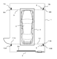
図1、図2および図3は、本発明の一実施例による機械式駐車装置の乗込室を示す平面図、背面図および側面図である。 1, 2, and 3 are a plan view, a rear view, and a side view showing a passenger compartment of a mechanical parking device according to an embodiment of the present invention.
乗込室1は、駐車車両2のための扉3Aを備えた出入口3を有しており、乗込室1内には、既に準備されたトレー4が配置されている。駐車車両の運転手は、出入口3から進入させた駐車車両2をトレー4上の所定位置に停止させた後、乗込室1を後にする。その後、トレー4に搭載された状態の駐車車両2は、例えば昇降装置を用いて地下側の格納スペースへと搬送されて格納される。
The
乗込室1内には、図1および図3に示すように駐車車両2におけるフロント側での高さ方向の許容値を超えた突出を検出する第一の高さ方向検出装置5と、図1~図3に示すように駐車車両2におけるリヤ側での高さ方向の許容値を超えた突出を検出する第二の高さ方向検出装置6が配置されている。
Inside the
第一の高さ方向検出装置5は、トレー4および駐車車両2のフロント側における両側に分散されて配置された支持柱7A,7Bと、支持柱7A,7Bに所定高さ位置でそれぞれ対向するように取り付けられた発光部8Aおよび受光部8Bと、駐車車両2におけるフロント側の高さ方向で発光部8Aと受光部8B間のビーム9を遮ったときに高さ方向の許容値を超えた突出物13の存在を検出する異常検出部等を有して構成されている。
The first height
第二の高さ方向検出装置6は、トレー4および駐車車両2のリヤ側における両側に分散されて配置された支持柱10A,10Bと、支持柱10A,10Bに所定高さ位置でそれぞれ対向するように取り付けられた発光部11Aおよび受光部11Bと、駐車車両2におけるリヤ側の高さ方向で発光部11Aと受光部11B間のビーム12を遮ったときに高さ方向の許容値を超えた突出物13の存在を検出する異常検出部等を有して構成されている。
The second height
ここで、各ビーム9,12の高さおよび位置は、トレー4上に搭載された状態の駐車車両2を昇降装置等を使用して搬送し格納スペースへと格納する一連の移動中に、駐車車両2の突出物13が機械式駐車装置側の固定構造部材等に衝突および接触しない許容範囲を越えて突出したことを検出できるように選定されている。駐車車両2の突出物13としては、例えば駐車車両2のリヤ側に取り付けられた飾り部品等を想定している。
Here, the height and position of each
この検出対象となる駐車車両2側における突出物13の特定に応じて、駐車車両2のフロント側に配置した第一の高さ方向検出装置5を省略することもできる。また、トレー4上まで乗り込まれた駐車車両2が所定の停止位置となったとき、駐車車両2の長手方向両端部および幅方向両端部の異常突出を検出するために、高さ方向検出装置5,6と類似した構成の位置検出装置を高さ方向検出装置5,6の近傍に構成し、この位置検出装置と高さ方向検出装置5,6の異常検出部が連動するようにすることもできる。
Depending on the identification of the
駐車車両2の運転手が上述した機械式駐車装置を利用して駐車する場合、乗込室1の出入口3から駐車車両2を運転してトレー4上に乗り込ませ、駐車車両2をトレー4上の所定位置に停止させる。
When the driver of the parked
このとき、駐車車両2のフロント側に構成されている第一の高さ方向検出装置5は、発光部8Aから受光部8B間にビーム9を照射している。また駐車車両2のリヤ側に構成されている第二の高さ方向検出装置6は、発光部11Aから受光部11B間にビーム12を照射している。
At this time, the first height
従って、図3に示すように駐車車両2のリヤ側に上方への突出物13である飾り部品が装着されている場合、第二の高さ方向検出装置6は、この飾り部品によってビーム12が遮光されるかどうかを監視している。飾り部品が高さ方向の許容値を超えていないとき、第二の高さ方向検出装置6の異常検出部は、異常を検出しない。
Therefore, as shown in FIG. 3, when a decorative component, which is an upwardly protruding
しかし、駐車車両2のリヤ側に、上方への突出物13である飾り部品が装着されていて、かつ飾り部品が高さ方向の許容値を超えているとき、第二の高さ方向検出装置6が設置されていない機械式駐車装置では、駐車車両2が乗込室1から格納スペースへと搬送されてしまう。
However, when a decorative component, which is an upwardly protruding
図4は、このときの駐車車両近傍を便宜的に示した側面図である。 FIG. 4 is a side view showing the vicinity of the parked vehicle at this time for convenience.
同図に示すように、駐車車両2のリヤ側に取り付けられた飾り部品等の突出部13が高さ方向の許容値を超えているため、機械式駐車装置のすみ切りなどの固定構造部材14に突出物13が衝突したり接触したりして、飾り部品を損傷させてしまう危険がある。
As shown in the figure, since the
上述したように、このような飾り部品を付けた駐車車両2においては、図1~図3に示した第二の高さ方向検出装置6のビーム12を遮光する。第二の高さ方向検出装置6は、詳細な図示を省略したが、ビーム12の遮光信号を取り込む異常検出部と、異常検出部での検知があったときに運転手に通知する異常報知部などを有しており、異常検出部でビーム12の遮光信号を取り込んだとき、運転手が駐車車両2内もしくはその近傍にいる間に、異常報知部によって異常を報知する。この異常報知は、例えば、近傍に配置されたスピーカからの警報や音声や、強調された表示などによって運転手に通知される。
As described above, in the parked
これによって、駐車車両2の運転手は飾り部品を取り外したり、駐車を断念するなどの処置を講じたりすることができ、結果として飾り部品の破損を未然に防ぐことができる。
Thereby, the driver of the parked
尚、上述した第一の高さ方向検出装置5および第二の高さ方向検出装置6の具体的な構成は、図示のものに限らず採用することができる。また、本発明は、垂直循環方式、エレベータ方式、多層循環方式、水平循環方式など種々の機械式駐車装置に適用することができる。
Note that the specific configurations of the first height
以上説明したように本発明は、乗込室1内に乗り込ませた駐車車両2を格納スペースへと搬送して格納する機械式駐車装置において、駐車車両2の少なくともリヤ側における両側に分散されて所定高さ位置でそれぞれ対向するように取り付けられた発光部11Aおよび受光部11Bと、駐車車両2におけるリヤ側の高さ方向で発光部11Aと受光部11B間のビーム12を遮ったときに高さ方向の許容値を超えた突出物13の存在を検出する異常検出部を有した高さ方向検出装置6を設けたことを特徴とする。
As explained above, the present invention provides a mechanical parking device that transports and stores a parked
このような構成によれば、異常検出部でビーム12の遮光信号を取り込んだとき、機械式駐車装置側の固定構造部材によって損傷する危険がある駐車車両2の高さ方向の突出物13を検出することができるので、飾り部品等の破損を未然に防ぐことができる。
According to such a configuration, when the abnormality detection unit captures the light blocking signal of the
1 乗込室
2 駐車車両
6 高さ方向検出装置
11A 発光部
11B 受光部
12 ビーム
13 突出物
1
Claims (1)
前記乗込室内に、前記駐車車両のリヤ側の高さ方向の許容値を超える突出を検出する高さ方向検出装置を備え、
前記高さ方向検出装置は、前記駐車車両における幅方向両側に分散されて所定高さ位置でそれぞれ対向するように取り付けられた発光部および受光部を有してビームを投受光する構成とされ、
前記所定高さ位置は、前記格納スペース内において、前記駐車車両を側面から見た前記リヤ側のすみ切りの範囲に突出する固定構造部材に前記駐車車両のリヤ側でボディから上方に突出する突出物である飾り部品が干渉しない位置とされ、
前記駐車車両における前記突出物が、高さ方向で前記発光部と前記受光部間のビームを遮ったときに、前記突出物が前記所定高さ位置の許容値を超えたことを検出する異常検出部を有する、
機械式駐車装置。
In a mechanical parking device in which a parked vehicle loaded into a boarding compartment is transported to a storage space and stored using a lifting device,
A height direction detection device is provided in the boarding room to detect a protrusion exceeding a permissible value in the rear side of the parked vehicle in the height direction;
The height direction detection device is configured to have a light emitting part and a light receiving part that are distributed on both sides of the parked vehicle in the width direction and are attached to face each other at a predetermined height position, and emit and receive a beam,
The predetermined height position includes a fixed structural member that protrudes in a corner area of the rear side of the parked vehicle when viewed from the side in the storage space, and a protrusion that protrudes upward from the body on the rear side of the parked vehicle. It is located in a position where decorative parts that are objects do not interfere,
abnormality detection for detecting that the protrusion exceeds an allowable value at the predetermined height position when the protrusion in the parked vehicle blocks a beam between the light emitting unit and the light receiving unit in the height direction; having a section;
Mechanical parking device.
Priority Applications (1)
| Application Number | Priority Date | Filing Date | Title |
|---|---|---|---|
| JP2020031499A JP7358275B2 (en) | 2020-02-27 | 2020-02-27 | mechanical parking device |
Applications Claiming Priority (1)
| Application Number | Priority Date | Filing Date | Title |
|---|---|---|---|
| JP2020031499A JP7358275B2 (en) | 2020-02-27 | 2020-02-27 | mechanical parking device |
Publications (2)
| Publication Number | Publication Date |
|---|---|
| JP2021134557A JP2021134557A (en) | 2021-09-13 |
| JP7358275B2 true JP7358275B2 (en) | 2023-10-10 |
Family
ID=77660556
Family Applications (1)
| Application Number | Title | Priority Date | Filing Date |
|---|---|---|---|
| JP2020031499A Active JP7358275B2 (en) | 2020-02-27 | 2020-02-27 | mechanical parking device |
Country Status (1)
| Country | Link |
|---|---|
| JP (1) | JP7358275B2 (en) |
Citations (2)
| Publication number | Priority date | Publication date | Assignee | Title |
|---|---|---|---|---|
| JP2017002524A (en) | 2015-06-08 | 2017-01-05 | Ihi運搬機械株式会社 | Mechanical parking device and control method thereof |
| JP2019127690A (en) | 2018-01-22 | 2019-08-01 | 極東開発工業株式会社 | Parking device |
-
2020
- 2020-02-27 JP JP2020031499A patent/JP7358275B2/en active Active
Patent Citations (2)
| Publication number | Priority date | Publication date | Assignee | Title |
|---|---|---|---|---|
| JP2017002524A (en) | 2015-06-08 | 2017-01-05 | Ihi運搬機械株式会社 | Mechanical parking device and control method thereof |
| JP2019127690A (en) | 2018-01-22 | 2019-08-01 | 極東開発工業株式会社 | Parking device |
Also Published As
| Publication number | Publication date |
|---|---|
| JP2021134557A (en) | 2021-09-13 |
Similar Documents
| Publication | Publication Date | Title |
|---|---|---|
| JP2010255377A (en) | Method and device for detecting projected part of vehicle to be parked in mechanical type parking device | |
| JP2009191573A (en) | Parking equipment and program | |
| JP5226610B2 (en) | Vehicle mounting abnormality detection system | |
| JP7358275B2 (en) | mechanical parking device | |
| JP6574139B2 (en) | Parking equipment | |
| JP6749058B2 (en) | Parking equipment | |
| JP6378486B2 (en) | Car stop device | |
| JP4146098B2 (en) | Multistage parking facilities | |
| JP7358268B2 (en) | mechanical parking device | |
| JP3957426B2 (en) | Stop position detection device for mechanical parking equipment | |
| JP2003253902A (en) | Mechanical parking system and vehicle turning device | |
| JP4667913B2 (en) | Automatic warehouse | |
| JP6548467B2 (en) | Mechanical parking apparatus and control method thereof | |
| CN210062948U (en) | Vehicle stop device | |
| KR20200005517A (en) | Human detection system | |
| JP4978823B2 (en) | Overhead traveling car | |
| JP6955440B2 (en) | Mechanical parking equipment carrier control system and mechanical parking equipment equipped with it | |
| KR101672493B1 (en) | Protection device for vehicle side panel when parking | |
| KR102672980B1 (en) | Method for controlling high place work apparatus | |
| JP6486292B2 (en) | Parking equipment | |
| JPH086485B2 (en) | Lifting type car parking machine | |
| JP3690716B2 (en) | forklift | |
| JP2002213096A (en) | Safety device for mechanical parking device | |
| JP2001295489A (en) | Plane reciprocating parking system | |
| JP2022162335A (en) | Inside safety monitoring device and method |
Legal Events
| Date | Code | Title | Description |
|---|---|---|---|
| RD01 | Notification of change of attorney |
Free format text: JAPANESE INTERMEDIATE CODE: A7421 Effective date: 20200716 |
|
| A621 | Written request for application examination |
Free format text: JAPANESE INTERMEDIATE CODE: A621 Effective date: 20220421 |
|
| A977 | Report on retrieval |
Free format text: JAPANESE INTERMEDIATE CODE: A971007 Effective date: 20230224 |
|
| A131 | Notification of reasons for refusal |
Free format text: JAPANESE INTERMEDIATE CODE: A131 Effective date: 20230307 |
|
| A521 | Request for written amendment filed |
Free format text: JAPANESE INTERMEDIATE CODE: A523 Effective date: 20230413 |
|
| A131 | Notification of reasons for refusal |
Free format text: JAPANESE INTERMEDIATE CODE: A131 Effective date: 20230711 |
|
| A521 | Request for written amendment filed |
Free format text: JAPANESE INTERMEDIATE CODE: A523 Effective date: 20230905 |
|
| TRDD | Decision of grant or rejection written | ||
| A01 | Written decision to grant a patent or to grant a registration (utility model) |
Free format text: JAPANESE INTERMEDIATE CODE: A01 Effective date: 20230926 |
|
| A61 | First payment of annual fees (during grant procedure) |
Free format text: JAPANESE INTERMEDIATE CODE: A61 Effective date: 20230927 |
|
| R150 | Certificate of patent or registration of utility model |
Ref document number: 7358275 Country of ref document: JP Free format text: JAPANESE INTERMEDIATE CODE: R150 |