JP7287950B2 - COMMUNICATION METHOD, COMMUNICATION DEVICE, AND PROGRAM - Google Patents
COMMUNICATION METHOD, COMMUNICATION DEVICE, AND PROGRAM Download PDFInfo
- Publication number
- JP7287950B2 JP7287950B2 JP2020511094A JP2020511094A JP7287950B2 JP 7287950 B2 JP7287950 B2 JP 7287950B2 JP 2020511094 A JP2020511094 A JP 2020511094A JP 2020511094 A JP2020511094 A JP 2020511094A JP 7287950 B2 JP7287950 B2 JP 7287950B2
- Authority
- JP
- Japan
- Prior art keywords
- image
- receiver
- visible light
- time
- information
- Prior art date
- Legal status (The legal status is an assumption and is not a legal conclusion. Google has not performed a legal analysis and makes no representation as to the accuracy of the status listed.)
- Active
Links
Images


Classifications
-
- G—PHYSICS
- G06—COMPUTING OR CALCULATING; COUNTING
- G06K—GRAPHICAL DATA READING; PRESENTATION OF DATA; RECORD CARRIERS; HANDLING RECORD CARRIERS
- G06K19/00—Record carriers for use with machines and with at least a part designed to carry digital markings
- G06K19/06—Record carriers for use with machines and with at least a part designed to carry digital markings characterised by the kind of the digital marking, e.g. shape, nature, code
-
- G—PHYSICS
- G06—COMPUTING OR CALCULATING; COUNTING
- G06K—GRAPHICAL DATA READING; PRESENTATION OF DATA; RECORD CARRIERS; HANDLING RECORD CARRIERS
- G06K7/00—Methods or arrangements for sensing record carriers, e.g. for reading patterns
- G06K7/10—Methods or arrangements for sensing record carriers, e.g. for reading patterns by electromagnetic radiation, e.g. optical sensing; by corpuscular radiation
-
- H—ELECTRICITY
- H04—ELECTRIC COMMUNICATION TECHNIQUE
- H04B—TRANSMISSION
- H04B10/00—Transmission systems employing electromagnetic waves other than radio-waves, e.g. infrared, visible or ultraviolet light, or employing corpuscular radiation, e.g. quantum communication
- H04B10/11—Arrangements specific to free-space transmission, i.e. transmission through air or vacuum
- H04B10/114—Indoor or close-range type systems
- H04B10/116—Visible light communication
-
- H—ELECTRICITY
- H04—ELECTRIC COMMUNICATION TECHNIQUE
- H04N—PICTORIAL COMMUNICATION, e.g. TELEVISION
- H04N23/00—Cameras or camera modules comprising electronic image sensors; Control thereof
- H04N23/60—Control of cameras or camera modules
Landscapes
- Engineering & Computer Science (AREA)
- Physics & Mathematics (AREA)
- Electromagnetism (AREA)
- Signal Processing (AREA)
- General Physics & Mathematics (AREA)
- Theoretical Computer Science (AREA)
- Multimedia (AREA)
- Computer Networks & Wireless Communication (AREA)
- Health & Medical Sciences (AREA)
- General Health & Medical Sciences (AREA)
- Toxicology (AREA)
- Artificial Intelligence (AREA)
- Computer Vision & Pattern Recognition (AREA)
- Optical Communication System (AREA)
- Studio Devices (AREA)
Description
本発明は、通信方法、通信装置、送信機およびプログラムなどに関する。 The present invention relates to a communication method, a communication device, a transmitter, a program, and the like.
近年のホームネットワークでは、Ethernet(登録商標)や無線LAN(Local Area Network)でのIP(Internet Protocol)接続によるAV家電の連携に加え、環境問題に対応した電力使用量の管理や、宅外からの電源ON/OFFといった機能を持つホームエネルギーマネジメントシステム(HEMS)によって、多様な家電機器がネットワークに接続される家電連携機能の導入が進んでいる。しかしながら、通信機能を有するには、演算力が十分ではない家電や、コスト面で通信機能の搭載が難しい家電などもある。 In recent years, in home networks, in addition to coordinating AV home appliances by IP (Internet Protocol) connection via Ethernet (registered trademark) or wireless LAN (Local Area Network), power usage management in response to environmental issues, A home energy management system (HEMS), which has functions such as turning on/off the power of a home appliance, is promoting the introduction of a home appliance linkage function in which various home appliances are connected to a network. However, some home appliances do not have sufficient computing power to have a communication function, and some home appliances cannot be equipped with a communication function due to cost reasons.
このような問題を解決するため、特許文献1では、光を用いて自由空間に情報を伝達する光空間伝送装置において、照明光の単色光源を複数用いた通信を行うことで、限られた送信装置のなかで、効率的に機器間の通信を実現する技術が記載されている。
In order to solve such a problem, in
しかしながら、前記従来の方式では、適用される機器が照明のような3色光源を持つ場合に限定される。また、送信された情報を受信する受信機は、ユーザに有益な画像を表示することができない。 However, the conventional method is limited to the case where the equipment to which it is applied has a three-color light source such as lighting. Also, a receiver that receives the transmitted information cannot display an image useful to the user.
本発明は、このような課題を解決し、多様な機器間の通信を可能とする通信方法などを提供する。 The present invention solves such problems and provides a communication method and the like that enable communication between various devices.
本発明の一形態に係る通信方法は、イメージセンサを備えた端末を用いた通信方法であって、前記端末が可視光通信を行うことが可能か否かを判断し、前記端末が可視光通信を行うことが可能と判断した場合に、前記イメージセンサにより、輝度変化する被写体を撮像することにより、復号用画像を取得し、前記復号用画像に現れる縞模様から前記被写体が送信する第1の識別情報を取得し、前記可視光通信の判断において、前記端末が可視光通信を行うことが可能でないと判断した場合に、前記イメージセンサにより、前記被写体を撮像することによって撮像画像を取得し、前記撮像画像のエッジ検出を行うことで、少なくとも1つの輪郭を抽出し、前記少なくとも1つの輪郭の中から、所定の特定領域を特定し、前記特定領域のラインパターンから前記被写体が送信する第2の識別情報を取得する。 A communication method according to one aspect of the present invention is a communication method using a terminal equipped with an image sensor, the terminal determines whether or not the terminal can perform visible light communication, and the terminal performs visible light communication. When it is determined that it is possible to perform acquiring identification information, and acquiring a captured image by capturing an image of the subject with the image sensor when it is determined that the terminal is not capable of performing visible light communication in the determination of the visible light communication, At least one contour is extracted by performing edge detection of the captured image, a predetermined specific area is specified from the at least one contour, and a second line pattern transmitted by the subject is detected from the line pattern of the specific area. to obtain the identity of
なお、これらの包括的または具体的な態様は、システム、方法、集積回路、コンピュータプログラムまたはコンピュータ読み取り可能なCD-ROMなどの記録媒体で実現されてもよく、システム、方法、集積回路、コンピュータプログラムおよび記録媒体の任意な組み合わせで実現されてもよい。また、一実施形態に関わる方法を実行するコンピュータプログラムがサーバの記録媒体に保存されており、端末の要求に応じて、サーバから端末に配信する態様で実現されてもよい。 In addition, these generic or specific aspects may be realized by a system, method, integrated circuit, computer program, or a recording medium such as a computer-readable CD-ROM. and any combination of recording media. Moreover, a computer program for executing the method according to one embodiment may be stored in a recording medium of a server, and may be implemented in a mode of being distributed from the server to the terminal in response to a request from the terminal.
本発明によれば、多様な機器間の通信を実現できる。 According to the present invention, communication between various devices can be realized.
本発明の一態様に係る通信方法は、イメージセンサを備えた端末を用いた通信方法であって、前記端末が可視光通信を行うことが可能か否かを判断し、前記端末が可視光通信を行うことが可能と判断した場合に、前記イメージセンサにより、輝度変化する被写体を撮像することにより、復号用画像を取得し、前記復号用画像に現れる縞模様から、前記被写体が送信する第1の識別情報を取得し、前記可視光通信の判断において、前記端末が可視光通信を行うことが可能でないと判断した場合に、前記イメージセンサにより、前記被写体を撮像することによって撮像画像を取得し、前記撮像画像のエッジ検出を行うことで、少なくとも1つの輪郭を抽出し、前記少なくとも1つの輪郭の中から、所定の特定領域を特定し、前記特定領域のラインパターンから前記被写体が送信する第2の識別情報を取得する。 A communication method according to an aspect of the present invention is a communication method using a terminal equipped with an image sensor, the terminal determines whether or not the terminal is capable of performing visible light communication, and the terminal performs visible light communication. When it is determined that it is possible to perform and acquires a captured image by capturing an image of the subject with the image sensor when it is determined that the terminal is not capable of performing visible light communication in the determination of the visible light communication. and extracting at least one contour by performing edge detection on the captured image, identifying a predetermined specific region from the at least one contour, and detecting the first line pattern transmitted by the subject from the line pattern of the specific region. Acquire the identification information of 2.
これにより、例えば実施の形態10のように、受信機などの端末は、可視光通信ができるか否かに関わらず、送信機などの被写体から、第1の識別情報または第2の識別情報を取得することができる。つまり、端末は、可視光通信を行うことができる場合には、被写体から例えば光IDを第1の識別情報として取得する。一方、端末は、可視光通信を行うことができなくても、その被写体から例えば画像IDまたはフレームIDを第2の識別情報として取得することができる。具体的には、例えば図183および図188に示す送信画像が被写体として撮像され、その送信画像の領域が特定領域(すなわち選択領域)として選択され、その送信画像のラインパターンから第2の識別情報が取得される。したがって、可視光通信が不可能な場合でも、第2の識別情報を適切に取得することができる。なお、縞模様は、輝線パターンまたは輝線パターン領域とも呼ばれる。
As a result, for example, as in
また、前記特定領域の特定では、所定の大きさ以上の四角形の輪郭を有する領域、または、所定の大きさ以上の角丸四角形の輪郭を有する領域を、前記特定領域として特定してもよい。 Further, in specifying the specific area, an area having a rectangular outline of a predetermined size or more, or an area having a rounded square outline of a predetermined size or more may be identified as the specific area.
これにより、例えば図179に示すように、四角形または角丸四角形の領域を特定領域として適切に特定することができる。 As a result, for example, as shown in FIG. 179, a square or rounded square area can be appropriately specified as the specified area.
また、前記可視光通信の判断では、前記端末が露光時間を所定の値以下に変更することができる端末であると特定した場合に、可視光通信を行うことが可能であると判断し、前記端末が露光時間を前記所定の値以下に変更することができない端末であると特定した場合に、可視光通信を行うことが可能でないと判断してもよい。 Further, in determining the visible light communication, if the terminal is specified as a terminal capable of changing the exposure time to a predetermined value or less, it is determined that the visible light communication can be performed. If the terminal is identified as a terminal that cannot change the exposure time to the predetermined value or less, it may be determined that visible light communication is not possible.
これにより、例えば図180に示すように、可視光信号を行うことが可能か否かを適切に判断することができる。 Accordingly, as shown in FIG. 180, for example, it is possible to appropriately determine whether or not the visible light signal can be transmitted.
また、前記可視光通信の判断において、前記端末が可視光通信を行うことが可能と判断した場合に、前記被写体を撮像するときには、前記イメージセンサの露光時間を第1の露光時間に設定し、前記第1の露光時間で前記被写体を撮像することで、前記復号用画像を取得し、前記可視光通信の判断において、前記端末が可視光通信を行うことが可能でないと判断した場合に、前記被写体を撮像するときには、前記イメージセンサの露光時間を第2の露光時間に設定し、前記第2の露光時間で前記被写体を撮像することで、前記撮像画像を取得し、前記第1の露光時間は、前記第2の露光時間よりも短くてもよい。 setting the exposure time of the image sensor to a first exposure time when capturing an image of the subject when the terminal determines that the visible light communication can be performed in the determination of the visible light communication; When the image for decoding is acquired by imaging the subject with the first exposure time, and the terminal determines that the visible light communication is not possible in the determination of the visible light communication, the When capturing an image of a subject, the exposure time of the image sensor is set to a second exposure time, and the captured image is obtained by capturing the subject with the second exposure time, and the captured image is captured at the first exposure time. may be shorter than the second exposure time.
これにより、第1の露光時間での撮像によって、縞模様を有する復号用画像を取得して、その縞模様に対する復号によって、第1の識別情報を適切に取得することができる。さらに、第2の露光時間での撮像によって、通常撮影画像を撮像画像として取得し、その通常撮影画像に現れているラインパターンから第2の識別情報を適切に取得することができる。これにより、端末は、第1の露光時間と第2の露光時間とを使い分けることによって、その端末に適した第1の識別情報または第2の識別情報を取得することができる。 This makes it possible to acquire a decoding image having a striped pattern by imaging with the first exposure time, and to appropriately acquire the first identification information by decoding the striped pattern. Furthermore, by imaging with the second exposure time, it is possible to acquire the normally shot image as the shot image, and appropriately acquire the second identification information from the line pattern appearing in the normally shot image. Thereby, the terminal can acquire the first identification information or the second identification information suitable for the terminal by properly using the first exposure time and the second exposure time.
また、前記被写体は、前記イメージセンサから見て矩形形状であり、当該被写体の中心領域が輝度変化することにより、前記第1の識別情報を送信し、当該被写体の周縁にバーコード状のラインパターンが配置されており、前記可視光通信の判断において、前記端末が可視光通信を行うことが可能と判断した場合に、前記被写体を撮像するときには、前記イメージセンサの有する複数の露光ラインに対応する複数の輝線から構成される輝線パターンを含む前記復号用画像を取得し、前記輝線パターンを復号することによって前記第1の識別情報を取得し、前記可視光通信の判断において、前記端末が可視光通信を行うことが可能でないと判断した場合に、前記被写体を撮像するときには、前記撮像画像の前記ラインパターンから前記第2の識別情報を取得してもよい。 Further, the subject has a rectangular shape as viewed from the image sensor, and the first identification information is transmitted by changing the brightness of a central area of the subject, and a barcode-like line pattern is formed around the periphery of the subject. is arranged, and in the determination of the visible light communication, when the terminal determines that it is possible to perform visible light communication, when imaging the subject, the plurality of exposure lines of the image sensor correspond to obtaining the decoding image including a bright line pattern composed of a plurality of bright lines, obtaining the first identification information by decoding the bright line pattern, The second identification information may be acquired from the line pattern of the captured image when the subject is captured when it is determined that communication is not possible.
これにより、中心領域が輝度変化する被写体から、第1の識別情報および第2の識別情報を適切に取得することができる。 As a result, the first identification information and the second identification information can be appropriately acquired from a subject whose central region changes in brightness.
また、前記復号用画像から得られる前記第1の識別情報と、前記ラインパターンから得られる前記第2の識別情報は、同一の情報であってもよい。 Further, the first identification information obtained from the decoding image and the second identification information obtained from the line pattern may be the same information.
これにより、可視光通信が可能な端末でも、可視光通信が不可能な端末でも、その被写体から同じ情報を取得することができる。 As a result, the same information can be obtained from the subject regardless of whether the terminal is capable of visible light communication or the terminal is not capable of visible light communication.
また、前記可視光通信の判断において、前記端末が可視光通信を行うことが可能と判断した場合に、前記第1の識別情報に関連付けられている第1の動画像を表示し、前記第1の動画像をスライドさせる操作を受け付けると、前記第1の動画像の次に前記第1の識別情報に関連付けられている第2の動画像を表示してもよい。 Further, in the determination of the visible light communication, when it is determined that the terminal is capable of performing visible light communication, the first moving image associated with the first identification information is displayed, and the first moving image is displayed. A second moving image associated with the first identification information may be displayed next to the first moving image when an operation of sliding the moving image is received.
例えば、第1の動画像および第2の動画像のそれぞれは、図162に示す第1のAR画像P46および第2のAR画像P46cである。また、第1の識別情報は、例えば上述のように光IDである。上記一態様に係る通信方法では、第1の動画像をスライドさせる操作、つまりスワイプが受け付けられると、第1の動画像の次に第1の識別情報に関連付けられている第2の動画像が表示される。したがって、ユーザに有益な画像を容易に表示することができる。また、図194Aに示すように、事前に可視光通信が可能か否かの判断が行われるため、不可能な場合にまで、可視光信号を取得しようとする無駄な処理を省くことができ、処理負担を軽減することができる。 For example, the first moving image and the second moving image are the first AR image P46 and the second AR image P46c shown in FIG. 162, respectively. Also, the first identification information is, for example, the light ID as described above. In the communication method according to the above aspect, when an operation of sliding the first moving image, that is, a swipe is accepted, the second moving image associated with the first identification information is displayed next to the first moving image. Is displayed. Therefore, it is possible to easily display an image that is beneficial to the user. Further, as shown in FIG. 194A, it is determined in advance whether or not visible light communication is possible. Processing load can be reduced.
また、前記第2の動画像の表示では、前記第1の動画像を横方向にスライドさせる操作を受け付けると、前記第2の動画像を表示し、前記第1の動画像を縦方向にスライドさせる動作を受け付けると、前記第1の識別情報に関連付けられている静止画像を表示してもよい。 Further, in the display of the second moving image, when an operation of sliding the first moving image in the horizontal direction is received, the second moving image is displayed and the first moving image is slid in the vertical direction. A still image associated with the first identification information may be displayed when an operation to cause the display to be performed is received.
これにより、例えば図162に示すように、第1の動画像の横方向へのスライド、すなわちスワイプによって、第2の動画像が表示される。さらに、例えば図163および図164に示すように、第1の動画像の縦方向へのスライドによって、第1の識別情報に関連付けられている静止画像が表示される。静止画像は、例えば図164に示すAR画像P47である。したがって、ユーザに有益な多種多様な画像を容易に表示することができる。 As a result, for example, as shown in FIG. 162, the second moving image is displayed by sliding the first moving image in the horizontal direction, that is, by swiping. Furthermore, as shown in FIGS. 163 and 164, for example, by sliding the first moving image in the vertical direction, a still image associated with the first identification information is displayed. The still image is the AR image P47 shown in FIG. 164, for example. Therefore, it is possible to easily display a wide variety of images that are beneficial to the user.
また、前記第1の動画像および前記第2の動画像のそれぞれにおいて、最初に表示されるピクチャ内のオブジェクトは同一の位置にあってもよい。 Also, in each of the first moving image and the second moving image, the object in the first displayed picture may be at the same position.
これにより、例えば図162に示すように、第1の動画像に代わって第2の動画像が表示されるときには、それらの最初に表示されるオブジェクトが同一位置にあるため、ユーザは、第1の動画像および第2の動画像が互いに関連していることを容易に把握することができる。 Accordingly, when the second moving image is displayed instead of the first moving image, for example, as shown in FIG. and the second moving image are related to each other.
また、前記イメージセンサによる撮像によって前記第1の識別情報を再び取得したときには、表示されている動画像の次に前記第1の識別情報に関連付けられている次の動画像を表示してもよい。 Further, when the first identification information is acquired again by imaging with the image sensor, the next moving image associated with the first identification information may be displayed next to the displayed moving image. .
これにより、例えば図162に示すように、スライドまたはスワイプなどの操作が行われなくても、第1の識別情報である光IDが取り直されると、次の動画像が表示される。したがって、ユーザに有益な動画像をより容易に表示することができる。 As a result, as shown in FIG. 162, for example, the next moving image is displayed when the light ID, which is the first identification information, is reacquired without an operation such as slide or swipe. Therefore, moving images beneficial to the user can be displayed more easily.
また、前記表示されている動画像および前記次の動画像のそれぞれにおいて、最初に表示されるピクチャ内のオブジェクトは同一の位置にあってもよい。 Also, in each of the moving image being displayed and the next moving image, the object in the first displayed picture may be at the same position.
これにより、例えば図162に示すように、表示されている動画像に代わって次の動画像が表示されるときには、それらの最初に表示されるオブジェクトが同一位置にあるため、ユーザは、それらの動画像が互いに関連していることを容易に把握することができる。 As a result, for example, as shown in FIG. 162, when the next moving image is displayed in place of the displayed moving image, the first displayed objects are at the same position, so that the user can It is possible to easily grasp that the moving images are related to each other.
また、前記第1の動画像および前記第2の動画像のうちの少なくとも一方の動画像は、前記動画像内の位置が前記動画像の端に近いほど、当該位置における透明度が高くなるように形成されていてもよい。 Further, at least one of the first moving image and the second moving image is arranged such that the closer the position in the moving image is to the end of the moving image, the higher the transparency at that position. may be formed.
これにより、例えば図93または図166に示すように、その動画像が通常撮影画像に重畳されて表示される場合には、通常撮影画像によって示される環境に、輪郭が曖昧なオブジェクトが現実に存在するように、撮像表示画像を表示することができる。 As a result, for example, as shown in FIG. 93 or FIG. 166, when the moving image is superimposed on the normal photographed image and displayed, an object with an ambiguous outline actually exists in the environment indicated by the normal photographed image. The captured display image can be displayed as shown in FIG.
また、前記第1の動画像および前記第2の動画像のうちの少なくとも一方の動画像が表示される領域の外に、画像を表示してもよい。 Further, an image may be displayed outside the area in which at least one of the first moving image and the second moving image is displayed.
これにより、例えば図161に示すサブ画像Ps46のように、動画像が表示される領域の外に、画像が表示されるため、ユーザにより有益な多種多様な画像を容易に表示することができる。 As a result, an image is displayed outside the area where the moving image is displayed, such as sub-image Ps46 shown in FIG. 161, so that a wide variety of useful images for the user can be easily displayed.
また、前記イメージセンサによる第1の露光時間による撮像によって、通常撮影画像を取得し、前記第1の露光時間よりも短い第2の露光時間による撮像によって、複数の輝線のパターンからなる領域である輝線パターン領域を含む前記復号用画像を取得し、前記復号用画像に対する復号によって前記第1の識別情報を取得し、前記第1の動画像または前記第2の動画像のうちの少なくとも一方の動画像の表示では、前記通常撮影画像から、前記復号用画像における前記輝線パターン領域と同一の位置にある基準領域を特定し、前記基準領域に基づいて、前記通常撮影画像において前記動画像が重畳される領域を対象領域として認識し、前記対象領域に前記動画像を重畳してもよい。例えば、前記第1の動画像または前記第2の動画像のうちの少なくとも一方の動画像の表示では、前記通常撮影画像における、前記基準領域の上、下、左または右の領域を前記対象領域として認識してもよい。 Also, an area composed of a pattern of a plurality of bright lines is obtained by acquiring a normal photographed image by imaging with a first exposure time by the image sensor, and by imaging with a second exposure time shorter than the first exposure time. obtaining the image for decoding including a bright line pattern area, obtaining the first identification information by decoding the image for decoding, and moving at least one of the first moving image and the second moving image. In displaying the image, a reference area located at the same position as the bright line pattern area in the decoding image is specified from the normal captured image, and the moving image is superimposed on the normal captured image based on the reference area. The moving image may be superimposed on the target area by recognizing the target area. For example, in the display of at least one of the first moving image and the second moving image, an area above, below, left or right of the reference area in the normal shot image may be the target area. can be recognized as
これにより、例えば図50~図52および図172に示すように、基準領域に基づいて対象領域が認識され、その対象領域に動画像が重畳されるため、動画像が重畳される領域の自由度を容易に高めることができる。 As a result, for example, as shown in FIGS. 50 to 52 and 172, the target region is recognized based on the reference region, and the moving image is superimposed on the target region. can be easily increased.
また、前記第1の動画像または前記第2の動画像のうちの少なくとも一方の動画像の表示では、前記輝線パターン領域のサイズが大きいほど、前記動画像のサイズを大きくしてもよい。 Further, in displaying at least one of the first moving image and the second moving image, the size of the moving image may be increased as the size of the bright line pattern area is increased.
これにより、図172に示すように、動画像のサイズが輝線パターン領域のサイズに応じて変化するため、動画像のサイズが固定されている場合と比べて、その動画像によって示されるオブジェクトがより現実に存在するように、その動画像を表示することができる。 As a result, as shown in FIG. 172, since the size of the moving image changes according to the size of the bright line pattern area, compared to the case where the size of the moving image is fixed, the object indicated by the moving image is more visible. The moving image can be displayed as if it exists in reality.
本発明の一態様に係る送信機は、照明板と、前記照明板の背面側から光を照射する光源と、前記光源の輝度を変化させるマイクロコントローラと、を備え、前記マイクロコントローラは、前記光源を輝度変化させることにより、前記光源から前記照明板を介して第1の識別情報を送信し、前記照明板の前面側の周辺にバーコード状のラインパターンが配置されており、前記ラインパターンに第2の識別情報が符号化されており、前記第1の識別情報と、前記第2の識別情報は、同じ情報である。例えば、前記照明板の形状は、矩形形状である。 A transmitter according to an aspect of the present invention includes an illumination plate, a light source that irradiates light from the back side of the illumination plate, and a microcontroller that changes the brightness of the light source, wherein the microcontroller is the light source. By changing the luminance of the light source, the first identification information is transmitted through the illumination plate, and a barcode-shaped line pattern is arranged around the front side of the illumination plate, and the line pattern The second identification information is encoded, and the first identification information and the second identification information are the same information. For example, the illumination plate has a rectangular shape.
これにより、可視光通信を行うことが可能な端末に対しても、不可能な端末に対しても、同じ情報を送信することができる。 As a result, the same information can be transmitted to a terminal capable of performing visible light communication and to a terminal not capable of performing visible light communication.
なお、これらの包括的または具体的な態様は、装置、システム、方法、集積回路、コンピュータプログラムまたはコンピュータ読み取り可能なCD-ROMなどの記録媒体で実現されてもよく、装置、システム、方法、集積回路、コンピュータプログラムまたは記録媒体の任意な組み合わせで実現されてもよい。 In addition, these general or specific aspects may be realized by an apparatus, system, method, integrated circuit, computer program, or recording medium such as a computer-readable CD-ROM. It may be implemented in any combination of circuits, computer programs or recording media.
以下、実施の形態について、図面を参照しながら具体的に説明する。 Hereinafter, embodiments will be specifically described with reference to the drawings.
なお、以下で説明する実施の形態は、いずれも包括的または具体的な例を示すものである。以下の実施の形態で示される数値、形状、材料、構成要素、構成要素の配置位置及び接続形態、ステップ、ステップの順序などは、一例であり、本発明を限定する主旨ではない。また、以下の実施の形態における構成要素のうち、最上位概念を示す独立請求項に記載されていない構成要素については、任意の構成要素として説明される。 It should be noted that the embodiments described below are all comprehensive or specific examples. Numerical values, shapes, materials, components, arrangement positions and connection forms of components, steps, order of steps, and the like shown in the following embodiments are examples and are not intended to limit the present invention. In addition, among the constituent elements in the following embodiments, constituent elements that are not described in independent claims representing the highest concept will be described as optional constituent elements.
(実施の形態1)
以下、実施の形態1について説明する。(Embodiment 1)
(発光部の輝度の観測)
1枚の画像を撮像するとき、全ての撮像素子を同一のタイミングで露光させるのではなく、撮像素子ごとに異なる時刻に露光を開始・終了する撮像方法を提案する。図1は、1列に並んだ撮像素子は同時に露光させ、列が近い順に露光開始時刻をずらして撮像する場合の例である。ここでは、同時に露光する撮像素子の露光ラインと呼び、その撮像素子に対応する画像上の画素のラインを輝線と呼ぶ。(Observation of luminance of light-emitting part)
When capturing one image, instead of exposing all the imaging elements at the same timing, an imaging method is proposed in which exposure is started and ended at different times for each imaging element. FIG. 1 shows an example in which imaging elements arranged in a row are exposed simultaneously, and the exposure start time is shifted in order of proximity of the row. Here, the lines of pixels on the image corresponding to the image sensors to be exposed at the same time are referred to as exposure lines, and the lines of pixels on the image corresponding to the image sensors are referred to as bright lines.
この撮像方法を用いて、点滅している光源を撮像素子の全面に写して撮像した場合、図2のように、撮像画像上に露光ラインに沿った輝線(画素値の明暗の線)が生じる。この輝線のパターンを認識することで、撮像フレームレートを上回る速度の光源輝度変化を推定することができる。これにより、信号を光源輝度の変化として送信することで、撮像フレームレート以上の速度での通信を行うことができる。光源が2種類の輝度値をとることで信号を表現する場合、低い方の輝度値をロー(LO),高い方の輝度値をハイ(HI)と呼ぶ。ローは光源が光っていない状態でも良いし、ハイよりも弱く光っていても良い。 When this imaging method is used to capture a blinking light source on the entire surface of the imaging device, bright lines (bright and dark lines of pixel values) appear on the captured image along the exposure lines, as shown in FIG. . By recognizing this bright line pattern, it is possible to estimate the light source luminance change at a speed higher than the imaging frame rate. Accordingly, by transmitting a signal as a change in light source luminance, communication can be performed at a speed equal to or higher than the imaging frame rate. When a light source expresses a signal by taking two kinds of luminance values, the lower luminance value is called low (LO), and the higher luminance value is called high (HI). The low can be without any light source, or it can be less bright than the high.
この方法によって、撮像フレームレートを超える速度で情報の伝送を行う。 By this method, information is transmitted at a speed exceeding the imaging frame rate.
一枚の撮像画像中に、露光時間が重ならない露光ラインが20ラインあり、撮像のフレームレートが30fpsのときは、1.67ミリ秒周期の輝度変化を認識できる。露光時間が重ならない露光ラインが1000ラインある場合は、3万分の1秒(約33マイクロ秒)周期の輝度変化を認識できる。なお、露光時間は例えば10ミリ秒よりも短く設定される。 When there are 20 exposure lines whose exposure times do not overlap in one captured image, and the frame rate of imaging is 30 fps, it is possible to recognize a luminance change with a period of 1.67 milliseconds. If there are 1,000 exposure lines whose exposure times do not overlap, luminance changes with a cycle of 1/30,000 second (approximately 33 microseconds) can be recognized. Note that the exposure time is set to be shorter than 10 milliseconds, for example.
図2は、一つの露光ラインの露光が完了してから次の露光ラインの露光が開始される場合を示している。 FIG. 2 shows the case where the exposure of the next exposure line is started after the exposure of one exposure line is completed.
この場合、1秒あたりのフレーム数(フレームレート)がf、1画像を構成する露光ライン数がlのとき、各露光ラインが一定以上の光を受光しているかどうかで情報を伝送すると、最大でflビット毎秒の速度で情報を伝送することができる。 In this case, when the number of frames per second (frame rate) is f and the number of exposure lines that make up one image is l, if information is transmitted based on whether or not each exposure line receives a certain amount of light, the maximum can transmit information at a rate of fl bits per second.
なお、ラインごとではなく、画素ごとに時間差で露光を行う場合は、さらに高速で通信が可能である。 Further, when exposure is performed with a time difference for each pixel instead of for each line, communication can be performed at a higher speed.
このとき、露光ラインあたりの画素数がm画素であり、各画素が一定以上の光を受光しているかどうかで情報を伝送する場合には、伝送速度は最大でflmビット毎秒となる。 At this time, when the number of pixels per exposure line is m pixels and information is transmitted depending on whether or not each pixel receives a certain amount of light, the maximum transmission speed is flm bits per second.
図3のように、発光部の発光による各露光ラインの露光状態を複数のレベルで認識可能であれば、発光部の発光時間を各露光ラインの露光時間より短い単位の時間で制御することで、より多くの情報を伝送することができる。 As shown in FIG. 3, if it is possible to recognize the exposure state of each exposure line by light emission of the light emitting unit at a plurality of levels, it is possible to control the light emission time of the light emitting unit in units shorter than the exposure time of each exposure line. , can transmit more information.
露光状態をElv段階で認識可能である場合には、最大でflElvビット毎秒の速度で情報を伝送することができる。 If the exposure state is recognizable in Elv steps, information can be transmitted at a rate of up to flElv bits per second.
また、各露光ラインの露光のタイミングと少しずつずらしたタイミングで発光部を発光させることで、発信の基本周期を認識することができる。 In addition, by causing the light emitting unit to emit light at timing slightly shifted from the exposure timing of each exposure line, the basic period of transmission can be recognized.
図4は、一つの露光ラインの露光が完了する前に次の露光ラインの露光が開始される場合を示している。即ち、隣接する露光ラインの露光時間が、部分的に時間的な重なりを持つ構成となっている。このような構成により、(1)一つの露光ラインの露光時間の終了を待って次の露光ラインの露光を開始する場合に比べ、所定の時間内におけるサンプル数を多くすることができる。所定時間内におけるサンプル数が多くなることにより、被写体である光送信機が発生する光信号をより適切に検出することが可能となる。即ち、光信号を検出する際のエラー率を低減することが可能となる。更に、(2)一つの露光ラインの露光時間の終了を待って次の露光ラインの露光を開始する場合に比べ、各露光ラインの露光時間を長くすることができるため、被写体が暗い場合であっても、より明るい画像を取得することが可能となる。即ち、S/N比を向上させることが可能となる。なお、全ての露光ラインにおいて、隣接する露光ラインの露光時間が、部分的に時間的な重なりを持つ構成となる必要はなく、一部の露光ラインについて部分的に時間的な重なりを持たない構成とすることも可能である。一部の露光ラインについて部分的に時間的な重なりを持たないように構成するにより、撮像画面上における露光時間の重なりによる中間色の発生を抑制でき、より適切に輝線を検出することが可能となる。 FIG. 4 shows the case where the exposure of the next exposure line is started before the exposure of one exposure line is completed. In other words, the exposure times of adjacent exposure lines are partially overlapped. With such a configuration, (1) the number of samples within a predetermined time can be increased compared to the case where the exposure time of one exposure line is completed before the exposure of the next exposure line is started. By increasing the number of samples within a predetermined period of time, it becomes possible to more appropriately detect the optical signal generated by the optical transmitter, which is the subject. That is, it is possible to reduce the error rate when detecting optical signals. Furthermore, (2) the exposure time of each exposure line can be lengthened compared to the case where the exposure of the next exposure line is started after waiting for the end of the exposure time of one exposure line, so even when the subject is dark. However, it is possible to obtain a brighter image. That is, it becomes possible to improve the S/N ratio. In all exposure lines, the exposure times of adjacent exposure lines do not need to have a partial temporal overlap, and some exposure lines do not have a partial temporal overlap. It is also possible to By configuring some exposure lines so that they do not partially overlap in time, it is possible to suppress the occurrence of intermediate colors due to overlap of exposure times on the imaging screen, and it is possible to detect bright lines more appropriately. .
この場合は、各露光ラインの明るさから露光時間を算出し、発光部の発光の状態を認識する。 In this case, the exposure time is calculated from the brightness of each exposure line, and the light emission state of the light emitting unit is recognized.
なお、各露光ラインの明るさを、輝度が閾値以上であるかどうかの2値で判別する場合には、発光していない状態を認識するために、発光部は発光していない状態を各ラインの露光時間以上の時間継続しなければならない。 When the brightness of each exposure line is determined by a binary value indicating whether or not the brightness is equal to or greater than a threshold value, the light emitting unit detects the non-emission state of each line in order to recognize the non-emission state. must continue for at least the exposure time of
図5Aは、各露光ラインの露光開始時刻が等しい場合に、露光時間の違いによる影響を示している。7500aは前の露光ラインの露光終了時刻と次の露光ラインの露光開始時刻とが等しい場合であり、7500bはそれより露光時間を長くとった場合である。7500bのように、隣接する露光ラインの露光時間が、部分的に時間的な重なりを持つ構成とすることにより、露光時間を長くとることが可能となる。即ち、撮像素子に入射する光が増大し、明るい画像を得ることができる。また、同一の明るさの画像を撮像するための撮像感度を低く抑えられることで、ノイズの少ない画像が得られるため、通信エラーが抑制される。 FIG. 5A shows the effect of different exposure times when the exposure start times of the exposure lines are the same. 7500a is the case where the exposure end time of the previous exposure line is equal to the exposure start time of the next exposure line, and 7500b is the case where the exposure time is longer than that. As in 7500b, the exposure times of adjacent exposure lines partially overlap each other, thereby making it possible to lengthen the exposure time. That is, the amount of light incident on the image sensor increases, and a bright image can be obtained. In addition, since an image with less noise can be obtained by suppressing the imaging sensitivity for imaging an image with the same brightness, communication errors can be suppressed.
図5Bは、露光時間が等しい場合に、各露光ラインの露光開始時刻の違いによる影響を示している。7501aは前の露光ラインの露光終了時刻と次の露光ラインの露光開始時刻とが等しい場合であり、7501bは前の露光ラインの露光終了より早く次の露光ラインの露光を開始する場合である。7501bのように、隣接する露光ラインの露光時間が、部分的に時間的な重なりを持つ構成とすることにより、時間あたりに露光できるラインを増やすことが可能となる。これにより、より解像度が高くなり、多くの情報量が得られる。サンプル間隔(=露光開始時刻の差)が密になることで、より正確に光源輝度の変化を推定することができ、エラー率が低減でき、更に、より短い時間における光源輝度の変化を認識することができる。露光時間に重なりを持たせることで、隣接する露光ラインの露光量の差を利用して、露光時間よりも短い光源の点滅を認識することができる。 FIG. 5B shows the effect of different exposure start times for each exposure line when the exposure times are the same. 7501a is the case where the exposure end time of the previous exposure line is equal to the exposure start time of the next exposure line, and 7501b is the case where the exposure of the next exposure line is started earlier than the end of exposure of the previous exposure line. As in 7501b, the exposure times of adjacent exposure lines partially overlap each other, thereby increasing the number of lines that can be exposed per time. As a result, the resolution becomes higher and a large amount of information can be obtained. By increasing the sample interval (=difference in exposure start time), it is possible to estimate changes in light source brightness more accurately, reduce the error rate, and recognize changes in light source brightness over a shorter period of time. be able to. By overlapping the exposure times, it is possible to recognize blinking of the light source shorter than the exposure time by utilizing the difference in the amount of exposure of adjacent exposure lines.
また、上述のサンプル数が少ない場合、つまり、サンプル間隔(図5Bに示す時間差tD)が長いと、光源輝度の変化を正確に検出することができない可能性が高くなる。この場合には、露光時間を短くすることによって、その可能性を抑えることができる。つまり、光源輝度の変化を正確に検出することができる。また、露光時間は、露光時間>(サンプル間隔-パルス幅)を満たすことが望ましい。パルス幅は、光源の輝度がHighになっている期間である光のパルス幅である。これにより、Highの輝度を適切に検出することができる。Also, when the number of samples is small, that is, when the sample interval (time difference t D shown in FIG. 5B) is long, there is a high possibility that changes in light source luminance cannot be accurately detected. In this case, the possibility can be suppressed by shortening the exposure time. That is, changes in light source luminance can be accurately detected. Also, the exposure time preferably satisfies the condition of exposure time>(sample interval−pulse width). The pulse width is the pulse width of light, which is the period during which the luminance of the light source is high. Thereby, High luminance can be appropriately detected.
図5A、図5Bで説明したように、隣接する露光ラインの露光時間が、部分的に時間的な重なりをもつように、各露光ラインを順次露光する構成において、露光時間を通常撮影モードよりも短く設定することにより発生する輝線パターンを信号伝送に用いることにより通信速度を飛躍的に向上させることが可能になる。ここで、可視光通信時における露光時間を1/480秒以下に設定することにより適切な輝線パターンを発生させることが可能となる。ここで、露光時間は、フレーム周波数=fとすると、露光時間<1/8×fと設定する必要がある。撮影の際に発生するブランキングは、最大で1フレームの半分の大きさになる。即ち、ブランキング時間は、撮影時間の半分以下であるため、実際の撮影時間は、最も短い時間で1/2fとなる。更に、1/2fの時間内において、4値の情報を受ける必要があるため、少なくとも露光時間は、1/(2f×4)よりも短くする必要が生じる。通常フレームレートは、60フレーム/秒以下であることから、1/480秒以下の露光時間に設定することにより、適切な輝線パターンを画像データに発生させ、高速の信号伝送を行うことが可能となる。 As described with reference to FIGS. 5A and 5B, in a configuration in which each exposure line is sequentially exposed so that the exposure times of adjacent exposure lines partially overlap, the exposure time is set to be longer than that in the normal shooting mode. By using the bright line pattern generated by the short setting for signal transmission, it is possible to dramatically improve the communication speed. Here, by setting the exposure time at the time of visible light communication to 1/480 seconds or less, it is possible to generate an appropriate bright line pattern. Here, assuming that the frame frequency=f, the exposure time must be set as follows: exposure time<1/8×f. The blanking that occurs during shooting has a maximum size of half of one frame. That is, since the blanking time is less than half the shooting time, the shortest actual shooting time is 1/2f. Furthermore, since it is necessary to receive quaternary information within the time of 1/2f, at least the exposure time needs to be shorter than 1/(2f×4). Since the normal frame rate is 60 frames/second or less, by setting the exposure time to 1/480 second or less, it is possible to generate an appropriate bright line pattern in the image data and perform high-speed signal transmission. Become.
図5Cは、各露光ラインの露光時間が重なっていない場合、露光時間が短い場合の利点を示している。露光時間が長い場合は、光源は7502aのように2値の輝度変化をしていたとしても、撮像画像では7502eのように中間色の部分ができ、光源の輝度変化を認識することが難しくなる傾向がある。しかし、7502dのように、一つの露光ラインの露光終了後、次の露光ラインの露光開始まで所定の露光しない空き時間(所定の待ち時間)tD2を設ける構成とすることにより、光源の輝度変化を認識しやすくすることが可能となる。即ち、7502fのような、より適切な輝線パターンを検出することが可能となる。7502dのように、所定の露光しない空き時間を設ける構成は、露光時間tEを各露光ラインの露光開始時刻の時間差tDよりも小さくすることにより実現することが可能となる。通常撮影モードが、隣接する露光ラインの露光時間が、部分的に時間的な重なりを持つ構成である場合において、露光時間を通常撮影モード時よりも、所定の露光しない空き時間が生じるまで短く設定することにより、実現することができる。また、通常撮影モードが、前の露光ラインの露光終了時刻と次の露光ラインの露光開始時刻とが等しい場合であっても、所定の露光しない時間が生じるまで露光時間を短く設定することにより、実現することができる。また、7502gのように、各露光ラインの露光開始時刻の間隔tDを大きくすることによっても、一つの露光ラインの露光終了後、次の露光ラインの露光開始まで所定の露光しない空き時間(所定の待ち時間)tD2を設ける構成をとることができる。この構成では、露光時間を長くすることができるため、明るい画像を撮像することができ、ノイズが少なくなることからエラー耐性が高い。一方で、この構成では、一定時間内に露光できる露光ラインが少なくなるため、7502hのように、サンプル数が少なくなるという欠点があるため、状況によって使い分けることが望ましい。例えば、撮像対象が明るい場合には前者の構成を用い、暗い場合には後者の構成を用いることで、光源輝度変化の推定誤差を低減することができる。FIG. 5C shows the advantage of short exposure times when the exposure times of the exposure lines do not overlap. When the exposure time is long, even if the light source has a binary brightness change like 7502a, the captured image has a neutral color part like 7502e, and it tends to be difficult to recognize the brightness change of the light source. There is However, as in 7502d, after the end of exposure of one exposure line, a predetermined idle time (predetermined waiting time) tD2 is provided until exposure of the next exposure line is started. can be easily recognized. That is, it becomes possible to detect a more appropriate bright line pattern such as 7502f. The configuration of providing a predetermined idle time during which no exposure is performed, as in 7502d, can be realized by making the exposure time tE smaller than the time difference tD between the exposure start times of the exposure lines. When the normal shooting mode has a structure in which the exposure times of adjacent exposure lines partially overlap, the exposure time is set shorter than in the normal shooting mode until a predetermined non-exposure period occurs. It can be realized by Further, even when the exposure end time of the previous exposure line and the exposure start time of the next exposure line are the same in the normal shooting mode, by setting the exposure time to be short until the predetermined non-exposure time occurs, can be realized. Also, by increasing the interval tD between the exposure start times of each exposure line as in 7502g, a predetermined non-exposure time (predetermined waiting time) tD2 can be provided. In this configuration, since the exposure time can be lengthened, a bright image can be captured, and noise is reduced, resulting in high error resistance. On the other hand, this configuration has the disadvantage that the number of exposure lines that can be exposed within a certain period of time decreases, and thus the number of samples decreases as in 7502h. For example, by using the former configuration when the imaging target is bright and using the latter configuration when the imaging target is dark, it is possible to reduce the estimation error of the light source luminance change.
なお、全ての露光ラインにおいて、隣接する露光ラインの露光時間が、部分的に時間的な重なりを持つ構成となる必要はなく、一部の露光ラインについて部分的に時間的な重なりを持たない構成とすることも可能である。また、全ての露光ラインにおいて、一つの露光ラインの露光終了後、次の露光ラインの露光開始まで所定の露光しない空き時間(所定の待ち時間)を設ける構成となる必要はなく、一部の露光ラインについて部分的に時間的な重なりを持つ構成とすることも可能である。このような構成とすることにより、それぞれの構成における利点を生かすことが可能となる。また、通常のフレームレート(30fps、60fps)にて撮影を行う通常撮影モードと、可視光通信を行う1/480秒以下の露光時間にて撮影を行う可視光通信モードとにおいて、同一の読み出し方法または回路にて信号の読み出しを行ってもよい。同一の読み出し方法または回路にて信号を読み出すことにより、通常撮影モードと、可視光通信モードとに対して、それぞれ別の回路を用いる必要がなくなり、回路規模を小さくすることが可能となる。 In all exposure lines, the exposure times of adjacent exposure lines do not need to have a partial temporal overlap, and some exposure lines do not have a partial temporal overlap. It is also possible to Further, in all exposure lines, it is not necessary to provide a predetermined non-exposure time (predetermined waiting time) after the end of exposure of one exposure line until the start of exposure of the next exposure line. It is also possible to configure the lines to have partial temporal overlap. With such a configuration, it is possible to take advantage of the advantages of each configuration. In addition, the same readout method is used in the normal shooting mode in which shooting is performed at a normal frame rate (30 fps, 60 fps) and in the visible light communication mode in which shooting is performed with an exposure time of 1/480 seconds or less for visible light communication. Alternatively, signals may be read out in a circuit. By reading out signals with the same reading method or circuit, it is not necessary to use separate circuits for the normal imaging mode and the visible light communication mode, and the circuit scale can be reduced.
図5Dは、光源輝度の最小変化時間tSと、露光時間tEと、各露光ラインの露光開始時刻の時間差tDと、撮像画像との関係を示している。tE+tD<tSとした場合は、必ず一つ以上の露光ラインが露光の開始から終了まで光源が変化しない状態で撮像するため、7503dのように輝度がはっきりとした画像が得られ、光源の輝度変化を認識しやすい。2tE>tSとした場合は、光源の輝度変化とは異なるパターンの輝線が得られる場合があり、撮像画像から光源の輝度変化を認識することが難しくなる。FIG. 5D shows the relationship between the minimum change time tS of the light source luminance, the exposure time tE , the time difference tD between the exposure start times of the exposure lines, and the captured image. When t E +t D <t S , one or more exposure lines are always imaged with the light source unchanged from the start to the end of exposure, so an image with clear brightness such as 7503d can be obtained. It is easy to recognize the brightness change of the light source. If 2t E >t S , a bright line pattern different from the change in luminance of the light source may be obtained, making it difficult to recognize the change in luminance of the light source from the captured image.
図5Eは、光源輝度の遷移時間tTと、各露光ラインの露光開始時刻の時間差tDとの関係を示している。tTに比べてtDが大きいほど、中間色になる露光ラインが少なくなり、光源輝度の推定が容易になる。tD>tTのとき中間色の露光ラインは連続で2ライン以下になり、望ましい。tTは、光源がLEDの場合は1マイクロ秒以下、光源が有機ELの場合は5マイクロ秒程度となるため、tDを5マイクロ秒以上とすることで、光源輝度の推定を容易にすることができる。FIG. 5E shows the relationship between the transition time tT of the light source luminance and the time difference tD between the exposure start times of the exposure lines. The larger tD is compared to tT , the fewer exposure lines will be intermediate colors, and the easier it will be to estimate the light source luminance. When t D >t T , the intermediate color exposure lines are not more than two continuous lines, which is desirable. Since tT is 1 microsecond or less when the light source is an LED and about 5 microseconds when the light source is an organic EL, tD is set to 5 microseconds or more to facilitate estimation of the light source luminance. be able to.
図5Fは、光源輝度の高周波ノイズtHTと、露光時間tEとの関係を示している。tHTに比べてtEが大きいほど、撮像画像は高周波ノイズの影響が少なくなり、光源輝度の推定が容易になる。tEがtHTの整数倍のときは高周波ノイズの影響がなくなり、光源輝度の推定が最も容易になる。光源輝度の推定には、tE>tHTであることが望ましい。高周波ノイズの主な原因はスイッチング電源回路に由来し、多くの電灯用のスイッチング電源ではtHTは20マイクロ秒以下であるため、tEを20マイクロ秒以上とすることで、光源輝度の推定を容易に行うことができる。FIG. 5F shows the relationship between the high-frequency noise tHT of the light source luminance and the exposure time tE . The larger tE is compared to tHT , the less the captured image is affected by high-frequency noise, and the easier it is to estimate the light source luminance. When tE is an integral multiple of tHT , the effect of high-frequency noise disappears, making estimation of the light source luminance the easiest. For estimating the light source luminance, it is desirable that t E >t HT . The main cause of high-frequency noise is the switching power supply circuit, and tHT is 20 microseconds or less in many switching power supplies for lamps. can be easily done.
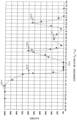
図5Gは、tHTが20マイクロ秒の場合の、露光時間tEと高周波ノイズの大きさとの関係を表すグラフである。tHTは光源によってばらつきがあることを考慮すると、グラフより、tEは、ノイズ量が極大をとるときの値と等しくなる値である、15マイクロ秒以上、または、35マイクロ秒以上、または、54マイクロ秒以上、または、74マイクロ秒以上として定めると効率が良いことが確認できる。高周波ノイズ低減の観点からはtEは大きいほうが望ましいが、前述のとおり、tEが小さいほど中間色部分が発生しづらくなるという点で光源輝度の推定が容易になるという性質もある。そのため、光源輝度の変化の周期が15~35マイクロ秒のときはtEは15マイクロ秒以上、光源輝度の変化の周期が35~54マイクロ秒のときはtEは35マイクロ秒以上、光源輝度の変化の周期が54~74マイクロ秒のときはtEは54マイクロ秒以上、光源輝度の変化の周期が74マイクロ秒以上のときはtEは74マイクロ秒以上として設定すると良い。FIG. 5G is a graph showing the relationship between the exposure time t E and the magnitude of high frequency noise when t HT is 20 microseconds. Considering that tHT varies depending on the light source, from the graph, tE is a value equal to the value when the amount of noise is maximized, 15 microseconds or more, or 35 microseconds or more, or It can be confirmed that the efficiency is good when it is defined as 54 microseconds or more or 74 microseconds or more. From the viewpoint of high-frequency noise reduction, it is desirable that tE is large. Therefore, when the period of change in light source luminance is 15 to 35 microseconds, tE is 15 microseconds or more, and when the period of change in light source luminance is 35 to 54 microseconds, tE is 35 microseconds or more. When the period of change in is 54 to 74 microseconds, tE should be set to 54 microseconds or longer, and when the period of change in light source luminance is 74 microseconds or longer, tE should be set to 74 microseconds or longer.
図5Hは、露光時間tEと認識成功率との関係を示す。露光時間tEは光源の輝度が一定である時間に対して相対的な意味を持つため、光源輝度が変化する周期tSを露光時間tEで割った値(相対露光時間)を横軸としている。グラフより、認識成功率をほぼ100%としたい場合は、相対露光時間を1.2以下にすれば良いことがわかる。例えば、送信信号を1kHzとする場合は露光時間を約0.83ミリ秒以下とすれば良い。同様に、認識成功率を95%以上としたい場合は相対露光時間を1.25以下に、認識成功率を80%以上としたい場合は相対露光時間を1.4以下にすれば良いということがわかる。また、相対露光時間が1.5付近で認識成功率が急激に下がり、1.6でほぼ0%となるため、相対露光時間が1.5を超えないように設定すべきであることがわかる。また、認識率が7507cで0になった後、7507dや、7507e、7507fで、再度上昇していることがわかる。そのため、露光時間を長くして明るい画像を撮像したい場合などは、相対露光時間が1.9から2.2、2.4から2.6、2.8から3.0となる露光時間を利用すれば良い。例えば、中間モードとして、これらの露光時間を使うと良い。FIG. 5H shows the relationship between exposure time t E and recognition success rate. Since the exposure time tE has a relative meaning with respect to the time during which the brightness of the light source is constant, the value (relative exposure time) obtained by dividing the cycle tS at which the brightness of the light source changes by the exposure time tE is plotted on the horizontal axis. there is From the graph, it can be seen that the relative exposure time should be set to 1.2 or less if the recognition success rate is to be approximately 100%. For example, when the transmission signal is 1 kHz, the exposure time should be approximately 0.83 milliseconds or less. Similarly, if a recognition success rate of 95% or more is desired, the relative exposure time should be 1.25 or less, and if a recognition success rate of 80% or more is desired, the relative exposure time should be 1.4 or less. Recognize. In addition, the recognition success rate drops sharply around the relative exposure time of 1.5 and becomes almost 0% at 1.6, so it can be seen that the relative exposure time should not exceed 1.5. . Also, it can be seen that after the recognition rate becomes 0 at 7507c, it rises again at 7507d, 7507e, and 7507f. Therefore, if you want to capture a bright image by increasing the exposure time, use an exposure time with a relative exposure time of 1.9 to 2.2, 2.4 to 2.6, or 2.8 to 3.0. do it. For example, intermediate modes may use these exposure times.
図6Aは、本実施の形態における情報通信方法のフローチャートである。 FIG. 6A is a flowchart of an information communication method according to this embodiment.
本実施の形態における情報通信方法は、被写体から情報を取得する情報通信方法であって、ステップSK91~SK93を含む。 The information communication method according to the present embodiment is an information communication method for obtaining information from a subject, and includes steps SK91 to SK93.
つまり、この情報通信方法は、イメージセンサによる前記被写体の撮影によって得られる画像に、前記イメージセンサに含まれる複数の露光ラインに対応する複数の輝線が前記被写体の輝度変化に応じて生じるように、前記イメージセンサの第1の露光時間を設定する第1の露光時間設定ステップSK91と、前記イメージセンサが、輝度変化する前記被写体を、設定された前記第1の露光時間で撮影することによって、前記複数の輝線を含む輝線画像を取得する第1の画像取得ステップSK92と、取得された前記輝線画像に含まれる前記複数の輝線のパターンによって特定されるデータを復調することにより情報を取得する情報取得ステップSK93とを含み、前記第1の画像取得ステップSK92では、前記複数の露光ラインのそれぞれは、順次異なる時刻で露光を開始し、かつ、当該露光ラインに隣接する隣接露光ラインの露光が終了してから所定の空き時間経過後に、露光を開始する。 In other words, in this information communication method, a plurality of bright lines corresponding to a plurality of exposure lines included in the image sensor are generated in an image obtained by photographing the subject with an image sensor according to changes in luminance of the subject. a first exposure time setting step SK91 for setting a first exposure time of the image sensor; a first image acquisition step SK92 for acquiring a bright line image including a plurality of bright lines; and information acquisition for acquiring information by demodulating data specified by the pattern of the plurality of bright lines included in the acquired bright line image. In the first image acquisition step SK92, each of the plurality of exposure lines sequentially starts exposure at different times, and the exposure of adjacent exposure lines adjacent to the exposure line is completed. After a predetermined idle time has passed since then, exposure is started.
図6Bは、本実施の形態における情報通信装置のブロック図である。 FIG. 6B is a block diagram of the information communication device in this embodiment.
本実施の形態における情報通信装置K90は、被写体から情報を取得する情報通信装置であって、構成要素K91~K93を備える。 An information communication device K90 in the present embodiment is an information communication device that obtains information from a subject, and includes components K91 to K93.
つまり、この情報通信装置K90は、イメージセンサによる前記被写体の撮影によって得られる画像に、前記イメージセンサに含まれる複数の露光ラインに対応する複数の輝線が前記被写体の輝度変化に応じて生じるように、前記イメージセンサの露光時間を設定する露光時間設定部K91と、輝度変化する前記被写体を、設定された前記露光時間で撮影することによって、前記複数の輝線を含む輝線画像を取得する前記イメージセンサを有する画像取得部K92と、取得された前記輝線画像に含まれる前記複数の輝線のパターンによって特定されるデータを復調することにより情報を取得する情報取得部K93とを備え、前記複数の露光ラインのそれぞれは、順次異なる時刻で露光を開始し、かつ、当該露光ラインに隣接する隣接露光ラインの露光が終了してから所定の空き時間経過後に、露光を開始する。 In other words, the information communication device K90 is arranged such that a plurality of bright lines corresponding to a plurality of exposure lines included in the image sensor appear in an image obtained by photographing the subject with the image sensor according to changes in the brightness of the subject. an exposure time setting unit K91 for setting the exposure time of the image sensor; and the image sensor for acquiring a bright line image including the plurality of bright lines by photographing the subject whose brightness changes with the set exposure time. and an information acquisition unit K93 for acquiring information by demodulating data specified by the patterns of the plurality of bright lines included in the acquired bright line image, wherein the plurality of exposure lines , start exposure at different times sequentially, and start exposure after a predetermined idle time has elapsed after the exposure of the adjacent exposure line is completed.
このような図6Aおよび図6Bによって示される情報通信方法および情報通信装置K90では、例えば図5Cなどに示すように、複数の露光ラインのそれぞれは、その露光ラインに隣接する隣接露光ラインの露光が終了してから所定の空き時間経過後に、露光を開始するため、被写体の輝度変化を認識しやすくすることができる。その結果、被写体から情報を適切に取得することができる。 In the information communication method and information communication apparatus K90 shown in FIGS. 6A and 6B, as shown in FIG. 5C, for example, each of a plurality of exposure lines is exposed in an adjacent exposure line adjacent to the exposure line. Since the exposure is started after a predetermined idle time has passed since the end, it is possible to easily recognize the luminance change of the subject. As a result, information can be appropriately acquired from the subject.
なお、上記実施の形態において、各構成要素は、専用のハードウェアで構成されるか、各構成要素に適したソフトウェアプログラムを実行することによって実現されてもよい。各構成要素は、CPUまたはプロセッサなどのプログラム実行部が、ハードディスクまたは半導体メモリなどの記録媒体に記録されたソフトウェアプログラムを読み出して実行することによって実現されてもよい。例えばプログラムは、図6Aのフローチャートによって示される情報通信方法をコンピュータに実行させる。 In the above-described embodiments, each component may be implemented by dedicated hardware or by executing a software program suitable for each component. Each component may be realized by reading and executing a software program recorded in a recording medium such as a hard disk or a semiconductor memory by a program execution unit such as a CPU or processor. For example, the program causes the computer to execute the information communication method illustrated by the flow chart of FIG. 6A.
(実施の形態2)
本実施の形態では、上記実施の形態1における情報通信装置K90であるスマートフォンなどの受信機と、LEDや有機ELなどの光源の点滅パターンとして情報を送信する送信機とを用いた各適用例について説明する。(Embodiment 2)
In this embodiment, each application example using a receiver such as a smartphone that is the information communication device K90 in the first embodiment and a transmitter that transmits information as a blinking pattern of a light source such as an LED or an organic EL is described. explain.
なお、以下の説明では、通常撮影モード、または通常撮影モードによる撮影を通常撮影といい、可視光通信モード、または可視光通信モードによる撮影を可視光撮影(可視光通信)という。また、通常撮影および可視光撮影の代わりに、中間モードによる撮影を用いてもよく、後述の合成画像の代わりに中間画像を用いてもよい。 In the following description, the normal shooting mode or shooting in the normal shooting mode is called normal shooting, and the visible light communication mode or shooting in the visible light communication mode is called visible light shooting (visible light communication). Also, instead of normal photography and visible light photography, intermediate mode photography may be used, and an intermediate image may be used instead of a composite image, which will be described later.
図7は、本実施の形態における受信機の撮影動作の一例を示す図である。 FIG. 7 is a diagram showing an example of the imaging operation of the receiver according to this embodiment.
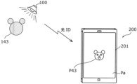
受信機8000は、撮影モードを通常撮影、可視光通信、通常撮影、・・・のように切り替える。そして、受信機8000は、通常撮影画像と可視光通信画像とを合成することによって、輝線模様と被写体およびその周囲とが鮮明に映し出された合成画像を生成し、その合成画像をディスプレイに表示する。この合成画像は、通常撮影画像における信号が送信されている箇所に、可視光通信画像の輝線模様を重畳することによって生成された画像である。また、この合成画像によって映し出される輝線模様、被写体およびその周囲はそれぞれ鮮明であって、ユーザによって十分に認識される鮮明度を有する。このような合成画像が表示されることによって、ユーザは、どこから、またはどの位置から信号が送信されているかをより明確に知ることができる。
The
図8は、本実施の形態における受信機の撮影動作の他の例を示す図である。 FIG. 8 is a diagram showing another example of the imaging operation of the receiver according to this embodiment.
受信機8000は、カメラCa1およびカメラCa2を備える。このような受信機8000では、カメラCa1は通常撮影を行い、カメラCa2は可視光撮影を行う。これにより、カメラCa1は、上述のような通常撮影画像を取得し、カメラCa2は、上述のような可視光通信画像を取得する。そして、受信機8000は、通常撮影画像および可視光通信画像を合成することによって、上述の合成画像を生成してディスプレイに表示する。
図9は、本実施の形態における受信機の撮影動作の他の例を示す図である。 FIG. 9 is a diagram showing another example of the imaging operation of the receiver according to this embodiment.
2つのカメラを有する上記受信機8000では、カメラCa1は、撮影モードを通常撮影、可視光通信、通常撮影、・・・のように切り替える。一方、カメラCa2は、通常撮影を継続して行う。そして、カメラCa1とカメラCa2とで同時に通常撮影が行われているときには、受信機8000は、それらのカメラによって取得された通常撮影画像から、ステレオ視(三角測量の原理)を利用して、受信機8000から被写体までの距離(以下、被写体距離という)を推定する。このように推定された被写体距離を用いることによって、受信機8000は、可視光通信画像の輝線模様を通常撮影画像の適切な位置に重畳することができる。つまり、適切な合成画像を生成することができる。
In the
図10は、本実施の形態における受信機の表示動作の一例を示す図である。 FIG. 10 is a diagram showing an example of the display operation of the receiver according to this embodiment.
受信機8000は、上述のように、撮影モードを可視光通信、通常撮影、可視光通信、・・・のように切り替える。ここで、受信機8000は、最初に可視光通信を行うときに、アプリケーションプログラムを起動する。そして、受信機8000は、可視光通信によって受信した信号に基づいて、自らの位置を推定する。次に、受信機8000は、通常撮影を行うときには、その通常撮影によって取得された通常撮影画像に、AR(Augmented Reality)情報を表示する。このAR情報は、上述のように推定された位置などに基づいて取得されるものである。また、受信機8000は、9軸センサによる検出結果、および通常撮影画像の動き検出などに基づいて、受信機8000の移動および方向の変化を推定し、その推定された移動および方向の変化に合わせてAR情報の表示位置を移動させる。これにより、AR情報を通常撮影画像の被写体像に追随させることができる。
The
また、受信機8000は、通常撮影から可視光通信に撮影モードを切り替えると、その可視光通信時には、直前の通常撮影時に取得された最新の通常撮影画像にAR情報を重畳する。そして、受信機8000は、AR情報が重畳された通常撮影画像を表示する。また、受信機8000は、通常撮影時と同様に、9軸センサによる検出結果に基づいて、受信機8000の移動および方向の変化を推定し、その推定された移動および方向の変化に合わせてAR情報および通常撮影画像を移動させる。これにより、可視光通信時にも、通常撮影時と同様に、受信機8000の移動などに合わせてAR情報を通常撮影画像の被写体像に追随させることができる。また、受信機8000の移動などに合わせて、その通常画像を拡大および縮小することができる。
In addition, when the imaging mode is switched from normal imaging to visible light communication, the
図11は、本実施の形態における受信機の表示動作の一例を示す図である。 FIG. 11 is a diagram showing an example of the display operation of the receiver according to this embodiment.
例えば、受信機8000は、図11の(a)に示すように、輝線模様が映し出された上記合成画像を表示してもよい。また、受信機8000は、図11の(b)に示すように、輝線模様の代わりに、信号が送信されていることを通知するための所定の色を有する画像である信号明示オブジェクトを通常撮影画像に重畳することによって合成画像を生成し、その合成画像を表示してもよい。
For example, the
また、受信機8000は、図11の(c)に示すように、信号が送信されている箇所が点線の枠と識別子(例えば、ID:101、ID:102など)とによって示されている通常撮影画像を合成画像として表示してもよい。また、受信機8000は、図11の(d)に示すように、輝線模様の代わりに、特定の種類の信号が送信されていることを通知するための所定の色を有する画像である信号識別オブジェクトを通常撮影画像に重畳することによって合成画像を生成し、その合成画像を表示してもよい。この場合、その信号識別オブジェクトの色は、送信機から出力されている信号の種類によって異なる。例えば、送信機から出力されている信号が位置情報である場合には、赤色の信号識別オブジェクトが重畳され、送信機から出力されている信号がクーポンである場合には、緑色の信号識別オブジェクトが重畳される。
In addition, as shown in FIG. 11C, the
図12は、本実施の形態における受信機の動作の一例を示す図である。 FIG. 12 is a diagram showing an example of the operation of the receiver according to this embodiment.
例えば、受信機8000は、可視光通信によって信号を受信した場合には、通常撮影画像を表示するとともに、送信機を発見したことをユーザに通知するための音を出力してもよい。この場合、受信機8000は、発見した送信機の個数、受信した信号の種類、または、その信号によって特定される情報の種類などによって、出力される音の種類、出力回数、または出力時間を異ならせてもよい。
For example, when receiving a signal by visible light communication, the
図13は、本実施の形態における受信機の動作の他の例を示す図である。 FIG. 13 is a diagram showing another example of the operation of the receiver according to this embodiment.
例えば、合成画像に映し出された輝線模様にユーザがタッチすると、受信機8000は、そのタッチされた輝線模様に対応する被写体から送信された信号に基づいて、情報通知画像を生成し、その情報通知画像を表示する。この情報通知画像は、例えば、店舗のクーポンや場所などを示す。なお、輝線模様は、図11に示す信号明示オブジェクト、信号識別オブジェクト、または点線枠などであってもよい。以下に記載されている輝線模様についても同様である。
For example, when the user touches the bright line pattern displayed in the composite image, the
図14は、本実施の形態における受信機の動作の他の例を示す図である。 FIG. 14 is a diagram showing another example of the operation of the receiver according to this embodiment.
例えば、合成画像に映し出された輝線模様にユーザがタッチすると、受信機8000は、そのタッチされた輝線模様に対応する被写体から送信された信号に基づいて、情報通知画像を生成し、その情報通知画像を表示する。この情報通知画像は、例えば、受信機8000の現在地を地図などによって示す。
For example, when the user touches the bright line pattern displayed in the composite image, the
図15は、本実施の形態における受信機の動作の他の例を示す図である。 FIG. 15 is a diagram showing another example of the operation of the receiver according to this embodiment.
例えば、合成画像が表示されている受信機8000に対してユーザがスワイプを行うと、受信機8000は、図11の(c)に示す通常撮影画像と同様の、点線枠および識別子を有する通常撮影画像を表示するとともに、スワイプの操作に追随するように情報の一覧を表示する。この一覧には、各識別子によって示される箇所(送信機)から送信される信号によって特定される情報が示されている。また、スワイプは、例えば、受信機8000におけるディスプレイの右側の外から中に指を動かす操作であってもよい。なお、スワイプは、ディスプレイの上側から、下側から、または左側から中に指を動かす操作であってもよい。
For example, when the user swipes the
また、その一覧に含まれる情報がユーザによってタップされると、受信機8000は、その情報をより詳細に示す情報通知画像(例えばクーポンを示す画像)を表示してもよい。
Also, when the user taps information included in the list, the
図16は、本実施の形態における受信機の動作の他の例を示す図である。 FIG. 16 is a diagram showing another example of the operation of the receiver according to this embodiment.
例えば、合成画像が表示されている受信機8000に対してユーザがスワイプを行うと、受信機8000は、スワイプの操作に追随するように情報通知画像を合成画像に重畳して表示する。この情報通知画像は、被写体距離を矢印とともにユーザに分かり易く示すものである。また、スワイプは、例えば、受信機8000におけるディスプレイの下側の外から中に指を動かす操作であってもよい。なお、スワイプは、ディスプレイの左側から、上側から、または右側から中に指を動かす操作であってもよい。
For example, when the user swipes the
図17は、本実施の形態における受信機の動作の他の例を示す図である。 FIG. 17 is a diagram showing another example of the operation of the receiver according to this embodiment.
例えば、受信機8000は、複数の店舗を示すサイネージである送信機を被写体として撮影し、その撮影によって取得された通常撮影画像を表示する。ここで、通常撮影画像に映し出された被写体に含まれる、1つの店舗のサイネージの画像をユーザがタップすると、受信機8000は、その店舗のサイネージから送信される信号に基づいて情報通知画像を生成し、その情報通知画像8001を表示する。この情報通知画像8001は、例えば店舗の空席状況などを示す画像である。
For example, the
本実施の形態における情報通信方法は、被写体から情報を取得する情報通信方法であって、イメージセンサによる前記被写体の撮影によって得られる画像に、前記イメージセンサに含まれる露光ラインに対応する輝線が前記被写体の輝度変化に応じて生じるように、前記イメージセンサの露光時間を設定する第1の露光時間設定ステップと、前記イメージセンサが、輝度変化する前記被写体を、設定された前記露光時間で撮影することによって、前記輝線を含む画像である輝線画像を取得する輝線画像取得ステップと、前記輝線画像に基づいて、前記輝線が現われた部位の空間的な位置が識別し得る態様で、前記被写体と当該被写体の周囲とが映し出された表示用画像を表示する画像表示ステップと、取得された前記輝線画像に含まれる前記輝線のパターンによって特定されるデータを復調することにより送信情報を取得する情報取得ステップとを含む。 An information communication method according to the present embodiment is an information communication method for acquiring information from a subject, wherein an image obtained by photographing the subject with an image sensor includes bright lines corresponding to exposure lines included in the image sensor. a first exposure time setting step of setting an exposure time of the image sensor so as to occur according to a change in brightness of the subject; a bright line image acquiring step of acquiring a bright line image, which is an image including the bright lines; An image display step of displaying a display image showing the surroundings of a subject; and an information acquisition step of acquiring transmission information by demodulating data specified by the bright line pattern included in the acquired bright line image. including.
例えば、図7、図8および図11に示すような合成画像または中間画像が表示用画像として表示される。また、被写体と当該被写体の周囲とが映し出された表示用画像において、輝線が現われた部位の空間的な位置は、輝線模様、信号明示オブジェクト、信号識別オブジェクト、または点線枠などによって識別される。したがって、ユーザは、このような表示画像を見ることによって、輝度変化によって信号を送信している被写体を容易に見つけることができる。 For example, composite images or intermediate images as shown in FIGS. 7, 8 and 11 are displayed as display images. Further, in a display image in which a subject and its surroundings are projected, the spatial position of a portion where a bright line appears is identified by a bright line pattern, a signal manifestation object, a signal identification object, a dotted line frame, or the like. Therefore, by looking at such a displayed image, the user can easily find the subject that is transmitting the signal by the luminance change.
また、前記情報通信方法は、さらに、前記露光時間よりも長い露光時間を設定する第2の露光時間設定ステップと、前記イメージセンサが、前記被写体と当該被写体の周囲とを前記長い露光時間で撮影することによって、通常撮影画像を取得する通常画像取得ステップと、前記通常撮影画像において前記輝線が現われた部位を、前記輝線画像に基づいて特定し、前記部位を指し示す画像である信号オブジェクトを前記通常撮影画像に重畳することによって、合成画像を生成する合成ステップとを含み、前記画像表示ステップでは、前記合成画像を前記表示用画像として表示してもよい。 The information communication method further includes a second exposure time setting step of setting an exposure time longer than the exposure time; a normal image obtaining step of obtaining a normal photographed image; a site where the bright lines appear in the normally photographed image are specified based on the bright line image; and a synthesizing step of generating a synthetic image by superimposing it on the captured image, and the image display step may display the synthetic image as the display image.
例えば、信号オブジェクトは、輝線模様、信号明示オブジェクト、信号識別オブジェクト、または点線枠などであって、図7、図8および図11に示すように、合成画像が表示用画像として表示される。これにより、ユーザは、輝度変化によって信号を送信している被写体をさらに容易に見つけることができる。 For example, the signal object is a bright line pattern, a signal manifestation object, a signal identification object, a dotted line frame, etc. As shown in FIGS. 7, 8 and 11, a synthesized image is displayed as a display image. As a result, the user can more easily find the object transmitting the signal by the change in brightness.
また、前記第1の露光時間設定ステップでは、露光時間を1/3000秒に設定し、前記輝線画像取得ステップでは、前記被写体の周囲が映し出された前記輝線画像を取得し、前記画像表示ステップでは、前記輝線画像を前記表示用画像として表示してもよい。 Further, in the first exposure time setting step, the exposure time is set to 1/3000 second, in the bright line image acquiring step, the bright line image showing the surroundings of the subject is acquired, and in the image displaying step, , the bright line image may be displayed as the display image.
例えば、輝線画像は中間画像として取得されて表示される。したがって、通常撮影画像と可視光通信画像とを取得して合成するなどの処理を行う必要がなく、処理の簡略化を図ることができる。 For example, a bright line image is obtained and displayed as an intermediate image. Therefore, there is no need to perform processing such as acquiring and synthesizing the normally captured image and the visible light communication image, and the processing can be simplified.
また、前記イメージセンサは、第1のイメージセンサと第2のイメージセンサを含み、前記通常画像取得ステップでは、前記第1のイメージセンサが撮影することによって、前記通常撮影画像を取得し、前記輝線画像取得ステップでは、前記第2のイメージセンサが前記第1のイメージセンサの撮影と同時に撮影することによって、前記輝線画像を取得してもよい。 Further, the image sensor includes a first image sensor and a second image sensor, and in the normal image obtaining step, the normal image is obtained by photographing by the first image sensor, and the bright line In the image acquisition step, the bright line image may be acquired by the second image sensor taking an image simultaneously with the image taking by the first image sensor.
例えば、図8に示すように、通常撮影画像と輝線画像である可視光通信画像とがそれぞれのカメラで取得される。したがって、1つのカメラで通常撮影画像と可視光通信画像とを取得する場合と比べて、それらの画像を早く取得することができ、処理を高速化することができる。 For example, as shown in FIG. 8, a normal captured image and a visible light communication image, which is a bright line image, are acquired by respective cameras. Therefore, compared to the case where a single camera acquires a normal shot image and a visible light communication image, these images can be acquired quickly, and the processing speed can be increased.
また、前記情報通信方法は、さらに、前記表示用画像における前記輝線が現われた部位がユーザによる操作によって指定された場合には、指定された部位の前記輝線のパターンから取得された前記送信情報に基づく提示情報を提示する情報提示ステップを含んでもよい。例えば、前記ユーザによる操作は、タップ、スワイプ、前記部位に指先を所定の時間以上継続して当てる操作、前記部位に視線を向けた状態を所定の時間以上継続する操作、前記部位に関連付けて示される矢印に前記ユーザの身体の一部を動かす操作、輝度変化するペン先を前記部位に当てる操作、または、タッチセンサに触れることによって、前記表示用画像に表示されているポインタを前記部位に当てる操作である。 Further, in the information communication method, when a region where the bright line appears in the display image is designated by a user's operation, the transmission information acquired from the bright line pattern of the designated region is An information presentation step of presenting presentation information based on the information may be included. For example, the operation by the user includes tapping, swiping, an operation of keeping the fingertip on the part for a predetermined time or more, an operation of keeping the line of sight directed to the part for a predetermined time or more, and an operation of showing in association with the part. The pointer displayed on the display image is applied to the part by moving a part of the user's body in line with the arrow, touching the part with the pen tip whose brightness changes, or by touching the touch sensor. Operation.
例えば、図13~図17に示すように、提示情報が情報通知画像として表示される。これにより、ユーザに所望の情報を提示することができる。 For example, as shown in FIGS. 13 to 17, presentation information is displayed as an information notification image. Thereby, desired information can be presented to the user.
また、被写体から情報を取得する情報通信方法であって、イメージセンサによる前記被写体の撮影によって得られる画像に、前記イメージセンサに含まれる露光ラインに対応する輝線が前記被写体の輝度変化に応じて生じるように、前記イメージセンサの露光時間を設定する第1の露光時間設定ステップと、前記イメージセンサが、輝度変化する前記被写体を、設定された前記露光時間で撮影することによって、前記輝線を含む画像である輝線画像を取得する輝線画像取得ステップと、取得された前記輝線画像に含まれる前記輝線のパターンによって特定されるデータを復調することにより情報を取得する情報取得ステップとを含み、前記輝線画像取得ステップでは、前記イメージセンサが移動されている期間に、複数の前記被写体を撮影することによって、前記輝線が現われた部位を複数含む前記輝線画像を取得し、前記情報取得ステップでは、前記部位ごとに、当該部位の前記輝線のパターンによって特定されるデータを復調することによって、複数の前記被写体のそれぞれの位置を取得し、前記情報通信方法は、さらに、取得された複数の前記被写体のそれぞれの位置、および前記イメージセンサの移動状態に基づいて、前記イメージセンサの位置を推定する位置推定ステップを含んでもよい。 Also, in the information communication method for acquiring information from a subject, in an image obtained by photographing the subject with an image sensor, a bright line corresponding to an exposure line included in the image sensor is generated according to a change in brightness of the subject. a first exposure time setting step of setting an exposure time of the image sensor; and an information acquisition step of acquiring information by demodulating data specified by the pattern of the bright lines included in the acquired bright line image, wherein the bright line image In the obtaining step, the bright line image including a plurality of parts in which the bright lines appear is obtained by photographing a plurality of the subjects while the image sensor is being moved, and obtaining the positions of each of the plurality of subjects by demodulating the data specified by the pattern of the bright lines of the part, and the information communication method further comprises: A position estimation step of estimating the position of the image sensor based on the position and the movement state of the image sensor may be included.
これにより、複数の照明などの被写体による輝度変化によって、イメージセンサを含む受信機の位置を正確に推定することができる。 This makes it possible to accurately estimate the position of a receiver including an image sensor based on changes in brightness caused by objects such as multiple lights.
また、被写体から情報を取得する情報通信方法であって、イメージセンサによる前記被写体の撮影によって得られる画像に、前記イメージセンサに含まれる露光ラインに対応する輝線が前記被写体の輝度変化に応じて生じるように、前記イメージセンサの露光時間を設定する第1の露光時間設定ステップと、前記イメージセンサが、輝度変化する前記被写体を、設定された前記露光時間で撮影することによって、前記輝線を含む画像である輝線画像を取得する輝線画像取得ステップと、取得された前記輝線画像に含まれる前記輝線のパターンによって特定されるデータを復調することにより情報を取得する情報取得ステップと、取得された前記情報を提示する情報提示ステップとを含み、前記情報提示ステップでは、前記イメージセンサのユーザに対して、予め定められたジェスチャを促す画像を前記情報として提示してもよい。 Also, in the information communication method for acquiring information from a subject, in an image obtained by photographing the subject with an image sensor, a bright line corresponding to an exposure line included in the image sensor is generated according to a change in brightness of the subject. a first exposure time setting step of setting an exposure time of the image sensor; an information acquisition step of acquiring information by demodulating data specified by the bright line pattern included in the acquired bright line image; and the acquired information and an information presenting step of presenting the information, wherein the information presenting step may present an image prompting a user of the image sensor to perform a predetermined gesture as the information.
これにより、ユーザが、促されたとおりのジェスチャを行うか否かによって、そのユーザに対する認証などを行うことができ、利便性を高めることができる。 Accordingly, the user can be authenticated or the like depending on whether or not the user performs the gesture as prompted, and convenience can be improved.
また、被写体から情報を取得する情報通信方法であって、イメージセンサによる前記被写体の撮影によって得られる画像に、前記イメージセンサに含まれる露光ラインに対応する輝線が前記被写体の輝度変化に応じて生じるように、前記イメージセンサの露光時間を設定する露光時間設定ステップと、前記イメージセンサが、輝度変化する前記被写体を、設定された前記露光時間で撮影することによって、前記輝線を含む輝線画像を取得する画像取得ステップと、取得された前記輝線画像に含まれる前記輝線のパターンによって特定されるデータを復調することにより情報を取得する情報取得ステップとを含み、前記画像取得ステップでは、反射面に映る複数の前記被写体を撮影することによって前記輝線画像を取得し、前記情報取得ステップでは、前記輝線画像に含まれる輝線の強度に応じて、前記輝線を、複数の前記被写体のそれぞれに対応する輝線に分離し、前記被写体ごとに、当該被写体に対応する輝線のパターンによって特定されるデータを復調することにより情報を取得してもよい。 Also, in the information communication method for acquiring information from a subject, in an image obtained by photographing the subject with an image sensor, a bright line corresponding to an exposure line included in the image sensor is generated according to a change in brightness of the subject. and an exposure time setting step of setting the exposure time of the image sensor, and the image sensor captures the subject whose luminance changes at the set exposure time, thereby obtaining a bright line image including the bright lines. and an information acquisition step of acquiring information by demodulating data specified by the bright line pattern included in the acquired bright line image, wherein the image acquisition step includes: acquiring the bright line image by photographing a plurality of the subjects, and in the information obtaining step, converting the bright lines into bright lines corresponding to each of the plurality of subjects according to the intensity of the bright lines included in the bright line image; The information may be obtained by separating and demodulating the data specified by the bright line pattern corresponding to each subject.
これにより、複数の照明などの被写体がそれぞれ輝度変化する場合でも、被写体のそれぞれから適切な情報を取得することができる。 This makes it possible to acquire appropriate information from each of the subjects even when the brightness of each subject such as a plurality of lights changes.
また、被写体から情報を取得する情報通信方法であって、イメージセンサによる前記被写体の撮影によって得られる画像に、前記イメージセンサに含まれる露光ラインに対応する輝線が前記被写体の輝度変化に応じて生じるように、前記イメージセンサの露光時間を設定する露光時間設定ステップと、前記イメージセンサが、輝度変化する前記被写体を、設定された前記露光時間で撮影することによって、前記輝線を含む輝線画像を取得する画像取得ステップと、取得された前記輝線画像に含まれる前記輝線のパターンによって特定されるデータを復調することにより情報を取得する情報取得ステップとを含み、前記画像取得ステップでは、反射面に映る前記被写体を撮影することによって前記輝線画像を取得し、前記情報通信方法は、さらに、前記輝線画像内における輝度分布に基づいて、前記被写体の位置を推定する位置推定ステップを含んでもよい。 Also, in the information communication method for acquiring information from a subject, in an image obtained by photographing the subject with an image sensor, a bright line corresponding to an exposure line included in the image sensor is generated according to a change in brightness of the subject. and an exposure time setting step of setting the exposure time of the image sensor, and the image sensor captures the subject whose luminance changes at the set exposure time, thereby obtaining a bright line image including the bright lines. and an information acquisition step of acquiring information by demodulating data specified by the bright line pattern included in the acquired bright line image, wherein the image acquisition step includes: Obtaining the bright line image by photographing the subject, the information communication method may further include a position estimation step of estimating the position of the subject based on a luminance distribution in the bright line image.
これにより、輝度分布に基づいて適切な被写体の位置を推定することができる。 This makes it possible to estimate an appropriate subject position based on the luminance distribution.
また、前記送信ステップでは、輝度変化を、前記第1のパターンにしたがった輝度変化と、前記第2のパターンにしたがった輝度変化とで切り替えるときには、緩衝時間を空けて切り替えてもよい。 Further, in the transmitting step, when switching the luminance change between the luminance change according to the first pattern and the luminance change according to the second pattern, a buffer time may be provided before switching.
これにより、第1の信号と第2の信号との混信を抑えることができる。 Thereby, interference between the first signal and the second signal can be suppressed.
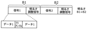
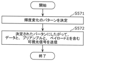
また、輝度変化によって信号を送信する情報通信方法であって、送信対象の信号を変調することによって、輝度変化のパターンを決定する決定ステップと、発光体が、決定された前記パターンにしたがって輝度変化することによって前記送信対象の信号を送信する送信ステップとを含み、前記信号は、複数の大ブロックからなり、前記複数の大ブロックのそれぞれは、第1のデータと、前記第1のデータに対するプリアンブルと、前記第1のデータに対するチェック信号とを含み、前記第1のデータは、複数の小ブロックからなり、前記小ブロックは、第2のデータと、前記第2のデータに対するプリアンブルと、前記第2のデータに対するチェック信号とを含んでもよい。 Also, an information communication method for transmitting a signal by means of luminance change, comprising: a determination step of determining a pattern of luminance change by modulating a signal to be transmitted; and a transmitting step of transmitting the signal to be transmitted by transmitting the signal to be transmitted, the signal being composed of a plurality of large blocks, each of the plurality of large blocks being first data and a preamble for the first data. and a check signal for the first data, wherein the first data is composed of a plurality of small blocks, and the small blocks include second data, a preamble for the second data, and the first data. and a check signal for 2 data.
これにより、ブランキング期間を要する受信機でも、ブランキング期間を必要としない受信機でも、適切にデータを取得することができる。 As a result, both a receiver that requires a blanking period and a receiver that does not require a blanking period can appropriately acquire data.
また、輝度変化によって信号を送信する情報通信方法であって、複数の送信機がそれぞれ、送信対象の信号を変調することによって、輝度変化のパターンを決定する決定ステップと、送信機ごとに、当該送信機に備えられた発光体が、決定された前記パターンにしたがって輝度変化することによって前記送信対象の信号を送信する送信ステップとを含み、前記送信ステップでは、互いに周波数またはプロトコルが異なる信号を送信してもよい。 Also, an information communication method for transmitting signals by means of luminance changes, comprising: a determination step of determining a pattern of luminance change by modulating a signal to be transmitted by each of a plurality of transmitters; a transmitting step in which a light-emitting body provided in a transmitter transmits the signal to be transmitted by changing luminance according to the determined pattern, wherein the transmitting step transmits signals having different frequencies or different protocols. You may
これにより、複数の送信機からの信号の混信を抑えることができる。 Thereby, interference of signals from a plurality of transmitters can be suppressed.
また、輝度変化によって信号を送信する情報通信方法であって、複数の送信機がそれぞれ、送信対象の信号を変調することによって、輝度変化のパターンを決定する決定ステップと、送信機ごとに、当該送信機に備えられた発光体が、決定された前記パターンにしたがって輝度変化することによって前記送信対象の信号を送信する送信ステップとを含み、前記送信ステップでは、前記複数の送信機のうちの1つの送信機は、他方の送信機から送信される信号を受信し、受信された信号と混信しない態様で、他の信号を送信してもよい。 Also, an information communication method for transmitting signals by means of luminance changes, comprising: a determination step of determining a pattern of luminance change by modulating a signal to be transmitted by each of a plurality of transmitters; a transmitting step of transmitting the signal to be transmitted by a light-emitting body provided in a transmitter that changes in luminance according to the determined pattern, wherein the transmitting step comprises one of the plurality of transmitters; One transmitter may receive the signal transmitted from the other transmitter and transmit the other signal in a manner that does not interfere with the received signal.
これにより、複数の送信機からの信号の混信を抑えることができる。 Thereby, interference of signals from a plurality of transmitters can be suppressed.
(駅での案内)
図18Aは、電車のホームにおける本発明の利用形態の一例を示したものである。ユーザが、携帯端末を電子掲示板や照明にかざし、可視光通信により、電子掲示板に表示されている情報、または、電子掲示板の設置されている駅の電車情報・駅の構内情報などを取得する。ここでは、電子掲示板に表示されている情報自体が、可視光通信により、携帯端末に送信されてもよいし、電子掲示板に対応するID情報が携帯端末に送信され、携帯端末が取得したID情報をサーバに問い合わせることにより、電子掲示板に表示されている情報を取得してもよい。サーバは、携帯端末からID情報が送信されてきた場合に、ID情報に基づき、電子掲示板に表示されている内容を携帯端末に送信する。携帯端末のメモリに保存されている電車のチケット情報と、電子掲示板に表示されている情報とを対比し、ユーザのチケットに対応するチケット情報が電子掲示板に表示されている場合に、携帯端末のディスプレイに、ユーザの乗車予定の電車が到着するホームへの行き先を示す矢印を表示する。降車時に出口や乗り換え経路に近い車両までの経路を表示するとしてもよい。(guidance at the station)
FIG. 18A shows an example of usage of the present invention on a train platform. A user holds a portable terminal up to an electronic bulletin board or a light and obtains information displayed on the electronic bulletin board, train information of the station where the electronic bulletin board is installed, premises information of the station, etc. by visible light communication. Here, the information itself displayed on the electronic bulletin board may be transmitted to the mobile terminal by visible light communication, or the ID information corresponding to the electronic bulletin board may be transmitted to the mobile terminal, and the ID information acquired by the mobile terminal may be transmitted to the mobile terminal. information displayed on the electronic bulletin board may be acquired by inquiring of the server. When the ID information is transmitted from the mobile terminal, the server transmits the contents displayed on the electronic bulletin board to the mobile terminal based on the ID information. The train ticket information stored in the memory of the mobile terminal is compared with the information displayed on the electronic bulletin board, and if the ticket information corresponding to the user's ticket is displayed on the electronic bulletin board, the The display shows an arrow indicating the destination of the train that the user plans to board. A route to a vehicle close to an exit or transfer route may be displayed when getting off.
座席指定がされている場合は、その座席までの経路を表示するとしてもよい。矢印を表示する際には、地図や、電車案内情報における電車の路線の色と同じ色を用いて矢印を表示することにより、より分かりやすく表示することができる。また、矢印の表示とともに、ユーザの予約情報(ホーム番号、車両番号、発車時刻、座席番号)を表示することもできる。ユーザの予約情報を併せて表示することにより、誤認識を防ぐことが可能となる。チケット情報がサーバに保存されている場合には、携帯端末からサーバに問い合わせてチケット情報を取得し対比するか、または、サーバ側でチケット情報と電子掲示板に表示されている情報とを対比することにより、チケット情報に関連する情報を取得することができる。ユーザが乗換検索を行った履歴から目的の路線を推定し、経路を表示してもよい。また、電子掲示板に表示されている内容だけでなく、電子掲示板が設置されている駅の電車情報・構内情報を取得し、対比を行ってもよい。ディスプレイ上の電子掲示板の表示に対してユーザに関連する情報を強調表示してもよいし、書き換えて表示してもよい。ユーザの乗車予定が不明である場合には、各路線の乗り場への案内の矢印を表示してもよい。駅の構内情報を取得した場合には、売店・お手洗いへなどの案内する矢印をディスプレイに表示してもよい。ユーザの行動特性を予めサーバで管理しておき、ユーザが駅構内で売店・お手洗いに立ち寄ることが多い場合に、売店・お手洗いなどへ案内する矢印をディスプレイに表示する構成にしてもよい。売店・お手洗いに立ち寄る行動特性を有するユーザに対してのみ、売店・お手洗いなどへ案内する矢印を表示し、その他のユーザに対しては表示を行わないため処理量を減らすことが可能となる。売店・お手洗いなどへ案内する矢印の色を、ホームへの行き先を案内する矢印と異なる色としてもよい。両方の矢印を同時に表示する際には、異なる色とすることにより、誤認識を防ぐことが可能となる。尚、図18Aでは電車の例を示したが、飛行機やバスなどでも同様の構成で表示を行うことが可能である。 If a seat is assigned, the route to that seat may be displayed. When displaying the arrows, the arrows can be displayed in a more comprehensible manner by displaying the arrows in the same color as the color of the train route in the map or the train guide information. In addition to displaying the arrow, it is also possible to display the user's reservation information (platform number, vehicle number, departure time, seat number). By also displaying the reservation information of the user, it is possible to prevent erroneous recognition. If the ticket information is stored in the server, the ticket information is obtained and compared by inquiring the server from the mobile terminal, or the ticket information is compared with the information displayed on the electronic bulletin board on the server side. can acquire information related to the ticket information. A target route may be estimated from the user's transfer search history, and the route may be displayed. In addition to the contents displayed on the electronic bulletin board, train information and premises information of the station where the electronic bulletin board is installed may be acquired and compared. Information related to the user may be highlighted or rewritten for display on the electronic bulletin board on the display. If the user's boarding schedule is unknown, arrows may be displayed to guide the boarding point of each route. When the premises information of the station is acquired, arrows may be displayed on the display to guide the user to shops, restrooms, and the like. The user's behavioral characteristics may be managed in advance by a server, and when the user frequently visits a store or restroom in the station, an arrow may be displayed on the display to guide the user to the store or restroom. It is possible to reduce the amount of processing by displaying an arrow that guides the user to the shop or restroom only for users who have the behavior characteristic of stopping by the shop or restroom, and not displaying it for other users. . The color of the arrow leading to the shop, restroom, etc. may be different from the color of the arrow guiding the destination to the platform. When both arrows are displayed at the same time, erroneous recognition can be prevented by using different colors. Note that FIG. 18A shows an example of a train, but it is possible to display with a similar configuration on an airplane, a bus, or the like.
具体的には、スマートフォンなどの携帯端末(すなわち後述の受信機200などの受信機)は、図18Aの(1)に示すように、電子掲示板を撮像することによって、その電子掲示板から可視光信号を光IDまたは光データとして受信する。このとき、携帯端末は、自己位置推定を行う。つまり、携帯端末は、光データによって直接的または間接的に示される電子掲示板の地図上の位置を取得する。そして、携帯端末は、例えば9軸センサによって得られる自らの姿勢と、撮像によって得られた画像に映し出されている電子掲示板の画像内における位置、形状および大きさなどとに基づいて、電子掲示板に対する携帯端末の相対位置を算出する。携帯端末は、電子掲示板の地図上の位置と、その相対位置とに基づいて、携帯端末の地図上の位置である自己位置を推定する。携帯端末は、この自己位置である起点から、例えばチケット情報によって示される目的地までの経路を検索し、その経路に沿って目的地までユーザを案内するナビゲーションを開始する。なお、携帯端末は、その起点および目的地を示す情報をサーバに送信し、サーバによって検索された上述の経路を、そのサーバから取得してもよい。このとき、携帯端末は、サーバからその経路を含む地図をサーバから取得してもよい。
Specifically, a mobile terminal such as a smartphone (that is, a receiver such as the
携帯端末は、ナビゲーションでは、図18Aの(2)~(4)に示すように、カメラによる撮像を繰り返し、その撮像によって得られる通常撮影画像をリアルタイムに順次表示しながら、ユーザの行き先を示す矢印などの方向指示画像をその通常撮影画像に重畳する。ユーザは、携帯端末を携帯しながら、その表示される方向指示画像にしたがって移動する。そして、携帯端末は、上述の各通常撮影画像に映し出されている物体または特徴点の動きに基づいて、携帯端末の自己位置を更新する。例えば、携帯端末は、上述の各通常撮影画像に映し出されている物体または特徴点の動きを検出し、その動きに基づいて、携帯端末の移動方向および移動距離を推定する。そして、携帯端末は、その推定された移動方向および移動距離と、図18Aの(1)において推定された自己位置とに基づいて、現在の自己位置を更新する。この自己位置の更新は、通常撮影画像のフレーム周期ごとに行われてもよく、そのフレーム周期よりも長い周期ごとに行われてもよい。つまり、携帯端末が地下のフロアまたは経路にあるときには、その携帯端末は、GPSデータを取得することができない。したがって、このよう場合には、携帯端末は、GPSデータを用いることなく、上述の各通常撮影画像の特徴点などの動きに基づいて、自己位置の推定または更新を行う。 In navigation, as shown in (2) to (4) of FIG. 18A , the mobile terminal repeats imaging with the camera, and sequentially displays normal captured images obtained by the imaging in real time, while arrows indicating the destination of the user are displayed. A direction indicating image such as , is superimposed on the normal photographed image. The user moves according to the displayed direction instruction image while carrying the portable terminal. Then, the mobile terminal updates its own position based on the movement of the object or the feature point displayed in each of the above-described normal captured images. For example, the mobile terminal detects the motion of the object or feature point appearing in each of the above-described normal shot images, and estimates the moving direction and moving distance of the mobile terminal based on the motion. Then, the mobile terminal updates its current self-location based on the estimated moving direction and moving distance and the estimated self-location in (1) of FIG. 18A. This update of the self-position may be performed for each frame period of the normal captured image, or may be performed for each period longer than the frame period. That is, when the mobile terminal is on an underground floor or pathway, the mobile terminal cannot acquire GPS data. Therefore, in such a case, the mobile terminal estimates or updates its own position based on the movement of the feature points of the above-mentioned normal shot images without using GPS data.
ここで、携帯端末は、図18Aの(4)に示すように、目的地への経路の途中などで、ユーザにエレベータを案内してもよい。また、携帯端末は、図18Aの(5)および(6)に示すように、光データを送信する送信機、または、その光データの反射光を撮像すると、その光データを受信し、図18Aの(1)に示す例と同様に、自己位置を推定する。例えば、ユーザがエレベータに搭乗した場合でも、携帯端末は、エレベータの籠の内部に照明装置などとして設置されている送信機(すなわち後述の送信機100などの送信機)から送信される光データを受信する。例えば、その光データは、エレベータの籠が現在位置する階を直接的または間接的に示している。したがって、携帯端末は、その光データを受信することによって、携帯端末が現在位置する階を特定することができる。光データによって、籠の現在位置が直接的に示されていない場合には、携帯端末は、その光データによって示される情報をサーバに送信し、サーバにおいてその情報に対応付けられている階数情報を、そのサーバから取得する。これにより、携帯端末は、その階数情報によって示される階を、携帯端末が現在位置する階として特定する。このように特定される階は、自己位置として扱われる。
Here, as shown in (4) of FIG. 18A, the mobile terminal may guide the user to the elevator on the way to the destination. Further, as shown in (5) and (6) in FIG. 18A, the mobile terminal receives the optical data from the transmitter that transmits the optical data, or when the reflected light of the optical data is captured, and receives the optical data. The self-position is estimated in the same manner as the example shown in (1). For example, even when a user gets on an elevator, the mobile terminal receives optical data transmitted from a transmitter (that is, a transmitter such as a
その結果、端末装置は、図18Aの(7)に示すように、通常撮像画像の特徴点などの動きから導出された自己位置を、その光データを用いて導出された自己位置に置き換えることによって、自己位置の再設定を行う。 As a result, as shown in (7) of FIG. 18A, the terminal device replaces the self-position derived from the movement of the feature points of the normal captured image with the self-position derived using the optical data. , to reposition itself.
そして、携帯端末は、図18Aの(8)に示すように、ユーザがエレベータから降りた後、目的地に辿り着いていなければ、図18Aの(2)~(4)と同様の処理を行いながらナビゲーションを行う。また、携帯端末は、ナビゲーションを行っているときには、GPSデータを取得することができるか否かを繰り返し確認している。したがって、携帯端末は、地下のフロアまたは経路から地上に上がると、GPSデータを取得することができると判断する。そして、携帯端末は、自己位置の推定方法を、特徴点などの動きに基づく推定方法から、GPSデータに基づく推定方法に切り替える。そして、携帯端末は、図18Aの(9)に示すように、GPSデータに基づいて自己位置を推定しながら、ユーザが目的地に到着するまでナビゲーションを引き続き実行する。なお、携帯端末は、例えばユーザが再び地下に入ると、GPSデータを取得することができなくなるため、自己位置の推定方法を、GPSデータに基づく推定方法から、特徴点などの動きに基づく推定方法に切り替える。 Then, as shown in (8) of FIG. 18A, if the user has not reached the destination after getting off the elevator, the mobile terminal performs the same processes as (2) to (4) of FIG. 18A. navigate while Also, the mobile terminal repeatedly confirms whether or not GPS data can be acquired during navigation. Therefore, the mobile terminal determines that it can acquire GPS data when it rises above ground from an underground floor or pathway. Then, the portable terminal switches the self-position estimation method from the estimation method based on the movement of the feature points to the estimation method based on the GPS data. Then, as shown in (9) of FIG. 18A, the mobile terminal continues to perform navigation while estimating its own position based on the GPS data until the user arrives at the destination. For example, when the user goes underground again, the mobile terminal cannot acquire GPS data. switch to
以下、図18Aの例について、詳細に説明する。 The example of FIG. 18A will be described in detail below.
図18Aに示す例において、例えばスマートフォンまたはスマートグラスなどのウェアラブル機器として実装される受信機は、図18Aの(1)で、送信機から送信された可視光信号(光データ)を受信する。送信機は、例えば、電飾看板、ポスター、または、像を照らす照明として実装される。受信機は、受信した光データと、受信機にあらかじめ設定されている情報と、ユーザの指示とに従って、目的地までのナビゲーションを開始する。受信機は、光データをサーバへ送信し、このデータに関連付けられたナビ情報を取得する。ナビ情報には、以下の第1の情報から第6の情報が含まれている。第1の情報は、送信機の位置および形状を示す情報である。第2の情報は、目的地までの経路を示す情報である。第3の情報は、目的地までの経路上およびその付近にある別の送信機の情報である。具体的には、別の送信機の情報は、その送信機が送信している光データと、送信機の位置および形状と、反射光の位置および形状とを示す。第4の情報は、経路上およびその付近に関する位置特定情報である。具体的には、位置特定情報は、画像特徴量もしくは位置を特定するための電波情報または音波情報である。第5の情報は、目的地までの距離および到達予想時間を示す情報である。第6の情報は、AR表示を行うためのコンテンツ情報の一部または全部である。ナビ情報は、受信機の中にあらかじめ格納されていてもよい。なお、上述の形状には、大きさが含まれていてもよい。 In the example shown in FIG. 18A, a receiver implemented as a wearable device such as a smartphone or smart glasses receives the visible light signal (optical data) transmitted from the transmitter at (1) in FIG. 18A. Transmitters are implemented, for example, as lights that illuminate illuminated signs, posters, or statues. The receiver starts navigation to the destination according to the received optical data, the information preset in the receiver, and the user's instructions. The receiver transmits the light data to the server and obtains the navigation information associated with this data. The navigation information includes the following first to sixth information. The first information is information indicating the position and shape of the transmitter. The second information is information indicating the route to the destination. The third information is information of other transmitters on and near the route to the destination. Specifically, the information of another transmitter indicates the optical data that the transmitter is transmitting, the position and shape of the transmitter, and the position and shape of the reflected light. The fourth information is location specific information on and around the route. Specifically, the position specifying information is radio wave information or sound wave information for specifying an image feature amount or a position. The fifth information is information indicating the distance to the destination and the expected arrival time. The sixth information is part or all of content information for AR display. The navigation information may be pre-stored in the receiver. Note that the above shape may include a size.
受信機は、撮像によって得られた画像中の送信機の写り方と加速度センサのセンサ値とから計算された送信機と受信機との相対位置と、送信機の位置情報とから、受信機の自己位置を推定し、その自己位置をナビゲーションの起点とする。受信機は、光データではなく、画像特徴量、バーコードもしくは2次元コード、電波、または音波などによって、受信機の自己位置を推定して、ナビゲーションを開始してもよい。 The receiver determines the position of the receiver based on the relative position between the transmitter and the receiver calculated from the appearance of the transmitter in the image obtained by imaging and the sensor value of the acceleration sensor, and the position information of the transmitter. The self-position is estimated, and the self-position is used as the starting point of navigation. The receiver may start navigation by estimating its self-position based on image feature values, barcodes or two-dimensional codes, radio waves, or sound waves instead of optical data.
受信機は、図18Aの(2)のように、目的地までのナビゲーションを表示する。このナビゲーションの表示は、カメラの撮像によって得られる通常撮影画像に他の画像を重畳するAR表示であってもよく、地図の表示であってもよく、音声またはバイブレーションによる指示であってもよく、これらの組み合わせであってもよい。受信機、光データ、または、サーバ上の設定により、表示方法が選択されてもよい。いずれかの設定が他に優先されてもよい。また、到達地(すなわち目的地)が交通機関の搭乗場所であれば、受信機は、時刻表を取得し、予約済みの時刻、または、到達予想時刻付近の発車時刻もしくは搭乗時刻を表示してもよい。また、到達地が劇場などであれば、受信機は、開演時刻または入場期限を表示してもよい。 The receiver displays navigation to the destination as shown in (2) of FIG. 18A. This navigation display may be an AR display in which another image is superimposed on a normal shot image obtained by imaging with a camera, may be a map display, or may be an instruction by voice or vibration. A combination of these may be used. The display method may be selected by setting on the receiver, optical data, or server. Either setting may take precedence over the other. Also, if the destination (that is, the destination) is a boarding place for transportation, the receiver acquires the timetable and displays the reserved time or the departure time or boarding time near the expected arrival time. good too. Also, if the destination is a theater or the like, the receiver may display the opening time or the entry deadline.
受信機は、図18Aの(3)および(4)に示すように、受信機の移動に従ってナビゲーションを進める。絶対的な位置情報が得られない状況では、受信機は、複数枚の画像中の特徴点の画像間での移動距離から、それらの画像の撮像が行われた間における受信機の移動距離と方向を推定してもよい。また、受信機は、加速度センサ、電波、または音波の推移から、受信機の移動距離と方向を推定してもよい。また、受信機は、SLAM(Simultaneous Localization and Mapping)またはPTAM(Parallel Tracking and Mapping)により受信機の移動距離と方向を推定してもよい。 The receiver advances navigation according to the movement of the receiver, as shown in (3) and (4) of FIG. 18A. In a situation where absolute position information cannot be obtained, the receiver calculates the moving distance of the receiver while the images were captured from the moving distance between the images of the feature points in the plurality of images. Direction may be estimated. Also, the receiver may estimate the movement distance and direction of the receiver from an acceleration sensor, radio waves, or changes in sound waves. The receiver may also estimate the moving distance and direction of the receiver by SLAM (Simultaneous Localization and Mapping) or PTAM (Parallel Tracking and Mapping).
図18Aの(5)で、受信機は、図18Aの(1)で受信した光データとは別の光データを、例えばエレベータの外で受信した場合、その光データをサーバへ送り、その光データに関連付けられた送信機の形状および位置を取得してもよい。そして、受信機は、図18Aの(1)と同様の方法で受信機の自己位置を推定してもよい。これにより、受信機は、図18Aの(3)および(4)の過程で生じた受信機の自己位置推定の誤差を解消してナビゲーションの現在位置を補正する。受信機は、可視光信号の一部のみを受信し、完全な光データが得られなかった場合は、ナビ情報から最近傍にある送信機を、その可視光信号を送信している送信機であると推定し、以降、上述と同様に、受信機の自己位置推定を行う。これにより、受信条件が十分でない送信機、例えば、小さい送信機、遠くにある送信機、または、暗い送信機であっても、それらの送信機を、受信機の自己位置推定に利用することができる。 In (5) of FIG. 18A, when the receiver receives optical data different from the optical data received in (1) of FIG. 18A, for example, outside an elevator, it sends the optical data to the server, The shape and position of the transmitter associated with the data may be obtained. Then, the receiver may estimate its own position by a method similar to (1) in FIG. 18A. As a result, the receiver corrects the current navigation position by eliminating errors in the receiver's self-position estimation that occurred in processes (3) and (4) of FIG. 18A. The receiver receives only a portion of the visible light signal, and if the complete light data is not available, the nearest transmitter from the navigation information is the transmitter that is transmitting that visible light signal. It is assumed that there is, and thereafter, the self-position estimation of the receiver is performed in the same manner as described above. This allows transmitters with poor reception conditions, e.g. small transmitters, distant transmitters, or even dark transmitters, to be used for receiver self-localization. can.
受信機は、図18Aの(6)で、反射光により光データを受信する。受信機は、撮像方向、光の強さ、または、輪郭の明瞭さから、受信された光データの媒体が反射光であると識別する。反射光である場合は、受信機は、ナビ情報から反射光の位置(すなわち地図上の位置)を特定し、撮像されている反射光の領域の中心部を、その反射光の位置と推定する。そして、受信機は、図18Aの(5)と同様に、受信機の自己位置を推定し、ナビゲーションの現在位置の補正を行う。 The receiver receives the optical data by the reflected light at (6) in FIG. 18A. The receiver identifies the medium of the received optical data as reflected light from the imaging direction, light intensity, or contour clarity. If it is reflected light, the receiver identifies the position of the reflected light from the navigation information (that is, the position on the map), and estimates the center of the reflected light area being imaged as the position of the reflected light. . Then, the receiver estimates its own position and corrects the current navigation position, as in (5) of FIG. 18A.
受信機は、GPS、GLONASS、Galileo、北斗衛星測位システム、IRNSS等の位置を特定するための信号を受信した場合は、その信号により受信機の位置を特定し、ナビゲーションの現在位置(すなわち自己位置)を補正する。受信機は、上記信号の強さが十分であれば、すなわち所定の強度よりも強ければ、その信号のみによって自己位置を推定し、所定の強さ以下であれば、図18Aの(3)および(4)で利用した方法を併用してもよい。 When the receiver receives a signal for identifying a position such as GPS, GLONASS, Galileo, Beidou satellite positioning system, IRNSS, etc., the receiver identifies the position of the receiver by the signal, and the current navigation position (i.e. self-position ) is corrected. If the strength of the signal is sufficient, that is, if it is stronger than a predetermined strength, the receiver estimates the self-position only by the signal, and if it is less than the predetermined strength, (3) and (3) in FIG. 18A The method used in (4) may be used together.
受信機は、可視光信号を受信した場合、[1]その可視光信号と同時に受信している所定のIDを持つ電波信号、[2]最後に受信した所定のIDを持つ電波信号、または、[3]最後に推定した受信機の位置を示す情報を、可視光信号によって示される情報と合わせてサーバに送信する。これにより、その可視光信号を送信する送信機が特定される。または、受信機は、上述の電波信号、もしくは、受信機の位置を示す情報によって特定されるアルゴリズムで可視光信号を受信し、上述と同様に特定されるサーバに、その可視光信号によって示される情報を送信してもよい。 When the receiver receives a visible light signal, [1] a radio signal having a predetermined ID received at the same time as the visible light signal, [2] a radio signal having a predetermined ID received last, or [3] Sending the information indicating the last estimated position of the receiver to the server together with the information indicated by the visible light signal. This identifies the transmitter that transmits the visible light signal. Alternatively, the receiver receives a visible light signal by an algorithm specified by the above-described radio signal or information indicating the position of the receiver, and the server specified in the same manner as described above is indicated by the visible light signal. You may send information.
受信機は、自己位置を推定し、その自己位置付近にある商品の情報を表示してもよい。また、受信機は、ユーザの指定する商品の位置までのナビゲーションをしてもよい。また、受信機は、ユーザが指定する複数の商品の所在をすべて周るために最適なルートを提示してもよい。その最適なルートは、最短距離のルート、最短所要時間のルート、または、移動の労力が最も少ないルートである。また、受信機は、ユーザの指定する商品または場所に加えて、所定の場所を通るようにナビゲーションを行ってもよい。これにより、所定の場所の宣伝、または、その場所にある商品または店の宣伝を行うことができる。 The receiver may estimate its self-location and display information about items near its self-location. Also, the receiver may navigate to the position of the product specified by the user. Also, the receiver may present the optimum route for visiting all the locations of a plurality of products specified by the user. The optimal route is the route with the shortest distance, the route with the shortest required time, or the route with the least travel effort. Also, the receiver may perform navigation so as to pass through a predetermined location in addition to the product or location specified by the user. This makes it possible to advertise a given location or advertise a product or store located at that location.
図18Bは、本実施の形態におけるエレベータでの受信機200によるナビゲーションを説明するための図である。
FIG. 18B is a diagram for explaining navigation by
例えば、スマートフォンとして構成されている受信機は、ユーザが地下3階(B3)にいるときに、図18Bの(1)に示すように、AR表示を用いたガイド、すなわちARナビゲーションを実行する。ARナビゲーションは、図18Aに示すように、通常撮影画像に矢印などの方向指示画像を重畳することによって、ユーザを目的地まで案内するナビゲーション機能である。なお、以下、ARナビゲーションを、単に、ナビゲーションまたはナビともいう。 For example, a receiver configured as a smartphone performs guidance using AR display, that is, AR navigation, as shown in (1) of FIG. 18B when the user is on the third basement floor (B3). AR navigation, as shown in FIG. 18A, is a navigation function that guides a user to a destination by superimposing a direction indicating image such as an arrow on a normally captured image. In addition, hereinafter, AR navigation is also simply referred to as navigation or navigation.
そして、ユーザがエレベータに搭乗すると、受信機は、図18Bの(2)に示すように、エレベータの籠に配置されている送信機から光信号(すなわち可視光信号、光データ、または光ID)を受信する。これにより、受信機は、その光信号に基づいて、エレベータIDと階数情報とを取得する。エレベータIDは、その送信機が配置されているエレベータまたはその籠を識別するための識別情報であり、階数情報は、その籠が現在位置する階(または階数)を示す情報である。例えば、受信機は、光信号(またはその光信号によって示される情報)をサーバに送信し、サーバにおいてその光信号に対して関連付けられているエレベータIDと階数情報とを、そのサーバから取得する。送信機は、エレベータの籠がどの階にあっても、常に同じ光信号を送信してもよく、籠が位置する階に応じて異なる光信号を送信してもよい。また、送信機は、例えば照明装置として構成されている。この送信機からの光は、エレベータの籠内部を明るく照らす。したがって、受信機は、このような光に重畳される光信号を送信機から直接受信することもでき、籠の内壁面または床による反射を介して間接的に受信することもできる。 Then, when the user boards the elevator, the receiver receives an optical signal (i.e., visible light signal, optical data, or optical ID) from the transmitter located in the elevator car, as shown in (2) of FIG. 18B. receive. Thereby, the receiver obtains the elevator ID and the floor information based on the optical signal. The elevator ID is identification information for identifying the elevator or its car in which the transmitter is located, and the floor information is information indicating the floor (or floor number) where the car is currently located. For example, the receiver transmits the light signal (or information indicated by the light signal) to the server and obtains from the server the elevator ID and floor information associated with the light signal at the server. The transmitter may always send the same optical signal no matter what floor the elevator car is on, or may send different optical signals depending on the floor on which the car is located. Also, the transmitter is configured as, for example, a lighting device. Light from this transmitter brightly illuminates the interior of the elevator car. Thus, the receiver can receive the optical signal superimposed on such light either directly from the transmitter or indirectly via reflection from the inner wall or floor of the cage.
受信機は、その受信機が入っている籠が上昇しているときにも、送信機から送信される光信号に基づいて取得されるエレベータIDおよび階数情報にしたがって、受信機が現在位置している階を逐次特定している。そして、受信機は、図18Bの(3)に示すように、受信機が現在位置している階が目的の階になると、エレベータから降りることを促すメッセージまたは画像を、受信機のディスプレイに表示する。また、受信機は、エレベータから降りることを促す音声を出力してもよい。 The receiver detects the current position of the receiver according to the elevator ID and floor information obtained based on the optical signal transmitted from the transmitter even when the car containing the receiver is ascending. Each floor is identified one by one. Then, as shown in (3) of FIG. 18B, when the floor where the receiver is currently located becomes the target floor, the receiver displays a message or an image prompting to get off the elevator on the display of the receiver. do. Also, the receiver may output a voice prompting to get off the elevator.
そして、目的の階が地下1階のように、GPSデータが届かない場所であれば、受信機は、上述のような通常撮影画像の特徴点の移動を用いた推定方法によって、図18Bの(4)に示すように、自己位置を推定しながら上述のARナビゲーションを再開する。一方、目的の階が地上1階のように、GPSデータが届く場所であれば、受信機は、そのGPSデータを用いた推定方法によって、図18Bの(4)に示すように、自己位置を推定しながら上述のARナビゲーションを再開する。 Then, if the target floor is a place where GPS data does not reach, such as the first basement floor, the receiver uses the above-described estimation method using the movement of the feature points of the normal photographed image ( As shown in 4), the above-described AR navigation is resumed while estimating the self-position. On the other hand, if the target floor is a location where GPS data can reach, such as the first floor above ground, the receiver determines its own position by an estimation method using the GPS data, as shown in (4) of FIG. 18B. Resume the AR navigation described above while estimating.
図18Cは、本実施の形態におけるエレベータに備えられるシステム構成の一例を示す図である。 FIG. 18C is a diagram showing an example of a system configuration provided in an elevator according to this embodiment.
エレベータの籠420には、上述の送信機である送信機100が設置されている。この送信機100は、エレベータの籠420の照明装置として、その籠420の天井に配置されている。また、送信機100は、内蔵カメラ404とマイク411とを備えている。内蔵カメラ404は、籠420の内部を撮像し、マイク411は、籠420の内部の音を収音する。
A
また、籠420には、監視カメラシステム401と、階数表示部414と、センサ403とが設置されている。監視カメラシステム401は、籠420の内部を撮像する少なくとも1つのカメラを有するシステムである。階数表示部414は、籠420が現在位置する階を表示する。センサ403は、例えば、気圧センサおよび加速度センサのうちの少なくとも1つを備える。
In addition, a
また、エレベータは、画像認識部402、現在階検出部405、光変調部406、発光回路407、無線部409、および音声認識部410を備える。
The elevator also includes an image recognition unit 402 , a current
画像認識部402は、監視カメラシステム401または内蔵カメラ404による撮像によって得られた画像から、階数表示部414に表示されている文字(つまり階数)を認識し、その認識によって得られる現在階データを出力する。現在階データは、階数表示部414に表示されている階数を示す。
The image recognition unit 402 recognizes the characters (that is, the floor number) displayed on the
音声認識部410は、マイク411から出力される音声データに基づいて、籠420が現在位置する階を認識し、その階を示す階データを出力する。
The speech recognition unit 410 recognizes the floor on which the
現在階検出部405は、センサ403、画像認識部402、および音声認識部410のうちの少なくとも1つから出力されるデータに基づいて、籠420が現在位置する階を検出する。そして、現在階検出部405は、その検出された階を示す情報を光変調部406に出力する。
Current
光変調部406は、現在階検出部405から出力される階を示す情報と、エレベータIDとを示す信号を変調し、その変調された信号を発光回路407に出力する。発光回路407は、その変調された信号にしたがって送信機100の輝度を変化させる。これにより、籠420が現在位置する階と、エレベータIDとを示す上述の可視光信号、光信号、光データ、または光IDが送信機100から送信される。
また、無線部409は、光変調部406と同様、現在階検出部405から出力される階を示す情報と、エレベータIDとを示す信号を変調し、その変調された信号を無線によって送信する。例えば、無線部409は、Wi-FiまたはBluetoothによって信号を送信する。
Similarly to
これにより、受信機200は、無線信号および光信号のうちの少なくとも一方を受信することによって、受信機200が現在位置する階とエレベータIDとを特定することができる。
Accordingly, the
また、エレベータは、上述の階数表示部414を有する現在階検出部412を備えていてもよい。この現在階検出部412は、エレベータ制御部413と階数表示部414とから構成されている。エレベータ制御部413は、籠420の昇降および停止を制御する。このようなエレベータ制御部413は、籠420が現在位置する階を把握している。そして、このエレベータ制御部413は、その把握されている階を示すデータを現在階データとして光変調部406および無線部409に出力してもよい。
The elevator may also include a
このような構成によって、受信機200は、図18Aおよび図18Bに示すARナビゲーションを実現することができる。
With such a configuration,
(道案内への応用例)
図19は、実施の形態2における送受信システムの応用例の一例を示す図である。(Application example for directions)
FIG. 19 is a diagram showing an application example of the transmission/reception system according to the second embodiment.
受信機8955aは、例えば案内板として構成される送信機8955bの送信IDを受信し、案内板に表示された地図のデータをサーバから取得して表示する。このとき、サーバは受信機8955aのユーザに適した広告を送信し、受信機8955aはこの広告情報も表示するとしてもよい。受信機8955aは、現在地から、ユーザが指定した場所までの経路を表示する。
The
(利用ログ蓄積と解析への応用例)
図20は、実施の形態2における送受信システムの応用例の一例を示す図である。(Example of application to usage log accumulation and analysis)
FIG. 20 is a diagram showing an application example of the transmission/reception system according to the second embodiment.
受信機8957aは、例えば看板として構成される送信機8957bの送信するIDを受信し、サーバからクーポン情報を取得して表示する。受信機8957aは、その後のユーザの行動、例えば、クーポンを保存したり、クーポンに表示された店舗に移動したり、その店舗で買い物を行ったり、クーポンを保存せずに立ち去ったりといった行動をサーバ8957cに保存する。これにより、看板8957bから情報を取得したユーザのその後の行動を解析することができ、看板8957bの広告価値を見積もることができる。
The
本実施の形態における情報通信方法は、被写体から情報を取得する情報通信方法であって、イメージセンサによる前記被写体である第1の被写体の撮影によって得られる画像に、前記イメージセンサに含まれる各露光ラインに対応する複数の輝線が前記第1の被写体の輝度変化に応じて生じるように、前記イメージセンサの第1の露光時間を設定する第1の露光時間設定ステップと、前記イメージセンサが、輝度変化する前記第1の被写体を、設定された前記第1の露光時間で撮影することによって、前記複数の輝線を含む画像である第1の輝線画像を取得する第1の輝線画像取得ステップと、取得された前記第1の輝線画像に含まれる前記複数の輝線のパターンによって特定されるデータを復調することにより第1の送信情報を取得する第1の情報取得ステップと、前記第1の送信情報が取得された後に、制御信号を送信することによって、扉の開閉駆動機器に対して前記扉を開かせる扉制御ステップとを含む。 An information communication method according to the present embodiment is an information communication method for obtaining information from a subject, wherein an image obtained by photographing a first subject, which is the subject, by an image sensor includes each exposure included in the image sensor. a first exposure time setting step of setting a first exposure time of the image sensor such that a plurality of bright lines corresponding to lines are generated according to a change in brightness of the first object; a first bright line image obtaining step of obtaining a first bright line image, which is an image including the plurality of bright lines, by photographing the changing first subject at the set first exposure time; a first information acquiring step of acquiring first transmission information by demodulating data specified by the pattern of the plurality of bright lines included in the acquired first bright line image; and the first transmission information. is obtained, a door control step of causing a door opening/closing driving device to open the door by transmitting a control signal.
これにより、イメージセンサを備えた受信機を扉の鍵のように用いることができ、特別な電子錠を不要にすることができる。その結果、演算力が少ないような機器を含む多様な機器間で通信を行うことができる。 This allows the receiver equipped with the image sensor to be used like a door key, eliminating the need for a special electronic lock. As a result, communication can be performed between various devices including devices with low computing power.
また、前記情報通信方法は、さらに、前記イメージセンサが、輝度変化する第2の被写体を、設定された前記第1の露光時間で撮影することによって、複数の輝線を含む画像である第2の輝線画像を取得する第2の輝線画像取得ステップと、取得された前記第2の輝線画像に含まれる前記複数の輝線のパターンによって特定されるデータを復調することにより第2の送信情報を取得する第2の情報取得ステップと、取得された前記第1および第2の送信情報に基づいて、前記イメージセンサを備えた受信装置が前記扉に近づいているか否かを判定する接近判定ステップとを含み、前記扉制御ステップでは、前記受信装置が前記扉に近づいていると判定されたときに、前記制御信号を送信してもよい。 Further, in the information communication method, the image sensor captures a second subject whose luminance changes at the set first exposure time, thereby generating a second image including a plurality of bright lines. a second bright line image acquiring step of acquiring a bright line image; and acquiring second transmission information by demodulating data specified by the plurality of bright line patterns included in the acquired second bright line image. a second information acquisition step; and an approach determination step of determining whether or not the receiving device having the image sensor is approaching the door based on the acquired first and second transmission information. In the door control step, the control signal may be transmitted when it is determined that the receiving device is approaching the door.
これにより、受信装置(受信機)が扉に近づいたときにのみ、つまり、適切なタイミングにのみ、その扉を開かせることができる。 Thereby, the door can be opened only when the receiving device (receiver) approaches the door, that is, only at an appropriate timing.
また、前記情報通信方法は、さらに、前記第1の露光時間よりも長い第2の露光時間を設定する第2の露光時間設定ステップと、前記イメージセンサが、第3の被写体を、設定された前記第2の露光時間で撮影することによって、前記第3の被写体が映し出された通常画像を取得する通常画像取得ステップとを含み、前記通常画像取得ステップでは、前記イメージセンサのオプティカルブラックを含む領域にある複数の露光ラインのそれぞれに対して、当該露光ラインの隣の露光ラインに対する電荷の読み出しが行われた時点から所定の時間経過後に、電荷の読み出しを行い、前記第1の輝線画像取得ステップでは、前記オプティカルブラックを電荷の読み出しに用いることなく、前記イメージセンサにおける前記オプティカルブラック以外の領域にある複数の露光ラインのそれぞれに対して、当該露光ラインの隣の露光ラインに対する電荷の読み出しが行われた時点から、前記所定の時間よりも長い時間経過後に、電荷の読み出しを行ってもよい。 The information communication method further includes a second exposure time setting step of setting a second exposure time longer than the first exposure time; and a normal image obtaining step of obtaining a normal image in which the third subject is projected by photographing with the second exposure time, wherein the normal image obtaining step includes an area including optical black of the image sensor. For each of the plurality of exposure lines in the above, after a predetermined time has elapsed from the time when the charge readout for the exposure line adjacent to the exposure line is performed, the charge is read out, and the first bright line image acquisition step Then, for each of a plurality of exposure lines in a region other than the optical black in the image sensor, the charge is read for the exposure line adjacent to the exposure line without using the optical black for reading the charge. After a period of time longer than the predetermined period of time has passed from the point of time when the charge is read out, the electric charge may be read out.
これにより、第1の輝線画像が取得されるときには、オプティカルブラックに対する電荷の読み出し(露光)は行われないため、イメージセンサにおけるオプティカルブラック以外の領域である有効画素領域に対する電荷の読み出し(露光)にかかる時間を長くすることができる。その結果、その有効画素領域において信号を受信する時間を長くすることができ、多くの信号を取得することができる。 As a result, when the first bright line image is acquired, the charge readout (exposure) for the optical black is not performed, so the charge readout (exposure) for the effective pixel region other than the optical black in the image sensor is performed. It can take longer. As a result, the time for receiving signals in the effective pixel area can be lengthened, and many signals can be obtained.
また、前記情報通信方法は、さらに、前記第1の輝線画像に含まれる前記複数の輝線のパターンにおける、当該複数の輝線のそれぞれに垂直な方向の長さが、予め定められた長さ未満であるか否かを判定する長さ判定ステップと、前記パターンの長さが前記予め定められた長さ未満であると判定された場合には、前記イメージセンサのフレームレートを、前記第1の輝線画像を取得したときの第1のフレームレートよりも遅い第2のフレームレートに変更するフレームレート変更ステップと、前記イメージセンサが、輝度変化する前記第1の被写体を、前記第2のフレームレートで、且つ、設定された前記第1の露光時間で撮影することによって、複数の輝線を含む画像である第3の輝線画像を取得する第3の輝線画像取得ステップと、取得された前記第3の輝線画像に含まれる前記複数の輝線のパターンによって特定されるデータを復調することにより前記第1の送信情報を取得する第3の情報取得ステップとを含んでもよい。 Further, in the information communication method, the length in the direction perpendicular to each of the plurality of bright lines in the pattern of the plurality of bright lines included in the first bright line image is less than a predetermined length. a length determination step of determining whether or not there is a frame rate of the image sensor when it is determined that the length of the pattern is less than the predetermined length; a frame rate changing step of changing the frame rate to a second frame rate that is slower than the first frame rate when the image was acquired; and a third bright line image obtaining step of obtaining a third bright line image, which is an image including a plurality of bright lines, by photographing at the set first exposure time; and a third information acquisition step of acquiring the first transmission information by demodulating data specified by the plurality of bright line patterns included in the bright line image.
これにより、第1の輝線画像に含まれる輝線のパターン(輝線領域)によって示される信号長が、送信された信号の例えば1ブロック分に満たない場合には、フレームレートが落とされて、改めて輝線画像が第3の輝線画像として取得される。その結果、第3の輝線画像に含まれる輝線のパターンの長さを長くすることができ、送信された信号を1ブロック分取得することができる。 As a result, when the signal length indicated by the bright line pattern (bright line area) included in the first bright line image is less than, for example, one block worth of the transmitted signal, the frame rate is reduced and the bright line An image is acquired as a third bright line image. As a result, the length of the bright line pattern included in the third bright line image can be increased, and the transmitted signal for one block can be obtained.
また、前記情報通信方法は、さらに、前記イメージセンサによって得られる画像の縦幅と横幅の比率を設定する比率設定ステップを含み、前記第1の輝線画像取得ステップは、設定された前記比率によって、前記画像における前記各露光ラインと垂直な方向の端がクリッピングされるか否かを判定するクリッピング判定ステップと、前記端がクリッピングされると判定されたときには、前記比率設定ステップで設定された前記比率を、前記端がクリッピングされない比率である非クリッピング比率に変更する比率変更ステップと、前記イメージセンサが、輝度変化する前記第1の被写体を撮影することによって、前記非クリッピング比率の前記第1の輝線画像を取得する取得ステップとを含んでもよい。 In addition, the information communication method further includes a ratio setting step of setting a ratio of the vertical width to the horizontal width of the image obtained by the image sensor, and the first bright line image acquisition step is performed according to the set ratio, a clipping determination step of determining whether or not an end of the image in a direction perpendicular to each exposure line is clipped; and the ratio set in the ratio setting step when it is determined that the end is clipped. to a non-clipping ratio, which is a ratio at which the edge is not clipped; and an acquiring step of acquiring the image.
これにより、例えばイメージセンサの有効画素領域の横幅と縦幅の比率が4:3であって、画像の横幅と縦幅の比率が16:9に設定され、水平方向に沿う輝線が表れる場合、つまり、露光ラインが水平方向に沿っている場合には、上述の画像の上端および下端がクリッピングされると判定される。つまり、第1の輝線画像の端が欠落してしまうと判定される。この場合には、その画像の比率が、クリッピングされない比率である例えば4:3に変更される。その結果、第1の輝線画像の端の欠落を防ぐことができ、第1の輝線画像から多くの情報を取得することができる。 As a result, for example, when the ratio of the width and height of the effective pixel area of the image sensor is 4:3, and the ratio of the width and height of the image is set to 16:9, and a bright line appears along the horizontal direction, That is, when the exposure line extends in the horizontal direction, it is determined that the upper and lower edges of the image are clipped. That is, it is determined that the edge of the first bright line image is missing. In this case, the ratio of the image is changed to a non-clipped ratio, such as 4:3. As a result, it is possible to prevent the end of the first bright line image from being missing, and to obtain a large amount of information from the first bright line image.
また、前記情報通信方法は、さらに、前記第1の輝線画像に含まれる前記複数の輝線のそれぞれに平行な方向に、前記第1の輝線画像を圧縮することによって、圧縮画像を生成する圧縮ステップと、前記圧縮画像を送信する圧縮画像送信ステップとを含んでもよい。 The information communication method further includes a compression step of generating a compressed image by compressing the first bright line image in a direction parallel to each of the plurality of bright lines included in the first bright line image. and a compressed image transmission step of transmitting the compressed image.
これにより、複数の輝線によって示される情報を欠落させることなく適切に第1の輝線画像を圧縮することができる。 As a result, the first bright line image can be appropriately compressed without missing information indicated by the plurality of bright lines.
また、前記情報通信方法は、さらに、前記イメージセンサを備える受信装置が、予め定められた態様で動かされたか否かを判定するジェスチャ判定ステップと、前記予め定められた態様で動かされたと判定したときには、前記イメージセンサを起動する起動ステップとを含んでもよい。 Further, the information communication method further includes a gesture determining step of determining whether or not the receiving device including the image sensor has been moved in a predetermined manner, and determining that the receiving device has been moved in the predetermined manner. and sometimes an activation step of activating the image sensor.
これにより、必要なときにのみイメージセンサを簡単に起動させることができ、消費電力効率の向上を図ることができる。 As a result, the image sensor can be easily activated only when necessary, and power consumption efficiency can be improved.
本実施の形態では、上述のスマートフォンなどの受信機と、LEDや有機ELの点滅パターンとして情報を送信する送信機とを用いた各適用例について説明する。 In this embodiment, application examples using a receiver such as the above-described smartphone and a transmitter that transmits information as a blinking pattern of an LED or an organic EL will be described.
図21は、実施の形態2における送信機と受信機の適用例を示す図である。
FIG. 21 is a diagram showing an application example of a transmitter and a receiver according to
ロボット8970は、例えば自走式の掃除機としての機能と、上記各実施の形態における受信機としての機能とを有する。照明機器8971a,8971bは、それぞれ上記各実施の形態における送信機としての機能を有する。
例えば、ロボット8970は、室内を移動しながら、掃除を行うとともに、その室内を照らす照明機器8971aを撮影する。この照明機器8971aは、輝度変化することによって照明機器8971aのIDを送信している。その結果、ロボット8970は、上記各実施の形態と同様に、照明機器8971aからそのIDを受信し、そのIDに基づいて自らの位置(自己位置)を推定する。つまり、ロボット8970は、9軸センサによる検出結果と、撮影によって得られる画像に映る照明機器8971aの相対位置と、IDによって特定される照明機器8971aの絶対位置とに基づいて、移動しながら自己位置を推定している。
For example, the
さらに、ロボット8970は、移動することによって照明機器8971aから離れると、照明機器8971aに対して消灯を命令する信号(消灯命令)を送信する。例えば、ロボット8970は、予め定められた距離だけ照明機器8971aから離れると、消灯命令を送信する。または、ロボット8970は、撮影によって得られる画像にその照明機器8971aが映らなくなったときに、あるいは、その画像に他の照明機器が映ると、消灯命令を照明機器8971aに送信する。照明機器8971aは、消灯命令をロボット8970から受信すると、その消灯命令に応じて消灯する。
Furthermore, when the
次に、ロボット8970は、移動して掃除を行っている途中で、推定された自己位置に基づいて、照明機器8971bに近づいたことを検知する。つまり、ロボット8970は、照明機器8971bの位置を示す情報を保持しており、自己位置とその照明機器8971bの位置との間の距離が予め定められた距離以下になったときに、照明機器8971bに近づいたことを検知する。そして、ロボット8970は、その照明機器8971bに対して点灯を命令する信号(点灯命令)を送信する。照明機器8971bは、点灯命令を受けると、その点灯命令に応じて点灯する。
Next, the
これにより、ロボット8970は、移動しながら自らの周りだけを明るくして、掃除を容易に行うことができる。
As a result, the
図22は、実施の形態2における送信機および受信機の適用例を示す図である。
22 is a diagram showing an application example of the transmitter and receiver in
照明機器8974は、上記各実施の形態における送信機としての機能を有する。この照明機器8974は、輝度変化しながら例えば鉄道の駅にある路線掲示板8975を照らす。ユーザによってその路線掲示板8975に向けられた受信機8973は、その路線掲示板8975を撮影する。これにより、受信機8973は、その路線掲示板8975のIDを取得し、そのIDに関連付けられている情報であって、その路線掲示板8975に記載されている各路線についての詳細な情報を取得する。そして、受信機8973は、その詳細な情報を示す案内画像8973aを表示する。例えば、案内画像8973aは、路線掲示板8975に記載されている路線までの距離と、その路線に向かう方向と、その路線において次に電車が到着する時刻とを示す。
The
ここで、受信機8973は、その案内画像8973aがユーザによってタッチされると、補足案内画像8973bを表示する。この補足案内画像8973bは、例えば、鉄道の時刻表、案内画像8973aによって示される路線とは異なる別の路線に関する情報、および、その駅に関する詳細な情報、のうちの何れかをユーザによる選択操作に応じて表示するための画像である。
Here, when the
(実施の形態3)
ここで、音声同期再生の応用例について以下に説明する。(Embodiment 3)
Here, an application example of audio synchronous reproduction will be described below.
図23は、実施の形態3におけるアプリケーションの一例を示す図である。
23 is a diagram illustrating an example of an application according to
例えばスマートフォンとして構成される受信機1800aは、例えば街頭デジタルサイネージとして構成される送信機1800bから送信された信号(可視光信号)を受信する。つまり、受信機1800aは、送信機1800bによる画像再生のタイミングを受信する。受信機1800aは、その画像再生と同じタイミングで、音声を再生する。言い換えれば、受信機1800aは、送信機1800bによって再生される画像と音声とが同期するように、その音声の同期再生を行う。なお、受信機1800aは、送信機1800bによって再生される画像(再生画像)と同一の画像、または、その再生画像に関連する関連画像を、音声とともに再生してもよい。また、受信機1800aは、受信機1800aに接続された機器に、音声などの再生をさせてもよい。また、受信機1800aは、可視光信号を受信した後には、その可視光信号に対応付けられている音声または関連画像などのコンテンツをサーバからダウンロードしてもよい。受信機1800aは、そのダウンロード後に同期再生を行う。
A
これにより、送信機1800bからの音声が聞こえない場合や、街頭音声再生が禁止されているため送信機1800bからの音声が再生されていない場合でも、ユーザは、送信機1800bの表示に合わせた音声を聞くことができる。また、音声到達までに時間がかかるような距離がある場合でも、表示に合わせた音声を聞くことが出来る。
As a result, even when the sound from the
ここで、音声同期再生による多言語対応について以下に説明する。 Here, multi-language correspondence by voice synchronous playback will be described below.
図24は、実施の形態3におけるアプリケーションの一例を示す図である。
24 is a diagram illustrating an example of an application according to
受信機1800aおよび受信機1800cのそれぞれは、その受信機に設定された言語の音声であって、送信機1800dに表示されている例えば映画などの映像に対応する音声を、サーバから取得して再生する。具体的には、送信機1800dは、表示されている映像を識別するためのIDを示す可視光信号を受信機に送信する。受信機は、その可視光信号を受信すると、その可視光信号に示されるIDと、自らに設定されている言語とを含む要求信号をサーバに送信する。受信機は、その要求信号に対応する音声をサーバから取得して再生する。これにより、ユーザは、自分の設定した言語で送信機1800dに表示された作品を楽しむことが出来る。
Each of the
ここで、音声同期方法について以下に説明する。 Here, the audio synchronization method will be described below.
図25および図26は、実施の形態3における送信信号の例と音声同期方法の例とを示す図である。
25 and 26 are diagrams showing an example of a transmission signal and an example of an audio synchronization method according to
それぞれ異なるデータ(例えば図25に示すデータ:1~6など)は、一定時間(N秒)ごとの時刻に関連付けられている。これらのデータは、例えば、時間を識別するためのIDであってもよく、時間であってもよく、音声データ(例えば64Kbpsのデータ)であってもよい。以下、データがIDであることを前提に説明する。それぞれ異なるIDは、IDに付随する付加情報部分が異なったものであるとしても良い。 Different data (for example, data shown in FIG. 25: 1 to 6, etc.) are associated with time at regular time intervals (N seconds). These data may be, for example, an ID for identifying time, time, or voice data (eg, 64 Kbps data). The following description assumes that the data is an ID. The different IDs may have different additional information portions attached to the IDs.
IDを構成するパケットは異なっているほうが望ましい。そのためIDは連続していないほうが望ましい。もしくは、IDをパケット化する際に、非連続な部分を一つのパケットとして構成するパケット化方法が望ましい。誤り訂正信号は、連続したIDであっても異なるパターンとなる傾向が高いため、誤り訂正信号を一つのパケットにまとめるのではなく、複数のパケットに分散させて構成するとしても良い。 It is desirable that the packets that make up the ID are different. Therefore, it is desirable that the IDs are not continuous. Alternatively, when packetizing the ID, a packetization method is desirable in which discontinuous portions are configured as one packet. Since the error correction signal tends to have different patterns even if the IDs are continuous, the error correction signal may be distributed over a plurality of packets instead of being collected in one packet.
送信機1800dは、例えば表示している画像の再生時刻に合わせてIDを送信する。受信機は、IDが変更されたタイミングを検出することで、送信機1800dの画像の再生時刻(同期時刻)を認識することができる。
The
(a)の場合は、ID:1とID:2の変化時点を受信しているため、正確に同期時刻を認識することができる。 In the case of (a), since the change points of ID: 1 and ID: 2 are received, the synchronization time can be recognized accurately.
IDが送信されている時間Nが長い場合は、このような機会が少なく、(b)のようにIDが受信されることがある。この場合でも、以下の方法で同期時刻を認識することができる。 If the time period N during which the ID is transmitted is long, there are few such opportunities, and the ID may be received as in (b). Even in this case, the synchronization time can be recognized by the following method.
(b1)IDが変化した受信区間の中点をID変化点と想定する。また、過去に推定したID変化点から時間Nの整数倍後の時刻もID変化点と推定し、複数のID変化点の中点をより正確なID変化点と推定する。このような推定のアルゴリズムにより、徐々に正確なID変化点を推定することができる。 (b1) Assume that the midpoint of the receiving section where the ID changes is the ID change point. Also, the time after an integral multiple of the time N from the previously estimated ID change point is also estimated as an ID change point, and the middle point of a plurality of ID change points is estimated as a more accurate ID change point. With such an estimation algorithm, it is possible to gradually estimate an accurate ID change point.
(b2)上記に加え、IDが変化しなかった受信区間、及び、その時間Nの整数倍後の時刻はID変化点が含まれないと推定することで、徐々にID変化点である可能性のある区間が減り、正確なID変化点を推定することができる。 (b2) In addition to the above, by estimating that the ID change point is not included in the reception interval in which the ID did not change and the time after an integer multiple of the time N, the possibility that the ID change point gradually occurs. is reduced, and an accurate ID change point can be estimated.
Nを0.5秒以下に設定することで、正確に同期させることができる。 Accurate synchronization can be achieved by setting N to 0.5 seconds or less.
Nを2秒以下に設定することで、ユーザに遅延を感じさせずに同期させることができる。 By setting N to 2 seconds or less, synchronization can be performed without causing the user to perceive a delay.
Nを10秒以下に設定することで、IDの浪費を抑えて同期させることができる。 By setting N to 10 seconds or less, waste of IDs can be suppressed for synchronization.
図26は、実施の形態3における送信信号の例を示す図である。
26 is a diagram showing an example of a transmission signal in
図26では、時間パケットによって同期を行うことで、IDの浪費を避けることができる。時間パケットは、送信された時刻を保持しているパケットである。長い時間を表現する必要がある場合は、細かい時間を表す時間パケット1と粗い時間を表す時間パケット2に分割して時間パケットを構成する。例えば、時間パケット2は、時刻のうちの時および分を示し、時間パケット1は、時刻のうちの秒のみを示す。時刻を示すパケットを3以上の時間パケットに分割するとしても良い。粗い時間は必要性が薄いため、細かい時間パケットを荒い時間パケットより多く送信することで、受信機は、素早く正確に同期時刻を認識することができる。
In FIG. 26, ID waste can be avoided by synchronizing with time packets. A time packet is a packet that holds the time it was sent. When it is necessary to express a long time, the time packets are divided into a
つまり、本実施の形態では、可視光信号は、時刻のうちの時および分を示す第2の情報(時間パケット2)と、時刻のうちの秒を示す第1の情報(時間パケット1)とを含むことによって、可視光信号が送信機1800dから送信される時刻を示す。そして、受信機1800aは、第2の情報を受信するとともに、その第2の情報を受信する回数よりも多くの回数だけ第1の情報を受信する。
That is, in the present embodiment, the visible light signal includes second information (time packet 2) indicating the hour and minute of the time, and first information (time packet 1) indicating the second of the time. to indicate the time at which the visible light signal is transmitted from
ここで、同期時刻調整について以下に説明する。 Here, synchronization time adjustment will be described below.
図27は、実施の形態3における受信機1800aの処理フローの一例を示す図である。
27 is a diagram illustrating an example of a processing flow of
信号が送信されてから受信機1800aで処理され、音声または動画が再生されるまでにはある程度の時間がかかるため、この処理時間を見越して音声または動画を再生する処理を行うことで、正確に同期再生を行うことができる。
Since it takes a certain amount of time for the signal to be processed by the
まず、受信機1800aには、処理遅延時間が指定される(ステップS1801)。これは、処理プログラム中に保持されていてもよいし、ユーザが指定してもよい。ユーザが補正を行うことで、受信機個体に合わせたより正確な同期が実現可能となる。この処理遅延時間は、受信機のモデル毎、受信機の温度やCPU使用割合によって変化させることで、より正確に同期を行うことが出来る。
First, a processing delay time is designated to the
受信機1800aは、時間パケットを受信したか否か、または、音声同期用として関連付けられたIDを受信したか否かを判定する(ステップS1802)。ここで、受信機1800aは、受信したと判定すると(ステップS1802のY)、さらに、処理待ち画像があるか否かを判定する(ステップS1804)。処理待ち画像があると判定すると(ステップS1804のY)、受信機1800aは、その処理待ち画像を廃棄し、または、処理待ち画像の処理を後に回して、取得された最新の画像からの受信処理を行う(ステップS1805)。これにより、処理待ち量による不測の遅延を回避することができる。
The
受信機1800aは、可視光信号(具体的には輝線)が画像中のどの位置にあるのかを計測する(ステップS1806)。つまり、イメージセンサにおける最初の露光ラインから、露光ラインに垂直な方向のどの位置に信号が現れているかを計測することで、画像取得開始時刻から信号受信時刻までの時間差(画像内遅延時間)を計算することができる。
The
受信機1800aは、認識した同期時刻に、処理遅延時間と画像内遅延時間を加えた時刻の音声または動画を再生することで、正確に同期再生を行うことができる(ステップS1807)。
The
一方、ステップS1802において、受信機1800aは、時間パケットまたは音声同期用IDを受信していないと判定すると、撮像によって得られた画像から信号を受信する(ステップS1803)。
On the other hand, if the
図28は、実施の形態3における受信機1800aのユーザインタフェースの一例を示す図である。
FIG. 28 is a diagram showing an example of a user interface of
ユーザは、図28の(a)に示すように、受信機1800aに表示されたボタンBt1~Bt4の何れかを押すことで、上述の処理遅延時間を調整することができる。また、図28の(b)のようにスワイプ動作で処理遅延時間を設定できるとしてもよい。これにより、ユーザの感覚に基づいてより正確に同期再生を行うことができる。
The user can adjust the above-described processing delay time by pressing any of buttons Bt1 to Bt4 displayed on the
ここで、イヤホン限定再生について以下に説明する。 Here, earphone limited reproduction will be described below.
図29は、実施の形態3における受信機1800aの処理フローの一例を示す図である。
29 is a diagram illustrating an example of a processing flow of
この処理フローによって示されるイヤホン限定再生によって、周囲に迷惑をかけずに音声再生を行うことができる。 The earphone-only reproduction indicated by this processing flow enables audio reproduction without disturbing the surroundings.
受信機1800aは、イヤホン限定の設定が行われているかどうかを確認する(ステップS1811)。イヤホン限定の設定が行われている場合には、例えば、受信機1800aにイヤホン限定の設定がなされている。あるいは、受信された信号(可視光信号)中にイヤホン限定である設定がされている。または、イヤホン限定であることが、受信された信号に関連付けられてサーバまたは受信機1800aに記録されている。
The
受信機1800aは、イヤホン限定されていることを確認すると(ステップS1811のY)、イヤホンが受信機1800aに接続されているか否かを判定する(ステップS1813)。
When
受信機1800aは、イヤホン限定がされていないことを確認すると(ステップS1811のN)、または、イヤホンが接続されていると判定すると(ステップS1813のY)、音声を再生する(ステップS1812)。音声を再生するときには、受信機1800aは、音量が設定範囲内となるようにその音量を調整する。この設定範囲は、イヤホン限定の設定と同様に設定されている。
When the
受信機1800aは、イヤホンが接続されていないと判定すると(ステップS1813のN)、イヤホンの接続をユーザに促す通知を行う(ステップS1814)。この通知は、例えば、画面表示、音声出力または振動によって行われる。
When the
また、受信機1800aは、強制的に音声再生を行うことを禁じる設定がされていない場合には、強制再生のためのインタフェース用意し、ユーザが強制再生の操作を行ったか否かを判定する(ステップS1815)。ここで、強制再生の操作を行ったと判定すると(ステップS1815のY)、受信機1800aは、イヤホンが接続されていない場合でも音声を再生する(ステップS1812)。
In addition, if the
一方、強制再生の操作を行っていないと判定すると(ステップS1815のN)、受信機1800aは、あらかじめ受信した音声データ、および解析した同期時刻を保持しておくことで、イヤホンが接続された際に速やかに音声の同期再生を行う。
On the other hand, if it is determined that the forced reproduction operation has not been performed (N in step S1815), the
図30は、実施の形態3における受信機1800aの処理フローの他の例を示す図である。
FIG. 30 is a diagram showing another example of the processing flow of
受信機1800aは、まず、送信機1800dからIDを受信する(ステップS1821)。つまり、受信機1800aは、送信機1800dのID、または、送信機1800dに表示されているコンテンツのID、を示す可視光信号を受信する。
The
次に、受信機1800aは、その受信したIDに関連付けられている情報(コンテンツ)を、サーバからダウンロードする(ステップS1822)。または、受信機1800aは、受信機1800aの内部にあるデータ保持部からその情報を読み出す。以下、この情報を関連情報という。
Next, the
次に、受信機1800aは、その関連情報に含まれている同期再生フラグがONを示しているか否かを判定する(ステップS1823)。ここで、同期再生フラグがONを示していないと判定すると(ステップS1823のN)、受信機1800aは、その関連情報によって示される内容を出力する(ステップS1824)。つまり、その内容が画像である場合には、受信機1800aは画像を表示し、その内容が音声である場合には、受信機1800aは音声を出力する。
Next, the
一方、受信機1800aは、同期再生フラグがONを示していると判定すると(ステップS1823のY)、さらに、その関連情報に含まれている時刻合わせモードが、送信機基準モードに設定されているか、絶対時刻モードに設定されているかを判定する(ステップS1825)。絶対時刻モードに設定されていると判定すると、受信機1800aは、最後の時刻合わせが現在時刻から一定時間以内に行われたか否かを判定する(ステップS1826)。このときの時刻合わせは、所定の方法によって時刻情報を入手し、その時刻情報を用いて、受信機1800aに備えられている時計の時刻を、基準クロックの絶対時刻に合わせる処理である。所定の方法は、例えばGPS(Global Positioning System)電波またはNTP(Network Time Protocol)電波を用いた方法である。なお、上述の現在時刻は、端末装置である受信機1800aが可視光信号を受信した時刻であってもよい。
On the other hand, when the
受信機1800aは、最後の時刻合わせが一定時間以内に行われたと判定すると(ステップS1826のY)、受信機1800aの時計の時刻に基づいて関連情報を出力することにより、送信機1800dに表示されるコンテンツと関連情報とを同期させる(ステップS1827)。関連情報によって示される内容が例えば動画像である場合には、受信機1800aは、送信機1800dに表示されるコンテンツに同期するように、その動画像を表示する。関連情報によって示される内容が例えば音声である場合には、受信機1800aは、送信機1800dに表示されるコンテンツに同期するように、その音声を出力する。例えば、関連情報が音声を示す場合には、関連情報は、音声を構成する各フレームを含み、それらのフレームにはタイムスタンプが付けられている。受信機1800aは、自らの時計の時刻に該当するタイプスタンプが付けられているフレームを再生することによって、送信機1800dのコンテンツに同期された音声を出力する。
When
受信機1800aは、最後の時刻合わせが一定時間以内に行われていないと判定すると(ステップS1826のN)、所定の方法で時刻情報の入手を試み、その時刻情報を入手することができたか否かを判定する(ステップS1828)。ここで、時刻情報を入手することができたと判定すると(ステップS1828のY)、受信機1800aは、その時刻情報を用いて、受信機1800aの時計の時刻を更新する(ステップS1829)。そして、受信機1800aは、上述のステップS1827の処理を実行する。
When the
また、ステップS1825において、時刻合わせモードが送信機基準モードであると判定したとき、または、ステップS1828において、時刻情報を入手することができなかったと判定すると(ステップS1828のN)、受信機1800aは、送信機1800dから時刻情報を取得する(ステップS1830)。つまり、受信機1800aは、可視光通信によって同期信号である時刻情報を送信機1800dから取得する。例えば、同期信号は、図26に示す時間パケット1および時間パケット2である。または、受信機1800aは、Bluetooth(登録商標)またはWi-Fiなどの電波によって時刻情報を送信機1800dから取得する。そして、受信機1800aは、上述のステップS1829およびS1827の処理を実行する。
Also, when it is determined in step S1825 that the time adjustment mode is the transmitter reference mode, or when it is determined in step S1828 that the time information could not be obtained (N in step S1828), the
本実施の形態では、ステップS1829,S1830のように、GPS電波またはNTP電波によって、受信機1800aである端末装置の時計と基準クロックとの間で同期をとるための処理(時刻合わせ)が行われた時刻が、端末装置が可視光信号を受信した時刻から所定の時間より前である場合、送信機1800dから送信された可視光信号が示す時刻により、端末装置の時計と、送信機の時計との間で同期をとる。これにより、端末装置は、送信機1800dで再生される送信機側コンテンツと同期するタイミングに、コンテンツ(動画または音声)を再生することができる。
In this embodiment, as in steps S1829 and S1830, a process (time adjustment) for synchronizing the clock of the terminal device, which is the
図31Aは、実施の形態3における同期再生の具体的な方法を説明するための図である。同期再生の方法には、図31Aに示す方法a~eがある。
31A is a diagram for explaining a specific method of synchronous reproduction according to
(方法a)
方法aでは、送信機1800dは、上記各実施の形態と同様に、ディスプレイを輝度変化させることよって、コンテンツIDおよびコンテンツ再生中時刻を示す可視光信号を出力する。コンテンツ再生中時刻は、コンテンツIDが送信機1800dから送信されたときに送信機1800dによって再生されている、コンテンツの一部であるデータの再生時刻である。データは、コンテンツが動画像であれば、その動画像を構成するピクチャまたはシーケンスなどであり、コンテンツが音声であれば、その音声を構成するフレームなどである。再生時刻は、例えば、コンテンツの先頭からの再生時間を時刻として示す。コンテンツが動画像であれば、再生時刻はPTS(Presentation Time Stamp)としてコンテンツに含まれている。つまり、コンテンツには、そのコンテンツを構成するデータごとに、そのデータの再生時刻(表示時刻)が含まれている。(Method a)
In method a,
受信機1800aは、上記各実施の形態と同様に送信機1800dを撮影することによって、その可視光信号を受信する。そして、受信機1800aは、可視光信号によって示されるコンテンツIDを含む要求信号をサーバ1800fに送信する。サーバ1800fは、その要求信号を受信し、要求信号に含まれるコンテンツIDに対応付けられているコンテンツを受信機1800aに送信する。
受信機1800aは、そのコンテンツを受信すると、そのコンテンツを、(コンテンツ再生中時刻+ID受信からの経過時間)の時点から再生する。ID受信からの経過時間は、コンテンツIDが受信機1800aによって受信されたときからの経過時間である。
When the
(方法b)
方法bでは、送信機1800dは、上記各実施の形態と同様に、ディスプレイを輝度変化させることよって、コンテンツIDおよびコンテンツ再生中時刻を示す可視光信号を出力する。受信機1800aは、上記各実施の形態と同様に送信機1800dを撮影することによって、その可視光信号を受信する。そして、受信機1800aは、可視光信号によって示されるコンテンツIDおよびコンテンツ再生中時刻を含む要求信号をサーバ1800fに送信する。サーバ1800fは、その要求信号を受信し、要求信号に含まれるコンテンツIDに対応付けられているコンテンツのうち、コンテンツ再生中時刻以降の一部のコンテンツのみを受信機1800aに送信する。(Method b)
In method b, the
受信機1800aは、その一部のコンテンツを受信すると、その一部のコンテンツを、(ID受信からの経過時間)の時点から再生する。
When the
(方法c)
方法cでは、送信機1800dは、上記各実施の形態と同様に、ディスプレイを輝度変化させることよって、送信機IDおよびコンテンツ再生中時刻を示す可視光信号を出力する。送信機IDは、送信機を識別するための情報である。(Method c)
In method c,
受信機1800aは、上記各実施の形態と同様に送信機1800dを撮影することによって、その可視光信号を受信する。そして、受信機1800aは、可視光信号によって示される送信機IDを含む要求信号をサーバ1800fに送信する。
サーバ1800fは、送信機IDごとに、その送信機IDの送信機によって再生されるコンテンツのタイムテーブルである再生予定表を保持している。さらに、サーバ1800fは時計を備えている。このようなサーバ1800fは、その要求信号を受信すると、その要求信号に含まれる送信機IDと、サーバ1800fの時計の時刻(サーバ時刻)とに対応付けられているコンテンツを、再生中のコンテンツとして、再生予定表から特定する。そして、サーバ1800fは、そのコンテンツを受信機1800aに送信する。
The
受信機1800aは、そのコンテンツを受信すると、そのコンテンツを、(コンテンツ再生中時刻+ID受信からの経過時間)の時点から再生する。
When the
(方法d)
方法dでは、送信機1800dは、上記各実施の形態と同様に、ディスプレイを輝度変化させることよって、送信機IDおよび送信機時刻を示す可視光信号を出力する。送信機時刻は、送信機1800dに備えられている時計によって示される時刻である。(Method d)
In method d,
受信機1800aは、上記各実施の形態と同様に送信機1800dを撮影することによって、その可視光信号を受信する。そして、受信機1800aは、可視光信号によって示される送信機IDおよび送信機時刻を含む要求信号をサーバ1800fに送信する。
サーバ1800fは、上述の再生予定表を保持している。このようなサーバ1800fは、その要求信号を受信すると、その要求信号に含まれる送信機IDと送信機時刻とに対応付けられているコンテンツを、再生中のコンテンツとして、再生予定表から特定する。さらに、サーバ1800fは、送信機時刻からコンテンツ再生中時刻を特定する。つまり、サーバ1800fは、特定されたコンテンツの再生開始時刻を再生予定表から見つけ出し、送信機時刻と再生開始時刻との間の時間をコンテンツ再生中時刻として特定する。そして、サーバ1800fは、そのコンテンツおよびコンテンツ再生中時刻を受信機1800aに送信する。
The
受信機1800aは、そのコンテンツおよびコンテンツ再生中時刻を受信すると、そのコンテンツを、(コンテンツ再生中時刻+ID受信からの経過時間)の時点から再生する。
When the
このように、本実施の形態では、可視光信号は、その可視光信号が送信機1800dから送信される時刻を示す。したがって、端末装置である受信機1800aは、可視光信号が送信機1800dから送信される時刻(送信機時刻)に対応付けられたコンテンツを受信することができる。例えば、送信機時刻が5時43分であれば、5時43分に再生されるコンテンツを受信することができる。
Thus, in this embodiment, a visible light signal indicates the time at which the visible light signal is transmitted from
また、本実施の形態では、サーバ1800fは、それぞれ時刻に関連付けられている複数のコンテンツを有している。しかし、可視光信号が示す時刻に関連付けられたコンテンツがサーバ1800fに存在しない場合がある。このような場合には、端末装置である受信機1800aは、その複数のコンテンツのうち、可視光信号が示す時刻に最も近く、かつ、可視光信号が示す時刻の後の時刻に関連付けられているコンテンツを受信してもよい。これにより、可視光信号が示す時刻に関連付けられたコンテンツがサーバ1800fに存在しなくても、そのサーバ1800fにある複数のコンテンツの中から、適切なコンテンツを受信することができる。
Also, in this embodiment, the
また、本実施の形態における再生方法は、光源の輝度変化により可視光信号を送信する送信機1800dから、可視光信号を受信機1800a(端末装置)のセンサにより受信する信号受信ステップと、受信機1800aから、可視光信号に対応付けられたコンテンツを要求するための要求信号をサーバ1800fに送信する送信ステップと、受信機1800aが、サーバ1800fからコンテンツを受信するコンテンツ受信ステップと、コンテンツを再生する再生ステップとを含む。可視光信号は、送信機IDと送信機時刻とを示す。送信機IDはID情報である。また、送信機時刻は、送信機1800dの時計によって示される時刻であり、その可視光信号が送信機1800dから送信される時刻である。そして、コンテンツ受信ステップでは、受信機1800aは、可視光信号によって示される送信機IDおよび送信機時刻に対応付けられたコンテンツを受信する。これにより、受信機1800aは、送信機IDおよび送信機時刻に対して適切なコンテンツを再生することができる。
Further, the reproduction method according to the present embodiment includes a signal receiving step of receiving a visible light signal from a
(方法e)
方法eでは、送信機1800dは、上記各実施の形態と同様に、ディスプレイを輝度変化させることよって、送信機IDを示す可視光信号を出力する。(Method e)
In method e,
受信機1800aは、上記各実施の形態と同様に送信機1800dを撮影することによって、その可視光信号を受信する。そして、受信機1800aは、可視光信号によって示される送信機IDを含む要求信号をサーバ1800fに送信する。
サーバ1800fは、上述の再生予定表を保持し、さらに、時計を備えている。このようなサーバ1800fは、その要求信号を受信すると、その要求信号に含まれる送信機IDとサーバ時刻とに対応付けられているコンテンツを、再生中のコンテンツとして、再生予定表から特定する。なお、サーバ時刻は、サーバ1800fの時計によって示される時刻である。さらに、サーバ1800fは、特定されたコンテンツの再生開始時刻も再生予定表から見つけ出す。そして、サーバ1800fは、そのコンテンツおよびコンテンツ再生開始時刻を受信機1800aに送信する。
The
受信機1800aは、そのコンテンツおよびコンテンツ再生開始時刻を受信すると、そのコンテンツを、(受信機時刻-コンテンツ再生開始時刻)の時点から再生する。なお、受信機時刻は、受信機1800aに備えられている時計によって示される時刻である。
When the
このように、本実施の形態における再生方法は、光源の輝度変化により可視光信号を送信する送信機1800dから、可視光信号を受信機1800a(端末装置)のセンサにより受信する信号受信ステップと、受信機1800aから、可視光信号に対応付けられたコンテンツを要求するための要求信号をサーバ1800fに送信する送信ステップと、受信機1800aが、各時刻と、各時刻に再生されるデータとを含むコンテンツを、サーバ1800fから受信するコンテンツ受信ステップと、そのコンテンツのうち、受信機1800aに備えられている時計の時刻に該当するデータを再生する再生ステップとを含む。したがって、受信機1800aは、そのコンテンツにおけるデータを、間違った時刻に再生してしまうことなく、そのコンテンツに示される正しい時刻に、適切に再生することができる。また、送信機1800dにおいても、そのコンテンツに関連するコンテンツ(送信機側コンテンツ)が再生されていれば、受信機1800aは、コンテンツをその送信機側コンテンツに適切に同期させて再生することができる。
As described above, the reproduction method according to the present embodiment includes a signal receiving step of receiving a visible light signal from a
なお、上記方法c~eであっても、方法bのように、サーバ1800fは、コンテンツのうち、コンテンツ再生中時刻以降の一部のコンテンツのみを受信機1800aに送信してもよい。
It should be noted that, even in methods c to e described above, the
また、上記方法a~eでは、受信機1800aは、サーバ1800fに要求信号を送信して、サーバ1800fから必要なデータを受信するが、このよう送受信をすることなく、サーバ1800fにあるデータを予め保持しておいてもよい。
In the above methods a to e, the
図31Bは、上述の方法eによって同期再生を行う再生装置の構成を示すブロック図である。 FIG. 31B is a block diagram showing the configuration of a playback device that performs synchronous playback according to method e described above.
再生装置B10は、上述の方法eによって同期再生を行う受信機1800aまたは端末装置であって、センサB11と、要求信号送信部B12と、コンテンツ受信部B13と、時計B14と、再生部B15とを備えている。
The playback device B10 is a
センサB11は、例えばイメージセンサであって、光源の輝度変化により可視光信号を送信する送信機1800dから、その可視光信号を受信する。要求信号送信部B12は、可視光信号に対応付けられたコンテンツを要求するための要求信号をサーバ1800fに送信する。コンテンツ受信部B13は、各時刻と、各時刻に再生されるデータとを含むコンテンツを、サーバ1800fから受信する。再生部B15は、そのコンテンツのうち、時計B14の時刻に該当するデータを再生する。
The sensor B11 is an image sensor, for example, and receives the visible light signal from the
図31Cは、上述の方法eによって同期再生を行う端末装置の処理動作を示すフローチャートである。 FIG. 31C is a flow chart showing the processing operation of the terminal device that performs synchronous playback according to method e described above.
再生装置B10は、上述の方法eによって同期再生を行う受信機1800aまたは端末装置であって、ステップSB11~SB15の各処理を実行する。
The playback device B10 is a
ステップSB11では、光源の輝度変化により可視光信号を送信する送信機1800dから、その可視光信号を受信する。ステップSB12では、可視光信号に対応付けられたコンテンツを要求するための要求信号をサーバ1800fに送信する。ステップSB13では、各時刻と、各時刻に再生されるデータとを含むコンテンツを、サーバ1800fから受信する。ステップSB15では、そのコンテンツのうち、時計B14の時刻に該当するデータを再生する。
At step SB11, the visible light signal is received from the
このように、本実施の形態における再生装置B10および再生方法では、コンテンツにおけるデータを、間違った時刻に再生してしまうことなく、そのコンテンツに示される正しい時刻に、適切に再生することができる。 As described above, the reproducing apparatus B10 and the reproducing method according to the present embodiment can properly reproduce the data in the content at the correct time shown in the content without reproducing the data at the wrong time.
なお、本実施の形態において、各構成要素は、専用のハードウェアで構成されるか、各構成要素に適したソフトウェアプログラムを実行することによって実現されてもよい。各構成要素は、CPUまたはプロセッサなどのプログラム実行部が、ハードディスクまたは半導体メモリなどの記録媒体に記録されたソフトウェアプログラムを読み出して実行することによって実現されてもよい。ここで、本実施の形態の再生装置B10などを実現するソフトウェアは、図31Cに示すフローチャートに含まれる各ステップをコンピュータに実行させるプログラムである。 In addition, in the present embodiment, each component may be configured by dedicated hardware, or may be realized by executing a software program suitable for each component. Each component may be realized by reading and executing a software program recorded in a recording medium such as a hard disk or a semiconductor memory by a program execution unit such as a CPU or processor. Here, the software that implements the playback device B10 and the like of the present embodiment is a program that causes a computer to execute each step included in the flowchart shown in FIG. 31C.
図32は、実施の形態3における同期再生の事前準備を説明するための図である。 FIG. 32 is a diagram for explaining advance preparation for synchronous playback according to the third embodiment.
受信機1800aは、同期再生を行うために、受信機1800aに備えられている時計の時刻を基準クロックの時刻に合わせる時刻合わせを行う。この時刻合わせのために、受信機1800aは、以下の(1)~(5)の処理を行う。
In order to perform synchronous reproduction, the
(1)受信機1800aは、信号を受信する。この信号は、送信機1800dのディスプレイの輝度変化によって送信される可視光信号であっても、無線機器からのWi-FiまたはBluetooth(登録商標)に基づく電波信号であってもよい。または、受信機1800aは、このような信号を受信する代わりに、受信機1800aの位置を示す位置情報を例えばGPSなどによって取得する。そして、受信機1800aは、その位置情報によって、受信機1800aが予め定められた場所または建物に入ったことを認識する。
(1)
(2)受信機1800aは、上記信号を受信すると、または、予め定められた場所に入ったことを認識すると、その信号または場所などに関連付けられているデータ(関連情報)を要求する要求信号をサーバ(可視光ID解決サーバ)1800fに送信する。
(2) When receiving the signal or recognizing that the
(3)サーバ1800fは、上述のデータと、受信機1800aに時刻合わせをさせるための時刻合わせ要求とを受信機1800aに送信する。
(3) The
(4)受信機1800aは、データと時刻合わせ要求とを受信すると、時刻合わせ要求をGPSタイムサーバ、NTPサーバまたは、電気通信事業者(キャリア)の基地局に送信する。
(4) Upon receiving the data and the time adjustment request, the
(5)上記サーバまたは基地局は、その時刻合わせ要求を受信すると、現在時刻(基準クロックの時刻または絶対時刻)を示す時刻データ(時刻情報)を受信機1800aに送信する。受信機1800aは、自らに備えられている時計の時刻を、その時刻データに示される現在時刻に合わせることによって、時刻合わせを行う。
(5) Upon receiving the time adjustment request, the server or base station transmits time data (time information) indicating the current time (the time of the reference clock or the absolute time) to the
このように本実施の形態では、受信機1800a(端末装置)に備えられている時計と、基準クロックとの間では、GPS(Global Positioning System)電波、または、NTP(Network Time Protocol)電波によって、同期がとられている。したがって、受信機1800aは、基準クロックにしたがった適切な時刻に、その時刻に該当するデータを再生することができる。
Thus, in this embodiment, GPS (Global Positioning System) radio waves or NTP (Network Time Protocol) radio waves are used between the clock provided in the
図33は、実施の形態3における受信機1800aの応用例を示す図である。
FIG. 33 is a diagram showing an application example of
受信機1800aは、上述のようにスマートフォンとして構成されて、例えば、透光性を有する樹脂またはガラスなどの部材で構成されたホルダー1810に保持されて利用される。このホルダー1810は、背板部1810aと、背板部1810aに立設された係止部1810bとを有する。受信機1800aは、背板部1810aと係止部1810bとの間に、その背板部1810aに沿わせるように挿入される。
The
図34Aは、実施の形態3における、ホルダー1810に保持された受信機1800aの正面図である。
34A is a front view of
受信機1800aは、上述のように挿入された状態でホルダー1810に保持される。このとき、係止部1810bは、受信機1800aの下部と係止し、その下部を背板部1810aと挟持する。また、受信機1800aの背面は、背板部1810aと対向し、受信機1800aのディスプレイ1801は露出した状態となる。
図34Bは、実施の形態3における、ホルダー1810に保持された受信機1800aの背面図である。
FIG. 34B is a rear view of
また、背板部1810aには、通孔1811が形成され、その通孔1811の近くに可変フィルタ1812が取り付けられている。受信機1800aがホルダー1810に保持されると、受信機1800aのカメラ1802は、背板部1810aから通孔1811を介して露出する。また、受信機1800aのフラッシュライト1803は、可変フィルタ1812に対向する。
A through
可変フィルタ1812は、例えば円盤状に形成され、それぞれ扇状で同じサイズの3つの色フィルタ(赤色フィルタ、黄色フィルタ、および緑色フィルタ)を有する。また、可変フィルタ1812は、可変フィルタ1812の中心を軸にして回転自在に背板部1810aに取り付けられている。また、赤色フィルタは、赤色の透光性を有するフィルタであって、黄色フィルタは、黄色の透光性を有するフィルタであって、緑色フィルタは、緑色の透光性を有するフィルタである。
The
したがって、可変フィルタ1812が回転されて、例えば、赤色フィルタがフラッシュライト1803aに対向する位置に配置される。この場合、フラッシュライト1803aから放たれる光は、赤色フィルタを透過することによって、赤色の光としてホルダー1810の内部で拡散する。その結果、ホルダー1810の略全体が赤色に発光する。
Accordingly, the
同様に、可変フィルタ1812が回転されて、例えば、黄色フィルタがフラッシュライト1803aに対向する位置に配置される。この場合、フラッシュライト1803aから放たれる光は、黄色フィルタを透過することによって、黄色の光としてホルダー1810の内部で拡散する。その結果、ホルダー1810の略全体が黄色に発光する。
Similarly,
同様に、可変フィルタ1812が回転されて、例えば、緑色フィルタがフラッシュライト1803aに対向する位置に配置される。この場合、フラッシュライト1803aから放たれる光は、緑色フィルタを透過することによって、緑色の光としてホルダー1810の内部で拡散する。その結果、ホルダー1810の略全体が緑色に発光する。
Similarly,
つまり、ホルダー1810は、ペンライトのように、赤色、黄色または緑色に点灯する。
That is,
図35は、実施の形態3における、ホルダー1810に保持された受信機1800aのユースケースを説明するための図である。
FIG. 35 is a diagram for explaining a use case of
例えば、ホルダー1810に保持された受信機1800aであるホルダー付受信機は、遊園地などで利用される。つまり、遊園地において移動するフロートに向けられた複数のホルダー付受信機は、そのフロートから流れる音楽に合わせて、同期しながら点滅する。つまり、フロートは、上記各実施の形態における送信機として構成され、フロートに取り付けられている光源の輝度変化によって可視光信号を送信する。例えば、フロートは、フロートのIDを示す可視光信号を送信する。そして、ホルダー付受信機は、上記各実施の形態と同様に、受信機1800aのカメラ1802の撮影によって、その可視光信号、つまりIDを受信する。IDを受信した受信機1800aは、そのIDに対応付けられたプログラムを例えばサーバから取得する。このプログラムは、所定の各時刻において受信機1800aのフラッシュライト1803を点灯させる命令からなる。この所定の各時刻は、フロートから流れる音楽に合わせて(同期するように)設定されている。そして、受信機1800aは、そのプログラムにしたがって、フラッシュライト1803aを点滅させる。
For example, a holder-equipped receiver, which is
これにより、そのIDを受信した各受信機1800aのホルダー1810は、そのIDのフロートから流れる音楽に合わせて同じタイミングで点灯することを繰り返す。
As a result, the
ここで、各受信機1800aは、設定されている色フィルタ(以下、設定フィルタという)に応じてフラッシュライト1803の点滅を行う。設定フィルタとは、受信機1800aのフラッシュライト1803に対向している色フィルタである。また、各受信機1800aは、ユーザによる操作に基づいて、現在の設定フィルタを認識している。または、各受信機1800aは、カメラ1802の撮影によって得られる画像の色などに基づいて、現在の設定フィルタを認識している。
Here, each
つまり、IDを受信した複数の受信機1800aのうち、所定の時刻では、設定フィルタが赤色フィルタであることを認識している複数の受信機1800aのホルダー1810のみが同時に点灯する。次の時刻では、設定フィルタが緑色フィルタであることを認識している複数の受信機1800aのホルダー1810のみが同時に点灯する。さらに次の時刻では、設定フィルタが黄色フィルタであることを認識している複数の受信機1800aのホルダー1810のみが同時に点灯する。
That is, among the plurality of
このように、ホルダー1810に保持される受信機1800aは、上述の図23~図29に示す同期再生と同様に、フロートの音楽と、他のホルダー1810に保持される受信機1800aとに同期して、フラッシュライト1803、すなわちホルダー1810を点滅させる。
In this way, the
図36は、実施の形態3における、ホルダー1810に保持された受信機1800aの処理動作を示すフローチャートである。
FIG. 36 is a flow chart showing processing operations of
受信機1800aは、フロートからの可視光信号によって示されるフロートのIDを受信する(ステップS1831)。次に、受信機1800aは、そのIDに対応付けられているプログラムをサーバから取得する(ステップS1832)。次に、受信機1800aは、そのプログラムを実行することにより、設定フィルタに応じた所定の各時刻にフラッシュライト1803を点灯させる(ステップS1833)。
ここで、受信機1800aは、受信したIDまたは取得したプログラムに応じた画像をディスプレイ1801に表示させてもよい。
Here, the
図37は、実施の形態3における受信機1800aによって表示される画像の一例を示す図である。
FIG. 37 is a diagram showing an example of an image displayed by
受信機1800aは、例えばサンタクロースのフロートからIDを受信すると、図37の(a)に示すように、サンタクロースの画像を表示させる。さらに、受信機1800aは、図37の(b)に示すように、フラッシュライト1803の点灯と同時に、そのサンタクロースの画像の背景色を、設定フィルタの色に変更してもよい。例えば、設定フィルタの色が赤色の場合には、フラッシュライト1803の点灯によって、ホルダー1810が赤色に点灯すると同時に、赤色の背景色を有するサンタクロースの画像がディスプレイ1801に表示される。つまり、ホルダー1810の点滅と、ディスプレイ1801の表示とが同期する。
For example, when the
図38は、実施の形態3におけるホルダーの他の例を示す図である。
38 is a diagram showing another example of the holder according to
ホルダー1820は、上述のホルダー1810と同様に構成されているが、通孔1811および可変フィルタ1812がない。このようなホルダー1820は、背板部1820aに受信機1800aのディスプレイ1801が向けられた状態で、その受信機1800aを保持する。この場合、受信機1800aは、フラッシュライト1803の代わりに、ディスプレイ1801を発光させる。これにより、ディスプレイ1801からの光がホルダー1820の略全体に拡散する。したがって、受信機1800aが、上述のプログラムに応じて、赤色の光でディスプレイ1801を発光させると、ホルダー1820は赤色に点灯する。同様に、受信機1800aが、上述のプログラムに応じて、黄色の光でディスプレイ1801を発光させると、ホルダー1820は黄色に点灯する。受信機1800aが、上述のプログラムに応じて、緑色の光でディスプレイ1801を発光させると、ホルダー1820は緑色に点灯する。このようなホルダー1820を用いれば、可変フィルタ1812の設定を省くことができる。
(可視光信号)
図39A~図39Dは、実施の形態3における可視光信号の一例を示す図である。(visible light signal)
39A to 39D are diagrams showing examples of visible light signals according to
送信機は、上述と同様、例えば図39Aに示すように、4PPMの可視光信号を生成し、この可視光信号にしたがって輝度変化する。具体的には、送信機は、4スロットを一信号単位に割り当て、複数の信号単位からなる可視光信号を生成する。信号単位は、スロットごとにHigh(H)またはLow(L)を示す。そして、送信機は、Hのスロットにおいて明るく発光し、Lのスロットにおいて暗く発光または消灯する。例えば、1スロットは、1/9600秒の時間に相当する期間である。 The transmitter generates a visible light signal of 4PPM, for example, as shown in FIG. 39A, in the same manner as described above, and changes the luminance according to this visible light signal. Specifically, the transmitter allocates four slots to one signal unit and generates a visible light signal made up of a plurality of signal units. A signal unit indicates High (H) or Low (L) for each slot. The transmitter then lights brightly in the H slots and dimly lights or extinguishes in the L slots. For example, one slot is a period corresponding to 1/9600 seconds.
また、送信機は、例えば図39Bに示すように、一信号単位に割り当てられるスロット数が可変となる可視光信号を生成してもよい。この場合、信号単位では、1つ以上の連続するスロットにおいてHを示す信号と、そのHの信号に続く1つのスロットにおいてLを示す信号とからなる。Hのスロット数が可変であるため、信号単位の全体のスロット数が可変となる。例えば図39Bに示すように、送信機は、3スロットの信号単位、4スロットの信号単位、6スロットの信号単位の順に、それらの信号単位を含む可視光信号を生成する。そして、送信機は、この場合にも、Hのスロットにおいて明るく発光し、Lのスロットにおいて暗く発光または消灯する。 Also, the transmitter may generate a visible light signal in which the number of slots assigned to one signal unit is variable, as shown in FIG. 39B, for example. In this case, the signal unit consists of a signal indicating H in one or more consecutive slots and a signal indicating L in one slot following the H signal. Since the number of slots in H is variable, the total number of slots in signal units is variable. For example, as shown in FIG. 39B, the transmitter generates a visible light signal including signal units of 3 slots, 4 slots, and 6 slots in this order. The transmitter then again lights up brightly in the H slot and dimly lit or off in the L slot.
また、送信機は、例えば図39Cに示すように、複数のスロットを一信号単位に割り当てることなく、任意の期間(信号単位期間)を一信号単位に割り当ててもよい。この信号単位期間は、Hの期間と、そのHの期間に続くLの期間とからなる。Hの期間は、変調前の信号に応じて調整される。Lの期間は、固定であって、上記スロットに相当する期間であってもよい。また、Hの期間およびLの期間はそれぞれ例えば100μs以上の期間である。例えば図39Cに示すように、送信機は、信号単位期間が210μsの信号単位、信号単位期間が220μsの信号単位、信号単位期間が230μsの信号単位の順に、それらの信号単位を含む可視光信号を送信する。そして、送信機は、この場合にも、Hの期間において明るく発光し、Lの期間において暗く発光または消灯する。 Also, the transmitter may allocate an arbitrary period (signal unit period) to one signal unit without allocating a plurality of slots to one signal unit, as shown in FIG. 39C, for example. This signal unit period consists of an H period and an L period following the H period. The period of H is adjusted according to the signal before modulation. The period of L may be fixed and may be a period corresponding to the slot. Also, the H period and the L period are each, for example, a period of 100 μs or longer. For example, as shown in FIG. 39C, the transmitter generates a visible light signal including those signal units in the order of a signal unit having a signal unit period of 210 μs, a signal unit having a signal unit period of 220 μs, and a signal unit having a signal unit period of 230 μs. to send. Then, the transmitter again emits bright light during the H period and dimly emits or extinguishes during the L period.
また、送信機は、例えば図39Dに示すように、LとHとを交互に示す信号を可視光信号として生成してもよい。この場合、可視光信号においてLの期間と、Hの期間とは、それぞれ変調前の信号に応じて調整される。例えば図39Dに示すように、送信機は、100μsの期間においてHを示し、次に、120μsの期間においてLを示し、次に、110μsの期間においてHを示し、さらに、200μsの期間においてLを示す可視光信号を送信する。そして、送信機は、この場合にも、Hの期間において明るく発光し、Lの期間において暗く発光または消灯する。 Also, the transmitter may generate a signal alternately showing L and H as a visible light signal, as shown in FIG. 39D, for example. In this case, the L period and the H period of the visible light signal are adjusted according to the signal before modulation. For example, as shown in FIG. 39D, the transmitter indicates H for a period of 100 μs, then L for a period of 120 μs, then H for a period of 110 μs, and then L for a period of 200 μs. transmit a visible light signal indicating Then, the transmitter again emits bright light during the H period and dimly emits or extinguishes during the L period.
図40は、実施の形態3における可視光信号の構成を示す図である。
40 is a diagram showing a structure of a visible light signal according to
可視光信号は、例えば、信号1と、その信号1に対応する明るさ調整信号と、信号2と、その信号2に対応する明るさ調整信号とを含む。送信機は、変調前の信号を変調することによって信号1および信号2を生成すると、それらの信号に対する明るさ調整信号を生成し、上述の可視光信号を生成する。
Visible light signals include, for example,
信号1に対応する明るさ調整信号は、信号1にしたがった輝度変化による明るさの増減を補う信号である。信号2に対応する明るさ調整信号は、信号2にしたがった輝度変化による明るさの増減を補う信号である。ここで、信号1と、その信号1の明るさ調整信号とにしたがった輝度変化によって、明るさB1が表現され、信号2と、その信号2の明るさ調整信号とにしたがった輝度変化によって、明るさB2が表現される。本実施の形態における送信機は、その明るさB1と明るさB2とが等しくなるように、信号1および信号2のそれぞれの明るさ調整信号を可視光信号の一部として生成する。これにより、明るさが一定に保たれ、ちらつきを抑えることができる。
A brightness adjustment signal corresponding to the
また、送信機は、上述の信号1を生成するときには、データ1と、そのデータ1に続くプリアンブル(ヘッダ)と、そのプリアンブルに続くデータ1とを含む信号1を生成する。ここで、プリアンブルは、その前後に配置されているデータ1に対応する信号である。例えば、このプリアンブルは、データ1を読み出すための識別子となる信号である。このように、2つのデータ1と、それらの間に配置されるプリアンブルとから信号1が構成されているため、受信機は、前にあるデータ1の途中から可視光信号を読み出しても、そのデータ1(すなわち信号1)を正しく復調することができる。
Also, when the transmitter generates
本発明の一態様に係る再生方法は、光源の輝度変化により可視光信号を送信する送信機から、前記可視光信号を端末装置のセンサにより受信する信号受信ステップと、前記端末装置から、前記可視光信号に対応付けられたコンテンツを要求するための要求信号をサーバに送信する送信ステップと、前記端末装置が、各時刻と、前記各時刻に再生されるデータとを含むコンテンツを、前記サーバから受信するコンテンツ受信ステップと、前記コンテンツのうち、前記端末装置に備えられている時計の時刻に該当するデータを再生する再生ステップとを含む。 A reproducing method according to an aspect of the present invention includes a signal receiving step of receiving the visible light signal from a transmitter that transmits the visible light signal by a change in luminance of a light source with a sensor of a terminal device; a transmitting step of transmitting a request signal for requesting content associated with an optical signal to a server; and a reproducing step of reproducing the data corresponding to the time of the clock provided in the terminal device among the contents.
これにより、図31Cに示すように、各時刻と、その各時刻に再生されるデータとを含むコンテンツが端末装置に受信され、端末装置の時計の時刻に該当するデータが再生される。したがって、端末装置は、そのコンテンツにおけるデータを、間違った時刻に再生してしまうことなく、そのコンテンツに示される正しい時刻に、適切に再生することができる。具体的には、図31Aの方法eのように、端末装置である受信機は、コンテンツを(受信機時刻-コンテンツ再生開始時刻)の時点から再生する。上述の端末装置の時計の時刻に該当するデータは、コンテンツのうちの(受信機時刻-コンテンツ再生開始時刻)の時点にあるデータである。また、送信機においても、そのコンテンツに関連するコンテンツ(送信機側コンテンツ)が再生されていれば、端末装置は、コンテンツをその送信機側コンテンツに適切に同期させて再生することができる。なお、コンテンツは音声または画像である。 As a result, as shown in FIG. 31C, the content including each time and the data to be reproduced at each time is received by the terminal device, and the data corresponding to the clock time of the terminal device is reproduced. Therefore, the terminal device can appropriately reproduce the data in the content at the correct time shown in the content without reproducing the data at the wrong time. Specifically, as in method e in FIG. 31A, the receiver, which is a terminal device, reproduces the content from the time point of (receiver time−content reproduction start time). The data corresponding to the clock time of the terminal device described above is the data at the point of time (receiver time - content reproduction start time) in the content. Also, if content (transmitter-side content) related to the content (transmitter-side content) is reproduced in the transmitter, the terminal device can appropriately synchronize the content with the transmitter-side content and reproduce it. Note that the content is audio or image.
また、前記端末装置に備えられている時計と、基準クロックとの間では、GPS(Global Positioning System)電波、または、NTP(Network Time Protocol)電波によって、同期がとられていてもよい。 Further, the clock provided in the terminal device and the reference clock may be synchronized by GPS (Global Positioning System) radio waves or NTP (Network Time Protocol) radio waves.
これにより、図30および図32に示すように、端末装置(受信機)の時計と基準クロックとの間で同期がとられているため、基準クロックにしたがった適切な時刻に、その時刻に該当するデータを再生することができる。 As a result, as shown in FIGS. 30 and 32, the clock of the terminal device (receiver) and the reference clock are synchronized. data can be played back.
また、前記可視光信号は、前記可視光信号が前記送信機から送信される時刻を示してもよい。 Also, the visible light signal may indicate the time at which the visible light signal is transmitted from the transmitter.
これにより、図31Aの方法dに示すように、端末装置(受信機)は、可視光信号が送信機から送信される時刻(送信機時刻)に対応付けられたコンテンツを受信することができる。例えば、送信機時刻が5時43分であれば、5時43分に再生されるコンテンツを受信することができる。 Thereby, as shown in method d of FIG. 31A, the terminal device (receiver) can receive the content associated with the time (transmitter time) at which the visible light signal is transmitted from the transmitter. For example, if the transmitter time is 5:43, content played at 5:43 can be received.
また、前記再生方法では、さらに、前記GPS電波または前記NTP電波によって、前記端末装置の時計と前記基準クロックとの間で同期をとるための処理が行われた時刻が、前記端末装置が前記可視光信号を受信した時刻から所定の時間より前である場合、前記送信機から送信された前記可視光信号が示す時刻により、前記端末装置の時計と、前記送信機の時計との間で同期をとってもよい。 Further, in the reproducing method, the time at which processing for synchronizing the clock of the terminal device and the reference clock is performed by the GPS radio wave or the NTP radio wave is displayed on the terminal device. If the time is earlier than a predetermined time from the time when the optical signal is received, the clock of the terminal device and the clock of the transmitter are synchronized according to the time indicated by the visible light signal transmitted from the transmitter. very good
例えば、端末装置の時計と基準クロックとの間で同期をとるための処理が行われてから所定の時間が経過してしまうと、その同期が適切に保たれていない場合がある。このような場合には、端末装置は、送信機で再生される送信機側コンテンツと同期する時刻に、コンテンツを再生することできない可能性がある。そこで、上記本発明の一態様に係る再生方法では、図30のステップS1829,S1830のように、所定の時間が経過したときには、端末装置(受信機)の時計と送信機の時計との間で同期がとられる。したがって、端末装置は、送信機で再生される送信機側コンテンツと同期する時刻に、コンテンツを再生することができる。 For example, if a predetermined amount of time has elapsed since the process for synchronizing the clock of the terminal device and the reference clock was performed, the synchronization may not be properly maintained. In such a case, the terminal device may not be able to reproduce the content at the time synchronized with the transmitter-side content reproduced by the transmitter. Therefore, in the reproduction method according to one aspect of the present invention, as in steps S1829 and S1830 in FIG. Synchronized. Therefore, the terminal device can reproduce the content at the time synchronized with the transmitter-side content reproduced by the transmitter.
また、前記サーバは、それぞれ時刻に関連付けられている複数のコンテンツを有しており、前記コンテンツ受信ステップでは、前記可視光信号が示す時刻に関連付けられたコンテンツが前記サーバに存在しない場合には、前記複数のコンテンツのうち、前記可視光信号が示す時刻に最も近く、かつ、前記可視光信号が示す時刻の後の時刻に関連付けられているコンテンツを受信してもよい。 Further, the server has a plurality of contents each associated with a time, and in the content receiving step, if the content associated with the time indicated by the visible light signal does not exist in the server, Among the plurality of contents, the content closest to the time indicated by the visible light signal and associated with the time after the time indicated by the visible light signal may be received.
これにより、図31Aの方法dに示すように、可視光信号が示す時刻に関連付けられたコンテンツがサーバに存在しなくても、そのサーバにある複数のコンテンツの中から、適切なコンテンツを受信することができる。 As a result, as shown in method d of FIG. 31A, even if the server does not have content associated with the time indicated by the visible light signal, appropriate content is received from among the plurality of content on the server. be able to.
また、光源の輝度変化により可視光信号を送信する送信機から、前記可視光信号を端末装置のセンサにより受信する信号受信ステップと、前記端末装置から、前記可視光信号に対応付けられたコンテンツを要求するための要求信号をサーバに送信する送信ステップと、前記端末装置が、前記サーバからコンテンツを受信するコンテンツ受信ステップと、前記コンテンツを再生する再生ステップと、を含み、前記可視光信号は、ID情報と、前記可視光信号が前記送信機から送信される時刻とを示し、前記コンテンツ受信ステップでは、前記可視光信号によって示されるID情報および時刻に対応付けられた前記コンテンツを受信してもよい。 Further, a signal receiving step of receiving the visible light signal from a transmitter that transmits the visible light signal according to a change in brightness of a light source by a sensor of the terminal device, and receiving content associated with the visible light signal from the terminal device. a transmitting step of transmitting a request signal for making a request to a server; a content receiving step of receiving content from the server by the terminal device; and a reproducing step of reproducing the content, wherein the visible light signal is ID information and a time at which the visible light signal is transmitted from the transmitter, and in the content receiving step, the content associated with the ID information and the time indicated by the visible light signal is received. good.
これにより、図31Aの方法dのように、ID情報(送信機ID)に関連付けられている複数のコンテンツの中から、可視光信号が送信機から送信される時刻(送信機時刻)に対応付けられたコンテンツが受信されて再生される。したがって、その送信機IDおよび送信機時刻に対して適切なコンテンツを再生することができる。 As a result, as in method d in FIG. 31A , the visible light signal is associated with the time (transmitter time) at which the visible light signal is transmitted from the transmitter from among the plurality of contents associated with the ID information (transmitter ID). received and played back. Therefore, appropriate content can be reproduced for that transmitter ID and transmitter time.
また、前記可視光信号は、時刻のうちの時および分を示す第2の情報と、時刻のうちの秒を示す第1の情報とを含むことによって、前記可視光信号が前記送信機から送信される時刻を示し、前記信号受信ステップでは、前記第2の情報を受信するとともに、前記第2の情報を受信する回数よりも多くの回数だけ前記第1の情報を受信してもよい。 Further, the visible light signal includes second information indicating the hour and minute of the time and first information indicating the second of the time, so that the visible light signal is transmitted from the transmitter. In the signal receiving step, the second information may be received and the first information may be received a number of times greater than the number of times the second information is received.
これにより、例えば、可視光信号に含まれる各パケットが送信される時刻を秒単位で端末装置に通知する場合には、時、分および秒の全てを用いて表現される現時点の時刻を示すパケットを、1秒経過ごとに端末装置に送信する手間を軽減することができる。つまり、図26に示すように、パケットが送信される時刻のうちの時および分が、前に送信されたパケットに示される時および分から更新されていなければ、秒のみを示すパケット(時間パケット1)である第1の情報だけを送信すればよい。したがって、送信機によって送信される、秒を示すパケット(時間パケット1)である第1の情報よりも、時および分を示すパケット(時間パケット2)である第2の情報を少なくすることによって、冗長な内容を含むパケットの送信を抑えることができる。 As a result, for example, when notifying the terminal device of the time at which each packet included in the visible light signal is transmitted in units of seconds, the packet indicating the current time expressed using all of the hour, minute, and second to the terminal device each time one second elapses can be reduced. That is, as shown in FIG. 26, a packet indicating only seconds (time packet 1 ) need only be transmitted. Thus, by sending less second information, packets indicating hours and minutes (time packet 2), than first information, packets indicating seconds (time packet 1), transmitted by the transmitter, Transmission of packets containing redundant content can be suppressed.
(実施の形態4)
本実施の形態では、光IDを用いたAR(Augmented Reality)を実現する表示方法などについて説明する。(Embodiment 4)
In this embodiment, a display method and the like for realizing AR (Augmented Reality) using a light ID will be described.
図41は、本実施の形態における受信機がAR画像を表示する例を示す図である。 FIG. 41 is a diagram showing an example in which the receiver according to this embodiment displays an AR image.
本実施の形態における受信機200は、上記実施の形態1~3のうちの何れかの実施の形態における、イメージセンサおよびディスプレイ201を備えた受信機であって、例えばスマートフォンとして構成されている。このような受信機200は、そのイメージセンサによる被写体の撮像によって、上述の通常撮影画像である撮像表示画像Paと、上述の可視光通信画像または輝線画像である復号用画像とを取得する。
具体的には、受信機200のイメージセンサは、駅名標として構成されている送信機100を撮像する。送信機100は、上記実施の形態1~3のうちの何れかの実施の形態における送信機であって、1つまたは複数の発光素子(例えばLED)を備える。この送信機100は、その1つまたは複数の発光素子を点滅させることによって輝度変化し、その輝度変化によって光ID(光識別情報)を送信する。この光IDは、上述の可視光信号である。
Specifically, the image sensor of the
受信機200は、送信機100を通常露光時間で撮像することによって、その送信機100が映し出された撮像表示画像Paを取得するとともに、その通常露光時間よりも短い通信用露光時間で送信機100を撮像することによって、復号用画像を取得する。なお、通常露光時間は、上述の通常撮影モードにおける露光時間であり、通信用露光時間は、上述の可視光通信モードにおける露光時間である。
The
受信機200は、その復号用画像に対する復号によって光IDを取得する。つまり、受信機200は、送信機100から光IDを受信する。受信機200は、その光IDをサーバに送信する。そして、受信機200は、その光IDに対応するAR画像P1と認識情報とをサーバから取得する。受信機200は、撮像表示画像Paのうち、その認識情報に応じた領域を対象領域として認識する。例えば、受信機200は、送信機100である駅名標が映し出されている領域を対象領域として認識する。そして、受信機200は、その対象領域にAR画像P1を重畳し、AR画像P1が重畳された撮像表示画像Paをディスプレイ201に表示する。例えば、送信機100である駅名標に、駅名として日本語で「京都駅」が記載されている場合、受信機200は、英語で駅名が記載されたAR画像P1、つまり「Kyoto Station」と記載されているAR画像P1を取得する。この場合、撮像表示画像Paの対象領域にそのAR画像P1が重畳されるため、英語で駅名が記載されている駅名標が現実に存在するように、撮像表示画像Paを表示することができる。その結果、英語を理解できるユーザは、日本語が読めなくても、その撮像表示画像Paを見れば、その送信機100である駅名標に記載されている駅名を容易に理解することができる。
The
例えば、認識情報は、認識対象の画像(例えば上述の駅名標の画像)であってもよく、その画像の特徴点および特徴量であってもよい。特徴点および特徴量は、例えば、SIFT(Scale-invariant feature transform)、SURF(Speed-Upped Robust Feature)、ORB(Oriented-BRIEF)、AKAZE(Accelerated KAZE)などの画像処理によって得られる。または、認識情報は、認識対象の画像に類似する白い四角形の画像であってもよく、さらに、その四角形の縦横比(アスペクト比)を示してもよい。または、識別情報は、認識対象の画像に現れるランダムドットであってもよい。さらに、認識情報は、上述の白い四角形またはランダムドットなどの、所定の方向を基準とする向きを示してもよい。所定の方向は、例えば重力方向である。 For example, the recognition information may be an image to be recognized (for example, the image of the above-mentioned station name sign), or may be feature points and feature amounts of the image. Feature points and feature quantities are obtained by image processing such as SIFT (Scale-invariant feature transform), SURF (Speed-Upped Robust Feature), ORB (Oriented-BRIEF), and AKAZE (Accelerated KAZE). Alternatively, the recognition information may be an image of a white rectangle similar to the image to be recognized, and may indicate the aspect ratio of the rectangle. Alternatively, the identification information may be random dots appearing in the image to be recognized. Additionally, the recognition information may indicate an orientation relative to a predetermined direction, such as the white squares or random dots mentioned above. The predetermined direction is, for example, the direction of gravity.
受信機200は、撮像表示画像Paの中から、このような認識情報に応じた領域を対象領域として認識する。具体的には、認識情報が画像であれば、受信機200は、その認識情報である画像に類似する領域を対象領域として認識する。また、認識情報が、画像処理によって得られた特徴点および特徴量であれば、受信機200は、その画像処理を撮像表示画像Paに対して行うことによって、特徴点検出および特徴量抽出を行う。そして、受信機200は、撮像表示画像Paにおいて、認識情報である特徴点および特徴量に類似する、特徴点および特徴量を有する領域を対象領域として認識する。また、認識情報が、白い四角形とその向きを示してれば、受信機200は、まず、自らに備えられた加速度センサによって重力方向を検出する。そして、受信機200は、重力方向を基準にして配置された撮像表示画像Paから、認識情報により示される向きに向けられた白い四角形に類似する領域を対象領域として認識する。
The
ここで、認識情報は、撮像表示画像Paのうちの基準領域を特定するための基準情報と、その基準領域に対する対象領域の相対位置を示す対象情報とを含んでいてもよい。基準情報は、上述のような、認識対象の画像、特徴点および特徴量、白い四角形の画像、またはランダムドットなどである。この場合、受信機200は、対象領域を認識するときには、まず、基準情報に基づいて撮像表示画像Paから基準領域を特定する。そして、受信機200は、撮像表示画像Paのうち、基準領域の位置を基準として対象情報により示される相対位置にある領域を、対象領域として認識する。なお、対象情報は、対象領域が基準領域と同じ位置にあることを示していてもよい。このように、認識情報が基準情報と対象情報とを含むことによって、幅広い範囲で対象領域を認識することができる。また、AR画像が重畳される場所をサーバが自由に設定して受信機200に教えることができる。
Here, the recognition information may include reference information for specifying a reference area in the captured display image Pa, and target information indicating the relative position of the target area with respect to the reference area. The reference information is an image to be recognized, feature points and feature amounts, a white square image, random dots, or the like, as described above. In this case, when recognizing the target area, the
また、基準情報は、撮像表示画像Paにおける基準領域が、撮像表示画像のうちのディスプレイが映し出されている領域であることを示していてもよい。この場合、送信機100が例えばテレビなどのディスプレイとして構成されていれば、そのディスプレイが映し出されている領域を基準にして対象領域を認識することができる。
Further, the reference information may indicate that the reference area in the captured display image Pa is the area where the display is shown in the captured display image. In this case, if the
言い換えれば、本実施の形態における受信機200は、光IDに基づいて、基準画像と、画像認識方法とを特定する。画像認識方法は、撮像表示画像Paを認識する方法であって、例えば、幾何学的特徴量抽出、スペクトル特徴量抽出、またはテクスチャ特徴量抽出などである。基準画像は、基準となる特徴量を示すデータである。その特徴量は、例えば、画像の白色の外枠の特徴量であって、具体的には、画像の特徴をベクトルで表現したデータであってもよい。受信機200は、撮像表示画像Paから、画像認識方法にしたがって特徴量を抽出し、その特徴量と基準画像の特徴量とを比較することによって、撮像表示画像Paから上述の基準領域または対象領域を見つけ出す。
In other words,
また、画像認識方法には、例えば、ロケーション利用方法、マーカー利用方法、およびマーカーレス方法があってもよい。ロケーション利用方法は、GPSの位置情報(すなわち受信機200の位置)を活用した方法であって、その位置情報に基づいて撮像表示画像Paから対象領域が認識される。マーカー利用方法は、二次元バーコードのような白および黒の図形で構成されたマーカーをターゲット特定用のマークとして用いる方法である。つまり、このマーカー利用方法では、撮像表示画像Paに映し出されているマーカーに基づいて対象領域が認識される。マーカーレス方法では、撮像表示画像Paに対する画像分析により、その撮像表示画像Paから特徴点または特徴量を抽出し、その抽出された特徴点または特徴量に基づいて、ターゲットの位置および領域を特定する方法である。つまり、画像認識方法がマーカーレス方法である場合、その画像認識方法は、上述の幾何学的特徴量抽出、スペクトル特徴量抽出、またはテクスチャ特徴量抽出などである。 Image recognition methods may also include, for example, location-based methods, marker-based methods, and markerless methods. The location utilization method is a method utilizing GPS position information (that is, the position of the receiver 200), and the target area is recognized from the captured display image Pa based on the position information. The marker utilization method is a method of using a marker composed of black and white figures such as a two-dimensional bar code as a mark for target identification. That is, in this marker utilization method, the target area is recognized based on the marker displayed in the captured display image Pa. In the markerless method, a feature point or feature amount is extracted from the captured display image Pa by image analysis of the captured display image Pa, and the position and area of the target are specified based on the extracted feature point or feature amount. The method. That is, when the image recognition method is the markerless method, the image recognition method is the above-mentioned geometric feature amount extraction, spectral feature amount extraction, texture feature amount extraction, or the like.
このような受信機200は、送信機100から光IDを受信し、その光ID(以下、受信光IDという)に対応付けられた基準画像および画像認識方法をサーバから取得することによって、その基準画像および画像認識方法を特定してもよい。つまり、サーバには、基準画像および画像認識方法を含むセットが複数保存され、複数のセットのそれぞれは互いに異なる光IDに対応付けられている。これにより、サーバに保存されている複数のセットの中から、受信光IDに対応付けられた1つのセットを特定することができる。したがって、AR画像の重畳のための画像処理の速度を向上させることができる。また、受信機200は、サーバに問い合わせることによって、受信光IDに対応付けられた基準画像などを取得してもよく、自らが予め保持している複数の基準画像の中から、その受信光IDに対応付けられた基準画像を取得してもよい。
Such a
また、サーバは、光IDごとに、その光IDに対応付けられた相対位置情報を、基準画像、画像認識方法およびAR画像とともに保持していてもよい。相対位置情報は、例えば、上述の基準領域と対象領域との相対的な位置関係を示す情報である。これにより、受信機200は、受信光IDをサーバに送信して問い合わせたときには、その受信光IDに対応付けられた基準画像、画像認識方法、AR画像および相対位置情報を取得する。この場合、受信機200は、基準画像および画像認識方法に基づいて撮像表示画像Paから上述の基準領域を特定する。そして、受信機200は、その基準領域の位置から、上述の相対位置情報によって示される方向および距離にある領域を、上述の対象領域として認識し、その対象領域にAR画像を重畳する。また、受信機200は、相対位置情報がなければ、上述の基準領域を対象領域として認識し、その基準領域にAR画像を重畳してもよい。つまり、受信機200は、相対位置情報の取得に代えて、基準画像に基づいてAR画像を表示するプログラムを予め保持し、例えば、基準領域である白枠内にAR画像を表示してもよい。この場合には、相対位置情報は不要である。
Also, the server may hold, for each light ID, relative position information associated with the light ID together with the reference image, the image recognition method, and the AR image. The relative position information is, for example, information indicating the relative positional relationship between the reference area and the target area. Accordingly, when the
基準画像、相対位置情報、AR画像、および画像認識方法の保持または取得には、以下の4つのバリエーション(1)~(4)がある。 There are four variations (1) to (4) below for retaining or acquiring reference images, relative position information, AR images, and image recognition methods.
(1)サーバは、基準画像、相対位置情報、AR画像、および画像認識方法からなるセットを複数保持している。受信機200は、それらのセットの中から、受信光IDに対応付けられた1つのセットを取得する。
(1) The server holds multiple sets of reference images, relative position information, AR images, and image recognition methods.
(2)サーバは、基準画像およびAR画像からなるセットを複数保持している。受信機200は、予め定められた相対位置情報および画像認識方法を用い、かつ、それらのセットの中から、受信光IDに対応付けられた1つのセットを取得する。または、受信機200は、相対位置情報および画像認識方法からなる複数のセットを予め保持し、その複数のセットの中から、受信光IDに対応付けられた1つのセットを選択してもよい。この場合、受信機200は、受信光IDをサーバに送信して問い合わせ、その受信光IDに対応する相対位置情報および画像認識方法を特定するための情報をサーバから取得してもよい。そして、受信機200は、予め保持している、それぞれ相対位置情報および画像認識方法からなる複数のセットの中から、そのサーバから取得された情報に基づいて1つのセットを選択する。あるいは、受信機200は、サーバに問い合わせることなく、予め保持している、それぞれ相対位置情報および画像認識方法からなる複数のセットの中から、受信光IDに対応付けられた1つのセットを選択してもよい。
(2) The server holds multiple sets of reference images and AR images. The
(3)受信機200は、基準画像、相対位置情報、AR画像、および画像認識方法からなるセットを複数保持し、それらのセットの中から1つのセットを選択する。受信機200は、上記(2)と同様に、サーバに問い合わせることによって、1つのセットを選択してもよく、受信機光IDに対応付けられた1つのセットを選択してもよい。
(3) The
(4)受信機200は、基準画像およびAR画像からなるセットを複数保持し、受信光IDに対応付けられた1つのセットを選択する。受信機200は、予め定められた画像認識方法および相対位置情報を用いる。
(4) The
図42は、本実施の形態における表示システムの一例を示す図である。 FIG. 42 is a diagram showing an example of a display system according to this embodiment.
本実施の形態における表示システムは、例えば、上述の駅名標である送信機100と、受信機200と、サーバ300とを備える。
The display system according to the present embodiment includes, for example,
受信機200は、上述のようにAR画像が重畳された撮像表示画像を表示するために、まず、送信機100から光IDを受信する。次に、受信機200は、その光IDをサーバ300に送信する。
The
サーバ300は、光IDごとに、その光IDに対応付けられたAR画像および認識情報を保持している。そこで、サーバ300は、受信機200から光IDを受信すると、その受信された光IDに対応付けられたAR画像および認識情報を選択し、その選択されたAR画像および認識情報を受信機200に送信する。これにより、受信機200は、サーバ300から送信されたAR画像および認識情報を受信し、AR画像が重畳された撮像表示画像を表示する。
図43は、本実施の形態における表示システムの他の例を示す図である。 FIG. 43 is a diagram showing another example of the display system according to this embodiment.
本実施の形態における表示システムは、例えば、上述の駅名標である送信機100と、受信機200と、第1のサーバ301と、第2のサーバ302とを備える。
The display system according to the present embodiment includes, for example,
受信機200は、上述のようにAR画像が重畳された撮像表示画像を表示するために、まず、送信機100から光IDを受信する。次に、受信機200は、その光IDを第1のサーバ301に送信する。
The
第1のサーバ301は、受信機200から光IDを受信すると、その受信された光IDに対応付けられたURL(Uniform Resource Locator)とKeyを受信機200に通知する。このような通知を受けた受信機200は、そのURL基づいて第2のサーバ302にアクセスし、Keyを第2のサーバ302に受け渡す。
Upon receiving the light ID from the
第2のサーバ302は、Keyごとに、そのKeyに対応付けられたAR画像および認識情報を保持している。そこで、第2のサーバ302は、受信機200からKeyを受け取ると、そのKeyに対応付けられたAR画像および認識情報を選択し、その選択されたAR画像および認識情報を受信機200に送信する。これにより、受信機200は、第2のサーバ302から送信されたAR画像および認識情報を受信し、AR画像が重畳された撮像表示画像を表示する。
The
図44は、本実施の形態における表示システムの他の例を示す図である。 FIG. 44 is a diagram showing another example of the display system according to this embodiment.
本実施の形態における表示システムは、例えば、上述の駅名標である送信機100と、受信機200と、第1のサーバ301と、第2のサーバ302とを備える。
The display system according to the present embodiment includes, for example,
受信機200は、上述のようにAR画像が重畳された撮像表示画像を表示するために、まず、送信機100から光IDを受信する。次に、受信機200は、その光IDを第1のサーバ301に送信する。
The
第1のサーバ301は、受信機200から光IDを受信すると、その受信された光IDに対応付けられたKeyを第2のサーバ302に通知する。
Upon receiving the light ID from the
第2のサーバ302は、Keyごとに、そのKeyに対応付けられたAR画像および認識情報を保持している。そこで、第2のサーバ302は、第1のサーバ301からKeyを受け取ると、そのKeyに対応付けられたAR画像および認識情報を選択し、その選択されたAR画像および認識情報を、第1のサーバ301に送信する。第1のサーバ301は、第2のサーバ302からAR画像および認識情報を受信すると、そのAR画像および認識情報を受信機200に送信する。これにより、受信機200は、第1のサーバ301から送信されたAR画像および認識情報を受信し、AR画像が重畳された撮像表示画像を表示する。
The
なお、上述の例では、第2のサーバ302は、AR画像および認識情報を第1のサーバ301に送信したが、第1のサーバ301に送信することなく、受信機200に送信してもよい。
Although the
図45は、本実施の形態における受信機200の処理動作の一例を示すフローチャートである。
FIG. 45 is a flowchart showing an example of the processing operation of
まず、受信機200は、上述の通常露光時間および通信用露光時間による撮像を開始する(ステップS101)。そして、受信機200は、通信用露光時間での撮像により得られる復号用画像に対する復号によって、光IDを取得する(ステップS102)。次に、受信機200は、その光IDをサーバに送信する(ステップS103)。
First, the
受信機200は、送信された光IDに対応するAR画像と認識情報とをサーバから取得する(ステップS104)。次に、受信機200は、通常露光時間の撮像により得られる撮像表示画像のうち、その認識情報に応じた領域を対象領域として認識する(ステップS105)。そして、受信機200は、その対象領域にAR画像を重畳し、そのAR画像が重畳された撮像表示画像を表示する(ステップS106)。
The
次に、受信機200は、撮像と撮像表示画像の表示とを終了すべきか否かを判定する(ステップS107)。ここで、受信機200は、終了すべきでないと判定すると(ステップS107のN)、さらに、受信機200の加速度が閾値以上であるか否かを判定する(ステップS108)。この加速度は、受信機200に備えられている加速度センサによって計測される。受信機200は、加速度が閾値未満であると判定すると(ステップS108のN)、ステップS105からの処理を実行する。これにより、受信機200のディスプレイ201に表示されている撮像表示画像がずれる場合であっても、その撮像表示画像の対象領域にAR画像を追従させることができる。また、受信機200は、加速度が閾値以上であると判定すると(ステップS108のY)、ステップS102からの処理を実行する。これにより、撮像表示画像に送信機100が映らなくなった場合に、送信機100と異なる被写体が映し出されている領域を誤って対象領域として認識してしまうことを抑えることができる。
Next, the
このように本実施の形態では、AR画像が撮像表示画像に重畳されて表示されるため、ユーザに有益な画像を表示することができる。さらに、処理負荷を抑えて適切な対象領域にAR画像を重畳することができる。 As described above, in the present embodiment, since the AR image is superimposed on the captured display image, it is possible to display an image useful to the user. Furthermore, the AR image can be superimposed on an appropriate target area while suppressing the processing load.
つまり、一般的な拡張現実(すなわちAR)では、予め保存されている膨大な数の認識対象画像と、撮像表示画像とを比較することによって、その撮像表示画像に何れかの認識対象画像が含まれているか否かが判定される。そして、認識対象画像が含まれていると判定されれば、その認識対象画像に対応するAR画像が撮像表示画像に重畳される。このとき、認識対象画像を基準にAR画像の位置合わせが行われる。このように、一般的な拡張現実では、膨大な数の認識対象画像と撮像表示画像とを比較するため、さらに、位置合わせにおいても撮像表示画像における認識対象画像の位置検出が必要となるため、計算量が多く、処理負荷が高いという問題がある。 That is, in general augmented reality (that is, AR), by comparing a large number of pre-stored recognition target images with a captured display image, any recognition target image is included in the captured display image. It is determined whether or not Then, if it is determined that the recognition target image is included, the AR image corresponding to the recognition target image is superimposed on the captured display image. At this time, positioning of the AR images is performed with reference to the recognition target image. As described above, in general augmented reality, since a huge number of recognition target images and captured display images are compared, it is necessary to detect the position of the recognition target image in the captured display image for alignment. There is a problem that the amount of calculation is large and the processing load is high.
しかし、本実施の形態における表示方法では、被写体の撮像によって得られる復号用画像を復号することによって光IDが取得される。つまり、被写体である送信機から送信された光IDが受信される。さらに、この光IDに対応するAR画像と認識情報とがサーバから取得される。したがって、サーバでは、膨大な数の認識対象画像と撮像表示画像とを比較する必要がなく、光IDに予め対応付けられているAR画像を選択して表示装置に送信することができる。これにより、計算量を減らして処理負荷を大幅に抑えることができる。さらに、AR画像の表示処理を高速にすることができる。 However, in the display method according to the present embodiment, the light ID is acquired by decoding the decoding image obtained by imaging the subject. That is, the light ID transmitted from the transmitter, which is the subject, is received. Furthermore, an AR image and recognition information corresponding to this light ID are obtained from the server. Therefore, the server does not need to compare a huge number of images to be recognized and captured display images, and can select an AR image associated with the light ID in advance and transmit it to the display device. As a result, the amount of calculation can be reduced and the processing load can be greatly reduced. Furthermore, the display processing of the AR image can be speeded up.
また、本実施の形態では、この光IDに対応する認識情報がサーバから取得される。認識情報は、撮像表示画像においてAR画像が重畳される領域である対象領域を認識するための情報である。この認識情報は、例えば白い四角形が対象領域であることを示す情報であってもよい。この場合には、対象領域を簡単に認識することができ、処理負荷をさらに抑えることができる。つまり、認識情報の内容に応じて、処理負荷をさらに抑えることができる。また、サーバでは、光IDに応じてその認識情報の内容を任意に設定することができるため、処理負荷と認識精度とのバランスを適切に保つことができる。 Further, in the present embodiment, recognition information corresponding to this light ID is acquired from the server. The recognition information is information for recognizing the target area, which is the area where the AR image is superimposed in the captured display image. This recognition information may be, for example, information indicating that a white rectangle is the target area. In this case, the target area can be easily recognized, and the processing load can be further reduced. That is, the processing load can be further reduced according to the content of the recognition information. In addition, since the server can arbitrarily set the content of the recognition information in accordance with the light ID, it is possible to maintain an appropriate balance between the processing load and the recognition accuracy.
なお、本実施の形態では、受信機200が光IDをサーバに送信した後に、受信機200がその光IDに対応するAR画像および認識情報をサーバから取得するが、AR画像および認識情報のうちの少なくとも一方を予め取得しておいてもよい。つまり、受信機200は、受信される可能性のある複数の光IDに対応する複数のAR画像および複数の認識情報をまとめてサーバから取得して保存しておく。その後、受信機200は、光IDを受信すると、自らに保存されている複数のAR画像および複数の認識情報から、その光IDに対応するAR画像および認識情報を選択する。これにより、AR画像の表示処理をさらに高速にすることができる。
In the present embodiment,
図46は、本実施の形態における受信機200がAR画像を表示する他の例を示す図である。
FIG. 46 is a diagram showing another example in which
送信機100は、例えば図46に示すように、照明装置として構成され、施設の案内板101を照らしながら輝度変化することによって、光IDを送信している。案内板101は、その送信機100からの光によって照らされているため、送信機100と同様に輝度変化し、光IDを送信している。
The
受信機200は、送信機100によって照らされた案内板101を撮像することによって、上述と同様に、撮像表示画像Pbと復号用画像とを取得する。受信機200は、その復号用画像に対する復号によって光IDを取得する。つまり、受信機200は、案内板101から光IDを受信する。受信機200は、その光IDをサーバに送信する。そして、受信機200は、その光IDに対応するAR画像P2と認識情報とをサーバから取得する。受信機200は、撮像表示画像Pbのうち、その認識情報に応じた領域を対象領域として認識する。例えば、受信機200は、案内板101における枠102が映し出されている領域を対象領域として認識する。この枠102は、施設の待ち時間を示すための枠である。そして、受信機200は、その対象領域にAR画像P2を重畳し、AR画像P2が重畳された撮像表示画像Pbをディスプレイ201に表示する。例えば、AR画像P2は、文字列「30分」を含む画像である。この場合、撮像表示画像Pbの対象領域にそのAR画像P2が重畳されるため、受信機200は、待ち時間「30分」が記載された案内板101が現実に存在するように、撮像表示画像Pbを表示することができる。これにより、案内板101に特別な表示装置を備えることなく、受信機200のユーザに待ち時間を簡単に、かつ、分かりやすく知らせることができる。
The
図47は、本実施の形態における受信機200がAR画像を表示する他の例を示す図である。
FIG. 47 is a diagram showing another example in which
送信機100は、例えば図47に示すように、2つの照明装置からなる。送信機100は、施設の案内板104を照らしながら輝度変化することによって、光IDを送信している。案内板104は、その送信機100からの光によって照らされているため、送信機100と同様に輝度変化し、光IDを送信している。また、案内板104は、例えば「ABCランド」および「アドベンチャーランド」などの複数の施設の名称を示す。
受信機200は、送信機100によって照らされた案内板104を撮像することによって、上述と同様に、撮像表示画像Pcと復号用画像とを取得する。受信機200は、その復号用画像に対する復号によって光IDを取得する。つまり、受信機200は、案内板104から光IDを受信する。受信機200は、その光IDをサーバに送信する。そして、受信機200は、その光IDに対応するAR画像P3と認識情報とをサーバから取得する。受信機200は、撮像表示画像Pcのうち、その認識情報に応じた領域を対象領域として認識する。例えば、受信機200は、案内板104が映し出されている領域を対象領域として認識する。そして、受信機200は、その対象領域にAR画像P3を重畳し、AR画像P3が重畳された撮像表示画像Pcをディスプレイ201に表示する。例えば、AR画像P3は、複数の施設の名称を示す画像である。このAR画像P3では、施設の待ち時間が長いほど、その施設の名称が小さく表示され、逆に、施設の待ち時間が短いほど、その施設の名称が大きく表示されている。この場合、撮像表示画像Pcの対象領域にそのAR画像P3が重畳されるため、受信機200は、待ち時間に応じた大きさの各施設名称が記載された案内板104が現実に存在するように、撮像表示画像Pcを表示することができる。これにより、案内板104に特別な表示装置を備えることなく、受信機200のユーザに各施設の待ち時間を簡単に、かつ、分かりやすく知らせることができる。
The
図48は、本実施の形態における受信機200がAR画像を表示する他の例を示す図である。
FIG. 48 is a diagram showing another example in which
送信機100は、例えば図48に示すように、2つの照明装置からなる。送信機100は、城壁105を照らしながら輝度変化することによって、光IDを送信している。城壁105は、その送信機100からの光によって照らされているため、送信機100と同様に輝度変化し、光IDを送信している。また、城壁105には、例えば、キャラクターの顔を模った小さいマークが隠れキャラクター106として刻まれている。
受信機200は、送信機100によって照らされた城壁105を撮像することによって、上述と同様に、撮像表示画像Pdと復号用画像とを取得する。受信機200は、その復号用画像に対する復号によって光IDを取得する。つまり、受信機200は、城壁105から光IDを受信する。受信機200は、その光IDをサーバに送信する。そして、受信機200は、その光IDに対応するAR画像P4と認識情報とをサーバから取得する。受信機200は、撮像表示画像Pdのうち、その認識情報に応じた領域を対象領域として認識する。例えば、受信機200は、城壁105のうち隠れキャラクター106を含む範囲が映し出されている領域を対象領域として認識する。そして、受信機200は、その対象領域にAR画像P4を重畳し、AR画像P4が重畳された撮像表示画像Pdをディスプレイ201に表示する。例えば、AR画像P4は、キャラクターの顔を模った画像である。このAR画像P4は、撮像表示画像Pdに映し出されている隠れキャラクター106よりも十分に大きい画像である。この場合、撮像表示画像Pdの対象領域にそのAR画像P4が重畳されるため、受信機200は、キャラクターの顔を模った大きなマークが刻まれた城壁105が現実に存在するように、撮像表示画像Pdを表示することができる。これにより、受信機200のユーザに、隠れキャラクター106の位置を分かりやすく知らせることができる。
The
図49は、本実施の形態における受信機200がAR画像を表示する他の例を示す図である。
FIG. 49 is a diagram showing another example in which
送信機100は、例えば図49に示すように、2つの照明装置からなる。送信機100は、施設の案内板107を照らしながら輝度変化することによって、光IDを送信している。案内板107は、その送信機100からの光によって照らされているため、送信機100と同様に輝度変化し、光IDを送信している。また、案内板107の隅の複数箇所には、赤外線遮断塗料108が塗布されている。
受信機200は、送信機100によって照らされた案内板107を撮像することによって、上述と同様に、撮像表示画像Peと復号用画像とを取得する。受信機200は、その復号用画像に対する復号によって光IDを取得する。つまり、受信機200は、案内板107から光IDを受信する。受信機200は、その光IDをサーバに送信する。そして、受信機200は、その光IDに対応するAR画像P5と認識情報とをサーバから取得する。受信機200は、撮像表示画像Peのうち、その認識情報に応じた領域を対象領域として認識する。例えば、受信機200は、案内板107が映し出されている領域を対象領域として認識する。
The
具体的には、認識情報には、複数箇所の赤外線遮断塗料108に外接する矩形が対象領域であることが示されている。また、赤外線遮断塗料108は、送信機100から照射される光に含まれる赤外線を遮断する。したがって、受信機200のイメージセンサには、赤外線遮断塗料108がその周辺よりも暗い像として認識される。受信機200は、それぞれ暗い像として現れる複数箇所の赤外線遮断塗料108に外接する矩形を対象領域として認識する。
Specifically, the recognition information indicates that the target area is a rectangle circumscribing the
そして、受信機200は、その対象領域にAR画像P5を重畳し、AR画像P5が重畳された撮像表示画像Peをディスプレイ201に表示する。例えば、AR画像P5は、案内板107の施設において行われる催しのスケジュールを示す。この場合、撮像表示画像Peの対象領域にそのAR画像P5が重畳されるため、受信機200は、催しのスケジュールが記載された案内板107が現実に存在するように、撮像表示画像Peを表示することができる。これにより、案内板107に特別な表示装置を備えることなく、受信機200のユーザに施設の催しのスケジュールを分かりやすく知らせることができる。
The
なお、案内板107には、赤外線遮断塗料108の代わりに、赤外線反射塗料が塗布されていてもよい。赤外線反射塗料は、送信機100から照射される光に含まれる赤外線を反射する。したがって、受信機200のイメージセンサには、赤外線反射塗料がその周辺よりも明るい像として認識される。つまり、この場合には、受信機200は、それぞれ明るい像として現れる複数箇所の赤外線反射塗料に外接する矩形を対象領域として認識する。
In place of the
図50は、本実施の形態における受信機200がAR画像を表示する他の例を示す図である。
FIG. 50 is a diagram showing another example in which
送信機100は、駅名標として構成され、駅出口案内板110の近くに配置されている。駅出口案内板110は、光源を備えて発光しているが、送信機100とは異なり、光IDを送信しない。
The
受信機200が送信機100および駅出口案内板110を撮像することによって撮像表示画像Ppreおよび復号用画像Pdecを取得する。送信機100は輝度変化し、駅出口案内板110は発光しているため、その復号用画像Pdecには、送信機100に対応する輝線パターン領域Pdec1と、駅出口案内板110に対応する明領域Pdec2とが現れる。輝線パターン領域Pdec1は、受信機200のイメージセンサが有する複数の露光ラインの通信用露光時間での露光によって現れる複数の輝線のパターンからなる領域である。
The
ここで、識別情報は、上述のように、撮像表示画像Ppreのうちの基準領域Pbasを特定するための基準情報と、その基準領域Pbasに対する対象領域Ptarの相対位置を示す対象情報とを含んでいる。例えば、その基準情報は、撮像表示画像Ppreにおける基準領域Pbasの位置が、復号用画像Pdecにおける輝線パターン領域Pdec1の位置と同じであることを示す。さらに、対象情報は、対象領域の位置が基準領域の位置であることを示す。 Here, as described above, the identification information includes the reference information for specifying the reference area Pbas in the captured display image Ppre and the target information indicating the relative position of the target area Ptar with respect to the reference area Pbas. there is For example, the reference information indicates that the position of the reference region Pbas in the captured display image Ppre is the same as the position of the bright line pattern region Pdec1 in the decoding image Pdec. Furthermore, the target information indicates that the position of the target area is the position of the reference area.
したがって、受信機200は、基準情報に基づいて撮像表示画像Ppreから基準領域Pbasを特定する。つまり、受信機200は、撮像表示画像Ppreにおいて、復号用画像Pdecにおける輝線パターン領域Pdec1の位置と同一の位置にある領域を、基準領域Pbasとして特定する。さらに、受信機200は、撮像表示画像Ppreのうち、基準領域Pbasの位置を基準として対象情報により示される相対位置にある領域を、対象領域Ptarとして認識する。上述の例では、対象情報は、対象領域Ptarの位置が基準領域Pbasの位置であることを示すため、受信機200は、撮像表示画像Ppreのうちの基準領域Pbasを対象領域Ptarとして認識する。
Therefore, the
そして、受信機200は、撮像表示画像Ppreにおける対象領域PtarにAR画像P1を重畳する。
Then, the
このように、上述の例では、対象領域Ptarを認識するために、輝線パターン領域Pdec1を利用している。一方、輝線パターン領域Pdec1を利用せずに、撮像表示画像Ppreだけから、送信機100が映し出されている領域を、対象領域Ptarとして認識しようとする場合には、誤認識が生じる可能性がある。つまり、撮像表示画像Ppreのうちの、送信機100が映し出されている領域ではなく、駅出口案内板110が映し出されている領域を、対象領域Ptarとして誤認識してしまう可能性がある。これは、撮像表示画像Ppreにおける、送信機100の画像と駅出口案内板110の画像とが似ているからである。しかし、上述の例のように、輝線パターン領域Pdec1を利用する場合には、誤認識の発生を抑えて、正確に対象領域Ptarを認識することができる。
Thus, in the above example, the bright line pattern area Pdec1 is used to recognize the target area Ptar. On the other hand, if an attempt is made to recognize the area where the
図51は、本実施の形態における受信機200がAR画像を表示する他の例を示す図である。
FIG. 51 is a diagram showing another example in which
図50に示す例では、送信機100は、駅名標の全体を輝度変化させることによって光IDを送信し、対象情報は、対象領域の位置が基準領域の位置であることを示している。しかし、本実施の形態では、送信機100は、駅名標の全体を輝度変化させることなく、駅名標の外枠の一部に配置された発光素子を輝度変化させることによって光IDを送信してもよい。また、対象情報は、基準領域Pbasに対する対象領域Ptarの相対位置を示していればよく、例えば、対象領域Ptarの位置が基準領域Pbasの上(具体的には、鉛直方向上向き)であることを示していてもよい。
In the example shown in FIG. 50, the
図51に示す例では、送信機100は、駅名標の外枠下部に水平方向に沿って配置された複数の発光素子を輝度変化させることによって光IDを送信する。また、対象情報は、対象領域Ptarの位置が基準領域Pbasの上であることを示す。
In the example shown in FIG. 51, the
このような場合、受信機200は、基準情報に基づいて撮像表示画像Ppreから基準領域Pbasを特定する。つまり、受信機200は、撮像表示画像Ppreにおいて、復号用画像Pdecにおける輝線パターン領域Pdec1の位置と同一の位置にある領域を、基準領域Pbasとして特定する。具体的には、受信機200は、水平方向に長く垂直方向に短い矩形状の基準領域Pbasを特定する。さらに、受信機200は、撮像表示画像Ppreのうち、基準領域Pbasの位置を基準として対象情報により示される相対位置にある領域を、対象領域Ptarとして認識する。つまり、受信機200は、撮像表示画像Ppreのうちの基準領域Pbasよりも上にある領域を、対象領域Ptarとして認識する。なお、このときには、受信機200は、自らに備えられている加速度センサによって計測される重力方向に基づいて、基準領域Pbasよりも上の向きを特定する。
In such a case, the
なお、対象情報は、対象領域Ptarの相対位置だけでなく、対象領域Ptarのサイズ、形状およびアスペクト比を示してもよい。この場合、受信機200は、対象情報によって示されるサイズ、形状およびアスペクト比の対象領域Ptarを認識する。また、受信機200は、基準領域Pbasのサイズに基づいて、対象領域Ptarのサイズを決定してもよい。
Note that the target information may indicate not only the relative position of the target region Ptar, but also the size, shape and aspect ratio of the target region Ptar. In this case, the
図52は、本実施の形態における受信機200の処理動作の他の例を示すフローチャートである。
FIG. 52 is a flowchart showing another example of the processing operation of
受信機200は、図45に示す例と同様に、ステップS101~S104の処理を実行する。
The
次に、受信機200は、復号用画像Pdecから輝線パターン領域Pdec1を特定する(ステップS111)。次に、受信機200は、撮像表示画像Ppreから、その輝線パターン領域Pdec1に対応する基準領域Pbasを特定する(ステップS112)。そして、受信機200は、認識情報(具体的には対象情報)とその基準領域Pbasとに基づいて、撮像表示画像Ppreから対象領域Ptarを認識する(ステップS113)。
Next, the
次に、受信機200は、図45に示す例と同様に、撮像表示画像Ppreの対象領域PtarにAR画像を重畳し、そのAR画像が重畳された撮像表示画像Ppreを表示する(ステップS106)。そして、受信機200は、撮像と撮像表示画像Ppreの表示とを終了すべきか否かを判定する(ステップS107)。ここで、受信機200は、終了すべきでないと判定すると(ステップS107のN)、さらに、受信機200の加速度が閾値以上であるか否かを判定する(ステップS114)。この加速度は、受信機200に備えられている加速度センサによって計測される。受信機200は、加速度が閾値未満であると判定すると(ステップS114のN)、ステップS113からの処理を実行する。これにより、受信機200のディスプレイ201に表示されている撮像表示画像Ppreがずれる場合であっても、その撮像表示画像Ppreの対象領域PtarにAR画像を追従させることができる。また、受信機200は、加速度が閾値以上であると判定すると(ステップS114のY)、ステップS111またはステップS102からの処理を実行する。これにより、送信機100と異なる被写体(例えば、駅出口案内板110)が映し出されている領域を誤って対象領域Ptarとして認識してしまうことを抑えることができる。
Next, similarly to the example shown in FIG. 45, the
図53は、本実施の形態における受信機200がAR画像を表示する他の例を示す図である。
FIG. 53 is a diagram showing another example in which
受信機200は、表示されている撮像表示画像PpreにおけるAR画像P1がタップされると、そのAR画像P1を拡大して表示する。または、受信機200は、タップされると、AR画像P1に示されている内容よりも詳細な内容を示す新たなAR画像を、そのAR画像P1の代わりに表示してもよい。また、AR画像P1が、複数ページからなる情報誌の1ページ分の情報を示す場合には、受信機200は、AR画像P1のページの次のページの情報を示す新たなAR画像を、そのAR画像P1の代わりに表示してもよい。または、受信機200は、タップされると、そのAR画像P1に関連する動画像を新たなAR画像として、そのAR画像P1の代わりに表示してもよい。このとき、受信機200は、対象領域Ptarからオブジェクト(図53の例では紅葉)が出ていくような動画像をAR画像として表示してもよい。
When the AR image P1 in the captured display image Ppre being displayed is tapped, the
図54は、本実施の形態における受信機200の撮像によって取得される撮像表示画像Ppreおよび復号用画像Pdecを示す図である。
FIG. 54 is a diagram showing captured display image Ppre and decoding image Pdec obtained by imaging by
受信機200は、撮像しているときには、例えば図54の(a1)に示すように、30fpsのフレームレートで撮像表示画像Ppreおよび復号用画像Pdecなどの撮像画像を取得する。具体的には、受信機200は、時刻t1に撮像表示画像Ppre「A」を取得し、時刻t2に復号用画像Pdecを取得し、時刻t3に撮像表示画像Ppre「B」を取得するように、撮像表示画像Ppreと復号用画像Pdecとを交互に取得する。
During imaging, the
また、受信機200は、撮像画像を表示しているときには、撮像画像のうち撮像表示画像Ppreのみを表示し、復号用画像Pdecを表示しない。つまり、受信機200は、図54の(a2)に示すように、復号用画像Pdecを取得するときには、その復号用画像Pdecの代わりに、直前に取得された撮像表示画像Ppreを表示する。具体的には、受信機200は、時刻t1には、取得された撮像表示画像Ppre「A」を表示し、時刻t2には、時刻t1で取得された撮像表示画像Ppre「A」を再び表示する。これにより、受信機200は、15fpsのフレームレートで撮像表示画像Ppreを表示する。
Further, when displaying the captured image, the
ここで、図54の(a1)に示す例では、受信機200は、撮像表示画像Ppreと復号用画像Pdecとを交互に取得するが、本実施の形態におけるこれらの画像の取得形態は、このような形態に限らない。つまり、受信機200は、N(Nは1以上の整数)枚の復号用画像Pdecを連続して取得し、その後、M(Mは1以上の整数)枚の撮像表示画像Ppreを連続して取得することを繰り返してもよい。
Here, in the example shown in (a1) of FIG. 54, the
また、受信機200は、取得される撮像画像を、撮像表示画像Ppreと復号用画像Pdecとに切り替える必要があり、この切り替えに時間がかかってしまうことがある。そこで、図54の(b1)に示すように、受信機200は、撮像表示画像Ppreの取得と、復号用画像Pdecの取得と間の切り替え時において、切り替え期間を設けてもよい。具体的には、受信機200は、時刻t3に復号用画像Pdecを取得すると、時刻t3~t5までの切り替え期間において、撮像画像を切り替えるための処理を実行し、時刻t5に撮像表示画像Ppre「A」を取得する。その後、受信機200は、時刻t5~t7までの切り替え期間において、撮像画像を切り替えるための処理を実行し、時刻t7に復号用画像Pdecを取得する。
In addition, the
このように切り替え期間が設けられた場合、受信機200は、図54の(b2)に示すように、切り替え期間では、直前に取得された撮像表示画像Ppreを表示する。したがって、この場合には、受信機200における撮像表示画像Ppreの表示のフレームレートは低く、例えば3fpsとなる。このようにフレームレートが低い場合には、ユーザが受信機200を動かしても、表示されている撮像表示画像Ppreがその受信機200の動きに応じて移動しないことがある。つまり、撮像表示画像Ppreはライブビューとして表示されない。そこで、受信機200は、撮像表示画像Ppreを受信機200の動きに応じて移動させてもよい。
When the switching period is provided in this way, the
図55は、本実施の形態における受信機200に表示される撮像表示画像Ppreの一例を示す図である。
FIG. 55 is a diagram showing an example of captured display image Ppre displayed on
受信機200は、例えば図55の(a)に示すように、撮像によって得られた撮像表示画像Ppreをディスプレイ201に表示する。ここで、ユーザが受信機200を左側に動かす。このとき、受信機200による撮像によって新たな撮像表示画像Ppreが取得されない場合、受信機200は、図55の(b)に示すように、表示されている撮像表示画像Ppreを右側に移動させる。つまり、受信機200は、加速度センサを備え、その加速度センサによって計測される加速度に応じて、受信機200の動きに整合するように、表示されている撮像表示画像Ppreを移動させる。これにより、受信機200は、撮像表示画像Ppreを擬似的にライブビューとして表示することができる。
The
図56は、本実施の形態における受信機200の処理動作の他の例を示すフローチャートである。
FIG. 56 is a flow chart showing another example of the processing operation of
受信機200は、まず、上述と同様に、撮像表示画像Ppreの対象領域PtarにAR画像を重畳して、その対象領域Ptarに追従させる(ステップS122)。つまり、撮像表示画像Ppreにおける対象領域Ptarと共に移動するAR画像が表示される。そして、受信機200は、AR画像の表示を維持するか否かを判定する(ステップS122)。ここで、AR画像の表示を維持しないと判定すると(ステップS122のN)、受信機200は、撮像によって新たな光IDを取得すれば、その光IDに対応する新たなAR画像を撮像表示画像Ppreに重畳して表示する(ステップS123)。
First, as described above, the
一方、AR画像の表示を維持すると判定すると(ステップS122のY)、受信機200は、ステップS121からの処理を繰り返し実行させる。このときには、受信機200は、他のAR画像を取得していても他のAR画像を表示しない。または、受信機200は、新たな復号用画像Pdecを取得していても、その復号用画像Pdecに対する復号によって光IDを取得することは行わない。このときには、復号にかかる消費電力を抑えることができる。
On the other hand, when determining to maintain the display of the AR image (Y in step S122), the
このように、AR画像の表示を維持することによって、表示されているそのAR画像が消去されたり、他のAR画像の表示によって見え難くなってしまうことを抑えることができる。つまり、表示されているAR画像をユーザに見え易くすることができる。 By maintaining the display of the AR image in this way, it is possible to prevent the displayed AR image from being erased or from being obscured by the display of another AR image. That is, it is possible to make the displayed AR image easier for the user to see.
例えば、ステップS122では、受信機200は、AR画像が表示されてから予め定められた期間(一定期間)が経過するまでは、AR画像の表示を維持すると判定する。つまり、受信機200は、撮像表示画像Ppreを表示するときには、ステップS121で重畳されているAR画像である第1のAR画像と異なる第2のAR画像の表示を抑制しながら、予め定められた表示期間だけ、その第1のAR画像を表示する。受信機200は、この表示期間には、新たに取得される復号用画像Pdecに対する復号を禁止してもよい。
For example, in step S122, the
これにより、ユーザが一度表示された第1のAR画像を見ているときに、その第1のAR画像がそれとは異なる第2のAR画像にすぐに置き換わってしまうことを抑えることができる。さらに、新たに取得される復号用画像Pdecの復号は、第2のAR画像の表示が抑制されているときには無駄な処理であるため、その復号を禁止することによって、消費電力を抑えることができる。 As a result, when the user is viewing the first AR image that has been displayed once, it is possible to prevent the first AR image from being immediately replaced with a different second AR image. Furthermore, decoding the newly obtained decoding image Pdec is a wasteful process when the display of the second AR image is suppressed, so power consumption can be suppressed by prohibiting the decoding. .
または、ステップS122では、受信機200は、フェイスカメラを備え、そのフェイスカメラによる撮像結果に基づいて、ユーザの顔が近付いていることを検出すると、AR画像の表示を維持すると判定してもよい。つまり、受信機200は、撮像表示画像Ppreを表示するときには、さらに、受信機200に備えられたフェイスカメラによる撮像によって、受信機200にユーザの顔が近づいている否かを判定する。そして、受信機200は、顔が近づいていると判定すると、ステップS121で重畳されているAR画像である第1のAR画像と異なる第2のAR画像の表示を抑制しながら、その第1のAR画像を表示する。
Alternatively, in step S122, the
または、ステップS122では、受信機200は、加速度センサを備え、その加速度センサによる計測結果に基づいて、ユーザの顔が近付いていることを検出すると、AR画像の表示を維持すると判定してもよい。つまり、受信機200は、撮像表示画像Ppreを表示するときには、さらに、加速度センサによって計測される受信機200の加速度によって、受信機200にユーザの顔が近づいている否かを判定する。例えば、加速度センサによって計測される受信機200の加速度が、受信機200のディスプレイ201に対して垂直外向きの方向に正の値を示す場合に、受信機200はユーザの顔が近付いていると判定する。そして、受信機200は、顔が近づいていると判定すると、ステップS121で重畳されているAR画像である第1の拡張現実画像と異なる第2のAR画像の表示を抑制しながら、その第1のAR画像を表示する。
Alternatively, in step S122, the
これにより、ユーザが第1のAR画像を見ようとして受信機200に顔を近づけているときに、その第1のAR画像がそれとは異なる第2のAR画像に置き換わってしまうことを抑えることができる。
As a result, when the user brings his/her face closer to the
または、ステップS122では、受信機200は、その受信機200に備えられているロックボタンが押下されると、AR画像の表示を維持すると判定してもよい。
Alternatively, in step S122, the
また、ステップS122では、受信機200は、上述の一定期間(すなわち表示期間)が経過すると、AR画像の表示を維持しないと判定する。また、受信機200は、上述の一定期間が経過していない場合であっても、加速度センサによって閾値以上の加速度が計測されたときには、AR画像の表示を維持しないと判定する。つまり、受信機200は、撮像表示画像Ppreを表示するときには、さらに、上述の表示期間において、受信機200の加速度を加速度センサによって計測し、計測された加速度が閾値以上か否かを判定する。そして、受信機200は、閾値以上と判定したときには、第2のAR画像の表示の抑制を解除することによって、ステップS123において、第1のAR画像の代わりに第2のAR画像を表示する。
Also, in step S122, the
これにより、閾値以上の表示装置の加速度が計測されたときに、第2のAR画像の表示の抑制が解除される。したがって、例えば、ユーザが他の被写体にイメージセンサを向けようとして受信機200を大きく動かしたときには、第2のAR画像を直ぐに表示することができる。
Accordingly, when the acceleration of the display device equal to or greater than the threshold is measured, the suppression of the display of the second AR image is released. Therefore, for example, when the user moves the
図57は、本実施の形態における受信機200がAR画像を表示する他の例を示す図である。
FIG. 57 is a diagram showing another example in which
送信機100は、例えば図57に示すように、照明装置として構成され、小さい人形用のステージ111を照らしながら輝度変化することによって、光IDを送信している。ステージ111は、その送信機100からの光によって照らされているため、送信機100と同様に輝度変化し、光IDを送信している。
The
2つの受信機200は、送信機100によって照らされたステージ111を左右から撮像する。
The two
2つの受信機200のうちの左側の受信機200は、送信機100によって照らされたステージ111を左側から撮像することによって、上述と同様に、撮像表示画像Pfと復号用画像とを取得する。左側の受信機200は、その復号用画像に対する復号によって光IDを取得する。つまり、左側の受信機200は、ステージ111から光IDを受信する。左側の受信機200は、その光IDをサーバに送信する。そして、左側の受信機200は、その光IDに対応する三次元のAR画像と認識情報とをサーバから取得する。この三次元のAR画像は、例えば人形を立体的に表示するための画像である。左側の受信機200は、撮像表示画像Pfのうち、その認識情報に応じた領域を対象領域として認識する。例えば、左側の受信機200は、ステージ111中央の上側の領域を対象領域として認識する。
The
次に、左側の受信機200は、撮像表示画像Pfに映し出されているステージ111の向きに基づいて、その向きに応じた二次元のAR画像P6aを三次元のAR画像から生成する。そして、左側の受信機200は、その対象領域に二次元のAR画像P6aを重畳し、AR画像P6aが重畳された撮像表示画像Pfをディスプレイ201に表示する。この場合、撮像表示画像Pfの対象領域にその二次元のAR画像P6aが重畳されるため、左側の受信機200は、ステージ111上に人形が現実に存在するように、撮像表示画像Pfを表示することができる。
Next, based on the orientation of the
同様に、2つの受信機200のうちの右側の受信機200は、送信機100によって照らされたステージ111を右側から撮像することによって、上述と同様に、撮像表示画像Pgと復号用画像とを取得する。右側の受信機200は、その復号用画像に対する復号によって光IDを取得する。つまり、右側の受信機200は、ステージ111から光IDを受信する。右側の受信機200は、その光IDをサーバに送信する。そして、右側の受信機200は、その光IDに対応する三次元のAR画像と認識情報とをサーバから取得する。右側の受信機200は、撮像表示画像Pgのうち、その認識情報に応じた領域を対象領域として認識する。例えば、右側の受信機200は、ステージ111中央の上側の領域を対象領域として認識する。
Similarly, the
次に、右側の受信機200は、撮像表示画像Pgに映し出されているステージ111の向きに基づいて、その向きに応じた二次元のAR画像P6bを三次元のAR画像から生成する。そして、右側の受信機200は、その対象領域に二次元のAR画像P6bを重畳し、AR画像P6bが重畳された撮像表示画像Pgをディスプレイ201に表示する。この場合、撮像表示画像Pgの対象領域にその二次元のAR画像P6bが重畳されるため、右側の受信機200は、ステージ111上に人形が現実に存在するように、撮像表示画像Pgを表示することができる。
Next, the
このように、2つの受信機200は、ステージ111上の同じ位置に、AR画像P6aおよびP6bを表示する。また、これらのAR画像P6aおよびP6bは、仮想的な人形が実際に所定の方向を向いているように、受信機200の向きに応じて生成されている。したがって、ステージ111のどの方向から撮像しても、ステージ111上に人形が現実に存在するように、撮像表示画像を表示することができる。
Thus, two
なお、上述の例では、受信機200は、三次元のAR画像から、受信機200とステージ111との間の位置関係に応じた二次元のAR画像を生成したが、その二次元のAR画像をサーバから取得してもよい。つまり、受信機200は、光IDと共に、その位置関係を示す情報をサーバに送信し、三次元のAR画像の代わりに、その二次元のAR画像をサーバから取得する。これにより、受信機200の負担を軽減することができる。
In the above example,
図58は、本実施の形態における受信機200がAR画像を表示する他の例を示す図である。
FIG. 58 is a diagram showing another example in which
送信機100は、例えば図58に示すように、照明装置として構成され、円柱状の構造物112を照らしながら輝度変化することによって、光IDを送信している。構造物112は、その送信機100からの光によって照らされているため、送信機100と同様に輝度変化し、光IDを送信している。
The
受信機200は、送信機100によって照らされた構造物112を撮像することによって、上述と同様に、撮像表示画像Phと復号用画像とを取得する。受信機200は、その復号用画像に対する復号によって光IDを取得する。つまり、受信機200は、構造物112から光IDを受信する。受信機200は、その光IDをサーバに送信する。そして、受信機200は、その光IDに対応するAR画像P7と認識情報とをサーバから取得する。受信機200は、撮像表示画像Phのうち、その認識情報に応じた領域を対象領域として認識する。例えば、受信機200は、構造物112の中央部が映し出されている領域を対象領域として認識する。そして、受信機200は、その対象領域にAR画像P7を重畳し、AR画像P7が重畳された撮像表示画像Phをディスプレイ201に表示する。例えば、AR画像P7は、文字列「ABCD」を含む画像であって、その文字列は構造物112の中央部の曲面に合わせて歪んでいる。この場合、撮像表示画像Phの対象領域にその歪んだ文字列を含むAR画像P2が重畳されるため、受信機200は、構造物112に対して描かれた文字列が現実に存在するように、撮像表示画像Phを表示することができる。
The
図59は、本実施の形態における受信機200がAR画像を表示する他の例を示す図である。
FIG. 59 is a diagram showing another example in which
送信機100は、例えば図59に示すように、飲食店のメニュー113を照らしながら輝度変化することによって、光IDを送信している。メニュー113は、その送信機100からの光によって照らされているため、送信機100と同様に輝度変化し、光IDを送信している。また、メニュー113は、例えば「ABCスープ」、「XYZサラダ」および「KLMランチ」などの複数の料理の名称を示す。
The
受信機200は、送信機100によって照らされたメニュー113を撮像することによって、上述と同様に、撮像表示画像Piと復号用画像とを取得する。受信機200は、その復号用画像に対する復号によって光IDを取得する。つまり、受信機200は、メニュー113から光IDを受信する。受信機200は、その光IDをサーバに送信する。そして、受信機200は、その光IDに対応するAR画像P8と認識情報とをサーバから取得する。受信機200は、撮像表示画像Piのうち、その認識情報に応じた領域を対象領域として認識する。例えば、受信機200は、メニュー113が映し出されている領域を対象領域として認識する。そして、受信機200は、その対象領域にAR画像P8を重畳し、AR画像P8が重畳された撮像表示画像Piをディスプレイ201に表示する。例えば、AR画像P8は、複数の料理のそれぞれに使われている食材をマークで示す画像である。例えば、AR画像P8は、卵が使われている料理「XYZサラダ」に対しては、卵を模ったマークを示し、豚肉が使われている料理「KLMランチ」に対しては、豚を模ったマークを示す。この場合、撮像表示画像Piの対象領域にそのAR画像P8が重畳されるため、受信機200は、食材のマークが付されたメニュー113が現実に存在するように、撮像表示画像Piを表示することができる。これにより、メニュー113に特別な表示装置を備えることなく、受信機200のユーザに各料理の食材を簡単に、かつ、分かりやすく知らせることができる。
The
また、受信機200は、複数のAR画像を取得して、ユーザによって設定されたユーザ情報に基づいて、それらの複数のAR画像からユーザに適したAR画像を選択し、そのAR画像を重畳してもよい。例えば、ユーザが卵にアレルギー反応を示すことがユーザ情報に示されていれば、受信機200は、卵が使われた料理に対して卵のマークが付されたAR画像を選択する。また、豚肉の摂取が禁止されていることがユーザ情報に示されていれば、受信機200は、豚肉が使われた料理に対して豚のマークが付されたAR画像を選択する。または、受信機200は、光IDと共に、そのユーザ情報をサーバに送信し、その光IDとユーザ情報に応じたAR画像をサーバから取得してもよい。これにより、ユーザごとに、そのユーザに対して喚起を促すメニューを表示することができる。
In addition, the
図60は、本実施の形態における受信機200がAR画像を表示する他の例を示す図である。
FIG. 60 is a diagram showing another example in which
送信機100は、例えば図60に示すように、テレビとして構成され、ディスプレイに映像を表示しながら輝度変化することによって、光IDを送信している。また、送信機100の近傍には、通常のテレビ114が配置されている。テレビ114は、ディスプレイに映像を表示しているが、光IDを送信していない。
受信機200は、例えば送信機100とともにテレビ114を撮像することによって、上述と同様に、撮像表示画像Pjと復号用画像とを取得する。受信機200は、その復号用画像に対する復号によって光IDを取得する。つまり、受信機200は、送信機100から光IDを受信する。受信機200は、その光IDをサーバに送信する。そして、受信機200は、その光IDに対応するAR画像P9と認識情報とをサーバから取得する。受信機200は、撮像表示画像Pjのうち、その認識情報に応じた領域を対象領域として認識する。
The
例えば、受信機200は、復号用画像の輝線パターン領域を利用することによって、撮像表示画像Pjにおいて、光IDを送信している送信機100が映し出されている領域の下部を第1の対象領域として認識する。なお、このとき、認識情報に含まれる基準情報は、撮像表示画像Pjにおける基準領域の位置が、復号用画像における輝線パターン領域の位置と同じであることを示す。さらに、認識情報に含まれる対象情報は、その基準領域の下部に対象領域があることを示す。受信機200は、このような認識情報を用いて上述の第1の対象領域を認識している。
For example, the
さらに、受信機200は、撮像表示画像Pjの下部において予め位置が固定されている領域を第2の対象領域として認識する。第2の対象領域は、第1の対象領域よりも大きい。なお、認識情報に含まれる対象情報は、さらに、第1の対象領域の位置だけでなく、上述のような第2の対象領域の位置およびサイズも示している。受信機200は、このような認識情報を用いて上述の第2の対象領域を認識している。
Furthermore, the
そして、受信機200は、その第1の対象領域および第2の対象領域にAR画像P9を重畳し、AR画像P8が重畳された撮像表示画像Pjをディスプレイ201に表示する。このAR画像P9の重畳では、受信機200は、そのAR画像P9のサイズを第1の対象領域のサイズに合わせ、サイズ調整されたAR画像P9をその第1の対象領域に重畳する。さらに、受信機200は、AR画像P9のサイズを第2の対象領域のサイズに合わせ、サイズ調整されたAR画像P9をその第2の対象領域に重畳する。
Then, the
例えば、AR画像P9は、送信機100の映像に対する字幕を示す。また、AR画像P9の字幕の言語は、受信機200に設定登録されているユーザ情報に応じた言語である。つまり、受信機200は、光IDをサーバに送信するときに、そのユーザ情報(例えば、ユーザの国籍または使用言語などを示す情報)もサーバに送信する。そして、受信機200は、そのユーザ情報に応じた言語の字幕を示すAR画像P9を取得する。または、受信機200は、それぞれ異なる言語の字幕を示す複数のAR画像P9を取得し、設定登録されているユーザ情報に応じて、それらの複数のAR画像P9から、重畳に使用されるAR画像P9を選択してもよい。
For example, AR image P9 indicates a subtitle for the video of
言い換えれば、図60に示す例では、受信機200は、それぞれ画像を表示している複数のディスプレイを被写体として撮像することによって、撮像表示画像Pjおよび復号用画像を取得する。そして、受信機200は、対象領域を認識するときには、撮像表示画像Pjのうち、複数のディスプレイのうちの光IDを送信しているディスプレイである送信ディスプレイ(すなわち送信機100)が現れている領域を対象領域として認識する。次に、受信機200は、送信ディスプレイに表示されている画像に対応する第1の字幕をAR画像としてその対象領域に重畳する。さらに、受信機200は、撮像表示画像Pjのうちの対象領域よりも大きい領域に、第1の字幕が拡大された字幕である第2の字幕を重畳する。
In other words, in the example shown in FIG. 60, the
これにより、受信機200は、送信機100の映像に字幕が現実に存在するように、撮像表示画像Pjを表示することができる。さらに、受信機200は、撮像表示画像Pjの下部にも、大きな字幕を重畳するため、送信機100の映像に付されている字幕が小さくても、字幕を見やすくすることができる。なお、送信機100の映像に付される字幕がなく、撮像表示画像Pjの下部に大きな字幕だけが重畳される場合には、その重畳されている字幕が送信機100の映像に対する字幕か、テレビ114の映像に対する字幕かを判断することが困難である。しかし、本実施の形態では、光IDを送信する送信機100の映像に対しても字幕が付されるため、ユーザは、重畳されている字幕が何れの映像に対する字幕かを容易に判断することができる。
Thereby, the
また、受信機200は、撮像表示画像Pjの表示では、さらに、サーバから取得される情報に、音声情報が含まれているか否かを判定してもよい。そして、受信機200は、音声情報が含まれていると判定したときには、第1および第2の字幕よりも、音声情報が示す音声を優先して出力する。これにより、音声が優先的に出力されるため、ユーザが字幕を読む負担を軽減することができる。
Further, in displaying the captured display image Pj, the
また、上述の例では、ユーザ情報(すなわちユーザの属性)に応じて字幕の言語を異ならせたが、送信機100に表示されている映像(すなわちコンテンツ)そのものを異ならせてもよい。例えば、送信機100に表示されている映像がニュースの映像である場合において、ユーザが日本人であることがユーザ情報に示されていれば、受信機200は、日本で放送されているニュース映像をAR画像として取得する。そして、受信機200は、そのニュース映像を、送信機100のディスプレイが映し出されている領域(すなわち対象領域)に重畳する。一方、ユーザが米国人であることがユーザ情報に示されていれば、受信機200は、米国で放送されているニュース映像をAR画像として取得する。そして、受信機200は、そのニュース映像を、送信機100のディスプレイが映し出されている領域(すなわち対象領域)に重畳する。これにより、ユーザに適した映像を表示することができる。なお、ユーザ情報には、ユーザの属性として、例えば、国籍または使用言語などが示され、受信機200はその属性に基づいて上述のAR画像を取得する。
Also, in the above example, the subtitle language is changed according to the user information (that is, the user's attribute), but the video (that is, the content) itself that is displayed on the
図61は、本実施の形態における認識情報の一例を示す図である。 FIG. 61 is a diagram showing an example of recognition information in this embodiment.
認識情報が例えば上述のような特徴点および特徴量などであっても、誤認識が生じる可能性がある。例えば、送信機100aおよび100bは、それぞれ送信機100と同様に駅名標として構成されている。これらの送信機100aおよび100bは、互に異なる駅名標であっても、互に近い位置にあれば、類似しているために誤認識される可能性がある。
Even if the recognition information is, for example, the feature points and feature amounts as described above, there is a possibility of misrecognition. For example, each of the
そこで、送信機100aおよび100bのそれぞれの認識情報は、送信機100aまたは100bの画像全体の各特徴点および各特徴量を示すことなく、その画像のうちの特徴的な一部分のみの各特徴点および各特徴量を示してもよい。
Therefore, the recognition information of each of the
例えば、送信機100aの部分a1と、送信機100bの部分b1とは互に大きく異なり、送信機100aの部分a2と、送信機100bの部分b2とは互に大きく異なる。そこで、サーバは、送信機100aおよび100bが予め定められた範囲内(すなわち近距離)に設置されていれば、送信機100aに対応する認識情報として、部分a1および部分a2のそれぞれの画像の特徴点および特徴量を保持する。同様に、サーバは、送信機100bに対応する識別情報として、部分b1および部分b2のそれぞれの画像の特徴点および特徴量を保持する。
For example, the portion a1 of the
これにより、受信機200は、互に類似する送信機100aおよび100bが互に近くにある場合(上述の予め定められた範囲内にある場合)であっても、それらの識別情報を用いて適切に対象領域を認識することができる。
With this, even when mutually
図62は、本実施の形態における受信機200の処理動作の他の例を示すフローチャートである。
FIG. 62 is a flowchart showing another example of the processing operation of
受信機200は、まず、受信機200に設定登録されているユーザ情報に基づいて、ユーザに視覚障害があるか否かを判定する(ステップS131)。ここで、受信機200は、視覚障害があると判定すると(ステップS131のY)、重畳して表示されるAR画像の文字を音声で出力する(ステップS132)。一方、受信機200は、視覚障害がないと判定すると(ステップS131のN)、さらに、ユーザ情報に基づいて、ユーザに聴覚障害があるか否かを判定する(ステップS133)。ここで、受信機200は、聴覚障害があると判定すると(ステップS133のY)、音声出力を停止する(ステップS134)。このとき、受信機200は、全ての機能による音声の出力を停止する。
The
なお、受信機200は、ステップS131において視覚障害があると判定したときに(ステップS131のY)、ステップS133の処理を行ってもよい。つまり、受信機200は、視覚障害があり、かつ、聴覚障害がないと判定したときに、重畳して表示されるAR画像の文字を音声で出力してもよい。
Note that the
図63は、本実施の形態における受信機200が輝線パターン領域を識別する一例を示す図である。
FIG. 63 is a diagram showing an example of how
受信機200は、まず、それぞれ光IDを送信する2つの送信機を撮像することによって復号用画像を取得し、その復号用画像に対する復号によって、図63の(e)に示すように、光IDを取得する。このとき、復号用画像には2つの輝線パターン領域XおよびYが含まれているため、受信機200は、輝線パターン領域Xに対応する送信機の光IDと、輝線パターン領域Yに対応する送信機の光IDとを取得する。輝線パターン領域Xに対応する送信機の光IDは、例えば、アドレス0~9のそれぞれに対応する数値(すなわちデータ)からなり、「5,2,8,4,3,6,1,9,4,3」を示す。輝線パターン領域Xに対応する送信機の光IDも同様に、例えば、アドレス0~9のそれぞれに対応する数値からなり、「5,2,7,7,1,5,3,2,7,4」を示す。
The
受信機200は、これらの光IDを一度取得しても、すなわちこれらの光IDが既知であっても、撮像しているときに、それぞれの光IDがどちらの輝線パターン領域から得られたのか分からない状況になることがある。このような場合、受信機200は、図63の(a)~(d)に示す処理を行うことによって、それぞれの既知の光IDがどちらの輝線パターン領域から得られたのかを容易に、かつ、迅速に判定することができる。
Even if the
具体的には、受信機200は、まず、図63の(a)に示すように、復号用画像Pdec11を取得して、その復号用画像Pdec11に対する復号によって、輝線パターン領域XおよびYのそれぞれの光IDのアドレス0の数値を取得する。例えば、輝線パターン領域Xの光IDのアドレス0の数値は「5」であり、輝線パターン領域Yの光IDのアドレス0の数値も「5」である。それぞれの光IDのアドレス0の数値が「5」であるため、このときには、既知の光IDがどちらの輝線パターン領域から得られたのかを判定することができない。
Specifically, as shown in (a) of FIG. 63, the
そこで、受信機200は、図63の(b)に示すように、復号用画像Pdec12を取得して、その復号用画像Pdec12に対する復号によって、輝線パターン領域XおよびYのそれぞれの光IDのアドレス1の数値を取得する。例えば、輝線パターン領域Xの光IDのアドレス1の数値は「2」であり、輝線パターン領域Yの光IDのアドレス1の数値も「2」である。それぞれの光IDのアドレス1の数値が「2」であるため、このときにも、既知の光IDがどちらの輝線パターン領域から得られたのかを判定することができない。
Therefore, as shown in FIG. 63(b), the
そこで、さらに、受信機200は、図63の(c)に示すように、復号用画像Pdec13を取得して、その復号用画像Pdec13に対する復号によって、輝線パターン領域XおよびYのそれぞれの光IDのアドレス2の数値を取得する。例えば、輝線パターン領域Xの光IDのアドレス2の数値は「8」であり、輝線パターン領域Yの光IDのアドレス2の数値は「7」である。このときには、既知の光ID「5,2,8,4,3,6,1,9,4,3」が輝線パターン領域Xから得られたと判定することができ、既知の光ID「5,2,7,7,1,5,3,2,7,4」が輝線パターン領域Yから得られたと判定することができる。
Therefore, as shown in (c) of FIG. 63, the
しかし、受信機200は、信頼度を高めるために、さらに、図63の(d)に示すように、それぞれの光IDのアドレス3の数値を取得してもよい。つまり、受信機200は、復号用画像Pdec14を取得して、その復号用画像Pdec14に対する復号によって、輝線パターン領域XおよびYのそれぞれの光IDのアドレス3の数値を取得する。例えば、輝線パターン領域Xの光IDのアドレス3の数値は「4」であり、輝線パターン領域Yの光IDのアドレス3の数値は「7」である。このときには、既知の光ID「5,2,8,4,3,6,1,9,4,3」が輝線パターン領域Xから得られたと判定することができ、既知の光ID「5,2,7,7,1,5,3,2,7,4」が輝線パターン領域Yから得られたと判定することができる。つまり、アドレス2だけでなくアドレス3によっても、輝線パターン領域XおよびYの光IDを識別することができるため、信頼度を高めることができる。
However, in order to increase reliability, the
このように、本実施の形態では、光IDの全てのアドレスの数値(すなわちデータ)を改めて取得することなく、少なくとも1つのアドレスの数値を取得し直す。これによって、既知の光IDがどちらの輝線パターン領域から得られたのかを容易に、かつ、迅速に判定することができる。 Thus, in this embodiment, the numerical value of at least one address is reacquired without reacquiring the numerical values (that is, data) of all the addresses of the light ID. This makes it possible to easily and quickly determine from which bright line pattern area the known light ID was obtained.
なお、上述の図63の(c)および(d)に示す例では、所定のアドレスに対して取得された数値が、既知の光IDの数値と一致しているが、一致していなくてもよい。例えば、図63の(d)に示す例において、受信機200は、輝線パターン領域Yの光IDのアドレス3の数値として「6」を取得する。このアドレス3の数値「6」は、既知の光ID「5,2,7,7,1,5,3,2,7,4」のアドレス3の数値「7」とは異なる。しかし、数値「6」は数値「7」に近い数値であるため、受信機200は、既知の光ID「5,2,7,7,1,5,3,2,7,4」が輝線パターン領域Yから得られたと判定してもよい。なお、受信機は、数値「6」が数値「7」±n(nは例えば1以上の数)の範囲内にあるか否かによって、数値「6」が数値「7」に近い数値であるか否かを判定してもよい。
In the examples shown in (c) and (d) of FIG. 63, the numerical value obtained for the predetermined address matches the numerical value of the known light ID. good. For example, in the example shown in (d) of FIG. 63 , the
図64は、本実施の形態における受信機200の他の例を示す図である。
FIG. 64 is a diagram showing another example of
受信機200は、上述の例ではスマートフォンとして構成されているが、イメージセンサを備えたヘッドマウントディスプレイ(グラスともいう)として構成されていてもよい。
The
このような受信機200は、上述のようなAR画像の表示のための処理回路(以下、AR処理回路という)を常に起動しておくと消費電力が多くなるため、予め定められた信号を検出したときに、そのAR処理回路を起動してもよい。
Such a
例えば、受信機200は、タッチセンサ202を備えている。タッチセンサ202は、ユーザの指などに触れると、タッチ信号を出力する。受信機200は、そのタッチ信号を検出したときに、AR処理回路を起動する。
For example,
または、受信機200は、Bluetooth(登録商標)またはWi-Fi(登録商標)などの電波信号を検出したときに、AR処理回路を起動してもよい。
Alternatively, the
または、受信機200は、加速度センサを備え、その加速度センサによって重力の向きと反対の向きへの閾値以上の加速度が計測されたときに、AR処理回路を起動してもよい。つまり、受信機200は、上記加速度を示す信号を検出したときに、AR処理回路を起動する。例えば、ユーザが、グラスとして構成されている受信機200の鼻あて部分を下から指先で上向きに突きあげると、受信機200は上記加速度を示す信号を検出して、AR処理回路を起動する。
Alternatively, the
または、受信機200は、GPSおよび9軸センサなどによって、イメージセンサが送信機100に向けられたことを検知したときに、AR処理回路を起動してもよい。つまり、受信機200は、受信機200が所定の向きに向けられたことを示す信号を検出したときに、AR処理回路を起動する。この場合、送信機100が上述の日本語の駅名標などであれば、受信機200は、英語の駅名を示すAR画像をその駅名標に重畳して表示する。
Alternatively, the
図65は、本実施の形態における受信機200の処理動作の他の例を示すフローチャートである。
FIG. 65 is a flowchart showing another example of the processing operation of
受信機200は、送信機100から光IDを取得すると(ステップS141)、その光IDに応じたモード指定情報を受信することによって、ノイズキャンセルのモードを切り替える(ステップS142)。そして、受信機200は、そのモードの切り替え処理を終了すべきか否かを判定し(ステップS143)、終了すべきでないと判定すると(ステップS143のN)ステップS141からの処理を繰り返し実行する。ノイズキャンセルのモードの切り替えは、例えば、飛行機内におけるエンジンなどの騒音を消去するモード(ON)と、その騒音の消去を行わないモード(OFF)である。具体的には、受信機200を携帯するユーザは、その受信機200に接続されるイヤホンを耳にあてて、その受信機200から出力される音楽などの音声を聞いている。このようなユーザが飛行機に搭乗すると、受信機200は光IDを取得する。その結果、受信機200は、ノイズキャンセルのモードをOFFからONに切り替える。これにより、ユーザは、機内であっても、エンジンの騒音などのノイズが含まれない音声を聞くことができる。また、ユーザが飛行機から出るときにも、受信機200は光IDを取得する。この光IDを取得した受信機200は、ノイズキャンセルのモードをONからOFFに切り替える。なお、ノイズキャンセルの対象となるノイズは、エンジンの騒音だけでなく、人の声など、どのような音であってもよい。
When the
図66は、本実施の形態における複数の送信機を含む送信システムの一例を示す図である。 FIG. 66 is a diagram showing an example of a transmission system including multiple transmitters according to this embodiment.
この送信システムは、予め定められた順に配列された複数の送信機120を備えている。これらの送信機120は、送信機100と同様、上記実施の形態1~3のうちの何れかの実施の形態における送信機であって、1つまたは複数の発光素子(例えばLED)を備える。先頭の送信機120は、予め定められた周波数(キャリア周波数)にしたがって1つまたは複数の発光素子の輝度を変化させることによって、光IDを送信する。さらに、先頭の送信機120は、その輝度の変化を示す信号を同期信号として後続の送信機120に出力する。後続の送信機120は、その同期信号を受けると、その同期信号にしたがって1つまたは複数の発光素子の輝度を変化させることによって、光IDを送信する。さらに、後続の送信機120は、その輝度の変化を示す信号を同期信号として次の後続の送信機120に出力する。これにより、送信システムに含まれる全ての送信機120は、同期して光IDを送信する。
This transmission system comprises a plurality of
ここで、同期信号は、先頭の送信機120から後続の送信機120に受け渡され、後続の送信機120からさらに次の後続の送信機120に受け渡されて、最後の送信機120にまで届く。同期信号の受け渡しには例えば約1μ秒かかる。したがって、送信システムに、N(Nは2以上の整数)台の送信機120が備えられていれば、同期信号が先頭の送信機120から最後の送信機120に届くまで1×Nμ秒かかることになる。その結果、光IDの送信のタイミングが最大Nμ秒ずれることになる。例えば、N台の送信機120が9.6kHzの周波数にしたがって光IDを送信し、受信機200が9.6kHzの周波数で光IDを受信しようとしても、受信機200は、Nμ秒ずれた光IDを受信するため、その光IDを正しく受信することができない場合がある。
Here, the synchronization signal is passed from the leading
そこで、本実施の形態では、先頭の送信機120は、送信システムに含まれる送信機120の台数に応じて速めに光IDを送信する。例えば、先頭の送信機120は、9.605kHzの周波数にしたがって光IDを送信する。一方、受信機200は、9.6kHzの周波数で光IDを受信する。このとき、受信機200はNμ秒ずれた光IDを受信しても、先頭の送信機120の周波数が受信機200の周波数よりも0.005kHzだけ高いため、その光IDのずれによる受信エラーの発生を抑えることができる。
Therefore, in the present embodiment, the leading
また、先頭の送信機120は、最後の送信機120から同期信号をフィードバックしてもらうことによって、周波数の調整量を制御してもよい。例えば、先頭の送信機120は、自ら同期信号を出力してから、最後の送信機120からフィードバックされた同期信号を受け取るまでの時間を計測する。そして、先頭の送信機120は、その時間が長いほど、基準の周波数(例えば、9.6kHz)よりも高い周波数にしたがって光IDを送信する。
Also, the
図67は、本実施の形態における複数の送信機および受信機を含む送信システムの一例を示す図である。 FIG. 67 is a diagram showing an example of a transmission system including a plurality of transmitters and receivers according to this embodiment.
この送信システムは、例えば2つの送信機120と受信機200とを備えている。2つの送信機120のうちの一方の送信機120は、9.599kHzの周波数にしたがって光IDを送信する。他方の送信機120は、9.601kHzの周波数にしたがって光IDを送信する。このような場合、2つの送信機120はそれぞれ、自らの光IDの周波数を電波信号で受信機200に通知する。
This transmission system comprises for example two
受信機200は、それらの周波数の通知を受けると、通知された周波数のそれぞれにしたがった復号を試みる。つまり、受信機200は、9.599kHzの周波数にしたがって、復号用画像に対する復号を試み、これにより光IDが受信できなければ、9.601kHzの周波数にしたがって、復号用画像に対する復号を試みる。このように、受信機200は、通知された全ての周波数のそれぞれにしたがって、復号用画像に対する復号を試みる。言い換えれば、受信機200は、通知されたそれぞれの周波数に対して総当たりを行う。または、受信機200は、通知された全ての周波数の平均周波数にしたがった復号を試みてもよい。つまり、受信機200は、9.599kHzと9.601kHzとの平均周波数である9.6kHzにしたがった復号を試みる。
Upon being notified of those frequencies,
これにより、受信機200と送信機120とのそれぞれの周波数の違いによる受信エラーの発生率を低下させることができる。
As a result, it is possible to reduce the incidence of reception errors due to the difference in frequency between
図68Aは、本実施の形態における受信機200の処理動作の一例を示すフローチャートである。
FIG. 68A is a flowchart showing an example of the processing operation of
受信機200は、まず、撮像を開始して(ステップS151)、パラメータNを1に初期化する(ステップS152)。次に、受信機200は、その撮像によって得られた復号用画像を、パラメータNに対応する周波数にしたがって復号し、その復号結果に対する評価値を算出する(ステップS153)。例えば、パラメータN=1、2、3、4、5のそれぞれには、9.6kHz、9.601kHz、9.599kHz、9.602kHzなどの周波数が予め対応付けられている。評価値は、復号結果が正しい光IDに類似しているほど高い数値を示す。
The
次に、受信機200は、パラメータNの数値が、予め定められた1以上の整数であるNmaxに等しいか否かを判定する(ステップS154)。ここで、受信機200は、Nmaxに等しくないと判定すると(ステップS154のN)、パラメータNをインクリメントして(ステップS155)、ステップS153からの処理を繰り返し実行する。一方、受信機200は、Nmaxに等しいと判定すると(ステップS154のY)、最大の評価値が算出された周波数を最適周波数として、受信機200の場所を示す場所情報に対応付けてサーバに登録する。このように登録される最適周波数および場所情報は、登録後、その場所情報に示される場所に移動してきた受信機200による光IDの受信のために用いられる。また、場所情報は、例えばGPSによって計測される位置を示す情報であってもよく、無線LAN(Local Area Network)におけるアクセスポイントの識別情報(例えば、SSID:Service Set Identifier)であってもよい。
Next,
また、サーバへの登録を行った受信機200は、その最適周波数による復号によって得られた光IDにしたがって、例えば上述のようなAR画像の表示を行う。
Also, the
図68Bは、本実施の形態における受信機200の処理動作の一例を示すフローチャートである。
FIG. 68B is a flowchart showing an example of the processing operation of
図68Aに示すサーバへの登録が行われた後、受信機200は、自らが存在する場所を示す場所情報をサーバに送信する(ステップS161)。次に、受信機200は、その場所情報に対応付けて登録されている最適周波数をそのサーバから取得する(ステップS162)。
After being registered with the server shown in FIG. 68A, the
次に、受信機200は、撮像を開始し(ステップS163)、その撮像によって得られた復号用画像を、ステップS162で取得した最適周波数にしたがって復号する(ステップS164)。受信機200は、この復号によって得られた光IDにしたがって、例えば上述のようなAR画像の表示を行う。
Next, the
このように、サーバへの登録が行われた後では、受信機200は、図68Aに示す処理を実行することなく、最適周波数を取得して光IDを受信することができる。なお、受信機200は、ステップS162において最適周波数を取得することができなかったときに、図68Aに示す処理を実行することによって最適周波数を取得してもよい。
In this way, after being registered with the server, the
[実施の形態4のまとめ]
図69Aは、本実施の形態における表示方法を示すフローチャートである。[Summary of Embodiment 4]
FIG. 69A is a flowchart showing a display method according to this embodiment.
本実施の形態における表示方法は、上述の受信機200である表示装置が画像を表示する表示方法であって、ステップSL11~SL16を含む。
The display method according to the present embodiment is a display method in which the display device, which is the
ステップSL11では、イメージセンサが被写体を撮像することによって撮像表示画像および復号用画像を取得する。ステップSL12では、その復号用画像に対する復号によって光IDを取得する。ステップSL13では、その光IDをサーバに送信する。ステップSL14では、その光IDに対応するAR画像と認識情報とをサーバから取得する。ステップSL15では、撮像表示画像のうち、認識情報に応じた領域を対象領域として認識する。ステップSL16では、対象領域にAR画像が重畳された撮像表示画像を表示する。 At step SL11, the image sensor picks up an image of the subject to acquire a captured display image and a decoding image. At step SL12, the light ID is obtained by decoding the decoding image. At step SL13, the light ID is transmitted to the server. At step SL14, the AR image and recognition information corresponding to the light ID are obtained from the server. At step SL15, the area corresponding to the recognition information is recognized as the target area in the captured display image. At step SL16, the captured display image in which the AR image is superimposed on the target area is displayed.
これにより、AR画像が撮像表示画像に重畳されて表示されるため、ユーザに有益な画像を表示することができる。さらに、処理負荷を抑えて適切な対象領域にAR画像を重畳することができる。 As a result, the AR image is superimposed on the captured display image and displayed, so that an image beneficial to the user can be displayed. Furthermore, the AR image can be superimposed on an appropriate target area while suppressing the processing load.
つまり、一般的な拡張現実(すなわちAR)では、予め保存されている膨大な数の認識対象画像と、撮像表示画像とを比較することによって、その撮像表示画像に何れかの認識対象画像が含まれているか否かが判定される。そして、認識対象画像が含まれていると判定されれば、その認識対象画像に対応するAR画像が撮像表示画像に重畳される。このとき、認識対象画像を基準にAR画像の位置合わせが行われる。このように、一般的な拡張現実では、膨大な数の認識対象画像と撮像表示画像とを比較するため、さらに、位置合わせにおいても撮像表示画像における認識対象画像の位置検出が必要となるため、計算量が多く、処理負荷が高いという問題がある。 That is, in general augmented reality (that is, AR), by comparing a large number of pre-stored recognition target images with a captured display image, any recognition target image is included in the captured display image. It is determined whether or not Then, if it is determined that the recognition target image is included, the AR image corresponding to the recognition target image is superimposed on the captured display image. At this time, positioning of the AR images is performed with reference to the recognition target image. As described above, in general augmented reality, since a huge number of recognition target images and captured display images are compared, it is necessary to detect the position of the recognition target image in the captured display image for alignment. There is a problem that the amount of calculation is large and the processing load is high.
しかし、本実施の形態にける表示方法では、図41~図68Bにも示すように、被写体の撮像によって得られる復号用画像を復号することによって光IDが取得される。つまり、被写体である送信機から送信された光IDが受信される。さらに、この光IDに対応するAR画像と認識情報とがサーバから取得される。したがって、サーバでは、膨大な数の認識対象画像と撮像表示画像とを比較する必要がなく、光IDに予め対応付けられているAR画像を選択して表示装置に送信することができる。これにより、計算量を減らして処理負荷を大幅に抑えることができる。 However, in the display method according to the present embodiment, as shown in FIGS. 41 to 68B, the light ID is obtained by decoding the decoding image obtained by imaging the subject. That is, the light ID transmitted from the transmitter, which is the subject, is received. Furthermore, an AR image and recognition information corresponding to this light ID are obtained from the server. Therefore, the server does not need to compare a huge number of images to be recognized and captured display images, and can select an AR image associated with the light ID in advance and transmit it to the display device. As a result, the amount of calculation can be reduced and the processing load can be greatly suppressed.
また、本実施の形態における表示方法では、この光IDに対応する認識情報がサーバから取得される。認識情報は、撮像表示画像においてAR画像が重畳される領域である対象領域を認識するための情報である。この認識情報は、例えば白い四角形が対象領域であることを示す情報であってもよい。この場合には、対象領域を簡単に認識することができ、処理負荷をさらに抑えることができる。つまり、認識情報の内容に応じて、処理負荷をさらに抑えることができる。また、サーバでは、光IDに応じてその認識情報の内容を任意に設定することができるため、処理負荷と認識精度とのバランスを適切に保つことができる。 Further, in the display method according to the present embodiment, recognition information corresponding to this light ID is obtained from the server. The recognition information is information for recognizing the target area, which is the area where the AR image is superimposed in the captured display image. This recognition information may be, for example, information indicating that a white rectangle is the target area. In this case, the target area can be easily recognized, and the processing load can be further reduced. That is, the processing load can be further reduced according to the content of the recognition information. In addition, since the server can arbitrarily set the content of the recognition information in accordance with the light ID, it is possible to maintain an appropriate balance between the processing load and the recognition accuracy.
ここで、認識情報は、撮像表示画像のうちの基準領域を特定するための基準情報であり、対象領域の認識では、その基準情報に基づいて撮像表示画像から基準領域を特定し、撮像表示画像のうち、その基準領域の位置により対象領域を認識してもよい。 Here, the recognition information is reference information for specifying a reference area in the captured and displayed image, and in recognizing the target area, the reference area is specified from the captured and displayed image based on the reference information, and the captured and displayed image is identified. Among them, the target area may be recognized based on the position of the reference area.
または、認識情報は、撮像表示画像のうちの基準領域を特定するための基準情報と、その基準領域に対する対象領域の相対位置を示す対象情報とを含んでいてもよい。この場合、対象領域の認識では、基準情報に基づいて撮像表示画像から基準領域を特定し、撮像表示画像のうち、その基準領域の位置を基準として対象情報により示される相対位置にある領域を、対象領域として認識する。 Alternatively, the recognition information may include reference information for specifying a reference area in the captured display image and target information indicating the relative position of the target area with respect to the reference area. In this case, in recognizing the target area, the reference area is specified from the captured display image based on the reference information, and the area in the captured display image at the relative position indicated by the target information with respect to the position of the reference area is Recognize as target area.
これにより、図50および図51に示すように、撮像表示画像において認識される対象領域の位置の自由度を広げることができる。 Thereby, as shown in FIGS. 50 and 51, it is possible to expand the degree of freedom of the position of the target area recognized in the captured display image.
また、基準情報は、撮像表示画像における基準領域の位置が、復号用画像における、イメージセンサが有する複数の露光ラインの露光によって現れる複数の輝線のパターンからなる輝線パターン領域の位置と同じであることを示してもよい。 Further, the reference information indicates that the position of the reference region in the captured display image is the same as the position of the bright line pattern region formed by the patterns of a plurality of bright lines appearing in the image for decoding by exposure of the plurality of exposure lines of the image sensor. may be indicated.
これにより、図50および図51に示すように、撮像表示画像における輝線パターン領域に対応する領域を基準にして対象領域を認識することができる。 As a result, as shown in FIGS. 50 and 51, the target area can be recognized with reference to the area corresponding to the bright line pattern area in the captured display image.
また、基準情報は、撮像表示画像における基準領域が、撮像表示画像のうちのディスプレイが映し出されている領域であることを示してもよい。 Further, the reference information may indicate that the reference area in the captured display image is the area where the display is shown in the captured display image.
これにより、図41に示すように、例えば駅名標をディスプレイとすれば、そのディスプレイが映し出されている領域を基準にして対象領域を認識することができる。 As a result, as shown in FIG. 41, for example, if a station name sign is used as a display, the target area can be recognized based on the area where the display is projected.
また、撮像表示画像の表示では、上述のAR画像である第1のAR画像と異なる第2のAR画像の表示を抑制しながら、予め定められた表示期間だけ、第1のAR画像を表示してもよい。 In displaying the captured display image, the first AR image is displayed only for a predetermined display period while suppressing the display of the second AR image different from the first AR image, which is the AR image described above. may
これにより、図56に示すように、ユーザが一度表示された第1のAR画像を見ているときに、その第1のAR画像がそれとは異なる第2のAR画像にすぐに置き換わってしまうことを抑えることができる。 As a result, as shown in FIG. 56, when the user views the first AR image once displayed, the first AR image is immediately replaced with a different second AR image. can be suppressed.
また、撮像表示画像の表示では、表示期間には、新たに取得される復号用画像に対する復号を禁止してもよい。 Further, in the display of the captured display image, the decoding of the newly obtained image for decoding may be prohibited during the display period.
これにより、図56に示すように、新たに取得される復号用画像の復号は、第2のAR画像の表示が抑制されているときには無駄な処理であるため、その復号を禁止することによって、消費電力を抑えることができる。 As a result, as shown in FIG. 56, the decoding of the newly acquired decoding image is a wasteful process when the display of the second AR image is suppressed. Power consumption can be reduced.
また、撮像表示画像の表示では、さらに、表示期間において、表示装置の加速度を加速度センサによって計測し、計測された加速度が閾値以上か否かを判定してもよい。そして、閾値以上と判定したときには、第2のAR画像の表示の抑制を解除することによって、第1のAR画像の代わりに第2のAR画像を表示してもよい。 Further, in the display of the captured display image, the acceleration of the display device may be measured by an acceleration sensor during the display period, and it may be determined whether or not the measured acceleration is equal to or greater than a threshold. Then, when it is determined to be equal to or greater than the threshold, the second AR image may be displayed instead of the first AR image by canceling the suppression of the display of the second AR image.
これにより、図56に示すように、閾値以上の表示装置の加速度が計測されたときに、第2のAR画像の表示の抑制が解除される。したがって、例えば、ユーザが他の被写体にイメージセンサを向けようと表示装置を大きく動かしたときには、第2のAR画像を直ぐに表示することができる。 As a result, as shown in FIG. 56, suppression of display of the second AR image is released when the acceleration of the display device equal to or greater than the threshold is measured. Therefore, for example, when the user moves the display device significantly to direct the image sensor to another subject, the second AR image can be immediately displayed.
また、撮像表示画像の表示では、さらに、表示装置に備えられたフェイスカメラによる撮像によって、表示装置にユーザの顔が近づいている否かを判定してもよい。そして、顔が近づいていると判定すると、第1のAR画像と異なる第2のAR画像の表示を抑制しながら、第1のAR画像を表示してもよい。または、撮像表示画像の表示では、さらに、加速度センサによって計測される表示装置の加速度によって、表示装置にユーザの顔が近づいている否かを判定してもよい。そして、顔が近づいていると判定すると、第1のAR画像と異なる第2のAR画像の表示を抑制しながら、第1のAR画像を表示してもよい。 Further, in the display of the captured display image, whether or not the user's face is approaching the display device may be determined by capturing an image using a face camera provided in the display device. Then, when it is determined that the face is approaching, the first AR image may be displayed while suppressing the display of the second AR image different from the first AR image. Alternatively, in the display of the captured display image, whether or not the user's face is approaching the display device may be determined based on the acceleration of the display device measured by the acceleration sensor. Then, when it is determined that the face is approaching, the first AR image may be displayed while suppressing the display of the second AR image different from the first AR image.
これにより、図56に示すように、ユーザが第1のAR画像を見ようとして表示装置に顔を近づけているときに、その第1のAR画像がそれとは異なる第2のAR画像に置き換わってしまうことを抑えることができる。 As a result, as shown in FIG. 56, when the user brings the face closer to the display device to see the first AR image, the first AR image is replaced with the second AR image. can be suppressed.
また、図60に示すように、撮像表示画像および復号用画像の取得では、それぞれ画像を表示している複数のディスプレイを被写体として撮像することによって、その撮像表示画像および復号用画像を取得してもよい。このとき、対象領域の認識では、撮像表示画像のうち、複数のディスプレイのうちの光IDを送信しているディスプレイである送信ディスプレイが現れている領域を対象領域として認識する。また、撮像表示画像の表示では、送信ディスプレイに表示されている画像に対応する第1の字幕をAR画像として対象領域に重畳し、さらに、撮像表示画像のうちの対象領域よりも大きい領域に、第1の字幕が拡大された字幕である第2の字幕を重畳する。 Further, as shown in FIG. 60, in acquiring the captured display image and the decoding image, a plurality of displays each displaying an image are captured as subjects, and the captured display image and the decoding image are acquired. good too. At this time, in recognizing the target area, the area in which the transmitting display, which is the display transmitting the optical ID, appears among the plurality of displays is recognized as the target area. Also, in the display of the captured display image, the first caption corresponding to the image displayed on the transmission display is superimposed as an AR image on the target area, and further, in the captured display image, a larger area than the target area A second subtitle, which is an enlarged subtitle of the first subtitle, is superimposed.
これにより、送信ディスプレイの画像に第1の字幕が重畳されるため、その第1の字幕が複数のディスプレイのうちの何れのディスプレイの画像に対する字幕であるかを、ユーザに容易に把握させることができる。また、第1の字幕が拡大された字幕である第2の字幕も表示されるため、第1の字幕が小さくて読み難い場合であっても、第2の字幕の表示によって、字幕を読み易くすることができる。 As a result, since the first caption is superimposed on the image of the transmission display, it is possible for the user to easily understand which one of the plurality of displays the first caption is for. can. In addition, since the second subtitles, which are subtitles obtained by enlarging the first subtitles, are also displayed, even if the first subtitles are small and difficult to read, the display of the second subtitles makes the subtitles easier to read. can do.
また、撮像表示画像の表示では、さらに、上述のサーバから取得される情報に、音声情報が含まれているか否かを判定し、含まれていると判定したときには、第1および第2の字幕よりも、その音声情報が示す音声を優先して出力してもよい。 Further, in the display of the captured display image, it is further determined whether or not the information obtained from the server contains audio information. Alternatively, the audio indicated by the audio information may be output preferentially.
これにより、音声が優先的に出力されるため、ユーザが字幕を読む負担を軽減することができる。 As a result, audio is preferentially output, so that the user's burden of reading subtitles can be reduced.
図69Bは、本実施の形態における表示装置の構成を示すブロック図である。 FIG. 69B is a block diagram showing the configuration of the display device according to this embodiment.
本実施の形態における表示装置10は、画像を表示する表示装置であって、イメージセンサ11と、復号部12と、送信部13と、取得部14と、認識部15と、表示部16とを備える。なお、この表示装置10は、上述の受信機200に相当する。
The
イメージセンサ11は、被写体を撮像することによって撮像表示画像および復号用画像を取得する。復号部12は、その復号用画像に対する復号によって光IDを取得する。送信部13は、その光IDをサーバに送信する。取得部14は、光IDに対応するAR画像と認識情報とをサーバから取得する。認識部15は、撮像表示画像のうち、その認識情報に応じた領域を対象領域として認識する。表示部16は、その対象領域にAR画像が重畳された撮像表示画像を表示する。
The
これにより、AR画像が撮像表示画像に重畳されて表示されるため、ユーザに有益な画像を表示することができる。さらに、処理負荷を抑えて適切な対象領域にAR画像を重畳することができる。 As a result, the AR image is superimposed on the captured display image and displayed, so that an image beneficial to the user can be displayed. Furthermore, the AR image can be superimposed on an appropriate target area while suppressing the processing load.
なお、本実施の形態において、各構成要素は、専用のハードウェアで構成されるか、各構成要素に適したソフトウェアプログラムを実行することによって実現されてもよい。各構成要素は、CPUまたはプロセッサなどのプログラム実行部が、ハードディスクまたは半導体メモリなどの記録媒体に記録されたソフトウェアプログラムを読み出して実行することによって実現されてもよい。ここで、本実施の形態の受信機200または表示装置10などを実現するソフトウェアは、図45、図52、図56、図62、図65、および図68A~図69Aに示すフローチャートに含まれる各ステップをコンピュータに実行させるプログラムである。
In addition, in the present embodiment, each component may be configured by dedicated hardware, or may be realized by executing a software program suitable for each component. Each component may be realized by reading and executing a software program recorded in a recording medium such as a hard disk or a semiconductor memory by a program execution unit such as a CPU or processor. Here, the software that implements the
[実施の形態4の変形例1]
以下、実施の形態4の変形例1、つまり、光IDを用いたARを実現する表示方法の変形例1について説明する。[
図70は、実施の形態4の変形例1における受信機がAR画像を表示する例を示す図である。
70] FIG. 70 is a diagram illustrating an example in which a receiver displays an AR image according to
受信機200は、そのイメージセンサによる被写体の撮像によって、上述の通常撮影画像である撮像表示画像Pkと、上述の可視光通信画像または輝線画像である復号用画像とを取得する。
The
具体的には、受信機200のイメージセンサは、ロボットとして構成されている送信機100cと、送信機100cの隣にいる人物21を撮像する。送信機100cは、上記実施の形態1~3のうちの何れかの実施の形態における送信機であって、1つまたは複数の発光素子(例えばLED)131を備える。この送信機100cは、その1つまたは複数の発光素子131を点滅させることによって輝度変化し、その輝度変化によって光ID(光識別情報)を送信する。この光IDは、上述の可視光信号である。
Specifically, the image sensor of the
受信機200は、送信機100cおよび人物21を通常露光時間で撮像することによって、それらが映し出された撮像表示画像Pkを取得する。さらに、受信機200は、その通常露光時間よりも短い通信用露光時間で送信機100cおよび人物21を撮像することによって、復号用画像を取得する。
The
受信機200は、その復号用画像に対する復号によって光IDを取得する。つまり、受信機200は、送信機100cから光IDを受信する。受信機200は、その光IDをサーバに送信する。そして、受信機200は、その光IDに対応するAR画像P10と認識情報とをサーバから取得する。受信機200は、撮像表示画像Pkのうち、その認識情報に応じた領域を対象領域として認識する。例えば、受信機200は、送信機100cであるロボットが映し出されている領域の右側にある領域を対象領域として認識する。具体的には、受信機200は、撮像表示画像Pkに映し出されている送信機100cの2つのマーカ132aおよび132bの間の距離を特定する。そして、受信機200は、その距離に応じた幅および高さを有する領域を対象領域として認識する。つまり、認識情報は、マーカ132aおよび132bの形状と、それらのマーカ132aおよび132bを基準とする対象領域の位置および大きさとを示している。
The
そして、受信機200は、その対象領域にAR画像P10を重畳し、AR画像P10が重畳された撮像表示画像Pkをディスプレイ201に表示する。例えば、受信機200は、送信機100cとは異なる他のロボットを示すAR画像P10を取得する。この場合、撮像表示画像Pkの対象領域にそのAR画像P10が重畳されるため、送信機100cの隣に他のロボットが現実に存在するように、撮像表示画像Pkを表示することができる。その結果、人物21は、他のロボットが実在していなくても、送信機100cと共に他のロボットと一緒に写真に写ることができる。
Then, the
図71は、実施の形態4の変形例1における受信機200がAR画像を表示する他の例を示す図である。
FIG. 71 is a diagram showing another example in which
送信機100は、例えば図71に示すように、表示パネルを有する画像表示装置として構成され、その表示パネルに静止画像PSを表示しながら輝度変化することによって、光IDを送信している。なお、表示パネルは、例えば液晶ディスプレイまたは有機EL(electroluminescence)ディスプレイである。
The
受信機200は、送信機100を撮像することによって、上述と同様に、撮像表示画像Pmと復号用画像とを取得する。受信機200は、その復号用画像に対する復号によって光IDを取得する。つまり、受信機200は、送信機100から光IDを受信する。受信機200は、その光IDをサーバに送信する。そして、受信機200は、その光IDに対応するAR画像P11と認識情報とをサーバから取得する。受信機200は、撮像表示画像Pmのうち、その認識情報に応じた領域を対象領域として認識する。例えば、受信機200は、送信機100における表示パネルが映し出されている領域を対象領域として認識する。そして、受信機200は、その対象領域にAR画像P11を重畳し、AR画像P11が重畳された撮像表示画像Pmをディスプレイ201に表示する。例えば、AR画像P11は、送信機100の表示パネルに表示されている静止画像PSと同一または実質的に同一のピクチャを表示順で先頭のピクチャとして有する動画像である。つまり、AR画像P11は、静止画像PSから動きだす動画像である。
The
この場合、撮像表示画像Pmの対象領域にそのAR画像P11が重畳されるため、受信機200は、動画像を表示する画像表示装置が現実に存在するように、撮像表示画像Pmを表示することができる。
In this case, since the AR image P11 is superimposed on the target area of the captured display image Pm, the
図72は、実施の形態4の変形例1における受信機200がAR画像を表示する他の例を示す図である。
FIG. 72 is a diagram showing another example in which
送信機100は、例えば図72に示すように駅名標として構成され、輝度変化することによって、光IDを送信している。
The
受信機200は、図72の(a)に示すように、送信機100から離れた位置から送信機100を撮像する。これにより、受信機200は、上述と同様に、撮像表示画像Pnと復号用画像とを取得する。受信機200は、その復号用画像に対する復号によって光IDを取得する。つまり、受信機200は、送信機100から光IDを受信する。受信機200は、その光IDをサーバに送信する。そして、受信機200は、その光IDに対応するAR画像P12~P14と認識情報とをサーバから取得する。受信機200は、撮像表示画像Pnのうち、その認識情報に応じた2つの領域を第1および第2の対象領域として認識する。例えば、受信機200は、送信機100の周囲の領域を第1の対象領域として認識する。そして、受信機200は、その第1の対象領域にAR画像P12を重畳し、AR画像P12が重畳された撮像表示画像Pnをディスプレイ201に表示する。例えば、AR画像P12は、受信機200のユーザに対して送信機100への接近を促す矢印である。
この場合、撮像表示画像Pnの第1の対象領域にそのAR画像P12が重畳されて表示されるため、ユーザは、受信機200を送信機100に向けた状態で送信機100に近づく。このような受信機200の送信機100への接近によって、撮像表示画像Pnに映し出されている送信機100の領域(上述の基準領域に相当)は大きくなる。その領域の大きさが第1の閾値以上になると、受信機200は、例えば図72の(b)に示すように、さらに、送信機100が映し出されている領域である第2の対象領域にAR画像P13を重畳する。つまり、受信機200は、AR画像P12およびP13が重畳された撮像表示画像Pnをディスプレイ201に表示する。例えば、AR画像P13は、ユーザに対して、駅名標に示される駅周辺の概要を知らせるメッセージである。また、AR画像P13は、撮像表示画像Pnに映し出されている送信機100の領域の大きさと等しい。
In this case, the AR image P12 is superimposed on the first target area of the captured display image Pn and displayed, so the user approaches the
また、この場合にも、撮像表示画像Pnの第1の対象領域に矢印であるAR画像P12が重畳されて表示されるため、ユーザは、受信機200を送信機100に向けた状態で送信機100に近づく。このような受信機200の送信機100への接近によって、撮像表示画像Pnに映し出されている送信機100の領域(上述の基準領域に相当)はさらに大きくなる。その領域の大きさが第2の閾値以上になると、受信機200は、例えば図72の(c)に示すように、第2の対象領域に重畳されているAR画像P13をAR画像P14に変更する。さらに、受信機200は、第1の対象領域に重畳されているAR画像P12を削除する。
Also in this case, the AR image P12, which is an arrow, is displayed superimposed on the first target area of the captured display image Pn. Close to 100. As the
つまり、受信機200は、AR画像P14が重畳された撮像表示画像Pnをディスプレイ201に表示する。例えば、AR画像P14は、ユーザに対して、駅名標に示される駅周辺の詳細を知らせるメッセージである。また、AR画像P14は、撮像表示画像Pnに映し出されている送信機100の領域の大きさと等しい。この送信機100の領域は、受信機200が送信機100に近いほど大きい。したがって、AR画像P14は、AR画像P13よりも大きい。
That is, the
このように、受信機200は、送信機100に近づくほど、AR画像を大きくし、多くの情報を表示する。また、AR画像P12のようなユーザに接近を促す矢印が表示されるため、送信機100に近づくと多くの情報が表示されることをユーザに容易に把握させることができる。
In this way, the closer the
図73は、実施の形態4の変形例1における受信機200がAR画像を表示する他の例を示す図である。
FIG. 73 is a diagram showing another example in which
図72に示す例では、受信機200は、送信機100に近づくと多くの情報を表示させるが、送信機100との間の距離に関わらず、多くの情報を例えば吹き出しの形態で表示してもよい。
In the example shown in FIG. 72, the
具体的には、受信機200は、図73に示すように、送信機100を撮像することにより、上述と同様に、撮像表示画像Poと復号用画像とを取得する。受信機200は、その復号用画像に対する復号によって光IDを取得する。つまり、受信機200は、送信機100から光IDを受信する。受信機200は、その光IDをサーバに送信する。そして、受信機200は、その光IDに対応するAR画像P15と認識情報とをサーバから取得する。受信機200は、撮像表示画像Poのうち、その認識情報に応じた領域を対象領域として認識する。例えば、受信機200は、送信機100の周囲の領域を対象領域として認識する。そして、受信機200は、その対象領域にAR画像P15を重畳し、AR画像P15が重畳された撮像表示画像Poをディスプレイ201に表示する。例えば、AR画像P15は、ユーザに対して、駅名標に示される駅周辺の詳細を吹き出しの形態で知らせるメッセージである。
Specifically, as shown in FIG. 73, the
この場合、撮像表示画像Poの対象領域にそのAR画像P15が重畳されるため、受信機200のユーザは送信機100に近づかなくても多くの情報を受信機200に表示させることができる。
In this case, since the AR image P15 is superimposed on the target area of the captured display image Po, the user of the
図74は、実施の形態4の変形例1における受信機200の他の例を示す図である。
FIG. 74 is a diagram showing another example of
受信機200は、上述の例ではスマートフォンとして構成されているが、図64に示す例と同様に、イメージセンサを備えたヘッドマウントディスプレイ(グラスともいう)として構成されていてもよい。
このような受信機200は、復号用画像の一部の復号対象領域に対してのみ復号を行うことによって光IDを取得する。例えば、受信機200は、図74の(a)に示すように、視線検出カメラ203を備えている。視線検出カメラ203は、受信機200であるヘッドマウントディスプレイを装着しているユーザの眼を撮像する。受信機200は、この視線検出カメラ203による撮像によって得られた眼の画像に基づいて、そのユーザの視線を検出する。
Such a
受信機200は、図74の(b)に示すように、例えば、ユーザの視界のうち、検出された視線が向けられている領域に視線枠204が現れるように、その視線枠204を表示する。したがって、この視線枠204は、ユーザの視線の動きに応じて移動する。受信機200は、復号用画像のうち、その視線枠204内に相当する領域を復号対象領域として扱う。つまり、受信機200は、復号用画像のうち復号対象領域外に輝線パターン領域があっても、その輝線パターン領域に対する復号を行わず、復号対象領域内の輝線パターン領域に対してのみ復号を行う。これにより、復号用画像に複数の輝線パターン領域が有る場合でも、それらの全ての輝線パターン領域に対する復号を行わないため、処理負荷を軽減することができるとともに、余計なAR画像の表示を抑えることができる。
As shown in FIG. 74(b), the
また、受信機200は、それぞれ音声を出力するための複数の輝線パターン領域が復号用画像に含まれている場合には、復号対象領域内の輝線パターン領域のみを復号して、その輝線パターン領域に対応する音声のみを出力してもよい。あるいは、受信機200は、復号用画像に含まれる複数の輝線パターン領域のそれぞれを復号し、復号対象領域内の輝線パターン領域に対応する音声を大きく出力し、復号対象領域外の輝線パターン領域に対応する音声を小さく出力してもよい。また、復号対象領域外に複数の輝線パターン領域がある場合には、受信機200は、復号対象領域に近い輝線パターン領域ほど、その輝線パターン領域に対応する音声を大きく出力してもよい。
Further, when the decoding image includes a plurality of bright line pattern areas for each outputting sound, the
図75は、実施の形態4の変形例1における受信機200がAR画像を表示する他の例を示す図である。
FIG. 75 is a diagram showing another example in which
送信機100は、例えば図75に示すように、表示パネルを有する画像表示装置として構成され、その表示パネルに画像を表示しながら輝度変化することによって、光IDを送信している。
The
受信機200は、送信機100を撮像することによって、上述と同様に、撮像表示画像Ppと復号用画像とを取得する。
The
このとき、受信機200は、復号用画像における輝線パターン領域と同じ位置にあってその輝線パターン領域と同じ大きさの領域を、撮像表示画像Ppの中から特定する。そして、受信機200は、その領域の一端から他端に向けて繰り返し移動する走査線P100を表示してもよい。
At this time, the
この走査線P100が表示されている間、受信機200は、復号用画像に対する復号によって光IDを取得し、その光IDをサーバに送信する。そして、受信機200は、その光IDに対応するAR画像と認識情報とをサーバから取得する。受信機200は、撮像表示画像Ppのうち、その認識情報に応じた領域を対象領域として認識する。
While the scanning line P100 is being displayed, the
このような対象領域を認識すると、受信機200は、走査線P100の表示を終了し、その対象領域にAR画像を重畳し、そのAR画像が重畳された撮像表示画像Ppをディスプレイ201に表示する。
When such a target area is recognized, the
これにより、送信機100の撮像が行われてからAR画像が表示されるまでの間、移動する走査線P100が表示されるため、光IDおよびAR画像の読み取りなどの処理が行われていることをユーザに対して知らせることができる。
As a result, the moving scanning line P100 is displayed after the
図76は、実施の形態4の変形例1における受信機200がAR画像を表示する他の例を示す図である。
FIG. 76 is a diagram showing another example in which
2つの送信機100はそれぞれ、例えば図76に示すように、表示パネルを有する画像表示装置として構成され、その表示パネルに同一の静止画像PSを表示しながら輝度変化することによって、光IDを送信している。ここで、2つの送信機100はそれぞれ、互いに異なる態様で輝度変化することによって、互いに異なる光ID(例えば光ID「01」および「02」)を送信している。
Each of the two
受信機200は、図71に示す例と同様に、2つの送信機100を撮像することによって、撮像表示画像Pqと復号用画像とを取得する。受信機200は、その復号用画像に対する復号によって光ID「01」および「02」を取得する。つまり、受信機200は、2つの送信機100のうちの一方から光ID「01」を受信し、他方から光ID「02」を受信する。受信機200は、それらの光IDをサーバに送信する。そして、受信機200は、その光ID「01」に対応するAR画像P16と認識情報とをサーバから取得する。さらに、受信機200は、光ID「02」に対応するAR画像P17と認識情報とをサーバから取得する。
The
受信機200は、撮像表示画像Pqのうち、それらの認識情報に応じた領域を対象領域として認識する。例えば、受信機200は、2つの送信機100のそれぞれの表示パネルが映し出されている領域を対象領域として認識する。そして、受信機200は、光ID「01」に対応する対象領域にAR画像P16を重畳し、光ID「02」に対応する対象領域にAR画像P17を重畳する。そして、受信機200は、AR画像P16およびP17が重畳された撮像表示画像Pqをディスプレイ201に表示する。例えば、AR画像P16は、光ID「01」に対応する送信機100の表示パネルに表示されている静止画像PSと同一または実質的に同一のピクチャを表示順で先頭のピクチャとして有する動画像である。また、AR画像P17は、光ID「02」に対応する送信機100の表示パネルに表示されている静止画像PSと同一または実質的に同一のピクチャを表示順で先頭のピクチャとして有する動画像である。つまり、それぞれ動画像であるAR画像P16およびAR画像P17の先頭のピクチャは同じである。しかし、AR画像P16およびAR画像P17は互いに異なる動画像であって、それぞれの先頭以外のピクチャは異なっている。
The
したがって、このようなAR画像P16およびAR画像P17が撮像表示画像Pqに重畳されるため、受信機200は、同じピクチャから再生される互いに異なる動画像を表示する画像表示装置が現実に存在するように、撮像表示画像Pqを表示することができる。
Therefore, since the AR image P16 and the AR image P17 are superimposed on the captured display image Pq, the
図77は、実施の形態4の変形例1における受信機200の処理動作の一例を示すフローチャートである。この図77のフローチャートによって示される処理動作は、具体的には、図71に示す送信機100が2つある場合に、それらの送信機100を個別に撮像する受信機200の処理動作の一例である。
77 is a flowchart showing an example of the processing operation of
まず、受信機200は、第1の送信機100を第1の被写体として撮像することによって第1の光IDを取得する(ステップS201)。次に、受信機200は、撮像表示画像の中から、その第1の被写体を認識する(ステップS202)。つまり、受信機200は、第1の光IDに対応する第1のAR画像および第1の認識情報をサーバから取得し、その第1の認識情報に基づいて第1の被写体を認識する。そして、受信機200は、その第1のAR画像である第1の動画像の再生を最初から開始する(ステップS203)。つまり、受信機200は、第1の動画像の先頭のピクチャから再生を開始する。
First, the
ここで、受信機200は、第1の被写体が撮像表示画像から外れたか否かを判定する(ステップS204)。つまり、受信機200は、撮像表示画像から第1の被写体を認識することができなくなったか否かを判定する。ここで、第1の被写体が撮像表示画像から外れたと判定すると(ステップS204のY)、受信機200は、第1のAR画像である第1の動画像の再生を中断する(ステップS205)。
Here, the
次に、受信機200は、第1の送信機100とは異なる第2の送信機100を第2の被写体として撮像することによって、ステップS201で取得された第1の光IDとは異なる第2の光IDを取得したか否かを判定する(ステップS206)。ここで、受信機200は、第2の光IDを取得したと判定すると(ステップS206のY)、第1の光IDを取得したとき以降のステップS202~S203と同様の処理を行う。つまり、受信機200は、撮像表示画像の中から、第2の被写体を認識する(ステップS207)。そして、受信機200は、第2の光IDに対応する第2のAR画像である第2の動画像の再生を最初から開始する(ステップS208)。つまり、受信機200は、第2の動画像の先頭のピクチャから再生を開始する。
Next, the
一方、受信機200は、ステップS206において、第2の光IDを取得していないと判定すると(ステップS206のN)、第1の被写体が再び撮像表示画像に入ったか否かを判定する(ステップS209)。つまり、受信機200は、撮像表示画像から第1の被写体を再び認識したか否かを判定する。ここで、受信機200は、第1の被写体が撮像表示画像に入ったと判定すると(ステップS209のY)、さらに、予め定められた時間(すなわち所定時間)が経過したか否かを判定する(ステップS210)。つまり、受信機200は、第1の被写体が撮像表示画像から外れてから再び入るまでにおいて、所定時間が経過したか否かを判定する。ここで、所定時間が経過していないと判定すると(ステップS210のY)、受信機200は、中断された第1の動画像の途中からの再生を開始する(ステップS211)。なお、この途中からの再生開始時に最初に表示される第1の動画像のピクチャである再生再開先頭ピクチャは、第1の動画像の再生が中断されたときの最後に表示されたピクチャの次の表示順のピクチャであってもよい。あるいは、再生再開先頭ピクチャは、最後に表示されたピクチャからn(nは1以上の整数)枚だけ表示順で前のピクチャであってもよい。
On the other hand, when the
一方、所定時間が経過したと判定すると(ステップS210のN)、受信機200は、中断された第1の動画像の最初からの再生を開始する(ステップS212)。
On the other hand, if it is determined that the predetermined time has passed (N of step S210), the
また、上述の例では、受信機200は、撮像表示画像の対象領域にAR画像を重畳するが、このときに、AR画像の明るさを調整してもよい。つまり、受信機200は、サーバから取得したAR画像の明るさが、撮像表示画像の対象領域の明るさと一致するか否かを判定する。そして、受信機200は、一致しないと判定すると、AR画像の明るさを調整することによって、そのAR画像の明るさを対象領域の明るさに一致させる。そして、受信機200は、明るさが調整されたAR画像を撮像表示画像の対象領域に重畳する。これにより、重畳されるAR画像を、より実在するオブジェクトの画像に近づけることができ、ユーザのAR画像に対する違和感を抑えることができる。なお、AR画像の明るさは、そのAR画像の空間的な平均の明るさであり、対象領域の明るさも、その対象領域の空間的な平均の明るさである。
Also, in the above example, the
また、受信機200は、図53に示すように、AR画像をタップすると、そのAR画像を拡大してディスプレイ201の全体に表示してもよい。また、図53に示す例では、受信機200は、AR画像がタップされるそのAR画像を他のAR画像に切り替えるが、タップに関わらずに、自動的にAR画像を切り替えてもよい。例えば、受信機200は、AR画像が表示されている時間があらかじめ定められた時間だけ経過すると、そのAR画像を他のAR画像に切り替えて表示する。また、受信機200は、現在時刻があらかじめ定められた時刻になると、それまで表示されていたAR画像を、他のAR画像に切り替えて表示する。これにより、ユーザは操作を行うことなく、簡単に新たなAR画像を見ることができる。
Further, as shown in FIG. 53, when the AR image is tapped, the
[実施の形態4の変形例2]
以下、実施の形態4の変形例2、つまり、光IDを用いたARを実現する表示方法の変形例2について説明する。[
図78は、実施の形態4またはその変形例1における受信機200において想定されるAR画像を表示するときの課題の一例を示す図である。
FIG. 78 is a diagram showing an example of a problem when displaying an AR image assumed in
例えば、実施の形態4またはその変形例1における受信機200は、時刻t1に、被写体を撮像する。なお、上述の被写体は、輝度変化によって光IDを送信するテレビなどの送信機、または、その送信機からの光によって照らされるポスター、案内板、もしくは看板などである。その結果、受信機200は、イメージセンサの有効画素領域によって得られる画像の全体(以下、全撮像画像という)を、ディスプレイ201に撮像表示画像として表示する。このとき、受信機200は、その撮像表示画像のうち、光IDに基づいて取得された認識情報に応じた領域を、AR画像が重畳される対象領域として認識する。対象領域は、例えばテレビなどの送信機の像またはポスターなどの像を示す領域である。そして、受信機200は、その撮像表示画像の対象領域にAR画像を重畳し、AR画像が重畳された撮像表示画像をディスプレイ201に表示する。なお、AR画像は、静止画または動画でもよく、1つ以上の文字または記号からなる文字列であってもよい。
For example,
ここで、受信機200のユーザは、AR画像を大きく表示させるために被写体に近づくと、時刻t2において、イメージセンサにおける対象領域に対応する領域(以下、認識領域という)が有効画素領域からはみ出す。なお、認識領域は、イメージセンサの有効画素領域中、撮像表示画像における対象領域の画像が投影される領域である。つまり、イメージセンサにおける有効画素領域と認識領域はそれぞれ、ディスプレイ201における撮像表示画像および対象領域に相当する。
Here, when the user of the
認識領域が有効画素領域からはみ出すことによって、受信機200は、撮像表示画像から対象領域を認識することできず、AR画像を表示することができない状態となる。
When the recognition area protrudes from the effective pixel area, the
そこで、本変形例における受信機200は、ディスプレイ201の全体に表示される撮像表示画像よりも画角の広い画像を全撮像画像として取得する。
Therefore, the
図79は、実施の形態4の変形例2における受信機200がAR画像を表示する例を示す図である。
79 is a diagram showing an example in which
本変形例に係る受信機200の全撮像画像の画角、つまりイメージセンサの有効画素領域の画角は、ディスプレイ201の全体に表示される撮像表示画像の画角よりも広い。なお、イメージセンサにおいて、ディスプレイ201に表示される画像範囲に相当する領域を、以下、表示領域という。
The angle of view of the entire captured image of the
例えば、受信機200は、時刻t1に、被写体を撮像する。その結果、受信機200は、イメージセンサの有効画素領域によって得られる全撮像画像のうち、有効画素領域よりも狭い表示領域によって得られる画像のみを、撮像表示画像としてディスプレイ201に表示する。このとき、受信機200は、上述と同様、その全撮像画像のうち、光IDに基づいて取得された認識情報に応じた領域を、AR画像が重畳される対象領域として認識する。そして、受信機200は、その撮像表示画像の対象領域にAR画像を重畳し、AR画像が重畳された撮像表示画像をディスプレイ201に表示する。
For example,
ここで、受信機200のユーザは、AR画像を大きく表示させるために被写体に近づくと、イメージセンサにおける認識領域が拡大する。そして、時刻t2において、その認識領域はイメージセンサにおける表示領域からはみ出す。つまり、ディスプレイ201に表示されている撮像表示画像から、対象領域の画像(例えば、ポスターの像など)がはみ出してしまう。しかし、イメージセンサにおける認識領域は、有効画素領域からははみ出していない。つまり、受信機200は、時刻t2においても、対象領域を含む全撮像画像を取得している。その結果、受信機200は、全撮像画像から対象領域を認識することでき、対象領域のうち撮像表示画像内にある一部の領域にのみ、その領域に対応するAR画像の一部を重畳してディスプレイ201に表示する。
Here, when the user of the
これにより、ユーザがAR画像を大きく表示させるために被写体に近づき、対象領域が撮像表示画像からはみ出しても、AR画像の表示を継続することができる。 Accordingly, even if the user approaches the subject to display the AR image in a large size and the target area protrudes from the captured display image, the AR image can be displayed continuously.
図80は、実施の形態4の変形例2における受信機200の処理動作の一例を示すフローチャートである。
FIG. 80 is a flowchart showing an example of the processing operation of
受信機200は、イメージセンサが被写体を撮像することによって全撮像画像および復号用画像を取得する(ステップS301)。次に、受信機200は、その復号用画像に対する復号によって光IDを取得する(ステップS302)。次に、受信機200は、その光IDをサーバに送信する(ステップS303)。次に、受信機200は、その光IDに対応するAR画像と認識情報とをサーバから取得する(ステップS304)。次に、受信機200は、全撮像画像のうち、認識情報に応じた領域を対象領域として認識する(ステップS305)。
The
ここで、受信機200は、イメージセンサの有効画素領域中の、その対象領域の画像に対応する領域である認識領域が、表示領域からはみ出しているか否かを判定する(ステップS306)。ここで、はみ出していると判定すると(ステップS306のYes)、受信機200は、対象領域のうち、撮像表示画像内にある一部の領域にのみ、その領域に対応するAR画像の一部を表示する(ステップS307)。一方、受信機200は、はみ出していないと判定すると(ステップS306のNo)、受信機200は、撮像表示画像の対象領域にAR画像を重畳し、そのAR画像が重畳された撮像表示画像を表示する(ステップS308)。
Here, the
そして、受信機200は、AR画像の表示処理を終了すべきか否かを判定し(ステップS309)、終了すべきでないと判定すると(ステップS309のNo)、ステップS305からの処理を繰り返し実行する。
Then, the
図81は、実施の形態4の変形例2における受信機200がAR画像を表示する他の例を示す図である。
FIG. 81 is a diagram showing another example in which
受信機200は、上述の表示領域に対する認識領域の大きさの比率によってAR画像の画面表示を切り替えてもよい。
The
イメージセンサの表示領域の水平方向の幅をw1、垂直方向の幅をh1とし、認識領域の水平方向の幅をw2、垂直方向の幅をh2とする場合、受信機は、比率(h2/h1)および(w2/w1)のうちの大きい方の比率を閾値と比較する。 If the horizontal width of the display area of the image sensor is w1, the vertical width is h1, and the horizontal width of the recognition area is w2, and the vertical width is h2, then the receiver uses the ratio (h2/h1 ) and (w2/w1) are compared to a threshold.
例えば、受信機200は、図81の(画面表示1)のように、AR画像が対象領域に重畳された撮像表示画像を表示しているときには、その大きい方の比率を、第1の閾値(例えば、0.9)と比較する。そして、大きい方の比率が0.9以上になったときには、受信機200は、図81の(画面表示2)のように、ディスプレイ201の全体にAR画像を拡大して表示する。なお、認識領域が表示領域よりも大きくなったとき、さらに、有効画素領域よりも大きくなったときにも、受信機200は、ディスプレイ201の全体にAR画像を拡大して表示し続ける。
For example, when the
また、受信機200は、例えば、図81の(画面表示2)のように、ディスプレイ201の全体にAR画像を拡大して表示しているときには、その大きい方の比率を、第2の閾値(例えば、0.7)と比較する。第2の閾値は、第1の閾値よりも小さい。そして、大きい方の比率が0.7以下になったときには、受信機200は、図81の(画面表示1)のように、AR画像が対象領域に重畳された撮像表示画像を表示する。
Further, for example, when the
図82は、実施の形態4の変形例2における受信機200の処理動作の他の例を示すフローチャートである。
FIG. 82 is a flowchart showing another example of the processing operation of
受信機200は、まず、光ID処理を行う(ステップS301a)。この光ID処理は、図80に示すステップS301~S304を含む処理である。次に、受信機200は、撮像表示画像のうち、認識情報に応じた領域を対象領域として認識する(ステップS311)。そして、受信機200は、撮像表示画像の対象領域にAR画像を重畳し、そのAR画像が重畳された撮像表示画像を表示する(ステップS312)。
The
次に、受信機200は、認識領域の比率、すなわち比率(h2/h1)および(w2/w1)のうちの大きい方の比率が第1の閾値K(例えばK=0.9)以上であるか否かを判定する(ステップS313)。ここで、第1の閾値K以上でないと判定すると(ステップS313のNo)、受信機200は、ステップS311からの処理を繰り返し実行する。一方、第1の閾値K以上であると判定すると(ステップS313のYes)、受信機200は、AR画像をディスプレイ201の全体に拡大して表示する(ステップS314)。このとき、受信機200は、イメージセンサの電源をオンとオフとに周期的に切り換える。イメージセンサの電源を周期的にオフにすることによって、受信機200の省電力化を図ることができる。
Next, the
次に、受信機200は、イメージセンサの電源が周期的にオンにされているときに、認識領域の比率が第2の閾値L(例えばL=0.7)以下であるか否かを判定する。ここで、第2の閾値L以下でないと判定すると(ステップS315のNo)、受信機200は、ステップS314からの処理を繰り返し実行する。一方、第2の閾値L以下であると判定すると(ステップS315のYes)、受信機200は、撮像表示画像の対象領域にAR画像を重畳し、そのAR画像が重畳された撮像表示画像を表示する(ステップS316)。
Next, the
そして、受信機200は、AR画像の表示処理を終了すべきか否かを判定し(ステップS317)、終了すべきでないと判定すると(ステップS317のNo)、ステップS313からの処理を繰り返し実行する。
Then, the
このように、第2の閾値Lを第1の閾値Kよりも小さい値にしておくことによって、受信機200の画面表示が(画面表示1)と(画面表示2)とで頻繁に切り替えられることを防ぎ、画面表示の状態を安定化させることができる。
Thus, by setting the second threshold L to a value smaller than the first threshold K, the screen display of the
なお、図81および図82に示す例では、表示領域と有効画素領域とは同一であってもよく、異なっていてもよい。また、その例では、表示領域に対する認識領域の大きさの比率を用いたが、表示領域と有効画素領域とが異なる場合には、表示領域の代わりに、有効画素領域に対する認識領域の大きさの比率を用いてもよい。 In the examples shown in FIGS. 81 and 82, the display area and the effective pixel area may be the same or different. Also, in the example, the ratio of the size of the recognition area to the display area is used, but if the display area and the effective pixel area are different, instead of the display area, A ratio may be used.
図83は、実施の形態4の変形例2における受信機200がAR画像を表示する他の例を示す図である。
FIG. 83 is a diagram showing another example in which
図83に示す例では、図79に示す例と同様、受信機200のイメージセンサは、表示領域よりも広い有効画素領域を有する。
In the example shown in FIG. 83, similar to the example shown in FIG. 79, the image sensor of the
例えば、受信機200は、時刻t1に、被写体を撮像する。その結果、受信機200は、イメージセンサの有効画素領域によって得られる全撮像画像のうち、有効画素領域よりも狭い表示領域によって得られる画像のみを、撮像表示画像としてディスプレイ201に表示する。このとき、受信機200は、上述と同様、その全撮像画像のうち、光IDに基づいて取得された認識情報に応じた領域を、AR画像が重畳される対象領域として認識する。そして、受信機200は、その撮像表示画像の対象領域にAR画像を重畳し、AR画像が重畳された撮像表示画像をディスプレイ201に表示する。
For example,
ここで、ユーザは、受信機200(具体的にはイメージセンサ)の向きを変えると、イメージセンサにおける認識領域が、例えば図83中左上方向に移動し、時刻t2では、表示領域からはみ出す。つまり、ディスプレイ201に表示されている撮像表示画像から、対象領域の画像(例えば、ポスターの像など)がはみ出してしまう。しかし、イメージセンサにおける認識領域は、有効画素領域からははみ出していない。つまり、受信機200は、時刻t2においても、対象領域を含む全撮像画像を取得している。その結果、受信機200は、全撮像画像から対象領域を認識することでき、対象領域のうちの撮像表示画像内にある一部の領域にのみ、その領域に対応するAR画像の一部を重畳してディスプレイ201に表示する。さらに、受信機200は、イメージセンサにおける認識領域の動き、すなわち全撮像画像における対象領域の動きに応じて、表示されるAR画像の一部の大きさおよび位置を変更する。
Here, when the user changes the direction of the receiver 200 (specifically, the image sensor), the recognition area of the image sensor moves, for example, toward the upper left in FIG. 83, and protrudes from the display area at time t2. That is, the image of the target area (for example, the image of the poster) protrudes from the captured display image displayed on the
また、上述のように認識領域が表示領域からはみ出したときには、受信機200は、有効画素領域の縁と、表示領域の縁との間の距離(以下、領域間距離という)に対応するピクセル数を閾値と比較する。
Further, when the recognition area protrudes from the display area as described above, the
例えば、有効画素領域の上辺と、表示領域の上辺との間と距離と、有効画素領域の下辺と、表示領域の下辺との間と距離とのうち、短い方の距離(以下、第1の距離という)に対応するピクセル数をdhとする。また、有効画素領域の左辺と、表示領域の左辺との間と距離と、有効画素領域の右辺と、表示領域の右辺との間と距離とのうち、短い方の距離(以下、第2の距離という)に対応するピクセル数をdwとする。このとき、上述の領域間距離は、第1および第2の距離のうちの短い方の距離である。 For example, the distance between the upper side of the effective pixel area and the upper side of the display area and the distance between the lower side of the effective pixel area and the lower side of the display area, whichever is shorter (hereinafter referred to as the first Let dh be the number of pixels corresponding to distance). Also, the distance between the left side of the effective pixel area and the left side of the display area and the distance between the right side of the effective pixel area and the right side of the display area, whichever is shorter (hereinafter referred to as the second Let dw be the number of pixels corresponding to distance). At this time, the inter-region distance described above is the shorter one of the first and second distances.
つまり、受信機200は、ピクセル数dw、dhのうちの小さい方のピクセル数を、閾値Nと比較する。そして、受信機200は、例えば時刻t2において、その小さい方のピクセル数が閾値N以下になれば、そのイメージセンサにおける認識領域の位置に応じてAR画像の一部の大きさおよび位置を変更することなく固定する。すなわち、受信機200は、AR画像の画面表示を切り替える。例えば、受信機200は、表示されるAR画像の一部の大きさおよび位置を、その小さい方のピクセル数が閾値Nとなったときにディスプレイ201に表示されていたAR画像の一部の大きさおよび位置に固定する。
That is, the
したがって、時刻t3において、認識領域がさらに移動し、有効画素領域からはみ出すことになっても、受信機200は、時刻t2と同様にAR画像の一部を表示し続ける。すなわち、受信機200は、ピクセル数dw、dhのうちの小さい方のピクセル数が閾値N以下であるかぎり、時刻t2のときと同様、大きさおよび位置が固定されたAR画像の一部を撮像表示画像に重畳して表示し続ける。
Therefore, at time t3, even if the recognition area moves further and protrudes from the effective pixel area,
図83に示す例では、受信機200は、イメージセンサにおける認識領域の移動に応じて、表示されるAR画像の一部の大きさおよび位置を変更したが、AR画像全体の表示倍率および位置を変更してもよい。
In the example shown in FIG. 83,
図84は、実施の形態4の変形例2における受信機200がAR画像を表示する他の例を示す図である。具体的には、図84は、AR画像の表示倍率が変更される例を示す。
FIG. 84 is a diagram showing another example in which
例えば、図83に示す例と同様、時刻t1の状態から、ユーザは、受信機200(具体的にはイメージセンサ)の向きを変えると、イメージセンサにおける認識領域が、例えば図84中左上方向に移動し、時刻t2では、表示領域からはみ出す。つまり、ディスプレイ201に表示されている撮像表示画像から、対象領域の画像(例えば、ポスターの像など)がはみ出してしまう。しかし、イメージセンサにおける認識領域は、有効画素領域からははみ出していない。つまり、受信機200は、時刻t2においても、対象領域を含む全撮像画像を取得している。その結果、受信機200は、全撮像画像から対象領域を認識することできる。
For example, as in the example shown in FIG. 83, when the user changes the orientation of the receiver 200 (specifically, the image sensor) from the state of time t1, the recognition area on the image sensor moves, for example, toward the upper left in FIG. It moves out of the display area at time t2. That is, the image of the target area (for example, the image of the poster) protrudes from the captured display image displayed on the
そこで、図84に示す例では、受信機200は、対象領域のうちの撮像表示画像内にある一部の領域のサイズに、AR画像全体のサイズが一致するように、そのAR画像の表示倍率を変更する。つまり、受信機200はAR画像を縮小する。そして、受信機200は、表示倍率が変更された(すなわち縮小された)AR画像をその領域に重畳してディスプレイ201に表示する。さらに、受信機200は、イメージセンサにおける認識領域の動き、すなわち全撮像画像における対象領域の動きに応じて、表示されるAR画像の表示倍率および位置を変更する。
Therefore, in the example shown in FIG. 84, the
また、上述のように認識領域が表示領域からはみ出したときには、受信機200は、ピクセル数dw、dhのうちの小さい方のピクセル数を、閾値Nと比較する。そして、受信機200は、例えば時刻t2において、その小さい方のピクセル数が閾値N以下になれば、そのイメージセンサにおける認識領域の位置に応じてAR画像の表示倍率および位置を変更することなく固定する。つまり、受信機200は、AR画像の画面表示を切り替える。例えば、受信機200は、表示されるAR画像の表示倍率および位置を、その小さい方のピクセル数が閾値Nとなったときにディスプレイ201に表示されていたAR画像の表示倍率および位置に固定する。
Further, when the recognition area protrudes from the display area as described above, the
したがって、時刻t3において、認識領域がさらに移動し、有効画素領域からはみ出すことになっても、受信機200は、時刻t2と同様にAR画像を表示し続ける。すなわち、受信機200は、ピクセル数dw、dhのうちの小さい方のピクセル数が閾値N以下であるかぎり、時刻t2のときと同様、表示倍率および位置が固定されたAR画像を撮像表示画像に重畳して表示し続ける。
Therefore, at time t3, even if the recognition area moves further and protrudes from the effective pixel area, the
なお、上述の例では、ピクセル数dw、dhのうちの小さい方と閾値とを比較したが、その小さい方のピクセル数の比率と閾値とを比較してもよい。そのピクセル数dwの比率は、例えば、有効画素領域の水平方向のピクセル数w0に対するピクセル数dwの比率(dw/w0)である。同様に、ピクセル数dhの比率は、例えば、有効画素領域の垂直方向のピクセル数h0に対するピクセル数dhの比率(dh/h0)である。または、有効画素領域の水平方向または垂直方向のピクセル数の代わりに、表示領域の水平方向または垂直方向のピクセル数を用いて、ピクセル数dw、dhのそれぞれの比率を表してもよい。ピクセル数dw、dhの比率と比較される閾値は、例えば0.05である。 In the above example, the smaller of the numbers of pixels dw and dh is compared with the threshold, but the ratio of the smaller number of pixels may be compared with the threshold. The ratio of the number of pixels dw is, for example, the ratio (dw/w0) of the number of pixels dw to the number of pixels w0 in the horizontal direction of the effective pixel area. Similarly, the ratio of the number of pixels dh is, for example, the ratio (dh/h0) of the number of pixels dh to the number of pixels h0 in the vertical direction of the effective pixel area. Alternatively, instead of the number of pixels in the horizontal or vertical direction of the effective pixel area, the number of pixels in the horizontal or vertical direction of the display area may be used to express the respective ratios of the number of pixels dw and dh. A threshold to be compared with the ratio of the numbers of pixels dw and dh is, for example, 0.05.
また、ピクセル数dw、dhのうちの小さい方の画角と閾値とを比較してもよい。有効画素領域の対角線のピクセル数がmであって、その対角線に対応する画角がθ(例えば55°)である場合、ピクセル数dwに対応する画角は、θ×dw/mであり、ピクセル数dhに対応する画角は、θ×dh/mである。 Alternatively, the smaller angle of view of the number of pixels dw and dh may be compared with the threshold. When the number of pixels on the diagonal line of the effective pixel area is m and the angle of view corresponding to the diagonal is θ (for example, 55°), the angle of view corresponding to the number of pixels dw is θ×dw/m, The angle of view corresponding to the number of pixels dh is θ×dh/m.
また、図83および図84に示す例では、受信機200は、有効画素領域と認識領域との間の領域間距離に基づいて、AR画像の画面表示を切り替えたが、表示領域と認識領域との関係に基づいて、AR画像の画面表示を切り替えてもよい。
Also, in the examples shown in FIGS. 83 and 84, the
図85は、実施の形態4の変形例2における受信機200がAR画像を表示する他の例を示す図である。具体的には、図85は、表示領域と認識領域との関係に基づいてAR画像の画面表示を切り替える例を示す。また、図85に示す例では、図79に示す例と同様、受信機200のイメージセンサは、表示領域よりも広い有効画素領域を有する。
FIG. 85 is a diagram showing another example in which
例えば、受信機200は、時刻t1に、被写体を撮像する。その結果、受信機200は、イメージセンサの有効画素領域によって得られる全撮像画像のうち、有効画素領域よりも狭い表示領域によって得られる画像のみを、撮像表示画像としてディスプレイ201に表示する。このとき、受信機200は、上述と同様、その全撮像画像のうち、光IDに基づいて取得された認識情報に応じた領域を、AR画像が重畳される対象領域として認識する。そして、受信機200は、その撮像表示画像の対象領域にAR画像を重畳し、AR画像が重畳された撮像表示画像をディスプレイ201に表示する。
For example,
ここで、ユーザは、受信機200の向きを変えると、受信機200は、イメージセンサにおける認識領域の動きに応じて、表示されるAR画像の位置を変更させる。そして、例えば、イメージセンサにおける認識領域が、例えば図85中左上方向に移動し、時刻t2では、認識領域の縁の一部と表示領域の縁の一部とが一致する。つまり、ディスプレイ201に表示されている撮像表示画像の隅に、対象領域の画像(例えばポスターなどの像)が配置される。その結果、受信機200は、撮像表示画像の隅にある対象領域にAR画像を重畳してディスプレイ201に表示する。
Here, when the user changes the orientation of the
そして、認識領域がさらに移動して表示領域からはみ出すときには、受信機200は、時刻t2で表示されていたAR画像の大きさおよび位置を変更することなく固定する。つまり、受信機200は、AR画像の画面表示を切り替える。
Then, when the recognition area moves further and protrudes from the display area,
したがって、時刻t3において、認識領域がさらに移動し、有効画素領域からはみ出すことになっても、受信機200は、時刻t2と同様にAR画像を表示し続ける。すなわち、受信機200は、認識領域が表示領域からはみ出ているかぎり、受信機200は、時刻t2のときと同じサイズのAR画像を、撮像表示画像における時刻t2のときと同じ位置に重畳して表示し続ける。
Therefore, at time t3, even if the recognition area moves further and protrudes from the effective pixel area, the
このように、図85に示す例では、受信機200は、認識領域が表示領域からはみ出すか否かに応じてAR画像の画面表示を切り替える。また、受信機200は、表示領域を包含し、その表示領域よりも大きく有効画素領域よりも小さい判定領域を、表示領域の代わりに用いてもよい。この場合、受信機200は、認識領域が判定領域からはみ出すか否かに応じてAR画像の画面表示を切り替える。
Thus, in the example shown in FIG. 85, the
以上、図79~図85を用いてAR画像の画面表示について説明したが、受信機200は、全撮像画像から対象領域を認識することができなくなったときに、その直前まで認識されていた対象領域の大きさのAR画像を撮像表示画像に重畳して表示してもよい。 The screen display of the AR image has been described above using FIGS. The AR image of the size of the area may be superimposed on the captured display image and displayed.
図86は、実施の形態4の変形例2における受信機200がAR画像を表示する他の例を示す図である。
FIG. 86 is a diagram showing another example in which
なお、図49に示す例では、受信機200は、送信機100によって照らされた案内板107を撮像することによって、上述と同様に、撮像表示画像Peと復号用画像とを取得する。受信機200は、その復号用画像に対する復号によって光IDを取得する。つまり、受信機200は、案内板107から光IDを受信する。しかし、案内板107の表面全体が、光を吸収するような色(例えば暗色)であれば、その表面は送信機100によって照らされても暗いため、受信機200は、光IDを正しく受信することができない場合がある。または、案内板107の表面全体が、復号用画像(すなわち輝線画像)のような縞模様であっても、受信機200は、光IDを正しく受信することができない場合がある。
In the example shown in FIG. 49, the
そこで、図86に示すように、案内板107の近くに反射板109を配置しておいてもよい。これにより、受信機200は、送信機100から反射板109によって反射された光、つまり、送信機100から送信される可視光(具体的には光ID)を受けることができる。その結果、受信機200は、適切に光IDを受信してAR画像P5を表示することができる。
Therefore, as shown in FIG. 86, a
[実施の形態4の変形例1および2のまとめ]
図87Aは、本発明の一態様に係る表示方法を示すフローチャートである。[Summary of
FIG. 87A is a flowchart illustrating a display method according to one aspect of the present invention.
本発明の一態様に係る表示方法は、ステップS41~S43を含む。 A display method according to an aspect of the present invention includes steps S41 to S43.
ステップS41では、光の輝度変化により信号を送信する送信機によりライトアップされている対象物を被写体として撮像センサにより撮像することによって、撮像画像を取得する。ステップS42では、その撮像画像から信号を復号する。ステップS43では、復号された信号に対応する動画像をメモリから読み出し、撮像画像中のその被写体に対応する対象領域に、動画像を重畳させてディスプレイに表示する。ここで、ステップS43では、その動画像に含まれる複数の画像のうちの何れかの画像であって、その対象物を含む画像と、前記対象物を含む画像の表示時間で前後にある所定の数の複数の画像とのうちの、何れかの画像から、その動画像を表示する。例えば、その所定の数は、10フレームである。あるいは、対象物は、静止画であり、ステップS43では、静止画と同一の画像から、その動画像を表示する。なお、動画像の表示が開始される画像は、静止画と同一の画像に限らず、その静止画と同一の画像、すなわち対象物を含む画像から、表示順で所定のフレーム数だけ前後にある画像であってもよい。また、対象物は、静止画に限らず、人形などであってもよい。 In step S41, a captured image is obtained by capturing an image of an object illuminated by a transmitter that transmits a signal according to a change in luminance of light with an imaging sensor as a subject. In step S42, signals are decoded from the captured image. In step S43, the moving image corresponding to the decoded signal is read out from the memory, the moving image is superimposed on the target area corresponding to the subject in the captured image, and displayed on the display. Here, in step S43, one of a plurality of images included in the moving image is an image including the object and a predetermined display time preceding or following the image including the object. A moving image is displayed from any one of the plurality of images. For example, the predetermined number is ten frames. Alternatively, the object is a still image, and in step S43, the moving image is displayed from the same image as the still image. It should be noted that the image at which the moving image starts to be displayed is not limited to the same image as the still image, i.e., the image that is the same as the still image, i.e., the image that includes the object is located before or after the predetermined number of frames in display order. It may be an image. Also, the object is not limited to a still image, and may be a doll or the like.
なお、撮像センサおよび撮像画像は、例えば、実施の形態4におけるイメージセンサおよび全撮像画像である。また、ライトアップされる静止画は、画像表示装置の表示パネルに表示される静止画像であってもよく、送信機からの光によって照らされるポスター、案内板、もしくは看板などであってもよい。 Note that the imaging sensor and the captured image are, for example, the image sensor and the entire captured image in the fourth embodiment. The still image to be illuminated may be a still image displayed on the display panel of the image display device, or may be a poster, information board, signboard, or the like illuminated by the light from the transmitter.
また、このような表示方法は、さらに、信号をサーバに送信する送信ステップと、その信号に対応する動画像をサーバから受信する受信ステップとを含んでもよい。 Moreover, such a display method may further include a transmitting step of transmitting the signal to the server and a receiving step of receiving the moving image corresponding to the signal from the server.
これにより、例えば図71に示すように、静止画が動き出すように仮想現実的に動画像を表示することができ、ユーザに有益な画像を表示することができる。 As a result, as shown in FIG. 71, for example, a moving image can be displayed in virtual reality as if a still image starts to move, and an image beneficial to the user can be displayed.
また、静止画は、所定の色の外枠を有し、本発明の一態様に係る表示方法は、さらに、その所定の色により、撮像画像から対象領域を認識する認識ステップを含んでもよい。この場合、ステップS43では、認識された対象領域のサイズと同一となるように、動画像をリサイズし、撮像画像中の対象領域に、リサイズされた動画像を重畳させてディスプレイに表示してもよい。例えば、所定の色の外枠は、静止画を取り囲む白色または黒色の矩形枠であり、実施の形態4における認識情報によって示される。そして、実施の形態4におけるAR画像が動画像としてリサイズされて重畳される。
Further, the still image has an outer frame of a predetermined color, and the display method according to one aspect of the present invention may further include a recognition step of recognizing the target area from the captured image by the predetermined color. In this case, in step S43, the moving image may be resized so as to have the same size as the recognized target area, and the resized moving image may be superimposed on the target area in the captured image and displayed on the display. good. For example, the predetermined colored outer frame is a white or black rectangular frame surrounding the still image, and is indicated by the recognition information in the fourth embodiment. Then, the AR image in
これにより、動画像が被写体として実在するように、より現実的にその動画像を表示することができる。 As a result, the moving image can be displayed more realistically so that the moving image actually exists as a subject.
また、撮像センサの撮像領域のうち、その撮像領域よりも小さい領域である表示領域に投影される画像のみがディスプレイに表示される。この場合、ステップS43では、その撮像領域において被写体が投影されている投影領域が、表示領域よりも大きい場合には、投影領域のうち、表示領域を越えた部分によって得られる画像を、ディスプレイに表示しなくてもよい。ここで、例えば図79に示すように、撮像領域および投影領域は、イメージセンサの有効画素領域および認識領域である。 Further, only the image projected onto the display area, which is smaller than the imaging area of the imaging sensor, is displayed on the display. In this case, in step S43, if the projection area in which the subject is projected in the imaging area is larger than the display area, the image obtained by the part of the projection area exceeding the display area is displayed on the display. You don't have to. Here, for example, as shown in FIG. 79, the imaging area and projection area are the effective pixel area and recognition area of the image sensor.
これにより、例えば図79に示すように、被写体である静止画に撮像センサが近づくことによって、投影領域(図79の認識領域)によって得られる画像の一部がディスプレイに表示されなくても、被写体である静止画の全体が撮像領域に投影されている場合がある。したがって、この場合には、被写体である静止画を適切に認識することができ、撮像画像中の被写体に対応する対象領域に、動画像を適切に重畳させることができる。 As a result, for example, as shown in FIG. 79, when the imaging sensor approaches a still image that is a subject, even if part of the image obtained by the projection area (recognition area in FIG. 79) is not displayed on the display, the subject In some cases, the entire still image is projected onto the imaging area. Therefore, in this case, it is possible to appropriately recognize the still image as the subject, and appropriately superimpose the moving image on the target area corresponding to the subject in the captured image.
また、例えば、表示領域の水平方向および垂直方向のそれぞれの幅が、w1およびh1であり、投影領域の水平方向および垂直方向のそれぞれの幅が、w2およびh2である。この場合、ステップS43では、h2/h1またはw2/w1のいずれか大きい値が所定の値以上である場合には、動画像をディスプレイの全画面に表示し、h2/h1またはw2/w1のいずれか大きい値が所定の値よりも小さい場合には、撮像画像中の対象領域に動画像を重畳させてディスプレイに表示してもよい。 Also, for example, the horizontal and vertical widths of the display area are w1 and h1, respectively, and the horizontal and vertical widths of the projection area are w2 and h2, respectively. In this case, in step S43, if the larger value of h2/h1 or w2/w1 is equal to or greater than a predetermined value, the moving image is displayed on the full screen of the display, and either h2/h1 or w2/w1 is displayed. When the larger value is smaller than the predetermined value, the moving image may be superimposed on the target area in the captured image and displayed on the display.
これにより、例えば図81に示すように、被写体である静止画に撮像センサが近づくと、動画像が全画面に表示されるため、ユーザは、撮像センサをさらに静止画に近づけて動画像を大きく表示させる必要がない。そのため、撮像センサを静止画に近づけすぎて、投影領域(図81の認識領域)が撮像領域(有効画素領域)からはみ出してしまうことによって、信号を復号することができなくなることを抑えることができる。 Accordingly, as shown in FIG. 81, for example, when the imaging sensor approaches the still image, which is the subject, the moving image is displayed on the full screen. No need to display. Therefore, it is possible to prevent the signal from being unable to be decoded due to the projection area (recognition area in FIG. 81) protruding from the imaging area (effective pixel area) due to the imaging sensor being too close to the still image. .
また、本発明の一態様に係る表示方法は、さらに、動画像をディスプレイの全画面に表示する場合には、撮像センサの動作をオフにする制御ステップを含んでいてもよい。 Further, the display method according to one aspect of the present invention may further include a control step of turning off the operation of the imaging sensor when the moving image is displayed on the full screen of the display.
これにより、例えば図82のステップS314に示すように、撮像センサの動作をオフにすることによって、撮像センサの消費電力を抑えることができる。 As a result, power consumption of the image sensor can be suppressed by turning off the operation of the image sensor, for example, as shown in step S314 of FIG.
また、ステップS43では、撮像センサが移動することにより、撮像画像から対象領域が認識できなくなった場合には、認識できなくなる直前に認識していた対象領域のサイズと同一のサイズで動画像を表示してもよい。なお、撮像画像から対象領域が認識できないとは、例えば、被写体である静止画に対応する対象領域の少なくとも一部が撮像画像に含まれていない状況である。このように、対象領域が認識できない場合には、例えば図85の時刻t3のときのように、直前に認識していた対象領域のサイズと同じサイズの動画像が表示される。したがって、撮像センサを移動させてしまったために、動画像の少なくとも一部が表示されなくなることを抑えることができる。 Further, in step S43, when the target area cannot be recognized from the captured image due to the movement of the imaging sensor, the moving image is displayed in the same size as the size of the target area that was recognized immediately before it became unrecognizable. You may Note that the target area cannot be recognized from the captured image is, for example, a situation in which at least part of the target area corresponding to the still image that is the subject is not included in the captured image. In this way, when the target area cannot be recognized, a moving image having the same size as the previously recognized target area is displayed, as at time t3 in FIG. 85, for example. Therefore, it is possible to prevent at least part of the moving image from not being displayed due to the movement of the imaging sensor.
また、ステップS43では、撮像センサが移動することにより、対象領域のうちの一部のみが、撮像画像のうちのディスプレイに表示される領域に含まれる場合には、その対象領域の一部に対応する動画像の空間領域の一部を、対象領域の一部に重畳させてディスプレイに表示してもよい。なお、動画像の空間領域の一部とは、動画像を構成する各ピクチャのうちの一部である。 Further, in step S43, when only part of the target area is included in the area displayed on the display of the captured image due to the movement of the imaging sensor, the part of the target area is displayed. A part of the spatial area of the moving image may be superimposed on a part of the target area and displayed on the display. A part of the spatial region of the moving image is a part of each picture forming the moving image.
これにより、例えば図83の時刻t2のときのように、動画像(図83のAR画像)の空間領域の一部のみがディスプレイに表示される。その結果、撮像センサが被写体となる静止画に適切に向けられていないことをユーザに知らせることができる。 As a result, only part of the spatial region of the moving image (the AR image in FIG. 83) is displayed on the display, for example, at time t2 in FIG. As a result, it is possible to inform the user that the imaging sensor is not properly directed to the still image that is the subject.
また、ステップS43では、撮像センサが移動することにより、撮像画像から対象領域が認識できなくなった場合には、認識できなくなる直前に表示されていた、対象領域の一部に対応する動画像の空間領域の一部を、継続して表示してもよい。 Further, in step S43, when the target area cannot be recognized from the captured image due to the movement of the imaging sensor, the space of the moving image corresponding to the part of the target area displayed immediately before the target area becomes unrecognizable is displayed. A portion of the region may be displayed continuously.
これにより、例えば図83の時刻t3のときのように、ユーザが、被写体となる静止画と異なる方向に撮像センサを向けたときにも、動画像(図83のAR画像)の空間領域の一部が継続して表示される。その結果、撮像センサをどのように向ければ動画像の全体が表示されるかを、ユーザに把握しやすくすることができる。 As a result, even when the user points the imaging sensor in a direction different from the still image as the subject, for example, at time t3 in FIG. part is displayed continuously. As a result, it is possible to make it easier for the user to understand how the imaging sensor should be directed to display the entire moving image.
また、ステップS43では、撮像センサの撮像領域における水平方向および垂直方向のそれぞれの幅が、w0およびh0であり、撮像領域において被写体が投影されている投影領域と、その撮像領域との間の水平方向および垂直方向のそれぞれの距離が、dhおよびdwである場合、dw/w0またはdh/h0のいずれか小さい方の値が、所定値以下の場合に、対象領域が認識できないと判断してもよい。なお、投影領域は、例えば図83に示す認識領域である。または、ステップS43では、撮像センサの撮像領域において被写体が投影されている投影領域と、その撮像領域との間の水平方向および垂直方向のそれぞれの距離のうちの短い方に対応する画角が所定値以下の場合に、対象領域が認識できないと判断してもよい。 Further, in step S43, the horizontal and vertical widths of the imaging area of the imaging sensor are w0 and h0, respectively, and the horizontal distance between the projection area in which the subject is projected in the imaging area and the imaging area. If the distances in the direction and the vertical direction are dh and dw, respectively, and the smaller value of dw/w0 or dh/h0 is equal to or less than a predetermined value, it is determined that the target area cannot be recognized. good. Note that the projection area is, for example, the recognition area shown in FIG. Alternatively, in step S43, the angle of view corresponding to the shorter of the horizontal and vertical distances between the projection area in which the subject is projected in the imaging area of the imaging sensor and the imaging area is predetermined. It may be determined that the target area cannot be recognized if the value is less than or equal to the value.
これにより、対象領域が認識できるか否かを適切に判断することができる。 This makes it possible to appropriately determine whether or not the target area can be recognized.
図87Bは、本発明の一態様に係る表示装置の構成を示すブロック図である。 FIG. 87B is a block diagram illustrating a structure of a display device according to one embodiment of the present invention.
本発明の一態様に係る表示装置A10は、撮像センサA11と、復号部A12と、表示制御部A13とを備える。 A display device A10 according to one aspect of the present invention includes an imaging sensor A11, a decoding unit A12, and a display control unit A13.
撮像センサA11は、光の輝度変化により信号を送信する送信機によりライトアップされている静止画を被写体として撮像することによって、撮像画像を取得する。 The imaging sensor A11 acquires a captured image by capturing, as a subject, a still image that is lit up by a transmitter that transmits a signal based on changes in the luminance of light.
復号部A12は、その撮像画像から信号を復号する復号部する。 The decoding unit A12 is a decoding unit that decodes a signal from the captured image.
表示制御部A13は、復号された信号に対応する動画像をメモリから読み出し、その撮像画像中の被写体に対応する対象領域に、その動画像を重畳させてディスプレイに表示する。ここで、表示制御部A13は、その動画像に含まれる複数の画像のうち、静止画と同一の画像である先頭画像から、その複数の画像を順に表示する。 The display control unit A13 reads the moving image corresponding to the decoded signal from the memory, superimposes the moving image on the target area corresponding to the subject in the captured image, and displays it on the display. Here, the display control unit A13 sequentially displays the plurality of images from the first image, which is the same image as the still image, among the plurality of images included in the moving image.
これにより、上述の表示方法と同様の効果を奏することができる。 Thereby, the same effect as the display method described above can be obtained.
また、撮像センサA11は、複数のマイクロミラーと、フォトセンサとを有し、表示装置A10は、さらに、撮像センサを制御する撮像制御部を備えてもよい。この場合、撮像制御部は、撮像画像のうち、信号を含む領域を信号領域として特定し、複数のマイクロミラーのうち、特定した信号領域に対応するマイクロミラーの角度を制御する。そして、撮像制御部は、複数のマイクロミラーのうち、角度が制御されたマイクロミラーによる反射光のみを、上述のフォトセンサに受光させる。 Further, the imaging sensor A11 may include a plurality of micromirrors and a photosensor, and the display device A10 may further include an imaging control section that controls the imaging sensor. In this case, the imaging control unit identifies a region containing a signal in the captured image as a signal region, and controls the angle of the micromirror corresponding to the identified signal region among the plurality of micromirrors. Then, the imaging control unit causes the photosensor to receive only light reflected by the micromirrors whose angles are controlled among the plurality of micromirrors.
これにより、光の輝度変化によって表される信号である可視光信号に高周波成分が含まれていても、その高周波成分を正しく復号することができる。 As a result, even if a visible light signal, which is a signal represented by a change in luminance of light, contains high frequency components, the high frequency components can be correctly decoded.
なお、上記各実施の形態および各変形例において、各構成要素は、専用のハードウェアで構成されるか、各構成要素に適したソフトウェアプログラムを実行することによって実現されてもよい。各構成要素は、CPUまたはプロセッサなどのプログラム実行部が、ハードディスクまたは半導体メモリなどの記録媒体に記録されたソフトウェアプログラムを読み出して実行することによって実現されてもよい。例えばプログラムは、図77、図80、図82および図87Aのフローチャートによって示される表示方法をコンピュータに実行させる。 In each of the above-described embodiments and modifications, each component may be implemented by dedicated hardware, or by executing a software program suitable for each component. Each component may be realized by reading and executing a software program recorded in a recording medium such as a hard disk or a semiconductor memory by a program execution unit such as a CPU or processor. For example, the program causes the computer to execute the display method illustrated by the flow charts of FIGS. 77, 80, 82 and 87A.
以上、一つまたは複数の態様に係る表示方法について、上記各実施の形態および各変形例に基づいて説明したが、本発明は、この実施の形態に限定されるものではない。本発明の趣旨を逸脱しない限り、当業者が思いつく各種変形を本実施の形態に施したものや、異なる実施の形態および変形例における構成要素を組み合わせて構築される形態も、本発明の範囲内に含まれてもよい。 Although the display method according to one or more aspects has been described based on the above embodiments and modifications, the present invention is not limited to these embodiments. As long as it does not deviate from the spirit of the present invention, various modifications that a person skilled in the art can think of are applied to this embodiment, and a form constructed by combining the components of different embodiments and modifications is also within the scope of the present invention. may be included in
[実施の形態4の変形例3]
以下、実施の形態4の変形例3、つまり、光IDを用いたARを実現する表示方法の変形例3について説明する。[
Hereinafter,
図88は、AR画像の拡大および移動の一例を示す図である。 FIG. 88 is a diagram showing an example of enlarging and moving an AR image.
受信機200は、図88の(a)に示すように、上記実施の形態4もしくはその変形例1または2と同様、撮像表示画像Ppreの対象領域にAR画像P21を重畳する。そして、受信機200は、そのAR画像P21が重畳された撮像表示画像Ppreをディスプレイ201に表示する。例えば、AR画像P21は動画像である。
As shown in (a) of FIG. 88, the
ここで、受信機200は、図88の(b)に示すように、サイズ変更の指示を受け付けると、その指示に応じてAR画像P21のサイズを変更する。例えば、受信機200は、拡大の指示を受け付けると、その指示に応じてAR画像P21を拡大する。サイズ変更の指示は、ユーザによるAR画像P21に対する例えばピンチ操作、ダブルタップまたは長押しによって行われる。具体的には、受信機200は、ピンチアウトによって行われる拡大の指示を受け付けると、その指示に応じてAR画像P21を拡大する。逆に、受信機200は、ピンチインによって行われる縮小の指示を受け付けると、その指示に応じてAR画像P21を縮小する。
Here, as shown in FIG. 88(b), the
また、受信機200は、図88の(c)に示すように、位置変更の指示を受け付けると、その指示に応じてAR画像P21の位置を変更する。位置変更の指示は、ユーザによるAR画像に対する例えばスワイプなどによって行われる。具体的には、受信機200は、スワイプによって行われる位置変更の指示を受け付けると、その指示に応じてAR画像P21の位置を変更する。すなわち、AR画像P21が移動する。
Further, as shown in (c) of FIG. 88, the
これにより、動画像であるAR画像の拡大によって、そのAR画像をより見易くすることができるとともに、動画像であるAR画像の縮小または移動によって、AR画像に隠れている撮像表示画像Ppreの領域をユーザに表示することができる。 Accordingly, by enlarging the AR image, which is a moving image, the AR image can be made easier to see, and by reducing or moving the AR image, which is a moving image, the area of the captured display image Ppre that is hidden in the AR image can be removed. can be displayed to the user.
図89は、AR画像の拡大の一例を示す図である。 FIG. 89 is a diagram showing an example of enlarging an AR image.
受信機200は、図89の(a)に示すように、上記実施の形態4もしくはその変形例1または2と同様、撮像表示画像Ppreの対象領域にAR画像P22を重畳する。そして、受信機200は、そのAR画像P22が重畳された撮像表示画像Ppreをディスプレイ201に表示する。例えば、AR画像P22は、文字列が記載されている静止画像である。
As shown in (a) of FIG. 89, the
ここで、受信機200は、図89の(b)に示すように、サイズ変更の指示を受け付けると、その指示に応じてAR画像P22のサイズを変更する。例えば、受信機200は、拡大の指示を受け付けると、その指示に応じてAR画像P22を拡大する。サイズ変更の指示は、上述と同様、ユーザによるAR画像P22に対する例えばピンチ操作、ダブルタップまたは長押しによって行われる。具体的には、受信機200は、ピンチアウトによって行われる拡大の指示を受け付けると、その指示に応じてAR画像P22を拡大する。このAR画像P22の拡大によって、AR画像P22に記載されている文字列をユーザに対して読み易くすることができる。
Here, as shown in (b) of FIG. 89, the
また、受信機200は、図89の(c)に示すように、さらに、サイズ変更の指示を受け付けると、その指示に応じてAR画像P22のサイズを変更する。例えば、受信機200は、さらなる拡大の指示を受け付けると、その指示に応じてAR画像P22をさらに拡大する。このAR画像P22の拡大によって、AR画像P22に記載されている文字列をユーザに対してさらに読み易くすることができる。
Further, as shown in (c) of FIG. 89, the
なお、受信機200は、拡大の指示を受け付けたときに、その指示に応じたAR画像の拡大率が閾値以上になる場合には、高解像度のAR画像を取得してもよい。この場合、受信機200は、既に表示されている元のAR画像の代わりに、その高解像度のAR画像を上述の拡大率まで拡大して表示してもよい。例えば、受信機200は、640×480画素のAR画像の代わりに、1920×1080画素のAR画像を表示する。これにより、AR画像が現実に被写体として撮像されているように、そのAR画像を拡大することができるとともに、光学ズームでは得られない高解像度の画像を表示することができる。
It should be noted that
図90は、受信機200によるAR画像の拡大および移動に関する処理動作の一例を示すフローチャートである。
FIG. 90 is a flow chart showing an example of processing operations for enlarging and moving an AR image by the
まず、受信機200は、図45のフローチャートに示すステップS101と同様に、通常露光時間および通信用露光時間による撮像を開始する(ステップS401)。この撮像が開始されると、通常露光時間による撮像表示画像Ppreと、通信用露光時間による復号用画像(すなわち輝線画像)Pdecとがそれぞれ周期的に得られる。そして、受信機200は、その復号用画像Pdecを復号することによって光IDを取得する。
First, the
次に、受信機200は、図45のフローチャートに示すステップS102~S106の処理を含むAR画像重畳処理を行う(ステップS402)。このAR画像重畳処理が行われると、AR画像が撮像表示画像Ppreに重畳されて表示される。このとき、受信機200は、光ID取得レートを下げる(ステップS403)。光ID取得レートとは、ステップS401において開始される撮像によって得られる単位時間あたりの撮像画像の枚数のうちの、復号用画像(すなわち輝線画像)Pdecの枚数の割合である。例えば、光ID取得レートが下がることによって、単位時間あたりに得られる復号用画像Pdecの枚数は、単位時間あたりに得られる撮像表示画像Ppreの枚数よりも少なくなる。
Next, the
次に、受信機200は、サイズ変更の指示を受け付けたか否かを判定する(ステップS404)。ここで、サイズ変更の指示を受け付けたと判定すると(ステップS404のYes)、受信機200は、さらに、そのサイズ変更の指示が拡大の指示か否かを判定する(ステップS405)。サイズ変更の指示が拡大の指示であると判定すると(ステップS405のYes)、受信機200は、さらに、AR画像の再取得が必要か否かを判定する(ステップS406)。例えば、受信機200は、拡大の指示に応じたAR画像の拡大率が閾値以上になると判断した場合に、AR画像の再取得が必要と判定する。ここで、受信機200は、再取得が必要と判定すると(ステップS406のYes)、高解像度のAR画像を例えばサーバから取得して、重畳して表示されているAR画像を、その高解像度のAR画像に置き換える(ステップS407)。
Next, the
そして、受信機200は、受け付けられたサイズ変更の指示に応じて、AR画像のサイズを変更する(ステップS408)。つまり、ステップS407で高解像度のAR画像を取得した場合には、受信機200は、その高解像度のAR画像を拡大する。また、ステップS406で、AR画像の再取得が不要と判定された場合には(ステップS406のNo)、受信機200は、重畳されているAR画像を拡大する。また、ステップS405で、サイズ変更の指示が縮小の指示であると判定すると(ステップS405のNo)、受信機200は、受け付けられたサイズ変更の指示、すなわち縮小の指示に応じて、重畳して表示されているAR画像を縮小する。
Then, the
一方、受信機200は、ステップS404で、サイズ変更の指示を受け付けていないと判定すると(ステップS404のNo)、位置変更の指示を受け付けたか否かを判定する(ステップS409)。ここで、位置変更の指示を受け付けたと判定すると(ステップS409のYes)、受信機200は、その位置変更の指示に応じて、重畳して表示されているAR画像の位置を変更する(ステップS410)。つまり、受信機200は、AR画像を移動させる。また、位置変更の指示を受け付けていないと判定すると(ステップS409のNo)、受信機200は、ステップS404からの処理を繰り返し実行する。
On the other hand, if the
ステップS408でAR画像のサイズが変更されると、または、ステップS410でAR画像の位置が変更されると、受信機200は、ステップS401から周期的に取得されている光IDが、取得されなくなったか否かを判定する(ステップS411)。ここで、光IDが取得されなくなったと判定すると(ステップS411のYes)、受信機200は、AR画像の拡大および移動に関する処理動作を終了する。一方、現在も光IDが取得されていると判定すると(ステップS411のNo)、受信機200は、ステップS404からの処理を繰り返し実行する。
When the size of the AR image is changed in step S408, or when the position of the AR image is changed in step S410, the
図91は、受信機200によるAR画像の重畳の一例を示す図である。
FIG. 91 is a diagram showing an example of AR image superimposition by the
受信機200は、上述のように、撮像表示画像Ppre中の対象領域にAR画像P23を重畳する。ここで、図91に示すように、AR画像P23は、AR画像P23の各部位がAR画像P23の端に近いほどその部位における透過率が高くなるように構成されている。透過率は、重畳される画像が透けて表示される度合いである。例えば、AR画像の全体の透過率が100%とは、撮像表示画像の対象領域にAR画像が重畳されていても、ディスプレイ201にはそのAR画像が表示されずに対象領域のみが表示されることを意味する。逆に、AR画像の全体の透過率が0%とは、ディスプレイ201には撮像表示画像の対象領域は表示されず、その対象領域に重畳されているAR画像のみが表示されることを意味する。
The
例えば、AR画像P23が矩形状である場合、AR画像P23における各部位の透過率は、その部位が矩形の上端、下端、左端または右端に近いほど高い。より具体的には、それらの端における透過率は100%である。また、AR画像P23の中央部分には、AR画像P23よりも小さい透過率0%の矩形領域があり、その矩形領域には、例えば「Kyoto Station」と英語で記載されている。つまり、AR画像P23の周縁部では、透過率がグラデーションのように0%から100%まで段階的に変化している。 For example, when the AR image P23 is rectangular, the transmittance of each part in the AR image P23 is higher as the part is closer to the upper end, lower end, left end, or right end of the rectangle. More specifically, the transmittance at those edges is 100%. In addition, in the central part of the AR image P23, there is a rectangular area with a transmittance of 0%, which is smaller than the AR image P23. That is, in the peripheral portion of the AR image P23, the transmittance changes stepwise from 0% to 100% like gradation.
受信機200は、このようなAR画像P23を、図91に示すように、撮像表示画像Ppre中の対象領域に重畳する。このとき、受信機200は、AR画像P23のサイズを対象領域のサイズに合わせて、そのリサイズされたAR画像P23を対象領域に重畳する。例えば、対象領域には、AR画像P23の中央部にある矩形領域と同じ背景色の駅名標の像が現れている。なお、駅名標には日本語で「京都」と記載されている。
The
ここで、上述のように、AR画像P23の各部位の透過率は、その部位がAR画像P23の端に近いほど高い。したがって、対象領域にAR画像P23が重畳されると、AR画像P23の中央部分の矩形領域は表示されても、そのAR画像P23の端は表示されず、対象領域の端、すなわち、駅名標の像の端が表示される。 Here, as described above, the transmittance of each portion of the AR image P23 is higher as the portion is closer to the edge of the AR image P23. Therefore, when the AR image P23 is superimposed on the target area, even if the central rectangular area of the AR image P23 is displayed, the edge of the AR image P23 is not displayed, and the edge of the target area, that is, the station name sign, is displayed. The edges of the image are displayed.
これにより、AR画像P23と対象領域とのずれを目立ち難くすることができる。つまり、AR画像P23が対象領域に重畳されても、受信機200の動きなどによって、AR画像P23と対象領域との間にずれが生じることがある。この場合、仮にAR画像P23の全体の透過率が0%であれば、AR画像P23の端と、対象領域の端とが表示され、そのずれが目立ってしまう。しかし、本変形例におけるAR画像P23では、端に近い部位ほどその部位の透過率が高いため、AR画像P23の端が表示され難くすることができ、その結果、AR画像P23と対象領域との間のずれを目立ち難くすることができる。さらに、AR画像P23の周縁部では、グラデーションのように透過率が変化しているため、AR画像P23が対象領域に重畳されていることを目立ち難くすることができる。
This makes it possible to make the deviation between the AR image P23 and the target area inconspicuous. In other words, even if the AR image P23 is superimposed on the target area, a shift may occur between the AR image P23 and the target area due to the movement of the
図92は、受信機200によるAR画像の重畳の一例を示す図である。
FIG. 92 is a diagram showing an example of AR image superimposition by the
受信機200は、上述のように、撮像表示画像Ppre中の対象領域にAR画像P24を重畳する。ここで、図92に示すように、撮像される被写体は、例えば飲食店のメニューである。このメニューは白枠に囲われ、さらに、その白枠は黒枠に囲われている。つまり、被写体は、メニューと、そのメニューを囲う白枠と、その白枠を囲う黒枠とを含む。
The
受信機200は、撮像表示画像Ppreのうちの、白枠の像よりも大きく、黒枠の像よりも小さい領域を対象領域として認識する。そして、受信機200は、AR画像P24のサイズをその対象領域のサイズに合わせて、そのリサイズされたAR画像P24を対象領域に重畳する。
The
これにより、重畳されているAR画像P24が、受信機200の動きなどによって、対象領域からずれてしまった場合でも、そのAR画像P24を、黒枠に囲まれた状態で表示させ続けることができる。したがって、AR画像P24と対象領域との間のずれを目立ち難くすることができる。
As a result, even if the superimposed AR image P24 deviates from the target area due to movement of the
なお、図92に示す例では、枠の色は黒または白であるが、これらの色に限定されず、どのような色であってもよい。 In the example shown in FIG. 92, the color of the frame is black or white, but it is not limited to these colors and may be any color.
図93は、受信機200によるAR画像の重畳の一例を示す図である。
FIG. 93 is a diagram showing an example of AR image superimposition by the
例えば、受信機200は、夜空にライトアップされた城が描かれたポスターを被写体として撮像する。例えば、このポスターは、バックライトとして構成された上述の送信機100によって照らされ、そのバックライトによって可視光信号(すなわち光ID)を送信している。受信機200は、その撮像によって、そのポスターである被写体の像を含む撮像表示画像Ppreと、その光IDに対応するAR画像P25とを取得する。ここで、AR画像P25は、上述の城が描かれている領域が抜き取られたポスターの像と同一の形状を有する。すなわち、AR画像P25における、ポスターの像の城に対応する領域は、マスキングされている。さらに、AR画像P25は、上述のAR画像P23と同様、AR画像P25の各部位がAR画像P25の端に近いほどその部位における透過率が高くなるように構成されている。また、AR画像P25において透過率が0%である中央部分には、夜空に打ち上げられる花火が動画として表示される。
For example,
受信機200は、このようなAR画像P25のサイズを、被写体の像である対象領域のサイズに合わせて、そのリサイズされたAR画像P25を対象領域に重畳する。その結果、ポスターに描かれている城は、AR画像ではなく、被写体の像として表示され、さらに、花火の動像がAR画像として表示される。
The
これにより、ポスターの中で現実に花火が打ち上げられているように撮像表示画像Ppreを表示することができる。また、AR画像P25の各部位の透過率は、その部位がAR画像P25の端に近いほど高い。したがって、対象領域にAR画像P25が重畳されると、AR画像P25の中央部分は表示されても、そのAR画像P25の端は表示されず、対象領域の端が表示される。その結果、AR画像P25と対象領域とのずれを目立ち難くすることができる。さらに、AR画像P25の周縁部では、グラデーションのように透過率が変化しているため、AR画像P25が対象領域に重畳されていることを目立ち難くすることができる。 As a result, the captured display image Ppre can be displayed as if fireworks were actually set off in the poster. Also, the transmittance of each portion of the AR image P25 is higher as the portion is closer to the edge of the AR image P25. Therefore, when the AR image P25 is superimposed on the target area, the edge of the AR image P25 is not displayed, and the edge of the target area is displayed, even if the central portion of the AR image P25 is displayed. As a result, it is possible to make the deviation between the AR image P25 and the target area inconspicuous. Furthermore, since the transmittance changes like a gradation in the peripheral portion of the AR image P25, it is possible to make it less noticeable that the AR image P25 is superimposed on the target area.
図94は、受信機200によるAR画像の重畳の一例を示す図である。
FIG. 94 is a diagram showing an example of AR image superimposition by the
例えば、受信機200は、テレビとして構成されている送信機100を被写体として撮像する。具体的には、この送信機100は、夜空にライトアップされた城をディスプレイに表示するとともに、可視光信号(すなわち光ID)を送信している。受信機200は、その撮像によって、送信機100が映し出された撮像表示画像Ppreと、その光IDに対応するAR画像P26とを取得する。ここで、受信機200は、まず、撮像表示画像Ppreをディスプレイ201に表示する。このとき、受信機200は、ディスプレイ201に、ユーザに消灯を促すメッセージmも表示する。具体的には、そのメッセージmは、例えば「部屋の照明をオフにして、部屋を暗くしてください」である。
For example, the
このメッセージmの表示によって、ユーザが消灯し、送信機100が設置されている部屋が暗くなると、受信機200は、AR画像P26を撮像表示画像Ppreに重畳して表示する。ここで、AR画像P26は、撮像表示画像Ppreと同じサイズであって、そのAR画像P26における、撮像表示画像Ppreの城に対応する領域はくり抜かれている。つまり、AR画像P26における、撮像表示画像Ppreの城に対応する領域はマスキングされている。したがって、その領域から撮像表示画像Ppreの城をユーザに見せることができる。また、AR画像P26におけるその領域の周縁部では、上述と同様に、透過率がグラデーションのように0%から100%まで段階的に変化していてもよい。この場合には、撮像表示画像PpreとAR画像P26との間のずれを目立ち難くすることができる。
When the display of this message m turns off the light of the user and the room in which the
上述の例では、周縁部の透過率が高いAR画像を、撮像表示画像Ppreの対象領域に重畳することによって、AR画像と対象領域とのずれを目立ち難くしている。しかし、このようなAR画像の代わりに、撮像表示画像Ppreと同じサイズであって、全体が半透明(すなわち透過率が50%)のAR画像を撮像表示画像Ppreに重畳してもよい。この場合であっても、AR画像と対象領域とのずれを目立ち難くすることができる。また、撮像表示画像Ppreが全体的に明るい場合には、均一に透明度が低いAR画像を撮像表示画像Ppreに重畳し、逆に、撮像表示画像Ppreが全体的に暗い場合には、均一に透明度が高いAR画像を撮像表示画像Ppreに重畳してもよい。 In the above example, by superimposing an AR image with a high peripheral transmittance on the target area of the captured display image Ppre, the shift between the AR image and the target area is made less noticeable. However, instead of such an AR image, an AR image that has the same size as the captured display image Ppre and is entirely translucent (that is, has a transmittance of 50%) may be superimposed on the captured display image Ppre. Even in this case, it is possible to make the shift between the AR image and the target area inconspicuous. Further, when the captured display image Ppre is bright as a whole, an AR image with uniformly low transparency is superimposed on the captured display image Ppre. A high AR image may be superimposed on the captured display image Ppre.
なお、AR画像P25およびAR画像P26の花火などのオブジェクトは、CG(computer graphics)によって表現されてもよい。この場合には、マスキングを不要にすることができる。また、図94に示す例では、受信機200は、ユーザに消灯を促すメッセージmを表示するが、このような表示を行うことなく、自動的に消灯してもよい。例えば、受信機200は、Bluetooth(登録商標)、ZigBee、または特定小電力無線局等によって、テレビである送信機100が設定されている照明装置に対して消灯信号を出力する。これによって、自動的に照明装置の消灯が行われる。
Objects such as fireworks in the AR image P25 and the AR image P26 may be represented by CG (computer graphics). In this case, masking can be dispensed with. In addition, in the example shown in FIG. 94, the
図95Aは、受信機200による撮像によって得られる撮像表示画像Ppreの一例を示す図である。
FIG. 95A is a diagram showing an example of an imaged display image Ppre obtained by imaging by the
例えば、送信機100は、スタジアムに設置されている大型ディスプレイとして構成されている。そして、送信機100は、例えばファーストフードおよびドリンクの注文が光IDで可能であることを示すメッセージを表示するとともに、可視光信号(すなわち光ID)を送信する。このようなメッセージが表示されると、ユーザは受信機200を送信機100に向けて撮像を行う。つまり、受信機200は、スタジアムに設置されている大型ディスプレイとして構成されている送信機100を被写体として撮像する。
For example,
受信機200は、その撮像によって撮像表示画像Ppreと復号用画像Pdecとを取得する。そして、受信機200は、その復号用画像Pdecを復号することによって光IDを取得し、その光IDと撮像表示画像Ppreとをサーバに送信する。
The
サーバは、光IDごとに、その光IDに対応付けられた設置情報の中から、受信機200から送信された光IDに対応付けられた、撮像された大型ディスプレイの設置情報を特定する。例えば、設置情報は、大型ディスプレイが設置されている位置および向きと、その大型ディスプレイの大きさとなどを示す。さらに、サーバは、その撮像表示画像Ppreに映し出されている大型ディスプレイの大きさおよび向きと、その設置情報とに基づいて、スタジアムにおいてその撮像表示画像Ppreの撮像が行われた座席の番号を特定する。そして、サーバは、その座席の番号を含むメニュー画面を受信機200に表示させる。
For each light ID, the server identifies the installation information of the imaged large display associated with the light ID transmitted from the
図95Bは、受信機200のディスプレイ201に表示されるメニュー画面の一例を示す図である。
95B is a diagram showing an example of a menu screen displayed on
メニュー画面m1は、例えば商品ごとに、その商品の注文数が入力される入力欄ma1と、サーバによって特定されたスタジアムの座席の番号が記載されている座席欄mb1と、注文ボタンmc1とを含む。ユーザは、受信機200を操作することによって、所望の商品に対応する入力欄ma1にその商品の注文数を入力し、注文ボタンmc1を選択する。これにより、注文が確定され、受信機200は、その入力結果に応じた注文内容をサーバに送信する。
The menu screen m1 includes, for each product, for example, an input field ma1 for inputting the number of orders for that product, a seat field mb1 for entering the stadium seat number specified by the server, and an order button mc1. . By operating the
サーバは、その注文内容を受信すると、その注文内容にしたがった注文数の商品を、上述のように特定された番号の座席に届けるようにスタジアムのスタッフに指示する。 When the server receives the order details, the server instructs the stadium staff to deliver the ordered number of products according to the order details to the seats with the specified numbers as described above.
図96は、受信機200とサーバとの処理動作の一例を示すフローチャートである。
FIG. 96 is a flow chart showing an example of processing operations between the
受信機200は、まず、スタジアムの大型ディスプレイとして構成されている送信機100を撮像する(ステップS421)。受信機200は、その撮像によって得られる復号用画像Pdecを復号することによって、送信機100から送信される光IDを取得する(ステップS422)。受信機200は、ステップS422で取得された光IDと、ステップS421の撮像によって得られた撮像表示画像Ppreとをサーバに送信する(ステップS423)。
The
サーバは、その光IDおよび撮像表示画像Ppreを受信すると(ステップS424)、その光IDに基づいて、スタジアムに設置されている大型ディスプレイの設置情報を特定する(ステップS425)。例えば、サーバは、光IDごとに、その光IDに対応付けられた大型ディスプレイの設置情報を示すテーブルを保持し、受信機200から送信された光IDに対応付けられた設置情報をそのテーブルから検索することによって、その設置情報を特定する。
When the server receives the light ID and the captured display image Ppre (step S424), the server identifies the installation information of the large display installed in the stadium based on the light ID (step S425). For example, the server holds, for each light ID, a table indicating installation information of the large display associated with the light ID, and extracts the installation information associated with the light ID transmitted from the
次に、サーバは、その特定された設置情報と、撮像表示画像Ppreに映っている大型ディスプレイの大きさおよび向きとに基づいて、スタジアムにおいて、その撮像表示画像Ppreの取得(すなわち撮像)が行われた座席の番号を特定する(ステップS426)。そして、サーバは、特定された座席の番号を含むメニュー画面m1のURL(Uniform Resource Locator)を受信機200に送信する(ステップS427)。 Next, the server acquires (i.e., captures) the captured display image Ppre in the stadium based on the specified installation information and the size and orientation of the large display shown in the captured display image Ppre. The assigned seat number is specified (step S426). The server then transmits the URL (Uniform Resource Locator) of the menu screen m1 including the identified seat number to the receiver 200 (step S427).
受信機200は、サーバから送信されたメニュー画面m1のURLを受信すると(ステップS428)、そのURLにアクセスし、メニュー画面m1を表示する(ステップS429)。ここで、ユーザは、受信機200を操作することによって、注文内容をメニュー画面m1に入力し、注文ボタンmc1を選択することによって、注文を確定する。これにより、受信機200は、注文内容をサーバに送信する(ステップS430)。
When the
サーバは、その受信機200から送信された注文内容を受信すると、その注文内容にしたがった受注処理を行う(ステップS431)。このとき、サーバは、例えば、その注文内容に応じた注文数の商品を、ステップS426で特定された番号の座席に届けるようにスタジアムのスタッフに指示する。
When the server receives the order content transmitted from the
このように、受信機200による撮像によって得られた撮像表示画像Ppreに基づいて、座席の番号が特定されるため、受信機200のユーザは、商品の注文の際に、わざわざ座席の番号を入力する必要がない。したがって、ユーザは、座席の番号の入力を省いて簡単に商品の注文を行うことができる。
Since the seat number is specified based on the imaged display image Ppre obtained by imaging by the
なお、上述の例では、サーバが座席の番号を特定したが、受信機200が座席の番号を特定してもよい。この場合には、受信機200は、サーバから設置情報を取得して、その設置情報と、撮像表示画像Ppreに映っている大型ディスプレイの大きさおよび向きとに基づいて座席の番号を特定する。
Although the server identifies the seat number in the above example, the
図97は、受信機1800aによって再生される音声の音量を説明するための図である。
FIG. 97 is a diagram for explaining the volume of audio reproduced by
受信機1800aは、図23に示す例と同様に、例えば街頭デジタルサイネージとして構成される送信機1800bから送信された光ID(可視光信号)を受信する。そして、受信機1800aは、送信機1800bによる画像再生と同じタイミングで、音声を再生する。つまり、受信機1800aは、送信機1800bによって再生される画像と同期するように音声を再生する。なお、受信機1800aは、送信機1800bによって再生される画像(再生画像)と同一の画像、または、その再生画像に関連するAR画像(ARの動画像)を、音声とともに再生してもよい。
The
ここで、受信機1800aは、上述のように音声を再生するときには、送信機1800bまでの距離に応じてその音声の音量を調整する。具体的には、受信機1800aは、送信機1800bまでの距離が長いほど音量を小さく調整し、逆に、送信機1800bまでの距離が短いほど音量を大きく調整する。
Here, when the
受信機1800aは、送信機1800bまでの距離を、GPS(Global Positioning System)などを利用して特定してもよい。具体的には、受信機1800aは、光IDに対応付けられた送信機1800bの位置情報をサーバなどから取得し、さらに、GPSによって受信機1800aの位置を特定する。そして、受信機1800aは、サーバから取得された位置情報によって示される送信機1800bの位置と、特定された受信機1800aの位置との間の距離を、上述の送信機1800bまでの距離として特定する。なお、受信機1800aは、GPSの代わりにBluetooth(登録商標)などを利用して、送信機1800bまでの距離を特定してもよい。
また、受信機1800aは、撮像によって得られる上述の復号用画像Pdecの輝線パターン領域の大きさに基づいて、送信機1800bまでの距離を特定してもよい。輝線パターン領域は、図51および図52に示す例と同様、受信機1800aのイメージセンサが有する複数の露光ラインの通信用露光時間での露光によって現れる複数の輝線のパターンからなる領域である。この輝線パターン領域は、撮像表示画像Ppreに映し出されている送信機1800bのディスプレイの領域に相当する。具体的には、受信機1800aは、輝線パターン領域が大きいほど短い距離を送信機1800bまでの距離として特定し、逆に、輝線パターン領域が小さいほど長い距離を送信機1800bまでの距離として特定する。また、受信機1800aは、輝線パターン領域の大きさと距離との関係を示す距離データを用い、その距離データにおいて、撮像表示画像Ppre中の輝線パターン領域の大きさに対応付けられている距離を、送信機1800bまでの距離として特定してもよい。なお、受信機1800aは、上述のように受信された光IDをサーバに送信し、その光IDに対応付けられた距離データをそのサーバから取得してもよい。
Further, the
このように、送信機1800bまでの距離に応じて音量が調整されるため、受信機1800aのユーザは、受信機1800aによって再生される音声を、現実に送信機1800bによって再生されている音声のように聞き取ることができる。
In this way, since the volume is adjusted according to the distance to
図98は、受信機1800aから送信機1800bまでの距離と音量との関係を示す図である。
FIG. 98 is a diagram showing the relationship between the distance from
例えば、送信機1800bまでの距離がL1~L2[m]の間では、音量は、Vmin~Vmax[dB]までの範囲において、その距離に比例して増加または減少する。具体的には、受信機1800aは、送信機1800bまでの距離がL1[m]からL2[m]まで長くなれば、音量をVmax[dB]からVmin[dB]まで直線的に減少させる。また、送信機1800bまでの距離がL1[m]よりも短くなっても、受信機1800aは、音量をVmax[dB]に維持し、送信機1800bまでの距離がL2[m]よりも長くなっても、音量をVmin[dB]に維持する。
For example, when the distance to the
このように、受信機1800aは、最大音量Vmaxと、その最大音量Vmaxの音声が出力される最長距離L1と、最小音量Vminと、その最小音量Vminの音声が出力される最短距離L2とを記憶している。また、受信機1800aは、自らに設定されている属性に応じて、その最大音量Vmax、最小音量Vmin、最長距離L1および最短距離L2を変更してもよい。例えば、属性がユーザの年齢であって、その年齢が高齢を示す場合には、受信機1800aは、最大音量Vmaxを基準最大音量よりも大きくし、最小音量Vminを基準最小音量よりも大きくしてもよい。また、属性は、音声の出力が、スピーカから行われるかイヤホンから行われるかを示す情報であってもよい。
In this way, the
このように、受信機1800aには最小音量Vminが設定されているため、受信機1800aが送信機1800bから遠すぎるために、音声が聞こえないことを抑えることができる。さらに、受信機1800aには最大音量Vmaxが設定されているため、受信機1800aが送信機1800bから近すぎるために、必要以上に大音量の音声が出力されてしまうことを抑えることができる。
In this way, since the
図99は、受信機200によるAR画像の重畳の一例を示す図である。
FIG. 99 is a diagram showing an example of AR image superimposition by the
受信機200は、ライトアップされた看板を撮像する。ここで、看板は、光IDを送信する上述の送信機100である照明装置によってライトアップされている。したがって、受信機200は、その撮像によって撮像表示画像Ppreと復号用画像Pdecとを取得する。そして、受信機200は、復号用画像Pdecを復号することによって光IDを取得し、その光IDに対応付けられた複数のAR画像P27a~P27cと認識情報とをサーバから取得する。受信機200は、認識情報に基づいて、撮像表示画像Ppreのうちの看板が映し出されている領域m2の周辺を対象領域として認識する。
The
具体的には、受信機200は、図99の(a)に示すように、領域m2の左側に接する領域を第1の対象領域として認識し、その第1の対象領域にAR画像P27aを重畳する。
Specifically, as shown in (a) of FIG. 99, the
次に、受信機200は、図99の(b)に示すように、領域m2の下側を含む領域を第2の対象領域として認識し、その第2の対象領域にAR画像P27bを重畳する。
Next, as shown in (b) of FIG. 99, the
次に、受信機200は、図99の(c)に示すように、領域m2の上側に接する領域を第3の対象領域として認識し、その第3の対象領域にAR画像P27cを重畳する。
Next, as shown in (c) of FIG. 99, the
ここで、AR画像P27a~P27cのそれぞれは、例えば雪男のキャラクターの画像であって、動画であってもよい。 Here, each of the AR images P27a to P27c is, for example, an image of a Yukio character, and may be a moving image.
また、受信機200は、光IDを継続して繰り返し取得している間、予め定められた順序およびタイミングで、認識される対象領域を第1~第3の対象領域のうちの何れかに切り替えてもよい。つまり、受信機200は、認識される対象領域を、第1の対象領域、第2の対象領域、第3の対象領域の順に切り替えてもよい。あるいは、受信機200は、上述の光IDを取得するごとに、予め定められた順序で、認識される対象領域を第1~第3の対象領域のうちの何れかに切り替えてもよい。つまり、受信機200は、最初に光IDを取得し、その光IDを継続して繰り返し取得している間には、図99の(a)に示すように、第1の対象領域を認識して、その第1の対象領域にAR画像P27aを重畳する。そして、受信機200は、その光IDを取得できなくなった場合には、AR画像P27aを非表示にする。次に、受信機200は、再び光IDを取得した場合には、その光IDを継続して繰り返し取得している間、図99の(b)に示すように、第2の対象領域を認識して、その第2の対象領域にAR画像P27bを重畳する。そして、受信機200は、再び、その光IDを取得できなくなった場合には、AR画像P27bを非表示にする。次に、受信機200は、再び光IDを取得した場合には、その光IDを継続して繰り返し取得している間、図99の(c)に示すように、第3の対象領域を認識して、その第3の対象領域にAR画像P27cを重畳する。
In addition, while the
このように光IDを取得するごとに、認識される対象領域を切り替える場合には、受信機200は、N(Nは2以上の整数)回に1回の頻度で、表示されるAR画像の色を変更してもよい。N回は、AR画像が表示される回数であって、例えば200回であってもよい。つまり、AR画像P27a~P27cは、全て同じ白色のキャラクターの画像であるが、200回に1回の頻度で、例えばピンク色のキャラクターのAR画像が表示される。受信機200は、そのピンク色のキャラクターのAR画像が表示されているときに、ユーザによるそのAR画像に対する操作を受け付けると、そのユーザに対してポイントを付与してもよい。
In the case where the target area to be recognized is switched each time the light ID is acquired in this way, the
このように、AR画像が重畳される対象領域を切り替えたり、AR画像の色を所定の頻度で変更することによって、送信機100によってライトアップされた看板の撮像にユーザの興味を向けることができ、ユーザに光IDを繰り返し取得させることができる。
In this way, by switching the target area on which the AR image is superimposed or changing the color of the AR image at a predetermined frequency, the user's interest can be directed to the image of the signboard illuminated by the
図100は、受信機200によるAR画像の重畳の一例を示す図である。
FIG. 100 is a diagram showing an example of AR image superimposition by the
受信機200は、例えば建物内における複数の通路が交差する位置の床面に描かれたマークM4を撮像することによって、ユーザの進むべき進路を提示する、いわゆるウェイファインダー(Way Finder)としての機能を有する。建物は、例えばホテルなどであって、提示される進路は、チェックインを行ったユーザが自らの部屋に向かう進路である。
The
マークM4は、輝度変化によって光IDを送信する上述の送信機100である照明装置によってライトアップされている。したがって、受信機200は、そのマークM4の撮像によって撮像表示画像Ppreと復号用画像Pdecとを取得する。そして、受信機200は、復号用画像Pdecを復号することによって光IDを取得し、その光IDと受信機200の端末情報とをサーバに送信する。受信機200は、その光IDおよび端末情報に対応付けられた複数のAR画像P28と認識情報とをサーバから取得する。なお、光IDおよび端末情報は、ユーザのチェックインのときに、複数のAR画像P28および認識情報に対応付けてサーバに格納されている。
The mark M4 is illuminated by a lighting device, which is the
受信機200は、認識情報に基づいて、撮像表示画像PpreのうちのマークM4が映し出されている領域m4の周辺において複数の対象領域を認識する。そして、受信機200は、図100に示すように、その複数の対象領域のそれぞれに、例えば動物の足跡のようなAR画像P28を重畳して表示する。
Based on the recognition information, the
具体的には、認識情報は、マークM4の位置で右に曲がる進路を示す。受信機200は、このような認識情報に基づいて、撮像表示画像Ppreにおける経路を特定し、その経路に沿って配列される複数の対象領域を認識する。この経路は、ディスプレイ201の下側から領域m4に向かい、領域m4で右に曲がる経路である。受信機200は、あたかも動物がその経路に沿って歩いたかのように、認識された複数の対象領域のそれぞれにAR画像P28を配置する。
Specifically, the recognition information indicates a course that turns right at the position of the mark M4. Based on such recognition information, the
ここで、受信機200は、撮像表示画像Ppreにおける経路を特定する場合には、自らに備えられている9軸センサによって検出される地磁気を利用してもよい。この場合、認識情報は、マークM4の位置で進むべき方位を地磁気の向きを基準として示す。例えば、認識情報は、マークM4の位置で進むべき方向として西を示す。受信機200は、このような認識情報に基づいて、撮像表示画像Ppreにおいて、ディスプレイ201の下側から領域m4に向かい、領域m4で西に向かう経路を特定する。そして、受信機200は、その経路に沿って配列される複数の対象領域を認識する。なお、受信機200は、9軸センサによる重力加速度の検出によって、ディスプレイ201の下側を特定する。
Here, the
このように、受信機200によってユーザの進路が提示されるため、ユーザはその進路にしたがって進めば、簡単に目的地に辿り着くことができる。また、その進路は、撮像表示画像PpreにおけるAR画像として表示されるため、ユーザに分かりやすくその進路を提示することができる。
In this way, since the route of the user is presented by the
なお、送信機100である照明装置は、短パルスの光でマークM4を照らすことによって、明るさを抑えながら光IDを適切に送信することができる。また、受信機200は、マークM4を撮像したが、ディスプレイ201側に配置されているカメラ(いわゆる自取りカメラ)を用いて、照明装置を撮像してもよい。また、受信機200は、マークM4および照明装置の両方を撮像してもよい。
Note that the illumination device that is the
図101は、受信機200によるラインスキャン時間の求め方の一例を説明するための図である。
FIG. 101 is a diagram for explaining an example of how the
受信機200は、復号用画像Pdecを復号する場合には、ラインスキャン時間を用いて復号を行う。このラインスキャン時間は、イメージセンサに含まれる1つの露光ラインの露光が開始されてから、次の露光ラインの露光が開始されるまでの時間である。受信機200は、このラインスキャン時間が判明していれば、その判明しているラインスキャン時間を用いて復号用画像Pdecを復号する。しかし、そのラインスキャン時間が判明していない場合には、受信機200は、ラインスキャン時間を復号用画像Pdecから求める。
When decoding the decoding image Pdec, the
例えば、受信機200は、図101に示すように、復号用画像Pdecにおいて輝線パターンを構成する複数の明線と複数の暗線の中から、最小幅の線を見つけ出す。なお、明線は、送信機100の輝度が高いときに、1つまたは複数の連続する露光ラインのそれぞれが露光することによって生じる復号用画像Pdec上の線である。また、暗線は、送信機100の輝度が低いときに、1つまたは複数の連続する露光ラインのそれぞれが露光することによって生じる復号用画像Pdec上の線である。
For example, as shown in FIG. 101, the
受信機200は、その最小幅の線を見つけると、その最小幅の線に対応する露光ラインのライン数、つまりピクセル数を特定する。送信機100が光IDを送信するために輝度変化するキャリア周波数が9.6kHzである場合、送信機100の輝度が高い時間または低い時間は、最短で104μsである。したがって、受信機200は、104μsを、特定された最小幅のピクセル数で除算することによって、ラインスキャン時間を算出する。
When the
図102は、受信機200によるラインスキャン時間の求め方の一例を説明するための図である。
FIG. 102 is a diagram for explaining an example of how the
受信機200は、復号用画像Pdecの輝線パターンに対してフーリエ変換を行い、そのフーリエ変換によって得られる空間周波数に基づいてラインスキャン時間を求めてもよい。
The
例えば図102に示すように、受信機200は、上述のフーリエ変換によって、空間周波数と、復号用画像Pdecにおけるその空間周波数の成分の強度との関係を示すスペクトルを導出する。次に、受信機200は、そのスペクトルに示される複数のピークのそれぞれを順に選択する。そして、受信機200は、ピークを選択するごとに、その選択されたピークの空間周波数(例えば図102における空間周波数f2)が、9.6kHzの時間周波数によって得られるようなラインスキャン時間を、ラインスキャン時間候補として算出する。9.6kHzは、上述のように送信機100の輝度変化のキャリア周波数である。これにより、複数のラインスキャン時間候補が算出される。受信機200は、これらの複数のラインスキャン時間候補のうちの最尤の候補を、ラインスキャン時間として選択する。
For example, as shown in FIG. 102, the
最尤の候補を選択するためには、受信機200は、撮像におけるフレームレートと、イメージセンサに含まれる露光ラインの数とに基づいて、ラインスキャン時間の許容範囲を算出する。つまり、受信機200は、1×10⁶[μs]/{(フレームレート)×(露光ライン数)}によって、ラインスキャン時間の最大値を算出する。そして、受信機200は、その最大値×定数K(K<1)~最大値までを、ラインスキャン時間の許容範囲として決定する。定数Kは、例えば0.9または0.8などである。In order to select the most likely candidate, the
受信機200は、複数のラインスキャン時間候補のうち、この許容範囲にある候補を最尤の候補、すなわちラインスキャン時間として選択する。
The
なお、受信機200は、図101に示す例によって算出されたラインスキャン時間が上述の許容範囲にあるか否かによって、その算出されたラインスキャン時間の信頼性を評価してもよい。
Note that the
図103は、受信機200によるラインスキャン時間の求め方の一例を示すフローチャートである。
FIG. 103 is a flow chart showing an example of how the
受信機200は、復号用画像Pdecの復号を試みることによって、ラインスキャン時間を求めてもよい。具体的には、まず、受信機200は、撮像を開始する(ステップS441)。次に、受信機200は、ラインスキャン時間が判明しているか否かを判定する(ステップS442)。例えば、受信機200は、自らの種類および型式をサーバに通知し、その種類および型式に応じたラインスキャン時間を問い合わせることによって、そのラインスキャン時間が判明しているか否かを判定してもよい。ここで、判明していると判定すると(ステップS442のYes)、受信機200は、光IDの基準取得回数をn(nは2以上の整数であって、例えば4)に設定する(ステップS443)。次に、受信機200は、その判明しているラインスキャン時間を用いて復号用画像Pdecを復号することによって、光IDを取得する(ステップS444)。このとき、受信機200は、ステップS441で開始された撮像によって順次得られる複数の復号用画像Pdecのそれぞれに対して復号を行うことによって、複数の光IDを取得する。ここで、受信機200は、同じ光IDを基準取得回数(すなわちn回)だけ取得したか否かを判定する(ステップS445)。n回取得したと判定すると(ステップS445のYes)、受信機200は、その光IDを信用し、その光IDを用いた処理(例えばAR画像の重畳)を開始する(ステップS446)。一方、n回取得していないと判定すると(ステップS445のNo)、受信機200は、その光IDを信用せず、処理を終了する。
The
ステップS442において、ラインスキャン時間が判明していないと判定すると(ステップS442のNo)、受信機200は、光IDの基準取得回数をn+k(kは1以上の整数)に設定する(ステップS447)。つまり、受信機200は、ラインスキャン時間が判明していないときには、ラインスキャン時間が判明しているときよりも多い基準取得回数を設定する。次に、受信機200は、仮のラインスキャン時間を決定する(ステップS448)。そして、受信機200は、仮決めのラインスキャン時間を用いて復号用画像Pdecを復号することによって、光IDを取得する(ステップS449)。このとき、受信機200は、上述と同様、ステップS441で開始された撮像によって順次得られる複数の復号用画像Pdecのそれぞれに対して復号を行うことによって、複数の光IDを取得する。ここで、受信機200は、同じ光IDを基準取得回数(すなわち(n+k)回)だけ取得したか否かを判定する(ステップS450)。
If it is determined in step S442 that the line scan time has not been determined (No in step S442), the
(n+k)回取得したと判定すると(ステップS450のYes)、受信機200は、仮決めのラインスキャン時間が正しいラインスキャン時間であると判断する。そして、受信機200は、受信機200の種類および型式と、そのラインスキャン時間とをサーバに通知する(ステップS451)。これにより、サーバでは、受信機の種類および型式と、その受信機に適したラインスキャン時間とが対応付けて記憶される。したがって、同じ種類および型式の他の受信機が撮像を開始した場合には、他の受信機は、サーバに問い合わせることによって、自らのラインスキャン時間を特定することができる。つまり、他の受信機は、ステップS442の判定において、ラインスキャン時間が判明していると判定することができる。
If it is determined that it has been acquired (n+k) times (Yes in step S450), the
そして、受信機200は、(n+k)回取得された光IDを信用し、その光IDを用いた処理(例えばAR画像の重畳)を開始する(ステップS446)。
Then, the
また、ステップS450において、同じ光IDを(n+k)回取得していないと判定すると(ステップS450のNo)、受信機200は、さらに、終了条件が満たされたか否かを判定する(ステップS452)。終了条件は、例えば、撮像開始から予め定められた時間が経過したこと、あるいは、光IDの取得が最大取得回数以上行われたことなどである。このような終了条件が満たされたと判定すると(ステップS452のYes)、受信機200は処理を終了する。一方、終了条件が満たされていないと判定すると(ステップS452のNo)、受信機200は、仮決めのラインスキャン時間を変更する(ステップS453)。そして、受信機200は、その変更された仮決めのラインスキャン時間を用いてステップS449からの処理を繰り返し実行する。
Further, if it is determined in step S450 that the same light ID has not been obtained (n+k) times (No in step S450), the
このように、受信機200は、ラインスキャン時間が判明していなくても、図101~図103に示す例のように、そのラインスキャン時間を求めることができる。これにより、受信機200の種類および型式がどのようなものであっても、受信機200は、復号用画像Pdecを適切に復号して光IDを取得することができる。
Thus, even if the line scan time is not known, the
図104は、受信機200によるAR画像の重畳の一例を示す図である。
FIG. 104 is a diagram showing an example of AR image superimposition by the
受信機200は、テレビとして構成されている送信機100を撮像する。この送信機100は、例えばテレビ番組を表示しながら輝度変化することによって、光IDとタイムコードを周期的に送信している。タイムコードは、送信されるたびに、その送信時の時刻を示す情報であって、例えば図26に示す時間パケットであってもよい。
受信機200は、上述の撮像によって、撮像表示画像Ppreと復号用画像Pdecとを周期的に取得する。そして、受信機200は、周期的に取得される撮像表示画像Ppreをディスプレイ201に表示しながら、復号用画像Pdecを復号することによって、上述の光IDとタイムコードを取得する。次に、受信機200は、その光IDをサーバ300に送信する。サーバ300は、その光IDを受信すると、その光IDに対応付けられた音声データと、AR開始時刻情報と、AR画像P29と、認識情報とを受信機200に送信する。
The
受信機200は、音声データを取得すると、その音声データを送信機100に映し出されているテレビ番組の映像と同期させて再生する。つまり、音声データは、複数の音声単位データからなり、それらの複数の音声単位データにはタイムコードが含まれている。受信機200は、音声データのうち、光IDとともに送信機100から取得されるタイムコードと同一の時刻を示すタイムコードを含む音声単位データから、複数の音声単位データの再生を開始する。これにより、音声データの再生が、テレビ番組の映像と同期される。なお、このような音声と映像との同期は、図23以降の各図によって示される音声同期再生と同様の方法によって行われてもよい。
When the
受信機200は、AR画像P29および認識情報を取得すると、撮像表示画像Ppreのうち、その認識情報に応じた領域を対象領域として認識し、その対象領域にAR画像P29を重畳する。例えば、AR画像P29は、受信機200のディスプレイ201の亀裂を示す画像であって、対象領域は、撮像表示画像Ppreのうちの送信機100の像を横切る領域である。
When receiving the AR image P29 and the recognition information, the
ここで、受信機200は、上述のようなAR画像P29が重畳された撮像表示画像Ppreを、AR開始時刻情報に応じたタイミングに表示する。AR開始時刻情報は、AR画像P29が表示される時刻を示す情報である。つまり、受信機200は、送信機100から随時送信されるタイムコードのうち、AR開始時刻情報と同一の時刻を示すタイムコードを受信したタイミングに、上述のAR画像P29が重畳された撮像表示画像Ppreを表示する。例えば、AR開始時刻情報によって示される時刻は、テレビ番組において、魔法使いの少女が氷の魔法をかけるシーンが登場する時刻である。また、この時刻には、受信機200は、音声データの再生によって、そのAR画像P29の亀裂が生じる音を受信機200のスピーカから出力してもよい。
Here, the
これにより、ユーザは、テレビ番組のシーンを、より臨場感を持って視聴することできる。 This allows the user to view the scenes of the TV program with a more realistic feeling.
また、受信機200は、AR開始時刻情報によって示される時刻に、受信機200に備えられているバイブレータを振動させてもよく、光源をフラッシュのように発光させてもよく、ディスプレイ201を瞬間的に明るくさせたり点滅させたりしてもよい。また、AR画像P29は、亀裂を示す画像だけでなく、ディスプレイ201の結露が凍り付いた状態を示す画像を含んでいてもよい。
In addition,
図105は、受信機200によるAR画像の重畳の一例を示す図である。
FIG. 105 is a diagram showing an example of AR image superimposition by the
受信機200は、例えば玩具の杖として構成されている送信機100を撮像する。この送信機100は、光源を備え、その光源が輝度変化することによって、光IDを送信している。
A
受信機200は、上述の撮像によって、撮像表示画像Ppreと復号用画像Pdecとを周期的に取得する。そして、受信機200は、周期的に取得される撮像表示画像Ppreをディスプレイ201に表示しながら、復号用画像Pdecを復号することによって、上述の光IDを取得する。次に、受信機200は、その光IDをサーバ300に送信する。サーバ300は、その光IDを受信すると、その光IDに対応付けられたAR画像P30と認識情報とを受信機200に送信する。
The
ここで、認識情報は、さらに、送信機100を把持する人物によるジェスチャ(すなわち動作)を示すジェスチャ情報を含む。ジェスチャ情報は、例えば、人物が送信機100を右から左に動かすジェスチャを示す。受信機200は、各撮像表示画像Ppreに映し出されている、送信機100を把持する人物によるジェスチャと、ジェスチャ情報によって示されるジェスチャとを比較する。そして、受信機200は、それらのジェスチャが一致すると、例えば、多くの星型のAR画像P30が、そのジェスチャによって移動する送信機100の軌跡に沿って配列されるように、それらのAR画像P30を撮像表示画像Ppreに重畳する。
Here, the recognition information further includes gesture information indicating gestures (that is, actions) by a
図106は、受信機200によるAR画像の重畳の一例を示す図である。
FIG. 106 is a diagram showing an example of AR image superimposition by the
受信機200は、上述と同様に、例えば玩具の杖として構成されている送信機100を撮像する。
受信機200は、その撮像によって、撮像表示画像Ppreと復号用画像Pdecとを周期的に取得する。そして、受信機200は、周期的に取得される撮像表示画像Ppreをディスプレイ201に表示しながら、復号用画像Pdecを復号することによって、上述の光IDを取得する。次に、受信機200は、その光IDをサーバ300に送信する。サーバ300は、その光IDを受信すると、その光IDに対応付けられたAR画像P31と認識情報とを受信機200に送信する。
The
ここで、認識情報は、上述と同様に、送信機100を把持する人物によるジェスチャを示すジェスチャ情報を含む。ジェスチャ情報は、例えば、人物が送信機100を右から左に動かすジェスチャを示す。受信機200は、各撮像表示画像Ppreに映し出されている、送信機100を把持する人物によるジェスチャと、ジェスチャ情報によって示されるジェスチャとを比較する。そして、受信機200は、それらのジェスチャが一致すると、例えば、撮像表示画像Ppreにおいて、その送信機100を把持する人物が映し出されている領域である対象領域に、ドレスの衣装を示すAR画像P30を重畳する。
Here, the recognition information includes gesture information indicating gestures made by a
このように、本変形例における表示方法では、光IDに対応するジェスチャ情報をサーバから取得する。次に、周期的に取得される撮像表示画像によって示される被写体の動きが、サーバから取得されたジェスチャ情報によって示される動きと一致するか否かを判定する。そして、一致すると判定されたときに、AR画像が重畳された撮像表示画像Ppreを表示する。 Thus, in the display method in this modified example, the gesture information corresponding to the light ID is acquired from the server. Next, it is determined whether or not the movement of the subject indicated by the captured display images acquired periodically matches the movement indicated by the gesture information acquired from the server. Then, when it is determined that they match, the captured display image Ppre on which the AR image is superimposed is displayed.
これにより、例えば人物などの被写体の動きに応じてAR画像を表示することができる。つまり、適切なタイミングにAR画像を表示することができる。 As a result, an AR image can be displayed according to the movement of a subject such as a person. That is, the AR image can be displayed at appropriate timing.
図107は、受信機200の姿勢に応じて取得される復号用画像Pdecの一例を示す図である。
FIG. 107 is a diagram showing an example of a decoding image Pdec acquired according to the attitude of the
例えば、図107の(a)に示すように、受信機200は、横向きの姿勢で、輝度変化によって光IDを送信する送信機100を撮像する。なお、横向きの姿勢は、受信機200のディスプレイ201の長手方向が水平方向に沿う姿勢である。また、受信機200に備えられているイメージセンサの各露光ラインは、ディスプレイ201の長手方向に対して直交している。上述のような撮像によって、輝線の数が少ない輝線パターン領域Xを含む復号用画像Pdecが取得される。この復号用画像Pdecの輝線パターン領域Xでは、輝線の数が少ない。つまり、輝度がHighまたはLowに変化する部位が少ない。したがって、受信機200は、その復号用画像Pdecに対する復号によって適切に光IDを取得することができない場合がある。
For example, as shown in (a) of FIG. 107, the
そこで、例えば、図107の(b)に示すように、ユーザは、受信機200の姿勢を横向きから縦向きに変える。なお、縦向きの姿勢は、受信機200のディスプレイ201の長手方向が垂直方向に沿う姿勢である。このような姿勢の受信機200は、光IDを送信する送信機100を撮像すると、輝線の数が多い輝線パターン領域Yを含む復号用画像Pdecを取得することができる。
Therefore, for example, as shown in FIG. 107(b), the user changes the attitude of the
このように、受信機200の姿勢に応じて、光IDを適切に取得することができない場合があるため、受信機200に光IDを取得させるときには、撮像している受信機200の姿勢を適宜変更するとよい。姿勢が変更されているときには、受信機200は、光IDを取得し易い姿勢になったタイミングで、光IDを適切に取得することができる。
As described above, the light ID may not be acquired appropriately depending on the attitude of the
図108は、受信機200の姿勢に応じて取得される復号用画像Pdecの他の例を示す図である。
FIG. 108 is a diagram showing another example of decoding image Pdec acquired according to the attitude of
例えば、送信機100は、喫茶店のデジタルサイネージとして構成され、映像表示期間に、喫茶店の広告に関する映像を表示し、光ID送信期間に、輝度変化によって光IDを送信する。つまり、送信機100は、映像表示期間における映像の表示と、光ID送信期間における光IDの送信とを交互に繰り返し実行する。
For example, the
受信機200は、送信機100の撮像によって、撮像表示画像Ppreと復号用画像Pdecとを周期的に取得する。このとき、送信機100の映像表示期間および光ID送信期間の繰り返し周期と、受信機200による撮像表示画像Ppreおよび復号用画像Pdecの取得の繰り返し周期との同期によって、輝線パターン領域を含む復号用画像Pdecを取得することができない場合がある。さらに、受信機200の姿勢によって、輝線パターン領域を含む復号用画像Pdecを取得することができない場合がある。
The
例えば、受信機200は、図108の(a)に示すような姿勢で、送信機100を撮像する。つまり、受信機200は、送信機100に近づき、受信機200のイメージセンサの全体に送信機100の像が投影されるように、その送信機100を撮像する。
For example, the
ここで、受信機200が撮像表示画像Ppreを取得するタイミングが、送信機100の映像表示期間内にあれば、受信機200は、送信機100が映し出された撮像表示画像Ppreを適切に取得する。
Here, if the timing at which the
そして、受信機200が復号用画像Pdecを取得するタイミングが、送信機100の映像表示期間と光ID送信期間とに跨る場合であっても、受信機200は、輝線パターン領域Z1を含む復号用画像Pdecを取得することができる。
Even if the timing at which the
つまり、イメージセンサに含まれる各露光ラインの露光は、垂直方向の上端にある露光ラインから下側に順に開始される。したがって、映像表示期間において、受信機200が復号用画像Pdecを取得するためにイメージセンサの露光を開始しても、輝線パターン領域を得ることはできない。しかし、その映像表示期間が光ID送信期間に切り替わると、その光ID送信期間に露光が行われる各露光ラインに対応した輝線パターン領域を得ることができる。
That is, the exposure of each exposure line included in the image sensor is sequentially started from the exposure line at the upper end in the vertical direction downward. Therefore, even if the
ここで、受信機200は、図108の(b)に示すような姿勢で、送信機100を撮像する。つまり、受信機200は、送信機100から離れ、受信機200のイメージセンサの上側の領域のみに送信機100の像が投影されるように、その送信機100を撮像する。このときには、上述と同様、受信機200が撮像表示画像Ppreを取得するタイミングが、送信機100の映像表示期間内にあれば、受信機200は、送信機100が映し出された撮像表示画像Ppreを適切に取得する。しかし、受信機200が復号用画像Pdecを取得するタイミングが、送信機100の映像表示期間と光ID送信期間とに跨る場合には、受信機200が、輝線パターン領域を含む復号用画像Pdecを取得することができないことがある。つまり、送信機100の映像表示期間が光ID送信期間に切り替わっても、その光ID送信期間に露光が行われるイメージセンサの下側にある各露光ラインには、輝度変化する送信機100の像が投影されないことがある。したがって、輝線パターン領域を有する復号用画像Pdecを取得することができない。
Here, the
一方、受信機200は、図108の(c)に示すように、送信機100から離れた状態で、受信機200のイメージセンサの下側の領域のみに送信機100の像が投影されるように、その送信機100を撮像する。このときには、上述と同様、受信機200が撮像表示画像Ppreを取得するタイミングが、送信機100の映像表示期間内にあれば、受信機200は、送信機100が映し出された撮像表示画像Ppreを適切に取得する。さらに、受信機200が復号用画像Pdecを取得するタイミングが、送信機100の映像表示期間と光ID送信期間とに跨る場合でも、受信機200が輝線パターン領域を含む復号用画像Pdecを取得することができることがある。つまり、送信機100の映像表示期間が光ID送信期間に切り替わると、その光ID送信期間に露光が行われるイメージセンサの下側にある各露光ラインには、輝度変化する送信機100の像が投影される。したがって、輝線パターン領域Z2を有する復号用画像Pdecを取得することができる。
On the other hand, as shown in (c) of FIG. 108, the
このように、受信機200の姿勢に応じて、光IDを適切に取得することができない場合があるため、受信機200は、光IDを取得するときには、受信機200の姿勢を変えるようにユーザに促してもよい。つまり、受信機200は、撮像が開始されると、受信機200の姿勢が変わるように、例えば「動かしてください」または「振ってください」というメッセージの表示または音声出力を行う。これにより、受信機200は、姿勢を変えながら撮像を行うため、光IDを適切に取得することができる。
As described above, depending on the attitude of the
図109は、受信機200の処理動作の一例を示すフローチャートである。
FIG. 109 is a flow chart showing an example of the processing operation of the
例えば、受信機200は、撮像しているときに、受信機200が振られているか否かを判定する(ステップS461)。具体的には、受信機200は、受信機200に備えられた9軸センサの出力に基づいて、振られているか否かを判定する。ここで、受信機200は、撮像中に振られていると判定すると(ステップS461のYes)、上述の光ID取得レートを上げる(ステップS462)。具体的には、受信機200は、撮像中に得られる単位時間あたりの全ての撮像画像を復号用画像(すなわち輝線画像)Pdecとして取得し、取得された全ての復号用画像のそれぞれをデコードする。または、受信機200は、全ての撮像画像が撮像表示画像Ppreとして取得されているときには、つまり、復号用画像Pdecの取得およびデコードが停止されているときには、その取得およびデコードを開始する。
For example, the
一方、受信機200は、撮像中に振られていないと判定すると(ステップS461のNo)、低い光ID取得レートで復号用画像Pdecを取得する(ステップS463)。具体的には、光ID取得レートがステップS462で上げられて現在も高い光ID取得レートになっていれば、受信機200は、現在の光ID取得レートが高いため、その光ID取得レートを下げる。これにより、受信機200による復号用画像Pdecの復号処理が行われる頻度が少なくなるため、消費電力を抑えることができる。
On the other hand, if the
そして、受信機200は、光ID取得レートの調整処理を終了するための終了条件が満たされたか否かを判定し(ステップS464)、満たされていないと判定すると(ステップS464のNo)、ステップS461からの処理を繰り返し実行する。一方、受信機200は、終了条件が満たされたと判定すると(ステップS464のYes)、光ID取得レートの調整処理を終了する。
Then, the
図110は、受信機200によるカメラレンズの切り替え処理の一例を示す図である。
FIG. 110 is a diagram illustrating an example of camera lens switching processing by the
受信機200は、広角レンズ211と望遠レンズ212とをそれぞれカメラレンズとして備えていてもよい。広角レンズ211を用いた撮像によって得られる撮像画像は、画角の広い画像であって、その画像には被写体が小さく映し出される。一方、望遠レンズ212を用いた撮像によって得られる撮像画像は、画角の狭い画像であって、その画像には被写体が大きく映し出される。
上述のような受信機200は、撮像を行うときには、図110に示す方法A~Eの何れかの方法によって、撮像に用いられるカメラレンズを切り替えてもよい。
The
方法Aでは、受信機200は、通常撮像の場合でも、光IDを受信する場合でも、撮像するときには常に望遠レンズ212を用いる。ここで、通常撮像の場合とは、撮像によって全ての撮像画像を撮像表示画像Ppreとして取得する場合である。また、光IDを受信する場合とは、撮像によって撮像表示画像Ppreと復号用画像Pdecを周期的に取得する場合である。
In method A, the
方法Bでは、受信機200は、通常撮像の場合には、広角レンズ211を用いる。一方、光IDを受信する場合には、受信機200は、まず、広角レンズ211を用いる。そして、受信機200は、その広角レンズ211を用いているときに取得された復号用画像Pdecに輝線パターン領域が含まれていれば、カメラレンズを広角レンズ211から望遠レンズ212に切り替える。この切り替え後には、受信機200は、画角の狭い、すなわち輝線パターン領域が大きく表れた復号用画像Pdecを取得することができる。
In method B,
方法Cでは、受信機200は、通常撮像の場合には、広角レンズ211を用いる。一方、光IDを受信する場合には、受信機200は、カメラレンズを広角レンズ211と望遠レンズ212とに切り替える。つまり、受信機200は、広角レンズ211を用いて撮像表示画像Ppreを取得し、望遠レンズ212を用いて復号用画像Pdecを取得する。
In method C,
方法Dでは、受信機200は、通常撮像の場合でも、光IDを受信する場合でも、ユーザによる操作に応じて、カメラレンズを広角レンズ211と望遠レンズ212とに切り替える。
In method D, the
方法Eでは、受信機200は、光IDを受信する場合、広角レンズ211を用いて取得された復号用画像Pdecを復号し、正しく復号できなければ、カメラレンズを広角レンズ211から望遠レンズ212に切り替える。または、受信機200は、望遠レンズ212を用いて取得された復号用画像Pdecを復号し、正しく復号できなければ、カメラレンズを望遠レンズ212から広角レンズ211に切り替える。なお、受信機200は、復号用画像Pdecを正しく復号できたか否かを判定するときには、まず、その復号用画像Pdecに対する復号によって得られる光IDをサーバに送信する。サーバは、その光IDが自らに登録されている光IDに一致していれば、一致していることを示す一致情報を受信機200に通知し、一致していなければ、一致していないことを示す不一致情報を受信機200に通知する。受信機200は、サーバから通知された情報が一致情報であれば、復号用画像Pdecが正しく復号できたと判定し、サーバから通知された情報が不一致情報であれば、復号用画像Pdecが正しく復号できなかったと判定する。または、受信機200は、復号用画像Pdecの復号によって得られる光IDが、予め定められた条件を満たす場合には、復号用画像Pdecが正しく復号できたと判定する。一方、その条件を満たさない場合には、受信機200は、復号用画像Pdecが正しく復号できなかったと判定する。
In method E, the
このようにカメラレンズを切り替えることによって、適切な復号用画像Pdecを取得することができる。 By switching the camera lens in this manner, an appropriate decoding image Pdec can be obtained.
図111は、受信機200によるカメラの切り替え処理の一例を示す図である。
FIG. 111 is a diagram illustrating an example of camera switching processing by the
例えば、受信機200は、カメラとしてインカメラ213とアウトカメラ(図111では図示せず)とを備える。インカメラ213は、フェイスカメラまたは自撮りカメラともいい、受信機200におけるディスプレイ201と同じ面に配置されているカメラである。アウトカメラは、受信機200におけるディスプレイ201の面と反対側の面に配置されているカメラである。
For example, the
このような受信機200は、インカメラ213を上に向けた状態で、照明装置として構成された送信機100をインカメラ213によって撮像する。この撮像によって、受信機200は、復号用画像Pdecを取得し、その復号用画像Pdecに対する復号によって、送信機100から送信される光IDを取得する。
Such a
次に、受信機200は、その取得された光IDをサーバに送信することによって、その光IDに対応付けられたAR画像および認識情報をサーバから取得する。受信機200は、アウトカメラおよびインカメラ213のそれぞれによって得られる各撮像表示画像Ppreの中から、その認識情報に応じた対象領域を認識する処理を開始する。ここで、受信機200は、アウトカメラおよびインカメラ213のそれぞれによって得られた撮像表示画像Ppreの何れからも、対象領域を認識することができない場合、受信機200を動かすようにユーザに促す。受信機200に促されたユーザは、受信機200を動かす。具体的には、ユーザは、インカメラ213およびアウトカメラがユーザの前後方向を向くように、受信機200を動かす。その結果、受信機200は、アウトカメラによって取得された撮像表示画像Ppreの中から、対象領域を認識する。つまり、受信機200は、人が映し出された領域を対象領域として認識し、撮像表示画像Ppreのうちのその対象領域にAR画像を重畳し、そのAR画像が重畳された撮像表示画像Ppreを表示する。
Next, the
図112は、受信機200とサーバとの処理動作の一例を示すフローチャートである。
FIG. 112 is a flow chart showing an example of processing operations between the
受信機200は、照明装置である送信機100をインカメラ213で撮像することによって、その送信機100から送信される光IDを取得し、その光IDをサーバに送信する(ステップS471)。サーバは、受信機200から光IDを受信し(ステップS472)、その光IDに基づいて、受信機200の位置を推定する(ステップS473)。例えば、サーバは、光IDごとに、その光IDを送信する送信機100が配置されている部屋、建物、またはスペースなど示すテーブルを記憶している。そして、サーバは、そのテーブルにおいて、受信機200から送信された光IDに対応付けられた部屋などを、受信機200の位置として推定する。さらに、サーバは、その推定された位置に対応付けられたAR画像および認識情報を受信機200に送信する(ステップS474)。
The
受信機200は、サーバから送信されたAR画像および認識情報を取得する(ステップS475)。ここで、受信機200は、アウトカメラおよびインカメラ213のそれぞれによって得られた各撮像表示画像Ppreの中から、その認識情報に応じた対象領域を認識する処理を開始する。そして、受信機200は、例えばアウトカメラによって取得された撮像表示画像Ppreの中から対象領域を認識する(ステップS476)。受信機200は、撮像表示画像Ppreのうちの対象領域にAR画像を重畳し、そのAR画像が重畳された撮像表示画像Ppreを表示する(ステップS477)。
The
なお、上述の例では、受信機200は、サーバから送信されたAR画像および認識情報を取得すると、ステップS476において、アウトカメラおよびインカメラ213のそれぞれによって得られた各撮像表示画像Ppreの中から対象領域を認識する処理を開始した。しかし、受信機200は、ステップS476において、アウトカメラのみによって得られた撮像表示画像Ppreの中から対象領域を認識する処理を開始してもよい。つまり、光IDを取得するためのカメラ(上述の例ではインカメラ213)と、AR画像が重畳される撮像表示画像Ppreを取得するためのカメラ(上述の例ではアウトカメラ)とを、常に異ならせてもよい。
In the above example, when the
また、上述の例では、受信機200は、照明装置である送信機100をインカメラ213で撮像したが、送信機100によって照らされた床面をアウトカメラで撮影してもよい。このようなアウトカメラによる撮像でも、受信機200は、送信機100から送信される光IDを取得することができる。
In the above example, the
図113は、受信機200によるAR画像の重畳の一例を示す図である。
FIG. 113 is a diagram showing an example of AR image superimposition by the
受信機200は、例えばコンビニエンスストアなどの店舗に設置された電子レンジとして構成されている送信機100を撮像する。この送信機100は、電子レンジの庫内を撮像するためのカメラと、その庫内を照らす照明装置とを備える。そして、送信機100は、庫内に収納された飲食物(すなわち温め対象物)を、カメラによる撮像によって認識する。また、送信機100は、その飲食物を温めるときには、上述の照明装置を発光させるとともに、その照明装置を輝度変化させることによって、認識された飲食物を示す光IDを送信する。なお、この照明装置は電子レンジの庫内を照らすが、その照明装置の光は、電子レンジの透過性を有する窓部から外部に放たれる。したがって、光IDは、照明装置から電子レンジの窓部を介して、電子レンジの外部に送信される。
The
ここで、ユーザは、コンビニエンスストアにて飲食物を購入し、その飲食物を温めるために、電子レンジである送信機100にその飲食物を入れる。このとき、送信機100は、カメラによってその飲食物を認識し、その認識された飲食物を示す光IDを送信しながら飲食物の温めを開始する。
Here, the user purchases food at a convenience store and puts the food into
受信機200は、その温めを開始した送信機100を撮像することによって、送信機100から送信された光IDを取得し、その光IDをサーバに送信する。次に、受信機200は、その光IDに対応付けられたAR画像、音声データおよび認識情報をサーバから取得する。
The
上述のAR画像は、送信機100の内部の仮想的な様子を示す動画であるAR画像P32aと、庫内に収納された飲食物を詳細に示すAR画像P32bと、送信機100から湯気が出ている様子を動画によって示すAR画像P32cと、飲食物の温め完了までの残り時間を動画によって示すAR画像P32dとを含む。
The AR images described above are an AR image P32a that is a moving image showing a virtual state inside the
例えば、AR画像P32aは、電子レンジの庫内に収納された飲食物がピザであれば、ピザを載せたターンテーブルが回転していて、そのピザの周りを複数の小人が踊っている動画である。AR画像P32bは、例えば、庫内に収納された飲食物がピザであれば、その商品名「ピザ」と、そのピザの材料とを示す画像である。 For example, if the food stored in the microwave oven is pizza, the AR image P32a is an animation in which a turntable on which the pizza is placed is rotating and a plurality of small people are dancing around the pizza. is. For example, if the food stored in the refrigerator is pizza, the AR image P32b is an image showing the product name "pizza" and the ingredients of the pizza.
受信機200は、認識情報に基づいて、撮像表示画像Ppreのうちの送信機100の窓部が映し出されている領域を、AR画像P32aの対象領域として認識し、その対象領域にAR画像P32aを重畳する。さらに、受信機200は、認識情報に基づいて、撮像表示画像Ppreのうちの、送信機100が映し出されている領域よりも上にある領域を、AR画像P32bの対象領域として認識し、その対象領域にAR画像P32bを重畳する。さらに、受信機200は、認識情報に基づいて、撮像表示画像Ppreのうち、AR画像P32aの対象領域と、AR画像P32bの対象領域との間にある領域を、AR画像P32cの対象領域として認識し、その対象領域にAR画像P32cを重畳する。さらに、受信機200は、認識情報に基づいて、撮像表示画像Ppreのうち、送信機100が映し出されている領域の下にある領域を、AR画像P32dの対象領域として認識し、その対象領域にAR画像P32dを重畳する。
Based on the recognition information, the
さらに、受信機200は、音声データを再生することによって、飲食物が加熱されるときに生じる音を出力する。
Furthermore, the
受信機200によって上述のようなAR画像P32a~P32dが表示され、さらに、音が出力されることによって、飲食物の温めが完了するまでの間、ユーザの興味を受信機200に引き付けることができる。その結果、温めの完了を待っているユーザの負担を軽減することができる。また、湯気などを示すAR画像P32cが表示され、飲食物が加熱されるときに生じる音が出力されることによって、ユーザにシズル感を与えることができる。また、AR画像P32dの表示によって、ユーザは、飲食物の温め完了までの残り時間を容易に知ることができる。したがって、ユーザは、温め完了までの間、例えば、電子レンジである送信機100から離れて店舗内に陳列されている本などを読むことができる。また、受信機200は、残り時間が0になったときには、温めが完了したことをユーザに通知してもよい。
The AR images P32a to P32d as described above are displayed by the
なお、上述の例では、AR画像P32aは、ピザを載せたターンテーブルが回転していて、そのピザの周りを複数の小人が踊っている動画であったが、例えば、庫内の温度分布を仮想的に示す画像であってもよい。また、AR画像P32bは、庫内に収納された飲食物の商品名および材料を示す画像であったが、栄養成分またはカロリーを示す画像であってもよい。あるいは、AR画像P32bは、割引券を示す画像であってもよい。 In the above example, the AR image P32a is a moving image of a rotating turntable on which a pizza is placed and a plurality of small people dancing around the pizza. may be an image that virtually shows the Also, the AR image P32b is an image indicating the product name and ingredients of the food and drink stored in the refrigerator, but may be an image indicating nutritional components or calories. Alternatively, the AR image P32b may be an image showing a discount coupon.
このように本変形例における表示方法では、被写体は、照明装置を備えた電子レンジであって、照明装置は、電子レンジの庫内を照らし、かつ、輝度変化することによって光IDを電子レンジの外部に送信する。そして、撮像表示画像Ppreおよび復号用画像Pdecの取得では、光IDを送信している電子レンジを撮像することによって撮像表示画像Ppreおよび復号用画像Pdecを取得する。対象領域の認識では、撮像表示画像Ppreに映し出されている電子レンジの窓部分を対象領域として認識する。撮像表示画像Ppreの表示では、庫内の状態変化を示すAR画像が重畳された撮像表示画像Ppreを表示する。 As described above, in the display method according to the present modification, the subject is a microwave oven equipped with a lighting device, and the lighting device illuminates the inside of the microwave oven, and changes the luminance so that the light ID is displayed in the microwave oven. Send externally. In acquisition of the captured display image Ppre and the decoding image Pdec, the captured display image Ppre and the decoding image Pdec are acquired by capturing an image of the microwave oven transmitting the optical ID. In recognition of the target area, the window portion of the microwave oven displayed in the captured display image Ppre is recognized as the target area. In the display of the imaged display image Ppre, the imaged display image Ppre on which the AR image showing the state change in the refrigerator is superimposed is displayed.
これにより、電子レンジの庫内の状態変化がAR画像として表示されるため、電子レンジの利用者に庫内の様子を分かりやすく伝えることができる。 As a result, changes in the state of the inside of the microwave oven are displayed as an AR image, so that the user of the microwave oven can be informed of the state of the inside of the microwave oven in an easy-to-understand manner.
図114は、受信機200、電子レンジ、中継サーバおよび電子決済用サーバを含むシステムの処理動作を示すシーケンス図である。なお、電子レンジは、上述と同様、カメラおよび照明装置を備え、その照明装置の輝度を変化させることによって光IDを送信する。つまり、電子レンジは送信機100としての機能を有する。
FIG. 114 is a sequence diagram showing processing operations of a
まず、電子レンジは、庫内に収納された飲食物をカメラによって認識する(ステップS481)。次に、電子レンジは、その認識された飲食物を示す光IDを照明装置の輝度変化によって受信機200に送信する。
First, the microwave oven recognizes the food and drink stored in the oven with the camera (step S481). Next, the microwave oven transmits the light ID indicating the recognized food to the
受信機200は、電子レンジを撮像することによって、その電子レンジから送信された光IDを受信し(ステップS483)、光IDとカード情報とを中継サーバに送信する。カード情報は、受信機200に予め保存されているクレジットカードなどの情報であって、電子決済に必要な情報である。
中継サーバは、光IDごとに、その光IDに対応するAR画像、認識情報および商品情報を示すテーブルを保持している。この商品情報は、光IDによって示される飲食物の料金などを示す。このような中継サーバは、受信機200から送信された光IDとカード情報とを受信すると(ステップS486)、その光IDに対応付けられた商品情報を上述のテーブルから見つけ出す。そして、中継サーバは、その商品情報とカード情報とを電子決済用サーバに送信する(ステップS486)。電子決済用サーバは、中継サーバから送信された商品情報とカード情報とを受信すると(ステップS487)、その商品情報とカード情報とに基づいて電子決済の処理を行う(ステップS488)。そして、電子決済用サーバは、その電子決済の処理が完了すると、その完了を中継サーバに通知する(ステップS489)。 The relay server holds, for each light ID, a table showing the AR image, recognition information, and product information corresponding to that light ID. This product information indicates the price of the food and drink indicated by the light ID. When such a relay server receives the light ID and the card information transmitted from the receiver 200 (step S486), it finds the product information associated with the light ID from the table described above. The relay server then transmits the product information and card information to the electronic payment server (step S486). Upon receiving the product information and card information transmitted from the relay server (step S487), the electronic payment server performs electronic payment processing based on the product information and card information (step S488). When the electronic payment processing is completed, the electronic payment server notifies the relay server of the completion (step S489).
中継サーバは、電子決済用サーバからの決済完了の通知を確認すると(ステップS490)、飲食物の温め開始しを電子レンジに指示する(ステップS491)。さらに、中継サーバは、上述のテーブルにおいて、ステップS485で受信した光IDに対応付けられているAR画像および認識情報を受信機200に送信する(ステップS493)。
When the relay server confirms the payment completion notification from the electronic payment server (step S490), it instructs the microwave oven to start heating food (step S491). Further, the relay server transmits to the
電子レンジは、中継サーバから温め開始の指示を受けると、庫内に収納された飲食物の温めを開始する(ステップS492)。また、受信機200は、中継サーバから送信されたAR画像および認識情報を受信すると、ステップS483から開始されている撮像によって周期的に取得される撮像表示画像Ppreから、その認識情報に応じた対象領域を認識する。そして、受信機200は、その対象領域にAR画像を重畳する(ステップS494)。
Upon receiving the instruction to start warming from the relay server, the microwave oven starts warming the food stored in the oven (step S492). In addition, when the
これにより、受信機200のユーザは、電子レンジの庫内に飲食物を入れて撮像を行えば、簡単に決済を済ませて、飲食物の温めを開始することができる。また、決済ができない場合には、ユーザによる飲食物の温めを禁止することができる。さらに、温めが開始されたときには、図113に示すAR画像P32aなどの表示を行うことができ、庫内の様子をユーザに知らせることができる。
As a result, the user of the
図115は、POS端末、サーバ、受信機200および電子レンジを含むシステムの処理動作を示すシーケンス図である。なお、電子レンジは、上述と同様、カメラおよび照明装置を備え、その照明装置の輝度を変化させることによって光IDを送信する。つまり、電子レンジは送信機100としての機能を有する。また、POS(point-of-sale)端末は、電子レンジと同じコンビニエンスストアなどの店舗に設置された端末である。
FIG. 115 is a sequence diagram showing processing operations of a system including a POS terminal, server,
まず、受信機200のユーザは、店舗で、商品である飲食物を選び、その飲食物を購入するためにPOS端末が設置された場所に向かう。その店舗の店員は、POS端末を操作し、飲食物の代金をユーザから受け取る。この店員によるPOS端末の操作によって、POS端末は、操作入力データと販売情報とを取得する(ステップS501)。販売情報は、例えば商品の名称、個数および値段と、販売場所と、販売日時とを示す。操作入力データは、例えば、店員によって入力されたユーザの性別および年代などを示す。POS端末は、その操作入力データと販売情報とをサーバに送信する(ステップS502)。サーバは、POS端末から送信された操作入力データと販売情報とを受信する(ステップS503)。
First, the user of the
一方、受信機200のユーザは、店員に飲食物の代金を支払うと、その飲食物を温めるために電子レンジの庫内に飲食物を入れる。電子レンジは、庫内に収納された飲食物をカメラによって認識する(ステップS504)。次に、電子レンジは、その認識された飲食物を示す光IDを照明装置の輝度変化によって受信機200に送信する(ステップS505)。そして、電子レンジは、飲食物の温めを開始する(ステップS507)。
On the other hand, the user of the
受信機200は、電子レンジを撮像することによって、その電子レンジから送信された光IDを受信し(ステップS508)、光IDと端末情報とをサーバに送信する(ステップS509)。端末情報は、受信機200に予め保存されている情報であって、例えば、受信機200のディスプレイ201に表示される言語の種別(例えば英語または日本語など)を示す。
The
サーバは、受信機200からアクセスされ、受信機200から送信された光IDと端末情報とを受信すると、その受信機200からのアクセスが、最初のアクセスか否かを判定する(ステップS510)。最初のアクセスは、ステップS503の処理が行われたときから所定時間内において最初に行われるアクセスである。ここで、サーバは、その受信機200からのアクセスが最初のアクセスであると判定すると(ステップS510のYes)、操作入力データと端末情報とを関連付けて保存する(ステップS511)。
When the server is accessed by the
なお、サーバは、受信機200からのアクセスが最初のアクセスか否かを判定したが、販売情報によって示される商品が、光IDによって示される飲食物に一致するか否かを判定してもよい。また、サーバは、ステップS511では、操作入力データと端末情報とを関連付けるだけでなく、販売情報もそれらに関連付けて保存してもよい。
Although the server determines whether or not the access from the
(屋内での利用)
図116は、地下街等の屋内での利用の様子を示す図である。(Indoor use)
FIG. 116 is a diagram showing how the system is used indoors, such as in an underground mall.
受信機200は、照明装置として構成された送信機100の送信する光IDを受信し、自身の現在位置を推定する。また、受信機200は、地図上に現在位置を表示して道案内を行ったり、付近の店舗の情報を表示したりする。
The
緊急時には送信機100から災害情報や避難情報を送信することで、通信が混雑している場合や、通信基地局が故障した場合や、通信基地局からの電波が届かない場所にいる場合であっても、これらの情報を得ることができる。これは、緊急放送を聞き逃した場合や、緊急放送を聞くことができない聴覚障害者に有効である。
By transmitting disaster information and evacuation information from the
つまり、受信機200は、撮像することによって、送信機100から送信された光IDを取得し、さらに、その光IDに対応付けられたAR画像P33と認識情報とをサーバから取得する。そして、受信機200は、上述の撮像によって得られた撮像表示画像Ppreから、認識情報に応じた対象領域を認識し、その対象領域に、矢印の形状をしたAR画像P33を重畳する。これにより、受信機200を上述のウェイファインダー(図100参照)として利用することができる。
In other words, the
(拡張現実オブジェクトの表示)
図117は、拡張現実オブジェクトを表示する様子を示す図である。(Displaying Augmented Reality Objects)
FIG. 117 is a diagram showing how an augmented reality object is displayed.
拡張現実を表示させる舞台2718eは、上述の送信機100として構成され、発光部2718a、2718b、2718c、2718dの発光パターンや位置パターンで、拡張現実オブジェクトの情報や、拡張現実オブジェクトを表示させる基準位置を送信する。
A
受信機200は、受信した情報を基に、AR画像である拡張現実オブジェクト2718fを撮像画像に重畳して表示させる。
Based on the received information, the
なお、これらの包括的または具体的な態様は、装置、システム、方法、集積回路、コンピュータプログラムまたはコンピュータ読み取り可能なCD-ROMなどの記録媒体で実現されてもよく、装置、システム、方法、集積回路、コンピュータプログラムまたは記録媒体の任意な組み合わせで実現されてもよい。また、一実施形態に関わる方法を実行するコンピュータプログラムがサーバの記録媒体に保存されており、端末の要求に応じて、サーバから端末に配信する態様で実現されてもよい。 In addition, these general or specific aspects may be realized by an apparatus, system, method, integrated circuit, computer program, or recording medium such as a computer-readable CD-ROM. It may be implemented in any combination of circuits, computer programs or recording media. Moreover, a computer program for executing the method according to one embodiment may be stored in a recording medium of a server, and may be implemented in a mode of being distributed from the server to the terminal in response to a request from the terminal.
[実施の形態4の変形例4]
図118は、実施の形態4の変形例4における表示システムの構成を示す図である。[
118 is a diagram illustrating a configuration of a display system according to
この表示システム500は、可視光信号を用いた物体認識と拡張現実(Augmented Reality/Mixed Reality)表示とを行う。
This
受信機200は、撮像を行い、可視光信号の受信と、物体認識または空間認識のための特徴量の抽出とを行う。特徴量の抽出は、撮像によって得られる撮像画像からの画像特徴量の抽出である。なお、可視光信号は、赤外線または紫外線などの可視光隣接キャリア信号であってもよい。また、本変形例では、受信機200が、拡張現実感画像(すなわちAR画像)が表示される対象物の認識を行う認識装置として構成されている。なお、図118に示す例では、対象物は例えばAR対象物501などである。
The
送信機100は、自身またはAR対象物501を識別するためのID等の情報を、可視光信号または電波信号として送信する。なお、IDは、例えば上述の光IDなどの識別情報であり、AR対象物501は、上述の対象領域である。可視光信号は、送信機100が有する光源の輝度変化により送信される信号である。
The
受信機200またはサーバ300は、送信機100が送信する識別情報と、AR認識情報及びAR表示情報を紐付けて保持している。紐付けは1対1であってもよいし、1対多であってもよい。AR認識情報とは、上述の認識情報であって、AR表示を行うためのAR対象物501を認識するための情報である。具体的には、AR認識情報は、AR対象物501の画像特徴量(SIFT特徴量、SURF特徴量、またはORB特徴量等)、色、形状、大きさ、反射率、透過率、または三次元モデル等である。また、AR認識情報は、どの認識手法を用いて認識を行うかを示す識別情報または認識アルゴリズムを含んでもよい。AR表示情報は、AR表示を行うための情報であり、画像(すなわち上述のAR画像)、映像、音声、三次元モデル、モーションデータ、表示座標、表示サイズ、または透過率等である。また、AR表示情報は、色相、彩度および明度のそれぞれの絶対値または変更割合であってもよい。
The
送信機100は、サーバ300としての機能を兼ねてもよい。つまり、送信機100は、AR認識情報およびAR表示情報を保持し、有線または無線通信によって、それらの情報を送信してもよい。
The
受信機200は、カメラ(具体的にはイメージセンサ)で画像を撮像する。また、受信機200は、可視光信号、または、WiFiもしくはBluetooth(登録商標)などの電波信号を受信する。また、受信機200は、GPS等によって得られる位置情報、ジャイロセンサもしくは加速度センサによって得られる情報、およびマイクからの音声などの情報を取得し、これらの全ての情報あるいは一部の情報を統合して付近に存在するAR対象物を認識してもよい。また、受信機200は、それらの情報を統合せず、何れかの情報のみを用いてAR対象物を認識してもよい。
図119は、実施の形態4の変形例4に係る表示システムの処理動作を示すフローチャートである。
119 is a flowchart illustrating processing operations of a display system according to
受信機200は、まず、既に可視光信号を受信しているか否かを判定する(ステップS521)。つまり、受信機200は、例えば、可視光信号を光源の輝度変化により送信する送信機100を撮影することにより、識別情報を示す可視光信号を取得しているか否かを判定する。このときには、その撮影によって、送信機100の撮像画像が取得される。
The
ここで、受信機200は、既に可視光信号を受信していると判定した場合には(ステップS521のY)、受信した情報からAR対象物(物体、基準点、空間座標、または空間中の受信機200の位置と向き)を特定する。さらに、受信機200は、AR対象物の相対位置を認識する。この相対位置は、受信機200からAR対象物までの距離および方向によって表される。例えば、受信機200は、図50に示す輝線パターン領域の大きさおよび位置などに基づいて、AR対象物(すなわち輝線パターン領域である対象領域)を特定し、そのAR対象物の相対位置を認識する。
Here, if the
そして、受信機200は、可視光信号に含まれるID等の情報と相対位置とをサーバ300に送信し、その情報および相対位置とをキーとして用いることによって、サーバ300に登録されたAR認識情報とAR表示情報とを取得する(ステップS522)。このとき、受信機200は、認識したAR対象物の情報だけでなく、そのAR対象物の付近に存在する他のAR対象物の情報(すなわちAR認識情報およびAR表示情報)も同時に取得しても良い。これにより、付近に存在する他のAR対象物がその受信機200によって撮像された際に、受信機200は、素早く、また、誤りなく、その付近に存在する他のAR対象物を認識することができる。例えば、付近に存在する他のAR対象物は、最初に認識したAR対象物とは異なる。
Then,
なお、受信機200は、サーバ300にアクセスする代わりに、受信機200内のデータベースからこれらの情報を取得してもよい。受信機200は、これらの情報を、取得時から一定時間経過後、または特定の処理(例えば、画面のオフ、ボタン押下、アプリの終了もしくは停止、AR画像の表示、または、別のAR対象物の認識等)の後に廃棄してもよい。あるいは、受信機200は、取得される複数の情報のそれぞれで、その情報の取得から一定時間経過ごとに、その情報の信頼度を下げ、複数の情報のうち信頼度の高い情報を用いてもよい。
Note that the
ここで、受信機200は、各AR対象物との相対位置に基づいて、その相対位置の関係において有効なAR対象物のAR認識情報を優先して取得してもよい。例えば、受信機200は、ステップS521において、複数の送信機100を撮影することにより、複数の可視光信号(すなわち識別情報)を取得し、ステップS522において、それらの複数の可視光信号に対応する複数のAR認識情報(すなわち画像特徴量)を取得する。このとき、受信機200は、ステップS522において、複数のAR対象物のうち、それらの送信機100の撮影を行う受信機200から最も近いAR対象物の画像特徴量を選択する。つまり、この選択された画像特徴量が、可視光信号を用いて特定される1つのAR対象物(すなわち第1の対象物)の特定に用いられる。これにより、複数の画像特徴量が取得されても、適切な画像特徴量を第1の対象物の特定に用いることができる。
Here, the
一方、受信機200は、可視光信号を受信していないと判定した場合には(ステップS521のN)、さらに、既にAR認識情報を取得しているか否かを判定する(ステップS523)。AR認識情報を取得していないと判定すると(ステップS523のN)、受信機200は、可視光信号によって示されるID等の識別情報を用いずに、画像処理により、または、位置情報もしくは電波情報などのその他の情報を用いてAR対象物の候補を認識する(ステップS524)。この処理は受信機200のみで行われてもよい。あるいは、受信機200は、撮像画像、またはその撮像画像の画像特徴量などの情報をサーバ300へ送信し、サーバ300が、そのAR対象物の候補を認識してもよい。その結果、受信機200は、認識された候補に対応したAR認識情報とAR表示情報とを、サーバ300または自身のデータベースから取得する。
On the other hand, when the
ステップS522の後、受信機200は、例えば画像認識など、可視光信号によって示されるID等の識別情報を用いない別の方法で、AR対象物を検出しているか否かを判定する(ステップS525)。つまり、受信機200は、複数の方法でAR対象物を認識したか否かを判定する。具体的には、受信機200は、可視光信号によって示される識別情報に基づいて取得された画像特徴量を用いて、撮像画像からAR対象物(すなわち第1の対象物)を特定する。そして、受信機200は、そのような識別情報を用いずに、画像処理により、撮像画像からAR対象物(すなわち第2の対象物)を特定しているか否かを判定する。
After step S522, the
ここで、受信機200は、複数の方法でAR対象物を認識したと判定すると(ステップS525のY)、可視光信号による認識結果を優先する。つまり、受信機200は、各方法によって認識されたAR対象物が一致しているか否かを確認する。そして、一致していなければ、受信機200は、それらのAR対象物の中から、撮像画像中においてAR画像が重畳される1つのAR対象物を、可視光信号によって認識されたAR対象物に決定する(ステップS526)。つまり、第1の対象物が第2の対象物と異なる場合には、受信機200は、第1の対象物を優先して、AR画像が表示される対象物として認識する。なお、AR画像が表示される対象物は、AR画像が重畳される対象物である。
Here, when the
または、受信機200は、複数の方法のそれぞれに付与された優先順に基づいて、高い優先順位が付与された方法を優先してもよい。つまり、受信機200は、各方法によって認識されたAR対象物の中から、撮像画像中においてAR画像が重畳される1つのAR対象物を、例えば最も高い優先順位が付与された方法によって認識されたAR対象物に決定する。または、受信機200は、多数決もしくは優先度付き多数決によって、撮像画像中においてAR画像が重畳される1つのAR対象物を決定してもよい。この処理によって、それまでの認識結果が覆された場合は、受信機200はエラー対応処理を行う。
Alternatively,
次に、受信機200は、取得したAR認識情報に基いて、撮像画像中のAR対象物の状態(具体的には、絶対位置、受信機200からの相対位置、大きさ、角度、照明状況、またはオクルージョン等)を認識する(ステップS527)。そして、受信機200は、その認識結果に合わせてAR表示情報(すなわちAR画像)を撮像画像に重畳して表示する(ステップS528)。つまり、受信機200は、撮像画像中の認識されたAR対象物にAR表示情報を重畳する。または、受信機200は、AR表示情報のみを表示する。
Next, based on the acquired AR recognition information, the
これらにより、画像処理のみでは困難な認識または検出が可能になる。その困難な認識または検出は、例えば、(文字内容だけが異なっているなどの)画像的に類似したAR対象物の識別、模様が少ないAR対象物の検出、反射率もしくは透過率が高いAR対象物の検出、形状もしくは模様が変化するAR対象物(例えば動物など)の検出、または、広い角度(いろいろな方向)からのAR対象物の検出である。つまり、本変形例では、これらのAR対象物の認識とAR表示とを行うことができる。また、可視光信号を用いない画像処理では、認識したいAR対象物が多くなるに従い、画像特徴量の近傍検索に時間がかかり、認識処理に時間がかかるようになり、また、認識率も悪化する。しかし、本変形例では、認識対象の増加による認識時間の増加と認識率の悪化の影響は、まったくないか極めて小さく、効果的なAR対象物の認識が可能となる。また、AR対象物の相対位置を用いることで、効率的な認識が可能となる。例えば、AR対象物までのおおよその距離を利用することで、画像特徴量の計算に際してAR対象物の大きさに非依存とするための処理を省いたり、大きさに依存する特徴を利用することができる。また、AR対象物の角度を利用し、通常であれば多くの角度に対して画像特徴量の評価が必要なところ、そのAR対象物の角度に対応する画像特徴量の保持と計算のみを行えばよく、計算速度またはメモリ効率を向上することができる。 These allow difficult recognition or detection by image processing alone. The difficult recognition or detection is, for example, the identification of graphically similar AR objects (such as differing only in text content), the detection of AR objects with few patterns, the detection of AR objects with high reflectance or transmittance. detection of objects, detection of AR objects whose shape or pattern changes (such as animals), or detection of AR objects from wide angles (various directions). That is, in this modified example, recognition and AR display of these AR objects can be performed. In addition, in image processing that does not use visible light signals, as the number of AR objects to be recognized increases, it takes time to search for neighborhoods of image feature values, recognition processing takes time, and the recognition rate deteriorates. . However, in this modified example, the effect of the increase in recognition time and the deterioration of the recognition rate due to the increase in the number of recognition objects does not exist or is extremely small, and effective recognition of AR objects is possible. In addition, efficient recognition is possible by using the relative position of the AR target object. For example, by using the approximate distance to the AR target, it is possible to omit the processing to make it independent of the size of the AR target when calculating the image feature amount, or to use features that depend on the size. can be done. In addition, by using the angle of the AR object, normally it is necessary to evaluate the image feature amount for many angles, but only the image feature amount corresponding to the angle of the AR object is stored and calculated. can improve computational speed or memory efficiency.
[実施の形態4の変形例4のまとめ]
図120は、本発明の一態様に係る認識方法を示すフローチャートである。[Summary of
FIG. 120 is a flowchart illustrating a recognition method according to one aspect of the present invention.
本発明の一態様に係る表示方法は、拡張現実感画像(AR画像)が表示される対象物の認識方法であって、ステップS531~535を含む。 A display method according to an aspect of the present invention is a method of recognizing an object on which an augmented reality image (AR image) is displayed, and includes steps S531 to S535.
ステップS531では、受信機200は、可視光信号を光源の輝度変化により送信する送信機100を撮影することにより、識別情報を取得する。識別情報は例えば光IDである。ステップS532では、受信機200は、その識別情報をサーバ300に送信し、サーバ300から識別情報に対応する画像特徴量を取得する。画像特徴量は、AR認識情報または認識情報として示される。
In step S531, the
ステップS533では、受信機200は、その画像特徴量を用いて、送信機100の撮像画像から第1の対象物を特定する。ステップS534では、受信機200は、識別情報(すなわち光ID)を用いずに、画像処理により、送信機100の撮像画像から第2の対象物を特定する。
In step S533, the
ステップS535では、ステップS533で特定された第1の対象物が、ステップS534で特定された第2の対象物と異なる場合に、受信機200は、第1の対象物を優先して、拡張現実感画像が表示される対象物として認識する。
In step S535, if the first object identified in step S533 is different from the second object identified in step S534, the
例えば、拡張現実感画像、撮像画像、および対象物はそれぞれ、実施の形態4およびその各変形例におけるAR画像、撮像表示画像、対象領域に相当する。
For example, an augmented reality image, a captured image, and a target object respectively correspond to the AR image, the captured display image, and the target area in
これにより、図119に示すように、可視光信号によって示される識別情報を用いて特定された第1の対象物と、その識別情報を用いずに画像処理によって特定された第2の対象物とが異なる場合であっても、拡張現実感画像が表示される対象物として第1の対象物が優先して認識される。したがって、撮像画像から、拡張現実感画像が表示される対象物を適切に認識することができる。 As a result, as shown in FIG. 119, the first object identified using the identification information indicated by the visible light signal and the second object identified by image processing without using the identification information. are different, the first object is preferentially recognized as the object on which the augmented reality image is displayed. Therefore, the object for which the augmented reality image is displayed can be appropriately recognized from the captured image.
また、画像特徴量は、第1の対象物の画像特徴量に加え、第1の対象物の近辺に位置し、第1の対象物とは異なる第3の対象物の画像特徴量も含んでいてもよい。 In addition to the image feature amount of the first object, the image feature amount includes the image feature amount of a third object located near the first object and different from the first object. You can
これにより、図119のステップS522に示すように、第1の対象物の画像特徴量だけでなく、第3の対象物の画像特徴量も取得されるため、その後に、第3の対象物が撮像画像に現れるときには、迅速にその第3の対象物を特定または認識することができる。 As a result, as shown in step S522 in FIG. 119, not only the image feature amount of the first object but also the image feature amount of the third object are acquired. The third object can be quickly identified or recognized when it appears in the captured image.
また、受信機200は、ステップS531において、複数の送信機を撮影することにより、複数の識別情報を取得し、ステップS532において、複数の識別情報に対応する複数の画像特徴量を取得する場合がある。このような場合には、受信機200は、ステップS533では、複数の対象物のうち、複数の送信機の撮影を行う受信機200から最も近い対象物の画像特徴量を、第1の対象物の特定に用いてもよい。
Further, in step S531, the
これにより、図119のステップS522に示すように、複数の画像特徴量が取得されても、適切な画像特徴量を第1の対象物の特定に用いることができる。 As a result, as shown in step S522 in FIG. 119, even if a plurality of image feature amounts are acquired, an appropriate image feature amount can be used to identify the first object.
なお、本変形例における認識装置は、例えば上述の受信機200に備えられた装置であって、プロセッサと記録媒体とを備える。この記録媒体には、図120に示す認識方法をプロセッサに実行させるプログラムが記録されている。また、本変形例におけるプログラムは、図120に示す認識方法をコンピュータに実行させるプログラムである。
Note that the recognition device in this modification is, for example, a device provided in the
(実施の形態5)
図121は、本実施の形態に係る可視光信号の動作モードの一例を示す図である。(Embodiment 5)
FIG. 121 is a diagram showing an example of operation modes of visible light signals according to this embodiment.
可視光信号の物理(PHY)層の動作モードには、図121に示すように、2つのモードがある。1つ目の動作モードは、パケットPWM(Pulse Width Modulation)が行われるモードであり、2つ目の動作モードは、パケットPPM(Pulse-Position Modulation)が行われるモードである。上記各実施の形態またはその変形例に係る送信機は、この何れかの動作モードにしたがって送信対象の信号を変調することによって、可視光信号を生成して送信する。 There are two modes of operation of the physical (PHY) layer of visible light signals, as shown in FIG. The first operation mode is a mode in which packet PWM (Pulse Width Modulation) is performed, and the second operation mode is a mode in which packet PPM (Pulse-Position Modulation) is performed. The transmitter according to each of the above-described embodiments or modifications thereof generates and transmits a visible light signal by modulating a signal to be transmitted according to one of these operation modes.
パケットPWMの動作モードでは、RLL(Run-Length Limited)符号化は行われず、光クロックレートは100kHzであり、前方誤り訂正(FEC)は、繰り返し符号化され、典型的なデータレートは5.5kbpsである。 In the packet PWM mode of operation, no RLL (Run-Length Limited) coding is performed, the optical clock rate is 100 kHz, forward error correction (FEC) is iteratively coded, and the typical data rate is 5.5 kbps. is.
このパケットPWMでは、パルス幅が変調され、パルスは、2つの明るさの状態によって表される。2つの明るさの状態は、明るい状態(BrightまたはHigh)と暗い状態(DarkまたはLow)であるが、典型的には、光のオンとオフである。パケット(PHYパケットともいう)と呼ばれる物理層の信号のチャンクは、MAC(medium access control)フレームに対応している。送信機は、PHYパケットを繰り返し送信し、特別な順番によらずに複数のPHYパケットのセットを送信することができる。 In this packet PWM, the pulse width is modulated and the pulse is represented by two brightness states. The two brightness states are a bright state (Bright or High) and a dark state (Dark or Low), typically a light on and off. Physical layer signal chunks called packets (also called PHY packets) correspond to MAC (medium access control) frames. The transmitter can repeatedly send PHY packets and send multiple sets of PHY packets in no particular order.
なお、パケットPWMは、通常の送信機から送信される可視光信号の生成に用いられる。 Note that packet PWM is used to generate a visible light signal transmitted from a normal transmitter.
パケットPPMの動作モードでは、RLL符号化は行われず、光クロックレートは100kHzであり、前方誤り訂正(FEC)は、繰り返し符号化され、典型的なデータレートは8kbpsである。 In the packet PPM mode of operation, no RLL coding is performed, the optical clock rate is 100 kHz, forward error correction (FEC) is iteratively coded, and the typical data rate is 8 kbps.
このパケットPPMでは、短い時間長のパルスの位置が変調される。つまり、このパルスは、明るいパルス(High)と暗いパルス(Low)のうちの明るいパルスであり、このパルスの位置が変調される。また、このパルスの位置は、パルスと次のパルスとの間のインターバルによって示される。 In this packet PPM, the position of short duration pulses is modulated. That is, this pulse is a bright pulse out of a bright pulse (High) and a dark pulse (Low), and the position of this pulse is modulated. Also, the position of this pulse is indicated by the interval between the pulse and the next pulse.
パケットPPMは、深い調光を実現する。各実施の形態およびその変形例において説明されていないパケットPPMにおけるフォーマット、波形および特徴は、パケットPWMと同様である。なお、パケットPPMは、非常に明るく発光する光源を有する送信機から送信される可視光信号の生成に用いられる。 Packet PPM provides deep dimming. The format, waveform, and features of packet PPM, which are not described in each embodiment and its modifications, are the same as those of packet PWM. It should be noted that packet PPMs are used to generate visible light signals that are transmitted from transmitters having very bright light sources.
また、パケットPWMおよびパケットPPMのそれぞれにおいて、可視光信号の物理層における調光は、オプショナルフィールドの平均輝度によって制御される。 Also, in each of packet PWM and packet PPM, dimming in the physical layer of the visible light signal is controlled by the average brightness of the optional field.
図122Aは、実施の形態5に係る他の可視光信号の生成方法を示すフローチャートである。この可視光信号の生成方法は、送信機が備える光源の輝度変化によって送信される可視光信号を生成する方法であって、ステップSE1~SE3を含む。
122A is a flowchart showing another visible light signal generation method according to
ステップSE1では、互いに異なる輝度値である第1および第2の輝度値のそれぞれが、時間軸上に沿って交互に現れるデータであるプリアンブルを生成する。 In step SE1, a preamble is generated as data in which first and second luminance values that are different from each other appear alternately along the time axis.
ステップSE2では、第1および第2の輝度値が時間軸上に沿って交互に現れるデータにおいて、第1の輝度値が現れてから次の第1の輝度値が現れるまでのインターバルを、送信対象の信号に応じた方式にしたがって決定することにより、第1のペイロードを生成する。 In step SE2, in the data in which the first and second luminance values appear alternately along the time axis, the interval from the appearance of the first luminance value to the appearance of the next first luminance value is determined as the object of transmission. A first payload is generated by determining according to a scheme according to the signal of .
ステップSE3では、プリアンブルと第1のペイロードとを結合することによって可視光信号を生成する。 At step SE3, a visible light signal is generated by combining the preamble and the first payload.
図122Bは、実施の形態5に係る他の信号生成装置の構成を示すブロック図である。この信号生成装置E10は、送信機が備える光源の輝度変化によって送信される可視光信号を生成する信号生成装置であって、プリアンブル生成部E11と、ペイロード生成部E12と、結合部E13とを備える。また、この信号生成装置E10は、図122Aに示すフローチャートの処理を実行する。
122B is a block diagram showing a configuration of another signal generation device according to
つまり、プリアンブル生成部E11は、互いに異なる輝度値である第1および第2の輝度値のそれぞれが、時間軸上に沿って交互に現れるデータであるプリアンブルを生成する。 That is, the preamble generation unit E11 generates a preamble that is data in which the first and second luminance values that are mutually different luminance values alternately appear along the time axis.
ペイロード生成部E12は、第1および第2の輝度値が時間軸上に沿って交互に現れるデータにおいて、第1の輝度値が現れてから次の第1の輝度値が現れるまでのインターバルを、送信対象の信号に応じた方式にしたがって決定することにより、第1のペイロードを生成する。 In the data in which the first and second luminance values appear alternately along the time axis, the payload generator E12 sets the interval from the appearance of the first luminance value to the appearance of the next first luminance value as follows: A first payload is generated by determining according to a scheme dependent on the signal to be transmitted.
結合部E13では、プリアンブルと第1のペイロードとを結合することによって可視光信号を生成する。 The combiner E13 generates a visible light signal by combining the preamble and the first payload.
例えば、第1および第2の輝度値は、Bright(High)およびDark(Low)であり、第1のペイロードは、PHYペイロードである。このように生成された可視光信号を送信することによって、受信パケット数を増やすことができるとともに、信頼度を高めることができる。その結果、多様な機器間の通信を可能にすることができる。 For example, the first and second luminance values are Bright (High) and Dark (Low), and the first payload is the PHY payload. By transmitting the visible light signal generated in this way, it is possible to increase the number of received packets and improve reliability. As a result, communication between various devices can be enabled.
例えば、プリアンブルおよび第1のペイロードのそれぞれにおける第1の輝度値の時間長は、10μ秒以下である。 For example, the time length of the first luminance value in each of the preamble and the first payload is 10 μs or less.
これにより、可視光通信を行いながら光源の平均的な輝度を抑えることができる。 As a result, the average brightness of the light source can be suppressed while performing visible light communication.
また、プリアンブルは、第1のペイロードに対するヘッダであり、そのヘッダの時間長は、第1の輝度値が現れてから次の第1の輝度値が現れるまでのインターバルを3つ含む。ここで、その3つのインターバルのそれぞれは、160μ秒である。つまり、パケットPPMのモード1におけるヘッダ(SHR)に含まれる各パルス間のインターバルのパターンが定義される。なお、上記各パルスは、例えば第1の輝度値を有するパルスである。
Also, the preamble is a header for the first payload, and the time length of the header includes three intervals from the appearance of the first luminance value to the appearance of the next first luminance value. Here each of the three intervals is 160 μs. That is, the pattern of intervals between each pulse contained in the header (SHR) in
また、プリアンブルは、第1のペイロードに対するヘッダであり、そのヘッダの時間長は、第1の輝度値が現れてから次の第1の輝度値が現れるまでのインターバルを3つ含む。ここで、その3つのインターバルのうちの1つ目のインターバルは、160μ秒であり、2つ目のインターバルは、180μ秒であり、3つ目のインターバルは、160μ秒である。つまり、パケットPPMのモード2におけるヘッダ(SHR)に含まれる各パルス間のインターバルのパターンが定義される。
Also, the preamble is a header for the first payload, and the time length of the header includes three intervals from the appearance of the first luminance value to the appearance of the next first luminance value. Here, the first of the three intervals is 160 μs, the second is 180 μs, and the third is 160 μs. That is, the pattern of intervals between each pulse contained in the header (SHR) in
また、プリアンブルは、第1のペイロードに対するヘッダであり、そのヘッダの時間長は、第1の輝度値が現れてから次の第1の輝度値が現れるまでのインターバルを3つ含む。ここで、3つのインターバルのうちの1つ目のインターバルは、80μ秒であり、2つ目のインターバルは、90μ秒であり、3つ目のインターバルは、80μ秒である。つまり、パケットPPMのモード3におけるヘッダ(SHR)に含まれる各パルス間のインターバルのパターンが定義される。
Also, the preamble is a header for the first payload, and the time length of the header includes three intervals from the appearance of the first luminance value to the appearance of the next first luminance value. Here, the first interval of the three intervals is 80 μs, the second interval is 90 μs, and the third interval is 80 μs. That is, the pattern of intervals between each pulse contained in the header (SHR) in
このように、パケットPPMのモード1、モード2およびモード3のそれぞれのヘッダのパターンが定義されるため、受信機は、可視光信号における第1のペイロードを適切に受信することができる。
Thus, the patterns of the headers of each of
また、送信対象の信号は、第1のビットx0から第6のビットx5までの6ビットからなり、第1のペイロードの時間長は、第1の輝度値が現れてから次の第1の輝度値が現れるまでのインターバルを2つ含む。ここで、パラメータykが、yk=x3k+x3k+1×2+x3k+2×4として表される場合(kは0または1)、第1のペイロードの生成では、第1のペイロードにおける2つのインターバルのそれぞれを、上述の方式であるインターバルPk=180+30×yk[μ秒]にしたがって決定する。つまり、パケットPPMのモード1では、送信対象の信号が、第1のペイロード(PHYペイロード)に含まれる各パルス間のインターバルとして変調される。Also, the signal to be transmitted consists of 6 bits from the first bit x 0 to the sixth bit x 5 , and the time length of the first payload is the time length of the first payload after the appearance of the first luminance value. contains two intervals until the appearance of the luminance value of . Here, if the parameter y k is expressed as y k = x 3k + x 3k + 1 x 2 + x 3k + 2 x 4 (where k is 0 or 1), then in generating the first payload, Each of the two intervals is determined according to the above formula, interval P k =180+30×y k [μsec]. That is, in
また、送信対象の信号は、第1のビットx0から第12のビットx11までの12ビットからなり、第1のペイロードの時間長は、第1の輝度値が現れてから次の第1の輝度値が現れるまでのインターバルを4つ含む。ここで、パラメータykが、yk=x3k+x3k+1×2+x3k+2×4として表される場合(kは0、1、2または3)、第1のペイロードの生成では、第1のペイロードにおける4つのインターバルのそれぞれを、上述の方式であるインターバルPk=180+30×yk[μ秒]にしたがって決定する。つまり、パケットPPMのモード2では、送信対象の信号が、第1のペイロード(PHYペイロード)に含まれる各パルス間のインターバルとして変調される。The signal to be transmitted consists of 12 bits from the first bit x 0 to the twelfth bit x 11 , and the time length of the first payload is the time length of the first payload after the appearance of the first luminance value. contains four intervals until the appearance of the luminance value of . Here, if the parameter y k is expressed as y k = x 3k + x 3k + 1 x 2 + x 3k + 2 x 4, where k is 0, 1, 2 or 3, then in generating the first payload, the first Each of the four intervals in a payload of 1 is determined according to the above scheme, interval P k =180+30×y k [μsec]. That is, in
また、送信対象の信号は、第1のビットx0から第3nのビットx3n-1までの3nビットからなり(nは2以上の整数)、第1のペイロードの時間長は、第1の輝度値が現れてから次の第1の輝度値が現れるまでのインターバルをn個含む。ここで、パラメータykが、yk=x3k+x3k+1×2+x3k+2×4として表される場合(kは0~(n-1)までの整数)、第1のペイロードの生成では、第1のペイロードにおけるn個の前記インターバルのそれぞれを、上述の方式であるインターバルPk=100+20×yk[μ秒]にしたがって決定する。つまり、パケットPPMのモード3では、送信対象の信号が、第1のペイロード(PHYペイロード)に含まれる各パルス間のインターバルとして変調される。In addition, the signal to be transmitted consists of 3n bits from the first bit x 0 to the 3nth bit x 3n-1 (n is an integer of 2 or more), and the time length of the first payload is It contains n intervals from the appearance of a luminance value to the appearance of the next first luminance value. Here, if the parameter y k is represented as y k = x 3k + x 3k + 1 x 2 + x 3k + 2 x 4 (where k is an integer from 0 to (n-1)), the first payload generation Now determine each of the n said intervals in the first payload according to the above scheme, interval P k =100+20×y k [μsec]. That is, in
このように、パケットPPMのモード1、モード2およびモード3では、送信対象の信号が各パルス間のインターバルとして変調されるため、受信機は、そのインターバルに基づいて、可視光信号を適切に送信対象の信号に復調することができる。
Thus, in
また、可視光信号の生成方法では、さらに、第1のペイロードに対するフッタを生成し、可視光信号の生成では、第1のペイロードの次にそのフッタを結合してもよい。つまり、パケットPWMおよびパケットPPMのモード3では、第1のペイロード(PHYペイロード)に続いてフッタ(SFT)が送信される。これにより、第1のペイロードの終了をフッタによって明確に特定することができるため、可視光通信を効率的に行うことができる。
Also, the visible light signal generating method may further include generating a footer for the first payload, and combining the footer next to the first payload in generating the visible light signal. That is, in
また、可視光信号の生成では、フッタが送信されない場合には、そのフッタに代えて、送信対象の信号の次の信号に対するヘッダを結合してもよい。つまり、パケットPWMおよびパケットPPMのモード3では、フッタ(SFT)の代わりに、第1のペイロード(PHYペイロード)に続いて、その次の第1のペイロードに対するヘッダ(SHR)が送信される。これにより、第1のペイロードの終了を、次の第1のペイロードに対するヘッダによって明確に特定することができるとともに、フッタが送信されないため、可視光通信をより効率的に行うことができる。
Also, in the generation of the visible light signal, if the footer is not transmitted, the header of the signal next to the signal to be transmitted may be combined instead of the footer. That is, in
なお、上記各実施の形態および各変形例において、各構成要素は、専用のハードウェアで構成されるか、各構成要素に適したソフトウェアプログラムを実行することによって実現されてもよい。各構成要素は、CPUまたはプロセッサなどのプログラム実行部が、ハードディスクまたは半導体メモリなどの記録媒体に記録されたソフトウェアプログラムを読み出して実行することによって実現されてもよい。例えばプログラムは、図122Aのフローチャートによって示される可視光信号の生成方法をコンピュータに実行させる。 In each of the above-described embodiments and modifications, each component may be implemented by dedicated hardware, or by executing a software program suitable for each component. Each component may be realized by reading and executing a software program recorded in a recording medium such as a hard disk or a semiconductor memory by a program execution unit such as a CPU or processor. For example, the program causes the computer to perform the visible light signal generation method illustrated by the flowchart of FIG. 122A.
以上、一つまたは複数の態様に係る可視光信号の生成方法について、上記各実施の形態および各変形例に基づいて説明したが、本発明は、この実施の形態に限定されるものではない。本発明の趣旨を逸脱しない限り、当業者が思いつく各種変形を本実施の形態に施したものや、異なる実施の形態および変形例における構成要素を組み合わせて構築される形態も、本発明の範囲内に含まれてもよい。 Although the visible light signal generation method according to one or more aspects has been described based on the above embodiments and modifications, the present invention is not limited to these embodiments. As long as it does not deviate from the spirit of the present invention, various modifications that a person skilled in the art can think of are applied to this embodiment, and a form constructed by combining the components of different embodiments and modifications is also within the scope of the present invention. may be included in
(実施の形態6)
本実施の形態では、可視光信号の復号方法および符号化方法などについて説明する。(Embodiment 6)
In the present embodiment, a decoding method, an encoding method, and the like of a visible light signal will be described.
図123は、MPMにおけるMACフレームのフォーマットを示す図である。 FIG. 123 is a diagram showing the format of a MAC frame in MPM.
MPM(Mirror Pulse Modulation)におけるMAC(medium access control)フレームのフォーマットは、MHR(medium access control header)とMSDU(medium access control service-data unit)とから構成される。MHRフィールドは、シーケンス番号サブフィールドを含む。MSDUは、フレームペイロードを含み、可変長である。MHRとMSDUとを含むMPDU(medium access control protocol-data unit)のビット長は、macMpmMpduLengthとして設定される。 The format of a MAC (medium access control) frame in MPM (Mirror Pulse Modulation) consists of MHR (medium access control header) and MSDU (medium access control service-data unit). The MHR field contains a sequence number subfield. The MSDU contains the frame payload and is of variable length. The bit length of MPDU (medium access control protocol-data unit) containing MHR and MSDU is set as macMpmMpduLength.
なお、MPMは、実施の形態5における変調方式であって、例えば、図121に示されるように送信対象の情報または信号を変調する方式である。
MPM is a modulation scheme in
図124は、MPMにおけるMACフレームを生成する符号化装置の処理動作を示すフローチャートである。具体的には、図124は、シーケンス番号サブフィールドのビット長の決め方を示す図である。なお、符号化装置は、例えば、可視光信号を送信する上述の送信機または送信装置などに備えられている。 FIG. 124 is a flowchart showing the processing operation of an encoding device that generates MAC frames in MPM. Specifically, FIG. 124 is a diagram showing how to determine the bit length of the sequence number subfield. Note that the encoding device is provided in, for example, the above-described transmitter or transmission device that transmits a visible light signal.
シーケンス番号サブフィールドは、フレームシーケンス番号(シーケンス番号ともいう)を含む。シーケンス番号サブフィールドのビット長は、macMpmSnLengthとして設定される。シーケンス番号サブフィールドのビット長が可変長に設定されている場合、シーケンス番号サブフィールドにおける先頭のビットは、最終フレームフラグとして使用される。つまり、この場合、シーケンス番号サブフィールドは、最終フレームフラグと、シーケンス番号を示すビット列とを含む。その最終フレームフラグは、最終フレームでは1に設定され、その他のフレームでは、0に設定される。つまり、この最終フレームフラグは、処理対象フレームが最終フレームであるか否かを示す。なお、この最終フレームフラグは、上述のストップビットに相当する。また、シーケンス番号は、上述のアドレスに相当する。 The sequence number subfield contains the frame sequence number (also called sequence number). The bit length of the sequence number subfield is set as macMpmSnLength. If the bit length of the sequence number subfield is set to variable length, the leading bit in the sequence number subfield is used as the last frame flag. That is, in this case, the sequence number subfield contains the last frame flag and a bit string indicating the sequence number. The last frame flag is set to 1 in the last frame and to 0 in other frames. That is, this final frame flag indicates whether or not the frame to be processed is the final frame. Note that this final frame flag corresponds to the stop bit described above. Also, the sequence number corresponds to the address described above.
まず、符号化装置は、SNが可変長に設定されているか否かを判定する(ステップS101a)。なお、SNは、シーケンス番号サブフィールドのビット長である。つまり、符号化装置は、macMpmSnLengthが0xfを示すか否かを判定する。macMpmSnLengthが0xfを示すときには、SNは可変長であり、macMpmSnLengthが0xf以外を示すときには、SNは固定長である。符号化装置は、SNが可変長に設定されていない、すなわち、SNが固定長に設定されていると判定すると(ステップS101aのN)、SNをmacMpmSnLengthによって示される値に決定する(ステップS102a)。このとき、符号化装置は、最終フレームフラグ(すなわちLFF)を使用しない。 First, the encoding device determines whether SN is set to a variable length (step S101a). Note that SN is the bit length of the sequence number subfield. That is, the encoding device determines whether macMpmSnLength indicates 0xf. When macMpmSnLength indicates 0xf, SN has a variable length, and when macMpmSnLength indicates other than 0xf, SN has a fixed length. When the encoding device determines that SN is not set to a variable length, that is, that SN is set to a fixed length (N in step S101a), it determines SN to be the value indicated by macMpmSnLength (step S102a). . At this time, the encoder does not use the last frame flag (ie LFF).
一方、符号化装置は、SNが可変長に設定されていると判定すると(ステップS101aのY)、処理対象フレームが最終フレームか否かを判定する(ステップS103a)。ここで、符号化装置は、処理対象フレームが最終フレームであると判定すると(ステップS103aのY)、SNを5ビットに決定する(ステップS104a)。このとき、符号化装置は、シーケンス番号サブフィールドにおける先頭のビットとして、1を示す最終フレームフラグを決定する。 On the other hand, when the encoding apparatus determines that the SN is set to a variable length (Y in step S101a), it determines whether the frame to be processed is the last frame (step S103a). Here, when the encoding apparatus determines that the frame to be processed is the final frame (Y in step S103a), it determines SN to be 5 bits (step S104a). At this time, the encoder determines the last frame flag indicating 1 as the leading bit in the sequence number subfield.
また、符号化装置は、処理対象フレームが最終フレームでないと判定すると(ステップS103aのN)、最終フレームのシーケンス番号の値が、1-15のうちの何れかを判定する(ステップS105a)。なお、シーケンス番号は、0から昇順に、各フレームに対して割り当てられる整数である。また、ステップS103aでNの場合には、フレーム数は2以上である。したがって、この場合には、最終フレームのシーケンス番号の値は、0を除く1-15のうちの何れかを取り得る。 If the encoding device determines that the frame to be processed is not the final frame (N in step S103a), the encoding device determines whether the value of the sequence number of the final frame is one of 1 to 15 (step S105a). The sequence number is an integer assigned to each frame in ascending order from 0. Moreover, in the case of N in step S103a, the number of frames is two or more. Therefore, in this case, the value of the sequence number of the final frame can be anywhere from 1-15, excluding zero.
符号化装置は、ステップS105aにおいて、最終フレームのシーケンス番号の値が1であると判定すると、SNを1ビットに決定する(ステップS106a)。このとき、符号化装置は、シーケンス番号サブフィールドにおける先頭のビットである最終フレームフラグの値を、0に決定する。 When the encoding apparatus determines in step S105a that the value of the sequence number of the last frame is 1, it determines SN to be 1 bit (step S106a). At this time, the encoding device sets the value of the last frame flag, which is the leading bit in the sequence number subfield, to zero.
例えば、最終フレームのシーケンス番号の値が1である場合、最終フレームのシーケンス番号サブフィールドは、最終フレームフラグ(1)とシーケンス番号の値(1)とを含む(1,1)として表される。このとき、符号化装置は、処理対象フレームのシーケンス番号サブフィールドのビット長を1ビットに決定する。つまり、符号化装置は、最終フレームフラグ(0)のみを含むシーケンス番号サブフィールドを決定する。 For example, if the last frame sequence number value is 1, then the last frame sequence number subfield is represented as (1,1) containing the last frame flag (1) and the sequence number value (1). . At this time, the encoding device determines the bit length of the sequence number subfield of the frame to be processed to be 1 bit. That is, the encoder determines a sequence number subfield that contains only the last frame flag (0).
符号化装置は、ステップS105aにおいて、最終フレームのシーケンス番号の値が2であると判定すると、SNを2ビットに決定する(ステップS107a)。このときにも、符号化装置は、最終フレームフラグの値を0に決定する。 When the encoding apparatus determines in step S105a that the value of the sequence number of the final frame is 2, it determines SN to be 2 bits (step S107a). Also at this time, the encoding device determines the value of the last frame flag to be 0.
例えば、最終フレームのシーケンス番号の値が2である場合、最終フレームのシーケンス番号サブフィールドは、最終フレームフラグ(1)とシーケンス番号の値(2)とを含む(1,0,1)として表される。なお、シーケンス番号は、ビット列によって示されるが、そのビット列では、左端のビットがLSB(least significant bit)であって、右端のビットがMSB(most significant bit)である。したがって、シーケンス番号の値(2)は、ビット列(0,1)と表記される。このように、最終フレームのシーケンス番号の値が2である場合、符号化装置は、処理対象フレームのシーケンス番号サブフィールドのビット長を2ビットに決定する。つまり、符号化装置は、最終フレームフラグ(0)と、シーケンス番号を示すビット(0)または(1)とを含むシーケンス番号サブフィールドを決定する。 For example, if the last frame sequence number value is 2, then the last frame sequence number subfield is represented as (1,0,1) containing the last frame flag (1) and the sequence number value (2). be done. The sequence number is indicated by a bit string, in which the leftmost bit is the LSB (least significant bit) and the rightmost bit is the MSB (most significant bit). Therefore, the sequence number value (2) is denoted as bit string (0,1). Thus, when the value of the sequence number of the final frame is 2, the encoding device determines the bit length of the sequence number subfield of the frame to be processed to be 2 bits. That is, the encoder determines a sequence number subfield containing a last frame flag (0) and a bit (0) or (1) indicating the sequence number.
符号化装置は、ステップS105aにおいて、最終フレームのシーケンス番号の値が3または4であると判定すると、SNを3ビットに決定する(ステップS108a)。このときにも、符号化装置は、最終フレームフラグの値を0に決定する。 When the encoding apparatus determines in step S105a that the value of the sequence number of the final frame is 3 or 4, it determines SN to be 3 bits (step S108a). Also at this time, the encoding device determines the value of the last frame flag to be 0.
符号化装置は、ステップS105aにおいて、最終フレームのシーケンス番号の値が5-8の何れかの整数であると判定すると、SNを4ビットに決定する(ステップS109a)。このときにも、符号化装置は、最終フレームフラグの値を0に決定する。 When the encoding apparatus determines in step S105a that the value of the sequence number of the final frame is an integer between 5 and 8, it determines SN to be 4 bits (step S109a). Also at this time, the encoding device determines the value of the last frame flag to be 0.
符号化装置は、ステップS105aにおいて、最終フレームのシーケンス番号の値が9-15の何れかの整数であると判定すると、SNを5ビットに決定する(ステップS110a)。このときにも、符号化装置は、最終フレームフラグの値を0に決定する。 When the encoding apparatus determines in step S105a that the value of the sequence number of the final frame is any integer from 9 to 15, it determines SN to be 5 bits (step S110a). Also at this time, the encoding device determines the value of the last frame flag to be 0.
図125は、MPMにおけるMACフレームを復号する復号装置の処理動作を示すフローチャートである。具体的には、図125は、シーケンス番号サブフィールドのビット長の決め方を示す図である。なお、復号装置は、例えば、可視光信号を受信する上述の受信機または受信装置などに備えられている。 FIG. 125 is a flowchart showing the processing operation of a decoding device that decodes MAC frames in MPM. Specifically, FIG. 125 is a diagram showing how to determine the bit length of the sequence number subfield. Note that the decoding device is provided in, for example, the above-described receiver or receiving device that receives the visible light signal.
ここで、復号装置は、SNが可変長に設定されているか否かを判定する(ステップS201a)。つまり、復号装置は、macMpmSnLengthが0xfを示すか否かを判定する。復号装置は、SNが可変長に設定されていない、すなわち、SNが固定長に設定されていると判定すると(ステップS201aのN)、SNをmacMpmSnLengthによって示される値に決定する(ステップS202a)。このとき、復号装置は、最終フレームフラグ(すなわちLFF)を使用しない。 Here, the decoding device determines whether SN is set to a variable length (step S201a). That is, the decoding device determines whether or not macMpmSnLength indicates 0xf. When the decoding device determines that the SN is not set to a variable length, ie, that the SN is set to a fixed length (N in step S201a), it determines the SN to be the value indicated by macMpmSnLength (step S202a). At this time, the decoding device does not use the last frame flag (ie LFF).
一方、復号装置は、SNが可変長に設定されていると判定すると(ステップS201aのY)、復号対象フレームの最終フレームフラグの値が1であるか0であるかを判定する(ステップS203a)。つまり、復号装置は、復号対象フレームが最終フレームであるか否かを判定する。ここで、復号装置は、最終フレームフラグの値が1であると判定すると(ステップS203aの1)、SNを5ビットに決定する(ステップS204a)。 On the other hand, when the decoding device determines that the SN is set to a variable length (Y in step S201a), it determines whether the value of the final frame flag of the decoding target frame is 1 or 0 (step S203a). . That is, the decoding device determines whether or not the frame to be decoded is the final frame. Here, when the decoding device determines that the value of the last frame flag is 1 (1 in step S203a), it determines SN to be 5 bits (step S204a).
また、復号装置は、最終フレームフラグの値が0であると判定すると(ステップS203aの0)、最終フレームのシーケンス番号サブフィールドにおける第2ビットから第5ビットまでのビット列によって示される値が、1-15のうちの何れであるかを判定する(ステップS205a)。最終フレームは、1を示す最終フレームフラグを有し、復号対象フレームと同じソースから生成されたフレームである。また、各ソースは、撮像画像中の位置によって特定される。なお、ソースは、例えば複数のフレーム(すなわちパケット)に分割される。つまり、最終フレームは、1つのソースの分割によって生成された複数のフレームの中の最後のフレームである。また、シーケンス番号サブフィールドにおける第2ビットから第5ビットまでのビット列によって示される値は、シーケンス番号の値である。 Further, when the decoding device determines that the value of the final frame flag is 0 (0 in step S203a), the value indicated by the bit string of the second to fifth bits in the sequence number subfield of the final frame is 1. -15 (step S205a). A final frame is a frame that has a final frame flag indicating 1 and is generated from the same source as the frame to be decoded. Also, each source is identified by its position in the captured image. Note that the source is, for example, divided into a plurality of frames (ie packets). That is, the last frame is the last frame among the multiple frames generated by splitting one source. Also, the value indicated by the bit string from the second bit to the fifth bit in the sequence number subfield is the value of the sequence number.
復号装置は、ステップS205aにおいて、上記ビット列によって示される値が1であると判定すると、SNを1ビットに決定する(ステップS206a)。例えば、最終フレームのシーケンス番号サブフィールドが(1,1)の2ビットである場合、最終フレームフラグは1であり、最終フレームのシーケンス番号、すなわち上記ビット列によって示される値は1である。このとき、復号装置は、復号対象フレームのシーケンス番号サブフィールドのビット長を1ビットに決定する。つまり、復号装置は、復号対象フレームのシーケンス番号サブフィールドを(0)に決定する。 When the decoding device determines in step S205a that the value indicated by the bit string is 1, it determines SN to be 1 bit (step S206a). For example, if the last frame sequence number subfield is two bits (1, 1), the last frame flag is 1 and the last frame sequence number, ie, the value indicated by the above bit string, is 1. At this time, the decoding device determines the bit length of the sequence number subfield of the decoding target frame to be 1 bit. That is, the decoding device determines the sequence number subfield of the decoding target frame to be (0).
復号装置は、ステップS205aにおいて、上記ビット列によって示される値が2であると判定すると、SNを2ビットに決定する(ステップS207a)。例えば、最終フレームのシーケンス番号サブフィールドが(1,0,1)の3ビットである場合、最終フレームフラグは1であり、最終フレームのシーケンス番号、すなわち上記ビット列(0,1)によって示される値は2である。なお、上記ビット列では、左端のビットがLSB(least significant bit)であって、右端のビットがMSB(most significant bit)である。このとき、復号装置は、復号対象フレームのシーケンス番号サブフィールドのビット長を2ビットに決定する。つまり、復号装置は、復号対象フレームのシーケンス番号サブフィールドを(0,0)または(0,1)に決定する。 When the decoding device determines in step S205a that the value indicated by the bit string is 2, it determines SN to be 2 bits (step S207a). For example, if the last frame sequence number subfield is 3 bits (1, 0, 1), the last frame flag is 1, and the value indicated by the last frame sequence number, i.e., the bit string (0, 1) is 2. In the above bit string, the leftmost bit is the LSB (least significant bit) and the rightmost bit is the MSB (most significant bit). At this time, the decoding device determines the bit length of the sequence number subfield of the decoding target frame to be 2 bits. That is, the decoding device determines the sequence number subfield of the decoding target frame to be (0,0) or (0,1).
復号装置は、ステップS205aにおいて、上記ビット列によって示される値が3または4であると判定すると、SNを3ビットに決定する(ステップS208a)。 When the decoding device determines in step S205a that the value indicated by the bit string is 3 or 4, it determines SN to be 3 bits (step S208a).
復号装置は、ステップS205aにおいて、上記ビット列によって示される値が5-8の何れかの整数であると判定すると、SNを4ビットに決定する(ステップS209a)。 When the decoding device determines in step S205a that the value indicated by the bit string is any integer from 5 to 8, it determines SN to be 4 bits (step S209a).
復号装置は、ステップS205aにおいて、上記ビット列によって示される値が9-15の何れかの整数であると判定すると、SNを5ビットに決定する(ステップS210a)。 When the decoding device determines in step S205a that the value indicated by the bit string is any integer from 9 to 15, it determines SN to be 5 bits (step S210a).
図126は、MACのPIBの属性を示す図である。 FIG. 126 is a diagram showing PIB attributes of MAC.
MACのPIB(physical-layer personal-area-network information base)の属性には、macMpmSnLengthとmacMpmMpduLengthとがある。macMpmSnLengthは、0x0-0xfまでの範囲における何れかの整数値であって、シーケンス番号サブフィールドのビット長を示す。具体的には、macMpmSnLengthは、0x0-0xeまでの範囲における何れかの整数値である場合には、その整数値をシーケンス番号サブフィールドの固定のビット長として示す。また、macMpmSnLengthは、0xfである場合には、シーケンス番号サブフィールドのビット長が可変であることを示す。 MAC PIB (physical-layer personal-area-network information base) attributes include macMpmSnLength and macMpmMpduLength. macMpmSnLength is any integer value in the range 0x0-0xf indicating the bit length of the sequence number subfield. Specifically, if macMpmSnLength is any integer value in the range 0x0-0xe, it indicates that integer value as the fixed bit length of the sequence number subfield. Also, when macMpmSnLength is 0xf, it indicates that the bit length of the sequence number subfield is variable.
macMpmMpduLengthは、0x00-0xffまでの範囲における何れかの整数値であって、MPDUのビット長を示す。 macMpmMpduLength is any integer value in the range of 0x00-0xff and indicates the bit length of MPDU.
図127は、MPMの調光方法を説明するための図である。 FIG. 127 is a diagram for explaining the MPM dimming method.
MPMは、調光機能を有する。MPMの調光方法には、例えば図127に示す、(a)アナログ調光方式、(b)PWM調光方式、(c)VPPM調光方式、および(d)フィールド挿入調光方式がある。 MPM has a dimming function. MPM dimming methods include, for example, (a) analog dimming method, (b) PWM dimming method, (c) VPPM dimming method, and (d) field insertion dimming method shown in FIG.
アナログ調光方式では、例えば(a2)に示すように、輝度を変化させることによって可視光信号を送信する。ここで、その可視光信号を暗くする場合には、例えば(a1)に示すように、可視光信号の全体の輝度を下げる。逆に、その可視光信号を明るくする場合には、例えば(a3)に示すように、可視光信号の全体の輝度を上げる。 In the analog dimming method, for example, as shown in (a2), a visible light signal is transmitted by changing the luminance. Here, when darkening the visible light signal, the overall brightness of the visible light signal is lowered, as shown in (a1), for example. Conversely, to brighten the visible light signal, the overall brightness of the visible light signal is increased, as shown in (a3), for example.
PWM調光方式では、例えば(b2)に示すように、輝度を変化させることによって可視光信号を送信する。ここで、その可視光信号を暗くする場合には、例えば(b1)に示すように、(b2)に示す高い輝度の光が出力される期間において、僅かな期間だけその輝度を下げる。逆に、その可視光信号を明るくする場合には、例えば(b3)に示すように、(b2)に示す低い輝度の光が出力される期間において、僅かな期間だけその輝度を上げる。なお、上述の僅かな期間は、元のパルス幅の1/3未満で、50μ秒未満でなければならない。 In the PWM dimming method, for example, as shown in (b2), the visible light signal is transmitted by changing the luminance. Here, when darkening the visible light signal, for example, as shown in (b1), the luminance is lowered for a short period during the period in which the high luminance light shown in (b2) is output. Conversely, to brighten the visible light signal, for example, as shown in (b3), the luminance is increased for a short period during the period in which the low luminance light shown in (b2) is output. Note that the fractional period mentioned above should be less than 1/3 of the original pulse width and less than 50 microseconds.
VPPM調光方式では、例えば(c2)に示すように、輝度を変化させることによって可視光信号を送信する。ここで、その可視光信号を暗くする場合には、例えば(c1)に示すように、輝度の立ち下がりのタイミングを早める。逆に、その可視光信号を明るくする場合には、例えば(c3)に示すように、輝度の立ち下がりのタイミングを遅らせる。なお、VPPM変調方式は、MPMにおけるPHYのPPMモードに対してのみ用いることができる。 In the VPPM dimming method, a visible light signal is transmitted by changing the luminance, as shown in (c2), for example. Here, when darkening the visible light signal, the timing of the fall of luminance is advanced, as shown in (c1), for example. Conversely, when brightening the visible light signal, the fall timing of the luminance is delayed as shown in (c3), for example. Note that the VPPM modulation scheme can be used only for the PPM mode of PHY in MPM.
フィールド挿入調光方式では、例えば(d2)に示すように、複数のPPDU(physical-layer data unit)を含む可視光信号を送信する。ここで、その可視光信号を暗くする場合には、例えば(d1)に示すように、PPDUの間に、PPDUの輝度よりも低い輝度の調光フィールドを挿入する。逆に、その可視光信号を明るくする場合には、例えば(d3)に示すように、PPDUの間に、PPDUの輝度よりも高い輝度の調光フィールドを挿入する。 In the field insertion dimming method, a visible light signal including a plurality of PPDUs (physical-layer data units) is transmitted, for example, as shown in (d2). Here, to darken the visible light signal, a dimming field with a luminance lower than that of the PPDU is inserted between the PPDUs, as shown in (d1), for example. Conversely, to brighten the visible light signal, a dimming field with a higher luminance than the PPDU is inserted between the PPDUs, as shown in (d3), for example.
図128は、PHYのPIBの属性を示す図である。 FIG. 128 is a diagram showing PIB attributes of PHY.
PHY(physical layer)のPIBの属性には、phyMpmMode、phyMpmPlcpHeaderMode、phyMpmPlcpCenterMode、phyMpmSymbolSize、phyMpmOddSymbolBit、phyMpmEvenSymbolBit、phyMpmSymbolOffset、およびphyMpmSymbolUnitがある。 PHY (physical layer) PIB attributes include phyMpmMode, phyMpmPlcpHeaderMode, phyMpmPlcpCenterMode, phyMpmSymbolSize, phyMpmOddSymbolBit, phyMpmEvenSymbolBit, phyMpmSymbolOffset, and phyMpmSymbolUnit.
phyMpmModeは、0または1であって、MPMのPHYモードを示す。具体的には、phyMpmModeは、0である場合には、PHYモードがPWMモードであることを示し、1である場合には、PHYモードがPWMモードであることを示す。 phyMpmMode is 0 or 1 and indicates the PHY mode of the MPM. Specifically, when phyMpmMode is 0, it indicates that the PHY mode is the PWM mode, and when it is 1, it indicates that the PHY mode is the PWM mode.
phyMpmPlcpHeaderModeは、0x0-0xfまでの範囲における何れかの整数値であって、PLCP(Physical Layer Conversion Protocol)ヘッダサブフィールドモードおよびPLCPフッタサブフィールドモードを示す。 phyMpmPlcpHeaderMode is any integer value in the range from 0x0 to 0xf, indicating a PLCP (Physical Layer Conversion Protocol) header subfield mode and a PLCP footer subfield mode.
phyMpmPlcpCenterModeは、0x0-0xfまでの範囲における何れかの整数値であって、PLCPセンタサブフィールドモードを示す。 phyMpmPlcpCenterMode is any integer value in the range 0x0-0xf to indicate the PLCP center subfield mode.
phyMpmSymbolSizeは、0x0-0xfまでの範囲における何れかの整数値であって、ペイロードサブフィールドのシンボル数を示す。具体的には、phyMpmSymbolSizeは、0x0の場合には、そのシンボル数が可変であることを示し、Nとして参照される。 phyMpmSymbolSize is any integer value in the range 0x0-0xf indicating the number of symbols in the payload subfield. Specifically, phyMpmSymbolSize, when 0x0, indicates that the number of symbols is variable and is referred to as N.
phyMpmOddSymbolBitは、0x0-0xfまでの範囲における何れかの整数値であって、ペイロードサブフィールドの各奇数シンボルに含まれるビット長を示し、Moddとして参照される。phyMpmOddSymbolBit is any integer value in the range 0x0-0xf indicating the bit length contained in each odd symbol of the payload subfield, referred to as Modd .
phyMpmEvenSymbolBitは、0x0-0xfまでの範囲における何れかの整数値であって、ペイロードサブフィールドの各偶数シンボルに含まれるビット長を示し、Mevenとして参照される。phyMpmEvenSymbolBit is any integer value in the range 0x0-0xf indicating the bit length contained in each even symbol of the payload subfield, referred to as M even .
phyMpmSymbolOffsetは、0x00-0xffまでの範囲における何れかの整数値であって、ペイロードサブフィールドのシンボルのオフセット値を示し、W1として参照される。phyMpmSymbolOffset is any integer value in the range 0x00-0xff indicating the symbol offset value of the payload subfield, referenced as W1 .
phyMpmSymbolUnitは、0x00-0xffまでの範囲における何れかの整数値であって、ペイロードサブフィールドのシンボルのユニット値を示し、W2として参照される。phyMpmSymbolUnit is any integer value in the range 0x00-0xff indicating the symbol unit value of the payload subfield, referenced as W2 .
図129は、MPMを説明するための図である。 FIG. 129 is a diagram for explaining the MPM.
MPMは、PSDU(PHY service data unit)フィールドのみで構成される。また、PSDUフィールドは、MPMのPLCPによって変換されるMPDUを含む。 The MPM is composed only of PSDU (PHY service data unit) fields. Also, the PSDU field contains the MPDU that is transformed by the PLCP of the MPM.
MPMのPLCPは、図129に示すように、MPDUを5つのサブフィールドに変換する。5つのサブフィールドは、PLCPヘッダサブフィールド、フロントペイロードサブフィールド、PLCPセンタサブフィールド、バックペイロードサブフィールド、およびPLCPフッタサブフィールドである。MPMのPHYモードは、phyMpmModeとして設定される。 PLCP of MPM converts MPDU into 5 subfields as shown in FIG. The five subfields are the PLCP Header Subfield, Front Payload Subfield, PLCP Center Subfield, Back Payload Subfield, and PLCP Footer Subfield. The PHY mode of the MPM is set as phyMpmMode.
図129に示すように、MPMのPLCPは、ビット再配置部301aと、複製部302aと、フロント変換部303aと、バック変換部304aとを備える。
As shown in FIG. 129, the MPM PLCP includes a
ここで、(x0、x1、x2、...)は、MPDUに含まれる各ビットであり、LSNは、シーケンス番号サブフィールドのビット長であり、Nは、各ペイロードサブフィールドのシンボル数である。ビット再配置部301aは、以下の(式1)にしたがって、(x0、x1、x2、...)を(y0、y1、y2、...)に再配置する。where (x 0 , x 1 , x 2 , ...) are the bits contained in the MPDU, L SN is the bit length of the sequence number subfield, and N is the length of each payload subfield. is the number of symbols.
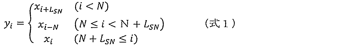
この再配置によって、MPDUの先頭にあるシーケンス番号サブフィールドに含まれる各ビットは、LSNだけ後側に移動する。複製部302aは、そのビット再配置後のMPDUを複製する。This rearrangement causes each bit contained in the sequence number subfield at the beginning of the MPDU to be moved backward by L SN . The duplicating
フロントペイロードサブフィールドおよびバックペイロードサブフィールドはそれぞれ、N個のシンボルからなる。ここで、Moddは、奇数番目のシンボルに含まれるビット長であり、Mevenは、偶数番目のシンボルに含まれるビット長であり、W1は、シンボル値オフセット(上述のオフセット値)であり、W2は、シンボル値単位(上述のユニット値)である。なお、N、Modd、Meven、W1、およびW2は、図128に示すPHYのPIBによって設定される。The front payload subfield and the back payload subfield each consist of N symbols. Here, M odd is the bit length included in the odd-numbered symbols, M even is the bit length included in the even-numbered symbols, and W1 is the symbol value offset (the offset value described above). , W2 are the symbol value units (unit values described above). Note that N, M odd , M even , W 1 , and W 2 are set by the PHY PIB shown in FIG.
フロント変換部303aおよびバック変換部304aは、再配置されたMPDUのペイロードビット(y0、y1、y2、...)を、以下の(式2)~(式5)によってziに変換する。The


フロント変換部303aは、ziを用いて、フロントペイロードサブフィールドのi番目のシンボル(すなわちシンボル値)を以下の(式6)によって算出する。The
![]()
![]()
バック変換部304aは、ziを用いて、バックペイロードサブフィールドのi番目のシンボル(すなわちシンボル値)を以下の(式7)によって算出する。The
![]()
![]()
図130は、PLCPヘッダサブフィールドを示す図である。 FIG. 130 is a diagram showing PLCP header subfields.
PLCPヘッダサブフィールドは、図130に示すように、PWMモードでは、4つのシンボルによって構成され、PPMモードでは、3つのシンボルによって構成される。 As shown in FIG. 130, the PLCP header subfield consists of 4 symbols in PWM mode and 3 symbols in PPM mode.
図131は、PLCPセンタサブフィールドを示す図である。 FIG. 131 is a diagram showing the PLCP center subfield.
PLCPセンタのサブフィールドは、図131に示すように、PWMモードでは、4つのシンボルによって構成され、PPMモードでは、3つのシンボルによって構成される。 As shown in FIG. 131, the PLCP center subfield consists of 4 symbols in PWM mode and 3 symbols in PPM mode.
図132は、PLCPフッタサブフィールドを示す図である。 FIG. 132 is a diagram showing the PLCP footer subfield.
PLCPフッタサブフィールドは、図132に示すように、PWMモードでは、4つのシンボルによって構成され、PPMモードでは、3つのシンボルによって構成される。 The PLCP footer subfield consists of 4 symbols in PWM mode and 3 symbols in PPM mode, as shown in FIG.
図133は、MPMにおけるPHYのPWMモードの波形を示す図である。 FIG. 133 is a diagram showing PWM mode waveforms of PHY in MPM.
PWMモードでは、シンボルは、光強度の2つの状態のうちの何れか、すなわち明るい状態または暗い状態として送信されなければならない。MPMにおけるPHYのPWMモードでは、シンボル値は、マイクロ秒単位の連続時間に対応する。例えば、図133に示すように、第1のシンボル値は、第1の明るい状態の連続時間に対応し、第2のシンボル値は、次の暗い状態の連続時間に対応する。なお、図133に示す例では、各サブフィールドの最初の状態は、明るい状態であるが、暗い状態であってもよい。 In PWM mode, symbols must be transmitted in one of two states of light intensity: bright or dark. In the PWM mode of the PHY in MPM, the symbol values correspond to continuous time in microseconds. For example, as shown in FIG. 133, the first symbol value corresponds to the first bright state duration and the second symbol value corresponds to the next dark state duration. In the example shown in FIG. 133, the initial state of each subfield is bright, but it may be dark.
図134は、MPMにおけるPHYのPPMモードの波形を示す図である。 FIG. 134 is a diagram showing waveforms in PPM mode of PHY in MPM.
PPMモードでは、図134に示すように、シンボル値は、明るい状態の開始から次の明るい状態の開始までの時間をマイクロ秒単位で表す。明るい状態の時間は、シンボル値の90%より短くなければならない。 In PPM mode, the symbol values represent the time in microseconds from the start of a bright state to the start of the next bright state, as shown in FIG. The bright state duration must be less than 90% of the symbol value.
両方のモードについて、送信機は、複数のシンボルの一部のみを送信することができる。しかし、送信機は、PLCPセンタサブフィールドのすべてのシンボルと、少なくともN個のシンボルとを送信しなければならない。その少なくともN個のシンボルのぞれぞれは、フロントペイロードサブフィールドおよびバックペイロードサブフィールドの何れかに含まれるシンボルである。 For both modes, the transmitter can only send a portion of the multiple symbols. However, the transmitter must transmit all symbols of the PLCP center subfield and at least N symbols. Each of the at least N symbols is a symbol contained in either the front payload subfield and the back payload subfield.
(実施の形態6のまとめ)
図135は、実施の形態6の復号方法の一例を示すフローチャートである。なお、この図135に示すフローチャートは、図125に示すフローチャートに相当する。(Summary of Embodiment 6)
135 is a flowchart illustrating an example of a decoding method according to
この復号方法は、複数のフレームで構成される可視光信号を復号する方法であって、図135に示すように、ステップS310bと、ステップS320bと、ステップS330bとを含む。また、これらの複数のフレームのそれぞれはシーケンス番号とフレームペイロードとを含む。 This decoding method is a method of decoding a visible light signal composed of a plurality of frames, and includes steps S310b, S320b, and S330b as shown in FIG. Each of these multiple frames also includes a sequence number and a frame payload.
ステップS310bでは、復号対象フレームにおいてシーケンス番号が格納されるサブフィールドのビット長を決定するための情報であるmacSnLengthに基づいて、そのサブフィールドのビット長が可変長か否かを判定する可変長判定処理を行う。 In step S310b, based on macSnLength which is information for determining the bit length of the subfield in which the sequence number is stored in the decoding target frame, variable length determination is performed to determine whether the bit length of the subfield is variable. process.
ステップS320bでは、その可変長判定処理の結果に基づいて、そのサブフィールドのビット長を決定する。そして、ステップS330bでは、決定されたサブフィールドのビット長に基づいて、復号対象フレームを復号する。 In step S320b, the bit length of the subfield is determined based on the result of the variable length determination process. Then, in step S330b, the decoding target frame is decoded based on the determined bit length of the subfield.
ここで、ステップS320bにおける上記サブフィールドのビット長の決定は、ステップS321b~S324bを含む。 Here, the determination of the bit length of the subfield in step S320b includes steps S321b to S324b.
つまり、ステップS310bの可変長判定処理において、サブフィールドのビット長が可変長ではないと判定された場合には、そのサブフィールドのビット長を、上述のmacSnLengthによって示される値に決定する(ステップS321b)。 That is, if it is determined in the variable length determination process in step S310b that the bit length of the subfield is not variable, the bit length of the subfield is determined to be the value indicated by macSnLength (step S321b). ).
一方、ステップS310bの可変長判定処理において、サブフィールドのビット長が可変長であると判定された場合には、復号対象フレームが、上記複数のフレームのうちの最終フレームであるか否か判定する最終判定処理を行う(ステップS322b)。ここで、最終フレームであると判定された場合には(ステップS322bのY)、そのサブフィールドのビット長を所定の値に決定する(ステップS323b)。一方、最終フレームでないと判定された場合には(ステップS322bのN)、最終フレームのシーケンス番号の値に基づいて、そのサブフィールドのビット長を決定する(ステップS324b)。 On the other hand, if it is determined in the variable length determination process in step S310b that the bit length of the subfield is variable, it is determined whether or not the frame to be decoded is the last frame of the plurality of frames. A final determination process is performed (step S322b). Here, if it is determined to be the last frame (Y in step S322b), the bit length of that subfield is determined to a predetermined value (step S323b). On the other hand, if it is determined that the frame is not the final frame (N in step S322b), the bit length of the subfield is determined based on the value of the sequence number of the final frame (step S324b).
これにより、図135に示すように、シーケンス番号が格納されるサブフィールド(具体的には、シーケンス番号サブフィールド)のビット長が固定長であっても可変長であっても、そのサブフィールドのビット長を適切に決定することができる。 As a result, as shown in FIG. 135, regardless of whether the bit length of the subfield storing the sequence number (specifically, the sequence number subfield) is fixed or variable, the Bit length can be determined appropriately.
ここで、ステップS322bの最終判定処理では、復号対象フレームが最終フレームであるか否かを示す最終フレームフラグに基づいて、その復号対象フレームが最終フレームであるか否かを判定してもよい。具体的には、ステップS322bの最終判定処理では、最終フレームフラグが1を示す場合に、その復号対象フレームが最終フレームであると判定し、最終フレームフラグが0を示す場合に、その復号対象フレームが最終フレームではないと判定してもよい。例えば、最終フレームフラグは、そのサブフィールドの1ビット目に含まれていてもよい。 Here, in the final determination process in step S322b, it may be determined whether or not the decoding target frame is the final frame based on the final frame flag indicating whether or not the decoding target frame is the final frame. Specifically, in the final determination process in step S322b, when the final frame flag indicates 1, it is determined that the decoding target frame is the final frame, and when the final frame flag indicates 0, the decoding target frame is determined to be the final frame. is not the final frame. For example, the last frame flag may be included in the 1st bit of the subfield.
これにより、図125のステップS203aに示すように、復号対象フレームが最終フレームであるか否かを適切に判定することができる。 Accordingly, as shown in step S203a in FIG. 125, it is possible to appropriately determine whether or not the frame to be decoded is the final frame.
より具体的には、ステップS320bにおけるサブフィールドのビット長の決定では、ステップS322bの最終判定処理において、復号対象フレームが最終フレームであると判定された場合には、サブフィールドのビット長を、上述の所定の値である5ビットに決定してもよい。つまり、図125のステップS204aに示すように、サブフィールドのビット長SNが5ビットに決定される。 More specifically, in determining the bit length of the subfield in step S320b, if it is determined in the final determination processing in step S322b that the frame to be decoded is the final frame, the bit length of the subfield is determined as described above. may be determined to be 5 bits, which is a predetermined value of . That is, as shown in step S204a of FIG. 125, the bit length SN of the subfield is determined to be 5 bits.
また、ステップS320bにおけるサブフィールドのビット長の決定では、ステップS322bの最終判定処理において、復号対象フレームが最終フレームではないと判定された場合に、最終フレームのシーケンス番号の値が1であるときには、サブフィールドのビット長を、1ビットに決定してもよい。また、最終フレームのシーケンス番号の値が2であるときには、そのサブフィールドのビット長を、2ビットに決定してもよい。また、最終フレームのシーケンス番号の値が3または4であるときには、そのサブフィールドのビット長を、3ビットに決定してもよい。また、最終フレームのシーケンス番号の値が5から8の何れかの整数であるときには、そのサブフィールドのビット長を、4ビットに決定してもよい。また、最終フレームのシーケンス番号の値が9から15の何れかの整数であるときには、そのサブフィールドのビット長を、5ビットに決定してもよい。つまり、図125のステップS206a~S210aに示すように、サブフィールドのビット長SNが1~5ビットの何れかに決定される。 Further, in determining the bit length of the subfield in step S320b, if it is determined in the final determination process in step S322b that the frame to be decoded is not the final frame and the value of the sequence number of the final frame is 1, The bit length of the subfield may be determined to be 1 bit. Also, when the value of the sequence number of the final frame is 2, the bit length of that subfield may be determined to be 2 bits. Also, when the value of the sequence number of the final frame is 3 or 4, the bit length of that subfield may be determined to be 3 bits. Also, when the value of the sequence number of the final frame is any integer from 5 to 8, the bit length of the subfield may be determined to be 4 bits. Also, when the value of the sequence number of the final frame is any integer from 9 to 15, the bit length of the subfield may be determined to be 5 bits. That is, as shown in steps S206a to S210a of FIG. 125, the bit length SN of the subfield is determined to be any one of 1 to 5 bits.
図136は、実施の形態6の符号化方法の一例を示すフローチャートである。なお、この図136に示すフローチャートは、図124に示すフローチャートに相当する。
136 is a flowchart showing an example of an encoding method according to
この符号化方法は、符号化対象の情報を、複数のフレームで構成される可視光信号に符号化する方法であって、図136に示すように、ステップS410aと、ステップS420aと、ステップS430aとを含む。また、これらの複数のフレームのそれぞれはシーケンス番号とフレームペイロードとを含む。 This encoding method is a method of encoding information to be encoded into a visible light signal composed of a plurality of frames, and as shown in FIG. including. Each of these multiple frames also includes a sequence number and a frame payload.
ステップS410aでは、処理対象フレームにおいてシーケンス番号が格納されるサブフィールドのビット長を決定するための情報であるmacSnLengthに基づいて、そのサブフィールドのビット長が可変長か否かを判定する可変長判定処理を行う。 In step S410a, based on macSnLength, which is information for determining the bit length of the subfield in which the sequence number is stored in the frame to be processed, variable length determination is performed to determine whether the bit length of the subfield is variable. process.
ステップS420aでは、その可変長判定処理の結果に基づいて、そのサブフィールドのビット長を決定する。そして、ステップS430aでは、決定されたサブフィールドのビット長に基づいて、符号化対象の情報の一部を処理対象フレームに符号化する。 In step S420a, the bit length of the subfield is determined based on the result of the variable length determination process. Then, in step S430a, a part of the information to be encoded is encoded into the processing target frame based on the determined bit length of the subfield.
ここで、ステップS420aにおける上記サブフィールドのビット長の決定では、ステップS421a~S424aを含む。 Here, determination of the bit length of the subfield in step S420a includes steps S421a to S424a.
つまり、ステップS410aの可変長判定処理において、サブフィールドのビット長が可変長ではないと判定された場合には、そのサブフィールドのビット長を、上述のmacSnLengthによって示される値に決定する(ステップS421a)。 That is, if it is determined in the variable length determination process of step S410a that the bit length of the subfield is not variable, the bit length of the subfield is determined to be the value indicated by macSnLength (step S421a). ).
一方、ステップS410aの可変長判定処理において、サブフィールドのビット長が可変長であると判定された場合には、処理対象フレームが、上記複数のフレームのうちの最終フレームであるか否か判定する最終判定処理を行う(ステップS422a)。ここで、最終フレームであると判定された場合には(ステップS422aのY)、そのサブフィールドのビット長を所定の値に決定する(ステップS423a)。一方、最終フレームでないと判定された場合には(ステップS422aのN)、最終フレームのシーケンス番号の値に基づいて、そのサブフィールドのビット長を決定する(ステップS424a)。 On the other hand, if it is determined in the variable length determination process of step S410a that the bit length of the subfield is variable, it is determined whether or not the frame to be processed is the final frame of the plurality of frames. A final determination process is performed (step S422a). Here, if it is determined to be the last frame (Y in step S422a), the bit length of that subfield is determined to a predetermined value (step S423a). On the other hand, if it is determined that the frame is not the final frame (N in step S422a), the bit length of the subfield is determined based on the value of the sequence number of the final frame (step S424a).
これにより、図136に示すように、シーケンス番号が格納されるサブフィールド(具体的には、シーケンス番号サブフィールド)のビット長が固定長であっても可変長であっても、そのサブフィールドのビット長を適切に決定することができる。 As a result, as shown in FIG. 136, regardless of whether the bit length of the subfield storing the sequence number (specifically, the sequence number subfield) is fixed or variable, the Bit length can be determined appropriately.
なお、本実施の形態における復号装置は、プロセッサとメモリとを備え、メモリには、図135に示す復号方法をプロセッサに実行させるプログラムが記録されている。本実施の形態における符号化装置は、プロセッサとメモリとを備え、メモリには、図136に示す符号化方法をプロセッサに実行させるプログラムが記録されている。また、本実施の形態におけるプログラムは、図135に示す復号方法、または図136に示す符号化方法をコンピュータに実行させるプログラムである。 The decoding device according to the present embodiment includes a processor and memory, and the memory stores a program that causes the processor to execute the decoding method shown in FIG. 135 . The encoding device according to the present embodiment includes a processor and memory, and the memory stores a program that causes the processor to execute the encoding method shown in FIG. 136 . A program according to the present embodiment is a program that causes a computer to execute the decoding method shown in FIG. 135 or the encoding method shown in FIG.
(実施の形態7)
本実施の形態では、光IDを可視光信号によって送信する送信方法について説明する。なお、本実施の形態における送信機および受信機は、上記各実施の形態における送信機(または送信装置)および受信機(または受信装置)と同一の機能および構成を有していてもよい。(Embodiment 7)
In this embodiment, a transmission method for transmitting a light ID by a visible light signal will be described. The transmitter and receiver in this embodiment may have the same functions and configurations as the transmitter (or transmitting device) and receiver (or receiving device) in the above embodiments.
図137は、本実施の形態における受信機がAR画像を表示する例を示す図である。 FIG. 137 is a diagram showing an example of AR image display by a receiver according to this embodiment.
本実施の形態における受信機200は、イメージセンサおよびディスプレイ201を備えた受信機であって、例えばスマートフォンとして構成されている。このような受信機200は、そのイメージセンサによる被写体の撮像によって、上述の通常撮影画像である撮像表示画像Paと、上述の可視光通信画像または輝線画像である復号用画像とを取得する。
具体的には、受信機200のイメージセンサは送信機100を撮像する。送信機100は、例えば電球のような形態を有し、ガラス球141と、そのガラス球141の内部で炎のように光りながら揺らめく発光部142とを備える。この発光部142は、送信機100に備えられた1つまたは複数の発光素子(例えばLED)の点灯によって光る。この送信機100は、その発光部142を点滅させることによって輝度変化し、その輝度変化によって光ID(光識別情報)を送信する。この光IDは、上述の可視光信号である。
Specifically, the image sensor of the
受信機200は、送信機100を通常露光時間で撮像することによって、その送信機100が映し出された撮像表示画像Paを取得するとともに、その通常露光時間よりも短い通信用露光時間で送信機100を撮像することによって、復号用画像を取得する。なお、通常露光時間は、上述の通常撮影モードにおける露光時間であり、通信用露光時間は、上述の可視光通信モードにおける露光時間である。
The
受信機200は、その復号用画像に対する復号によって光IDを取得する。つまり、受信機200は、送信機100から光IDを受信する。受信機200は、その光IDをサーバに送信する。そして、受信機200は、その光IDに対応するAR画像P42と認識情報とをサーバから取得する。受信機200は、撮像表示画像Paのうち、その認識情報に応じた領域を対象領域として認識する。そして、受信機200は、その対象領域にAR画像P42を重畳し、AR画像P42が重畳された撮像表示画像Paをディスプレイ201に表示する。
The
例えば、受信機200は、図51に示す例と同様に、認識情報にしたがって、送信機100が映し出されている領域の左上にある領域を対象領域として認識する。その結果、例えば妖精を示すAR画像P42は、送信機100の周りを飛んでいるように表示される。
For example, as in the example shown in FIG. 51, the
図138は、AR画像P42が重畳された撮像表示画像Paの他の例を示す図である。 FIG. 138 is a diagram showing another example of the captured display image Pa on which the AR image P42 is superimposed.
受信機200は、図138に示すように、AR画像P42が重畳された撮像表示画像Paをディスプレイ201に表示する。
ここで、上述の認識情報は、撮像表示画像Paにおける閾値以上の輝度を有する範囲が基準領域であることを示す。さらに、その認識情報は、その基準領域に対して予め定められた方向に対象領域があることと、その対象領域が基準領域の中心(または重心)から予め定められた距離だけ離れていることを示す。 Here, the recognition information described above indicates that the range having luminance equal to or higher than the threshold value in the captured display image Pa is the reference area. Further, the recognition information indicates that the target area is in a predetermined direction with respect to the reference area and that the target area is separated from the center (or the center of gravity) of the reference area by a predetermined distance. show.
したがって、受信機200によって撮像されている送信機100の発光部142が揺らめくと、図138に示すように、撮像表示画像Paの対象領域に重畳されるAR画像P42も、その発光部142の動きに同期するように動く。つまり、発光部142が揺らめくと、撮像表示画像Paに映し出されている発光部142の像142aも揺らめく。この像142aは、上述の閾値以上の輝度を有する範囲であって、基準領域である。すなわち、基準領域が動くため、受信機200は、その基準領域と対象領域との間の距離が予め定められた距離に維持されるように、対象領域を移動させて、その移動する対象領域にAR画像P42を重畳する。その結果、発光部142が揺らめくと、撮像表示画像Paの対象領域に重畳されるAR画像P42も、その発光部142の動きに同期するように動く。なお、基準領域の中心位置は、発光部142の変形によっても移動することがある。したがって、発光部142が変形する場合にも、AR画像42は、その移動する基準領域の中心位置との間の距離が予め定められた距離に維持されるように動くことがある。
Therefore, when the
また、上述の例では、受信機200は、認識情報に基づいて対象領域を認識し、その対象領域にAR画像P42を重畳するが、その対象領域を中心にAR画像P42を振動させてもよい。つまり、受信機200は、時間に対する振幅の変化を示す関数にしたがって、そのAR画像P42を例えば上下方向に振動させる。その関数は、例えば正弦波などの三角関数である。
In the above example, the
また、受信機200は、上述の閾値以上の輝度を有する範囲の大きさに応じて、AR画像P42の大きさを変化させてもよい。つまり、受信機200は、撮像表示画像Paにおける明るい領域の面積が大きくなるほど、AR画像P42のサイズを大きくし、逆に、その明るい領域の面積が小さくなるほど、AR画像P42のサイズを小さくする。
Also, the
または、受信機200は、上述の閾値以上の輝度を有する範囲における平均輝度が高いほど、AR画像P42のサイズを大きくし、逆に、その平均輝度が低いほど、AR画像P42のサイズを小さくしてもよい。なお、AR画像P42のサイズの代わりに、AR画像P42の透明度を、その平均輝度に応じて変化させてもよい。
Alternatively, the
また、図138に示す例では、発光部142の像142aの中では何れの画素も閾値以上の輝度を有するが、何れかの画素が閾値未満であってもよい。つまり、像142aに相当する、閾値以上の輝度を有する範囲は、環状であってもよい。この場合にも、その閾値以上の輝度を有する範囲が基準領域として特定され、その基準領域の中心(または重心)から予め定められた距離だけ離れた対象領域に、AR画像P42が重畳される。
Further, in the example shown in FIG. 138, any pixel in the
図139は、本実施の形態における受信機200がAR画像を表示する他の例を示す図である。
FIG. 139 is a diagram showing another example in which
送信機100は、例えば図139に示すように、照明装置として構成され、例えば壁に描かれた3つの円からなる図形143を照らしながら輝度変化することによって、光IDを送信している。図形143は、その送信機100からの光によって照らされているため、送信機100と同様に輝度変化し、光IDを送信している。
The
受信機200は、送信機100によって照らされた図形143を撮像することによって、上述と同様に、撮像表示画像Paと復号用画像とを取得する。受信機200は、その復号用画像に対する復号によって光IDを取得する。つまり、受信機200は、図形143から光IDを受信する。受信機200は、その光IDをサーバに送信する。そして、受信機200は、その光IDに対応するAR画像P43と認識情報とをサーバから取得する。受信機200は、撮像表示画像Paのうち、その認識情報に応じた領域を対象領域として認識する。例えば、受信機200は、図形143が映し出されている領域を対象領域として認識する。そして、受信機200は、その対象領域にAR画像P43を重畳し、AR画像P43が重畳された撮像表示画像Paをディスプレイ201に表示する。例えば、AR画像P43は、キャラクターの顔画像である。
The
ここで、図形143は、上述のように3つの円からなるが、この図形143には幾何学的な特徴が少ない。したがって、図形143の撮像によって得られる撮像画像だけからでは、その図形143に応じたAR画像を、サーバに蓄積された多くの画像から適切に選択して取得することは難しい。しかし、本実施の形態では、受信機200は、光IDを取得し、その光IDに対応するAR画像P43をサーバから取得する。したがって、サーバに多くの画像が蓄積されていても、その光IDに対応するAR画像P43を、図形143に応じたAR画像として、その多くの画像の中から適切に選択して取得することができる。
Here, the figure 143 consists of three circles as described above, but this figure 143 has few geometric features. Therefore, it is difficult to appropriately select and acquire an AR image corresponding to the graphic 143 from many images accumulated in the server only from the captured image obtained by imaging the graphic 143 . However, in the present embodiment, the
図140は、本実施の形態における受信機200の動作を示すフローチャートである。
FIG. 140 is a flowchart showing the operation of
本実施の形態における受信機200は、まず、複数のAR画像候補を取得する(ステップS541)。例えば、受信機200は、可視光通信と異なる無線通信(BTLEまたはWi-Fiなど)によって、サーバから複数のAR画像候補を取得する。次に、受信機200は、被写体を撮像する(ステップS542)。受信機200は、この撮像によって、上述のように、撮像表示画像Paと復号用画像とを取得する。しかし、その被写体が送信機100の写真である場合には、その被写体からは光IDは送信されていないため、受信機200は、復号用画像に対する復号を行っても光IDを取得することはできない。
そこで、受信機200は、光IDを取得することができたか否か、すなわち、被写体から光IDを受信したか否かを判定する(ステップS543)。
Therefore, the
ここで、光IDを受信していないと判定すると(ステップS543のNo)、受信機200は、自らに設定されているAR表示フラグが1であるか否かを判定する(ステップS544)。AR表示フラグは、光IDが取得されていなくても撮像表示画像PaだけからAR画像を表示してもよいか否かを示すフラグである。AR表示フラグが1である場合には、そのAR表示フラグは、撮像表示画像PaだけからAR画像を表示してもよいこと示し、AR表示フラグが0である場合には、そのAR表示フラグは、撮像表示画像PaだけからAR画像を表示してはいけないこと示す。
Here, if it is determined that the light ID has not been received (No in step S543), the
AR表示フラグが1であると判定すると(ステップS544のYes)、受信機200は、ステップS541で取得された複数のAR画像候補の中から、撮像表示画像Paに対応する候補をAR画像として選択する(ステップS545)。つまり、受信機200は、撮像表示画像Paに含まれる特徴量を抽出し、その抽出された特徴量に関連付けられている候補をAR画像として選択する。
When determining that the AR display flag is 1 (Yes in step S544), the
そして、受信機200は、選択された候補であるAR画像を撮像表示画像Paに重畳して表示する(ステップS546)。
Then, the
一方、AR表示フラグが0であると判定すると(ステップS544のNo)、受信機200は、AR画像を表示しない。
On the other hand, when determining that the AR display flag is 0 (No in step S544), the
また、ステップS543で光IDを受信したと判定すると(ステップS543のYes)、受信機200は、ステップS541で取得された複数のAR画像候補の中から、その光IDに関連付けられている候補をAR画像として選択する(ステップS547)。そして、受信機200は、選択された候補であるAR画像を撮像表示画像Paに重畳して表示する(ステップS546)。
Further, when it is determined that the light ID has been received in step S543 (Yes in step S543), the
なお、上述の例では、AR表示フラグは受信機200に設定されているが、サーバに設定されていてもよい。この場合には、受信機200は、ステップS544において、サーバにAR表示フラグが1であるか0であるかを問い合わせる。
Although the AR display flag is set in the
これにより、受信機200が撮像を行っても光IDを受信していないときに、その受信機200に対してAR画像を表示させるか否かを、AR表示フラグによって制御することができる。
Thus, when the
図141は、本実施の形態における送信機100の動作を説明するための図である。
FIG. 141 is a diagram for explaining the operation of
例えば、送信機100はプロジェクタとして構成されている。ここで、プロジェクタから照射されてスクリーンに反射される光の強度は、そのプロジェクタの光源の経年劣化、または、その光源からスクリーンまでの距離などの各要因によって変化する。光の強度が小さい場合には、送信機100から送信される光IDが受信機200に受信され難くなる。
For example,
そこで、本実施の形態における送信機100は、その各要因に応じた光の強度の変化を抑えるために、光源を発光させるためのパラメータを調整する。このパラメータは、光源を発光させるためにその光源に入力される電流の値と、その発光時間(より具体的には、単位時間当たりの発光時間)とのうちの少なくとも一方である。例えば、電流の値を大きくするほど、発光時間を長くするほど、光源の光の強度は大きくなる。
Therefore,
つまり、送信機100は、光源が経年劣化しているほど、その光源の光を強めるようにパラメータを調整する。具体的には、送信機100は、タイマを備え、そのタイマによって計測される光源の使用時間が長いほど、その光源の光を強めるようにパラメータを調整する。つまり、送信機100は、使用時間が長いほど、光源の電流の値を高めたり、発光時間を長くしたりする。または、送信機100は、光源から照射される光の強度を検出し、その検出された光の強度が低下しないようにパラメータを調整する。すなわち、送信機100は、検出される光の強度が小さいほど、その光を強めるようにパラメータを調整する。
In other words, the
また、送信機100は、光源からスクリーンまでの照射距離が長いほど、その光源の光を強めるようにパラメータを調整する。具体的には、送信機100は、照射されてスクリーンに反射された光の強度を検出し、その検出された光の強度が小さいほど、光源の光を強めるようにパラメータを調整する。つまり、送信機100は、検出された光の強度が小さいほど、その光源の電流の値を高めたり、発光時間を長くしたりする。これによって、反射される光の強度が照射距離に関わらず一定になるように、パラメータが調整される。または、送信機100は、光源からスクリーンまでの照射距離を測距センサによって検出し、その検出された照射距離が長いほど、光源の光を強めるようにパラメータを調整する。
Further, the
また、送信機100は、スクリーンの色が黒いほど、その光源の光を強めるようにパラメータを調整する。具体的には、送信機100は、スクリーンを撮像することによって、そのスクリーンの色を検出し、その検出された色が黒いほど、光源の光を強めるようにパラメータを調整する。つまり、送信機100は、検出された色が黒いほど、その光源の電流の値を高めたり、発光時間を長くしたりする。これによって、反射される光の強度がスクリーンの色に関わらず一定になるように、パラメータが調整される。
Also, the
また、送信機100は、外光が強いほど、その光源の光を強めるようにパラメータを調整する。具体的には、送信機100は、光源をONにして光を照射したときのスクリーンの明るさと、光源をOFFにして光を照射していないときのスクリーンの明るさとの差を検出する。そして、送信機100は、その明るさの差が小さいほど、光源の光を強めるようにパラメータを調整する。つまり、送信機100は、明るさの差が小さいほど、その光源の電流の値を高めたり、発光時間を長くしたりする。これによって、外光に関わらず、光IDのS/N比が一定になるように、パラメータが調整される。または、送信機100は、例えばLEDディスプレイとして構成されている場合には、太陽光の強度を検出し、その太陽光の強度が大きいほど、光源の光を強めるようにパラメータを調整してもよい。
Further, the
なお、上述のようなパラメータの調整は、ユーザによる操作が行われたときに実施されてもよい。例えば、送信機100は、キャリブレーションボタンを備え、そのキャリブレーションボタンがユーザによって押下されたときに、上述のパラメータの調整を実施する。または、送信機100は、定期的に上述のパラメータの調整を実施してもよい。
Note that the adjustment of the parameters as described above may be performed when an operation is performed by the user. For example, the
図142は、本実施の形態における送信機100の他の動作を説明するための図である。
FIG. 142 is a diagram for explaining another operation of
例えば、送信機100はプロジェクタとして構成され、光源からの光を、前部材を通してスクリーンに照射する。プロジェクタが液晶プロジェクタの場合には、その前部材は液晶パネルであり、プロジェクタがDLP(登録商標)プロジェクタの場合には、その前部材はDMD(Digital Mirror Device)である。つまり、前部材は、映像の輝度を画素ごとに調整する部材である。また、光源は、前部材に向けて光を照射するが、その光の強度をHighとLowとに切り替える。また、光源は、単位時間あたりのHighの時間を調整することによって、時間平均的な明るさを調整する。
For example, the
ここで、前部材の透過率が例えば100%である場合には、プロジェクタからスクリーンへ投影される映像が明るすぎることがないように、光源は暗くなる。つまり、光源は、単位時間あたりのHighの時間を短くする。 Here, if the transmittance of the front member is, for example, 100%, the light source is darkened so that the image projected from the projector onto the screen is not too bright. That is, the light source shortens the High time per unit time.
このとき、光源は、輝度変化によって光IDを送信する場合には、光IDのパルス幅を広くする。 At this time, the light source widens the pulse width of the light ID when transmitting the light ID according to the luminance change.
一方、前部材の透過率が例えば20%である場合には、プロジェクタからスクリーンへ投影される映像が暗すぎることがないように、光源は明るくなる。つまり、光源は、単位時間あたりのHighの時間を長くする。 On the other hand, if the transmittance of the front member is, for example, 20%, the light source will be bright so that the image projected from the projector onto the screen is not too dark. That is, the light source lengthens the High time per unit time.
このとき、光源は、輝度変化によって光IDを送信する場合には、光IDのパルス幅を狭くする。 At this time, the light source narrows the pulse width of the light ID when transmitting the light ID according to the luminance change.
このように、光源が暗い場合には、光IDのパルス幅が広くなり、逆に、光源が明るい場合には、光IDのパルス幅が狭くなるため、光IDの送信によって、光源からの光の強度が弱すぎたり、明るすぎたりしてしまうことを抑えることができる。 Thus, when the light source is dark, the pulse width of the light ID is widened, and conversely, when the light source is bright, the pulse width of the light ID is narrowed. It is possible to prevent the intensity of the image from being too weak or too bright.
なお、上述の例では、送信機100はプロジェクタであるが、大型LEDディスプレイとして構成されていてもよい。大型LEDディスプレイは、画素スイッチと共通スイッチとを備える。画素スイッチのONおよびOFFによって映像が表現され、共通スイッチのONおよびオフによって光IDが送信される。この場合、機能的に、画素スイッチが前部材に相当し、共通スイッチが光源に相当する。画素スイッチによる平均輝度が高い場合には、共通スイッチによる光IDのパルス幅を短くしてもよい。
Although the
図143は、本実施の形態における送信機100の他の動作を説明するための図である。具体的には、図143は、調光機能付きスポットライトとして構成された送信機100の調光度と、その送信機100の光源に入力される電流(具体的にはピーク電流の値)との関係を示す。
FIG. 143 is a diagram for explaining another operation of
送信機100は、自らに備えられている光源に対して指定される調光度を受け付け、その指定された調光度で光源を発光させる。なお、調光度は、光源の平均輝度の最大平均輝度に対する割合である。平均輝度は、瞬間的な輝度ではなく、時間平均における輝度である。また、調光度の調整は、光源に入力される電流の値を調整したり、光源の輝度がLowとなる時間を調整することによって実現される。光源の輝度がLowとなる時間は、光源をオフする時間であってもよい。
The
ここで、送信機100は、送信対象信号を光IDとして送信するときには、その送信対象信号を予め定められたモードで符号化することによって符号化信号を生成する。そして、送信機100は、その符号化信号にしたがって、自らに備えられた光源を輝度変化させることによって、その符号化信号を光ID(すなわち可視光信号)として送信する。
Here, when transmitting a signal to be transmitted as an optical ID,
例えば、指定された調光度が0%以上x3(%)以下である場合には、送信機100は、デューティ比35%のPWMモードで送信対象信号を符号化することによって符号化信号を生成する。x3(%)は例えば50%である。なお、本実施の形態では、デューティ比35%のPWMモードを、第1のモードともいい、上述のx3を、第1の値ともいう。
For example, when the specified dimming degree is 0% or more and x3(%) or less, the
つまり、送信機100は、指定される調光度が0%以上x3(%)以下である場合には、可視光信号のデューティ比を35%に維持しながら、光源の調光度をピーク電流の値によって調整する。
In other words, when the designated dimming degree is 0% or more and x3(%) or less, the
また、指定された調光度がx3(%)よりも大きく100%以下である場合には、送信機100は、デューティ比65%のPWMモードで送信対象信号を符号化することによって符号化信号を生成する。なお、本実施の形態では、デューティ比65%のPWMモードを、第2のモードともいう。
Further, when the specified dimming degree is greater than x3(%) and equal to or less than 100%, the
つまり、送信機100は、指定される調光度がx3(%)よりも大きく100%以下である場合には、可視光信号のデューティ比を65%に維持しながら、光源の調光度をピーク電流の値によって調整する。
In other words, when the specified dimming degree is greater than x3(%) and equal to or less than 100%, the
このように、本実施の形態における送信機100は、光源に対して指定される調光度を指定調光度として受け付ける。そして、送信機100は、指定調光度が第1の値以下である場合には、その指定調光度で光源を発光させながら、第1のモードで符号化された信号を輝度変化により送信する。また、送信機100は、指定調光度の値が第1の値よりも大きい場合には、その指定調光度で光源を発光させながら、第2のモードで符号化された信号を輝度変化により送信する。具体的には、第2のモードで符号化された信号のデューティ比は、第1のモードで符号化された信号のデューティ比よりも大きい。
In this way,
ここで、第2のモードのデューティ比は第1のモードのデューティ比よりも大きいため、第2のモードにおける調光度に対するピーク電流の変化率を、第1のモードにおける調光度に対するピーク電流の変化率よりも小さくすることができる。 Here, since the duty ratio of the second mode is greater than the duty ratio of the first mode, the change rate of the peak current with respect to the dimming level in the second mode is defined as the change in the peak current with respect to the dimming level in the first mode. can be smaller than the rate.
また、指定される調光度がx3(%)を超えるときには、モードが第1のモードから第2のモードに切り替えられる。したがって、このときには、ピーク電流を瞬間的に低下させることができる。つまり、指定される調光度がx3(%)であるときには、ピーク電流はy3(mA)であるが、指定される調光度がx3(%)を少しでも超えると、ピーク電流をy2(mA)に抑えることができる。なお、y3(mA)は例えば143mAであり、y2(mA)は例えば100mAである。その結果、調光度を大きくするために、ピーク電流がy3(mA)よりも大きくなることを抑えることができ、大きな電流が流れることによって光源が劣化してしまうことを抑制することができる。 Also, when the specified dimming degree exceeds x3 (%), the mode is switched from the first mode to the second mode. Therefore, at this time, the peak current can be reduced instantaneously. That is, when the specified dimming level is x3 (%), the peak current is y3 (mA). can be reduced to Note that y3 (mA) is, for example, 143 mA, and y2 (mA) is, for example, 100 mA. As a result, it is possible to suppress the peak current from becoming larger than y3 (mA) in order to increase the dimming degree, and it is possible to suppress deterioration of the light source due to the flow of a large current.
また、指定される調光度がx4(%)を超えるときには、モードが第2のモードであっても、ピーク電流がy3(mA)よりも大きくなる。しかし、指定される調光度がx4(%)を超える頻度が少ない場合には、光源の劣化を抑えることができる。なお、本実施の形態では、上述のx4を、第2の値ともいう。また、図143に示す例では、x4(%)は100%未満であるが、100%であってもよい。 Also, when the designated dimming degree exceeds x4 (%), the peak current becomes larger than y3 (mA) even if the mode is the second mode. However, if the specified dimming degree rarely exceeds x4 (%), deterioration of the light source can be suppressed. Note that, in the present embodiment, x4 described above is also referred to as a second value. Also, in the example shown in FIG. 143, x4(%) is less than 100%, but may be 100%.
つまり、本実施の形態における送信機100では、指定調光度が第1の値よりも大きく第2の値以下である場合に、第2のモードで符号化された信号を輝度変化により送信するための光源のピーク電流の値は、指定調光度が第1の値である場合に、第1のモードで符号化された信号を輝度変化により送信するための光源のピーク電流の値よりも小さい。
In other words, in the
これにより、信号を符号化するモードの切り替えによって、指定調光度が第1の値よりも大きく第2の値以下である場合における光源のピーク電流の値は、指定調光度が第1の値である場合における光源のピーク電流の値よりも小さくなる。したがって、指定調光度を大きくするほど、大きなピーク電流が光源に流れることを抑えることができる。その結果、光源の劣化を抑制することができる。 Thus, by switching the signal encoding mode, the value of the peak current of the light source when the designated dimming degree is greater than the first value and less than or equal to the second value is less than the value of the peak current of the light source in some cases. Therefore, as the designated dimming degree is increased, it is possible to suppress a large peak current from flowing through the light source. As a result, deterioration of the light source can be suppressed.
さらに、本実施の形態における送信機100は、指定される調光度がx1(%)以上x2(%)よりも小さい場合には、指定される調光度で光源を発光させながら、第1のモードで符号化された信号を輝度変化により送信するとともに、指定される調光度の変化に対してピーク電流の値を一定の値に維持する。x2(%)はx3(%)よりも小さい。なお、本実施の形態では、上述のx2を第3の値ともいう。
Furthermore, when the designated dimming degree is x1 (%) or more and smaller than x2 (%),
つまり、送信機100は、指定調光度がx2(%)よりも小さい場合には、指定調光度が小さくなるにしたがって、光源をオフにする時間を長くすることにより、小さくなるその指定調光度で光源を発光させ、かつ、ピーク電流の値を一定の値に維持する。具体的には、送信機100は、符号化信号のデューティ比を35%に維持しながら、複数の符号化信号のそれぞれを送信する周期を長くする。これにより、光源をオフにする時間、すなわち消灯期間が長くなる。その結果、ピーク電流の値を一定に維持しながら、調光度を小さくすることができる。また、指定調光度が小さくなる場合でも、ピーク電流の値が一定に維持されるため、輝度変化によって送信される信号である可視光信号(すなわち光ID)を、受信機200に受信させ易くすることができる。
In other words, when the designated dimming degree is less than x2 (%), the
ここで、送信機100は、符号化信号を輝度変化により送信する時間と、光源をオフにする時間とを足した1周期が10ミリ秒を超えないように、光源をオフする時間を決定する。例えば、光源をオフにする時間が長すぎて、その1周期が10ミリ秒を超えると、符号化信号を送信するための光源の輝度変化がちらつきとして人の眼に認識されてしまう虞がある。そのため、本実施の形態では、1周期が10ミリ秒を超えないように、光源をオフする時間が決定されるため、ちらつきが人に認識されてしまうことを抑えることができる。
Here, the
さらに、送信機100は、指定調光度がx1(%)よりも小さい場合にも、その指定調光度で光源を発光させながら、第1のモードで符号化された信号を輝度変化により送信する。このとき、送信機100は、指定調光度が小さくなるにしたがって、ピーク電流の値を小さくすることにより、その小さくなる指定調光度で光源を発光させる。x1(%)はx2(%)よりも小さい。なお、本実施の形態では、上述のx1を第4の値ともいう。
Furthermore, even when the designated dimming degree is less than x1(%), the
これにより、指定調光度がより小さくても、その指定調光度で光源を適切に発光させることができる。 As a result, even if the designated dimming degree is smaller, the light source can be caused to emit light appropriately at the designated dimming degree.
ここで、図143に示す例では、第1のモードにおける最大のピーク電流の値(すなわちy3(mA))は、第2のモードにおける最大のピーク電流の値(すなわちy4(mA))よりも小さいが、同じであってもよい。すなわち、送信機100は、指定される調光度がx3(%)よりも大きいx3a(%)まで、第1のモードで送信対象信号を符号化する。そして、送信機100は、指定された調光度がx3a(%)である場合には、第2のモードにおける最大のピーク電流の値(すなわちy4(mA))と同じピーク電流の値で光源を発光させる。この場合、x3aが第1の値となる。なお、第2のモードにおける最大のピーク電流の値は、指定される調光度が最大値、すなわち100%であるときのピーク電流の値である。
Here, in the example shown in FIG. 143, the maximum peak current value in the first mode (ie y3 (mA)) is higher than the maximum peak current value in the second mode (ie y4 (mA)). Smaller, but may be the same. That is, the
つまり、本実施の形態では、指定調光度が第1の値である場合における、光源のピーク電流の値と、指定調光度が最大値である場合における、光源のピーク電流の値とは同じであってもよい。この場合には、y3(mA)以上のピーク電流で光源を発光させる調光度の範囲が広がるため、調光度の広い範囲で、光IDを受信機200に受信させ易くすることができる。言い換えれば、第1のモードでも、大きいピーク電流を光源に流すことができるため、その光源の輝度変化によって送信される信号を、受信機に受信させ易くすることができる。なお、この場合には、大きいピーク電流が流れる期間が長くなるため、光源が劣化し易くなる。
That is, in the present embodiment, the value of the peak current of the light source when the designated dimming degree is the first value is the same as the value of the peak current of the light source when the designated dimming degree is the maximum value. There may be. In this case, since the range of the dimming degree that causes the light source to emit light with a peak current of y3 (mA) or more is widened, the light ID can be easily received by the
図144は、本実施の形態における光IDの受信し易さを説明するための比較例を示す図である。 FIG. 144 is a diagram showing a comparative example for explaining the easiness of receiving an optical ID in this embodiment.
本実施の形態では、図143に示すように、調光度が小さい場合には、第1のモードが用いられ、調光度が大きい場合には、第2のモードが用いられる。第1のモードは、調光度の増加が小さくてもピーク電流の増加を大きくするモードであり、第2のモードは、調光度の増加が大きくてもピーク電流の増加を抑えるモードである。したがって、第2のモードによって、大きなピーク電流が光源に流れることが抑えれるため、光源の劣化を抑制することができる。さらに、第1のモードによって、調光度が小さくても大きなピーク電流が光源に流れるため、光IDを受信機200に容易に受信させることができる。
In this embodiment, as shown in FIG. 143, the first mode is used when the degree of dimming is small, and the second mode is used when the degree of dimming is large. The first mode is a mode that increases the peak current even if the increase in the degree of dimming is small, and the second mode is the mode that suppresses the increase in the peak current even if the increase in the degree of dimming is large. Therefore, the second mode suppresses the flow of a large peak current to the light source, thereby suppressing deterioration of the light source. Furthermore, in the first mode, a large peak current flows through the light source even if the degree of dimming is small, so that the
一方、調光度が小さい場合にも第2のモードが用いられる場合には、図144に示すように、調光度が小さい場合には、ピーク電流の値も小さいため、光IDを受信機200に受信させることが難しくなる。 On the other hand, when the second mode is used even when the degree of dimming is small, as shown in FIG. difficult to receive.
したがって、本実施の形態における送信機100では、光源の劣化の抑制と、光IDの受信し易さとの両立を図ることができる。
Therefore, in
また、送信機100は、光源のピーク電流の値が第5の値を超えた場合、その光源の輝度変化による信号の送信を停止してもよい。第5の値は、例えばy3(mA)であってもよい。
Further, when the value of the peak current of the light source exceeds the fifth value, the
これにより、光源の劣化をさらに抑制することができる。 This makes it possible to further suppress deterioration of the light source.
また、送信機100は、図141に示す例と同様に、光源の使用時間を計測してもよい。そして、その使用時間が所定時間以上である場合、送信機100は、指定調光度よりも大きい調光度で光源を発光させるためのパラメータの値を用いて、信号を輝度変化により送信してもよい。この場合、パラメータの値は、ピーク電流の値または光源をオフにする時間であってもよい。これにより、光源の経時的な劣化によって光IDが受信機200に受信され難くなることを抑えることができる。
Also, the
または、送信機100は、光源の使用時間を計測し、その使用時間が所定時間以上である場合、使用時間が所定時間未満である場合よりも、光源の電流のパルス幅を大きくしてもよい。これにより、上述と同様、光源の劣化によって光IDが受信され難くなることを抑えることができる。
Alternatively, the
なお、上記実施の形態では、送信機100は、指定される調光度に応じて第1のモードと第2のモードとが切り換えられるが、ユーザによる操作に応じてそのモードの切り替えを行ってもよい。つまり、送信機100は、ユーザによってスイッチが操作されると、第1のモードを第2のモードに切り替えたり、逆に、第2のモードを第1のモードに切り替えたりする。また、送信機100は、モードが切り換えられるときには、そのことをユーザに通知してもよい。例えば、送信機100は、音を鳴らしたり、人に視認可能な周期で光源を点滅させたり、通知用のLEDを点灯させたりすることによって、モードの切り替えをユーザに通知してもよい。また、送信機100は、モードの切り替えだけでなく、ピーク電流と調光度との関係が変化する時点にも、その関係が変化することをユーザに通知してもよい。その時点は、例えば図143に示す調光度がx1(%)から変化する時点、または調光度がx2(%)から変化する時点である。
In the above-described embodiment, the
図145Aは、本実施の形態における送信機100の動作を示すフローチャートである。
FIG. 145A is a flowchart showing the operation of
送信機100は、まず、光源に対して指定される調光度を指定調光度として受け付ける(ステップS551)。次に、送信機100は、信号を光源の輝度変化により送信する(ステップS552)。具体的には、送信機100は、指定調光度が第1の値以下である場合には、その指定調光度で光源を発光させながら、第1のモードで符号化された信号を輝度変化により送信する。また、送信機100は、指定調光度が第1の値よりも大きい場合には、その指定調光度で光源を発光させながら、第2のモードで符号化された信号を輝度変化により送信する。ここで、指定調光度が第1の値よりも大きく第2の値以下である場合に、第2のモードで符号化された信号を輝度変化により送信するための光源のピーク電流の値は、指定調光度が第1の値である場合に、第1のモードで符号化された信号を輝度変化により送信するための光源のピーク電流の値よりも小さい。
The
図145Bは、本実施の形態における送信機100の構成を示すブロック図である。
FIG. 145B is a block diagram showing the configuration of
送信機100は、受付部551と、送信部552とを備える。受付部551は、光源に対して指定される調光度を指定調光度として受け付ける(ステップS551)。送信部552は、信号を光源の輝度変化により送信する。具体的には、送信部552は、指定調光度が第1の値以下である場合には、その指定調光度で光源を発光させながら、第1のモードで符号化された信号を輝度変化により送信する。また、送信部552は、指定調光度が第1の値よりも大きい場合には、その指定調光度で光源を発光させながら、第2のモードで符号化された信号を輝度変化により送信する。ここで、指定調光度が第1の値よりも大きく第2の値以下である場合に、第2のモードで符号化された信号を輝度変化により送信するための光源のピーク電流の値は、指定調光度が第1の値である場合に、第1のモードで符号化された信号を輝度変化により送信するための光源のピーク電流の値よりも小さい。
The
これにより、図143に示すように、信号を符号化するモードの切り替えによって、指定調光度が第1の値よりも大きく第2の値以下である場合における光源のピーク電流の値は、指定調光度が第1の値である場合における光源のピーク電流の値よりも小さくなる。したがって、指定調光度を大きくするほど、大きなピーク電流が光源に流れることを抑えることができる。その結果、光源の劣化を抑制することができる。 As a result, as shown in FIG. 143, by switching the signal encoding mode, the value of the peak current of the light source when the designated dimming level is greater than the first value and equal to or less than the second value is changed to the designated dimming level. It is smaller than the value of the peak current of the light source when the luminous intensity is the first value. Therefore, as the designated dimming degree is increased, it is possible to suppress a large peak current from flowing through the light source. As a result, deterioration of the light source can be suppressed.
図146は、本実施の形態における受信機200がAR画像を表示する他の例を示す図である。
FIG. 146 is a diagram showing another example in which
受信機200は、そのイメージセンサによる被写体の撮像によって、上述の通常撮影画像である撮像表示画像Pkと、上述の可視光通信画像または輝線画像である復号用画像とを取得する。
The
具体的には、受信機200のイメージセンサは、サイネージとして構成されている送信機100と、送信機100の隣にいる人物21とを撮像する。送信機100は、上記各実施の形態における送信機であって、1つまたは複数の発光素子(例えばLED)と、すりガラスのように透光性を有する透光板144とを備える。1つまたは複数の発光素子は、送信機100の内部で発光し、1つまたは複数の発光素子からの光は、透光板144を透過して外部に照射される。その結果、送信機100の透光板144が明るく光っている状態になる。このような送信機100は、その1つまたは複数の発光素子を点滅させることによって輝度変化し、その輝度変化によって光ID(光識別情報)を送信する。この光IDは、上述の可視光信号である。
Specifically, the image sensor of
ここで、透光板144には、「ここにスマートフォンをかざしてください」というメッセージが記載されている。そこで、受信機200のユーザは、人物21を送信機100の隣に立たせて、腕を送信機100の上にかけるようにその人物21に指示する。そして、ユーザは、受信機200のカメラ(すなわちイメージセンサ)を人物21および送信機100に向けて撮像を行う。受信機200は、送信機100および人物21を通常露光時間で撮像することによって、それらが映し出された撮像表示画像Pkを取得する。さらに、受信機200は、その通常露光時間よりも短い通信用露光時間で送信機100および人物21を撮像することによって、復号用画像を取得する。
Here, the
受信機200は、その復号用画像に対する復号によって光IDを取得する。つまり、受信機200は、送信機100から光IDを受信する。受信機200は、その光IDをサーバに送信する。そして、受信機200は、その光IDに対応するAR画像P44と認識情報とをサーバから取得する。受信機200は、撮像表示画像Pkのうち、その認識情報に応じた領域を対象領域として認識する。例えば、受信機200は、送信機100であるサイネージが映し出されている領域を対象領域として認識する。
The
そして、受信機200は、その対象領域がAR画像P44によって覆い隠されるように、そのAR画像P44を撮像表示画像Pkに重畳し、その撮像表示画像Pkをディスプレイ201に表示する。例えば、受信機200は、サッカー選手を示すAR画像P44を取得する。この場合、撮像表示画像Pkの対象領域を覆い隠すようにそのAR画像P44が重畳されるため、人物21の隣にサッカー選手が現実に存在するように、撮像表示画像Pkを表示することができる。その結果、人物21は、サッカー選手が隣にいなくても、そのサッカー選手と一緒に写真に写ることができる。より具体的には、人物21の腕をサッカー選手の肩にかけた状態で、そのサッカー選手と一緒に写真に写ることができる。
The
(実施の形態8)
本実施の形態では、光IDを可視光信号によって送信する送信方法について説明する。なお、本実施の形態における送信機および受信機は、上記各実施の形態における送信機(または送信装置)および受信機(または受信装置)と同一の機能および構成を有していてもよい。(Embodiment 8)
In this embodiment, a transmission method for transmitting a light ID by a visible light signal will be described. The transmitter and receiver in this embodiment may have the same functions and configurations as the transmitter (or transmitting device) and receiver (or receiving device) in the above embodiments.
図147は、本実施の形態における送信機100の動作を説明するための図である。具体的には、図147は、調光機能付きスポットライトとして構成された送信機100の調光度と、その送信機100の光源に入力される電流(具体的にはピーク電流の値)との関係を示す。
FIG. 147 is a diagram for explaining the operation of
本実施の形態における送信機100は、指定された調光度が0%以上x14(%)以下である場合には、デューティ比35%のPWMモードで送信対象信号を符号化することによって符号化信号を生成する。つまり、送信機100は、指定される調光度が0%からx14(%)に変化する場合には、可視光信号のデューティ比を35%に維持しながら、ピーク電流の値を増加することによって、その指定された調光度で光源を発光させる。なお、デューティ比35%のPWMモードは、実施の形態7と同様、第1のモードともいい、上述のx14を第1の値ともいう。例えば、x14(%)は、50~60%の範囲内の値である。
また、送信機100は、指定された調光度がx13(%)以上100%以下である場合には、デューティ比65%のPWMモードで送信対象信号を符号化することによって符号化信号を生成する。つまり、送信機100は、指定される調光度が100%からx13(%)に変化する場合には、可視光信号のデューティ比を65%に維持しながら、ピーク電流の値を抑えることによって、その指定された調光度で光源を発光させる。なお、デューティ比65%のPWMモードは、実施の形態7と同様、第2のモードともいい、上述のx13を第2の値ともいう。ここで、x13(%)は、x14(%)よりも小さい値であって、例えば、40~50%の範囲内の値である。
Further, when the specified dimming degree is x13(%) or more and 100% or less, the
このように、本実施の形態では、指定される調光度が増加する場合には、PWMモードは、調光度x14(%)において、デューティ比35%のPWMモードからデューティ比65%のPWMモードに切り替えられる。一方、指定される調光度が減少する場合には、PWMモードは、調光度x14(%)よりも小さい調光度x13(%)において、デューティ比65%のPWMモードからデューティ比35%のPWMモードに切り替えられる。つまり、本実施の形態では、指定される調光度が増加する場合と、指定される調光度が減少する場合とで、PWMモードが切り替えられる調光度が異なる。以下、PWMモードが切り替えられる調光度を、切り替え点という。 Thus, in the present embodiment, when the specified dimming degree increases, the PWM mode changes from the PWM mode with a duty ratio of 35% to the PWM mode with a duty ratio of 65% at the dimming degree of x14 (%). can be switched. On the other hand, when the specified dimming degree decreases, the PWM mode changes from a PWM mode with a duty ratio of 65% to a PWM mode with a duty ratio of 35% at a dimming degree of x13 (%) smaller than the dimming degree of x14 (%). can be switched to That is, in the present embodiment, the dimming degree at which the PWM mode is switched differs depending on whether the designated dimming degree increases or decreases. Hereinafter, the dimming level at which the PWM mode is switched is referred to as a switching point.
したがって、本実施の形態では、PWMモードの頻繁な切り替えを抑制することができる。実施の形態7の図143に示す例では、PWMモードの切り替え点は、50%であって、指定される調光度が増加する場合と、指定される調光度が減少する場合とで同じである。その結果、図143に示す例では、指定される調光度の増減が50%の前後で繰り返されると、PWMモードが、デューティ比35%のPWMモードとデューティ比65%のPWMモードとに頻繁に切り替えられる。しかし、本実施の形態では、指定される調光度が増加する場合と、指定される調光度が減少する場合とで、PWMモードの切り替え点が異なるため、このようなPWMモードの頻繁な切り替えを抑えることができる。
Therefore, in this embodiment, frequent switching of the PWM mode can be suppressed. In the example shown in FIG. 143 of
また、本実施の形態では、実施の形態7の図143に示す例と同様、指定される調光度が小さい場合には、小さいデューティ比のPWMモードが用いられ、逆に、指定される調光度が大きい場合には、大きいデューティ比のPWMモードが用いられる。
Further, in the present embodiment, similarly to the example shown in FIG. 143 of
したがって、指定される調光度が大きい場合には、大きいデューティ比のPWMモードが用いられるため、調光度に対するピーク電流の変化率を小さくすることができ、小さいピーク電流によって光源を大きい調光度で発光させることができる。例えば、デューティ比35%のように小さいデューティ比のPWMモードでは、ピーク電流を250mAにしなければ、光源を100%の調光度で発光させることができない。しかし、本実施の形態では、大きい調光度に対しては、デューティ比65%のように大きいデューティ比のPWMモードが用いられるため、例えば、ピーク電流をより小さい154mAにするだけで、光源を100%の調光度で発光させることができる。つまり、光源に過電流を流してその光源の寿命を縮めてしまうことを抑えることができる。 Therefore, when the specified dimming degree is large, the PWM mode with a large duty ratio is used, so that the rate of change of the peak current with respect to the dimming degree can be reduced, and the small peak current causes the light source to emit light at a large dimming degree. can be made For example, in PWM mode with a small duty ratio, such as 35% duty ratio, the light source cannot emit light at 100% dimming unless the peak current is 250 mA. However, in the present embodiment, a PWM mode with a large duty ratio, such as a duty ratio of 65%, is used for large dimming levels. % dimming. In other words, it is possible to prevent the life of the light source from being shortened due to overcurrent flowing through the light source.
また、指定される調光度が小さい場合には、小さいデューティ比のPWMモードが用いられるため、調光度に対するピーク電流の変化率を大きくすることができる。その結果、小さい調光度で光源を発光させながら、大きいピーク電流によって可視光信号を送信することができる。光源は、入力される電流が大きいほど、明るく発光する。したがって、大きいピーク電流によって可視光信号が送信される場合には、受信機200に可視光信号を受信させ易くすることができる。言い換えれば、受信機200に受信可能な可視光信号を送信することができる調光度の範囲を、より小さい調光度まで広げることができる。例えば、図195に示すように、受信機200は、ピーク電流がIa(mA)以上であれば、そのピーク電流によって送信される可視光信号を受信することができる。この場合、デューティ比65%のように大きいデューティ比のPWMモードでは、受信可能な可視光信号を送信することができる調光度の範囲は、x12(%)以上である。しかし、デューティ比35%のように小さいデューティ比のPWMモードでは、受信可能な可視光信号を送信することができる調光度の範囲を、x12(%)よりも小さいx11(%)以上にすることができる。
Moreover, when the designated dimming degree is small, the PWM mode with a small duty ratio is used, so that the change rate of the peak current with respect to the dimming degree can be increased. As a result, the visible light signal can be transmitted with a large peak current while the light source is illuminated with a small dimming degree. The light source emits brighter light as the input current increases. Therefore, when a visible light signal is transmitted with a large peak current, the
このように、PWMモードを切り替えることによって、光源の寿命を長くし、且つ、広い調光度の範囲で可視光信号を送信することができる。 By switching the PWM mode in this way, the life of the light source can be extended and the visible light signal can be transmitted in a wide dimming range.
図148Aは、本実施の形態における送信方法を示すフローチャートである。 FIG. 148A is a flow chart showing a transmission method according to this embodiment.
本実施の形態における送信方法は、光源の輝度変化により信号を送信する送信方法であって、受付ステップS561と、送信ステップS562とを含む。受付ステップS561では、送信機100は、光源に対して指定される調光度を指定調光度として受け付ける。送信ステップS562では、送信機100は、その指定調光度で光源を発光させながら、第1のモードまたは第2のモードで符号化された信号を輝度変化により送信する。ここで、第2のモードで符号化された信号のデューティ比は、第1のモードで符号化された前記信号のデューティ比よりも大きい。また、送信ステップS562では、送信機100は、指定調光度が小さい値から大きい値に変更される場合、指定調光度が第1の値であるときに、信号の符号化に用いられるモードを、第1のモードから第2のモードに切り替える。さらに、送信機100は、指定調光度が大きい値から小さい値に変更される場合、指定調光度が第2の値であるときに、信号の符号化に用いられるモードを、第2のモードから第1のモードに切り替える。ここで、第2の値は、第1の値よりも小さい。
The transmission method according to the present embodiment is a transmission method for transmitting a signal according to changes in luminance of a light source, and includes reception step S561 and transmission step S562. In receiving step S561, the
例えば、第1モードおよび第2のモードはそれぞれ、図147に示すデューティ比35%のPWMモードおよびデューティ比65%のPWMモードである。また、第1の値および第2の値はそれぞれ、図147に示すx14(%)およびx15(%)である。 For example, the first mode and the second mode are the PWM mode with a duty ratio of 35% and the PWM mode with a duty ratio of 65%, respectively, shown in FIG. Also, the first value and the second value are x14(%) and x15(%) shown in FIG. 147, respectively.
これにより、第1のモードと第2のモードとの切り替えが行われる指定調光度(すなわち切り替え点)は、指定調光度が増加する場合と減少する場合とで異なる。したがって、これらのモードの頻繁な切り替えを抑えることができる。すなわち、いわゆるチャタリングの発生を抑えることができる。その結果、信号を送信する送信機100の動作を安定させることができる。また、第2のモードで符号化された信号のデューティ比は、第1のモードで符号化された信号のデューティ比よりも大きい。したがって、図143に示す送信方法と同様に、指定調光度を大きくするほど、大きなピーク電流が光源に流れることを抑えることができる。その結果、光源の劣化を抑制することができる。また、光源の劣化が抑えられるため、多様な機器間の通信を長期的に行うことができる。また、指定調光度が小さい場合には、デューティ比が小さい第1のモードが用いられる。したがって、上述のピーク電流を大きくすることができ、受信機200に受信され易い信号を可視光信号として送信することができる。
As a result, the designated dimming degree (that is, the switching point) at which switching between the first mode and the second mode is performed differs depending on whether the designated dimming degree increases or decreases. Therefore, frequent switching between these modes can be suppressed. That is, it is possible to suppress the occurrence of so-called chattering. As a result, the operation of
また、送信ステップS562では、第1のモードから第2のモードへの切り替えが行われる際に、送信機100は、符号化された信号を輝度変化により送信するための光源のピーク電流を、第1の電流値から、その第1の電流値よりも小さい第2の電流値に変更する。さらに、第2のモードから第1のモードへの切り替えが行われる際に、送信機100は、ピーク電流を、第3の電流値から、第3の電流値よりも大きい第4の電流値に変更する。ここで、第1の電流値は、第4の電流値よりも大きく、第2の電流値は、第3の電流値よりも大きい。
Further, in the transmission step S562, when switching from the first mode to the second mode, the
例えば、第1の電流値、第2の電流値、第3の電流値、および第4の電流値はそれぞれ、図147に示す電流値Ie、電流値Ic、電流値Ib、および電流値Idである。 For example, the first current value, second current value, third current value, and fourth current value are current value Ie, current value Ic, current value Ib, and current value Id shown in FIG. be.
これにより、第1のモードと第2のモードとを適切に切り替えることができる。 Thereby, it is possible to appropriately switch between the first mode and the second mode.
図148Bは、本実施の形態における送信機100の構成を示すブロック図である。
FIG. 148B is a block diagram showing the configuration of
本実施の形態における送信機100は、光源の輝度変化により信号を送信する送信機であって、受付部561と、送信部562とを備える。受付部561は、光源に対して指定される調光度を指定調光度として受け付ける。送信部562は、その指定調光度で光源を発光させながら、第1のモードまたは第2のモードで符号化された信号を輝度変化により送信する。ここで、第2のモードで符号化された信号のデューティ比は、第1のモードで符号化された前記信号のデューティ比よりも大きい。また、送信部562は、指定調光度が小さい値から大きい値に変更される場合、指定調光度が第1の値であるときに、信号の符号化に用いられるモードを、第1のモードから第2のモードに切り替える。さらに、送信部562は、指定調光度が大きい値から小さい値に変更される場合、指定調光度が第2の値であるときに、信号の符号化に用いられるモードを、第2のモードから第1のモードに切り替える。ここで、第2の値は、第1の値よりも小さい。
このような送信機100によって、図148Aに示すフローチャートの送信方法が実現される。
Such a
図149は、本実施の形態における可視光信号の詳細な構成の一例を示す図である。 FIG. 149 is a diagram showing an example of detailed configuration of a visible light signal in this embodiment.
このような可視光信号は、PWMモードの信号である。 Such a visible light signal is a PWM mode signal.
可視光信号のパケットは、Lデータ部と、プリアンブルと、Rデータ部とからなる。なお、Lデータ部およびRデータ部はそれぞれ、ペイロードに相当する。 A visible light signal packet consists of an L data portion, a preamble, and an R data portion. Note that the L data portion and the R data portion each correspond to a payload.
プリアンブルは、時間軸に沿ってHighとLowの輝度値を交互に示す。つまり、プリアンブルは、時間長C0だけHighの輝度値を示し、次の時間長C1だけLowの輝度値を示し、次の時間長C2だけHighの輝度値を示し、次の時間長C3だけLowの輝度値を示す。なお、時間長C0およびC3は、例えば100μsである。また、時間長C1およびC2は、例えば時間長C1およびC3よりも10μsだけ短い90μsである。The preamble alternately indicates High and Low luminance values along the time axis. That is, the preamble indicates a high luminance value for a time length C0 , indicates a low luminance value for the next time length C1 , indicates a high luminance value for the next time length C2 , and indicates a high luminance value for the next time length C2. Only 3 indicates a Low luminance value. Note that the time lengths C0 and C3 are, for example, 100 μs. Also, the time lengths C1 and C2 are, for example, 90 μs shorter than the time lengths C1 and C3 by 10 μs.
Lデータ部は、時間軸に沿ってHighとLowの輝度値を交互に示し、プリアンブルの直前に配置される。つまり、Lデータ部は、時間長D’0だけHighの輝度値を示し、次の時間長D’1だけLowの輝度値を示し、次の時間長D’2だけHighの輝度値を示し、次の時間長D’3だけLowの輝度値を示す。なお、時間長D’0~D’3は、送信対象の信号に応じた数式にしたがって決定される。この数式は、D’0=W0+W1×(3-y0)、D’1=W0+W1×(7-y1)、D’2=W0+W1×(3-y2)、およびD’3=W0+W1×(7-y3)である。ここで、定数W0は、例えば110μsであり、定数W1は、例えば30μsである。変数y0およびy2は、2ビットで表される0~3の何れかの整数であり、変数y1およびy3は、3ビットで表される0~7の何れかの整数である。また、変数y0~y3は送信対象の信号である。なお、図149~図152では、かけ算を意味する記号として「*」が用いられている。The L data section alternately indicates high and low luminance values along the time axis and is placed immediately before the preamble. That is, the L data part indicates a high luminance value for the time length D' 0 , indicates a low luminance value for the next time length D' 1 , indicates a high luminance value for the next time length D' 2 , A low luminance value is shown for the next time length D' 3 . Note that the time lengths D' 0 to D' 3 are determined according to mathematical formulas according to the signal to be transmitted. This formula is D' 0 = W 0 + W 1 × (3-y 0 ), D' 1 = W 0 + W 1 × (7-y 1 ), D' 2 = W 0 + W 1 × (3-y 2 ), and D′ 3 =W 0 +W 1 ×(7−y 3 ). Here, the constant W0 is, for example, 110 μs, and the constant W1 is, for example, 30 μs. The variables y 0 and y 2 are any integers from 0 to 3 represented by 2 bits, and the variables y 1 and y 3 are any integers from 0 to 7 represented by 3 bits. Variables y 0 to y 3 are signals to be transmitted. In FIGS. 149 to 152, "*" is used as a symbol representing multiplication.
Rデータ部は、Rデータ部は、時間軸に沿ってHighとLowの輝度値を交互に示し、プリアンブルの直後に配置される。つまり、Rデータ部は、時間長D0だけHighの輝度値を示し、次の時間長D1だけLowの輝度値を示し、次の時間長D2だけHighの輝度値を示し、次の時間長D3だけLowの輝度値を示す。なお、時間長D0~D3は、送信対象の信号に応じた数式にしたがって決定される。この数式は、D0=W0+W1×y0、D1=W0+W1×y1、D2=W0+W1×y2、およびD3=W0+W1×y3である。The R data portion alternately indicates High and Low luminance values along the time axis, and is placed immediately after the preamble. That is, the R data part indicates a high luminance value for the time length D0 , indicates a low luminance value for the next time length D1 , indicates a high luminance value for the next time length D2 , and indicates a high luminance value for the next time length D2. A length D of 3 indicates the Low luminance value. Note that the time lengths D 0 to D 3 are determined according to mathematical formulas according to the signal to be transmitted. The formulas are D0 = W0 + W1 * y0 , D1 = W0 + W1 * y1 , D2 = W0 + W1 * y2 , and D3 = W0 + W1 * y3 .
ここで、Lデータ部とRデータ部とは、明るさに対して補完関係がある。つまり、Lデータ部の明るさが明るければ、Rデータ部の明るさは暗く、逆に、Lデータ部の明るさが暗ければ、Rデータ部の明るさは明るくなる。つまり、Lデータ部の時間長とRデータ部の時間長との和は、送信対象の信号に関わらずに一定である。言い換えれば、送信対象の信号に関わらず、光源から送信される可視光信号の時間平均の明るさを一定にすることができる。 Here, the L data portion and the R data portion have a complementary relationship with respect to brightness. That is, if the brightness of the L data section is bright, the brightness of the R data section is dark, and conversely, if the brightness of the L data section is dark, the brightness of the R data section is bright. That is, the sum of the time length of the L data portion and the time length of the R data portion is constant regardless of the signal to be transmitted. In other words, regardless of the signal to be transmitted, the time-average brightness of the visible light signal transmitted from the light source can be made constant.
また、D’0=W0+W1×(3-y0)、D’1=W0+W1×(7-y1)、D’2=W0+W1×(3-y2)、およびD’3=W0+W1×(7-y3)における、3と7との比率を変更することによって、PWMモードのデューティ比を変更することができる。なお、3と7との比率は、変数y0およびy2の最大値と、変数y1およびy3の最大値との比率に相当する。例えば、その比率が3:7の場合には、デューティ比が小さいPWMモードが選択され、逆に、その比率が7:3の場合には、デューティ比が大きいPWMモードが選択される。したがって、その比率を調整することによって、PWMモードを、図143および図147に示すデューティ比35%のPWMモードと、デューティ比65%のPWMモードとに切り替えることができる。また、何れのPWMモードに切り替えられているかを受信機200に通知するために、プリアンブルを利用してもよい。例えば、送信機100は、切り替えられたPWMモードに対応付けられたパターンのプリアンブルをパケットに含めることによって、その切り替えられたPWMモードを受信機200に通知する。なお、プリアンブルのパターンは、時間長C0、C1、C2およびC3によって変更される。Also, D' 0 = W 0 + W 1 × (3-y 0 ), D' 1 = W 0 + W 1 × (7-y 1 ), D' 2 = W 0 + W 1 × (3-y 2 ), and by changing the ratio of 3 and 7 in D′ 3 =W 0 +W 1 ×(7−y 3 ), the duty ratio of the PWM mode can be changed. Note that the ratio between 3 and 7 corresponds to the ratio between the maximum values of variables y0 and y2 and the maximum values of variables y1 and y3 . For example, when the ratio is 3:7, a PWM mode with a small duty ratio is selected, and conversely, when the ratio is 7:3, a PWM mode with a large duty ratio is selected. Therefore, by adjusting the ratio, the PWM mode can be switched between the PWM mode with a duty ratio of 35% and the PWM mode with a duty ratio of 65% shown in FIGS. A preamble may also be used to notify the
しかし、図149に示す可視光信号では、パケットに2つのデータ部が含まれているため、そのパケットの送信に時間がかかってしまう。例えば、送信機100がDLPプロジェクタである場合、送信機100は、赤、緑、および青のそれぞれの映像を時分割で投影する。ここで、送信機100は、赤の映像を投影するときに、可視光信号を送信することが望ましい。それは、このとき送信される可視光信号が、赤色の波長を有するため、受信機200に受信され易いからである。赤の映像が継続して投影される期間は例えば1.5msである。なお、この期間を、以下、赤色投影期間という。このように短い赤色投影期間に、上述のLデータ部、プリアンブルおよびRデータ部からなるパケットを送信することは困難である。
However, since the visible light signal shown in FIG. 149 includes two data parts in the packet, it takes time to transmit the packet. For example, if
そこで、2つのデータ部のうちRデータ部のみを有するパケットが想起される。 A packet having only the R data portion of the two data portions is then recalled.
図150は、本実施の形態における可視光信号の詳細な構成の他の例を示す図である。 FIG. 150 is a diagram showing another example of detailed configuration of a visible light signal in this embodiment.
図150に示す可視光信号のパケットは、図149に示す例と異なり、Lデータ部を含んでいない。その代わりに、図150に示す可視光信号のパケットは、無効データと、平均輝度調整部とを含む。 Unlike the example shown in FIG. 149, the visible light signal packet shown in FIG. 150 does not include the L data portion. Instead, the visible light signal packet shown in FIG. 150 contains invalid data and an average brightness adjustment.
無効データは、時間軸に沿ってHighとLowの輝度値を交互に示す。つまり、無効データは、時間長A0だけHighの輝度値を示し、次の時間長A1だけLowの輝度値を示す。時間長A0は、例えば100μsであり、時間長A1は、例えばA1=W0-W1によって示される。このような無効データは、パケットにLデータ部が含まれていないことを示す。The invalid data alternately shows high and low luminance values along the time axis. That is, the invalid data indicates a high luminance value for the time length A0 , and indicates a low luminance value for the next time length A1 . The length of time A 0 is for example 100 μs and the length of time A 1 is for example denoted by A 1 =W 0 −W 1 . Such invalid data indicates that the packet does not contain the L data portion.
平均輝度調整部は、時間軸に沿ってHighとLowの輝度値を交互に示す。つまり、無効データは、時間長B0だけHighの輝度値を示し、次の時間長B1だけLowの輝度値を示す。時間長B0は、例えばB0=100+W1×((3-y0)+(3-y2))によって示され、時間長B1は、例えばB1=W1×((7-y1)+(7-y3))によって示される。The average luminance adjusting section alternately indicates High and Low luminance values along the time axis. That is, the invalid data indicates a high luminance value for the time length B0 , and indicates a low luminance value for the next time length B1 . The length of time B 0 is for example given by B 0 =100+W 1 ×((3−y 0 )+(3−y 2 )) and the length of time B 1 is for example B 1 =W 1 ×((7−y 1 )+(7−y 3 )).
このような平均輝度調整部によって、パケットにおける平均輝度を、送信対象の信号y0~y3に関わらず一定にすることができる。つまり、パケットにおいて輝度値がHighの時間長の総和(すなわち合計ON時間)を、A0+C0+C2+D0+D2+B0=790にすることができる。さらに、パケットにおいて輝度値がLowの時間長の総和(すなわち合計OFF時間)を、A1+C1+C3+D1+D3+B1=910にすることができる。With such an average brightness adjustment unit, the average brightness in a packet can be made constant regardless of the signals y 0 to y 3 to be transmitted. That is, the sum of the lengths of time in which the luminance value is High in the packet (that is, the total ON time) can be A 0 +C 0 +C 2 +D 0 +D 2 +B 0 =790. Furthermore, the sum of the lengths of time when the luminance value is Low in the packet (that is, the total OFF time) can be A 1 +C 1 +C 3 +D 1 +D 3 +B 1 =910.
しかし、このような可視光信号の構成であっても、パケットにおける全時間長E0のうちの一部の時間長である有効時間長E1を短くすることができない。この有効時間長E1は、パケットにおいて最初にHighの輝度値が現れてから、最後に現れるHighの輝度が終了するまでの時間であって、受信機200が可視光信号のパケットを復調または復号するために必要な時間である。具体的には、有効時間長E1は、E1=A0+A1+C0+C1+C2+C3+D0+D1+D2+D3+B0である。なお、全時間長E0は、E0=E1+B1である。However, even with such a visible light signal configuration, the effective time length E1 , which is a part of the total time length E0 in the packet, cannot be shortened. This effective time length E1 is the time from when the high luminance value first appears in the packet to when the last high luminance value ends, and the
つまり、有効時間長E1は、図150に示す構成の可視光信号であっても、最大1700μsであるため、送信機100は、上述の赤色投影期間に、その有効時間長E1だけ継続して1つのパケットを送信することは困難である。That is , since the maximum effective time length E1 is 1700 μs even for the visible light signal having the configuration shown in FIG. It is difficult to send a single packet over
そこで、有効時間長E1を短くし、かつ、パケットの平均輝度を送信対象の信号に関わらず一定にするために、HighとLowのそれぞれの輝度値の時間長だけでなく、Hightの輝度値も調整することが想起される。Therefore, in order to shorten the effective time length E1 and keep the average brightness of the packet constant regardless of the signal to be transmitted, not only the time length of each High and Low brightness value but also the High brightness value It is also envisioned to adjust
図151は、本実施の形態における可視光信号の詳細な構成の他の例を示す図である。 FIG. 151 is a diagram showing another example of detailed configuration of a visible light signal in this embodiment.
図151に示す可視光信号のパケットでは、図150に示す例と異なり、有効時間長E1を短くするために、平均輝度調整部のHighの輝度値の時間長B0は、送信対象の信号に関わらず最短の100μsに固定されている。その代わりに、図151に示す可視光信号のパケットでは、送信対象の信号に含まれる変数y0およびy2に応じて、すなわち、時間長D0およびD2に応じて、Highの輝度値が調整される。例えば、時間長D0およびD2が短い場合には、送信機100は、図151の(a)に示すように、Highの輝度値を大きな値に調整する。また、時間長D0およびD2が長い場合には、送信機100は、図151の(b)に示すように、Highの輝度値を小さな値に調整する。具体的には、時間長D0およびD2がそれぞれ最短のW0(例えば110μs)である場合には、Highの輝度値は100%の明るさである。また、時間長D0およびD2がそれぞれ最大の「W0+3W1」(例えば200μs)である場合には、Highの輝度値は77.2%の明るさである。In the visible light signal packet shown in FIG . 151, unlike the example shown in FIG . Regardless, it is fixed at the shortest 100 μs. Instead, in the visible light signal packet shown in FIG. 151, the High luminance value is changed according to the variables y0 and y2 included in the signal to be transmitted, that is, according to the time lengths D0 and D2 . adjusted. For example, when the time lengths D0 and D2 are short, the
このような可視光信号のパケットでは、輝度値がHighの時間長の総和(すなわち合計ON時間)を、例えば、A0+C0+C2+D0+D2+B0=610~790にすることができる。さらに、輝度値がLowの時間長の総和(すなわち合計OFF時間)を、A1+C1+C3+D1+D3+B1=910にすることができる。In such a visible light signal packet, the sum of the time lengths during which the luminance value is High (that is, the total ON time) can be, for example, A 0 +C 0 +C 2 +D 0 +D 2 +B 0 =610 to 790. . Furthermore, the sum of the lengths of time when the luminance value is Low (that is, the total OFF time) can be A 1 +C 1 +C 3 +D 1 +D 3 +B 1 =910.
しかし、図151に示す可視光信号では、パケットにおける全時間長E0および有効時間長E1のそれぞれの最短の時間長を、図150に示す例よりも短くすることはできるが、最大の時間長を短くすることができない。However, in the visible light signal shown in FIG. 151, the shortest time lengths of the total time length E0 and the valid time length E1 in the packet can be made shorter than the example shown in FIG. length cannot be shortened.
そこで、有効時間長E1を短くし、かつ、パケットの平均輝度を送信対象の信号に関わらず一定にするために、送信対象の信号に応じて、パケットに含まれるデータ部としてLデータ部とRデータ部とを使い分かることが想起される。Therefore, in order to shorten the effective time length E1 and keep the average brightness of the packet constant regardless of the signal to be transmitted, the data part included in the packet may be the L data part or the L data part, depending on the signal to be transmitted. It is recalled that the R data section can be used to find out.
図152は、本実施の形態における可視光信号の詳細な構成の他の例を示す図である。 FIG. 152 is a diagram showing another example of detailed configuration of a visible light signal in this embodiment.
図152に示す可視光信号では、図149~図151に示す例と異なり、有効時間長を短くするために、送信対象の信号である変数y0~y3の総和に応じて、Lデータ部を含むパケットと、Rデータ部を含むパケットとが使い分けられる。In the visible light signal shown in FIG. 152, unlike the examples shown in FIGS. 149 to 151, in order to shorten the effective time length, L data portion and a packet containing the R data part are used properly.
つまり、送信機100は、変数y0~y3の総和が7以上の場合には、図152の(a)に示すように、2つのデータ部のうちLデータ部のみを含むパケットを生成する。以下、このパケットをLパケットという。また、送信機100は、変数y0~y3の総和が6以下の場合には、図152の(b)に示すように、2つのデータ部のうちRデータ部のみを含むパケットを生成する。以下、このパケットをRパケットという。In other words, when the sum of variables y 0 to y 3 is 7 or more,
Lパケットは、図152の(a)に示すように、平均輝度調整部と、Lデータ部と、プリアンブルと、無効データとを含む。 The L packet, as shown in (a) of FIG. 152, includes an average luminance adjustment portion, an L data portion, a preamble, and invalid data.
Lパケットの平均輝度調整部は、Highの輝度値を示すことなく、時間長B’0だけLowの輝度値を示す。時間長B’0は、例えばB’0=100+W1×(y0+y1+y2+y3-7)によって示される。The L-packet average luminance adjustment unit does not indicate a High luminance value, but indicates a Low luminance value for a time length B'0 . The time length B' 0 is given by, for example, B' 0 =100+W 1 ×(y 0 +y 1 +y 2 +y 3 -7).
Lパケットの無効データは、時間軸に沿ってHighとLowの輝度値を交互に示す。つまり、無効データは、時間長A’0だけHighの輝度値を示し、次の時間長A’1だけLowの輝度値を示す。時間長A’0は、A’0=W0-W1によって示され、例えば80μsであり、時間長A’1は、例えば150μsである。このような無効データは、その無効データを有するパケットに、Rデータ部が含まれていないことを示す。The invalid data of the L packet alternately indicate High and Low luminance values along the time axis. In other words, the invalid data indicates a high luminance value for the time length A'0 , and indicates a low luminance value for the next time length A'1 . The time length A' 0 is denoted by A' 0 =W 0 -W 1 and is for example 80 µs and the time length A' 1 is for example 150 µs. Such invalid data indicates that the packet having the invalid data does not contain the R data portion.
このようなLパケットでは、全時間長E’0は、送信対象の信号に関わらず、E’0=5W0+12W1+4b+230=1540μsである。また、有効時間長E’1は、送信対象の信号に応じた時間長であって、900~1290μsの範囲にある。また、全時間長E’0が一定の1540μsであるのに対して、輝度値がHighの時間長の総和(すなわち合計ON時間)は、490~670μsの範囲で送信対象の信号に応じて変化する。したがって、送信機100は、このLパケットにおいても、図151に示す例と同様に、合計ON時間に応じて、すなわち時間長D0およびD2に応じて、Highの輝度値を100%~73.1%の範囲で変化させる。For such an L-packet, the total time length E'0 is E'0 = 5W0 + 12W1 + 4b + 230 = 1540 µs, regardless of the signal to be transmitted. Also, the effective time length E'1 is a time length corresponding to the signal to be transmitted, and is in the range of 900 to 1290 μs. In addition, while the total time length E′0 is a constant 1540 μs, the sum of the time lengths during which the luminance value is High (that is, the total ON time) varies within the range of 490 to 670 μs depending on the signal to be transmitted. do. Therefore, in this L packet as well, as in the example shown in FIG . Vary in the range of .1%.
Rパケットは、図150に示す例と同様、図152の(b)に示すように、無効データと、プリアンブルと、Rデータ部と、平均輝度調整部とを含む。 As in the example shown in FIG. 150, the R packet includes invalid data, a preamble, an R data portion, and an average brightness adjustment portion, as shown in FIG. 152(b).
ここで、図152の(b)に示すRパケットでは、有効時間長E1を短くするために、平均輝度調整部におけるHighの輝度値の時間長B0は、送信対象の信号に関わらず最短の100μsに固定されている。また、平均輝度調整部におけるLowの輝度値の時間長B1は、全時間長E1を一定にするために、例えばB1=W1×(6-(y0+y1+y2+y3)によって示される。さらに、図152の(b)に示すRパケットにおいても、送信対象の信号に含まれる変数y0およびy2に応じて、すなわち、時間長D0およびD2に応じて、Highの輝度値が調整される。Here, in the R packet shown in FIG. 152(b), in order to shorten the valid time length E1 , the time length B0 of the High luminance value in the average luminance adjustment unit is the shortest regardless of the signal to be transmitted. is fixed at 100 μs. In addition, the time length B 1 of the low luminance value in the average luminance adjustment unit is, for example, B 1 =W 1 ×(6−(y 0 +y 1 +y 2 +y 3 ) in order to keep the total time length E 1 constant. Furthermore , in the R packet shown in (b) of Fig. 152 , the High is adjusted.
このようなRパケットでは、全時間長E0は、送信対象の信号に関わらず、E0=4W0+6W1+4b+260=1280μsである。また、有効時間長E1は、送信対象の信号に応じた時間長であって、1100~1280μsの範囲にある。また、全時間長E0が一定の1280μsであるのに対して、輝度値がHighの時間長の総和(すなわち合計ON時間)は、610~790μsの範囲で送信対象の信号に応じて変化する。したがって、送信機100は、このLパケットにおいても、図151に示す例と同様に、合計ON時間に応じて、すなわち時間長D0およびD2に応じて、Highの輝度値を80.3%~62.1%の範囲で変化させる。For such an R packet, the total time length E 0 is E 0 =4W 0 +6W 1 +4b+260=1280 μs, regardless of the signal to be transmitted. Also, the effective time length E1 is a time length corresponding to the signal to be transmitted, and is in the range of 1100 to 1280 μs. In addition, while the total time length E0 is a constant 1280 μs, the sum of the time lengths when the luminance value is High (that is, the total ON time) varies within the range of 610 to 790 μs depending on the signal to be transmitted. . Therefore , in this L packet as well, as in the example shown in FIG . Vary in the range of ~62.1%.
このように、図152に示す可視光信号では、パケットにおける有効時間長の最大値を短くすることができる。したがって、送信機100は、上述の赤色投影期間に、その有効時間長E1またはE’1だけ継続して1つのパケットを送信することができる。Thus, in the visible light signal shown in FIG. 152, the maximum valid time length in the packet can be shortened. Thus, the
ここで、図152に示す例では、送信機100は、変数y0~y3の総和が7以上の場合に、Lパケットを生成し、変数y0~y3の総和が6以下の場合に、Rパケットを生成する。言い換えれば、変数y0~y3の総和は整数であるため、送信機100は、変数y0~y3の総和が6よりも大きい場合に、Lパケットを生成し、変数y0~y3の総和が6以下の場合に、Rパケットを生成する。つまり、この例では、パケットのタイプを切り替えるための閾値は6である。しかし、このようなパケットのタイプの切り替えの閾値は、6に限定されずに、3~10の何れかの値であってもよい。Here, in the example shown in FIG. 152,
図153は、変数y0~y3の総和と、全時間長および有効時間長との関係を示す図である。図153に示す全時間長は、Rパケットの全時間長E0と、Lパケットの全時間長E’0とのうちの大きい方の時間長である。また、図153に示す有効時間長は、Rパケットの有効時間長E1の最大値と、Lパケットの有効時間長E’1の最大値とのうちの大きい方の時間長である。なお、図153に示す例では、定数W0、W1、およびbは、それぞれW0=110μs、W1=15μsおよびb=100μsである。FIG. 153 is a diagram showing the relationship between the sum of variables y 0 to y 3 and the total time length and valid time length. The total time length shown in FIG. 153 is the larger one of the total time length E0 of the R packet and the total time length E′0 of the L packet. The valid time length shown in FIG. 153 is the larger one of the maximum value of the valid time length E1 of the R packet and the maximum value of the valid time length E'1 of the L packet. Note that in the example shown in FIG. 153, the constants W 0 , W 1 and b are W 0 =110 μs, W 1 =15 μs and b=100 μs, respectively.
全時間長は、図153に示すように、変数y0~y3の総和に応じて変化するが、その総和が約10で最小になる。また、有効時間長は、図153に示すように、変数y0~y3の総和に応じて変化するが、その総和が約3で最小になる。The total time length varies according to the sum of variables y 0 to y 3 as shown in FIG. Also, as shown in FIG. 153, the valid time length varies according to the sum of variables y 0 to y 3 , but is minimized when the sum is about 3.
したがって、パケットのタイプの切り替えの閾値は、3~10の範囲で、全時間長および有効時間長のうちの何れを短くするかに応じて設定されてもよい。 Thus, the threshold for packet type switching may be set in the range of 3 to 10, depending on which of the total length of time and the valid length of time is to be shortened.
図154Aは、本実施の形態における送信方法を示すフローチャートである。 FIG. 154A is a flow chart showing a transmission method according to this embodiment.
本実施の形態における送信方法は、発光体の輝度変化によって可視光信号を送信する送信方法であって、決定ステップS571と、送信ステップS572とを含む。決定ステップS571では、送信機100は、信号を変調することによって、輝度変化のパターンを決定する。送信ステップS572では、送信機100は、その発光体に含まれる光源によって表現される赤色の輝度を、決定されたパターンにしたがって変化させることによって可視光信号を送信する。ここで、可視光信号は、データと、プリアンブルと、ペイロードとを含む。データでは、第1の輝度値、および、その第1の輝度値よりも小さい第2の輝度値が、時間軸上に沿って現れ、第1の輝度値および第2の輝度値のうちの少なくとも一方が継続する時間長は第1の所定の値以下である。プリアンブルでは、第1および第2の輝度値のそれぞれが、時間軸上に沿って交互に現れる。ペイロードでは、第1および第2の輝度値が時間軸上に沿って交互に現れ、第1および第2の輝度値のそれぞれが継続する時間長は第1の所定の値よりも大きく、かつ、上述の信号および所定の方式にしたがって決定されている。
The transmission method according to the present embodiment is a transmission method for transmitting a visible light signal according to changes in luminance of a light emitter, and includes determination step S571 and transmission step S572. In decision step S571, the
例えば、データ、プリアンブルおよびペイロードはそれぞれ、図152の(a)および(b)に示す無効データ、プリアンブル、およびLデータ部もしくはRデータ部である。また、例えば、第1の所定の値は100μsである。 For example, the data, preamble and payload are invalid data, preamble, and L data section or R data section shown in (a) and (b) of FIG. 152, respectively. Also, for example, the first predetermined value is 100 μs.
これにより、図152の(a)および(b)に示すように、可視光信号は、変調される信号に応じて決定される波形のペイロード(すなわち、Lデータ部またはRデータ部)を1つ含み、2つのペイロードを含んでいない。したがって、可視光信号、すなわち可視光信号のパケットを、短くすることができる。その結果、例えば、発光体に含まれる光源によって表現される赤色の光の発光期間が短くても、その発光期間に可視光信号のパケットを送信することができる。 As a result, as shown in (a) and (b) of FIG. 152, the visible light signal has one payload (that is, the L data portion or the R data portion) of a waveform determined according to the signal to be modulated. contains and does not contain two payloads. Therefore, the visible light signal, ie the packet of the visible light signal, can be shortened. As a result, for example, even if the emission period of red light represented by the light source included in the light emitter is short, it is possible to transmit packets of visible light signals during the emission period.
また、ペイロードでは、第1の時間長の第1の輝度値、第2の時間長の第2の輝度値、第3の時間長の第1の輝度値、第4の時間長の第2の輝度値の順で、それぞれの輝度値が現れてもよい。この場合、送信ステップS572では、送信機100は、第1の時間長と第3の時間長の和が、第2の所定の値よりも小さい場合、第1の時間長と第3の時間長の和が、第2の所定の値よりも大きい場合よりも、光源に流れる電流値を大きくする。ここで、第2の所定の値は、第1の所定の値よりも大きい。なお、第2の所定の値は、例えば220μsよりも大きい値である。
Also, in the payload, the first luminance value of the first time length, the second luminance value of the second time length, the first luminance value of the third time length, the second luminance value of the fourth time length, Each luminance value may appear in luminance value order. In this case, in the transmitting step S572, the
これにより、図151および図152に示すように、第1の時間長と第3の時間長の和が小さい場合には、光源の電流値は大きくされ、第1の時間長と第3の時間長の和が大きい場合には、光源の電流値は小さくされる。したがって、データ、プリアンブルおよびペイロードからなるパケットの平均輝度を、信号に関わらずに一定に保つことができる。 Accordingly, as shown in FIGS. 151 and 152, when the sum of the first time length and the third time length is small, the current value of the light source is increased, and the first time length and the third time length are increased. If the sum of lengths is large, the current value of the light source is reduced. Therefore, the average brightness of a packet consisting of data, preamble and payload can be kept constant regardless of the signal.
また、ペイロードでは、第1の時間長D0の第1の輝度値、第2の時間長D1の第2の輝度値、第3の時間長D2の第1の輝度値、第4の時間長D3の第2の輝度値の順で、それぞれの輝度値が現れてもよい。この場合、信号から得られる4つのパラメータyk(k=0,1,2,3)の総和が第3の所定の値以下である場合、第1~4の時間長D0~D3のそれぞれは、Dk=W0+W1×yk(W0、W1は、0以上の整数)に従って決定されている。例えば、図152の(b)に示すように、第3の所定の値は3である。Also, in the payload, the first luminance value of the first duration D0 , the second luminance value of the second duration D1 , the first luminance value of the third duration D2 , the fourth Each luminance value may appear in order of the second luminance value of duration D3 . In this case, when the sum of the four parameters y k (k=0, 1, 2, 3) obtained from the signal is equal to or less than the third predetermined value, the first to fourth time lengths D 0 to D 3 Each is determined according to D k =W 0 +W 1 ×y k (W 0 and W 1 are integers equal to or greater than 0). For example, the third predetermined value is 3, as shown in FIG. 152(b).
これにより、図152の(b)に示すように、第1~4の時間長D0~D3のそれぞれをW0以上にしながら、信号に応じて短い波形のペイロードを生成することができる。As a result, as shown in FIG. 152(b), it is possible to generate a payload with a short waveform according to the signal while setting each of the first to fourth time lengths D 0 to D 3 to W 0 or more.
また、4つのパラメータyk(k=0,1,2,3)の総和が第3の所定の値以下である場合、送信ステップS572では、データ、プリアンブルおよびペイロードを、データ、プリアンブル、ペイロードの順に送信してもよい。なお、図152の(b)に示す例の場合、そのペイロードはRデータ部である。Also, if the sum of the four parameters y k (k=0, 1, 2, 3) is less than or equal to the third predetermined value, in transmission step S572, the data, preamble and payload are converted to You can send them in order. In the example shown in FIG. 152(b), the payload is the R data portion.
これにより、図152の(b)に示すように、データ(すなわち無効データ)を含む可視光信号のパケットがLデータ部を含んでいないことを、そのデータによって、そのパケットを受信する受信機200に知らせることができる。
As a result, as shown in (b) of FIG. 152, the
また、4つのパラメータyk(k=0,1,2,3)の総和が第3の所定の値よりも大きい場合、第1~4の時間長D0~D3のそれぞれは、D0=W0+W1×(A-y0)、D1=W0+W1×(B-y1)、D2=W0+W1×(A-y2)、およびD3=W0+W1×(B-y3)(AおよびBはそれぞれ、0以上の整数)に従って決定されていてもよい。Further, when the sum of the four parameters y k (k=0, 1, 2, 3) is greater than the third predetermined value, each of the first to fourth time lengths D 0 to D 3 is D 0 =W 0 +W 1 ×(A−y 0 ), D 1 =W 0 +W 1 ×(B−y 1 ), D 2 =W 0 +W 1 ×(A−y 2 ), and D 3 =W 0 +W It may be determined according to 1 ×(B−y 3 ) (A and B are each an integer equal to or greater than 0).
これにより、図152の(a)に示すように、第1~4の時間長D0~D3(すなわち、第1~4の時間長D’0~D’3)のそれぞれをW0以上にしながら、上述の総和が大きくても、信号に応じて短い波形のペイロードを生成することができる。As a result, as shown in (a) of FIG. 152, each of the first to fourth time lengths D 0 to D 3 (that is, the first to fourth time lengths D' 0 to D' 3 ) is W 0 or more. However, even if the above sum is large, it is possible to generate a short waveform payload according to the signal.
また、4つのパラメータyk(k=0,1,2,3)の総和が第3の所定の値よりも大きい場合、送信ステップS572では、データ、プリアンブルおよびペイロードを、ペイロード、プリアンブル、データの順に送信してもよい。なお、図152の(a)に示す例の場合、そのペイロードはLデータ部である。Also, if the sum of the four parameters y k (k=0, 1, 2, 3) is greater than the third predetermined value, then in transmission step S572, the data, preamble and payload are converted to the payload, preamble and data. You can send them in order. In the example shown in FIG. 152(a), the payload is the L data portion.
これにより、図152の(a)に示すように、データ(すなわち無効データ)を含む可視光信号のパケットがRデータ部を含んでいないことを、そのデータによって、そのパケットを受信する受信装置に知らせることができる。 As a result, as shown in (a) of FIG. 152, the packet of the visible light signal containing the data (that is, the invalid data) does not contain the R data portion. can let you know.
また、発光体は、赤色の光源、青色の光源、および緑色の光源を含む複数の光源を有し、送信ステップS572では、その複数の光源のうち、赤色の光源のみを用いて可視光信号を送信してもよい。 In addition, the light emitter has a plurality of light sources including a red light source, a blue light source, and a green light source. You may send.
これにより、発光体は、赤色の光源、青色の光源、および緑色の光源を用いて映像を表示することができるとともに、受信機200に受信し易い波長の可視光信号を送信することができる。
As a result, the light emitter can display an image using a red light source, a blue light source, and a green light source, and can transmit a visible light signal having a wavelength that can be easily received by the
なお、発光体は例えばDLPプロジェクタであってもよい。DLPプロジェクタは、上述のように、赤色の光源、青色の光源、緑色の光源を含む複数の光源を有していてもよいが、1つの光源のみを有していてもよい。つまり、DLPプロジェクタは、1つの光源と、DMD(Digital Micromirror Device)と、光源とDMDとの間に配置されるカラーホイールとを備えていてもよい。この場合には、DLPプロジェクタは、光源からカラーホイールを介してDMDへ時分割で出力される赤色の光、青色の光、および緑色の光のうち、赤色の光が出力される期間に、可視光信号のパケットを送信する。 Note that the light emitter may be, for example, a DLP projector. A DLP projector may have multiple light sources, including a red light source, a blue light source, and a green light source, as described above, but may also have only one light source. That is, the DLP projector may comprise one light source, a DMD (Digital Micromirror Device), and a color wheel arranged between the light source and the DMD. In this case, the DLP projector outputs the red light, the blue light, and the green light in a time division manner from the light source to the DMD via the color wheel, and during the period when the red light is output, the visible Send packets of optical signals.
図154Bは、本実施の形態における送信機100の構成を示すブロック図である。
FIG. 154B is a block diagram showing the configuration of
本実施の形態における送信機100は、発光体の輝度変化によって可視光信号を送信する送信機、決定部571と、送信部572とを備える。決定部571は、信号を変調することによって、輝度変化のパターンを決定する。送信部572は、その発光体に含まれる光源によって表現される赤色の輝度を、決定されたパターンにしたがって変化させることによって可視光信号を送信する。ここで、可視光信号は、データと、プリアンブルと、ペイロードとを含む。データでは、第1の輝度値、および、その第1の輝度値よりも小さい第2の輝度値が、時間軸上に沿って現れ、第1の輝度値および第2の輝度値のうちの少なくとも一方が継続する時間長は第1の所定の値以下である。プリアンブルでは、第1および第2の輝度値のそれぞれが、時間軸上に沿って交互に現れる。ペイロードでは、第1および第2の輝度値が時間軸上に沿って交互に現れ、第1および第2の輝度値のそれぞれが継続する時間長は第1の所定の値よりも大きく、かつ、上述の信号および所定の方式にしたがって決定されている。
このような送信機100によって、図154Aに示すフローチャートの送信方法が実現される。
Such a
(実施の形態9)
本実施の形態では、実施の形態4などと同様、光IDを用いたAR(Augmented Reality)を実現する表示方法および表示装置などについて説明する。なお、本実施の形態における送信機および受信機は、上記各実施の形態における送信機(または送信装置)および受信機(または受信装置)と同一の機能および構成を有していてもよい。また、本実施の形態における受信機は、表示装置として構成されている。(Embodiment 9)
In the present embodiment, a display method and a display device that realize AR (Augmented Reality) using optical IDs will be described, as in the case of the fourth embodiment. The transmitter and receiver in this embodiment may have the same functions and configurations as the transmitter (or transmitting device) and receiver (or receiving device) in the above embodiments. Further, the receiver in this embodiment is configured as a display device.
図155は、実施の形態9における表示システムの構成を示す図である。
155 shows a configuration of a display system according to
この表示システム500は、可視光信号を用いた物体認識と拡張現実(Augmented Reality/Mixed Reality)表示とを行う。
This
送信機100は、例えば図155に示すように、照明装置として構成され、AR対象物501を照らしながら輝度変化することによって、光IDを送信している。AR対象物501は、その送信機100からの光によって照らされているため、送信機100と同様に輝度変化し、光IDを送信している。
The
受信機200は、そのAR対象物501を撮像する。つまり、受信機200は、上述の通常露光時間および通信用露光時間のそれぞれの露光時間でAR対象物501を撮像する。これにより、受信機200は、上述と同様、撮像表示画像と、可視光通信画像または輝線画像である復号用画像とを取得する。
The
受信機200は、その復号用画像に対する復号によって光IDを取得する。つまり、受信機200は、AR対象物501から光IDを受信する。受信機200は、その光IDをサーバ300に送信する。そして、受信機200は、その光IDに関連付けられているAR画像P11と認識情報とをサーバ300から取得する。受信機200は、撮像表示画像のうち、その認識情報に応じた領域を対象領域として認識する。例えば、受信機200は、AR対象物501が映し出されている領域を対象領域として認識する。そして、受信機200は、その対象領域にAR画像P11を重畳し、AR画像P11が重畳された撮像表示画像をディスプレイに表示する。例えば、AR画像P11は、動画像である。
The
受信機200は、そのAR画像P11の動画像の全ての表示または再生が完了すると、その動画像の再生完了をサーバ300に通知する。この再生完了の通知を受けたサーバ300は、その受信機200に対してポイントなどの報酬を付与する。なお、受信機200は、動画像の再生完了をサーバ300に通知するときには、再生完了だけでなく、受信機200のユーザの個人情報も通知してもよく、報酬を格納するためのウォレットIDも通知してもよい。サーバ300は、これらの通知を受けることによって、その受信機200に対してポイントを付与する。
When the display or reproduction of all the moving images of the AR image P11 is completed, the
図156は、受信機200とサーバ300の処理動作を示すシーケンス図である。
FIG. 156 is a sequence diagram showing processing operations of
受信機200は、AR対象物501を撮像することによって、可視光信号として光IDを取得する(ステップS51)。そして、受信機200は、その光IDをサーバ300に送信する(ステップS52)。
The
サーバ300は、その光IDを取得すると(ステップS53)、その光IDに関連付けられている認識情報およびAR画像P11を受信機200に送信する(ステップS54)。
When the
受信機200は、認識情報にしたがって、撮像表示画像のうちの例えばAR対象物501が映し出されている領域を対象領域として認識し、その対象領域にAR画像P11が重畳された撮像表示画像をディスプレイに表示する。そして、その受信機200は、そのAR画像P11である動画像の再生を開始する(ステップS56)。
According to the recognition information, the
次に、受信機200は、その動画像の再生が全て完了したか否かを判定する(ステップS57)。再生が全て完了したと判定すると(ステップS57のYes)、受信機200は、その動画像の再生完了をサーバ300に通知する(ステップS58)。
Next, the
サーバ300は、その再生完了の通知を受信機200から受けると、その受信機200に対してポイントを付与する(ステップS59)。
When the
ここで、サーバ300は、図157に示すように、受信機200に対してポイントを付与するための条件をより厳しくしてもよい。
Here,
図157は、サーバ300の処理動作を示すフローチャートである。
FIG. 157 is a flow chart showing processing operations of the
サーバ300は、まず、受信機200から光IDを取得する(ステップS60)。次に、サーバ300は、その光IDに関連付けられている認識情報およびAR画像P11を受信機200に送信する(ステップS61)。
そして、サーバ300は、受信機200からAR画像P11である動画像の再生完了の通知を受けたか否かを判定する(ステップS62)。ここで、サーバ300は、動画像の再生完了の通知を受けたと判定すると(ステップS62のYes)、さらに、過去に同じAR画像P11が受信機200において再生されたか否かを判定する(ステップS63)。過去に同じAR画像P11が受信機200において再生されていないと判定すると(ステップS63のNo)、サーバ300は、受信機200に対してポイントを付与する(ステップS66)。一方、過去に同じAR画像P11が受信機200において再生されていると判定すると(ステップS63のYes)、サーバ300は、さらに、その過去の再生から所定期間が経過しているか否かを判定する(ステップS64)。例えば、所定期間は、1か月であってもよく、3か月であってもよく、1年などであってもよく、どのような期間であってもよい。
Then, the
ここで、サーバ300は、所定期間が経過していないと判定する(ステップS64のNo)、受信機200に対してポイントを付与しない。一方、サーバ300は、所定期間が経過していると判定すると(ステップS64のYes)、さらに、受信機200の現在の場所が、過去に同じAR画像P11が再生された場所(以下、過去再生場所という)と異なるか否かを判定する(ステップS65)。サーバ300は、受信機200の現在の場所が過去再生場所と異なると判定すると(ステップS65のYes)、受信機200に対してポイントを付与する(ステップS66)。一方、サーバ300は、受信機200の現在の場所が過去再生場所と同じであると判定すると(ステップS65のNo)、受信機200に対してポイントを付与しない。
Here, the
これにより、AR画像P11の全ての再生によってポイントが受信機200に対して付与されるため、受信機200のユーザがAR画像P11の全てを再生しようとする意欲を高めることができる。例えば、サーバ300からデータ量の多いAR画像P11を取得するためには、高いパケット料が必要になり、ユーザは、そのAR画像P11の再生を途中で中断する可能性がある。しかし、ポイントの付与によって、AR画像P11の全てを再生させることができる。なお、ポイントは、パケット料の割引であってもよい。さらに、AR画像P11のデータ量に応じたポイントを受信機200に付与してもよい。
As a result, since points are given to the
図158は、送信機100および受信機200がそれぞれ車両に搭載された場合における通信の例を示す図である。
FIG. 158 is a diagram showing an example of communication when
車両200nは、上述の受信機200を備え、複数の車両100nは、上述の送信機100を備えている。また、複数の車両100nは、例えば、車両200nの前方を走行している。さらに、車両200nは、複数の車両100nのうちの何れか1つの車両100nと無線で通信している。
A
ここで、車両200nは、前方にある複数の車両100nのうちの何れの車両100nと無線通信しているのかを把握するために、その通信相手の車両100nに対して、可視光信号を送信するように無線通信によって要求する。
Here, the
通信相手の車両100nは、車両200nからその要求を受けると、後方に向けて可視光信号を送信する。例えば、通信相手の車両100nは、バックライトを点滅させることによって、可視光信号を送信する。
When receiving the request from the
車両200nは、イメージセンサによって前方を撮像する。これにより、車両200nは、上述と同様、撮像表示画像と復号用画像とを取得する。撮像表示画像には、車両200nの前方を走行する複数の車両100nが映し出されている。
The
車両200nは、その復号用画像における輝線パターン領域の位置を特定し、例えば、撮像表示画像における、その輝線パターン領域と同一の位置にマーカーを重畳する。そして、車両200nは、マーカーが重畳された撮像表示画像を車内のディスプレイに表示する。例えば、複数の車両100nのうちの何れか1つの車両100nのバックライトにマーカーが重畳された撮像表示画像が表示される。これにより、車両200nの運転者などの乗員は、その撮像表示画像を見ることによって、何れの車両100nが通信相手であるのかを容易に把握することができる。
The
図159は、車両200nの処理動作を示すフローチャートである。
FIG. 159 is a flow chart showing the processing operation of the
車両200nは、その車両200nの周辺にある車両100nと無線通信を開始する(ステップS71)。このとき、車両200nの乗員は、その車両200nのイメージセンサによる周辺の撮像によって得られる画像に、複数の車両が映し出されている場合、それらの複数の車両の中で、何れの車両が無線通信の通信相手であるのかを把握することができない。そこで、車両200nは、可視光信号の送信を無線通信で通信相手の車両100nに要求する(ステップS72)。この要求を受け付けた通信相手の車両100nは、可視光信号を送信する。車両200nは、イメージセンサによって周辺を撮像し、その撮像によって、通信相手の車両100nから送信された可視光信号を受信する(ステップS73)。つまり、車両200nは、上述のように、撮像表示画像および復号用画像を取得する。そして、車両200nは、その復号用画像における輝線パターン領域の位置を特定し、撮像表示画像における、その輝線パターン領域と同一の位置にマーカーを重畳する。これにより、車両200nは、撮像表示画像に複数の車両が映し出されていても、それらの複数の車両のうち、マーカーが重畳された車両を、通信相手の車両100nとして特定することができる(ステップS74)。
The
図160は、本実施の形態における受信機200がAR画像を表示する例を示す図である。
FIG. 160 is a diagram showing an example in which
受信機200は、そのイメージセンサによる被写体の撮像によって、例えば図54に示すように、撮像表示画像Pkと復号用画像とをそれぞれ繰り返し取得する。
The
具体的には、受信機200のイメージセンサは、サイネージとして構成されている送信機100と、送信機100の隣にいる人物21とを撮像する。送信機100は、上記各実施の形態における送信機であって、1つまたは複数の発光素子(例えばLED)と、すりガラスのように透光性を有する透光板144とを備える。1つまたは複数の発光素子は、送信機100の内部で発光し、1つまたは複数の発光素子からの光は、透光板144を透過して外部に照射される。その結果、送信機100の透光板144が明るく光っている状態になる。このような送信機100は、その1つまたは複数の発光素子を点滅させることによって輝度変化し、その輝度変化によって光ID(すなわち光識別情報)を送信する。この光IDは、上述の可視光信号である。
Specifically, the image sensor of
ここで、透光板144には、「ここにスマートフォンをかざしてください」というメッセージが記載されている。そこで、受信機200のユーザは、人物21を送信機100の隣に立たせて、腕を送信機100に差し出すようにその人物21に指示する。そして、ユーザは、受信機200のカメラ(すなわちイメージセンサ)を人物21および送信機100に向けて撮像を行う。受信機200は、送信機100および人物21を通常露光時間で撮像することによって、それらが映し出された撮像表示画像Pkを取得する。さらに、受信機200は、その通常露光時間よりも短い通信用露光時間で送信機100および人物21を撮像することによって、復号用画像を取得する。
Here, the
受信機200は、その復号用画像に対する復号によって光IDを取得する。つまり、受信機200は、送信機100から光IDを受信する。受信機200は、その光IDをサーバに送信する。そして、受信機200は、その光IDに関連付けられているAR画像P45と認識情報とをサーバから取得する。受信機200は、撮像表示画像Pkのうち、その認識情報に応じた領域を対象領域として認識する。例えば、受信機200は、送信機100であるサイネージが映し出されている領域を対象領域として認識する。
The
そして、受信機200は、その対象領域がAR画像P45によって覆い隠されるように、そのAR画像P45を撮像表示画像Pkに重畳し、その撮像表示画像Pkをディスプレイ201に表示する。例えば、受信機200は、サッカー選手を示すAR画像P45を取得する。この場合、撮像表示画像Pkの対象領域を覆い隠すようにそのAR画像P45が重畳されるため、人物21の隣にサッカー選手が現実に存在するように、撮像表示画像Pkを表示することができる。その結果、人物21は、サッカー選手が隣にいなくても、そのサッカー選手と一緒に写真に写ることができる。
Then, the
ここで、AR画像P45は、握手をしている状態のサッカー選手を示す。そこで、人物21は、そのAR画像P45と握手をしている撮像表示画像Pkが得られるように、自らの手を送信機100に差し出す。しかし、人物21には、撮像表示画像Pkに重畳されるAR画像P45が見えず、AR画像P45のサッカー選手と握手ができているのか分からない。
Here, the AR image P45 shows a soccer player shaking hands. Therefore, the
そこで、本実施の形態における受信機200は、ライブビューとして撮像表示画像Pkを表示装置D5に送信して、その表示装置D5のディスプレイに撮像表示画像Pkを表示させる。表示装置D5のディスプレイは、人物21に向けられている。したがって、人物21は、その表示装置D5に表示される撮像表示画像Pkを見ることによって、AR画像P45のサッカー選手と握手ができているのを把握することができる。
Therefore, the
図161は、本実施の形態における受信機200がAR画像を表示する他の例を示す図である。
FIG. 161 is a diagram showing another example in which
送信機100は、例えば図161に示すように、例えば音楽コンテンツのアルバムのデジタルサイネージとして構成され、輝度変化することによって、光IDを送信している。
As shown in FIG. 161, the
受信機200は、送信機100を撮像することによって、上述と同様に、撮像表示画像Prと復号用画像とを繰り返し取得する。受信機200は、その復号用画像に対する復号によって光IDを取得する。つまり、受信機200は、送信機100から光IDを受信する。受信機200は、その光IDをサーバに送信する。そして、受信機200は、その光IDによって特定されるアルバムに関連付けられている第1のAR画像P46、認識情報、第1の音楽コンテンツおよびサブ画像Ps46をサーバから取得する。
By imaging the
受信機200は、そのサーバから取得された第1の音楽コンテンツの再生を開始する。これにより、第1の音楽コンテンツである1曲目の歌が受信機200のスピーカから出力される。
The
さらに、受信機200は、撮像表示画像Prのうち、認識情報に応じた領域を対象領域として認識する。例えば、受信機200は、送信機100が映し出されている領域を対象領域として認識する。そして、受信機200は、その対象領域に第1のAR画像P46を重畳し、さらに、その対象領域の外に、サブ画像Ps46を重畳する。受信機200は、その第1のAR画像P46およびサブ画像Ps46が重畳された撮像表示画像Prをディスプレイ201に表示する。例えば、第1のAR画像P46は、第1の音楽コンテンツである1曲目の歌に関する動画像であり、サブ画像Ps46は、上述のアルバムに関する静止画像である。受信機200は、第1の音楽コンテンツに同期させて、その第1のAR画像P46の動画像を再生する。
Further, the
図162は、受信機200の処理動作を示す図である。
162 is a diagram showing processing operations of the
例えば、受信機200は、図161に示す状態と同様、図162の(a)に示すように、第1のAR画像P46と第1の音楽コンテンツとを同期させて再生する。ここで、受信機200のユーザは、受信機200に対する操作を行う。例えば、図162の(b)に示すように、ユーザはスワイプを行う。具体的には、ユーザは、受信機200のディスプレイ201に表示されている第1のAR画像P46に指先を当てた状態で、横方向にその指先を動かす。言い換えれば、ユーザは、第1のAR画像P46を横方向にスライドさせる。この場合、受信機200は、第1の音楽コンテンツの次に上述の光IDに関連付けられている第2の音楽コンテンツと、第1のAR画像P46の次に上述の光IDに関連付けられている第2のAR画像P46cとを、サーバから取得する。例えば、第2の音楽コンテンツは、2曲目の歌であり、第2のAR画像P46cは、2曲目の歌に関する動画像である。
For example, as in the state shown in FIG. 161, the
そして、受信機200は、再生される音楽コンテンツを第1の音楽コンテンツから第2の音楽コンテンツに切り替える。つまり、受信機200は、第1の音楽コンテンツの再生を停止し、第2の音楽コンテンツである2曲目の歌の再生を開始する。
The
このとき、受信機200は、撮像表示画像Prの対象領域に重畳されている画像を、第1のAR画像P46から第2のAR画像P46cに切り替える。つまり、受信機20は、第1のAR画像P46の再生を停止し、第2のAR画像P46cの再生を開始する。
At this time, the
ここで、第2のAR画像P46cの最初に表示されるピクチャは、第1のAR画像P46の最初に表示されるピクチャと同一である。 Here, the first displayed picture of the second AR image P46c is the same as the first displayed picture of the first AR image P46.
したがって、受信機200は、図162の(a)に示すように、2曲目の歌の再生を開始するときには、まず、第1のAR画像P46の最初のピクチャと同一のピクチャを表示する。その後、受信機200は、図162の(b)に示すように、第2のAR画像P46cに含まれる2枚目以降の複数のピクチャを順に表示する。
Therefore, as shown in (a) of FIG. 162, the
ここで再び、ユーザが、図162の(b)に示すように、受信機200に対してスワイプを行う。その操作に応じて、受信機200は、上述と同様、第2の音楽コンテンツの次に上述の光IDに関連付けられている第3の音楽コンテンツと、第2のAR画像P46cの次に上述の光IDに関連付けられている第3のAR画像P46dとを、サーバから取得する。例えば、第3の音楽コンテンツは、3曲目の歌であり、第3のAR画像P46dは、3曲目の歌に関する動画像である。
Here again, the user swipes the
そして、受信機200は、再生される音楽コンテンツを第2の音楽コンテンツから第3の音楽コンテンツに切り替える。つまり、受信機200は、第2の音楽コンテンツの再生を停止し、第3の音楽コンテンツである3曲目の歌の再生を開始する。
The
このとき、受信機200は、撮像表示画像Prの対象領域に重畳されている画像を、第2のAR画像P46cから第3のAR画像P46dに切り替える。つまり、受信機20は、第2のAR画像P46cの再生を停止し、第3のAR画像P46dの再生を開始する。
At this time, the
ここで、第3のAR画像P46dの最初に表示されるピクチャは、第1のAR画像P46の最初に表示されるピクチャと同一である。 Here, the first displayed picture of the third AR image P46d is the same as the first displayed picture of the first AR image P46.
したがって、受信機200は、図162の(a)に示すように、3曲目の歌の再生を開始するときには、まず、第1のAR画像P46の最初のピクチャと同一のピクチャを表示する。その後、受信機200は、図162の(d)に示すように、第3のAR画像P46dに含まれる2枚目以降の複数のピクチャを順に表示する。
Therefore, as shown in FIG. 162(a),
なお、上述の例では、図162の(b)に示すように、受信機200は、動画像であるAR画像をスライドさせる操作(つまりスワイプ)を受け付けると、次の動画像を表示する。しかし、受信機200は、その操作の代わりに、光IDの取り直しがあったときに、次の動画像を表示してもよい。光IDの取り直しがあったときとは、イメージセンサによる撮像によって光IDが再び取得したときである。つまり、受信機200は、撮像を行うことによって、撮像表示画像および復号用画像を繰り返し取得しているが、その繰り返し取得される復号用画像から輝線パターン領域が消えて再び現れるときに、光IDが取り直される。例えば、送信機100に向けられていた受信機200のイメージセンサが、他の向きに向けられたときに、復号用画像から輝線パターン領域が消える。そして、そのイメージセンサが再び送信機100に向けられたときに、復号用画像に輝線パターン領域が現れる。このときに、光IDが取り直される。
In the above example, as shown in (b) of FIG. 162,
このように、本実施の形態における表示方法では、受信機200は、イメージセンサによる撮像によって可視光信号を光ID(すなわち識別情報)として取得する。そして、受信機200は、その光IDに関連付けられている動画像である第1のAR画像P46を表示する。次に、受信機200は、第1のAR画像P46をスライドさせる操作を受け付けると、その第1のAR画像P46の次に光IDに関連付けられている動画像である第2のAR画像P46cを表示する。したがって、ユーザに有益な画像を容易に表示することができる。
As described above, in the display method according to the present embodiment,
また、本実施の形態における表示方法では、第1のAR画像P46および第2のAR画像P46cのそれぞれにおいて、最初に表示されるピクチャ内のオブジェクトは同一の位置にあってもよい。例えば、図162に示す例では、第1のAR画像P46および第2のAR画像P46cのそれぞれの最初に表示されるピクチャは同一である。したがって、それらのピクチャ内のオブジェクトは同一位置にある。例えば、図162の(a)に示すように、オブジェクトである歌手は、第1のAR画像P46および第2のAR画像P46cのそれぞれの最初に表示されるピクチャ内において同一位置にある。その結果、ユーザは、第1のAR画像P46および第2のAR画像P46cが互いに関連していることを容易に把握することができる。なお、図162に示す例では、第1のAR画像P46および第2のAR画像P46cのそれぞれの最初に表示されるピクチャは同一であるが、それらのピクチャ内のオブジェクトが同一位置にあれば、それらのピクチャは異なっていてもよい。 In addition, in the display method according to the present embodiment, objects in the first displayed picture may be located at the same position in each of the first AR image P46 and the second AR image P46c. For example, in the example shown in FIG. 162, the first displayed picture of each of the first AR image P46 and the second AR image P46c is the same. Therefore, the objects in those pictures are co-located. For example, as shown in (a) of FIG. 162, the singer, which is an object, is at the same position in the first displayed picture of each of the first AR image P46 and the second AR image P46c. As a result, the user can easily understand that the first AR image P46 and the second AR image P46c are related to each other. In the example shown in FIG. 162, the first displayed picture of each of the first AR image P46 and the second AR image P46c is the same. Those pictures can be different.
また、本実施の形態における表示方法では、受信機200は、イメージセンサによる撮像によって光IDを再び取得したときには、表示されている動画像の次に光IDに関連付けられている次の動画像を表示する。これにより、ユーザに有益な動画像をより容易に表示することができる。
Further, in the display method according to the present embodiment, when the
また、本実施の形態における表示方法では、受信機200は、図161に示すように、第1のAR画像P46および第2のAR画像P46cのうちの少なくとも一方の動画像が表示される領域の外に、サブ画像Ps46を表示する。これにより、ユーザにより有益な多種多様な画像を容易に表示することができる。
Further, in the display method according to the present embodiment,
図163は、受信機200に対する操作の一例を示す図である。
FIG. 163 is a diagram showing an example of an operation on
例えば、図161および図162に示すように、受信機200のディスプレイ201にAR画像が表示されているときに、ユーザは、図163に示すように、縦方向のスワイプを行う。具体的には、ユーザは、受信機200のディスプレイ201に表示されているAR画像に指先を当てた状態で、縦方向にその指先を動かす。言い換えれば、ユーザは、例えば第1のAR画像P46などのAR画像を縦方向にスライドさせる。この場合、受信機200は、上述の光IDに関連付けられている他のAR画像を、サーバから取得する。
For example, as shown in FIGS. 161 and 162, when an AR image is displayed on
図164は、受信機200に表示されるAR画像の例を示す図である。
164 is a diagram showing an example of an AR image displayed on
受信機200は、図163に示すようなスワイプの操作が行われると、上述の他のAR画像としてサーバから取得されたAR画像P47を、撮像表示画像Prに重畳して表示する。
When a swipe operation as shown in FIG. 163 is performed, the
例えば、受信機200は、音楽コンテンツの歌手を示す静止画像であるAR画像P47を、図146および図160に示す例と同様に、撮像表示画像Prに重畳して表示する。ここで、AR画像P47は、撮像表示画像Prのうちの対象領域、つまり、デジタルサイネージである送信機100が映し出されている領域に、重畳されている。したがって、図146および図160に示す例と同様に、その送信機100の隣に人物が立つと、その人物の隣に歌手が現実に存在するように、撮像表示画像Prを表示することができる。その結果、人物は、歌手が隣にいなくても、その歌手と一緒に写真に写ることができる。
For example,
このように、本実施の形態における表示方法では、受信機200は、第1のAR画像P46を横方向にスライドさせる操作を受け付けると、第2のAR画像P46cを表示し、第1のAR画像P46を縦方向にスライドさせる動作を受け付けると、光IDに関連付けられている静止画像であるAR画像P47を表示する。したがって、ユーザに有益な多種多様な画像を容易に表示することができる。
As described above, in the display method according to the present embodiment, when
図165は、撮像表示画像に重畳されるAR画像の例を示す図である。 FIG. 165 is a diagram showing an example of an AR image superimposed on a captured display image.
受信機200は、図165に示すように、撮像表示画像Pr1にAR画像P48を重畳するときには、そのAR画像P48の一部をトリミングして、その一部のみを撮像表示画像Pr1に重畳してもよい。例えば、受信機200は、矩形のAR画像P48の周縁領域を切り取り、AR画像P48の中央の丸い領域のみを撮像表示画像Pr1に重畳してもよい。
As shown in FIG. 165, when superimposing the AR image P48 on the captured display image Pr1, the
図166は、撮像表示画像に重畳されるAR画像の例を示す図である。 FIG. 166 is a diagram showing an example of an AR image superimposed on a captured display image.
受信機200は、例えば喫茶店のデジタルサイネージとして構成された送信機100を撮像する。その撮像によって、受信機200は、上述と同様、撮像表示画像Pr2と復号用画像とを取得する。撮像表示画像Pr2には、そのデジタルサイネージである送信機100がサイネージ像100iとして写し出されている。受信機200は、その復号用画像に対する復号によって光IDを取得し、その光IDに関連付けられているAR画像P49をサーバから取得する。そして、受信機200は、撮像表示画像Pr2におけるサイネージ像100iの上側にある領域を対象領域として認識し、その対象領域にAR画像P49を重畳する。AR画像P49は、例えばコーヒーがポットから流れ落ちる動画像である。この動画像であるAR画像P49は、ポットから流れ落ちるコーヒーの領域内の位置がそのAR画像P49の下端に近いほど、その位置における透明度が高くなるように形成されている。これにより、コーヒーが現実に流れ落ちているように、AR画像P49を表示することができる。
The
なお、このようなAR画像P49は、輪郭が曖昧な動画像であれば、どのような動画像であってもよく、例えば炎の動画像であってもよい。AR画像P49が炎の動画像である場合には、AR画像49の周縁部分における透明度は、外側に向かって次第に大きくなる。また、その透明度が時間的に変化してもよい。これにより、AR画像P49をゆらめく炎として現実感あふれるように表示することができる。 It should be noted that such an AR image P49 may be any moving image as long as it has an ambiguous outline, and may be, for example, a moving image of flames. When the AR image P49 is a flame moving image, the transparency of the peripheral portion of the AR image P49 gradually increases toward the outside. Moreover, the transparency may change with time. As a result, the AR image P49 can be displayed as a flickering flame in a realistic manner.
また、図162に示す第1のAR画像P46、第2のAR画像P46cおよび第3のAR画像P46dのうちの少なくとも1つの動画像が、図166に示すような透明度を有するように形成されていてもよい。 Also, at least one moving image of the first AR image P46, the second AR image P46c, and the third AR image P46d shown in FIG. 162 is formed to have transparency as shown in FIG. may
つまり、本実施の形態における表示方法では、第1のAR画像P46および第2のAR画像P46cのうちの少なくとも一方の動画像は、その動画像内の位置がその動画像の端に近いほど、当該位置における透明度が高くなるように形成されていてもよい。これにより、その動画像が通常撮影画像に重畳されて表示される場合には、通常撮影画像によって示される環境に、輪郭が曖昧なオブジェクトが現実に存在するように、撮像表示画像を表示することができる。 That is, in the display method according to the present embodiment, the closer the position in the moving image of at least one of the first AR image P46 and the second AR image P46c is to the edge of the moving image, the more You may form so that the transparency in the said position may become high. As a result, when the moving image is superimposed on the normal photographed image and displayed, the captured display image is displayed so that an object with an ambiguous outline actually exists in the environment indicated by the normal photographed image. can be done.
図167は、本実施の形態における送信機100の一例を示す図である。
FIG. 167 is a diagram showing an example of
送信機100は、可視光通信モードでの撮像が不可能な受信機、すなわち光通信非対応の受信機に対しても情報を画像IDとして送信することができるように構成されている。つまり、送信機100は、上述と同様、例えばデジタルサイネージとして構成され、輝度変化することによって、光IDを送信する。さらに、送信機100には、ラインパターン151~154が描かれている。これらのラインパターン151~154のそれぞれは、複数の水平方向に沿う短い直線の配列パターンであって、これらの複数の直線はそれぞれ、垂直方向に互い離れて配列されている。つまり、ラインパターン151~154のそれぞれは、バーコードのように構成されている。ラインパターン151は、送信機100に描かれているAの文字の左側に配置され、ラインパターン152は、そのAの文字の右側に配置されている。ラインパターン153は、送信機100に描かれているBの文字に配置され、ラインパターン154は、送信機100に描かれているCの文字に配置されている。なお、A、BおよびCの文字は、例示であって、どのような文字または画像が送信機100に描かれていてもよい。
The
光通信非対応の受信機は、イメージセンサの露光時間を上述の通信用露光時間に設定することができないため、送信機100を撮像しても、その撮像によって光IDを取得することはできない。しかし、受信機は、その送信機100の撮像によって、ラインパターン151~154が映し出されている通常撮影画像(すなわち撮像表示画像)を取得し、それらのラインパターン151~154から画像IDを取得することができる。したがって、光通信非対応の受信機は、送信機100から光IDを取得することができなくても、画像IDを取得することができ、その画像IDを光IDの代わりに用いることによって、上述と同様、AR画像を撮像表示画像に重畳して表示することができる。
A receiver that does not support optical communication cannot set the exposure time of the image sensor to the communication exposure time described above. However, the receiver obtains a normal photographed image (that is, a photographed display image) in which the
なお、ラインパターン151~154のそれぞれから同一の画像IDが取得されてもよく、互いに異なる画像IDが取得されてもよい。
The same image ID may be obtained from each of the
図168は、本実施の形態における送信機の他の例を示す図である。 FIG. 168 is a diagram showing another example of a transmitter in this embodiment.
本実施の形態における送信機100eは、送信機本体115と、レンチキュラーレンズ116とを備える。なお、図168の(a)は、送信機100eの上面図を示し、図168の(b)は、送信機100eの正面図を示す。
送信機本体115は、図167に示す送信機100と同様の構成を有する。つまり、送信機本体115の正面には、A、BおよびCの文字と、それらの文字に付随するラインパターンとが描かれている。
レンチキュラーレンズ116は、送信機本体115の正面、つまり、A、BおよびCの文字とラインパターンとが描かれている面を覆うように、送信機本体115に取り付けられている。
The
したがって、図168の(c)に示す送信機100eの正面左側から見えるラインパターン151~154と、図168の(d)に示す送信機100eの正面右側から見えるラインパターン151~154とを、異ならせることができる。
Therefore,
図169は、本実施の形態における送信機100の他の例を示す図である。なお、図169の(a)は、本物として構成されている送信機100が受信機200aによって撮像される例を示す。また、図169の(b)は、その送信機100の偽物として構成されている送信機100fが受信機200aによって撮像される例を示す。
FIG. 169 is a diagram showing another example of
本物の送信機100は、図169の(a)に示すように、図167に示す例と同様、光通信非対応の受信機に対して画像IDを送信することができるように構成されている。つまり、送信機100の正面には、A、BおよびCの文字と、ラインパターン154などが描かれている。さらに、送信機100の正面には、文字列161が描かれていてもよい。この文字列161は、赤外線反射塗料、赤外線吸収塗料または赤外線遮断塗料の塗布によって形成されている。したがって、この文字列161は、人の目には見えないが、受信機200aのイメージセンサによる撮像によって得られる通常撮影画像には映し出される。
As shown in FIG. 169(a), the
受信機200aは、光通信非対応の受信機である。したがって、受信機200aは、送信機100から上述の可視光信号が送信されても、その可視光信号を受信することはできない。しかし、受信機200aは、送信機100を撮像すれば、その撮像によって得られる通常撮影画像に映し出されているラインパターンから、画像IDを取得することができる。さらに、受信機200aは、その通常撮影画像に、文字列161が例えば「ここにスマートフォンをかざしてください」と映し出されていれば、その送信機100が本物であると判定することができる。つまり、受信機200は、取得された画像IDが不正なものでないと判断することができる。言い換えれば、受信機200は、文字列161が通常撮影画像に映し出されているか否かに応じて、画像IDを認証することができる。受信機200は、画像IDが不正なものではないと判断すると、その画像IDをサーバに送信する処理など、その画像IDを用いた処理を行う。
The
一方、上述のような送信機100が不正に複製される場合がある。つまり、本物の送信機100ではなく、その送信機100の偽物として構成された送信機100fが設置されている場合がある。このような偽物の送信機100fの正面には、A、BおよびCの文字と、ラインパターン154fとが描かれている。A、BおよびCの文字と、ラインパターン154fとは、本物の送信機100に描かれているA、BおよびCの文字と、ラインパターン154とに類似するように、悪意のある人によって描かれている。つまり、ラインパターン154fは、ラインパターン154に類似しているが、異なっている。
On the other hand, the
しかし、悪意のある人は、本物の送信機100を不正に複製する場合には、赤外線反射塗料、赤外線吸収塗料または赤外線遮断塗料によって描かれた文字列161を視認することができない。したがって、文字列161は、偽物の送信機100fの正面には描かれていない。
However, if a malicious person illegally duplicates the
したがって、受信機200aは、このような偽物の送信機100fを撮像すれば、その撮像によって得られる通常撮影画像に映し出されているラインパターンから、不正な画像IDを取得してしまう。しかし、受信機200aは、図169の(b)に示すように、その通常撮影画像に文字列161が映し出されていないため、その画像IDが不正なものであると判断することができる。その結果、受信機200は、その不正な画像IDを用いた処理を禁止することができる。
Therefore, if the
図170は、光通信対応の受信機200と、光通信非対応の受信機200aとを用いたシステムの一例を示す図である。
FIG. 170 is a diagram showing an example of a system using a
例えば、光通信非対応の受信機200aは、送信機100を撮像する。なお、この送信機100には、図167に示す例と同様、ラインパターン154が描かれているが、図168に示す文字列161は描かれていない。したがって、受信機200aは、撮像によって取得される通常撮影画像に映し出されているラインパターンから、画像IDを取得することができるが、その画像IDを認証することができない。そこで、受信機200aは、その画像IDが不正なものであっても、その画像IDを信用し、その画像IDを用いた処理を行う。例えば、受信機200aは、その画像IDに関連付けられた手続きをサーバ300に依頼する。その手続きは、例えば、不正な銀行口座へのお金の振り込みなどである。
For example, the
一方、光通信対応の受信機200は、送信機100を撮像することによって、上述と同様に、可視光信号である光IDを取得するとともに、画像IDも取得する。そこで、受信機200は、その画像IDが光IDと一致するか否かを判定する。ここで、画像IDが光IDと異なると判定すると、受信機200は、画像IDに関連付けられた手続きの依頼を破棄するようにサーバ300に要求する。
On the other hand, the
したがって、サーバ300は、光通信非対応の受信機200aから、画像IDに関連付けられた手続きを依頼されても、光通信対応の受信機200から要求を受け付けた場合には、その手続きの依頼を破棄する。
Therefore, even if the
これにより、不正な画像IDが得られるようなラインパターン154が、悪意のある人によって送信機100に描かれていても、その画像IDに関連付けられた手続きの依頼を適切に破棄することができる。
As a result, even if a malicious person draws a
図171は、受信機200の処理動作を示すフローチャートである。
171 is a flow chart showing the processing operation of the
受信機200は、送信機100の撮像によって、通常撮影画像を取得する(ステップS81)。そして、受信機200は、その通常撮影画像に映し出されているラインパターンから画像IDを取得する(ステップS82)。
The
次に、受信機200は、可視光通信により光IDを送信機100から取得する(ステップS83)。つまり、受信機200は、可視光通信モードによる送信機100の撮像によって復号用画像を取得し、その復号用画像に対する復号によって光IDを取得する。
Next, the
そして、受信機200は、ステップS82で取得された画像IDが、ステップS83で取得された光IDに一致するか否かを判定する(ステップS84)。ここで、一致すると判定すると(ステップS84のYes)、受信機200は、光IDに関連付けられた手続きをサーバ300に依頼する(ステップS85)。一方、一致しないと判定すると(ステップS84のNo)、受信機200は、光IDに関連付けられた手続きの依頼を破棄するようにサーバ300に要求する(ステップS86)。
The
図172は、AR画像の表示の例を示す図である。 FIG. 172 is a diagram showing an example of AR image display.
例えば、送信機100は、サーベルのように形成され、サーベルの柄以外の部分が輝度変化することによって可視光信号を光IDとして送信している。
For example, the
受信機200は、図172の(a)に示すように、送信機100の近くから、その送信機100を撮像する。受信機200は、その撮像を行っている間には、上述のように、撮像表示画像Pr3と復号用画像とを繰り返し取得している。そして、受信機200は、復号用画像に対する復号によって光IDを取得すると、その光IDをサーバに送信する。その結果、受信機200は、その光IDに関連付けられているAR画像P50と認識情報とをサーバから取得する。受信機200は、撮像表示画像Pr3のうち、その認識情報に応じた領域を対象領域として認識する。例えば、受信機200は、撮像表示画像Pr3のうち、サーベルの柄以外の部分が映し出されている領域の上にある領域を対象領域として認識する。
The
具体的には、図50~図52の例に示すように、識別情報は、撮像表示画像Pr3のうちの基準領域を特定するための基準情報と、その基準領域に対する対象領域の相対位置を示す対象情報とを含んでいる。例えば、その基準情報は、撮像表示画像Pr3における基準領域の位置が、復号用画像における輝線パターン領域の位置と同じであることを示す。さらに、対象情報は、対象領域の位置が基準領域の上であることを示す。 Specifically, as shown in the examples of FIGS. 50 to 52, the identification information indicates reference information for specifying the reference area in the captured display image Pr3 and the relative position of the target area with respect to the reference area. It contains subject information. For example, the reference information indicates that the position of the reference area in the captured display image Pr3 is the same as the position of the bright line pattern area in the decoding image. Furthermore, the target information indicates that the position of the target area is above the reference area.
したがって、受信機200は、基準情報に基づいて撮像表示画像Pr3から基準領域を特定する。つまり、受信機200は、撮像表示画像Pr3において、復号用画像における輝線パターン領域の位置と同一の位置にある領域を、基準領域として特定する。つまり、受信機200は、撮像表示画像Pr3のうち、サーベルの柄以外の部分が映し出されている領域を、基準領域として特定する。
Therefore, the
さらに、受信機200は、撮像表示画像Pr3のうち、基準領域の位置を基準として対象情報により示される相対位置にある領域を、対象領域として認識する。上述の例では、対象情報は、対象領域の位置が基準領域の上であることを示すため、受信機200は、撮像表示画像Pr3のうちの基準領域の上にある領域を対象領域として認識する。つまり、受信機200は、撮像表示画像Pr3のうち、サーベルの柄以外の部分が映し出されている領域の上にある領域を、対象領域として認識する。
Further, the
そして、受信機200は、その対象領域にAR画像P50を重畳し、AR画像P50が重畳された撮像表示画像Pr3をディスプレイ201に表示する。例えば、AR画像P50は、人の動画像である。
Then, the
ここで、受信機200は、図172の(b)に示すように、送信機100から遠ざかる。したがって、撮像表示画像Pr3に映し出されているサーベルは小さくなる。つまり、復号用画像の輝線パターン領域のサイズが小さくなる。その結果、受信機200は、AR画像P50の大きさを輝線パターン領域の大きさに整合するように小さくする。つまり、受信機200は、輝線パターン領域とAR画像P50とのサイズの比率を一定に保つように、AR画像P50のサイズを調整する。
Here, the
これにより、受信機200は、サーベルの上に人が現実に存在するように、撮像表示画像Pr3を表示することができる。
Thereby, the
このように、本実施の形態における表示方法では、受信機200は、イメージセンサによる通常露光時間(すなわち第1の露光時間)による撮像によって、通常撮影画像を取得する。また、受信機200は、その通常露光時間よりも短い通信用露光時間(すなわち第2の露光時間)による撮像によって、複数の輝線のパターンからなる領域である輝線パターン領域を含む復号用画像を取得し、その復号用画像に対する復号によって光IDを取得する。次に、受信機200は、通常撮影画像から、復号用画像における輝線パターン領域と同一の位置にある基準領域を特定し、その基準領域に基づいて、通常撮影画像において動画像が重畳される領域を対象領域として認識する。そして、受信機200は、その対象領域に動画像を重畳する。なお、動画像は、図162などに示す第1のAR画像P46および第2のAR画像P46cのうちの少なくとも一方の動画像であってもよい。
As described above, in the display method according to the present embodiment,
また、受信機200は、通常撮影画像における、基準領域の上、下、左または右の領域を対象領域として認識してもよい。
Also, the
これにより、例えば図50~図52および図172に示すように、基準領域に基づいて対象領域が認識され、その対象領域に動画像が重畳されるため、動画像が重畳される領域の自由度を容易に高めることができる。 As a result, for example, as shown in FIGS. 50 to 52 and 172, the target region is recognized based on the reference region, and the moving image is superimposed on the target region. can be easily increased.
また、本実施の形態における表示方法では、受信機200は、輝線パターン領域のサイズに応じて、動画像のサイズを変化させてもよい。例えば、受信機200は、輝線パターン領域のサイズが大きいほど、動画像のサイズを大きくする。
Further, in the display method according to the present embodiment,
これにより、図172に示すように、動画像のサイズが輝線パターン領域のサイズに応じて変化するため、動画像のサイズが固定されている場合と比べて、その動画像によって示されるオブジェクトがより現実に存在するように、その動画像を表示することができる。 As a result, as shown in FIG. 172, since the size of the moving image changes according to the size of the bright line pattern area, compared to the case where the size of the moving image is fixed, the object indicated by the moving image is more visible. The moving image can be displayed as if it exists in reality.
(実施の形態9のまとめ)
図173Aは、本発明の一態様に係る表示方法を示すフローチャートである。(Summary of Embodiment 9)
FIG. 173A is a flowchart illustrating a display method according to one aspect of the present invention.
本発明の一態様に係る表示方法は、画像を表示する表示方法であって、ステップSG1~SG3を含む。つまり、上述の受信機200である表示装置は、イメージセンサによる撮像によって可視光信号を識別情報(すなわち光ID)として取得する(ステップSG1)。次に、表示装置は、その光IDに関連付けられている第1の動画像を表示する(ステップSG2)。そして、表示装置は、第1の動画像をスライドさせる操作を受け付けると、その第1の動画像の次に上記光IDに関連付けられている第2の動画像を表示する(ステップSG3)。
A display method according to an aspect of the present invention is a display method for displaying an image, and includes steps SG1 to SG3. That is, the display device, which is the
図173Bは、本発明の一態様に係る表示装置の構成を示すブロック図である。 FIG. 173B is a block diagram illustrating a structure of a display device according to one embodiment of the present invention.
本発明の一態様に係る表示装置G10は、画像を表示する装置であって、取得部G11と表示部G12とを備える。なお、表示装置G10は、上述の受信機200である。取得部G11は、イメージセンサによる撮像によって可視光信号を識別情報(すなわち光ID)として取得する。次に、表示部G12は、その光IDに関連付けられている第1の動画像を表示する。そして、表示部G12は、第1の動画像をスライドさせる操作を受け付けると、その第1の動画像の次に上記光IDに関連付けられている第2の動画像を表示する。
A display device G10 according to an aspect of the present invention is a device that displays an image, and includes an acquisition unit G11 and a display unit G12. Note that the display device G10 is the
例えば、第1の動画像および第2の動画像のそれぞれは、図162に示す第1のAR画像P46および第2のAR画像P46cである。図173Aおよび図173Bに示す表示方法および表示装置G10では、第1の動画像をスライドさせる操作、つまりスワイプが受け付けられると、第1の動画像の次に識別情報に関連付けられている第2の動画像が表示される。したがって、ユーザに有益な画像を容易に表示することができる。 For example, the first moving image and the second moving image are the first AR image P46 and the second AR image P46c shown in FIG. 162, respectively. In the display method and display device G10 shown in FIGS. 173A and 173B, when an operation of sliding the first moving image, that is, a swipe is accepted, the second moving image associated with the identification information is displayed next to the first moving image. A moving image is displayed. Therefore, it is possible to easily display an image that is beneficial to the user.
なお、上記実施の形態において、各構成要素は、専用のハードウェアで構成されるか、各構成要素に適したソフトウェアプログラムを実行することによって実現されてもよい。各構成要素は、CPUまたはプロセッサなどのプログラム実行部が、ハードディスクまたは半導体メモリなどの記録媒体に記録されたソフトウェアプログラムを読み出して実行することによって実現されてもよい。例えばプログラムは、図156、図157、図159、図171および図173Aのフローチャートによって示される表示方法をコンピュータに実行させる。 In the above-described embodiments, each component may be implemented by dedicated hardware or by executing a software program suitable for each component. Each component may be realized by reading and executing a software program recorded in a recording medium such as a hard disk or a semiconductor memory by a program execution unit such as a CPU or processor. For example, the program causes the computer to execute the display method illustrated by the flow charts of FIGS. 156, 157, 159, 171 and 173A.
(実施の形態10)
本実施の形態では、実施の形態4および実施の形態9などと同様、光IDを用いたAR(Augmented Reality)を実現する表示方法および表示装置などについて説明する。なお、本実施の形態における送信機および受信機は、上記各実施の形態における送信機(または送信装置)および受信機(または受信装置)と同一の機能および構成を有していてもよい。また、本実施の形態における受信機は、表示装置として構成されている。(Embodiment 10)
In this embodiment, as in the fourth and ninth embodiments, a display method and a display device for realizing AR (Augmented Reality) using a light ID will be described. The transmitter and receiver in this embodiment may have the same functions and configurations as the transmitter (or transmitting device) and receiver (or receiving device) in the above embodiments. Further, the receiver in this embodiment is configured as a display device.
図174は、本実施の形態における送信機に描かれる画像の一例を示す図である。また、図175は、本実施の形態における送信機に描かれる画像の他の例を示す図である。 174 is a diagram showing an example of an image drawn on a transmitter in this embodiment. FIG. FIG. 175 is a diagram showing another example of an image drawn on the transmitter according to this embodiment.
送信機100は、図167に示す例と同様、可視光通信モードでの撮像が不可能な受信機、すなわち光通信非対応の受信機に対しても情報を画像IDとして送信することができるように構成されている。つまり、送信機100には、略四角形の送信画像Im1またはIm2が描かれている。また、送信機100は、上述と同様、例えばサイネージとして構成され、輝度変化することによって、光IDを送信する。なお、送信機100は、光源を備え、その光源の輝度変化によって、光IDを受信機200に直接送信してもよい。または、送信機100は、光源を備え、その光源からの光を送信画像Im1またはIm2に照射し、その送信画像Im1またはIm2に反射させることによって、その光を光IDとして受信機200に送信してもよい。
As in the example shown in FIG. 167, the
このような送信機100の送信画像Im1またはIm2は、図174および図175に示すように、略四角形に形成されている。送信画像Im1またはIm2は、略四角形のベース画像Bi1またはBi2と、そのベース画像に付加されるラインパターン155aまたは155bとを有する。
Such transmission image Im1 or Im2 of
図174に示す例では、ラインパターン155aは、ベース画像Bi1の4辺のそれぞれにおいて、その辺に沿って配列される複数の短い直線の配列パターンであって、これらの短い直線はそれぞれ、その辺に対して直交している。つまり、送信機100のベース画像にロゴタイプが描かれている場合、そのロゴタイプの周囲に信号が埋め込まれている。なお、ラインパターンに含まれる短い直線を、以下、短線という。
In the example shown in FIG. 174, the
また、図174に示す例では、ラインパターン155aに含まれる複数の短線は、送信機100の中央、すなわちベース画像Bi1の中心に向かうほど濃さが薄くなるように形成されている。これにより、ベース画像Bi1にラインパターン155aが付加されても、そのラインパターン155aを目立ち難くすることができる。
Also, in the example shown in FIG. 174, the plurality of short lines included in the
なお、ラインパターン155aは、図174に示す例では、ベース画像Bi1の角には配置されていないが、その角にも配置されていてもよい。また、ベース画像Bi1の角が丸くなっている場合には、ラインパターン155aはその角に配置されていなくてもよい。
Although the
一方、図175に示す例では、ラインパターン155bは、ベース画像Bi2の周縁にある枠線w内に配置されている。例えば、ベース画像Bi2は、ロゴタイプ(具体的にはABCの文字列)を囲うように四角形の枠線wを描くことによって形成されている。ラインパターン155bは、その四角形の枠線wに沿って配列される複数の短線の配列パターンであって、これらの短線は、その枠線wに対して直交している。また、これらの短線は、枠線w内に配置されている。
On the other hand, in the example shown in FIG. 175, the
なお、ラインパターン155bは、図175に示す例では、枠線wの角には配置されていないが、その角にも配置されていてもよい。また、枠線wの角が丸くなっている場合には、ラインパターン155bはその角に配置されていなくてもよい。
Although the
図176は、本実施の形態における送信機100および受信機200の例を示す図である。
FIG. 176 is a diagram showing an example of
例えば、図168に示す例と同様、送信機100は、図176に示すように、レンチキュラーレンズ116を備えていてもよい。このようなレンチキュラーレンズ116は、送信機100に描かれている送信画像Im2の枠線wを除く領域を覆うように、その送信機100に取り付けられている。
For example, similar to the example shown in FIG. 168,
受信機200は、送信機100の撮像によって、ラインパターン155bが映し出されている通常撮影画像(すなわち撮像表示画像)を取得し、それらのラインパターン155bから画像IDを取得する。ここで、受信機200は、受信機200のユーザに対して、受信機200を動かすように促す。例えば、受信機200は、送信機100の撮像が行われているときに、「受信機を動かしてください」というメッセージを表示する。その結果、受信機200がユーザによって移動される。このとき、受信機200は、通常撮影画像に映し出されている送信機100、すなわち送信画像Im2のうちのベース画像Bi2が変化するか否かを判定することによって、取得された画像IDを認証する。例えば、受信機200は、ベース画像Bi2のロゴタイプが、「ABC」から「DEF」に変化したと判定すると、取得された画像IDが正しいIDであると判断する。
The
光IDを送信する送信機100には、上述の送信画像Im1またはIm2が描かれていてもよい。また、上述の送信画像Im1またはIm2は、送信機100からの光IDを含む光によって照らされ、その光を反射することによって、光IDを送信してもよい。この場合、受信機200は、送信画像Im1またはIm2の画像IDと、光IDとを撮像によって取得することができる。このとき、光IDと画像IDとは同じであってもよく、光IDと画像IDのそれぞれの一部が同じであってもよい。
The transmission image Im1 or Im2 described above may be drawn on the
また、送信機100は、送信スイッチがONにされたときには、点灯し、その点灯開始から10秒後に消灯してもよい。送信機100は、この点灯期間中、光IDを送信する。このような場合、受信機200は、画像IDを取得し、送信スイッチがONにされたときに、通常撮影画像に映し出されている送信画像の明るさが急に変化した場合に、その画像IDが正しいIDであると判断してもよい。また、受信機200は、画像IDを取得し、送信スイッチがONにされたときに、通常撮影画像に映し出されている送信画像が明るくなり、所定時間の経過後に暗くなれば、その画像IDが正しいIDであると判断してもよい。これにより、送信画像Im1またはIm2が不正にコピーされて用いられることを抑えることができる。
Further, the
図177は、ラインパターンの基本周波数を説明するための図である。 FIG. 177 is a diagram for explaining the fundamental frequency of line patterns.
送信画像Im1またはIm2を生成するための符号化装置は、ラインパターンの基本周波数を決定する。このとき、例えば、図177の(a)に示すように、ラインパターンが付加されるベース画像が横長の長方形である場合、符号化装置は、そのベース画像を、図177の(b)に示すように、正方形に変形する。このとき、例えば、長方形のベース画像の短辺が長辺と同じ長さになるように、そのベース画像の形状が変形される。 A coding device for generating a transmission image Im1 or Im2 determines the fundamental frequency of the line pattern. At this time, for example, when the base image to which the line pattern is added is a horizontally long rectangle as shown in FIG. So, transform into a square. At this time, for example, the shape of the rectangular base image is modified so that the short sides of the rectangular base image have the same length as the long sides.
次に、符号化装置は、図177の(c)に示すように、正方形に変形されたベース画像の対角線の長さを基本周期として設定し、その基本周期の逆数である周波数を基本周波数として決定する。なお、正方形に変形されたベース画像を、以下、正方ベース画像という。 Next, as shown in (c) of FIG. 177, the encoding device sets the length of the diagonal of the base image transformed into a square as the fundamental period, and sets the reciprocal of the fundamental period as the fundamental frequency. decide. A base image transformed into a square is hereinafter referred to as a square base image.
図178Aは、符号化装置の処理動作を示すフローチャートである。また、図178Bは、符号化装置の処理動作を説明するための図である。 FIG. 178A is a flowchart showing processing operations of the encoding device. Also, FIG. 178B is a diagram for explaining the processing operation of the encoding device.
まず、符号化装置は、処理対象の情報に対して誤り検出符号(誤り訂正符号ともいう)を付加する(ステップS171)。例えば、符号化装置は、図178Bに示すように、処理対象の情報である13ビットのビット列に対して、8ビットの誤り検出符号を付加する。 First, the encoding device adds an error detection code (also called an error correction code) to information to be processed (step S171). For example, the encoding device adds an 8-bit error detection code to a 13-bit bit string that is information to be processed, as shown in FIG. 178B.
次に、符号化装置は、誤り検出符号が付加された情報を、それぞれNビットからなる(k+1)個の値xkに分割する。なお、kは1以上の整数である。例えば、符号化装置は、図178Bに示すように、k=6の場合、その情報をそれぞれN=3ビットからなる7個の値xkに分割する。つまり、その情報は、それぞれ3ビットの2進数によって示される値x0、x1、x2、・・・、x6に分割される。例えば、値x0、x1およびx2は、x0=010、x1=010、およびx2=100である。 Next, the encoding device divides the information to which the error detection code is added into (k+1) values xk each consisting of N bits. Note that k is an integer of 1 or more. For example, as shown in FIG. 178B, the encoding device divides the information into 7 values xk each consisting of N=3 bits when k=6. That is, the information is divided into values x0, x1, x2, . . . , x6 each indicated by a 3-bit binary number. For example, the values x0, x1 and x2 are x0=010, x1=010 and x2=100.
次に、符号化装置は、値x0~x6のそれぞれに対して、つまり値xkに対して、その値xkに対応する周波数fkを算出する(ステップS173)。例えば、符号化装置は、値xkに対して基本周波数の(A+B×xk)倍の値を、その値xkに対応する周波数fkとして算出する。なお、AおよびBは、正の整数である。これにより、図178Bに示すように、値x0~x6のそれぞれに対して、周波数f0~f6が算出される。 Next, for each of the values x0 to x6, that is, for the value xk, the encoding device calculates the frequency fk corresponding to the value xk (step S173). For example, the encoding device calculates a value (A+B×xk) times the fundamental frequency for the value xk as the frequency fk corresponding to the value xk. Note that A and B are positive integers. As a result, frequencies f0 to f6 are calculated for the values x0 to x6, respectively, as shown in FIG. 178B.
次に、符号化装置は、周波数f0~f6の先頭に、位置決め周波数fPを付加する(ステップS174)。このとき、符号化装置は、基本周波数のA倍未満、または、基本周波数の(A+B×2N-1)倍よりも大きい値に、位置決め周波数fPを設定する。これにより、図178Bに示すように、周波数f0~f6の先頭に、これらの周波数と異なる位置決め周波数fPが配置される。Next, the encoding device adds the positioning frequency fP to the beginning of the frequencies f0 to f6 (step S174). At this time, the encoding device sets the positioning frequency fP to a value less than A times the fundamental frequency or greater than (A+B×2 N−1 ) times the fundamental frequency. As a result, as shown in FIG. 178B, the positioning frequency fP different from these frequencies is arranged at the beginning of the frequencies f0 to f6.
次に、符号化装置は、上述の正方ベース画像の周縁に、(k+2)個の指定領域を設定する。そして、符号化装置は、指定領域のそれぞれについて、その指定領域の元の色を基準に、正方ベース画像の辺の方向に沿って、その指定領域の輝度値(または色)を周波数fkで変化させる(ステップS175)。例えば、図178Bの(a)または(b)に示すように、正方ベース画像の周縁に(k+2)個の指定領域JP、J0~J6が設定される。なお、正方ベース画像の周縁に枠線がある場合には、その枠線を(k+2)個の領域に分割することによって、(k+2)個のそれぞれの領域が指定領域として設定される。より具体的には、(k+2)個の指定領域は、指定領域JP、JP0、JP1、JP2、JP3、JP4、JP5、JP6の順に、正方ベース画像の4辺に沿って時計周りに設定される。符号化装置は、このように設定された指定領域のそれぞれにおいて、輝度値(または色)を周波数fkで変化させる。この輝度値の変化によって、正方ベース画像に対してラインパターンが付加される。 Next, the encoding device sets (k+2) specified regions around the perimeter of the square base image. Then, for each of the specified regions, the encoding device changes the luminance value (or color) of the specified region at the frequency fk along the direction of the sides of the square base image based on the original color of the specified region. (step S175). For example, as shown in (a) or (b) of FIG. 178B, (k+2) specified regions JP, J0 to J6 are set on the periphery of the square base image. If the square base image has a frame line around its perimeter, the frame line is divided into (k+2) regions, and each of the (k+2) regions is set as the specified region. More specifically, the (k+2) specified regions are set clockwise along the four sides of the square base image in the order of specified regions JP, JP0, JP1, JP2, JP3, JP4, JP5, and JP6. . The encoding device changes the luminance value (or color) at the frequency fk in each of the specified regions set in this way. A line pattern is added to the square base image by this change in luminance value.
次に、符号化装置は、ラインパターン付きの正方ベース画像の縦横比を、元のベース画像の縦横比に戻す(ステップS176)。例えば、図178Bの(a)に示すラインパターン付きの正方ベース画像は、図178Bの(c)に示すラインパターン付きのベース画像に変形される。この場合、ラインパターン付きの正方ベース画像は、縦方向に縮小される。したがって、図178の(c)に示すように、ラインパターン付きのベース画像では、そのベース画像の上下にあるラインパターンの幅は、左右にあるラインパターンの幅よりも小さくなる。 Next, the encoding device restores the aspect ratio of the square base image with the line pattern to the aspect ratio of the original base image (step S176). For example, a square base image with a line pattern shown in (a) of FIG. 178B is transformed into a base image with a line pattern shown in (c) of FIG. 178B. In this case, the square base image with the line pattern is shrunk vertically. Therefore, as shown in FIG. 178(c), in a base image with a line pattern, the width of the line patterns above and below the base image is smaller than the width of the line patterns on the left and right.
したがって、ステップS175において、ラインパターンを正方ベース画像に対して付加するときには、図178Bの(b)に示すように、正方ベース画像の上下に付加されるラインパターンと、左右に付加されるラインパターンとのそれぞれの幅を異ならせてもよい。その幅を異ならせるために、例えば、元のベース画像の縦横比の逆の比率を用いてもよい。つまり、符号化装置は、その正方ベース画像の左右に付加される指定領域またはラインパターンの幅に対して、上述の逆の比率を乗算することによって得られる幅を、正方ベース画像の上下に付加される指定領域またはラインパターンの幅に決定する。これにより、ステップS176において、ラインパターン付きの正方ベース画像の縦横比が元に戻されても、図178Bの(d)に示すように、ベース画像の上下にあるラインパターンと、左右にあるラインパターンとのそれぞれの幅を同一にすることができる。 Therefore, when adding line patterns to the square base image in step S175, as shown in (b) of FIG. and may have different widths. For example, the inverse aspect ratio of the original base image may be used to vary the width. That is, the encoding device adds the width obtained by multiplying the width of the specified area or line pattern added to the left and right of the square base image by the inverse ratio described above to the top and bottom of the square base image. Determines the width of the specified area or line pattern to be used. As a result, even if the aspect ratio of the square base image with the line pattern is restored in step S176, as shown in (d) of FIG. The width of each of the patterns can be the same.
さらに、符号化装置は、ラインパターン付きベース画像の周囲に、すなわち、(k+2)個の指定領域の外側に、それらの指定領域とは異なる色の枠を追加してもよい(ステップS177)。例えば、図178Bに示すように、黒い枠Q1が追加される。これにより、(k+2)個の指定領域を検出し易くすることができる。 Furthermore, the encoding device may add a frame around the line pattern attached base image, that is, outside the (k+2) designated regions, in a color different from those of the designated regions (step S177). For example, a black frame Q1 is added as shown in FIG. 178B. This makes it easier to detect the (k+2) specified regions.
図179は、復号装置である受信機200の処理動作を示すフローチャートである。
FIG. 179 is a flowchart showing processing operations of
まず、受信機200は、送信画像を撮像する(ステップS181)。次に、受信機200は、その撮像によって得られる通常撮影画像からエッジ検出を行い(ステップS182)、さらに、輪郭を抽出する(ステップS183)。
First, the
そして、受信機200は、抽出された輪郭の中から、所定の大きさ以上の四角形の輪郭を有する領域、または、所定の大きさ以上の角丸四角形の輪郭を有する領域に対して、以下のステップS184~S187の処理を実行する。
Then, the
つまり、受信機200は、その領域を正方形の領域に透視変換する(ステップS184)。具体的には、変換対象の領域が四角形の領域である場合には、受信機200は、その四角形の頂点を基準にして透視変換を行う。また、変換対象の領域が角丸四角形の領域である場合には、受信機200は、その領域の各辺を延長して、2つの辺が交わる点を基準にして透視変換を行う。
That is, the
次に、受信機200は、正方形の領域に含まれる複数の指定領域のそれぞれに対して、その指定領域における輝度変化の周波数を求める(ステップS185)。
Next,
次に、受信機200は、周波数fPの指定領域を見つけ出し、その周波数fPの指定領域を基準にして、正方形の領域の周縁において時計周りに順に配置されている各指定領域の周波数fkを並べる(ステップS186)。
Next, the
そして、受信機200は、図178Aに示すステップS171~S174の逆の処理を、周波数の配列に対して行うことによって、ラインパターンを復号する(ステップS187)。つまり、受信機200は、処理対象の情報を取得することができる。
Then,
このような受信機200による処理動作では、ステップS184において、正方形の領域に透視変換することによって、送信画像を、正面からだけでなく、正面以外の方向から撮像した場合でも、送信画像のラインパターンを正しく復号することができる。また、ステップS186において、基本周波数fPを基準に、各指定領域の周波数が順に並べられることによって、送信画像を横向きで撮像したり、上下逆向きに撮像した場合でも、その送信画像のラインパターンを正しく復号することができる。
In such a processing operation by the
図180は、受信機200の処理動作を示すフローチャートである。
FIG. 180 is a flow chart showing the processing operation of the
まず、受信機200は、露光時間を通常露光時間よりも短い通信用露光時間に設定することができるか否かを判定する(ステップS191)。すなわち、受信機200は、自らが光通信非対応の機器であるか、光通信対応の機器であるかを判定する。ここで、受信機200は、通信用露光時間に設定することができないと判定すると(ステップS191のN)、画像信号(すなわち画像ID)を受信する(ステップS193)。通信用露光時間は、例えば1/2000秒以下の時間である。
First, the
一方、受信機200は、通信用露光時間に設定することができると判定すると(ステップS191のY)、ラインスキャン時間が端末(すなわち受信機200)またはサーバに登録されているか否かを判定する(ステップS192)。なお、ラインスキャン時間は、図101および図102の例に示すように、イメージセンサに含まれる1つの露光ラインの露光が開始されてから、次の露光ラインの露光が開始されるまでの時間である。受信機200は、このラインスキャン時間が登録されていれば、その登録されているラインスキャン時間を用いて復号用画像を復号する。
On the other hand, when the
受信機200は、ラインスキャン時間が登録されていないと判定すると(ステップS192のN)、ステップS193の処理を行う。一方、受信機200は、ラインスキャン時間が登録されていると判定すると(ステップS192のY)、そのラインスキャン時間を用いて、可視光信号である光IDを受信する(ステップS194)。
When the
受信機200は、可視光信号を受信すると、自らが可視光信号の同一性検証モードに設定されていれば、画像信号と可視光信号との同一性を検証する(ステップS195)。ここで、受信機200は、画像信号と可視光信号とが異なっていれば、それらの信号が異なっていることを示すメッセージまたは画像をディスプレイに表示する。または、受信機200は、それらの信号が異なっていることをサーバに通知する。
Upon receiving the visible light signal, the
図181Aは、本実施の形態におけるシステムの構成の一例を示す図である。 FIG. 181A is a diagram showing an example of the configuration of a system according to this embodiment.
本実施の形態におけるシステムは、複数の送信機100と、受信機200とを備える。送信機100は、自走式のロボットとして構成されている。例えば、そのロボットは、自動掃除ロボット、または人とコミュニケーションを行うロボットである。受信機200は、監視カメラまたは環境設置カメラなどのカメラとして構成されている。以下、送信機100を、ロボット100と称し、受信機200を、カメラ200と称す。
The system according to this embodiment includes
ロボット100は、可視光信号である光IDをカメラ200に送信する。カメラ200は、そのロボット100から送信される光IDを受信する。
図181Bは、本実施の形態におけるカメラ200の処理を示す図である。
FIG. 181B is a diagram showing processing of
複数のロボット100のそれぞれは、自動走行している。このような場合、まず、カメラ200は、通常撮影モードでの撮像を行い、その撮像によって得られる通常撮影画像から、動いている物体をロボット100として検出する(ステップS221)。次に、カメラ200は、検出されたロボット100に対して、IDを送信するように促すID送信依頼信号を、電波通信によって送信する(ステップS225)。ロボット100は、このID送信依頼信号を受信すると、ロボット100のID(すなわち光ID)の可視光通信による送信を開始する。
Each of the plurality of
次に、カメラ200は、撮影モードを、通常撮影モードから可視光認識モードに変更する(ステップS226)。この可視光認識モードは、可視光通信モードの一種であっる。具体的には、可視光認識モードは、カメラ200のイメージセンサに含まれる全ての露光ラインのうち、ロボット100の像を捉えている特定の複数の露光ラインのみが、通信用露光時間でのラインスキャンに用いられる。つまり、カメラ200は、その特定の複数の露光ラインに対してのみラインスキャンを行い、他の露光ラインに対する露光を行わない。このようなラインスキャンによって、カメラ200は、ロボット100からID(すなわち光ID)を検出する(ステップS227)。
Next,
次に、カメラ200は、復号用画像(すなわち輝線画像)における可視光信号の位置、つまり輝線パターンが現れている位置と、カメラ200の撮像方向とに基づいて、ロボット100の現在位置を認識する(ステップS228)。そして、カメラ200は、そのロボット100のIDおよび現在位置と、そのIDの検出時刻とを、ロボット100およびサーバに通知する。
Next, the
そして、カメラ200は、撮影モードを、可視光認識モードから通常撮影モードに変更する(ステップS230)。
The
ここで、複数のロボット100のそれぞれは、ロボット検出用信号を送信しながら自動走行していてもよい。このロボット検出用信号は、可視光信号であるが、カメラ200の通常撮影モードにおける撮像でも認識され得る周波数の光信号である。つまり、ロボット検出用信号の周波数は、光IDの周波数よりも低い。
Here, each of the plurality of
このような場合、カメラ200は、動いている物体をロボット100として検出する代わりに、通常撮影画像からロボット検出用信号を検知したときに(ステップS223)、ステップS225~S230の処理を実行してもよい。
In such a case, instead of detecting a moving object as the
また、複数のロボット100のそれぞれは、位置認識依頼信号を電波通信などによって送信し、かつ、IDを可視光通信によって送信しながら自動走行していてもよい。
Further, each of the plurality of
このような場合、カメラ200は、その位置認識依頼信号を受信したときに(ステップS224)、ステップS226~S230の処理を実行してもよい。なお、カメラ200が位置認識依頼信号を受信したときに、通常撮影画像にロボット100が映し出されていない場合がある。このようなときには、カメラ200は、ロボット100が写し出されていないことを、そのロボット100に通知してもよい。つまり、カメラ200は、ロボット100の位置を認識することができないことを、そのロボット100に通知してもよい。
In such a case,
図182は、本実施の形態におけるシステムの構成の他の例を示す図である。 FIG. 182 is a diagram showing another example of the configuration of the system according to this embodiment.
例えば、送信機100は、複数の光源171を備えて、それらの光源171を輝度変化させることによって、複数の光源171のそれぞれから光IDを送信してもよい。これにより、カメラ200の死角を減らすことができる。つまり、カメラ200において光IDが受信され易くすることができる。また、カメラ200によって複数の光源171が撮像される場合には、カメラ200は、多点測量によって、ロボット100の位置をより適切に認識することができる。つまり、ロボット100の位置認識精度を向上することができる。
For example, the
また、ロボット100は、複数の光源171のそれぞれから互いに異なる光IDを送信してもい。この場合には、カメラ200は、複数の光源171の全てではなく、一部の光源171だけ(例えば1つの光源171だけ)を撮像した場合であっても、その一部の光源171の光IDから、ロボット100の位置を正確に認識することができる。
Also, the
また、ロボット100は、カメラ200からロボット100の現在位置が通知されたときには、そのカメラ200に対してポイントなどの報酬を付与してもよい。
Further, when the
図183は、本実施の形態における送信機に描かれる画像の他の例を示す図である。 FIG. 183 is a diagram showing another example of an image drawn on the transmitter according to this embodiment.
送信機100は、図174および図175に示す例と同様、可視光通信モードでの撮像が不可能な受信機、すなわち光通信非対応の受信機に対しても情報を画像IDとして送信することができるように構成されている。なお、画像IDは、フレームIDとも称される。つまり、送信機100には、略四角形の送信画像Im3が描かれている。また、送信機100は、上述と同様、例えばサイネージとして構成され、輝度変化することによって、光IDを送信する。なお、送信機100は、光源を備え、その光源の輝度変化によって、光IDを受信機200に直接送信してもよい。具体的には、送信画像Im3は、透光性を有する板の表面に描かれ、光源からの光は、その板の裏面に向けて照射される。その結果、光源の輝度変化は、送信画像Im3の輝度変化として現れ、その送信画像Im3の輝度変化によって、光IDが可視光信号として受信機200に送信される。または、送信機100は、液晶ディスプレイまたは有機ELディスプレイなどのディスプレイを備えた表示装置であってもよい。送信機100は、ディスプレイに送信画像Im3を表示させながら、そのディスプレイを輝度変化させることによって、光IDを送信する。あるいは、送信機100は、光源を備え、その光源からの光を送信画像Im3に照射し、その送信画像Im3に反射させることによって、その光を光IDとして受信機200に送信してもよい。
174 and 175, the
このような送信機100の送信画像Im3は、図174および図175に示す送信画像Im1およびIm2のように、略四角形に形成されている。送信画像Im3は、略四角形のベース画像Bi3と、そのベース画像Bi3に付加されるラインパターン155cとを有する。
Such transmission image Im3 of
図183に示す例では、ラインパターン155cは、ベース画像Bi3の4辺のそれぞれにおいて、その辺に沿って配列される複数の短い直線の配列パターンであって、これらの短い直線(短線ともいう)はそれぞれ、その辺に対して直交している。また、ラインパターン155cは、32個のブロック(上述の指定領域)からなる。これらのブロックは、後述のように、PHYシンボルともいう。その32個のブロックのそれぞれの周波数の指標は、-1、0、1、2、または3である。-1の指標は、基本周波数の200倍を示し、0の指標は、基本周波数の210倍を示し、1の指標は、基本周波数の220倍を示し、2の指標は、基本周波数の230倍を示し、3の指標は、基本周波数の240倍を示す。ここで、基本周波数は、上述のように、ベース画像Bi3の対角線の長さ(すなわち基本周期)の逆数である。つまり、-1の指標に対応するブロックでは、基本周波数×200の周波数で短線が配列されている。言い換えれば、そのブロックにおける互いに隣り合う短線の間隔は、ベース画像Bi3の対角線の1/200である。したがって、本実施の形態における上記各PHYシンボル(すなわちブロック)は、配列パターンによって、-1、0、1、2および3のうちの何れかの数値を示す。
In the example shown in FIG. 183, the
このような送信画像Im3は、受信機200のイメージセンサによって被写体として撮像される。つまり、被写体は、イメージセンサから見て矩形形状であり、当該被写体の中心領域の光が輝度変化することにより、可視光信号を送信し、当該被写体の周縁にバーコード状のラインパターンが配置されている。
Such a transmission image Im3 is captured by the image sensor of the
図184は、フレームIDを構成するMACフレームのフォーマットの一例を示す図である。 FIG. 184 is a diagram showing an example format of a MAC frame forming a frame ID.
MAC(medium access control)フレームは、MACヘッダと、MACペイロードとからなる。MACヘッダは、4ビットで構成される。MACペイロードは、可変長のパディングと、可変長のID1と、固定長のID2とからなる。ID2は、MACフレームが44ビットで構成される場合には、5ビットからなり、MACフレームが70ビットで構成される場合には、3ビットからなる。パディングは、例えば「0000000000001」、「0001」、「01」または「1」などからなり、左端のビットから最初に1が現れるまでの部分である。 A MAC (medium access control) frame consists of a MAC header and a MAC payload. The MAC header consists of 4 bits. The MAC payload consists of variable length padding, variable length ID1 and fixed length ID2. ID2 consists of 5 bits when the MAC frame consists of 44 bits, and consists of 3 bits when the MAC frame consists of 70 bits. The padding consists of, for example, "0000000000001", "0001", "01", or "1", and is the portion from the leftmost bit to the first appearance of 1.
ID1は、上述のフレームIDであって、可視光信号によって示される識別情報である光IDと同一の情報である。つまり、可視光信号と、ラインパターンから取得される信号は、同一の識別情報である。これにより、受信機200は、可視光信号を受信することができなくても、送信画像Im3を撮像すれば、その送信画像Im3のラインパターン155cから可視光信号と同一の識別情報を取得することができる。
ID1 is the frame ID described above, which is the same information as the light ID, which is identification information indicated by the visible light signal. That is, the visible light signal and the signal acquired from the line pattern are the same identification information. Accordingly, even if the
図185は、MACヘッダの構成の一例を示す図である。 FIG. 185 is a diagram showing an example of the configuration of a MAC header.
例えば、MACヘッダのうちのアドレス「0」のビットは、ヘッダバージョンを示す。具体的には、アドレス「0」のビットが「0」の場合には、ヘッダバージョンは1である。 For example, the bit at address '0' in the MAC header indicates the header version. Specifically, if the bit at address '0' is '0', the header version is 1;
MACヘッダのうちのアドレス「1-2」の2ビットは、プロトコルを示す。具体的には、そのアドレス「1-2」の2ビットが「00」の場合には、MACフレームのプロトコルは、IEC(International Electrotechnical Commission)に準拠し、アドレス「1-2」の2ビットが「01」の場合には、MACフレームのプロトコルは、LinkRay(登録商標) Dataに準拠する。また、アドレス「1-2」の2ビットが「10」の場合には、MACフレームのプロトコルは、IEEE(The Institute of Electrical and Electronics Engineers, Inc.)に準拠する。 Two bits of address "1-2" in the MAC header indicate the protocol. Specifically, when the two bits of the address "1-2" are "00", the protocol of the MAC frame conforms to the IEC (International Electrotechnical Commission), and the two bits of the address "1-2" are In the case of "01", the protocol of the MAC frame conforms to LinkRay (registered trademark) Data. Also, when two bits of the address "1-2" are "10", the protocol of the MAC frame conforms to IEEE (The Institute of Electrical and Electronics Engineers, Inc.).
MACヘッダのうちのアドレス「3」のビットは、他のプロトコルを示す。具体的には、MACフレームがIECに準拠し、かつ、そのアドレス「3」のビットが「0」の場合には、1パケットあたりのビット数は4ビットである。また、MACフレームがIECに準拠し、かつ、そのアドレス「3」のビットが「1」の場合には、1パケットあたりのビット数は8ビットである。一方、MACフレームがLinkRay Dataに準拠し、かつ、そのアドレス「3」のビットが「0」の場合には、1パケットあたりのビット数は32ビットである。なお、上述の1パケットあたりのビット数は、DATAPARTの長さ(すなわちdatapart長)である。 The bit at address '3' in the MAC header indicates another protocol. Specifically, when the MAC frame conforms to IEC and the bit of address "3" is "0", the number of bits per packet is 4 bits. Also, if the MAC frame conforms to IEC and the bit of address "3" is "1", the number of bits per packet is 8 bits. On the other hand, if the MAC frame complies with LinkRay Data and the bit at address "3" is "0", the number of bits per packet is 32 bits. Note that the number of bits per packet described above is the length of the DATAPART (that is, the datapart length).
図186は、パケット分割数を導出するためのテーブルの一例を示す図である。 FIG. 186 is a diagram showing an example of a table for deriving the number of packet divisions.
受信機200は、ラインパターン155cから、MACフレームに含まれるID1であるフレームIDを復号するとともに、そのフレームIDに対応する分割数を導出する。これは、輝度変化を伴う可視光通信では、光IDとパケット分割数とによって、送受信される情報が定義され、送信画像を用いた通信でも、その可視光通信との互換性を保つためには、その分割数が必要とされるからである。
The
本実施の形態における受信機200は、図186に示すテーブルを参照し、ID1のビット数(以下、ID長という)と、datapart長との組を用いて、そのフレームIDに対する分割数を導出する。受信機200は、例えば、MACヘッダのアドレス「3」のビットに基づいて、datapart長が何ビットであるかを特定し、さらに、MACフレームのID1の長さであるID長を特定する。そして、受信機200は、図186に示すテーブルにおいて、その特定されたdatapart長とID長との組に対応付けられている分割数を見つけ出すことによって、その分割数を導出する。具体的には、datapart長が4ビットであって、ID長が10ビットであれば、分割数「5」が導出される。
なお、受信機200は、図186に示すテーブルから分割数を導出できない場合、つまり、特定されたdatapart長とID長との組に対応付けられている分割数がテーブルに存在しない場合には、分割数を0に決定してもよい。
If
また、図186に示すテーブルでは、datapart長「4ビット」とID長「14ビット」との組には、分割数「6」および「7」が対応付けられている。そこで、例えば、フレームIDが符号化される場合には、ID長が15ビットであれば、分割数を「7」に設定してもよい。そして、受信機200がフレームIDを復号する場合に、datapart長が4ビットであって、ID長が15ビットであれば、受信機200は、分割数「7」を導出する。さらに、受信機200は、その15ビットのID1における先頭の1ビットを無視して、14ビットのID1を最終的なフレームIDとして導出してもよい。
Also, in the table shown in FIG. 186, division numbers "6" and "7" are associated with a set of datapart length "4 bits" and ID length "14 bits". Therefore, for example, when the frame ID is encoded, if the ID length is 15 bits, the number of divisions may be set to "7". Then, when the
なお、フレームIDがIEEEのプロトコルに準拠する場合、受信機200は、例えば暫定的に、分割数「0」を導出してもよい。なお、分割数「0」は、分割が行われないことを示す。
Note that if the frame ID conforms to the IEEE protocol, the
これにより、輝度変化を伴う可視光通信において用いられる光IDおよび分割数を、送信画像を用いた通信にもフレームIDおよび分割数として適切に適用することができる。つまり、輝度変化を伴う可視光通信と、送信画像を用いた通信との互換性を保つことができる。 As a result, the light ID and the number of divisions used in visible light communication involving changes in brightness can be appropriately applied as the frame ID and the number of divisions to communication using a transmitted image. In other words, it is possible to maintain compatibility between visible light communication involving luminance changes and communication using a transmitted image.
図187は、PHY符号化を示す図である。 FIG. 187 is a diagram showing PHY encoding.
まず、フレームIDを符号化する符号化装置は、MACフレームに対してECC(Error Check Code)を追加する。次に、符号化装置は、そのECCが追加されたMACフレームを複数のブロックに分割する。この複数のブロックのビット数はN(Nは、例えば2または3)である。符号化装置は、その複数のブロックのそれぞれについて、そのブロックに含まれるNビットによって示される値をグレイコードに変換する。なお、グレイコードは、互いに隣り合う数値において1ビットだけが異なるコードである。言い換えれば、グレイコードは、前後に隣接する符号間のハミング距離が必ず1であるという特性を持つ。互いに隣接するシンボル間での誤りが最も発生しやすいが、このグレイコードを用いれば、そのシンボル間で複数のビットが異なることはないため、誤り検出の効率を向上することができる。 First, the encoding device that encodes the frame ID adds an ECC (Error Check Code) to the MAC frame. The encoder then divides the ECC-added MAC frame into multiple blocks. The number of bits of these blocks is N (N is 2 or 3, for example). For each of the plurality of blocks, the encoding device converts the value indicated by the N bits contained in that block into a Gray code. Note that the Gray code is a code in which only one bit is different between adjacent numerical values. In other words, the Gray code has the property that the Hamming distance between adjacent codes is always 1. Errors are most likely to occur between symbols that are adjacent to each other, but if the Gray code is used, a plurality of bits do not differ between symbols, so the efficiency of error detection can be improved.
そして、符号化装置は、その複数のブロックのそれぞれについて、そのグレイコードに変換された値を、その値に対応するPHYシンボルに変換する。これにより、例えば、それぞれシンボル番号(0~29)が割り当てられた30個のPHYシンボルが生成される。このPHYシンボルは、図183に示すラインパターン155cのブロックに相当し、一定の間隔ごとに短線が配列されたパターン(すなわち縞々のパターン)である。例えば、グレイコードに変換された値が1を示す場合には、図183に示すように、基本周波数の220倍の周波数を有するブロック(すなわちPHYシンボル)が生成される。
Then, the encoding device converts the values converted to Gray code into PHY symbols corresponding to the values for each of the plurality of blocks. This generates, for example, 30 PHY symbols each assigned a symbol number (0-29). This PHY symbol corresponds to the block of the
図188は、PHYシンボルを有する送信画像Im3の一例を示す図である。 FIG. 188 is a diagram showing an example of a transmission image Im3 having PHY symbols.
ベース画像Bi3の周囲には、図188に示すように、上述の30個のPHYシンボルと、2つのヘッダシンボルとが配置される。なお、ヘッダシンボルは、PHYシンボルのうちのヘッダとしての機能を有するシンボルある。2つのヘッダシンボルは、回転位置合わせ用のヘッダシンボルと、PHYバージョン指定用のヘッダシンボルとからなる。これらのヘッダシンボルの周波数の指標は-1である。つまり、図183に示すように、これらのヘッダシンボルの周波数は、基本周波数の200倍である。回転位置合わせ用のヘッダシンボルは、30個のPHYシンボルの配置を受信機200に認識させるためのシンボルである。受信機200は、この回転位置合わせ用のヘッダシンボルの位置を基準に、各PHYシンボルの配置を認識する。例えば、このような回転位置合わせ用のヘッダシンボルは、ベース画像Bi3の左上端に配置される。
Around the base image Bi3, as shown in FIG. 188, the above-mentioned 30 PHY symbols and two header symbols are arranged. A header symbol is a symbol having a function as a header among PHY symbols. The two header symbols consist of a header symbol for rotational alignment and a header symbol for specifying the PHY version. The frequency index of these header symbols is -1. That is, as shown in Figure 183, the frequency of these header symbols is 200 times the fundamental frequency. The header symbol for rotational alignment is a symbol for making
PHYバージョン指定用のヘッダシンボルは、PHYバージョンを指定するためのシンボルである。例えば、回転位置合わせ用のヘッダシンボルからのPHYバージョン指定用のヘッダシンボルの相対位置によって、PHYバージョンが指定される。ヘッダシンボル以外の上述の30個のPHYシンボルは、回転位置合わせ用のヘッダシンボルの右側から、ベース画像Bi3の周囲に時計回りに、シンボル番号の小さい順に配置される。 A header symbol for specifying the PHY version is a symbol for specifying the PHY version. For example, the PHY version is specified by the relative position of the header symbol for specifying the PHY version from the header symbol for rotational alignment. The above 30 PHY symbols other than the header symbol are arranged clockwise around the base image Bi3 from the right side of the header symbol for rotational alignment in ascending order of symbol numbers.
図189は、2つのPHYバージョンを説明するための図である。 FIG. 189 is a diagram for explaining two PHY versions.
PHYバージョンには、PHYバージョン1とPHYバージョン2とがある。PHYバージョン1では、回転位置合わせ用のヘッダシンボルの右隣りに、PHYバージョン指定用のヘッダシンボルが配置される。PHYバージョン2では、回転位置合わせ用のヘッダシンボルの右隣りには、PHYバージョン指定用のヘッダシンボルは配置されない。つまり、PHYバージョン2では、回転位置合わせ用のヘッダシンボルとPHYバージョン指定用のヘッダシンボルとの間に、シンボル番号「0」のPHYシンボルが挟まれるように、PHYバージョン指定用のヘッダシンボルが配置される。このように、PHYバージョン指定用のヘッダシンボルは、その配置によって、PHYバージョンを示す。
PHY versions include
PHYバージョン1では、1つのPHYシンボルあたりのビット数Nは、2であり、ECCは16ビットあり、MACフレームは44ビットである。PHYボディは、MACフレームとECCとからなり、60ビットである。また、最大のID長(ID1の長さ)は34ビットであり、ID2は5ビットである。
In
PHYバージョン2では、1つのPHYシンボルあたりのビット数Nは、3であり、ECCは20ビットあり、MACフレームは70ビットである。PHYボディは、MACフレームとECCとからなり、90ビットである。また、最大のID長(ID1の長さ)は62ビットであり、ID2は3ビットである。
In
図190は、グレイコードを説明するための図である。 FIG. 190 is a diagram for explaining the Gray code.
PHYバージョン1では、ビット数Nは2である。この場合、図187に示すグレイコード変換では、10進数で表記される「0、1、2、3」に対応する2進数の「00、01、10、11」は、グレイコード「00、01、11、10」に変換される。
In
PHYバージョン2では、ビット数Nは3である。この場合、図187に示すグレイコード変換では、10進数で表記される「0、1、2、3、4、5、6、7」に対応する2進数の「000、001、010、011、100、101、110、111」は、グレイコード「000、001、011、010、110、111、101、100」に変換される。
In
図191は、受信機200による復号処理の一例を示す図である。
191 is a diagram showing an example of decoding processing by the
受信機200は、送信機100の送信画像Im3を撮像し、その撮像された送信画像Im3のラインパターン155cに含まれるヘッダシンボル(PHY heder symbol)の位置に基づいて、PHYバージョンを認識する(ステップS601)。なお、受信機200は、可視光通信が可能か否かを判断し、可視光通信が可能でないと判断した場合に送信画像Im3を撮像してもよい。この場合、受信機200は、イメージセンサにより、被写体を撮像することによって撮像画像を取得し、その撮像画像のエッジ検出を行うことで、少なくとも1つの輪郭を抽出する。さらに、受信機200は、その少なくとも1つの輪郭の中から、所定の大きさ以上の四角形の輪郭を有する領域、または、所定の大きさ以上の角丸四角形の輪郭を有する領域を、選択領域として選択する。この選択領域には、被写体である送信画像Im3が映し出されている可能性が高い。したがって、ステップS601では、受信機200は、その選択領域のラインパターン155cに含まれるヘッダシンボルの位置に基づいて、PHYバージョンを認識する。
The
また、受信機200は、上述の可視光通信の判断において、可視光通信が可能と判断した場合に、被写体を撮像するときには、上記各実施の形態と同様、イメージセンサの露光時間を第1の露光時間に設定し、その第1の露光時間で被写体を撮像することで、識別情報を含む復号用画像を取得する。具体的には、受信機200は、上述の可視光通信の判断において、可視光通信が可能と判断した場合に、被写体を撮像するときには、上記各実施の形態と同様、イメージセンサの有する複数の露光ラインに対応する複数の輝線から構成される輝線パターンを含む復号用画像を取得し、その輝線パターンを復号することによって可視光信号を取得する。一方、受信機200は、上述の可視光通信の判断において、可視光通信が可能でないと判断した場合に、被写体を撮像するときには、イメージセンサの露光時間を第2の露光時間に設定し、その第2の露光時間で被写体を撮像することで、撮像画像として通常画像を取得する。ここで、上述の第1の露光時間は、第2の露光時間よりも短い。
Further, when the
次に、受信機200は、ラインパターン155cを構成する複数のPHYシンボルから、ECCが追加されたMACフレームを復元し、そのECCを確認する(ステップS602)。これにより、受信機200は、送信機100からMACフレームを受信する。そして、受信機200は、指定時間以内に指定回数だけ同一のMACフレームを受信したことを確認すると(ステップS603)、分割数(すなわちパケット分割数)を計算する(ステップS604)。つまり、受信機200は、受信機200は、図186に示すテーブルを参照し、MACフレームにおけるID長とdatapart長との組を用いて、そのMACフレームに対する分割数を導出する。これにより、分割数と、MACフレームのID1であるフレームIDとが復号される。つまり、受信機200は、上述の選択領域のラインパターンから識別情報を取得する。具体的には、受信機200は、上述の可視光通信の判断において、可視光通信が可能でないと判断した場合に、被写体を撮像するときには、通常画像のラインパターンから信号を取得する。ここで、可視光信号と、その信号は、同一の識別情報である。
Next,
ところで、送信画像Im3を有する送信機100は、不正に複製される場合がある。例えば、カメラとディスプレイとを備えたスマートフォンなどの機器が、送信画像Im3を有する送信機100になりすますことがある。具体的には、そのスマートフォンは、送信機100の送信画像Im3をカメラで撮像し、その撮像された送信画像Im3をディスプレイに表示する。これにより、スマートフォンは、送信機100のように、送信画像Im3の表示によって、フレームIDを受信機200に送信することができる。
By the way, the
そこで、受信機200は、スマートフォンなどの機器に表示される送信画像Im3が不正か否かを判定し、送信画像Im3が不正であると判定する場合には、その不正な送信画像Im3からのフレームIDの復号、またはそのフレームIDの利用を禁止してもよい。
Therefore, the
図192は、受信機200による送信画像Im3の不正検知の方法を説明するための図である。
FIG. 192 is a diagram for explaining a method of fraud detection of transmission image Im3 by
送信画像Im3は例えば四角形である。不正な送信画像Im3であれば、その送信画像Im3の四角形の枠は、その送信画像Im3を表示するディスプレイの枠に対して、同一平面内で傾いている可能性が高い。一方、正当な送信画像Im3であれば、その送信画像Im3の四角形の枠は、上述の枠に対して、同一平面内で傾いていない。 The transmission image Im3 is, for example, a rectangle. If the transmitted image Im3 is invalid, it is highly likely that the rectangular frame of the transmitted image Im3 is tilted within the same plane with respect to the frame of the display that displays the transmitted image Im3. On the other hand, if the transmission image Im3 is valid, the rectangular frame of the transmission image Im3 is not tilted within the same plane with respect to the above-described frame.
また、不正な送信画像Im3であれば、その送信画像Im3の四角形の枠は、その送信画像Im3を表示するディスプレイの枠に対して、奥行き方向に傾いている可能性が高い。一方、正当な送信画像Im3であれば、その送信画像Im3の四角形の枠は、上述の枠に対して、奥行き方向に傾いていない。 Also, if the transmission image Im3 is an illegal transmission image Im3, there is a high possibility that the rectangular frame of the transmission image Im3 is tilted in the depth direction with respect to the frame of the display that displays the transmission image Im3. On the other hand, if the transmission image Im3 is valid, the rectangular frame of the transmission image Im3 is not tilted in the depth direction with respect to the above-described frame.
受信機200は、上述のような正当な送信画像Im3と不正な送信画像Im3との差異に基づいて、送信画像Im3の不正検知を行う。
The
具体的には、受信機200は、図192の(a)に示すように、カメラによる撮像によって、送信画像Im3の枠(図192の(a)に示す破線の四角形)と、その送信画像Im3を表示する例えばスマートフォンのディスプレイの枠(図192の(a)に示す実線の四角形)とを認識する。次に、受信機200は、送信画像Im3の枠の2つの対角線のうちの何れか1つと、ディスプレイの枠の2つの対角線のうちの何れか1つとを含む組み合わせごとに、その組み合わせに含まれる2つの対角線のなす角度を算出する。そして、受信機200は、組み合わせごとに算出されたなす角度のうち、絶対値が最小のなす角度が第1閾値(例えば、5度)以上であるか否かを判定することによって、その送信画像Im3が不正か否かを判定する。つまり、受信機200は、送信画像Im3の四角形の枠が、ディスプレイの枠に対して、同一平面内で傾いているか否かによって、その送信画像Imが不正か否かを判定する。受信機200は、その絶対値が最小のなす角度が第1閾値以上であれば、その送信画像Im3が不正であると判定し、そのなす角度が第1閾値未満であれば、その送信画像Im3が正当であると判定する。
Specifically, as shown in (a) of FIG. 192, the
また、図192の(b)に示すように、受信機200は、送信画像Im3の枠の上下方向に互いに対向する2つの辺の比率(a/b)と、スマートフォンのディスプレイの枠の上下方向に互いに対向する2つの辺の比率(A/B)とを算出する。そして、受信機200は、それらの比率を比較する。具体的には、受信機200は、比率(a/b)と比率(A/B)のうちの小さい比率を大きい比率で除算する。そして、受信機200は、その除算によって得られる値が第2閾値(例えば、0.9)以上であるか否かを判定することによって、その送信画像Im3が不正か否かを判定する。つまり、受信機200は、送信画像Im3の四角形の枠が、ディスプレイの枠に対して、奥行き方向に傾いているか否かによって、その送信画像Imが不正か否かを判定する。受信機200は、その除算によって得られる値が第2閾値未満であれば、その送信画像Im3が不正であると判定し、その値が第2閾値以上であれば、その送信画像Im3が正当であると判定する。
In addition, as shown in (b) of FIG. 192, the
受信機200は、送信画像Im3が正当である場合にのみ、その送信画像Im3からフレームIDを復号し、送信画像Im3が不正であれば、その送信画像Im3からのフレームIDの復号を禁止する。
The
図193は、受信機200による送信画像Im3の不正検知を含む復号処理の一例を示すフローチャートである。
FIG. 193 is a flowchart showing an example of decoding processing including fraud detection of transmission image Im3 by
まず、受信機200は、送信画像Im3を撮像し、その送信画像Im3の枠を検出する(ステップS611)。次に、受信機200は、送信画像Im3の枠を内包する四角形枠の検出処理を行う(ステップS612)。四角形枠は、上述のスマートフォンなどの機器が有する四角形のディスプレイの外周からなる枠である。ここで、受信機200は、そのステップS612における検出処理によって、四角形枠が検出されたいか否かを判定する(ステップS613)。四角形枠が検出されていないと判定すると(ステップS613のNo)、受信機200は、フレームIDの復号を禁止する(ステップS619)。
First, the
一方、四角形枠が検出されたと判定すると(ステップS613のYes)、受信機200は、送信画像Im3の枠と、検出された四角形枠とのそれぞれの対角線のなす角度を算出する(ステップS614)。そして、受信機200は、そのなす角度が第1閾値未満であるか否かを判定する(ステップS615)。ここで、そのなす角度が第1閾値以上であると判定すると(ステップS615のNo)、受信機200は、フレームIDの復号を禁止する(ステップS619)。
On the other hand, if it is determined that a rectangular frame has been detected (Yes in step S613), the
一方、そのなす角度が第2閾値未満であると判定すると(ステップS615のYes)、受信機200は、送信画像Im3の枠における2辺の比率(a/b)と、四角形枠における2辺の比率(A/B)とを用いた除算を行う(ステップS616)。そして、受信機200は、その除算によって得られる値が第2閾値未満か否かを判定する(ステップS617)。ここで、その得られる値が第2閾値以上であると判定すると(ステップS617のNo)、受信機200は、フレームIDを復号する(ステップS618)。一方、受信機200は、その得られる値が第2閾値未満であると判定すると(ステップS617のYes)、フレームIDの復号を禁止する(ステップS619)。
On the other hand, if it is determined that the formed angle is less than the second threshold (Yes in step S615), the
なお、上述の例では、受信機200は、ステップS613、S615またはS617の判定結果に応じて、フレームIDの復号を禁止する。しかし、受信機200は、フレームIDの復号を先に実行し、その後、上記各ステップを実行してもよい。この場合には、受信機200は、ステップS613、S615またはS617の判定結果に応じて、復号されたフレームIDの利用を禁止、またはそのフレームIDを破棄する。
Note that, in the above example, the
また、送信画像Im3には、プリズムシールが貼着されていてもよい。この場合、受信機200は、図176に示す例と同様、受信機200の移動によって、送信画像Im3のプリズムシールの模様または色が変化するか否かを判定する。そして、受信機200は、変化すると判定すると、その送信画像Im3が正当なものであると判断し、その送信画像Im3からフレームIDを復号する。一方、変化しないと判定すると、受信機200は、その送信画像Im3が不正なものであると判断し、その送信画像Im3からのフレームIDの復号を禁止する。なお、上述と同様、受信機200は、フレームIDの復号を先に実行し、その後、上記模様または色の変化の判定を実行してもよい。この場合には、受信機200は、上記模様または色が変化しないと判定すると、復号されたフレームIDの利用を禁止、またはそのフレームIDを破棄する。
Also, a prism sticker may be attached to the transmission image Im3. In this case, as in the example shown in FIG. 176, the
また、受信機200は、ユーザに受信機200を送信画像Im3に近づけさせることによって、その送信画像Im3が正当なものであるか否かを判定してもよい。例えば、送信機100は、送信画像Im3を点灯させて、その送信画像Im3を輝度変化させることによって、可視光信号を送信している。そこで、受信機200は、送信画像Im3を撮像したときには、ユーザに対して受信機200をその送信画像Im3に近づけるように促すメッセージをディスプレイに表示する。ユーザは、そのメッセージに応じて、受信機200のカメラ(すなわちイメージセンサ)を、送信画像Im3に近づける。このとき、受信機200のカメラは、送信画像Im3からの光の受光量が増大するため、イメージセンサの露光時間を例えば最小に設定する。その結果、受信機200による送信画像Im3の撮像によってディスプレイに表示される画像には、縞模様が現れる。なお、受信機200が光通信対応であれば、その縞模様は輝線パターンとして明瞭に現れる。一方、受信機200が光通信非対応であっても、その縞模様は輝線パターンとして明瞭には現れないが、ぼんやりと現れ、その縞模様が現れるか否かによって、送信画像Im3が正当なものか否かを判定することができる。つまり、受信機200は、縞模様が現れれば、その送信画像Im3を正当なものと判定し、縞模様が現れなければ、その送信画像Im3を不正なものと判定する。
Also, the
なお、上述と同様、受信機200は、フレームIDの復号を先に実行し、その後、上記縞模様の判定を実行してもよい。この場合には、受信機200は、上記縞模様が現れないと判定すると、復号されたフレームIDの利用を禁止、またはそのフレームIDを破棄する。
As described above, the
(変形例)
本実施の形態における受信機200は、実施の形態9における受信機200の機能を備えた表示装置であってもよい。つまり、表示装置は、可視光通信が可能か否かを判断し、可能な場合には、実施の形態9を含む上記各実施の形態における受信機200と同様、可視光または光IDに関する処理を行う。一方、表示装置は、可視光通信が不可能な場合には、上述の送信画像またはフレームIDに関する処理を行う。なお、その可視光通信とは、被写体の輝度変化によって信号を送信し、イメージセンサがその被写体を撮像することによって得られる、そのイメージセンサの各露光ラインに対応する輝線パターンを、復号することによってその信号を受信する通信方式である。(Modification)
図194Aは、本変形例に係る表示方法を示すフローチャートである。 FIG. 194A is a flowchart showing a display method according to this modification.
本発明の一態様に係る表示方法は、画像を表示する表示方法であって、ステップSG1~SG4を含む。つまり、上述の受信機200である表示装置は、まず、可視光通信が可能か否かを判断する(ステップSG4)。ここで、可視光通信が可能と判断する場合(ステップSG4のYes)、表示装置は、イメージセンサにより、被写体を撮像すすることによって可視光信号を識別情報(すなわち光ID)として取得する(ステップSG1)。次に、表示装置は、その光IDに関連付けられている第1の動画像を表示する(ステップSG2)。そして、表示装置は、第1の動画像をスライドさせる操作を受け付けると、その第1の動画像の次に上記光IDに関連付けられている第2の動画像を表示する(ステップSG3)。
A display method according to an aspect of the present invention is a display method for displaying an image, and includes steps SG1 to SG4. That is, the display device, which is the
図194Bは、本変形例に係る表示装置の構成を示すブロック図である。 FIG. 194B is a block diagram showing the configuration of the display device according to this modification.
本発明の一態様に係る表示装置G10は、画像を表示する装置であって、判断部G13と取得部G11と表示部G12とを備える。なお、表示装置G10は、上述の受信機200である。判断部G13は、可視光通信が可能か否かを判断する。取得部G11は、判断部G13において可視光通信が可能と判断された場合に、イメージセンサにより被写体を撮像することによって可視光信号を識別情報(すなわち光ID)として取得する。次に、表示部G12は、その光IDに関連付けられている第1の動画像を表示する。そして、表示部G12は、第1の動画像をスライドさせる操作を受け付けると、その第1の動画像の次に上記光IDに関連付けられている第2の動画像を表示する。
A display device G10 according to an aspect of the present invention is a device that displays an image, and includes a determination unit G13, an acquisition unit G11, and a display unit G12. Note that the display device G10 is the
例えば、第1の動画像および第2の動画像のそれぞれは、図162に示す第1のAR画像P46および第2のAR画像P46cである。図194Aおよび図194Bに示す表示方法および表示装置G10では、第1の動画像をスライドさせる操作、つまりスワイプが受け付けられると、第1の動画像の次に識別情報に関連付けられている第2の動画像が表示される。したがって、ユーザに有益な画像を容易に表示することができる。また、事前に可視光通信が可能か否かの判断が行われるため、不可能な場合にまで、可視光信号を取得しようとする無駄な処理を省くことができ、処理負担を軽減することができる。 For example, the first moving image and the second moving image are the first AR image P46 and the second AR image P46c shown in FIG. 162, respectively. In the display method and display device G10 shown in FIGS. 194A and 194B, when an operation of sliding the first moving image, that is, a swipe is accepted, the second moving image associated with the identification information is displayed next to the first moving image. A moving image is displayed. Therefore, it is possible to easily display an image that is beneficial to the user. In addition, since it is determined in advance whether or not visible light communication is possible, it is possible to omit useless processing to acquire visible light signals even when it is not possible, thereby reducing the processing load. can.
ここで、表示装置G10は、可視光通信の判断において、可視光通信が可能でないと判断した場合には、送信画像Im3から識別情報(すなわちフレームID)を取得してもよい。この場合、表示装置G10は、イメージセンサにより、被写体を撮像することによって撮像画像を取得し、その撮像画像のエッジ検出を行うことで、少なくとも1つの輪郭を抽出する。次に、表示装置G10は、その少なくとも1つの輪郭の中から、所定の大きさ以上の四角形の輪郭を有する領域、または、所定の大きさ以上の角丸四角形の輪郭を有する領域を、選択領域として選択する。そして、表示装置G10は、その選択領域のラインパターンから識別情報を取得する。なお、上述の角丸四角形は、4つの角のそれぞれの外周が円弧状になっている四角形である。 Here, the display device G10 may acquire identification information (that is, frame ID) from the transmission image Im3 when it determines that the visible light communication is not possible in the determination of the visible light communication. In this case, the display device G10 acquires a captured image by capturing an image of a subject with an image sensor, and extracts at least one contour by performing edge detection on the captured image. Next, the display device G10 selects, from among the at least one contour, a region having a rectangular contour of a predetermined size or more, or a region having a rounded rectangular contour of a predetermined size or more. Select as Then, the display device G10 acquires identification information from the line pattern of the selected area. In addition, the above-mentioned rounded quadrilateral is a quadrilateral in which the outer periphery of each of the four corners is arcuate.
これにより、例えば図183および図188に示す送信画像が被写体として撮像され、その送信画像の領域が選択領域として選択され、その送信画像のラインパターンから識別情報が取得される。したがって、可視光通信が不可能な場合でも、識別情報を適切に取得することができる。 As a result, for example, the transmission images shown in FIGS. 183 and 188 are picked up as the subject, the area of the transmission image is selected as the selection area, and the identification information is acquired from the line pattern of the transmission image. Therefore, even when visible light communication is impossible, the identification information can be properly obtained.
また、表示装置G10は、可視光通信の判断において、可視光通信が可能と判断した場合に、被写体を撮像するときには、イメージセンサの露光時間を第1の露光時間に設定し、その第1の露光時間で被写体を撮像することで、識別情報を含む復号用画像を取得する。また、表示装置G10は、可視光通信の判断において、可視光通信が可能でないと判断した場合に、被写体を撮像するときには、イメージセンサの露光時間を第2の露光時間に設定し、その第2の露光時間で前記被写体を撮像することで、撮像画像として通常画像を取得する。ここで、上述の第1の露光時間は、第2の露光時間よりも短い。 Further, when the display device G10 determines that the visible light communication is possible in determining the visible light communication, the display device G10 sets the exposure time of the image sensor to the first exposure time when capturing an image of the subject, and sets the exposure time to the first exposure time. A decoding image including identification information is obtained by capturing an image of the subject with the exposure time. When the display device G10 determines that the visible light communication is not possible, the display device G10 sets the exposure time of the image sensor to the second exposure time when capturing an image of the subject. By imaging the subject with an exposure time of , a normal image is obtained as the captured image. Here, the first exposure time described above is shorter than the second exposure time.
これにより、露光時間を切り替えることによって、可視光通信による識別情報の取得と、送信画像の撮像による識別情報の取得とを、適切に切り替えることができる。 Accordingly, by switching the exposure time, acquisition of identification information by visible light communication and acquisition of identification information by capturing a transmission image can be appropriately switched.
また、上述の被写体は、イメージセンサから見て矩形形状であり、その被写体の中心領域が輝度変化することにより、可視光信号を送信し、その被写体の周縁にバーコード状のラインパターンが配置されている。表示装置G10は、可視光通信の判断において、可視光通信が可能と判断した場合に、その被写体を撮像するときには、イメージセンサの有する複数の露光ラインに対応する複数の輝線から構成される輝線パターンを含む復号用画像を取得し、その輝線パターンを復号することによって可視光信号を取得する。可視光信号は例えば光IDである。また、表示装置G10は、可視光通信の判断において、可視光通信が可能でないと判断した場合に、その被写体を撮像するときには、通常画像のラインパターンから信号を取得する。ここで、可視光信号と、その信号は、同一の識別情報である。 In addition, the above-described subject has a rectangular shape as viewed from the image sensor, and when the central area of the subject changes in brightness, a visible light signal is transmitted, and a barcode-like line pattern is arranged around the periphery of the subject. ing. When the display device G10 determines that the visible light communication is possible in the judgment of the visible light communication, when the subject is imaged, a bright line pattern composed of a plurality of bright lines corresponding to a plurality of exposure lines of the image sensor. is obtained, and a visible light signal is obtained by decoding the bright line pattern. A visible light signal is, for example, a light ID. When the display device G10 determines that the visible light communication is not possible, the display device G10 obtains a signal from the line pattern of the normal image when imaging the subject. Here, the visible light signal and the signal are the same identification information.
これにより、可視光信号によって示される識別情報と、ラインパターンの信号によって示される識別情報とが同一であるため、可視光通信が不可能であっても、可視光信号によって示される識別情報を適切に取得することができる。 Accordingly, since the identification information indicated by the visible light signal and the identification information indicated by the line pattern signal are the same, the identification information indicated by the visible light signal can be appropriately used even if visible light communication is impossible. can be obtained.
図194Cは、本変形例に係る通信方法を示すフローチャートである。 FIG. 194C is a flowchart showing a communication method according to this modification.
本発明の一態様に係る通信方法は、イメージセンサを備えた端末を用いた通信方法であって、ステップSG11~SG13を含む。つまり、上述の受信機200である端末は、まず、端末が可視光通信を行うことが可能か否かを判断する(ステップSG11)。ここで、端末が可視光通信を行うことが可能と判断した場合(ステップSG11のYes)、端末は、ステップSG12の処理を実行する。つまり、端末は、イメージセンサにより、輝度変化する被写体を撮像することにより、復号用画像を取得し、その復号用画像に現れる縞模様から、被写体が送信する第1の識別情報を取得する(ステップSG12)。一方、端末は、ステップSG11での可視光通信の判断において、端末が可視光通信を行うことが可能でないと判断した場合(ステップSG11のNo)、ステップSG13の処理を実行する。つまり、端末は、イメージセンサにより、被写体を撮像することによって撮像画像を取得し、その撮像画像のエッジ検出を行うことで、少なくとも1つの輪郭を抽出し、その少なくとも1つの輪郭の中から、所定の特定領域を特定し、その特定領域のラインパターンから被写体が送信する第2の識別情報を取得する(ステップSG13)。なお、第1の識別情報は、例えば光IDであり、第2の識別情報は、例えば画像IDまたはフレームIDである。
A communication method according to an aspect of the present invention is a communication method using a terminal equipped with an image sensor, and includes steps SG11 to SG13. That is, the terminal, which is the
図194Dは、本変形例に係る通信装置の構成を示すブロック図である。 FIG. 194D is a block diagram showing the configuration of a communication device according to this modification.
本発明の一態様に係る通信装置G20は、イメージセンサを備えた端末を用いた通信装置であって、判断部G21と、第1の取得部G22と、第2の取得部G23とを備える。 A communication device G20 according to one aspect of the present invention is a communication device using a terminal having an image sensor, and includes a determination unit G21, a first acquisition unit G22, and a second acquisition unit G23.
判断部G21は、端末が可視光通信を行うことが可能か否かを判断する。 The determination unit G21 determines whether or not the terminal can perform visible light communication.
第1の取得部G22は、判断部G21において、端末が可視光通信を行うことが可能と判断された場合に、イメージセンサにより、輝度変化する被写体を撮像することにより、復号用画像を取得し、その復号用画像に現れる縞模様から被写体が送信する第1の識別情報を取得する。 When the determination unit G21 determines that the terminal is capable of performing visible light communication, the first acquisition unit G22 acquires an image for decoding by capturing an image of a subject whose luminance changes with the image sensor. , the first identification information transmitted by the subject is obtained from the striped pattern appearing in the decoding image.
第2の取得部G23は、判断部G21において、端末が可視光通信を行うことが可能でないと判断された場合に、イメージセンサにより、被写体を撮像することによって撮像画像を取得し、その撮像画像のエッジ検出を行うことで、少なくとも1つの輪郭を抽出し、少なくとも1つの輪郭の中から、所定の特定領域を特定し、その特定領域のラインパターンから被写体が送信する第2の識別情報を取得する。 A second acquisition unit G23 acquires a captured image by capturing an image of a subject with an image sensor when the determination unit G21 determines that the terminal is not capable of performing visible light communication. At least one contour is extracted by performing edge detection, a predetermined specific area is specified from the at least one contour, and second identification information transmitted by the subject is acquired from the line pattern of the specific area. do.
なお、端末は、通信装置G20に含まれていてもよく、通信装置G20の外部にあってもよい。または、端末は、通信装置G20を含んでいてもよい。つまり、図194Cに示すフローチャートの各ステップは、端末によって実行されてもよく、通信装置G20によって実行されてもよい。 Note that the terminal may be included in the communication device G20 or may be outside the communication device G20. Alternatively, the terminal may include the communication device G20. That is, each step of the flowchart shown in FIG. 194C may be executed by the terminal or by the communication device G20.
これにより、受信機200などの端末は、可視光通信ができるか否かに関わらず、送信機などの被写体から、第1の識別情報または第2の識別情報を取得することができる。つまり、端末は、可視光通信を行うことができる場合には、被写体から例えば光IDを第1の識別情報として取得する。一方、端末は、可視光通信を行うことができなくても、その被写体から例えば画像IDまたはフレームIDを第2の識別情報として取得することができる。具体的には、例えば図183および図188に示す送信画像が被写体として撮像され、その送信画像の領域が特定領域(すなわち選択領域)として選択され、その送信画像のラインパターンから第2の識別情報が取得される。したがって、可視光通信が不可能な場合でも、第2の識別情報を適切に取得することができる。
Accordingly, a terminal such as the
また、端末は、上述の特定領域の特定では、所定の大きさ以上の四角形の輪郭を有する領域、または、所定の大きさ以上の角丸四角形の輪郭を有する領域を、その特定領域として特定してもよい。 Further, in identifying the above-mentioned specific area, the terminal identifies, as the specific area, an area having a rectangular outline of a predetermined size or more, or an area having a rounded rectangular outline of a predetermined size or more. may
これにより、例えば図179に示すように、四角形または角丸四角形の領域を特定領域として適切に特定することができる。 As a result, for example, as shown in FIG. 179, a square or rounded square area can be appropriately specified as the specified area.
また、端末は、上述の可視光通信の判断では、端末が露光時間を所定の値以下に変更することができる端末であると特定した場合に、可視光通信を行うことが可能であると判断し、端末が露光時間を前記所定の値以下に変更することができない端末であると特定した場合に、可視光通信を行うことが可能でないと判断してもよい。 Also, in the determination of visible light communication described above, the terminal determines that visible light communication is possible when the terminal is specified as a terminal that can change the exposure time to a predetermined value or less. However, if the terminal is identified as a terminal that cannot change the exposure time to the predetermined value or less, it may be determined that visible light communication is not possible.
これにより、例えば図180に示すように、可視光信号を行うことが可能か否かを適切に判断することができる。 Accordingly, as shown in FIG. 180, for example, it is possible to appropriately determine whether or not the visible light signal can be transmitted.
また、端末は、可視光通信の判断において、端末が可視光通信を行うことが可能と判断した場合に、被写体を撮像するときには、イメージセンサの露光時間を第1の露光時間に設定し、その第1の露光時間で被写体を撮像することで、復号用画像を取得してもよい。さらに、端末は、可視光通信の判断において、端末が可視光通信を行うことが可能でないと判断した場合に、被写体を撮像するときには、イメージセンサの露光時間を第2の露光時間に設定し、その第2の露光時間で被写体を撮像することで、撮像画像を取得してもよい。ここで、第1の露光時間は、前記第2の露光時間よりも短い。 Further, when the terminal determines that it is possible to perform visible light communication in determining visible light communication, the terminal sets the exposure time of the image sensor to the first exposure time when capturing an image of the subject, and sets the exposure time of the image sensor to the first exposure time. An image for decoding may be acquired by imaging the subject with the first exposure time. Further, the terminal sets the exposure time of the image sensor to the second exposure time when capturing an image of the subject when the terminal determines that the visible light communication is not possible in determining the visible light communication, A captured image may be obtained by capturing an image of the subject with the second exposure time. Here, the first exposure time is shorter than the second exposure time.
これにより、第1の露光時間での撮像によって、輝線パターン領域を有する復号用画像を取得して、その輝線パターン領域に対する復号によって、第1の識別情報を適切に取得することができる。さらに、第2の露光時間での撮像によって、通常撮影画像を撮像画像として取得し、その通常撮影画像に現れているラインパターンから第2の識別情報を適切に取得することができる。これにより、端末は、第1の露光時間と第2の露光時間とを使い分けることによって、その端末に適した第1の識別情報または第2の識別情報を取得することができる。 This makes it possible to obtain a decoding image having a bright line pattern area by imaging with the first exposure time, and appropriately obtain the first identification information by decoding the bright line pattern area. Furthermore, by imaging with the second exposure time, it is possible to acquire the normally shot image as the shot image, and appropriately acquire the second identification information from the line pattern appearing in the normally shot image. Thereby, the terminal can acquire the first identification information or the second identification information suitable for the terminal by properly using the first exposure time and the second exposure time.
また、被写体は、イメージセンサから見て矩形形状であり、その被写体の中心領域が輝度変化することにより、第1の識別情報を送信し、当該被写体の周縁にバーコード状のラインパターンが配置されている。そして、端末は、可視光通信の判断において、端末が可視光通信を行うことが可能と判断した場合に、被写体を撮像するときには、イメージセンサの有する複数の露光ラインに対応する複数の輝線から構成される輝線パターンを含む復号用画像を取得し、その輝線パターンを復号することによって第1の識別情報を取得する。さらに、端末は、可視光通信の判断において、端末が可視光通信を行うことが可能でないと判断した場合に、被写体を撮像するときには、撮像画像のラインパターンから第2の識別情報を取得してもよい。 In addition, the subject has a rectangular shape as seen from the image sensor, and the brightness of the center area of the subject changes to transmit the first identification information, and a barcode-like line pattern is arranged around the periphery of the subject. ing. Then, when the terminal determines that it is possible to perform visible light communication in determining visible light communication, when capturing an image of a subject, the terminal is composed of a plurality of bright lines corresponding to a plurality of exposure lines of the image sensor. The first identification information is obtained by obtaining a decoding image including the bright line pattern to be obtained, and decoding the bright line pattern. Further, when the terminal determines that visible light communication is not possible in determining visible light communication, the terminal acquires the second identification information from the line pattern of the captured image when capturing an image of the subject. good too.
これにより、中心領域が輝度変化する被写体から、第1の識別情報および第2の識別情報を適切に取得することができる。 As a result, the first identification information and the second identification information can be appropriately acquired from a subject whose central region changes in brightness.
また、復号用画像から得られる第1の識別情報と、ラインパターンから得られる第2の識別情報は、同一の情報であってもよい。 Also, the first identification information obtained from the decoding image and the second identification information obtained from the line pattern may be the same information.
これにより、可視光通信が可能な端末でも、可視光通信が不可能な端末でも、その被写体から同じ情報を取得することができる。 As a result, the same information can be obtained from the subject regardless of whether the terminal is capable of visible light communication or the terminal is not capable of visible light communication.
図194Eは、実施の形態10およびその変形例に係る送信機の構成を示すブロック図である。
194E is a block diagram showing a configuration of a transmitter according to
送信機G30は、上述の送信機100に相当する。この送信機G30は、光源G31と、マイクロコントローラG32と、照明板G33とを備える。光源G31は、照明板33の背面側から光を照射する。マイクロコントローラG32は、光源G31の輝度を変化させる。なお、照明板G33は、光源G31からの光を透過させる板、すなわち、透光性を有する板である。また、照明板G33の形状は、例えば矩形形状である。
Transmitter G30 corresponds to
マイクロコントローラG32は、光源G31を輝度変化させることにより、その光源G31から照明板G33を介して第1の識別情報を送信する。また、また、照明板G33の前面側の周辺にバーコード状のラインパターンG34が配置されており、ラインパターンG34に第2の識別情報が符号化されている。さらに、第1の識別情報と、第2の識別情報は、同じ情報である。 The microcontroller G32 transmits the first identification information from the light source G31 through the illumination plate G33 by changing the brightness of the light source G31. Further, a barcode-like line pattern G34 is arranged around the front side of the illumination plate G33, and the second identification information is encoded in the line pattern G34. Furthermore, the first identification information and the second identification information are the same information.
これにより、可視光通信を行うことが可能な端末に対しても、不可能な端末に対しても、同じ情報を送信することができる。 As a result, the same information can be transmitted to a terminal capable of performing visible light communication and to a terminal not capable of performing visible light communication.
なお、上記実施の形態において、各構成要素は、専用のハードウェアで構成されるか、各構成要素に適したソフトウェアプログラムを実行することによって実現されてもよい。各構成要素は、CPUまたはプロセッサなどのプログラム実行部が、ハードディスクまたは半導体メモリなどの記録媒体に記録されたソフトウェアプログラムを読み出して実行することによって実現されてもよい。例えばプログラムは、図191、図193、図194A、および図194Cのフローチャートによって示される表示方法をコンピュータに実行させる。 In the above-described embodiments, each component may be implemented by dedicated hardware or by executing a software program suitable for each component. Each component may be realized by reading and executing a software program recorded in a recording medium such as a hard disk or a semiconductor memory by a program execution unit such as a CPU or processor. For example, the program causes the computer to execute the display method illustrated by the flowcharts of FIGS. 191, 193, 194A, and 194C.
(実施の形態11)
本実施の形態におけるサーバの管理方法は、携帯端末のユーザに適切なサービスを提供することができる方法である。(Embodiment 11)
The server management method according to the present embodiment is a method capable of providing appropriate services to mobile terminal users.
図195は、本実施の形態におけるサーバを含む通信システムの構成の一例を示す図である。 FIG. 195 is a diagram showing an example of the configuration of a communication system including servers according to this embodiment.
この通信システムは、送信機100、受信機200、第1のサーバ301、第2のサーバ302、および店舗システム310を備える。本実施の形態における送信機100および受信機200は、上記各実施の形態における送信機100および受信機200と同一の機能をそれぞれ備えていてもよい。また、送信機100は、例えば店舗のサイネージとして構成され、輝度変化することによって光IDを可視光信号として送信する。店舗システム310は、送信機100を有する店舗を管理するための少なくとも1つのコンピュータを有する。また、受信機200は、例えば、カメラおよびディスプレイを備えたスマートフォンとして構成された携帯端末である。
This communication system comprises a
例えば、受信機200のユーザは、受信機200を操作することによって、店舗システム310に対して事前に予約処理を行う。この予約処理は、そのユーザの名前など、そのユーザに関する情報であるユーザ情報と、そのユーザが注文するメニューとを、ユーザが店舗に訪れる前に店舗システム310に登録するための処理である。なお、ユーザは、このような予約処理を行っていなくてもよい。
For example, the user of the
そして、ユーザは、店舗に訪れると、その店舗のサイネージである送信機100を受信機200で撮像する。これにより、受信機200は、送信機100から可視光通信によって光IDを受信する。そして、受信機200は、その光IDを、無線通信を介して第2のサーバ302に送信する。第2のサーバ302は、受信機200から光IDを受信すると、その光IDに対応付けられている店舗情報を、無線通信を介して受信機200に送信する。店舗情報は、そのサイネージを掲げる店舗に関する情報である。
Then, when the user visits a store, the
受信機200は、第2のサーバ302から店舗情報を受信すると、ユーザ情報およびその店舗情報を、無線通信を介して第1のサーバ301に送信する。第1のサーバ301は、そのユーザ情報および店舗情報を受信すると、その店舗情報によって示される店舗システム310に対して問い合わせることによって、そのユーザ情報によって示されるユーザによる予約処理が完了しているか否かを判定する。
When the store information is received from the
ここで、第1のサーバ301は、予約処理が完了していると判定すると、店舗システム310に対してユーザの店舗への到着を、無線通信を介して通知する。一方、予約処理が完了していないと判定すると、第1のサーバ301は、その店舗のメニューリストを、無線通信を介して受信機200に送信する。受信機200は、そのメニューリストを受信すると、ディスプレイにそのメニューリストを表示し、ユーザからのメニューの選択を受け付ける。そして、受信機200は、ユーザによって選択されたメニューを選択メニューとして、無線通信を介して第1のサーバ301に通知する。
Here, when the
第1のサーバ301は、受信機200からの選択メニューの通知を受け付けると、その選択メニューを、無線通信を介して店舗システム310に通知する。
When the
図196は、第1のサーバ301による管理方法を示すフローチャートである。
196 is a flow chart showing a management method by the
まず、第1のサーバ301は、受信機200である携帯端末から店舗情報を受信する(ステップS621)。次に、第1のサーバ301は、その店舗情報によって示される店舗に対する予約処理が完了しているか否かを判定する(ステップS622)。ここで、第1のサーバ301は、予約処理が完了していると判定すると(ステップS622のYes)、携帯端末のユーザの店舗への到着を、店舗システム310に通知する(ステップS623)。一方、第1のサーバ301は、予約処理が完了していないと判定すると(ステップS622のNo)、その店舗のメニューリストを携帯端末に通知する(ステップS624)。さらに、第1のサーバ301は、そのメニューリストから選択されたメニューである選択メニューが携帯端末から通知されると、その選択メニューを店舗システム310に通知する(ステップS625)。
First, the
このように、本実施の形態におけるサーバ(すなわち第1のサーバ301)の管理方法では、前記サーバが、携帯端末から店舗情報を受信し、前記店舗情報に基づいて、前記携帯端末のユーザによる店舗のメニューの予約処理が完了しているか否かを判断し、前記予約処理が完了している場合には、店舗システムに対して前記携帯端末の前記ユーザが前記店舗に到着している旨の通知を行う。また、その管理方法では、前記予約処理が完了していない場合には、前記サーバが、前記店舗のメニューリストを前記携帯端末に通知し、前記携帯端末から、メニューの選択を受け付けた場合、前記店舗システムに対して選択されたメニューの通知を行う。また、その管理方法では、前記携帯端末は、前記店舗に設置された被写体を撮影することにより可視光信号を識別情報として取得し、前記識別情報を他のサーバに送信し、前記他のサーバから識別情報に対応する店舗情報を受信し、受信した店舗情報を前記サーバに送信する。 As described above, in the management method of the server (that is, the first server 301) according to the present embodiment, the server receives store information from the mobile terminal and, based on the store information, stores the information about the store by the user of the mobile terminal. determines whether or not the reservation processing for the menu of (1) is completed, and if the reservation processing is completed, notifies the store system that the user of the portable terminal has arrived at the store. I do. Further, in the management method, when the reservation processing is not completed, the server notifies the mobile terminal of the menu list of the store, and when the menu selection is accepted from the mobile terminal, the Notifies the selected menu to the store system. Further, in the management method, the mobile terminal acquires a visible light signal as identification information by photographing a subject installed in the store, transmits the identification information to another server, and receives the information from the other server. Store information corresponding to the identification information is received, and the received store information is transmitted to the server.
これにより、携帯端末のユーザは、事前に予約処理をしておけば、店舗に到着すると、すぐに店舗に対して注文メニューの調理を開始させることができ、出来立ての料理を飲食することができる。また、ユーザは、予約処理をしていなくても、店舗に到着すると、すぐにメニューリストからメニューを選択して、店舗に対して注文することができる。 As a result, if the user of the portable terminal makes a reservation in advance, upon arrival at the store, the user can immediately start cooking the ordered menu at the store, and can eat and drink freshly prepared food. can. In addition, the user can select a menu from the menu list and place an order with the store as soon as they arrive at the store, even if they have not made a reservation.
なお、受信機200は、店舗情報に代えて、識別情報(つまり光ID)を第1のサーバ301に送信し、第1のサーバ301は、その識別情報に基づいて予約処理の完了の有無を確認してもよい。この場合、識別情報を第2のサーバ302に送信することなく、携帯端末から識別情報が第1のサーバ301に送信される。
Note that the
(実施の形態12)
本実施の形態では、上記各実施の形態と同様、光IDを用いた通信方法および通信装置などについて説明する。なお、本実施の形態における送信機および受信機は、上記各実施の形態における送信機(または送信装置)および受信機(または受信装置)と同一の機能および構成を有していてもよい。(Embodiment 12)
In the present embodiment, as in the above embodiments, a communication method and a communication device using an optical ID will be described. The transmitter and receiver in this embodiment may have the same functions and configurations as the transmitter (or transmitting device) and receiver (or receiving device) in the above embodiments.
図197は、本実施の形態における照明システムを示す図である。 FIG. 197 is a diagram showing a lighting system according to this embodiment.
この照明システムは、例えば図197の(a)に示すように、複数の第1の照明装置100pと、複数の第2の照明装置100qとを備える。このような照明システムは、例えば、大型店舗の天井に取り付けられる。また、複数の第1の照明装置100pと、複数の第2の照明装置100qとは、それぞれ長尺状に形成され、それらの長手方向に沿って一列に配置される。また、第1の照明装置100pと第2の照明装置100qとは交互に配置されている。
For example, as shown in FIG. 197(a), this lighting system includes a plurality of
第1の照明装置100pは、上記各実施の形態における送信機100として構成され、照明用の光を発するとともに、可視光信号を光IDとして送信する。また、第2の照明装置100qは、照明用の光を発するとともに、ダミー信号を送信する。つまり、第2の照明装置100qは、周期的に輝度変化することによって、照明用の光を発するとともに、ダミー信号を送信する。受信機によって照明システムが可視光通信モードで撮像されると、その撮像によって得られる上述の可視光通信画像または輝線画像である復号用画像には、第1の照明装置100pに対応する領域に、輝線パターン領域が現れる。しかし、その復号用画像における、第2の照明装置100qに対応する領域には、輝線パターン領域はあらわれない。
The
このように、図197の(a)に示す照明システムでは、互いに隣り合う2つの第1の照明装置100pの間に、第2の照明装置100qが配置されている。これにより、可視光信号を受信する受信機は、復号用画像における輝線パターン領域の端を適切に特定することができ、それぞれの第1の照明装置100pから送信される可視光信号を区別して受信することができる。
Thus, in the lighting system shown in FIG. 197(a), the second lighting device 100q is arranged between two
また、第2の照明装置100qが発光しているとき(つまりダミー信号を送信しているとき)の平均輝度と、第1の照明装置100pが発光しているとき(つまり可視光信号を送信しているとき)の平均輝度とは、等しい。したがって、照明システムにおける各照明装置の明るさのばらつきを抑えることができる。なお、その各照明装置の明るさは、人が見て感じる明るさである。これにより、店舗内の人が、その照明システムにおける明るさのばらつきを感じ難くすることができる。また、第2の照明装置100qの輝度変化が、点灯(オン)と消灯(オフ)との切り換えで行われる場合には、第2の照明装置100qが調光機能を有していなくても、第2の照明装置100qの平均輝度を、オンとオフとのデューティ比によって調整することができる。
Also, the average luminance when the second lighting device 100q emits light (that is, when transmitting a dummy signal) and the average luminance when the
また、照明システムは、例えば図197の(b)に示すように、複数の第1の照明装置100pを備え、第2の照明装置100qを備えていなくてもよい。この場合、複数の第1の照明装置100pは、それらの長手方向に沿って一列に、かつ、互いに離間して配置される。
Further, the lighting system may include a plurality of
したがって、図197の(b)に示す照明システムであっても、図197の(a)に示す照明システムと同様、可視光信号を受信する受信機は、復号用画像における輝線パターン領域の端を適切に特定することができる。その結果、受信機は、それぞれの第1の照明装置100pから送信される可視光信号を区別して受信することができる。
Therefore, even in the illumination system shown in FIG. 197(b), the receiver that receives the visible light signal detects the edge of the bright line pattern region in the decoding image as in the illumination system shown in FIG. 197(a). can be properly identified. As a result, the receiver can distinguish and receive visible light signals transmitted from the respective
または、複数の第1の照明装置100pは、隣接して配置され、互いに隣接する2つの第1の照明装置100pの境界部分は、カバーによって覆われてもよい。このカバーによって、境界部分から照射される光が遮られる。もしくは、複数の第1の照明装置100pのそれぞれは、その第1の照明装置100pの長手方向の両端部分から光が照射されない構造を有していてもよい。
Alternatively, the plurality of
このような図197の(a)および(b)に示す照明システムでは、受信機は、その照明システムに含まれる第1の照明装置100pの長手方向の長さを用いて、第1の照明装置100pからの距離を算出することができる。したがって、受信機は、その受信機の位置を正確に推定することができる。
In such a lighting system shown in (a) and (b) of FIG. 197, the receiver uses the longitudinal length of the
図198は、照明装置の配置および復号用画像の一例を示す図である。 FIG. 198 is a diagram illustrating an example of an arrangement of lighting devices and a decoding image.
例えば、図198の(a)に示すように、第1の照明装置100pと第2の照明装置100qとは隣接して配置されている。ここで、第2の照明装置100qは、100μs以下の周期でオンとオフとを切り換えることによって、ダミー信号を送信している。
For example, as shown in (a) of FIG. 198, the
受信機は、その第1の照明装置100pと第2の照明装置100qとを撮像することによって、図198の(b)に示す復号用画像を撮像する。ここで、第2の照明装置100qにおけるオンとオフとの切り換えの周期は、受信機の露光時間と比較して短すぎる。したがって、復号用画像における第2の照明装置100qに対応する領域(以下、ダミー領域という)の輝度は一様である。また、このダミー領域の輝度は、第1の照明装置100pおよび第2の照明装置100q以外のバックグラウンドに対応する領域よりも高い。また、このダミー領域の輝度は、第1の照明装置100pに対応する領域、すなわち輝線パターン領域における高い輝度よりも低い。
The receiver captures the decoding image shown in (b) of FIG. 198 by capturing the images of the
したがって、受信機は、ダミー領域に対応する照明装置を、輝線パターン領域に対応する照明装置と区別することができる。 Therefore, the receiver can distinguish the illumination device corresponding to the dummy area from the illumination device corresponding to the bright line pattern area.
図199は、照明装置の配置および復号用画像の他の例を示す図である。 FIG. 199 is a diagram showing another example of the arrangement of lighting devices and a decoding image.
例えば、図199の(a)に示すように、第1の照明装置100pと第2の照明装置100qとは隣接して配置されている。ここで、第2の照明装置100qは、100μsを超える周期でオンとオフとを切り換えることによって、ダミー信号を送信している。
For example, as shown in (a) of FIG. 199, the
受信機は、その第1の照明装置100pと第2の照明装置100qとを撮像することによって、図199の(b)に示す復号用画像を撮像する。ここで、第2の照明装置100qにおけるオンとオフとの切り換えの周期は、受信機の露光時間と比較して長い。したがって、復号用画像におけるダミー領域の輝度は、一様ではなく、そのダミー領域では、明るい領域と暗い領域とが交互に現れる。例えば、受信機は、既定の最大幅よりも広い暗い領域が復号用画像に現れている場合には、その暗い領域を含む範囲にダミー領域があることを認識することができる。
The receiver picks up an image for decoding shown in (b) of FIG. 199 by picking up images of the
したがって、受信機は、ダミー領域に対応する照明装置を、輝線パターン領域に対応する照明装置と区別することができる。 Therefore, the receiver can distinguish the illumination device corresponding to the dummy area from the illumination device corresponding to the bright line pattern area.
図200は、第1の照明装置100pを用いた位置推定を説明するための図である。
FIG. 200 is a diagram for explaining position estimation using the
受信機200は、上述のように、第1の照明装置100pを撮像することによって、受信機200の位置を推定することができる。
The
しかし、受信機200は、その推定された位置における床からの高さが、許容範囲よりも高い場合には、エラーをユーザに通知してもよい。例えば、受信機200は、復号用画像または通常撮影画像に映し出されている第1の照明装置100pの長手方向の長さと、加速度センサの出力などに基づいて、その第1の照明装置100pの位置および向きを特定する。さらに、受信機200は、床から第1の照明装置100pが設置されている天井までの高さを用いて、受信機200の位置における床からの高さを特定する。そして、受信機200は、その受信機200の位置での高さが許容範囲よりも高い場合には、エラーを通知する。なお、上述の第1の照明装置100pの位置および向きは、受信機200に対する相対的な位置および向きである。したがって、第1の照明装置100pの位置および向きが特定されることによって、受信機200の位置および向きが特定されていると言える。
However, the
図201は、受信機200の処理動作を示すフローチャートである。
FIG. 201 is a flow chart showing processing operations of the
まず、受信機200は、図201の(a)に示すように、受信機200の位置を推定する(ステップS231)。次に、受信機200は、床から天井までの高さを導出する(ステップS232)。例えば、受信機200は、メモリに保存されている高さを読み出すことによって、その床から天井までの高さを導出する。または、受信機200は、周辺にある送信機から電波によって送信される情報を受信することによって、その床から天井までの高さを導出する。
First, the
次に、受信機は、ステップS231で推定された受信機200の位置と、ステップS232で導出された、床から天井までの高さに基づいて、床から受信機200までの高さが許容範囲内であるか否かを判定する(ステップS233)。ここで、受信機は、その高さが許容範囲内であると判定すると(ステップS233のYes)、受信機200の位置および向きを表示する(ステップS234)。一方、受信機は、その高さが許容範囲内にないと判定すると(ステップS233のNo)、受信機200の向きのみを表示する(ステップS235)。
Next, the receiver determines that the height from the floor to the
または、受信機200は、図201の(b)に示すように、ステップS235の代わりに、ステップS236を実行してもよい。つまり、受信機は、その高さが許容範囲内にないと判定すると(ステップS233のNo)、位置推定においてエラーが生じたことをユーザに通知する(ステップS236)。
Alternatively,
図202は、本実施の形態における通信システムの一例を示す図である。 FIG. 202 is a diagram illustrating an example of a communication system according to this embodiment.
通信システムは、受信機200とサーバ300とを備える。受信機200は、GPS、電波または可視光信号によって送信される位置情報または送信機IDを受信する。なお、位置情報は、例えば送信機または受信機の位置を示す情報であり、送信機IDは、送信機を識別するための識別情報である。そして、受信機200は、その受信された位置情報または送信機IDをサーバ300に送信する。サーバ300は、その位置情報または送信機IDに関連付けられている地図またはコンテンツを受信機200に送信する。
The communication system comprises
図203は、本実施の形態における受信機200による自己位置推定の処理を説明するための図である。
FIG. 203 is a diagram for explaining self-position estimation processing by
受信機200は、予め定められた周期ごとに、自己位置推定を行う。この自己位置推定は、複数の処理からなる。上述の周期は、例えば、受信機200による撮像のフレーム周期である。
例えば、受信機200は、前のフレーム周期において行われた自己位置推定の結果を直前自己位置として取得する。そして、受信機200は、その直前自己位置からの移動距離および移動方向を、加速度センサおよびジャイロセンサなどからの出力に基づいて推定する。さらに、受信機200は、その推定された移動距離および移動方向にしたがって直前自己位置を変更することによって、現在のフレーム周期における自己位置推定を行う。これにより、第1の自己位置推定結果が得られる。一方、受信機200は、電波と、可視光信号と、加速度センサおよび方位センサからの出力とのうちの少なくとも1つに基づいて、現在のフレーム周期における自己位置推定を行う。これにより、第2の自己位置推定結果が得られる。そして、受信機200は、例えば、Kalman filterなどを用いて、第1の自己位置推定結果に基づく第2の自己位置推定結果の調整を行う。これによって、現在のフレーム周期における最終的な自己位置推定の結果が得られる。
For example, the
図204は、本実施の形態における受信機200による自己位置推定を示すフローチャートである。
FIG. 204 is a flowchart showing self-position estimation by
まず、受信機200は、電波の強さなどに基づいて、受信機200の位置を推定する(ステップS241)。これにより、受信機200の推定位置Aが得られる。
First, the
次に、受信機200は、加速度センサ、ジャイロセンサおよび方位センサなどからの出力に基づいて、受信機200の移動方向および移動方向を計測する(ステップS242)。
Next,
次に、受信機200は、可視光信号を受信し、その受信された可視光信号と、加速度センサおよび方位センサなどからの出力に基づいて、受信機200の位置を計測する(ステップS243)。
Next,
そして、受信機200は、ステップS242で計測された受信機200の移動距離および移動方向と、ステップS243で計測された受信機200の位置とを用いて、ステップS241で得られた推定位置Aを更新する(ステップS243)。この推定位置Aの更新には、Kalman filterなどのアルゴリズムが用いられる。そして、ステップS242以降の処理が繰り返し実行される。
Then,
図205は、本実施の形態における受信機200の自己位置推定の処理の概略を示すフローチャートである。
FIG. 205 is a flow chart showing an outline of self-position estimation processing of
まず、受信機200は、例えばBluetooth(登録商標)などの電波の強さなどに基づいて、受信機200のおおまかな位置を推定する(ステップS251)。次に、受信機200は、可視光信号などを用いて、受信機200の詳細な位置を推定する(ステップS252)。これにより、例えば±10cmの誤差範囲で自己位置を推定することができる。
First, the
なお、各送信機に割り当て可能な光IDの数は少なく、世界の各送信機に対して唯一の光IDを与えることはできない。しかし、本実施の形態では、上述のステップS251の処理のように、電波の強さなどに基づいて、その電波を送信する送信機が存在するエリアが絞り込まれる。そして、それぞれ同じ光IDを有する複数の送信機がそのエリアに存在しなければ、受信機200は、ステップS252の処理によって、つまり、光IDに基づいて、そのエリアから1つの送信機を特定することができる。
Note that the number of light IDs that can be assigned to each transmitter is small, and it is not possible to give each transmitter in the world a unique light ID. However, in the present embodiment, as in the processing of step S251 described above, the area in which the transmitter transmitting the radio wave exists is narrowed down based on the strength of the radio wave. Then, if a plurality of transmitters each having the same light ID does not exist in that area,
サーバは、送信機ごとに、その送信機が有する光IDと、その送信機の位置を示す位置情報と、その送信機が有する電波のIDとを互いに関連付けて記憶している。 For each transmitter, the server associates and stores the optical ID possessed by the transmitter, the location information indicating the position of the transmitter, and the ID of the radio wave possessed by the transmitter.
図206は、本実施の形態における電波のIDと光IDとの関係を示す図である。 FIG. 206 is a diagram showing the relationship between radio wave IDs and optical IDs in this embodiment.
例えば、電波のIDには、光IDと同じ情報が含まれる。なお、電波IDは、Bluetooth(登録商標)またはWi-Fi(登録商標)などに用いられる識別情報である。つまり、送信機は、電波のIDを電波で送信するとともに、その電波のIDの少なくとも一部と一致する情報を光IDとして送信する。例えば、電波のIDに含まれる下位の数ビットが、光IDと一致する。これにより、サーバは、電波のIDと光IDとを一元的に管理することができる。 For example, the radio ID includes the same information as the optical ID. The radio wave ID is identification information used for Bluetooth (registered trademark), Wi-Fi (registered trademark), or the like. That is, the transmitter transmits the ID of the radio wave by radio waves, and also transmits information matching at least part of the ID of the radio waves as the optical ID. For example, several low-order bits included in the radio wave ID match the light ID. This allows the server to centrally manage radio wave IDs and optical IDs.
また、受信機200は、受信機200の付近に、同じ光IDを送信する複数の送信機が存在するかを、電波を介して確認することができる。そして、受信機200は、複数の送信機が存在することを確認した場合には、電波を介して何れかの送信機の光IDを変更させてもよい。
Also, the
図207は、本実施の形態における受信機200による撮像の一例を説明するための図である。
FIG. 207 is a diagram for explaining an example of imaging by
例えば、受信機200は、図207の(a)に示すように、位置Aにおいて、第1の照明装置100pを可視光通信モードで撮像する。さらに、受信機200は、位置Bにおいて、第1の照明装置100pを可視光通信モードで撮像する。ここで、位置Aと位置Bとは、第1の照明装置100pに対して点対称の関係にある。この場合には、受信機200は、位置Aでも位置Bでも、図207の(b)に示すように、その撮像によって同一の復号用画像を生成する。したがって、受信機200は、図207の(b)に示す復号用画像だけからは、受信機200が位置Aにあるのか位置Bにあるのかを区別することができない。そこで、受信機200は、自己位置推定の候補として位置Aと位置Bとを提示してもよい。また、受信機200は、過去の受信機200の位置と、その位置からの移動方向などに基づいて、複数の候補から1つの候補を絞り込んでもよい。また、復号用画像に2つ以上の照明装置が映し出されている場合には、位置Aにおいて得られる復号用画像と、位置Bにおいて得られる復号用画像とは異なる。したがって、この場合には、受信機200の候補となる位置を1つに絞り込むことができる。
For example, as shown in (a) of FIG. 207, the
なお、受信機200は、方位センサからの出力に基づいて、位置Aと位置Bから1つの位置に絞り込むことができる。しかし、このような場合でも、方位センサの信頼性が低いときには、受信機200は、位置Aおよび位置Bのそれぞれを、受信機200の位置の候補として提示してもよい。
Note that the
図208は、本実施の形態における受信機200による撮像の他の例を説明するための図である。
FIG. 208 is a diagram for explaining another example of imaging by
例えば、第1の照明装置100pの周囲には、ミラー901が配置されていてもよい。これにより、位置Aにおける撮像によって得られる復号用画像と、位置Bにおける撮像によって得られる復号用画像とを異ならせることができる。つまり、復号用画像に基づく自己位置推定によって、受信機200の位置を1つに絞り込めなくなる状況の発生を抑制することができる。
For example, a
図209は、本実施の形態における受信機200によって用いられるカメラを説明するための図である。
FIG. 209 is a diagram for explaining a camera used by
例えば、受信機200は、複数のカメラを備え、その複数のカメラから、可視光通信に用いられるカメラを選択する。具体的には、受信機200は、加速度センサからの出力データに基づいて、受信機200の向きを特定し、複数のカメラから上向きのカメラを選択する。または、受信機200は、受信機200の向きと、複数のカメラの画角とに基づいて、水平方向よりも上向きの撮像を行うことができる1つまたは複数のカメラを選択してもよい。また、受信機200は、複数のカメラを選択した場合には、その複数のカメラの中から、画角において上向きの領域が最も広い1つのカメラをさらに選択してもよい。また、受信機200は、カメラの撮像によって得られた画像のうち一部の領域に対しては、自己位置推定または光IDの受信のための処理を行わなくてもよい。その一部の領域は、水平方向よりも下向きにある領域でもよく、あるいは、水平方向から下に所定の角度だけ傾く方向よりもさらに下向きにある領域である。
For example, the
これにより、受信機200の計算負荷を削減することができる。
Thereby, the calculation load of the
図210は、本実施の形態における受信機200が送信機の可視光信号を変更させる処理の一例を示すフローチャートである。
FIG. 210 is a flow chart showing an example of processing for changing the visible light signal of the transmitter by
受信機200は、まず、可視光信号として可視光信号Aを受信する(ステップS261)。
The
次に、受信機200は、「可視光信号Aを送信している場合には可視光信号Bに変更する」という命令を電波で送信する(ステップS262)。
Next, the
そして、送信機100は、受信機からステップS262で送信された命令を受信する。第1の照明装置100pである送信機は、その命令に基づいて、自らが送信する可視光信号が可視光信号Aに設定されている場合には、その設定されている可視光信号Aを可視光信号Bに変更する(ステップS263)。
The
図211は、本実施の形態における受信機200が送信機の可視光信号を変更させる処理の他の例を示すフローチャートである。
FIG. 211 is a flowchart showing another example of processing for changing the visible light signal of the transmitter by
受信機200は、まず、可視光信号として可視光信号Aを受信する(ステップS271)。
次に、受信機200は、周囲の電波を受信することによって、電波通信可能な送信機を探し、その送信機のリストを作成する(ステップS272)。
Next,
次に、受信機200は、作成されたリストに示される複数の送信機の順序を所定の順序で並べ替える(ステップS273)。この所定の順序は、例えば、電波強度の強い順、ランダム順、または、送信機のIDの小さい順である。
Next,
次に、受信機200は、リストに示される1番目の送信機に対して、所定の時間の間、可視光信号Bを送信するように電波で命令する(ステップS274)。そして、受信機200は、ステップS271で受信された可視光信号Aが可視光信号Bに変更されたか否かを判定する(ステップS275)。ここで、受信機200は、変更されたと判定すると(ステップS275のY)、リストに示される1番目の送信機に対して、可視光信号Bの送信を継続するように命令する(ステップS276)。
Next, the
一方、可視光信号Aが可視光信号Bに変更されないと判定すると(ステップS275のN)、受信機200は、リストの1番目の送信機に対して、可視光信号を変更前の信号に戻すように命令する(ステップS277)。そして、受信機200は、リストに示される1番目の送信機をそのリストから削除し、2番目以降の各送信機の順番を1つ繰り上げる(ステップS278)。そして、受信機200は、ステップS274からの処理を繰り返し実行する。
On the other hand, if it is determined that visible light signal A is not changed to visible light signal B (N in step S275),
このような処理によって、受信機200は、受信機200に現在受信されている可視光信号を送信している送信機を適切に特定し、その送信機に対して可視光信号を変更させることができる。
Such processing allows the
(実施の形態13)
受信機200は、実施の形態2の図18A~図18Cに示す例と同様、自己位置推定と、その推定結果を用いたナビゲーションを行う。受信機200は、自己位置推定を行うときには、復号用画像に含まれる輝線パターン領域の大きさおよび位置を用いる。つまり、受信機200は、受信機200の姿勢と、送信機100の大きさおよび形状と、復号用画像に含まれる輝線パターン領域の大きさ、形状および位置とに基づいて、送信機100に対する受信機200の相対位置を特定する。そして、受信機200は、送信機100からの可視光信号によって特定される地図上の送信機100の位置と、上述の特定された相対位置とを用いて自らの位置を推定する。なお、受信機200の姿勢は、例えば、受信機200に備えられている加速度センサおよび方位センサなどのセンサからの出力データによって特定される受信機200のカメラの向きである。(Embodiment 13)
図212は、受信機200によるナビゲーションを説明するための図である。
FIG. 212 is a diagram for explaining navigation by the
送信機100は、例えば、図212の(a)に示すように、バス停を案内するためのデジタルサイネージとして構成され、地下街に設定されている。そして、送信機100は、実施の形態2の図18A~図18Cに示す例と同様、可視光信号を送信している。ここで、送信機100には、ARナビゲーションを促す画像が表示されている。受信機200のユーザは、この送信機100を見て、ARナビゲーションによってバス停まで案内してもらいたい場合には、スマートフォンとして構成されている受信機200にインストールされているARナビゲーションのアプリケーションを起動する。この起動によって、受信機200は、内蔵されているカメラに、可視光通信モードでの撮像と、通常撮影モードでの撮像とを交互に切り替えて実行させる。そして、受信機200は、通常撮影モードでの撮像が行われるごとに、その撮像によって得られる通常撮影画像を受信機200のディスプレイに表示する。そして、ユーザは、その受信機200のカメラを送信機100に向ける。これにより、受信機200は、可視光通信モードでの撮像が行われるタイミングで、復号用画像を取得し、その復号用画像に含まれる輝線パターン領域の復号を行うことによって、送信機100からの可視光信号を受信する。そして、受信機200は、その可視光信号によって示される情報(すなわち光ID)をサーバに送信し、その情報に関連付けられている送信機100の地図上の位置を示すデータをそのサーバから受信する。さらに、受信機200は、送信機100の地図上の位置を用いて自己位置推定を行い、その推定された自己位置をサーバに送信する。サーバは、受信機200の位置と、目的地であるバス停までの経路を検索し、地図と、その経路とを示すデータを受信機200に送信する。なお、このときの自己位置推定によって得られた受信機200の位置は、ユーザを目的地に案内するための起点である。
The
次に、受信機200は、図212の(b)に示すように、その検索された経路にしたがってナビゲーションを開始する。このとき、受信機200は、通常撮影画像に対して方向指示画像431を重畳してディスプレイに表示する。この方向指示画像431は、その検索された経路と、受信機200の現在位置と、カメラの向きとに基づいて生成され、目的地に向かう方向に向けられた矢印として構成されている。
Next, the
そして、受信機200は、地下街を移動するときには、図212の(c)および(d)に示すように、通常撮影画像に映し出されている特徴点の動きに基づいて、現在の自己位置を推定する。
Then, when moving through the underground mall, the
さらに、受信機200は、図212の(e)に示すように、図212の(a)に示す送信機100とは異なる送信機100から可視光信号を受信すると、そのときまでに推定されていた自己位置を補正する。つまり、受信機200は、可視光信号を用いた自己位置推定を再び行うことによって、自己位置を更新する。
Furthermore, as shown in (e) of FIG. 212, the
そして、受信機200は、図212の(f)に示すように、目的地であるバス停までユーザを案内する。
Then, the
このように、受信機200は、スタート地点で、まず、可視光信号に基づく自己位置推定を行い、その推定によって得られた自己位置を周期的に更新してもよい。例えば、受信機200は、図212の(c)および(d)に示すように、通常撮影モードでの撮像で、通常撮影画像を一定のフレームレートで取得している場合には、それらの通常撮影画像に映し出されている特徴点の移動量から、自己位置を更新してもよい。そして、受信機200は、通常撮影モードでの撮像が行われている途中で定期的に可視光通信モードでの撮像を行う。受信機200は、図212の(e)に示すように、その可視光通信モードでの撮像によって得られる復号用画像に輝線パターン領域が映し出されていれば、その時点で最近に更新された自己位置を、その映し出されている輝線パターン領域に基づいて補正してもよい。
In this way, the
ここで、受信機200は、輝線パターン領域に対する復号によって、可視光信号を受信することができなくても、自己位置を推定することができる。つまり、受信機200は、復号用画像に映し出されている輝線パターン領域を完全に復号することができなくても、その輝線パターン領域に基づいて、または、輝線パターン領域のようなストライプ状の領域に基づいて、自己位置推定を行ってもよい。
Here, the
図213は、受信機200による自己位置推定の一例を示すフローチャートである。
FIG. 213 is a flowchart showing an example of self-position estimation by the
受信機200は、地図と、複数の送信機100のそれぞれの送信機データとを、サーバまたは受信機200が有する記録媒体から取得する(ステップS341)。なお、送信機データは、送信機100が配置さているその地図上の位置と、その送信機100の形状およびサイズを示す。
The
次に、受信機200は、可視光通信モード(すなわち短時間露光)で撮像し、その撮像によって得られる復号用画像からストライプ状の領域(すなわち領域A)を検出する(ステップS342)。
Next, the
そして、受信機200は、ストライプ状の領域が可視光信号である可能性があるか否かを判定する(ステップS343)。つまり、受信機200は、そのストライプ状の領域が、可視光信号によって現れた輝線パターン領域であるか否かを判定する。ここで、受信機200は、可視光信号である可能性がないと判定すると(ステップS343のN)、処理を終了する。一方、受信機200は、可視光信号である可能性があると判定すると(ステップS343のY)、さらに、その可視光信号を受信することができたか否かを判定する(ステップS344)。つまり、受信機200は、復号用画像の輝線パターン領域を復号し、その復号によって可視光信号として光IDを取得することができたか否かを判定する。
The
ここで、受信機200は、可視光信号を受信することができたと判定すると(ステップS344のY)、復号用画像における領域Aの形状、大きさおよび位置を取得する(ステップS347)。つまり、受信機200は、可視光通信モードでの撮像によって復号用画像にストライプ状の像として映し出されている送信機100の形状、大きさおよび位置を取得する。
Here, when the
そして、受信機200は、送信機100の送信機データと、取得された領域Aの形状、大きさおよび位置とに基づいて、送信機100と受信機200との相対位置を計算し、受信機200の現在位置(つまり現在の自己位置)を更新する(ステップS348)。例えば、受信機200は、ステップS341で取得された各送信機100の送信機データから、受信された可視光信号に対応する送信機100の送信機データを選択する。つまり、受信機200は、地図上に示される複数の送信機100のうち、その可視光信号に対応する送信機100を、領域Aの像として映し出されている撮像対象の送信機100として選択する。そして、受信機200は、ステップS347で取得された送信機100の形状、大きさおよび位置と、撮像対象の送信機100の送信機データに示される形状および大きさとに基づいて、受信機200の送信機100に対する相対位置を計算する。その後、受信機200は、その相対位置と、ステップS341で取得された地図と、撮像対象の送信機100の送信機データによって示される地図上の位置とに基づいて、自己位置を更新する。
Then, the
一方、受信機200は、ステップS344で可視光信号を受信することができないと判定すると(ステップS344のN)、受信機200のカメラによって地図上のどの位置または範囲が撮像されているのかを推定する(ステップS345)。つまり、受信機200は、その時点で推定されている現在の自己位置と、受信機200の撮像部であるカメラの向きまたは方向とに基づいて、地図上において撮像されている位置または範囲を推定する。そして、受信機200は、地図上に示される複数の送信機100の中から、撮像されている可能性が最も高い送信機100が、領域Aの像として映し出されている送信機100であるとみなす(ステップS346)。つまり、受信機200は、受信機200は、地図上に示される複数の送信機100のうち、その撮像されている可能性が最も高い送信機100を、撮像対象の送信機100として選択する。なお、撮像されている可能性が最も高い送信機100は、例えば、ステップS345で推定された撮像の位置または範囲に最も近い送信機100である。
On the other hand, when the
図214は、受信機200によって受信される可視光信号を説明するための図である。
FIG. 214 is a diagram for explaining visible light signals received by the
復号用画像に含まれる輝線パターン領域は、2つのケースによって現れる。第1のケースでは、受信機200が、例えば天井に配置されている照明装置などの送信機100を直接的に撮像することによって輝線パターン領域が現れる。言い換えれば、第1のケースでは、輝線パターン領域が現れる原因となる光は直接光である。第2のケースでは、受信機200が送信機100を間接的に撮像することによって輝線パターン領域が現れる。つまり、受信機200は、照明装置などの送信機100を撮像することなく、送信機100からの光を反射している壁または床などの反射領域を撮像する。これによって、復号用画像に輝線パターン領域が現れる。言い換えれば、第2のケースでは、輝線パターン領域が現れる原因となる光は反射光である。
A bright line pattern area included in the image for decoding appears in two cases. In the first case, the
したがって、本実施の形態における受信機200は、復号用画像に輝線パターン領域があれば、その輝線パターン領域が現れているケースが第1のケースか、第2のケースかを判定する。つまり、受信機200は、輝線パターン領域が送信機100の直接光によって現れているのか、送信機100の反射光によって現れているのかを判定する。
Therefore, if the decoding image has a bright line pattern area,
そして、受信機200は、第1のケースであると判定すると、復号用画像における輝線パターン領域を、復号用画像に映し出されている送信機100として用いて、その送信機100に対する受信機200の相対位置を特定する。つまり、受信機200は、撮像に用いられたカメラの向きおよび画角と、輝線パターン領域の形状、大きさおよび位置と、送信機100の形状および大きさと用いて、三角測量または幾何学的な測量方法によって、受信機200の相対位置を特定する。
Then, when the
一方、受信機200は、第2のケースであると判定すると、復号用画像における輝線パターン領域を、復号用画像に映し出されている反射領域として用いて、その送信機100に対する受信機200の相対位置を特定する。つまり、受信機200は、撮像に用いられたカメラの向きおよび画角と、輝線パターン領域の形状、大きさおよび位置と、地図によって示される床または壁の位置および向きと、送信機100の形状および大きさと用いて、三角測量または幾何学的な測量方法によって、受信機200の相対位置を特定する。このとき、受信機200は、輝線パターン領域の位置として、その輝線パターン領域の中心を用いてもよい。
On the other hand, when the
図215は、受信機200による自己位置推定の他の例を示すフローチャートである。
FIG. 215 is a flowchart showing another example of self-position estimation by
受信機200は、まず、可視光通信モードでの撮像によって可視光信号を受信する(ステップS351)。そして、受信機200は、地図と、複数の送信機100のそれぞれの送信機データとを、サーバまたは受信機200が有する記録媒体(すなわちデータベース)から取得する(ステップS352)。
The
次に、受信機200は、ステップS351で受信された可視光信号が反射光によって受信されたか否かを判定する(ステップS353)。
Next, the
そして、受信機200は、ステップS353で反射光によって受信されたと判定すると(ステップS353のY)、ステップS351での撮像によって得られる復号用画像におけるストライプ状の領域の中心部を、床または壁に映し出されている送信機100の位置とみなす(ステップS354)。
Then, when the
次に、受信機200は、図213のステップS348と同様、送信機100と受信機200との相対位置を計算し、受信機200の現在位置を更新する(ステップS355)。一方、受信機200は、ステップS353で反射光によって受信されていないと判定すると(ステップS353のN)、床または壁の反射を考慮することなく、受信機200の現在位置を更新する。
Next,
図216は、受信機200による反射光の判定の例を示すフローチャートである。
FIG. 216 is a flowchart illustrating an example of determination of reflected light by the
受信機200は、復号用画像からストライプ状の領域または輝線パターン領域を領域Aとして検出する(ステップS641)。次に、受信機200は、その復号用画像の撮像が行われたときのカメラの向きを加速度センサによって特定する(ステップS642)。次に、受信機200は、その時点において既に推定されている受信機200の地図上の位置から、ステップS642で特定されたカメラの向きに、送信機100が存在するか否かを地図データから特定する(ステップS643)。つまり、受信機200は、その時点において推定されている受信機200の地図上における位置と、受信機200の撮像の向きまたは方向と、地図上における各送信機100の位置とに基づいて、送信機100を直接撮像しているか否かを判断する。
The
そして、受信機200は、送信機100が存在すると判定すると(ステップS644のYes)、領域Aの光、つまり可視光信号の受信に用いられた光が直接光であると判定する(ステップS645)。一方、受信機200は、送信機100が存在しないと判定すると(ステップS644のNo)、領域Aの光、つまり可視光信号の受信に用いられた光が反射光であると判定する(ステップS646)。
When the
このように、受信機200は、加速度センサを用いて、輝線パターン領域が現れる原因となる光が直接光か反射光かを判定する。また、受信機200は、カメラの向きが上向きであれば、その光が直接光であると判定し、カメラの向きが下向きであれば、その光が反射光であると判定してもよい。
In this way, the
また、受信機200は、加速度センサの出力の代わりに、復号用画像に含まれる輝線パターン領域の光の強さ、位置、または大きさなどに基づいて、直接光か反射光かを判定してもよい。例えば、受信機200は、光の強さが所定強度未満であれば、輝線パターン領域が現れる原因となる光が反射光であると判定する。または、受信機200は、輝線パターン領域の位置が復号用画像の下部にあれば、その光が反射光であると判定する。または、受信機200は、輝線パターン領域の大きさが所定サイズよりも大きければ、その光が反射光であると判定する。
Further, the
図217は、受信機200によるナビゲーションの一例を示すフローチャートである。
217 is a flowchart showing an example of navigation by the
受信機200は、例えばアウトカメラとインカメラとディスプレイとを備えているスマートフォンであって、ユーザを目的地まで道案内するための画像をディスプレイに表示することによって、ナビゲーションを行っている。つまり、受信機200は、実施の形態2の図18A~図18Cに示す例のように、ARナビゲーションを実行する。このとき、受信機200は、アウトカメラでの撮像を行い、その撮像によって得られる画像に基づいて、周辺の危険探知を行う。そして、受信機200は、ユーザが危険な状況にあるか否かを判定する(ステップS361)。
The
ここで、受信機200は、ユーザが危険な状況にあると判定すると(ステップS361のY)、受信機200のディスプレイに、注意喚起のメッセージを表示する、または、ナビゲーションを停止する(ステップS364)。
Here, when
一方、受信機200は、ユーザが危険な状況でないと判定すると(ステップS361のN)、その受信機200が位置するエリアにおいて歩きスマホが禁止されているか否かを判定する(ステップS362)。例えば、受信機200は、地図データを参照し、受信機200の現在位置が、その地図データによって示される歩きスマホ禁止の範囲に含まれているか否かを判定する。ここで、受信機200は、歩きスマホが禁止されていないと判定すると(ステップS362のN)、ナビゲーションを続行する(ステップS366)。一方、受信機200は、歩きスマホが禁止されていると判定すると(ステップS362のY)、インカメラでユーザの視線を認識することによって、ユーザが受信機200を見ているか否かを判定する(ステップS363)。ここで、受信機200は、受信機200を見ていないと判定すると(ステップS363のN)、ナビゲーションを続行する(ステップS366)。一方、受信機200は、受信機200を見ていると判定すると(ステップS363のY)、受信機200のディスプレイに、注意喚起のメッセージを表示する、または、ナビゲーションを停止する(ステップS364)。
On the other hand, when the
そして、受信機200は、ユーザが危険な状況を脱したか、または、ユーザが受信機200を注視している状態を脱したか否かを判定する(ステップS365)。ここで、受信機200は、その状況または状態を脱したと判定すると(ステップS365のY)、ナビゲーションを続行する(ステップS366)。一方、受信機200は、その状況または状態を脱していないと判定すると(ステップS365のN)、ステップS364の処理を繰り返し実行する。
Then,
また、受信機200は、加速度センサおよびジャイロセンサなどからの出力に基づいて移動速度を検知してもよい。この場合、受信機200は、その移動速度が閾値以上であるか否かを判定し、閾値上である場合には、ナビゲーションを停止させてもよい。このとき、受信機200は、その移動速度での歩行が危険であることを通知するためのメッセージを表示してもよい。これにより、歩きスマホによる危険を回避することができる。
Also, the
ここで、送信機100は、プロジェクタとして構成されていてもよい。
Here,
図218は、プロジェクタとして構成されている送信機100の例を示す図である。
FIG. 218 is a diagram showing an example of
例えば、送信機100は、床または壁に画像441を投影する。また、送信機100は、画像441を投影しながら、その投影に用いられる光を輝度変化させることによって、可視光信号を送信している。なお、投影される画像441には、ARナビゲーションを促す文字などが表示されていてもよい。受信機200は、その床または壁に投影されている画像441を撮像することによって、可視光信号を受信する。そして、受信機200は、その投影されている画像441を用いて自己位置推定を行ってもよい。例えば、受信機200は、その可視光信号に対応付けられている画像441の地図上の位置をサーバから取得し、その画像441の位置を用いて自己位置推定を行う。または、受信機200は、その可視光信号に対応付けられている送信機100の地図上の位置をサーバから取得し、床または壁に投影されている画像441を、上述の第2のケースのように、反射光として扱うことによって、自己位置推定を行ってもよい。
For example,
図219は、受信機200による自己位置推定の他の例を示すフローチャートである。
FIG. 219 is a flowchart showing another example of self-position estimation by
受信機200は、まず、送信機100、所定の画像、または、所定のコード(2次元コードなど)を撮像する(ステップS371)。なお、送信機100の撮像では、受信機200は、その送信機100から可視光信号を受信する。
The
次に、受信機200は、ステップS371で撮像された被写体の位置(つまり地図上の位置)を取得する。そして、受信機200は、その位置、形状および大きさと、ステップS371での撮像によって得られた画像内における被写体の位置、形状および大きさとに基づいて、受信機200の位置、すなわち自己位置を推定する(ステップS372)。
Next,
次に、受信機200は、ステップS371での撮像によって得られた画像によって示される所定の位置にユーザを案内するナビゲーションを開始する(ステップS373)。なお、被写体が送信機100であれば、その所定の位置は、可視光信号によって特定される位置である。被写体が所定の画像であれば、その所定の位置は、所定の画像を解析することによって得られる位置である。被写体がコードであれば、その所定の位置は、そのコードを復号することによって得られる位置である。受信機200は、ナビゲーションを行っているときには、カメラによる撮像を繰り返し、その撮像によって得られる通常撮影画像をリアルタイムに順次表示しながら、ユーザの行き先を示す矢印などの方向指示画像をその通常撮影画像に重畳する。ユーザは、受信機200を携帯しながら、その表示される方向指示画像にしたがって移動を開始する。
Next,
次に、受信機200は、GPSなどの位置情報(すなわちGPSデータ)を受信することができるか否かを判定する(ステップS374)。ここで、受信機200は、受信することができると判定すると(ステップS374のY)、そのGPSなどの位置情報を用いて現在の受信機200の自己位置を推定する(ステップS375)。一方、受信機200は、GPSなどの位置情報を受信することができないと判定すると(ステップS374のN)、上述の各通常撮影画像に映し出されている物体または特徴点の動きに基づいて、受信機200の自己位置を推定する(ステップS376)。例えば、受信機200は、上述の各通常撮影画像に映し出されている物体または特徴点の動きを検出し、その動きに基づいて、受信機200の移動方向および移動距離を推定する。そして、受信機200は、その推定された移動方向および移動距離と、ステップS372で推定された位置とに基づいて、現在の受信機200の自己位置を推定する。
Next, the
次に、受信機200は、最近に推定された自己位置が、目的地である所定の位置から予め定められた距離以内にあるか否かを判定する(ステップS377)。ここで、受信機200は、その自己位置がその距離以内にあると判定すると(ステップS377のY)、ユーザが目的地に到着したと判断して、ナビゲーションの処理を終了する。一方、受信機200は、その自己位置がその距離以内にないと判定すると(ステップS377のN)、ユーザが目的地に到着していないと判断して、ステップS374からの処理を繰り返し実行する。
Next,
また、受信機200は、ナビゲーションの途中で現在の自己位置を見失った場合、つまり、自己位置を推定することができなくなった場合には、通常撮影画像に対する方向指示画像の重畳を停止し、最後に推定された自己位置を地図上に表示してもよい。または、受信機200は、最後に推定された自己位置を含む周辺の地図を表示してもよい。
Further, when the
図220は、送信機100による処理の一例を示すフローチャートである。図220に示す例では、送信機100は、エレベータに設置されている照明装置である。
FIG. 220 is a flowchart showing an example of processing by the
送信機100は、エレベータの動作状況を示すエレベータ動作情報を、そのエレベータから得られるか否かを判定する(ステップS381)。なお、エレベータ動作情報は、エレベータが上昇しているか、下降しているか、停止しているかなどの状況と、エレベータが現在位置している階と、停止予定の階などを示していてもよい。
The
ここで、送信機100は、エレベータ動作情報が得られたと判定すると(ステップS381のY)、そのエレベータ動作情報の全てまたは一部の情報を可視光信号によって送信する(ステップS386)。または、送信機100は、その送信機100から送信される可視光信号(すなわち光ID)に、エレベータ動作情報を関連付けてサーバに保持させてもよい。
Here, when the
一方、送信機100は、エレベータ動作情報が得られないと判定すると(ステップS381のN)、加速度センサによって、エレベータが停止中、上昇中、および下降中の何れの状態にあるかを認識する(ステップS382)。さらに、送信機100は、エレベータの階表示部から、エレベータが現在位置する階を特定することができるか否かを判定する(ステップS383)。なお、階表示部は、図18Cに示す階数表示部に相当する。ここで、階を特定することができたと判定すると(ステップS383のY)、送信機100は、上述のステップS386の処理を実行する。一方、階を特定することができないと判定すると(ステップS383のN)、送信機100は、さらに、その階表示部をカメラで撮像し、その撮像によって得られた画像から、エレベータが現在位置する階を認識することができるか否かを判定する(ステップS384)。
On the other hand, when the
ここで、送信機100は、その階を認識することができたと判定すると(ステップS384のY)、上述のステップS386の処理を実行する。一方、送信機100は、階を認識することができないと判定すると(ステップS384のN)、予め定められた可視光信号を送信する(ステップS385)。
If the
図221は、受信機200によるナビゲーションの他の例を示すフローチャートである。図221に示す例では、送信機100は、エレベータに設置されている照明装置である。
221 is a flowchart showing another example of navigation by the
受信機200は、まず、受信機200の現在位置がエスカレータ上にあるか否かを判定する(ステップS391)。なお、エスカレータは、スロープ状のエスカレータであっても、水平状のエスカレータであってもよい。
ここで、エスカレータ上にあると判定すると(ステップS391のY)、受信機200は、受信機200の動きを推定する(ステップS392)。この動きは、エスカレータ以外の固定された床または壁などを基準とする受信機200の動きである。つまり、受信機200は、まず、エスカレータの動きの方向と速度とをサーバから取得する。そして、受信機200は、SLAM(Simultaneous Localization and Mapping)などのフレーム間画像処理によって認識された、エスカレータ上での受信機200の動きに、そのエスカレータの動きを足し合わせることによって、受信機200の動きを推定する。
Here, if it is determined that it is on the escalator (Y of step S391), the
一方、受信機200は、エスカレータ上にないと判定すると(ステップS391のN)、受信機200の現在位置がエレベータ内にあるか否かを判定する(ステップS393)。ここで、受信機200は、エレベータ内にないと判定すると(ステップS393のN)、処理を終了する。一方、受信機200は、エレベータ内にあると判定すると(ステップS393のY)、エレベータ(具体的には、エレベータの籠)が現在位置する階を、可視光信号、電波信号または他の手段によって特定することができるか否かを判定する(ステップS394)。
On the other hand, if the
ここで、階を特定することができないと判定すると(ステップS394のN)、受信機200は、ユーザがエレベータから降りる予定の階を表示する(ステップS395)。さらに、受信機200は、ユーザがエレベータから降りることによって受信機200がエレベータから出たか否かを認識するとともに、可視光信号、電波信号またはその他の手段によって、受信機200が現在位置する階を認識する。そして、受信機200は、その認識された階が予定されていた階と異なっていれば、ユーザが降りた階が間違っていることをユーザに通知する(ステップS396)。
Here, if it is determined that the floor cannot be specified (N of step S394), the
また、受信機200は、エレベータが現在位置する階を特定することができたとステップS394で判定すると(ステップS394のY)、ユーザがエレベータから降りる予定の階、つまり、目的の階に受信機200があるか否かを判定する(ステップS397)。ここで、受信機200が目的の階にあると判定すると(ステップS397のY)、受信機200は、ユーザに降りることを促すメッセージなどを表示する(ステップS399)。または、受信機200は、その目的の階に関する広告を表示する。また、受信機200は、ユーザが降りようとしない場合には、警告のメッセージを表示してもよい。
Further, when the
一方、受信機200は、受信機200が目的の階にないと判定すると(ステップS397のN)、ユーザに降りないように注意を促すメッセージなどを表示する(ステップS398)。または、受信機200は、広告を表示してもよい。また、受信機200は、ユーザが降りようとする場合には、警告のメッセージを表示してもよい。
On the other hand, when the
図222は、受信機200による処理の一例を示すフローチャートである。
222 is a flowchart illustrating an example of processing by the
図222に示すフローチャートでは、受信機200は、可視光信号と通常露光画像情報(すなわち通常撮影画像)とを併用する。
In the flowchart shown in FIG. 222, the
例えばスマートフォンまたはスマートグラスなどのウェアラブル機器として構成される受信機200は、通常の露光時間より短い露光時間での撮像によって画像A(すなわち上述の復号用画像)を取得する(ステップS631)。そして、受信機200は、その画像Aを復号することによって、可視光信号を受信する(ステップS632)。受信機200は、受信した可視光信号に基づき、一例として受信機200の現在位置を特定して、所定の位置までのナビゲーションを開始する。
For example, the
受信機200は、次に、上述の短い露光時間より長い露光時間(例えば、自動露光設定による露光時間)での撮像によって画像B(すなわち上述の通常撮影画像)を取得する(ステップS633)。ここで、画像Aは、物体検出または特徴量抽出には不適である。したがって、受信機200は、上述の短い露光時間での撮像による画像Aの取得と、上述の長い露光時間での撮像による画像Bの取得とを交互に所定の回数ずつ繰り返し行う。これにより、受信機200は、その得られた複数の画像Bを用いて上述の物体検出または特徴量抽出などの画像処理を行う(ステップS634)。例えば、受信機200は、画像Bから特定の物体を検出することで、受信機200の位置を補正する。また、例えば、受信機200は、2枚または複数の画像Bのそれぞれから特徴点を抽出し、画像間で同じ特徴点がどのように移動したかを識別する。その結果、受信機200は、2枚または複数の画像Bのそれぞれの撮像時点の間での、受信機200の移動の距離と方向を認識し、受信機200の現在位置を補正することができる。
図223は、受信機200のディスプレイに表示される画面の一例を示す図である。
FIG. 223 is a diagram showing an example of a screen displayed on the display of
受信機200は、ナビゲーションのアプリケーションを起動したときには、例えば図223に示すように、送信機100のロゴマークを表示する。そのロゴマークは、例えば、「ARナビ」と記載されたロゴマークである。そして、受信機200は、そのロゴマークを撮像するように、ユーザを誘導してもよい。送信機100は、例えばデジタルサイネージとして構成され、可視光信号を送信するために、そのロゴマークを輝度変化させながら表示している。または、送信機100は、例えばプロジェクタとして構成され、可視光を送信するために、上述のロゴマークを輝度変化させながら床または壁に投影している。受信機200は、そのロゴマークを可視光通信モードで撮像することによって、送信機100からの可視光信号を受信する。なお、受信機200は、ロゴマークの代わりに、送信機100として構成されている近くの照明装置またはランドマークの絵を表示してもよい。
When the navigation application is activated, the
また、受信機200は、ユーザが何かに困ったときのためのコールセンターの電話番号を表示してもよい。このとき、受信機200は、ユーザの使用言語と、推定されている自己位置とを、コールセンターのサーバに通知してもよい。ユーザの使用言語は、例えば受信機200に予め登録されてもよく、ユーザによる操作によって設定されてもよい。これにより、コールセンターは、受信機200のユーザから電話がかかってきたときに、そのユーザに迅速に対応することができる。例えば、コールセンターは、電話でユーザを目的地まで案内することができる。
Also, the
また、受信機200は、予め登録されているランドマークの形態と、そのランドマークの大きさと、そのランドマークの地図上での位置とに基づいて、自己位置を補正してもよい。つまり、受信機200は、通常撮影画像が取得されると、その通常撮影画像からランドマークが映し出されている画像領域を検出する。そして、受信機200は、その通常撮影画像における画像領域の形状、大きさおよび位置と、ランドマークの大きさおよび地図上の位置とに基づいて、自己位置推定を行う。
Further, the
また、受信機200は、インカメラを使って天井または後ろにあるランドマークを認識または検出してもよい。また、受信機200は、カメラによる撮像によって得られる画像のうち、例えば水平方向に対して所定の角度以上(または所定の角度以下)の領域のみを使用してもよい。例えば、送信機100またはランドマークが天井側に配置されることが多ければ、受信機200は、そのカメラの画像のうち、水平方向よりも上側にある被写体が映し出されている領域のみを用いる。受信機200は、その領域のみから、輝線パターン領域またはランドマークの画像領域の検出を行う。これにより、受信機200の処理量を削減することができる。
The
また、受信機200は、図212の例に示すように、ARナビゲーションを行うときには、方向指示画像431を通常撮影画像に重畳するが、さらに、キャラクターを重畳してもよい。
Further, as shown in the example of FIG. 212, the
図224は、受信機200によるキャラクターの表示例を示す図である。
FIG. 224 is a diagram showing a character display example by the
受信機200は、例えばデジタルサイネージとして構成されている送信機100から可視光信号を受信すると、その可視光信号に対応するキャラクター432を上述のAR画像として例えばサーバから取得する。そして、受信機200は、図224に示すように、方向指示画像431だけでなく、そのキャラクター432も通常撮影画像に重畳して表示する。例えば、そのキャラクター432は、飲料水の製造販売会社の広告用のキャラクターであって、その飲料水が封入された缶の画像として表示される。また、そのキャラクター432は、ユーザの目的地までの経路において販売されている飲料水の広告用のキャラクターである。このようなキャラクター432は、方向指示画像431によって指し示される方向または位置にあって、ユーザを先導するように表示されてもよい。このようなキャラクターによる広告は、アフィリエイトによって実現されてもよい。
When the
また、キャラクターは、動物または人の形をしていてもよい。この場合、受信機200は、方向指示画像の上を歩くようなキャラクターを通常撮影画像に重畳してもよい。また、複数のキャラクターが通常撮影画像に重畳されてもよい。さらに、受信機200は、キャラクターの代わりに、または、キャラクターとともに、広告用の動画像をコマーシャルとして通常撮影画像に重畳してもよい。
A character may also be in the form of an animal or a person. In this case, the
また、受信機200は、会社の広告のために支払われた広告料金によって、広告用のキャラクターの大きさおよび表示時間などを変えてもよい。また、複数の広告用のキャラクターが表示される場合には、受信機200は、キャラクターごとに支払われた広告料金に応じて、それらのキャラクターの奥行き方向の表示順序を決定してもよい。また、受信機200は、表示されているキャラクターの商品が販売されている店舗に入ったときに、その店舗に対する課金を電子決済で行ってもよい。
Also, the
また、受信機200は、そのキャラクター432を表示しているときに、他のデジタルサイネージから他の可視光信号を受信した場合には、表示されているキャラクター432を、他の可視光信号に応じたキャラクターに変更してもよい。
Further, when the
受信機200は、会社のコマーシャルとなる動画像を通常撮影画像に重畳してもよい。コマーシャルの動画像または広告の表示時間および回数などに応じて、広告主に対して課金が行われてもよい。受信機200は、コマーシャルの言語として、ユーザの言語を表示してもよく、ユーザがそのコマーシャルの商品の購入意思を店の人に伝えるための文章または音声リンクを、その店舗の人の言語で表示してもよい。また、受信機200は、その商品の値段をユーザの通貨で表示してもよい。
The
図225は、受信機200のディスプレイに表示される画面の他の例を示す図である。
225 is a diagram showing another example of a screen displayed on the display of
受信機200は、例えば図225の(a)に示すように、店名「XYZ」の本屋が前方にあることを通知するためのメッセージを、ユーザの使用言語である英語で表示する。このようなメッセージは、上述のように動画のコマーシャルとして表示されてもよい。そして、受信機200は、その本屋に入ると、例えば図225の(b)に示すように、その本屋の店員に伝えるための文章を、その店員の言語(例えば日本語)と、ユーザの使用言語である英語とで表示してもよい。
また、受信機200は、ナビゲーションの途中でユーザに寄り道を促してもよい。この場合、受信機200は、余裕時間に応じて寄り道を提案してもよい。余裕時間は、図212の例では、バス停からのバスの発車時刻と、ユーザがそのバス停に到着する時刻との差分である。
Also, the
また、受信機200は、近くの店の宣伝を表示してもよい。この場合、受信機200は、すぐ横の店か、これから通る道沿いの店の宣伝を表示してもよい。また、受信機200は、コマーシャルの動画像の再生終了時に、そのコマーシャルに対応する店の横に受信機200が存在するように、動画像の再生開始のタイミングを計算してもよい。また、受信機200は、通り過ぎた店の宣伝表示を停止してもよい。
The
さらに、ユーザが店などに寄り道した場合に、受信機200が元の目的地への案内に戻れるように、店には、起点を得るための送信機100である照明装置などが設置されていてもよい。または、受信機200は、「XYZ店の前から再開する」と記されたボタンを表示してもよい。また、受信機200は、コマーシャルを見て来店した人だけに割引価格を適用してもよく、クーポンを表示してもよい。また、受信機200は、商品購入の支払いを行うために、アプリケーションによってバーコードを表示して電子決済してもよい。
Furthermore, when the user makes a detour to a store or the like, the store is equipped with a lighting device or the like serving as the
また、サーバは、各ユーザの受信機200によるナビゲーションの結果に基づいて、動線分析を行ってもよい。
Also, the server may perform flow line analysis based on the results of navigation by the
また、受信機200は、ナビゲーションにおいてカメラが使用されない場合には、自己位置推定の手法を、加速度センサなどによるPDR(Pedestrian Dead Reckoning)に切り替えてもよい。例えば、ナビゲーションのアプリケーションがオフにされた場合、または、受信機200がユーザのポケットなどに入って、カメラによって得られる画像が真っ暗になる場合に、自己位置推定の手法がPDRに切り替えられる。また、受信機200は、電波(BluetoothまたはWi-Fi)または音波を自己位置推定に利用してもよい。
Further, when the camera is not used for navigation, the
また、受信機200は、ユーザが間違った方向に行こうとすると、バイブレーションまたは音でそのことを通知してもよい。例えば、受信機200は、交差点においてユーザが正しい方向に行こうとする場合と、間違った方向に行こうとする場合とで、バイブレーションまたは音の種類を異ならせてもよい。なお、受信機200は、移動することなく、間違った方向に向けられたとき、または正しい方向に向けられたときに、上述のバイブレーションまたは音による通知を行ってもよい。これにより、視覚障害者にも使い勝手を向上することができる。なお、正しい方向とは、探索された経路に沿って目的地に向かう方向っであり、間違った方向とは、その正しい方向以外の方向である。
Also, the
また、受信機200は、上述の例ではスマートフォンとして構成されているが、スマートウォッチまたはスマートグラスとして構成されていてもよい。受信機200がスマートグラスとして構成されている場合には、受信機200によるカメラを用いたナビゲーションが、そのナビゲーションと関連していないアプリケーションによって中断されることを抑制することができる。
Also, the
また、受信機200は、ナビゲーションを開始してから一定時間が経過するとそのナビゲーションを終了させてもよい。その一定時間は、目的地までの距離に応じて変更されてもよい。あるいは、受信機200は、GPSのデータが届く場所に入ると、ナビゲーションを終了してもよい。または、受信機200は、GPSの場所が一定距離離れたらナビゲーションを終了してもよい。また、受信機200は、到着予定時刻または到着までの残りの距離を表示してもよい。さらに、受信機200は、図212の例では、目的地であるバス停においてバスが発車する時刻を表示してもよい。
Also, the
また、受信機200は、階段または交差点などの位置では、ユーザに注意喚起を行ってもよく、ユーザの希望または健康状態などに応じて、階段ではなくエレベータなどに案内してもよい。例えば、受信機200は、ユーザが高齢(例えば80代の年齢)であれば、階段を避けてエレベータに案内してもよい。また、受信機200は、ユーザが大きな荷物を持っていると判定すると、階段を避けてエレベータに案内してもよい。例えば、受信機200は、加速度センサからの出力に基づいて、ユーザの歩行速度が普段の速度よりも遅いか否かを判定し、遅い場合に、大きな荷物を持っていると判定してもよい。あるいは、受信機200は、加速度センサからの出力に基づいて、ユーザの歩幅が普段の歩幅よりも短いか否かを判定し、短い場合に、大きな荷物を持っていると判定してもよい。さらに、受信機200は、ユーザが女性であれば、安全なコースに案内してもよい。なお、安全なコースは、地図データにおいて示されている。
Also, the
また、受信機200は、カメラによる撮像によって得られる画像に基づいて、受信機200の周囲の人または車などの障害物を認識してもよい。そして、受信機200は、ユーザがその障害物に衝突しそうな場合には、ユーザに対してその障害物を回避するように促してもよい。例えば、受信機200は、音を鳴らすことによって、ユーザに止まるように、または障害物を避けるように促してもよい。
また、受信機200は、ナビゲーションを行うときには、過去の他のユーザの移動時間から、到着予想時刻を修正してもよい。このとき、受信機200は、ユーザの年齢および性別に基づいて修正してもよい。例えば、受信機200は、ユーザが20代の年齢であれば、到着予想時刻を前に修正し、ユーザが80代の年齢であれば、到着予想時刻を後に修正する。
Also, when performing navigation, the
また、受信機200は、ナビゲーションの開始時に同じ送信機100であるデジタルサイネージを撮像した場合でも、ユーザによって目的地を異ならせてもよい。例えば、受信機200は、ユーザの性別に応じて目的地となるトイレの位置を異ならせてもよく、ユーザの国籍などに応じて目的地となる入国または帰国のカウンターを異ならせてもよい。あるいは、受信機200は、ユーザのチケットに応じて目的地となる電車または飛行機の乗り場を異ならせてもよい。また、受信機200は、ユーザのチケットに応じて目的地となるショーの座席を異ならせてもよい。また、受信機200は、ユーザの宗派に応じて目的地となるお祈りスペースを異ならせてもよい。
Moreover, even when
また、受信機200は、ナビゲーションを開始するときには、いきなりナビゲーションを開始することなく、「XYZへの案内を始めますか? Yes/No」のようなダイアログを表示してもよい。また、受信機200は、案内先がどこか(登場ゲート、ラウンジ、または店舗など)をユーザに問い合わせてもよい。
Also, when starting navigation, the
また、受信機200は、ナビゲーションを行っているときには、他のアプリケーションによる通知または着信を抑制してもよい。これにより、ナビゲーションが中断されることを抑えることができる。
Also, the
また、受信機200は、目的地として待ち合わせ場所にユーザを案内してもよい。
Also, the
図226は、待ち合わせ場所へのナビゲーションを行うためのシステム構成を示す図である。 FIG. 226 is a diagram showing a system configuration for navigating to a meeting place.
例えば、受信機200aを有するユーザと、受信機200bを有するユーザとが待ち合わせ場所に集合する。なお、受信機200aおよび受信機200bのそれぞれは、上述の受信機200の機能を有する。
For example, a user having a
上述ような待ち合わせが行われる場合、受信機200aは、図226の(a)に示すように、自己位置推定によって得られた位置と、受信機200aの番号と、待ち合わせの相手(すなわち受信機200b)の番号とをサーバ300に送信する。なお、番号は、電話番号であってもよく、受信機を識別し得るものであればどのような識別番号であってもよい。また、番号以外の情報であってもよい。
When a meeting is performed as described above, the
サーバ300は、受信機200aからの上記各情報を受信すると、図226の(b)に示すように、受信機200bに対して、受信機200aの位置と番号とを送信する。そして、サーバ300は、受信機200aからの待ち合わせの招待を受け入れるか否かを受信機200bに問い合わせる。ここで、受信機200bのユーザは、受信機200bを操作することによって、その招待を受け入れる。つまり、受信機200bは、図226の(c)に示すように、その待ち合わせを了承することをサーバ300に伝える。そして、受信機200bは、図226の(d)に示すように、自己位置推定によって得られた受信機200bの位置をサーバ300に通知する。
Upon receiving the above information from
その結果、サーバ300は、受信機200aおよび受信機200bのそれぞれの位置を特定する。そして、サーバ300は、それぞれの位置の中間地点を待ち合わせ場所(すなわち目的地)に設定し、受信機200aおよび受信機200bに対して、その待ち合わせ場所までの経路を通知する。これにより、受信機200aおよび受信機200bのそれぞれで待ち合わせ場所までのARナビゲーションが実行される。なお、上述の例では、受信機200aおよび受信機200bのそれぞれの位置の中間地点が、目的地として設定されるが、他の場所が目的地に設定されてもよい。例えば、それぞれランドマークが設置されている複数の場所のうち、移動時間が最短となる場所が目的地に設定されてもよい。なお、移動時間は、受信機200aおよび受信機200bがその場所に到達するまでの予想時間である。
As a result,
これにより、待ち合わせをスムーズに行うことができる。 As a result, the meeting can be smoothly performed.
ここで、受信機200aは、目的地付近に到着すると、受信機200bを有するユーザを識別するための画像を通常撮影画像に重畳してもよい。
Here, when the
図227は、受信機200aのディスプレイに表示される画面の一例を示す図である。
FIG. 227 is a diagram showing an example of a screen displayed on the display of
例えば、サーバ300は、受信機200bの位置を受信機200aに定期的に送信している。この受信機200bの位置は、受信機200bによる自己位置推定によって得られる位置である。したがって、受信機200aは、受信機200bの地図上での位置を把握している。そこで、受信機200aは、通常撮影画像において、受信機200bの位置が映し出されている場合には、図227に示すように、その位置を指し示す矢印433を通常撮影画像に重畳してもよい。なお、受信機200bも、受信機200aと同様、受信機200aの位置を指し示す矢印を通常撮影画像に重畳してもよい。
For example, the
これにより、待ち合わせ場所に人が多くいる場合であっても、待ち合わせ相手を容易に見つけ出すことができる。 As a result, even when there are many people at the meeting place, it is possible to find the meeting partner easily.
なお、上述の例では、矢印433などのインジケータは、待ち合わせに用いられるが、待ち合わせ以外にも用いられてもよい。受信機200bのユーザは、待ち合わせに関わらず、行き先など何かに困っている場合には、受信機200bを操作することによって、そのことをサーバ300に通知してもよい。この場合、サーバ300は、コールセンターの係員が有する受信機200aのディスプレイに、図227の例に示す画像を表示させてもよい。このとき、サーバ300は、矢印433の代わりにクエスチョンマークを表示させてもよい。これにより、そのコールセンターの係員は、受信機200bのユーザが困っていることを容易に確認することができる。
Note that in the above example, the indicators such as the
また、受信機200は、コンサートホールの内部を案内してもよい。
Also, the
図228は、コンサートホールの内部を示す図である。 FIG. 228 is a diagram showing the inside of a concert hall.
受信機200は、例えば図228に示すコンサートホールの内部の地図と、そのコンサートホールの入口から座席までの経路434とを、サーバから取得してもよい。例えば、受信機200は、その入口に配置された送信機100から可視光信号を受信することによって自己位置を推定し、その経路434に沿ってユーザを、そのユーザの座席まで案内する。ここで、コンサートホールの内部に階段があれば、受信機200は、加速度センサなどの出力に基づいて、ユーザが階段を何段登ったか、または、何段降りたかを特定し、その特定された段数に基づいて自己位置を更新してもよい。
The
また、受信機200は、上述の例では、可視光信号を受信していない場合には、特徴点の動きに基づいて自己位置推定を行ったが、通常撮影画像から特徴点を検出することができなくなった場合には、加速度センサからの出力を用いてもよい。具体的には、受信機200は、通常撮影画像から特徴点を検出することができるときに、上述のように移動距離を推定し、その移動距離と、移動中の加速度センサからの出力データとの関係を学習する。この学習には、例えばDNN(Deep Neural Network)などの機械学習が用いられてもよい。そして、受信機200は、特徴点の検出が不可能になったときに、その学習結果と、移動中の加速度センサからの出力データとを用いて、移動距離を導出する。または、受信機200は、特徴点の検出が不可能になったときには、直前の移動速度で等速に受信機200が移動していると仮定し、その仮定に基づいて移動距離を導出してもよい。
Further, in the above example, the
[第1の態様]
通信方法では、端末の傾きが地面に平行な面に対して所定の角度よりも大きいか否か判断し、所定の角度よりも小さいと判断し、かつ、アウトカメラで輝度変化する被写体を撮像する場合、前記アウトカメラのイメージセンサの露光時間を第1の露光時間に設定し、前記イメージセンサを用いて前記第1の露光時間で前記被写体を撮像することで、復号用画像を取得し、前記復号用画像から前記被写体が送信する第1の信号を復号できる場合には、前記復号用画像から前記第1の信号を復号し、前記第1の信号により特定される位置を取得し、前記復号用画像から前記被写体が送信する信号を復号できない場合には、前記端末に保存されており、複数の送信機の位置を含む地図情報と、端末の位置とを用いて、前記端末の位置から所定の範囲にある送信機に関連する位置を特定する。[First aspect]
In the communication method, it is determined whether or not the tilt of the terminal is greater than a predetermined angle with respect to a plane parallel to the ground, it is determined that the angle is less than the predetermined angle, and an object whose brightness changes is captured by the out-camera. In this case, the exposure time of the image sensor of the out-camera is set to a first exposure time, and the image for decoding is acquired by capturing the subject with the first exposure time using the image sensor, and the When the first signal transmitted by the subject can be decoded from the image for decoding, the first signal is decoded from the image for decoding, the position specified by the first signal is acquired, and the decoding is performed. If the signal transmitted by the subject cannot be decoded from the image for use, map information stored in the terminal, including the positions of a plurality of transmitters, and the position of the terminal are used to determine the position of the terminal. Identify locations relative to transmitters within range of .
図229は、本発明の第1の態様における通信方法の一例を示すフローチャートである。 FIG. 229 is a flow chart showing an example of the communication method according to the first aspect of the present invention.
まず、受信機200である端末は、端末の傾きが地面に平行な面に対して所定の角度よりも大きいか否か判断する(ステップSG21)。なお、地面に平行な面は、例えば水平面であってもよい。具体的には、端末は、加速度センサからの出力データを用いて端末の傾きを検出することによって、その傾きが大きいか否かを判断する。この傾きは、端末の前面または背面の傾きである。
First, the terminal, which is
ここで、端末は、その傾きが所定の角度よりも大きいと判断し、かつ、アウトカメラで輝度変化する被写体を撮像する場合(ステップSG21のYes)、アウトカメラのイメージセンサの露光時間を第1の露光時間に設定する(ステップSG22)。そして、端末は、そのイメージセンサを用いて第1の露光時間で被写体を撮像することで、復号用画像を取得する(ステップSG23)。 Here, when the terminal determines that the tilt is greater than the predetermined angle and images the subject whose luminance changes with the out-camera (Yes in step SG21), the exposure time of the image sensor of the out-camera is set to the first (step SG22). Then, the terminal obtains a decoding image by imaging the subject with the first exposure time using the image sensor (step SG23).
ここで取得される復号用画像は、端末の傾きが地面に平行な面に対して所定の角度よりも大きいときに得られた画像であるため、地面側にある被写体への撮像によって得られる画像ではない。したがって、その復号用画像の撮像では、天井側に配置されている照明装置、または、壁面に設置されているデジタルサイネージなどの、可視光信号を送信可能な送信機100が、被写体として撮像されている可能性が高い。言い換えれば、復号用画像の撮像では、送信機100からの反射光が被写体として撮像されている可能性が低い。したがって、送信機100が被写体として撮像されている可能性が高い復号用画像を適切に取得することができる。つまり、図214および図215のステップS353に示すように、床または壁からの反射光を撮像しているのか、送信機100からの直接光を撮像しているのかを、適切に判定することができる。
The image for decoding obtained here is an image obtained when the inclination of the terminal is greater than a predetermined angle with respect to a plane parallel to the ground, so an image obtained by capturing an object on the ground side. isn't it. Therefore, in capturing the image for decoding, the
次に、端末は、復号用画像から被写体が送信する第1の信号を復号できるか否かを判定する(ステップSG24)。ここで、第1の信号を復号できる場合には(ステップSG24のYes)、端末は、復号用画像から第1の信号を復号し(ステップSG25)、第1の信号により特定される位置を取得する(ステップSG26)。一方、復号用画像から被写体が送信する信号を復号できない場合には(ステップSG24のNo)、端末は、その端末に保存されており、複数の送信機の位置を含む地図情報と、端末の位置とを用いて、その端末の位置から所定の範囲にある送信機に関連する位置を特定する(ステップSG27)。 Next, the terminal determines whether or not the first signal transmitted by the subject can be decoded from the decoding image (step SG24). Here, if the first signal can be decoded (Yes in step SG24), the terminal decodes the first signal from the decoding image (step SG25) and acquires the position specified by the first signal. (step SG26). On the other hand, if the signal transmitted by the subject cannot be decoded from the decoding image (No in step SG24), the terminal stores map information including the positions of a plurality of transmitters and the position of the terminal. is used to specify the position associated with the transmitter within a predetermined range from the position of the terminal (step SG27).
これにより、図213のステップS344~S348に示すように、例えば可視光信号である第1の信号を受信することができても、受信することができなくても、被写体となる送信機の位置を特定することができる。その結果、端末の現在の自己位置を適切に推定することができる。 As a result, as shown in steps S344 to S348 in FIG. 213, even if the first signal, which is, for example, a visible light signal, can or cannot be received, the position of the transmitter, which is the subject, is determined. can be specified. As a result, the current self-position of the terminal can be properly estimated.
[第2の態様]
第2の態様の通信方法では、前記第1の通信方法において、前記第1の露光時間は、前記イメージセンサに含まれる複数の露光ラインに対応する輝線が前記復号用画像に現れるように設定される。[Second aspect]
In the communication method of the second aspect, in the first communication method, the first exposure time is set such that bright lines corresponding to a plurality of exposure lines included in the image sensor appear in the decoding image. be.
これにより、復号用画像から第1の信号を適切に復号することができる。 Thereby, the first signal can be appropriately decoded from the decoding image.
[第3の態様]
第3の態様の通信方法では、前記第1の態様の通信方法において、前記被写体は、輝度変化により信号を送信する第1の送信機からの光が床面で反射した反射光である。[Third aspect]
In a communication method according to a third aspect, in the communication method according to the first aspect, the subject is reflected light that is reflected on a floor surface from a first transmitter that transmits a signal according to changes in brightness.
これにより、反射光の撮像によって復号用画像が得られ、その復号用画像から第1の信号を復号することできない場合であっても、第1の送信機の位置を特定することができる。 Thereby, even if the image for decoding is obtained by imaging the reflected light and the first signal cannot be decoded from the image for decoding, the position of the first transmitter can be specified.
[第4の態様]
第4の態様の通信方法では、前記第1の態様の通信方法において、前記アウトカメラのイメージセンサの露光時間を、前記第1の露光時間よりも長い第2の露光時間に設定し、前記第2の露光時間で撮像することで、複数の通常画像を取得し、前記複数の通常画像から複数の空間特徴量を算出し、前記複数の空間特徴量を用いて、前記端末の位置を算出する。[Fourth aspect]
A communication method according to a fourth aspect is the communication method according to the first aspect, wherein the exposure time of the image sensor of the out-camera is set to a second exposure time longer than the first exposure time; A plurality of normal images are acquired by imaging with an exposure time of 2, a plurality of spatial feature amounts are calculated from the plurality of normal images, and the position of the terminal is calculated using the plurality of spatial feature amounts. .
なお、通常画像は、上述の通常撮影画像である。 Note that the normal image is the above-described normal captured image.
これにより、図212の(c)および(d)に示すように、GPSのデータが届かないような地下街に端末があっても、複数の通常画像から、その端末の現在の自己位置を適切に推定することができる。なお、空間特徴量は、特徴点であってもよい。 As a result, as shown in (c) and (d) of FIG. 212, even if the terminal is in an underground mall where GPS data does not reach, the current self-position of the terminal can be appropriately determined from a plurality of normal images. can be estimated. Note that the spatial feature amount may be a feature point.
[第5の態様]
第5の態様の通信方法では、前記第4の態様の通信方法において、前記第1の露光時間で第2の送信機を撮像することで、復号用画像を取得し、前記復号用画像から前記第2の送信機が送信する第2の信号を復号し、前記第2の信号により特定される位置を取得し、前記第2の信号により特定される位置を前記地図情報における移動開始位置とし、前記複数の空間特徴量を用いて、前記端末の移動量を算出することで、前記端末の位置を特定する。[Fifth aspect]
In the communication method according to the fifth aspect, in the communication method according to the fourth aspect, an image for decoding is acquired by imaging the second transmitter with the first exposure time, and the image for decoding is obtained from the image for decoding. Decoding a second signal transmitted by a second transmitter, obtaining a position specified by the second signal, setting the position specified by the second signal as a movement start position in the map information, The position of the terminal is specified by calculating the amount of movement of the terminal using the plurality of spatial feature amounts.
これにより、図212の(a)に示すように移動開始位置である起点からの移動量に基づいて端末の位置が特定されるため、より正確な自己位置推定を行うことができる。 As a result, as shown in (a) of FIG. 212, the position of the terminal is specified based on the amount of movement from the starting point, which is the movement start position, so that more accurate self-position estimation can be performed.
本発明の通信方法は、多様な機器間の通信を行うことができるという効果を奏し、例えば、スマートフォン、グラスまたはタブレットなどの表示装置等に利用できる。 INDUSTRIAL APPLICABILITY The communication method of the present invention has the effect of enabling communication between various devices, and can be used, for example, in display devices such as smartphones, glasses, and tablets.
G20 通信装置
G21 判断部
G22 第1の取得部
G23 第2の取得部G20 communication device G21 determination unit G22 first acquisition unit G23 second acquisition unit
Claims (18)
前記端末が可視光通信を行うことが可能か否かを判断し、
前記端末が可視光通信を行うことが可能と判断した場合に、前記イメージセンサにより、輝度変化する被写体を撮像することにより、復号用画像を取得し、前記復号用画像に現れる縞模様から、前記被写体が送信する第1の識別情報を取得し、
前記可視光通信の判断において、前記端末が可視光通信を行うことが可能でないと判断した場合に、前記イメージセンサにより、前記被写体を撮像することによって撮像画像を取得し、前記撮像画像のエッジ検出を行うことで、少なくとも1つの輪郭を抽出し、前記少なくとも1つの輪郭の中から、所定の特定領域を特定し、前記特定領域のラインパターンから前記被写体が送信する第2の識別情報を取得する、
通信方法。 A communication method using a terminal equipped with an image sensor,
determining whether the terminal is capable of performing visible light communication;
When the terminal determines that it is possible to perform visible light communication, the image sensor acquires an image for decoding by capturing an image of a subject whose luminance changes, and from the striped pattern appearing in the image for decoding, the Acquiring the first identification information transmitted by the subject,
In the determination of the visible light communication, when the terminal determines that the visible light communication is not possible, the image sensor acquires a captured image by capturing an image of the subject, and edge detection of the captured image. extracts at least one contour, identifies a predetermined specific region from the at least one contour, and obtains second identification information transmitted by the subject from the line pattern of the specific region ,
Communication method.
所定の大きさ以上の四角形の輪郭を有する領域、または、所定の大きさ以上の角丸四角形の輪郭を有する領域を、前記特定領域として特定する、
請求項1に記載の通信方法。 In identifying the specific region,
Identifying a region having a rectangular contour of a predetermined size or more, or a region having a rounded rectangular contour of a predetermined size or more as the specific region;
The communication method according to claim 1.
前記端末が露光時間を所定の値以下に変更することができる端末であると特定した場合に、可視光通信を行うことが可能であると判断し、
前記端末が露光時間を前記所定の値以下に変更することができない端末であると特定した場合に、可視光通信を行うことが可能でないと判断する、
請求項1に記載の通信方法。 In the judgment of visible light communication,
determining that visible light communication can be performed when the terminal is identified as a terminal capable of changing the exposure time to a predetermined value or less;
determining that visible light communication is not possible when the terminal is identified as a terminal that cannot change the exposure time to the predetermined value or less;
The communication method according to claim 1.
前記可視光通信の判断において、前記端末が可視光通信を行うことが可能でないと判断した場合に、前記被写体を撮像するときには、前記イメージセンサの露光時間を第2の露光時間に設定し、前記第2の露光時間で前記被写体を撮像することで、前記撮像画像を取得し、
前記第1の露光時間は、前記第2の露光時間よりも短い、
請求項1から3のいずれか1項に記載の通信方法。 In the judgment of the visible light communication, when the terminal judges that the visible light communication is possible, when the subject is imaged, the exposure time of the image sensor is set to the first exposure time, and the exposure time of the image sensor is set to the first exposure time. Acquiring the image for decoding by imaging the subject with an exposure time of 1;
In the determination of the visible light communication, if the terminal determines that it is not possible to perform visible light communication, when imaging the subject, the exposure time of the image sensor is set to a second exposure time, Acquiring the captured image by capturing the subject with a second exposure time;
wherein the first exposure time is shorter than the second exposure time;
The communication method according to any one of claims 1 to 3.
前記可視光通信の判断において、前記端末が可視光通信を行うことが可能と判断した場合に、前記被写体を撮像するときには、前記イメージセンサの有する複数の露光ラインに対応する複数の輝線から構成される輝線パターンを含む前記復号用画像を取得し、前記輝線パターンを復号することによって前記第1の識別情報を取得し、
前記可視光通信の判断において、前記端末が可視光通信を行うことが可能でないと判断した場合に、前記被写体を撮像するときには、前記撮像画像の前記ラインパターンから前記第2の識別情報を取得する、
請求項4に記載の通信方法。 The subject has a rectangular shape as seen from the image sensor, and the first identification information is transmitted by changing the brightness of the central area of the subject, and a barcode-like line pattern is arranged around the periphery of the subject. has been
In the judgment of the visible light communication, when the terminal judges that it is possible to perform visible light communication, when the subject is imaged, a plurality of bright lines corresponding to the plurality of exposure lines of the image sensor are used. obtaining the decoding image including a bright line pattern, and obtaining the first identification information by decoding the bright line pattern;
In the judgment of the visible light communication, when the terminal judges that the visible light communication is not possible, when the subject is imaged, the second identification information is obtained from the line pattern of the imaged image. ,
The communication method according to claim 4.
請求項5に記載の通信方法。 The first identification information obtained from the decoding image and the second identification information obtained from the line pattern are the same information.
The communication method according to claim 5.
前記第1の動画像をスライドさせる操作を受け付けると、前記第1の動画像の次に前記第1の識別情報に関連付けられている第2の動画像を表示する、
請求項1に記載の通信方法。 displaying a first moving image associated with the first identification information when determining that the terminal is capable of performing visible light communication in the determination of the visible light communication;
displaying a second moving image associated with the first identification information next to the first moving image when an operation of sliding the first moving image is received;
The communication method according to claim 1.
前記第1の動画像を横方向にスライドさせる操作を受け付けると、前記第2の動画像を表示し、
前記第1の動画像を縦方向にスライドさせる動作を受け付けると、前記第1の識別情報に関連付けられている静止画像を表示する
請求項7に記載の通信方法。 In the display of the second moving image,
receiving an operation to slide the first moving image in the horizontal direction, displaying the second moving image;
8. The communication method according to claim 7, wherein a still image associated with the first identification information is displayed when an operation of sliding the first moving image in the vertical direction is received.
請求項8に記載の通信方法。 In each of the first moving image and the second moving image, an object in the first displayed picture is at the same position.
The communication method according to claim 8.
請求項7または8に記載の通信方法。 When the first identification information is acquired again by imaging with the image sensor, the next moving image associated with the first identification information is displayed next to the displayed moving image.
The communication method according to claim 7 or 8.
請求項10に記載の通信方法。 In each of the moving image being displayed and the next moving image, the object in the first displayed picture is at the same position.
The communication method according to claim 10.
請求項11に記載の通信方法。 At least one of the first moving image and the second moving image is formed such that the closer a position within the moving image is to an end of the moving image, the higher is the transparency at that position. ing,
The communication method according to claim 11.
請求項12に記載の通信方法。 displaying an image outside an area in which at least one of the first moving image and the second moving image is displayed;
The communication method according to claim 12.
前記第1の露光時間よりも短い第2の露光時間による撮像によって、複数の輝線のパターンからなる領域である輝線パターン領域を含む前記復号用画像を取得し、前記復号用画像に対する復号によって前記第1の識別情報を取得し、
前記第1の動画像または前記第2の動画像のうちの少なくとも一方の動画像の表示では、前記通常撮影画像から、前記復号用画像における前記輝線パターン領域と同一の位置にある基準領域を特定し、
前記基準領域に基づいて、前記通常撮影画像において前記動画像が重畳される領域を対象領域として認識し、前記対象領域に前記動画像を重畳する、
請求項7に記載の通信方法。 Acquiring a normal shot image by imaging with the first exposure time by the image sensor,
The decoding image including a bright line pattern region, which is a region composed of a plurality of bright line patterns, is acquired by imaging with a second exposure time shorter than the first exposure time, and the decoding of the decoding image is performed to obtain the decoding image. Acquire the identification information of 1,
In the display of at least one of the first moving image and the second moving image, a reference area located at the same position as the bright line pattern area in the decoding image is specified from the normal captured image. death,
recognizing an area where the moving image is superimposed in the normal captured image as a target area based on the reference area, and superimposing the moving image on the target area;
The communication method according to claim 7.
請求項14に記載の通信方法。 In displaying at least one of the first moving image and the second moving image, an area above, below, left, or right of the reference area in the normal image is recognized as the target area. do,
15. A communication method according to claim 14.
請求項14に記載の通信方法。 In displaying at least one of the first moving image and the second moving image, the size of the moving image is increased as the size of the bright line pattern area increases.
15. A communication method according to claim 14.
前記端末が可視光通信を行うことが可能か否かを判断する判断部と、
前記判断部において、前記端末が可視光通信を行うことが可能と判断された場合に、前記イメージセンサにより、輝度変化する被写体を撮像することにより、復号用画像を取得し、前記復号用画像に現れる縞模様から前記被写体が送信する第1の識別情報を取得する第1の取得部と、
前記判断部において、前記端末が可視光通信を行うことが可能でないと判断された場合に、前記イメージセンサにより、前記被写体を撮像することによって撮像画像を取得し、前記撮像画像のエッジ検出を行うことで、少なくとも1つの輪郭を抽出し、前記少なくとも1つの輪郭の中から、所定の特定領域を特定し、前記特定領域のラインパターンから前記被写体が送信する第2の識別情報を取得する第2の取得部とを備える、
通信装置。 A communication device using a terminal equipped with an image sensor,
a determination unit that determines whether the terminal is capable of performing visible light communication;
When the determination unit determines that the terminal is capable of performing visible light communication, the image sensor acquires an image for decoding by imaging an object whose luminance changes, and converts the image for decoding into the image for decoding. a first acquisition unit that acquires first identification information transmitted by the subject from the appearing striped pattern;
When the determination unit determines that the terminal is not capable of performing visible light communication, the image sensor acquires a captured image by capturing an image of the subject, and edge detection is performed on the captured image. extracting at least one contour, identifying a predetermined specific region from the at least one contour, and acquiring second identification information transmitted by the subject from the line pattern of the specific region; and an obtaining unit for
Communication device.
前記端末が可視光通信を行うことが可能か否かを判断し、
前記端末が可視光通信を行うことが可能と判断した場合に、前記イメージセンサにより、輝度変化する被写体を撮像することにより、復号用画像を取得し、前記復号用画像に現れる縞模様から前記被写体が送信する第1の識別情報を取得し、
前記可視光通信の判断において、前記端末が可視光通信を行うことが可能でないと判断した場合に、前記イメージセンサにより、前記被写体を撮像することによって撮像画像を取得し、前記撮像画像のエッジ検出を行うことで、少なくとも1つの輪郭を抽出し、前記少なくとも1つの輪郭の中から、所定の特定領域を特定し、前記特定領域のラインパターンから前記被写体が送信する第2の識別情報を取得する、
ことをコンピュータに実行させるプログラム。 A program for executing a communication method using a terminal equipped with an image sensor,
determining whether the terminal is capable of performing visible light communication;
When the terminal determines that it is possible to perform visible light communication, an image for decoding is obtained by capturing an image of an object whose brightness changes with the image sensor, and the striped pattern appearing in the image for decoding is detected from the object. obtain the first identification information sent by
In the determination of the visible light communication, when the terminal determines that the visible light communication is not possible, the image sensor acquires a captured image by capturing an image of the subject, and edge detection of the captured image. extracts at least one contour, identifies a predetermined specific area from the at least one contour, and obtains second identification information transmitted by the subject from the line pattern of the specific area ,
A program that makes a computer do something.
Applications Claiming Priority (13)
| Application Number | Priority Date | Filing Date | Title |
|---|---|---|---|
| JP2018066406 | 2018-03-30 | ||
| JP2018066406 | 2018-03-30 | ||
| JP2018083454 | 2018-04-24 | ||
| JP2018083454 | 2018-04-24 | ||
| JP2018206923 | 2018-11-01 | ||
| JP2018206923 | 2018-11-01 | ||
| US201962806977P | 2019-02-18 | 2019-02-18 | |
| US62/806,977 | 2019-02-18 | ||
| US201962808560P | 2019-02-21 | 2019-02-21 | |
| US62/808,560 | 2019-02-21 | ||
| JP2019042442 | 2019-03-08 | ||
| JP2019042442 | 2019-03-08 | ||
| PCT/JP2019/014013 WO2019189768A1 (en) | 2018-03-30 | 2019-03-29 | Communication method, communication device, transmitter, and program |
Publications (2)
| Publication Number | Publication Date |
|---|---|
| JPWO2019189768A1 JPWO2019189768A1 (en) | 2021-05-13 |
| JP7287950B2 true JP7287950B2 (en) | 2023-06-06 |
Family
ID=68061897
Family Applications (1)
| Application Number | Title | Priority Date | Filing Date |
|---|---|---|---|
| JP2020511094A Active JP7287950B2 (en) | 2018-03-30 | 2019-03-29 | COMMUNICATION METHOD, COMMUNICATION DEVICE, AND PROGRAM |
Country Status (2)
| Country | Link |
|---|---|
| JP (1) | JP7287950B2 (en) |
| WO (1) | WO2019189768A1 (en) |
Families Citing this family (3)
| Publication number | Priority date | Publication date | Assignee | Title |
|---|---|---|---|---|
| CN114666455A (en) * | 2020-12-23 | 2022-06-24 | Oppo广东移动通信有限公司 | Shooting control method and device, storage medium and electronic device |
| WO2023272648A1 (en) * | 2021-06-30 | 2023-01-05 | Oppo广东移动通信有限公司 | Visible-light communication method, apparatus and system, and device |
| CN113938194A (en) * | 2021-09-24 | 2022-01-14 | 华中科技大学 | Method and system for identifying radio ID of target equipment based on physical event perception |
Citations (2)
| Publication number | Priority date | Publication date | Assignee | Title |
|---|---|---|---|---|
| WO2014103155A1 (en) | 2012-12-27 | 2014-07-03 | パナソニック株式会社 | Information communication method |
| JP2015179392A (en) | 2014-03-19 | 2015-10-08 | カシオ計算機株式会社 | Code symbol display device, information processor, and program |
-
2019
- 2019-03-29 WO PCT/JP2019/014013 patent/WO2019189768A1/en not_active Ceased
- 2019-03-29 JP JP2020511094A patent/JP7287950B2/en active Active
Patent Citations (2)
| Publication number | Priority date | Publication date | Assignee | Title |
|---|---|---|---|---|
| WO2014103155A1 (en) | 2012-12-27 | 2014-07-03 | パナソニック株式会社 | Information communication method |
| JP2015179392A (en) | 2014-03-19 | 2015-10-08 | カシオ計算機株式会社 | Code symbol display device, information processor, and program |
Also Published As
| Publication number | Publication date |
|---|---|
| JPWO2019189768A1 (en) | 2021-05-13 |
| WO2019189768A1 (en) | 2019-10-03 |
Similar Documents
| Publication | Publication Date | Title |
|---|---|---|
| US10951310B2 (en) | Communication method, communication device, and transmitter | |
| JP6876617B2 (en) | Display method and display device | |
| TWI736702B (en) | Information communication method, information communication device and program | |
| JP6524132B2 (en) | INFORMATION COMMUNICATION METHOD, INFORMATION COMMUNICATION DEVICE, AND PROGRAM | |
| CN110114988B (en) | Transmission method, transmission device, and recording medium | |
| JP6378511B2 (en) | Information communication method, information communication apparatus, and program | |
| JP7134094B2 (en) | Transmission method, transmission device and program | |
| JPWO2014103156A1 (en) | Information communication method | |
| JP7287950B2 (en) | COMMUNICATION METHOD, COMMUNICATION DEVICE, AND PROGRAM | |
| WO2018110373A1 (en) | Transmission method, transmission device, and program | |
| JP5608307B1 (en) | Information communication method | |
| JP2020167521A (en) | Communication methods, communication devices, transmitters, and programs | |
| JP2018032884A (en) | Receiving program and receiving apparatus | |
| HK1241619A1 (en) | Display method and display device |
Legal Events
| Date | Code | Title | Description |
|---|---|---|---|
| A621 | Written request for application examination |
Free format text: JAPANESE INTERMEDIATE CODE: A621 Effective date: 20220329 |
|
| A131 | Notification of reasons for refusal |
Free format text: JAPANESE INTERMEDIATE CODE: A131 Effective date: 20221115 |
|
| A601 | Written request for extension of time |
Free format text: JAPANESE INTERMEDIATE CODE: A601 Effective date: 20230131 |
|
| A521 | Request for written amendment filed |
Free format text: JAPANESE INTERMEDIATE CODE: A523 Effective date: 20230331 |
|
| TRDD | Decision of grant or rejection written | ||
| A01 | Written decision to grant a patent or to grant a registration (utility model) |
Free format text: JAPANESE INTERMEDIATE CODE: A01 Effective date: 20230509 |
|
| A61 | First payment of annual fees (during grant procedure) |
Free format text: JAPANESE INTERMEDIATE CODE: A61 Effective date: 20230525 |
|
| R150 | Certificate of patent or registration of utility model |
Ref document number: 7287950 Country of ref document: JP Free format text: JAPANESE INTERMEDIATE CODE: R150 |