JP7247211B2 - clinical data management system - Google Patents
clinical data management system Download PDFInfo
- Publication number
- JP7247211B2 JP7247211B2 JP2020550782A JP2020550782A JP7247211B2 JP 7247211 B2 JP7247211 B2 JP 7247211B2 JP 2020550782 A JP2020550782 A JP 2020550782A JP 2020550782 A JP2020550782 A JP 2020550782A JP 7247211 B2 JP7247211 B2 JP 7247211B2
- Authority
- JP
- Japan
- Prior art keywords
- clinical data
- data
- implantable neuromodulation
- feedback
- therapy
- Prior art date
- Legal status (The legal status is an assumption and is not a legal conclusion. Google has not performed a legal analysis and makes no representation as to the accuracy of the status listed.)
- Active
Links
- 238000013523 data management Methods 0.000 title 1
- 230000000638 stimulation Effects 0.000 claims description 51
- 230000004007 neuromodulation Effects 0.000 claims description 44
- 238000002560 therapeutic procedure Methods 0.000 claims description 33
- 230000008904 neural response Effects 0.000 claims description 23
- 230000007383 nerve stimulation Effects 0.000 claims description 12
- 238000000034 method Methods 0.000 claims description 9
- 238000012806 monitoring device Methods 0.000 claims description 8
- 238000012552 review Methods 0.000 claims description 8
- 230000001537 neural effect Effects 0.000 claims description 5
- 238000004891 communication Methods 0.000 claims description 4
- 238000001914 filtration Methods 0.000 claims description 3
- 230000001225 therapeutic effect Effects 0.000 claims description 3
- 238000004445 quantitative analysis Methods 0.000 claims description 2
- 230000001502 supplementing effect Effects 0.000 claims 1
- 238000004458 analytical method Methods 0.000 description 14
- 238000005259 measurement Methods 0.000 description 12
- 230000008859 change Effects 0.000 description 10
- 230000004044 response Effects 0.000 description 8
- 210000000278 spinal cord Anatomy 0.000 description 8
- 208000002193 Pain Diseases 0.000 description 6
- 238000004364 calculation method Methods 0.000 description 6
- 210000005036 nerve Anatomy 0.000 description 6
- 238000003860 storage Methods 0.000 description 6
- 230000001144 postural effect Effects 0.000 description 5
- 230000036982 action potential Effects 0.000 description 4
- 230000005540 biological transmission Effects 0.000 description 4
- 150000001875 compounds Chemical class 0.000 description 4
- 238000010586 diagram Methods 0.000 description 4
- 230000000763 evoking effect Effects 0.000 description 4
- 230000003993 interaction Effects 0.000 description 4
- 238000003825 pressing Methods 0.000 description 4
- 208000000094 Chronic Pain Diseases 0.000 description 3
- 206010034719 Personality change Diseases 0.000 description 3
- 238000013500 data storage Methods 0.000 description 3
- 239000000284 extract Substances 0.000 description 3
- 208000035824 paresthesia Diseases 0.000 description 3
- 230000008569 process Effects 0.000 description 3
- 238000012545 processing Methods 0.000 description 3
- 238000012546 transfer Methods 0.000 description 3
- 239000008186 active pharmaceutical agent Substances 0.000 description 2
- 210000004556 brain Anatomy 0.000 description 2
- 239000003086 colorant Substances 0.000 description 2
- 238000007405 data analysis Methods 0.000 description 2
- 238000013461 design Methods 0.000 description 2
- 229910003460 diamond Inorganic materials 0.000 description 2
- 239000010432 diamond Substances 0.000 description 2
- 230000006870 function Effects 0.000 description 2
- 230000001939 inductive effect Effects 0.000 description 2
- 238000012986 modification Methods 0.000 description 2
- 230000004048 modification Effects 0.000 description 2
- 230000010004 neural pathway Effects 0.000 description 2
- 210000000118 neural pathway Anatomy 0.000 description 2
- 230000001902 propagating effect Effects 0.000 description 2
- 230000035807 sensation Effects 0.000 description 2
- 239000003826 tablet Substances 0.000 description 2
- 238000012384 transportation and delivery Methods 0.000 description 2
- 208000028399 Critical Illness Diseases 0.000 description 1
- 206010013886 Dysaesthesia Diseases 0.000 description 1
- 208000019695 Migraine disease Diseases 0.000 description 1
- 208000018737 Parkinson disease Diseases 0.000 description 1
- 210000001015 abdomen Anatomy 0.000 description 1
- 230000009471 action Effects 0.000 description 1
- 238000013459 approach Methods 0.000 description 1
- 230000027455 binding Effects 0.000 description 1
- 238000009739 binding Methods 0.000 description 1
- 230000002051 biphasic effect Effects 0.000 description 1
- 238000013480 data collection Methods 0.000 description 1
- 238000013144 data compression Methods 0.000 description 1
- 238000007418 data mining Methods 0.000 description 1
- -1 devices Substances 0.000 description 1
- 238000003745 diagnosis Methods 0.000 description 1
- 230000000694 effects Effects 0.000 description 1
- 230000007717 exclusion Effects 0.000 description 1
- 239000000835 fiber Substances 0.000 description 1
- 239000000945 filler Substances 0.000 description 1
- 239000007943 implant Substances 0.000 description 1
- 230000006872 improvement Effects 0.000 description 1
- 230000010354 integration Effects 0.000 description 1
- 238000007726 management method Methods 0.000 description 1
- 239000000463 material Substances 0.000 description 1
- 230000028161 membrane depolarization Effects 0.000 description 1
- 239000000203 mixture Substances 0.000 description 1
- 238000012544 monitoring process Methods 0.000 description 1
- 210000002569 neuron Anatomy 0.000 description 1
- 238000004091 panning Methods 0.000 description 1
- 210000005037 parasympathetic nerve Anatomy 0.000 description 1
- 210000000578 peripheral nerve Anatomy 0.000 description 1
- 238000007781 pre-processing Methods 0.000 description 1
- 238000011084 recovery Methods 0.000 description 1
- 238000010079 rubber tapping Methods 0.000 description 1
- 238000012216 screening Methods 0.000 description 1
- 210000002466 splanchnic nerve Anatomy 0.000 description 1
- 230000003068 static effect Effects 0.000 description 1
- 238000012360 testing method Methods 0.000 description 1
- 238000013024 troubleshooting Methods 0.000 description 1
- 238000009827 uniform distribution Methods 0.000 description 1
Images


Classifications
-
- A—HUMAN NECESSITIES
- A61—MEDICAL OR VETERINARY SCIENCE; HYGIENE
- A61N—ELECTROTHERAPY; MAGNETOTHERAPY; RADIATION THERAPY; ULTRASOUND THERAPY
- A61N1/00—Electrotherapy; Circuits therefor
- A61N1/18—Applying electric currents by contact electrodes
- A61N1/32—Applying electric currents by contact electrodes alternating or intermittent currents
- A61N1/36—Applying electric currents by contact electrodes alternating or intermittent currents for stimulation
- A61N1/3605—Implantable neurostimulators for stimulating central or peripheral nerve system
-
- A—HUMAN NECESSITIES
- A61—MEDICAL OR VETERINARY SCIENCE; HYGIENE
- A61N—ELECTROTHERAPY; MAGNETOTHERAPY; RADIATION THERAPY; ULTRASOUND THERAPY
- A61N1/00—Electrotherapy; Circuits therefor
- A61N1/18—Applying electric currents by contact electrodes
- A61N1/32—Applying electric currents by contact electrodes alternating or intermittent currents
- A61N1/36—Applying electric currents by contact electrodes alternating or intermittent currents for stimulation
- A61N1/372—Arrangements in connection with the implantation of stimulators
- A61N1/37211—Means for communicating with stimulators
- A61N1/37252—Details of algorithms or data aspects of communication system, e.g. handshaking, transmitting specific data or segmenting data
- A61N1/37282—Details of algorithms or data aspects of communication system, e.g. handshaking, transmitting specific data or segmenting data characterised by communication with experts in remote locations using a network
-
- A—HUMAN NECESSITIES
- A61—MEDICAL OR VETERINARY SCIENCE; HYGIENE
- A61N—ELECTROTHERAPY; MAGNETOTHERAPY; RADIATION THERAPY; ULTRASOUND THERAPY
- A61N1/00—Electrotherapy; Circuits therefor
- A61N1/18—Applying electric currents by contact electrodes
- A61N1/32—Applying electric currents by contact electrodes alternating or intermittent currents
- A61N1/36—Applying electric currents by contact electrodes alternating or intermittent currents for stimulation
- A61N1/3605—Implantable neurostimulators for stimulating central or peripheral nerve system
- A61N1/36128—Control systems
- A61N1/36135—Control systems using physiological parameters
-
- G—PHYSICS
- G16—INFORMATION AND COMMUNICATION TECHNOLOGY [ICT] SPECIALLY ADAPTED FOR SPECIFIC APPLICATION FIELDS
- G16H—HEALTHCARE INFORMATICS, i.e. INFORMATION AND COMMUNICATION TECHNOLOGY [ICT] SPECIALLY ADAPTED FOR THE HANDLING OR PROCESSING OF MEDICAL OR HEALTHCARE DATA
- G16H10/00—ICT specially adapted for the handling or processing of patient-related medical or healthcare data
- G16H10/60—ICT specially adapted for the handling or processing of patient-related medical or healthcare data for patient-specific data, e.g. for electronic patient records
-
- G—PHYSICS
- G16—INFORMATION AND COMMUNICATION TECHNOLOGY [ICT] SPECIALLY ADAPTED FOR SPECIFIC APPLICATION FIELDS
- G16H—HEALTHCARE INFORMATICS, i.e. INFORMATION AND COMMUNICATION TECHNOLOGY [ICT] SPECIALLY ADAPTED FOR THE HANDLING OR PROCESSING OF MEDICAL OR HEALTHCARE DATA
- G16H20/00—ICT specially adapted for therapies or health-improving plans, e.g. for handling prescriptions, for steering therapy or for monitoring patient compliance
- G16H20/70—ICT specially adapted for therapies or health-improving plans, e.g. for handling prescriptions, for steering therapy or for monitoring patient compliance relating to mental therapies, e.g. psychological therapy or autogenous training
-
- G—PHYSICS
- G16—INFORMATION AND COMMUNICATION TECHNOLOGY [ICT] SPECIALLY ADAPTED FOR SPECIFIC APPLICATION FIELDS
- G16H—HEALTHCARE INFORMATICS, i.e. INFORMATION AND COMMUNICATION TECHNOLOGY [ICT] SPECIALLY ADAPTED FOR THE HANDLING OR PROCESSING OF MEDICAL OR HEALTHCARE DATA
- G16H40/00—ICT specially adapted for the management or administration of healthcare resources or facilities; ICT specially adapted for the management or operation of medical equipment or devices
- G16H40/60—ICT specially adapted for the management or administration of healthcare resources or facilities; ICT specially adapted for the management or operation of medical equipment or devices for the operation of medical equipment or devices
- G16H40/67—ICT specially adapted for the management or administration of healthcare resources or facilities; ICT specially adapted for the management or operation of medical equipment or devices for the operation of medical equipment or devices for remote operation
-
- A—HUMAN NECESSITIES
- A61—MEDICAL OR VETERINARY SCIENCE; HYGIENE
- A61B—DIAGNOSIS; SURGERY; IDENTIFICATION
- A61B5/00—Measuring for diagnostic purposes; Identification of persons
- A61B5/0002—Remote monitoring of patients using telemetry, e.g. transmission of vital signals via a communication network
- A61B5/0031—Implanted circuitry
-
- A—HUMAN NECESSITIES
- A61—MEDICAL OR VETERINARY SCIENCE; HYGIENE
- A61B—DIAGNOSIS; SURGERY; IDENTIFICATION
- A61B5/00—Measuring for diagnostic purposes; Identification of persons
- A61B5/24—Detecting, measuring or recording bioelectric or biomagnetic signals of the body or parts thereof
- A61B5/316—Modalities, i.e. specific diagnostic methods
- A61B5/369—Electroencephalography [EEG]
- A61B5/377—Electroencephalography [EEG] using evoked responses
-
- A—HUMAN NECESSITIES
- A61—MEDICAL OR VETERINARY SCIENCE; HYGIENE
- A61N—ELECTROTHERAPY; MAGNETOTHERAPY; RADIATION THERAPY; ULTRASOUND THERAPY
- A61N1/00—Electrotherapy; Circuits therefor
- A61N1/18—Applying electric currents by contact electrodes
- A61N1/32—Applying electric currents by contact electrodes alternating or intermittent currents
- A61N1/36—Applying electric currents by contact electrodes alternating or intermittent currents for stimulation
- A61N1/3605—Implantable neurostimulators for stimulating central or peripheral nerve system
- A61N1/36128—Control systems
-
- A—HUMAN NECESSITIES
- A61—MEDICAL OR VETERINARY SCIENCE; HYGIENE
- A61N—ELECTROTHERAPY; MAGNETOTHERAPY; RADIATION THERAPY; ULTRASOUND THERAPY
- A61N1/00—Electrotherapy; Circuits therefor
- A61N1/18—Applying electric currents by contact electrodes
- A61N1/32—Applying electric currents by contact electrodes alternating or intermittent currents
- A61N1/36—Applying electric currents by contact electrodes alternating or intermittent currents for stimulation
- A61N1/372—Arrangements in connection with the implantation of stimulators
- A61N1/37211—Means for communicating with stimulators
- A61N1/37235—Aspects of the external programmer
- A61N1/37247—User interfaces, e.g. input or presentation means
Landscapes
- Health & Medical Sciences (AREA)
- Engineering & Computer Science (AREA)
- General Health & Medical Sciences (AREA)
- Public Health (AREA)
- Biomedical Technology (AREA)
- Life Sciences & Earth Sciences (AREA)
- Nuclear Medicine, Radiotherapy & Molecular Imaging (AREA)
- Radiology & Medical Imaging (AREA)
- Animal Behavior & Ethology (AREA)
- Veterinary Medicine (AREA)
- Epidemiology (AREA)
- Primary Health Care (AREA)
- Medical Informatics (AREA)
- Neurosurgery (AREA)
- Neurology (AREA)
- Business, Economics & Management (AREA)
- Psychiatry (AREA)
- Social Psychology (AREA)
- Psychology (AREA)
- Child & Adolescent Psychology (AREA)
- Developmental Disabilities (AREA)
- Hospice & Palliative Care (AREA)
- General Business, Economics & Management (AREA)
- Biophysics (AREA)
- Physiology (AREA)
- Human Computer Interaction (AREA)
- Electrotherapy Devices (AREA)
- Measuring And Recording Apparatus For Diagnosis (AREA)
- Measurement And Recording Of Electrical Phenomena And Electrical Characteristics Of The Living Body (AREA)
- Medical Treatment And Welfare Office Work (AREA)
Description
本発明は神経刺激に関し、より詳しくは、植込み型神経刺激デバイスから臨床データを回収し、かかる臨床データを最適化して効率的に提示するための管理システムと方法に関する。 The present invention relates to neurostimulation and, more particularly, to management systems and methods for retrieving clinical data from implantable neurostimulation devices and for optimizing and efficiently presenting such clinical data.
様々な状況において、神経刺激を与えることによって、複合活動電位(CAP:compound action potential)を上昇させることが望ましい。例えば、ニューロモデュレーションは、慢性疼痛、パーキンソン病、片頭痛をはじめとする各種の疾患の治療に使用されている。ニューロモデュレーションシステムは、電気パルスを組織に与えて、治療的効果を生じさせるものである。慢性疼痛緩和のために使用される場合、電気パルスは脊髄後柱(DC:dorsal column)に与えられ、これは脊髄刺激療法(SCS:spinal cord stimulation)と呼ばれる。ニューロモデュレーションシステムは典型的に植込み型電気パルス発生器と、経皮的誘導型電力伝送により充電可能であってよいバッテリ等の電源を含む。電極アレイがパルス発生器に接続され、脊髄後柱上方の背側硬膜外腔内に位置付けられる。電極により脊髄後柱に加えられる電気パルスにより、ニューロンの脱分極が起こり、伝搬活動電位が発生する。このように刺激された線維が、その脊髄分節から脳への痛みの伝達を阻害する。疼痛緩和効果を持続させるために、刺激は実質的に連続的に、例えば50~100Hzの周波数範囲で与えられる。 In various situations, it is desirable to raise the compound action potential (CAP) by applying neural stimulation. For example, neuromodulation is used to treat chronic pain, Parkinson's disease, migraines, and a variety of other conditions. A neuromodulation system applies electrical pulses to tissue to produce a therapeutic effect. When used for chronic pain relief, electrical pulses are delivered to the dorsal column (DC), which is called spinal cord stimulation (SCS). A neuromodulation system typically includes an implantable electrical pulse generator and a power source, such as a battery, which may be rechargeable by transcutaneous inductive power transfer. An electrode array is connected to a pulse generator and positioned in the dorsal epidural space above the dorsal column of the spinal cord. An electrical pulse applied to the dorsal column of the spinal cord by the electrode causes depolarization of the neuron, generating a propagating action potential. These stimulated fibers block the transmission of pain from that spinal cord segment to the brain. To prolong the pain-relieving effect, stimulation is provided substantially continuously, eg, in the frequency range of 50-100 Hz.
本明細書に含まれる文献、行為、材料、デバイス、製品、又はその他の記述はすべて、本発明の内容を提供することを目的としているにすぎない。これらの事柄の何れか又はすべてが、先行技術基準の一部を形成する、又は本願の各請求項の優先権日以前に存在していた、本発明に関係の深い分野における通常の一般的知識であったことを認めるものと解釈すべきではない。 Any publications, acts, materials, devices, products, or other descriptions contained herein are for the sole purpose of providing the context of the invention. Any or all of these matters form part of the prior art reference or existed prior to the priority date of each claim of the present application, common general knowledge in the field pertinent to the present invention should not be construed as an admission that
本明細書全体を通じて、「~を含む(comprising)」又はその変化形(comprises又はcomprising)は、明記された要素、整数、若しくはステップ、又は要素、整数、若しくはステップの群の包含を暗示しており、他の何れの要素、整数、若しくはステップ、又は要素、整数、若しくはステップの群の排除は暗示していていないと理解されたい。 Throughout this specification, the use of "comprising" or variations thereof implies inclusion of the specified element, integer, or step, or group of elements, integers, or steps. and the exclusion of any other element, integer or step or group of elements, integers or steps is implied.
本明細書において、ある要素が一連の選択肢の「の少なくとも1つ」であってよいとの明記は、その要素が列挙された選択肢の何れの1つであってもよく、又は挙げられた選択肢の2つ以上の何れの組合せであってもよいと理解されたい。 In this specification, a statement that an element can be "at least one of" a set of options means that the element can be any one of the listed options or can be any one of the listed options. It should be understood that any combination of two or more of
第一の態様によれば、本発明は植込み型ニューロモデュレーションデバイスの臨床データを管理するシステムを提供し、システムは、
電気神経刺激療法を提供するように構成され、及び、電気神経刺激療法に対する神経反応の記録を捕捉するように構成され、及び、神経反応の記録を含む臨床データを体外受信器に通信するように構成された植込み型ニューロモデュレーションデバイスと、
受信器を介した植込み型ニューロモデュレーションデバイスからの臨床データを受信し、臨床データを閲覧者による精査のために提示するように構成された監視デバイスと、
を含む。
According to a first aspect, the present invention provides a system for managing clinical data of an implantable neuromodulation device, the system comprising:
configured to provide electrical nerve stimulation therapy; configured to capture recordings of neural responses to the electrical nerve stimulation therapy; and to communicate clinical data including the recordings of neural responses to an extracorporeal receiver. a configured implantable neuromodulation device;
a monitoring device configured to receive clinical data from an implantable neuromodulation device via a receiver and to present the clinical data for review by a viewer;
including.
第二の態様によれば、本発明は、植込み型ニューロモデュレーションデバイスの臨床データを管理する方法を提供し、方法は、
植込み型ニューロモデュレーションデバイスが電気神経刺激療法を提供するステップと、
植込み型ニューロモデュレーションデバイスが電気神経刺激療法に対する神経反応の記録を捕捉するステップと、
神経応答の記録を含む臨床データを体外受信器に通信するステップと、
受信器を介した植込み型ニューロモデュレーションデバイスからの臨床データを受信し、臨床データを閲覧者による精査のために提示するステップと、
を含む。
According to a second aspect, the present invention provides a method of managing clinical data for an implantable neuromodulation device, the method comprising:
providing electrical nerve stimulation therapy with an implantable neuromodulation device;
an implantable neuromodulation device capturing recordings of neural responses to electrical nerve stimulation therapy;
communicating clinical data, including recordings of neural responses, to an extracorporeal receiver;
receiving clinical data from an implantable neuromodulation device via a receiver and presenting the clinical data for review by a viewer;
including.
第三の態様によれば、本発明は植込み型ニューロモデュレーションデバイスの臨床データを管理するための非一時的コンピュータ可読媒体を提供し、これは、1つ又は複数のプロセッサにより実行されると、以下を実行させる命令を含む:
植込み型ニューロモデュレーションデバイスから、臨床データであって、植込み型ニューロモデュレーションデバイスにより提供される電気神経刺激療法に対する神経応答の植込み型ニューロモデュレーションデバイスにより捕捉された記録を含む臨床データを受信することと、
臨床データを閲覧者による精査のために提示すること。
According to a third aspect, the invention provides a non-transitory computer-readable medium for managing clinical data of an implantable neuromodulation device, which when executed by one or more processors comprises: Contains instructions to do the following:
Receive clinical data from the implantable neuromodulation device, the clinical data comprising recordings captured by the implantable neuromodulation device of neural responses to electrical nerve stimulation therapy provided by the implantable neuromodulation device. and
Present clinical data for review by the reader.
本発明の幾つかの実施形態において、植込み型ニューロモデュレーションデバイスは、デバイスの動作中に実質的に連続的に臨床データを記録するように構成される。例えば、本発明の幾つかの実施形態において、植込み型ニューロモデュレーションデバイスは、少なくとも8時間のデバイスの動作期間中に臨床データを記録するように構成される。本発明の幾つかの実施形態において、植込み型ニューロモデュレーションデバイスは、少なくとも2日間のデバイスの動作期間中に臨床データを記録するように構成される。本発明の幾つかの実施形態において、植込み型ニューロモデュレーションデバイスは、少なくとも5日間のデバイスの動作期間中に臨床データを記録するように構成される。 In some embodiments of the invention, the implantable neuromodulation device is configured to record clinical data substantially continuously during operation of the device. For example, in some embodiments of the present invention, an implantable neuromodulation device is configured to record clinical data during a period of operation of the device of at least 8 hours. In some embodiments of the invention, the implantable neuromodulation device is configured to record clinical data during a period of operation of the device for at least two days. In some embodiments of the invention, the implantable neuromodulation device is configured to record clinical data during a period of operation of the device for at least 5 days.
本発明の幾つかの実施形態において、植込み型ニューロモデュレーションデバイスは、体外受信器の無線通信範囲内にあるときにはいつでも、記録した臨床データのすべてを体外受信器に通信するように構成される。本発明の幾つかの実施形態において、植込み型ニューロモデュレーションデバイスは、記録されたデータが受信器に通信されると、記録された臨床データのすべてを削除するように構成される。 In some embodiments of the invention, the implantable neuromodulation device is configured to communicate all recorded clinical data to the external receiver whenever it is within wireless communication range of the external receiver. In some embodiments of the invention, the implantable neuromodulation device is configured to delete all recorded clinical data once the recorded data is communicated to the receiver.
本発明の幾つかの実施形態において、植込み型ニューロモデュレーションデバイスはさらに、植込み型ニューロモデュレーションデバイスに入力された使用者のコマンドを含む臨床データを記録するように構成される。本発明の幾つかの実施形態において、植込み型ニューロモデュレーションデバイスはさらに、刺激電流、フィードバックターゲット、バッテリ状態、及びその他を含む臨床データを記録するように構成される。 In some embodiments of the invention, the implantable neuromodulation device is further configured to record clinical data, including user commands entered into the implantable neuromodulation device. In some embodiments of the invention, the implantable neuromodulation device is further configured to record clinical data including stimulation currents, feedback targets, battery status, and others.
本発明の幾つかの実施形態において、監視デバイスは、時間範囲によりふるい分けることによって選択された臨床データの小集合を提示することにより、臨床データを精査のために提示するように構成される。本発明の幾つかの実施形態において、ふるい分けは、異なる時間範囲の所定のリストから選択することによって行われる。本発明の幾つかの実施形態において、ふるい分けは、閲覧者がカスタマイズされた時限を定義することによって行われる。本発明の幾つかの実施形態において、ふるい分けは、グラフィカルユーザインタフェースが、閲覧者が精査のための開始及び/又は終了時間を定めることができるようにするスライダバーを提示することによって行われる。 In some embodiments of the invention, the monitoring device is configured to present clinical data for review by presenting a subset of the clinical data selected by filtering by time range. In some embodiments of the invention, sifting is done by selecting from a predefined list of different time ranges. In some embodiments of the invention, screening is done by the viewer defining a customized time period. In some embodiments of the invention, filtering is done by presenting a slider bar in which the graphical user interface allows the viewer to define the start and/or end time for scrutiny.
本発明の幾つかの実施形態において、監視デバイスは、臨床データから導き出される統計を提示するように構成される。本発明の幾つかの実施形態において、統計は、閲覧者が表示のための臨床データの小集合を選択したときに、選択された時限について再計算される。 In some embodiments of the invention, the monitoring device is configured to present statistics derived from clinical data. In some embodiments of the invention, statistics are recalculated for selected time periods when the viewer selects a subset of clinical data for display.
本発明の幾つかの実施形態において、臨床データはログ記録イベントを含み、これはインディシアによって精査のために提示され、このようなインディシアの各々をクリック又はタップして、そのインディシアにより表されるそれぞれのログ記録イベントの概要又は全詳細が明らかにされてよい。本発明の幾つかの実施形態において、ログ記録イベントは、患者コマンドイベントカテゴリ、エラーイベントカテゴリ、例外イベントカテゴリ、刺激装置応答イベントカテゴリ、プログラミングコマンドイベントカテゴリ、バッテリイベントカテゴリ、及びその他イベントカテゴリのうちの1つ、又は複数、又は全部を含む。 In some embodiments of the invention, the clinical data includes logged events, which are presented for scrutiny by indicia, and clicking or tapping on each such indicia to display by that indicia. A summary or full details of each logged event logged may be disclosed. In some embodiments of the invention, logged events are selected from among the patient command event category, error event category, exception event category, stimulator response event category, programming command event category, battery event category, and other event categories. Including one, more than one, or all.
本発明の幾つかの実施形態において、治療ログが表示される。本発明の幾つかの実施形態において、治療ログは治療パラメータの複数のヒストグラムを含む。本発明の幾つかの実施形態において、治療パラメータは、植込み機器により得られるフィードバック可変測定値を含み、各ヒストグラムは臨床データの小集合を表す。本発明の幾つかの実施形態において、ヒストグラムはヒストグラムのヒートマップ表現を使ってタイムスケール上に表現される。本発明の幾つかの実施形態において、フィードバック可変値はECAPマグニチュードである。本発明の幾つかの実施形態において、治療パラメータはフィードバックターゲットを含む。本発明の幾つかの実施形態において、治療パラメータは刺激電流値を含む。本発明の幾つかの実施形態において、提示される臨床データはデバイスプログラミングデータを含む。本発明の幾つかの実施形態において、提示される臨床データは、デバイスのプログラミング中に臨床医が入力するプログラミングノートの形態のデバイスプログラミングデータを含む。 In some embodiments of the invention, a treatment log is displayed. In some embodiments of the invention, the treatment log includes multiple histograms of treatment parameters. In some embodiments of the invention, the treatment parameters include feedback variable measurements obtained by the implanted device, and each histogram represents a subset of clinical data. In some embodiments of the invention, the histogram is represented on the timescale using a heatmap representation of the histogram. In some embodiments of the invention, the feedback variable is the ECAP magnitude. In some embodiments of the invention, treatment parameters include feedback targets. In some embodiments of the invention, the therapy parameters include stimulation current values. In some embodiments of the invention, the presented clinical data includes device programming data. In some embodiments of the invention, the clinical data presented includes device programming data in the form of programming notes entered by the clinician during programming of the device.
本発明の幾つかの実施形態において、提示される臨床データは、ECAP記録トレースを含む。本発明の幾つかの実施形態において、提示される臨床データは複数のECAP記録トレースを含む。 In some embodiments of the invention, the clinical data presented includes ECAP recording traces. In some embodiments of the invention, the clinical data presented includes multiple ECAP recording traces.
本発明の幾つかの実施形態において、提示される臨床データは治療パラメータの1つ又は複数のヒストグラムの定量分析を含む。 In some embodiments of the invention, the clinical data presented includes quantitative analysis of one or more histograms of treatment parameters.
ここで、本発明の一例を下記のような添付の図面に関して説明する。 An example of the present invention will now be described with respect to the accompanying drawings as follows.
図1は、植込み型脊髄刺激装置100を概略的に示す。刺激装置100は、患者の下腹部又は後上電部の適切な場所に植え込まれた電子モジュール110と、硬膜上腔内に植え込まれ、モジュール110に適切なリードにより接続された電極アセンブリ150を含む。植込み型神経デバイス100の動作の様々な局面は、体外制御デバイス192により再構成可能である。さらに、植込み型神経デバイス100はデータ収集の役割を果たし、収集されたデータは何れかの適当な経皮的通信チャネル190を介して体外デバイス192に通信される。
FIG. 1 schematically shows an implantable
図2は、植込み型神経刺激装置100のブロック図である。モジュール110は、バッテリ112と、テレメトリモジュール114を含む。本発明の実施形態において、体外デバイス192と電子モジュール110との間の電力及び/又はデータ伝送のために、赤外線(IR)、電磁、容量式、及び誘導式伝送等、何れの適当な種類の経皮的通信190がテレメトリモジュール114によって使用されてもよい。モジュールコントローラ116は、本発明の焦点である臨床データを記憶120するためだけでなく、患者の設定及び制御プログラム122を保存するため、及びその他のための関連するメモリ118を有する。コントローラ116は、パルス発生器124を制御して、患者の設定及び制御プログラム122に従って電流パルスの形態の刺激を発生させる。電極選択モジュール126は、発生したパルスを電極アレイ150の中の適当な電極に切り替えて、選択された電極の周囲の組織に電流パルスが送達されるようにする。測定回路128は、電極選択モジュール126により選択される電極アレイの検知電極において検知された神経反応の測定値を捕捉するように構成され、コントローラ116はかかる神経反応測定値を、時限電圧トレース、ECAP振幅の1回の測定、又は誘発されたECAP又はそれが存在しないことに関する所望の情報を捕捉する他のあらゆる形態の何れかで臨床データ記憶装置120に保存する。
FIG. 2 is a block diagram of an
図3は、植込み型刺激装置100と神経180との相互作用を示す概略図であり、この場合は脊髄であるが、代替的実施形態は末梢神経、内蔵神経、副交感神経、又は脳構造を含む何れの所望の神経組織に隣接して位置付けられてもよい。電極選択モジュール126は、電極アレイ150の刺激電極2を選択して、電流パルスを神経180を含む周辺組織に送達し、また、総電荷転送をゼロに保つための刺激電流回復用にアレイ150の対極板4を選択する。
FIG. 3 is a schematic diagram showing the interaction of
神経180への適切な刺激の送達は神経反応を誘発し、これは複合活動電位を含み、それが図のように、慢性疼痛のための脊髄刺激装置の場合では、所望の場所に刺激感覚(paraesthesia)を生じさせるという治療目的のために神経180に沿って伝搬する。このために、刺激電極は、刺激を治療的に適切な何れかの周波数、例えば30Hzで刺激を送達するために使用されるが、kHz範囲という高さを含む他の周波数が使用されてもよく、及び/又は刺激は、患者にとって適当な、バースト、すなわち単発を含む非周期で送達されてもよい。デバイスのフィッティングを行うために、臨床医は、使用者が刺激感覚として体験する感覚を誘発することを求める各種の構成の刺激を与える。使用者の体の、痛みにより影響を受ける領域と一致する場所と大きさの異常感覚を誘発する刺激構成が見つかると、臨床医はこの構成をその後の使用に指定する。
Delivery of an appropriate stimulus to
デバイス100はさらに、神経180に沿って伝搬する複合活動電位(CAP)の存在と強度を、そのようなCAPが電極2及び4からの刺激により誘発されているか、又はそれ以外に誘発されているかを問わず、検知するように構成される。そのために、測定電極6及び測定基準電極8として機能するものとして、アレイ150のどの電極が電極選択モジュール126によって選択されてもよい。測定電極6及び8により検知された信号は、測定回路128に送られ、これは例えば、本出願人による国際公開第WO2012155183号パンフレットの教示に従って動作してよく、その内容を参照によって本願に援用する。回路128の出力は、フィードバック構成の中のコントローラ116によってその後の刺激の印加を制御するために使用され、コントローラ116はまた、神経反応又は、ECAP振幅等の1つ又は複数のそのパラメータの記録も臨床データ記憶装置120に保存する。神経経路に与えられた電気刺激によってその神経経路上で誘発された複合活動電位(CAP)の電気測定値を得ることが望ましい、様々な状況がある。神経反応は、刺激及び/又は刺激アーチファクトと同時に起こる可能性があるため、CAP測定は植込み型設計の難しい課題を提供する。しかしながら、本発明では、この問題が解決されれば、ECAP測定値及びその他のデバイスパラメータを含む大量の臨床データを植込み型神経刺激デバイスによって生成し、臨床データ記憶装置120に保存できることが認められた。したがって、本発明は、臨床データがデバイス100によって、使用中に、また臨床設定中にも捕捉できるようにし、これはバッテリ効率が良く、ひいては実地配備に有利となる。このような実地データを捕捉するシステムを提供することによって、本発明はデバイス動作のモニタリング、治療効率、動作限界との適合、及びその他を実質的に改善する。このようなデータは、植込み機器の受容者が通常の日常生活を送りながら捕捉し、後で検索及び分析するために保存でき、このようなデータを臨床看護者のいる人工的環境中で時限的に捕捉するだけではない。
図4は、本発明の第一の実施形態による植込み型ニューロモデュレーションデバイス100の臨床データを管理するためのシステム400の構成を示す。刺激装置100は、数週間乃至数カ月間等、長期間にわたって刺激を与え、神経応答、刺激設定、異常感覚ターゲットレベル、及び後述するその他の動作パラメータを記録する。刺激装置100は、記録された神経応答がフィードバック構成の中で刺激設定を連続的又は継続的に制御するために使用されるという点で、閉ループ型刺激装置(CLS:Closed Loop Stimulator)を含む。適当なSCS治療を実行するために、刺激装置100は、1日あたり何時間にもわたり、毎分数十、数百、又はさらには数千の刺激を送達してよい。フィードバックループは、この時間のほとんど又はすべてにわたり、毎回の刺激の後に神経反応記録を取得すること、又は少なくともこのような記録を定期的に取得することによって動作してよい。各記録は、誘発された神経反応の振幅の測定値等のフィードバック可変値を生成し、それがひいては、フィードバックループによって次の刺激のための刺激パラメータを変化させることになる。刺激装置100はそれゆえ、このようなデータを数十若しくは数百Hz、又はさらにはkHzの速度で生成し、数時間又は数日の間にこのプロセスによって大量の臨床データが得られる。これは、何れの神経反応を記録する能力も一切持たないSCSデバイス等の、過去のニューロモデュレーションデバイスとは異なる。
FIG. 4 shows the configuration of a
受信器の範囲内に入ると、刺激装置100はテレメトリモジュール114を介してデータをクリニックインタフェースの臨床プログラミングアプリケーション410へと転送し、それが臨床データログファイル412を編集し、これは操作され、最適化されて、臨床医、フィールド臨床エンジニア(FCE)、又はその他による実地診断のために臨床データビューワ414によって効率的に提示される。
Once within range of the receiver, the
臨床データビューワ414は、刺激装置100により生成されるデータを分析するために使用されるソフトウェアアプリケーションである。臨床データビューワは、臨床インタフェース(CI)タブレットコンピュータにインストールされる。臨床データビューワは、訓練を受けたスタッフによりCIタブレットに、又はMicrosoft Windows等の何れかの適当なオペレーティングシステムを実行するその他のコンピュータ上にインストールされてもよい。データは、臨床プログラミングアプリケーション(CPA)410により刺激装置100から収集される。データは、2つの主な入手源にグループ分けされる:1.プログラミングセッション中にリアルタイムで収集されるデータと、2.患者による非臨床的使用期間後に刺激装置からダウンロードされるデータ。
このデータは、CPA 410により臨床データログ(.h5)ファイル412に保存される。臨床データビューワ414は、1回に1つの臨床データログファイルを開くことができる。データの流れを図4に示す。臨床データアップローダ416は、CIの背景で実行されるアプリケーションであり、CPA 410により生成されたファイルをファイルサーバへと自動的にアップロードする。データログローダ422は、データサーバ上で実行されるサービスであり、患者データファルダをモニタして新しいファイルを探し、臨床データログファイルが臨床データアップローダ416によりアップロードされると、そのデータを抽出して、データベース424にプッシュする。
This data is saved by
刺激装置100によりダウンロードされたログはすべて、ログのダウンロードの高速化を可能にするためにテレメトリモジュール114により転送される前に、及び/又は刺激装置100によるより高解像度データの保存を可能にするために臨床データ記憶装置120に保存される前に、適当なデータ圧縮技術を使って圧縮され、事後解析及び使用中のイベントに関するより詳細なデータマイニングのためのより多くのデータが提供される。サーバ422、424、426は、デバイス接続時にログがダウンロードされた直後に単純な1つの閲覧ページの中で、デバイス利用状況、治療アウトプット、及びエラーの概要を使用者又は臨床医に提供するように構成されてよい。このように大量のニューロモデュレーションデータの取得、保存、ダウンロード、及び解析が可能であることは、本実施形態が、重篤な状態の患者の転帰を改善し、より迅速でより費用対効果の高い、より正確なトラブルシューティング及び患者状態を可能にし、病因の診断と患者転帰の予想を目的として、後の解析のために患者集団を通じた統計を収集できることを意味する。
All logs downloaded by the
システム400の主要コンポーネントは臨床データビューワ414であり、これは、臨床データログファイル412に保存されたデータの解析を容易にするソフトウェアアプリケーションである。臨床データビューワ414は、患者の問題を診断し、治療をその患者にとって最適化するために実地で使用されるものである。
A major component of
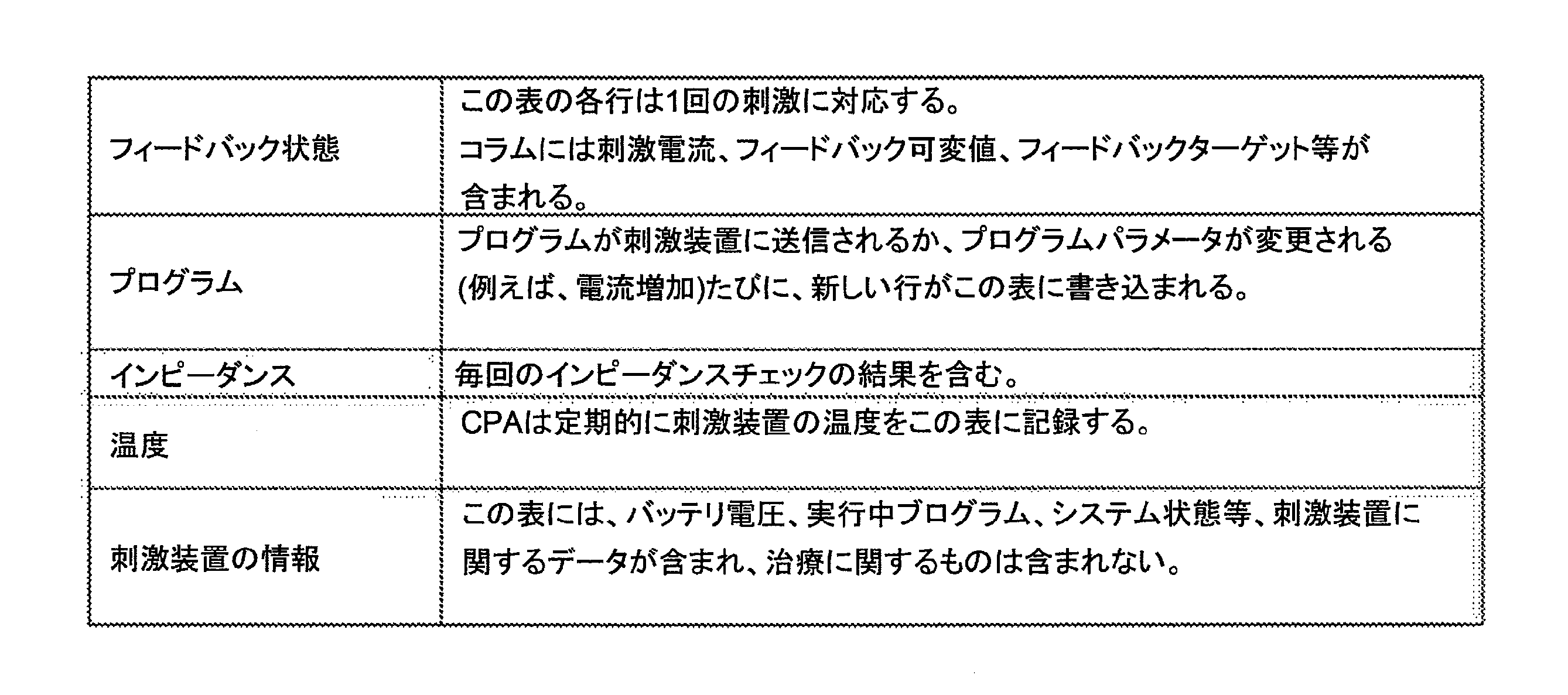
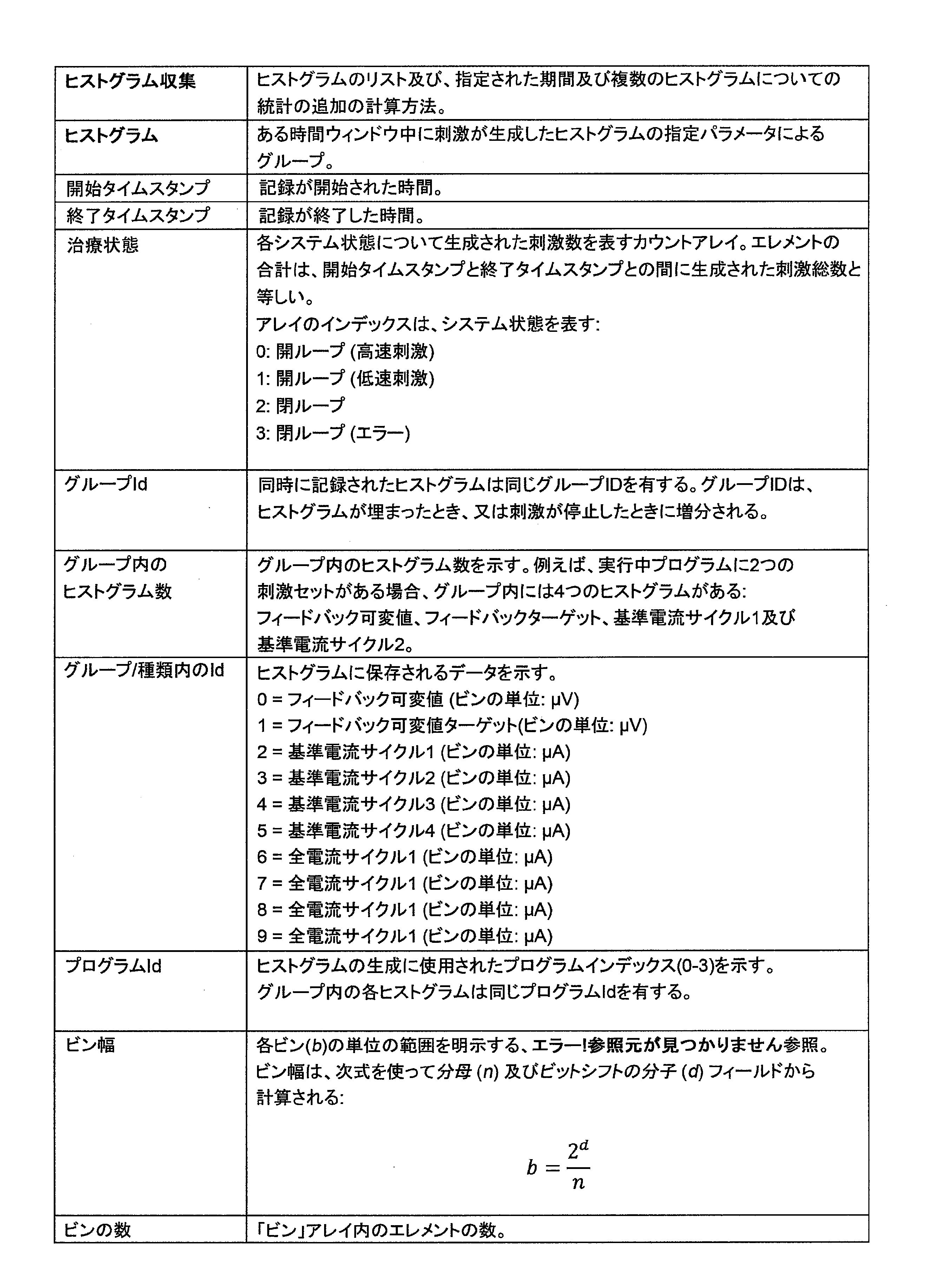
多くの略語と用語を定義する必要がある。コラムとは、表中のデータのコラムを指す。特定の可変値に関するデータは、表中のコラムに保存され、コラムと呼ばれる。CDV 414の中で見る特定の種類のデータを選択することは、そのデータの種類のコラムを選択することである。エラーログは、時間ベースのエラーイベントの記録であり、臨床医又はフィールド臨床エンジニア(FCE)とのプログラミングセッション中に刺激装置100からダウンロードできる。基準電流は、刺激装置100の1つの電流源出力により生成される電流である。基準電流は、12.5mA(1つの電流源出力の最大値)を超えることはあり得ない。特に別段の明記がないかぎり、データログ412の中に戻される値は、基準電流に関する。刺激とは、典型的に2相又は3相のパルスを指す。刺激とは、これらのパルスの1つの送達を指す。全電流は、CPA 410内に表示され、プログラミングワークシート上にFCEにより書き留められる電流レベルである。刺激セットアップに関する十分な情報が入手可能であれば、全電流は基準電流を使って計算できる。例えば、(CPA上で)各々50%に設定された2つの刺激電極があり、基準電流が5mAであるとき、全電流は10mAとなる。治療ログは、各刺激の圧縮記録であり、プログラミングセッション中に刺激装置100の記憶装置120からダウンロードできる。利用状況ログは、イベントの時間ベースの記録であり、プログラミングセッション中に刺激装置100の記憶装置120からダウンロードできる。利用状況ログは、刺激装置100と患者及び臨床医の相互作用に加え、このような相互作用に対する刺激装置100からの応答を記録する。フィードバック可変値(FBV)は、ECAP信号の振幅の測定値を表す値である。臨床データログ412は、刺激装置からダウンロードされるデータの種類の各々に関するデータログを含む多数のデータログを含む(例えば、利用状況ログ、ヒストグラム等)。
Many abbreviations and terms need to be defined. A column refers to a column of data in a table. Data about specific variable values are stored in columns in the table, called columns. Selecting a particular type of data to view in
臨床データビューワ414は、臨床プログラミングアプリケーションに統合しやすいように書かれる。図5は、ソフトウェアモジュールのデータ解析スイートを示しており、臨床データビューワ414により使用されるモジュールがハイライトされている。コードの再使用を最大にし、ソフトウェアツールを通じた試験を簡略化するために、独立したソフトウェアモジュールが使用される。
The
図6は、本発明の本実施形態による、臨床プログラミングアプリケーション410により実行される、約17分間の臨床利用期間に関する、記憶装置120からの臨床データの提示を示している。図7は、本発明の本実施形態による臨床データビューワ414により実行される、約5分間の非臨床利用期間に関する、記憶装置120からの臨床データの提示を示している。図8は、本発明の本実施形態による臨床データビューワ414により実行される、約8週間の非臨床利用期間に関する、記憶装置120からの臨床データの提示を示している。臨床データビューワ414は、1回に1つの臨床データログファイル412を開くことができるが、1回にアプリケーション414の複数のインスタンスが実行されてもよい。患者利用状況データ(すなわち、利用状況ログ、エラーログ、及び治療ログ)は、PatientUsageDataProviderクラスによってロードされ、これはデータをロードし、破損データをフィルタして除去し、タイムスタンプをフィックスして、データ解析API 502の中の機能を使って、BatteryChargeIntervalCollection及びStimulationIntervalCollection等の処理済みデータを生成する。これを行うためには、H5ファイル中の生データを標準フォーマットに変換しなければならない。これは、ClinicalDataLogH5Parserモジュール506の中のクラスによって行われる。
FIG. 6 illustrates the presentation of clinical data from
臨床データビューワアプリケーション414は、モデル-ビュー-ビュー-モデル設計パターンに従っており、それによってビジネスロジック(すなわち、図5のデータ解析API 502)をデータ表示方法を説明するロジックから分離できる。臨床データビューワ414は、WPFデータ結合を使ってビュー及びそれらのビューモデルとの間で通知を連携する。
The clinical
図7及び8に示されるメインウィンドウ700は、アプリケーション414の基本ビューであり、ClinicalDataViewerに結合される。メインウィンドウ700には、<Frame>コントロールが含まれ、これはPageControllerにより提供される可能性のあるページの1つを表示する。各ページは、CustomPageクラスから導き出され、それによってタイトルページ、戻るボタン、及びカスタムコマンド等の共通のページ特徴に均一性を持たせることができる。メインウィンドウ700は、ページ間のナビゲーションを制御する。これらのページは各々、それ自体のビューコントローラに結合され、その各々は親ビューコントローラであるClinicalDataViewerの特性であるが、特定のDataLogのために作られるDataLogTableViewModelは例外である。
The
臨床データビューワ414は、異なるページ間のナビゲーションを制御する展開可能メニュー702を有する。メニュー702は、図9a及び9bに示されるように、≡アイコンを押すことにより展開できる。図9bは特に、閲覧者が、臨床データビューワ414に表示し、プロットしようとするデータの種類の選択する手段を示している。
The
図7及び8の患者利用状況ページは、CPA 410とのプログミングセッション中に刺激装置100からダウンロードされた利用状況ログ、治療ログ、及びエラーログからのデータを表示しており、患者がクリニック以外で刺激装置100をどのように使用したかを解析するために使用される。患者利用状況ページは、患者が実地で刺激装置100をどのように使用していたかを評価することにおいて特に有利であり、これについては以下にさらに詳しく説明する。
The patient usage pages of FIGS. 7 and 8 display data from the usage log, treatment log, and error log downloaded from the
患者利用状況データは、ドロップダウンメニュー704から時間範囲を選択するとによって、カスタム又は既定時間によりふるい分けすることができる。既定時間範囲(1日、1週間、1カ月、又は3カ月)を選択すると、その範囲内の直近のデータポイントまでのすべてのデータが選択される。カスタム時間範囲が選択されると、使用者は開始及び終了点を選択できる。使用者がデータの特定のエリアにズームインしようとした場合、使用者は時間範囲を閲覧中のエリアに設定できる。時間範囲が選択されると、その時間範囲内にないデータはすべて表示から隠され、統計のすべてが選択された時間範囲について再計算される。
Patient utilization data can be filtered by custom or predefined time by selecting a time range from drop down
各ログ記録イベント(すなわち、利用状況ログのアイテム又はエラーログのアイテム)は、患者利用状況ページのフィールド706の中にダイヤモンドとして表示され、時間(x軸)に対してプロットされる。ダイヤモンドをクリックすると、ポップアップ1010が開き、そこには図10に示されるように、そのイベントに関連する生データが表示される。イベントは7つのカテゴリにグループ分けされ(1行につき1つ)、その中の6つのみが図のデータセットにポピュレートされるため、図6~10のフィールド706には6つのカテゴリのみが示されている。各カテゴリは、イベント種類ごとに設定された色を有する。
Each logged event (ie, usage log item or error log item) is displayed as a diamond in
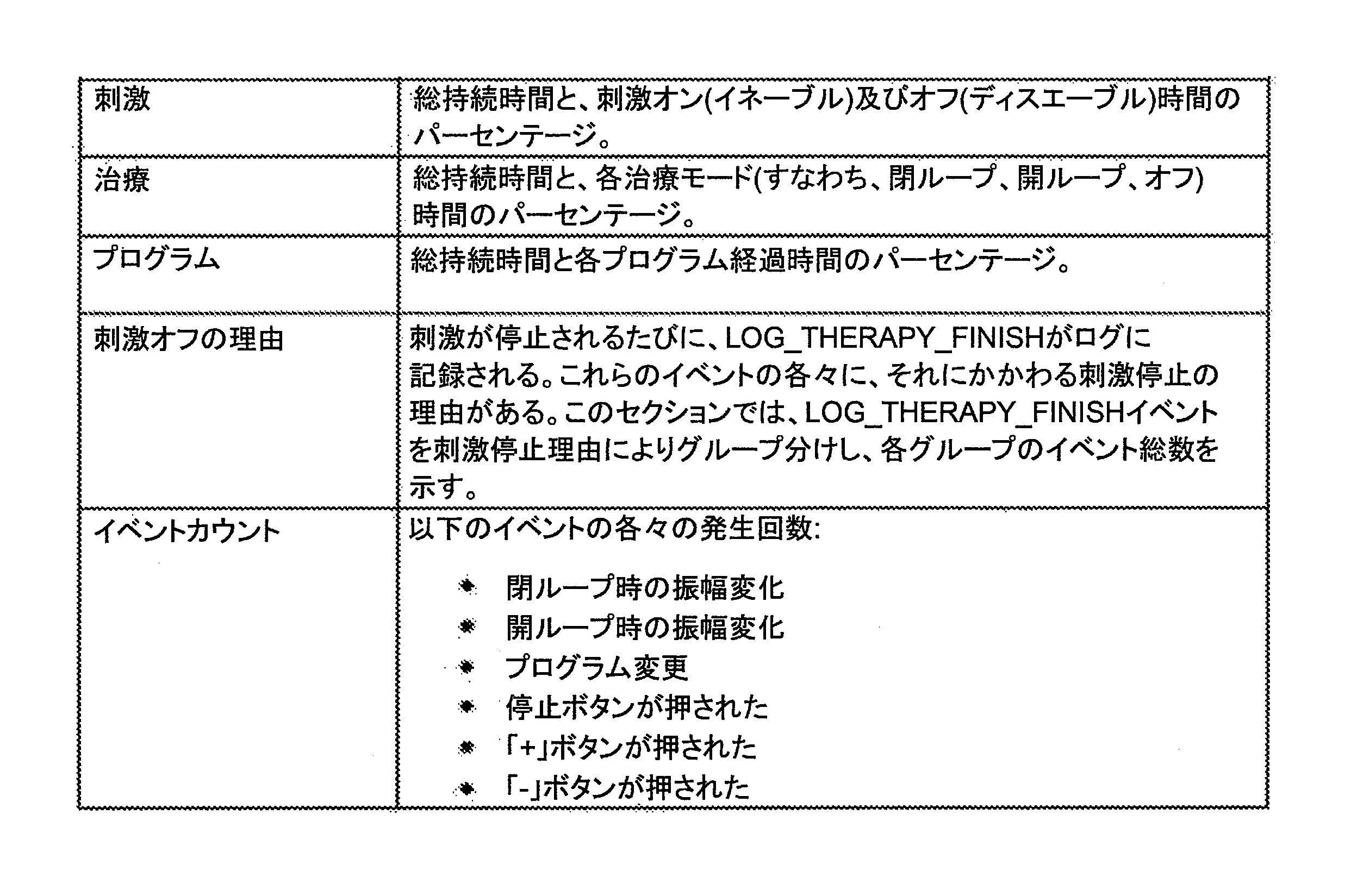
より詳しくは、ログ記録イベントのカテゴリは以下のとおりである。患者コマンドイベントカテゴリ1023は、リモートコントロールから刺激装置に送信されるコマンドを含み、これには、プログラム選択、治療停止、治療オフ、振幅増大及び振幅縮小、が含まれ、これらは各々、図10に示されるように、カテゴリライン1023の中でそれぞれの色により表される。エラーイベントカテゴリ1021は、エラーログアイテムを含み、これには不適合、電極切断、及びエラーログアイテムが含まれる。例外イベントカテゴリは、例外ログアイテムを含み、これにはテレメトリダウンモード、治療ダウンモード、及び例外ログアイテムが含まれる。図7~10のデータセットでは例外は発生しなかったため、例外ラインは示されていない。
More specifically, the categories of logging events are: The Patient
刺激装置応答イベントカテゴリ1024は、患者コマンド又はプログラミングコマンドに対する動作がなされたとの刺激装置からの確認を含み、これには振幅フィードバックON切替、振幅フィードバックOFF切替、治療終了、治療開始フィードバックオン、治療開始フィードバックオフ、及びフィードバックループが含まれる。プログラミングコマンドイベントカテゴリ1025は、臨床プログラミングアプリケーションから刺激装置に送信されるコマンドを含み、これには治療停止指示及びプログラム済みデバイスが含まれる。バッテリイベントカテゴリ1022は、バッテリ充電イベントを含み、これにはバッテリ切断、高温、充電開始、バッテリ充電済み、充電成功、充電タイムアウト、及び充電終了が含まれる。その他イベントカテゴリ1026は、刺激装置によりログ記録された、治療に影響のないその他のイベントを含み、これには、設定時間、消去、リセット、セーフモード充電可能、ハードウェアリセット、クリア、エクストラデータ、連続番号、新規RTC ID、フィラ、イベントなしが含まれる。
The stimulator
図7~10において、インタバル708も計算され、示されている。インタバル708は、1つのシステム状態に対応するイベント間の時間を表す。臨床データビューワ414は、各インタバル708に関するシステムの状態を、それ以前のイベントに基づいて計算する。インタバル708は、図7~10に示されるように、患者利用状況ページで、時間(x軸)に対してプロットされた色付きのバーとして表示される。何れかのインタバルを表すバーをクリックすると、ポップアップが開き、そこにその時間の刺激装置の状態に関する詳細な情報が表示される。インタバル708は、図10に示されるように、3つのカテゴリ1031、1032、1033にグループ分けされる。プログラムインタバル1031は、患者が使用していた当該プログラムを示す。このカテゴリの中で、4つのプログラムのどれが選択されたかを示すために4つの色が使用され、無色は刺激オフを示す。治療インタバル1032は治療の状況を示し、開ループ刺激、閉ループ刺激、又は刺激オフが色で示される。充電インタバル1033は、刺激装置が充電中であることを示す。
図7~10において、治療ログ710がヒートマップの形態で表示される。各ヒートマップは、各時点(x時間)で特定の大きさ(y軸)を有する刺激の割合の表現(色の強度)である。色が濃いほど、その時点でその大きさを有する刺激の割合は大きい。少なくとも3つのヒートマップ(フィードバック可変値712、フィードバックターゲット714、及び現在716)が、使用中の追加の各刺激セットに関する追加の現在のヒートマップと共に表示される。
7-10,
図7において、利用状況サマリタブ720に表示されるデータは、以下のように刺激インタバルから得られる:
In FIG. 7, the data displayed in the
利用状況サマリは、デフォルトでは円グラフ722として表示されるが、プロットの右クリックでその他のプロット及びデータオプションも利用可能である。
The Usage Summary is displayed as a
臨床データビューワ414のバッテリタブ724はさらに図11aに示されている。バッテリタブ724は、刺激装置100のバッテリ寿命及び充電パターンに関する詳細を示す。統計は、充電の開示及び終了時をログ記録する利用状況ログイベントとこれらの各時点におけるバッテリ電圧を使って計算される。以下の統計が利用可能である:
A

各放電インタバルについてのバッテリ放電速度計算を生成するために、刺激がオンであった総時間が計算される。図11bに示されるように、刺激がイネーブルされている持続時間とインタバルの総持続時間がそのインタバルの全電圧変化についてプロットされる。赤い円は1回の放電インタバルを表し、オレンジの十字は総時間を表し、青い十字はそのインタバル中の総刺激時間を表す。総時間は常に刺激時間より長いことに留意されたく、差は刺激がオフの時間を表す。 The total time the stimulation was on is calculated to generate a battery discharge rate calculation for each discharge interval. As shown in FIG. 11b, the duration for which stimulation is enabled and the total duration of the interval are plotted for the total voltage change in that interval. Red circles represent one discharge interval, orange crosses represent total time, and blue crosses represent total stimulation time during that interval. Note that the total time was always longer than the stimulation time, so the difference represents the time the stimulation was off.
次に、図のように、総持続時間及び刺激持続中の点を通る2つのベストフィットラインが計算される。ベストフィットラインは、次式を使って計算される:
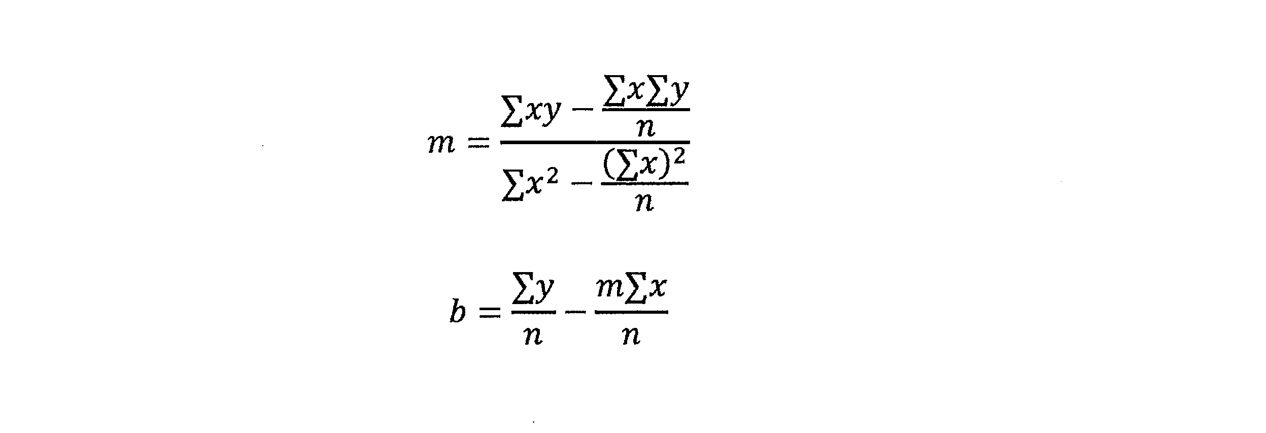
すると、放電速度が、対応するベストフィットラインの勾配から得られる。バッテリ寿命は、4.1V~3.25Vの間の、850mVの範囲の健全なバッテリ電圧に基づいて計算される。バッテリ寿命は、放電速度を健全電圧範囲で割ることにより計算される。バッテリ寿命予測は、平均利用状況及び刺激のみに基づいて計算される。平均電流引出しは、バッテリ容量(200mAh)を刺激中に計算されたバッテリ寿命で割ることにより計算される。 The discharge rate is then obtained from the slope of the corresponding best-fit line. Battery life is calculated based on healthy battery voltages in the range of 850mV between 4.1V and 3.25V. Battery life is calculated by dividing the discharge rate by the healthy voltage range. Battery life prediction is calculated based on average usage and stimulation only. Average current draw is calculated by dividing the battery capacity (200 mAh) by the calculated battery life during stimulation.
図12は、臨床データビューワ414のヒストグラムタブ728を示す。ヒストグラムタブ728の中で、スライダバー1210はグラフィカルユーザインタフェースであり、それによって閲覧者はデータのうち8週間分の小集合を選択できる。この選択されたデータ小集合について、臨床データビューワ414は、閲覧者がタブ728の中でより詳しく評価するために、フィードバック可変値1220、フィードバックターゲット1230、及び刺激電流1240に関するヒストグラムデータを抽出する。各短期間のデータから抽出されたヒストグラムはまた、治療ログ710として提示され、これは8週間の期間全体にわたる個別ヒストグラムを示し、各ヒストグラム1220、1230、1240のコラムの高さを効率的に表すためにヒートマップが使用される。
FIG. 12 shows the
ヒストグラムタブ728によって、治療ログの中の個別のヒストグラムの各々を表示できる。ヒストグラムは時間によりグループ分けされる。ヒストグラムの記録は、刺激が開始されるとすぐに開始され、刺激が停止すると停止する。時間はスライダ1210を調節するか、+又は-ボタンを押すことにより選択される。時間が変更されると、以下の項目が自動的に更新される:(a)表示される個別ヒストグラムプロットの数はその時点で使用中の刺激セットサイクル数に依存する、個別ヒストグラムプロット1220、1230、1240、(b)治療ログヒートマップ上で黄色のハイライトにより示されるヒストグラム時間ウィンドウ、(c)表示中のヒストグラムの全部に適用されるヒストグラムメタデータである統計。統計は1250で示され、これには開始時間、終了時間、タイムスタンプ調整(オリジナル又は調整後であり、後者は、電源喪失によりタイムスタンプがリセットされた場合のインスタンスを補正するために、タイムスタンプが調整されたことを示す)、ヒストグラム期間、プログラム、刺激装置のモード%(開ループ、閉ループ、エラー)が含まれる。
図13bに示されるように、ヒストグラムビューコントローラは、ヒストグラムヒートマップ710を生成するため、及び個別ヒストグラムプロット1220、1230、1240を表示するために使用されるロジックを含む。HistogramCollectionは異なる種類のヒストグラム(すなわち、FBV、CV、ターゲット)を含んでいることがあるため、正しいヒストグラムを表示するためにリストをふるい分けするのはヒストグラムビューコントローラの役割である。
As shown in FIG. 13b, the histogram view controller contains the logic used to generate the
個別ヒストグラムのさらに詳細な事柄を得るか、又はそれにズームインするために、閲覧者はヒストグラムの表示をダブルクリックできる。これによって、図13aに示されるようなヒストグラム詳細ページが開く。ヒストグラムの拡大版の表示に加えて、ヒストグラム詳細ページにはまた、最小、最大、平均、中央値、モード、及び標準偏差を含む統計も表示される。 To get more detail on an individual histogram or to zoom in on it, the viewer can double-click on the histogram display. This opens the Histogram Details page as shown in Figure 13a. In addition to displaying a magnified version of the histogram, the histogram details page also displays statistics including minimum, maximum, mean, median, mode, and standard deviation.
異なるビューコントローラ及びそれらに関連するモデルとビューが図13bに示されている。新しいファイルがロードされると、選択されたデータログは融合され、その後、関連するUsageLog、HistogramCollection、又はErrorLogクラスのコンストラクタに渡される。利用状況ログについて、タイムスタンプをフィックスするために追加の処理が行われてよい。これらのモデルが作られると、そのビューコントローラのコンストラクタにこれを渡すことができる。 Different view controllers and their associated models and views are shown in Figure 13b. When a new file is loaded, the selected datalogs are fused and then passed to the associated UsageLog, HistogramCollection, or ErrorLog class constructor. Additional processing may be performed on the usage log to fix the timestamp. Once these models are created, you can pass them to your view controller's constructor.
図14は、プログラミングセッションページを示す。これは、EcapDataTemplate 1410の中にECAPトレースを表示する。プログラミングセッションページは、プログラミングセッションビューコントローラに結合されたデータである。プログラミングセッションページはさらに、刺激電流レベル1422及びフィードバック可変値(ECAP振幅)1424等の時系列データを表示し、このようなトレースはDataLogColumnsのセクション1430の中で選択可能であり、追加的又は代替的に、例えばプログラム、フィードバック状態、インピーダンス、温度、刺激装置情報等のその他のトレースが時系列データとして表示するために選択されてよい。プログラミングノート1426もまた、時間シリーズプロットに重ねて表示される。ECAPトレース1410を構成するプログラムパラメータは、ProgramDataTemplateウィンドウ1440に表示されてよい。
FIG. 14 shows the programming session page. This displays the ECAP trace in the
ECAPの表示に関わるコンポーネントは図15に示されている。ECAPは、1410において、EcapDataTemplate(DataTemplates.xamlの中で定義)を使って表示され、これはEcapCollectionへの参照を保持するEcapViewControllerに結合される。EcapCollectionは、臨床データログファイル内のEcapデータログへの参照を保持する。EcapViewControllerの要求に応じて、EcapCollectionはEcapデータログから1つのECAPを読み出し、新しいECAPオブジェクトを返す。この「遅延読み込み」方式(すなわち、必要な場合にのみデータをメモリに読み込む)により、臨床データビューワはメモリの消費を最小限にすることができる。 The components involved in displaying ECAP are shown in FIG. The ECAP is displayed at 1410 using an EcapDataTemplate (defined in DataTemplates.xaml), which is bound to an EcapViewController that holds a reference to the EcapCollection. EcapCollection holds references to Ecap datalogs in the clinical datalog file. Upon request of the EcapViewController, EcapCollection reads one ECAP from the Ecap datalog and returns a new ECAP object. This "lazy loading" approach (ie, loading data into memory only when needed) allows the clinical data viewer to minimize memory consumption.
プログラミングノート1426はすべて、ノートデータログがNoteLogクラスのコンストラクタに渡されると、臨床データログファイルから読み出される。NoteLogは、各々がタイムスタンプとディスクショナリオブジェクトを含むノートオブジェクトの集合を含む。ノート1426は、主要刺激ドメインプロット上にLineAnnotationsの形態で表示される。 All programming notes 1426 are read from the clinical data log file when the note data log is passed to the constructor of the NoteLog class. A NoteLog contains a collection of note objects, each containing a timestamp and a dictionary object. Notes 1426 are displayed in the form of LineAnnotations on the primary stimulus domain plot.
図14のプログラミングページは、プログラミングセッション中(CPA410が刺激装置100に接続されている間)に臨床プログラミングアプリケーション410により収集されたデータを表示する。図6.1は、臨床データログファイルが開かれたときのページのデフォルト状態を示す。左上のフィールドによって、コラムをプロットに追加し、又はそこから削除することができる。右上のメインフレームは、選択された時系列プロットを提示する。左下のフレームは姿勢変更を評価する。下のプロットは、利用可能な多数の記録から選択された1つのECAP記録のプロットを示す。
The programming page of FIG. 14 displays data collected by
プログラミング中に収集されたデータは、5つの異なる表に書き込まれる。 Data collected during programming are written into five different tables.
CPA 410を使って入力されたプログラミングノート1426は、図14の時系列プロット上に表示される。青い縦の破線は、そのノートが記録された正確な時刻を示す。ノート1426は、スクリーン左上隅のノートボタンをトグルすることによって、隠したり表示したりすることができる。プログラミングタブにより、使用者はプログラミングセッション中に収集されたデータに関する統計を計算でき、これは典型的に、各姿勢が短時間保持される、又は設定された姿勢について電流が経時的に変更される、多数の指示された姿勢変化からなる。
Programming notes 1426 entered using
例えば、図16は、FBVが特定の範囲(これは、患者の選好による利用範囲であってよい)内に含まれる刺激数の計算方法を表す。プロセスは以下のように進められる:
1.統計を計算したいデータ(この例ではFbv)を選択する(「プロットするコラムを選択してください」の下)。コラムがクリックされると、チャートに影付きのアノテーション(この例では半透明の緑)が追加されて、選択されたデータがハイライトされる。
2.スライダをドラッグするか、スライダの横の上下ボタンを使うことによって、統計を計算する時間範囲を選択する。すると、アノテーションの幅(プロット上の緑の影付きエリア)が収縮して、選択されたエリアが示される。
3.上限(最大)及び下限(閾値)利用範囲を入力する。この例では、この患者の閾値は40uV、最大値は60uVである。
4.表から利用統計を抽出する。利用範囲中の点の数は、選択された利用範囲中にこれらの刺激がいくつあったかを示す。この例では、この時間ウィンドウ内の162の刺激のうち82が40~60uVであった。これら162の刺激の結果の平均Fbvは、39.5uVであった。
For example, FIG. 16 illustrates how the number of stimuli that the FBV falls within a particular range (which may be the available range according to patient preference) is calculated. The process proceeds as follows:
1. Select the data (Fbv in this example) for which you want to calculate statistics (under "Select columns to plot"). When a column is clicked, a shaded annotation (translucent green in this example) is added to the chart to highlight the selected data.
2. Select the time range for which statistics are calculated by dragging the slider or using the up and down buttons next to the slider. The width of the annotation (the green shaded area on the plot) then shrinks to show the selected area.
3. Enter the upper (maximum) and lower (threshold) available ranges. In this example, this patient has a threshold of 40 uV and a maximum of 60 uV.
4. Extract usage statistics from a table. The number of points in the utilization range indicates how many of these stimuli were in the selected utilization range. In this example, 82 of the 162 stimuli within this time window were between 40 and 60 uV. The average Fbv resulting from these 162 stimulations was 39.5uV.
図17のECAPプロットは、臨床データビューワ14のコンポーネントであり、それによって使用者はプログラミングセッション中に記録された個別のECAPトレース1710を見ることができる。表示中の特定のあるECAP又は複数のECAPは、+又は-ボタンを押してファイル中の多数のECAPをステップスルーするか、又はスライダ1720をドラッグすることによって変更できる。複数のECAP 1710は、「ホールド」ボタン1730を押して現在のECAPをプロットにロックすることによって比較できる。ホールドされたECAPは、「クリア」ボタンを押すと消える。
The ECAP plot of FIG. 17 is a component of the clinical data viewer 14 that allows the user to view individual ECAP traces 1710 recorded during the programming session. The particular ECAP or ECAPs being displayed can be changed by pressing the + or - buttons to step through multiple ECAPs in the file or by dragging the
ECAPが生成された時間は、一例を1740で示す、時系列プロット上の縦線でアノテートされる。ホールドされた各ECAPが時系列ブロット上でアノテートされる。アノテーション1740の色は、ECAPトレース1710の色と一致する。
The time at which the ECAP was generated is annotated with a vertical line on the time series plot, an example of which is shown at 1740 . Each held ECAP is annotated on the time series blot. The color of
図18は、臨床データビューワ414の姿勢変更評価ページを示しており、これはプログラミングセッション中(CPAが刺激装置100に接続されている間)に臨床プログラミングアプリケーション410により収集されたデータを表示する。これは、プログラミングセッション中にCPA 410の中で使用者が入力したノートと特定のコマンドのログの組合せを使って、フィールドのうちの幾つかに自動入力する。すると、それによって使用者は、使用者が規定する時間及び振幅範囲のFBV(uV)及び電流(mA)に関する情報を計算できる。図18は、開かれた臨床データログファイルの中にプログラミングデータがあるときのページのデフォルト情報を示す。
FIG. 18 shows the postural change assessment page of
姿勢変更評価ページは、プログラミングセッション中に1つの静止姿勢の患者についての成長曲線が計算され、各レベル(閾値、快適-、快適+、最大)がCPA 410の中でマークされるか又は他の箇所に記録され、患者に対して一連の姿勢変更を行うように依頼し、各々がノートフィールドの中にマークされる(表示された各姿勢変更の前)ことを前提としている。姿勢変更評価ページは6つのセクションに分けられ、これにはFCE(フィールド臨床エンジニア)入力1810、訪問情報1820、及び成長曲線を説明し、患者の治療ウィンドウを特定する(閾値と最大値との間(両端を含む)のFBVとして定義される)成長曲線値1830が含まれる。
The Posture Change Assessment page indicates that the growth curve is calculated for the patient in one static posture during the programming session and each level (Threshold, Comfort-, Comfort+, Maximum) is marked in the
成長曲線値のセクション1830には8つのフィールドがあり、以下のように2つずつペアになっている。閾値(uV及びmA):このフィールドのデータは、選択された姿勢変更時間(「開示時間」と「終了時間」)と、その時間枠中に「T」ボタンが最後に押されたのはいつかに基づいて自動生成される。快適-(uV及びmA):このフィールドのデータは、選択された姿勢変更時間と、その時間枠中に「C-」ボタンが最後に押されたのはいつかに基づいて自動生成される。快適+(uV及びmA):このフィールドのデータは、選択された姿勢変更時間と、その時間枠中に「C+」ボタンが最後に押されたのはいつかに基づいて自動生成される。Max(uV及びmA):このフィールドのデータは、選択された姿勢変更時間と、その時間枠中に「M」ボタンが最後に押されたのはいつかに基づいて自動生成される。これらのフィールドの各々はまた、使用者が臨床データビューワ414の中で編集することもできる。これによって、解析をより自由に行うことができる。例えば、それによって、プログラミングセッション中、ノートがCPAに入力するのではなく書き留められたかもしれない場合のデータの解析が可能となる。各フィールドは、その横にインクリメント/デクリメントボタンを有し、その分解能はフィールドに応じて1uV又は1mAである。各フィールドはタイムスタンプを有し、これは、データがどこからログファイルの中に自動入力されたかを示す。フィールド内の何れかのデータが使用者により変更されると、タイムスタンプは削除され、数値が手で調整されたことを示すメッセージに置き換えられる。
The Growth
姿勢値セクション1840により、使用者はその中でFBV(uV)及び電流(mA)に関する幾つかの統計(最小、最大、平均)を計算するウィンドウを選択できる(プログラミングセッション中)。このセクションには以下の8つのフィールドがある。開始時間:分析ウィンドウの開始。上の姿勢変更開始時間から自動入力される。これは、タイムスタンプの右側の矢印を使用して、又はさらに右側のドロップダウンから「ノートを開始」を選択することによっても編集できる。ノート:これは、ファイルにログ記録されるあらゆるノートとすることもでき、姿勢変更に関している必要はない。終了時間:分析ウィンドウの終了。これは、上述の開始時間と同様に機能する。最大(uV及びmA):選択されたウィンドウ内の最大FBV(uV)及び電流(mA)。平均(uV及びmA):選択されたウィンドウ内の平均FBV(uV)及び電流(mA)。最小(uV及びmA):選択されたウィンドウ内の最小FBV(uV)及び電流(mA)。
治療ウィンドウ統計セクション1850は、プログラミングセッション中に、時間ウィンドウ内のFBVについての幾つかの計算を含み、これは姿勢値に基づいて定義される。計算は、成長曲線値に基づく閾値、快適-(快適+ではない)、及び最大の値に基づく。このセクションには以下のような7つのフィールドがある(値は自動入力され、使用者は編集不可)。送達刺激総数:その時間ウィンドウ内に送達された刺激の総数。閾値未満刺激総数:送達された刺激のうち、FBVが閾値(uV)を下回った総数。最大値超過刺激総数:送達された刺激のうち、FBVが最大値より大きかった総数。0~10%以内刺激総数:送達された刺激のうち、FBVが快適-(uV)値の±10%以内であった総数(快適-の≧90%且つ≦110%)。11~20%以内刺激総数:送達された刺激のうち、FBVが快適-の>110%且つ≦120%、又は快適-の≧80%且つ<90%であった総数。21~40%以内刺激総数:送達された刺激のうち、FBVが快適-の>120%且つ≦140%、又は最適-の≧60%且つ<80%であった総数。40%超の刺激総数:送達された刺激のうち、FBVが快適-(uV)値の>140%又は<60%であった総数。
The Treatment
姿勢変更評価ページのエクスポートセクションにより、使用者は.csvファイル又はその他をエクスポートできる。 The export section of the posture change assessment page allows the user to. Can export csv files or others.
図19は、臨床データビューワ414の患者ダッシュボードインタフェースページを示しており、これは、ある時間内のデバイス利用状況統計の総合的なサマリであり、成長曲線データを使用し、刺激装置100からダウンロードされた治療ログを使用する。ページには幾つかのフィールドが含まれ、これはログデータから自動入力でき、幾つかは使用者が編集することもできる(オレンジの影付きボックス)。白い背景のボックスは自動入力され、使用者による編集はできない。
FIG. 19 shows the patient dashboard interface page of the
CDV 414はさらに、刺激装置のバッテリがなくなったことにより不正確となったタイムスタンプを修正する。バッテリがプログラミングセッションの合間に複数回なくなった場合、最後のイベントのみが修正されることに留意されたい。代替的に、CDVはタイムスタンプを、利用状況及びエラーログ又はヒストグラム中のアイテムのタイムスタンプが時系列に並ぶようにシフトさせる。これによって、タイムスタンプにエラーが生じるが、イベントを正しい時系列で表示できることになる。総合エラーは、刺激装置のバッテリがなくなってから充電が開始されまでの時間の量と等しい。
The
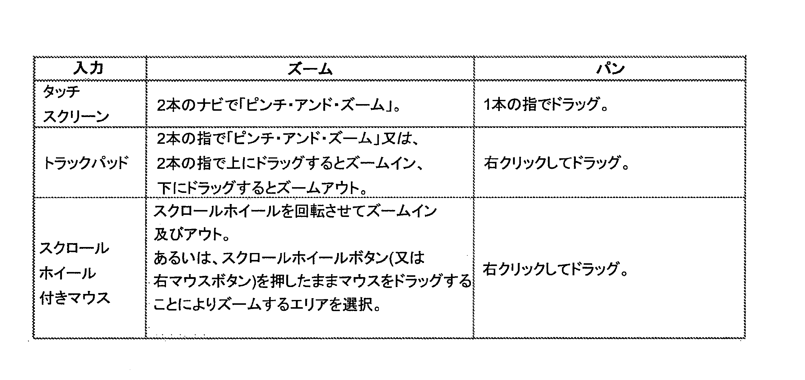
入力機器にとって適当であれば、CDV 414の各チャートのズーミングとパンニングが提供される。
Zooming and panning of each chart in
利用状況ログの生のテキストファイルの中のデータは、臨床データビューワ414により表示される前に幾つかの段階で処理されなければならない。高レベル処理の概要を図20に示す。利用状況ログをパースは、生の利用状況ログのテキストストリングをUsageLogオブジェクトに変換する。エラー/例外ログが利用可能である場合、これを利用状況ログに融合できる。これによってより詳細な統計を計算でき(例えば、刺激停止の理由を計算するとき)、これは、利用状況ログだけでは、その治療固有のエラーイベントを含まないからである。利用状況ログに保存されたタイムスタンプは、バッテリがなくなったことにより不正確であり得る。タイムスタンプの修正方法は2つある。第一の機能は、利用状況ログを順次処理して、時間がCPA 410により設定されたことを示すイベントを探すことによって果たされる。時間設定イベントが発見されると、エラーは、そのイベントの「タイムスタンプ」及び「以前のタイムスタンプ」フィールドの値の差から特定できる。すべてのタイムスタンプが「バッテリフィックス」によりフィックスできるわけではない。バッテリが複数回なくなると、最後にバッテリがなくなった時点までの間隔だけがフィックス可能である。残りの不正確なタイムスタンプは、これらが時系列になるように調整されるが、これは、ある程度のエラーが依然として存在することを意味しており、これはバッテリがなくなっていた時間の量に比例する。このエラーは図21において、「充電ラグエラー」と表示されている。
The data in the usage log raw text files must be processed in several stages before being displayed by the
図20のプロセスは次に、刺激及びバッテリ充電インタバルの生成へと進む。データの補間により、デバイスの状態を各イベント間のインタバルについて特定できる。StimulationIntervalCollectionクラスのコンストラクタは、利用状況ログの中のアイテムを順次処理し、一連の状態可変数に基づいてStimulatoinIntervalsを追加する。 The process of FIG. 20 then proceeds to generate stimulation and battery charge intervals. By interpolating the data, the state of the device can be determined for the interval between each event. The constructor of the StimulationIntervalCollection class iterates through the items in the usage log and adds StimulationIntervals based on the set of state variables.
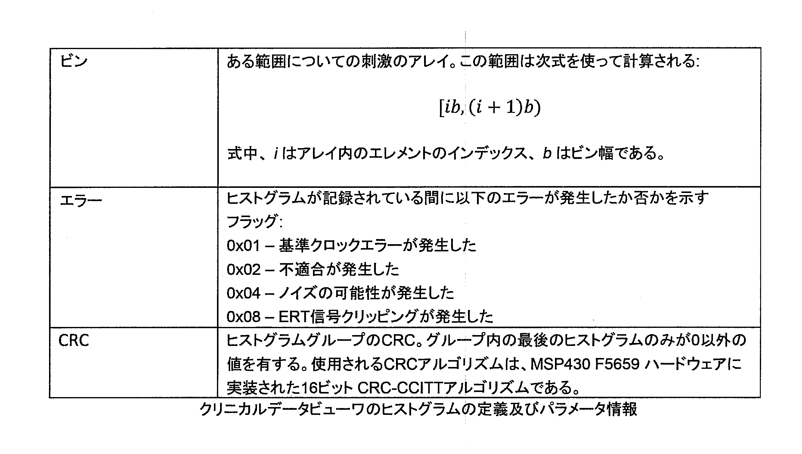
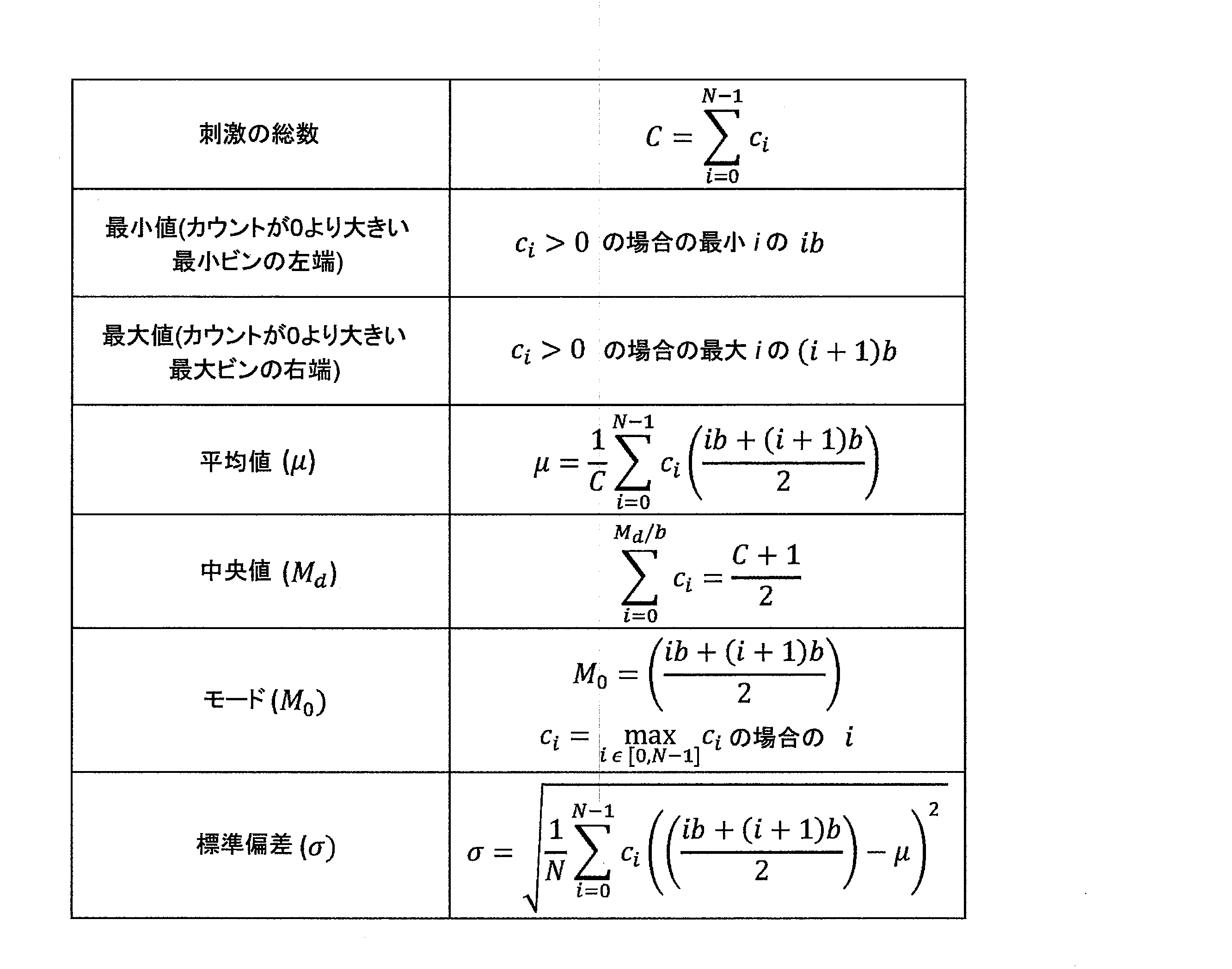
前述のように、臨床データビューワ414はまた、ファームウェアから得られたヒストグラムをパースし、これらがヒートマップの形態で個別又は一緒にプロットできるようにする。これについては図22~25及び以下においてさらに説明する。下表は、個別のヒストグラムに関する統計の計算方法を説明している。単位(刺激総数を除く)は、x軸により使用されているものと同じ単位、すなわちFBV及びFBVターゲットについてはuV、CVについてはuAであることに留意されたい。
As mentioned above, the
臨床データビューワ414はさらに、「フィードバック可変値が快適レベルのX%以内だった時間は何%だったか?」等のクエリに対する自動出力を提供するように構成される。この問題は、あるウィンドウ、例えば図24のウィンドウ[11,12]内のカウント数を計算することに一般化できる。このウィンドウ内のカウント数の計算は、ビン内の数値の分布が均一であることを前提しており、これは典型的に厳密には正しくないが、この前提に立つことで計算効率が大幅に改善される。
The
この問題を解決する第一のステップは、エッジの値についての「ビンインデックス」xを特定することである:

次に、l1及びl2が当てはまる整数のビンインデックスiを計算する:

上の例では、i1=1、i2=4である。次に、使用されるビンの分数を計算できる:

上の例では、r1=0.25、r2=0.5である。最後に、ビンの合計を計算できる:

前述の質問の拡張は、「最近3カ月間で、フィードバック可変値が快適レベルのX%以内だった時間は何%だったか?」である。このような質問に答えるには、ある範囲内のカウント数を複数のヒストグラムにわたって合計しなければならない。 An extension of the previous question is "In the last three months, what percentage of the time was the feedback variable within X% of your comfort level?" To answer such questions, counts within a range must be summed across multiple histograms.
この統計を計算するためのアルゴリズムは、前述のものと同様である。例えば、11と12の間の刺激の数を、時間t1からt2について計算するものとする。アルゴリズムは次のとおり:
1.ヒストグラムのリストの中の各ヒストグラムセットについて、そのヒストグラムのタイムスパンのどれだけが期間[t1,t2]内にあるかを計算する。
2.上述のアルゴリズムを使ってl1とl2の間の刺激の数を計算する。
3.ステップ(0)で計算された比率にステップ(0)のカウントを乗じる。
4.また、各ヒストグラムの刺激の総数を計算し、ステップ(0)からの割合を乗じる。
5.ステップ(0)からのカウントを加算して、その範囲内で発生した刺激の数を特定し、ステップ(0)から、その時間の刺激総数を計算する。
The algorithm for computing this statistic is similar to that described above. For example, the number of stimuli between 1 1 and 1 2 is to be calculated for times t 1 to t 2 . The algorithm is as follows:
1. For each histogram set in the list of histograms, compute how much of that histogram's time span is within the period [t 1 , t 2 ].
2. Calculate the number of stimuli between l 1 and l 2 using the algorithm described above.
3. Multiply the ratio calculated in step (0) by the count in step (0).
4. Also calculate the total number of stimuli in each histogram and multiply by the percentage from step (0).
5. Add the counts from step (0) to determine the number of stimuli that occurred within that range, and from step (0) calculate the total number of stimuli for that time.
当業者であれば、具体的な実施形態において示される本発明には、幅広く説明された本発明の本質又は範囲から逸脱することなく、数多くの改変及び/又は改良を加えてよいことがわかるであろう。したがって、本実施形態はあらゆる点において、限定的又は制約的ではなく例示的であると解釈されるべきである。 Those skilled in the art will appreciate that the invention as illustrated in the specific embodiments may undergo numerous modifications and/or improvements without departing from the spirit or scope of the invention as broadly described. be. Therefore, the embodiments are to be interpreted in all respects as illustrative rather than restrictive or restrictive.
2 刺激電極
4 対極板
6 測定電極
8 測定基準電極
100 植込み型刺激装置
110 電子モジュール
112 バッテリ
114 テレメトリモジュール
116 コントローラ
118 メモリ
120 臨床データ記憶装置
122 設定及び制御プログラム
124 パルス発生器
126 電極選択モジュール
128 回路
150 電極アレイ
180 神経
400 システム
410 臨床プログラミングアプリケーション
412 臨床データログファイル
414 臨床データビューワ
416 臨床データアップローダ
422 データログローダ
424 データベース
700 メインウィンドウ
2
Claims (19)
電気神経刺激療法を提供するように構成され、及び、前記電気神経刺激療法に対する神経反応の記録を捕捉するように構成され、前記神経反応の記録は少なくとも1つのECAP記録トレースを含み、フィードバック治療パラメータの記録を補足し、フィードバック構成の中の前記フィードバック治療パラメータを使用してその後の電気神経刺激の印加を制御するように構成され、及び、前記神経反応の記録と前記フィードバック治療パラメータの記録を含む臨床データを体外受信器に通信するように構成された植込み型ニューロモデュレーションデバイスと、
前記受信器を介した前記植込み型ニューロモデュレーションデバイスからの前記臨床データを受信し、前記臨床データを閲覧者による精査のために提示するように構成された監視デバイスと、
を含むシステム。 In the system that manages clinical data of implantable neuromodulation devices,
configured to provide electrical nerve stimulation therapy and configured to capture a recording of a neural response to said electrical nerve stimulation therapy, said recording of neural response comprising at least one ECAP recording trace, feedback treatment parameters; and configured to control subsequent application of electrical neural stimulation using said feedback therapy parameters in a feedback configuration, and comprising recording said neural response and recording said feedback therapy parameters . an implantable neuromodulation device configured to communicate clinical data to an extracorporeal receiver;
a monitoring device configured to receive the clinical data from the implantable neuromodulation device via the receiver and to present the clinical data for review by a viewer;
system including.
植込み型ニューロモデュレーションデバイスが電気神経刺激療法を提供するステップと、
前記植込み型ニューロモデュレーションデバイスが前記電気神経刺激療法に対する神経反応の記録を捕捉するステップであって、前記神経反応の記録は少なくとも1つのECAP記録トレースを含む、補足するステップと、
前記植込み型ニューロモデュレーションデバイスがフィードバック治療パラメータの記録を補足するステップであって、フィードバック構成の中の前記フィードバック治療パラメータは、その後の電気神経刺激療法の印加を制御するために使用される、補足するステップと、
前記神経反応の記録と前記フィードバック治療パラメータの記録を含む臨床データを体外受信器に通信するステップと、
前記受信器を介した前記植込み型ニューロモデュレーションデバイスからの前記臨床データを受信し、前記臨床データを閲覧者による精査のために提示するステップと、
を含む方法。 A computer-implemented method of managing clinical data for an implantable neuromodulation device, comprising:
providing electrical nerve stimulation therapy with an implantable neuromodulation device;
the implantable neuromodulation device capturing a recording of a neural response to the electrical nerve stimulation therapy , the recording of the neural response comprising at least one ECAP recording trace;
the implantable neuromodulation device supplementing the recording of feedback therapy parameters, wherein the feedback therapy parameters in a feedback configuration are used to control the subsequent application of electrical nerve stimulation therapy; and
communicating clinical data, including recordings of said neural responses and recordings of said feedback therapy parameters, to an extracorporeal receiver;
receiving the clinical data from the implantable neuromodulation device via the receiver and presenting the clinical data for review by a viewer;
method including .
前記植込み型ニューロモデュレーションデバイスから、臨床データであって、前記植込み型ニューロモデュレーションデバイスにより提供される、前記植込み型ニューロモデュレーションデバイスにより捕捉された電気神経刺激療法に対する神経反応の記録とフィードバック治療パラメータの記録を含む臨床データを受信することであって、前記神経反応の記録は少なくとも1つのECAP記録トレースを含み、前記フィードバック治療パラメータは、その後の電気神経刺激の印加を制御するために使用される、受信することと、
前記臨床データを閲覧者による精査のために提示することと、
を実行させる命令を含む、非一時的コンピュータ可読媒体。 When executed by one or more processors in a non-transitory computer-readable medium for managing clinical data of an implantable neuromodulation device,
clinical data, provided by said implantable neuromodulation device, from said implantable neuromodulation device recording and feedback of neural responses to electrical nerve stimulation therapy captured by said implantable neuromodulation device; Receiving clinical data including recordings of treatment parameters , said recordings of neural responses comprising at least one ECAP recording trace, said feedback treatment parameters being used to control subsequent application of electrical nerve stimulation. to be received ;
presenting the clinical data for review by a viewer;
A non - transitory computer-readable medium containing instructions to cause the
Applications Claiming Priority (1)
| Application Number | Priority Date | Filing Date | Title |
|---|---|---|---|
| PCT/AU2018/050278 WO2019178634A1 (en) | 2018-03-23 | 2018-03-23 | System for managing clinical data |
Publications (2)
| Publication Number | Publication Date |
|---|---|
| JP2021520538A JP2021520538A (en) | 2021-08-19 |
| JP7247211B2 true JP7247211B2 (en) | 2023-03-28 |
Family
ID=67988231
Family Applications (1)
| Application Number | Title | Priority Date | Filing Date |
|---|---|---|---|
| JP2020550782A Active JP7247211B2 (en) | 2018-03-23 | 2018-03-23 | clinical data management system |
Country Status (7)
| Country | Link |
|---|---|
| US (1) | US20210001133A1 (en) |
| EP (1) | EP3768161A4 (en) |
| JP (1) | JP7247211B2 (en) |
| CN (1) | CN112153939A (en) |
| AU (1) | AU2018414327B2 (en) |
| CA (1) | CA3096951A1 (en) |
| WO (1) | WO2019178634A1 (en) |
Families Citing this family (28)
| Publication number | Priority date | Publication date | Assignee | Title |
|---|---|---|---|---|
| US10568559B2 (en) | 2011-05-13 | 2020-02-25 | Saluda Medical Pty Ltd | Method and apparatus for measurement of neural response |
| WO2012155189A1 (en) | 2011-05-13 | 2012-11-22 | National Ict Australia Ltd | Method and apparatus for estimating neural recruitment - f |
| US9872990B2 (en) | 2011-05-13 | 2018-01-23 | Saluda Medical Pty Limited | Method and apparatus for application of a neural stimulus |
| CA2835486C (en) | 2011-05-13 | 2022-07-19 | Saluda Medical Pty Limited | Method and apparatus for measurement of neural response - a |
| ES2834958T3 (en) | 2012-11-06 | 2021-06-21 | Saluda Medical Pty Ltd | System to control the electrical conditions of a tissue |
| CA2929971C (en) | 2013-11-15 | 2023-03-07 | Saluda Medical Pty Ltd | Monitoring brain neural potentials |
| JP6671021B2 (en) | 2013-11-22 | 2020-03-25 | サルーダ・メディカル・ピーティーワイ・リミテッド | Method and device for detecting a neural response in a neural measurement |
| EP3122247B1 (en) | 2014-03-28 | 2025-05-07 | Saluda Medical Pty Ltd | Assessing neural state from action potentials |
| WO2015168735A1 (en) | 2014-05-05 | 2015-11-12 | Saluda Medical Pty Ltd | Improved neural measurement |
| US10632307B2 (en) | 2014-07-25 | 2020-04-28 | Saluda Medical Pty Ltd | Neural stimulation dosing |
| US11006846B2 (en) | 2014-11-17 | 2021-05-18 | Saluda Medical Pty Ltd | Method and device for detecting a neural response in neural measurements |
| US10500399B2 (en) | 2014-12-11 | 2019-12-10 | Saluda Medical Pty Ltd | Method and device for feedback control of neural stimulation |
| EP3229890B1 (en) | 2014-12-11 | 2020-05-27 | Saluda Medical Pty Limited | Implantable electrode positioning |
| WO2016115596A1 (en) | 2015-01-19 | 2016-07-28 | Saluda Medical Pty Ltd | Method and device for neural implant communication |
| AU2016245335B2 (en) | 2015-04-09 | 2020-11-19 | Saluda Medical Pty Ltd | Electrode to nerve distance estimation |
| WO2016191807A1 (en) | 2015-05-31 | 2016-12-08 | Saluda Medical Pty Ltd | Brain neurostimulator electrode fitting |
| US11006857B2 (en) | 2015-06-01 | 2021-05-18 | Closed Loop Medical Pty Ltd | Motor fibre neuromodulation |
| ES2888773T3 (en) | 2016-04-05 | 2022-01-07 | Saluda Medical Pty Ltd | Improved neuromodulation feedback control |
| AU2017280112B2 (en) | 2016-06-24 | 2022-11-17 | Saluda Medical Pty Ltd | Neural stimulation for reduced artefact |
| US11944820B2 (en) | 2018-04-27 | 2024-04-02 | Saluda Medical Pty Ltd | Neurostimulation of mixed nerves |
| US20210386991A1 (en) * | 2020-06-10 | 2021-12-16 | Medtronic, Inc. | Maintaining temporal resolution of evoked compound action potential (ecap) therapy data in memory constrained system |
| US11857793B2 (en) * | 2020-06-10 | 2024-01-02 | Medtronic, Inc. | Managing storage of sensed information |
| US12097373B2 (en) | 2020-06-10 | 2024-09-24 | Medtronic, Inc. | Control policy settings for electrical stimulation therapy |
| JP2023539349A (en) | 2020-08-28 | 2023-09-13 | サルーダ・メディカル・ピーティーワイ・リミテッド | Nerve stimulation responsive to posture |
| EP4183444B1 (en) * | 2021-11-18 | 2025-01-29 | Medtronic, Inc. | Therapy programming based on evoked compound action potentials |
| US12508433B2 (en) | 2021-11-18 | 2025-12-30 | Medtronic, Inc. | Therapy programming based on evoked compound action potentials |
| US12539425B2 (en) | 2021-11-18 | 2026-02-03 | Medtronic, Inc. | Therapy programming based on evoked compound action potentials |
| WO2025189254A1 (en) * | 2024-03-15 | 2025-09-18 | Saluda Medical Pty Ltd | Assisted programming system for neural stimulation therapy |
Citations (5)
| Publication number | Priority date | Publication date | Assignee | Title |
|---|---|---|---|---|
| WO2012155185A1 (en) | 2011-05-13 | 2012-11-22 | National Ict Australia Ltd | Method and apparatus for measurement of neural response |
| US20130172774A1 (en) | 2011-07-01 | 2013-07-04 | Neuropace, Inc. | Systems and Methods for Assessing the Effectiveness of a Therapy Including a Drug Regimen Using an Implantable Medical Device |
| US20140243926A1 (en) | 2013-02-22 | 2014-08-28 | Boston Scientific Neuromodulation Corporation | Neurostimulation system and method for automatically adjusting stimulation and reducing energy requirements using evoked action potential |
| WO2016059556A1 (en) | 2014-10-16 | 2016-04-21 | Mainstay Medical Limited | Systems and methods for monitoring muscle rehabilitation |
| JP2016519382A (en) | 2013-05-24 | 2016-06-30 | ボストン サイエンティフィック ニューロモデュレイション コーポレイション | System and method for managing medical services |
Family Cites Families (13)
| Publication number | Priority date | Publication date | Assignee | Title |
|---|---|---|---|---|
| US8332047B2 (en) * | 2004-11-18 | 2012-12-11 | Cardiac Pacemakers, Inc. | System and method for closed-loop neural stimulation |
| US7353063B2 (en) * | 2004-12-22 | 2008-04-01 | Cardiac Pacemakers, Inc. | Generating and communicating web content from within an implantable medical device |
| US8838215B2 (en) * | 2006-03-01 | 2014-09-16 | Angel Medical Systems, Inc. | Systems and methods of medical monitoring according to patient state |
| US7894905B2 (en) * | 2006-03-13 | 2011-02-22 | Neuropace, Inc. | Implantable system enabling responsive therapy for pain |
| US20080270188A1 (en) * | 2007-04-25 | 2008-10-30 | Medtronic, Inc. | Graphical display of patient data |
| US20090063193A1 (en) * | 2007-08-31 | 2009-03-05 | Mike Barton | Dashboard diagnostics for wireless patient communicator |
| US8376943B2 (en) * | 2007-09-24 | 2013-02-19 | Medtronic, Inc. | Patient event information |
| KR102095898B1 (en) * | 2009-08-14 | 2020-04-02 | 데이비드 버톤 | Biological signal monitoring apparatus |
| US9326698B2 (en) * | 2011-02-18 | 2016-05-03 | The Trustees Of The University Of Pennsylvania | Method for automatic, unsupervised classification of high-frequency oscillations in physiological recordings |
| CN103842022B (en) * | 2011-05-13 | 2016-03-09 | 萨鲁达医疗有限公司 | For controlling the method and apparatus of nerve stimulation-E |
| US11006846B2 (en) * | 2014-11-17 | 2021-05-18 | Saluda Medical Pty Ltd | Method and device for detecting a neural response in neural measurements |
| WO2017053504A1 (en) * | 2015-09-22 | 2017-03-30 | Cardiac Pacemakers, Inc. | Systems and methods for monitoring autonomic health |
| US11089997B2 (en) * | 2017-01-11 | 2021-08-17 | Boston Scientific Neuromodulation Corporation | Patient-specific calibration of pain quantification |
-
2018
- 2018-03-23 JP JP2020550782A patent/JP7247211B2/en active Active
- 2018-03-23 EP EP18910394.8A patent/EP3768161A4/en active Pending
- 2018-03-23 CA CA3096951A patent/CA3096951A1/en active Pending
- 2018-03-23 AU AU2018414327A patent/AU2018414327B2/en active Active
- 2018-03-23 US US17/040,521 patent/US20210001133A1/en active Pending
- 2018-03-23 WO PCT/AU2018/050278 patent/WO2019178634A1/en not_active Ceased
- 2018-03-23 CN CN201880093552.8A patent/CN112153939A/en active Pending
Patent Citations (5)
| Publication number | Priority date | Publication date | Assignee | Title |
|---|---|---|---|---|
| WO2012155185A1 (en) | 2011-05-13 | 2012-11-22 | National Ict Australia Ltd | Method and apparatus for measurement of neural response |
| US20130172774A1 (en) | 2011-07-01 | 2013-07-04 | Neuropace, Inc. | Systems and Methods for Assessing the Effectiveness of a Therapy Including a Drug Regimen Using an Implantable Medical Device |
| US20140243926A1 (en) | 2013-02-22 | 2014-08-28 | Boston Scientific Neuromodulation Corporation | Neurostimulation system and method for automatically adjusting stimulation and reducing energy requirements using evoked action potential |
| JP2016519382A (en) | 2013-05-24 | 2016-06-30 | ボストン サイエンティフィック ニューロモデュレイション コーポレイション | System and method for managing medical services |
| WO2016059556A1 (en) | 2014-10-16 | 2016-04-21 | Mainstay Medical Limited | Systems and methods for monitoring muscle rehabilitation |
Also Published As
| Publication number | Publication date |
|---|---|
| JP2021520538A (en) | 2021-08-19 |
| WO2019178634A1 (en) | 2019-09-26 |
| EP3768161A1 (en) | 2021-01-27 |
| US20210001133A1 (en) | 2021-01-07 |
| AU2018414327A1 (en) | 2020-10-01 |
| AU2018414327B2 (en) | 2025-02-06 |
| CN112153939A (en) | 2020-12-29 |
| CA3096951A1 (en) | 2019-09-26 |
| EP3768161A4 (en) | 2021-11-17 |
Similar Documents
| Publication | Publication Date | Title |
|---|---|---|
| JP7247211B2 (en) | clinical data management system | |
| DE60308555T2 (en) | PROGRAMMING OF AN IMPLANTABLE NEUROSTIMULATOR WITH DISPLAY OF THE LIFE OF THE BATTERY | |
| US20220007987A1 (en) | Automated Neural Conduction Velocity Estimation | |
| AU2011245691B2 (en) | Stimulation electrode selection | |
| JP2022540861A (en) | monitoring the quality of neural recordings | |
| US20060020292A1 (en) | Therapy programming guidance based on stored programming history | |
| US20040138581A1 (en) | Signal quality monitoring and control for a medical device system | |
| US12303693B2 (en) | Systems and methods for controlling operation of an implanted neurostimulation system based on a mapping of episode durations and seizure probability biomarkers | |
| AU2011245691A1 (en) | Stimulation electrode selection | |
| US20230172529A1 (en) | System and methods for facilitating neuromodulation therapy by automatically classifying electrographic records based on location and pattern of electrographic seizures | |
| US20240194357A1 (en) | System and method to autonomously and remotely monitor, analyze and respond to physiological and diagnostic device data from a medical implant | |
| US11931583B2 (en) | User interface for a titration assist system | |
| CN115662563A (en) | Method for presenting neurostimulation electroencephalographic data and related product | |
| US11752341B2 (en) | Display signal to assess autonomic response to vagus nerve stimulation treatment | |
| EP3793669A1 (en) | R-r interval analysis for ecg waveforms to assess autonomic response to vagus nerve simulation | |
| US20250132023A1 (en) | Triaging and monitoring patient states | |
| US20260041915A1 (en) | Systems, apparatuses, and methods for facilitating electrode placement for spinal cord stimulation | |
| US20240382768A1 (en) | Computer-assisted programming of neuromodulation therapy | |
| EP3793670B1 (en) | Assessment system with wand detection cable synchronizing ecg recording | |
| WO2024226622A1 (en) | System and method to determine and review therapy | |
| CN120857959A (en) | Neurostimulation device programming using aggregated patient data | |
| CN120358977A (en) | Automatic calibration method and system for local field potential sensing tool for deep brain stimulation |
Legal Events
| Date | Code | Title | Description |
|---|---|---|---|
| A621 | Written request for application examination |
Free format text: JAPANESE INTERMEDIATE CODE: A621 Effective date: 20210308 |
|
| A977 | Report on retrieval |
Free format text: JAPANESE INTERMEDIATE CODE: A971007 Effective date: 20220311 |
|
| A131 | Notification of reasons for refusal |
Free format text: JAPANESE INTERMEDIATE CODE: A131 Effective date: 20220411 |
|
| A601 | Written request for extension of time |
Free format text: JAPANESE INTERMEDIATE CODE: A601 Effective date: 20220711 |
|
| A521 | Request for written amendment filed |
Free format text: JAPANESE INTERMEDIATE CODE: A523 Effective date: 20221011 |
|
| TRDD | Decision of grant or rejection written | ||
| A01 | Written decision to grant a patent or to grant a registration (utility model) |
Free format text: JAPANESE INTERMEDIATE CODE: A01 Effective date: 20230213 |
|
| A61 | First payment of annual fees (during grant procedure) |
Free format text: JAPANESE INTERMEDIATE CODE: A61 Effective date: 20230315 |
|
| R150 | Certificate of patent or registration of utility model |
Ref document number: 7247211 Country of ref document: JP Free format text: JAPANESE INTERMEDIATE CODE: R150 |