JP7246641B2 - agricultural machine - Google Patents
agricultural machine Download PDFInfo
- Publication number
- JP7246641B2 JP7246641B2 JP2019182770A JP2019182770A JP7246641B2 JP 7246641 B2 JP7246641 B2 JP 7246641B2 JP 2019182770 A JP2019182770 A JP 2019182770A JP 2019182770 A JP2019182770 A JP 2019182770A JP 7246641 B2 JP7246641 B2 JP 7246641B2
- Authority
- JP
- Japan
- Prior art keywords
- area
- unit
- specific
- obstacle
- vehicle speed
- Prior art date
- Legal status (The legal status is an assumption and is not a legal conclusion. Google has not performed a legal analysis and makes no representation as to the accuracy of the status listed.)
- Active
Links
Images


Landscapes
- Combines (AREA)
- Control Of Position, Course, Altitude, Or Attitude Of Moving Bodies (AREA)
- Image Analysis (AREA)
- Guiding Agricultural Machines (AREA)
Description
本発明は、圃場に存在する物体を検出しながら作業走行する農作業機に関する。 BACKGROUND OF THE INVENTION 1. Field of the Invention The present invention relates to an agricultural work machine that travels while detecting an object existing in a field.
特許文献1による農作業機には、圃場に存在する障害物を検出するための超音波式の障害物センサが備えられており、障害物センサによって障害物が検出された場合、危険防止のためにエンジン等が停止される。 The agricultural work machine according to Patent Document 1 is equipped with an ultrasonic obstacle sensor for detecting an obstacle existing in a field. The engine etc. are stopped.
特許文献2によるコンバインには、レーザースキャナが備えられている。このレーザースキャナは、刈取対象物が刈り取られることによって圃場面の大部分が露出している領域に立ち入った人を検出するために、刈取部の右側部分に偏ってレーザーが照射されるように構成されている。また、特許文献2では、障害物を検出するために、レーザースキャナに代えて、ミリ波レーダを用いること、あるいはカメラ等を用いた画像処理を用いることも可能であると記載されている。
The combine according to US Pat. This laser scanner is configured to irradiate the laser biased to the right side of the reaping part in order to detect a person who has entered an area where most of the field is exposed due to the reaping of the material to be reaping. It is Moreover,
特許文献3によるコンバインでは、機体に設けられた撮影部によって逐次取得された撮影画像が入力されることで、この撮影画像に写っている認識対象物が存在する存在領域がその推定確率ともに出力される。高い推定確率で認識対象物が推定されると、警告の報知や走行制御が行われる。この認識対象物の推定には機械学習が用いられているが、機械学習の詳しい構成は開示されていない。 In the combine disclosed in Patent Literature 3, photographed images sequentially obtained by a photographing unit provided in the machine body are input, and an existence region in which a recognition target object shown in the photographed image exists is output together with its estimated probability. be. When the recognition target is estimated with a high estimation probability, a warning is issued and travel control is performed. Although machine learning is used for estimation of this recognition object, the detailed structure of machine learning is not disclosed.
圃場における農作業機による作業走行では、人や動物などの物体が走行障害物として存在する可能性がある。この物体が機体進行方向で機体の近くに存在している場合、機体に物体が干渉することを回避する必要がある。このためには、走行障害物となるような物体は高い精度で検出されるとともに、機体との距離も高い精度で算出される必要がある。しかしながら、従来の農作業機に搭載されている物体検出技術では、圃場における物体を迅速かつ高精度に検出することが困難であった。このような実情から、圃場における物体を、機体からの距離とともに迅速かつ高精度に検出する物体検出技術を搭載した農作業機が要望されている。 Objects, such as people and animals, may exist as traveling obstacles during work travel by agricultural implements in fields. If this object exists near the fuselage in the direction of travel of the fuselage, it is necessary to avoid interference of the object with the fuselage. For this purpose, it is necessary to detect an object that may become a traveling obstacle with high accuracy, and to calculate the distance to the aircraft with high accuracy. However, with the object detection technology installed in conventional agricultural machinery, it has been difficult to detect objects in a field quickly and with high accuracy. Under such circumstances, there is a demand for an agricultural working machine equipped with an object detection technology for quickly and accurately detecting an object in a field along with the distance from the machine.
本発明による、圃場を作業走行する農作業機は、前記圃場の特定領域を撮影する撮影ユニットと、前記撮影ユニットからの撮影画像を入力して、前記撮影画像に写っている特定物体を認識し、当該特定物体が前記撮影画像において占める領域を示す特定物体輪郭を含む物体領域情報を出力するニューラルネットワークと、前記特定領域を撮影し、前記特定領域に存在する物体全ての空間位置を示す物体位置情報を生成する空間位置測定部と、前記物体位置情報から圃場面を基準面とする3次元座標系で展開された3次元点群データを作成し、前記特定物体輪郭の内部に含まれる前記3次元点群データと前記特定物体輪郭とから、農作物が存在する前記特定物体の1つである未刈地と前記農作物が刈り取られた前記特定物体の1つである既刈地との境界を含む圃場刈取り情報を作成する圃場情報作成部と、前記物体位置情報と前記物体領域情報と前記圃場刈取り情報とに基づいて前記特定物体の1つである走行障害物の空間位置を決定し、機体から前記走行障害物までの距離である特定物体距離を算出する距離算出部と、前記特定物体距離に基づいて物体検出信号を出力する物体検出信号生成部と、を備える。 According to the present invention, an agricultural work machine that runs in a field receives a photographing unit that photographs a specific area of the field and a photographed image from the photographing unit, recognizes a specific object in the photographed image, a neural network for outputting object area information including a specific object contour indicating the area occupied by the specific object in the captured image; and object position information indicating the spatial positions of all objects existing in the specific area by photographing the specific area. and a three-dimensional point group data developed in a three-dimensional coordinate system with the field field as a reference plane from the object position information, and the three-dimensional point cloud data included in the contour of the specific object Based on the point cloud data and the contour of the specific object, an agricultural field including a boundary between an uncut land that is one of the specific objects on which crops are present and a cut land that is one of the specific objects from which the crops have been cut. a field information creating unit that creates reaping information; a spatial position of a traveling obstacle that is one of the specific objects is determined based on the object position information, the object area information, and the field reaping information ; A distance calculation unit that calculates a specific object distance, which is a distance to a traveling obstacle, and an object detection signal generation unit that outputs an object detection signal based on the specific object distance.
この構成によれば、ニューラルネットワークは撮影ユニットからの撮影画像を用いて圃場の特定領域に存在する特定物体を認識し、当該特定物体の撮影画像において占める領域を示す物体領域情報を出力する。空間位置測定部は、撮影された圃場の特定領域に存在する物体全ての空間位置を示す物体位置情報を生成する。ニューラルネットワークが検知した特定物体が特定領域において占める領域の空間位置が、物体領域情報と物体位置情報とを対応させることで算出され、さらに機体から特定物体までの距離が算出される。例えば、物体領域情報に示された特定物体が人間などの走行障害物である場合、物体領域情報と物体位置情報とを対応させることで、機体から走行障害物までの距離が算出されるので、その距離に応じた機体の制御が可能となる。この発明では、特定物体の正確な空間位置の算出はできなくても特定物体の検知能力に優れているニューラルネットワークと、特定物体の検知能力はなくても何らかの物体(不明物体)の正確な空間位置の算出能力に優れている空間位置測定部とを組み合わせることで、圃場における特定物体を、機体からの距離とともに迅速かつ高精度に検出することができる農作業機が提供される。 According to this configuration, the neural network recognizes the specific object existing in the specific area of the field using the photographed image from the photographing unit, and outputs object area information indicating the area occupied by the specific object in the photographed image. The spatial position measurement unit generates object position information indicating the spatial positions of all objects existing in the specific area of the photographed field. The spatial position of the area occupied by the specific object detected by the neural network in the specific area is calculated by associating the object area information with the object position information, and the distance from the aircraft to the specific object is calculated. For example, if the specific object indicated by the object area information is a traveling obstacle such as a human being, the distance from the aircraft to the traveling obstacle can be calculated by associating the object area information with the object position information. It is possible to control the aircraft according to the distance. In this invention, a neural network that is excellent in the ability to detect a specific object even if it cannot calculate the exact spatial position of the specific object, and a neural network that can accurately detect some object (unknown object) even if it does not have the ability to detect the specific object. By combining with a spatial position measuring unit that excels in position calculation capability, an agricultural work machine is provided that can quickly and accurately detect a specific object in a field along with the distance from the machine.
撮影画像から、撮影画像における特定物体を認識して当該特定物体の当該撮影画像における領域を示す物体領域情報を出力するために、本発明の好適な実施形態の1つでは、前記ニューラルネットワークは、エンコーダネットワークとデコーダネットワークとからなるセグメンテーションニューラルネットワーク(セマンティックセグメンテーション)で構成され、前記物体領域情報には、前記特定物体の輪郭が含まれている。この構成では、撮影画像が入力されると、当該撮影画像に含まれる物体を少なくとも1つ以上に分別して、その分別がわかるように識別された画像、例えば、物体の種別に応じて異なる色で表現された画像(ラベル画像)が出力される。したがって、物体領域情報から撮影画像における特定物体の輪郭を示すデータを取り出すことができる。 In one preferred embodiment of the present invention, in order to recognize a specific object in a photographed image and output object region information indicating the region of the specific object in the photographed image, the neural network comprises: It is composed of a segmentation neural network (semantic segmentation) consisting of an encoder network and a decoder network, and the object region information includes the contour of the specific object. In this configuration, when a photographed image is input, objects included in the photographed image are classified into at least one or more, and images identified so that the classification can be understood, for example, in different colors according to the type of the object. A represented image (label image) is output. Therefore, data indicating the contour of the specific object in the captured image can be extracted from the object area information.
セグメンテーションニューラルネットワークを、そのまま実装すると、ネットワーク構造が複雑となることから、演算処理負担が大きくなり、処理速度が低下する。ネットワークを高速化するためには、ネットワークを構成する隠れ層のユニット(パーセプトロンとも呼ばれる)数をプルーニングにより低減することが好適である。このため、本発明の好適な実施形態の1つでは、前記エンコーダネットワーク及び前記デコーダネットワークを構成する隠れ層には、畳み込み層とプーリング層とバッチ正規化層(batchNormalizationLayer)とが含まれ、前記バッチ正規化層におけるパラメータに基づいてプルーニング(Pruning)が行われる。この構成では、バッチ正規化層におけるバッチ正規化演算によって得られたパラメータに基づいて、良好な出力を行うための寄与率が小さいと判断されたユニットは、不使用にする。これにより、ネットワーク構造が簡単化され、ニューラルネットワークの処理速度が速くなる。 If the segmentation neural network is implemented as it is, the network structure becomes complicated, so the arithmetic processing load increases and the processing speed decreases. In order to speed up the network, it is preferable to reduce the number of hidden layer units (also called perceptrons) constituting the network by pruning. For this reason, in one preferred embodiment of the present invention, the hidden layers constituting the encoder network and the decoder network include a convolution layer, a pooling layer and a batch normalization layer, and the batch Pruning is performed based on the parameters in the normalization layer. In this configuration, units judged to have a small contribution to good output based on the parameters obtained by the batch normalization operation in the batch normalization layer are not used. This simplifies the network structure and increases the processing speed of the neural network.
特定物体までの距離は、特定物体との干渉を回避するための機体制御などに用いられるので、迅速かつ正確に算出される必要がある。また、特定物体までの距離の算出に外乱等でエラー値となった測定値が用いられることはできるだけ避けなければならない。このような観点から、本発明の好適な実施形態の1つでは、前記特定物体距離は、前記走行障害物の前記輪郭から算出される前記走行障害物の重心から前記機体までの距離、または前記輪郭内に含まれる距離測定点の統計的代表値である。重心位置は、輪郭を示す多数の距離測定点の座標(空間位置)から算出される。統計的代表値は、中間値や中央値や平均値であり、これも多数の距離測定点に基づいて算出される。このように、特定物体距離の算出に、特定物体の重心や統計的代表値を用いることで、特定物体までの距離の算出において、エラー値が大きな割合を占めることは抑制される。 Since the distance to the specific object is used for airframe control to avoid interference with the specific object, it must be calculated quickly and accurately. In addition, it is necessary to avoid, as far as possible, the use of measurement values that are erroneous due to disturbances or the like in calculating the distance to a specific object. From this point of view, in one preferred embodiment of the present invention, the specific object distance is the distance from the center of gravity of the traveling obstacle to the aircraft body calculated from the contour of the traveling obstacle , or the above. It is a statistical representation of distance measurement points contained within the contour. The position of the center of gravity is calculated from coordinates (spatial positions) of a large number of distance measurement points that indicate the contour. Statistical representative values are medians, medians and averages, which are also calculated based on a large number of distance measurement points. In this way, by using the center of gravity of the specific object and the statistical representative value to calculate the specific object distance, it is possible to prevent the error value from occupying a large proportion in the calculation of the distance to the specific object.
本発明の好適な実施形態の1つでは、前記空間位置測定部は、前記特定領域に対するステレオマッチング技術を用いて前記物体位置情報を生成する。この構成では、圃場の特定領域の撮影画像を用いたステレオマッチングにより、3次元点群データが生成される。点群データの各点はそれぞれ3次元位置、つまり空間位置を有するので、3次元点群データに基づいて物体位置情報が生成される。ステレオマッチングに用いられる撮影画像は、ニューラルネットワークに用いられる撮影画像を流用することも可能であるが、ステレオマッチングに適した解像度の撮影画像を得るために、好ましくは、専用のカメラによる撮影画像が用いられるとよい。もちろん、その際には、ニューラルネットワークに用いられる撮影画像の撮影視野と同じかそれより広い撮影視野をもつステレオマッチング用撮影画像が用いられる。 In one preferred embodiment of the present invention, the spatial localization section generates the object position information using a stereo matching technique for the specific region. In this configuration, three-dimensional point cloud data is generated by stereo matching using a photographed image of a specific area of a field. Since each point of the point cloud data has a three-dimensional position, that is, a spatial position, object position information is generated based on the three-dimensional point cloud data. The captured image used for stereo matching can be the captured image used for the neural network, but in order to obtain a captured image with a resolution suitable for stereo matching, it is preferable to use a dedicated camera. should be used. Of course, at that time, a stereo matching photographic image having a photographic field of view equal to or wider than that of the photographic image used for the neural network is used.
種々の農作業機の中でも農作物を刈り取る収穫機が走行する圃場には、圃場面から高く生育した農作物の存在する未刈地、この農作物を刈り取った後に残された未刈地、それらの囲む畔が存在する。稲や麦などの農作物は倒伏姿勢となっている区域もあり、その高さは場所によって変動する。さらに、既刈地と未刈地の領域は、刈取り作業の進行に伴って変動する。人や動物などの特定物体の検出において、既刈地と未刈地の区別、未刈地に生育している農作物の高さを検出しておくことは、重要である。このことから、前記農作業機が農作物を刈り取る収穫部を有する収穫機である場合での、本発明の好適な実施形態の1つでは、前記既刈地は前記収穫部によって前記農作物が刈り取られた領域であり、前記未刈地は前記収穫部によって前記農作物が刈り取られる前の領域である。この圃場刈取り情報を用いることで、農作物に沈み込んでいる領域で検出される特定物体や、既刈地である圃場面の上方の領域で検出されている特定物体は誤検出とみなすことが可能であり、それらの領域をマスキングすることができる。また、畔より遠く離れた領域で検出された物体は、走行障害物にはならないので、そのような領域もマスキングすることが可能である。これにより、人や動物などの走行障害物を迅速かつ正確に検出して、機体がそれらと干渉することを回避することができる。 Among various types of agricultural machinery, in the field where the harvester for harvesting crops runs, there are uncut land where there are crops growing high above the field, uncut land left after harvesting these crops, and ridges surrounding them. exist. In some areas, agricultural crops such as rice and wheat are in a lodging posture, and the height varies depending on the location. Furthermore, the areas of already-cut and un-cut land fluctuate as the cutting work progresses. In detecting a specific object such as a person or an animal, it is important to distinguish between already cut land and uncut land and to detect the height of crops growing on the uncut land. Therefore, in one preferred embodiment of the present invention, in the case where the agricultural work machine is a harvester having a harvesting unit for harvesting crops, the already harvested land is harvested by the harvesting unit. An area, and the uncut land is an area before the crop is harvested by the harvesting unit . By using this field harvesting information, specific objects detected in areas submerged in crops and specific objects detected in areas above already harvested fields can be regarded as erroneous detections. , and those regions can be masked. Also, objects detected in areas far from the ridge do not become obstacles to travel, so such areas can also be masked. As a result, it is possible to quickly and accurately detect running obstacles such as people and animals and avoid the aircraft from interfering with them.
本発明の好適な実施形態の1つでは、前記機体からの位置に基づいて規定される障害物警戒領域を設定する警戒領域設定部と、車速を変更する車速変更指令出力部(物体検出信号生成部の一例)とが備えられており、前記走行障害物が前記障害物警戒領域に存在する場合、前記車速変更指令出力部は前記特定物体距離に基づいて車速を変更する。この構成によれば、検出された特定物体、つまり走行障害物が障害物警戒領域に存在するとみなされると、当該走行障害物と機体との位置関係に応じて車速が変更される。したがって、機体と走行障害物との位置関係から所定時間内での干渉可能性が大きい場合と、干渉可能性が小さい場合とによって車速の変更度合を相違させることができる。その際、例えば、機体と走行障害物との位置関係から相対的に短い時間内での干渉可能性が大きい場合での車速の変更は、車速ゼロへの変更、つまり機体を停止にさせることになる。これにより、機体と走行障害物との位置関係から相対的に短い時間内での干渉可能性が小さい場合でも、機体を停止させ、作業性を低下させるようなことは、低減される。 In one of the preferred embodiments of the present invention, a caution area setting unit for setting an obstacle caution area defined based on the position from the aircraft, a vehicle speed change command output unit for changing the vehicle speed (object detection signal generation (an example of part) , and when the traveling obstacle exists in the obstacle warning area, the vehicle speed change command output part changes the vehicle speed based on the specific object distance. According to this configuration, when it is determined that the detected specific object, that is, the traveling obstacle exists in the obstacle warning area, the vehicle speed is changed according to the positional relationship between the traveling obstacle and the aircraft body. Therefore, it is possible to change the degree of vehicle speed change depending on whether there is a high possibility of interference within a predetermined period of time due to the positional relationship between the machine body and the traveling obstacle, and when the possibility of interference is low. At that time, for example, if there is a high possibility of interference within a relatively short time due to the positional relationship between the aircraft and the traveling obstacle, changing the vehicle speed to zero, that is, stopping the aircraft. Become. As a result, even when the possibility of interference within a relatively short period of time is small due to the positional relationship between the machine body and the traveling obstacle, it is possible to reduce the possibility of stopping the machine body and lowering workability.
以下、本発明に係る農作業機の一例である収穫機としてのコンバインの実施形態を図面に基づいて説明する。収穫対象となる農作物は、小麦や稲などの植立穀稈である。この実施形態で、機体1の前後方向を定義するときは、作業状態における機体進行方向に沿って定義する。図1に符号(F)で示す方向が機体前側、図1に符号(B)で示す方向が機体後側である。機体1の左右方向を定義するときは、機体進行方向視で見た状態で左右を定義する。「上側(上方)」または「下側(下方)」は、機体1の鉛直方向(垂直方向)での位置関係であり、地上高さにおける関係を示す。 Hereinafter, an embodiment of a combine as a harvesting machine, which is an example of an agricultural working machine according to the present invention, will be described with reference to the drawings. Agricultural crops to be harvested are planted culms such as wheat and rice. In this embodiment, when defining the longitudinal direction of the machine body 1, it is defined along the traveling direction of the machine body in the working state. The direction indicated by symbol (F) in FIG. 1 is the front side of the fuselage, and the direction indicated by symbol (B) in FIG. 1 is the rear side of the fuselage. When defining the left-right direction of the airframe 1, the left-right is defined as viewed in the traveling direction of the airframe. “Upper (above)” or “lower (lower)” is a positional relationship in the vertical direction (vertical direction) of the airframe 1, and indicates a relationship at ground level.
図1に示すように、コンバインは、左右一対のクローラ走行装置10を備えた機体1の前部に横軸芯周りで昇降操作自在に収穫部である刈取部2が連結されている。左右それぞれのクローラ走行装置10の速度差によって、機体1は左右旋回可能となる。機体1の後部には、機体横幅方向に並ぶ状態で脱穀装置11と、穀粒を貯留する穀粒タンク12とが備えられている。機体1の前部右側箇所に搭乗運転部14が備えられ、この搭乗運転部14の下方に図示されていないエンジンが備えられている。
As shown in FIG. 1, the combine has a
図1に示すように、脱穀装置11は、刈取部2で刈り取られて後方に搬送されてきた刈取穀稈を内部に受け入れて、穀稈の株元をフィードチェーン111と挟持レール112とによって挟持して搬送しながら穂先側を扱胴113にて脱穀処理する。そして、扱胴113の下方に備えられた選別部にて脱穀処理物に対する穀粒選別処理が実行され、そこで選別された穀粒が穀粒タンク12へ搬送され、貯留される。また、詳述はしないが、穀粒タンク12にて貯留される穀粒を外部に排出する穀粒排出装置13が備えられている。
As shown in FIG. 1, the threshing
刈取部2には、引起された植立穀稈の株元を切断するバリカン型の切断装置22、穀稈搬送装置23等が備えられている。穀稈搬送装置23は、株元が切断された縦姿勢の刈取穀稈を徐々に横倒れ姿勢に変更させながら、フィードチェーン111の始端部に向けて搬送する。
The reaping
搭乗運転部14の天井部には、衛星測位モジュール80も設けられている。衛星測位モジュール80には、GNSS(global navigation satellite system)信号(GPS信号を含む)を受信するための衛星用アンテナが含まれている。衛星測位モジュール80による衛星航法を補完するために、ジャイロ加速度センサや磁気方位センサからなる慣性航法ユニットを衛星測位モジュール80に組み込んでもよい。もちろん、慣性航法ユニットは別の場所に配置できる。コンバインの前部には、障害物検出のために用いられる光学センサユニット9が設けられている。この光学センサユニット9には、RGBカメラである撮影ユニット9Aと、深度計測が可能なステレオビジョンカメラ9Bと、照明器9Cが含まれている。
A
図2に示すように、光学センサユニット9の各カメラは、圃場における機体1の進行方向前方の特定領域を撮影視野とするように設定されている。この実施形態では、ステレオビジョンカメラ9Bの水平視野角、垂直視野角、斜め視野角は、それぞれ、100°、70°、100°程度である。
As shown in FIG. 2, each camera of the
図3に示すように、撮影ユニット9Aから出力される撮影画像は、ニューラルネットワーク4の入力データとして用いられる。ニューラルネットワーク4は、撮影画像を入力して、この撮影画像に写っている特定物体を認識し、当該特定物体の撮影画像において占める領域を示す物体領域情報を出力する。
As shown in FIG. 3, the photographed image output from the photographing
この実施形態では、ニューラルネットワーク4は、エンコーダネットワーク4Aとデコーダネットワーク4Bとからなるセグメンテーションニューラルネットワークとして構成されている。エンコーダネットワーク4Aは入力層41と複数の隠れ層42とからなり、デコーダネットワーク4Bは複数の隠れ層42と出力層43とからなる。隠れ層42は、畳み込み層とプーリング層を含んでいる。セグメンテーションタイプのニューラルネットワーク4から出力される出力データは、入力された撮影画像に対するラベル画像であり、その各画素には、検出された(分別された)特定物体を識別するラベルが割り当てられている。なお、図3では、ラベルとして濃淡色が用いられており、濃淡色によって特定物体としての植立穀稈(未刈地)と刈り跡(既刈地)とが区分けされている。
In this embodiment, the
さらに、この実施形態では、ニューラルネットワーク4を高速化するために、隠れ層42には、バッチ正規化層(batchNormalizationLayer)44が介在しており、バッチ正規化層44におけるパラメータに基づいてプルーニング(Pruning)が行われる。このプルーニングでは、以下に説明するように、バッチ正規化層44におけるパラメータに基づいて隠れ層42のユニット数が削減される。
Furthermore, in this embodiment, to speed up the
ここでのプルーニングの説明にあたって、バッチ正規化層への入力ベクトルを、
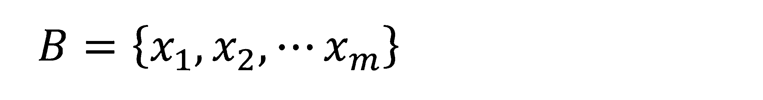
出力を、
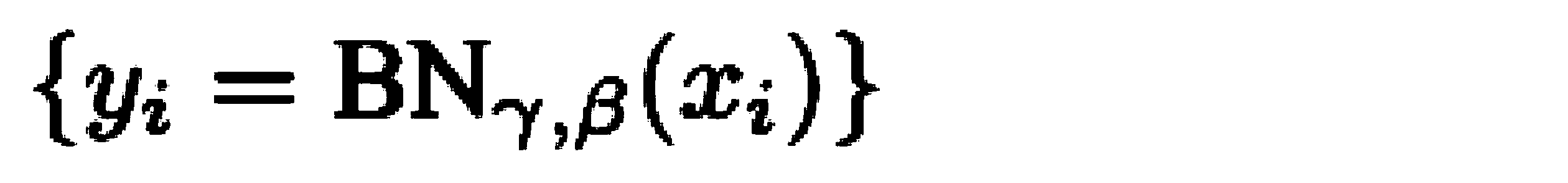
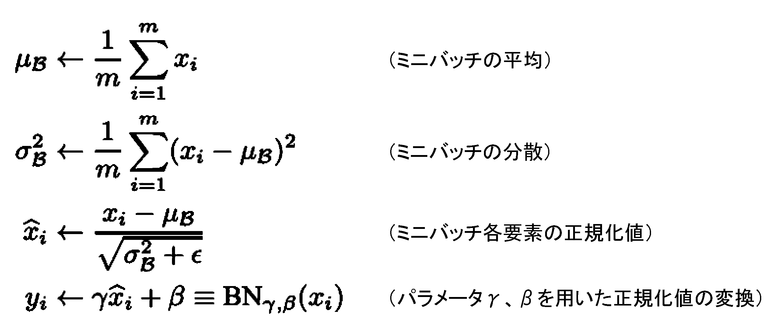
ここで用いられたγがユニット削減のパラメータとして用いられる。つまり、学習処理において、パラメータ:γが小さいユニットが削除される。
For the discussion of pruning here, let the input vector to the batch normalization layer be
the output as
γ used here is used as a parameter for unit reduction. That is, in the learning process, units with a small parameter γ are deleted.
光学センサユニット9の撮影ユニット9Aからの撮影画像、及び、ステレオビジョンカメラ9Bからのステレオビジョン画像を用いて、特定物体の検出および特定物体の空間位置を求める処理の模式的な流れ図が、図4に示されている。
FIG. 4 is a schematic flowchart of the process of detecting a specific object and determining the spatial position of the specific object using the captured image from the
まず、一方では、撮影ユニット9Aからの撮影画像が、学習済のニューラルネットワーク4に入力されると、撮影画像に特定物体が存在しているどうかが推定され、特定物体が推定されると、推定された特定物体が占める領域を示す物体領域情報が出力される(#a)。図4では、物体領域情報は、人と植立穀稈(未刈地)と刈り跡(既刈地)と畔とが区分けされたラベル画像として示されている。検出された人が占める領域である人の輪郭は、このラベル画像から求めることができる。
First, on the one hand, when the photographed image from the photographing
他方では、ステレオビジョンカメラ9Bからのステレオビジョン画像に基づいて、空間位置測定部52が、ステレオマッチング技術を用いて、特定領域に存在する物体全ての空間位置(多数の距離測定点からなる深度データ群である)を示す物体位置情報を生成する。物体位置情報は、図4では、各画素の深度を濃淡色で表した、深度画像と呼ばれる画像として出力される(#b)。各画素は、ステレオマッチング点に対応しており、これらの点群は、三次元座標値を有するので、3次元点群データと呼ばれ、3次元座標空間(特定領域)に展開可能である。
On the other hand, based on the stereo vision image from the
次に、ニューラルネットワーク4から出力された物体領域情報と、空間位置測定部52から出力された物体位置情報とに基づいて、機体1から走行障害物となる人や動物(図4では人)までの距離である特定物体距離が距離算出部53によって算出される(#c)。なお、この実施形態では、特定物体距離は、検出された人の輪郭に含まれる多数の距離測定点を用いて算出される人の輪郭の重心(図4ではP1で示されている)から機体1までの距離である。特定物体距離の基準点として、輪郭の重心に代えて、輪郭に含まれる多数の距離測定点の統計的代表値(中間値や中央値や平均値など)を用いてもよい。
Next, based on the object area information output from the
以上の図4の説明では、物体位置情報がそのまま距離算出部53に与えられ、特定物体距離の算出に用いられている。別実施形態として、この図4に示す方法に代えて、図5に示されているような方法を採用してもよい。図5に示された方法では、圃場情報作成部54は、物体位置情報から圃場面を1つの基準面(底面)とする3次元座標系で展開された3次元点群データを作成する(#c1)。さらに、圃場情報作成部54は、3次元点群データと物体領域情報とから、畔、植立穀稈、刈り跡、既刈地と未刈地との境界を含む圃場刈取り情報を作成する(#c2と#c3)。距離算出部53は、物体位置情報と物体領域情報と圃場刈取り情報とに基づいて、走行障害物である特定物体を決定し、この決定された特定物体の重心(図5ではP1で示されている)と機体1との距離を特定物体距離として算出する(#c)。
In the above description of FIG. 4, the object position information is directly given to the
検出された走行障害物が機体1と干渉する可能性がある場合、走行障害物との干渉回避の制御が行われる。このために用いる障害物警戒領域は、図6に示すように、機体1の進行方向前方に広がる圃場面に対応する基準面(XY平面)上に規定される。ここでは、障害物警戒領域は、機体1との位置関係が異なる第1警戒領域(図6では濃く塗りつぶされ、符号Z1が付与されている)と第2警戒領域(図6では薄く塗りつぶされ、符号Z2が付与されている)とからなる。 If there is a possibility that the detected traveling obstacle will interfere with the airframe 1, control is performed to avoid interference with the traveling obstacle. The obstacle warning area used for this purpose is defined on a reference plane (XY plane) corresponding to a field spreading forward in the traveling direction of the machine body 1, as shown in FIG. Here, the obstacle caution area is divided into a first caution area (shown darkly in FIG. 6 and denoted by symbol Z1) and a second caution area (shown lightly in FIG. is given the reference Z2).
第1警戒領域は、刈取部2の作業幅と、機体1から機体1の進行方向前方への警戒距離(図6では符号L1で示されている)とによって規定される長方形から、撮影ユニット9A及びステレオビジョンカメラ9Bのカメラ画角によって決まる死角領域を切り取った先端楔状の領域である。言い換えると、第1警戒領域は、実質的にコンバインの走行軌跡幅である刈取部2の左右幅の一辺とし、機体1から進行方向前方への所定距離(警戒距離)を他辺とする長方形から、カメラ画角によって決まる死角領域を切り取った形状である。この第1警戒領域に存在する走行障害物は、コンバインの進行によりコンバインと接触することになる。したがって、その警戒距離は、コンバインの車速に応じて変更されるのが好ましいが、この実施形態では、作業走行速度が実質的に一定であるので、数mに設定されている。
The first warning area is a rectangle defined by the working width of the reaping
第2警戒領域は、機体1の進行方向前方へ広がった平面における、カメラ画角によって決まる死角領域を切り取った先端楔状の領域から、第1警戒領域を切り取った形状である。コンバインの左右方向に関して、第1警戒領域の3倍程度の幅を有し、機体1の進行方向前方に関して、第1警戒領域の2倍弱の長さ(図6では符号L2で示されている)を有する。第2警戒領域の左右方向広がりは、コンバインの旋回を考慮して設定され、第2警戒領域の進行方向の広がりは、機体1と走行障害物との干渉までに時間的に余裕が、第1警戒領域より大きくなるように設定されている。 The second warning area has a shape obtained by cutting out the first warning area from a tip wedge-shaped area obtained by cutting out the blind spot area determined by the angle of view of the camera on the plane extending forward in the traveling direction of the airframe 1 . It has a width about three times that of the first caution area in the horizontal direction of the combine harvester, and a length slightly less than two times that of the first caution area in the forward direction of movement of the machine body 1 (indicated by L2 in FIG. 6). ). The width of the second caution area in the left-right direction is set in consideration of the turn of the combine harvester, and the width of the traveling direction of the second caution area is set so that there is enough time before the machine body 1 interferes with a traveling obstacle. It is set to be larger than the warning area.
図7には、コンバインの制御系の機能ブロック図が示されている。この実施形態の制御系は、多数のECUと呼ばれる電子制御ユニットと、各種動作機器、センサ群やスイッチ群、それらの間のデータ伝送を行う車載LANなどの配線網から構成されている。報知デバイス84は、運転者や圃場周辺にいる管理者等に走行障害物の検出結果や作業走行の状態などの警告を報知するためのデバイスであり、ブザー、ランプ、スピーカ、ディスプレイなどである。検出された走行障害物が第1警戒領域に存在している場合には、切迫した状態を示すような警告音や警告光や警告メッセージが緊急警戒報知として報知され、第1警戒領域に存在している場合には、緊急警戒報知よりは穏やかな注意音や注意光や注意メッセージが注意報知として報知される。
FIG. 7 shows a functional block diagram of the control system of the combine. The control system of this embodiment is composed of a large number of electronic control units called ECUs, various operating devices, a group of sensors, a group of switches, and a wiring network such as an in-vehicle LAN for data transmission between them. The
通信部85は、外部の通信機器との間でデータ交換するために用いられる。制御ユニット6は、この制御系の中核要素であり、複数のECUの集合体として示されている。衛星測位モジュール80からの測位データ、および、光学センサユニット9からの画像データは、配線網を通じて制御ユニット6に入力される。
A
制御ユニット6は、入出力インタフェースとして、出力処理部6Bと入力処理部6Aとを備えている。出力処理部6Bは、車両走行機器群7Aおよび作業装置機器群7Bと接続している。車両走行機器群7Aには、車両走行に関する制御機器、例えばエンジン制御機器、変速制御機器、制動制御機器、操舵制御機器などが含まれている。作業装置機器群7Bには、刈取部2、脱穀装置11、穀粒排出装置13、穀稈搬送装置23における動力制御機器などが含まれている。
The control unit 6 has an
入力処理部6Aには、走行系検出センサ群8Aや作業系検出センサ群8Bなどが接続されている。走行系検出センサ群8Aには、エンジン回転数調整具、アクセルペダル、ブレーキペダル、変速操作具などの状態を検出するセンサが含まれている。作業系検出センサ群8Bには、刈取部2、脱穀装置11、穀粒排出装置13、穀稈搬送装置23における装置状態および穀稈や穀粒の状態を検出するセンサが含まれている。
A travel system detection sensor group 8A, a work system detection sensor group 8B, and the like are connected to the
制御ユニット6には、作業走行制御モジュール60、障害物検出ユニット50、車速変更指令出力部65、機体位置算出部66、報知部67が制御機能部として備えられている。なお、これらの制御機能部は、それぞれ別体で構成され、車載LAN等で接続される。
The control unit 6 includes a work
報知部67は、制御ユニット6の各機能部からの要求に基づいて報知データを生成し、報知デバイス84に与える。機体位置算出部66は、衛星測位モジュール80から逐次送られてくる測位データに基づいて、機体1の地図座標(または圃場座標)である機体位置を算出する。
The
この実施形態のコンバインは自動走行(自動操舵)と手動走行(手動操舵)の両方で走行可能である。作業走行制御モジュール60には、走行制御部61と作業制御部62とに加えて、作業走行指令部63および走行経路設定部64が備えられている。自動操舵で走行する自動走行モードと、手動操舵で走行する手動操舵モードとのいずれかを選択する走行モードスイッチ(非図示)が搭乗運転部14内に設けられている。この走行モードスイッチを操作することで、手動操舵走行から自動操舵走行への移行、あるいは自動操舵走行から手動操舵走行への移行が可能である。
The combine of this embodiment can travel both automatically (automatic steering) and manually (manual steering). The work
走行制御部61は、エンジン制御機能、操舵制御機能、車速制御機能などを有し、車両走行機器群7Aに走行制御信号を与える。作業制御部62は、刈取部2、脱穀装置11、穀粒排出装置13、穀稈搬送装置23などの動きを制御するために、作業装置機器群7Bに作業制御信号を与える。
The
走行経路設定部64は、自動走行のための走行経路をメモリに展開する。メモリに展開された走行経路は、順次自動走行における目標走行経路として用いられる。この走行経路は、手動走行であっても、コンバインが当該走行経路に沿って走行するためのガイダンスのために利用することも可能である。
The travel
作業走行指令部63は、自動走行指令として、自動操舵指令および車速指令を生成して、走行制御部61に与える。自動操舵指令は、走行経路設定部64によって走行経路と、機体位置算出部66によって算出された自機位置との間の方位ずれおよび位置ずれを解消するように生成される。自動走行時には、車速指令は、前もって設定されている車速値に基づいて生成される。手動走行時には、車速指令は、手動車速操作に基づいて生成される。但し、走行障害物検出などの緊急事態が発生した場合は、強制的な停止を含む車速変更や、エンジン停止などが自動的に行われる。
The work
自動走行モードが選択されている場合、作業走行指令部63によって与えられる自動走行指令に基づいて、走行制御部61は、操舵に関する車両走行機器群7Aや車速に関する車両走行機器群7Aを制御する。手動走行モードが選択されている場合、運転者による操作に基づいて、走行制御部61が制御信号を生成し、車両走行機器群7Aを制御する。
When the automatic traveling mode is selected, based on the automatic traveling command given by the work traveling
障害物検出ユニット50は、図4または図5を用いて説明した物体検出処理を行う。このため、障害物検出ユニット50には、AI部51、空間位置測定部52、距離算出部53、圃場情報作成部54、物体検出信号生成部55、警戒領域設定部56が含まれている。障害物検出ユニット50を構成する上記の構成要素は、主に説明目的で分けられており、当該構成要素の統合や、当該構成要素の分割は、自由に行われてよい。
The
AI部51は、図3で説明したセグメンテーションニューラルネットワーク4の学習済モデルが実装されており、図4または図5で説明したような原理で走行障害物の検出(特定物体検出)を行う。
The
空間位置測定部52、距離算出部53、圃場情報作成部54は、図4と図5とを用いて説明した機能を有する。警戒領域設定部56は、機体1に対する位置に基づいて規定される障害物警戒領域を設定する。この実施形態では、障害物警戒領域は、図6を用いて述べたように、第1警戒領域と第2警戒領域とに区分けられている。
The spatial
距離算出部53は、AI部51や空間位置測定部52などと連係することにより、検出された走行障害物の位置、特に機体1からの走行障害物までの距離(特定物体距離)を算出する。物体検出信号生成部55は、機体1からの走行障害物までの距離に基づいて、検出される走行障害物が第1警戒領域と第2警戒領域とのどちらに存在するものであるかを判定し、警戒領域別の物体検出信号を生成する。この物体検出信号には、報知部67に与える走行障害物報知信号と、車速変更指令出力部65に与える障害物走行信号とが含まれ、さらに障害物走行信号には、走行障害物が存在する警戒領域別の信号が含まれる。
The
車速変更指令出力部65は、受け取った障害物走行信号から、走行障害物が第1警戒領域に存在する場合には、車速変更値を含む第1車速変更指令を作業走行指令部63に出力し、走行障害物が第2警戒領域に存在する場合には、車速変更値を含む第2車速変更指令を作業走行指令部63に出力する。第1車速変更指令は、車速をゼロにする指令、つまり機体1を停止する命令である。もちろん、第1車速変更指令は、車速をゼロに近い値にする指令、あるいは、段階的に車速をゼロにする指令であってもよい。第2車速変更指令は、車速を微速、例えば時速1km程度に減速する減速値である。第2車速変更指令として、直前の車速の数分の1に減速するといった、直前車速に対する割合で決められた減速値であってもよい。いずれにせよ、第1車速変更指令による第1車速変更値は、第2車速変更指令による第2車速変更値より大きく、緊急避難のための指令となっている。車速変更指令出力部65から与えられた車速変更指令に基づいて、作業走行指令部63は、走行制御部61に制御指令を与えて、機体1を緊急的に減速させる。走行障害物の存在が第1警戒領域から第2警戒領域に移行すれば、停止していた機体1は、第2車速変更指令で規定されている微速で前進する。さらには、走行障害物が警戒領域で、検出されなくなれば、通常の作業車速での走行に戻る。
Vehicle speed change
次に、上述した制御系における、走行障害物検出時の車速減速の制御ルーチンの一例が図8に示されている。この制御ルーチンがスタートすれば、フラグや変数のリセットなどの初期設定が行われる(#01)。警戒領域の設定、つまり第1警戒領域と第2警戒領域が設定される(#02)。第1警戒領域が、車速によって変更される場合には、現在車速が取得され、その車速に基づいて、第1警戒領域が設定される。 Next, FIG. 8 shows an example of a control routine for decelerating the vehicle speed when an obstacle is detected in the control system described above. When this control routine starts, initialization such as resetting of flags and variables is performed (#01). A caution area is set, that is, a first caution area and a second caution area are set (#02). When the first caution area is changed depending on the vehicle speed, the current vehicle speed is acquired and the first caution area is set based on the vehicle speed.
光学センサユニット9から画像データ(撮影画像)が取り込まれる(#03)。取り込まれた画像データを用いて、障害物検出ユニット50による特定物体検出処理(走行障害物検出処理)が行われる(#04)。
Image data (photographed image) is taken in from the optical sensor unit 9 (#03). A specific object detection process (running obstacle detection process) is performed by the
走行障害物が検出されているかどうかの判定が行われ、走行障害物が検出されていると(#05Yes分岐)、障害物警戒領域における走行障害物の位置が算出される(#11)。 It is determined whether or not a running obstacle is detected, and if a running obstacle is detected (#05 Yes branch), the position of the running obstacle in the obstacle warning area is calculated (#11).
走行障害物が第1警戒領域に入っているかどうかチェックされる(#12)。走行障害物が第1警戒領域に入っていれば(#12Yes分岐)、車速変更指令出力部65が第1車速変更指令として、停止指令を作業走行指令部63に与える(#13)。さらに停止フラグをONにする(#14)。なお、ステップ#14において、減速フラグがONであるときは(第2警戒領域から第1境界領域に走行障害物が移動したときは)、減速フラグをOFFにして停止フラグをONにする。これにより機体1は停止し、制御はステップ#02に戻る。
It is checked whether a running obstacle is in the first warning area (#12). If the traveling obstacle is in the first warning area (#12 Yes branch), the vehicle speed change
ステップ#12のチェックで走行障害物が第1警戒領域に入っていない場合(#12No分岐)、さらに、第2警戒領域に入っているかどうかチェックされる(#20)。走行障害物が第2警戒領域に入っていれば(#20Yes分岐)、車速変更指令出力部65が第2車速変更指令として、減速指令を作業走行指令部63に与える(#21)。さらに減速フラグをONにする(#22)。なお、ステップ#22において、停止フラグがONであるときは(第1警戒領域から第2境界領域に走行障害物が移動したときは)、停止フラグをOFFにして減速フラグをONにする。これにより機体1は微速走行し(時速1km程度)、制御はステップ#02に戻る。
If it is determined in
ステップ#20のチェックで走行障害物が第2警戒領域に入っていない場合(#20No分岐)、警戒領域には走行障害物が存在しないことになる。このように警戒領域には走行障害物が存在しない場合、あるいは、そもそも走行障害物が検出されなかった場合(#08No分岐)、停止フラグの状態と減速フラグとの状態がチェックされ、その状態に応じたフラグ内容の書き換えが行われる。具体的には、その際に、停止フラグがONであれば(#30Yes分岐)、停止フラグはOFFに書き換えられ(#31)、さらに、走行指令が有効となり、機体1は通常走行を行う(#32)。次いで、制御はステップ#02に戻る。その際に、停止フラグがONでなければ(#30No分岐)、減速フラグの内容がチェックされる(#40)。減速フラグがONであれば(#40Yes分岐)、減速フラグはOFFに書き換えられる(#41)、さらに、走行指令が有効となり、機体1は通常走行を行う(#42)。通常走行とは、走行障害物等が検出されていない際の作業走行であり、その車速は、走行障害物が第2警戒領域に存在している際の車速より、速い速度である。次いで、制御はステップ#02に戻る。減速フラグがOFFであれば(#40No分岐)、もちろん走行指令は有効であり、通常走行が行われる(#43)。そして、制御はステップ#02に戻る。
If it is determined in
このような走行障害物検出と車速変更との制御により、例えば、機体1の進行方向前方の警戒領域に圃場作業者が進入すると、機体1は停止または減速し、警戒領域から圃場作業者が出ていくと、コンバインは、再び通常の車速での作業走行に復帰する。 By controlling the detection of traveling obstacles and the change of vehicle speed in this manner, for example, when a field worker enters a warning area in front of the machine 1 in the traveling direction, the machine 1 stops or decelerates, and the field worker leaves the warning area. Then, the combine returns to work running at normal vehicle speed.
この走行障害物検出に基づく車速減速の制御は、コンバインが自動走行であっても、手動走行であっても、実行させることが可能である。 This control of vehicle speed deceleration based on the detection of traveling obstacles can be executed whether the combine is traveling automatically or traveling manually.
上述した実施形態では、第1警戒領域と第2警戒領域とを設定し、走行障害物がそれぞれの警戒領域に存在した場合、機体1の停止、または通常走行より遅い車速への変更が行われた。これに代えて、警戒領域を3つ以上設け、それぞれの領域に応じて、機体1を停止または微速への変更が行われてもよい。さらには、警戒領域を無段階に設定し、機体1と走行障害物との距離に応じて、機体1の停止、あるいは通常走行より遅い車速への無段階の変更が行われてもよい。 In the above-described embodiment, the first warning area and the second warning area are set, and when a traveling obstacle exists in each of the warning areas, the machine body 1 is stopped or the vehicle speed is changed to slower than normal driving. rice field. Alternatively, three or more warning areas may be provided, and the aircraft 1 may be stopped or slowed down according to each area. Furthermore, the caution area may be set steplessly, and the vehicle body 1 may be stopped or the vehicle speed may be changed steplessly to a speed lower than that of normal running, depending on the distance between the vehicle body 1 and the traveling obstacle.
なお、上記実施形態(別実施形態を含む、以下同じ)で開示される構成は、矛盾が生じない限り、他の実施形態で開示される構成と組み合わせて適用することが可能であり、また、本明細書において開示された実施形態は例示であって、本発明の実施形態はこれに限定されず、本発明の目的を逸脱しない範囲内で適宜改変することが可能である。 It should be noted that the configurations disclosed in the above embodiments (including other embodiments, the same shall apply hereinafter) can be applied in combination with configurations disclosed in other embodiments as long as there is no contradiction. The embodiments disclosed in this specification are exemplifications, and the embodiments of the present invention are not limited thereto, and can be modified as appropriate without departing from the object of the present invention.
本発明は、圃場で作業走行を行う、収穫機、田植機、トタクタなどの農作業機に適用される。 INDUSTRIAL APPLICABILITY The present invention is applied to agricultural working machines such as harvesters, rice transplanters, and totactors that travel for work in fields.
1 :機体
2 :刈取部
4 :セグメンテーションニューラルネットワーク(ニューラルネットワーク)
4A :エンコーダネットワーク
4B :デコーダネットワーク
41 :入力層
42 :隠れ層
43 :出力層
44 :バッチ正規化層
50 :障害物検出ユニット
51 :AI部
52 :空間位置測定部
53 :距離算出部
54 :圃場情報作成部
55 :物体検出信号生成部
56 :警戒領域設定部
6 :制御ユニット
61 :走行制御部
63 :作業走行指令部
65 :車速変更指令出力部
67 :報知部
9 :光学センサユニット
9A :撮影ユニット
9B :ステレオビジョンカメラ
1: Airframe 2: Reaping unit 4: Segmentation neural network (neural network)
4A:
Claims (7)
前記圃場の特定領域を撮影する撮影ユニットと、
前記撮影ユニットからの撮影画像を入力して、前記撮影画像に写っている特定物体を認識し、当該特定物体が前記撮影画像において占める領域を示す特定物体輪郭を含む物体領域情報を出力するニューラルネットワークと、
前記特定領域を撮影し、前記特定領域に存在する物体全ての空間位置を示す物体位置情報を生成する空間位置測定部と、
前記物体位置情報から圃場面を基準面とする3次元座標系で展開された3次元点群データを作成し、前記特定物体輪郭の内部に含まれる前記3次元点群データと前記特定物体輪郭とから、農作物が存在する前記特定物体の1つである未刈地と前記農作物が刈り取られた前記特定物体の1つである既刈地との境界を含む圃場刈取り情報を作成する圃場情報作成部と、
前記物体位置情報と前記物体領域情報と前記圃場刈取り情報とに基づいて前記特定物体の1つである走行障害物の空間位置を決定し、機体から前記走行障害物までの距離である特定物体距離を算出する距離算出部と、
前記特定物体距離に基づいて物体検出信号を出力する物体検出信号生成部と、を備える農作業機。 An agricultural work machine for working and traveling in a field,
a photographing unit for photographing a specific area of the field;
A neural network that receives a photographed image from the photographing unit, recognizes a specific object appearing in the photographed image, and outputs object area information including a specific object contour indicating an area occupied by the specific object in the photographed image. and,
a spatial position measuring unit that captures an image of the specific area and generates object position information indicating the spatial positions of all objects existing in the specific area;
3D point cloud data developed in a 3D coordinate system with the field surface as a reference plane is created from the object position information, and the 3D point cloud data included inside the specific object contour and the specific object contour are generated. a field information creating unit for creating field harvesting information including a boundary between an uncut land that is one of the specific objects on which the crops are present and a harvested land that is one of the specific objects from which the crops have been cut. and,
determining a spatial position of a traveling obstacle, which is one of the specific objects , based on the object position information, the object area information, and the field reaping information; a distance calculation unit that calculates
and an object detection signal generator that outputs an object detection signal based on the specific object distance.
前記既刈地は前記収穫部によって前記農作物が刈り取られた領域であり、前記未刈地は前記収穫部によって前記農作物が刈り取られる前の領域である請求項1から5のいずれか一項に記載の農作業機。 The agricultural machine is a harvester having a harvesting unit for harvesting crops,
6. The harvesting unit according to any one of claims 1 to 5, wherein the harvested land is an area where the crops have been harvested, and the uncut land is an area before the crops have been harvested by the harvesting unit. agricultural machinery.
前記走行障害物が前記障害物警戒領域に存在する場合、前記車速変更指令出力部は前記特定物体距離に基づいて車速を変更する請求項1から6のいずれか一項に記載の農作業機。 A warning area setting unit that sets an obstacle warning area defined based on the position from the aircraft, and a vehicle speed change command output unit that changes the vehicle speed,
The agricultural work machine according to any one of claims 1 to 6, wherein the vehicle speed change command output unit changes the vehicle speed based on the specific object distance when the traveling obstacle exists in the obstacle warning area.
Priority Applications (1)
| Application Number | Priority Date | Filing Date | Title |
|---|---|---|---|
| JP2019182770A JP7246641B2 (en) | 2019-10-03 | 2019-10-03 | agricultural machine |
Applications Claiming Priority (1)
| Application Number | Priority Date | Filing Date | Title |
|---|---|---|---|
| JP2019182770A JP7246641B2 (en) | 2019-10-03 | 2019-10-03 | agricultural machine |
Publications (2)
| Publication Number | Publication Date |
|---|---|
| JP2021058099A JP2021058099A (en) | 2021-04-15 |
| JP7246641B2 true JP7246641B2 (en) | 2023-03-28 |
Family
ID=75379448
Family Applications (1)
| Application Number | Title | Priority Date | Filing Date |
|---|---|---|---|
| JP2019182770A Active JP7246641B2 (en) | 2019-10-03 | 2019-10-03 | agricultural machine |
Country Status (1)
| Country | Link |
|---|---|
| JP (1) | JP7246641B2 (en) |
Families Citing this family (6)
| Publication number | Priority date | Publication date | Assignee | Title |
|---|---|---|---|---|
| JP7558119B2 (en) * | 2021-06-28 | 2024-09-30 | 株式会社クボタ | Work Support System |
| KR102603672B1 (en) * | 2021-11-17 | 2023-11-21 | 한국생산기술연구원 | Agricultural vehicle autonomous driving device, system and method thereof |
| TWI833209B (en) * | 2022-04-27 | 2024-02-21 | 緯創資通股份有限公司 | Optimalizing method and computer system for neural network and computer readable storage medium |
| WO2023219155A1 (en) * | 2022-05-12 | 2023-11-16 | ソニーセミコンダクタソリューションズ株式会社 | Information processing apparatus, data structure, and program |
| DE102023107047A1 (en) * | 2023-03-21 | 2024-09-26 | Claas E-Systems Gmbh | Agricultural work machine with an anonymization module |
| US12520758B2 (en) | 2024-05-23 | 2026-01-13 | Deere & Company | Controlling an agricultural harvester based upon material other than grain (MOG) content characteristics |
Citations (2)
| Publication number | Priority date | Publication date | Assignee | Title |
|---|---|---|---|---|
| JP2018124973A (en) | 2017-01-27 | 2018-08-09 | 株式会社デンソーアイティーラボラトリ | Object detection system, object detection device, object detection program, and object detection method |
| JP2019083703A (en) | 2017-11-01 | 2019-06-06 | 国立大学法人京都大学 | Harvesting machine |
Family Cites Families (1)
| Publication number | Priority date | Publication date | Assignee | Title |
|---|---|---|---|---|
| JP2944773B2 (en) * | 1991-03-20 | 1999-09-06 | ヤンマー農機株式会社 | Image processing method for automatic traveling work machine |
-
2019
- 2019-10-03 JP JP2019182770A patent/JP7246641B2/en active Active
Patent Citations (2)
| Publication number | Priority date | Publication date | Assignee | Title |
|---|---|---|---|---|
| JP2018124973A (en) | 2017-01-27 | 2018-08-09 | 株式会社デンソーアイティーラボラトリ | Object detection system, object detection device, object detection program, and object detection method |
| JP2019083703A (en) | 2017-11-01 | 2019-06-06 | 国立大学法人京都大学 | Harvesting machine |
Non-Patent Citations (3)
| Title |
|---|
| ステレオカメラによるYOLOと3次元点群を利用した人物検出,第25回画像センシングシンポジウム 講演論文,2019年06月13日,第1-3頁,https://www.mech.chuo-u.ac.jp/umedalab/publications/paper.html |
| 竹藤輝 外2名,視覚障害者のための歩行支援装置の検討,2019年度 電気・情報関係学会九州支部連合大会 講演論文集,日本,2019年09月19日,第292頁, https://www.jstage.jst.go.jp/article/jceeek/2019/0/2019_292/_article/-char/ja/ |
| 高橋正裕 外2名,ステレオカメラによるYOLOと3次元点群を利用した人物検出,第31回 人間情報学会講演集,日本,2018年12月17日,第1-2頁,http://www.ahi-soc.info/pdf/31stAHI_proceedings.pdf |
Also Published As
| Publication number | Publication date |
|---|---|
| JP2021058099A (en) | 2021-04-15 |
Similar Documents
| Publication | Publication Date | Title |
|---|---|---|
| JP7246641B2 (en) | agricultural machine | |
| JP7195543B2 (en) | harvester | |
| JP7565677B2 (en) | Obstacle detection system for agricultural vehicles | |
| KR102589076B1 (en) | harvest | |
| KR102618797B1 (en) | Combine, field farming map creation method, field farming map creation program, and recording medium on which field farming map creation program is recorded | |
| US20190225214A1 (en) | Advanced wild-life collision avoidance for vehicles | |
| JP7068781B2 (en) | Harvester | |
| JP6854713B2 (en) | combine | |
| WO2020218528A1 (en) | Agricultural machine such as harvester | |
| JP2021007386A (en) | Automatic travel system | |
| JP2020178619A (en) | Agricultural work machine | |
| CN113874874A (en) | Work vehicle, obstacle detection method, and obstacle detection program | |
| CN111343853B (en) | Agricultural work vehicle, work vehicle collision warning system and work vehicle | |
| WO2020218464A1 (en) | Harvester, obstacle determination program, recording medium on which obstacle determination program is recorded, obstacle determination method, agricultural work machine, control program, recording medium on which control program is recorded, and control method | |
| JP6904539B2 (en) | Harvester | |
| KR20220027811A (en) | Automatic driving system, agricultural equipment, program, recording medium and method recording the program | |
| JP7041889B2 (en) | Head harvester combine | |
| JP7174487B2 (en) | agricultural machine | |
| JP2022092391A (en) | Mobile vehicle | |
| JP7080042B2 (en) | Harvester collision warning system and harvester | |
| CN115599085A (en) | Work support system | |
| JP6765349B2 (en) | Harvester | |
| JP2024084284A (en) | Farm Work Vehicle | |
| Michihisa et al. | Obstacle detection and avoidance for autonomous combine harvester | |
| JP2025101045A (en) | Work machine, image processing device, and method for detecting specific object from image |
Legal Events
| Date | Code | Title | Description |
|---|---|---|---|
| A621 | Written request for application examination |
Free format text: JAPANESE INTERMEDIATE CODE: A621 Effective date: 20220210 |
|
| A977 | Report on retrieval |
Free format text: JAPANESE INTERMEDIATE CODE: A971007 Effective date: 20221118 |
|
| A131 | Notification of reasons for refusal |
Free format text: JAPANESE INTERMEDIATE CODE: A131 Effective date: 20221129 |
|
| A521 | Request for written amendment filed |
Free format text: JAPANESE INTERMEDIATE CODE: A523 Effective date: 20230127 |
|
| TRDD | Decision of grant or rejection written | ||
| A01 | Written decision to grant a patent or to grant a registration (utility model) |
Free format text: JAPANESE INTERMEDIATE CODE: A01 Effective date: 20230207 |
|
| A61 | First payment of annual fees (during grant procedure) |
Free format text: JAPANESE INTERMEDIATE CODE: A61 Effective date: 20230307 |
|
| R150 | Certificate of patent or registration of utility model |
Ref document number: 7246641 Country of ref document: JP Free format text: JAPANESE INTERMEDIATE CODE: R150 |