[go: up one dir, main page]

JP7236235B2 - Cooling system - Google Patents

Cooling system Download PDF

Info

Publication number
JP7236235B2
JP7236235B2 JP2018188553A JP2018188553A JP7236235B2 JP 7236235 B2 JP7236235 B2 JP 7236235B2 JP 2018188553 A JP2018188553 A JP 2018188553A JP 2018188553 A JP2018188553 A JP 2018188553A JP 7236235 B2 JP7236235 B2 JP 7236235B2
Authority
JP
Japan
Prior art keywords
heat sink
heat
induced flow
cooling device
flow
Prior art date
Legal status (The legal status is an assumption and is not a legal conclusion. Google has not performed a legal analysis and makes no representation as to the accuracy of the status listed.)
Active
Application number
JP2018188553A
Other languages
Japanese (ja)
Other versions
JP2020057720A (en
Inventor
健太 江森
淳平 新井田
滋春 山上
雄二 斎藤
Current Assignee (The listed assignees may be inaccurate. Google has not performed a legal analysis and makes no representation or warranty as to the accuracy of the list.)
Renault SAS
Original Assignee
Renault SAS
Priority date (The priority date is an assumption and is not a legal conclusion. Google has not performed a legal analysis and makes no representation as to the accuracy of the date listed.)
Filing date
Publication date
Application filed by Renault SAS filed Critical Renault SAS
Priority to JP2018188553A priority Critical patent/JP7236235B2/en
Publication of JP2020057720A publication Critical patent/JP2020057720A/en
Application granted granted Critical
Publication of JP7236235B2 publication Critical patent/JP7236235B2/en
Active legal-status Critical Current
Anticipated expiration legal-status Critical

Links

Images

Landscapes

  • Cooling Or The Like Of Semiconductors Or Solid State Devices (AREA)
  • Cooling Or The Like Of Electrical Apparatus (AREA)

Description

本発明は、冷却装置に関する。 The present invention relates to cooling devices.

コンバータ等の電力変換装置には半導体、コンデンサ、又はコイルなどの発熱要素となる電子部品が含まれているため、これらを冷却するヒートシンクが取り付けられる。一方、このような電力変換装置において、大電力化や小型化を実現する観点から、各回路要素及び冷却構造を高密度に構成することが要求される。 A power conversion device such as a converter includes electronic components that generate heat, such as semiconductors, capacitors, or coils, so heat sinks are attached to cool these components. On the other hand, in such a power conversion device, it is required to configure each circuit element and cooling structure with high density from the viewpoint of achieving high power and miniaturization.

しかしながら、高密度化により電力変換装置内の発熱密度が上昇するため、より高い冷却性能が要求されることとなる。ここで、ヒートシンクの冷却性能は、一般的にその体積(熱容量)、材料(熱伝導率)、及び形状に応じた表面積(伝熱面積)に依存する。 However, as the density increases, the heat generation density in the power converter increases, so higher cooling performance is required. Here, the cooling performance of a heat sink generally depends on its volume (heat capacity), material (thermal conductivity), and surface area (heat transfer area) depending on its shape.

したがって、冷却性能を向上させるためには、ヒートシンク自体を大型化することが要求され、電力変換装置全体の大型化に繋がることとなる。このため、ヒートシンク自体の大型化を抑えつつも、冷却性能の向上を実現する観点からヒートシンクの材料及び形状の改善が検討されている。 Therefore, in order to improve the cooling performance, it is required to increase the size of the heat sink itself, which leads to an increase in the size of the power converter as a whole. For this reason, improvements in the material and shape of the heat sink have been studied from the viewpoint of realizing an improvement in cooling performance while suppressing an increase in the size of the heat sink itself.

例えば、特許文献1では、複数のフィンが設けられたヒートシンクが提案されている。そして、ファンからの冷却風をヒートシンクのフィンに流通させて、ヒートシンクに設けられた発熱体を冷却させる。 For example, Patent Document 1 proposes a heat sink provided with a plurality of fins. Then, the cooling air from the fan is circulated through the fins of the heat sink to cool the heating element provided on the heat sink.

特開2009-290004号公報JP 2009-290004 A

しかしながら、特許文献1の構成では、複数のフィンがファンからの冷却風の流れを乱すことで、圧力損失が大きくなり、冷却効率が低下する。 However, in the configuration of Patent Document 1, the plurality of fins disturb the flow of cooling air from the fan, resulting in increased pressure loss and reduced cooling efficiency.

このような事情に鑑み、本発明の目的は、より冷却効率の高い冷却装置を提供することにある。 In view of such circumstances, an object of the present invention is to provide a cooling device with higher cooling efficiency.

本発明のある態様によれば、第1面に発熱体が接合されたヒートシンクと、ヒートシンクの第1面に対向する第2面に設けられ、電気的に誘起流を発生させる誘起流発生装置と、を備える冷却装置が提供される。 According to one aspect of the present invention, a heat sink having a first surface to which a heating element is joined, and an induced flow generator provided on a second surface of the heat sink facing the first surface and electrically generating an induced flow. is provided.

本発明によれば、より冷却効率の高い冷却装置を提供することができる。 According to the present invention, it is possible to provide a cooling device with higher cooling efficiency.

図1は、本発明の第1実施形態による冷却装置の構成を説明する図である。FIG. 1 is a diagram illustrating the configuration of a cooling device according to a first embodiment of the present invention. 図2は、図1におけるA-A’線矢視断面図である。2 is a cross-sectional view taken along the line A-A' in FIG. 1. FIG. 図3は、第1実施形態の変形例1-1を説明する断面図である。FIG. 3 is a cross-sectional view for explaining Modification 1-1 of the first embodiment. 図4は、第2実施形態による冷却装置の構成を説明する断面図である。FIG. 4 is a cross-sectional view illustrating the configuration of the cooling device according to the second embodiment. 図5は、図4におけるB1-B1’線矢視断面図である。5 is a cross-sectional view taken along line B1-B1' in FIG. 4. FIG. 図6は、図4におけるB2-B2’線矢視断面図である。6 is a cross-sectional view taken along line B2-B2' in FIG. 4. FIG. 図7は、第2実施形態による冷却装置の斜視図である。FIG. 7 is a perspective view of the cooling device according to the second embodiment. 図8は、第2実施形態の変形例2-1による冷却装置の斜視図である。FIG. 8 is a perspective view of a cooling device according to modification 2-1 of the second embodiment. 図9は、変形例2-2による冷却装置の斜視図である。FIG. 9 is a perspective view of a cooling device according to modification 2-2. 図10は、変形例2-3による冷却装置の斜視図である。FIG. 10 is a perspective view of a cooling device according to modification 2-3. 図11は、変形例2-4による冷却装置の斜視図である。FIG. 11 is a perspective view of a cooling device according to modification 2-4. 図12は、変形例2-5による冷却装置の斜視図である。FIG. 12 is a perspective view of a cooling device according to modification 2-5. 図13は、変形例2-6による冷却装置の斜視図である。FIG. 13 is a perspective view of a cooling device according to modification 2-6. 図14は、比較例によるファンを備えた冷却装置の構成を説明する図である。FIG. 14 is a diagram illustrating the configuration of a cooling device having a fan according to a comparative example. 図15は、第3実施形態による冷却装置の構成を説明する断面図である。FIG. 15 is a cross-sectional view illustrating the configuration of the cooling device according to the third embodiment. 図16は、第3実施形態の変形例3-1による冷却装置の構成を説明する断面図である。FIG. 16 is a cross-sectional view for explaining the configuration of a cooling device according to modification 3-1 of the third embodiment. 図17は、変形例3-2による冷却装置の構成を説明する断面図である。FIG. 17 is a cross-sectional view illustrating the configuration of a cooling device according to modification 3-2. 図18は、変形例3-3による冷却装置の構成を説明する斜視図である。FIG. 18 is a perspective view illustrating the configuration of a cooling device according to modification 3-3. 図19は、変形例3-4による冷却装置の構成を説明する斜視図である。FIG. 19 is a perspective view illustrating the configuration of a cooling device according to modification 3-4. 図20は、変形例3-5による冷却装置の構成を説明する断面図である。FIG. 20 is a cross-sectional view illustrating the configuration of a cooling device according to modification 3-5. 図21は、変形例3-5による冷却装置の斜視図である。FIG. 21 is a perspective view of a cooling device according to modification 3-5. 図22は、変形例3-6による冷却装置の構成を説明する斜視図である。FIG. 22 is a perspective view illustrating the configuration of a cooling device according to modification 3-6. 図23は、第4実施形態にかかるプラズマアクチュエータの構成を説明する断面図である。FIG. 23 is a cross-sectional view for explaining the configuration of the plasma actuator according to the fourth embodiment. 図24は、プラズマアクチュエータが設けられた冷却装置の構成を説明する断面図である。FIG. 24 is a cross-sectional view illustrating the configuration of a cooling device provided with plasma actuators. 図25は、図24におけるD-D’線矢視断面図である。25 is a cross-sectional view taken along line D-D' in FIG. 24. FIG.

以下、図面等を参照して、本発明の各実施形態について説明する。なお、各実施形態及びその変形例の説明に用いる図面は、各実施形態の構成の要部を概略的に示すものである。 Hereinafter, each embodiment of the present invention will be described with reference to the drawings and the like. It should be noted that the drawings used for describing each embodiment and its modifications schematically show the essential parts of the configuration of each embodiment.

(第1実施形態)
以下、第1実施形態について説明する。
(First embodiment)
The first embodiment will be described below.

図1は、本実施形態による冷却装置10の構成を説明する流れ方向の断面図である。また、図2は、図1におけるA-A’線矢視断面図である。 FIG. 1 is a flow direction cross-sectional view for explaining the configuration of a cooling device 10 according to the present embodiment. 2 is a cross-sectional view taken along line A-A' in FIG.

図示のように、冷却装置10は、発熱体1、本実施形態のヒートシンクを構成するヒートシンク本体2、及び誘起流発生装置3を備える。発熱体1は、モータ、エンジン、及び家電などの電子機器に含まれる種々の発熱要素である。特に、発熱体1としては、半導体、半導体のモールドパッケージ、コンデンサ、及びコイル等の電子部品が想定される。 As illustrated, the cooling device 10 includes a heating element 1 , a heat sink main body 2 that constitutes the heat sink of the present embodiment, and an induced flow generator 3 . Heat generating elements 1 are various heat generating elements included in electronic devices such as motors, engines, and home appliances. In particular, as the heating element 1, electronic components such as semiconductors, semiconductor mold packages, capacitors, and coils are assumed.

ヒートシンク本体2は、発熱体1が発生する熱を周囲の雰囲気中に放出する構造物である。本実施形態では、ヒートシンク本体2は、板状部材として形成されている。そして、ヒートシンク本体2の一方側(Z軸負方向側)の表面であって第1面として機能する第1表面2aに、発熱体1が接合されている。 The heat sink main body 2 is a structure that releases the heat generated by the heating element 1 into the surrounding atmosphere. In this embodiment, the heat sink main body 2 is formed as a plate-like member. The heating element 1 is bonded to the first surface 2a which is the surface on one side (Z-axis negative direction side) of the heat sink body 2 and functions as the first surface.

ヒートシンク本体2は、例えば、銅若しくはアルミニウムなどの比較的熱伝導率の高い金属製材料、又はFR4(Flame Retardant Type 4)若しくはセラミクス等の比較的熱伝導率が高い非金属製材料で構成される。 The heat sink body 2 is made of, for example, a metallic material with relatively high thermal conductivity such as copper or aluminum, or a non-metallic material with relatively high thermal conductivity such as FR4 (Flame Retardant Type 4) or ceramics. .

誘起流発生装置3は、ヒートシンク本体2の他方側(Z軸正方向側)の面、すなわち、第1表面2aの裏面の第2面として機能する第2表面2bに設けられる。誘起流発生装置3は、X軸方向における一方側(図上ではX軸正方向)に誘起流発生部3aを有している。したがって、誘起流発生装置3は、図2上のX軸正方向に向かって誘起流Ifを発生させることができる。 The induced flow generator 3 is provided on the second surface 2b functioning as the second surface of the heat sink main body 2 on the other side (the Z-axis positive direction side), that is, the second surface behind the first surface 2a. The induced flow generator 3 has an induced flow generator 3a on one side in the X-axis direction (the positive direction of the X-axis in the figure). Therefore, the induced flow generator 3 can generate the induced flow If in the positive direction of the X-axis in FIG.

より詳細に、誘起流発生装置3は、周囲の相(空気雰囲気、窒素雰囲気若しくはアルゴン雰囲気等の不活性ガス雰囲気等の気相、又は水等の液相)中の分子に対して電気的に作用し、当該雰囲気における電荷分布に偏りを与えることで圧力差を与えて誘起流Ifを生じさせる装置である。なお、以下では、説明の便宜上、周囲の相が空気雰囲気(空気層7)であることを前提とする。しかしながら、以下の説明は他の気相又は液相であっても同様に適用することができる。 More specifically, the induced flow generator 3 is electrically connected to molecules in the surrounding phase (gas phase such as an air atmosphere, an inert gas atmosphere such as a nitrogen atmosphere or an argon atmosphere, or a liquid phase such as water). It is a device that produces an induced flow If by giving a pressure difference by giving a bias to the charge distribution in the atmosphere. In the following description, for convenience of explanation, it is assumed that the surrounding phase is an air atmosphere (air layer 7). However, the following description is equally applicable to other gas or liquid phases.

誘起流発生装置3は、Y軸方向における長さがヒートシンク本体2と略等しく(図1参照)、X軸方向における長さがヒートシンク本体2より短く構成され、ヒートシンク本体2のX軸方向における伸長領域内の所定位置に取り付けられる。 The induced flow generator 3 has a length in the Y-axis direction substantially equal to that of the heat sink body 2 (see FIG. 1) and a length in the X-axis direction shorter than that of the heat sink body 2. The heat sink body 2 extends in the X-axis direction. Attached to a predetermined position within an area.

また、本実施形態の誘起流発生装置3は、発熱体1に対して誘起流Ifの方向(X軸方向)において上流に配置される。 Further, the induced flow generator 3 of the present embodiment is arranged upstream of the heating element 1 in the direction of the induced flow If (X-axis direction).

より詳細には、本実施形態の誘起流発生装置3は、第1表面2aに接合された発熱体1に対向する第2表面2bの周辺位置(以下、「発熱体対向位置P1」とも称する)に沿って流れるように、発熱体1から図2上において左側(X軸負方向側)にオフセットした位置に配置されている。特に、誘起流Ifの流速が相対的に速くなる誘起流発生部3aから所定距離離れた位置が、発熱体対向位置P1と略一致するように、誘起流発生装置3の配置位置が調節されることが好ましい。これにより、誘起流Ifによる冷却の効率がより向上する。 More specifically, the induced flow generator 3 of the present embodiment is arranged at a peripheral position of the second surface 2b facing the heating element 1 joined to the first surface 2a (hereinafter also referred to as "heating element facing position P1"). 2 to the left side (X-axis negative direction side) of the heating element 1 so as to flow along the . In particular, the arrangement position of the induced flow generator 3 is adjusted so that a position a predetermined distance away from the induced flow generating section 3a where the flow velocity of the induced flow If is relatively high substantially coincides with the position P1 facing the heating element. is preferred. This further improves the efficiency of cooling by the induced flow If.

なお、発熱体1と誘起流発生装置3の間におけるY方向の幅の関係は、発熱体1の幅や熱量、ヒートシンク本体2へ熱が広がる面積に応じて誘起流Ifが熱伝達に効果的に幅になるよう適宜調整が可能である。 The width of the heat generating element 1 and the induced flow generator 3 in the Y direction depends on the width of the heat generating element 1, the amount of heat, and the area where the heat spreads to the heat sink body 2, so that the induced flow If is effective for heat transfer. The width can be adjusted as appropriate.

上記構成を有する冷却装置10において、発熱体1の熱は先ずヒートシンク本体2に伝達される。そして、ヒートシンク本体2に伝達された熱は、当該ヒートシンク本体2において拡散されつつ、Z軸負方向(誘起流発生装置3の方向)に向かって伝導する。 In the cooling device 10 having the above configuration, the heat of the heating element 1 is first transferred to the heat sink main body 2 . Then, the heat transferred to the heat sink main body 2 is diffused in the heat sink main body 2 and conducted in the Z-axis negative direction (the direction of the induced flow generator 3).

一方、誘起流発生装置3が発生させる誘起流Ifは、ヒートシンク本体2の第2表面2bに沿ってX軸正方向に流れ、ヒートシンク本体2の第2表面2bと空気層7との間の熱伝達を促進する。特に、発熱体1直下のヒートシンク本体2と接する空気層7の界面に誘起流Ifを流すことができるので、固体流体間に発生する断熱層のような境界層の過剰な発達を抑制することができる。その結果、比較的少ない誘起流Ifの流量で効果的に冷却を実行することが可能となる。 On the other hand, the induced flow If generated by the induced flow generator 3 flows along the second surface 2b of the heat sink body 2 in the positive direction of the X axis, and the heat generated between the second surface 2b of the heat sink body 2 and the air layer 7 is Facilitate transmission. In particular, since the induced flow If can flow in the interface of the air layer 7 in contact with the heat sink main body 2 immediately below the heat generating element 1, excessive development of a boundary layer such as a heat insulating layer generated between solid fluids can be suppressed. can. As a result, it becomes possible to effectively perform cooling with a relatively small flow rate of the induced flow If.

以上説明した構成を有する本実施形態によれば、以下の作用効果を奏する。 According to this embodiment having the configuration described above, the following effects are obtained.

本実施形態による冷却装置10は、第1面としての第1表面2aに発熱体1に接合されたヒートシンクとしてのヒートシンク本体2と、ヒートシンク本体2の第1表面2aに対向する第2面(第1表面2aの裏面)としての第2表面2bに設けられ、電気的に誘起流Ifを発生させる誘起流発生装置3と、を備える。 A cooling device 10 according to the present embodiment includes a heat sink body 2 as a heat sink that is joined to a heating element 1 on a first surface 2 a as a first surface, and a second surface (second surface) of the heat sink body 2 facing the first surface 2 a. and an induced flow generator 3 that is provided on the second surface 2b (the back surface of the first surface 2a) and electrically generates an induced flow If.

これにより、誘起流Ifがヒートシンク本体2の第2表面2bを通過することで、当該第2表面2bから空気層7へ熱伝達を促進することができ、発熱体1の冷却をより効率的に行うことができる。また、誘起流Ifの作用でヒートシンク本体2の第2表面2bと空気層7の間の界面に流れを生じさせることができるので、当該界面における境界層(断熱層)の過剰な発達を抑制することができる。結果として、ファンなどを用いて物理的に生じさせた冷却風と比べて比較的少ない流量の誘起流Ifで発熱体1を効率的に冷却することができる。 As a result, the induced flow If passes through the second surface 2b of the heat sink body 2, thereby promoting heat transfer from the second surface 2b to the air layer 7, thereby cooling the heat generating element 1 more efficiently. It can be carried out. In addition, since the induced flow If can generate a flow at the interface between the second surface 2b of the heat sink body 2 and the air layer 7, excessive development of the boundary layer (heat insulating layer) at the interface can be suppressed. be able to. As a result, the heating element 1 can be efficiently cooled with the induced flow If of a relatively small flow rate compared to cooling air that is physically generated using a fan or the like.

特に、本実施形態の誘起流発生装置3は、ヒートシンク本体2の第2表面2bに沿った方向に誘起流Ifを発生させるように配置される。これにより、誘起流Ifがヒートシンク本体2の第2表面2b上における熱の拡散をより促進することができる。結果として、ヒートシンク本体2の第2表面2bと空気層7との間の実質的な伝熱領域をより拡大するこができるので、冷却効率をより向上させることができる。 In particular, the induced flow generator 3 of this embodiment is arranged so as to generate the induced flow If in the direction along the second surface 2b of the heat sink body 2 . Thereby, the induced flow If can further promote the diffusion of heat on the second surface 2 b of the heat sink body 2 . As a result, the substantial heat transfer area between the second surface 2b of the heat sink body 2 and the air layer 7 can be further expanded, so that the cooling efficiency can be further improved.

さらに、本実施形態では、誘起流発生装置3は、第1表面2aに接合された発熱体1に対向する第2表面2bの位置としての発熱体対向位置P1に向かって誘起流Ifを発生させるように配置される。 Furthermore, in the present embodiment, the induced flow generator 3 generates the induced flow If toward the heating element facing position P1 as the position of the second surface 2b facing the heating element 1 joined to the first surface 2a. are arranged as follows.

これにより、ヒートシンク本体2上において発熱源である発熱体1に近い位置に好適に誘起流Ifを当てることができる。特に、誘起流発生装置3が発生させる誘起流Ifの流速が相対的に高い領域を発熱体対向位置P1に調節すれば、熱量が比較的高い部分に高い流速の誘起流Ifを当てることができるので、第2表面2bと空気層7との間の熱伝達をより効率的にすることができる。結果として、発熱体1に対する冷却効率をさらに向上させることができる。 As a result, the induced flow If can be preferably applied to a position on the heat sink main body 2 near the heating element 1 which is the heat source. In particular, by adjusting the area where the flow rate of the induced flow If generated by the induced flow generator 3 is relatively high to the position P1 facing the heating element, the induced flow If with a high flow rate can be applied to the portion where the amount of heat is relatively high. Therefore, heat transfer between the second surface 2b and the air layer 7 can be made more efficient. As a result, the cooling efficiency for the heating element 1 can be further improved.

なお、本実施形態の発熱体1は、本実施形態の発熱体1としては、モータ、エンジン、及び家電などの電子機器内に設けられた電子部品が想定される。すなわち、コンデンサ及びコイル等の通電により発熱する電子部品を発熱体1として、本実施形態の冷却装置10の構成を適用することができる。したがって、電子部品を冷却するための好適な構成が提供されることとなる。 Note that the heat generating element 1 of the present embodiment is assumed to be an electronic component provided in an electronic device such as a motor, an engine, or a household appliance. That is, the configuration of the cooling device 10 of the present embodiment can be applied by using an electronic component, such as a capacitor and a coil, which generates heat when energized, as the heating element 1 . Therefore, a suitable configuration for cooling electronic components is provided.

次に、本実施形態の変形例1-1について説明する。 Next, Modification 1-1 of this embodiment will be described.

図3は、本実施形態の変形例1-1による冷却装置10の構成を説明する図である。図3に示すように、本変形例1-1では、発熱体1が絶縁材11を介してヒートシンク本体2に取り付けられている点で図1又は図2で示した冷却装置10の構成と異なる。絶縁材11は、発熱体1とヒートシンク本体2の導通を遮断する。これにより、ヒートシンク本体2に、銅又はアルミニウムなどの導電性材料を用いた場合であっても、発熱体1とヒートシンク本体2の間を好適に絶縁することができる。 FIG. 3 is a diagram illustrating the configuration of the cooling device 10 according to Modification 1-1 of the present embodiment. As shown in FIG. 3, in Modification 1-1, the heating element 1 is attached to the heat sink main body 2 via the insulating material 11, which is different from the configuration of the cooling device 10 shown in FIG. 1 or FIG. . The insulating material 11 interrupts electrical continuity between the heating element 1 and the heat sink main body 2 . As a result, even when the heat sink body 2 is made of a conductive material such as copper or aluminum, the heating element 1 and the heat sink body 2 can be preferably insulated.

(第2実施形態)
以下、第2実施形態について説明する。なお、第1実施形態と同様の要素には同一の符号を付し、その説明を省略する。
(Second embodiment)
A second embodiment will be described below. Elements similar to those of the first embodiment are assigned the same reference numerals, and descriptions thereof are omitted.

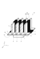
図4は、本実施形態による冷却装置10の構成を説明する流れ方向の断面図である。また、図5は、図4におけるB1-B1’線矢視断面図である。さらに、図6は、図4におけるB2-B2’線矢視断面図である。そして、図7は、冷却装置10の斜視図である。 FIG. 4 is a flow direction cross-sectional view for explaining the configuration of the cooling device 10 according to the present embodiment. 5 is a cross-sectional view taken along line B1-B1' in FIG. Furthermore, FIG. 6 is a cross-sectional view taken along line B2-B2' in FIG. 7 is a perspective view of the cooling device 10. FIG.

本実施形態による冷却装置10では、ヒートシンクが、ヒートシンク本体2と、ヒートシンク本体2の第2表面2bに設けられた放熱フィン6と、により構成されている。 In the cooling device 10 according to this embodiment, the heat sink is composed of the heat sink main body 2 and the heat radiation fins 6 provided on the second surface 2 b of the heat sink main body 2 .

放熱フィン6は、発熱体1からヒートシンク本体2を介して伝達された熱を、その表面6aから空気層7へ放出する部材である。すなわち、放熱フィン6は、ヒートシンクと空気層7との間の伝熱領域(表面積)をより大きくすることを目的として構成される構造である。 The radiating fins 6 are members that radiate heat transferred from the heating element 1 through the heat sink main body 2 to the air layer 7 from the surface 6a thereof. That is, the heat radiation fins 6 have a structure intended to increase the heat transfer area (surface area) between the heat sink and the air layer 7 .

放熱フィン6は、ヒートシンク本体2の第2表面2bから図4上で下方(Z軸正方向)に向かって伸長する断面視略矩形状に形成される。そして、本実施形態の放熱フィン6は、Y軸方向に沿って略一定のピッチで複数(図4では4つ)設けられており、全体として櫛歯形状に構成される。以下では、放熱フィン6の表面6aの内、Z軸方向に沿った面(相対的に面積が大きい面)を「幅広面6a1」と称する。また、Y軸方向に沿った面(相対的に面積が小さい面)を「幅狭面6a2」と称する。 The radiation fins 6 are formed in a substantially rectangular cross-sectional shape extending downward (positive direction of the Z-axis) in FIG. 4 from the second surface 2b of the heat sink body 2 . A plurality (four in FIG. 4) of the heat dissipating fins 6 of the present embodiment are provided at a substantially constant pitch along the Y-axis direction, and are configured in a comb shape as a whole. Below, among the surfaces 6a of the radiation fins 6, a surface along the Z-axis direction (a surface having a relatively large area) is referred to as a "wide surface 6a1". A surface along the Y-axis direction (a surface having a relatively small area) is referred to as a "narrow surface 6a2".

また、放熱フィン6は、ヒートシンク本体2と同一材料又は異なる材料により構成される。すなわち、放熱フィン6は、例えば、銅若しくはアルミニウムなどの比較的熱伝導率の高い金属製材料又はFR4若しくはセラミクス等の比較的熱伝導率が高い非金属製材料で構成される。 Moreover, the radiation fins 6 are made of the same material as or different from that of the heat sink main body 2 . That is, the radiation fins 6 are made of, for example, a metallic material with relatively high thermal conductivity such as copper or aluminum, or a non-metallic material with relatively high thermal conductivity such as FR4 or ceramics.

なお、ヒートシンク本体2が金属等の導電性材料で形成されている場合には、放熱フィン6を熱伝導率が比較的高い非導電性材料で形成することで、ヒートシンク本体2と放熱フィン6の間の熱伝導性能を確保しつつ、絶縁機能を与えることができる。一方、ヒートシンク本体2が絶縁材料で構成されるなどの発熱体1との間の絶縁機能が確保されている場合には、放熱フィン6をアルミニウムなどの比較的熱伝導率が高く且つ低コストの材料で形成することが好ましい。 When the heat sink main body 2 is formed of a conductive material such as metal, the heat sink main body 2 and the heat dissipating fins 6 can be separated by forming the heat dissipating fins 6 of a non-conductive material having a relatively high thermal conductivity. It is possible to provide an insulating function while ensuring the heat conduction performance between the layers. On the other hand, if the heat sink main body 2 is made of an insulating material or otherwise has an insulating function from the heat generating element 1, the heat radiating fins 6 may be made of a material such as aluminum having relatively high thermal conductivity and low cost. It is preferably made of material.

さらに、本実施形態の誘起流発生装置3は、ヒートシンク本体2の第2表面2b及び放熱フィン6の表面6aのY軸方向における伸長領域の全域に亘って形成されている。すなわち、本実施形態では、「ヒートシンクの第2面」は、ヒートシンク本体2の第2表面2b及び放熱フィン6の表面6aにより構成される。 Further, the induced flow generator 3 of the present embodiment is formed over the entire extension region in the Y-axis direction of the second surface 2b of the heat sink body 2 and the surface 6a of the radiation fin 6. As shown in FIG. That is, in the present embodiment, the “second surface of the heat sink” is composed of the second surface 2 b of the heat sink body 2 and the surface 6 a of the radiation fins 6 .

以上説明した構成を有する本実施形態によれば、以下の作用効果を奏する。 According to this embodiment having the configuration described above, the following effects are obtained.

本実施形態による冷却装置10では、ヒートシンクは、ヒートシンク本体2と、該ヒートシンク本体2に構成される第1面である第1表面2aに対向する第2面としての第2表面2bに設けられた放熱フィン6をさらに含む。 In the cooling device 10 according to the present embodiment, the heat sink is provided on the heat sink main body 2 and the second surface 2 b as the second surface facing the first surface 2 a which is the first surface configured in the heat sink main body 2. It further includes heat radiating fins 6 .

これにより、簡易な構成でヒートシンクと空気層7との間の伝熱面積を増加させて、冷却性能をより向上させることができる。 As a result, the heat transfer area between the heat sink and the air layer 7 can be increased with a simple configuration, and the cooling performance can be further improved.

特に、本実施形態では、誘起流発生装置3が、放熱フィン6の表面6aの少なくとも一部に亘るように設けられる。したがって、放熱フィン6が設けられていない場合と比べて、誘起流発生装置3が設けられている領域(誘起流Ifの発生源として機能させることのできる領域)を実質的に増加させることができる。このため、第2表面2b及び放熱フィン6の表面6aと空気層7との間の熱伝達をより効率的にすることができる。結果として、発熱体1に対する冷却効率をさらに向上させることができる。 In particular, in this embodiment, the induced current generator 3 is provided so as to cover at least a portion of the surface 6a of the radiation fin 6. As shown in FIG. Therefore, compared to the case where the radiation fins 6 are not provided, it is possible to substantially increase the area where the induced flow generator 3 is provided (the area that can function as the generation source of the induced flow If). . Therefore, the heat transfer between the air layer 7 and the second surface 2b and the surface 6a of the heat radiating fins 6 can be made more efficient. As a result, the cooling efficiency for the heating element 1 can be further improved.

さらに、本実施形態では、放熱フィン6は、櫛歯状に複数設けられる。 Furthermore, in the present embodiment, a plurality of heat radiation fins 6 are provided in a comb shape.

これにより、例えば幅広面6a1など、上に誘起流発生装置3を設けるための比較的広い領域を確保することができる。さらに、この構成であれば、誘起流Ifの流路を櫛歯状に並ぶ放熱フィン6の間に画定することができるので、各放熱フィン6の配置間隔及びサイズ(Y軸方向の幅及びX軸方向の長さ等)を適宜調節することで、ヒートシンク本体2の第2表面2b上に所望の経路の誘起流Ifの流路を構成することができる。 As a result, a relatively wide area, such as the wide surface 6a1, for providing the induced flow generator 3 thereon can be secured. Furthermore, with this configuration, the flow path of the induced flow If can be defined between the radiating fins 6 arranged in a comb-teeth shape. By appropriately adjusting the length in the axial direction, etc., it is possible to form a channel for the induced flow If of a desired path on the second surface 2 b of the heat sink body 2 .

また、本実施形態では、図7に示すように、ヒートシンク本体2がY軸方向に所定ピッチで形成される櫛歯状の放熱フィン6を有し、誘起流発生装置3が放熱フィン6の表面6aにおいてY軸方向に沿って伸長するように配置されている。 In this embodiment, as shown in FIG. 7, the heat sink main body 2 has comb-tooth-shaped heat radiation fins 6 formed at a predetermined pitch in the Y-axis direction, and the induced current generator 3 is formed on the surface of the heat radiation fins 6. 6a are arranged to extend along the Y-axis direction.

これにより、より広いY軸方向の幅領域で誘起流Ifを発生させることができる。このため、ヒートシンク本体2及び放熱フィン6と空気層7との間の熱伝達をより促進することができ、冷却効率をより向上させることができる。 Thereby, the induced flow If can be generated in a wider width region in the Y-axis direction. Therefore, the heat transfer between the heat sink main body 2 and the heat radiation fins 6 and the air layer 7 can be further promoted, and the cooling efficiency can be further improved.

以下では、第2実施形態の各変形例2-1~2-6について説明する。 Modifications 2-1 to 2-6 of the second embodiment will be described below.

(変形例2-1)
図8は、変形例2-1による冷却装置10の斜視図である。図示のように、本変形例2-1による冷却装置10では、発熱体1とヒートシンク本体2の間にヒートスプレッダ8が設けられている点で、図7に示した冷却装置10の構成と異なる。
(Modification 2-1)
FIG. 8 is a perspective view of a cooling device 10 according to modification 2-1. As shown, the cooling device 10 according to Modification 2-1 differs from the cooling device 10 shown in FIG. 7 in that a heat spreader 8 is provided between the heating element 1 and the heat sink main body 2 .

ヒートスプレッダ8は、ヒートシンク本体2又は放熱フィン6と同一の材料又は異なる材料で形成することができる。好ましくは、ヒートスプレッダ8は、銅、アルミニウム、及び炭素構造体(カーボンブラック又はダイヤモンド等)の熱伝導率が比較的高い材料で形成される。特に、好ましくは、銅などの比較的低コストの材料で構成される。 The heat spreader 8 can be made of the same material as or different from that of the heat sink body 2 or the radiation fins 6 . Preferably, the heat spreader 8 is formed of relatively high thermal conductivity materials such as copper, aluminum and carbon structures (such as carbon black or diamond). In particular, it is preferably constructed of relatively low-cost materials such as copper.

以上のように、本変形例の冷却装置10は、ヒートシンク本体2と発熱体1との間に設けられたヒートスプレッダ8をさらに備える。 As described above, the cooling device 10 of this modified example further includes the heat spreader 8 provided between the heat sink main body 2 and the heating element 1 .

これにより、ヒートスプレッダ8によって発熱体1からの熱をより広範囲に拡散させつつヒートシンク本体2及び放熱フィン6に伝達させることができる。したがって、発熱体1からの熱を、複数の放熱フィン6の内の特定の放熱フィン6に偏らせることなく、より均等に伝達させることができる。結果として、複数の放熱フィン6の表面6aと空気層7との間の実質的な伝熱領域を増大させて、熱伝達性能をより向上させることができる。 As a result, the heat from the heating element 1 can be diffused over a wider range by the heat spreader 8 and transmitted to the heat sink main body 2 and the radiation fins 6 . Therefore, the heat from the heating element 1 can be transmitted more evenly without biasing the heat to a specific heat radiating fin 6 among the plurality of radiating fins 6 . As a result, the substantial heat transfer area between the surfaces 6a of the plurality of heat radiating fins 6 and the air layer 7 can be increased, and the heat transfer performance can be further improved.

なお、本変形例2-1では、ヒートシンク本体2に放熱フィン6を設けてなるヒートシンクにおいて、ヒートスプレッダ8を設ける例を説明した。しかしながら、これに限られず、図1等に示した放熱フィン6を備えていない態様のヒートシンク本体2にかかる冷却装置10において、発熱体1とヒートシンク本体2の間にヒートスプレッダ8を設ける構成としても良い。 In this modified example 2-1, an example in which the heat spreader 8 is provided in the heat sink in which the heat sink main body 2 is provided with the radiation fins 6 has been described. However, the present invention is not limited to this, and the heat spreader 8 may be provided between the heating element 1 and the heat sink main body 2 in the cooling device 10 related to the heat sink main body 2 without the heat radiation fins 6 shown in FIG. .

(変形例2-2)
図9は、変形例2-2による冷却装置10の斜視図である。図示のように、本変形例による冷却装置10では、誘起流発生装置3が放熱フィン6の片側の幅広面6a1に設けられている点で、図7に示した冷却装置10の構成と異なる。
(Modification 2-2)
FIG. 9 is a perspective view of a cooling device 10 according to modification 2-2. As shown, the cooling device 10 according to this modified example differs from the cooling device 10 shown in FIG.

より詳細には、本変形例の冷却装置10では、誘起流発生装置3が片側の幅広面6a1の先端部(図9上では放熱フィン6の上部領域)に所定長さに亘って伸長している。特に、図9では放熱フィン6の先端から、片側の幅広面6a1のZ軸方向における全長さの略1/3程度の長さの位置まで延在している。また、誘起流発生装置3は、X軸方向において、放熱フィン6の片側の幅広面6a1の長さ領域の略全域に亘るように設けられている。 More specifically, in the cooling device 10 of this modified example, the induced flow generator 3 extends over a predetermined length to the tip of the wide surface 6a1 on one side (upper region of the radiation fins 6 in FIG. 9). there is In particular, in FIG. 9, it extends from the tip of the radiating fin 6 to a position of about 1/3 of the total length in the Z-axis direction of the wide surface 6a1 on one side. In addition, the induced flow generator 3 is provided so as to cover substantially the entire length region of the wide surface 6a1 on one side of the radiation fin 6 in the X-axis direction.

さらに、誘起流発生装置3は、誘起流Ifがヒートシンク本体2の第2表面2bに向かって流れるように、誘起流発生部3aがZ軸負方向(図上下方)に向くように配置されている。これにより、本実施形態では、誘起流発生部3aからの誘起流Ifは、放熱フィン6の片側の幅広面6a1に沿って流れつつ、ヒートシンク本体2の第2表面2bに衝突して隣接する放熱フィン6の方向(Y軸の正方向)に向かう。そして、誘起流Ifは、隣接する放熱フィン6の幅広面6a1に衝突してZ軸方向の上方に向かうように誘導される。これにより、誘起流Ifは、隣接する放熱フィン6の間で渦を描くように流れることとなる。 Further, the induced flow generator 3 is arranged such that the induced flow generator 3a faces in the negative Z-axis direction (vertical direction in the drawing) so that the induced flow If flows toward the second surface 2b of the heat sink body 2. there is As a result, in the present embodiment, the induced flow If from the induced flow generating portion 3a flows along the wide surface 6a1 on one side of the heat radiating fin 6, collides with the second surface 2b of the heat sink main body 2, and radiates adjacent to the second surface 2b. It goes in the direction of the fin 6 (the positive direction of the Y-axis). Then, the induced flow If collides with the wide surface 6a1 of the adjacent radiation fin 6 and is guided upward in the Z-axis direction. As a result, the induced flow If flows like a whirlpool between the adjacent radiation fins 6 .

本変形例によれば、誘起流発生装置3は、その誘起流発生部3aがヒートシンク本体2の第2表面2bに向けられつつ、放熱フィン6の片側の幅広面6a1に沿ってX軸方向に伸長して配置されている。このため、誘起流発生装置3が発生させた誘起流Ifをヒートシンク本体2の第2表面2bに衝突させるその経路を好適に調節することができる。したがって、誘起流Ifによってヒートシンク本体2の第2表面2b及び放熱フィン6の表面6aの放熱効果をより高めることができる。 According to this modification, the induced flow generating device 3 is configured such that the induced flow generating portion 3a is directed toward the second surface 2b of the heat sink main body 2, and the induced flow generating device 3 extends along the wide surface 6a1 on one side of the heat radiating fin 6 in the X-axis direction. It is stretched and arranged. Therefore, the path along which the induced flow If generated by the induced flow generator 3 collides with the second surface 2b of the heat sink body 2 can be adjusted appropriately. Therefore, the heat dissipation effect of the second surface 2b of the heat sink body 2 and the surface 6a of the heat dissipation fins 6 can be further enhanced by the induced flow If.

特に、本変形例においては、誘起流発生装置3が、放熱フィン6の幅広面6a1のX軸方向における長さ領域の略全域に亘っていることにより、上記誘起流Ifが放熱フィン6の表面6a及びヒートシンク本体2の第2表面2bとの間で接触する領域をより大きくすることができる。結果として、放熱効果をより好適に発揮させることができる。 In particular, in this modification, the induced flow generator 3 extends over substantially the entire length region of the wide surface 6a1 of the radiation fin 6 in the X-axis direction, so that the induced flow If is generated on the surface of the radiation fin 6. The area of contact between 6a and the second surface 2b of the heatsink body 2 can be larger. As a result, the heat dissipation effect can be exhibited more favorably.

さらに、本変形例では、放熱フィン6の片側の幅広面6a1にのみ誘起流発生装置3が配置されている。このため、誘起流Ifは、当該片側の幅広面6a1、ヒートシンク本体2の第2表面2b、及び隣接する放熱フィン6の幅広面6a1を沿う渦状の経路で流れることとなる。したがって、誘起流Ifによる放熱フィン6の幅広面6a1及びヒートシンク本体2の第2表面2bからの放熱効果をさらに高めることができる。 Furthermore, in this modification, the induced flow generator 3 is arranged only on one wide surface 6 a 1 of the radiation fin 6 . Therefore, the induced flow If flows in a spiral path along the wide surface 6 a 1 on one side, the second surface 2 b of the heat sink body 2 , and the adjacent wide surface 6 a 1 of the radiation fin 6 . Therefore, the heat dissipation effect from the wide surface 6a1 of the heat dissipation fin 6 and the second surface 2b of the heat sink body 2 by the induced flow If can be further enhanced.

(変形例2-3)
図10は、変形例2-3による冷却装置10の斜視図である。図示のように、本変形例による冷却装置10では、図9で説明した誘起流発生装置3と同様の構成を有する誘起流発生装置3が、放熱フィン6の両側の幅広面6a1に設けられている。
(Modification 2-3)
FIG. 10 is a perspective view of a cooling device 10 according to modification 2-3. As shown in the figure, in the cooling device 10 according to this modified example, induced flow generators 3 having the same configuration as the induced flow generator 3 described with reference to FIG. there is

本変形例の冷却装置10では、隣接する放熱フィン6における対向する2つの幅広面6a1の間で、誘起流Ifが、それぞれ、ヒートシンク本体2の第2表面2bに向かってZ軸方向の下方に流れる。そして、それぞれの誘起流Ifが、ヒートシンク本体2の第2表面2bに衝突して反射しつつ合流して、当該第2表面2bから離れる方向に流れることとなる。 In the cooling device 10 of this modified example, the induced flow If flows downward in the Z-axis direction toward the second surface 2b of the heat sink main body 2 between the two opposing wide surfaces 6a1 of the adjacent heat radiating fins 6. flow. Then, each induced flow If collides with the second surface 2b of the heat sink body 2, reflects, joins, and flows away from the second surface 2b.

これにより、放熱フィン6の両側の幅広面6a1及びヒートシンク本体2の第2表面2bに沿った渦状の経路で流れることとなる。したがって、誘起流Ifによる放熱フィン6の表面6a及びヒートシンク本体2の第2表面2bからの放熱促進効果をさらに高めることができる。 As a result, the heat flows in a spiral path along the wide surfaces 6 a 1 on both sides of the radiation fins 6 and the second surface 2 b of the heat sink body 2 . Therefore, the effect of promoting heat dissipation from the surface 6a of the heat radiating fin 6 and the second surface 2b of the heat sink body 2 by the induced flow If can be further enhanced.

なお、上記変形例2-1~2-3においては、誘起流Ifがヒートシンク本体2の第2表面2bに沿って流れるか、又は第2表面2bで反射して離れる方向に流れるように誘起流発生装置3を配置する例を説明した。しかしながら、これらの例に代えて、ヒートシンク本体2の第2表面2bに対して誘起流Ifが所定角度をなして斜めに衝突するように、誘起流発生装置3の配置位置(誘起流発生部3aを向ける位置)を調節しても良い。 In Modifications 2-1 to 2-3, the induced flow If flows along the second surface 2b of the heat sink body 2, or is reflected by the second surface 2b and flows in a direction away from the induced flow. An example of arranging the generator 3 has been described. However, instead of these examples, the arrangement position of the induced flow generator 3 (induced flow generation section 3a position) may be adjusted.

すなわち、誘起流発生装置3の配置位置は、発熱体1からヒートシンク本体2又は放熱フィン6に伝達する熱の分布などに応じた誘起流Ifの所望の流れ方向を実現する観点から、適宜、調節することが可能である。 That is, the arrangement position of the induced flow generator 3 is appropriately adjusted from the viewpoint of realizing a desired flow direction of the induced flow If according to the distribution of heat transferred from the heating element 1 to the heat sink main body 2 or the radiation fins 6. It is possible to

(変形例2-4)
図11は、変形例2-4による冷却装置10の斜視図である。図示のように、本変形例による冷却装置10では、図7等で説明した櫛歯状の放熱フィン6に代えて、略円柱形状の突起状の放熱フィン6が、ヒートシンク本体2の第2表面2bに設けられる。
(Modification 2-4)
FIG. 11 is a perspective view of the cooling device 10 according to modification 2-4. As shown in the figure, in the cooling device 10 according to this modified example, instead of the comb-shaped heat radiation fins 6 described in FIG. 2b.

特に、本変形例の放熱フィン6は、ヒートシンク本体2の第2表面2b上において、X軸方向に沿って等間隔に2列配置され、Y軸方向に沿って等間隔に3列配置される。すなわち、複数の放熱フィン6は、ヒートシンク本体2の第2表面2bに6つ配置されている。 In particular, on the second surface 2b of the heat sink body 2, the radiation fins 6 of this modification are arranged in two rows at equal intervals along the X-axis direction, and arranged in three rows at equal intervals along the Y-axis direction. . That is, six of the plurality of radiation fins 6 are arranged on the second surface 2 b of the heat sink body 2 .

さらに、誘起流発生装置3は、X軸方向に2列の放熱フィン6の間においてヒートシンク本体2の第2表面2bに設けられている。特に、誘起流発生装置3は、その誘起流発生部3aをX軸正方向に向けた状態で、第2表面2bのY軸方向における全領域に亘るように設けられている。 Furthermore, the induced flow generator 3 is provided on the second surface 2b of the heat sink main body 2 between the two rows of radiation fins 6 in the X-axis direction. In particular, the induced flow generator 3 is provided so as to extend over the entire area of the second surface 2b in the Y-axis direction, with the induced flow generation section 3a directed in the positive direction of the X-axis.

以上説明した本変形例による冷却装置10によれば、放熱フィン6が突起状(ピン形状)に形成されている。これにより、ヒートシンク本体2の第2表面2b上において流れる誘起流Ifが、放熱フィン6の表面6aに衝突しつつ変えられることとなる。 According to the cooling device 10 according to this modified example described above, the radiation fins 6 are formed in a projecting shape (pin shape). As a result, the induced flow If flowing on the second surface 2b of the heat sink body 2 is changed while colliding with the surface 6a of the heat radiating fin 6. As shown in FIG.

したがって、放熱フィン6をヒートシンク本体2の第2表面2b上の適切な位置に配置することで、誘起流Ifの流れ方向を適宜調節することができる。結果として、ヒートシンク本体2又は放熱フィン6と周囲の空気層7との間の熱伝達をより促進することができる。 Therefore, by arranging the radiation fins 6 at appropriate positions on the second surface 2b of the heat sink body 2, the flow direction of the induced flow If can be appropriately adjusted. As a result, heat transfer between the heat sink main body 2 or the heat radiation fins 6 and the surrounding air layer 7 can be promoted more.

特に、突起状の放熱フィン6であれば、誘起流発生装置3を各放熱フィン6の間を縫うように配置するなど、当該誘起流発生装置3を多様な配置態様で配置することができる。このため、ヒートシンク本体2の第2表面2b上において誘起流Ifの方向の調節を、より高い自由度で行うことができる。 In particular, if the radiating fins 6 are projecting, the induced flow generating device 3 can be arranged in various ways, such as arranging the induced flow generating device 3 so as to weave between the radiating fins 6 . Therefore, the direction of the induced flow If can be adjusted on the second surface 2b of the heat sink body 2 with a higher degree of freedom.

さらに、本変形例の構成によれば、誘起流発生装置3が発生させる誘起流Ifは、先ず、発熱体1に近いヒートシンク本体2の第2表面2bを流れ、当該第2表面2bを流れた後に放熱フィン6の表面6aに沿って流れることとなる。すなわち、誘起流Ifを、より熱量が高いヒートシンク本体2の第2表面2bに先に接触させることができるため、誘起流Ifによる放熱作用をより効率的に発揮させることができる。 Furthermore, according to the configuration of this modification, the induced flow If generated by the induced flow generator 3 first flows through the second surface 2b of the heat sink body 2 near the heating element 1, and then flows through the second surface 2b. It will flow along the surface 6a of the heat radiation fin 6 later. That is, since the induced flow If can be brought into contact with the second surface 2b of the heat sink main body 2 having a higher heat quantity first, the heat dissipation effect of the induced flow If can be exhibited more efficiently.

また、本実施形態では、誘起流発生装置3は、X軸方向に2列の放熱フィン6の間においてヒートシンク本体2の第2表面2bに設けられ、X軸方向に沿った誘起流Ifを発生させる構成をとっている。このため、放熱フィン6に衝突して方向を変えられる誘起流Ifと、Y軸方向において隣接する放熱フィン6の間を通過する誘起流Ifと、が合流することで誘起流Ifの3次元的な流れが生成される。このため、当該誘起流Ifの作用でヒートシンク本体2又は放熱フィン6の放熱性能をより向上させることができる。 In this embodiment, the induced flow generator 3 is provided on the second surface 2b of the heat sink main body 2 between the two rows of radiation fins 6 in the X-axis direction, and generates an induced flow If along the X-axis direction. It is configured to let For this reason, the induced flow If that collides with the radiation fins 6 and changes its direction and the induced flow If that passes through the adjacent radiation fins 6 in the Y-axis direction merge. flow is generated. Therefore, the heat dissipation performance of the heat sink main body 2 or the heat dissipation fins 6 can be further improved by the action of the induced flow If.

(変形例2-5)
図12は、変形例2-5による冷却装置10の斜視図である。図示のように、本変形例による冷却装置10では、誘起流発生装置3が、第2表面2b上に設置された複数の放熱フィン6の間を縫うように、X軸方向又はY軸方向に対して所定角度をなして斜め方向に伸長するように設けられている。
(Modification 2-5)
FIG. 12 is a perspective view of the cooling device 10 according to modification 2-5. As illustrated, in the cooling device 10 according to the present modification, the induced flow generator 3 is arranged in the X-axis direction or the Y-axis direction so as to weave between the plurality of heat radiation fins 6 installed on the second surface 2b. It is provided so as to form a predetermined angle and extend obliquely.

本変形例の構成によっても、ヒートシンク本体2又は放熱フィン6の放熱性能を向上させ得る誘起流Ifの3次元的な流れを形成することができる。 With the configuration of this modified example as well, it is possible to form a three-dimensional flow of the induced flow If that can improve the heat dissipation performance of the heat sink main body 2 or the heat dissipation fins 6 .

(変形例2-6)
図13は、変形例2-6による冷却装置10の斜視図である。図示のように、本変形例による冷却装置10では、放熱フィン6が略四角柱形状に形成されている点が図11で説明した構成と異なる。
(Modification 2-6)
FIG. 13 is a perspective view of the cooling device 10 according to modification 2-6. As shown in the figure, the cooling device 10 according to this modified example differs from the configuration described with reference to FIG. 11 in that the radiation fins 6 are formed in a substantially quadrangular prism shape.

特に、本変形例の誘起流発生装置3は、Y軸又はZ軸と直交する放熱フィン6の表面6aを覆いつつ、ヒートシンク本体2の第2表面2bにおけるY軸方向の略全域に亘って伸長するように設けられている。 In particular, the induced flow generator 3 of this modified example extends over substantially the entire Y-axis direction of the second surface 2b of the heat sink body 2 while covering the surface 6a of the radiation fins 6 perpendicular to the Y-axis or Z-axis. It is designed to

本変形例の構成によれば、放熱フィン6の周囲における誘起流Ifが、図12で説明した略円柱形状に形成された放熱フィン6の場合と異なる態様の3次元的な流れが形成されることとなる。 According to the configuration of this modified example, the induced flow If around the heat dissipating fins 6 forms a three-dimensional flow that is different from the case of the heat dissipating fins 6 formed in a substantially cylindrical shape described with reference to FIG. 12 . It will happen.

本変形例の構成によっても、ヒートシンク本体2又は放熱フィン6の放熱性能を向上させ得る誘起流Ifの3次元的な流れを形成することができる。 With the configuration of this modified example as well, it is possible to form a three-dimensional flow of the induced flow If that can improve the heat dissipation performance of the heat sink main body 2 or the heat dissipation fins 6 .

なお、放熱フィン6の数、設置位置、及び形状、並びに誘起流発生装置3の構成については、変形例2-5及び変形例2-6において説明した例に限られるものではない。すなわち、これらの構成は、ヒートシンク本体2又は放熱フィン6における熱分布などに応じて好適な誘起流Ifの流速、流量、又は流れ方向を実現する観点から適宜変更することが可能である。 Note that the number, installation position, and shape of the radiation fins 6 and the configuration of the induced flow generator 3 are not limited to the examples described in Modifications 2-5 and 2-6. That is, these configurations can be changed as appropriate from the viewpoint of achieving a suitable flow velocity, flow rate, or flow direction of the induced flow If according to the heat distribution in the heat sink main body 2 or the radiation fins 6 .

例えば、誘起流発生装置3をヒートシンク本体2の第1表面2a上における発熱体1の領域に対向する第2表面2b上の領域(発熱体対向位置P1)を囲うように配置して、3次元的に誘起流Ifを発生させるようにしても良い。また、誘起流Ifによる冷却作用を高める観点から、誘起流発生装置3を複数設けても良い。 For example, the induced flow generator 3 is arranged on the first surface 2a of the heat sink main body 2 so as to surround the area on the second surface 2b facing the area of the heat generating element 1 (heat generating element facing position P1). Alternatively, the induced flow If may be generated in a specific manner. Moreover, from the viewpoint of enhancing the cooling effect of the induced flow If, a plurality of induced flow generators 3 may be provided.

また、放熱フィン6は、上述した略円柱形状及び略四角柱形状以外の任意の形状(多角柱形状、円錐形状、又は多角錐形状など)に形成されても良い。 Moreover, the radiation fins 6 may be formed in any shape (polygonal prism shape, conical shape, polygonal pyramid shape, etc.) other than the above-described substantially cylindrical shape and substantially quadrangular prism shape.

上述した第2実施形態及び各変形例2-1~2-6の構成によれば、誘起流Ifによってヒートシンク本体2の第2表面2b又は放熱フィン6の表面6aに流れを作ることで、誘起流Ifの圧力損失を大きく増加させることなく熱伝達性能をより向上させることができる。結果として、誘起流Ifの作用によって、第2表面2b及び表面6aと空気層7との間に生成する境界層の発達を抑制することができる。すなわち、ヒートシンク本体2の大きさ及び形状を変更せずとも、誘起流Ifの作用によって冷却性能の向上を図ることができる。 According to the configurations of the above-described second embodiment and modifications 2-1 to 2-6, the induced flow If is generated on the second surface 2b of the heat sink main body 2 or the surface 6a of the heat radiating fin 6, thereby induced The heat transfer performance can be further improved without greatly increasing the pressure loss of the flow If. As a result, the action of the induced flow If can suppress the development of a boundary layer generated between the air layer 7 and the second surfaces 2b and 6a. That is, without changing the size and shape of the heat sink main body 2, the cooling performance can be improved by the action of the induced flow If.

(第3実施形態)
以下、第3実施形態について説明する。なお、第1実施形態又は第2実施形態と同様の要素には同一の符号を付し、その説明を省略する。
(Third embodiment)
A third embodiment will be described below. Elements similar to those of the first embodiment or the second embodiment are assigned the same reference numerals, and descriptions thereof are omitted.

図14は、比較例による冷却装置100の構成を説明する図である。図示のように、冷却装置100は、図2で説明した冷却装置10と同様のヒートシンク本体2と、ファン4と、を備えているものの、誘起流発生装置3を備えていない。 FIG. 14 is a diagram illustrating the configuration of a cooling device 100 according to a comparative example. As illustrated, the cooling device 100 includes a heat sink body 2 and a fan 4 similar to the cooling device 10 described with reference to FIG.

冷却装置100においても、ヒートシンク本体2の第1表面2a上における発熱体1からの熱がヒートシンク本体2に伝達して第2表面2bから空気層7へ放出される。ファン4は、発熱体1として想定される部品又は機器の形態及び設置スペースに応じて要求される流量及び流速などの要素を考慮してDC/AC軸ファン又はブロアファンなどで適宜構成される。なお、ヒートシンク本体2に放熱フィン6が設けられる場合には、当該放熱フィン6の形態に応じたタイプのファン4を構成することが好ましい。 In the cooling device 100 as well, the heat from the heating element 1 on the first surface 2a of the heat sink body 2 is transferred to the heat sink body 2 and released to the air layer 7 from the second surface 2b. The fan 4 is appropriately composed of a DC/AC axial fan or a blower fan in consideration of factors such as the flow rate and flow velocity required according to the form of the component or equipment assumed as the heating element 1 and the installation space. When the heat sink main body 2 is provided with the heat radiation fins 6 , it is preferable to construct the fan 4 of a type corresponding to the shape of the heat radiation fins 6 .

また、図14の例において、ファン4はヒートシンク本体2の第2表面2bに沿った方向(X軸正方向)に冷却風(以下、「主流Mf」とも称する)が流れるように、ヒートシンク本体2のX軸方向における一端部の近傍に設けられている。 In addition, in the example of FIG. 14, the fan 4 is arranged so that the cooling air (hereinafter also referred to as "main stream Mf") flows in the direction along the second surface 2b of the heat sink body 2 (positive direction of the X axis). is provided near one end in the X-axis direction.

この構成により、ファン4を駆動させることで、主流Mfがヒートシンク本体2の第2表面2bに沿って流れる。この時、ヒートシンク本体2の第2表面2bと主流Mfとの間で生じる摩擦によって、当該主流Mfの流速が低下して第2表面2bと空気層7の間に境界層18が発生する。境界層18は、主流Mfがファン4の位置からX軸正方向に進むに連れて発達して厚みが増加する。この境界層18の発達によって、第2表面2bと空気層7の間の界面における流速が低下し、第2表面2bから空気層7への熱伝達が妨げられる。結果として、発熱体1の冷却効率が低下する。以下に詳細に説明する本実施形態による冷却装置10によれば、このような境界層18の発達を抑制することができる。 With this configuration, the main flow Mf flows along the second surface 2 b of the heat sink body 2 by driving the fan 4 . At this time, friction between the second surface 2 b of the heat sink body 2 and the main flow Mf reduces the flow velocity of the main flow Mf, and a boundary layer 18 is generated between the second surface 2 b and the air layer 7 . The boundary layer 18 develops and increases in thickness as the main flow Mf advances from the position of the fan 4 in the positive direction of the X axis. Due to the development of this boundary layer 18, the flow velocity at the interface between the second surface 2b and the air layer 7 is reduced and the heat transfer from the second surface 2b to the air layer 7 is impeded. As a result, the cooling efficiency of the heating element 1 is lowered. According to the cooling device 10 according to this embodiment, which will be described in detail below, the development of such a boundary layer 18 can be suppressed.

図15は、本実施形態による冷却装置10の構成を説明する断面図である。図15に示す冷却装置10は、図14で説明した冷却装置100の構成に加えて、ヒートシンク本体2の第2表面2bに誘起流発生装置3が設けられている。 FIG. 15 is a cross-sectional view illustrating the configuration of the cooling device 10 according to this embodiment. A cooling device 10 shown in FIG. 15 is provided with an induced flow generator 3 on the second surface 2 b of the heat sink body 2 in addition to the configuration of the cooling device 100 described with reference to FIG. 14 .

特に、誘起流発生装置3は、ヒートシンク本体2の第2表面2bにおける発熱体1の略直下位置に設けられている。 In particular, the induced flow generator 3 is provided on the second surface 2 b of the heat sink body 2 at a position substantially directly below the heating element 1 .

この構成によれば、誘起流発生装置3による誘起流Ifによって、ヒートシンク本体2の第2表面2bにおける発熱体1の直下位置で流れを生じさせることで、第2表面2bと主流Mfとの摩擦を軽減して境界層18を薄くすることができる。 According to this configuration, the induced flow If generated by the induced flow generator 3 generates a flow directly below the heating element 1 on the second surface 2b of the heat sink body 2, thereby causing friction between the second surface 2b and the main flow Mf. can be reduced to make the boundary layer 18 thinner.

さらに、本実施形態による冷却装置10では、誘起流発生装置3の厚みT1(Z軸方向における長さ)が、境界層18の厚みD1(X軸方向における最大の厚み)よりも薄く構成される。この構成により、ヒートシンク本体2の第2表面2bに設けられた誘起流発生装置3自身が、ファン4の主流Mfの流れを妨げることをより好適に抑制することができる。 Furthermore, in the cooling device 10 according to the present embodiment, the thickness T1 (the length in the Z-axis direction) of the induced flow generator 3 is configured to be thinner than the thickness D1 (the maximum thickness in the X-axis direction) of the boundary layer 18. . With this configuration, the induced flow generator 3 itself provided on the second surface 2 b of the heat sink body 2 can more preferably suppress the flow of the main flow Mf of the fan 4 .

以上説明した構成を有する本実施形態によれば、以下の作用効果を奏する。 According to this embodiment having the configuration described above, the following effects are obtained.

本実施形態の冷却装置10は、ヒートシンク本体2に供給する主流Mfを発生させる主流発生装置としてのファン4を備える。 The cooling device 10 of the present embodiment includes a fan 4 as a main stream generating device that generates the main stream Mf to be supplied to the heat sink main body 2 .

これにより、誘起流発生装置3からの誘起流Ifの流量をファン4からの主流によって補うことができるので、発熱体1に対する冷却性能をより高めることができる。 As a result, the flow rate of the induced flow If from the induced flow generator 3 can be supplemented by the main flow from the fan 4, so that the cooling performance for the heating element 1 can be further enhanced.

特に、レイアウト性を考慮して、誘起流発生装置3を比較的薄く形成する場合において、発熱体1の発熱量によっては誘起流Ifの流量が所望の冷却性能の観点から必ずしも十分とは言えないシーンが生じることも想定される。このようなシーンに対しても、本実施形態の冷却装置10の構成であれば、ファン4の主流Mfにより冷却のための流量を好適に補うことができる。 In particular, when the induced flow generator 3 is formed relatively thin in consideration of the layout, the flow rate of the induced flow If is not always sufficient from the viewpoint of the desired cooling performance depending on the amount of heat generated by the heating element 1. It is also envisioned that a scene will occur. Even in such a scene, with the configuration of the cooling device 10 of the present embodiment, the flow rate for cooling can be suitably supplemented by the main stream Mf of the fan 4 .

さらに、誘起流発生装置3からの誘起流Ifを、ヒートシンク本体2の第2表面2bの付近における主流Mfの速度を加速するように作用させることができる。したがって、本実施形態の冷却装置10であれば、誘起流発生装置3及びファン4を併用することによる流量の増加という作用に加えて、冷却性能を低下させる要因となる境界層18の発達を抑制することができ、発熱体1に対する冷却性能をより一層高めることができる。 Furthermore, the induced flow If from the induced flow generator 3 can act to accelerate the velocity of the main flow Mf in the vicinity of the second surface 2b of the heat sink body 2 . Therefore, with the cooling device 10 of the present embodiment, in addition to the action of increasing the flow rate due to the combined use of the induced flow generator 3 and the fan 4, the development of the boundary layer 18, which is a factor that lowers the cooling performance, is suppressed. and the cooling performance for the heating element 1 can be further enhanced.

特に、図15に示す冷却装置10においては、誘起流発生装置3は、発熱体対向位置P1の近傍に設けられている。 In particular, in the cooling device 10 shown in FIG. 15, the induced flow generator 3 is provided near the position P1 facing the heating element.

したがって、誘起流発生装置3からの誘起流Ifによって、発熱体対向位置P1の周りで流れを発生させることができる。また、ファン4は、第2表面2bに沿った方向に主流が流れるように、ヒートシンク本体2のX軸方向における一端部の近傍に設けられている。このため、第2表面2bに沿った方向に流れるファン4の主流Mfの少なくとも一部は、誘起流Ifとともに、発熱体対向位置P1における第2表面2bと空気層7の界面を通過する。これにより、ヒートシンク本体2の第2表面2bから空気層7への熱伝達をより促進することができ、その結果、冷却装置10の冷却性能をさらに向上させることができる。 Therefore, the induced flow If from the induced flow generator 3 can generate a flow around the position P1 facing the heating element. The fan 4 is provided near one end of the heat sink main body 2 in the X-axis direction so that the main stream flows in the direction along the second surface 2b. Therefore, at least part of the main stream Mf of the fan 4 flowing in the direction along the second surface 2b passes through the interface between the second surface 2b and the air layer 7 at the position P1 facing the heating element together with the induced flow If. Thereby, the heat transfer from the second surface 2b of the heat sink body 2 to the air layer 7 can be further promoted, and as a result, the cooling performance of the cooling device 10 can be further improved.

また、本実施形態では、誘起流発生装置3は、主流Mfとヒートシンク本体2の間に発生する境界層18の厚みD1よりも薄く構成される。 Further, in this embodiment, the induced flow generator 3 is configured to be thinner than the thickness D1 of the boundary layer 18 generated between the main flow Mf and the heat sink body 2 .

これにより、ヒートシンク本体2の第2表面2bに設けられた誘起流発生装置3自身によって、ファン4の主流Mfの流れを妨げることがより確実に抑制される。結果として、境界層18の発達を抑制する効果がより向上するので、さらなる冷却性能の向上に寄与することとなる。 As a result, the induced flow generator 3 itself provided on the second surface 2 b of the heat sink body 2 is more reliably prevented from obstructing the flow of the main flow Mf of the fan 4 . As a result, the effect of suppressing the development of the boundary layer 18 is further improved, which contributes to further improvement of the cooling performance.

さらに、本実施形態では、誘起流発生装置3及びファン4は、それぞれが発生させる主流Mf及び誘起流Ifが相互に略平行となる位置に配置される。 Furthermore, in the present embodiment, the induced flow generator 3 and the fan 4 are arranged at positions where the main flow Mf and the induced flow If respectively generated by them are substantially parallel to each other.

これにより、主流Mfが当該主流Mfと同方向に流れる誘起流Ifを加速させるので、境界層18の発達を抑制する効果がより好適に発揮させることができる。 As a result, the main flow Mf accelerates the induced flow If flowing in the same direction as the main flow Mf, so that the effect of suppressing the development of the boundary layer 18 can be exhibited more favorably.

以下では、第3実施形態の各変形例3-1~3-4について説明する。 Modifications 3-1 to 3-4 of the third embodiment will be described below.

(変形例3-1)
図16は、変形例3-1による冷却装置10の構成を説明する断面図である。図示のように、本変形例による冷却装置10は、図15に示したヒートシンク本体2、誘起流発生装置3、及びファン4が筐体5に収容された形態をとる。
(Modification 3-1)
FIG. 16 is a cross-sectional view illustrating the configuration of the cooling device 10 according to Modification 3-1. As shown, the cooling device 10 according to this modified example has a form in which the heat sink main body 2, the induced flow generator 3, and the fan 4 shown in FIG.

筐体5は、金属材料又は樹脂材料により構成される。特に、発熱体1が電子部品であってアルミニウム等の金属材料で筐体5を構成する場合には、当該筐体5の表面にアルマイト処理等の絶縁処理を施すことが好ましい。 The housing 5 is made of a metal material or a resin material. In particular, when the heating element 1 is an electronic component and the housing 5 is made of a metal material such as aluminum, the surface of the housing 5 is preferably subjected to insulation treatment such as alumite treatment.

以上のように、本変形例の冷却装置10では、ヒートシンク本体2は、通気口としての入口5a及び出口5bを備える筐体5に収容される。したがって、ファン4を作動させると、図中左側の筐体5の入口5aから主流Mfが取り込まれる。そして、取り込まれた主流Mfは、筐体5内においてヒートシンク本体2の冷却に用いられて、筐体5の出口5bから排出される。 As described above, in the cooling device 10 of this modified example, the heat sink main body 2 is housed in the housing 5 having the inlet 5a and the outlet 5b as vents. Therefore, when the fan 4 is operated, the main stream Mf is taken in from the inlet 5a of the housing 5 on the left side in the figure. The main flow Mf taken in is used for cooling the heat sink main body 2 in the housing 5 and is discharged from the outlet 5 b of the housing 5 .

したがって、ファン4からの主流Mf及び誘起流Ifを筐体5内に維持して拡散させること無く、ヒートシンク本体2の第2表面2bに沿って流すことができる。このため、ヒートシンクと空気層7との間の熱伝達をより効率的に実行することができ、冷却性能がより向上する。また、筐体5により外部からの暴露や感電等をより確実に防止することができる。 Therefore, the main flow Mf and the induced flow If from the fan 4 can flow along the second surface 2b of the heat sink body 2 without being maintained inside the housing 5 and diffused. Therefore, heat transfer between the heat sink and the air layer 7 can be performed more efficiently, and the cooling performance is further improved. In addition, the housing 5 can more reliably prevent external exposure, electric shock, and the like.

なお、本変形例の冷却装置10において、図7~図13で説明した形態の放熱フィン6をヒートシンク本体2に設けても良い。この構成により、主流Mf及び誘起流Ifがヒートシンク本体2の第2表面2b及び放熱フィン6の表面6aを沿うように流れるので、当該第2表面2b及び表面6aの空気層7への熱伝達を促進することができる。 In addition, in the cooling device 10 of this modified example, the heat sink main body 2 may be provided with the heat radiation fins 6 having the configuration described with reference to FIGS. 7 to 13 . With this configuration, the main flow Mf and the induced flow If flow along the second surface 2b of the heat sink body 2 and the surfaces 6a of the heat radiation fins 6, so that heat transfer to the air layer 7 on the second surfaces 2b and the surfaces 6a is suppressed. can be promoted.

(変形例3-2)
図17は、変形例3-2による冷却装置10の構成を説明する断面図である。図示のように、本変形例による冷却装置10では、ヒートシンク本体2に発熱体1及び誘起流発生装置3が複数(図17では2つずつ)設けられている。
(Modification 3-2)
FIG. 17 is a cross-sectional view illustrating the configuration of the cooling device 10 according to modification 3-2. As illustrated, in the cooling device 10 according to this modified example, a heat sink main body 2 is provided with a plurality of heat generators 1 and induced flow generators 3 (two each in FIG. 17).

本変形例によれば、冷却対象である発熱体1が複数設けられている場合であっても、それらに応じてそれぞれ誘起流発生装置3を設けることで、誘起流Ifによるヒートシンク本体2の第2表面2bと空気層7との熱伝達の促進効果及び上記境界層18の発達を抑制する効果を好適に発揮させることができる。 According to this modification, even if a plurality of heat generating elements 1 to be cooled are provided, the heat sink main body 2 is cooled by the induced flow If by providing the induced flow generator 3 for each of them. The effect of promoting heat transfer between the second surface 2b and the air layer 7 and the effect of suppressing the development of the boundary layer 18 can be exhibited favorably.

(変形例3-3)
図18は、変形例3-3による冷却装置10の構成を説明する斜視図である。図示のように、本変形例による冷却装置10では、図7で説明した櫛歯状の放熱フィン6を備える冷却装置10に、図14等で説明したファン4を設けた態様で構成される。
(Modification 3-3)
FIG. 18 is a perspective view illustrating the configuration of the cooling device 10 according to modification 3-3. As shown in the figure, the cooling device 10 according to this modified example is configured in such a manner that the fan 4 described in FIG.

本変形例の構成によると、上述のように誘起流Ifによって第2表面2bと空気層7の間に境界層18が薄くなることで、ファン4の主流Mfが隣接する放熱フィン6の間に吸い込まれるように流れ込む。このため、主流Mfが誘起流Ifと共に、ヒートシンク本体2の第2表面2bと放熱フィン6の表面6aに沿って流れることとなる。 According to the configuration of this modified example, the boundary layer 18 between the second surface 2b and the air layer 7 is thinned by the induced flow If as described above, so that the main stream Mf of the fan 4 flows between the adjacent radiating fins 6. It flows like being sucked in. Therefore, the main flow Mf will flow along the second surface 2b of the heat sink main body 2 and the surface 6a of the radiation fin 6 together with the induced flow If.

したがって、ファン4の主流により誘起流発生装置3からの誘起流Ifの風量を補助する効果が、ヒートシンク本体2の第2表面2bに沿う領域だけでなく、放熱フィン6の表面6aに沿う領域においても発揮されることとなる。このため、放熱フィン6の表面6aから空気層7への伝熱も促進される。 Therefore, the effect of assisting the air volume of the induced flow If from the induced flow generator 3 by the main stream of the fan 4 is obtained not only in the region along the second surface 2b of the heat sink main body 2 but also in the region along the surface 6a of the heat radiating fins 6. will also be exhibited. Therefore, the heat transfer from the surface 6a of the radiation fin 6 to the air layer 7 is also promoted.

さらに、ファン4の主流Mfが放熱フィン6の表面6aに沿って流れることで、ヒートシンク本体2の第2表面2bの場合と同様に、表面6aと主流Mfとの間で摩擦が生じ、主流Mfの流速が低下して境界層18が生じることが想定される。これに対して、本変形例の構成であれば、放熱フィン6の表面6aに沿って主流とともに誘起流Ifが流れるので、放熱フィン6の表面6aと空気層7の界面に生じる境界層18の発達も抑制することができる。結果として、発熱体1に対する冷却効果をより一層向上させることができる。 Furthermore, since the main flow Mf of the fan 4 flows along the surface 6a of the heat radiation fin 6, friction occurs between the surface 6a and the main flow Mf, as in the case of the second surface 2b of the heat sink body 2, and the main flow Mf It is assumed that the flow velocity of is reduced and a boundary layer 18 is formed. On the other hand, in the configuration of this modified example, since the induced flow If flows along the surface 6a of the radiation fin 6 along with the main flow, the boundary layer 18 formed at the interface between the surface 6a of the radiation fin 6 and the air layer 7 is formed. Development can also be suppressed. As a result, the cooling effect on the heating element 1 can be further improved.

(変形例3-4)
図19は、変形例3-4による冷却装置10の構成を説明する斜視図である。図示のように、本変形例による冷却装置10では、図9で説明した構成(誘起流発生装置3が放熱フィン6の片側の幅広面6a1に設けられる構成)の冷却装置10に、図14等で説明したファン4を設けた態様で構成される。
(Modification 3-4)
FIG. 19 is a perspective view illustrating the configuration of the cooling device 10 according to modification 3-4. As shown in the figure, in the cooling device 10 according to this modified example, the cooling device 10 having the configuration described in FIG. The fan 4 described in 1 is provided.

本変形例の構成によれば、ヒートシンク本体2の第2表面2bへ向かって流れる誘起流Ifの方向と主流Mfの方向が略直交する。このため、誘起流Ifと主流Mfの合成により、ヒートシンク本体2の第2表面2bに向かって斜めに流れる合成流W1が生じる。 According to the configuration of this modification, the direction of the induced flow If flowing toward the second surface 2b of the heat sink body 2 and the direction of the main flow Mf are substantially orthogonal. Therefore, the combination of the induced flow If and the main flow Mf produces a combined flow W1 that flows obliquely toward the second surface 2b of the heat sink body 2 .

したがって、誘起流If及び主流Mfの方向と異なる合成流W1が発生することで、ヒートシンク本体2の第2表面2b及び放熱フィン6の表面6aの周辺の流れを乱すことができる。結果として、ヒートシンク本体2の第2表面2b及び放熱フィン6の表面6aと空気層7の間の熱伝達を促進することができる。 Therefore, by generating a combined flow W1 that is different in direction from the induced flow If and the main flow Mf, the flow around the second surface 2b of the heat sink body 2 and the surface 6a of the heat radiating fins 6 can be disturbed. As a result, the heat transfer between the air layer 7 and the second surface 2b of the heat sink body 2 and the surface 6a of the radiation fins 6 can be promoted.

なお、上記変形例3-3及び変形例3-4のいずれの場合においても、誘起流発生装置3の厚みT1は、境界層18のD1及び放熱フィン6の厚み(図19の略四角柱状の放熱フィン6におけるY軸方向の長さ)よりも薄く形成することが好ましい。これにより、放熱フィン6の表面6aに設けられた誘起流発生装置3自身によって、ファン4の主流の流れを妨げることがより確実に抑制される。結果として、境界層18の発達を抑制する効果がより向上するので、さらなる冷却性能の向上に寄与することとなる。 In both of Modifications 3-3 and 3-4, the thickness T1 of the induced flow generator 3 is equal to the thickness D1 of the boundary layer 18 and the thickness of the radiation fins 6 (the thickness of the substantially quadrangular prism in FIG. 19). It is preferably formed thinner than the length of the radiation fins 6 in the Y-axis direction). As a result, the induced flow generator 3 itself provided on the surface 6 a of the heat radiating fin 6 is more reliably prevented from obstructing the flow of the main stream of the fan 4 . As a result, the effect of suppressing the development of the boundary layer 18 is further improved, which contributes to further improvement of the cooling performance.

(変形例3-5)
図20は、変形例3-5による冷却装置10の構成を説明する断面図である。図21は、変形例3-5による冷却装置10の構成を説明する斜視図である。図示のように、本変形例による冷却装置10では、図7で説明した櫛歯状の放熱フィン6を備える冷却装置10において、放熱フィン6の図上下方(Z軸における正方向側)にファン4が設けられている。
(Modification 3-5)
FIG. 20 is a cross-sectional view for explaining the configuration of a cooling device 10 according to modification 3-5. FIG. 21 is a perspective view illustrating the configuration of the cooling device 10 according to modification 3-5. As shown in the figure, in the cooling device 10 according to this modified example, in the cooling device 10 provided with the comb-shaped heat radiation fins 6 described with reference to FIG. 4 is provided.

また、ヒートシンク本体2及び放熱フィン6には、X軸方向における所定間隔に沿って複数の誘起流発生装置3が設けられている。特に、図21では、2つの誘起流発生装置3-1,3-2が示されている。誘起流発生装置3-1は、X軸正方向に向かう誘起流Ifを発生させるように構成されている。また、誘起流発生装置3-2は、X軸負方向に向かう誘起流Ifを発生させるように構成されている。 A plurality of induced flow generators 3 are provided on the heat sink main body 2 and the radiation fins 6 along predetermined intervals in the X-axis direction. In particular, FIG. 21 shows two induced flow generators 3-1 and 3-2. The induced flow generator 3-1 is configured to generate an induced flow If directed in the positive direction of the X-axis. Also, the induced flow generator 3-2 is configured to generate an induced flow If directed in the negative direction of the X axis.

本変形例による冷却装置10の構成により、ファン4からの主流Mfは、隣接する放熱フィン6の間を表面6aに沿ってヒートシンク本体2の第2表面2bに向かって流れる。そして、第2表面2bに衝突した主流Mfは、誘起流発生装置3-1が生成する誘起流Ifの作用によりX軸正方向に向かう成分と、誘起流発生装置3-2が生成する誘起流Ifの作用によりX軸負方向に向かう成分と、に分かれることとなる。 Due to the configuration of the cooling device 10 according to this modified example, the main flow Mf from the fan 4 flows between the adjacent radiation fins 6 along the surface 6a toward the second surface 2b of the heat sink main body 2 . The main stream Mf that collides with the second surface 2b has a component directed in the positive direction of the X axis due to the action of the induced flow If generated by the induced flow generator 3-1, and an induced flow generated by the induced flow generator 3-2. and a component in the negative direction of the X-axis due to the action of If.

したがって、本変形例による冷却装置10によれば、放熱フィン6の表面6aの表層及びヒートシンク本体2の第2表面2bの表層に冷却風を発生させることができるので、当該表面6a及び第2表面2bと空気層7との間の熱伝達をより促進することができる。 Therefore, according to the cooling device 10 according to this modified example, since the cooling air can be generated on the surface layer of the surface 6a of the radiation fin 6 and the surface layer of the second surface 2b of the heat sink body 2, the surface 6a and the second surface Heat transfer between 2b and air layer 7 can be promoted more.

(変形例3-6)
図22は、変形例3-6による冷却装置10の構成を説明する斜視図である。図示のように、本変形例による冷却装置10では、図11で説明した突起状の放熱フィン6を備える冷却装置10において、放熱フィン6の図上上方(Z軸における正方向側)にファン4が設けられている。
(Modification 3-6)
FIG. 22 is a perspective view illustrating the configuration of the cooling device 10 according to modification 3-6. As shown in the figure, in the cooling device 10 according to this modified example, in the cooling device 10 provided with the projecting radiation fins 6 described with reference to FIG. is provided.

また、ヒートシンク本体2の第2表面2bにおけるX軸方向の両縁部において、当該第2表面2bのY軸方向の全長さ領域に亘って、それぞれ、誘起流発生装置3-1,3-2が設けられている。 Further, at both edges of the second surface 2b of the heat sink body 2 in the X-axis direction, induced flow generators 3-1 and 3-2 are provided over the entire length of the second surface 2b in the Y-axis direction. is provided.

誘起流発生装置3-1は、X軸正方向に向かう誘起流Ifを発生させるように、その誘起流発生部3a-1がX軸正方向に向くように配置されている。また、誘起流発生装置3-2は、X軸負方向に向かう誘起流Ifを発生させるように、その誘起流発生部3a-2がX軸負方向に向くように配置されている。 The induced flow generating device 3-1 is arranged such that the induced flow generating portion 3a-1 faces in the positive direction of the X-axis so as to generate the induced flow If in the positive direction of the X-axis. Further, the induced flow generator 3-2 is arranged such that the induced flow generating portion 3a-2 faces in the negative direction of the X-axis so as to generate the induced flow If in the negative direction of the X-axis.

本変形例による冷却装置10の構成によれば、ファン4からの主流Mfは、ヒートシンク本体2の第2表面2bに向かって流れる。そして、主流Mfは第2表面2bに衝突して、誘起流発生装置3-1が生成する誘起流Ifの作用によりX軸正方向に向かう成分と、誘起流発生装置3-2が生成する誘起流Ifの作用によりX軸負方向に向かう成分と、に分かれることとなる。これにより、誘起流Ifによって、主流Mfが突起状の放熱フィン6の表面6aを通過しつつ第2表面2bに沿って流れるように好適に誘導することができる。結果として、放熱フィン6の表面6a及びヒートシンク本体2の第2表面2bと空気層7との間の熱伝達をより促進することができる。 According to the configuration of the cooling device 10 according to this modified example, the main flow Mf from the fan 4 flows toward the second surface 2 b of the heat sink body 2 . Then, the main stream Mf collides with the second surface 2b, and the component directed in the positive direction of the X axis by the action of the induced flow If generated by the induced flow generator 3-1 and the induced flow generated by the induced flow generator 3-2 A component directed in the negative direction of the X-axis due to the action of the flow If. Thus, the induced flow If can suitably guide the main flow Mf to flow along the second surface 2b while passing through the surfaces 6a of the projecting heat radiation fins 6 . As a result, the heat transfer between the air layer 7 and the surface 6a of the heat radiating fins 6 and the second surface 2b of the heat sink body 2 can be further promoted.

(第4実施形態)
以下、第4実施形態について説明する。なお、第1~3の実施形態と同様の要素には同一の符号を付し、その説明を省略する。本実施形態では、上記各実施形態で説明した誘起流発生装置3の一態様として、プラズマアクチュエータ17を採用する例を説明する。
(Fourth embodiment)
A fourth embodiment will be described below. Elements similar to those in the first to third embodiments are denoted by the same reference numerals, and descriptions thereof are omitted. In this embodiment, an example in which a plasma actuator 17 is employed as one aspect of the induced current generator 3 described in each of the above embodiments will be described.

図23は、第4実施形態にかかるプラズマアクチュエータ17の構成を説明する断面図である。 FIG. 23 is a cross-sectional view for explaining the configuration of the plasma actuator 17 according to the fourth embodiment.

図示のように、プラズマアクチュエータ17は、第1電極12と、接地された第2電極13との間に誘電体14が挟持されて構成される。そして、プラズマアクチュエータ17は、電源装置15に接続されている。なお、プラズマアクチュエータ17の上部及び下部には所定の絶縁層が施される。 As illustrated, the plasma actuator 17 is constructed by sandwiching a dielectric 14 between a first electrode 12 and a grounded second electrode 13 . The plasma actuator 17 is connected to the power supply 15 . Predetermined insulating layers are applied to the upper and lower portions of the plasma actuator 17 .

第1電極12及び第2電極13は、Z軸方向において相互に位置ずれした位置に設けられている。また、第1電極12及び第2電極13は、銅、アルミニウム、又は鉄などの金属材料で構成される。第1電極12及び第2電極13は、例えば、数百umオーダーの厚さの銅テープにより構成される。 The first electrode 12 and the second electrode 13 are provided at positions displaced from each other in the Z-axis direction. Also, the first electrode 12 and the second electrode 13 are made of a metal material such as copper, aluminum, or iron. The first electrode 12 and the second electrode 13 are made of, for example, a copper tape with a thickness on the order of several hundreds of micrometers.

誘電体14は、所定の絶縁材料で構成される。特に、当該絶縁材料としては、高電圧に対する耐性及び高絶縁性の観点からポリテトラフルオロエチレン、ポリイミド、又はナイロンを採用することが好ましい。これらの絶縁材料であれば、数百umオーダーの厚さであっても数kV程度の高電圧に対しても耐性を保つことができる。 Dielectric 14 is made of a predetermined insulating material. In particular, polytetrafluoroethylene, polyimide, or nylon is preferably used as the insulating material from the viewpoint of resistance to high voltage and high insulation. With these insulating materials, even if the thickness is on the order of hundreds of micrometers, it is possible to maintain resistance to a high voltage of about several kV.

また、第2電極13及び誘電体14は、Y軸方向(図23の紙面直交方向)において位置ずれして設けられている。すなわち、第2電極13及び誘電体14は、Z軸方向において相互に重ならないように設けられている。 In addition, the second electrode 13 and the dielectric 14 are provided so as to be displaced in the Y-axis direction (perpendicular to the paper surface of FIG. 23). That is, the second electrode 13 and the dielectric 14 are provided so as not to overlap each other in the Z-axis direction.

そして、本実施形態のプラズマアクチュエータ17は、Z軸方向における全体の厚さが例えば1mm以下程度となるように構成される。 The plasma actuator 17 of this embodiment is configured so that the overall thickness in the Z-axis direction is, for example, about 1 mm or less.

電源装置15は交流電源により構成され、プラズマアクチュエータ17の第1電極12及び第2電極13にそれぞれ接続される。すなわち、電源装置15がプラズマアクチュエータ17に交流電圧を印加することで、第1電極12からX軸正方向側にプラズマ雰囲気16を発生させる。このプラズマ雰囲気16中のイオンが空気分子に電気的に作用することで移動させ、X軸正方向に沿って流れる誘起流Ifを発生させることができる。すなわち、第1電極12が誘起流発生部3aとして機能する。 The power supply device 15 is composed of an AC power supply and is connected to the first electrode 12 and the second electrode 13 of the plasma actuator 17, respectively. That is, the power supply device 15 applies an AC voltage to the plasma actuator 17 to generate the plasma atmosphere 16 from the first electrode 12 toward the positive direction of the X axis. The ions in the plasma atmosphere 16 electrically act on the air molecules to move them, thereby generating an induced flow If that flows along the positive direction of the X-axis. That is, the first electrode 12 functions as the induced current generating portion 3a.

ここで、プラズマアクチュエータ17により生成される誘起流Ifは、第1電極12からX軸正方向に発生するものの、特に、プラズマ雰囲気16からX軸正方向に所定距離離れた位置P2において流速が最大となる。これは、プラズマ雰囲気16中の荷電粒子にクーロン力による体積力が生じて加速が始まり、上記所定距離離れた位置で一定の速度に達するためである。 Here, although the induced flow If generated by the plasma actuator 17 is generated from the first electrode 12 in the positive direction of the X-axis, the flow velocity is maximum at a position P2, which is a predetermined distance away from the plasma atmosphere 16 in the positive direction of the X-axis. becomes. This is because the charged particles in the plasma atmosphere 16 generate body force due to the Coulomb force, start accelerating, and reach a constant speed at the position separated by the predetermined distance.

なお、上述の誘起流が発生するプラズマ雰囲気16からの所定距離は、電源装置15の印可交流電圧の周波数、電極材料、及び誘電体14の材料によって異なるが、たとえば数mm~数cmとなる。 The predetermined distance from the plasma atmosphere 16 where the above-described induced flow is generated varies depending on the frequency of the AC voltage applied to the power supply 15, the electrode material, and the material of the dielectric 14, but is, for example, several mm to several cm.

図24は、プラズマアクチュエータ17を備えた冷却装置10の構成を説明する断面図である。また、図25は、図24のD-D´線矢視断面図である。 FIG. 24 is a cross-sectional view for explaining the configuration of the cooling device 10 having the plasma actuator 17. As shown in FIG. 25 is a cross-sectional view taken along line DD' of FIG.

図示のように、本実施形態の冷却装置10は、図1で説明した冷却装置10の誘起流発生装置3としてプラズマアクチュエータ17を採用した構成をとる。より詳細には、第2電極13及び誘電体14がヒートシンク本体2の第2表面2bに接続されている。なお、プラズマアクチュエータ17とヒートシンク本体2の第2表面2bの間に適宜絶縁材を設けてもよい。 As illustrated, the cooling device 10 of this embodiment employs a plasma actuator 17 as the induced flow generating device 3 of the cooling device 10 described with reference to FIG. More specifically, the second electrode 13 and the dielectric 14 are connected to the second surface 2b of the heatsink body 2. As shown in FIG. An insulating material may be appropriately provided between the plasma actuator 17 and the second surface 2 b of the heat sink body 2 .

このように、冷却装置10の誘起流発生装置3にプラズマアクチュエータ17を採用することによって、誘起流発生装置3を境界層18の厚みD1に比べて薄く形成することができる。なお、ヒートシンク本体2に放熱フィン6が設けられる場合であっても、放熱フィン6の厚みに比べて薄く形成することができる。これにより、プラズマアクチュエータ17自身が、ヒートシンク本体2の第2表面2b又は放熱フィン6の表面6aに沿う流体の流れを阻害するという事態をより好適に抑制することができる。 By employing the plasma actuator 17 in the induced flow generator 3 of the cooling device 10 in this manner, the induced flow generator 3 can be formed thinner than the thickness D1 of the boundary layer 18 . Even if the heat sink main body 2 is provided with the radiating fins 6 , the thickness of the radiating fins 6 can be reduced. As a result, it is possible to more preferably prevent the plasma actuator 17 itself from blocking the flow of fluid along the second surface 2 b of the heat sink body 2 or the surface 6 a of the radiation fins 6 .

特に、複数の誘起流発生装置3が設けられる冷却装置10(例えば図13に示す冷却装置10)、及びファン4を設ける冷却装置10(例えば図15に示す冷却装置10)において、当該誘起流発生装置3にプラズマアクチュエータ17を採用することで、より好適に冷却性能を発揮させることができる。 In particular, in a cooling device 10 provided with a plurality of induced flow generators 3 (for example, the cooling device 10 shown in FIG. 13) and a cooling device 10 provided with a fan 4 (for example, the cooling device 10 shown in FIG. 15), the induced flow generation Adoption of the plasma actuator 17 in the device 3 allows more favorable cooling performance to be exhibited.

また、プラズマアクチュエータ17であれば、誘起流Ifを電気的に制御できる。より詳細には、電源装置15による電源供給のオン/オフを切り替えることで誘起流Ifを発生させる状態と発生させない状態の切り替えることができる。この電源供給のオン/オフの切り替えにより、主流Mfの流れを乱して乱流を促進して熱伝達を向上させることができる。さらに、誘起流Ifを発生させる必要が無い状況では、電源供給をオフ状態としておくことで、誘起流Ifの作用に起因する圧力損失の発生を抑制することができる。さらに、電源装置15による印加電圧の大きさを適宜調節することで、誘起流Ifの流速・流量を調節することができる。 Also, the plasma actuator 17 can electrically control the induced flow If. More specifically, by switching on/off the power supply from the power supply device 15, it is possible to switch between a state in which the induced current If is generated and a state in which it is not generated. This on/off switching of the power supply disturbs the flow of the main stream Mf to promote turbulence and improve heat transfer. Furthermore, in situations where it is not necessary to generate the induced flow If, it is possible to suppress the occurrence of pressure loss due to the action of the induced flow If by turning off the power supply. Furthermore, by appropriately adjusting the magnitude of the voltage applied by the power supply device 15, the velocity and flow rate of the induced flow If can be adjusted.

なお、本実施形態の冷却装置10においては、プラズマアクチュエータ17の作動により、電力損出に起因する発熱が想定される。しかしながら、上述のように、プラズマ雰囲気16から誘起流Ifの流速が最大となる位置P2までは所定距離離れる。したがって、発熱体1の中心位置C1とプラズマアクチュエータ17の中心位置C2の間の距離を、当該中心位置C2と上記位置P2の間の距離を越えるように構成することが好ましい。これにより、発熱体1とプラズマアクチュエータ17との熱干渉を軽減しつつも、当該発熱体1に対する冷却効率も高くすることができる。 In addition, in the cooling device 10 of the present embodiment, heat generation due to power loss is assumed due to the operation of the plasma actuator 17 . However, as described above, there is a predetermined distance from the plasma atmosphere 16 to the position P2 where the flow velocity of the induced flow If is maximum. Therefore, it is preferable that the distance between the center position C1 of the heating element 1 and the center position C2 of the plasma actuator 17 exceeds the distance between the center position C2 and the position P2. As a result, while reducing thermal interference between the heating element 1 and the plasma actuator 17, the cooling efficiency for the heating element 1 can be increased.

例えば、電源装置15の印可電圧(印可交流電圧の実効値)が数kV程度で且つ交流周波数が20kHz以下程度の場合には、位置P2はプラズマ雰囲気16から2cm程度離れた位部分となる。したがって、この場合、発熱体1の中心位置C1とプラズマアクチュエータ17の中心位置C2の間の距離を2cm以上に構成することで、発熱体対向位置P1で最大の流速の誘起流を流すことができ、熱伝達をより促進することができる。すなわち、発熱体1の中心位置C1とプラズマアクチュエータ17の中心位置C2の間の距離を、プラズマ雰囲気16から誘起流が発生する位置までは所定距離以上とすることが好ましい。 For example, when the applied voltage (effective value of the applied AC voltage) of the power supply 15 is about several kV and the AC frequency is about 20 kHz or less, the position P2 is about 2 cm away from the plasma atmosphere 16 . Therefore, in this case, by setting the distance between the center position C1 of the heating element 1 and the center position C2 of the plasma actuator 17 to be 2 cm or more, the induced flow with the maximum flow velocity can flow at the heating element facing position P1. , the heat transfer can be more promoted. That is, it is preferable that the distance between the center position C1 of the heating element 1 and the center position C2 of the plasma actuator 17 from the plasma atmosphere 16 to the position where the induced flow is generated is greater than or equal to a predetermined distance.

以上説明した構成を有する本実施形態の冷却装置10によれば、以下の作用効果を奏する。 According to the cooling device 10 of this embodiment having the configuration described above, the following effects are obtained.

本実施形態の冷却装置10では、誘起流発生装置3は、第1電極12及び第2電極13の間に誘電体14を介在させてなるプラズマアクチュエータ17を備える。 In the cooling device 10 of this embodiment, the induced current generator 3 includes a plasma actuator 17 having a dielectric 14 interposed between the first electrode 12 and the second electrode 13 .

これにより、冷却装置10の全体のサイズ及び体積の大幅な増加を伴うことなく、発熱体1の冷却を促進する誘起流Ifを発生させる構成を実現することができる。特に、プラズマアクチュエータ17は比較的小型に形成することができるので、誘起流発生装置3自身が、ヒートシンク本体2の第2表面2b又は放熱フィン6の表面6aに沿う流れを阻害するという事態をより好適に抑制することができる。 As a result, it is possible to realize a configuration for generating an induced flow If that promotes cooling of the heating element 1 without significantly increasing the overall size and volume of the cooling device 10 . In particular, since the plasma actuator 17 can be formed in a relatively small size, the induced flow generator 3 itself prevents the flow along the second surface 2b of the heat sink body 2 or the surface 6a of the radiation fins 6 from being obstructed. It can be suitably suppressed.

また、プラズマアクチュエータ17に対する電気的制御又は構成材料の選択によって、誘起流Ifを発生させる領域を比較的小さくすることができる。したがって、冷却装置10の全体の圧力損失への影響を少なくしつつも、冷却のための流れを生成する構成が実現される。特に、制御装置としての電源装置15を用いたプラズマアクチュエータ17の電気的制御が可能となることで、冷却のための流れの流量及び流速等を調節する受動部品(流路の構造等)に比べて、当該流量及び流速等に調節に対する高速な応答性を持たせることが可能となる。 In addition, the area where the induced flow If is generated can be made relatively small by electrical control of the plasma actuator 17 or selection of constituent materials. Therefore, a configuration is realized that generates a flow for cooling while reducing the influence on the overall pressure loss of the cooling device 10 . In particular, since it is possible to electrically control the plasma actuator 17 using the power supply device 15 as a control device, compared to passive components (such as the structure of the flow path) that adjust the flow rate and flow velocity of the flow for cooling Therefore, it is possible to provide the flow rate, flow velocity, and the like with high-speed responsiveness to the adjustment.

さらに、本実施形態では、プラズマアクチュエータ17は、ヒートシンク本体2の第1表面2aに接合された発熱体1に対向する第2表面2bの位置(発熱体対向位置P1)において、発熱体1との間で所定距離離れた位置に配置される。 Furthermore, in the present embodiment, the plasma actuator 17 is connected to the heat generating element 1 at the position of the second surface 2b facing the heat generating element 1 joined to the first surface 2a of the heat sink body 2 (heat generating element facing position P1). are placed at a predetermined distance from each other.

これにより、熱量が相対的にヒートシンク本体2の部分に、流速が高くなった状態の誘起流Ifを与えることができるので、冷却をより効率的に行うことができる。特に、本実施形態では、プラズマアクチュエータ17が生成する誘起流Ifの流速が最大となる位置P2に発熱体1の中心位置C1が配置されるため、冷却の効率がより一層高くなる。また、プラズマアクチュエータ17と発熱体1が離れて配置されることによって、プラズマアクチュエータ17の発熱による発熱体1への熱干渉も抑制することができる。 As a result, the induced flow If having a high flow velocity can be applied to the portion of the heat sink main body 2 having a relatively large amount of heat, so that cooling can be performed more efficiently. In particular, in the present embodiment, the central position C1 of the heating element 1 is arranged at the position P2 where the velocity of the induced flow If generated by the plasma actuator 17 is maximum, so the cooling efficiency is further enhanced. Further, by arranging the plasma actuator 17 and the heating element 1 apart from each other, thermal interference with the heating element 1 due to the heat generated by the plasma actuator 17 can be suppressed.

なお、本実施形態では、図1で説明した構成の冷却装置10(第1実施形態の冷却装置10)の誘起流発生装置3にプラズマアクチュエータ17を採用する例を説明した。しかしながら、これに限らず、第2実施形態の冷却装置10(図4~図7に示す冷却装置10)、変形例2-1~変形例2-6の何れかの冷却装置10(図8~図13のいずれかに示す冷却装置10)、第3実施形態の冷却装置10(図15に示す冷却装置10)、及び変形例3-1~変形例3-6の何れかの冷却装置10(図16~図20若しくは図21、及び図22のいずれかに示す冷却装置10)の誘起流発生装置3にプラズマアクチュエータ17を採用しても良い。 In this embodiment, an example in which the plasma actuator 17 is employed in the induced flow generating device 3 of the cooling device 10 (cooling device 10 of the first embodiment) configured as described in FIG. 1 has been described. However, not limited to this, the cooling device 10 of the second embodiment (cooling device 10 shown in FIGS. 4 to 7), the cooling device 10 of any of modifications 2-1 to 2-6 (FIGS. 8 to 13), the cooling device 10 of the third embodiment (the cooling device 10 shown in FIG. 15), and the cooling device 10 of any of Modifications 3-1 to 3-6 ( A plasma actuator 17 may be employed in the induced flow generating device 3 of the cooling device 10) shown in any one of FIGS. 16 to 20 or FIGS.

以上、本発明の実施形態について説明したが、上記各実施形態及び各変形例は本発明の適用例の一部を示したに過ぎず、本発明の技術的範囲を上記実施形態の具体的構成に限定する趣旨ではない。 Although the embodiments of the present invention have been described above, the above-described embodiments and modifications merely show a part of the application examples of the present invention, and the technical scope of the present invention is limited to the specific configurations of the above-described embodiments. It is not intended to be limited to

例えば上記図16及び図17で説明した冷却装置10(変形例3-1及び変形例3-2の冷却装置10)では、ファン4を筐体5の入口5aに配置する例を説明した。しかしながら、この構成に代えて、ファン4を筐体5の出口5bに配置してファン4の作動により出口5bから空気を吸い込む構成としても良い。 For example, in the cooling device 10 described with reference to FIGS. 16 and 17 (the cooling devices 10 of Modifications 3-1 and 3-2), an example in which the fan 4 is arranged at the inlet 5a of the housing 5 has been described. However, instead of this configuration, the fan 4 may be arranged at the outlet 5b of the housing 5 so that the operation of the fan 4 sucks air from the outlet 5b.

また、上記各実施形態を説明する図面において発熱体1は四角形状で示している。しかしながら、発熱体1として想定されるコイル及びコンデンサ等の電子部品、又は冷却が要求される他の装置などの形状に応じた形状の発熱体1についても、上記各実施形態に適用することができる。 Further, in the drawings for explaining each of the above-described embodiments, the heating element 1 is shown in a rectangular shape. However, the heating element 1 having a shape corresponding to the shape of electronic components such as coils and capacitors assumed as the heating element 1, or other devices that require cooling can also be applied to each of the above-described embodiments. .

さらに、上記各実施形態では、一つの発熱体1に対して一つの誘起流発生装置3を設ける例について説明した。しかしながら、これに限らず、一つの発熱体1に対して複数の誘起流発生装置3を設けても良いし、複数の発熱体1に対して一つの誘起流発生装置3を設ける構成としても良い。 Furthermore, in each of the above-described embodiments, an example in which one induced flow generator 3 is provided for one heating element 1 has been described. However, the configuration is not limited to this, and a plurality of induced flow generators 3 may be provided for one heating element 1, or a configuration in which one induced flow generating device 3 is provided for a plurality of heating elements 1 may be employed. .

また、誘起流発生装置3としては、上記第4実施形態で説明したプラズマアクチュエータ17以外の装置を用いることもできる。例えば、誘起流発生装置3を圧電素子等の電気的作用により気流を生じさせる他の装置により構成しても良い。 Further, as the induced current generator 3, a device other than the plasma actuator 17 described in the fourth embodiment can be used. For example, the induced flow generator 3 may be configured by other devices that generate airflow by electrical action, such as piezoelectric elements.

さらに、上記各実施形態では、主流Mfに対して略直交する方向又は略平行する方向に誘起流Ifを発生させる態様を説明した。しかしながら、発生させる誘起流Ifの方向は当該態様に限られず、主流Mfに対して所定の角度をなすように誘起流Ifを発生させても良い。特に、境界層18を抑制する観点から誘起流Ifを発生させるのであれば、当該誘起流Ifの方向、流量又は流速を適宜、調節することが可能である。 Furthermore, in each of the above-described embodiments, a mode in which the induced flow If is generated in a direction substantially orthogonal to or substantially parallel to the main flow Mf has been described. However, the direction of the generated induced flow If is not limited to this aspect, and the induced flow If may be generated so as to form a predetermined angle with respect to the main flow Mf. In particular, if the induced flow If is generated from the viewpoint of suppressing the boundary layer 18, it is possible to appropriately adjust the direction, flow rate, or flow velocity of the induced flow If.

また、上記各実施形態では、主流発生装置として、送風式のファン4又は吸い込み式のファンを用いる例を説明した。しかしながら、主流発生装置は、ヒートシンクから空気層7への放熱を助長する機能を果たすものであれば、他のタイプの装置を採用しても良い。例えば、ファン4又は吸い込み式のファンに代えて、自然滞留によりヒートシンクの周辺に気流の流れを生じさせる装置を採用しても良い。 Further, in each of the above-described embodiments, examples of using the blower type fan 4 or the suction type fan as the mainstream generating device have been described. However, other types of mainstream generators may be employed as long as they function to promote heat dissipation from the heat sink to the air layer 7 . For example, instead of the fan 4 or a suction type fan, a device that generates an air flow around the heat sink by natural retention may be employed.

1 発熱体
2 ヒートシンク
2a 第1表面
2b 第2表面
3 誘起流発生装置
4 ファン
5 筐体
5a 入口
5b 出口
6 放熱フィン
6a 表面
7 空気層
8 ヒートスプレッダ
10 冷却装置
17 プラズマアクチュエータ
18 境界層
REFERENCE SIGNS LIST 1 heating element 2 heat sink 2a first surface 2b second surface 3 induced current generator 4 fan 5 housing 5a inlet 5b outlet 6 heat dissipation fin 6a surface 7 air layer 8 heat spreader 10 cooling device 17 plasma actuator 18 boundary layer

Claims (12)

熱を発生する発熱体と、
第1面に前記発熱体が接合されたヒートシンクと、
前記ヒートシンクの前記第1面に対する裏面である第2面に設けられ、前記第2面に沿った方向に電気的に誘起流を発生させる誘起流発生装置と
前記ヒートシンクを冷却する主流を前記第2面上で前記誘起流の流れに沿った方向に発生させる主流発生装置と、を備え、
前記誘起流発生装置は、前記第2面において、前記第1面の前記発熱体に対してオフセットして配置される、
冷却装置。
a heating element that generates heat;
a heat sink having the heating element bonded to the first surface;
an induced current generator provided on a second surface of the heat sink, which is the back surface of the heat sink with respect to the first surface, for electrically generating an induced current in a direction along the second surface ;
a main flow generating device for generating a main flow for cooling the heat sink on the second surface in a direction along the flow of the induced flow;
The induced flow generator is arranged offset from the heating element on the first surface on the second surface,
Cooling system.
請求項に記載の冷却装置であって、
前記誘起流発生装置は、前記第1面に接合された前記発熱体に対向する前記第2面の位置に向かって前記誘起流を発生させるように配置された、
冷却装置。
A cooling device according to claim 1 ,
The induced flow generator is arranged to generate the induced flow toward a position of the second surface facing the heating element joined to the first surface,
Cooling system.
請求項1又は2に記載の冷却装置であって、
前記誘起流発生装置は、第1電極及び第2電極の間に誘電体を介在させてなるプラズマアクチュエータを含む、
冷却装置。
The cooling device according to claim 1 or 2 ,
The induced current generator includes a plasma actuator having a dielectric interposed between a first electrode and a second electrode,
Cooling system.
請求項に記載の冷却装置であって、
前記プラズマアクチュエータは、前記第1面に接合された前記発熱体に対向する前記第2面の位置において、前記発熱体との間で所定距離離れた位置に配置された、
冷却装置。
A cooling device according to claim 3 ,
The plasma actuator is arranged at a position on the second surface facing the heat generating element joined to the first surface, at a position separated from the heat generating element by a predetermined distance,
Cooling system.
請求項1~の何れか1項に記載の冷却装置であって、
前記ヒートシンクは、ヒートシンク本体と、該ヒートシンク本体に構成される前記第1面の裏面に設けられた放熱フィンと、を含み、
前記第2面は、前記放熱フィンの表面として構成される、
冷却装置。
The cooling device according to any one of claims 1 to 4 ,
The heat sink includes a heat sink body and heat radiation fins provided on the back surface of the first surface configured in the heat sink body,
The second surface is configured as a surface of the heat dissipation fins,
Cooling system.
請求項に記載の冷却装置であって、
前記放熱フィンは、櫛歯状に複数設けられた、
冷却装置。
A cooling device according to claim 5 ,
The heat radiation fins are provided in a plurality in a comb shape,
Cooling system.
請求項に記載の冷却装置であって、
前記放熱フィンは、突起状に形成された、
冷却装置。
A cooling device according to claim 5 ,
The heat radiation fin is formed in a projecting shape,
Cooling system.
請求項1~7の何れか1項に記載の冷却装置であって、
前記誘起流発生装置及び前記主流発生装置は、それぞれが発生させる前記主流及び前記誘起流が相互に平行となる位置に配置される、
冷却装置。
The cooling device according to any one of claims 1 to 7 ,
The induced flow generating device and the main flow generating device are arranged at positions where the main flow and the induced flow respectively generated by them are parallel to each other.
Cooling system.
請求項1~8の何れか1項に記載の冷却装置であって、
前記誘起流発生装置は、
前記主流と前記ヒートシンクの間に発生する境界層の厚みよりも薄く構成される、
冷却装置。
The cooling device according to any one of claims 1 to 8 ,
The induced flow generator is
configured to be thinner than the thickness of a boundary layer generated between the main stream and the heat sink;
Cooling system.
請求項1~の何れか1項に記載の冷却装置であって、
前記ヒートシンクは、通気口を備える筐体に収容される、
冷却装置。
The cooling device according to any one of claims 1 to 9 ,
the heat sink is housed in a housing with a vent;
Cooling system.
請求項1~10の何れか1項に記載の冷却装置であって、
前記発熱体は、電子機器内に設けられた電子部品である、
冷却装置。
The cooling device according to any one of claims 1 to 10 ,
The heating element is an electronic component provided in an electronic device,
Cooling system.
請求項1~11の何れか1項に記載の冷却装置であって、
前記ヒートシンクは、
前記第1面と前記発熱体の間に設けられるヒートスプレッダをさらに備える、
冷却装置。
The cooling device according to any one of claims 1 to 11 ,
The heat sink
further comprising a heat spreader provided between the first surface and the heating element;
Cooling system.
JP2018188553A 2018-10-03 2018-10-03 Cooling system Active JP7236235B2 (en)

Priority Applications (1)

Application Number Priority Date Filing Date Title
JP2018188553A JP7236235B2 (en) 2018-10-03 2018-10-03 Cooling system

Applications Claiming Priority (1)

Application Number Priority Date Filing Date Title
JP2018188553A JP7236235B2 (en) 2018-10-03 2018-10-03 Cooling system

Publications (2)

Publication Number Publication Date
JP2020057720A JP2020057720A (en) 2020-04-09
JP7236235B2 true JP7236235B2 (en) 2023-03-09

Family

ID=70107687

Family Applications (1)

Application Number Title Priority Date Filing Date
JP2018188553A Active JP7236235B2 (en) 2018-10-03 2018-10-03 Cooling system

Country Status (1)

Country Link
JP (1) JP7236235B2 (en)

Families Citing this family (3)

* Cited by examiner, † Cited by third party
Publication number Priority date Publication date Assignee Title
WO2023281286A1 (en) * 2021-07-08 2023-01-12 日産自動車株式会社 Cooling device
WO2023156804A1 (en) * 2022-02-15 2023-08-24 日産自動車株式会社 Cooling device
WO2024069203A1 (en) * 2022-09-29 2024-04-04 日産自動車株式会社 Cooling device

Citations (8)

* Cited by examiner, † Cited by third party
Publication number Priority date Publication date Assignee Title
JP2003218298A (en) 2002-01-18 2003-07-31 Ikeda Electric Co Ltd Heat radiating structure of power module
JP2005166923A (en) 2003-12-02 2005-06-23 Yaskawa Electric Corp Cooler for electronic apparatus
JP2006100758A (en) 2004-09-22 2006-04-13 Samsung Electro Mech Co Ltd Noiseless efficient heat sink device using ion wind
JP2008078260A (en) 2006-09-20 2008-04-03 Notei Seimitsu Kogyo Kofun Yugenkoshi Heat sink device for generating ion wind
US20090065177A1 (en) 2007-09-10 2009-03-12 Chien Ouyang Cooling with microwave excited micro-plasma and ions
JP2009200252A (en) 2008-02-21 2009-09-03 Sharp Corp Heat exchange device
US20100230087A1 (en) 2007-10-31 2010-09-16 Chien Ouyang Cooling using micro-plasma excited on transmission lines structure
JP2014175476A (en) 2013-03-08 2014-09-22 Toshiba Corp Cooling device

Patent Citations (8)

* Cited by examiner, † Cited by third party
Publication number Priority date Publication date Assignee Title
JP2003218298A (en) 2002-01-18 2003-07-31 Ikeda Electric Co Ltd Heat radiating structure of power module
JP2005166923A (en) 2003-12-02 2005-06-23 Yaskawa Electric Corp Cooler for electronic apparatus
JP2006100758A (en) 2004-09-22 2006-04-13 Samsung Electro Mech Co Ltd Noiseless efficient heat sink device using ion wind
JP2008078260A (en) 2006-09-20 2008-04-03 Notei Seimitsu Kogyo Kofun Yugenkoshi Heat sink device for generating ion wind
US20090065177A1 (en) 2007-09-10 2009-03-12 Chien Ouyang Cooling with microwave excited micro-plasma and ions
US20100230087A1 (en) 2007-10-31 2010-09-16 Chien Ouyang Cooling using micro-plasma excited on transmission lines structure
JP2009200252A (en) 2008-02-21 2009-09-03 Sharp Corp Heat exchange device
JP2014175476A (en) 2013-03-08 2014-09-22 Toshiba Corp Cooling device

Also Published As

Publication number Publication date
JP2020057720A (en) 2020-04-09

Similar Documents

Publication Publication Date Title
JP7236235B2 (en) Cooling system
US9192079B2 (en) Power electronic module cooling system and method
US9651318B2 (en) Synthetic jet embedded heat sink
US9622390B2 (en) Apparatus for cooling inverter
US10206310B2 (en) Electronics assemblies incorporating three-dimensional heat flow structures
JP2004518395A (en) Coil with cooling means
JP7146934B2 (en) Cooling system
JPH0897582A (en) Cooling device
JP2021108350A (en) Heat sink, electric power conversion device, motor unit, and electric vehicle
WO2011084347A1 (en) Improving electrohydrodynamic air mover performance
JP2023018985A (en) Cooling system
US10986750B2 (en) Heat exchange device in directed flow system
EP4481807A1 (en) Cooling device
US20240334641A1 (en) Electronics arrangement and semiconductor switching device having the electronics arrangement
CN113597826A (en) Cooling of electronic components using electrohydrodynamic flow cells
US12207434B2 (en) Cooling device
JP7597076B2 (en) Power Conversion Equipment
JP7294762B2 (en) Electronics
JP4670828B2 (en) Electronics
JP6785721B2 (en) Inverter device with integrated DCDC converter.
JP2022156103A (en) motor controller
CN118844013A (en) Motor with a motor housing having a motor housing with a motor housing
KR20210088195A (en) Converter
JP2018073885A (en) Electric apparatus unit
JP2012028714A (en) Radiator, inverter device, and resistor

Legal Events

Date Code Title Description
A621 Written request for application examination

Free format text: JAPANESE INTERMEDIATE CODE: A621

Effective date: 20210802

A977 Report on retrieval

Free format text: JAPANESE INTERMEDIATE CODE: A971007

Effective date: 20220324

A131 Notification of reasons for refusal

Free format text: JAPANESE INTERMEDIATE CODE: A131

Effective date: 20220412

A521 Request for written amendment filed

Free format text: JAPANESE INTERMEDIATE CODE: A523

Effective date: 20220615

A131 Notification of reasons for refusal

Free format text: JAPANESE INTERMEDIATE CODE: A131

Effective date: 20221004

A521 Request for written amendment filed

Free format text: JAPANESE INTERMEDIATE CODE: A523

Effective date: 20221219

TRDD Decision of grant or rejection written
A01 Written decision to grant a patent or to grant a registration (utility model)

Free format text: JAPANESE INTERMEDIATE CODE: A01

Effective date: 20230131

A61 First payment of annual fees (during grant procedure)

Free format text: JAPANESE INTERMEDIATE CODE: A61

Effective date: 20230227

R150 Certificate of patent or registration of utility model

Ref document number: 7236235

Country of ref document: JP

Free format text: JAPANESE INTERMEDIATE CODE: R150