JP7228712B2 - Abnormal host monitoring - Google Patents
Abnormal host monitoring Download PDFInfo
- Publication number
- JP7228712B2 JP7228712B2 JP2021555483A JP2021555483A JP7228712B2 JP 7228712 B2 JP7228712 B2 JP 7228712B2 JP 2021555483 A JP2021555483 A JP 2021555483A JP 2021555483 A JP2021555483 A JP 2021555483A JP 7228712 B2 JP7228712 B2 JP 7228712B2
- Authority
- JP
- Japan
- Prior art keywords
- host
- information
- detected
- deployed
- abnormal
- Prior art date
- Legal status (The legal status is an assumption and is not a legal conclusion. Google has not performed a legal analysis and makes no representation as to the accuracy of the status listed.)
- Active
Links
Images


Classifications
-
- H—ELECTRICITY
- H04—ELECTRIC COMMUNICATION TECHNIQUE
- H04L—TRANSMISSION OF DIGITAL INFORMATION, e.g. TELEGRAPHIC COMMUNICATION
- H04L61/00—Network arrangements, protocols or services for addressing or naming
- H04L61/09—Mapping addresses
- H04L61/10—Mapping addresses of different types
- H04L61/103—Mapping addresses of different types across network layers, e.g. resolution of network layer into physical layer addresses or address resolution protocol [ARP]
-
- H—ELECTRICITY
- H04—ELECTRIC COMMUNICATION TECHNIQUE
- H04L—TRANSMISSION OF DIGITAL INFORMATION, e.g. TELEGRAPHIC COMMUNICATION
- H04L12/00—Data switching networks
- H04L12/28—Data switching networks characterised by path configuration, e.g. LAN [Local Area Networks] or WAN [Wide Area Networks]
- H04L12/46—Interconnection of networks
- H04L12/4633—Interconnection of networks using encapsulation techniques, e.g. tunneling
-
- H—ELECTRICITY
- H04—ELECTRIC COMMUNICATION TECHNIQUE
- H04L—TRANSMISSION OF DIGITAL INFORMATION, e.g. TELEGRAPHIC COMMUNICATION
- H04L45/00—Routing or path finding of packets in data switching networks
- H04L45/02—Topology update or discovery
- H04L45/04—Interdomain routing, e.g. hierarchical routing
-
- H—ELECTRICITY
- H04—ELECTRIC COMMUNICATION TECHNIQUE
- H04L—TRANSMISSION OF DIGITAL INFORMATION, e.g. TELEGRAPHIC COMMUNICATION
- H04L45/00—Routing or path finding of packets in data switching networks
- H04L45/66—Layer 2 routing, e.g. in Ethernet based MAN's
-
- H—ELECTRICITY
- H04—ELECTRIC COMMUNICATION TECHNIQUE
- H04L—TRANSMISSION OF DIGITAL INFORMATION, e.g. TELEGRAPHIC COMMUNICATION
- H04L45/00—Routing or path finding of packets in data switching networks
- H04L45/74—Address processing for routing
-
- H—ELECTRICITY
- H04—ELECTRIC COMMUNICATION TECHNIQUE
- H04L—TRANSMISSION OF DIGITAL INFORMATION, e.g. TELEGRAPHIC COMMUNICATION
- H04L63/00—Network architectures or network communication protocols for network security
- H04L63/14—Network architectures or network communication protocols for network security for detecting or protecting against malicious traffic
- H04L63/1408—Network architectures or network communication protocols for network security for detecting or protecting against malicious traffic by monitoring network traffic
- H04L63/1416—Event detection, e.g. attack signature detection
-
- H—ELECTRICITY
- H04—ELECTRIC COMMUNICATION TECHNIQUE
- H04L—TRANSMISSION OF DIGITAL INFORMATION, e.g. TELEGRAPHIC COMMUNICATION
- H04L63/00—Network architectures or network communication protocols for network security
- H04L63/14—Network architectures or network communication protocols for network security for detecting or protecting against malicious traffic
- H04L63/1408—Network architectures or network communication protocols for network security for detecting or protecting against malicious traffic by monitoring network traffic
- H04L63/1425—Traffic logging, e.g. anomaly detection
-
- H—ELECTRICITY
- H04—ELECTRIC COMMUNICATION TECHNIQUE
- H04L—TRANSMISSION OF DIGITAL INFORMATION, e.g. TELEGRAPHIC COMMUNICATION
- H04L63/00—Network architectures or network communication protocols for network security
- H04L63/14—Network architectures or network communication protocols for network security for detecting or protecting against malicious traffic
- H04L63/1441—Countermeasures against malicious traffic
- H04L63/1466—Active attacks involving interception, injection, modification, spoofing of data unit addresses, e.g. hijacking, packet injection or TCP sequence number attacks
-
- H—ELECTRICITY
- H04—ELECTRIC COMMUNICATION TECHNIQUE
- H04L—TRANSMISSION OF DIGITAL INFORMATION, e.g. TELEGRAPHIC COMMUNICATION
- H04L12/00—Data switching networks
- H04L12/28—Data switching networks characterised by path configuration, e.g. LAN [Local Area Networks] or WAN [Wide Area Networks]
- H04L12/46—Interconnection of networks
- H04L12/4641—Virtual LANs, VLANs, e.g. virtual private networks [VPN]
-
- H—ELECTRICITY
- H04—ELECTRIC COMMUNICATION TECHNIQUE
- H04L—TRANSMISSION OF DIGITAL INFORMATION, e.g. TELEGRAPHIC COMMUNICATION
- H04L2101/00—Indexing scheme associated with group H04L61/00
- H04L2101/60—Types of network addresses
- H04L2101/618—Details of network addresses
- H04L2101/622—Layer-2 addresses, e.g. medium access control [MAC] addresses
-
- Y—GENERAL TAGGING OF NEW TECHNOLOGICAL DEVELOPMENTS; GENERAL TAGGING OF CROSS-SECTIONAL TECHNOLOGIES SPANNING OVER SEVERAL SECTIONS OF THE IPC; TECHNICAL SUBJECTS COVERED BY FORMER USPC CROSS-REFERENCE ART COLLECTIONS [XRACs] AND DIGESTS
- Y02—TECHNOLOGIES OR APPLICATIONS FOR MITIGATION OR ADAPTATION AGAINST CLIMATE CHANGE
- Y02D—CLIMATE CHANGE MITIGATION TECHNOLOGIES IN INFORMATION AND COMMUNICATION TECHNOLOGIES [ICT], I.E. INFORMATION AND COMMUNICATION TECHNOLOGIES AIMING AT THE REDUCTION OF THEIR OWN ENERGY USE
- Y02D30/00—Reducing energy consumption in communication networks
Landscapes
- Engineering & Computer Science (AREA)
- Computer Security & Cryptography (AREA)
- Computer Networks & Wireless Communication (AREA)
- Signal Processing (AREA)
- Computer Hardware Design (AREA)
- Computing Systems (AREA)
- General Engineering & Computer Science (AREA)
- Data Exchanges In Wide-Area Networks (AREA)
Description
イーサネット仮想プライベートネットワーク(Ethernet Virtual Private Network、EVPN)は、レイヤ2仮想プライベートネットワーク(Virtual Private Network、VPN)技術であり、制御プレーンがマルチプロトコルボーダーゲートウェイプロトコル(Multi Protocol Border Gateway Protocol、MP-BGP)を用いてルーティング情報を通知し、データプレーンが仮想拡張可能ローカルエリアネットワーク(Virtual eXtensible Local Area Network、VXLAN)カプセル化方式を用いてパケットを転送する。VXLANは、IP(Internet Protocol)ネットワークに基づく、媒体アクセス制御(Media Access Control、MAC)及びユーザデータグラムプロトコル(User Datagram Protocol、UDP)のカプセル化形態を採用したレイヤ2VPN技術である。VXLANは、既存のサービスプロバイダ又は企業IPネットワークに基づいて、分散のサイトへレイヤ2相互接続を提供可能であるとともに、異なるテナントへサービスのアイソレーションを提供することもできる。 Ethernet Virtual Private Network (EVPN) is a Layer 2 Virtual Private Network (VPN) technology in which the control plane implements the Multi Protocol Border Gateway Protocol (MP-BGP). is used to advertise routing information, and the data plane forwards packets using Virtual eXtensible Local Area Network (VXLAN) encapsulation. VXLAN is a Layer 2 VPN technology based on IP (Internet Protocol) network and adopting Media Access Control (MAC) and User Datagram Protocol (UDP) encapsulation forms. Based on existing service provider or enterprise IP networks, VXLAN can provide Layer 2 interconnections to distributed sites as well as provide service isolation to different tenants.
EVPNネットワークは、ホスト及びエッジ機器を備える。エッジ機器は、ホストの転送エントリを学習し、転送エントリを利用してデータパケットをホストへ送信してもよい。例えば、エッジ機器Aは、ホストAから送信されたアドレス解析プロトコル(Address Resolution Protocol、ARP)パケットを受信した後、ホストAの転送エントリ1を学習し、ホストAのアドレスをエッジ機器Bへ通知し、エッジ機器Bは、ホストAの転送エントリ2を学習する。エッジ機器Bは、ホストBからホストAに送信されたデータパケットを受信すると、転送エントリ2を利用してデータパケットをエッジ機器Aへ送信し、エッジ機器Aは、転送エントリ1を利用してデータパケットをホストAへ送信する。 An EVPN network comprises hosts and edge devices. The edge device may learn the host's forwarding entries and utilize the forwarding entries to send data packets to the host. For example, after receiving an Address Resolution Protocol (ARP) packet sent from host A, edge device A learns forwarding entry 1 of host A and notifies edge device B of host A's address. , edge device B learns forwarding entry 2 of host A; When the edge device B receives the data packet sent from the host B to the host A, it uses the transfer entry 2 to send the data packet to the edge device A, and the edge device A uses the transfer entry 1 to transfer the data packet. Send the packet to host A.
本発明の実施例又は従来技術における技術案がより明瞭に説明されるように、以下では、本発明の実施例又は従来技術の記述に使用必要な図面を簡単に紹介する。明らかに、以下の記述に係る図面が単に本発明に記載の幾つかの実施例に過ぎず、当業者であれば、本発明の実施例のこれらの図面から他の図面を取得可能である。
本発明の実施例で使用される用語は、単に特定の実施例を記述する目的であり、本発明を制限するためのものではない。本発明及び添付する特許請求の範囲で使用される単数形式の「一種」、「前記」及び「当該」も、文脈から他の意味を明瞭で分かる場合でなければ、複数の形式も含むことを意図する。理解すべきことは、本文で使用される用語「及び/又は」が、1つ又は複数の関連する列挙項目を含む如何なる或いは全ての可能な組み合わせを指す。 The terminology used in the embodiments of the invention is for the purpose of describing particular embodiments only and is not intended to be limiting of the invention. As used in the present invention and the appended claims, the singular forms "a", "said", and "the" are intended to include the plural forms as well, unless the context clearly dictates otherwise. Intend. It should be understood that the term "and/or" as used herein refers to any and all possible combinations of one or more of the associated listed items.
理解すべきことは、本発明の実施例において第1、第2、第3等という用語を用いて各種の情報を記述するが、これらの情報は、これらの用語に限定されるものではない。これらの用語は、単に同一のタイプの情報同士を区分するために用いられる。例えば、本発明の範囲を逸脱しない限り、第1情報が第2情報と呼称されてもよく、類似的に、第2情報が第1情報と呼称されてもよい。これは、コンテキストに依存する。例えば、ここで使用される言葉「場合」は、「…とき」や「…ときに」あるいは「特定の状況に応じて」として解釈されてもよい。 It should be understood that although the terms first, second, third, etc. are used to describe various pieces of information in embodiments of the present invention, these pieces of information are not limited to these terms. These terms are only used to distinguish between similar types of information. For example, first information may be referred to as second information, and similarly, second information may be referred to as first information, without departing from the scope of the present invention. This is context dependent. For example, the word "if" as used herein may be interpreted as "when" or "when" or "depending on the particular circumstances".
EVPNネットワークが攻撃を受けたときに、攻撃者がホストを介して大量の攻撃ARPパケットを送信する可能性があるため、エッジ機器は、大量の転送エントリを学習してしまう。このように、エントリリソースの浪費が発生し、エッジ機器の処理性能へ影響を与える。そこで、一例では、エッジ機器は、ARPパケットを受信した後、ARPパケットをコントローラへ送信して、ARPパケットが攻撃者から送信されたものであるかをコントローラに分析させる。ARPパケットが攻撃者から送信されたものである場合に、コントローラは、警告情報を生成して、管理者に攻撃行為に応対させてもよい。 When an EVPN network is attacked, the edge device will learn a large number of forwarding entries because the attacker may send a large number of attack ARP packets through the host. In this way, entry resources are wasted, affecting the processing performance of edge devices. So, in one example, after receiving an ARP packet, the edge device sends the ARP packet to the controller to have the controller analyze whether the ARP packet was sent by an attacker. If the ARP packet was sent by an attacker, the controller may generate warning information to prompt the administrator to respond to the attack.
しかし、EVPNネットワークに大量のARPパケットが存在し、これらのARPパケットが攻撃者から送信されたものであるか否かはコントローラによって分析されることは、作業量が非常に大きくて、コントローラの大量のリソースが費やされ、処理性能が低減される。 However, there is a large amount of ARP packets in the EVPN network, and it is a very large amount of work to analyze whether these ARP packets are sent by an attacker or not by the controller. resources are consumed and processing performance is reduced.
本発明の実施例は、異常ホストモニタニング方法を提出する。当該方法は、ホスト、エッジ機器、コントローラ、クラウドプラットフォーム、ルーティング管理機器及びデータ処理機器を含むネットワーク、例えばEVPNネットワーク等に適用可能である。図1は、本発明の実施例の応用場面の模式図である。図1において、ホスト111及びホスト112を例として説明したが、実際の応用において、ホストの数は、より多くなってもよい。また、エッジ機器121及びエッジ機器122を例として説明したが、実際の応用において、エッジ機器の数は、より多くなってもよい。
An embodiment of the present invention presents an abnormal host monitoring method. The method is applicable to networks including hosts, edge devices, controllers, cloud platforms, routing management devices and data processing devices, such as EVPN networks. FIG. 1 is a schematic diagram of an application scene of an embodiment of the present invention. Although the hosts 111 and 112 are described as examples in FIG. 1, the number of hosts may be larger in actual applications. Also, although
ホスト111と112は、物理サーバ上で配置された仮想マシンであってもよく、物理サーバであってもよく、他のタイプのホスト、例えば、パソコン、端末機器、移動端末等であってもよい。 The hosts 111 and 112 may be virtual machines located on physical servers, physical servers, or other types of hosts such as personal computers, terminal devices, mobile terminals, and the like. .
エッジ機器121と122は、VXLANトンネルエンドポイント(VXLAN Tunnel End Point、VTEP)機器であってもよく、他のタイプのエッジ機器であってもよい。更に、VTEP機器は、EVPNネットワークのエッジ機器としてもよく、VXLANに関する処理は、何れもVTEP機器で行われる。
コントローラ141は、ソフトウェア定義ネットワーク(Software Define Network、SDN)コントローラであってもよく、他のタイプのコントローラであってもよい。クラウドプラットフォーム151は、Openstackクラウドプラットフォームであってもよく、他のタイプのクラウドプラットフォームであってもよい。EVPNネットワークは、Openstackクラウドプラットフォーム及びSDNコントローラを用いて制御プレーンの機能を実現する。 Controller 141 may be a Software Defined Network (SDN) controller or other type of controller. The cloud platform 151 may be an Openstack cloud platform or other types of cloud platforms. EVPN networks use the Openstack cloud platform and SDN controllers to implement control plane functionality.
ルーティング管理機器131は、EVPNネットワークにおける全てのルーティング情報を収集する。例えば、ルーティング管理機器131は、ルートリフレクタ(Route Reflector、RR)であってもよく、他のタイプの機器であってもよい。 The routing management device 131 collects all routing information in the EVPN network. For example, the routing management device 131 may be a Route Reflector (RR) or other type of device.
データ処理機器161は、ビッグデータ処理システムにおける機器であってもよく、データ処理機器161は、ビッグデータ技術を採用してデータ収集、データ分析、データ記憶、データ統計、データマイニング等の機能を実現してもよい。 The data processing device 161 may be a device in a big data processing system, and the data processing device 161 adopts big data technology to realize the functions of data collection, data analysis, data storage, data statistics, data mining, etc. You may
本発明の実施例における異常ホストモニタニング方法を紹介する前に、以下の技術を先に紹介する。 Before introducing the abnormal host monitoring method in the embodiments of the present invention, the following techniques are first introduced.
1、ホストタイプ。本実施例におけるホストは、デプロイ済みホストと検出すべきホストとに分けられてもよい。デプロイ済みホストは、ネットワークに本当に配置されたホストであり、正当なホストである。デプロイ済みホストは、オンラインホストとオフラインホストを含んでもよい。オンラインホストは、既にネットワークにアクセスしたホストであり、オフラインホストは、ネットワークへアクセスしていないホストであり、オンラインホストとオフラインホストは、何れもネットワークに本当に配置された正当なホストである。 1. Host type. Hosts in this embodiment may be divided into deployed hosts and hosts to be discovered. A deployed host is a host that has truly been placed on the network and is a legitimate host. Deployed hosts may include online hosts and offline hosts. An online host is a host that has already accessed the network, an offline host is a host that has not accessed the network, and both online and offline hosts are legitimate hosts that are truly located on the network.
検出すべきホストは、検出が必要なホストであり、本実施例における異常ホストモニタニング方法は、当該検出すべきホストが異常ホストであるか否かを検出する。検出すべきホストが異常ホストである場合に、検出すべきホストは、デプロイ済みホストに属さず、異常処理を行う必要がある。検出すべきホストが異常ホストではなく、即ち、検出すべきホストが正常ホストである場合に、検出すべきホストは、デプロイ済みホストに属し、ネットワークへのアクセスが許可される。 A host to be detected is a host that needs to be detected, and the abnormal host monitoring method in this embodiment detects whether or not the host to be detected is an abnormal host. When the host to be detected is an abnormal host, the host to be detected does not belong to the deployed host, and it is necessary to perform abnormality processing. If the host to be detected is not an abnormal host, that is, if the host to be detected is a normal host, the host to be detected belongs to the deployed hosts and is allowed access to the network.
2、コントローラは、デプロイ済みホストのホスト情報を取得し、当該ホスト情報をローカルに記録する。 2. The controller obtains the host information of the deployed host and records the host information locally.
一例では、クラウドプラットフォームは、テナントへホストを作成し(例えば、物理サーバ上でテナントへ仮想マシンを作成し、又は、物理サーバをテナントへ割り当てる)、当該ホストへホスト情報を割り当ててもよい。区分の便宜上、クラウドプラットフォームがテナントへ作成した全てのホストは、何れもデプロイ済みホストと呼称される。その後、クラウドプラットフォームは、デプロイ済みホストのホスト情報をコントローラへ送信して当該ホスト情報を記憶させる。 In one example, the cloud platform may create hosts for tenants (e.g., create virtual machines for tenants on physical servers or assign physical servers to tenants) and assign host information to the hosts. For convenience of classification, all hosts created by the cloud platform for tenants are referred to as deployed hosts. The cloud platform then sends the host information of the deployed host to the controller to store the host information.
注意すべきことは、EVPNネットワークにおける全てのデプロイ済みホストが何れもクラウドプラットフォームによって作成されてもよい。つまり、クラウドプラットフォームからコントローラへ送信されたホスト情報は、全てのデプロイ済みホストのホスト情報を含む。 Note that all deployed hosts in the EVPN network may all be created by the cloud platform. That is, the host information sent from the cloud platform to the controller contains host information for all deployed hosts.
ホスト情報は、アドレス情報とホスト識別子を含んでもよいが、それらに限定されない。更に、当該アドレス情報は、IPアドレス、MACアドレス及びネットワーク識別子を含んでもよいが、それらに限定されない。ネットワーク識別子は、VNI(VXLAN Network Identifier、仮想拡張可能ローカルエリアネットワークのネットワーク識別子)等であってもよい。ホストが物理サーバ上に配置された仮想マシンである場合に、当該ホスト識別子は、当該仮想マシンの所在する物理サーバの機器識別子となってもよく、ホストが物理サーバである場合に、当該ホスト識別子は、当該物理サーバの機器識別子となってもよい。 Host information may include, but is not limited to, address information and host identifiers. Additionally, the address information may include, but is not limited to, IP addresses, MAC addresses and network identifiers. The network identifier may be a VNI (VXLAN Network Identifier, Virtual Extensible Local Area Network Network Identifier) or the like. If the host is a virtual machine placed on a physical server, the host identifier may be the device identifier of the physical server where the virtual machine resides. may be the device identifier of the physical server.
表1は、コントローラに記憶されたホスト情報の例示であり、これらのホスト情報は、EVPNネットワークにおける全てのデプロイ済みホストのホスト情報の例示であり、以降ではこれらのホスト情報を例として説明する。

3、コントローラは、上記デプロイ済みホストのリンク層検出プロトコル(Link Layer Discovery Protocol、LLDP)情報を取得し、デプロイ済みホストのLLDP情報をローカルに記憶してもよい。当該LLDP情報は、デプロイ済みホストに対応するホスト識別子、デプロイ済みホストに関連するエッジ機器の機器情報を含んでもよいが、それらに限定されない。当該機器情報は、IPアドレス及び/又はMACアドレス等を含んでもよい。 3. The controller may obtain the Link Layer Discovery Protocol (LLDP) information of the deployed host and locally store the LLDP information of the deployed host. The LLDP information may include, but is not limited to, a host identifier corresponding to the deployed host, device information of the edge device associated with the deployed host. The device information may include IP addresses and/or MAC addresses.
一例では、デプロイ済みホストが物理サーバ上に配置された仮想マシンである場合に、デプロイ済みホストに対応するホスト識別子は、当該仮想マシンの所在する物理サーバの機器識別子となってもよく、デプロイ済みホストに関連するエッジ機器は、当該仮想マシンの所在する物理サーバに接続されたエッジ機器となってもよい。又は、デプロイ済みホストが物理サーバである場合に、デプロイ済みホストに対応するホスト識別子は、当該物理サーバの機器識別子となってもよく、デプロイ済みホストに関連するエッジ機器は、当該物理サーバに接続されたエッジ機器となってもよい。 For example, if the deployed host is a virtual machine arranged on a physical server, the host identifier corresponding to the deployed host may be the device identifier of the physical server where the virtual machine resides. An edge device associated with the host may be an edge device connected to the physical server where the virtual machine resides. Alternatively, when the deployed host is a physical server, the host identifier corresponding to the deployed host may be the device identifier of the physical server, and the edge device associated with the deployed host is connected to the physical server. edge device.
上記実施例を参照すると、デプロイ済みホストは、オンラインホストとオフラインホストを含んでもよい。オンラインホストに関し、オンラインホストのLLDP情報を取得するために、以下の方式を参照してもよい。 Referring to the above example, deployed hosts may include online hosts and offline hosts. For an online host, you may refer to the following methods to obtain the LLDP information of the online host.
図1に示すように、ホスト111がオンラインした後、即ち、ホスト111がオンラインホストになると、ホスト111は、ホスト111に接続されたエッジ機器121へLLDPパケットを送信してもよい。当該LLDPパケットは、ホスト111の管理アドレス、ホスト識別子等のコンテンツを含む。エッジ機器121は、LLDPパケットを受信した後、openflowを介して当該LLDPパケットをコントローラ141へ送信してもよい。
As shown in FIG. 1, after the host 111 comes online, ie, when the host 111 becomes an online host, the host 111 may send LLDP packets to the
ここで、コントローラ141は、エッジ機器121へ制御フローテーブルを配信してもよく、この制御フローテーブルは、エッジ機器121がLLDPパケットをコントローラ141へ送信するために用いられる。例えば、この制御フローテーブルのマッチフィールは、プロトコルタイプがLLDPタイプであることを含み、アクションは、コントローラへ報告することを含む。これにより、エッジ機器121は、LLDPパケットを受信した後、当該LLDPパケットが当該制御フローテーブルにマッチングしたため、LLDPパケットをコントローラ141へ送信してもよい。
Here, controller 141 may distribute a control flow table to edge
コントローラ141は、LLDPパケットを受信した後、ホスト111の管理アドレス、ホスト識別子等のコンテンツをLLDPパケットから取得する。また、コントローラ141が全てのエッジ機器を管理できるため、コントローラ141は、エッジ機器121から送信されたLLDPパケットを受信した後、エッジ機器121の機器情報(例えば、IPアドレス、MACアドレス等)を取得してもよい。このように、コントローラ141は、ホスト111のホスト識別子とエッジ機器121の機器情報を取得可能であり、当該ホスト識別子と当該機器情報は、ホスト111のLLDP情報に含まれる。
After receiving the LLDP packet, the controller 141 acquires contents such as the management address and host identifier of the host 111 from the LLDP packet. Also, since the controller 141 can manage all the edge devices, the controller 141 acquires the device information (for example, IP address, MAC address, etc.) of the
オフラインホストに関し、オフラインホストのLLDP情報を取得するために、以下の方式を採用してもよい。 For offline hosts, the following schemes may be adopted to obtain the LLDP information of offline hosts.
(1)ホスト112がオンラインしておらず、且つオフラインホスト112が物理サーバ上に配置された仮想マシンであると仮定すれば、当該物理サーバが既にオンラインしている場合に、物理サーバは、当該物理サーバに接続されたエッジ機器122へLLDPパケットを送信してもよい。当該LLDPパケットは、物理サーバのホスト識別子を含み、このホスト識別子は、当該物理サーバ上に配置された全ての仮想マシンのホスト識別子でもある。
(1) Assuming that the host 112 is not online and the offline host 112 is a virtual machine placed on a physical server, if the physical server is already online, the physical server LLDP packets may be sent to the
エッジ機器122は、LLDPパケットを受信した後、当該LLDPパケットをコントローラ141へ送信する。コントローラ141は、LLDPパケットを受信した後、物理サーバのホスト識別子をLLDPパケットから取得し、エッジ機器122の機器情報(例えば、IPアドレス、MACアドレス等)を取得する。物理サーバのホスト識別子とエッジ機器122の機器情報は、ホスト112のLLDP情報に含まれる。
After receiving the LLDP packet, the
(2)ホスト111がオンラインしておらず、且つオフラインホスト111が物理サーバであると仮定すれば、エッジ機器121は、ホスト111へLLDPパケットを送信してもよく、当該LLDPパケットには、エッジ機器121の機器情報(例えば、IPアドレス、MACアドレス等)が付加されてもよい。一例では、ホスト111がオンラインしていないが、そのオペレーティングシステム及びLLDPデーモンが依然として正常に動作しているため、オンラインしていない場合に、エッジ機器121から送信されたLLDPパケットを受信可能である。ホスト111は、LLDPパケットを受信した後、エッジ機器121の機器情報、ホスト111のホスト識別子をクラウドプラットフォーム151へ送信してもよい。ホストがクラウドプラットフォームによって直接制御されるため、内部チャンネルを介して情報をクラウドプラットフォームへ送信してもよい。クラウドプラットフォーム151は、エッジ機器121の機器情報、ホスト111のホスト識別子をコントローラ141へ送信し、エッジ機器121の機器情報、ホスト111のホスト識別子は、エッジ機器121のLLDP情報に含まれる。
(2) Assuming that the host 111 is not online and the offline host 111 is a physical server, the
このように、コントローラ141は、各デプロイ済みホストのLLDP情報を取得し、各デプロイ済みホストのLLDP情報を記憶してもよい。表2は、LLDP情報の1つの例示である。

4、ルーティング管理機器は、ルーティング情報を受信し、当該ルーティング情報をエッジ機器に同期させる。 4. The routing management device receives the routing information and synchronizes the routing information with the edge device.
一例では、図1に示すように、ホスト111は、オンラインしているとき、エッジ機器121へARPパケット(例えば、ARP要求パケット又はGratuitous ARPパケット等)を送信する。エッジ機器121は、ARPパケットを受信した後、ARPパケットのソースアドレス(即ち、ホスト111のアドレス、例えば、IPアドレス及び/又はMACアドレス等)とARPパケットのイングレスポートとの対応関係を転送エントリに記録してもよい。
In one example, as shown in FIG. 1, host 111 sends an ARP packet (eg, an ARP request packet or a gratuitous ARP packet, etc.) to edge
更に、エッジ機器121は、当該ARPパケットを受信した後、更にBGPメッセージ(例えば、MP-BGPメッセージ)を生成してもよい。当該BGPメッセージは、ルーティング情報を含んでもよい。当該ルーティング情報は、ホスト111のアドレス情報(当該アドレス情報は、IPアドレス、MACアドレス及びネットワーク識別子を含んでもよい)、エッジ機器121の機器情報(当該機器情報は、IPアドレス、MACアドレス等を含んでもよい)を含んでもよいが、それらに限定されない。
Further,
エッジ機器121は、BGPメッセージを生成した後、BGPメッセージをエッジ機器122へ送信してもよい。エッジ機器122は、BGPメッセージを受信した後、BGPメッセージからホスト111のアドレス情報を取得し、ホスト111のアドレス情報(例えば、IPアドレス、MACアドレス及びネットワーク識別子等)とトンネルとの対応関係を転送エントリに記録してもよく、この転送エントリの学習手順について限定しない。当該トンネルは、エッジ機器122とエッジ機器121との間のトンネル、例えばVXLANトンネル等であってもよい。
After
エッジ機器121がBGPメッセージをエッジ機器122へ送信することは、以下の2種の方式を含んでもよいが、それらに限定されない。
方式一では、エッジ機器121がBGPメッセージをエッジ機器122へ直接送信可能である。
In scheme 1,
方式二では、エッジ機器121がBGPメッセージをルーティング管理機器131へ送信し、ルーティング管理機器131がBGPメッセージを受信した後、当該BGPメッセージをエッジ機器122へ送信してもよい。
In method 2, the
方式一を実現するために、いずれか2つのエッジ機器の間でBGPピアを確立する必要がある。例えば、100個のエッジ機器が存在するときに、それぞれのエッジ機器は、何れも他の99個のエッジ機器とのBGPピアを確立する必要があり、ネットワークリソース及びCPU(Central Processing Unit)リソースの消耗は、非常に大きい。 To implement method 1, a BGP peer must be established between any two edge devices. For example, when there are 100 edge devices, each edge device needs to establish a BGP peer with 99 other edge devices, which consumes network resources and CPU (Central Processing Unit) resources. The wastage is very high.
実施形態二では、EVPNネットワークにルーティング管理機器131(例えば、ルートリフレクタ)を配置してもよい。このように、各エッジ機器がルーティング管理機器131とのBGPピアを確立するだけでよく、他のエッジ機器とのBGPピアを確立する必要がなくなり、ネットワークリソース及びCPUリソースの消耗が低減される。 In Embodiment 2, a routing management device 131 (eg, route reflector) may be placed in the EVPN network. In this way, each edge device only needs to establish a BGP peer with the routing management device 131 and does not need to establish BGP peers with other edge devices, reducing consumption of network resources and CPU resources.
EVPNネットワークにルーティング管理機器131が配置されたときに、方式二を用いてBGPメッセージを伝送してもよい。即ち、各エッジ機器は、BGPメッセージを送信する際、BGPメッセージをルーティング管理機器131へ送信し、ルーティング管理機器131にBGPメッセージを他のエッジ機器へ送信させる。 Method 2 may be used to transmit BGP messages when the routing management device 131 is deployed in the EVPN network. That is, when each edge device transmits a BGP message, it transmits the BGP message to the routing management device 131 and causes the routing management device 131 to transmit the BGP message to other edge devices.
本発明の実施例では、方式二を採用することを例として説明する。方式二を採用するときに、ルーティング管理機器131は、EVPNネットワークで生成された全てのBGPメッセージを収集可能であり、各BGPメッセージは、何れも配布者で配布されたルーティング情報、例えば、ホストのアドレス情報、エッジ機器の機器情報等を含む。 In the embodiment of the present invention, the method 2 is taken as an example. When adopting Method 2, the routing management device 131 can collect all BGP messages generated in the EVPN network, and each BGP message contains routing information distributed by the distributor, such as host It includes address information, device information of edge devices, and the like.
上記応用場面において、本発明は、異常ホストモニタニング方法を提供する。図2は、異常ホストモニタニング方法のフロー模式図である。図2を参照すると、当該方法は、データ処理機器に適用可能であり、当該方法は、以下のステップを含んでもよい。 In the above application scene, the present invention provides an abnormal host monitoring method. FIG. 2 is a flow schematic diagram of an abnormal host monitoring method. Referring to FIG. 2, the method is applicable to data processing equipment and may include the following steps.
ステップ201では、デプロイ済みホストのホスト情報をコントローラから取得する。当該ホスト情報は、デプロイ済みホストのアドレス情報を含む。また、当該ホスト情報は、デプロイ済みホストのホスト識別子を更に含んでもよい。
At
上記実施例を参照すると、EVPNネットワークにおける全てのデプロイ済みホストのホスト情報が既にコントローラに記憶されたため、データ処理機器は、EVPNネットワークにおける全てのデプロイ済みホストのホスト情報をコントローラから取得可能である。表1に示すように、これらのホスト情報は、アドレス情報及びホスト識別子を含んでもよいが、それらに限定されない。当該アドレス情報は、IPアドレス、MACアドレス及びネットワーク識別子等を含んでもよいが、それらに限定されない。 Referring to the above embodiment, the host information of all deployed hosts in the EVPN network has already been stored in the controller, so the data processing appliance can obtain the host information of all deployed hosts in the EVPN network from the controller. As shown in Table 1, these host information may include, but are not limited to, address information and host identifiers. The address information may include, but is not limited to, IP addresses, MAC addresses, network identifiers, and the like.
ステップ202では、検出すべきホストのルーティング情報を取得し、当該ルーティング情報は、検出すべきホストのアドレス情報を含む。検出すべきホストは、検出が必要なホストであり、異常ホスト又は正常ホストである。
In
一例では、データ処理機器は、ルーティング管理機器と交渉してBGPピアを確立してもよい。具体的に、データ処理機器にBGPプロトコルを配置してもよい。このように、データ処理機器は、ルーティング管理機器と交渉してBGPピアを確立することができ、このBGPピアの確立手順について限定しない。 In one example, the data processing equipment may negotiate with the routing management equipment to establish a BGP peer. Specifically, the BGP protocol may be deployed in the data processing equipment. In this way, the data processing equipment can negotiate with the routing management equipment to establish a BGP peer and does not limit this BGP peer establishment procedure.
一例では、検出すべきホストのルーティング情報を取得することは、ルーティング管理機器から送信された検出すべきホストのルーティング情報を受信することを含んでもよいが、それらに限定されない。 In one example, obtaining routing information of the host to be detected may include, but is not limited to, receiving routing information of the host to be detected transmitted from a routing management device.
具体的に、データ処理機器が既にルーティング管理機器と交渉してBGPピアを確立したため、ルーティング管理機器は、ルーティング情報を受信するたびに、当該ルーティング情報をデータ処理機器へ送信してもよい。 Specifically, the routing management device may send routing information to the data processing device whenever it receives routing information because the data processing device has already negotiated with the routing management device to establish a BGP peer.
具体的に、上記実施例を参照すると、ルーティング管理機器は、EVPNネットワークで生成された全てのBGPメッセージを収集してもよい。BGPメッセージは、ルーティング情報を含み、当該ルーティング情報は、検出すべきホストのアドレス情報、及び、検出すべきホストに関連するエッジ機器の機器情報を含んでもよい。データ処理機器が既にルーティング管理機器と交渉してBGPピアを確立したため、ルーティング管理機器は、各BGPメッセージを収集したときに、当該BGPメッセージをデータ処理機器へ送信する。データ処理機器は、BGPメッセージを受信した後、ルーティング情報、例えば、検出すべきホストのアドレス情報、検出すべきホストに関連するエッジ機器の機器情報をBGPメッセージから取得してもよい。 Specifically, referring to the above example, the routing manager may collect all BGP messages generated in the EVPN network. The BGP message includes routing information, which may include address information of the host to be detected and equipment information of the edge device associated with the host to be detected. As the data processing equipment has already negotiated with the routing management equipment to establish a BGP peer, the routing management equipment sends each BGP message to the data processing equipment as it collects it. After receiving the BGP message, the data processing device may obtain routing information from the BGP message, eg address information of the host to be detected, equipment information of the edge device associated with the host to be detected.
ステップ203では、デプロイ済みホストのアドレス情報に検出すべきホストのアドレス情報が含まれているか否かを特定する。
In
デプロイ済みホストのアドレス情報に検出すべきホストのアドレス情報が含まれていない場合に、ステップ204を実行してもよい。デプロイ済みホストのアドレス情報に検出すべきホストのアドレス情報が含まれている場合に、ステップ205を実行してもよい。 Step 204 may be executed if the address information of the deployed host does not contain the address information of the host to be detected. Step 205 may be executed when the address information of the deployed host contains the address information of the host to be detected.
ステップ204では、当該検出すべきホストを異常ホストとして特定する。
At
ステップ205では、当該検出すべきホストを正常ホストとして特定する。
At
一例では、データ処理機器は、表1に示すように、EVPNネットワークにおける全てのデプロイ済みホストのホスト情報をコントローラから取得してもよい。これにより、表1に示すホスト情報に検出すべきホストのアドレス情報が含まれている場合に、検出すべきホストを正常ホストとして特定してもよく、表1に示すホスト情報に検出すべきホストのアドレス情報が含まれていない場合に、検出すべきホストを異常ホストとして特定してもよい。 In one example, the data processing appliance may obtain host information for all deployed hosts in the EVPN network from the controller, as shown in Table 1. As a result, when the host information shown in Table 1 contains the address information of the host to be detected, the host to be detected may be specified as a normal host. address information is not included, the host to be detected may be identified as an abnormal host.
1つの場合に、図1に示すように、ホスト111(検出すべきホストと仮定する)は、オンラインした後、エッジ機器121へARPパケットを送信する。ホスト111が正常ホストである場合に、ARPパケットに付加されるのは、本当のアドレス情報、例えば、IPアドレスA及びMACアドレスAである。
In one case, host 111 (assumed to be the host to be detected) sends an ARP packet to edge
エッジ機器121は、ARPパケットを受信した後、ホスト111に対するBGPメッセージを生成し、当該BGPメッセージをルーティング管理機器131へ送信してもよい。ルーティング管理機器131は、当該BGPメッセージを受信した後、当該BGPメッセージをデータ処理機器161へ送信してもよい。
After receiving the ARP packet, the
当該BGPメッセージは、ルーティング情報を含んでもよく、当該ルーティング情報は、ホスト111のIPアドレスAとMACアドレスA、ホスト111のネットワーク識別子(例えば、VNI1)、エッジ機器121の機器情報(IPアドレス1とMACアドレス1)を含んでもよいが、それらに限定されない。 The BGP message may include routing information, which includes IP address A and MAC address A of host 111, a network identifier of host 111 (eg, VNI1), device information of edge device 121 (IP address 1 and MAC address 1), but not limited to them.
この場合に、ルーティング情報に含まれるホスト111のアドレス情報がIPアドレスA、MACアドレスA及びネットワーク識別子VNI1であり、表1に示すホスト情報に上記アドレス情報が含まれているか否かは、判断される。表1に示すホスト情報が上記アドレス情報を含むため、ホスト111を正常ホストとして特定可能である。 In this case, the address information of the host 111 included in the routing information is the IP address A, the MAC address A, and the network identifier VNI1, and it is determined whether or not the host information shown in Table 1 includes the address information. be. Since the host information shown in Table 1 includes the above address information, the host 111 can be specified as a normal host.
別の場合に、図1に示すように、ホスト111(検出すべきホストと仮定する)は、オンラインした後、エッジ機器121へARPパケットを送信する。ホスト111が異常ホスト(例えば、攻撃者)である場合に、ARPパケットに付加されるのは、攻撃者が偽造したアドレス情報、例えば、IPアドレスAAA及びMACアドレスAAAである。
Alternatively, as shown in FIG. 1, host 111 (assumed to be the host to be detected) sends an ARP packet to edge
エッジ機器121は、ARPパケットを受信した後、ホスト111に対するBGPメッセージを生成し、当該BGPメッセージをルーティング管理機器131へ送信してもよい。ルーティング管理機器131は、当該BGPメッセージを受信した後、当該BGPメッセージをデータ処理機器161へ送信してもよい。
After receiving the ARP packet, the
当該BGPメッセージは、ルーティング情報を含んでもよく、当該ルーティング情報は、ホスト111のIPアドレスAAAとMACアドレスAAA、ホスト111のネットワーク識別子(例えば、VNI1)、エッジ機器121の機器情報(IPアドレス1とMACアドレス1)を含んでもよいが、それらに限定されない。 The BGP message may include routing information, which includes IP address AAA and MAC address AAA of host 111, network identifier of host 111 (eg, VNI1), device information of edge device 121 (IP address 1 and MAC address 1), but not limited to them.
この場合に、ルーティング情報に含まれるホスト111のアドレス情報がIPアドレスAAA、MACアドレスAAA及びネットワーク識別子VNI1であり、表1に示すホスト情報に上記アドレス情報が含まれているか否かは、判断される。表1に示すホスト情報が上記アドレス情報を含まないため、ホスト111を異常ホストとして特定してもよい。 In this case, the address information of the host 111 included in the routing information is the IP address AAA, the MAC address AAA, and the network identifier VNI1, and it is determined whether or not the host information shown in Table 1 includes the above address information. be. Since the host information shown in Table 1 does not include the above address information, the host 111 may be specified as an abnormal host.
一例では、データ処理機器161は、ホスト111を異常ホストとして特定したときに、警告情報も生成して管理者に攻撃行為に応対させてもよい。この処理手順について繰り返し説明しない。 In one example, when data processing appliance 161 identifies host 111 as an anomalous host, it may also generate warning information to prompt the administrator to respond to aggressive behavior. This processing procedure will not be repeatedly described.
上記技術案によると、本発明の実施例では、データ処理機器(通常は、ビッグデータ処理システム)が、デプロイ済みホストのホスト情報をコントローラから取得し、ルーティング管理機器から検出すべきホストのルーティング情報を取得し、ホスト情報及びルーティング情報に基づいて検出すべきホストが異常ホストであるか否かを分析可能であるため、ビッグデータ処理システムのデータ収集能力及びデータ処理能力は、十分に発揮され、検出すべきホストが異常ホストであるか否かは、正確に分析される。上記方式により、コントローラを介して検出すべきホストが異常ホストであるか否かを分析する必要がなくなり、コントローラの作業量が低減され、コントローラの処理リソースが節約され、コントローラの処理性能が向上する。上記方式において、ビッグデータ技術に基づいて検出すべきホストが異常ホストであるか否かを分析し、ホスト行為の分析、異常検出及びエラー訂正を行うため、ネットワーク管理者は、各ホストのネットワークアクセス情報を正確に把握し、ホストの異常アクセス行為を迅速に感知することができる。 According to the above technical solution, in the embodiment of the present invention, a data processing device (usually a big data processing system) obtains host information of a deployed host from a controller, and obtains routing information of a host to be detected from a routing management device. can be acquired, and it is possible to analyze whether or not the host to be detected is an abnormal host based on the host information and routing information. Whether or not the host to be detected is an abnormal host is analyzed accurately. With the above method, there is no need to analyze whether the host to be detected via the controller is an abnormal host, the workload of the controller is reduced, the processing resources of the controller are saved, and the processing performance of the controller is improved. . In the above method, based on big data technology, it analyzes whether the host to be detected is an abnormal host or not, analyzes the host behavior, detects anomalies and corrects errors. It is possible to accurately grasp information and quickly detect abnormal access behavior of the host.
上記応用場面において、本発明は、別の異常ホストモニタニング方法を更に提供する。図3は、異常ホストモニタニング方法のフローの模式図である。図3に示すように、当該方法は、データ処理機器に適用可能であり、当該方法は、以下のステップを含んでもよい。 In the above application scene, the present invention further provides another abnormal host monitoring method. FIG. 3 is a schematic diagram of the flow of the abnormal host monitoring method. As shown in FIG. 3, the method is applicable to data processing equipment and may include the following steps.
ステップ301では、デプロイ済みホストのホスト情報をコントローラから取得する。当該ホスト情報は、デプロイ済みホストのアドレス情報を含む。また、当該ホスト情報は、デプロイ済みホストのホスト識別子を更に含んでもよい。
At
ステップ301の実施手順は、ステップ201を参照すればよいため、ここで繰り返し説明しない。
The implementation procedure of
ステップ302では、デプロイ済みホストのLLDP情報をコントローラから取得する。当該LLDP情報は、デプロイ済みホストのホスト識別子、デプロイ済みホストに関連する第1エッジ機器の機器情報を含む。
At
上記実施例を参照すると、EVPNネットワークにおける全てのデプロイ済みホストのLLDP情報が既にコントローラに記憶されたため、データ処理機器は、EVPNネットワークにおける全てのデプロイ済みホストのLLDP情報をコントローラから取得してもよい。表2に示すように、これらのLLDP情報は、デプロイ済みホストのホスト識別子、当該デプロイ済みホストに関連する第1エッジ機器の機器情報を含んでもよいが、それらに限定されない。 Referring to the above example, since the LLDP information for all deployed hosts in the EVPN network has already been stored in the controller, the data processing appliance may obtain the LLDP information for all deployed hosts in the EVPN network from the controller. . As shown in Table 2, these LLDP information may include, but are not limited to, the host identifier of the deployed host, device information of the first edge device associated with the deployed host.
ステップ303では、検出すべきホストのルーティング情報を取得し、当該ルーティング情報は、検出すべきホストのアドレス情報、検出すべきホストに関連する第2エッジ機器の機器情報、例えば、IPアドレス及び/又はMACアドレスを含む。検出すべきホストに関連するエッジ機器は、第2エッジ機器と呼称されてもよい。ステップ303の実施手順は、ステップ202を参照すればよいため、ここで繰り返し説明しない。
In
ステップ304では、デプロイ済みホストのアドレス情報に検出すべきホストのアドレス情報が含まれているか否かを特定する。
In
デプロイ済みホストのアドレス情報に検出すべきホストのアドレス情報が含まれていない場合に、ステップ305を実行してもよく、デプロイ済みホストのアドレス情報に検出すべきホストのアドレス情報が含まれている場合に、ステップ306を実行してもよい。 Step 305 may be executed when the address information of the deployed host does not contain the address information of the host to be detected, and the address information of the deployed host contains the address information of the host to be detected. If so, step 306 may be performed.
ステップ305では、当該検出すべきホストを異常ホストとして特定する。
At
一例では、データ処理機器は、EVPNネットワークにおける全てのデプロイ済みホストのホスト情報をコントローラから取得してもよい。表1に示すように、これを基に、表1に示すホスト情報に検出すべきホストのアドレス情報が含まれていない場合に、検出すべきホストを異常ホストとして特定してもよい。表1に示すホスト情報に検出すべきホストのアドレス情報が含まれている場合に、ステップ306及び後続のステップを実行してもよい。 In one example, the data processing appliance may obtain host information for all deployed hosts in the EVPN network from the controller. As shown in Table 1, based on this, if the host information shown in Table 1 does not contain the address information of the host to be detected, the host to be detected may be specified as an abnormal host. Step 306 and subsequent steps may be performed if the host information shown in Table 1 includes the address information of the host to be detected.
ステップ306では、目標ホストに関連する第1エッジ機器の機器情報をLLDP情報から取得する。記述の便宜上、本実施例では、アドレス情報が前記検出すべきホストと同じであるデプロイ済みホストを目標ホストと呼称する。
At
上記実施例を参照すると、デプロイ済みホストのホスト情報は、デプロイ済みホストのアドレス情報、デプロイ済みホストのホスト識別子を含み、LLDP情報は、デプロイ済みホストのホスト識別子、デプロイ済みホストに関連する第1エッジ機器の機器情報を含み、ルーティング情報は、検出すべきホストのアドレス情報を含む。 Referring to the above example, the host information of the deployed host includes the address information of the deployed host, the host identifier of the deployed host, and the LLDP information includes the host identifier of the deployed host, the first The device information of the edge device is included, and the routing information includes the address information of the host to be detected.
これにより、デプロイ済みホストのアドレス情報に検出すべきホストのアドレス情報が含まれている場合に、目標ホストに関連する第1エッジ機器の機器情報をLLDP情報から取得することは、目標ホストのアドレス情報(目標ホストのアドレス情報と検出すべきホストのアドレス情報とが同じである)に基づいてホスト情報を検索し、目標ホストのホスト識別子を取得することと、目標ホストのホスト識別子に基づいてLLDP情報を検索し、目標ホストに関連する第1エッジ機器の機器情報を取得することと、を含んでもよい。 Accordingly, when the address information of the deployed host includes the address information of the host to be detected, obtaining the device information of the first edge device related to the target host from the LLDP information is equivalent to the address of the target host. retrieving host information based on the information (the address information of the target host and the address information of the host to be detected are the same) to obtain the host identifier of the target host; and performing LLDP based on the host identifier of the target host. retrieving information to obtain equipment information for the first edge equipment associated with the target host.
例えば、表1に示すように、ホスト情報がアドレス情報とホスト識別子との対応関係を含むため、データ処理機器は、検出すべきホストのアドレス情報に基づいて表1に示すホスト情報を検索することにより、検出すべきホストのアドレス情報と同じであるデプロイ済みホスト(即ち、目標ホスト)のホスト識別子を特定してもよい。 For example, as shown in Table 1, the host information includes the correspondence relationship between the address information and the host identifier, so the data processing device can search the host information shown in Table 1 based on the address information of the host to be detected. may identify the host identifier of the deployed host (ie, the target host) that is the same as the address information of the host to be detected.
例えば、検出すべきホストのアドレス情報がIPアドレスA、MACアドレスA及びネットワーク識別子VNI1である場合に、検出すべきホストのアドレス情報に基づいて表1に示すホスト情報を検索すると、表1においてヒットして目標ホストのホスト識別子をaaaとして取得可能である。更に例えば、検出すべきホストのアドレス情報がIPアドレスB、MACアドレスB及びネットワーク識別子VNI1である場合に、検出すべきホストのアドレス情報に基づいて表1に示すホスト情報を検索すると、ヒットして目標ホストのホスト識別子をbbbとして取得可能である。 For example, when the address information of the host to be detected is IP address A, MAC address A, and network identifier VNI1, searching for the host information shown in Table 1 based on the address information of the host to be detected results in hits in Table 1. to obtain the host identifier of the target host as aaa. Further, for example, when the address information of the host to be detected is IP address B, MAC address B, and network identifier VNI1, searching for the host information shown in Table 1 based on the address information of the host to be detected yields no hits. The host identifier of the target host can be obtained as bbb.
目標ホストのホスト識別子をaaaとして取得した後、ホスト識別子aaaによって表2に示すLLDP情報を検索し、目標ホストに関連する第1エッジ機器の機器情報をIPアドレス1及びMACアドレス1として取得する。 After obtaining the host identifier of the target host as aaa, search the LLDP information shown in Table 2 by the host identifier aaa, and obtain the device information of the first edge device related to the target host as IP address 1 and MAC address 1.
ステップ307では、第2エッジ機器の機器情報(即ち、ルーティング情報に付加される機器情報)と目標ホストに関連する第1エッジ機器の機器情報とが同じであるか否かを特定する。
In
第2エッジ機器の機器情報と目標ホストに関連する第1エッジ機器の機器情報とが異なる場合に、ステップ308を実行してもよく、第2エッジ機器の機器情報と目標ホストに関連する第1エッジ機器の機器情報とが同じである場合に、ステップ309を実行してもよい。
If the device information of the second edge device and the device information of the first edge device associated with the target host are different,
上記実施例を参照すると、検出すべきホストのルーティング情報に第2エッジ機器の機器情報が含まれており、また、目標ホストに関連する第1エッジ機器の機器情報が既に取得されたため、本ステップ307では、検出すべきホストに関連する第2エッジ機器の機器情報と目標ホストに関連する第1エッジ機器の機器情報とが同じであるか否かを判断可能である。 Referring to the above embodiment, the routing information of the host to be detected includes the device information of the second edge device, and the device information of the first edge device related to the target host has already been acquired, so this step At 307, it can be determined whether the equipment information of the second edge device associated with the host to be detected and the equipment information of the first edge device associated with the target host are the same.
ステップ308では、当該検出すべきホストを異常ホストとして特定する。
At
ステップ309では、当該検出すべきホストを正常ホストとして特定する。
At
1つの場合に、図1に示すように、ホスト111(検出すべきホストと仮定する)は、オンラインした後、エッジ機器121へARPパケットを送信してもよい。ホスト111が正常ホストである場合に、ARPパケットに付加されるのは、本当のアドレス情報、例えば、IPアドレスA及びMACアドレスAである。
In one case, host 111 (assumed to be the host to be detected) may send an ARP packet to edge
エッジ機器121は、ARPパケットを受信した後、ホスト111に対するBGPメッセージを生成し、当該BGPメッセージをルーティング管理機器131へ送信してもよい。ルーティング管理機器131は、当該BGPメッセージを受信した後、当該BGPメッセージをデータ処理機器161へ送信してもよい。
After receiving the ARP packet, the
当該BGPメッセージは、ルーティング情報を含んでもよく、当該ルーティング情報は、ホスト111のIPアドレスAとMACアドレスA、ホスト111のネットワーク識別子(例えば、VNI1)、エッジ機器121の機器情報(IPアドレス1とMACアドレス1)を含んでもよいが、それらに限定されない。エッジ機器121の機器情報は、検出すべきホストに関連する第2エッジ機器の機器情報である。
The BGP message may include routing information, which includes IP address A and MAC address A of host 111, a network identifier of host 111 (eg, VNI1), device information of edge device 121 (IP address 1 and MAC address 1), but not limited to them. The device information of the
この場合に、ルーティング情報に含まれるホスト111のアドレス情報がIPアドレスA、MACアドレスA及びネットワーク識別子VNI1であり、データ処理機器161は、表1に示すホスト情報に上記アドレス情報が含まれているか否かを判断してもよい。表1に示すホスト情報に上記アドレス情報が含まれているため、上記アドレス情報に対応する目標ホストのホスト識別子、例えば、ホスト識別子aaaをホスト情報から取得可能である。その後、データ処理機器161は、ホスト識別子aaaに基づいて表2に示すLLDP情報を検索し、ホスト識別子aaaに対応する機器情報を取得してもよい。即ち、当該機器情報は、IPアドレス1及びMACアドレス1である。ホスト識別子aaaに対応する機器情報は、目標ホストに関連する第1エッジ機器の機器情報である。 In this case, the address information of the host 111 included in the routing information is the IP address A, the MAC address A, and the network identifier VNI1, and the data processing device 161 determines whether the above address information is included in the host information shown in Table 1. You can decide whether or not Since the address information is included in the host information shown in Table 1, the host identifier of the target host corresponding to the address information, eg, the host identifier aaa, can be obtained from the host information. After that, the data processing device 161 may search the LLDP information shown in Table 2 based on the host identifier aaa to acquire the device information corresponding to the host identifier aaa. That is, the device information is IP address 1 and MAC address 1 . The device information corresponding to the host identifier aaa is the device information of the first edge device related to the target host.
以上のように、検出すべきホストに関連する第2エッジ機器の機器情報は、IPアドレス1とMACアドレス1であり、目標ホストに関連する第1エッジ機器の機器情報は、IPアドレス1とMACアドレス1である。つまり、上記2つの機器情報は、同じである。したがって、ホスト111が正常ホストであることは、特定できる。 As described above, the device information of the second edge device related to the host to be detected is IP address 1 and MAC address 1, and the device information of the first edge device related to the target host is IP address 1 and MAC address 1. Address 1. That is, the above two pieces of device information are the same. Therefore, it can be identified that the host 111 is a normal host.
別の場合に、図1に示すように、ホスト111(検出すべきホストと仮定する)は、オンラインした後、エッジ機器121へARPパケットを送信してもよい。ホスト111が異常ホスト(例えば、攻撃者)である場合に、ARPパケットに含まれるのは、攻撃者が偽造したアドレス情報となる。攻撃者が偽造したのがホスト112のアドレス情報である場合に、ARPパケットに含まれるのは、IPアドレスB及びMACアドレスBとなる。
Alternatively, as shown in FIG. 1, host 111 (assumed to be the host to be detected) may send an ARP packet to edge
エッジ機器121は、ARPパケットを受信した後、ホスト111に対するBGPメッセージを生成し、当該BGPメッセージをルーティング管理機器131へ送信してもよい。ルーティング管理機器131は、当該BGPメッセージを受信した後、当該BGPメッセージをデータ処理機器161へ送信してもよい。
After receiving the ARP packet, the
当該BGPメッセージは、ルーティング情報を含んでもよく、当該ルーティング情報は、ホスト111のIPアドレスBとMACアドレスB、ホスト111のネットワーク識別子(例えば、VNI1)、エッジ機器121の機器情報(IPアドレス1とMACアドレス1)を含んでもよいが、それらに限定されない。 The BGP message may include routing information, which includes IP address B and MAC address B of host 111, a network identifier of host 111 (eg, VNI1), device information of edge device 121 (IP address 1 and MAC address 1), but not limited to them.
この場合に、ルーティング情報に含まれるホスト111のアドレス情報がIPアドレスB、MACアドレスB及びネットワーク識別子VNI1であり、データ処理機器161は、表1に示すホスト情報に上記アドレス情報が含まれているか否かを判断してもよい。表1に示すホスト情報に上記アドレス情報が含まれているため、上記アドレス情報に対応する目標ホストのホスト識別子、例えば、ホスト識別子bbbをホスト情報から取得可能である。その後、データ処理機器161は、ホスト識別子bbbに基づいて表2に示すLLDP情報を検索し、ホスト識別子bbbに対応する機器情報を取得してもよい。即ち、当該機器情報は、IPアドレス2とMACアドレス2である。ホスト識別子bbbに対応する機器情報は、目標ホストに関連する第1エッジ機器の機器情報である。 In this case, the address information of the host 111 included in the routing information is the IP address B, the MAC address B, and the network identifier VNI1, and the data processing device 161 determines whether the host information shown in Table 1 includes the above address information. You can decide whether or not Since the address information is included in the host information shown in Table 1, the host identifier of the target host corresponding to the address information, eg, the host identifier bbb, can be obtained from the host information. After that, the data processing device 161 may search the LLDP information shown in Table 2 based on the host identifier bbb to acquire the device information corresponding to the host identifier bbb. That is, the device information is IP address 2 and MAC address 2 . The device information corresponding to the host identifier bbb is the device information of the first edge device related to the target host.
このように、検出すべきホストに関連する第2エッジ機器の機器情報は、IPアドレス1とMACアドレス1であり、目標ホストに関連する第1エッジ機器の機器情報は、IPアドレス2とMACアドレス2である。つまり、上記2つの機器情報は、異なる。したがって、ホスト111が異常ホストであることは、特定可能である。 Thus, the device information of the second edge device related to the host to be detected is IP address 1 and MAC address 1, and the device information of the first edge device related to the target host is IP address 2 and MAC address 2. That is, the above two pieces of device information are different. Therefore, it can be identified that the host 111 is an abnormal host.
以上のように、ホスト111がARPパケットを送信する際に、ARPパケットに付加されたのが攻撃者の偽造した正当なホストのアドレス情報であっても、データ処理機器161は、ホスト111を異常ホストとして認識可能である。 As described above, when the host 111 transmits an ARP packet, even if the address information of the legitimate host forged by the attacker is added to the ARP packet, the data processing device 161 detects that the host 111 is abnormal. Recognizable as a host.
一例では、データ処理機器161は、ホスト111を異常ホストとして特定したときに、警告情報も生成して管理者に攻撃行為に応対させてもよい。この処理手順について繰り返し説明しない。 In one example, when data processing appliance 161 identifies host 111 as an anomalous host, it may also generate warning information to prompt the administrator to respond to aggressive behavior. This processing procedure will not be repeatedly described.
上記技術案によると、本発明の実施例では、攻撃者の偽造したのが正常ホストのアドレス情報であっても、データ処理機器(通常は、ビッグデータ処理システム)はこの検出すべきホストが異常ホストであるか否かを分析可能であるため、正常ホストと異常ホストとを認識する正確率は高められ、ビッグデータ処理システムのデータ収集能力及びデータ処理能力は、十分に発揮することができる。上記方式により、コントローラを介して検出すべきホストが異常ホストであるか否かを分析する必要がなくなり、コントローラの作業量が低減され、コントローラの処理リソースが節約され、コントローラの処理性能が向上する。上記方式において、ビッグデータ技術に基づいて検出すべきホストが異常ホストであるか否かを分析し、ホスト行為の分析、異常検出及びエラー訂正を行うため、ネットワーク管理者は、各ホストのネットワークアクセス情報を正確に把握し、ホストの異常アクセス行為を迅速に感知することができる。 According to the above technical solution, in the embodiment of the present invention, even if the address information of a normal host is forged by an attacker, the data processing device (usually a big data processing system) detects that the host to be detected is abnormal. Since it is possible to analyze whether it is a host or not, the accuracy rate of recognizing a normal host and an abnormal host is increased, and the data collection capability and data processing capability of the big data processing system can be fully exhibited. With the above method, there is no need to analyze whether the host to be detected via the controller is an abnormal host, the workload of the controller is reduced, the processing resources of the controller are saved, and the processing performance of the controller is improved. . In the above method, based on big data technology, it analyzes whether the host to be detected is an abnormal host or not, analyzes the host behavior, detects anomalies and corrects errors. It is possible to accurately grasp information and quickly detect abnormal access behavior of the host.
上記実施例では、検出すべきホストのルーティング情報(例えば、アドレス情報、検出すべきホストに関連するエッジ機器の機器情報)がデータ処理機器によって取得された後、当該検出すべきホストに対応するエントリが履歴データベースに存在するか否かを特定することと、前記検出すべきホストに対応するエントリが前記履歴データベースに存在する場合に、前記ルーティング情報及び前記ルーティング情報の取得時間を当該エントリに記憶することと、前記検出すべきホストに対応するエントリが前記履歴データベースに存在しない場合に、当該検出すべきホストに対応するエントリを履歴データベースに追加し、追加されたエントリに前記ルーティング情報及び前記ルーティング情報の取得時間を記憶することと、を更に含んでもよい。 In the above embodiment, after the routing information of the host to be detected (for example, address information, device information of the edge device related to the host to be detected) is acquired by the data processing device, the entry corresponding to the host to be detected is exists in a history database, and if an entry corresponding to the host to be detected exists in the history database, storing the routing information and the acquisition time of the routing information in the entry. and when the entry corresponding to the host to be detected does not exist in the history database, the entry corresponding to the host to be detected is added to the history database, and the routing information and the routing information are added to the added entry. and storing the acquisition time of the .
例えば、表3は、履歴データベースの1つの例示であり、当該履歴データベースは、ルーティング情報を記録する。無論、表3は、1つの例示に過ぎず、他のコンテンツを含んでもよく、ここで限定されない。

一例では、ホスト111がオフラインしてから再度オンラインすると仮定すれば、ホスト111は、ARPパケットを再送してもよい。エッジ機器121は、当該ARPパケットを受信した後、ルーティング管理機器131へBGPメッセージを送信してもよい。ルーティング管理機器131は、BGPメッセージをデータ処理機器161へ送信してもよい。データ処理機器161は、ホスト111のルーティング情報を最終的に取得する。この手順は、上記実施例を参照すればよく、繰り返し説明しない。当該ルーティング情報は、ホスト111のアドレス情報(例えば、IPアドレスA、MACアドレスAとネットワーク識別子VNI1)、エッジ機器121の機器情報(例えば、IPアドレス1とMACアドレス1)を含む。データ処理機器161は、当該ルーティング情報の取得時間、例えば時刻Dを更に特定してもよい。
In one example, assuming host 111 goes offline and then comes back online, host 111 may resend the ARP packet. The
本発明の実施例では、データ処理機器161は、アドレス情報(例えば、IPアドレスA、MACアドレスAとネットワーク識別子VNI1)に対応するエントリが表3に示す履歴データベースに存在するか否かを判断してもよい。存在するため、表4に示すように、IPアドレスA、MACアドレスAとネットワーク識別子VNI1、IPアドレス1とMACアドレス1、時刻Dの対応関係を当該エントリに記憶する。
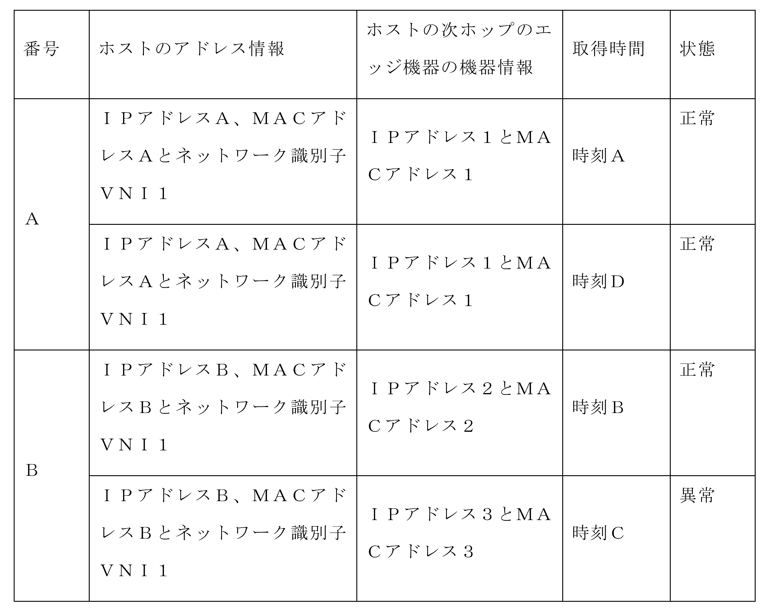
このように、本実施例では、ビッグデータシステムが膨大な情報を記憶可能であるため、データ処理機器161は、エントリに既存したルーティング情報を置換するのではなく、エントリにルーティング情報を追加することができる。即ち、長期間にわたってルーティング情報を保存可能であり、時間順で保存可能であり、情報を高速に検索することができる。ビッグデータシステムが膨大な情報を記憶可能であるため、履歴データベースには、正常ルーティング時の情報だけでなく、異常ルーティング時の情報も記憶され得る。履歴データベースは、更に履歴時間に応じて検索可能であるため、長期間に渡るアクセス行為異常の原因の遡りをサポートする。例えば、上述した表3や4に示すように、IPアドレスB、MACアドレスB及びネットワーク識別子VNI1に対応するホストは、時刻Cで異常が発生する。したがって、ビッグデータシステムで保存された時系列属性を有する膨大な情報に基づいて、履歴の任意時間点における異常アクセス行為を高速に遡ることができる。 Thus, in this embodiment, since the big data system can store a large amount of information, the data processing device 161 adds routing information to the entry rather than replacing existing routing information in the entry. can be done. That is, routing information can be stored for a long period of time, can be stored in chronological order, and information can be searched at high speed. Since big data systems can store vast amounts of information, the history database can store information not only during normal routing, but also during abnormal routing. Since the history database can be searched further according to history time, it supports tracing back the cause of access behavior anomalies over a long period of time. For example, as shown in Tables 3 and 4 above, the host corresponding to IP address B, MAC address B, and network identifier VNI1 malfunctions at time C. Therefore, based on the huge amount of information with chronological attributes stored in the big data system, it is possible to trace back abnormal access behavior at any point in history at high speed.
上記実施例では、データ処理機器161は、データ収集器とデータ分析器を更に備えてもよく、データ収集器は、データの収集を実施し、データ分析器は、データの分析を実施する。こうすると、データ収集器は、ステップ301-ステップ303を実行可能であり、データ分析器は、ステップ304-ステップ309を実行可能である。 In the above embodiments, the data processing device 161 may further comprise a data collector and a data analyzer, the data collector performing data collection and the data analyzer performing data analysis. The data collector can then perform steps 301-303 and the data analyzer can perform steps 304-309.
上記方法と同様な出願思想に基づき、本発明の実施例は、異常ホストモニタニング装置を更に提出する。当該異常ホストモニタニング装置は、データ処理機器に用いられる。図4は、前記装置の構成図であり、図4に示すように、前記装置は、以下のモジュールを備える。 Based on the same application idea as the above method, the embodiment of the present invention further provides an abnormal host monitoring device. The abnormal host monitoring device is used in data processing equipment. FIG. 4 is a block diagram of the device, and as shown in FIG. 4, the device comprises the following modules.
第1取得モジュール41は、デプロイ済みホストのホスト情報をコントローラから取得する。前記ホスト情報は、前記デプロイ済みホストのアドレス情報を含む。 A first acquisition module 41 acquires host information of a deployed host from the controller. The host information includes address information of the deployed host.
第2取得モジュール42は、検出すべきホストのルーティング情報を取得する。前記ルーティング情報は、前記検出すべきホストのアドレス情報を含む。
A second obtaining
第1判断モジュール43は、前記デプロイ済みホストのアドレス情報に前記検出すべきホストのアドレス情報が含まれているか否かを特定する。
The
第1特定モジュール44は、前記デプロイ済みホストのアドレス情報に前記検出すべきホストのアドレス情報が含まれていない場合に、前記検出すべきホストを異常ホストとして特定する。
The
一例では、前記装置は、ルーティング管理機器と交渉してBGPピアを確立するための確立モジュールを更に備え(図示せず)、前記第2取得モジュール42は、前記ルーティング管理機器から送信された検出すべきホストのルーティング情報を受信するために用いられる。
In one example, the device further comprises an establishment module (not shown) for negotiating with a routing management device to establish a BGP peer, wherein the
一例では、前記装置は、前記デプロイ済みホストのLLDP情報を前記コントローラから取得するための第3取得モジュールを更に備える(図示せず)。前記LLDP情報は、前記デプロイ済みホストに関連する第1エッジ機器の機器情報を含む。前記デプロイ済みホストのアドレス情報に前記検出すべきホストのアドレス情報が含まれている場合に、前記装置は、目標ホストに関連する前記第1エッジ機器の機器情報を前記LLDP情報から取得するための第4取得モジュールを更に備える(図示せず)。前記目標ホストは、前記検出すべきホストと同じアドレス情報を有するデプロイ済みホストである。第2特定モジュールは、前記検出すべきホストに関連する第2エッジ機器の機器情報と前記目標ホストに関連する前記第1エッジ機器の機器情報とが異なる場合に、前記検出すべきホストを前記異常ホストとして特定する。前記検出すべきホストに関連する前記第2エッジ機器の機器情報は、前記ルーティング情報に含まれる。 In one example, the apparatus further comprises a third obtaining module (not shown) for obtaining LLDP information of the deployed host from the controller. The LLDP information includes device information of a first edge device associated with the deployed host. When the address information of the deployed host includes the address information of the host to be detected, the device is configured to acquire device information of the first edge device related to the target host from the LLDP information. A fourth acquisition module is further provided (not shown). The target host is a deployed host that has the same address information as the host to be detected. A second identification module identifies the host to be detected as abnormal when the device information of the second edge device related to the host to be detected is different from the device information of the first edge device related to the target host. Identify as a host. Device information of the second edge device related to the host to be detected is included in the routing information.
一例では、前記ホスト情報は、前記デプロイ済みホストのホスト識別子を更に含み、前記LLDP情報は、前記デプロイ済みホストのホスト識別子を更に含み、前記第4取得モジュールは、具体的に、前記目標ホストのアドレス情報に基づいて当該目標ホストのホスト情報を検索し、前記目標ホストのホスト識別子を取得し、前記目標ホストのホスト識別子に基づいて当該目標ホストのLLDP情報を検索し、前記目標ホストに関連する前記第1エッジ機器の機器情報を取得するために用いられる。 In one example, the host information further includes a host identifier of the deployed host, the LLDP information further includes a host identifier of the deployed host, and the fourth obtaining module specifically includes: retrieving host information of the target host based on address information; obtaining a host identifier of the target host; retrieving LLDP information of the target host based on the host identifier of the target host; It is used to acquire the device information of the first edge device.
一例では、前記第2特定モジュールは、更に、前記検出すべきホストに関連する前記第2エッジ機器の機器情報と前記目標ホストに関連する前記第1エッジ機器の機器情報とが同じである場合に、前記検出すべきホストを正常ホストとして特定するために用いられる。 In one example, the second identification module further determines if the device information of the second edge device related to the host to be detected and the device information of the first edge device related to the target host are the same. , is used to identify the host to be detected as a normal host.
一例では、前記装置は、前記検出すべきホストのルーティング情報が前記第2取得モジュールによって取得された後、前記検出すべきホストに対応するエントリが履歴データベースに存在するか否かを特定するための第2判断モジュールと、前記検出すべきホストに対応するエントリが前記履歴データベースに存在する場合に、前記ルーティング情報及び前記ルーティング情報の取得時間を前記エントリに記憶するための記憶モジュールと、前記検出すべきホストに対応するエントリが前記履歴データベースに存在しない場合に、前記検出すべきホストに対応するエントリを前記履歴データベースに追加し、追加されたエントリに前記ルーティング情報及び前記ルーティング情報の取得時間を記憶するための追加モジュールとを更に備える(図示せず)。 In one example, the device is configured to: after the routing information of the host to be detected is obtained by the second obtaining module, for determining whether an entry corresponding to the host to be detected exists in a history database; a second determination module; a storage module for storing, in the history database, an entry corresponding to the host to be detected, the routing information and the acquisition time of the routing information in the entry; when an entry corresponding to the host to be detected does not exist in the history database, an entry corresponding to the host to be detected is added to the history database, and the routing information and the acquisition time of the routing information are stored in the added entry (not shown).
本発明の実施例は、データ処理機器を提供する。ハードウェア実装から言うと、データ処理機器のハードウェアアーキテクチャ模式図の詳細は、図5に示されてもよい。データ処理機器は、機器読み取り可能な記憶媒体502とプロセッサ501を備える。前記データ処理機器は、インターフェース503とバス504を更に備えてもよい。前記機器読み取り可能な記憶媒体502には、前記プロセッサ501によって実行され得る機器の実行可能な指令が記憶される。前記プロセッサ501は、機器読み取り可能な記憶媒体502と通信し、機器読み取り可能な記憶媒体502に記憶された機器の実行可能な指令を読み取って実行することにより、本発明の上記例示に開示された異常ホストのモニタニング操作を実施する。インターフェース503は、コントローラ、ルーティング管理機器への接続に用いられてもよい。プロセッサ501、機器読み取り可能な記憶媒体502とインターフェース503の間では、バス504を介して互いに通信可能である。
An embodiment of the invention provides a data processing apparatus. In terms of hardware implementation, the details of the hardware architecture schematic of the data processing device may be shown in FIG. The data processing device comprises a machine
ここで、機器読み取り可能な記憶媒体は、如何なる電気的なもの、磁気的なもの、光学的なもの又は他の物理的記憶装置であってもよく、情報(例えば、実行可能な指令、データ等)を含むか記憶可能である。例えば、機器読み取り可能な記憶媒体は、揮発性メモリ、RAM(Radom Access Memory、ランダムアクセスメモリ)及び不揮発性メモリ、フラッシュメモリ、記憶ドライバ(例えば、ハードディスクドライバ)、ソリッド・ステート・ディスク、如何なるタイプの記憶ディスク(例えば、光ディスク、dvd等)若しくは類似する記憶媒体、又はそれらの組み合わせであってもよい。 Here, a machine-readable storage medium may be any electrical, magnetic, optical, or other physical storage device that stores information (e.g., executable instructions, data, etc.) ) is contained or storable. For example, machine-readable storage media include volatile memory, RAM (Radom Access Memory) and non-volatile memory, flash memory, storage drivers (e.g., hard disk drivers), solid state disks, any type of It may be a storage disc (eg, optical disc, dvd, etc.) or similar storage medium, or a combination thereof.
上記実施例で説明されるシステム、装置、モジュール又は手段は、具体的にコンピュータチップ又は実体によって実施されてもよく、又はある機能を有する製品によって実施されてもよい。1つの典型的な実施機器は、コンピュータである。コンピュータの具体的な形式は、パソコン、ラップトップコンピュータ、携帯電話、カメラ電話、スマートフォン、PDA、メディアプレーヤー、ナビゲーション機器、電子メール送受信機器、ゲームコンソール、タブレットPC、ウェアラブル機器又はこれらの機器のうちの任意何種かの機器の組み合わせであってもよい。 The systems, devices, modules or means described in the above embodiments may be specifically implemented by computer chips or entities, or may be implemented by products having certain functions. One typical implementation device is a computer. Specific forms of computers include personal computers, laptop computers, mobile phones, camera phones, smart phones, PDAs, media players, navigation devices, e-mail sending and receiving devices, game consoles, tablet PCs, wearable devices, or any of these devices. It may be a combination of any number of devices.
記述の便宜上、上記装置を記述する際、機能に応じて各種の手段に区分してそれぞれ記述する。無論、本発明の実施時に、各手段の機能は、同一又は複数のソフトウェア及び/又はハードウェアで実現されてもよい。 For convenience of description, when describing the above apparatus, various means will be classified according to their functions. Of course, when implementing the present invention, the functions of each means may be realized by the same or multiple pieces of software and/or hardware.
本分野における技術者であれば理解できるように、本発明の実施例は、方法、システム又はコンピュータプログラム製品として提供され得る。したがって、本発明は、100%ハードウェアの実施例、100%ソフトウェアの実施例、又はソフトウェアとハードウェアとを組み合わせた態様の実施例の形式を採用してもよい。また、本発明の実施例は、1つ又は複数の、コンピュータ利用可能なプログラムコードを含むコンピュータ利用可能な記憶媒体(磁気ディスクメモリ、CD-ROM、光学メモリ等を含むが、それらに限定されない)で実施されるコンピュータプログラム製品の形式を採用してもよい。 As will be appreciated by those skilled in the art, embodiments of the present invention may be provided as a method, system or computer program product. Accordingly, the present invention may take the form of a 100% hardware embodiment, a 100% software embodiment, or an embodiment combining software and hardware aspects. Embodiments of the present invention also include one or more computer-usable storage media (including, but not limited to, magnetic disk memories, CD-ROMs, optical memories, etc.) containing computer-usable program code. may take the form of a computer program product implemented in
本発明は、本発明の実施例の方法、機器(システム)及びコンピュータプログラム製品に基づくフローチャート及び/又はブロック図を参照して記述されている。コンピュータプログラム指令にてフローチャート及び/又はブロック図における各フロー及び/又はブロック、並びにフローチャート及び/又はブロック図におけるフロー及び/又はブロックの組み合わせを実施可能であることは理解されるべきである。これらのコンピュータプログラム指令を汎用コンピュータ、専用コンピュータ、組み込み型処理機器又は他のプログラム可能なデータ処理機器のプロセッサへ供給して1つのマシンを生成することにより、コンピュータ又は他のプログラム可能なデータ処理機器のプロセッサで実行される指令にて、フローチャートの1つのフロー若しくは複数のフロー及び/又はブロック図の1つのブロック若しくは複数のブロックにおける指定の機能を実施するための装置を発生してもよい。 The present invention is described with reference to flowchart illustrations and/or block diagrams of methods, apparatus (systems) and computer program products according to embodiments of the invention. It is to be understood that each flow and/or block in the flowchart illustrations and/or block diagrams, and combinations of flows and/or blocks in the flowchart illustrations and/or block diagrams, can be implemented by computer program instructions. computer or other programmable data processing equipment by supplying these computer program instructions to a processor of a general purpose computer, special purpose computer, embedded processing equipment or other programmable data processing equipment to produce a machine may generate apparatus for performing the functions specified in one flow or flows of the flowcharts and/or one block or blocks of the block diagrams.
また、これらのコンピュータプログラム指令は、更に、コンピュータ又は他のプログラム可能なデータ処理機器が特定の方式で動作するようガイドできるコンピュータ可読メモリに記憶されてもよい。このように、当該コンピュータ可読メモリに記憶された指令は、指令装置を含む製品を生成し、当該指令装置は、フローチャートの1つのフロー若しくは複数のフロー及び/又はブロック図の1つのブロック若しくは複数のブロックにおける指定の機能を実現する。 These computer program instructions may also be stored in a computer readable memory capable of directing a computer or other programmable data processing apparatus to operate in a specified manner. Thus, the instructions stored in the computer readable memory produce a product that includes a command device, the command device is a flowchart flow or flows and/or a block diagram block or blocks. Implements a specified function in a block.
これらのコンピュータプログラム指令は、コンピュータ又は他のプログラム可能なデータ処理機器にロードされて、コンピュータ又は他のプログラム可能な機器に一連の操作ステップを実施してコンピュータで実現される処理を生成してもよい。これにより、コンピュータ又は他のプログラム可能な機器で実行される指令は、フローチャートの1つのフロー若しくは複数のフロー及び/又はブロック図の1つのブロック若しくは複数のブロックにおける指定の機能を実現するステップを提供する。 These computer program instructions may be loaded into a computer or other programmable data processing device to perform a series of operational steps on the computer or other programmable device to produce a computer-implemented process. good. Accordingly, the instructions executed by the computer or other programmable device provide steps to implement the specified functionality in the flowchart flow or flows and/or the block diagram block or blocks. do.
上述したのは、本発明の実施例に過ぎず、本発明を制限するためのものではない。当業者にとって、本発明は種々な変更や変形があり得る。本発明の精神及び原則内でなされた如何なる変更、均等物による置換、改良等も、本発明の保護範囲内に含まれる。 The above are only examples of the present invention and are not intended to limit the present invention. For those skilled in the art, the present invention may have various modifications and variations. Any modification, equivalent replacement, improvement, etc. made within the spirit and principle of the present invention shall fall within the protection scope of the present invention.
Claims (11)
デプロイ済みホストのホスト情報をコントローラから取得するステップであって、前記ホスト情報は、前記デプロイ済みホストのアドレス情報を含むステップと、
ルーティング管理機器と交渉してボーダーゲートウェイプロトコル(BGP)ピアを確立するステップと、
検出すべきホストのルーティング情報を取得するステップであって、前記ルーティング情報は、前記検出すべきホストのアドレス情報を含むステップと、
前記デプロイ済みホストのアドレス情報に前記検出すべきホストのアドレス情報が含まれているか否かを特定するステップと、
前記デプロイ済みホストのアドレス情報に前記検出すべきホストのアドレス情報が含まれていない場合に、前記検出すべきホストを異常ホストとして特定するステップと、を含み、
前記検出すべきホストのルーティング情報を取得するステップは、
前記ルーティング管理機器から送信された前記検出すべきホストのルーティング情報を受信することを含む、
ことを特徴とする異常ホストモニタニング方法。 An abnormal host monitoring method used in data processing equipment, comprising:
obtaining host information of a deployed host from a controller, said host information including address information of said deployed host;
negotiating with a routing management device to establish a Border Gateway Protocol (BGP) peer;
obtaining routing information of a host to be detected, said routing information including address information of said host to be detected;
identifying whether the address information of the deployed host includes the address information of the host to be detected;
identifying the host to be detected as an abnormal host when the address information of the deployed host does not include the address information of the host to be detected ;
The step of obtaining routing information of the host to be detected comprises:
receiving routing information of the host to be detected transmitted from the routing management device;
An abnormal host monitoring method characterized by:
前記デプロイ済みホストのアドレス情報に前記検出すべきホストのアドレス情報が含まれている場合に、前記異常ホストモニタニング方法は、
目標ホストに関連する第1エッジ機器の機器情報を前記LLDP情報から取得するステップであって、前記目標ホストは、前記検出すべきホストと同じアドレス情報を有するデプロイ済みホストであるステップと、
前記検出すべきホストに関連する第2エッジ機器の機器情報と前記目標ホストに関連する前記第1エッジ機器の機器情報とが異なる場合に、前記検出すべきホストを前記異常ホストとして特定するステップであって、前記検出すべきホストに関連する前記第2エッジ機器の機器情報は、前記ルーティング情報に含まれるステップと、を更に含み、
ことを特徴とする請求項1に記載の異常ホストモニタニング方法。 the abnormal host monitoring method obtains Link Layer Discovery Protocol (LLDP) information of the deployed host from the controller, the LLDP information includes equipment information of a first edge device associated with the deployed host;
When the address information of the deployed host includes the address information of the host to be detected, the abnormal host monitoring method includes:
obtaining device information of a first edge device associated with a target host from the LLDP information, wherein the target host is a deployed host having the same address information as the host to be detected;
identifying the host to be detected as the abnormal host when the device information of the second edge device related to the host to be detected is different from the device information of the first edge device related to the target host; wherein device information of the second edge device related to the host to be detected is included in the routing information;
The abnormal host monitoring method according to claim 1, characterized by:
前記目標ホストに関連する前記第1エッジ機器の機器情報を前記LLDP情報から取得するステップは、
前記目標ホストのアドレス情報に基づいて当該目標ホストのホスト情報を検索し、前記目標ホストのホスト識別子を取得することと、
前記目標ホストのホスト識別子に基づいて当該目標ホストのLLDP情報を検索し、前記目標ホストに関連する前記第1エッジ機器の機器情報を取得することと、を含むことを特徴とする請求項2に記載の異常ホストモニタニング方法。 said host information further comprising a host identifier of said deployed host, said LLDP information further comprising a host identifier of said deployed host;
obtaining device information of the first edge device associated with the target host from the LLDP information;
retrieving host information of the target host based on the address information of the target host to obtain a host identifier of the target host;
retrieving LLDP information of the target host based on the host identifier of the target host to obtain device information of the first edge device associated with the target host . Anomalous host monitoring method as described.
前記検出すべきホストに対応するエントリが履歴データベースに存在するか否かを特定するステップと、
前記検出すべきホストに対応するエントリが前記履歴データベースに存在する場合に、前記ルーティング情報及び前記ルーティング情報の取得時間を前記エントリに記憶するステップと、
前記検出すべきホストに対応するエントリが前記履歴データベースに存在しない場合に、前記検出すべきホストに対応するエントリを前記履歴データベースに追加し、追加されたエントリに前記ルーティング情報及び前記ルーティング情報の取得時間を記憶するステップと、を更に含むことを特徴とする請求項1に記載の異常ホストモニタニング方法。 After obtaining the routing information of the host to be detected, the abnormal host monitoring method includes:
determining whether an entry corresponding to the host to be detected exists in a history database;
if an entry corresponding to the host to be detected exists in the history database, storing the routing information and the acquisition time of the routing information in the entry;
adding an entry corresponding to the host to be detected to the history database when the entry corresponding to the host to be detected does not exist in the history database, and obtaining the routing information and the routing information for the added entry The abnormal host monitoring method of claim 1, further comprising the step of storing the time.
デプロイ済みホストのホスト情報をコントローラから取得するための第1取得モジュールであって、前記ホスト情報は、前記デプロイ済みホストのアドレス情報を含む第1取得モジュールと、
ルーティング管理機器と交渉してBGPピアを確立するための確立モジュールと、
検出すべきホストのルーティング情報を取得するための第2取得モジュールであって、前記ルーティング情報は、前記検出すべきホストのアドレス情報を含む第2取得モジュールと、
前記デプロイ済みホストのアドレス情報に前記検出すべきホストのアドレス情報が含まれているか否かを特定するための第1判断モジュールと、
前記デプロイ済みホストのアドレス情報に前記検出すべきホストのアドレス情報が含まれていない場合に、前記検出すべきホストを異常ホストとして特定するための第1特定モジュールと、を備え、
前記第2取得モジュールは、前記ルーティング管理機器から送信された前記検出すべきホストのルーティング情報を受信するために用いられる、
ことを特徴とする異常ホストモニタニング装置。 An abnormal host monitoring device used in data processing equipment,
a first acquisition module for acquiring host information of a deployed host from a controller, wherein the host information includes address information of the deployed host;
an establishment module for negotiating with routing management equipment to establish a BGP peer;
a second obtaining module for obtaining routing information of a host to be detected, wherein the routing information includes address information of the host to be detected;
a first determination module for determining whether or not the address information of the deployed host includes the address information of the host to be detected;
a first identification module for identifying the host to be detected as an abnormal host when the address information of the deployed host does not include the address information of the host to be detected ;
wherein the second acquisition module is used to receive routing information of the host to be detected transmitted from the routing management device;
An abnormal host monitoring device characterized by:
前記デプロイ済みホストのアドレス情報に前記検出すべきホストのアドレス情報が含まれている場合に、前記異常ホストモニタニング装置は、
目標ホストに関連する前記第1エッジ機器の機器情報を前記LLDP情報から取得するための第4取得モジュールであって、前記目標ホストは、前記検出すべきホストと同じアドレス情報を有するデプロイ済みホストである第4取得モジュールと、
前記検出すべきホストに関連する第2エッジ機器の機器情報と前記目標ホストに関連する前記第1エッジ機器の機器情報とが異なる場合に、前記検出すべきホストを前記異常ホストとして特定するための第2特定モジュールであって、前記検出すべきホストに関連する前記第2エッジ機器の機器情報は、前記ルーティング情報に含まれる第2特定モジュールと、を更に備え、
ことを特徴とする請求項6に記載の異常ホストモニタニング装置。 The abnormal host monitoring device further comprises a third acquisition module for acquiring LLDP information of the deployed host from the controller, wherein the LLDP information is device information of a first edge device related to the deployed host. including
When the address information of the deployed host includes the address information of the host to be detected, the abnormal host monitoring device
a fourth obtaining module for obtaining device information of the first edge device associated with a target host from the LLDP information, wherein the target host is a deployed host having the same address information as the host to be detected; a fourth acquisition module;
for identifying the host to be detected as the abnormal host when the device information of the second edge device related to the host to be detected and the device information of the first edge device related to the target host are different; a second identification module, wherein the device information of the second edge device related to the host to be detected is included in the routing information;
7. The abnormal host monitoring device according to claim 6 , wherein:
前記第4取得モジュールは、前記目標ホストのアドレス情報に基づいて当該目標ホストのホスト情報を検索し、前記目標ホストのホスト識別子を取得し、前記目標ホストのホスト識別子に基づいて当該目標ホストのLLDP情報を検索し、前記目標ホストに関連する前記第1エッジ機器の機器情報を取得するために用いられることを特徴とする請求項7に記載の異常ホストモニタニング装置。 said host information further comprising a host identifier of said deployed host, said LLDP information further comprising a host identifier of said deployed host;
The fourth obtaining module retrieves host information of the target host based on the address information of the target host, obtains a host identifier of the target host, and LLDP of the target host based on the host identifier of the target host. 8. The abnormal host monitoring apparatus according to claim 7 , used for searching information and obtaining device information of the first edge device related to the target host.
前記検出すべきホストのルーティング情報が前記第2取得モジュールによって取得された後、前記検出すべきホストに対応するエントリが履歴データベースに存在するか否かを特定するための第2判断モジュールと、
前記検出すべきホストに対応するエントリが前記履歴データベースに存在する場合に、前記ルーティング情報及び前記ルーティング情報の取得時間を前記エントリに記憶するための記憶モジュールと、
前記検出すべきホストに対応するエントリが前記履歴データベースに存在しない場合に、前記検出すべきホストに対応するエントリを前記履歴データベースに追加し、追加されたエントリに前記ルーティング情報及び前記ルーティング情報の取得時間を記憶するための追加モジュールと、を更に備えることを特徴とする請求項6に記載の異常ホストモニタニング装置。 The abnormal host monitoring device,
a second determining module for determining whether an entry corresponding to the host to be detected exists in a history database after the routing information of the host to be detected is obtained by the second obtaining module;
a storage module for storing the routing information and the acquisition time of the routing information in the entry when the entry corresponding to the host to be detected exists in the history database;
adding an entry corresponding to the host to be detected to the history database when the entry corresponding to the host to be detected does not exist in the history database, and obtaining the routing information and the routing information for the added entry 7. The abnormal host monitoring apparatus of claim 6 , further comprising an additional module for storing time.
機器読み取り可能な記憶媒体と、プロセッサと、を備え、
前記機器読み取り可能な記憶媒体には、機器読み取り可能な指令が記憶され、
前記プロセッサは、前記機器読み取り可能な指令を呼び出すことにより、請求項1から5の何れか一項に記載の異常ホストモニタニング方法を実行することを特徴とするデータ処理機器。 A data processing device,
comprising a machine-readable storage medium and a processor,
The machine-readable storage medium stores a machine-readable command,
6. A data processing apparatus, wherein said processor executes the abnormal host monitoring method according to any one of claims 1 to 5 by invoking said machine-readable instructions.
Applications Claiming Priority (3)
| Application Number | Priority Date | Filing Date | Title |
|---|---|---|---|
| CN201910212398.8A CN111010362B (en) | 2019-03-20 | 2019-03-20 | Monitoring method and device for abnormal host |
| CN201910212398.8 | 2019-03-20 | ||
| PCT/CN2020/080223 WO2020187295A1 (en) | 2019-03-20 | 2020-03-19 | Monitoring of abnormal host |
Publications (2)
| Publication Number | Publication Date |
|---|---|
| JP2022525205A JP2022525205A (en) | 2022-05-11 |
| JP7228712B2 true JP7228712B2 (en) | 2023-02-24 |
Family
ID=70111541
Family Applications (1)
| Application Number | Title | Priority Date | Filing Date |
|---|---|---|---|
| JP2021555483A Active JP7228712B2 (en) | 2019-03-20 | 2020-03-19 | Abnormal host monitoring |
Country Status (5)
| Country | Link |
|---|---|
| US (1) | US12160431B2 (en) |
| EP (1) | EP3944582B1 (en) |
| JP (1) | JP7228712B2 (en) |
| CN (1) | CN111010362B (en) |
| WO (1) | WO2020187295A1 (en) |
Families Citing this family (4)
| Publication number | Priority date | Publication date | Assignee | Title |
|---|---|---|---|---|
| CN112437077A (en) * | 2020-11-19 | 2021-03-02 | 迈普通信技术股份有限公司 | Third party ARP attack and exception handling method, VRRP network and system |
| CN113987476B (en) * | 2021-10-26 | 2025-06-24 | 新华三信息安全技术有限公司 | A method, device, electronic device and storage medium for determining a compromised host |
| CN114978580B (en) * | 2022-04-08 | 2023-09-29 | 中国电信股份有限公司 | Network detection method and device, storage medium and electronic equipment |
| CN116152196A (en) * | 2023-02-20 | 2023-05-23 | 同济大学 | An anomaly detection method and device for time-series encoded images based on cloud platform |
Citations (11)
| Publication number | Priority date | Publication date | Assignee | Title |
|---|---|---|---|---|
| JP2000183968A (en) | 1998-12-17 | 2000-06-30 | Nippon Telegr & Teleph Corp <Ntt> | Packet communication system and nodes and edge devices constituting the same |
| JP2005198090A (en) | 2004-01-08 | 2005-07-21 | Fujitsu Ltd | Network unauthorized connection prevention method and apparatus |
| JP2006197518A (en) | 2005-01-17 | 2006-07-27 | Hitachi Ltd | Network management method and network management system |
| JP2011124774A (en) | 2009-12-10 | 2011-06-23 | Toshiba Corp | Network monitoring device, and network monitoring method |
| JP2012147377A (en) | 2011-01-14 | 2012-08-02 | Fujitsu Advanced Engineering Ltd | Communication apparatus, communication method, and communication program |
| JP2014011674A (en) | 2012-06-29 | 2014-01-20 | Fujitsu Ltd | Storage system management program and storage system management device |
| US20160359888A1 (en) | 2015-06-05 | 2016-12-08 | Cisco Technology, Inc. | System and method of assigning reputation scores to hosts |
| JP2016208092A (en) | 2015-04-15 | 2016-12-08 | エヌ・ティ・ティ・コミュニケーションズ株式会社 | Communication path monitoring device, communication system, failure determination method, and program |
| CN106888217A (en) | 2017-03-27 | 2017-06-23 | 上海斐讯数据通信技术有限公司 | A kind of management-control method attacked for ARP and system |
| CN107438068A (en) | 2017-07-04 | 2017-12-05 | 杭州迪普科技股份有限公司 | A kind of method and device of preventing ARP aggression |
| US20180027012A1 (en) | 2016-07-20 | 2018-01-25 | Cisco Technology, Inc. | Technologies for preventing man-in-the-middle attacks in software defined networks |
Family Cites Families (22)
| Publication number | Priority date | Publication date | Assignee | Title |
|---|---|---|---|---|
| US7733788B1 (en) * | 2004-08-30 | 2010-06-08 | Sandia Corporation | Computer network control plane tampering monitor |
| KR100863313B1 (en) * | 2007-02-09 | 2008-10-15 | 주식회사 코어세스 | Alp spoof automatic blocking device and method |
| CN101370019B (en) * | 2008-09-26 | 2011-06-22 | 北京星网锐捷网络技术有限公司 | Method and switchboard for preventing packet cheating attack of address analysis protocol |
| US9276953B2 (en) * | 2011-05-13 | 2016-03-01 | International Business Machines Corporation | Method and apparatus to detect and block unauthorized MAC address by virtual machine aware network switches |
| CN102694876A (en) * | 2012-05-10 | 2012-09-26 | 北京星网锐捷网络技术有限公司 | Method and device for determining effectiveness of learned MAC (Media Access Control) address and gateway equipment |
| CN103259732B (en) * | 2013-04-03 | 2016-09-28 | 北京邮电大学 | A kind of SDN broadcast processing method triggering agency based on ARP event |
| CN104780139B (en) * | 2014-01-09 | 2018-02-13 | 北京东土科技股份有限公司 | A kind of defence method and system based on MAC Address attack |
| KR20160002269A (en) | 2014-06-30 | 2016-01-07 | 한국전자통신연구원 | SDN-based ARP Spoofing Detection apparatus and method therefor |
| CN105282112A (en) | 2014-07-15 | 2016-01-27 | 中兴通讯股份有限公司 | Terminal and method for detecting security of data interaction in terminal |
| CN104660582B (en) | 2014-12-17 | 2018-01-19 | 南京晓庄学院 | Software-defined network architecture for DDoS identification, protection and path optimization |
| US10333905B2 (en) * | 2015-10-16 | 2019-06-25 | Orock Technologies, Inc. | System for providing end-to-end protection against network-based attacks |
| CN105430113B (en) * | 2015-11-03 | 2018-07-03 | 上海斐讯数据通信技术有限公司 | SDN network ARP message processing methods, system, controller and interchanger |
| CN105812502A (en) * | 2016-03-07 | 2016-07-27 | 北京工业大学 | OpenFlow-based implementation method for address resolution protocol proxy technology |
| CN106506200A (en) * | 2016-10-31 | 2017-03-15 | 中国工程物理研究院计算机应用研究所 | A kind of ARP protocol submodel based on SDN |
| CN106506534B (en) * | 2016-12-09 | 2019-09-27 | 河南工业大学 | An ARP attack detection method for SDN network |
| US10038671B2 (en) * | 2016-12-31 | 2018-07-31 | Fortinet, Inc. | Facilitating enforcement of security policies by and on behalf of a perimeter network security device by providing enhanced visibility into interior traffic flows |
| CN107018136A (en) | 2017-04-06 | 2017-08-04 | 福建中金在线信息科技有限公司 | A kind of detection method and device of ARP attacks |
| CN107465621B (en) | 2017-08-18 | 2020-08-11 | 迈普通信技术股份有限公司 | Router discovery method, SDN controller, router and network system |
| CN107579988B (en) | 2017-09-25 | 2020-01-07 | 新华三技术有限公司 | Method and device for configuring security policy |
| CN107995162A (en) * | 2017-10-27 | 2018-05-04 | 深信服科技股份有限公司 | Network security sensory perceptual system, method and readable storage medium storing program for executing |
| US11218446B2 (en) * | 2018-06-15 | 2022-01-04 | Orock Technologies, Inc. | Secure on-premise to cloud communication |
| US11729210B2 (en) * | 2020-04-17 | 2023-08-15 | Cisco Technology, Inc. | Detecting spoofing in device classification systems |
-
2019
- 2019-03-20 CN CN201910212398.8A patent/CN111010362B/en active Active
-
2020
- 2020-03-19 EP EP20773249.6A patent/EP3944582B1/en active Active
- 2020-03-19 JP JP2021555483A patent/JP7228712B2/en active Active
- 2020-03-19 US US17/593,547 patent/US12160431B2/en active Active
- 2020-03-19 WO PCT/CN2020/080223 patent/WO2020187295A1/en not_active Ceased
Patent Citations (11)
| Publication number | Priority date | Publication date | Assignee | Title |
|---|---|---|---|---|
| JP2000183968A (en) | 1998-12-17 | 2000-06-30 | Nippon Telegr & Teleph Corp <Ntt> | Packet communication system and nodes and edge devices constituting the same |
| JP2005198090A (en) | 2004-01-08 | 2005-07-21 | Fujitsu Ltd | Network unauthorized connection prevention method and apparatus |
| JP2006197518A (en) | 2005-01-17 | 2006-07-27 | Hitachi Ltd | Network management method and network management system |
| JP2011124774A (en) | 2009-12-10 | 2011-06-23 | Toshiba Corp | Network monitoring device, and network monitoring method |
| JP2012147377A (en) | 2011-01-14 | 2012-08-02 | Fujitsu Advanced Engineering Ltd | Communication apparatus, communication method, and communication program |
| JP2014011674A (en) | 2012-06-29 | 2014-01-20 | Fujitsu Ltd | Storage system management program and storage system management device |
| JP2016208092A (en) | 2015-04-15 | 2016-12-08 | エヌ・ティ・ティ・コミュニケーションズ株式会社 | Communication path monitoring device, communication system, failure determination method, and program |
| US20160359888A1 (en) | 2015-06-05 | 2016-12-08 | Cisco Technology, Inc. | System and method of assigning reputation scores to hosts |
| US20180027012A1 (en) | 2016-07-20 | 2018-01-25 | Cisco Technology, Inc. | Technologies for preventing man-in-the-middle attacks in software defined networks |
| CN106888217A (en) | 2017-03-27 | 2017-06-23 | 上海斐讯数据通信技术有限公司 | A kind of management-control method attacked for ARP and system |
| CN107438068A (en) | 2017-07-04 | 2017-12-05 | 杭州迪普科技股份有限公司 | A kind of method and device of preventing ARP aggression |
Also Published As
| Publication number | Publication date |
|---|---|
| JP2022525205A (en) | 2022-05-11 |
| CN111010362A (en) | 2020-04-14 |
| EP3944582B1 (en) | 2023-12-27 |
| EP3944582A1 (en) | 2022-01-26 |
| WO2020187295A1 (en) | 2020-09-24 |
| EP3944582A4 (en) | 2022-04-27 |
| US20220174081A1 (en) | 2022-06-02 |
| CN111010362B (en) | 2021-09-21 |
| US12160431B2 (en) | 2024-12-03 |
Similar Documents
| Publication | Publication Date | Title |
|---|---|---|
| US11477097B2 (en) | Hierarchichal sharding of flows from sensors to collectors | |
| JP7228712B2 (en) | Abnormal host monitoring | |
| AU2019396129B2 (en) | Apparatus and process for monitoring network behaviour of internet-of-things (IoT) devices | |
| US9608841B2 (en) | Method for real-time synchronization of ARP record in RSMLT cluster | |
| US10764393B2 (en) | Determining a persistent network identity of a networked device | |
| US9094308B2 (en) | Finding latency through a physical network in a virtualized network | |
| US10541913B2 (en) | Table entry in software defined network | |
| US12468657B2 (en) | Message forwarding method and apparatus based on remote direct data storage, and network card and device | |
| KR101253390B1 (en) | Router detection | |
| CN107547349B (en) | Virtual machine migration method and device | |
| US8904524B1 (en) | Detection of fast flux networks | |
| EP3667532A1 (en) | Methods for detecting and mitigating malicious network activity based on dynamic application context and devices thereof | |
| WO2020135575A1 (en) | System and method for obtaining network topology, and server | |
| US20180295029A1 (en) | Managing groups of servers | |
| CN106878184A (en) | A kind of data message transmission method and device | |
| US20250280015A1 (en) | Blocking and alerting with domain fronting intelligence | |
| CN105162703A (en) | Multi-level network topology intelligent discovery and generation method and system based on hybrid protocol | |
| CN104618246A (en) | Network topology discovery method for XEN virtualization environment | |
| WO2016114750A1 (en) | Data link layer information | |
| US20070016670A1 (en) | Determining data flows in a network | |
| CN113839894A (en) | Message processing method and system | |
| US20180217860A1 (en) | Integrated network data collection apparatus and method | |
| US10187414B2 (en) | Differential malware detection using network and endpoint sensors | |
| CN110753364B (en) | Network monitoring method, system, electronic device and storage medium | |
| US10931565B2 (en) | Multi-VRF and multi-service insertion on edge gateway virtual machines |
Legal Events
| Date | Code | Title | Description |
|---|---|---|---|
| A621 | Written request for application examination |
Free format text: JAPANESE INTERMEDIATE CODE: A621 Effective date: 20210914 |
|
| A977 | Report on retrieval |
Free format text: JAPANESE INTERMEDIATE CODE: A971007 Effective date: 20221005 |
|
| A131 | Notification of reasons for refusal |
Free format text: JAPANESE INTERMEDIATE CODE: A131 Effective date: 20221018 |
|
| A521 | Request for written amendment filed |
Free format text: JAPANESE INTERMEDIATE CODE: A523 Effective date: 20230105 |
|
| TRDD | Decision of grant or rejection written | ||
| A01 | Written decision to grant a patent or to grant a registration (utility model) |
Free format text: JAPANESE INTERMEDIATE CODE: A01 Effective date: 20230131 |
|
| A61 | First payment of annual fees (during grant procedure) |
Free format text: JAPANESE INTERMEDIATE CODE: A61 Effective date: 20230213 |
|
| R150 | Certificate of patent or registration of utility model |
Ref document number: 7228712 Country of ref document: JP Free format text: JAPANESE INTERMEDIATE CODE: R150 |
|
| R250 | Receipt of annual fees |
Free format text: JAPANESE INTERMEDIATE CODE: R250 |