JP7216004B2 - Mask and method of protecting eyes or stabilizing eyelids of a subject undergoing eyelash extension - Google Patents
Mask and method of protecting eyes or stabilizing eyelids of a subject undergoing eyelash extension Download PDFInfo
- Publication number
- JP7216004B2 JP7216004B2 JP2019547238A JP2019547238A JP7216004B2 JP 7216004 B2 JP7216004 B2 JP 7216004B2 JP 2019547238 A JP2019547238 A JP 2019547238A JP 2019547238 A JP2019547238 A JP 2019547238A JP 7216004 B2 JP7216004 B2 JP 7216004B2
- Authority
- JP
- Japan
- Prior art keywords
- mask
- subject
- cover
- eyelid
- eyelid cover
- Prior art date
- Legal status (The legal status is an assumption and is not a legal conclusion. Google has not performed a legal analysis and makes no representation as to the accuracy of the status listed.)
- Active
Links
- 210000000744 eyelid Anatomy 0.000 title claims description 145
- 210000000720 eyelash Anatomy 0.000 title claims description 107
- 238000000034 method Methods 0.000 title claims description 34
- 230000000087 stabilizing effect Effects 0.000 title claims description 9
- 210000003128 head Anatomy 0.000 claims description 14
- 210000005069 ears Anatomy 0.000 claims description 4
- 230000008878 coupling Effects 0.000 claims 1
- 238000010168 coupling process Methods 0.000 claims 1
- 238000005859 coupling reaction Methods 0.000 claims 1
- 230000007246 mechanism Effects 0.000 description 50
- 239000000853 adhesive Substances 0.000 description 22
- 230000001070 adhesive effect Effects 0.000 description 22
- 239000000463 material Substances 0.000 description 12
- 238000013461 design Methods 0.000 description 11
- 239000012636 effector Substances 0.000 description 11
- 230000008569 process Effects 0.000 description 11
- 230000004888 barrier function Effects 0.000 description 9
- 239000000835 fiber Substances 0.000 description 9
- 230000008901 benefit Effects 0.000 description 8
- 238000007639 printing Methods 0.000 description 7
- 210000001061 forehead Anatomy 0.000 description 6
- 238000013459 approach Methods 0.000 description 5
- 239000004033 plastic Substances 0.000 description 5
- 229920003023 plastic Polymers 0.000 description 5
- XEEYBQQBJWHFJM-UHFFFAOYSA-N Iron Chemical compound [Fe] XEEYBQQBJWHFJM-UHFFFAOYSA-N 0.000 description 4
- 230000006378 damage Effects 0.000 description 4
- 210000004709 eyebrow Anatomy 0.000 description 4
- 238000004519 manufacturing process Methods 0.000 description 4
- 238000005259 measurement Methods 0.000 description 4
- 238000005094 computer simulation Methods 0.000 description 3
- 230000000694 effects Effects 0.000 description 3
- 238000002955 isolation Methods 0.000 description 3
- 230000013011 mating Effects 0.000 description 3
- 241000282412 Homo Species 0.000 description 2
- 241000251131 Sphyrna Species 0.000 description 2
- 208000027418 Wounds and injury Diseases 0.000 description 2
- 230000002146 bilateral effect Effects 0.000 description 2
- 238000005266 casting Methods 0.000 description 2
- 239000002537 cosmetic Substances 0.000 description 2
- 230000001815 facial effect Effects 0.000 description 2
- 239000003292 glue Substances 0.000 description 2
- 210000004209 hair Anatomy 0.000 description 2
- 230000001965 increasing effect Effects 0.000 description 2
- 230000001939 inductive effect Effects 0.000 description 2
- 208000014674 injury Diseases 0.000 description 2
- 229910052742 iron Inorganic materials 0.000 description 2
- 239000000696 magnetic material Substances 0.000 description 2
- 230000003287 optical effect Effects 0.000 description 2
- 210000004279 orbit Anatomy 0.000 description 2
- 238000012552 review Methods 0.000 description 2
- 238000010146 3D printing Methods 0.000 description 1
- 239000004677 Nylon Substances 0.000 description 1
- 239000004698 Polyethylene Substances 0.000 description 1
- 208000023109 Prominent forehead Diseases 0.000 description 1
- 241000220010 Rhode Species 0.000 description 1
- 229910000831 Steel Inorganic materials 0.000 description 1
- 239000004830 Super Glue Substances 0.000 description 1
- 239000004676 acrylonitrile butadiene styrene Substances 0.000 description 1
- 229920000122 acrylonitrile butadiene styrene Polymers 0.000 description 1
- 239000000654 additive Substances 0.000 description 1
- 230000000996 additive effect Effects 0.000 description 1
- 238000004026 adhesive bonding Methods 0.000 description 1
- 239000002390 adhesive tape Substances 0.000 description 1
- 210000003484 anatomy Anatomy 0.000 description 1
- 230000003796 beauty Effects 0.000 description 1
- 238000011960 computer-aided design Methods 0.000 description 1
- 238000007796 conventional method Methods 0.000 description 1
- 238000005516 engineering process Methods 0.000 description 1
- FGBJXOREULPLGL-UHFFFAOYSA-N ethyl cyanoacrylate Chemical compound CCOC(=O)C(=C)C#N FGBJXOREULPLGL-UHFFFAOYSA-N 0.000 description 1
- 239000002657 fibrous material Substances 0.000 description 1
- 231100001261 hazardous Toxicity 0.000 description 1
- 238000003780 insertion Methods 0.000 description 1
- 230000037431 insertion Effects 0.000 description 1
- 238000007689 inspection Methods 0.000 description 1
- 239000006210 lotion Substances 0.000 description 1
- 238000012986 modification Methods 0.000 description 1
- 230000004048 modification Effects 0.000 description 1
- 239000012811 non-conductive material Substances 0.000 description 1
- 229920001778 nylon Polymers 0.000 description 1
- -1 polyethylene Polymers 0.000 description 1
- 229920000573 polyethylene Polymers 0.000 description 1
- 238000011160 research Methods 0.000 description 1
- 239000011435 rock Substances 0.000 description 1
- 210000003625 skull Anatomy 0.000 description 1
- 238000002791 soaking Methods 0.000 description 1
- 239000010959 steel Substances 0.000 description 1
- 238000012795 verification Methods 0.000 description 1
Images


Classifications
-
- A—HUMAN NECESSITIES
- A45—HAND OR TRAVELLING ARTICLES
- A45D—HAIRDRESSING OR SHAVING EQUIPMENT; EQUIPMENT FOR COSMETICS OR COSMETIC TREATMENTS, e.g. FOR MANICURING OR PEDICURING
- A45D44/00—Other cosmetic or toiletry articles, e.g. for hairdressers' rooms
-
- A—HUMAN NECESSITIES
- A41—WEARING APPAREL
- A41D—OUTERWEAR; PROTECTIVE GARMENTS; ACCESSORIES
- A41D13/00—Professional, industrial or sporting protective garments, e.g. surgeons' gowns or garments protecting against blows or punches
- A41D13/05—Professional, industrial or sporting protective garments, e.g. surgeons' gowns or garments protecting against blows or punches protecting only a particular body part
- A41D13/11—Protective face masks, e.g. for surgical use, or for use in foul atmospheres
- A41D13/1161—Means for fastening to the user's head
- A41D13/1169—Means for fastening to the user's head using adhesive
-
- A—HUMAN NECESSITIES
- A41—WEARING APPAREL
- A41D—OUTERWEAR; PROTECTIVE GARMENTS; ACCESSORIES
- A41D13/00—Professional, industrial or sporting protective garments, e.g. surgeons' gowns or garments protecting against blows or punches
- A41D13/05—Professional, industrial or sporting protective garments, e.g. surgeons' gowns or garments protecting against blows or punches protecting only a particular body part
- A41D13/11—Protective face masks, e.g. for surgical use, or for use in foul atmospheres
- A41D13/1184—Protective face masks, e.g. for surgical use, or for use in foul atmospheres with protection for the eyes, e.g. using shield or visor
-
- A—HUMAN NECESSITIES
- A41—WEARING APPAREL
- A41G—ARTIFICIAL FLOWERS; WIGS; MASKS; FEATHERS
- A41G3/00—Wigs
-
- A—HUMAN NECESSITIES
- A41—WEARING APPAREL
- A41G—ARTIFICIAL FLOWERS; WIGS; MASKS; FEATHERS
- A41G5/00—Hair pieces, inserts, rolls, pads, or the like; Toupées
- A41G5/02—Artificial eyelashes; Artificial eyebrows
-
- A—HUMAN NECESSITIES
- A45—HAND OR TRAVELLING ARTICLES
- A45D—HAIRDRESSING OR SHAVING EQUIPMENT; EQUIPMENT FOR COSMETICS OR COSMETIC TREATMENTS, e.g. FOR MANICURING OR PEDICURING
- A45D40/00—Casings or accessories specially adapted for storing or handling solid or pasty toiletry or cosmetic substances, e.g. shaving soaps or lipsticks
- A45D40/30—Masks for marking lips or eyelashes
-
- A—HUMAN NECESSITIES
- A45—HAND OR TRAVELLING ARTICLES
- A45D—HAIRDRESSING OR SHAVING EQUIPMENT; EQUIPMENT FOR COSMETICS OR COSMETIC TREATMENTS, e.g. FOR MANICURING OR PEDICURING
- A45D44/00—Other cosmetic or toiletry articles, e.g. for hairdressers' rooms
- A45D44/002—Masks for cosmetic treatment of the face
-
- B—PERFORMING OPERATIONS; TRANSPORTING
- B05—SPRAYING OR ATOMISING IN GENERAL; APPLYING FLUENT MATERIALS TO SURFACES, IN GENERAL
- B05B—SPRAYING APPARATUS; ATOMISING APPARATUS; NOZZLES
- B05B13/00—Machines or plants for applying liquids or other fluent materials to surfaces of objects or other work by spraying, not covered by groups B05B1/00 - B05B11/00
- B05B13/02—Means for supporting work; Arrangement or mounting of spray heads; Adaptation or arrangement of means for feeding work
- B05B13/04—Means for supporting work; Arrangement or mounting of spray heads; Adaptation or arrangement of means for feeding work the spray heads being moved during spraying operation
- B05B13/0431—Means for supporting work; Arrangement or mounting of spray heads; Adaptation or arrangement of means for feeding work the spray heads being moved during spraying operation with spray heads moved by robots or articulated arms, e.g. for applying liquid or other fluent material to 3D-surfaces
-
- B—PERFORMING OPERATIONS; TRANSPORTING
- B25—HAND TOOLS; PORTABLE POWER-DRIVEN TOOLS; MANIPULATORS
- B25J—MANIPULATORS; CHAMBERS PROVIDED WITH MANIPULATION DEVICES
- B25J11/00—Manipulators not otherwise provided for
- B25J11/0075—Manipulators for painting or coating
-
- B—PERFORMING OPERATIONS; TRANSPORTING
- B25—HAND TOOLS; PORTABLE POWER-DRIVEN TOOLS; MANIPULATORS
- B25J—MANIPULATORS; CHAMBERS PROVIDED WITH MANIPULATION DEVICES
- B25J11/00—Manipulators not otherwise provided for
- B25J11/008—Manipulators for service tasks
-
- B—PERFORMING OPERATIONS; TRANSPORTING
- B25—HAND TOOLS; PORTABLE POWER-DRIVEN TOOLS; MANIPULATORS
- B25J—MANIPULATORS; CHAMBERS PROVIDED WITH MANIPULATION DEVICES
- B25J15/00—Gripping heads and other end effectors
- B25J15/0019—End effectors other than grippers
-
- B—PERFORMING OPERATIONS; TRANSPORTING
- B25—HAND TOOLS; PORTABLE POWER-DRIVEN TOOLS; MANIPULATORS
- B25J—MANIPULATORS; CHAMBERS PROVIDED WITH MANIPULATION DEVICES
- B25J18/00—Arms
- B25J18/06—Arms flexible
-
- B—PERFORMING OPERATIONS; TRANSPORTING
- B25—HAND TOOLS; PORTABLE POWER-DRIVEN TOOLS; MANIPULATORS
- B25J—MANIPULATORS; CHAMBERS PROVIDED WITH MANIPULATION DEVICES
- B25J19/00—Accessories fitted to manipulators, e.g. for monitoring, for viewing; Safety devices combined with or specially adapted for use in connection with manipulators
- B25J19/02—Sensing devices
- B25J19/021—Optical sensing devices
- B25J19/022—Optical sensing devices using lasers
-
- B—PERFORMING OPERATIONS; TRANSPORTING
- B25—HAND TOOLS; PORTABLE POWER-DRIVEN TOOLS; MANIPULATORS
- B25J—MANIPULATORS; CHAMBERS PROVIDED WITH MANIPULATION DEVICES
- B25J19/00—Accessories fitted to manipulators, e.g. for monitoring, for viewing; Safety devices combined with or specially adapted for use in connection with manipulators
- B25J19/06—Safety devices
-
- B—PERFORMING OPERATIONS; TRANSPORTING
- B25—HAND TOOLS; PORTABLE POWER-DRIVEN TOOLS; MANIPULATORS
- B25J—MANIPULATORS; CHAMBERS PROVIDED WITH MANIPULATION DEVICES
- B25J9/00—Programme-controlled manipulators
- B25J9/02—Programme-controlled manipulators characterised by movement of the arms, e.g. cartesian coordinate type
- B25J9/023—Cartesian coordinate type
-
- B—PERFORMING OPERATIONS; TRANSPORTING
- B25—HAND TOOLS; PORTABLE POWER-DRIVEN TOOLS; MANIPULATORS
- B25J—MANIPULATORS; CHAMBERS PROVIDED WITH MANIPULATION DEVICES
- B25J9/00—Programme-controlled manipulators
- B25J9/02—Programme-controlled manipulators characterised by movement of the arms, e.g. cartesian coordinate type
- B25J9/04—Programme-controlled manipulators characterised by movement of the arms, e.g. cartesian coordinate type by rotating at least one arm, excluding the head movement itself, e.g. cylindrical coordinate type or polar coordinate type
- B25J9/041—Cylindrical coordinate type
- B25J9/042—Cylindrical coordinate type comprising an articulated arm
- B25J9/043—Cylindrical coordinate type comprising an articulated arm double selective compliance articulated robot arms [SCARA]
-
- B—PERFORMING OPERATIONS; TRANSPORTING
- B25—HAND TOOLS; PORTABLE POWER-DRIVEN TOOLS; MANIPULATORS
- B25J—MANIPULATORS; CHAMBERS PROVIDED WITH MANIPULATION DEVICES
- B25J9/00—Programme-controlled manipulators
- B25J9/16—Programme controls
- B25J9/1615—Programme controls characterised by special kind of manipulator, e.g. planar, scara, gantry, cantilever, space, closed chain, passive/active joints and tendon driven manipulators
-
- B—PERFORMING OPERATIONS; TRANSPORTING
- B25—HAND TOOLS; PORTABLE POWER-DRIVEN TOOLS; MANIPULATORS
- B25J—MANIPULATORS; CHAMBERS PROVIDED WITH MANIPULATION DEVICES
- B25J9/00—Programme-controlled manipulators
- B25J9/16—Programme controls
- B25J9/1674—Programme controls characterised by safety, monitoring, diagnostic
- B25J9/1676—Avoiding collision or forbidden zones
-
- B—PERFORMING OPERATIONS; TRANSPORTING
- B25—HAND TOOLS; PORTABLE POWER-DRIVEN TOOLS; MANIPULATORS
- B25J—MANIPULATORS; CHAMBERS PROVIDED WITH MANIPULATION DEVICES
- B25J9/00—Programme-controlled manipulators
- B25J9/16—Programme controls
- B25J9/1679—Programme controls characterised by the tasks executed
-
- B—PERFORMING OPERATIONS; TRANSPORTING
- B25—HAND TOOLS; PORTABLE POWER-DRIVEN TOOLS; MANIPULATORS
- B25J—MANIPULATORS; CHAMBERS PROVIDED WITH MANIPULATION DEVICES
- B25J9/00—Programme-controlled manipulators
- B25J9/16—Programme controls
- B25J9/1694—Programme controls characterised by use of sensors other than normal servo-feedback from position, speed or acceleration sensors, perception control, multi-sensor controlled systems, sensor fusion
- B25J9/1697—Vision controlled systems
-
- B—PERFORMING OPERATIONS; TRANSPORTING
- B33—ADDITIVE MANUFACTURING TECHNOLOGY
- B33Y—ADDITIVE MANUFACTURING, i.e. MANUFACTURING OF THREE-DIMENSIONAL [3-D] OBJECTS BY ADDITIVE DEPOSITION, ADDITIVE AGGLOMERATION OR ADDITIVE LAYERING, e.g. BY 3-D PRINTING, STEREOLITHOGRAPHY OR SELECTIVE LASER SINTERING
- B33Y10/00—Processes of additive manufacturing
-
- G—PHYSICS
- G06—COMPUTING; CALCULATING OR COUNTING
- G06F—ELECTRIC DIGITAL DATA PROCESSING
- G06F18/00—Pattern recognition
- G06F18/20—Analysing
- G06F18/21—Design or setup of recognition systems or techniques; Extraction of features in feature space; Blind source separation
- G06F18/214—Generating training patterns; Bootstrap methods, e.g. bagging or boosting
-
- G—PHYSICS
- G06—COMPUTING; CALCULATING OR COUNTING
- G06F—ELECTRIC DIGITAL DATA PROCESSING
- G06F18/00—Pattern recognition
- G06F18/20—Analysing
- G06F18/21—Design or setup of recognition systems or techniques; Extraction of features in feature space; Blind source separation
- G06F18/217—Validation; Performance evaluation; Active pattern learning techniques
-
- G—PHYSICS
- G06—COMPUTING; CALCULATING OR COUNTING
- G06T—IMAGE DATA PROCESSING OR GENERATION, IN GENERAL
- G06T7/00—Image analysis
- G06T7/70—Determining position or orientation of objects or cameras
-
- G—PHYSICS
- G06—COMPUTING; CALCULATING OR COUNTING
- G06V—IMAGE OR VIDEO RECOGNITION OR UNDERSTANDING
- G06V10/00—Arrangements for image or video recognition or understanding
- G06V10/40—Extraction of image or video features
- G06V10/42—Global feature extraction by analysis of the whole pattern, e.g. using frequency domain transformations or autocorrelation
-
- G—PHYSICS
- G06—COMPUTING; CALCULATING OR COUNTING
- G06V—IMAGE OR VIDEO RECOGNITION OR UNDERSTANDING
- G06V40/00—Recognition of biometric, human-related or animal-related patterns in image or video data
- G06V40/10—Human or animal bodies, e.g. vehicle occupants or pedestrians; Body parts, e.g. hands
- G06V40/16—Human faces, e.g. facial parts, sketches or expressions
- G06V40/168—Feature extraction; Face representation
- G06V40/171—Local features and components; Facial parts ; Occluding parts, e.g. glasses; Geometrical relationships
-
- G—PHYSICS
- G06—COMPUTING; CALCULATING OR COUNTING
- G06V—IMAGE OR VIDEO RECOGNITION OR UNDERSTANDING
- G06V40/00—Recognition of biometric, human-related or animal-related patterns in image or video data
- G06V40/10—Human or animal bodies, e.g. vehicle occupants or pedestrians; Body parts, e.g. hands
- G06V40/18—Eye characteristics, e.g. of the iris
- G06V40/193—Preprocessing; Feature extraction
-
- A—HUMAN NECESSITIES
- A45—HAND OR TRAVELLING ARTICLES
- A45D—HAIRDRESSING OR SHAVING EQUIPMENT; EQUIPMENT FOR COSMETICS OR COSMETIC TREATMENTS, e.g. FOR MANICURING OR PEDICURING
- A45D44/00—Other cosmetic or toiletry articles, e.g. for hairdressers' rooms
- A45D2044/007—Devices for determining the condition of hair or skin or for selecting the appropriate cosmetic or hair treatment
-
- A—HUMAN NECESSITIES
- A45—HAND OR TRAVELLING ARTICLES
- A45D—HAIRDRESSING OR SHAVING EQUIPMENT; EQUIPMENT FOR COSMETICS OR COSMETIC TREATMENTS, e.g. FOR MANICURING OR PEDICURING
- A45D29/00—Manicuring or pedicuring implements
-
- A—HUMAN NECESSITIES
- A45—HAND OR TRAVELLING ARTICLES
- A45D—HAIRDRESSING OR SHAVING EQUIPMENT; EQUIPMENT FOR COSMETICS OR COSMETIC TREATMENTS, e.g. FOR MANICURING OR PEDICURING
- A45D44/00—Other cosmetic or toiletry articles, e.g. for hairdressers' rooms
- A45D44/12—Ear, face, or lip protectors
-
- B—PERFORMING OPERATIONS; TRANSPORTING
- B25—HAND TOOLS; PORTABLE POWER-DRIVEN TOOLS; MANIPULATORS
- B25J—MANIPULATORS; CHAMBERS PROVIDED WITH MANIPULATION DEVICES
- B25J9/00—Programme-controlled manipulators
- B25J9/10—Programme-controlled manipulators characterised by positioning means for manipulator elements
- B25J9/104—Programme-controlled manipulators characterised by positioning means for manipulator elements with cables, chains or ribbons
- B25J9/1045—Programme-controlled manipulators characterised by positioning means for manipulator elements with cables, chains or ribbons comprising tensioning means
-
- B—PERFORMING OPERATIONS; TRANSPORTING
- B25—HAND TOOLS; PORTABLE POWER-DRIVEN TOOLS; MANIPULATORS
- B25J—MANIPULATORS; CHAMBERS PROVIDED WITH MANIPULATION DEVICES
- B25J9/00—Programme-controlled manipulators
- B25J9/16—Programme controls
- B25J9/1694—Programme controls characterised by use of sensors other than normal servo-feedback from position, speed or acceleration sensors, perception control, multi-sensor controlled systems, sensor fusion
-
- G—PHYSICS
- G06—COMPUTING; CALCULATING OR COUNTING
- G06T—IMAGE DATA PROCESSING OR GENERATION, IN GENERAL
- G06T2207/00—Indexing scheme for image analysis or image enhancement
- G06T2207/10—Image acquisition modality
- G06T2207/10004—Still image; Photographic image
- G06T2207/10012—Stereo images
-
- G—PHYSICS
- G06—COMPUTING; CALCULATING OR COUNTING
- G06T—IMAGE DATA PROCESSING OR GENERATION, IN GENERAL
- G06T2207/00—Indexing scheme for image analysis or image enhancement
- G06T2207/30—Subject of image; Context of image processing
- G06T2207/30196—Human being; Person
- G06T2207/30201—Face
Landscapes
- Engineering & Computer Science (AREA)
- Robotics (AREA)
- Mechanical Engineering (AREA)
- Health & Medical Sciences (AREA)
- General Health & Medical Sciences (AREA)
- Theoretical Computer Science (AREA)
- Textile Engineering (AREA)
- Physics & Mathematics (AREA)
- General Physics & Mathematics (AREA)
- Computer Vision & Pattern Recognition (AREA)
- Oral & Maxillofacial Surgery (AREA)
- Physical Education & Sports Medicine (AREA)
- Data Mining & Analysis (AREA)
- Multimedia (AREA)
- Human Computer Interaction (AREA)
- Bioinformatics & Computational Biology (AREA)
- General Engineering & Computer Science (AREA)
- Evolutionary Computation (AREA)
- Evolutionary Biology (AREA)
- Bioinformatics & Cheminformatics (AREA)
- Artificial Intelligence (AREA)
- Life Sciences & Earth Sciences (AREA)
- Orthopedic Medicine & Surgery (AREA)
- Optics & Photonics (AREA)
- Manufacturing & Machinery (AREA)
- Materials Engineering (AREA)
- Chemical & Material Sciences (AREA)
- Ophthalmology & Optometry (AREA)
- Manipulator (AREA)
- Measurement Of The Respiration, Hearing Ability, Form, And Blood Characteristics Of Living Organisms (AREA)
- Automation & Control Theory (AREA)
- Cosmetics (AREA)
- Respiratory Apparatuses And Protective Means (AREA)
- Surgical Instruments (AREA)
- Toys (AREA)
- Medicines Containing Plant Substances (AREA)
- Pharmaceuticals Containing Other Organic And Inorganic Compounds (AREA)
Description
関連アプリケーションとの相互参照
[0001] 本出願は、2016年11月16日に提出された「Machine for Beauty Salon」と題された米国仮特許出願第62/423,000号の利益を主張する。この出願の全内容は、参照により本明細書に組み込まれる。
CROSS-REFERENCE TO RELATED APPLICATIONS [0001] This application claims the benefit of US Provisional Patent Application No. 62/423,000, entitled "Machine for Beauty Salon," filed November 16, 2016. The entire contents of this application are incorporated herein by reference.
発明の分野
[0002] 本発明は、まつ毛エクステンションを自動的に適用する方法に関する。
FIELD OF THE INVENTION [0002] The present invention relates to a method of automatically applying eyelash extensions.
[0003] まつ毛エクステンションは世界中で人気が高まっている。まつ毛エクステンションは天然まつ毛繊維に一対一で固定されているという事実により、「人工まつ毛」または「人工まつ毛構造」と呼ばれるものと通常は区別されている。「人工まつ毛」は、まぶたに固定された裏打ち材(まつ毛繊維の近位端の細いストリップ)に結合された(通常は片目用の)まつ毛繊維の完全なセットである。したがって、このプロセスはより単純であり、家庭用に提供されている。しかしながら、まつ毛エクステンションは、通常はシアノアクリレート接着剤を用いて、美容技術者によって各天然まつ毛繊維に1本ずつ苦労して接着される。エクステンションは、米国特許第8,127,774号に開示されるように分岐を有することができ、米国特許第8,113,218号に開示されるように、近くのまつ毛と連結されるためのいくつかの方法がある。 [0003] Eyelash extensions are growing in popularity throughout the world. Eyelash extensions are usually distinguished from what are called "artificial eyelashes" or "artificial eyelash structures" by the fact that they are fixed one-to-one to natural eyelash fibers. An "artificial eyelash" is a complete set of eyelash fibers (usually for one eye) attached to a liner (a narrow strip at the proximal end of the eyelash fibers) that is secured to the eyelid. The process is therefore simpler and offered for home use. However, eyelash extensions are painstakingly glued one by one to each natural eyelash fiber by a cosmetic technician, usually using a cyanoacrylate adhesive. The extensions can have branches as disclosed in U.S. Pat. No. 8,127,774 and can have branches for connecting with nearby lashes as disclosed in U.S. Pat. No. 8,113,218. There are several ways.
[0004] まつ毛エクステンションを初めて適用するときは、装着するのにかなりの時間がかかり、最長で2時間かかる。装着の際には、各まつ毛エクステンションをピンセットで正しい向きに摘み上げ、接着剤に浸してから、接着が生じるまで対象者の天然まつ毛繊維のうちの1本に対して配置させる。この大量の人件費に美容サロンのお金がかかるため、そして必要とされる時間の長さと費用がいくらかの顧客を思いとどまらせるため、いくつかの省力化装置が提案されている。そのような装置の1つは、米国特許出願公開第2014/0261514号に開示された、手持ちのまつ毛用のディスペンサである。エクステンションが工場から出てくるトレイに関しては、米国特許第8,701,685号に見られるように、省力化の提案もなされている。これらのトレイは、人間にとって困難であるのは、プロセスにおける接着工程だけではないという事実に対抗することを意図している。まつ毛のエクステンションをピンセットで拾うだけでも困難である。また、各エクステンションに、エクステンションを天然のまつ毛繊維に固定するために用いられる予め取り付けられた熱収縮チューブを備えることによって、接着剤の取り扱いおよびエクステンションを接着剤に浸す工程をなくすことができることが提案されている。 [0004] The first time eyelash extensions are applied, they take a considerable amount of time to wear, up to two hours. During application, each eyelash extension is picked up with tweezers in the correct orientation, dipped in the adhesive, and then placed against one of the subject's natural eyelash fibers until adhesion occurs. Because this large amount of labor costs cost beauty salons money, and because the length of time required and the cost discourage some customers, several labor-saving devices have been proposed. One such device is the handheld eyelash dispenser disclosed in US Patent Application Publication No. 2014/0261514. Labor-saving suggestions have also been made with respect to trays where extensions come out of the factory, as seen in US Pat. No. 8,701,685. These trays are intended to combat the fact that it is not just the gluing step in the process that is difficult for humans. Even picking up eyelash extensions with tweezers is difficult. It is also proposed that each extension can be provided with pre-attached heat shrink tubing that is used to secure the extension to the natural eyelash fibers, thereby eliminating the glue handling and step of soaking the extensions in glue. It is
[0005] したがって、まつ毛エクステンションを取り付けるための時間とコストの両方を減らすことのできる、まつ毛エクステンションをより効果的に取り付ける方法が必要とされている。さらに、そのようなシステムは、エクステンションの受益者が処置を信頼できるように、明らかに安全であることが必要とされている。ここに記載された発明は、分岐、連結、またはその他に関わらず全てのまつ毛エクステンションに適用され、接着剤、熱収縮チューブ、またはその他に関わらず、天然まつ毛への全ての接着方法に適用される。 [0005] Accordingly, there is a need for a more effective method of applying eyelash extensions that can reduce both the time and cost of applying eyelash extensions. Moreover, such a system needs to be demonstrably secure so that the beneficiary of the extension can trust the treatment. The invention described herein applies to all eyelash extensions, whether branched, connected, or otherwise, and to all methods of attachment to natural eyelashes, whether adhesive, heat shrink tubing, or otherwise. .
[0006] まつ毛エクステンションの取り付けは、人間による手作業を必要とせずにエクステンションを配置するロボット機構を用いて自動化することができる。しかしながら、非常に高価で複雑なフェイルセーフロボット機構が使用されない限り、ロボットの故障の場合にエクステンションプロセスの安全性を確実にするために安全システムが提供されるべきである。本発明の主題は、安全性を提供するためにロボットまつ毛エクステンションシステムと組み合わせて使用されることができる一連のシャッタおよびマスクである。いくつかの実施形態は、まつ毛をロボット筐体内に挿入することのみを可能にする、ロボット工学に不可欠なシャッタに関する。本発明の他の実施形態では、マスクが人間の対象者に固定され、ロボットがマスクの隣に位置するかまたはマスクに位置合わせされた状態で、マスクを通して対象者のまつ毛のみを可能にする。 [0006] The application of eyelash extensions can be automated using a robotic mechanism that positions the extensions without the need for manual human intervention. However, unless very expensive and complex fail-safe robotic mechanisms are used, a safety system should be provided to ensure the safety of the extension process in case of robot failure. The subject of the present invention is a series of shutters and masks that can be used in combination with robotic eyelash extension systems to provide safety. Some embodiments relate to a shutter integral to robotics that only allows the eyelashes to be inserted into the robot housing. In other embodiments of the invention, the mask is fixed to a human subject and the robot is positioned next to or aligned with the mask to allow only the subject's eyelashes through the mask.
[0007] 本発明のさらなる目的、特徴および利点は、いくつかの図において同じ参照番号は共通の部分を指している図面と関連して以下の好ましい実施形態の詳細な説明からより容易に明らかである。 [0007] Further objects, features and advantages of the present invention are more readily apparent from the following detailed description of the preferred embodiment in conjunction with the drawings, in which like reference numerals refer to common parts in the several figures. be.
[0045] 以下の説明は、多数の特定の構成、パラメータなどを示している。しかしながら、そのような説明は本発明の範囲に対する限定として意図されているのではなく、代わりに例示的な実施形態の説明として提供されていることが認識されるべきである。 [0045] The following description sets forth a number of specific configurations, parameters, and the like. However, it should be appreciated that such description is not intended as a limitation on the scope of the invention, but is instead provided as a description of exemplary embodiments.
[0046] 以下の説明において、用語「まつ毛」が使用されている場合、それは人の1つ以上の天然まつ毛繊維を指すことを意味する。「まつ毛エクステンション」という用語が「エクステンション」が使用されている場合、それは人工まつ毛エクステンションを指すことを意味している。 [0046] In the following description, when the term "lashes" is used, it is meant to refer to one or more of a person's natural eyelash fibers. When the term "eyelash extension" is used, it is meant to refer to artificial eyelash extensions.
[0047] 本明細書に開示された発明は、自動まつ毛エクステンションロボット機構と関連して使用されて対象者に対してより大きな安全性、ロボットの設計の単純化、およびエクステンションを取り付ける潜在的に増加した速度をもたらすために使用できる一連のシャッタまたはマスクに関する。この安全性は、ロボット筐体の一部であり、ロボットがシャッタを通ってロボットの筐体内に突き出ている人のまつ毛のみにアクセスすることを可能にするシャッタによって提供され得る。安全性はまた、対象者に固定され、人のまつ毛だけがマスクを超えて突き出ることを可能にするマスクによっても提供され得る。その場合、ロボット筐体は、マスクと接合されることができるより大きな開口部を有することができる。いずれの実施形態においても、それぞれについて順に説明し、ロボットのアクセスを対象者のまつ毛だけに制限することで、対象者の安全性が向上する。さらに、本出願の外で開示されている安全性を提供するための他の解決策があることに留意されたい。いくつかの実施形態では、安全性への複数のアプローチを組み合わせることができるが、他の実施形態では、これらのアプローチのうちの1つで対象者に安全性を提供するのに十分であり得る。 [0047] The invention disclosed herein can be used in conjunction with an automated eyelash extension robotic mechanism to provide greater safety to the subject, simplify the design of the robot, and potentially increase the application of extensions. A series of shutters or masks that can be used to provide controlled speed. This safety may be provided by a shutter that is part of the robot housing and allows the robot to access only the person's eyelashes protruding through the shutter and into the robot housing. Security may also be provided by a mask that is fixed to the subject and only allows the person's eyelashes to protrude beyond the mask. In that case, the robot housing can have a larger opening that can be joined with the mask. In either embodiment, each is described in turn, and the subject's safety is enhanced by limiting the robot's access to only the subject's eyelashes. Furthermore, it should be noted that there are other solutions for providing security that are disclosed outside this application. In some embodiments, multiple approaches to safety can be combined, while in other embodiments, one of these approaches may be sufficient to provide safety to the subject. .
ロボットまつ毛エクステンション及びシャッタ
[0048] 図1は、そのようなシステムの基本的な外部の特徴を説明するロボットまつ毛エクステンションシステムの外観図である。ロボット機構は本明細書の主題ではないが、以下に説明する安全発明の文脈を説明するためにそれを広い意味で説明することは有用である。このシステムは、対象者301および使用者を保護することを目的とした外部筐体201を有する(「対象者」という用語は、まつ毛エクステンションを受けている人を示すのに使用され、「使用者」という用語は、装置を操作している人、通常、必ずしもそうではないが美容技術者である)。対象者301は、歯科医のオフィスの椅子、より適切には、対象者の髪を洗うためにしばしば行われるようにリクライニングすることができる美容室用の椅子、と非常によく似た椅子102にもたれている。筐体201は、その内部のロボット機構が対象者301のまつ毛にアクセスできるように、対象者301の顔に対して筐体201を位置決めするために使用されるアーム103によって床、天井、または椅子に取り付けられる。アーム103は多くの形態をとることができる(そしてまさしく囲い201を対象者301の上に移動させて床から筐体201までの距離を設定する簡単な方法を有するカートでさえあり得る)、しかしここではアーム103は通常は歯科医院でX線装置のようなさまざまな用具を置くのに使用されるアームとして描かれることを意味する。アーム103は、歯科医院で使用されるもののようなパンタグラフ機構(図示せず)を含むことができ、それは歯科医の器具テーブルを様々な位置に容易に移動させるので常に水平に保たれる。図1のシステムはまた、開口部およびシャッタ(下部シャッタ205および上部シャッタ206)からなる窓204を示す。シャッタ205,206は、対象者301のまつ毛がそれを通って延びる小さなスリットだけがあるように、使用者によって位置決めされ得る。シャッタ205,206は、故障した場合に筐体201内のロボット機構から対象者301を保護するのに十分な剛性を有する材料で構成されることを意図している。明瞭にするために、窓204ならびにシャッタ205,206のサイズはここでは誇張されている。ロボット工学の専門家は、本質的に安全であり、したがってそのような設計においてシャッタ205,206を不要にするロボットを作成することが可能であることに気付くであろう。そのような設計は本発明の主題ではないが、他の関連出願において説明されている。シャッタ205,206はまた、それらが対象者間で交換され得るように容易に取り外し可能であるように作られていてもよい。シャッタ205,206は、良好な衛生状態を維持するために使い捨てであるかまたは容易に洗浄されるように設計されることができる。
Robotic Eyelash Extensions and Shutters [0048] Figure 1 is an external view of a robotic eyelash extension system illustrating the basic external features of such a system. Although the robotics mechanism is not the subject of this specification, it is useful to discuss it in its broadest sense in order to explain the context of the safety inventions discussed below. The system has an
[0049] 使用されるロボット機構は他の関連出願に記載されており、詳細に説明する必要はない。しかしながら、まつ毛エクステンションのためのロボット機構は、まつ毛エクステンションを天然まつ毛に沿って正確に位置決めすることができる小さなロボットマニピュレータおよびグリッパを備えることを理解することが重要である。そうすることはまた、一般に、ロボット機構が人間の天然まつ毛に自分自身を導くことができるように視覚システムにも関連する。安全シャッタやマスクは天然まつ毛の視界を過度に覆い隠すべきではないので、これは重要である。最後に、一般的に、まつ毛エクステンションは非常に軽く、そして非常に弱いロボットがそれらを操れることに注意することが重要である。これは、ロボット機構が大きな産業用ロボットと比較してそれほど強力ではないことを意味し、対象者に安全を提供するために非常に軽い保護をすることが実際的であり得る。 [0049] The robotic mechanism used is described in other related applications and need not be described in detail. However, it is important to understand that robotic mechanisms for eyelash extensions comprise small robotic manipulators and grippers that can precisely position the eyelash extensions along the natural eyelashes. Doing so generally also involves the vision system so that the robotic mechanism can guide itself to the human natural eyelashes. This is important as safety shutters or masks should not unduly obscure the view of natural lashes. Finally, it is important to note that eyelash extensions are generally very light and very weak robots can manipulate them. This means that the robotic mechanism is not very powerful compared to large industrial robots and it may be practical to have very light protection to provide safety to the subject.
[0050] 図2は、好ましい実施形態の筐体の詳細を示す。この実施形態では、筐体201は、下部シャッタ205および上部シャッタ206を備えた窓204を有する。下部シャッタ205は、筐体201の床207内に定位置に固定される。下部シャッタ205は、対象者の顔の輪郭に合うように作られ、必要に応じて上部シャッタ206の対応するサイズのバージョンとともに、小、中、および大のような複数のサイズで提供することができる。いくつかの実施形態では、例えば、対象者301に合わせるためにより多くのサイズが望まれる場合、超小型および超大型のものを提供することができる。逆に、より少ないサイズが望まれるいくつかの実施形態では、例えば、小型および大型のみが提供され得る。下部シャッタ205は、対象者301の顔まで快適に突き当たるように設計されており、したがって対象者301の顔に接触することができる領域に丸みを帯びた縁部209を有する。上部シャッタ206も同様に、それが対象者301と接触するであろう全ての位置に丸みを帯びた縁部209を有するように設計されているが、適切な動作時には、仮にあったとしても、上部シャッタ206は、まぶたの遠位端のみで対象者301に接触するようになっていなければならない。
[0050] Figure 2 shows details of the housing of the preferred embodiment. In this embodiment,
[0051] 図3はウィンドウ204の詳細図を示す。実際には、対象者301は、リクライニング位置で椅子102に横たわっている。使用者が望む場合は、下まつ毛がシャッタ205,206の間のアクセススロットに入る可能性がないことを確実にするために、対象者301の下まつ毛を粘着テープ268で彼らの頬210にテープ止めすることができる(図4に示すように)。次に、新しいまたはきれいな下部シャッタ205が筐体201の床207に設置される。次に、筐体201は、下部シャッタ205のアイプロファイル211が対象者301の頬210にテープで固定された下部まつ毛の真上に載るように位置決めされるために、ハンドル108(図2参照)を使用してアーム103上で複数の方向に移動される。これが達成されると、対象者301は、上面213上の作業領域212(アイプロファイル211に示される破線から延びる)において、上まつ毛がアイプロファイル211の上に載るまで、彼らの目を開閉させることができる。この時点で、適切なサイズの新しいまたはきれいな上部シャッタ206を上部シャッタ設置スロット214に挿入し、そのアイプロファイル215が下部シャッタアイプロファイル211の真上になる点まで押し下げることができる。図4は、シャッタ205,206が所定の位置にあるときの装置の部分断面図を示す。対象者301の上まぶたの天然のまつ毛260が下部シャッタ205の上にあることが分かる。
[0051] FIG. 3 shows a detailed view of
[0052] センサは、シャッタ205,206の位置を検知して、動作中にそれらが適切な位置に設置されている(そしてその位置に維持されている)ことを確認するために使用され得る。そのようなセンサは、単純な光学センサ、または、例えば上部シャッタ設置スロット214であるシャッタ205,206が取り付けられているスロット内の機械式スイッチとすることができる。好ましい実施形態では、シャッタ205、206は、まつ毛が間違ってシャッタ205、206に接着される可能性がないことを確実にするために、エクステンションと天然まつ毛繊維との間に使用される接着剤に不適合なプラスチックでできている。当業者であれば、ここに示されているシャッタは簡略化されているので、下部シャッターアイプロファイル211は筐体フロア207の平面内に載っていることが分かるであろう。実際、アイプロファイル曲線を対象者の快適さのために最適な平面内にあるようにするために、より複雑な3次元下側シャッタ205を作成することが有利であり得る。
[0052] Sensors may be used to sense the position of the
[0053] この実施形態に示されるシャッタ205,206の意図は、対象者301をロボット機構の動きから隔離するように働くロボット機構のための筐体を作成する一般的な概念を説明することである。シャッタ205と206を合わせると、まつ毛だけが突き出る小さなスロットが形成されるので、対象者301は、ロボットがまつ毛にのみ触れることができ、彼らの目には触れることができないことを快適に感じることができる。
[0053] The intent of the
マスク
[0054] いくつかの実施形態では、対象者301の顔を覆うのにマスクタイプのバリアが使用され、ロボットは彼らのまつ毛にのみ触れることができるが、彼らの目には触れることができないから対象者301に安全性及び快適性を提供することができる。この手法は、上述のシャッタ205,206の手法と幾分類似しているが、マスクは、筐体201の一部であるシャッタ205,206よりもむしろ、通常は対象者301に固定される。図5は、そのようなマスク型バリアを使用する本発明のわずかに異なる実施形態からまつ毛エクステンションを取得する準備をしている対象者301を示す。図5では、対象者301はテーブル302の上に横たわっている。対象者301の顔にはマスク303が載っている。マスクタイプのバリア303は、使用される接着剤とは不適合な硬質または半硬質のプラスチックでできており、そこから対象者の上まつ毛が上向きに突出する2つのスロット304を有している。図6にさらに示されているように、このマスク型バリア303を用いる実施形態は、代替的な筐体251の前面256の窓204の代わりに、前面256は開口を全く有していないこと、を除いてほとんどの点で図1~4の実施形態と同様である。代わりに、代替の筐体251の床に窓269があり、それによって中にあるロボット機構がマスクの作業領域へのアクセスが増えるようになる。マスク303のサイズが開口部よりも大きい場合、所望の場合は、筐体251の底部のいくつかの特徴に当たることにより、または真空源または磁石によって吸引されて接触することにより、マスク303を筐体251に嵌合させることができるが、マスク303を代替の筐体251と嵌合させる必要はまったくない。しかし、好ましい実施形態では、マスク303は、それを代替の筐体251の底部に嵌合するための特徴を必要とせず、マスク303は筐体251の底部の開口部よりも大きいので、マスク303はあらゆる状況において対象者301を単に保護する。これが、マスク303が特大の形状に見えるように描かれる理由である。マスク303は、まつ毛がスロット304を通して挿入されるのを容易にするために2つの部分から構成され得ることに留意することが重要である。例えば、点線305で示された領域は、図3に関連して説明された手順に従ってマスク303の作業領域の上に対象者301の上まつ毛を得る後にマスク303に当てられる別個の構成要素とすることができる。また、この戦略では、マスク303を多くの一般的なサイズで提供されることができ、あるいはマスク303を対象者にとってカスタマイズ可能であるように容易に成形可能な材料から作られることさえできることに留意することが重要である。このような材料は現在、義足の脚および腕のソケットを形成するために一般的に使用されている。最後に、設計は、ロボット機構はマスクにかかわらず、人を傷つけるほど強くはないという考えに基づいていることに注意することが重要である。すなわち、非常に大型の産業用ロボットは、マスクを介してぶつかったり、たくさんの力を伝達させたりする可能性があるため、たとえ力がマスク全体に分散されても対象者301は怪我をする可能性がある。しかしながら、一般に、そのような大きく強力なロボット機構を使用する必要も、ロボット自体を特に対象者301に近づける必要もない(例えば、ロボット機構の一部を構成する任意の大型ロボットは、ロボットとエンドエフェクタとの間に力制限クラッチを有して、対象者301から十分に後退させることができる)。
Masks [0054] In some embodiments, a mask-type barrier is used to cover the subject's 301 face, and the robot can only touch their eyelashes, but not their eyes. can provide the subject 301 with safety and comfort. This approach is somewhat similar to the
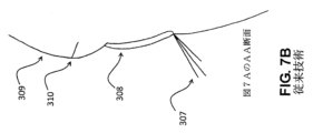
[0055] 上記の2分割マスク等、概ね図5で参照されるマスクの多くの特殊な実施形態がある。これらの実施形態をより詳細に説明するために、ここでの説明は、エクステンションプロセス中に安全性を提供することが目的であるという理解の下に、マスクのみに焦点を合わせるものとする。説明は、対象者301の顔の上に適用されたマスクを参照する。図7Aおよび7Bは、概ね、上まつ毛307、下まつ毛306、眉毛310、額309、およびまぶた308を有する対象者301を示している。対象者の下まぶたは概ね破線311内の領域として示されている。まぶたが言及されるとき、それが下まぶたであると特に述べられていない限り、それは一般に上まぶたであると想定される。図7Aでは、対象者301の右目は開いており、対象者301の左目は閉じている。これらの断面図がマスクの様々な特徴を明らかにするのを助けるので、説明はマスクの正面図と様々な断面図の両方を参照する。これらのマスクは一般的に対称的であり、そして特に明記しない限り、人間の顔の左右対称性を模倣する左右対称性を有すると仮定されるべきである。当然ながら、ロボットまつ毛エクステンション機構の特定の構成にとって有利であり得るいくつかの実施形態では、非対称マスクを有することが可能である。
[0055] There are many special embodiments of the mask referenced generally in FIG. 5, such as the two-part mask described above. In order to describe these embodiments in more detail, the description here will focus only on the mask, with the understanding that the purpose is to provide safety during the extension process. The description refers to a mask applied over the subject's 301 face. 7A and 7B generally show subject 301 with
[0056] いくつかの実施形態では、図8Aおよび図8Bに示すように、マスク313の着用および着脱をより簡単に可能にするために、2分割のマスク313を提供することが好ましい。マスク313は、上部マスク314と下部マスク315とからなる。実際には、対象者301は、目を閉じている間に下部マスク315を着用し、次に目を開いて、下部マスク315の下に下まつ毛308を残しながら下部マスク315の下側から上まつ毛307を引っ張る。次に、対象者301は、再び目を閉じて、まぶた308と額309を覆う上部マスク316を着用する。上部マスク314は下部マスク315の上端に対して位置合わせし、上まつ毛307のための正しい隙間316を確保する。マスク313は、対象者301の頭の後ろを包む弾性ストラップ312によって対象者301の頭に保持される。もちろん、たくさんの解決法の内、耳上のフック、接着剤、マスクを真空供給装置に接続すること、および弾性ストラップを含む、マスクを一般に人の頭部に保持する多くの方法がある。明確にするために、弾性ストラップ312は、2分割マスク313の他の図には示されていない。
[0056] In some embodiments, as shown in Figures 8A and 8B, it is preferred to provide a
[0057] 図9Aおよび図9Bに示すようないくつかの実施形態では、上部マスク314の下端は、舌部318を越えて下部マスク315の上端と嵌合する溝317を含む。図10Aおよび図10Bに示すような他の実施形態では、上部マスク314が下部マスク315上に重なり、磁石319が上部マスク314に接着され、磁性材料320が下部マスク315に接着され、結果として得られる磁力が上部及び下部マスク314,315を正しい向きに保持する。ラッチ、嵌合機構、面ファスナ、弾性ストラップ、フック、およびクリップを含む、上部マスク314および下部マスク315のそれぞれの向きを維持するための当該技術分野において既知の他の多くの方法がある。
[0057] In some embodiments, such as shown in FIGS. 9A and 9B, the lower edge of
[0058] 実際には、2分割マスク313は、ロボット機構が隙間316内の上まつ毛307のみにアクセスすることを可能にすることによって対象者301に安全性を提供する。この安全性は、ロボット機構が2分割マスク313を突き通すかまたは上部マスク314と下部マスク315とを押しのけるほど十分に強くなく、そしてロボット機構上の道具または部品が隙間316を通って嵌ることができない限り完全である。実際には、これはロボット機構に機能を追加することで保証できる。ロボット機構(図示せず)がピンセット330で終端する図11を考察する。ピンセット330は狭い先端部331を有するので、それらは隙間316を通って嵌合することができる。しかしながら、ハンマーヘッドピンセット332がピンセット330の代わりに使用される場合、延長構造333および334は、あらゆる状況において狭い先端331が隙間316を通って到達するのを妨げる。ピンセット330の片側だけからの特徴(ロボットがピンセット330を回転させることができないように設けられる)、ピンセット330の側部から突き出ているリング、およびピンセット330の側部から突き出ているロッドを含む、ピンセット330の特徴を「成長」させてそれらが隙間316を通して到達できないようにするための多くの可能な方法がある。いくつかの実施形態では、ロボットがピンセット335を軸線Xの周りに大きく回転させることができない限り、隙間316に嵌って通り抜けることができない湾曲ピンセット335を使用することで十分であり得る。さらに他の実施形態では、図12に示すように、それらが隙間316と整列できないように、単純に、十分に急な角度で配向される、ピンセット330が可能である。この場合、ロボット機構は、ピンセット330を軸線Xの周りに矢印336の方向に大きく回転させることができてはならない。ロボット工学の分野では、ロボットがピンセット330などのエンドエフェクタを所望の量を超えて回転させないようにする方法がよく理解されている。時にはこの回転防止をソフトウェアで達成できるが、ハードストップまたは本質的にその動きが制限されているアクチュエータの選択によっても達成できる。それでもなお、いくつかのロボットでは、2つ以上のロボット関節が軸Xの周りの回転を可能にし、可動範囲の範囲を困難にし、これはハンマーヘッドピンセット332のようなピンセットの選択を強いることができる。
[0058] In effect, the two-
[0059] いくつかの実施形態では、フェイスマスク340、右まぶたカバー341、および左まぶたカバー342を含む3分割マスク350を提供することが好ましい。図13に示すこの実施形態では、フェイスマスク340は対象者301の顔の大部分を覆い、対象者301の左右の目の上に開口部を残す。次いで、フェイスマスク350の左右の開口部は、左右のまぶたカバー341,342によって大部分が満たされ、これらはそれぞれ、対象者301の左右の両目のそれぞれのまぶた308上に直接位置する。実際には、これは左右のまぶたカバー341,342の両方の周りに円周方向の隙間345が生じさせる。これは各対象者301がその額309からのまぶた308の異なる間隔を有し、3分割マスク350が各個人の顔に合わせてカスタマイズされないためである。これにより、対象者のそれぞれのまぶた308上に配置されるときに、フェイスマスク340と左右のまぶたカバー341,342の各々との間の距離が可変になる。2分割マスク313と同様に、対象者301は、顔の上にフェースマスク340が顔の上に配置される前に両目を閉じ、次に、下まつ毛306が顔マスク340の下に残るが、上まつ毛307が露出されるように両目を開く。対象者301は目を閉じ、左右のまぶたカバー341,342がそれぞれのまぶた308の上に置かれる。また、2分割マスクと同様に、図13に示す弾性ストラップ312のような、弾性ストラップを使用してフェイスマスク340を対象者301の頭部に保持することができる。明確にするために、弾性ストラップ312は、3分割マスク350の他の図には示されない。後述するように、まぶたカバー341,342は、各まぶた308に貼り付けられることができる。また、図示されていないが、いくつかの実施形態では、まぶたカバーはまた、フェイスマスク340にクリップ留めまたは固定されていてもよい。
[0059] In some embodiments, it is preferred to provide a three-
[0060] この実施形態では、ロボット機構のどの部分も円周方向隙間345に嵌合して通らない限り、安全性は3分割マスク350によって提供される。これを行う方法は、2分割マスク313の上述の実施形態と同様であるが、円周方向隙間345が隙間316よりも多くの場所に存在するため、幾分より制限されている。例えば、図11のピンセット330は、円周方向隙間345は隙間316よりも左右のまぶたカバー341,342のいたるところにあるため、それらが隙間316を通って延びることができるのと同じ方法で、しかしさらに多くの場所で、円周方向隙間345を通って容易に延びることができる。しかしながら、ピンセット(または他の任意のエンドエフェクタ)が円周方向隙間345を通って到達できないように特徴を設計することは依然として可能である。例えば、湾曲ピンセット335は、図14に示されるように、ロボット機構がピンセット335を軸線Xの周りに大きく回転させることができない限り、円周方向隙間345を通って到達することはできない。それでもなお、左右のまぶたカバー341,342に加えることができる力は、加えられる力のすべてが対象者301の目に伝達されるので、フェイスマスク340または他の実施形態ではマスクに加えられることができる力よりも小さくなる。
[0060] In this embodiment, safety is provided by the three-
[0061] 2分割マスク313または3分割マスク350のいずれにおいても、マスクの着用中の小さな動きが下まつ毛306がいずれかのマスクの下側からも出ないように、テープを使用して下まつ毛306をさらに押さえることが望ましい場合がある。別の置換では、2分割マスク313または3分割マスク350のいずれかを左右のバージョンにすることも可能である。例えば、マスクは右目のみへのアクセスを提供する2つまたは3つの部分で製造されることができ、第2のマスクは左目のみへのアクセスを提供するように作成されることができる。そのような構成は、作業が行われていない目へのアクセスを提供せず、安全性をわずかに高めるという利点を有している。3分割マスクの設計を使用するこのような構成は、図15に示されており、右マスク353および左マスク354を含む。この構成は、独特のマスク部分の数を増加させるので好ましくないが、採用されるロボット機構の詳細によっては有利であり得る。
[0061] In either the two-
[0062] 3分割マスク350が目の周りにより大きな隙間を生じさせるとともにより小さい力に対してのみ許容性があるならばなぜ3分割マスク350が好まれるのか疑問に思うことは合理的であり得る。3分割マスク350にはいくつかの利点がある。第1に、まぶたカバー341,342がまぶた308の上に直接着座するので、まぶたカバー341,342の外面からまつ毛の基部355までの距離は、2分割マスク313はまぶた308の上に着座できるようにつくられることができないため(それが単一の個人に合うように特別に設計されていない限り)、2分割マスク313が使用される場合よりも短くなり得る。例えば、対象者301Aおよび対象者301Bに対する2分割マスク313と3分割マスク350の現在説明している実施形態の両方のAA断面を示す、図16A~図16Dを検討する。対象者301Bは突出した額を有しており、むしろ平らな額を有する対象者301Bとは異なっている。もちろん、そのような顔の構造および幾何学的形状のバリエーションは、様々な人の間で非常に一般的であり、まぶたからの鼻筋の高さなどの他の顔の構造におけるバリエーションもあり得る。図16Aでは、2分割マスク313は対象者301Aに非常にしっかりとフィットし、上部マスク314からまぶた308への最小限のまぶたオフセット349を生成する。しかし、図16Bでは、同じ2分割マスク313は、対象者301Bにむしろうまくフィットせず、上部マスク314からまぶた308への大きなまぶたオフセット349を生じる。これは、ロボット機構が上まつ毛307の基部を撮像しアクセスすることを困難にする。いくつかの場合には、そのような大きなまぶたオフセット349は、2分割マスク313を使用することを不可能にする可能性がある。しかしながら、図16Cおよび図16Dでは、3分割マスク350は、まぶたカバー342がまぶた308の上に直接位置しているので、対象者301Aおよび301Bのいずれかとの最小まぶたオフセット349を可能にすることが分かる。
[0062] It may be reasonable to wonder why a three-
[0063] 視認性が3分割マスク350を使用する正当な理由であるが、それが唯一の理由ではない。多くの人は、目を閉じるたときにまぶたのばたつきを経験する。つまり、彼らのまぶた、それゆえまつ毛は抑え切れずに振動する。人によっては、ばたつきの大きさがまつ毛の直径よりも大きくなることがある。これは、ロボット機構がエクステンションを配置しているときに、エクステンションを配置するために対象者301のまつ毛307をリアルタイムで追跡しなければならないことを意味する。そのような追跡を達成する方法は知られているが、それらは所望のものよりも洗練されたロボットおよび視覚システムに関連し、まつ毛を配置するプロセスを遅くさせてしまい、これらの全ては望ましくない。図17Aおよび図17Bを参照すると、まぶたカバー341,342に粘着性裏打ち346(両側に粘着性を有する)が与えられ、まぶた308に優しく貼り付けられ、さらに安定物体347に接続されると、まぶたのばたつきが止まり、上まつ毛307は静止することがわかった。この結果は予想外であり、人間のまぶたと人間の顔との間の一般的に順応的な関係に関連すると考えられており、まぶたが人の自分の体によってしっかりと保持されていないのでまぶたを静止した状態に保持することは容易である。図17Aおよび図17Bに示すようないくつかの実施形態では、安定物体347は地上基準の固定物体を含む。しかしながら、他の同様の実施形態では、安定物体347は対象者301の頭に結び付けられることができ、または他の実施形態では、安定物体347はロボット機構を保持するフレームを含む。安定物体347をロボット機構が固定されているのと同じ構造にすることが好ましく、この構造は概ね静止していて地面に結び付けられるべきであることが分かった。この組み合わせは、ロボット機構によって検知されるように上まつ毛307の最小の動きを提供する。しかしながら、ロボット機構が対象者301にどのように接続されるかに応じて、他の実施形態が好ましい可能性がある。また、まぶたカバー341,342と安定物体347との間に分離接続348を設けることが有利であることが分かった。まぶたカバー341,342を所定の位置に保持するのに必要な力が大きくなると、例えば、対象者301が突然頭を動かした場合、分離接続348は切断される。図17Aおよび図17Bに示す好ましい実施形態では、分離接続348は、安定物体347に固着する分離磁石351を含む。これが機能するためには、安定物体347は鉄や多くのスチールのような磁石に引き付けられた材料で作られなければならない。いくつかの実施形態では、安定物体347は、分離磁石351と接合するために提供される鉄などの適切に磁気的に引き寄せられる材料があるという条件で、別の材料で作られることができる。しかしながら、分離接続348は、当技術分野で知られている他の多くの方法の中でも、面ファスナ材料、または他の接着接続で構成されることができる。
[0063] While visibility is a valid reason for using the 3-
[0064] 別の実施形態では、2分割マスク313および3分割マスク350の一部または全部は、図18に示すように、硬質または半硬質のプラスチックではなく、可撓性テープ370で構成されることができる。これは、可撓性テープ370が対象者301の顔に一致し、ロボット機構との潜在的な干渉を低減し、ビジョンシステム360の視認性を向上させることができるので望ましい。いくつかの実施形態では、可撓性テープ370は、ロボット機構からのあらゆる衝撃に対する強度を高めるために、耐パンク性または繊維強化されている。テープ370が吸収することができる力は剛性構造よりも小さいが、ロボット機構の設計によっては、それらは安全性を確実にするのに十分である。この実施形態は、手動のエクステンションプロセス中にテープが下まつ毛306を保持するために通常使用され、対象者301がこのテープの使用に慣れている可能性があるため、さらに有利である。この実施形態では、テープ370は対象者301の皮膚に貼り付けられており、テープ370を所定の位置に保持するための弾性ストラップは必要とされない。
[0064] In another embodiment, part or all of the two-
[0065] 別の実施形態では、マスクは個人に合うようにカスタマイズされている。これは、3分割マスク350のように、対象者のまぶたとマスクとの間のまぶたのずれを最小限に抑えるための別の解決策として使用することができる。もちろん、カスタムデザインのマスクを個々のクライアントの顔の輪郭にぴったり合わせることができるため、オフセットを最小限に抑えるように機能する。カスタムフィットマスクを作成するには、いくつかの方法がある。1つの手法では、従来の方法を使用して、対象者301の顔のキャスティングを行うことができる。このキャスティングは直接使用されることができ、あるいはネガ型を製造するために使用されることができ、それは次にポジ型マスクを製造するために使用される。そのような方法は、特に衣装および特殊効果のために、マスク製造の分野において周知である。しかしながら、これらの方法は時間がかかり、そしてきれいな結果を生み出すために当業者を必要とする。
[0065] In another embodiment, the mask is personalized. This can be used as an alternative solution to minimize eyelid misalignment between the subject's eyelids and the mask, like the three-
[0066] カスタムマスク480を作成する好ましい実施形態では、最新の走査および印刷技術が使用される。図19は、カスタムマスクを製造するためのプロセス460を示す。スキャンデータ470を生成するために、顔走査ステップ461において、3次元(3D)スキャナを使用して対象者301の顔がスキャンされる。飛行時間測定法または他の3次元走査技術を使用することによって、現在、しばしば低コストで、多くの適切なスキャナ入手可能である。例えば、コロラド州ボールダーのOccipital(登録商標)社によって製造されているStructure(登録商標)センサは、そのようなセンサの1つである。別のものは、サウスカロライナ州ロックヒルの3D Systems(登録商標)からのSense(登録商標)3Dである。次に、スキャンデータ470を使用して、顔モデル作成ステップ462において対象者301の顔の顔モデル471を作成する。当技術分野で周知の多くのコンピュータ支援設計システムは、顔スキャンからコンピュータモデルを生成することができ、そのようなソフトウェアは一般的に3Dスキャナと共に提供される。このソフトウェアはまた、対象者301の顔のコンピュータモデルから割れ目を充填し、誤ったデータ点を除去して、最終的な顔モデル472を生成する、顔モデルを「きれい」にするステップ463において顔モデルを自動的に「きれい」にすることもできる。次に、コンピュータは、ステップ463で生成された「きれい」な顔モデルの表面からマスクを成長させることによって、マスクモデル作成ステップ464でベースマスクモデル473を作成する。次に、まつ毛のスリット、マスクを頭に固定するための構造(例えば、ゴムバンド用)、ロボットに接続するための構造(例えば、マスクの前面から伸びた柱)がマスクモデル474を生成するためのステップ465で自動的に追加される。最も一般的な場合では、技術者を使用して、マスクモデルを人間が検討するステップ466においてマスクモデル474が適切に設計されていることを確実することができる。しかしながら、いくつかの実施形態では、マスクモデル474を人間なしで自動的にチェックし、それによってステップ466を自動化することが可能である。この最終検討は、印刷の準備ができている最終マスクモデル475を生成する。カスタムマスク480を印刷するために、3D印刷のような積層造形法が使用される。適しているであろう多くの3Dプリンタが当該技術分野において知られており、例えば、ミネソタ州エデンプレーリーのStratasys(登録商標)によって製造されたFortus(登録商標)380mcがカスタムマスク480に十分な印刷量を有している。いくつかの実施形態では、この印刷は現場外で行われ、マスク480は、対象者301に使用するために現場に送達されるまで準備ができていない。しかしながら、いくつかのより新しい3Dプリンタは、主題301が待っている間に現場で印刷を行うことができるほど十分に速い。
[0066] The preferred embodiment for creating the
[0067] この実施形態は、カスタムマスク480が対象者301に非常に正確にフィットし、剛性があり(したがって良好な安全保護を提供し)、ビジョンシステム460に良好な視認性を与えるので、大きな利点を有する。しかしながら、この実施形態にはかなりの不利益、主に追加の時間と費用がある。3Dスキャナを使用して対象者301を走査し、次いでコンピュータモデル482を修正し、次いでカスタムマスク480を印刷することは、サロンでかなりの時間がかかるか、または対象者301にマスク480の配達を待たせることになる。また、カスタムマスク480の印刷は高価であり得、マスク480は使用後に保管されるべきである。この時間とコストのために、これはおそらくプレミアムなサービスとしてを除いて好ましい実施形態であるとは思われない。
[0067] This embodiment is advantageous because the
[0068] 上記実施形態は、一般に、エクステンションプロセスを実行しているロボット機構と協働することを目的としているが、本明細書に提示されるマスク設計は、一般に、従来のまつ毛エクステンションに対する安全性の提供に適用可能である。例えば、カスタムマスク480は、手技中に怪我の可能性を減らすため、または美容師にハンドレストを提供するために、美容師からまつ毛エクステンションを受ける対象者に使用されることができる。
[0068] Although the above embodiments are generally intended to work with robotic mechanisms performing the extension process, the mask designs presented herein are generally safe for conventional eyelash extensions. applicable to the provision of For example,
[0069] 本発明のさらに別の実施形態では、マスクからの保護は、目の周りの柔らかい部分、まぶたの上、まぶたのすぐ上、および目のすぐ下の周りにのみ提供される。これらの領域はここでは「柔らかい」と呼ばれ、なぜならそれらは目窩を覆っているからであり、人間の額や上頬とは異なり、表面の下には骨の多い頭蓋骨がない。したがって、ロボットが非常に弱く、例えば皮膚を貫通することがほとんどできない場合、これらが保護が望ましい唯一の分野になる可能性がある。例えば、額に軽傷を負わせることはできないが、それでもまぶた(またはまぶたの下にある目)をひどく傷つける可能性がある、非常に弱いロボットで使用される軽量のプラスチック製ピンセットのセットを想像するのは簡単である。 [0069] In yet another embodiment of the present invention, protection from the mask is provided only in the soft areas around the eyes, above the eyelids, just above the eyelids, and around just below the eyes. These areas are called "soft" here because they cover the eye sockets, and unlike the human forehead and upper cheeks, there is no bony skull beneath the surface. So if the robot is so weak that it can barely penetrate skin, for example, these may be the only areas where protection is desirable. For example, imagine a set of lightweight plastic tweezers used on a very weak robot that cannot inflict minor injuries to the forehead, but can still severely injure the eyelid (or the eye under the eyelid). is easy.
[0070] そのような場合、図20Aおよび図20Bに示すような実施形態を使用することができる。ここでは、右上貼付マスク371がまぶたの真上を含む右まぶたを覆い、右下貼付マスク372が目の真下を覆う。右上の貼付マスク371および右下の貼付マスク372は、右の接着マスク接続部373において、目の右隅で重なっている。右側貼付マスク接続部373は、接着剤、マジックテープ(登録商標)、磁石接続、またはマスクの上部と下部との間の任意の同様の光接続のうちの1つを含む。上部と下部とを接続すると、まぶたがばたつきに対して安定するのに役立つ。左側は、鏡像の同じ構成要素、すなわち左側貼付マスク接続部376を介して接続する上部および下部左側貼付マスク374,375を含む。4つのマスク部分は、ポリエチレン、ナイロン、またはABSなどの半硬質の薄いプラスチック、または柔軟なゴム材料で作ることができる。さらに、ロボット機構およびエンドエフェクタが特に安全な設計のものである場合、マスク部の全部または一部を、手動のまつ毛エクステンションプロセスの間に下蓋に使用される現在の「ゲルパッド」などのローションを注入した繊維材料で構成されることができる。拡張プロセス実際には、0.5から2mm程度の厚さは、それでもなお妥当な保護を提供する薄いマスクを可能にする。いくつかの実施形態では、まつ毛の根元のより良好な視認性を可能にするために、マスクの1つ以上の部分がまつ毛の近くで先細になっている。例えば、図20Aおよび図20Bでは、左右の上部貼付マスク371,374はテーパエッジ378を有する。異なる幅のまつ毛および異なるアイソケット形状を有する人を収容するために、複数のサイズのマスクを提供することもまた望ましい可能性がある。しかしながら、図20Aおよび図20Bに示されている上部および下部の貼付マスクのトポロジーは広範囲の人に適合し、通常はほんの数サイズしか必要とされないことが分かっている。マスクは、適度な強度の任意の生体適合性接着剤で人に接着されることができる。強すぎる接着剤を使用しないこと(そうしないとマスクを快適に取り外すことができない)も、接着剤を弱くすること(そうしないと使用中にマスクが脱落してしまう)が重要である。例えば、ノースカロライナ州シャーロットのBSNメディカル(登録商標)により製造された接着剤であるJobst(登録商標)「It Stays!、ニュージャージー州ノースベールのADM(登録商標)Unlimited社によるPros-Aide(登録商標)や、ペンシルバニア州グレンロックのAdhesives Research(登録商標)によるSoftWear(登録商標)や、ロードアイランド州クランストンのTorbot(登録商標)社によるSkin Tac(登録商標)を含む多くの適切な種類の接着剤がある。
[0070] In such cases, embodiments such as those shown in Figures 20A and 20B may be used. Here, the upper
[0071] 上述の実施形態のわずかな置換を図21Aおよび図21Bに示す。ここでは、上部および下部右貼付マスク381,382は、右貼付マスク接続部383において、目の目頭および目尻の両方で重なっている。同様に、左側では、上部および下部左側貼付マスク384,385が左側貼付マスク接続部386を介して接続される。すなわち、図21Aおよび図21Bにおける唯一の違いは、貼付マスクが2箇所で接続されていることである。この実施形態は、上部マスクと下部マスクとの間により大きな構造的接続を提供することができ、これはまぶたのばたつきを低減するのに役立つ。もちろん、組み合わせたマスクを上述のような安定した物体に固定することもさらに可能である。
[0071] A slight permutation of the above-described embodiment is shown in Figures 21A and 21B. Here, the upper and lower right applied
[0072] 先の実施形態の別のわずかな置換を図22Aおよび図22Bに示す。目の目頭および目尻の両方で重なり合うように示されているが、示されている解決策は前の2つの実施形態のどちらとも適合する。ここでは、拡張された右下マスク392および拡張された左下マスク395が対象者301の頬のさらに下方に延びている。これは、対象者301のほおをより多くカバーするという点で利点を与える。また、対象者301のまつ毛307は、一般に、ロボット機構または人が頭の上から見ることになり、頬を下方に向かってさらに下マスクを延ばすことは、まつ毛307を照らすための均一な色のより大きな領域を提供するのに有利であり得る。これは特に、コンピュータビジョンに使用されるアルゴリズムは、人間よりも色の変化に対して敏感である可能性があるので、ロボット機構によって行われる自動まつ毛エクステンションの場合には有利である。実際に、図22Bでは、上方から見たときにさらに長い見た目の部分を提供するように、拡張された左下マスク395は下側に沿って対象者301の頬から離れて持ち上がっている。
[0072] Another slight permutation of the previous embodiment is shown in Figures 22A and 22B. Although shown to overlap at both the inner and outer corners of the eye, the solution shown is compatible with either of the previous two embodiments. Here, the extended lower
[0073] いくつかの実施形態では、まぶたのばたつきをさらに低減するために、図17AおよびBに関連して上述したシステムと同様に、柔軟なマスクをロボットまたは安定した場所に固定することが望ましい。図23に示すように、対象者301は、図20Aおよび図20Bに示したのと基本的に同じ上下左右のマスクを被っている。しかしながら、また、対象者301は、固定フレーム385も身に付けている。固定フレーム385は目鏡フレームに類似しており、レンズなしの通常の目鏡のように対象者301の耳と鼻との上に置かれる。しかし、固定フレーム385はまた、固定フレーム385をそれぞれ右上および左上の貼付マスク371,374に結合する右および左の貼付マスクアンカ380,382をそれぞれ含む。上部および下部貼付マスク間の接続と同様に、左右の貼付マスクアンカー380,382は、接着剤、面ファスナ、または磁石接続、または他の任意の薄型接続で作ることができる。さらに、固定フレーム385は、固定フレーム385をロボットにラッチする左右のラッチ381および383を含む。この実施形態では、ラッチは単純な磁石として示されており、これはロボットが嵌合磁石または磁性材料を含む場合には十分であるが、当然ながら任意の数の接続が可能である。この実施形態の利点は、対象者301がロボットに近づく前に固定フレーム385を着用し、それらを貼付マスクに接続することができ、着用プロセスが単純化されることである。しかしながら、いくつかの実施形態では、固定フレーム385を省き、ロボット上の左右の貼付マスクアンカー380,382のための嵌合機能を単に提供することで十分であり得る。
[0073] In some embodiments, it may be desirable to fix the flexible mask to a robot or stable location, similar to the system described above with respect to FIGS. 17A and B, to further reduce eyelid flutter. . As shown in FIG. 23, subject 301 is wearing basically the same top, bottom, left, and right masks as shown in FIGS. 20A and 20B. However, subject 301 also wears fixed
その他の安全戦略
[0074] 上述の実施形態の多くにおいて、マスクが所定の位置にあることを知ることは有用であり得る。例えば、ロボット機構がまつ毛エクステンションを配置している実施形態では、マスクの全ての部分が存在することを確認することは有用である。これはコンピュータビジョンシステムによる検査によって達成できることが可能であるが、マスクを提供する目的は部分的にフェイルセーフな安全性を提供することであるので、よりフェイルセーフな方法を提供することが望ましい。マスクの全ての部分が重なり合う最も単純な実施形態では、そのようなフェイルセーフの検証は、マスク自体が導電性であり、マスクの最初の部分と最後の部分とが、導電経路が閉じられたときにロボット機構を有効にする回路にその導電経路を戻すように、マスクの部分間の接続が導電接続を有することによって達成される。このようにして、マスクのいずれかの部分が切断されると、導電経路が開き、ロボットを無効にする。もちろん、ロボット工学および自動機械の当業者は、接続を確認するために抵抗測定ではなく容量測定または誘導測定またはこれらの何らかの組み合わせの使用を含む、そのような回路を開発する多くの方法があることに気付くであろう。いくつかの実施形態では、図9Aおよび図9Bに示されるもののように、重なり合うタブはなく、余分な接続ストラップが提供されるべきである。他の実施形態では、図23に示すように、マスクの各部分に一度だけ触れることは便利ではないため、ここでも接続ストラップを使用する必要がある。あるいは、そのマスクのチェーンの接続を検証するために、例えば、導電経路の最後の部分に抵抗器とを含むループバック回路を使用することが可能である。例えば、図23では、抵抗器のいずれかの側への接続が最初に右側上部マスク371を通り、次に固定フレーム385を通り、そしてそこから、結果として得られる回路の抵抗が、それが抵抗器を通して閉じられていることを示している場合にのみ有効になる、ロボット機構へと接続されて、抵抗器が右側下部マスク372に配置され得る。
Other Safety Strategies [0074] In many of the embodiments described above, it may be useful to know that the mask is in place. For example, in embodiments where a robotic mechanism is placing eyelash extensions, it is useful to ensure that all portions of the mask are present. It is possible that this could be accomplished by inspection with a computer vision system, but since the purpose of providing masks is to provide partial fail-safe safety, it is desirable to provide a more fail-safe method. In the simplest embodiment, where all portions of the mask overlap, such fail-safe verification is based on the fact that the mask itself is conductive and that the first and last portions of the mask are Connections between portions of the mask are accomplished by having conductive connections so as to return the conductive paths to the circuitry that enables the robotic mechanism to operate. In this way, if any portion of the mask is cut, a conductive path is opened, disabling the robot. Of course, those skilled in the art of robotics and automatic machines will appreciate that there are many ways to develop such circuits, including using capacitive or inductive measurements, or some combination thereof, rather than resistive measurements to verify connections. will notice. In some embodiments, there should be no overlapping tabs and extra connecting straps should be provided, such as those shown in FIGS. 9A and 9B. In another embodiment, as shown in FIG. 23, it is not convenient to touch each part of the mask only once, so connecting straps must be used here as well. Alternatively, a loopback circuit including, for example, a resistor at the end of the conductive path can be used to verify the connection of the chain of masks. For example, in FIG. 23, the connections to either side of the resistor are first through the right
[0075] 安全性を達成するための別の手段では、上述したものと同様のインターロックを設けることが可能であるが、ロボット機構及びマスクによって提供されたピンセットまたは他のエンドエフェクタとマスクとの間の経路をチェックし、この場合ロボットを停止させる。ここでの目標は、ロボットが意図せずにマスクに触れ、それ故に容認できないほど対象者に接近した場合にロボットを停止させることである。もちろん、この場合、回路は、接続がロボットを無効にするための条件であり、切断がロボットを有効にするための条件であることを認識すべきであるが、このように論理を逆転するための安全上重要な回路は当業界でよく知られている。いくつかの実施形態では、この回路は、抵抗測定、またはこれらの何らかの組み合わせではなく、容量センシングまたは誘導センシングに頼ることができる。 [0075] Another means of achieving safety may be to provide interlocks similar to those described above, but with the addition of tweezers or other end effectors provided by the robotics and mask to the mask. Check the path between and stop the robot in this case. The goal here is to stop the robot if it touches the mask unintentionally and is therefore unacceptably close to the subject. Of course, in this case the circuit should recognize that connection is a condition for disabling the robot and disconnection is a condition for enabling it, but in order to reverse the logic in this way safety critical circuits are well known in the art. In some embodiments, the circuit may rely on capacitive or inductive sensing rather than resistive measurements, or some combination thereof.
[0076] 別の実施形態では、マスクは不要であり、ロボットの安全性は純粋に上述のインターロックによってもたらされる。つまり、ロボットピンセットやエンドエフェクタが対象者に近すぎる、または対象者に触れると、ロボットの動作が停止する。いくつかの実施形態では、これはロボットへの電力を除去することを構成することができるが、他の実施形態では、ロボットの動きを止めるためにブレーキが使用される。この方法ではインターロックシステムに対する要求が大きくなるが、マスクが不要なためシステム設計が簡単になる。それにもかかわらず、この実施形態はまつ毛を安定化させず、これは、図21Aおよび図21Bに示されるものなどのマスク設計の多くにとって有利である。 [0076] In another embodiment, no mask is required and robot safety is provided purely by the interlocks described above. That is, if the robot tweezers or end effector are too close to or touch the subject, the robot will stop moving. In some embodiments this can consist of removing power to the robot, while in other embodiments a brake is used to stop the robot from moving. Although this method puts more demands on the interlock system, it simplifies the system design because no mask is required. Nevertheless, this embodiment does not stabilize the lashes, which is an advantage for many mask designs such as those shown in Figures 21A and 21B.
[0077] この実施形態の一例として、対象者301と検知ピンセット401とを含む図24を考察する。ロボット機構403の物理的形態は明瞭さを保つために図24には示されていないが、検知されたピンセット401はロボット機構403によって操作されていることが理解される。検知ピンセット401は、容量センサ402に電気的に接続されている。検知ピンセット401をより良好にアンテナとして機能させることを可能にするために、アンテナ領域404を検知ピンセット401の一部として組み込むことができる。検知されたピンセット401が、貧弱なアンテナを構成するであろう非導電性材料で作られている場合、これは特に重要であり得る。アンテナ領域404は、検知されたピンセット401の表面の一部であり得るが、特にアンテナ領域404が検知されたピンセット401に適合することができない複雑な幾何学形状を使用する場合、それはまたピンセット401から突き出る別個の物理的表面であり得る。容量センサ402は、静電容量を検出する技術分野で周知の任意の数の回路のうちの1つとすることができる。例えば、南アフリカのプレトリアのAzoteq(登録商標)によって製造されているIQS127Dのような、容量性検知を提供する多くの集積回路が安価に入手可能である。次いで、容量センサ402は、検知されたピンセット401と対象者301との間の距離を示す信号をロボット機構403に提供する。いくつかの実施形態では、この信号は連続測定であり得、他の実施形態では、距離が安全閾値を下回ったかどうかを示す単一の高/低信号と同じくらい単純であり得る。好ましい実施形態では、この信号はフェイルセーフであるべきであり、その結果、容量センサ402への電気接続が失敗した場合、または容量センサ402が故障した場合、信号はいかなる安全閾値よりも小さな距離を示す。
[0077] As an example of this embodiment, consider FIG. Although the physical form of
[0078] いくつかの実施形態では、眉毛はまつ毛とかなり類似した特性を有するので、まつ毛ではなく眉毛を伸ばすための安全性を提供するために同じ装置を使用することができる。この実施形態では、マスクの隙間は、まつ毛ではなく眉毛の周りに設けられる。 [0078] In some embodiments, eyebrows have very similar properties to eyelashes, so the same device can be used to provide safety for extending eyebrows rather than eyelashes. In this embodiment, the gaps in the mask are provided around the eyebrows rather than the eyelashes.
[0079] 上記に基づいて、本発明がまつ毛エクステンションをより効果的に取り付ける方法を提供し、それがそうする時間と費用の両方を削減することは容易に明らかであるはずである。本発明のシステムおよび方法は明らかに安全であるので、エクステンションを受ける人は手順に自信を持つことができる。好ましい実施形態を参照して説明したが、本発明の精神から逸脱することなく本発明に様々な変更または修正を加えることができることを容易に理解されたい。一般に、本発明は特許請求の範囲によってのみ限定されることを意図している。
(項目1)
まつ毛エクステンションをしている対象者を保護するように構成されたマスクにおいて、
対応する前記対象者の目を露出させることなく、前記対象者の少なくとも1つのまつ毛を露出させるように構成された隙間を含み、対象者の顔の輪郭をたどって、前記対象者の対応する上まぶたの少なくとも一部および対応する下まぶたの少なくとも一部を覆うように構成された、マスク。
(項目2)
第1の部分および第2の部分をさらに含み、前記第1の部分は、前記対象者の前記対応する上まぶたを覆うように構成され、前記第2の部分は、前記対象者の前記対応する下まぶたを覆うように構成され、前記第1の部分および前記第2の部分は、互いに当接したときに前記少なくとも1つのまつ毛の上に前記隙間を形成するように構成された、項目1に記載のマスク。
(項目3)
前記第1の部分および前記第2の部分のうちの少なくとも1つは、前記対象者の前記顔に貼り付くように構成された、項目2に記載のマスク。
(項目4)
前記第1の部分および前記第2の部分のうちの前記少なくとも1つは、接着剤を使用して前記対象者の顔に貼り付くように構成された、項目3に記載のマスク。
(項目5)
前記第1の部分および前記第2の部分のうちの前記少なくとも1つは、真空源を使用して前記対象者の顔に貼り付くように構成された、項目3に記載のマスク。
(項目6)
上まぶたカバーとフェイスマスクとをさらに備え、前記フェイスマスクは空隙を含み、前記空隙は、前記上まぶたカバーが前記フェイスマスクの内側に嵌り、前記フェイスマスクと同一面になることを可能にするように構成され、前記上まぶたカバーは、前記空隙の内側にあるときに前記フェイスマスクと前記隙間を形成するように構成された、項目1に記載のマスク。
(項目7)
前記上まぶたカバーは、前記対象者の前記対応する上まぶたに貼り付くように構成され、前記上まぶたカバーは、前記上まぶたカバーをアンカーに結合するように構成された固定接続部を含む、項目6に記載のマスク。
(項目8)
前記アンカーは、前記対象者の頭部である、項目7に記載のマスク。
(項目9)
前記アンカーは、固定された物体である、項目7に記載のマスク。
(項目10)
前記アンカーは、ロボットまつ毛エクステンションシステムである、項目7に記載のマスク。
(項目11)
前記固定接続部は、前記対象者の頭部が前記アンカーに対して変位したときに切断するように構成された分離接続部を含む、項目7に記載のマスク。
(項目12)
前記対象者の前記対応する上まぶたを覆うように構成された上まぶたカバーと、前記対象者の前記対応する下まぶたを覆うように構成された下まぶたカバーとをさらに備え、前記上まぶたカバーおよび前記下まぶたカバーの各々は、前記対象者の皮膚に貼りつくように構成され、前記上まぶたカバーおよび前記下まぶたカバーは、互いに接続されるように構成され、前記上まぶたカバーおよび前記下まぶたカバーは、互いに接続されたときに前記少なくとも1つのまつ毛の上に隙間を形成するように構成された、項目1に記載のマスク。
(項目13)
前記対象者の第2の上まぶたを覆うように構成された第2の上まぶたカバーと、前記対象者の第2の下まぶたを覆うように構成された第2の下まぶたカバーとをさらに含み、前記第2の上まぶたカバー及び前記第2の下まぶたカバーの各々は、前記対象者の前記皮膚に貼り付くように構成され、前記第2の上まぶたカバー及び前記下まぶたカバーは、互いに接続されるように構成され、前記第2の上まぶたカバー及び前記第2の下まぶたカバーは、互いに接続されたときに前記対象者の少なくとも1つの他のまつ毛の上に第2の隙間を形成するように構成された、項目12に記載のマスク。
(項目14)
前記上まぶたカバーおよび前記下まぶたカバーのうちの少なくとも1つは、アンカーに結合されるように構成された固定接続部を含む、項目12に記載のマスク。
(項目15)
前記アンカーは、前記対象者の頭部である、項目14に記載のマスク。
(項目16)
前記アンカーは、固定された物体である、項目14に記載のマスク。
(項目17)
前記アンカーは、ロボットまつ毛エクステンションシステムである、項目14に記載のマスク。
(項目18)
前記対象者の耳及び鼻の上に置かれるように構成された1組の固定フレームをさらに含み、前記1組の固定フレームは前記アンカーを含み、前記1組の固定フレームは、第2のアンカーに選択的に結合されるようにさらに構成された、項目14に記載のマスク。
(項目19)
前記マスクは、実質的に可撓性の材料からなる、項目12に記載のマスク。
(項目20)
前記マスクは、半硬質材料からなる、項目12に記載のマスク。
(項目21)
前記マスクは、実質的に硬質材料からなる、項目12に記載のマスク。
(項目22)
前記対象者の前記対応する上まぶたを覆うように構成された上まぶたカバーと、前記対象者の前記対応する下まぶたを覆うように構成された下まぶたカバーとをさらに備え、前記上まぶたカバー及び前記下まぶたカバーは、前記対象者の前記皮膚に貼り付くように構成された接着性裏当てが設けられ、前記対象者の前記皮膚に貼り付けられたときに重ならないように構成され、前記対象者の前記皮膚に貼り付けられたときに前記少なくとも1つのまつ毛の上に前記隙間を形成するように構成された、項目1に記載のマスク。
(項目23)
前記上まぶたカバーは、アンカーに結合するように構成された固定接続部を含む、項目22に記載のマスク。
(項目24)
前記マスクは、前記対象者の前記顔の特定の幾何学形状に対応してたどるように構成され、前記特定の幾何学形状は、前記対象者の前記顔の三次元走査により判断される、項目1に記載のマスク。
(項目25)
まつ毛エクステンションを受けている対象者を保護するためのマスクを作成する方法において、
前記対象者の顔を三次元で走査するステップと、
前記走査に基づいて前記顔に対応するフェイスマスクモデルを生成するステップと、
対応する前記対象者の目を露出させることなく、前記対象者の少なくとも1つのまつ毛が露出される位置に対応する隙間を前記フェイスマスクモデルに含めるステップと、
前記顔にぴったりと合うように、前記フェイスマスクモデルに基づいて前記マスクを作るステップとを含む、マスクを作成する方法。
(項目26)
まつ毛エクステンションを受けている対象者を保護するように構成されたシステムにおいて、
少なくとも2つのシャッタを有する筐体を含むロボット機構を備え、前記少なくとも2つのシャッタは、前記対象者の対応する目を露出させることなく、前記対象者の少なくとも1つのまつ毛を露出するように構成された隙間を残すように互いに選択的に連動するように構成され、前記少なくとも2つのシャッタおよび前記筐体は、前記少なくとも1つのまつ毛以外の前記対象者のいかなる部分へのロボット機構によるアクセスを禁止するように構成された、システム。
(項目27)
前記少なくとも2つのシャッタがいつ連動しているかを示し、この状態について前記ロボット機構と通信するように構成されたスイッチをさらに備えた、項目26に記載の装置。
(項目28)
少なくとも2つの部分を含み、対象者の顔の輪郭をたどるように構成されたマスクであって、前記対象者の少なくとも1つのまつ毛を、前記対象者の対応する目を露出させることなく、露出させるように構成された隙間をさらに含む、マスクを用いて、まつ毛エクステンションを受ける対象者の目を保護する、またはまぶたを安定させる方法において、
少なくとも2つのサイズの中から前記マスクについて適切なサイズを選択するステップと、
前記マスクを前記対象者に合わせるステップと、
前記マスクを前記対象者の顔に貼り付けるステップと、
前記マスクをほぼ静止した物体に固定するステップとを含む、方法。
(項目29)
人間である対象者に対して作業を実行するように構成された本質的に安全なロボットシステムにおいて、
前記人間である対象者に危害を与えることのできない弱いロボット機構と、
前記人間と前記ロボット機構との間の安全障壁であって、前記人間である対象者または前記人間である対象者の周囲に固定された、安全障壁と、
前記ロボット機構に結合された少なくとも1つのエンドエフェクタであって、前記安全障壁は、前記少なくとも1つのエンドエフェクタの危害を与え得るいかなる部分も通過することができない窓または隙間を含むことにより、前記少なくとも1つのエンドエフェクタによる危害から前記人間である対象者を保護する、エンドエフェクタとを含む、本質的に安全なロボットシステム。
(項目30)
前記窓または隙間は、前記人間である対象者の前記解剖学的構造の部分が窓または隙間を通って突き出ることを可能にし、前記少なくとも1つのエンドエフェクタが前記部分にアクセスできるように構成された、項目29に記載の本質的に安全なロボットシステム。
(項目31)
前記部品は、少なくとも1つのまつ毛を含む、項目30に記載の本質的に安全なロボットシステム。
(項目32)
前記部分は、前記人間である対象者の毛髪を含む、項目30に記載の本質的に安全なロボットシステム。
[0079] Based on the above, it should be readily apparent that the present invention provides a more effective method of attaching eyelash extensions, which reduces both the time and expense of doing so. The system and method of the present invention are demonstrably safe, allowing the person undergoing extensions to feel confident in the procedure. Although described with reference to preferred embodiments, it will be readily appreciated that various changes and modifications can be made to the invention without departing from the spirit of the invention. Generally, the invention is intended to be limited only by the claims that follow.
(Item 1)
A mask configured to protect a subject with eyelash extensions,
a gap configured to expose at least one eyelash of the subject without exposing the corresponding eye of the subject, following the contours of the subject's face, and A mask configured to cover at least a portion of an eyelid and at least a portion of a corresponding lower eyelid.
(Item 2)
Further comprising a first portion and a second portion, wherein the first portion is configured to cover the corresponding upper eyelid of the subject, and the second portion is configured to cover the corresponding upper eyelid of the subject. Item 1, wherein the first portion and the second portion are configured to cover the lower eyelid, and the first portion and the second portion are configured to form the gap above the at least one eyelash when abutting each other. Mask as described.
(Item 3)
3. The mask of item 2, wherein at least one of the first portion and the second portion is configured to adhere to the face of the subject.
(Item 4)
4. The mask of item 3, wherein the at least one of the first portion and the second portion is configured to adhere to the subject's face using an adhesive.
(Item 5)
4. The mask of item 3, wherein the at least one of the first portion and the second portion is configured to adhere to the subject's face using a vacuum source.
(Item 6)
Further comprising an upper eyelid cover and a face mask, the face mask including a gap, the gap allowing the upper eyelid cover to fit inside the face mask and be flush with the face mask. and wherein the upper eyelid cover is configured to form the gap with the face mask when inside the gap.
(Item 7)
wherein said upper eyelid cover is configured to adhere to said corresponding upper eyelid of said subject, said upper eyelid cover including a fixed connection configured to couple said upper eyelid cover to an anchor. 6. Mask according to 6.
(Item 8)
8. Mask according to
(Item 9)
8. Mask according to
(Item 10)
8. Mask according to
(Item 11)
8. The mask of
(Item 12)
an upper eyelid cover configured to cover the corresponding upper eyelid of the subject; and a lower eyelid cover configured to cover the corresponding lower eyelid of the subject, wherein the upper eyelid cover and Each of the lower eyelid covers is configured to adhere to the subject's skin, the upper eyelid cover and the lower eyelid cover are configured to be connected to each other, and the upper eyelid cover and the lower eyelid cover are configured to form a gap above the at least one eyelash when connected together.
(Item 13)
further comprising a second upper eyelid cover configured to cover the subject's second upper eyelid; and a second lower eyelid cover configured to cover the subject's second lower eyelid. , each of the second upper eyelid cover and the second lower eyelid cover is configured to stick to the skin of the subject, and the second upper eyelid cover and the lower eyelid cover are connected to each other wherein the second upper eyelid cover and the second lower eyelid cover form a second gap over at least one other eyelash of the subject when connected together 13. The mask of item 12, configured to:
(Item 14)
13. The mask of item 12, wherein at least one of the upper eyelid cover and the lower eyelid cover includes a fixed connection configured to be coupled to an anchor.
(Item 15)
15. The mask of item 14, wherein the anchor is the subject's head.
(Item 16)
15. Mask according to item 14, wherein the anchor is a fixed object.
(Item 17)
15. The mask of item 14, wherein the anchor is a robotic eyelash extension system.
(Item 18)
further comprising a set of fixation frames configured to be placed over the ears and nose of the subject, the set of fixation frames including the anchors, the set of fixation frames including a second anchor. 15. The mask of item 14, further configured to be selectively coupled to the .
(Item 19)
13. Mask according to item 12, wherein the mask is made of a substantially flexible material.
(Item 20)
13. The mask of item 12, wherein the mask is made of a semi-rigid material.
(Item 21)
13. Mask according to item 12, wherein the mask consists essentially of a hard material.
(Item 22)
an upper eyelid cover configured to cover the corresponding upper eyelids of the subject; and a lower eyelid cover configured to cover the corresponding lower eyelids of the subject, wherein the upper eyelid covers and the lower eyelid cover is provided with an adhesive backing configured to adhere to the skin of the subject and is configured to not overlap when adhered to the skin of the subject; 2. The mask of item 1, configured to form the gap above the at least one eyelash when applied to the skin of a person.
(Item 23)
23. The mask of item 22, wherein the upper eyelid cover includes a fixed connection configured to couple to an anchor.
(Item 24)
wherein said mask is configured to correspondingly follow a particular geometry of said face of said subject, said particular geometry determined by a three-dimensional scan of said face of said subject; 1. The mask according to 1.
(Item 25)
A method of making a mask for protecting a subject undergoing eyelash extension, comprising:
scanning the subject's face in three dimensions;
generating a face mask model corresponding to the face based on the scan;
including gaps in the face mask model corresponding to locations where at least one eyelash of the subject is exposed without exposing corresponding eyes of the subject;
and C. making said mask based on said face mask model to fit said face.
(Item 26)
In a system configured to protect a subject undergoing eyelash extensions, comprising:
a robotic mechanism including a housing having at least two shutters, the at least two shutters configured to expose at least one eyelash of the subject without exposing a corresponding eye of the subject. wherein said at least two shutters and said housing are configured to selectively interlock with each other to leave a gap between said at least two shutters and said housing prohibits robotic access to any part of said subject other than said at least one eyelash. A system configured to
(Item 27)
27. Apparatus according to item 26, further comprising a switch configured to indicate when the at least two shutters are engaged and to communicate with the robotic mechanism about this state.
(Item 28)
A mask comprising at least two portions and configured to follow the contours of a subject's face, exposing at least one eyelash of the subject without exposing the corresponding eye of the subject. A method of protecting an eye or stabilizing an eyelid of a subject undergoing eyelash extension with a mask, further comprising a gap configured to:
selecting an appropriate size for said mask from among at least two sizes;
fitting the mask to the subject;
affixing the mask to the subject's face;
fixing said mask to a substantially stationary object.
(Item 29)
In an intrinsically safe robotic system configured to perform a task on a human subject,
a weak robotic mechanism incapable of harming the human subject;
a safety barrier between the human and the robotic mechanism, the safety barrier fixed around the human subject or around the human subject;
at least one end effector coupled to the robotic mechanism, wherein the safety barrier comprises a window or gap through which any potentially hazardous portion of the at least one end effector cannot pass, thereby An intrinsically safe robotic system comprising an end effector that protects the human subject from harm by one end effector.
(Item 30)
The window or gap is configured to allow a portion of the anatomy of the human subject to protrude through the window or gap and to allow the at least one end effector to access the portion. 30. Intrinsically safe robotic system according to , item 29.
(Item 31)
31. Intrinsically safe robotic system according to item 30, wherein said part comprises at least one eyelash.
(Item 32)
31. The intrinsically safe robotic system of item 30, wherein said portion comprises hair of said human subject.
Claims (18)
上まつげを有する前記対象者の上まぶたを覆うように構成された上まぶたカバーであって、上端縁部と前記上まつ毛の基部に対応するように構成された反対側の下端縁部とを備えた、上まぶたカバーと、
前記対象者の下まぶたを覆うように構成された下まぶたカバーであって、上端縁部と反対側の下端縁部とを備え、前記上端縁部は前記上まぶたカバーの前記下端縁部の形状を補う、下まぶたカバーとを備え、
前記上まぶたカバーおよび前記下まぶたカバーは、対応する目の隅で互いに接続されるように、および前記下まぶたカバーの前記上端縁部と前記上まぶたカバーの前記下端縁部との間に隙間を形成するように構成されており、前記隙間は、対応する前記対象者の目を露出させることなく、前記対象者の少なくとも1つのまつ毛を露出させるように構成された、マスク。 A mask configured to protect a subject with eyelash extensions,
An upper eyelid cover configured to cover the upper eyelids of the subject having upper eyelashes, comprising an upper edge and an opposite lower edge configured to correspond to the base of the upper eyelashes an upper eyelid cover,
A lower eyelid cover configured to cover the subject's lower eyelids, comprising an upper edge and an opposite lower edge, wherein the upper edge has the shape of the lower edge of the upper eyelid cover. Compensating for the lower eyelid cover and
The upper eyelid cover and the lower eyelid cover are connected to each other at corresponding eye corners, and a gap is provided between the upper edge of the lower eyelid cover and the lower edge of the upper eyelid cover. wherein the gap is configured to expose at least one eyelash of the subject without exposing a corresponding eye of the subject.
前記マスクを前記対象者に位置合わせするステップと、
前記隙間が前記対象者の対応する目を露出させることなく前記対象者の少なくとも1つのまつ毛を露出させて、前記マスクを前記対象者の顔に貼り付けるステップとを含む、方法。 An upper eyelid cover configured to cover the upper eyelids of the subject having upper eyelashes, comprising an upper edge and an opposite lower edge configured to correspond to the base of the upper eyelashes and a lower eyelid cover configured to cover the subject's lower eyelids, comprising an upper edge and an opposite lower edge, wherein the upper edge extends from the upper eyelid. a lower eyelid cover that complements the shape of the lower edge of the cover, wherein the upper eyelid cover and the lower eyelid cover are connected to each other at corresponding eye corners, and the upper edge of the lower eyelid cover; A method of protecting an eye or stabilizing an eyelid of a subject undergoing eyelash extension using a mask configured to form a gap between an edge and the lower edge of the upper eyelid cover, comprising:
aligning the mask with the subject;
affixing the mask to the subject's face such that the gap exposes at least one eyelash of the subject without exposing the subject's corresponding eye.
前記1組のアンカーフレームを第2のアンカーに結合するステップとをさらに含む、請求項12に記載の方法。 securing at least one of the upper eyelid cover and the lower eyelid cover to a first anchor, the first anchor being a set of anchors positioned over the subject's ear and nose; a step that is part of the anchor frame;
13. The method of claim 12, further comprising coupling said set of anchor frames to a second anchor.
Applications Claiming Priority (3)
| Application Number | Priority Date | Filing Date | Title |
|---|---|---|---|
| US201662423000P | 2016-11-16 | 2016-11-16 | |
| US62/423,000 | 2016-11-16 | ||
| PCT/US2017/061897 WO2018093970A1 (en) | 2016-11-16 | 2017-11-16 | Eyelid covering and stabilization for automatic eyelash extension |
Publications (2)
| Publication Number | Publication Date |
|---|---|
| JP2019535475A JP2019535475A (en) | 2019-12-12 |
| JP7216004B2 true JP7216004B2 (en) | 2023-01-31 |
Family
ID=62145151
Family Applications (5)
| Application Number | Title | Priority Date | Filing Date |
|---|---|---|---|
| JP2019547238A Active JP7216004B2 (en) | 2016-11-16 | 2017-11-16 | Mask and method of protecting eyes or stabilizing eyelids of a subject undergoing eyelash extension |
| JP2019547237A Active JP7118080B2 (en) | 2016-11-16 | 2017-11-16 | Eyelash evaluation method and apparatus |
| JP2019547239A Active JP7614724B2 (en) | 2016-11-16 | 2017-11-16 | A Deformable End-Effector for Cosmetic Robotics |
| JP2019547235A Active JP7271432B2 (en) | 2016-11-16 | 2017-11-16 | machine for beauty salon |
| JP2023001159A Pending JP2023052256A (en) | 2016-11-16 | 2023-01-06 | Deformable end effector for cosmetic robotics |
Family Applications After (4)
| Application Number | Title | Priority Date | Filing Date |
|---|---|---|---|
| JP2019547237A Active JP7118080B2 (en) | 2016-11-16 | 2017-11-16 | Eyelash evaluation method and apparatus |
| JP2019547239A Active JP7614724B2 (en) | 2016-11-16 | 2017-11-16 | A Deformable End-Effector for Cosmetic Robotics |
| JP2019547235A Active JP7271432B2 (en) | 2016-11-16 | 2017-11-16 | machine for beauty salon |
| JP2023001159A Pending JP2023052256A (en) | 2016-11-16 | 2023-01-06 | Deformable end effector for cosmetic robotics |
Country Status (9)
| Country | Link |
|---|---|
| US (5) | US11589667B2 (en) |
| EP (4) | EP3542306B1 (en) |
| JP (5) | JP7216004B2 (en) |
| KR (4) | KR102415549B1 (en) |
| CN (4) | CN110191652B (en) |
| AU (1) | AU2017361268B2 (en) |
| CA (1) | CA3043718C (en) |
| IL (2) | IL266650B (en) |
| WO (4) | WO2018093971A1 (en) |
Families Citing this family (27)
| Publication number | Priority date | Publication date | Assignee | Title |
|---|---|---|---|---|
| US10609975B2 (en) | 2017-05-30 | 2020-04-07 | L'oreal | Systems and methods for fabricating custom eyelash prostheses |
| US20210060764A1 (en) * | 2017-08-31 | 2021-03-04 | Laser Mechanisms, Inc. | Robotic arm end effector |
| US10589423B2 (en) * | 2018-06-18 | 2020-03-17 | Shambhu Nath Roy | Robot vision super visor for hybrid homing, positioning and workspace UFO detection enabling industrial robot use for consumer applications |
| US10789746B2 (en) * | 2018-08-20 | 2020-09-29 | The Lash Lounge Franchise, Llc | Systems and methods for creating custom lash design |
| CN109050915B (en) * | 2018-08-30 | 2022-07-01 | 徐州工程学院 | Mechanical and electrical integration system for arms of flying robot |
| JP2022504368A (en) * | 2018-10-25 | 2022-01-13 | ウィンク・ロボティクス | Detachable end effector for beauty robotics |
| US11297923B2 (en) * | 2018-11-18 | 2022-04-12 | Carol MA | Applying method and system of nail polish |
| EP3897427B1 (en) | 2018-12-21 | 2024-05-01 | R2 Technologies, Inc. | Automated dermatological cryospray treatment planning system |
| KR20210107061A (en) * | 2018-12-21 | 2021-08-31 | 알2 테크놀로지스, 인크. | Automated Control and Positioning Systems for Dermatological Refrigeration Spray Devices |
| CN109940626B (en) * | 2019-01-23 | 2021-03-09 | 浙江大学城市学院 | A control method of thrush robot system based on robot vision |
| US11339159B2 (en) | 2019-07-17 | 2022-05-24 | Pfizer Inc. | Toll-like receptor agonists |
| US11617406B1 (en) * | 2019-08-15 | 2023-04-04 | Christopher Fiala | Handheld device for applying eyelash extensions |
| US20240074560A1 (en) | 2019-10-29 | 2024-03-07 | NailPro, Inc. | Automated total nail care systems, devices and methods |
| US20210237116A1 (en) * | 2020-02-03 | 2021-08-05 | Ross-Hime Designs, Inc. | Robotic marking system |
| KR102394884B1 (en) * | 2020-05-07 | 2022-05-04 | 한양대학교 산학협력단 | Specimen collection method, robot and system |
| EP3922417B1 (en) * | 2020-06-09 | 2023-06-07 | Mobile Industrial Robots A/S | Gripping system for an autonomous guided vehicle |
| CN113850708A (en) * | 2020-06-28 | 2021-12-28 | 华为技术有限公司 | Interaction method, interaction device and intelligent mirror |
| JP7381442B2 (en) | 2020-12-21 | 2023-11-15 | 東芝三菱電機産業システム株式会社 | Plant operation support equipment |
| WO2024003773A1 (en) | 2022-07-01 | 2024-01-04 | Pfizer Inc. | 2,7-naphthyridine compounds as mastl inhibitors |
| WO2024009191A1 (en) | 2022-07-05 | 2024-01-11 | Pfizer Inc. | Pyrido[4,3-d]pyrimidine compounds |
| WO2024074977A1 (en) | 2022-10-04 | 2024-04-11 | Pfizer Inc. | Substituted 1 h-pyrazolo-pyridine and-pyrimidine compounds |
| WO2024084364A1 (en) | 2022-10-18 | 2024-04-25 | Pfizer Inc. | Compounds for the treatment of cancer |
| WO2024105563A1 (en) | 2022-11-16 | 2024-05-23 | Pfizer Inc. | Substituted bicyclic pyridone derivatives |
| USD1042972S1 (en) * | 2022-12-15 | 2024-09-17 | Qingdao Meidisen Business Consulting Co., Ltd. | Eyelash grafting practice model |
| KR102568438B1 (en) * | 2023-04-04 | 2023-08-23 | 주식회사 강원에너지 | high performance mixer |
| WO2024209339A1 (en) | 2023-04-05 | 2024-10-10 | Pfizer Inc. | Pyrido[4,3-d]pyrimidine compounds |
| WO2024213979A1 (en) | 2023-04-10 | 2024-10-17 | Pfizer Inc. | Pyrido[4,3-d]pyrimidine compounds |
Citations (8)
| Publication number | Priority date | Publication date | Assignee | Title |
|---|---|---|---|---|
| US20070295352A1 (en) | 2006-06-23 | 2007-12-27 | Daniel Phu Dinh | Eyelash extensions and method for applying eyelash extensions |
| US20100018545A1 (en) | 2008-07-22 | 2010-01-28 | Natalia Franklin | Original eyelash butterfly guard |
| US20100145156A1 (en) | 2003-12-02 | 2010-06-10 | Andrew Peter Davis | Retracting eye drape |
| US20140158147A1 (en) | 2012-12-04 | 2014-06-12 | Kerri Butcher International | Makeup application assist device |
| US20140261430A1 (en) | 2013-03-15 | 2014-09-18 | Lucy Carol Davis | Facial Mask Apparatus and Method of Making |
| US20150128986A1 (en) | 2013-11-12 | 2015-05-14 | Heather Stookey | Eye lash positioning system |
| US20160000606A1 (en) | 2014-07-01 | 2016-01-07 | Laurence Spier | Surgical robotic instrument shield |
| US20160051033A1 (en) | 2014-08-20 | 2016-02-25 | And B, LLC | Eye makeup device |
Family Cites Families (85)
| Publication number | Priority date | Publication date | Assignee | Title |
|---|---|---|---|---|
| US4784165A (en) * | 1986-03-07 | 1988-11-15 | Stein Robert F | Eyelash curler |
| US5198661A (en) * | 1992-02-28 | 1993-03-30 | Scientific Technologies Incorporated | Segmented light curtain system and method |
| US5803076A (en) * | 1996-04-15 | 1998-09-08 | Myers; Warren R. | Vacuum adherent face mask |
| US6358128B1 (en) | 1999-03-05 | 2002-03-19 | Ebara Corporation | Polishing apparatus |
| FR2810761B1 (en) * | 2000-06-26 | 2003-09-05 | Oreal | COSMETIC TREATMENT PROCESS AND DEVICE, IN PARTICULAR FOR CARE, MAKE-UP OR COLORING |
| WO2002051285A1 (en) * | 2000-12-26 | 2002-07-04 | Shiseido Company, Ltd. | Mascara selecting method, mascara selecting system, and mascara counseling tool |
| US6994708B2 (en) | 2001-04-19 | 2006-02-07 | Intuitive Surgical | Robotic tool with monopolar electro-surgical scissors |
| US7324668B2 (en) * | 2001-10-01 | 2008-01-29 | L'oreal S.A. | Feature extraction in beauty analysis |
| CA2633137C (en) | 2002-08-13 | 2012-10-23 | The Governors Of The University Of Calgary | Microsurgical robot system |
| DE102005020938A1 (en) * | 2004-03-01 | 2006-11-16 | Kastriot Merlaku | Electronic cosmetic vanity unit has printer cartridge linked to personal computer and digital camera |
| US8113418B2 (en) | 2004-05-13 | 2012-02-14 | Cisco Technology, Inc. | Virtual readers for scalable RFID infrastructures |
| FR2875044B1 (en) * | 2004-09-07 | 2007-09-14 | Oreal | METHOD AND APPARATUS FOR GENERATING A SYNTHESIS IMAGE OF AT LEAST ONE CILN FRA |
| US7773091B2 (en) | 2004-09-07 | 2010-08-10 | L'oreal | Method and device for generating a synthesized image of at least one fringe of lashes |
| JP2006305012A (en) * | 2005-04-27 | 2006-11-09 | Kazuyoshi Tsuji | Eyelash curler |
| US20070006748A1 (en) * | 2005-07-11 | 2007-01-11 | Chen-Hai Liu | Stencil strap for eyebrow stenciling |
| AU2012201123A1 (en) * | 2005-08-30 | 2012-03-22 | Novalash Inc. | Quality Controlled Artificial Eyelashes Extension System |
| US8236010B2 (en) | 2006-03-23 | 2012-08-07 | Ethicon Endo-Surgery, Inc. | Surgical fastener and cutter with mimicking end effector |
| WO2007139658A2 (en) * | 2006-05-24 | 2007-12-06 | Objectvideo, Inc. | Intelligent imagery-based sensor |
| US20070295353A1 (en) | 2006-06-23 | 2007-12-27 | Daniel Phu Dinh | Eyelash extensions and method for applying eyelash extensions |
| JP2008017936A (en) * | 2006-07-11 | 2008-01-31 | Fujifilm Corp | Makeup apparatus and method |
| US7648464B1 (en) | 2006-07-19 | 2010-01-19 | Pacesetter, Inc. | Detecting ischemia using an implantable cardiac device based on morphology of cardiac pressure signal |
| US8191504B2 (en) * | 2006-11-27 | 2012-06-05 | United Technologies Corporation | Coating apparatus and methods |
| JP4168072B2 (en) * | 2006-12-21 | 2008-10-22 | ファナック株式会社 | Robot system |
| KR100792229B1 (en) | 2007-01-19 | 2008-01-08 | (주)이지쓰위그 | Accelerated Eyelash Extender and Eyelash Extension Method Using the Same |
| US8036448B2 (en) * | 2007-04-05 | 2011-10-11 | Restoration Robotics, Inc. | Methods and devices for tattoo application and removal |
| US8061367B2 (en) * | 2007-10-19 | 2011-11-22 | The Procter & Gamble Company | Eyelash extension system |
| US8015980B2 (en) * | 2007-10-19 | 2011-09-13 | The Procter & Gamble Company | Methods and apparatuses for applying eyelash extensions |
| US7886743B2 (en) | 2008-03-31 | 2011-02-15 | Intuitive Surgical Operations, Inc. | Sterile drape interface for robotic surgical instrument |
| US8884242B2 (en) | 2008-09-13 | 2014-11-11 | Brightex Bio-Photonics Llc | Method and system for analyzing physical conditions using digital images |
| US8113218B2 (en) | 2009-01-08 | 2012-02-14 | Quyen T Nguyen | Interlocked V-shaped pointed eyelashes |
| US8061365B2 (en) | 2009-03-18 | 2011-11-22 | Rehco, Llc | Automated nail polishing device |
| WO2010114718A1 (en) * | 2009-03-31 | 2010-10-07 | University Of Connecticut | Flexible electrochromic device, electrodes therefor, and method of manufacture |
| JP2011087658A (en) * | 2009-10-20 | 2011-05-06 | Tsunetaka Kawaguchi | Method for eyelash extension and optical irradiator |
| FR2955253B1 (en) * | 2010-01-18 | 2012-03-02 | Oreal | COSMETIC METHOD FOR MODIFYING THE APPEARANCE OF THE CONTOUR OF THE EYE. |
| US20110298579A1 (en) * | 2010-06-08 | 2011-12-08 | Cedes Safety & Automation Ag | Dynamically adaptable safety zones |
| JP5808171B2 (en) | 2010-07-16 | 2015-11-10 | 株式会社 資生堂 | Eye image simulation device, eye image generation method, and eye image generation program |
| JP4938118B2 (en) * | 2010-08-17 | 2012-05-23 | ファナック株式会社 | Human cooperation robot system |
| JP4981983B2 (en) * | 2010-09-03 | 2012-07-25 | 株式会社松風 | Artificial eyelashes and how to attach artificial eyelashes |
| US8967158B2 (en) | 2010-09-03 | 2015-03-03 | Matsukaze Co., Ltd. | Artificial eyelash and method for attaching the same |
| TW201212852A (en) * | 2010-09-21 | 2012-04-01 | Zong Jing Investment Inc | Facial cosmetic machine |
| CN102406308B (en) | 2010-09-21 | 2013-07-24 | 宗经投资股份有限公司 | facial makeup machine |
| JP3165077U (en) | 2010-10-13 | 2011-01-06 | 株式会社THX Group | Tweezers with pinpoint blower |
| US8911453B2 (en) * | 2010-12-21 | 2014-12-16 | Restoration Robotics, Inc. | Methods and systems for directing movement of a tool in hair transplantation procedures |
| US8951266B2 (en) * | 2011-01-07 | 2015-02-10 | Restoration Robotics, Inc. | Methods and systems for modifying a parameter of an automated procedure |
| US20120192330A1 (en) * | 2011-01-27 | 2012-08-02 | Mcmullen Joseph E | Multi-use eye mask or shield |
| US9259289B2 (en) | 2011-05-13 | 2016-02-16 | Intuitive Surgical Operations, Inc. | Estimation of a position and orientation of a frame used in controlling movement of a tool |
| US9173824B2 (en) * | 2011-05-17 | 2015-11-03 | The Procter & Gamble Company | Mascara and applicator |
| US9188973B2 (en) * | 2011-07-08 | 2015-11-17 | Restoration Robotics, Inc. | Calibration and transformation of a camera system's coordinate system |
| US8790319B2 (en) * | 2011-07-15 | 2014-07-29 | Sunless, Inc. | Method and system for applying a heated skin treatment spray |
| JPWO2013051219A1 (en) * | 2011-10-03 | 2015-03-30 | ヤーマン株式会社 | Laser epilator |
| JP3172833U (en) | 2011-10-25 | 2012-01-12 | エキスパートマグネティックス株式会社 | Makeup robot |
| US8701685B2 (en) | 2011-11-28 | 2014-04-22 | Zachary Chipman | Eyelash extension trays |
| US20130146076A1 (en) | 2011-12-09 | 2013-06-13 | Achelle Dunaway | Makeup shield |
| TWI463955B (en) | 2012-02-20 | 2014-12-11 | Zong Jing Investment Inc | Eye makeup device |
| KR101294576B1 (en) | 2012-04-17 | 2013-08-07 | 국립대학법인 울산과학기술대학교 산학협력단 | Attaching device for extension eyelashes |
| JP2015519954A (en) * | 2012-05-15 | 2015-07-16 | ザ プロクター アンド ギャンブルカンパニー | A method for quantitatively determining eyelash aggregation |
| JP2014036278A (en) * | 2012-08-07 | 2014-02-24 | Nippon Hoso Kyokai <Nhk> | Image encoder, image decoder and program |
| JP2014036728A (en) * | 2012-08-13 | 2014-02-27 | Shiseido Co Ltd | Eyelash analysis device, eyelash analysis method, and eyelash analysis program |
| EP2890529A2 (en) * | 2012-08-31 | 2015-07-08 | Rethink Robotics Inc. | Systems and methods for safe robot operation |
| US9004076B2 (en) | 2012-09-10 | 2015-04-14 | Jessica Le | Method for extending eyelashes to achieve a particular look |
| KR101467917B1 (en) * | 2012-09-13 | 2014-12-02 | 이미리 | method for bonding false eyelashes |
| US9427562B2 (en) | 2012-12-13 | 2016-08-30 | Corindus, Inc. | System for guide catheter control with introducer connector |
| TW201424624A (en) * | 2012-12-21 | 2014-07-01 | Zong Jing Investment Inc | Method for moving cosmetic tool of auto-makeup apparatus |
| KR20150140672A (en) * | 2013-03-09 | 2015-12-16 | 사라 타바콜리 | Cascading eyelashes |
| AU2014235564B2 (en) | 2013-03-15 | 2016-11-24 | Elc Management Llc | Method for applying false eyelashes |
| ITMI20130516A1 (en) | 2013-04-05 | 2014-10-06 | Sofar Spa | SURGICAL SYSTEM WITH STERILE TOWELS |
| KR101346818B1 (en) * | 2013-04-26 | 2014-01-02 | 장미희 | Speed eyelash lengthen tools |
| KR20150008290A (en) * | 2013-07-12 | 2015-01-22 | 국립대학법인 울산과학기술대학교 산학협력단 | Motorized attaching device for extension eyelashes |
| DE202013105501U1 (en) | 2013-12-03 | 2015-03-03 | Daimler Ag | working device |
| WO2015094092A1 (en) * | 2013-12-18 | 2015-06-25 | Delaval Holding Ab | End effector, robot, and rotary milking system |
| US9271557B2 (en) * | 2014-03-13 | 2016-03-01 | Elc Management, Llc | Cosmetic applicator system with one functional and one non-functional applicator |
| JP2015181721A (en) * | 2014-03-24 | 2015-10-22 | タカラベルモント株式会社 | wagon and table |
| US9456646B2 (en) * | 2014-06-17 | 2016-10-04 | Ize Calina | Systems and methods for eyelash extensions |
| JP2017521225A (en) | 2014-07-23 | 2017-08-03 | プリマドンナ, インコーポレイテッドPreemadonna Inc. | Equipment for applying coatings to nails |
| EP3191009B1 (en) | 2014-09-12 | 2021-03-31 | Board of Regents of the University of Nebraska | Quick-release end effectors and related systems |
| JP6677441B2 (en) * | 2014-10-20 | 2020-04-08 | 株式会社デンソーウェーブ | Robot, robot shape design method |
| US9179723B1 (en) * | 2014-10-30 | 2015-11-10 | Jee-Young Yoo | Method of reforming eyelashes |
| CN104323566A (en) * | 2014-11-11 | 2015-02-04 | 苏州鑫阳瑞机械有限公司 | Automatic safety-type hairdressing device and automatic hairdressing method |
| JP5840316B1 (en) * | 2015-03-25 | 2016-01-06 | 株式会社松風 | Eyelash extension manufacturing method, eyelash extension and eyelash extension mounting method |
| US9607347B1 (en) * | 2015-09-04 | 2017-03-28 | Qiang Li | Systems and methods of 3D scanning and robotic application of cosmetics to human |
| US9811717B2 (en) * | 2015-09-04 | 2017-11-07 | Qiang Li | Systems and methods of robotic application of cosmetics |
| CN105167387A (en) * | 2015-09-28 | 2015-12-23 | 何柳 | Eyelash five-point positioning extending method |
| JP5925947B1 (en) * | 2015-10-10 | 2016-05-25 | 合同会社Pit | Eyelash extension evaluation device, eyelash extension evaluation method, eyelash extension evaluation system, and program |
| US9408452B1 (en) | 2015-11-19 | 2016-08-09 | Khaled A. M. A. A. Al-Khulaifi | Robotic hair dryer holder system with tracking |
| WO2018116393A1 (en) | 2016-12-21 | 2018-06-28 | オリンパス株式会社 | Medical manipulator and end effector unit |
-
2017
- 2017-11-16 CN CN201780083675.9A patent/CN110191652B/en active Active
- 2017-11-16 WO PCT/US2017/061899 patent/WO2018093971A1/en unknown
- 2017-11-16 JP JP2019547238A patent/JP7216004B2/en active Active
- 2017-11-16 EP EP17871279.0A patent/EP3542306B1/en active Active
- 2017-11-16 WO PCT/US2017/061897 patent/WO2018093970A1/en unknown
- 2017-11-16 CN CN201780083673.XA patent/CN110177482A/en active Pending
- 2017-11-16 CN CN201780083665.5A patent/CN110168564B/en active Active
- 2017-11-16 KR KR1020197016671A patent/KR102415549B1/en active Active
- 2017-11-16 AU AU2017361268A patent/AU2017361268B2/en active Active
- 2017-11-16 US US16/461,250 patent/US11589667B2/en active Active
- 2017-11-16 CA CA3043718A patent/CA3043718C/en active Active
- 2017-11-16 JP JP2019547237A patent/JP7118080B2/en active Active
- 2017-11-16 KR KR1020197016669A patent/KR102619890B1/en active Active
- 2017-11-16 WO PCT/US2017/061891 patent/WO2018093964A1/en unknown
- 2017-11-16 EP EP17872028.0A patent/EP3541228B1/en active Active
- 2017-11-16 KR KR1020197016667A patent/KR102078518B1/en active IP Right Grant
- 2017-11-16 US US16/461,224 patent/US11006733B2/en active Active
- 2017-11-16 IL IL266650A patent/IL266650B/en unknown
- 2017-11-16 WO PCT/US2017/061894 patent/WO2018093967A1/en unknown
- 2017-11-16 JP JP2019547239A patent/JP7614724B2/en active Active
- 2017-11-16 US US16/461,205 patent/US11375799B2/en active Active
- 2017-11-16 IL IL266649A patent/IL266649B2/en unknown
- 2017-11-16 EP EP17871128.9A patent/EP3541230A4/en active Pending
- 2017-11-16 EP EP17871113.1A patent/EP3541219B1/en active Active
- 2017-11-16 US US16/461,273 patent/US10562178B2/en active Active
- 2017-11-16 JP JP2019547235A patent/JP7271432B2/en active Active
- 2017-11-16 CN CN201780083695.6A patent/CN110191662A/en active Pending
- 2017-11-16 KR KR1020197016673A patent/KR102356241B1/en active Active
-
2021
- 2021-04-26 US US17/239,891 patent/US11744348B2/en active Active
-
2023
- 2023-01-06 JP JP2023001159A patent/JP2023052256A/en active Pending
Patent Citations (9)
| Publication number | Priority date | Publication date | Assignee | Title |
|---|---|---|---|---|
| US20100145156A1 (en) | 2003-12-02 | 2010-06-10 | Andrew Peter Davis | Retracting eye drape |
| US20070295352A1 (en) | 2006-06-23 | 2007-12-27 | Daniel Phu Dinh | Eyelash extensions and method for applying eyelash extensions |
| US20100018545A1 (en) | 2008-07-22 | 2010-01-28 | Natalia Franklin | Original eyelash butterfly guard |
| JP2012509090A (en) | 2008-07-22 | 2012-04-19 | フランクリン、ナタリア | Original eyelash butterfly guard |
| US20140158147A1 (en) | 2012-12-04 | 2014-06-12 | Kerri Butcher International | Makeup application assist device |
| US20140261430A1 (en) | 2013-03-15 | 2014-09-18 | Lucy Carol Davis | Facial Mask Apparatus and Method of Making |
| US20150128986A1 (en) | 2013-11-12 | 2015-05-14 | Heather Stookey | Eye lash positioning system |
| US20160000606A1 (en) | 2014-07-01 | 2016-01-07 | Laurence Spier | Surgical robotic instrument shield |
| US20160051033A1 (en) | 2014-08-20 | 2016-02-25 | And B, LLC | Eye makeup device |
Also Published As
Similar Documents
| Publication | Publication Date | Title |
|---|---|---|
| JP7216004B2 (en) | Mask and method of protecting eyes or stabilizing eyelids of a subject undergoing eyelash extension | |
| CN110123454A (en) | Medical robot work station | |
| US8886330B2 (en) | Method and apparatus for cochlear implant surgery | |
| Dahroug et al. | Review on otological robotic systems: toward microrobot-assisted cholesteatoma surgery | |
| ES2891857T3 (en) | Surgical robotic system for integrated surgical planning and implant preparation | |
| EP3597111A1 (en) | Medical headgear and transcranial ultrasound transmission device comprising same | |
| JP2003117257A (en) | Skin structure for robot and robot with the same | |
| JP2007510476A (en) | Ophthalmic surgery protective shield | |
| US20230165713A1 (en) | Microsurgical robotic system with remote center of motion | |
| JP7387383B2 (en) | robot loose mode | |
| AU2013308391A1 (en) | Electrical apparatus and methods and apparatus for positioning and implanting components thereof | |
| KR20210012462A (en) | Robot for dental treatment | |
| JP7296254B2 (en) | Marker mounting device and method for mounting marker mounting device | |
| CN114727675A (en) | Protective shield for medical use | |
| US11523753B2 (en) | Head tracking frame for dental navigation | |
| CN215874990U (en) | Heavy eyelid designer | |
| JP7329813B2 (en) | Eyelash perm treatment method and eyelashes | |
| NL2012936B1 (en) | Thyroid protector. | |
| TWI629974B (en) | Surgical guidance system | |
| JP7531963B1 (en) | Drape set and draping method | |
| US11927764B2 (en) | Head mounted display device | |
| De Seta et al. | Robot-assisted cochlear implantation | |
| Usevitch | Magnetically Steered Robotic Insertion of Cochlear-Implant Electrode Arrays in Guinea Pigs |
Legal Events
| Date | Code | Title | Description |
|---|---|---|---|
| A621 | Written request for application examination |
Free format text: JAPANESE INTERMEDIATE CODE: A621 Effective date: 20201112 |
|
| A131 | Notification of reasons for refusal |
Free format text: JAPANESE INTERMEDIATE CODE: A131 Effective date: 20220201 |
|
| A521 | Request for written amendment filed |
Free format text: JAPANESE INTERMEDIATE CODE: A523 Effective date: 20220502 |
|
| A131 | Notification of reasons for refusal |
Free format text: JAPANESE INTERMEDIATE CODE: A131 Effective date: 20220727 |
|
| A521 | Request for written amendment filed |
Free format text: JAPANESE INTERMEDIATE CODE: A523 Effective date: 20221018 |
|
| TRDD | Decision of grant or rejection written | ||
| A01 | Written decision to grant a patent or to grant a registration (utility model) |
Free format text: JAPANESE INTERMEDIATE CODE: A01 Effective date: 20221220 |
|
| A61 | First payment of annual fees (during grant procedure) |
Free format text: JAPANESE INTERMEDIATE CODE: A61 Effective date: 20230119 |
|
| R150 | Certificate of patent or registration of utility model |
Ref document number: 7216004 Country of ref document: JP Free format text: JAPANESE INTERMEDIATE CODE: R150 |