[go: up one dir, main page]

JP7198595B2 - SUBSTRATE LIQUID PROCESSING METHOD, SUBSTRATE LIQUID PROCESSING APPARATUS AND STORAGE MEDIUM - Google Patents

SUBSTRATE LIQUID PROCESSING METHOD, SUBSTRATE LIQUID PROCESSING APPARATUS AND STORAGE MEDIUM Download PDF

Info

Publication number
JP7198595B2
JP7198595B2 JP2018104493A JP2018104493A JP7198595B2 JP 7198595 B2 JP7198595 B2 JP 7198595B2 JP 2018104493 A JP2018104493 A JP 2018104493A JP 2018104493 A JP2018104493 A JP 2018104493A JP 7198595 B2 JP7198595 B2 JP 7198595B2
Authority
JP
Japan
Prior art keywords
processing
substrate
liquid
concentration
processing liquid
Prior art date
Legal status (The legal status is an assumption and is not a legal conclusion. Google has not performed a legal analysis and makes no representation as to the accuracy of the status listed.)
Active
Application number
JP2018104493A
Other languages
Japanese (ja)
Other versions
JP2019212652A (en
Inventor
拓巳 本田
和成 佐野
宏展 百武
Current Assignee (The listed assignees may be inaccurate. Google has not performed a legal analysis and makes no representation or warranty as to the accuracy of the list.)
Tokyo Electron Ltd
Original Assignee
Tokyo Electron Ltd
Priority date (The priority date is an assumption and is not a legal conclusion. Google has not performed a legal analysis and makes no representation as to the accuracy of the date listed.)
Filing date
Publication date
Application filed by Tokyo Electron Ltd filed Critical Tokyo Electron Ltd
Priority to JP2018104493A priority Critical patent/JP7198595B2/en
Priority to US16/426,258 priority patent/US10840081B2/en
Priority to KR1020190063901A priority patent/KR102615919B1/en
Priority to CN201910470720.7A priority patent/CN110556294B/en
Publication of JP2019212652A publication Critical patent/JP2019212652A/en
Application granted granted Critical
Publication of JP7198595B2 publication Critical patent/JP7198595B2/en
Active legal-status Critical Current
Anticipated expiration legal-status Critical

Links

Images

Classifications

    • H10P90/126
    • H10P50/283
    • H10P50/642
    • H10P50/667
    • H10P72/0402
    • H10P72/0426
    • H10P72/0431
    • H10P72/0448
    • H10P72/06
    • H10P72/0604

Landscapes

  • Engineering & Computer Science (AREA)
  • Computer Hardware Design (AREA)
  • Physics & Mathematics (AREA)
  • Condensed Matter Physics & Semiconductors (AREA)
  • General Physics & Mathematics (AREA)
  • Manufacturing & Machinery (AREA)
  • Microelectronics & Electronic Packaging (AREA)
  • Power Engineering (AREA)
  • Chemical & Material Sciences (AREA)
  • Chemical Kinetics & Catalysis (AREA)
  • General Chemical & Material Sciences (AREA)
  • Weting (AREA)
  • Inorganic Chemistry (AREA)

Description

本開示は、基板液処理方法、基板液処理装置及び記憶媒体に関する。 The present disclosure relates to a substrate liquid processing method, a substrate liquid processing apparatus, and a storage medium.

近年、多用な種類の半導体素子が提案されている。例えば特許文献1には、垂直方向に多層膜が形成された半導体素子が開示されている。このような半導体素子は、例えば特許文献2に開示された方法により製造される。特許文献2には、処理液が貯留された処理槽に基板を浸漬させることによりパターンエッチングを行い、上述したような半導体素子を製造する方法(浸漬エッチングプロセス)が開示されている。 In recent years, various types of semiconductor devices have been proposed. For example, Patent Literature 1 discloses a semiconductor element in which a multilayer film is formed in a vertical direction. Such a semiconductor device is manufactured by the method disclosed in Patent Document 2, for example. Patent Literature 2 discloses a method (immersion etching process) of performing pattern etching by immersing a substrate in a processing tank in which a processing liquid is stored to manufacture a semiconductor device as described above.

特開2011-77521号公報JP 2011-77521 A 特許第6118739号明細書Patent No. 6118739

ここで、浸漬エッチングプロセスにおいては、パターン形状に応じて、処理中に処理パラメータを変更したい場合がある。 Here, in the immersion etching process, it may be desired to change the processing parameters during processing according to the pattern shape.

そこで、本開示は、浸漬エッチングプロセスにおいて、適切なタイミングで処理パラメータを変更することを目的とする。 Accordingly, the present disclosure aims to change the processing parameters at appropriate times in the immersion etching process.

本開示に係る基板液処理方法は、処理液に基板を浸漬させることによって基板を処理する工程と、基板を処理する工程の処理条件が変更される変換点を検知する工程と、変換点が検知された場合に、処理条件を変更する工程と、を含む。 A substrate liquid processing method according to the present disclosure includes the steps of processing a substrate by immersing the substrate in a processing liquid, detecting a turning point at which a processing condition in the step of processing the substrate is changed, and detecting the turning point. and changing the processing conditions if required.

本開示に係る基板液処理装置は、処理液に基板を浸漬させることによって該基板に液処理を行う基板液処理装置であって、処理液を貯留する処理液貯留部と、処理液貯留部に処理液を供給する処理液供給部と、処理液を加熱する加熱部と、制御部と、を備え、制御部は、基板に対する処理条件が変更される変換点に係る情報に基づき変換点を特定することと、変換点が特定された場合に、処理条件が変更されるように処理液供給部及び加熱部を制御することと、を実行するように構成されている。 A substrate liquid processing apparatus according to the present disclosure is a substrate liquid processing apparatus that performs liquid processing on a substrate by immersing the substrate in the processing liquid, and includes a processing liquid storage unit that stores the processing liquid, and a processing liquid storage unit that stores the processing liquid. A processing liquid supply unit that supplies the processing liquid, a heating unit that heats the processing liquid, and a control unit. and controlling the processing liquid supply unit and the heating unit so that the processing conditions are changed when the conversion point is specified.

本開示によれば、浸漬エッチングプロセスにおいて、適切なタイミングで処理パラメータを変更することができる。 According to the present disclosure, process parameters can be changed at appropriate times in an immersion etching process.

第1実施形態に係る基板液処理システムを模式的に示す平面図である。1 is a plan view schematically showing a substrate liquid processing system according to a first embodiment; FIG. 第1実施形態に係る基板液処理装置の模式図である。1 is a schematic diagram of a substrate liquid processing apparatus according to a first embodiment; FIG. 第1実施形態に係る制御部の機能的な構成を示すブロック図である。3 is a block diagram showing the functional configuration of a control unit according to the first embodiment; FIG. 基板(半導体素子)を模式的に示す図であり、(a)はエッチング処理前の基板、(b)はエッチング処理後の基板を示している。BRIEF DESCRIPTION OF THE DRAWINGS It is a figure which shows a board|substrate (semiconductor element) typically, (a) has shown the board|substrate before an etching process, (b) has shown the board|substrate after an etching process. パターン形状に応じた理想的なエッチングレートの一例を示すグラフである。5 is a graph showing an example of an ideal etching rate according to pattern shape; 変換点での処理パラメータの変更例を示すグラフである。7 is a graph showing an example of changing processing parameters at conversion points; シリコン濃度の経時変化の一例を示すグラフである。4 is a graph showing an example of changes in silicon concentration over time. 基板液処理のフローチャートである。4 is a flowchart of substrate liquid processing; 第2実施形態に係る基板液処理装置に含まれる容積可変機構の模式図であり、(a)は外槽の容積を増やした状態、(b)は外槽の容積を減らした状態を示している。8A and 8B are schematic diagrams of a variable volume mechanism included in the substrate liquid processing apparatus according to the second embodiment, in which (a) shows a state in which the volume of the outer bath is increased, and (b) shows a state in which the volume of the outer bath is decreased; there is 第3実施形態に係る基板液処理装置に含まれる容積可変機構の模式図であり、(a)は外槽の容積を減らした状態、(b)は外槽の容積を増やした状態を示している。8A and 8B are schematic diagrams of a variable volume mechanism included in a substrate liquid processing apparatus according to a third embodiment, in which (a) shows a state in which the volume of the outer tank is reduced, and (b) shows a state in which the volume of the outer tank is increased; there is 第4実施形態に係る基板処理装置に含まれるバブル発生機構の模式図であり、(a)は上面図、(b)は正面図、(c)は側面図である。It is a schematic diagram of the bubble generation mechanism contained in the substrate processing apparatus which concerns on 4th Embodiment, (a) is a top view, (b) is a front view, (c) is a side view. バブル発生機構の制御例を示す表であり、(a)は濃度変更時の制御例、(b)は温度変更時の制御例を示している。2 is a table showing an example of control of a bubble generating mechanism, where (a) shows an example of control when changing concentration, and (b) shows an example of control when changing temperature. 第5実施形態に係る基板処理装置での水蒸気排出制御例を示す表である。FIG. 14 is a table showing an example of water vapor discharge control in the substrate processing apparatus according to the fifth embodiment; FIG. 第6実施形態に係る基板処理装置に含まれる容積可変機構の模式図である。FIG. 12 is a schematic diagram of a variable volume mechanism included in a substrate processing apparatus according to a sixth embodiment;

以下、実施形態について、図面を参照しつつ詳細に説明する。説明において、同一要素又は同一機能を有する要素には同一の符号を付し、重複する説明を省略する。 Hereinafter, embodiments will be described in detail with reference to the drawings. In the explanation, the same reference numerals are given to the same elements or elements having the same function, and duplicate explanations are omitted.

[第1実施形態]
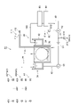
図1に示すように、第1実施形態に係る基板液処理システム1Aは、キャリア搬入出部2と、ロット形成部3と、ロット載置部4と、ロット搬送部5と、ロット処理部6と、制御部7とを備える。
[First embodiment]
As shown in FIG. 1, the substrate liquid processing system 1A according to the first embodiment includes a carrier loading/unloading section 2, a lot formation section 3, a lot placement section 4, a lot transfer section 5, and a lot processing section 6. and a control unit 7 .

このうちキャリア搬入出部2は、複数枚(たとえば、25枚)の基板(シリコンウエハ)8を水平姿勢で上下に並べて収容したキャリア9の搬入及び搬出を行う。このキャリア搬入出部2には、複数個のキャリア9を載置するキャリアステージ10と、キャリア9の搬送を行うキャリア搬送機構11と、キャリア9を一時的に保管するキャリアストック12,13と、キャリア9を載置するキャリア載置台14とが設けられている。ここで、キャリアストック12は、製品となる基板8をロット処理部6で処理する前に一時的に保管する。また、キャリアストック13は、製品となる基板8をロット処理部6で処理した後に一時的に保管する。 Of these, the carrier loading/unloading section 2 loads and unloads a carrier 9 containing a plurality of (for example, 25) substrates (silicon wafers) 8 arranged vertically in a horizontal posture. The carrier loading/unloading section 2 includes a carrier stage 10 on which a plurality of carriers 9 are placed, a carrier transport mechanism 11 for transporting the carriers 9, carrier stocks 12 and 13 for temporarily storing the carriers 9, A carrier mounting table 14 on which the carrier 9 is mounted is provided. Here, the carrier stock 12 is temporarily stored before the substrates 8 as products are processed in the lot processing unit 6 . Further, the carrier stock 13 is temporarily stored after the substrates 8 as products are processed by the lot processing unit 6 .

そして、キャリア搬入出部2は、外部からキャリアステージ10に搬入されたキャリア9を、キャリア搬送機構11を用いてキャリアストック12やキャリア載置台14に搬送する。また、キャリア搬入出部2は、キャリア載置台14に載置されたキャリア9を、キャリア搬送機構11を用いてキャリアストック13やキャリアステージ10に搬送する。キャリアステージ10に搬送されたキャリア9は、外部へ搬出される。 Then, the carrier loading/unloading section 2 transports the carrier 9 loaded onto the carrier stage 10 from the outside to the carrier stock 12 and the carrier mounting table 14 using the carrier transport mechanism 11 . Further, the carrier loading/unloading section 2 transports the carrier 9 mounted on the carrier mounting table 14 to the carrier stock 13 and the carrier stage 10 using the carrier transport mechanism 11 . The carrier 9 transported to the carrier stage 10 is carried out to the outside.

ロット形成部3は、1又は複数のキャリア9に収容された基板8を組合せて同時に処理される複数枚(たとえば、50枚)の基板8からなるロットを形成する。なお、ロットを形成するときは、基板8の表面にパターンが形成されている面を互いに対向するようにロットを形成してもよく、また、基板8の表面にパターンが形成されている面がすべて一方を向くようにロットを形成してもよい。このロット形成部3には、複数枚の基板8を搬送する基板搬送機構15が設けられている。なお、基板搬送機構15は、基板8の搬送途中で基板8の姿勢を水平姿勢から垂直姿勢及び垂直姿勢から水平姿勢に変更させることができる。 The lot forming section 3 combines the substrates 8 accommodated in one or more carriers 9 to form a lot consisting of a plurality of (for example, 50) substrates 8 to be processed simultaneously. When forming lots, the lots may be formed so that the surfaces of the substrate 8 on which the pattern is formed face each other. The lots may be formed so that they all face one way. The lot forming section 3 is provided with a substrate transport mechanism 15 for transporting a plurality of substrates 8 . The substrate transport mechanism 15 can change the posture of the substrate 8 from the horizontal posture to the vertical posture and from the vertical posture to the horizontal posture while the substrate 8 is being transported.

そして、ロット形成部3は、キャリア載置台14に載置されたキャリア9から基板搬送機構15を用いて基板8をロット載置部4に搬送し、ロットを形成する基板8をロット載置部4に載置する。また、ロット形成部3は、ロット載置部4に載置されたロットを基板搬送機構15でキャリア載置台14に載置されたキャリア9へ搬送する。なお、基板搬送機構15は、複数枚の基板8を支持するための基板支持部として、処理前(ロット搬送部5で搬送される前)の基板8を支持する処理前基板支持部と、処理後(ロット搬送部5で搬送された後)の基板8を支持する処理後基板支持部の2種類を有している。これにより、処理前の基板8等に付着したパーティクル等が処理後の基板8等に転着するのを防止する。 Then, the lot forming section 3 transports the substrates 8 from the carrier 9 mounted on the carrier mounting table 14 to the lot mounting section 4 by using the substrate transfer mechanism 15, and the substrates 8 forming a lot are transferred to the lot mounting section. 4. In addition, the lot forming section 3 transports the lot placed on the lot placing section 4 to the carrier 9 placed on the carrier placing table 14 by the substrate transport mechanism 15 . The substrate transport mechanism 15 includes, as substrate support units for supporting a plurality of substrates 8, an unprocessed substrate support unit that supports the substrates 8 before processing (before being transported by the lot transport unit 5), and a substrate support unit that supports the substrates 8 before processing. There are two types of post-processing substrate supporting parts that support the substrates 8 later (after being transferred by the lot transfer part 5). This prevents particles or the like attached to the substrate 8 or the like before processing from being transferred to the substrate 8 or the like after processing.

ロット載置部4は、ロット搬送部5によってロット形成部3とロット処理部6との間で搬送されるロットをロット載置台16で一時的に載置(待機)する。このロット載置部4には、処理前(ロット搬送部5で搬送される前)のロットを載置する搬入側ロット載置台17と、処理後(ロット搬送部5で搬送された後)のロットを載置する搬出側ロット載置台18とが設けられている。搬入側ロット載置台17及び搬出側ロット載置台18には、1ロット分の複数枚の基板8が垂直姿勢で前後に並べて載置される。 The lot placing unit 4 temporarily places (stands by) the lot transported between the lot forming unit 3 and the lot processing unit 6 by the lot transporting unit 5 on the lot placing table 16 . The lot placement unit 4 includes a load-in side lot placement table 17 for placing a lot before processing (before being transported by the lot transporting unit 5) and a lot after processing (after being transported by the lot transporting unit 5). A carrying-out side lot placing table 18 for placing a lot is provided. A plurality of substrates 8 for one lot are placed on the load-in side lot placement table 17 and the carry-out side lot placement table 18 side by side in a vertical posture.

そして、ロット載置部4では、ロット形成部3で形成したロットが搬入側ロット載置台17に載置され、そのロットがロット搬送部5を介してロット処理部6に搬入される。また、ロット載置部4では、ロット処理部6からロット搬送部5を介して搬出されたロットが搬出側ロット載置台18に載置され、そのロットがロット形成部3に搬送される。 In the lot placing section 4 , the lot formed in the lot forming section 3 is placed on the loading-side lot placing table 17 , and the lot is carried into the lot processing section 6 via the lot conveying section 5 . In the lot placing section 4 , the lot carried out from the lot processing section 6 via the lot conveying section 5 is placed on the carry-out side lot placing table 18 , and the lot is conveyed to the lot forming section 3 .

ロット搬送部5は、ロット載置部4とロット処理部6との間やロット処理部6の内部間でロットの搬送を行う。このロット搬送部5には、ロットの搬送を行うロット搬送機構19が設けられている。ロット搬送機構19は、ロット載置部4とロット処理部6に沿わせて配置したレール20と、複数枚の基板8を保持しながらレール20に沿って移動する移動体21とで構成する。移動体21には、垂直姿勢で前後に並んだ複数枚の基板8を保持する基板保持体22が進退自在に設けられている。 The lot transport unit 5 transports lots between the lot placement unit 4 and the lot processing unit 6 and between the insides of the lot processing unit 6 . The lot transport unit 5 is provided with a lot transport mechanism 19 for transporting lots. The lot transport mechanism 19 comprises a rail 20 arranged along the lot placing section 4 and the lot processing section 6, and a movable body 21 that moves along the rail 20 while holding a plurality of substrates 8. FIG. The moving body 21 is provided with a substrate holder 22 that holds a plurality of substrates 8 arranged vertically in a forward and backward direction so as to be able to move back and forth.

そして、ロット搬送部5は、搬入側ロット載置台17に載置されたロットをロット搬送機構19の基板保持体22で受取り、そのロットをロット処理部6に受け渡す。また、ロット搬送部5は、ロット処理部6で処理されたロットをロット搬送機構19の基板保持体22で受取り、そのロットを搬出側ロット載置台18に受け渡す。さらに、ロット搬送部5は、ロット搬送機構19を用いてロット処理部6の内部においてロットの搬送を行う。 The lot transporter 5 receives the lot placed on the loading-side lot placement table 17 by the substrate holder 22 of the lot transport mechanism 19 and transfers the lot to the lot processing unit 6 . The lot transporter 5 also receives the lot processed by the lot processing unit 6 by the substrate holder 22 of the lot transport mechanism 19 , and transfers the lot to the carry-out side lot table 18 . Furthermore, the lot transport unit 5 uses the lot transport mechanism 19 to transport the lot inside the lot processing unit 6 .

ロット処理部6は、垂直姿勢で前後に並んだ複数枚の基板8を1ロットとしてエッチングや洗浄や乾燥などの処理を行う。このロット処理部6には、基板8の乾燥処理を行う乾燥処理装置23と、基板保持体22の洗浄処理を行う基板保持体洗浄処理装置24と、基板8の洗浄処理を行う洗浄処理装置25と、基板8のエッチング処理を行う2台の本発明によるエッチング処理装置26とが並べて設けられている。 The lot processing unit 6 performs processing such as etching, cleaning, and drying on a plurality of substrates 8 arranged in a vertical posture as one lot. The lot processing section 6 includes a drying processing device 23 for drying the substrate 8 , a substrate holder cleaning processing device 24 for cleaning the substrate holder 22 , and a cleaning processing device 25 for cleaning the substrate 8 . , and two etching processing apparatuses 26 according to the present invention for etching the substrate 8 are provided side by side.

乾燥処理装置23は、処理槽27と、処理槽27に昇降自在に設けられた基板昇降機構28とを備える。処理槽27には、乾燥用の処理ガス(IPA(イソプロピルアルコール)等)が供給される。基板昇降機構28には、1ロット分の複数枚の基板8が垂直姿勢で前後に並べて保持される。乾燥処理装置23は、ロット搬送機構19の基板保持体22からロットを基板昇降機構28で受取り、基板昇降機構28でそのロットを昇降させることで、処理槽27に供給した乾燥用の処理ガスで基板8の乾燥処理を行う。また、乾燥処理装置23は、基板昇降機構28からロット搬送機構19の基板保持体22にロットを受け渡す。 The drying processing apparatus 23 includes a processing tank 27 and a substrate elevating mechanism 28 provided in the processing tank 27 so as to be vertically movable. A drying processing gas (IPA (isopropyl alcohol) or the like) is supplied to the processing bath 27 . The substrate lifting mechanism 28 holds a plurality of substrates 8 for one lot side by side in a vertical posture. The drying processing apparatus 23 receives the lot from the substrate holder 22 of the lot transport mechanism 19 by the substrate lifting mechanism 28 , lifts the lot by the substrate lifting mechanism 28 , and uses the processing gas for drying supplied to the processing tank 27 . A drying process for the substrate 8 is performed. The drying processing device 23 also transfers the lot from the substrate lifting mechanism 28 to the substrate holder 22 of the lot transport mechanism 19 .

基板保持体洗浄処理装置24は、処理槽29を有し、この処理槽29に洗浄用の処理液及び乾燥ガスを供給できるようになっており、ロット搬送機構19の基板保持体22に洗浄用の処理液を供給した後、乾燥ガスを供給することで基板保持体22の洗浄処理を行う。 The substrate holder cleaning processing apparatus 24 has a processing bath 29, and can supply a cleaning processing liquid and a drying gas to the processing bath 29. After the treatment liquid is supplied, the substrate holder 22 is cleaned by supplying dry gas.

洗浄処理装置25は、洗浄用の処理槽30とリンス用の処理槽31とを有し、各処理槽30,31に基板昇降機構32,33を昇降自在に設けている。洗浄用の処理槽30には、洗浄用の処理液(SC-1等)が貯留される。リンス用の処理槽31には、リンス用の処理液(純水等)が貯留される。 The cleaning processing apparatus 25 has a processing bath 30 for cleaning and a processing bath 31 for rinsing. A cleaning treatment liquid (SC-1 or the like) is stored in the cleaning treatment bath 30 . A processing liquid for rinsing (pure water or the like) is stored in the processing tank 31 for rinsing.

エッチング処理装置26は、エッチング用の処理槽34とリンス用の処理槽35とを有し、各処理槽34,35に基板昇降機構36,37が昇降自在に設けられている。エッチング用の処理槽34には、エッチング用の処理液(燐酸水溶液)が貯留される。リンス用の処理槽35には、リンス用の処理液(純水等)が貯留される。 The etching processing apparatus 26 has a processing bath 34 for etching and a processing bath 35 for rinsing. An etching treatment liquid (phosphoric acid aqueous solution) is stored in the etching treatment bath 34 . A processing liquid for rinsing (pure water or the like) is stored in the processing tank 35 for rinsing.

これら洗浄処理装置25とエッチング処理装置26は、同様の構成となっている。エッチング処理装置26について説明すると、基板昇降機構36には、1ロット分の複数枚の基板8が垂直姿勢で前後に並べて保持される。エッチング処理装置26において、ロット搬送機構19の基板保持体22からロットを基板昇降機構36で受取り、基板昇降機構36でそのロットを昇降させることでロットを処理槽34のエッチング用の処理液に浸漬させて基板8のエッチング処理を行う。その後、エッチング処理装置26は、基板昇降機構36からロット搬送機構19の基板保持体22にロットを受け渡す。また、ロット搬送機構19の基板保持体22からロットを基板昇降機構37で受取り、基板昇降機構37でそのロットを昇降させることでロットを処理槽35のリンス用の処理液に浸漬させて基板8のリンス処理を行う。その後、基板昇降機構37からロット搬送機構19の基板保持体22にロットを受け渡す。 The cleaning processing device 25 and the etching processing device 26 have the same configuration. To explain the etching processing apparatus 26, a substrate lifting mechanism 36 holds a plurality of substrates 8 for one lot in a vertical posture, lined up in front and behind. In the etching processing apparatus 26, the lot is received by the substrate lifting mechanism 36 from the substrate holder 22 of the lot transport mechanism 19, and the lot is lifted and lowered by the substrate lifting mechanism 36 so that the lot is immersed in the processing liquid for etching in the processing bath 34. Then, the substrate 8 is etched. After that, the etching processing apparatus 26 transfers the lot from the substrate lifting mechanism 36 to the substrate holder 22 of the lot transport mechanism 19 . Also, the lot is received by the substrate lifting mechanism 37 from the substrate holder 22 of the lot transport mechanism 19 , and the lot is lifted by the substrate lifting mechanism 37 so that the lot is immersed in the treatment liquid for rinsing in the treatment tank 35 . rinsing. After that, the lot is transferred from the substrate lifting mechanism 37 to the substrate holder 22 of the lot transport mechanism 19 .

制御部7は、基板液処理システム1Aの各部(キャリア搬入出部2、ロット形成部3、ロット載置部4、ロット搬送部5、ロット処理部6)の動作を制御する。この制御部7は、たとえばコンピュータからなり、コンピュータで読み取り可能な記憶媒体138を備える。記憶媒体138には、基板液処理システム1Aにおいて実行される各種の処理を制御するプログラムが格納される。制御部7は、記憶媒体138に記憶されたプログラムを読み出して実行することによって基板液処理システム1Aの動作を制御する。なお、プログラムは、コンピュータによって読み取り可能な記憶媒体138に記憶されていたものであって、他の記憶媒体から制御部7の記憶媒体138にインストールされたものであってもよい。コンピュータによって読み取り可能な記憶媒体138としては、たとえばハードディスク(HD)、フレキシブルディスク(FD)、コンパクトディスク(CD)、マグネットオプティカルディスク(MO)、メモリカードなどがある。 The control unit 7 controls the operation of each unit (carrier loading/unloading unit 2, lot formation unit 3, lot placement unit 4, lot transfer unit 5, lot processing unit 6) of the substrate liquid processing system 1A. The control unit 7 is composed of a computer, for example, and has a computer-readable storage medium 138 . The storage medium 138 stores programs for controlling various processes executed in the substrate liquid processing system 1A. The control unit 7 controls the operation of the substrate liquid processing system 1A by reading out and executing programs stored in the storage medium 138 . The program may be stored in the computer-readable storage medium 138 and may be installed in the storage medium 138 of the control unit 7 from another storage medium. The computer-readable storage medium 138 includes, for example, a hard disk (HD), flexible disk (FD), compact disk (CD), magnet optical disk (MO), memory card, and the like.

〔基板液処理装置〕
続いて、図2を参照して、基板液処理システム1Aが含む基板液処理装置A1について詳細に説明する。図2に示すように、基板液処理装置A1は、エッチング処理装置26を含んで構成されている。
[Substrate liquid processing device]
Subsequently, the substrate liquid processing apparatus A1 included in the substrate liquid processing system 1A will be described in detail with reference to FIG. As shown in FIG. 2, the substrate liquid processing apparatus A1 includes an etching processing apparatus 26. As shown in FIG.

エッチング処理装置26は、所定濃度の薬剤(燐酸)の水溶液をエッチング用の処理液として用いて基板8を液処理(エッチング処理)する。後述するように、処理液の濃度(燐酸濃度)は適宜変更される。エッチング処理装置26は、図2に示すように、処理液貯留部38と、処理液供給部39と、処理液循環部40と、処理液排出部41と、ベントライン60と、シリコン濃度計80(検出部)と、燐酸濃度計90と、バブル発生機構111と、を備える。 The etching processing apparatus 26 performs liquid processing (etching processing) on the substrate 8 using an aqueous solution of a chemical (phosphoric acid) having a predetermined concentration as a processing liquid for etching. As will be described later, the concentration of the treatment liquid (concentration of phosphoric acid) is appropriately changed. As shown in FIG. 2, the etching apparatus 26 includes a processing liquid reservoir 38, a processing liquid supply section 39, a processing liquid circulation section 40, a processing liquid discharge section 41, a vent line 60, and a silicon concentration meter 80. (a detection unit), a phosphoric acid concentration meter 90, and a bubble generation mechanism 111 are provided.

処理液貯留部38は、処理液を貯留し基板8を処理する。処理液貯留部38は、上部を開放させた処理槽34(内槽)の上部周囲に、上部を開放させた外槽42を形成し、処理槽34と外槽42に処理液を貯留する。処理槽34は、基板8を基板昇降機構36によって浸漬させることにより液処理する処理液を貯留する。外槽42は、処理槽34からオーバーフローした処理液を貯留する。外槽42に貯留された処理液は、処理液循環部40によって処理槽34に供給される。外槽42には、外槽42における液面高さを検出する液面センサー(不図示)が設けられていてもよい。 The processing liquid reservoir 38 stores the processing liquid and processes the substrate 8 . The processing liquid reservoir 38 has an open-topped outer tank 42 formed around the top of the open-topped processing tank 34 (inner tank). The processing bath 34 stores a processing liquid for liquid processing by immersing the substrate 8 by the substrate lifting mechanism 36 . The outer bath 42 stores the processing liquid overflowing from the processing bath 34 . The processing liquid stored in the outer bath 42 is supplied to the processing bath 34 by the processing liquid circulation unit 40 . The outer tank 42 may be provided with a liquid level sensor (not shown) that detects the height of the liquid level in the outer tank 42 .

ここで、処理槽34内において液処理(エッチング処理)される基板8について図4(a),(b)を参照して説明する。図4(a)は、エッチング処理前の基板8である基板8Aを模式的に示す図であり、図4(b)はエッチング処理後の基板8である基板8Bを模式的に示す図である。図4(a)に示されるように、エッチング処理前の基板8Aは、基板部150と、複数の酸化膜151と、複数の窒化膜152と、複数のチャネルホール153と、ブロッキング絶縁膜154と、を有する。基板部150は、例えば単結晶シリコンによって形成されている。基板部150の一部領域に不純物がドーピングされることにより不純物領域が形成されると共に、該不純物領域上に下部絶縁膜及び下部電極層が形成されている(いずれも不図示)。そして、下部電極層が形成された基板部150上に、複数の酸化膜151及び複数の窒化膜152が形成(積層)されている。酸化膜151及び窒化膜152は、互いに交互に積層されている。酸化膜151は、例えばシリコン酸化物を利用して形成される。窒化膜152は、例えばシリコン窒化物を利用して形成される。そして、最上部の酸化膜151上に上部電極層及び上部絶縁膜が形成されている(いずれも不図示)。チャネルホール153は、複数の酸化膜151及び複数の窒化膜152を積層方向に貫通するように伸びている。各チャネルホール153の側壁にはブロッキング絶縁膜154が形成されている。 Here, the substrate 8 to be liquid-processed (etched) in the processing tank 34 will be described with reference to FIGS. 4(a) and 4(b). FIG. 4(a) is a diagram schematically showing a substrate 8A which is the substrate 8 before etching, and FIG. 4(b) is a diagram schematically showing a substrate 8B which is the substrate 8 after etching. . As shown in FIG. 4A, the substrate 8A before etching includes a substrate portion 150, a plurality of oxide films 151, a plurality of nitride films 152, a plurality of channel holes 153, and a blocking insulating film 154. , have The substrate section 150 is made of single crystal silicon, for example. An impurity region is formed by doping an impurity in a portion of the substrate portion 150, and a lower insulating film and a lower electrode layer are formed on the impurity region (both not shown). A plurality of oxide films 151 and a plurality of nitride films 152 are formed (stacked) on the substrate portion 150 on which the lower electrode layer is formed. The oxide films 151 and the nitride films 152 are alternately laminated. The oxide film 151 is formed using silicon oxide, for example. The nitride film 152 is formed using silicon nitride, for example. An upper electrode layer and an upper insulating film are formed on the uppermost oxide film 151 (both not shown). The channel hole 153 extends through the plurality of oxide films 151 and the plurality of nitride films 152 in the stacking direction. A blocking insulating film 154 is formed on the sidewall of each channel hole 153 .

図4(b)に示されるように、エッチング処理が施される基板8Bでは、幅方向の両端部において積層方向に沿って処理液を導入する導入部155が形成されている。そして、該導入部155から処理液が導入されることにより、図4(b)に示される基板8Bでは、各窒化膜152が処理液によって除去される。窒化膜152が除去されることにより、窒化膜152が存在していた領域は開口部156となる。開口部156には、電化トラップ層、ブロッキング絶縁膜、及びコントロールゲート等が形成される。 As shown in FIG. 4B, the substrate 8B to be etched is formed with introduction portions 155 for introducing the treatment liquid along the stacking direction at both ends in the width direction. Then, by introducing the processing liquid from the introducing portion 155, each nitride film 152 is removed by the processing liquid from the substrate 8B shown in FIG. 4(b). By removing the nitride film 152 , the region where the nitride film 152 was present becomes an opening 156 . A charge trap layer, a blocking insulating film, a control gate, and the like are formed in the opening 156 .

図2に戻り、処理液供給部39は、処理液貯留部38に処理液を供給する。処理液供給部39は、水溶液供給部43と、水供給部44とを備える。水溶液供給部43は、第1水溶液供給部43Xと、第2水溶液供給部43Yとを有する。 Returning to FIG. 2 , the processing liquid supply section 39 supplies the processing liquid to the processing liquid storage section 38 . The treatment liquid supply section 39 includes an aqueous solution supply section 43 and a water supply section 44 . The aqueous solution supply section 43 has a first aqueous solution supply section 43X and a second aqueous solution supply section 43Y.

第1水溶液供給部43Xは、水溶液供給源45Xと、バルブ46Xと、流路49Xとを有する。水溶液供給源45Xは、所定濃度の燐酸水溶液を供給する。水溶液供給源45Xから供給される燐酸水溶液は、流路49Xを介して処理液貯留部38に供給される。バルブ46Xは、流路49Xにおける水溶液供給源45Xの下流側に設けられている。バルブ46Xは、制御部7に接続されており、制御部7によって開閉制御及び流量制御される。 The first aqueous solution supply unit 43X has an aqueous solution supply source 45X, a valve 46X, and a channel 49X. The aqueous solution supply source 45X supplies an aqueous solution of phosphoric acid having a predetermined concentration. The phosphoric acid aqueous solution supplied from the aqueous solution supply source 45X is supplied to the treatment liquid reservoir 38 through the channel 49X. The valve 46X is provided downstream of the aqueous solution supply source 45X in the channel 49X. The valve 46X is connected to the controller 7 and is controlled to open/close and flow rate by the controller 7 .

第2水溶液供給部43Yは、水溶液供給源45Yと、バルブ46Yと、流路49Yとを有する。水溶液供給源45Yは、所定濃度の燐酸水溶液を供給する。水溶液供給源45Yから供給される燐酸水溶液に含まれるシリコン(含有成分)の濃度(シリコン濃度)は、上述した第1水溶液供給部43Xの水溶液供給源45Xから供給される燐酸水溶液におけるシリコン濃度よりも高い。水溶液供給源45Yから供給される燐酸水溶液は、流路49Yを介して処理液貯留部38に供給される。バルブ46Yは、流路49Yにおける水溶液供給源45Yの下流側に設けられている。バルブ46Yは、制御部7に接続されており、制御部7によって開閉制御及び流量制御される。 The second aqueous solution supply unit 43Y has an aqueous solution supply source 45Y, a valve 46Y, and a channel 49Y. The aqueous solution supply source 45Y supplies an aqueous solution of phosphoric acid having a predetermined concentration. The concentration (silicon concentration) of silicon (contained component) contained in the phosphoric acid aqueous solution supplied from the aqueous solution supply source 45Y is higher than the silicon concentration in the phosphoric acid aqueous solution supplied from the aqueous solution supply source 45X of the first aqueous solution supply unit 43X. expensive. The phosphoric acid aqueous solution supplied from the aqueous solution supply source 45Y is supplied to the treatment liquid reservoir 38 through the channel 49Y. The valve 46Y is provided downstream of the aqueous solution supply source 45Y in the channel 49Y. The valve 46Y is connected to the controller 7 and is controlled to open/close and flow rate by the controller 7 .

水供給部44は、処理液貯留部38に水(純水)を供給する。水供給部44は、所定温度(例えば室温)の純水を供給するための水供給源47を、処理液貯留部38の外槽42にバルブ48を介して接続する。バルブ48は、制御部7に接続されており、制御部7で開閉制御及び流量制御される。 The water supply unit 44 supplies water (pure water) to the processing liquid storage unit 38 . The water supply unit 44 connects a water supply source 47 for supplying pure water at a predetermined temperature (for example, room temperature) to the outer tank 42 of the treatment liquid storage unit 38 via a valve 48 . The valve 48 is connected to the control unit 7 and controlled by the control unit 7 for opening/closing and flow control.

処理液循環部40は、外槽42内の処理液を処理槽34に送る。処理液循環部40は、循環流路49(循環路)と、ポンプ50と、ヒーター51(加熱部)と、フィルター52と、を有する。循環流路49は、処理液貯留部38の外槽42の底部から処理槽34の底部に延びた流路であり、外槽42から処理槽34に処理液を循環させる。循環流路49には、ポンプ50、ヒーター51、及びフィルター52が上流側(外槽42側)から下流側(処理槽34側)に順に設けられている。ポンプ50及びヒーター51は制御部7に接続されており制御部7により駆動制御される。ポンプ50は、処理液を上流側から下流側に圧送する。ヒーター51は、処理液を設定温度まで加熱する。フィルター52は、処理液中に混入したパーティクルを除去する。 The processing liquid circulation unit 40 sends the processing liquid in the outer bath 42 to the processing bath 34 . The treatment liquid circulation section 40 has a circulation flow path 49 (circulation path), a pump 50 , a heater 51 (heating section), and a filter 52 . The circulation flow path 49 is a flow path extending from the bottom of the outer tank 42 of the processing liquid reservoir 38 to the bottom of the processing tank 34 , and circulates the processing liquid from the outer tank 42 to the processing tank 34 . A pump 50 , a heater 51 , and a filter 52 are provided in the circulation flow path 49 in order from the upstream side (outer tank 42 side) to the downstream side (processing tank 34 side). The pump 50 and the heater 51 are connected to the controller 7 and driven and controlled by the controller 7 . The pump 50 pumps the processing liquid from the upstream side to the downstream side. The heater 51 heats the processing liquid to a set temperature. The filter 52 removes particles mixed in the processing liquid.

処理液排出部41は、処理液循環部40の循環流路49から処理液を排出する。処理液排出部41は、例えば、排液流路41Aと、バルブ41Bとを有する。排液流路41Aは、循環流路49内の処理液を導出する。排液流路41Aの一端部は循環流路49に接続されており、排液流路41Aの他端部は基板液処理システム1Aの排液管(不図示)に接続されている。バルブ41Bは、排液流路41Aに設けられている。バルブ41Bは、制御部7に接続されており、制御部7によって開閉制御される。 The processing liquid discharge section 41 discharges the processing liquid from the circulation flow path 49 of the processing liquid circulation section 40 . The processing liquid discharge part 41 has, for example, a drainage channel 41A and a valve 41B. The drainage channel 41A leads out the processing liquid in the circulation channel 49 . One end of the drainage channel 41A is connected to the circulation channel 49, and the other end of the drainage channel 41A is connected to a drainage pipe (not shown) of the substrate liquid processing system 1A. The valve 41B is provided in the drainage channel 41A. The valve 41B is connected to the controller 7 and controlled to be opened/closed by the controller 7 .

ベントライン60は、循環流路49のフィルター52において発生した水蒸気を外槽42に送る構成である。ベントライン60は、排出流路61Aと、バルブ61B(流量制御バルブ)とを有する。排出流路61Aは、フィルター52において発生した水蒸気を外槽42に導出する。排出流路61Aの一端部はフィルター52に接続されており、排出流路61Aの他端部は外槽42に接続されている。バルブ61Bは、排出流路61Aに設けられている。バルブ61Bは、制御部7に接続されており、制御部7によって開閉制御される。 The vent line 60 is configured to send the water vapor generated in the filter 52 of the circulation flow path 49 to the outer tank 42 . The vent line 60 has a discharge channel 61A and a valve 61B (flow control valve). 61 A of discharge flow paths lead out the water vapor|steam which generate|occur|produced in the filter 52 to the outer tank 42. As shown in FIG. One end of the discharge channel 61A is connected to the filter 52, and the other end of the discharge channel 61A is connected to the outer tank . The valve 61B is provided in the discharge channel 61A. The valve 61B is connected to the controller 7 and controlled to be opened/closed by the controller 7 .

シリコン濃度計80は、循環流路49から分岐されて外槽42に向かって延びる分岐流路100に設けられており、処理液に含まれるシリコンの濃度(シリコン濃度)を測定する。シリコン濃度計80は、処理液に含まれるシリコンの処理液中における濃度(シリコン濃度)を、後述する変換点に係る情報として検出する検出部として機能する。シリコン濃度計80は、測定したシリコン濃度を制御部7に出力する。当該シリコン濃度は、制御部7による変換点の特定に用いられる(詳細は後述)。燐酸濃度計90は、分岐流路100に設けられており、処理液中の燐酸濃度を測定する。燐酸濃度計90は、測定した燐酸濃度を制御部7に出力する。 The silicon concentration meter 80 is provided in a branch channel 100 branched from the circulation channel 49 and extending toward the outer bath 42, and measures the concentration of silicon (silicon concentration) contained in the treatment liquid. The silicon concentration meter 80 functions as a detection unit that detects the concentration of silicon contained in the treatment liquid (silicon concentration) as information related to a conversion point, which will be described later. The silicon concentration meter 80 outputs the measured silicon concentration to the controller 7 . The silicon concentration is used for specifying the conversion point by the control unit 7 (details will be described later). A phosphoric acid concentration meter 90 is provided in the branch channel 100 and measures the phosphoric acid concentration in the treatment liquid. The phosphoric acid concentration meter 90 outputs the measured phosphoric acid concentration to the controller 7 .

バブル発生機構111は、処理液貯留部38内においてバブリングを行う。バブル発生機構111は、窒素供給源112と、バルブ113と、供給管114とを有する。窒素供給源112は、窒素を供給する。窒素供給源112から供給される窒素は、供給管114を介して処理液貯留部38の処理槽34に供給される。供給管114は、その一端が窒素供給源112に接続されると共に、その他端側が処理槽34の底面に沿って延びている。供給管114の他端側(処理槽34の対面に沿って延びた部分)には複数のガスノズルが形成されており、該ガスノズルから、バブリングに用いられる窒素ガスが吐出される。バルブ113は、供給管114における窒素供給源112の下流側に設けられている。バルブ113は、制御部7に接続されており、制御部7によって開閉制御及び流量制御される。バブル発生機構111によって処理槽34内でバブリングが行われることにより、処理槽34内においては処理液の上昇流が生じる。これにより、処理液の状態を均一に保ちやすくなる。 The bubble generation mechanism 111 causes bubbling inside the processing liquid reservoir 38 . The bubble generation mechanism 111 has a nitrogen supply source 112 , a valve 113 and a supply pipe 114 . Nitrogen source 112 supplies nitrogen. Nitrogen supplied from the nitrogen supply source 112 is supplied to the processing tank 34 of the processing liquid reservoir 38 via the supply pipe 114 . The supply pipe 114 has one end connected to the nitrogen supply source 112 and the other end extending along the bottom surface of the processing tank 34 . A plurality of gas nozzles are formed on the other end side of the supply pipe 114 (the portion extending along the opposite side of the processing tank 34), and nitrogen gas used for bubbling is discharged from the gas nozzles. Valve 113 is provided downstream of nitrogen supply source 112 in supply pipe 114 . The valve 113 is connected to the controller 7 and is controlled by the controller 7 for opening/closing and flow control. The bubble generation mechanism 111 causes bubbling in the processing tank 34 , thereby generating an upward flow of the processing liquid in the processing tank 34 . This makes it easier to keep the state of the treatment liquid uniform.

続いて、エッチング処理装置26を制御する制御部7について詳細に説明する。制御部7は、例えば処理槽34の処理液に基板8を浸漬させる基板処理期間において、基板8に対する処理条件が変更される変換点に係る情報に基づき変換点を特定することと、変換点が特定された場合に、処理条件が変更されるように、処理液供給部39を制御することと、を実行するように構成されている。本実施形態では、基板8に対する処理条件として、処理液の濃度及び処理液におけるシリコン濃度が変更される。 Next, the control unit 7 that controls the etching processing apparatus 26 will be described in detail. For example, during a substrate processing period in which the substrate 8 is immersed in the processing liquid in the processing tank 34, the control unit 7 specifies a conversion point based on information relating to the conversion point at which the processing conditions for the substrate 8 are changed; and controlling the processing liquid supply unit 39 so that the processing conditions are changed when specified. In this embodiment, as the processing conditions for the substrate 8, the concentration of the processing liquid and the silicon concentration in the processing liquid are changed.

最初に、制御部7の処理イメージについて、図4~図7を参照して説明する。図4(a),(b)を用いて上述したように、基板8の窒化膜152は処理液によって除去(エッチング)される。ここで、図4(b)に示されるように、チャネルホール153の側壁にはブロッキング絶縁膜154が形成されている。窒化膜152の除去が進みブロッキング絶縁膜154が露出した状態において、処理液のエッチングレート(酸化膜に対するエッチングレート。以下同様)が何ら変更されない場合には、時間の経過にともなって、処理液によりブロッキング絶縁膜154が大幅に除去されてしまうおそれがある。特に、チャネルホール153の側壁のうち先にエッチングが開始される側のブロッキング絶縁膜154は、長い時間エッチングが行われることとなり、より顕著に削られてしまう。そこで、本実施形態のエッチング処理装置26の制御部7では、基板8のパターン形状に応じた処理状況に基づいて、処理液のエッチングレートを変化させる。図5において横軸はエッチング処理時間を示しており、下図の縦軸は酸化膜に対するエッチングレートを示しており、上図は基板8の酸化膜151、窒化膜152、チャネルホール153、及びブロッキング絶縁膜154の位置を模式的に示している。図5に示されるように、制御部7は、エッチング処理時間X1になる前段階(すなわち、チャネルホール153の側壁に形成されたブロッキング絶縁膜154の位置に到達する前段階)においては、処理液のエッチングレートを比較的高い値とし、エッチング処理時間X1になった後段階においては、処理液のエッチングレートを低く(0に近い値に)する(図5の下図参照)。なお、図5ではエッチング処理時間X1において、エッチングレートが瞬時に所望の値まで低下しているが、実際には、後述する処理液の濃度及びシリコン濃度を変更することによって、エッチングレートが徐々に所望の値に近づく。上述した、ブロッキング絶縁膜154の除去を抑制するとの内容は一例であり、制御部7の制御はこの目的に限定して行われるものではない。 First, a processing image of the control unit 7 will be described with reference to FIGS. 4 to 7. FIG. As described above with reference to FIGS. 4A and 4B, the nitride film 152 on the substrate 8 is removed (etched) by the processing liquid. Here, as shown in FIG. 4B, a blocking insulating film 154 is formed on the sidewall of the channel hole 153 . In the state where the removal of the nitride film 152 progresses and the blocking insulating film 154 is exposed, if the etching rate of the processing solution (the etching rate for the oxide film; the same shall apply hereinafter) of the processing solution is not changed at all, then the processing solution may increase the etching rate over time. A large portion of the blocking insulating film 154 may be removed. In particular, the blocking insulating film 154 on the side of the side wall of the channel hole 153 on which etching is started first is etched for a long time, and is significantly etched away. Therefore, the control unit 7 of the etching processing apparatus 26 of the present embodiment changes the etching rate of the processing liquid based on the processing status according to the pattern shape of the substrate 8 . In FIG. 5, the horizontal axis indicates the etching processing time, the vertical axis in the lower diagram indicates the etching rate for the oxide film, and the upper diagram shows the oxide film 151, the nitride film 152, the channel hole 153, and the blocking insulation of the substrate 8. The position of membrane 154 is shown schematically. As shown in FIG. 5, the control unit 7 controls the processing liquid in the stage before the etching processing time X1 (that is, the stage before reaching the position of the blocking insulating film 154 formed on the side wall of the channel hole 153). is set to a relatively high value, and the etching rate of the processing solution is set to a low value (to a value close to 0) after the etching processing time X1 (see the lower diagram of FIG. 5). In FIG. 5, the etching rate is instantaneously decreased to the desired value at the etching processing time X1. close to the desired value. The content of suppressing the removal of the blocking insulating film 154 described above is an example, and the control of the control unit 7 is not limited to this purpose.

制御部7は、処理液のエッチングレートを低下させる際の処理として、具体的には、図6に示すように、エッチング処理時間X1になったタイミングである変換点を検知すると、処理液の濃度(燐酸濃度)を下げると共に、処理液におけるシリコン濃度を上げることにより、処理液のエッチングレートを低下させる(詳細は後述)。また、制御部7は、図7に示すように、処理液におけるシリコン濃度の経時変化の傾きの変化点を変換点として特定する(詳細は後述)。なお、制御部7は、変換点を検知すると、ヒーター51を制御することにより処理液の温度を低下させ、ブロッキング絶縁膜154に対する処理液のエッチングレートを低下させてもよい。 Specifically, as shown in FIG. 6, the control unit 7 detects a transition point, which is the timing of the etching processing time X1, as a process for lowering the etching rate of the processing liquid. (Concentration of phosphoric acid) is lowered and the concentration of silicon in the treatment liquid is increased to lower the etching rate of the treatment liquid (details will be described later). Further, as shown in FIG. 7, the control unit 7 specifies the change point of the slope of the change in silicon concentration over time in the treatment liquid as a conversion point (details will be described later). Note that the control unit 7 may control the heater 51 to lower the temperature of the processing liquid when detecting the conversion point, thereby reducing the etching rate of the processing liquid for the blocking insulating film 154 .

続いて、制御部7の具体的な機能構成について、図3を参照して説明する。図3は制御部7の機能的な構成を示すブロック図である。図3に示されるように、制御部7は、変換点特定部71と、シリコン濃度調整部72と、燐酸濃度調整部73と、バブリング制御部74とを備える。 Next, a specific functional configuration of the control section 7 will be described with reference to FIG. FIG. 3 is a block diagram showing the functional configuration of the control section 7. As shown in FIG. As shown in FIG. 3 , the control section 7 includes a conversion point specifying section 71 , a silicon concentration adjusting section 72 , a phosphoric acid concentration adjusting section 73 and a bubbling control section 74 .

変換点特定部71は、基板8に対する処理条件が変更される変換点に係る情報に基づき、変換点を特定する(変換点に到達しているか否かを判定する)。変換点に係る情報とは、例えば、シリコン濃度計80から取得される、処理液中におけるシリコン濃度である。変換点特定部71は、処理液中におけるシリコン濃度の経時変化の傾きの変化点を、変換点として特定する。図7は、シリコン濃度の経時変化の一例を示しており、横軸は時間、縦軸はシリコン濃度を示している。図7に示されるように、シリコン濃度は、チャネルホール153が露出する(詳細にはブロッキング絶縁膜154が露出する)エッチング処理時間X1を境にして、単位時間におけるシリコン濃度の増加量(シリコン濃度の経時変化の傾き)が緩やかになる。すなわち、図7に示されるように、エッチング処理時間X1となった後のシリコン濃度の経時変化の傾きは、エッチング処理時間X1となる前のシリコン濃度の経時変化の傾きAよりも緩やかになる。このことは、図5に示されるように、ブロッキング絶縁膜154が露出するまで(エッチング処理時間X1となるまで)は窒化膜152が削られているのに対し、エッチング処理時間X1となると窒化膜152の処理断面積が小さくなり新たに削られる窒化膜152の量が減少し処理液中におけるシリコン濃度の増加量が減少することに基づいている。変換点特定部71は、処理液中におけるシリコン濃度の経時変化の傾きが緩やかになった点を変換点として特定することにより、エッチング処理時間X1となった時点を変換点として高精度に特定することができる。 The conversion point identification unit 71 identifies a conversion point (determines whether or not the conversion point has been reached) based on information relating to the conversion point at which the processing conditions for the substrate 8 are changed. Information related to the conversion point is, for example, the concentration of silicon in the treatment liquid obtained from the silicon concentration meter 80 . The conversion point identifying unit 71 identifies a change point of the slope of the change in silicon concentration over time in the treatment liquid as a conversion point. FIG. 7 shows an example of changes in silicon concentration over time, where the horizontal axis indicates time and the vertical axis indicates silicon concentration. As shown in FIG. 7, the silicon concentration increases by the amount of increase in silicon concentration per unit time (silicon concentration slope of change over time) becomes gentler. That is, as shown in FIG. 7, the slope of the silicon concentration over time after the etching processing time X1 is gentler than the slope A of the silicon concentration over time before the etching processing time X1. This is because, as shown in FIG. 5, the nitride film 152 is etched until the blocking insulating film 154 is exposed (until the etching processing time X1 is reached), whereas the nitride film is removed when the etching processing time X1 is reached. This is based on the fact that the processed cross-sectional area of 152 becomes smaller, the amount of newly etched nitride film 152 is reduced, and the amount of increase in silicon concentration in the processing solution is reduced. The conversion point specifying unit 71 specifies a point at which the slope of the change in the silicon concentration over time in the processing liquid becomes gentle as the conversion point, thereby specifying with high accuracy the point at which the etching processing time X1 is reached as the conversion point. be able to.

シリコン濃度調整部72は、変換点特定部71によって変換点が特定された場合に、処理条件である、処理液におけるシリコン濃度が変更されるように処理液供給部39のバルブ46X,46Yを制御する。具体的には、シリコン濃度調整部72は、エッチング処理の開始後、変換点が特定(検知)される前段階においては、第1水溶液供給部43Xの水溶液供給源45Xから処理液貯留部38に処理液が供給されるようにバルブ46Xを開く。シリコン濃度調整部72は、第2水溶液供給部43Yのバルブ46Yを閉じる。この場合には、処理液貯留部38には、比較的シリコン濃度が低い、低シリコン濃度の処理液が供給される。そして、シリコン濃度調整部72は、変換点が特定(検知)された場合に、高シリコン濃度の処理液が第2水溶液供給部43Yの水溶液供給源45Yから処理液貯留部38に供給されるように、バルブ46Xを閉じると共にバルブ46Yを開く。このように、シリコン濃度調整部72は、変換点が特定された場合に処理液におけるシリコン濃度が上昇するように、処理液供給部39のバルブ46X,46Yを制御する。 The silicon concentration adjustment unit 72 controls the valves 46X and 46Y of the processing liquid supply unit 39 so that the silicon concentration in the processing liquid, which is a processing condition, is changed when the conversion point is specified by the conversion point specifying unit 71. do. Specifically, after the etching process is started, the silicon concentration adjusting section 72 supplies the processing liquid storage section 38 with the aqueous solution supply source 45X of the first aqueous solution supply section 43X before the conversion point is specified (detected). The valve 46X is opened so that the processing liquid is supplied. The silicon concentration adjustment section 72 closes the valve 46Y of the second aqueous solution supply section 43Y. In this case, the processing liquid reservoir 38 is supplied with a low silicon concentration processing liquid having a relatively low silicon concentration. Then, when the conversion point is specified (detected), the silicon concentration adjusting section 72 is arranged so that the processing liquid with a high silicon concentration is supplied from the aqueous solution supply source 45Y of the second aqueous solution supply section 43Y to the processing liquid storage section 38. Then, the valve 46X is closed and the valve 46Y is opened. In this manner, the silicon concentration adjusting section 72 controls the valves 46X and 46Y of the processing liquid supply section 39 so that the silicon concentration in the processing liquid increases when the conversion point is specified.

図6は変換点での処理パラメータの変更例を示している。図6の横軸はエッチング処理時間を示しており、縦軸は燐酸濃度、シリコン濃度、窒素(N2)流量、酸化膜エッチングレートの高低を示している。図6に示されるように、処理液中のシリコン濃度は、エッチングの開始時においては例えばX[ppm]とされており、その後、窒化膜152のエッチングが進むことにより処理液中のシリコン濃度が上昇する。そして、エッチング処理時間X1になる(変換点が特定される)と、上述したように高シリコン濃度の処理液が処理液貯留部38に供給され処理液中のシリコン濃度が更に上昇する。シリコン濃度調整部72は、シリコン濃度計80から処理液中のシリコン濃度を取得し、該シリコン濃度が、X[ppm]よりも高いY[ppm](図6参照)まで上昇すると、その後、処理液中のシリコン濃度がY[ppm]で一定となるようにバルブ41Bを制御し、シリコン濃度一定制御を行う。 FIG. 6 shows an example of changing the processing parameters at the conversion point. The horizontal axis of FIG. 6 indicates the etching processing time, and the vertical axis indicates the phosphoric acid concentration, the silicon concentration, the nitrogen (N2) flow rate, and the oxide film etching rate. As shown in FIG. 6, the silicon concentration in the processing liquid is, for example, X [ppm] at the start of etching, and thereafter, as the etching of the nitride film 152 progresses, the silicon concentration in the processing liquid increases to X [ppm]. To rise. Then, when the etching processing time X1 is reached (the conversion point is specified), the processing liquid having a high silicon concentration is supplied to the processing liquid reservoir 38 as described above, and the silicon concentration in the processing liquid further increases. The silicon concentration adjusting unit 72 acquires the silicon concentration in the treatment liquid from the silicon concentration meter 80, and when the silicon concentration rises to Y [ppm] (see FIG. 6) higher than X [ppm], then the treatment is started. The silicon concentration constant control is performed by controlling the valve 41B so that the silicon concentration in the liquid is constant at Y [ppm].

燐酸濃度調整部73は、変換点特定部71によって変換点が特定された場合に、処理条件である、処理液の濃度(燐酸濃度)が変更されるように処理液供給部39のバルブ48を制御する。燐酸濃度調整部73は、水供給部44のバルブ48の開度を調節することにより、処理液の濃度を調整する。燐酸濃度調整部73は、変換点が特定された場合に処理液の濃度を低下させるべく、水供給部44から処理液貯留部38への水の供給量を増加させるように、水供給部44のバルブ48の開度を調節する。また、燐酸濃度調整部73は、ベントライン60のバルブ61Bの開度を調節することにより、水蒸気の排出量を調整し、処理液の濃度及び温度の変更にかかる時間を短縮させる。燐酸濃度調整部73は、例えば濃度を上昇させる或いは温度を低下させる場合において、ベントライン60において排出される水蒸気の排出量を増加させるべくバルブ61Bの開度を調節することにより、濃度上昇或いは温度低下に要する時間を短縮させる。なお、濃度を低下させる場合においては水供給部44から処理液貯留部38への水の供給量が増加するため、処理液貯留部38における液面が過度に上昇してしまい液面制御が適切に行えなくなるおそれがある。このため、燐酸濃度調整部73は、処理液貯留部38への水の供給量を増加させる場合において、処理液排出部41のバルブ41Bを開き、処理液貯留部38から処理液を排出し、処理液貯留部38における液面上昇を抑制してもよい。 The phosphoric acid concentration adjusting unit 73 turns the valve 48 of the processing liquid supply unit 39 so that the concentration of the processing liquid (phosphoric acid concentration), which is a processing condition, is changed when the conversion point is specified by the conversion point specifying unit 71 . Control. The phosphoric acid concentration adjusting section 73 adjusts the concentration of the treatment liquid by adjusting the degree of opening of the valve 48 of the water supply section 44 . The phosphoric acid concentration adjustment unit 73 increases the amount of water supplied from the water supply unit 44 to the treatment liquid reservoir 38 in order to reduce the concentration of the treatment liquid when the conversion point is specified. to adjust the opening degree of the valve 48 of . In addition, the phosphoric acid concentration adjustment unit 73 adjusts the opening of the valve 61B of the vent line 60 to adjust the discharge amount of water vapor, thereby shortening the time required to change the concentration and temperature of the processing liquid. For example, when increasing the concentration or decreasing the temperature, the phosphoric acid concentration adjusting unit 73 adjusts the degree of opening of the valve 61B to increase the amount of water vapor discharged through the vent line 60, thereby increasing the concentration or decreasing the temperature. Reduces the time it takes to degrade. When the concentration is lowered, the amount of water supplied from the water supply unit 44 to the processing liquid storage unit 38 increases, so the liquid level in the processing liquid storage unit 38 rises excessively. may not be able to go to Therefore, when increasing the amount of water supplied to the processing liquid storage section 38, the phosphoric acid concentration adjusting section 73 opens the valve 41B of the processing liquid discharge section 41 to discharge the processing liquid from the processing liquid storage section 38, A rise in the liquid level in the processing liquid reservoir 38 may be suppressed.

図6に示されるように、処理液の濃度(燐酸濃度)は、エッチングの開始時においては例えばA[w%]とされており、エッチング処理時間X1となるまでは当該燐酸濃度が維持される。そして、エッチング処理時間X1に到達する(変換点が特定される)と、燐酸濃度調整部73によってバルブ48が制御されることにより、燐酸濃度が低下する。燐酸濃度調整部73は、燐酸濃度計90から燐酸濃度を取得し、該燐酸濃度が、A[w%]よりも低いB[w%](図6参照)まで低下すると、その後、燐酸濃度がB[w%]で一定となるように、燐酸濃度一定制御を行う。 As shown in FIG. 6, the concentration of the processing solution (phosphoric acid concentration) is set to, for example, A [w %] at the start of etching, and the phosphoric acid concentration is maintained until the etching processing time X1. . Then, when the etching processing time X1 is reached (the conversion point is specified), the phosphoric acid concentration is lowered by controlling the valve 48 by the phosphoric acid concentration adjusting unit 73 . The phosphoric acid concentration adjusting unit 73 acquires the phosphoric acid concentration from the phosphoric acid concentration meter 90. When the phosphoric acid concentration decreases to B [w%] (see FIG. 6), which is lower than A [w%], the phosphoric acid concentration Phosphoric acid concentration constant control is performed so that B [w %] is constant.

図6に示されるように、変換点においてシリコン濃度の上昇及び燐酸濃度の低下制御が行われることにより、酸化膜エッチングレートは、変換点を境にして低下する(低下量が大きくなる)こととなる。すなわち、酸化膜エッチングレートは、エッチングの開始時において例えばα[A]とされており、その後エッチングが進むにつれて徐々に低下する。そして、エッチング処理時間X1に到達すると、上述したシリコン濃度の上昇及び燐酸濃度の低下制御が行われ、酸化膜エッチングレートの低下量が大きくなる。その後、エッチング領域が、α[A]よりも低いβ[A]まで低下すると、上述したシリコン濃度一定制御及び燐酸濃度一定制御が行われて、酸化膜エッチングレートについても一定値(β[A])に制御される。 As shown in FIG. 6, the silicon concentration is increased and the phosphoric acid concentration is controlled to decrease at the conversion point, so that the oxide film etching rate decreases (decrease amount increases) at the conversion point. Become. That is, the oxide film etching rate is, for example, α[A] at the start of etching, and then gradually decreases as the etching progresses. Then, when the etching processing time X1 is reached, the above-described control of increasing the silicon concentration and decreasing the phosphoric acid concentration is performed, and the reduction amount of the oxide film etching rate increases. After that, when the etching region decreases to β[A], which is lower than α[A], the above-described constant silicon concentration control and constant phosphoric acid concentration control are performed, and the oxide film etching rate is also constant (β[A] ).

バブリング制御部74は、処理液貯留部38内において所定のバブリング処理が行われるようにバブル発生機構111のバルブ113の開度を調節する。バブリング制御部74は、燐酸濃度調整部73による燐酸濃度調整に対応させるように、バブリング処理を制御する。すなわち、図6に示されるように、エッチングの開始時~エッチング処理時間X1となるまでは、バブリングに係る窒素の流量がa[L/min]となるようにバルブ113の開度が調節される。そして、エッチング処理時間X1に到達する(変換点が特定される)と、バブリング制御部74によってバルブ113の開度が調節されることにより、バブリングに係る窒素の流量が低下する。バブリング制御部74は、窒素の流量がb[L/min]となるまで窒素の流量を低下させる。このように、バブリング制御部74は、燐酸濃度の低下に応じてバブリングに係る窒素の流量を低下させる。さらに、バブリング制御部74は、窒素の流量がb[L/min]まで低下すると、その後は徐々に窒素の流量を上げる。これにより、処理液において窒素ガス置換を満遍なく行い、酸化膜の再析出を抑制することできる。 The bubbling control unit 74 adjusts the opening degree of the valve 113 of the bubble generation mechanism 111 so that a predetermined bubbling process is performed inside the treatment liquid reservoir 38 . The bubbling control section 74 controls the bubbling process so as to correspond to the phosphoric acid concentration adjustment by the phosphoric acid concentration adjusting section 73 . That is, as shown in FIG. 6, from the start of etching to the etching processing time X1, the opening of the valve 113 is adjusted so that the flow rate of nitrogen associated with bubbling becomes a [L/min]. . Then, when the etching processing time X1 is reached (the conversion point is specified), the opening degree of the valve 113 is adjusted by the bubbling control unit 74, thereby reducing the flow rate of nitrogen related to bubbling. The bubbling control unit 74 reduces the nitrogen flow rate until the nitrogen flow rate reaches b [L/min]. In this manner, the bubbling control unit 74 reduces the flow rate of nitrogen associated with bubbling in accordance with the decrease in phosphoric acid concentration. Further, when the nitrogen flow rate drops to b [L/min], the bubbling control unit 74 gradually increases the nitrogen flow rate thereafter. As a result, the treatment liquid can be evenly replaced with nitrogen gas, and the redeposition of the oxide film can be suppressed.

〔基板液処理方法〕 [Substrate liquid processing method]

次に、基板液処理方法の一例について、図8を参照して説明する。図8は、基板液処理のフローチャートであり、より詳細には、処理条件である処理液の濃度及び処理液におけるシリコン濃度を変更する処理を示すフローチャートである。 Next, an example of the substrate liquid processing method will be described with reference to FIG. FIG. 8 is a flowchart of substrate liquid processing, and more specifically, a flowchart showing processing for changing the concentration of the processing liquid and the silicon concentration in the processing liquid, which are processing conditions.

図8に示されるように、制御部7は、シリコン濃度計80が検出した、処理液におけるシリコン濃度を連続的に(所定の時間間隔で)取得する(ステップS1)。制御部7は、シリコン濃度の経時変化の傾きが所定量だけ変化しているか否かを判定する(ステップS2)。具体的には、制御部7は、単位時間におけるシリコン濃度の増加量が所定量だけ緩やかになっている(傾きが小さくなっている)か否かを判定する。ステップS2においてシリコン濃度の経時変化の傾きが所定量だけ変化していないと判定した場合には、制御部7は、引き続きシリコン濃度を取得し(すなわちステップS1を実行し)、所定の時間経過後に再度ステップS2を実行する。一方で、ステップS2においてシリコン濃度の経時変化の傾きが所定量だけ変化していると判定した場合には、制御部7は、エッチング領域が変換点に到達していると特定する(ステップS3)。 As shown in FIG. 8, the controller 7 continuously (at predetermined time intervals) acquires the silicon concentration in the treatment liquid detected by the silicon concentration meter 80 (step S1). The control unit 7 determines whether or not the slope of the change over time of the silicon concentration has changed by a predetermined amount (step S2). Specifically, the control unit 7 determines whether or not the amount of increase in the silicon concentration per unit time has moderated by a predetermined amount (the slope has decreased). When it is determined in step S2 that the slope of the change in silicon concentration over time has not changed by the predetermined amount, the control unit 7 continues to acquire the silicon concentration (that is, executes step S1), and after the predetermined time has elapsed, Step S2 is executed again. On the other hand, when it is determined in step S2 that the slope of the silicon concentration change over time has changed by a predetermined amount, the control unit 7 specifies that the etching region has reached the conversion point (step S3). .

続いて、制御部7は、処理条件であるシリコン濃度が変更されるように、処理液供給部39のバルブ46X,46Yを制御する(ステップS4)。具体的には、制御部7は、処理液におけるシリコン濃度が上昇するように、低シリコン濃度の処理液を供給する第1水溶液供給部43Xのバルブ46Xを閉じると共に、高シリコン濃度の処理液を供給する第2水溶液供給部43Yのバルブ46Yを開く。 Subsequently, the control unit 7 controls the valves 46X and 46Y of the processing liquid supply unit 39 so that the silicon concentration, which is the processing condition, is changed (step S4). Specifically, the control unit 7 closes the valve 46X of the first aqueous solution supply unit 43X that supplies the processing liquid with the low silicon concentration and supplies the processing liquid with the high silicon concentration so that the silicon concentration in the processing liquid increases. The valve 46Y of the second aqueous solution supply unit 43Y to be supplied is opened.

また、制御部7は、処理条件である燐酸濃度が変更されるように、処理液供給部39のバルブ48を制御する(ステップS5)。具体的には、制御部7は、水供給部44のバルブ48の開度を調節し処理液貯留部38への水の供給量を上げることにより処理液の濃度(燐酸濃度)を低下させる。なお、ステップS5は、ステップS4に先行して行われてもよいし、ステップS4と同時に行われてもよい。 The control unit 7 also controls the valve 48 of the processing liquid supply unit 39 so that the concentration of phosphoric acid, which is the processing condition, is changed (step S5). Specifically, the control unit 7 adjusts the degree of opening of the valve 48 of the water supply unit 44 to increase the amount of water supplied to the processing liquid reservoir 38, thereby reducing the concentration of the processing liquid (concentration of phosphoric acid). Note that step S5 may be performed prior to step S4, or may be performed simultaneously with step S4.

続いて、制御部7は、シリコン濃度及び燐酸濃度が目標値に到達したか否かを判定する(ステップS6)。制御部7は、シリコン濃度計80から取得されるシリコン濃度、及び、燐酸濃度計90から取得される燐酸濃度の少なくともいずれか一方が目標値に到達していない場合には、所定時間経過後、再度ステップS6の処理を行う。一方で、制御部7は、シリコン濃度計80から取得されるシリコン濃度、及び、燐酸濃度計90から取得される燐酸濃度の双方がいずれも目標値に到達している場合には、シリコン濃度及び燐酸濃度が当該目標値の値に維持されるように、処理液供給部39を制御する(ステップS7)。以上が、基板液処理(詳細には、処理条件である処理液の濃度及び処理液におけるシリコン濃度の変更処理)である。 Subsequently, the control unit 7 determines whether or not the silicon concentration and the phosphoric acid concentration have reached their target values (step S6). If at least one of the silicon concentration obtained from the silicon concentration meter 80 and the phosphoric acid concentration obtained from the phosphoric acid concentration meter 90 has not reached the target value, the control unit 7, after a predetermined time has passed, The process of step S6 is performed again. On the other hand, when both the silicon concentration obtained from the silicon concentration meter 80 and the phosphoric acid concentration obtained from the phosphoric acid concentration meter 90 reach the target values, the control unit 7 controls the silicon concentration and The processing liquid supply unit 39 is controlled so that the phosphoric acid concentration is maintained at the target value (step S7). The above is the substrate liquid processing (more specifically, processing for changing the concentration of the processing liquid and the silicon concentration in the processing liquid, which are the processing conditions).

〔作用効果〕
近年、多用なパターン形状の半導体素子が提案されている。処理液が貯留された処理槽に基板を浸漬させることによりパターンエッチングを行う方法においては、パターン形状に応じて、処理中に処理パラメータを変更したい場合がある。例えば、図4に示されるようなチャネルホール153の側壁にブロッキング絶縁膜154が形成されている基板8においては、エッチングにより窒化膜152の除去が進みブロッキング絶縁膜154が露出した状態において、ブロッキング絶縁膜154が大幅に除去されることを回避すべく、処理液の酸化膜に対するエッチングレートを低下させることが望まれる場合がある。すなわち、浸漬エッチングプロセス中において、意図するタイミング(予め定めた所望のタイミング)で処理条件(処理パラメータ)を適切に変更することが望まれている。
[Effect]
In recent years, semiconductor elements with various pattern shapes have been proposed. In a method of performing pattern etching by immersing a substrate in a processing tank containing a processing liquid, it is sometimes desired to change processing parameters during processing according to the shape of the pattern. For example, in the substrate 8 having the blocking insulating film 154 formed on the side wall of the channel hole 153 as shown in FIG. In some cases, it may be desirable to reduce the etching rate of the processing solution to the oxide film in order to avoid excessive removal of the film 154 . That is, it is desired to appropriately change the processing conditions (processing parameters) at intended timing (predetermined desired timing) during the immersion etching process.

この点、本実施形態に係る基板液処理方法は、処理液に基板8を浸漬させることによって基板8を処理する工程と、基板8を処理する工程の処理条件が変更される変換点を検知する工程と、変換点が検知された場合に、処理条件を変更する工程と、を含んでいる。このように、本実施形態に係る基板液処理方法では、基板8を処理する工程の処理条件が変更される変換点が検知された場合に、該処理条件が変更される。予め処理条件を変更するタイミング(変換点)を定めておき、該変換点が検知された場合に処理条件を変更することによって、浸漬エッチングプロセス中において、所望のタイミングで処理条件(処理パラメータ)を変更することができる。すなわち、上述した例であれば、ブロッキング絶縁膜154が露出するタイミングを変換点として設定しておくことにより、ブロッキング絶縁膜154が露出した際に、酸化膜に対するエッチングレートを低下させるように燐酸濃度等の処理条件を変更することが可能となる。 In this regard, the substrate liquid processing method according to the present embodiment detects a change point at which the processing conditions of the step of processing the substrate 8 and the step of processing the substrate 8 are changed by immersing the substrate 8 in the processing liquid. and changing the processing conditions when a turning point is detected. As described above, in the substrate liquid processing method according to the present embodiment, the processing conditions are changed when a change point at which the processing conditions of the step of processing the substrate 8 are changed is detected. By predetermining the timing (conversion point) for changing the processing conditions and changing the processing conditions when the conversion point is detected, the processing conditions (processing parameters) can be changed at the desired timing during the immersion etching process. can be changed. That is, in the example described above, by setting the timing at which the blocking insulating film 154 is exposed as the conversion point, the phosphoric acid concentration is adjusted to decrease the etching rate for the oxide film when the blocking insulating film 154 is exposed. It is possible to change processing conditions such as

上述した変換点を検知する工程では、処理液に含まれる含有成分であるシリコンの処理液中における濃度(シリコン濃度)を検出し、該シリコン濃度の経時変化の傾きに基づき変換点を検知している。上述したように、エッチングが進みチャネルホール153(詳細にはブロッキング絶縁膜154)が露出した後においては、ブロッキング絶縁膜154が削られることを抑制すべく酸化膜のエッチングレートを下げたい。このような場合においては、何らかの方法によってブロッキング絶縁膜154が露出したタイミングを変換点として検知することが重要となる。ここで、ブロッキング絶縁膜154が露出する前と露出する後とでは、窒化膜152の削れる量が大きく異なるため、処理液中におけるシリコン濃度の経時変化の傾きが変化することとなる。このことに着目し、シリコン濃度の経時変化の傾きに基づいて変換点を検知することによって、処理パラメータの変更を行うタイミング(具体的には、ブロッキング絶縁膜154が露出したタイミング)を適切に検知することができる。 In the step of detecting the conversion point described above, the concentration (silicon concentration) of silicon, which is a component contained in the treatment liquid, in the treatment liquid is detected, and the conversion point is detected based on the slope of the change over time of the silicon concentration. there is As described above, after etching progresses and the channel hole 153 (specifically, the blocking insulating film 154) is exposed, it is desired to lower the etching rate of the oxide film in order to prevent the blocking insulating film 154 from being removed. In such a case, it is important to detect the timing at which the blocking insulating film 154 is exposed by some method as a conversion point. Here, since the amount of nitride film 152 that is removed differs greatly between before and after the blocking insulating film 154 is exposed, the slope of the change over time of the silicon concentration in the processing liquid changes. Focusing on this fact, the timing of changing the processing parameter (specifically, the timing at which the blocking insulating film 154 is exposed) is appropriately detected by detecting the conversion point based on the slope of the change in silicon concentration over time. can do.

上述した処理条件を変更する工程では、変換点が検知された場合に、処理液の濃度(燐酸濃度)及び処理液に含まれる含有成分の処理液中における濃度(シリコン濃度)の少なくともいずれか一方を変更する。このように、燐酸濃度及びシリコン濃度の少なくとも一方を変更することによって、処理パラメータである、酸化膜のエッチングレートを適切に変更することができる。 In the step of changing the processing conditions described above, at least one of the concentration of the processing liquid (concentration of phosphoric acid) and the concentration (concentration of silicon) of the component contained in the processing liquid in the processing liquid when the conversion point is detected. to change By changing at least one of the phosphoric acid concentration and the silicon concentration in this manner, the etching rate of the oxide film, which is a processing parameter, can be appropriately changed.

上述した処理条件を変更する工程では、変換点が検知された場合に、処理液の濃度を低下させる。これにより、例えばチャネルホール153露出時(詳細にはブロッキング絶縁膜154露出時)が変換点とされる場合において、ブロッキング絶縁膜154が削られることを抑制したいタイミングで、処理液の濃度(燐酸濃度)を低下させることによって、酸化膜に対する処理液のエッチングレートを適切に下げることができる。 In the step of changing the processing conditions described above, the concentration of the processing liquid is reduced when the conversion point is detected. As a result, for example, when the channel hole 153 is exposed (more specifically, when the blocking insulating film 154 is exposed) is set as the conversion point, the concentration of the processing liquid (phosphoric acid concentration ), the etching rate of the treatment liquid for the oxide film can be appropriately lowered.

上述した処理条件を変更する工程では、変換点が検知された場合に、処理液に含まれる含有成分の処理液中における濃度(シリコン濃度)を上昇させる。これにより、例えばチャネルホール153露出時(詳細にはブロッキング絶縁膜154露出時)が変換点とされる場合において、ブロッキング絶縁膜154が削られることを抑制したいタイミングで、シリコン濃度を上昇させることによって、酸化膜に対する処理液のエッチングレートを適切に下げることができる。 In the step of changing the processing conditions described above, when the conversion point is detected, the concentration (silicon concentration) in the processing liquid of the component contained in the processing liquid is increased. As a result, for example, when the channel hole 153 is exposed (more specifically, when the blocking insulating film 154 is exposed) as the conversion point, the silicon concentration is increased at the timing at which it is desired to suppress the etching of the blocking insulating film 154. , the etching rate of the treatment liquid for the oxide film can be appropriately lowered.

上述した処理条件を変更する工程では、基板8を浸漬させる処理液の容量を変更する。これにより、例えば、処理液貯留部38への水の供給量を上げて処理液の容量を増やすことによって、処理液の濃度(燐酸濃度)を適切且つ簡易に低下させる(変更する)ことができる。なお、処理条件を変更する工程では、変換点が検知された場合に、処理液の温度を低下させるようにヒーター51が制御されてもよい。これにより、酸化膜に対する処理液のエッチングレートを適切に下げることができる。 In the step of changing the processing conditions described above, the volume of the processing liquid in which the substrate 8 is immersed is changed. As a result, for example, by increasing the volume of the processing liquid by increasing the amount of water supplied to the processing liquid reservoir 38, the concentration of the processing liquid (concentration of phosphoric acid) can be appropriately and easily reduced (changed). . In the step of changing the processing conditions, the heater 51 may be controlled to lower the temperature of the processing liquid when the conversion point is detected. As a result, the etching rate of the treatment liquid for the oxide film can be appropriately lowered.

上述した基板液処理方法を実現すべく、本実施形態に係る基板液処理装置A1は、処理液に基板8を浸漬させることによって該基板8に液処理を行う基板液処理装置であって、処理液を貯留する処理液貯留部38と、処理液貯留部38に処理液を供給する処理液供給部39と、処理液を加熱するヒーター51と、制御部7と、を備え、制御部7は、基板8に対する処理条件が変更される変換点に係る情報に基づき変換点を特定することと、変換点が特定された場合に、処理条件が変更されるように処理液供給部39を制御することと、を実行するように構成されている。このように、予め処理条件を変更するタイミング(変換点)を定めておき、該変換点が検知された場合に処理条件を変更することによって、浸漬エッチングプロセス中において、所望のタイミングで処理条件(処理パラメータ)を変更することができる。また、処理液を供給する処理液供給部39を制御することによって、処理条件のうち、処理液の濃度の変更を容易且つ確実に行うことができる。 In order to realize the substrate liquid processing method described above, the substrate liquid processing apparatus A1 according to the present embodiment is a substrate liquid processing apparatus that performs liquid processing on the substrate 8 by immersing the substrate 8 in the processing liquid. A processing liquid storage section 38 for storing liquid, a processing liquid supply section 39 for supplying the processing liquid to the processing liquid storage section 38, a heater 51 for heating the processing liquid, and a control section 7, wherein the control section 7 specifying a conversion point based on information relating to the conversion point at which the processing conditions for the substrate 8 are changed; and controlling the processing liquid supply unit 39 so that the processing conditions are changed when the conversion point is specified. and is configured to perform In this way, by predetermining the timing (conversion point) for changing the processing conditions and changing the processing conditions when the conversion point is detected, the processing conditions ( processing parameters) can be changed. Further, by controlling the processing liquid supply unit 39 that supplies the processing liquid, it is possible to easily and reliably change the concentration of the processing liquid among the processing conditions.

上述した基板液処理装置A1は、処理液に含まれる含有成分(シリコン)の処理液中における濃度(シリコン濃度)を、前記変換点に係る情報として検出するシリコン濃度計80を備える。これにより、変換点の検知に用いる、シリコン濃度を適切且つ簡易に取得することができる。 The above-described substrate liquid processing apparatus A1 includes a silicon concentration meter 80 that detects the concentration (silicon concentration) of the component (silicon) contained in the processing liquid as the information related to the conversion point. Thereby, the silicon concentration used for detection of the conversion point can be obtained appropriately and easily.

制御部7は、処理液に含まれる含有成分(シリコン)の処理液中における濃度(シリコン濃度)の経時変化の傾きの変化点を変換点として特定する。これにより、変換点を適切且つ簡易に検知することができる。 The control unit 7 specifies the change point of the slope of the change over time of the concentration (silicon concentration) of the component (silicon) contained in the treatment liquid as the conversion point. As a result, the conversion point can be detected appropriately and easily.

[第2実施形態]
第2実施形態に係る基板液処理装置について説明する。以下では、第1実施形態と異なる点を主に説明する。図9(a),(b)に示されるように、第2実施形態に係る基板液処理装置は、上述した基板液処理装置A1の各構成に加えて、処理液貯留部238の容積を変更可能に構成された容積可変機構250を有している。
[Second embodiment]
A substrate liquid processing apparatus according to the second embodiment will be described. Differences from the first embodiment will be mainly described below. As shown in FIGS. 9A and 9B, in the substrate liquid processing apparatus according to the second embodiment, in addition to each configuration of the substrate liquid processing apparatus A1 described above, the volume of the processing liquid reservoir 238 is changed. It has a variable volume mechanism 250 that is configured to be able to.

最初に、容積可変機構250を設ける目的について説明する。処理条件である処理液の濃度(燐酸濃度)を変更する構成では、例えば燐酸濃度を上昇させる場合において、処理液貯留部238の外槽242における液面が下がり、外槽242における液面変動が大きくなって、液面が液面管理幅を超えることが考えられる。この場合には、基板液処理を適切に行うことができなくなるおそれがある。このような事態を防止すべく、例えば外槽容量を増やすことが考えられるが、その場合には、処理液の総容量が増えてしまい、処理液消費量が増加することが問題となる。第2実施形態に係る基板液処理装置では、処理液貯留部238の容積、詳細には、外槽242の容積を適宜変更可能に構成された容積可変機構250が設けられている。容積可変機構250が設けられていることにより、処理液の容量に応じて外槽242の容積を変更することができ、外槽242における液面高さが管理範囲外となることを防止することができる。 First, the purpose of providing the variable volume mechanism 250 will be described. In the configuration for changing the concentration of the processing liquid (concentration of phosphoric acid), which is a processing condition, for example, when increasing the concentration of phosphoric acid, the liquid level in the outer tank 242 of the processing liquid reservoir 238 drops, and the liquid level in the outer tank 242 fluctuates. It is conceivable that the liquid level increases and the liquid level exceeds the liquid level control width. In this case, substrate liquid processing may not be performed properly. In order to prevent such a situation, it is conceivable to increase the capacity of the outer tank, for example. The substrate liquid processing apparatus according to the second embodiment is provided with a volume variable mechanism 250 that can appropriately change the volume of the processing liquid reservoir 238 , more specifically, the volume of the outer bath 242 . Since the variable volume mechanism 250 is provided, the volume of the outer tank 242 can be changed according to the volume of the processing liquid, and the liquid level in the outer tank 242 can be prevented from being out of the control range. can be done.

容積可変機構250は、伸縮部251と、供給管252a,252b,252cと、窒素供給源253と、バルブ254と、吸引部255と、バルブ256とを有している。伸縮部251は、例えば樹脂材を用いて蛇腹状に形成された部材であり、伸縮(膨張及び収縮)可能に構成されている。伸縮部251は外槽242に設けられている。伸縮部251は、窒素供給源253から窒素ガスを供給されることにより膨張すると共に、吸引部255によって吸引されることにより収縮するように構成されている。伸縮部251には供給管252aが接続されており、該供給管252aから供給管252b,252cがそれぞれ分岐している。供給管252bには、窒素供給源253及びバルブ254が設けられている。供給管252cには、吸引部255及びバルブ256が設けられている。容積可変機構250では、バルブ256が閉じられると共にバルブ254が開かれることによって、窒素供給源253から伸縮部251に窒素ガスが供給され、伸縮部251が膨張する(図9(b)参照)。また、容積可変機構250では、バルブ254が閉じられると共にバルブ256が開かれることによって、吸引部255によって伸縮部251内が吸引され、伸縮部251が収縮する(図9(a)参照)。なお、吸引部255はバキューム機構ではなくエジェクタであってもよい。このような容積可変機構250では、伸縮部251の内部の圧力が変化することにより、伸縮部251が外槽242において伸縮(膨張及び収縮)可能に構成されており、伸縮部251の容積(すなわち外槽242の容積)を適切且つ簡易に変更することができる。 The variable volume mechanism 250 has an expansion/contraction section 251 , supply pipes 252 a , 252 b and 252 c , a nitrogen supply source 253 , a valve 254 , a suction section 255 and a valve 256 . The expansion/contraction part 251 is a member formed in a bellows shape using a resin material, for example, and is configured to be expandable/contractible (expansion and contraction). The expandable part 251 is provided in the outer tub 242 . The expansion/contraction portion 251 is configured to expand when nitrogen gas is supplied from the nitrogen supply source 253 and to contract when sucked by the suction portion 255 . A supply pipe 252a is connected to the expandable portion 251, and supply pipes 252b and 252c branch off from the supply pipe 252a. A nitrogen supply source 253 and a valve 254 are provided in the supply pipe 252b. A suction portion 255 and a valve 256 are provided in the supply pipe 252c. In the variable volume mechanism 250, when the valve 256 is closed and the valve 254 is opened, nitrogen gas is supplied from the nitrogen supply source 253 to the expandable section 251, and the expandable section 251 expands (see FIG. 9B). In the variable volume mechanism 250, when the valve 254 is closed and the valve 256 is opened, the inside of the expandable section 251 is sucked by the suction section 255, and the expandable section 251 contracts (see FIG. 9A). Note that the suction unit 255 may be an ejector instead of the vacuum mechanism. In such a variable volume mechanism 250, the expansion/contraction portion 251 is configured to expand and contract (expand and contract) in the outer tank 242 by changing the internal pressure of the expansion/contraction portion 251. volume of the outer tank 242) can be changed appropriately and easily.

[第3実施形態]
第3実施形態に係る基板液処理装置について説明する。以下では、上述した各実施形態と異なる点を主に説明する。図10(a),(b)に示されるように、第3実施形態に係る基板液処理装置は、上述した基板液処理装置A1の各構成に加えて、処理液貯留部338の容積を変更可能に構成された容積可変機構350を有している。容積可変機構350を設ける目的については、上述した第2実施形態と同様である。
[Third embodiment]
A substrate liquid processing apparatus according to the third embodiment will be described. Differences from the above-described embodiments will be mainly described below. As shown in FIGS. 10A and 10B, in the substrate liquid processing apparatus according to the third embodiment, in addition to each configuration of the substrate liquid processing apparatus A1 described above, the volume of the processing liquid reservoir 338 is changed. It has a variable volume mechanism 350 configured to be able to. The purpose of providing the variable volume mechanism 350 is the same as in the above-described second embodiment.

容積可変機構350は、空洞部351と、供給管352a,352b,352cと、バルブ353,バルブ354とを有している。空洞部351は、中空構造の部材であり、外槽342に設けられている。空洞部351には供給管352aが接続されており、該供給管352aから供給管352b,352cがそれぞれ分岐している。供給管352bには、バルブ353が設けられている。供給管352cには、バルブ354が設けられている。容積可変機構350では、バルブ354が閉じられると共にバルブ353が閉じられる(或いは微陽圧とされる)ことにより、空洞部351にガスが充填され空洞部351に処理液が入らない状態とされる(図10(a)参照)。この場合には、外槽342の容積を減らすことができる。また、容積可変機構350では、バルブ353が閉じられると共にバルブ354が開かれて大気開放されることにより、空洞部351からガスが放出され空洞部351に処理液が入る状態とされる(図10(b)参照)。この場合には、外槽の容積を増やすことができる。このような容積可変機構350では、空洞部351内にガスを充填(或いは空洞部351からガスを開放)するという簡易な構成によって、外槽342の容積を適切且つ簡易に変更することができる。 The variable volume mechanism 350 has a cavity 351 , supply pipes 352 a , 352 b , 352 c , valves 353 and 354 . The hollow portion 351 is a member having a hollow structure and is provided in the outer tank 342 . A supply pipe 352a is connected to the cavity 351, and supply pipes 352b and 352c branch off from the supply pipe 352a. A valve 353 is provided in the supply pipe 352b. A valve 354 is provided in the supply pipe 352c. In the variable volume mechanism 350, the valve 354 is closed and the valve 353 is closed (or a slightly positive pressure is applied), so that the cavity 351 is filled with gas and the processing liquid does not enter the cavity 351. (See FIG. 10(a)). In this case, the volume of the outer tank 342 can be reduced. In addition, in the variable volume mechanism 350, the valve 353 is closed and the valve 354 is opened to open to the atmosphere, so that the gas is released from the cavity 351 and the treatment liquid enters the cavity 351 (FIG. 10). (b)). In this case, the volume of the outer tank can be increased. With such a variable volume mechanism 350, the volume of the outer tank 342 can be appropriately and easily changed by a simple configuration in which the cavity 351 is filled with gas (or the gas is released from the cavity 351).

[第4実施形態]
第4実施形態に係る基板液処理装置について説明する。以下では、上述した各実施形態と異なる点を主に説明する。図11は第4実施形態に係る基板処理装置に含まれるバブル発生機構470の模式図であり、(a)は上面図、(b)は正面図、(c)は側面図である。図11(a)~(c)に示されるように、第4実施形態に係る基板液処理装置は、上述した基板液処理装置A1の各構成に加えて、外槽442内においてバブリングを行うバブル発生機構470を有している。バブル発生機構470は、第1実施形態において説明したバブル発生機構111と同様の構成とされているが、バブル発生機構111が処理槽34に設けられていたのに対し、バブル発生機構470は外槽442に設けられている。
[Fourth embodiment]
A substrate liquid processing apparatus according to the fourth embodiment will be described. Differences from the above-described embodiments will be mainly described below. 11A and 11B are schematic diagrams of a bubble generating mechanism 470 included in a substrate processing apparatus according to the fourth embodiment, where (a) is a top view, (b) is a front view, and (c) is a side view. As shown in FIGS. 11A to 11C, the substrate liquid processing apparatus according to the fourth embodiment includes, in addition to each configuration of the substrate liquid processing apparatus A1 described above, a bubble for bubbling in the outer bath 442. It has a generating mechanism 470 . The bubble generating mechanism 470 has the same structure as the bubble generating mechanism 111 described in the first embodiment, but the bubble generating mechanism 111 is provided in the processing tank 34, whereas the bubble generating mechanism 470 is provided outside. It is provided in the tank 442 .

最初に、外槽442にバブル発生機構470を設ける目的について説明する。一般的なエッチング処理装置では、処理槽の処理液に基板を浸漬させて、処理液貯留部の上部をバスリッド(蓋)によって閉じた状態で、基板のエッチング処理を行う。バスリッドを用いることにより、基板液処理プロセス時における、処理液の温度及び濃度の安定性を向上させることができる。一方で、バスリッドを用いた場合には、水が蒸発しにくくなるため、濃度又は温度を可変とする場合、具体的には濃度を上昇させる場合或いは温度を低下させる場合において、それぞれ変更時間が長くなってしまう。このことにより、基板液処理のスループットが低下することが問題となる。このようなことに鑑み、第4実施形態に係る基板液処理装置では、短期間で処理液の濃度上昇及び温度低下を実現すべく、蒸発を促進させるための構成として、外槽442にバブル発生機構470を設けている。バブル発生機構470によって外槽442内でバブリングが行われることにより、外槽442における気液界面(気体と液面とが接する箇所)を増やすことができ、蒸発が促進され、処理液の濃度上昇及び温度低下に要する時間を短縮することができる。 First, the purpose of providing the bubble generating mechanism 470 in the outer tub 442 will be described. In a general etching apparatus, a substrate is immersed in a processing liquid in a processing tank, and the substrate is etched with the upper portion of the processing liquid reservoir closed by a bus lid (lid). By using the bath lid, it is possible to improve the stability of the temperature and concentration of the processing liquid during the substrate liquid processing process. On the other hand, when the bath lid is used, water is difficult to evaporate, so when the concentration or temperature is made variable, specifically when the concentration is increased or the temperature is decreased, the change time is long. turn into. This poses a problem that the throughput of substrate liquid processing is lowered. In view of this, in the substrate liquid processing apparatus according to the fourth embodiment, in order to increase the concentration of the processing liquid and decrease the temperature of the processing liquid in a short period of time, as a structure for promoting evaporation, bubbles are generated in the outer bath 442. A mechanism 470 is provided. By bubbling in the outer tank 442 by the bubble generating mechanism 470, the gas-liquid interface (the place where the gas and the liquid surface contact) in the outer tank 442 can be increased, the evaporation is promoted, and the concentration of the processing liquid is increased. And the time required for temperature reduction can be shortened.

バブル発生機構470は、窒素供給源(不図示)から供給される窒素ガスを、供給管471から外槽442内に供給する。供給管471は、図11(a)に示されるように外槽442の形状に沿って設けられており、外槽442の底面側からバブリングが行われるように、ガスノズルから窒素ガスを吐出する。 The bubble generating mechanism 470 supplies nitrogen gas supplied from a nitrogen supply source (not shown) through the supply pipe 471 into the outer tank 442 . The supply pipe 471 is provided along the shape of the outer tank 442 as shown in FIG. 11(a), and the nitrogen gas is discharged from the gas nozzle so as to cause bubbling from the bottom side of the outer tank 442.

ここで、制御部7は、図12(a),(b)に示されるように、濃度及び温度の目標値からの乖離に応じてバブル発生量が変化するように、バブル発生機構470を制御してもよい。すなわち、制御部7は、処理液の濃度を上昇させる場合において、濃度の目標値からの乖離が大きいほど(上昇幅が大きいほど)多量のバブルが発生するようにバブル発生機構470を制御してもよい。例えば図12(a)に示される例では、制御部7は、上昇幅(濃度差)が3[wt%]よりも大きい場合には窒素ガス流量を3[L/min]とし、上昇幅(濃度差)が1.1~2.9[wt%]である場合には窒素ガス流量を2[L/min]とし、上昇幅(濃度差)が1[wt%]よりも小さい場合には窒素ガス流量を1[L/min]とするように、バブル発生機構470を制御している。また、制御部7は、処理液の温度を低下させる場合において、温度の目標値からの乖離が大きいほど(下降幅が大きいほど)多量のバブルが発生するようにバブル発生機構470を制御してもよい。例えば図12(b)に示される例では、制御部7は、下降幅(温度差)が3[℃]よりも大きい場合には窒素ガス流量を3[L/min]とし、下降幅(温度差)が1.1~2.9[℃]である場合には窒素ガス流量を2[L/min]とし、下降幅(温度差)が1[℃]よりも小さい場合には窒素ガス流量を1[L/min]とするように、バブル発生機構470を制御している。このように制御することによって、濃度の上昇幅又は温度の下降幅が大きいほど、外槽442における気液界面を増やすことができ、処理液濃度の上昇又は処理液温度の下降に要する時間を効果的に短縮することができる。 Here, as shown in FIGS. 12(a) and 12(b), the control unit 7 controls the bubble generation mechanism 470 so that the amount of generated bubbles changes according to the deviation of the concentration and temperature from the target values. You may That is, when increasing the concentration of the treatment liquid, the control unit 7 controls the bubble generating mechanism 470 so that the greater the divergence of the concentration from the target value (the greater the range of increase), the more bubbles are generated. good too. For example, in the example shown in FIG. 12A, the control unit 7 sets the nitrogen gas flow rate to 3 [L/min] when the increase width (concentration difference) is greater than 3 [wt %], and the increase width ( When the concentration difference) is 1.1 to 2.9 [wt%], the nitrogen gas flow rate is set to 2 [L / min], and when the increase width (concentration difference) is smaller than 1 [wt%] The bubble generating mechanism 470 is controlled so that the nitrogen gas flow rate is 1 [L/min]. Further, when the temperature of the treatment liquid is lowered, the control unit 7 controls the bubble generation mechanism 470 so that the greater the deviation of the temperature from the target value (the greater the rate of decrease), the more bubbles are generated. good too. For example, in the example shown in FIG. 12B, the control unit 7 sets the nitrogen gas flow rate to 3 [L/min] when the drop width (temperature difference) is greater than 3 [°C], and the drop width (temperature When the difference) is 1.1 to 2.9 [°C], the nitrogen gas flow rate is set to 2 [L / min], and when the decrease width (temperature difference) is smaller than 1 [°C], the nitrogen gas flow rate is is controlled to 1 [L/min]. By controlling in this way, the larger the width of increase in concentration or the width of decrease in temperature, the more the gas-liquid interface in the outer tank 442 can be increased, and the time required for increasing the concentration of the processing liquid or decreasing the temperature of the processing liquid can be effectively reduced. can be significantly shortened.

[第5実施形態]
第5実施形態に係る基板液処理装置について説明する。以下では、上述した各実施形態と異なる点を主に説明する。第5実施形態に係る基板液処理装置は、第4実施形態に係る基板液処理装置と同様に、処理液の濃度上昇に要する時間を短縮するための構成を有している。具体的には、第5実施形態に係る基板液処理装置では、図2に示すベントライン60(排出流路)に設けられたバルブ61B(流量制御バルブ)の開度が調節されることにより、濃度の上昇幅に応じて、排出される水蒸気量が調整される。バルブ61Bは、ベントライン60から排出される水蒸気量を調整する。バルブ61B(流量制御バルブ)の開度が調節されることにより、濃度の上昇幅に応じて、排出される水蒸気量が調整される。すなわち、制御部7は、処理液の濃度を上昇させる場合において、該濃度の目標値からの乖離が大きいほど多量の水蒸気が排出されるように、バルブ61Bを制御する。図13に示される例では、制御部7は、上昇幅(濃度差)が3[wt%]よりも大きい場合には排出されるベント流量(水蒸気量)を10[L/min]とし、上昇幅(濃度差)が1.1~2.9[wt%]である場合にはベント流量を7[L/min]とし、上昇幅(濃度差)が1[wt%]よりも小さい場合にはベント流量を4[L/min]とするように、バルブ61Bを制御している。これにより、濃度の上昇幅が大きいほど、排出される水蒸気量を増やすことができ、処理液濃度の上昇に要する時間を効果的に短縮することができる。
[Fifth embodiment]
A substrate liquid processing apparatus according to the fifth embodiment will be described. Differences from the above-described embodiments will be mainly described below. The substrate liquid processing apparatus according to the fifth embodiment, like the substrate liquid processing apparatus according to the fourth embodiment, has a configuration for shortening the time required for increasing the concentration of the processing liquid. Specifically, in the substrate liquid processing apparatus according to the fifth embodiment, by adjusting the opening degree of the valve 61B (flow rate control valve) provided in the vent line 60 (discharge channel) shown in FIG. The amount of water vapor to be discharged is adjusted according to the range of increase in concentration. Valve 61B adjusts the amount of water vapor discharged from vent line 60 . By adjusting the degree of opening of the valve 61B (flow rate control valve), the amount of water vapor to be discharged is adjusted according to the range of increase in concentration. That is, when increasing the concentration of the treatment liquid, the control unit 7 controls the valve 61B so that the greater the divergence of the concentration from the target value, the more water vapor is discharged. In the example shown in FIG. 13, the control unit 7 sets the vent flow rate (water vapor amount) to 10 [L/min] when the increase width (concentration difference) is greater than 3 [wt%], and increases When the width (concentration difference) is 1.1 to 2.9 [wt%], the vent flow rate is set to 7 [L/min], and when the increase width (concentration difference) is smaller than 1 [wt%] controls the valve 61B so that the vent flow rate is 4 [L/min]. As a result, the amount of water vapor discharged can be increased as the range of increase in the concentration increases, and the time required for increasing the concentration of the treatment liquid can be effectively shortened.

[第6実施形態]
第6実施形態に係る基板液処理装置について説明する。以下では、上述した各実施形態と異なる点を主に説明する。第6実施形態に係る基板液処理装置は、第3実施形態に係る基板液処理装置(図10参照)の構成と、第4実施形態に係る基板液処理装置(図11参照)の構成とを合わせた構成を有している。すなわち、第3実施形態に係る基板液処理装置は、図14に示されるように、外槽642の容積を変更可能に構成された容積可変機構650と、外槽642内においてバブリングを行うバブル発生機構660とを有している。容積可変機構650の構成は、第3実施形態の容積可変機構350と同様であり、バブル発生機構660の構成は、第4実施形態のバブル発生機構470と同様である。このような構成によれば、外槽642の容積変更による液面高さ制御と、外槽642における気液界面増加による処理時間短縮とを共に実現することができる。
[Sixth embodiment]
A substrate liquid processing apparatus according to the sixth embodiment will be described. Differences from the above-described embodiments will be mainly described below. The substrate liquid processing apparatus according to the sixth embodiment has the configuration of the substrate liquid processing apparatus according to the third embodiment (see FIG. 10) and the configuration of the substrate liquid processing apparatus according to the fourth embodiment (see FIG. 11). It has a matching configuration. That is, as shown in FIG. 14, the substrate liquid processing apparatus according to the third embodiment includes a variable volume mechanism 650 configured to change the volume of the outer tank 642 and a bubble generating mechanism for causing bubbling in the outer tank 642. mechanism 660; The configuration of the variable volume mechanism 650 is similar to that of the variable volume mechanism 350 of the third embodiment, and the configuration of the bubble generation mechanism 660 is similar to that of the bubble generation mechanism 470 of the fourth embodiment. With such a configuration, it is possible to control the liquid level by changing the volume of the outer tank 642 and shorten the processing time by increasing the gas-liquid interface in the outer tank 642 .

以上、実施形態について説明したが、本開示は上記実施形態に限定されるものではない。 Although the embodiments have been described above, the present disclosure is not limited to the above embodiments.

例えば、処理条件を変更する工程は、基板を処理する工程後において、処理液を貯留する処理槽から基板が搬出された後に行われてもよい。この場合には、基板処理に影響を与えることなく、適切に処理条件を変更することができる。 For example, the step of changing the processing conditions may be performed after the substrate is unloaded from the processing tank storing the processing liquid after the substrate processing step. In this case, the processing conditions can be appropriately changed without affecting the substrate processing.

また、シリコン濃度の経時変化の傾きの変化点を変換点として特定するとして説明したが、変換点の特定方法はこれに限定されない。例えば、制御部は、基板に形成されるパターンに応じて予め定められた処理時間に基づき、基板を処理液に浸漬させた後、該処理時間が経過した時点を変換点として特定してもよい。これにより、予めパターン形状に応じた処理時間を設定しておくことによって、適切且つ簡易に変換点を検知することができる。また、変換点の特定は、処理液の画像又は温度等に基づき行われてもよい。また、処理液貯留部については、外槽及び内槽を含んで構成されているとして説明したが、単一の槽(例えば内槽に相当する槽のみ)或いは3つ以上の槽によって構成されていてもよい。 Further, although the change point of the slope of the silicon concentration change over time is specified as the conversion point, the method of specifying the conversion point is not limited to this. For example, the control unit may identify, as the conversion point, the time at which the processing time has elapsed after the substrate is immersed in the processing liquid based on the processing time predetermined according to the pattern formed on the substrate. . Accordingly, by setting the processing time corresponding to the pattern shape in advance, the conversion point can be detected appropriately and easily. Also, the conversion point may be specified based on the image of the treatment liquid, the temperature, or the like. Further, although the processing liquid reservoir has been described as including an outer tank and an inner tank, it may be composed of a single tank (for example, only a tank corresponding to the inner tank) or three or more tanks. may

A1…基板液処理装置、7…制御部、8…基板、34…処理槽(内槽)、38,238,338…処理液貯留部、39…処理液供給部、42,242,342,442,642…外槽、49…循環流路(循環路)、51…ヒーター(加熱部)、61A…排出流路、61B…バルブ(流量制御バルブ)、80…シリコン濃度計(検出部)、111,470…バブル発生機構、250,350,650…容積可変機構。 A1 Substrate liquid processing apparatus 7 Control section 8 Substrate 34 Processing tank (inner tank) 38, 238, 338 Processing liquid reservoir 39 Processing liquid supply section 42, 242, 342, 442 , 642... Outer tank, 49... Circulation channel (circulation channel), 51... Heater (heating unit), 61A... Discharge channel, 61B... Valve (flow control valve), 80... Silicon concentration meter (detection unit), 111 , 470... Bubble generation mechanism, 250, 350, 650... Volume variable mechanism.

Claims (15)

処理液に基板を浸漬させることによって基板をエッチング処理する工程と、
前記基板をエッチング処理する工程が行われる基板処理期間において、前記基板に対するエッチング処理条件が変更される変換点を検知する工程と、
前記変換点が検知された場合に、前記基板処理期間における前記変換点の検知後の前記基板に対する前記エッチング処理条件を変更する工程と、を含み、
前記エッチング処理条件を変更する工程では、前記変換点が検知された場合に、前記処理液を貯留する処理液貯留部内においてバブリングを行うことにより、前記処理液の濃度を上昇させ基板液処理方法。
etching the substrate by immersing the substrate in a processing liquid;
a step of detecting a turning point at which etching conditions for the substrate are changed during a substrate processing period in which the step of etching the substrate is performed;
changing the etching process conditions for the substrate after detection of the transition point during the substrate processing period when the transition point is detected;
In the step of changing the etching process conditions, when the conversion point is detected , bubbling is performed in a processing liquid reservoir that stores the processing liquid, thereby increasing the concentration of the processing liquid. Processing method.
前記変換点を検知する工程では、前記処理液に含まれる含有成分の前記処理液中における濃度を検出し、該濃度の経時変化の傾きに基づき前記変換点を検知する、請求項1記載の基板液処理方法。 2. The substrate according to claim 1, wherein in the step of detecting said conversion point, the concentration in said treatment liquid of a component contained in said treatment liquid is detected, and said conversion point is detected based on a slope of change in said concentration with time. Liquid processing method. 前記エッチング処理条件を変更する工程では、前記変換点が検知された場合に、前記処理液に含まれる含有成分の前記処理液中における濃度を上昇させる、請求項1又は2記載の基板液処理方法。 3. The substrate liquid processing method according to claim 1, wherein in the step of changing the etching processing conditions, when the conversion point is detected, the concentration of the component contained in the processing liquid is increased in the processing liquid. . 前記エッチング処理条件を変更する工程では、前記基板を浸漬させる前記処理液の容量を変更する、請求項1~3のいずれか一項記載の基板液処理方法。 4. The substrate liquid processing method according to claim 1 , wherein in the step of changing said etching processing conditions, the volume of said processing liquid in which said substrate is immersed is changed. 処理液に基板を浸漬させることによって該基板に液処理を行う基板液処理装置であって、
処理液を貯留する処理液貯留部と、
前記処理液貯留部に処理液を供給する処理液供給部と、
前記処理液を加熱する加熱部と、
制御部と、
前記処理液貯留部に設けられると共に、前記処理液貯留部の容積を変更可能に構成された容積可変機構と、
前記処理液貯留部内においてバブリングを行うバブル発生機構と、を備え、
前記制御部は、
前記基板にエッチング処理を行う基板処理期間において、前記基板に対するエッチング処理条件が変更される変換点に係る情報に基づき前記変換点を特定することと、
前記変換点が特定された場合に、前記基板処理期間における前記変換点の特定後の前記基板に対する前記エッチング処理条件が変更されるように前記処理液供給部及び前記加熱部を制御することと、を実行するように構成されている、基板液処理装置。
A substrate liquid processing apparatus for performing liquid processing on a substrate by immersing the substrate in the processing liquid,
a processing liquid reservoir for storing the processing liquid;
a processing liquid supply unit that supplies the processing liquid to the processing liquid storage unit;
a heating unit that heats the treatment liquid;
a control unit;
a variable volume mechanism provided in the processing liquid reservoir and configured to change the volume of the processing liquid reservoir;
a bubble generating mechanism that causes bubbling in the processing liquid reservoir ,
The control unit
In a substrate processing period in which etching processing is performed on the substrate, specifying the conversion point based on information related to a conversion point at which etching processing conditions for the substrate are changed;
controlling the processing liquid supply unit and the heating unit such that, when the conversion point is identified, the etching processing conditions for the substrate after the conversion point is identified in the substrate processing period are changed; A substrate liquid processing apparatus configured to perform
前記処理液に含まれる含有成分の前記処理液中における濃度を、前記変換点に係る情報として検出する検出部を更に備える、請求項記載の基板液処理装置。 6. The substrate liquid processing apparatus according to claim 5 , further comprising a detection unit that detects a concentration in said processing liquid of a component contained in said processing liquid as information relating to said conversion point. 前記制御部は、前記処理液に含まれる含有成分の前記処理液中における濃度の経時変化の傾きの変化点を前記変換点として特定する、請求項記載の基板液処理装置。 7. The substrate liquid processing apparatus according to claim 6 , wherein said control unit specifies a change point of a slope of a temporal change of a concentration of a component contained in said processing liquid in said processing liquid as said conversion point. 前記制御部は、前記基板に形成されるパターンに応じて予め定められた処理時間に基づき、前記基板を前記処理液に浸漬させた後、前記処理時間が経過した時点を前記変換点として特定する、請求項5~7のいずれか一項記載の基板液処理装置。 The control unit identifies, as the conversion point, a point in time after the substrate is immersed in the processing liquid based on a predetermined processing time according to the pattern formed on the substrate, and the processing time has elapsed. The substrate liquid processing apparatus according to any one of claims 5 to 7 . 前記容積可変機構は、その内部の圧力が変化することにより前記処理液貯留部内において伸縮可能に構成されている、請求項5~8のいずれか一項記載の基板液処理装置。 9. The substrate liquid processing apparatus according to claim 5 , wherein said variable volume mechanism is configured to be able to expand and contract within said processing liquid reservoir according to a change in internal pressure. 前記容積可変機構は、中空構造であり、その内部にガスが充填されることにより前記処理液貯留部の容積を減らし、その内部からガスが放出されることにより前記処理液貯留部の容積を増やす、請求項5~8のいずれか一項記載の基板液処理装置。 The variable volume mechanism has a hollow structure, and is filled with gas to reduce the volume of the processing liquid reservoir, and discharges the gas from the interior to increase the volume of the processing liquid reservoir. The substrate liquid processing apparatus according to any one of claims 5 to 8 . 前記処理液貯留部は、前記基板を浸漬させる内槽と、前記内槽からオーバーフローする前記処理液を受ける外槽と、前記外槽から前記内槽に前記処理液を循環させる循環路と、を有し、
前記容積可変機構及び前記バブル発生機構の少なくともいずれか一方は、前記外槽に設けられている、請求項5~10のいずれか一項記載の基板液処理装置。
The processing liquid reservoir includes an inner tank for immersing the substrate, an outer tank for receiving the processing liquid overflowing from the inner tank, and a circulation path for circulating the processing liquid from the outer tank to the inner tank. have
11. The substrate liquid processing apparatus according to claim 5 , wherein at least one of said variable volume mechanism and said bubble generating mechanism is provided in said outer tank.
前記バブル発生機構は、前記外槽に設けられており、
前記制御部は、
前記処理液の濃度を上昇させる場合において、該濃度の目標値からの乖離が大きいほど多量のバブルが発生するように前記バブル発生機構を制御し、
前記処理液の温度を低下させる場合において、該温度の目標値からの乖離が大きいほど多量のバブルが発生するように前記バブル発生機構を制御する、請求項11記載の基板液処理装置。
The bubble generating mechanism is provided in the outer tank,
The control unit
controlling the bubble generation mechanism so that, when increasing the concentration of the treatment liquid, more bubbles are generated as the deviation of the concentration from the target value increases;
12. The substrate liquid processing apparatus according to claim 11 , wherein when the temperature of said processing liquid is lowered, said bubble generation mechanism is controlled such that a greater amount of bubbles are generated as the temperature deviates from a target value.
前記循環路から分岐する排出流路に設けられ、該排出流路から排出される水蒸気量を調節する流量制御バルブを更に備える、請求項11又は12記載の基板液処理装置。 13. The substrate liquid processing apparatus according to claim 11 , further comprising a flow rate control valve provided in a discharge channel branching from said circulation channel, for adjusting the amount of water vapor discharged from said discharge channel. 前記制御部は、前記処理液の濃度を上昇させる場合において、該濃度の目標値からの乖離が大きいほど多量の水蒸気が排出されるように前記流量制御バルブを制御する、請求項13記載の基板液処理装置。 14. The substrate according to claim 13 , wherein, when increasing the concentration of the processing liquid, the control unit controls the flow rate control valve such that the greater the divergence of the concentration from the target value, the more water vapor is discharged. Liquid processing equipment. 請求項1~のいずれか一項記載の基板液処理方法を行うための基板液処理プログラムを記憶したコンピュータ読み取り可能な記憶媒体。 A computer-readable storage medium storing a substrate liquid treatment program for performing the substrate liquid treatment method according to any one of claims 1 to 4 .
JP2018104493A 2018-05-31 2018-05-31 SUBSTRATE LIQUID PROCESSING METHOD, SUBSTRATE LIQUID PROCESSING APPARATUS AND STORAGE MEDIUM Active JP7198595B2 (en)

Priority Applications (4)

Application Number Priority Date Filing Date Title
JP2018104493A JP7198595B2 (en) 2018-05-31 2018-05-31 SUBSTRATE LIQUID PROCESSING METHOD, SUBSTRATE LIQUID PROCESSING APPARATUS AND STORAGE MEDIUM
US16/426,258 US10840081B2 (en) 2018-05-31 2019-05-30 Liquid processing apparatus, liquid processing method, and storage medium
KR1020190063901A KR102615919B1 (en) 2018-05-31 2019-05-30 Liquid processing apparatus, liquid processing method, and storage medium
CN201910470720.7A CN110556294B (en) 2018-05-31 2019-05-31 Substrate liquid processing method, substrate liquid processing device and storage medium

Applications Claiming Priority (1)

Application Number Priority Date Filing Date Title
JP2018104493A JP7198595B2 (en) 2018-05-31 2018-05-31 SUBSTRATE LIQUID PROCESSING METHOD, SUBSTRATE LIQUID PROCESSING APPARATUS AND STORAGE MEDIUM

Publications (2)

Publication Number Publication Date
JP2019212652A JP2019212652A (en) 2019-12-12
JP7198595B2 true JP7198595B2 (en) 2023-01-04

Family

ID=68693626

Family Applications (1)

Application Number Title Priority Date Filing Date
JP2018104493A Active JP7198595B2 (en) 2018-05-31 2018-05-31 SUBSTRATE LIQUID PROCESSING METHOD, SUBSTRATE LIQUID PROCESSING APPARATUS AND STORAGE MEDIUM

Country Status (4)

Country Link
US (1) US10840081B2 (en)
JP (1) JP7198595B2 (en)
KR (1) KR102615919B1 (en)
CN (1) CN110556294B (en)

Families Citing this family (7)

* Cited by examiner, † Cited by third party
Publication number Priority date Publication date Assignee Title
JP7408445B2 (en) * 2020-03-17 2024-01-05 キオクシア株式会社 Semiconductor manufacturing equipment and semiconductor device manufacturing method
JP7526074B2 (en) * 2020-10-30 2024-07-31 株式会社Screenホールディングス Substrate processing apparatus and substrate processing method
JP7560212B2 (en) * 2020-11-19 2024-10-02 東京エレクトロン株式会社 Substrate processing apparatus and substrate processing method
JP2022176662A (en) 2021-05-17 2022-11-30 株式会社Screenホールディングス Substrate processing method and substrate processing apparatus
JP7696766B2 (en) * 2021-06-21 2025-06-23 キオクシア株式会社 SUBSTRATE PROCESSING APPARATUS, SUBSTRATE PROCESSING METHOD, AND SEMICONDUCTOR DEVICE MANUFACTURING METHOD
JP7737321B2 (en) * 2022-02-01 2025-09-10 株式会社Screenホールディングス Substrate processing apparatus and substrate processing method
TWI837779B (en) 2022-03-16 2024-04-01 日商鎧俠股份有限公司 Substrate processing equipment

Citations (7)

* Cited by examiner, † Cited by third party
Publication number Priority date Publication date Assignee Title
JP2003168665A (en) 2001-11-30 2003-06-13 Sony Corp Polishing method and electrolytic polishing apparatus
JP2012074525A (en) 2010-09-28 2012-04-12 Sharp Corp Etching method and etching device
JP2013093478A (en) 2011-10-27 2013-05-16 Tokyo Electron Ltd Substrate processing device, substrate processing method, and computer readable storage medium storing substrate processing program
JP2016119443A (en) 2014-12-18 2016-06-30 株式会社リコー Etching device and etching method
JP2017011051A (en) 2015-06-19 2017-01-12 株式会社ジェイ・イー・ティ Substrate processing system and substrate processing method
JP2018056258A (en) 2016-09-28 2018-04-05 株式会社Screenホールディングス Substrate processing apparatus and substrate processing method
JP2018056555A (en) 2016-09-23 2018-04-05 株式会社Screenホールディングス Substrate processing apparatus and substrate processing method

Family Cites Families (19)

* Cited by examiner, † Cited by third party
Publication number Priority date Publication date Assignee Title
JPS5347826A (en) 1976-10-13 1978-04-28 Ricoh Co Ltd Developing liquid for diazo copying
JPS54133880U (en) * 1978-03-09 1979-09-17
JPS54133880A (en) * 1978-04-10 1979-10-17 Hitachi Ltd Etching method
JPH05129274A (en) * 1991-08-22 1993-05-25 Shimada Phys & Chem Ind Co Ltd Multi-component chemical treatment equipment
US5730162A (en) * 1995-01-12 1998-03-24 Tokyo Electron Limited Apparatus and method for washing substrates
DE19840989A1 (en) * 1997-09-09 1999-03-18 Tokyo Electron Ltd Object wet cleaning method for e.g. semiconductor wafer
JPH1197404A (en) * 1997-09-16 1999-04-09 Dainippon Screen Mfg Co Ltd Device and method for processing substrate
JPH11186215A (en) * 1997-12-19 1999-07-09 Denso Corp Detection of etching amount in wet etching
JP3557580B2 (en) * 1998-04-16 2004-08-25 東京エレクトロン株式会社 Cleaning treatment method and cleaning treatment device
JP2006114884A (en) * 2004-09-17 2006-04-27 Ebara Corp Substrate cleaning processing apparatus and substrate processing unit
KR101603731B1 (en) 2009-09-29 2016-03-16 삼성전자주식회사 Vertical nand charge trap flash memory device and method for manufacturing same
JP2015070080A (en) * 2013-09-27 2015-04-13 東京エレクトロン株式会社 Etching method, etching device and storage medium
JP6118739B2 (en) 2014-01-31 2017-04-19 東京エレクトロン株式会社 Substrate liquid processing apparatus, substrate liquid processing method, and computer readable recording medium recording substrate liquid processing program
US20160018358A1 (en) * 2014-07-18 2016-01-21 Eci Technology, Inc. Analysis of silicon concentration in phosphoric acid etchant solutions
JP6418694B2 (en) * 2015-03-26 2018-11-07 株式会社Screenホールディングス Substrate processing apparatus and substrate processing method
JP6393238B2 (en) * 2015-06-10 2018-09-19 東京エレクトロン株式会社 Substrate liquid processing apparatus, substrate liquid processing method, and storage medium
JP6509104B2 (en) * 2015-09-30 2019-05-08 東京エレクトロン株式会社 Substrate liquid processing system
JP6441198B2 (en) * 2015-09-30 2018-12-19 東京エレクトロン株式会社 Substrate liquid processing apparatus, substrate liquid processing method, and computer readable storage medium storing substrate liquid processing program
JP6732546B2 (en) * 2016-06-09 2020-07-29 東京エレクトロン株式会社 Substrate liquid processing apparatus, substrate liquid processing method and storage medium

Patent Citations (7)

* Cited by examiner, † Cited by third party
Publication number Priority date Publication date Assignee Title
JP2003168665A (en) 2001-11-30 2003-06-13 Sony Corp Polishing method and electrolytic polishing apparatus
JP2012074525A (en) 2010-09-28 2012-04-12 Sharp Corp Etching method and etching device
JP2013093478A (en) 2011-10-27 2013-05-16 Tokyo Electron Ltd Substrate processing device, substrate processing method, and computer readable storage medium storing substrate processing program
JP2016119443A (en) 2014-12-18 2016-06-30 株式会社リコー Etching device and etching method
JP2017011051A (en) 2015-06-19 2017-01-12 株式会社ジェイ・イー・ティ Substrate processing system and substrate processing method
JP2018056555A (en) 2016-09-23 2018-04-05 株式会社Screenホールディングス Substrate processing apparatus and substrate processing method
JP2018056258A (en) 2016-09-28 2018-04-05 株式会社Screenホールディングス Substrate processing apparatus and substrate processing method

Also Published As

Publication number Publication date
US20190371595A1 (en) 2019-12-05
CN110556294A (en) 2019-12-10
CN110556294B (en) 2024-07-09
KR102615919B1 (en) 2023-12-19
JP2019212652A (en) 2019-12-12
KR20190136998A (en) 2019-12-10
US10840081B2 (en) 2020-11-17

Similar Documents

Publication Publication Date Title
JP7198595B2 (en) SUBSTRATE LIQUID PROCESSING METHOD, SUBSTRATE LIQUID PROCESSING APPARATUS AND STORAGE MEDIUM
KR102111236B1 (en) Substrate liquid processing apparatus, substrate liquid processing method, and computer-readable storage medium having substrate liquid processing program stored therein
KR102280703B1 (en) Substrate liquid processing apparatus, substrate liquid processing method and computer readable recording medium having substrate liquid processing program recorded therein
US10699910B2 (en) Substrate liquid treatment apparatus, substrate liquid treatment method and storage medium
JP6434367B2 (en) Substrate liquid processing apparatus, substrate liquid processing method, and computer readable storage medium storing substrate liquid processing program
JP6732546B2 (en) Substrate liquid processing apparatus, substrate liquid processing method and storage medium
JP6441198B2 (en) Substrate liquid processing apparatus, substrate liquid processing method, and computer readable storage medium storing substrate liquid processing program
KR102530228B1 (en) A computer readable storage medium storing a substrate liquid processing device, a substrate liquid processing method, and a substrate liquid processing program
JP2016184649A (en) Substrate liquid processing device and substrate liquid processing method, and computer readable storage medium storing substrate liquid processing program
JP7101075B2 (en) Substrate liquid processing equipment and storage medium
CN109494175B (en) Substrate liquid processing device and storage medium
JP6516908B2 (en) Etching processing control apparatus using phosphoric acid aqueous solution, etching processing control method using phosphoric acid aqueous solution, and computer readable storage medium storing program for etching substrate with phosphoric acid aqueous solution
JP6552687B2 (en) Substrate liquid processing apparatus, substrate liquid processing method, and computer readable storage medium storing substrate liquid processing program
JP6548787B2 (en) Substrate liquid processing apparatus, substrate liquid processing method, and computer readable storage medium storing substrate liquid processing program
KR20210064061A (en) Substrate processing apparatus and substrate processing method

Legal Events

Date Code Title Description
A621 Written request for application examination

Free format text: JAPANESE INTERMEDIATE CODE: A621

Effective date: 20210309

A977 Report on retrieval

Free format text: JAPANESE INTERMEDIATE CODE: A971007

Effective date: 20220127

A131 Notification of reasons for refusal

Free format text: JAPANESE INTERMEDIATE CODE: A131

Effective date: 20220215

A521 Request for written amendment filed

Free format text: JAPANESE INTERMEDIATE CODE: A523

Effective date: 20220406

A02 Decision of refusal

Free format text: JAPANESE INTERMEDIATE CODE: A02

Effective date: 20220823

A521 Request for written amendment filed

Free format text: JAPANESE INTERMEDIATE CODE: A523

Effective date: 20221028

C60 Trial request (containing other claim documents, opposition documents)

Free format text: JAPANESE INTERMEDIATE CODE: C60

Effective date: 20221028

A911 Transfer to examiner for re-examination before appeal (zenchi)

Free format text: JAPANESE INTERMEDIATE CODE: A911

Effective date: 20221109

TRDD Decision of grant or rejection written
C21 Notice of transfer of a case for reconsideration by examiners before appeal proceedings

Free format text: JAPANESE INTERMEDIATE CODE: C21

Effective date: 20221115

A01 Written decision to grant a patent or to grant a registration (utility model)

Free format text: JAPANESE INTERMEDIATE CODE: A01

Effective date: 20221122

A61 First payment of annual fees (during grant procedure)

Free format text: JAPANESE INTERMEDIATE CODE: A61

Effective date: 20221219

R150 Certificate of patent or registration of utility model

Ref document number: 7198595

Country of ref document: JP

Free format text: JAPANESE INTERMEDIATE CODE: R150

R250 Receipt of annual fees

Free format text: JAPANESE INTERMEDIATE CODE: R250