JP7191286B2 - footwear - Google Patents
footwear Download PDFInfo
- Publication number
- JP7191286B2 JP7191286B2 JP2019187163A JP2019187163A JP7191286B2 JP 7191286 B2 JP7191286 B2 JP 7191286B2 JP 2019187163 A JP2019187163 A JP 2019187163A JP 2019187163 A JP2019187163 A JP 2019187163A JP 7191286 B2 JP7191286 B2 JP 7191286B2
- Authority
- JP
- Japan
- Prior art keywords
- outsole
- holding member
- footwear
- insole
- bent
- Prior art date
- Legal status (The legal status is an assumption and is not a legal conclusion. Google has not performed a legal analysis and makes no representation as to the accuracy of the status listed.)
- Active
Links
Images


Landscapes
- Footwear And Its Accessory, Manufacturing Method And Apparatuses (AREA)
Description
本発明は、履物に関し、特に屈曲可能な履物に関する。 The present invention relates to footwear, and more particularly to bendable footwear.
運動靴、カジュアルシューズ、ビジネスシューズ、スリッパ等、広く一般に多種多様の履物が利用されている。このような履物は、底部を構成するアウトソール部と足を固定する固定部とを有し、その具体的な構造は、例えば、特許文献1に開示される構造を参照することができる。 A wide variety of footwear such as sports shoes, casual shoes, business shoes, and slippers are widely used. Such footwear has an outsole portion that forms a bottom portion and a fixing portion that fixes a foot.
ところで、近年は、履物に関し多種多様な要請があり、例えば履物を屈曲可能とする等コンパクトに収納可能な構成とすることが要請されている。 By the way, in recent years, there have been various demands regarding footwear.
本願発明は上記事情に鑑みてなされたものであり、屈曲部を介して屈曲可能な履物を提供することを目的とする。 The present invention has been made in view of the above circumstances, and an object of the present invention is to provide footwear that can be bent via a bent portion.
上記目的を達成するために、本発明に係る履物は、屈曲可能な履物であって、底部を構成するアウトソール部と、前記アウトソール部の上面側に設けられ、足を固定する固定部と、を有し、前記固定部および前記アウトソール部は、屈曲部を介して屈曲可能とすることを特徴とする。 In order to achieve the above object, footwear according to the present invention is bendable footwear comprising an outsole portion forming a bottom portion, and a fixing portion provided on the upper surface side of the outsole portion for fixing the foot. , wherein the fixing portion and the outsole portion are bendable via a bending portion.
本発明によれば、上記の構成により、屈曲部を介して屈曲可能な履物を提供することができる。 According to the present invention, with the above configuration, it is possible to provide footwear that is bendable via the bending portion.
前記固定部および前記アウトソール部の屈曲させた状態を保持する保持部材を設けることとすれば、屈曲させた状態を保持することができる。 By providing a holding member for holding the bent state of the fixing portion and the outsole portion, the bent state can be maintained.
前記保持部材は、目視できないように設けられることとすれば、美感を向上させることができる。 If the holding member is provided so as not to be visually observed, aesthetics can be improved.
前記保持部材は、所定に被覆されることにより、前記目視できないように設けられることができる。 The holding member can be provided so as to be invisible by being covered in a predetermined manner.
前記アウトソール部の上面側に敷かれる中敷を有し、前記保持部材は、前記中敷に覆われて被覆されることができる。 An insole may be provided on the upper surface side of the outsole portion, and the holding member may be covered by the insole.
前記中敷は、前記アウトソール部の後部および前記固定部の後部まで延びるとともに、前記保持部材は、前記アウトソール部の後部の上面側と前記中敷の後部の底面側との間に設けられ、前記中敷の後部の底面側により覆われる位置に設けられることとすれば、保持部材をアウトソール部により被覆することができる。 The insole extends to the rear portion of the outsole portion and the rear portion of the fixing portion, and the holding member is provided between the upper surface side of the rear portion of the outsole portion and the bottom surface side of the rear portion of the insole. If it is provided at a position covered by the bottom side of the rear portion of the insole, the holding member can be covered with the outsole portion.
前記保持部材は、前記足を履いた状態において、前記足の踵に覆われて被覆されることができる。 The holding member can be covered by the heel of the foot when the foot is worn.
前記中敷を前記固定部の内部空間から外した状態であって、前記足を履いた状態において、前記保持部材の設置位置は、前記足の踵の位置と対応する位置となるように設定されることにより、前記足の踵に覆われて被覆されることができる。 In a state in which the insole is removed from the internal space of the fixing portion and the foot is put on, the installation position of the holding member is set to correspond to the position of the heel of the foot. By doing so, the heel of the foot can be covered and covered.
前記アウトソール部の上面側または前記固定部に収納部を設け、前記保持部材を前記収納部に収納することにより、被覆されることができる。 A storage portion is provided on the upper surface side of the outsole portion or the fixing portion, and the holding member can be covered by storing the holding member in the storage portion.
前記保持部材は、前記アウトソール部の上面側に設けられ、前記固定部および前記アウトソール部の前部側を後部側に屈曲させたときに前記固定部および前記アウトソール部の屈曲させた状態を保持するとともに、更に、前記保持部材は、前記固定部および前記アウトソール部の前部側を屈曲させた状態で前記アウトソール部の底面を係止して保持することとすれば、屈曲させた状態を保持することができる。 The holding member is provided on the upper surface side of the outsole portion, and the state in which the fixing portion and the outsole portion are bent when the front side of the fixing portion and the outsole portion is bent rearward. Furthermore, if the holding member locks and holds the bottom surface of the outsole portion in a state in which the front side of the fixing portion and the outsole portion is bent, state can be maintained.
前記保持部材は、側方に帯状または線状に延びるように構成され、前記側方の両端部を前記アウトソール部の後部の上面側に固定して設けられるとともに、伸縮可能とし、前記保持部材の伸縮力により前記アウトソール部の前部側の底面を下方に付勢し保持することができる。 The holding member is configured to extend laterally in a belt-like or linear shape, and is provided with both ends of the side fixed to the upper surface side of the rear portion of the outsole portion, and is expandable and contractible. , the bottom surface of the outsole portion on the front portion side can be urged downward and held.
前記保持部材は、前記固定部および前記アウトソール部の前部側を屈曲させた状態としたときに、前記アウトソール部の先端部の位置が前記保持部材の後端部の位置よりも前方の位置に保持されることとすれば、保持部材によるアウトソール部の保持面積を小さくすることができ、小さい外力で保持部材による保持状態を解除することが可能となる。 In the holding member, when the fixing portion and the front portion side of the outsole portion are bent, the position of the tip portion of the outsole portion is located forward of the position of the rear end portion of the holding member. If the outsole portion is held in place, the holding area of the outsole portion by the holding member can be reduced, and the holding state by the holding member can be released with a small external force.
前記アウトソール部の外周部は、側方の外側に突出する突出部を有することができる。 The outer peripheral portion of the outsole portion may have a protrusion that protrudes laterally outward.
前記アウトソール部の外周部は、前記突出部と前後方向に隣接するとともに側方の内側に没する窪部を有することができる。 The outer peripheral portion of the outsole portion may have a depression that is adjacent to the protrusion in the front-rear direction and that is recessed inward in the lateral direction.
前記突出部を第1の突出部とするとともに、前記アウトソール部の外周部は、前記窪部と前後方向に隣接するとともに側方の外側に突出する第2の突出部を有することができる。 The protrusion may be a first protrusion, and the outer peripheral portion of the outsole portion may have a second protrusion adjacent to the recess in the front-rear direction and protruding laterally outward.
前記アウトソール部の外周部は、前記第1の突出部、前記窪部、および前記第2の突出部により波型に湾曲するように構成される領域を含むことができる。 An outer peripheral portion of the outsole portion may include a region configured to be curved in a wavy shape by the first protrusion, the recess, and the second protrusion.
前記第1の突出部、前記窪部、および前記第2の突出部のいずれかの位置と対応する位置に、前記固定部および前記アウトソール部の屈曲部の位置が設定されることとすれば、前記第1の突出部、前記窪部、前記第2の突出部により屈曲の際の撓みが履物に対して与える影響を緩和することができる。 If the positions of the fixing portion and the bending portion of the outsole portion are set at positions corresponding to any one of the first protrusion, the recess, and the second protrusion. , the first projecting portion, the recessed portion, and the second projecting portion can reduce the influence of the bending of the footwear on the footwear.
前記アウトソール部は、先端部が上方に反り返えるように構成されるとともに、前記アウトソール部の先端部は、前記履物を水平面に置いたときに前記水平面から離間するように構成されることとすれば、屈曲の際の屈曲量を少なくすることができる。また、屈曲量を少なくすることとすると、屈曲させた状態から元の状態に戻るときの反発力が小さくなるので、屈曲させた状態としたときに、アウトソール部の先端部の位置が保持部材の後端部の位置よりも前方の位置に保持されたとしても、その保持状態を維持することが可能となる。 The outsole portion is configured such that a tip portion thereof can be bent upward, and the tip portion of the outsole portion is configured to be separated from the horizontal surface when the footwear is placed on the horizontal surface. Then, the bending amount at the time of bending can be reduced. In addition, if the amount of bending is reduced, the repulsive force when returning from the bent state to the original state is reduced. Even if it is held at a position forward of the position of the rear end, it is possible to maintain that holding state.
前記反り返りの起点を前記第1の突出部、前記窪部、および前記第2の突出部が設けられる前記覆い部のいずれかの位置とすることとすれば、屈曲の起点と反り返りの起点を一致させることができる。 If the starting point of the warping is set to any one of the first projecting portion, the recessed portion, and the cover portion where the second projecting portion is provided, the bending starting point and the warping starting point coincide with each other. can be made
前記アウトソール部の先端部は、前記履物を水平面に置いたときに前記水平面から上方に20mm乃至80mm離間するように構成されることが好ましい。 It is preferable that the tip portion of the outsole portion is configured to be separated from the horizontal surface by 20 mm to 80 mm when the footwear is placed on the horizontal surface.
本発明によれば、屈曲部を介して屈曲可能な履物を提供することができる。 ADVANTAGE OF THE INVENTION According to this invention, the footwear which can be bent through a bending part can be provided.
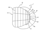
以下、本発明の実施形態について図面を参照して詳細に説明する。図1は、本発明の実施形態に係る履物の構成を示す平面図、図2は、同履物の構成を示す側面図、図3は、同履物の構成を示す図1のA-A側面断面図、図4は、同履物の図1のB-B正面断面図、図5は、同履物の図4の一部を拡大して示す拡大正面断面図、図6は、同履物の図1のC-C正面断面図、図7は、同履物の図6の一部を拡大して示す拡大正面断面図、図8は、同履物のインソール部の構成を示す平面図、図9は、同履物のインソール部の構成を示す側面図、図10は、同履物の保持部材の構成を説明するための履物の一部を切り欠いた側面図、図11は、同履物の保持部材の構成を説明するための図10の背面から見た背面図、図12は、同履物を屈曲させた状態を示す側面図、図13は、同履物を屈曲させた状態を示す平面図である。なお、以下の説明においては、図1乃至図3に示した方向を基準として各方向を定義するものとする。 BEST MODE FOR CARRYING OUT THE INVENTION Hereinafter, embodiments of the present invention will be described in detail with reference to the drawings. 1 is a plan view showing the structure of footwear according to an embodiment of the present invention, FIG. 2 is a side view showing the structure of the same footwear, and FIG. 3 is a cross-sectional view taken along the line AA of FIG. 4 is a front cross-sectional view of the same footwear along the line BB in FIG. 1, FIG. 5 is an enlarged front cross-sectional view showing a part of FIG. 4 of the same footwear in an enlarged manner, and FIG. 7 is an enlarged front sectional view showing a part of FIG. 6 of the same footwear, FIG. 8 is a plan view showing the configuration of the insole part of the same footwear, and FIG. FIG. 10 is a side view showing the configuration of the insole portion of the footwear, FIG. 10 is a partially cutaway side view of the footwear for explaining the configuration of the holding member of the footwear, and FIG. 11 is the configuration of the holding member of the footwear. FIG. 12 is a side view showing the footwear in a bent state, and FIG. 13 is a plan view showing the footwear in a bent state. In the following description, each direction is defined with reference to the directions shown in FIGS. 1 to 3. FIG.
これらの図を参照して本発明の実施形態に係る履物1の構成の概要を説明すると、履物1は、屈曲可能な構成となっており、アウトソール部10、固定部(アッパー)20、覆い部30、中敷40、および保持部材50を有している(履物1は、外力を加えて屈曲させた後に外力を解除すると元の形状に戻る)。
The outline of the structure of the
アウトソール部10は、履物1の底部を構成するものであり、底面10b側には、滑り止めとして機能を有する複数の溝10b´が設けられている。アウトソール部10は、ゴム、樹脂、発泡性等の材料で形成されており、屈曲部Aを介して屈曲可能な構成となっている(アウトソール部10は、外力を加えて屈曲させた後に外力を解除すると元の形状に戻る)。アウトソール部10は、先端部10´が上方に反り返えるように構成されている。
The
アウトソール部10の先端部10´は、非屈曲の状態(静止状態)において、履物1を水平面Bに置いたときに当該水平面Bから離間するように構成されている。すなわち、アウトソール部10の先端部10´は、履物1を水平面Bに置いたときに当該水平面Bから上方に所定の高さ離間するように構成されており、アウトソール部10の先端部10´の高さHは、20mm乃至80mmに設定されている。より好ましくは、アウトソール部10の先端部10´の高さは、水平面Bから上方に30mm乃至70mm離間するように設定されることが好ましく、水平面Bから上方に40mm乃至60mm離間するように設定されることが更に好ましい。
The tip portion 10' of the
固定部20は、アウトソール部10の上面10c側に設けられるアッパーであり、足先、足の甲、足の側部、および足の後部を挿入するための内部空間を有し、足先、足の甲、足の側部、および足の後部を覆うように固定することができる。固定部20は、表面側および裏面側を所定の生地で構成されるとともに、表面側および裏面側の布材料間に綿状の材料またはスポンジ状の材料を介在させた構成となっており、屈曲部Aを介して屈曲可能な構成となっている(固定部20は、外力を加えて屈曲させた後に外力を解除すると元の形状に戻る)。
The fixing
この固定部20の下端部の周縁部20aと上述したアウトソール部10の外周部10´´とは、繋ぎ合わせ部25を介して繋ぎ合わせられている。繋ぎ合わせ部25によるアウトソール部10の外周部10´´と固定部20の下端側の周縁部20aとの繋ぎ合わせは、縫合により行うことができる。
A
ここで、アウトソール部10は、正面視の断面形状が凹状となっている。そして、アウトソール部10の外周部10´´の上部側より詳しくはアウトソール部10の上面10c 側の外周縁部の上方に突出する突出部分10aは、所定の覆い部30をなしている。
Here, the
すなわち、覆い部30は、繋ぎ合わせ部25から上方に短尺に延びて固定部20の下端側の外周縁部20aを覆うことができる。覆い部30は、繋ぎ合わせ部25から上方に突出するとともに、短尺に帯状に周回しつつ延びるように設けられており、アウトソール部10の外周部10´´の一構成をなしている。
That is, the covering
つまり、覆い部30は、アウトソール部10の本体部分と同様に、ゴム、樹脂、発泡性等の材料で形成されており、屈曲部Aを介して屈曲可能な構成となっている。覆い部30は、アウトソール部10の外周部10´´と固定部20の下端側の周縁部20aとを縫合するための縫合代とすることができる。覆い部30の内側は、固定部20の下端側の周縁部20aと所定に離間し非固着の状態とすることができる。
In other words, the
ここで、覆い部30は、第1突出部31および第2の突出部32と窪部33を有している。すなわち、第1の突出部31は、覆い部30の側方の外側に突出するように構成されている。また、窪部33は、第1の突出部31と前後方向に隣接より詳しくは後方に隣接するとともに側方の内側に没するように構成されている。第2の突出部33は、窪部33と前後方向に隣接より詳しくは後方に隣接するとともに側方の外側に突出するように構成されている。すなわち、覆い部30は、第1の突出部31、窪部33、および第2の突出部32により波型に湾曲するように構成される領域を含んでいる。
Here, the
この覆い部30の第1の突出部31、窪部33、および第2の突出部32は、覆い部30の前後方向における中間部に設けられており、固定部20、アウトソール部10、および中敷40の屈曲部Aの位置は、覆い部30の第1の突出部31、窪部33、および第2の突出部32が設けられる覆い部30のいずれかの位置と対応する位置に設定されている。また、先端部10´が反り返るように構成されるアウトソール部10の反り返りの起点Cは、屈曲部Aの位置と対応する位置とすることとしており、屈曲部Aの位置と同様に、第1の突出部31、窪部33、および第2の突出部32が設けられる覆い部30のいずれかの位置と対応する位置としている。
The first projecting
中敷40は、アウトソール部10の上面10c側の輪郭形状と略同等の輪郭形状となっている。中敷40は、アウトソール部10の後部または固定部20の後部まで延びている。すなわち、中敷40は、固定部20の内部空間に挿入されるとともに、アウトソール部10の上面10c側に敷かれて足の裏側と接触し、取り外し可能な構成となっている。中敷40は、ゴム、樹脂、発泡性等の材料で形成されており、屈曲部Aを介して屈曲可能な構成となっている(中敷40は、外力を加えて屈曲させた後に外力を解除すると元の形状に戻る)。
The
保持部材50は、アウトソール部10の後部の上面10c側に設けられている。保持部材50は、所定に被覆されることにより、目視できないように設けられている。すなわち、保持部材50は、以下に詳述するように、目視できない位置に設けられている。
The holding
より詳しくは、保持部材50は、アウトソール部10の後部の上面10c側と中敷40の後部の底面40b側との間に設けられ、中敷40の後部の底面40b側により覆われる位置に設けられている。すなわち、保持部材50は、中敷40に覆われることにより被覆することができる。
More specifically, the holding
また、保持部材50は、中敷40を固定部20の内部空間から外した状態であって、足を履いた状態において、保持部材50の設置位置は、足の踵の位置と対応する位置となるように設定されている。すなわち、保持部材50は、足を履いた状態において、足の踵に覆われることにより被覆することができる。
In addition, when the
保持部材50は、固定部20、アウトソール部10、および中敷40の前部側を後部側に屈曲させたときに固定部20、アウトソール部10、および中敷40の屈曲させた状態を保持することができる。保持部材50は、固定部20、アウトソール部10、および中敷40の前部側を屈曲させた状態でアウトソール部10の底面10bを係止して保持することができる。上述したように、アウトソール部10の底面10bには、溝10b´が設けられており、溝10b´により保持部材50の係止された状態を保持することができる。
The holding
保持部材50は、側方に帯状に延びるように構成され、側方の両端部51,52をアウトソール部10の後部の上面10c側の側端10c1,10c2側に固定して設けられている。保持部材50は、側方の中間部53を非固定状態としかつ伸縮可能としている。保持部材50は、ゴム製のバンドとすることができる。
The holding
以上のように構成された履物1は以下のように保持部材50により屈曲した状態を保持することができる。
The
すなわち、保持部材50は、側方の中間部53を上方に引っ張り上げて伸長させ環状部50dを形成した状態(図10および図11)として、固定部20、アウトソール部10、および中敷40の前部側を屈曲させた状態でその先端側を環状部50d内に挿入する。
That is, the holding
そして、保持部材50の中間部53より詳しくは環状部50dを引っ張り上げた状態を解除し、固定部20、アウトソール部10、および中敷40の前部側を保持部材50の側方の中間部53とアウトソール10の後部側の上面10c側との間に挟み込み、保持部材50の伸縮力によりアウトソール部10の前部側の底面10bを下方に押圧して付勢し保持することができる(図12および図13)。
Then, the
図12および図13からも明らかなように、保持部材50は、固定部20、アウトソール部10、および中敷40の前部側を屈曲させて環状部50dに挿入し環状部50dの引っ張り上げた状態を解除したときには、アウトソール部10の先端部10´の位置が保持部材50の後端部50´の位置よりも前方の位置となるように保持することができる。
12 and 13, the holding
以上説明したように、本発明によれば、底部を構成するアウトソール部10と、アウトソール部10の上面10c側に設けられ、足を固定する固定部20と、を有し、固定部20およびアウトソール部10は、屈曲部Aを介して屈曲可能とすることとしたので、屈曲部Aを介して屈曲可能な履物1を提供することができる。
As described above, according to the present invention, the
また、アウトソール部10の上面10c側に設けられ、固定部20、アウトソール部10、および中敷40の前部側を後部側に屈曲させたときに固定部20、アウトソール部10、および中敷40の屈曲させた状態を保持する保持部材50を有することとしたので、履物1の屈曲させた状態を保持することができる。
Further, when the front side of the fixing
更に、保持部材50は、固定部20、アウトソール部10、および中敷40の前部側を屈曲させた状態としたときに、アウトソール部10の先端部10´の位置が保持部材50の後端部50´の位置よりも前方の位置に保持されることとしたので、保持部材50によるアウトソール部10の保持面積を小さくすることができ、小さい外力で保持部材50による保持状態を解除することが可能となる。
Furthermore, when the holding
更にまた、中敷40は、アウトソール部10の後部および固定部20の後部まで延びるとともに、保持部材50は、アウトソール部10の後部の上面10c側と中敷40の後部の底面40b側との間に設けられ、中敷40の後部の底面40b側により覆われる位置に設けられることとしたので、保持部材50を中敷40により被覆することができる。
Furthermore, the
また更に、第1の突出部31、窪部33、および第2の突出部32が設けられる覆い部30のいずれかの位置と対応する位置に、固定部20、アウトソール部10、および中敷40の屈曲部Aの位置が設定されることとしたので、第1の突出部31、窪部33、第2の突出部32により屈曲の際の撓みが履物1に対して与える影響を緩和することができる。
Furthermore, the fixing
また、アウトソール部10は、先端部10´が上方に反り返えるように構成されるとともに、アウトソール部10の先端部10´は、水平面Bから離間するように構成されることとしたので、屈曲の際の屈曲量を少なくすることができる。また、屈曲量を少なくすることとすると、屈曲させた状態から元の状態に戻るときの反発力が小さくなるので、屈曲させた状態としたときに、アウトソール部10の先端部10´の位置が保持部材50の後端部50´の位置よりも前方の位置に保持されたとしても、その保持状態を維持することが可能となる。
Further, the
更に、反り返りの起点Cを第1の突出部31、窪部33、および第2の突出部が32設けられる覆い部30のいずれかの位置と対応する位置とすることとしたので、屈曲の起点と反り返りの起点を一致させることができる。
Furthermore, since the starting point C of warping is set to a position corresponding to any one of the
なお、本発明は、上述した実施形態に限定されることなく特許請求の範囲を逸脱しない範囲内において種々の応用実施、変形実施が可能であることは勿論である。 It goes without saying that the present invention is not limited to the above-described embodiments, and that various applications and modifications are possible without departing from the scope of the claims.
すなわち、例えば、上述した実施形態にあっては、アウトソール部10に設けられる突出部31,32および窪部33は、アウトソール部10の外周部10´´の上部側なす覆い部30に設けることとしているが、アウトソール部10の外周部10´´の上下方向の中間部や下部側に設けることとしても所要の効果を奏する。
That is, for example, in the above-described embodiment, the
ただし、突出部31,32および窪部33は、アウトソール部10の外周部10´´の上部側なす覆い部30に設けることとした方が、アウトソール部10の上下方向の中間部や下部側に設けることとするよりも屈曲の際の撓みが履物に対して与える影響を更に緩和することができるので好ましい。
However, the
また、上述した実施形態にあっては、保持部材50は、側方の両端部51,52をアウトソール部10の後部の上面10c側の側端10c1,10c2側に固定しつつアウトソール部10の後部の上面10c側に設けることとしているが、側方の両端部51,52を固定部20の後部の下部側の内側面側に固定しつつアウトソール部10の後部の上面10c側に設けることとしても所要の効果を奏する。
In the above-described embodiment, the holding
ただし、保持部材50は、側方の両端部51,52をアウトソール部10の後部の上面10c側の側端10c1,10c2側に固定しつつアウトソール部10の後部の上面10c側に設けることとした方が、側方の両端部51,52を固定部20の後部の下部側の内側面側に固定しつつアウトソール部10の後部の上面10c側に設けることとするよりも、伸縮長さを長くすることができ、また中敷40により被覆し易くより好ましい。
However, the holding
更に、上述した実施形態にあっては、固定部20は、足先、足の甲、足の側部、および足の後部を全体的に固定するように構成することとしているが、図14に示すように、足の甲の一部を固定する構成としても所要の効果を奏する。
Furthermore, in the embodiment described above, the fixing
更にまた、覆い部30は、固定部20の下端側の周縁部20aを覆うこととしているが、固定部20の全体を覆うこととしても所要の効果を奏する。
Furthermore, although the
また更に、上述した実施形態にあっては、保持部材50は帯状とすることとしているが、線状とすることとしても所要の効果を奏する。ただし、保持部材50は帯状とすることとした方が、線状とすることとするよりも保持面積を大きく設定することができるのでより好ましい。
Furthermore, in the above-described embodiment, the holding
また、保持部材50は、面ファスナーや粘着テープ等を含むこととして、これら面ファスナーや粘着テープ等により固定部20およびアウトソール部10の屈曲させた状態を保持することとしてもよい。
Further, the holding
また、上述した実施形態にあっては、保持部材50は、中敷40や足の踵に覆われて被覆されることにより、目視できない位置に設けることとしているが、目視できないように収納されて設けることとしてもよい。
In the above-described embodiment, the holding
すなわち、図15および図16に示すように、アウトソール部10の上面10c側に収納部11より詳しくはポケット11を設け、保持部材50は、収納部11(ポケット11)に収納されることにより被覆されることとしてもよい。この場合にあっては、収納部11は、保持部材50を出し入れする出し入れ口を有し、出し入れ口は、開閉部材12より詳しくはファスナー12により開閉可能なように構成することとしてもよい。また、収納部11は、アウトソール部10の上面10c側に設ける他固定部20の内側面側に設けることとしてもよい。
That is, as shown in FIGS. 15 and 16, a
なお、本発明の履物は、室内履き、外履き、運動靴、カジュアルシューズ、ビジネスシューズ、スリッパ等各種の履物を含むことができる。 The footwear of the present invention can include various types of footwear such as indoor shoes, outdoor shoes, sports shoes, casual shoes, business shoes, and slippers.
A:屈曲部
B:水平面
C:反り返りの起点
H:高さ
1:履物
10:アウトソール部
10´:先端部
10´´:外周部
10a:突出部分
10b:底面
10b´:溝
10c:上面
10c1,10c2:側端
11:収納部(ポケット)
12:開閉部材(ファスナー)
20:固定部
20a:下端側の周縁部
30:覆い部
31:第1の突出部
32:第2の突出部
33:窪部
40:中敷
40b:底面
50:保持部材
50d:環状部
50´:後端部
51,52:端部
53:中間部
A: Bending portion B: Horizontal plane C: Starting point of warping H: Height 1: Footwear 10: Outsole portion 10': Tip portion 10'':
12: Opening and closing member (fastener)
20: Fixing
Claims (14)
底部を構成するアウトソール部と、
前記アウトソール部の上面側に設けられ、足を固定する固定部と、を有し、
前記固定部および前記アウトソール部は、屈曲部を介して屈曲可能とし、
前記固定部および前記アウトソール部の屈曲させた状態を保持する保持部材を設け、
前記アウトソール部の上面側に敷かれる中敷を有し、
前記保持部材は、前記中敷に覆われて被覆されることにより、目視できないように設けられ 、
前記保持部材は、前記アウトソール部の上面側に設けられ、前記固定部および前記アウトソール部の前部側を後部側に屈曲させたときに前記固定部および前記アウトソール部の屈曲させた状態を保持するとともに、
更に、前記保持部材は、前記固定部および前記アウトソール部の前部側を屈曲させた状態で前記アウトソール部の底面を係止して保持し、
前記保持部材は、側方に帯状または線状に延びるように構成され、前記側方の両端部を前記アウトソール部の後部の上面側に固定して設けられるとともに、伸縮可能とし、
前記保持部材の伸縮力により前記アウトソール部の前部側の底面を下方に付勢し保持することを特徴とする履物。 bendable footwear,
an outsole that forms the bottom;
a fixing part that is provided on the upper surface side of the outsole part and fixes the foot,
The fixing portion and the outsole portion are bendable via a bending portion.death,
providing a holding member that holds the fixed portion and the outsole portion in a bent state;
Having an insole laid on the upper surface side of the outsole part,
The holding member is provided so as to be invisible by being covered and covered with the insole. ,
The holding member is provided on the upper surface side of the outsole portion, and the state in which the fixing portion and the outsole portion are bent when the front side of the fixing portion and the outsole portion is bent rearward. while holding
Further, the holding member locks and holds the bottom surface of the outsole portion in a state where the fixing portion and the front portion side of the outsole portion are bent,
The holding member is configured to extend laterally in a belt-like or linear shape, and is provided with both ends of the side fixed to the upper surface side of the rear portion of the outsole portion, and is expandable and contractable,
The elastic force of the holding member biases and holds the bottom surface on the front side of the outsole portion downward.Footwear characterized by:
前記保持部材は、前記アウトソール部の後部の上面側と前記中敷の後部の底面側との間に設けられ、前記中敷の後部の底面側により覆われる位置に設けられることを特徴とする請求項1に記載の履物。 The insole extends to the rear portion of the outsole portion and the rear portion of the fixing portion,
The holding member is provided between the upper surface side of the rear portion of the outsole portion and the bottom surface side of the rear portion of the insole, and is provided at a position covered by the bottom surface side of the rear portion of the insole. 10. Footwear according to claim 1 .
Priority Applications (1)
| Application Number | Priority Date | Filing Date | Title |
|---|---|---|---|
| JP2019187163A JP7191286B2 (en) | 2019-10-10 | 2019-10-10 | footwear |
Applications Claiming Priority (1)
| Application Number | Priority Date | Filing Date | Title |
|---|---|---|---|
| JP2019187163A JP7191286B2 (en) | 2019-10-10 | 2019-10-10 | footwear |
Publications (2)
| Publication Number | Publication Date |
|---|---|
| JP2021061924A JP2021061924A (en) | 2021-04-22 |
| JP7191286B2 true JP7191286B2 (en) | 2022-12-19 |
Family
ID=75486747
Family Applications (1)
| Application Number | Title | Priority Date | Filing Date |
|---|---|---|---|
| JP2019187163A Active JP7191286B2 (en) | 2019-10-10 | 2019-10-10 | footwear |
Country Status (1)
| Country | Link |
|---|---|
| JP (1) | JP7191286B2 (en) |
Citations (1)
| Publication number | Priority date | Publication date | Assignee | Title |
|---|---|---|---|---|
| JP2016221356A (en) | 2011-08-10 | 2016-12-28 | ガヴリエリ ブランズ,エルエルシー | Split sole footwear |
Family Cites Families (1)
| Publication number | Priority date | Publication date | Assignee | Title |
|---|---|---|---|---|
| GB0622431D0 (en) * | 2006-11-10 | 2006-12-20 | Ive Felicity | Disposable/roll up footwear |
-
2019
- 2019-10-10 JP JP2019187163A patent/JP7191286B2/en active Active
Patent Citations (1)
| Publication number | Priority date | Publication date | Assignee | Title |
|---|---|---|---|---|
| JP2016221356A (en) | 2011-08-10 | 2016-12-28 | ガヴリエリ ブランズ,エルエルシー | Split sole footwear |
Also Published As
| Publication number | Publication date |
|---|---|
| JP2021061924A (en) | 2021-04-22 |
Similar Documents
| Publication | Publication Date | Title |
|---|---|---|
| CN112839539B (en) | Quick-entry shoe with compressible lattice structure | |
| US8516719B2 (en) | Article of footwear construction with binding portions | |
| CN113226099B (en) | Easy entry footwear with articulating sole structure | |
| US20210259364A1 (en) | Shoe having counter | |
| US20150216252A1 (en) | Footwear with magnetic closures | |
| KR101826077B1 (en) | shoes | |
| KR101825557B1 (en) | assemblable shoes | |
| JP2004160234A (en) | Footwear product upper, footwear structure and footwear upper, method of manufacturing footwear | |
| US6978559B2 (en) | Lining of footwear having functions of ventilation and waterproof | |
| JP3501444B2 (en) | Insole board split type sole structure | |
| US20180160768A1 (en) | Comfort system for footwear | |
| JP7191286B2 (en) | footwear | |
| US20140068971A1 (en) | Footwear construction eliminating the use of a foxing or a foxing-like band | |
| US7234248B2 (en) | Footwear | |
| EP4445789A1 (en) | Sole and shoe including the sole | |
| JP7490673B2 (en) | Tongue construction, shoes | |
| KR102107837B1 (en) | Restoring type shoes and manufacturing method of therefor | |
| KR102853405B1 (en) | Toe box shoes | |
| JP5303078B1 (en) | footwear | |
| JPH05220005A (en) | Safe footgear | |
| JP2008264258A (en) | Footwear and its manufacturing method | |
| US20250338919A1 (en) | Shoe | |
| JP2020078396A (en) | Shoes, shoe soles, and shoe uppers | |
| JP6421400B2 (en) | shoes | |
| JP3122770U (en) | Sandals and slippers |
Legal Events
| Date | Code | Title | Description |
|---|---|---|---|
| A621 | Written request for application examination |
Free format text: JAPANESE INTERMEDIATE CODE: A621 Effective date: 20220518 |
|
| A871 | Explanation of circumstances concerning accelerated examination |
Free format text: JAPANESE INTERMEDIATE CODE: A871 Effective date: 20220518 |
|
| A131 | Notification of reasons for refusal |
Free format text: JAPANESE INTERMEDIATE CODE: A131 Effective date: 20220624 |
|
| A521 | Request for written amendment filed |
Free format text: JAPANESE INTERMEDIATE CODE: A523 Effective date: 20220809 |
|
| TRDD | Decision of grant or rejection written | ||
| A01 | Written decision to grant a patent or to grant a registration (utility model) |
Free format text: JAPANESE INTERMEDIATE CODE: A01 Effective date: 20221027 |
|
| A61 | First payment of annual fees (during grant procedure) |
Free format text: JAPANESE INTERMEDIATE CODE: A61 Effective date: 20221115 |
|
| R150 | Certificate of patent or registration of utility model |
Ref document number: 7191286 Country of ref document: JP Free format text: JAPANESE INTERMEDIATE CODE: R150 |
|
| S531 | Written request for registration of change of domicile |
Free format text: JAPANESE INTERMEDIATE CODE: R313531 |
|
| R350 | Written notification of registration of transfer |
Free format text: JAPANESE INTERMEDIATE CODE: R350 |
|
| R154 | Certificate of patent or utility model (reissue) |
Free format text: JAPANESE INTERMEDIATE CODE: R154 |