JP7190442B2 - Assembly and headgear for recharging implantable medical electrical systems - Google Patents
Assembly and headgear for recharging implantable medical electrical systems Download PDFInfo
- Publication number
- JP7190442B2 JP7190442B2 JP2019553377A JP2019553377A JP7190442B2 JP 7190442 B2 JP7190442 B2 JP 7190442B2 JP 2019553377 A JP2019553377 A JP 2019553377A JP 2019553377 A JP2019553377 A JP 2019553377A JP 7190442 B2 JP7190442 B2 JP 7190442B2
- Authority
- JP
- Japan
- Prior art keywords
- recharging
- flexible body
- wearable medical
- medical device
- patient
- Prior art date
- Legal status (The legal status is an assumption and is not a legal conclusion. Google has not performed a legal analysis and makes no representation as to the accuracy of the status listed.)
- Active
Links
Images


Classifications
-
- A—HUMAN NECESSITIES
- A61—MEDICAL OR VETERINARY SCIENCE; HYGIENE
- A61N—ELECTROTHERAPY; MAGNETOTHERAPY; RADIATION THERAPY; ULTRASOUND THERAPY
- A61N1/00—Electrotherapy; Circuits therefor
- A61N1/18—Applying electric currents by contact electrodes
- A61N1/32—Applying electric currents by contact electrodes alternating or intermittent currents
- A61N1/36—Applying electric currents by contact electrodes alternating or intermittent currents for stimulation
- A61N1/372—Arrangements in connection with the implantation of stimulators
- A61N1/378—Electrical supply
- A61N1/3787—Electrical supply from an external energy source
-
- A—HUMAN NECESSITIES
- A61—MEDICAL OR VETERINARY SCIENCE; HYGIENE
- A61N—ELECTROTHERAPY; MAGNETOTHERAPY; RADIATION THERAPY; ULTRASOUND THERAPY
- A61N1/00—Electrotherapy; Circuits therefor
- A61N1/02—Details
- A61N1/04—Electrodes
- A61N1/0404—Electrodes for external use
- A61N1/0472—Structure-related aspects
- A61N1/0484—Garment electrodes worn by the patient
-
- A—HUMAN NECESSITIES
- A61—MEDICAL OR VETERINARY SCIENCE; HYGIENE
- A61N—ELECTROTHERAPY; MAGNETOTHERAPY; RADIATION THERAPY; ULTRASOUND THERAPY
- A61N1/00—Electrotherapy; Circuits therefor
- A61N1/02—Details
- A61N1/04—Electrodes
- A61N1/05—Electrodes for implantation or insertion into the body, e.g. heart electrode
- A61N1/0526—Head electrodes
- A61N1/0529—Electrodes for brain stimulation
-
- A—HUMAN NECESSITIES
- A61—MEDICAL OR VETERINARY SCIENCE; HYGIENE
- A61N—ELECTROTHERAPY; MAGNETOTHERAPY; RADIATION THERAPY; ULTRASOUND THERAPY
- A61N1/00—Electrotherapy; Circuits therefor
- A61N1/18—Applying electric currents by contact electrodes
- A61N1/32—Applying electric currents by contact electrodes alternating or intermittent currents
- A61N1/36—Applying electric currents by contact electrodes alternating or intermittent currents for stimulation
- A61N1/372—Arrangements in connection with the implantation of stimulators
- A61N1/37211—Means for communicating with stimulators
- A61N1/37217—Means for communicating with stimulators characterised by the communication link, e.g. acoustic or tactile
- A61N1/37223—Circuits for electromagnetic coupling
-
- A—HUMAN NECESSITIES
- A61—MEDICAL OR VETERINARY SCIENCE; HYGIENE
- A61N—ELECTROTHERAPY; MAGNETOTHERAPY; RADIATION THERAPY; ULTRASOUND THERAPY
- A61N1/00—Electrotherapy; Circuits therefor
- A61N1/18—Applying electric currents by contact electrodes
- A61N1/32—Applying electric currents by contact electrodes alternating or intermittent currents
- A61N1/36—Applying electric currents by contact electrodes alternating or intermittent currents for stimulation
- A61N1/372—Arrangements in connection with the implantation of stimulators
- A61N1/37211—Means for communicating with stimulators
- A61N1/37252—Details of algorithms or data aspects of communication system, e.g. handshaking, transmitting specific data or segmenting data
- A61N1/37276—Details of algorithms or data aspects of communication system, e.g. handshaking, transmitting specific data or segmenting data characterised by means for reducing power consumption during telemetry
-
- A—HUMAN NECESSITIES
- A61—MEDICAL OR VETERINARY SCIENCE; HYGIENE
- A61N—ELECTROTHERAPY; MAGNETOTHERAPY; RADIATION THERAPY; ULTRASOUND THERAPY
- A61N1/00—Electrotherapy; Circuits therefor
- A61N1/18—Applying electric currents by contact electrodes
- A61N1/32—Applying electric currents by contact electrodes alternating or intermittent currents
- A61N1/36—Applying electric currents by contact electrodes alternating or intermittent currents for stimulation
- A61N1/372—Arrangements in connection with the implantation of stimulators
- A61N1/375—Constructional arrangements, e.g. casings
- A61N1/37514—Brain implants
-
- H—ELECTRICITY
- H02—GENERATION; CONVERSION OR DISTRIBUTION OF ELECTRIC POWER
- H02J—CIRCUIT ARRANGEMENTS OR SYSTEMS FOR SUPPLYING OR DISTRIBUTING ELECTRIC POWER; SYSTEMS FOR STORING ELECTRIC ENERGY
- H02J50/00—Circuit arrangements or systems for wireless supply or distribution of electric power
- H02J50/10—Circuit arrangements or systems for wireless supply or distribution of electric power using inductive coupling
Landscapes
- Health & Medical Sciences (AREA)
- General Health & Medical Sciences (AREA)
- Animal Behavior & Ethology (AREA)
- Veterinary Medicine (AREA)
- Public Health (AREA)
- Life Sciences & Earth Sciences (AREA)
- Engineering & Computer Science (AREA)
- Biomedical Technology (AREA)
- Nuclear Medicine, Radiotherapy & Molecular Imaging (AREA)
- Radiology & Medical Imaging (AREA)
- Physics & Mathematics (AREA)
- Neurosurgery (AREA)
- Heart & Thoracic Surgery (AREA)
- Neurology (AREA)
- Cardiology (AREA)
- Psychology (AREA)
- Electromagnetism (AREA)
- Acoustics & Sound (AREA)
- Electrotherapy Devices (AREA)
Description
[0001]本開示は、医療装置に関し、より詳細には、医療装置のうちの1つまたは複数の電源を再充電することに関連付けられた組立体およびヘッドギアに関する。 [0001] The present disclosure relates to medical devices and, more particularly, to assemblies and headgear associated with recharging one or more power sources of medical devices.
[0002]医療装置は、患者の監視、および/または患者への治療の提供等の様々な機能を提供するために、患者内の複数の場所の外部に、またはこれらの場所に部分的に植え込まれて、または完全に植え込まれて構成され得る。植込み型医療装置(IMD)が植え込まれ得る場所の例は、患者の頭蓋、胸骨下の場所、または臀部付近を含むが、他の例では、IMDは他の場所に植え込まれ得る。IMDは、意図される機能を提供するために電力を必要とする、1つまたは複数の処理回路および1つまたは複数の電気構成要素を含み得る。多くの場合、この機能をIMDに提供するために、電源がIMD内に収容されるか、またはそうでない場合、電源も植え込まれる。IMDは、誘導結合のための再充電コイル等の再充電構成要素を含むことができ、これらは、例えば電磁場からIMDの電源への電流を生成および方向付けすることによって、埋め込まれた電源を再充電することが可能である。 [0002] Medical devices are implanted externally or partially at multiple locations within a patient to provide various functions such as monitoring the patient and/or providing therapy to the patient. It can be configured to be implanted or fully implanted. Examples of locations where an implantable medical device (IMD) may be implanted include a patient's skull, a substernal location, or near the hip, although in other examples the IMD may be implanted in other locations. An IMD may include one or more processing circuits and one or more electrical components that require power to provide their intended functions. In many cases, a power source is housed within the IMD, or otherwise implanted as well, to provide the IMD with this functionality. IMDs can include recharging components, such as recharging coils for inductive coupling, which recharge the implanted power source by, for example, generating and directing current from an electromagnetic field to the IMD's power source. It is possible to charge.
[0003]本開示は、頭蓋に装着された医療装置(例えば、1つまたは複数の植込み型医療装置(IMD))の電源を再充電することに関連する装置、システムおよび技法に関する。ウェアラブル医療装置は、患者の1つまたは複数のIMDに充電電力を送達するのに適した所定の場所に1つまたは複数の再充電コイルを保有することができる。例えば、ウェアラブル医療装置は、再充電コイルをウェアラブル医療装置の可撓性本体に結合するように構成される定着部材(例えば、取付け組立体)を含むことができる。第2の定着部材は、第2の再充電コイルを可撓性本体に結合することができる。患者は自身の頭部の一部分にわたってウェアラブル医療装置を着用することができるため、可撓性本体および定着部材は、患者の頭蓋に植え込まれたそれぞれのIMDと位置が合った、頭部におけるそれぞれの場所に再充電コイルを保有することができる。このようにして、患者は、ウェアラブル医療装置を頭部に配置して、コイルとIMDとの間の再充電および/または通信機能のために再充電コイルをIMDと再現可能に位置合わせすることができる。いくつかの例では、可撓性本体は、ハットと類似した形状を有することができる。 [0003] The present disclosure relates to devices, systems, and techniques related to recharging a cranially-mounted medical device (eg, one or more implantable medical devices (IMDs)). A wearable medical device may possess one or more recharging coils in predetermined locations suitable for delivering charging power to one or more of a patient's IMDs. For example, a wearable medical device can include an anchoring member (eg, mounting assembly) configured to couple the recharging coil to the flexible body of the wearable medical device. A second anchoring member may couple the second recharging coil to the flexible body. Because the patient can wear the wearable medical device over a portion of their head, the flexible body and anchoring member are each positioned on the head in alignment with the respective IMD implanted in the patient's skull. A recharging coil can be held at the location of In this way, a patient can place the wearable medical device on their head to reproducibly align the recharging coil with the IMD for recharging and/or communication functions between the coil and the IMD. can. In some examples, the flexible body can have a shape similar to a hat.
[0004]いくつかの例では、ウェアラブル医療装置は、患者の頭部上で使用するためにウェアラブル医療装置に取外し可能に固定されるように構成される再充電装置または再充電システムを含むことができる。このようにして、再充電装置は、頭部に対し再現可能な場所において患者の頭部に対し繰り返し可能に取外しおよび固定され得る。再充電装置は1つまたは複数の再充電コイルを含むことができ、いくつかの例では、再充電コイルに電力を供給するように構成される電源も含むことができる。いくつかの例では、再充電コイルは可撓性本体に固定され得、電源は、頭部の外周の周りに延び、可撓性本体よりも剛体である固定部材に固定され得る。 [0004] In some examples, a wearable medical device may include a recharging device or recharging system configured to be removably secured to the wearable medical device for use on a patient's head. can. In this way, the recharging device can be repeatedly removed and secured to the patient's head at reproducible locations on the head. The recharging device can include one or more recharging coils and, in some examples, can also include a power source configured to power the recharging coils. In some examples, the recharging coil may be secured to the flexible body and the power source may be secured to a securing member that extends around the circumference of the head and is more rigid than the flexible body.
[0005]1つの例では、ウェアラブル医療システムは、患者の頭部の頭皮の左前象限、左後象限、右後象限および右前象限の各々の少なくとも一部分を覆うように構成される可撓性本体を含む。ウェアラブル医療システムは、可撓性本体に接続され、頭部の外周の周りに延び、患者の頭皮に対し可撓性本体を安定させるように構成される、固定部材も含む。ウェアラブル医療システムは、可撓性本体の或る場所に装着するように構成され、頭蓋に装着可能な植込み型医療装置の植込み型電源を再充電するように構成される再充電コイルに可撓性本体を結合するように構成される、定着部材も含む。 [0005] In one example, a wearable medical system includes a flexible body configured to cover at least a portion of each of the left anterior quadrant, the left posterior quadrant, the right posterior quadrant, and the right anterior quadrant of the scalp of a patient's head. include. The wearable medical system also includes a fixation member connected to the flexible body and extending around the perimeter of the head and configured to stabilize the flexible body against the patient's scalp. The wearable medical system is configured to be mounted at a location on the flexible body and flexible to a recharging coil configured to recharge an implantable power source of a cranially mountable implantable medical device. A fixing member configured to couple the body is also included.
[0006]別の例では、ウェアラブル医療システムは、患者の頭部の頭皮の左前象限、左後象限、右後象限および右前象限の各々の少なくとも一部分を覆うように構成される可撓性本体を含む。ウェアラブル医療システムは、可撓性本体に接続され、頭部の外周の周りに延び、患者の頭皮に対し可撓性本体を安定させるように構成される、固定部材も含む。ウェアラブル医療システムは、可撓性本体または固定部材の少なくとも一方に固定される外部電源も含む。ウェアラブル医療システムは、第1の頭蓋に装着可能な植込み型医療装置の第1の植込み型電源を再充電するために電源からエネルギーを伝送するように取外し可能に構成される第1の再充電コイルも含む。ウェアラブル医療システムは、第2の頭蓋に装着可能な植込み型医療装置の第2の植込み型電源を再充電するために電源からエネルギーを伝送するように取外し可能に構成される第2の再充電コイルも含む。ウェアラブル医療システムは、外部電源を第1および第2の再充電コイルに結合する1つまたは複数のケーブルも含む。ウェアラブル医療システムは、可撓性本体の第1の場所に装着し、第1の再充電コイルを可撓性本体にしっかりと取り付けるように構成される、第1の定着部材も含む。ウェアラブル医療システムは、可撓性本体の第2の場所に装着するように構成される第2の定着部材も含む。第2の定着部材は、第2の再充電コイルを可撓性本体にしっかりと取り付けるように構成される。 [0006] In another example, a wearable medical system includes a flexible body configured to cover at least a portion of each of the left anterior quadrant, the left posterior quadrant, the right posterior quadrant, and the right anterior quadrant of the scalp of a patient's head. include. The wearable medical system also includes a fixation member connected to the flexible body and extending around the perimeter of the head and configured to stabilize the flexible body against the patient's scalp. The wearable medical system also includes an external power source fixed to at least one of the flexible body or the fixed member. The wearable medical system includes a first recharging coil removably configured to transfer energy from a power source to recharge a first implantable power source of a first cranially mountable implantable medical device. Also includes The wearable medical system includes a second recharging coil removably configured to transfer energy from the power source to recharge the second implantable power source of the second cranially mountable implantable medical device. Also includes The wearable medical system also includes one or more cables coupling an external power source to the first and second recharging coils. The wearable medical system also includes a first anchoring member configured to be mounted on the flexible body at a first location to securely attach the first recharging coil to the flexible body. The wearable medical system also includes a second anchoring member configured to attach to the flexible body at a second location. A second anchoring member is configured to securely attach the second recharging coil to the flexible body.
[0007]別の例では、ウェアラブル医療システムは、再充電コイルを収容するように構成され、各々が患者の頭部の頭皮の湾曲を近似する凹状の第1の主面および凸状の第2の主面を画定する、湾曲した容器を含む。第1の主面は、患者の頭皮とインターフェースするように構成され、第2の主面は、湾曲した容器の、第1の主面の反対側にある。第2の主面は、第2の主面から離れるように延びる隆起と、湾曲した容器を通って延びるボアとを画定する。ウェアラブル医療システムは、ボアによって受けられるように構成される円筒形凹部と、ブラケットを湾曲した容器にしっかりと取り付けるために第2の主面の隆起を受けるように構成されるチャネルとを画定するブラケットも含む。ウェアラブル医療システムは、ブラケットによってしっかりと受けられるようにブラケットの円筒形凹部内に延びるように構成されるピンも含む。ピンは、ピンがブラケットの凹部によって受けられるときに円筒形凹部の口部を押し付けるように構成されるプレートを含む。 [0007] In another example, a wearable medical system is configured to house a recharging coil with a concave first major surface and a convex second major surface each approximating the curvature of the scalp of a patient's head. a curved container that defines a major surface of the The first major surface is configured to interface with a patient's scalp and the second major surface is opposite the first major surface of the curved container. The second major surface defines a ridge extending away from the second major surface and a bore extending through the curved container. A wearable medical system defines a cylindrical recess configured to be received by a bore and a channel configured to receive a ridge on a second major surface to securely attach the bracket to a curved container. Also includes The wearable medical system also includes a pin configured to extend within the cylindrical recess of the bracket so as to be securely received by the bracket. The pin includes a plate configured to press against the mouth of the cylindrical recess when the pin is received by the recess in the bracket.
[0047]本開示は、植込み型医療装置(IMD)等の頭蓋に装着された医療装置の電源を再充電することに関する装置、システムおよび方法を対象とする。患者は、患者の頭部または頭部付近に位置する1つまたは複数の医療装置を用いて監視および/または処置され得る。医療装置は、患者の完全に外部にあってもよく、部分的に患者内に植え込まれてもよく、または患者内に完全に植え込まれてもよい。例えば、患者は、脳内に配設されたそれぞれの電気リードに結合された、頭蓋に装着された2つのIMDを有することができ、各IMDは、脳患者を監視するかまたは脳患者に治療を与える(例えば、神経信号を監視する、および/または脳障害の1つまたは複数の症状を治療する脳深部刺激を送達する)等の機能を提供するように構成される。 [0047] The present disclosure is directed to devices, systems and methods related to recharging the power supply of a cranially-mounted medical device, such as an implantable medical device (IMD). A patient may be monitored and/or treated with one or more medical devices located at or near the patient's head. The medical device may be completely external to the patient, partially implanted within the patient, or fully implanted within the patient. For example, a patient may have two IMDs attached to the skull coupled to respective electrical leads disposed in the brain, each IMD monitoring or treating the brain patient. (eg, monitor neural signals and/or deliver deep brain stimulation to treat one or more symptoms of a brain disorder).
[0048]これらの頭蓋に装着されたIMDの各々は、IMDの機能を実行するのに必要な電力を提供するように構成される再充電可能な電源を含むことができる。IMDは各々、外部再充電コイルからの電磁場に(例えば、誘導結合を介して)曝されることに応じてそれぞれの電源を再充電するための電流を生成するように構成される再充電コイルを含むことができる。更にまたは代替的に、IMDは、コイルを介して外部装置から通信を受信することができる。外部再充電コイルとIMDのコイルとの間で伝達されるエネルギーの効率および速度は、IMDのそれぞれのコイルに対する外部再充電コイルの位置合わせに関係することができる。再充電セッションは、数分から1時間超までかかり得る。しかしながら、患者が再充電セッションの持続時間にわたって再充電コイルを自身の頭部に手で保持することが困難であり、再充電セッションの持続時間にわたって外部再充電コイルの適切な位置を維持することが困難であり、かつ/または患者がIMDのコイルに対する各再充電コイルの正しい位置を最初に見つけることが困難である場合がある。 [0048] Each of these cranially-mounted IMDs can include a rechargeable power source configured to provide the power necessary to perform the functions of the IMD. The IMDs each have a recharge coil configured to generate a current to recharge the respective power supply in response to being exposed to an electromagnetic field from an external recharge coil (e.g., via inductive coupling). can contain. Additionally or alternatively, the IMD can receive communications from an external device via the coil. The efficiency and speed of energy transferred between the external recharging coil and the coils of the IMD can be related to the alignment of the external recharging coil with respect to the respective coils of the IMD. A recharge session can take from a few minutes to over an hour. However, patients have difficulty manually holding the recharging coil on their head for the duration of the recharging session and are unable to maintain proper positioning of the external recharging coil for the duration of the recharging session. It may be difficult and/or difficult for the patient to initially find the correct position of each recharging coil relative to the coils of the IMD.
[0049]本開示の態様は、ウェアラブル医療装置および再充電装置が、患者の頭部に対し繰り返し可能に取付けおよび取外しされ得るように、ウェアラブル医療装置を介して患者の頭部に再充電装置を取外し可能に固定することに関する。再充電装置は、充電装置が患者の頭部に固定される度に、頭蓋に装着された各IMDの各再充電コイルと位置合わせされた磁場を生成するように構成され得る。例えば、再充電装置は、患者の頭部に固定されたウェアラブル医療装置に取り付けられ得る。ウェアラブル医療装置が患者の頭部における適所に収まると、再充電装置の再充電コイルは、IMDのそれぞれの再充電コイルと位置合わせされたそれぞれの電磁場を生成するように動作することができ、それによって双方のIMDの双方の電源が同時に充電される。このようにして、ウェアラブル医療装置は、再充電コイルを、ウェアラブル医療装置のそれぞれの場所に固定するように構成され得、それによって、ウェアラブル医療装置は、患者が再充電コイルを再現可能に配置し、再充電セッションの持続時間にわたって患者の頭部に対し再充電コイルの配置を維持するのを支援する。いくつかの例では、再充電コイルは、1つまたは複数の再充電コイルとインターフェースするように構成されるブラケットまたは他の構造を含むことができる取付け組立体等の定着部材を用いて、ウェアラブル医療装置に取外し可能に取り付けられ得る。 [0049] Aspects of the present disclosure provide a recharging device to the patient's head via the wearable medical device such that the wearable medical device and the recharging device can be repeatedly attached and detached from the patient's head. Removable fixation. The recharging device may be configured to generate a magnetic field aligned with each recharging coil of each cranially-mounted IMD each time the charging device is secured to the patient's head. For example, the recharging device may be attached to a wearable medical device secured to the patient's head. When the wearable medical device is in place on the patient's head, the recharging coils of the recharging device can operate to generate respective electromagnetic fields aligned with respective recharging coils of the IMD, which simultaneously charges both power supplies of both IMDs. In this manner, the wearable medical device can be configured to secure the recharging coils to respective locations of the wearable medical device such that the wearable medical device allows the patient to reproducibly position the recharging coils. , to help maintain placement of the recharging coil relative to the patient's head for the duration of the recharging session. In some examples, the recharging coils are used in wearable medical applications using anchoring members such as mounting assemblies that can include brackets or other structures configured to interface with one or more recharging coils. It can be removably attached to the device.
[0050]本明細書に開示される例は、患者の頭部に取外し可能に固定されるように構成されるウェアラブル医療装置および再充電装置を対象とする。再充電装置は、ウェアラブル医療装置を介して患者の頭部に固定されたときの、図1Aと併せて上記で説明したもの等の植込み型医療電気システムにおける電源56の再充電を容易にするように構成される。本明細書に開示されるウェアラブル医療装置の例は、再充電装置または再充電システムの再充電コイルを、患者の頭皮16外の適所に、かつ、頭皮の外側に配設されるか、少なくとも部分的に頭皮内に配設されるか、または完全に頭皮の下に植え込まれた医療装置、例えばIMD14の再充電可能な装置の近傍に保持するように構成され得る。図1Aを更に参照すると、IMD14のための植込み部位の頭蓋骨に沿った場所は、患者ごとに、例えば、必要とされる刺激治療または監視のタイプに依拠して異なる可能性があることが理解されるべきである。更に、場合によっては、患者は2つ以上のIMD14を必要とする場合があり、それらのいずれも、図1Aに示す場所にあってもなくてもよい。更に、いくつかの例では、IMD14の再充電は、1日2回以上必要とされる場合があり、IMD14を再充電するのに必要な時間は、約数分、数十分、1時間超、または少なくとも数時間であり得る。
[0050] Examples disclosed herein are directed to wearable medical devices and recharging devices configured to be removably secured to a patient's head. The recharging device is designed to facilitate recharging of power source 56 in an implantable medical electrical system such as that described above in conjunction with FIG. 1A when secured to the patient's head via a wearable medical device. configured to Examples of wearable medical devices disclosed herein have the recharging device or recharging system's recharging coil in place outside of the patient's
[0051]以下の詳細な説明は、本質的に例示的なものであり、本明細書に開示される本発明の実施形態の範囲、適用可能性または構成をいかなる形でも限定することは意図されていない。むしろ、以下の説明は、実際の例を与えるものであり、当業者であれば、例のうちのいくつかは適切な代替形態を有し得ることを理解するであろう。例は、以下で添付の図面と併せて説明される。これらの図面は(そのように述べられていない限り)縮尺通りでなく、類似の符号/文字は類似の要素を示す。図面に含まれる例示的な追加の説明の注記は、示される実施形態の範囲を限定することを意図したものではない。構成、材料、寸法、および製造プロセスの例は、選択された要素に対して与えられる。他の全ての要素は、当業者に知られているものを採用している。 [0051] The following detailed description is exemplary in nature and is not intended to limit in any way the scope, applicability or configuration of the embodiments of the invention disclosed herein. not Rather, the following description provides actual examples, and those skilled in the art will appreciate that some of the examples may have suitable alternatives. Examples are described below in conjunction with the accompanying drawings. The drawings are not to scale (unless so stated) and similar symbols/letters indicate similar elements. The exemplary additional descriptive notes contained in the drawings are not intended to limit the scope of the illustrated embodiments. Examples of configurations, materials, dimensions, and manufacturing processes are given for selected elements. All other elements employ those known to those skilled in the art.
[0052]いくつかのタイプの植込み型医療電気システムは、疼痛および/または精神疾患、睡眠障害もしくは運動障害等の神経系の状態を治療するために採用される。いくつかの例では、これらのシステムは、植込み型パルス発生器装置(例えば、パルス発生器を含むIMD)に電気的に接続された少なくとも1つの細長い植込み型医療電気リードを含み、このリードは、発生器装置から患者に電気刺激治療を送達する1つまたは複数の電極を含む。例えば、電極は、脳深部刺激、皮質刺激、後頭神経刺激、または任意の他のタイプの治療を送達することができる。他の例では、IMDは、脳の活動、または他の解剖学的構造の活動を監視してもよい。他の例では、IMDは、脳、または患者の頭部に関連付けられた他の構造に薬剤治療を送達してもよい。 [0052] Several types of implantable medical electrical systems are employed to treat pain and/or neurological conditions such as psychiatric, sleep or movement disorders. In some examples, these systems include at least one elongated implantable medical electrical lead electrically connected to an implantable pulse generator device (e.g., an IMD including a pulse generator), the lead comprising: It includes one or more electrodes for delivering electrical stimulation therapy from the generator device to the patient. For example, the electrodes can deliver deep brain stimulation, cortical stimulation, occipital nerve stimulation, or any other type of therapy. In other examples, the IMD may monitor brain activity, or activity of other anatomical structures. In other examples, IMDs may deliver drug therapy to the brain or other structures associated with the patient's head.
[0053]図1Aは、患者の頭皮16の上側の視界(superior view)からの、そのような例示的な植え込まれたシステムの概念図である。図1Aの例は、リード28A、28B(まとめて「リード28」)が接続される例示的な植込み型医療装置(IMD)14を示す。ここで、IMD14は、患者の頭皮16の下で、患者の頭蓋骨23の凹部形成(hollowed-out)領域、または凹状領域に植え込まれる。IMD14は植込み型パルス発生器とすることができ、ここから、リード28A、28Bが、頭蓋骨23を通じて穿孔された穿頭孔26A、26B(まとめて、「孔26」)を通って患者の脳まで延びる。植込みのための患者の頭蓋骨23へのアクセスは、患者の頭皮16を通じて形成される「Cフラップ」切開24により得ることができた。「凹部形成」とは、その凹部形成領域内に装置を部分的にまたは完全に適合させるようにIMD14のための任意の空間を作成するために、頭蓋骨の一部または全てが除去された任意の領域を指すことができる。
[0053] FIG. 1A is a conceptual illustration of such an exemplary implanted system from a superior view of a patient's
[0054]図1Aは、例えば、IMD14の電子部分を含みおよび/または封入する相対的に柔軟な生体適合性材料から形成されたハウジング36を含むIMD14を更に示す。例えば、IMD14は、図1Aに示すように、制御モジュール34と、パワーモジュール32と、再充電モジュール30とを含むことができる。パワーモジュール32は、再充電可能な電源、例えば、再充電可能なバッテリを含む。再充電モジュール30は、パワーモジュール32に結合され得、経皮的誘導エネルギー伝送(例えば、誘導結合)を介してエネルギーを受信するように構成される二次コイルを含むことができる。
[0054] FIG. 1A further illustrates
[0055]本明細書に記載されるようなウェアラブル医療装置および再充電装置は、固定時に、再充電装置の1つまたは複数の再充電コイルが患者の頭皮および植え込まれたIMDに対し所定の場所に位置するように、患者の頭皮16に取外し可能に固定され得る。所定の場所は、再充電装置の再充電コイルによって生成される電磁場が、IMD14の再充電モジュール30の1つまたは複数の二次コイルと相対的に位置合わせされた場所とすることができる。この場所は、図1においてラベル付けされているように、左前象限(LAQ)、右前象限(RAQ)、左後象限(LPQ)および右後象限(RPQ)等の異なる所定の領域として頭皮16を画定することにより支援され得る。LAQ、LPQ、RAQおよびRPQによれば、患者の頭部の「左」側および「右」側は、患者の頭部の長手方向の正中線10に沿って分割され得る。いくつかの例では、LAQ、LPQ、RAQおよびRPQは、患者の頭皮を横切って延び得る。それぞれのIMDに関連付けられた各象限を参照することは、ウェアラブル医療装置に対し再充電コイルの場所を特定するのに役立ち得る。
[0055] Wearable medical devices and recharging devices such as those described herein, when secured, allow one or more recharging coils of the recharging device to engage the patient's scalp and the implanted IMD. It can be removably secured to the patient's
[0056]例えば、図1Bおよび図1Cは、それぞれ患者の左横側および患者の右横側から見たときの患者の頭部12を示す概念図である。図1Bに示されるように、LAQおよびLPQは合わせて、患者の額から患者の首の近くの場所まで延びる概ね対角線上の底面インターフェースを画定するように、患者の頭部12の前側から患者の頭部12の後側に延びる。同様に、図1Cに示されるように、RAQおよびRPQは合わせて、患者の頭部12の前側から頭部12の後側に延びる。このようにして、LAQ、LPQ、RAQおよびRPQは、患者の頭皮16を概ね覆うことができる。本明細書では4つの象限が記載されているが、再充電装置の再充電コイルの適切な配置のために、より少ないまたはより多いセクションを用いて頭皮16の様々な場所を説明することができる。
[0056] For example, FIGS. 1B and 1C are conceptual diagrams showing a patient's
[0057]図1Dは、患者の頭蓋に配設された2つのIMD14Aおよび14B(以後、「IMD14」)を有する例示的な患者と、IMD14の電源を再充電するように構成される再充電装置40とを示す概念図である。IMD14は、それぞれの電極を患者37の脳38内に配設するそれぞれの電気刺激リード15Aおよび15Bに結合され得る。リード15Aおよび15Bは、例えば、患者37の右脳半球および左脳半球を治療するように植え込まれ得る。他の例では、3つ以上のIMDが患者37の頭蓋17に植え込まれてもよい。
[0057] FIG. 1D illustrates an exemplary patient having two
[0058]図1Dの例において、再充電装置40は、それぞれのケーブルを介して再充電コイル42Aおよび42Bに結合された電源ユニット44を含む。再充電コイル42Aおよび42Bの各々は、それぞれのIMD14Aおよび14Bに充電電力を提供するように構成され得る。例えば、再充電コイル42Aは、再充電コイル42Bと同時にまたは再充電コイル42Bと独立して充電電力を提供することが可能であり得、逆もまた同様である。いくつかの例では、それぞれのIMD14のパラメータが異なる(例えば、パラメータは、それぞれのIMD14の電源の電力レベルであるか、または電力を受信した結果としてのIMD14の温度である等)結果として、電力の第1の量は電力の第2の量と異なるが、再充電コイル42Aは、再充電コイル42Bが第2の量の電力をIMD14Bに提供するのと同時に第1の量の電力をIMD14Aに提供することができる。
[0058] In the example of Figure ID, recharging device 40 includes a
[0059]本明細書において論考されるように、再充電装置40は、再充電装置40の再充電コイル42A、42BがIMD14と物理的に位置合わせされているとき、より効果的に双方のIMD14の再充電電源となり得る。例えば、再充電装置40は、それぞれの再充電コイル42A、42Bが、それぞれのIMD14内に収容されているかまたは他の形でそれぞれのIMD14に固定されている再充電コイルと位置合わせされているとき、IMD14に、1秒あたり、より多くの電力を提供することができる。再充電装置40が双方のIMDに同時に電力を提供するように構成されることを考慮すると、このため、双方の再充電コイルを同時に位置合わせすることが有利であり得る。同時に、本明細書において論考されるように、充電の相対的に頻繁(例えば、1日1回)で長い(例えば、最大1時間)特性を考慮すると、ウェアラブル医療装置が着用される(例えば、患者36に固定される)ときに、再充電コイル42A、42Bを各IMD14のそれぞれの再充電コイルと確実に位置合わせするように構成されるウェアラブル医療装置に、再充電装置40が堅く固定可能であることが有利であり得る。
[0059] As discussed herein, recharging device 40 more effectively recharges both
[0060]図2は、IMD14の例示的な構成要素を示すブロック図である。図2の例において、IMD14は、処理回路部50と、刺激回路部52と、メモリ54と、テレメトリ回路部56と、電源58と、センサ60と、二次コイル66とを備える。他の例では、IMD14は、より多くのまたはより少ない数の構成要素を含んでもよい。1つの例として、いくつかの事例では、IMD14はセンサ60を含まない場合がある。図2では、IMD14のほとんどの構成要素が、ハウジング16の単一の実質的に隣接した区画内に含まれるものとして示されているが、他の例では、IMD14の構成要素は、他の構成でIMD14内に含まれてもよい。例えば、いくつかの事例では、IMDの構成要素は、IMD14の複数のハウジング内に含まれてもよく、またはいくつかの構成要素は、本明細書に記載されているように、ハウジング16の内部の密封された区画の部分的に外側もしくは完全に外側に固定され、ハウジング16の区画内の他の構成要素に電気的に結合されてもよい。
[0060] FIG. 2 is a block diagram illustrating exemplary components of
[0061]概して、IMD14は、IMD14および処理回路部50に属する、本明細書に記載の様々な技法を行うためのハードウェアの任意の適切な構成を、単独でまたはソフトウェアおよび/もしくはファームウェアと組み合わせて含むことができる。様々な例において、IMD14の処理回路部50は、1つまたは複数のマイクロプロセッサ、デジタル信号プロセッサ(DSP)、特定用途向け集積回路(ASIC)、フィールドプログラマブルゲートアレイ(FPGA)または任意の他の等価な集積回路部もしくはディスクリート論理回路部等の1つまたは複数のプロセッサ、およびそのような構成要素の任意の組合せを含むことができる。IMD14はまた、様々な例において、1つまたは複数のプロセッサに、それらに属する動作を実行させるための実行可能な命令を含む、ランダムアクセスメモリ(RAM)、リードオンリーメモリ(ROM)、プログラマブルリードオンリーメモリ(PROM)、消去可能プログラマブルリードオンリーメモリ(EPROM)、電子的消去可能プログラマブルリードオンリーメモリ(EEPROM)、フラッシュメモリ等のメモリ54を含むことができる。メモリ54は、治療プログラム62、センス電極または刺激電極の組合せ64、または刺激回路部52およびIMD14によって提供される治療のための治療パラメータ値を指定する他の命令を記憶することができる。更に、処理回路部50、刺激回路部52およびテレメトリ回路部56は、回路部の別個の部分として記載されているが、いくつかの例では、処理回路部50、刺激回路部52および/またはテレメトリ回路部56は、互いに完全にまたは部分的に一体化されてもよい。いくつかの例では、処理回路部50、刺激回路部52および/またはテレメトリ回路部56は、ASIC、DSP、FPGAまたは他のハードウェアユニット等の個々のハードウェアユニットに対応する。
[0061] In general,
[0062]刺激回路部52は、処理回路部50の制御下で、電気刺激を生成および送達することができる。いくつかの例では、処理回路部50は、メモリ54にアクセスして、少なくとも1つの治療プログラム62に選択的にアクセスし、これを刺激回路部52にロードすることによって刺激回路部52を制御する。例えば、動作時に、処理回路部50は、メモリ54にアクセスして、1つの治療プログラム62を刺激回路部52にロードすることができる。そのような例では、関連刺激パラメータは、電圧振幅、電流振幅、パルスレート、パルス幅、デューティサイクル、または、刺激回路部52が電気刺激信号を送達するのに用いる刺激電極の組合せ64に記憶されているような電極28A、28B、28Cおよび28Dの組合せを含むことができる。刺激回路部52は、リード28の電極28A、28B、28Cおよび28Dのうちの1つまたは複数を介して電気刺激治療を生成および送達するように構成され得るが、刺激回路部52は、異なる治療を患者に提供するように構成されてもよい。例えば、刺激回路部52は、カテーテルを介して薬剤送達治療を送達するように構成されてもよい。これらの治療および他の治療は、IMD14によって提供されてもよい。
[0062]
[0063]電源58は、二次コイル66の使用を通じて再充電可能であり得る。二次コイル66は、本明細書に記載されているように、ウェアラブル医療装置に固定され、患者の頭部12に装着されるコイル等の、患者の外部に配設された一次コイルと誘導結合することが可能なワイヤのコイルまたは他の装置であり得る。二次コイル66は、外部一次コイルからの電磁場を受ける(例えば、物理的にこの電磁場に曝される)ときに、ワイヤ内に電流が誘導され得るように構成されるワイヤの巻線を含むことができる。誘導された電流は、次に、電源58を再充電するのに用いられ得る。このようにして、電流は、電源58と関連付けて二次コイル66において誘導され得る。誘導は、外部充電装置の一次コイルにおいて、選択された電力レベルに基づいて生成された電流によって生じ得る。二次コイル66と外部一次コイルとの間の結合は、2つのコイルの位置合わせに依拠することができる。いくつかの例では、結合効率は、2つのコイルが共通軸を共有し、かつ互いに極めて近接しているときに増大する。外部充電装置および/またはIMD14は、位置合わせの評価を示す、1つまたは複数の可聴トーン、視覚的標識、触覚フィードバック等を提供することができる(例えば、位置合わせが改善するかまたは損なわれるのに応じて、より大きい/より小さい/異なる可聴トーン/視覚標識/触覚フィードバックを提供する)。
[0063] The
[0064]誘導結合は、通常、再充電可能な電源58を再充電するための方法として記載されているが、代替的に、他の無線エネルギー伝達技法が用いられてもよい。これらの技法のうちの任意のものが、計算された累積温熱量をフィードバックとして用いて充電プロセスが制御され得るように、IMD14において熱を生成することができる。
[0064] Although inductive coupling is generally described as the method for recharging the
[0065]IMD14は、二次コイル66において誘導された電気信号をフィルタリングし、かつ/または電源58を再充電することが可能な電気信号に変換する1つまたは複数の回路を含むことができる。例えば、交流電流誘導において、IMD14は、誘導による交流電流を、電源58のための直流電流に変換するように構成される半波整流器回路および/または全波整流器回路を含むことができる。全波整流器回路は、電源58のための誘導エネルギーを変換するのにより効率的であり得る。一方で、半波整流器回路は、より緩やかな速度でエネルギーを電源58に蓄積するのに用いられ得る。いくつかの例では、IMD14は、各回路間で切り替えて、電源58の充電速度およびIMD14の温度を制御することができるように、全波整流器回路および半波整流器回路の双方を含むことができる。
[0065]
[0066]いくつかの例では、IMD14は、誘導結合中に誘導された電流および/または電圧を測定するように構成される測定回路を含むことができる。この測定は、外部充電装置からIMD14に送信される電力を測定または計算するのに用いられ得る。いくつかの例では、送信される電力は、IMD14の温度および周囲組織の温度を概算するのに用いられ得る。この方法は、IMD14のハウジングと接触する組織の温度を間接的に測定するのに用いられ得る。他の例では、IMD14は、測定された電圧または電流を用いて、送信電力を推定してもよい。
[0066] In some examples,
[0067]電源58は、1つまたは複数のコンデンサ、バッテリまたは他のエネルギー蓄積装置を含むことができる。次に、電源58は、IMD14の構成要素に動作電力を送達することができる。いくつかの例では、電源58は、動作電力を生成するための発電回路を含むことができる。電源58は、数百または数千の放電および再充電サイクルを通じて動作するように構成され得る。電源58は、再充電プロセス中に動作電力をIMD14に提供するようにも構成され得る。いくつかの例では、電源58は、充電中に発生する熱量を低減するための材料を用いて構築され得る。他の例では、IMD14は、IMD14のハウジングのより大きな表面領域にわたって電源58および/または二次コイル66において発生する熱を放散するのに役立つことができる材料から構築され得る。
[0067]
[0068]IMD14は1つまたは複数のセンサ60を含む。センサ60は、それぞれの患者またはIMD14パラメータの値を検知する1つまたは複数の検知要素を含むことができる。例えば、センサ60は、1つまたは複数の加速度計、光センサ、化学センサ、温度センサ、圧力センサ、または任意の他のタイプのセンサを含むことができる。IMD14は、IMD14のハウジング内に、かつ/またはリード28のうちの1つもしくは他のリードを介して結合された更なるセンサを含むことができる。例えば、IMD14は、テレメトリ回路部56を介してリモートセンサから無線でセンサ信号を受信することができる。いくつかの例では、これらのリモートセンサのうちの1つまたは複数は、患者の外部にあってもよい(例えば、肌の外表面上に担持されるか、衣服に取り付けられるか、または他の形で患者の外部に位置決めされる)。センサ60は、治療の送達を制御するか、または他の形でIMDを管理するためのフィードバックとして用いられ得る患者またはIMDパラメータ値を出力することができる。
[0068]
[0069]例えば、センサ60は、再充電中の温度を検知する温度センサとすることができる。温度センサとして、センサ60は、IMD14の温度を測定するように構成される1つまたは複数の温度センサ(例えば、熱電対またはサーミスタ)を含むことができる。本明細書に記載されているように、温度センサ60は、IMD14、および/またはIMD14のハウジングを取り囲みかつ/もしくはこれに接触する組織の温度を直接測定するのに用いられ得る。処理回路部50(または外部充電装置)は、この温度測定を、電源58の充電中に組織に提供される累積温熱量を決定するための組織温度フィードバックとして用いることができる。単一の温度センサが適切である場合があるが、複数の温度センサが、IMD14のより良好な温度勾配または平均温度を提供する場合もある。IMD14の様々な温度も、累積温熱量を決定するためにモデル化され、提供されてもよい。処理回路部50は、センサ60を用いて温度を継続的に測定することができるが、再充電セッション中の温度のみを測定することによって、エネルギーを節約することができる。更に、温度は、累積温熱量を計算するのに必要なレートでサンプリングされ得るが、サンプリングレートは、適宜電力を節約するために低減されてもよい。
[0069] For example, the
[0070]処理回路部50は、テレメトリ回路部56を用いて、患者の頭部12に装着された充電装置および/または外部のプログラマとの情報の交換を制御することもできる。テレメトリ回路部56は、無線周波数プロトコルまたは誘導通信プロトコルを用いた無線通信のために構成され得る。テレメトリ回路部56は、例えば、プログラマと通信するように構成される1つまたは複数のアンテナを含むことができる。処理回路部50は、動作情報を送信し、テレメトリ回路部56を介して治療プログラム62または治療パラメータ調節を受信することができる。また、いくつかの例では、IMD14は、テレメトリ回路部56を介して、刺激装置、制御装置またはセンサ等の他の植え込まれた装置と通信することができる。更に、テレメトリ回路部56は、センサ60からの測定値を送信するように構成され得る。他の例では、処理回路部50は、電源58の動作に関連する追加の情報を外部充電装置に送信してもよい。例えば、処理回路部50は、テレメトリ回路部56を用いて、電源58が完全に充電されていること、電源58が完全に放電されていることの標識、または電源58の任意の他の充電ステータスを送信することができる。処理回路部50は、電源58がIMD14の構成要素に動作電力を提供することを阻止することができる、電源58に関する任意の問題またはエラーを示す情報を外部充電装置に送信することもできる。
[0070] Processing
[0071]外部装置とIMD14との間の通信を容易にするために用いられ得るローカル無線通信技法の例は、802.11またはBluetooth(登録商標)仕様セットまたは他の標準もしくは専用テレメトリプロトコルに従うRF通信を含む。このようにして、他の外部装置が、セキュアな無線接続を確立する必要なく外部充電装置と通信することが可能であり得る。本明細書に記載されているように、テレメトリ回路部56は、IMD14から測定された組織温度を受信するように構成され得る。組織温度は、IMD14のハウジングの付近またはハウジングの外部等、再充電可能な電源58に隣接して測定され得る。IMD14は、組織温度を測定することができるが、1つまたは複数の異なる植込み型温度センサ(例えば、スタンドアローンの植込み型温度検知装置)が異なる位置において組織温度を独立して測定し、この温度を外部充電装置に送信することができる。いくつかの例では、IMD14による複数の温度読み値が、外部充電装置に送信される単一の温度値を生成するために平均化されるかまたは他の形で用いられ得る。温度は異なるレート、例えば、約数マイクロ秒、数ミリ秒、数秒、数分または更には数時間でサンプリングおよび/または送信され得る。次に、処理回路部50は、受信した組織温度を用いて、累積温熱量を計算することができる。処理回路部50は、二次コイル66に対する外部一次コイルの位置合わせに関するフィードバック情報を外部充電装置(例えば、充電装置40)に送信することができる。この位置合わせ情報は、充電装置40または他の装置によって、外部充電コイル(例えば、一次コイル)を位置決めするためにウェアラブル医療装置における場所を決定するときに、ユーザにフィードバックを与えるために用いられ得る。したがって、いくつかの例では、IMD14は、充電コイルが患者の頭皮に対して位置するべき場所を決定するのを支援するデータを提供することができる。ウェアラブル医療装置は、患者の頭皮に位置するが、ウェアラブル医療装置に対する外部再充電コイルの場所は、それぞれの場所における再充電コイルの取付けのために決定され得る。
[0071] Examples of local wireless communication techniques that may be used to facilitate communication between an external device and the
[0072]本開示の態様は、再充電装置(例えば、1つまたは複数の再充電コイル)を、患者の頭皮16に対する複数の場所に固定するように構成されるウェアラブル医療装置に関する。複数の場所において再充電コイルを固定するようにウェアラブル医療装置を構成することは、患者が、再充電装置の再充電コイルを、IMD14の二次コイル66と繰り返し位置合わせする能力を改善することができる。このようにして、再充電セッションごとに、ウェアラブル医療装置は、再充電コイルを一貫して場所特定し、再充電装置がIMD14の電源58を相対的に高い効率で再充電することができることを可能にすることができる。
[0072] Aspects of the present disclosure relate to wearable medical devices configured to secure a recharging device (eg, one or more recharging coils) at multiple locations relative to the
[0073]更に、本明細書において論じられるように、ウェアラブル医療装置は、患者の頭部12における所定の場所に取外し可能に固定可能であり得、それによって、固定時に、再充電装置の再充電コイルは、患者の頭皮16に対しそれぞれの所定の場所に確実に位置することができる。いくつかの例では、ウェアラブル医療装置は、所定の方式で実質的に所定の場所においてのみ頭部12に固定するように(例えば、ウェアラブル医療装置を、所定の場所以外の場所で頭部12に固定することが困難、不可能および/または不快であるように)構成され得る。更に、ウェアラブル医療装置は、患者の頭部12に固定するのが相対的に容易であり得、それによって、ウェアラブル医療装置を頭部12に固定するのに、単一の手および最小量の動きしか必要としないことができる。更に、固定されている間、ウェアラブル医療装置は、患者の頭部12において相対的に安定し得、それによって、ウェアラブル医療装置は、頭部12から意図せずに固定解除されることを回避するように構成され得る。ウェアラブル医療装置は、ウェアラブル医療装置を頭部12から取り外すためにウェアラブル医療装置に特定の除去力が加わるまで、実質的に無限の期間にわたって頭部12に固定されたままであるように構成され得る。ウェアラブル医療装置は、頭部12に固定されているとき、相対的に快適であるように構成され得る。いくつかの例では、ウェアラブル医療装置は、患者の頭部12に特に適合するように、ウェアラブル医療装置の適合を調節するように構成される1つまたは複数の調節機構を含むことができる。
[0073] Further, as discussed herein, the wearable medical device may be removably fixable in place on the patient's
[0074]ウェアラブル医療装置の形状に依拠して、再充電装置は、コイルの異なる組を利用することができる。図3A~図3Dは、本明細書において開示されている例示的なウェアラブル医療装置によって保持され得る例示的な再充電コイル構成要素の概念的形態を示す。コイル構成要素は、剛体基板またはKapton等の可撓性基板に接着された、巻線またはプリント回路基板(PCB)型の金属トレースによって形成され得る。コイル構成要素は、(例えば、図5に示されるような)再充電回路部も含む充電モジュールの一部とすることができる。図3A~図3Dの再充電コイルは、例えば、図4A、図4C、図5~図6C、図8A、図8Bおよび図10A~図34Cのウェアラブル医療装置等の、本明細書において記載されているようなウェアラブル医療装置によって用いられ得る。 [0074] Depending on the shape of the wearable medical device, the recharging device may utilize different sets of coils. 3A-3D illustrate conceptual forms of exemplary recharging coil components that may be carried by exemplary wearable medical devices disclosed herein. The coil components may be formed by wire-wound or printed circuit board (PCB) type metal traces bonded to a rigid substrate or a flexible substrate such as Kapton. The coil component may be part of a charging module that also includes recharging circuitry (eg, as shown in FIG. 5). The recharging coils of FIGS. 3A-3D are described herein, such as, for example, the wearable medical devices of FIGS. 4A, 4C, 5-6C, 8A, 8B and 10A-34C. It can be used by wearable medical devices such as
[0075]図3Aは、本明細書において論考され、示されるウェアラブル医療装置によって用いられ得る、相対的にコンパクトな再充電コイル構成要素80A~80F(まとめて、「コイル構成要素80」)の様々な形状を示す概念図である。コイル構成要素80は、相対的に剛体または相対的に可撓性とすることができ、相対的に平坦であるかまたは事前に形成された湾曲を有することができる。
[0075] FIG. 3A illustrates a variety of relatively compact
[0076]図3B~図3Dは、本明細書に論考され、示されるウェアラブル医療装置によって用いられ得る、それぞれ3つの更なるタイプのコイル構成要素82、84、86の例示的な形状を示す概念図である。図3Bを参照すると、構成要素82は、基板の外周の周りにのみ延びる再充電コイルを有する。図3Cを参照すると、構成要素84は、基板の外周の周りにおよび外周内を同心巻きで延びる単一の再充電コイルを有するか、または複数の同心再充電コイルを有する。複数の再充電コイルを有する構成要素84の例において、コイルは、個々にオンにされ得る。図3Dを参照すると、構成要素86は、基板にわたって分散された、複数の相対的に小さなコイルを有する。コイルは、個々にオンにされてもよく、グループでオンにされてもよい。コイル構成要素82、84、86の各々は、相対的に剛体または相対的に可撓性とすることができ、相対的に平坦であるかまたは事前に形成された湾曲を有することができる。
[0076] Figures 3B-3D conceptually illustrate exemplary shapes for three additional types of
[0077]図4Aは、患者の頭部12に固定される、ウェアラブル医療装置101および再充電装置103を含むことができる再充電システム100の組み立てられていない図を示す概念図である。ウェアラブル医療装置101は、取付け時に、ウェアラブル医療装置101および再充電装置103を頭部12に固定するように頭皮16の周囲の少なくとも一部分の周りに延びるように構成される固定部材102を含むことができる。固定部材102は、1つの相対的に平坦な平面に沿って頭皮16の外周の周りに実質的に完全に延びるように構成されるバンドとすることができる。例えば、患者の頭部12の側面図を示す概念図である図4Bを参照すると、固定部材102は、頭部12の額106から頭部12の背面の前部中央108に延びる相対的に平坦な面104に沿って頭部12に固定され得る。いくつかの例では、固定部材102は、固定部材102が平面104以外の平面に沿って頭部12に固定されることが困難であるか、不可能であるか、またはそうでなければ不快であり得るように、実質的に平面104のみに沿って頭部12に固定するように構成され得る。しかしながら、固定部材102が頭部12に固定される平面104は変更可能であり得、それによって、再充電装置100は、異なる方式で異なる平面を識別または選択するように構成され得る。
[0077] FIG. 4A is a conceptual diagram showing an unassembled view of a
[0078]いくつかの例では、固定部材102は、相対的に非弾性にまたは堅くすることができ、それによって、固定部材102は、通常の動作力に応じて全体形状を維持するように構成され得る。例えば、固定部材102は、固定部材102が頭部12に固定される平面104に沿って頭皮16の断面形状に概ね合致する相対的に円形の形状を画定するように構成され得る。固定部材102は、平面104に沿って頭皮16の周囲よりもわずかに小さい周囲を画定するように構成され得、それによって固定部材102は、頭部12に適合するようにわずかに伸びる(例えば、断面における差に等しい量だけ伸びる)。いくつかの例では、固定部材102は、頭部12と固定部材102との間のこの締まり嵌めの結果として、ウェアラブル医療装置101を頭部12に固定することができる。固定部材102は、ウェアラブル医療装置101を頭部12に固定することを促進する卵型、長方形、角丸長方形、または任意の他の形状の断面形状を有することができる。固定部材102の相対的非弾性の材料は、ポリエチレン、高密度ポリエチレン、ナイロン等を含むことができる。
[0078] In some examples, the
[0079]他の例では、固定部材102は相対的に可撓性であってもよく、それによって、固定部材102は所定の形状を実質的に保持しない。そのような例では、固定部材102は、相対的に小さな周囲長の直径を画定し、かつ/または固定部材102が相対的に非弾性であるかもしくは堅い例よりも相対的に伸びる材料から作製され得る。相対的により可撓性の固定部材102は、相対的に小さな周囲、および相対的に堅い固定材料102と比較してより弾性の構造の結果として、頭部12に固定され得る。したがって、固定部材102は、固定部材102の相対的堅さと相対的周囲と相対的弾性との締まり嵌め関係の結果として、頭部12に固定されるように構成され得る。
[0079] In other examples, the
[0080]固定部材102は、固定部材102が頭部に固定されるときに頭蓋骨23の輪郭に合致するように伸びるように構成される弾性材料から作製され得る。例えば、固定部材102は、マイクロポリエステルおよび/もしくはスパンデックス材料等の布、または単独のもしくは互いに組み合わされた、ポリプロピレン、ポリエチレン、シリコーン、ポリカーボネート、アクリル、アクリロニトリルブタジエンスチレン、ポリスチレン、スチレンアクリロニトリル等の材料、または他の類似の材料から作製され得る。いくつかの例では、固定部材102は、ウェアラブル医療装置101の外面に延びることができる。他の例では、固定部材102は、内部構成要素であってもよく、それによって固定部材102は可撓性本体110のポケット内に封入される。
[0080] The
[0081]可撓性本体110は、再充電装置100の構成要素とすることができる。可撓性本体104は、相対的に可撓性の縫合されたまたは織られた布またはシートとすることができる。可撓性本体104は、固定部材102に堅く固定され得、それによって、可撓性本体110および固定部材102のうちの一方または双方を損傷することなく固定部材102から可撓性本体104を除去することが困難となり得る。例えば、固定部材102は、可撓性本体110の一部分を折り曲げて固定部材102自体に縫合することによって作成されたポケット内に配設され得るか、または固定部材102は、可撓性本体110に縫合もしくは結合されるか、または他の形で直接連結され得る。
[0081] The
[0082]可撓性本体110は、固定部材102の上縁112から径方向に延びるように構成され得る。ここで、上縁112は、固定部材102の外周の周りに延びる固定部材102の縁である。頭部12に固定されるとき、上縁112は、固定部材102の、頭部12の顔から最も遠い部分になることができる(例えば、上縁112が、頭部12に固定されるとき、患者の頭部12の「最上部」付近にあるようにする)。可撓性本体110は、固定部材102が頭部に安定して装着されているとき、患者の頭皮16の左前象限、左後象限、右後象限および右前象限の各々の少なくともいくらかの輪郭に一致するように構成され得る。例えば、固定部材102は、頭皮16が頭部12の周りに延びる通りに、頭皮16の外側境界に固定されるように構成され得、可撓性本体110は、安定して装着された固定部材102から径方向に内方に延びるとき、頭皮16のほとんどまたは全てを実質的に覆うように構成され得る。
[0082] The
[0083]再充電システム100の再充電装置103は、電源区画116(例えば、電源、処理回路部、および/または他の機能構成要素等の電気構成要素を含む電源ユニット)を含むことができる。再充電装置103は、図1Dの再充電装置40に類似することができる。電源区画116は、各々がそれぞれの再充電コイル80、82、84、86を含むことができる1つまたは複数の再充電コイル容器118A、118B(まとめて、「再充電コイル容器118」)に結合され得、ここで、再充電装置103は、電源区画116、再充電コイル容器118およびそれぞれの再充電コイル80、82、84、86を含むことができる。再充電コイル容器118は、図1Dの再充電コイル42Aおよび42Bに類似することができ、電源区画116は、図1Dの電源ユニット42に類似することができる。電源区画116は、1つまたは複数のケーブル120A、120B(まとめて、「ケーブル120」)を通じて再充電コイル容器118内に収容された再充電コイル80、82、84、86に結合され得る。電源区画116は電源を含むことができ、再充電コイル容器118の再充電コイルに電流を提供するように構成され得、それによって、これらの再充電コイルは電磁場を生成することができ、この電磁場から、植え込まれた頭蓋に装着された医療装置(例えば、図2からのIMD14の二次コイル66)のそれぞれの充電モジュールの二次コイルが、植え込まれた医療装置の電力供給装置(例えば、電源56)を再充電するための電流を引き出すことができる。
[0083] The recharging device 103 of the
[0084]電源区画116は、ウェアラブル医療システム101に固定されるように構成され得る。電源区画116は、安定しているが一時的な方式で固定されるように構成され得、それによって、電源区画116は、ウェアラブル医療システム101に対し多数回取付けおよび取外しされ得る。いくつかの例では、ウェアラブル医療装置101は、ウェアラブル医療装置101の対向する側にある前側122および後側124を画定することができる。ここで、前側122は、前側122が頭部12の前部と位置合わせされるように頭部122に固定されるように構成され、後側124は、頭部12の後部と位置合わせされるように構成される。そのような例において、電源区画116は、ウェアラブル医療装置101の後端124において固定機構102にクリップ留めされるかまたは他の形で取り付けられるように構成され得る。
[0084] The
[0085]いくつかの例では、ケーブル120は、電源区画116と1つまたは複数の再充電コイル容器118との間に実質的に永久的に結合され得、それによって、ケーブル120、電源区画116および/または再充電コイル容器118を損傷することなく、電源区画116および/または再充電コイル容器118からケーブル120を除去することが困難または不可能であり得る。他の例では、ケーブル120は、電源区画116を再充電コイル容器118に結合するように、電源区画116および/または再充電コイル容器118内に挿入されるように構成され得る。例えば、ケーブル120は、電源区画116および再充電コイル容器118のうちの一方または双方にプラグインするためのマイクロユニバーサルシリアルバス(USB)フォーマットを利用することができる。
[0085] In some examples,
[0086]再充電コイル容器118は、図3Aのコイル構成要素80A等のコイル構成要素を封入するハウジングを含むことができる。再充電コイル容器118は、可撓性本体110に固定されるように構成され得る。再充電コイル容器118は、再充電コイル容器118が頭皮16に接触するように可撓性本体110の主面に固定されるように構成され得る。例えば、可撓性本体110は、再充電装置100の外面上の第1の主面126、および第1の主面の反対側の第2の主面128を画定することができ、第2の主面128は、固定部材102が頭部12に固定されると、頭皮16に接触するように構成される。この例では、再充電コイル容器118は、可撓性本体110の第2の主面128に固定されるように構成され得る。
[0086]
[0087]再充電コイル容器118は、可撓性本体110の第2の主面128に固定されるときに頭皮16に接触するように構成される主面130を画定することができる。再充電コイル容器118の主面130は、頭皮16の湾曲を近似する湾曲を画定することができる。例えば、図4Cは、図4Aに示す平面132に沿って取得された再充電コイル容器118Bの断面図を示す概念図である。図4Cに示すように、再充電コイル容器118Bの主面130は、概ね患者の頭部12の中心点にある中心点135に対し半径134を有する湾曲を画定する。このようにして、主面130の湾曲の半径134は、実質的に、患者の頭皮16の湾曲に類似し得る。いくつかの例では、主面130は、患者の頭皮16の湾曲をより良好に近似するように、主面130の異なる部分にわたって変化する半径134を画定することができる(例えば、患者の頭部12は完全に球形でないため)。頭皮16に接触し、頭皮16の湾曲を近似する主面130を画定するように再充電コイル容器118を構成することにより、再充電コイル容器118が頭皮16に対し配設されるときに再充電コイルおよびウェアラブル医療装置100の快適さおよび/または位置合わせを改善することができる。
[0087] The recharging
[0088]いくつかの例では、ウェアラブル医療装置101は、固定部材102および可撓性本体110の正面122から外方に延びるように構成される、ひさし136を含むことができる。例えば、ウェアラブル医療装置101が患者の頭部12の固定されるとき、ひさし136は、患者の額106の上を外方に延び、かつ/または患者の眼を(例えば、再充電装置100が屋外で着用されているとき、太陽から)陰にするように構成され得る。ひさし136は、高密度ポリエチレン等のポリマー等のような相対的に堅い材料から作製され得、それによって、ひさし136は、再充電コイル容器118を1つまたは複数の所定の場所に位置決めするためにウェアラブル医療装置101を頭部12に対し操作するときに、ひさし136の形状および可撓性本体110の形状を維持する。
[0088] In some examples, the wearable medical device 101 can include a
[0089]ひさし136は、ウェアラブル医療装置101が頭部12に固定されるときに、ひさし136およびウェアラブル医療装置101の快適性を増大させるために、相対的に堅い材料を覆う相対的にコンプライアントな、または軟らかい材料を含むことができる(例えば、マイクロポリエステル材料)。いくつかの例では、ひさし136は、ひさし136が固定部材102および可撓性本体110から離れるように延びるとき、静的「U」形状に曲げ可能であるように構成され得る。他の例では、ひさし136は、更にまたは代替的に、ひさし136が固定部材102および可撓性本体110から離れるように延びるとき、相対的に平坦なプレートを画定するように構成され得る。ひさし136が固定部材102および可撓性本体110から離れるように延びる量は、説明のためにのみ示され、ひさし136は異なる例では異なる長さで延びる場合がある。いくつかの例では、ひさし136の材料の品質の量は、電源区画116がウェアラブル医療装置101の後部124に固定されるとき、電源区画116に対するカウンタウェイトを与えることができる。
[0089] The
[0090]いくつかの例では、可撓性本体110は、少なくとも固定部材102から可撓性本体110における中央スポットに延びる複数の継ぎ目138を含むことができる。継ぎ目138は、可撓性本体110に、構造的サポート、例えば堅さを与えることができる。継ぎ目138が可撓性本体110に堅さを与える結果として、ウェアラブル医療装置101は、再充電コイル容器118が患者の頭部12上に植え込まれる装置14の再充電コイルと位置合わせされる能力を改善することができ、これによりウェアラブル医療装置101および再充電装置103が患者の頭部12上に植え込まれる装置14の電源を再充電することができる効率を改善する。継ぎ目138は、可撓性本体110を、4つの相対的に等しい象限に分割することができるが、他の例では、継ぎ目138は、可撓性本体110をより多くの(例えば、6つ)またはより少ない(例えば2つ)サブセクションに分割してもよい。
[0090] In some examples, the
[0091]いくつかの例では、電源区画116は、充電コイル容器118の再充電コイルへの電流を制御するための機能的充電制御装置を含むことができる。例えば、電源区画116は、再充電装置103の機能を提供するために、回路部、コイル、メモリ等を含むことができる。例えば、図5は、再充電コイル容器118に結合された電源区画116を含むことができる再充電装置103の構成要素のブロック図である。
[0091] In some examples, the
[0092]図5は、明確にするために、コイル80が充電コイル容器118内に収容された状態で示されているが、他の例では、コイル82、84、86または他のタイプのコイルが充電コイル容器118内に収容され得ることが理解されよう。図5の電源区画116は、電力管理回路部162および変調回路部164等の構成要素に制御信号を送信することによって、再充電可能な電源158からのエネルギーの送達を制御する処理回路部150を収容するハウジングを含むことができる。これらの構成要素の各々または回路部は、本明細書に記載の機能のうちのいくつかまたは全てを実行するように構成される電気回路部を含むことができる。示すように、電源区画116は、再充電装置101に属する技法を行うために、ハードウェアの任意の適切な構成を、単独でまたはソフトウェアおよび/もしくはファームウェアと組み合わせて含むことができる。処理回路部150は、1つまたは複数のマイクロプロセッサ、DSP、ASIC、FPGAまたは任意の他の等価な集積回路部もしくはディスクリート論理回路部等の1つまたは複数のプロセッサ、およびそのような構成要素の任意の組合せを含むことができる。例えば、処理回路部150は、テレメトリ回路部156に関して論考したプロセスを行うように構成される1つまたは複数のプロセッサを含むことができる。
[0092] Although FIG. 5 shows
[0093]電力管理回路部162は、電源区画116の入力ポート166から受信されるAC電圧を用いて、再充電可能な電源158を再充電する。変調回路部164は、電源158によって提供されるDC電圧を、ケーブル120を介して再充電コイル80に送達するのに望ましい振幅および周波数でAC電圧に変換する。ケーブルは、充電コイル容器118に結合され、そこで入出力ポート168を介してコイル80に結合され得る。単一のコイル80のみがケーブル120を介して電源区画116に結合されるものとして示されているが、2つ以上のコイルが同じまたは異なるそれぞれのケーブル120を介して電源区画116のI/Oポート168に結合されてもよい。
[0093] Power management circuitry 162 recharges rechargeable power supply 158 using the AC voltage received from
[0094]図5の例は、テレメトリ回路部156を含む電源区画116を更に示す。テレメトリ回路部156は、処理回路部150の制御下のIMD14と再充電装置100との間の無線通信をサポートすることができる。テレメトリ回路部156はまた、無線通信技法を介して、または有線接続を通じた直接通信を介して、別のコンピューティング装置と通信するように構成され得る。いくつかの例では、テレメトリ回路部156は、コイル80を介して、ならびに/または別のコイルおよび/もしくは他の専用テレメトリアンテナを介して(例えば、無線周波数テレメトリを介して)無線通信を提供することができる。例えば、テレメトリ回路部156は、それぞれのIMD14の温度が誘導電流の結果として閾値を超えることを示す1つまたは複数のIMD14からの信号を受信することができ、これに応じて、再充電装置103は、それぞれのIMD14がIMD14において誘導される電流を低減するために、電磁場の電力を低減することができる。処理回路部150は、テレメトリを介して再充電ステータス情報を受信し、この情報を、ユーザインターフェース154を介して患者に提示することができる。ユーザインターフェース154は、ディスプレイ、1つまたは複数のボタンもしくはダイヤル、および/または1つまたは複数のスピーカを含むことができる。処理回路部150はまた、ユーザインターフェース154を介してユーザ入力を受信するように構成され得る。
[0094] The example of FIG.
[0095]メモリ152は、テレメトリを介して受信される情報を記憶することができ、また、処理回路部150によって実行されることになるプログラム命令を記憶することができる。メモリ152は、RAM、ROM、PROM、EPROM、EEPROM、フラッシュメモリ、ハードディスク、CD-ROM等を含むことができる。更に、メモリ152は、処理回路部150によって実行されると、処理回路部150および再充電装置100に、本開示全体を通じて再充電装置100に属するとみなされる機能を提供させる実行可能命令を記憶することができる。例えば、メモリ152は、処理回路部150に、受信したユーザ入力に応じて1つまたは複数の再充電コイル容器118のコイル80に電流を送信させる命令を含むことができる。
[0095]
[0096]処理回路部150、テレメトリ回路部156、電力管理回路部162および変調回路部164は別個の回路として記載されているが、いくつかの例では、処理回路部150、テレメトリ回路部156、電力管理回路部162および/または変調回路部164は、機能的に一体化されてもよい。いくつかの例では、処理回路部150、テレメトリ回路部156、電力管理回路部162および/または変調回路部164は、ASIC、DSP、FPGA等の個々のハードウェアユニット、または他のハードウェアユニットに対応することができる。
[0096] Although processing
[0097]図6A~図6Cは、それぞれ展開斜視図、展開断面図および組立て断面図における再充電コイル容器118Bおよび取付け組立体の概念図を示す。図6Bおよび図6Cの断面図は、図6Aの切断面171に沿って取得される。取付け組立体170は、再充電コイル容器118Bと相互接続するように構成されるブラケット172を含む。例えば、ブラケット172は、ボア円筒形突起178が共通軸178に沿って再充電コイル容器118のボア176に向かって動かされるとき、ボア176によって受けられることになるように構成される円筒形突起174を画定することができる。円筒形突起174およびボア176は、スナップ嵌めまたは締まり嵌めを画定することができ、ここで、円筒形突起174の外径178は、ボア176の内径178と実質的に同様であるかまたはわずかに大きい。
[0097] Figures 6A-6C show conceptual views of the recharging
[0098]更に、ブラケット172は、再充電コイル容器118Bの隆起182を受けるように構成されるチャネル180を画定することができる。チャネル180は、円筒形突起178の一部分の周りにまたは完全に円筒形突起178の周りに配設され得る一方で、隆起182は、部分的にまたは完全にボア176の周りに配設される。他の例では、チャネル180は、円以外の形状(例えば、正方形、長方形、またはパターン内の複数の場所)で円筒形突起178の周りに延びてもよい(およびその内部で隆起182がボア176の周りに延びることができる)。チャネル180および隆起182は、隆起182の外寸がチャネル180のそれぞれの内寸以上になるように、スナップ嵌めまたは締まり嵌めを画定することができる。
[0098] Additionally, the
[0099]ブラケット172は、コイル容器118Bの外縁186の周りに延びるように構成されるリップ184を画定することができる。隆起182とチャネル180との間および円筒形突起174とボア176との間の締まり嵌めの結果として、リップ184は外縁186に対し押し付けられ、ブラケット172をコイル容器118Bに固定する。これらの締まり嵌めの1つまたは複数は、ブラケット172およびコイル容器118Bが、ユーザが意図的にブラケット172およびコイル容器118Bをこじ開けることなく分離する可能性が低くなるように、ブラケット172をコイル容器118Bに固定するように構成され得る。
[0099] The
[0100]取付け組立体170は、ピン188を含むことができる。ピン188は、円筒形凹部190によって受けられるように構成され得る。ピン188は、プレス嵌め/締まり嵌め等により受けられ得る(ただし、明確にするために締まり嵌めが以下で論考される)。いくつかの例では、ピン188は、ピン188自体が円筒形凹部190とのプレス嵌めを画定するのではなく、可撓性本体110の材料がピン188と円筒形凹部190との間の何らかの空間を占有する結果としてピン188が円筒形凹部190によって受けられるように構成され得る。他の例では、以下で記載されるように可撓性本体110に孔が作成され得、この孔を通じて、ピン188が妨害されることなく延び、締まり嵌めにより円筒形凹部190によってしっかりと受けられる。円筒形凹部190は、組立体軸178を中心とすることができる。円筒形凹部190は、ブラケット172の反対側から延びる円筒形突起174内に延びることができる。他の例では、円筒形凹部190は、ブラケット172を通って延びるボアを含むかまたはこれと置き換えられ得る。ピン188の端部におけるプレート192は、ピン188が円筒形凹部190によって受けられるとき、ブラケット172の表面194とほぼ同一面上にあることができる。ピン188は、可撓性本体100の外側主要面(例えば、図4Aの第1の主要面126)から、内側主要面(例えば、図4Aの第2の主要面128)まで延びるように構成され得、それによって、プレート192は外側主要面に押し付けられ、ブラケット172の表面194は内側主要面に押し付けられる。
[0100] The mounting
[0101]いくつかの例では、取付け組立体170は、ピン188を受けるように構成される穿刺構成要素196を含むことができる。穿刺構成要素196は、可撓性本体110を穿刺するのに十分鋭い、鋭い先端部を含むことができる。穿刺構成要素196は、穿刺構成要素196が孔を作成することができるようにピン188によって受けられるように構成され得、この孔を通して、ピン188は次に、ブラケット172およびその内部でコイル容器118Bを可撓性本体110に固定するように延びることができる。例えば、コイル容器118Bは、内側主要面(例えば、図4Aの第2の主要面128)における特定の所定の場所にナビゲートされ得、それに応じて、ユーザは、ピン188に固定された穿刺構成要素196を用いて、穿刺構成要素196をボア176に通して押すことによって可撓性本体110内に孔を作成することができる。可撓性本体110に孔が作成されると、穿刺構成要素196は、完成した取付け組立体170の一部でないため破棄され得る。次に、ブラケット172がコイル容器118Bに固定され得、ピンが孔(コイル容器118Bが所定の場所に保持されるときに穿刺構成要素196が孔を作製する結果として正しいスポットにある)を通じて押され、ブラケット172に固定され得る。
[0101] In some examples, the mounting
[0102]コイル118のボア176は、ピン188を設置し、ブラケット172をピン188に取り付けるための、可撓性の本体上の場所を決定することを容易にすることもできる。例えば、患者がウェアラブル医療装置を着用し、可撓性本体が頭皮の上に配設されている間、ユーザは、コイル118を可撓性本体の外表面上に位置決めすることができる。例えば、コイル118の下のIMD14の二次コイルに対するコイル118の正しい位置合わせに関する、再充電装置103によって提供されるフィードバックにより、ユーザは、マーカ、ペン、ピン、または他のマーキング装置を挿入し、可撓性本体内にマークを設置するか、または小孔を作成することができる。
[0102] The
[0103]図7Aは、可撓性本体110の第2の主要面128におけるマッピング201の概念図を示す。マッピング201は、再充電コイル容器118が固定され得る複数の所定の場所に相関する第2の主要面128における視覚的標識を含むことができる。例えば、図7Aに示すように、マッピング201は、円形の指標200A~200D(まとめて、「指標200」)を含むことができる。いくつかの例では、複数の円形指標200の各々が、指標200の各々を識別するための数、文字等の一意の識別子を含むことができる。更に、図7Aに示すように、いくつかの例では、指標200は、可撓性本体110の継ぎ目138によって分割される第2の主要面128の異なる象限において視覚的に異なって見え得る。例えば、異なる象限の指標200は、異なる色であり得るか、または相対的に異なる形状を画定することができるか、または図7Aに示すのと相対的に異なる線で第2の主要面128上に「描かれ」得る。第2の主要面にわたって指標200の外観を変えることによって、ユーザが選択された指標200およびそこでの選択された所定の場所を利用するために識別する能力を改善することができる。マップの円形指標200によって識別される場所は、患者によって、再充電コイルをウェアラブル医療装置101に取り付けるのに用いられるブラケットまたは他の定着部材を再取付けするための正しい場所を識別するのに用いられ得る。
[0103] FIG. 7A shows a conceptual diagram of the
[0104]ウェアラブル医療装置101は、固定部材102Aを含むことができ、固定部材102Aは、本明細書に記載の任意の差異を除いて、固定部材102と実質的に類似し得る。いくつかの例では、ウェアラブル医療装置101は、固定部材102Aの周方向の長さを機能的に調節し、そこでそれぞれの患者の頭部12に対するウェアラブル医療装置101の適合を調節することができる、調節機構を含むことができる。調節機構はウェアラブル医療装置101の後部セクション124に位置することができる。例えば、図7Aに示されるように、固定部材102Aの部分202は、可撓性本体110から外方に延びることができる。更に、可撓性本体110は、固定部材102Aの部分202から距離204だけ延び、そこで固定部材102Aが固定部材102Aの周方向の長さを増減させることを可能にすることができる。
[0104] The wearable medical device 101 can include a
[0105]調節機構は、固定部材102の部分202と周方向に位置合わせるフック・アンド・ループ・ストラップ206を含むことができる。固定部材102の部分202は、嵌合するフック・アンド・ループ・ストリップも有することができ、それによって、部分202のそれぞれのフック・アンド・ループ・ストリップに嵌合されるフック・アンド・ループ・ストラップ206の長さに依拠して、固定部材102の周方向の長さが変更され得る。
[0105] The adjustment mechanism may include a hook and
[0106]図7Bおよび図7Cは、異なる例示的な調節機構を有するウェアラブル医療装置101の後部124の概念図を示す。例えば、図7Bは、複数の孔210を画定する嵌合ストラップ208を示す。孔210は、固定部材102Bの様々な周方向の長さに対応することができ、これは、本明細書に記載の任意の差異を除いて、固定部材102Aと実質的に類似し得る。固定部材102Bの部分218は、孔210によってしっかりと受けられるように固定部材102から延びるように構成される1つまたは複数のプロングまたはピン(図示せず)を画定することができる。固定部材102Bの部分218のピンが通って延びる孔210を調節または修正することによって、ウェアラブル医療装置101は、固定部材102Bの内部の周方向の長さを機能的に変えることができる。
[0106] Figures 7B and 7C show conceptual views of the
[0107]別の例として、図7Cは、固定部材102Cの周方向の長さを増減させるように構成されるクリックホイール212を示し、これは、本明細書に記載の任意の差異を除いて、固定部材102A、102Bと実質的に類似し得る。例えば、クリックホイール212の回転可能または移動可能な部分214が第1の方向に回されるとき、クリックホイール212は、固定部材102Cの或る長さの部分220を収集し、内部的に固定し、そこで長さ固定部材102Cを低減することができる(例えば、クリックホイール212内に固定部材102Cの関連付けられた量の部分220を格納することによる)。同様に、クリックホイール212の回転可能または移動可能な部分214が第2の反対方向に回されるとき、クリックホイール212は、固定部材102Cの或る長さの部分220を解放および「出力」し、そこで、解放された量だけ固定部材102Cの周方向の長さ全体を増大させることができる。
[0107] As another example, FIG. 7C shows a
[0108]いくつかの例では、ウェアラブル医療装置101は、第2の主要面128に隣接した1つまたは複数の場所にケーブル120を固定するように構成される1つまたは複数のクリップ216を含むことができる。クリップ216は移動可能であり得、それによって、ケーブル120はウェアラブル医療装置101に沿った異なる相対的場所に固定され得る。クリップ216は、ケーブル120を固定部材102および/または可撓性本体110に固定するように構成され得る。クリップ216を用いてケーブル120を充電装置100の異なる領域に固定することにより、ウェアラブル医療装置101の快適性を増大させ、ケーブル120が電源区画116および再充電コイル容器118間に配線されるときにケーブル120が「よじれる」ことを回避することができる。
[0108] In some examples, the wearable medical device 101 includes one or
[0109]図8Aおよび図8Bは、再充電コイル容器118が可撓性本体110の第2の主要面128に固定されるときの充電システム100の概念図を示す。図8Aおよび図8Bは、説明の目的でフック・アンド・ループ・ストラップ206による調節機構を示しているが、他の例では、本開示に沿う他の調節機構が用いられてもよいことが理解されよう。更に、指標200は、明確にするために、図8Aおよび図8Bにおける色または線の視覚的差異なしで示されるが、他の例では、指標200は、異なる指標にわたって多くの異なる色または線のタイプを含んでもよいことが理解されよう。
[0109] FIGS. 8A and 8B show conceptual views of charging
[0110]図8Aは、固定部材102の部分202およびフック・アンド・ループ・ストラップ206に固定された電源区画116と、可撓性本体110の第2の主要面128に固定された1つの再充電コイル容器118Bとを示す。言い換えれば、ブラケット172は、再充電コイル容器118Bがブラケット172に固定されている間にピン188が第2の主要面128を通って延びる(図示せず)結果として、可撓性本体110の第2の主要面128に固定され得る。図8Aに示されるように、再充電装置103のケーブル120は、ケーブル120が電源区画116から再充電コイル容器118Bに延びるときに固定解除され得る。穿孔部材196は、既に孔230を作成しておくことができ、この孔を通して、別のピン188が、再充電コイル容器118Aが固定される別のブラケット172に固定するように延びることができる。
[0110] FIG. 8A shows
[0111]いくつかの例では、一方または双方のコイル容器118が、それぞれの容器118が位置することになる可撓性本体110における場所を示すマーカ229Aを含むことができる。例えば、コイル容器118Aは、可撓性本体110のマーカ229Bと合致するマーカ229Aを含む。明確にするために、図8Aには1つの指標のみがマーカ229Bで示されているが、いくつかの例では、各指標は、それぞれのマーカ229Bを有することができる。可撓性本体110上のマーカ229Bは指標220に独自とすることができ、それによって、各指標200は、コイル容器118Aがいずれの指標200に固定されることになるかをユーザが覚えておくことができるように、相対的に独自のマーカ229Bを有することができる。明確にする目的で、コイル容器118Aにおけるマーカ229Aは、可撓性本体110上のマーカ229Bと実質的に同一であるように示されているが、他の例では、1つのマーカ229Aは他のマーカ229Bと異なっていてもよい。説明の目的で、マーカ229A、229Bは図8Aにおいて幾何学的形状(星)として示されているが、マーカ229Aは、本明細書における開示に従う任意の符号シンボルまたは視覚的識別子とすることができる。
[0111] In some examples, one or both
[0112]図8Bは、可撓性本体110の第2の主要面128に固定された再充電コイル容器118Aを示す。再充電コイル容器118Aは、再充電コイル容器118Aに固定されるブラケット172によって受けられることになる孔230(図示せず)を通して延びるピン188を通じて可撓性本体110に固定され得る。図8Bに示されるように、ケーブル120は、1つまたは複数のクリップ216を用いることにより再充電装置103に固定され得る。いくつかの例では、各ケーブル120は少なくとも1つのクリップ216によって固定され得る。
[0112] FIG. 8B shows a recharging
[0113]図9Aおよび図9Bは、異なる機構を有する電源区画116A、116Bの概念図を示す。例えば、電源区画116Aは、クリップ234に押し付けられるブロック232を解放するボタン230を含むことができる。ボタン230が押し下げられると、ブロック232は、電源区画116Aの中央ハウジング236に向かって戻るように移動することができる。このようにして、操作者は、例えば、単にボタン230を押下し、固定部材102をクリップ234と電源中央ハウジング236との間で操ることで、電源区画116Aを固定部材102に固定することができる。
[0113] Figures 9A and 9B show conceptual diagrams of
[0114]代替的に、電源区画116Bはクリップを含むことができる。例えば、電源区画116Bは、枢動部材240が中に枢動することができる空洞242を含む。枢動部材240は、枢動部材240と、電源区画116Bの底部244付近の電源区画116Bの中央ハウス236との間に間隙が現れるように枢動することができる。人物は、枢動部材240の上部246を押し、電源区画116Bの底部244付近に間隙が現れるようにすることができる。押した後、人物は、固定部材102を操って、枢動部材240と電源区画116Bの中央ハウジング236との間の間隙内に入れることができる。
[0114] Alternatively, the
[0115]図4A~図9Bのウェアラブル医療装置101は主にバードビルキャップとして示されているが、ウェアラブル医療装置101は、患者の頭部に依然として再充電装置(例えば、再充電装置103)を固定しながら、異なる形状に構築され得る。例えば、図10A~図31Cは、例示的なウェアラブル医療装置、およびいくつかの例では、例示的な固定部材、例示的な本体、例示的な電源、例示的な再充電コイル、および電源およびリードを接続する例示的なリードを含む再充電装置の様々な概念図を示す。以下の再充電装置の再充電コイルは、図3A~図3Dの再充電コイル80、82、84、86に従って成形され得る。これらの再充電コイルは、相対的に剛体または可撓性のハウジングに収納され得、ハウジングのためのいくつかの適切な剛体材料は、限定ではないが、アクリロニトリルブタジエンスチレン(ABS)、ポリ塩化ビニル(PVC)、ポリカーボネート、高密度ポリエチレン(HDPE)、ポリエーテルエーテルケトン(PEEK)、ポリエチレンテレフタレート(PET)およびポリプロピレンを含み、ハウジングのためのいくつかの適切な可撓性材料は、限定ではないが、シリコーンゴムおよび熱可塑性エラストマーを含む。 [0115] Although the wearable medical device 101 of FIGS. 4A-9B is primarily shown as a birdbill cap, the wearable medical device 101 still carries a recharging device (eg, recharging device 103) on the patient's head. While fixed, it can be constructed in different shapes. For example, FIGS. 10A-31C depict an exemplary wearable medical device and, in some examples, exemplary fixation members, exemplary bodies, exemplary power sources, exemplary recharging coils, and power sources and leads. 1A-1C show various conceptual diagrams of a recharging device including exemplary leads connecting the . The recharging coils of the following recharging devices can be shaped according to the recharging coils 80, 82, 84, 86 of FIGS. 3A-3D. These recharging coils may be housed in relatively rigid or flexible housings, some suitable rigid materials for the housing include, but are not limited to, acrylonitrile butadiene styrene (ABS), polyvinyl chloride (PVC), polycarbonate, high density polyethylene (HDPE), polyetheretherketone (PEEK), polyethylene terephthalate (PET) and polypropylene, some suitable flexible materials for the housing include, but are not limited to: , including silicone rubbers and thermoplastic elastomers.
[0116]図10A~図10Cは、患者の頭皮16の外側で患者の頭部に装着するための、キャップの形態のウェアラブル医療装置300の斜視図を示す概念図である。ウェアラブル医療装置300は、本明細書に記載の任意の差異を除いて、固定部材102に実質的に類似している固定部材302を含むことができる。固定部材302は、概ね水平な平面で頭部12の周りに延びることができる(すなわち、図10A~図10Cに示すように、患者の額106を横切り、患者の両耳の横を通り、患者の首に隣接して頭皮16の後部を横切る)。いくつかの例では、固定部材302は、ウェアラブル医療装置300の外周の周りに延びる小さなバンドを含むことができる。他の例では、固定部材302は、患者の頭部12の上に適合し、患者の頭皮16の(例えば、図1の)左前、右前、左後および右後象限LAQ、RAQ、RPQ、LPQの各々の少なくとも一部分に一致するように構成される比較的可撓性の材料も含むことができる。他の例では、ウェアラブル医療装置300は、固定部材302間に延びることによって頭皮16に一致するように構成される可撓性本体310を含む。図10~図10Cは、可撓性本体310に取り付けられる複数の保持特徴304を含むウェアラブル医療装置300を更に示し、各保持特徴304は、再充電コイル容器318のうちの1つを保持するように構成される。再充電コイル容器318は、再充電コイル118と実質的に類似することができる。複数の保持特徴304は、ウェアラブル医療装置300が患者の頭部12に装着されるときに患者の頭皮16の各象限に位置する少なくとも1つの特徴304、例えば左前象限に位置する保持特徴304A、右前象限に位置する保持特徴304B、右後象限に位置する保持特徴304Cおよび左後象限に位置する特徴304Dを含むことができる。
[0116] FIGS. 10A-10C are conceptual diagrams showing perspective views of a wearable
[0117]このため、患者は、ウェアラブル医療装置300が頭部12に装着されるときにそれぞれの再充電コイル容器318が患者の医療電気システムの植込み部位の場所に対応するように挿入され得る適切な保持特徴304を選択することができる。図10A~図10Cを更に参照すると、別の保持特徴306がウェアラブル医療装置300に含まれて示される。保持特徴306は、電源区画316を保持するように構成され得る。保持特徴304、306は、可撓性本体310の内側層313Aと外側層313Bとの間に形成されるポケットとすることができる。保持特徴304、306は、内側層313Bからアクセス可能であるように構成され得る。代替的に、保持特徴304、306は、外側層313Aからアクセス可能であり得るように構成されてもよい。いくつかの例では、本明細書の例のうちの任意のものの保持機能は、代替的にまたは更に、VELCRO(登録商標)ブランドのフック・アンド・ループ特徴等のループ・アンド・フック特徴、スナップ、フック、弾性もしくは他の伸張可能バンド、ボタン、ジッパーまたは任意の他のタイプの保持特徴を含んでもよい。ウェアラブル医療装置300は、ポリエステル/スパンデックスの混合、および/またはLycraおよび/または綿から形成され得、それによって、固定部材302および可撓性本体310は、再充電コイル容器318の安定した位置を維持するように患者の頭皮16の外側に一致するように構成される。
[0117] As such, the patient is provided with an appropriate
[0118]図11A~図11Cは、ウェアラブル医療装置400の様々な図を含む。ウェアラブル医療装置400は、再充電コイル容器418(本明細書に記載の差異を除いて再充電コイル容器118、318に実質的に類似している)および電源区画416(本明細書に記載の差異を除いて実質的に電源区画116、316に類似している)が一体化される再充電ユニットを含むことができる。例えば、頭皮16に向けられた再充電ユニット482の第1の側は、再充電コイル容器418、およびそこにコイル80、82、84、86のうちの1つを含むことができる一方、再充電ユニット482の他方の側は、電源区画416を含むことができる。これらの再充電ユニット482は、相対的に剛体または可撓性のハウジングを含むことができ、ハウジングに適したいくつかの剛体材料は、限定ではないが、ABS、PVC、ポリカーボネート、HDPE、PEEK、PETおよびポリプロピレンを含み、ハウジングに適したいくつかの可撓性材料は、限定ではないが、シリコーンゴム、および熱可塑性エラストマーを含む。
[0118] FIGS. 11A-11C include various views of a wearable
[0119]図11A~図11Cは、固定部材402を示す。固定部材402は、本明細書に記載の任意の差異を除いて、固定部材102、302に実質的に類似することができる。固定部材402は、患者の頭皮16の外側で患者の頭部12に装着するためのヘッドバンドによって部分的に形成され得、それによって、固定部材402は、概ね水平な平面で、患者の頭皮16の左前、右前、左後および右後象限LAQ、RAQ、RPQ、LPQ(図1)の各々に沿って、頭部12の周りに延びることができる。図11A~図11Cは、可撓性本体410を含む再充電装置400を更に示す。可撓性本体410は、本明細書に記載の任意の差異を除いて、実質的に可撓性本体110、310と類似することができる。可撓性本体410は、固定部材402に取り付けられた可撓性ストリップの編まれた格子細工によって形成され得、格子細工は、複数のポケットまたは保持特徴428を画定する。いくつかの例によれば、ウェアラブル医療装置400の固定部材410および可撓性本体410は、ポリエステル/スパンデックスの混合、および/またはLycraおよび/または綿等の伸縮性材料から作製される。各保持特徴428は、そこで充電ユニット482のうちの1つを保持するように構成され得、複数の保持特徴は、固定部材402が患者の頭部12に装着されているときに患者の頭皮16の各象限に位置する少なくとも1つの保持特徴を含む。
[0119] FIGS.
[0120]例えば、保持特徴428Aは左前象限に位置し、保持特徴428Bは右前象限に位置し、保持特徴428Cは右後象限に位置し、保持特徴428Dは左後象限に位置する。このため、患者は、各充電ユニット482の保持された場所が各IMD14植込み部位の場所に対応するように各充電ユニット482を挿入するための適切な保持特徴428を選択することができる。患者が適切な保持特徴428を選択した後、再充電装置400が、各連続充電セッションのための選択された保持特徴428に対応する適切な向きで身に付けられ得るように、向き指標404が固定部材402に装着されて示される。
[0120] For example,
[0121]図12A~図12Dは、本明細書に記載の任意の差異を除いて、ウェアラブル医療装置100、300または400に実質的に類似することができるウェアラブル医療装置500の様々な図を示す概念図である。ウェアラブル医療装置500は、再充電コイル容器518(本明細書に記載の差異を除いて、再充電コイル容器118、318および418に実質的に類似している)および電源区画516(本明細書に記載の差異を除いて電源区画116、316および416に実質的に類似している)が一体化される再充電ユニット582を含むことができる。例えば、頭皮に向けられた再充電ユニット582の第1の側は、再充電コイル容器518およびそこにコイル80、82、84、86のうちの1つを含むことができる一方、再充電ユニット582の他方の側は、電源区画516を含むことができる。
[0121] Figures 12A-12D show various views of a wearable
[0122]図12A~図12Dは、患者の頭部12に装着するためのキャップの形態の固定部材502を含むウェアラブル医療装置500を示す。固定部材502は、患者の頭皮16の左前、右前、左後および右後象限(図1)の各々に沿って、患者の頭皮16の外側で頭部12の周りに延び、頭部12に一致するように構成され得る。固定部材502は、ウェアラブル医療装置500の外側層とすることができる一方、可撓性本体510は、機能的にウェアラブル医療装置500の内側ライナである。可撓性本体510は、可撓性ストリップの格子細工から作製され得、これは格子細工に沿った任意の選択された場所で各充電モジュール582のフック形状の端部502に係合するための複数の保持特徴を形成する。このようにして、充電モジュール582は、固定部材502と可撓性本体510との間のポケットに保持され得る。ウェアラブル医療装置400と同様に、ウェアラブル医療装置500は向き指標504を含み、それによって、ウェアラブル医療装置500は、各連続充電セッションについて、各充電モジュール582の選択された場所に対応する適切な向きで身に付けられ得る。いくつかの例によれば、可撓性本体510は、ABS、PVC、ポリカーボネート、HDPE、PEEK、PETまたはポリプロピレンから作製され得、固定部材502は、ポリエステル/スパンデックスの混合から作製され得る。
[0122] Figures 12A-12D show a wearable
[0123]図13A~図13Cは、本明細書に記載の任意の差異を除いてウェアラブル医療装置100、300、400および500と実質的に類似することができるウェアラブル医療装置600の様々な図を示す概念図である。ウェアラブル医療装置600は、再充電コイル容器618(本明細書に記載の差異を除いて、再充電コイル容器118、318、418および518に実質的に類似している)および電源区画616(本明細書に記載の差異を除いて電源区画116、316、416および516に実質的に類似している)が一体化される再充電ユニット682を含むことができる。例えば、頭皮16に向けられた再充電ユニット682の第1の側は、再充電コイル容器618およびそこにコイル80、82、84、86のうちの1つを含むことができる一方、再充電ユニット682の他方の側は、電源区画616を含むことができる。
[0123] Figures 13A-13C provide various views of a wearable
[0124]図13A~図13Cは、固定部材602(本明細書に記載の差異を除いて固定部材102、302、402および402に実質的に類似することができる)を含むウェアラブル医療装置600を示す。固定部材602は、頭皮16の外側で患者の頭部12に装着するように構成されるヘッドバンドによって部分的に形成され得る。したがって、固定部材602は、患者の頭皮16の左前、右前、左後および右後象限(図1)の各々に沿って頭部12に装着されるとき、概ね水平な平面で頭部の周りに延びるように構成され得る。
[0124] FIGS. 13A-13C illustrate a wearable
[0125]図13A~図13Cは、ウェアラブル医療装置600の可撓性本体610を更に示す。可撓性本体610は、固定部材602に取り付けられ、固定部材602間に延びるように構成されるキャップであり得る。可撓性本体610は内側層610Aおよび外側層610Bを含むことができ、それらの間に、ポケットまたはポケットのグループが、充電ユニット682のための複数の保持特徴を提供するためにキャップの外周の周りに360°形成される。このため、患者は、各充電モジュール682の保持される場所が各IMD14植込み部位の場所に対応するように各充電モジュール682を挿入するための、可撓性本体610の内側層610Aおよび外側層610B間のウェアラブル医療装置600の外周の周りの適切な場所を選択することができる。可撓性本体610の外側層610Bは、固定部材602内に径方向に更に延びることができ、それらの間に、充電モジュール682のための別の複数の保持特徴を提供するために固定部材602の外周の周りに360°延びる、1つまたは複数のポケットの別の組が形成される。
[0125] FIGS. 13A-13C further illustrate the flexible body 610 of the wearable
[0126]図13A~図13Cは、固定部材602が患者の頭部12に装着されるときに再充電装置600によって保持される複数の充電ユニット682を示す。例えば、図13A~図13Cは、患者の頭部12に固定されるときの充電ユニット682を、保持特徴628Aによって固定されるとき左前象限に、保持特徴628Bによって固定されるとき右前象限に、保持特徴628Cによって固定されるとき右後象限に、保持特徴628Dによって固定されるとき左後象限に示す。再充電装置600は、向き指標404および504に実質的に類似することができる向き指標604を含むことができる。いくつかの例によれば、ウェアラブル医療装置600の固定部材602および可撓性本体610は、ポリエステル/スパンデックスの混合等の伸縮性材料から作製される。
[0126] FIGS. 13A-13C illustrate a plurality of charging
[0127]図14A~図14Eは、本明細書に記載の任意の差異を除いて再充電装置100、300、400、500および600に実質的に類似することができるウェアラブル医療装置700の様々な図を示す概念図である。ウェアラブル医療装置700は、再充電コイル容器718(本明細書に記載の差異を除いて再充電コイル容器118、318、418、518および618に実質的に類似している)および電源区画716(本明細書に記載の差異を除いて電源区画116、316、416、516および616に実質的に類似している)が一体化される再充電ユニット782を含むことができる。例えば、頭皮16に向けられるように構成される再充電ユニット782の第1の側は、再充電コイル容器718およびそこにコイル80、82、84、86のうちの1つを含むことができる一方、再充電ユニット782の他方の側は、電源区画716を含むことができる。
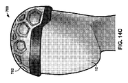
[0127] Figures 14A-14E illustrate various wearable
[0128]図14A~図14Dは、患者の頭皮16の外側で患者の頭部12に装着するための、キャップの形態の、固定部材702を含むときのウェアラブル医療装置700を示す。固定部材702は、概ね水平な平面で頭部の周りに延びることができる(すなわち、図14A~図14Eに示すように、患者の額を横切り、患者の両耳の横を通り、患者の首に隣接して頭皮の後部を横切る)。ウェアラブル医療装置700は、本明細書において用いられるとき、可撓性本体を実質的に含まない場合があり、むしろ、固定部材702自体が、患者の頭皮16の左前、右前、左後および右後象限(図1)の各々の少なくとも一部分を横切って延びることができる。図14A~図14Eは、複数の保持特徴728を画定するときの固定部材702を更に示し、各保持特徴728は、固定部材702の外面に形成される凹部である。いくつかの実施形態では、保持特徴728を画定する凹部は、固定部材702の内面まで全体に延び、貫通孔を形成することができる。示される実施形態によれば、各保持特徴728は、充電モジュール782の形状に対応する六角形形状を有する。保持特徴728は、プレス嵌めまたはスナップ嵌め等を用いて充電モジュール782を固定するように構成され得る。複数の保持特徴728は、固定部材728が患者の頭部12に装着されるとき、患者の頭皮16の各象限に位置する少なくとも1つの特徴728を含む。
[0128] FIGS. 14A-14D show the wearable
[0129]例えば、頭部に装着されるとき、ウェアラブル医療装置700は、左前象限に位置する保持特徴728A、右前象限に位置する保持特徴728B、および左後象限に位置する保持特徴728Cを画定することができる。このため、患者は、IMD14植込み部位の場所に対応するように充電モジュール782を挿入するための適切な保持特徴728を選択することができる。この機能の結果として、再充電装置700は、再充電装置700が頭部12に固定されるときに再充電コイル80、82、84、86がIMD14の二次コイルとしっかりと位置合わせされる量を増大することができる。いくつかの例によれば、ウェアラブル医療装置700は、頑丈で相対的に軽量の発泡体、例えば、強化された膨張ポリスチレンから製造され得る。
[0129] For example, when worn on the head, the wearable
[0130]図15A~図15Dは、本明細書に記載の任意の差異を除いて、再充電装置100、300、400、500、600および700に実質的に類似することができるウェアラブル医療装置800の様々な図を示す概念図である。ウェアラブル医療装置800は固定部材802を含むことができる。固定部材802は、患者の頭皮16の外側で患者の頭部12に装着されるように構成される可撓性キャップを含むことができる。ウェアラブル医療装置800は、本明細書において用いられるとき、可撓性本体を実質的に含まない場合があり、固定部材802自体が、概ね水平な平面で頭部12の周りに延びるように構成され得る(すなわち、患者の頭皮16の左前、右前、左後および右後象限(図1)の各々に沿って、患者の額を横切り、患者の両耳の横を通り、患者の首に隣接して頭皮の後部を横切る)。
[0130] Figures 15A-15D illustrate a wearable
[0131]ウェアラブル医療装置800は、ヘッドギア510の保持特徴828を含むことができる。固定部材802は、ウェアラブル医療装置800の正中線804のいずれかの側に少なくとも1つの保持特徴82を画定することができ、ここで、正中線804は、患者の額から頭部12の後部に実質的にまっすぐ戻るように延びる。固定部材802は、ウェアラブル医療装置800の左側に1つの保持特徴828を画定し、右側に1つの保持特徴828を画定することができる。保持特徴828は、固定部材802の内側層と外側層との間に形成されるポケットとすることができる。保持特徴は、コイル容器内の、電源区画に結合されたコイル80、82、84、86、および中に固定された全ての構成要素をしっかりと受けるように構成され得る。
[0131] The wearable
[0132]図15A~図15Dは、左部分802Lと右部分802Rとに分割されている固定部材802を示す。左部分802Lは、頭皮16の左前および左後象限に一致するように構成され得る一方、右部分802Rは、患者の頭皮16の右前および右後象限に一致するように構成される。いくつかの例では、例えば矢印806に従って、固定部材キャップ513が頭部に装着されるときに、左部分802Lおよび右部分802Rの双方が、患者の頭部12の正中線804平面から、およびそこに向かって自由に動くための、より大きな外周縁を有する。このため、患者は、しっかりと受けられた再充電コイルの一方または双方の位置を調節することができる。ウェアラブル医療装置800は、好ましくは、Neoprene等の伸縮性材料から形成され、それによって、固定部材キャップ802は、保持される再充電コイルの安定した位置を維持するように患者の頭皮16の外側に一致する。更に、保持される再充電コイルは、保持特徴828と並んで延びる可撓性発泡体層によって緩衝され得る。
[0132] Figures 15A-15D show a
[0133]図16A~図16Bは、本明細書に記載の任意の差異を除いてウェアラブル医療装置100、300、400、500、600、700、および800に実質的に類似することができるウェアラブル医療装置900の様々な図を示す概念図である。ウェアラブル医療装置900は、患者の頭部12に装着されるとき、概ね水平な平面で、患者の頭皮16の左前、右前、左後および右後象限LAQ、RAQ、RPQ、LPQ(図1)の各々に沿って頭部の周りに延びる固定部材902を含む。ウェアラブル医療装置900は、少なくとも2つの保持特徴928を含む。例えば、再充電装置900は、右後パッド928Bおよび左後パッド928Aを含むことができる。左後パッド928Aおよび右後パッド928Bの双方が固定部材902に取り付けられ得る。いくつかの例では、パッド928A、928Bは、可撓性で、緩衝付きであり得る。更なるパッド928A、928Bは、その内側層と外側層との間に形成されるポケットを画定することができる。これらのポケットは、そこに再充電コイル、例えば、上記で記載したコイル80、82、84、86(図3B~図3D)のうちの任意のものを保持するように構成され得る。いくつかの例によれば、パッド928A、928Bは、以下の材料:ABS、PVC、ポリカーボネート、HDPE、PEEK、PET、ポリプロピレン、シリコーンゴムおよび熱可塑性エラストマーのうちの1つまたは複数から形成され得る。電源区画および(例えば、図5に示されるような)中に格納される他の構成要素は、再充電コイルの一方または双方と一体化され得る。これらの充電組立体は、対応するパッド928A、928B内にしっかりと受けられ得る。代替的に、(例えば、図5に示されるような)電源区画ユニットのいくつかの部分は、固定部材502内に受けられるかまたは固定部材502上に装着され得る。いくつかの例では、固定部材902の前部904は、ポリエステル/スパンデックスの混合、および/またはLycraおよび/または綿等の伸縮性材料から形成され、固定部材902の後部906は、ABS、PVC、ポリカーボネート、HDPE、PEEK、PET、ポリプロピレン、シリコーンゴムおよび熱可塑性エラストマーのうちの1つまたは複数等の、相対的に剛体であるがコンフォーマブルな材料から形成される。
[0133] Figures 16A-16B illustrate wearable medical devices that can be substantially similar to wearable
[0134]図17A~図17Hは、本明細書に記載の任意の差異を除いてウェアラブル医療装置100、300、400、500、600、700、800および900に実質的に類似することができるウェアラブル医療装置1000の様々な図を示す概念図である。ウェアラブル医療装置1000は、再充電コイル容器1018(本明細書に記載の差異を除いて再充電コイル容器118、318、418、518、618および718に実質的に類似することができる)および電源区画1016(本明細書に記載の差異を除いて実質的に電源区画116、316、416、516、616および716に類似することができる)が一体化される再充電ユニット1082を含むことができる。例えば、頭皮16に向けられるように構成される再充電ユニット1082の第1の側は、再充電コイル容器1018、およびそこにコイル80、82、84、86のうちの1つを含むことができる一方、再充電ユニット1082の他方の側は、電源区画1016および電源区画1016内に記憶される任意の構成要素(例えば、図5の構成要素)を含むことができる。
[0134] Figures 17A-17H illustrate wearables that can be substantially similar to wearable
[0135]図17A~図17Hは、患者の頭部12に装着されるとき、概ね水平な平面で、患者の頭皮16の左前、右前、左後および右後象限(図1)の各々に沿って頭部12の周りに延びる代替的な固定部材1002Aまたは1002Bを有するウェアラブル医療装置1000を示す。固定部材1002Aは、患者の頭部12の外周全体の周りに延びるように構成されて示される一方、固定部材1002Bは、患者の頭部12の外周の一部分のみの周りに延びるように構成されて示される。図17A~図17Hは、それぞれの固定部材1002A、1002Bに取り付けられた対向する左端部および右端部を有する可撓性レールによって形成されるウェアラブル医療装置1000の複数の保持特徴1004を更に示す。保持特徴1004は、それぞれの固定部材1002A、1002Bが頭部12に装着されるときに、頭皮16の左象限および右象限にわたるようにそれぞれの固定部材1002A、1002Bの上に弧状に延びることができる。
[0135] Figures 17A-17H show the patient's
[0136]いくつかの例では、充電モジュール1082は、図17Hのブラケット1012等のブラケットを含むことができる。ブラケットは、保持特徴1004が充電ユニット1082をしっかりと受けることを可能にするように構成され得る。いくつかの例では、ブラケットは、充電ユニット1082との摺動係合により充電ユニット1082を受けることができ、それによって、患者は、図17Cの矢印1008に従って、それぞれの充電ユニット1082Aを、IMD14植込み場所と対応するように選択された位置に摺動させることができる。いくつかの例では、示されるように、保持特徴レール1004の断面形状は、実質的に丸いかまたは平坦であり得る。他の例では、保持特徴1004は、充電モジュール1082のブラケットと係合するように構成される他の断面形状を画定してもよい。いくつかの例では、各保持特徴1004の端部は、それぞれの固定部材1002A、1002Bへの枢動ジョイントに取り付けられ、このため、患者は図17Bの矢印1006に従って更なる前方/後方調節を行うことができる。いくつかの例では、固定部材1002A、1002Bおよび保持特徴レール1004は、ABS、PVC、ポリカーボネート、HDPE、PEEK、PETまたはポリプロピレン等の相対的に弾力性のあるプラスチックから形成される。
[0136] In some examples, charging
[0137]図18A~図18Dは、本明細書に記載の任意の差異を除いて再充電装置100、300、400、500、600、700、800、900および1000に実質的に類似することができるウェアラブル医療装置1100の様々な図を示す概念図である。ウェアラブル医療装置1100は、再充電コイル容器1118(本明細書に記載の差異を除いて再充電コイル容器118、318、418、518、618、718および1018に実質的に類似することができる)および電源区画1116(本明細書に記載の差異を除いて実質的に電源区画116、316、416、516、616、716および1016に類似することができる)が一体化される再充電ユニット1182を含むことができる。例えば、頭皮16に向けられるように構成される再充電ユニット1182の第1の側は、再充電コイル容器1118、およびそこにコイル80、82、84、86のうちの1つを含むことができる一方、再充電ユニットの他方の側は、電源区画1116および電源区画1116内に格納される任意の構成要素(例えば、図5の構成要素)を含むことができる。
[0137] Figures 18A-18D may be substantially similar to recharging
[0138]ウェアラブル医療装置1100は、概ね水平な平面で患者の頭部12の外周全体の周りに延びるように構成される固定部材1102を含む。固定部材1102は、患者に装着されるときに、患者の頭皮16の左前、右前、左後および右後象限(図1)の各々のうちの少なくともいくつかに横切るように更に構成される。ウェアラブル医療装置1100は、可撓性本体レール1110A、1110Bを更に含む。可撓性本体レール1110A、1110Bは、ウェアラブル医療装置1100が頭部12に装着されるとき、患者の頭皮16の左象限および右象限にわたるように、固定部材1102の上方に弧状に延びるように構成される2つの可撓性レールを含むことができる。充電ユニット1182は、可撓性本体レール1110A、1110Bのうちの一方または双方に装着するように構成され得る。
[0138] The wearable
[0139]いくつかの例では、固定部材1102は、1つまたは複数の係合ゾーン1104A、1104Bを含むことができる。係合ゾーン1104A、1104Bは、頭部12の1つの側に沿って延びるように構成され得る。例えば、係合ゾーン1104Aは、患者の頭皮16の左後および左前象限に沿って延びる一方、係合ゾーン1104Bは、患者の頭皮16の右後および右前象限に沿って延びる。係合ゾーンは、フック・アンド・ループ・ストリップによって形成され得、可撓性本体レール1110Aの、対応して嵌合するフック・アンド・ループ・ストリップを受けるように構成され得る。このようにして、患者は、矢印1106に従って、可撓性本体レール1110Aの広がりの向きを調節することができる。更に、患者は、IMD14植込み場所に対応する場所においてそれぞれの可撓性本体レール1110A、1110Bに充電ユニット1182を固定する前に、それぞれの可撓性本体レール1110A、1110Bの長さに沿ってそれぞれの充電ユニット1182を摺動させることができる。
[0139] In some examples, the securing
[0140]いくつかの例では、可撓性本体レール1110Bは、固定部材1102に堅く固定され得る。例えば、可撓性本体レール1110Bは、前部の場所において固定部材1102に取り付けられる第1の端部と、後部の場所において固定部材1102に取り付けられる第2の端部とを含むことができる。このようにして、可撓性本体レール1110Bは、固定部材1102が患者の頭部12に装着されるときに、患者の頭部12の正中線平面(図1)に概ね位置合わせされるように構成され得る。いくつかの例では、可撓性本体レール1110A、1110Bの双方が、枢動ジョイント1108において接続され得る。枢動ジョイント1108は、可撓性本体レール1110Aが、可撓性本体レール1110Bに対し、矢印1106に従って回転することを可能にするように構成され得る。いくつかの例では、固定部材1102および可撓性本体レール1110A、1110Bは、ABS、PVC、ポリカーボネート、HDPE、PEEK、PETおよびポリプロピレンのうちの1つまたは複数から形成され得る。
[0140] In some examples, the
[0141]図19A~図19Dは、本明細書に記載の差異を除いてウェアラブル医療装置100、300、400、500、600、700、800、900、1000および1100に実質的に類似することができるウェアラブル医療装置1200の様々な図を示す概念図である。ウェアラブル医療装置1200は、再充電コイル容器1218(本明細書に記載の差異を除いて再充電コイル容器118、318、418、518、618、718、1018および1118に実質的に類似することができる)および電源区画1216(本明細書に記載の差異を除いて実質的に電源区画116、316、416、516、616、716、1016および1116に類似することができる)が一体化される再充電ユニット1282を含むことができる。例えば、頭皮16に向けられるように構成される再充電ユニット1282の第1の側は、再充電コイル容器1218、およびそこにコイル80、82、84、86のうちの1つを含むことができる一方、再充電ユニット1282の他方の側は、電源区画1216および電源区画1216内に格納される任意の構成要素(例えば、図5の構成要素)を含むことができる。
[0141] Figures 19A-19D may be substantially similar to wearable
[0142]ウェアラブル医療装置1200は、患者の頭部12に装着されるとき、患者の頭皮16の左前、右前、左後および右後象限(図1)の各々に沿って概ね水平な平面で患者の頭部12の外周全体の周りに延びる可撓性ヘッドバンドによって形成される固定部材1202を含む。固定部材1202は、充電ユニット1282をしっかりと受けるように構成される保持特徴1228を画定することができる。保持特徴1228は、充電モジュール482をその開口部に保持するために、充電ユニット1282をしっかりと受けるように構成される開口部を画定することができる。保持特徴1228は、矢印1204に従って、概ね水平な平面で固定部材1202に対し移動するために固定部材1202と摺動可能に係合するように構成され得る。保持特徴1228は、相対的に硬性のプラスチック、ABS、PVC、ポリカーボネート、HDPE、PEEK、PETまたはポリプロピレンから形成され得る。固定部材ヘッドバンド1202は、ポリエステル/スパンデックスの混合、および/またはLycraおよび/または綿などの伸縮性材料から形成され得る。
[0142] When worn on the patient's
[0143]図20A~図20Hは、本明細書に記載の任意の差異を除いて再充電装置100、300、400、500、600、700、800、900、1000、1100および1200に実質的に類似することができるウェアラブル医療装置1300の様々な図を示す概念図である。ウェアラブル医療装置1300は、患者の頭部12に装着されるとき、患者の頭皮16の左前、右前、左後および右後象限(図1)の各々に沿って概ね水平な平面で患者の頭部12の外周全体の周りに延びる可撓性ヘッドバンドによって形成される固定部材1302を含む。ウェアラブル医療装置1300は、1つまたは複数の弾性バンドを含む可撓性本体1310を含む。再充電コイル80、82、84、86および/または再充電ユニットは、可撓性本体1310のバンドに装着され得る。可撓性本体1310のバンドの大部分は、患者の頭皮16の左および右の象限、または患者の頭皮16の前部および後部の象限にわたるように弧状に事前形成され得る。可撓性本体1310は、ABS、PVC、ポリカーボネート、HDPE、PEEK、PETまたはポリプロピレンから形成され得る。
[0143] Figures 20A-20H are substantially similar to recharging
[0144]可撓性本体1310のバンドは、固定部材1302に対し移動可能であり得る。例えば、可撓性本体1310の各バンドの第1の端部1302-1および第2の端部1302-2の各々は、固定部材1302の1つまたは複数の係合特徴1304を介して固定部材1302に解放可能に固定され得る。例えば、係合特徴1304は、例えばスナップ嵌めを介して、第1の端部1302-1および第2の端部1302-2の突起を受けることができる、固定部材1302の内面に画定される凹部を含むことができる。固定部材1302は、固定部材1302全体に沿って概ね均一に分散した(かつそこで、充電装置1300が頭部12に装着されるときに、頭皮16の全ての象限にわたって分散した)複数の係合特徴1304を含むことができる。
[0144] The band of
[0145]いくつかの例では、可撓性本体1310は、固定部材1302間に延びるように構成される2つ以上のバンドを含むことができる。例えば、図20Aに示されるように、ウェアラブル医療装置1300は、可撓性本体の第1のレール1310Aおよび可撓性本体の第2のレール1310Bを含む。いくつかの例では、可撓性本体の1つのレール1310Aは固定部材1302に対し動かされるように構成され得る一方、可撓性本体の他のレール1310Bは、固定部材1302に対し相対的に静止するように構成され得る。例えば、可撓性本体の静止したバンド1310Bは、前部の場所において固定部材1302に取り付けられた第1の端部から、後部の場所において固定部材1302に取り付けられた第2の端部まで弧状に延びることができる。このようにして、可撓性本体の相対的に静止したバンドの弧は、固定部材1302が患者の頭部12に装着されるとき、頭部12(図1)の正中線に概ね位置合わせされ得る。同様に、いくつかの例では、図20Dに示されるように、ウェアラブル医療装置1300は、可撓性本体の2つの移動可能なバンド1310Aおよび1310Cと共に、可撓性本体の1つの相対的に静止したバンド1310Bを含むことができる。
[0145] In some examples, the
[0146]図21A~図21Fは、本明細書に記載の任意の差異を除いて再充電装置100、300、400、500、600、700、800、900、1000、1100、1200および1300に実質的に類似することができるウェアラブル医療装置1400の様々な図を示す概念図である。ウェアラブル医療装置1400は、患者の頭部12に装着されるとき、患者の頭皮16の左前、右前、左後および右後象限(図1)の各々に沿って概ね水平な平面で患者の頭部12の外周全体の周りに延びる可撓性ヘッドバンドによって形成される固定部材1402を含む。ウェアラブル医療装置1400は、1つまたは複数の弾性バンドを含む可撓性本体1410を含む。再充電コイル80、82、84、86、および/または再充電ユニットは、可撓性本体1410のバンドに装着され得る。可撓性本体1410のバンドの大部分は、患者の頭皮16の左および右の象限、または患者の頭皮16の前部および後部の象限にわたるように弧状に事前形成され得る。可撓性本体1410は、ABS、PVC、ポリカーボネート、HDPE、PEEK、PETまたはポリプロピレンから形成され得る。
[0146] Figures 21A-21F are substantially identical to recharging
[0147]可撓性本体1410のバンドは、固定部材1402に対し移動可能であり得る。例えば、可撓性本体1410の各バンドの第1の端部1402-1および第2の端部1402-2の各々は、固定部材1402の1つまたは複数の係合特徴1404を介して固定部材1402に解放可能に固定され得る。例えば、係合特徴1404は、例えばスナップ嵌めを介して、第1の端部1402-1および第2の端部1402-2の突起1406を受けることができる固定部材1402の内面上に画定される凹部を含むことができる。固定部材1402は、固定部材1402全体に沿って概ね均一に分散した(かつそこで、ウェアラブル医療装置1400が頭部12に装着されるときに、頭皮16の全ての象限にわたって分散した)複数の係合特徴1404を含むことができる。
[0147] The band of
[0148]可撓性本体1410は、固定部材1402間に延びるように構成される2つ以上のバンドを含むことができる。可撓性本体のレール1410Aは、可撓性本体のレール1410Aが固定部材1402に対し機能的に動かされ得るように、複数の場所において固定部材1402に固定されるように構成され得る。同様に、可撓性本体1410Bの他のレールは、固定部材1302に沿って、1つまたは相対的により少ない場所において固定部材1402に固定されるように構成され得る。可撓性本体1410のバンドは、枢動ジョイント1408によって共に固定され得、それによって、可撓性本体1410のバンドは、枢動ジョイント1408によって共に固定され得、それによって、可撓性本体1410のバンドは、矢印1412に従って、互いに対し回転され得る。例えば、可撓性本体の静止したバンド1410Bは、(例えば、図21Cに示されるような頭部の正中線平面と概ね位置合わせされるように)前部の場所において固定部材1402に取り付けられた第1の端部から、後部の場所において固定部材1402に取り付けられた第2の端部まで弧状に延びるように、固定部材1402のみに固定されるように構成され得る。他の例では、可撓性本体1410の全てのまたは多くのレールは、可撓性本体のバンド1410Aと類似して、複数の場所において固定部材1402に固定されるように構成される。固定部材1402は、ポリエステル/スパンデックスの混合、および/またはLycraおよび/または綿等の伸縮性材料から形成され得る。
[0148] The
[0149]図22A~図22Cは、本明細書に記載の任意の差異を除いてウェアラブル医療装置100、300、400、500、600、700、800、900、1000、1100、1200、1300および1400に実質的に類似することができるウェアラブル医療装置1500の様々な図を示す概念図である。ウェアラブル医療装置1500は、患者の頭部12に装着されるとき、患者の頭皮16の左前、右前、左後および右後象限(図1)の各々に沿って概ね水平な平面で患者の頭部12の外周全体の周りに延びる可撓性ヘッドバンドによって形成される固定部材1502を含む。ウェアラブル医療装置1500は、可撓性本体の2つのパネル1510A、1510Bを含む。再充電コイル80、82、84、86、および/または再充電ユニットは、可撓性本体1510のパネルに装着され得る。可撓性本体1510は、ABS、PVC、ポリカーボネート、HDPE、PEEK、PETまたはポリプロピレンから形成され得る。
[0149] Figures 22A-22C illustrate wearable
[0150]可撓性本体のパネル1510A、1510Bは、固定部材1502に対し移動可能であり得る。例えば、可撓性本体1510の各パネルは、正中線1506に近づくかまたは正中線1506から離れるように矢印1504に従って動くように構成され得る。可撓性本体1410のパネルは、相対的に堅くすることができ、それによって、正中線1506に対し或る位置に動かされると、可撓性本体のパネルは、頭部14に装着されるときの相対位置に留まることができる。固定部材1402は、ポリエステル/スパンデックスの混合、および/またはLycraおよび/または綿等の伸縮性材料から形成され得る。
[0150] The
[0151]図23A~図23Dは、本明細書に記載の差異を除いてウェアラブル医療装置100、300、400、500、600、700、800、900、1000、1100、1200、1300、1400および1500に実質的に類似することができるウェアラブル医療装置1600の様々な図を示す概念図である。ウェアラブル医療装置1600は、頭皮16の外側で患者の頭部12に装着するための固定部材1602を含む。固定部材1602は、バンド1602Aの第1の端部に取り付けられた弾性バンド1602Aおよび耳フック1602Bを含む。
[0151] Figures 23A-23D illustrate wearable
[0152]ウェアラブル医療装置1600は、コンフォーマブル部材1604を更に含む。コンフォーマブル部材1604は、1つまたは複数の再充電コイル80、82、84、86および電源区画の1つまたは複数の構成要素(例えば、図5の構成要素)を含むことができる。コンフォーマブル部材1604は、固定部材バンド1602Aの第2の端部に取り付けられ得る。いくつかの例では、コンフォーマブル部材1604は、固定部材1602が患者の頭部12に装着されるとき、患者の頭皮16の象限のうちの少なくとも1つに一致するように構成され得る。
[0152] The wearable
[0153]いくつかの例では、固定部材バンド1602Aは、耳フック1602Bに対し移動可能である。このようにして、固定部材バンド1602Aは、頭皮16に対しコンフォーマブル部材1604を動かすために、頭皮16に対し動かされ得る。いくつかの例では、固定部材バンド1604は、固定部材1602が頭部12に装着されるときに、頭皮16の外側に概ね一致し、ぴったり適合するように内方の張力を有して概ね垂直な平面に沿って弧状に患者の頭部12の上に少なくとも部分的に延びることができる。
[0153] In some examples, the securing
[0154]図24A~図24Dは、本明細書に記載の任意の差異を除いてウェアラブル医療装置100、300、400、500、600、700、800、900、1000、1100、1200、1300、1400、1500および1600に実質的に類似することができるウェアラブル医療装置1700の様々な図を示す概念図である。ウェアラブル医療装置1700は、固定部材1702A、1702B、1702C(合わせて、「固定部材1702」)を含むことができる。固定部材1702は、枢動接合部1704において共に接合され得る。再充電コイル80、82、84、86および/または充電ユニットは、固定部材1702に固定され得る。固定部材1702は、ABS、PVC、ポリカーボネート、HDPE、PEEK、PET、ポリプロピレン、シリコーンゴムおよび熱可塑性エラストマーのうちの1つまたは複数から主に形成され得る。
[0154] Figures 24A-24D illustrate wearable
[0155]いくつかの例では、固定部材1702の各々が、患者の頭皮16の象限のうちの任意の1つに対し移動可能かつコンフォーマブルであり得る。例えば、ウェアラブル医療システム1700が頭部12に装着されるとき、枢動ジョイント1704は、頭部12の最上部に載るように構成され得、その後、固定部材1702の各々が、概ね垂直な平面に沿って、頭部12の片側を弧状に下方に延びるように構成され得る。このようにして、固定部材1702は、ウェアラブル医療システム1700を患者の頭部12に固定することができる。更に、枢動ジョイント1704が、固定部材1702が互いに対し移動することを可能にする結果として、ウェアラブル医療システム1700は、IMD14植込み部位に対応する場所の各々において1つまたは複数の再充電コイルを位置決めするように調節され得る。
[0155] In some examples, each of the fixation members 1702 may be moveable and conformable with respect to any one of the quadrants of the patient's
[0156]図25A~図25Hは、本明細書に記載の任意の差異を除いてウェアラブル医療装置100、300、400、500、600、700、800、900、1000、1100、1200、1300、1400、1500、1600および1700に実質的に類似することができるウェアラブル医療装置1800の様々な図を示す概念図である。ウェアラブル医療装置1800は、固定部材1802A、1802B(合わせて、「固定部材1802」)を含むことができる。固定部材1802の各々は2つの端部を有し、各端部は、枢動接合部1804において別の固定部材1802の別の端部に固定され得る。(例えば、図5に示すような)充電ユニットの再充電コイル80、82、84、86および/または構成要素は、固定部材1802に固定されるかまたは固定部材1802に収容され得る。いくつかの例では、再充電コイルを含む各固定部材1802は、それぞれの固定部材1802に一体化された制御ユニットのいくつかのまたは全ての構成要素も含むことができる。他の例では、1つの制御ユニットは、複数の固定部材1802に一体化されるかまたは他の形で固定される複数のコイルを制御してもよい。固定部材1802は、ABS、PVC、ポリカーボネート、HDPE、PEEK、PETおよびポリプロピレンのうちの1つまたは複数から主に形成され得る。
[0156] Figures 25A-25H illustrate wearable
[0157]いくつかの例では、固定部材1802の各々が、患者の頭皮16の象限のうちの任意の1つに対し移動可能かつコンフォーマブルであり得る。例えば、枢動ジョイント1804は、患者の頭部12の耳の付近に位置するように構成され得る一方、固定部材1802は、患者の頭部12にウェアラブル医療装置1800を固定するために、概ね水平な平面に沿って、患者の頭部12の上を弧状に延びる。患者は、矢印1806に従って、固定部材1802を互いに対し動かして、固定部材1802の再充電コイルの場所を、植込み部位に対応するように調節することができる。いくつかの例では、可撓性ハウジング1810は、固定部材1802が矢印1806に沿って曲がるとき、固定部材1802間に延びることができる。可撓性ハウジング1810は、固定部材1802の曲げに応じて、収縮および拡張するアコーディオン構造を画定することができる。
[0157] In some examples, each of the fixation members 1802 may be moveable and conformable with respect to any one of the quadrants of the patient's
[0158]図26A~図26Bは、本明細書に記載の任意の差異を除いて再充電装置100、300、400、500、600、700、800、900、1000、1100、1200、1300、1400、1500、1600、1700および1800に実質的に類似することができるウェアラブル医療装置1900の様々な図を示す概念図である。ウェアラブル医療装置1900は、固定部材1902を含むことができる。固定部材1902は、弾性バンド1904と、弾性バンド1904の各端部に固定された終端パッド1906の対とを含むことができる。パッド1906は、弾性バンド1904が頭部12の上を延びている間、頭部12の耳に対し押し付けられるように構成される。ウェアラブル医療装置1900は、パッド1906から延びるコンフォーマブル部材1908を含むことができる。コンフォーマブル部材1908は、コンフォーマブル部材1908がパッド1906に対し枢動することを可能にする隠れた内部枢動ジョイントを介して固定部材1902に取り付けられ得る。コンフォーマブル部材1908は、コンフォーマブル部材1908がパッド1906から離れるように弧状に延びるようにパッド1906に固定され得る。例えば、コンフォーマブル部材1908のうちの一方は、患者の頭皮16の右後象限にわたる弧範囲を画定することができ、コンフォーマブル部材1908のうちの他方は、患者の頭皮16の左後象限にわたる弧範囲を画定する。
[0158] Figures 26A-26B illustrate recharging
[0159](例えば、図5に示すような)充電ユニットの再充電コイル80、82、84、86および/または構成要素は、コンフォーマブル部材1908に固定されるかまたはコンフォーマブル部材1908内に収容され得る。いくつかの例では、コンフォーマブル部材1908の各々は、再充電コイル、およびまた、それぞれのコンフォーマブル部材1908における充電ユニットのいくつかまたは全ての構成要素の双方を含むことができる。他の例では、1つの充電ユニットは、複数のコンフォーマブル部材1908に一体化されるかまたは他の形で固定される複数のコイルを制御してもよい。いくつかの例では、コンフォーマブル部材は、ABS、PVC、ポリカーボネート、HDPE、PEEK、PETおよびポリプロピレンのうちの1つまたは複数から主に形成され得る。
[0159] The recharging coils 80, 82, 84, 86 and/or components of the charging unit (eg, as shown in FIG. 5) are fixed to or within the
[0160]図27A~図27Dは、本明細書に記載の任意の差異を除いてウェアラブル医療装置100、300、400、500、600、700、800、900、1000、1100、1200、1300、1400、1500、1600、1700、1800および1900に実質的に類似することができるウェアラブル医療装置2000の様々な図を示す概念図である。ウェアラブル医療装置2000は、2つの固定部材2002の対向する端部に取り付けられた2つのコンフォーマブル部材2004を含むことができる。固定部材2002は各々、調節可能な弾性バンドを含むことができ、これらの弾性バンドは、矢印2006に従って、弾性バンドに対するコンフォーマブル部材2004の移動を可能にするように構成される。示されるように、固定部材2002は、患者の頭部12に装着されるとき、頭部12にわたって概ね垂直な平面で弧状に延びるように構成される。更に、ウェアラブル医療装置2000が頭部12に装着されるとき、コンフォーマブル部材2004のうちの一方は、患者の頭皮16の一方または双方の右の象限に一致するように構成されるのに対し、コンフォーマブル部材2004の他方は、患者の頭皮の一方または双方の左の象限に一致するように構成される。
[0160] Figures 27A-27D illustrate wearable
[0161]いくつかの例では、各コンフォーマブル部材2004は、相対的に可撓性であり、かつ緩衝付きである。例えば、コンフォーマブル部材2004の各々は、シリコーンゴムまたは熱可塑性エラストマーから形成され得る。コンフォーマブル部材2004は、コンフォーマブル部材2004の内側層および外側層間にポケットを画定することができる。コンフォーマブル部材2004の各々によって画定されるポケットは、内部に1つまたは複数の再充電コイル、例えば、(例えば図5におけるような)制御ユニットの上述した構成要素のうちの任意のものを保持するように構成され得る。
[0161] In some examples, each
[0162]図28A~図28Eは、本明細書に記載の任意の差異を除いてウェアラブル医療装置100、300、400、500、600、700、800、900、1000、1100、1200、1300、1400、1500、1600、1700、1800、1900および2000に実質的に類似することができるウェアラブル医療装置2100の様々な図を示す概念図である。ウェアラブル医療装置2100は、頭皮16の各象限の一部分を覆うような大きさのカバーの内側層および外側層間に装着される複数の再充電コイルを含むことができる。ウェアラブル医療装置2100は固定部材2102を含むことができ、固定部材2102は、それ自体が、伸張可能なキャップを含むことができる。固定部材2102は、Neoprene等から作製され得る。可撓性本体2110は、複数のポケットを画定するために、固定部材2102から離れるように延びることができる。例えば、固定部材2102は、実質的に、頭皮16のほとんどまたは全てを横切って延び、固定部材2102と同様に、実質的に頭皮16に接触し、頭皮16に一致することができる。可撓性本体2110は、固定部材2102から離れるように径方向に延び、可撓性本体2110自体と固定部材2102との間にポケットを画定することができる。
[0162] Figures 28A-28E illustrate wearable
[0163]固定部材2102および可撓性本体2110によって作成される1つまたは複数のポケットは、(例えば、図5におけるように)コイル80、82、84、86および/または再充電構成要素を保持するように構成され得る。固定部材2102および可撓性本体2110によって画定される各ポケットは、頭皮16の異なる象限(LAQ、RAQ、RPQ、LPQ)にわたって中心合わせされ、実質的にその象限を覆うことができる。各象限を覆うように配置されて示される。
[0163] One or more pockets created by securing
[0164]ウェアラブル医療装置2100は、電子充電ユニット2182の取付けのために構成されるドッキングフォブ(docking fob)2104を含むことができる。充電ユニット2182は、図5の回路部および構成要素等の再充電コイルを制御するように構成される回路部を含むことができる。ドッキングフォブ2104に取り付けられると、充電ユニット2182は、固定部材2102および可撓性本体2110によって画定されるポケット内に固定される各再充電コイルと電気的に結合され得る。ここにヘッドギア910の再充電コイルと結合するための制御ユニット2185。
[0164] The wearable
[0165]図29A~図29Eは、本明細書に記載の任意の差異を除いてウェアラブル医療装置100、300、400、500、600、700、800、900、1000、1100、1200、1300、1400、1500、1600、1700、1800、1900、2000および2100に実質的に類似することができるウェアラブル医療装置2200の様々な図を示す概念図である。ウェアラブル医療装置2200は、頭皮16の各象限の一部分を覆うような大きさのカバーの内側層および外側層間に装着される複数の再充電コイル80、82、84、86を含むことができる。ウェアラブル医療装置2200は固定部材2202を含むことができ、固定部材2202は、それ自体がヘルメットを含むことができ、このヘルメット内に再充電コイル80、82、84、86が埋め込まれ、このヘルメットに電子再充電制御ユニット2282が装着される。電気再充電制御ユニット2822は、(例えば、図5に示されるような)本明細書に記載の電源区画の構成要素を含むことができる。固定部材2202は、ABS、PVC、ポリカーボネート、HDPE、PEEK、PET、ポリプロピレン、シリコーンゴムおよび熱可塑性エラストマーのうちの1つまたは複数から形成され得る。
[0165] Figures 29A-29E illustrate wearable
[0166]ウェアラブル医療装置2200は、サイズ調節部材2204を含むことができる。サイズ調節部材2204は、ねじり機構等の機構を用いて固定部材2202の内部サイズを変更するように構成され得る。サイズ調節部材2204は、固定部材2202の後部下縁においてウェアラブル医療装置2200に固定され得る。いくつかの例では、再充電制御ユニット2282は、1つまたは複数の頭蓋に装着されたIMD14の場所を検出するように構成され得る。IMD14の場所の検出に応じて、制御ユニット2282は、これらのIMD14と位置合わせされた再充電コイルを特定および活性化する(例えば、再充電コイルに電流を送信する)ことができる。
[0166] The wearable
[0167]図30A~図30Dは、本明細書に記載の任意の差異を除いてウェアラブル医療装置100、300、400、500、600、700、800、900、1000、1100、1200、1300、1400、1500、1600、1700、1800、1900、2000、2100および2200に実質的に類似することができるウェアラブル医療装置2300の様々な図を示す概念図である。ウェアラブル医療装置2300は、下方に患者の首まで達するように構成されるキャップを含むことができる固定部材2302を含むことができる。固定部材2302は、固定部材2302の内側層と外側層との間に再充電コイル80、82、84、86を一体化するように構成され得る。いくつかの例では、固定部材2302は、固定部材2302にわたって埋め込まれた複数の充電コイルを含むことができ、それによって、充電コイルは、ウェアラブル医療システム2300が患者の頭部12に装着されるとき、頭皮16の全ての象限にわたって分散される。
[0167] Figures 30A-30D illustrate wearable
[0168]ウェアラブル医療装置2300は、固定部材2302に固定されたカラー部材2304を含むことができる。カラー部材2304は、固定部材2302の後部下縁に取り付けられ得る。カラー部材2304は、再充電コイル(例えば、図5の構成要素)を制御するように構成される構成要素を含む電子再充電制御ユニットを含むことができる。固定部材2302は、ポリエステル、スパンデックス、綿およびLycraのうちの1つまたは複数から形成され得る。
[0168] The wearable
[0169]図31A~図31Cは、本明細書に記載の任意の差異を除いてウェアラブル医療装置100、300、400、500、600、700、800、900、1000、1100、1200、1300、1400、1500、1600、1700、1800、1900、2000、2100、2200および2300に実質的に類似することができるウェアラブル医療装置2400の様々な図を示す概念図である。ウェアラブル医療装置2400は、頭皮16の上に掛かり、下方に患者の首まで達するように構成されるフードを含むことができる固定部材2402を含むことができる。固定部材2402は、固定部材2402の内側層と外側層との間に再充電コイル80、82、84、86を一体化するように構成され得る。いくつかの例では、固定部材2402は、固定部材2402にわたって埋め込まれた複数の充電コイルを含むことができ、それによって、充電コイルは、ウェアラブル医療システム2400が患者の頭部12に装着されるとき、頭皮16の全ての象限にわたって分散される。
[0169] Figures 31A-31C illustrate wearable
[0170]ウェアラブル医療装置2400は、固定部材2402に固定されるタッセル2404を含むことができる。タッセル2404は、固定部材2402の後部下縁の付近に取り付けられ得る。タッセル2404は、固定部材2402を締め付けるかまたは緩めるように構成され得る。いくつかの例では、ウェアラブル医療装置2400は、スエットシャツに一体化され得、ここで、固定部材2402は、機能的に、スエットシャツのフードである。固定部材2402は、ポリエステル、スパンデックス、綿およびLycraのうちの1つまたは複数から形成され得る。
[0170] The wearable
[0171]図32A~図34C図32Bは、コンフォーマブルキャップ2502A、2502B、2502D、2502Eおよび弾性ヘッドバンド2502Cの固定部材2502A、2502B、2502C、2502D、2502E(合わせて、「固定部材2502」)、および関連付けられた充電モジュール2504A、2504B、2504C、2504D(合わせて、「充電モジュール2504」)を含む再充電組立体2500A、2500B、2500Cの斜視図を示す概念図である。各固定部材2502は、上述した適切な材料のうちの任意のものから形成され得、それぞれの固定部材2502が頭部12に装着されるとき、頭皮16の左前象限、左後象限、右後象限および右前象限の各々の少なくとも一部分に一致するように構成される。更に、各固定部材2502は、電源区画にまたはその近くに1つまたは複数の充電モジュール2504を取り付けるために全体にわたって分散される取付け手段を含み、関連する電源および再充電回路部(例えば、図5の電力管理回路162および再充電可能な電源158)は、固定部材2502内に位置する。例えば、図34A~図34Cに示すように、固定部材2502Eは、固定部材2502Eのための電源および電力管理回路を有する場所の近くにVelcoを含むことができ、それによって、それぞれの充電モジュール2504Dは、それぞれの固定部材2502Eに直接取り付けられ得る。図33A~図33Cに示すような別の例では、固定部材2502Dは、充電モジュール2504Cのうちの1つを固定部材2502Dの電源および電力管理回路ハウジングに隣接した場所に磁気的に保持するように構成される磁気要素を含むことができる。充電モジュール2504は、本明細書に記載の再充電装置103と実質的に同様に機能することができ、それによって、図33に示されるように、充電モジュール2504は、IMD14の電源を再充電するのに用いられ得る。
[0171] Figures 32A-34C
[0172]本開示は、再充電コイルを患者の頭部に固定するためのウェアラブル医療装置に関連する特定のシステムおよび方法を主に対象とする。しかしながら、本開示の1つまたは複数の態様は、患者の他の領域に固定され得る他のタイプのウェアラブル医療装置にも適用可能であり得る。例えば、本開示の態様は、患者の側に位置する1つまたは複数のIMDと位置合わせされた1つまたは複数の場所、または鎖骨下の場所等に1つまたは複数の再充電コイルを固定するのに用いられ得るスリーブにも適用可能である。 [0172] This disclosure is primarily directed to certain systems and methods related to wearable medical devices for securing a recharging coil to a patient's head. However, one or more aspects of the present disclosure may also be applicable to other types of wearable medical devices that may be secured to other areas of a patient. For example, aspects of the present disclosure secure one or more recharging coils at one or more locations aligned with one or more IMDs located on the side of the patient, or at locations such as a subclavian location. It is also applicable to sleeves that can be used for
[0173]以下の実施例は、本明細書において予期され論考される様々な実施例および組合せを記載する。実施例1:患者の頭部の頭皮の左前象限、左後象限、右後象限および右前象限の各々の少なくとも一部分を覆うように構成される可撓性本体と、可撓性本体に接続された固定部材であって、頭部の外周の周りに延び、患者の頭皮に対し可撓性本体を安定させるように構成される、固定部材と、可撓性本体の或る場所に装着するように構成される定着部材であって、可撓性本体を、頭蓋に装着可能な植込み型医療装置の植込み型電源を再充電するように構成される再充電コイルに結合するように構成される、定着部材とを備える、ウェアラブル医療システム。 [0173] The following examples describe various embodiments and combinations contemplated and discussed herein. Example 1: A flexible body configured to cover at least a portion of each of the left anterior quadrant, the left posterior quadrant, the right posterior quadrant and the right anterior quadrant of the scalp of a patient's head; a fixation member extending around the circumference of the head and configured to stabilize the flexible body against the patient's scalp; An anchoring member configured to couple the flexible body to a recharging coil configured to recharge an implantable power source of a cranially mountable implantable medical device. A wearable medical system, comprising:
[0174]実施例2:可撓性本体または固定部材のうちの少なくとも一方に固定された外部電源と、可撓性本体の第1の表面に取外し可能に固定された再充電コイルであって、頭蓋に装着可能な植込み型医療装置の植込み型電源を再充電するために電源からエネルギーを伝送するように構成される、再充電コイルと、外部電源を再充電コイルに結合するケーブルとを更に備える、実施例1に記載のウェアラブル医療システム。 [0174] Example 2: An external power source secured to at least one of a flexible body or a securing member and a recharging coil removably secured to a first surface of the flexible body, comprising: Further comprising a recharging coil configured to transfer energy from the power source to recharge the implantable power source of the cranially wearable implantable medical device, and a cable coupling the external power source to the recharging coil. A wearable medical system according to Example 1.
[0175]実施例3:定着部材は第1の定着部材であり、場所は第1の場所であり、再充電コイルは第1の再充電コイルであり、植込み型電源は第1の植込み型電源であり、頭蓋に装着可能な植込み型医療装置は第1の頭蓋に装着された植込み型医療装置であり、ウェアラブル医療システムは、可撓性本体の第2の場所に装着するように構成される第2の定着部材であって、可撓性本体を、第2の頭蓋に装着可能な植込み型医療装置の第2の植込み型電源を再充電するように構成される第2の再充電コイルに結合するように構成される、第2の定着部材を更に備える、実施例1に記載のウェアラブル医療システム。 [0175] Example 3: The fusing member is the first fusing member, the location is the first location, the recharging coil is the first recharging coil, and the implantable power source is the first implantable power source and the cranially mountable implantable medical device is a first cranially mounted implantable medical device, and the wearable medical system is configured to mount at a second location on the flexible body A second anchoring member, wherein the flexible body is connected to a second recharging coil configured to recharge a second implantable power source of a second cranially mountable implantable medical device. 2. The wearable medical system of example 1, further comprising a second anchoring member configured to couple.
[0176]実施例4:可撓性本体または固定部材のうちの少なくとも一方に固定された外部電源と、可撓性本体の第1の表面に取外し可能に固定された第1の再充電コイルであって、第1の頭蓋に装着可能な植込み型医療装置の第1の植込み型電源を再充電するために電源からエネルギーを伝送するように構成される、第1の再充電コイルと、可撓性本体の第2の表面に取外し可能に固定された第2の再充電コイルであって、第2の頭蓋に装着可能な植込み型医療装置の第2の植込み型電源を再充電するために電源からエネルギーを伝送するように構成される、第2の再充電コイルと、外部電源を第1および第2の再充電コイルに結合するように構成される1つまたは複数のケーブルとを更に備える、実施例3に記載のウェアラブル医療システム。 [0176] Example 4: With an external power source secured to at least one of the flexible body or the securing member and a first recharging coil removably secured to the first surface of the flexible body. a first recharging coil configured to transfer energy from a power source to recharge a first implantable power source of a first cranially mountable implantable medical device; a second recharging coil removably secured to the second surface of the body and a power source for recharging a second implantable power source of the second cranially mountable implantable medical device; and one or more cables configured to couple an external power source to the first and second recharging coils; A wearable medical system according to Example 3.
[0177]実施例5:第1の再充電コイルおよび第2の再充電コイルは、第1の頭蓋に装着可能な植込み型医療装置の植込み型電源、および第2の頭蓋に装着可能な植込み型医療装置の第2の植込み型電源の双方を再充電するために電源からエネルギーを同時に伝送するように構成される、実施例3または4に記載のウェアラブル医療システム。 [0177] Example 5: A first recharging coil and a second recharging coil are an implantable power source of an implantable medical device wearable on a first skull and an implantable power supply wearable on a second skull. 5. A wearable medical system according to example 3 or 4, configured to simultaneously transmit energy from the power sources to recharge both of the second implantable power sources of the medical device.
[0178]実施例6:第1の定着部材は、第1の再充電コイルが、第1の定着部材に結合されるときに、第1の頭蓋に装着可能な植込み型医療システムの第1の植込み型再充電コイルと位置合わせされるように、第1の場所に隣接した第3の場所において可撓性本体の第1の表面に固定され、第2の定着部材は、第2の再充電コイルが、第2の定着部材に結合されるときに、第2の頭蓋に装着可能な植込み型医療システムの第2の植込み型再充電コイルと位置合わせされるように、第2の場所に隣接した第4の場所において可撓性本体の第2の表面に固定される、実施例3~5のいずれかに記載のウェアラブル医療システム。 [0178] Example 6: The first anchoring member is a first anchoring member of an implantable medical system mountable on a first skull when the first recharging coil is coupled to the first anchoring member. A second anchoring member secured to the first surface of the flexible body at a third location adjacent the first location so as to be aligned with the implantable recharging coil, the second anchoring member having a second recharging Adjacent the second location such that the coil is aligned with the second implantable recharging coil of the second cranially mountable implantable medical system when coupled to the second anchoring member. 6. The wearable medical system of any of Examples 3-5, secured to the second surface of the flexible body at a fourth location.
[0179]実施例7:可撓性本体は、複数の場所を特定するマップを備え、第1の場所および第2の場所は共に、これらの複数の場所内であり、第1の再充電コイルは、第1の場所を特定する第1の特定を含み、第2の再充電コイルは、第2の場所を特定する第2の特定を含む、実施例3~5のいずれかに記載のウェアラブル医療システム。 [0179] Example 7: The flexible body comprises a map identifying multiple locations, the first location and the second location are both within these multiple locations, and the first recharging coil includes a first identification identifying a first location and the second recharging coil includes a second identification identifying a second location. medical system.
[0180]実施例8:1つまたは複数のケーブルは第1の再充電コイルおよび第2の再充電コイルに取外し可能に結合可能である、実施例3~7のいずれかに記載のウェアラブル医療システム。 [0180] Example 8: The wearable medical system of any of Examples 3-7, wherein the one or more cables are removably couplable to the first recharging coil and the second recharging coil .
[0181]実施例9:可撓性本体または固定部材のうちの少なくとも一方に固定された第1の外部電源と、可撓性本体の第1の表面に取外し可能に固定された第1の再充電コイルであって、第1の頭蓋に装着可能な植込み型医療装置の第1の植込み型電源を再充電するために第1の電源からエネルギーを伝送するように構成される、第1の再充電コイルと、可撓性本体または固定部材のうちの少なくとも一方に固定された第2の外部電源と、可撓性本体の第2の表面に取外し可能に固定された第2の再充電コイルであって、第2の頭蓋に装着可能な植込み型医療装置の第2の植込み型電源を再充電するために第2の電源からエネルギーを伝送するように構成される、第2の再充電コイルとを更に備える、実施例1に記載のウェアラブル医療システム。 [0181] Example 9: A first external power source secured to at least one of the flexible body or the securing member and a first regenerator removably secured to the first surface of the flexible body. a charging coil configured to transfer energy from the first power source to recharge the first implantable power source of the first cranially mountable implantable medical device; a charging coil, a second external power source secured to at least one of the flexible body or the securing member, and a second recharging coil removably secured to a second surface of the flexible body. a second recharging coil configured to transfer energy from the second power source to recharge the second implantable power source of the second cranially mountable implantable medical device; 2. The wearable medical system of example 1, further comprising:
[0182]実施例10:固定部材は、可撓性本体よりも相対的に剛体であるバンドを含む、実施例1~9のいずれかに記載のウェアラブル医療システム。
[0183]実施例11:可撓性本体は、複数の場所を特定するマップを備え、上記場所は、これらの複数の場所のうちの1つである、実施例1~10のいずれかに記載のウェアラブル医療システム。
[0182] Example 10: The wearable medical system of any of Examples 1-9, wherein the fixation member comprises a band that is relatively more rigid than the flexible body.
[0183] Example 11: Any of Examples 1-10, wherein the flexible body comprises a map identifying a plurality of locations, the location being one of the plurality of locations. of wearable medical systems.
[0184]実施例12:可撓性本体から径方向に外側に延びるように構成されるひさしを更に備え、ひさしは左前象限および右前象限の少なくとも一部分に沿って可撓性本体に接続される、実施例1~11のいずれかに記載のウェアラブル医療システム。 [0184] Example 12: Further comprising a visor configured to extend radially outwardly from the flexible body, the visor being connected to the flexible body along at least a portion of the left front quadrant and the right front quadrant. A wearable medical system according to any of Examples 1-11.
[0185]実施例13:可撓性本体は、固定部材間で可撓性本体を横切って実質的に直線状に延びることによって頭皮の少なくとも一部分を覆うときに、可撓性本体の形状を固定するように構成される少なくとも2つの継ぎ目を含み、少なくとも2つの継ぎ目のうちの第1の継ぎ目は、左前象限から右後象限まで延び、少なくとも2つの継ぎ目のうちの第2の継ぎ目は、右前象限から左後象限まで延びる、実施例1~12のいずれかに記載のウェアラブル医療システム。 [0185] Example 13: The flexible body fixes the shape of the flexible body when it covers at least a portion of the scalp by extending substantially linearly across the flexible body between the fixation members. wherein a first of the at least two seams extends from the left front quadrant to the right rear quadrant and a second of the at least two seams extends from the right front quadrant; to the left rear quadrant.
[0186]実施例14:固定部材は、固定部材の外周を調節するように構成される調節可能な機構を備える、実施例1~13のいずれかに記載のウェアラブル医療システム。
[0187]実施例15:固定部材はクリックホイールを備え、クリックホイールは、クリックホイールが第1の方向に回されるとき、固定部材の外周を大きくするように構成され、クリックホイールが第1の方向と反対の第2の方向に回されるとき、外周を小さくするように構成される、実施例14に記載のウェアラブル医療システム。
[0186] Example 14: The wearable medical system of any of Examples 1-13, wherein the fixation member comprises an adjustable mechanism configured to adjust a perimeter of the fixation member.
[0187] Example 15: The stationary member comprises a click wheel, the click wheel is configured to increase the circumference of the stationary member when the click wheel is rotated in a first direction, and the click wheel rotates in the first direction. 15. A wearable medical system according to example 14, configured to decrease in circumference when rotated in a second, opposite direction.
[0188]実施例16:固定部材は、重なり合う端部を有するバンドを含み、重なり合う端部間の調節可能な重なり合いの量は、固定部材の外周を画定する、実施例15に記載のウェアラブル医療システム。 [0188] Example 16: The wearable medical system of Example 15, wherein the fixation member comprises a band having overlapping ends, and an adjustable amount of overlap between the overlapping ends defines a perimeter of the fixation member. .
[0189]実施例17:電源は、左後象限および右後象限に隣接した固定部材に電源を取り付けるように構成される取付け機構を備える、実施例1~16のいずれかに記載のウェアラブル医療システム。 [0189] Example 17: The wearable medical system of any of Examples 1-16, wherein the power source comprises an attachment mechanism configured to attach the power source to a stationary member adjacent the left posterior quadrant and the right posterior quadrant. .
[0190]実施例18:外部電源を収容するように構成される湾曲したハウジングを更に備え、湾曲したハウジングは、頭皮とインターフェースするように構成される第1の主面と、湾曲したハウジングの、第1の主面の反対側にある第2の主面とを画定し、第1の主面および第2の主面は、患者の頭部の後部の湾曲を近似する、実質的に類似した湾曲を画定する、実施例1~17のいずれかに記載のウェアラブル医療システム。 [0190] Example 18: Further comprising a curved housing configured to house an external power source, the curved housing having a first major surface configured to interface with the scalp; and a second major surface opposite the first major surface, the first major surface and the second major surface being substantially similar to approximate the posterior curvature of the patient's head. 18. The wearable medical system of any of Examples 1-17, defining a curve.
[0191]実施例19:再充電コイルを収容するように構成される湾曲した容器を更に備え、湾曲した容器は、患者の頭皮の湾曲を近似する凹状の主面を画定し、患者の頭皮とインターフェースするように構成される、実施例1~18のいずれかに記載のウェアラブル医療システム。 [0191] Example 19: Further comprising a curved container configured to house the recharging coil, the curved container defining a concave major surface approximating the curvature of the patient's scalp, and 19. A wearable medical system according to any preceding example, configured to interface.
[0192]実施例20:主面は第1の主面であり、湾曲した容器は、湾曲した容器の、第1の主面の反対側にあり、患者の頭皮の湾曲を近似する第2の主面を画定し、第2の主面は、第2の主面から離れるように延びる隆起を画定し、可撓性本体は、頭皮と接触するように構成される第1の表面と、第1の表面に対し、可撓性本体の反対側にある第2の表面とを含み、定着部材は、再充電コイルのための湾曲したハウジングを可撓性本体に固定するための取付け組立体を備え、取付け組立体は、第2の主面の隆起を受け、ブラケットを湾曲した容器にしっかりと取り付けるように構成される凹部およびチャネルを画定するブラケットと、可撓性本体の第2の表面から可撓性本体内の孔を通り、可撓性本体の第1の表面を越えてブラケットの凹部内に延び、ブラケットによってしっかりと受けられるように構成されるピンであって、ピンがブラケットの凹部によって受けられるとき、可撓性本体の第2の表面に対し押し付けるように構成されるプレートを含む、ピンとを備える、実施例19に記載のウェアラブル医療システム。 [0192] Example 20: The major surface is a first major surface, and the curved container has a second major surface opposite the first major surface of the curved container, approximating the curvature of the patient's scalp. defining a major surface, the second major surface defining a ridge extending away from the second major surface, the flexible body comprising a first surface configured to contact the scalp; and a second surface opposite the flexible body to the first surface, the anchoring member having a mounting assembly for securing the curved housing for the recharging coil to the flexible body. a bracket defining recesses and channels configured to receive ridges on the second major surface and securely attach the bracket to the curved container; A pin configured to extend through a hole in the flexible body, beyond the first surface of the flexible body and into a recess in the bracket and be securely received by the bracket, the pin extending into the recess in the bracket. 20. The wearable medical system of example 19, comprising a pin including a plate configured to press against the second surface of the flexible body when received by the second surface of the flexible body.
[0193]実施例21:湾曲した容器は、湾曲した容器を通って延びるボアを含み、隆起内で中心合わせされ、ボアは、ブラケットが湾曲した容器にしっかりと取り付けられるとき、ブラケットの凹部を受けるように構成され、ボアは、第1の主面可撓性本体上の場所を視認可能にマーキングするために、頭蓋に装着可能な植込み型医療装置上の湾曲したハウジングの位置決めを可能にするようにマーキングペンを受け入れるように構成される、実施例20に記載のウェアラブル医療システム。 [0193] Example 21: A curved container includes a bore extending through the curved container, centered within the ridge, the bore receiving a recess in the bracket when the bracket is securely attached to the curved container. wherein the bore is configured to permit positioning of a curved housing on a cranially mountable implantable medical device for visibly marking a location on the first major surface flexible body. 21. A wearable medical system according to example 20, configured to receive a marking pen in the.
[0194]実施例22:ピンに取外し可能に固定されるように構成される穿刺要素を更に含み、穿刺要素は、可撓性本体に孔を作成するように第1の表面から貫通して第2の表面まで可撓性本体を穿刺するように構成される穿刺先端を含む、実施例20または21に記載のウェアラブル医療システム。 [0194] Example 22: Further comprising a piercing element configured to be removably secured to the pin, the piercing element penetrating from the first surface to create the hole in the flexible body and extending to the second surface. 22. The wearable medical system of example 20 or 21, comprising a piercing tip configured to pierce the flexible body to two surfaces.
[0195]実施例23:患者の頭部の頭皮の左前象限、左後象限、右後象限および右前象限の各々の少なくとも一部分を覆うように構成される可撓性本体と、可撓性本体に接続された固定部材であって、頭部の外周の周りに延び、患者の頭皮に対し可撓性本体を安定させるように構成される、固定部材と、可撓性本体または固定部材のうちの少なくとも一方に固定された外部電源と、第1の頭蓋に装着可能な植込み型医療装置の第1の植込み型電源を再充電するために電源からエネルギーを伝送するように取外し可能に構成される第1の再充電コイルと、第2の頭蓋に装着可能な植込み型医療装置の第2の植込み型電源を再充電するために電源からエネルギーを伝送するように取外し可能に構成される、第2の再充電コイルと、外部電源を第1および第2の再充電コイルに結合する1つまたは複数のケーブルと、可撓性本体の第1の場所に装着するように構成される第1の定着部材であって、第1の再充電コイルを、可撓性本体にしっかりと取り付けるように構成される、第1の定着部材と、可撓性本体の第2の場所に装着するように構成される第2の定着部材であって、第2の再充電コイルを、可撓性本体にしっかりと取り付けるように構成される、第2の定着部材とを備える、ウェアラブル医療システム。 [0195] Example 23: A flexible body configured to cover at least a portion of each of the left anterior quadrant, the left posterior quadrant, the right posterior quadrant and the right anterior quadrant of the scalp of a patient's head; A connected fixation member, the fixation member extending around the circumference of the head and configured to stabilize the flexible body against the patient's scalp, and the flexible body or one of the fixation members. an external power source secured to at least one of the first cranially mountable implantable medical device; one recharging coil and a second implantable power source of a second cranially mountable implantable medical device that is removable configured to transfer energy from the power source to recharge the second implantable power source. A recharging coil, one or more cables coupling an external power source to the first and second recharging coils, and a first anchoring member configured to be mounted at a first location on the flexible body. wherein the first recharging coil is configured to be mounted to a first anchoring member configured to be securely attached to the flexible body and to a second location on the flexible body; and a second anchoring member configured to securely attach a second recharging coil to the flexible body.
[0196]実施例24:固定部材は、可撓性本体よりも相対的に剛体であるバンドを含む、実施例23に記載のウェアラブル医療システム。
[0197]実施例25:可撓性本体は、複数の場所を特定するマップを備え、上記場所はこれらの複数の場所のうちの1つである、実施例23または24に記載のウェアラブル医療システム。
[0196] Example 24: The wearable medical system of Example 23, wherein the fixation member comprises a band that is relatively more rigid than the flexible body.
[0197] Example 25: The wearable medical system of Examples 23 or 24, wherein the flexible body comprises a map identifying a plurality of locations, the location being one of the plurality of locations. .
[0198]実施例26:可撓性本体から径方向に外側に延びるように構成されるひさしを更に備え、ひさしは左前象限および右前象限の少なくとも一部分に沿って可撓性本体に接続される、実施例23~25のいずれかに記載のウェアラブル医療システム。 [0198] Example 26: Further comprising a visor configured to extend radially outwardly from the flexible body, the visor being connected to the flexible body along at least a portion of the left front quadrant and the right front quadrant. A wearable medical system according to any of Examples 23-25.
[0199]実施例27:可撓性本体は、固定部材間で可撓性本体を横切って実質的に直線状に延びることによって頭皮の少なくとも一部分を覆うときに、可撓性本体の形状を固定するように構成される少なくとも2つの継ぎ目を含み、少なくとも2つの継ぎ目のうちの第1の継ぎ目は、左前象限から右後象限まで延び、少なくとも2つの継ぎ目のうちの第2の継ぎ目は、右前象限から左後象限まで延びる、実施例23~26のいずれかに記載のウェアラブル医療システム。 [0199] Example 27: The flexible body fixes the shape of the flexible body when it covers at least a portion of the scalp by extending substantially linearly across the flexible body between the fixation members. wherein a first of the at least two seams extends from the left front quadrant to the right rear quadrant and a second of the at least two seams extends from the right front quadrant; to the left rear quadrant.
[0200]実施例28:固定部材は、固定部材の外周を調節するように構成される調節可能な機構を備える、実施例23~27のいずれかに記載のウェアラブル医療システム。
[0201]実施例29:外部電源を収容するように構成される湾曲したハウジングを更に備え、湾曲したハウジングは、頭皮とインターフェースするように構成される第1の主面と、湾曲したハウジングの、第1の主面の反対側にある第2の主面とを画定し、第1の主面および第2の主面は、患者の頭皮の湾曲を近似する、実質的に類似した湾曲を画定する、実施例23~28のいずれかに記載のウェアラブル医療システム。
[0200] Example 28: The wearable medical system of any of Examples 23-27, wherein the fixation member comprises an adjustable mechanism configured to adjust a perimeter of the fixation member.
[0201] Example 29: Further comprising a curved housing configured to house an external power source, the curved housing having a first major surface configured to interface with the scalp; and a second major surface opposite the first major surface, the first major surface and the second major surface defining substantially similar curvatures that approximate the curvature of the patient's scalp. 29. The wearable medical system of any of Examples 23-28.
[0202]実施例30:第1の再充電コイルおよび第2の再充電コイルを収容するように構成される第1の湾曲した容器および第2の湾曲した容器を更に備え、第1の湾曲した容器および第2の湾曲した容器の各々は、頭皮の湾曲を近似する凹状の第1の主面、および頭皮の湾曲を近似する第2の主面を画定し、第1の主面は、患者の頭皮とインターフェースするように構成され、第2の主面は、それぞれの湾曲した容器の、第1の主面の反対側にあり、第2の主面は、第2の主面から離れるように延びる隆起を画定し、可撓性本体は、頭皮と接触するように構成される第1の表面と、第1の表面に対し、可撓性本体の反対側にある第2の表面とを含み、ウェアラブル医療システムは、第1の再充電コイルおよび第2の再充電コイルのための第1および第2の湾曲したハウジングを可撓性本体に固定するための第1および第2の取付け組立体を更に備え、各取付け組立体は、第2の主面の隆起を受け、ブラケットを湾曲した容器にしっかりと取り付けるように構成される凹部およびチャネルを画定するブラケットと、可撓性本体の第2の表面から可撓性本体内の孔を通り、可撓性本体の第1の表面を越えてブラケットの凹部内に延び、ブラケットによってしっかりと受けられるように構成されるピンであって、ピンがブラケットの凹部によって受けられるとき、可撓性本体の第2の表面に対し押し付けるように構成されるプレートを含む、ピンとを備える、実施例23~29のいずれかに記載のウェアラブル医療システム。 [0202] Example 30: Further comprising a first curved container and a second curved container configured to house the first recharging coil and the second recharging coil; The container and the second curved container each define a concave first major surface approximating the curvature of the scalp and a second major surface approximating the curvature of the scalp, the first major surface approximating the curvature of the patient. with a second major surface opposite the first major surface and a second major surface facing away from the second major surface of each curved vessel. and the flexible body has a first surface configured to contact the scalp and a second surface opposite the flexible body to the first surface. The wearable medical system includes first and second mounting sets for securing first and second curved housings for the first recharging coil and the second recharging coil to the flexible body. Further comprising a body, each mounting assembly includes a bracket defining a recess and a channel configured to receive the ridge on the second major surface and securely attach the bracket to the curved container; a pin configured to extend from the second surface through a hole in the flexible body, beyond the first surface of the flexible body and into a recess in the bracket and to be securely received by the bracket, the pin comprising: 30. A wearable medical system according to any of examples 23-29, comprising a pin including a plate configured to press against the second surface of the flexible body when the pin is received by the recess of the bracket.
[0203]実施例31:再充電コイルを収容するように構成され、各々が患者の頭部の頭皮の湾曲を近似する凹状の第1の主面および凸状の第2の主面を画定する湾曲した容器であって、第1の主面は、患者の頭皮とインターフェースするように構成され、第2の主面は、湾曲した容器の、第1の主面の反対側にあり、第2の主面は、第2の主面から離れるように延びる隆起と、湾曲した容器を通って延びるボアを画定する、湾曲した容器と、ボアによって受けられるように構成される円筒形凹部、およびブラケットを湾曲した容器にしっかりと取り付けるように第2の主面の隆起を受けるように構成されるチャネルを画定するブラケットと、ブラケットによってしっかりと受けられるようにブラケットの円筒形凹部内に延びるように構成されるピンであって、ブラケットの凹部によって受けられるとき、円筒形凹部の口部を押し付けるように構成されるプレートを含む、ピンとを備える、ウェアラブル医療システム。 [0203] Example 31: Configured to house a recharging coil, each defining a concave first major surface and a convex second major surface approximating the curvature of the scalp of the patient's head A curved container having a first major surface configured to interface with a patient's scalp, a second major surface opposite the first major surface, and a second major surface of the curved container. a curved container defining a ridge extending away from the second major surface, a bore extending through the curved container, a cylindrical recess configured to be received by the bore, and a bracket a bracket defining a channel configured to receive a ridge on the second major surface to securely attach the container to a curved container; A wearable medical system comprising: a pin that is held by the bracket, the pin including a plate configured to press against the mouth of the cylindrical recess when received by the recess of the bracket.
[0204]実施例32:頭蓋に装着可能な植込み型医療装置の植込み型電源を再充電するためにエネルギーを伝達するように構成される、湾曲した容器内に収容される再充電コイルを更に備える、実施例31に記載のウェアラブル医療装置。 [0204] Example 32: Further comprising a recharging coil contained within a curved container configured to transfer energy to recharge an implantable power source of a cranially mountable implantable medical device. 32. The wearable medical device according to embodiment 31.
[0205]実施例33:外部電源を収容するように構成される湾曲したハウジングであって、頭皮とインターフェースするように構成される第1の主面と、湾曲したハウジングの、第1の主面の反対側にある第2の主面とを画定し、第1の主面および第2の主面は、患者の頭皮の湾曲を近似する、実質的に類似した湾曲を画定する、湾曲したハウジングと、外部電源を再充電コイルに結合するケーブルとを更に備える、実施例32に記載のウェアラブル医療装置。 [0205] Example 33: A curved housing configured to house an external power source, the first major surface configured to interface with the scalp, and the first major surface of the curved housing and a second major surface opposite to the first major surface and the second major surface defining substantially similar curvatures approximating the curvature of the patient's scalp. 33. The wearable medical device of example 32, further comprising: and a cable coupling an external power source to the recharging coil.
[0206]実施例34:頭蓋に装着可能な植込み型医療装置の植込み型電源を再充電するために、再充電コイルに外部電源からエネルギーを伝送させるように構成される処理回路部を更に備える、実施例33に記載のウェアラブル医療装置。 [0206] Example 34: Further comprising processing circuitry configured to cause a recharging coil to transmit energy from an external power source to recharge an implantable power source of a cranially mountable implantable medical device. A wearable medical device according to Example 33.
[0207]実施例35:湾曲した容器は第1の湾曲した容器であり、ブラケットは第1のブラケットであり、ピンは第1のピンであり、ウェアラブル医療装置は、第1の湾曲した容器に実質的に類似した第2の湾曲した容器と、第1のブラケットに実質的に類似した第2のブラケットと、第1のピンに実質的に類似した第2のピンと、第1の頭蓋に装着可能な植込み型医療装置の第1の植込み型電源を再充電するためにエネルギーを伝送するように構成される、第1の湾曲した容器内に収容される第1の再充電コイルと、第2の頭蓋に装着可能な植込み型医療装置の第2の植込み型電源を再充電するためにエネルギーを伝送するように構成される、第2の湾曲した容器内に収容される第2の再充電コイルと、外部電源を収容するように構成される湾曲したハウジングであって、頭皮とインターフェースするように構成される第1の主面と、湾曲したハウジングの、第1の主面の反対側にある第2の主面とを画定し、第1の主面および第2の主面は、患者の頭皮の湾曲を近似する、実質的に類似した湾曲を画定する、湾曲したハウジングと、外部電源を第1の再充電コイルおよび第2の再充電コイルに結合する1つまたは複数のケーブルとを更に備える、実施例31に記載のウェアラブル医療装置。 [0207] Example 35: The curved container is the first curved container, the bracket is the first bracket, the pin is the first pin, and the wearable medical device is attached to the first curved container. A second curved container substantially similar to the first bracket, a second bracket substantially similar to the first bracket, a second pin substantially similar to the first pin, and attached to the first skull. a first recharging coil housed within a first curved housing configured to transmit energy to recharge a first implantable power source of a potential implantable medical device; a second recharging coil housed within a second curved vessel configured to transmit energy to recharge a second implantable power source of an implantable medical device wearable on the skull of the and a curved housing configured to house an external power source, the first major surface configured to interface with the scalp; and a curved housing opposite the first major surface. a curved housing defining a second major surface, the first major surface and the second major surface defining substantially similar curvatures approximating the curvature of the patient's scalp; and an external power source. 32. The wearable medical device of example 31, further comprising one or more cables coupled to the first recharging coil and the second recharging coil.
[0208]実施例36:第1および第2の頭蓋に装着可能な植込み型医療装置の第1および第2の植込み型電源を再充電するために、第1の再充電コイルおよび第2の再充電コイルに外部電源からエネルギーを伝送させるように構成される処理回路部を更に備える、実施例35に記載のウェアラブル医療装置。 [0208] Example 36: To recharge first and second implantable power sources of first and second cranially mountable implantable medical devices, a first recharging coil and a second 36. The wearable medical device of embodiment 35, further comprising processing circuitry configured to cause the charging coil to transmit energy from an external power source.
[0209]実施例37:頭蓋に装着可能な植込み型医療装置と通信するように構成されるテレメトリ回路部を更に備える、実施例1~35のいずれかに記載のウェアラブル医療装置。 [0209] Example 37: The wearable medical device of any of Examples 1-35, further comprising telemetry circuitry configured to communicate with the cranially mountable implantable medical device.
[0210]実施例38:本明細書に記載の方法に従って実施例1~37のいずれかに記載のウェアラブル医療装置の或る場所において再充電コイルを固定する方法。
[0211]実施例39:実施例1~37のいずれかに記載のウェアラブル医療装置のうちの任意のものを組み立てる方法。
[0210] Example 38: A method of securing a recharging coil at a location of the wearable medical device of any of Examples 1-37 according to the methods described herein.
[0211] Example 39: A method of assembling any of the wearable medical devices of any of Examples 1-37.
[0212]実施例40:実施例1~37のいずれかに記載のウェアラブル医療装置を用いて1つまたは複数の植込み型医療装置の植込み型電源を充電する方法。
[0213]実施例41:植込み型医療システムの1つまたは複数の再充電コイルのためのヘッドギアであって、システムは、パワーモジュールと、制御モジュールと、再充電モジュールと、全てのモジュールを含むハウジングとを備え、ハウジングは、患者の頭皮の下に植え込むように構成され、ヘッドギアは、頭皮の外側で患者の頭部に装着するための固定部材であって、装着されるとき、頭皮の左前象限、左後象限、右後象限および右前象限の各々に沿って概ね水平な平面で頭部の周りに延び、頭皮の外側に概ね一致するように構成される、固定部材と、固定部材に取り付けられる複数の保持特徴であって、固定部材が頭部に装着されるとき、頭皮の左の象限のうちの一方または双方に沿って位置し、複数のうちの第2の保持特徴は、固定部材が頭部に装着されるとき、頭皮の右の象限のうちの一方または双方に沿って位置し、各保持特徴は、再充電コイルを保持するように構成される、複数の保持特徴とを備える、ヘッドギア。
[0212] Example 40: A method of charging an implantable power source of one or more implantable medical devices using the wearable medical device of any of Examples 1-37.
[0213] Example 41: A headgear for one or more recharging coils of an implantable medical system, the system comprising a power module, a control module, a recharging module, and a housing containing all modules. and wherein the housing is configured to be implanted under the patient's scalp, and the headgear is a securing member for wearing on the patient's head outside the scalp and, when worn, in the left anterior quadrant of the scalp. , a fixation member configured to extend around the head in a generally horizontal plane along each of the left posterior quadrant, the right posterior quadrant and the right anterior quadrant and generally conform to the outside of the scalp; and attached to the fixation member. A plurality of retention features positioned along one or both of the left quadrants of the scalp when the retention member is attached to the head, a second retention feature of the plurality being positioned along one or both of the left quadrants of the scalp when the retention member is attached to the head. a plurality of retention features positioned along one or both of the right quadrants of the scalp when worn on the head, each retention feature configured to retain a recharging coil; headgear.
[0214]実施例42:固定部材は、内側層、外側層を有する可撓性キャップを含み、複数のうちの各保持特徴は、キャップの内側層および外側層間に形成されるポケットを含む、実施例41に記載のヘッドギア。 [0214] Example 42: The fixation member comprises a flexible cap having an inner layer, an outer layer, and each retention feature of the plurality comprises a pocket formed between the inner layer and the outer layer of the cap. The headgear of Example 41.
[0215]実施例43:キャップの内側層および外側層の一方または双方は、可撓性ストリップの格子細工を含む、実施例42に記載のヘッドギア。
[0216]実施例44:固定部材は内側層および外側層を含み、各保持特徴は、内側層および外側層間のポケットを含む、実施例1~43のいずれかに記載のヘッドギア。
[0215] Example 43: The headgear of Example 42, wherein one or both of the inner and outer layers of the cap include a latticework of flexible strips.
[0216] Example 44: The headgear of any of Examples 1-43, wherein the securing member includes an inner layer and an outer layer, and each retention feature includes a pocket between the inner layer and the outer layer.
[0217]実施例45:固定部材はキャップを含み、各保持特徴は、キャップの外面に形成される凹部を含む、実施例1~44のいずれかに記載のヘッドギア。
[0218]実施例46:固定部材は、左部分および右部分に分割される可撓性キャップを含み、左部分は、頭皮の左前象限および左後象限に対しコンフォーマブルであり、右部分は、頭皮の右前象限および右後象限に対しコンフォーマブルであり、左部分および右部分は各々、内側層および外側層を有し、左部分および右部分は各々、固定部材が頭部に装着されるとき、患者の頭部の正中線平面から離れるように、および正中線平面に向かうように自由に動く外周上縁を有し、各保持特徴は、キャップの対応する部分の内側層および外側層間に形成されるポケットを含む、実施例1~45のいずれかに記載のヘッドギア。
[0217] Example 45: The headgear of any of Examples 1-44, wherein the securing member comprises a cap and each retention feature comprises a recess formed in an outer surface of the cap.
[0218] Example 46: The fixation member comprises a flexible cap divided into left and right portions, the left portion conformable to the left anterior and left posterior quadrants of the scalp, and the right portion , conformable to the right anterior quadrant and the right posterior quadrant of the scalp, the left and right portions each having an inner layer and an outer layer, and the left and right portions each having a fixation member attached to the head. Each retention feature has a peripheral upper edge that is free to move away from and toward the midline plane of the patient's head when pressed, and each retention feature is positioned between the inner and outer layers of the corresponding portion of the cap. 46. The headgear of any of Examples 1-45, comprising a pocket formed in the headgear.
[0219]実施例47:各保持特徴は、固定部材の上方で弧状に延びる可撓性レールを含み、各レールは、固定部材が頭部に装着されるとき、各レールの弧が頭皮の左の象限および右の象限にわたるように固定部材に取り付けられた左端および右端を有する、実施例1~46のいずれかに記載のヘッドギア。 [0219] Example 47: Each retention feature includes a flexible rail that extends in an arc above the fixation member, each rail having an arc that extends to the left of the scalp when the fixation member is attached to the head. 47. The headgear of any of Examples 1-46, having a left end and a right end attached to the securing member to span the quadrant of the headgear and the right quadrant.
[0220]実施例48:各可撓性レールは、前方向および後方向に自由に動く、実施例47に記載のヘッドギア。
[0221]実施例49:固定部材が頭部に装着されるとき、複数の保持特徴は、頭皮の全ての象限に沿って分散される、実施例1~48のいずれかに記載のヘッドギア。
[0220] Example 48: The headgear of Example 47, wherein each flexible rail is free to move forward and backward.
[0221] Example 49: The headgear of any of Examples 1-48, wherein the plurality of retention features are distributed along all quadrants of the scalp when the securing member is attached to the head.
[0222]実施例50:右後パッドおよび左後パッドを更に備え、左および右のパッドは、固定部材に取り付けられ、その内部に延び、各パッドは可撓性であり、緩衝付きであり、内側層および外側層を含み、各保持特徴は、パッドのうちの1つの内側層および外側層間に形成されるポケットを含む、実施例1~49のいずれかに記載のヘッドギア。 [0222] Example 50: Further comprising a right rear pad and a left rear pad, wherein the left and right pads are attached to and extend within the stationary member, each pad being flexible and cushioned; 50. The headgear of any of Examples 1-49, comprising inner and outer layers, each retention feature comprising a pocket formed between the inner and outer layers of one of the pads.
[0223]実施例51:実施例41~50のいずれかに記載のヘッドギアおよび充電モジュールを備える再充電組立体であって、充電モジュールは再充電コイルと、コイルに結合された電子再充電制御ユニットと、コイルおよび制御ユニットを含むハウジングとを備え、ハウジングは、ヘッドギアの各保持特徴によって保持されるように構成される、再充電組立体。 [0223] Example 51: A recharging assembly comprising the headgear of any of Examples 41-50 and a charging module, wherein the charging module comprises a recharging coil and an electronic recharging control unit coupled to the coil. and a housing containing a coil and a control unit, the housing configured to be retained by a respective retention feature of the headgear.
[0224]実施例52:実施例41~50のいずれかに記載のヘッドギアおよび充電モジュールを備える再充電組立体であって、充電モジュールは、再充電コイルと、電子再充電制御ユニットと、コイルを制御ユニットに結合するリードとを備え、ヘッドギアは、固定部材に取り付けられる別の保持特徴を更に備え、この別の保持特徴は、充電モジュールの制御ユニットを保持するように構成される、再充電組立体。 [0224] Example 52: A recharging assembly comprising the headgear and charging module of any of Examples 41-50, wherein the charging module includes a recharging coil, an electronic recharging control unit, and a coil. and leads coupled to the control unit, the headgear further comprising another retention feature attached to the securing member, the another retention feature configured to retain the control unit of the charging module. three-dimensional.
[0225]実施例53:植込み型医療システムの1つまたは複数の再充電コイルのためのヘッドギアであって、システムは、パワーモジュールと、制御モジュールと、再充電モジュールと、全てのモジュールを含むハウジングとを備え、ハウジングは、患者の頭皮の下に植え込むように構成され、ヘッドギアは、頭皮の外側で患者の頭部に装着するための固定部材であって、頭部に装着されるとき、頭皮の左前象限、左後象限、右後象限および右前象限の各々に沿って概ね水平な平面で頭部の周りに延び、頭皮の外側に概ね一致するように構成される、固定部材と、個々の再充電コイルを保持するように構成され、固定部材が頭部に装着されるとき、頭皮の象限のうちの任意の1つにおいて位置決めするために固定部材に移動可能に取り付けられる、保持特徴とを備える、ヘッドギア。 [0225] Example 53: A headgear for one or more recharging coils of an implantable medical system, the system comprising a power module, a control module, a recharging module, and a housing containing all modules. and wherein the housing is configured to be implanted under the patient's scalp, and the headgear is a securing member for attachment to the patient's head outside the scalp, the headgear comprising: a fixation member configured to extend around the head in a generally horizontal plane along each of the left anterior, left posterior, right posterior and right anterior quadrants of the head and to generally conform to the exterior of the scalp; a retaining feature configured to retain the recharging coil and movably attached to the securing member for positioning in any one of the quadrants of the scalp when the securing member is attached to the head; Ready, headgear.
[0226]実施例54:保持特徴は、固定部材に対し概ね水平な平面で移動するために固定部材の周りに摺動可能に係合される、実施例53に記載のヘッドギア。
[0227]実施例55:固定部材は、左係合ゾーンおよび右係合ゾーンを含み、左係合ゾーンは、固定部材が患者の頭部に装着されるとき、頭皮の左後象限および左前象限に沿って延び、右係合ゾーンは、固定部材が患者の頭部に装着されるとき、頭皮の右後象限および右前象限に沿って延び、保持特徴は可撓性レールを備え、レールは、固定部材係合ゾーンのうちの一方に沿った任意の場所での可逆/解放可能な取付けのために構成される第1の端部と、固定部材係合ゾーンのうちの他方に沿った任意の場所での可逆/解放可能な取付けのために構成される第2の端部とを有し、保持特徴レールの各端部が対応する固定部材係合ゾーンに取り付けられ、固定部材が患者の頭部に装着されるとき、レールは固定部材の上方で弧状に延び、弧は頭皮の左の象限および右の象限にわたる、実施例53または54に記載のヘッドギア。
[0226] Example 54: The headgear of Example 53, wherein the retaining feature is slidably engaged about the securing member for movement in a plane generally horizontal with respect to the securing member.
[0227] Example 55: The fixation member includes a left engagement zone and a right engagement zone, wherein the left engagement zone is the left posterior quadrant and the left anterior quadrant of the scalp when the fixation member is attached to the patient's head. and the right engagement zone extends along the right posterior quadrant and the right anterior quadrant of the scalp when the fixation member is attached to the patient's head, and the retention feature comprises a flexible rail, the rail comprising: A first end configured for reversible/releasable attachment anywhere along one of the locking member engagement zones and any along the other of the locking member engagement zones and a second end configured for reversible/releasable attachment in place, each end of the retention feature rail being attached to a corresponding fixation member engagement zone, the fixation member being attached to the patient's head. 55. A headgear according to example 53 or 54, wherein the rail extends in an arc over the fixed member when attached to the head, the arc spanning the left and right quadrants of the scalp.
[0228]実施例56:保持特徴は、保持された再充電コイルの第1の端部と第2の端部との間の長さに沿って、この再充電コイルの移動を可能にするように更に構成される、実施例55に記載のヘッドギア。 [0228] Example 56: A retention feature is configured to allow movement of a retained recharging coil along its length between the first and second ends of the recharging coil. 56. The headgear of example 55, further comprising:
[0229]実施例57:実施例53~56のいずれかに記載のヘッドギアと、充電モジュールとを備える再充電組立体であって、充電モジュールは、再充電コイルと、コイルに結合された電子再充電制御ユニットと、コイルおよび制御ユニットを含むハウジングとを備え、ハウジングは、ヘッドギアの保持特徴によって保持されるように構成される、再充電組立体。 [0229] Example 57: A recharging assembly comprising the headgear of any of Examples 53-56 and a charging module, wherein the charging module includes a recharging coil and an electronic rechargeable battery coupled to the coil. A recharging assembly comprising a charging control unit and a housing including a coil and the control unit, the housing configured to be retained by a retaining feature of headgear.
[0230]実施例58:植込み型医療電気システムを再充電するためのヘッドギアであって、システムは、パワーモジュールと、制御モジュールと、再充電モジュールと、全てのモジュールを含むハウジングとを備え、ハウジングは、患者の頭皮の下に植え込むように構成され、ヘッドギアは、頭皮の外側で患者の頭部に装着するための固定部材であって、頭部に装着されるとき、頭皮の左前象限、左後象限、右後象限および右前象限の各々に沿って概ね水平な平面で頭部の周りに延び、頭皮の外側に概ね一致するように構成される、固定部材と、固定部材に取り付けられ、内部に再充電コイルが装着された弾性バンドであって、固定部材が患者の頭部に装着されるとき、バンドは固定部材の上方で弧状に延び、固定部材に対し移動可能であり、弧は頭皮の左の象限および右の象限、または頭皮の前の象限および後の象限にわたる、バンドとを備える、ヘッドギア。 [0230] Example 58: A headgear for recharging an implantable medical electrical system, the system comprising a power module, a control module, a recharging module, and a housing containing all modules, wherein the housing is configured to be implanted under the patient's scalp, and the headgear is a securing member for attachment to the patient's head outside the scalp and, when attached to the head, in the left anterior quadrant of the scalp, the left a fixation member configured to extend around the head in a generally horizontal plane along each of the posterior quadrant, the right posterior quadrant and the right anterior quadrant and generally conform to the exterior of the scalp; an elastic band having a recharging coil attached to it, the band extending in an arc over and movable relative to the fixation member when the fixation member is applied to the patient's head, the arc extending over the scalp; a band spanning the left and right quadrants of the scalp, or the front and back quadrants of the scalp.
[0231]実施例59:固定部材は、固定部材が患者の頭部に装着されるとき、頭皮の左後象限、左前象限、右後象限および右前象限に沿って概ね均一に分散した係合特徴を含み、バンドは、固定部材の係合特徴のうちの1つまたは複数との可逆/解放可能な取付けのために構成される第1の端部と、固定部材の係合特徴のうちの別の1つまたは複数との可逆/解放可能な取付けのために構成される第2の端部とを有する、実施例58に記載のヘッドギア。 [0231] Example 59: The fixation member has engagement features generally evenly distributed along the left posterior quadrant, the left anterior quadrant, the right posterior quadrant and the right anterior quadrant of the scalp when the fixation member is attached to the patient's head. wherein the band has a first end configured for reversible/releasable attachment with one or more of the locking member engagement features and another of the locking member engagement features. 59. Headgear according to example 58, having a second end configured for reversible/releasable attachment with one or more of the .
[0232]実施例60:固定部材が患者の頭部に装着されるとき、バンドは頭皮の前部および後部の象限にわたり、患者の頭部の正中線平面から離れるように、および正中線平面に向かうように移動可能である、実施例58に記載のヘッドギア。 [0232] Example 60: When the fixation member is worn on the patient's head, the band spans the anterior and posterior quadrants of the scalp, away from and in the midline plane of the patient's head. 59. The headgear of example 58, wherein the headgear is movable in a facing direction.
[0233]実施例61:バンドはまた、電子再充電制御ユニットが内部に装着され、制御ユニットは再充電コイルに結合される、実施例58~60のいずれかに記載のヘッドギア。
[0234]実施例62:植込み型医療電気システムを再充電するためのヘッドギアであって、システムは、パワーモジュールと、制御モジュールと、再充電モジュールと、全てのモジュールを含むハウジングとを備え、ハウジングは、患者の頭皮の下に植え込むように構成され、ヘッドギアは、頭皮の外側で患者の頭部に装着するための固定部材であって、頭部に装着されるとき、固定部材の第1の端部から固定部材の第2の端部まで、患者の頭部にわたって概ね垂直な平面に沿って弧状に延び、頭皮の外側に概ね一致するように構成される弾性バンドを備える、固定部材と、固定部材が患者の頭部に装着されるとき、頭皮の左前象限、左後象限、右後象限および右前象限のうちの少なくとも1つに一致するために固定部材バンドの第1の端部および第2の端部の一方または双方に取り付けられている少なくとも1つのコンフォーマブル部材であって、少なくとも1つのコンフォーマブル部材の各々は、内部に再充電コイルが装着される、コンフォーマブル部材とを備える、ヘッドギア。
[0233] Example 61: The headgear of any of Examples 58-60, wherein the band also has an electronic recharge control unit mounted therein, the control unit being coupled to the recharge coil.
[0234] Example 62: A headgear for recharging an implantable medical electrical system, the system comprising a power module, a control module, a recharging module, and a housing containing all modules, wherein the housing is configured to be implanted under the patient's scalp, and the headgear is a securing member for attachment to the patient's head outside the scalp, the first of the securing members being attached to the head. a securing member comprising an elastic band extending arcuately across the patient's head along a generally vertical plane from an end to a second end of the securing member and configured to generally conform to the outside of the scalp; The first end and the first end of the fixation member band are adapted to conform to at least one of the left front quadrant, left rear quadrant, right rear quadrant and right front quadrant of the scalp when the fixation member is attached to the patient's head. at least one conformable member attached to one or both of two ends, each of the at least one conformable member having a recharging coil mounted therein; headgear.
[0235]実施例63:固定部材は耳フックを更に備え、固定部材バンドの第1の端部は、バンドが耳フックに対し移動可能であるように耳フックに取り付けられ、少なくとも1つのコンフォーマブル部材は、固定部材バンドの第2の端部に取り付けられる単一のコンフォーマブル部材を含む、実施例62のヘッドギア。
[0235] Embodiment 63: The fixation member further comprises an ear hook, the first end of the fixation member band is attached to the ear hook such that the band is movable relative to the ear hook, and the at least one conformer 63. The headgear of
[0236]実施例64:固定部材の弾性バンドは、内部に別の再充電コイルが装着され、少なくとも1つのコンフォーマブル部材は、弾性バンドの対を含み、対の各々は固定部材に対し移動可能であり、対のうちの第1のバンドは、第1のバンドの第1の端部から第1のバンドの第2の端部まで弧状に延び、第1のバンドの第1の端部は、第1のバンドが固定部材バンドに対し移動可能であるように、固定部材バンドの第2の端部に取り付けられ、第1のバンドの弧は、固定部材が患者の頭部に装着されるとき、患者の頭皮の象限のうちの任意の1つにわたり、対のうちの第2のバンドは、第2のバンドの第1の端部から第2のバンドの第2の端部まで弧状に延び、第2のバンドの第1の端部は、第2のバンドが固定部材バンドおよび第1のバンドに対し移動可能であるように、固定部材の第2の端部および第1のバンドの第1の端部に取り付けられ、第2のバンドの弧は、固定部材が患者の頭部に装着されるとき、患者の頭皮の象限のうちの任意の1つにわたる、実施例62または63に記載のヘッドギア。 [0236] Example 64: The elastic bands of the stationary member have another recharging coil mounted therein, and at least one conformable member includes a pair of elastic bands, each pair moving relative to the stationary member. Possible, a first band of the pair arcuately extending from a first band first end to a first band second end, and the first band first end is attached to the second end of the fixation member band such that the first band is movable relative to the fixation member band, and the arc of the first band extends when the fixation member is attached to the patient's head. The second band of the pair then arcs from the first end of the second band to the second end of the second band across any one of the quadrants of the patient's scalp. and the first end of the second band extends between the second end of the securing member and the first band such that the second band is movable relative to the securing member band and the first band. and the arc of the second band spans any one of the quadrants of the patient's scalp when the fixation member is attached to the patient's head, Example 62 or 63 Headgear as described.
[0237]実施例65:少なくとも1つのコンフォーマブル部材は単一の弾性バンドを含み、単一の弾性バンドは、単一の弾性バンドの第1の端部から単一の弾性バンドの第2の端部まで弧状に延び、単一の弾性バンドの第1の端部は、固定部材バンドの第1の端部に取り付けられ、単一の弾性バンドの第2の端部は、固定部材バンドの第2の端部に取り付けられ、単一の弾性バンドは、固定部材バンドに対し移動可能であり、単一の弾性バンドの弧は、固定部材が患者の頭部に装着されるとき、頭皮の左の象限および右の象限にわたる、実施例62~64のいずれかに記載のヘッドギア。 [0237] Example 65: The at least one conformable member comprises a single elastic band, the single elastic band extending from a first end of the single elastic band to a second end of the single elastic band. the first end of the single elastic band attached to the first end of the retainer band and the second end of the single elastic band attached to the retainer band and a single elastic band is movable with respect to the fixation member band, the arc of the single elastic band being applied to the scalp when the fixation member is applied to the patient's head. The headgear of any of Examples 62-64 spanning the left and right quadrants of the headgear of any of Examples 62-64.
[0238]実施例66:少なくとも1つのコンフォーマブル部材は、弾性バンドの対を含み、対の各々は固定部材バンドに対し移動可能であり、対のうちの第1のバンドは、第1のバンドの第1の端部から第1のバンドの第2の端部まで弧状に延び、第1のバンドの第1の端部は、固定部材バンドの第1の端部に取り付けられ、第1のバンドの弧は、固定部材が患者の頭部に装着されるとき、患者の頭皮の左後象限にわたり、対のうちの第2のバンドは、第2のバンドの第1の端部から第2のバンドの第2の端部まで弧状に延び、第2のバンドの第1の端部は、固定部材バンドの第2の端部に取り付けられ、第2のバンドの弧は、固定部材が患者の頭部に装着されるとき、患者の頭皮の右後象限にわたる、実施例62~65のいずれかに記載のヘッドギア。 [0238] Example 66: The at least one conformable member comprises a pair of elastic bands, each of the pair being movable relative to the fixation member band, a first band of the pair comprising a first extending arcuately from a first end of the band to a second end of the first band, the first end of the first band being attached to the first end of the securing member band; The arc of the bands spans the left posterior quadrant of the patient's scalp when the fixation member is applied to the patient's head, the second band of the pair extending from the first end of the second band to the second band. The second band extends arcuately to the second end of the second band, the first end of the second band being attached to the second end of the securing member band, the arc of the second band extending to the second end of the securing member. 66. The headgear of any of Examples 62-65, spanning the right posterior quadrant of the patient's scalp when worn on the patient's head.
[0239]実施例67:少なくとも1つのコンフォーマブル部材は、緩衝パッドの対を含み、パッドの対のうちの第1のパッドは、固定部材バンドの第1の端部に取り付けられ、固定部材が患者の頭部に装着されるとき、頭皮の左の象限のうちの一方または双方に一致し、パッドの対のうちの第2のパッドは、固定部材バンドの第2の端部に取り付けられ、固定部材が患者の頭部に装着されるとき、頭皮の右の象限のうちの一方または双方に一致する、実施例62~66のいずれかに記載のヘッドギア。 [0239] Example 67: The at least one conformable member comprises a pair of cushioning pads, a first pad of the pair of pads being attached to a first end of the fixation member band, the fixation member is attached to the patient's head, conforming to one or both of the left quadrants of the scalp, the second pad of the pair of pads being attached to the second end of the retainer band. 67. The headgear according to any of Examples 62-66, wherein the fixation member conforms to one or both of the right quadrants of the scalp when worn on the patient's head.
[0240]実施例68:少なくとも1つのコンフォーマブル部材の各々はまた、電子再充電制御ユニットが内部に装着され、各制御ユニットは対応する再充電コイルに結合される、実施例62~67のいずれかに記載のヘッドギア。 [0240] Example 68: Each of the at least one conformable member is also internally mounted with an electronic recharge control unit, each control unit coupled to a corresponding recharge coil, of Examples 62-67 Headgear according to any of the preceding paragraphs.
[0241]実施例69:植込み型医療電気システムを再充電するためのヘッドギアであって、システムは、パワーモジュールと、制御モジュールと、再充電モジュールと、全てのモジュールを含むハウジングとを備え、ハウジングは、患者の頭蓋骨の凹部形成領域において患者の頭皮の下に植え込むように構成され、ヘッドギアは、頭皮の外側で、頭皮の左前象限、左後象限、右後象限および右前象限の全てを覆うような大きさのカバーであって、内側層および外側層を含む、カバーと、カバーの内側層および外側層間で、全体に分散して装着される複数の再充電コイルと、複数の再充電コイルの各々に結合される電子再充電制御ユニットとを備える、ヘッドギア。 [0241] Example 69: A headgear for recharging an implantable medical electrical system, the system comprising a power module, a control module, a recharging module, and a housing containing all modules, wherein the housing is configured to be implanted under the patient's scalp in a recessed region of the patient's skull, the headgear being external to the scalp and covering all of the left anterior quadrant, the left posterior quadrant, the right posterior quadrant and the right anterior quadrant of the scalp. a cover of uniform size, comprising an inner layer and an outer layer; a plurality of recharging coils distributed throughout and mounted between the inner and outer layers of the cover; and a plurality of recharging coils. and an electronic recharge control unit coupled to each.
[0242]実施例70:カバーの後部下縁に取り付けられたカラー部材を更に備え、カラー部材は電子再充電制御ユニットを含む、実施例69に記載のヘッドギア。
[0243]実施例71:植込み型医療電気システムのための再充電組立体であって、システムは、パワーモジュールと、制御モジュールと、再充電モジュールと、全てのモジュールを含むハウジングとを備え、ハウジングは、患者の頭蓋骨の凹部形成領域において患者の頭皮の下に植え込むように構成され、再充電組立体は、頭皮の外側で患者の頭部に装着するための固定部材であって、固定部材が頭部に装着されるとき、固定部材は、頭皮の左前象限、左後象限、右後象限および右前象限に対しコンフォーマブルであり、固定部材は全体に分散した取付け手段を有する、固定部材と、再充電コイルと、コイルに結合された電子再充電制御ユニットと、コイルおよび制御ユニットを含むハウジングとを備える充電モジュールであって、ハウジングは、固定部材が頭部に装着されるとき、頭皮の象限のうちの任意の1つに沿って選択された場所で固定部材の取付け手段と嵌合するように構成される取付け手段を含む、充電モジュールとを備える、組立体。
[0242] Example 70: The headgear of Example 69, further comprising a collar member attached to the rear lower edge of the cover, the collar member including the electronic recharge control unit.
[0243] Example 71: A recharging assembly for an implantable medical electrical system, the system comprising a power module, a control module, a recharging module, and a housing containing all modules, wherein the housing is configured to be implanted under the patient's scalp in a recessed region of the patient's skull, and the recharging assembly is a securing member for attachment to the patient's head outside the scalp, the securing member comprising the securing member being conformable to the left front quadrant, the left back quadrant, the right back quadrant and the right front quadrant of the scalp when worn on the head, the securing member having attachment means distributed throughout; , a recharging coil, an electronic recharging control unit coupled to the coil, and a housing containing the coil and the control unit, the housing being adapted to the scalp when the securing member is worn on the head. a charging module including attachment means configured to mate with the attachment means of the securing member at selected locations along any one of the quadrants.
[0244]実施例72:固定部材および充電モジュールハウジングの取付け手段は磁気要素を含む、実施例71に記載の組立体。
[0245]実施例73:固定部材および充電モジュールハウジングの取付け手段はVelcroを含む、実施例71に記載の組立体。
[0244] Example 72: The assembly of Example 71, wherein the securing member and the charging module housing attachment means include magnetic elements.
[0245] Example 73: The assembly of Example 71, wherein the securing member and charging module housing attachment means comprises Velcro.
[0246]実施例74:植込み型医療装置と、植込み型医療装置の電源を充電するように構成される再充電器であって、充電コイルを備える、再充電器と、ヘッドギアとを備え、ヘッドギアは、頭皮の外側で患者の頭部に装着するための固定部材であって、頭部に装着されるとき、頭皮の左前象限、左後象限、右後象限および右前象限の各々に沿って頭部の周りに延び、頭皮の外側に概ね一致するように構成される、固定部材と、固定部材に取付けられる複数の保持特徴であって、固定部材が頭部に装着されるとき、頭皮の左の象限のうちの一方または双方に沿って位置し、複数のうちの第2の保持特徴は、固定部材が頭部に装着されるとき、頭皮の右の象限のうちの一方または双方に沿って位置し、各保持特徴は、再充電コイルを保持するように構成される、複数の保持特徴とを備える、医療システム。 [0246] Example 74: An implantable medical device and a recharger configured to charge a power source of the implantable medical device, the recharger comprising a charging coil, headgear comprising: is a fixation member for attachment to the patient's head outside of the scalp which, when attached to the head, extends along each of the left anterior quadrant, the left posterior quadrant, the right posterior quadrant and the right anterior quadrant of the scalp; a securing member configured to extend around the head and generally conform to the outside of the scalp; and a plurality of retention features attached to the securing member, the securing member being positioned to the left of the scalp when the securing member is worn on the head. and a second retention feature of the plurality along one or both of the right quadrants of the scalp when the fixation member is attached to the head. a plurality of retention features positioned and each retention feature configured to retain a recharging coil.
[0247]実施例75:固定部材は、内側層、外側層を有する可撓性キャップを含み、複数のうちの各保持特徴は、キャップの内側層および外側層間に形成されるポケットを含む、実施例74に記載の医療システム。 [0247] Example 75: The fixation member comprises a flexible cap having an inner layer, an outer layer, and each retention feature of the plurality comprises a pocket formed between the inner layer and the outer layer of the cap. A medical system according to Example 74.
[0248]実施例76:キャップの内側層および外側層の一方または双方は、可撓性ストリップの格子細工を含む、実施例75に記載の医療システム。
[0249]実施例77:固定部材は内側層および外側層を含み、各保持特徴は、内側層および外側層間のポケットを含む、実施例74に記載の医療システム。
[0248] Example 76: The medical system of Example 75, wherein one or both of the inner and outer layers of the cap include latticework of flexible strips.
[0249] Example 77: The medical system of Example 74, wherein the fixation member includes an inner layer and an outer layer, and each retention feature includes a pocket between the inner layer and the outer layer.
[0250]実施例78:固定部材はキャップを含み、各保持特徴は、キャップの外面に形成される凹部を含む、実施例74に記載の医療システム。
[0251]実施例79:固定部材は、左部分および右部分に分割される可撓性キャップを含み、左部分は、頭皮の左前象限および左後象限に対しコンフォーマブルであり、右部分は、頭皮の右前象限および右後象限に対しコンフォーマブルであり、左部分および右部分は各々、内側層および外側層を有し、左部分および右部分は各々、固定部材が頭部に装着されるとき、患者の頭部の正中線平面から離れるように、および正中線平面に向かうように自由に動く外周上縁を有し、各保持特徴は、キャップの対応する部分の内側層および外側層間に形成されるポケットを含む、実施例74に記載の医療システム。
[0250] Example 78: The medical system of Example 74, wherein the fixation member includes a cap and each retention feature includes a recess formed in an outer surface of the cap.
[0251] Example 79: The fixation member comprises a flexible cap divided into left and right portions, the left portion conformable to the left anterior and left posterior quadrants of the scalp, and the right portion , conformable to the right anterior quadrant and the right posterior quadrant of the scalp, the left and right portions each having an inner layer and an outer layer, and the left and right portions each having a fixation member attached to the head. Each retention feature has a peripheral upper edge that is free to move away from and toward the midline plane of the patient's head when pressed, each retaining feature being positioned between the inner and outer layers of the corresponding portion of the cap. 75. The medical system of example 74, comprising a pocket formed in the .
[0252]実施例80:各保持特徴は、固定部材の上方で弧状に延びる可撓性レールを含み、各レールは、固定部材が頭部に装着されるとき、各レールの弧が頭皮の左の象限および右の象限にわたるように固定部材に取り付けられた左端および右端を有する、実施例74に記載の医療システム。 [0252] Example 80: Each retention feature includes a flexible rail that extends in an arc above the fixation member, each rail having an arc that extends to the left of the scalp when the fixation member is attached to the head. 75. The medical system of example 74, having a left end and a right end attached to the fixation member to span the quadrants of and right quadrants.
[0253]実施例81:各可撓性レールは、前方向および後方向に自由に動く、実施例80に記載の医療システム。
[0254]実施例82:固定部材が頭部に装着されるとき、複数の保持特徴は、頭皮の全ての象限に沿って分散される、実施例74~81のいずれかに記載の医療システム。
[0253] Example 81: The medical system of Example 80, wherein each flexible rail is free to move forward and backward.
[0254] Example 82: The medical system of any of Examples 74-81, wherein the plurality of retention features are distributed along all quadrants of the scalp when the fixation member is attached to the head.
[0255]実施例83:右後パッドおよび左後パッドを更に備え、左および右のパッドは、固定部材に取り付けられ、その内部に延び、各パッドは可撓性であり、緩衝付きであり、内側層および外側層を含み、各保持特徴は、パッドのうちの1つの内側層および外側層間に形成されるポケットを含む、実施例74に記載の医療システム。 [0255] Example 83: Further comprising a right rear pad and a left rear pad, wherein the left and right pads are attached to and extend within the stationary member, each pad being flexible and cushioned; 75. The medical system of example 74, comprising inner and outer layers, each retention feature comprising a pocket formed between the inner and outer layers of one of the pads.
[0256]実施例84:再充電器は、再充電コイルと別個に収容される制御ユニットを更に含み、ヘッドギアは、再充電器の制御ユニットを保持するように構成される固定部材に取り付けられる別の保持特徴を更に備える、実施例74~83のいずれかに記載の医療システム。 [0256] Example 84: The recharger further includes a control unit housed separately from the recharge coil, wherein the headgear is attached to a stationary member configured to hold the control unit of the recharger. 84. The medical system of any of Examples 74-83, further comprising a retention feature of .
[0257]実施例85:医療装置は、脳深部刺激治療を患者に送達するように構成される、実施例74~84のいずれかに記載の医療システム。
[0258]実施例86:植込み型医療装置の電源を充電するように構成される再充電器であって、再充電コイルを備える、再充電器と、ヘッドギアとを備え、ヘッドギアは、頭皮の外側で患者の頭部に装着するための固定部材であって、頭部に装着されるとき、頭部の周りに延び、頭皮の外側に概ね一致するように構成される、固定部材と、固定部材に取り付けられる複数の保持特徴であって、固定部材が頭部に装着されるとき、頭皮の一方または双方の象限に沿って位置し、複数のうちの第2の保持特徴は、固定部材が頭部に装着されるとき、頭皮の右の象限のうちの一方または双方に沿って位置し、各保持特徴は、再充電コイルを保持するように構成される、複数の保持特徴とを備える、医療システム。
[0257] Example 85: The medical system of any of Examples 74-84, wherein the medical device is configured to deliver deep brain stimulation therapy to the patient.
[0258] Example 86: A recharger configured to charge a power source of an implantable medical device, comprising: a recharger comprising a recharge coil; and headgear, the headgear external to the scalp a fixation member for attachment to the head of a patient in , wherein the fixation member is configured to extend around the head and generally conform to the outside of the scalp when attached to the head; a plurality of retention features attached to the head and positioned along one or both quadrants of the scalp when the retention member is attached to the head; a plurality of retention features positioned along one or both of the right quadrants of the scalp when worn on the head, each retention feature configured to retain a recharging coil. system.
[0259]本技術の様々な態様は、医師もしくは患者プログラマ、電気刺激装置または他の装置等のプログラマにおいて具現化される、1つまたは複数のマイクロプロセッサ、DSP、ASIC、FPGA、または他の同等の集積またはディスクリート論理回路、ならびにそのような構成要素の任意の組合せを含む、1つまたは複数のプロセッサ内で実施され得る。「プロセッサ」または「処理回路」という用語は、一般に、上記の論理回路部のうちの任意のものを単独で、または他の論理回路部、または任意の他の同等の回路との組合せにおいて指すことができる。1つまたは複数の例において、本開示に記載の機能は、ハードウェア、ソフトウェア、ファームウェア、またはそれらの任意の組合せで実施され得る。ソフトウェアで実施される場合、機能は、1つまたは複数の命令またはコードとして、コンピュータ可読媒体に記憶され、ハードウェアベースの処理ユニットによって実行され得る。コンピュータ可読媒体は、有形の非一時的媒体を形成するコンピュータ可読ストレージ媒体を含むことができる。命令は、1つまたは複数のDSP、ASIC、FPGA、汎用マイクロプロセッサ等のプロセッサ、または他の同等の集積またはディスクリート論理回路部によって実行され得る。したがって、「プロセッサ」または「処理回路部」という用語は、本明細書において用いられるとき、本明細書に記載の技法の実施に適した上記の構造のうちの任意のものまたは任意の他の構造のうちの1つまたは複数を指すことができる。加えて、いくつかの態様において、本明細書に記載の機能は、専用ハードウェアおよび/またはソフトウェアモジュール内に提供され得る。モジュールまたはユニットとしての様々な特徴の描写は、異なる機能的態様を強調することが意図され、必ずしも、そのようなモジュールまたはユニットが別個のハードウェアまたはソフトウェア構成要素によって実現されなくてはならないことを暗に意味するものではない。むしろ、1つまたは複数のモジュールまたはユニットに関連付けられた機能は、別個のハードウェアもしくはソフトウェア構成要素によって実行され得るか、または共通のもしくは別個のハードウェアもしくはソフトウェア構成要素内に一体化され得る。また、技法は、1つまたは複数の回路または論理要素において完全に実施され得る。本開示の技法は、IMD、外部プログラマ、IMDおよび外部プログラマの組合せ、集積回路(IC)もしくはICのセット、ならびに/またはIMDおよび/もしくは外部プログラマに常駐するディスクリート電子回路部を含む、多岐にわたる装置または機械において実施され得る。 [0259] Various aspects of the present technology are embodied in one or more microprocessors, DSPs, ASICs, FPGAs, or other equivalents, in programmers such as physician or patient programmers, electrical stimulators or other devices. may be implemented in one or more processors including integrated or discrete logic circuits, as well as any combination of such components. The term "processor" or "processing circuitry" may generally refer to any of the above logic circuitry alone or in combination with other logic circuitry or any other equivalent circuitry. can be done. In one or more examples, the functions described in this disclosure may be implemented in hardware, software, firmware, or any combination thereof. If implemented in software, the functions may be stored as one or more instructions or code on a computer-readable medium and executed by a hardware-based processing unit. Computer-readable media may include computer-readable storage media that form tangible, non-transitory media. The instructions may be executed by one or more DSPs, ASICs, FPGAs, processors such as general purpose microprocessors, or other equivalent integrated or discrete logic circuitry. Accordingly, the terms "processor" or "processing circuitry" as used herein may refer to any of the above structures or any other structure suitable for implementing the techniques described herein. can refer to one or more of Additionally, in some aspects the functionality described herein may be provided within dedicated hardware and/or software modules. The depiction of various features as modules or units is intended to emphasize different functional aspects and not necessarily that such modules or units must be realized by separate hardware or software components. not implied. Rather, functionality associated with one or more modules or units may be performed by separate hardware or software components, or may be integrated within common or separate hardware or software components. Also, the techniques may be fully implemented in one or more circuits or logic elements. The techniques of this disclosure can be used in a wide variety of devices, including IMDs, external programmers, combinations of IMDs and external programmers, integrated circuits (ICs) or sets of ICs, and/or discrete electronic circuitry residing in IMDs and/or external programmers. or may be implemented in a machine.
Claims (15)
前記可撓性本体に接続された固定部材であって、前記頭部の外周の周りに延び、前記患者の前記頭皮に対し前記可撓性本体を安定させるように構成され、前記可撓性本体より剛体である、固定部材と、
前記可撓性本体の或る場所に装着するように構成される取付け組立体であって、前記可撓性本体を、頭蓋に装着可能な植込み型医療装置の植込み型電源を再充電するように構成される再充電コイルに結合するように構成され、また
前記取付け組立体は、凹部を有するブラケットを有し、前記ブラケットは前記可撓性本体の前記第1の表面に接触し、前記再充電コイルに結合するようになっており、ピンが前記可撓性本体内で孔を通じて延び、前記ブラケットによってしっかりと受け入れられるようにブラケットの凹部内に延び、前記ピンは、該ピンが前記ブラケットの前記凹部によって受け入れられるとき、前記可撓性本体の前記第2の表面に接触するようになっているプレートを含む、
取付け組立体と、
を備える、ウェアラブル医療システム。 a flexible body configured to cover at least a portion of each of the left anterior quadrant, the left posterior quadrant, the right posterior quadrant and the right anterior quadrant of the scalp of the patient's head and having a first surface and a second surface;
a fixation member connected to the flexible body, extending around the perimeter of the head and configured to stabilize the flexible body relative to the scalp of the patient; a more rigid fixing member;
A mounting assembly configured to attach to a location of the flexible body, the flexible body to recharge an implantable power source of a cranially mountable implantable medical device. and the mounting assembly includes a bracket having a recess, the bracket contacting the first surface of the flexible body and the recharging coil. A pin is adapted to be coupled to the coil, a pin extending through the hole in the flexible body and into a recess in the bracket for being securely received by the bracket, the pin connecting the pin to the bracket in the bracket. a plate adapted to contact the second surface of the flexible body when received by the recess;
a mounting assembly;
A wearable medical system comprising:
前記可撓性本体の前記第1の表面に取外し可能に固定された前記再充電コイルであって、前記頭蓋に装着可能な植込み型医療装置の前記植込み型電源を再充電するために前記電源からエネルギーを伝送するように構成される、再充電コイルと、
前記外部電源を前記再充電コイルに結合するケーブルと、
を更に備える、請求項1に記載のウェアラブル医療システム。 an external power source fixed to at least one of the flexible body or the fixing member;
The recharging coil removably secured to the first surface of the flexible body from the power source for recharging the implantable power source of the cranially mountable implantable medical device. a recharging coil configured to transmit energy;
a cable coupling the external power source to the recharging coil;
2. The wearable medical system of claim 1, further comprising:
前記場所は第1の場所であり、
前記再充電コイルは第1の再充電コイルであり、
前記植込み型電源は第1の植込み型電源であり、
前記頭蓋に装着可能な植込み型医療装置は第1の頭蓋に装着された植込み型医療装置であり、
前記取付け組立体は更に、
前記可撓性本体の第2の場所に装着するように構成される第2の取付け組立体を有し、該第2の取付け組立体は、前記可撓性本体を、第2の頭蓋に装着可能な植込み型医療装置の第2の植込み型電源を再充電するように構成される第2の再充電コイルに結合するように構成される、請求項1または2のいずれかに記載のウェアラブル医療システム。 the mounting assembly comprises a first mounting assembly;
said location is a first location,
the recharging coil is a first recharging coil;
the implantable power source is a first implantable power source;
wherein the cranial implantable medical device is a first cranial implantable medical device;
The mounting assembly further includes:
a second attachment assembly configured to attach to a second location of the flexible body, the second attachment assembly attaching the flexible body to a second skull; 3. The wearable medical device of any of claims 1 or 2, configured to couple to a second recharging coil configured to recharge a second implantable power source of a possible implantable medical device. system.
前記可撓性本体の前記第1の表面に取外し可能に固定された前記第1の再充電コイルであって、前記第1の頭蓋に装着可能な植込み型医療装置の前記第1の植込み型電源を再充電するために前記電源からエネルギーを伝送するように構成される、前記第1の再充電コイルと、
前記可撓性本体の前記第2の表面に取外し可能に固定された前記第2の再充電コイルであって、前記第2の頭蓋に装着可能な植込み型医療装置の前記第2の植込み型電源を再充電するために前記電源からエネルギーを伝送するように構成される、前記第2の再充電コイルと、
前記外部電源を前記第1および第2の再充電コイルに結合するように構成される1つまたは複数のケーブルと、
を更に備える、請求項3に記載のウェアラブル医療システム。 an external power source fixed to at least one of the flexible body or the fixing member;
said first recharging coil removably secured to said first surface of said flexible body and said first implantable power source of said first cranially mountable implantable medical device; the first recharging coil configured to transfer energy from the power source to recharge the
said second recharging coil removably secured to said second surface of said flexible body, said second implantable power supply of said second cranially mountable implantable medical device; the second recharging coil configured to transfer energy from the power source to recharge the
one or more cables configured to couple the external power source to the first and second recharging coils;
4. The wearable medical system of Claim 3, further comprising:
前記第2の取付け組立体は、前記第2の再充電コイルが、前記第2の取付け組立体に結合されるときに、前記第2の頭蓋に装着可能な植込み型医療システムの第2の植込み型再充電コイルと位置合わせされるように、前記第2の場所に隣接した第4の場所において前記可撓性本体の第1の表面に固定される、請求項3~5のいずれか一項に記載のウェアラブル医療システム。 The first mounting assembly is mounted on a first implant of an implantable medical system mountable on the first skull when the first recharging coil is coupled to the first mounting assembly. secured to the first surface of the flexible body at a third location adjacent to the first location so as to be aligned with the mold recharging coil;
The second mounting assembly is mounted on a second implant of an implantable medical system mountable on the second skull when the second recharging coil is coupled to the second mounting assembly. Affixed to a first surface of said flexible body at a fourth location adjacent said second location so as to be aligned with a mold recharging coil. The wearable medical system according to .
前記第1の場所および前記第2の場所は共に、前記複数の場所内であり、
前記第1の再充電コイルは、前記第1の場所を特定する第1の特定を含み、
前記第2の再充電コイルは、前記第2の場所を特定する第2の特定を含む、請求項3~6のいずれか一項に記載のウェアラブル医療システム。 the flexible body comprises a map identifying a plurality of locations;
both the first location and the second location are within the plurality of locations;
the first recharging coil includes a first identification identifying the first location;
The wearable medical system of any one of claims 3-6, wherein the second recharging coil includes a second identification that identifies the second location.
前記再充電コイルのための前記湾曲したハウジングを前記可撓性本体に固定するための取付け組立体を備え、前記取付け組立体は、
前記第2の主面の前記隆起を受け、ブラケットを前記湾曲した容器にしっかりと取り付けるように構成される凹部およびチャネルを画定するブラケットと、
前記可撓性本体の前記第2の表面から前記可撓性本体内の孔を通り、前記可撓性本体の前記第1の表面を越えて前記ブラケットの前記凹部内に延び、前記ブラケットによってしっかりと受けられるように構成されるピンであって、前記ピンが前記ブラケットの前記凹部によって受けられるとき、前記可撓性本体の前記第2の表面に対し押し付けるように構成されるプレートを含む、ピンと、
を備える、請求項13において引用される請求項12に記載のウェアラブル医療システム。 The major surface is a first major surface and the curved container has a second major surface on the opposite side of the curved container from the first major surface that approximates the curvature of the patient's scalp. a first surface defining a surface, the second major surface defining a ridge extending away from the second major surface, the flexible body configured to contact the scalp; and a second surface opposite the flexible body relative to the first surface, the mounting assembly comprising:
a mounting assembly for securing the curved housing for the recharging coil to the flexible body, the mounting assembly comprising:
a bracket defining a recess and channel configured to receive the ridge of the second major surface and to securely attach the bracket to the curved container;
extending from the second surface of the flexible body through a hole in the flexible body and beyond the first surface of the flexible body into the recess of the bracket and secured by the bracket; a plate configured to press against the second surface of the flexible body when the pin is received by the recess of the bracket; ,
13. The wearable medical system of claim 12, recited in claim 13, comprising:
Applications Claiming Priority (3)
| Application Number | Priority Date | Filing Date | Title |
|---|---|---|---|
| US201762481937P | 2017-04-05 | 2017-04-05 | |
| US62/481,937 | 2017-04-05 | ||
| PCT/US2018/026325 WO2018187620A1 (en) | 2017-04-05 | 2018-04-05 | Assemblies and headgear thereof for recharging implantable medical electrical systems |
Publications (2)
| Publication Number | Publication Date |
|---|---|
| JP2020512857A JP2020512857A (en) | 2020-04-30 |
| JP7190442B2 true JP7190442B2 (en) | 2022-12-15 |
Family
ID=62067822
Family Applications (1)
| Application Number | Title | Priority Date | Filing Date |
|---|---|---|---|
| JP2019553377A Active JP7190442B2 (en) | 2017-04-05 | 2018-04-05 | Assembly and headgear for recharging implantable medical electrical systems |
Country Status (5)
| Country | Link |
|---|---|
| US (1) | US11369801B2 (en) |
| EP (1) | EP3606608B1 (en) |
| JP (1) | JP7190442B2 (en) |
| CN (1) | CN110494186B (en) |
| WO (1) | WO2018187620A1 (en) |
Families Citing this family (9)
| Publication number | Priority date | Publication date | Assignee | Title |
|---|---|---|---|---|
| CN110167630B (en) * | 2016-09-19 | 2023-12-22 | Nyx科技有限公司 | Multifunctional closed-loop neurofeedback stimulation device and method thereof |
| US10956551B2 (en) * | 2017-08-07 | 2021-03-23 | Clarius Mobile Health Corp. | Systems and methods for securing operation of an ultrasound scanner |
| WO2022015707A1 (en) | 2020-07-13 | 2022-01-20 | EPIC Neuro, Inc. | Brain stimulation using subcranial electrode and subcutaneous electrode |
| US12447349B2 (en) * | 2020-12-09 | 2025-10-21 | Imec Vzw | Brain-computer interface system |
| EP4098316B1 (en) * | 2021-06-03 | 2024-05-15 | INBRAIN Neuroelectronics SL | Neurostimulation system |
| CN113941087A (en) * | 2021-09-29 | 2022-01-18 | 北京品驰医疗设备有限公司 | Wireless battery charging outfit of wear-type and deep brain electricity stimulating system |
| CN114870256A (en) * | 2022-04-08 | 2022-08-09 | 苏州维伟思医疗科技有限公司 | Implantable generator and implantable cardiac medical device applying same |
| EP4507777A1 (en) * | 2022-04-11 | 2025-02-19 | Wyss Center for Bio and Neuro Engineering | Wearable holding device for neural implant headpiece |
| US11837356B1 (en) * | 2022-06-24 | 2023-12-05 | CraniUS LLC | Medical implant software systems and methods |
Citations (4)
| Publication number | Priority date | Publication date | Assignee | Title |
|---|---|---|---|---|
| WO2007123147A1 (en) | 2006-04-18 | 2007-11-01 | Osaka University | Transcranial magnetic stimulation head fixing tool and transcranial magnetic stimulator |
| US20090270951A1 (en) | 2008-04-23 | 2009-10-29 | Medtronic, Inc. | Recharge system and method for deep or angled devices |
| US20100331918A1 (en) | 2009-06-30 | 2010-12-30 | Boston Scientific Neuromodulation Corporation | Moldable charger with curable material for charging an implantable pulse generator |
| US20140084860A1 (en) | 2007-09-20 | 2014-03-27 | Boston Scientific Neuromodulation Corporation | Apparatus and methods for charging an implanted medical device power source |
Family Cites Families (7)
| Publication number | Priority date | Publication date | Assignee | Title |
|---|---|---|---|---|
| US7003353B1 (en) * | 2002-12-10 | 2006-02-21 | Quallion Llc | Photovoltaic powered charging apparatus for implanted rechargeable batteries |
| US7317947B2 (en) | 2003-05-16 | 2008-01-08 | Medtronic, Inc. | Headset recharger for cranially implantable medical devices |
| US7651506B2 (en) | 2003-10-02 | 2010-01-26 | University Of Florida Research Foundation, Inc. | Frameless stereotactic guidance of medical procedures |
| JP4960710B2 (en) * | 2007-01-09 | 2012-06-27 | ソニーモバイルコミュニケーションズ株式会社 | Non-contact power transmission coil, portable terminal, terminal charging device, planar coil magnetic layer forming apparatus and magnetic layer forming method |
| US10682520B2 (en) * | 2012-01-27 | 2020-06-16 | Medtronic, Inc. | Managing recharge power for implantable medical devices |
| US8886333B2 (en) * | 2012-07-19 | 2014-11-11 | Boston Scientific Neuromodulation Corporation | Self-affixing external charging system for an implantable medical device |
| US10390582B2 (en) * | 2014-12-05 | 2019-08-27 | Two Guys And A Hat Inc. | Protective headgear |
-
2018
- 2018-04-05 US US15/946,370 patent/US11369801B2/en active Active
- 2018-04-05 CN CN201880023229.3A patent/CN110494186B/en active Active
- 2018-04-05 WO PCT/US2018/026325 patent/WO2018187620A1/en not_active Ceased
- 2018-04-05 JP JP2019553377A patent/JP7190442B2/en active Active
- 2018-04-05 EP EP18720858.2A patent/EP3606608B1/en active Active
Patent Citations (4)
| Publication number | Priority date | Publication date | Assignee | Title |
|---|---|---|---|---|
| WO2007123147A1 (en) | 2006-04-18 | 2007-11-01 | Osaka University | Transcranial magnetic stimulation head fixing tool and transcranial magnetic stimulator |
| US20140084860A1 (en) | 2007-09-20 | 2014-03-27 | Boston Scientific Neuromodulation Corporation | Apparatus and methods for charging an implanted medical device power source |
| US20090270951A1 (en) | 2008-04-23 | 2009-10-29 | Medtronic, Inc. | Recharge system and method for deep or angled devices |
| US20100331918A1 (en) | 2009-06-30 | 2010-12-30 | Boston Scientific Neuromodulation Corporation | Moldable charger with curable material for charging an implantable pulse generator |
Also Published As
| Publication number | Publication date |
|---|---|
| WO2018187620A1 (en) | 2018-10-11 |
| US20180289969A1 (en) | 2018-10-11 |
| US11369801B2 (en) | 2022-06-28 |
| CN110494186A (en) | 2019-11-22 |
| EP3606608A1 (en) | 2020-02-12 |
| CN110494186B (en) | 2023-09-29 |
| EP3606608B1 (en) | 2023-10-18 |
| JP2020512857A (en) | 2020-04-30 |
Similar Documents
| Publication | Publication Date | Title |
|---|---|---|
| JP7190442B2 (en) | Assembly and headgear for recharging implantable medical electrical systems | |
| JP7718974B2 (en) | Systems and methods for peripheral nerve stimulation to treat tremor | |
| US20240316351A1 (en) | Devices and methods for positioning external devices in relation to implanted devices | |
| CN204147427U (en) | Wearable electrocutaneous stimulation equipment | |
| US12201448B2 (en) | Headset for neurostimulation and sensing of body parameters | |
| US10293169B2 (en) | Wearable antenna assembly | |
| US20140304773A1 (en) | Systems, devices, components and methods for communicating with an imd using a portable electronic device and a mobile computing device | |
| US9440070B2 (en) | Wearable transdermal electrical stimulation devices and methods of using them | |
| US11433230B2 (en) | Devices, systems, and methods for delivering electrical current to the body | |
| US20150142078A1 (en) | External, head-worn electrical stimulator for treating headache conditions | |
| US11944836B2 (en) | Method and wearable device to stimulate positive DNA gene expression and other positive biological processes and mitigate negative DNA gene expression and other negative biological processes in order to improve health and wellness | |
| KR200474627Y1 (en) | A Portable Menstrual Pain Relief Device | |
| KR102408464B1 (en) | Smart Multifunctional Heat Vest | |
| EP3762087B1 (en) | Burr hole plugs for electrical stimulation systems | |
| US20240033512A1 (en) | External neurostimulator | |
| CN219304541U (en) | Wireless charging/power supply auxiliary device and charging/power supply system | |
| EP4674470A1 (en) | Device for auricular nerve stimulation | |
| RU2792204C2 (en) | Heat and cold energy delivery to human or animal body | |
| KR20220057155A (en) | Transcranial Pulse Stimulation Apparatus |
Legal Events
| Date | Code | Title | Description |
|---|---|---|---|
| A621 | Written request for application examination |
Free format text: JAPANESE INTERMEDIATE CODE: A621 Effective date: 20210322 |
|
| A977 | Report on retrieval |
Free format text: JAPANESE INTERMEDIATE CODE: A971007 Effective date: 20211228 |
|
| A131 | Notification of reasons for refusal |
Free format text: JAPANESE INTERMEDIATE CODE: A131 Effective date: 20220105 |
|
| A601 | Written request for extension of time |
Free format text: JAPANESE INTERMEDIATE CODE: A601 Effective date: 20220405 |
|
| A521 | Request for written amendment filed |
Free format text: JAPANESE INTERMEDIATE CODE: A523 Effective date: 20220407 |
|
| A131 | Notification of reasons for refusal |
Free format text: JAPANESE INTERMEDIATE CODE: A131 Effective date: 20220801 |
|
| A521 | Request for written amendment filed |
Free format text: JAPANESE INTERMEDIATE CODE: A523 Effective date: 20220816 |
|
| TRDD | Decision of grant or rejection written | ||
| A01 | Written decision to grant a patent or to grant a registration (utility model) |
Free format text: JAPANESE INTERMEDIATE CODE: A01 Effective date: 20221104 |
|
| A61 | First payment of annual fees (during grant procedure) |
Free format text: JAPANESE INTERMEDIATE CODE: A61 Effective date: 20221205 |
|
| R150 | Certificate of patent or registration of utility model |
Ref document number: 7190442 Country of ref document: JP Free format text: JAPANESE INTERMEDIATE CODE: R150 |