JP7179488B2 - Conveyor system and its control method - Google Patents
Conveyor system and its control method Download PDFInfo
- Publication number
- JP7179488B2 JP7179488B2 JP2018092353A JP2018092353A JP7179488B2 JP 7179488 B2 JP7179488 B2 JP 7179488B2 JP 2018092353 A JP2018092353 A JP 2018092353A JP 2018092353 A JP2018092353 A JP 2018092353A JP 7179488 B2 JP7179488 B2 JP 7179488B2
- Authority
- JP
- Japan
- Prior art keywords
- control
- transport
- carriage
- module
- truck
- Prior art date
- Legal status (The legal status is an assumption and is not a legal conclusion. Google has not performed a legal analysis and makes no representation as to the accuracy of the status listed.)
- Active
Links
Images


Classifications
-
- B—PERFORMING OPERATIONS; TRANSPORTING
- B60—VEHICLES IN GENERAL
- B60L—PROPULSION OF ELECTRICALLY-PROPELLED VEHICLES; SUPPLYING ELECTRIC POWER FOR AUXILIARY EQUIPMENT OF ELECTRICALLY-PROPELLED VEHICLES; ELECTRODYNAMIC BRAKE SYSTEMS FOR VEHICLES IN GENERAL; MAGNETIC SUSPENSION OR LEVITATION FOR VEHICLES; MONITORING OPERATING VARIABLES OF ELECTRICALLY-PROPELLED VEHICLES; ELECTRIC SAFETY DEVICES FOR ELECTRICALLY-PROPELLED VEHICLES
- B60L13/00—Electric propulsion for monorail vehicles, suspension vehicles or rack railways; Magnetic suspension or levitation for vehicles
- B60L13/03—Electric propulsion by linear motors
-
- B—PERFORMING OPERATIONS; TRANSPORTING
- B65—CONVEYING; PACKING; STORING; HANDLING THIN OR FILAMENTARY MATERIAL
- B65G—TRANSPORT OR STORAGE DEVICES, e.g. CONVEYORS FOR LOADING OR TIPPING, SHOP CONVEYOR SYSTEMS OR PNEUMATIC TUBE CONVEYORS
- B65G17/00—Conveyors having an endless traction element, e.g. a chain, transmitting movement to a continuous or substantially-continuous load-carrying surface or to a series of individual load-carriers; Endless-chain conveyors in which the chains form the load-carrying surface
- B65G17/12—Conveyors having an endless traction element, e.g. a chain, transmitting movement to a continuous or substantially-continuous load-carrying surface or to a series of individual load-carriers; Endless-chain conveyors in which the chains form the load-carrying surface comprising a series of individual load-carriers fixed, or normally fixed, relative to traction element
-
- B—PERFORMING OPERATIONS; TRANSPORTING
- B60—VEHICLES IN GENERAL
- B60L—PROPULSION OF ELECTRICALLY-PROPELLED VEHICLES; SUPPLYING ELECTRIC POWER FOR AUXILIARY EQUIPMENT OF ELECTRICALLY-PROPELLED VEHICLES; ELECTRODYNAMIC BRAKE SYSTEMS FOR VEHICLES IN GENERAL; MAGNETIC SUSPENSION OR LEVITATION FOR VEHICLES; MONITORING OPERATING VARIABLES OF ELECTRICALLY-PROPELLED VEHICLES; ELECTRIC SAFETY DEVICES FOR ELECTRICALLY-PROPELLED VEHICLES
- B60L13/00—Electric propulsion for monorail vehicles, suspension vehicles or rack railways; Magnetic suspension or levitation for vehicles
- B60L13/03—Electric propulsion by linear motors
- B60L13/035—Suspension of the vehicle-borne motorparts
-
- B—PERFORMING OPERATIONS; TRANSPORTING
- B65—CONVEYING; PACKING; STORING; HANDLING THIN OR FILAMENTARY MATERIAL
- B65G—TRANSPORT OR STORAGE DEVICES, e.g. CONVEYORS FOR LOADING OR TIPPING, SHOP CONVEYOR SYSTEMS OR PNEUMATIC TUBE CONVEYORS
- B65G43/00—Control devices, e.g. for safety, warning or fault-correcting
-
- G—PHYSICS
- G05—CONTROLLING; REGULATING
- G05D—SYSTEMS FOR CONTROLLING OR REGULATING NON-ELECTRIC VARIABLES
- G05D13/00—Control of linear speed; Control of angular speed; Control of acceleration or deceleration, e.g. of a prime mover
- G05D13/62—Control of linear speed; Control of angular speed; Control of acceleration or deceleration, e.g. of a prime mover characterised by the use of electric means, e.g. use of a tachometric dynamo, use of a transducer converting an electric value into a displacement
-
- B—PERFORMING OPERATIONS; TRANSPORTING
- B65—CONVEYING; PACKING; STORING; HANDLING THIN OR FILAMENTARY MATERIAL
- B65G—TRANSPORT OR STORAGE DEVICES, e.g. CONVEYORS FOR LOADING OR TIPPING, SHOP CONVEYOR SYSTEMS OR PNEUMATIC TUBE CONVEYORS
- B65G2203/00—Indexing code relating to control or detection of the articles or the load carriers during conveying
- B65G2203/02—Control or detection
- B65G2203/0266—Control or detection relating to the load carrier(s)
- B65G2203/0283—Position of the load carrier
-
- B—PERFORMING OPERATIONS; TRANSPORTING
- B65—CONVEYING; PACKING; STORING; HANDLING THIN OR FILAMENTARY MATERIAL
- B65G—TRANSPORT OR STORAGE DEVICES, e.g. CONVEYORS FOR LOADING OR TIPPING, SHOP CONVEYOR SYSTEMS OR PNEUMATIC TUBE CONVEYORS
- B65G54/00—Non-mechanical conveyors not otherwise provided for
- B65G54/02—Non-mechanical conveyors not otherwise provided for electrostatic, electric, or magnetic
Landscapes
- Engineering & Computer Science (AREA)
- Mechanical Engineering (AREA)
- Physics & Mathematics (AREA)
- Electromagnetism (AREA)
- Power Engineering (AREA)
- Transportation (AREA)
- General Physics & Mathematics (AREA)
- Automation & Control Theory (AREA)
- Control Of Position, Course, Altitude, Or Attitude Of Moving Bodies (AREA)
- Control Of Linear Motors (AREA)
- Control Of Conveyors (AREA)
Description
本発明は、制御システムおよび制御方法に関する。 The present invention relates to control systems and control methods.
工業製品を組み立てるためのFA(ファクトリーオートメーション)化された生産ラインにおいて、部品などを搬送する搬送システムが用いられる。 2. Description of the Related Art Conveyance systems for conveying parts and the like are used in factory automation (FA) production lines for assembling industrial products.
近年、搬送システムとして可動磁石型リニアモータシステムが提案されている。可動磁石型リニアモータシステムは、複数個の界磁永久磁石をN極とS極が交互に並ぶようにして搭載した可動子と、可動子の移動経路に沿って配列したコイル、およびコイルに電流を供給する電流制御器とを備える。 In recent years, a moving magnet type linear motor system has been proposed as a transport system. A moving magnet type linear motor system consists of a mover mounted with a plurality of field permanent magnets arranged so that N poles and S poles are alternately arranged, coils arranged along the moving path of the mover, and a current flowing through the coils. and a current controller that supplies the
また、搬送路の長さはシステムによって異なるため、台車の位置を測定するエンコーダ、台車にトルクを印加するコイルなどを一体化した搬送モジュールを複数連結した搬送システムが提案されている。 In addition, since the length of the transport path differs depending on the system, a transport system has been proposed in which a plurality of transport modules are integrated with an encoder for measuring the position of the truck and a coil for applying torque to the truck.
特許文献1に記載された搬送システムは、電流制御器に入力される信号を切り替えることで、搬送モジュールの境界付近における台車の制御性および停止位置の精度を向上させている。
The transport system described in
しかしながら、特許文献1に記載された搬送システムでは、電流制御器に入力される信号を切り替えるための切り替え手段が必要となり、装置の大型化、コストアップ、制御の複雑化などの問題があった。
However, the transfer system described in
本発明は、上述の問題に鑑みてなされたものであって、簡易な構成で搬送モジュール境界付近の台車の制御性を向上可能な搬送システムおよびその制御方法を提供することを目的としている。 SUMMARY OF THE INVENTION It is an object of the present invention to provide a transfer system and a control method thereof that can improve the controllability of a carriage near the transfer module boundary with a simple configuration.
一実施形態としての搬送システムは、台車が走行する搬送路を構成する複数の搬送モジュールと、前記複数の搬送モジュールにそれぞれ対応して設けられるとともに、予め記憶された駆動条件および制御開始タイミングに従い、前記台車の位置制御を行う複数の制御部とを備え、前記複数の搬送モジュールのうちの一つの搬送モジュールである第一の搬送モジュールに対応する前記複数の前記制御部のうちの一つの制御部は、前記第一の搬送モジュールに前記台車が進入してきた進入タイミングと、前記制御開始タイミングとの差に基づいて、前記台車の位置制御を行う。 A transport system as one embodiment includes a plurality of transport modules constituting a transport path along which a carriage travels , and provided corresponding to each of the plurality of transport modules. a plurality of controllers for controlling the position of the carriage, wherein control of one of the plurality of controllers corresponding to a first transport module, which is one of the plurality of transport modules. The unit performs position control of the carriage based on the difference between the entry timing when the carriage enters the first transfer module and the control start timing .
他の実施形態としての搬送システムの制御方法は、台車が走行する搬送路を構成する複数の搬送モジュールと、前記複数の搬送モジュールにそれぞれ対応して設けられるとともに、予め記憶された駆動条件および制御開始タイミングに従い、前記台車の位置制御を行う複数の制御部とを備えた搬送システムの制御方法であって、前記複数の搬送モジュールのうちの一つの搬送モジュールである第一の搬送モジュールに対応する前記複数の前記制御部のうちの一つの制御部は、前記第一の搬送モジュールに前記台車が進入してきた進入タイミングと、前記制御開始タイミングとの差に基づいて、前記台車の位置制御を行う。 A control method for a transport system as another embodiment includes: a plurality of transport modules constituting a transport path along which a carriage travels; A control method for a transport system including a plurality of control units that perform position control of the carriage according to start timing , the method corresponding to a first transport module that is one of the plurality of transport modules. one of the plurality of controllers controls the position of the truck based on the difference between the timing at which the truck enters the first transfer module and the control start timing. do
本発明によれば、簡易な構成で搬送モジュール境界付近の台車の制御性を向上可能な搬送システムおよびその制御方法を提供することができる。 ADVANTAGE OF THE INVENTION According to this invention, the conveyance system which can improve the controllability of the trolley|bogie near the boundary of a conveyance module by simple structure, and its control method can be provided.
[第1実施形態]
以下、図面を参照して本発明の第1実施形態について説明する。なお、以下の説明および図面では、複数の同一構成要素について、区別する場合には同一の数字の符号の末尾にさらに小文字のアルファベットを識別子として付記し、特に区別する必要が無い場合には識別子を省略して数字のみの符号を用いる。
[First embodiment]
A first embodiment of the present invention will be described below with reference to the drawings. In the following descriptions and drawings, when distinguishing multiple identical components, lowercase letters are added to the end of the same numerical code as identifiers, and identifiers are added when there is no particular need to distinguish them. We omit it and use a code consisting of numbers only.
図1は、本実施形態の搬送システムの構成を示す概略図である。図1(a)は搬送装置の上面図、図1(b)は搬送システムの側面図、図1(c)は搬送システムの正面図である。なお、図1では台車2の移動(走行)方向をX軸方向とし、鉛直方向をZ軸方向、X軸およびZ軸方向に直交する方向をY軸方向とする。また、X軸において、台車2aから台車2bへの方向、つまり搬送路1の下流側への方向をプラス(+)とし、その逆方向をマイナス(-)とする。
FIG. 1 is a schematic diagram showing the configuration of the transport system of this embodiment. FIG. 1(a) is a top view of the transport device, FIG. 1(b) is a side view of the transport system, and FIG. 1(c) is a front view of the transport system. In FIG. 1, the moving (running) direction of the
搬送システムは例えば工場などに設置される。工場床面には路盤となる架台1000が敷設され、架台1000上には、複数の搬送モジュール10が並んで設置される。複数の搬送モジュール10は台車2の搬送路1を形成し、台車2は搬送路1に沿って走行可能である。また、搬送路1上には、適宜、加工などのための工程装置が設置される。図面の簡略化のために、図1には、3台の搬送モジュール10a、10b、10cが示されているが、搬送モジュール10の数は限定されない。また、2台の台車2a、2bが示されているが、台車2の数も限定されるものではない。
The transport system is installed, for example, in a factory. A
搬送モジュール10は筐体100、位置検出部103、電機子104を備える。筐体100には、ガイド106が設けられ、台車2は、ガイド106に沿って移動可能となっている。筐体100は、走行方向(X軸)の直交断面において凹部を有している。搬送装置は可動磁石型リニアモータを構成し、筐体100の凹部の内側面のそれぞれには、固定子となる電機子104が対向するように取り付けられている。また、電機子104は、U相、V相、W相の順に台車2の移動方向に沿って並んで配置されている。それぞれの電機子104は、磁極鉄心に巻回されたコイル群によって構成され、後述する制御装置によって駆動される。
The transfer module 10 includes a
複数の位置検出部103は筐体100の一方の側面に一定の間隔で取り付けられている。位置検出部103は、例えば光学式のエンコーダなどから構成され、台車2のスケール26に記録された位置情報を読み取ることで、台車2の位置を検出することが可能である。
A plurality of
台車2は、把持部23、スケール26、ベアリング28、マグネット27を備えて構成される。台車2の下部にはベアリング28が設けられている。ベアリング28は筐体100のガイド106に装着され、台車2がガイド106上で移動自在に支持される。台車2の下部には、筐体100の凹部に嵌入する支持板270が設けられている。支持板には台車2の移動方向に沿って、複数のマグネット(永久磁石)27が交互に異極が現れるように配置されている。マグネット27が電機子104による電磁力を受けて、台車2は搬送モジュール10上を走行する。
The
把持部23は、台車2上に取り付けられ、ワーク25を把持する。台車2の側部には、その移動方向に沿ってスケール26が設けられている。上述したように、スケール26には位置情報が記録されている。位置検出部103は、スケール26に対向して、筐体100の側面の所定の位置に設けられている。位置検出部103は、たとえばエンコーダであり、スケール26のスケール長よりも短い間隔で取り付けられている。これによって、搬送モジュール10に台車2が存在する場合、複数(図1の例では3台)の位置検出部103の少なくとも1つがスケール26を読取ることができる。
The gripping part 23 is mounted on the
図2は、本実施形態による搬送装置を備えるワーク加工装置の構成を示すブロック図である。複数の搬送モジュール10a、10b、10c、・・・、10dは搬送路1を構成している。また、搬送モジュール10a、10b、10c、・・・、10dには、対応する制御装置4a、4b、4c、・・・、4dがそれぞれ設けられている。上述したように、制御装置4は、搬送モジュール10の電機子104に接続されており、電機子104のコイルに界磁電流を供給することで、台車2を搬送させることができる。
FIG. 2 is a block diagram showing the configuration of a work processing apparatus equipped with a conveying device according to this embodiment. A plurality of
搬送コントローラ40は、複数の制御装置4と通信可能にカスケード接続されている。搬送コントローラ40は、制御装置4の上位制御部として機能し、台車2の搬送に関する情報を複数の制御装置4との間で送受信する。これによって、制御装置4は、各台車2を複数の搬送モジュール10で構成される搬送路1上で自在に走行させることが可能になる。
The
工程装置5は、搬送モジュール10に隣接して設置されている。図2の例では、工程装置5a、5b、・・・、5dが搬送モジュール10a、10b、・・・、10dにそれぞれ隣接して設置されている。工程装置5は、台車2の把持部23にワーク25を供給または排出し、台車2上に把持されているワーク25に所定の加工を施すことができる。工程装置5が行う加工は様々で、たとえばワーク25における部品の組み付け、接着剤の塗布、部品の取り外し、ワーク25の検査、ワーク25への光線の照射などを含み得る。
The process device 5 is installed adjacent to the transfer module 10 . 2,
工程コントローラ50は複数の工程装置5a、5b、・・・、5cと通信可能にカスケード接続されている。工程装置5は、工程コントローラ50との間で工程に関する情報を送受信することで、予め定められる加工などを行うことができる。工程コントローラ50はまた、搬送コントローラ40と接続されており、ワーク25の供給、搬送、加工および排出動作全体を制御することができる。
A
図3は、本実施形態の搬送システムのブロック図であって、主に搬送コントローラ40、制御装置4の詳細な構成を示している。
FIG. 3 is a block diagram of the transport system of this embodiment, and mainly shows the detailed configuration of the
搬送コントローラ40は、指令値生成部41、記憶部42、通信制御部43を備える。指令値生成部41は、台車2毎の駆動プロファイルを生成する。駆動プロファイルは、台車2を移動させるための情報であって、台車2の移動距離および速度に関する情報を含む。通信制御部43は、搬送コントローラ40と接続される複数の制御装置4および工程コントローラ50と、各種の制御信号および制御データを所定のタイミングで送受信する。記憶部42は、搬送装置の各種パラメータ、たとえば搬送モジュール10の台数および配置、台車2の停止位置および駆動に関する設定を記憶している。指令値生成部41で生成される駆動プロファイルは、記憶部42に記憶されるパラメータを用いて算出される。
The
制御装置4は、通信制御部401、記憶部402、目標位置生成部403、計算部404、タイマ部405、位置判定部406、位置FB(Feed Back)制御部407、電流FB制御部410、駆動アンプ部411、電流検出部412を備える。
The
通信制御部401は、搬送コントローラ40の通信制御部43と接続されており、制御信号、制御データを所定のタイミングで搬送コントローラ40と送受信する。また、通信制御部401は他の制御装置4の通信制御部401とカスケード接続されている。
The
記憶部402は、RAM(Random Access Memory)、不揮発性メモリなどから構成され、搬送コントローラ40から送信された駆動プロファイルを記憶し、所定のタイミングで目標位置生成部403に送信する。
The
目標位置生成部403は、受信した駆動プロファイルに基づき、台車2の目標位置を生成する。また、目標位置生成部403は、計算部404から出力された結果に応じて、目標位置の切り替えを行うことができる。
The
計算部404は、位置判定部406の判定結果に基づき、搬送モジュール10に台車2が位置するか否か、すなわち台車2が搬送モジュール10に進入したか否かを判定する。台車2が搬送モジュール10上に位置する場合、計算部404は台車2の目標位置に対する位置ずれ量である位置偏差を算出する。例えば、制御装置4bの計算部404は、台車2の駆動プロファイルに基づき、台車2の制御開始時刻t2と、台車2が搬送モジュール10bに進入した時刻との差から位置偏差を計算する。計算部404によって計算された位置偏差は、位置FB制御部407、目標位置生成部403にそれぞれ出力される。
Based on the determination result of the
タイマ部405は、制御装置4を制御しているCPU(Central Processing Unit)の動作クロックに同期したタイマである。タイマ部405は、搬送コントローラ40からの搬送開始指令を受信したタイミング(制御開始タイミング)で、タイマ部405の信号のカウント(計時)を始める。
A
位置判定部406は、位置検出部103からの信号を入力する。位置検出部103は台車2のスケール26を読み取ることで位置情報を表す信号を出力し、位置判定部406は、入力された信号に基づき台車2の位置を判定する。
A
位置FB制御部407は、位置判定部406によって判定された台車2の位置と目標位置生成部403で生成された台車2の目標位置との比較を行い、比較結果に基づきPID(Proportional Integral Differential Controller)制御を行う。位置FB制御部407は、PID制御による制御指令値を電流FB制御部410に出力する。また、位置FB制御部407は、制御装置4で台車2の搬送制御を開始する時においては、計算部404から出力される位置偏差を用いて、制御指令値を生成し、電流FB制御部410に出力する。
The position
電流FB制御部410は、位置FB制御部407から出力された制御指令値と、電流検出部412によって検出された電流値とを比較し、比較結果に応じて駆動アンプ部411に出力する電流指令値を生成する。駆動アンプ部411は、電流FB制御部410から入力された電流指令値をU、V、W相の三相交流指令値に変換し、電機子104に流す電流を制御する。電機子104は、U、V、W相からなる三相交流によって駆動され、各相に流れる電流の総和がゼロになるように結線されている。
The current
電流検出部412は抵抗素子、ホール素子などから構成され、電機子104に流れる電流値を計測し、計測した電流値を電流FB制御部410にフィードバックする。このような電流フィードバック制御を行うことによって、台車2の応答性を向上させることができる。
The
図4は本実施形態における制御方法を説明するための図である。図4(a)は、台車2が搬送モジュール10a、10bに亘って移動する搬送システムの概略構成を表している。ここでは、説明の簡略化のため、隣接する2つの搬送モジュール10a、10bを図示する。図4(b)は台車2の搬送プロファイル301を表しており、横軸は台車2のX方向の位置を示し、縦軸は時間を示している。ここで、台車2の搬送(走行)方向の中央位置を台車2の位置とする。図4(b)の搬送プロファイル301において、点301aは時刻t0に対応し、点301bは時刻t1に対応し、点301cは時刻t2に対応している。また、点301dは時刻t3に対応し、点301eは時刻t4に対応し、点301fは時刻t5に対応している。図4(c)は、図4(b)の搬送プロファイル301を速度のプロファイルとして表したものであって、横軸は台車2の速度を示し、縦軸は時間を示している。
FIG. 4 is a diagram for explaining the control method in this embodiment. FIG. 4(a) shows a schematic configuration of a transport system in which a
台車2は搬送モジュール10aの位置301a(P1)に停止している。制御装置4a、4bは、搬送コントローラ40からの搬送開始指令を受信し、台車2の搬送制御を開始する。搬送プロファイル301は、点301aから点301f(P2)までの1つの台車2の位置の時間変化を表しており、1つまたは複数の制御装置4における搬送制御を表している。
The
図4(b)に示された搬送プロファイル301は、点301aから始まり、点301fで終了する。まず、時刻t0において、制御装置4aは搬送モジュール10aを駆動することで台車2の位置制御を開始する。台車2は、停止した状態から速度v0で移動し始める。時刻t0~t1において、制御装置4aは台車2を加速させる。時刻t1において、台車2は速度v1(>v0)になり、位置301bを通過する。時刻t1~t2において、制御装置4aは台車2を速度v1で移動させる。
The
時刻t2において、台車2は搬送モジュール10bの位置検出部103bによって読み取り可能な位置に達し、制御装置4bは搬送プロファイル301に基づいて搬送制御を開始する。すなわち、台車2のスケール26が搬送モジュール10bの位置検出部103に対向する位置に達することで、制御装置4bは位置情報を取得することが可能となり、台車2の位置制御を開始する。制御装置4bは台車2を位置制御し、台車2は速度v1を維持しながら移動を続ける。なお、搬送モジュール10bが位置制御を開始する時刻t2および位置Pbsは、パラメータとして、制御装置4の記憶部402に記憶されている。
At time t2, the
時刻t3において、台車2のスケール26の後端部は搬送モジュール10aの位置検出部103aによって読み取り可能な限界位置に達し、搬送モジュール10aの制御装置4aは位置制御を終了する。搬送モジュール10aが位置制御を終了する位置Paeは、搬送プロファイル301のパラメータ(要素)として制御装置4の記憶部42に記憶されている。制御装置4aは、搬送プロファイル301に従い、位置301a(P1)から点301d(Pae)の範囲において位置制御を実行する。
At time t3, the rear end of the scale 26 of the
時刻t3~t4において、制御装置4bは台車2を速度v1で移動させる。時刻t4~t5において、制御装置4bは台車2を速度v1からv0へ減速させ、時刻t5において、制御装置4bは台車2を停止させる。すなわち、制御装置4bは、搬送プロファイル301に従い、点301cから点301fの範囲において位置制御を実行する。搬送モジュール10a、10b間の境界Pb1の近傍、すなわち境界Pb1を挟んだ点301cから点301dにおいては、制御装置4a、4bがともに1つの台車2の位置制御を行うことになる。
From time t3 to t4, the
ここで、図4(b)において、搬送モジュール10a、10bを1つの共通の座標系で表した位置座標を「X」とし、搬送モジュール10a、10bのそれぞれにおける位置座標を「Xa」、「Xb」とする。また、上述したように台車2の速度を「v」とする。位置座標X、Xa、Xb、速度vは、それぞれ搬送プロファイル301上の点を引数として、その属性を表すことができる。たとえば、「X(301a)」は搬送プロファイル301上の点301aにおける台車2のX座標を表し、「Xa(301a)」は搬送プロファイル301上の点301aにおける台車2のXa座標を表す。同様に、「v(301a)」は搬送プロファイル301上の点301aにおける台車2の速度を表す。
Here, in FIG. 4B, let "X" be the position coordinates of the
次に、駆動プロファイルについて説明する。駆動プロファイルは、各搬送モジュール10内に台車2が存在する状態での位置制御を、1または複数の駆動要素(駆動条件)で表したものである。ここで、駆動要素とは、台車2の搬送状態を、開始位置、終了位置、開始位置速度、終了位置速度の組み合わせで表したものである。例えば、1つの駆動要素は、(開始位置、終了位置、開始位置速度、終了位置速度)で記述される。
Next, the driving profile will be explained. The drive profile expresses position control in a state where the
本実施形態においては、駆動要素に、上記の4項目の他に、搬送開始指令から各搬送モジュール10で台車2の駆動制御を開始するまでの時間(制御開始時間)が含まれる。したがって、駆動要素は、(開始位置、終了位置、開始位置速度、終了位置速度、制御開始時間)で記述される。1つの台車2に関する駆動要素を時刻順に並べたものを括弧{}内に記述することで、台車2に対する駆動プロファイルを表すことができる。
In this embodiment, in addition to the above four items, the drive elements include the time from the transfer start command until each transfer module 10 starts drive control of the carriage 2 (control start time). Therefore, the drive element is described by (start position, end position, start position velocity, end position velocity, control start time). A drive profile for the
さらに、搬送コントローラ40から1つの搬送開始指令が送信されると、1つの搬送モジュール10上を1または複数の台車2が通過および停止する。そのため、1つの搬送モジュール10に対する1または複数の駆動プロファイルを括弧[]内に記述したものを、搬送モジュール10に対する「モジュール駆動指令」と称する。
Furthermore, when one transport start command is transmitted from the
例えば、図4(b)において、搬送コントローラ40から制御装置4aに送信されるモジュール駆動指令は、以下のように記述される。
[{(Xa(301a)、Xa(301b)、v0、v1、t0)、(Xa(301b)、Xa(301d)、v1、v1、t1)}] ・・・式1
For example, in FIG. 4B, the module driving command transmitted from the
[{(Xa (301a), Xa (301b), v0, v1, t0), (Xa (301b), Xa (301d), v1, v1, t1)}]
また、搬送コントローラ40から制御装置4bに送信されるモジュール駆動指令は、以下のように記述される。
[{(Xb(301c)、Xb(301e)、v1、v1、t2)、(Xb(301e)、Xb(301f)、v1、v0、t4)}] ・・・式2
Also, the module driving command transmitted from the
[{(Xb(301c), Xb(301e), v1, v1, t2), (Xb(301e), Xb(301f), v1, v0, t4)}]
モジュール駆動指令は、搬送開始指令に先立ち、搬送コントローラ40から制御装置4に予め送信される。制御装置4は受信したモジュール駆動指令を記憶部402内に格納する。その後、制御装置4は、搬送コントローラ40から搬送開始指令を受信すると、記憶部402に格納されているモジュール駆動指令に従って、台車2の位置制御を行う。
The module drive command is transmitted in advance from the
図5は、本実施形態の搬送システムの制御方法を示すフローチャートである。まず、搬送コントローラ40は、工程コントローラ50から受信した移動指令が存在するか否かを判定する(ステップS401)。移動指令は、台車2の移動を制御装置4に指示するものであって、台車2の搬送方法を示す情報を併せて含んでいる。移動指令が存在しない場合(ステップS401においてNo)、搬送コントローラ40は、ステップS401に戻り、工程コントローラ50からの移動指令を待機する。移動指令が存在する場合(ステップS401においてYes)、搬送コントローラ40はステップS402の処理を実行する。
FIG. 5 is a flow chart showing the control method of the transport system of this embodiment. First, the
続いて、搬送コントローラ40の指令値生成部41は、台車2毎の搬送プロファイルを生成する(ステップS402)。搬送コントローラ40は搬送方法に応じた駆動プロファイルを生成し、駆動プロファイルは搬送方法の情報に関連付けられ得る。
Subsequently, the
搬送コントローラ40は、台車2毎の駆動プロファイルをさらに搬送モジュール10毎に纏め、モジュール駆動指令を生成する(ステップS403)。搬送コントローラ40はモジュール駆動指令を各制御装置4に送信する(ステップS404)。すなわち、搬送コントローラ40は、1台の台車2に関する各搬送モジュール10におけるモジュール駆動指令を順次送信する。搬送コントローラ40は、搬送開始指令を各制御装置4に送信する(ステップS405)。
The
制御装置4が搬送開始指令を受信すると、計算部404において、タイマ部405のカウント値の計数を開始させる(ステップS406)。タイマ部405のカウントが、モジュール駆動指令によって指示された制御開始時刻に達すると、制御装置4は台車2が搬送モジュール10に存在するか否かを判定する(ステップS407)。すなわち、制御装置4は、台車2が予め定められた制御開始時刻において搬送モジュール10に存在するか否か判定する。
When the
制御開始時刻において台車2が搬送モジュール10に存在する場合(ステップS407においてYes)、制御装置4は台車2の駆動を開始する(ステップS408)。制御装置4はモジュール搬送指令に従い、台車2を駆動する(ステップS409)。例えば、図4において、制御装置4bは、台車2が制御開始タイミングにおいて搬送モジュール10bに進入したことを検出すると、制御装置4bはモジュール駆動指令に基づき台車2の搬送を開始する。モジュール駆動指令による搬送が終了すると、制御装置4aは位置制御を終了する(ステップS409)。
If the
一方、制御開始タイミングにおいて台車2が搬送モジュール10に存在しない場合(ステップS407においてNo)、制御装置4は台車2が搬送モジュール10に進入するまで待機する(ステップS420)。台車2が予め定められた制御開始タイミングから遅れて搬送モジュール10bに到達すると(ステップS420においてYes)、制御装置4は台車2の位置偏差を算出する(ステップS421)。制御装置4bの位置FB制御部407は位置偏差に基づき台車2を駆動し始める(ステップS408)。さらに、制御装置4bはモジュール駆動指令に従い台車2を駆動し、位置制御を終了する(ステップS409)。
On the other hand, if the
続いて、上述の位置偏差の算出処理について詳述する。図6は、本実施形態における制御方法を説明するための図であって、図4に対応している。すなわち、図6(a)は、台車2が2つ搬送モジュール10a、10bに亘って移動する搬送システムの概略構成を表している。図6(b)は搬送プロファイル301と、台車2の位置を単位時間ごとにプロットした台車FB位置901とを表す。図6(b)において、横軸は台車2のX方向の位置を示し、縦軸は時間を示している。また、図6(c)は、図6(b)の搬送プロファイル301を速度のプロファイルとして表したものであって、横軸は台車2の速度を示し、縦軸は時間を示している。台車2の位置制御は、2つの搬送モジュール10a、10bに接続された制御装置4a、4bによってなされる。
Next, the calculation processing of the above-described positional deviation will be described in detail. FIG. 6 is a diagram for explaining the control method in this embodiment, and corresponds to FIG. That is, FIG. 6(a) shows a schematic configuration of a transport system in which the
図6(b)において、台車FB位置901は、台車2の実際の位置を表している。位置FB制御部407は台車2の目標位置と台車FB位置901とを比較し、比較結果に応じて電流指令値を生成する。本実施形態においては、台車FB位置901は、位置判定部406で判定された台車2の実際の位置情報、または、計算部404で計算された位置情報となる。
In FIG. 6(b), the truck FB position 901 represents the actual position of the
台車2は搬送モジュール10a上で停止しており、制御装置4a、4bは、搬送コントローラ40からの搬送開始指令を受信すると、台車2の位置制御を開始する。すなわち、時刻t0において、台車2は停止した状態から速度v0で移動を開始する。搬送プロファイル301においては、台車2は時刻t1に速度v1(>v0)に到達し、時刻t2に位置Pbsに移動することが予定されている。ところが、時刻t2において、台車2は制御装置4bが制御を開始する位置Pbsには到達しておらず、搬送の遅れが生じている。この場合、制御装置4bは、台車2が搬送モジュール10bに進入するのを待機する状態になる(図5のステップS420参照)。時刻t9において、台車2が搬送モジュール10bに進入し、スケール26が位置検出部103bによって読み取り可能な状態(進入タイミング)になると、制御装置4bは搬送モジュール10bにおける位置制御を開始する。すなわち、制御装置4bにおいて、計算部404が位置偏差を計算する(図5のステップS421参照)。
The
本実施形態では、制御装置4bにおいて制御開始時刻(t2)が予め設定されている。制御開始時刻において台車2が検出されなかった場合、実際に台車2が検出された時刻t9に基づき、位置偏差計算を行うことができる。制御装置4bの計算部404は、予め定められた制御開始時刻t2に対応する点301cと、位置判定部406によって判定された台車2の進入の時刻t9に対応する点301rとから次式に従い、位置偏差を算出することができる。
Xb(301c)-Xb(301r)=h301 ・・・式3
In this embodiment, the control start time (t2) is preset in the
Xb(301c)-Xb(301r)=h301 Expression 3
ここで、Xb(301c)は搬送プロファイル301における点301cに対応する位置を表し、制御装置4bに記憶されたモジュール駆動指令の制御開始時刻t2に対応する位置である。Xb(301r)は、台車2が搬送モジュール10bに進入した時刻t9に対応する位置を表し、搬送プロファイル301において時刻t9に対応する点301rから算出される。位置FB制御部407は、Xb(301c)とXb(301r)との差分を位置偏差h301として算出する。
Here, Xb (301c) represents the position corresponding to the
従って、台車2が制御開始時刻t2よりも遅れた時刻t9に搬送モジュール10bに進入した場合(図5のステップS420参照)、目標位置生成部403において算出される台車2の目標位置Ref(t)は、次式で表される。
Ref(t9)=Xb(301r) ・・・式4
Therefore, when the
Ref(t9)=Xb(301r)
一方、台車2が遅れることなく、搬送プロファイルに従い搬送モジュール10bに搬送され、かつ、制御装置4bが制御開始時刻t2に位置制御を開始できる場合(図5のステップS407参照)、台車2の目標位置は次式で表される。
Ref(t2)=Xb(301c) ・・・式5
On the other hand, when the
Ref(t2)=Xb(301c) Equation 5
位置FB制御部407は上述の目標位置Refと台車2の実際の位置との位置偏差に基づき制御指令値を生成し、台車2を駆動する。すなわち、位置FB制御部407は、位置判定部406で判定された台車2の実際の位置情報を用いて、位置制御を行う。本実施形態によれば、搬送モジュール10毎に制御開始時刻を設定することにより、台車2の搬送の遅れを低減し、複数の搬送モジュール10間における制御を安定にすることが可能となる。
The position
以下に、比較例として、上述した位置偏差の算出がなされなかった場合の動作を説明する。この場合、図6において、時刻t9で台車2の位置偏差の計算が行われないので、台車2の遅れの有無によらず、制御装置4bは位置偏差をゼロとして位置制御を始める。すなわち、目標位置生成部403において算出される台車2の目標位置は、次式で表される。
Ref(t9)=Xb(301c) ・・・式6
As a comparative example, the operation when the above-described positional deviation is not calculated will be described below. In this case, since the calculation of the positional deviation of the
Ref(t9)=Xb(301c) Equation 6
搬送モジュール10bにおける搬送プロファイルは点線で示された搬送プロファイル3011のようになる。搬送プロファイル3011は、搬送プロファイル301に対して、(t9-t2)時間遅れたものとなる。このため、台車2が点3011fに対応する位置P2に到達する時刻はt6となり、時間tfdの遅れが生じる。この場合、台車2が多くの搬送モジュール10に亘って走行することにより、搬送の遅れ時間tfdが累積してしまう。
The transfer profile in the
さらに、制御装置4a、4bが同時に台車2を搬送制御する区間(位置Pbsから位置Pae)においては、台車2は互いに異なる制御指令値によって位置制御されることなる。例えば、制御装置4aは、目標位置に達しない台車2を加速させようとし、制御装置4bは、進入速度が早い台車2を減速させようとする。その結果、台車2が急加速、急減速を繰り返し、台車2の位置制御が不安定となってしまう。
Furthermore, in the section (position Pbs to position Pae) where the
台車2の搬送モジュール10への進入時において搬送プロファイル301に対する位置偏差が生じ、2台の制御装置4a、4bが位置偏差を共有できない場合、上述したように台車2の位置制御が不安定になり得る。ここで、特許文献1においては、位置情報を共有するために、電流制御器に入力される信号を切り替える切り替え手段が設けられている。しかしながら、既に述べたように、切り替え手段を設けることによるコスト上昇、装置および制御の複雑化などが生じてしまう。また、位置情報を共有するために、複数の制御装置4間で通信を行うことも考えられるが、台車2の位置制御周期の2倍以上の周期で通信を確立させなければならない。このため、装置および制御が複雑になり、コストが増大するなどの問題が生じ得る。
When the
これに対して、本実施形態においては、モジュール駆動指令に制御開始時刻を付加することにより、進入先の制御装置において予め定められた制御開始時刻に位置偏差を算出することができる。このため、プロファイルに対する台車の到達時間のずれを低減し、台車が搬送モジュールに進入する際における搬送制御を安定にすることが可能となる。さらに、本実施形態によれば、位置情報を複数の制御装置において共有するための切り替え手段を用いる必要がないため、コストの増大および装置の複雑化を伴うことなく、安定した搬送制御を実現することが可能となる。 On the other hand, in the present embodiment, by adding the control start time to the module drive command, the position deviation can be calculated at the predetermined control start time in the destination control device. Therefore, it is possible to reduce the deviation of the arrival time of the carriage from the profile and stabilize the transfer control when the carriage enters the transfer module. Furthermore, according to this embodiment, since there is no need to use switching means for sharing position information among a plurality of control devices, stable transport control can be achieved without increasing costs and complicating the device. becomes possible.
[第2実施形態]
続いて、第2実施形態における搬送システムを説明する。以下、第1実施形態と同様の構成については同一の符号を付し、第1実施形態と異なる構成を中心に説明する。
[Second embodiment]
Next, a transport system according to the second embodiment will be described. Hereinafter, the same reference numerals are given to the same configurations as in the first embodiment, and the description will focus on the configurations different from the first embodiment.
図7は、本実施形態における搬送システムの構成の概略図である。図7(a)は搬送システムの上面図、図7(b)は搬送システムの側面図、図7(c)は搬送システムの正面図である。なお、図7では台車2の移動(走行)方向をX軸方向とし、鉛直方向をZ軸方向、X軸およびZ軸方向に直交する方向をY軸方向とする。また、X軸において、台車2aから台車2bへの方向、つまり搬送路の下流側への方向をプラス(+)とし、その逆方向をマイナス(-)とする。
FIG. 7 is a schematic diagram of the configuration of the transport system in this embodiment. 7(a) is a top view of the transport system, FIG. 7(b) is a side view of the transport system, and FIG. 7(c) is a front view of the transport system. In FIG. 7, the moving (running) direction of the
本実施形態において、台車2の速度を検出する速度検出部105が、搬送モジュール10のそれぞれの端部に取り付けられている。すなわち、搬送モジュール10の一の端部には速度検出部105aが取り付けられ、他の端部には速度検出部105bが取り付けられている。複数の搬送モジュール10が連結されることにより、速度検出部105a、105bの対が構成される。速度検出部105a、105bによって検出された台車2の時間差に基づき、台車2の速度を算出することができる。また、搬送モジュール10の端部に速度検出部105を設けることにより、台車2が搬送モジュール10に進入した際における速度を検出することができる。速度検出部105は位置検出部103と同様のエンコーダによって構成され得るが、他の速度検出器として例えばレーザ光を使った検出器によって構成されても良い。
In this embodiment, a
図8は本実施形態の制御ブロック図であって、主に搬送コントローラ40および制御装置4の詳細な構成を示している。本実施形態においては、台車2の制御性を高めるために、位置FB制御部407’の後段に、速度FB制御部409が設けられている。速度FB制御部409は、搬送プロファイル301における速度指令値と、検出された台車2の速度との差分に基づき、フィードバック制御を行う。本実施形態における搬送システムは、台車2の速度指令値に対する微小な変動に対してフィードバック制御を行うことで、台車2の制御指令値に対する応答性を更に高めている。
FIG. 8 is a control block diagram of this embodiment, and mainly shows the detailed configuration of the
位置判定部406’は、第1実施形態における位置判定部406と同様に、位置検出部103からの位置情報を示す信号から、台車2の位置を判定する。また、位置判定部406’は、台車2の位置情報を、位置判定部406’内部の微分器で微分することで台車2の速度を算出し、台車2の速度を判定することができる。算出された台車2の速度は、速度FB制御部409に出力される。
The
位置FB制御部407’は、第1実施形態における位置FB制御部407と同様に、位置判定部406’で判定された台車2の位置と目標位置生成部403で生成された台車2の目標位置とを比較し、比較結果を制御値として速度FB制御部409に出力する。
The position
速度判定部408には速度検出部105からの位置情報が入力されている。速度判定部408は微分器を備え、入力された位置情報を微分することによって台車2の速度を算出する。上述したように、速度検出部105は、搬送モジュール10の端部に設けられているため、速度判定部408は台車2が搬送モジュール10に進入した際における速度を算出することができる。
The position information from the
速度FB制御部409は、位置判定部406’によって判定された台車2の速度情報と、位置FB制御部407’から出力される制御値との比較を行い、比較結果を制御指令値として電流FB制御部410に出力する。台車2が搬送モジュール10に進入し、制御装置4が台車2の搬送制御を開始する場合においては、速度FB制御部409は、速度判定部408によって判定された速度を用いて制御指令値を生成し、電流FB制御部410に出力する。
The speed
図9は、本実施形態の搬送システムによる台車2の搬送制御を示すフローチャートである。第1実施形態と同様に、工程コントローラ50からの移動指令がなされると(ステップS901においてYes)、搬送コントローラ40は、台車2毎の搬送プロファイルを生成する(ステップS902)。搬送コントローラ40は、搬送モジュール10毎にモジュール駆動指令を生成し(ステップS903)、モジュール駆動指令を各制御装置4に送信する(ステップS904)。続いて、搬送コントローラ40は、搬送開始指令を各制御装置4に送信し(ステップS905)、各制御装置4はタイマ部405におけるカウント値の計数を開始させる。タイマ部405のカウント値が、モジュール駆動指令によって指示された制御開始時刻に達すると、制御装置4は台車2が搬送モジュール10に存在するか否かを判定する(ステップS907)。
FIG. 9 is a flow chart showing the transport control of the
制御開始時刻において台車2が搬送モジュール10に存在する場合(ステップS907でYes)、制御装置4は台車2の駆動を開始する(ステップS908)。制御装置4は、モジュール駆動指令に従い、台車2を駆動し、モジュール搬送指令による搬送が終了すると、制御装置4は位置制御を終了する(ステップS909)。制御開始時刻において台車2が搬送モジュール10に存在しない場合(ステップS907においてNo)、制御装置4は、台車2が搬送モジュール10に進入するのを待機する(ステップS915においてNo)。速度検出部105は搬送モジュール10の端部に設けられているため、台車2の搬送モジュール10への進入を最初に検出するのは速度検出部105である。速度検出部105が台車2の搬送モジュール10への進入を検出すると(ステップS915においてYes)、速度判定部408は速度検出部105の位置情報に基づき台車2の速度を算出する(ステップS916)。
If the
さらに、位置検出部103が台車2を検出するまで、制御装置4は台車2の進入を待機する(ステップS920)。台車2が搬送モジュール10に進入し、位置検出部103が台車2を検出すると(ステップS920においてYes)、制御装置4は台車2の位置偏差を算出する(ステップS921)。さらに、制御装置4は位置偏差に基づき台車2の駆動を開始し(ステップS908)、モジュール駆動指令による位置制御を実行する(ステップS909)。ここで、制御装置4は、位置制御において位置判定部406’で算出した速度情報を用いる。制御装置4はモジュール駆動指令に従い台車2を駆動し、位置制御を終了する(ステップS909)。
Further, the
本実施形態によれば、第1実施形態において述べた効果に加えて、さらに以下の効果を奏することが可能となる。すなわち、台車の速度を位置制御において用いることにより、制御応答性を改善させることができる。また、搬送モジュールの端側に速度検出部を設けることで、台車が搬送モジュールに進入した直後の位置制御を安定して行うことができる。 According to this embodiment, in addition to the effects described in the first embodiment, the following effects can be obtained. In other words, control responsiveness can be improved by using the speed of the truck in position control. Further, by providing the speed detection section at the end side of the transfer module, it is possible to stably perform position control immediately after the carriage enters the transfer module.
[第3実施形態]
続いて、第3実施形態における搬送システムを説明する。以下、第2実施形態と異なる構成を中心に説明する。本実施形態の搬送システムは、制御装置に対して、当該制御装置に対応する搬送モジュールのモジュール駆動指令に加えて、上流側の搬送モジュールのモジュール駆動指令をさらに送信している。これにより、下流側の制御装置において、上流側の搬送モジュールにおける位置偏差を推定することができ、搬送モジュールの境界付近における位置偏差の積分値を計算することが可能となる。
[Third embodiment]
Next, a conveying system according to the third embodiment will be described. The following description focuses on the configuration different from that of the second embodiment. The transport system of the present embodiment further transmits module drive commands for upstream transport modules to the control device in addition to module drive commands for the transport modules corresponding to the control device. As a result, the downstream control device can estimate the positional deviation in the upstream transport module and calculate the integrated value of the positional deviation near the boundary of the transport module.
図10は本実施形態の搬送システムによる台車2の搬送制御を示すフローチャートである。ここで、図7に示されたように、台車2は搬送モジュール(第1の搬送モジュール)10aから搬送モジュール(第2の搬送モジュール)10bに搬送されるものとする。第2実施形態と同様に、工程コントローラ50からの移動指令がなされると(ステップS1001においてYes)、搬送コントローラ40は、台車2毎の搬送プロファイルを生成する(ステップS1002)。さらに、搬送コントローラ40は、搬送モジュール10毎にモジュール駆動指令を生成し(ステップS1003)、2つのモジュール駆動指令を制御装置4のそれぞれに送信する(ステップS1004)。例えば、図7において、搬送モジュール10bの制御装置(第2の制御部)4bには、上流側の搬送モジュール10aを駆動するためのモジュール駆動指令(第1の駆動条件)と、搬送モジュール10bを駆動するための第2のモジュール駆動指令(第2の駆動条件)とが送信される。同様に、制御装置(第1の制御部)4aには、上流側の搬送モジュール(未図示)の第1のモジュール駆動指令と、搬送モジュール10aを駆動するための第2のモジュール駆動指令とが送信される。
FIG. 10 is a flow chart showing the transport control of the
続いて、搬送コントローラ40は、搬送開始指令を各制御装置4に送信し(ステップS1005)、各制御装置4はタイマ部405におけるカウント値の計数を開始させる。タイマ部405のカウント値が、モジュール駆動指令によって指示された制御開始時刻に達すると、制御装置4は台車2が搬送モジュール10に存在するか否かを判定する(ステップS1007)。
Subsequently, the
制御開始時刻において台車2が搬送モジュール10に存在する場合(ステップS1007でYes)、制御装置4は台車2の駆動を開始し(ステップS1008)、モジュール駆動指令による搬送制御を実行する(ステップS1009)。例えば、制御装置4bは搬送モジュール10bのための第2のモジュール駆動指令に従い、搬送制御を実行する。制御開始時刻において台車2が搬送モジュール10に存在しない場合(ステップS1007においてNo)、制御装置4は、台車2が搬送モジュール10に進入するのを待機する(ステップS1015においてNo)。速度検出部105が台車2の搬送モジュール10への進入を検出すると(ステップS1015においてYes)、速度判定部408は速度検出部105の位置情報に基づき台車2の速度を算出する(ステップS1016)。
If the
続いて、位置検出部103が台車2を検出するまで、制御装置4は台車2の進入を待機する(ステップS1020)。台車2が搬送モジュール10に進入し、位置検出部103が台車2を検出すると(ステップS9100においてYes)、制御装置4は台車2の位置偏差を算出する(ステップS1021)。さらに、制御装置4は、上流の第1のモジュール駆動指令に基づき、上流の搬送モジュールにおける位置偏差e(t)の履歴を推測し、次式で表されるPID制御における積分要素(第2項)を算出する(ステップS1022)。
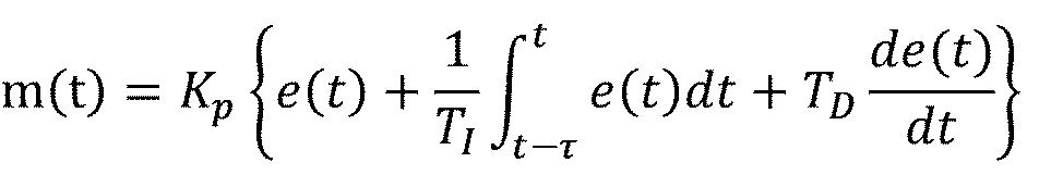
ここで、m(t)は時刻tにおける制御指令値、e(t)は時刻tにおける位置偏差、Kpは比例係数、TIは積分係数、TDは微分係数を表している。例えば、図6において、台車2が搬送モジュール10bに進入した際の位置偏差e(t)がh301であるとする。搬送モジュール10aにおける第1のモジュール駆動指令によれば、時刻t1~t2において、台車2は一定の速度v1で移動することになっている。このため、制御開始時刻t9より前の所定の積分期間τにおいて、位置偏差h301が続いて生じていたことが推定される。また、第1のモジュール駆動指令が、制御開始時刻前に台車2が加速していることを示している場合、所定の積分期間τにおいて位置偏差e(t)は次第に大きくなっていることが推定される。このようにして推定された位置偏差e(t)の履歴に基づき、制御装置4bは制御開始時における積分要素を計算することができる。
Here, m(t) is a control command value at time t, e(t) is a positional deviation at time t, Kp is a proportional coefficient, TI is an integral coefficient, and TD is a differential coefficient. For example, in FIG. 6, assume that the positional deviation e(t) when the
制御装置4は、上述の処理において計算された位置偏差、積分要素、微分要素に基づき台車2の駆動を開始し(ステップS1008)、モジュール駆動指令による位置制御を実行する(ステップS1009)。ここで、制御装置4は、搬送制御において位置判定部406’で算出した速度情報を用いる。制御装置4はモジュール駆動指令に従い台車2を駆動し、位置制御を終了する(ステップS1009)。
The
上述したように、本実施形態における搬送システムは、第1、第2実施形態における効果に加えてさらに、以下の効果を奏することができる。すなわち、本実施形態における搬送システムは、制御対象の搬送モジュールのモジュール駆動指令に加えて、上流の搬送モジュールのモジュール駆動指令を制御装置に送信している。これにより、制御装置は、上流の搬送モジュールにおける位置偏差の履歴を推定し、PID制御における積分要素を計算することが可能となる。これにより、複数の搬送モジュールに亘って積分制御を行う場合において、台車2を安定に制御することが可能となる。例えば、搬送モジュールの境界近傍に台車2を停止させるような場合に、台車が不安定な挙動を示すことなく、搬送モジュールの境界付近において台車の停止位置を高精度に制御することが可能となる。
As described above, the transport system of this embodiment can achieve the following effects in addition to the effects of the first and second embodiments. In other words, the transport system according to the present embodiment transmits module drive commands for upstream transport modules to the control device in addition to module drive commands for the transport modules to be controlled. This allows the controller to estimate the history of positional deviations in the upstream transport module and calculate the integral element in PID control. This makes it possible to stably control the
なお、1つの制御装置に送信するモジュール駆動指令の数は上述の例に限定されない。例えば、制御対象2つ以上の上流のモジュール駆動指令を送信してもよい。これにより、さらに長い積分期間における積分要素を推定することが可能となる。 Note that the number of module drive commands to be transmitted to one control device is not limited to the above example. For example, a command to drive two or more upstream modules to be controlled may be transmitted. This makes it possible to estimate the integral elements over longer integration periods.
[他の実施形態]
本発明は上述の実施形態に限定されることなく、様々な態様での変更実施が可能である。上述の実施形態において、搬送開始時刻を判断するためのタイマ部は、搬送開始指令をトリガとして計時を開始しているが、複数の制御部において同期している限り、指令または信号の種類を問わない。
[Other embodiments]
The present invention is not limited to the above-described embodiments, and can be modified in various ways. In the above-described embodiment, the timer unit for determining the transport start time is triggered by the transport start command and starts timing. do not have.
2 台車
4 制御装置
10 搬送モジュール
40 搬送コントローラ
50 工程コントローラ
103 位置検出部
105 速度検出部
2
Claims (16)
前記複数の搬送モジュールにそれぞれ対応して設けられるとともに、予め記憶された駆動条件および制御開始タイミングに従い、前記台車の位置制御を行う複数の制御部とを備え、
前記複数の搬送モジュールのうちの一つの搬送モジュールである第一の搬送モジュールに対応する前記複数の前記制御部のうちの一つの制御部は、前記第一の搬送モジュールに前記台車が進入してきた進入タイミングと、前記制御開始タイミングとの差に基づいて、前記台車の位置制御を行うことを特徴とする搬送システム。 a plurality of transport modules forming a transport path along which the carriage travels;
a plurality of control units provided respectively corresponding to the plurality of transfer modules and performing position control of the carriage in accordance with pre-stored drive conditions and control start timing ;
One controller among the plurality of controllers corresponding to a first carrier module, which is one carrier module among the plurality of carrier modules, detects that the carriage has entered the first carrier module. A conveying system , wherein position control of the carriage is performed based on a difference between an approach timing and the control start timing .
前記制御部は、前記位置検出部によって前記台車が検出されたタイミングを前記進入タイミングとすることを特徴とする請求項1に記載の搬送システム。 2. The conveying system according to claim 1, wherein the controller sets the timing at which the carriage is detected by the position detector as the approach timing.
前記タイマは、前記複数の制御部が同時に所定の指令を受信することにより、計時を開始し、前記受信から所定時間後を前記制御開始タイミングとすることを特徴とする請求項2乃至4のいずれか1項に記載の搬送システム。 The control unit includes a timer for determining the control start timing ,
5. The timer according to any one of claims 2 to 4 , wherein the timer starts counting when the plurality of control units simultaneously receive a predetermined command, and sets a predetermined time after the reception as the control start timing. or the transport system according to item 1 .
前記台車は、前記コイル群から電磁力を受けるマグネットを有し、
前記制御部は、前記コイル群に流す電流を制御することにより、前記位置制御を行うことを特徴とする請求項1乃至6のいずれか1項に記載の搬送システム。 the transport module has a group of coils,
The truck has a magnet that receives an electromagnetic force from the coil group,
7. The transfer system according to any one of claims 1 to 6 , wherein the control unit performs the position control by controlling currents to be applied to the coil groups.
前記上位制御部は、前記駆動条件と前記搬送開始指令を複数の前記制御部のそれぞれに送信することを特徴とする請求項6に記載の搬送システム。 further comprising an upper control unit capable of communicating with a plurality of said control units,
7. The conveying system according to claim 6 , wherein the host controller transmits the drive condition and the conveying start command to each of the plurality of controllers.
前記制御部は、前記速度検出部によって検出された前記台車の速度を用いて、前記位置制御を実行することを特徴とする請求項3または4に記載の搬送システム。 further comprising a speed detection unit that detects the speed of the carriage in the transfer module;
5. The conveying system according to claim 3 , wherein the controller executes the position control using the speed of the cart detected by the speed detector.
複数の前記制御部は、第1の駆動条件に従い前記第1の搬送モジュールにおける前記位置制御を行う第1の制御部と、第2の駆動条件に従い前記第2の搬送モジュールにおける前記位置制御を行う第2の制御部とを備え、
前記第2の制御部は、前記第1の駆動条件を前記第2の駆動条件とともに予め記憶し、前記制御開始タイミングにおいて前記位置検出部によって検出された前記台車の位置と前記第1の駆動条件とを用いて、前記制御開始タイミングより前における前記位置偏差を求めて前記台車の位置を制御することを特徴とする請求項3に記載の搬送システム。 The plurality of transport modules includes a first transport module and a second transport module into which the carriage enters from the first transport module,
The plurality of controllers include a first controller that performs the position control in the first transport module according to a first drive condition, and a second controller that performs the position control in the second transport module according to a second drive condition. and a second control unit,
The second control unit pre-stores the first drive condition together with the second drive condition, and stores the position of the truck detected by the position detection unit at the control start timing and the first drive condition. 4. The conveying system according to claim 3 , wherein the positional deviation of the carriage is obtained before the control start timing by using and to control the position of the carriage.
前記複数の搬送モジュールのうちの一つの搬送モジュールである第一の搬送モジュールに対応する前記複数の前記制御部のうちの一つの制御部は、前記第一の搬送モジュールに前記台車が進入してきた進入タイミングと、前記制御開始タイミングとの差に基づいて、前記台車の位置制御を行うことを特徴とする制御方法。 a plurality of transport modules that form a transport path along which the carriage travels ; A control method for a transport system comprising a control unit of
One controller among the plurality of controllers corresponding to a first carrier module, which is one carrier module among the plurality of carrier modules, detects that the carriage has entered the first carrier module. A control method , wherein position control of the truck is performed based on a difference between an approach timing and the control start timing .
前記台車により搬送されるワークに対して加工する工程装置と、a process device for processing the workpiece conveyed by the carriage;
を有するワーク加工装置。A work processing device having
前記台車により前記ワークを搬送する工程と、 a step of transporting the work by the carriage;
前記台車により搬送された前記ワークに対して、前記工程装置により前記加工する工程と a step of processing the work conveyed by the carriage by the process device;
を有することを特徴とする製造方法。 A manufacturing method characterized by having
Priority Applications (3)
| Application Number | Priority Date | Filing Date | Title |
|---|---|---|---|
| JP2018092353A JP7179488B2 (en) | 2018-05-11 | 2018-05-11 | Conveyor system and its control method |
| US16/393,448 US10745203B2 (en) | 2018-05-11 | 2019-04-24 | Transport system, control method, processing system, and manufacturing method of article |
| CN201910386546.8A CN110471464B (en) | 2018-05-11 | 2019-05-10 | Conveyor system, control method, processing system, and method for manufacturing article |
Applications Claiming Priority (1)
| Application Number | Priority Date | Filing Date | Title |
|---|---|---|---|
| JP2018092353A JP7179488B2 (en) | 2018-05-11 | 2018-05-11 | Conveyor system and its control method |
Publications (3)
| Publication Number | Publication Date |
|---|---|
| JP2019197490A JP2019197490A (en) | 2019-11-14 |
| JP2019197490A5 JP2019197490A5 (en) | 2021-07-26 |
| JP7179488B2 true JP7179488B2 (en) | 2022-11-29 |
Family
ID=68465147
Family Applications (1)
| Application Number | Title | Priority Date | Filing Date |
|---|---|---|---|
| JP2018092353A Active JP7179488B2 (en) | 2018-05-11 | 2018-05-11 | Conveyor system and its control method |
Country Status (3)
| Country | Link |
|---|---|
| US (1) | US10745203B2 (en) |
| JP (1) | JP7179488B2 (en) |
| CN (1) | CN110471464B (en) |
Families Citing this family (12)
| Publication number | Priority date | Publication date | Assignee | Title |
|---|---|---|---|---|
| DE112017006943B4 (en) * | 2017-01-27 | 2026-01-29 | Murata Machinery, Ltd. | Article transfer device |
| US10934099B2 (en) * | 2018-05-02 | 2021-03-02 | Caromation, Inc. | Electric pallet conveyor |
| US10944314B2 (en) | 2018-08-08 | 2021-03-09 | Canon Kabushiki Kaisha | Transport system, mover, control apparatus, and control method |
| JP6938457B2 (en) | 2018-08-08 | 2021-09-22 | キヤノン株式会社 | Transport system, mover, control device and control method |
| US11186302B2 (en) | 2018-11-13 | 2021-11-30 | Rockwell Automation Technologies, Inc. | Section based safety functions for independent cart applications |
| JP7479835B2 (en) * | 2019-12-24 | 2024-05-09 | キヤノン株式会社 | TRANSPORTATION DEVICE AND METHOD FOR MANUFACTURING AN ARTICLE |
| WO2021157239A1 (en) * | 2020-02-04 | 2021-08-12 | パナソニックIpマネジメント株式会社 | Linear motor system |
| JP7483397B2 (en) | 2020-02-07 | 2024-05-15 | キヤノン株式会社 | Transport System |
| CN113333298B (en) * | 2020-03-03 | 2022-11-29 | 顺丰科技有限公司 | Cross-band control method, system, computer device, and storage medium |
| JP7534923B2 (en) | 2020-10-30 | 2024-08-15 | キヤノン株式会社 | TRANSPORT SYSTEM AND CONTROL METHOD FOR TRANSPORT SYSTEM |
| JP7559620B2 (en) * | 2021-03-02 | 2024-10-02 | 村田機械株式会社 | Transport System |
| US20230191916A1 (en) * | 2021-12-20 | 2023-06-22 | Micah Skidmore | Novel electromagnetic propulsion and levitation technology |
Citations (4)
| Publication number | Priority date | Publication date | Assignee | Title |
|---|---|---|---|---|
| JP2011078196A (en) | 2009-09-30 | 2011-04-14 | Thk Co Ltd | Drive system and control method for linear motor |
| JP2015202793A (en) | 2014-04-15 | 2015-11-16 | キヤノン株式会社 | Carriage transfer system |
| JP2015208083A (en) | 2014-04-18 | 2015-11-19 | キヤノン株式会社 | linear motor controller and linear motor control system |
| JP2017042029A (en) | 2015-08-21 | 2017-02-23 | 村田機械株式会社 | Linear motor system |
Family Cites Families (21)
| Publication number | Priority date | Publication date | Assignee | Title |
|---|---|---|---|---|
| NO790437L (en) * | 1978-02-14 | 1979-08-15 | Vgl Ind Ltd | CONTROL CIRCUIT FOR Vending Machine. |
| US5032975A (en) | 1987-08-07 | 1991-07-16 | Canon Kabushiki Kaisha | Controller for automatic assembling apparatus |
| JP3115297B2 (en) | 1989-10-09 | 2000-12-04 | キヤノン株式会社 | Control device for automatic equipment |
| JPH04112117A (en) * | 1990-08-29 | 1992-04-14 | Mazda Motor Corp | Transfer control method from linear conveying device |
| DE4313884C2 (en) * | 1993-04-28 | 1996-07-25 | Fraunhofer Ges Forschung | High speed / staging and transportation facility and staging and transportation method |
| US6052644A (en) * | 1994-12-27 | 2000-04-18 | Komatsu Ltd. | Apparatus and method for limiting vehicle speed of a working vehicle |
| CA2179971C (en) | 1995-06-30 | 2001-10-30 | Takahisa Yamamoto | An adaptable communication apparatus and an adaptable communication system |
| US6240335B1 (en) * | 1998-12-14 | 2001-05-29 | Palo Alto Technologies, Inc. | Distributed control system architecture and method for a material transport system |
| JP4532712B2 (en) | 2000-09-29 | 2010-08-25 | キヤノン株式会社 | Electronics |
| JP3414385B2 (en) * | 2001-01-15 | 2003-06-09 | サンケン電気株式会社 | Position control device |
| JP3826039B2 (en) | 2002-01-22 | 2006-09-27 | キヤノン株式会社 | Signal processing device |
| JP4109902B2 (en) | 2002-05-27 | 2008-07-02 | キヤノン株式会社 | Display device |
| SE527525C2 (en) * | 2003-12-22 | 2006-04-04 | Abb As | Control device, method and control system for starting or stopping an upcoming task of a robot |
| JP4864749B2 (en) * | 2007-02-01 | 2012-02-01 | トヨタ自動車株式会社 | Vehicle travel control device |
| JP5438053B2 (en) * | 2011-03-14 | 2014-03-12 | 日本特殊陶業株式会社 | Sensor control device, sensor control system, and sensor control method |
| JP6521772B2 (en) | 2015-07-07 | 2019-05-29 | キヤノン株式会社 | Transport system and control method thereof, and carriage and control method thereof |
| JP6704705B2 (en) | 2015-10-22 | 2020-06-03 | キヤノン株式会社 | Movable magnet type linear motor control system and control method thereof |
| JP7066333B2 (en) | 2017-05-17 | 2022-05-13 | キヤノン株式会社 | Transport system, processing system, article manufacturing method, transport system control method and movable mechanism |
| JP7137300B2 (en) | 2017-09-25 | 2022-09-14 | キヤノン株式会社 | Conveying device, conveying system, conveying system control method, processing system, and article manufacturing method |
| US10889449B2 (en) | 2017-09-25 | 2021-01-12 | Canon Kabushiki Kaisha | Transport system and manufacturing method of article |
| US10965201B2 (en) | 2017-09-25 | 2021-03-30 | Canon Kabushiki Kaisha | Transport system, processing system and manufacturing method of article |
-
2018
- 2018-05-11 JP JP2018092353A patent/JP7179488B2/en active Active
-
2019
- 2019-04-24 US US16/393,448 patent/US10745203B2/en active Active
- 2019-05-10 CN CN201910386546.8A patent/CN110471464B/en active Active
Patent Citations (4)
| Publication number | Priority date | Publication date | Assignee | Title |
|---|---|---|---|---|
| JP2011078196A (en) | 2009-09-30 | 2011-04-14 | Thk Co Ltd | Drive system and control method for linear motor |
| JP2015202793A (en) | 2014-04-15 | 2015-11-16 | キヤノン株式会社 | Carriage transfer system |
| JP2015208083A (en) | 2014-04-18 | 2015-11-19 | キヤノン株式会社 | linear motor controller and linear motor control system |
| JP2017042029A (en) | 2015-08-21 | 2017-02-23 | 村田機械株式会社 | Linear motor system |
Also Published As
| Publication number | Publication date |
|---|---|
| CN110471464B (en) | 2023-12-12 |
| US10745203B2 (en) | 2020-08-18 |
| CN110471464A (en) | 2019-11-19 |
| JP2019197490A (en) | 2019-11-14 |
| US20190344967A1 (en) | 2019-11-14 |
Similar Documents
| Publication | Publication Date | Title |
|---|---|---|
| JP7179488B2 (en) | Conveyor system and its control method | |
| JP6313642B2 (en) | Linear motor control device and linear motor control system | |
| CN109178829B (en) | Trolley conveyor system and method of manufacturing articles | |
| CN106612095B (en) | Moving magnet type linear motor control system and component manufacturing method | |
| KR101584022B1 (en) | Transfer system | |
| EP3650971B1 (en) | Independent cart system and method of operating the same | |
| JP6733170B2 (en) | Linear motor system | |
| US11969841B2 (en) | Transport system, transport method, and article manufacturing method | |
| US4507598A (en) | Two-axis positioning system | |
| WO2019007202A1 (en) | Linear transmission system and control device thereof, and multi-mover cooperative control system | |
| US10364103B2 (en) | Conveyor systems and methods of controlling moving stage | |
| JP2021525689A (en) | How to control the transport unit of a transport device in the form of a long stator linear motor | |
| JP6490273B2 (en) | Linear motor control device and linear motor control system | |
| JP6803476B2 (en) | Work transfer system | |
| CN117566383B (en) | Control methods and related equipment for moving components of magnetic drive systems | |
| JP2017040621A (en) | Moving body and position detection method for the same | |
| TWI866020B (en) | Driving device, driving method, and driving program | |
| CN104779889B (en) | Linear motor position feedback control system and its control method | |
| JP2017126286A (en) | Mobile body, mobile body system, and method of calculating correction coefficient for mobile body | |
| JP6448836B2 (en) | Carriage transfer system | |
| US20250100816A1 (en) | Method and electromagnetic transport device for detecting a mover | |
| JP2018074829A (en) | Transport system | |
| Schmülling et al. | Decoupling and adjustment of forces in an electromagnetic guiding system with six degrees of freedom | |
| JP2022025311A (en) | Moving object control method and moving object control system | |
| JPH0851704A (en) | Carrier |
Legal Events
| Date | Code | Title | Description |
|---|---|---|---|
| A521 | Request for written amendment filed |
Free format text: JAPANESE INTERMEDIATE CODE: A523 Effective date: 20210506 |
|
| A621 | Written request for application examination |
Free format text: JAPANESE INTERMEDIATE CODE: A621 Effective date: 20210506 |
|
| A977 | Report on retrieval |
Free format text: JAPANESE INTERMEDIATE CODE: A971007 Effective date: 20220325 |
|
| A131 | Notification of reasons for refusal |
Free format text: JAPANESE INTERMEDIATE CODE: A131 Effective date: 20220407 |
|
| A131 | Notification of reasons for refusal |
Free format text: JAPANESE INTERMEDIATE CODE: A131 Effective date: 20220614 |
|
| RD01 | Notification of change of attorney |
Free format text: JAPANESE INTERMEDIATE CODE: A7421 Effective date: 20220630 |
|
| TRDD | Decision of grant or rejection written | ||
| A01 | Written decision to grant a patent or to grant a registration (utility model) |
Free format text: JAPANESE INTERMEDIATE CODE: A01 Effective date: 20221018 |
|
| A61 | First payment of annual fees (during grant procedure) |
Free format text: JAPANESE INTERMEDIATE CODE: A61 Effective date: 20221116 |
|
| R151 | Written notification of patent or utility model registration |
Ref document number: 7179488 Country of ref document: JP Free format text: JAPANESE INTERMEDIATE CODE: R151 |